D GB USA F NL II 22835 - static.maerklin.de · 5 Informations concernant la locomotive réelle :...
36
Modell der Serie Re 4/4 II 22835 D GB F USA NL
Transcript of D GB USA F NL II 22835 - static.maerklin.de · 5 Informations concernant la locomotive réelle :...
Modell der Serie Re 4/4 II
22835D GB F USA NL

2
3
Inhaltsverzeichnis: SeiteInformationen zum Vorbild 4Sicherheitshinweise 6Wichtige Hinweise 6Multiprotokollbetrieb 6Hinweise zum Digitalbetrieb 7Schaltbare Funktionen 9Parameter/Register 10Betriebshinweise 26Wartung und Instandhaltung 28Ersatzteile 34
Table of Contents: Page Information about the prototype 4Safety Notes 11Important Notes 11Multi-Protocol Operation 11Notes on digital operation 12Controllable Functions 14Parameter/Register 15Information about operation 26Service and maintenance 28Spare Parts 34
Sommaire : PageInformations concernant la locomotive réelle 5Remarques importantes sur la sécurité 16Information importante 16Mode multiprotocole 16Remarques relatives au fonctionnement en mode digital 17Fonctions commutables 19Paramètre/Registre 20Remarques sur l’exploitation 26Entretien et maintien 28Pièces de rechange 34
Inhoudsopgave: PaginaInformatie van het voorbeeld 5Veiligheidsvoorschriften 21Belangrijke aanwijzing 21Multiprotocolbedrijf 21Aanwijzingen voor digitale besturing 22Schakelbare functies 24Parameter/Register 25Opmerkingen over de werking 26Onderhoud en handhaving 28Onderdelen 34
4
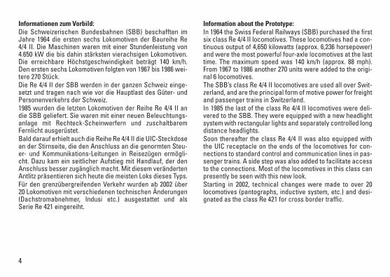
Informationen zum Vorbild: Die Schweizerischen Bundesbahnen (SBB) beschafften im Jahre 1964 die ersten sechs Lokomotiven der Baureihe Re 4/4 II. Die Maschinen waren mit einer Stundenleistung von 4.650 kW die bis dahin stärksten vierachsigen Lokomotiven. Die erreichbare Höchstgeschwindigkeit beträgt 140 km/h. Den ersten sechs Lokomotiven folgten von 1967 bis 1986 wei-tere 270 Stück. Die Re 4/4 II der SBB werden in der ganzen Schweiz einge-setzt und tragen nach wie vor die Hauptlast des Güter- und Personenverkehrs der Schweiz. 1985 wurden die letzten Lokomotiven der Reihe Re 4/4 II an die SBB geliefert. Sie waren mit einer neuen Beleuchtungs-anlage mit Rechteck-Scheinwerfern und zuschaltbarem Fernlicht ausgerüstet. Bald darauf erhielt auch die Reihe Re 4/4 II die UIC-Steckdose an der Stirnseite, die den Anschluss an die genormten Steu-er- und Kommunikations-Leitungen in Reisezügen ermögli-cht. Dazu kam ein seitlicher Aufstieg mit Handlauf, der den Anschluss besser zugänglich macht. Mit diesem veränderten Antlitz präsentieren sich heute die meisten Loks dieses Typs. Für den grenzübergreifenden Verkehr wurden ab 2002 über 20 Lokomotiven mit verschiedenen technischen Änderungen (Dachstromabnehmer, Indusi etc.) ausgestattet und als Serie Re 421 eingereiht.
Information about the Prototype: In 1964 the Swiss Federal Railways (SBB) purchased the first six class Re 4/4 II locomotives. These locomotives had a con-tinuous output of 4,650 kilowatts (approx. 6,236 horsepower) and were the most powerful four-axle locomotives at the last time. The maximum speed was 140 km/h (approx. 88 mph). From 1967 to 1986 another 270 units were added to the origi-nal 6 locomotives. The SBB’s class Re 4/4 II locomotives are used all over Swit-zerland, and are the principal form of motive power for freight and passenger trains in Switzerland. In 1985 the last of the class Re 4/4 II locomotives were deli-vered to the SBB. They were equipped with a new headlight system with rectangular lights and separately controlled long distance headlights. Soon thereafter the class Re 4/4 II was also equipped with the UIC receptacle on the ends of the locomotives for con-nections to standard control and communication lines in pas-senger trains. A side step was also added to facilitate access to the connections. Most of the locomotives in this class can presently be seen with this new look. Starting in 2002, technical changes were made to over 20 locomotives (pantographs, inductive system, etc.) and desi-gnated as the class Re 421 for cross border traffic.
5
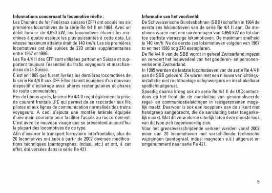
Informations concernant la locomotive réelle :Les Chemins de fer Fédéraux suisses (CFF) ont acquis les six premières locomotives de la série Re 4/4 II en 1964. Avec un débit horaire de 4.650 kW, les locomotives étaient les ma-chines à quatre essieux les plus puissantes à cette date. La vitesse maximum atteinte était de 140 km/h. Les six premières locomotives ont été suivies de 270 unités supplémentaires entre 1967 et 1986. Les Re 4/4 II des CFF sont utilisées partout en Suisse et sup-portent toujours l’essentiel du frafic voyageurs et marchan-dises de la Suisse. C’est en 1985 que furent livrées les dernières locomotives de la série Re 4/4 II aux CFF. Elles étaient équipées d’un nouveau dispositif d’éclairage avec phares rectangulaires et phares de route commutables. Peu de temps après, la série Re 4/4 II reçut également la prise de courant frontale UIC qui permet de se raccorder aux fils pilotes et aux lignes de communication normalisés des trains voyageurs. A ceci s’ajouta une montée latérale équipée d’une main courante pour faciliter l’accès au raccordement. C’est avec ce nouveau visage que se présentent aujourd’hui la plupart des locomotives de ce type. Afin d’assurer le transport ferroviaire interfrontalier, plus de 20 locomotives ont subi à partir de 2002 diverses modifica-tions techniques (pantographes, Indusi, etc.) et ont, à cet effet, été versées dans la série Re 421.
Informatie van het voorbeeld: De Schweizerische Bundesbahnen (SBB) schaffen in 1964 de eerste zes lokomotieven van de serie Re 4/4 II aan. De ma-chines waren met een uurvermogen van 4.650 kW de tot dan toe sterkste vierassige lokomotieven. De maximum snelheid is 140 km/h. Na de eerste zes lokomotieven volgden van 1967 to en met 1986 nog 270 exemplaren. De Re 4/4 II van de SBB wordt in geheel Zwitserland ingezet en vervoert het leeuwedeel van het goederen- en personen-verkeer in Zwitserland. In 1985 werden de laatste locomotieven van de serie Re 4/4 II aan de SBB geleverd. Ze waren met een nieuwe verlichtings-installatie met rechthoekige schijnwerpers en inschakelbaar spotlicht uitgerust. Spoedig daarna kreeg ook de serie Re 4/4 II de UICcontact-doos op het front die de aansluiting van genormaliseerde regel- en communicatieleidingen in reizigerstreinen moge-lijk maakt. Daarvoor is ook een loopplank aan de zijkant met handgreep aangebracht, die de aansluiting beter toeganke-lijk maakt. Met dit veranderde uiterlijk laten deze meeste locs van dit type zich tegenwoordig zien. Voor het grensoverschrijdende verkeer werden vanaf 2002 meer dan 20 locomotieven met verschillende technische wijzigingen (pantograaf, indusi magneten e.d.) uitgerust en omgenummerd naar serie Re 421.
6
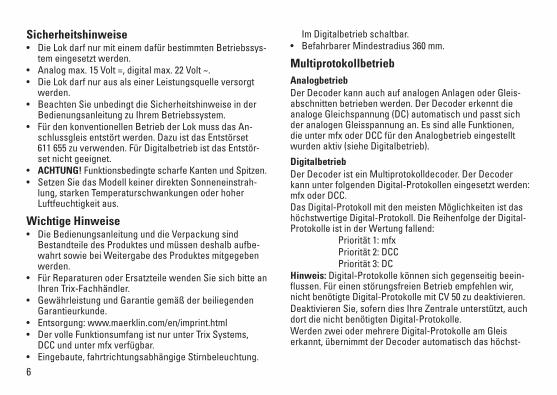
Sicherheitshinweise • DieLokdarfnurmiteinemdafürbestimmtenBetriebssys-
tem eingesetzt werden.• Analogmax.15Volt=,digitalmax.22Volt~.• DieLokdarfnurausalseinerLeistungsquelleversorgt
werden.• BeachtenSieunbedingtdieSicherheitshinweiseinder
Bedienungsanleitung zu Ihrem Betriebssystem.• FürdenkonventionellenBetriebderLokmussdasAn-
schlussgleis entstört werden. Dazu ist das Entstörset 611 655 zu verwenden. Für Digitalbetrieb ist das Entstör-set nicht geeignet.
• ACHTUNG! Funktionsbedingte scharfe Kanten und Spitzen.• SetzenSiedasModellkeinerdirektenSonneneinstrah-
lung, starken Temperaturschwankungen oder hoher Luftfeuchtigkeit aus.
Wichtige Hinweise • DieBedienungsanleitungunddieVerpackungsind
Bestandteile des Produktes und müssen deshalb aufbe-wahrt sowie bei Weitergabe des Produktes mitgegeben werden.
• FürReparaturenoderErsatzteilewendenSiesichbitteanIhren Trix-Fachhändler.
• GewährleistungundGarantiegemäßderbeiliegendenGarantieurkunde.
• Entsorgung:www.maerklin.com/en/imprint.html• DervolleFunktionsumfangistnurunterTrixSystems,
DCC und unter mfx verfügbar.• Eingebaute,fahrtrichtungsabhängigeStirnbeleuchtung.
Im Digitalbetrieb schaltbar. • BefahrbarerMindestradius360mm.
Multiprotokollbetrieb AnalogbetriebDer Decoder kann auch auf analogen Anlagen oder Gleis-abschnitten betrieben werden. Der Decoder erkennt die analoge Gleichspannung (DC) automatisch und passt sich der analogen Gleisspannung an. Es sind alle Funktionen, die unter mfx oder DCC für den Analogbetrieb eingestellt wurden aktiv (siehe Digitalbetrieb).
DigitalbetriebDer Decoder ist ein Multiprotokolldecoder. Der Decoder kannunterfolgendenDigital-Protokolleneingesetztwerden:mfx oder DCC. Das Digital-Protokoll mit den meisten Möglichkeiten ist das höchstwertige Digital-Protokoll. Die Reihenfolge der Digital-ProtokolleistinderWertungfallend: Priorität1:mfx Priorität2:DCC Priorität3:DCHinweis: Digital-Protokolle können sich gegenseitig beein-flussen. Für einen störungsfreien Betrieb empfehlen wir, nicht benötigte Digital-Protokolle mit CV 50 zu deaktivieren.Deaktivieren Sie, sofern dies Ihre Zentrale unterstützt, auch dort die nicht benötigten Digital-Protokolle.Werden zwei oder mehrere Digital-Protokolle am Gleis erkannt, übernimmt der Decoder automatisch das höchst-
7
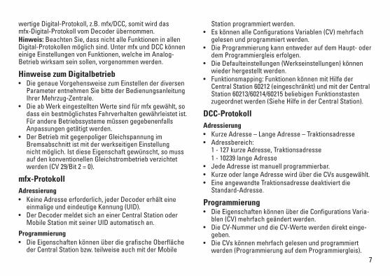
wertige Digital-Protokoll, z.B. mfx/DCC, somit wird das mfx-Digital-Protokoll vom Decoder übernommen. Hinweis: Beachten Sie, dass nicht alle Funktionen in allen Digital-Protokollen möglich sind. Unter mfx und DCC können einige Einstellungen von Funktionen, welche im Analog-Betrieb wirksam sein sollen, vorgenommen werden.
Hinweise zum Digitalbetrieb • DiegenaueVorgehensweisezumEinstellenderdiversen
Parameter entnehmen Sie bitte der Bedienungsanleitung Ihrer Mehrzug-Zentrale.
• DieabWerkeingestelltenWertesindfürmfxgewählt,sodass ein bestmöglichstes Fahrverhalten gewährleistet ist. Für andere Betriebssysteme müssen gegebenenfalls Anpassungen getätigt werden.
• DerBetriebmitgegenpoligerGleichspannungimBremsabschnitt ist mit der werkseitigen Einstellung nicht möglich. Ist diese Eigenschaft gewünscht, so muss auf den konventionellen Gleichstrombetrieb verzichtet werden(CV29/Bit2=0).
mfx-ProtokollAdressierung • KeineAdresseerforderlich,jederDecodererhälteine
einmalige und eindeutige Kennung (UID).• DerDecodermeldetsichaneinerCentralStationoder
Mobile Station mit seiner UID automatisch an.
Programmierung• DieEigenschaftenkönnenüberdiegrafischeOberfläche
der Central Station bzw. teilweise auch mit der Mobile
Station programmiert werden. • EskönnenalleConfigurationsVariablen(CV)mehrfach
gelesen und programmiert werden.• DieProgrammierungkannentwederaufdemHaupt-oder
dem Programmiergleis erfolgen. • DieDefaulteinstellungen(Werkseinstellungen)können
wieder hergestellt werden.• Funktionsmapping:FunktionenkönnenmitHilfeder
Central Station 60212 (eingeschränkt) und mit der Central Station 60213/60214/60215 beliebigen Funktionstasten zugeordnet werden (Siehe Hilfe in der Central Station).
DCC-ProtokollAdressierung• KurzeAdresse–LangeAdresse–Traktionsadresse• Adressbereich:
1 - 127 kurze Adresse, Traktionsadresse 1 - 10239 lange Adresse• JedeAdresseistmanuellprogrammierbar.• KurzeoderlangeAdressewirdüberdieCVsausgewählt.• EineangewandteTraktionsadressedeaktiviertdie
Standard-Adresse.
Programmierung• DieEigenschaftenkönnenüberdieConfigurationsVaria-
blen (CV) mehrfach geändert werden. • DieCV-NummerunddieCV-Wertewerdendirekteinge-
geben.• DieCVskönnenmehrfachgelesenundprogrammiert
werden (Programmierung auf dem Programmiergleis).
8
• DieCVskönnenbeliebigprogrammiertwerden(Program-mierung auf dem Hauptgleis PoM). PoM ist nur bei den in der CV-Tabelle gekennzeichneten CV möglich. Die Pro-grammierung auf dem Hauptgleis (PoM) muss von Ihrer Zentrale unterstützt werden (siehe Bedienungsanleitung ihres Gerätes).
• DieDefaulteinstellungen(Werkseinstellungen)könnenwieder hergestellt werden.
• 14bzw.28/126Fahrstufeneinstellbar.• AutomatischesBremsen(CV27=Wert16)• AlleFunktionenkönnenentsprechenddemFunktions-
mapping geschaltet werden.• WeitereInformation,sieheCV-TabelleDCC-Protokoll.Es wird empfohlen, die Programmierungen grundsätzlich auf dem Programmiergleis vorzunehmen.
Logische FunktionenAnfahr-/Bremsverzögerung• DieBeschleunigungs-undBremszeitkanngetrennt
voneinander eingestellt werden. • DielogischeFunktionsabschaltungABVkannüberdas
Funktionsmapping auf jede beliebige Funktionstaste gelegt werden.
9
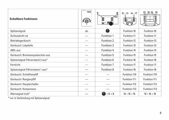
Schaltbare Funktionen
Spitzensignal an Funktion f0 Funktion f0
Schlusslicht rot — Funktion 1 Funktion f1 Funktion f1
Betriebsgeräusch — Funktion 2 Funktion f2 Funktion f2
Geräusch:Lokpfeife — Funktion 3 Funktion f3 Funktion f3
ABV, aus — Funktion 4 Funktion f4 Funktion f4
Geräusch:Bremsenquietschenaus — Funktion 5 Funktion f5 Funktion f5
Spitzensignal Führerstand 2 aus* — Funktion 6 Funktion f6 Funktion f6
Fernlicht — Funktion 7 Funktion f7 Funktion f7
Spitzensignal Führerstand 1 aus* — Funktion 8 Funktion f8 Funktion f8
Geräusch:Schaffnerpfiff — — Funktion f10 Funktion f10
Geräusch:Rangierpfiff — — Funktion f11 Funktion f11
Geräusch:Hauptschalter — — Funktion f12 Funktion f12
Geräusch:Kompressor — — Funktion f13 Funktion f13
Warnsignal (rot)* — + 6 + 8 f0 + f6 + f8 f0 + f6 + f8* nur in Verbindung mit Spitzensignal
STOP mobile station
1 5 f0 f8 f0f8f0 - f3 f4 - f7
10
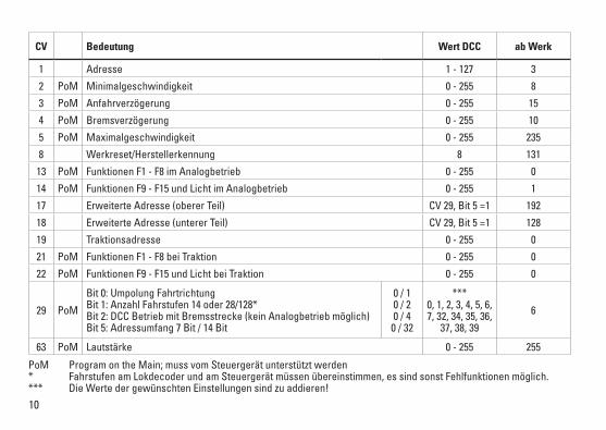
CV Bedeutung Wert DCC ab Werk
1 Adresse 1 - 127 3
2 PoM Minimalgeschwindigkeit 0 - 255 8
3 PoM Anfahrverzögerung 0 - 255 15
4 PoM Bremsverzögerung 0 - 255 10
5 PoM Maximalgeschwindigkeit 0 - 255 235
8 Werkreset/Herstellerkennung 8 131
13 PoM Funktionen F1 - F8 im Analogbetrieb 0 - 255 0
14 PoM Funktionen F9 - F15 und Licht im Analogbetrieb 0 - 255 1
17 Erweiterte Adresse (oberer Teil) CV29,Bit5=1 192
18 Erweiterte Adresse (unterer Teil) CV29,Bit5=1 128
19 Traktionsadresse 0 - 255 0
21 PoM Funktionen F1 - F8 bei Traktion 0 - 255 0
22 PoM Funktionen F9 - F15 und Licht bei Traktion 0 - 255 0
29 PoM
Bit0:UmpolungFahrtrichtung Bit1:AnzahlFahrstufen14oder28/128* Bit2:DCCBetriebmitBremsstrecke(keinAnalogbetriebmöglich) Bit5:Adressumfang7Bit/14Bit
0 / 1 0 / 2 0 / 4
0 / 32
*** 0, 1, 2, 3, 4, 5, 6, 7, 32, 34, 35, 36,
37, 38, 39
6
63 PoM Lautstärke 0 - 255 255
PoM Program on the Main; muss vom Steuergerät unterstützt werden* Fahrstufen am Lokdecoder und am Steuergerät müssen übereinstimmen, es sind sonst Fehlfunktionen möglich.*** Die Werte der gewünschten Einstellungen sind zu addieren!
11
travel. They can be turned on and off in digital operation. • Minimumradiusforoperationis360mm/14-3/16“.
Multi-Protocol Operation Analog OperationThis decoder can also be operated on analog layouts or ar-eas of track that are analog. The decoder recognizes alter-nating current (DC) and automatically adapts to the analog track voltage. All functions that were set under mfx or DCC for analog operation are active (see Digital Operation).
Digital OperationThe decoders are multi-protocol decoders. These decoders canbeusedunderthefollowingdigitalprotocols:mfxorDCC.The digital protocol with the most possibilities is the highest order digital protocol. The sequence of digital protocols in descendingorderis: Priority1:mfx Priority2:DCC Priority3:DCNote: Digital protocols can influence each other. For trouble-free operation, we recommend deactivating those digital protocols not needed by using CV 50. Deactivate unneeded digital protocols at this CV if your controller supports this function. If two or more digital protocols are recognized in the track, the decoder automatically takes on the highest order digital protocol,example:mfx/DCC;thedecodertakesonthemfxdigital protocol (see previous table).Note: Please note that not all functions are possible in all
Safety Notes• Thislocomotiveisonlytobeusedwiththeoperating
system it is designed for.• Analogmax.15voltsDC,digitalmax.22voltsAC.• Thislocomotivemustneverbesuppliedwithpowerfrom
more than one power pack.• Pleasemakenoteofthesafetynotesintheinstructions
for your operating system.• Thefeedertrackmustbeequippedtopreventinter-
ference with radio and television reception, when the locomotive is to be run in conventional operation. The 611 655 interference suppression set is to be used for this purpose. The interference suppression set is not suitable for digital operation.
• WARNING! Sharp edges and points required for operation.• Donotexposethemodeltodirectsunlight,extreme
changes in temperature, or high humidity.
Important Notes• Theoperatinginstructionsandthepackagingareacom-
ponent part of the product and must therefore be kept as well as transferred along with the product to others.
• PleaseseeyourauthorizedTrixdealerforrepairsorspare parts.
• Thewarrantycardincludedwiththisproductspecifiesthe warranty conditions.
• Disposing:www.maerklin.com/en/imprint.html• ThefullrangeoffunctionsisonlyavailableunderTrix
Systems and under DCC.• Built-inheadlightsthatchangeoverwiththedirectionof
12
digital protocols. Several settings for functions, which are supposed to be active in analog operation, can be done under mfx and DCC.
Notes on digital operation • Theoperatinginstructionsforyourcentralunitwillgive
you exact procedures for setting the different parame-ters.
• Thevaluessetatthefactoryhavebeenselectedformfxin order to guarantee the best possible running characte-ristics. Adjustments may have to be made for other operating systems.
• Thesettingdoneatthefactorydoesnotpermitoperationwith opposite polarity DC power in the braking block. If you want this characteristic, you must do without conventionalDCpoweroperation(CV29/Bit2=0).
mfx ProtocolAddresses • Noaddressisrequired;eachdecoderisgivenaone-
time, unique identifier (UID).• ThedecoderautomaticallyregistersitselfonaCentral
Station or a Mobile Station with its UID.
Programming • Thecharacteristicscanbeprogrammedusingthe
graphic screen on the Central Station or also partially with the Mobile Station.
• AlloftheConfigurationVariables(CV)canbereadandprogrammed repeatedly.
• Theprogrammingcanbedoneeitheronthemaintrackorthe programming track.
• Thedefaultsettings(factorysettings)canbeproducedrepeatedly.
• Functionmapping:Functionscanbeassignedtoanyofthe function buttons with the help of the 60212 Central Station (with limitations) and with the 60213/60214/60215 Central Station (See help section in the Central Station).
DCC ProtocolAddresses • Shortaddress–longaddress–multipleunitaddress• Addressrange:
1 - 127 for short address and multiple unit address, 1 - 10239 for long address
• Everyaddresscanbeprogrammedmanually.• AshortoralongaddressisselectedusingtheCVs.• Amultipleunitaddressthatisbeinguseddeactivatesthe
standard address.
Programming• Thecharacteristicscanbechangedrepeatedlyusingthe
Configuration Variables (CV).• TheCVnumbersandtheCVvaluesareentereddirectly.• TheCVscanbereadandprogrammedrepeatedly.(Pro-
gramming is done on the programming track.)• TheCVscanbeprogrammedinanyorderdesired.(Pro-
gramming can be done on the main track PoM). The PoM can only be done with those designated in the CV table. Programming on the main track PoM must be supported
13
by your central controller (Please see the description for this unit.).
• Thedefaultsettings(factorysettings)canbeproducedrepeatedly.
• 14/28or126speedlevelscanbeset.• Allofthefunctionscanbecontrolledaccordingtothe
function mapping (see CV description).• SeetheCVdescriptionfortheDCCprotocolforadditional
information.We recommend that in general programming should be done on the programming track.
Logic FunctionsAcceleration/Braking Delay • Theaccelerationandbrakingtimecanbesetseparately
from each other.• ThelogicfunctionABVcanbeassignedtoanyfunction
button by using the function mapping.
14
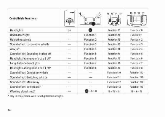
Controllable Functions
Headlights on Function f0 Function f0
Red marker light — Function 1 Function f1 Function f1
Operating sounds — Function 2 Function f2 Function f2
Soundeffect:Locomotivewhistle — Function 3 Function f3 Function f3
ABV, off — Function 4 Function f4 Function f4
Soundeffect:Squealingbrakesoff — Function 5 Function f5 Function f5
Headlights at engineer´s cab 2 off* — Function 6 Function f6 Function f6
Long distance headlights — Function 7 Function f7 Function f7
Headlights at engineer´s cab 1 off* — Function 8 Function f8 Function f8
Soundeffect:Conductorwhistle — — Function f10 Function f10
Soundeffect:Switchingwhistle — — Function f11 Function f11
Soundeffect:Mainrelay — — Function f12 Function f12
Soundeffect:compressor — — Function f13 Function f13
Warning signal (red)* — + 6 + 8 f0 + f6 + f8 f0 + f6 + f8
* only in conjunction with Headlights/marker lights
STOP mobile station
1 5 f0 f8 f0f8f0 - f3 f4 - f7
15
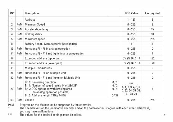
PoM Program on the Main; must be supported by the controller* The speed levels on the locomotive decoder and on the controller must agree with each other; otherwise, you may have malfunctions.*** The values for the desired settings must be added.
CV Discription DCC Value Factory-Set
1 Address 1 - 127 3
2 PoM Minimum Speed 0 - 255 8
3 PoM Acceleration delay 0 - 255 15
4 PoM Braking delay 0 - 255 10
5 PoM Maximum speed 0 - 255 235
8 Factory Reset / Manufacturer Recognition 8 131
13 PoM Functions F1 - F8 in analog operation 0 - 255 0
14 PoM Functions F9 - F15 and lights in analog operation 0 - 255 1
17 Extended address (upper part) CV29,Bit5=1 192
18 Extended address (lower part) CV29,Bit5=1 128
19 Multiple Unit Address 0 - 255 0
21 PoM Functions F1 - F8 on Multiple Unit 0 - 255 0
22 PoM Functions F9 - F15 and lights on Multiple Unit 0 - 255 0
29 PoM
Bit0:Reversingdirection Bit1:Numberofspeedlevels14or28/128* Bit2:DCCoperationwithbrakingarea (no analog operation possible) Bit5:Addresslength7Bit/14Bit
0 / 1 0 / 2 0 / 4
0 / 32
*** 0, 1, 2, 3, 4, 5, 6, 7, 32, 34, 35, 36,
37, 38, 39
6
63 PoM Volume 0 - 255 255
16
Remarques importantes sur la sécurité • Lalocomotivenepeutêtreutiliséequ‘aveclesystèmed‘exploitationindiqué.
• Analogiquemax.15Volt=,digitalmax.22Volt~.• Lalocomotivenepeutpasêtrealimentéeélectriquementparplusd‘unesourcedecourantàlafois.
• Ilestimpératifdetenircomptedesremarquessurlasécuritédécritesdanslemoded‘emploidevotresystèmed‘exploitation.
• Pour l’exploitation de la locomotive en mode conventi-onnel,lavoiederaccordementdoitêtredéparasitée.Acet effet, utiliser le set de déparasitage réf. 611 655. Le set de déparasitage ne convient pas pour l’exploitation en mode numérique.
• ATTENTION! Pointes et bords coupants lors du fonctionne-ment du produit.
• Nepasexposerlemodèleàunensoleillementdirect,à de fortes variations de température ou à un taux d‘humiditéimportant.
Information importante• Lanoticed‘utilisationetl’emballagefontpartieintégranteduproduit;ilsdoiventdoncêtreconservéset,lecaséchéant, transmis avec le produit.
• Pourtouteréparationouremplacementdepièces,adressez vous à votre détaillant-spécialiste Trix.
• Garantielégaleetgarantiecontractuelleconformémentau certificat de garantie ci-joint.
• Elimination:www.maerklin.com/en/imprint.html• L’intégralitédesfonctionsestdisponibleuniquementen
exploitation Trix Systems, DCC et mfx. • Feuxdesignalisations‘inversantselonlesensdemar-
che; feux commutables en exploitation digital. • Rayonminimald’inscriptionencourbe360mm.
Mode multiprotocole Mode analogiqueOn peut aussi faire fonctionner le décodeur sur des instal-lations ou des sections de voie analogiques. Le décodeur identifie automatiquement la tension de voie analogique (CC). Toutes les fonctions qui ont été paramétrée pour le mode analogique sous mfx ou sous DCC sont actives (voir mode numérique).
Mode numériqueLes décodeur sont des décodeur multiprotocole. Le décodeurpeutêtreutiliséaveclesprotocolesnumériquessuivants:mfx,DCCLe protocole numérique offrant les possibilités les plus nombreuses est le protocole numérique à bit de poids fort. La hiérarchisation des protocoles numériques est descendante: Priorité1:mfx Priorité2:DCC Priorité3:DCIndication : des protocoles numériques peuvent s’influencer réciproquement. Pour une exploitation sans perturbations, nous recommandons de désactiver avec CV 50 des proto-coles numériques non nécessaires.
17
Dans la mesure où votre centrale les supporte, désactivez y aussi les protocoles numériques non nécessaires.Lorsque deux ou plusieurs protocoles numériques sont identifiés au niveau de la voie, le décodeur reprend automa-tiquement le protocole numérique à bit de poids fort, p. ex. mfx/DCC. Le protocole numérique mfx est donc repris par le décodeur (voir tableau antérieur).Indication : remarquez que toutes les fonctions ne peuvent pasêtreactionnéesdanstouslesprotocolesnumériques.Sous mfx et sous DCC, il est possible de procéder à quelquesparamétragesdefonctionsdevantêtreactivesdans le cadre de l’exploitation analogique.
Remarques relatives au fonctionnement en mode digital • Encequiconcernelaprocédurederéglagedesdiversparamètres,veuillezvousréféreraumoded‘emploidevotre centrale de commande multitrain.
• Lesvaleursparamétréesd’usinesontchoisiespourmfx de manière à garantir le meilleur comportement de roulement possible. Pour d’autres systèmes d’exploitation, ces valeurs devrontéventuellementêtreadaptées.
• Lesvaleursparamétréesd’usinesontchoisiesdema-nière à garantir le meilleur comportement de roulement possible.
• L’exploitationaveccourantcontinudepolaritéinversedans les sections de freinage n’est pas possible avec le réglage d’usine. Si cette propriété est désirée, il faut alors renoncer à l’exploitation conventionnelle en cou-rantcontinu(CV29/Bit2=0).
Protocole mfxAdressage • Aucuneadressen’estnécessaire,ledécodeurreçoittou-
tefois une identification unique et non équivoque (UID).• AvecsonUID,ledécodeurindiqueautomatiquement
à une station centrale ou à une station mobile qu’il est connecté.
Programmation• Lescaractéristiquespeuventêtreprogramméespar
l’intermédiaire de la couche graphique de la station cen-trale, voire en partie aussi au moyen de la station mobile.
• Touteslesconfigurationsvariables(CV)peuventêtrelueset programmées de façon réitérée.
• Laprogrammationpeutêtreréaliséesoitsurlavoieprincipale, soit sur la voie de programmation.
• Lesparamétragespardéfaut(paramétragesusine)peuventêtrerétablis.
• Mappagedesfonctions:lesfonctionspeuventêtreaffectées à de quelconques touches de fonction au moyen de la station centrale (60212) (restreinte) et avec la station centrale 60213/60214/60215 (voir Aide au niveau de la station centrale).
Protocole DCCAdressage• Adressebrève–adresselongue–adressedetraction.• Champd’adresse: 1–127adressebrève,adressedetraction 1–10239adresselongue
18
• Chaqueadresseestprogrammablemanuellement.• L’adressebrèveoulongueestchoisieparl’intermédiaire
des CVs.• Uneadressedetractionutiliséedésactivel’adresse
standard.
Programmation• Lescaractéristiquespeuventêtremodifiéesdefaçon
réitérée par l’intermédiaire des variables de configuration (CVs).
• Touteslesconfigurationsvariables(CV)peuventêtrelueset programmées de façon réitérée.
• Laprogrammationpeutêtreréaliséesoitsurlavoieprincipale, soit sur la voie de programmation.
• LesCVspeuventêtreprogramméeslibrement(pro-grammation de la voie principale (PoM). La PoM n’est possible que pour les CVs identifiées dans le tableau des CVs. La programmation sur la voie principale (PoM) doit êtresupportéeparvotrecentrale(voirmoded’emploidevotre appareil).
• Lesparamétragespardéfaut(paramétragesusine)peuventêtrerétablis.
• 14/28,voire126cransdemarchesontparamétrables.• Touteslesfonctionspeuventêtrecommutéesenfonction
du mappage des fonctions (voir le descriptif des CVs).• Pourtouteinformationcomplémentaire,voirletableau
des CVs, protocole DCC. Il est recommandé, de réaliser la programmation, fonda-mentalement, sur la voie de programmation.
Fonctions logiquesRetard au démarrage / au freinage• Lestempsd’accélérationetdefreinagepeuventêtre
paramétrés séparément les uns des autres. • Parl’intermédiairedumappagedesfonctions,lamisehorsfonctiondelafonctionlogiqueABVpeutêtreaffec-tée à n’importe quelle touche de fonction.
19
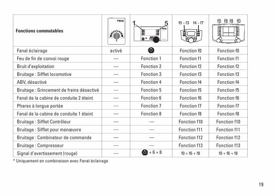
Fonctions commutables
Fanal éclairage activé Fonction f0 Fonction f0
Feu de fin de convoi rouge — Fonction 1 Fonction f1 Fonction f1
Bruit d’exploitation — Fonction 2 Fonction f2 Fonction f2
Bruitage:Siffletlocomotive — Fonction 3 Fonction f3 Fonction f3
ABV, désactivé — Fonction 4 Fonction f4 Fonction f4
Bruitage:Grincementdefreinsdésactivé — Fonction 5 Fonction f5 Fonction f5
Fanal de la cabine de conduite 2 éteint — Fonction 6 Fonction f6 Fonction f6
Phares à longue portée — Fonction 7 Fonction f7 Fonction f7
Fanal de la cabine de conduite 1 éteint — Fonction 8 Fonction f8 Fonction f8
Bruitage:SiffletContrôleur — — Fonction f10 Fonction f10
Bruitage:Siffletpourmanœuvre — — Fonction f11 Fonction f11
Bruitage:Combinateurdecommande — — Fonction f12 Fonction f12
Bruitage:Compresseur — — Fonction f13 Fonction f13
Signald‘avertissement(rouge) — + 6 + 8 f0 + f6 + f8 f0 + f6 + f8
* Uniquement en combinaison avec Fanal éclairage
STOP mobile station
1 5 f0 f8 f0f8f0 - f3 f4 - f7
20
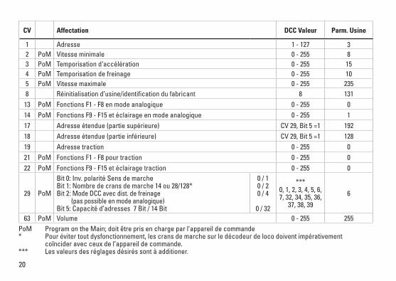
CV Affectation DCC Valeur Parm. Usine
1 Adresse 1 - 127 3 2 PoM Vitesse minimale 0 - 255 83 PoM Temporisationd‘accélération 0 - 255 154 PoM Temporisation de freinage 0 - 255 105 PoM Vitesse maximale 0 - 255 2358 Réinitialisation d’usine/identification du fabricant 8 13113 PoM Fonctions F1 - F8 en mode analogique 0 - 255 014 PoM Fonctions F9 - F15 et éclairage en mode analogique 0 - 255 117 Adresse étendue (partie supérieure) CV29,Bit5=1 19218 Adresse étendue (partie inférieure) CV29,Bit5=1 12819 Adresse traction 0 - 255 021 PoM Fonctions F1 - F8 pour traction 0 - 255 022 PoM Fonctions F9 - F15 et éclairage traction 0 - 255 0
29 PoM
Bit0:Inv.polaritéSensdemarche Bit1:Nombredecransdemarche14ou28/128* Bit2:Mode DCC avec dist. de freinage (pas possible en mode analogique) Bit5:Capacitéd’adresses7Bit/14Bit
0 / 1 0 / 2 0 / 4
0 / 32
*** 0, 1, 2, 3, 4, 5, 6, 7, 32, 34, 35, 36,
37, 38, 39
6
63 PoM Volume 0 - 255 255PoM ProgramontheMain;doitêtreprisenchargeparl’appareildecommande* Pour éviter tout dysfonctionnement, les crans de marche sur le décodeur de loco doivent impérativement coïncider avec ceux de l’appareil de commande.*** Les valeurs des réglages désirés sont à additioner.
21
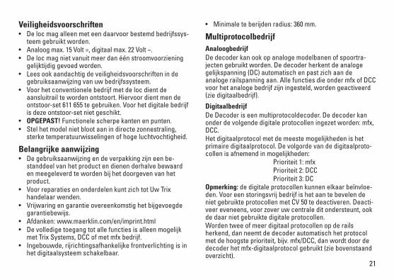
Veiligheidsvoorschriften• Delocmagalleenmeteendaarvoorbestemdbedrijfssys-
teem gebruikt worden.• Analoogmax.15Volt=,digitaalmax.22Volt~.• Delocmagnietvanuitmeerdanéénstroomvoorziening
gelijktijdig gevoed worden.• Leesookaandachtigdeveiligheidsvoorschrifteninde
gebruiksaanwijzing van uw bedrijfssysteem. • Voorhetconventionelebedrijfmetdelocdientde
aansluitrail te worden ontstoort. Hiervoor dient men de ontstoor-set 611 655 te gebruiken. Voor het digitale bedrijf is deze ontstoor-set niet geschikt.
• OPGEPAST! Functionele scherpe kanten en punten.• Stelhetmodelnietblootaanindirectezonnestraling,
sterke temperatuurwisselingen of hoge luchtvochtigheid.
Belangrijke aanwijzing• Degebruiksaanwijzingendeverpakkingzijneenbe-
standdeel van het product en dienen derhalve bewaard en meegeleverd te worden bij het doorgeven van het product.
• VoorreparatiesenonderdelenkuntzichtotUwTrixhandelaar wenden.
• Vrijwaringengarantieovereenkomstighetbijgevoegdegarantiebewijs.
• Afdanken:www.maerklin.com/en/imprint.html• Devolledigetoegangtotallefunctiesisalleenmogelijk
met Trix Systems, DCC of met mfx bedrijf.• Ingebouwde,rijrichtingsafhankelijkefrontverlichtingisin
het digitaalsysteem schakelbaar.
• Minimaleteberijdenradius:360mm.
MultiprotocolbedrijfAnaloogbedrijfDe decoder kan ook op analoge modelbanen of spoortra-jecten gebruikt worden. De decoder herkent de analoge gelijkspanning (DC) automatisch en past zich aan de analoge railspanning aan. Alle functies die onder mfx of DCC voor het analoge bedrijf zijn ingesteld, worden geactiveerd (zie digitaalbedrijf).
DigitaalbedrijfDe Decoder is een multiprotocoldecoder. De decoder kan onderdevolgendedigitaleprotocolleningezetworden:mfx,DCC. Het digitaalprotocol met de meeste mogelijkheden is het primaire digitaalprotocol. De volgorde van de digitaalproto-collenisafnemendinmogelijkheden: Prioriteit1:mfx Prioriteit2:DCC Prioriteit3:DCOpmerking: de digitale protocollen kunnen elkaar beïnvloe-den. Voor een storingsvrij bedrijf is het aan te bevelen de niet gebruikte protocollen met CV 50 te deactiveren. Deacti-veer eveneens, voor zover uw centrale dit ondersteunt, ook de daar niet gebruikte digitale protocollen. Worden twee of meer digitaal protocollen op de rails herkend, dan neemt de decoder automatisch het protocol met de hoogste prioriteit, bijv. mfx/DCC, dan wordt door de decoder het mfx-digitaalprotocol gebruikt (zie bovenstaand overzicht).
22
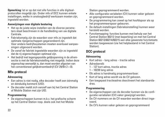
Opmerking: let er op dat niet alle functies in alle digitaal-protocollen mogelijk zijn. Onder mfx of DCC kunnen enkele instellingen, welke in analoogbedrijf werkzaam moeten zijn, ingesteld worden.
Aanwijzingen voor digitale besturing • Hetopdejuistewijzeinstellenvandediverseparame-
ters staat beschreven in de handleiding van uw digitale Centrale.
• Fabrieksmatigzijndewaardenvoormfxzoingesteltdatoptimale rijeigenschappen gegarandeerd zijn. Voor andere bedrijfssystemen moeten eventueel aanpas-singen uitgevoerd worden.
• Devanafdefabriekingesteldewaardenzijnzoingestelddat de rij-eigenschappen optimaal zijn.
• Hetbedrijfmettegengepooldegelijkspanningindeafrem-sectie is met de fabrieksinstelling niet mogelijk. Indien deze eigenschap wenselijk is, dan moet worden afgezien van hetconventioneelgelijkstroombedrijf(CV29/Bit2=0).
Mfx-protocolAdressering • Eenadresisnietnodig,elkedecoderheefteenéénmalig
en éénduidig kenmerk (UID).• DedecodermeldtzichvanzelfaanbijhetCentralStation
of Mobile Station met zijn UID.
Programmering • Deeigenschappenkunnenm.b.v.hetgrafischescherm
op het Central Station resp. deels ook met het Mobile
Station geprogrammeerd worden.• Alleconfiguratievariabelen(CV)kunnenvakergelezen
en geprogrammeerd worden.• Deprogrammeringkanzowelophethoofdspooralsop
het programmeerspoor gebeuren.• Dedefault-instellingen(fabrieksinstelling)kunnenweer
hersteld worden.• Functiemapping:functieskunnenmetbehulpvanhet
Central Station 60212 (met beperking) en met het Central Station 60213/60214/60215 aan elke gewenste functietoets worden toegewezen (zie het helpbestand in het Central Station).
DCC-protocolAdressering • Kortadres–langadres–tractieadres• Adresbereik: 1–127kortadres,tractieadres 1–10239langadres
• Elkadresishandmatigprogrammeerbaar.• KortoflangadreswordtviadeCVgekozen.• Eentoegepasttractieadresdeactiveerthetstandaarda-
dres.
Programmering• Deeigenschappenvandedecoderkunnenviadeconfi-
guratie variabelen (CV) vaker gewijzigd worden.• DeCV-nummersendeCV-waardenwordendirectinge-
voerd.• DeCV’skunnenvakergelezenengeprogrammeerd
23
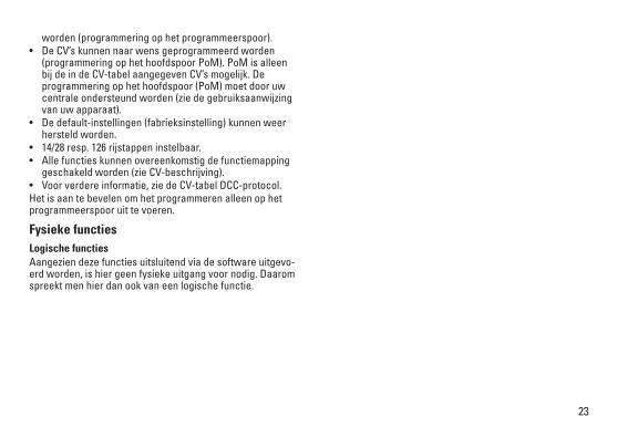
worden (programmering op het programmeerspoor).• DeCV’skunnennaarwensgeprogrammeerdworden
(programmering op het hoofdspoor PoM). PoM is alleen bij de in de CV-tabel aangegeven CV’s mogelijk. De programmering op het hoofdspoor (PoM) moet door uw centrale ondersteund worden (zie de gebruiksaanwijzing van uw apparaat).
• Dedefault-instellingen(fabrieksinstelling)kunnenweerhersteld worden.
• 14/28resp.126rijstappeninstelbaar.• Allefunctieskunnenovereenkomstigdefunctiemapping
geschakeld worden (zie CV-beschrijving).• Voorverdereinformatie,ziedeCV-tabelDCC-protocol.Het is aan te bevelen om het programmeren alleen op het programmeerspoor uit te voeren.
Fysieke functiesLogische functiesAangezien deze functies uitsluitend via de software uitgevo-erd worden, is hier geen fysieke uitgang voor nodig. Daarom spreekt men hier dan ook van een logische functie.
24
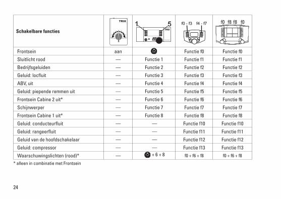
Schakelbare functies
Frontsein aan Functie f0 Functie f0
Sluitlicht rood — Functie 1 Functie f1 Functie f1
Bedrijfsgeluiden — Functie 2 Functie f2 Functie f2
Geluid:locfluit — Functie 3 Functie f3 Functie f3
ABV, uit — Functie 4 Functie f4 Functie f4
Geluid:piependeremmenuit — Functie 5 Functie f5 Functie f5
Frontsein Cabine 2 uit* — Functie 6 Functie f6 Functie f6
Schijnwerper — Functie 7 Functie f7 Functie f7
Frontsein Cabine 1 uit* — Functie 8 Functie f8 Functie f8
Geluid:conducteurfluit — — Functie f10 Functie f10
Geluid:rangeerfluit — — Functie f11 Functie f11
Geluid van de hoofdschakelaar — — Functie f12 Functie f12
Geluid:compressor — — Functie f13 Functie f13
Waarschuwingslichten (rood)* — + 6 + 8 f0 + f6 + f8 f0 + f6 + f8
* alleen in combinatie met Frontsein
STOP mobile station
1 5 f0 f8 f0f8f0 - f3 f4 - f7
25
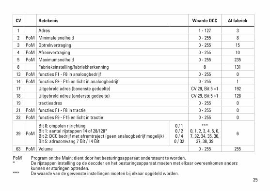
PoM Program on the Main; dient door het besturingsapparaat ondersteunt te worden. * De rijstappen instelling op de decoder en het besturingsapparaat moeten met elkaar overeenkomen anders kunnen er storingen optreden.*** De waarde van de gewenste instellingen moeten bij elkaar opgeteld worden.
CV Betekenis Waarde DCC Af fabriek
1 Adres 1 - 127 3 2 PoM Minimale snelheid 0 - 255 83 PoM Optrekvertraging 0 - 255 154 PoM Afremvertraging 0 - 255 105 PoM Maximumsnelheid 0 - 255 2358 Fabrieksinstelling/fabriekherkenning 8 13113 PoM functies F1 - F8 in analoogbedrijf 0 - 255 014 PoM functies F9 - F15 en licht in analoogbedrijf 0 - 255 117 Uitgebreld adres (bovenste gedeelte) CV29,Bit5=1 19218 Uitgebreld adres (onderste gedeelte) CV29,Bit5=1 12819 tractieadres 0 - 255 021 PoM functies F1 - F8 in tractie 0 - 255 022 PoM functies F9 - F15 en licht in tractie 0 - 255 0
29 PoM
Bit0:ompolenrijrichting Bit1:aantalrijstappen14of28/128* Bit2:DCCbedrijfmetafremtraject(geenanaloogbedrijfmogelijk) Bit5:adresomvang7Bit/14Bit
0 / 1 0 / 2 0 / 4
0 / 32
*** 0, 1, 2, 3, 4, 5, 6, 7, 32, 34, 35, 36,
37, 38, 39
6
63 PoM Volume 0 - 255 255
26
27
28
29
30
!
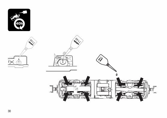
7149 7149
40h
31
32
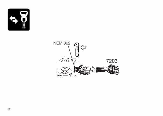
7203
NEM 362
33
34
Det
ails
der
Dar
stel
-lu
ng k
önne
n vo
n de
m
Mod
ell a
bwei
chen
.34
29
27
3031 32
33
7
3 2 1
6
5
9
14
14
1011
12
1113
20
20
4 5
1717
18
15
16
18
21
22
19
22
23 24
30 32
3133
298
2526
28
2135
35
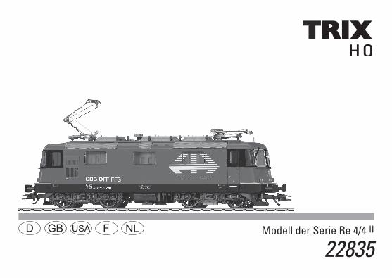
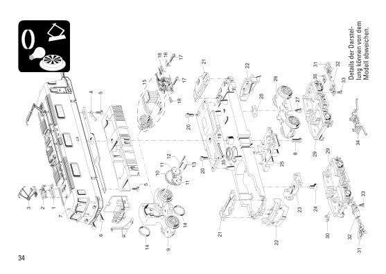
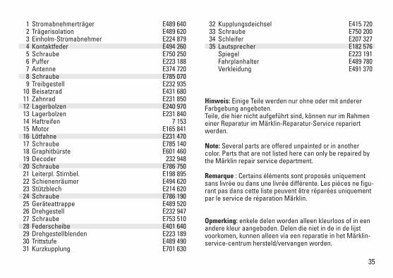
Hinweis: Einige Teile werden nur ohne oder mit anderer Farbgebung angeboten. Teile, die hier nicht aufgeführt sind, können nur im Rahmen einer Reparatur im Märklin-Reparatur-Service repariert werden.
Note: Several parts are offered unpainted or in another color. Parts that are not listed here can only be repaired by the Märklin repair service department.
Remarque:Certainsélémentssontproposésuniquementsans livrée ou dans une livrée différente. Les pièces ne figu-rantpasdanscettelistepeuventêtreréparéesuniquementpar le service de réparation Märklin.
Opmerking: enkele delen worden alleen kleurloos of in een andere kleur aangeboden. Delen die niet in de in de lijst voorkomen, kunnen alleen via een reparatie in het Märklin-service-centrum hersteld/vervangen worden.
1 Stromabnehmerträger E489 640 2 Trägerisolation E489 620 3 Einholm-Stromabnehmer E224 879 4 Kontaktfeder E494 260 5 Schraube E750 250 6 Puffer E223 188 7 Antenne E374 720 8 Schraube E785 070 9 Treibgestell E232 935 10 Beisatzrad E431 680 11 Zahnrad E231 850 12 Lagerbolzen E240 970 13 Lagerbolzen E231 840 14 Haftreifen 7 153 15 Motor E165 841 16 Lötfahne E231 470 17 Schraube E785 140 18 Graphitbürste E601 460 19 Decoder 232 948 20 Schraube E786 750 21 Leiterpl. Stirnbel. E198 895 22 Schienenräumer E494 620 23 Stützblech E214 620 24 Schraube E786 190 25 Geräteattrappe E489 520 26 Drehgestell E232 947 27 Schraube E753 510 28 Federscheibe E401 640 29 Drehgestellblenden E223 189 30 Trittstufe E489 490 31 Kurzkupplung E701 630
32 Kupplungsdeichsel E415 720 33 Schraube E750 200 34 Schleifer E207 327 35 Lautsprecher E182 576 Spiegel E223 191 Fahrplanhalter E489 780 Verkleidung E491 370
Gebr. Märklin & Cie. GmbH Stuttgarter Str. 55 - 57 73033 Göppingen Germanywww.trix.de
236117/1113/Ha1EfÄnderungen vorbehalten
© Gebr. Märklin & Cie. GmbHwww.maerklin.com/en/imprint.html
Due to different legal requirements regarding electro-magnetic compatibility, this item may be used in the USA only after separate certification for FCC compliance and an adjustment if necessary.
Use in the USA without this certification is not permitted and absolves us of any liabili-ty.Ifyoushouldwantsuchcertificationtobedone,pleasecontactus–alsoduetotheadditional costs incurred for this.