DE-07-MI004-PTB012 Rev 2 EN 18-08-2010 - Rumit Sl€¦ · EC type-examination certificate ... 3/h...
29
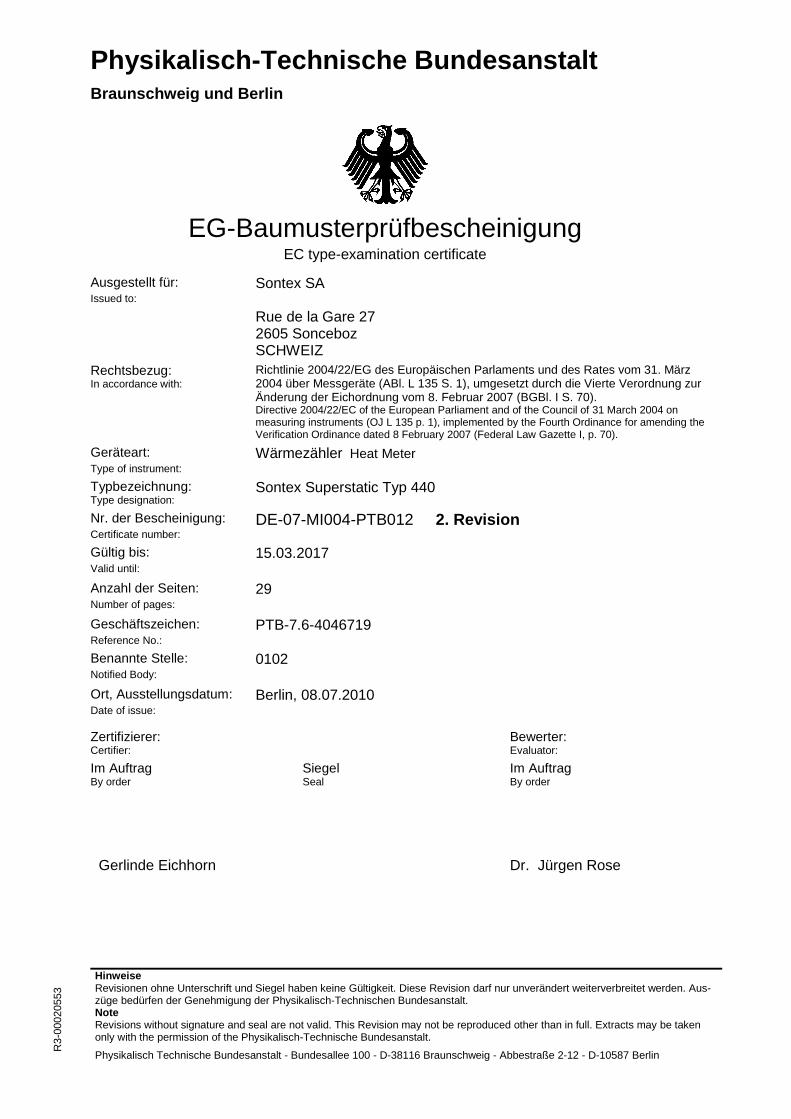
Physikalisch-Technische Bundesanstalt Braunschweig und Berlin Hinweise Revisionen ohne Unterschrift und Siegel haben keine Gültigkeit. Diese Revision darf nur unverändert weiterverbreitet werden. Aus- züge bedürfen der Genehmigung der Physikalisch-Technischen Bundesanstalt. Note Revisions without signature and seal are not valid. This Revision may not be reproduced other than in full. Extracts may be taken only with the permission of the Physikalisch-Technische Bundesanstalt. Physikalisch Technische Bundesanstalt - Bundesallee 100 - D-38116 Braunschweig - Abbestraße 2-12 - D-10587 Berlin R3-00020553 EG-Baumusterprüfbescheinigung EC type-examination certificate Ausgestellt für: Issued to: Sontex SA Rue de la Gare 27 2605 Sonceboz SCHWEIZ Rechtsbezug: In accordance with: Richtlinie 2004/22/EG des Europäischen Parlaments und des Rates vom 31. März 2004 über Messgeräte (ABl. L 135 S. 1), umgesetzt durch die Vierte Verordnung zur Änderung der Eichordnung vom 8. Februar 2007 (BGBl. I S. 70). Directive 2004/22/EC of the European Parliament and of the Council of 31 March 2004 on measuring instruments (OJ L 135 p. 1), implemented by the Fourth Ordinance for amending the Verification Ordinance dated 8 February 2007 (Federal Law Gazette I, p. 70). Geräteart: Type of instrument: Wärmezähler Heat Meter Typbezeichnung: Type designation: Sontex Superstatic Typ 440 Nr. der Bescheinigung: Certificate number: DE-07-MI004-PTB012 2. Revision Gültig bis: Valid until: 15.03.2017 Anzahl der Seiten: Number of pages: 29 Geschäftszeichen: Reference No.: PTB-7.6-4046719 Benannte Stelle: Notified Body: 0102 Ort, Ausstellungsdatum: Date of issue: Berlin, 08.07.2010 Zertifizierer: Certifier: Bewerter: Evaluator: Im Auftrag By order Siegel Seal Im Auftrag By order Gerlinde Eichhorn Dr. Jürgen Rose
Transcript of DE-07-MI004-PTB012 Rev 2 EN 18-08-2010 - Rumit Sl€¦ · EC type-examination certificate ... 3/h...
Physikalisch-Technische Bundesanstalt
Braunschweig und Berlin
Hinweise Revisionen ohne Unterschrift und Siegel haben keine Gültigkeit. Diese Revision darf nur unverändert weiterverbreitet werden. Aus-züge bedürfen der Genehmigung der Physikalisch-Technischen Bundesanstalt. Note Revisions without signature and seal are not valid. This Revision may not be reproduced other than in full. Extracts may be taken only with the permission of the Physikalisch-Technische Bundesanstalt.
Physikalisch Technische Bundesanstalt - Bundesallee 100 - D-38116 Braunschweig - Abbestraße 2-12 - D-10587 Berlin
R3-
0002
0553
EG-Baumusterprüfbescheinigung EC type-examination certificate
Ausgestellt für: Issued to:
Sontex SA Rue de la Gare 27 2605 Sonceboz SCHWEIZ
Rechtsbezug: In accordance with:
Richtlinie 2004/22/EG des Europäischen Parlaments und des Rates vom 31. März 2004 über Messgeräte (ABl. L 135 S. 1), umgesetzt durch die Vierte Verordnung zur Änderung der Eichordnung vom 8. Februar 2007 (BGBl. I S. 70). Directive 2004/22/EC of the European Parliament and of the Council of 31 March 2004 on measuring instruments (OJ L 135 p. 1), implemented by the Fourth Ordinance for amending the Verification Ordinance dated 8 February 2007 (Federal Law Gazette I, p. 70).
Geräteart: Type of instrument:
Wärmezähler Heat Meter Typbezeichnung: Type designation:
Sontex Superstatic Typ 440 Nr. der Bescheinigung: Certificate number:
DE-07-MI004-PTB012 2. Revision Gültig bis: Valid until:
15.03.2017
Anzahl der Seiten: Number of pages:
29
Geschäftszeichen: Reference No.:
PTB-7.6-4046719 Benannte Stelle: Notified Body:
0102
Ort, Ausstellungsdatum: Date of issue:
Berlin, 08.07.2010
Zertifizierer: Certifier:
Bewerter: Evaluator:
Im Auftrag By order
Siegel Seal
Im Auftrag By order
Gerlinde Eichhorn
Dr. Jürgen Rose
Physikalisch-Technische Bundesanstalt Anlage zur EG-Baumusterprüfbescheinigung Annex to EC type-examination certificate vom 08.07.2010, Bescheinigung Nr: DE-07-MI004-PTB012, 2. Revision dated 08.07.2010, Certificate number: DE-07-MI004-PTB012, Revision 2
Seite 2 von 29 Seiten Page 2 of 29 pages
Physikalisch-Technische Bundesanstalt Bundesallee 100 38116 Braunschweig DEUTSCHLAND
Abbestraße 2-12 10587 Berlin DEUTSCHLAND
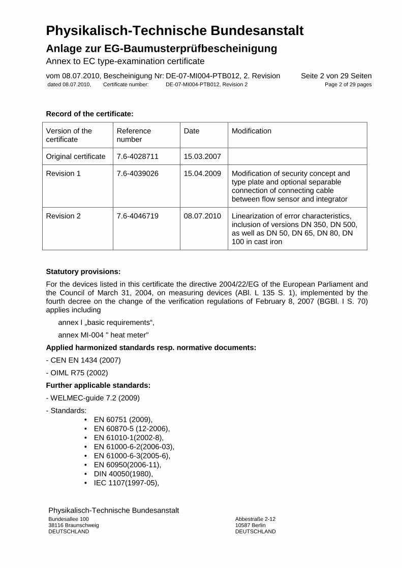
Record of the certificate:
Version of the certificate
Reference number
Date Modification
Original certificate 7.6-4028711 15.03.2007
Revision 1 7.6-4039026 15.04.2009 Modification of security concept and type plate and optional separable connection of connecting cable between flow sensor and integrator
Revision 2 7.6-4046719 08.07.2010 Linearization of error characteristics, inclusion of versions DN 350, DN 500, as well as DN 50, DN 65, DN 80, DN 100 in cast iron
Statutory provisions:
For the devices listed in this certificate the directive 2004/22/EG of the European Parliament and the Council of March 31, 2004, on measuring devices (ABl. L 135 S. 1), implemented by the fourth decree on the change of the verification regulations of February 8, 2007 (BGBl. I S. 70) applies including
annex I „basic requirements“,
annex MI-004 " heat meter"
Applied harmonized standards resp. normative docume nts:
- CEN EN 1434 (2007)
- OIML R75 (2002)
Further applicable standards:
- WELMEC-guide 7.2 (2009)
- Standards: • EN 60751 (2009), • EN 60870-5 (12-2006), • EN 61010-1(2002-8), • EN 61000-6-2(2006-03), • EN 61000-6-3(2005-6), • EN 60950(2006-11), • DIN 40050(1980), • IEC 1107(1997-05),
Physikalisch-Technische Bundesanstalt Anlage zur EG-Baumusterprüfbescheinigung Annex to EC type-examination certificate vom 08.07.2010, Bescheinigung Nr: DE-07-MI004-PTB012, 2. Revision dated 08.07.2010, Certificate number: DE-07-MI004-PTB012, Revision 2
Seite 3 von 29 Seiten Page 3 of 29 pages
• IEC751 (1985), • EN61000-4-4 (2005-07) • EN 55022 (2003-12), • EN 50082-1 (1994), • EN 61000-4 (2006), • EN 61010-1 (2002) • EN 300220-3 (2001)
- Technical directives:
• PTB-directive K 7.1, calibration of heat meters (2006) • PTB-requirements A 50.7 for electronic and software-controlled measuring devices and additional equipment for electricity, gas, water and heat, including annexes 1, 2 and 3 • PTB-requirements A 50.1, interfaces of measuring devices and additional equipment (1989) • AGFW-requirements FW 510 for circulating water of industrial heating systems and district heat systems as well as information on their operation (2003). AGFW | The energy efficiency association for heat, refrigeration and combined heat and power generation (Energieeffiziensverband für Wärme, Kälte und KWK) e.V.
The devices / measuring systems have to be in line with the following provisions:
1 Type designation
Heat meter Superstatic 440
2 Description
2.1 Structure
Microprocessor-controlled heat meter consisting of the oscillating flow sensor Superstatic 440 either permanently connected or with interchangeable connection at the place of installation to the integrator 531 and with optional permanently connected platinum resistance temperature sensors Pt 100 or Pt 500 or interchangeable EC-labeled temperature sensor pairs Pt 100 or Pt 500 , either for installation in the supply or the return line of the circulating system of the heat exchanger; field of application: in heating systems.
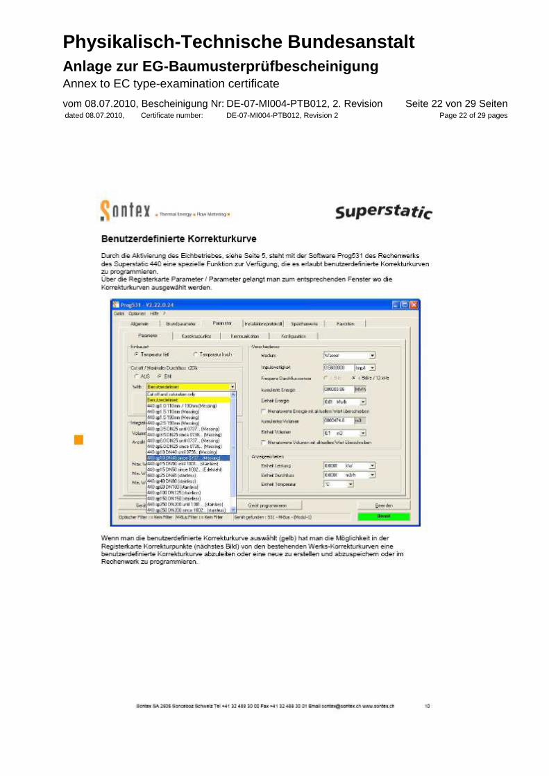
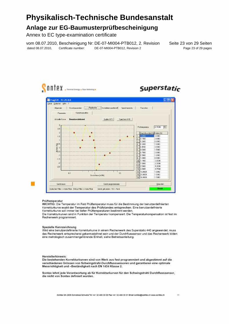
The measuring head (piezo sensing electronics) of the base part which remains in the field is interchangeable under the exclusive condition that when assessing the conformity acc. to MID-module F or carrying out the local re-calibration of the integrator no individual volume corrections have been implemented during the measurement test (see section 5 and 6.1 where this is described as a so-called user-defined volume correction).
If, however, a so-called user-defined volume adjustment has been carried out with the integrator to reach the best possible measuring accuracy, the measuring head and the
Physikalisch-Technische Bundesanstalt Anlage zur EG-Baumusterprüfbescheinigung Annex to EC type-examination certificate vom 08.07.2010, Bescheinigung Nr: DE-07-MI004-PTB012, 2. Revision dated 08.07.2010, Certificate number: DE-07-MI004-PTB012, Revision 2
Seite 4 von 29 Seiten Page 4 of 29 pages
integrator build a metrologically connected and inseparable entity which has to be marked as such on the type plate, see section 5.1.
2.2 Transducer
Oscillating flow sensor with microprocessor-controlled electronics acc. to the documents see section 2.6. Platinum resistance temperature sensor optional Pt 100 acc. to EN 60751 or Pt 500 on the basis of EN 60751, in two- or four-wire technology.
2.3 Processing of measurement data
The pulses triggered by the piezo sensing electronics are calculated by multiplying the excitation of the oscillating jet in the flow sensor, software-controlled by the integrator, with the calculated temperature difference of the supply and return line and the calculated thermal coefficient. The sum is shown on the LC-display as thermal energy consumption.
2.4 Display of measurement data
The accumulated thermal energy is displayed on the 8-digit display of the heat meter integrator in physical units, either in KWh, MWh, MJ or GJ with max. 3 digits after the decimal point.
2.5 Optional equipment and functions that are subject to the directive for measuring devices
- none -
2.6 Technical documentations
The measuring devices have to be in line with the documents mentioned below:
a) Complete set of technical documents acc. to the application the EC type-examination certificate of Febr. 19, 2007, the request for revision 1 of Dec. 17, 2008, as well as the notification of modification for the 2. revision of April 20, 2010.
b) Calibration specifications for the production of heat meters and components of the accredited QM system with the registration number 16333
c) Installation and operating instruction „Installation of Superstatic 440 DE EN MID“ latest version
2.7 Integrated equipment and functions which are not subject to the measuring devices directive
Equipment and functions without interaction are the displays (by pressing a key) of device parameter and measurement data repetitions of e.g. set day energy register contents and measuring results of volume and temperature difference. In compliance with the nominal operation conditions specified in section 3 acc. to EN 1434, the measuring device can also be used as cold meter for ambient cooling measurements.
Physikalisch-Technische Bundesanstalt Anlage zur EG-Baumusterprüfbescheinigung Annex to EC type-examination certificate vom 08.07.2010, Bescheinigung Nr: DE-07-MI004-PTB012, 2. Revision dated 08.07.2010, Certificate number: DE-07-MI004-PTB012, Revision 2
Seite 5 von 29 Seiten Page 5 of 29 pages
Remote read-out-, control and signal inputs (compatibility acc. to documents see section 2.6):
Optical interface acc. to EN 1434-3, EN 60870-5 Max. 2 open collector in- and outputs manufacturer-specific M-Bus-interface acc. to EN 1434-3, EN 60870-5 Modem acc. to EN 60870-5, EN 60950 RS 232 acc. to EN 60870-5 Module RS-232 with two relay outputs acc. to EN 1434-3, EN 60870-5 Module RS-232 acc. to EN 1434-3, EN 60870-5 M-Bus with two relay outputs acc. to EN 1434-3, EN 60870-5 M-Bus module acc. to EN 1434-3, EN 60870-5 Relay module manufacturer-specific Analogue module with two outputs 0..20mA manufacturer-specific Analogue module with two outputs 0..20mA, manufacturer-specific 4..20mA or 0..10VDC Combi-module with RS-232 or M-Bus, three relay manufacturer-specific outputs (open collector), 4 freely programmable outputs 0..20mA, 4..20mA or 0..10VDC LON-module manufacturer-specific Remote Radio, bidirectional manufacturer-specific Max. 6 pulse inputs manufacturer-specific
3 Technical data
3.1 Nominal operating conditions
Integrator:
Heat transfer medium: water, field of application: heating
Limit values of temperature range θ: 2 °C to 200 °C
Limit values of temperature difference ∆θ: 3 K to 150 K

Physikalisch-Technische Bundesanstalt Anlage zur EG-Baumusterprüfbescheinigung Annex to EC type-examination certificate vom 08.07.2010, Bescheinigung Nr: DE-07-MI004-PTB012, 2. Revision dated 08.07.2010, Certificate number: DE-07-MI004-PTB012, Revision 2
Seite 6 von 29 Seiten Page 6 of 29 pages
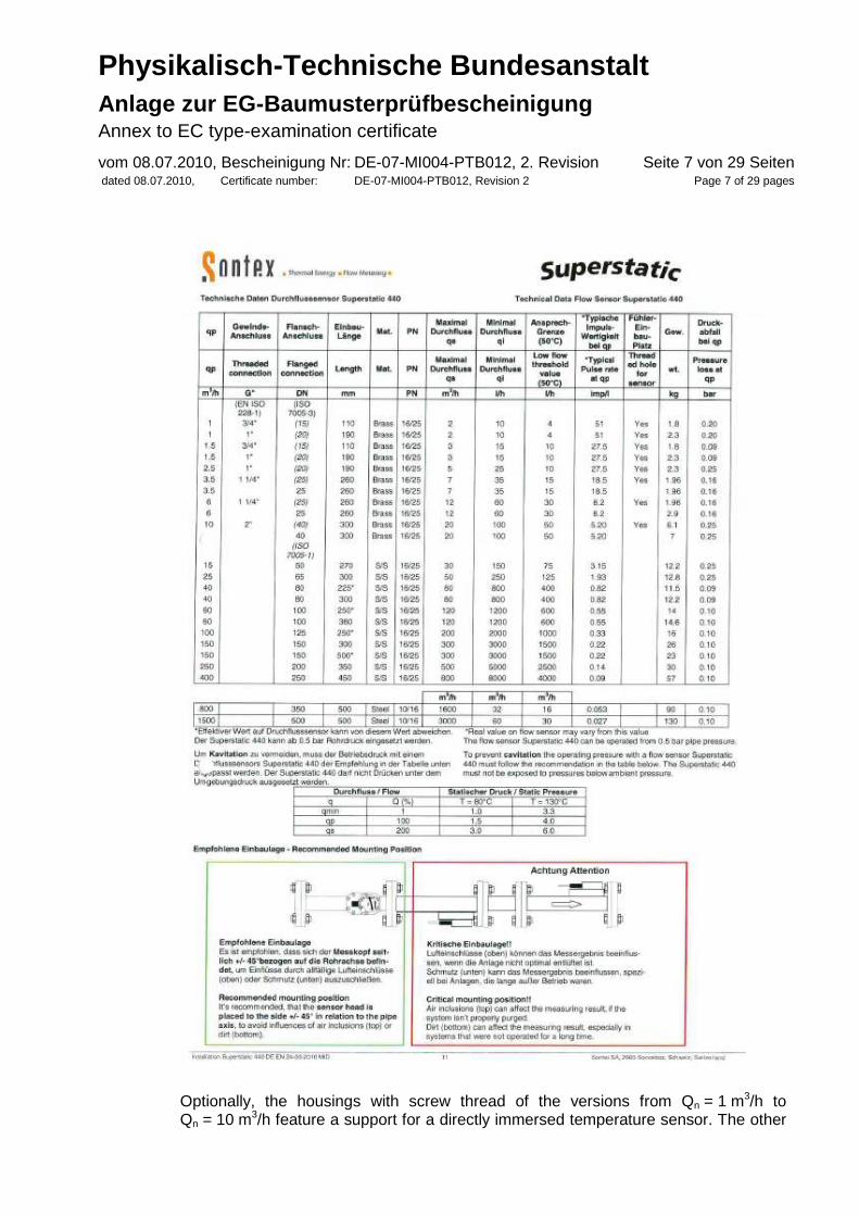
Flow sensor:
Physikalisch-Technische Bundesanstalt Anlage zur EG-Baumusterprüfbescheinigung Annex to EC type-examination certificate vom 08.07.2010, Bescheinigung Nr: DE-07-MI004-PTB012, 2. Revision dated 08.07.2010, Certificate number: DE-07-MI004-PTB012, Revision 2
Seite 7 von 29 Seiten Page 7 of 29 pages
Optionally, the housings with screw thread of the versions from Qn = 1 m3/h to Qn = 10 m3/h feature a support for a directly immersed temperature sensor. The other

Physikalisch-Technische Bundesanstalt Anlage zur EG-Baumusterprüfbescheinigung Annex to EC type-examination certificate vom 08.07.2010, Bescheinigung Nr: DE-07-MI004-PTB012, 2. Revision dated 08.07.2010, Certificate number: DE-07-MI004-PTB012, Revision 2
Seite 8 von 29 Seiten Page 8 of 29 pages
temperature sensor is also immersed directly in the circulating system of the heat exchanger, normally by using T-fittings or ball valves.
Temperature range of flow sensor: optional 5° C to 130° C
Mounting position: horizontal or vertical, falling or rising pipe
In case of the integrators mounted on the flow sensor, the upper temperature is limited to 90° C.
(Metrological) Class of accuracy: optional 2 or 3 (all versions)
Temperature sensor pair:
Platinum-resistance thermometer, optional Pt 100 acc. to EN 60751 or Pt 500 on the base of EN 60751, in two- or four-wire technology. In case the temperature sensors used by the operator of the measuring devices are interchangeable, they must have their own MID-conformity label.
Ambient conditions / influencing variables:
- Climatic: max. ambient temperature 55 °C, min. ambient temperature 5 °C, Humidity class: IP 65
- Electro-magnetic class: E1
- Mechanical class: M1
- Pressure class: PN/PS: 10/16/25 bar
3.2 Further operating conditions
Auxiliary energy: optional mains connection 115 V/230 V AC 50 Hz or battery 3.6 V or external supply 12 V to 24 V or 24 V AC
4 Interfaces and compatibility conditions
The length of the connecting cables of the optional temperature sensors Pt 100 or Pt 500 in two-wire technology should not exceed 15 m each for the supply and the return line; in four-wire technology they should not exceed 50 m, optionally shielded or unshielded.
The cable cross-sections have to be in line with EN 1434-2, section 3. The length of the shielded connecting cable to the flow sensor must not exceed 10 m.
In case the temperature sensors used in the measuring devices are interchangeable, they have to be connected to the connecting points in accordance with the installation and operating instruction (see section 2). Attention has to be paid that their electrical compatibility Pt 100 resp. Pt 500 is in line with the integrator.
Physikalisch-Technische Bundesanstalt Anlage zur EG-Baumusterprüfbescheinigung Annex to EC type-examination certificate vom 08.07.2010, Bescheinigung Nr: DE-07-MI004-PTB012, 2. Revision dated 08.07.2010, Certificate number: DE-07-MI004-PTB012, Revision 2
Seite 9 von 29 Seiten Page 9 of 29 pages
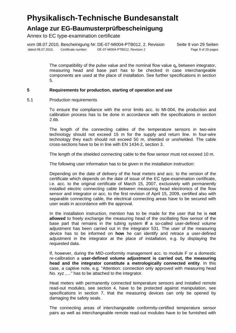
The compatibility of the pulse value and the nominal flow value qp between integrator, measuring head and base part has to be checked in case interchangeable components are used at the place of installation. See further specifications in section 5.
5 Requirements for production, starting of operatio n and use
5.1 Production requirements
To ensure the compliance with the error limits acc. to MI-004, the production and calibration process has to be done in accordance with the specifications in section 2.6b.
The length of the connecting cables of the temperature sensors in two-wire technology should not exceed 15 m for the supply and return line. In four-wire technology they each should not exceed 50 m, shielded or unshielded. The cable cross-sections have to be in line with EN 1434-2, section 3.
The length of the shielded connecting cable to the flow sensor must not exceed 10 m.
The following user information has to be given in the installation instruction:
Depending on the date of delivery of the heat meters and acc. to the version of the certificate which depends on the date of issue of the EC type-examination certificate, i.e. acc. to the original certificate of March 15, 2007, exclusively with permanently installed electric connecting cable between measuring head electronics of the flow sensor and integrator or acc. to the first revision of April 15, 2009, certified also with separable connecting cable, the electrical connecting areas have to be secured with user seals in accordance with the approval.
In the installation instruction, mention has to be made for the user that he is not allowed to freely exchange the measuring head of the oscillating flow sensor of the base part that remains in the tubing system if a so-called user-defined volume adjustment has been carried out in the integrator 531. The user of the measuring device has to be informed on how he can identify and retrace a user-defined adjustment in the integrator at the place of installation, e.g. by displaying the requested data.
If, however, during the MID-conformity management acc. to module F or a domestic re-calibration a user-defined volume adjustment is carried out, the measuring head and the integrator constitute a metrologically connected entity . In this case, a captive note, e.g. “Attention: connection only approved with measuring head No. xyz ,…” has to be attached to the integrator.
Heat meters with permanently connected temperature sensors and installed remote read-out modules, see section 4, have to be protected against manipulation, see specifications in section 7, that the measuring devices can only be opened by damaging the safety seals.
The connecting areas of interchangeable conformity-certified temperature sensor pairs as well as interchangeable remote read-out modules have to be furnished with

Physikalisch-Technische Bundesanstalt Anlage zur EG-Baumusterprüfbescheinigung Annex to EC type-examination certificate vom 08.07.2010, Bescheinigung Nr: DE-07-MI004-PTB012, 2. Revision dated 08.07.2010, Certificate number: DE-07-MI004-PTB012, Revision 2
Seite 10 von 29 Seiten Page 10 of 29 pages
safety measures (see section 4 and 2.7) for the user of the measuring devices acc. to the specifications see section 7.
When mounting the measuring head (piezo sensing electronics) on the base part, the specified torques (see specifications in section 2.6b) have to be followed. The shielded connection cable to the flow sensor always has to be grounded with strain relief.
If the heat meter is intended for symmetrical installation of the temperature sensor pair with protection pockets, the permanently connected temperature sensors must have a separate EC type-examination certificate also including the conformity-tested protection pockets. If, however, the sensor is connected permanently, the sensor does not have an EC-label. In any case, when supplying the protection pockets, they have to be stated on a list that is enclosed in the shipment to make sure that the user can clearly assign them to the measuring device or they have to be marked accordingly so that the corresponding heat meter can be identified.
5.2 Requirements for the start of operation
After the installation and the functional test acc. to the installation instruction, every device has to be equipped with the security measures mentioned in the specifications, see section 7. Each device has to be supplied with an installation and operating instruction describing the start of operation.
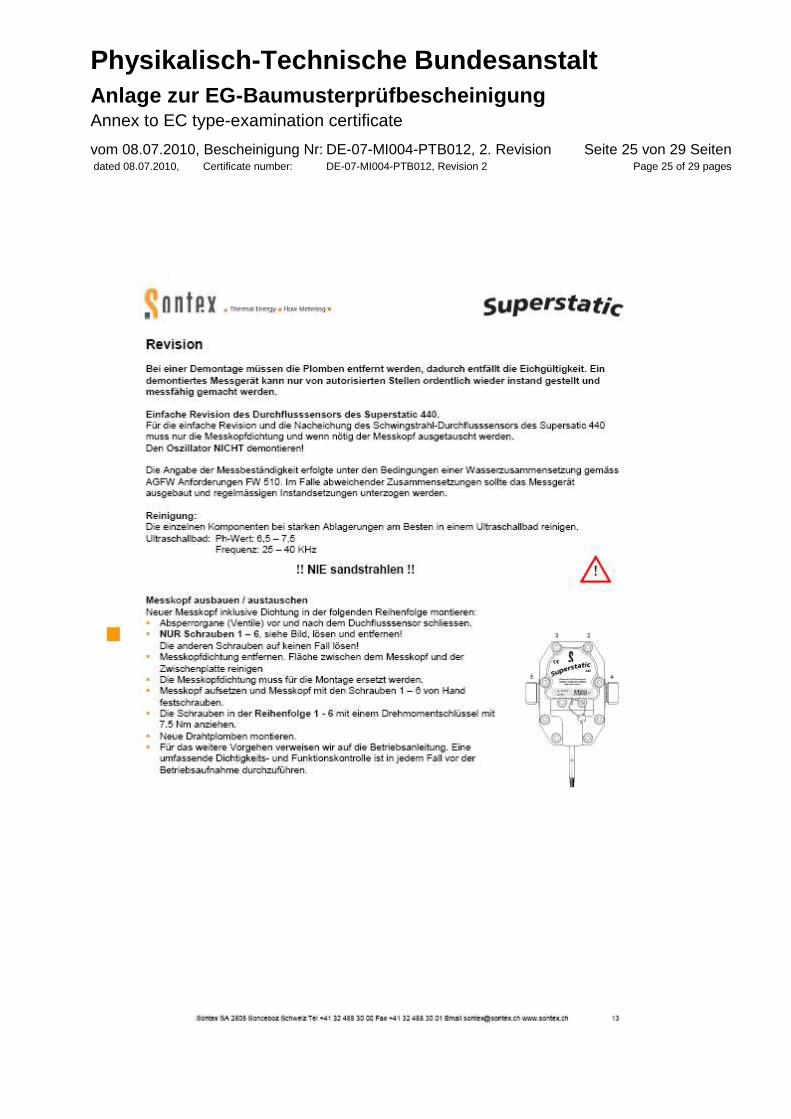
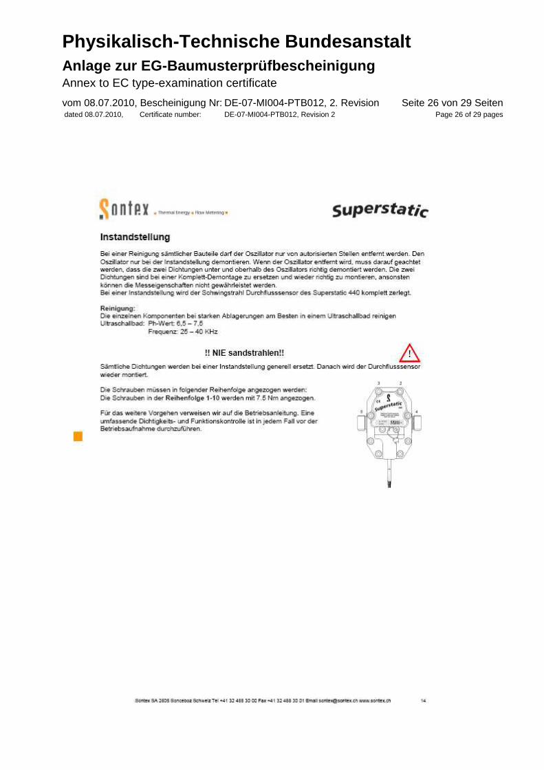
When mounting the measuring head (piezo sensing electronics) on the base part in the field, the specified torques stated in the installation instruction have to be followed. The seals have to be replaced after every disassembly. The shielded connection cable to the flow sensor always has to be grounded with strain relief!
The length of the connecting cables of the temperature sensors in two-wire technology must not exceed 15 m for the supply and return line, see section 4, and 50 m in four-wire technology. With regard to the cable cross-sections, EN 1434-2, section 3, applies.
The length of the shielded connecting cable to the flow sensor must not exceed 10 m.
The specifications made in the installation and operating instruction supplied with every device have to be adhered to.
After electrical connection of the flow sensor to the integrator, the terminals 9, 10, 11 have to be secured by the supplied user seal.
5.3 Requirements for the use
The user is asked to follow the operating conditions mentioned below (also listed in the installation and operating instruction):
The temperature sensors have to be installed symmetrically in the supply and return line; preferably directly. If protection pockets are used, they have to be tested especially for their conformity with the temperature sensor used. The supply and
Physikalisch-Technische Bundesanstalt Anlage zur EG-Baumusterprüfbescheinigung Annex to EC type-examination certificate vom 08.07.2010, Bescheinigung Nr: DE-07-MI004-PTB012, 2. Revision dated 08.07.2010, Certificate number: DE-07-MI004-PTB012, Revision 2
Seite 11 von 29 Seiten Page 11 of 29 pages
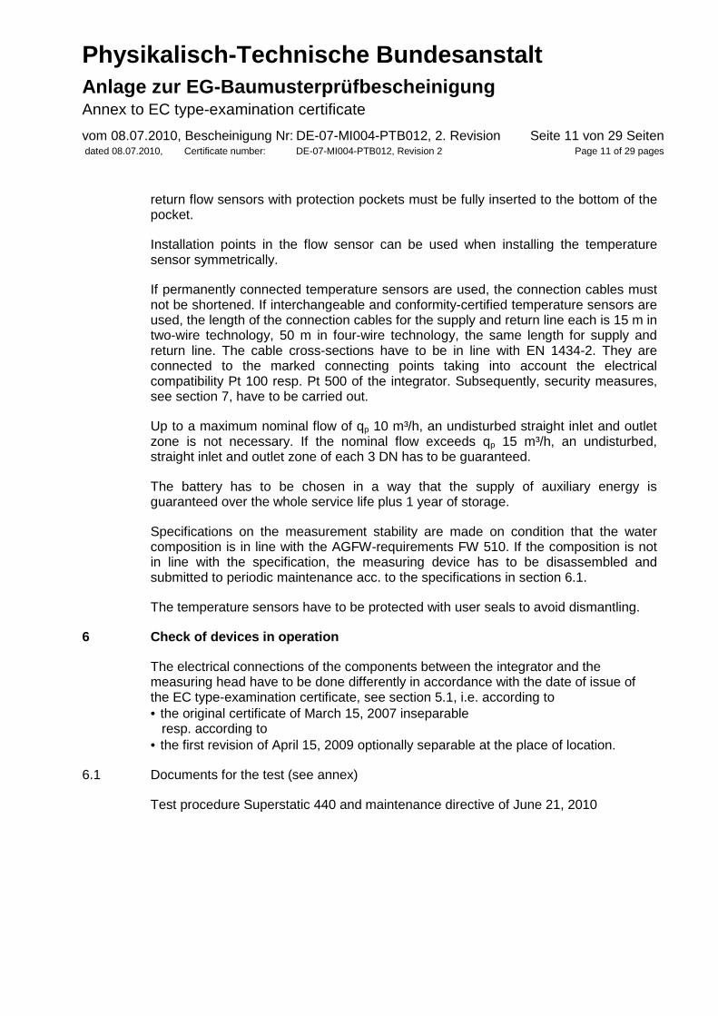
return flow sensors with protection pockets must be fully inserted to the bottom of the pocket.
Installation points in the flow sensor can be used when installing the temperature sensor symmetrically.
If permanently connected temperature sensors are used, the connection cables must not be shortened. If interchangeable and conformity-certified temperature sensors are used, the length of the connection cables for the supply and return line each is 15 m in two-wire technology, 50 m in four-wire technology, the same length for supply and return line. The cable cross-sections have to be in line with EN 1434-2. They are connected to the marked connecting points taking into account the electrical compatibility Pt 100 resp. Pt 500 of the integrator. Subsequently, security measures, see section 7, have to be carried out.
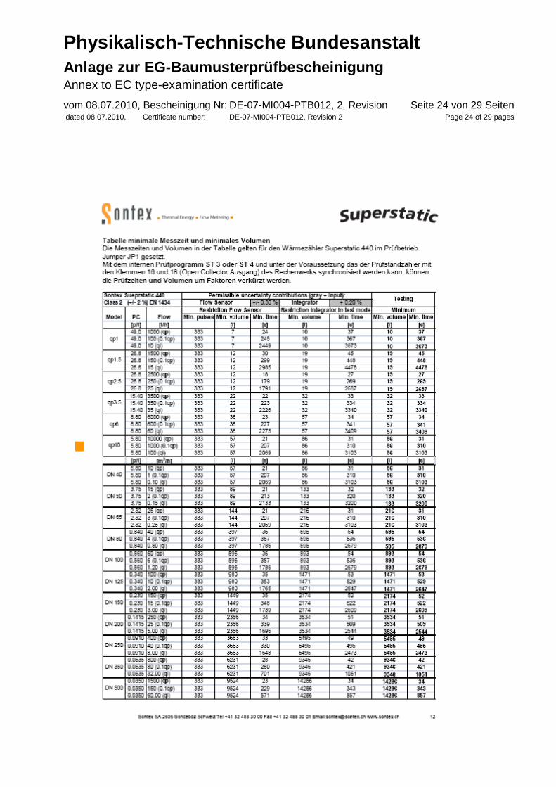
Up to a maximum nominal flow of qp 10 m³/h, an undisturbed straight inlet and outlet zone is not necessary. If the nominal flow exceeds qp 15 m³/h, an undisturbed, straight inlet and outlet zone of each 3 DN has to be guaranteed.
The battery has to be chosen in a way that the supply of auxiliary energy is guaranteed over the whole service life plus 1 year of storage.
Specifications on the measurement stability are made on condition that the water composition is in line with the AGFW-requirements FW 510. If the composition is not in line with the specification, the measuring device has to be disassembled and submitted to periodic maintenance acc. to the specifications in section 6.1.
The temperature sensors have to be protected with user seals to avoid dismantling.
6 Check of devices in operation
The electrical connections of the components between the integrator and the measuring head have to be done differently in accordance with the date of issue of the EC type-examination certificate, see section 5.1, i.e. according to • the original certificate of March 15, 2007 inseparable resp. according to • the first revision of April 15, 2009 optionally separable at the place of location.
6.1 Documents for the test (see annex)
Test procedure Superstatic 440 and maintenance directive of June 21, 2010

Physikalisch-Technische Bundesanstalt Anlage zur EG-Baumusterprüfbescheinigung Annex to EC type-examination certificate vom 08.07.2010, Bescheinigung Nr: DE-07-MI004-PTB012, 2. Revision dated 08.07.2010, Certificate number: DE-07-MI004-PTB012, Revision 2
Seite 12 von 29 Seiten Page 12 of 29 pages
6.2 Test equipment
With regard to EN 1434-5, no special test equipment is necessary. However special test equipment and procedures may be necessary according to the documents referred into section 6.1.
6.3 Identification
Hardware: The hardware type is permanently stored in the EEPROM.
Software: The number of the version can be called on the display: 4.x. for the integrator upper and base part A CRC-sign is used for the whole software including the metrological part and application part.
With regard to the main metrological relevant components, the heat meter corresponds to the measuring device with the number Z 22.12/03.06 approved in accordance with the homologation for Germany, however the range of functions has been extended and the standards of the directive 2004/22/EG are met.
6.4 Metrological test
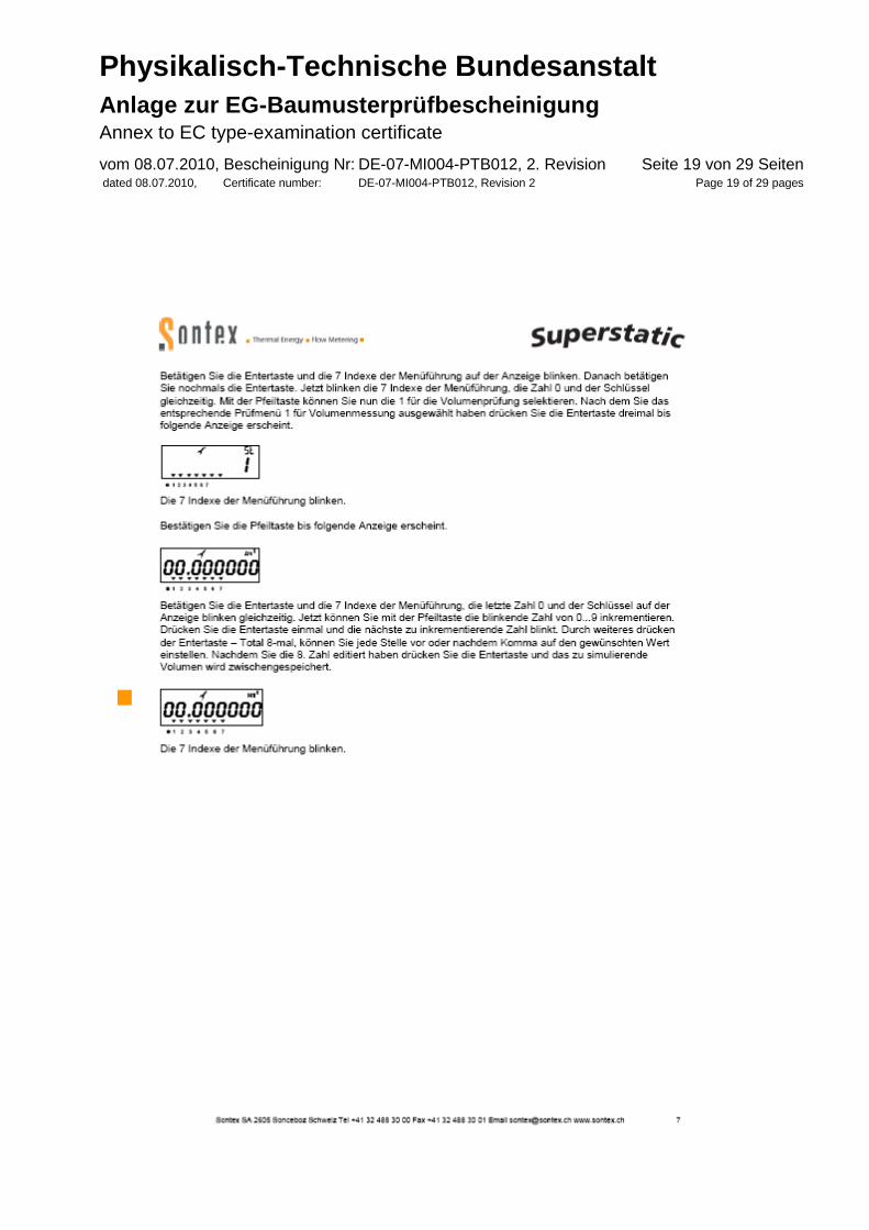
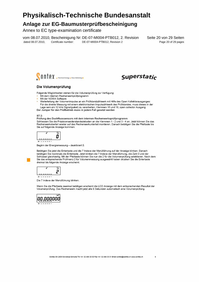
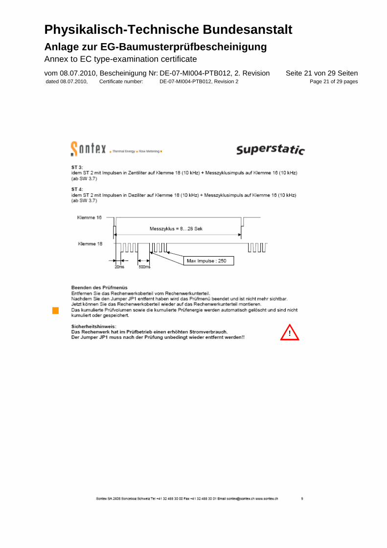
According to the specifications in the documents, see section 6.1, the integrator is checked by simulating the supply and return line temperatures with precision resistances following the basic value characteristics acc. to EN 60751, section 5 of EN 1434-5; field of application: heating. The signals of the flow sensors are simulated electrically.
The values of the high resolution display have to be in line with the energy display in normal condition. This test after start of production can be omitted in case of a test-integrated query using a check sum (CRC-sign).
7 Security measures
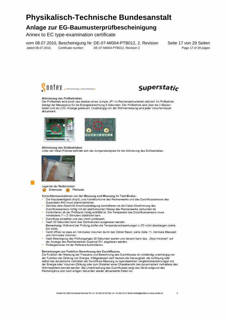
Security measures: Test procedure Superstatic 440 DE 21-06-2010, page 17 and installation and operating instruction „Installation of Superstatic 440 DE EN MID 21-06-2010, page 7 and 12
Depending on the delivery date of the heat meter version, see section 5.1, the connection cables between the integrator and the measuring head are submitted to a specific labeling obligation.
After electrical connection of the flow sensor to the integrator, the terminals 9, 10, 11 have to be secured with the supplied user seals.
Electronic log: not available

Physikalisch-Technische Bundesanstalt Anlage zur EG-Baumusterprüfbescheinigung Annex to EC type-examination certificate vom 08.07.2010, Bescheinigung Nr: DE-07-MI004-PTB012, 2. Revision dated 08.07.2010, Certificate number: DE-07-MI004-PTB012, Revision 2
Seite 13 von 29 Seiten Page 13 of 29 pages
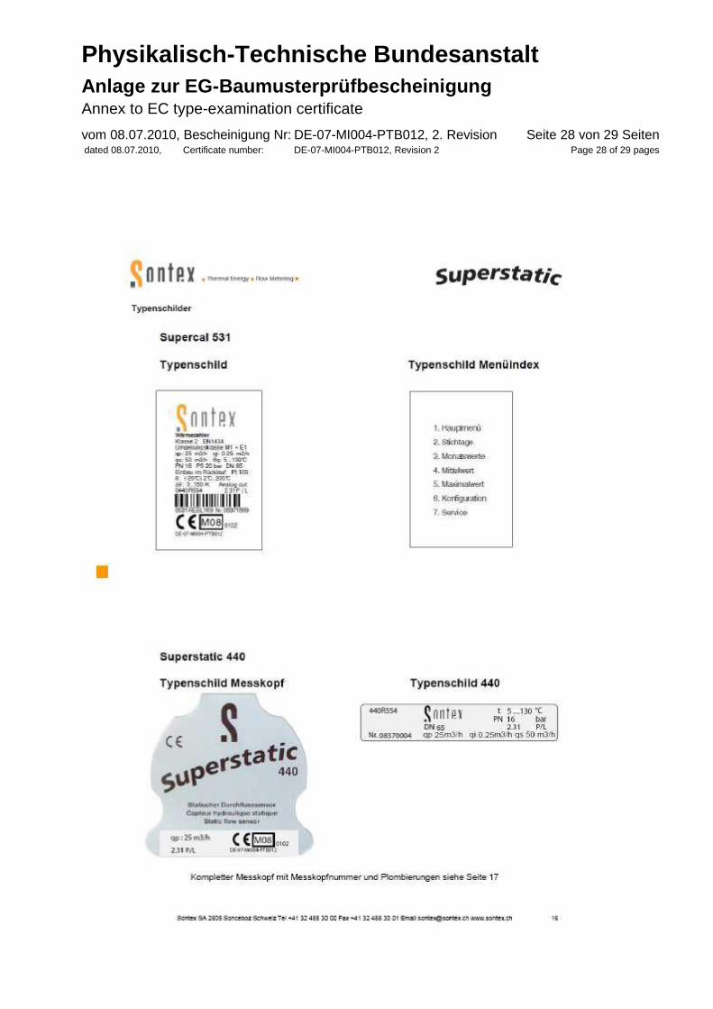
8 Labeling and markings
Type plate:
Test procedure Superstatic DE 440 21-06-2010, page 16
Number of the type-examination certificate: DE-07-MI004-PTB012
Further markings:
If necessary, customer-specific information on installed interfaces acc. to section 2.7
Annex: Test procedure Superstatic 440 of June 21, 2010

Physikalisch-Technische Bundesanstalt Anlage zur EG-Baumusterprüfbescheinigung Annex to EC type-examination certificate vom 08.07.2010, Bescheinigung Nr: DE-07-MI004-PTB012, 2. Revision dated 08.07.2010, Certificate number: DE-07-MI004-PTB012, Revision 2
Seite 14 von 29 Seiten Page 14 of 29 pages
Physikalisch-Technische Bundesanstalt Anlage zur EG-Baumusterprüfbescheinigung Annex to EC type-examination certificate vom 08.07.2010, Bescheinigung Nr: DE-07-MI004-PTB012, 2. Revision dated 08.07.2010, Certificate number: DE-07-MI004-PTB012, Revision 2
Seite 15 von 29 Seiten Page 15 of 29 pages
Physikalisch-Technische Bundesanstalt Anlage zur EG-Baumusterprüfbescheinigung Annex to EC type-examination certificate vom 08.07.2010, Bescheinigung Nr: DE-07-MI004-PTB012, 2. Revision dated 08.07.2010, Certificate number: DE-07-MI004-PTB012, Revision 2
Seite 16 von 29 Seiten Page 16 of 29 pages
Physikalisch-Technische Bundesanstalt Anlage zur EG-Baumusterprüfbescheinigung Annex to EC type-examination certificate vom 08.07.2010, Bescheinigung Nr: DE-07-MI004-PTB012, 2. Revision dated 08.07.2010, Certificate number: DE-07-MI004-PTB012, Revision 2
Seite 17 von 29 Seiten Page 17 of 29 pages

Physikalisch-Technische Bundesanstalt Anlage zur EG-Baumusterprüfbescheinigung Annex to EC type-examination certificate vom 08.07.2010, Bescheinigung Nr: DE-07-MI004-PTB012, 2. Revision dated 08.07.2010, Certificate number: DE-07-MI004-PTB012, Revision 2
Seite 18 von 29 Seiten Page 18 of 29 pages
Physikalisch-Technische Bundesanstalt Anlage zur EG-Baumusterprüfbescheinigung Annex to EC type-examination certificate vom 08.07.2010, Bescheinigung Nr: DE-07-MI004-PTB012, 2. Revision dated 08.07.2010, Certificate number: DE-07-MI004-PTB012, Revision 2
Seite 19 von 29 Seiten Page 19 of 29 pages
Physikalisch-Technische Bundesanstalt Anlage zur EG-Baumusterprüfbescheinigung Annex to EC type-examination certificate vom 08.07.2010, Bescheinigung Nr: DE-07-MI004-PTB012, 2. Revision dated 08.07.2010, Certificate number: DE-07-MI004-PTB012, Revision 2
Seite 20 von 29 Seiten Page 20 of 29 pages
Physikalisch-Technische Bundesanstalt Anlage zur EG-Baumusterprüfbescheinigung Annex to EC type-examination certificate vom 08.07.2010, Bescheinigung Nr: DE-07-MI004-PTB012, 2. Revision dated 08.07.2010, Certificate number: DE-07-MI004-PTB012, Revision 2
Seite 21 von 29 Seiten Page 21 of 29 pages
Physikalisch-Technische Bundesanstalt Anlage zur EG-Baumusterprüfbescheinigung Annex to EC type-examination certificate vom 08.07.2010, Bescheinigung Nr: DE-07-MI004-PTB012, 2. Revision dated 08.07.2010, Certificate number: DE-07-MI004-PTB012, Revision 2
Seite 22 von 29 Seiten Page 22 of 29 pages
Physikalisch-Technische Bundesanstalt Anlage zur EG-Baumusterprüfbescheinigung Annex to EC type-examination certificate vom 08.07.2010, Bescheinigung Nr: DE-07-MI004-PTB012, 2. Revision dated 08.07.2010, Certificate number: DE-07-MI004-PTB012, Revision 2
Seite 23 von 29 Seiten Page 23 of 29 pages
Physikalisch-Technische Bundesanstalt Anlage zur EG-Baumusterprüfbescheinigung Annex to EC type-examination certificate vom 08.07.2010, Bescheinigung Nr: DE-07-MI004-PTB012, 2. Revision dated 08.07.2010, Certificate number: DE-07-MI004-PTB012, Revision 2
Seite 24 von 29 Seiten Page 24 of 29 pages
Physikalisch-Technische Bundesanstalt Anlage zur EG-Baumusterprüfbescheinigung Annex to EC type-examination certificate vom 08.07.2010, Bescheinigung Nr: DE-07-MI004-PTB012, 2. Revision dated 08.07.2010, Certificate number: DE-07-MI004-PTB012, Revision 2
Seite 25 von 29 Seiten Page 25 of 29 pages
Physikalisch-Technische Bundesanstalt Anlage zur EG-Baumusterprüfbescheinigung Annex to EC type-examination certificate vom 08.07.2010, Bescheinigung Nr: DE-07-MI004-PTB012, 2. Revision dated 08.07.2010, Certificate number: DE-07-MI004-PTB012, Revision 2
Seite 26 von 29 Seiten Page 26 of 29 pages

Physikalisch-Technische Bundesanstalt Anlage zur EG-Baumusterprüfbescheinigung Annex to EC type-examination certificate vom 08.07.2010, Bescheinigung Nr: DE-07-MI004-PTB012, 2. Revision dated 08.07.2010, Certificate number: DE-07-MI004-PTB012, Revision 2
Seite 27 von 29 Seiten Page 27 of 29 pages
Physikalisch-Technische Bundesanstalt Anlage zur EG-Baumusterprüfbescheinigung Annex to EC type-examination certificate vom 08.07.2010, Bescheinigung Nr: DE-07-MI004-PTB012, 2. Revision dated 08.07.2010, Certificate number: DE-07-MI004-PTB012, Revision 2
Seite 28 von 29 Seiten Page 28 of 29 pages

Physikalisch-Technische Bundesanstalt Anlage zur EG-Baumusterprüfbescheinigung Annex to EC type-examination certificate vom 08.07.2010, Bescheinigung Nr: DE-07-MI004-PTB012, 2. Revision dated 08.07.2010, Certificate number: DE-07-MI004-PTB012, Revision 2
Seite 29 von 29 Seiten Page 29 of 29 pages