
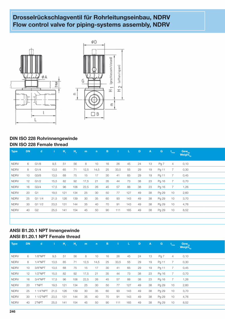
Drosselrückschlagventil für Rohrleitungseinbau, NDRV Flow...
20
Type DN d i H 1 H 2 m n B I L D A G t max Gew kg Weight kg NDRV 6 G1/8 9,5 51 56 8 10 16 26 45 24 13 Pg 7 4 0,10 NDRV 8 G1/4 13,5 65 71 12,5 14,5 25 33,5 55 29 19 Pg 11 7 0,30 NDRV 10 G3/8 13,5 68 75 15 17 30 41 65 29 19 Pg 11 7 0,45 NDRV 12 G1/2 15,5 82 92 17,5 21 35 44 73 38 23 Pg 16 7 0,70 NDRV 16 G3/4 17,5 96 106 22,5 26 45 57 88 38 23 Pg 16 7 1,26 NDRV 20 G1 19,5 121 134 25 30 50 77 127 49 38 Pg 29 10 2,60 NDRV 25 G1 1/4 21,5 126 139 30 35 60 93 143 49 38 Pg 29 10 3,70 NDRV 30 G1 1/2 23,5 131 144 35 40 70 91 143 49 38 Pg 29 10 4,76 NDRV 40 G2 25,5 141 154 45 50 90 111 165 49 38 Pg 29 10 8,52 DIN ISO 228 Rohrinnengewinde DIN ISO 228 Female thread Drosselrückschlagventil für Rohrleitungseinbau, NDRV Flow control valve for piping-systems assembly, NDRV ANSI B1.20.1 NPT Innengewinde ANSI B1.20.1 NPT Female thread Type DN d i H 1 H 2 m n B I L D A G t max Gew kg Weight kg NDRV 6 1/8”NPT 9,5 51 56 8 10 16 26 45 24 13 Pg 7 4 0,10 NDRV 8 1/4”NPT 13,5 65 71 12,5 14,5 25 33,5 55 29 19 Pg 11 7 0,30 NDRV 10 3/8”NPT 13,5 68 75 15 17 30 41 65 29 19 Pg 11 7 0,45 NDRV 12 1/2”NPT 15,5 82 92 17,5 21 35 44 73 38 23 Pg 16 7 0,70 NDRV 16 3/4”NPT 17,5 96 106 22,5 26 45 57 88 38 23 Pg 16 7 1,26 NDRV 20 1”NPT 19,5 121 134 25 30 50 77 127 49 38 Pg 29 10 2,60 NDRV 25 1 1/4”NPT 21,5 126 139 30 35 60 93 143 49 38 Pg 29 10 3,70 NDRV 30 1 1/2”NPT 23,5 131 144 35 40 70 91 143 49 38 Pg 29 10 4,76 NDRV 40 2”NPT 25,5 141 154 45 50 90 111 165 49 38 Pg 29 10 8,52 246
Transcript of Drosselrückschlagventil für Rohrleitungseinbau, NDRV Flow...
Type DN d i H1 H2 m n B I L D A G tmax GewkgWeightkg
NDRV 6 G1/8 9,5 51 56 8 10 16 26 45 24 13 Pg 7 4 0,10
NDRV 8 G1/4 13,5 65 71 12,5 14,5 25 33,5 55 29 19 Pg 11 7 0,30
NDRV 10 G3/8 13,5 68 75 15 17 30 41 65 29 19 Pg 11 7 0,45
NDRV 12 G1/2 15,5 82 92 17,5 21 35 44 73 38 23 Pg 16 7 0,70
NDRV 16 G3/4 17,5 96 106 22,5 26 45 57 88 38 23 Pg 16 7 1,26
NDRV 20 G1 19,5 121 134 25 30 50 77 127 49 38 Pg 29 10 2,60
NDRV 25 G1 1/4 21,5 126 139 30 35 60 93 143 49 38 Pg 29 10 3,70
NDRV 30 G1 1/2 23,5 131 144 35 40 70 91 143 49 38 Pg 29 10 4,76
NDRV 40 G2 25,5 141 154 45 50 90 111 165 49 38 Pg 29 10 8,52
DIN ISO 228 Rohrinnengewinde DIN ISO 228 Female thread
Drosselrückschlagventil für Rohrleitungseinbau, NDRVFlow control valve for piping-systems assembly, NDRV
PN[MPa]
Best.Nr.Order no.
Kat. PN[MPa]
Best.Nr.Order no.
Kat. PN[MPa]
Best.Nr.Order no.
Kat. PN[MPa]
Best.Nr.Order no.
Kat.
35 26868 1 35 30690 2 35 37675 4 35 37676 4
35 19562 1 35 30652 2 35 10298 4 35 09934 4
35 21359 1 35 30653 2 35 18568 4 35 37677 4
35 22829 1 35 30654 2 35 30145 4 35 25847 4
35 28978 1 35 21586 2 35 15776 4 35 31353 4
35 28977 1 35 29227 2 35 32425 4 35 34418 4
35 30086 1 35 30346 2 35 15777 4 35 37678 4
35 29494 1 35 31338 2 35 37679 4 35 37680 4
35 30867 1 35 32226 2 35 37681 4 35 37682 4
Werkstoffe / Materials 1A 18 4A 48
Gehäuse / Body Stahl / Steel Stahl / Steel Edelstahl / AISI 316 Edelstahl / AISI 316
O-Ring / O-ring NBR FPM NBR FPM
Tmin / Tmax -20°C / 100°C -20°C / 100°C -30°C / 100°C -20°C / 100°C
Öffnungsdruck /
Cracking pressure
0,05 MPa 0,05 MPa 0,05 MPa 0,05 MPa
ANSI B1.20.1 NPT Innengewinde ANSI B1.20.1 NPT Female thread
Type DN d i H1 H2 m n B I L D A G tmax GewkgWeightkg
NDRV 6 1/8”NPT 9,5 51 56 8 10 16 26 45 24 13 Pg 7 4 0,10
NDRV 8 1/4”NPT 13,5 65 71 12,5 14,5 25 33,5 55 29 19 Pg 11 7 0,30
NDRV 10 3/8”NPT 13,5 68 75 15 17 30 41 65 29 19 Pg 11 7 0,45
NDRV 12 1/2”NPT 15,5 82 92 17,5 21 35 44 73 38 23 Pg 16 7 0,70
NDRV 16 3/4”NPT 17,5 96 106 22,5 26 45 57 88 38 23 Pg 16 7 1,26
NDRV 20 1”NPT 19,5 121 134 25 30 50 77 127 49 38 Pg 29 10 2,60
NDRV 25 1 1/4”NPT 21,5 126 139 30 35 60 93 143 49 38 Pg 29 10 3,70
NDRV 30 1 1/2”NPT 23,5 131 144 35 40 70 91 143 49 38 Pg 29 10 4,76
NDRV 40 2”NPT 25,5 141 154 45 50 90 111 165 49 38 Pg 29 10 8,52
PN[MPa]
Best.Nr.Order no.
Kat. PN[MPa]
Best.Nr.Order no.
Kat. PN[MPa]
Best.Nr.Order no.
Kat. PN[MPa]
Best.Nr.Order no.
Kat.
35 30993 1 35 37683 2 35 37684 4 35 37685 4
35 28480 1 35 30558 2 35 37686 4 35 26257 4
35 24251 1 35 37687 2 35 37688 4 35 37689 4
35 24519 1 35 37690 2 35 33600 4 35 28789 4
35 30997 1 35 37691 2 35 30786 4 35 32525 4
35 30998 1 35 37692 3 35 37693 4 35 37694 4
35 31000 1 35 37695 3 35 37696 4 35 37697 4
35 31001 1 35 37698 3 35 37699 4 35 37700 4
35 31003 1 35 37701 3 35 37702 4 35 37703 4
246 247246 247
Type DN d i H1 H2 m n B I L D A G tmax GewkgWeightkg
NDRV 6 G1/8 9,5 51 56 8 10 16 26 45 24 13 Pg 7 4 0,10
NDRV 8 G1/4 13,5 65 71 12,5 14,5 25 33,5 55 29 19 Pg 11 7 0,30
NDRV 10 G3/8 13,5 68 75 15 17 30 41 65 29 19 Pg 11 7 0,45
NDRV 12 G1/2 15,5 82 92 17,5 21 35 44 73 38 23 Pg 16 7 0,70
NDRV 16 G3/4 17,5 96 106 22,5 26 45 57 88 38 23 Pg 16 7 1,26
NDRV 20 G1 19,5 121 134 25 30 50 77 127 49 38 Pg 29 10 2,60
NDRV 25 G1 1/4 21,5 126 139 30 35 60 93 143 49 38 Pg 29 10 3,70
NDRV 30 G1 1/2 23,5 131 144 35 40 70 91 143 49 38 Pg 29 10 4,76
NDRV 40 G2 25,5 141 154 45 50 90 111 165 49 38 Pg 29 10 8,52
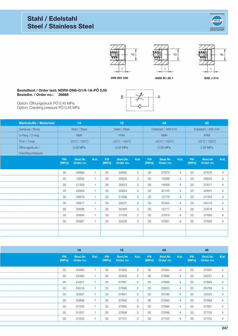
Bestelltext / Order text: NDRV-DN6-G1/8-1A-PÖ 0,05Bestellnr. / Order no.: 26868
Option: Öffnungsdruck PÖ 0,45 MPaOption: Cracking pressure PÖ 0,45 MPa
Stahl / EdelstahlSteel / Stainless Steel
DIN ISO 228 ANSI B1.20.1 SAE J 514
PN[MPa]
Best.Nr.Order no.
Kat. PN[MPa]
Best.Nr.Order no.
Kat. PN[MPa]
Best.Nr.Order no.
Kat. PN[MPa]
Best.Nr.Order no.
Kat.
35 26868 1 35 30690 2 35 37675 4 35 37676 4
35 19562 1 35 30652 2 35 10298 4 35 09934 4
35 21359 1 35 30653 2 35 18568 4 35 37677 4
35 22829 1 35 30654 2 35 30145 4 35 25847 4
35 28978 1 35 21586 2 35 15776 4 35 31353 4
35 28977 1 35 29227 2 35 32425 4 35 34418 4
35 30086 1 35 30346 2 35 15777 4 35 37678 4
35 29494 1 35 31338 2 35 37679 4 35 37680 4
35 30867 1 35 32226 2 35 37681 4 35 37682 4
Werkstoffe / Materials 1A 18 4A 48
Gehäuse / Body Stahl / Steel Stahl / Steel Edelstahl / AISI 316 Edelstahl / AISI 316
O-Ring / O-ring NBR FPM NBR FPM
Tmin / Tmax -20°C / 100°C -20°C / 100°C -30°C / 100°C -20°C / 100°C
Öffnungsdruck /
Cracking pressure
0,05 MPa 0,05 MPa 0,05 MPa 0,05 MPa
Type DN d i H1 H2 m n B I L D A G tmax GewkgWeightkg
NDRV 6 1/8”NPT 9,5 51 56 8 10 16 26 45 24 13 Pg 7 4 0,10
NDRV 8 1/4”NPT 13,5 65 71 12,5 14,5 25 33,5 55 29 19 Pg 11 7 0,30
NDRV 10 3/8”NPT 13,5 68 75 15 17 30 41 65 29 19 Pg 11 7 0,45
NDRV 12 1/2”NPT 15,5 82 92 17,5 21 35 44 73 38 23 Pg 16 7 0,70
NDRV 16 3/4”NPT 17,5 96 106 22,5 26 45 57 88 38 23 Pg 16 7 1,26
NDRV 20 1”NPT 19,5 121 134 25 30 50 77 127 49 38 Pg 29 10 2,60
NDRV 25 1 1/4”NPT 21,5 126 139 30 35 60 93 143 49 38 Pg 29 10 3,70
NDRV 30 1 1/2”NPT 23,5 131 144 35 40 70 91 143 49 38 Pg 29 10 4,76
NDRV 40 2”NPT 25,5 141 154 45 50 90 111 165 49 38 Pg 29 10 8,52
1A 18 4A 48
PN[MPa]
Best.Nr.Order no.
Kat. PN[MPa]
Best.Nr.Order no.
Kat. PN[MPa]
Best.Nr.Order no.
Kat. PN[MPa]
Best.Nr.Order no.
Kat.
35 30993 1 35 37683 2 35 37684 4 35 37685 4
35 28480 1 35 30558 2 35 37686 4 35 26257 4
35 24251 1 35 37687 2 35 37688 4 35 37689 4
35 24519 1 35 37690 2 35 33600 4 35 28789 4
35 30997 1 35 37691 2 35 30786 4 35 32525 4
35 30998 1 35 37692 3 35 37693 4 35 37694 4
35 31000 1 35 37695 3 35 37696 4 35 37697 4
35 31001 1 35 37698 3 35 37699 4 35 37700 4
35 31003 1 35 37701 3 35 37702 4 35 37703 4
246 247246 247
SAE J 514 UN/UNF InnengewindeSAE J 514 UN/UNF Female thread
Type DN d i H1 H2 m n B I L D A G tmax GewkgWeightkg
NDRV 8 7/16”UNF 13 65 71 12,5 14,5 25 33 54,5 29 19 Pg 11 7 0,30
NDRV 10 9/16”UNF 13,5 68 75 15 17 30 41 65 29 19 Pg 11 7 0,46
NDRV 12 3/4”UNF 15,5 82 92 17,5 21 35 44 73 38 23 Pg 16 7 0,72
NDRV 16 1 1/16”UN 20 96 106 22,5 26 45 59,5 97,5 38 23 Pg 16 7 1,37
NDRV 20 1 5/16”UN 20 121 134 25 30 50 77,5 127,5 49 38 Pg 29 10 2,66
NDRV 25 1 5/8”UN 20 126 139 30 35 60 91,5 141,5 49 38 Pg 29 10 2,86
NDRV 30 1 7/8”UN 20 131 144 35 40 70 87,5 139,5 49 38 Pg 29 10 4,45
NDRV 40 2 1/2”UN 25,5 141 154 45 50 90 111 165 49 38 Pg 29 10 8,03
PN[MPa]
Best.Nr.Order no.
Kat. PN[MPa]
Best.Nr.Order no.
Kat. PN[MPa]
Best.Nr.Order no.
Kat. PN[MPa]
Best.Nr.Order no.
Kat.
35 36102 2 35 36486 2 35 37706 4 35 37707 4
35 37708 2 35 37709 2 35 37710 4 35 37711 4
35 37712 2 35 34898 2 35 37713 4 35 37714 4
35 36068 2 35 37715 2 35 37716 4 35 37717 4
35 37718 3 35 37719 3 35 37720 4 35 37721 4
35 37722 3 35 37723 3 35 37724 4 35 37725 4
35 37726 3 35 37727 3 35 37728 4 35 37729 4
35 37730 3 35 37731 3 35 37732 4 35 37733 4
Drosselrückschlagventil für Rohrleitungseinbau, NDRVFlow control valve for piping-systems assembly, NDRV
248 249248 249
Type DN d i H1 H2 m n B I L D A G tmax GewkgWeightkg
NDRV 8 7/16”UNF 13 65 71 12,5 14,5 25 33 54,5 29 19 Pg 11 7 0,30
NDRV 10 9/16”UNF 13,5 68 75 15 17 30 41 65 29 19 Pg 11 7 0,46
NDRV 12 3/4”UNF 15,5 82 92 17,5 21 35 44 73 38 23 Pg 16 7 0,72
NDRV 16 1 1/16”UN 20 96 106 22,5 26 45 59,5 97,5 38 23 Pg 16 7 1,37
NDRV 20 1 5/16”UN 20 121 134 25 30 50 77,5 127,5 49 38 Pg 29 10 2,66
NDRV 25 1 5/8”UN 20 126 139 30 35 60 91,5 141,5 49 38 Pg 29 10 2,86
NDRV 30 1 7/8”UN 20 131 144 35 40 70 87,5 139,5 49 38 Pg 29 10 4,45
NDRV 40 2 1/2”UN 25,5 141 154 45 50 90 111 165 49 38 Pg 29 10 8,03
1A 18 4A 48
PN[MPa]
Best.Nr.Order no.
Kat. PN[MPa]
Best.Nr.Order no.
Kat. PN[MPa]
Best.Nr.Order no.
Kat. PN[MPa]
Best.Nr.Order no.
Kat.
35 36102 2 35 36486 2 35 37706 4 35 37707 4
35 37708 2 35 37709 2 35 37710 4 35 37711 4
35 37712 2 35 34898 2 35 37713 4 35 37714 4
35 36068 2 35 37715 2 35 37716 4 35 37717 4
35 37718 3 35 37719 3 35 37720 4 35 37721 4
35 37722 3 35 37723 3 35 37724 4 35 37725 4
35 37726 3 35 37727 3 35 37728 4 35 37729 4
35 37730 3 35 37731 3 35 37732 4 35 37733 4
Stahl / EdelstahlSteel / Stainless Steel
248 249248 249
∆p-Q-Kennlinien von MHA-Stromventilen∆p-Q-characteristic lines of MHA-flow valves
NDV - NDVP - NDRV - NDRVPDie Durchfl usswerte gelten für Hydrauliköl (Dichte 880kg/m3) und einer kinematischen Viskosität n von 35 mm2/s The fl ow values are valid
for hydraulic oil (spissitude 880 kg/m3) and the kinematic viscosity n of 35 mm2/s.
)
314
315
∆p-Q-Kennlinien von MHA-Stromventilen∆p-Q-characteristic lines of MHA-flow valves
NDVE Die Durchfl usswerte gelten für Hydrauliköl (Dichte 880kg/m3) und einer kinematischen Viskosität n von 35 mm2/s The fl ow values are valid
for hydraulic oil (spissitude 880 kg/m3) and the kinematic viscosity n of 35 mm2/s.
316
NomenklaturNomenclature
Nenndruck PN
Der Nenndruck beziffert die Druckstufe eines hydraulischen Bau-teils bei fortlaufender dynamischer Anwendung. Die Ziffer wird ge-rundet, um den international vorgeschriebenen Werten zu entspre-chen.Diese Nenndruckwerte sind international anerkannt und dienen zur Bestimmung gebräuchlicher Komponentengrößen untereinander.Für alle Kugelhähne gilt ein Auslegungs- und Prüfdruck von 1,5 x PN gemäß DIN 3230 T5 und ISO 5108 für Gehäuse. Für Dichtun-gen gilt 1,1 x PN.Der Nenndruck gibt den zulässigen Betriebsüberdruck bei 20°C an.
Maximaler Arbeitsdruck P max.
P max. ist der maximale Arbeitsdruck einer Komponente ein-schließlich der Druckspitzen für beschränkte Dauer dynamischer Anwendung bzw. der maximale Arbeitsdruck, der Temperaturab-schläge berücksichtigt.
Berstdruck P Berst
Belastungsprüfungen auf Berstdruck betragen mindestens das 2,4 fache des NenndrucksP Berst = 2,4 x PN
Nennweite DN
Die Nennweite ist eine numerische Größenbezeichnung zueinander passender Teile,für die nicht der Rohr-Außendurchmesser oder die Gewindegröße angegeben sind, wie z.B. Flansche.Die Nennweiten entsprechen annähernd den lichten Durchmessern in mm der Kugelhähne.Reduzierte Durchmesser werden von MHA gekennzeichnet durch z.B. DN25/32Der Kugelhahn entspricht DN 25, der Anschluss entspricht DN 32
Leckrate
Leckrate für Kugelhähne mit Kunststoffdichtungen:DIN EN 12266 Leckrate A -Keine sichtbar feststellbare Undichtheit während der Dauer der Prüfung mit Flüssigkeit oder Luft.
Nominal pressure PN
The nominal pressure indicates the pressure rate of a hydrau-lic component and continuous dynamic application. The number is rounded up in order to comply with the internationally specifi ed terms. These nominal pressure values are internationally recognised and assist to appoint common component dimensions.For all ball valves conform to a design and test pressure 1.5 x PN according to DIN 3230 T5 and ISO 5108 for body. For ball seats we admit 1,1 x PN.The nominal pressure specifi es the admissible working overpres-sure at 20°C.
Maximum working pressure P max.
P max. is the maximum working pressure of a component inclu-ding pressure peeks for limited duration of dynamic application resp. the maximum working pressure which considers temperatu-re reduction ratings.
Burst pressure P Burst
The safety factor for burst pressure tests is a minimum of 2.4 times the nominal pressure.P Burst = 2.4 x PN
Nominal diameter DN
The nominal diameter is a numeric dimension of mating parts wi-thout indication of outer tube diameter or thread size, for examp-le fl anges.The nominal diameters match approximately the clear diameter of the ball valves in mm.Reduced diameters are marked by MHA with for example DN25/32. That corresponds to the ball valve being DN 25 and the adapter being DN 32.
Leakage rate
Leakage rate of ball valves with synthetic ball seats:DIN EN 12266 leakage rate A -No visually noticeable leakage during the duration of the test with fl uid or air.
276
ZeichenSymbol
BenennungDesignation
Einheit
Unit
Umrechnungsfaktor
Conversion factor
Umrechnungsfaktor
Conversion factor
B, H, LMaßangaben Dimensions
mm 1 Inch = 25,4 mm
PDruck
PressureMPa 1 psi = 0,007 MPa 1 bar = 0,1 MPa
TTemperaturTemperature
°C 1 °F = 9/5x°C+32 °K = °C+273
MtDrehmoment
TorqueNm 1 lb inch = 0,115 Nm
∆PDruckdifferenz
Differential pressureMPa 1 psi = 0,007 MPa
QDurchfluss
Flowl/min
1 USgall/min = 3,785 l/min
1 UKgall/min = 4,546 l/min
WGewichtWeight
Kg 1 lb = 0,4536 kg
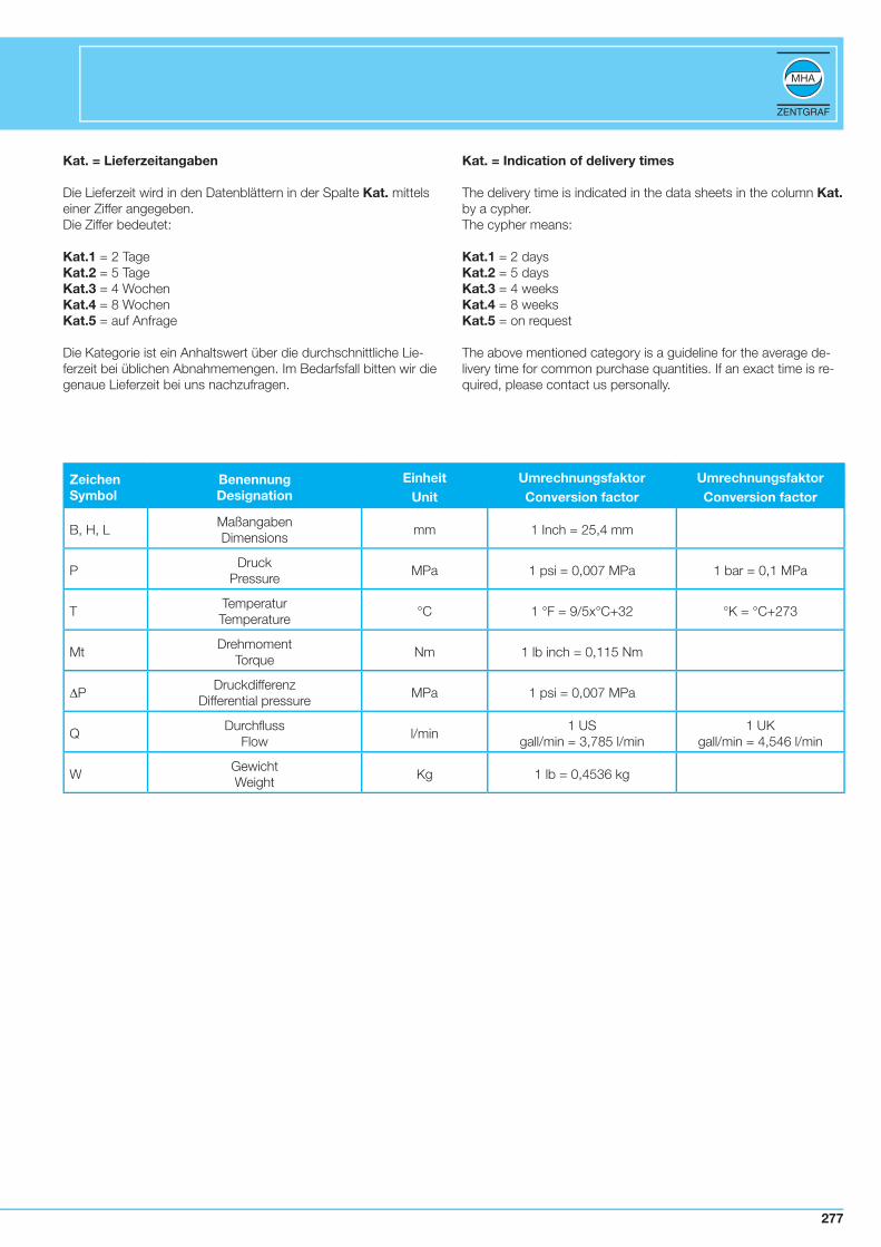
Kat. = Lieferzeitangaben
Die Lieferzeit wird in den Datenblättern in der Spalte Kat. mittels einer Ziffer angegeben.Die Ziffer bedeutet:
Kat.1 = 2 Tage Kat.2 = 5 Tage Kat.3 = 4 Wochen Kat.4 = 8 Wochen Kat.5 = auf Anfrage
Die Kategorie ist ein Anhaltswert über die durchschnittliche Lie-ferzeit bei üblichen Abnahmemengen. Im Bedarfsfall bitten wir die genaue Lieferzeit bei uns nachzufragen.
Kat. = Indication of delivery times
The delivery time is indicated in the data sheets in the column Kat. by a cypher.The cypher means:
Kat.1 = 2 daysKat.2 = 5 daysKat.3 = 4 weeksKat.4 = 8 weeksKat.5 = on request
The above mentioned category is a guideline for the average de-livery time for common purchase quantities. If an exact time is re-quired, please contact us personally.
277

Werkstoffbezeichnung Norm Temperaturbereich* Verwendungszweck
Automatenstahl11SMn30(alt 9SMn28K)
1.0715 /DIN EN 10277-3(SAE 1213)
-20°C bis +120°C Allgemeine Ölhydraulik ohne besondere Anfor-derungen an den Werkstoff
Niedrig legierter StahlS355J2G3(alt St52-3)
1.0570 /DIN EN 10025
-40°C bis +120°C Allgemeine Öl- und Wasserhydraulik sowie Gasanwendungen mit besonderen Anforde-rungen an die Zähigkeit
EdelstahlX6CrNiMoTi17-12-2X5CrNiMo17-12-2X2CrNiMo17-13-2
DIN EN 100881.4571 (AISI 316 Ti)1.4401 (AISI 316)1.4404 (AISI 316 L)
-200°C bis +200°C Spezieller Einsatz in der Chemie- und Kraft-werkindustrie bei hohen Anforderungen an den Werkstoff und an den Korrosionsschutz
MessingCuZn40Pb2(alt Ms58)
2.0402 /CW617N EN 12164
-40°C bis +100°C Kugelwerkstoff für Ölhydraulik
Verwendete Standardwerkstoffe für MHA - Produkte
* allgemeine Temperaturgrenzen. Unter Berücksichtigung der Temperaturabschläge ist eine Auslegung außerhalb der angegebenen Grenzen möglich.
Werkstoffbezeichnung Handelsname Temperaturbereich Verwendungszweck
PolyacetalPOM
DelrinHostaform CUltraform
-30°C bis +100°C Hohe Druck- und Abriebsfestigkeitgeringe Wasseraufnahme, besondersgeeignet für Hydrauliköle, sonstige Öle und schwer entflammbare Flüssigkeiten
PolytetrafluorethylenePTFE
TeflonHostflonFluon
-200°C bis +220°CDruck/Temperatur -Diagramm beachten
Hervorragende chemische Beständigkeit bei fast allen Medien, keine Wasseraufnahme, gute Gleitfähigkeit. (Lebensmittel zugelassen FDA-US Food and Drug Administration)
PolyvinnylidenfluoridPVDF
DyflorKynarSolef
-40°C bis +150°CDruck/Temperatur -Diagramm beachten
Mechanische Eigenschaften wie PTFE bei höherer Steifigkeit und jedoch geringerer thermischer Belastbarkeit beständig gegen Ketone und Ester bei höheren Tempe-raturen
PolyetheretherketonePEEK
ArlonVictrex
-40°C bis +250°C Gute chemische Beständigkeit bei vielen Medien, geeignet für Dampf, hohe Temperatur-beständigkeit, hohe Verschleiß-festigkeit
GraugussGG25
0.60257DIN 1651
-40°C bis +250°C Einsatz bei abrasiven Medien
Gehäuse, Verschraubungen, Schaltwelle und Kugel
Kugeldichtungen
278
Werkstoffbezeichnung Norm Temperaturbereich Verwendungszweck
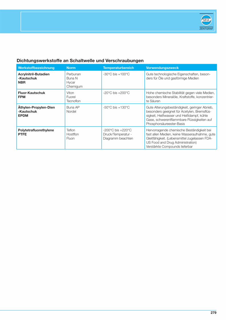
Acrylnitril-Butadien-KautschukNBR
PerbunanBuna NHycarChemigum
-30°C bis +100°C Gute technologische Eigenschaften, beson-ders für Öle und gasförmige Medien
Fluor-KautschukFPM
VitonFuorelTecnoflon
-20°C bis +200°C Hohe chemische Stabilität gegen viele Medien, besonders Mineralöle, Kraftstoffe, konzentrier-te Säuren
Äthylen-Propylen-Dien-KautschukEPDM
Buna APNordel
-50°C bis +130°C Gute Alterungsbeständigkeit, geringer Abrieb, besonders geeignet für Acetylen, Bremsflüs-sigkeit, Heißwasser und Heißdampf, kühle Gase, schwerentflammbare Flüssigkeiten auf Phosphorsäureester-Basis
PolytetrafluorethylenePTFE
TeflonHostflonFluon
-200°C bis +220°C Druck/Temperatur -Diagramm beachten
Hervorragende chemische Beständigkeit bei fast allen Medien, keine Wasseraufnahme, gute Gleitfähigkeit. (Lebensmittel zugelassen FDA-US Food and Drug Administration)Verstärkte Compounds lieferbar
Dichtungswerkstoffe an Schaltwelle und Verschraubungen
279
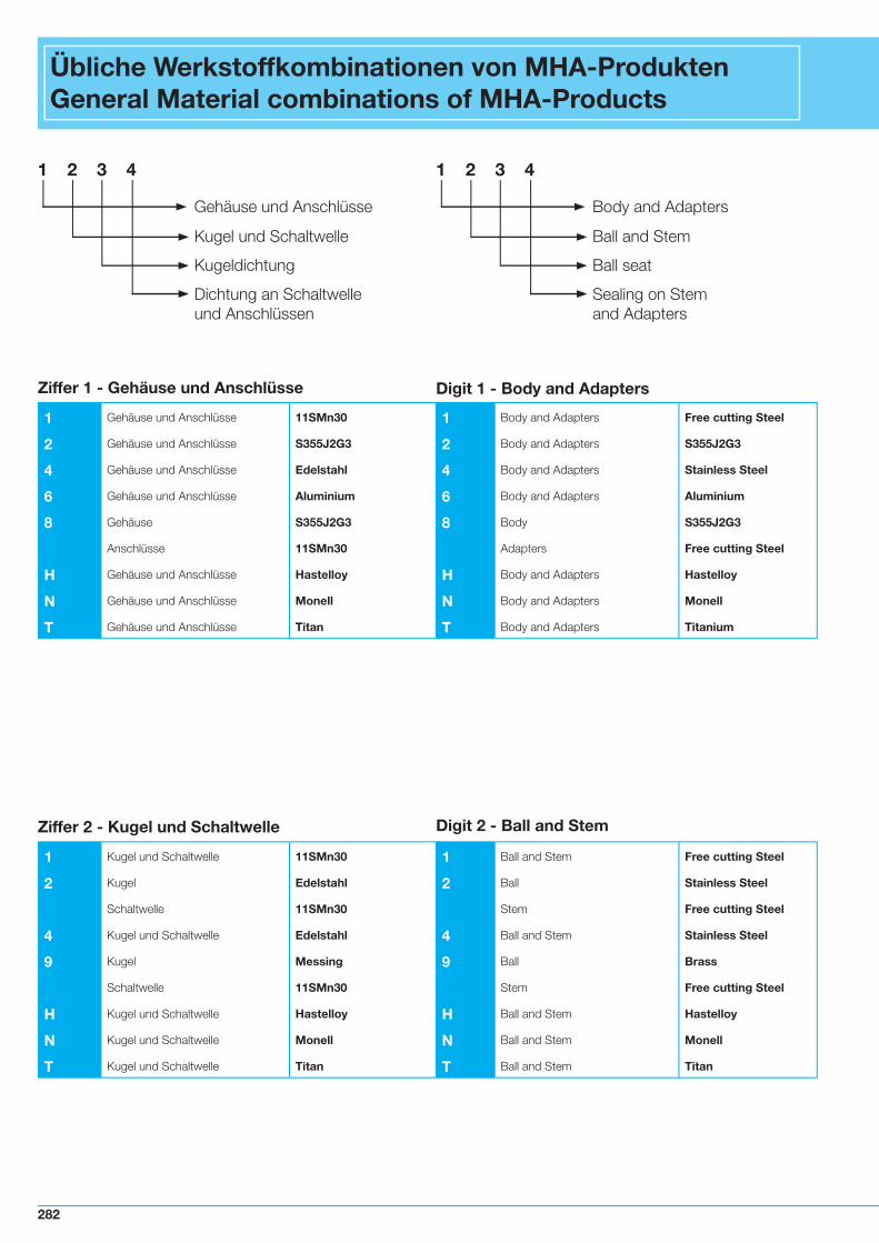
Übliche Werkstoffkombinationen von MHA-ProduktenGeneral Material combinations of MHA-Products
1 2 3 4
Gehäuse und Anschlüsse
Kugel und Schaltwelle
Kugeldichtung
Dichtung an Schaltwelleund Anschlüssen
1 2 3 4
Body and Adapters
Ball and Stem
Ball seat
Sealing on Stemand Adapters
1 Gehäuse und Anschlüsse 11SMn30 1 Body and Adapters Free cutting Steel
2 Gehäuse und Anschlüsse S355J2G3 2 Body and Adapters S355J2G3
4 Gehäuse und Anschlüsse Edelstahl 4 Body and Adapters Stainless Steel
6 Gehäuse und Anschlüsse Aluminium 6 Body and Adapters Aluminium
8 Gehäuse S355J2G3 8 Body S355J2G3
Anschlüsse 11SMn30 Adapters Free cutting Steel
H Gehäuse und Anschlüsse Hastelloy H Body and Adapters Hastelloy
N Gehäuse und Anschlüsse Monell N Body and Adapters Monell
T Gehäuse und Anschlüsse Titan T Body and Adapters Titanium
Ziffer 1 - Gehäuse und Anschlüsse Digit 1 - Body and Adapters
1 Kugel und Schaltwelle 11SMn30 1 Ball and Stem Free cutting Steel
2 Kugel Edelstahl 2 Ball Stainless Steel
Schaltwelle 11SMn30 Stem Free cutting Steel
4 Kugel und Schaltwelle Edelstahl 4 Ball and Stem Stainless Steel
9 Kugel Messing 9 Ball Brass
Schaltwelle 11SMn30 Stem Free cutting Steel
H Kugel und Schaltwelle Hastelloy H Ball and Stem Hastelloy
N Kugel und Schaltwelle Monell N Ball and Stem Monell
T Kugel und Schaltwelle Titan T Ball and Stem Titan
Ziffer 2 - Kugel und Schaltwelle Digit 2 - Ball and Stem
282
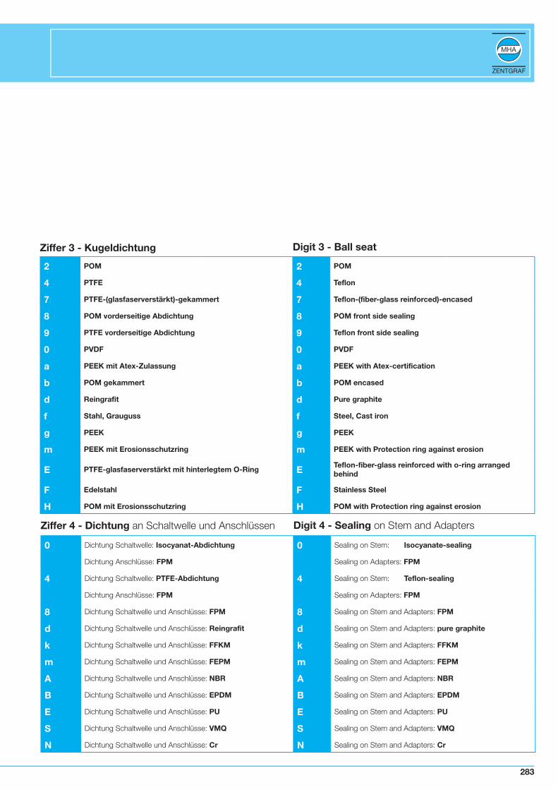
2 POM 2 POM
4 PTFE 4 Teflon
7 PTFE-(glasfaserverstärkt)-gekammert 7 Teflon-(fiber-glass reinforced)-encased
8 POM vorderseitige Abdichtung 8 POM front side sealing
9 PTFE vorderseitige Abdichtung 9 Teflon front side sealing
0 PVDF 0 PVDF
a PEEK mit Atex-Zulassung a PEEK with Atex-certification
b POM gekammert b POM encased
d Reingrafit d Pure graphite
f Stahl, Grauguss f Steel, Cast iron
g PEEK g PEEK
m PEEK mit Erosionsschutzring m PEEK with Protection ring against erosion
E PTFE-glasfaserverstärkt mit hinterlegtem O-Ring ETeflon-fiber-glass reinforced with o-ring arranged behind
F Edelstahl F Stainless Steel
H POM mit Erosionsschutzring H POM with Protection ring against erosion
Ziffer 3 - Kugeldichtung Digit 3 - Ball seat
0 Dichtung Schaltwelle: Isocyanat-Abdichtung 0 Sealing on Stem: Isocyanate-sealing
Dichtung Anschlüsse: FPM Sealing on Adapters: FPM
4 Dichtung Schaltwelle: PTFE-Abdichtung 4 Sealing on Stem: Teflon-sealing
Dichtung Anschlüsse: FPM Sealing on Adapters: FPM
8 Dichtung Schaltwelle und Anschlüsse: FPM 8 Sealing on Stem and Adapters: FPM
d Dichtung Schaltwelle und Anschlüsse: Reingrafit d Sealing on Stem and Adapters: pure graphite
k Dichtung Schaltwelle und Anschlüsse: FFKM k Sealing on Stem and Adapters: FFKM
m Dichtung Schaltwelle und Anschlüsse: FEPM m Sealing on Stem and Adapters: FEPM
A Dichtung Schaltwelle und Anschlüsse: NBR A Sealing on Stem and Adapters: NBR
B Dichtung Schaltwelle und Anschlüsse: EPDM B Sealing on Stem and Adapters: EPDM
E Dichtung Schaltwelle und Anschlüsse: PU E Sealing on Stem and Adapters: PU
S Dichtung Schaltwelle und Anschlüsse: VMQ S Sealing on Stem and Adapters: VMQ
N Dichtung Schaltwelle und Anschlüsse: Cr N Sealing on Stem and Adapters: Cr
Ziffer 4 - Dichtung an Schaltwelle und Anschlüssen Digit 4 - Sealing on Stem and Adapters
283
Oberflächenbeschichtungen von MHA-ProduktenSurface coating of MHA products
MHA kann folgende Oberfl ächenbeschichtungen, bzw. -be-handlungen für Gehäusewerkstoffe liefern:
Stahl • gelb verzinkt = Standard • phosphatiert • MHA Protect = Zink-Eisen Beschichtung • chemisch vernickelt • lackiert
Edelstahl • dreh- bzw. Ziehqualität = Standard • glasperlengestrahlt • elektropoliert • keramofi nished
Aluminium • eloxiert • hart eloxiert
MHA Produkte aus Stahl werden standardmäßig einheitlich mit ei-nem hochwertigen Oberfl ächenschutz geliefert. Galvanisch verzinkt und gelb chromatiert (Kurzzeichen A3C nach DIN/ISO 4042). Eine galvanisch abgeschiedene Zinkschicht bietet folgende Vorteile: Durch eine Schichtdicke von mind. 8 µm und die zusätzliche Ver-siegelung durch den Chromatierungsprozess steigt die Korrosions-beständigkeit deutlich an. Bei Kratzern und Schlagstellen, die sich bei der Montage nicht vermeiden lassen, entwickelt Zink eine ka-thodische Schutzwirkung, die das Stahlprodukt vor korrosivem Ab-trag und Lochfrass schützt. Die durch den Chromatierungsprozess bestimmte goldgelbe Färbung bietet eine anspruchsvolle Optik.
Die Anwender von MHA Produkten profi tieren von:
• Homogenen Schichtdicken (durchschnittlich 13 µm, gemessen an Außenkonturen) für gute Gewindeverschraubbarkeit
• Sehr gute Korrosionsbeständigkeit
Fertigungsbegleitende Korrosionsbeständigkeits- Prüfungen in Form von Salzsprühnebel-Prüfungen werden nach DIN 50021/5% NaCl durchgeführt und zeigen eine durchschnittliche Beständigkeit von 154 h der A3C– Beschichtung.
Vorteile der Zn-Fe-Beschichtung „MHA - Protect“ gegenüber chromatisierter Zn- Beschichtung:
• MHA - Protect ist ein alkalischer Elektrolyt zur Abscheidunghochkorrosionsbeständiger Zn-Fe-Überzüge
• Korrosionsschutz bei MHA – Protect ist höher als bei chromatisierten Zinküberzügen
• Sehr gute Schichtdickenverteilung und Metalltiefenstreuung• Gleichmäßiger technischer Glanz• Umweltunbedenkliches cyanidfreies Verfahren• Wesentlich bessere Haftfestigkeiten als bei chromatisierten
Zinküberzügen• Beständigkeit im Salzsprühtest nach DIN 50021 = 305 Std.
Chrom VI – freie Oberfl ächenbeschichtung
MHA hat die Möglichkeit Chrom VI – freie Oberfl ächenbeschich-tungen Fe/Zn DISP durchzuführen.Das Verfahren entspricht den Vorschriften der EU Richtlinie 2000/53/EG „EU-Altauto-Directive“ (ELV)
MHA can supply the following surface coating or surface treatment for body materials:
Steel • yellow zinc plated = standard • phosphated • MHA protect = zinc – iron coating • chemically nickel – plated • varnished
Stainless Steel • rotary or traction quality - standard • glass bead blasted • electro polished • ceramic fi nished
Aluminium • anodised • hard anodised
MHA steel products are supplied as standard with a high quality surface coating. Galvanised and yellow chrome-plated (abbreviati-on: A3C to DIN/ISO 4042).A galvanic isolated zinc layer has the following advantages: By using a layer thickness of 8 µm and an additional chrome sealing, the corrosion resistance increases obviously. The zinc coa-ting develops a cathodic protection against scratches and dents that occur during assembly. This effect protects the steel product from corrosive attack and pitting. The yellow coating occurring th-rough the chrome-plating process provides a superior look.
The user of MHA products benefi ts from:
• homogeneous coating thickness (average 13 µm, measured at outline) for an easy thread fi tting
• high corrosion resistance
Corrosion resistance tests accompanying the production are car-ried out in form of salt spray tests according to DIN 50021/5% NaCl and show an average resistance of 154 h of the A3C- coa-ting.
Advantages of the Zn-Fe-coating „MHA-Protect” compared to the chrome plating:
• MHA-Protect is an alkaline electrolyte for deposition of highly corrosion resistant Zn-Fe-coatings
• Protection against corrosion with MHA-Protect is higher than with chrome-plating
• Approved layer thickness distribution and metal depth dispersion
• Even technical fl ashiness• Environmentally compatible and cyanide-free processing• Substantially better adhesiveness comparedto chrome-plating• Resistance in salt atomised spray test according to
DIN50021 = 305 h
Chromium VI – free plating
MHA has got the possibility to carry out chromium VI – free plating Fe/ZN DISP. The process conforms to the EU Directive 2000/53/EG “end of life vehicles directive“ (ELV)
286

Abnahmen, Prüfmöglichkeiten, ZertifikateTechnical approvals, tests and certificates
MHA hat folgende Prüfmöglichkeiten:
Prüfmedien: Luft, Stickstoff, Helium, Wasser, Öl
Prüfdrücke: 0,01 MPa bis 650 MPa Wasser, 0,6 MPa bis 40 MPa Luft, 20 MPa Stickstoff, Heliumlecktest
Prüftemperaturen: 20°C bis 500°C
Druck-, Dichtheits- und Funktionsprüfungen nach: EN 12266-T1 und T2DIN 3230-T5 und T6
Weitere Prüfungen nach Kundenanforderung
MHA besitzt folgende Zertifi kate:
• AD Merkblatt HP 0• DIN EN ISO 9001:2000• DGR 97/23/EG (Druckgeräterichtlinie) Module D, H, H1• „ATEX“-Konformitätsbewertung Richtlinie 94/9, EX II 2G c • Fire-safe Zulassung nach BS6755T.2, API6 FA und ISO 10497,
für Baureihen BKH und KH
MHA kann folgende Abnahmen durchführen und entspre-chende Zeugnisse ausstellen:
Prüfzeugnisse nach DIN EN 10204 für Kugelhähne• 3.1• 2.2Werkstoffabnahmezeugnisse nach DIN EN 10204 • 3.1• 3.2• 2.2
Obligatorische Prüfungen von Kugelhähnen:
Die Prüfungen der Kugelhähne basieren auf der DIN EN 12266-1Standardprüfungen sind Prüfungen nach P10, P11,P12P10 = Festigkeitprüfung des Gehäuses mit 1,5 x PN bei halb geöffneter KugelP11 = Dichtheitsprüfung des Gehäuses und der Schaltwellen-durchführung mit max. 0,6 MPa Luft oder 1,5 x PN bei halb geöffneter KugelDie Prüfung erfolgt stichprobenartig.P12 = beinhaltet die Dichtheitsprüfung der Kugeldichtungen mit 1,1 x PN oder 0,6 MPa Luft.
Speziell zu vereinbarende Prüfungen von Kugelhähnen:
Es können alle Prüfungen nach DIN EN 12266-1 vereinbart und durchgeführt werden. Ebenfalls zu vereinbaren ist das Prüfl os ( bis 100%).Zeugnisse: Die Ergebnisse der Prüfungen können durch folgende Zeugnisse nach DIN EN 10204 belegt werden:• DIN EN 10204 – 3.1 wird von MHA ausgestellt• DIN EN 10204 – 3.2 wird von unabhängigen Sachverständigen
erstellt
MHA has the following test facilities:
Test mediums: air, nitrogen, helium, water, hydraulic oil
Test pressures: 0.01 MPa to 650 MPa water 0,6 MPa to 40 MPa air, 20 MPa nitrogen, helium leak testTest temperatures: 20°C to 500°C
Pressure, leak and functioning test according to: EN 12266-T1 and T2DIN 3230-T5 and T6,
as well as tests specifi ed by the customer
MHA holds the following certifi cation:
• AD-Directive HP 0• DIN EN ISO 9001:2000• PED 97/23/EC (Pressure Equipment Directive) modules D, H, H1• “ATEX” conformity assessment directive 94/9, EX II 2G c• Fire safe approval according to BS6755T.2, API6 FA and ISO
10497, for type BKH and KH
MHA can carry out the following technical approval and issue the following certifi cates:
Test certifi cates according to DIN EN 10204 for ball valves• 3.1 • 2.2Material certifi cates according to DIN EN 10204 • 3.1• 3.2• 2.2
Compulsory test of ball valves:
The test of ball valves are based upon DIN EN 12266 -1Standard tests are according to the methods P10, P11, P12P10 = strength test of the body with 1.5 x PN with ball in half opened positionP11 = leak test of the body and stem with max. 0.6 MPA air or 1.5 x PN with ball in half opened position.The test is carried out randomlyP12 also includes the leak test of the ball seats with 1,1 x PN or 0.6 MPa air
Special tests of ball valves to be agreed up-front:
All tests according to DIN EN 12266-1 can be agreed and carried out. Also the inspection lot (up to 100%) has be to defi ned.
Certifi cates: the result of the tests can be proven by the following certifi cates:• DIN EN 10204 – 3.1 issued by MHA • DIN EN 10204 – 3.2 issued by independent
authorities
288

Folgende Abnahmegesellschaften können durch MHA be-auftragt werden:
• TÜV Technischer Überwachungsverein• ABS American Bureau of Shipping• BV Bureau Veritas• China Classifi cation • DNV Det Norske Veritas• GL Germ. Lloyd• LRS Lloyds Register of Shipping• US cost guardAndere auf Anfrage
Following approval authorities can be assigned by MHA:
• TÜV Technischer Überwachungsverein• ABS American Bureau of Shipping• BV Bureau Veritas• China Classifi cation• DNV Det Norske Veritas• GL Germ. Lloyd• LRS Lloyds Register of Shipping• US Cost guardothers on request
289
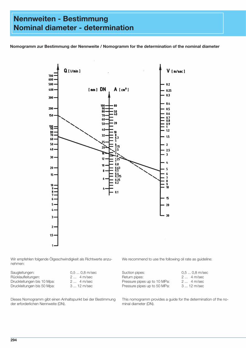
Wir empfehlen folgende Ölgeschwindigkeit als Richtwerte anzu-nehmen:
Saugleitungen: 0,5 ... 0,8 m/secRücklaufl eitungen: 2 ... 4 m/secDruckleitungen bis 10 Mpa: 2 ... 4 m/secDruckleitungen bis 50 Mpa: 3 ... 12 m/sec
Dieses Nomogramm gibt einen Anhaltspunkt bei der Bestimmung der erforderlichen Nennweite (DN).
Nomogramm zur Bestimmung der Nennweite / Nomogramm for the determination of the nominal diameter
Nennweiten - BestimmungNominal diameter - determination
We recommend to use the following oil rate as guideline:
Suction pipes: 0,5 ... 0,8 m/secReturn pipes: 2 ... 4 m/secPressure pipes up to 10 MPa: 2 ... 4 m/secPressure pipes up to 50 MPa: 3 ... 12 m/sec
This nomogramm provides a guide for the determination of the no-minal diameter (DN).
294
Beispiel 1: Man wählt eine Geschwindigkeit v = 8 m/secund eine Durchfl ussmenge Q = 150 l/min
Die geradlinige Verbindung dieser beiden Werte auf den äußeren Skalen ergibt auf der mittleren Skala die Nennweite DN 20.
Beispiel 2:Man wählt eine Geschwindigkeit v = 5,5 m/secund eine Durchfl ussmenge Q = 66 l/min
Die geradlinige Verbindung dieser beiden Werte auf den äußeren Skalen ergibt auf der mittleren Skala die Nennweite DN 16. Der Widerstand der Rohre, der Krümmer und Ventile sowie Visko-sität, Temperatureinfl üsse auf die Viskosität und andere Faktoren sind nicht berücksichtigt.
Nenndurchfl usstabelle
Die aufgeführten Durchfl ussmengen wurden mit Wasser für Kugel-hähne in geöffnetem Zustand bei einer Temperatur von +15°C er-mittelt.
Nennweite / Nominal diameter Kv Cv
[mm] [inch] [m3/h] [gal/min]
15 1/2“ 19,4 22,6
20 3/4“ 45,6 53,0
25 1“ 71,5 83,1
32 1 1/4“ 105 122,1
40 1 1/2“ 170 197,7
50 2“ 275 319,8
65 2 1/2“ 507 589,5
80 3“ 905 1052,3
100 4“ 1414 1644,2
125 5“ 2362 2746,5
150 6“ 3694 4295,3
Der Durchfl usskoeffi zient Kv nach VDI/VDE 2173 gibt die Wasser-menge in Kubikmeter pro Stunde an, bei ∆p=0,1 MPa und 35 c St bei 5 bis 30°C.Der in den USA immer noch übliche Cv-Wert gibt an, wie viele US gal/min Wasser von 60°F bei einem ∆p=1 psi durch das Ventil fl ie-ßen.
Example 1:A velocity v = 8 m/sec and a fl ow rate of Q = 150 l/min have been selected.
The straight line linking these two values on the outer scales inter-sects the nominal diameter DN 20 on the middle scale.
Example 2:A velocity v = 5,5 m/sec and a fl ow rate of Q = 66 l/min have been selected.
The straight line linking these two values on the other scales inter-sects the nominal diameter DN 16 on the middle scale. No allowance is incorporated for the resistance of the pipes, el-bows and valves, viscosity, the effect to temperature on viscosity and other factors.
Nominal fl ow rate list
The indicated fl ow rates have been determined for ball valves in open position with water at a temperature of +15°C.
The nominal fl ow rate coeffi cient Kv according to VDI/VDE 2173 indicates the quantity of water in cubic meter per hour, at ∆p=0,1 MPa and 35 c St at 5 up to 30°C.The Cv-value which is still common practice in USA specifi es how much US gal/min of water at 60°F fl ow through the valve at ∆p=1psi.
295

CE-Kennzeichnung für MHA-ProdukteCE-Marking for MHA-products
Information zur Druckgeräterichtlinie (DGR 97/23/EG)CE–Kennzeichnung für MHA – Produkte Die Anwendung der DGR 97/23/EG ist ab dem 29.05.2002 ver-bindlich. Die Anwendung der DGR ist gesetzlich vorgeschrieben.MHA ist zertifi ziert für Modul D, H, H
1.
VerantwortungDer Hersteller ist verpfl ichtet sicherzustellen, dass ein Produkt, das auf dem Gemeinschaftsmarkt in Verkehr gebracht werden soll, ent-sprechend den Richtlinien entworfen und hergestellt wird.Der Arbeitgeber darf nur Druckgeräte beschaffen oder benutzen, die den Bestimmungen der Druckgeräterichtlinie entsprechen.
VorgehensweiseVentile werden nach zunehmendem Gefahrenpotential in Kategori-en (Kategorie I bis III) eingestuft. Kategorie I entspricht der niedrigs-ten, Kategorie III der höchsten, gefährlichsten Kategorie. Für diese Einstufung werden folgende Kriterien herangezogen:
• Nennweite • Druck • Medium, - gefährliche oder ungefährlich
Gase oder Flüssigkeiten Gruppe 1 umfasst gefährliche Medien: • explosionsgefährlich • hochentzündlich • leicht entzündlich • entzündlich (wenn die max. zulässige
Temperatur über dem Flammpunkt liegt) • sehr giftig • giftig • brandfördernd Gruppe 2 umfasst alle ungefährlichen Medien, die unter Gruppe 1 nicht genannt sind, wie Hydrauliköl, Wasser, Luft , Stickstoff
AuswirkungKeine CE - Kennzeichnung für:• Alle Ventile < DN200 für ungefährliche Flüssigkeiten
der Gruppe 2 (z.B. Hydrauliköl, Wasser)• Alle Ventile bis einschließlich DN 25 für alle
Medien der Gruppe 1 und 2, gasförmig und fl üssig
CE - Kennzeichnung für Ventile ≥ DN 32:• MHA erstellte eine Konformitätsbescheinigung für
Ventile der Kategorie I und II• Für Ventile der Kategorie III ist eine externe
Beurteilung erforderlich• Kosten, die extern entstehen, werden im Angebot
durch MHA berücksichtigt.
Für Ventile der Kategorie I bis III gilt:
• Der Lieferung ist eine Konformitätsbescheinigung beizufügen
• Jeder Verpackungseinheit ist eine Betriebsanleitung beizufügen
• Die Rückverfolgbarkeit muss gewährleistet sein.
Information about essential contents and consequences of the Pressure Equipment Directive (PED 97/23 EC)CE-marking for MHA products
From 29th May 2002 the application of the Pressure Equipment Di-rective (PED 97/23 EC) is mandatory throughout in the European Community. MHA is certifi ed for modul D, H, H
1.
ResponsibilityManufacturers are obliged to ensure that products which are placed on the market in the European Community are designed and ma-nufactured according to the regulations of the Pressure Equipment Directive. The company is only allowed to purchase and use pres-sure equipment which corresponds to the regulations of the Pres-sure Equipment Directive
ProcedureValves have to be classifi ed in categories (category I to III ). Ca-tegory I relates to the lowest, category III to the highest, hazard category.
The classifi cation is carried out under consideration of
• diameter • pressure • medium, - hazardous or harmless gases or liquids
Group 1 comprises hazardous mediums • explosive • extremely fl ammable • highly fl ammable • fl ammable ( where the maximum allowable
temperature is above fl ashpoint ) • very toxic • toxic • oxidising
Group 2 comprises all harmless mediums which are not listed in Group 1 such as hydraulic oil, water, air and oxygen.
ConsequencesNo CE - marking for:• All valves < DN200 for harmless liquits of Group 2,
such as hydraulic oil, water• All valves up to and including DN 25 for all mediums
in Group 1 and 2, gaseous and liquid
CE – marking for valves ≥ DN 32:• With regards to valves of category I and II MHA
prepares a declaration of conformity • With regards to valves of category III an external
conformity examination is necessary. • The resulting costs will be included in our quotation.
Concerning valves of the categories I to IIIhas to be observed that:• a certifi cation of conformity has to be enclosed with
each delivery.• operating instructions have to be enclosed with
each packing unity.• the traceability of products must be guaranteed.
318

Besondere Verantwortung des Herstellers:Klassifi zierung in Kategorien:Liegen MHA keine Angaben über Druck, Temperatur und Medium vor, erfolgt eine Klassifi zierung entsprechend der Medien der Grup-pe 2 ( ungefährliche Medien. ) Besondere Verantwortung der Anwender und Händler:Umfassende Information an den Hersteller über die Einsatzbedin-gungen, Druck, min. und max. Temperatur, Medium. Begleitende Dokumente bei Umverpackung müssen den neuen Verpackungseinheiten beigelegt werden.Eine sorgfältige Zuordnung der Dokumente zu den Produkten und die Rückverfolgbarkeit der Produkte ist sicher zu stellen.
Particular responsibilities of manufacturersClassifi cation in categories: If MHA should not be informed about pressure, temperature and fl uid, the valves will be classifi ed according to fl uids of group 2 ( harmless fl uids ).
Particular responsibilities of users and dealers:Manufacturers should be informed extensively about relevant facts such as pressure, minimum and maximum temperature and fl uid.
Should the products be repacked, documents have to be enclosed with the new packing unities.The traceability of products must be guaranteed.
319