Doppelpass Stadionheft Ausgabe 09 SV Ostermünchen - SV DJK Edling

(de) Bedienungs−anleitung
(en) Operating instructions
Druckaufbau− und Entlüftungs�ventilSoft start/quick exhaust valveMS6(N)−SV
743 2670904a

MS6(N)−SV
Festo MS6(N)−SV 0904a 2
Symbole/Symbols: Einbau und Inbetriebnahme nur von qualifi�ziertem Fachpersonal, gemäß Bedienungs�anleitung.
WarnungWarning, Caution
HinweisPlease note
UmweltAntipollution
ZubehörAccessories
Fitting and commissioning to be carried outby qualified personnel only in accordancewith the operating instructions.
Deutsch 3 . . . . . . . . . . . . . . . . . . . . . . . . . . . . . . . . . . . . . . . . . . . . . . . . . . . . . . . . . . . . . . . . . . .
English 35 . . . . . . . . . . . . . . . . . . . . . . . . . . . . . . . . . . . . . . . . . . . . . . . . . . . . . . . . . . . . . . . . . . . .
MS6(N)−SV
Festo MS6(N)−SV 0904a Deutsch 3
Druckaufbau− und Entlüftungsventil MS6(N)−SVDeutsch
Inhaltsverzeichnis
1 Bedienteile und Anschlüsse 4 . . . . . . . . . . . . . . . . . . . . . . . . . . . . . . . . . . . .
2 Funktion und Anwendung 5 . . . . . . . . . . . . . . . . . . . . . . . . . . . . . . . . . . . . . .
3 Voraussetzungen für den Produkteinsatz 6 . . . . . . . . . . . . . . . . . . . . . . . . .
4 Einbau mechanisch/pneumatisch 8 . . . . . . . . . . . . . . . . . . . . . . . . . . . . . . . Mechanisch 8 . . . . . . . . . . . . . . . . . . . . . . . . . . . . . . . . . . . . . . . . . . . . . . . . . .
Pneumatisch � Anschluss 1 und 2 (Gewindegröße G½ oder NPT½−14) 10 .
Pneumatisch � Anschluss 3 (Gewindegröße G1 oder NPT1) 10 . . . . . . . . . . .
5 Elektrischer Anschluss 11 . . . . . . . . . . . . . . . . . . . . . . . . . . . . . . . . . . . . . . . .
6 Anschlussbeispiele (elektrisch) 13 . . . . . . . . . . . . . . . . . . . . . . . . . . . . . . . . . MS6(N)−SV mit Multipol−Steckdose NECA−S1G9−P9−MP1 14 . . . . . . . . . . . . .
MS6(N)−SV mit Multipol−Steckdose NECA−S1G9−P9−MP3 16 . . . . . . . . . . . . .
Betriebsarten Automatischer Start/Überwachter Start 17 . . . . . . . . . . . . . . .
Meldekontakte 13/14 19 . . . . . . . . . . . . . . . . . . . . . . . . . . . . . . . . . . . . . . . . . .
7 Inbetriebnahme 20 . . . . . . . . . . . . . . . . . . . . . . . . . . . . . . . . . . . . . . . . . . . . . .
8 Betrieb 25 . . . . . . . . . . . . . . . . . . . . . . . . . . . . . . . . . . . . . . . . . . . . . . . . . . . . . .
9 Wartung und Pflege 25 . . . . . . . . . . . . . . . . . . . . . . . . . . . . . . . . . . . . . . . . . . .
10 Ausbau 25 . . . . . . . . . . . . . . . . . . . . . . . . . . . . . . . . . . . . . . . . . . . . . . . . . . . . . .
11 Außerbetriebnahme und Entsorgung 26 . . . . . . . . . . . . . . . . . . . . . . . . . . . . .
12 Zubehör 26 . . . . . . . . . . . . . . . . . . . . . . . . . . . . . . . . . . . . . . . . . . . . . . . . . . . . .
13 Diagnose und Fehlerbehandlung 27 . . . . . . . . . . . . . . . . . . . . . . . . . . . . . . . . LED−Anzeige 27 . . . . . . . . . . . . . . . . . . . . . . . . . . . . . . . . . . . . . . . . . . . . . . . . . .
Fehlercode 27 . . . . . . . . . . . . . . . . . . . . . . . . . . . . . . . . . . . . . . . . . . . . . . . . . . .
14 Technische Daten 29 . . . . . . . . . . . . . . . . . . . . . . . . . . . . . . . . . . . . . . . . . . . . .

MS6(N)−SV
Festo MS6(N)−SV 0904a Deutsch4
1 Bedienteile und Anschlüsse
Druckaufbau− und Entlüftungsventil MS6(N)−SV nach DIN�EN�ISO�13849−1, max.�erreichbarer Performance Level �e", Kategorie 3 + 4.
8
7
6
5
1
2
3
4
9
1 LED Anzeige (LED Power und LED Er�ror)
2 Drosselschraube für Softstartfunk�tion
3 Pneumatischer Anschluss 1 (EingangDruckluft)
4 Elektronikblock
5 Ventilblock
6 Multipol−Steckdose NECA
7 Pneumatischer Anschluss 3 (Entlüf�tung)
8 Anschluss Funktionserde
9 Pneumatischer Anschluss 2 (Aus�gang Druckluft)
Bild�1

MS6(N)−SV
Festo MS6(N)−SV 0904a Deutsch 5
2 Funktion und Anwendung
Das elektropneumatische Druckaufbau− und Entlüftungsventil MS6(N)−SV dientbestimmungsgemäß dem schnellen und sicheren Druckabbau und dem sanftenDruckaufbau in pneumatischen Leitungssystemen und Endgeräten der Industrie.
Bei dem MS6(N)−SV handelt es sich um ein eigensicheres, redundantes mecha�tronisches System nach den Forderungen der DIN�EN�ISO�13849−1, bei dem dassicherheitsgerichtete pneumatische Schutzziel, sicheres Entlüften, auch bei einemFehler im Ventil (z.�B. durch Verschleiß, Verschmutzung) gewährleistet ist.
Über den elektrischen Anschluss (Multipol−Steckdose NECA Sub−D, 9−polig) erhältdas MS6(N)−SV die sicheren Enable−Signale (EN1/EN2) von handelsüblichenelektronischen oder elektromechanischen Sicherheitsschaltgeräten, welche dieSchutzeinrichtungen der Maschine (z.�B. Not−Aus, Lichtgitter, elektrische Türschal�ter der Schutzeinhausung, etc.) überwachen.
Zur bestimmungsgemäßen Verwendung gehört die Einhaltung der in dieser Bedie�nungsanleitung festgelegten Grenzwerte (z.�B. Betriebsmedium, Drücke, Tempera�turen, Betriebspannungen, Durchflüsse).
Die bestimmungsgemäße Verwendung wurde von der BGIA geprüft und ist durcheine BG−Prüfbescheinigung dokumentiert.
Betriebsarten
Die folgenden 2 Betriebsarten sind möglich:
� �Automatischer Start" (automatic reset)
� �Überwachter Start" (monitored reset)
In beiden Betriebsarten kann das MS6(N)−SV entweder mit statischen oder dyna�mischen Enable−Signalen (EN1/EN2) angesteuert werden (è Kapitel 6 �Anschluss�beispiele").
HinweisDas Produkt ist ausschließlich für industrielle Zwecke geeignet.

MS6(N)−SV
Festo MS6(N)−SV 0904a Deutsch6
3 Voraussetzungen für den Produkteinsatz
Das MS6(N)−SV wurde unter sorgfältiger Anwendung der zutreffenden Normen undRichtlinien sowie der anerkannten Regeln der Technik entwickelt und gefertigt. DieSchutzfunktion des Geräts kann jedoch beeinträchtigt werden, wenn es nicht be�stimmungsgemäß eingesetzt wird. In diesem Fall können Gefahren für Leib undLeben von Personen entstehen.
Installation und Inbetriebnahme
Die Installation und Inbetriebnahme sind nur durch geschultes Fachpersonal zuläs�sig. Das MS6(N)−SV darf nur gemäß den in Kapitel 14 �Technische Daten" festge�legten Werten angeschlossen und betrieben werden.
WarnungDer Einsatz unzulässiger Medien kann Schäden am Produkt verursachen.
S Verwenden Sie das MS6(N)−SV nicht in Verbindung mit entzündlichen Gasenoder Sauerstoff. Das Gerät ist nur zum Einsatz mit Medien vorgesehen, die inden Technischen Daten als geeignet aufgeführt sind.
S Entfernen Sie die Transportvorkehrungen wie Schutzwachs, Folien (Polyamid),Kappen (Polyethylen), Kartonagen (außer den Verschlusselementen der pneu�matischen Anschlüsse).
Die Verpackungen sind vorgesehen für eine Verwertung auf stofflicher Basis (Aus�nahme: Ölpapier = Restmüll).
S Überprüfen Sie das Gerät auf Transportschäden. Bauen Sie nur unbeschädigteGeräte im Originalzustand ein.
S Entfernen Sie Partikel in den Zuleitungen mittels Durchblasen der Rohre undSchläuche. Dadurch schützen Sie das MS6(N)−SV vor frühzeitigem Ausfall oderhöherem Verschleiß (è DIN�ISO�4414, Abs. 9.4).

MS6(N)−SV
Festo MS6(N)−SV 0904a Deutsch 7
Betrieb und Wartung
Der Betreiber hat die Verantwortung, dass die örtlich geltenden Sicherheitsvor�schriften eingehalten werden.
S Prüfen Sie die Umgebungsbedingungen des Einsatzortes und die Grenzwertedes Einsatzfalls. Das Gerät darf nur eingebaut werden, wenn sich alle Werte imzulässigen Bereich befinden (è Kapitel 14 �Technische Daten").
S Das Gerät darf nur im Originalzustand ohne eigenmächtige Veränderungeneingesetzt werden.
HinweisBei Schäden, die aus unbefugten Eingriffen oder nicht bestimmungsgemäßerVerwendung entstehen, erlischt der Garantie− und Haftungsanspruch gegen�über dem Hersteller.
MS6(N)−SV
Festo MS6(N)−SV 0904a Deutsch8
4 Einbau mechanisch/pneumatisch
Mechanisch
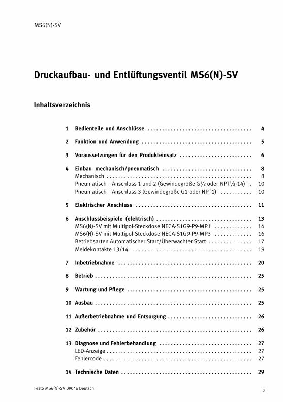
HinweisInformationen zur Montage von Modulverbinder, Anschlussplatte undBefestigungswinkel finden Sie in der Bedienungsanleitung, die dem Zubehörbeigefügt ist.
S Platzieren Sie das MS6(N)−SV sonahe wie möglich am Einsatzort.
S Platzieren Sie das MS6(N)−SV so,dass Sie ausreichend Platz für denAnschluss der Multipolsteckdoseund des Schalldämpfers haben(è�Bild�2 mit Schalldämpfer UOS−1von Festo).
S Beachten Sie den minimal zulässigenWandabstand von 32�mm (è�Bild�2).
Bei Verwendung des Befestigungs�winkels MS6−WPB von Festo ist die�ser Abstand gewährleistet.
S Die Einbaulage ist beliebig.
S Beachten Sie die Durchflussrichtungvon 1 nach 2. Als Orientierung dienen die Ziffern1 auf dem Produktgehäuse(è�Bild�3).
Bild�2
Bild�3
1

MS6(N)−SV
Festo MS6(N)−SV 0904a Deutsch 9
Zusammenbau mit Wartungsgeräten der MS−Baureihe
WarnungDer falsche Einbau in die Wartungskombination kann die Sicherheitsfunktiondes MS6(N)−SV beeinträchtigen.
S Nach dem MS6(N)−SV dürfen nur Geräte platziert werden, die die pneu�matische Schutzmaßnahme � sicheres Entlüften � nicht beeinträchtigen.
Beim Zusammenbau mit einem oder mehreren bereits vorhandenenWartungsgeräten der gleichen Baureihe (è Bild�4):
1. Demontieren Sie, falls vorhanden, die Abdeckkappe MS6−END 1 auf der Zu�sammenbauseite (nach oben schieben).
2. Platzieren Sie die Modulverbinder MS6−MV 2 in den Nuten der Einzelgeräte.Dabei ist zwischen den Einzelgeräten eine Dichtung erforderlich.
3. Befestigen Sie die Modulverbinder MS6−MV mit 2 Schrauben.
max 1,2�Nm
1
2
1 Abdeckkappe MS6−END 2 Modulverbinder MS6−MV
Bild�4

MS6(N)−SV
Festo MS6(N)−SV 0904a Deutsch10
Pneumatisch � Anschluss 1 und 2 (Gewindegröße G½ oder NPT½−14)
Bei Verwendung von Anschlussverschraubungen mit Schlüsselweite größer SW24:
S Entfernen Sie die Abdeckkappe MS6−END (nach oben schieben), falls vorhan�den.
Bei Verwendung von Anschlussverschraubungen:
S Beachten Sie die zulässige Einschraubtiefe der Anschlussgewinde:
Max. Einschraubtiefe [mm]
ISO 228 NPT
10,0 10,0
Für größere Einschraubtiefen müssen die Anschlussplatten MS6−AG�/AQ�von Festo verwendet werden.
S Achten Sie auf korrekten Anschluss der Druckluftleitungen.
S Drehen Sie die Verschraubungen unter Verwendung von geeignetem Dichtma�terial in die pneumatischen Anschlüsse.
Pneumatisch � Anschluss 3 (Gewindegröße G1 oder NPT1)
Bei der Entlüftung einer Anlage über das MS6(N)−SV entstehen hohe Schalldruck�pegel. Daher ist der Einsatz eines Schalldämpfers zu empfehlen.
WarnungBei der Verwendung eines handelsüblichen Schalldämpfers kann es zum Zuset�zen des Dämpferkörpers kommen, was zu einer reduzierten Entlüftungsleistung(Staudruck) führen kann.
S Verwenden Sie den zum Gerät zugehörigen Sicherheitsschalldämpfer(è�Kapitel 12 �Zubehör").
S Verwenden Sie einen handelsüblichen Schalldämpfer nur dann, wenn dieserregelmässig durch Servicepersonal gewartet und in Verbindung mit einerStaudrucküberwachung eingesetzt wird.
S Drehen Sie den Schalldämpfer in den pneumatischen Anschluss 3. BeimMS6N−SV muss zusätzlich ein Adapter zwischen Schalldämpfer und Gerät mon�tiert werden.
S Achten Sie auf eine ungehinderte Entlüftung. Der Schalldämpfer oder der An�schluss 3 dürfen nicht versperrt werden.

MS6(N)−SV
Festo MS6(N)−SV 0904a Deutsch 11
5 Elektrischer Anschluss
WarnungElektrischen Anschluss nur in spannungslosem Zustand und nur durch Fachper�sonal herstellen.
WarnungVerwenden Sie ausschließlich Stromquellen, die eine sichere elektrische Tren�nung der Betriebsspannung nach IEC/DIN EN 60204−1 gewährleisten. Berück�sichtigen Sie zusätzlich die allgemeinen Anforderungen an PELV−Stromkreisegemäß IEC/DIN EN 60204−1.
HinweisLange Signalleitungen reduzieren die Störfestigkeit.
S Stellen Sie sicher, dass die Signalleitungen stets kürzer sind als 20 m.
Erdungskabel anschließen
1. Montieren Sie das Erdungskabel 2und die zwei Zahnscheiben mit derbeiliegenden Schraube 1 am An�schluss Funktionserde (è�Bild�5).
Dabei muss sich je eine Zahnscheibeauf einer Seite des Kabelschuhs be�finden.
2. Verbinden Sie den Erdungsanschlussniederohmig (kurze Leitung mit gro�ßem Querschnitt) mit dem Erdpoten�tial.
Sie vermeiden damit Störungendurch elektromagnetische Einflüsseund stellen die elektromagnetischeVerträglichkeit gemäß den EMV−Richtlinien sicher.
Bild�5
1
2
MS6(N)−SV
Festo MS6(N)−SV 0904a Deutsch12
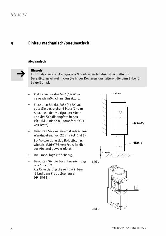
Multipol−Steckdose anschließen
HinweisDas MS6(N)−SV darf nur mit den dafür zugelassenen Multipol−SteckdosenNECA−�−MP� verwendet werden (è Bild�6). Informationen zur Klemmenbele�gung finden Sie in der beigefügten Montageanleitung der jeweiligen Multipol−Steckdose.
S Schließen Sie die Multipol−Steckdose an.
Achten Sie darauf, das die Schrauben fest angezogen sind, damit SchutzartIP65 gewährleistet ist. Das Anziehdrehmoment beträgt max. 0,4 ± 0,1�Nm.
Bild�6
NECA−S1G9−P9−MP3
NECA−S1G9−P9−MP1

MS6(N)−SV
Festo MS6(N)−SV 0904a Deutsch 13
Eingänge und Ausgänge
Klemme in Mul�tipol−SteckdoseNECA
E/A Belegung
1 EN1 Enable−Signal 1(statisch oder dyna�misch)
nach EN�61131−2Typ�2, max. 6�mA
è Beispiele Kapitel 6�Anschlussbeispiele"
2 EN2 Enable−Signal 2(statisch oder dyna�misch)
nach EN�61131−2Typ�2, max. 6�mA
è Beispiele Kapitel 6�Anschlussbeispiele"
3 13 Meldekontakte, NO potentialfrei,max 120 mA
è Beispiele Kapitel 6�A hl b i i l "
4 14max. 120�mA
p p�Anschlussbeispiele"
5 A5 Kontakt für Betriebsart�Automatischer Start"
è Beispiele Kapitel 6�Anschlussbeispiele"
6 S34 Kontakt für Betriebsart�Automatischer Start"oder �ÜberwachterStart"
nach EN�61131−2Typ�2, max. 6�mA
è Beispiele Kapitel 6�Anschlussbeispiele"
7 � �
8 +L1 Betriebsspannung +24�V�DC ±10%
9 M GND
Bild�7
6 Anschlussbeispiele (elektrisch)
HinweisDie Leitungen für die Enable−Signale sind von der Spannungsversorgung ge�trennt zu führen. Zusätzlich sind die Leitungen über entsprechende Maßnah�men vor Beschädigung zu schützen.

MS6(N)−SV
Festo MS6(N)−SV 0904a Deutsch14
HinweisZur einfacheren Inbetriebnahme empfiehlt es sich, einen Resetknopf (Öffner) imSpannungsversorgungskreis vorzusehen. Das Rücksetzen im Fehlerfall wirddadurch vereinfacht.
MS6(N)−SV mit Multipol−Steckdose NECA−S1G9−P9−MP1
Die Multipol−Steckdose NECA−�−MP1 ist für statische und taktende Sicherheits�ausgänge einsetzbar.
� Statische Enable−Signale (EN1/EN2 = 24�V)
Bild�8
Die Diagramme für das Schaltverhalten finden Sie im Kapitel 7 �Inbetriebnahme"(è�Bild�13 und Bild�14).

MS6(N)−SV
Festo MS6(N)−SV 0904a Deutsch 15
� Taktende Enable−Signale (EN1/EN2) zur Querschlusserkennung
Die Querschlusserkennung mittels Taktsignalen wird grundsätzlich durch dasverwendete Sicherheitsschaltgerät/Sicherheits−SPS durchgeführt.
Bild�9
HinweisDa die Taktausgänge diverser Steuerungshersteller nicht genormt sind, ist dieVerwendbarkeit jeweils zu überprüfen. Liegt der Takt außerhalb der beschriebe�nen Grenzen wird das vom MS6(N)−SV als Fehler erkannt und eine sichere Ab�schaltung herbeigeführt.

MS6(N)−SV
Festo MS6(N)−SV 0904a Deutsch16
MS6(N)−SV mit Multipol−Steckdose NECA−S1G9−P9−MP3
� Statische Enable−Signale (EN1 = 0�V, EN2 = 24�V)
� Querschlussüberwachung mit statischen Signalen möglich.
Vorteil: Ein Querschluss der Leitungen EN1 und EN2 verhindert einen unbeab�sichtigten Anlauf des Ventils.
Bild�10
Die Diagramme für das Schaltverhalten finden Sie im Kapitel 7 �Inbetriebnahme"(è�Bild�15 und Bild�16).

MS6(N)−SV
Festo MS6(N)−SV 0904a Deutsch 17
Betriebsarten Automatischer Start/Überwachter Start
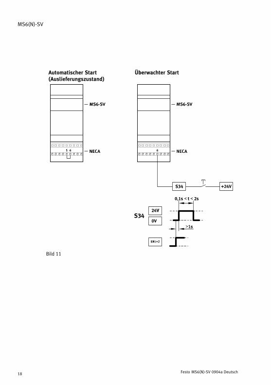
Betriebsarten (è Bild�11):
� Die Betriebsart �Automatischer Start" (automatic reset) ist durch eine Brückevon Klemme 5 auf 6 in der Multipolsteckdose voreingestellt (Auslieferungszu�stand).
� Die Betriebsart �Überwachter Start" (monitored reset) ist aus Sicht desGesamtsystems als unterlagerter Start anzusehen. Führend ist immer das Frei�gabesignal des Sicherheitsrelais oder der Steuerung.
HinweisDer durch den Starttaster generierte Impuls muss in einem Zeitfenster zwischen0,1�s und 2�s liegen.
Wird der Starttaster zu lange gedrückt oder gar eingerastet, wird ein Quer�schluss erkannt und das Gerät geht in den Fehlermodus.
HinweisDas Startsignal auf S34 darf erst 1�s nach dem Anlegen der Enable−SignaleEN1/EN2 erzeugt werden.
Liegt das Startsignal vor oder zeitgleich mit den Enable−Signalen wird diesesnicht anerkannt und muss erneut gesetzt werden.
MS6(N)−SV
Festo MS6(N)−SV 0904a Deutsch18
Automatischer Start(Auslieferungszustand)
Überwachter Start
Bild�11

MS6(N)−SV
Festo MS6(N)−SV 0904a Deutsch 19
Meldekontakte 13/14
Die Meldekontakte 13/14 sind potentialfreie Schließerkontakte eines Halbleiter�relais. Über die Klemmen 3 und 4 der Multipol−Steckdose NECA kann die Meldungbei Bedarf in den Rückführkreis (feedback circuit) einer Sicherheitssteuerung auf�genommen werden. Alternativ kann die Information über einen angebauten Druck�sensor an die Steuerung rückgemeldet werden (nur MS6(N)−SV−�−AD�).
HinweisDie Belegung dieser Kontakte ist für die Erreichung der Sicherheitskategorienicht erforderlich.
Bild�12
Die Diagramme für das Schaltverhalten finden Sie im Kapitel 7 �Inbetriebnahme"(mit Multipol−Steckdose NECA−S1G9−P9−MP1 è Bild�13 und Bild�14/ mit Multipol−Steckdose NECA−S1G9−P9−MP3 è Bild�15 und Bild�16).

MS6(N)−SV
Festo MS6(N)−SV 0904a Deutsch20
7 Inbetriebnahme
Die folgende Beschreibung der Inbetriebnahme wird grafisch unterstützt durch dieDiagramme auf den nächsten Seiten (mit Multipol−Steckdose NECA−S1G9−P9−MP1è Bild�13 und Bild�14/ mit Multipol−Steckdose NECA−S1G9−P9−MP3 è Bild�15und Bild�16). Die Diagramme zeigen das Schaltverhalten der Ein− und Ausgänge imNormalbetrieb (bei eingestellter Betriebsart �Automatischer Start"). Aktionen desBedieners werden im Diagramm durch einen Pfeil symbolisiert.
Für die Inbetriebnahme gehen Sie wie folgt vor:
1. Betriebsdruck p1 anlegen.
2. Betriebsspannung für das MS6(N)−SV einschalten.
Nach 1�s leuchten die beiden LEDs Power (grün) und Error (rot) für etwa 6�s. Indieser Zeit testet sich das Gerät selbstständig auf Fehler. Dies ist durch einkurzes Abblasen am Schalldämpfer erkenntlich.
Anschließend erlischt die LED Error (rot). Die LED Power (grün) beginnt zu blin�ken. Das MS6(N)−SV ist betriebsbereit.
Solange sich das Gerät in diesem Zustand befindet, wird das Ventil durch einenSelbsttest einmal pro Stunde pneumatisch getestet.
3. Enable−Signale EN1/EN2 anlegen (bei Betriebsart �Überwachter Start" ist zu�sätzlich ein Startsignal auf S34 erforderlich è Bild�11).
LED Power (grün) leuchtet. Der Ausgangsdruck p2 wird langsam aufgebaut.
Die Dauer �t" des Druckaufbaus wird über die am Deckel angebrachte Drossel�schraube eingestellt. Entsprechend der eingestellten Drosselstellung steigtder Ausgangsdruck an (è Bild�23). Bei Erreichen des Durchschaltdrucks(ca.�50% vom Betriebsdruck p1) öffnet der Hauptsitz des Ventils (è Bild�22).Das MS6(N)−SV ist dann betriebsbereit.
Es sind keine weiteren Einstellungen erforderlich.
MS6(N)−SV
Festo MS6(N)−SV 0904a Deutsch 21
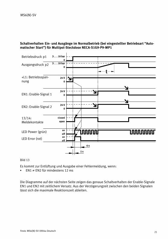
Schaltverhalten Ein− und Ausgänge im Normalbetrieb (bei eingestellter Betriebsart �Auto�matischer Start") für Multipol−Steckdose NECA−S1G9−P9−MP1
Betriebsdruck p1
Ausgangsdruck p2
+L1: Betriebsspan�nung
EN1: Enable−Signal 1
EN2: Enable−Signal 2
13/14:Meldekontakte
LED Power (grün)
LED Error (rot)
Bild�13
Es kommt zur Entlüftung und Ausgabe einer Fehlermeldung, wenn:S EN1 � EN2 für mindestens 12�ms
Die Diagramme auf der nächsten Seite zeigen das genaue Schaltverhalten der Enable−SignaleEN1 und EN2 mit zeitlichem Versatz. Aus der Verzögerungzeit zwischen den beiden Signalenlässt sich die maximale Reaktionszeit ableiten.

MS6(N)−SV
Festo MS6(N)−SV 0904a Deutsch22
EN2 vor EN1 (für Multipol−Steckdose NECA−S1G9−P9−MP1)
EN2: Enable−Signal 2
EN1: Enable−Signal 1
13/14: Melde�kontakte
Max. Reaktionszeit von der Entlüftung bis Belüftung: t2 + t1 = 75�ms + 5�ms = 80�msMax. Reaktionszeit von der Belüftung bis Entlüftung: t3 + t4 = 15�ms + 2�ms = 17�ms
EN1 vor EN2 (für Multipol−Steckdose NECA−S1G9−P9−MP1)
EN2: Enable−Signal 2
EN1: Enable−Signal 1
13/14: Melde�kontakte
Max. Reaktionszeit von der Entlüftung bis Belüftung: t2 + t1 + t4 = 75�ms + 5�ms + 2�ms = 82�msMax. Reaktionszeit von der Belüftung bis Entlüftung: t2 + t3 + t4 = 75�ms + 15�ms + 2�ms = 92�ms
t1 > 5�ms: Pegel von EN2/EN1 muss min. 5�ms HIGH sein (Entprellzeit/Eingangsfilter/Stabili�sierungszeit).
t2 <= 75�ms: Max. zulässige Verzögerungszeit zwischen EN1 und EN2. Bei Überschreiten wirddas MS6(N)−SV nicht belüftet und eine Fehlermeldung ausgegeben.
t3 >= 15�ms: Pegel von EN2/EN1 muss min. 15�ms LOW sein (Entprellzeit/Eingangsfilter/Stabili�sierungszeit).
t4 = 2�ms: Max. interne Verzögerungszeit bedingt durch den Programmablauf.tp1 } 2: Belüftungtp2 } 3: Entlüftung
Bild�14
MS6(N)−SV
Festo MS6(N)−SV 0904a Deutsch 23
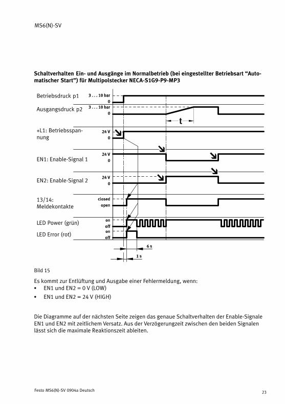
Schaltverhalten Ein− und Ausgänge im Normalbetrieb (bei eingestellter Betriebsart �Auto�matischer Start") für Multipolstecker NECA−S1G9−P9−MP3
Betriebsdruck p1
Ausgangsdruck p2
+L1: Betriebsspan�nung
EN1: Enable−Signal 1
EN2: Enable−Signal 2
13/14:Meldekontakte
LED Power (grün)
LED Error (rot)
Bild�15
Es kommt zur Entlüftung und Ausgabe einer Fehlermeldung, wenn:S EN1 und EN2 = 0 V (LOW)
S EN1 und EN2 = 24�V (HIGH)
Die Diagramme auf der nächsten Seite zeigen das genaue Schaltverhalten der Enable−SignaleEN1 und EN2 mit zeitlichem Versatz. Aus der Verzögerungzeit zwischen den beiden Signalenlässt sich die maximale Reaktionszeit ableiten.

MS6(N)−SV
Festo MS6(N)−SV 0904a Deutsch24
EN2 vor EN1 (für Multipol−Steckdose NECA−S1G9−P9−MP3)
EN2: Enable−Signal 2
EN1: Enable−Signal 1
13/14: Melde�kontakte
Max. Reaktionszeit von der Entlüftung bis Belüftung: t2 + t1 = 75�ms + 5�ms = 80�msMax. Reaktionszeit von der Belüftung bis Entlüftung: t3 + t4 = 15�ms + 2�ms = 17�ms
EN1 vor EN2 (für Multipol−Steckdose NECA−S1G9−P9−MP3)
EN2: Enable−Signal 2
EN1: Enable−Signal 1
13/14: Melde�kontakte
Max. Reaktionszeit von der Entlüftung bis Belüftung: t2 + t1 + t4 = 75�ms + 5�ms + 2�ms = 82�msMax. Reaktionszeit von der Belüftung bis Entlüftung: t2 + t3 + t4 = 75�ms + 15�ms + 2�ms = 92�ms
t1 > 5�ms: Pegel von EN2 (EN1) muss min. 5�ms HIGH (LOW) sein (Entprellzeit/Eingangsfilter/Stabilisierungszeit).
t2 <= 75�ms: Max. zulässige Verzögerungszeit zwischen EN1 und EN2. Bei Überschreiten wirddas MS6(N)−SV nicht belüftet und eine Fehlermeldung ausgegeben.
t3 >= 15�ms: Pegel von EN2 (EN1) muss min. 15�ms LOW (HIGH) sein (Entprellzeit/Eingangsfil�ter/Stabilisierungszeit).
t4 = 2�ms: Max. interne Verzögerungszeit bedingt durch den Programmablauf.tp1 } 2: Belüftungtp2 } 3: Entlüftung
Bild�16

MS6(N)−SV
Festo MS6(N)−SV 0904a Deutsch 25
8 Betrieb
SicherheitshinweisIm prozesssicheren (d.�h. belüfteten) Zustand wird das mechanische Systemdes MS6(N)−SV nicht getestet. Liegt die prozessbedingte Schalthäufigkeit(sicheres Entlüften) bei weniger als einmal pro Monat, muss vom Maschinenbe�treiber eine Zwangsabschaltung herbeigeführt werden.
HinweisDie Pausendauer nach dem Entlüften beträgt 1�s. Erst nach dieser Zeit wird einerneutes Einschalten akzeptiert und durchgeführt.
9 Wartung und Pflege
S Schalten Sie zur äußeren Reinigung folgende Energiequellen ab:
� Betriebsspannung� Druckluft.
S Reinigen Sie bei Bedarf das MS6(N)−SV von außen.
Zulässige Reinigungsmedien sind Seifenlauge (max. +50 °C), Waschbenzin und allewerkstoffschonenden Medien.
10 Ausbau
1. Schalten Sie zum Ausbau folgende Energiequellen ab:
� Betriebsspannung� Druckluft.
2. Trennen Sie die jeweiligen Anschlüsse vom MS6(N)−SV.

MS6(N)−SV
Festo MS6(N)−SV 0904a Deutsch26
11 Außerbetriebnahme und Entsorgung
Das Produkt kann in Abstimmung mit dem Entsorger komplett dem Metallrecyclingzugeführt werden (z.�B. EAK�17�04�02). Gegebenenfalls ist der Elektronikblock zudemontieren, der keine gefährlichen Bauteile enthält, und separat dem Elektronik�schrottrecycling zuzuführen ist (EAK�16�02�16).
12 Zubehör
Bezeichnung Typ
Multipol−Steckdose NECA−S1G9−P9−MP1
NECA−S1G9−P9−MP3
Schalldämpfer UOS−1
Bild�17
MS6(N)−SV
Festo MS6(N)−SV 0904a Deutsch 27
13 Diagnose und Fehlerbehandlung
LED−Anzeige
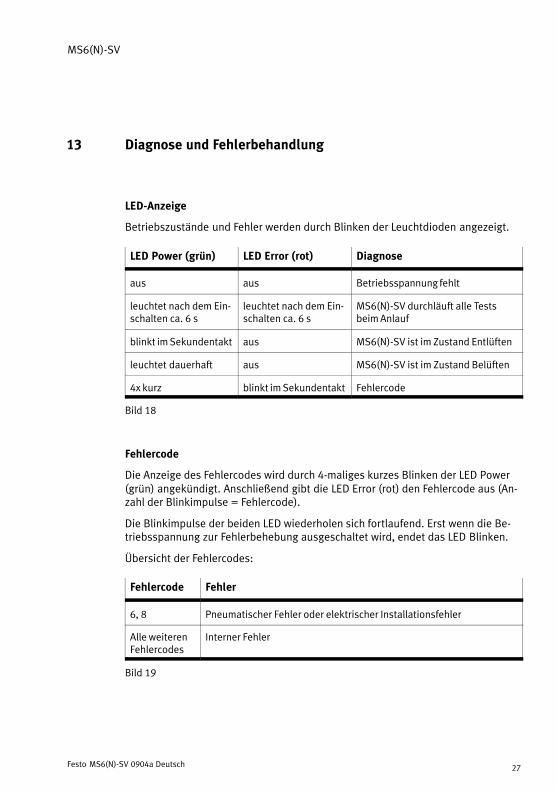
Betriebszustände und Fehler werden durch Blinken der Leuchtdioden angezeigt.
LED Power (grün) LED Error (rot) Diagnose
aus aus Betriebsspannung fehlt
leuchtet nach dem Ein�schalten ca. 6 s
leuchtet nach dem Ein�schalten ca. 6 s
MS6(N)−SV durchläuft alle Testsbeim Anlauf
blinkt im Sekundentakt aus MS6(N)−SV ist im Zustand Entlüften
leuchtet dauerhaft aus MS6(N)−SV ist im Zustand Belüften
4x kurz blinkt im Sekundentakt Fehlercode
Bild�18
Fehlercode
Die Anzeige des Fehlercodes wird durch 4−maliges kurzes Blinken der LED Power(grün) angekündigt. Anschließend gibt die LED Error (rot) den Fehlercode aus (An�zahl der Blinkimpulse = Fehlercode).
Die Blinkimpulse der beiden LED wiederholen sich fortlaufend. Erst wenn die Be�triebsspannung zur Fehlerbehebung ausgeschaltet wird, endet das LED Blinken.
Übersicht der Fehlercodes:
Fehlercode Fehler
6, 8 Pneumatischer Fehler oder elektrischer Installationsfehler
Alle weiterenFehlercodes
Interner Fehler
Bild�19

MS6(N)−SV
Festo MS6(N)−SV 0904a Deutsch28
Beispiel für Fehlercode 6
1 2 1
Bild�20
Nach 4 kurzen Blinkimpulsen der LED Power 1 folgen 6 lange Blinkimpulse derLED Error 2. Damit wird Fehlercode 6, ein pneumatischer Fehler, signalisiert. Einpneumatischer Fehler tritt auf, wenn z.�B. der Betriebsdruck unter dem erforder�lichen Mindestdruck oder überhaupt nicht anliegt.
Störungsbeseitigung bei auftretendem Fehlercode:
� Überprüfen Sie die Druckluftversorgung
� Überprüfen Sie die Spannungsversorgung
� Überprüfen Sie die Installation der Signalleitungen
� Nehmen Sie das Gerät in Betrieb (è Kapitel 7 �Inbetriebnahme")
� Tauschen Sie das Gerät aus, falls der Fehler erneut auftritt

MS6(N)−SV
Festo MS6(N)−SV 0904a Deutsch 29
14 Technische Daten
Sicherheitstechnische Kenngrößen
Typ MS6−SV MS6N−SV
Entspricht Norm� Kategorie� Max. erreichbarer Performance−Level� MTTFd−Wert� B10d−Wert
DIN�EN�ISO�13849−1� Kategorie 3 + 4� PL��e"� 200�Jahre (= hoch)� 500�000�Schaltspiele
Entspricht Norm� Max. erreichbarer Safety Integrity Level� PFHd−Wert
EN�61508� SIL��3"� 10−8�<�PFHd�<�10−7
Max. Einsatzdauer 20 Jahre
Sicherheitshinweis Schaltfrequenz min. 1/Monat
Allgemeine Daten
Typ MS6−SV MS6N−SV
Pneumatischer Anschluss 1, 2Pneumatischer Anschluss 3
G½ (ISO�228)G1 (ISO�228)
NPT½−14NPT1
Einbaulage beliebig
Betriebsmedium gefilterte Druckluft, geölt oder ungeölt,Filterfeinheit 40��m
Ventilfunktion 3/2−Wegeventil, monostabil geschlossen
Steuerart direkt
Steuerluftversorgung intern
Strömungsrichtung nicht reversibel
Betriebsdruck p1Durchschaltdruck
[bar][bar]
3,5 � 10ca. 50% von p1 (è Bild�22)

MS6(N)−SV
Festo MS6(N)−SV 0904a Deutsch30
Typ MS6N−SVMS6−SV
Restdruck im Normalbetrieb [bar] 0 (restdruckfrei)
Max. Restdruck im Fehlerfall(worst case)
[bar] 0,4 (bei p1 = 10�bar und voll geöffneterDrossel)
Normalnenndurchfluss 1 −−> 2 [l/min] 4�300 (bei p1 = 6�bar, p2 = 5�bar)
Normaldurchfluss 2 −−> 3 [l/min] 9�000 (bei p1 = 6�bar)
Min. Normaldurchfluss 2 −−> 3im kritischsten Fehlerfall
[l/min] 6�000 (bei p1 = 6�bar)
C−Wert [l/(s*bar)] 19,3
b−Wert 0,21
UmgebungstemperaturMediumstemperatur
[°C][°C]
−10 � +50 (0 � +50 mit Drucksensor)−10 � +50 (0 � +50 mit Drucksensor)
Elektrischer Anschluss Sub−D, 9−polig (das Produkt darf nur mitden zugehörigen Multipol−SteckdosenNECA−S1G9−P9−MP� betrieben werden)
Spannungsversorgung� Nennwert� Toleranz
[V�DC][V�DC]
2421,6���26,4
Max. Stromaufnahme� beim Einschalten� im Normalbetrieb
[A][A]
1,00,12
Schutz gegen elektrischen Schlag (Schutzgegen direktes und indirektes Berührennach EN 60204−1/IEC 204)
durch PELV−Netzteil
Schaltstellungsanzeige LED und potenzialfreier Kontakt
Halbleiterrelais (Meldekontakt 13/14)
� Max. Spannung� Max. kontinuierlicher Strom� Max. Widerstand im einge�
schalteten Zustand� Max. Leckagestrom im aus�
geschalteten Zustand
[V][A]
[�]
[�A]
600,12
25 (typ. 18)
1

MS6(N)−SV
Festo MS6(N)−SV 0904a Deutsch 31
Typ MS6N−SVMS6−SV
Schaltzeit� aus� ein
[ms][ms]
40130
Min. Pausenzeit nach einer Ent�lüftung
[s] 1
Schalldruckpegel [dB(A)] 75 mit Schalldämpfer UOS−1
Schutzklasse III
Schutzart nach IEC�60529 IP65 mit Multipol−Steckdose NECA
CE−Zeichen (è Konformitätserklärung) nach EU−EMV−Richtlinie
Zulassung BGIA (è Konformitätserklärung)
Brandklasse nach UL94 V0−V2
Bild�21

MS6(N)−SV
Festo MS6(N)−SV 0904a Deutsch32
Durchschaltdruck
Mit der im Deckel befindlichen Drosselschraube wird ein langsamer Druckaufbauvon Ausgangsdruck p2 erzeugt. Durch Drehen der Drosselschraube kann derDruckanstieg eingestellt werden. Hat der Ausgangsdruck p2 ca. 50% vom Be�triebsdruck p1 erreicht, öffnet das Ventil und am Ausgang liegt der volle Betriebs�druck p1 an.
Toleranzbereich
t
100%
Befüllzeit über Drossel
einstellbar
70%
50%
30%
p Durchschaltpunkt
Bild�22
Beispiel:
Ist der Betriebsdruck p1 = 4 bar, so ist unter Beachtung der zulässigen Toleranzvon ±20% ein Durchschaltdruck von 1,2 bis 2,8 bar zulässig.

MS6(N)−SV
Festo MS6(N)−SV 0904a Deutsch 33
Durchfluss qn in Abhängigkeit von der Anzahl Umdrehungen n der Drossel�schraube
p1: 4�bar
p1: 6�bar
p1: 8�bar
p1: 10�bar
Bild�23
MS6(N)−SV
Festo MS6(N)−SV 0904a Deutsch34
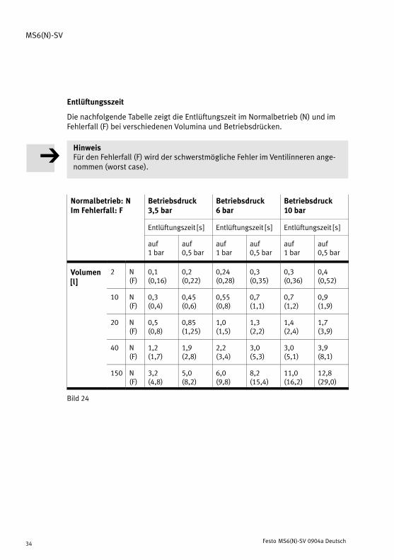
Entlüftungsszeit
Die nachfolgende Tabelle zeigt die Entlüftungszeit im Normalbetrieb (N) und imFehlerfall (F) bei verschiedenen Volumina und Betriebsdrücken.
HinweisFür den Fehlerfall (F) wird der schwerstmögliche Fehler im Ventilinneren ange�nommen (worst case).
Normalbetrieb: NIm Fehlerfall: F
Betriebsdruck3,5�bar
Betriebsdruck6�bar
Betriebsdruck10�bar
Entlüftungszeit [s] Entlüftungszeit [s] Entlüftungszeit [s]
auf1�bar
auf0,5�bar
auf1�bar
auf0,5�bar
auf1�bar
auf0,5�bar
Volumen[l]
2 N(F)
0,1(0,16)
0,2(0,22)
0,24(0,28)
0,3(0,35)
0,3(0,36)
0,4(0,52)[ ]
10 N(F)
0,3(0,4)
0,45(0,6)
0,55(0,8)
0,7(1,1)
0,7(1,2)
0,9(1,9)
20 N(F)
0,5(0,8)
0,85(1,25)
1,0(1,5)
1,3(2,2)
1,4(2,4)
1,7(3,9)
40 N(F)
1,2(1,7)
1,9(2,8)
2,2(3,4)
3,0(5,3)
3,0(5,1)
3,9(8,1)
150 N(F)
3,2(4,8)
5,0(8,2)
6,0(9,8)
8,2(15,4)
11,0(16,2)
12,8(29,0)
Bild�24
MS6(N)−SV
Festo MS6(N)−SV 0904a English 35
Soft start/quick exhaust valve MS6(N)−SVEnglish
Contents
1 Operating elements and ports 36 . . . . . . . . . . . . . . . . . . . . . . . . . . . . . . . . . .
2 Function and application 37 . . . . . . . . . . . . . . . . . . . . . . . . . . . . . . . . . . . . . . .
3 Conditions for the safe use of the product 38 . . . . . . . . . . . . . . . . . . . . . . . . .
4 Mechanical/pneumatic installation 40 . . . . . . . . . . . . . . . . . . . . . . . . . . . . . . Mechanical 40 . . . . . . . . . . . . . . . . . . . . . . . . . . . . . . . . . . . . . . . . . . . . . . . . . .
Pneumatic � connection 1 and 2 (thread size G½ or NPT½−14) 42 . . . . . . . .
Pneumatic � connection 3 (thread size G1 or NPT1) 42 . . . . . . . . . . . . . . . . . .
5 Electrical connection 43 . . . . . . . . . . . . . . . . . . . . . . . . . . . . . . . . . . . . . . . . . .
6 Connection examples (electrical) 45 . . . . . . . . . . . . . . . . . . . . . . . . . . . . . . . . MS6(N)−SV with NECA−S1G9−P9−MP1 multi−pin plug socket 46 . . . . . . . . . . .
MS6(N)−SV with NECA−S1G9−P9−MP3 multi−pin plug socket 48 . . . . . . . . . . .
Automatic start / Monitored start operation modes 49 . . . . . . . . . . . . . . . . .
Signal contacts 13/14 51 . . . . . . . . . . . . . . . . . . . . . . . . . . . . . . . . . . . . . . . . . .
7 Commissioning 52 . . . . . . . . . . . . . . . . . . . . . . . . . . . . . . . . . . . . . . . . . . . . . . .
8 Operation 57 . . . . . . . . . . . . . . . . . . . . . . . . . . . . . . . . . . . . . . . . . . . . . . . . . . .
9 Care and maintenance 57 . . . . . . . . . . . . . . . . . . . . . . . . . . . . . . . . . . . . . . . . .
10 Dismantling 57 . . . . . . . . . . . . . . . . . . . . . . . . . . . . . . . . . . . . . . . . . . . . . . . . .
11 Removal from operation and disposal 58 . . . . . . . . . . . . . . . . . . . . . . . . . . . .
12 Accessories 58 . . . . . . . . . . . . . . . . . . . . . . . . . . . . . . . . . . . . . . . . . . . . . . . . . .
13 Diagnostics and error handling 59 . . . . . . . . . . . . . . . . . . . . . . . . . . . . . . . . . LED display 59 . . . . . . . . . . . . . . . . . . . . . . . . . . . . . . . . . . . . . . . . . . . . . . . . . .
Fault code 59 . . . . . . . . . . . . . . . . . . . . . . . . . . . . . . . . . . . . . . . . . . . . . . . . . . .
14 Technical specifications 61 . . . . . . . . . . . . . . . . . . . . . . . . . . . . . . . . . . . . . . .
MS6(N)−SV
Festo MS6(N)−SV 0904a English36
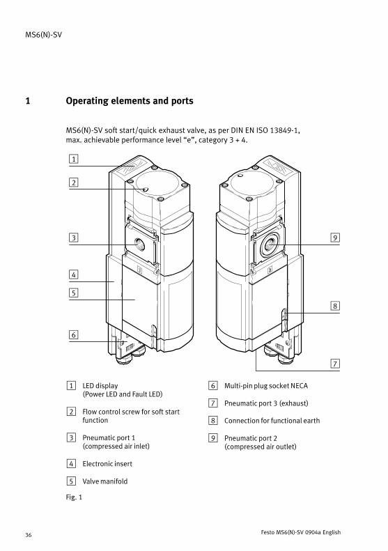
1 Operating elements and ports
MS6(N)−SV soft start/quick exhaust valve, as per DIN�EN�ISO�13849−1,max.achievable performance level �e", category 3 + 4.
8
7
6
5
1
2
3
4
9
1 LED display (Power LED and Fault LED)
2 Flow control screw for soft startfunction
3 Pneumatic port 1 (compressed air inlet)
4 Electronic insert
5 Valve manifold
6 Multi−pin plug socket NECA
7 Pneumatic port 3 (exhaust)
8 Connection for functional earth
9 Pneumatic port 2 (compressed air outlet)
Fig.�1
MS6(N)−SV
Festo MS6(N)−SV 0904a English 37
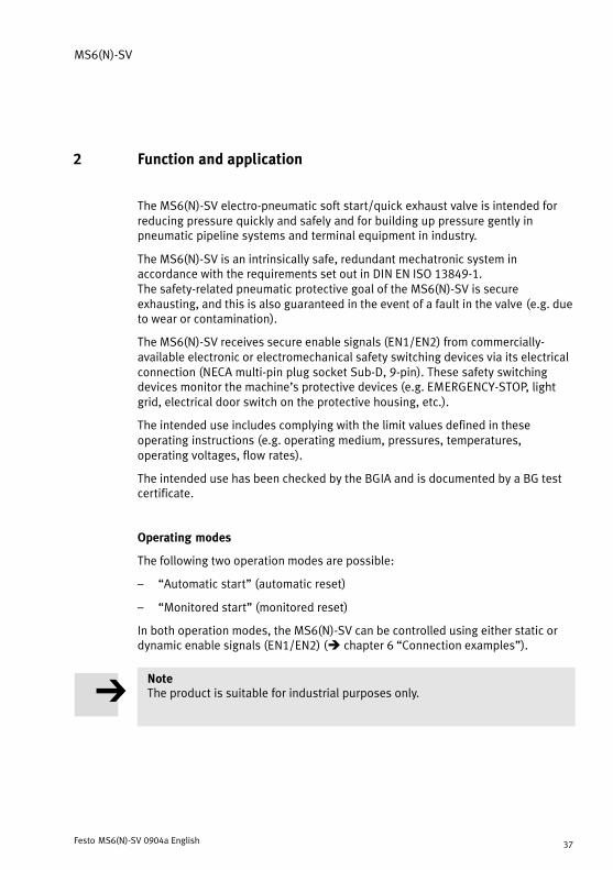
2 Function and application
The MS6(N)−SV electro−pneumatic soft start/quick exhaust valve is intended forreducing pressure quickly and safely and for building up pressure gently inpneumatic pipeline systems and terminal equipment in industry.
The MS6(N)−SV is an intrinsically safe, redundant mechatronic system inaccordance with the requirements set out in DIN�EN�ISO�13849−1. The safety−related pneumatic protective goal of the MS6(N)−SV is secureexhausting, and this is also guaranteed in the event of a fault in the valve (e.g.�dueto wear or contamination).
The MS6(N)−SV receives secure enable signals (EN1/EN2) from commercially−available electronic or electromechanical safety switching devices via its electricalconnection (NECA multi−pin plug socket Sub−D, 9−pin). These safety switchingdevices monitor the machine’s protective devices (e.g.�EMERGENCY−STOP, lightgrid, electrical door switch on the protective housing, etc.).
The intended use includes complying with the limit values defined in theseoperating instructions (e.g.�operating medium, pressures, temperatures,operating voltages, flow rates).
The intended use has been checked by the BGIA and is documented by a BG testcertificate.
Operating modes
The following two operation modes are possible:
� �Automatic start" (automatic reset)
� �Monitored start" (monitored reset)
In both operation modes, the MS6(N)−SV can be controlled using either static ordynamic enable signals (EN1/EN2) (è chapter 6 �Connection examples").
NoteThe product is suitable for industrial purposes only.

MS6(N)−SV
Festo MS6(N)−SV 0904a English38
3 Conditions for the safe use of the product
The MS6(N)−SV was developed and produced in careful compliance with therelevant norms and directives, as well as the approved technical rules. However,the device’s protective function can be impaired if the device is not used asintended. This could endanger the lives and physical condition of persons.
Installation and commissioning
The device must only be installed and commissioned by trained specialists. The MS6(N)−SV must only be connected and operated using the values specified inchapter 14, �Technical data".
WarningThe use of impermissible media can damage the product.
S Do not use the MS6(N)−SV together with inflammable gases or acid. Thedevice is only intended for use with media listed as appropriate in thetechnical data.
S Remove all transport packing such as protective wax, foils (polyamide), caps(polyethylene), cardboard boxes (except for the sealing elements of thepneumatic connections).
The packing is intended for recycling (except for: oiled paper = other waste).
S Check the device for damage caused during transport. Only install undamageddevices in their original condition.
S Remove dirt particles in the supply lines by blowing through the tubing andhoses. In this way you will protect the MS6(N)−SV from premature failure orheavy wear (è DIN�ISO�4414, section 9.4).

MS6(N)−SV
Festo MS6(N)−SV 0904a English 39
Operation and maintenance
The operator is responsible for complying with the locally−applicable safetyregulations.
S Check the ambient conditions on−site and the limit values for the case ofapplication. The device must only be installed if all the values are within thepermissible range (è chapter 14, �Technical data")
S The device must only be used in its original condition and withoutunauthorised modifications.
NoteIn the event of damage caused by unauthorised manipulation or use other thanthat intended, the guarantee is invalidated and the manufacturer is not liablefor damages.

MS6(N)−SV
Festo MS6(N)−SV 0904a English40
4 Mechanical/pneumatic installation
Mechanical
NoteInformation about fitting module connectors, sub−bases and mounting bracketscan be found in the operating instructions enclosed with the relevantaccessories.
S Place the MS6(N)−SV as close aspossible to the location where it willbe used.
S Place the MS6(N)−SV so that you willhave sufficient space to connect themulti−pin plug socket and thesilencer (è�Fig.�2 with a UOS−1silencer from Festo).
S Observe the minimum permissibledistance from the wall of 32�mm(è�Fig.�2).
If using the MS6−WPB mountingbracket from Festo, this minimumdistance is guaranteed.
S It can be fitted in any position.
S Note the direction of flow from1to2. The numbers 1 on the producthousing serve as a guide (è�Fig.�3).
Fig.�2
Fig.�3
1

MS6(N)−SV
Festo MS6(N)−SV 0904a English 41
Combination with service units of the MS series
WarningIncorrectly installing the device in the service unit combination can impair theMS6(N)−SV’s safety function.
S Only devices that do not impede the MS6(N)−SV’s pneumatic safety measure(safe exhausting) may be placed after the MS6(N)−SV.
If fitted together with one or several existing service units of the same series(èFig.�4):
1. Remove the MS6−END cover cap ( 1 ), if fitted, from the side to be combined(push upwards).
2. Place the MS6−MV module connectors ( 2 ) in the grooves of the individualunits. There must be a seal between the individual units.
3. Fasten the MS6−MV module connectors with two screws.
max 1.2�Nm
1
2
1 MS6−END cover cap 2 MS6−MV module connector
Fig.�4
MS6(N)−SV
Festo MS6(N)−SV 0904a English42
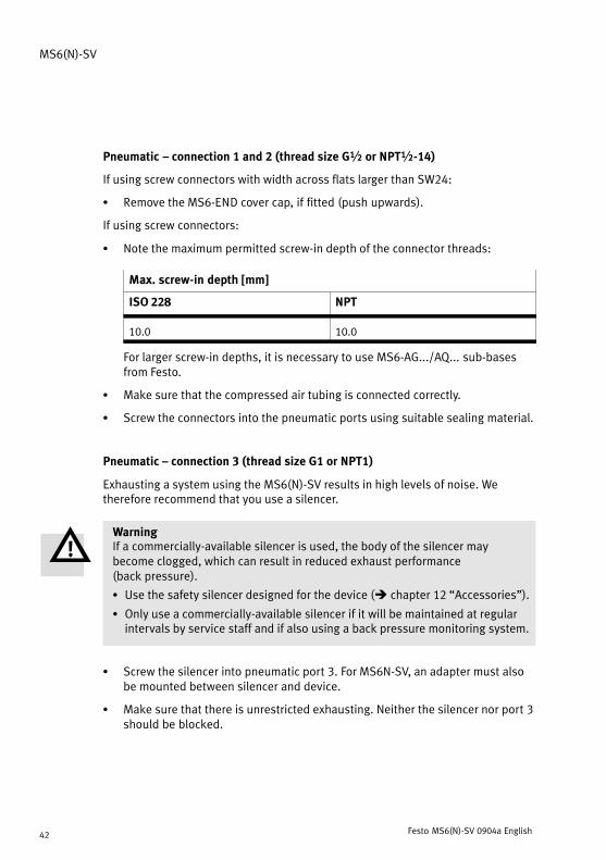
Pneumatic � connection 1 and 2 (thread size G½ or NPT½−14)
If using screw connectors with width across flats larger than SW24:
S Remove the MS6−END cover cap, if fitted (push upwards).
If using screw connectors:
S Note the maximum permitted screw−in depth of the connector threads:
Max. screw−in depth [mm]
ISO 228 NPT
10.0 10.0
For larger screw−in depths, it is necessary to use MS6−AG.../AQ... sub−basesfrom Festo.
S Make sure that the compressed air tubing is connected correctly.
S Screw the connectors into the pneumatic ports using suitable sealing material.
Pneumatic � connection 3 (thread size G1 or NPT1)
Exhausting a system using the MS6(N)−SV results in high levels of noise. Wetherefore recommend that you use a silencer.
WarningIf a commercially−available silencer is used, the body of the silencer maybecome clogged, which can result in reduced exhaust performance(backpressure).
S Use the safety silencer designed for the device (è�chapter 12 �Accessories").
S Only use a commercially−available silencer if it will be maintained at regularintervals by service staff and if also using a back pressure monitoring system.
S Screw the silencer into pneumatic port3. For MS6N−SV, an adapter must alsobe mounted between silencer and device.
S Make sure that there is unrestricted exhausting. Neither the silencer nor port3should be blocked.

MS6(N)−SV
Festo MS6(N)−SV 0904a English 43
5 Electrical connection
WarningElectrical connections should be established only in the absence of voltage andby qualified personnel.
WarningUse only power units which guarantee reliable electrical isolation of theoperating voltage as per IEC/DIN EN 60204−1. Observe also the generalrequirements for PELV power circuits as per IEC/DIN EN 60204−1.
NoteLong signal cables reduce the immunity to interference.
S Make sure that the signal cables are not longer than 20 m.
Connect the earth cable
1. Fit the earth cable ( 2 ) and the twotoothed discs to the functional earthconnection using the enclosed screw( 1 ) (è�Fig.�5).
There must be one toothed disc oneach side of the cable lug.
2. Connect the earth connection withlow impedance (short cable withlarge cross−sectional area) to theearth potential.
You can thereby avoid interferencefrom electromagnetic sources andensure electromagnetic compatibilityin accordance with EMC directives.
Fig.�5
1
2

MS6(N)−SV
Festo MS6(N)−SV 0904a English44
Connect multi−pin plug socket
NoteThe MS6(N)−SV may only be used with the approved NECA−...−MP... multi−pinplug sockets (è Fig.�6). For information about terminal connections, see theassembly instructions enclosed with each multi−pin plug socket.
S Connect the multi−pin plug socket.
Make sure that the screws are fastened tightly in order to guarantee protectionclass IP65. The maximum tightening torque is 0.4 ±0.1�Nm.
Fig.�6
NECA−S1G9−P9−MP3
NECA−S1G9−P9−MP1

MS6(N)−SV
Festo MS6(N)−SV 0904a English 45
Inputs and outputs
Terminal inmulti−pin plugsocket NECA
I/O Assignment
1 EN1 Enable signal 1(static or dynamic)
as per EN�61131−2type�2, max. 6�mA
è examples in chapter 6,�Connection examples"
2 EN2 Enable signal 2(static or dynamic)
as per EN�61131−2type�2, max. 6�mA
è examples in chapter 6,�Connection examples"
3 13 Signal contacts, NO potential−freeMax 120 mA
è examples in chapter 6,�C ti l "
4 14Max. 120�mA
p p�Connection examples"
5 A5 Contact for �Automaticstart" operation mode
è examples in chapter 6,�Connection examples"
6 S34 Contact for �Automaticstart" or �Monitoredstart" operation mode
as per EN�61131−2type�2, max. 6�mA
è examples in chapter 6,�Connection examples"
7 � �
8 +L1 Operating voltage +24�V�DC ±10 %
9 M GND
Fig.�7
6 Connection examples (electrical)
NoteThe wires for the enable signals should be laid separately from the powersupply. In addition, the wires should be protected against damage usingsuitable measures.
NoteFor easier commissioning, we recommend planning a reset button (normallyclosed) in the power supply circuit. This simplifies resetting in case of fault.
MS6(N)−SV
Festo MS6(N)−SV 0904a English46
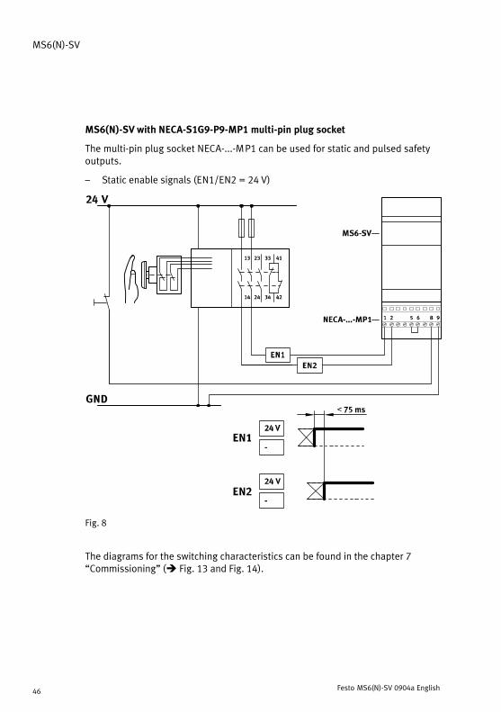
MS6(N)−SV with NECA−S1G9−P9−MP1 multi−pin plug socket
The multi−pin plug socket NECA−...−MP1 can be used for static and pulsed safetyoutputs.
� Static enable signals (EN1/EN2 = 24�V)
Fig.�8
The diagrams for the switching characteristics can be found in the chapter 7�Commissioning" (è�Fig.�13 and Fig.�14).

MS6(N)−SV
Festo MS6(N)−SV 0904a English 47
� Pulsed enable signals (EN1/EN2) for cross−circuit recognition
Cross−circuit recognition by means of clock signals is carried out through thesafety switching device/safety PLC.
Fig.�9
NoteSince the clock outputs of various controller producers are not standardised,suitability must be checked in each case. If the clock is outside the describedlimits, the MS6(N)−SV recognises this as a fault and performs a safedisconnection.

MS6(N)−SV
Festo MS6(N)−SV 0904a English48
MS6(N)−SV with NECA−S1G9−P9−MP3 multi−pin plug socket
� Static enable signals (EN1 = 0�V, EN2 = 24�V)
� Cross circuit monitoring possible with static signals.
Advantage: A cross circuit in the EN1 and EN2 wires prevents the valve fromstarting up unintentionally.
Fig.�10
The diagrams for the switching characteristics can be found in the chapter 7�Commissioning" (è�Fig.�15 and Fig.�16).

MS6(N)−SV
Festo MS6(N)−SV 0904a English 49
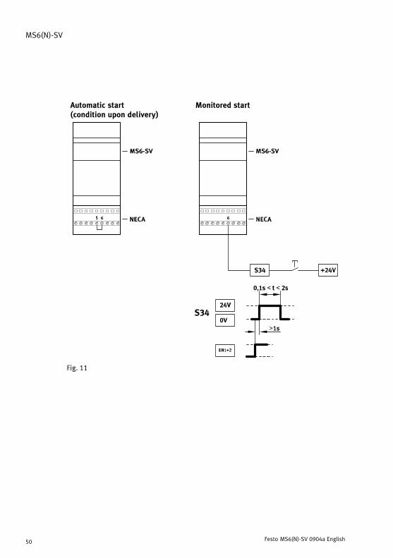
Automatic start / Monitored start operation modes
Operation modes (è Fig.�11):
� The �Automatic start" (automatic reset) operation mode is preset with acurrent bridge from terminal 5 to terminal 6 in the multi−pin plug socket(ondelivery).
� The �Monitored start" (monitored reset) operation mode should be seen as asubordinate start from the perspective of the entire system. The enable signalfrom the safety relay or the control system always has priority.
NoteThe impulse generated by the start button has to be within a time−frame of0.1s and 2�s.
If the start button is held down for too long or locked down, the systemidentifies a cross circuit and the device is placed in fault mode.
NoteThe start signal for S34 must not be generated until 1�s after the enable signalsEN1/EN2 are created.
If the start signal is made before or simultaneously with the enable signals, itwill not be recognised and will have to be made again.
MS6(N)−SV
Festo MS6(N)−SV 0904a English50
Automatic start (condition upon delivery)
Monitored start
Fig.�11

MS6(N)−SV
Festo MS6(N)−SV 0904a English 51
Signal contacts 13/14
The signal contacts 13/14 are potential−free normally open contacts of asemiconductor relay. Through terminals 3 and 4 of the NECA multi−pin plug socket,the message can be picked up in the feedback circuit of a safety control system.Alternatively, the information can be reported back to the controller via anattached pressure sensor (only MS6(N)−SV−...−AD...).
NoteAssignment of these contacts is not required to achieve the safety category.
Fig.�12
The diagrams for the switching characteristics can be found in the chapter 7�Commissioning" (with multi−pin plug socket NECA−S1G9−P9−MP1 è Fig.�13 andFig.�14 / with multi−pin plug socket NECA−S1G9−P9−MP3 è Fig.�15 and Fig.�16).

MS6(N)−SV
Festo MS6(N)−SV 0904a English52
7 Commissioning
The following description of commissioning is graphically supported by thediagrams on the next pages (with multi−pin plug socket NECA−S1G9−P9−MP1èFig.�13 and Fig.�14 / with multi−pin plug socket NECA−S1G9−P9−MP3 è Fig.�15and Fig.�16). The diagrams show the switching characteristics of the inputs andoutputs in normal operation (if the �Automatic start" operation mode has beenset). The operator’s actions are marked on the diagram by an arrow.
To start up the device, proceed as follows:
1. Apply operating pressure p1.
2. Switch on the operating voltage for the MS6(N)−SV.
After 1�s the two LEDs Power (green) and Error (red) light up for around 6�s.During this time, the device automatically tests itself for faults. A shortexhaust of air from the silencer identifies this fact.
Then the LED Error (red) goes out. The Power LED (green) starts to flash. The MS6(N)−SV is ready for operation.
The valve is tested pneumatically in a self−test once an hour for as long as thedevice remains in this state.
3. Create EN1/EN2 enable signals (in �Monitored start" operation mode, therealso needs to be a start signal at S34 è Fig.�11).
Power LED (green) lights up. Output pressure p2 is built up slowly.
The duration (�t") of the pressure build−up is adjusted using the flow controlscrew attached to the cap. The output pressure rises in accordance with theflow control setting (è Fig.�23). When the switch−through pressure is reached(approx.�50 % of operating pressure p1), the valve’s main seat opens(èFig.�22). The MS6(N)−SV is then ready for operation.
No further settings are required.

MS6(N)−SV
Festo MS6(N)−SV 0904a English 53
Input and output switching characteristics in normal operation (when the �Automatic start"operation mode is set) for NECA−S1G9−P9−MP1 multi−pin plug socket
Operat. pressure p1
Output pressure p2
+L1: Operating voltage
EN1: Enable signal 1
EN2: Enable signal 2
13/14: Signal contacts
Power LED (green)
Fault LED (red)
Fig.�13
Venting and output of an error message occurs when:
S EN1 � EN2 for at least 12�ms
The diagrams on the next page show the precise switching characteristics of the Enable signalsEN1 and EN2 with a time offset. The maximum reaction time can be derived from the delaybetween the two signals.
MS6(N)−SV
Festo MS6(N)−SV 0904a English54
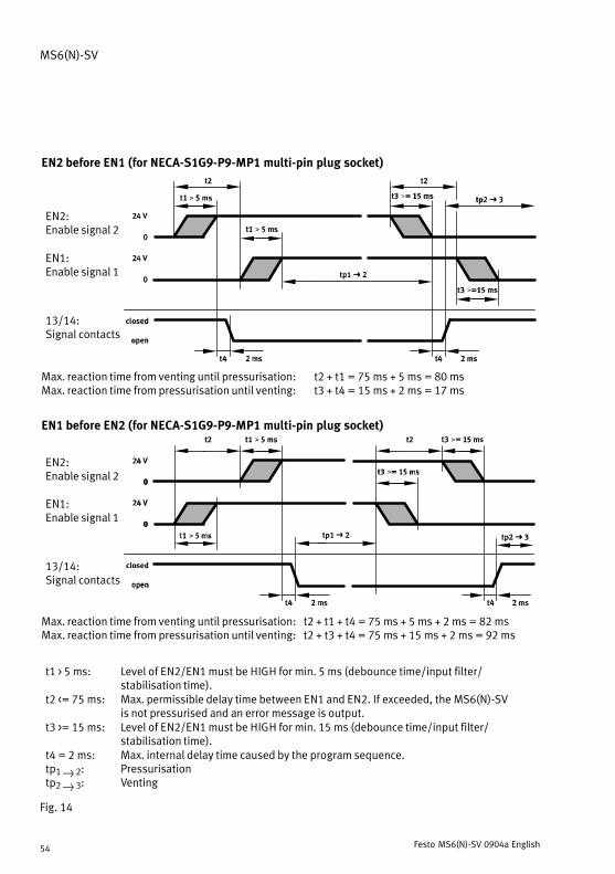
EN2 before EN1 (for NECA−S1G9−P9−MP1 multi−pin plug socket)
EN2: Enable signal 2
EN1: Enable signal 1
13/14: Signal contacts
Max. reaction time from venting until pressurisation: t2 + t1 = 75�ms + 5�ms = 80�msMax. reaction time from pressurisation until venting: t3 + t4 = 15�ms + 2�ms = 17�ms
EN1 before EN2 (for NECA−S1G9−P9−MP1 multi−pin plug socket)
EN2: Enable signal 2
EN1: Enable signal 1
13/14: Signal contacts
Max. reaction time from venting until pressurisation: t2 + t1 + t4 = 75�ms + 5�ms + 2�ms = 82�msMax. reaction time from pressurisation until venting: t2 + t3 + t4 = 75�ms + 15�ms + 2�ms = 92�ms
t1 > 5�ms: Level of EN2/EN1 must be HIGH for min. 5�ms (debounce time/input filter/stabilisation time).
t2 <= 75�ms: Max. permissible delay time between EN1 and EN2. If exceeded, the MS6(N)−SVis not pressurised and an error message is output.
t3 >= 15�ms: Level of EN2/EN1 must be HIGH for min. 15�ms (debounce time/input filter/stabilisation time).
t4 = 2�ms: Max. internal delay time caused by the program sequence.tp1 } 2: Pressurisationtp2 } 3: Venting
Fig.�14

MS6(N)−SV
Festo MS6(N)−SV 0904a English 55
Input and output switching characteristics in normal operation (when the �Automatic start"operation mode is set) for NECA−S1G9−P9−MP3 multi−pin plug
Operat. pressure p1
Output pressure p2
+L1: Operating voltage
EN1: Enable signal 1
EN2: Enable signal 2
13/14: Signal contacts
Power LED (green)
Error LED (red)
Fig.�15
Venting and output of an error message occurs when:
S EN1 and EN2 = 0 V (LOW)
S EN1 and EN2 = 24�V (HIGH)
The diagrams on the next page show the precise switching characteristics of the Enable signalsEN1 and EN2 with a time offset. The maximum reaction time can be derived from the delaybetween the two signals.

MS6(N)−SV
Festo MS6(N)−SV 0904a English56
EN2 before EN1 (for NECA−S1G9−P9−MP3 multi−pin plug socket)
EN2: Enable signal 2
EN1: Enable signal 1
13/14: Signal contacts
Max. reaction time from venting until pressurisation: t2 + t1 = 75�ms + 5�ms = 80�msMax. reaction time from pressurisation until venting: t3 + t4 = 15�ms + 2�ms = 17�ms
EN1 before EN2 (for NECA−S1G9−P9−MP3 multi−pin plug socket)
EN2: Enable signal 2
EN1: Enable signal 1
13/14: Signal contacts
Max. reaction time from venting until pressurisation: t2 + t1 + t4 = 75�ms + 5�ms + 2�ms = 82�msMax. reaction time from pressurisation until venting: t2 + t3 + t4 = 75�ms + 15�ms + 2�ms = 92�ms
t1 > 5�ms: Level of EN2 (EN1) must be HIGH (LOW) for min. 5�ms (debounce time/inputfilter/stabilisation time).
t2 <= 75�ms: Max. permissible delay time between EN1 and EN2. If exceeded, the MS6(N)−SVis not pressurised and an error message is output.
t3 >= 15�ms: Level of EN2 (EN1) must be LOW (HIGH) for min. 15�ms (debounce time/inputfilter/stabilisation time).
t4 = 2�ms: Max. internal delay time caused by the program sequence.tp1 } 2: Pressurisationtp2 } 3: Venting
Fig.�16

MS6(N)−SV
Festo MS6(N)−SV 0904a English 57
8 Operation
Safety noteIn its process−reliable (i.e. pressurised) state, the MS6(N)−SV’s mechanicalsystem is not tested. If the process−related switching frequency (reliableexhausting) is less than once a month, the machine’s operator has to carry out aforced switch off.
NoteThe pause period after venting is 1�s. Only after this time is a new swtich−onaccepted and performed.
9 Care and maintenance
S Switch off the following sources of energy before cleaning the exterior of thedevice:
� Operating voltage� Compressed air supply
S If necessary, clean the exterior of the MS6(N)−SV.
Soap suds (max. +50 °C), petroleum ether and all non−abrasive cleaning agentsmay be used.
10 Dismantling
1. Switch off the following sources of energy before dismantling:
� Operating voltage� Compressed air supply
2. Disconnect the relevant connections of the MS6(N)−SV.

MS6(N)−SV
Festo MS6(N)−SV 0904a English58
11 Removal from operation and disposal
In coordination with the waste disposal contractor, the product can completelyundergo metal recycling (e.g.�EAK�17�04�02). If necessary, the electronic insert,which contains no dangerous components, must be removed and sent for elec�tronic scrap recycling (EAK�16�02�16).
12 Accessories
Designation Type
Multi−pin plug socket NECA−S1G9−P9−MP1
NECA−S1G9−P9−MP3
Silencer UOS−1
Fig.�17

MS6(N)−SV
Festo MS6(N)−SV 0904a English 59
13 Diagnostics and error handling
LED display
Operating statuses and faults are indicated by flashing LEDs.
Power LED (green) Error LED (red) Diagnosis
off off Operating voltage not applied
lights up for approx.6s after switching on
lights up for approx.6s after switching on
MS6(N)−SV runs through all testswhen started up
flashes at 1 secondintervals
off MS6(N)−SV is in the exhaust state
permanentlyilluminated
off MS6(N)−SV is in the pressurise state
4 x briefly flashes at 1 secondintervals
Fault code
Fig.�18
Fault code
The fault code is indicated by 4 brief flashes of the Power LED (green). Then theError LED (red) displays the fault code (number of flash pulses = fault code).
The flash pulses for both LEDs repeat continuously. The LEDs only stop flashingwhen the operating voltage is switched off in order to eliminate the fault.
Overview of the fault codes:
Fault code Fault
6, 8 Pneumatic fault or electrical installation fault
All other fault codes Internal fault
Fig.�19

MS6(N)−SV
Festo MS6(N)−SV 0904a English60
Example for fault code 6
1 2 1
Fig.�20
After four short flash pulses on the Power LED ( 1 ), there are six long flash pulseson the Error LED ( 2 ). This indicates fault code 6, a pneumatic fault. A pneumaticfault occurs if, for�example, the operating pressure is below the minimum pressureor if there is no pressure at all.
Eliminating the fault when this fault code appears
� Check the compressed air supply
� Check the voltage supply
� Check the installation of the signal lines
� Put the device into operation (è chapter 7, �Startup")
� Replace the device if the fault occurs again

MS6(N)−SV
Festo MS6(N)−SV 0904a English 61
14 Technical specifications
Safety engineering index values
Type MS6−SV MS6N−SV
Conforms to standard� Category� Max. achievable Performance Level� MTTFd value� B10d value
DIN�EN�ISO 13849−1� Category 3 + 4� PL �e"� 200 years (= high)� 500 000�switching cycles
Conforms to standard� Max. achievable Safety Integrity Level� PFHd value
EN�61508� SIL �3"� 10−8 < PFHd < 10−7
Max. period of use 20 years
Safety note switching frequency min. 1/month
General data
Type MS6−SV MS6N−SV
Pneumatic connection 1, 2Pneumatic connection 3
G½ (ISO�228)G1 (ISO�228)
NPT½−14NPT1
Installation position as desired
Operating medium filtered compressed air, lubricated orunlubricated, grade of filtration 40��m
Valve function 3/2−way valve, single solenoid, closed
Type of pilot control direct
Pilot air supply internal
Direction of flow non−reversible
Operating pressure p1Switch−through pressure
[bar][bar]
3.5 � 10approx. 50 % of p1 (è Fig.�22)

MS6(N)−SV
Festo MS6(N)−SV 0904a English62
Type MS6N−SVMS6−SV
Residual pressure in normaloperation
[bar] 0 (no residual pressure)
Max. residual pressure in eventof fault (worst case)
[bar] 0.4 (if p1 = 10�bar and flow control valveis fully open)
Standard nominal flow rate 1 −−> 2
[l/min] 4�300 (if p1 = 6�bar, p2 = 5�bar)
Standard flow rate 2 −−> 3 [l/min] 9�000 (if p1 = 6�bar)
Min. standard flow rate 2 −−> 3inevent of critical fault
[l/min] 6�000 (if p1 = 6�bar)
C value [l/(s*bar)] 19.3
b value 0.21
Ambient temperatureMedium temperature
[°C][°C]
−10 � +50 (0 � +50 with pressure sensor)−10 � +50 (0 � +50 with pressure sensor)
Electrical connection Sub−D, 9−pin (the product may only be operated withthe corresponding multi−pin plugsockets NECA−S1G9−P9−MP�)
Voltage supply� Nominal value� Tolerance
[V�DC][V�DC]
2421.6���26.4
Max. current consumption� when switching on� in normal operation
[A][A]
1.00.12
Protection against electric shock (protection against direct and indirectcontact as per EN60204−1/IEC 204)
by means of PELV power supply unit
Switching position display LED and floating contact

MS6(N)−SV
Festo MS6(N)−SV 0904a English 63
Type MS6N−SVMS6−SV
Semiconductor relay (signal contact 13/14)
� Max. voltage� Max. continuous current� Max. resistance in the
switched−on state� Max. leakage current in the
switched−off state
[V][A]
[�]
[�A]
600.12
25 (typ. 18)
1
Response time� off� on
[ms][ms]
40130
Min. pause after venting [s] 1
Noise level [dB (A)] 75 with silencer UOS−1
Protection type III
Protection class acc. to IEC�60529 IP65 with multi−pin plug socket NECA
CE symbol (è conformity declaration) in accordance with EU EMC Directive
Certification BGIA (è conformity declaration)
Fire protection classification to UL94 V0−V2
Fig.�21

MS6(N)−SV
Festo MS6(N)−SV 0904a English64
Switch−through pressure
The flow control screw in the cover generates a gradual pressure build−up of outputpressure p2. The pressure rise can be adjusted by turning the flow control screw.Once output pressure p2 reaches approximately 50 % of operating pressurep1, thevalve opens and the full operating pressure p1 is reached at the output.
Tolerance range
t
100 %
Build−up time can be
adjusted via a restrictor
70 %
50 %
30 %
p Switching point
Fig.�22
Example:
If operating pressure p1 = 4 bar, a switch−through pressure of 1.2 to 2.8 bar ispermissible, given the maximum permitted tolerance of ±20 %.

MS6(N)−SV
Festo MS6(N)−SV 0904a English 65
Flow rate (qn) in relation to the number of rotations (n) of the flow control screw
p1: 4 bar
p1: 6 bar
p1: 8 bar
p1: 10 bar
Fig.�23
MS6(N)−SV
Festo MS6(N)−SV 0904a English66
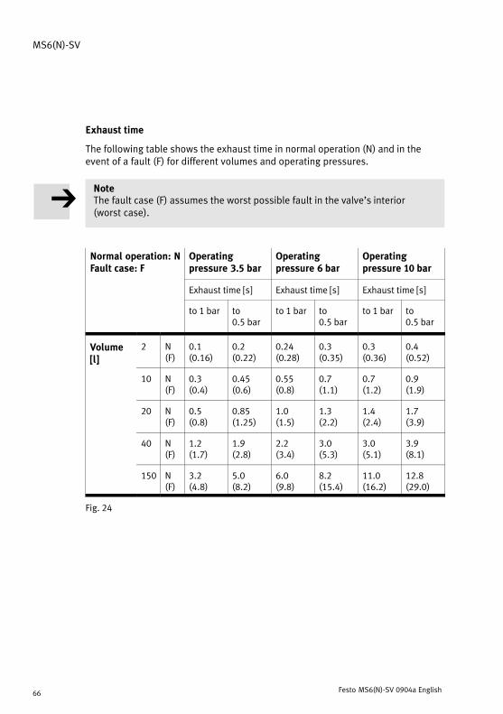
Exhaust time
The following table shows the exhaust time in normal operation (N) and in theevent of a fault (F) for different volumes and operating pressures.
NoteThe fault case (F) assumes the worst possible fault in the valve’s interior(worstcase).
Normal operation: NFault case: F
Operatingpressure 3.5�bar
Operatingpressure 6�bar
Operatingpressure 10�bar
Exhaust time [s] Exhaust time [s] Exhaust time [s]
to 1�bar to0.5�bar
to 1�bar to0.5�bar
to 1�bar to0.5�bar
Volume[l]
2 N(F)
0.1(0.16)
0.2(0.22)
0.24(0.28)
0.3(0.35)
0.3(0.36)
0.4(0.52)[ ]
10 N(F)
0.3(0.4)
0.45(0.6)
0.55(0.8)
0.7(1.1)
0.7(1.2)
0.9(1.9)
20 N(F)
0.5(0.8)
0.85(1.25)
1.0(1.5)
1.3(2.2)
1.4(2.4)
1.7(3.9)
40 N(F)
1.2(1.7)
1.9(2.8)
2.2(3.4)
3.0(5.3)
3.0(5.1)
3.9(8.1)
150 N(F)
3.2(4.8)
5.0(8.2)
6.0(9.8)
8.2(15.4)
11.0(16.2)
12.8(29.0)
Fig.�24

MS6(N)−SV
Festo MS6(N)−SV 0904a 67

MS6(N)−SV
Festo MS6(N)−SV 0904a 68
Weitergabe sowie Vervielfältigung dieses Dokuments,Verwertung und Mitteilung seines Inhalts sind verboten,soweit nicht ausdrücklich gestattet. Zuwiderhandlungenverpflichten zu Schadenersatz. Alle Rechte sind für denFall der Patent−, Gebrauchsmuster� oder Geschmacks−mustereintragung vorbehalten.
Copyright:EFesto AG�&�Co. KG,PostfachD−73726 Esslingen
Phone:+49/711/347−0
Fax:+49/711/347−2144
The reproduction, distribution and utilization of thisdocument as well as the comunication of its contents toothers without express authorization is prohibited.Offenders will be held liable for the payment of damages.All rights reserved in the event of the grant of a patent,utility module or design.
+49/711/347−2144
e−mail:[email protected]
Internet:http://www.festo.com
Original: de
Version: 0904a


![Hubankerventil 3/2-Wege direktwirkend · 6014 2/21 Schaltzeiten [ms]: Messung am Ventilausgang 6 bar und +20 °C Öffnen: Druckaufbau 0…90%, Schließen: Druckabbau 100…10% Nenn-weite](https://static.fdokument.com/doc/165x107/60d185b8fb652b2e34573643/hubankerventil-32-wege-direktwirkend-6014-221-schaltzeiten-ms-messung-am-ventilausgang.jpg)