
English - Fujitsu Technology Solutionsmanuals.ts.fujitsu.com/file/3285/d1751-d1755-bios-en.pdf ·...
81
Description D1751 / 1755 Setup Utility for TX150 S2 / Econel 40 Preliminary English answers 2
-
Upload
truonghanh -
Category
Documents
-
view
214 -
download
0
Transcript of English - Fujitsu Technology Solutionsmanuals.ts.fujitsu.com/file/3285/d1751-d1755-bios-en.pdf ·...

Description
D1751 / 1755 Setup Utility for TX150 S2 / Econel 40 Preliminary
English
answers 2

Dieses Handbuch wurde auf Recycling-Papier gedruckt. This manual has been printed on recycled paper. Ce manuel est imprimé sur du papier recyclé. Este manual ha sido impreso sobre papel reciclado. Questo manuale è stato stampato su carta da riciclaggio. Denna handbok är tryckt på recyclingpapper. Dit handboek werd op recycling-papier gedrukt.
Herausgegeben von/Published by Fujitsu Siemens Computers GmbH Bestell-Nr./Order No.: A26361-D1751-Z140-1-7619 Printed in the Federal Republic of Germany AG 0704 07/04
A26361-D1751-Z140-1-7619
D1751 / 1755 Setup Utility for TX150 S2 / Econel 40 Preliminary
REFERENCE MANUAL
D1751 / 1755 Setup Utility for TX150 S2 / Econel 40 Preliminary
REFERENCE MANUAL
Introduction
Using the Setup Utility
Main Menu
Advanced Menu
Power menu
Security Menu
S MServer Menu
Exit Menu
Error Messages
Index
July 2004 edition

Intel and Pentium are registered trademarks and MMX and OverDrive are trademarks of Intel Corporation, USA.
Microsoft, MS, MS-DOS and Windows are registered trademarks of Microsoft Corporation. Examples of Windows operating systems: Windows 95, Windows 98, Windows Me, Windows NT, Windows 2000, Windows XP.
PS/2 and OS/2 Warp are registered trademarks of International Business Machines, Inc.
All other trademarks referenced are trademarks or registered trademarks of their respective owners, whose protected rights are acknowledged.
Copyright � 2003
All rights, including rights of translation, reproduction by printing, copying or similar methods, in part or in whole, are reserved.
Offenders will be liable for damages.
All rights, including rights created by patent grant or registration of a utility model or design, are reserved.
Delivery subject to availability. Right of technical modification reserved.

Contents Introduction .....................................................................................................................................1 Notational conventions ......................................................................................................................1 Using the Setup Utility.....................................................................................................................3 Calling Setup Utility ...........................................................................................................................3
Calling the Boot Menu immediately............................................................................................4 Summary of Setup Utility Keys ..................................................................................................5
Operating Setup Utility.......................................................................................................................5 Main menu........................................................................................................................................7 System Information............................................................................................................................9
AMIBIOS ID...............................................................................................................................9 Version ......................................................................................................................................9 Build Date..................................................................................................................................9 CPU Type................................................................................................................................10 CPU Speed..............................................................................................................................10 CPU FSB Speed......................................................................................................................10 CPU Cache Level 1 .................................................................................................................10 CPU Cache Level 2 .................................................................................................................10 CPU Cache Level 3 .................................................................................................................10 CPU ID Number.......................................................................................................................10 BMC Firmware Version............................................................................................................10 LAN Firmware Version.............................................................................................................10 LAN Address ...........................................................................................................................10
System Time ...................................................................................................................................11 System Date....................................................................................................................................11 Floppy A ..........................................................................................................................................11 Primary/Secondary IDE Master/Slave..............................................................................................11
Type ........................................................................................................................................13 LBA/Large Mode......................................................................................................................13 Block (Multi-sector Transfer)....................................................................................................13 PIO Mode ................................................................................................................................14 S.M.A.R.T................................................................................................................................14 32 Bit Data Transfer.................................................................................................................14
Boot Settings ...................................................................................................................................15 BOOT Settings Configuration ..................................................................................................15 BOOT Device Priority ..............................................................................................................17 Hard Disk Drives......................................................................................................................19 Removable Devices.................................................................................................................19 ATAPI CD-ROM Drives............................................................................................................20
System Memory...............................................................................................................................20
A26361-D1751-Z140-1-7619 Preliminary

Contents
Advanced menu ............................................................................................................................ 21 CPU Configuration .......................................................................................................................... 22
Ratio Status ............................................................................................................................ 22 Ratio Actual Value................................................................................................................... 22 L3 Cache................................................................................................................................. 22 Fast String Operation .............................................................................................................. 23 Compatible FPU Code ............................................................................................................ 23 Split Lock Operation................................................................................................................ 23 Adjacent Sector Prefetch......................................................................................................... 23 Hyper Threading Function ....................................................................................................... 23 MPS Revision.......................................................................................................................... 23 CPU Mismatch Detection ........................................................................................................ 23 CPU Clock Throttling Delay..................................................................................................... 24
PCI IRQ Configuration .................................................................................................................... 24 Peripheral Configuration.................................................................................................................. 25
OnBoard Floppy Controller...................................................................................................... 25 Floppy Type ............................................................................................................................ 25 Serial Port 1 Address .............................................................................................................. 26 Serial Multiplexer..................................................................................................................... 26 Serial Port2 Adress ................................................................................................................. 26 Parallel Port Address .............................................................................................................. 26 PS/2 Mouse Support ............................................................................................................... 27
IDE Configuration............................................................................................................................ 27 IDE Channel Selection ............................................................................................................ 27
USB Configuration .......................................................................................................................... 28 USB Function.......................................................................................................................... 28 Legacy USB Support............................................................................................................... 28 USB 2.0 Controller .................................................................................................................. 28
ACPI Configuration ......................................................................................................................... 29 ACPI Aware O/S ..................................................................................................................... 29 Advanced ACPI Configuration................................................................................................. 29
PCIPnP Configuration ..................................................................................................................... 31 Plug & Play O/S ...................................................................................................................... 32 OffBoard PCI/ISA IDE Card .................................................................................................... 32 PCI Device Scan Order ........................................................................................................... 32 LSI SCSI 1020 ........................................................................................................................ 32 C.S.A. Gigabit Ethernet ........................................................................................................... 33 PCI Slot 1 to 5 Configuration................................................................................................... 33
IPMI Configuration .......................................................................................................................... 34 Event Log Full Mode ............................................................................................................... 34 Clear System Event Log.......................................................................................................... 35 BMC Time Sync. ..................................................................................................................... 35 System Event Log................................................................................................................... 35 LAN Setting............................................................................................................................. 36
A26361-D1751-Z140-1-7619 Preliminary
Contents
Security ..........................................................................................................................................39 Setup Password ..............................................................................................................................40 System Password............................................................................................................................40 Set Setup Password ........................................................................................................................40 Set System Password .....................................................................................................................42 Clear System Password ..................................................................................................................44 Setup Password Lock ......................................................................................................................44 Boot Sector Virus Protection............................................................................................................44 Diskette Write..................................................................................................................................45 Flash Write ......................................................................................................................................45 System Load ...................................................................................................................................45 SETUP Prompt................................................................................................................................45 Power menu ...................................................................................................................................47 Power Failure Recovery...................................................................................................................47 Resume On Ring .............................................................................................................................47 Resume On LAN .............................................................................................................................47 Resume On RTC Alarm...................................................................................................................48 Server menu...................................................................................................................................49 O/S Boot Timeout ............................................................................................................................49
Mode .......................................................................................................................................50 Timeout Value .................................................................................................................................50 Diagnostic System...........................................................................................................................50 ASR&R Boot Delay..........................................................................................................................50 Power Cycle Delay ..........................................................................................................................51 Boot Retry Counter ..........................................................................................................................51 Temperature Monitoring...................................................................................................................51 Remote Access Configuration .........................................................................................................52
Remote Access .......................................................................................................................52 CPU Status Configuration................................................................................................................54
CPU Status..............................................................................................................................54 Memory Status Configuration ..........................................................................................................55
Memory Module 1, 2, 3, 4 ........................................................................................................55 Exit menu .......................................................................................................................................57 Save Changes & Exit.......................................................................................................................58 Discard Changes and Exit ...............................................................................................................59 Load previous values.......................................................................................................................60 Load Optimal Defaults .....................................................................................................................61 Econel 40 Differences ...................................................................................................................62 Main menu.......................................................................................................................................62 Advanced menu...............................................................................................................................62
Missing items in comparison to TX 150S2 BIOS setup ............................................................62 Additional items .......................................................................................................................62 Remote Access type & parameters .........................................................................................64 IDE Configuration ....................................................................................................................65
Error Messages..............................................................................................................................67 Index...............................................................................................................................................71
A26361-D1751-Z140-1-7619 Preliminary


Introduction Most systems are already configured by the manufacturer or the dealer. There is no need to run the Setup Utility when starting the computer unless you get a Run Setup message. In Setup Utility you can set the system functions and the hardware configuration of the device. When it is supplied, the device is set to factory default settings. You can change these settings in Setup Utility. Any changes you make take effect as soon as you save the settings and quit the Setup Utility. You can select the following settings in the Setup Utility : Main Basic system information Advanced Further system information Security Security functions Power System wake-up and power restore
configuration Server Server management Exit Save changes or load default settings and
exit Setup
i
The individual menus and setting options are described in chronological order in the next chapters. Since the setting options and menus depend on the hardware configuration of your device, some of them may not be offered in the Setup Utility.
Notational conventions The meanings of the symbols and fonts used in this manual are as follows:
!
Pay particular attention to texts marked with this symbol. Failure to observe this warning endangers your life, destroys the system, or may lead to loss of data.
i
Supplementary information, remarks, and tips follow this symbol.
► Text which follows this symbol describes activities that must be performed in the order shown. Ë This symbol indicates that you must enter a blank space (press the Space Bar) at this point. ↵ This symbol indicates that you must press the Enter key. Text in this typeface indicates screen outputs. Text in this bold typeface indicates the entries you make via the keyboard. Text in italics indicates commands or menu items. "Quotation marks" indicate names of chapters or terms.
i
In the menus, shown on the screen, the following conventions are availiable: White items can be changed. Blue items cannot be changed, they are fixed.
A26361-D1751-Z140-1-7619 Preliminary 1


Using the Setup Utility
Calling Setup Utility ► Restart the device (switching On/Off or warm boot). The following message is displayed on the screen (the message is only displayed, if Quiet Boot is set to Disabled): Press DEL to run Setup,
Press F8 for BBS Popup ► Press the Del key to enter the Setup Utility. ► If you have assigned a supervisor password, you must now enter this password and confirm it
with the Enter key. The Main menu of Setup Utility is displayed on the screen:
Setup Utility main menu of TX 150 S2 BIOS setup.
A26361-D1751-Z140-1-7619 Preliminary 3

Using the Setup Utility
General Help Pressing the F1 key opens a window where all keys which have a function in the BIOS Setup are listed and explained. When you select an item, a brief help is given besides the Menu item.
General Help
Calling the Boot Menu immediately
i
You may use this function if you do not want to boot the system from the drive specified as first device in the entry Boot Sequence in the submenu Boot Options.
► Press function key F8 . After a while, the Boot Menu appears as pop up window on the screen.
► Select, from which drive you want to boot the operating system. The selection options are the same as in the submenu Boot Options of the Setup Utility main menu. Your selection is only valid for the current system boot. At the next system start, the options selected in the entry Boot Sequence in the submenu Boot Options are valid again. ► Use the arrow keys ↑ or ↓ to select from which drive you want to boot the system now and
press the Enter key or press Esc to boot using defaults. Your computer supports three Setup Utility levels. The above screen is the Setup Utility Basic Level screen. This allows you to view and change only the basic configuration of your computer.
4 A26361-D1751-Z140-1-7619 Preliminary
Using the Setup Utility
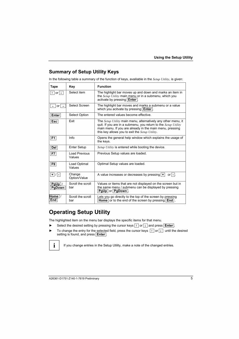
Summary of Setup Utility Keys In the following table a summary of the function of keys, availiable in the Setup Utility, is given:
Tape Key Function ↑ or ↓
Select item
The highlight bar moves up and down and marks an item in the Setup Utility main menu or in a submenu, which you acitvate by pressing Enter .
← or →
Select Screen
The highlight bar moves and marks a submenu or a value which you acitvate by pressing Enter .
Enter
Select Option
The entered values become effective.
Esc
Exit
The Setup Utility main menu, alternatively any other menu, it quit. If you are in a submenu, you return to the Setup Utility main menu. If you are already in the main menu, pressing this key allows you to exit the Setup Utility.
F1
Info
Opens the general help window which explains the usage of the keys.
Del
Enter Setup
Setup Utility is entered while booting the device.
F7
Load Previous Values
Previous Setup values are loaded.
F9
Load Optimal Values
Optimal Setup values are loaded.
+ / -
Change Option/Value
A value increases or decreases by pressing + or - .
PgUp / PgDown
Scroll the scroll bar
Values or items that are not displayed on the screen but in the same menu / submenu can be displayed by pressing PgUp or PgDown .
Home / End
Scroll the scroll bar
Lets you go directly to the top of the screen by pressing Home or to the end of the screen by pressing End .
Operating Setup Utility The highlighted item on the menu bar displays the specific items for that menu. ► Select the desired setting by pressing the cursor keys ↑ or ↓ and press Enter . ► To change the entry for the selected field, press the cursor keys ↑ or ↓ until the desired
setting is found, and press Enter .
i
If you change entries in the Setup Utility, make a note of the changed entries.
A26361-D1751-Z140-1-7619 Preliminary 5


Main menu The first screen appears if you select the menu Main from the Setup Utility. There are several differences in the BIOS structure, i.g. the Server menu does not exist in the Econel 40 BIOS.
Main menu of TX150 S2 BIOS
A26361-D1751-Z140-1-7619 Preliminary 7

Main menu
Main menu of Econel 40 BIOS
8 A26361-D1751-Z140-1-7619 Preliminary

Main menu
System Information In this item, general system information is given. All these settings are fix and not changeable.
System Information menu
AMIBIOS ID Displays the BIOS ID for the corresponding system E40A Econel 40 T150A TX150 S2
Version displays the BIOS version number.
Build Date shows the date of build.
A26361-D1751-Z140-1-7619 Preliminary 9
Main menu
CPU Type indicates the type of processor currently installed in the system.
CPU Speed displays the speed of the CPU
CPU FSB Speed displays the FSB speed of the CPU.
CPU Cache Level 1 indicates the size of first-level cache (i.e. first-level cache is also integrated in the CPU chip).
CPU Cache Level 2 indicates the size of second-level cache (i.e. second-level cache is also integrated in the CPU chip).
CPU Cache Level 3 indicates the size of third-level cache (i.e. third-level cache is also integrated in the CPU chip).
CPU ID Number displays the identification number of the CPU.
BMC Firmware Version indicates the version of the Baseboard Management Controller (BMC) firmware.
LAN Firmware Version This item is displayed, if the Onboard LAN option ROM Scan is set to Enabled
LAN Address indicates the LAN IP address.
10 A26361-D1751-Z140-1-7619 Preliminary
Main menu
System Time indicates the time of the device. The time is shown in the format "hours:minutes:seconds". ► If you want to change the current time set, use the Tab key to move to the field to be
changed and press + or - until you get the desired value or enter the value directly.
!
If the settings in the Time and Date fields are frequently wrong when you power up the computer, the lithium battery is dead. Replace the battery.
System Date indicates the date of the device. The date is shown in the format "weekday-month-day-year". ► If you want to change the current date set, use the Tab key to move to the field to be
changed and press + or - until you get the desired value or enter the value directly.
!
If the settings in the Time and Date fields are frequently wrong when you power up the computer, the lithium battery is dead. Replace the battery.
Floppy A Different entries are possible in this menu: Disabled, 1.44 MB 3.5-inch (default) The entry depends on the floppy disk drive installed Disabled No floppy disk drive installed
Primary/Secondary IDE Master/Slave You can configure the hard disk drive connected to the master/slave port of the parallel IDE channel1/2. ► Call the submenu
Primary IDE Master or Primary IDE Slave or Secondary IDE Master or Secondary IDE Slave to make corresponding settings of the the parallel ATA hard disk drive.
i
There are several differences in the IDE configuration between Econel 40 and TX 150S2 (see chapter �Econel 40 Differences� section �IDE Configuration�).
A26361-D1751-Z140-1-7619 Preliminary 11

Main menu
Example for Primary IDE Master menu
Example for Secondary IDE Master menu
12 A26361-D1751-Z140-1-7619 Preliminary

Main menu
i
You should change the default settings only if you are connecting an additional IDE drive to the IDE connector. The maximum transfer rate of two IDE drives connected to the same connector is determined by the slowest one. Fast hard disks should therefore be connected to the first IDE connector and identified as Parallel ATA (Primary Master). In the case of system boards with newer controllers, all IDE drives are supported independently and configured for the maximum transfer rate. This means that a fast and a slow IDE drive can be connected to one connector without impeding the speed of the fast drive. The values Device, Vendor, Size, LBA Mode, Block Mode, PIO Mode, Async DMA, UltraDMA and SMART monitoring are autodetected by BIOS and are not user-configurable. These items show N/A if no IDE device is installed in the system.
Type indicates, which type of hard disk is installed in the system Not installed no hard disk installed Auto autotypes hard drives are installed in the system (default). CD-ROM a CD-ROM drive is installed in the system. ARMD a ZIP, LS-120 or MO drive is installed in the system
LBA/Large Mode This item allows you to set the addressing on consecutive sector numbers (LBA = Logical Block Addressing). LBA/Large Mode activates the logical-block-addressing for IDE so that the logical values generated are within the above BIOS limitations. This means that a hard disk capacity of over 528 Mbyte can be supported. Operating systems and application programmes work with these logical hard disk values. IDE hard disks of over 528 Mbyte are configured and operated using LBA mode. If a hard disk supports LBA mode, you can use the full capacity of the IDE hard disk.
! Change the default entries only if you are installing another hard disk drive.
Auto If the hard disk supports LBA and it has a capacity of more than 528 Mbyte, the
BIOS translates the hard disk parameters, allowing the disk's full capacity to be used. This allows the disk's full capacity to be used (default).
Disabled The BIOS uses the hard disk parameters and supports a maximum capacity of 528 Mbyte.
Block (Multi-sector Transfer) Enables or disables data multi-sectors transfer. Auto Data transfer from and to the device is done multiple sectors at a time if the device
supports multi-sector transfer feature (default). Disabled Data transfer from and to the device is done one sector at a time.
A26361-D1751-Z140-1-7619 Preliminary 13

Main menu
PIO Mode The PIO (Programmed Input Output) mode defines the transfer rate of the IDE hard disk drive. If at all possible use the entry Auto in the field Type. This means BIOS will determine the best possible transfer rate for the hard drive. If transfer rates are set incorrectly, the hard drive will be either too slow (i. e. the hard disk has a higher transfer rate than the one that was set) or the hard drive does not boot correctly, or does not respond (i. e. the hard drive is set to a higher transfer rate than it is capable of). Auto (default), 0, 1, 2, 3, 4
S.M.A.R.T. Sets the S.M.A.R.T. (Self Monitoring Analysis and Reporting Technology). Auto autodetects if the device supports this feature (default) Enabled enables this function Disabled disables this function
32 Bit Data Transfer permits 32 bit IDE transfer rate Enabled enables this function Disabled disables this function (default)
14 A26361-D1751-Z140-1-7619 Preliminary
Main menu
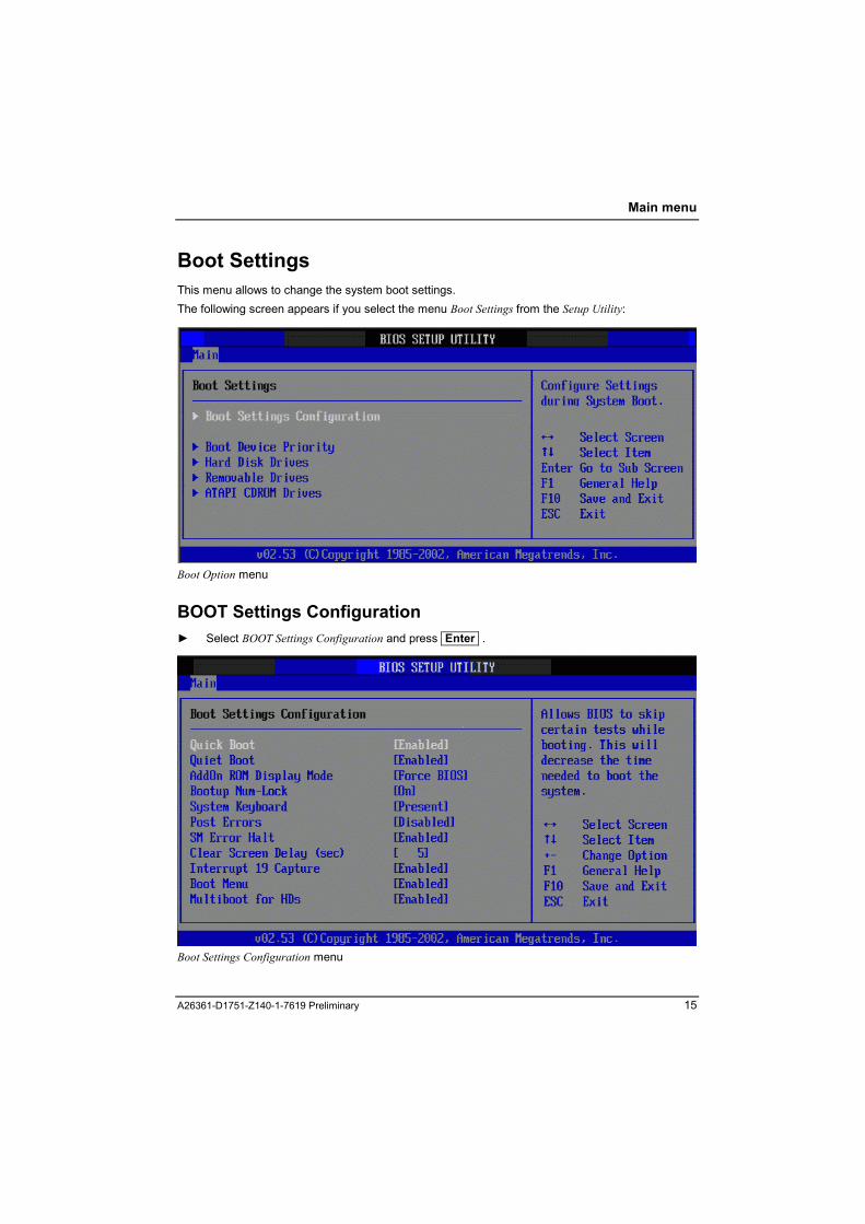
Boot Settings This menu allows to change the system boot settings. The following screen appears if you select the menu Boot Settings from the Setup Utility:
Boot Option menu
BOOT Settings Configuration ► Select BOOT Settings Configuration and press Enter .
Boot Settings Configuration menu
A26361-D1751-Z140-1-7619 Preliminary 15

Main menu
Quick Boot This setting allows BIOS to skip certain tests while booting. This can reduce the extent of the self-test to accelerate the system start-up. Time needed to boot the system will decrease. Enabled When the device is switched on, the quick self-test is carried out, in which the floppy
disk drives are not checked (default). Disabled When the device is switched off, the complete device configuration is tested.
Quiet Boot minimises startup display during boot. Enabled The OEM logo is displayed on the screen instead of the POST messages. A switch
to the POST information is made if you press the Del key or if errors occur (default).
Disabled The normal POST information is displayed on the screen.
AddOn ROM Display Mode
This item is active when "Quiet Boot" is enabled. When set to selection "Keep current", users don't see the initialization of PCI option ROM during POST. Force BIOS BIOS will switch logo screen to text screen during PCI option ROM initialization. Keep current BIOS doesn't switch logo screen to text screen during PCI option ROM initialization
Bootup NumLock Allows to select the power-on state for the NumLock function. On the NumLock function is switched on (default) Off the function is switched off.
System Keyboard determines whether there is a keyboard present or not. Absent there is no keyboard connected to the computer Present a keyboard is connected to the computer (default).
Post Errors defines whether the system start-up is to be aborted and the system halted when an error is detected. Enabled If the self-test detects an error, system start-up is aborted after the self-test, and the
system is halted. Disabled The system start-up is not aborted. The error is ignored if possible (default).
16 A26361-D1751-Z140-1-7619 Preliminary

Main menu
SM Error Halt Error Handling for System Monitoring, configures the system behaviour during the self-test in case of a system monitoring error reported by the BMC (e.g. fan monitoring, temperature monitoring). Enabled If an error is reported to the BIOS by the BMC, the system start-up is cancelled and
the system is stopped after the self-test (default). Disabled The system start is not cancelled when an error is reported to the BIOS by the BMC.
Clear Screen Display (sec)
Allows you to set the delay time in seconds before clearing the screen to boot. 0 no delay. 1, 2, 3, 4, 5
Interrupt 19 Capture Enabled this function allows the option ROMs to trap Interrupt 19 Disabled this function is disabled (default).
Boot Menu specifies whether the BOOT menu can be invoked with F8 during the POST. Enabled The Boot menu can be invoked (default). Disabled The Boot menu cannot be invoked.
Multiboot for HD´s Determines whether the option Boot device Priority should be used or not. Enabled Boot device Priority specifies the boot sequence (default). Disabled Boot device Priority cannot affect the boot sequence.
Scan order is used as boot order.
BOOT Device Priority specifies the sequence of the system files that the system BIOS requires during booting. This sequence can be changed with the cursor.
A26361-D1751-Z140-1-7619 Preliminary 17

Main menu
Boot Device Priority menu These items specify the boot device priority sequence from the available devices. The number of device items that appear on the screen depends on the number of devices installed in the system.
i
This menu displays for Econel 40 three devices for device priority. The chosen devices are only an example for the devices in the boot sequence.
1st Boot Device ATAPI CDROM The system is booting from the ATAPI CD-ROM drive 2nd Boot Device PM-ST320413A Hard Disk, the displayed string depends on the hard disk. 3rd Boot Device 1st Floppy Drive The system is booting from first floppy drive 4th Boot Device LSI MPI Boot Support OnBoard SCSI HDD8 (not given for Econel 40) 5th Boot Device IBA GE Slot 0108v OnBoard LAN (not given for Econel 40)
18 A26361-D1751-Z140-1-7619 Preliminary
Main menu
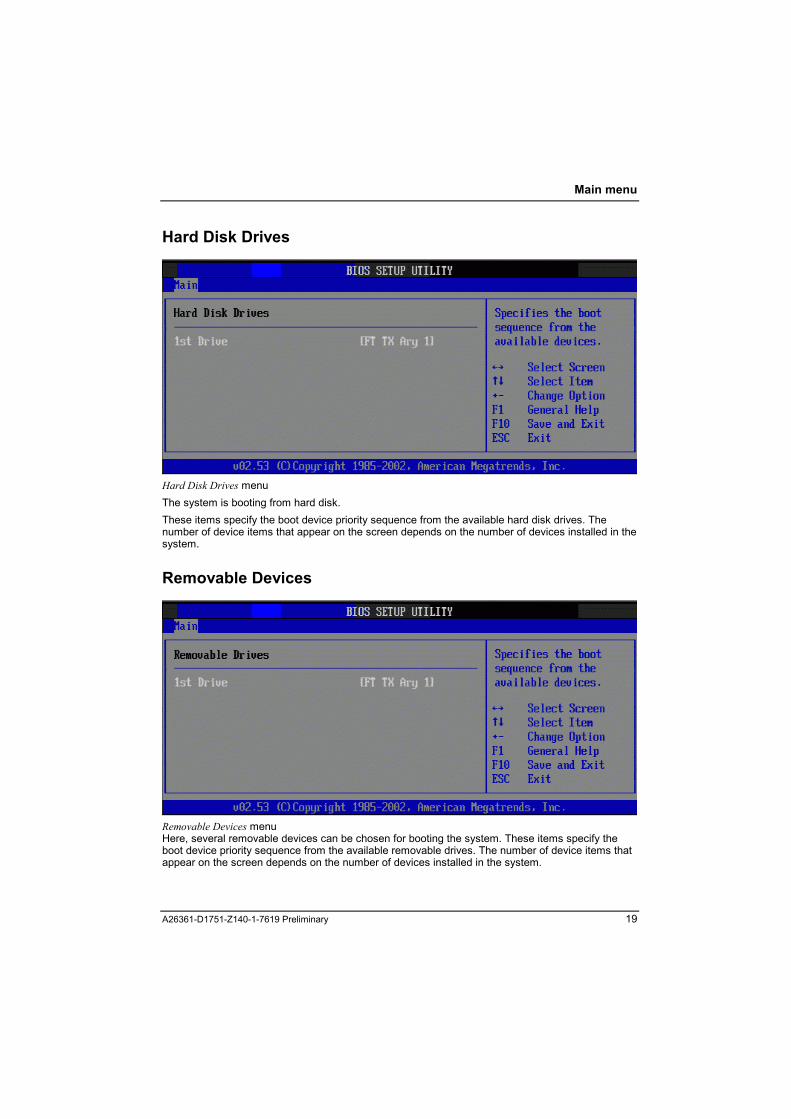
Hard Disk Drives
Hard Disk Drives menu The system is booting from hard disk. These items specify the boot device priority sequence from the available hard disk drives. The number of device items that appear on the screen depends on the number of devices installed in the system.
Removable Devices
Removable Devices menu Here, several removable devices can be chosen for booting the system. These items specify the boot device priority sequence from the available removable drives. The number of device items that appear on the screen depends on the number of devices installed in the system.
A26361-D1751-Z140-1-7619 Preliminary 19

Main menu
ATAPI CD-ROM Drives If an ATAPI CD-ROM drive is installed, the entry enables you to boot from CD-ROM drive. The number of device items on the screen depends on the number of devices installed in the system.
ATAPI CDROM Drives menu
System Memory displays the autodetected system memory.
20 A26361-D1751-Z140-1-7619 Preliminary
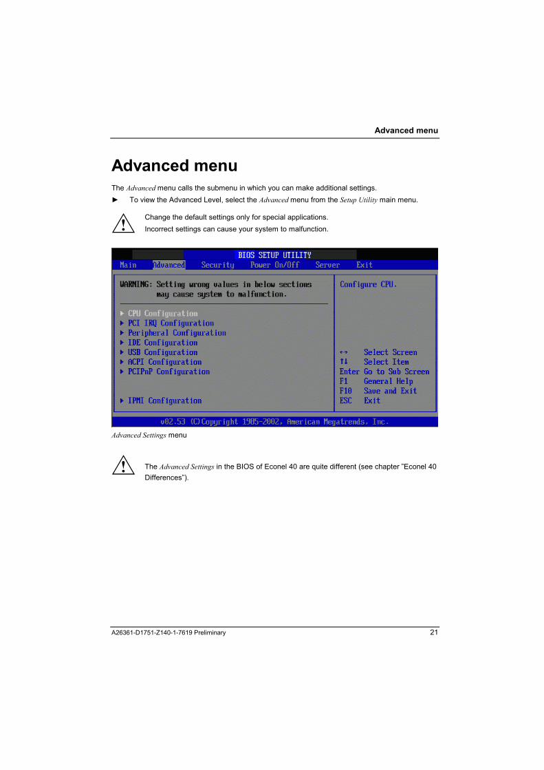
Advanced menu
Advanced menu The Advanced menu calls the submenu in which you can make additional settings. ► To view the Advanced Level, select the Advanced menu from the Setup Utility main menu.
!
Change the default settings only for special applications. Incorrect settings can cause your system to malfunction.
Advanced Settings menu
! The Advanced Settings in the BIOS of Econel 40 are quite different (see chapter �Econel 40 Differences�).
A26361-D1751-Z140-1-7619 Preliminary 21
Advanced menu
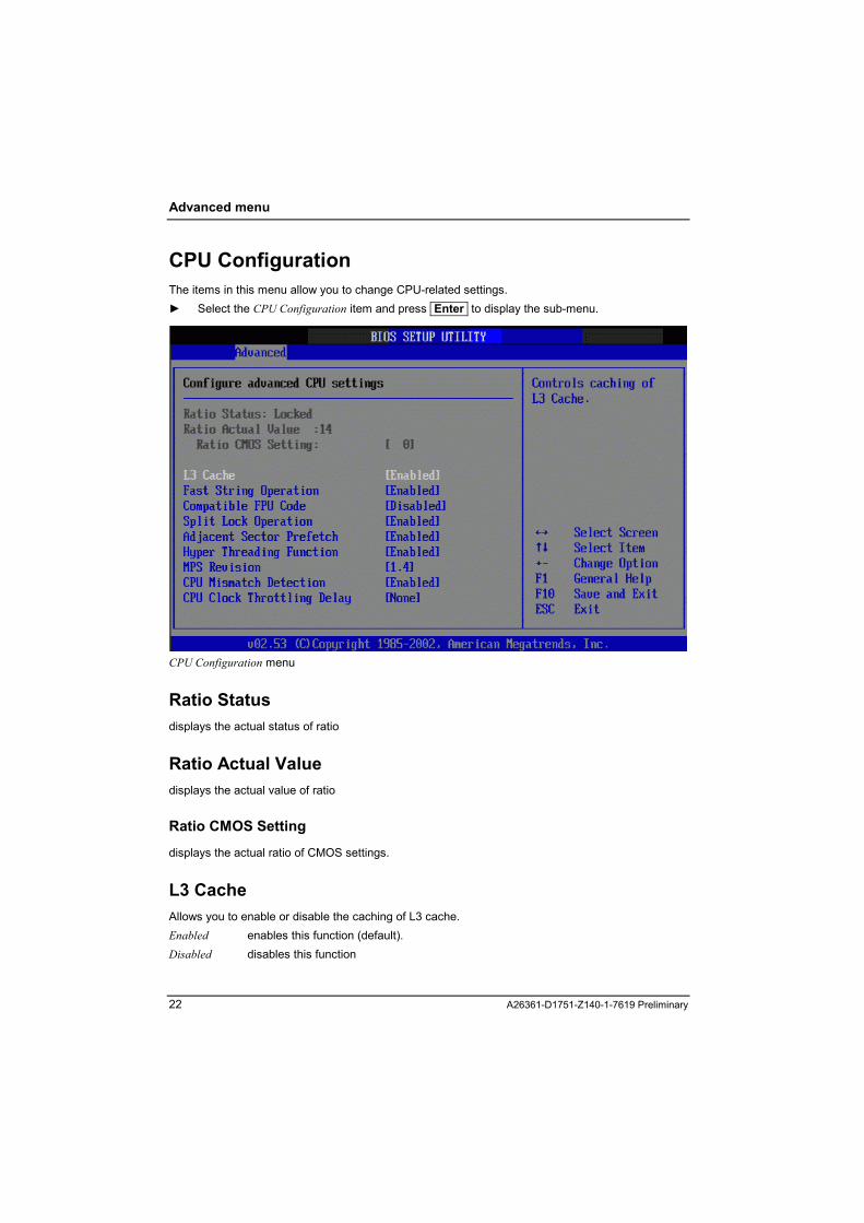
CPU Configuration The items in this menu allow you to change CPU-related settings. ► Select the CPU Configuration item and press Enter to display the sub-menu.
CPU Configuration menu
Ratio Status displays the actual status of ratio
Ratio Actual Value displays the actual value of ratio
Ratio CMOS Setting displays the actual ratio of CMOS settings.
L3 Cache Allows you to enable or disable the caching of L3 cache. Enabled enables this function (default). Disabled disables this function
22 A26361-D1751-Z140-1-7619 Preliminary
Advanced menu
Fast String Operation Allows you to enable or disable the CPU Fast String feature. Enabled enables this function (default) Disabled disables this function
Compatible FPU Code Allows you to enable or disable the P6-Compatible PU-OPCODE register usage model. Enabled enables this function Disabled disables this function (default)
Split Lock Operation Allows you to enable or disable the split lock feature. Enabled enables this function (default) Disabled disables this function
Adjacent Sector Prefetch Allows you to enable or disable the adjacent sector prefetch feature. Enabled enables this function (default) Disabled disables this function
Hyper Threading Function Allows you to enable or disable the CPU Hyper-Threading Technology feature. Enabled enables this function Disabled disables this function (default)
MPS Revision Allows you to select the Multiprocessor Specification Revision. Some operating systems may require 1.1. 1.1, 1.4 (default)
CPU Mismatch Detection Allows you to enable or disable the detection of CPU frequency change and front side bus (FSB) frequency mismatch. Enabled detecton of of CPU frequency change and front side bus (FSB) frequency mismatch
is allowed (default). Disabled this feature is disabled.
A26361-D1751-Z140-1-7619 Preliminary 23
Advanced menu
CPU Clock Throttling Delay Allows you to set the CPU clock throttling delay in minutes. 1, 5, 10, 20, 30, 60 None CPU clock throttling delay is disabled (default).
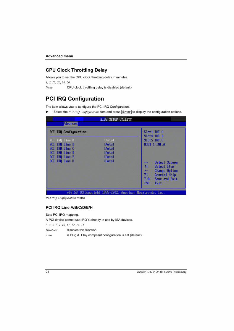
PCI IRQ Configuration The item allows you to configure the PCI IRQ Configuration. ► Select the PCI IRQ Configuration item and press Enter to display the configuration options.
PCI IRQ Configuration menu
PCI IRQ Line A/B/C/D/E/H Sets PCI IRQ mapping. A PCI device cannot use IRQ´s already in use by ISA devices. 3, 4, 5, 7, 9, 10, 11, 12, 14, 15 Disabled disables this function Auto A Plug & Play compliant configuration is set (default).
24 A26361-D1751-Z140-1-7619 Preliminary

Advanced menu
Peripheral Configuration Allows you to configure the Super I/O chipset. ► Select the Peripheral Configuration item and press Enter to display the configuration options.
Peripheral Configuration menu
OnBoard Floppy Controller This field is used to enable and disable the built-in floppy disk controller on the system board. Enabled The floppy disk controller is enabled - IRQ 6 is used (default). Disabled The floppy disk controller is disabled - IRQ 6 is free.
Floppy Type Specifies which floppy disk drive controller is to be used. It is possible to choose from the local (default) controller and the controller for remote access. The default controller permits access to the floppy disk drive installed in the system. On the other hand, the controller for remote access permits access to a floppy disk drive of another system or to a floppy-disk image file stored on another system. The data are routed via the network in this case. Local The default floppy-disk drive controller of the system is used (default). Remote The floppy-disk drive controller for remote access is used. Remote Once The floppy-disk drive controller for remote access is used for the subsequent system
start-up. Then the system automatically switches over to Local.
i
This item does not exist in the Econel 40 BIOS, it appears only in the TX150 S2 BIOS.
A26361-D1751-Z140-1-7619 Preliminary 25

Advanced menu
Serial Port 1 Address This field selects the address1 and the interrupt1 used to access the relevant serial port. The serial port is set to the shown address and interrupt. 3E8/IRQ4, 2E8/IRQ3 , 3F8/IRQ4, Disabled 3F8/IRQ4 The serial port 3F8/IRQ4 is set to the next available combination (address, interrupt). Disabled The serial port is disabled (default).
Serial Multiplexer specifies whether the serial interface can be used by the system or the BMC (default). System The serial interface can be used by the system or the operating system. BMC The serial interface can be used by the BMC. The operating system cannot use the
serial interface (default). Shared The serial interface can be used by both, BMC and system.
i
This item does not exist in the Econel 40 BIOS, it appears only in the TX150 S2 BIOS.
Serial Port2 Address This field selects the address2 and the interrupt2 used to access the relevant serial port. The serial port is set to the shown address and interrupt. 3E8/IRQ4, 3F8/IRQ4, 2F8/IRQ3 2E8/IRQ3 The serial port 2E8/IRQ3 is set to the next available combination (address, interrupt)
(default). Disabled The serial port is disabled.
Parallel Port Address Allows you to select the Parallel Port base addresses. 378 (default), 278, 3BC Disabled The parallel port is disabled.
Parallel Port Mode Parallel Port mode can be set. Normal (default), Bidirectional, ECP, EPP
Parallel Port IRQ This item selects the interrupt used to access the relevant parallel port. IRQ7 (default), IRQ5
26 A26361-D1751-Z140-1-7619 Preliminary

Advanced menu
PS/2 Mouse Support Allows enabling or disabling support for PS/2 mouse. Auto The connected mouse is automatically detected and activated. Operating systems
that support Plug & Play automatically configure the mouse (default). Enabled The mouse controller is enabled - IRQ 12 is used. Disabled The mouse controller is disabled - IRQ 12 is free.
IDE Configuration The items in this menu allow you to set or change the configurations for the IDE devices installed in the system.
i
In this menu there are several differences between TX 150S2 and Econel 40 (see also chapter �Econel 40 Differences�, the differences are described in this chapter).
► Select an item then press Enter if you wish to configure the item.
IDE Configuration menu
IDE Channel Selection Allows you to select the IDE channel that you wish to enable. Disabled disables this function Primary primary IDE channel is enabled Secondary secondary IDE channel is enabled (default for TX150 S2) Both both IDE channels are enabled (default for Econel 40).
A26361-D1751-Z140-1-7619 Preliminary 27

Advanced menu
USB Configuration The items in this menu allows you to change the USB-related features. ► Select an item then press Enter to display the configuration options.
USB Configuration menu
!
The Module Version and USB Devices Enabled items show the autodetected values. If no USB device is detected, the item shows None.
USB Function Allows you to set the number of USB ports to activate. Disabled no USB port is activated. 2 USB Ports 2 USB ports are activated. All USB Ports all USB ports are activated (default).
Legacy USB Support Allows you to enable or disable support for legacy USB devices. Disabled disables this function (default). Enabled enables this function. Auto disables the legacy support if no USB devices are connected.
USB 2.0 Controller Allows you to enable or disable the USB controller. Disabled disables the USB controller. Enabled enables the USB controller (default).
28 A26361-D1751-Z140-1-7619 Preliminary

Advanced menu
ACPI Configuration The items in this menu allow you to change the ACPI (Advanced Configuration and Power Interface) settings. ► Select an item then press Enter to display the configuration options. ► For displaying the second item press Enter and a submenu appears.
ACPI Configuration menu
ACPI Aware O/S Allows you to enable or disable ACPI support for your operating system. Yes Select this value if your operating system supports ACPI. No Select this value if your operating system does not support ACPI.
Advanced ACPI Configuration Allows you to change the advanced ACPI settings.
A26361-D1751-Z140-1-7619 Preliminary 29

Advanced menu
ACPI Configuration menu
ACPI 2.0 Support Allows yout to add tables according to the ACPI 2.0 specifications or not. No disables this function (default). Yes allows adding tables according to the ACPI 2.0 specifications.
BIOS --> AML ACPI table Allows you to enable or disable the inclusion of the BIOS -> AML exchange pointer to (X)RSDT pointer list. Enabled enables this function (default). Disabled disables this function.
Headless Mode Allows you to enable or disable the Headless operation mode though ACPI. Enabled enables this function. Disabled disables this function (default).
ACPI EMS Support Allows you to enable or disable the support for the Emergency Management Services. Enabled enables this function. Disabled disables this function (default).
30 A26361-D1751-Z140-1-7619 Preliminary
Advanced menu
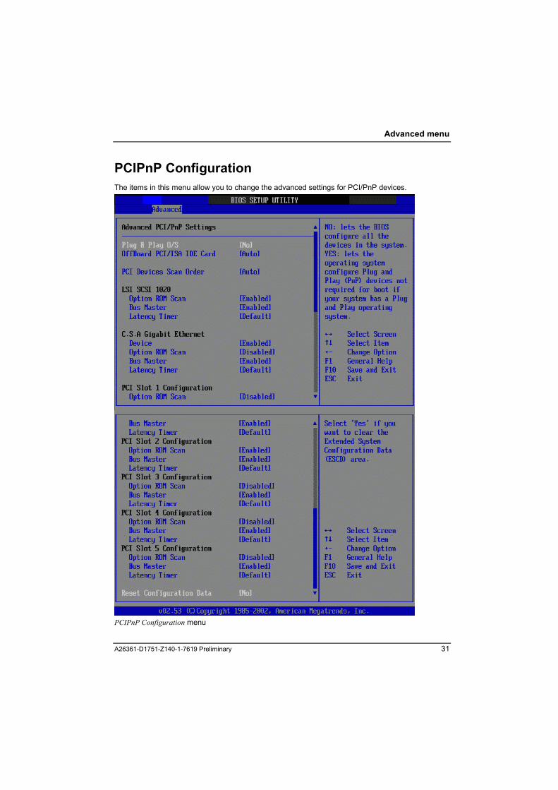
PCIPnP Configuration The items in this menu allow you to change the advanced settings for PCI/PnP devices.
PCIPnP Configuration menu
A26361-D1751-Z140-1-7619 Preliminary 31

Advanced menu
!
Take caution when changing the settings of the PCI PnP menu items. Incorrect field values may cause the system to malfunction.
Plug & Play O/S No BIOS configures all the devices in the system (default). Yes If you install a Plug & Play operating system, the operating system configures the
Plug & Play devices not required for boot.
OffBoard PCI/ISA IDE Card Allows you to select the appropriate PCI slot number as required by some PCI IDE cards. Auto automatical selection (default). PCI Slot1, PCI Slot2, PCI Slot,3 PCI Slot4, PCI Slot5
PCI Device Scan Order Allows you to set the PCI devices scan order. Bus 0 First Scan onboard SCSI first and the rest in PFA order (default). Bus N First Scan in PFA orderfirst and as last the onboard SCSI. Auto Scan buses in PFA order.
i
This item does not exist in the Econel 40 BIOS.
LSI SCSI 1020
i
This item does not exist in the Econel 40 BIOS.
Option ROM Scan
Allows you to enable or disable the initialization of the expansion ROM. Enabled enables the initialization of the expansion ROM. Disabled disables the initialization of the expansion ROM.
BUS Master
Allows you to enable or disable the selected device as a PCI bus master. Enabled enables the selected device as a PCI bus master. Disabled disables the selected device as a PCI bus master.
32 A26361-D1751-Z140-1-7619 Preliminary

Advanced menu
Latency Timer
Allows you to select a value in units of PCI clocks for the PCI device latency timer register. Default 32, 64, 96, 128, 160, 192, 224
C.S.A. Gigabit Ethernet
Device Allows you to enable or disable the PCI device. Enabled enables the PCI device. Disabled disables the PCI device.
Option ROM Scan
Allows you to enable or disable the initialization of the expansion ROM. Enabled enables the initialization of the expansion ROM. Disabled disables the initialization of the expansion ROM.
BUS Master
Allows you to enable or disable the selected device as a PCI bus master. Enabled enables the selected device as a PCI bus master. Disabled disables the selected device as a PCI bus master.
Latency Timer
Allows you to select a value in units of PCI clocks for the PCI device latency timer register. Default 32, 64, 96, 128, 160, 192, 224
PCI Slot 1 to 5 Configuration
Option ROM Scan
Allows you to enable or disable the initialization of the expansion ROM. Enabled enables the initialization of the expansion ROM. Disabled disables the initialization of the expansion ROM.
BUS Master
Allows you to enable or disable the selected device as a PCI bus master. Enabled enables the selected device as a PCI bus master (default). Disabled disables the selected device as a PCI bus master.
A26361-D1751-Z140-1-7619 Preliminary 33
Advanced menu
Latency Timer
Allows you to select a value in units of PCI clocks for the PCI device latency timer register. Default 32, 64, 96, 128, 160, 192, 224
Reset Configuration Data Allows you to refresh the ESCD (Extended System Configuration) table. Yes ESCD is refreshed after next reboot. This item is set to No again. No (default)
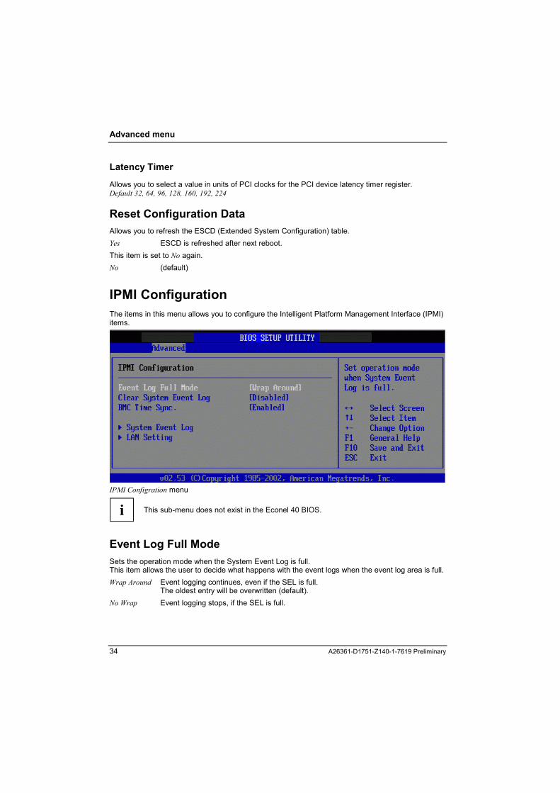
IPMI Configuration The items in this menu allows you to configure the Intelligent Platform Management Interface (IPMI) items.
IPMI Configration menu
i
This sub-menu does not exist in the Econel 40 BIOS.
Event Log Full Mode Sets the operation mode when the System Event Log is full. This item allows the user to decide what happens with the event logs when the event log area is full. Wrap Around Event logging continues, even if the SEL is full.
The oldest entry will be overwritten (default). No Wrap Event logging stops, if the SEL is full.
34 A26361-D1751-Z140-1-7619 Preliminary

Advanced menu
Clear System Event Log This allows you to clear the event log. Enabled Clears the event log after leaving BIOS setup with Save and Exit or F10. After
clearing event log this entry will be set automatically to Disabled again. Disabled The System Event Log is not cleared (default).
BMC Time Sync. Synchronizes the BIOS time with BMC time. Enabled Activates the BMC Time Sync. function (default). Disabled Deactivates the BMC Time Sync. function.
System Event Log This item displays the total number of entries.
System Event Log menu
SEL Entry number Shows the current Event Log entry. ► Use the + / - keys to traverse the event log number. 1 (default), 2, 3, ..., 255
A26361-D1751-Z140-1-7619 Preliminary 35

Advanced menu
LAN Setting These items in this menu allow you to configure the LAN interface used by the IPMI Baseboard Management Controller.
LAN Setting menu
Local IP Address
Allows you to set the Local IP Address. ► Use the + / - keys to change the IP address number or enter the value directly.
Subnet Mask
Allows you to set the Subnet Mask. ► Use the + / - keys to change the Subnet Mask number or enter the value directly.
Gateway Address
Allows you to set the Gateway Address. ► Use the + / - keys to change the Gateway Address number or enter the value directly.
36 A26361-D1751-Z140-1-7619 Preliminary

Advanced menu
User ID 1 Password
Allows you to set the User ID 1 Password.
To set a User ID 1 Password: ► Select the User ID 1 Password item and press Enter . ► On the password box that appears, type a password composed of letters and/or numbers, then
press Enter . ► Confirm the password when prompted. The message �Password Installed� appears after you have successfully set your password.
To change the User ID 1 password: Follow the same steps as in setting the password.
To clear the User ID 1 password: ► Select User ID 1 Password, then press Enter . The message �Password Uninstalled� appears.
A26361-D1751-Z140-1-7619 Preliminary 37


Security The Security menu offers you various options for protecting your system and personal data from unauthorized access. By combining these options, you can achieve maximum protection for your system: • Preventing unauthorized Setup Utility entry
You can activate this protection by setting a setup (supervisor) password in the Security menu. • Preventing unauthorized system access
You can activate this protection by setting a system (user) password in the Security menu. • Preventing unauthorized system booting from disk drive (see chapter �Calling the Boot Menu
immediately�). • Preventing unauthorized writing of disk drives • Boot sector virus protection • Flash Write Protection
Security menu
A26361-D1751-Z140-1-7619 Preliminary 39

Security
Setup Password Installed a setup password is set. Not installed a setup password is not already set or is deleted.
System Password Installed a system password is set. Not installed a system password is not already set or is deleted.
Set Setup Password To prevent an unauthorized Setup Utility entry. You can activate this protection by setting a setup (supervisor) password in the Security menu. To set or change the setup password, proceed as follows: ► Call the Setup Utility. ► Select the Security menu. ► Select the Set Setup Password item. ► Press Enter to display the Set Setup Password menu. The following screen appears:
40 A26361-D1751-Z140-1-7619 Preliminary
Security
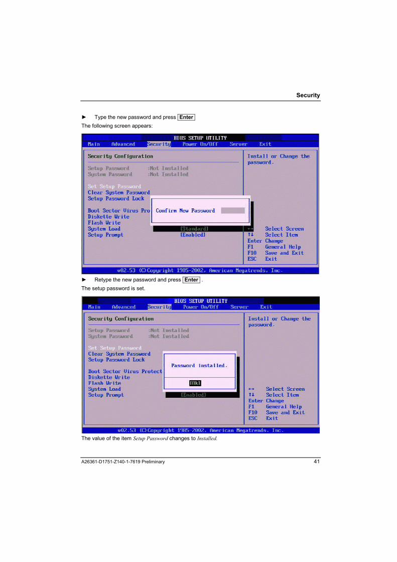
► Type the new password and press Enter The following screen appears:
► Retype the new password and press Enter . The setup password is set.
The value of the item Setup Password changes to Installed.
A26361-D1751-Z140-1-7619 Preliminary 41

Security
i When you enter a blank instead of a new user password, the old user password is deleted. Then the value of the item Setup Password changes to Not installed
Set System Password To prevent an unauthorized system access. You can activate this protection by setting a system (user) password in the Security menu. Condition: Setup Password is set. To change the system password, proceed as follows: ► Call the Setup Utility. ► Select the Security menu. ► Select the Set System Password item. ► Press Enter to display the Set System Password menu. ► Type the new password and press Enter ► Retype the new password and press Enter . The setup password is set.
42 A26361-D1751-Z140-1-7619 Preliminary

Security
The value of the item System Password changes to Installed.
i When you enter a blank instead of a new password, the old password is deleted. Then the value of the item System Password changes to Not installed
Now, the system password is requested every time when you enter Setup.
i
If both passwords are configured, you can enter Setup either with the Setup Password or the System Password. With the System Password you have only limited access to the setup menu, e.g. you can change the System Password.
A26361-D1751-Z140-1-7619 Preliminary 43

Security
Clear System Password ► Select Clear System Password, then press Enter . ► When prompted with the message �Clear System Password?� select OK, then press Enter .
Setup Password Lock With this setting you can prevent unauthorized access to the settings of devices with its own BIOS. An Adapter BIOS can be branched or not. Condition: Setup password has been set Standard: to process boot without Adapter BIOS locked (default). To enter the Adapter BIOS
Setup is possible. Extended: Process boot with Adapter BIOS locked. To enter the Adapter BIOS-Setup is
impossible.
Boot Sector Virus Protection Allows you to check your hard disk boot sectors each time when system is powered on. You will be warned about all changes and must confirm to acknowledge the warning. Enabled boot sector virus protection is enabled. Disabeld boot sector virus protection is disabled (default)
44 A26361-D1751-Z140-1-7619 Preliminary

Security
Diskette Write This option prevents unauthorized writing of floppies. ► To activate this protection, select the item Diskette Write in the Security menu. Enabled acitvates diskette write protection (default). Disabled deacitvates diskette write protection.
Flash Write This option prevents BIOS from being overwritten. ► To activate this protection, select the item Flash Write in the Security menu. Enabled no BIOS write protection (default). Disabled activates BIOS write protection.
System Load Standard allows booting from a floppy disk or an ATAPI-CD-ROM (default). Diskette / CDROM Lock
prevents booting from these drives.
SETUP Prompt Here you can decide whether the prompt Press DEL to enter Setup is displayed during POST or not. ► To activate this protection, select the item Setup Prompt in the Security menu Enabled The prompt Press DEL to enter Setup is displayed on the screen during POST
(default). Disabled The prompt Press DEL to enter Setup is not displayed on the screen during
POST.
A26361-D1751-Z140-1-7619 Preliminary 45


Power menu The Power menu items allow you to change the settings for the Power On/Off Configuration. ► Select an item then press Enter to display the configuration options.
Power On/Off Configuration menu
Power Failure Recovery Here the system status after an AC fail recovery is determined. Power Off system stays in off state after an AC power loss. Power On system goes on after an AC power loss. Previous State system goes into either off or on state whatever the system state was before the AC
power loss (default).
Resume On Ring This option prevents the server from being switched on by a modem. ► To activate this protection, select the item Resume On Ring in the Power On/Off menu. Enabled no protection against unauthorized switching on by a modem. Disabled acitvates unauthorized switching on by a modem (default).
Resume On LAN This option prevents the server from being switched on by Onboard LAN Controller/PCI LAN card.
A26361-D1751-Z140-1-7619 Preliminary 47

Power menu
To activate this protection, select the item Resume On LAN in the Power On/Off menu. Enabled no protection against unauthorized switching on by Onboard LAN Controller/PCI LAN
card. Disabled acitvates unauthorized switching on by Onboard LAN Controller/PCI LAN card
(default).
Resume On RTC Alarm This option prevents the server from being switched on by the internal system clock. To activate this protection, select the item Resume OnRTC Alarm in the Power On/Off menu. Enabled no protection against unauthorized switching on by the internal system clock Disabled acitvates unauthorized switching on by the internal system clock (default).
i
When this item is set to Enabled, the items RTC Alarm Date, RTC Alarm Hour, RTC Alarm Minute, and RTC Alarm Second appear with set values.
48 A26361-D1751-Z140-1-7619 Preliminary

Server menu
i The whole chapter Server menu, i. e. the menu Server does not exist in the Econel 40 BIOS.
The Server menu provides the basic management function for administrator. ► Select an item then press Enter to display the configuration options.
Server menu
O/S Boot Timeout The O/S Boot Timeout supervises the OS booting process. If there is an error during the OS boot phase, the booting process is aborted and a log message is written. Enabled enables OS Boot Timeout during the OS boot phase. Disabled: Disables OS Boot Timeout function (default).
A26361-D1751-Z140-1-7619 Preliminary 49
Server menu
Mode Specifies the action that takes place after the boot watchdog has expired. Continue the system continues booting (default). Reset the system is shut down and restarted (warm boot). Power Cycle the system is switched off and restarted after waiting a moment (cold boot).
Timeout Value determines the expiration time, the maximum time for the Boot Watchdog. Within this time the operating system has to be loaded, otherwise the Boot Watchdog intervenes as configured in Mode. 1-100 min: select the desired boot watchdog time 0 disables the boot watchdog function (default).
Diagnostic System After specified boot retries switch off system or start Diagnostic System at next boot from IDE Hard Disk, PXE or Remote Image Disk. IDE, PXE, Remote Image Disk Disabled the Diagnostic System is not activated (default).
Next Boot Uses Selects if the system boots from the Diagnostic system or from the device specified in the Boot Option menu. This item is invisible if Diagnostic System is set to disabled. Boot Option system boots from the device specified in the Boot Option menu. Diagnostic System system boots from the Diagnostic system
ASR&R Boot Delay ASR&R stands for Automatic Server Recovery and Reboot. It defines the period of time in minutes after which the system is powered on again due to a shut-down caused by a critical condition. 2 (default)
► Use the + / - keys to change the boot delay value or enter the value directly.
50 A26361-D1751-Z140-1-7619 Preliminary

Server menu
Power Cycle Delay This setup item defines the minimum time in seconds between power off and consecutive power on. 0~15 seconds 5 seconds (default)
Use the + / - keys to change the time or enter the value directly.
Boot Retry Counter The Boot Retry Counter is a counter which counts the number of failed boot processes. If the selected number of boot retries is reached, the next boot will use the diagnostic system, if enabled. Otherwise the system switches off. 3 (default) Use the + / - keys to change the retry value or enter the value directly.
Temperature Monitoring Monitors the system inlet temperature for a critical value. Enabled system switches off when critical temperature is exceeded. Disabled: disables this function (default).
A26361-D1751-Z140-1-7619 Preliminary 51

Server menu
Remote Access Configuration The items in this menu allow you to change the remote access type and parameters. ► Select the item and press Enter to display the sub-menu.
Remote Access Configuration menu
Remote Access Allows you to enable or disable Remote Access via Serial Port Console Redirection. Enabled enables Remote Access Disabled: disables Remote Access (default).
Serial Port Number Selects the serial port for console redirection. COM1, COM2 (default)
52 A26361-D1751-Z140-1-7619 Preliminary

Server menu
Serial Port Mode Selects the baudrate of the serial port used for console redirection. 9600 (default), 19200, 38400, 57600, 115200 Flow Control Sets the flow control of the serial port used for console redirection. None (default), Hardware, Software
Redirection After BIOS POST Sets the redirection after the Power-On Self Test (POST). Disabled, Boot Loader, Always (default) Standart: Redirection stops after the POST Enahnced: Redirection continues during the OS loading process (default).
Media Type Selects the interface for console redirection. This item is only visible if Serial Port is set to COM 1. Serial: Console redirection is done via the selected COM port LAN: Console redirection is done via LAN (default).
Terminal Type Selects the target terminal type. ANSI, VT100 (default), VT-UTF8
VT-UTF8 Combo Key Support Disables or enables the VT-UTF8 combination key support for ANSI/VT100 terminals. Enabled enables this function. Disabled disables this function (default).
A26361-D1751-Z140-1-7619 Preliminary 53

Server menu
CPU Status Configuration The items in this menu allow you to change the CPU status configuration. ► Select the item and press Enter to display the sub-menu.
CPU Status Configuration menu
CPU Status If the CPU fails, the Service Processor stops the CPU on demand or due to CPU errors. Disabled CPU is disabled on demand. Enabled (default)
Failed if the CPU fails (IERR), the Service Processor will set the CPU status to Failed.
54 A26361-D1751-Z140-1-7619 Preliminary

Server menu
Memory Status Configuration If the status for one or more memory modules is failed, the system reduces the memory and tries to boot with the reduced memory. The items in this menu allow you to change the memory status configuration. ► Select the item and press Enter to display the sub-menu.
Memory Status Configuration menu
Memory Module 1, 2, 3, 4 Configures the memory module status on each memory slot.
During POST When an uncorrectable error happens or system does memory correction too often, the status of physical bank of this specific memory module will be set to Disabled. After the status is set to Disabled, the system will boot up with the rest of GOOD memory.
During OS runtime When an uncorrectable error happens or system does memory correction too often, the status of physical bank of this specific memory module will be set to Failed. The user can enter setup either to disable the failed memory module, or replace the defective memory module and set the status from Failed to Enabled. Disabled, Enabled (default), Failed
A26361-D1751-Z140-1-7619 Preliminary 55


Exit menu The Exit menu items allow you to load the optimal default values for the BIOS items, and save or discard your changes to the BIOS items. When you have changed some values in the BIOS setup, you should save your changes and exit BIOS setup program. There are two possibilities to exit Setup. ► select Exit from the menu bar. The following screen appears:
Exit menu Here you can select the way, you want to exit Setup, either via accepting or discarding all changes. You can also discard all changes without leaving Setup, or load default values. The other possibility to exit Setup: ► press Esc when you are in the first level of Setup menus (Main, Advanced, Security, Power
On/Off, Server) The following message appears:
A26361-D1751-Z140-1-7619 Preliminary 57

Exit menu
Save Changes & Exit Condition: Setup Utility settings have been changed This option allows user to exit system setup with saving the changes. ► Select the item Save Changes & Exit and press Enter . You get the following confirmation message:
► Select Ok to save all the present setting values the user made in this time into CMOS. ► Select Cancel to return to setup utility. Therefore, when you boot up your computer next time, the BIOS will re-configure your system according data in CMOS.
58 A26361-D1751-Z140-1-7619 Preliminary
Exit menu
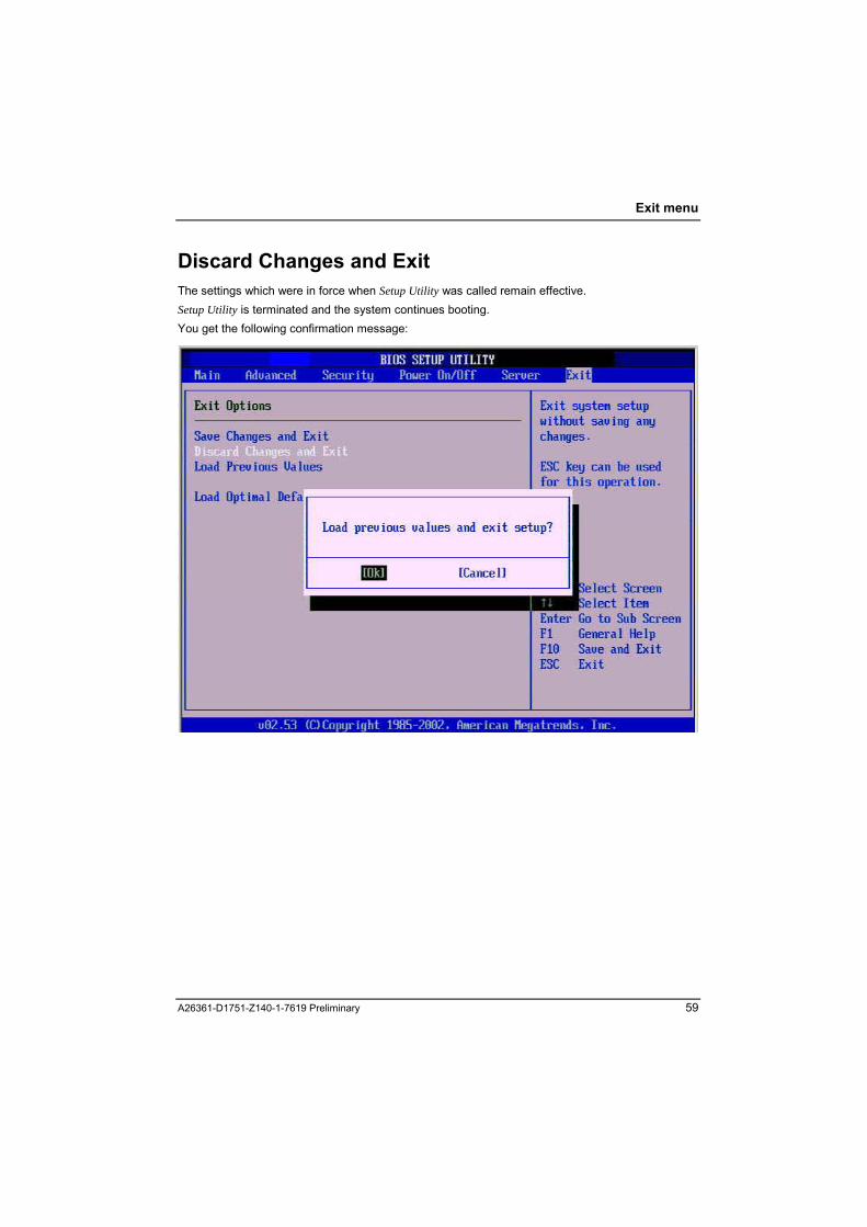
Discard Changes and Exit The settings which were in force when Setup Utility was called remain effective. Setup Utility is terminated and the system continues booting. You get the following confirmation message:
A26361-D1751-Z140-1-7619 Preliminary 59

Exit menu
Load previous values This option allows user to load previous values values to discard all changes. ► Press Enter on this item to ask for confirmation message.
► Select Ok to load previous values. ► Select Cancel to return to setup utility.
You may also use the F7 key for this operation.
60 A26361-D1751-Z140-1-7619 Preliminary

Exit menu
Load Optimal Defaults Loads the optimal values for the best system performance. You may also use the F9 key to load the optimal defaults. ► Press Enter on this item to ask for confirmation:
A26361-D1751-Z140-1-7619 Preliminary 61

Econel 40 Differences in comparison to TX 150S2 BIOS setup BIOS are described in the following chapter.
Main menu There are no differences
Advanced menu
Advanced menu of Econel 40 The items CPU Configuration, Peripheral Configuration, IDE Configuration, USB Configuration, ACPI Configuration, PCIPnP Configuration are the same as in the TX150 S2 BIOS (description see chapter �Advanced menu�).
Missing items in comparison to TX 150S2 BIOS setup??? The item IPMI Configuration do not exist in the Econel 40 BIOS.
Additional items Econal 40 has two additional items in the Advanced menu
A26361-D1751-Z140-1-7619 Preliminary 62

Econel 40 Differences
Hardware Health Configuration In this submenu some critical values of hardware health monitoring are shown. These values are fixed.
A26361-D1751-Z140-1-7619 Preliminary 63

Econel 40 Differences
Remote Access type & parameters The items in this menu allow you to change the remote access type and parameters (see also chapter �Remote Access Configuration� in the Server menu of TX150 S2 BIOS). ► Select the item and press Enter to display the sub-menu.
Remote Access type & parameters of Econel 40
Remote Access
Allows you to enable or disable Remote Access via Serial Port Console Redirection. Enabled enables Remote Access Disabled: disables Remote Access (default).
Serial Port Number Selects the serial port for console redirection. COM1, COM2 (default)
Serial Port Mode
Selects the baudrate of the serial port used for console redirection. 9600, 19200 (default), 38400, 57600, 115200 Flow Control
Sets the flow control of the serial port used for console redirection.
64 A26361-D1751-Z140-1-7619 Preliminary

Econel 40 Differences
None (default), Hardware, Software
Redirection After BIOS POST
Disables or sets the redirection after the Power-On Self Test (POST). Disabled, Boot Loader, Always (default)
Terminal Type
Selects the target terminal type. ANSI (default), VT100, VT-UTF8
VT-UTF8 Combo Key Support
Disables or enables the VT-UTF8 combination key support for ANSI/VT100 terminals. Enabled enables this function. Disabled disables this function (default).
IDE Configuration The items in this menu allow you to set or change the configurations for the IDE devices installed in the system. Select an item then press Enter if you wish to configure the item.
IDE Configuration menu of Econel 40
S-ATA Mode
With this option both S-ATA interfaces can be mapped as primary IDE master/slave interface, if the operating system cannot handle the S-ATA hard disks in native mode.
A26361-D1751-Z140-1-7619 Preliminary 65

Econel 40 Differences
Native S-ATA controller is working as a native PCI device (default). Legacy S-ATA is mapped as legacy primary IDE master/slave.
i
When set to legacy, the primary IDE interface is disabled on the system board and the S-ATA hard disks will appear as Primary IDE Master and Primary IDE Slave in the Main Menu after reboot.
S-ATA Interface
This option enables or disables the S-ATA interface. Enabled Both S-ATA interfaces on the system board are enabled (default). Disabled Both S-ATA interfaces on the system board are disabled.
Configure S-ATA as RAID With this option both S-ATA hard disks can be configured as RAID (RAID: Redundant Array of Inexpensive Disks) Yes Both S-ATA hard disks are working in a RAID configuration as one logical device. No Both S-ATA hard disks are working as two physical devices.
66 A26361-D1751-Z140-1-7619 Preliminary
Error Messages
Error Messages TX150 S2 BIOS V0.10 Error Messages "Refresh timer test failed"
"RAM R/W test failed"
"KBC BAT Test failed"
"Display memory test failed"
"CMOS Battery Low"
"CMOS Settings Wrong"
"CMOS Checksum Bad"
"CMOS Memory Size Wrong"
"CMOS Display Type Wrong"
"CMOS Date/Time Not Set"
"DMA Controller Error"
"DMA-1 Error"
"DMA-2 Error"
"Timer Error"
"Password check failed"
"Unlock Keyboard"
"Keyboard/Interface Error"
"Keyboard Error"
"Floppy Controller Failure"
"A: Drive Error"
"B: Drive Error"
"Primary Master Hard Disk Error"
"Primary Slave Hard Disk Error"
"Secondary Master Hard Disk Error"
"Secondary Slave Hard Disk Error"
"Third Master Hard Disk Error"
"Third Slave Hard Disk Error"
"Fourth Master Hard Disk Error"
"Fourth Slave Hard Disk Error"
"Primary Master Drive - ATAPI Incompatible"
"Primary Slave Drive - ATAPI Incompatible"
"Secondary Master Drive - ATAPI Incompatible"
"Secondary Slave Drive - ATAPI Incompatible"
"Third Master Drive - ATAPI Incompatible"
"Third Slave Drive - ATAPI Incompatible"
A26361-D1751-Z140-1-7619 Preliminary 67

Error Messages
"Fourth Master Drive - ATAPI Incompatible"
"Fourth Slave Drive - ATAPI Incompatible"
"S.M.A.R.T. Command Failed"
"S.M.A.R.T. Status BAD, Backup and Replace"
"NVRAM Checksum Bad, NVRAM Cleared"
"Resource Conflict"
"NVRAM Ignored"
"NVRAM Bad"
"PCI I/O conflict:"
"PCI IRQ routing table error"
“Non Fujitsu Siemens Memory Module detected - Warranty restricted”
“CPU had been changed - RUN SETUP”
“Memory devices had been disabled - RUN SETUP”
“Patch for installed CPU not load”
“Expansion ROM not initialized” “Critical error logged to server management processor”
“Frontpanel NMI activated”
“Baseboard Management Controller Error”
“Memory configuration has changed - RUN SETUP”
“No usable CPU”
“Baseboard Management Controller has detected an Error”
“A temperature has exceeded the warning threshold”
“A temperature has exceeded the critical threshold”
“CPU fan speed has exceeded the warning threshold”
“CPU fan speed has exceeded the critical threshold”
“System fan speed has exceeded the warning threshold”
“System fan speed has exceeded the critical threshold”
“Power supply fan speed has exceeded the warning threshold”
“Power supply fan speed has exceeded the critical threshold”
“System board voltage has exceeded the critical threshold”
“System Event Log utilization has exceeded the warning threshold”
“CPU runtime error (IERR#) detected”
“Memory type mixing detected”
“No usable system memory”
!
Non Fujitsu Siemens Memory Module detected - Warranty restricted. Memory module failed. This module is no longer available for the operateing system.
68 A26361-D1751-Z140-1-7619 Preliminary

Error Messages
Econel 40 BIOS V0.13 Error Message "Refresh timer test failed"
"RAM R/W test failed"
"KBC BAT Test failed"
"Display memory test failed"
"CMOS Battery Low"
"CMOS Settings Wrong"
"CMOS Checksum Bad"
"CMOS Memory Size Wrong"
"CMOS Display Type Wrong"
"CMOS Date/Time Not Set"
"DMA Controller Error"
"DMA-1 Error"
"DMA-2 Error"
"Timer Error"
"Password check failed"
"Unlock Keyboard"
"Keyboard/Interface Error"
"Keyboard Error"
"Floppy Controller Failure"
"A: Drive Error"
"B: Drive Error"
"Primary Master Hard Disk Error"
"Primary Slave Hard Disk Error"
"Secondary Master Hard Disk Error"
"Secondary Slave Hard Disk Error"
"Third Master Hard Disk Error"
"Third Slave Hard Disk Error"
"Fourth Master Hard Disk Error"
"Fourth Slave Hard Disk Error"
"Primary Master Drive - ATAPI Incompatible"
"Primary Slave Drive - ATAPI Incompatible"
"Secondary Master Drive - ATAPI Incompatible"
"Secondary Slave Drive - ATAPI Incompatible"
"Third Master Drive - ATAPI Incompatible"
"Third Slave Drive - ATAPI Incompatible"
"Fourth Master Drive - ATAPI Incompatible"
"Fourth Slave Drive - ATAPI Incompatible"
A26361-D1751-Z140-1-7619 Preliminary 69

Error Messages
"S.M.A.R.T. Command Failed"
"S.M.A.R.T. Status BAD, Backup and Replace"
"NVRAM Checksum Bad, NVRAM Cleared"
"Resource Conflict"
"NVRAM Ignored"
"NVRAM Bad"
"PCI I/O conflict:"
"PCI IRQ routing table error"
“Multi-Bit ECC Error”
“Non Fujitsu Siemens Memory Module detected - Warranty restricted”
“CPU had been changed - RUN SETUP”
“Memory configuration has changed - RUN SETUP”
“Patch for installed CPU not load”
“Previous boot incomplete - Default configuration used”
“Expansion ROM not initialized”
“Ambient Temperature Error”
70 A26361-D1751-Z140-1-7619 Preliminary

Index
Index
1 1st Boot Device 19
2 2nd Boot Device 19
3 32 Bit Data Transfer 13 3rd Boot Device 19
4 4th Boot Device 19
5 5th Boot Device 19
A ACPI Aware O/S 30 ACPI Configuration 30 AddOn ROM Display Mode 16 Adjacent Sector Prefetch 23 Advanced ACPI Configuration 31 Advanced menu 21 ASR&R Boot Delay 52 ATAPI CD-ROM Drives 20
B Bloc (Multi-sector Transfer) 12 BMC Time Sync. 36 BOOT Device Priority 18 Boot Menu 17 Boot Retry Counter 53 Boot Sector Virus Protection 46 Boot Settings 14 Bootup NumLock 16 BUS Master 34, 35
C C.S.A. Gigabit Ethernet 34 Clear System Event Log 36 Clear System Password 46 Compatible FPU Code 23 CPU Clock Throttling Delay 24 CPU Configuration 22 CPU Mismatch Detection 24 CPU Status 54 CPU Status Configuration 54
D DEL
Enter Setup 3 Device 34 Diagnostic System 52 Discard Values and Exit 59 Diskette Write 47
E Error Messages 68 Event Log Full Mode 35 Exit menu 57
F F8
Boot Menu 3 Fast String Operation 23 Flash Write 47 Floppy A 10 Floppy Type 26 function key F8 5
H Hard Drive 19 Hyper Threading Function 23
I IDE Channel Selection 28 IDE Configuration 28 IPMI Configration 35
L L3 Cache 23 LAN Setting 38 Latency Timer 34, 35 LBA/Large Mode 12 Legacy USB Support 29 Load previous values 60 LSI SCSI 1020 33
M Main menu 7 Memory Module 1, 2, 3, 4 55 Memory Status Configuration 55 Mode 52 MSP Revision 23 Multiboot for HD´s 17
A26361-D1751-Z140-1-7619 Preliminary 71

Index
N Notational conventions 2
O O/S Boot Timeout 51 OffBoard PCI/ISA IDE Card 33 OnBoard Floppy Controller 25 Option ROM Order 33 Option ROM Scan 33, 34
P Parallel Port Address 27 PCI Device Scan Order 33 PCI IRQ Configuration 24 PCI IRQ Line A 24 PCI IRQ Line B 24 PCI IRQ Line C 24 PCI IRQ Line D 24 PCI IRQ Line E 24 PCI IRQ Line H 24 PCI Slot 1 to 5 Configuration 34 PCIPnP Configuration 32 Peripheral Configuration 25 PIO Mode 13 Plug & Play O/S 33 POST Errors 16 Power Cycle Delay (sec) 52 Power Failure Recovery 49 Power menu 49 Primary IDE Master 10 Primary IDE Slave 12 PS/2 Mouse Support 27
Q Quick Boot 15 Quiet Boot 15
R Ratio Actual Value 22 Ratio Status 22 Remote Acess Configuration 53 Removable Devices 19
Resume On LAN 50 Resume On Ring 49 Resume On RTC Alarm 50
S S.M.A.R.T. 13 Save Changes & Exit 58 SDRR Browser 37 Secondary IDE Master 12 Secondary IDE Slave 12 Security 41 Serial Multiplexer 26 Serial Port 1 Address 26 Serial Port2 Adress 26 Server menu 51 Set Setup Password 42 Set System Password 44 Setup Password 42 Setup Password Lock 46 SETUP Prompt 47 Setup Utility 1, 3 SM Error Halt 16 Split Lock Operation 23 System Date 10 System Event Log 36 System Information 8 System Keyboard 16 System Load 47 System Memory 20 System Password 42 System Time 9
T Temperature Monitoring 53 Timeout value 52 Type 12
U USB 2.0 Controller 30 USB Configuration 29 USB Function 29
72 A26361-D1751-Z140-1-7619 Preliminary

Information on this document On April 1, 2009, Fujitsu became the sole owner of Fujitsu Siemens Compu-ters. This new subsidiary of Fujitsu has been renamed Fujitsu Technology So-lutions.
This document from the document archive refers to a product version which was released a considerable time ago or which is no longer marketed.
Please note that all company references and copyrights in this document have been legally transferred to Fujitsu Technology Solutions.
Contact and support addresses will now be offered by Fujitsu Technology So-lutions and have the format …@ts.fujitsu.com.
The Internet pages of Fujitsu Technology Solutions are available at http://ts.fujitsu.com/... and the user documentation at http://manuals.ts.fujitsu.com.
Copyright Fujitsu Technology Solutions, 2009
Hinweise zum vorliegenden Dokument Zum 1. April 2009 ist Fujitsu Siemens Computers in den alleinigen Besitz von Fujitsu übergegangen. Diese neue Tochtergesellschaft von Fujitsu trägt seit-dem den Namen Fujitsu Technology Solutions.
Das vorliegende Dokument aus dem Dokumentenarchiv bezieht sich auf eine bereits vor längerer Zeit freigegebene oder nicht mehr im Vertrieb befindliche Produktversion.
Bitte beachten Sie, dass alle Firmenbezüge und Copyrights im vorliegenden Dokument rechtlich auf Fujitsu Technology Solutions übergegangen sind.
Kontakt- und Supportadressen werden nun von Fujitsu Technology Solutions angeboten und haben die Form …@ts.fujitsu.com.
Die Internetseiten von Fujitsu Technology Solutions finden Sie unter http://de.ts.fujitsu.com/..., und unter http://manuals.ts.fujitsu.com finden Sie die Benutzerdokumentation.
Copyright Fujitsu Technology Solutions, 2009


![Schutzkonzept Version 2020-06-04 · 7(&+1,6&+( .200,66,21 )h5 '$6 *(%5$8&+6 81' 63257+81'(:(6(1 GHU 6FKZHL]HULVFKHQ .\QRORJLVFKHQ *HVHOOVFKDIW &200,66,21 7(&+1,48( 3285 &+,(16 ' 87,/,7(](https://static.fdokument.com/doc/165x107/60ff9936e6c8a62abf5d89f5/schutzkonzept-version-2020-06-04-716-2006621-h5-6-586.jpg)