
flender g ear units - mgh.be · PDF fileLes réducteurs à engrenages Flender sont...
224
Catalog MD 20.1 • 2006/2007 Zahnradgetriebe Gear Units Réducteurs à engrenages flender gear units
Transcript of flender g ear units - mgh.be · PDF fileLes réducteurs à engrenages Flender sont...
Ca
talo
gM
D2
0.1
•2
00
6/2
00
7
ZahnradgetriebeGear UnitsRéducteurs à engrenages
Ca
talo
gM
D2
0.1
•2
00
6/2
00
7Fl
ende
rG
ear
Un
its
Die Informationen in diesem Katalog enthalten Beschreibungenbzw. Leistungsmerkmale, welche im konkreten Anwendungsfallnicht immer in der beschriebenen Form zutreffen bzw. welchesich durch Weiterentwicklung der Produkte ändern können. Diegewünschten Leistungsmerkmale sind nur dann verbindlich,wenn sie bei Vertragsabschluss ausdrücklich vereinbart werden.Liefermöglichkeiten und technische Änderungen vorbehalten.Alle Erzeugnisbezeichnungen können Marken oder Erzeugnis-namen der Siemens AG oder anderer, zuliefernder Unternehmensein, deren Benutzung durch Dritte für deren Zwecke die Rechteder Inhaber verletzen kann.
The information provided in this catalog contains descriptions orcharacteristics of performance which in case of actual use do notalways apply as described or which may change as a result offurther development of the products. An obligation to providethe respective characteristics shall only exist if expressly agreedin the terms of contract. Availability and technical specificationsare subject to change without notice.All product designations may be trademarks or product names ofSiemens AG or supplier companies whose use by third parties fortheir own purposes could violate the rights of the owners.
Les informations de ce catalogue contiennent des descriptionsou des caractéristiques qui, dans des cas d’utilisation concrets, nesont pas toujours applicables dans la forme décrite ou qui, enraison d’un développement ultérieur des produits, sontsusceptibles d’être modifiées. Les caractéristiques particulièressouhaitées ne sont obligatoires que si elles sont expressémentstipulées en conclusion du contrat. Sous réserve des possibilitésde livraison et de modifications techniques.Toutes les désignations de produits peuvent être des marques oudes noms de produits de Siemens AG ou de sociétés tiercesagissant en qualité de fournisseurs, dont l'utilisation par des tiers à leurs propres fins peut enfreindre les droits de leurspropriétaires respectifs.
A. Friedr. Flender AG
P.O. Box 1364
46393 Bocholt
Alfred-Flender-Strasse 77
46395 Bocholt
www.flender.com Order No. E86060-K5720-A111-A1-6300
flender gear unitsSubj
ect
toch
ange
|D
ispo
18
50
0|
KG0
90
75
.0RO
22
0D
e/En
/Fr
|Pr
inte
din
Ger
man
y|
©Si
emen
sA
G2
00
7

1
2
3
4
5
6
7
8
9
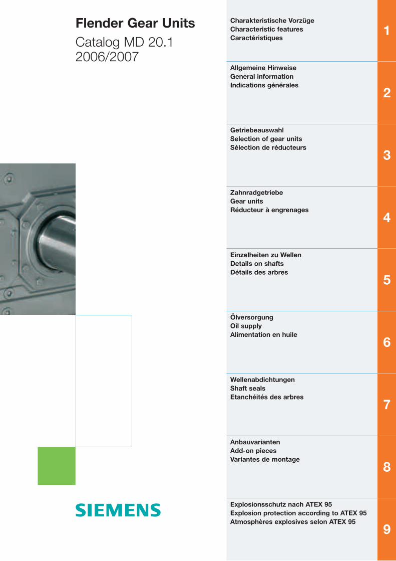
Flender Gear UnitsCatalog MD 20.12006/2007
Charakteristische VorzügeCharacteristic featuresCaractéristiques
Allgemeine HinweiseGeneral informationIndications générales
GetriebeauswahlSelection of gear unitsSélection de réducteurs
ZahnradgetriebeGear unitsRéducteur à engrenages
Einzelheiten zu WellenDetails on shaftsDétails des arbres
ÖlversorgungOil supplyAlimentation en huile
WellenabdichtungenShaft sealsEtanchéités des arbres
AnbauvariantenAdd-on piecesVariantes de montage
Explosionsschutz nach ATEX 95Explosion protection according to ATEX 95Atmosphères explosives selon ATEX 95
Willkommen bei Automation and Drives
II Siemens MD 20.1 · 2006/2007
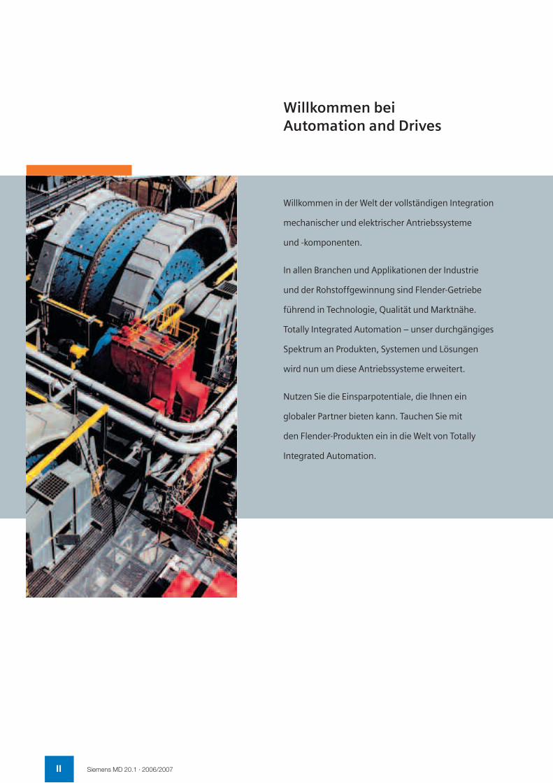
Willkommen in der Welt der vollständigen Integration
mechanischer und elektrischer Antriebssysteme
und -komponenten.
In allen Branchen und Applikationen der Industrie
und der Rohstoffgewinnung sind Flender-Getriebe
führend in Technologie, Qualität und Marktnähe.
Totally Integrated Automation – unser durchgängiges
Spektrum an Produkten, Systemen und Lösungen
wird nun um diese Antriebssysteme erweitert.
Nutzen Sie die Einsparpotentiale, die Ihnen ein
globaler Partner bieten kann. Tauchen Sie mit
den Flender-Produkten ein in die Welt von Totally
Integrated Automation.

IIISiemens MD 20.1 · 2006/2007
Welcome to Automation and Drives
Welcome to the world of the totally integrated
mechanical and electrical drive systems and
components!
In all industry sectors, for all industrial applications
and the winning of raw materials Flender gear units
are leading in technology, quality and market
orientation. Totally Integrated Automation – our
integrated range of products, systems and solutions
is now being expanded to include these drive
systems.
Utilize the savings potential which a global partner
can offer you. Enter the world of Totally Integrated
Automation with Flender products.
Bienvenue chez Automation and Drives
Bienvenue dans le monde de l’intégration totale des
systèmes et composants d’entraînement mécaniques
et électriques.
Les réducteurs à engrenages Flender sont leaders
par la technologie, la qualité et la proximité avec les
marchés dans toutes les branches et applications
industrielles, tout comme dans l’extraction des
matières premières. Totally Integrated Automation –
notre gamme extensive de produits, de systèmes et
de solutions, est désormais complétée par ces
systèmes d’entraînement.
Tirez profit des potentiels d’économies que peut
vous offrir un partenaire mondial. Avec les produits
Flender, plongez dans le monde de la Totally
Integrated Automation.
2 Siemens MD 20.1 2006/2007
������������� ���� �� ��������� � ����������
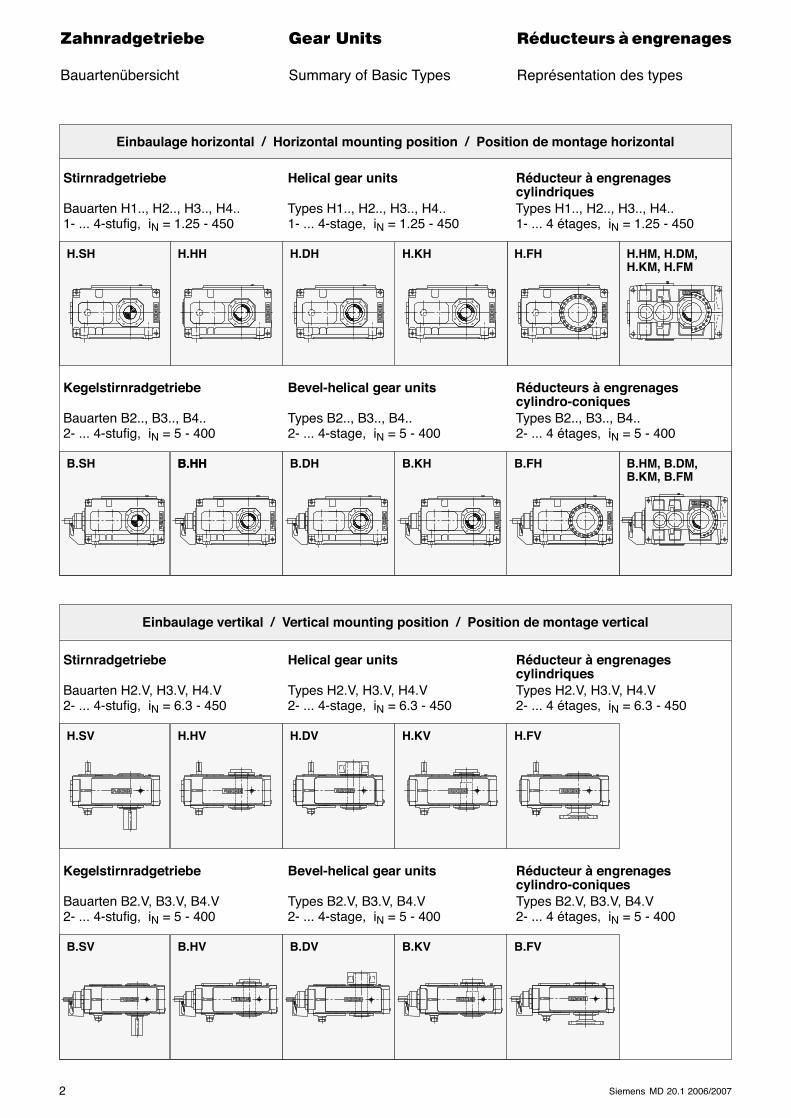
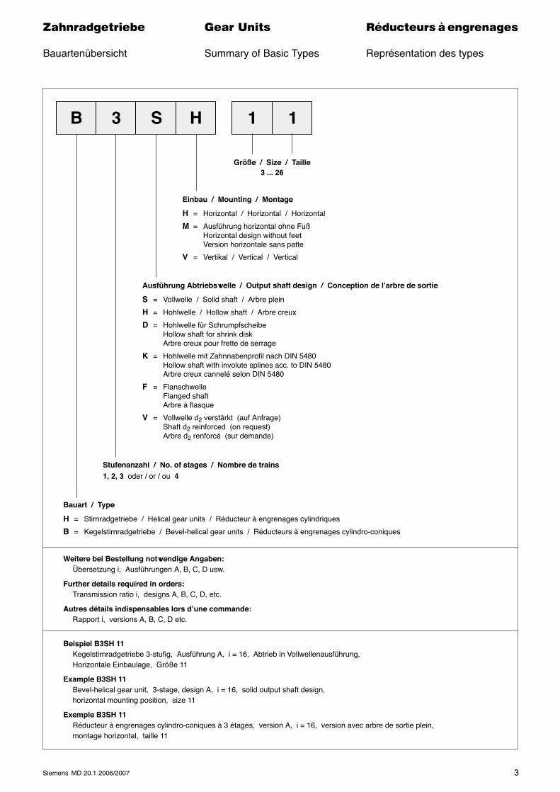
Bauartenübersicht Summary of Basic Types Représentation des types
Einbaulage horizontal / Horizontal mounting position / Position de montage horizontal
Stirnradgetriebe Helical gear units Réducteur à engrenagescylindriques
Bauarten H1.., H2.., H3.., H4.. Types H1.., H2.., H3.., H4.. Types H1.., H2.., H3.., H4..1- ... 4-stufig, iN = 1.25 - 450 1- ... 4-stage, iN = 1.25 - 450 1- ... 4 étages, iN = 1.25 - 450
Kegelstirnradgetriebe Bevel-helical gear units Réducteurs à engrenagescylindro-coniques
Bauarten B2.., B3.., B4.. Types B2.., B3.., B4.. Types B2.., B3.., B4..2- ... 4-stufig, iN = 5 - 400 2- ... 4-stage, iN = 5 - 400 2- ... 4 étages, iN = 5 - 400
Einbaulage vertikal / Vertical mounting position / Position de montage vertical
Stirnradgetriebe Helical gear units Réducteur à engrenagescylindriques
Bauarten H2.V, H3.V, H4.V Types H2.V, H3.V, H4.V Types H2.V, H3.V, H4.V2- ... 4-stufig, iN = 6.3 - 450 2- ... 4-stage, iN = 6.3 - 450 2- ... 4 étages, iN = 6.3 - 450
Kegelstirnradgetriebe Bevel-helical gear units Réducteur à engrenagescylindro-coniques
Bauarten B2.V, B3.V, B4.V Types B2.V, B3.V, B4.V Types B2.V, B3.V, B4.V2- ... 4-stufig, iN = 5 - 400 2- ... 4-stage, iN = 5 - 400 2- ... 4 étages, iN = 5 - 400
H.SH H.HH H.KH H.HM, H.DM,H.KM, H.FM
B.SH B.HH
H.SV
H.DH H.FH
B.HH B.DH B.KH B.FH B.HM, B.DM,B.KM, B.FM
H.HV H.KVH.DV H.FV
B.SV B.HV B.KVB.DV B.FV
3Siemens MD 20.1 2006/2007
������������� ���� �� ��������� � ����������
Bauartenübersicht Summary of Basic Types Représentation des types
Ausführung Abtriebswelle / Output shaft design / Conception de l’arbre de sortie
S = Vollwelle / Solid shaft / Arbre plein
H = Hohlwelle / Hollow shaft / Arbre creux
D = Hohlwelle für SchrumpfscheibeHollow shaft for shrink diskArbre creux pour frette de serrage
K = Hohlwelle mit Zahnnabenprofil nach DIN 5480Hollow shaft with involute splines acc. to DIN 5480Arbre creux cannelé selon DIN 5480
F = FlanschwelleFlanged shaftArbre à flasque
V = Vollwelle d2 verstärkt (auf Anfrage)Shaft d2 reinforced (on request)Arbre d2 renforcé (sur demande)
Stufenanzahl / No. of stages / Nombre de trains1, 2, 3 oder / or / ou 4
Bauart / Type
H = Stirnradgetriebe / Helical gear units / Réducteur à engrenages cylindriques
B = Kegelstirnradgetriebe / Bevel-helical gear units / Réducteurs à engrenages cylindro-coniques
Einbau / Mounting / Montage
H = Horizontal / Horizontal / Horizontal
M = Ausführung horizontal ohne FußHorizontal design without feetVersion horizontale sans patte
V = Vertikal / Vertical / Vertical
Größe / Size / Taille3 ... 26
B 3 S H 1
Weitere bei Bestellung notwendige Angaben:Übersetzung i, Ausführungen A, B, C, D usw.
Further details required in orders:Transmission ratio i, designs A, B, C, D, etc.
Autres détails indispensables lors d’une commande:Rapport i, versions A, B, C, D etc.
Beispiel B3SH 11Kegelstirnradgetriebe 3-stufig, Ausführung A, i = 16, Abtrieb in Vollwellenausführung,Horizontale Einbaulage, Größe 11
Example B3SH 11Bevel-helical gear unit, 3-stage, design A, i = 16, solid output shaft design,horizontal mounting position, size 11
Exemple B3SH 11Réducteur à engrenages cylindro-coniques à 3 étages, version A, i = 16, version avec arbre de sortie plein,montage horizontal, taille 11
1
4 Siemens MD 20.1 2006/2007
������������� ���� �� ��������� � ����������
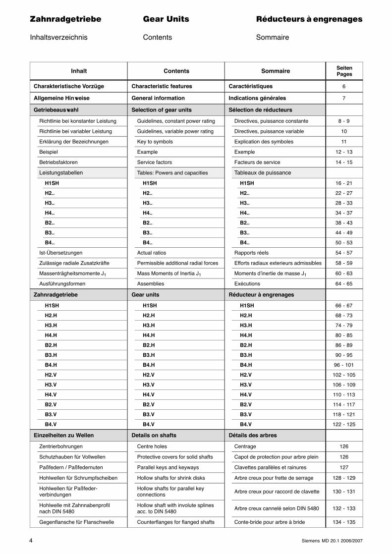
Inhaltsverzeichnis Contents Sommaire
Inhalt Contents Sommaire SeitenPages
Charakteristische Vorzüge Characteristic features Caractéristiques 6
Allgemeine Hinweise General information Indications générales 7
Getriebeauswahl Selection of gear units Sélection de réducteurs
Richtlinie bei konstanter Leistung Guidelines, constant power rating Directives, puissance constante 8 - 9
Richtlinie bei variabler Leistung Guidelines, variable power rating Directives, puissance variable 10
Erklärung der Bezeichnungen Key to symbols Explication des symboles 11
Beispiel Example Exemple 12 - 13
Betriebsfaktoren Service factors Facteurs de service 14 - 15
Leistungstabellen Tables: Powers and capacities Tableaux de puissance
H1SH H1SH H1SH 16 - 21
H2.. H2.. H2.. 22 - 27
H3.. H3.. H3.. 28 - 33
H4.. H4.. H4.. 34 - 37
B2.. B2.. B2.. 38 - 43
B3.. B3.. B3.. 44 - 49
B4.. B4.. B4.. 50 - 53
Ist-Übersetzungen Actual ratios Rapports réels 54 - 57
Zulässige radiale Zusatzkräfte Permissible additional radial forces Efforts radiaux exterieurs admissibles 58 - 59
Massenträgheitsmomente J1 Mass Moments of Inertia J1 Moments d’inertie de masse J1 60 - 63
Ausführungsformen Assemblies Exécutions 64 - 65
Zahnradgetriebe Gear units Réducteur à engrenages
H1SH H1SH H1SH 66 - 67
H2.H H2.H H2.H 68 - 73
H3.H H3.H H3.H 74 - 79
H4.H H4.H H4.H 80 - 85
B2.H B2.H B2.H 86 - 89
B3.H B3.H B3.H 90 - 95
B4.H B4.H B4.H 96 - 101
H2.V H2.V H2.V 102 - 105
H3.V H3.V H3.V 106 - 109
H4.V H4.V H4.V 110 - 113
B2.V B2.V B2.V 114 - 117
B3.V B3.V B3.V 118 - 121
B4.V B4.V B4.V 122 - 125
Einzelheiten zu Wellen Details on shafts Détails des arbres
Zentrierbohrungen Centre holes Centrage 126
Schutzhauben für Vollwellen Protective covers for solid shafts Capot de protection pour arbre plein 126
Paßfedern / Paßfedernuten Parallel keys and keyways Clavettes parallèles et rainures 127
Hohlwellen für Schrumpfscheiben Hollow shafts for shrink disks Arbre creux pour frette de serrage 128 - 129
Hohlwellen für Paßfeder-verbindungen
Hollow shafts for parallel keyconnections Arbre creux pour raccord de clavette 130 - 131
Hohlwelle mit Zahnnabenprofilnach DIN 5480
Hollow shaft with involute splinesacc. to DIN 5480 Arbre creux cannelé selon DIN 5480 132 - 133
Gegenflansche für Flanschwelle Counterflanges for flanged shafts Conte-bride pour arbre à bride 134 - 135
5Siemens MD 20.1 2006/2007
������������� ���� �� ��������� � ����������
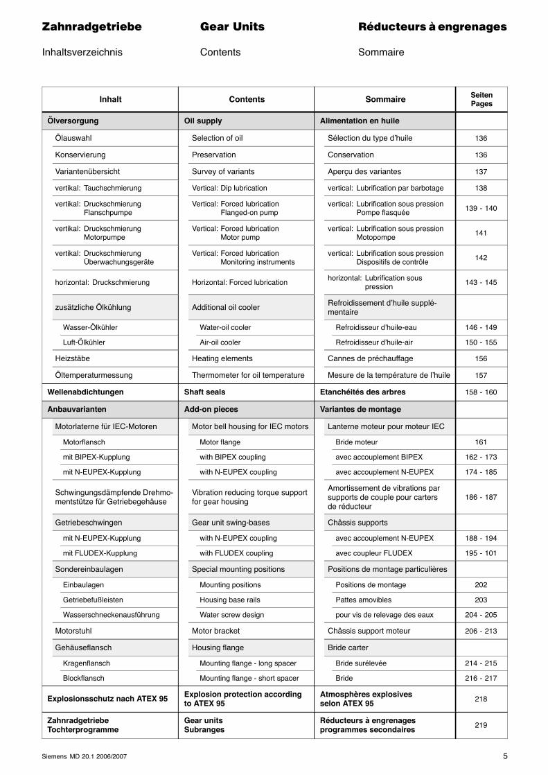
Inhaltsverzeichnis Contents Sommaire
Inhalt Contents Sommaire SeitenPages
Ölversorgung Oil supply Alimentation en huile
Ölauswahl Selection of oil Sélection du type d’huile 136
Konservierung Preservation Conservation 136
Variantenübersicht Survey of variants Aperçu des variantes 137
vertikal: Tauchschmierung Vertical: Dip lubrication vertical: Lubrification par barbotage 138
vertikal: DruckschmierungFlanschpumpe
Vertical: Forced lubricationFlanged-on pump
vertical: Lubrification sous pressionPompe flasquée 139 - 140
vertikal: DruckschmierungMotorpumpe
Vertical: Forced lubricationMotor pump
vertical: Lubrification sous pressionMotopompe 141
vertikal: DruckschmierungÜberwachungsgeräte
Vertical: Forced lubricationMonitoring instruments
vertical: Lubrification sous pressionDispositifs de contrôle 142
horizontal: Druckschmierung Horizontal: Forced lubrication horizontal: Lubrification souspression 143 - 145
zusätzliche Ölkühlung Additional oil cooler Refroidissement d’huile supplé-mentaire
Wasser-Ölkühler Water-oil cooler Refroidisseur d’huile-eau 146 - 149
Luft-Ölkühler Air-oil cooler Refroidisseur d’huile-air 150 - 155
Heizstäbe Heating elements Cannes de préchauffage 156
Öltemperaturmessung Thermometer for oil temperature Mesure de la température de l’huile 157
Wellenabdichtungen Shaft seals Etanchéités des arbres 158 - 160
Anbauvarianten Add-on pieces Variantes de montage
Motorlaterne für IEC-Motoren Motor bell housing for IEC motors Lanterne moteur pour moteur IEC
Motorflansch Motor flange Bride moteur 161
mit BIPEX-Kupplung with BIPEX coupling avec accouplement BIPEX 162 - 173
mit N-EUPEX-Kupplung with N-EUPEX coupling avec accouplement N-EUPEX 174 - 185
Schwingungsdämpfende Drehmo-mentstütze für Getriebegehäuse
Vibration reducing torque supportfor gear housing
Amortissement de vibrations parsupports de couple pour cartersde réducteur
186 - 187
Getriebeschwingen Gear unit swing-bases Châssis supports
mit N-EUPEX-Kupplung with N-EUPEX coupling avec accouplement N-EUPEX 188 - 194
mit FLUDEX-Kupplung with FLUDEX coupling avec coupleur FLUDEX 195 - 101
Sondereinbaulagen Special mounting positions Positions de montage particulières
Einbaulagen Mounting positions Positions de montage 202
Getriebefußleisten Housing base rails Pattes amovibles 203
Wasserschneckenausführung Water screw design pour vis de relevage des eaux 204 - 205
Motorstuhl Motor bracket Châssis support moteur 206 - 213
Gehäuseflansch Housing flange Bride carter
Kragenflansch Mounting flange - long spacer Bride surélevée 214 - 215
Blockflansch Mounting flange - short spacer Bride 216 - 217
Explosionsschutz nach ATEX 95 Explosion protection accordingto ATEX 95
Atmosphères explosivesselon ATEX 95 218
ZahnradgetriebeTochterprogramme
Gear unitsSubranges
Réducteurs à engrenagesprogrammes secondaires 219
6 Siemens MD 20.1 2006/2007
������������� ���� �� ��������� � ����������
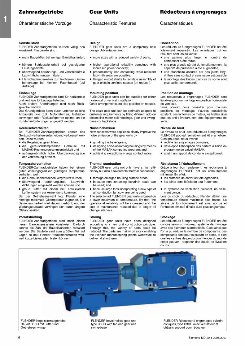
Charakteristische Vorzüge Characteristic Features Caractéristiques
KonstruktionFLENDER-Zahnradgetriebe wurden völlig neukonzipiert. Pluspunkte sind:
� mehr Baugrößen bei weniger Bauteilvarianten,
� höhere Betriebssicherheit bei gesteigerterLeistungsdichte,
� überwiegend berührungs- und verschleißfreieLabyrinthdichtungen möglich,
� Flanschabtriebswellen zur leichteren Getrie-bemontage bei kleinem Raumbedarf (aufAnfrage).
EinbaulageFLENDER-Zahnradgetriebe sind für horizontaleund vertikale Einbaulage lieferbar.Auch andere Anordnungen sind nach Rück-sprache möglich.Das Grundgetriebe kann durch unterschiedlicheAnbauteile wie z.B. Motorlaternen, Getriebe-schwingen oder Rücklaufsperren optimal an dieKundenanforderungen angepaßt werden.
GeräuschverhaltenBei FLENDER-Zahnradgetrieben konnte dasGeräuschverhalten entscheidend verbessert wer-den. Dazu wurden:� die Kegelräder geschliffen,� die geräuschdämpfenden Gehäuse mit
MASAK-Rechenprogramm entwickelt und� außergewöhnlich hohe Überdeckungsgrade
der Verzahnung erreicht.
TemperaturverhaltenFLENDER-Zahnradgetriebe haben bei einemguten Wirkungsgrad ein günstiges Temperatur-verhalten, weil� die Gehäuseoberflächen vergrößert wurden,� überwiegend berührungsfreie Labyrinth-
dichtungen eingesetzt werden können und� große Lüfter mit einem neu entwickelten
Luftleitsystem zur Anwendung kommen.Bei der Getriebeauswahl legt Flender eineniedrige maximale Öltemperatur zugrunde. DieBetriebssicherheit wird dadurch erhöht, und derWartungsaufwand verringert sich durch längereÖlstandszeiten.
VorratshaltungFLENDER-Zahnradgetriebe sind nach einemneuen Baukastensystem konstruiert. Dadurchkonnte die Zahl der Bauteilvarianten reduziertwerden. Die Bauteile sind zum größten Teil aufLager, so daß Flender-Produktionsstätten welt-weit kurze Lieferzeiten bieten können.
DesignFLENDER gear units are a completely newdesign. Advantages are:
� more sizes with a reduced variety of parts;
� higher operational reliability combined withincreased power capacity;
� predominantly non-contacting wear-resistantlabyrinth seals are possible;
� flanged output shafts to facilitate assembly ofgear units in confined spaces (on request).
Mounting positionFLENDER gear units can be supplied for eitherhorizontal or vertical installation.Other arrangements are also possible on request.
The basic gear unit can be optimally adapted tocustomer requirements by fitting different add-onpieces like motor bell housings, gear unit swing-bases or backstops.
Noise behaviourNew concepts were applied to clearly improve thenoise emission of the gear units by
� grinding the bevel gears;� designing noise-absorbing housings by means
of the MASAK computing program; and� achieving exceptionally large contact ratios.
Thermal conductionFLENDER gear units not only have a high effi-ciency but also a favourable thermal conduction
� through enlarged housing surface areas;� because non-contacting labyrinth seals can
be used; and� because large fans incorporating a new type of
air conduction fan cowl are being used.The selection of FLENDER gear units is based ona lower maximum oil temperature. By that, theoperational reliability will be increased and thecost of maintenance reduced due to longer oilchange intervals.
StoringFLENDER gear units have been designedaccording to a new unit construction principle.Through this, the variety of parts could bereduced. The parts are mainly on stock enablingthe Flender manufacturing plants worldwide todeliver at short term.
ConceptionLes réducteurs à engrenages FLENDER ont ététotalement repensés. Les avantages qui enrésultent sont les suivants:� une gamme plus large: le nombre de
composant a été réduit,� une plus grande sûreté de fonctionnement: la
capacité de puissance a été augmentée,� une étancheité assurée par des joints laby-
rinthes sans contact et sans usure est possible� le montage des brides d’arbres de sortie sont
plus facile (sur demande).
Position de montageLes réducteurs à engrenages FLENDER sontlivrables pour un montage en position horizontaleou verticale.Vous pouvez nous consulter pour d’autrespositions de montage: d’autres possibilitésexistent. Les lanternes de moteur, les bielles ainsique les anti-dévireurs sont des équipements desérie.
Niveau de bruitLe niveau de bruit des réducteurs à engrenagesFLENDER pouvait sensiblement être amélioré.C’est pourquoi nous avons:� rectifié les engrenages coniques,� développé l’absorption des carters à l’aide du
programme de calcul MASAK,� atteint un rapport de conduite exceptionnel.
Résistance à l’échauffementGrâce à leur bon rendement, les réducteurs àengrenages FLENDER ont un échauffementminimisé. En effet:� les surfaces de carter ont été agrandies,� les joints sont libérés de tout frottement,
� le système de ventilation puissant, nouvelle-ment conçu.
Lors du choix du réducteur, Flender définit unetempérature d’huile maximale plus basse. Lasûreté de fonctionnement est ainsi accrue etl’entretien diminué (l’huile dure plus longtemps).
StockageLes réducteurs à engrenages FLENDER ont étéconçus selon un nouveau système de montageavec des éléments standardisés. C’est ainsi quel’on a pu réduire le nombre de composants. Lescomposants sont pour la plupart en stock, si bienque les centres de production Flender du mondeentier peuvent proposer des délais de livraisoncourts.
FLENDER-KegelstirnradgetriebeBauart B3DH mit Lüfter undGetriebeschwinge
FLENDER bevel-helical gear unittype B3DH with fan and gear unitswing-base
FLENDER Réducteur à engrenages cylindro-coniques, type B3DH avec ventilateur etchâssis support pour réducteur
1
7Siemens MD 20.1 2006/2007
������������� ���� �� ��������� � ����������
Allgemeine Hinweise General Information Indications générales
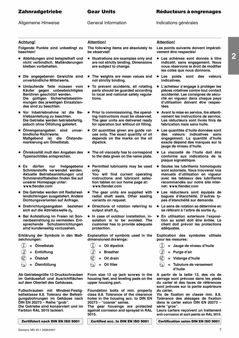
Achtung!Folgende Punkte sind unbedingt zubeachten!
� Abbildungen sind beispielhaft undnicht verbindlich. Maßänderungenbleiben vorbehalten.
� Die angegebenen Gewichte sindunverbindliche Mittelwerte.
� Umlaufende Teile müssen vomKäufer gegen unbeabsichtigtesBerühren geschützt werden.Die gültigen Sicherheitsbestim-mungen des jeweiligen Einsatzlan-des sind zu beachten.
� Vor Inbetriebnahme ist die Be-triebsanleitung zu beachten.Die Getriebe werden betriebsfertig,jedoch ohne Ölfüllung geliefert.
� Ölmengenangaben sind unver-bindliche Richtwerte.Maßgebend ist die Ölstands-markierung am Ölmeßstab.
� Ölviskosität muß den Angaben desTypenschildes entsprechen.
� Es dürfen nur freigegebeneSchmierstoffe verwendet werden.Aktuelle Betriebsanleitungen undSchmierstofftabellen finden Sie aufunserer Homepage unter:www.flender.com
� Die Getriebe werden mit Radialwel-lendichtringen ausgeliefert. AndereDichtungsvarianten auf Anfrage.
� Drehrichtungsangaben beziehensich auf die Abtriebswelle d2.
� Bei Aufstellung im Freien ist Son-nenbestrahlung zu vermeiden. Ent-sprechende Schutzeinrichtungensind kundenseitig vorzusehen.
Erklärung der Symbole in den Maß-zeichnungen:
= Ölmeßstab
= Entlüftung
= Ölablaß
= Öleinfüllung
Ab Getriebegröße 13 Druckschraubenim Gehäusefuß und Ausrichtflächenauf dem Oberteil des Gehäuses.
Fußschrauben mit Mindest-Festig-keitsklasse 8.8. Toleranz der Befesti-gungsbohrungen im Gehäuse nachDIN EN 20273 – Reihe ”grob”.Die Getriebe sind konserviert und imFarbton RAL 5015 lackiert.
������������ �� � � �� �� ����
Attention!The following items are absolutely tobe observed!
� Illustrations are examples only andare not strictly binding. Dimensionsare subject to change.
� The weights are mean values andnot strictly binding.
� To prevent accidents, all rotatingparts should be guarded accordingto local and national safety regula-tions.
� Prior to commissioning, the operat-ing instructions must be observed.The gear units are delivered readyfor operation but without oil filling.
� Oil quantities given are guide val-ues only. The exact quantity of oildepends on the marks on the oildipstick.
� The oil viscosity has to correspondto the data given on the name plate.
� Permitted lubricants may be usedonly.You will find current operatinginstructions and lubricant selec-tion tables on our home page at:www.flender.com
� The gear units are supplied withradial shaft seals. Other sealingvariants on request.
� Directions of rotation referring tooutput shaft d2.
� In case of outdoor installation, in-solation is to be avoided. Thecustomer has to provide adequateprotection.
Explanation of symbols used in thedimensioned drawings:
= Oil dipstick
= Breather
= Oil drain
= Oil filler
From size 13 up jack screws in thehousing feet, and leveling pads on theupper housing part.
Foundation bolts of min. propertyclass 8.8. Tolerance of the clearanceholes in the housing acc. to DIN EN20273 – ”coarse” series.The gear housings are protectedagainst corrosion and sprayed in RAL5015.
��������� � �� � � �� �� ����
Attention!Les points suivants doivent impérati-vement être respectés!
� Les schémas sont donnés à titreindicatif, sans engagement. Nousnous réservons le droit de modifierles cotes que nous donnons.
� Les poids sont des valeursindicatives.
� L’acheteur s’engage à protéger lespièces rotatives contre tout contactaccidentel. Les consignes de sécu-rité en vigueur dans chaque paysd’utilisation doivent être respec-tées.
� Avant la mise en service, lire attenti-vement les instructions de service.Les réducteurs sont livrés finis defabrication mais sans huile.
� Les quantités d’huile données sontdes valeurs indicatives sansengagement. La quantité d’huileexacte dépend des marques sur lajauge de niveau d’huile.
� La viscosité de l’huile doit êtreconforme aux indications de laplaque signalétique.
� Seules les lubrifiants homologuéssont autorisés. Vous trouverez nosmanuels d’utilisation en vigueuravec les tableaux des lubrifiantsrecommandés sur notre site inter-net: www.flender.com
� Les réducteurs sont équipés debagues d’étanchéité. D’autres ty-pes d’étanchéité sur demande.
� Le sens de rotation se détermine ense référant à l’arbre de sortie d2.
� En utilisation exterieure l’exposi-tion au soleil doit être évitée. Leclient doit prévoir les protectionsadéquates.
Explication des symboles utiliséspour les mesures:
= Jauge de niveau d’huile
= Purge d’air
= Vidange d’huile
= Tubulure de versementd’huile
A partir de la taille 13, des vis deserrage sont prévues dans les piedsdu carter et des faces de référencessont prévues sur la partie supérieuredu carter.Vis de fixation en classe min. 8.8.Tolérance des alésages de fixationdans le carter selon DIN EN 20273 –série ”gros”.Leurs carters reçoivent un traitementanti-corrosion et sont peints en RAL 5015.
����������� ����� � � �� �� ����
2
8 Siemens MD 20.1 2006/2007
������������� ���� �� ��������� � ����������
Richtlinien für die Auswahl Guidelines for the Selection Directives de sélectionKonstante Leistung Constant Mechanical Power Puissance constantemechanisch Rating mécanique
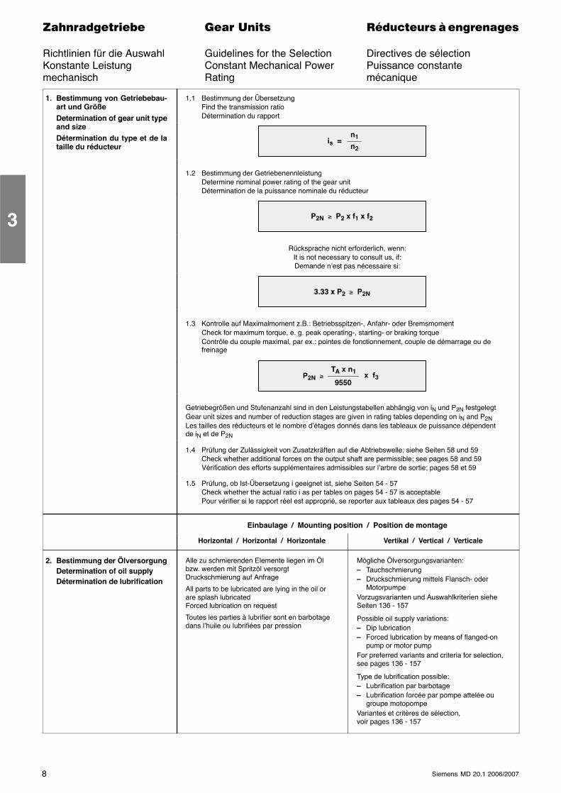
1. Bestimmung von Getriebebau-art und GrößeDetermination of gear unit type
1.1 Bestimmung der ÜbersetzungFind the transmission ratioDétermination du rapportDetermination of gear unit type
and sizeDétermination du type et de lataille du réducteur
is =n1
n2
1.2 Bestimmung der GetriebenennleistungDetermine nominal power rating of the gear unitDétermination de la puissance nominale du réducteur
P2N ≥ P2 x f1 x f2
Rücksprache nicht erforderlich, wenn:It is not necessary to consult us, if:Demande n’est pas nécessaire si:
3.33 x P2 ≥ P2N
1.3 Kontrolle auf Maximalmoment z.B.: Betriebsspitzen-, Anfahr- oder BremsmomentCheck for maximum torque, e. g. peak operating-, starting- or braking torqueContrôle du couple maximal, par ex.: pointes de fonctionnement, couple de démarrage ou defreinage
P2N ≥TA x n1
9550 x f3
Getriebegrößen und Stufenanzahl sind in den Leistungstabellen abhängig von iN und P2N festgelegtGear unit sizes and number of reduction stages are given in rating tables depending on iN and P2NLes tailles des réducteurs et le nombre d’étages donnés dans les tableaux de puissance dépendentde iN et de P2N
1.4 Prüfung der Zulässigkeit von Zusatzkräften auf die Abtriebswelle; siehe Seiten 58 und 59Check whether additional forces on the output shaft are permissible; see pages 58 and 59Vérification des efforts supplémentaires admissibles sur l’arbre de sortie; pages 58 et 59
1.5 Prüfung, ob Ist-Übersetzung i geeignet ist, siehe Seiten 54 - 57Check whether the actual ratio i as per tables on pages 54 - 57 is acceptablePour vérifier si le rapport réel est approprié, se reporter aux tableaux des pages 54 - 57
Einbaulage / Mounting position / Position de montage
Horizontal / Horizontal / Horizontale Vertikal / Vertical / Verticale
2. Bestimmung der ÖlversorgungDetermination of oil supplyDétermination de lubrification
Alle zu schmierenden Elemente liegen im Ölbzw. werden mit Spritzöl versorgtDruckschmierung auf Anfrage
All parts to be lubricated are lying in the oil orare splash lubricatedForced lubrication on request
Toutes les parties à lubrifier sont en barbotagedans l’huile ou lubrifiées par pression
Mögliche Ölversorgungsvarianten:– Tauchschmierung– Druckschmierung mittels Flansch- oder
MotorpumpeVorzugsvarianten und Auswahlkriterien sieheSeiten 136 - 157
Possible oil supply variations:– Dip lubrication– Forced lubrication by means of flanged-on
pump or motor pumpFor preferred variants and criteria for selection,see pages 136 - 157
Type de lubrification possible:– Lubrification par barbotage– Lubrification forcée par pompe attelée ou
groupe motopompeVariantes et critères de sélection,voir pages 136 - 157
3
9Siemens MD 20.1 2006/2007
������������� ���� �� ��������� � ����������
Richtlinien für die Auswahl Guidelines for the Selection Directives de sélectionKonstante Leistung Thermal Capacities Puissance constantethermisch thermique
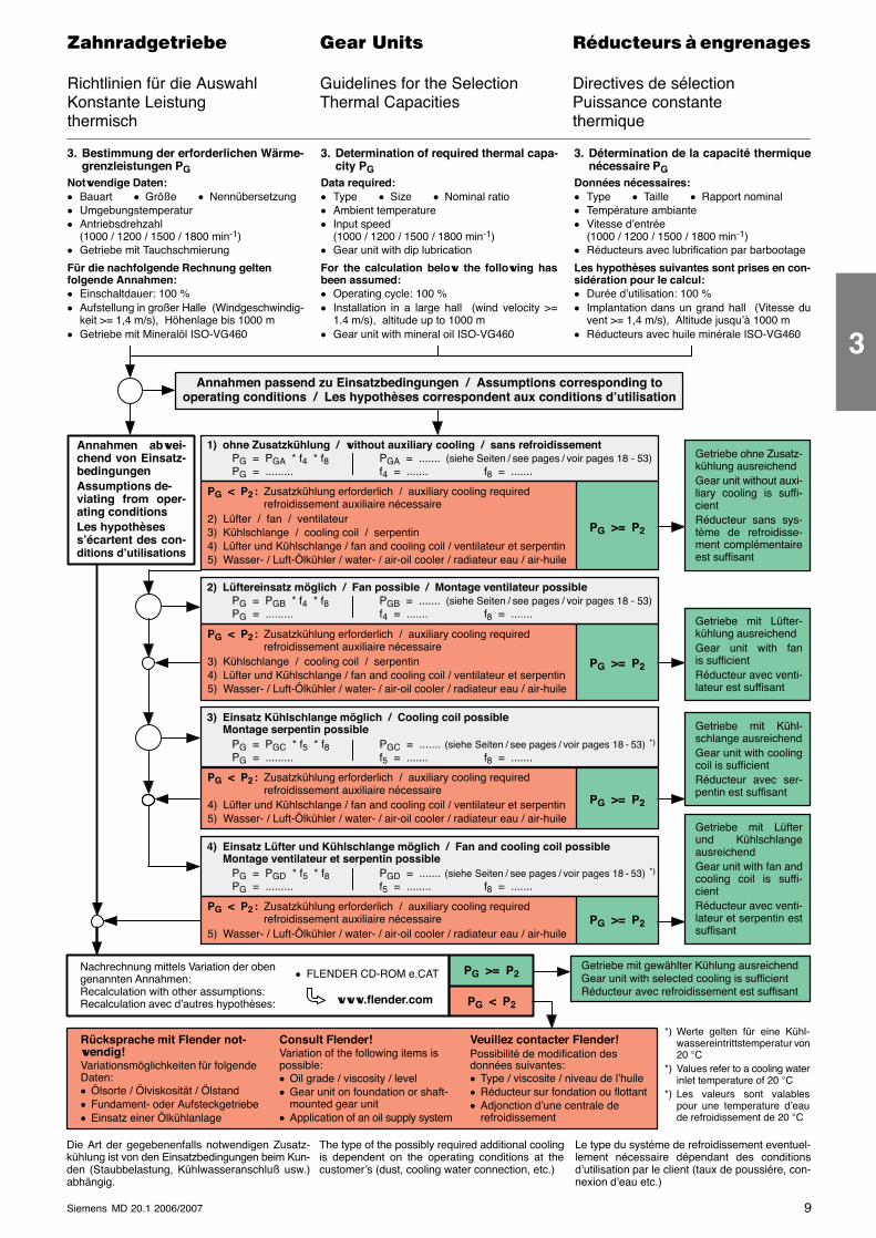
3. Bestimmung der erforderlichen Wärme-grenzleistungen PG
Notwendige Daten:� Bauart � Größe � Nennübersetzung� Umgebungstemperatur� Antriebsdrehzahl
(1000 / 1200 / 1500 / 1800 min-1)� Getriebe mit Tauchschmierung
Für die nachfolgende Rechnung geltenfolgende Annahmen:� Einschaltdauer: 100 %� Aufstellung in großer Halle (Windgeschwindig-
keit >= 1,4 m/s), Höhenlage bis 1000 m� Getriebe mit Mineralöl ISO-VG460
3. Determination of required thermal capa-city PG
Data required:� Type � Size � Nominal ratio� Ambient temperature� Input speed
(1000 / 1200 / 1500 / 1800 min-1)� Gear unit with dip lubrication
For the calculation below the following hasbeen assumed:� Operating cycle: 100 %� Installation in a large hall (wind velocity >=
1.4 m/s), altitude up to 1000 m� Gear unit with mineral oil ISO-VG460
3. Détermination de la capacité thermiquenécessaire PG
Données nécessaires:� Type � Taille � Rapport nominal� Température ambiante� Vitesse d’entrée
(1000 / 1200 / 1500 / 1800 min-1)� Réducteurs avec lubrification par barbootage
Les hypothèses suivantes sont prises en con-sidération pour le calcul:� Durée d’utilisation: 100 %� Implantation dans un grand hall (Vitesse du
vent >= 1,4 m/s), Altitude jusqu’à 1000 m� Réducteurs avec huile minérale ISO-VG460
1) ohne Zusatzkühlung / without auxiliary cooling / sans refroidissementGetriebe ohne Zusatz-kühlung ausreichendGear unit without auxi-liary cooling is suffi-cientRéducteur sans sys-tème de refroidisse-ment complémentaireest suffisant
Getriebe mit Lüfter-kühlung ausreichendGear unit with fanis sufficientRéducteur avec venti-lateur est suffisant
Getriebe mit Kühl-schlange ausreichendGear unit with coolingcoil is sufficientRéducteur avec ser-pentin est suffisant
Getriebe mit Lüfterund KühlschlangeausreichendGear unit with fan andcooling coil is suffi-cientRéducteur avec venti-lateur et serpentin estsuffisant
Annahmen abwei-chend von Einsatz-bedingungenAssumptions de-viating from oper-ating conditionsLes hypothèsess’écartent des con-ditions d’utilisations
Annahmen passend zu Einsatzbedingungen / Assumptions corresponding tooperating conditions / Les hypothèses correspondent aux conditions d’utilisation
PG = PGA * f4 * f8PG = .........
PGA = ....... (siehe Seiten / see pages / voir pages 18 - 53)f4 = ....... f8 = .......
PG < P2 : Zusatzkühlung erforderlich / auxiliary cooling requiredrefroidissement auxiliaire nécessaire
2) Lüfter / fan / ventilateur3) Kühlschlange / cooling coil / serpentin4) Lüfter und Kühlschlange / fan and cooling coil / ventilateur et serpentin5) Wasser- / Luft-Ölkühler / water- / air-oil cooler / radiateur eau / air-huile
PG >= P2
2) Lüftereinsatz möglich / Fan possible / Montage ventilateur possiblePG = PGB * f4 * f8PG = .........
PGB = ....... (siehe Seiten / see pages / voir pages 18 - 53)f4 = ....... f8 = .......
PG < P2 : Zusatzkühlung erforderlich / auxiliary cooling requiredrefroidissement auxiliaire nécessaire
3) Kühlschlange / cooling coil / serpentin4) Lüfter und Kühlschlange / fan and cooling coil / ventilateur et serpentin5) Wasser- / Luft-Ölkühler / water- / air-oil cooler / radiateur eau / air-huile
PG >= P2
3) Einsatz Kühlschlange möglich / Cooling coil possibleMontage serpentin possible
PG = PGC * f5 * f8PG = .........
PGC = ....... (siehe Seiten / see pages / voir pages 18 - 53) *)
f5 = ....... f8 = .......
PG < P2 : Zusatzkühlung erforderlich / auxiliary cooling requiredrefroidissement auxiliaire nécessaire
4) Lüfter und Kühlschlange / fan and cooling coil / ventilateur et serpentin5) Wasser- / Luft-Ölkühler / water- / air-oil cooler / radiateur eau / air-huile
PG >= P2
4) Einsatz Lüfter und Kühlschlange möglich / Fan and cooling coil possibleMontage ventilateur et serpentin possible
PG = PGD * f5 * f8PG = .........
PGD = ....... (siehe Seiten / see pages / voir pages 18 - 53) *)
f5 = ........ f8 = .......
PG < P2 : Zusatzkühlung erforderlich / auxiliary cooling requiredrefroidissement auxiliaire nécessaire
5) Wasser- / Luft-Ölkühler / water- / air-oil cooler / radiateur eau / air-huilePG >= P2
Die Art der gegebenenfalls notwendigen Zusatz-kühlung ist von den Einsatzbedingungen beim Kun-den (Staubbelastung, Kühlwasseranschluß usw.)abhängig.
The type of the possibly required additional coolingis dependent on the operating conditions at thecustomer’s (dust, cooling water connection, etc.)
Le type du systéme de refroidissement eventuel-lement nécessaire dépendant des conditionsd’utilisation par le client (taux de poussiére, con-nexion d’eau etc.)
Getriebe mit gewählter Kühlung ausreichendGear unit with selected cooling is sufficientRéducteur avec refroidissement est suffisant
Rücksprache mit Flender not-wendig!Variationsmöglichkeiten für folgendeDaten:� Ölsorte / Ölviskosität / Ölstand� Fundament- oder Aufsteckgetriebe� Einsatz einer Ölkühlanlage
Veuillez contacter Flender!Possibilité de modification desdonnées suivantes:� Type / viscosite / niveau de l’huile� Réducteur sur fondation ou flottant� Adjonction d’une centrale de
refroidissement
Consult Flender!Variation of the following items ispossible:� Oil grade / viscosity / level� Gear unit on foundation or shaft-
mounted gear unit� Application of an oil supply system
*) Werte gelten für eine Kühl-wassereintrittstemperatur von20 °C
*) Values refer to a cooling waterinlet temperature of 20 °C
*) Les valeurs sont valablespour une temperature d’eaude refroidissement de 20 °C
Nachrechnung mittels Variation der obengenannten Annahmen:Recalculation with other assumptions:Recalculation avec d’autres hypothèses: PG < P2
PG >= P2
www.flender.com
� FLENDER CD-ROM e.CAT
3
10 Siemens MD 20.1 2006/2007
������������� ���� �� ��������� � ����������
Richtlinien für die Auswahl Guidelines for the Selection Directives de sélectionVariable Leistung Variable Power Rating Puissance variable
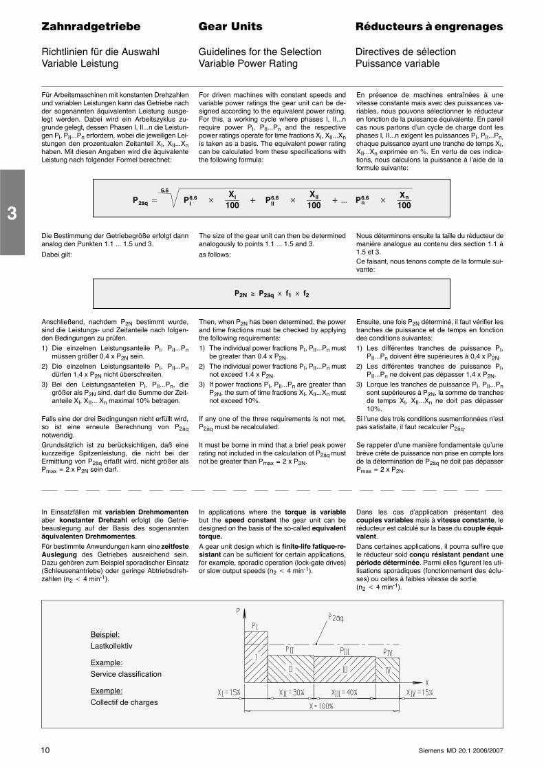
Für Arbeitsmaschinen mit konstanten Drehzahlenund variablen Leistungen kann das Getriebe nachder sogenannten äquivalenten Leistung ausge-legt werden. Dabei wird ein Arbeitszyklus zu-grunde gelegt, dessen Phasen I, II...n die Leistun-gen PI, PII...Pn erfordern, wobei die jeweiligen Lei-stungen den prozentualen Zeitanteil XI, XII...Xnhaben. Mit diesen Angaben wird die äquivalenteLeistung nach folgender Formel berechnet:
For driven machines with constant speeds andvariable power ratings the gear unit can be de-signed according to the equivalent power rating.For this, a working cycle where phases I, II...nrequire power PI, PII...Pn and the respectivepower ratings operate for time fractions XI, XII...Xnis taken as a basis. The equivalent power ratingcan be calculated from these specifications withthe following formula:
En présence de machines entraînées à unevitesse constante mais avec des puissances va-riables, nous pouvons sélectionner le réducteuren fonction de la puissance équivalente. En pareilcas nous partons d’un cycle de charge dont lesphases I, II...n exigent les puissances PI, PII...Pn,chaque puissance ayant une tranche de temps XI,XII...Xn exprimée en %. En vertu de ces indica-tions, nous calculons la puissance à l’aide de laformule suivante:
P2äq � P6.6I �
XI
100� P6.6
II �XII
100� ��� P6.6
n �Xn
100
6.6
Die Bestimmung der Getriebegröße erfolgt dannanalog den Punkten 1.1 ... 1.5 und 3.
Dabei gilt:
The size of the gear unit can then be determinedanalogously to points 1.1 ... 1.5 and 3.
as follows:
Nous déterminons ensuite la taille du réducteur demanière analogue au contenu des section 1.1 à1.5 et 3.Ce faisant, nous tenons compte de la formule sui-vante:
P2N ≥ P2äq � f1 � f2
Anschließend, nachdem P2N bestimmt wurde,sind die Leistungs- und Zeitanteile nach folgen-den Bedingungen zu prüfen.1) Die einzelnen Leistungsanteile PI, PII...Pn
müssen größer 0,4 x P2N sein.2) Die einzelnen Leistungsanteile PI, PII...Pn
dürfen 1,4 x P2N nicht überschreiten.3) Bei den Leistungsanteilen PI, PII...Pn, die
größer als P2N sind, darf die Summe der Zeit-anteile XI, XII... Xn maximal 10% betragen.
Falls eine der drei Bedingungen nicht erfüllt wird,so ist eine erneute Berechnung von P2äqnotwendig.Grundsätzlich ist zu berücksichtigen, daß einekurzzeitige Spitzenleistung, die nicht bei derErmittlung von P2äq erfaßt wird, nicht größer alsPmax = 2 x P2N sein darf.
Then, when P2N has been determined, the powerand time fractions must be checked by applyingthe following requirements:1) The individual power fractions PI, PII...Pn must
be greater than 0.4 x P2N.2) The individual power fractions PI, PII...Pn must
not exceed 1.4 x P2N.3) If power fractions PI, PII...Pn are greater than
P2N, the sum of time fractions XI, XII...Xn mustnot exceed 10%.
If any one of the three requirements is not met,P2äq must be recalculated.
It must be borne in mind that a brief peak powerrating not included in the calculation of P2äq mustnot be greater than Pmax = 2 x P2N.
Ensuite, une fois P2N déterminé, il faut vérifier lestranches de puissance et de temps en fonctiondes conditions suivantes:1) Les différentes tranches de puissance PI,
PII...Pn doivent être supérieures à 0,4 x P2N.2) Les différentes tranches de puissance PI,
PII...Pn ne doivent pas dépasser 1,4 x P2N.3) Lorque les tranches de puissance PI, PII...Pn
sont supérieures à P2N, la somme de tranchesde temps XI, XII...Xn ne doit pas dépasser10%.
Si l’une des trois conditions susmentionnées n’estpas satisfaite, il faut recalculer P2äq.
Se rappeler d’une manière fondamentale qu’unebrève crête de puissance non prise en compte lorsde la détermination de P2äq ne doit pas dépasserPmax = 2 x P2N.
In Einsatzfällen mit variablen Drehmomentenaber konstanter Drehzahl erfolgt die Getrie-beauslegung auf der Basis des sogenanntenäquivalenten Drehmomentes.Für bestimmte Anwendungen kann eine zeitfesteAuslegung des Getriebes ausreichend sein.Dazu gehören zum Beispiel sporadischer Einsatz(Schleusenantriebe) oder geringe Abtriebsdreh-zahlen (n2 � 4 min-1).
In applications where the torque is variablebut the speed constant the gear unit can bedesigned on the basis of the so-called equivalenttorque.A gear unit design which is finite-life fatique-re-sistant can be sufficient for certain applications,for example, sporadic operation (lock-gate drives)or slow output speeds (n2 � 4 min-1).
Dans les cas d’application présentant descouples variables mais à vitesse constante, leréducteur est calculé sur la base du couple équi-valent.Dans certaines applications, il pourra suffire quele réducteur soid conçu résistant pendant unepériode déterminée. Parmi elles figurent les uti-lisations sporadiques (fonctionnement des éclu-ses) ou celles à faibles vitesse de sortie(n2 � 4 min-1).
Beispiel:Lastkollektiv
Example:Service classification
Exemple:Collectif de charges
3
11Siemens MD 20.1 2006/2007
������������� ���� �� ��������� � ����������
Erklärung der Bezeichnungen Key to Symbols Explication des symboles
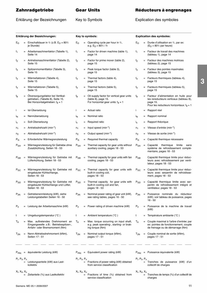
Erklärung der Bezeichnungen:
ED = Einschaltdauer in % (z.B. ED = 80%je Stunde)
f1 = Arbeitsmaschinenfaktor (Tabelle 1),Seite 14
f2 = Antriebsmaschinenfaktor (Tabelle 2),Seite 15
f3 = Spitzenmomentfaktor (Tabelle 3),Seite 15
f4 = Wärmefaktoren (Tabelle 4),Seite 15
f5 = Wärmefaktoren (Tabelle 5),Seite 15
f8 = Ölversorgungsfaktor bei Vertikal-getrieben, (Tabelle 8), Seite 15.Bei Horizontalgetrieben: f8 = 1
i = Ist-Übersetzung
iN = Nennübersetzung
is = Soll-Übersetzung
n1 = Antriebsdrehzahl (min-1)
n2 = Abtriebsdrehzahl (min-1)
PG = Erforderliche Wärmegrenzleistung
PGA = Wärmegrenzleistung für Getriebe ohneZusatzkühlung, Seiten 18 - 53
PGB = Wärmegrenzleistung für Getriebe mitLüfterkühlung, Seiten 18 - 53
PGC = Wärmegrenzleistung für Getriebe miteingebauter Kühlschlange,Seiten 18 - 53
PGD = Wärmegrenzleistung für Getriebe miteingebauter Kühlschlange und Lüfter,Seiten 18 - 53
P2N = Getriebenennleistung (kW), sieheLeistungstabellen Seiten 16 - 50
P2 = Leistung der Arbeitsmaschine (kW)
t = Umgebungstemperatur (°C )
TA = Max. auftretendes Drehmoment anEingangswelle z.B.: Betriebsspitzen-,Anfahr- oder Bremsmoment (Nm)
T2N = Nenn-Abtriebsdrehmoment (kNm),Seiten 17 - 51
Key to symbols:
ED = Operating cycle per hour in %,e.g. ED = 80% / h
f1 = Factor for driven machine (table 1),page 14
f2 = Factor for prime mover (table 2),page 15
f3 = Peak torque factor (table 3),page 15
f4 = Thermal factors (table 4),page 15
f5 = Thermal factors (table 5),page 15
f8 = Oil supply factor for vertical gear units(table 8), page 15.For horizontal gear units: f8 = 1
i = Actual ratio
iN = Nominal ratio
is = Required ratio
n1 = Input speed (min-1)
n2 = Output speed (min-1)
PG = Required thermal capacity
PGA = Thermal capacity for gear units withoutauxiliary cooling, pages 18 - 53
PGB = Thermal capacity for gear units with fancooling, pages 18 - 53
PGC = Thermal capacity for gear units withbuilt-in cooling coil,pages 18 - 53
PGD = Thermal capacity for gear units withbuilt-in cooling coil and fan,pages 18 - 53
P2N = Nominal power rating of gear unit (kW),see rating tables, pages 16 - 50
P2 = Power rating of driven machine (kW)
t = Ambient temperature (°C )
TA = Max. torque occurring on input shaft,e.g. peak operating-, starting- or brak-ing torque (Nm)
T2N = Nominal output torque (kNm),pages 17 - 51
Explication des symboles:
ED = Durée d’utilisation en %, par ex:(ED = 80% par heure)
f1 = Facteur de travail des machines(tableau 1), page 14
f2 = Facteur des machines motrices(tableau 2), page 15
f3 = Facteur des pointes maximales(tableau 3), page 15
f4 = Facteurs thermiques (tableau 4),page 15
f5 = Facteurs thermiques (tableau 5),page 15
f8 = Facteur d’alimentation en huile pourles rereducteurs verticaux (tableau 8),page 15.Pour les reducteurs horizontaux: f8 = 1
i = Rapport réel
iN = Rapport nominal
is = Rapport théorique
n1 = Vitesse d’entrée (min-1)
n2 = Vitesse de sortie (min-1)
PG = Capacité thermique nécessaire
PGA = Capacité thermique limite sanssystème de refroidissement complé-mentaire, pages 18 - 53
PGB Capacité thermique limite pour réduc-teurs avec refroidissement par venti-lateur, pages 18 - 53
PGC = Capacité thermique limite pour réduc-teurs avec serpentin de refroidisse-ment, pages 18 - 53
PGD = Capacité thermique limite avec ser-pentin de refroidissement intégré etventilateur, pages 18 - 53
P2N = Puissance nominale du réducteur(kW); voir tableau de puissance, pages16 - 50
P2 = Puissance de la machine de travail(kW)
t = Température ambiante (°C )
TA = Couple maximal à l’arbre d’entrée; parex: pointes de fonctionnement, couplede freinage ou de démarrage (Nm)
T2N = Couple nominal de sortie (kNm),pages 17 - 51
P2äq = äquivalente Leistung (kW)
PI, PII, Pn= Leistungsanteile (kW) aus Last-
kollektiv
XI, XII, Xn= Zeitanteile (%) aus Lastkollektiv
P2äq = Equivalent power rating (kW)
PI, PII, Pn= Fractions of power rating (kW) obtained
from service classification
XI, XII, Xn= Fractions of time (%) obtained from
service classification
P2äq = Puissance équivalente (kW)
PI, PII, Pn= Tranches de puissance (kW) d’un
collectif de charges
XI, XII, Xn= Tranches de temps (%) d’un collectif de
charges
3
12 Siemens MD 20.1 2006/2007
������������� ���� �� ��������� � ����������
Richtlinien für die Auswahl Guidelines for the Selection Directives de sélectionBerechnungsbeispiel Calculation Example Exemple de calculmechanisch Mechanical Power Rating mécanique
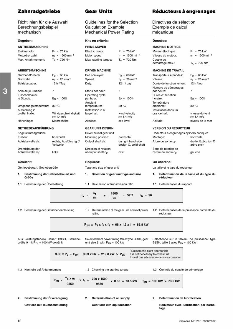
Gegeben:
ANTRIEBSMASCHINEElektromotor: P1 = 75 kWMotordrehzahl: n1 = 1500 min-1
Max. Anfahrmoment: TA = 720 Nm
ARBEITSMASCHINE
Gurtbandförderer: P2 = 66 kWDrehzahl: n2 = 26 min-1
Betriebsdauer: 12 h / Tag
Anläufe je Stunde: 7Einschaltdauerje Stunde: ED = 100%
Umgebungstemperatur: 30 °CAufstellung ingroßer Halle: Windgeschwindigkeit
>= 1,4 m/sHöhenlage: Meereshöhe
GETRIEBEAUSFÜHRUNG
KegelstirnradgetriebeEinbau: horizontalAbtriebswelle d2: rechts, Ausführung C
VollwelleDrehrichtung derAbtriebswelle d2: links
Gesucht:
Getriebebauart, Getriebegröße
1. Bestimmung der Getriebebauart undGröße
1.1 Bestimmung der Übersetzung
Known criteria:
PRIME MOVERElectric motor: P1 = 75 kWMotor speed: n1 = 1500 min-1
Max. starting torque: TA = 720 Nm
DRIVEN MACHINE
Belt conveyor: P2 = 66 kWSpeed: n2 = 26 min-1
Duty: 12 h / day
Starts per hour: 7Operating cycleper hour: ED = 100%
Ambienttemperature: 30 °CInstallation in alarge hall: wind velocity
>= 1.4 m/sAltitude: sea level
GEAR UNIT DESIGN
Bevel-helical gear unitMounting position: horizontalOutput shaft d2: on right hand side
design C, solid shaftDirection of rotationof output shaft d2: ccw
Required:
Type and size of gear unit
1. Selection of gear unit type and size
1.1 Calculation of transmission ratio
Données:
MACHINE MOTRICEMoteur électrique: P1 = 75 kWVitesse du moteur: n1 = 1500 min-1
Couple dedémarrage max.: TA = 720 Nm
MACHINE DE TRAVAIL
Transporteur à bandes: P2 = 66 kWVitesse: n2 = 26 min-1
Durée de fonctionnement: 12 h / jourNombre de démarragespar heure: 7Durée d’utilisationhoraire: ED = 100%
Températureambiante: 30 °CInstallation dans ungrande hall: vitesse du vent
>= 1,4 m/sAltitude: niveau de la mer
VERSION DU REDUCTEUR
Réducteur à engrenages cylindro-coniquesMontage: horizontalArbre de sortie d2: droite, Exécution C
arbre pleinSens de rotation del’arbre de sortie d2: gauche
On cherche:
La taille et le type du réducteur
1. Détermination de la taille et du type duréducteur
1.1 Détermination du rapport
is =n1n2
=1500
26= 57.7 iN = 56
1.2 Bestimmung der Getriebenennleistung 1.2 Determination of the gear unit nominal powerrating
1.2 Détermination de la puissance nominale duréducteur
P2N ≥ P2 x f1 x f2 = 66 x 1.3 x 1 = 85.8 kW
Aus Leistungstabelle Bauart B3SH, Getriebe-größe 9 mit P2N = 100 kW gewählt.
Selected from power rating table: type B3SH, gearunit size 9, with P2N = 100 kW
Sélectionné sur le tableau de puissance: typeB3SH, taille 9 avec P2N = 100 kW
3.33 x P2 ≥ P2N 3.33 x 66 = 219.8 kW > P2N
Rücksprache nicht erforderlichIt is not necessary to consult usIl n’est pas nécessaire de nous consulter
1.3 Kontrolle auf Anfahrmoment 1.3 Checking the starting torque 1.3 Contrôle du couple de démarrage
P2N ≥ TA x n1
9550x f3 = 720 x 1500
9550x 0.65 = 73.5 kW P2N = 100 kW > 73.5 kW
2. Bestimmung der Ölversorgung
Getriebe mit Tauchschmierung
2. Determination of oil supply
Gear unit with dip lubication
2. Détermination de lubrification
Réducteur avec lubrification par barbo-tage
3
13Siemens MD 20.1 2006/2007
������������� ���� �� ��������� � ����������
Richtlinien für die Auswahl Guidelines for the Selection Directives de sélectionBerechnungsbeispiel Calculation Example Exemple de calculthermisch Thermal Capacity thermique
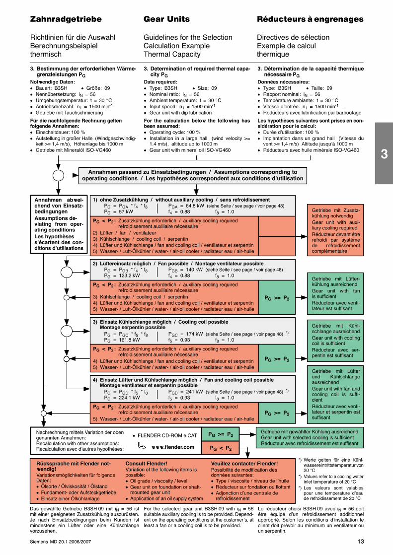
3. Bestimmung der erforderlichen Wärme-grenzleistungen PG
Notwendige Daten:� Bauart: B3SH � Größe: 09� Nennübersetzung: iN = 56� Umgebungstemperatur: t = 30 �C� Antriebsdrehzahl: n1 = 1500 min-1
� Getriebe mit Tauchschmierung
Für die nachfolgende Rechnung geltenfolgende Annahmen:� Einschaltdauer: 100 %� Aufstellung in großer Halle (Windgeschwindig-
keit >= 1,4 m/s), Höhenlage bis 1000 m� Getriebe mit Mineralöl ISO-VG460
3. Determination of required thermal capa-city PG
Data required:� Type: B3SH � Size: 09� Nominal ratio: iN = 56� Ambient temperature: t = 30 �C� Input speed: n1 = 1500 min-1
� Gear unit with dip lubrication
For the calculation below the following hasbeen assumed:� Operating cycle: 100 %� Installation in a large hall (wind velocity >=
1.4 m/s), altitude up to 1000 m� Gear unit with mineral oil ISO-VG460
3. Détermination de la capacité thermiquenécessaire PG
Données nécessaires:� Type: B3SH � Taille: 09� Rapport nominal: iN = 56� Température ambiante: t = 30 �C� Vitesse d’entrée: n1 = 1500 min-1
� Réducteurs avec lubrification par barbootage
Les hypothèses suivantes sont prises en con-sidération pour le calcul:� Durée d’utilisation: 100 %� Implantation dans un grand hall (Vitesse du
vent >= 1,4 m/s) Altitude jusqu’à 1000 m� Réducteurs avec huile minérale ISO-VG460
1) ohne Zusatzkühlung / without auxiliary cooling / sans refroidissement
Getriebe mit Zusatz-kühlung notwendigGear unit with auxi-liary cooling requiredRéducteur devant êtrerefroidi par systèmede refroidissementcomplémentaire
Getriebe mit Lüfter-kühlung ausreichendGear unit with fanis sufficientRéducteur avec venti-lateur est suffisant
Getriebe mit Kühl-schlange ausreichendGear unit with coolingcoil is sufficientRéducteur avec ser-pentin est suffisant
Getriebe mit Lüfterund KühlschlangeausreichendGear unit with fan andcooling coil is suffi-cientRéducteur avec venti-lateur et serpentin estsuffisant
Annahmen abwei-chend von Einsatz-bedingungenAssumptions de-viating from oper-ating conditionsLes hypothèsess’écartent des con-ditions d’utilisations
PG = PGA * f4 * f8PG = 57 kW
PGA = 64.8 kW (siehe Seite / see page / voir page 48)f4 = 0.88 f8 = 1.0
PG < P2 : Zusatzkühlung erforderlich / auxiliary cooling requiredrefroidissement auxiliaire nécessaire
2) Lüfter / fan / ventilateur3) Kühlschlange / cooling coil / serpentin4) Lüfter und Kühlschlange / fan and cooling coil / ventilateur et serpentin5) Wasser- / Luft-Ölkühler / water- / air-oil cooler / radiateur eau / air-huile
2) Lüftereinsatz möglich / Fan possible / Montage ventilateur possiblePG = PGB * f4 * f8PG = 123.2 kW
PGB = 140 kW (siehe Seite / see page / voir page 48)f4 = 0.88 f8 = 1.0
PG < P2 : Zusatzkühlung erforderlich / auxiliary cooling requiredrefroidissement auxiliaire nécessaire
3) Kühlschlange / cooling coil / serpentin4) Lüfter und Kühlschlange / fan and cooling coil / ventilateur et serpentin5) Wasser- / Luft-Ölkühler / water- / air-oil cooler / radiateur eau / air-huile
PG >= P2
3) Einsatz Kühlschlange möglich / Cooling coil possibleMontage serpentin possible
PG = PGC * f5 * f8PG = 161.8 kW
PGC = 174 kW (siehe Seite / see page / voir page 48) *)
f5 = 0.93 f8 = 1.0
PG < P2 : Zusatzkühlung erforderlich / auxiliary cooling requiredrefroidissement auxiliaire nécessaire
4) Lüfter und Kühlschlange / fan and cooling coil / ventilateur et serpentin5) Wasser- / Luft-Ölkühler / water- / air-oil cooler / radiateur eau / air-huile
PG >= P2
4) Einsatz Lüfter und Kühlschlange möglich / Fan and cooling coil possibleMontage ventilateur et serpentin possible
PG = PGD * f5 * f8PG = 224.1 kW
PGD = 241 kW (siehe Seite / see page / voir page 48) *)
f5 = 0.93 f8 = 1.0
PG < P2 : Zusatzkühlung erforderlich / auxiliary cooling requiredrefroidissement auxiliaire nécessaire
5) Wasser- / Luft-Ölkühler / water- / air-oil cooler / radiateur eau / air-huilePG >= P2
Das gewählte Getriebe B3SH 09 mit iN = 56 istmit einer geeigneten Zusatzkühlung auszurüsten.Je nach Einsatzbedingungen beim Kunden istmindestens ein Lüfter oder eine Kühlschlangevorzusehen.
For the selected gear unit B3SH 09 with iN = 56suitable auxiliary cooling is to be provided. Depend-ent on the operating conditions at the customer’s, atleast a fan or a cooling coil is to be provided.
Le réducteur choisi B3SH 09 avec iN = 56 doitêtre équipé d’un refroidissement additionnelapproprié. Selon les conditions d’installation leclient doit prévoir au minimum un ventilateur ouun serpentin.
Nachrechnung mittels Variation der obengenannten Annahmen:Recalculation with other assumptions:Recalculation avec d’autres hypothèses:
Getriebe mit gewählter Kühlung ausreichendGear unit with selected cooling is sufficientRéducteur avec refroidissement est suffisant
PG < P2
Annahmen passend zu Einsatzbedingungen / Assumptions corresponding tooperating conditions / Les hypothèses correspondent aux conditions d’utilisation
PG >= P2
Rücksprache mit Flender not-wendig!Variationsmöglichkeiten für folgendeDaten:� Ölsorte / Ölviskosität / Ölstand� Fundament- oder Aufsteckgetriebe� Einsatz einer Ölkühlanlage
Veuillez contacter Flender!Possibilité de modification desdonnées suivantes:� Type / viscosite / niveau de l’huile� Réducteur sur fondation ou flottant� Adjonction d’une centrale de
refroidissement
Consult Flender!Variation of the following items ispossible:� Oil grade / viscosity / level� Gear unit on foundation or shaft-
mounted gear unit� Application of an oil supply system
*) Werte gelten für eine Kühl-wassereintrittstemperatur von20 °C
*) Values refer to a cooling waterinlet temperature of 20 °C
*) Les valeurs sont valablespour une temperature d’eaude refroidissement de 20 °C
www.flender.com
� FLENDER CD-ROM e.CAT
3
14 Siemens MD 20.1 2006/2007
������������� ���� �� ��������� � ����������
Betriebsfaktoren Service Factors Facteurs de service
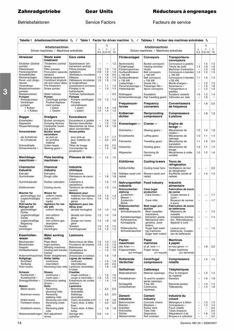
Tabelle 1 Arbeitsmaschinenfaktor f1 / Table 1 Factor for driven machine f1 / Tableau 1 Facteur des machines entraînées f1
Arbeitsmaschinen1)
Arbeitsmaschinen1)
ArbeitsmaschinenDriven machines / Machines entraînée ≤
0.5>
0.5-10>10
ArbeitsmaschinenDriven machines / Machines entraînée ≤
0.5>
0.5-10>10
Abwasser
Eindicker (Zentral-antrieb)FilterpressenFlockungsrührerKreiselbelüfterRechenanlagenRund- und Längs-räumerVoreindickerWasserschnecken-pumpenWasserturbinenPumpen
KreiselpumpenVerdränger-pumpen
1 Kolben> 1 Kolben
BaggerEimerkettenKippwerkeRaupenfahrzeuge
Schaufelräder
als Aufnehmerfür Urmaterial
SchneidköpfeSchwenkwerke ∗
Blechbiege-maschinen ∗
ChemischeIndustrieExtruderGummikneter
Gummikalander
Kühltrommeln
Mischer fürgleichmäßiges GutungleichmäßigesGut
Rührwerke fürRührgut mit
gleichmäßigerDichteungleichmäßigerDichteungleichmäßigeBegasung
ToasterZentrifugen
Eisenhütten-wesenBlechwenderBlockdrückerHaspelnKühlbettschieber
RollenrichtmaschinenRollgänge
DurchlaufStoßartig
Rohr-revers.
ScherenKontischnitt ∗Kurbelschnitt ∗
Stranggußtreiber ∗
WalzenBlech-revers.
Brammen-revers.
Draht-revers.Feinblech-revers.
Grobblech-revers.
Walzenanstellungen
Waste watertreatmentThickeners (centraldrive)Filter pressesFlocculation apparataAeratorsRaking equipmentCombined longitudi-nal and rotary rakesPre-thickenersScrew pumps
Water turbinesPumps
Centrifugal pumpsPositive-displace-ment pumps
1 piston> 1piston
DredgersBucket conveyorsDumping devicesCarterpillar travel-ling gearsBucket wheelexcavators
as pick-upfor primitivematerial
Cutter headsSlewing gears ∗
Plate bendingmachines ∗
ChemicalindustryExtrudersDough mills
Rubber calenders
Cooling drums
Mixers foruniform medianon-uniformmedia
Agitators for me-dia with
uniform density
non-uniformdensitynon-uniform gasabsorption
ToastersCentrifuges
Metal workingmillsPlate tiltersIngot pushersWinding machinesCooling bed transferframesRoller straightenersRoller tables
continuousintermittent
Reversing tube mills
Shearscontinuous ∗crank type ∗
Continuous castingdrivers ∗Rolls
Reversingblooming millsReversingslabbing millsReversing wire millsReversing sheetmillsReversing platemills
Roll adjustmentdrives
Eaux usées
Epaississeurs (en-traînement central)Filtres-pressesAgitateursVentilateurs circulairesRâteauxDéblayeurs circulaireset longitudinauxEpaississeurs primairesPompes à vishydrauliquesTurbines hydrauliquesPompes
Pompes centrifugesPompesvolumétriques
1 piston> piston
ExcavateursExcavateurs à godetsBennes basculantesMécanismes de trans-lation surchenillesRoues-pelles
pour pick-uppour matières debase
Têtes de forageCommandes depivotement ∗
Plieuses de tôle ∗
IndustriechimiqueExtrudeusesPétrisseurs de caout-choucCalandres àcaoutchoucTambours de refroidis-sementMalaxeurs pour
matières homogènesmatières non homo-gènes
Agitateurs pour ma-tières avec
densité homogène
densité non homo-gènecharge non homo-gène
ToastersCentrifugeuses
Laminoirs
Retourneurs de tôlesPousseurs de bramesBobineusesCoulisseaux durefroidisseurDresseuses à rouleauxLignes de rouleaux
continuesintermittentes
Laminoirs réversiblesà tubesCisailles
coupe continue ∗coupe à manivelle ∗
Entraîneurs de couléecontinue ∗Laminoirs
BloomingsréversiblesSlabbingsréversiblesTrains réversibles à filTrains réver. à tôlesfinesTrains réver. à tôlesfortes
Serrage descylindres
–
1.00.8 –1.01.0
– –
–
1.0
1.31.2
– –1.2
– –
– –
–
– –
–
–
1.01.4
1.0
1.2
1.4
1.01.0
1.01.0 – –
–
– – –
–1.0 –
–
–
– –
–
0.9
–
1.31.01.81.21.3
1.11.3
–
1.2
1.41.4
1.61.31.6
1.72.2
2.21.4
1.0
–1.8
1.5
1.3
1.31.6
1.3
1.4
1.6
1.31.2
1.01.21.61.5
1.6
1.52.01.8
1.51.01.4
2.5
2.5
1.82.0
1.8
1.0
1.2
1.51.32.01.31.5
1.31.5
2.0
1.3
1.81.5
1.61.51.8
1.72.2
2.21.8
1.0
1.61.8
1.5
1.4
1.41.7
1.5
1.6
1.8
1.51.3
1.21.21.61.5
1.6
1.52.01.8
1.51.01.4
2.5
2.5
1.82.0
1.8
–
Förderanlagen
BecherwerkeFörderhaspelFördermaschinenGurtbandförderer≤ 150 kWGurtbandförderer≥ 150 kWLastaufzüge ∗Personenaufzüge ∗Plattenbänder
RolltreppenSchienenfahrzeuge
Frequenzum-former
Kolbenver-dichter
Krananlagen ∗∗
Drehwerke ∗
Einziehwerke
Fahrwerke
Hubwerke
Wippwerke
Kühltürme
Kühlturmlüfter
Gebläse (axial undradial)
Nahrungsmittel-industrieRohrzuckerher-stellung
Zuckerrohr-Messer ∗Zuckerrohr-Mühle
Rübenzuckerher-stellung
Schnitzelmaische
Extraktionsanlage,Kühlmaschine,Kochapparat,
Rübenwäsche,Schneidmaschine
Papier-maschinenalle Arten ∗∗∗Pulperantriebe
(auf Anfrage)
RotierendeVerdichter
SeilbahnenMaterialbahnen
Pendelbahnen
SchlepplifteUmlaufbahnen
Zement-industrieBetonmischerBrecher ∗DrehöfenRohrmühleSichterWalzenmühlen
Conveyors
Bucket conveyorsHauling winchesHoistsBelt conveyors≤ 150 kWBelt conveyors≥ 150 kWGoods lifts ∗Passenger lifts ∗Apron conveyors
EscalatorsRail travelling gears
Frequencyconverters
Reciprocatingcompressors
Cranes ∗∗
Slewing gears ∗
Luffing gears
Travelling gears
Hoisting gears
Derricking jibcranes
Cooling towers
Cooling tower fans
Blowers (axial andradial)
Food industry
Cane sugarproduction
Cane knives ∗
Cane mills
Beet sugar pro-duction
Beet cossettesmacerators,Extraction plants,Mechanical refri-gerators, Juiceboilers,Sugar beet wash-ing machines,Sugar beet cutters
Papermachinesof all kind ∗∗∗Pulper drives
(on request)
Centrifugalcompressors
CablewaysMaterial ropeways
To-and-fro systemaerial ropewaysT-bar liftsContinuousropeways
CementindustryConcrete mixersBreakers ∗Rotary kilnsTube millsSeparatorsRoll crushers
Transporteurs-convoyeursConvoyeurs à godetsTreuils de puitsMachines d’extractionConvoyeurs à bandes≤ 150 kWConvoyeurs à bandes≥150 kWMonte-charges ∗Ascenseurs ∗Transporteurs àpalettesEscaliers roulantsVéhicules sur rails
Convertisseursde fréquence
Compresseursà pistons
Engins delevage ∗∗Mécanismes derotation ∗Mécanismes derelevageMécanismes detranslationMécanismes delevageMecanismes à voléevariable
Tours deréfrigérationVentilateurs de tourde réfrigérationSoufflante (axiale etradiale)
IndustriealimentaireFabrication de sucrede canne
Coupe cannes àsucre ∗Broyeurs de cannesà sucre
Fabrication de sucrede betteraves
Malaxeurs decossetteInstallations d’extrac-tion, Refroidisseurs,Appareil à cuire
Laveurs pourbetteraves, Coupeu-ses de betteraves
Machinesà papieren tout genre ∗∗∗Pulper machines
(sur demande)
Compresseursrotatifs
TéléphériquesPour le transportdu matériel Navettes
Remonte-pentesTélécabines
Industrie ducimentMélangeurs à bétonConcasseurs ∗Fours rotatifsTubes broyeursSéparateurs à airBroyeurs à cylindres
–1.4 –1.0
1.1
– – –
1.0 –
–
–
1.0
1.0
1.1
1.0
1.0
–
–
–
–
–
–
–
–
–
–
–
– –
– – – – – –
1.41.61.51.2
1.3
1.21.51.2
1.21.5
1.8
1.8
1.4
1.1
1.6
1.1
1.2
–
1.4
–
–
–
–
–
1.8
1.4
1.3
1.6
1.31.4
1.51.2 – –1.6 –
1.51.61.81.3
1.4
1.51.81.5
1.4 –
2.0
1.9
1.8
1.4
2.0
1.4
1.6
2.0
1.5
1.7
1.7
1.2
1.4
1.5
2.0
1.5
1.4
1.8
1.41.6
1.51.42.02.01.62.0
3
15Siemens MD 20.1 2006/2007
������������� ���� �� ��������� � ����������
Betriebsfaktoren Service Factors Facteurs de service
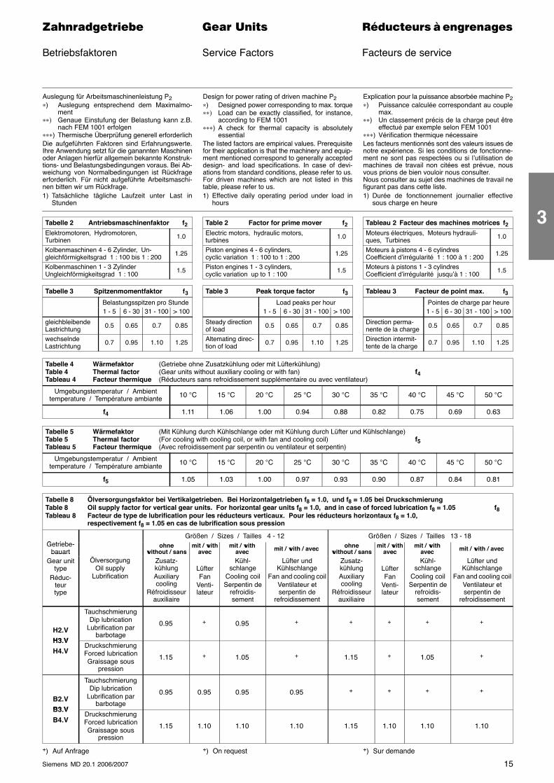
Auslegung für Arbeitsmaschinenleistung P2∗) Auslegung entsprechend dem Maximalmo-
ment∗∗) Genaue Einstufung der Belastung kann z.B.
nach FEM 1001 erfolgen∗∗∗) Thermische Überprüfung generell erforderlichDie aufgeführten Faktoren sind Erfahrungswerte.Ihre Anwendung setzt für die ganannten Maschinenoder Anlagen hierfür allgemein bekannte Konstruk-tions- und Belastungsbedingungen voraus. Bei Ab-weichung von Normalbedingungen ist Rückfrageerforderlich. Für nicht aufgeführte Arbeitsmaschi-nen bitten wir um Rückfrage.1) Tatsächliche tägliche Laufzeit unter Last in
Stunden
Design for power rating of driven machine P2∗) Designed power corresponding to max. torque∗∗) Load can be exactly classified, for instance,
according to FEM 1001∗∗∗) A check for thermal capacity is absolutely
essentialThe listed factors are empirical values. Prerequisitefor their application is that the machinery and equip-ment mentioned correspond to generally accepteddesign- and load specifications. In case of devi-ations from standard conditions, please refer to us.For driven machines which are not listed in thistable, please refer to us.1) Effective daily operating period under load in
hours
Explication pour la puissance absorbée machine P2∗) Puissance calculée correspondant au couple
max.∗∗) Un classement précis de la charge peut être
effectué par exemple selon FEM 1001∗∗∗) Vérification thermique nécessaireLes facteurs mentionnés sont des valeurs issues denotre expérience. Si les conditions de fonctionne-ment ne sont pas respectées ou si l’utilisation demachines de travail non citées est prévue, nousvous prions de bien vouloir nous consulter.Nous consulter au sujet des machines de travail nefigurant pas dans cette liste.1) Durée de fonctionnement journalier effective
sous charge en heure
Tabelle 2 Antriebsmaschinenfaktor f2Elektromotoren, Hydromotoren,Turbinen 1.0
Kolbenmaschinen 4 - 6 Zylinder, Un-gleichförmigkeitsgrad 1 : 100 bis 1 : 200 1.25
Kolbenmaschinen 1 - 3 ZylinderUngleichförmigkeitsgrad 1 : 100 1.5
Table 2 Factor for prime mover f2Electric motors, hydraulic motors,turbines 1.0
Piston engines 4 - 6 cylinders,cyclic variation 1 : 100 to 1 : 200 1.25
Piston engines 1 - 3 cylinders,cyclic variation up to 1 : 100 1.5
Tableau 2 Facteur des machines motrices f2Moteurs électriques, Moteurs hydrauli-ques, Turbines 1.0
Moteurs à pistons 4 - 6 cylindresCoefficient d’irrégularité 1 : 100 à 1 : 200 1.25
Moteurs à pistons 1 - 3 cylindresCoefficient d’irrégularité jusqu’à 1 : 100 1.5
Tabelle 3 Spitzenmomentfaktor f3
Belastungsspitzen pro Stunde1 - 5 6 - 30 31 - 100 > 100
gleichbleibendeLastrichtung 0.5 0.65 0.7 0.85
wechselndeLastrichtung 0.7 0.95 1.10 1.25
Table 3 Peak torque factor f3Load peaks per hour
1 - 5 6 - 30 31 - 100 > 100
Steady directionof load 0.5 0.65 0.7 0.85
Altemating direc-tion of load 0.7 0.95 1.10 1.25
Tableau 3 Facteur de point max. f3Pointes de charge par heure1 - 5 6 - 30 31 - 100 > 100
Direction perma-nente de la charge 0.5 0.65 0.7 0.85
Direction intermit-tente de la charge 0.7 0.95 1.10 1.25
Tabelle 4 Wärmefaktor (Getriebe ohne Zusatzkühlung oder mit Lüfterkühlung)Table 4 Thermal factor (Gear units without auxiliary cooling or with fan) f4Tableau 4 Facteur thermique (Réducteurs sans refroidissement supplémentaire ou avec ventilateur)
Umgebungstemperatur / Ambienttemperature / Température ambiante 10 °C 15 °C 20 °C 25 °C 30 °C 35 °C 40 °C 45 °C 50 °C
f4 1.11 1.06 1.00 0.94 0.88 0.82 0.75 0.69 0.63
Tabelle 5 Wärmefaktor (Mit Kühlung durch Kühlschlange oder mit Kühlung durch Lüfter und Kühlschlange)Table 5 Thermal factor (For cooling with cooling coil, or with fan and cooling coil) f5Tableau 5 Facteur thermique (Avec refroidissement par serpentin ou ventilateur et serpentin)
Umgebungstemperatur / Ambienttemperature / Température ambiante 10 °C 15 °C 20 °C 25 °C 30 °C 35 °C 40 °C 45 °C 50 °C
f5 1.05 1.03 1.00 0.97 0.93 0.90 0.87 0.84 0.81
Tabelle 8 Ölversorgungsfaktor bei Vertikalgetrieben. Bei Horizontalgetrieben f8 = 1.0, und f8 = 1.05 bei DruckschmierungTable 8 Oil supply factor for vertical gear units. For horizontal gear units f8 = 1.0, and in case of forced lubrication f8 = 1.05 f8Tableau 8 Facteur de type de lubrification pour les réducteurs verticaux. Pour les réducteurs horizontaux f8 = 1.0,
respectivement f8 = 1.05 en cas de lubrification sous pression
G t i bGrößen / Sizes / Tailles 4 - 12 Größen / Sizes / Tailles 13 - 18
Getriebe-bauart
Ö
ohnewithout / sans
mit / withavec
mit / withavec mit / with / avec ohne
without / sansmit / with
avecmit / with
avec mit / with / avecbauartGear unit
typeRéduc-
teurtype
ÖlversorgungOil supply
Lubrification
Zusatz-kühlungAuxiliarycooling
Réfroidisseurauxiliaire
LüfterFan
Venti-lateur
Kühl-schlange
Cooling coilSerpentin de
refroidis-sement
Lüfter undKühlschlange
Fan and cooling coilVentilateur etserpentin de
refroidissement
Zusatz-kühlungAuxiliarycooling
Réfroidisseurauxiliaire
LüfterFan
Venti-lateur
Kühl-schlange
Cooling coilSerpentin de
refroidis-sement
Lüfter undKühlschlange
Fan and cooling coilVentilateur etserpentin de
refroidissement
H2.VH3 V
TauchschmierungDip lubrication
Lubrification parbarbotage
0.95 + 0.95 + + + + +
H3.VH4.V
DruckschmierungForced lubricationGraissage sous
pression
1.15 + 1.05 + 1.15 + 1.05 +
B2.VB3 V
TauchschmierungDip lubrication
Lubrification parbarbotage
0.95 0.95 0.95 0.95 + + + +
B3.VB4.V
DruckschmierungForced lubricationGraissage sous
pression
1.15 1.10 1.10 1.10 1.15 1.10 1.10 1.10
+) Auf Anfrage +) On request +) Sur demande
3
16 Siemens MD 20.1 2006/2007
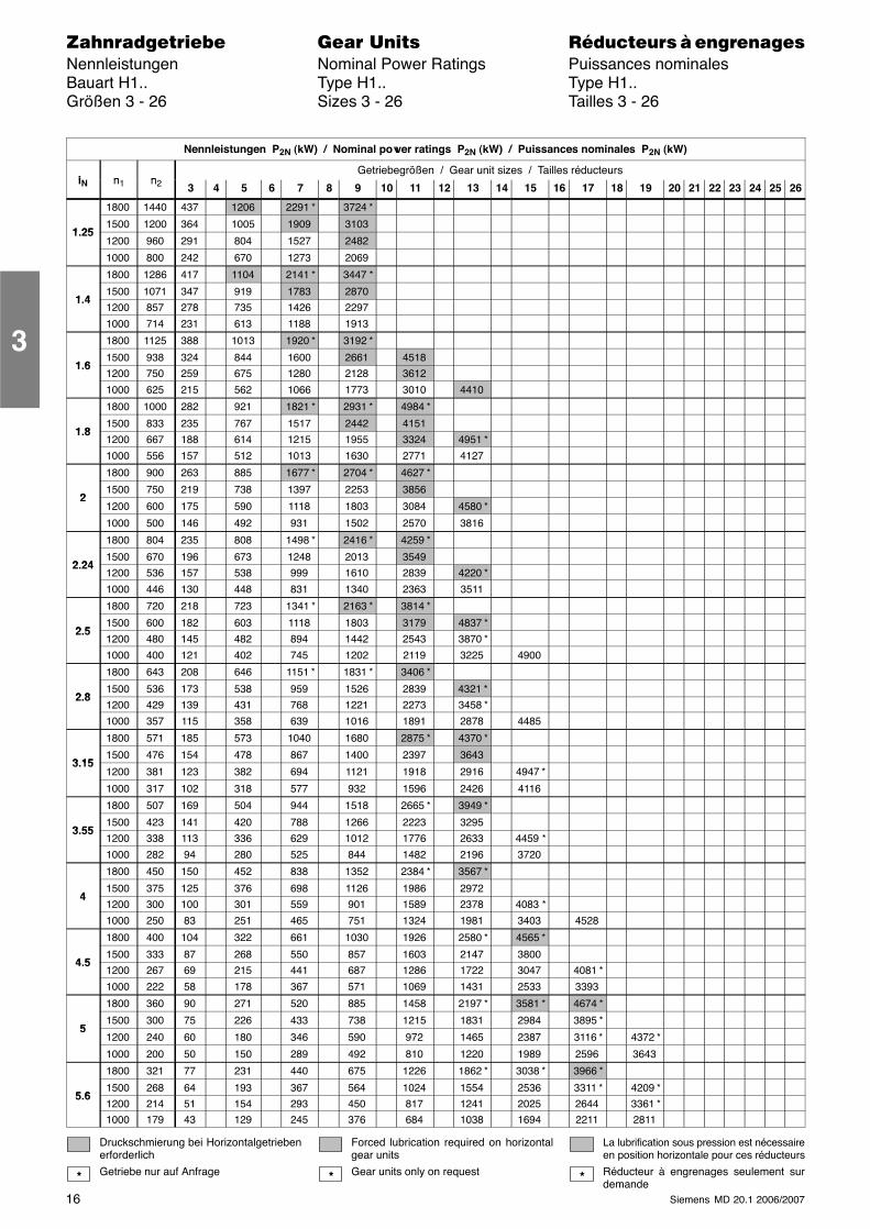
������������� ���� �� ��������� � ����������Nennleistungen Nominal Power Ratings Puissances nominalesBauart H1.. Type H1.. Type H1..Größen 3 - 26 Sizes 3 - 26 Tailles 3 - 26
Nennleistungen P2N (kW) / Nominal power ratings P2N (kW) / Puissances nominales P2N (kW)
i n nGetriebegrößen / Gear unit sizes / Tailles réducteurs
iN n1 n2 3 4 5 6 7 8 9 10 11 12 13 14 15 16 17 18 19 20 21 22 23 24 25 26
1800 1440 437 1206 2291 * 3724 *
1 251500 1200 364 1005 1909 3103
1.251200 960 291 804 1527 2482
1000 800 242 670 1273 2069
1800 1286 417 1104 2141 * 3447 *
1 41500 1071 347 919 1783 2870
1.41200 857 278 735 1426 2297
1000 714 231 613 1188 1913
1800 1125 388 1013 1920 * 3192 *
1 61500 938 324 844 1600 2661 4518
1.61200 750 259 675 1280 2128 3612
1000 625 215 562 1066 1773 3010 4410
1800 1000 282 921 1821 * 2931 * 4984 *
1 81500 833 235 767 1517 2442 4151
1.81200 667 188 614 1215 1955 3324 4951 *
1000 556 157 512 1013 1630 2771 4127
1800 900 263 885 1677 * 2704 * 4627 *
21500 750 219 738 1397 2253 3856
21200 600 175 590 1118 1803 3084 4580 *
1000 500 146 492 931 1502 2570 3816
1800 804 235 808 1498 * 2416 * 4259 *
2 241500 670 196 673 1248 2013 3549
2.241200 536 157 538 999 1610 2839 4220 *
1000 446 130 448 831 1340 2363 3511
1800 720 218 723 1341 * 2163 * 3814 *
2 51500 600 182 603 1118 1803 3179 4837 *
2.51200 480 145 482 894 1442 2543 3870 *
1000 400 121 402 745 1202 2119 3225 4900
1800 643 208 646 1151 * 1831 * 3406 *
2 81500 536 173 538 959 1526 2839 4321 *
2.81200 429 139 431 768 1221 2273 3458 *
1000 357 115 358 639 1016 1891 2878 4485
1800 571 185 573 1040 1680 2875 * 4370 *
3 151500 476 154 478 867 1400 2397 3643
3.151200 381 123 382 694 1121 1918 2916 4947 *
1000 317 102 318 577 932 1596 2426 4116
1800 507 169 504 944 1518 2665 * 3949 *
3 551500 423 141 420 788 1266 2223 3295
3.551200 338 113 336 629 1012 1776 2633 4459 *
1000 282 94 280 525 844 1482 2196 3720
1800 450 150 452 838 1352 2384 * 3567 *
41500 375 125 376 698 1126 1986 2972
41200 300 100 301 559 901 1589 2378 4083 *
1000 250 83 251 465 751 1324 1981 3403 4528
1800 400 104 322 661 1030 1926 2580 * 4565 *
4 51500 333 87 268 550 857 1603 2147 3800
4.51200 267 69 215 441 687 1286 1722 3047 4081 *
1000 222 58 178 367 571 1069 1431 2533 3393
1800 360 90 271 520 885 1458 2197 * 3581 * 4674 *
51500 300 75 226 433 738 1215 1831 2984 3895 *
51200 240 60 180 346 590 972 1465 2387 3116 * 4372 *
1000 200 50 150 289 492 810 1220 1989 2596 3643
1800 321 77 231 440 675 1226 1862 * 3038 * 3966 *
5 61500 268 64 193 367 564 1024 1554 2536 3311 * 4209 *
5.61200 214 51 154 293 450 817 1241 2025 2644 3361 *
1000 179 43 129 245 376 684 1038 1694 2211 2811
Druckschmierung bei Horizontalgetriebenerforderlich
Getriebe nur auf Anfrage
Forced lubrication required on horizontalgear units
Gear units only on request
La lubrification sous pression est nécessaireen position horizontale pour ces réducteurs
Réducteur à engrenages seulement surdemande
* * *
3
���� ���� �� - ����� ����� �� - ����� ����� �� - ��
H4
H3
H2
���� ���� �� - ����� ����� �� - ����� ����� �� - ��
���� ���� �� - ����� ����� �� - ����� ����� �� - ��
17Siemens MD 20.1 2006/2007
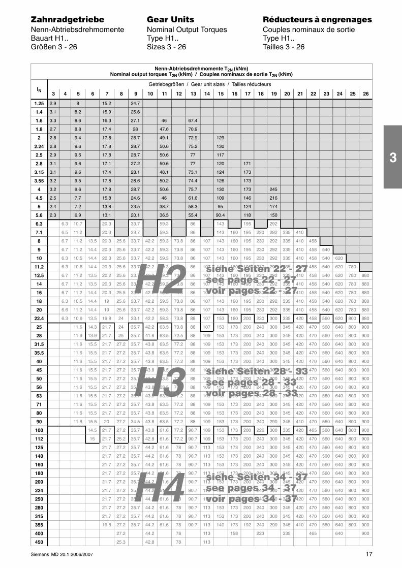
������������� ���� �� ��������� � ����������Nenn-Abtriebsdrehmomente Nominal Output Torques Couples nominaux de sortieBauart H1.. Type H1.. Type H1..Größen 3 - 26 Sizes 3 - 26 Tailles 3 - 26
Nenn-Abtriebsdrehmomente T2N (kNm)Nominal output torques T2N (kNm) / Couples nominaux de sortie T2N (kNm)
iGetriebegrößen / Gear unit sizes / Tailles réducteurs
iN3 4 5 6 7 8 9 10 11 12 13 14 15 16 17 18 19 20 21 22 23 24 25 26
1.25 2.9 8 15.2 24.7
1.4 3.1 8.2 15.9 25.6
1.6 3.3 8.6 16.3 27.1 46 67.4
1.8 2.7 8.8 17.4 28 47.6 70.9
2 2.8 9.4 17.8 28.7 49.1 72.9 129
2.24 2.8 9.6 17.8 28.7 50.6 75.2 130
2.5 2.9 9.6 17.8 28.7 50.6 77 117
2.8 3.1 9.6 17.1 27.2 50.6 77 120 171
3.15 3.1 9.6 17.4 28.1 48.1 73.1 124 173
3.55 3.2 9.5 17.8 28.6 50.2 74.4 126 173
4 3.2 9.6 17.8 28.7 50.6 75.7 130 173 245
4.5 2.5 7.7 15.8 24.6 46 61.6 109 146 216
5 2.4 7.2 13.8 23.5 38.7 58.3 95 124 174
5.6 2.3 6.9 13.1 20.1 36.5 55.4 90.4 118 150
6.3 6.3 10.7 20.3 33.7 59.3 86 143 195 292
7.1 6.5 11.2 20.3 33.7 59.3 86 143 160 195 230 292 335 410
8 6.7 11.2 13.5 20.3 25.6 33.7 42.2 59.3 73.8 86 107 143 160 195 230 292 335 410 458
9 6.7 11.2 14.4 20.3 25.6 33.7 42.2 59.3 73.8 86 107 143 160 195 230 292 335 410 458 540
10 6.3 10.5 14.4 20.3 25.6 33.7 42.2 59.3 73.8 86 107 143 160 195 230 292 335 410 458 540 620
11.2 6.3 10.6 14.4 20.3 25.6 33.7 42.2 59.3 73.8 86 107 143 160 195 230 292 335 410 458 540 620 780
12.5 6.7 11.2 13.5 20.2 25.6 33.7 42.2 59.3 73.8 86 107 143 160 195 230 292 335 410 458 540 620 780 880
14 6.7 11.2 13.5 20.3 25.6 33.7 42.2 59.3 73.8 86 107 143 160 195 230 292 335 410 458 540 620 780 880
16 6.7 11.2 14.4 20.3 25.5 33.7 42.2 59.3 73.8 86 107 143 160 195 230 292 335 410 458 540 620 780 880
18 6.3 10.5 14.4 19 25.6 33.7 42.2 59.3 73.8 86 107 143 160 195 230 292 335 410 458 540 620 780 880
20 6.6 11.2 14.4 19 25.6 33.7 42.2 59.3 73.8 86 107 143 160 195 230 292 335 410 458 540 620 780 880
22.4 6.3 10.9 13.5 19.8 24 33.1 42.2 58.3 73.8 88 107 153 160 200 230 300 335 420 458 560 620 800 880
25 11.6 14.3 21.7 24 35.7 42.2 63.5 73.8 88 107 153 173 200 240 300 345 420 470 560 640 800 900
28 11.6 13.9 21.7 25 35.7 41.6 63.5 72.5 88 109 153 173 200 240 300 345 420 470 560 640 800 900
31.5 11.6 15.5 21.7 27.2 35.7 43.8 63.5 77.2 88 109 153 173 200 240 300 345 420 470 560 640 800 900
35.5 11.6 15.5 21.7 27.2 35.7 43.8 63.5 77.2 88 109 153 173 200 240 300 345 420 470 560 640 800 900
40 11.6 15.5 21.7 27.2 35.7 43.8 63.5 77.2 88 109 153 173 200 240 300 345 420 470 560 640 800 900
45 11.6 15.5 21.7 27.2 35.7 43.8 63.5 77.2 88 109 153 173 200 240 300 345 420 470 560 640 800 900
50 11.6 15.5 21.7 27.2 35.7 43.8 63.5 77.2 88 109 153 173 200 240 300 345 420 470 560 640 800 900
56 11.6 15.5 21.7 27.2 35.7 43.8 63.5 77.2 88 109 153 173 200 240 300 345 420 470 560 640 800 900
63 11.6 15.5 21.7 27.2 35.7 43.8 63.5 77.2 88 109 153 173 200 240 300 345 420 470 560 640 800 900
71 11.6 15.5 21.7 27.2 35.7 43.8 63.5 77.2 88 109 153 173 200 240 300 345 420 470 560 640 800 900
80 11.6 15.5 21.7 27.2 35.7 43.8 63.5 77.2 88 109 153 173 200 240 300 345 420 470 560 640 800 900
90 11.6 15.5 20 27.2 34.5 43.8 63.5 77.2 88 109 153 173 200 240 290 345 410 470 560 640 800 900
100 14.5 21.7 27.2 35.7 43.8 61.6 77.2 90.7 109 153 173 200 226 300 335 420 465 560 640 800 900
112 15 21.7 25.2 35.7 42.8 61.6 77.2 90.7 109 153 173 200 240 300 345 420 470 560 640 800 900
125 21.7 27.2 35.7 44.2 61.6 78 90.7 113 153 173 200 240 300 345 420 470 560 640 800 900
140 21.7 27.2 35.7 44.2 61.6 78 90.7 113 153 173 200 240 300 345 420 470 560 640 800 900
160 21.7 27.2 35.7 44.2 61.6 78 90.7 113 153 173 200 240 300 345 420 470 560 640 800 900
180 21.7 27.2 35.7 44.2 61.6 78 90.7 113 153 173 200 240 300 345 420 470 560 640 800 900
200 21.7 27.2 35.7 44.2 61.6 78 90.7 113 153 173 200 240 300 345 420 470 560 640 800 900
224 21.7 27.2 35.7 44.2 61.6 78 90.7 113 153 173 200 240 300 345 420 470 560 640 800 900
250 21.7 27.2 35.7 44.2 61.6 78 90.7 113 153 173 200 240 300 345 420 470 560 640 800 900
280 21.7 27.2 35.7 44.2 61.6 78 90.7 113 153 173 200 240 300 345 420 470 560 640 800 900
315 21.7 27.2 35.7 44.2 61.6 78 90.7 113 153 173 200 240 300 345 420 470 560 640 800 900
355 19.6 27.2 35.7 44.2 61.6 78 90.7 113 140 173 192 240 290 345 410 470 560 640 800 900
400 27.2 44.2 78 113 158 223 335 465 640 900
450 25.3 42.8 78 113
3
18 Siemens MD 20.1 2006/2007
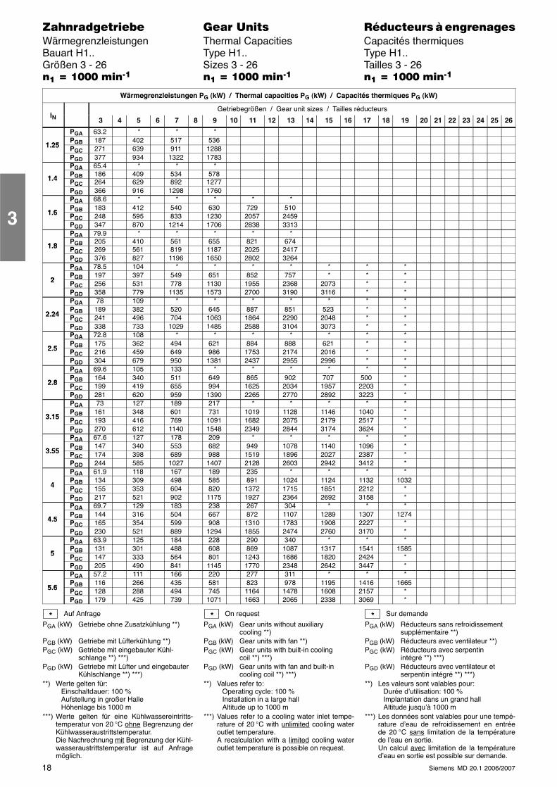
������������� ���� �� ��������� � ����������Wärmegrenzleistungen Thermal Capacities Capacités thermiquesBauart H1.. Type H1.. Type H1..Größen 3 - 26 Sizes 3 - 26 Tailles 3 - 26�� � ���� ����� �� � ���� ����� �� � ���� �����
Wärmegrenzleistungen PG (kW) / Thermal capacities PG (kW) / Capacités thermiques PG (kW)
iGetriebegrößen / Gear unit sizes / Tailles réducteurs
iN 3 4 5 6 7 8 9 10 11 12 13 14 15 16 17 18 19 20 21 22 23 24 25 26
PGA 63.2 * * *
1 25PGB 187 402 517 536
1.25 PGC 271 639 911 1288PGD 377 934 1322 1783PGA 65.4 * * *
1 4PGB 186 409 534 578
1.4 PGC 264 629 892 1277PGD 366 916 1298 1760PGA 68.6 * * * * *
1 6PGB 183 412 540 630 729 510
1.6 PGC 248 595 833 1230 2057 2459PGD 347 870 1214 1706 2838 3313PGA 79.9 * * * * *
1 8PGB 205 410 561 655 821 674
1.8 PGC 269 561 819 1187 2025 2417PGD 376 827 1196 1650 2802 3264PGA 78.5 104 * * * * * * *
2PGB 197 397 549 651 852 757 * * *
2 PGC 256 531 778 1130 1955 2368 2073 * *PGD 358 779 1135 1573 2700 3190 3116 * *PGA 78 109 * * * * * * *
2 24PGB 189 382 520 645 887 851 523 * *
2.24 PGC 241 496 704 1063 1864 2290 2048 * *PGD 338 733 1029 1485 2588 3104 3073 * *PGA 72.8 108 * * * * * * *
2 5PGB 175 362 494 621 884 888 621 * *
2.5 PGC 216 459 649 986 1753 2174 2016 * *PGD 304 679 950 1381 2437 2955 2996 * *PGA 69.6 105 133 * * * * * *
2 8PGB 164 340 511 649 865 902 707 500 *
2.8 PGC 199 419 655 994 1625 2034 1957 2203 *PGD 281 620 959 1390 2265 2770 2892 3223 *PGA 73 127 189 217 * * * * *
3 15PGB 161 348 601 731 1019 1128 1146 1040 *
3.15 PGC 193 416 769 1091 1682 2075 2179 2517 *PGD 270 612 1140 1548 2349 2844 3174 3624 *PGA 67.6 127 178 209 * * * * *
3 55PGB 147 340 553 682 949 1078 1140 1096 *
3.55 PGC 174 398 689 988 1519 1896 2027 2387 *PGD 244 585 1027 1407 2128 2603 2942 3412 *PGA 61.9 118 167 189 235 * * * *
4PGB 134 309 498 585 891 1024 1124 1132 1032
4 PGC 155 353 604 820 1372 1715 1851 2212 *PGD 217 521 902 1175 1927 2364 2692 3158 *PGA 69.7 129 183 238 267 304 * * *
4 5PGB 144 316 504 667 872 1107 1289 1307 1274
4.5 PGC 165 354 599 908 1310 1783 1908 2227 *PGD 230 521 889 1294 1855 2474 2760 3170 *PGA 63.9 125 184 228 290 340 * * *
5PGB 131 301 488 608 869 1087 1317 1541 1585
5 PGC 147 333 564 801 1243 1686 1820 2424 *PGD 205 490 841 1145 1770 2348 2642 3447 *PGA 57.2 111 166 220 277 311 * * *
5 6PGB 116 266 435 581 823 978 1195 1416 1665
5.6 PGC 128 288 494 745 1164 1478 1608 2157 *PGD 179 425 739 1071 1663 2065 2338 3069 *
Auf Anfrage
PGA (kW) Getriebe ohne Zusatzkühlung **)
PGB (kW) Getriebe mit Lüfterkühlung **)PGC (kW) Getriebe mit eingebauter Kühl-
schlange **) ***)PGD (kW) Getriebe mit Lüfter und eingebauter
Kühlschlange **) ***)**) Werte gelten für:
Einschaltdauer: 100 %Aufstellung in großer HalleHöhenlage bis 1000 m
***) Werte gelten für eine Kühlwassereintritts-temperatur von 20 °C ohne Begrenzung derKühlwasseraustrittstemperatur.Die Nachrechnung mit Begrenzung der Kühl-wasseraustrittstemperatur ist auf Anfragemöglich.
On request
PGA (kW) Gear units without auxiliarycooling **)
PGB (kW) Gear units with fan **)PGC (kW) Gear units with built-in cooling
coil **) ***)PGD (kW) Gear units with fan and built-in
cooling coil **) ***)**) Values refer to:
Operating cycle: 100 %Installation in a large hallAltitude up to 1000 m
***) Values refer to a cooling water inlet tempe-rature of 20 °C with unlimited cooling wateroutlet temperature.A recalculation with a limited cooling wateroutlet temperature is possible on request.
Sur demande
PGA (kW) Réducteurs sans refroidissementsupplémentaire **)
PGB (kW) Réducteurs avec ventilateur **)PGC (kW) Réducteurs avec serpentin
intégré **) ***)PGD (kW) Réducteurs avec ventilateur et
serpentin intégré **) ***)**) Les valeurs sont valables pour:
Durée d’utilisation: 100 %Implantation dans un grand hallAltitude jusqu’à 1000 m
***) Les données sont valables pour une tempé-rature d’eau de refroidissement en entréede 20 °C sans limitation de la températurede l’eau en sortie.Un calcul avec limitation de la températured’eau en sortie est possible sur demande.
* * *
3
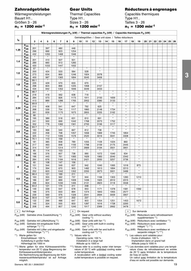
19Siemens MD 20.1 2006/2007
������������� ���� �� ��������� � ����������Wärmegrenzleistungen Thermal Capacities Capacités thermiquesBauart H1.. Type H1.. Type H1..Größen 3 - 26 Sizes 3 - 26 Tailles 3 - 26�� � ���� ����� �� � ���� ����� �� � ���� �����
Wärmegrenzleistungen PG (kW) / Thermal capacities PG (kW) / Capacités thermiques PG (kW)
iGetriebegrößen / Gear unit sizes / Tailles réducteurs
iN 3 4 5 6 7 8 9 10 11 12 13 14 15 16 17 18 19 20 21 22 23 24 25 26
PGA * * * *
1 25PGB 201 397 480 446
1.25 PGC 296 666 923 1254PGD 432 1050 1468 1946PGA * * * *
1 4PGB 201 410 507 501
1.4 PGC 289 660 913 1260PGD 420 1033 1447 1932PGA 57 * * * * *
1 6PGB 200 424 533 584 528 *
1.6 PGC 273 634 869 1246 1924 2078PGD 400 987 1365 1894 3045 3406PGA 69.1 * * * * *
1 8PGB 225 429 570 633 670 *
1.8 PGC 298 604 866 1225 1958 2157PGD 434 942 1352 1846 3049 3433PGA 68.7 * * * * * * * *
2PGB 218 418 562 638 718 * * * *
2 PGC 284 573 826 1173 1911 2150 1659 * *PGD 413 889 1286 1765 2952 3380 3133 * *PGA 69.9 * * * * * * * *
2 24PGB 210 408 541 647 792 625 * * *
2.24 PGC 268 539 754 1117 1860 2148 1734 * *PGD 391 839 1170 1675 2855 3335 3162 * *PGA 66 * * * * * * * *
2 5PGB 195 389 518 631 810 691 * * *
2.5 PGC 241 500 699 1042 1768 2073 1752 * *PGD 352 778 1082 1561 2700 3196 3117 * *PGA 63.7 * * * * * * * *
2 8PGB 183 366 540 667 812 738 * * *
2.8 PGC 222 458 708 1057 1656 1969 1745 1854 *PGD 325 712 1095 1576 2520 3016 3041 3308 *PGA 70.1 113 159 * * * * * *
3 15PGB 181 385 658 789 1055 1109 1024 860 *
3.15 PGC 217 463 848 1193 1798 2159 2175 2445 *PGD 314 707 1314 1777 2669 3194 3501 3951 *PGA 65 114 153 * * * * * *
3 55PGB 166 376 607 738 990 1072 1040 934 *
3.55 PGC 196 443 761 1083 1629 1983 2040 2342 *PGD 284 676 1184 1616 2421 2930 3257 3736 *PGA 60 108 147 156 * * * * *
4PGB 151 344 549 637 942 1040 1065 1018 873
4 PGC 174 394 670 903 1482 1813 1894 2213 *PGD 252 603 1042 1352 2200 2673 3001 3488 *PGA 68.4 121 169 211 * * * * *
4 5PGB 163 355 562 737 944 1168 1303 1283 1210
4.5 PGC 186 397 669 1009 1436 1925 2012 2315 *PGD 268 604 1030 1495 2131 2823 3118 3558 *PGA 63.2 121 174 211 248 * * * *
5PGB 149 339 547 678 953 1171 1378 1581 1592
5 PGC 166 375 633 894 1374 1843 1955 2577 *PGD 239 569 976 1326 2041 2694 3009 3907 *PGA 56.6 107 157 202 237 * * * *
5 6PGB 132 299 488 647 903 1054 1251 1453 1672
5.6 PGC 145 324 555 833 1287 1616 1728 2293 *PGD 208 494 857 1240 1917 2369 2662 3478 *
Auf Anfrage
PGA (kW) Getriebe ohne Zusatzkühlung **)
PGB (kW) Getriebe mit Lüfterkühlung **)PGC (kW) Getriebe mit eingebauter Kühl-
schlange **) ***)PGD (kW) Getriebe mit Lüfter und eingebauter
Kühlschlange **) ***)**) Werte gelten für:
Einschaltdauer: 100 %Aufstellung in großer HalleHöhenlage bis 1000 m
***) Werte gelten für eine Kühlwassereintritts-temperatur von 20 °C ohne Begrenzung derKühlwasseraustrittstemperatur.Die Nachrechnung mit Begrenzung der Kühl-wasseraustrittstemperatur ist auf Anfragemöglich.
On request
PGA (kW) Gear units without auxiliarycooling **)
PGB (kW) Gear units with fan **)PGC (kW) Gear units with built-in cooling
coil **) ***)PGD (kW) Gear units with fan and built-in
cooling coil **) ***)**) Values refer to:
Operating cycle: 100 %Installation in a large hallAltitude up to 1000 m
***) Values refer to a cooling water inlet tempe-rature of 20 °C with unlimited cooling wateroutlet temperature.A recalculation with a limited cooling wateroutlet temperature is possible on request.
Sur demande
PGA (kW) Réducteurs sans refroidissementsupplémentaire **)
PGB (kW) Réducteurs avec ventilateur **)PGC (kW) Réducteurs avec serpentin
intégré **) ***)PGD (kW) Réducteurs avec ventilateur et
serpentin intégré **) ***)**) Les valeurs sont valables pour:
Durée d’utilisation: 100 %Implantation dans un grand hallAltitude jusqu’à 1000 m
***) Les données sont valables pour une tempé-rature d’eau de refroidissement en entréede 20 °C sans limitation de la températurede l’eau en sortie.Un calcul avec limitation de la températured’eau en sortie est possible sur demande.
* * *
3
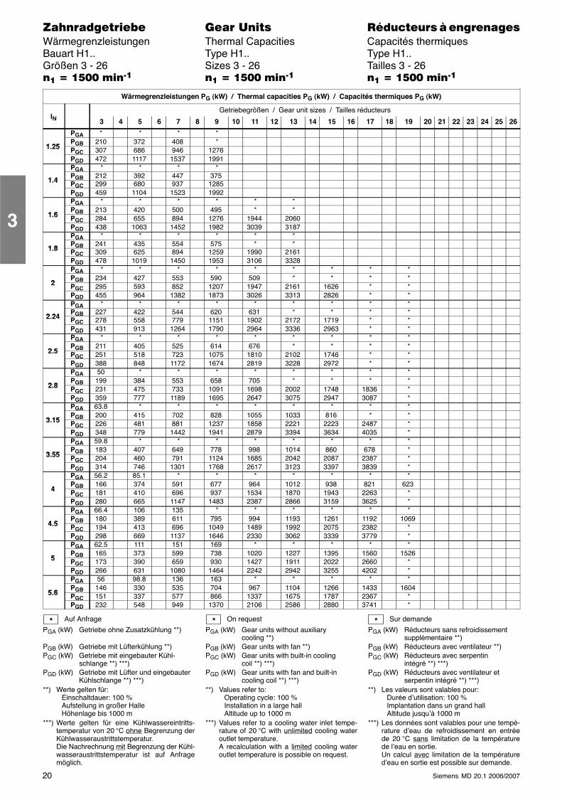
20 Siemens MD 20.1 2006/2007
������������� ���� �� ��������� � ����������Wärmegrenzleistungen Thermal Capacities Capacités thermiquesBauart H1.. Type H1.. Type H1..Größen 3 - 26 Sizes 3 - 26 Tailles 3 - 26�� � ���� ����� �� � ���� ����� �� � ���� �����
Wärmegrenzleistungen PG (kW) / Thermal capacities PG (kW) / Capacités thermiques PG (kW)
iGetriebegrößen / Gear unit sizes / Tailles réducteurs
iN 3 4 5 6 7 8 9 10 11 12 13 14 15 16 17 18 19 20 21 22 23 24 25 26
PGA * * * *
1 25PGB 210 372 408 *
1.25 PGC 307 686 946 1276PGD 472 1117 1537 1991PGA * * * *
1 4PGB 212 392 447 375
1.4 PGC 299 680 937 1285PGD 459 1104 1523 1992PGA * * * * * *
1 6PGB 213 420 500 495 * *
1.6 PGC 284 655 894 1276 1944 2060PGD 438 1063 1452 1982 3039 3187PGA * * * * * *
1 8PGB 241 435 554 575 * *
1.8 PGC 309 625 894 1259 1990 2161PGD 478 1019 1450 1953 3106 3328PGA * * * * * * * * *
2PGB 234 427 553 590 509 * * * *
2 PGC 295 593 852 1207 1947 2161 1626 * *PGD 455 964 1382 1873 3026 3313 2826 * *PGA * * * * * * * * *
2 24PGB 227 422 544 620 631 * * * *
2.24 PGC 278 558 779 1151 1902 2172 1719 * *PGD 431 913 1264 1790 2964 3336 2963 * *PGA * * * * * * * * *
2 5PGB 211 405 525 614 676 * * * *
2.5 PGC 251 518 723 1075 1810 2102 1746 * *PGD 388 848 1172 1674 2819 3228 2972 * *PGA 50 * * * * * * * *
2 8PGB 199 384 553 658 705 * * * *
2.8 PGC 231 475 733 1091 1698 2002 1748 1836 *PGD 359 777 1189 1695 2647 3075 2947 3087 *PGA 63.8 * * * * * * * *
3 15PGB 200 415 702 828 1055 1033 816 * *
3.15 PGC 226 481 881 1237 1858 2221 2223 2487 *PGD 348 779 1442 1941 2879 3394 3634 4035 *PGA 59.8 * * * * * * * *
3 55PGB 183 407 649 778 998 1014 860 678 *
3.55 PGC 204 460 791 1124 1685 2042 2087 2387 *PGD 314 746 1301 1768 2617 3123 3397 3839 *PGA 56.2 85.1 * * * * * * *
4PGB 166 374 591 677 964 1012 938 821 623
4 PGC 181 410 696 937 1534 1870 1943 2263 *PGD 280 665 1147 1483 2387 2866 3159 3625 *PGA 66.4 106 135 * * * * * *
4 5PGB 180 389 611 795 994 1193 1261 1192 1069
4.5 PGC 194 413 696 1049 1489 1992 2075 2382 *PGD 298 669 1137 1646 2330 3062 3339 3779 *PGA 62.5 111 151 169 * * * * *
5PGB 165 373 599 738 1020 1227 1395 1560 1526
5 PGC 173 390 659 930 1427 1911 2022 2660 *PGD 266 631 1080 1464 2242 2942 3255 4202 *PGA 56 98.8 136 163 * * * * *
5 6PGB 146 330 535 704 967 1104 1266 1433 1604
5.6 PGC 151 337 577 866 1337 1675 1787 2367 *PGD 232 548 949 1370 2106 2586 2880 3741 *
Auf Anfrage
PGA (kW) Getriebe ohne Zusatzkühlung **)
PGB (kW) Getriebe mit Lüfterkühlung **)PGC (kW) Getriebe mit eingebauter Kühl-
schlange **) ***)PGD (kW) Getriebe mit Lüfter und eingebauter
Kühlschlange **) ***)**) Werte gelten für:
Einschaltdauer: 100 %Aufstellung in großer HalleHöhenlage bis 1000 m
***) Werte gelten für eine Kühlwassereintritts-temperatur von 20 °C ohne Begrenzung derKühlwasseraustrittstemperatur.Die Nachrechnung mit Begrenzung der Kühl-wasseraustrittstemperatur ist auf Anfragemöglich.
On request
PGA (kW) Gear units without auxiliarycooling **)
PGB (kW) Gear units with fan **)PGC (kW) Gear units with built-in cooling
coil **) ***)PGD (kW) Gear units with fan and built-in
cooling coil **) ***)**) Values refer to:
Operating cycle: 100 %Installation in a large hallAltitude up to 1000 m
***) Values refer to a cooling water inlet tempe-rature of 20 °C with unlimited cooling wateroutlet temperature.A recalculation with a limited cooling wateroutlet temperature is possible on request.
Sur demande
PGA (kW) Réducteurs sans refroidissementsupplémentaire **)
PGB (kW) Réducteurs avec ventilateur **)PGC (kW) Réducteurs avec serpentin
intégré **) ***)PGD (kW) Réducteurs avec ventilateur et
serpentin intégré **) ***)**) Les valeurs sont valables pour:
Durée d’utilisation: 100 %Implantation dans un grand hallAltitude jusqu’à 1000 m
***) Les données sont valables pour une tempé-rature d’eau de refroidissement en entréede 20 °C sans limitation de la températurede l’eau en sortie.Un calcul avec limitation de la températured’eau en sortie est possible sur demande.
* * *
3
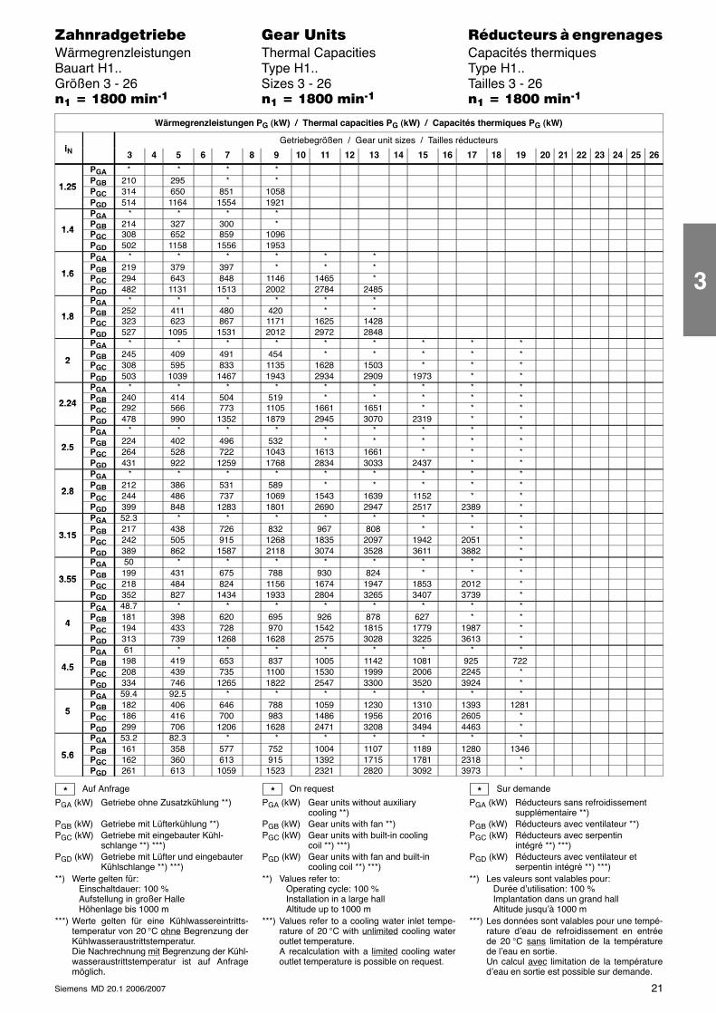
21Siemens MD 20.1 2006/2007
������������� ���� �� ��������� � ����������Wärmegrenzleistungen Thermal Capacities Capacités thermiquesBauart H1.. Type H1.. Type H1..Größen 3 - 26 Sizes 3 - 26 Tailles 3 - 26�� � �!�� ����� �� � �!�� ����� �� � �!�� �����
Wärmegrenzleistungen PG (kW) / Thermal capacities PG (kW) / Capacités thermiques PG (kW)
iGetriebegrößen / Gear unit sizes / Tailles réducteurs
iN 3 4 5 6 7 8 9 10 11 12 13 14 15 16 17 18 19 20 21 22 23 24 25 26
PGA * * * *
1 25PGB 210 295 * *
1.25 PGC 314 650 851 1058PGD 514 1164 1554 1921PGA * * * *
1 4PGB 214 327 300 *
1.4 PGC 308 652 859 1096PGD 502 1158 1556 1953PGA * * * * * *
1 6PGB 219 379 397 * * *
1.6 PGC 294 643 848 1146 1465 *PGD 482 1131 1513 2002 2784 2485PGA * * * * * *
1 8PGB 252 411 480 420 * *
1.8 PGC 323 623 867 1171 1625 1428PGD 527 1095 1531 2012 2972 2848PGA * * * * * * * * *
2PGB 245 409 491 454 * * * * *
2 PGC 308 595 833 1135 1628 1503 * * *PGD 503 1039 1467 1943 2934 2909 1973 * *PGA * * * * * * * * *
2 24PGB 240 414 504 519 * * * * *
2.24 PGC 292 566 773 1105 1661 1651 * * *PGD 478 990 1352 1879 2945 3070 2319 * *PGA * * * * * * * * *
2 5PGB 224 402 496 532 * * * * *
2.5 PGC 264 528 722 1043 1613 1661 * * *PGD 431 922 1259 1768 2834 3033 2437 * *PGA * * * * * * * * *
2 8PGB 212 386 531 589 * * * * *
2.8 PGC 244 486 737 1069 1543 1639 1152 * *PGD 399 848 1283 1801 2690 2947 2517 2389 *PGA 52.3 * * * * * * * *
3 15PGB 217 438 726 832 967 808 * * *
3.15 PGC 242 505 915 1268 1835 2097 1942 2051 *PGD 389 862 1587 2118 3074 3528 3611 3882 *PGA 50 * * * * * * * *
3 55PGB 199 431 675 788 930 824 * * *
3.55 PGC 218 484 824 1156 1674 1947 1853 2012 *PGD 352 827 1434 1933 2804 3265 3407 3739 *PGA 48.7 * * * * * * * *
4PGB 181 398 620 695 926 878 627 * *
4 PGC 194 433 728 970 1542 1815 1779 1987 *PGD 313 739 1268 1628 2575 3028 3225 3613 *PGA 61 * * * * * * * *
4 5PGB 198 419 653 837 1005 1142 1081 925 722
4.5 PGC 208 439 735 1100 1530 1999 2006 2245 *PGD 334 746 1265 1822 2547 3300 3520 3924 *PGA 59.4 92.5 * * * * * * *
5PGB 182 406 646 788 1059 1230 1310 1393 1281
5 PGC 186 416 700 983 1486 1956 2016 2605 *PGD 299 706 1206 1628 2471 3208 3494 4463 *PGA 53.2 82.3 * * * * * * *
5 6PGB 161 358 577 752 1004 1107 1189 1280 1346
5.6 PGC 162 360 613 915 1392 1715 1781 2318 *PGD 261 613 1059 1523 2321 2820 3092 3973 *
Auf Anfrage
PGA (kW) Getriebe ohne Zusatzkühlung **)
PGB (kW) Getriebe mit Lüfterkühlung **)PGC (kW) Getriebe mit eingebauter Kühl-
schlange **) ***)PGD (kW) Getriebe mit Lüfter und eingebauter
Kühlschlange **) ***)**) Werte gelten für:
Einschaltdauer: 100 %Aufstellung in großer HalleHöhenlage bis 1000 m
***) Werte gelten für eine Kühlwassereintritts-temperatur von 20 °C ohne Begrenzung derKühlwasseraustrittstemperatur.Die Nachrechnung mit Begrenzung der Kühl-wasseraustrittstemperatur ist auf Anfragemöglich.
On request
PGA (kW) Gear units without auxiliarycooling **)
PGB (kW) Gear units with fan **)PGC (kW) Gear units with built-in cooling
coil **) ***)PGD (kW) Gear units with fan and built-in
cooling coil **) ***)**) Values refer to:
Operating cycle: 100 %Installation in a large hallAltitude up to 1000 m
***) Values refer to a cooling water inlet tempe-rature of 20 °C with unlimited cooling wateroutlet temperature.A recalculation with a limited cooling wateroutlet temperature is possible on request.
Sur demande
PGA (kW) Réducteurs sans refroidissementsupplémentaire **)
PGB (kW) Réducteurs avec ventilateur **)PGC (kW) Réducteurs avec serpentin
intégré **) ***)PGD (kW) Réducteurs avec ventilateur et
serpentin intégré **) ***)**) Les valeurs sont valables pour:
Durée d’utilisation: 100 %Implantation dans un grand hallAltitude jusqu’à 1000 m
***) Les données sont valables pour une tempé-rature d’eau de refroidissement en entréede 20 °C sans limitation de la températurede l’eau en sortie.Un calcul avec limitation de la températured’eau en sortie est possible sur demande.
* * *
3
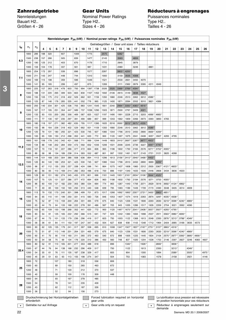
22 Siemens MD 20.1 2006/2007
������������� ���� �� ��������� � ����������Nennleistungen Nominal Power Ratings Puissances nominalesBauart H2.. Type H2.. Type H2..Größen 4 - 26 Sizes 4 - 26 Tailles 4 - 26
Nennleistungen P2N (kW) / Nominal power ratings P2N (kW) / Puissances nominales P2N (kW)
i n nGetriebegrößen / Gear unit sizes / Tailles réducteurs
iN n1 n2 4 5 6 7 8 9 10 11 12 13 14 15 16 17 18 19 20 21 22 23 24 25 26
1800 286 188 320 607 1009 1775 2575 4282 *
6 31500 238 157 266 505 839 1477 2143 3563 4859
6.31200 190 125 212 403 670 1179 1710 2845 3879
1000 159 104 178 337 561 987 1431 2380 3246 4861
1800 254 172 297 539 896 1577 2287 3803 * 4255 *
7 11500 211 143 247 448 744 1310 1900 3159 3535 4308
7.11200 169 115 198 359 596 1049 1521 2530 2831 3450 4070
1000 141 95 165 299 497 875 1269 2111 2362 2879 3395 4311 4946
1800 225 157 263 318 478 603 793 994 1397 1738 2026 2520 3369 * 3769 * 4594 *
81500 188 131 220 265 399 503 663 830 1167 1452 1692 2106 2815 3149 3838 4527
81200 150 105 175 212 318 402 529 662 931 1159 1350 1680 2246 2513 3062 3612 4586 *
1000 125 87 146 176 265 335 441 552 776 965 1125 1400 1871 2094 2552 3010 3821 4384
1800 200 140 234 301 425 536 705 883 1241 1545 1801 2240 2994 * 3350 * 4083 * 4816 *
91500 167 117 195 251 354 447 589 737 1036 1290 1503 1871 2500 2797 3409 4021
91200 133 93 155 200 282 356 469 587 825 1027 1197 1490 1991 2228 2715 3203 4066 * 4665 *
1000 111 77 130 167 235 297 391 490 689 857 999 1243 1662 1859 2266 2673 3393 3893 4765
1800 180 118 197 271 382 482 635 795 1117 1390 1620 2016 2695 * 3015 * 3675 * 4335 *
101500 150 98 164 226 318 402 529 662 931 1159 1350 1680 2246 2513 3062 3612 4586 *
101200 120 79 131 180 255 321 423 530 745 927 1080 1344 1796 2010 2450 2890 3669 * 4209 *
1000 100 65 109 150 212 268 352 441 620 772 900 1120 1497 1675 2041 2408 3057 3507 4293 4795
1800 161 106 178 242 342 431 568 711 999 1244 1449 1803 2410 * 2697 * 3287 * 3877 * 4922 *
11 21500 134 88 148 202 284 359 472 592 832 1035 1206 1501 2006 2245 2736 3227 4097 * 4700 *
11.21200 107 70 118 161 227 286 377 472 664 826 963 1198 1602 1792 2184 2576 3271 * 3753 * 4593 *
1000 89 58 98 134 189 238 314 393 552 687 801 997 1332 1491 1817 2143 2721 3121 3820 4268
1800 144 101 168 203 304 386 508 636 894 1112 1296 1613 2156 * 2412 * 2940 * 3468 * 4402 *
12 51500 120 84 140 169 253 321 423 530 745 927 1080 1344 1796 2010 2450 2890 3669 4209 *
12.51200 96 67 112 135 203 257 338 424 596 741 864 1075 1437 1608 1960 2312 2935 3367 * 4121 * 4603 *
1000 80 56 93 113 169 214 282 353 496 618 720 896 1197 1340 1633 1926 2446 2806 3434 3836 4523
1800 129 90 151 182 274 345 455 570 801 996 1161 1445 1931 * 2161 * 2634 * 3106 * 3944 * 4525 *
141500 107 75 125 151 227 286 377 472 664 826 963 1198 1602 1792 2184 2576 3271 3753 4593 *
141200 86 60 100 121 182 230 303 380 534 664 774 963 1287 1440 1756 2071 2629 3016 3692 * 4124 * 4862 *
1000 71 49 83 100 150 190 250 313 440 548 639 795 1063 1189 1449 1709 2170 2490 3048 3405 4014 4609
1800 113 79 132 170 240 301 398 499 701 873 1017 1266 1692 * 1893 * 2307 * 2721 * 3455 * 3963 * 4851 *
161500 94 65 110 141 199 250 331 415 583 726 846 1053 1407 1574 1919 2263 2874 3297 4035 * 4508 *
161200 75 52 87 113 159 200 264 331 465 579 675 840 1123 1256 1531 1806 2293 2630 3219 * 3596 * 4240 * 4869 *
1000 63 44 73 94 133 168 222 278 391 486 567 705 943 1055 1286 1517 1926 2209 2704 3021 3562 4090
1800 100 65 109 150 198 268 352 441 620 772 900 1120 1497 * 1675 * 2041 * 2408 * 3057 * 3507 * 4293 * 4795 *
181500 83 54 91 125 165 222 292 366 515 641 747 929 1242 1390 1694 1998 2537 2911 3563 * 3980 * 4693 *
181200 67 44 73 101 133 179 236 296 416 517 603 750 1003 1122 1368 1613 2048 2350 2876 * 3213 * 3788 * 4349 *
1000 56 36 61 84 111 150 197 247 347 432 504 627 838 938 1143 1348 1712 1964 2404 2685 3166 3635 4573
1800 90 62 105 135 179 241 317 397 558 695 810 1008 1347 * 1507 * 1837 * 2167 * 2751 * 3157 * 3863 * 4316 *
201500 75 51 87 113 149 201 264 331 465 579 675 840 1123 1256 1531 1806 2293 2630 3219 * 3596 * 4240 * 4869 *
201200 60 41 70 90 119 160 211 265 372 463 540 672 898 1005 1225 1445 1834 2104 2575 * 2877 * 3392 * 3895 * 4900 *
1000 50 34 58 75 99 134 176 220 310 386 450 560 748 837 1020 1204 1528 1753 2146 2397 2827 3246 4083 4607
1800 80 52 91 113 165 201 277 353 488 618 896 1340 * 1926 * 2806 * 3836 *
22 41500 67 44 76 94 138 168 232 296 409 517 750 1122 1613 2350 3213 * 4349 *
22.41200 54 35 61 76 111 135 187 238 329 417 605 904 1300 1894 2589 * 3505 * 4975 *
1000 45 29 51 63 93 113 155 198 274 347 504 753 1083 1578 2158 2921 4146
1800 72 107 180 318 556 806
251500 60 89 150 265 463 672
251200 48 71 120 212 370 537
1000 40 59 100 176 309 448
1800 64 93 167 278 485
281500 54 78 141 235 409
281200 43 62 112 187 326
1000 36 52 94 156 273
Druckschmierung bei Horizontalgetriebenerforderlich
Getriebe nur auf Anfrage
Forced lubrication required on horizontalgear units
Gear units only on request
La lubrification sous pression est nécessaireen position horizontale pour ces réducteurs
Réducteur à engrenages seulement surdemande
* * *
3
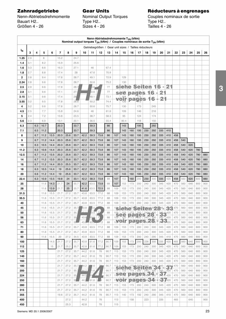
H4
H3 ���� ���� �� - ����� ����� �� - ����� ����� �� - ��
���� ���� �� - ����� ����� �� - ����� ����� �� - ��
���� ���� �� - ����� ����� �� - ����� ����� �� - ��H1
23Siemens MD 20.1 2006/2007
������������� ���� �� ��������� � ����������Nenn-Abtriebsdrehmomente Nominal Output Torques Couples nominaux de sortieBauart H2.. Type H2.. Type H2..Größen 4 - 26 Sizes 4 - 26 Tailles 4 - 26
Nenn-Abtriebsdrehmomente T2N (kNm)Nominal output torques T2N (kNm) / Couples nominaux de sortie T2N (kNm)
iGetriebegrößen / Gear unit sizes / Tailles réducteurs
iN3 4 5 6 7 8 9 10 11 12 13 14 15 16 17 18 19 20 21 22 23 24 25 26
1.25 2.9 8 15.2 24.7
1.4 3.1 8.2 15.9 25.6
1.6 3.3 8.6 16.3 27.1 46 67.4
1.8 2.7 8.8 17.4 28 47.6 70.9
2 2.8 9.4 17.8 28.7 49.1 72.9 129
2.24 2.8 9.6 17.8 28.7 50.6 75.2 130
2.5 2.9 9.6 17.8 28.7 50.6 77 117
2.8 3.1 9.6 17.1 27.2 50.6 77 120 171
3.15 3.1 9.6 17.4 28.1 48.1 73.1 124 173
3.55 3.2 9.5 17.8 28.6 50.2 74.4 126 173
4 3.2 9.6 17.8 28.7 50.6 75.7 130 173 245
4.5 2.5 7.7 15.8 24.6 46 61.6 109 146 216
5 2.4 7.2 13.8 23.5 38.7 58.3 95 124 174
5.6 2.3 6.9 13.1 20.1 36.5 55.4 90.4 118 150
6.3 6.3 10.7 20.3 33.7 59.3 86 143 195 292
7.1 6.5 11.2 20.3 33.7 59.3 86 143 160 195 230 292 335 410
8 6.7 11.2 13.5 20.3 25.6 33.7 42.2 59.3 73.8 86 107 143 160 195 230 292 335 410 458
9 6.7 11.2 14.4 20.3 25.6 33.7 42.2 59.3 73.8 86 107 143 160 195 230 292 335 410 458 540
10 6.3 10.5 14.4 20.3 25.6 33.7 42.2 59.3 73.8 86 107 143 160 195 230 292 335 410 458 540 620
11.2 6.3 10.6 14.4 20.3 25.6 33.7 42.2 59.3 73.8 86 107 143 160 195 230 292 335 410 458 540 620 780
12.5 6.7 11.2 13.5 20.2 25.6 33.7 42.2 59.3 73.8 86 107 143 160 195 230 292 335 410 458 540 620 780 880
14 6.7 11.2 13.5 20.3 25.6 33.7 42.2 59.3 73.8 86 107 143 160 195 230 292 335 410 458 540 620 780 880
16 6.7 11.2 14.4 20.3 25.5 33.7 42.2 59.3 73.8 86 107 143 160 195 230 292 335 410 458 540 620 780 880
18 6.3 10.5 14.4 19 25.6 33.7 42.2 59.3 73.8 86 107 143 160 195 230 292 335 410 458 540 620 780 880
20 6.6 11.2 14.4 19 25.6 33.7 42.2 59.3 73.8 86 107 143 160 195 230 292 335 410 458 540 620 780 880
22.4 6.3 10.9 13.5 19.8 24 33.1 42.2 58.3 73.8 88 107 153 160 200 230 300 335 420 458 560 620 800 880
25 11.6 14.3 21.7 24 35.7 42.2 63.5 73.8 88 107 153 173 200 240 300 345 420 470 560 640 800 900
28 11.6 13.9 21.7 25 35.7 41.6 63.5 72.5 88 109 153 173 200 240 300 345 420 470 560 640 800 900
31.5 11.6 15.5 21.7 27.2 35.7 43.8 63.5 77.2 88 109 153 173 200 240 300 345 420 470 560 640 800 900
35.5 11.6 15.5 21.7 27.2 35.7 43.8 63.5 77.2 88 109 153 173 200 240 300 345 420 470 560 640 800 900
40 11.6 15.5 21.7 27.2 35.7 43.8 63.5 77.2 88 109 153 173 200 240 300 345 420 470 560 640 800 900
45 11.6 15.5 21.7 27.2 35.7 43.8 63.5 77.2 88 109 153 173 200 240 300 345 420 470 560 640 800 900
50 11.6 15.5 21.7 27.2 35.7 43.8 63.5 77.2 88 109 153 173 200 240 300 345 420 470 560 640 800 900
56 11.6 15.5 21.7 27.2 35.7 43.8 63.5 77.2 88 109 153 173 200 240 300 345 420 470 560 640 800 900
63 11.6 15.5 21.7 27.2 35.7 43.8 63.5 77.2 88 109 153 173 200 240 300 345 420 470 560 640 800 900
71 11.6 15.5 21.7 27.2 35.7 43.8 63.5 77.2 88 109 153 173 200 240 300 345 420 470 560 640 800 900
80 11.6 15.5 21.7 27.2 35.7 43.8 63.5 77.2 88 109 153 173 200 240 300 345 420 470 560 640 800 900
90 11.6 15.5 20 27.2 34.5 43.8 63.5 77.2 88 109 153 173 200 240 290 345 410 470 560 640 800 900
100 14.5 21.7 27.2 35.7 43.8 61.6 77.2 90.7 109 153 173 200 226 300 335 420 465 560 640 800 900
112 15 21.7 25.2 35.7 42.8 61.6 77.2 90.7 109 153 173 200 240 300 345 420 470 560 640 800 900
125 21.7 27.2 35.7 44.2 61.6 78 90.7 113 153 173 200 240 300 345 420 470 560 640 800 900
140 21.7 27.2 35.7 44.2 61.6 78 90.7 113 153 173 200 240 300 345 420 470 560 640 800 900
160 21.7 27.2 35.7 44.2 61.6 78 90.7 113 153 173 200 240 300 345 420 470 560 640 800 900
180 21.7 27.2 35.7 44.2 61.6 78 90.7 113 153 173 200 240 300 345 420 470 560 640 800 900
200 21.7 27.2 35.7 44.2 61.6 78 90.7 113 153 173 200 240 300 345 420 470 560 640 800 900
224 21.7 27.2 35.7 44.2 61.6 78 90.7 113 153 173 200 240 300 345 420 470 560 640 800 900
250 21.7 27.2 35.7 44.2 61.6 78 90.7 113 153 173 200 240 300 345 420 470 560 640 800 900
280 21.7 27.2 35.7 44.2 61.6 78 90.7 113 153 173 200 240 300 345 420 470 560 640 800 900
315 21.7 27.2 35.7 44.2 61.6 78 90.7 113 153 173 200 240 300 345 420 470 560 640 800 900
355 19.6 27.2 35.7 44.2 61.6 78 90.7 113 140 173 192 240 290 345 410 470 560 640 800 900
400 27.2 44.2 78 113 158 223 335 465 640 900
450 25.3 42.8 78 113
3
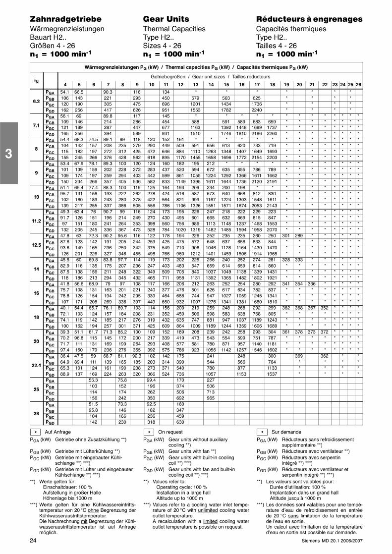
24 Siemens MD 20.1 2006/2007
������������� ���� �� ��������� � ����������Wärmegrenzleistungen Thermal Capacities Capacités thermiquesBauart H2.. Type H2.. Type H2..Größen 4 - 26 Sizes 4 - 26 Tailles 4 - 26�� � ���� ����� �� � ���� ����� �� � ���� �����
Wärmegrenzleistungen PG (kW) / Thermal capacities PG (kW) / Capacités thermiques PG (kW)
iNGetriebegrößen / Gear unit sizes / Tailles réducteurs
iN 4 5 6 7 8 9 10 11 12 13 14 15 16 17 18 19 20 21 22 23 24 25 26
PGA 54.1 66.5 90.3 116 134 * * * * * * *
6 3PGB 106 143 221 293 450 579 563 625 * * * *
6.3 PGC 120 190 305 475 696 1201 1434 1736 * * * *PGD 162 256 417 626 951 1553 1782 2240 * * * *PGA 56.1 69 89.8 117 145 * * * * * * * * * * * * *
7 1PGB 109 146 214 286 454 588 591 589 683 659 * * * * * * * *
7.1 PGC 121 189 287 447 677 1163 1392 1448 1689 1737 * * * * * * * *PGD 165 256 394 589 931 1510 1746 1810 2186 2260 * * * * * * * *PGA 54.4 68.3 74.5 89.1 99 118 120 152 161 * * * * * * * * * * * * * *
8PGB 104 142 157 208 235 279 290 449 509 591 656 613 620 733 719 * * * * * * * *
8 PGC 115 182 197 272 312 425 472 646 884 1110 1263 1348 1407 1649 1693 * * * * * * * *PGD 155 245 266 376 428 562 618 895 1170 1455 1658 1696 1772 2154 2203 * * * * * * * *PGA 53.4 67.9 78.1 89.3 100 120 124 160 182 195 212 * * * * * * * * * * * *
9PGB 101 139 159 202 228 272 283 437 520 594 672 635 655 786 789 * * * * * * * *
9 PGC 109 174 197 259 294 403 442 599 861 1055 1224 1292 1366 1611 1662 * * * * * * * *PGD 150 234 266 357 405 536 582 833 1149 1395 1611 1644 1736 2120 2191 * * * * * * * *PGA 51.1 65.4 77.4 88.3 100 119 125 164 193 209 234 200 198 * * * * * * * * * *
10PGB 95.7 131 156 193 222 262 278 424 516 587 673 640 668 812 830 * * * * * * * *
10 PGC 102 160 189 243 280 378 422 564 821 999 1167 1224 1303 1548 1611 * * * * * * * *PGD 139 217 255 337 386 505 556 786 1106 1326 1551 1571 1674 2053 2143 * * * * * * * *PGA 49.3 63.4 76 90.7 99 116 124 173 195 226 247 218 222 229 223 * * * * * * * *
11 2PGB 91.7 126 151 196 214 249 270 430 495 601 665 632 669 815 847 * * * * * * * *
11.2 PGC 97 151 180 241 264 353 398 560 756 986 1113 1148 1237 1468 1553 * * * * * * * *PGD 132 205 245 336 367 473 528 784 1020 1319 1482 1485 1594 1958 2070 * * * * * * * *PGA 47.8 63 72.3 90.2 95.6 116 122 178 194 226 252 235 235 260 250 301 289 * * * * * *
12 5PGB 87.6 123 142 191 205 244 259 425 475 572 648 637 656 833 844 * * * * * * * *
12.5 PGC 93.6 149 165 236 250 342 375 549 710 906 1046 1128 1164 1430 1470 * * * * * * * *PGD 126 201 226 327 346 455 498 766 960 1212 1401 1459 1506 1914 1965 * * * * * * * *PGA 45.5 60 69.8 83.8 97.7 114 119 173 202 225 266 240 252 274 281 328 333 * * * * * *
14PGB 82.9 116 135 175 207 236 247 403 483 547 659 614 659 814 860 * * * * * * * *
14 PGC 87.5 138 156 211 248 322 349 509 705 840 1037 1049 1138 1339 1431 * * * * * * * *PGD 118 186 213 294 345 432 465 711 958 1131 1392 1365 1482 1802 1921 * * * * * * * *PGA 41.8 56.6 68.9 79 97 108 117 166 206 212 263 252 254 280 292 341 354 336 * * * * *
16PGB 75.7 108 131 163 201 221 240 377 476 501 626 617 634 782 837 * * * * * * * *
16 PGC 78.8 126 154 194 242 295 339 464 688 744 947 1027 1059 1245 1341 * * * * * * * *PGD 107 171 208 269 336 397 449 650 932 1007 1276 1341 1381 1680 1810 * * * * * * * *PGA 40.1 54.4 65.7 76.1 89.7 103 114 156 200 219 259 248 268 292 299 362 368 367 352 * * * *
18PGB 72.1 103 124 157 184 208 231 352 450 506 598 583 638 768 805 * * * * * * * *
18 PGC 74.1 119 142 185 217 276 319 432 635 747 881 947 1037 1189 1243 * * * * * * * *PGD 100 162 194 257 301 371 425 609 864 1009 1189 1244 1359 1606 1689 * * * * * * * *PGA 39.3 51.1 61.7 71.3 85.2 100 109 152 189 208 239 242 258 293 304 361 378 373 372 * * * *
20PGB 70.2 96.8 115 145 172 200 217 339 419 473 543 554 599 751 787 * * * * * * * *
20 PGC 71.7 111 131 169 199 264 293 408 577 681 780 871 957 1140 1181 * * * * * * * *PGD 97.4 150 179 236 276 355 392 575 786 923 1056 1142 1257 1546 1602 * * * * * * * *PGA 36.4 47.5 59 68.7 81.1 92.3 102 142 175 241 248 300 369 362 * *
22 4PGB 64.9 89.4 111 139 165 185 203 314 390 544 566 764 * * * *
22.4 PGC 65.3 101 124 161 190 238 273 371 540 780 877 1133 * * * *PGD 88.9 137 169 224 263 320 366 524 736 1057 1153 1537 * * * *PGA 55.3 75.8 99.4 170 227
25PGB 103 152 196 374 506
25 PGC 114 174 262 506 713PGD 156 242 350 692 965PGA 51.5 73.3 92.5 160
28PGB 95.8 146 182 347
28 PGC 104 166 236 459PGD 142 230 318 630
Auf Anfrage
PGA (kW) Getriebe ohne Zusatzkühlung **)
PGB (kW) Getriebe mit Lüfterkühlung **)PGC (kW) Getriebe mit eingebauter Kühl-
schlange **) ***)PGD (kW) Getriebe mit Lüfter und eingebauter
Kühlschlange **) ***)**) Werte gelten für:
Einschaltdauer: 100 %Aufstellung in großer HalleHöhenlage bis 1000 m
***) Werte gelten für eine Kühlwassereintritts-temperatur von 20 °C ohne Begrenzung derKühlwasseraustrittstemperatur.Die Nachrechnung mit Begrenzung der Kühl-wasseraustrittstemperatur ist auf Anfragemöglich.
On request
PGA (kW) Gear units without auxiliarycooling **)
PGB (kW) Gear units with fan **)PGC (kW) Gear units with built-in cooling
coil **) ***)PGD (kW) Gear units with fan and built-in
cooling coil **) ***)**) Values refer to:
Operating cycle: 100 %Installation in a large hallAltitude up to 1000 m
***) Values refer to a cooling water inlet tempe-rature of 20 °C with unlimited cooling wateroutlet temperature.A recalculation with a limited cooling wateroutlet temperature is possible on request.
Sur demande
PGA (kW) Réducteurs sans refroidissementsupplémentaire **)
PGB (kW) Réducteurs avec ventilateur **)PGC (kW) Réducteurs avec serpentin
intégré **) ***)PGD (kW) Réducteurs avec ventilateur et
serpentin intégré **) ***)**) Les valeurs sont valables pour:
Durée d’utilisation: 100 %Implantation dans un grand hallAltitude jusqu’à 1000 m
***) Les données sont valables pour une tempé-rature d’eau de refroidissement en entréede 20 °C sans limitation de la températurede l’eau en sortie.Un calcul avec limitation de la températured’eau en sortie est possible sur demande.
* * *
3
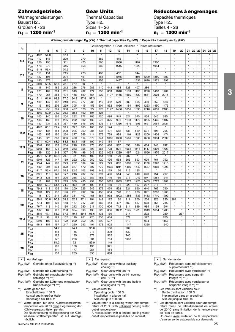
25Siemens MD 20.1 2006/2007
������������� ���� �� ��������� � ����������Wärmegrenzleistungen Thermal Capacities Capacités thermiquesBauart H2.. Type H2.. Type H2..Größen 4 - 26 Sizes 4 - 26 Tailles 4 - 26�� � ���� ����� �� � ���� ����� �� � ���� �����
Wärmegrenzleistungen PG (kW) / Thermal capacities PG (kW) / Capacités thermiques PG (kW)
iNGetriebegrößen / Gear unit sizes / Tailles réducteurs
iN 4 5 6 7 8 9 10 11 12 13 14 15 16 17 18 19 20 21 22 23 24 25 26
PGA 49.2 54.6 67.4 * * * * * * * * *
6 3PGB 112 146 220 279 382 415 * * * * * *
6.3 PGC 126 196 311 475 665 1088 1192 1360 * * * *PGD 176 276 445 658 966 1515 1628 1954 * * * *PGA 51.8 58.4 70.3 * * * * * * * * * * * * * * *
7 1PGB 116 151 215 278 400 452 344 * * * * * * * * * * *
7.1 PGC 127 196 294 451 656 1075 1196 1220 1380 1383 * * * * * * * *PGD 180 276 422 624 956 1497 1636 1670 1971 1997 * * * * * * * *PGA 50.9 59.5 63.6 72.9 77.3 88 * * * * * * * * * * * * * * * * *
8PGB 111 149 162 212 236 276 283 410 443 484 526 407 386 * * * * * * * * * *
8 PGC 121 189 204 281 319 432 477 635 853 1048 1183 1196 1228 1403 1409 * * * * * * * *PGD 170 266 288 404 458 599 654 929 1197 1465 1660 1629 1681 2003 2015 * * * * * * * *PGA 51.1 61.6 69.8 77.5 84.3 97.8 97.3 * * * * * * * * * * * * * * * *
9PGB 109 147 167 210 234 277 285 419 482 529 589 495 490 552 523 * * * * * * * *
9 PGC 116 182 206 269 305 415 453 601 852 1026 1184 1199 1253 1450 1473 * * * * * * * *PGD 164 255 289 386 437 576 622 878 1197 1436 1651 1635 1710 2059 2103 * * * * * * * *PGA 49.5 60.9 71.3 79.5 88.1 102 104 121 * * * * * * * * * * * * * * *
10PGB 103 140 166 204 232 272 285 420 498 549 624 545 554 645 635 * * * * * * * *
10 PGD 108 169 198 255 292 392 436 573 825 991 1153 1172 1235 1446 1487 * * * * * * * *PGB 153 237 278 367 419 546 599 836 1167 1386 1616 1598 1691 2051 2121 * * * * * * * *PGA 48.2 60.1 71.4 83.7 89.7 103 108 138 144 * * * * * * * * * * * * * *
11 2PGB 100 135 161 208 226 262 281 435 491 582 638 569 591 698 705 * * * * * * * *
11.2 PGD 103 159 190 254 277 369 414 575 769 993 1116 1122 1200 1408 1474 * * * * * * * *PGD 145 225 268 366 400 514 572 841 1086 1393 1561 1535 1638 1994 2092 * * * * * * * *PGA 47.1 60.4 68.9 84.6 88.4 105 109 149 154 167 * * * * * * * * * * * * *
12 5PGB 95.8 133 153 204 218 258 273 436 480 567 638 596 604 748 742 * * * * * * * *
12.5 PGD 99.8 158 175 249 263 358 393 568 728 921 1061 1118 1147 1396 1423 * * * * * * * *PGD 139 220 248 357 378 496 542 825 1029 1289 1487 1524 1566 1976 2017 * * * * * * * *PGA 45.1 58.2 67.3 79.8 92 106 109 151 169 179 207 * * * * * * * * * * * *
14PGB 90.9 126 147 189 222 252 262 420 496 553 663 593 629 761 792 * * * * * * * *
14 PGD 93.4 147 166 223 262 339 367 529 729 862 1062 1055 1138 1328 1410 * * * * * * * *PGD 130 204 234 322 377 472 507 770 1032 1211 1489 1440 1557 1883 1998 * * * * * * * *PGA 41.7 55.4 67.1 76.1 92.6 102 109 148 179 176 216 185 * * * * * * * * * * *
16PGB 83.1 118 143 177 216 237 256 397 496 514 640 610 620 754 797 * * * * * * * *
16 PGC 84.3 135 164 206 256 312 357 485 716 769 977 1043 1071 1251 1341 * * * * * * * *PGD 118 189 229 295 368 435 491 706 1009 1085 1372 1426 1463 1772 1901 * * * * * * * *PGA 40.2 53.7 64.5 74.2 86.8 99 109 144 180 191 223 197 207 217 * * * * * * * * *
18PGB 79.3 113 136 170 200 225 249 375 474 528 621 590 640 762 790 * * * * * * * *
18 PGC 79.3 127 152 196 231 292 337 455 664 778 915 973 1061 1210 1260 * * * * * * * *PGD 111 179 214 283 331 407 465 664 938 1093 1286 1333 1453 1710 1792 * * * * * * * *PGA 39.5 50.6 60.9 69.9 82.9 97.1 104 142 172 185 211 200 208 228 230 264 * * * * * * *
20PGB 77.4 106 126 158 187 217 235 362 444 497 569 567 608 755 785 * * * * * * * *
20 PGC 76.7 118 140 180 212 280 311 430 606 712 814 899 985 1168 1204 * * * * * * * *PGD 107 166 197 260 304 390 430 628 856 1002 1145 1228 1349 1654 1708 * * * * * * * *PGA 36.5 47.1 58.3 67.5 79.1 89.4 98.6 133 160 214 202 230 267 * * *
22 4PGB 71.5 98 121 152 179 201 220 336 414 571 577 765 * * * *
22.4 PGC 69.9 107 133 172 202 252 290 392 567 815 904 1157 * * * *PGD 98.3 151 187 247 290 352 401 573 802 1147 1238 1640 * * * *PGA 54.7 74.1 95.8 156 202
25PGB 113 166 213 398 532
25 PGC 122 185 278 532 745PGD 172 266 384 754 1048PGA 51.2 72 89.9 149
28PGB 105 160 198 371
28 PGC 111 177 251 484PGD 157 253 350 688
Auf Anfrage
PGA (kW) Getriebe ohne Zusatzkühlung **)
PGB (kW) Getriebe mit Lüfterkühlung **)PGC (kW) Getriebe mit eingebauter Kühl-
schlange **) ***)PGD (kW) Getriebe mit Lüfter und eingebauter
Kühlschlange **) ***)**) Werte gelten für:
Einschaltdauer: 100 %Aufstellung in großer HalleHöhenlage bis 1000 m
***) Werte gelten für eine Kühlwassereintritts-temperatur von 20 °C ohne Begrenzung derKühlwasseraustrittstemperatur.Die Nachrechnung mit Begrenzung der Kühl-wasseraustrittstemperatur ist auf Anfragemöglich.
On request
PGA (kW) Gear units without auxiliarycooling **)
PGB (kW) Gear units with fan **)PGC (kW) Gear units with built-in cooling
coil **) ***)PGD (kW) Gear units with fan and built-in
cooling coil **) ***)**) Values refer to:
Operating cycle: 100 %Installation in a large hallAltitude up to 1000 m
***) Values refer to a cooling water inlet tempe-rature of 20 °C with unlimited cooling wateroutlet temperature.A recalculation with a limited cooling wateroutlet temperature is possible on request.
Sur demande
PGA (kW) Réducteurs sans refroidissementsupplémentaire **)
PGB (kW) Réducteurs avec ventilateur **)PGC (kW) Réducteurs avec serpentin
intégré **) ***)PGD (kW) Réducteurs avec ventilateur et
serpentin intégré **) ***)**) Les valeurs sont valables pour:
Durée d’utilisation: 100 %Implantation dans un grand hallAltitude jusqu’à 1000 m
***) Les données sont valables pour une tempé-rature d’eau de refroidissement en entréede 20 °C sans limitation de la températurede l’eau en sortie.Un calcul avec limitation de la températured’eau en sortie est possible sur demande.
* * *
3
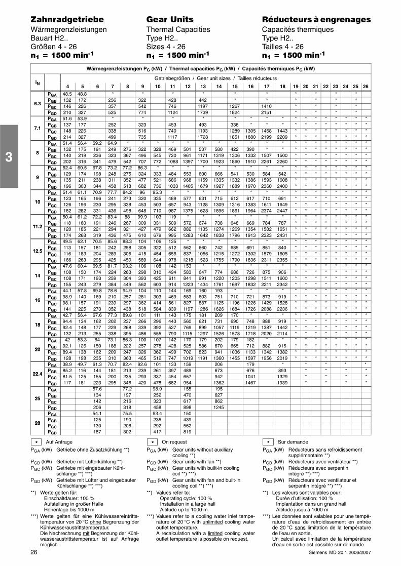
26 Siemens MD 20.1 2006/2007
������������� ���� �� ��������� � ����������Wärmegrenzleistungen Thermal Capacities Capacités thermiquesBauart H2.. Type H2.. Type H2..Größen 4 - 26 Sizes 4 - 26 Tailles 4 - 26�� � ���� ����� �� � ���� ����� �� � ���� �����
Wärmegrenzleistungen PG (kW) / Thermal capacities PG (kW) / Capacités thermiques PG (kW)
iNGetriebegrößen / Gear unit sizes / Tailles réducteurs
iN 4 5 6 7 8 9 10 11 12 13 14 15 16 17 18 19 20 21 22 23 24 25 26
PGA 48.5 48.8 * * * * * * * * * *
6 3PGB 132 172 256 322 428 442 * * * * * *
6.3 PGC 146 226 357 542 746 1197 1267 1410 * * * *PGD 210 327 525 774 1124 1739 1824 2151 * * * *PGA 51.6 53.9 * * * * * * * * * * * * * * * *
7 1PGB 137 177 252 323 453 493 338 * * * * * * * * * * *
7.1 PGC 148 226 338 516 740 1193 1289 1305 1458 1443 * * * * * * * *PGD 214 327 499 735 1117 1728 1851 1880 2199 2209 * * * * * * * *PGA 51.4 56.4 59.2 64.9 * * * * * * * * * * * * * * * * * * *
8PGB 132 175 191 249 276 322 328 469 501 537 580 422 390 * * * * * * * * * *
8 PGC 140 219 236 323 367 496 545 720 961 1171 1319 1306 1332 1507 1500 * * * * * * * *PGD 202 316 341 479 542 707 772 1088 1397 1700 1923 1860 1910 2261 2260 * * * * * * * *PGA 52.4 60.5 67.8 73.2 77.2 86.3 * * * * * * * * * * * * * * * * *
9PGB 129 174 198 248 275 324 333 484 553 600 666 541 530 584 542 * * * * * * * *
9 PGC 135 211 238 311 352 477 521 686 968 1159 1335 1332 1386 1593 1608 * * * * * * * *PGD 196 303 344 458 518 682 736 1033 1405 1679 1927 1889 1970 2360 2400 * * * * * * * *PGA 51.4 61.1 70.9 77.7 84.2 96 95.3 * * * * * * * * * * * * * * * *
10PGB 123 165 196 241 273 320 335 489 577 631 715 612 617 710 691 * * * * * * * *
10 PGC 126 196 230 295 338 453 503 657 943 1128 1309 1316 1383 1611 1649 * * * * * * * *PGD 182 282 331 436 498 648 710 987 1375 1628 1896 1861 1964 2374 2447 * * * * * * * *PGA 50.4 61.2 72.2 83.4 88 99.9 103 119 * * * * * * * * * * * * * * *
11 2PGB 118 160 191 246 267 309 331 509 572 674 738 648 669 784 787 * * * * * * * *
11.2 PGC 120 185 221 294 321 427 479 662 882 1135 1274 1269 1354 1582 1651 * * * * * * * *PGD 174 268 319 436 475 610 679 995 1283 1642 1838 1796 1913 2323 2431 * * * * * * * *PGA 49.5 62.1 70.5 85.6 88.3 104 106 135 * * * * * * * * * * * * * * *
12 5PGB 113 157 181 242 258 305 322 512 562 660 742 685 691 851 840 * * * * * * * *
12.5 PGC 116 183 204 289 305 415 454 655 837 1056 1215 1272 1302 1579 1605 * * * * * * * *PGD 166 263 295 425 450 589 644 978 1218 1523 1755 1790 1836 2311 2355 * * * * * * * *PGA 47.6 60.4 69.5 81.7 93.2 106 108 142 153 * * * * * * * * * * * * * *
14PGB 108 150 174 224 263 298 310 494 583 647 774 686 726 875 906 * * * * * * * *
14 PGC 108 171 193 259 304 393 425 611 841 991 1220 1205 1298 1511 1600 * * * * * * * *PGD 155 243 279 384 449 562 603 914 1223 1434 1761 1697 1832 2211 2342 * * * * * * * *PGA 44.1 57.8 69.8 78.6 94.9 104 110 144 169 160 193 * * * * * * * * * * * *
16PGB 98.9 140 169 210 257 281 303 469 583 603 751 710 721 873 919 * * * * * * * *
16 PGC 98.1 157 191 239 297 362 414 561 827 887 1125 1196 1226 1429 1528 * * * * * * * *PGD 141 225 273 352 438 518 584 839 1197 1286 1626 1684 1726 2088 2236 * * * * * * * *PGA 42.7 56.4 67.6 77.3 89.8 101 111 143 175 181 209 170 * * * * * * * * * * *
18PGB 94.4 134 162 202 237 266 296 443 560 621 731 690 748 888 919 * * * * * * * *
18 PGC 92.4 148 177 229 268 339 392 527 769 899 1057 1119 1219 1387 1442 * * * * * * * *PGD 132 213 255 338 395 486 555 790 1115 1297 1526 1578 1718 2020 2114 * * * * * * * *PGA 42 53.3 64 73.1 86.3 100 107 142 170 179 202 179 182 * * * * * * * * * *
20PGB 92.1 126 150 188 222 257 278 428 525 586 670 665 712 882 915 * * * * * * * *
20 PGC 89.4 138 162 209 247 326 362 499 702 823 941 1036 1133 1342 1382 * * * * * * * *PGD 128 198 235 310 363 465 512 747 1019 1191 1360 1455 1597 1956 2019 * * * * * * * *PGA 38.9 49.7 61.3 70.7 82.4 92.6 101 133 159 206 179 * * * * *
22 4PGB 85.2 116 144 181 213 239 261 397 489 673 676 893 * * * *
22.4 PGC 81.5 125 155 200 235 293 337 454 657 942 1041 1329 * * * *PGD 117 181 223 295 346 420 478 682 954 1362 1467 1939 * * * *PGA 57.6 77.2 98.9 155 195
25PGB 134 197 252 470 627
25 PGC 142 216 323 617 862PGD 206 318 458 898 1245PGA 54.1 75.5 93.4 150
28PGB 125 190 235 439
28 PGC 130 206 292 562PGD 187 302 417 819
Auf Anfrage
PGA (kW) Getriebe ohne Zusatzkühlung **)
PGB (kW) Getriebe mit Lüfterkühlung **)PGC (kW) Getriebe mit eingebauter Kühl-
schlange **) ***)PGD (kW) Getriebe mit Lüfter und eingebauter
Kühlschlange **) ***)**) Werte gelten für:
Einschaltdauer: 100 %Aufstellung in großer HalleHöhenlage bis 1000 m
***) Werte gelten für eine Kühlwassereintritts-temperatur von 20 °C ohne Begrenzung derKühlwasseraustrittstemperatur.Die Nachrechnung mit Begrenzung der Kühl-wasseraustrittstemperatur ist auf Anfragemöglich.
On request
PGA (kW) Gear units without auxiliarycooling **)
PGB (kW) Gear units with fan **)PGC (kW) Gear units with built-in cooling
coil **) ***)PGD (kW) Gear units with fan and built-in
cooling coil **) ***)**) Values refer to:
Operating cycle: 100 %Installation in a large hallAltitude up to 1000 m
***) Values refer to a cooling water inlet tempe-rature of 20 °C with unlimited cooling wateroutlet temperature.A recalculation with a limited cooling wateroutlet temperature is possible on request.
Sur demande
PGA (kW) Réducteurs sans refroidissementsupplémentaire **)
PGB (kW) Réducteurs avec ventilateur **)PGC (kW) Réducteurs avec serpentin
intégré **) ***)PGD (kW) Réducteurs avec ventilateur et
serpentin intégré **) ***)**) Les valeurs sont valables pour:
Durée d’utilisation: 100 %Implantation dans un grand hallAltitude jusqu’à 1000 m
***) Les données sont valables pour une tempé-rature d’eau de refroidissement en entréede 20 °C sans limitation de la températurede l’eau en sortie.Un calcul avec limitation de la températured’eau en sortie est possible sur demande.
* * *
3
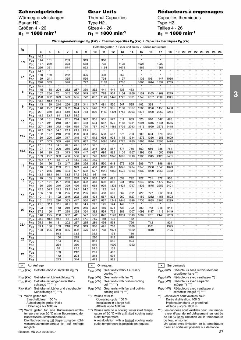
27Siemens MD 20.1 2006/2007
������������� ���� �� ��������� � ����������Wärmegrenzleistungen Thermal Capacities Capacités thermiquesBauart H2.. Type H2.. Type H2..Größen 4 - 26 Sizes 4 - 26 Tailles 4 - 26�� � �!�� ����� �� � �!�� ����� �� � �!�� �����
Wärmegrenzleistungen PG (kW) / Thermal capacities PG (kW) / Capacités thermiques PG (kW)
iNGetriebegrößen / Gear unit sizes / Tailles réducteurs
iN 4 5 6 7 8 9 10 11 12 13 14 15 16 17 18 19 20 21 22 23 24 25 26
PGA 40.6 * * * * * * * * * * *
6 3PGB 144 181 263 319 366 * * * * * * *
6.3 PGC 157 239 373 558 732 1102 1027 1020 * * * *PGD 236 361 574 832 1154 1678 1562 1661 * * * *PGA 44.6 * * * * * * * * * * * * * * * * *
7 1PGB 150 189 262 325 408 357 * * * * * * * * * * * *
7.1 PGC 159 241 355 536 738 1127 1102 1081 1147 1080 * * * * * * * *PGD 240 363 548 797 1163 1710 1666 1644 1832 1759 * * * * * * * *PGA 45.7 * * * * * * * * * * * * * * * * * * * * * *
8PGB 145 188 204 262 287 330 332 441 444 436 453 * * * * * * * * * * * *
8 PGC 152 234 251 342 386 519 567 728 954 1134 1266 1169 1165 1269 1219 * * * * * * * *PGD 228 352 379 529 595 772 837 1149 1449 1722 1931 1749 1757 2006 1941 * * * * * * * *PGA 48.3 50.5 54.7 * * * * * * * * * * * * * * * * * * * *
9PGB 143 189 214 266 293 341 347 481 530 547 595 402 363 * * * * * * * * * *
9 PGC 146 227 256 332 374 505 548 707 985 1160 1327 1265 1296 1455 1438 * * * * * * * *PGD 221 340 384 510 574 753 809 1113 1494 1755 2003 1877 1930 2262 2254 * * * * * * * *PGA 48.5 53.7 61 63.7 65.2 * * * * * * * * * * * * * * * * * *
10PGB 136 181 214 261 294 342 355 501 577 611 683 526 510 547 495 * * * * * * * *
10 PGC 137 211 248 317 361 483 534 687 975 1152 1331 1294 1345 1541 1555 * * * * * * * *PGD 207 318 372 489 555 720 787 1077 1485 1736 2013 1913 1999 2378 2418 * * * * * * * *PGA 48.3 55.6 64.6 72.1 73.2 79.4 * * * * * * * * * * * * * * * * *
11 2PGB 132 177 210 269 290 333 355 533 587 675 733 600 604 679 655 * * * * * * * *
11.2 PGC 130 200 239 317 345 457 512 698 923 1175 1314 1276 1350 1558 1609 * * * * * * * *PGD 197 303 359 490 533 682 756 1095 1401 1775 1980 1886 1994 2393 2478 * * * * * * * *PGA 47.9 57.7 64.6 76.5 76.6 87.5 86.5 * * * * * * * * * * * * * * * *
12 5PGB 127 174 200 266 282 332 348 543 587 677 756 662 656 786 754 * * * * * * * *
12.5 PGC 126 199 221 313 329 447 487 695 883 1105 1267 1298 1321 1585 1598 * * * * * * * *PGD 189 297 333 480 506 661 720 1083 1340 1662 1910 1908 1945 2426 2451 * * * * * * * *PGA 46.5 57 65 75 83.7 93.7 92.7 * * * * * * * * * * * * * * * *
14PGB 120 166 193 247 289 326 338 530 618 676 805 686 717 846 861 * * * * * * * *
14 PGC 118 186 209 281 329 424 458 653 892 1045 1284 1246 1336 1543 1623 * * * * * * * *PGD 177 276 316 434 507 632 677 1018 1355 1578 1933 1832 1969 2358 2482 * * * * * * * *PGA 43.5 55.4 66.4 73.6 87.3 94.2 98 116 * * * * * * * * * * * * * * *
16PGB 110 155 188 232 283 309 333 507 625 639 792 727 731 872 905 * * * * * * * *
16 PGC 107 171 207 260 322 392 448 602 882 941 1192 1249 1275 1477 1571 * * * * * * * *PGD 160 256 310 399 496 584 658 939 1333 1424 1797 1836 1875 2253 2401 * * * * * * * *PGA 42.3 54.7 65.2 73.7 84.5 94.5 102 122 142 * * * * * * * * * * * * * *
18PGB 105 150 180 225 263 295 326 483 606 667 782 722 777 912 934 * * * * * * * *
18 PGC 101 161 192 249 292 368 424 567 825 960 1127 1180 1282 1451 1503 * * * * * * * *PGD 151 242 290 383 447 550 627 887 1249 1446 1698 1736 1885 2206 2299 * * * * * * * *PGA 41.8 52.1 62.2 70.2 82 94.4 99.9 125 144 142 157 * * * * * * * * * * * *
20PGB 103 140 168 210 246 285 308 469 571 633 722 702 748 918 944 * * * * * * * *
20 PGC 97.8 150 177 228 268 354 392 539 755 882 1007 1098 1197 1412 1449 * * * * * * * *PGD 146 225 268 352 411 527 580 842 1143 1331 1519 1609 1761 2148 2209 * * * * * * * *PGA 38.7 48.6 59.6 68 78.5 87.3 94.7 118 135 162 * * * * * *
22 4PGB 95.6 130 161 202 237 265 289 436 533 726 712 924 * * * *
22.4 PGC 89.1 136 169 218 256 319 366 491 708 1009 1101 1395 * * * *PGD 133 205 253 335 392 476 541 768 1071 1522 1619 2125 * * * *PGA 56.1 73.8 92.5 133 156
25PGB 150 219 280 513 678
25 PGC 154 235 351 665 924PGD 234 360 519 1009 1392PGA 53 72.8 88.5 133
28PGB 139 212 261 482
28 PGC 142 224 318 606PGD 213 344 473 923
Auf Anfrage
PGA (kW) Getriebe ohne Zusatzkühlung **)
PGB (kW) Getriebe mit Lüfterkühlung **)PGC (kW) Getriebe mit eingebauter Kühl-
schlange **) ***)PGD (kW) Getriebe mit Lüfter und eingebauter
Kühlschlange **) ***)**) Werte gelten für:
Einschaltdauer: 100 %Aufstellung in großer HalleHöhenlage bis 1000 m
***) Werte gelten für eine Kühlwassereintritts-temperatur von 20 °C ohne Begrenzung derKühlwasseraustrittstemperatur.Die Nachrechnung mit Begrenzung der Kühl-wasseraustrittstemperatur ist auf Anfragemöglich.
On request
PGA (kW) Gear units without auxiliarycooling **)
PGB (kW) Gear units with fan **)PGC (kW) Gear units with built-in cooling
coil **) ***)PGD (kW) Gear units with fan and built-in
cooling coil **) ***)**) Values refer to:
Operating cycle: 100 %Installation in a large hallAltitude up to 1000 m
***) Values refer to a cooling water inlet tempe-rature of 20 °C with unlimited cooling wateroutlet temperature.A recalculation with a limited cooling wateroutlet temperature is possible on request.
Sur demande
PGA (kW) Réducteurs sans refroidissementsupplémentaire **)
PGB (kW) Réducteurs avec ventilateur **)PGC (kW) Réducteurs avec serpentin
intégré **) ***)PGD (kW) Réducteurs avec ventilateur et
serpentin intégré **) ***)**) Les valeurs sont valables pour:
Durée d’utilisation: 100 %Implantation dans un grand hallAltitude jusqu’à 1000 m
***) Les données sont valables pour une tempé-rature d’eau de refroidissement en entréede 20 °C sans limitation de la températurede l’eau en sortie.Un calcul avec limitation de la températured’eau en sortie est possible sur demande.
* * *
3
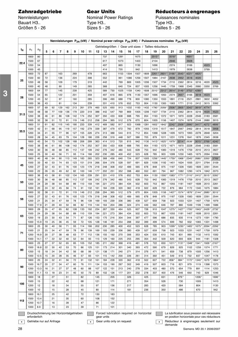
28 Siemens MD 20.1 2006/2007
������������� ���� �� ��������� � ����������Nennleistungen Nominal Power Ratings Puissances nominalesBauart H3.. Type H3.. Type H3..Größen 5 - 26 Sizes 5 - 26 Tailles 5 - 26
Nennleistungen P2N (kW) / Nominal power ratings P2N (kW) / Puissances nominales P2N (kW)
i n nGetriebegrößen / Gear unit sizes / Tailles réducteurs
iN n1 n2 5 6 7 8 9 10 11 12 13 14 15 16 17 18 19 20 21 22 23 24 25 26
1800 80 737 1281 1675 2513 * 3518 * 4691 *
22 41500 67 617 1073 1403 2104 2946 3928
22.41200 54 497 865 1130 1696 2374 3166 4523
1000 45 414 720 942 1413 1979 2638 3769
1800 72 87 163 269 478 663 1153 1304 1507 1809 2261 * 2601 * 3166 * 3543 * 4221 * 4825 *
251500 60 72 136 224 398 552 961 1086 1256 1507 1884 2167 2638 2952 3518 4020
251200 48 58 109 179 319 442 769 869 1005 1206 1507 1734 2110 2362 2814 3216 4020 4523
1000 40 48 90 149 265 368 640 724 837 1005 1256 1445 1759 1968 2345 2680 3350 3769
1800 64 77 145 239 425 589 730 1025 1159 1340 1608 2010 * 2312 * 2814 * 3149 * 3752 * 4289 *
281500 54 65 122 201 359 497 616 865 978 1130 1357 1696 1950 2374 2657 3166 3618 4523
281200 43 52 97 160 285 396 490 688 778 900 1080 1350 1553 1891 2116 2521 2881 3602 4052
1000 36 43 81 134 239 331 410 576 652 753 904 1130 1300 1583 1771 2110 2412 3015 3392
1800 57 69 92 129 162 213 261 379 460 525 650 913 1032 1193 1432 1790 * 2059 * 2506 * 2805 * 3342 * 3819 * 4774 *
31 51500 48 58 77 109 136 179 220 319 388 442 547 769 869 1005 1206 1507 1734 2110 2362 2814 3216 4020 4523
31.51200 38 46 61 86 108 142 174 252 307 350 433 608 688 795 954 1193 1372 1671 1870 2228 2546 3183 3581
1000 32 38 51 72 91 119 146 212 258 294 365 512 579 670 804 1005 1156 1407 1574 1876 2144 2680 3015
1800 51 61 82 115 145 190 233 339 412 469 582 817 923 1068 1281 1602 * 1842 * 2242 * 2509 * 2990 * 3417 * 4272 * 4806 *
35 51500 42 51 68 95 119 157 192 279 339 387 479 672 760 879 1055 1319 1517 1847 2067 2462 2814 3518 3958
35.51200 34 41 55 77 96 127 155 226 274 313 388 544 615 712 854 1068 1228 1495 1673 1993 2278 2848 3204
1000 28 34 45 63 79 104 128 186 226 258 319 448 507 586 703 879 1011 1231 1378 1641 1876 2345 2638
1800 45 54 73 102 128 168 206 299 363 414 513 720 815 942 1130 1413 * 1625 * 1979 * 2214 * 2638 * 3015 * 3769 * 4240 *
401500 38 46 61 86 108 142 174 252 307 350 433 608 688 795 954 1193 1372 1671 1870 2228 2546 3183 3581
401200 30 36 48 68 85 112 137 199 242 276 342 480 543 628 753 942 1083 1319 1476 1759 2010 2513 2827
1000 25 30 40 56 71 93 114 166 202 230 285 400 452 523 628 785 903 1099 1230 1465 1675 2094 2356
1800 40 48 64 90 113 149 183 265 323 368 456 640 724 837 1005 1256 * 1445 * 1759 * 1968 * 2345 * 2680 * 3350 * 3769 *
451500 33 40 53 74 93 123 151 219 266 304 376 528 597 691 829 1036 1192 1451 1624 1935 2211 2764 3109
451200 27 32 43 61 76 100 123 179 218 248 308 432 489 565 678 848 975 1187 1328 1583 1809 2261 2544
1000 22 26 35 49 62 82 100 146 177 202 251 352 398 460 552 691 794 967 1082 1290 1474 1842 2073
1800 36 43 58 81 102 134 165 239 291 331 410 576 652 753 904 1130 1300 * 1583 * 1771 * 2110 * 2412 * 3015 * 3392 *
501500 30 36 48 68 85 112 137 199 242 276 342 480 543 628 753 942 1083 1319 1476 1759 2010 2513 2827
501200 24 29 38 54 68 89 110 159 194 221 273 384 434 502 603 753 867 1055 1181 1407 1608 2010 2261
1000 20 24 32 45 56 74 91 132 161 184 228 320 362 418 502 628 722 879 984 1172 1340 1675 1884
1800 32 38 51 72 91 119 146 212 258 294 365 512 579 670 804 1005 1156 1407 * 1574 * 1876 * 2144 * 2680 * 3015 *
561500 27 32 43 61 76 100 123 179 218 248 308 432 489 565 678 848 975 1187 1328 1583 1809 2261 2544
561200 21 25 34 47 59 78 96 139 169 193 239 336 380 439 527 659 758 923 1033 1231 1407 1759 1979
1000 17.9 21 29 40 50 66 82 119 144 164 204 286 324 374 449 562 646 787 880 1049 1199 1499 1686
1800 29 35 47 65 82 108 133 192 234 267 330 464 525 607 728 910 1047 1275 * 1427 * 1700 * 1943 * 2429 * 2732 *
631500 24 29 38 54 68 89 110 159 194 221 273 384 434 502 603 753 867 1055 1181 1407 1608 2010 2261
631200 19 23 30 43 54 71 87 126 153 175 216 304 344 397 477 596 686 835 935 1114 1273 1591 1790
1000 15.9 19 25 36 45 59 72 105 128 146 181 254 288 332 399 499 574 699 782 932 1065 1331 1498
1800 25 30 40 56 71 93 114 166 202 230 285 400 452 523 628 785 903 1099 * 1230 * 1465 * 1675 * 2094 * 2356 *
711500 21 25 34 47 59 78 96 139 169 193 239 336 380 439 527 659 758 923 1033 1231 1407 1759 1979
711200 16.9 20 27 38 48 63 77 112 136 155 192 270 306 353 424 530 610 743 831 990 1132 1415 1592
1000 14.1 17 22 32 40 52 64 93 113 129 160 225 255 295 354 442 509 620 693 826 944 1181 1328
1800 23 27 37 52 65 85 105 152 185 211 262 368 416 481 578 722 830 1011 * 1131 * 1348 * 1541 * 1926 * 2167 *
801500 18.8 22 30 42 53 70 86 125 151 173 214 301 340 393 472 590 679 826 925 1102 1259 1574 1771
801200 15 18 24 34 42 56 68 99 121 138 171 240 271 314 376 471 541 659 738 879 1005 1256 1413
1000 12.5 15 20 28 35 46 57 83 101 115 142 200 226 261 314 392 451 549 615 732 837 1047 1178
1800 20 24 32 41 56 72 91 132 161 184 228 320 362 418 502 607 722 858 * 984 * 1172 * 1340 * 1675 * 1884 *
901500 16.7 20 27 34 47 60 76 111 134 153 190 267 302 349 419 507 603 716 821 979 1119 1398 1573
901200 13.3 16 21 27 37 48 60 88 107 122 151 213 240 278 334 403 480 570 654 779 891 1114 1253
1000 11.1 13 18 23 31 40 50 73 89 102 126 177 201 232 278 337 400 476 546 650 743 929 1046
1800 18 27 51 82 145 205 326 425 631 876 * 1206 * 1696 *
1001500 15 22 42 68 121 171 271 354 526 730 1005 1413
1001200 12 18 34 55 97 136 217 283 420 584 804 1130
1000 10 15 28 45 80 114 181 236 350 486 670 942
1800 16.1 25 42 72 130 183
1121500 13.4 21 35 60 108 152
1121200 10.7 16 28 47 86 122
1000 8.9 13 23 39 71 101
Druckschmierung bei Horizontalgetriebenerforderlich
Getriebe nur auf Anfrage
Forced lubrication required on horizontalgear units
Gear units only on request
La lubrification sous pression est nécessaireen position horizontale pour ces réducteurs
Réducteur à engrenages seulement surdemande
* * *
3
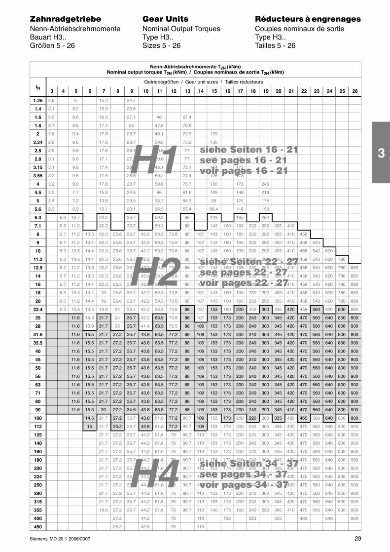
���� ���� �� - ����� ����� �� - ����� ����� �� - ��
H4
H2
���� ���� �� - ����� ����� �� - ����� ����� �� - ��
���� ���� �� - ����� ����� �� - ����� ����� �� - ��H1
29Siemens MD 20.1 2006/2007
������������� ���� �� ��������� � ����������Nenn-Abtriebsdrehmomente Nominal Output Torques Couples nominaux de sortieBauart H3.. Type H3.. Type H3..Größen 5 - 26 Sizes 5 - 26 Tailles 5 - 26
Nenn-Abtriebsdrehmomente T2N (kNm)Nominal output torques T2N (kNm) / Couples nominaux de sortie T2N (kNm)
iGetriebegrößen / Gear unit sizes / Tailles réducteurs
iN3 4 5 6 7 8 9 10 11 12 13 14 15 16 17 18 19 20 21 22 23 24 25 26
1.25 2.9 8 15.2 24.7
1.4 3.1 8.2 15.9 25.6
1.6 3.3 8.6 16.3 27.1 46 67.4
1.8 2.7 8.8 17.4 28 47.6 70.9
2 2.8 9.4 17.8 28.7 49.1 72.9 129
2.24 2.8 9.6 17.8 28.7 50.6 75.2 130
2.5 2.9 9.6 17.8 28.7 50.6 77 117
2.8 3.1 9.6 17.1 27.2 50.6 77 120 171
3.15 3.1 9.6 17.4 28.1 48.1 73.1 124 173
3.55 3.2 9.5 17.8 28.6 50.2 74.4 126 173
4 3.2 9.6 17.8 28.7 50.6 75.7 130 173 245
4.5 2.5 7.7 15.8 24.6 46 61.6 109 146 216
5 2.4 7.2 13.8 23.5 38.7 58.3 95 124 174
5.6 2.3 6.9 13.1 20.1 36.5 55.4 90.4 118 150
6.3 6.3 10.7 20.3 33.7 59.3 86 143 195 292
7.1 6.5 11.2 20.3 33.7 59.3 86 143 160 195 230 292 335 410
8 6.7 11.2 13.5 20.3 25.6 33.7 42.2 59.3 73.8 86 107 143 160 195 230 292 335 410 458
9 6.7 11.2 14.4 20.3 25.6 33.7 42.2 59.3 73.8 86 107 143 160 195 230 292 335 410 458 540
10 6.3 10.5 14.4 20.3 25.6 33.7 42.2 59.3 73.8 86 107 143 160 195 230 292 335 410 458 540 620
11.2 6.3 10.6 14.4 20.3 25.6 33.7 42.2 59.3 73.8 86 107 143 160 195 230 292 335 410 458 540 620 780
12.5 6.7 11.2 13.5 20.2 25.6 33.7 42.2 59.3 73.8 86 107 143 160 195 230 292 335 410 458 540 620 780 880
14 6.7 11.2 13.5 20.3 25.6 33.7 42.2 59.3 73.8 86 107 143 160 195 230 292 335 410 458 540 620 780 880
16 6.7 11.2 14.4 20.3 25.5 33.7 42.2 59.3 73.8 86 107 143 160 195 230 292 335 410 458 540 620 780 880
18 6.3 10.5 14.4 19 25.6 33.7 42.2 59.3 73.8 86 107 143 160 195 230 292 335 410 458 540 620 780 880
20 6.6 11.2 14.4 19 25.6 33.7 42.2 59.3 73.8 86 107 143 160 195 230 292 335 410 458 540 620 780 880
22.4 6.3 10.9 13.5 19.8 24 33.1 42.2 58.3 73.8 88 107 153 160 200 230 300 335 420 458 560 620 800 880
25 11.6 14.3 21.7 24 35.7 42.2 63.5 73.8 88 107 153 173 200 240 300 345 420 470 560 640 800 900
28 11.6 13.9 21.7 25 35.7 41.6 63.5 72.5 88 109 153 173 200 240 300 345 420 470 560 640 800 900
31.5 11.6 15.5 21.7 27.2 35.7 43.8 63.5 77.2 88 109 153 173 200 240 300 345 420 470 560 640 800 900
35.5 11.6 15.5 21.7 27.2 35.7 43.8 63.5 77.2 88 109 153 173 200 240 300 345 420 470 560 640 800 900
40 11.6 15.5 21.7 27.2 35.7 43.8 63.5 77.2 88 109 153 173 200 240 300 345 420 470 560 640 800 900
45 11.6 15.5 21.7 27.2 35.7 43.8 63.5 77.2 88 109 153 173 200 240 300 345 420 470 560 640 800 900
50 11.6 15.5 21.7 27.2 35.7 43.8 63.5 77.2 88 109 153 173 200 240 300 345 420 470 560 640 800 900
56 11.6 15.5 21.7 27.2 35.7 43.8 63.5 77.2 88 109 153 173 200 240 300 345 420 470 560 640 800 900
63 11.6 15.5 21.7 27.2 35.7 43.8 63.5 77.2 88 109 153 173 200 240 300 345 420 470 560 640 800 900
71 11.6 15.5 21.7 27.2 35.7 43.8 63.5 77.2 88 109 153 173 200 240 300 345 420 470 560 640 800 900
80 11.6 15.5 21.7 27.2 35.7 43.8 63.5 77.2 88 109 153 173 200 240 300 345 420 470 560 640 800 900
90 11.6 15.5 20 27.2 34.5 43.8 63.5 77.2 88 109 153 173 200 240 290 345 410 470 560 640 800 900
100 14.5 21.7 27.2 35.7 43.8 61.6 77.2 90.7 109 153 173 200 226 300 335 420 465 560 640 800 900
112 15 21.7 25.2 35.7 42.8 61.6 77.2 90.7 109 153 173 200 240 300 345 420 470 560 640 800 900
125 21.7 27.2 35.7 44.2 61.6 78 90.7 113 153 173 200 240 300 345 420 470 560 640 800 900
140 21.7 27.2 35.7 44.2 61.6 78 90.7 113 153 173 200 240 300 345 420 470 560 640 800 900
160 21.7 27.2 35.7 44.2 61.6 78 90.7 113 153 173 200 240 300 345 420 470 560 640 800 900
180 21.7 27.2 35.7 44.2 61.6 78 90.7 113 153 173 200 240 300 345 420 470 560 640 800 900
200 21.7 27.2 35.7 44.2 61.6 78 90.7 113 153 173 200 240 300 345 420 470 560 640 800 900
224 21.7 27.2 35.7 44.2 61.6 78 90.7 113 153 173 200 240 300 345 420 470 560 640 800 900
250 21.7 27.2 35.7 44.2 61.6 78 90.7 113 153 173 200 240 300 345 420 470 560 640 800 900
280 21.7 27.2 35.7 44.2 61.6 78 90.7 113 153 173 200 240 300 345 420 470 560 640 800 900
315 21.7 27.2 35.7 44.2 61.6 78 90.7 113 153 173 200 240 300 345 420 470 560 640 800 900
355 19.6 27.2 35.7 44.2 61.6 78 90.7 113 140 173 192 240 290 345 410 470 560 640 800 900
400 27.2 44.2 78 113 158 223 335 465 640 900
450 25.3 42.8 78 113
3

30 Siemens MD 20.1 2006/2007
������������� ���� �� ��������� � ����������Wärmegrenzleistungen Thermal Capacities Capacités thermiquesBauart H3.. Type H3.. Type H3..Größen 5 - 26 Sizes 5 - 26 Tailles 5 - 26�� � ���� ����� �� � ���� ����� �� � ���� �����
Wärmegrenzleistungen PG (kW) / Thermal capacities PG (kW) / Capacités thermiques PG (kW)
iNGetriebegrößen / Gear unit sizes / Tailles réducteurs
iN 5 6 7 8 9 10 11 12 13 14 15 16 17 18 19 20 21 22 23 24 25 26
PGA 196 258 270 325 350 * *
22 4PGB 303 432 440 * * * *
22.4 PGC 561 903 903 * * * *PGD 650 1043 1029 * * * *PGA 49.9 73.5 99.3 145 191 253 265 263 276 323 333 363 343 * * * *
25PGB 73.4 110 152 230 294 420 443 427 451 * * * * * * * *
25 PGC 105 169 247 419 533 850 913 851 906 * * * * * * * *PGD 125 201 293 492 617 986 1055 972 1033 * * * * * * * *PGA 48 74.2 99 142 186 214 254 264 265 274 326 338 380 370 * * * *
28PGB 70.7 112 150 222 286 327 417 434 425 441 * * * * * * * *
28 PGC 99.7 167 239 392 500 586 820 860 819 854 * * * * * * * *PGD 118 200 284 464 583 680 957 999 942 981 * * * * * * * *PGA 46.7 54 71.4 79.1 96.9 100 138 164 184 211 252 265 263 276 327 341 394 389 * * * *
31 5PGB 68.5 78.6 107 118 146 151 215 255 279 319 411 432 418 440 * * * * * * * *
31.5 PGC 95.6 109 158 173 230 286 374 431 480 556 783 829 785 826 * * * * * * * *PGD 114 130 190 206 273 333 443 509 560 647 917 969 906 952 * * * * * * * *PGA 45.2 51.9 69.4 79.7 93.9 99.8 134 159 180 206 244 264 255 274 325 342 404 404 * * * *
35 5PGB 66.2 75.6 104 119 142 149 208 246 271 311 395 425 401 433 * * * * * * * *
35.5 PGC 91.3 103 151 171 219 278 354 403 456 523 725 792 725 789 * * * * * * * *PGD 109 123 183 205 262 324 422 480 534 612 854 934 844 916 * * * * * * * *PGA 42.7 50.4 66 76.6 88.9 96.5 129 155 174 201 237 253 247 264 317 336 401 407 * * * *
40PGB 62.3 73.3 98.9 113 134 145 199 238 261 302 380 406 387 412 * * * * * * * *
40 PGC 84.8 98.8 141 161 204 265 333 384 431 499 683 734 685 730 * * * * * * * *PGD 101 117 170 194 244 310 397 457 506 586 809 867 799 853 * * * * * * * *PGA 40.8 48.7 63.6 74.3 85.6 94 128 149 167 194 237 245 246 254 316 326 393 402 * * * *
45PGB 59.6 70.7 95 110 128 141 199 229 250 291 378 390 383 397 * * * * * * * *
45 PGC 80.1 94.4 134 155 193 254 326 364 405 475 669 693 670 689 * * * * * * * *PGD 96 113 162 186 232 298 389 434 475 557 793 817 782 804 * * * * * * * *PGA 39.6 46.1 60.1 70.9 84.2 89.4 127 145 166 190 241 249 248 259 320 332 410 410 * * * *
50PGB 57.5 66.7 89.6 104 126 133 195 222 245 283 378 393 381 399 * * * * * * * *
50 PGC 77.3 87.7 126 145 189 236 319 344 394 448 662 678 655 671 * * * * * * * *PGD 92.8 105 152 174 225 277 381 411 465 529 785 805 771 793 * * * * * * * *PGA 37.6 44.3 57.5 68.4 80.4 86.2 118 145 161 183 232 250 240 258 311 332 401 421 * * * *
56PGB 54.5 63.9 85.2 100 120 128 181 221 238 271 361 390 367 394 * * * * * * * *
56 PGC 72.6 83 118 138 176 223 289 337 373 421 617 669 614 660 * * * * * * * *PGD 86.7 99.7 143 166 212 262 345 403 441 499 735 795 723 777 * * * * * * * *PGA 35.5 42.7 53.7 64.7 76.2 84.6 113 143 154 180 222 242 230 250 295 324 393 413 * * * *
63PGB 51.2 61.4 79.4 95.1 112 124 171 216 226 265 343 375 349 378 * * * * * * * *
63 PGC 67.3 80.1 109 129 163 218 268 330 347 410 570 622 567 616 * * * * * * * *PGD 80.6 96.2 130 156 197 257 321 395 411 486 681 746 672 730 * * * * * * * *PGA 35.1 40.5 52.1 61.6 74.6 80.5 110 133 150 174 216 229 221 237 292 303 373 397 * * * *
71PGB 50.6 58.1 76.7 90.4 110 119 166 200 219 255 333 353 334 357 * * * * * * * *
71 PGC 66.5 75.1 104 120 160 204 258 298 331 389 548 577 542 571 * * * * * * * *PGD 79.7 89.9 126 145 191 239 309 357 393 461 655 690 644 676 * * * * * * * *PGA 33.3 38.2 50.9 57.6 70.6 76.1 104 125 145 165 208 222 213 228 277 299 358 377 * * * *
80PGB 47.9 54.5 74.9 84.1 104 111 156 188 213 241 320 342 321 343 * * * * * * * *
80 PGC 61.8 69.7 100 111 148 189 238 277 319 361 517 555 512 546 * * * * * * * *PGD 74.2 83.6 121 134 179 222 286 332 378 429 620 663 608 648 * * * * * * * *PGA 32.9 37.8 48.1 55.7 67.1 74.3 100 123 136 160 196 215 201 219 263 283 349 361 * * * *
90PGB 47.3 54.1 70.7 81.1 98.8 108 151 183 199 233 301 328 302 329 * * * * * * * *
90 PGC 60.1 69.1 93.1 107 138 185 228 267 293 345 479 524 474 516 * * * * * * * *PGD 72.3 82.8 112 129 166 217 275 321 348 409 573 628 564 614 * * * * * * * *PGA 35.9 54.6 70.7 116 156 203 208 272 356 * *
100PGB 51.2 79.5 103 173 227 310 310 * * * *
100 PGC 64.2 103 172 247 332 484 478 * * * *PGD 77.2 125 202 297 394 581 569 * * * *PGA 35.5 51.7 67.2 112 146
112PGB 50.7 75.2 98.3 168 213
112 PGC 62.5 95.8 159 237 306PGD 75.2 116 188 286 364
Auf Anfrage
PGA (kW) Getriebe ohne Zusatzkühlung **)
PGB (kW) Getriebe mit Lüfterkühlung **)PGC (kW) Getriebe mit eingebauter Kühl-
schlange **) ***)PGD (kW) Getriebe mit Lüfter und eingebauter
Kühlschlange **) ***)**) Werte gelten für:
Einschaltdauer: 100 %, Aufstellung in großerHalle, Höhenlage bis 1000 m
***) Werte gelten für eine Kühlwassereintritts-temperatur von 20 °C ohne Begrenzung derKühlwasseraustrittstemperatur.Die Nachrechnung mit Begrenzung der Kühl-wasseraustrittstemperatur ist auf Anfragemöglich.
On request
PGA (kW) Gear units without auxiliarycooling **)
PGB (kW) Gear units with fan **)PGC (kW) Gear units with built-in cooling
coil **) ***)PGD (kW) Gear units with fan and built-in
cooling coil **) ***)**) Values refer to:
Operating cycle: 100 %, Installation in a largehall, Altitude up to 1000 m
***) Values refer to a cooling water inlet tempe-rature of 20 °C with unlimited cooling wateroutlet temperature.A recalculation with a limited cooling wateroutlet temperature is possible on request.
Sur demande
PGA (kW) Réducteurs sans refroidissementsupplémentaire **)
PGB (kW) Réducteurs avec ventilateur **)PGC (kW) Réducteurs avec serpentin
intégré **) ***)PGD (kW) Réducteurs avec ventilateur et
serpentin intégré **) ***)**) Les valeurs sont valables pour:
Durée d’utilisation: 100 %, Implantation dansun grand hall, Altitude jusqu’à 1000 m
***) Les données sont valables pour une tempé-rature d’eau de refroidissement en entréede 20 °C sans limitation de la températurede l’eau en sortie.Un calcul avec limitation de la températured’eau en sortie est possible sur demande.
* * *
3

31Siemens MD 20.1 2006/2007
������������� ���� �� ��������� � ����������Wärmegrenzleistungen Thermal Capacities Capacités thermiquesBauart H3.. Type H3.. Type H3..Größen 5 - 26 Sizes 5 - 26 Tailles 5 - 26�� � ���� ����� �� � ���� ����� �� � ���� �����
Wärmegrenzleistungen PG (kW) / Thermal capacities PG (kW) / Capacités thermiques PG (kW)
iNGetriebegrößen / Gear unit sizes / Tailles réducteurs
iN 5 6 7 8 9 10 11 12 13 14 15 16 17 18 19 20 21 22 23 24 25 26
PGA 173 209 206 232 * * *
22 4PGB 295 393 382 * * * *
22.4 PGC 580 913 901 * * * *PGD 681 1059 1023 * * * *PGA 49.8 72.6 96.6 136 170 207 212 203 207 234 235 * * * * * *
25PGB 79.1 118 160 235 288 385 399 375 386 * * * * * * * *
25 PGC 113 180 262 439 552 862 921 852 900 * * * * * * * *PGD 138 221 319 527 647 1004 1066 970 1021 * * * * * * * *PGA 48.1 73.7 97.1 134 170 193 216 221 215 217 252 255 * * * * * *
28PGB 76.5 120 159 229 285 324 394 404 387 394 * * * * * * * *
28 PGC 106 179 255 413 521 609 839 875 828 859 * * * * * * * *PGD 131 221 311 500 617 718 987 1024 956 987 * * * * * * * *PGA 47.1 54.2 71.3 78.6 95.8 98.4 132 156 171 194 222 230 223 230 267 274 276 * * * * *
31 5PGB 74.4 85.3 115 127 157 161 225 263 283 322 399 415 394 408 * * * * * * * *
31.5 PGC 102 117 169 185 245 305 396 454 503 581 808 852 802 840 * * * * * * * *PGD 126 144 210 227 300 365 481 549 598 690 959 1008 935 975 * * * * * * * *PGA 45.7 52.5 69.7 79.8 93.6 99 130 153 171 194 222 237 226 239 279 290 311 292 * * * *
35 5PGB 72.2 82.4 113 128 153 160 220 257 280 320 393 420 391 417 * * * * * * * *
35.5 PGC 98.3 110 163 183 234 297 376 427 481 550 755 822 749 812 * * * * * * * *PGD 121 137 202 227 289 356 460 521 576 658 905 984 884 954 * * * * * * * *PGA 43.3 51.1 66.5 76.9 88.9 96.2 126 150 167 192 219 231 223 235 279 293 322 310 * * * *
40PGB 68.1 80 107 123 145 156 212 251 272 313 383 406 383 404 * * * * * * * *
40 PGC 91.3 106 151 173 219 284 355 407 455 527 714 765 712 756 * * * * * * * *PGD 112 131 189 215 270 342 434 497 547 633 862 921 843 895 * * * * * * * *PGA 41.5 49.4 64.2 74.7 85.9 93.9 126 145 161 186 220 226 224 229 281 287 321 313 * * * *
45PGB 65.2 77.3 103 120 139 152 212 242 261 303 384 393 382 392 * * * * * * * *
45 PGC 86.3 101 144 166 207 272 347 387 429 502 701 724 698 715 * * * * * * * *PGD 106 125 180 206 256 329 427 474 516 603 847 871 828 848 * * * * * * * *PGA 40.4 47 61.2 71.9 85.2 90.3 127 144 164 187 232 239 236 245 300 309 365 356 * * * *
50PGB 63.2 73.2 98.2 114 137 145 210 238 262 301 395 410 394 410 * * * * * * * *
50 PGC 83.5 94.6 136 156 203 254 342 368 421 477 701 717 691 707 * * * * * * * *PGD 103 117 169 193 250 307 421 452 510 580 852 872 832 853 * * * * * * * *PGA 38.5 45.3 58.7 69.7 81.8 87.7 119 146 161 183 228 245 234 250 300 319 374 386 * * * *
56PGB 60.1 70.4 93.7 110 131 140 197 240 257 292 384 414 387 414 * * * * * * * *
56 PGC 78.5 89.7 128 148 190 241 311 361 400 451 658 713 652 700 * * * * * * * *PGD 96.9 111 160 185 236 292 383 446 486 550 805 869 789 846 * * * * * * * *PGA 36.4 43.9 55.1 66.4 78 86.5 115 145 156 182 222 242 229 249 293 320 382 398 * * * *
63PGB 56.6 67.9 87.6 105 124 137 188 236 247 289 371 405 375 406 * * * * * * * *
63 PGC 72.8 86.6 118 139 176 235 289 356 374 441 611 667 607 659 * * * * * * * *PGD 90.2 107 146 174 220 286 357 439 456 540 753 824 741 804 * * * * * * * *PGA 36.1 41.6 53.5 63.2 76.4 82.4 112 135 152 177 217 230 222 236 290 301 365 385 * * * *
71PGB 56 64.3 84.8 99.8 122 131 182 219 239 279 361 382 361 385 * * * * * * * *
71 PGC 72 81.2 113 130 173 220 279 321 357 419 589 620 581 611 * * * * * * * *PGD 89.2 100 141 163 214 267 345 398 436 512 725 764 712 746 * * * * * * * *PGA 34.3 39.2 52.3 59.1 72.4 78 106 128 148 167 210 224 214 228 277 299 352 368 * * * *
80PGB 53 60.3 82.8 92.9 114 123 172 207 233 264 348 371 348 371 * * * * * * * *
80 PGC 66.9 75.5 109 120 160 204 257 298 344 389 556 596 550 586 * * * * * * * *PGD 83 93.6 136 150 200 248 319 370 420 478 688 735 673 716 * * * * * * * *PGA 33.9 38.9 49.5 57.2 68.8 76.2 103 125 138 163 199 217 203 220 264 284 345 355 * * * *
90PGB 52.4 59.8 78.3 89.7 109 119 166 201 218 256 328 358 329 357 * * * * * * * *
90 PGC 65.1 74.8 100 115 149 200 247 288 316 372 515 563 509 555 * * * * * * * *PGD 81 92.7 126 145 186 242 307 358 388 455 637 697 625 680 * * * * * * * *PGA 37 56.3 72.7 119 160 207 212 276 358 * *
100PGB 56.8 88.1 114 191 251 340 340 * * * *
100 PGC 69.5 112 186 267 359 523 515 * * * *PGD 86.5 140 226 332 441 648 634 * * * *PGA 36.6 53.3 69.2 116 150
112PGB 56.2 83.4 108 185 235
112 PGC 67.8 103 172 257 330PGD 84.3 130 211 320 407
Auf Anfrage
PGA (kW) Getriebe ohne Zusatzkühlung **)
PGB (kW) Getriebe mit Lüfterkühlung **)PGC (kW) Getriebe mit eingebauter Kühl-
schlange **) ***)PGD (kW) Getriebe mit Lüfter und eingebauter
Kühlschlange **) ***)**) Werte gelten für:
Einschaltdauer: 100 %, Aufstellung in großerHalle, Höhenlage bis 1000 m
***) Werte gelten für eine Kühlwassereintritts-temperatur von 20 °C ohne Begrenzung derKühlwasseraustrittstemperatur.Die Nachrechnung mit Begrenzung der Kühl-wasseraustrittstemperatur ist auf Anfragemöglich.
On request
PGA (kW) Gear units without auxiliarycooling **)
PGB (kW) Gear units with fan **)PGC (kW) Gear units with built-in cooling
coil **) ***)PGD (kW) Gear units with fan and built-in
cooling coil **) ***)**) Values refer to:
Operating cycle: 100 %, Installation in a largehall, Altitude up to 1000 m
***) Values refer to a cooling water inlet tempe-rature of 20 °C with unlimited cooling wateroutlet temperature.A recalculation with a limited cooling wateroutlet temperature is possible on request.
Sur demande
PGA (kW) Réducteurs sans refroidissementsupplémentaire **)
PGB (kW) Réducteurs avec ventilateur **)PGC (kW) Réducteurs avec serpentin
intégré **) ***)PGD (kW) Réducteurs avec ventilateur et
serpentin intégré **) ***)**) Les valeurs sont valables pour:
Durée d’utilisation: 100 %, Implantation dansun grand hall, Altitude jusqu’à 1000 m
***) Les données sont valables pour une tempé-rature d’eau de refroidissement en entréede 20 °C sans limitation de la températurede l’eau en sortie.Un calcul avec limitation de la températured’eau en sortie est possible sur demande.
* * *
3
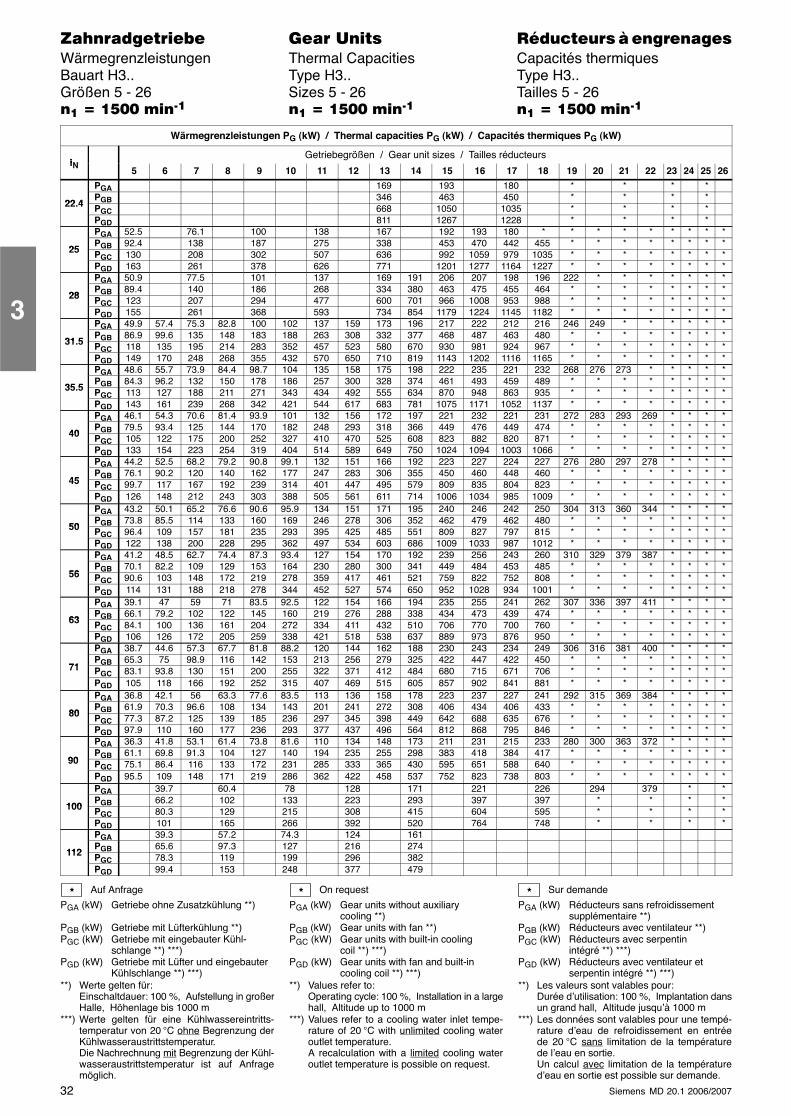
32 Siemens MD 20.1 2006/2007
������������� ���� �� ��������� � ����������Wärmegrenzleistungen Thermal Capacities Capacités thermiquesBauart H3.. Type H3.. Type H3..Größen 5 - 26 Sizes 5 - 26 Tailles 5 - 26�� � ���� ����� �� � ���� ����� �� � ���� �����
Wärmegrenzleistungen PG (kW) / Thermal capacities PG (kW) / Capacités thermiques PG (kW)
iNGetriebegrößen / Gear unit sizes / Tailles réducteurs
iN 5 6 7 8 9 10 11 12 13 14 15 16 17 18 19 20 21 22 23 24 25 26
PGA 169 193 180 * * * *
22 4PGB 346 463 450 * * * *
22.4 PGC 668 1050 1035 * * * *PGD 811 1267 1228 * * * *PGA 52.5 76.1 100 138 167 192 193 180 * * * * * * * * *
25PGB 92.4 138 187 275 338 453 470 442 455 * * * * * * * *
25 PGC 130 208 302 507 636 992 1059 979 1035 * * * * * * * *PGD 163 261 378 626 771 1201 1277 1164 1227 * * * * * * * *PGA 50.9 77.5 101 137 169 191 206 207 198 196 222 * * * * * * *
28PGB 89.4 140 186 268 334 380 463 475 455 464 * * * * * * * *
28 PGC 123 207 294 477 600 701 966 1008 953 988 * * * * * * * *PGD 155 261 368 593 734 854 1179 1224 1145 1182 * * * * * * * *PGA 49.9 57.4 75.3 82.8 100 102 137 159 173 196 217 222 212 216 246 249 * * * * * *
31 5PGB 86.9 99.6 135 148 183 188 263 308 332 377 468 487 463 480 * * * * * * * *
31.5 PGC 118 135 195 214 283 352 457 523 580 670 930 981 924 967 * * * * * * * *PGD 149 170 248 268 355 432 570 650 710 819 1143 1202 1116 1165 * * * * * * * *PGA 48.6 55.7 73.9 84.4 98.7 104 135 158 175 198 222 235 221 232 268 276 273 * * * * *
35 5PGB 84.3 96.2 132 150 178 186 257 300 328 374 461 493 459 489 * * * * * * * *
35.5 PGC 113 127 188 211 271 343 434 492 555 634 870 948 863 935 * * * * * * * *PGD 143 161 239 268 342 421 544 617 683 781 1075 1171 1052 1137 * * * * * * * *PGA 46.1 54.3 70.6 81.4 93.9 101 132 156 172 197 221 232 221 231 272 283 293 269 * * * *
40PGB 79.5 93.4 125 144 170 182 248 293 318 366 449 476 449 474 * * * * * * * *
40 PGC 105 122 175 200 252 327 410 470 525 608 823 882 820 871 * * * * * * * *PGD 133 154 223 254 319 404 514 589 649 750 1024 1094 1003 1066 * * * * * * * *PGA 44.2 52.5 68.2 79.2 90.8 99.1 132 151 166 192 223 227 224 227 276 280 297 278 * * * *
45PGB 76.1 90.2 120 140 162 177 247 283 306 355 450 460 448 460 * * * * * * * *
45 PGC 99.7 117 167 192 239 314 401 447 495 579 809 835 804 823 * * * * * * * *PGD 126 148 212 243 303 388 505 561 611 714 1006 1034 985 1009 * * * * * * * *PGA 43.2 50.1 65.2 76.6 90.6 95.9 134 151 171 195 240 246 242 250 304 313 360 344 * * * *
50PGB 73.8 85.5 114 133 160 169 246 278 306 352 462 479 462 480 * * * * * * * *
50 PGC 96.4 109 157 181 235 293 395 425 485 551 809 827 797 815 * * * * * * * *PGD 122 138 200 228 295 362 497 534 603 686 1009 1033 987 1012 * * * * * * * *PGA 41.2 48.5 62.7 74.4 87.3 93.4 127 154 170 192 239 256 243 260 310 329 379 387 * * * *
56PGB 70.1 82.2 109 129 153 164 230 280 300 341 449 484 453 485 * * * * * * * *
56 PGC 90.6 103 148 172 219 278 359 417 461 521 759 822 752 808 * * * * * * * *PGD 114 131 188 218 278 344 452 527 574 650 952 1028 934 1001 * * * * * * * *PGA 39.1 47 59 71 83.5 92.5 122 154 166 194 235 255 241 262 307 336 397 411 * * * *
63PGB 66.1 79.2 102 122 145 160 219 276 288 338 434 473 439 474 * * * * * * * *
63 PGC 84.1 100 136 161 204 272 334 411 432 510 706 770 700 760 * * * * * * * *PGD 106 126 172 205 259 338 421 518 538 637 889 973 876 950 * * * * * * * *PGA 38.7 44.6 57.3 67.7 81.8 88.2 120 144 162 188 230 243 234 249 306 316 381 400 * * * *
71PGB 65.3 75 98.9 116 142 153 213 256 279 325 422 447 422 450 * * * * * * * *
71 PGC 83.1 93.8 130 151 200 255 322 371 412 484 680 715 671 706 * * * * * * * *PGD 105 118 166 192 252 315 407 469 515 605 857 902 841 881 * * * * * * * *PGA 36.8 42.1 56 63.3 77.6 83.5 113 136 158 178 223 237 227 241 292 315 369 384 * * * *
80PGB 61.9 70.3 96.6 108 134 143 201 241 272 308 406 434 406 433 * * * * * * * *
80 PGC 77.3 87.2 125 139 185 236 297 345 398 449 642 688 635 676 * * * * * * * *PGD 97.9 110 160 177 236 293 377 437 496 564 812 868 795 846 * * * * * * * *PGA 36.3 41.8 53.1 61.4 73.8 81.6 110 134 148 173 211 231 215 233 280 300 363 372 * * * *
90PGB 61.1 69.8 91.3 104 127 140 194 235 255 298 383 418 384 417 * * * * * * * *
90 PGC 75.1 86.4 116 133 172 231 285 333 365 430 595 651 588 640 * * * * * * * *PGD 95.5 109 148 171 219 286 362 422 458 537 752 823 738 803 * * * * * * * *PGA 39.7 60.4 78 128 171 221 226 294 379 * *
100PGB 66.2 102 133 223 293 397 397 * * * *
100 PGC 80.3 129 215 308 415 604 595 * * * *PGD 101 165 266 392 520 764 748 * * * *PGA 39.3 57.2 74.3 124 161
112PGB 65.6 97.3 127 216 274
112 PGC 78.3 119 199 296 382PGD 99.4 153 248 377 479
Auf Anfrage
PGA (kW) Getriebe ohne Zusatzkühlung **)
PGB (kW) Getriebe mit Lüfterkühlung **)PGC (kW) Getriebe mit eingebauter Kühl-
schlange **) ***)PGD (kW) Getriebe mit Lüfter und eingebauter
Kühlschlange **) ***)**) Werte gelten für:
Einschaltdauer: 100 %, Aufstellung in großerHalle, Höhenlage bis 1000 m
***) Werte gelten für eine Kühlwassereintritts-temperatur von 20 °C ohne Begrenzung derKühlwasseraustrittstemperatur.Die Nachrechnung mit Begrenzung der Kühl-wasseraustrittstemperatur ist auf Anfragemöglich.
On request
PGA (kW) Gear units without auxiliarycooling **)
PGB (kW) Gear units with fan **)PGC (kW) Gear units with built-in cooling
coil **) ***)PGD (kW) Gear units with fan and built-in
cooling coil **) ***)**) Values refer to:
Operating cycle: 100 %, Installation in a largehall, Altitude up to 1000 m
***) Values refer to a cooling water inlet tempe-rature of 20 °C with unlimited cooling wateroutlet temperature.A recalculation with a limited cooling wateroutlet temperature is possible on request.
Sur demande
PGA (kW) Réducteurs sans refroidissementsupplémentaire **)
PGB (kW) Réducteurs avec ventilateur **)PGC (kW) Réducteurs avec serpentin
intégré **) ***)PGD (kW) Réducteurs avec ventilateur et
serpentin intégré **) ***)**) Les valeurs sont valables pour:
Durée d’utilisation: 100 %, Implantation dansun grand hall, Altitude jusqu’à 1000 m
***) Les données sont valables pour une tempé-rature d’eau de refroidissement en entréede 20 °C sans limitation de la températurede l’eau en sortie.Un calcul avec limitation de la températured’eau en sortie est possible sur demande.
* * *
3
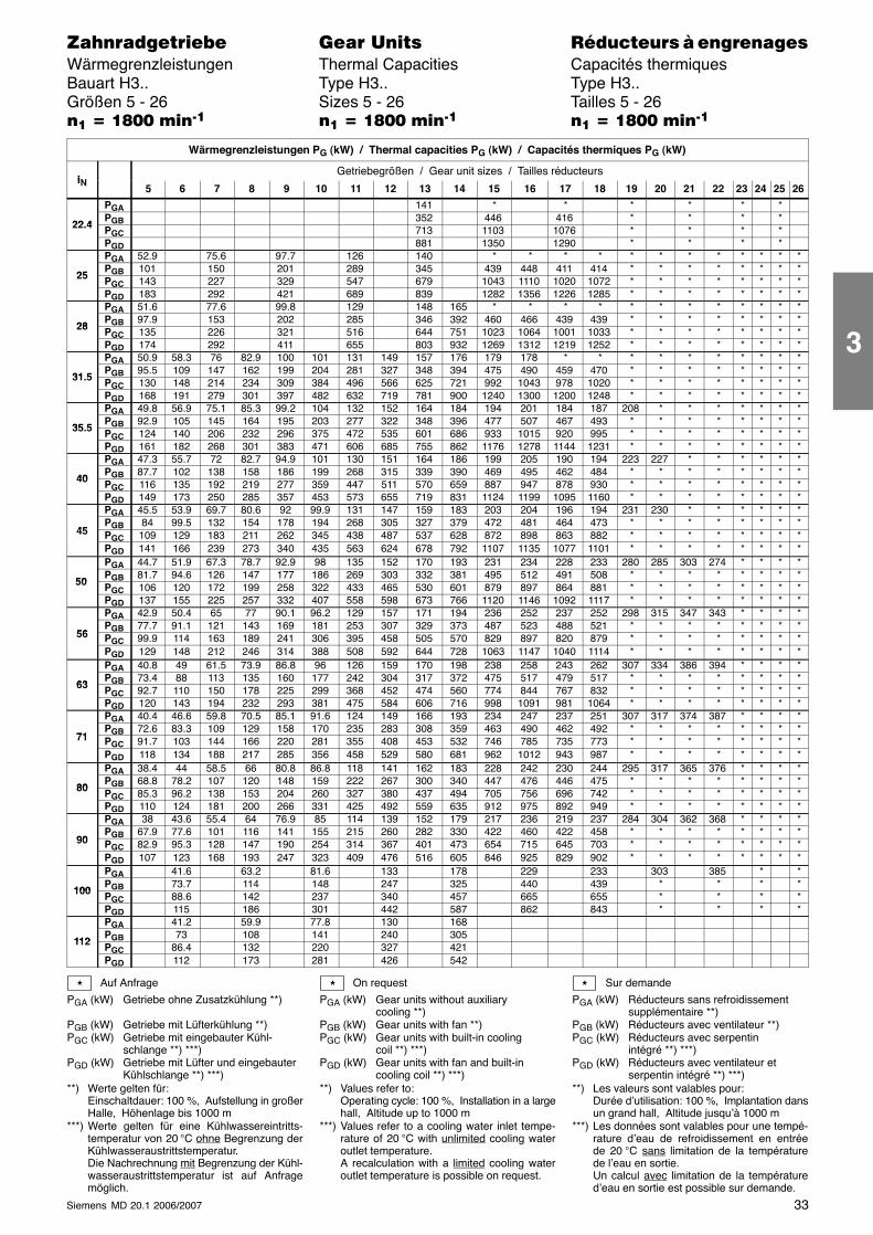
33Siemens MD 20.1 2006/2007
������������� ���� �� ��������� � ����������Wärmegrenzleistungen Thermal Capacities Capacités thermiquesBauart H3.. Type H3.. Type H3..Größen 5 - 26 Sizes 5 - 26 Tailles 5 - 26�� � �!�� ����� �� � �!�� ����� �� � �!�� �����
Wärmegrenzleistungen PG (kW) / Thermal capacities PG (kW) / Capacités thermiques PG (kW)
iNGetriebegrößen / Gear unit sizes / Tailles réducteurs
iN 5 6 7 8 9 10 11 12 13 14 15 16 17 18 19 20 21 22 23 24 25 26
PGA 141 * * * * * *
22 4PGB 352 446 416 * * * *
22.4 PGC 713 1103 1076 * * * *PGD 881 1350 1290 * * * *PGA 52.9 75.6 97.7 126 140 * * * * * * * * * * * *
25PGB 101 150 201 289 345 439 448 411 414 * * * * * * * *
25 PGC 143 227 329 547 679 1043 1110 1020 1072 * * * * * * * *PGD 183 292 421 689 839 1282 1356 1226 1285 * * * * * * * *PGA 51.6 77.6 99.8 129 148 165 * * * * * * * * * * * *
28PGB 97.9 153 202 285 346 392 460 466 439 439 * * * * * * * *
28 PGC 135 226 321 516 644 751 1023 1064 1001 1033 * * * * * * * *PGD 174 292 411 655 803 932 1269 1312 1219 1252 * * * * * * * *PGA 50.9 58.3 76 82.9 100 101 131 149 157 176 179 178 * * * * * * * * * *
31 5PGB 95.5 109 147 162 199 204 281 327 348 394 475 490 459 470 * * * * * * * *
31.5 PGC 130 148 214 234 309 384 496 566 625 721 992 1043 978 1020 * * * * * * * *PGD 168 191 279 301 397 482 632 719 781 900 1240 1300 1200 1248 * * * * * * * *PGA 49.8 56.9 75.1 85.3 99.2 104 132 152 164 184 194 201 184 187 208 * * * * * * *
35 5PGB 92.9 105 145 164 195 203 277 322 348 396 477 507 467 493 * * * * * * * *
35.5 PGC 124 140 206 232 296 375 472 535 601 686 933 1015 920 995 * * * * * * * *PGD 161 182 268 301 383 471 606 685 755 862 1176 1278 1144 1231 * * * * * * * *PGA 47.3 55.7 72 82.7 94.9 101 130 151 164 186 199 205 190 194 223 227 * * * * * *
40PGB 87.7 102 138 158 186 199 268 315 339 390 469 495 462 484 * * * * * * * *
40 PGC 116 135 192 219 277 359 447 511 570 659 887 947 878 930 * * * * * * * *PGD 149 173 250 285 357 453 573 655 719 831 1124 1199 1095 1160 * * * * * * * *PGA 45.5 53.9 69.7 80.6 92 99.9 131 147 159 183 203 204 196 194 231 230 * * * * * *
45PGB 84 99.5 132 154 178 194 268 305 327 379 472 481 464 473 * * * * * * * *
45 PGC 109 129 183 211 262 345 438 487 537 628 872 898 863 882 * * * * * * * *PGD 141 166 239 273 340 435 563 624 678 792 1107 1135 1077 1101 * * * * * * * *PGA 44.7 51.9 67.3 78.7 92.9 98 135 152 170 193 231 234 228 233 280 285 303 274 * * * *
50PGB 81.7 94.6 126 147 177 186 269 303 332 381 495 512 491 508 * * * * * * * *
50 PGC 106 120 172 199 258 322 433 465 530 601 879 897 864 881 * * * * * * * *PGD 137 155 225 257 332 407 558 598 673 766 1120 1146 1092 1117 * * * * * * * *PGA 42.9 50.4 65 77 90.1 96.2 129 157 171 194 236 252 237 252 298 315 347 343 * * * *
56PGB 77.7 91.1 121 143 169 181 253 307 329 373 487 523 488 521 * * * * * * * *
56 PGC 99.9 114 163 189 241 306 395 458 505 570 829 897 820 879 * * * * * * * *PGD 129 148 212 246 314 388 508 592 644 728 1063 1147 1040 1114 * * * * * * * *PGA 40.8 49 61.5 73.9 86.8 96 126 159 170 198 238 258 243 262 307 334 386 394 * * * *
63PGB 73.4 88 113 135 160 177 242 304 317 372 475 517 479 517 * * * * * * * *
63 PGC 92.7 110 150 178 225 299 368 452 474 560 774 844 767 832 * * * * * * * *PGD 120 143 194 232 293 381 475 584 606 716 998 1091 981 1064 * * * * * * * *PGA 40.4 46.6 59.8 70.5 85.1 91.6 124 149 166 193 234 247 237 251 307 317 374 387 * * * *
71PGB 72.6 83.3 109 129 158 170 235 283 308 359 463 490 462 492 * * * * * * * *
71 PGC 91.7 103 144 166 220 281 355 408 453 532 746 785 735 773 * * * * * * * *PGD 118 134 188 217 285 356 458 529 580 681 962 1012 943 987 * * * * * * * *PGA 38.4 44 58.5 66 80.8 86.8 118 141 162 183 228 242 230 244 295 317 365 376 * * * *
80PGB 68.8 78.2 107 120 148 159 222 267 300 340 447 476 446 475 * * * * * * * *
80 PGC 85.3 96.2 138 153 204 260 327 380 437 494 705 756 696 742 * * * * * * * *PGD 110 124 181 200 266 331 425 492 559 635 912 975 892 949 * * * * * * * *PGA 38 43.6 55.4 64 76.9 85 114 139 152 179 217 236 219 237 284 304 362 368 * * * *
90PGB 67.9 77.6 101 116 141 155 215 260 282 330 422 460 422 458 * * * * * * * *
90 PGC 82.9 95.3 128 147 190 254 314 367 401 473 654 715 645 703 * * * * * * * *PGD 107 123 168 193 247 323 409 476 516 605 846 925 829 902 * * * * * * * *PGA 41.6 63.2 81.6 133 178 229 233 303 385 * *
100PGB 73.7 114 148 247 325 440 439 * * * *
100 PGC 88.6 142 237 340 457 665 655 * * * *PGD 115 186 301 442 587 862 843 * * * *PGA 41.2 59.9 77.8 130 168
112PGB 73 108 141 240 305
112 PGC 86.4 132 220 327 421PGD 112 173 281 426 542
Auf Anfrage
PGA (kW) Getriebe ohne Zusatzkühlung **)
PGB (kW) Getriebe mit Lüfterkühlung **)PGC (kW) Getriebe mit eingebauter Kühl-
schlange **) ***)PGD (kW) Getriebe mit Lüfter und eingebauter
Kühlschlange **) ***)**) Werte gelten für:
Einschaltdauer: 100 %, Aufstellung in großerHalle, Höhenlage bis 1000 m
***) Werte gelten für eine Kühlwassereintritts-temperatur von 20 °C ohne Begrenzung derKühlwasseraustrittstemperatur.Die Nachrechnung mit Begrenzung der Kühl-wasseraustrittstemperatur ist auf Anfragemöglich.
On request
PGA (kW) Gear units without auxiliarycooling **)
PGB (kW) Gear units with fan **)PGC (kW) Gear units with built-in cooling
coil **) ***)PGD (kW) Gear units with fan and built-in
cooling coil **) ***)**) Values refer to:
Operating cycle: 100 %, Installation in a largehall, Altitude up to 1000 m
***) Values refer to a cooling water inlet tempe-rature of 20 °C with unlimited cooling wateroutlet temperature.A recalculation with a limited cooling wateroutlet temperature is possible on request.
Sur demande
PGA (kW) Réducteurs sans refroidissementsupplémentaire **)
PGB (kW) Réducteurs avec ventilateur **)PGC (kW) Réducteurs avec serpentin
intégré **) ***)PGD (kW) Réducteurs avec ventilateur et
serpentin intégré **) ***)**) Les valeurs sont valables pour:
Durée d’utilisation: 100 %, Implantation dansun grand hall, Altitude jusqu’à 1000 m
***) Les données sont valables pour une tempé-rature d’eau de refroidissement en entréede 20 °C sans limitation de la températurede l’eau en sortie.Un calcul avec limitation de la températured’eau en sortie est possible sur demande.
* * *
3
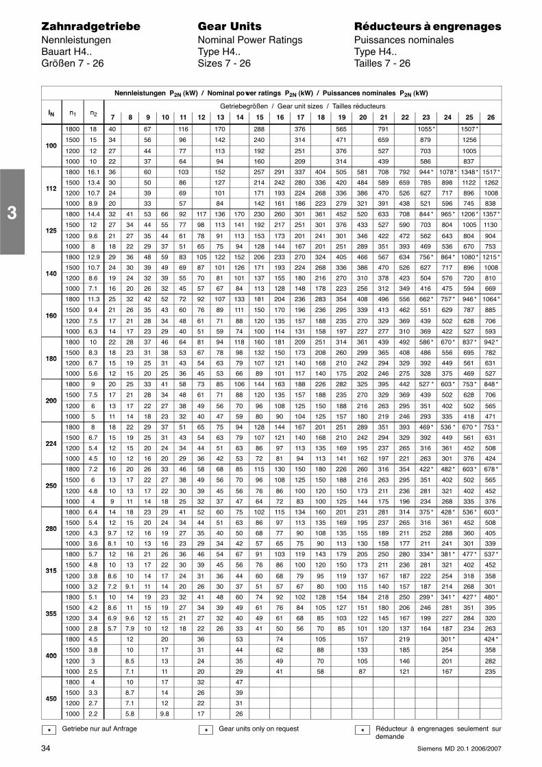
34 Siemens MD 20.1 2006/2007
������������� ���� �� ��������� � ����������Nennleistungen Nominal Power Ratings Puissances nominalesBauart H4.. Type H4.. Type H4..Größen 7 - 26 Sizes 7 - 26 Tailles 7 - 26
Nennleistungen P2N (kW) / Nominal power ratings P2N (kW) / Puissances nominales P2N (kW)
i n nGetriebegrößen / Gear unit sizes / Tailles réducteurs
iN n1 n2 7 8 9 10 11 12 13 14 15 16 17 18 19 20 21 22 23 24 25 26
1800 18 40 67 116 170 288 376 565 791 1055 * 1507 *
1001500 15 34 56 96 142 240 314 471 659 879 1256
1001200 12 27 44 77 113 192 251 376 527 703 1005
1000 10 22 37 64 94 160 209 314 439 586 837
1800 16.1 36 60 103 152 257 291 337 404 505 581 708 792 944 * 1078 * 1348 * 1517 *
1121500 13.4 30 50 86 127 214 242 280 336 420 484 589 659 785 898 1122 1262
1121200 10.7 24 39 69 101 171 193 224 268 336 386 470 526 627 717 896 1008
1000 8.9 20 33 57 84 142 161 186 223 279 321 391 438 521 596 745 838
1800 14.4 32 41 53 66 92 117 136 170 230 260 301 361 452 520 633 708 844 * 965 * 1206 * 1357 *
1251500 12 27 34 44 55 77 98 113 141 192 217 251 301 376 433 527 590 703 804 1005 1130
1251200 9.6 21 27 35 44 61 78 91 113 153 173 201 241 301 346 422 472 562 643 804 904
1000 8 18 22 29 37 51 65 75 94 128 144 167 201 251 289 351 393 469 536 670 753
1800 12.9 29 36 48 59 83 105 122 152 206 233 270 324 405 466 567 634 756 * 864 * 1080 * 1215 *
1401500 10.7 24 30 39 49 69 87 101 126 171 193 224 268 336 386 470 526 627 717 896 1008
1401200 8.6 19 24 32 39 55 70 81 101 137 155 180 216 270 310 378 423 504 576 720 810
1000 7.1 16 20 26 32 45 57 67 84 113 128 148 178 223 256 312 349 416 475 594 669
1800 11.3 25 32 42 52 72 92 107 133 181 204 236 283 354 408 496 556 662 * 757 * 946 * 1064 *
1601500 9.4 21 26 35 43 60 76 89 111 150 170 196 236 295 339 413 462 551 629 787 885
1601200 7.5 17 21 28 34 48 61 71 88 120 135 157 188 235 270 329 369 439 502 628 706
1000 6.3 14 17 23 29 40 51 59 74 100 114 131 158 197 227 277 310 369 422 527 593
1800 10 22 28 37 46 64 81 94 118 160 181 209 251 314 361 439 492 586 * 670 * 837 * 942 *
1801500 8.3 18 23 31 38 53 67 78 98 132 150 173 208 260 299 365 408 486 556 695 782
1801200 6.7 15 19 25 31 43 54 63 79 107 121 140 168 210 242 294 329 392 449 561 631
1000 5.6 12 15 20 25 36 45 53 66 89 101 117 140 175 202 246 275 328 375 469 527
1800 9 20 25 33 41 58 73 85 106 144 163 188 226 282 325 395 442 527 * 603 * 753 * 848 *
2001500 7.5 17 21 28 34 48 61 71 88 120 135 157 188 235 270 329 369 439 502 628 706
2001200 6 13 17 22 27 38 49 56 70 96 108 125 150 188 216 263 295 351 402 502 565
1000 5 11 14 18 23 32 40 47 59 80 90 104 125 157 180 219 246 293 335 418 471
1800 8 18 22 29 37 51 65 75 94 128 144 167 201 251 289 351 393 469 * 536 * 670 * 753 *
2241500 6.7 15 19 25 31 43 54 63 79 107 121 140 168 210 242 294 329 392 449 561 631
2241200 5.4 12 15 20 24 34 44 51 63 86 97 113 135 169 195 237 265 316 361 452 508
1000 4.5 10 12 16 20 29 36 42 53 72 81 94 113 141 162 197 221 263 301 376 424
1800 7.2 16 20 26 33 46 58 68 85 115 130 150 180 226 260 316 354 422 * 482 * 603 * 678 *
2501500 6 13 17 22 27 38 49 56 70 96 108 125 150 188 216 263 295 351 402 502 565
2501200 4.8 10 13 17 22 30 39 45 56 76 86 100 120 150 173 211 236 281 321 402 452
1000 4 9 11 14 18 25 32 37 47 64 72 83 100 125 144 175 196 234 268 335 376
1800 6.4 14 18 23 29 41 52 60 75 102 115 134 160 201 231 281 314 375 * 428 * 536 * 603 *
2801500 5.4 12 15 20 24 34 44 51 63 86 97 113 135 169 195 237 265 316 361 452 508
2801200 4.3 9.7 12 16 19 27 35 40 50 68 77 90 108 135 155 189 211 252 288 360 405
1000 3.6 8.1 10 13 16 23 29 34 42 57 65 75 90 113 130 158 177 211 241 301 339
1800 5.7 12 16 21 26 36 46 54 67 91 103 119 143 179 205 250 280 334 * 381 * 477 * 537 *
3151500 4.8 10 13 17 22 30 39 45 56 76 86 100 120 150 173 211 236 281 321 402 452
3151200 3.8 8.6 10 14 17 24 31 36 44 60 68 79 95 119 137 167 187 222 254 318 358
1000 3.2 7.2 9.1 11 14 20 26 30 37 51 57 67 80 100 115 140 157 187 214 268 301
1800 5.1 10 14 19 23 32 41 48 60 74 92 102 128 154 184 218 250 299 * 341 * 427 * 480 *
3551500 4.2 8.6 11 15 19 27 34 39 49 61 76 84 105 127 151 180 206 246 281 351 395
3551200 3.4 6.9 9.6 12 15 21 27 32 40 49 61 68 85 103 122 145 167 199 227 284 320
1000 2.8 5.7 7.9 10 12 18 22 26 33 41 50 56 70 85 101 120 137 164 187 234 263
1800 4.5 12 20 36 53 74 105 157 219 301 * 424 *
4001500 3.8 10 17 31 44 62 88 133 185 254 358
4001200 3 8.5 13 24 35 49 70 105 146 201 282
1000 2.5 7.1 11 20 29 41 58 87 121 167 235
1800 4 10 17 32 47
4501500 3.3 8.7 14 26 39
4501200 2.7 7.1 12 22 31
1000 2.2 5.8 9.8 17 26
Getriebe nur auf Anfrage Gear units only on request Réducteur à engrenages seulement surdemande
* * *
3
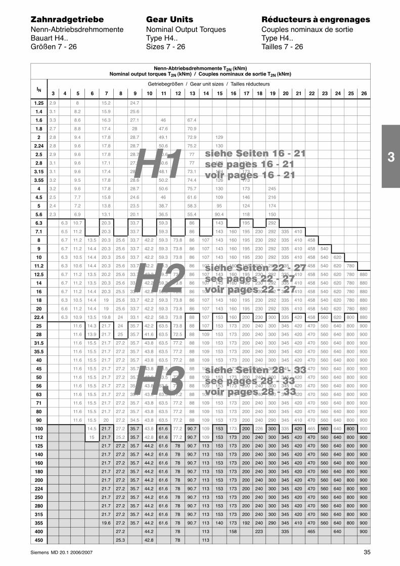
���� ���� �� - ����� ����� �� - ����� ����� �� - ��
H3
H2
���� ���� �� - ����� ����� �� - ����� ����� �� - ��
���� ���� �� - ����� ����� �� - ����� ����� �� - ��H1
35Siemens MD 20.1 2006/2007
������������� ���� �� ��������� � ����������Nenn-Abtriebsdrehmomente Nominal Output Torques Couples nominaux de sortieBauart H4.. Type H4.. Type H4..Größen 7 - 26 Sizes 7 - 26 Tailles 7 - 26
Nenn-Abtriebsdrehmomente T2N (kNm)Nominal output torques T2N (kNm) / Couples nominaux de sortie T2N (kNm)
iGetriebegrößen / Gear unit sizes / Tailles réducteurs
iN3 4 5 6 7 8 9 10 11 12 13 14 15 16 17 18 19 20 21 22 23 24 25 26
1.25 2.9 8 15.2 24.7
1.4 3.1 8.2 15.9 25.6
1.6 3.3 8.6 16.3 27.1 46 67.4
1.8 2.7 8.8 17.4 28 47.6 70.9
2 2.8 9.4 17.8 28.7 49.1 72.9 129
2.24 2.8 9.6 17.8 28.7 50.6 75.2 130
2.5 2.9 9.6 17.8 28.7 50.6 77 117
2.8 3.1 9.6 17.1 27.2 50.6 77 120 171
3.15 3.1 9.6 17.4 28.1 48.1 73.1 124 173
3.55 3.2 9.5 17.8 28.6 50.2 74.4 126 173
4 3.2 9.6 17.8 28.7 50.6 75.7 130 173 245
4.5 2.5 7.7 15.8 24.6 46 61.6 109 146 216
5 2.4 7.2 13.8 23.5 38.7 58.3 95 124 174
5.6 2.3 6.9 13.1 20.1 36.5 55.4 90.4 118 150
6.3 6.3 10.7 20.3 33.7 59.3 86 143 195 292
7.1 6.5 11.2 20.3 33.7 59.3 86 143 160 195 230 292 335 410
8 6.7 11.2 13.5 20.3 25.6 33.7 42.2 59.3 73.8 86 107 143 160 195 230 292 335 410 458
9 6.7 11.2 14.4 20.3 25.6 33.7 42.2 59.3 73.8 86 107 143 160 195 230 292 335 410 458 540
10 6.3 10.5 14.4 20.3 25.6 33.7 42.2 59.3 73.8 86 107 143 160 195 230 292 335 410 458 540 620
11.2 6.3 10.6 14.4 20.3 25.6 33.7 42.2 59.3 73.8 86 107 143 160 195 230 292 335 410 458 540 620 780
12.5 6.7 11.2 13.5 20.2 25.6 33.7 42.2 59.3 73.8 86 107 143 160 195 230 292 335 410 458 540 620 780 880
14 6.7 11.2 13.5 20.3 25.6 33.7 42.2 59.3 73.8 86 107 143 160 195 230 292 335 410 458 540 620 780 880
16 6.7 11.2 14.4 20.3 25.5 33.7 42.2 59.3 73.8 86 107 143 160 195 230 292 335 410 458 540 620 780 880
18 6.3 10.5 14.4 19 25.6 33.7 42.2 59.3 73.8 86 107 143 160 195 230 292 335 410 458 540 620 780 880
20 6.6 11.2 14.4 19 25.6 33.7 42.2 59.3 73.8 86 107 143 160 195 230 292 335 410 458 540 620 780 880
22.4 6.3 10.9 13.5 19.8 24 33.1 42.2 58.3 73.8 88 107 153 160 200 230 300 335 420 458 560 620 800 880
25 11.6 14.3 21.7 24 35.7 42.2 63.5 73.8 88 107 153 173 200 240 300 345 420 470 560 640 800 900
28 11.6 13.9 21.7 25 35.7 41.6 63.5 72.5 88 109 153 173 200 240 300 345 420 470 560 640 800 900
31.5 11.6 15.5 21.7 27.2 35.7 43.8 63.5 77.2 88 109 153 173 200 240 300 345 420 470 560 640 800 900
35.5 11.6 15.5 21.7 27.2 35.7 43.8 63.5 77.2 88 109 153 173 200 240 300 345 420 470 560 640 800 900
40 11.6 15.5 21.7 27.2 35.7 43.8 63.5 77.2 88 109 153 173 200 240 300 345 420 470 560 640 800 900
45 11.6 15.5 21.7 27.2 35.7 43.8 63.5 77.2 88 109 153 173 200 240 300 345 420 470 560 640 800 900
50 11.6 15.5 21.7 27.2 35.7 43.8 63.5 77.2 88 109 153 173 200 240 300 345 420 470 560 640 800 900
56 11.6 15.5 21.7 27.2 35.7 43.8 63.5 77.2 88 109 153 173 200 240 300 345 420 470 560 640 800 900
63 11.6 15.5 21.7 27.2 35.7 43.8 63.5 77.2 88 109 153 173 200 240 300 345 420 470 560 640 800 900
71 11.6 15.5 21.7 27.2 35.7 43.8 63.5 77.2 88 109 153 173 200 240 300 345 420 470 560 640 800 900
80 11.6 15.5 21.7 27.2 35.7 43.8 63.5 77.2 88 109 153 173 200 240 300 345 420 470 560 640 800 900
90 11.6 15.5 20 27.2 34.5 43.8 63.5 77.2 88 109 153 173 200 240 290 345 410 470 560 640 800 900
100 14.5 21.7 27.2 35.7 43.8 61.6 77.2 90.7 109 153 173 200 226 300 335 420 465 560 640 800 900
112 15 21.7 25.2 35.7 42.8 61.6 77.2 90.7 109 153 173 200 240 300 345 420 470 560 640 800 900
125 21.7 27.2 35.7 44.2 61.6 78 90.7 113 153 173 200 240 300 345 420 470 560 640 800 900
140 21.7 27.2 35.7 44.2 61.6 78 90.7 113 153 173 200 240 300 345 420 470 560 640 800 900
160 21.7 27.2 35.7 44.2 61.6 78 90.7 113 153 173 200 240 300 345 420 470 560 640 800 900
180 21.7 27.2 35.7 44.2 61.6 78 90.7 113 153 173 200 240 300 345 420 470 560 640 800 900
200 21.7 27.2 35.7 44.2 61.6 78 90.7 113 153 173 200 240 300 345 420 470 560 640 800 900
224 21.7 27.2 35.7 44.2 61.6 78 90.7 113 153 173 200 240 300 345 420 470 560 640 800 900
250 21.7 27.2 35.7 44.2 61.6 78 90.7 113 153 173 200 240 300 345 420 470 560 640 800 900
280 21.7 27.2 35.7 44.2 61.6 78 90.7 113 153 173 200 240 300 345 420 470 560 640 800 900
315 21.7 27.2 35.7 44.2 61.6 78 90.7 113 153 173 200 240 300 345 420 470 560 640 800 900
355 19.6 27.2 35.7 44.2 61.6 78 90.7 113 140 173 192 240 290 345 410 470 560 640 800 900
400 27.2 44.2 78 113 158 223 335 465 640 900
450 25.3 42.8 78 113
3
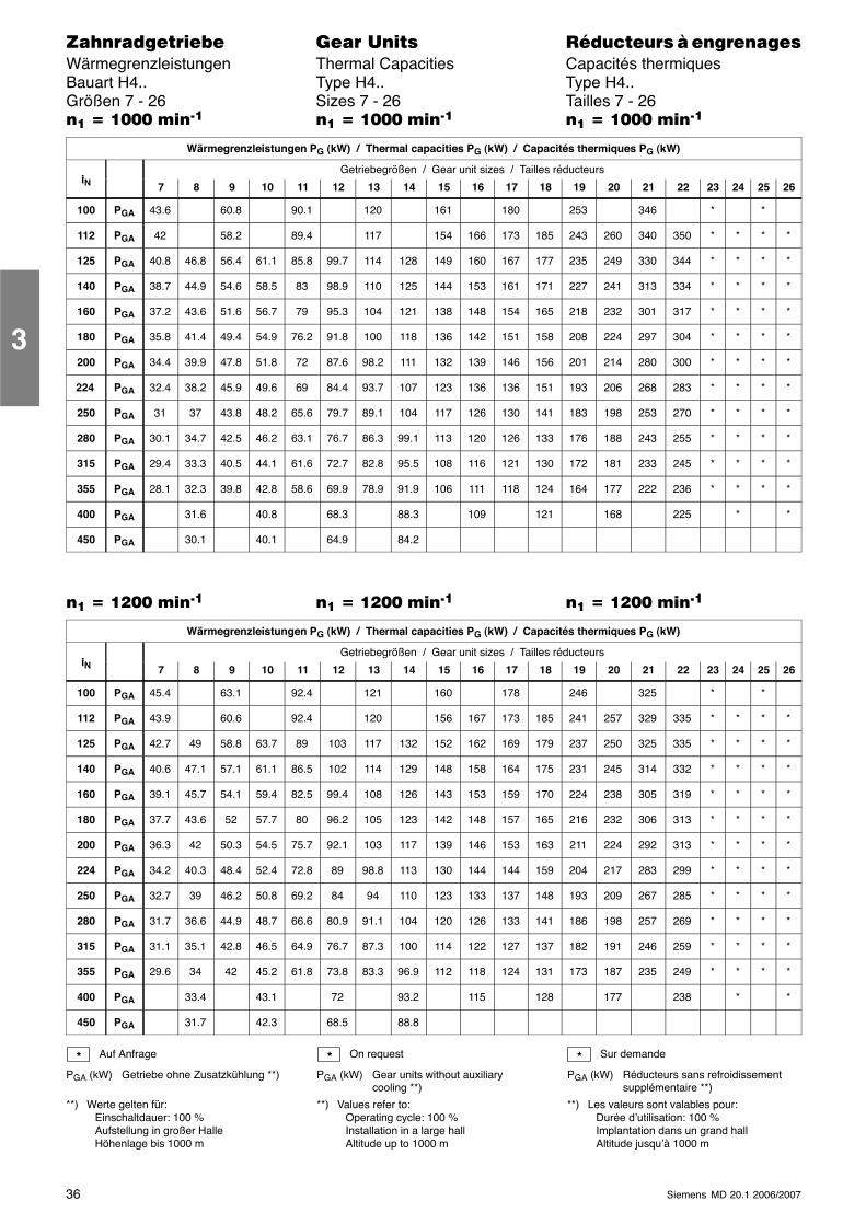
36 Siemens MD 20.1 2006/2007
������������� ���� �� ��������� � ����������Wärmegrenzleistungen Thermal Capacities Capacités thermiquesBauart H4.. Type H4.. Type H4..Größen 7 - 26 Sizes 7 - 26 Tailles 7 - 26�� � ���� ����� �� � ���� ����� �� � ���� �����
Wärmegrenzleistungen PG (kW) / Thermal capacities PG (kW) / Capacités thermiques PG (kW)
iGetriebegrößen / Gear unit sizes / Tailles réducteurs
iN 7 8 9 10 11 12 13 14 15 16 17 18 19 20 21 22 23 24 25 26
100 PGA 43.6 60.8 90.1 120 161 180 253 346 * *
112 PGA 42 58.2 89.4 117 154 166 173 185 243 260 340 350 * * * *
125 PGA 40.8 46.8 56.4 61.1 85.8 99.7 114 128 149 160 167 177 235 249 330 344 * * * *
140 PGA 38.7 44.9 54.6 58.5 83 98.9 110 125 144 153 161 171 227 241 313 334 * * * *
160 PGA 37.2 43.6 51.6 56.7 79 95.3 104 121 138 148 154 165 218 232 301 317 * * * *
180 PGA 35.8 41.4 49.4 54.9 76.2 91.8 100 118 136 142 151 158 208 224 297 304 * * * *
200 PGA 34.4 39.9 47.8 51.8 72 87.6 98.2 111 132 139 146 156 201 214 280 300 * * * *
224 PGA 32.4 38.2 45.9 49.6 69 84.4 93.7 107 123 136 136 151 193 206 268 283 * * * *
250 PGA 31 37 43.8 48.2 65.6 79.7 89.1 104 117 126 130 141 183 198 253 270 * * * *
280 PGA 30.1 34.7 42.5 46.2 63.1 76.7 86.3 99.1 113 120 126 133 176 188 243 255 * * * *
315 PGA 29.4 33.3 40.5 44.1 61.6 72.7 82.8 95.5 108 116 121 130 172 181 233 245 * * * *
355 PGA 28.1 32.3 39.8 42.8 58.6 69.9 78.9 91.9 106 111 118 124 164 177 222 236 * * * *
400 PGA 31.6 40.8 68.3 88.3 109 121 168 225 * *
450 PGA 30.1 40.1 64.9 84.2
�� � ���� ����� �� � ���� ����� �� � ���� �����
Wärmegrenzleistungen PG (kW) / Thermal capacities PG (kW) / Capacités thermiques PG (kW)
iGetriebegrößen / Gear unit sizes / Tailles réducteurs
iN 7 8 9 10 11 12 13 14 15 16 17 18 19 20 21 22 23 24 25 26
100 PGA 45.4 63.1 92.4 121 160 178 246 325 * *
112 PGA 43.9 60.6 92.4 120 156 167 173 185 241 257 329 335 * * * *
125 PGA 42.7 49 58.8 63.7 89 103 117 132 152 162 169 179 237 250 325 335 * * * *
140 PGA 40.6 47.1 57.1 61.1 86.5 102 114 129 148 158 164 175 231 245 314 332 * * * *
160 PGA 39.1 45.7 54.1 59.4 82.5 99.4 108 126 143 153 159 170 224 238 305 319 * * * *
180 PGA 37.7 43.6 52 57.7 80 96.2 105 123 142 148 157 165 216 232 306 313 * * * *
200 PGA 36.3 42 50.3 54.5 75.7 92.1 103 117 139 146 153 163 211 224 292 313 * * * *
224 PGA 34.2 40.3 48.4 52.4 72.8 89 98.8 113 130 144 144 159 204 217 283 299 * * * *
250 PGA 32.7 39 46.2 50.8 69.2 84 94 110 123 133 137 148 193 209 267 285 * * * *
280 PGA 31.7 36.6 44.9 48.7 66.6 80.9 91.1 104 120 126 133 141 186 198 257 269 * * * *
315 PGA 31.1 35.1 42.8 46.5 64.9 76.7 87.3 100 114 122 127 137 182 191 246 259 * * * *
355 PGA 29.6 34 42 45.2 61.8 73.8 83.3 96.9 112 118 124 131 173 187 235 249 * * * *
400 PGA 33.4 43.1 72 93.2 115 128 177 238 * *
450 PGA 31.7 42.3 68.5 88.8
Auf Anfrage
PGA (kW) Getriebe ohne Zusatzkühlung **)
**) Werte gelten für:Einschaltdauer: 100 %Aufstellung in großer HalleHöhenlage bis 1000 m
On request
PGA (kW) Gear units without auxiliarycooling **)
**) Values refer to:Operating cycle: 100 %Installation in a large hallAltitude up to 1000 m
Sur demande
PGA (kW) Réducteurs sans refroidissementsupplémentaire **)
**) Les valeurs sont valables pour:Durée d’utilisation: 100 %Implantation dans un grand hallAltitude jusqu’à 1000 m
* * *
3
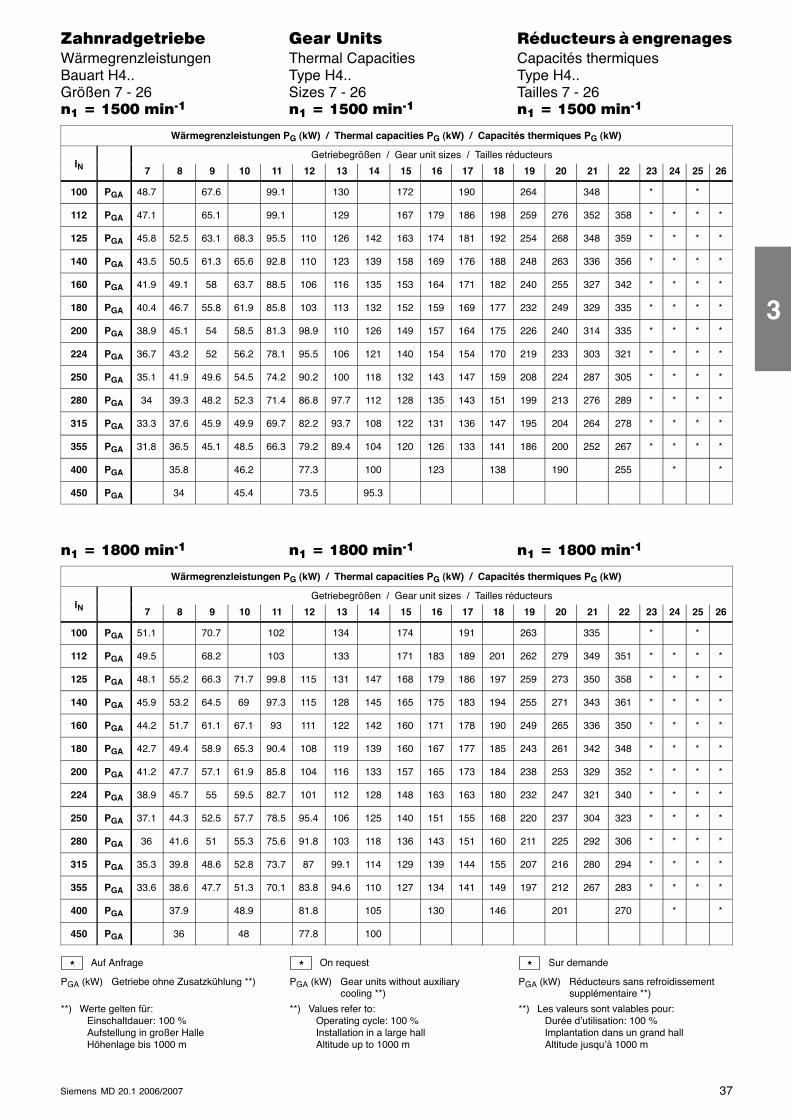
37Siemens MD 20.1 2006/2007
������������� ���� �� ��������� � ����������Wärmegrenzleistungen Thermal Capacities Capacités thermiquesBauart H4.. Type H4.. Type H4..Größen 7 - 26 Sizes 7 - 26 Tailles 7 - 26�� � ���� ����� �� � ���� ����� �� � ���� �����
Wärmegrenzleistungen PG (kW) / Thermal capacities PG (kW) / Capacités thermiques PG (kW)
iGetriebegrößen / Gear unit sizes / Tailles réducteurs
iN 7 8 9 10 11 12 13 14 15 16 17 18 19 20 21 22 23 24 25 26
100 PGA 48.7 67.6 99.1 130 172 190 264 348 * *
112 PGA 47.1 65.1 99.1 129 167 179 186 198 259 276 352 358 * * * *
125 PGA 45.8 52.5 63.1 68.3 95.5 110 126 142 163 174 181 192 254 268 348 359 * * * *
140 PGA 43.5 50.5 61.3 65.6 92.8 110 123 139 158 169 176 188 248 263 336 356 * * * *
160 PGA 41.9 49.1 58 63.7 88.5 106 116 135 153 164 171 182 240 255 327 342 * * * *
180 PGA 40.4 46.7 55.8 61.9 85.8 103 113 132 152 159 169 177 232 249 329 335 * * * *
200 PGA 38.9 45.1 54 58.5 81.3 98.9 110 126 149 157 164 175 226 240 314 335 * * * *
224 PGA 36.7 43.2 52 56.2 78.1 95.5 106 121 140 154 154 170 219 233 303 321 * * * *
250 PGA 35.1 41.9 49.6 54.5 74.2 90.2 100 118 132 143 147 159 208 224 287 305 * * * *
280 PGA 34 39.3 48.2 52.3 71.4 86.8 97.7 112 128 135 143 151 199 213 276 289 * * * *
315 PGA 33.3 37.6 45.9 49.9 69.7 82.2 93.7 108 122 131 136 147 195 204 264 278 * * * *
355 PGA 31.8 36.5 45.1 48.5 66.3 79.2 89.4 104 120 126 133 141 186 200 252 267 * * * *
400 PGA 35.8 46.2 77.3 100 123 138 190 255 * *
450 PGA 34 45.4 73.5 95.3
�� � �!�� ����� �� � �!�� ����� �� � �!�� �����
Wärmegrenzleistungen PG (kW) / Thermal capacities PG (kW) / Capacités thermiques PG (kW)
iGetriebegrößen / Gear unit sizes / Tailles réducteurs
iN 7 8 9 10 11 12 13 14 15 16 17 18 19 20 21 22 23 24 25 26
100 PGA 51.1 70.7 102 134 174 191 263 335 * *
112 PGA 49.5 68.2 103 133 171 183 189 201 262 279 349 351 * * * *
125 PGA 48.1 55.2 66.3 71.7 99.8 115 131 147 168 179 186 197 259 273 350 358 * * * *
140 PGA 45.9 53.2 64.5 69 97.3 115 128 145 165 175 183 194 255 271 343 361 * * * *
160 PGA 44.2 51.7 61.1 67.1 93 111 122 142 160 171 178 190 249 265 336 350 * * * *
180 PGA 42.7 49.4 58.9 65.3 90.4 108 119 139 160 167 177 185 243 261 342 348 * * * *
200 PGA 41.2 47.7 57.1 61.9 85.8 104 116 133 157 165 173 184 238 253 329 352 * * * *
224 PGA 38.9 45.7 55 59.5 82.7 101 112 128 148 163 163 180 232 247 321 340 * * * *
250 PGA 37.1 44.3 52.5 57.7 78.5 95.4 106 125 140 151 155 168 220 237 304 323 * * * *
280 PGA 36 41.6 51 55.3 75.6 91.8 103 118 136 143 151 160 211 225 292 306 * * * *
315 PGA 35.3 39.8 48.6 52.8 73.7 87 99.1 114 129 139 144 155 207 216 280 294 * * * *
355 PGA 33.6 38.6 47.7 51.3 70.1 83.8 94.6 110 127 134 141 149 197 212 267 283 * * * *
400 PGA 37.9 48.9 81.8 105 130 146 201 270 * *
450 PGA 36 48 77.8 100
Auf Anfrage
PGA (kW) Getriebe ohne Zusatzkühlung **)
**) Werte gelten für:Einschaltdauer: 100 %Aufstellung in großer HalleHöhenlage bis 1000 m
On request
PGA (kW) Gear units without auxiliarycooling **)
**) Values refer to:Operating cycle: 100 %Installation in a large hallAltitude up to 1000 m
Sur demande
PGA (kW) Réducteurs sans refroidissementsupplémentaire **)
**) Les valeurs sont valables pour:Durée d’utilisation: 100 %Implantation dans un grand hallAltitude jusqu’à 1000 m
* * *
3
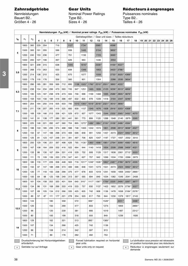
38 Siemens MD 20.1 2006/2007
������������� ���� �� ��������� � ����������Nennleistungen Nominal Power Ratings Puissances nominalesBauart B2.. Type B2.. Type B2..Größen 4 - 26 Sizes 4 - 26 Tailles 4 - 26
Nennleistungen P2N (kW) / Nominal power ratings P2N (kW) / Puissances nominales P2N (kW)
i n nGetriebegrößen / Gear unit sizes / Tailles réducteurs
iN n1 n2 4 5 6 7 8 9 10 11 12 13 14 15 16 17 18 19 20 21 22 23 24 25 26
1800 360 229 354 716 1127 1734 * 2585 * 4598 *
51500 300 191 295 596 939 1445 2154 3832 *
51200 240 153 236 477 751 1156 1723 3065 *
1000 200 127 196 397 626 963 1436 2554
1800 321 208 315 638 1005 1616 * 2339 * 4100 * 4537 *
5 61500 268 173 263 533 839 1349 1953 3423 * 3788 *
5.61200 214 138 210 425 670 1077 1559 2733 * 3025 * 4369 *
1000 179 116 176 356 560 901 1304 2286 2530 3654 *
1800 286 185 281 359 569 712 895 1138 1503 * 1760 * 2210 * 2551 * 3893 * 4222 *
6 31500 238 154 234 299 473 593 745 947 1251 1465 1839 2123 3239 * 3513 * 4859 *
6.31200 190 123 187 238 378 473 594 756 998 1169 1468 1695 2586 * 2805 * 3879 *
1000 159 103 156 199 316 396 497 632 835 978 1228 1418 2164 2347 3246 *
1800 254 164 250 319 505 633 795 1010 1393 * 1619 * 2018 * 2321 * 3510 * 3856 *
7 11500 211 136 207 265 419 525 660 839 1157 1345 1676 1928 2916 * 3203 * 4308 *
7.11200 169 109 166 212 336 421 529 672 927 1077 1343 1544 2335 * 2565 * 3450 * 4070 *
1000 141 91 138 177 280 351 441 561 773 899 1120 1288 1948 2140 2879 3395 *
1800 225 146 221 282 447 560 704 895 1272 * 1486 * 1884 * 2155 * 3109 * 3486 * 4594 *
81500 188 122 185 236 374 468 588 748 1063 1242 1574 1801 2598 2913 * 3838 * 4527 *
81200 150 97 147 188 298 373 469 596 848 991 1256 1437 2073 2324 * 3062 * 3612 *
1000 125 81 123 157 248 311 391 497 706 825 1047 1197 1727 1937 2552 3010
1800 200 129 196 251 397 498 626 795 1130 * 1365 * 1698 * 1981 * 2764 * 3099 * 4083 * 4816 *
91500 167 108 164 209 332 416 522 664 944 1140 1418 1654 2308 2588 3409 * 4021 *
91200 133 86 130 167 264 331 416 529 752 908 1129 1317 1838 2061 2715 * 3203 *
1000 111 72 109 139 220 276 347 441 627 757 942 1099 1534 1720 2266 2673
1800 180 116 177 226 358 448 563 716 1017 * 1249 * 1528 * 1862 * 2487 * 2789 * 3675 * 4335 *
101500 150 97 147 188 298 373 469 596 848 1041 1273 1551 2073 2324 3062 * 3612 *
101200 120 77 118 150 238 299 375 477 678 833 1019 1241 1658 1859 2450 * 2890 *
1000 100 64 98 125 198 249 313 397 565 694 849 1034 1382 1549 2041 2408
1800 161 104 158 202 320 401 504 640 910 * 1117 * 1367 * 1709 * 2225 * 2495 * 3287 * 3877 *
11 21500 134 86 131 168 266 333 419 533 757 930 1137 1422 1852 2076 2736 * 3227 *
11.21200 107 69 105 134 212 266 335 425 605 742 908 1136 1478 1658 2184 * 2576 *
1000 89 57 87 111 177 221 278 354 503 617 755 944 1230 1379 1817 2143
1800 144 180 358 572 999 * 1528 * 2231 * 3468 *
12 51500 120 150 299 477 833 1274 1859 2890 *
12.51200 96 120 239 381 666 1019 1487 2312 *
1000 80 100 199 318 555 849 1239 1926
1800 129 162 321 513 895 * 1369 *
141500 107 134 266 425 742 1136
141200 86 108 214 342 597 913
1000 71 89 176 282 492 753
Druckschmierung bei Horizontalgetriebenerforderlich
Getriebe nur auf Anfrage
Forced lubrication required on horizontalgear units
Gear units only on request
La lubrification sous pression est nécessaireen position horizontale pour ces réducteurs
Réducteur à engrenages seulement surdemande
* * *
3
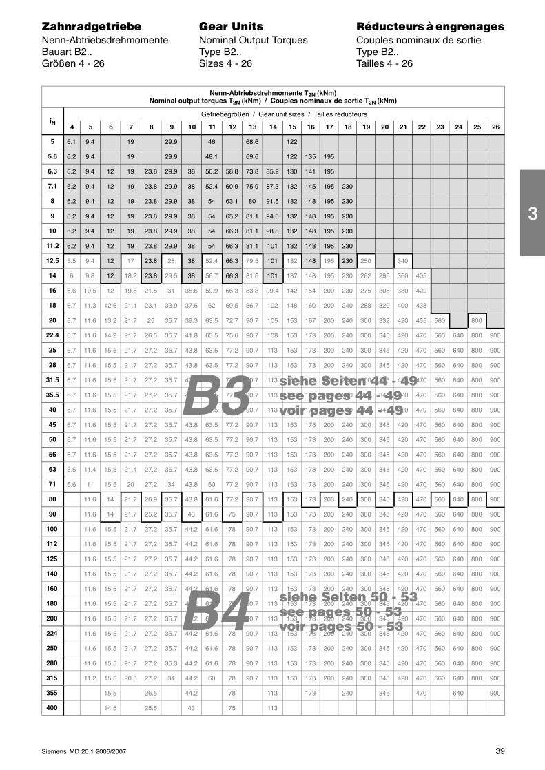
B4
B3 ���� ���� �� - ����� ����� �� - ����� ����� �� - ��
���� ���� !" - !���� ����� !" - !���� ����� !" - !�
39Siemens MD 20.1 2006/2007
������������� ���� �� ��������� � ����������Nenn-Abtriebsdrehmomente Nominal Output Torques Couples nominaux de sortieBauart B2.. Type B2.. Type B2..Größen 4 - 26 Sizes 4 - 26 Tailles 4 - 26
Nenn-Abtriebsdrehmomente T2N (kNm)Nominal output torques T2N (kNm) / Couples nominaux de sortie T2N (kNm)
iGetriebegrößen / Gear unit sizes / Tailles réducteurs
iN4 5 6 7 8 9 10 11 12 13 14 15 16 17 18 19 20 21 22 23 24 25 26
5 6.1 9.4 19 29.9 46 68.6 122
5.6 6.2 9.4 19 29.9 48.1 69.6 122 135 195
6.3 6.2 9.4 12 19 23.8 29.9 38 50.2 58.8 73.8 85.2 130 141 195
7.1 6.2 9.4 12 19 23.8 29.9 38 52.4 60.9 75.9 87.3 132 145 195 230
8 6.2 9.4 12 19 23.8 29.9 38 54 63.1 80 91.5 132 148 195 230
9 6.2 9.4 12 19 23.8 29.9 38 54 65.2 81.1 94.6 132 148 195 230
10 6.2 9.4 12 19 23.8 29.9 38 54 66.3 81.1 98.8 132 148 195 230
11.2 6.2 9.4 12 19 23.8 29.9 38 54 66.3 81.1 101 132 148 195 230
12.5 5.5 9.4 12 17 23.8 28 38 52.4 66.3 79.5 101 132 148 195 230 250 340
14 6 9.8 12 18.2 23.8 29.5 38 56.7 66.3 81.6 101 137 148 195 230 262 295 360 405
16 6.6 10.5 12 19.8 21.5 31 35.6 59.9 66.3 83.8 99.4 142 154 200 230 275 308 380 422
18 6.7 11.3 12.6 21.1 23.1 33.9 37.5 62 69.5 86.7 102 148 160 200 240 288 320 400 438
20 6.7 11.6 13.2 21.7 25 35.7 39.3 63.5 72.7 90.7 105 153 167 200 240 300 332 420 455 560 800
22.4 6.7 11.6 14.2 21.7 26.5 35.7 41.8 63.5 75.6 90.7 108 153 173 200 240 300 345 420 470 560 640 800 900
25 6.7 11.6 15.5 21.7 27.2 35.7 43.8 63.5 77.2 90.7 113 153 173 200 240 300 345 420 470 560 640 800 900
28 6.7 11.6 15.5 21.7 27.2 35.7 43.8 63.5 77.2 90.7 113 153 173 200 240 300 345 420 470 560 640 800 900
31.5 6.7 11.6 15.5 21.7 27.2 35.7 43.8 63.5 77.2 90.7 113 153 173 200 240 300 345 420 470 560 640 800 900
35.5 6.7 11.6 15.5 21.7 27.2 35.7 43.8 63.5 77.2 90.7 113 153 173 200 240 300 345 420 470 560 640 800 900
40 6.7 11.6 15.5 21.7 27.2 35.7 43.8 63.5 77.2 90.7 113 153 173 200 240 300 345 420 470 560 640 800 900
45 6.7 11.6 15.5 21.7 27.2 35.7 43.8 63.5 77.2 90.7 113 153 173 200 240 300 345 420 470 560 640 800 900
50 6.7 11.6 15.5 21.7 27.2 35.7 43.8 63.5 77.2 90.7 113 153 173 200 240 300 345 420 470 560 640 800 900
56 6.7 11.6 15.5 21.7 27.2 35.7 43.8 63.5 77.2 90.7 113 153 173 200 240 300 345 420 470 560 640 800 900
63 6.6 11.4 15.5 21.4 27.2 35.7 43.8 63.5 77.2 90.7 113 153 173 200 240 300 345 420 470 560 640 800 900
71 6.6 11 15.5 20 27.2 34 43.8 60 77.2 90.7 113 153 173 200 240 300 345 420 470 560 640 800 900
80 11.6 14 21.7 26.9 35.7 43.8 61.6 77.2 90.7 113 153 173 200 240 300 345 420 470 560 640 800 900
90 11.6 14 21.7 25.2 35.7 43 61.6 75 90.7 113 153 173 200 240 300 345 420 470 560 640 800 900
100 11.6 15.5 21.7 27.2 35.7 44.2 61.6 78 90.7 113 153 173 200 240 300 345 420 470 560 640 800 900
112 11.6 15.5 21.7 27.2 35.7 44.2 61.6 78 90.7 113 153 173 200 240 300 345 420 470 560 640 800 900
125 11.6 15.5 21.7 27.2 35.7 44.2 61.6 78 90.7 113 153 173 200 240 300 345 420 470 560 640 800 900
140 11.6 15.5 21.7 27.2 35.7 44.2 61.6 78 90.7 113 153 173 200 240 300 345 420 470 560 640 800 900
160 11.6 15.5 21.7 27.2 35.7 44.2 61.6 78 90.7 113 153 173 200 240 300 345 420 470 560 640 800 900
180 11.6 15.5 21.7 27.2 35.7 44.2 61.6 78 90.7 113 153 173 200 240 300 345 420 470 560 640 800 900
200 11.6 15.5 21.7 27.2 35.7 44.2 61.6 78 90.7 113 153 173 200 240 300 345 420 470 560 640 800 900
224 11.6 15.5 21.7 27.2 35.7 44.2 61.6 78 90.7 113 153 173 200 240 300 345 420 470 560 640 800 900
250 11.6 15.5 21.7 27.2 35.7 44.2 61.6 78 90.7 113 153 173 200 240 300 345 420 470 560 640 800 900
280 11.6 15.5 21.7 27.2 35.3 44.2 61.6 78 90.7 113 153 173 200 240 300 345 420 470 560 640 800 900
315 11.2 15.5 20.5 27.2 34 44.2 60 78 90.7 113 153 173 200 240 300 345 420 470 560 640 800 900
355 15.5 26.5 44.2 78 113 173 240 345 470 640 900
400 14.5 25.5 43 75 113
3
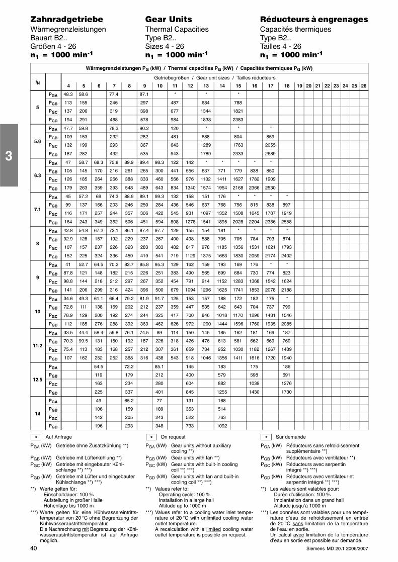
40 Siemens MD 20.1 2006/2007
������������� ���� �� ��������� � ����������Wärmegrenzleistungen Thermal Capacities Capacités thermiquesBauart B2.. Type B2.. Type B2..Größen 4 - 26 Sizes 4 - 26 Tailles 4 - 26�� � ���� ����� �� � ���� ����� �� � ���� �����
Wärmegrenzleistungen PG (kW) / Thermal capacities PG (kW) / Capacités thermiques PG (kW)
iNGetriebegrößen / Gear unit sizes / Tailles réducteurs
iN 4 5 6 7 8 9 10 11 12 13 14 15 16 17 18 19 20 21 22 23 24 25 26
PGA 48.3 58.6 77.4 87.1 * * *
5PGB 113 155 246 297 487 684 788
5PGC 137 206 319 398 677 1344 1821
PGD 194 291 468 578 984 1838 2383
PGA 47.7 59.8 78.3 90.2 120 * * *
5 6PGB 109 153 232 282 481 688 804 859
5.6PGC 132 199 293 367 643 1289 1763 2055
PGD 187 282 432 535 943 1789 2333 2689
PGA 47 58.7 68.3 75.8 89.9 89.4 98.3 122 142 * * * * *
6 3PGB 105 145 170 216 261 265 300 441 556 637 771 779 838 850
6.3PGC 126 185 264 266 388 333 460 566 976 1132 1411 1627 1782 1909
PGD 179 263 359 393 548 489 643 834 1340 1574 1954 2168 2366 2530
PGA 45 57.2 69 74.3 88.9 89.1 99.3 132 158 151 176 * * * *
7 1PGB 99 137 166 203 246 250 284 436 546 637 768 756 815 838 897
7.1PGC 116 171 257 244 357 306 422 545 931 1097 1352 1508 1645 1787 1919
PGD 164 243 349 362 506 451 594 808 1278 1541 1895 2028 2204 2386 2558
PGA 42.8 54.8 67.2 72.1 86.1 87.4 97.7 129 155 154 181 * * * *
8PGB 92.9 128 157 192 229 237 267 400 498 588 705 705 784 793 874
8PGC 107 157 237 226 323 283 383 482 817 978 1185 1356 1531 1621 1793
PGD 152 225 324 336 459 419 541 719 1129 1375 1663 1830 2059 2174 2402
PGA 41 52.7 64.5 70.2 82.7 85.8 95.3 129 162 159 193 169 176 * *
9PGB 87.8 121 148 182 215 226 251 383 490 565 699 684 730 774 823
9PGC 98.8 144 218 212 297 267 352 454 791 914 1152 1283 1368 1542 1624
PGD 141 206 299 316 424 396 500 679 1094 1296 1625 1741 1853 2078 2188
PGA 34.6 49.3 61.1 66.4 79.2 81.9 91.7 125 153 157 188 172 182 175 *
10PGB 72.8 111 138 169 202 212 237 359 447 535 642 643 704 737 799
10PGC 78.9 129 200 192 274 244 325 417 700 846 1018 1170 1296 1431 1546
PGD 112 185 276 288 392 363 462 626 972 1200 1444 1596 1760 1935 2085
PGA 33.5 44.4 58.4 59.8 76.1 74.5 89 114 150 145 185 162 181 169 187
11 2PGB 70.3 99.5 131 150 192 187 226 318 426 476 613 581 662 669 760
11.2PGC 75.4 113 183 168 257 212 307 361 659 734 952 1030 1182 1267 1439
PGD 107 162 252 252 368 316 438 543 918 1046 1356 1411 1616 1720 1940
PGA 54.5 72.2 85.1 145 183 175 186
12 5PGB 119 179 212 400 579 598 691
12.5PGC 163 234 280 604 882 1039 1276
PGD 225 337 401 845 1255 1430 1730
PGA 49 65.2 77 131 168
14PGB 106 159 189 353 514
14PGC 142 205 243 522 763
PGD 196 293 348 733 1092
Auf Anfrage
PGA (kW) Getriebe ohne Zusatzkühlung **)
PGB (kW) Getriebe mit Lüfterkühlung **)PGC (kW) Getriebe mit eingebauter Kühl-
schlange **) ***)PGD (kW) Getriebe mit Lüfter und eingebauter
Kühlschlange **) ***)**) Werte gelten für:
Einschaltdauer: 100 %Aufstellung in großer HalleHöhenlage bis 1000 m
***) Werte gelten für eine Kühlwassereintritts-temperatur von 20 °C ohne Begrenzung derKühlwasseraustrittstemperatur.Die Nachrechnung mit Begrenzung der Kühl-wasseraustrittstemperatur ist auf Anfragemöglich.
On request
PGA (kW) Gear units without auxiliarycooling **)
PGB (kW) Gear units with fan **)PGC (kW) Gear units with built-in cooling
coil **) ***)PGD (kW) Gear units with fan and built-in
cooling coil **) ***)**) Values refer to:
Operating cycle: 100 %Installation in a large hallAltitude up to 1000 m
***) Values refer to a cooling water inlet tempe-rature of 20 °C with unlimited cooling wateroutlet temperature.A recalculation with a limited cooling wateroutlet temperature is possible on request.
Sur demande
PGA (kW) Réducteurs sans refroidissementsupplémentaire **)
PGB (kW) Réducteurs avec ventilateur **)PGC (kW) Réducteurs avec serpentin
intégré **) ***)PGD (kW) Réducteurs avec ventilateur et
serpentin intégré **) ***)**) Les valeurs sont valables pour:
Durée d’utilisation: 100 %Implantation dans un grand hallAltitude jusqu’à 1000 m
***) Les données sont valables pour une tempé-rature d’eau de refroidissement en entréede 20 °C sans limitation de la températurede l’eau en sortie.Un calcul avec limitation de la températured’eau en sortie est possible sur demande.
* * *
3
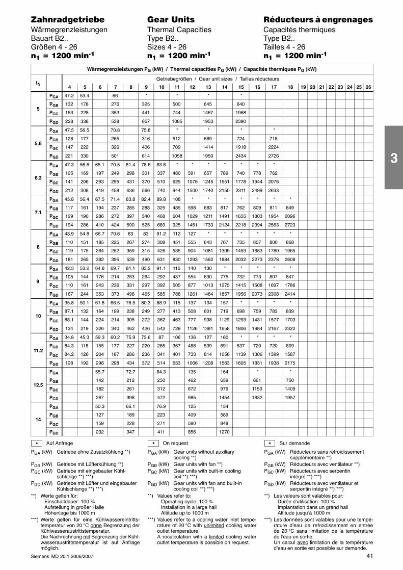
41Siemens MD 20.1 2006/2007
������������� ���� �� ��������� � ����������Wärmegrenzleistungen Thermal Capacities Capacités thermiquesBauart B2.. Type B2.. Type B2..Größen 4 - 26 Sizes 4 - 26 Tailles 4 - 26�� � ���� ����� �� � ���� ����� �� � ���� �����
Wärmegrenzleistungen PG (kW) / Thermal capacities PG (kW) / Capacités thermiques PG (kW)
iNGetriebegrößen / Gear unit sizes / Tailles réducteurs
iN 4 5 6 7 8 9 10 11 12 13 14 15 16 17 18 19 20 21 22 23 24 25 26
PGA 47.2 53.4 66 * * * *
5PGB 132 178 276 325 500 645 640
5PGC 153 228 353 441 744 1467 1968
PGD 228 338 538 657 1085 1953 2390
PGA 47.5 56.5 70.8 75.8 * * * *
5 6PGB 128 177 265 316 512 689 724 718
5.6PGC 147 222 326 406 709 1414 1918 2224
PGD 221 330 501 614 1058 1950 2434 2726
PGA 47.3 56.6 65.1 70.5 81.4 78.6 83.8 * * * * * * *
6 3PGB 125 169 197 249 298 301 337 480 591 657 789 740 778 762
6.3PGC 141 206 293 295 431 370 510 625 1076 1245 1551 1778 1944 2076
PGD 212 308 419 458 636 566 740 944 1500 1740 2150 2311 2499 2633
PGA 45.8 56.4 67.5 71.4 83.8 82.4 89.8 108 * * * * * * *
7 1PGB 117 161 194 237 285 288 325 485 598 683 817 762 809 811 849
7.1PGC 129 190 286 272 397 340 468 604 1029 1211 1491 1655 1803 1954 2096
PGD 194 286 410 424 590 525 689 925 1451 1733 2124 2218 2394 2563 2723
PGA 43.9 54.8 66.7 70.6 83 83 91.2 112 127 * * * * * *
8PGB 110 151 185 225 267 274 308 451 555 643 767 735 807 800 868
8PGC 119 175 264 252 359 315 426 535 904 1081 1309 1493 1683 1780 1965
PGD 181 265 382 395 539 490 631 830 1293 1562 1884 2032 2273 2378 2608
PGA 42.3 53.2 64.8 69.7 81.1 83.2 91.1 116 140 130 * * * * *
9PGB 105 144 176 214 253 264 292 437 554 630 775 732 773 807 847
9PGC 110 161 243 236 331 297 392 505 877 1013 1275 1415 1508 1697 1786
PGD 167 244 353 373 498 465 585 788 1261 1484 1857 1956 2073 2308 2414
PGA 35.8 50.1 61.8 66.5 78.5 80.3 88.9 115 137 134 157 * * * *
10PGB 87.1 132 164 199 238 249 277 413 508 601 719 698 759 783 839
10PGC 88.1 144 224 214 305 272 362 463 777 938 1129 1293 1431 1577 1703
PGD 134 219 326 340 462 426 542 729 1126 1381 1658 1806 1984 2167 2322
PGA 34.8 45.3 59.3 60.2 75.9 73.6 87 106 136 127 160 * * * *
11 2PGB 84.3 118 155 177 227 220 265 367 488 539 691 637 720 720 809
11.2PGC 84.2 126 204 187 286 236 341 401 733 814 1056 1139 1306 1399 1587
PGD 128 192 298 298 434 372 514 633 1066 1208 1563 1605 1831 1938 2175
PGA 55.7 72.7 84.3 135 164 * *
12 5PGB 142 212 250 462 659 661 750
12.5PGC 182 261 312 672 979 1150 1409
PGD 267 398 472 985 1454 1632 1957
PGA 50.3 66.1 76.9 125 154
14PGB 127 189 223 409 589
14PGC 159 228 271 580 848
PGD 232 347 411 856 1270
Auf Anfrage
PGA (kW) Getriebe ohne Zusatzkühlung **)
PGB (kW) Getriebe mit Lüfterkühlung **)PGC (kW) Getriebe mit eingebauter Kühl-
schlange **) ***)PGD (kW) Getriebe mit Lüfter und eingebauter
Kühlschlange **) ***)**) Werte gelten für:
Einschaltdauer: 100 %Aufstellung in großer HalleHöhenlage bis 1000 m
***) Werte gelten für eine Kühlwassereintritts-temperatur von 20 °C ohne Begrenzung derKühlwasseraustrittstemperatur.Die Nachrechnung mit Begrenzung der Kühl-wasseraustrittstemperatur ist auf Anfragemöglich.
On request
PGA (kW) Gear units without auxiliarycooling **)
PGB (kW) Gear units with fan **)PGC (kW) Gear units with built-in cooling
coil **) ***)PGD (kW) Gear units with fan and built-in
cooling coil **) ***)**) Values refer to:
Operating cycle: 100 %Installation in a large hallAltitude up to 1000 m
***) Values refer to a cooling water inlet tempe-rature of 20 °C with unlimited cooling wateroutlet temperature.A recalculation with a limited cooling wateroutlet temperature is possible on request.
Sur demande
PGA (kW) Réducteurs sans refroidissementsupplémentaire **)
PGB (kW) Réducteurs avec ventilateur **)PGC (kW) Réducteurs avec serpentin
intégré **) ***)PGD (kW) Réducteurs avec ventilateur et
serpentin intégré **) ***)**) Les valeurs sont valables pour:
Durée d’utilisation: 100 %Implantation dans un grand hallAltitude jusqu’à 1000 m
***) Les données sont valables pour une tempé-rature d’eau de refroidissement en entréede 20 °C sans limitation de la températurede l’eau en sortie.Un calcul avec limitation de la températured’eau en sortie est possible sur demande.
* * *
3
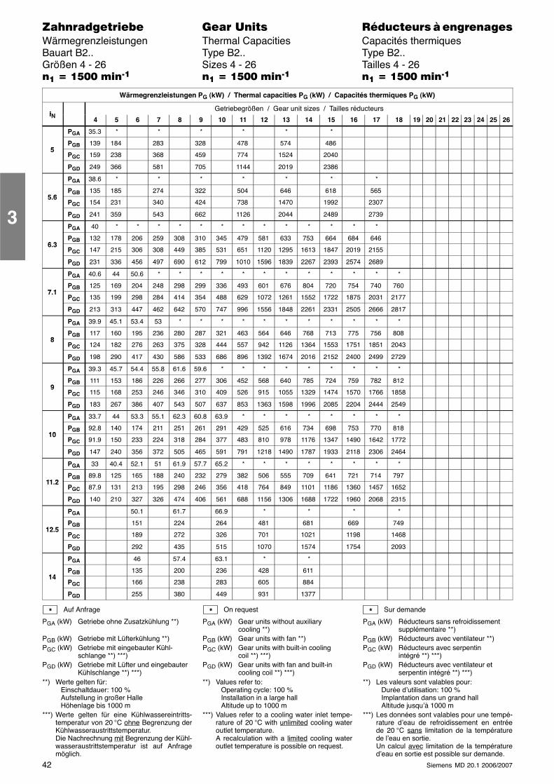
42 Siemens MD 20.1 2006/2007
������������� ���� �� ��������� � ����������Wärmegrenzleistungen Thermal Capacities Capacités thermiquesBauart B2.. Type B2.. Type B2..Größen 4 - 26 Sizes 4 - 26 Tailles 4 - 26�� � ���� ����� �� � ���� ����� �� � ���� �����
Wärmegrenzleistungen PG (kW) / Thermal capacities PG (kW) / Capacités thermiques PG (kW)
iNGetriebegrößen / Gear unit sizes / Tailles réducteurs
iN 4 5 6 7 8 9 10 11 12 13 14 15 16 17 18 19 20 21 22 23 24 25 26
PGA 35.3 * * * * * *
5PGB 139 184 283 328 478 574 486
5PGC 159 238 368 459 774 1524 2040
PGD 249 366 581 705 1144 2019 2386
PGA 38.6 * * * * * * *
5 6PGB 135 185 274 322 504 646 618 565
5.6PGC 154 231 340 424 738 1470 1992 2307
PGD 241 359 543 662 1126 2044 2489 2739
PGA 40 * * * * * * * * * * * * *
6 3PGB 132 178 206 259 308 310 345 479 581 633 753 664 684 646
6.3PGC 147 215 306 308 449 385 531 651 1120 1295 1613 1847 2019 2155
PGD 231 336 456 497 690 612 799 1010 1596 1839 2267 2393 2574 2689
PGA 40.6 44 50.6 * * * * * * * * * * * *
7 1PGB 125 169 204 248 298 299 336 493 601 676 804 720 754 740 760
7.1PGC 135 199 298 284 414 354 488 629 1072 1261 1552 1722 1875 2031 2177
PGD 213 313 447 462 642 570 747 996 1556 1848 2261 2331 2505 2666 2817
PGA 39.9 45.1 53.4 53 * * * * * * * * * * *
8PGB 117 160 195 236 280 287 321 463 564 646 768 713 775 756 808
8PGC 124 182 276 263 375 328 444 557 942 1126 1364 1553 1751 1851 2043
PGD 198 290 417 430 586 533 686 896 1392 1674 2016 2152 2400 2499 2729
PGA 39.3 45.7 54.4 55.8 61.6 59.6 * * * * * * * * *
9PGB 111 153 186 226 266 277 306 452 568 640 785 724 759 782 812
9PGC 115 168 253 246 346 310 409 526 915 1055 1329 1474 1570 1766 1858
PGD 183 267 386 407 543 507 637 853 1363 1598 1996 2085 2204 2444 2549
PGA 33.7 44 53.3 55.1 62.3 60.8 63.9 * * * * * * * *
10PGB 92.8 140 174 211 251 261 291 429 525 616 734 698 753 770 818
10PGC 91.9 150 233 224 318 284 377 483 810 978 1176 1347 1490 1642 1772
PGD 147 240 356 372 505 465 591 791 1218 1490 1787 1933 2118 2306 2464
PGA 33 40.4 52.1 51 61.9 57.7 65.2 * * * * * * * *
11 2PGB 89.8 125 165 188 240 232 279 382 506 555 709 641 721 714 797
11.2PGC 87.9 131 213 195 298 246 356 418 764 849 1101 1186 1360 1457 1652
PGD 140 210 327 326 474 406 561 688 1156 1306 1688 1722 1960 2068 2315
PGA 50.1 61.7 66.9 * * * *
12 5PGB 151 224 264 481 681 669 749
12.5PGC 189 272 326 701 1021 1198 1468
PGD 292 435 515 1070 1574 1754 2093
PGA 46 57.4 63.1 * *
14PGB 135 200 236 428 611
14PGC 166 238 283 605 884
PGD 255 380 449 931 1377
Auf Anfrage
PGA (kW) Getriebe ohne Zusatzkühlung **)
PGB (kW) Getriebe mit Lüfterkühlung **)PGC (kW) Getriebe mit eingebauter Kühl-
schlange **) ***)PGD (kW) Getriebe mit Lüfter und eingebauter
Kühlschlange **) ***)**) Werte gelten für:
Einschaltdauer: 100 %Aufstellung in großer HalleHöhenlage bis 1000 m
***) Werte gelten für eine Kühlwassereintritts-temperatur von 20 °C ohne Begrenzung derKühlwasseraustrittstemperatur.Die Nachrechnung mit Begrenzung der Kühl-wasseraustrittstemperatur ist auf Anfragemöglich.
On request
PGA (kW) Gear units without auxiliarycooling **)
PGB (kW) Gear units with fan **)PGC (kW) Gear units with built-in cooling
coil **) ***)PGD (kW) Gear units with fan and built-in
cooling coil **) ***)**) Values refer to:
Operating cycle: 100 %Installation in a large hallAltitude up to 1000 m
***) Values refer to a cooling water inlet tempe-rature of 20 °C with unlimited cooling wateroutlet temperature.A recalculation with a limited cooling wateroutlet temperature is possible on request.
Sur demande
PGA (kW) Réducteurs sans refroidissementsupplémentaire **)
PGB (kW) Réducteurs avec ventilateur **)PGC (kW) Réducteurs avec serpentin
intégré **) ***)PGD (kW) Réducteurs avec ventilateur et
serpentin intégré **) ***)**) Les valeurs sont valables pour:
Durée d’utilisation: 100 %Implantation dans un grand hallAltitude jusqu’à 1000 m
***) Les données sont valables pour une tempé-rature d’eau de refroidissement en entréede 20 °C sans limitation de la températurede l’eau en sortie.Un calcul avec limitation de la températured’eau en sortie est possible sur demande.
* * *
3
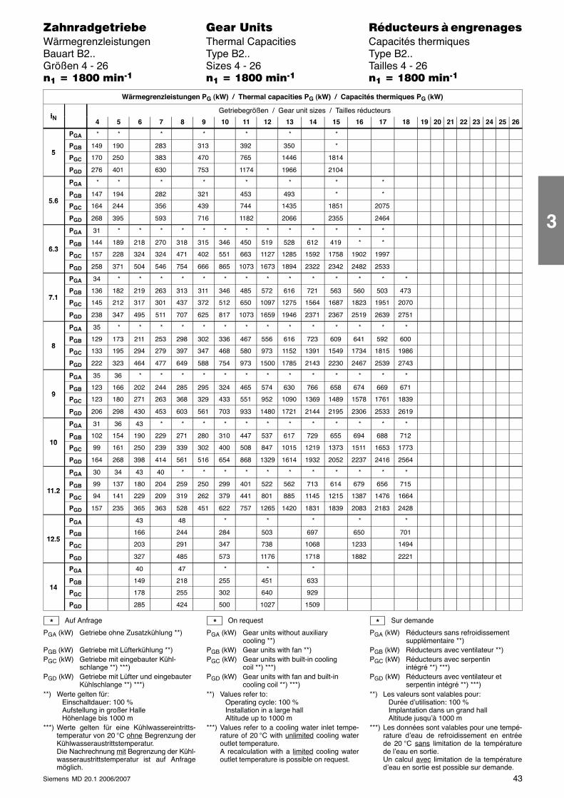
43Siemens MD 20.1 2006/2007
������������� ���� �� ��������� � ����������Wärmegrenzleistungen Thermal Capacities Capacités thermiquesBauart B2.. Type B2.. Type B2..Größen 4 - 26 Sizes 4 - 26 Tailles 4 - 26�� � �!�� ����� �� � �!�� ����� �� � �!�� �����
Wärmegrenzleistungen PG (kW) / Thermal capacities PG (kW) / Capacités thermiques PG (kW)
iNGetriebegrößen / Gear unit sizes / Tailles réducteurs
iN 4 5 6 7 8 9 10 11 12 13 14 15 16 17 18 19 20 21 22 23 24 25 26
PGA * * * * * * *
5PGB 149 190 283 313 392 350 *
5PGC 170 250 383 470 765 1446 1814
PGD 276 401 630 753 1174 1966 2104
PGA * * * * * * * *
5 6PGB 147 194 282 321 453 493 * *
5.6PGC 164 244 356 439 744 1435 1851 2075
PGD 268 395 593 716 1182 2066 2355 2464
PGA 31 * * * * * * * * * * * * *
6 3PGB 144 189 218 270 318 315 346 450 519 528 612 419 * *
6.3PGC 157 228 324 324 471 402 551 663 1127 1285 1592 1758 1902 1997
PGD 258 371 504 546 754 666 865 1073 1673 1894 2322 2342 2482 2533
PGA 34 * * * * * * * * * * * * * *
7 1PGB 136 182 219 263 313 311 346 485 572 616 721 563 560 503 473
7.1PGC 145 212 317 301 437 372 512 650 1097 1275 1564 1687 1823 1951 2070
PGD 238 347 495 511 707 625 817 1073 1659 1946 2371 2367 2519 2639 2751
PGA 35 * * * * * * * * * * * * * *
8PGB 129 173 211 253 298 302 336 467 556 616 723 609 641 592 600
8PGC 133 195 294 279 397 347 468 580 973 1152 1391 1549 1734 1815 1986
PGD 222 323 464 477 649 588 754 973 1500 1785 2143 2230 2467 2539 2743
PGA 35 36 * * * * * * * * * * * * *
9PGB 123 166 202 244 285 295 324 465 574 630 766 658 674 669 671
9PGC 123 180 271 263 368 329 433 551 952 1090 1369 1489 1578 1761 1839
PGD 206 298 430 453 603 561 703 933 1480 1721 2144 2195 2306 2533 2619
PGA 31 36 43 * * * * * * * * * * * *
10PGB 102 154 190 229 271 280 310 447 537 617 729 655 694 688 712
10PGC 99 161 250 239 339 302 400 508 847 1015 1219 1373 1511 1653 1773
PGD 164 268 398 414 561 516 654 868 1329 1614 1932 2052 2237 2416 2564
PGA 30 34 43 40 * * * * * * * * * * *
11 2PGB 99 137 180 204 259 250 299 401 522 562 713 614 679 656 715
11.2PGC 94 141 229 209 319 262 379 441 801 885 1145 1215 1387 1476 1664
PGD 157 235 365 363 528 451 622 757 1265 1420 1831 1839 2083 2183 2428
PGA 43 48 * * * * *
12 5PGB 166 244 284 503 697 650 701
12.5PGC 203 291 347 738 1068 1233 1494
PGD 327 485 573 1176 1718 1882 2221
PGA 40 47 * * *
14PGB 149 218 255 451 633
14PGC 178 255 302 640 929
PGD 285 424 500 1027 1509
Auf Anfrage
PGA (kW) Getriebe ohne Zusatzkühlung **)
PGB (kW) Getriebe mit Lüfterkühlung **)PGC (kW) Getriebe mit eingebauter Kühl-
schlange **) ***)PGD (kW) Getriebe mit Lüfter und eingebauter
Kühlschlange **) ***)**) Werte gelten für:
Einschaltdauer: 100 %Aufstellung in großer HalleHöhenlage bis 1000 m
***) Werte gelten für eine Kühlwassereintritts-temperatur von 20 °C ohne Begrenzung derKühlwasseraustrittstemperatur.Die Nachrechnung mit Begrenzung der Kühl-wasseraustrittstemperatur ist auf Anfragemöglich.
On request
PGA (kW) Gear units without auxiliarycooling **)
PGB (kW) Gear units with fan **)PGC (kW) Gear units with built-in cooling
coil **) ***)PGD (kW) Gear units with fan and built-in
cooling coil **) ***)**) Values refer to:
Operating cycle: 100 %Installation in a large hallAltitude up to 1000 m
***) Values refer to a cooling water inlet tempe-rature of 20 °C with unlimited cooling wateroutlet temperature.A recalculation with a limited cooling wateroutlet temperature is possible on request.
Sur demande
PGA (kW) Réducteurs sans refroidissementsupplémentaire **)
PGB (kW) Réducteurs avec ventilateur **)PGC (kW) Réducteurs avec serpentin
intégré **) ***)PGD (kW) Réducteurs avec ventilateur et
serpentin intégré **) ***)**) Les valeurs sont valables pour:
Durée d’utilisation: 100 %Implantation dans un grand hallAltitude jusqu’à 1000 m
***) Les données sont valables pour une tempé-rature d’eau de refroidissement en entréede 20 °C sans limitation de la températurede l’eau en sortie.Un calcul avec limitation de la températured’eau en sortie est possible sur demande.
* * *
3
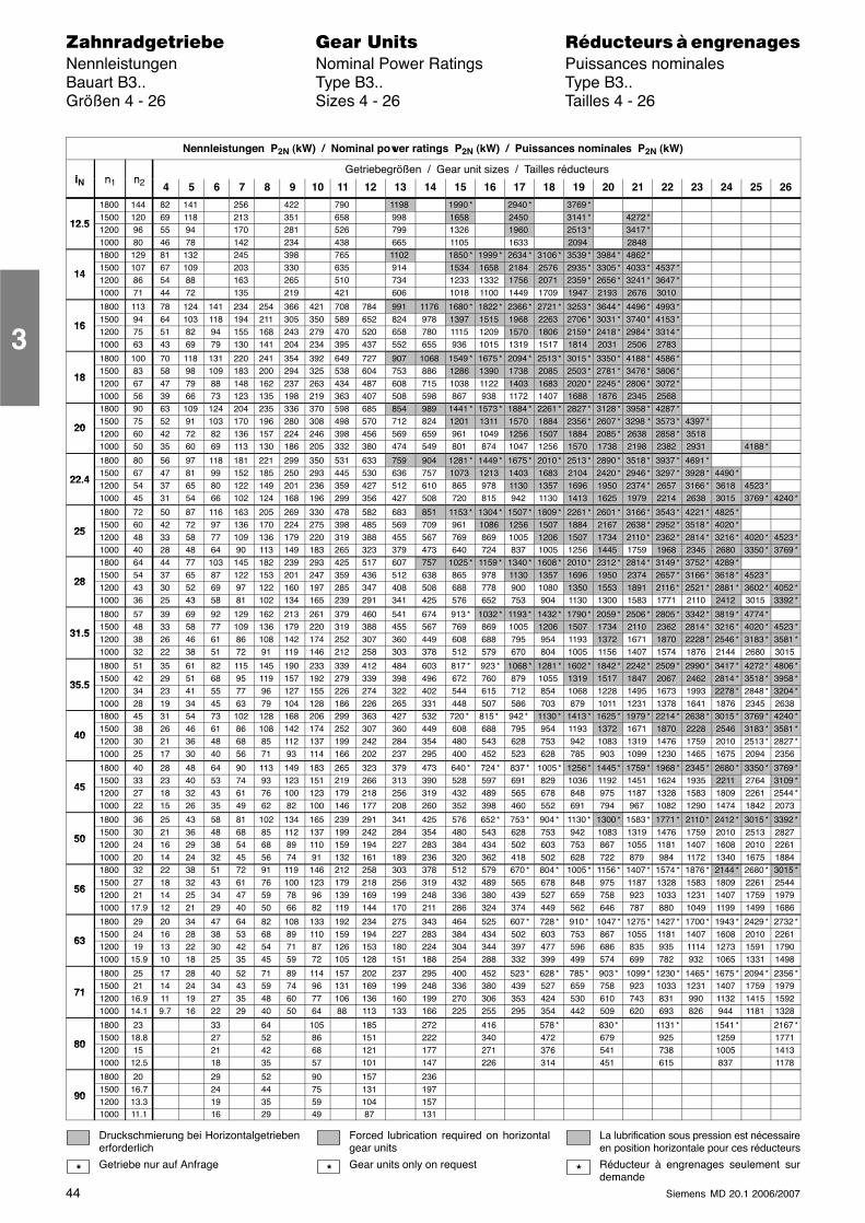
44 Siemens MD 20.1 2006/2007
������������� ���� �� ��������� � ����������Nennleistungen Nominal Power Ratings Puissances nominalesBauart B3.. Type B3.. Type B3..Größen 4 - 26 Sizes 4 - 26 Tailles 4 - 26
Nennleistungen P2N (kW) / Nominal power ratings P2N (kW) / Puissances nominales P2N (kW)
i n nGetriebegrößen / Gear unit sizes / Tailles réducteurs
iN n1 n2 4 5 6 7 8 9 10 11 12 13 14 15 16 17 18 19 20 21 22 23 24 25 26
1800 144 82 141 256 422 790 1198 1990 * 2940 * 3769 *
12 51500 120 69 118 213 351 658 998 1658 2450 3141 * 4272 *
12.51200 96 55 94 170 281 526 799 1326 1960 2513 * 3417 *1000 80 46 78 142 234 438 665 1105 1633 2094 28481800 129 81 132 245 398 765 1102 1850 * 1999 * 2634 * 3106 * 3539 * 3984 * 4862 *
141500 107 67 109 203 330 635 914 1534 1658 2184 2576 2935 * 3305 * 4033 * 4537 *
141200 86 54 88 163 265 510 734 1233 1332 1756 2071 2359 * 2656 * 3241 * 3647 *1000 71 44 72 135 219 421 606 1018 1100 1449 1709 1947 2193 2676 3010
1800 113 78 124 141 234 254 366 421 708 784 991 1176 1680 * 1822 * 2366 * 2721 * 3253 * 3644 * 4496 * 4993 *
161500 94 64 103 118 194 211 305 350 589 652 824 978 1397 1515 1968 2263 2706 * 3031 * 3740 * 4153 *
161200 75 51 82 94 155 168 243 279 470 520 658 780 1115 1209 1570 1806 2159 * 2418 * 2984 * 3314 *1000 63 43 69 79 130 141 204 234 395 437 552 655 936 1015 1319 1517 1814 2031 2506 2783
1800 100 70 118 131 220 241 354 392 649 727 907 1068 1549 * 1675 * 2094 * 2513 * 3015 * 3350 * 4188 * 4586 *
181500 83 58 98 109 183 200 294 325 538 604 753 886 1286 1390 1738 2085 2503 * 2781 * 3476 * 3806 *
181200 67 47 79 88 148 162 237 263 434 487 608 715 1038 1122 1403 1683 2020 * 2245 * 2806 * 3072 *1000 56 39 66 73 123 135 198 219 363 407 508 598 867 938 1172 1407 1688 1876 2345 25681800 90 63 109 124 204 235 336 370 598 685 854 989 1441 * 1573 * 1884 * 2261 * 2827 * 3128 * 3958 * 4287 *
201500 75 52 91 103 170 196 280 308 498 570 712 824 1201 1311 1570 1884 2356 * 2607 * 3298 * 3573 * 4397 *
201200 60 42 72 82 136 157 224 246 398 456 569 659 961 1049 1256 1507 1884 2085 * 2638 2858 * 35181000 50 35 60 69 113 130 186 205 332 380 474 549 801 874 1047 1256 1570 1738 2198 2382 2931 4188 *
1800 80 56 97 118 181 221 299 350 531 633 759 904 1281 * 1449 * 1675 * 2010 * 2513 * 2890 * 3518 * 3937 * 4691 *
22 41500 67 47 81 99 152 185 250 293 445 530 636 757 1073 1213 1403 1683 2104 2420 * 2946 * 3297 * 3928 * 4490 *
22.41200 54 37 65 80 122 149 201 236 359 427 512 610 865 978 1130 1357 1696 1950 2374 * 2657 3166 * 3618 4523 *1000 45 31 54 66 102 124 168 196 299 356 427 508 720 815 942 1130 1413 1625 1979 2214 2638 3015 3769 * 4240 *
1800 72 50 87 116 163 205 269 330 478 582 683 851 1153 * 1304 * 1507 * 1809 * 2261 * 2601 * 3166 * 3543 * 4221 * 4825 *
251500 60 42 72 97 136 170 224 275 398 485 569 709 961 1086 1256 1507 1884 2167 2638 * 2952 * 3518 * 4020 *
251200 48 33 58 77 109 136 179 220 319 388 455 567 769 869 1005 1206 1507 1734 2110 * 2362 * 2814 * 3216 * 4020 * 4523 *1000 40 28 48 64 90 113 149 183 265 323 379 473 640 724 837 1005 1256 1445 1759 1968 2345 2680 3350 * 3769 *1800 64 44 77 103 145 182 239 293 425 517 607 757 1025 * 1159 * 1340 * 1608 * 2010 * 2312 * 2814 * 3149 * 3752 * 4289 *
281500 54 37 65 87 122 153 201 247 359 436 512 638 865 978 1130 1357 1696 1950 2374 2657 * 3166 * 3618 * 4523 *
281200 43 30 52 69 97 122 160 197 285 347 408 508 688 778 900 1080 1350 1553 1891 2116 * 2521 * 2881 * 3602 * 4052 *1000 36 25 43 58 81 102 134 165 239 291 341 425 576 652 753 904 1130 1300 1583 1771 2110 2412 3015 3392 *
1800 57 39 69 92 129 162 213 261 379 460 541 674 913 * 1032 * 1193 * 1432 * 1790 * 2059 * 2506 * 2805 * 3342 * 3819 * 4774 *
31 51500 48 33 58 77 109 136 179 220 319 388 455 567 769 869 1005 1206 1507 1734 2110 2362 2814 * 3216 * 4020 * 4523 *
31.51200 38 26 46 61 86 108 142 174 252 307 360 449 608 688 795 954 1193 1372 1671 1870 2228 * 2546 * 3183 * 3581 *1000 32 22 38 51 72 91 119 146 212 258 303 378 512 579 670 804 1005 1156 1407 1574 1876 2144 2680 3015
1800 51 35 61 82 115 145 190 233 339 412 484 603 817 * 923 * 1068 * 1281 * 1602 * 1842 * 2242 * 2509 * 2990 * 3417 * 4272 * 4806 *
35 51500 42 29 51 68 95 119 157 192 279 339 398 496 672 760 879 1055 1319 1517 1847 2067 2462 2814 * 3518 * 3958 *
35.51200 34 23 41 55 77 96 127 155 226 274 322 402 544 615 712 854 1068 1228 1495 1673 1993 2278 * 2848 * 3204 *1000 28 19 34 45 63 79 104 128 186 226 265 331 448 507 586 703 879 1011 1231 1378 1641 1876 2345 26381800 45 31 54 73 102 128 168 206 299 363 427 532 720 * 815 * 942 * 1130 * 1413 * 1625 * 1979 * 2214 * 2638 * 3015 * 3769 * 4240 *
401500 38 26 46 61 86 108 142 174 252 307 360 449 608 688 795 954 1193 1372 1671 1870 2228 2546 3183 * 3581 *
401200 30 21 36 48 68 85 112 137 199 242 284 354 480 543 628 753 942 1083 1319 1476 1759 2010 2513 * 2827 *1000 25 17 30 40 56 71 93 114 166 202 237 295 400 452 523 628 785 903 1099 1230 1465 1675 2094 2356
1800 40 28 48 64 90 113 149 183 265 323 379 473 640 * 724 * 837 * 1005 * 1256 * 1445 * 1759 * 1968 * 2345 * 2680 * 3350 * 3769 *
451500 33 23 40 53 74 93 123 151 219 266 313 390 528 597 691 829 1036 1192 1451 1624 1935 2211 2764 3109 *
451200 27 18 32 43 61 76 100 123 179 218 256 319 432 489 565 678 848 975 1187 1328 1583 1809 2261 2544 *1000 22 15 26 35 49 62 82 100 146 177 208 260 352 398 460 552 691 794 967 1082 1290 1474 1842 2073
1800 36 25 43 58 81 102 134 165 239 291 341 425 576 652 * 753 * 904 * 1130 * 1300 * 1583 * 1771 * 2110 * 2412 * 3015 * 3392 *
501500 30 21 36 48 68 85 112 137 199 242 284 354 480 543 628 753 942 1083 1319 1476 1759 2010 2513 2827
501200 24 16 29 38 54 68 89 110 159 194 227 283 384 434 502 603 753 867 1055 1181 1407 1608 2010 22611000 20 14 24 32 45 56 74 91 132 161 189 236 320 362 418 502 628 722 879 984 1172 1340 1675 18841800 32 22 38 51 72 91 119 146 212 258 303 378 512 579 670 * 804 * 1005 * 1156 * 1407 * 1574 * 1876 * 2144 * 2680 * 3015 *
561500 27 18 32 43 61 76 100 123 179 218 256 319 432 489 565 678 848 975 1187 1328 1583 1809 2261 2544
561200 21 14 25 34 47 59 78 96 139 169 199 248 336 380 439 527 659 758 923 1033 1231 1407 1759 19791000 17.9 12 21 29 40 50 66 82 119 144 170 211 286 324 374 449 562 646 787 880 1049 1199 1499 1686
1800 29 20 34 47 64 82 108 133 192 234 275 343 464 525 607 * 728 * 910 * 1047 * 1275 * 1427 * 1700 * 1943 * 2429 * 2732 *
631500 24 16 28 38 53 68 89 110 159 194 227 283 384 434 502 603 753 867 1055 1181 1407 1608 2010 2261
631200 19 13 22 30 42 54 71 87 126 153 180 224 304 344 397 477 596 686 835 935 1114 1273 1591 17901000 15.9 10 18 25 35 45 59 72 105 128 151 188 254 288 332 399 499 574 699 782 932 1065 1331 1498
1800 25 17 28 40 52 71 89 114 157 202 237 295 400 452 523 * 628 * 785 * 903 * 1099 * 1230 * 1465 * 1675 * 2094 * 2356 *
711500 21 14 24 34 43 59 74 96 131 169 199 248 336 380 439 527 659 758 923 1033 1231 1407 1759 1979
711200 16.9 11 19 27 35 48 60 77 106 136 160 199 270 306 353 424 530 610 743 831 990 1132 1415 15921000 14.1 9.7 16 22 29 40 50 64 88 113 133 166 225 255 295 354 442 509 620 693 826 944 1181 1328
1800 23 33 64 105 185 272 416 578 * 830 * 1131 * 1541 * 2167 *
801500 18.8 27 52 86 151 222 340 472 679 925 1259 1771
801200 15 21 42 68 121 177 271 376 541 738 1005 14131000 12.5 18 35 57 101 147 226 314 451 615 837 1178
1800 20 29 52 90 157 236
901500 16.7 24 44 75 131 197
901200 13.3 19 35 59 104 1571000 11.1 16 29 49 87 131
Druckschmierung bei Horizontalgetriebenerforderlich
Getriebe nur auf Anfrage
Forced lubrication required on horizontalgear units
Gear units only on request
La lubrification sous pression est nécessaireen position horizontale pour ces réducteurs
Réducteur à engrenages seulement surdemande
* * *
3
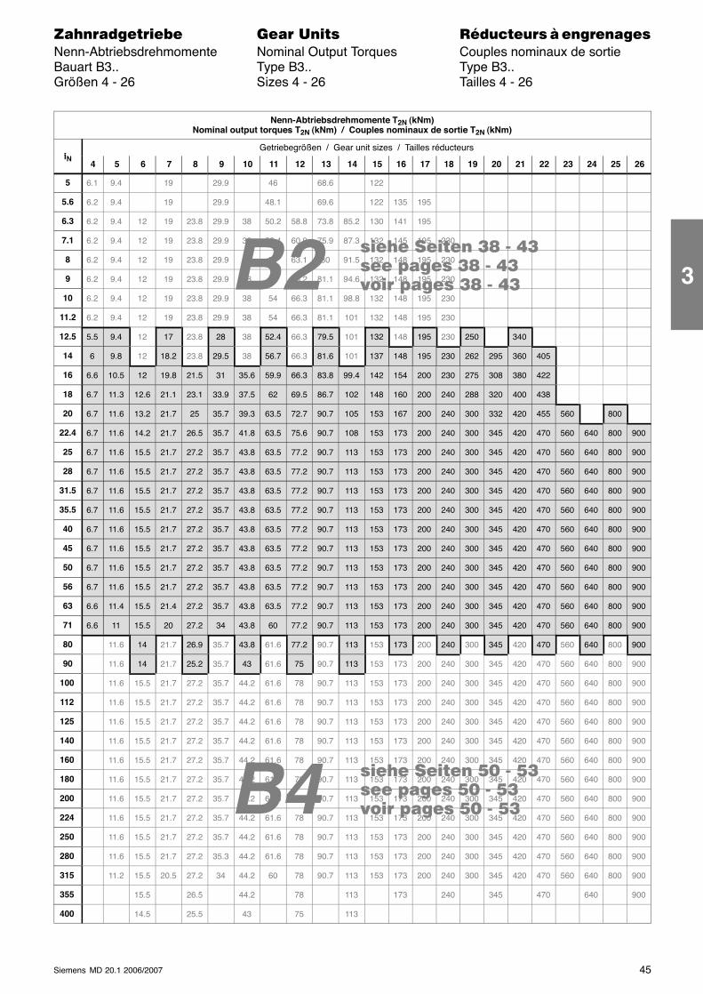
B4 ���� ���� !" - !���� ����� !" - !���� ����� !" - !�
���� ���� �� - ����� ����� �� - ����� ����� �� - ��B2
45Siemens MD 20.1 2006/2007
������������� ���� �� ��������� � ����������Nenn-Abtriebsdrehmomente Nominal Output Torques Couples nominaux de sortieBauart B3.. Type B3.. Type B3..Größen 4 - 26 Sizes 4 - 26 Tailles 4 - 26
Nenn-Abtriebsdrehmomente T2N (kNm)Nominal output torques T2N (kNm) / Couples nominaux de sortie T2N (kNm)
iGetriebegrößen / Gear unit sizes / Tailles réducteurs
iN4 5 6 7 8 9 10 11 12 13 14 15 16 17 18 19 20 21 22 23 24 25 26
5 6.1 9.4 19 29.9 46 68.6 122
5.6 6.2 9.4 19 29.9 48.1 69.6 122 135 195
6.3 6.2 9.4 12 19 23.8 29.9 38 50.2 58.8 73.8 85.2 130 141 195
7.1 6.2 9.4 12 19 23.8 29.9 38 52.4 60.9 75.9 87.3 132 145 195 230
8 6.2 9.4 12 19 23.8 29.9 38 54 63.1 80 91.5 132 148 195 230
9 6.2 9.4 12 19 23.8 29.9 38 54 65.2 81.1 94.6 132 148 195 230
10 6.2 9.4 12 19 23.8 29.9 38 54 66.3 81.1 98.8 132 148 195 230
11.2 6.2 9.4 12 19 23.8 29.9 38 54 66.3 81.1 101 132 148 195 230
12.5 5.5 9.4 12 17 23.8 28 38 52.4 66.3 79.5 101 132 148 195 230 250 340
14 6 9.8 12 18.2 23.8 29.5 38 56.7 66.3 81.6 101 137 148 195 230 262 295 360 405
16 6.6 10.5 12 19.8 21.5 31 35.6 59.9 66.3 83.8 99.4 142 154 200 230 275 308 380 422
18 6.7 11.3 12.6 21.1 23.1 33.9 37.5 62 69.5 86.7 102 148 160 200 240 288 320 400 438
20 6.7 11.6 13.2 21.7 25 35.7 39.3 63.5 72.7 90.7 105 153 167 200 240 300 332 420 455 560 800
22.4 6.7 11.6 14.2 21.7 26.5 35.7 41.8 63.5 75.6 90.7 108 153 173 200 240 300 345 420 470 560 640 800 900
25 6.7 11.6 15.5 21.7 27.2 35.7 43.8 63.5 77.2 90.7 113 153 173 200 240 300 345 420 470 560 640 800 900
28 6.7 11.6 15.5 21.7 27.2 35.7 43.8 63.5 77.2 90.7 113 153 173 200 240 300 345 420 470 560 640 800 900
31.5 6.7 11.6 15.5 21.7 27.2 35.7 43.8 63.5 77.2 90.7 113 153 173 200 240 300 345 420 470 560 640 800 900
35.5 6.7 11.6 15.5 21.7 27.2 35.7 43.8 63.5 77.2 90.7 113 153 173 200 240 300 345 420 470 560 640 800 900
40 6.7 11.6 15.5 21.7 27.2 35.7 43.8 63.5 77.2 90.7 113 153 173 200 240 300 345 420 470 560 640 800 900
45 6.7 11.6 15.5 21.7 27.2 35.7 43.8 63.5 77.2 90.7 113 153 173 200 240 300 345 420 470 560 640 800 900
50 6.7 11.6 15.5 21.7 27.2 35.7 43.8 63.5 77.2 90.7 113 153 173 200 240 300 345 420 470 560 640 800 900
56 6.7 11.6 15.5 21.7 27.2 35.7 43.8 63.5 77.2 90.7 113 153 173 200 240 300 345 420 470 560 640 800 900
63 6.6 11.4 15.5 21.4 27.2 35.7 43.8 63.5 77.2 90.7 113 153 173 200 240 300 345 420 470 560 640 800 900
71 6.6 11 15.5 20 27.2 34 43.8 60 77.2 90.7 113 153 173 200 240 300 345 420 470 560 640 800 900
80 11.6 14 21.7 26.9 35.7 43.8 61.6 77.2 90.7 113 153 173 200 240 300 345 420 470 560 640 800 900
90 11.6 14 21.7 25.2 35.7 43 61.6 75 90.7 113 153 173 200 240 300 345 420 470 560 640 800 900
100 11.6 15.5 21.7 27.2 35.7 44.2 61.6 78 90.7 113 153 173 200 240 300 345 420 470 560 640 800 900
112 11.6 15.5 21.7 27.2 35.7 44.2 61.6 78 90.7 113 153 173 200 240 300 345 420 470 560 640 800 900
125 11.6 15.5 21.7 27.2 35.7 44.2 61.6 78 90.7 113 153 173 200 240 300 345 420 470 560 640 800 900
140 11.6 15.5 21.7 27.2 35.7 44.2 61.6 78 90.7 113 153 173 200 240 300 345 420 470 560 640 800 900
160 11.6 15.5 21.7 27.2 35.7 44.2 61.6 78 90.7 113 153 173 200 240 300 345 420 470 560 640 800 900
180 11.6 15.5 21.7 27.2 35.7 44.2 61.6 78 90.7 113 153 173 200 240 300 345 420 470 560 640 800 900
200 11.6 15.5 21.7 27.2 35.7 44.2 61.6 78 90.7 113 153 173 200 240 300 345 420 470 560 640 800 900
224 11.6 15.5 21.7 27.2 35.7 44.2 61.6 78 90.7 113 153 173 200 240 300 345 420 470 560 640 800 900
250 11.6 15.5 21.7 27.2 35.7 44.2 61.6 78 90.7 113 153 173 200 240 300 345 420 470 560 640 800 900
280 11.6 15.5 21.7 27.2 35.3 44.2 61.6 78 90.7 113 153 173 200 240 300 345 420 470 560 640 800 900
315 11.2 15.5 20.5 27.2 34 44.2 60 78 90.7 113 153 173 200 240 300 345 420 470 560 640 800 900
355 15.5 26.5 44.2 78 113 173 240 345 470 640 900
400 14.5 25.5 43 75 113
3
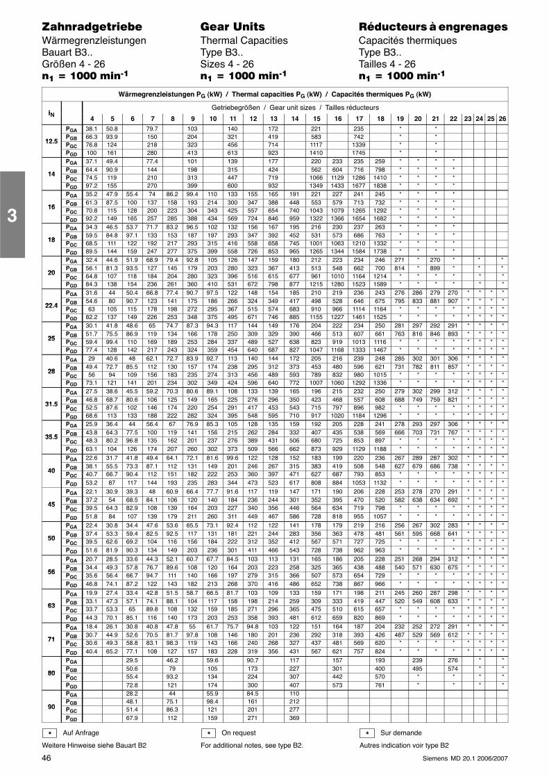
46 Siemens MD 20.1 2006/2007
������������� ���� �� ��������� � ����������Wärmegrenzleistungen Thermal Capacities Capacités thermiquesBauart B3.. Type B3.. Type B3..Größen 4 - 26 Sizes 4 - 26 Tailles 4 - 26�� � ���� ����� �� � ���� ����� �� � ���� �����
Wärmegrenzleistungen PG (kW) / Thermal capacities PG (kW) / Capacités thermiques PG (kW)
iNGetriebegrößen / Gear unit sizes / Tailles réducteurs
iN 4 5 6 7 8 9 10 11 12 13 14 15 16 17 18 19 20 21 22 23 24 25 26PGA 38.1 50.8 79.7 103 140 172 221 235 * *
12 5PGB 66.3 93.9 150 204 321 419 583 742 * *
12.5 PGC 76.8 124 218 323 456 714 1117 1339 * *PGD 100 161 280 413 613 923 1410 1745 * *PGA 37.1 49.4 77.4 101 139 177 220 233 235 259 * * * *
14PGB 64.4 90.9 144 198 315 424 562 604 716 798 * * * *
14 PGC 74.5 119 210 313 447 719 1066 1129 1286 1410 * * * *PGD 97.2 155 270 399 600 932 1349 1433 1677 1838 * * * *PGA 35.2 47.9 55.4 74 86.2 99.4 110 133 155 165 191 221 227 241 245 * * * *
16PGB 61.3 87.5 100 137 158 193 214 300 347 388 448 553 579 713 732 * * * *
16 PGC 70.8 115 128 200 223 304 343 425 557 654 740 1043 1079 1265 1292 * * * *PGD 92.2 149 165 257 285 388 434 569 724 846 959 1322 1366 1654 1682 * * * *PGA 34.3 46.5 53.7 71.7 83.2 96.5 102 132 156 167 195 216 230 237 263 * * * *
18PGB 59.5 84.8 97.1 133 153 187 197 293 347 392 452 531 573 686 763 * * * *
18 PGC 68.5 111 122 192 217 293 315 416 558 658 745 1001 1063 1210 1332 * * * *PGD 89.5 144 159 247 277 375 399 558 726 853 965 1265 1344 1584 1738 * * * *PGA 32.4 44.6 51.9 68.9 79.4 92.8 105 126 147 159 180 212 223 234 246 271 * 270 * * *
20PGB 56.1 81.3 93.5 127 145 179 203 280 323 367 413 513 548 662 700 814 * 899 * * *
20 PGC 64.8 107 118 184 204 280 323 396 516 615 677 961 1010 1164 1214 * * * * * *PGD 84.3 138 154 236 261 360 410 531 672 798 877 1215 1280 1523 1589 * * * * * *PGA 31.6 44 50.4 66.8 77.4 90.7 97.5 122 148 154 185 210 219 236 243 276 286 279 270 * * * *
22 4PGB 54.6 80 90.7 123 141 175 186 266 324 349 417 498 528 646 675 795 833 881 907 * * * *
22.4 PGC 63 105 115 178 198 272 295 367 515 574 683 910 966 1114 1164 * * * * * * * *PGD 82.2 137 149 226 253 348 375 495 671 746 885 1155 1227 1461 1525 * * * * * * * *PGA 30.1 41.8 48.6 65 74.7 87.3 94.3 117 144 149 176 204 222 234 250 281 297 292 291 * * * *
25PGB 51.7 75.5 86.9 119 134 166 178 250 309 329 390 466 513 607 661 763 816 846 893 * * * *
25 PGC 59.4 99.4 110 169 189 253 284 337 489 527 638 823 919 1013 1116 * * * * * * * *PGD 77.4 128 142 217 243 324 359 454 640 687 827 1047 1168 1333 1467 * * * * * * * *PGA 29 40.6 48 62.1 72.7 83.9 92.7 113 140 144 172 205 216 239 248 285 302 301 306 * * * *
28PGB 49.4 72.7 85.5 112 130 157 174 238 295 312 373 453 480 596 621 731 782 811 857 * * * *
28 PGC 56 94 109 156 183 235 274 313 456 489 593 789 832 980 1015 * * * * * * * *PGD 73.1 121 141 201 234 302 349 424 596 640 772 1007 1060 1292 1336 * * * * * * * *PGA 27.5 38.6 45.5 59.2 70.3 80.6 89.1 108 133 139 165 196 215 232 250 279 302 299 312 * * * *
31 5PGB 46.8 68.7 80.6 106 125 149 165 225 276 296 350 423 468 557 608 688 749 759 821 * * * *
31.5 PGC 52.5 87.6 102 146 174 220 254 291 417 453 543 715 797 896 982 * * * * * * * *PGD 68.6 113 133 188 222 282 324 395 548 595 710 917 1020 1184 1296 * * * * * * * *PGA 25.9 36.4 44 56.4 67 76.9 85.3 105 128 135 159 192 205 228 241 278 293 297 306 * * * *
35 5PGB 43.8 64.3 77.5 100 119 141 156 215 262 284 332 407 435 538 569 666 703 731 767 * * * *
35.5 PGC 48.3 80.2 96.8 135 162 201 237 276 389 431 506 680 725 853 897 * * * * * * * *PGD 63.1 104 126 174 207 260 302 373 509 566 662 873 929 1129 1188 * * * * * * * *PGA 22.6 31.7 41.8 49.4 64.1 72.1 81.6 99.6 122 128 152 183 199 220 236 267 289 287 302 * * * *
40PGB 38.1 55.5 73.3 87.1 112 131 149 201 246 267 315 383 419 508 548 627 679 686 738 * * * *
40 PGC 40.7 66.7 90.4 112 151 182 222 253 360 397 471 627 687 793 853 * * * * * * * *PGD 53.2 87 117 144 193 235 283 344 473 523 617 808 884 1053 1132 * * * * * * * *PGA 22.1 30.9 39.3 48 60.9 66.4 77.7 91.6 117 119 147 171 190 206 228 253 278 270 291 * * * *
45PGB 37.2 54 68.5 84.1 106 120 140 184 236 244 301 352 395 470 520 582 638 634 692 * * * *
45 PGC 39.5 64.3 82.9 108 139 164 203 227 340 356 446 564 634 719 798 * * * * * * * *PGD 51.8 84 107 139 179 211 260 311 449 467 586 728 818 955 1057 * * * * * * * *PGA 22.4 30.8 34.4 47.6 53.6 65.5 73.1 92.4 112 122 141 178 179 219 216 256 267 302 283 * * * *
50PGB 37.4 53.3 59.4 82.5 92.5 117 131 181 221 244 283 356 363 478 481 561 595 668 641 * * * *
50 PGC 39.5 62.6 69.2 104 116 156 184 222 312 352 412 567 571 727 725 * * * * * * * *PGD 51.6 81.9 90.3 134 149 203 236 301 411 466 543 728 738 962 963 * * * * * * * *PGA 20.7 28.5 33.6 44.3 52.1 60.7 67.7 84.5 103 113 131 165 186 205 228 251 268 294 312 * * * *
56PGB 34.4 49.3 57.8 76.7 89.6 108 120 164 203 223 258 325 365 438 488 540 571 630 675 * * * *
56 PGC 35.6 56.4 66.7 94.7 111 140 166 197 279 315 366 507 573 654 729 * * * * * * * *PGD 46.8 74.1 87.2 122 143 182 213 268 370 416 486 652 738 867 966 * * * * * * * *PGA 19.9 27.4 33.4 42.8 51.5 58.7 66.5 81.7 103 109 133 159 171 198 211 245 260 287 298 * * * *
63PGB 33.1 47.3 57.1 74.1 88.1 104 117 158 198 214 259 309 333 419 447 520 549 608 633 * * * *
63 PGC 33.7 53.3 65 89.8 108 132 159 185 271 296 365 475 510 615 657 * * * * * * * *PGD 44.3 70.1 85.1 116 140 173 203 253 358 393 481 612 659 820 869 * * * * * * * *PGA 18.4 26.1 30.8 40.8 47.8 55 61.7 75.7 94.8 103 122 151 164 187 204 232 252 272 291 * * * *
71PGB 30.7 44.9 52.6 70.5 81.7 97.8 108 146 180 201 236 292 318 393 426 487 529 569 612 * * * *
71 PGC 30.6 49.3 58.8 83.1 98.3 119 143 166 240 268 327 437 481 569 620 * * * * * * * *PGD 40.4 65.2 77.1 108 127 157 183 228 319 356 431 567 621 757 824 * * * * * * * *PGA 29.5 46.2 59.6 90.7 117 157 193 239 276 * *
80PGB 50.6 79 105 173 227 301 400 495 574 * *
80 PGC 55.4 93.2 134 224 307 442 570 * * * *PGD 72.8 121 174 300 407 573 761 * * * *PGA 28.2 44 55.9 84.5 110
90PGB 48.1 75.1 98.4 161 212
90 PGC 51.4 86.3 121 201 277PGD 67.9 112 159 271 369
Auf Anfrage
Weitere Hinweise siehe Bauart B2
On request
For additional notes, see type B2.
Sur demande
Autres indication voir type B2* * *
3
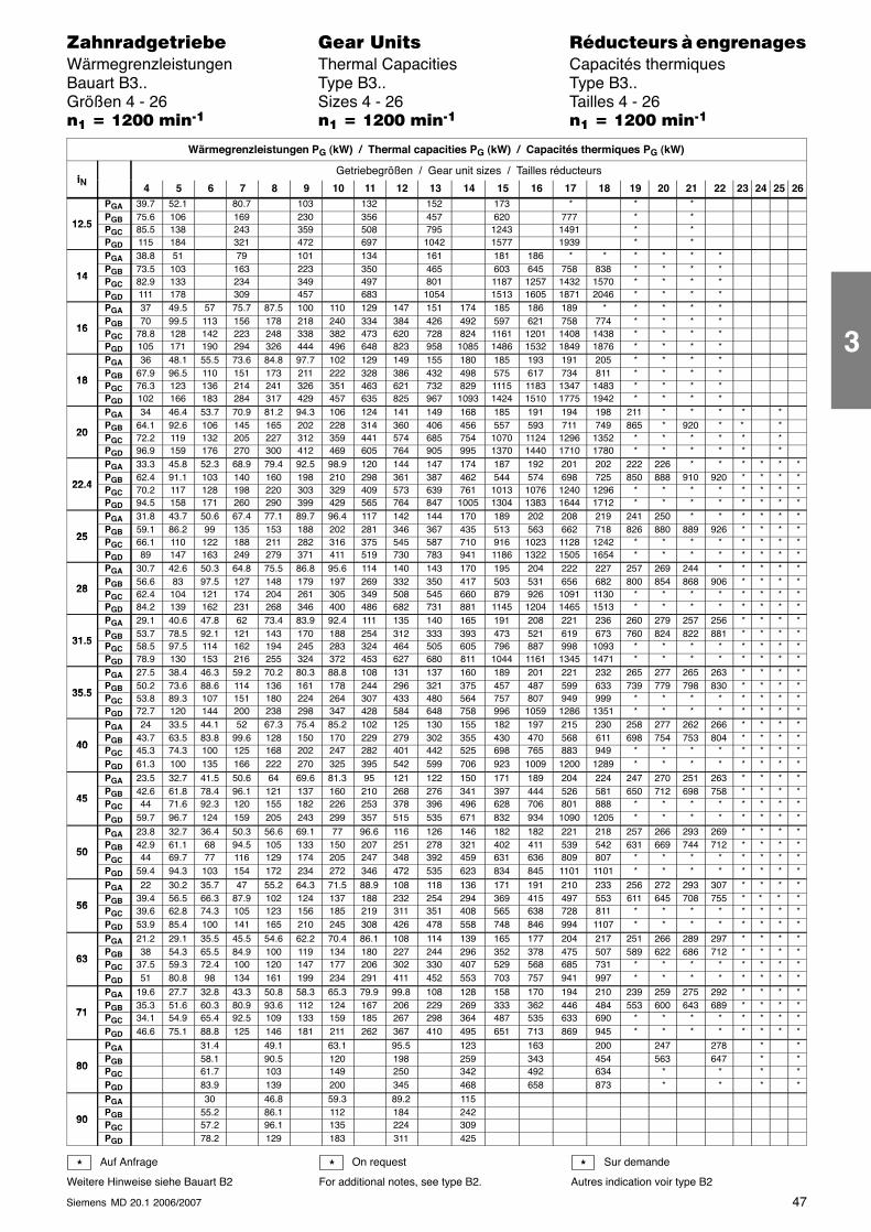
47Siemens MD 20.1 2006/2007
������������� ���� �� ��������� � ����������Wärmegrenzleistungen Thermal Capacities Capacités thermiquesBauart B3.. Type B3.. Type B3..Größen 4 - 26 Sizes 4 - 26 Tailles 4 - 26�� � ���� ����� �� � ���� ����� �� � ���� �����
Wärmegrenzleistungen PG (kW) / Thermal capacities PG (kW) / Capacités thermiques PG (kW)
iNGetriebegrößen / Gear unit sizes / Tailles réducteurs
iN 4 5 6 7 8 9 10 11 12 13 14 15 16 17 18 19 20 21 22 23 24 25 26PGA 39.7 52.1 80.7 103 132 152 173 * * *
12 5PGB 75.6 106 169 230 356 457 620 777 * *
12.5 PGC 85.5 138 243 359 508 795 1243 1491 * *PGD 115 184 321 472 697 1042 1577 1939 * *PGA 38.8 51 79 101 134 161 181 186 * * * * * *
14PGB 73.5 103 163 223 350 465 603 645 758 838 * * * *
14 PGC 82.9 133 234 349 497 801 1187 1257 1432 1570 * * * *PGD 111 178 309 457 683 1054 1513 1605 1871 2046 * * * *PGA 37 49.5 57 75.7 87.5 100 110 129 147 151 174 185 186 189 * * * * *
16PGB 70 99.5 113 156 178 218 240 334 384 426 492 597 621 758 774 * * * *
16 PGC 78.8 128 142 223 248 338 382 473 620 728 824 1161 1201 1408 1438 * * * *PGD 105 171 190 294 326 444 496 648 823 958 1085 1486 1532 1849 1876 * * * *PGA 36 48.1 55.5 73.6 84.8 97.7 102 129 149 155 180 185 193 191 205 * * * *
18PGB 67.9 96.5 110 151 173 211 222 328 386 432 498 575 617 734 811 * * * *
18 PGC 76.3 123 136 214 241 326 351 463 621 732 829 1115 1183 1347 1483 * * * *PGD 102 166 183 284 317 429 457 635 825 967 1093 1424 1510 1775 1942 * * * *PGA 34 46.4 53.7 70.9 81.2 94.3 106 124 141 149 168 185 191 194 198 211 * * * * *
20PGB 64.1 92.6 106 145 165 202 228 314 360 406 456 557 593 711 749 865 * 920 * * *
20 PGC 72.2 119 132 205 227 312 359 441 574 685 754 1070 1124 1296 1352 * * * * * *PGD 96.9 159 176 270 300 412 469 605 764 905 995 1370 1440 1710 1780 * * * * * *PGA 33.3 45.8 52.3 68.9 79.4 92.5 98.9 120 144 147 174 187 192 201 202 222 226 * * * * * *
22 4PGB 62.4 91.1 103 140 160 198 210 298 361 387 462 544 574 698 725 850 888 910 920 * * * *
22.4 PGC 70.2 117 128 198 220 303 329 409 573 639 761 1013 1076 1240 1296 * * * * * * * *PGD 94.5 158 171 260 290 399 429 565 764 847 1005 1304 1383 1644 1712 * * * * * * * *PGA 31.8 43.7 50.6 67.4 77.1 89.7 96.4 117 142 144 170 189 202 208 219 241 250 * * * * * *
25PGB 59.1 86.2 99 135 153 188 202 281 346 367 435 513 563 662 718 826 880 889 926 * * * *
25 PGC 66.1 110 122 188 211 282 316 375 545 587 710 916 1023 1128 1242 * * * * * * * *PGD 89 147 163 249 279 371 411 519 730 783 941 1186 1322 1505 1654 * * * * * * * *PGA 30.7 42.6 50.3 64.8 75.5 86.8 95.6 114 140 143 170 195 204 222 227 257 269 244 * * * * *
28PGB 56.6 83 97.5 127 148 179 197 269 332 350 417 503 531 656 682 800 854 868 906 * * * *
28 PGC 62.4 104 121 174 204 261 305 349 508 545 660 879 926 1091 1130 * * * * * * * *PGD 84.2 139 162 231 268 346 400 486 682 731 881 1145 1204 1465 1513 * * * * * * * *PGA 29.1 40.6 47.8 62 73.4 83.9 92.4 111 135 140 165 191 208 221 236 260 279 257 256 * * * *
31 5PGB 53.7 78.5 92.1 121 143 170 188 254 312 333 393 473 521 619 673 760 824 822 881 * * * *
31.5 PGC 58.5 97.5 114 162 194 245 283 324 464 505 605 796 887 998 1093 * * * * * * * *PGD 78.9 130 153 216 255 324 372 453 627 680 811 1044 1161 1345 1471 * * * * * * * *PGA 27.5 38.4 46.3 59.2 70.2 80.3 88.8 108 131 137 160 189 201 221 232 265 277 265 263 * * * *
35 5PGB 50.2 73.6 88.6 114 136 161 178 244 296 321 375 457 487 599 633 739 779 798 830 * * * *
35.5 PGC 53.8 89.3 107 151 180 224 264 307 433 480 564 757 807 949 999 * * * * * * * *PGD 72.7 120 144 200 238 298 347 428 584 648 758 996 1059 1286 1351 * * * * * * * *PGA 24 33.5 44.1 52 67.3 75.4 85.2 102 125 130 155 182 197 215 230 258 277 262 266 * * * *
40PGB 43.7 63.5 83.8 99.6 128 150 170 229 279 302 355 430 470 568 611 698 754 753 804 * * * *
40 PGC 45.3 74.3 100 125 168 202 247 282 401 442 525 698 765 883 949 * * * * * * * *PGD 61.3 100 135 166 222 270 325 395 542 599 706 923 1009 1200 1289 * * * * * * * *PGA 23.5 32.7 41.5 50.6 64 69.6 81.3 95 121 122 150 171 189 204 224 247 270 251 263 * * * *
45PGB 42.6 61.8 78.4 96.1 121 137 160 210 268 276 341 397 444 526 581 650 712 698 758 * * * *
45 PGC 44 71.6 92.3 120 155 182 226 253 378 396 496 628 706 801 888 * * * * * * * *PGD 59.7 96.7 124 159 205 243 299 357 515 535 671 832 934 1090 1205 * * * * * * * *PGA 23.8 32.7 36.4 50.3 56.6 69.1 77 96.6 116 126 146 182 182 221 218 257 266 293 269 * * * *
50PGB 42.9 61.1 68 94.5 105 133 150 207 251 278 321 402 411 539 542 631 669 744 712 * * * *
50 PGC 44 69.7 77 116 129 174 205 247 348 392 459 631 636 809 807 * * * * * * * *PGD 59.4 94.3 103 154 172 234 272 346 472 535 623 834 845 1101 1101 * * * * * * * *PGA 22 30.2 35.7 47 55.2 64.3 71.5 88.9 108 118 136 171 191 210 233 256 272 293 307 * * * *
56PGB 39.4 56.5 66.3 87.9 102 124 137 188 232 254 294 369 415 497 553 611 645 708 755 * * * *
56 PGC 39.6 62.8 74.3 105 123 156 185 219 311 351 408 565 638 728 811 * * * * * * * *PGD 53.9 85.4 100 141 165 210 245 308 426 478 558 748 846 994 1107 * * * * * * * *PGA 21.2 29.1 35.5 45.5 54.6 62.2 70.4 86.1 108 114 139 165 177 204 217 251 266 289 297 * * * *
63PGB 38 54.3 65.5 84.9 100 119 134 180 227 244 296 352 378 475 507 589 622 686 712 * * * *
63 PGC 37.5 59.3 72.4 100 120 147 177 206 302 330 407 529 568 685 731 * * * * * * * *PGD 51 80.8 98 134 161 199 234 291 411 452 553 703 757 941 997 * * * * * * * *PGA 19.6 27.7 32.8 43.3 50.8 58.3 65.3 79.9 99.8 108 128 158 170 194 210 239 259 275 292 * * * *
71PGB 35.3 51.6 60.3 80.9 93.6 112 124 167 206 229 269 333 362 446 484 553 600 643 689 * * * *
71 PGC 34.1 54.9 65.4 92.5 109 133 159 185 267 298 364 487 535 633 690 * * * * * * * *PGD 46.6 75.1 88.8 125 146 181 211 262 367 410 495 651 713 869 945 * * * * * * * *PGA 31.4 49.1 63.1 95.5 123 163 200 247 278 * *
80PGB 58.1 90.5 120 198 259 343 454 563 647 * *
80 PGC 61.7 103 149 250 342 492 634 * * * *PGD 83.9 139 200 345 468 658 873 * * * *PGA 30 46.8 59.3 89.2 115
90PGB 55.2 86.1 112 184 242
90 PGC 57.2 96.1 135 224 309PGD 78.2 129 183 311 425
Auf Anfrage
Weitere Hinweise siehe Bauart B2
On request
For additional notes, see type B2.
Sur demande
Autres indication voir type B2* * *
3
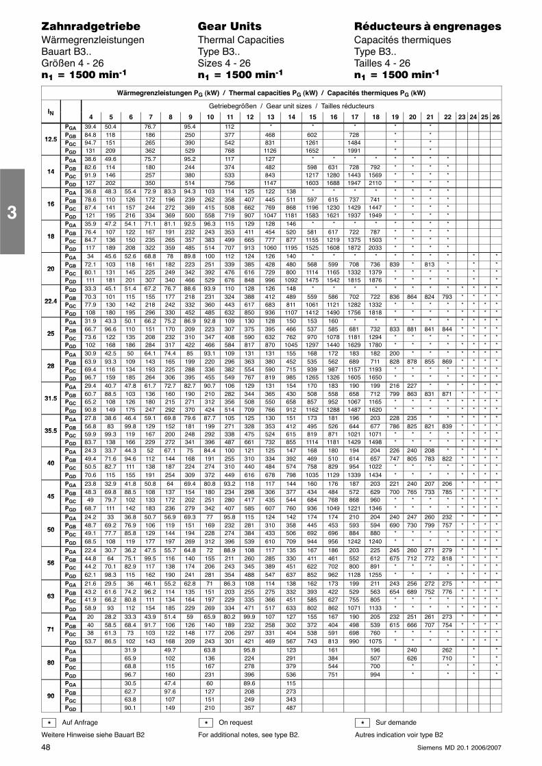
48 Siemens MD 20.1 2006/2007
������������� ���� �� ��������� � ����������Wärmegrenzleistungen Thermal Capacities Capacités thermiquesBauart B3.. Type B3.. Type B3..Größen 4 - 26 Sizes 4 - 26 Tailles 4 - 26�� � ���� ����� �� � ���� ����� �� � ���� �����
Wärmegrenzleistungen PG (kW) / Thermal capacities PG (kW) / Capacités thermiques PG (kW)
iNGetriebegrößen / Gear unit sizes / Tailles réducteurs
iN 4 5 6 7 8 9 10 11 12 13 14 15 16 17 18 19 20 21 22 23 24 25 26PGA 39.4 50.4 76.7 95.4 112 * * * * *
12 5PGB 84.8 118 186 250 377 468 602 728 * *
12.5 PGC 94.7 151 265 390 542 831 1261 1484 * *PGD 131 209 362 529 768 1126 1652 1991 * *PGA 38.6 49.6 75.7 95.2 117 127 * * * * * * * *
14PGB 82.6 114 180 244 374 482 598 631 728 792 * * * *
14 PGC 91.9 146 257 380 533 843 1217 1280 1443 1569 * * * *PGD 127 202 350 514 756 1147 1603 1688 1947 2110 * * * *PGA 36.8 48.3 55.4 72.9 83.3 94.3 103 114 125 122 138 * * * * * * * *
16PGB 78.6 110 126 172 196 239 262 358 407 445 511 597 615 737 741 * * * *
16 PGC 87.4 141 157 244 272 369 415 508 662 769 868 1196 1230 1429 1447 * * * *PGD 121 195 216 334 369 500 558 719 907 1047 1181 1583 1621 1937 1949 * * * *PGA 35.9 47.2 54.1 71.1 81.1 92.5 96.3 115 129 128 146 * * * * * * * *
18PGB 76.4 107 122 167 191 232 243 353 411 454 520 581 617 722 787 * * * *
18 PGC 84.7 136 150 235 265 357 383 499 665 777 877 1155 1219 1375 1503 * * * *PGD 117 189 208 322 359 485 514 707 913 1060 1195 1525 1608 1872 2033 * * * *PGA 34 45.6 52.6 68.8 78 89.8 100 112 124 126 140 * * * * * * * * * *
20PGB 72.1 103 118 161 182 223 251 339 385 428 480 568 599 708 736 839 * 813 * * *
20 PGC 80.1 131 145 225 249 342 392 476 616 729 800 1114 1165 1332 1379 * * * * * *PGD 111 181 201 307 340 466 529 676 848 996 1092 1475 1542 1815 1876 * * * * * *PGD 33.3 45.1 51.4 67.2 76.7 88.6 93.9 110 128 126 148 * * * * * * * * * * * *
22 4PGB 70.3 101 115 155 177 218 231 324 388 412 489 559 586 702 722 836 864 824 793 * * * *
22.4 PGC 77.9 130 142 218 242 332 360 443 617 683 811 1061 1121 1282 1332 * * * * * * * *PGD 108 180 195 296 330 452 485 632 850 936 1107 1412 1490 1756 1818 * * * * * * * *PGA 31.9 43.3 50.1 66.2 75.2 86.9 92.8 109 130 128 150 153 160 * * * * * * * * * *
25PGB 66.7 96.6 110 151 170 209 223 307 375 395 466 537 585 681 732 833 881 841 844 * * * *
25 PGC 73.6 122 135 208 232 310 347 408 590 632 762 970 1078 1181 1294 * * * * * * * *PGD 102 168 186 284 317 422 466 584 817 870 1045 1297 1440 1629 1780 * * * * * * * *PGA 30.9 42.5 50 64.1 74.4 85 93.1 109 131 131 155 168 172 183 182 200 * * * * * * *
28PGB 63.9 93.3 109 143 165 199 220 296 363 380 452 535 562 689 711 828 878 855 869 * * * *
28 PGC 69.4 116 134 193 225 288 336 382 554 590 715 939 987 1157 1193 * * * * * * * *PGD 96.7 159 185 264 306 395 455 549 767 819 985 1265 1326 1605 1650 * * * * * * * *PGA 29.4 40.7 47.8 61.7 72.7 82.7 90.7 106 129 131 154 170 183 190 199 216 227 * * * * * *
31 5PGB 60.7 88.5 103 136 160 190 210 282 344 365 430 508 558 658 712 799 863 831 871 * * * *
31.5 PGC 65.2 108 126 180 215 271 312 356 508 550 658 857 952 1067 1165 * * * * * * * *PGD 90.8 149 175 247 292 370 424 514 709 766 912 1162 1288 1487 1620 * * * * * * * *PGA 27.8 38.6 46.4 59.1 69.8 79.6 87.7 105 125 130 151 173 181 196 203 228 235 * * * * * *
35 5PGB 56.8 83 99.8 129 152 181 199 271 328 353 412 495 526 644 677 786 825 821 839 * * * *
35.5 PGC 59.9 99.3 119 167 200 248 292 338 475 524 615 819 871 1021 1071 * * * * * * * *PGD 83.7 138 166 229 272 341 396 487 661 732 855 1114 1181 1429 1498 * * * * * * * *PGA 24.3 33.7 44.3 52 67.1 75 84.4 100 121 125 147 168 180 194 204 226 240 208 * * * * *
40PGB 49.4 71.6 94.6 112 144 168 191 255 310 334 392 469 510 614 657 747 805 783 822 * * * *
40 PGC 50.5 82.7 111 138 187 224 274 310 440 484 574 758 829 954 1022 * * * * * * * *PGD 70.6 115 155 191 254 309 372 449 616 678 798 1035 1129 1339 1434 * * * * * * * *PGA 23.8 32.9 41.8 50.8 64 69.4 80.8 93.2 118 117 144 160 176 187 203 221 240 207 206 * * * *
45PGB 48.3 69.8 88.5 108 137 154 180 234 298 306 377 434 484 572 629 700 765 733 785 * * * *
45 PGC 49 79.7 102 133 172 202 251 280 417 435 544 684 768 868 960 * * * * * * * *PGD 68.7 111 142 183 236 279 342 407 585 607 760 936 1049 1221 1346 * * * * * * * *PGA 24.2 33 36.8 50.7 56.9 69.3 77 95.8 115 124 142 174 174 210 204 240 247 260 232 * * * *
50PGB 48.7 69.2 76.9 106 119 151 169 232 281 310 358 445 453 593 594 690 730 799 757 * * * *
50 PGC 49.1 77.7 85.8 129 144 194 228 274 384 433 506 692 696 884 880 * * * * * * * *PGD 68.5 108 119 177 197 269 312 396 539 610 709 944 956 1242 1240 * * * * * * * *PGA 22.4 30.7 36.2 47.5 55.7 64.8 72 88.9 108 117 135 167 186 203 225 245 260 271 279 * * * *
56PGB 44.8 64 75.1 99.5 116 140 155 211 260 285 330 411 461 552 612 675 712 772 818 * * * *
56 PGC 44.2 70.1 82.9 117 138 174 206 243 345 389 451 622 702 800 891 * * * * * * * *PGD 62.1 98.3 115 162 190 241 281 354 488 547 637 852 962 1128 1255 * * * * * * * *PGA 21.6 29.5 36 46.1 55.2 62.8 71 86.3 108 114 138 162 173 199 211 243 256 272 275 * * * *
63PGB 43.2 61.6 74.2 96.2 114 135 151 203 255 275 332 393 422 529 563 654 689 752 776 * * * *
63 PGC 41.9 66.2 80.8 111 134 164 197 229 335 366 451 585 627 755 805 * * * * * * * *PGD 58.9 93 112 154 185 229 269 334 471 517 633 802 862 1071 1133 * * * * * * * *PGA 20 28.2 33.3 43.9 51.4 59 65.9 80.2 99.9 107 127 155 167 190 205 232 251 261 273 * * * *
71PGB 40 58.5 68.4 91.7 106 126 140 189 232 258 302 372 404 498 539 615 666 707 754 * * * *
71 PGC 38 61.3 73 103 122 148 177 206 297 331 404 538 591 698 760 * * * * * * * *PGD 53.7 86.5 102 143 168 209 243 301 421 469 567 743 813 990 1075 * * * * * * * *PGA 31.9 49.7 63.8 95.8 123 161 196 240 262 * *
80PGB 65.9 102 136 224 291 384 507 626 710 * *
80 PGC 68.8 115 167 278 379 544 700 * * * *PGD 96.7 160 231 396 536 751 994 * * * *PGA 30.5 47.4 60 89.6 115
90PGB 62.7 97.6 127 208 273
90 PGC 63.8 107 151 249 343PGD 90.1 149 210 357 487
Auf Anfrage
Weitere Hinweise siehe Bauart B2
On request
For additional notes, see type B2.
Sur demande
Autres indication voir type B2* * *
3
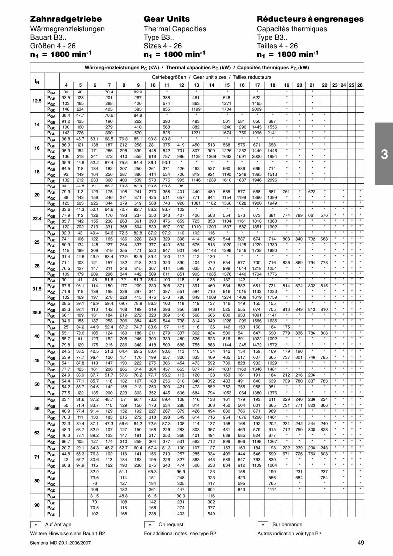
49Siemens MD 20.1 2006/2007
������������� ���� �� ��������� � ����������Wärmegrenzleistungen Thermal Capacities Capacités thermiquesBauart B3.. Type B3.. Type B3..Größen 4 - 26 Sizes 4 - 26 Tailles 4 - 26�� � �!�� ����� �� � �!�� ����� �� � �!�� �����
Wärmegrenzleistungen PG (kW) / Thermal capacities PG (kW) / Capacités thermiques PG (kW)
iNGetriebegrößen / Gear unit sizes / Tailles réducteurs
iN 4 5 6 7 8 9 10 11 12 13 14 15 16 17 18 19 20 21 22 23 24 25 26PGA 39 48 70.4 82.9 * * * * * *
12 5PGB 93.5 128 201 267 388 461 548 622 * *
12.5 PGC 103 165 288 420 574 863 1271 1465 * *PGD 148 234 403 585 835 1199 1704 2009 * *PGA 38.4 47.7 70.6 84.9 * * * * * * * * * *
14PGB 91.2 125 196 262 390 483 561 581 650 687 * * * *
14 PGC 100 160 279 410 568 882 1240 1296 1445 1556 * * * *PGD 143 226 390 570 826 1231 1674 1750 1996 2141 * * * *PGA 36.8 46.7 53.1 68.5 76.8 85.1 90.8 89.8 * * * * * * * * * * *
16PGB 86.9 121 138 187 212 258 281 375 419 450 513 568 575 671 658 * * * *
16 PGC 95.9 154 171 266 295 399 448 542 701 807 909 1226 1252 1440 1446 * * * *PGD 136 218 241 372 410 555 618 787 986 1128 1268 1662 1691 2000 1994 * * * *PGA 35.9 45.9 52.2 67.4 75.5 84.4 86.1 93.1 * * * * * * * * * * *
18PGB 84.5 118 134 182 207 250 261 371 426 462 527 560 586 669 714 * * * *
18 PGC 93 149 164 256 287 386 414 534 706 819 921 1190 1248 1395 1513 * * * *PGD 132 212 233 360 400 539 570 776 995 1146 1289 1610 1687 1946 2096 * * * *PGA 34.1 44.5 51 65.7 73.3 82.9 90.8 93.3 96 * * * * * * * * * * * *
20PGB 79.9 113 129 175 198 241 270 358 401 440 489 555 577 668 681 761 * 622 * * *
20 PGC 88 143 159 246 271 371 425 511 657 771 844 1154 1199 1360 1399 * * * * * *PGD 125 203 225 344 379 519 588 743 926 1081 1182 1566 1628 1900 1949 * * * * * *PGA 33.6 44.3 50.1 64.6 72.7 82.7 86.2 93.7 102 * * * * * * * * * * * * * *
22 4PGB 77.9 112 126 170 193 237 250 343 407 426 503 554 573 673 681 774 789 661 576 * * * *
22.4 PGC 85.7 142 155 238 263 361 390 476 659 725 858 1104 1161 1318 1360 * * * * * * * *PGD 122 202 219 331 368 504 539 697 932 1019 1203 1507 1582 1851 1902 * * * * * * * *PGA 32.3 43 49.4 64.6 72.5 82.8 87.2 97.2 110 102 116 * * * * * * * * * * * *
25PGB 74.1 106 122 165 186 228 243 329 398 414 486 544 587 674 714 803 840 732 688 * * * *
25 PGC 80.9 134 148 227 254 337 377 440 634 675 813 1020 1128 1229 1339 * * * * * * * *PGD 115 189 209 319 355 471 520 647 901 954 1143 1399 1546 1738 1890 * * * * * * * *PGA 31.4 42.6 49.9 63.4 72.9 82.5 89.4 100 117 112 130 * * * * * * * * * * * *
28PGB 71.1 103 121 157 182 218 240 320 390 404 479 554 577 700 716 826 869 794 773 * * * *
28 PGC 76.5 127 147 211 246 315 367 414 598 635 767 998 1044 1218 1251 * * * * * * * *PGD 109 179 209 296 344 442 509 611 851 903 1085 1378 1440 1734 1776 * * * * * * * *PGA 30.1 41 48 61.6 72 81.3 88.4 100 118 116 135 137 142 * * * * * * * * * *
31 5PGB 67.6 98.1 114 150 177 209 230 306 371 391 460 534 582 681 731 814 874 802 815 * * * *
31.5 PGC 71.8 119 139 198 236 297 341 387 551 594 710 916 1015 1133 1233 * * * * * * * *PGD 102 169 197 278 328 415 476 573 788 849 1009 1274 1409 1619 1759 * * * * * * * *PGA 28.5 39.1 46.9 59.4 69.7 78.9 86.3 100 118 119 137 146 149 155 155 * * * * * * * *
35 5PGB 63.3 92.1 110 142 168 199 219 296 356 381 443 525 555 674 705 813 849 813 810 * * * *
35.5 PGC 66.1 109 131 184 219 272 320 369 516 568 666 880 933 1091 1141 * * * * * * * *PGD 94.6 155 187 258 306 384 445 544 738 814 949 1228 1299 1566 1636 * * * * * * * *PGA 25 34.2 44.9 52.4 67.2 74.7 83.6 97 115 116 136 146 153 160 164 175 * * * * * * *
40PGB 55.1 79.6 105 124 160 186 211 279 337 362 424 500 541 647 690 779 836 786 808 * * * *
40 PGC 55.7 91 123 152 205 246 300 339 480 526 623 816 891 1022 1092 * * * * * * * *PGD 79.8 129 175 215 286 348 418 503 688 755 888 1144 1245 1472 1572 * * * * * * * *PGA 24.5 33.5 42.5 51.3 64.4 69.5 80.4 90.8 113 110 134 142 154 159 169 179 190 * * * * * *
45PGB 53.9 77.7 98.4 120 151 170 199 257 326 333 409 465 517 607 665 737 801 746 785 * * * *
45 PGC 54.1 87.8 113 147 190 222 275 306 454 473 592 739 828 933 1029 * * * * * * * *PGD 77.7 125 161 206 265 314 384 457 655 677 847 1037 1160 1346 1481 * * * * * * * *PGA 24.9 33.9 37.7 51.7 57.8 70.2 77.7 95.2 113 120 138 163 161 191 184 212 216 206 * * * * *
50PGB 54.4 77.1 85.7 118 132 167 188 256 310 340 392 483 491 640 639 739 780 837 783 * * * *
50 PGC 54.2 85.7 94.6 142 158 213 250 300 421 473 552 752 755 958 951 * * * * * * * *PGD 77.5 122 135 200 223 303 352 445 606 684 794 1053 1064 1380 1376 * * * * * * * *PGA 23.1 31.6 37.2 48.7 57 66.1 73.2 89.4 108 116 133 161 179 193 211 229 240 236 234 * * * *
56PGB 50 71.4 83.7 110 129 156 173 234 288 314 363 450 504 601 665 731 771 823 866 * * * *
56 PGC 48.9 77.4 91.4 129 152 192 227 267 379 426 494 680 766 871 969 * * * * * * * *PGD 70.3 111 130 183 215 272 318 398 549 614 716 954 1076 1260 1401 * * * * * * * *PGA 22.3 30.4 37.1 47.3 56.6 64.2 72.5 87.3 108 114 137 158 168 192 202 231 242 244 240 * * * *
63PGB 48.3 68.7 82.9 107 127 150 168 226 283 303 367 431 463 579 615 712 750 808 828 * * * *
63 PGC 46.3 73.1 89.2 123 147 181 217 252 368 401 494 639 685 824 877 * * * * * * * *PGD 66.7 105 127 174 210 259 304 377 531 582 712 899 966 1198 1267 * * * * * * * *PGA 20.7 29.1 34.3 45.2 52.7 60.4 67.4 81.3 100 107 127 153 163 184 198 222 239 238 243 * * * *
71PGB 44.8 65.3 76.3 102 118 141 156 210 257 285 334 409 444 546 590 671 726 763 808 * * * *
71 PGC 42 67.7 80.6 113 134 163 195 226 327 363 443 589 647 763 830 * * * * * * * *PGD 60.8 97.9 115 162 190 236 275 340 474 528 638 834 912 1109 1204 * * * * * * * *PGA 32.9 51.1 65.3 96.9 123 158 190 231 237 * *
80PGB 73.6 114 151 248 323 423 556 684 764 * *
80 PGC 76 127 184 305 417 595 765 * * * *PGD 109 182 261 447 604 843 1114 * * * *PGA 31.5 48.8 61.5 90.9 116
90PGB 70 108 142 231 302
90 PGC 70.5 118 166 274 377PGD 102 168 238 403 549
Auf Anfrage
Weitere Hinweise siehe Bauart B2
On request
For additional notes, see type B2.
Sur demande
Autres indication voir type B2* * *
3
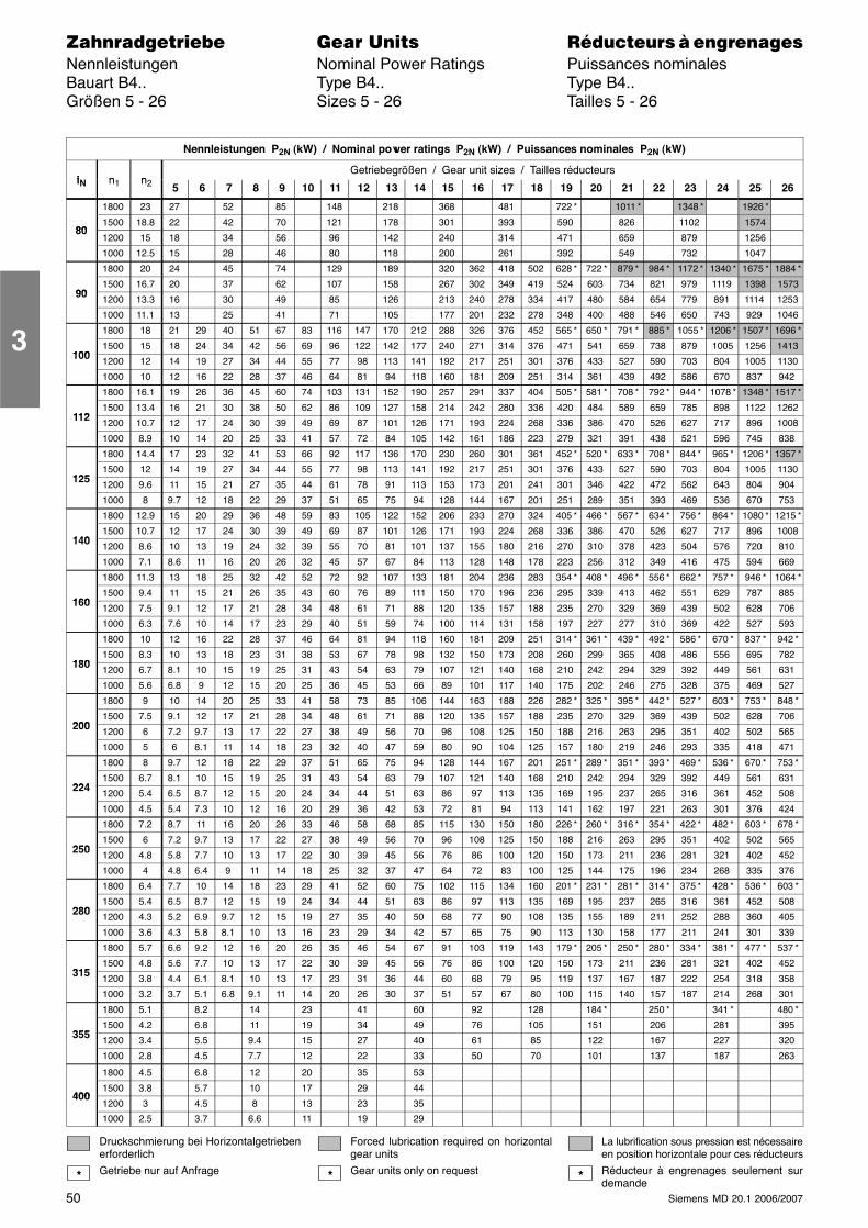
50 Siemens MD 20.1 2006/2007
������������� ���� �� ��������� � ����������Nennleistungen Nominal Power Ratings Puissances nominalesBauart B4.. Type B4.. Type B4..Größen 5 - 26 Sizes 5 - 26 Tailles 5 - 26
Nennleistungen P2N (kW) / Nominal power ratings P2N (kW) / Puissances nominales P2N (kW)
i n nGetriebegrößen / Gear unit sizes / Tailles réducteurs
iN n1 n2 5 6 7 8 9 10 11 12 13 14 15 16 17 18 19 20 21 22 23 24 25 26
1800 23 27 52 85 148 218 368 481 722 * 1011 * 1348 * 1926 *
801500 18.8 22 42 70 121 178 301 393 590 826 1102 1574
801200 15 18 34 56 96 142 240 314 471 659 879 1256
1000 12.5 15 28 46 80 118 200 261 392 549 732 1047
1800 20 24 45 74 129 189 320 362 418 502 628 * 722 * 879 * 984 * 1172 * 1340 * 1675 * 1884 *
901500 16.7 20 37 62 107 158 267 302 349 419 524 603 734 821 979 1119 1398 1573
90 1200 13.3 16 30 49 85 126 213 240 278 334 417 480 584 654 779 891 1114 1253
1000 11.1 13 25 41 71 105 177 201 232 278 348 400 488 546 650 743 929 1046
1800 18 21 29 40 51 67 83 116 147 170 212 288 326 376 452 565 * 650 * 791 * 885 * 1055 * 1206 * 1507 * 1696 *
1001500 15 18 24 34 42 56 69 96 122 142 177 240 271 314 376 471 541 659 738 879 1005 1256 1413
100 1200 12 14 19 27 34 44 55 77 98 113 141 192 217 251 301 376 433 527 590 703 804 1005 1130
1000 10 12 16 22 28 37 46 64 81 94 118 160 181 209 251 314 361 439 492 586 670 837 942
1800 16.1 19 26 36 45 60 74 103 131 152 190 257 291 337 404 505 * 581 * 708 * 792 * 944 * 1078 * 1348 * 1517 *
1121500 13.4 16 21 30 38 50 62 86 109 127 158 214 242 280 336 420 484 589 659 785 898 1122 1262
112 1200 10.7 12 17 24 30 39 49 69 87 101 126 171 193 224 268 336 386 470 526 627 717 896 1008
1000 8.9 10 14 20 25 33 41 57 72 84 105 142 161 186 223 279 321 391 438 521 596 745 838
1800 14.4 17 23 32 41 53 66 92 117 136 170 230 260 301 361 452 * 520 * 633 * 708 * 844 * 965 * 1206 * 1357 *
1251500 12 14 19 27 34 44 55 77 98 113 141 192 217 251 301 376 433 527 590 703 804 1005 1130
125 1200 9.6 11 15 21 27 35 44 61 78 91 113 153 173 201 241 301 346 422 472 562 643 804 904
1000 8 9.7 12 18 22 29 37 51 65 75 94 128 144 167 201 251 289 351 393 469 536 670 753
1800 12.9 15 20 29 36 48 59 83 105 122 152 206 233 270 324 405 * 466 * 567 * 634 * 756 * 864 * 1080 * 1215 *
1401500 10.7 12 17 24 30 39 49 69 87 101 126 171 193 224 268 336 386 470 526 627 717 896 1008
140 1200 8.6 10 13 19 24 32 39 55 70 81 101 137 155 180 216 270 310 378 423 504 576 720 810
1000 7.1 8.6 11 16 20 26 32 45 57 67 84 113 128 148 178 223 256 312 349 416 475 594 669
1800 11.3 13 18 25 32 42 52 72 92 107 133 181 204 236 283 354 * 408 * 496 * 556 * 662 * 757 * 946 * 1064 *
1601500 9.4 11 15 21 26 35 43 60 76 89 111 150 170 196 236 295 339 413 462 551 629 787 885
160 1200 7.5 9.1 12 17 21 28 34 48 61 71 88 120 135 157 188 235 270 329 369 439 502 628 706
1000 6.3 7.6 10 14 17 23 29 40 51 59 74 100 114 131 158 197 227 277 310 369 422 527 593
1800 10 12 16 22 28 37 46 64 81 94 118 160 181 209 251 314 * 361 * 439 * 492 * 586 * 670 * 837 * 942 *
1801500 8.3 10 13 18 23 31 38 53 67 78 98 132 150 173 208 260 299 365 408 486 556 695 782
180 1200 6.7 8.1 10 15 19 25 31 43 54 63 79 107 121 140 168 210 242 294 329 392 449 561 631
1000 5.6 6.8 9 12 15 20 25 36 45 53 66 89 101 117 140 175 202 246 275 328 375 469 527
1800 9 10 14 20 25 33 41 58 73 85 106 144 163 188 226 282 * 325 * 395 * 442 * 527 * 603 * 753 * 848 *
2001500 7.5 9.1 12 17 21 28 34 48 61 71 88 120 135 157 188 235 270 329 369 439 502 628 706
200 1200 6 7.2 9.7 13 17 22 27 38 49 56 70 96 108 125 150 188 216 263 295 351 402 502 565
1000 5 6 8.1 11 14 18 23 32 40 47 59 80 90 104 125 157 180 219 246 293 335 418 471
1800 8 9.7 12 18 22 29 37 51 65 75 94 128 144 167 201 251 * 289 * 351 * 393 * 469 * 536 * 670 * 753 *
2241500 6.7 8.1 10 15 19 25 31 43 54 63 79 107 121 140 168 210 242 294 329 392 449 561 631
224 1200 5.4 6.5 8.7 12 15 20 24 34 44 51 63 86 97 113 135 169 195 237 265 316 361 452 508
1000 4.5 5.4 7.3 10 12 16 20 29 36 42 53 72 81 94 113 141 162 197 221 263 301 376 424
1800 7.2 8.7 11 16 20 26 33 46 58 68 85 115 130 150 180 226 * 260 * 316 * 354 * 422 * 482 * 603 * 678 *
2501500 6 7.2 9.7 13 17 22 27 38 49 56 70 96 108 125 150 188 216 263 295 351 402 502 565
250 1200 4.8 5.8 7.7 10 13 17 22 30 39 45 56 76 86 100 120 150 173 211 236 281 321 402 452
1000 4 4.8 6.4 9 11 14 18 25 32 37 47 64 72 83 100 125 144 175 196 234 268 335 376
1800 6.4 7.7 10 14 18 23 29 41 52 60 75 102 115 134 160 201 * 231 * 281 * 314 * 375 * 428 * 536 * 603 *
2801500 5.4 6.5 8.7 12 15 19 24 34 44 51 63 86 97 113 135 169 195 237 265 316 361 452 508
280 1200 4.3 5.2 6.9 9.7 12 15 19 27 35 40 50 68 77 90 108 135 155 189 211 252 288 360 405
1000 3.6 4.3 5.8 8.1 10 13 16 23 29 34 42 57 65 75 90 113 130 158 177 211 241 301 339
1800 5.7 6.6 9.2 12 16 20 26 35 46 54 67 91 103 119 143 179 * 205 * 250 * 280 * 334 * 381 * 477 * 537 *
3151500 4.8 5.6 7.7 10 13 17 22 30 39 45 56 76 86 100 120 150 173 211 236 281 321 402 452
315 1200 3.8 4.4 6.1 8.1 10 13 17 23 31 36 44 60 68 79 95 119 137 167 187 222 254 318 358
1000 3.2 3.7 5.1 6.8 9.1 11 14 20 26 30 37 51 57 67 80 100 115 140 157 187 214 268 301
1800 5.1 8.2 14 23 41 60 92 128 184 * 250 * 341 * 480 *
3551500 4.2 6.8 11 19 34 49 76 105 151 206 281 395
355 1200 3.4 5.5 9.4 15 27 40 61 85 122 167 227 320
1000 2.8 4.5 7.7 12 22 33 50 70 101 137 187 263
1800 4.5 6.8 12 20 35 53
4001500 3.8 5.7 10 17 29 44
4001200 3 4.5 8 13 23 35
1000 2.5 3.7 6.6 11 19 29
Druckschmierung bei Horizontalgetriebenerforderlich
Getriebe nur auf Anfrage
Forced lubrication required on horizontalgear units
Gear units only on request
La lubrification sous pression est nécessaireen position horizontale pour ces réducteurs
Réducteur à engrenages seulement surdemande
* * *
3
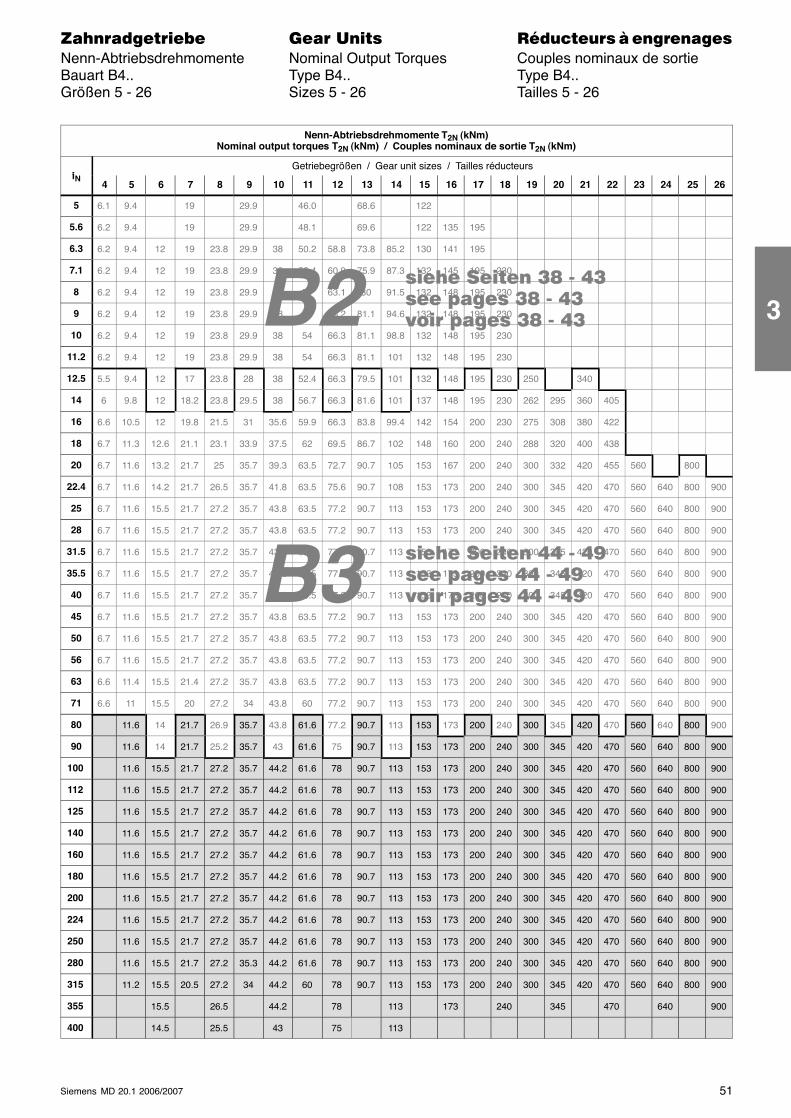
B3 ���� ���� �� - ����� ����� �� - ����� ����� �� - ��
���� ���� �� - ����� ����� �� - ����� ����� �� - ��B2
51Siemens MD 20.1 2006/2007
������������� ���� �� ��������� � ����������Nenn-Abtriebsdrehmomente Nominal Output Torques Couples nominaux de sortieBauart B4.. Type B4.. Type B4..Größen 5 - 26 Sizes 5 - 26 Tailles 5 - 26
Nenn-Abtriebsdrehmomente T2N (kNm)Nominal output torques T2N (kNm) / Couples nominaux de sortie T2N (kNm)
iGetriebegrößen / Gear unit sizes / Tailles réducteurs
iN4 5 6 7 8 9 10 11 12 13 14 15 16 17 18 19 20 21 22 23 24 25 26
5 6.1 9.4 19 29.9 46.0 68.6 122
5.6 6.2 9.4 19 29.9 48.1 69.6 122 135 195
6.3 6.2 9.4 12 19 23.8 29.9 38 50.2 58.8 73.8 85.2 130 141 195
7.1 6.2 9.4 12 19 23.8 29.9 38 52.4 60.9 75.9 87.3 132 145 195 230
8 6.2 9.4 12 19 23.8 29.9 38 54 63.1 80 91.5 132 148 195 230
9 6.2 9.4 12 19 23.8 29.9 38 54 65.2 81.1 94.6 132 148 195 230
10 6.2 9.4 12 19 23.8 29.9 38 54 66.3 81.1 98.8 132 148 195 230
11.2 6.2 9.4 12 19 23.8 29.9 38 54 66.3 81.1 101 132 148 195 230
12.5 5.5 9.4 12 17 23.8 28 38 52.4 66.3 79.5 101 132 148 195 230 250 340
14 6 9.8 12 18.2 23.8 29.5 38 56.7 66.3 81.6 101 137 148 195 230 262 295 360 405
16 6.6 10.5 12 19.8 21.5 31 35.6 59.9 66.3 83.8 99.4 142 154 200 230 275 308 380 422
18 6.7 11.3 12.6 21.1 23.1 33.9 37.5 62 69.5 86.7 102 148 160 200 240 288 320 400 438
20 6.7 11.6 13.2 21.7 25 35.7 39.3 63.5 72.7 90.7 105 153 167 200 240 300 332 420 455 560 800
22.4 6.7 11.6 14.2 21.7 26.5 35.7 41.8 63.5 75.6 90.7 108 153 173 200 240 300 345 420 470 560 640 800 900
25 6.7 11.6 15.5 21.7 27.2 35.7 43.8 63.5 77.2 90.7 113 153 173 200 240 300 345 420 470 560 640 800 900
28 6.7 11.6 15.5 21.7 27.2 35.7 43.8 63.5 77.2 90.7 113 153 173 200 240 300 345 420 470 560 640 800 900
31.5 6.7 11.6 15.5 21.7 27.2 35.7 43.8 63.5 77.2 90.7 113 153 173 200 240 300 345 420 470 560 640 800 900
35.5 6.7 11.6 15.5 21.7 27.2 35.7 43.8 63.5 77.2 90.7 113 153 173 200 240 300 345 420 470 560 640 800 900
40 6.7 11.6 15.5 21.7 27.2 35.7 43.8 63.5 77.2 90.7 113 153 173 200 240 300 345 420 470 560 640 800 900
45 6.7 11.6 15.5 21.7 27.2 35.7 43.8 63.5 77.2 90.7 113 153 173 200 240 300 345 420 470 560 640 800 900
50 6.7 11.6 15.5 21.7 27.2 35.7 43.8 63.5 77.2 90.7 113 153 173 200 240 300 345 420 470 560 640 800 900
56 6.7 11.6 15.5 21.7 27.2 35.7 43.8 63.5 77.2 90.7 113 153 173 200 240 300 345 420 470 560 640 800 900
63 6.6 11.4 15.5 21.4 27.2 35.7 43.8 63.5 77.2 90.7 113 153 173 200 240 300 345 420 470 560 640 800 900
71 6.6 11 15.5 20 27.2 34 43.8 60 77.2 90.7 113 153 173 200 240 300 345 420 470 560 640 800 900
80 11.6 14 21.7 26.9 35.7 43.8 61.6 77.2 90.7 113 153 173 200 240 300 345 420 470 560 640 800 900
90 11.6 14 21.7 25.2 35.7 43 61.6 75 90.7 113 153 173 200 240 300 345 420 470 560 640 800 900
100 11.6 15.5 21.7 27.2 35.7 44.2 61.6 78 90.7 113 153 173 200 240 300 345 420 470 560 640 800 900
112 11.6 15.5 21.7 27.2 35.7 44.2 61.6 78 90.7 113 153 173 200 240 300 345 420 470 560 640 800 900
125 11.6 15.5 21.7 27.2 35.7 44.2 61.6 78 90.7 113 153 173 200 240 300 345 420 470 560 640 800 900
140 11.6 15.5 21.7 27.2 35.7 44.2 61.6 78 90.7 113 153 173 200 240 300 345 420 470 560 640 800 900
160 11.6 15.5 21.7 27.2 35.7 44.2 61.6 78 90.7 113 153 173 200 240 300 345 420 470 560 640 800 900
180 11.6 15.5 21.7 27.2 35.7 44.2 61.6 78 90.7 113 153 173 200 240 300 345 420 470 560 640 800 900
200 11.6 15.5 21.7 27.2 35.7 44.2 61.6 78 90.7 113 153 173 200 240 300 345 420 470 560 640 800 900
224 11.6 15.5 21.7 27.2 35.7 44.2 61.6 78 90.7 113 153 173 200 240 300 345 420 470 560 640 800 900
250 11.6 15.5 21.7 27.2 35.7 44.2 61.6 78 90.7 113 153 173 200 240 300 345 420 470 560 640 800 900
280 11.6 15.5 21.7 27.2 35.3 44.2 61.6 78 90.7 113 153 173 200 240 300 345 420 470 560 640 800 900
315 11.2 15.5 20.5 27.2 34 44.2 60 78 90.7 113 153 173 200 240 300 345 420 470 560 640 800 900
355 15.5 26.5 44.2 78 113 173 240 345 470 640 900
400 14.5 25.5 43 75 113
3
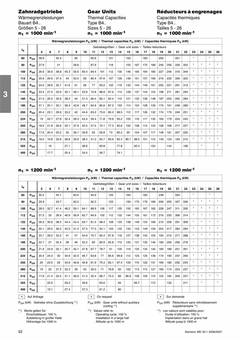
52 Siemens MD 20.1 2006/2007
������������� ���� �� ��������� � ����������Wärmegrenzleistungen Thermal Capacities Capacités thermiquesBauart B4.. Type B4.. Type B4..Größen 5 - 26 Sizes 5 - 26 Tailles 5 - 26�� � ���� ����� �� � ���� ����� �� � ���� �����
Wärmegrenzleistungen PG (kW) / Thermal capacities PG (kW) / Capacités thermiques PG (kW)
iGetriebegrößen / Gear unit sizes / Tailles réducteurs
iN 5 6 7 8 9 10 11 12 13 14 15 16 17 18 19 20 21 22 23 24 25 26
80 PGA 28.6 42.4 60 90.6 121 162 183 250 351 * *
90 PGA 27.9 41 58.6 87.9 118 155 167 175 188 240 256 339 355 * * * *
100 PGA 26.6 30.6 38.8 45.3 55.6 60.4 84.4 101 112 130 146 160 164 180 227 246 319 344 * * * *
112 PGA 25.6 29.9 37.4 44 53.5 59 80.4 97.6 107 126 139 151 157 169 216 232 309 322 * * * *
125 PGA 24.5 28.6 35.7 41.6 51 56 77 93.2 102 119 132 144 149 161 205 221 291 313 * * * *
140 PGA 23.4 27.5 33.9 40.1 48.1 53.9 72.8 88.8 97.6 114 128 137 144 154 198 211 281 294 * * * *
160 PGA 21.5 26.3 30.9 38.2 44 51.3 66.4 85.1 92.4 110 121 132 136 148 187 203 265 284 * * * *
180 PGA 21.1 25.1 30.1 36.4 42.9 48.7 64.6 80.6 87.2 103 114 124 128 139 175 191 248 269 * * * *
200 PGA 20.4 23.1 29.9 33.2 42 44.6 63.2 73.6 85.2 98.5 112 117 126 132 174 179 240 251 * * * *
224 PGA 19 22.7 27.8 32.4 39.3 43.4 59.4 71.8 79.9 93.2 105 116 117 130 163 179 224 243 * * * *
250 PGA 18.5 21.8 26.9 32.1 37.9 42.5 57.5 70.1 77.3 90.6 102 108 114 122 158 168 217 227 * * * *
280 PGA 17.6 20.4 25.2 30 36.1 39.8 55 65.8 73 85.2 95 104 107 117 148 161 207 220 * * * *
315 PGA 16.5 19.8 23.6 28.8 33.9 38.4 51.3 63.7 69.6 82.4 89.7 98.5 101 110 140 153 193 210 * * * *
355 PGA 19 27.1 36.6 60.8 77.8 92.4 104 144 196 * *
400 PGA 17.7 25.4 34.5 56.7 74.1
�� � ���� ����� �� � ���� ����� �� � ���� �����
Wärmegrenzleistungen PG (kW) / Thermal capacities PG (kW) / Capacités thermiques PG (kW)
iGetriebegrößen / Gear unit sizes / Tailles réducteurs
iN 5 6 7 8 9 10 11 12 13 14 15 16 17 18 19 20 21 22 23 24 25 26
80 PGA 30.5 45.1 63.5 94.9 125 165 183 248 334 * *
90 PGA 29.9 43.7 62.2 92.3 123 159 170 176 189 240 255 327 336 * * * *
100 PGA 28.5 32.7 41.4 48.2 59.1 64.1 88.9 106 117 135 150 163 167 182 228 247 311 330 * * * *
112 PGA 27.5 32 39.9 46.9 56.9 62.7 84.9 102 112 132 144 155 161 173 219 235 306 314 * * * *
125 PGA 26.3 30.6 38.2 44.4 54.4 59.7 81.5 98.4 108 125 138 149 154 166 210 226 291 309 * * * *
140 PGA 25.1 29.5 36.3 42.9 51.4 57.5 77.3 94.1 103 120 134 143 149 159 204 217 284 294 * * * *
160 PGA 23.1 28.2 33.2 41 47 54.9 70.7 90.4 97.8 116 127 138 142 155 194 210 271 288 * * * *
180 PGA 22.7 27 32.4 39 46 52.2 69 85.9 92.8 110 120 131 135 146 183 200 256 276 * * * *
200 PGA 21.9 24.9 32.1 35.7 45.1 47.8 67.7 78.7 91 105 119 125 134 140 183 189 251 261 * * * *
224 PGA 20.4 24.4 30 34.9 42.3 46.7 63.8 77 85.6 99.8 112 123 125 138 174 190 237 256 * * * *
250 PGA 20 23.5 29 34.6 40.8 45.8 61.9 75.4 83.1 97.4 109 116 122 131 169 180 232 243 * * * *
280 PGA 19 22 27.2 32.3 39 43 59.3 71 78.8 92 102 113 115 127 160 174 224 237 * * * *
315 PGA 17.8 21.4 25.5 31.1 36.6 41.5 55.4 68.7 75.2 89 96.9 106 109 119 152 165 209 227 * * * *
355 PGA 20.5 29.2 39.6 65.6 84 99.7 113 155 211 * *
400 PGA 19.1 27.4 37.3 61.2 80
Auf Anfrage
PGA (kW) Getriebe ohne Zusatzkühlung **)
**) Werte gelten für:Einschaltdauer: 100 %Aufstellung in großer HalleHöhenlage bis 1000 m
On request
PGA (kW) Gear units without auxiliarycooling **)
**) Values refer to:Operating cycle: 100 %Installation in a large hallAltitude up to 1000 m
Sur demande
PGA (kW) Réducteurs sans refroidissementsupplémentaire **)
**) Les valeurs sont valables pour:Durée d’utilisation: 100 %Implantation dans un grand hallAltitude jusqu’à 1000 m
* * *
3
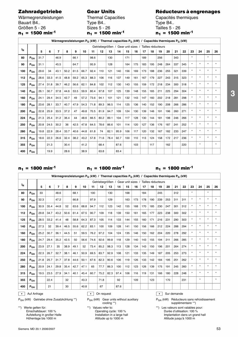
53Siemens MD 20.1 2006/2007
������������� ���� �� ��������� � ����������Wärmegrenzleistungen Thermal Capacities Capacités thermiquesBauart B4.. Type B4.. Type B4..Größen 5 - 26 Sizes 5 - 26 Tailles 5 - 26�� � ���� ����� �� � ���� ����� �� � ���� �����
Wärmegrenzleistungen PG (kW) / Thermal capacities PG (kW) / Capacités thermiques PG (kW)
iGetriebegrößen / Gear unit sizes / Tailles réducteurs
iN 5 6 7 8 9 10 11 12 13 14 15 16 17 18 19 20 21 22 23 24 25 26
80 PGA 31.7 46.9 66.1 98.6 130 171 189 256 343 * *
90 PGA 31.1 45.5 64.7 95.9 128 164 175 183 195 248 264 337 345 * * * *
100 PGA 29.6 34 43.1 50.2 61.5 66.7 92.4 110 121 140 156 169 173 188 236 255 321 339 * * * *
112 PGA 28.6 33.3 41.5 48.8 59.2 65.3 88.3 106 116 137 149 161 167 179 227 243 315 323 * * * *
125 PGA 27.4 31.8 39.7 46.2 56.6 62.1 84.8 102 112 130 143 155 159 172 218 234 300 318 * * * *
140 PGA 26.1 30.7 37.8 44.6 53.5 59.9 80.4 97.8 107 125 139 148 155 165 211 225 294 304 * * * *
160 PGA 24.1 29.4 34.5 42.7 49 57.2 73.6 94.1 101 121 132 143 147 160 202 218 281 298 * * * *
180 PGA 23.6 28.1 33.7 40.7 47.9 54.3 71.8 89.3 96.5 114 125 136 140 152 190 208 266 286 * * * *
200 PGA 22.8 25.9 33.5 37.2 47 49.8 70.5 81.9 94.7 109 124 130 139 146 191 196 260 271 * * * *
224 PGA 21.3 25.4 31.2 36.4 44 48.6 66.5 80.2 89.1 104 117 128 130 144 181 198 246 266 * * * *
250 PGA 20.8 24.5 30.2 36 42.5 47.8 64.5 78.6 86.6 101 114 120 127 136 176 187 241 252 * * * *
280 PGA 19.8 22.9 28.4 33.7 40.6 44.8 61.8 74 82.1 95.9 106 117 120 132 167 182 233 247 * * * *
315 PGA 18.6 22.3 26.6 32.4 38.2 43.2 57.8 71.6 78.4 92.7 100 110 113 124 158 172 217 236 * * * *
355 PGA 21.3 30.4 41.2 68.4 87.6 103 117 162 220 * *
400 PGA 19.9 28.6 38.9 63.8 83.4
�� � �!�� ����� �� � �!�� ����� �� � �!�� �����
Wärmegrenzleistungen PG (kW) / Thermal capacities PG (kW) / Capacités thermiques PG (kW)
iGetriebegrößen / Gear unit sizes / Tailles réducteurs
iN 5 6 7 8 9 10 11 12 13 14 15 16 17 18 19 20 21 22 23 24 25 26
80 PGA 33 48.6 68.1 100 130 168 184 245 312 * *
90 PGA 32.3 47.2 66.8 97.9 129 163 173 178 190 239 253 311 311 * * * *
100 PGA 30.9 35.4 44.8 52 63.6 68.8 94.7 112 123 142 155 168 170 185 230 247 301 312 * * * *
112 PGA 29.8 34.7 43.2 50.6 61.4 67.5 90.7 109 118 139 150 161 165 177 223 238 300 302 * * * *
125 PGA 28.5 33.2 41.4 48 58.8 64.3 87.3 105 114 133 144 155 160 171 216 231 290 303 * * * *
140 PGA 27.3 32 39.4 46.5 55.6 62.2 83.1 100 109 128 141 150 156 166 212 224 288 294 * * * *
160 PGA 25.2 30.7 36.1 44.5 51 59.5 76.2 97.2 104 124 135 146 150 162 204 220 278 292 * * * *
180 PGA 24.7 29.4 35.2 42.5 50 56.6 74.6 92.6 99.8 118 129 140 143 155 194 211 266 285 * * * *
200 PGA 23.9 27.1 35 38.9 49.1 52 73.4 85.2 98.3 113 128 134 143 150 196 201 264 274 * * * *
224 PGA 22.3 26.7 32.7 38.1 46.1 50.9 69.5 83.7 92.9 108 121 133 135 149 187 205 253 273 * * * *
250 PGA 21.8 25.7 31.7 37.8 44.6 50.1 67.6 82.3 90.6 106 119 126 133 142 184 195 251 262 * * * *
280 PGA 20.9 24.1 29.8 35.4 42.7 47.1 65 77.7 86.3 100 112 123 126 139 175 191 245 260 * * * *
315 PGA 19.5 23.5 27.9 34.1 40.1 45.4 60.7 75.2 82.3 97.4 106 116 119 131 166 180 228 248 * * * *
355 PGA 22.4 32 43.3 71.8 92 109 123 170 231 * *
400 PGA 21 30 40.8 67 87.6
Auf Anfrage
PGA (kW) Getriebe ohne Zusatzkühlung **)
**) Werte gelten für:Einschaltdauer: 100 %Aufstellung in großer HalleHöhenlage bis 1000 m
On request
PGA (kW) Gear units without auxiliarycooling **)
**) Values refer to:Operating cycle: 100 %Installation in a large hallAltitude up to 1000 m
Sur demande
PGA (kW) Réducteurs sans refroidissementsupplémentaire **)
**) Les valeurs sont valables pour:Durée d’utilisation: 100 %Implantation dans un grand hallAltitude jusqu’à 1000 m
* * *
3
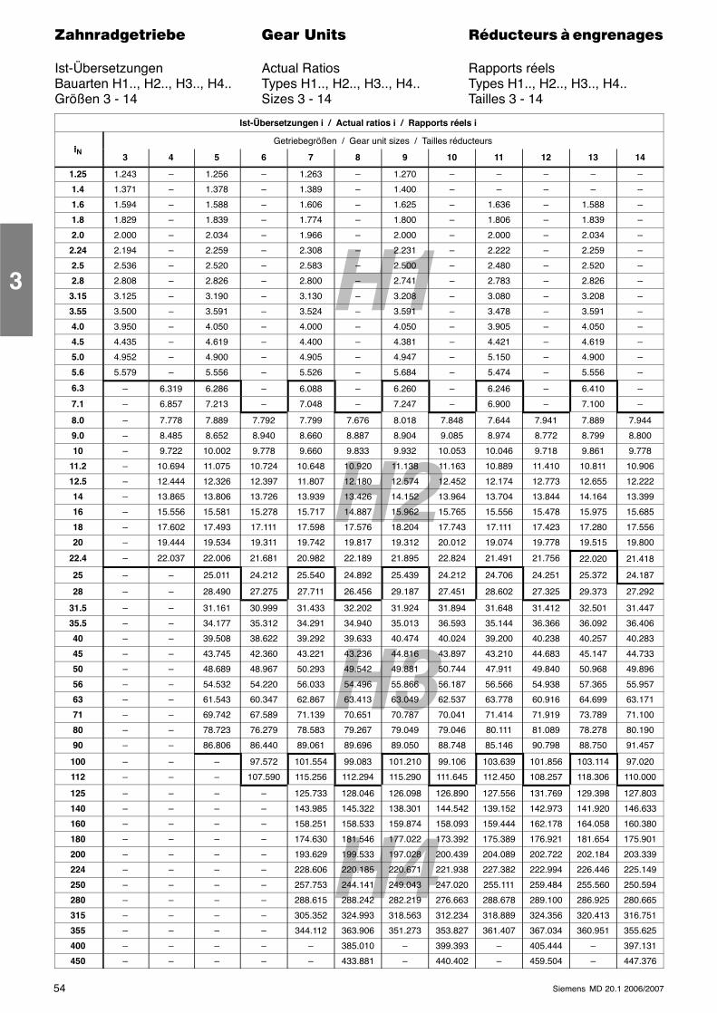
H2
H4
H1
H3
54 Siemens MD 20.1 2006/2007
������������� ���� �� ��������� � ����������
Ist-Übersetzungen Actual Ratios Rapports réelsBauarten H1.., H2.., H3.., H4.. Types H1.., H2.., H3.., H4.. Types H1.., H2.., H3.., H4..Größen 3 - 14 Sizes 3 - 14 Tailles 3 - 14
Ist-Übersetzungen i / Actual ratios i / Rapports réels i
iGetriebegrößen / Gear unit sizes / Tailles réducteurs
iN3 4 5 6 7 8 9 10 11 12 13 14
1.25 1.243 – 1.256 – 1.263 – 1.270 – – – – –
1.4 1.371 – 1.378 – 1.389 – 1.400 – – – – –
1.6 1.594 – 1.588 – 1.606 – 1.625 – 1.636 – 1.588 –
1.8 1.829 – 1.839 – 1.774 – 1.800 – 1.806 – 1.839 –
2.0 2.000 – 2.034 – 1.966 – 2.000 – 2.000 – 2.034 –
2.24 2.194 – 2.259 – 2.308 – 2.231 – 2.222 – 2.259 –
2.5 2.536 – 2.520 – 2.583 – 2.500 – 2.480 – 2.520 –
2.8 2.808 – 2.826 – 2.800 – 2.741 – 2.783 – 2.826 –
3.15 3.125 – 3.190 – 3.130 – 3.208 – 3.080 – 3.208 –
3.55 3.500 – 3.591 – 3.524 – 3.591 – 3.478 – 3.591 –
4.0 3.950 – 4.050 – 4.000 – 4.050 – 3.905 – 4.050 –
4.5 4.435 – 4.619 – 4.400 – 4.381 – 4.421 – 4.619 –
5.0 4.952 – 4.900 – 4.905 – 4.947 – 5.150 – 4.900 –
5.6 5.579 – 5.556 – 5.526 – 5.684 – 5.474 – 5.556 –
6.3 – 6.319 6.286 – 6.088 – 6.260 – 6.246 – 6.410 –
7.1 – 6.857 7.213 – 7.048 – 7.247 – 6.900 – 7.100 –
8.0 – 7.778 7.889 7.792 7.799 7.676 8.018 7.848 7.644 7.941 7.889 7.944
9.0 – 8.485 8.652 8.940 8.660 8.887 8.904 9.085 8.974 8.772 8.799 8.800
10 – 9.722 10.002 9.778 9.660 9.833 9.932 10.053 10.046 9.718 9.861 9.778
11.2 – 10.694 11.075 10.724 10.648 10.920 11.138 11.163 10.889 11.410 10.811 10.906
12.5 – 12.444 12.326 12.397 11.807 12.180 12.574 12.452 12.174 12.773 12.655 12.222
14 – 13.865 13.806 13.726 13.939 13.426 14.152 13.964 13.704 13.844 14.164 13.399
16 – 15.556 15.581 15.278 15.717 14.887 15.962 15.765 15.556 15.478 15.975 15.685
18 – 17.602 17.493 17.111 17.598 17.576 18.204 17.743 17.111 17.423 17.280 17.556
20 – 19.444 19.534 19.311 19.742 19.817 19.312 20.012 19.074 19.778 19.515 19.800
22.4 – 22.037 22.006 21.681 20.982 22.189 21.895 22.824 21.491 21.756 22.020 21.418
25 – – 25.011 24.212 25.540 24.892 25.439 24.212 24.706 24.251 25.372 24.187
28 – – 28.490 27.275 27.711 26.456 29.187 27.451 28.602 27.325 29.373 27.292
31.5 – – 31.161 30.999 31.433 32.202 31.924 31.894 31.648 31.412 32.501 31.447
35.5 – – 34.177 35.312 34.291 34.940 35.013 36.593 35.144 36.366 36.092 36.406
40 – – 39.508 38.622 39.292 39.633 40.474 40.024 39.200 40.238 40.257 40.283
45 – – 43.745 42.360 43.221 43.236 44.816 43.897 43.210 44.683 45.147 44.733
50 – – 48.689 48.967 50.293 49.542 49.881 50.744 47.911 49.840 50.968 49.896
56 – – 54.532 54.220 56.033 54.496 55.866 56.187 56.566 54.938 57.365 55.957
63 – – 61.543 60.347 62.867 63.413 63.049 62.537 63.778 60.916 64.699 63.171
71 – – 69.742 67.589 71.139 70.651 70.787 70.041 71.414 71.919 73.789 71.100
80 – – 78.723 76.279 78.583 79.267 79.049 79.046 80.111 81.089 78.278 80.190
90 – – 86.806 86.440 89.061 89.696 89.050 88.748 85.146 90.798 88.750 91.457
100 – – – 97.572 101.554 99.083 101.210 99.106 103.639 101.856 103.114 97.020
112 – – – 107.590 115.256 112.294 115.290 111.645 112.450 108.257 118.306 110.000
125 – – – – 125.733 128.046 126.098 126.890 127.556 131.769 129.398 127.803
140 – – – – 143.985 145.322 138.301 144.542 139.152 142.973 141.920 146.633
160 – – – – 158.251 158.533 159.874 158.093 159.444 162.178 164.058 160.380
180 – – – – 174.630 181.546 177.022 173.392 175.389 176.921 181.654 175.901
200 – – – – 193.629 199.533 197.028 200.439 204.089 202.722 202.184 203.339
224 – – – – 228.606 220.185 220.671 221.938 227.382 222.994 226.446 225.149
250 – – – – 257.753 244.141 249.043 247.020 255.111 259.484 255.560 250.594
280 – – – – 288.615 288.242 282.219 276.663 288.678 289.100 286.925 280.665
315 – – – – 305.352 324.993 318.563 312.234 318.889 324.356 320.413 316.751
355 – – – – 344.112 363.906 351.273 353.827 361.407 367.034 360.951 355.625
400 – – – – – 385.010 – 399.393 – 405.444 – 397.131
450 – – – – – 433.881 – 440.402 – 459.504 – 447.376
3
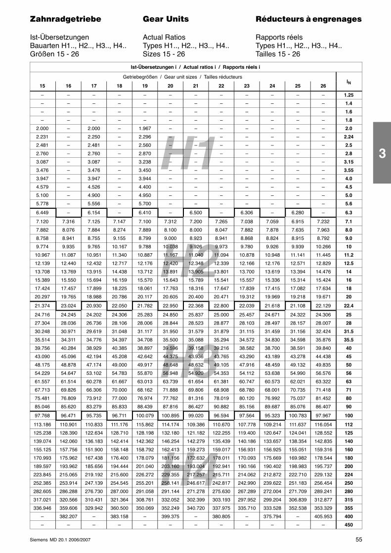
H2
H4
H1
H3
55Siemens MD 20.1 2006/2007
������������� ���� �� ��������� � ����������
Ist-Übersetzungen Actual Ratios Rapports réelsBauarten H1.., H2.., H3.., H4.. Types H1.., H2.., H3.., H4.. Types H1.., H2.., H3.., H4..Größen 15 - 26 Sizes 15 - 26 Tailles 15 - 26
Ist-Übersetzungen i / Actual ratios i / Rapports réels i
Getriebegrößen / Gear unit sizes / Tailles réducteursi
15 16 17 18 19 20 21 22 23 24 25 26iN
– – – – – – – – – – – – 1.25
– – – – – – – – – – – – 1.4
– – – – – – – – – – – – 1.6
– – – – – – – – – – – – 1.8
2.000 – 2.000 – 1.967 – – – – – – – 2.0
2.231 – 2.250 – 2.296 – – – – – – – 2.24
2.481 – 2.481 – 2.560 – – – – – – – 2.5
2.760 – 2.760 – 2.870 – – – – – – – 2.8
3.087 – 3.087 – 3.238 – – – – – – – 3.15
3.476 – 3.476 – 3.450 – – – – – – – 3.55
3.947 – 3.947 – 3.944 – – – – – – – 4.0
4.579 – 4.526 – 4.400 – – – – – – – 4.5
5.100 – 4.900 – 4.950 – – – – – – – 5.0
5.778 – 5.556 – 5.700 – – – – – – – 5.6
6.449 – 6.154 – 6.410 – 6.500 – 6.306 – 6.280 – 6.3
7.120 7.316 7.125 7.147 7.100 7.312 7.200 7.265 7.038 7.059 6.915 7.232 7.1
7.882 8.076 7.884 8.274 7.889 8.100 8.000 8.047 7.882 7.878 7.635 7.963 8.0
8.758 8.941 8.755 9.155 8.799 9.000 8.923 8.941 8.868 8.824 8.915 8.792 9.0
9.774 9.935 9.765 10.167 9.788 10.038 9.926 9.973 9.780 9.926 9.939 10.266 10
10.967 11.087 10.951 11.340 10.887 11.167 11.040 11.094 10.878 10.948 11.141 11.445 11.2
12.139 12.440 12.432 12.717 12.176 12.420 12.348 12.339 12.166 12.176 12.571 12.829 12.5
13.708 13.769 13.915 14.438 13.712 13.891 13.905 13.801 13.700 13.619 13.394 14.476 14
15.389 15.550 15.694 16.159 15.570 15.643 15.789 15.541 15.557 15.336 15.314 15.424 16
17.424 17.457 17.899 18.225 18.061 17.763 18.316 17.647 17.839 17.415 17.082 17.634 18
20.297 19.765 18.988 20.786 20.117 20.605 20.400 20.471 19.312 19.969 19.218 19.671 20
21.374 23.024 20.930 22.050 21.782 22.950 22.368 22.800 22.039 21.618 21.108 22.129 22.4
24.716 24.245 24.202 24.306 25.283 24.850 25.837 25.000 25.457 24.671 24.322 24.306 25
27.304 28.036 26.736 28.106 28.006 28.844 28.523 28.877 28.103 28.497 28.157 28.007 28
30.248 30.971 29.619 31.048 31.117 31.950 31.579 31.879 31.115 31.459 31.156 32.424 31.5
35.514 34.311 34.776 34.397 34.708 35.500 35.088 35.294 34.572 34.830 34.598 35.876 35.5
39.756 40.284 38.929 40.385 38.897 39.596 39.158 39.216 38.582 38.700 38.591 39.840 40
43.090 45.096 42.194 45.208 42.642 44.375 43.936 43.765 43.290 43.189 43.278 44.438 45
48.175 48.878 47.174 49.000 49.917 48.648 48.632 49.105 47.916 48.459 49.132 49.835 50
54.229 54.647 53.102 54.783 55.870 56.948 54.920 54.353 54.112 53.638 54.990 56.576 56
61.557 61.514 60.278 61.667 63.013 63.739 61.654 61.381 60.747 60.573 62.021 63.322 63
67.713 69.826 66.306 70.000 68.162 71.888 69.806 68.908 68.780 68.001 70.735 71.418 71
75.481 76.809 73.912 77.000 76.974 77.762 81.316 78.019 80.120 76.992 75.037 81.452 80
85.046 85.620 83.279 85.833 88.439 87.816 86.427 90.882 85.156 89.687 85.076 86.407 90
97.768 96.471 95.735 96.711 100.079 100.895 99.020 96.594 97.564 95.323 100.783 97.967 100
113.186 110.901 110.833 111.176 115.862 114.174 109.386 110.670 107.778 109.214 111.637 116.054 112
125.238 128.390 122.634 128.710 128.198 132.180 121.182 122.255 119.400 120.647 124.041 128.552 125
139.074 142.060 136.183 142.414 142.362 146.254 142.279 135.439 140.186 133.657 138.354 142.835 140
155.125 157.756 151.900 158.148 158.792 162.413 159.273 159.017 156.931 156.925 155.051 159.316 160
170.993 175.962 167.438 176.400 178.079 181.156 172.632 178.011 170.093 175.669 169.982 178.544 180
189.597 193.962 185.656 194.444 201.040 203.160 193.004 192.941 190.166 190.402 198.983 195.737 200
223.845 215.065 219.192 215.600 226.272 229.355 217.257 215.711 214.062 212.872 222.710 229.132 224
252.385 253.914 247.139 254.545 255.201 258.141 246.617 242.817 242.990 239.622 251.183 256.454 250
282.605 286.288 276.730 287.000 291.058 291.144 271.278 275.630 267.289 272.004 271.709 289.241 280
317.021 320.566 310.431 321.364 308.761 332.052 302.399 303.193 297.952 299.204 306.839 312.877 315
336.946 359.606 329.942 360.500 350.069 352.249 340.720 337.975 335.710 333.528 352.538 353.329 355
– 382.207 – 383.158 – 399.375 – 380.805 – 375.794 – 405.953 400
– – – – – – – – – – – – 450
3
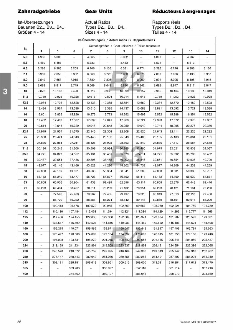
B2
B3
B4
56 Siemens MD 20.1 2006/2007
������������� ���� �� ��������� � ����������
Ist-Übersetzungen Actual Ratios Rapports réelsBauarten B2.., B3.., B4.. Types B2.., B3.., B4.. Types B2.., B3.., B4..Größen 4 - 14 Sizes 4 - 14 Tailles 4 - 14
Ist-Übersetzungen i / Actual ratios i / Rapports réels i
iGetriebegrößen / Gear unit sizes / Tailles réducteurs
iN4 5 6 7 8 9 10 11 12 13 14
5.0 4.936 5.006 – 4.865 – 5.002 – 4.897 – 4.967 –
5.6 5.480 5.488 – 5.333 – 5.483 – 5.534 – 5.613 –
6.3 6.296 6.386 6.205 6.206 6.135 6.381 6.271 6.296 6.226 6.386 6.156
7.1 6.959 7.058 6.802 6.860 6.725 7.053 6.875 7.037 7.036 7.138 6.957
8.0 7.549 7.657 7.915 7.880 7.825 8.101 8.000 7.994 8.005 8.108 7.915
9.0 8.693 8.817 8.749 8.569 8.649 8.810 8.842 8.693 8.947 8.817 8.847
10 9.872 10.108 9.490 9.823 9.935 10.099 10.157 9.965 10.164 10.108 10.049
11.2 10.769 10.923 10.928 10.615 10.804 10.914 11.045 10.769 11.052 10.923 10.928
12.5 12.034 12.703 12.528 12.433 12.385 12.554 12.662 12.334 12.670 12.482 12.528
14 13.484 13.964 13.538 13.515 13.385 14.137 13.683 13.821 13.692 13.721 13.538
16 15.601 15.835 15.826 16.275 15.773 15.952 15.693 15.522 15.888 16.354 15.552
18 17.482 17.407 17.307 17.692 17.041 17.963 17.724 17.393 17.572 17.978 17.007
20 19.614 19.645 19.729 19.948 20.648 20.259 19.940 19.744 19.995 20.276 20.376
22.4 21.919 21.954 21.575 22.146 22.308 22.208 22.520 21.643 22.114 22.226 22.282
25 25.380 25.421 24.349 25.446 25.152 25.843 25.400 25.185 25.103 25.864 25.131
28 27.836 27.881 27.211 28.125 27.923 28.563 27.842 27.836 27.517 28.587 27.548
31.5 30.196 30.245 31.508 30.509 32.084 30.985 32.400 31.975 32.021 32.838 32.057
35.5 34.771 34.827 34.557 35.131 35.461 35.679 35.811 34.771 35.392 35.709 35.432
40 39.487 39.551 37.486 39.896 38.468 40.902 38.846 39.861 40.654 40.936 40.700
45 43.077 43.146 43.166 43.523 44.296 44.202 44.732 43.077 44.209 44.238 44.259
50 49.060 49.139 49.021 49.568 50.304 50.341 51.280 49.060 50.681 50.383 50.737
56 55.152 55.240 53.477 55.723 54.877 56.592 55.417 55.152 54.769 56.639 54.831
63 60.808 60.906 60.904 61.438 62.499 62.396 63.114 60.808 62.376 62.448 62.446
71 69.293 69.404 68.467 70.011 70.259 71.102 70.951 69.293 70.121 71.161 70.200
80 – 77.598 75.489 79.267 77.465 79.497 78.228 80.949 77.313 82.118 77.400
90 – 86.720 86.022 88.585 88.274 88.842 89.143 89.869 88.101 90.016 88.200
100 – 100.413 96.178 102.572 99.945 102.869 99.667 103.259 102.921 104.750 101.780
112 – 110.130 107.484 112.498 111.694 112.824 111.384 114.129 114.262 115.777 111.569
125 – 119.466 124.455 122.035 129.330 122.389 128.971 123.804 131.287 125.592 129.831
140 – 137.567 136.499 140.525 141.846 140.933 141.452 142.562 145.106 144.621 143.498
160 – 156.225 148.071 159.585 153.871 160.047 153.443 161.897 157.408 165.791 155.663
180 – 170.427 170.506 174.092 177.184 174.597 176.692 176.615 181.258 179.166 179.248
200 – 194.098 193.631 198.272 201.215 198.847 200.656 201.145 205.841 204.050 205.487
224 – 218.199 211.234 222.891 219.508 223.537 218.898 226.121 224.554 229.386 222.065
250 – 240.578 240.572 245.752 249.995 246.464 249.300 249.313 255.742 252.913 252.907
280 – 274.147 270.443 280.042 281.036 280.855 280.256 284.101 287.497 288.204 284.310
315 – 302.121 298.181 308.618 309.861 309.513 309.000 313.091 316.984 317.612 313.470
355 – – 339.788 – 353.097 – 352.116 – 361.214 – 357.210
400 – – 374.460 – 389.127 – 388.046 – 398.073 – 393.660
3
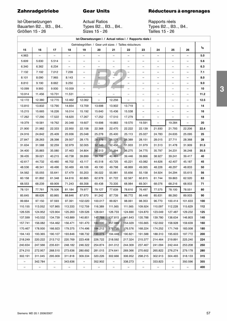
B2
B3
B4
57Siemens MD 20.1 2006/2007
������������� ���� �� ��������� � ����������
Ist-Übersetzungen Actual Ratios Rapports réelsBauarten B2.., B3.., B4.. Types B2.., B3.., B4.. Types B2.., B3.., B4..Größen 15 - 26 Sizes 15 - 26 Tailles 15 - 26
Ist-Übersetzungen i / Actual ratios i / Rapports réels i
Getriebegrößen / Gear unit sizes / Tailles réducteursi
15 16 17 18 19 20 21 22 23 24 25 26iN
4.963 – – – – – – – – – – – 5.0
5.609 5.630 5.514 – – – – – – – – – 5.6
6.340 6.362 6.234 – – – – – – – – – 6.3
7.132 7.192 7.012 7.239 – – – – – – – – 7.1
8.101 8.090 7.965 8.143 – – – – – – – – 8.0
8.810 9.190 8.662 9.250 – – – – – – – – 9.0
10.099 9.993 9.930 10.059 – – – – – – – – 10
10.914 11.456 10.731 11.531 – – – – – – – – 11.2
12.172 12.380 12.770 12.462 12.062 – 12.256 – – – – – 12.5
13.810 13.832 13.790 14.654 13.709 13.698 13.902 13.719 – – – – 14
15.215 15.665 16.226 16.014 15.192 15.640 15.436 15.538 – – – – 16
17.262 17.290 17.522 18.620 17.267 17.252 17.510 17.279 – – – – 18
19.379 19.581 19.762 20.348 19.607 19.698 19.883 19.570 19.591 – 19.284 – 20
21.900 21.982 22.333 22.950 22.158 22.368 22.470 22.222 22.139 21.930 21.793 22.206 22.4
24.916 24.842 25.409 25.936 25.048 25.278 25.400 25.113 25.027 24.783 24.635 25.095 25
27.847 28.263 28.398 29.507 28.175 28.576 28.571 28.389 28.151 28.015 27.711 28.368 28
31.634 31.588 32.259 32.979 32.005 32.143 32.456 31.933 31.979 31.513 31.478 31.909 31.5
34.400 35.883 35.080 37.463 34.804 36.513 35.294 36.275 34.775 35.797 34.231 36.248 35.5
39.435 39.021 40.215 40.738 39.899 39.706 40.461 39.446 39.866 38.927 39.241 39.417 40
42.617 44.732 43.460 46.702 43.117 45.518 43.725 45.221 43.082 44.626 42.407 45.187 45
48.536 48.341 49.496 50.469 49.106 49.190 49.798 48.869 49.065 48.226 48.297 48.833 50
54.562 55.055 55.641 57.479 55.203 56.022 55.981 55.656 55.158 54.924 54.294 55.615 56
60.158 61.892 61.348 64.616 60.865 62.978 61.722 62.567 60.815 61.744 59.863 62.520 63
68.553 68.239 69.909 71.243 69.358 69.438 70.335 68.984 69.301 68.076 68.216 68.933 71
78.131 77.761 76.506 81.184 79.977 79.127 77.639 78.610 76.497 77.575 78.100 78.551 80
85.645 88.626 83.865 88.846 87.670 91.242 87.739 86.772 86.448 85.631 88.260 89.933 90
99.664 97.150 97.593 97.391 102.020 100.017 99.821 98.061 98.353 96.770 100.414 101.633 100
110.155 113.052 107.865 113.333 112.759 116.389 111.565 111.565 109.924 110.097 112.228 115.629 112
126.535 124.952 123.904 125.263 129.526 128.641 126.733 124.690 124.870 123.049 127.487 129.232 125
137.599 143.532 134.739 143.889 140.851 147.769 137.815 141.643 135.788 139.780 138.634 146.803 140
157.741 156.082 154.462 156.471 161.470 160.690 157.989 154.029 155.665 152.002 158.928 159.639 160
170.467 178.930 166.923 179.375 174.496 184.212 170.735 176.576 168.224 174.252 171.749 183.008 180
194.143 193.365 190.107 193.846 198.732 199.073 194.448 190.821 191.588 188.310 195.603 197.772 200
218.249 220.222 213.712 220.769 223.408 226.722 218.592 217.324 215.377 214.464 219.891 225.240 224
240.634 247.566 235.631 248.182 246.322 254.874 241.012 244.309 237.467 241.094 242.444 253.208 250
274.210 272.957 268.510 273.636 280.692 281.015 274.641 269.366 270.602 265.822 276.274 279.178 280
302.191 311.045 295.909 311.818 309.334 320.226 302.666 306.952 298.215 302.913 304.465 318.133 315
– 342.784 – 343.636 – 352.902 – 338.273 – 333.823 – 350.596 355
– – – – – – – – – – – – 400
3
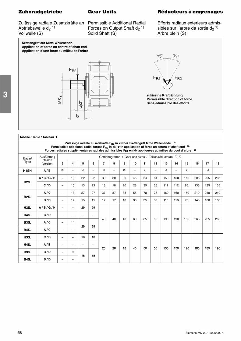
58 Siemens MD 20.1 2006/2007
������������� ���� �� ��������� � ����������
Zulässige radiale Zusatzkräfte an Permissible Additional Radial Efforts radiaux exterieurs admis-Abtriebswelle d2 1) Forces on Output Shaft d2 1) sibles sur l’arbre de sortie d2 1)
Vollwelle (S) Solid Shaft (S) Arbre plein (S)
Kraftangriff auf Mitte WellenendeApplication of force on centre of shaft endApplication d’une force au milieu de l’arbre
FR2
∅d 2
FR2 FR2
l2
2l2
zulässige KraftrichtungPermissible direction of forceSens admissible des efforts
Tabelle / Table / Tableau 1
Zulässige radiale Zusatzkräfte FR2 in kN bei Kraftangriff Mitte Wellenende 3)
Permissible additional radial forces FR2 in kN with application of force on centre of shaft end 3)
Forces radiales supplémentaires radiales admissiblés FR2 en kN appliquées au milieu du bout d’arbre 3)
Bauart AusführungDesign
Getriebegrößen / Gear unit sizes / Tailles réducteurs 1) 4)BauartType Design
Version 3 4 5 6 7 8 9 10 11 12 13 14 15 16 17 18
H1SH A / B 2) – 2) – 2) – 2) – 2) – 2) – 2) 2)
H2SA / B / G / H – 10 22 22 30 30 30 45 64 64 150 150 140 205 205 205
H2S.C / D – 10 13 13 18 18 10 28 35 35 112 112 85 135 135 135
B2SA / C – 13 27 27 37 37 38 55 78 78 160 160 150 210 210 210
B2S.B / D – 12 15 15 17 17 10 30 35 38 110 110 75 145 100 100
H3S. A / B / G / H – – 29 29
H4S. C / D – – – –40 40 40 60 85 85 190 190 185 265 265 265
B3S. A / C – 1429 29
40 40 40 60 85 85 190 190 185 265 265 265
B4S. A / C – –29 29
H3S. C / D – – 18 18
H4S. A / B – – – –26 26 18 40 50 50 150 150 120 185 185 190
B3S. B / D – 918 18
26 26 18 40 50 50 150 150 120 185 185 190
B4S. B / D – –18 18
3
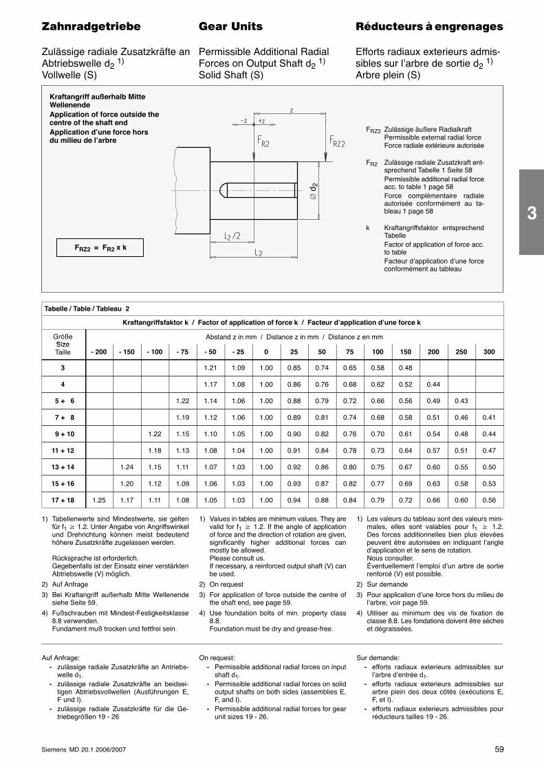
59Siemens MD 20.1 2006/2007
������������� ���� �� ��������� � ����������
Zulässige radiale Zusatzkräfte an Permissible Additional Radial Efforts radiaux exterieurs admis-Abtriebswelle d2 1) Forces on Output Shaft d2 1) sibles sur l’arbre de sortie d2 1)
Vollwelle (S) Solid Shaft (S) Arbre plein (S)
Kraftangriff außerhalb MitteWellenendeApplication of force outside thecentre of the shaft endApplication d’une force horsdu milieu de l’arbre
FRZ2 Zulässige äußere RadialkraftPermissible external radial forceForce radiale extérieure autorisée
FR2 Zulässige radiale Zusatzkraft ent-sprechend Tabelle 1 Seite 58Permissible additional radial forceacc. to table 1 page 58Force complémentaire radialeautorisée conformément au ta-bleau 1 page 58
k Kraftangriffsfaktor entsprechendTabelleFactor of application of force acc.to tableFacteur d’application d’une forceconformément au tableau
FRZ2 = FR2 x k
∅ d
2Tabelle / Table / Tableau 2
Kraftangriffsfaktor k / Factor of application of force k / Facteur d’application d’une force k
GrößeSize
Abstand z in mm / Distance z in mm / Distance z en mmSizeTaille - 200 - 150 - 100 - 75 - 50 - 25 0 25 50 75 100 150 200 250 300
3 1.21 1.09 1.00 0.85 0.74 0.65 0.58 0.48
4 1.17 1.08 1.00 0.86 0.76 0.68 0.62 0.52 0.44
5 + 6 1.22 1.14 1.06 1.00 0.88 0.79 0.72 0.66 0.56 0.49 0.43
7 + 8 1.19 1.12 1.06 1.00 0.89 0.81 0.74 0.68 0.58 0.51 0.46 0.41
9 + 10 1.22 1.15 1.10 1.05 1.00 0.90 0.82 0.76 0.70 0.61 0.54 0.48 0.44
11 + 12 1.18 1.13 1.08 1.04 1.00 0.91 0.84 0.78 0.73 0.64 0.57 0.51 0.47
13 + 14 1.24 1.15 1.11 1.07 1.03 1.00 0.92 0.86 0.80 0.75 0.67 0.60 0.55 0.50
15 + 16 1.20 1.12 1.09 1.06 1.03 1.00 0.93 0.87 0.82 0.77 0.69 0.63 0.58 0.53
17 + 18 1.25 1.17 1.11 1.08 1.05 1.03 1.00 0.94 0.88 0.84 0.79 0.72 0.66 0.60 0.56
1) Tabellenwerte sind Mindestwerte, sie geltenfür f1 � 1.2. Unter Angabe von Angriffswinkelund Drehrichtung können meist bedeutendhöhere Zusatzkräfte zugelassen werden.
Rücksprache ist erforderlich.Gegebenfalls ist der Einsatz einer verstärktenAbtriebswelle (V) möglich.
2) Auf Anfrage
3) Bei Kraftangriff außerhalb Mitte Wellenendesiehe Seite 59.
4) Fußschrauben mit Mindest-Festigkeitsklasse8.8 verwenden.Fundament muß trocken und fettfrei sein.
1) Values in tables are minimum values. They arevalid for f1 � 1.2. If the angle of applicationof force and the direction of rotation are given,significantly higher additional forces canmostly be allowed.Please consult us.If necessary, a reinforced output shaft (V) canbe used.
2) On request
3) For application of force outside the centre ofthe shaft end, see page 59.
4) Use foundation bolts of min. property class8.8.Foundation must be dry and grease-free.
1) Les valeurs du tableau sont des valeurs mini-males, elles sont valables pour f1 � 1.2.Des forces additionnelles bien plus élevéespeuvent être autorisées en indiquant l’angled’application et le sens de rotation.Nous consulter.Éventuellement l’emploi d’un arbre de sortierenforcé (V) est possible.
2) Sur demande
3) Pour application d’une force hors du milieu del’arbre, voir page 59.
4) Utiliser au minimum des vis de fixation declasse 8.8. Les fondations doivent être sècheset dégraissées.
Auf Anfrage:- zulässige radiale Zusatzkräfte an Antriebs-
welle d1.- zulässige radiale Zusatzkräfte an beidsei-
tigen Abtriebsvollwellen (Ausführungen E,F und I).
- zulässige radiale Zusatzkräfte für die Ge-triebegrößen 19 - 26
On request:- Permissible additional radial forces on input
shaft d1.- Permissible additional radial forces on solid
output shafts on both sides (assemblies E,F, and I).
- Permissible additional radial forces for gearunit sizes 19 - 26.
Sur demande:- efforts radiaux exterieurs admissibles sur
l’arbre d’entrée d1.- efforts radiaux exterieurs admissibles sur
arbre plein des deux côtés (exécutions E,F, et I).
- efforts radiaux exterieurs admissibles pourréducteurs tailles 19 - 26.
3
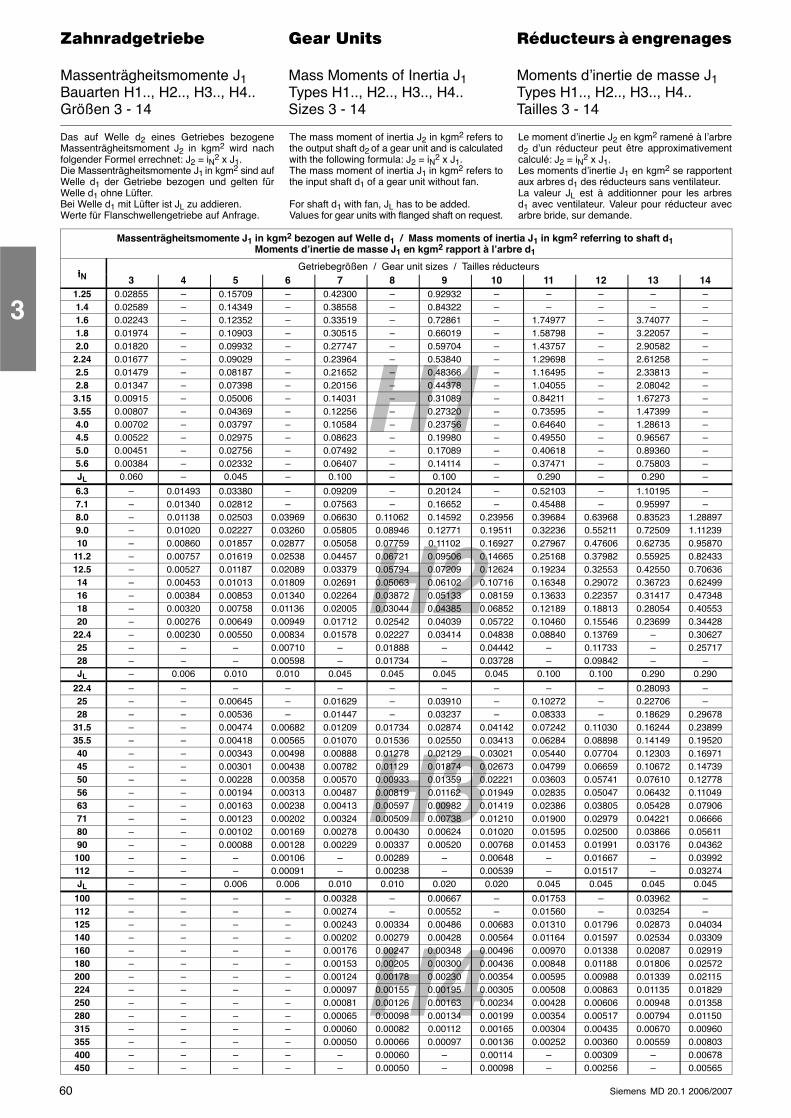
H1
H3
H2
H460 Siemens MD 20.1 2006/2007
������������� ���� �� ��������� � ����������
Massenträgheitsmomente J1 Mass Moments of Inertia J1 Moments d’inertie de masse J1Bauarten H1.., H2.., H3.., H4.. Types H1.., H2.., H3.., H4.. Types H1.., H2.., H3.., H4..Größen 3 - 14 Sizes 3 - 14 Tailles 3 - 14
Das auf Welle d2 eines Getriebes bezogeneMassenträgheitsmoment J2 in kgm2 wird nachfolgender Formel errechnet: J2 = iN2 x J1.Die Massenträgheitsmomente J1 in kgm2 sind aufWelle d1 der Getriebe bezogen und gelten fürWelle d1 ohne Lüfter.Bei Welle d1 mit Lüfter ist JL zu addieren.Werte für Flanschwellengetriebe auf Anfrage.
The mass moment of inertia J2 in kgm2 refers tothe output shaft d2 of a gear unit and is calculatedwith the following formula: J2 = iN2 x J1.The mass moment of inertia J1 in kgm2 refers tothe input shaft d1 of a gear unit without fan.
For shaft d1 with fan, JL has to be added.Values for gear units with flanged shaft on request.
Le moment d’inertie J2 en kgm2 ramené à l’arbred2 d’un réducteur peut être approximativementcalculé: J2 = iN2 x J1.Les moments d’inertie J1 en kgm2 se rapportentaux arbres d1 des réducteurs sans ventilateur.La valeur JL est à additionner pour les arbresd1 avec ventilateur. Valeur pour réducteur avecarbre bride, sur demande.
Massenträgheitsmomente J1 in kgm2 bezogen auf Welle d1 / Mass moments of inertia J1 in kgm2 referring to shaft d1Moments d’inertie de masse J1 en kgm2 rapport à l’arbre d1
iNGetriebegrößen / Gear unit sizes / Tailles réducteurs
iN 3 4 5 6 7 8 9 10 11 12 13 141.25 0.02855 – 0.15709 – 0.42300 – 0.92932 – – – – –1.4 0.02589 – 0.14349 – 0.38558 – 0.84322 – – – – –1.6 0.02243 – 0.12352 – 0.33519 – 0.72861 – 1.74977 – 3.74077 –1.8 0.01974 – 0.10903 – 0.30515 – 0.66019 – 1.58798 – 3.22057 –2.0 0.01820 – 0.09932 – 0.27747 – 0.59704 – 1.43757 – 2.90582 –2.24 0.01677 – 0.09029 – 0.23964 – 0.53840 – 1.29698 – 2.61258 –2.5 0.01479 – 0.08187 – 0.21652 – 0.48366 – 1.16495 – 2.33813 –2.8 0.01347 – 0.07398 – 0.20156 – 0.44378 – 1.04055 – 2.08042 –3.15 0.00915 – 0.05006 – 0.14031 – 0.31089 – 0.84211 – 1.67273 –3.55 0.00807 – 0.04369 – 0.12256 – 0.27320 – 0.73595 – 1.47399 –4.0 0.00702 – 0.03797 – 0.10584 – 0.23756 – 0.64640 – 1.28613 –4.5 0.00522 – 0.02975 – 0.08623 – 0.19980 – 0.49550 – 0.96567 –5.0 0.00451 – 0.02756 – 0.07492 – 0.17089 – 0.40618 – 0.89360 –5.6 0.00384 – 0.02332 – 0.06407 – 0.14114 – 0.37471 – 0.75803 –JL 0.060 – 0.045 – 0.100 – 0.100 – 0.290 – 0.290 –
6.3 – 0.01493 0.03380 – 0.09209 – 0.20124 – 0.52103 – 1.10195 –7.1 – 0.01340 0.02812 – 0.07563 – 0.16652 – 0.45488 – 0.95997 –8.0 – 0.01138 0.02503 0.03969 0.06630 0.11062 0.14592 0.23956 0.39684 0.63968 0.83523 1.288979.0 – 0.01020 0.02227 0.03260 0.05805 0.08946 0.12771 0.19511 0.32236 0.55211 0.72509 1.1123910 – 0.00860 0.01857 0.02877 0.05058 0.07759 0.11102 0.16927 0.27967 0.47606 0.62735 0.95870
11.2 – 0.00757 0.01619 0.02538 0.04457 0.06721 0.09506 0.14665 0.25168 0.37982 0.55925 0.8243312.5 – 0.00527 0.01187 0.02089 0.03379 0.05794 0.07209 0.12624 0.19234 0.32553 0.42550 0.7063614 – 0.00453 0.01013 0.01809 0.02691 0.05063 0.06102 0.10716 0.16348 0.29072 0.36723 0.6249916 – 0.00384 0.00853 0.01340 0.02264 0.03872 0.05133 0.08159 0.13633 0.22357 0.31417 0.4734818 – 0.00320 0.00758 0.01136 0.02005 0.03044 0.04385 0.06852 0.12189 0.18813 0.28054 0.4055320 – 0.00276 0.00649 0.00949 0.01712 0.02542 0.04039 0.05722 0.10460 0.15546 0.23699 0.34428
22.4 – 0.00230 0.00550 0.00834 0.01578 0.02227 0.03414 0.04838 0.08840 0.13769 – 0.3062725 – – – 0.00710 – 0.01888 – 0.04442 – 0.11733 – 0.2571728 – – – 0.00598 – 0.01734 – 0.03728 – 0.09842 – –JL – 0.006 0.010 0.010 0.045 0.045 0.045 0.045 0.100 0.100 0.290 0.290
22.4 – – – – – – – – – – 0.28093 –25 – – 0.00645 – 0.01629 – 0.03910 – 0.10272 – 0.22706 –28 – – 0.00536 – 0.01447 – 0.03237 – 0.08333 – 0.18629 0.29678
31.5 – – 0.00474 0.00682 0.01209 0.01734 0.02874 0.04142 0.07242 0.11030 0.16244 0.2389935.5 – – 0.00418 0.00565 0.01070 0.01536 0.02550 0.03413 0.06284 0.08898 0.14149 0.1952040 – – 0.00343 0.00498 0.00888 0.01278 0.02129 0.03021 0.05440 0.07704 0.12303 0.1697145 – – 0.00301 0.00438 0.00782 0.01129 0.01874 0.02673 0.04799 0.06659 0.10672 0.1473950 – – 0.00228 0.00358 0.00570 0.00933 0.01359 0.02221 0.03603 0.05741 0.07610 0.1277856 – – 0.00194 0.00313 0.00487 0.00819 0.01162 0.01949 0.02835 0.05047 0.06432 0.1104963 – – 0.00163 0.00238 0.00413 0.00597 0.00982 0.01419 0.02386 0.03805 0.05428 0.0790671 – – 0.00123 0.00202 0.00324 0.00509 0.00738 0.01210 0.01900 0.02979 0.04221 0.0666680 – – 0.00102 0.00169 0.00278 0.00430 0.00624 0.01020 0.01595 0.02500 0.03866 0.0561190 – – 0.00088 0.00128 0.00229 0.00337 0.00520 0.00768 0.01453 0.01991 0.03176 0.04362100 – – – 0.00106 – 0.00289 – 0.00648 – 0.01667 – 0.03992112 – – – 0.00091 – 0.00238 – 0.00539 – 0.01517 – 0.03274JL – – 0.006 0.006 0.010 0.010 0.020 0.020 0.045 0.045 0.045 0.045
100 – – – – 0.00328 – 0.00667 – 0.01753 – 0.03962 –112 – – – – 0.00274 – 0.00552 – 0.01560 – 0.03254 –125 – – – – 0.00243 0.00334 0.00486 0.00683 0.01310 0.01796 0.02873 0.04034140 – – – – 0.00202 0.00279 0.00428 0.00564 0.01164 0.01597 0.02534 0.03309160 – – – – 0.00176 0.00247 0.00348 0.00496 0.00970 0.01338 0.02087 0.02919180 – – – – 0.00153 0.00205 0.00300 0.00436 0.00848 0.01188 0.01806 0.02572200 – – – – 0.00124 0.00178 0.00230 0.00354 0.00595 0.00988 0.01339 0.02115224 – – – – 0.00097 0.00155 0.00195 0.00305 0.00508 0.00863 0.01135 0.01829250 – – – – 0.00081 0.00126 0.00163 0.00234 0.00428 0.00606 0.00948 0.01358280 – – – – 0.00065 0.00098 0.00134 0.00199 0.00354 0.00517 0.00794 0.01150315 – – – – 0.00060 0.00082 0.00112 0.00165 0.00304 0.00435 0.00670 0.00960355 – – – – 0.00050 0.00066 0.00097 0.00136 0.00252 0.00360 0.00559 0.00803400 – – – – – 0.00060 – 0.00114 – 0.00309 – 0.00678450 – – – – – 0.00050 – 0.00098 – 0.00256 – 0.00565
3
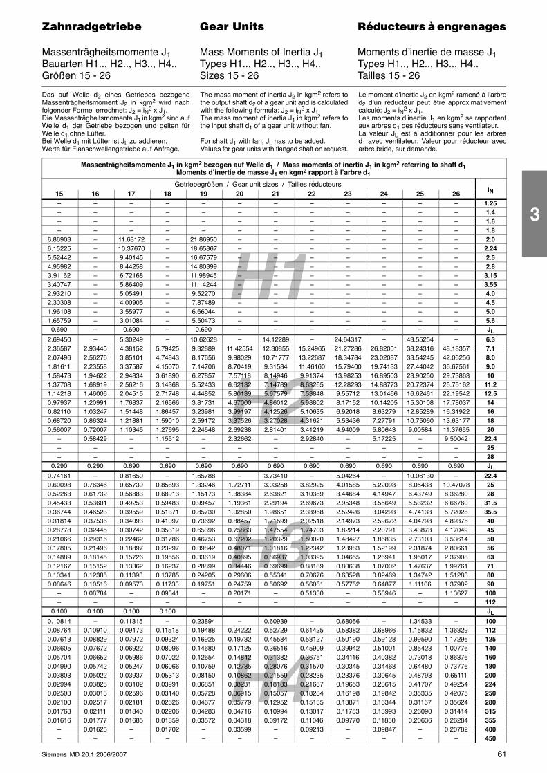
H1
H3
H2
H461Siemens MD 20.1 2006/2007
������������� ���� �� ��������� � ����������
Massenträgheitsmomente J1 Mass Moments of Inertia J1 Moments d’inertie de masse J1Bauarten H1.., H2.., H3.., H4.. Types H1.., H2.., H3.., H4.. Types H1.., H2.., H3.., H4..Größen 15 - 26 Sizes 15 - 26 Tailles 15 - 26
Das auf Welle d2 eines Getriebes bezogeneMassenträgheitsmoment J2 in kgm2 wird nachfolgender Formel errechnet: J2 = iN2 x J1.Die Massenträgheitsmomente J1 in kgm2 sind aufWelle d1 der Getriebe bezogen und gelten fürWelle d1 ohne Lüfter.Bei Welle d1 mit Lüfter ist JL zu addieren.Werte für Flanschwellengetriebe auf Anfrage.
The mass moment of inertia J2 in kgm2 refers tothe output shaft d2 of a gear unit and is calculatedwith the following formula: J2 = iN2 x J1.The mass moment of inertia J1 in kgm2 refers tothe input shaft d1 of a gear unit without fan.
For shaft d1 with fan, JL has to be added.Values for gear units with flanged shaft on request.
Le moment d’inertie J2 en kgm2 ramené à l’arbred2 d’un réducteur peut être approximativementcalculé: J2 = iN2 x J1.Les moments d’inertie J1 en kgm2 se rapportentaux arbres d1 des réducteurs sans ventilateur.La valeur JL est à additionner pour les arbresd1 avec ventilateur. Valeur pour réducteur avecarbre bride, sur demande.
Massenträgheitsmomente J1 in kgm2 bezogen auf Welle d1 / Mass moments of inertia J1 in kgm2 referring to shaft d1Moments d’inertie de masse J1 en kgm2 rapport à l’arbre d1
Getriebegrößen / Gear unit sizes / Tailles réducteursiN15 16 17 18 19 20 21 22 23 24 25 26iN
– – – – – – – – – – – – 1.25– – – – – – – – – – – – 1.4– – – – – – – – – – – – 1.6– – – – – – – – – – – – 1.8
6.86903 – 11.68172 – 21.86950 – – – – – – – 2.06.15225 – 10.37670 – 18.65867 – – – – – – – 2.245.52442 – 9.40145 – 16.67579 – – – – – – – 2.54.95982 – 8.44258 – 14.80399 – – – – – – – 2.83.91162 – 6.72168 – 11.98945 – – – – – – – 3.153.40747 – 5.86409 – 11.14244 – – – – – – – 3.552.93210 – 5.05491 – 9.52270 – – – – – – – 4.02.30308 – 4.00905 – 7.87489 – – – – – – – 4.51.96108 – 3.55977 – 6.66044 – – – – – – – 5.01.65759 – 3.01084 – 5.50473 – – – – – – – 5.60.690 – 0.690 – 0.690 – – – – – – – JL
2.69450 – 5.30249 – 10.62628 – 14.12289 – 24.64317 – 43.55254 – 6.32.36587 2.93445 4.38152 5.79425 9.32889 11.42554 12.30855 15.24965 21.27286 26.82051 38.24316 48.18357 7.12.07496 2.56276 3.85101 4.74843 8.17656 9.98029 10.71777 13.22687 18.34784 23.02087 33.54245 42.06256 8.01.81611 2.23558 3.37587 4.15070 7.14706 8.70419 9.31584 11.46160 15.79400 19.74133 27.44042 36.67561 9.01.58473 1.94622 2.94834 3.61890 6.27857 7.57118 8.14946 9.91374 13.98253 16.89503 23.90250 29.73863 101.37708 1.68919 2.56216 3.14368 5.52433 6.62132 7.14789 8.63265 12.28293 14.88773 20.72374 25.75162 11.21.14218 1.46006 2.04515 2.71748 4.44852 5.80139 5.67579 7.53848 9.55712 13.01466 16.62461 22.19542 12.50.97937 1.20991 1.76837 2.16566 3.81731 4.67000 4.86012 5.98802 8.17152 10.14205 15.30108 17.78037 140.82110 1.03247 1.51448 1.86457 3.23981 3.99197 4.12526 5.10635 6.92018 8.63279 12.85289 16.31922 160.68720 0.86324 1.21881 1.59010 2.59172 3.37526 3.27028 4.31621 5.53436 7.27791 10.75060 13.63177 180.56007 0.72007 1.10345 1.27695 2.24548 2.69238 2.81401 3.41219 4.94009 5.80643 9.00584 11.37655 20
– 0.58429 – 1.15512 – 2.32662 – 2.92840 – 5.17225 – 9.50042 22.4– – – – – – – – – – – – 25– – – – – – – – – – – – 28
0.290 0.290 0.690 0.690 0.690 0.690 0.690 0.690 0.690 0.690 0.690 0.690 JL
0.74161 – 0.81650 – 1.65788 – 3.73410 – 5.04264 – 10.06130 – 22.40.60098 0.76346 0.65739 0.85893 1.33246 1.72711 3.03258 3.82925 4.01585 5.22093 8.05438 10.47078 250.52263 0.61732 0.56883 0.68913 1.15173 1.38384 2.63821 3.10389 3.44684 4.14947 6.43749 8.36280 280.45433 0.53601 0.49253 0.59483 0.99457 1.19361 2.29194 2.69673 2.95348 3.55649 5.53232 6.66760 31.50.36744 0.46523 0.39559 0.51371 0.85730 1.02850 1.98651 2.33968 2.52426 3.04293 4.74133 5.72028 35.50.31814 0.37536 0.34093 0.41097 0.73692 0.88457 1.71599 2.02518 2.14973 2.59672 4.04798 4.89375 400.28778 0.32445 0.30742 0.35319 0.65396 0.75863 1.47554 1.74703 1.82214 2.20791 3.43873 4.17049 450.21066 0.29316 0.22462 0.31786 0.46753 0.67202 1.20329 1.50020 1.48427 1.86835 2.73103 3.53614 500.17805 0.21496 0.18897 0.23297 0.39842 0.48071 1.01816 1.22342 1.23983 1.52199 2.31874 2.80661 560.14889 0.18145 0.15726 0.19556 0.33619 0.40895 0.86937 1.03395 1.04655 1.26941 1.95017 2.37908 630.12167 0.15152 0.13362 0.16237 0.28899 0.34446 0.69699 0.88189 0.80638 1.07002 1.47637 1.99761 710.10341 0.12385 0.11393 0.13785 0.24205 0.29606 0.55341 0.70676 0.63528 0.82469 1.34742 1.51283 800.08646 0.10516 0.09573 0.11733 0.19751 0.24759 0.50692 0.56061 0.57752 0.64877 1.11106 1.37982 90
– 0.08784 – 0.09841 – 0.20171 – 0.51330 – 0.58946 – 1.13627 100– – – – – – – – – – – – 112
0.100 0.100 0.100 0.100 JL
0.10814 – 0.11315 – 0.23894 – 0.60939 – 0.68056 – 1.34533 – 1000.08764 0.10910 0.09173 0.11518 0.19488 0.24222 0.52729 0.61425 0.58382 0.68966 1.15832 1.36329 1120.07613 0.08829 0.07972 0.09324 0.16925 0.19732 0.45584 0.53127 0.50190 0.59128 0.99590 1.17296 1250.06605 0.07672 0.06922 0.08096 0.14680 0.17125 0.36516 0.45909 0.39942 0.51001 0.85423 1.00776 1400.05704 0.06652 0.05986 0.07022 0.12654 0.14842 0.31382 0.36751 0.34116 0.40382 0.73018 0.86376 1600.04990 0.05742 0.05247 0.06066 0.10759 0.12785 0.28076 0.31570 0.30345 0.34468 0.64480 0.73776 1800.03803 0.05022 0.03937 0.05313 0.08150 0.10862 0.21559 0.28235 0.23376 0.30645 0.48793 0.65111 2000.02994 0.03828 0.03102 0.03991 0.06851 0.08231 0.18183 0.21687 0.19653 0.23615 0.41707 0.49254 2240.02503 0.03013 0.02596 0.03140 0.05728 0.06915 0.15057 0.18284 0.16198 0.19842 0.35335 0.42075 2500.02100 0.02517 0.02181 0.02626 0.04677 0.05779 0.12952 0.15135 0.13871 0.16344 0.31167 0.35624 2800.01768 0.02111 0.01840 0.02206 0.04283 0.04716 0.10994 0.13017 0.11753 0.13993 0.26090 0.31414 3150.01616 0.01777 0.01685 0.01859 0.03572 0.04318 0.09172 0.11046 0.09770 0.11850 0.20636 0.26284 355
– 0.01625 – 0.01702 – 0.03599 – 0.09213 – 0.09847 – 0.20782 400– – – – – – – – – – – – 450
3
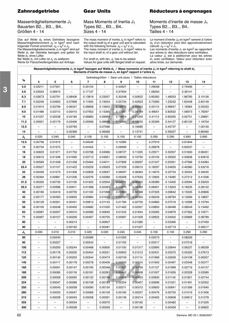
B2
B4
B3
62 Siemens MD 20.1 2006/2007
������������� ���� �� ��������� � ����������
Massenträgheitsmomente J1 Mass Moments of Inertia J1 Moments d’inertie de masse J1Bauarten B2.., B3.., B4.. Types B2.., B3.., B4.. Types B2.., B3.., B4..Größen 4 - 14 Sizes 4 - 14 Tailles 4 - 14
Das auf Welle d2 eines Getriebes bezogeneMassenträgheitsmoment J2 in kgm2 wird nachfolgender Formel errechnet: J2 = iN2 x J1.Die Massenträgheitsmomente J1 in kgm2 sind aufWelle d1 der Getriebe bezogen und gelten fürWelle d1 ohne Lüfter.Bei Welle d1 mit Lüfter ist JL zu addieren.Werte für Flanschwellengetriebe auf Anfrage.
The mass moment of inertia J2 in kgm2 refers tothe output shaft d2 of a gear unit and is calculatedwith the following formula: J2 = iN2 x J1.The mass moment of inertia J1 in kgm2 refers tothe input shaft d1 of a gear unit without fan.
For shaft d1 with fan, JL has to be added.Values for gear units with flanged shaft on request.
Le moment d’inertie J2 en kgm2 ramené à l’arbred2 d’un réducteur peut être approximativementcalculé: J2 = iN2 x J1.Les moments d’inertie J1 en kgm2 se rapportentaux arbres d1 des réducteurs sans ventilateur.La valeur JL est à additionner pour les arbresd1 avec ventilateur. Valeur pour réducteur avecarbre bride, sur demande.
Massenträgheitsmomente J1 in kgm2 bezogen auf Welle d1 / Mass moments of inertia J1 in kgm2 referring to shaft d1Moments d’inertie de masse J1 en kgm2 rapport à l’arbre d1
iNGetriebegrößen / Gear unit sizes / Tailles réducteurs
iN 4 5 6 7 8 9 10 11 12 13 14
5.0 0.03211 0.07501 – 0.20154 – 0.44627 – 1.29058 – 2.79496 –
5.6 0.03024 0.06915 – 0.17137 – 0.37934 – 1.08250 – 2.36141 –
6.3 0.02673 0.05791 0.08406 0.13819 0.23057 0.30248 0.50622 0.85265 1.48203 1.86785 3.10156
7.1 0.02249 0.04955 0.07668 0.11905 0.19554 0.25734 0.42923 0.73360 1.23242 1.63448 2.60149
8.0 0.01814 0.03799 0.06347 0.08858 0.15603 0.18973 0.33932 0.53110 0.96847 1.18384 2.05333
9.0 0.01486 0.03115 0.05410 0.07952 0.13365 0.17287 0.28749 0.48051 0.82632 1.06973 1.78297
10 0.01037 0.02538 0.04185 0.06883 0.09965 0.14614 0.21259 0.41113 0.60295 0.92751 1.29891
11.2 0.00931 0.02176 0.03406 0.05956 0.08888 0.12482 0.19220 0.35269 0.54127 0.80120 1.16704
12.5 – – 0.02760 – 0.07596 – 0.16085 – 0.45737 – 1.00155
14 – – 0.02366 – 0.06566 – 0.13741 – 0.39227 – 0.86460
JL 0.020 0.045 0.045 0.100 0.100 0.100 0.100 0.290 0.290 0.690 0.690
12.5 0.00756 0.01615 – 0.04549 – 0.10285 – 0.27616 – 0.61844 –
14 0.00734 0.01575 – 0.04455 – 0.09999 – 0.26878 – 0.60537 –
16 0.00623 0.01371 0.01750 0.03768 0.04966 0.08727 0.11205 0.23571 0.30357 0.51600 0.66451
18 0.00610 0.01346 0.01695 0.03713 0.04831 0.08550 0.10750 0.23105 0.29302 0.50838 0.64618
20 0.00569 0.01248 0.01458 0.03464 0.04011 0.07999 0.09297 0.21547 0.25301 0.47566 0.54284
22.4 0.00527 0.01157 0.01422 0.03229 0.03933 0.07329 0.09015 0.18297 0.24635 0.40380 0.53216
25 0.00456 0.01073 0.01308 0.02828 0.03637 0.06097 0.08364 0.14675 0.22734 0.32054 0.49435
28 0.00394 0.00881 0.01206 0.02376 0.03369 0.05206 0.07633 0.12605 0.19285 0.27212 0.41936
31.5 0.00335 0.00730 0.01109 0.01922 0.02934 0.04011 0.06322 0.09389 0.15405 0.20094 0.33203
35.5 0.00271 0.00586 0.00911 0.01568 0.02463 0.03275 0.05390 0.08401 0.13203 0.18235 0.28152
40 0.00190 0.00416 0.00755 0.01100 0.01996 0.02660 0.04168 0.07225 0.09842 0.15335 0.20806
45 0.00177 0.00393 0.00605 0.00984 0.01624 0.02280 0.03393 0.06249 0.08784 0.13099 0.18837
50 0.00129 0.00301 0.00431 0.00812 0.01143 0.01784 0.02750 0.04683 0.07516 0.10268 0.15794
56 0.00105 0.00248 0.00405 0.00682 0.01020 0.01462 0.02357 0.03850 0.06498 0.08549 0.13492
63 0.00087 0.00207 0.00310 0.00589 0.00840 0.01242 0.01844 0.03265 0.04876 0.07262 0.10571
71 0.00067 0.00157 0.00256 0.00467 0.00705 0.00997 0.01509 0.02622 0.04002 0.05866 0.08789
80 – – 0.00213 – 0.00607 – 0.01280 – 0.03390 – 0.07459
90 – – 0.00162 – 0.00481 – 0.01027 – 0.02719 – 0.06017
JL 0.006 0.010 0.010 0.020 0.020 0.045 0.045 0.100 0.100 0.290 0.290
80 – 0.00240 – 0.00589 – 0.01293 – 0.03573 – 0.08226 –
90 – 0.00227 – 0.00543 – 0.01193 – 0.03317 – 0.07518 –
100 – 0.00200 0.00244 0.00468 0.00600 0.01100 0.01317 0.02895 0.03644 0.06237 0.08339
112 – 0.00176 0.00230 0.00404 0.00551 0.00903 0.01212 0.02431 0.03375 0.05320 0.07613
125 – 0.00145 0.00202 0.00344 0.00474 0.00749 0.01114 0.01969 0.02939 0.04108 0.06307
140 – 0.00117 0.00178 0.00278 0.00409 0.00600 0.00915 0.01603 0.02467 0.03348 0.05377
160 – 0.00091 0.00147 0.00195 0.00348 0.00427 0.00759 0.01127 0.01999 0.02716 0.04157
180 – 0.00085 0.00118 0.00181 0.00281 0.00402 0.00608 0.01007 0.01626 0.02328 0.03385
200 – 0.00058 0.00092 0.00132 0.00198 0.00308 0.00433 0.00830 0.01145 0.01821 0.02744
224 – 0.00047 0.00086 0.00108 0.00183 0.00254 0.00407 0.00696 0.01021 0.01491 0.02352
250 – 0.00043 0.00058 0.00090 0.00134 0.00211 0.00312 0.00600 0.00841 0.01266 0.01840
280 – 0.00033 0.00047 0.00069 0.00109 0.00160 0.00257 0.00476 0.00705 0.01016 0.01506
315 – 0.00028 0.00043 0.00058 0.00091 0.00136 0.00214 0.00405 0.00608 0.00812 0.01278
355 – – 0.00034 – 0.00070 – 0.00162 – 0.00482 – 0.01025
400 – – 0.00028 – 0.00059 – 0.00138 – 0.00409 – 0.00820
3
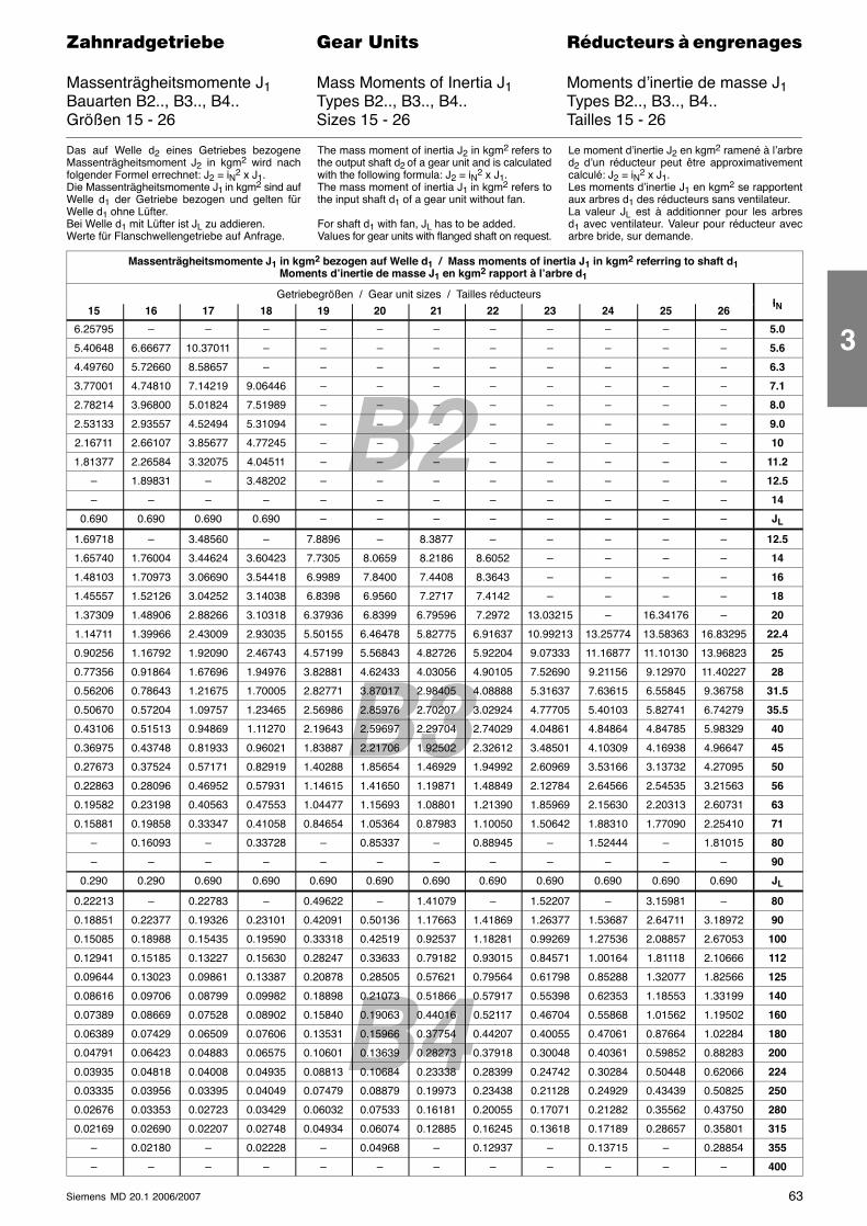
B2
B4
B3
63Siemens MD 20.1 2006/2007
������������� ���� �� ��������� � ����������
Massenträgheitsmomente J1 Mass Moments of Inertia J1 Moments d’inertie de masse J1Bauarten B2.., B3.., B4.. Types B2.., B3.., B4.. Types B2.., B3.., B4..Größen 15 - 26 Sizes 15 - 26 Tailles 15 - 26
Das auf Welle d2 eines Getriebes bezogeneMassenträgheitsmoment J2 in kgm2 wird nachfolgender Formel errechnet: J2 = iN2 x J1.Die Massenträgheitsmomente J1 in kgm2 sind aufWelle d1 der Getriebe bezogen und gelten fürWelle d1 ohne Lüfter.Bei Welle d1 mit Lüfter ist JL zu addieren.Werte für Flanschwellengetriebe auf Anfrage.
The mass moment of inertia J2 in kgm2 refers tothe output shaft d2 of a gear unit and is calculatedwith the following formula: J2 = iN2 x J1.The mass moment of inertia J1 in kgm2 refers tothe input shaft d1 of a gear unit without fan.
For shaft d1 with fan, JL has to be added.Values for gear units with flanged shaft on request.
Le moment d’inertie J2 en kgm2 ramené à l’arbred2 d’un réducteur peut être approximativementcalculé: J2 = iN2 x J1.Les moments d’inertie J1 en kgm2 se rapportentaux arbres d1 des réducteurs sans ventilateur.La valeur JL est à additionner pour les arbresd1 avec ventilateur. Valeur pour réducteur avecarbre bride, sur demande.
Massenträgheitsmomente J1 in kgm2 bezogen auf Welle d1 / Mass moments of inertia J1 in kgm2 referring to shaft d1Moments d’inertie de masse J1 en kgm2 rapport à l’arbre d1
Getriebegrößen / Gear unit sizes / Tailles réducteursiN15 16 17 18 19 20 21 22 23 24 25 26iN
6.25795 – – – – – – – – – – – 5.0
5.40648 6.66677 10.37011 – – – – – – – – – 5.6
4.49760 5.72660 8.58657 – – – – – – – – – 6.3
3.77001 4.74810 7.14219 9.06446 – – – – – – – – 7.1
2.78214 3.96800 5.01824 7.51989 – – – – – – – – 8.0
2.53133 2.93557 4.52494 5.31094 – – – – – – – – 9.0
2.16711 2.66107 3.85677 4.77245 – – – – – – – – 10
1.81377 2.26584 3.32075 4.04511 – – – – – – – – 11.2
– 1.89831 – 3.48202 – – – – – – – – 12.5
– – – – – – – – – – – – 14
0.690 0.690 0.690 0.690 – – – – – – – – JL
1.69718 – 3.48560 – 7.8896 – 8.3877 – – – – – 12.5
1.65740 1.76004 3.44624 3.60423 7.7305 8.0659 8.2186 8.6052 – – – – 14
1.48103 1.70973 3.06690 3.54418 6.9989 7.8400 7.4408 8.3643 – – – – 16
1.45557 1.52126 3.04252 3.14038 6.8398 6.9560 7.2717 7.4142 – – – – 18
1.37309 1.48906 2.88266 3.10318 6.37936 6.8399 6.79596 7.2972 13.03215 – 16.34176 – 20
1.14711 1.39966 2.43009 2.93035 5.50155 6.46478 5.82775 6.91637 10.99213 13.25774 13.58363 16.83295 22.4
0.90256 1.16792 1.92090 2.46743 4.57199 5.56843 4.82726 5.92204 9.07333 11.16877 11.10130 13.96823 25
0.77356 0.91864 1.67696 1.94976 3.82881 4.62433 4.03056 4.90105 7.52690 9.21156 9.12970 11.40227 28
0.56206 0.78643 1.21675 1.70005 2.82771 3.87017 2.98405 4.08888 5.31637 7.63615 6.55845 9.36758 31.5
0.50670 0.57204 1.09757 1.23465 2.56986 2.85976 2.70207 3.02924 4.77705 5.40103 5.82741 6.74279 35.5
0.43106 0.51513 0.94869 1.11270 2.19643 2.59697 2.29704 2.74029 4.04861 4.84864 4.84785 5.98329 40
0.36975 0.43748 0.81933 0.96021 1.83887 2.21706 1.92502 2.32612 3.48501 4.10309 4.16938 4.96647 45
0.27673 0.37524 0.57171 0.82919 1.40288 1.85654 1.46929 1.94992 2.60969 3.53166 3.13732 4.27095 50
0.22863 0.28096 0.46952 0.57931 1.14615 1.41650 1.19871 1.48849 2.12784 2.64566 2.54535 3.21563 56
0.19582 0.23198 0.40563 0.47553 1.04477 1.15693 1.08801 1.21390 1.85969 2.15630 2.20313 2.60731 63
0.15881 0.19858 0.33347 0.41058 0.84654 1.05364 0.87983 1.10050 1.50642 1.88310 1.77090 2.25410 71
– 0.16093 – 0.33728 – 0.85337 – 0.88945 – 1.52444 – 1.81015 80
– – – – – – – – – – – – 90
0.290 0.290 0.690 0.690 0.690 0.690 0.690 0.690 0.690 0.690 0.690 0.690 JL
0.22213 – 0.22783 – 0.49622 – 1.41079 – 1.52207 – 3.15981 – 80
0.18851 0.22377 0.19326 0.23101 0.42091 0.50136 1.17663 1.41869 1.26377 1.53687 2.64711 3.18972 90
0.15085 0.18988 0.15435 0.19590 0.33318 0.42519 0.92537 1.18281 0.99269 1.27536 2.08857 2.67053 100
0.12941 0.15185 0.13227 0.15630 0.28247 0.33633 0.79182 0.93015 0.84571 1.00164 1.81118 2.10666 112
0.09644 0.13023 0.09861 0.13387 0.20878 0.28505 0.57621 0.79564 0.61798 0.85288 1.32077 1.82566 125
0.08616 0.09706 0.08799 0.09982 0.18898 0.21073 0.51866 0.57917 0.55398 0.62353 1.18553 1.33199 140
0.07389 0.08669 0.07528 0.08902 0.15840 0.19063 0.44016 0.52117 0.46704 0.55868 1.01562 1.19502 160
0.06389 0.07429 0.06509 0.07606 0.13531 0.15966 0.37754 0.44207 0.40055 0.47061 0.87664 1.02284 180
0.04791 0.06423 0.04883 0.06575 0.10601 0.13639 0.28273 0.37918 0.30048 0.40361 0.59852 0.88283 200
0.03935 0.04818 0.04008 0.04935 0.08813 0.10684 0.23338 0.28399 0.24742 0.30284 0.50448 0.62066 224
0.03335 0.03956 0.03395 0.04049 0.07479 0.08879 0.19973 0.23438 0.21128 0.24929 0.43439 0.50825 250
0.02676 0.03353 0.02723 0.03429 0.06032 0.07533 0.16181 0.20055 0.17071 0.21282 0.35562 0.43750 280
0.02169 0.02690 0.02207 0.02748 0.04934 0.06074 0.12885 0.16245 0.13618 0.17189 0.28657 0.35801 315
– 0.02180 – 0.02228 – 0.04968 – 0.12937 – 0.13715 – 0.28854 355
– – – – – – – – – – – – 400
3
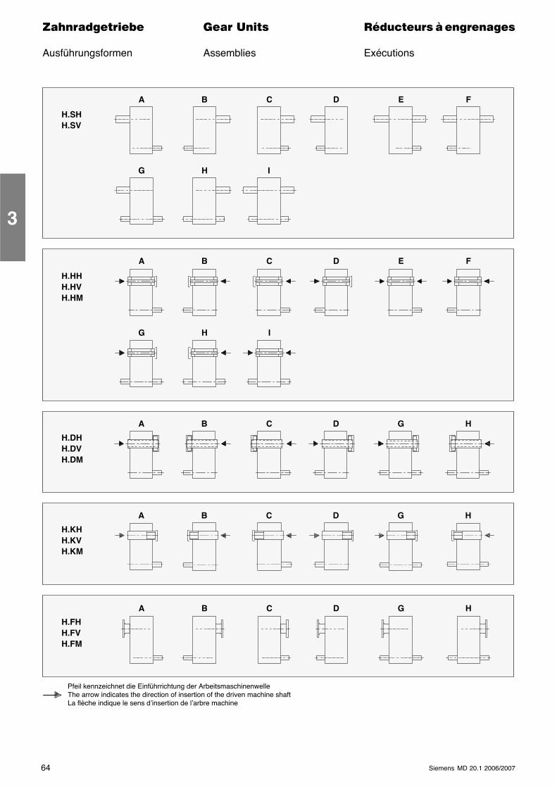
64 Siemens MD 20.1 2006/2007
������������� ���� �� ��������� � ����������
Ausführungsformen Assemblies Exécutions
H.SHH.SV
A B C D E F
G H I
H.HHH.HVH.HM
A
G
B C D E F
H I
H.DHH.DVH.DM
H.KHH.KVH.KM
H.FHH.FVH.FM
A B C D G H
Pfeil kennzeichnet die Einführrichtung der ArbeitsmaschinenwelleThe arrow indicates the direction of insertion of the driven machine shaftLa flèche indique le sens d’insertion de l’arbre machine
A B C D G H
A B C D G H
3
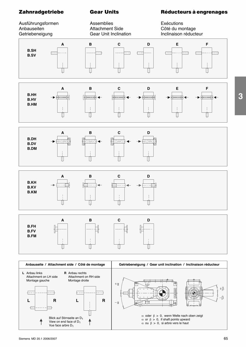
65Siemens MD 20.1 2006/2007
������������� ���� �� ��������� � ����������
Ausführungsformen Assemblies ExécutionsAnbauseiten Attachment Side Côté du montageGetriebeneigung Gear Unit Inclination Inclinaison réducteur
B.SHB.SV
A B C D E F
B.HHB.HVB.HM
A B C D E F
B.DHB.DVB.DM
A B C D
B.KHB.KVB.KM
B.FHB.FVB.FM
A B C D
R
Anbauseite / Attachment side / Côté de montage
L RL
L Anbau linksAttachment on LH sideMontage gauche
R Anbau rechtsAttachment on RH sideMontage droite
Getriebeneigung / Gear unit inclination / Inclinaison réducteur
A B C D
α oder β > 0, wenn Welle nach oben zeigtα or β > 0, if shaft points upwardα ou β > 0, si arbre vers le haut
Blick auf Stirnseite an D1View on end face of D1Vue face arbre D1
3
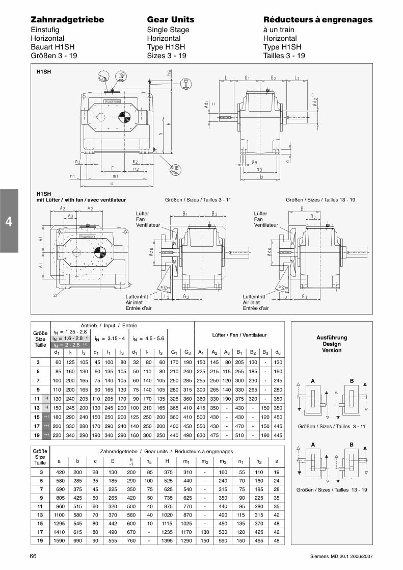
66 Siemens MD 20.1 2006/2007
������������� ���� �� ��������� � ����������Einstufig Single Stage à un trainHorizontal Horizontal HorizontalBauart H1SH Type H1SH Type H1SHGrößen 3 - 19 Sizes 3 - 19 Tailles 3 - 19
LüfterFanVentilateur
LufteintrittAir inletEntrée d’air
Größen / Sizes / Tailles 3 - 11 Größen / Sizes / Tailles 13 - 19H1SHmit Lüfter / with fan / avec ventilateur
LüfterFanVentilateur
LufteintrittAir inletEntrée d’air
H1SH
Antrieb / Input / Entrée
Größe iN = 1.25 - 2.8Lüfter / Fan / VentilateurGröße
Size iN = 1.6 - 2.8 +) iN = 3.15 - 4 iN = 4.5 - 5.6Lüfter / Fan / Ventilateur
SizeTaille iN = 2 - 2.8 ++)
iN 3.15 4 iN 4.5 5.6Taille
d1 l1 l3 d1 l1 l3 d1 l1 l3 G1 G3 A1 A2 A3 B1 B2 B3 d6
3 60 125 105 45 100 80 32 80 60 170 190 150 145 80 205 130 - 130
5 85 160 130 60 135 105 50 110 80 210 240 225 215 115 255 185 - 190
7 100 200 165 75 140 105 60 140 105 250 285 255 250 120 300 230 - 245
9 110 200 165 90 165 130 75 140 105 280 315 300 265 140 330 265 - 280
11 +) 130 240 205 110 205 170 90 170 135 325 360 360 330 190 375 320 - 350
13 +) 150 245 200 130 245 200 100 210 165 365 410 415 350 - 430 - 150 350
15 ++) 180 290 240 150 250 200 125 250 200 360 410 500 430 - 430 - 120 450
17 ++) 200 330 280 170 290 240 140 250 200 400 450 550 430 - 470 - 150 445
19 ++) 220 340 290 190 340 290 160 300 250 440 490 630 475 - 510 - 190 445
GrößeSize
Zahnradgetriebe / Gear units / Réducteurs à engrenagesSizeTaille a b c E h
-1h5 H m1 m2 m3 n1 n2 s
3 420 200 28 130 200 85 375 310 - 160 55 110 19
5 580 285 35 185 290 100 525 440 - 240 70 160 24
7 690 375 45 225 350 75 625 540 - 315 75 195 28
9 805 425 50 265 420 50 735 625 - 350 90 225 35
11 960 515 60 320 500 40 875 770 - 440 95 280 35
13 1100 580 70 370 580 40 1020 870 - 490 115 315 42
15 1295 545 80 442 600 10 1115 1025 - 450 135 370 48
17 1410 615 80 490 670 - 1235 1170 130 530 120 425 42
19 1590 690 90 555 760 - 1395 1290 150 590 150 465 48
4
AusführungDesignVersion
A B
A B
Größen / Sizes / Tailles 3 - 11
Größen / Sizes / Tailles 13 - 19
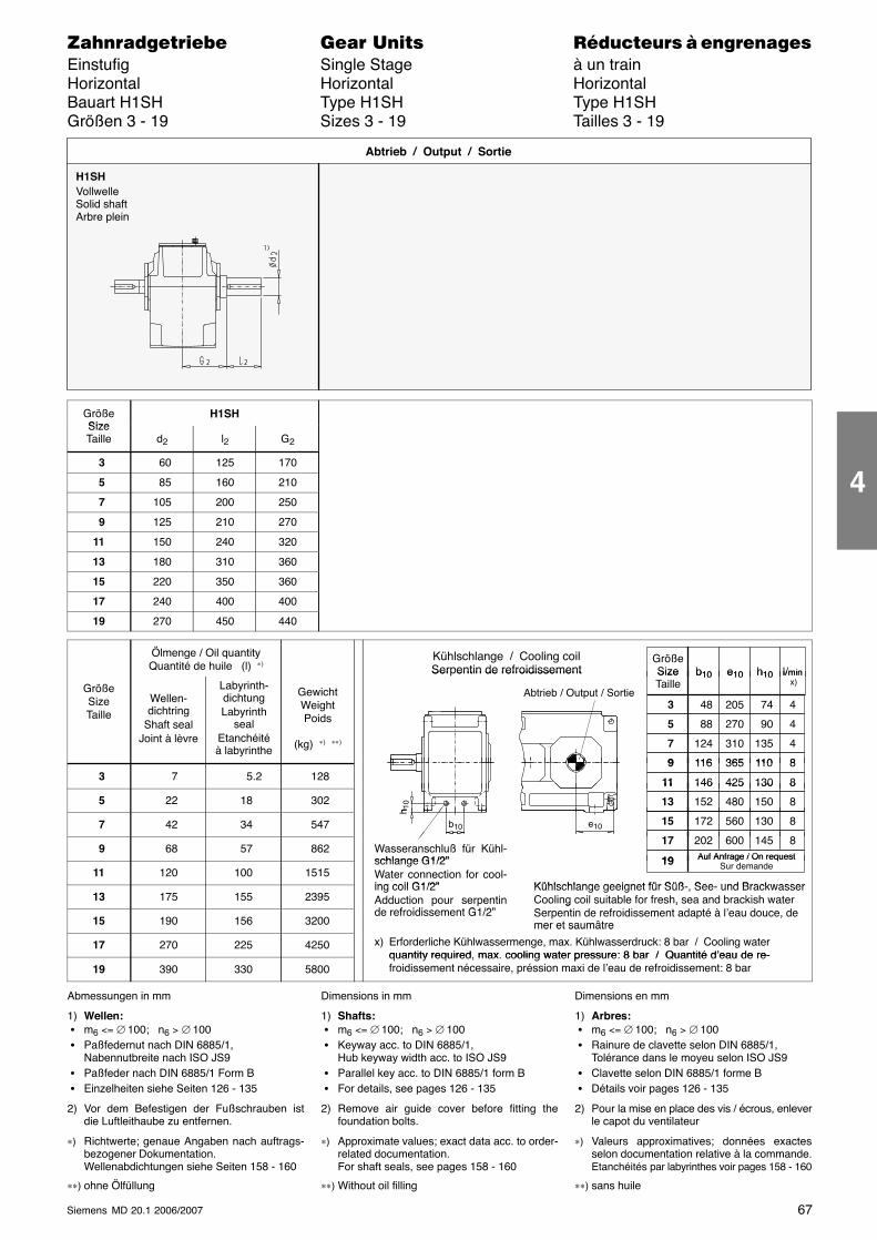
67Siemens MD 20.1 2006/2007
������������� ���� �� ��������� � ����������Einstufig Single Stage à un trainHorizontal Horizontal HorizontalBauart H1SH Type H1SH Type H1SHGrößen 3 - 19 Sizes 3 - 19 Tailles 3 - 19
H1SHVollwelleSolid shaftArbre plein
Abtrieb / Output / Sortie
GrößeSize
H1SHSizeTaille d2 l2 G2
3 60 125 170
5 85 160 210
7 105 200 250
9 125 210 270
11 150 240 320
13 180 310 360
15 220 350 360
17 240 400 400
19 270 450 440
Ölmenge / Oil quantityQuantité de huile (l) ∗) Größe
Size l/minb10 e10 h10
Kühlschlange / Cooling coilSerpentin de refroidissement
GrößeSizeTaille
Wellen-dichtring
Shaft sealJoint à lèvre
Labyrinth-dichtungLabyrinth
sealEtanchéitéà labyrinthe
GewichtWeightPoids
(kg) ∗) ∗∗)
Abtrieb / Output / Sortie
SizeTaille
48 74
l/min x)
3 205
b10 e10 h10
4
88 90 5 270 4
124 135 7 310 4
116 1109 365 8
Ser entin de refroidissement
3 7 5.2 128116 110 9 365 8
146 13011 425 8
5 22 18 302
146 13011 425 8
152 15013 480 8
h 10
7 42 34 547 172 13015 560 8
202 14517 600 8
b10
h 1
e10
9 68 57 862202 14517 600 8
19Wasseranschluß für Kühl-schlange G1/2” Auf Anfrage / On request
11 120 100 151519schlange G1/2”
Water connection for cool-ing coil G1/2” Kühlschlange geeignet für Süß See und Brackwasser
Auf Anfrage / On requestSur demande
13 175 155 2395ing coil G1/2”Adduction pour serpentind f idi t G1/2”
Kühlschlange geeignet für Süß-, See- und BrackwasserCooling coil suitable for fresh, sea and brackish waterS i d f idi d é à l’ d d
15 190 156 3200de refroidissement G1/2”
g ,Serpentin de refroidissement adapté à l’eau douce, demer et saumâtre
17 270 225 4250
mer et saumâtre
x) Erforderliche Kühlwassermenge, max. Kühlwasserdruck: 8 bar / Cooling waterquantity required max cooling water pressure: 8 bar / Quantité d’eau de re-
19 390 330 5800quantity required, max. cooling water pressure: 8 bar / Quantité d’eau de re-froidissement nécessaire, préssion maxi de l’eau de refroidissement: 8 bar
Abmessungen in mm
1) Wellen: � m6 <= ∅ 100; n6 > ∅ 100 � Paßfedernut nach DIN 6885/1,
Nabennutbreite nach ISO JS9 � Paßfeder nach DIN 6885/1 Form B � Einzelheiten siehe Seiten 126 - 135
2) Vor dem Befestigen der Fußschrauben istdie Luftleithaube zu entfernen.
∗) Richtwerte; genaue Angaben nach auftrags-bezogener Dokumentation.Wellenabdichtungen siehe Seiten 158 - 160
∗∗) ohne Ölfüllung
Dimensions in mm
1) Shafts: � m6 <= ∅ 100; n6 > ∅ 100 � Keyway acc. to DIN 6885/1,
Hub keyway width acc. to ISO JS9 � Parallel key acc. to DIN 6885/1 form B � For details, see pages 126 - 135
2) Remove air guide cover before fitting thefoundation bolts.
∗) Approximate values; exact data acc. to order-related documentation.For shaft seals, see pages 158 - 160
∗∗) Without oil filling
Dimensions en mm
1) Arbres: � m6 <= ∅ 100; n6 > ∅ 100 � Rainure de clavette selon DIN 6885/1,
Tolérance dans le moyeu selon ISO JS9 � Clavette selon DIN 6885/1 forme B � Détails voir pages 126 - 135
2) Pour la mise en place des vis / écrous, enleverle capot du ventilateur
∗) Valeurs approximatives; données exactesselon documentation relative à la commande.Etanchéités par labyrinthes voir pages 158 - 160
∗∗) sans huile
4
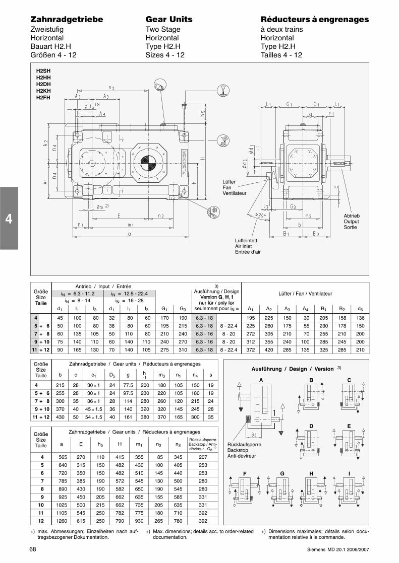
68 Siemens MD 20.1 2006/2007
������������� ���� �� ��������� � ����������Zweistufig Two Stage à deux trainsHorizontal Horizontal HorizontalBauart H2.H Type H2.H Type H2.HGrößen 4 - 12 Sizes 4 - 12 Tailles 4 - 12
LüfterFanVentilateur
LufteintrittAir inletEntrée d’air
AbtriebOutputSortie
H2SHH2HHH2DHH2KHH2FH
G ößAntrieb / Input / Entrée 3)
A füh / D iGrößeSize
iN = 6.3 - 11.2 iN = 12.5 - 22.4
)Ausführung / Design
Version G H ILüfter / Fan / Ventilateur
SizeTaille iN = 8 - 14 iN = 16 - 28
Version G, H, Inur für / only for
Lüfter / Fan / Ventilateur
Tailled1 l1 l3 d1 l1 l3 G1 G3
nur für / only forseulement pour iN = A1 A2 A3 A4 B1 B2 d6
4 45 100 80 32 80 60 170 190 6.3 - 18 195 225 150 30 205 158 136
5 + 6 50 100 80 38 80 60 195 215 6.3 - 18 8 - 22.4 225 260 175 55 230 178 150
7 + 8 60 135 105 50 110 80 210 240 6.3 - 16 8 - 20 272 305 210 70 255 210 200
9 + 10 75 140 110 60 140 110 240 270 6.3 - 16 8 - 20 312 355 240 100 285 245 200
11 + 12 90 165 130 70 140 105 275 310 6.3 - 18 8 - 22.4 372 420 285 135 325 285 210
GrößeSize
Zahnradgetriebe / Gear units / Réducteurs à engrenagesSizeTaille b c c1 D5 g h
-1m3 n1 n4 s
4 215 28 30 ± 1 24 77.5 200 180 105 150 19
5 + 6 255 28 30 ± 1 24 97.5 230 220 105 180 19
7 + 8 300 35 36 ± 1 28 114 280 260 120 215 24
9 + 10 370 40 45 ± 1.5 36 140 320 320 145 245 28
11 + 12 430 50 54 ± 1.5 40 161 380 370 165 300 35
Größe Zahnradgetriebe / Gear units / Réducteurs à engrenagesGrößeSizeTaille a E h5 H m1 n2 n3
RücklaufsperreBackstop / Anti-dévireur G8 +)
4 565 270 110 415 355 85 345 207
5 640 315 150 482 430 100 405 253
6 720 350 150 482 510 145 440 253
7 785 385 190 572 545 130 500 280
8 890 430 190 582 650 190 545 280
9 925 450 205 662 635 155 585 331
10 1025 500 215 662 735 205 635 331
11 1105 545 250 782 775 180 710 392
12 1260 615 250 790 930 265 780 392
+) max. Abmessungen; Einzelheiten nach auf-tragsbezogener Dokumentation.
+) Max. dimensions; details acc. to order-relateddocumentation.
+) Dimensions maximales; détails selon docu-mentation relative à la commande.
4
Ausführung / Design / Version 3)
A B C
D E
G H I
RücklaufsperreBackstopAnti-dévireur
F
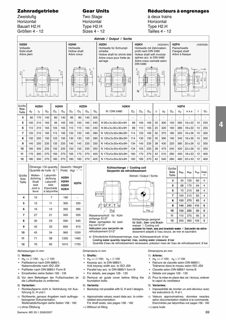
69Siemens MD 20.1 2006/2007
������������� ���� �� ��������� � ����������Zweistufig Two Stage à deux trainsHorizontal Horizontal HorizontalBauart H2.H Type H2.H Type H2.HGrößen 4 - 12 Sizes 4 - 12 Tailles 4 - 12
H2SHVollwelleSolid shaftArbre plein
H2HHHohlwelleHollow shaftArbre creux
H2DHHohlwelle für Schrumpf-scheibeHollow shaft for shrink diskArbre creux pour frette deserrage
Abtrieb / Output / Sortie
H2KHHohlwelle mit Zahnnaben-profil nach DIN 5480Hollow shaft with involutesplines acc. to DIN 5480Arbre creux cannelé selonDIN 5480
H2FHFlanschwelleFlanged shaftArbre à flasque
N
( K20/004 ) ( K20/028 )
GrößeSize
H2SH H2HH H2DH H2KH H2FHSizeTaille d2 l2 G2 D2 G4 D2 D3 G4 G5 N / DIN 5480 D2 D3 G4 c d2 D3 k2 n x s t G7
4 80 170 140 80 140 85 85 140 205 - - - - - - - - - - -
5 100 210 165 95 165 100 100 165 240 N 95 x 3 x 30 x 30 x 9H 89 100 165 25 300 150 260 16 x 22 10 255
6 110 210 165 105 165 110 110 165 240 N 95 x 3 x 30 x 30 x 9H 89 110 165 25 320 160 280 18 x 22 10 255
7 120 210 195 115 195 120 120 195 280 N 120 x 3 x 30 x 38 x 9H 114 120 195 30 370 180 320 16 x 26 10 300
8 130 250 195 125 195 130 130 195 285 N 120 x 3 x 30 x 38 x 9H 114 130 195 30 390 190 340 18 x 26 10 300
9 140 250 235 135 235 140 145 235 330 N 140 x 3 x 30 x 45 x 9H 134 145 235 38 430 220 380 20 x 26 12 350
10 160 300 235 150 235 150 155 235 350 N 140 x 3 x 30 x 45 x 9H 134 155 235 38 470 240 420 22 x 26 12 350
11 170 300 270 165 270 165 170 270 400 N 170 x 5 x 30 x 32 x 9H 160 170 270 42 510 260 450 18 x 33 12 400
12 180 300 270 180 270 180 185 270 405 N 170 x 5 x 30 x 32 x 9H 160 185 270 42 540 280 480 22 x 33 12 400
Ölmenge / Oil quantityQuantité de huile (l) ∗)
Gewicht / WeightPoids (kg) ∗) ∗∗) Größe
Size l/minb10 e10 h10
Kühlschlange / Cooling coilSerpentin de refroidissement
GrößeSizeTaille
Wellen-dichtring
Shaftseal
Joint àlèvre
Labyrinth-dichtungLabyrinth
sealEtanchéitéà labyrinthe
H2SHH2HHH2DHH2KH
H2FH
Abtrieb / Output / SortieSizeTaille
34 60
l/min x)
4 155
b10 e10 h10
4
68 64 5 170 4
70 68 6 215 4
p
4 10 7 190 -100 83 7 210 4
100 838 270 4 5 15 11 300 335
100 83 8 270 4
140 1109 245 810
6 16 12 355 395140 110 9 245 8
100 9510 295 8b10
h 10
e10
7 27 21 505 555
100 9510 295 8
110 9511 275 8Wasseranschluß für Kühl-hl G1/2”
b10 e10
8 30 23 590 645
0 955 8
200 10912 360 8schlange G1/2”Water connection for cool-
Kühlschlange geeignetfür Süß-, See- und Brack-
9 42 33 830 915
Water connection for cooling coil G1/2”Adduction pour serpentin de
für Süß-, See- und Brack-wasser / Cooling coilsuitable for fresh, sea and brackish water / Serpentin de refroi-
10 45 34 960 1050Adduction our ser entin derefroidissement G1/2”
suitable for fresh, sea and brackish water / Ser entin de refroi-dissement adapté à l’eau douce, de mer et saumâtre
11 71 58 1335 1465 x) Erforderliche Kühlwassermenge, max. Kühlwasserdruck: 8 barCooling water quantity required; max. cooling water pressure: 8 bar
12 76 60 1615 1755
Cooling water quantity required max. cooling water ressure: 8 barQuantité d’eau de refroidissement nécessaire, préssion maxi de l’eau de refroidissement: 8 bar
Abmessungen in mm
1) Wellen: � m6 <= ∅ 100; n6 > ∅ 100 � Paßfedernut nach DIN 6885/1,
Nabennutbreite nach ISO JS9 � Paßfeder nach DIN 6885/1 Form B � Einzelheiten siehe Seiten 126 - 135
2) Vor dem Befestigen der Fußschrauben istdie Luftleithaube zu entfernen.
3) Varianten: � Rücklaufsperre nicht in Verbindung mit Aus-
führung G, H und I.∗) Richtwerte; genaue Angaben nach auftrags-
bezogener Dokumentation.Wellenabdichtungen siehe Seiten 158 - 160
∗∗) ohne Ölfüllung
Dimensions in mm
1) Shafts: � m6 <= ∅ 100; n6 > ∅ 100 � Keyway acc. to DIN 6885/1,
Hub keyway width acc. to ISO JS9 � Parallel key acc. to DIN 6885/1 form B � For details, see pages 126 - 135
2) Remove air guide cover before fitting thefoundation bolts.
3) Variants: � Backstop not possible with G, H and I designs.
∗) Approximate values; exact data acc. to order-related documentation.For shaft seals, see pages 158 - 160
∗∗) Without oil filling
Dimensions en mm
1) Arbres: � m6 <= ∅ 100; n6 > ∅ 100 � Rainure de clavette selon DIN 6885/1,
Tolérance dans le moyeu selon ISO JS9 � Clavette selon DIN 6885/1 forme B � Détails voir pages 126 - 135
2) Pour la mise en place des vis / écrous, enleverle capot du ventilateur
3) Variantes: � Impossibilité de monter un anti-dévireur avec
les exécutions G, H et I.∗) Valeurs approximatives; données exactes
selon documentation relative à la commande.Etanchéités par labyrinthes voir pages 158 - 160
∗∗) sans huile
4
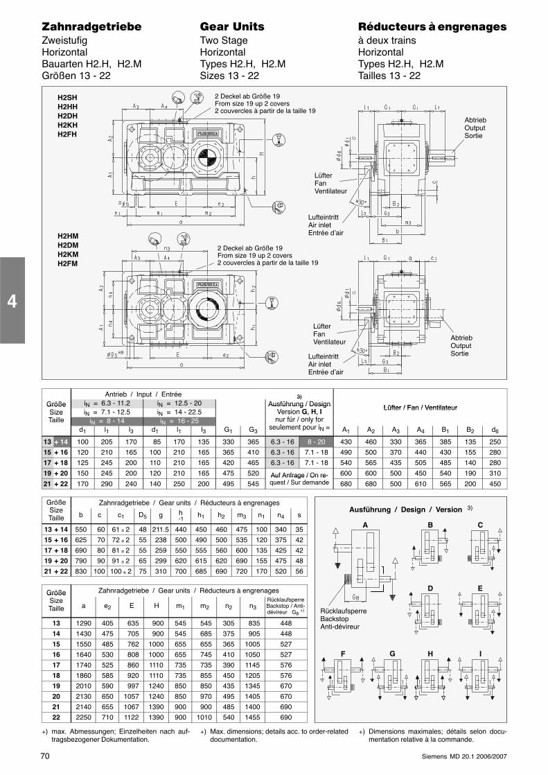
70 Siemens MD 20.1 2006/2007
������������� ���� �� ��������� � ����������Zweistufig Two Stage à deux trainsHorizontal Horizontal HorizontalBauarten H2.H, H2.M Types H2.H, H2.M Types H2.H, H2.MGrößen 13 - 22 Sizes 13 - 22 Tailles 13 - 22
LüfterFanVentilateur
LufteintrittAir inletEntrée d’air
H2SHH2HHH2DHH2KHH2FH
2 Deckel ab Größe 19From size 19 up 2 covers2 couvercles à partir de la taille 19
H2HMH2DMH2KMH2FM
LüfterFanVentilateur
LufteintrittAir inletEntrée d’air
2 Deckel ab Größe 19From size 19 up 2 covers2 couvercles à partir de la taille 19
AbtriebOutputSortie
AbtriebOutputSortie
Antrieb / Input / Entrée 3)Größe iN = 6.3 - 11.2 iN = 12.5 - 20
3)Ausführung / Design Lüfter / Fan / VentilateurGröße
Size iN = 7.1 - 12.5 iN = 14 - 22.5Ausführung / Design
Version G, H, Ifü / l f
Lüfter / Fan / VentilateurSizeTaille iN = 8 - 14 iN = 16 - 25
e s o G, , nur für / only for
seulement pour id1 l1 l3 d1 l1 l3 G1 G3
yseulement pour iN = A1 A2 A3 A4 B1 B2 d6
13 + 14 100 205 170 85 170 135 330 365 6.3 - 16 8 - 20 430 460 330 365 385 135 250
15 + 16 120 210 165 100 210 165 365 410 6.3 - 16 7.1 - 18 490 500 370 440 430 155 280
17 + 18 125 245 200 110 210 165 420 465 6.3 - 16 7.1 - 18 540 565 435 505 485 140 280
19 + 20 150 245 200 120 210 165 475 520 Auf Anfrage / On re- 600 600 500 450 540 190 310
21 + 22 170 290 240 140 250 200 495 545Auf Anfrage / On re-quest / Sur demande 680 680 500 610 565 200 450
GrößeSi
Zahnradgetriebe / Gear units / Réducteurs à engrenagesSizeTaille b c c1 D5 g h
-1h1 h2 m3 n1 n4 s
13 + 14 550 60 61 ± 2 48 211.5 440 450 460 475 100 340 35
15 + 16 625 70 72 ± 2 55 238 500 490 500 535 120 375 42
17 + 18 690 80 81 ± 2 55 259 550 555 560 600 135 425 42
19 + 20 790 90 91 ± 2 65 299 620 615 620 690 155 475 48
21 + 22 830 100 100 ± 2 75 310 700 685 690 720 170 520 56
Größe Zahnradgetriebe / Gear units / Réducteurs à engrenagesGrößeSizeTaille a e2 E H m1 m2 n2 n3
RücklaufsperreBackstop / Anti-dévireur G8 +)
13 1290 405 635 900 545 545 305 835 448
14 1430 475 705 900 545 685 375 905 448
15 1550 485 762 1000 655 655 365 1005 527
16 1640 530 808 1000 655 745 410 1050 527
17 1740 525 860 1110 735 735 390 1145 576
18 1860 585 920 1110 735 855 450 1205 576
19 2010 590 997 1240 850 850 435 1345 670
20 2130 650 1057 1240 850 970 495 1405 670
21 2140 655 1067 1390 900 900 485 1400 690
22 2250 710 1122 1390 900 1010 540 1455 690
+) max. Abmessungen; Einzelheiten nach auf-tragsbezogener Dokumentation.
+) Max. dimensions; details acc. to order-relateddocumentation.
+) Dimensions maximales; détails selon docu-mentation relative à la commande.
4
Ausführung / Design / Version 3)
A B C
D E
G H I
RücklaufsperreBackstopAnti-dévireur
F
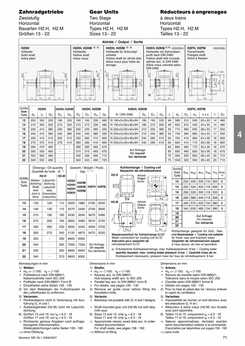
71Siemens MD 20.1 2006/2007
������������� ���� �� ��������� � ����������Zweistufig Two Stage à deux trainsHorizontal Horizontal HorizontalBauarten H2.H, H2.M Types H2.H, H2.M Types H2.H, H2.MGrößen 13 - 22 Sizes 13 - 22 Tailles 13 - 22
H2SHVollwelleSolid shaftArbre plein
H2HH, H2HM 3) 6)
HohlwelleHollow shaftArbre creux
H2DH, H2DM 3) 6)
Hohlwelle für Schrumpf-scheibeHollow shaft for shrink diskArbre creux pour frette deserrage
Abtrieb / Output / Sortie
H2KH, H2KM 3) 6)
Hohlwelle mit Zahnnaben-profil nach DIN 5480Hollow shaft with involutesplines acc. to DIN 5480Arbre creux cannelé selonDIN 5480
H2FH, H2FMFlanschwelleFlanged shaftArbre à flasque
N
( K20/004 ) ( K20/028 )
GrößeSize
H2SH H2HH, H2HM H2DH, H2DM H2KH, H2KM H2FH, H2FMSizeTaille d2 l2 G2 D2 G4 D2 D3 G4 G5 N / DIN 5480 D2 D3 G4 c d2 D3 k2 n x s t G7
13 200 350 335 190 335 190 195 335 480 N 190 x 5 x 30 x 36 x 9H 180 195 335 48 580 310 500 20 x 33 14 48014 210 350 335 210 335 210 215 335 480 N 190 x 5 x 30 x 36 x 9H 180 215 335 48 620 310 540 24 x 33 14 480
15 230 410 380 230 380 230 235 380 550 N 220 x 5 x 30 x 42 x 9H 210 235 380 55 710 360 630 28 x 33 17 55016 240 410 380 240 380 240 245 380 550 N 220 x 5 x 30 x 42 x 9H 210 245 380 55 740 360 660 30 x 33 17 550
17 250 410 415 250 415 250 260 415 600 N 250 x 5 x 30 x 48 x 9H 240 260 415 60 750 410 660 24 x 39 18 60018 270 470 415 275 415 280 285 415 600 N 250 x 5 x 30 x 48 x 9H 240 285 415 60 800 410 710 26 x 39 18 60019 290 470 465 - - 285 295 465 670
A f A f65 860 460 770 30 x 39 18 670
20 300 500 465 - - 310 315 465 670 Auf AnfrageOn request
65 930 460 830 32 x 39 18 67021 320 500 490 - - 330 335 490 715
On requestSur demande 75 950 520 850 28 x 45 20 710
22 340 550 490 - - 340 345 490 725Sur demande
75 1040 520 940 28 x 45 20 710
Ölmenge / Oil quantityQuantité de huile (l) ∗)
Gewicht / Weight / Poids(kg) ∗) ∗∗)
Kühlschlange / Cooling coilSerpentin de refroidissement
H2 H
GrößeSize l/minb10 e10 h10e11 h11
GrößeH2.H H2.M Abtrieb
OutputH2.H
SizeTaille
l/min x)
b10 e10 h10e11 h11
GrößeSizeTaille
Wellen-dichtring
Shaftseal
Joint àlèvre
Labyrinth-dichtungLabyrinth
sealEtanchéitéà labyrinthe
H2SHH2HHH2DHH2KH
H2HMH2KMH2DM
H2FH H2FM
OutputSortie
b10
h 10
e10
252 11613 455 8
252 11614 525 8
290 11915 535 8
290 11916 580 8
335
405
395
440
300
300
335
335
13 135 120 110 2000 1880 2160 2040 AbtriebOutput
H2.Mb10 e10 290 11916 580 8
340 13417 575 8
440
425
335
380
14 140 130 115 2570 2430 2740 2600Out utSortie 340 13418 635 8485 380
15 210 190 160 3430 3240 3670 3480
1
19Auf Anfrage20
16 215 200 165 3655 3465 3910 3720 h 11
Auf AnfrageOn request
Sur demande
2021
17 290 260 230 4650 4420 4950 4720e11b10
Sur demande22
18 300 270 240 5125 4870 5475 5220 Wasseranschluß für Kühlschlange G1/2”Kühlschlange geeignet für Süß-, See-und Brackwasser / Cooling coil suitable
e11b10
19 320 - 300 6600 6300Wasseranschluß für Kühlschlange G1/2Water connection for cooling coil G1/2”Adduction pour serpentin de
und Brackwasser / Cooling coil suitablefor fresh, sea and brackish waterSerpentin de refroidissement adapté
20 340 - 320 7500 7200 Auf AnfrageOn request
Adduction pour serpentin derefroidissement G1/2”
Serpentin de refroidissement adaptéà l’eau douce, de mer et saumâtre
21 320 - 350 8900 8400On request
Sur demandex) Erforderliche Kühlwassermenge, max. Kühlwasserdruck: 8 bar / Cooling water
quantity required; max. cooling water pressure: 8 bar / Quantité d’eau de re-22 340 - 370 9600 9200
quantity required; max. cooling water pressure: 8 bar / Quantité d’eau de re-froidissement nécessaire, préssion maxi de l’eau de refroidissement: 8 bar
Abmessungen in mm1) Wellen: � m6 <= ∅ 100; n6 > ∅ 100 � Paßfedernut nach DIN 6885/1,
Nabennutbreite nach ISO JS9 � Paßfeder nach DIN 6885/1 Form B � Einzelheiten siehe Seiten 126 - 1352) Vor dem Befestigen der Fußschrauben ist
die Luftleithaube zu entfernen.3) Varianten: � Rücklaufsperre nicht in Verbindung mit Aus-
führung G, H und I. � Aufsteckgetriebe (H2.M) nicht mit Labyrinth-
dichtung.6) Größen 13 und 15: nur iN = 6.3 - 18
Größen 17 und 19: nur iN = 6.3 - 16∗) Richtwerte; genaue Angaben nach auftrags-
bezogener Dokumentation.Wellenabdichtungen siehe Seiten 158 - 160
∗∗) ohne Ölfüllung
Dimensions in mm1) Shafts: � m6 <= ∅ 100; n6 > ∅ 100 � Keyway acc. to DIN 6885/1,
Hub keyway width acc. to ISO JS9 � Parallel key acc. to DIN 6885/1 form B � For details, see pages 126 - 1352) Remove air guide cover before fitting the
foundation bolts.3) Variants: � Backstop not possible with G, H and I designs.
� Shaft-mounted gear unit (H2.M) not with laby-rinth seal.
6) Sizes 13 and 15: only iN = 6.3 - 18Sizes 17 and 19: only iN = 6.3 - 16
∗) Approximate values; exact data acc. to order-related documentation.For shaft seals, see pages 158 - 160
∗∗) Without oil filling
Dimensions en mm1) Arbres: � m6 <= ∅ 100; n6 > ∅ 100 � Rainure de clavette selon DIN 6885/1,
Tolérance dans le moyeu selon ISO JS9 � Clavette selon DIN 6885/1 forme B � Détails voir pages 126 - 1352) Pour la mise en place des vis / écrous, enlever
le capot du ventilateur3) Variantes: � Impossibilité de monter un anti-dévireur avec
les exécutions G, H et I. � Réducteur à arbre creux (H2.M) non livrable
avec joint labyrinthe.6) Tailles 13 et 15: uniquement iN = 6.3 - 18
Tailles 17 et 19: uniquement iN = 6.3 - 16∗) Valeurs approximatives; données exactes
selon documentation relative à la commande.Etanchéités par labyrinthes voir pages 158 - 160
∗∗) sans huile
4
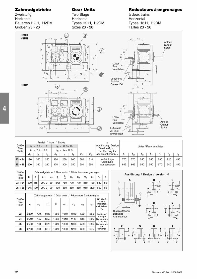
72 Siemens MD 20.1 2006/2007
������������� ���� �� ��������� � ����������Zweistufig Two Stage à deux trainsHorizontal Horizontal HorizontalBauarten H2.H, H2DM Types H2.H, H2DM Types H2.H, H2DMGrößen 23 - 26 Sizes 23 - 26 Tailles 23 - 26
LüfterFanVentilateur
LufteintrittAir inletEntrée d’air
H2SHH2DH
H2DM
LüfterFanVentilateur
LufteintrittAir inletEntrée d’air
AbtriebOutputSortie
AbtriebOutputSortie
Antrieb / Input / Entrée 3)GrößeSize
iN = 6.3 - 11.2 iN = 12.5 - 203)
Ausführung / DesignVersion G H I
Lüfter / Fan / VentilateurSizeTaille iN = 7.1 - 12.5 iN = 14 - 22.5
Version G, H, Inur für / only for
Lüfter / Fan / Ventilateur
Tailled1 l1 l3 d1 l1 l3 G1 G3
nur für / only forseulement pour iN = A1 A2 A3 A4 B1 B2 d6
23 + 24 190 330 280 150 250 200 560 610 Auf AnfrageOn request
770 770 550 550 630 220 450
25 + 26 200 340 290 170 300 250 600 650On request
Sur demande 845 865 550 550 670 240 450
GrößeSize
Zahnradgetriebe / Gear units / Réducteurs à engrenagesSizeTaille b c c1 D5 g h
-1h1 h2 m3 n1 n4 s
23 + 24 930 115 120 ± 2 80 342 780 770 770 810 180 580 56
25 + 26 1045 130 120 ± 2 90 400 860 860 860 910 200 660 66
Zahnradgetriebe / Gear units / Réducteurs à engrenages
GrößeSizeTaille a e2 E H m1 m2 n2 n3
Rücklauf-sperre
BackstopAntidévireur
G8
23 2380 730 1185 1550 1010 1010 550 1560 Maße aufAnfrage
24 2510 795 1250 1550 1010 1140 615 1625Anfrage
Dimensionson request
25 2580 790 1325 1720 1090 1090 590 1685on requestDimensions
sur26 2760 880 1415 1720 1090 1270 680 1775
surdemande
4
Ausführung / Design / Version 3)
A B C
D E
G H I
RücklaufsperreBackstopAnti-dévireur
F
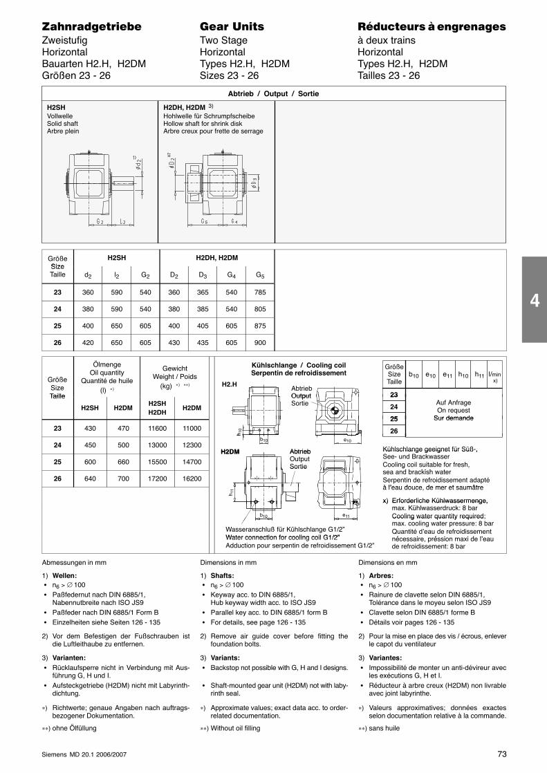
73Siemens MD 20.1 2006/2007
������������� ���� �� ��������� � ����������Zweistufig Two Stage à deux trainsHorizontal Horizontal HorizontalBauarten H2.H, H2DM Types H2.H, H2DM Types H2.H, H2DMGrößen 23 - 26 Sizes 23 - 26 Tailles 23 - 26
H2SHVollwelleSolid shaftArbre plein
H2DH, H2DM 3)
Hohlwelle für SchrumpfscheibeHollow shaft for shrink diskArbre creux pour frette de serrage
Abtrieb / Output / Sortie
GrößeSize
H2SH H2DH, H2DMSizeTaille d2 l2 G2 D2 D3 G4 G5
23 360 590 540 360 365 540 785
24 380 590 540 380 385 540 805
25 400 650 605 400 405 605 875
26 420 650 605 430 435 605 900
GrößeSizeTaille
ÖlmengeOil quantity
Quantité de huile(l) ∗)
GewichtWeight / Poids
(kg) ∗) ∗∗)AbtriebOutput
Kühlschlange / Cooling coilSerpentin de refroidissement
H2.H
GrößeSizeTaille
l/min x)
23
b10 e10 h10e11 h11
Taille
H2SH H2DMH2SHH2DH
H2DM
OutputSortie
23
24
25
Auf AnfrageOn request
Sur demande
23 430 470 11600 1100025
26
Sur demande
h 10
24 450 500 13000 12300 Kühlschlange geeignet für Süß-,AbtriebH2DM
b10
h
e10
25 600 660 15500 14700
Kühlschlange geeignet für Süß ,See- und BrackwasserCooling coil suitable for fresh,
d b ki h t
AbtriebOutputSortie
H2DM
26 640 700 17200 16200
g ,sea and brackish waterSerpentin de refroidissement adaptéà l’eau douce de mer et saumâtre
Sortie
à l’eau douce, de mer et saumâtre
x) Erforderliche Kühlwassermenge,
h 11
x) Erforderliche Kühlwassermenge,max. Kühlwasserdruck: 8 barCooling water quantity required;e11b10
Wasseranschluß für Kühlschlange G1/2”Water connection for cooling coil G1/2”
Cooling water quantity requiredmax. cooling water pressure: 8 barQuantité d’eau de refroidissementé i é i i d l’
1110
Water connection for cooling coil G1/2”Adduction pour serpentin de refroidissement G1/2”
nécessaire, préssion maxi de l’eaude refroidissement: 8 bar
Abmessungen in mm
1) Wellen: � n6 > ∅ 100 � Paßfedernut nach DIN 6885/1,
Nabennutbreite nach ISO JS9 � Paßfeder nach DIN 6885/1 Form B � Einzelheiten siehe Seiten 126 - 135
2) Vor dem Befestigen der Fußschrauben istdie Luftleithaube zu entfernen.
3) Varianten: � Rücklaufsperre nicht in Verbindung mit Aus-
führung G, H und I. � Aufsteckgetriebe (H2DM) nicht mit Labyrinth-
dichtung.
∗) Richtwerte; genaue Angaben nach auftrags-bezogener Dokumentation.
∗∗) ohne Ölfüllung
Dimensions in mm
1) Shafts: � n6 > ∅ 100 � Keyway acc. to DIN 6885/1,
Hub keyway width acc. to ISO JS9 � Parallel key acc. to DIN 6885/1 form B � For details, see page 126 - 135
2) Remove air guide cover before fitting thefoundation bolts.
3) Variants: � Backstop not possible with G, H and I designs.
� Shaft-mounted gear unit (H2DM) not with laby-rinth seal.
∗) Approximate values; exact data acc. to order-related documentation.
∗∗) Without oil filling
Dimensions en mm
1) Arbres: � n6 > ∅ 100 � Rainure de clavette selon DIN 6885/1,
Tolérance dans le moyeu selon ISO JS9 � Clavette selon DIN 6885/1 forme B � Détails voir pages 126 - 135
2) Pour la mise en place des vis / écrous, enleverle capot du ventilateur
3) Variantes: � Impossibilité de monter un anti-dévireur avec
les exécutions G, H et I. � Réducteur à arbre creux (H2DM) non livrable
avec joint labyrinthe.
∗) Valeurs approximatives; données exactesselon documentation relative à la commande.
∗∗) sans huile
4
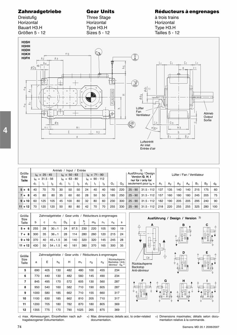
74 Siemens MD 20.1 2006/2007
������������� ���� �� ��������� � ����������Dreistufig Three Stage à trois trainsHorizontal Horizontal HorizontalBauart H3.H Type H3.H Type H3.HGrößen 5 - 12 Sizes 5 - 12 Tailles 5 - 12
LüfterFanVentilateur
LufteintrittAir inletEntrée d’air
AbtriebOutputSortie
H3SHH3HHH3DHH3KHH3FH
G ößAntrieb / Input / Entrée 3)
A füh / D iGrößeSize
iN = 25 - 45 iN = 50 - 63 iN = 71 - 90
)Ausführung / Design
Version G H ILüfter / Fan / Ventilateur
SizeTaille iN = 31.5 - 56 iN = 63 - 80 iN = 90 - 112
Version G, H, Inur für / only for
Lüfter / Fan / Ventilateur
Tailled1 l1 l3 d1 l1 l3 d1 l1 l3 G1 G3
nur für / only forseulement pour iN = A1 A2 A3 A4 B1 B2 d6
5 + 6 40 70 70 30 50 50 24 40 40 160 220 25 - 90 31.5 - 112 137 135 140 140 215 175 60
7 + 8 45 80 80 35 60 60 28 50 50 185 250 25 - 90 31.5 - 112 157 160 180 180 245 205 75
9 + 10 60 125 105 45 100 80 32 80 60 230 300 25 - 90 31.5 - 112 182 190 205 205 295 240 90
11 + 12 70 120 120 50 80 80 42 70 70 255 330 25 - 90 31.5 - 112 218 220 255 255 325 280 100
GrößeSize
Zahnradgetriebe / Gear units / Réducteurs à engrenagesSizeTaille b c c1 D5 g h
-1m3 n1 n4 s
5 + 6 255 28 30 ± 1 24 97.5 230 220 105 180 19
7 + 8 300 35 36 ± 1 28 114 280 260 120 215 24
9 + 10 370 40 45 ± 1.5 36 140 320 320 145 245 28
11 + 12 430 50 54 ± 1.5 40 161 380 370 165 300 35
Größe Zahnradgetriebe / Gear units / Réducteurs à engrenagesGrößeSizeTaille a E h5 H m1 n2 n3
RücklaufsperreBackstop / Anti-dévireur G8 +)
5 690 405 130 482 480 100 455 234
6 770 440 130 482 560 145 490 234
7 845 495 170 572 605 130 560 287
8 950 540 160 582 710 190 605 287
9 1000 580 185 662 710 155 660 317
10 1100 630 185 662 810 205 710 317
11 1200 705 180 782 870 180 805 369
12 1355 775 170 790 1025 265 875 369
+) max. Abmessungen; Einzelheiten nach auf-tragsbezogener Dokumentation.
+) Max. dimensions; details acc. to order-relateddocumentation.
+) Dimensions maximales; détails selon docu-mentation relative à la commande.
4
Ausführung / Design / Version 3)
C
D E
G H IF
A
RücklaufsperreBackstopAnti-dévireur
B
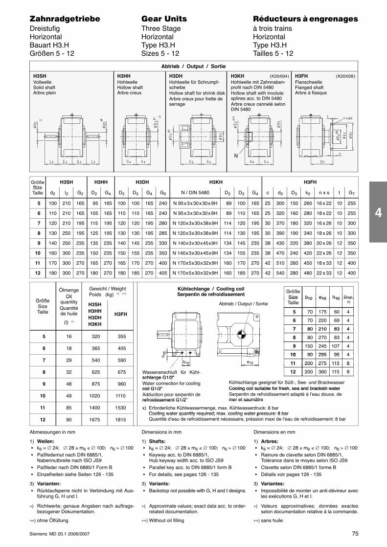
75Siemens MD 20.1 2006/2007
������������� ���� �� ��������� � ����������Dreistufig Three Stage à trois trainsHorizontal Horizontal HorizontalBauart H3.H Type H3.H Type H3.HGrößen 5 - 12 Sizes 5 - 12 Tailles 5 - 12
H3SHVollwelleSolid shaftArbre plein
H3HHHohlwelleHollow shaftArbre creux
H3DHHohlwelle für Schrumpf-scheibeHollow shaft for shrink diskArbre creux pour frette deserrage
Abtrieb / Output / Sortie
H3KHHohlwelle mit Zahnnaben-profil nach DIN 5480Hollow shaft with involutesplines acc. to DIN 5480Arbre creux cannelé selonDIN 5480
H3FHFlanschwelleFlanged shaftArbre à flasque
N
( K20/004 ) ( K20/028 )
GrößeSize
H3SH H3HH H3DH H3KH H3FHSizeTaille d2 l2 G2 D2 G4 D2 D3 G4 G5 N / DIN 5480 D2 D3 G4 c d2 D3 k2 n x s t G7
5 100 210 165 95 165 100 100 165 240 N 95 x 3 x 30 x 30 x 9H 89 100 165 25 300 150 260 16 x 22 10 255
6 110 210 165 105 165 110 110 165 240 N 95 x 3 x 30 x 30 x 9H 89 110 165 25 320 160 280 18 x 22 10 255
7 120 210 195 115 195 120 120 195 280 N 120 x 3 x 30 x 38 x 9H 114 120 195 30 370 180 320 16 x 26 10 300
8 130 250 195 125 195 130 130 195 285 N 120 x 3 x 30 x 38 x 9H 114 130 195 30 390 190 340 18 x 26 10 300
9 140 250 235 135 235 140 145 235 330 N 140 x 3 x 30 x 45 x 9H 134 145 235 38 430 220 380 20 x 26 12 350
10 160 300 235 150 235 150 155 235 350 N 140 x 3 x 30 x 45 x 9H 134 155 235 38 470 240 420 22 x 26 12 350
11 170 300 270 165 270 165 170 270 400 N 170 x 5 x 30 x 32 x 9H 160 170 270 42 510 260 450 18 x 33 12 400
12 180 300 270 180 270 180 185 270 405 N 170 x 5 x 30 x 32 x 9H 160 185 270 42 540 280 480 22 x 33 12 400
Größe
ÖlmengeOil
Gewicht / WeightPoids (kg) ∗) ∗∗) Größe
Size l/minb10 e10 h10
Kühlschlange / Cooling coilSerpentin de refroidissement
GrößeSizeTaille
OilquantityQuantitéde huile
(l) ∗)
H3SHH3HHH3DHH3KH
H3FH
Abtrieb / Output / SortieSizeTaille
l/min x)
b10 e10 h10
70 60 5 175 4
70 69 6 220 4
80 837 210 4
5 16 320 355
80 83 7 210 4
80 83 8 270 4
6 18 365 405 150 107 9 245 4
90 9510 295 410
7 29 540 590 90 9510 295 4
200 11511 275 8b10
h 10
e10
8 32 625 675
200 11511 275 8
200 11512 360 8Wasseranschluß für Kühl-schlange G1/2”
10 0
9 48 875 960schlange G1/2”Water connection for coolingcoil G1/2”
Kühlschlange geeignet für Süß-, See- und BrackwasserCooling coil suitable for fresh, sea and brackish water
10 49 1020 1110coil G1/2”Adduction pour serpentin derefroidissement G1/2”
Cooling coil suitable for fresh, sea and brackish waterSerpentin de refroidissement adapté à l’eau douce, demer et saumâtre
11 85 1400 1530
refroidissement G1/2 mer et saumâtre
x) Erforderliche Kühlwassermenge, max. Kühlwasserdruck: 8 barCooling water quantity required; max cooling water pressure: 8 bar
12 90 1675 1815Cooling water quantity required; max. cooling water pressure: 8 barQuantité d’eau de refroidissement nécessaire, préssion maxi de l’eau de refroidissement: 8 bar
Abmessungen in mm
1) Wellen: � k6 = ∅ 24; ∅ 28 ≥ m6 ≤ ∅ 100; n6 > ∅ 100 � Paßfedernut nach DIN 6885/1,
Nabennutbreite nach ISO JS9 � Paßfeder nach DIN 6885/1 Form B � Einzelheiten siehe Seiten 126 - 135
3) Varianten: � Rücklaufsperre nicht in Verbindung mit Aus-
führung G, H und I.
∗) Richtwerte; genaue Angaben nach auftrags-bezogener Dokumentation.
∗∗) ohne Ölfüllung
Dimensions in mm
1) Shafts: � k6 = ∅ 24; ∅ 28 ≥ m6 ≤ ∅ 100; n6 > ∅ 100 � Keyway acc. to DIN 6885/1,
Hub keyway width acc. to ISO JS9 � Parallel key acc. to DIN 6885/1 form B � For details, see pages 126 - 135
3) Variants: � Backstop not possible with G, H and I designs.
∗) Approximate values; exact data acc. to order-related documentation.
∗∗) Without oil filling
Dimensions en mm
1) Arbres: � k6 = ∅ 24; ∅ 28 ≥ m6 ≤ ∅ 100; n6 > ∅ 100 � Rainure de clavette selon DIN 6885/1,
Tolérance dans le moyeu selon ISO JS9 � Clavette selon DIN 6885/1 forme B � Détails voir pages 126 - 135
3) Variantes: � Impossibilité de monter un anti-dévireur avec
les exécutions G, H et I.
∗) Valeurs approximatives; données exactesselon documentation relative à la commande.
∗∗) sans huile
4
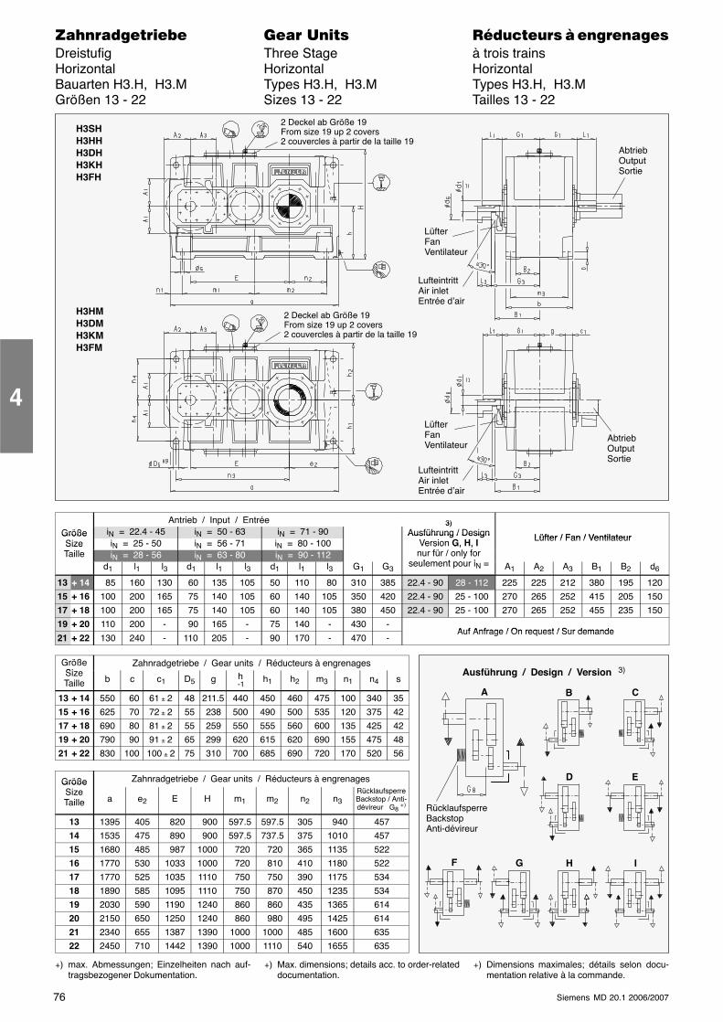
76 Siemens MD 20.1 2006/2007
������������� ���� �� ��������� � ����������Dreistufig Three Stage à trois trainsHorizontal Horizontal HorizontalBauarten H3.H, H3.M Types H3.H, H3.M Types H3.H, H3.MGrößen 13 - 22 Sizes 13 - 22 Tailles 13 - 22
LüfterFanVentilateur
LufteintrittAir inletEntrée d’air
AbtriebOutputSortie
H3SHH3HHH3DHH3KHH3FH
2 Deckel ab Größe 19From size 19 up 2 covers2 couvercles à partir de la taille 19
H3HMH3DMH3KMH3FM
LüfterFanVentilateur
LufteintrittAir inletEntrée d’air
2 Deckel ab Größe 19From size 19 up 2 covers2 couvercles à partir de la taille 19
AbtriebOutputSortie
Antrieb / Input / Entrée 3)Größe iN = 22.4 - 45 iN = 50 - 63 iN = 71 - 90
3)Ausführung / Design Lüfter / Fan / VentilateurGröße
Size iN = 25 - 50 iN = 56 - 71 iN = 80 - 100Ausführung / Design
Version G, H, Ifü / l f
Lüfter / Fan / VentilateurSizeTaille iN = 28 - 56 iN = 63 - 80 iN = 90 - 112
e s o G, , nur für / only for
seulement pour id1 l1 l3 d1 l1 l3 d1 l1 l3 G1 G3
yseulement pour iN = A1 A2 A3 B1 B2 d6
13 + 14 85 160 130 60 135 105 50 110 80 310 385 22.4 - 90 28 - 112 225 225 212 380 195 120
15 + 16 100 200 165 75 140 105 60 140 105 350 420 22.4 - 90 25 - 100 270 265 252 415 205 150
17 + 18 100 200 165 75 140 105 60 140 105 380 450 22.4 - 90 25 - 100 270 265 252 455 235 150
19 + 20 110 200 - 90 165 - 75 140 - 430 -Auf Anfrage / On request / Sur demande
21 + 22 130 240 - 110 205 - 90 170 - 470 -Auf Anfrage / On request / Sur demande
GrößeSi
Zahnradgetriebe / Gear units / Réducteurs à engrenagesSizeTaille b c c1 D5 g h
-1h1 h2 m3 n1 n4 s
13 + 14 550 60 61 ± 2 48 211.5 440 450 460 475 100 340 35
15 + 16 625 70 72 ± 2 55 238 500 490 500 535 120 375 42
17 + 18 690 80 81 ± 2 55 259 550 555 560 600 135 425 42
19 + 20 790 90 91 ± 2 65 299 620 615 620 690 155 475 48
21 + 22 830 100 100 ± 2 75 310 700 685 690 720 170 520 56
Größe Zahnradgetriebe / Gear units / Réducteurs à engrenagesGrößeSizeTaille a e2 E H m1 m2 n2 n3
RücklaufsperreBackstop / Anti-dévireur G8 +)
13 1395 405 820 900 597.5 597.5 305 940 457
14 1535 475 890 900 597.5 737.5 375 1010 457
15 1680 485 987 1000 720 720 365 1135 522
16 1770 530 1033 1000 720 810 410 1180 522
17 1770 525 1035 1110 750 750 390 1175 534
18 1890 585 1095 1110 750 870 450 1235 534
19 2030 590 1190 1240 860 860 435 1365 614
20 2150 650 1250 1240 860 980 495 1425 614
21 2340 655 1387 1390 1000 1000 485 1600 635
22 2450 710 1442 1390 1000 1110 540 1655 635
+) max. Abmessungen; Einzelheiten nach auf-tragsbezogener Dokumentation.
+) Max. dimensions; details acc. to order-relateddocumentation.
+) Dimensions maximales; détails selon docu-mentation relative à la commande.
4
Ausführung / Design / Version 3)
C
D E
G H IF
A
RücklaufsperreBackstopAnti-dévireur
B
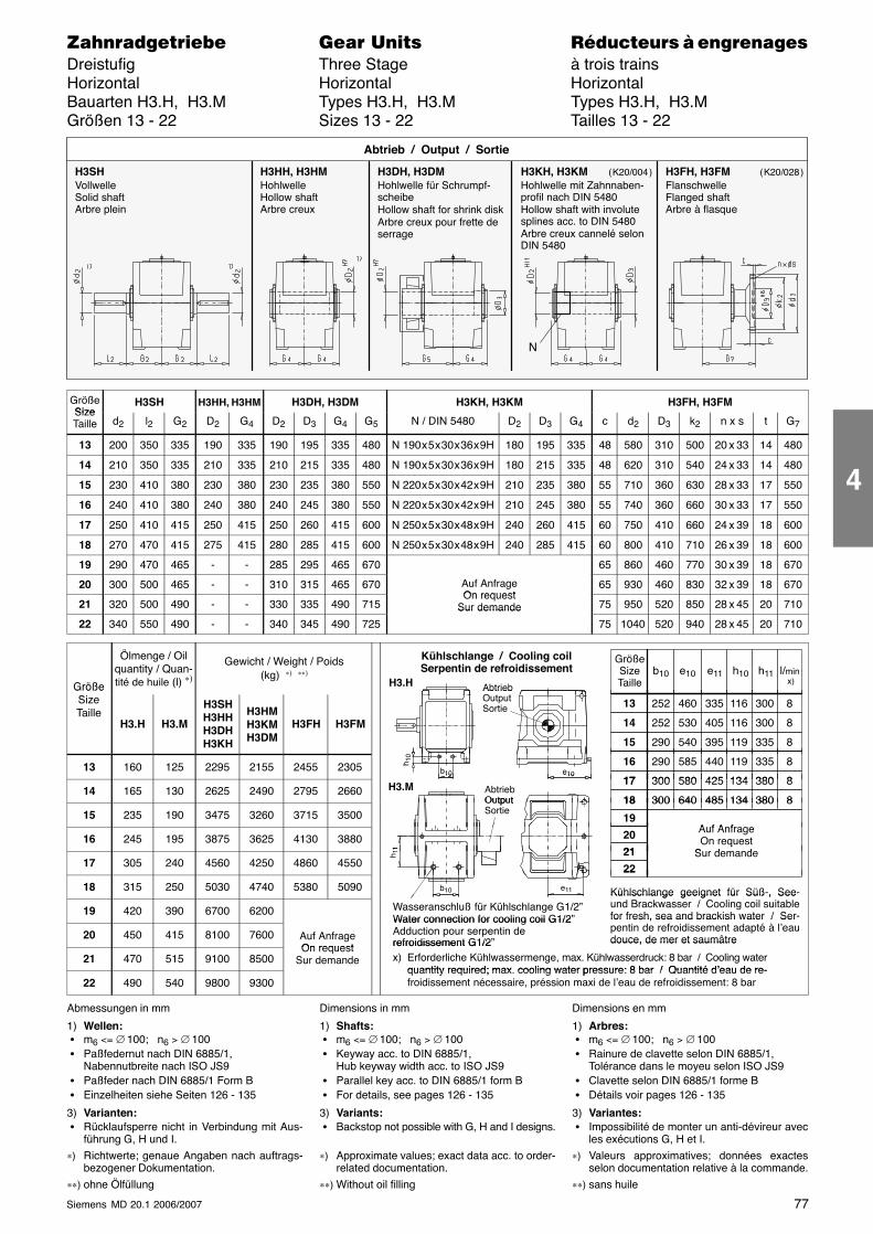
77Siemens MD 20.1 2006/2007
������������� ���� �� ��������� � ����������Dreistufig Three Stage à trois trainsHorizontal Horizontal HorizontalBauarten H3.H, H3.M Types H3.H, H3.M Types H3.H, H3.MGrößen 13 - 22 Sizes 13 - 22 Tailles 13 - 22
H3SHVollwelleSolid shaftArbre plein
H3HH, H3HMHohlwelleHollow shaftArbre creux
H3DH, H3DMHohlwelle für Schrumpf-scheibeHollow shaft for shrink diskArbre creux pour frette deserrage
Abtrieb / Output / Sortie
H3KH, H3KMHohlwelle mit Zahnnaben-profil nach DIN 5480Hollow shaft with involutesplines acc. to DIN 5480Arbre creux cannelé selonDIN 5480
H3FH, H3FMFlanschwelleFlanged shaftArbre à flasque
N
( K20/004 ) ( K20/028 )
GrößeSize
H3SH H3HH, H3HM H3DH, H3DM H3KH, H3KM H3FH, H3FMSizeTaille d2 l2 G2 D2 G4 D2 D3 G4 G5 N / DIN 5480 D2 D3 G4 c d2 D3 k2 n x s t G7
13 200 350 335 190 335 190 195 335 480 N 190 x 5 x 30 x 36 x 9H 180 195 335 48 580 310 500 20 x 33 14 480
14 210 350 335 210 335 210 215 335 480 N 190 x 5 x 30 x 36 x 9H 180 215 335 48 620 310 540 24 x 33 14 480
15 230 410 380 230 380 230 235 380 550 N 220 x 5 x 30 x 42 x 9H 210 235 380 55 710 360 630 28 x 33 17 550
16 240 410 380 240 380 240 245 380 550 N 220 x 5 x 30 x 42 x 9H 210 245 380 55 740 360 660 30 x 33 17 550
17 250 410 415 250 415 250 260 415 600 N 250 x 5 x 30 x 48 x 9H 240 260 415 60 750 410 660 24 x 39 18 600
18 270 470 415 275 415 280 285 415 600 N 250 x 5 x 30 x 48 x 9H 240 285 415 60 800 410 710 26 x 39 18 600
19 290 470 465 - - 285 295 465 670 65 860 460 770 30 x 39 18 670
20 300 500 465 - - 310 315 465 670 Auf AnfrageOn request
65 930 460 830 32 x 39 18 670
21 320 500 490 - - 330 335 490 715On request
Sur demande 75 950 520 850 28 x 45 20 710
22 340 550 490 - - 340 345 490 725
Sur demande
75 1040 520 940 28 x 45 20 710
Größe
Ölmenge / Oilquantity / Quan-tité de huile (l) ∗)
Gewicht / Weight / Poids(kg) ∗) ∗∗)
AbtriebO
Kühlschlange / Cooling coilSerpentin de refroidissement
GrößeSizeTaille
l/min x)
b10 e10 h10e11 h11H3.HGröße
SizeTaille
H3.H H3.M
H3SHH3HHH3DHH3KH
H3HMH3KMH3DM
H3FH H3FM
AbtriebOutputSortie 252 11613 460 8
252 11614 530 8
290 11915 540 8
335
405
395
300
300
335
13 160 125 2295 2155 2455 2305 290 11916 585 8
300 13417 580 8
440
425
335
380b10
h 10
e10
14 165 130 2625 2490 2795 2660 AbtriebOutput
300 13417 580 8
300 13418 640 8
425
485
380
380H3.M
10 e10
15 235 190 3475 3260 3715 3500OutputSortie
300 13418 640 8
19Auf Anfrage
485 380
16 245 195 3875 3625 4130 3880Auf AnfrageOn request
Sur demande
20
2111
17 305 240 4560 4250 4860 4550
qSur demande21
22
h 11
18 315 250 5030 4740 5380 5090 Kühlschlange geeignet für Süß-, See-
22
e11b10
19 420 390 6700 6200 Wasseranschluß für Kühlschlange G1/2”Water connection for cooling coil G1/2”
Kühlschlange geeignet für Süß , Seeund Brackwasser / Cooling coil suitablefor fresh, sea and brackish water / Ser-
20 450 415 8100 7600 Auf AnfrageOn request
Water connection for cooling coil G1/2Adduction pour serpentin derefroidissement G1/2”
for fresh, sea and brackish water / Serpentin de refroidissement adapté à l’eaudouce, de mer et saumâtre
21 470 515 9100 8500On request
Sur demande
refroidissement G1/2 douce, de mer et saumâtre
x) Erforderliche Kühlwassermenge, max. Kühlwasserdruck: 8 bar / Cooling waterquantity required; max cooling water pressure: 8 bar / Quantité d’eau de re-
22 490 540 9800 9300quantity required; max. cooling water pressure: 8 bar / Quantité d’eau de re-froidissement nécessaire, préssion maxi de l’eau de refroidissement: 8 bar
Abmessungen in mm
1) Wellen: � m6 <= ∅ 100; n6 > ∅ 100 � Paßfedernut nach DIN 6885/1,
Nabennutbreite nach ISO JS9 � Paßfeder nach DIN 6885/1 Form B � Einzelheiten siehe Seiten 126 - 135
3) Varianten: � Rücklaufsperre nicht in Verbindung mit Aus-
führung G, H und I.∗) Richtwerte; genaue Angaben nach auftrags-
bezogener Dokumentation.
∗∗) ohne Ölfüllung
Dimensions in mm
1) Shafts: � m6 <= ∅ 100; n6 > ∅ 100 � Keyway acc. to DIN 6885/1,
Hub keyway width acc. to ISO JS9 � Parallel key acc. to DIN 6885/1 form B � For details, see pages 126 - 135
3) Variants: � Backstop not possible with G, H and I designs.
∗) Approximate values; exact data acc. to order-related documentation.
∗∗) Without oil filling
Dimensions en mm
1) Arbres: � m6 <= ∅ 100; n6 > ∅ 100 � Rainure de clavette selon DIN 6885/1,
Tolérance dans le moyeu selon ISO JS9 � Clavette selon DIN 6885/1 forme B � Détails voir pages 126 - 135
3) Variantes: � Impossibilité de monter un anti-dévireur avec
les exécutions G, H et I.∗) Valeurs approximatives; données exactes
selon documentation relative à la commande.
∗∗) sans huile
4
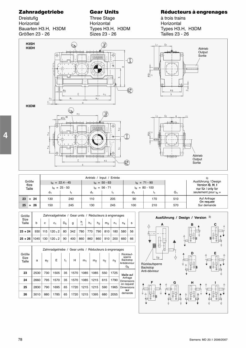
78 Siemens MD 20.1 2006/2007
������������� ���� �� ��������� � ����������Dreistufig Three Stage à trois trainsHorizontal Horizontal HorizontalBauarten H3.H, H3DM Types H3.H, H3DM Types H3.H, H3DMGrößen 23 - 26 Sizes 23 - 26 Tailles 23 - 26
H3SHH3DH
H3DM
AbtriebOutputSortie
AbtriebOutputSortie
Antrieb / Input / Entrée 3)GrößeSize
iN = 22.4 - 45 iN = 50 - 63 iN = 71 - 903)
Ausführung / DesignVersion G H ISize
Taille iN = 25 - 50 iN = 56 - 71 iN = 80 - 100Version G, H, Inur für / only forTaille
d1 l1 d1 l1 d1 l1 G1
nur für / only forseulement pour iN =
23 + 24 130 240 110 205 90 170 510 Auf AnfrageOn request
25 + 26 150 245 130 245 100 210 570On request
Sur demande
GrößeSi
Zahnradgetriebe / Gear units / Réducteurs à engrenagesSizeTaille b c c1 D5 g h
-1h1 h2 m3 n1 n4 s
23 + 24 930 115 120 ± 2 80 342 780 770 790 810 180 580 56
25 + 26 1045 130 120 ± 2 90 400 860 860 860 910 200 660 66
Zahnradgetriebe / Gear units / Réducteurs à engrenages
GrößeSizeTaille a e2 E f1 H m1 m2 n2 n3
Rücklauf-sperre
BackstopAntidévireur
G8
23 2530 730 1505 35 1570 1085 1085 550 1725Maße auf
24 2660 795 1570 35 1570 1085 1215 615 1790
Maße aufAnfrage
Dimensionson request
25 2830 790 1695 65 1720 1215 1215 590 1965on requestDimensions
sur
26 3010 880 1785 65 1720 1215 1395 680 2055sur
demande
4
Ausführung / Design / Version 3)
C
D E
G H IF
A
RücklaufsperreBackstopAnti-dévireur
B
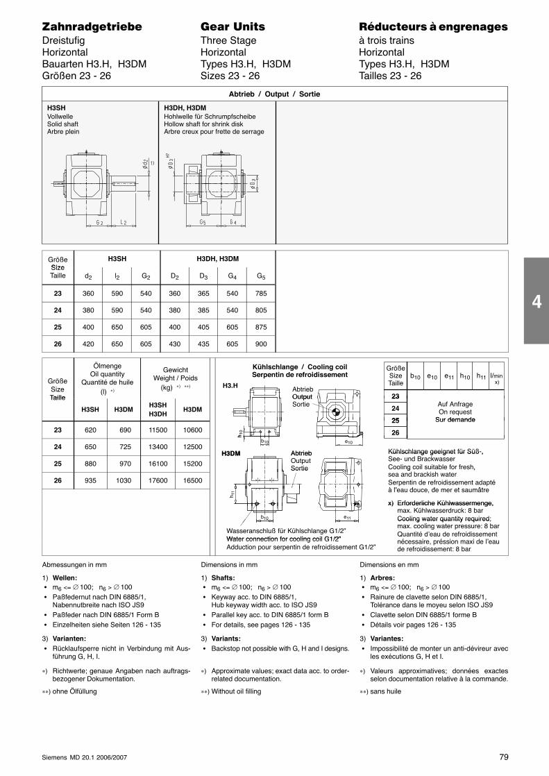
79Siemens MD 20.1 2006/2007
������������� ���� �� ��������� � ����������Dreistufig Three Stage à trois trainsHorizontal Horizontal HorizontalBauarten H3.H, H3DM Types H3.H, H3DM Types H3.H, H3DMGrößen 23 - 26 Sizes 23 - 26 Tailles 23 - 26
H3SHVollwelleSolid shaftArbre plein
H3DH, H3DMHohlwelle für SchrumpfscheibeHollow shaft for shrink diskArbre creux pour frette de serrage
Abtrieb / Output / Sortie
GrößeSize
H3SH H3DH, H3DMSizeTaille d2 l2 G2 D2 D3 G4 G5
23 360 590 540 360 365 540 785
24 380 590 540 380 385 540 805
25 400 650 605 400 405 605 875
26 420 650 605 430 435 605 900
GrößeSizeTaille
ÖlmengeOil quantity
Quantité de huile(l) ∗)
GewichtWeight / Poids
(kg) ∗) ∗∗) AbtriebOutput
Kühlschlange / Cooling coilSerpentin de refroidissement
H3.H
GrößeSizeTaille
l/min x)
23
b10 e10 h10e11 h11
Taille
H3SH H3DMH3SHH3DH
H3DM
OutputSortie
23
24
25
Auf AnfrageOn request
Sur demande
23 620 690 11500 1060025
26
Sur demande
h 10
24 650 725 13400 12500Kühlschlange geeignet für Süß-,AbtriebH3DM
b10
h
e10
25 880 970 16100 15200
Kühlschlange geeignet für Süß ,See- und BrackwasserCooling coil suitable for fresh,
d b ki h
AbtriebOutputSortie
H3DM
26 935 1030 17600 16500
Cooling coil suitable for fresh,sea and brackish waterSerpentin de refroidissement adaptéà l’eau douce de mer et saumâtre
Sortie
à l’eau douce, de mer et saumâtre
x) Erforderliche Kühlwassermenge,
h 11
x) Erforderliche Kühlwassermenge,max. Kühlwasserdruck: 8 barCooling water quantity required;e11b10
Wasseranschluß für Kühlschlange G1/2”Water connection for cooling coil G1/2”
Cooling water quantity requiredmax. cooling water pressure: 8 barQuantité d’eau de refroidissementé i é i i d l’
10
Water connection for cooling coil G1/2”Adduction pour serpentin de refroidissement G1/2”
Q a é d ea de e o d sse enécessaire, préssion maxi de l’eaude refroidissement: 8 bar
Abmessungen in mm
1) Wellen: � m6 <= ∅ 100; n6 > ∅ 100 � Paßfedernut nach DIN 6885/1,
Nabennutbreite nach ISO JS9 � Paßfeder nach DIN 6885/1 Form B � Einzelheiten siehe Seiten 126 - 135
3) Varianten: � Rücklaufsperre nicht in Verbindung mit Aus-
führung G, H, I.
∗) Richtwerte; genaue Angaben nach auftrags-bezogener Dokumentation.
∗∗) ohne Ölfüllung
Dimensions in mm
1) Shafts: � m6 <= ∅ 100; n6 > ∅ 100 � Keyway acc. to DIN 6885/1,
Hub keyway width acc. to ISO JS9 � Parallel key acc. to DIN 6885/1 form B � For details, see pages 126 - 135
3) Variants: � Backstop not possible with G, H and I designs.
∗) Approximate values; exact data acc. to order-related documentation.
∗∗) Without oil filling
Dimensions en mm
1) Arbres: � m6 <= ∅ 100; n6 > ∅ 100 � Rainure de clavette selon DIN 6885/1,
Tolérance dans le moyeu selon ISO JS9 � Clavette selon DIN 6885/1 forme B � Détails voir pages 126 - 135
3) Variantes: � Impossibilité de monter un anti-dévireur avec
les exécutions G, H et I.
∗) Valeurs approximatives; données exactesselon documentation relative à la commande.
∗∗) sans huile
4
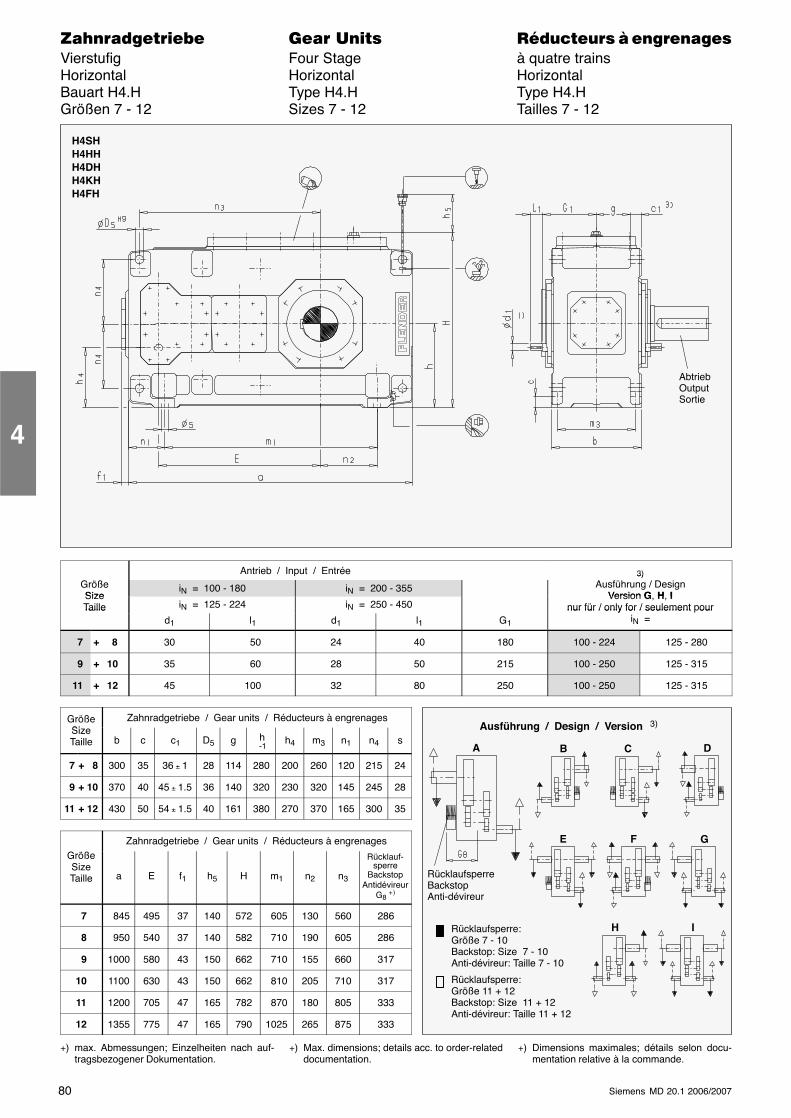
80 Siemens MD 20.1 2006/2007
������������� ���� �� ��������� � ����������Vierstufig Four Stage à quatre trainsHorizontal Horizontal HorizontalBauart H4.H Type H4.H Type H4.HGrößen 7 - 12 Sizes 7 - 12 Tailles 7 - 12
AbtriebOutputSortie
H4SHH4HHH4DHH4KHH4FH
Antrieb / Input / Entrée 3)GrößeSize
iN = 100 - 180 iN = 200 - 355
3)Ausführung / Design
Version G H ISizeTaille iN = 125 - 224 iN = 250 - 450
Version G, H, Inur für / only for / seulement pourTaille
d1 l1 d1 l1 G1
nur für / only for / seulement ouriN =
7 + 8 30 50 24 40 180 100 - 224 125 - 280
9 + 10 35 60 28 50 215 100 - 250 125 - 315
11 + 12 45 100 32 80 250 100 - 250 125 - 315
GrößeSi
Zahnradgetriebe / Gear units / Réducteurs à engrenagesSizeTaille b c c1 D5 g h
-1h4 m3 n1 n4 s
7 + 8 300 35 36 ± 1 28 114 280 200 260 120 215 24
9 + 10 370 40 45 ± 1.5 36 140 320 230 320 145 245 28
11 + 12 430 50 54 ± 1.5 40 161 380 270 370 165 300 35
Zahnradgetriebe / Gear units / Réducteurs à engrenagesGrößeSizeTaille a E f1 h5 H m1 n2 n3
Rücklauf-sperre
BackstopAntidévireur
G8 +)
7 845 495 37 140 572 605 130 560 286
8 950 540 37 140 582 710 190 605 286
9 1000 580 43 150 662 710 155 660 317
10 1100 630 43 150 662 810 205 710 317
11 1200 705 47 165 782 870 180 805 333
12 1355 775 47 165 790 1025 265 875 333
+) max. Abmessungen; Einzelheiten nach auf-tragsbezogener Dokumentation.
+) Max. dimensions; details acc. to order-relateddocumentation.
+) Dimensions maximales; détails selon docu-mentation relative à la commande.
4
Ausführung / Design / Version 3)
A
RücklaufsperreBackstopAnti-dévireur
B C
E F
Rücklaufsperre:Größe 7 - 10Backstop: Size 7 - 10Anti-dévireur: Taille 7 - 10
Rücklaufsperre:Größe 11 + 12Backstop: Size 11 + 12Anti-dévireur: Taille 11 + 12
D
G
H I
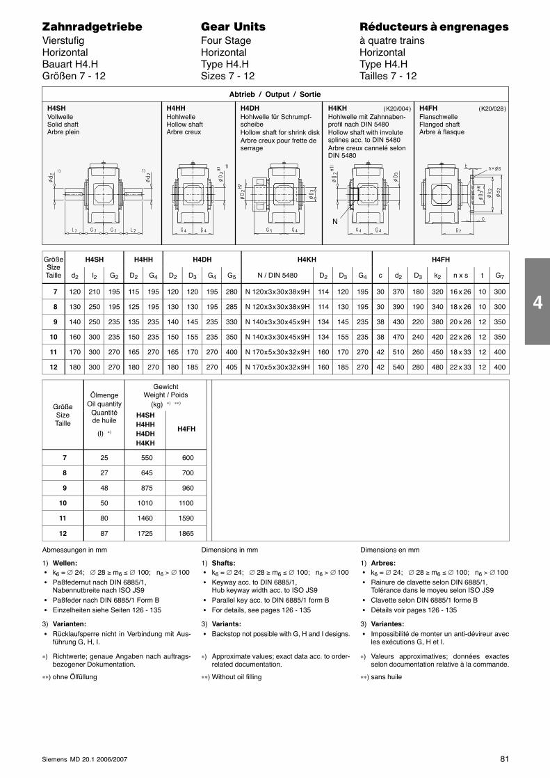
81Siemens MD 20.1 2006/2007
������������� ���� �� ��������� � ����������Vierstufig Four Stage à quatre trainsHorizontal Horizontal HorizontalBauart H4.H Type H4.H Type H4.HGrößen 7 - 12 Sizes 7 - 12 Tailles 7 - 12
H4SHVollwelleSolid shaftArbre plein
H4HHHohlwelleHollow shaftArbre creux
H4DHHohlwelle für Schrumpf-scheibeHollow shaft for shrink diskArbre creux pour frette deserrage
Abtrieb / Output / Sortie
H4KHHohlwelle mit Zahnnaben-profil nach DIN 5480Hollow shaft with involutesplines acc. to DIN 5480Arbre creux cannelé selonDIN 5480
H4FHFlanschwelleFlanged shaftArbre à flasque
N
( K20/004 ) ( K20/028 )
GrößeSize
H4SH H4HH H4DH H4KH H4FHSizeTaille d2 l2 G2 D2 G4 D2 D3 G4 G5 N / DIN 5480 D2 D3 G4 c d2 D3 k2 n x s t G7
7 120 210 195 115 195 120 120 195 280 N 120 x 3 x 30 x 38 x 9H 114 120 195 30 370 180 320 16 x 26 10 300
8 130 250 195 125 195 130 130 195 285 N 120 x 3 x 30 x 38 x 9H 114 130 195 30 390 190 340 18 x 26 10 300
9 140 250 235 135 235 140 145 235 330 N 140 x 3 x 30 x 45 x 9H 134 145 235 38 430 220 380 20 x 26 12 350
10 160 300 235 150 235 150 155 235 350 N 140 x 3 x 30 x 45 x 9H 134 155 235 38 470 240 420 22 x 26 12 350
11 170 300 270 165 270 165 170 270 400 N 170 x 5 x 30 x 32 x 9H 160 170 270 42 510 260 450 18 x 33 12 400
12 180 300 270 180 270 180 185 270 405 N 170 x 5 x 30 x 32 x 9H 160 185 270 42 540 280 480 22 x 33 12 400
Größe
ÖlmengeOil quantity
Q tité
GewichtWeight / Poids
(kg) ∗) ∗∗)GrößeSizeTaille
Quantitéde huile
(l) ∗)
H4SHH4HHH4DHH4KH
H4FH
7 25 550 600
8 27 645 700
9 48 875 960
10 50 1010 1100
11 80 1460 1590
12 87 1725 1865
Abmessungen in mm
1) Wellen: � k6 = ∅ 24; ∅ 28 ≥ m6 ≤ ∅ 100; n6 > ∅ 100 � Paßfedernut nach DIN 6885/1,
Nabennutbreite nach ISO JS9 � Paßfeder nach DIN 6885/1 Form B � Einzelheiten siehe Seiten 126 - 135
3) Varianten: � Rücklaufsperre nicht in Verbindung mit Aus-
führung G, H, I.
∗) Richtwerte; genaue Angaben nach auftrags-bezogener Dokumentation.
∗∗) ohne Ölfüllung
Dimensions in mm
1) Shafts: � k6 = ∅ 24; ∅ 28 ≥ m6 ≤ ∅ 100; n6 > ∅ 100 � Keyway acc. to DIN 6885/1,
Hub keyway width acc. to ISO JS9 � Parallel key acc. to DIN 6885/1 form B � For details, see pages 126 - 135
3) Variants: � Backstop not possible with G, H and I designs.
∗) Approximate values; exact data acc. to order-related documentation.
∗∗) Without oil filling
Dimensions en mm
1) Arbres: � k6 = ∅ 24; ∅ 28 ≥ m6 ≤ ∅ 100; n6 > ∅ 100 � Rainure de clavette selon DIN 6885/1,
Tolérance dans le moyeu selon ISO JS9 � Clavette selon DIN 6885/1 forme B � Détails voir pages 126 - 135
3) Variantes: � Impossibilité de monter un anti-dévireur avec
les exécutions G, H et I.
∗) Valeurs approximatives; données exactesselon documentation relative à la commande.
∗∗) sans huile
4
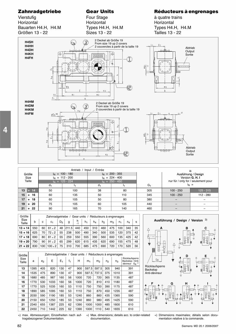
82 Siemens MD 20.1 2006/2007
������������� ���� �� ��������� � ����������Vierstufig Four Stage à quatre trainsHorizontal Horizontal HorizontalBauarten H4.H, H4.M Types H4.H, H4.M Types H4.H, H4.MGrößen 13 - 22 Sizes 13 - 22 Tailles 13 - 22
H4SHH4HHH4DHH4KHH4FH
2 Deckel ab Größe 19From size 19 up 2 covers2 couvercles à partir de la taille 19
H4HMH4DMH4KMH4FM
2 Deckel ab Größe 19From size 19 up 2 covers2 couvercles à partir de la taille 19
AbtriebOutputSortie
AbtriebOutputSortie
Antrieb / Input / Entrée 3)Größe iN = 100 - 180 iN = 200 - 355
3)Ausführung / DesignGröße
Size iN = 112 - 200 iN = 224 - 400Ausführung / Design
Version G, H, ISizeTaille iN = 125 - 224 iN = 250 - 450
Version G, H, Inur für / only for / seulement pour
id1 l1 d1 l1 G1
yiN =
13 + 14 50 100 38 80 305 100 - 250 125 - 315
15 + 16 60 135 50 110 345 100 - 250 112 - 280
17 + 18 60 105 50 80 380 – –
19 + 20 75 105 60 105 440 – –
21 + 22 90 165 70 140 460 – –
GrößeSi
Zahnradgetriebe / Gear units / Réducteurs à engrenagesSizeTaille b c c1 D5 g h
-1h1 h4 h2 m3 n1 n4 s
13 + 14 550 60 61 ± 2 48 211.5 440 450 310 460 475 100 340 35
15 + 16 625 70 72 ± 2 55 238 500 490 340 500 535 120 375 42
17 + 18 690 80 81 ± 2 55 259 550 555 390 560 600 135 425 42
19 + 20 790 90 91 ± 2 65 299 620 615 435 620 690 155 475 48
21 + 22 830 100 100 ± 2 75 310 700 685 475 690 720 170 520 56
Größe Zahnradgetriebe / Gear units / Réducteurs à engrenagesGrößeSizeTaille a e2 E E1 f1 H m1 m2 n2 n3
RücklaufsperreBackstop / Anti-dévireur G8 +)
13 1395 405 820 130 47 900 597.5 597.5 305 940 391
14 1535 475 890 130 47 900 597.5 737.5 375 1010 391
15 1680 485 987 160 56 1000 720 720 365 1135 487
16 1770 530 1033 160 56 1000 720 810 410 1180 487
17 1770 525 1035 160 53 1110 750 750 390 1175 487
18 1890 585 1095 160 53 1110 750 870 450 1235 487
19 2030 590 1190 185 53 1240 860 860 435 1365 590
20 2150 650 1250 185 53 1240 860 980 495 1425 590
21 2340 655 1387 225 62 1390 1000 1000 485 1600 610
22 2450 710 1442 225 62 1390 1000 1110 540 1655 610
+) max. Abmessungen; Einzelheiten nach auf-tragsbezogener Dokumentation.
+) Max. dimensions; details acc. to order-relateddocumentation.
+) Dimensions maximales; détails selon docu-mentation relative à la commande.
4
Ausführung / Design / Version 3)
A
RücklaufsperreBackstopAnti-dévireur
B C
D E
F G H I
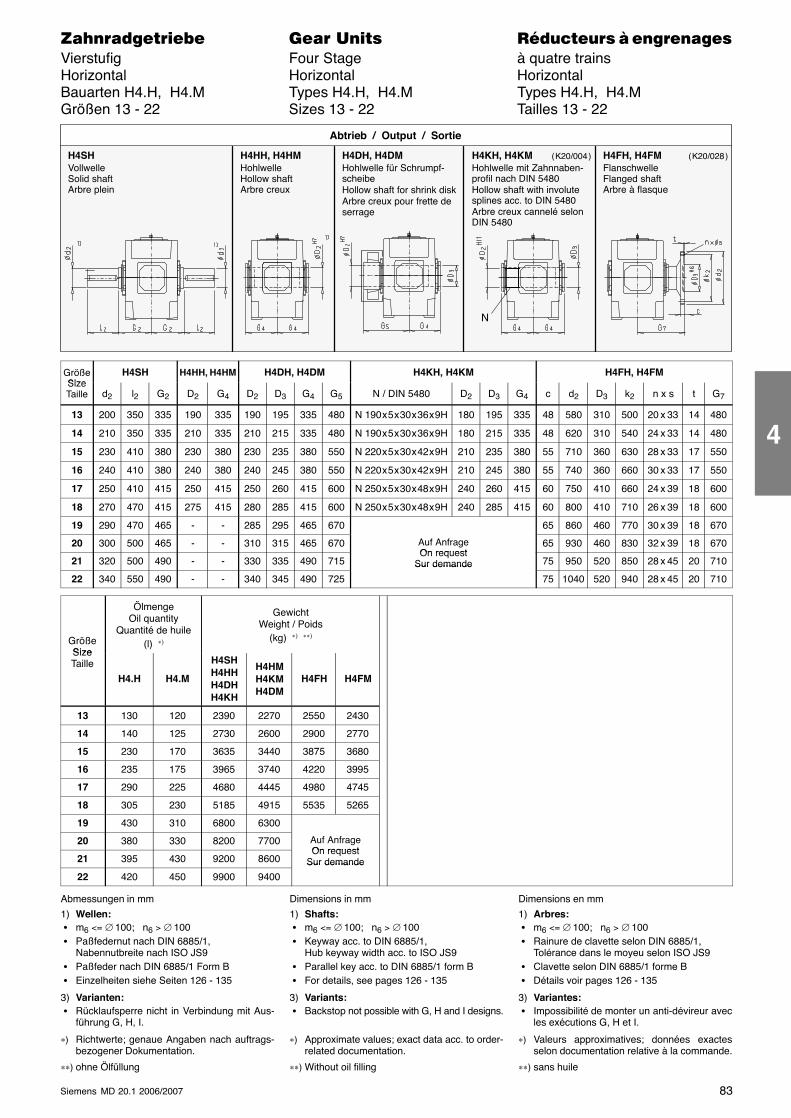
83Siemens MD 20.1 2006/2007
������������� ���� �� ��������� � ����������Vierstufig Four Stage à quatre trainsHorizontal Horizontal HorizontalBauarten H4.H, H4.M Types H4.H, H4.M Types H4.H, H4.MGrößen 13 - 22 Sizes 13 - 22 Tailles 13 - 22
H4SHVollwelleSolid shaftArbre plein
H4HH, H4HMHohlwelleHollow shaftArbre creux
H4DH, H4DMHohlwelle für Schrumpf-scheibeHollow shaft for shrink diskArbre creux pour frette deserrage
Abtrieb / Output / Sortie
H4KH, H4KMHohlwelle mit Zahnnaben-profil nach DIN 5480Hollow shaft with involutesplines acc. to DIN 5480Arbre creux cannelé selonDIN 5480
H4FH, H4FMFlanschwelleFlanged shaftArbre à flasque
N
( K20/004 ) ( K20/028 )
GrößeSize
H4SH H4HH, H4HM H4DH, H4DM H4KH, H4KM H4FH, H4FMSizeTaille d2 l2 G2 D2 G4 D2 D3 G4 G5 N / DIN 5480 D2 D3 G4 c d2 D3 k2 n x s t G7
13 200 350 335 190 335 190 195 335 480 N 190 x 5 x 30 x 36 x 9H 180 195 335 48 580 310 500 20 x 33 14 480
14 210 350 335 210 335 210 215 335 480 N 190 x 5 x 30 x 36 x 9H 180 215 335 48 620 310 540 24 x 33 14 480
15 230 410 380 230 380 230 235 380 550 N 220 x 5 x 30 x 42 x 9H 210 235 380 55 710 360 630 28 x 33 17 550
16 240 410 380 240 380 240 245 380 550 N 220 x 5 x 30 x 42 x 9H 210 245 380 55 740 360 660 30 x 33 17 550
17 250 410 415 250 415 250 260 415 600 N 250 x 5 x 30 x 48 x 9H 240 260 415 60 750 410 660 24 x 39 18 600
18 270 470 415 275 415 280 285 415 600 N 250 x 5 x 30 x 48 x 9H 240 285 415 60 800 410 710 26 x 39 18 600
19 290 470 465 - - 285 295 465 670 65 860 460 770 30 x 39 18 670
20 300 500 465 - - 310 315 465 670 Auf AnfrageOn request
65 930 460 830 32 x 39 18 670
21 320 500 490 - - 330 335 490 715On request
Sur demande 75 950 520 850 28 x 45 20 710
22 340 550 490 - - 340 345 490 725
Sur demande
75 1040 520 940 28 x 45 20 710
GrößeSize
ÖlmengeOil quantity
Quantité de huile(l) ∗)
GewichtWeight / Poids
(kg) ∗) ∗∗)
SizeTaille
H4.H H4.M
H4SHH4HHH4DHH4KH
H4HMH4KMH4DM
H4FH H4FM
13 130 120 2390 2270 2550 2430
14 140 125 2730 2600 2900 2770
15 230 170 3635 3440 3875 3680
16 235 175 3965 3740 4220 3995
17 290 225 4680 4445 4980 4745
18 305 230 5185 4915 5535 5265
19 430 310 6800 6300
20 380 330 8200 7700 Auf AnfrageOn request
21 395 430 9200 8600On request
Sur demande
22 420 450 9900 9400
Sur demande
Abmessungen in mm
1) Wellen: � m6 <= ∅ 100; n6 > ∅ 100 � Paßfedernut nach DIN 6885/1,
Nabennutbreite nach ISO JS9 � Paßfeder nach DIN 6885/1 Form B � Einzelheiten siehe Seiten 126 - 135
3) Varianten: � Rücklaufsperre nicht in Verbindung mit Aus-
führung G, H, I.
∗) Richtwerte; genaue Angaben nach auftrags-bezogener Dokumentation.
∗∗) ohne Ölfüllung
Dimensions in mm
1) Shafts: � m6 <= ∅ 100; n6 > ∅ 100 � Keyway acc. to DIN 6885/1,
Hub keyway width acc. to ISO JS9 � Parallel key acc. to DIN 6885/1 form B � For details, see pages 126 - 135
3) Variants: � Backstop not possible with G, H and I designs.
∗) Approximate values; exact data acc. to order-related documentation.
∗∗) Without oil filling
Dimensions en mm
1) Arbres: � m6 <= ∅ 100; n6 > ∅ 100 � Rainure de clavette selon DIN 6885/1,
Tolérance dans le moyeu selon ISO JS9 � Clavette selon DIN 6885/1 forme B � Détails voir pages 126 - 135
3) Variantes: � Impossibilité de monter un anti-dévireur avec
les exécutions G, H et I.
∗) Valeurs approximatives; données exactesselon documentation relative à la commande.
∗∗) sans huile
4
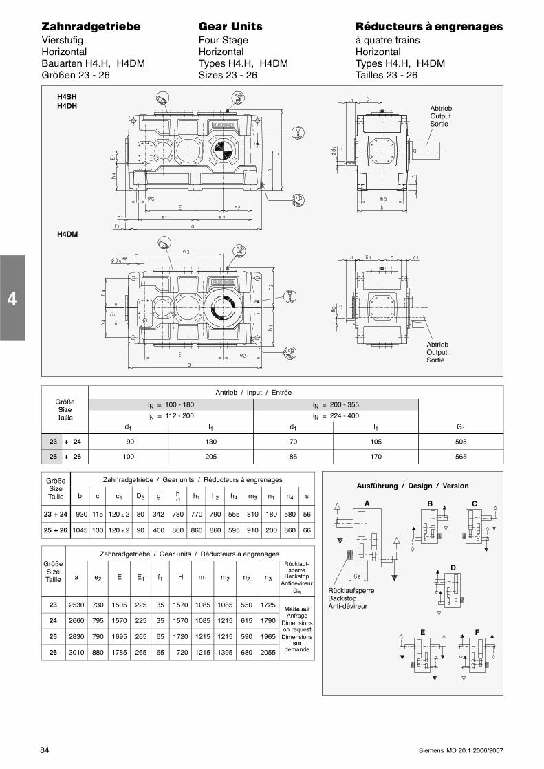
84 Siemens MD 20.1 2006/2007
������������� ���� �� ��������� � ����������Vierstufig Four Stage à quatre trainsHorizontal Horizontal HorizontalBauarten H4.H, H4DM Types H4.H, H4DM Types H4.H, H4DMGrößen 23 - 26 Sizes 23 - 26 Tailles 23 - 26
H4SHH4DH
H4DM
AbtriebOutputSortie
AbtriebOutputSortie
Antrieb / Input / EntréeGrößeSize
iN = 100 - 180 iN = 200 - 355SizeTaille iN = 112 - 200 iN = 224 - 400Taille
d1 l1 d1 l1 G1
23 + 24 90 130 70 105 505
25 + 26 100 205 85 170 565
GrößeSi
Zahnradgetriebe / Gear units / Réducteurs à engrenagesSizeTaille b c c1 D5 g h
-1h1 h2 h4 m3 n1 n4 s
23 + 24 930 115 120 ± 2 80 342 780 770 790 555 810 180 580 56
25 + 26 1045 130 120 ± 2 90 400 860 860 860 595 910 200 660 66
Zahnradgetriebe / Gear units / Réducteurs à engrenagesGrößeSizeTaille a e2 E E1 f1 H m1 m2 n2 n3
Rücklauf-sperre
BackstopAntidévireur
G8
23 2530 730 1505 225 35 1570 1085 1085 550 1725Maße auf
24 2660 795 1570 225 35 1570 1085 1215 615 1790
Maße aufAnfrage
Dimensionson request
25 2830 790 1695 265 65 1720 1215 1215 590 1965on requestDimensions
sur
26 3010 880 1785 265 65 1720 1215 1395 680 2055sur
demande
4
Ausführung / Design / Version
A
RücklaufsperreBackstopAnti-dévireur
B C
D
E F
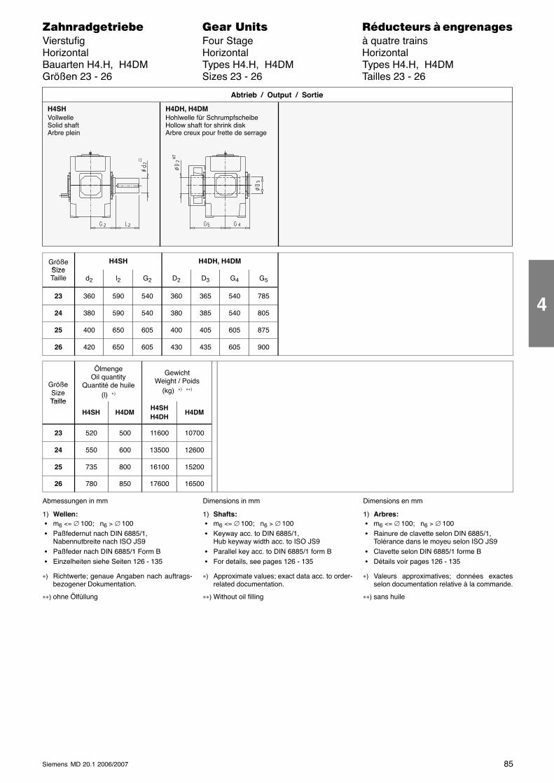
85Siemens MD 20.1 2006/2007
������������� ���� �� ��������� � ����������Vierstufig Four Stage à quatre trainsHorizontal Horizontal HorizontalBauarten H4.H, H4DM Types H4.H, H4DM Types H4.H, H4DMGrößen 23 - 26 Sizes 23 - 26 Tailles 23 - 26
H4SHVollwelleSolid shaftArbre plein
H4DH, H4DMHohlwelle für SchrumpfscheibeHollow shaft for shrink diskArbre creux pour frette de serrage
Abtrieb / Output / Sortie
GrößeSize
H4SH H4DH, H4DMSizeTaille d2 l2 G2 D2 D3 G4 G5
23 360 590 540 360 365 540 785
24 380 590 540 380 385 540 805
25 400 650 605 400 405 605 875
26 420 650 605 430 435 605 900
GrößeSizeTaille
ÖlmengeOil quantity
Quantité de huile(l) ∗)
GewichtWeight / Poids
(kg) ∗) ∗∗)
Taille
H4SH H4DMH4SHH4DH
H4DM
23 520 500 11600 10700
24 550 600 13500 12600
25 735 800 16100 15200
26 780 850 17600 16500
Abmessungen in mm
1) Wellen: � m6 <= ∅ 100; n6 > ∅ 100 � Paßfedernut nach DIN 6885/1,
Nabennutbreite nach ISO JS9 � Paßfeder nach DIN 6885/1 Form B � Einzelheiten siehe Seiten 126 - 135
∗) Richtwerte; genaue Angaben nach auftrags-bezogener Dokumentation.
∗∗) ohne Ölfüllung
Dimensions in mm
1) Shafts: � m6 <= ∅ 100; n6 > ∅ 100 � Keyway acc. to DIN 6885/1,
Hub keyway width acc. to ISO JS9 � Parallel key acc. to DIN 6885/1 form B � For details, see pages 126 - 135
∗) Approximate values; exact data acc. to order-related documentation.
∗∗) Without oil filling
Dimensions en mm
1) Arbres: � m6 <= ∅ 100; n6 > ∅ 100 � Rainure de clavette selon DIN 6885/1,
Tolérance dans le moyeu selon ISO JS9 � Clavette selon DIN 6885/1 forme B � Détails voir pages 126 - 135
∗) Valeurs approximatives; données exactesselon documentation relative à la commande.
∗∗) sans huile
4
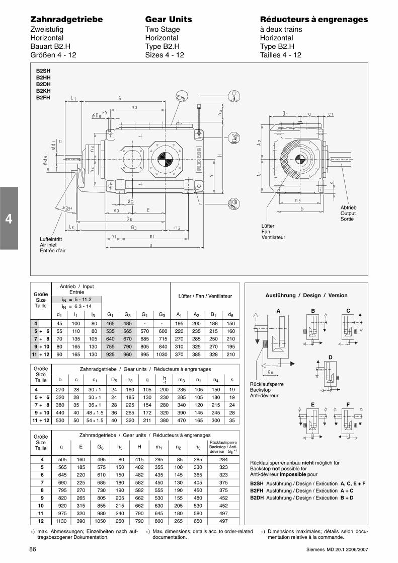
86 Siemens MD 20.1 2006/2007
������������� ���� �� ��������� � ����������Zweistufig Two Stage à deux trainsHorizontal Horizontal HorizontalBauart B2.H Type B2.H Type B2.HGrößen 4 - 12 Sizes 4 - 12 Tailles 4 - 12
LüfterFanVentilateurLufteintritt
Air inletEntrée d’air
AbtriebOutputSortie
B2SHB2HHB2DHB2KHB2FH
Größe
Antrieb / InputEntrée
Lüfter / Fan / VentilateurGrößeSize iN = 5 - 11.2
Lüfter / Fan / VentilateurSizeTaille iN = 6.3 - 14
d1 l1 l3 G1 G3 G1 G3 A1 A2 B1 d6
4 45 100 80 465 485 - - 195 200 188 150
5 + 6 55 110 80 535 565 570 600 220 235 215 160
7 + 8 70 135 105 640 670 685 715 270 285 250 210
9 + 10 80 165 130 755 790 805 840 310 325 270 195
11 + 12 90 165 130 925 960 995 1030 370 385 328 210
GrößeSize
Zahnradgetriebe / Gear units / Réducteurs à engrenagesSizeTaille b c c1 D5 e3 g h
-1m3 n1 n4 s
4 270 28 30 ± 1 24 160 105 200 235 105 150 19
5 + 6 320 28 30 ± 1 24 185 130 230 285 105 180 19
7 + 8 380 35 36 ± 1 28 225 154 280 340 120 215 24
9 + 10 440 40 48 ± 1.5 36 265 172 320 390 145 245 28
11 + 12 530 50 54 ± 1.5 40 320 211 380 470 165 300 35
Größe Zahnradgetriebe / Gear units / Réducteurs à engrenagesGrößeSizeTaille a E G6 h5 H m1 n2 n3
RücklaufsperreBackstop / Anti-dévireur G8 +)
4 505 160 495 80 415 295 85 285 284
5 565 185 575 150 482 355 100 330 323
6 645 220 610 150 482 435 145 365 323
7 690 225 685 180 582 450 130 405 375
8 795 270 730 190 582 555 190 450 375
9 820 265 805 205 662 530 155 480 452
10 920 315 855 215 662 630 205 530 452
11 975 320 980 240 790 645 180 580 497
12 1130 390 1050 250 790 800 265 650 497
+) max. Abmessungen; Einzelheiten nach auf-tragsbezogener Dokumentation.
+) Max. dimensions; details acc. to order-relateddocumentation.
+) Dimensions maximales; détails selon docu-mentation relative à la commande.
4
Ausführung / Design / Version
A B C
D
E F
RücklaufsperreBackstopAnti-dévireur
Rücklaufsperrenanbau nicht möglich fürBackstop not possible forAnti-dévireur impossible pour
B2SH Ausführung / Design / Exécution A, C, E + FB2FH Ausführung / Design / Exécution A + CB2DH Ausführung / Design / Exécution B + D
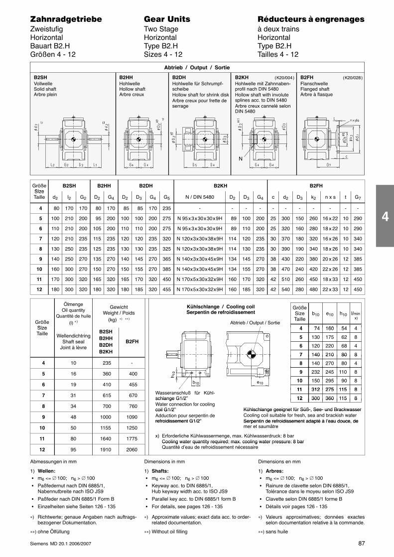
87Siemens MD 20.1 2006/2007
������������� ���� �� ��������� � ����������Zweistufig Two Stage à deux trainsHorizontal Horizontal HorizontalBauart B2.H Type B2.H Type B2.HGrößen 4 - 12 Sizes 4 - 12 Tailles 4 - 12
B2SHVollwelleSolid shaftArbre plein
B2HHHohlwelleHollow shaftArbre creux
B2DHHohlwelle für Schrumpf-scheibeHollow shaft for shrink diskArbre creux pour frette deserrage
Abtrieb / Output / Sortie
B2KHHohlwelle mit Zahnnaben-profil nach DIN 5480Hollow shaft with involutesplines acc. to DIN 5480Arbre creux cannelé selonDIN 5480
B2FHFlanschwelleFlanged shaftArbre à flasque
N
( K20/004 ) ( K20/028 )
GrößeSize
B2SH B2HH B2DH B2KH B2FHSizeTaille d2 l2 G2 D2 G4 D2 D3 G4 G5 N / DIN 5480 D2 D3 G4 c d2 D3 k2 n x s t G7
4 80 170 170 80 170 85 85 170 235 - - - - - - - - - - -
5 100 210 200 95 200 100 100 200 275 N 95 x 3 x 30 x 30 x 9H 89 100 200 25 300 150 260 16 x 22 10 290
6 110 210 200 105 200 110 110 200 275 N 95 x 3 x 30 x 30 x 9H 89 110 200 25 320 160 280 18 x 22 10 290
7 120 210 235 115 235 120 120 235 320 N 120 x 3 x 30 x 38 x 9H 114 120 235 30 370 180 320 16 x 26 10 340
8 130 250 235 125 235 130 130 235 325 N 120 x 3 x 30 x 38 x 9H 114 130 235 30 390 190 340 18 x 26 10 340
9 140 250 270 135 270 140 145 270 365 N 140 x 3 x 30 x 45 x 9H 134 145 270 38 430 220 380 20 x 26 12 385
10 160 300 270 150 270 150 155 270 385 N 140 x 3 x 30 x 45 x 9H 134 155 270 38 470 240 420 22 x 26 12 385
11 170 300 320 165 320 165 170 320 450 N 170 x 5 x 30 x 32 x 9H 160 170 320 42 510 260 450 18 x 33 12 450
12 180 300 320 180 320 180 185 320 455 N 170 x 5 x 30 x 32 x 9H 160 185 320 42 540 280 480 22 x 33 12 450
GrößeSize
ÖlmengeOil quantity
Quantité de huile(l) ∗)
GewichtWeight / Poids
(kg) ∗) ∗∗)Abtrieb / Output / Sortie
GrößeSizeTaille
74 54
l/min x)
4 160
b10 e10 h10
4
Kühlschlange / Cooling coilSerpentin de refroidissement
SizeTaille Wellendichtring
Shaft sealJoint à lèvre
B2SHB2HHB2DHB2KH
B2FH
74 54 4 160 4
130 62 5 175 8
120 68 6 220 4
140 80 7 210 8
4 10 235 -
140 80 7 210 8
140 80 8 270 4
5 16 360 400 232 110 9 245 8
150 9010 295 8
h 10
6 19 410 455150 9010 295 8
312 11511 275 8
b10
h
e10
7 31 615 670312 11511 275 8
300 11512 360 8Wasseranschluß für Kühl-schlange G1/2”
8 34 700 760
300 11512 360 8schlange G1/2Water connection for coolingcoil G1/2” Kühlschlange geeignet für Süß-, See- und Brackwasser
9 48 1000 1090
coil G1/2Adduction pour serpentin derefroidissement G1/2”
Kühlschlange geeignet für Süß-, See- und BrackwasserCooling coil suitable for fresh, sea and brackish waterSerpentin de refroidissement adapté à l’eau douce, de
10 50 1155 1250refroidissement G1/2” Serpentin de refroidissement adapté à l’eau douce, de
mer et saumâtre
11 80 1640 1775 x) Erforderliche Kühlwassermenge, max. Kühlwasserdruck: 8 barCooling water quantity required; max. cooling water pressure: 8 bar
12 95 1910 2060
Cooling water quantity required max. cooling water ressure: 8 barQuantité d’eau de refroidissement nécessaire
Abmessungen in mm
1) Wellen: � m6 <= ∅ 100; n6 > ∅ 100
� Paßfedernut nach DIN 6885/1,Nabennutbreite nach ISO JS9
� Paßfeder nach DIN 6885/1 Form B
� Einzelheiten siehe Seiten 126 - 135
∗) Richtwerte; genaue Angaben nach auftrags-bezogener Dokumentation.
∗∗) ohne Ölfüllung
Dimensions in mm
1) Shafts: � m6 <= ∅ 100; n6 > ∅ 100
� Keyway acc. to DIN 6885/1,Hub keyway width acc. to ISO JS9
� Parallel key acc. to DIN 6885/1 form B
� For details, see pages 126 - 135
∗) Approximate values; exact data acc. to order-related documentation.
∗∗) Without oil filling
Dimensions en mm
1) Arbres: � m6 <= ∅ 100; n6 > ∅ 100
� Rainure de clavette selon DIN 6885/1,Tolérance dans le moyeu selon ISO JS9
� Clavette selon DIN 6885/1 forme B
� Détails voir pages 126 - 135
∗) Valeurs approximatives; données exactesselon documentation relative à la commande.
∗∗) sans huile
4
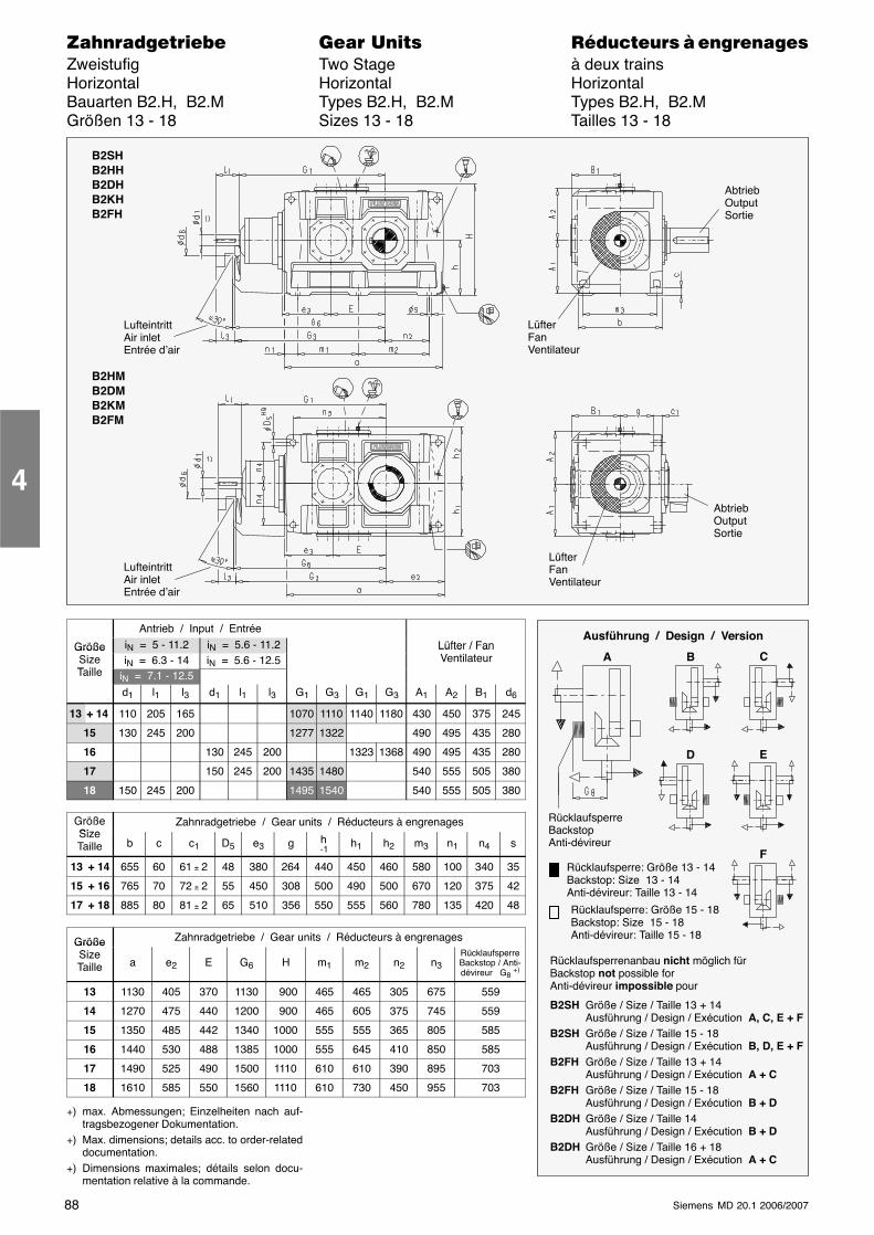
88 Siemens MD 20.1 2006/2007
������������� ���� �� ��������� � ����������Zweistufig Two Stage à deux trainsHorizontal Horizontal HorizontalBauarten B2.H, B2.M Types B2.H, B2.M Types B2.H, B2.MGrößen 13 - 18 Sizes 13 - 18 Tailles 13 - 18
LüfterFanVentilateur
LufteintrittAir inletEntrée d’air
B2SHB2HHB2DHB2KHB2FH
B2HMB2DMB2KMB2FM
LüfterFanVentilateur
LufteintrittAir inletEntrée d’air
AbtriebOutputSortie
AbtriebOutputSortie
Antrieb / Input / Entrée
Größe iN = 5 - 11.2 iN = 5.6 - 11.2 Lüfter / FanGrößeSizeT ill
iN = 6.3 - 14 iN = 5.6 - 12.5Lüfter / FanVentilateur
Taille iN = 7.1 - 12.5d1 l1 l3 d1 l1 l3 G1 G3 G1 G3 A1 A2 B1 d6
13 + 14 110 205 165 1070 1110 1140 1180 430 450 375 245
15 130 245 200 1277 1322 490 495 435 280
16 130 245 200 1323 1368 490 495 435 280
17 150 245 200 1435 1480 540 555 505 380
18 150 245 200 1495 1540 540 555 505 380
GrößeSize
Zahnradgetriebe / Gear units / Réducteurs à engrenagesSizeTaille b c c1 D5 e3 g h
-1h1 h2 m3 n1 n4 s
13 + 14 655 60 61 ± 2 48 380 264 440 450 460 580 100 340 35
15 + 16 765 70 72 ± 2 55 450 308 500 490 500 670 120 375 42
17 + 18 885 80 81 ± 2 65 510 356 550 555 560 780 135 420 48
Größe Zahnradgetriebe / Gear units / Réducteurs à engrenagesGrößeSizeTaille a e2 E G6 H m1 m2 n2 n3
RücklaufsperreBackstop / Anti-dévireur G8 +)
13 1130 405 370 1130 900 465 465 305 675 559
14 1270 475 440 1200 900 465 605 375 745 559
15 1350 485 442 1340 1000 555 555 365 805 585
16 1440 530 488 1385 1000 555 645 410 850 585
17 1490 525 490 1500 1110 610 610 390 895 703
18 1610 585 550 1560 1110 610 730 450 955 703
+) max. Abmessungen; Einzelheiten nach auf-tragsbezogener Dokumentation.
+) Max. dimensions; details acc. to order-relateddocumentation.
+) Dimensions maximales; détails selon docu-mentation relative à la commande.
4
Ausführung / Design / Version
A B C
D E
F
RücklaufsperreBackstopAnti-dévireur
Rücklaufsperre: Größe 13 - 14Backstop: Size 13 - 14Anti-dévireur: Taille 13 - 14
Rücklaufsperre: Größe 15 - 18Backstop: Size 15 - 18Anti-dévireur: Taille 15 - 18
Rücklaufsperrenanbau nicht möglich fürBackstop not possible forAnti-dévireur impossible pour
B2SH Größe / Size / Taille 13 + 14Ausführung / Design / Exécution A, C, E + F
B2SH Größe / Size / Taille 15 - 18Ausführung / Design / Exécution B, D, E + F
B2FH Größe / Size / Taille 13 + 14Ausführung / Design / Exécution A + C
B2FH Größe / Size / Taille 15 - 18Ausführung / Design / Exécution B + D
B2DH Größe / Size / Taille 14Ausführung / Design / Exécution B + D
B2DH Größe / Size / Taille 16 + 18Ausführung / Design / Exécution A + C
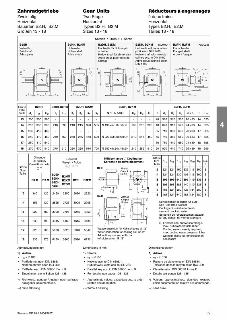
89Siemens MD 20.1 2006/2007
������������� ���� �� ��������� � ����������Zweistufig Two Stage à deux trainsHorizontal Horizontal HorizontalBauarten B2.H, B2.M Types B2.H, B2.M Types B2.H, B2.MGrößen 13 - 18 Sizes 13 - 18 Tailles 13 - 18
B2SHVollwelleSolid shaftArbre plein
B2HH, B2HMHohlwelleHollow shaftArbre creux
B2DH, B2DMHohlwelle für Schrumpf-scheibeHollow shaft for shrink diskArbre creux pour frette deserrage
Abtrieb / Output / Sortie
B2KH, B2KMHohlwelle mit Zahnnaben-profil nach DIN 5480Hollow shaft with involutesplines acc. to DIN 5480Arbre creux cannelé selonDIN 5480
B2FH, B2FMFlanschwelleFlanged shaftArbre à flasque
N
( K20/004 ) ( K20/028 )
GrößeSize
B2SH B2HH, B2HM B2DH, B2DM B2KH, B2KM B2FH, B2FMSizeTaille d2 l2 G2 D2 G4 D2 D3 G4 G5 N / DIN 5480 D2 D3 G4 c d2 D3 k2 n x s t G7
13 200 350 390 - - - - - - - - - - 48 580 310 500 20 x 33 14 525
14 210 350 390 210 390 210 215 390 535 N 190 x 5 x 30 x 36 x 9H 180 215 390 48 620 310 540 24 x 33 14 525
15 230 410 460 - - - - - - - - - - 55 710 360 630 28 x 33 17 625
16 240 410 460 240 450 240 245 450 620 N 220 x 5 x 30 x 42 x 9H 210 245 450 55 740 360 660 30 x 33 17 625
17 250 410 540 - - - - - - - - - - 60 750 410 660 24 x 39 18 695
18 270 470 540 275 510 280 285 510 700 N 250 x 5 x 30 x 48 x 9H 240 285 510 60 800 410 710 26 x 39 18 695
GrößeSizeT ill
ÖlmengeOil quantity
Quantité de huile(l) ∗)
GewichtWeight / Poids
(kg) ∗) ∗∗)
AbtriebOutput
Kühlschlange / Cooling coilSerpentin de refroidissement
GrößeSizeTaille
324 116
l/minx)
13 460
b11 e10 h10
8335
e11
300
h11
B2.H 324
b10
Taille
B2 H B2 M
B2SHB2HH
B2HMB2KM B2FH B2FM
Out utSortie 324 11614 530 8
396 11915 540 8
405
395
300
335
324
396B2.H B2.M B2HHB2DHB2KH
B2KMB2DM
B2FH B2FM 396 11915 540 8
396 11916 585 8
395
440
335
335
396
396
10
13 140 120 2450 2350 2620 2520Abtrieb
324 13417 580 8
324 13418 640 8
425
485
380
380B2.M
468
468b10
h 10
e10
14 155 130 2825 2725 3005 2905 Kühlschlange geeignet für Süß-,See- und BrackwasserC li il i bl f f h
AbtriebOutputSortie
B2.M
15 220 180 3990 3795 4245 4050Cooling coil suitable for fresh,sea and brackish waterSerpentin de refroidissement adaptéh 1
1
16 230 190 4345 4160 4615 4430
Ser entin de refroidissement ada téà l’eau douce, de mer et saumâtre
x) Erforderliche Kühlwassermenge,max Kühlwasserdruck: 8 bar
e11b11
17 320 260 5620 5320 5940 5640 Wasseranschluß für Kühlschlange G1/2”Water connection for cooling coil G1/2”Add ti ti d
) gmax. Kühlwasserdruck: 8 barCooling water quantity required;max. cooling water pressure: 8 barQ i é d’ d f idi
18 335 275 6150 5860 6520 6230
gAdduction pour serpentin derefroidissement G1/2”
gQuantité d’eau de refroidissementnécessaire
Abmessungen in mm
1) Wellen: � n6 > ∅ 100
� Paßfedernut nach DIN 6885/1,Nabennutbreite nach ISO JS9
� Paßfeder nach DIN 6885/1 Form B
� Einzelheiten siehe Seiten 126 - 135
∗) Richtwerte; genaue Angaben nach auftrags-bezogener Dokumentation.
∗∗) ohne Ölfüllung
Dimensions in mm
1) Shafts: � n6 > ∅ 100
� Keyway acc. to DIN 6885/1,Hub keyway width acc. to ISO JS9
� Parallel key acc. to DIN 6885/1 form B
� For details, see pages 126 - 135
∗) Approximate values; exact data acc. to order-related documentation.
∗∗) Without oil filling
Dimensions en mm
1) Arbres: � n6 > ∅ 100
� Rainure de clavette selon DIN 6885/1,Tolérance dans le moyeu selon ISO JS9
� Clavette selon DIN 6885/1 forme B
� Détails voir pages 126 - 135
∗) Valeurs approximatives; données exactesselon documentation relative à la commande.
∗∗) sans huile
4
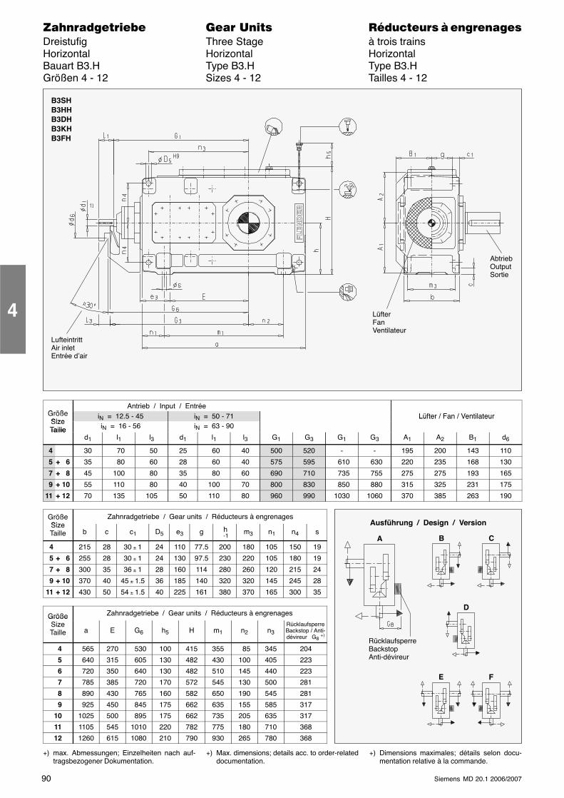
90 Siemens MD 20.1 2006/2007
������������� ���� �� ��������� � ����������Dreistufig Three Stage à trois trainsHorizontal Horizontal HorizontalBauart B3.H Type B3.H Type B3.HGrößen 4 - 12 Sizes 4 - 12 Tailles 4 - 12
LüfterFanVentilateur
LufteintrittAir inletEntrée d’air
AbtriebOutputSortie
B3SHB3HHB3DHB3KHB3FH
G ößAntrieb / Input / Entrée
GrößeSize
iN = 12.5 - 45 iN = 50 - 71 Lüfter / Fan / VentilateurSizeTaille iN = 16 - 56 iN = 63 - 90
Lüfter / Fan / Ventilateur
Tailled1 l1 l3 d1 l1 l3 G1 G3 G1 G3 A1 A2 B1 d6
4 30 70 50 25 60 40 500 520 - - 195 200 143 110
5 + 6 35 80 60 28 60 40 575 595 610 630 220 235 168 130
7 + 8 45 100 80 35 80 60 690 710 735 755 275 275 193 165
9 + 10 55 110 80 40 100 70 800 830 850 880 315 325 231 175
11 + 12 70 135 105 50 110 80 960 990 1030 1060 370 385 263 190
GrößeSize
Zahnradgetriebe / Gear units / Réducteurs à engrenagesSizeTaille b c c1 D5 e3 g h
-1m3 n1 n4 s
4 215 28 30 ± 1 24 110 77.5 200 180 105 150 19
5 + 6 255 28 30 ± 1 24 130 97.5 230 220 105 180 19
7 + 8 300 35 36 ± 1 28 160 114 280 260 120 215 24
9 + 10 370 40 45 ± 1.5 36 185 140 320 320 145 245 28
11 + 12 430 50 54 ± 1.5 40 225 161 380 370 165 300 35
Größe Zahnradgetriebe / Gear units / Réducteurs à engrenagesGrößeSizeTaille a E G6 h5 H m1 n2 n3
RücklaufsperreBackstop / Anti-dévireur G8 +)
4 565 270 530 100 415 355 85 345 204
5 640 315 605 130 482 430 100 405 223
6 720 350 640 130 482 510 145 440 223
7 785 385 720 170 572 545 130 500 281
8 890 430 765 160 582 650 190 545 281
9 925 450 845 175 662 635 155 585 317
10 1025 500 895 175 662 735 205 635 317
11 1105 545 1010 220 782 775 180 710 368
12 1260 615 1080 210 790 930 265 780 368
+) max. Abmessungen; Einzelheiten nach auf-tragsbezogener Dokumentation.
+) Max. dimensions; details acc. to order-relateddocumentation.
+) Dimensions maximales; détails selon docu-mentation relative à la commande.
4
Ausführung / Design / Version
A
RücklaufsperreBackstopAnti-dévireur
B C
D
E F
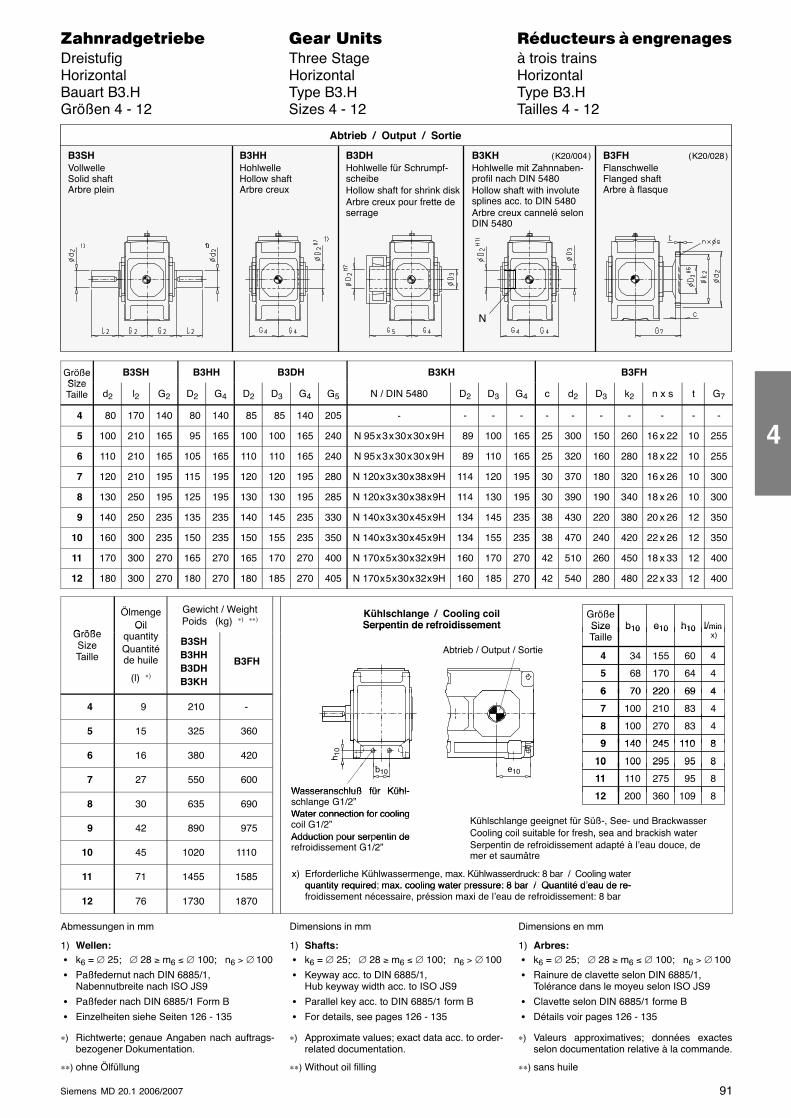
91Siemens MD 20.1 2006/2007
������������� ���� �� ��������� � ����������Dreistufig Three Stage à trois trainsHorizontal Horizontal HorizontalBauart B3.H Type B3.H Type B3.HGrößen 4 - 12 Sizes 4 - 12 Tailles 4 - 12
B3SHVollwelleSolid shaftArbre plein
B3HHHohlwelleHollow shaftArbre creux
B3DHHohlwelle für Schrumpf-scheibeHollow shaft for shrink diskArbre creux pour frette deserrage
Abtrieb / Output / Sortie
B3KHHohlwelle mit Zahnnaben-profil nach DIN 5480Hollow shaft with involutesplines acc. to DIN 5480Arbre creux cannelé selonDIN 5480
B3FHFlanschwelleFlanged shaftArbre à flasque
N
( K20/004 ) ( K20/028 )
GrößeSize
B3SH B3HH B3DH B3KH B3FHSizeTaille d2 l2 G2 D2 G4 D2 D3 G4 G5 N / DIN 5480 D2 D3 G4 c d2 D3 k2 n x s t G7
4 80 170 140 80 140 85 85 140 205 - - - - - - - - - - -
5 100 210 165 95 165 100 100 165 240 N 95 x 3 x 30 x 30 x 9H 89 100 165 25 300 150 260 16 x 22 10 255
6 110 210 165 105 165 110 110 165 240 N 95 x 3 x 30 x 30 x 9H 89 110 165 25 320 160 280 18 x 22 10 255
7 120 210 195 115 195 120 120 195 280 N 120 x 3 x 30 x 38 x 9H 114 120 195 30 370 180 320 16 x 26 10 300
8 130 250 195 125 195 130 130 195 285 N 120 x 3 x 30 x 38 x 9H 114 130 195 30 390 190 340 18 x 26 10 300
9 140 250 235 135 235 140 145 235 330 N 140 x 3 x 30 x 45 x 9H 134 145 235 38 430 220 380 20 x 26 12 350
10 160 300 235 150 235 150 155 235 350 N 140 x 3 x 30 x 45 x 9H 134 155 235 38 470 240 420 22 x 26 12 350
11 170 300 270 165 270 165 170 270 400 N 170 x 5 x 30 x 32 x 9H 160 170 270 42 510 260 450 18 x 33 12 400
12 180 300 270 180 270 180 185 270 405 N 170 x 5 x 30 x 32 x 9H 160 185 270 42 540 280 480 22 x 33 12 400
Größe
ÖlmengeOil
Gewicht / WeightPoids (kg) ∗) ∗∗)
GrößeSize l/min
)b10 e10 h10
Kühlschlange / Cooling coilSerpentin de refroidissement
GrößeSizeTaille
OilquantityQuantitéde huile
(l) ∗)
B3SHB3HHB3DHB3KH
B3FHAbtrieb / Output / Sortie
SizeTaille
l/min x)
b10 e10 h10
34 60 4 155 4
70 696 220 4
Serpentin de refroidissement
68 64 5 170 4
4 9 210 -
70 69 6 220 4
100 83 7 210 4
5 15 325 360 100 83 8 270 4
140 1109 245 8 6 16 380 420
140 110 9 245 8
100 9510 295 8b
h 10
e 7 27 550 600
100 9510 295 8
110 9511 275 8Wasseranschluß für Kühl-
b10 e10
8 30 635 690200 10912 360 8Wasseranschluß für Kühl-
schlange G1/2”Water connection for cooling
9 42 890 975Water connection for coolingcoil G1/2”Adduction pour serpentin de
Kühlschlange geeignet für Süß-, See- und BrackwasserCooling coil suitable for fresh, sea and brackish water
10 45 1020 1110
Adduction our ser entin derefroidissement G1/2”
Cooling coil suitable for fresh, sea and brackish waterSerpentin de refroidissement adapté à l’eau douce, demer et saumâtre
11 71 1455 1585 x) Erforderliche Kühlwassermenge, max. Kühlwasserdruck: 8 bar / Cooling waterquantity required; max. cooling water pressure: 8 bar / Quantité d’eau de re-
12 76 1730 1870
quantity required max. cooling water ressure: 8 bar / Quantité d eau de re-froidissement nécessaire, préssion maxi de l’eau de refroidissement: 8 bar
Abmessungen in mm
1) Wellen: � k6 = ∅ 25; ∅ 28 ≥ m6 ≤ ∅ 100; n6 > ∅ 100
� Paßfedernut nach DIN 6885/1,Nabennutbreite nach ISO JS9
� Paßfeder nach DIN 6885/1 Form B
� Einzelheiten siehe Seiten 126 - 135
∗) Richtwerte; genaue Angaben nach auftrags-bezogener Dokumentation.
∗∗) ohne Ölfüllung
Dimensions in mm
1) Shafts: � k6 = ∅ 25; ∅ 28 ≥ m6 ≤ ∅ 100; n6 > ∅ 100
� Keyway acc. to DIN 6885/1,Hub keyway width acc. to ISO JS9
� Parallel key acc. to DIN 6885/1 form B
� For details, see pages 126 - 135
∗) Approximate values; exact data acc. to order-related documentation.
∗∗) Without oil filling
Dimensions en mm
1) Arbres: � k6 = ∅ 25; ∅ 28 ≥ m6 ≤ ∅ 100; n6 > ∅ 100
� Rainure de clavette selon DIN 6885/1,Tolérance dans le moyeu selon ISO JS9
� Clavette selon DIN 6885/1 forme B
� Détails voir pages 126 - 135
∗) Valeurs approximatives; données exactesselon documentation relative à la commande.
∗∗) sans huile
4
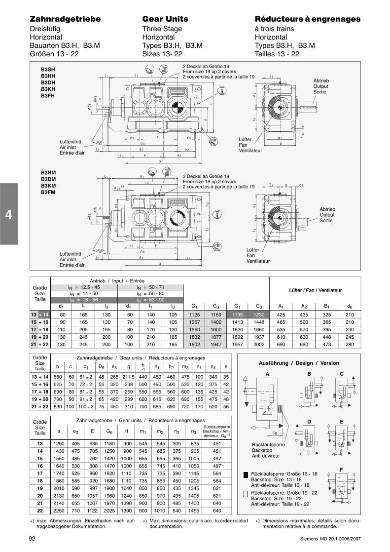
92 Siemens MD 20.1 2006/2007
������������� ���� �� ��������� � ����������Dreistufig Three Stage à trois trainsHorizontal Horizontal HorizontalBauarten B3.H, B3.M Types B3.H, B3.M Types B3.H, B3.MGrößen 13 - 22 Sizes 13- 22 Tailles 13 - 22
LüfterFanVentilateur
LufteintrittAir inletEntrée d’air
AbtriebOutputSortie
B3SHB3HHB3DHB3KHB3FH
2 Deckel ab Größe 19From size 19 up 2 covers2 couvercles à partir de la taille 19
B3HMB3DMB3KMB3FM
LüfterFanVentilateur
LufteintrittAir inletEntrée d’air
2 Deckel ab Größe 19From size 19 up 2 covers2 couvercles à partir de la taille 19
AbtriebOutputSortie
Antrieb / Input / EntréeGröße iN = 12.5 - 45 iN = 50 - 71
Lüfter / Fan / VentilateurGrößeSize iN = 14 - 50 iN = 56 - 80
Lüfter / Fan / VentilateurSizeTaille iN = 16 - 56 iN = 63 - 90
d1 l1 l3 d1 l1 l3 G1 G3 G1 G3 A1 A2 B1 d6
13 + 14 80 165 130 60 140 105 1125 1160 1195 1230 425 435 325 210
15 + 16 90 165 130 70 140 105 1367 1402 1413 1448 485 520 365 210
17 + 18 110 205 165 80 170 130 1560 1600 1620 1660 535 570 395 230
19 + 20 130 245 200 100 210 165 1832 1877 1892 1937 610 630 448 245
21 + 22 130 245 200 100 210 165 1902 1947 1957 2002 690 690 473 280
GrößeSi
Zahnradgetriebe / Gear units / Réducteurs à engrenagesSizeTaille b c c1 D5 e3 g h
-1h1 h2 m3 n1 n4 s
13 + 14 550 60 61 ± 2 48 265 211.5 440 450 460 475 100 340 35
15 + 16 625 70 72 ± 2 55 320 238 500 490 500 535 120 375 42
17 + 18 690 80 81 ± 2 55 370 259 550 555 560 600 135 425 42
19 + 20 790 90 91 ± 2 65 420 299 620 615 620 690 155 475 48
21 + 22 830 100 100 ± 2 75 450 310 700 685 690 720 170 520 56
Größe Zahnradgetriebe / Gear units / Réducteurs à engrenagesGrößeSizeTaille a e2 E G6 H m1 m2 n2 n3
RücklaufsperreBackstop / Anti-dévireur G8 +)
13 1290 405 635 1180 900 545 545 305 835 451
14 1430 475 705 1250 900 545 685 375 905 451
15 1550 485 762 1420 1000 655 655 365 1005 497
16 1640 530 808 1470 1000 655 745 410 1050 497
17 1740 525 860 1620 1110 735 735 390 1145 564
18 1860 585 920 1680 1110 735 855 450 1205 564
19 2010 590 997 1900 1240 850 850 435 1345 621
20 2130 650 1057 1960 1240 850 970 495 1405 621
21 2140 655 1067 1970 1390 900 900 485 1400 640
22 2250 710 1122 2025 1390 900 1010 540 1455 640
+) max. Abmessungen; Einzelheiten nach auf-tragsbezogener Dokumentation.
+) Max. dimensions; details acc. to order-relateddocumentation.
+) Dimensions maximales; détails selon docu-mentation relative à la commande.
4
Ausführung / Design / Version
A B C
D E
FRücklaufsperre: Größe 13 - 18Backstop: Size 13 - 18Anti-dévireur: Taille 13 - 18
Rücklaufsperre: Größe 19 - 22Backstop: Size 19 - 22Anti-dévireur: Taille 19 - 22
RücklaufsperreBackstopAnti-dévireur
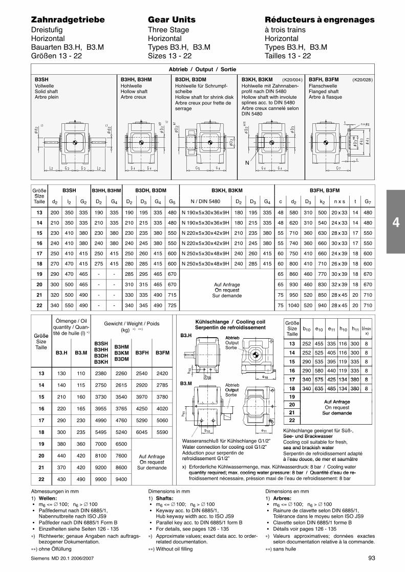
93Siemens MD 20.1 2006/2007
������������� ���� �� ��������� � ����������Dreistufig Three Stage à trois trainsHorizontal Horizontal HorizontalBauarten B3.H, B3.M Types B3.H, B3.M Types B3.H, B3.MGrößen 13 - 22 Sizes 13 - 22 Tailles 13 - 22
B3SHVollwelleSolid shaftArbre plein
B3HH, B3HMHohlwelleHollow shaftArbre creux
B3DH, B3DMHohlwelle für Schrumpf-scheibeHollow shaft for shrink diskArbre creux pour frette deserrage
Abtrieb / Output / Sortie
B3KH, B3KMHohlwelle mit Zahnnaben-profil nach DIN 5480Hollow shaft with involutesplines acc. to DIN 5480Arbre creux cannelé selonDIN 5480
B3FH, B3FMFlanschwelleFlanged shaftArbre à flasque
N
( K20/004 ) ( K20/028 )
GrößeSize
B3SH B3HH, B3HM B3DH, B3DM B3KH, B3KM B3FH, B3FMSizeTaille d2 l2 G2 D2 G4 D2 D3 G4 G5 N / DIN 5480 D2 D3 G4 c d2 D3 k2 n x s t G7
13 200 350 335 190 335 190 195 335 480 N 190 x 5 x 30 x 36 x 9H 180 195 335 48 580 310 500 20 x 33 14 480
14 210 350 335 210 335 210 215 335 480 N 190 x 5 x 30 x 36 x 9H 180 215 335 48 620 310 540 24 x 33 14 480
15 230 410 380 230 380 230 235 380 550 N 220 x 5 x 30 x 42 x 9H 210 235 380 55 710 360 630 28 x 33 17 550
16 240 410 380 240 380 240 245 380 550 N 220 x 5 x 30 x 42 x 9H 210 245 380 55 740 360 660 30 x 33 17 550
17 250 410 415 250 415 250 260 415 600 N 250 x 5 x 30 x 48 x 9H 240 260 415 60 750 410 660 24 x 39 18 600
18 270 470 415 275 415 280 285 415 600 N 250 x 5 x 30 x 48 x 9H 240 285 415 60 800 410 710 26 x 39 18 600
19 290 470 465 - - 285 295 465 670 65 860 460 770 30 x 39 18 670
20 300 500 465 - - 310 315 465 670 Auf AnfrageOn request
65 930 460 830 32 x 39 18 670
21 320 500 490 - - 330 335 490 715On request
Sur demande 75 950 520 850 28 x 45 20 710
22 340 550 490 - - 340 345 490 725 75 1040 520 940 28 x 45 20 710
Größe
Ölmenge / Oilquantity / Quan-tité de huile (l) ∗)
Gewicht / Weight / Poids(kg) ∗) ∗∗)
Abtrieb
Kühlschlange / Cooling coilSerpentin de refroidissement
GrößeSizeTaille
l/min x)
b10 e10 h10e11 h11B3.HGröße
SizeTaille
B3.H B3.M
B3SHB3HHB3DHB3KH
B3HMB3KMB3DM
B3FH B3FM
AbtriebOutputSortie
252 11613 455 8
252 11614 525 8
290 11915 535 8
335
405
395
300
300
335
B3.H
13 130 110 2380 2260 2540 2420 290 11916 580 8
340 13417 575 8
440
425
335
380b10
h 10
e10
14 140 115 2750 2615 2920 2785 AbtriebOutput
340 13417 575 8
340 13418 635 8
425
485
380
380B3.M
b10 e10
15 210 160 3730 3540 3970 3780OutputSortie
340 13418 635 8
19Auf Anfrage20
485 380
16 220 165 3955 3765 4250 4020Auf AnfrageOn request
Sur demande
20
21h 11
17 290 230 4990 4760 5290 5060Sur demande21
22
h 11
18 300 235 5495 5240 6045 5590 e11b10 Kühlschlange geeignet für Süß-,See- und Brackwasser
19 380 360 7000 6500Wasseranschluß für Kühlschlange G1/2”Water connection for cooling coil G1/2”
See- und BrackwasserCooling coil suitable for fresh,sea and brackish water
20 440 420 8100 7600 Auf AnfrageOn request
Water connection for cooling coil G1/2Adduction pour serpentin derefroidissement G1/2”
sea and brackish waterSerpentin de refroidissement adaptéà l’eau douce, de mer et saumâtre
21 370 420 9200 8600On request
Sur demande
refroidissement G1/2 à l eau douce, de mer et saumâtre
x) Erforderliche Kühlwassermenge, max. Kühlwasserdruck: 8 bar / Cooling waterquantity required; max cooling water pressure: 8 bar / Quantité d’eau de re-
22 430 490 9900 9400quantity required; max. cooling water pressure: 8 bar / Quantité d’eau de re-froidissement nécessaire, préssion maxi de l’eau de refroidissement: 8 bar
Abmessungen in mm1) Wellen: � m6 <= ∅ 100; n6 > ∅ 100 � Paßfedernut nach DIN 6885/1,
Nabennutbreite nach ISO JS9 � Paßfeder nach DIN 6885/1 Form B � Einzelheiten siehe Seiten 126 - 135∗) Richtwerte; genaue Angaben nach auftrags-
bezogener Dokumentation.∗∗) ohne Ölfüllung
Dimensions in mm1) Shafts: � m6 <= ∅ 100; n6 > ∅ 100 � Keyway acc. to DIN 6885/1,
Hub keyway width acc. to ISO JS9 � Parallel key acc. to DIN 6885/1 form B � For details, see pages 126 - 135∗) Approximate values; exact data acc. to order-
related documentation.∗∗) Without oil filling
Dimensions en mm1) Arbres: � m6 <= ∅ 100; n6 > ∅ 100 � Rainure de clavette selon DIN 6885/1,
Tolérance dans le moyeu selon ISO JS9 � Clavette selon DIN 6885/1 forme B � Détails voir pages 126 - 135∗) Valeurs approximatives; données exactes
selon documentation relative à la commande.∗∗) sans huile
4
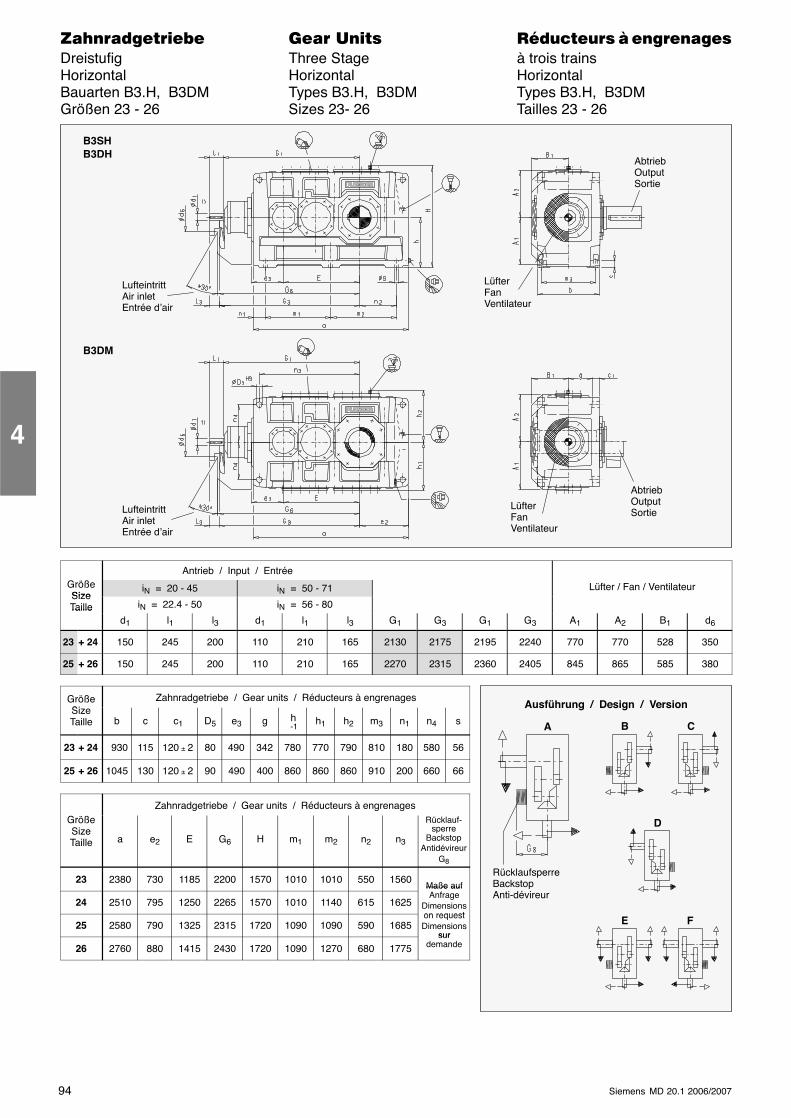
94 Siemens MD 20.1 2006/2007
������������� ���� �� ��������� � ����������Dreistufig Three Stage à trois trainsHorizontal Horizontal HorizontalBauarten B3.H, B3DM Types B3.H, B3DM Types B3.H, B3DMGrößen 23 - 26 Sizes 23- 26 Tailles 23 - 26
B3SHB3DH
B3DM
AbtriebOutputSortie
AbtriebOutputSortie
LüfterFanVentilateur
LufteintrittAir inletEntrée d’air
LüfterFanVentilateur
LufteintrittAir inletEntrée d’air
Antrieb / Input / EntréeGrößeSize
iN = 20 - 45 iN = 50 - 71 Lüfter / Fan / VentilateurSizeTaille iN = 22.4 - 50 iN = 56 - 80Taille
d1 l1 l3 d1 l1 l3 G1 G3 G1 G3 A1 A2 B1 d6
23 + 24 150 245 200 110 210 165 2130 2175 2195 2240 770 770 528 350
25 + 26 150 245 200 110 210 165 2270 2315 2360 2405 845 865 585 380
GrößeSi
Zahnradgetriebe / Gear units / Réducteurs à engrenagesSizeTaille b c c1 D5 e3 g h
-1h1 h2 m3 n1 n4 s
23 + 24 930 115 120 ± 2 80 490 342 780 770 790 810 180 580 56
25 + 26 1045 130 120 ± 2 90 490 400 860 860 860 910 200 660 66
Zahnradgetriebe / Gear units / Réducteurs à engrenagesGrößeSizeTaille a e2 E G6 H m1 m2 n2 n3
Rücklauf-sperre
BackstopAntidévireur
G8
23 2380 730 1185 2200 1570 1010 1010 550 1560Maße auf
24 2510 795 1250 2265 1570 1010 1140 615 1625
Maße aufAnfrage
Dimensionson request
25 2580 790 1325 2315 1720 1090 1090 590 1685on requestDimensions
sur
26 2760 880 1415 2430 1720 1090 1270 680 1775sur
demande
4
Ausführung / Design / Version
A
RücklaufsperreBackstopAnti-dévireur
B C
D
E F
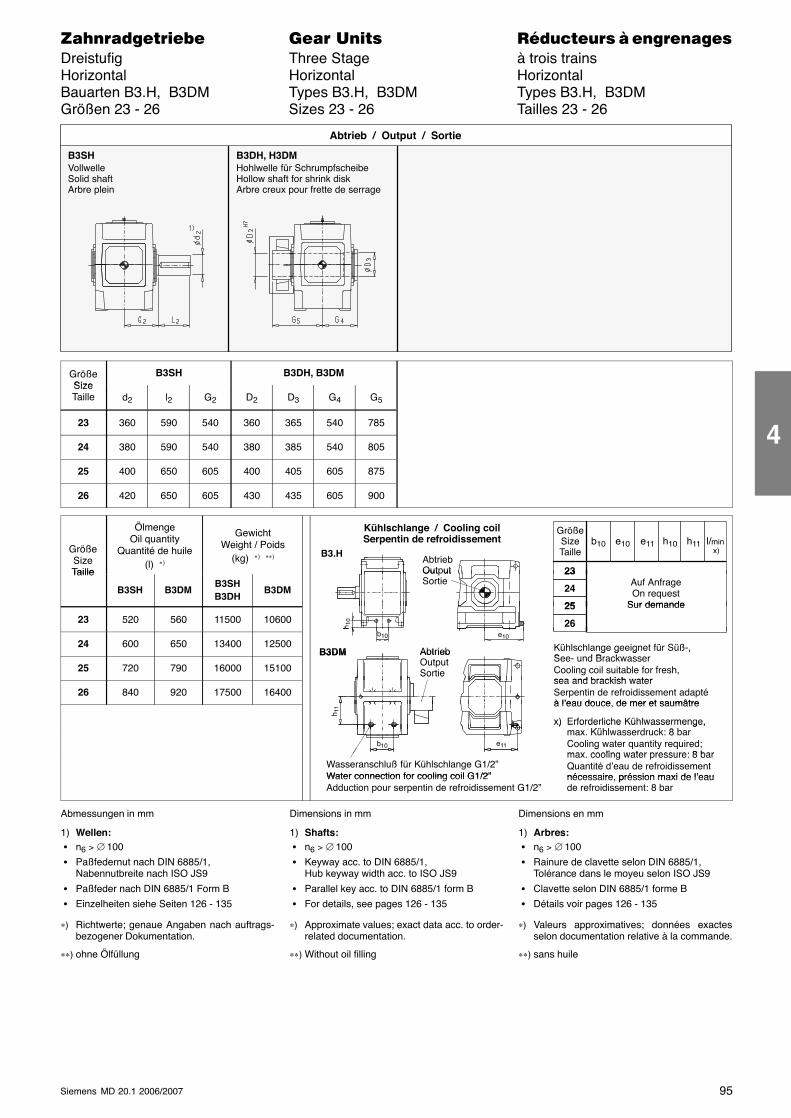
95Siemens MD 20.1 2006/2007
������������� ���� �� ��������� � ����������Dreistufig Three Stage à trois trainsHorizontal Horizontal HorizontalBauarten B3.H, B3DM Types B3.H, B3DM Types B3.H, B3DMGrößen 23 - 26 Sizes 23 - 26 Tailles 23 - 26
B3SHVollwelleSolid shaftArbre plein
B3DH, H3DMHohlwelle für SchrumpfscheibeHollow shaft for shrink diskArbre creux pour frette de serrage
Abtrieb / Output / Sortie
GrößeSize
B3SH B3DH, B3DMSizeTaille d2 l2 G2 D2 D3 G4 G5
23 360 590 540 360 365 540 785
24 380 590 540 380 385 540 805
25 400 650 605 400 405 605 875
26 420 650 605 430 435 605 900
GrößeSizeTaille
ÖlmengeOil quantity
Quantité de huile(l) ∗)
GewichtWeight / Poids
(kg) ∗) ∗∗) AbtriebOutput
Kühlschlange / Cooling coilSerpentin de refroidissement
B3.H
GrößeSizeTaille
l/min x)
23
b10 e10 h10e11 h11
Taille
B3SH B3DMB3SHB3DH
B3DM
Out utSortie
23
24
25
Auf AnfrageOn request
Sur demande
23 520 560 11500 1060025
26
Sur demande
b
h 10
24 600 650 13400 12500 Kühlschlange geeignet für Süß-,S d B k
AbtriebB3DM
b10
h
e10
25 720 790 16000 15100
g g g ,See- und BrackwasserCooling coil suitable for fresh,sea and brackish water
AbtriebOutputSortie
B3DM
26 840 920 17500 16400sea and brackish waterSerpentin de refroidissement adaptéà l’eau douce de mer et saumâtre
Sortie
à l’eau douce, de mer et saumâtre
x) Erforderliche Kühlwassermenge,Kühl d k 8 b
h 11
x) Erforderliche Kühlwassermenge,max. Kühlwasserdruck: 8 barCooling water quantity required;max cooling water pressure: 8 bar
e11b10
Wasseranschluß für Kühlschlange G1/2”Water connection for cooling coil G1/2”
g q y qmax. cooling water pressure: 8 barQuantité d’eau de refroidissementnécessaire préssion maxi de l’eauWater connection for cooling coil G1/2”
Adduction pour serpentin de refroidissement G1/2”nécessaire, préssion maxi de l’eaude refroidissement: 8 bar
Abmessungen in mm
1) Wellen: � n6 > ∅ 100
� Paßfedernut nach DIN 6885/1,Nabennutbreite nach ISO JS9
� Paßfeder nach DIN 6885/1 Form B
� Einzelheiten siehe Seiten 126 - 135
∗) Richtwerte; genaue Angaben nach auftrags-bezogener Dokumentation.
∗∗) ohne Ölfüllung
Dimensions in mm
1) Shafts: � n6 > ∅ 100
� Keyway acc. to DIN 6885/1,Hub keyway width acc. to ISO JS9
� Parallel key acc. to DIN 6885/1 form B
� For details, see pages 126 - 135
∗) Approximate values; exact data acc. to order-related documentation.
∗∗) Without oil filling
Dimensions en mm
1) Arbres: � n6 > ∅ 100
� Rainure de clavette selon DIN 6885/1,Tolérance dans le moyeu selon ISO JS9
� Clavette selon DIN 6885/1 forme B
� Détails voir pages 126 - 135
∗) Valeurs approximatives; données exactesselon documentation relative à la commande.
∗∗) sans huile
4
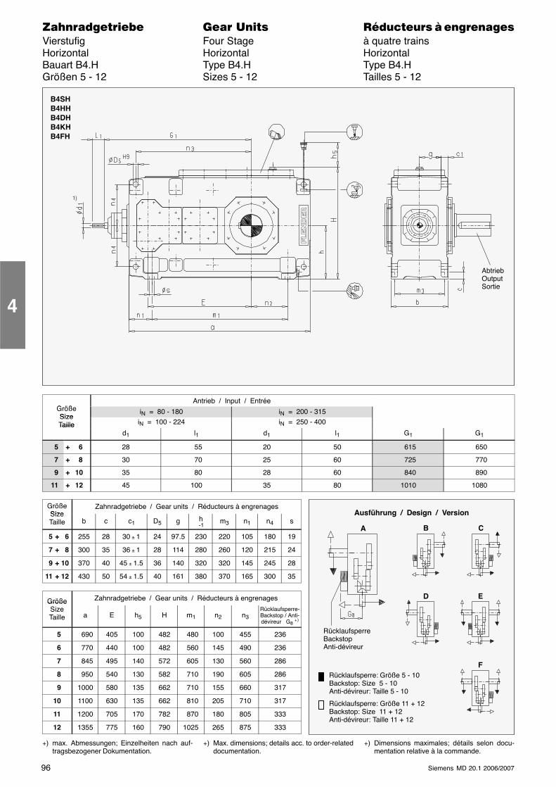
96 Siemens MD 20.1 2006/2007
������������� ���� �� ��������� � ����������Vierstufig Four Stage à quatre trainsHorizontal Horizontal HorizontalBauart B4.H Type B4.H Type B4.HGrößen 5 - 12 Sizes 5 - 12 Tailles 5 - 12
AbtriebOutputSortie
B4SHB4HHB4DHB4KHB4FH
��
G ößAntrieb / Input / Entrée
GrößeSize
iN = 80 - 180 iN = 200 - 315SizeTaille iN = 100 - 224 iN = 250 - 400Taille
d1 l1 d1 l1 G1 G1
5 + 6 28 55 20 50 615 650
7 + 8 30 70 25 60 725 770
9 + 10 35 80 28 60 840 890
11 + 12 45 100 35 80 1010 1080
GrößeSize
Zahnradgetriebe / Gear units / Réducteurs à engrenagesSizeTaille b c c1 D5 g h
-1m3 n1 n4 s
5 + 6 255 28 30 ± 1 24 97.5 230 220 105 180 19
7 + 8 300 35 36 ± 1 28 114 280 260 120 215 24
9 + 10 370 40 45 ± 1.5 36 140 320 320 145 245 28
11 + 12 430 50 54 ± 1.5 40 161 380 370 165 300 35
Größe Zahnradgetriebe / Gear units / Réducteurs à engrenagesGrößeSizeTaille a E h5 H m1 n2 n3
Rücklaufsperre-Backstop / Anti-dévireur G8 +)
5 690 405 100 482 480 100 455 236
6 770 440 100 482 560 145 490 236
7 845 495 140 572 605 130 560 286
8 950 540 130 582 710 190 605 286
9 1000 580 135 662 710 155 660 317
10 1100 630 135 662 810 205 710 317
11 1200 705 170 782 870 180 805 333
12 1355 775 160 790 1025 265 875 333
+) max. Abmessungen; Einzelheiten nach auf-tragsbezogener Dokumentation.
+) Max. dimensions; details acc. to order-relateddocumentation.
+) Dimensions maximales; détails selon docu-mentation relative à la commande.
4
Ausführung / Design / Version
A
RücklaufsperreBackstopAnti-dévireur
B C
D E
FRücklaufsperre: Größe 5 - 10Backstop: Size 5 - 10Anti-dévireur: Taille 5 - 10
Rücklaufsperre: Größe 11 + 12Backstop: Size 11 + 12Anti-dévireur: Taille 11 + 12
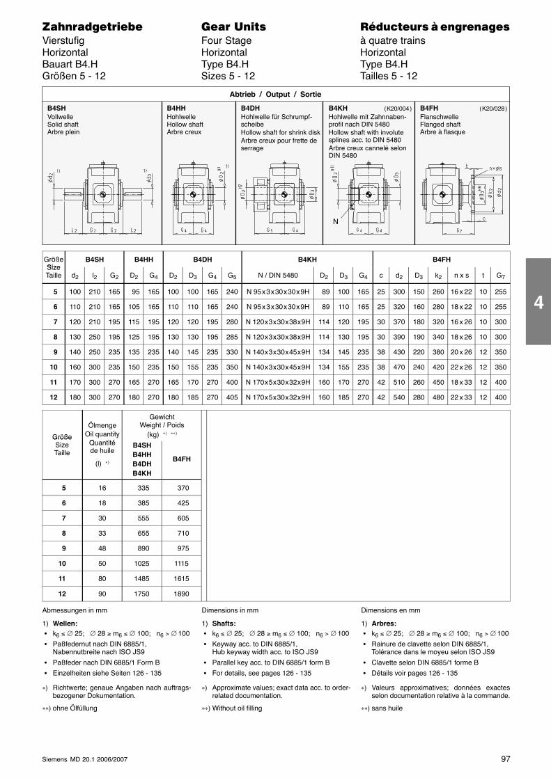
97Siemens MD 20.1 2006/2007
������������� ���� �� ��������� � ����������Vierstufig Four Stage à quatre trainsHorizontal Horizontal HorizontalBauart B4.H Type B4.H Type B4.HGrößen 5 - 12 Sizes 5 - 12 Tailles 5 - 12
B4SHVollwelleSolid shaftArbre plein
B4HHHohlwelleHollow shaftArbre creux
B4DHHohlwelle für Schrumpf-scheibeHollow shaft for shrink diskArbre creux pour frette deserrage
Abtrieb / Output / Sortie
B4KHHohlwelle mit Zahnnaben-profil nach DIN 5480Hollow shaft with involutesplines acc. to DIN 5480Arbre creux cannelé selonDIN 5480
B4FHFlanschwelleFlanged shaftArbre à flasque
N
( K20/004 ) ( K20/028 )
GrößeSize
B4SH B4HH B4DH B4KH B4FHSizeTaille d2 l2 G2 D2 G4 D2 D3 G4 G5 N / DIN 5480 D2 D3 G4 c d2 D3 k2 n x s t G7
5 100 210 165 95 165 100 100 165 240 N 95 x 3 x 30 x 30 x 9H 89 100 165 25 300 150 260 16 x 22 10 255
6 110 210 165 105 165 110 110 165 240 N 95 x 3 x 30 x 30 x 9H 89 110 165 25 320 160 280 18 x 22 10 255
7 120 210 195 115 195 120 120 195 280 N 120 x 3 x 30 x 38 x 9H 114 120 195 30 370 180 320 16 x 26 10 300
8 130 250 195 125 195 130 130 195 285 N 120 x 3 x 30 x 38 x 9H 114 130 195 30 390 190 340 18 x 26 10 300
9 140 250 235 135 235 140 145 235 330 N 140 x 3 x 30 x 45 x 9H 134 145 235 38 430 220 380 20 x 26 12 350
10 160 300 235 150 235 150 155 235 350 N 140 x 3 x 30 x 45 x 9H 134 155 235 38 470 240 420 22 x 26 12 350
11 170 300 270 165 270 165 170 270 400 N 170 x 5 x 30 x 32 x 9H 160 170 270 42 510 260 450 18 x 33 12 400
12 180 300 270 180 270 180 185 270 405 N 170 x 5 x 30 x 32 x 9H 160 185 270 42 540 280 480 22 x 33 12 400
Größe
ÖlmengeOil quantity
Q tité
GewichtWeight / Poids
(kg) ∗) ∗∗)GrößeSizeTaille
Quantitéde huile
(l) ∗)
B4SHB4HHB4DHB4KH
B4FH
5 16 335 370
6 18 385 425
7 30 555 605
8 33 655 710
9 48 890 975
10 50 1025 1115
11 80 1485 1615
12 90 1750 1890
Abmessungen in mm
1) Wellen: � k6 ≤ ∅ 25; ∅ 28 ≥ m6 ≤ ∅ 100; n6 > ∅ 100
� Paßfedernut nach DIN 6885/1,Nabennutbreite nach ISO JS9
� Paßfeder nach DIN 6885/1 Form B
� Einzelheiten siehe Seiten 126 - 135
∗) Richtwerte; genaue Angaben nach auftrags-bezogener Dokumentation.
∗∗) ohne Ölfüllung
Dimensions in mm
1) Shafts: � k6 ≤ ∅ 25; ∅ 28 ≥ m6 ≤ ∅ 100; n6 > ∅ 100
� Keyway acc. to DIN 6885/1,Hub keyway width acc. to ISO JS9
� Parallel key acc. to DIN 6885/1 form B
� For details, see pages 126 - 135
∗) Approximate values; exact data acc. to order-related documentation.
∗∗) Without oil filling
Dimensions en mm
1) Arbres: � k6 ≤ ∅ 25; ∅ 28 ≥ m6 ≤ ∅ 100; n6 > ∅ 100
� Rainure de clavette selon DIN 6885/1,Tolérance dans le moyeu selon ISO JS9
� Clavette selon DIN 6885/1 forme B
� Détails voir pages 126 - 135
∗) Valeurs approximatives; données exactesselon documentation relative à la commande.
∗∗) sans huile
4
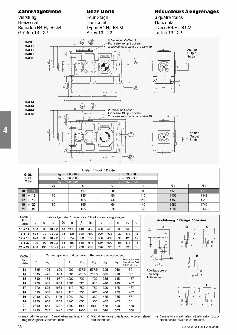
98 Siemens MD 20.1 2006/2007
������������� ���� �� ��������� � ����������Vierstufig Four Stage à quatre trainsHorizontal Horizontal HorizontalBauarten B4.H, B4.M Types B4.H, B4.M Types B4.H, B4.MGrößen 13 - 22 Sizes 13 - 22 Tailles 13 - 22
B4SHB4HHB4DHB4KHB4FH
2 Deckel ab Größe 19From size 19 up 2 covers2 couvercles à partir de la taille 19
B4HMB4DMB4KMB4FM
2 Deckel ab Größe 19From size 19 up 2 covers2 couvercles à partir de la taille 19
AbtriebOutputSortie
AbtriebOutputSortie
Antrieb / Input / EntréeGröße iN = 80 - 180 iN = 200 - 315GrößeSize iN = 90 - 200 iN = 224 - 355SizeTaille iN = 100 - 224 iN = 250 - 400
d1 l1 d1 l1 G1 G1
13 + 14 55 110 40 100 1170 1240
15 + 16 70 135 50 110 1402 1448
17 + 18 70 135 50 110 1450 1510
19 + 20 80 165 60 140 1680 1740
21 + 22 90 165 70 140 1992 2047
GrößeSi
Zahnradgetriebe / Gear units / Réducteurs à engrenagesSizeTaille b c c1 D5 g h
-1h1 h2 m3 n1 n4 s
13 + 14 550 60 61 ± 2 48 211.5 440 450 460 475 100 340 35
15 + 16 625 70 72 ± 2 55 238 500 490 500 535 120 375 42
17 + 18 690 80 81 ± 2 55 259 550 555 560 600 135 425 42
19 + 20 790 90 91 ± 2 65 299 620 615 620 690 155 475 48
21 + 22 830 100 100 ± 2 75 310 700 685 690 720 170 520 56
Größe Zahnradgetriebe / Gear units / Réducteurs à engrenagesGrößeSizeTaille a e2 E H m1 m2 n2 n3
RücklaufsperreBackstop / Anti-dévireur G8 +)
13 1395 405 820 900 597.5 597.5 305 940 391
14 1535 475 890 900 597.5 737.5 375 1010 391
15 1680 485 987 1000 720 720 365 1135 487
16 1770 530 1033 1000 720 810 410 1180 487
17 1770 525 1035 1110 750 750 390 1175 487
18 1890 585 1095 1110 750 870 450 1235 487
19 2030 590 1190 1240 860 860 435 1365 561
20 2150 650 1250 1240 860 980 495 1425 561
21 2340 655 1387 1390 1000 1000 485 1600 580
22 2450 710 1442 1390 1000 1110 540 1655 580
+) max. Abmessungen; Einzelheiten nach auf-tragsbezogener Dokumentation.
+) Max. dimensions; details acc. to order-relateddocumentation.
+) Dimensions maximales; détails selon docu-mentation relative à la commande.
4
Ausführung / Design / Version
A
RücklaufsperreBackstopAnti-dévireur
B C
D
E F
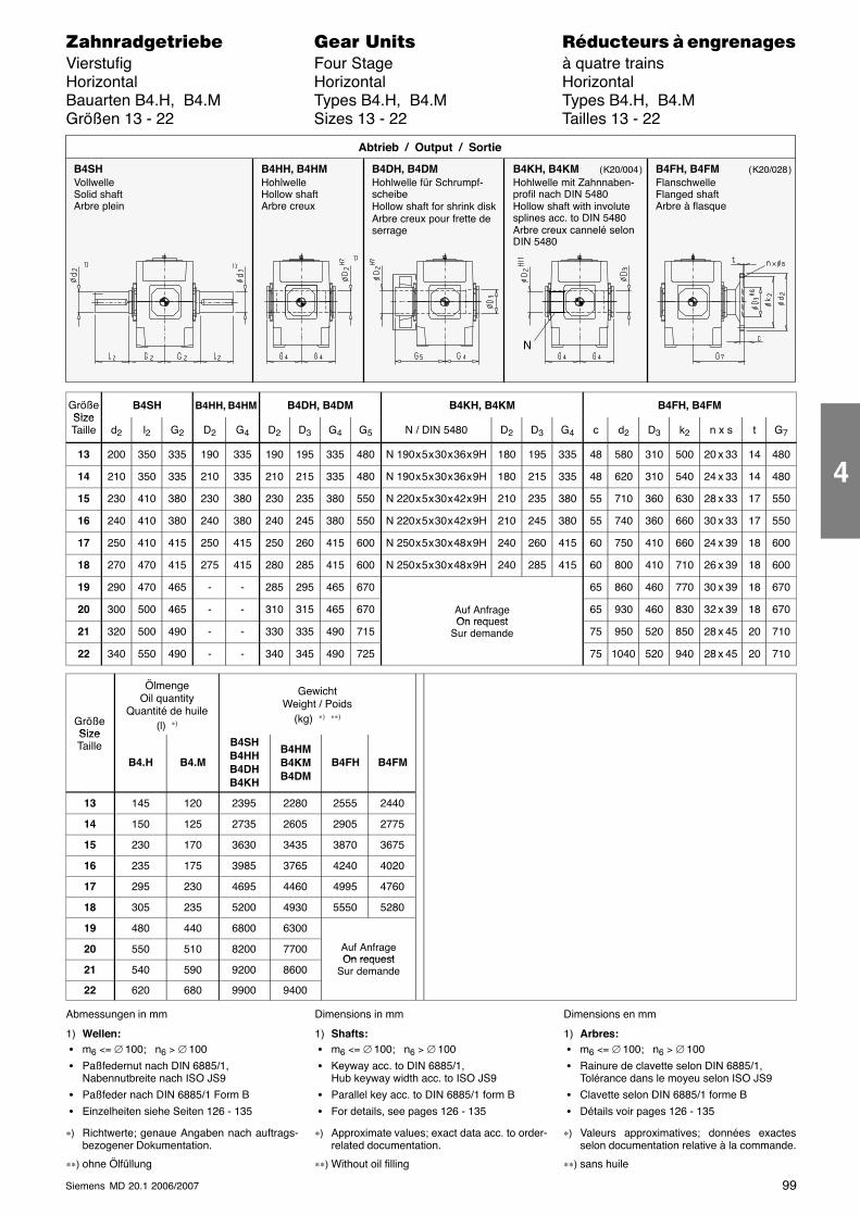
99Siemens MD 20.1 2006/2007
������������� ���� �� ��������� � ����������Vierstufig Four Stage à quatre trainsHorizontal Horizontal HorizontalBauarten B4.H, B4.M Types B4.H, B4.M Types B4.H, B4.MGrößen 13 - 22 Sizes 13 - 22 Tailles 13 - 22
B4SHVollwelleSolid shaftArbre plein
B4HH, B4HMHohlwelleHollow shaftArbre creux
B4DH, B4DMHohlwelle für Schrumpf-scheibeHollow shaft for shrink diskArbre creux pour frette deserrage
Abtrieb / Output / Sortie
B4KH, B4KMHohlwelle mit Zahnnaben-profil nach DIN 5480Hollow shaft with involutesplines acc. to DIN 5480Arbre creux cannelé selonDIN 5480
B4FH, B4FMFlanschwelleFlanged shaftArbre à flasque
N
( K20/004 ) ( K20/028 )
GrößeSize
B4SH B4HH, B4HM B4DH, B4DM B4KH, B4KM B4FH, B4FMSizeTaille d2 l2 G2 D2 G4 D2 D3 G4 G5 N / DIN 5480 D2 D3 G4 c d2 D3 k2 n x s t G7
13 200 350 335 190 335 190 195 335 480 N 190 x 5 x 30 x 36 x 9H 180 195 335 48 580 310 500 20 x 33 14 480
14 210 350 335 210 335 210 215 335 480 N 190 x 5 x 30 x 36 x 9H 180 215 335 48 620 310 540 24 x 33 14 480
15 230 410 380 230 380 230 235 380 550 N 220 x 5 x 30 x 42 x 9H 210 235 380 55 710 360 630 28 x 33 17 550
16 240 410 380 240 380 240 245 380 550 N 220 x 5 x 30 x 42 x 9H 210 245 380 55 740 360 660 30 x 33 17 550
17 250 410 415 250 415 250 260 415 600 N 250 x 5 x 30 x 48 x 9H 240 260 415 60 750 410 660 24 x 39 18 600
18 270 470 415 275 415 280 285 415 600 N 250 x 5 x 30 x 48 x 9H 240 285 415 60 800 410 710 26 x 39 18 600
19 290 470 465 - - 285 295 465 670 65 860 460 770 30 x 39 18 670
20 300 500 465 - - 310 315 465 670 Auf AnfrageOn request
65 930 460 830 32 x 39 18 670
21 320 500 490 - - 330 335 490 715On request
Sur demande 75 950 520 850 28 x 45 20 710
22 340 550 490 - - 340 345 490 725 75 1040 520 940 28 x 45 20 710
GrößeSize
ÖlmengeOil quantity
Quantité de huile(l) ∗)
GewichtWeight / Poids
(kg) ∗) ∗∗)
SizeTaille
B4.H B4.M
B4SHB4HHB4DHB4KH
B4HMB4KMB4DM
B4FH B4FM
13 145 120 2395 2280 2555 2440
14 150 125 2735 2605 2905 2775
15 230 170 3630 3435 3870 3675
16 235 175 3985 3765 4240 4020
17 295 230 4695 4460 4995 4760
18 305 235 5200 4930 5550 5280
19 480 440 6800 6300
20 550 510 8200 7700 Auf AnfrageOn request
21 540 590 9200 8600On request
Sur demande
22 620 680 9900 9400
Abmessungen in mm
1) Wellen: � m6 <= ∅ 100; n6 > ∅ 100
� Paßfedernut nach DIN 6885/1,Nabennutbreite nach ISO JS9
� Paßfeder nach DIN 6885/1 Form B
� Einzelheiten siehe Seiten 126 - 135
∗) Richtwerte; genaue Angaben nach auftrags-bezogener Dokumentation.
∗∗) ohne Ölfüllung
Dimensions in mm
1) Shafts: � m6 <= ∅ 100; n6 > ∅ 100
� Keyway acc. to DIN 6885/1,Hub keyway width acc. to ISO JS9
� Parallel key acc. to DIN 6885/1 form B
� For details, see pages 126 - 135
∗) Approximate values; exact data acc. to order-related documentation.
∗∗) Without oil filling
Dimensions en mm
1) Arbres: � m6 <= ∅ 100; n6 > ∅ 100
� Rainure de clavette selon DIN 6885/1,Tolérance dans le moyeu selon ISO JS9
� Clavette selon DIN 6885/1 forme B
� Détails voir pages 126 - 135
∗) Valeurs approximatives; données exactesselon documentation relative à la commande.
∗∗) sans huile
4
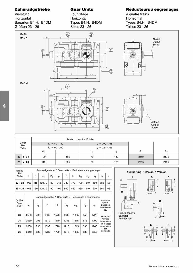
100 Siemens MD 20.1 2006/2007
������������� ���� �� ��������� � ����������Vierstufig Four Stage à quatre trainsHorizontal Horizontal HorizontalBauarten B4.H, B4DM Types B4.H, B4DM Types B4.H, B4DMGrößen 23 - 26 Sizes 23 - 26 Tailles 23 - 26
B4SHB4DH
B4DM
AbtriebOutputSortie
AbtriebOutputSortie
Antrieb / Input / EntréeGrößeSize
iN = 80 - 180 iN = 200 - 315SizeTaille iN = 90 - 200 iN = 224 - 355Taille
d1 l1 d1 l1 G1 G1
23 + 24 90 165 70 140 2110 2175
25 + 26 110 205 80 170 2395 2485
GrößeSi
Zahnradgetriebe / Gear units / Réducteurs à engrenagesSizeTaille b c c1 D5 g h
-1h1 h2 m3 n1 n4 s
23 + 24 930 115 120 ± 2 80 342 780 770 790 810 180 580 56
25 + 26 1045 130 120 ± 2 90 400 860 860 860 910 200 660 66
Zahnradgetriebe / Gear units / Réducteurs à engrenagesGrößeSizeTaille a e2 E H m1 m2 n2 n3
Rücklauf-sperre
BackstopAntidévireur
G8
23 2530 730 1505 1570 1085 1085 550 1725Maße auf
24 2660 795 1570 1570 1085 1215 615 1790
Maße aufAnfrage
Dimensionson request
25 2830 790 1695 1720 1215 1215 590 1965on requestDimensions
sur
26 3010 880 1785 1720 1215 1395 680 2055sur
demande
4
Ausführung / Design / Version
A
RücklaufsperreBackstopAnti-dévireur
B C
D
E F

101Siemens MD 20.1 2006/2007
������������� ���� �� ��������� � ����������Vierstufig Four Stage à quatre trainsHorizontal Horizontal HorizontalBauarten B4.H, B4DM Types B4.H, B4DM Types B4.H, B4DMGrößen 23 - 26 Sizes 23 - 26 Tailles 23 - 26
B4SHVollwelleSolid shaftArbre plein
B4DH, B4DMHohlwelle für SchrumpfscheibeHollow shaft for shrink diskArbre creux pour frette de serrage
Abtrieb / Output / Sortie
GrößeSize
B4SH B4DH, B4DMSizeTaille d2 l2 G2 D2 D3 G4 G5
23 360 590 540 360 365 540 785
24 380 590 540 380 385 540 805
25 400 650 605 400 405 605 875
26 420 650 605 430 435 605 900
GrößeSizeTaille
ÖlmengeOil quantity
Quantité de huile(l) ∗)
GewichtWeight / Poids
(kg) ∗) ∗∗)
Taille
B4SH B4DMB4SHB4DH
B4DM
23 710 790 11600 10700
24 810 910 13500 12600
25 1000 1110 16100 15200
26 1100 1200 17600 16500
Abmessungen in mm
1) Wellen: � m6 <= ∅ 100; n6 > ∅ 100
� Paßfedernut nach DIN 6885/1,Nabennutbreite nach ISO JS9
� Paßfeder nach DIN 6885/1 Form B
� Einzelheiten siehe Seiten 126 - 135
∗) Richtwerte; genaue Angaben nach auftrags-bezogener Dokumentation.
∗∗) ohne Ölfüllung
Dimensions in mm
1) Shafts: � m6 <= ∅ 100; n6 > ∅ 100
� Keyway acc. to DIN 6885/1,Hub keyway width acc. to ISO JS9
� Parallel key acc. to DIN 6885/1 form B
� For details, see pages 126 - 135
∗) Approximate values; exact data acc. to order-related documentation.
∗∗) Without oil filling
Dimensions en mm
1) Arbres: � m6 <= ∅ 100; n6 > ∅ 100
� Rainure de clavette selon DIN 6885/1,Tolérance dans le moyeu selon ISO JS9
� Clavette selon DIN 6885/1 forme B
� Détails voir pages 126 - 135
∗) Valeurs approximatives; données exactesselon documentation relative à la commande.
∗∗) sans huile
4
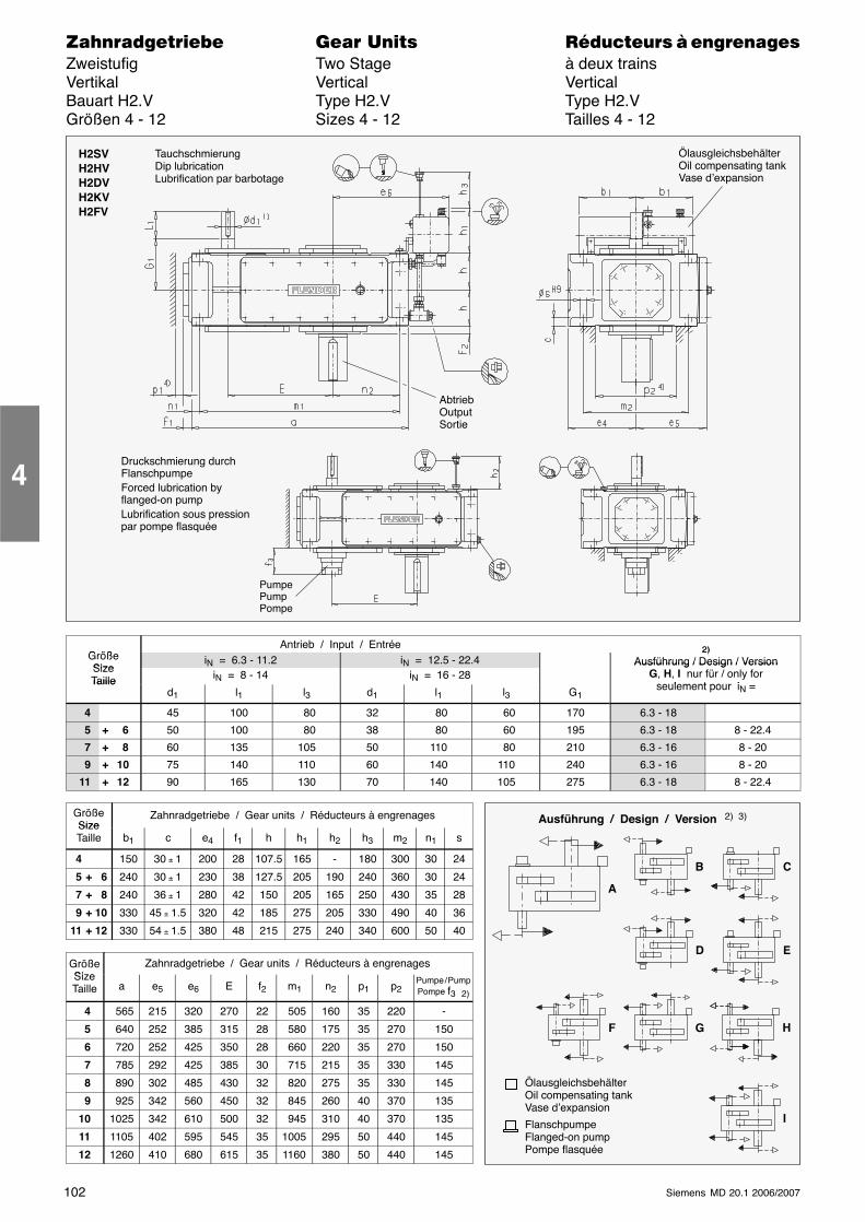
102 Siemens MD 20.1 2006/2007
������������� ���� �� ��������� � ����������Zweistufig Two Stage à deux trainsVertikal Vertical VerticalBauart H2.V Type H2.V Type H2.VGrößen 4 - 12 Sizes 4 - 12 Tailles 4 - 12
AbtriebOutputSortie
H2SVH2HVH2DVH2KVH2FV
ÖlausgleichsbehälterOil compensating tankVase d’expansion
PumpePumpPompe
TauchschmierungDip lubricationLubrification par barbotage
Druckschmierung durchFlanschpumpeForced lubrication byflanged-on pumpLubrification sous pressionpar pompe flasquée
G ößAntrieb / Input / Entrée 2)
GrößeSize
iN = 6.3 - 11.2 iN = 12.5 - 22.42)
Ausführung / Design / VersionSizeTaille iN = 8 - 14 iN = 16 - 28
Ausführung / Design / VersionG, H, I nur für / only for
seulement pour iTailled1 l1 l3 d1 l1 l3 G1
seulement pour iN =
4 45 100 80 32 80 60 170 6.3 - 18
5 + 6 50 100 80 38 80 60 195 6.3 - 18 8 - 22.4
7 + 8 60 135 105 50 110 80 210 6.3 - 16 8 - 20
9 + 10 75 140 110 60 140 110 240 6.3 - 16 8 - 20
11 + 12 90 165 130 70 140 105 275 6.3 - 18 8 - 22.4
GrößeSize
Zahnradgetriebe / Gear units / Réducteurs à engrenagesSizeTaille b1 c e4 f1 h h1 h2 h3 m2 n1 s
4 150 30 ± 1 200 28 107.5 165 - 180 300 30 24
5 + 6 240 30 ± 1 230 38 127.5 205 190 240 360 30 24
7 + 8 240 36 ± 1 280 42 150 205 165 250 430 35 28
9 + 10 330 45 ± 1.5 320 42 185 275 205 330 490 40 36
11 + 12 330 54 ± 1.5 380 48 215 275 240 340 600 50 40
GrößeSize
Zahnradgetriebe / Gear units / Réducteurs à engrenagesSizeTaille a e5 e6 E f2 m1 n2 p1 p2
Pumpe / PumpPompe f3 2)
4 565 215 320 270 22 505 160 35 220 -
5 640 252 385 315 28 580 175 35 270 150
6 720 252 425 350 28 660 220 35 270 150
7 785 292 425 385 30 715 215 35 330 145
8 890 302 485 430 32 820 275 35 330 145
9 925 342 560 450 32 845 260 40 370 135
10 1025 342 610 500 32 945 310 40 370 135
11 1105 402 595 545 35 1005 295 50 440 145
12 1260 410 680 615 35 1160 380 50 440 145
4
Ausführung / Design / Version 2) 3)
A
B C
D E
G H
I
F
ÖlausgleichsbehälterOil compensating tankVase d’expansion
FlanschpumpeFlanged-on pumpPompe flasquée
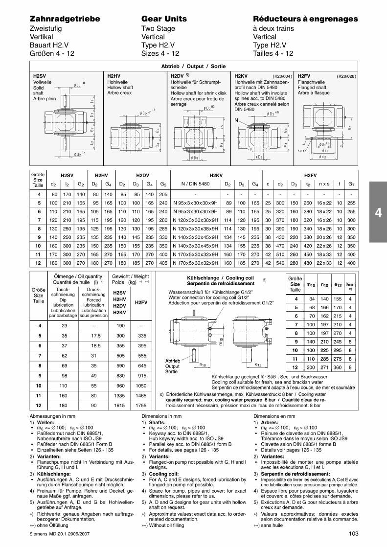
103Siemens MD 20.1 2006/2007
������������� ���� �� ��������� � ����������Zweistufig Two Stage à deux trainsVertikal Vertical VerticalBauart H2.V Type H2.V Type H2.VGrößen 4 - 12 Sizes 4 - 12 Tailles 4 - 12
H2SVVollwelleSolidshaftArbre plein
H2HVHohlwelleHollow shaftArbre creux
H2DV 5)
Hohlwelle für Schrumpf-scheibeHollow shaft for shrink diskArbre creux pour frette deserrage
Abtrieb / Output / Sortie
H2KVHohlwelle mit Zahnnaben-profil nach DIN 5480Hollow shaft with involutesplines acc. to DIN 5480Arbre creux cannelé selonDIN 5480
H2FVFlanschwelleFlanged shaftArbre à flasque
N
( K20/004 ) ( K20/028 )
GrößeSize
H2SV H2HV H2DV H2KV H2FVSizeTaille d2 l2 G2 D2 G4 D2 D3 G4 G5 N / DIN 5480 D2 D3 G4 c d2 D3 k2 n x s t G7
4 80 170 140 80 140 85 85 140 205 - - - - - - - - - - -
5 100 210 165 95 165 100 100 165 240 N 95 x 3 x 30 x 30 x 9H 89 100 165 25 300 150 260 16 x 22 10 255
6 110 210 165 105 165 110 110 165 240 N 95 x 3 x 30 x 30 x 9H 89 110 165 25 320 160 280 18 x 22 10 255
7 120 210 195 115 195 120 120 195 280 N 120 x 3 x 30 x 38 x 9H 114 120 195 30 370 180 320 16 x 26 10 300
8 130 250 195 125 195 130 130 195 285 N 120 x 3 x 30 x 38 x 9H 114 130 195 30 390 190 340 18 x 26 10 300
9 140 250 235 135 235 140 145 235 330 N 140 x 3 x 30 x 45 x 9H 134 145 235 38 430 220 380 20 x 26 12 350
10 160 300 235 150 235 150 155 235 350 N 140 x 3 x 30 x 45 x 9H 134 155 235 38 470 240 420 22 x 26 12 350
11 170 300 270 165 270 165 170 270 400 N 170 x 5 x 30 x 32 x 9H 160 170 270 42 510 260 450 18 x 33 12 400
12 180 300 270 180 270 180 185 270 405 N 170 x 5 x 30 x 32 x 9H 160 185 270 42 540 280 480 22 x 33 12 400
Ölmenge / Oil quantityQuantité de huile (l) ∗)
Gewicht / WeightPoids (kg) ∗) ∗∗)
GrößeSize l/minm10 n10 e12
Kühlschlange / Cooling coilSerpentin de refroidissement
3)
GrößeSizeTaille
Tauch-schmierung
Diplubrication
Lubrificationpar barbotage
Druck-schmierung
Forcedlubrication
Lubrificationsous pression
H2SVH2HVH2DVH2KV
H2FV
SizeTaille
34 155
l/min x)
4 140
m10 n10 e12
4
68 170 5 166 4
70 215 6 162 4
Serpentin de refroidissement
Wasseranschluß für Kühlschlange G1/2”Water connection for cooling coil G1/2”Adduction pour serpentin de refroidissement G1/2”
4 23 - 190 - 100 210 7 197 4
5 35 17.5 300 335 100 270 8 197 4
140 2459 210 810
6 37 18.5 355 395140 245 9 210 8
100 29510 225 8
m10
7 62 31 505 555Abtrieb
100 29510 225 8
110 27511 285 8 8 69 35 590 645
AbtriebOutputSortie
110 27511 285 8
200 36012 271 8e12n10
9 98 49 830 915Sortie
200 36012 271 8
Kühlschlange geeignet für Süß-, See- und BrackwasserC li il it bl f f h d b ki h t
10 110 55 960 1050
g g g ,Cooling coil suitable for fresh, sea and brackish waterSerpentin de refroidissement adapté à l’eau douce, de mer et saumâtre
11 160 80 1335 1465
Ser entin de refroidissement ada té à l eau douce, de mer et saumâtrex) Erforderliche Kühlwassermenge, max. Kühlwasserdruck: 8 bar / Cooling water
quantity required; max. cooling water pressure: 8 bar / Quantité d’eau de re-12 180 90 1615 1755
quantity required; max. cooling water pressure: 8 bar / Quantité d’eau de re-froidissement nécessaire, préssion maxi de l’eau de refroidissement: 8 bar
Abmessungen in mm1) Wellen: � m6 <= ∅ 100; n6 > ∅ 100 � Paßfedernut nach DIN 6885/1,
Nabennutbreite nach ISO JS9 � Paßfeder nach DIN 6885/1 Form B � Einzelheiten siehe Seiten 126 - 1352) Varianten: � Flanschpumpe nicht in Verbindung mit Aus-
führung G, H und I.3) Kühlschlange: � Ausführungen A, C und E mit Druckschmie-
rung durch Flanschpumpe nicht möglich.4) Freiraum für Pumpe, Rohre und Deckel, ge-
naue Maße ggf. anfragen.5) Ausführungen A, D und G bei Hohlwellen-
getriebe auf Anfrage.∗) Richtwerte; genaue Angaben nach auftrags-
bezogener Dokumentation.∗∗) ohne Ölfüllung
Dimensions in mm1) Shafts: � m6 <= ∅ 100; n6 > ∅ 100 � Keyway acc. to DIN 6885/1,
Hub keyway width acc. to ISO JS9 � Parallel key acc. to DIN 6885/1 form B � For details, see pages 126 - 1352) Variants: � Flanged-on pump not possible with G, H and I
designs.3) Cooling coil: � For A, C and E designs, forced lubrication by
flanged-on pump not possible.4) Space for pump, pipes and cover; for exact
dimensions, please refer to us.5) A, D and G designs for gear units with hollow
shaft on request.∗) Approximate values; exact data acc. to order-
related documentation.∗∗) Without oil filling
Dimensions en mm1) Arbres: � m6 <= ∅ 100; n6 > ∅ 100 � Rainure de clavette selon DIN 6885/1,
Tolérance dans le moyeu selon ISO JS9 � Clavette selon DIN 6885/1 forme B � Détails voir pages 126 - 1352) Variantes: � Impossibilité de monter une pompe attelée
avec les exécutions G, H et I.3) Serpentin de refroidissement: � Impossibilité de livrer les exécutions A, C et E avec
une lubrification sous pression par pompe attelée.4) Espace libre pour passage pompe, tuyauterie
et couvercle, côtes précises sur demande.5) Exécutions A, D et G pour réducteurs à arbre
creux sur demande.∗) Valeurs approximatives; données exactes
selon documentation relative à la commande.∗∗) sans huile
4
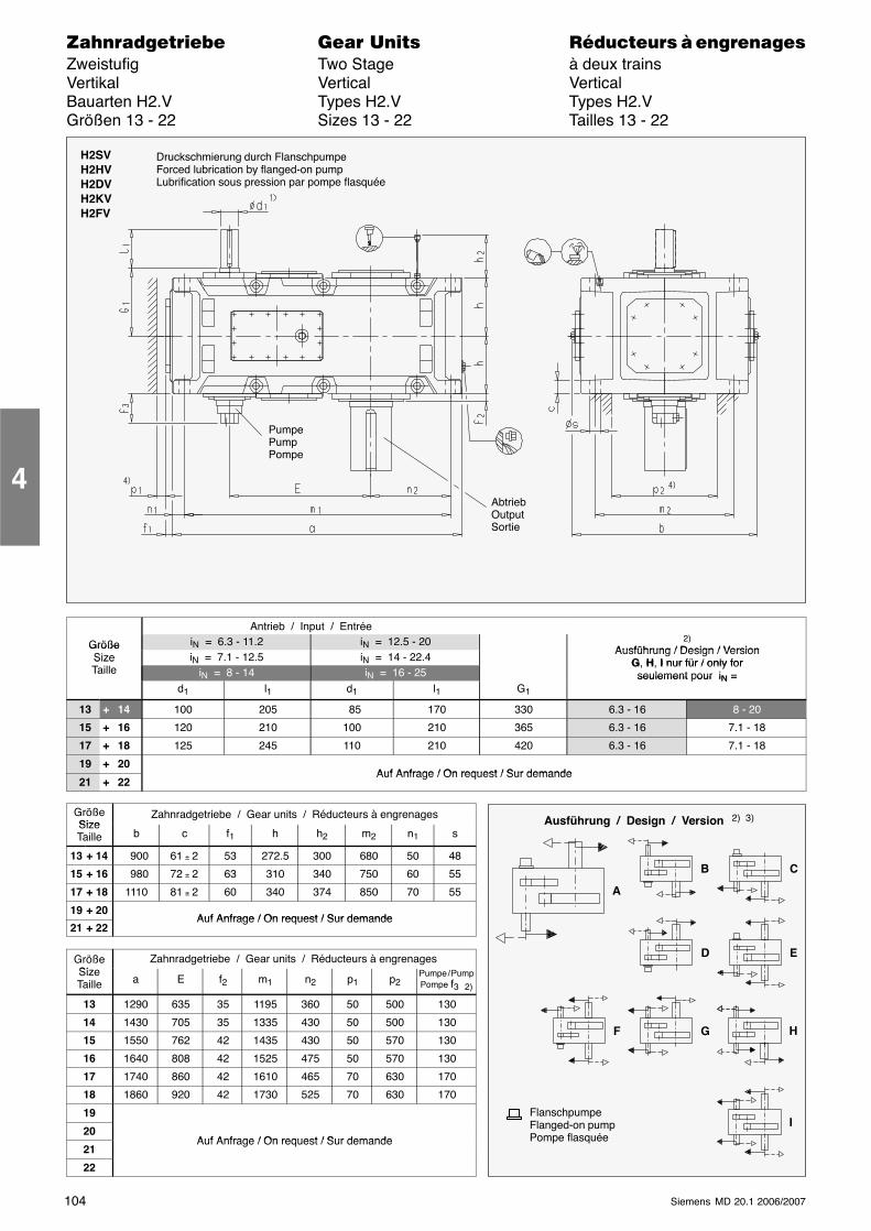
104 Siemens MD 20.1 2006/2007
������������� ���� �� ��������� � ����������Zweistufig Two Stage à deux trainsVertikal Vertical VerticalBauarten H2.V Types H2.V Types H2.VGrößen 13 - 22 Sizes 13 - 22 Tailles 13 - 22
H2SVH2HVH2DVH2KVH2FV
AbtriebOutputSortie
PumpePumpPompe
Druckschmierung durch FlanschpumpeForced lubrication by flanged-on pumpLubrification sous pression par pompe flasquée
Antrieb / Input / Entrée
Größe iN = 6.3 - 11.2 iN = 12.5 - 20 2)Ausführung / Design / VersionGröße
Size iN = 7.1 - 12.5 iN = 14 - 22.4Ausführung / Design / Version
G, H, I nur für / only forSizeTaille iN = 8 - 14 iN = 16 - 25
G, H, I nur für / only forseulement pour iN =
d1 l1 d1 l1 G1
seulement our iN =
13 + 14 100 205 85 170 330 6.3 - 16 8 - 20
15 + 16 120 210 100 210 365 6.3 - 16 7.1 - 18
17 + 18 125 245 110 210 420 6.3 - 16 7.1 - 18
19 + 20Auf Anfrage / On request / Sur demande
21 + 22Auf Anfrage / On request / Sur demande
GrößeSize
Zahnradgetriebe / Gear units / Réducteurs à engrenagesSizeTaille b c f1 h h2 m2 n1 s
13 + 14 900 61 ± 2 53 272.5 300 680 50 48
15 + 16 980 72 ± 2 63 310 340 750 60 55
17 + 18 1110 81 ± 2 60 340 374 850 70 55
19 + 20Auf Anfrage / On request / Sur demande
21 + 22Auf Anfrage / On request / Sur demande
GrößeSi
Zahnradgetriebe / Gear units / Réducteurs à engrenagesSizeTaille a E f2 m1 n2 p1 p2
Pumpe / PumpPompe f3 2)
13 1290 635 35 1195 360 50 500 130
14 1430 705 35 1335 430 50 500 130
15 1550 762 42 1435 430 50 570 130
16 1640 808 42 1525 475 50 570 130
17 1740 860 42 1610 465 70 630 170
18 1860 920 42 1730 525 70 630 170
19
20Auf Anfrage / On request / Sur demande
21Auf Anfrage / On request / Sur demande
22
4
Ausführung / Design / Version 2) 3)
A
B C
D E
G H
I
F
FlanschpumpeFlanged-on pumpPompe flasquée
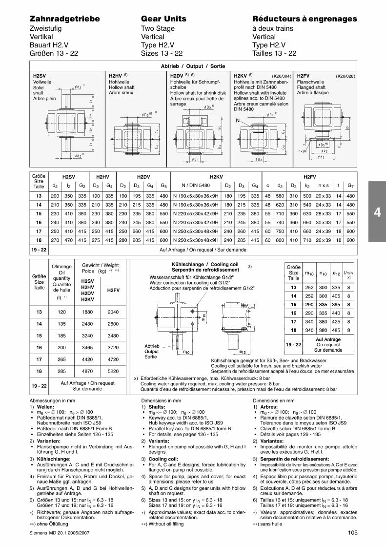
105Siemens MD 20.1 2006/2007
������������� ���� �� ��������� � ����������Zweistufig Two Stage à deux trainsVertikal Vertical VerticalBauart H2.V Type H2.V Type H2.VGrößen 13 - 22 Sizes 13 - 22 Tailles 13 - 22
H2SVVollwelleSolidshaftArbre plein
H2HV 6)
HohlwelleHollow shaftArbre creux
H2DV 5) 6)
Hohlwelle für Schrumpf-scheibeHollow shaft for shrink diskArbre creux pour frette deserrage
Abtrieb / Output / Sortie
H2KV 6)
Hohlwelle mit Zahnnaben-profil nach DIN 5480Hollow shaft with involutesplines acc. to DIN 5480Arbre creux cannelé selonDIN 5480
H2FVFlanschwelleFlanged shaftArbre à flasque
N
( K20/004 ) ( K20/028 )
GrößeSize
H2SV H2HV H2DV H2KV H2FVSizeTaille d2 l2 G2 D2 G4 D2 D3 G4 G5 N / DIN 5480 D2 D3 G4 c d2 D3 k2 n x s t G7
13 200 350 335 190 335 190 195 335 480 N 190 x 5 x 30 x 36 x 9H 180 195 335 48 580 310 500 20 x 33 14 480
14 210 350 335 210 335 210 215 335 480 N 190 x 5 x 30 x 36 x 9H 180 215 335 48 620 310 540 24 x 33 14 480
15 230 410 380 230 380 230 235 380 550 N 220 x 5 x 30 x 42 x 9H 210 235 380 55 710 360 630 28 x 33 17 550
16 240 410 380 240 380 240 245 380 550 N 220 x 5 x 30 x 42 x 9H 210 245 380 55 740 360 660 30 x 33 17 550
17 250 410 415 250 415 250 260 415 600 N 250 x 5 x 30 x 48 x 9H 240 260 415 60 750 410 660 24 x 39 18 600
18 270 470 415 275 415 280 285 415 600 N 250 x 5 x 30 x 48 x 9H 240 285 415 60 800 410 710 26 x 39 18 600
19 - 22 Auf Anfrage / On request / Sur demande
Größe
ÖlmengeOil
tit
Gewicht / WeightPoids (kg) ∗) ∗∗)
GrößeSizeT ill
l/minx)
m10 n10 e12
Kühlschlange / Cooling coilSerpentin de refroidissement
Wasseranschluß für Kühlschlange G1/2”
3)
GrößeSizeTaille
quantityQuantitéde huile
(l) ∗)
H2SVH2HVH2DVH2KV
H2FV
Taille
252 335
x)
13 300
10 10 12
8
252 40514 300 8
290 39515 335 8
Wasseranschluß für Kühlschlange G1/2”Water connection for cooling coil G1/2”Adduction pour serpentin de refroidissement G1/2”
13 120 1880 2040
290 39515 335 8
290 44016 335 8
m10
14 135 2430 2600 340 42517 380 8
340 48518 380 8
m1
15 185 3240 3480340 48518 380 8
Auf Anfrage
16 200 3465 3720 AbtriebOutput
19 - 22Auf AnfrageOn request
Sur demandee12n10
17 265 4420 4720
Out utSortie
Kühlschlange geeignet für Süß-, See- und BrackwasserCooling coil suitable for fresh sea and brackish water
Sur demandee12n10
18 285 4870 5220Cooling coil suitable for fresh, sea and brackish waterSerpentin de refroidissement adapté à l’eau douce, de mer et saumâtre
) E f d li h Kühl Kühl d k 8 b
19 - 22 Auf Anfrage / On requestSur demande
x) Erforderliche Kühlwassermenge, max. Kühlwasserdruck: 8 barCooling water quantity required, max. cooling water pressure: 8 barQuantité d’eau de refroidissement nécessaire, préssion maxi de l’eau de refroidissement: 8 bar
Abmessungen in mm1) Wellen: � m6 <= ∅ 100; n6 > ∅ 100 � Paßfedernut nach DIN 6885/1,
Nabennutbreite nach ISO JS9 � Paßfeder nach DIN 6885/1 Form B � Einzelheiten siehe Seiten 126 - 1352) Varianten: � Flanschpumpe nicht in Verbindung mit Aus-
führung G, H und I.3) Kühlschlange: � Ausführungen A, C und E mit Druckschmie-
rung durch Flanschpumpe nicht möglich.4) Freiraum für Pumpe, Rohre und Deckel, ge-
naue Maße ggf. anfragen.5) Ausführungen A, D und G bei Hohlwellen-
getriebe auf Anfrage.6) Größen 13 und 15: nur iN = 6.3 - 18
Größen 17 und 19: nur iN = 6.3 - 16∗) Richtwerte; genaue Angaben nach auftrags-
bezogener Dokumentation.∗∗) ohne Ölfüllung
Dimensions in mm1) Shafts: � m6 <= ∅ 100; n6 > ∅ 100 � Keyway acc. to DIN 6885/1,
Hub keyway width acc. to ISO JS9 � Parallel key acc. to DIN 6885/1 form B � For details, see pages 126 - 1352) Variants: � Flanged-on pump not possible with G, H and I
designs.3) Cooling coil: � For A, C and E designs, forced lubrication by
flanged-on pump not possible.4) Space for pump, pipes and cover; for exact
dimensions, please refer to us.5) A, D and G designs for gear units with hollow
shaft on request.6) Sizes 13 and 15: only iN = 6.3 - 18
Sizes 17 and 19: only iN = 6.3 - 16∗) Approximate values; exact data acc. to order-
related documentation.∗∗) Without oil filling
Dimensions en mm1) Arbres: � m6 <= ∅ 100; n6 > ∅ 100 � Rainure de clavette selon DIN 6885/1,
Tolérance dans le moyeu selon ISO JS9 � Clavette selon DIN 6885/1 forme B � Détails voir pages 126 - 1352) Variantes: � Impossibilité de monter une pompe attelée
avec les exécutions G, H et I.3) Serpentin de refroidissement: � Impossibilité de livrer les exécutions A, C et E avec
une lubrification sous pression par pompe attelée.4) Espace libre pour passage pompe, tuyauterie
et couvercle, côtes précises sur demande.5) Exécutions A, D et G pour réducteurs à arbre
creux sur demande.6) Tailles 13 et 15: uniquement iN = 6.3 - 18
Tailles 17 et 19: uniquement iN = 6.3 - 16∗) Valeurs approximatives; données exactes
selon documentation relative à la commande.∗∗) sans huile
4
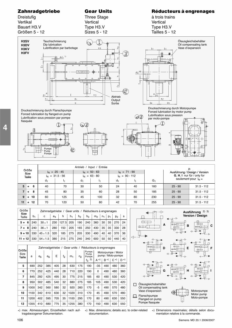
106 Siemens MD 20.1 2006/2007
������������� ���� �� ��������� � ����������Dreistufig Three Stage à trois trainsVertikal Vertical VerticalBauart H3.V Type H3.V Type H3.VGrößen 5 - 12 Sizes 5 - 12 Tailles 5 - 12
AbtriebOutputSortie
H3SVH3DVH3KVH3FV
ÖlausgleichsbehälterOil compensating tankVase d’expansion
PumpePumpPompe
Druckschmierung durch FlanschpumpeForced lubrication by flanged-on pumpLubrification sous pression par pompeflasquée
TauchschmierungDip lubricationLubrification par barbotage
Druckschmierung durch MotorpumpeForced lubrication by motor pumpLubrification sous pressionpar moto-pompe
GrößeAntrieb / Input / Entrée
2)GrößeSize
iN = 25 - 45 iN = 50 - 63 iN = 71 - 902)
Ausführung / Design / VersionSizeTaille iN = 31.5 - 56 iN = 63 - 80 iN = 90 - 112
Ausführung / Design / VersionG, H, I nur für / only for
seulement pour iTaille
d1 l1 d1 l1 d1 l1 G1seulement pour iN =
5 + 6 40 70 30 50 24 40 160 25 - 90 31.5 - 112
7 + 8 45 80 35 60 28 50 185 25 - 90 31.5 - 112
9 + 10 60 125 45 100 32 80 230 25 - 90 31.5 - 112
11 + 12 70 120 50 80 42 70 255 25 - 90 31.5 - 112
GrößeSize
Zahnradgetriebe / Gear units / Réducteurs à engrenagesSizeTaille b1 c e4 h h1 h2 h3 m2 n1 p1 p2 s
5 + 6 240 30 ± 1 230 127.5 205 190 240 360 30 35 270 24
7 + 8 240 36 ± 1 280 150 205 165 250 430 35 35 330 28
9 + 10 330 45 ± 1.5 320 185 275 205 330 490 40 40 370 36
11 + 12 330 54 ± 1.5 380 215 275 240 340 600 50 50 440 40
GrößeZahnradgetriebe / Gear units / Réducteurs à engrenages
GrößeSizeTaille a e5 e6 E f2 m1 n2
PumpePump
Pompe
Motorpumpe / Motorpump / Moto-pompeTaille 5 6 2 1 2
f3 2) A +) B +) C +) D +)
5 690 252 385 405 28 630 175 190 -35 490 480 360
6 770 252 425 440 28 710 220 190 0 490 480 360
7 845 292 425 495 30 775 215 185 60 490 530 420
8 950 302 485 540 32 880 275 185 105 490 530 420
9 1000 342 560 580 32 920 260 170 -5 490 570 480
10 1100 342 610 630 32 1020 310 170 45 490 570 480
11 1200 402 595 705 35 1100 295 170 80 490 630 550
12 1355 410 680 775 35 1255 380 170 150 490 630 550
+) max. Abmessungen; Einzelheiten nach auf-tragsbezogener Dokumentation.
+) Max. dimensions; details acc. to order-relateddocumentation.
+) Dimensions maximales; détails selon docu-mentation relative à la commande.
4
Ausführung 2) 3)
Version / Design
A
ÖlausgleichsbehälterOil compensating tankVase d’expansion
FlanschpumpeFlanged-on pumpPompe flasquée
B C
D E F
G H I
MotorpumpeMotor pumpMoto-pompe
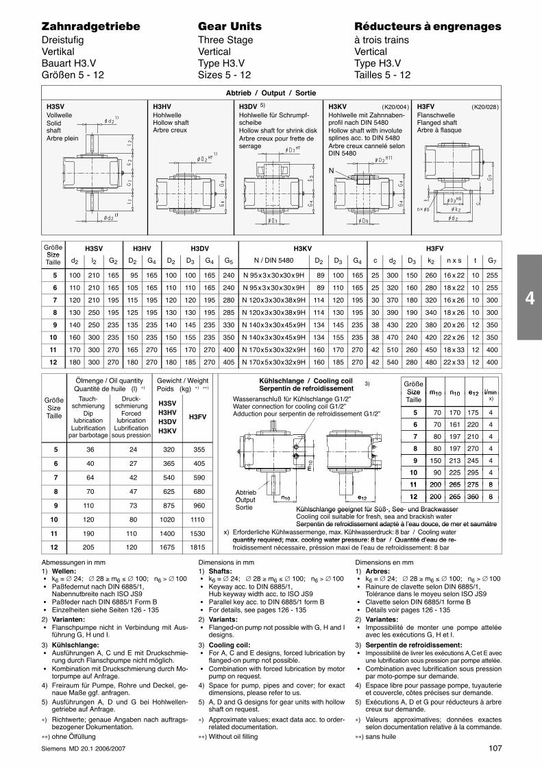
107Siemens MD 20.1 2006/2007
������������� ���� �� ��������� � ����������Dreistufig Three Stage à trois trainsVertikal Vertical VerticalBauart H3.V Type H3.V Type H3.VGrößen 5 - 12 Sizes 5 - 12 Tailles 5 - 12
H3SVVollwelleSolidshaftArbre plein
H3HVHohlwelleHollow shaftArbre creux
H3DV 5)
Hohlwelle für Schrumpf-scheibeHollow shaft for shrink diskArbre creux pour frette deserrage
Abtrieb / Output / Sortie
H3KVHohlwelle mit Zahnnaben-profil nach DIN 5480Hollow shaft with involutesplines acc. to DIN 5480Arbre creux cannelé selonDIN 5480
H3FVFlanschwelleFlanged shaftArbre à flasque
N
( K20/004 ) ( K20/028 )
GrößeSize
H3SV H3HV H3DV H3KV H3FVSizeTaille d2 l2 G2 D2 G4 D2 D3 G4 G5 N / DIN 5480 D2 D3 G4 c d2 D3 k2 n x s t G7
5 100 210 165 95 165 100 100 165 240 N 95 x 3 x 30 x30 x 9H 89 100 165 25 300 150 260 16 x 22 10 255
6 110 210 165 105 165 110 110 165 240 N 95 x 3 x 30 x 30 x 9H 89 110 165 25 320 160 280 18 x 22 10 255
7 120 210 195 115 195 120 120 195 280 N 120 x 3 x 30 x 38 x 9H 114 120 195 30 370 180 320 16 x 26 10 300
8 130 250 195 125 195 130 130 195 285 N 120 x 3 x 30 x 38 x 9H 114 130 195 30 390 190 340 18 x 26 10 300
9 140 250 235 135 235 140 145 235 330 N 140 x 3 x 30 x 45 x 9H 134 145 235 38 430 220 380 20 x 26 12 350
10 160 300 235 150 235 150 155 235 350 N 140 x 3 x 30 x 45 x 9H 134 155 235 38 470 240 420 22 x 26 12 350
11 170 300 270 165 270 165 170 270 400 N 170 x 5 x 30 x 32 x 9H 160 170 270 42 510 260 450 18 x 33 12 400
12 180 300 270 180 270 180 185 270 405 N 170 x 5 x 30 x 32 x 9H 160 185 270 42 540 280 480 22 x 33 12 400
Ölmenge / Oil quantityQuantité de huile (l) ∗)
Gewicht / WeightPoids (kg) ∗) ∗∗)
GrößeSize l/minm10 n10 e12
Kühlschlange / Cooling coilSerpentin de refroidissement
3)
GrößeSizeTaille
Tauch-schmierung
Diplubrication
Lubrificationpar barbotage
Druck-schmierung
Forcedlubrication
Lubrificationsous pression
H3SVH3HVH3DVH3KV
H3FV
SizeTaille
70 175
l/min x)
5 170
m10 n10 e12
4
70 220 6 161 4
80 210 7 197 4
p
Wasseranschluß für Kühlschlange G1/2”Water connection for cooling coil G1/2”Adduction pour serpentin de refroidissement G1/2”
5 36 24 320 355
80 09
80 270 8 197 4
6 40 27 365 405 150 245 9 213 4
90 29510 225 4m10
7 64 42 540 590 90 29510 225 4
200 27511 265 8
m
8 70 47 625 680 AbtriebOutput
200 27511 265 8
200 36012 265 8e12n10
9 110 73 875 960OutputSortie
200 36012 265 8
Kühlschlange geeignet für Süß-, See- und Brackwasser
e12n10
10 120 80 1020 1110
Kühlschlange geeignet für Süß , See und BrackwasserCooling coil suitable for fresh, sea and brackish waterSerpentin de refroidissement adapté à l’eau douce, de mer et saumâtre
11 190 110 1400 1530Ser entin de refroidissement ada té à l eau douce, de mer et saumâtre
x) Erforderliche Kühlwassermenge, max. Kühlwasserdruck: 8 bar / Cooling waterquantity required; max cooling water pressure: 8 bar / Quantité d’eau de re-
12 205 120 1675 1815quantity required; max. cooling water pressure: 8 bar / Quantité d’eau de re-froidissement nécessaire, préssion maxi de l’eau de refroidissement: 8 bar
Abmessungen in mm1) Wellen: � k6 = ∅ 24; ∅ 28 ≥ m6 ≤ ∅ 100; n6 > ∅ 100 � Paßfedernut nach DIN 6885/1,
Nabennutbreite nach ISO JS9 � Paßfeder nach DIN 6885/1 Form B � Einzelheiten siehe Seiten 126 - 1352) Varianten: � Flanschpumpe nicht in Verbindung mit Aus-
führung G, H und I.
3) Kühlschlange: � Ausführungen A, C und E mit Druckschmie-
rung durch Flanschpumpe nicht möglich. � Kombination mit Druckschmierung durch Mo-
torpumpe auf Anfrage.4) Freiraum für Pumpe, Rohre und Deckel, ge-
naue Maße ggf. anfragen.5) Ausführungen A, D und G bei Hohlwellen-
getriebe auf Anfrage.
∗) Richtwerte; genaue Angaben nach auftrags-bezogener Dokumentation.
∗∗) ohne Ölfüllung
Dimensions in mm1) Shafts: � k6 = ∅ 24; ∅ 28 ≥ m6 ≤ ∅ 100; n6 > ∅ 100 � Keyway acc. to DIN 6885/1,
Hub keyway width acc. to ISO JS9 � Parallel key acc. to DIN 6885/1 form B � For details, see pages 126 - 1352) Variants: � Flanged-on pump not possible with G, H and I
designs.
3) Cooling coil: � For A, C and E designs, forced lubrication by
flanged-on pump not possible. � Combination with forced lubrication by motor
pump on request.4) Space for pump, pipes and cover; for exact
dimensions, please refer to us.5) A, D and G designs for gear units with hollow
shaft on request.
∗) Approximate values; exact data acc. to order-related documentation.
∗∗) Without oil filling
Dimensions en mm1) Arbres: � k6 = ∅ 24; ∅ 28 ≥ m6 ≤ ∅ 100; n6 > ∅ 100 � Rainure de clavette selon DIN 6885/1,
Tolérance dans le moyeu selon ISO JS9 � Clavette selon DIN 6885/1 forme B � Détails voir pages 126 - 1352) Variantes: � Impossibilité de monter une pompe attelée
avec les exécutions G, H et I.
3) Serpentin de refroidissement: � Impossibilité de livrer les exécutions A, C et E avec
une lubrification sous pression par pompe attelée. � Combination avec lubrification sous pression
par moto-pompe sur demande.4) Espace libre pour passage pompe, tuyauterie
et couvercle, côtes précises sur demande.5) Exécutions A, D et G pour réducteurs à arbre
creux sur demande.
∗) Valeurs approximatives; données exactesselon documentation relative à la commande.
∗∗) sans huile
4
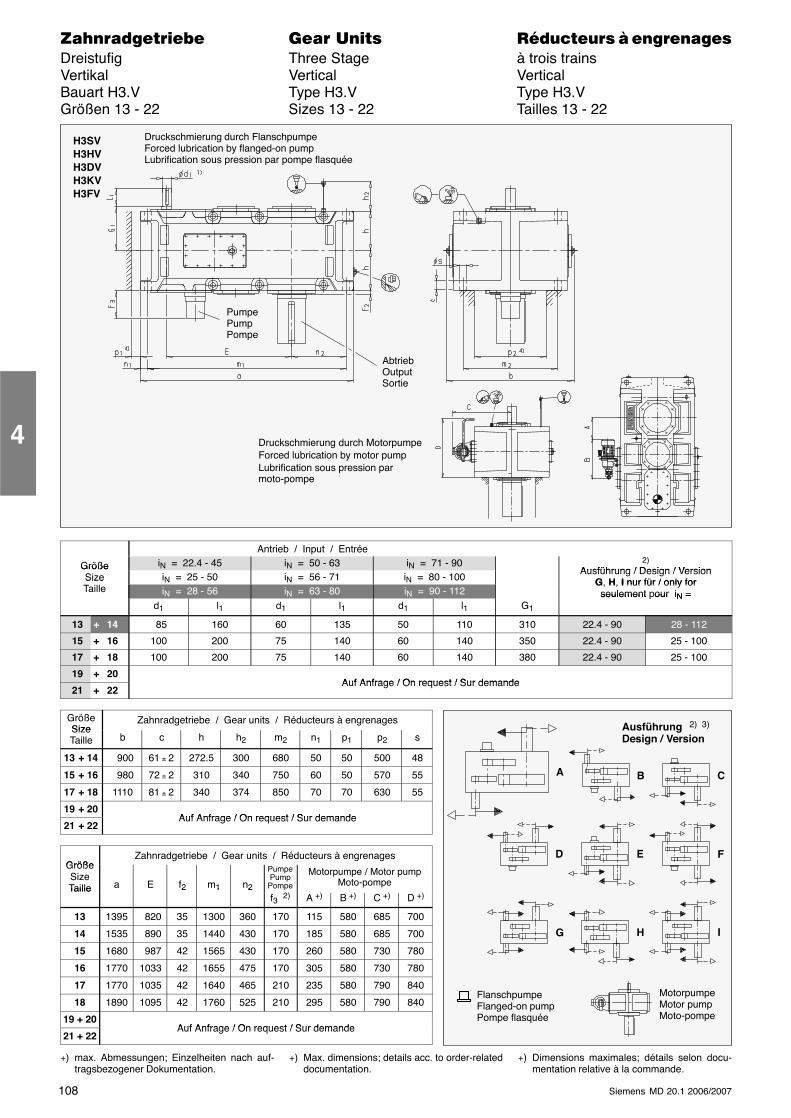
108 Siemens MD 20.1 2006/2007
������������� ���� �� ��������� � ����������Dreistufig Three Stage à trois trainsVertikal Vertical VerticalBauart H3.V Type H3.V Type H3.VGrößen 13 - 22 Sizes 13 - 22 Tailles 13 - 22
H3SVH3HVH3DVH3KVH3FV
AbtriebOutputSortie
PumpePumpPompe
Druckschmierung durch FlanschpumpeForced lubrication by flanged-on pumpLubrification sous pression par pompe flasquée
Druckschmierung durch MotorpumpeForced lubrication by motor pumpLubrification sous pression parmoto-pompe
Antrieb / Input / Entrée
Größe iN = 22.4 - 45 iN = 50 - 63 iN = 71 - 90 2)Ausführung / Design / VersionGröße
Size iN = 25 - 50 iN = 56 - 71 iN = 80 - 100Ausführung / Design / Version
G, H, I nur für / only forSizeTaille iN = 28 - 56 iN = 63 - 80 iN = 90 - 112
G, H, I nur für / only forseulement pour iN =
d1 l1 d1 l1 d1 l1 G1
seulement our iN =
13 + 14 85 160 60 135 50 110 310 22.4 - 90 28 - 112
15 + 16 100 200 75 140 60 140 350 22.4 - 90 25 - 100
17 + 18 100 200 75 140 60 140 380 22.4 - 90 25 - 100
19 + 20Auf Anfrage / On request / Sur demande
21 + 22Auf Anfrage / On request / Sur demande
GrößeSize
Zahnradgetriebe / Gear units / Réducteurs à engrenagesSizeTaille b c h h2 m2 n1 p1 p2 s
13 + 14 900 61 ± 2 272.5 300 680 50 50 500 48
15 + 16 980 72 ± 2 310 340 750 60 50 570 55
17 + 18 1110 81 ± 2 340 374 850 70 70 630 55
19 + 20Auf Anfrage / On request / Sur demande
21 + 22Auf Anfrage / On request / Sur demande
GrößeZahnradgetriebe / Gear units / Réducteurs à engrenages
GrößeSizeTaille a E f2 m1 n2
PumpePump
Pompe
Motorpumpe / Motor pumpMoto-pompeTaille 2 1 2
f3 2) A +) B +) C +) D +)
13 1395 820 35 1300 360 170 115 580 685 700
14 1535 890 35 1440 430 170 185 580 685 700
15 1680 987 42 1565 430 170 260 580 730 780
16 1770 1033 42 1655 475 170 305 580 730 780
17 1770 1035 42 1640 465 210 235 580 790 840
18 1890 1095 42 1760 525 210 295 580 790 840
19 + 20Auf Anfrage / On request / Sur demande
21 + 22Auf Anfrage / On request / Sur demande
+) max. Abmessungen; Einzelheiten nach auf-tragsbezogener Dokumentation.
+) Max. dimensions; details acc. to order-relateddocumentation.
+) Dimensions maximales; détails selon docu-mentation relative à la commande.
4
Ausführung 2) 3)
Design / Version
A
FlanschpumpeFlanged-on pumpPompe flasquée
B C
D E F
G H I
MotorpumpeMotor pumpMoto-pompe
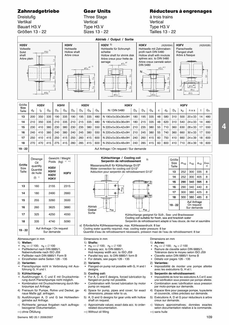
109Siemens MD 20.1 2006/2007
������������� ���� �� ��������� � ����������Dreistufig Three Stage à trois trainsVertikal Vertical VerticalBauart H3.V Type H3.V Type H3.VGrößen 13 - 22 Sizes 13 - 22 Tailles 13 - 22
H3SVVollwelleSolidshaftArbre plein
H3HVHohlwelleHollow shaftArbre creux
H3DV 5)
Hohlwelle für Schrumpf-scheibeHollow shaft for shrink diskArbre creux pour frette deserrage
Abtrieb / Output / Sortie
H3KVHohlwelle mit Zahnnaben-profil nach DIN 5480Hollow shaft with involutesplines acc. to DIN 5480Arbre creux cannelé selonDIN 5480
H3FVFlanschwelleFlanged shaftArbre à flasque
N
( K20/004 ) ( K20/028 )
GrößeSize
H3SV H3HV H3DV H3KV H3FVSizeTaille d2 l2 G2 D2 G4 D2 D3 G4 G5 N / DIN 5480 D2 D3 G4 c d2 D3 k2 n x s t G7
13 200 350 335 190 335 190 195 335 480 N 190 x 5 x 30 x 36 x 9H 180 195 335 48 580 310 500 20 x 33 14 480
14 210 350 335 210 335 210 215 335 480 N 190 x 5 x 30 x 36 x 9H 180 215 335 48 620 310 540 24 x 33 14 480
15 230 410 380 230 380 230 235 380 550 N 220 x 5 x 30 x 42 x 9H 210 235 380 55 710 360 630 28 x 33 17 550
16 240 410 380 240 380 240 245 380 550 N 220 x 5 x 30 x 42 x 9H 210 245 380 55 740 360 660 30 x 33 17 550
17 250 410 415 250 415 250 260 415 600 N 250 x 5 x 30 x 48 x 9H 240 260 415 60 750 410 660 24 x 39 18 600
18 270 470 415 275 415 280 285 415 600 N 250 x 5 x 30 x 48 x 9H 240 285 415 60 800 410 710 26 x 39 18 600
19 - 22 Auf Anfrage / On request / Sur demande
Größe
ÖlmengeOil
tit
Gewicht / WeightPoids (kg) ∗) ∗∗)
GrößeSize l/min
)m10 n10 e12
Kühlschlange / Cooling coilSerpentin de refroidissement
Wasseranschluß für Kühlschlange G1/2”
3)
GrößeSizeTaille
quantityQuantitéde huile
(l) ∗)
H3SVH3HVH3DVH3KV
H3FV
SizeTaille
252 335
l/min x)
13 300
m10 n10 e12
8
252 40514 300 8
290 39515 340 8
Wasseranschluß für Kühlschlange G1/2”Water connection for cooling coil G1/2”Adduction pour serpentin de refroidissement G1/2”
13 160 2155 2315290 39515 340 8
290 44016 340 8
m10
14 180 2490 2660 300 42517 380 8
300 48518 380 8
m1
15 255 3260 3500300 48518 380 8
Auf AnfrageO
16 260 3625 3880 AbtriebOutput
19 - 22Auf AnfrageOn request
Sur demandee12n10
17 325 4250 4550
Out utSortie
Kühlschlange geeignet für Süß-, See- und BrackwasserCooling coil suitable for fresh sea and brackish water
e12n10
18 335 4740 5090Cooling coil suitable for fresh, sea and brackish waterSerpentin de refroidissement adapté à l’eau douce, de mer et saumâtre
x) Erforderliche Kühlwassermenge max Kühlwasserdruck: 8 bar
19 - 22 Auf Anfrage / On requestSur demande
x) Erforderliche Kühlwassermenge, max. Kühlwasserdruck: 8 barCooling water quantity required; max. cooling water pressure: 8 barQuantité d’eau de refroidissement nécessaire, préssion maxi de l’eau de refroidissement: 8 bar
Abmessungen in mm1) Wellen: � m6 <= ∅ 100; n6 > ∅ 100 � Paßfedernut nach DIN 6885/1,
Nabennutbreite nach ISO JS9 � Paßfeder nach DIN 6885/1 Form B � Einzelheiten siehe Seiten 126 - 1352) Varianten: � Flanschpumpe nicht in Verbindung mit Aus-
führung G, H und I.3) Kühlschlange: � Ausführungen A, C und E mit Druckschmie-
rung durch Flanschpumpe nicht möglich. � Kombination mit Druckschmierung durch Mo-
torpumpe auf Anfrage.4) Freiraum für Pumpe, Rohre und Deckel, ge-
naue Maße ggf. anfragen.5) Ausführungen A, D und G bei Hohlwellen-
getriebe auf Anfrage.
∗) Richtwerte; genaue Angaben nach auftrags-bezogener Dokumentation.
∗∗) ohne Ölfüllung
Dimensions in mm1) Shafts: � m6 <= ∅ 100; n6 > ∅ 100 � Keyway acc. to DIN 6885/1,
Hub keyway width acc. to ISO JS9 � Parallel key acc. to DIN 6885/1 form B � For details, see pages 126 - 1352) Variants: � Flanged-on pump not possible with G, H and I
designs.3) Cooling coil: � For A, C and E designs, forced lubrication by
flanged-on pump not possible. � Combination with forced lubrication by motor
pump on request.4) Space for pump, pipes and cover; for exact
dimensions, please refer to us.5) A, D and G designs for gear units with hollow
shaft on request.
∗) Approximate values; exact data acc. to order-related documentation.
∗∗) Without oil filling
Dimensions en mm1) Arbres: � m6 <= ∅ 100; n6 > ∅ 100 � Rainure de clavette selon DIN 6885/1,
Tolérance dans le moyeu selon ISO JS9 � Clavette selon DIN 6885/1 forme B � Détails voir pages 126 - 1352) Variantes: � Impossibilité de monter une pompe attelée
avec les exécutions G, H et I.3) Serpentin de refroidissement: � Impossibilité de livrer les exécutions A, C et E avec
une lubrification sous pression par pompe attelée. � Combination avec lubrification sous pression
par moto-pompe sur demande.4) Espace libre pour passage pompe, tuyauterie
et couvercle, côtes précises sur demande.5) Exécutions A, D et G pour réducteurs à arbre
creux sur demande.
∗) Valeurs approximatives; données exactesselon documentation relative à la commande.
∗∗) sans huile
4
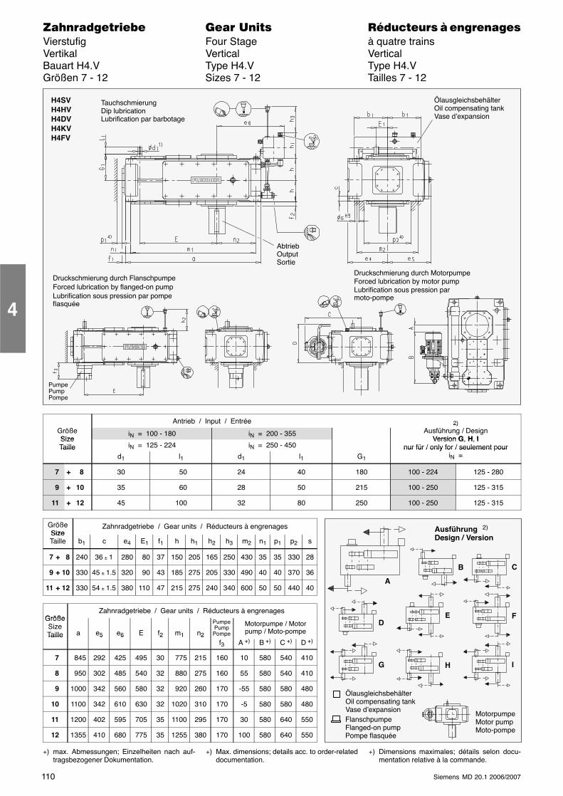
110 Siemens MD 20.1 2006/2007
������������� ���� �� ��������� � ����������Vierstufig Four Stage à quatre trainsVertikal Vertical VerticalBauart H4.V Type H4.V Type H4.VGrößen 7 - 12 Sizes 7 - 12 Tailles 7 - 12
AbtriebOutputSortie
H4SVH4HVH4DVH4KVH4FV
ÖlausgleichsbehälterOil compensating tankVase d’expansion
PumpePumpPompe
TauchschmierungDip lubricationLubrification par barbotage
Druckschmierung durch FlanschpumpeForced lubrication by flanged-on pumpLubrification sous pression par pompeflasquée
Druckschmierung durch MotorpumpeForced lubrication by motor pumpLubrification sous pression parmoto-pompe
Antrieb / Input / Entrée 2)GrößeSize
iN = 100 - 180 iN = 200 - 355
2)Ausführung / Design
Version G H ISizeTaille iN = 125 - 224 iN = 250 - 450
Version G, H, Inur für / only for / seulement pourTaille
d1 l1 d1 l1 G1
nur für / only for / seulement ouriN =
7 + 8 30 50 24 40 180 100 - 224 125 - 280
9 + 10 35 60 28 50 215 100 - 250 125 - 315
11 + 12 45 100 32 80 250 100 - 250 125 - 315
GrößeSize
Zahnradgetriebe / Gear units / Réducteurs à engrenagesSizeTaille b1 c e4 E1 f1 h h1 h2 h3 m2 n1 p1 p2 s
7 + 8 240 36 ± 1 280 80 37 150 205 165 250 430 35 35 330 28
9 + 10 330 45 ± 1.5 320 90 43 185 275 205 330 490 40 40 370 36
11 + 12 330 54 ± 1.5 380 110 47 215 275 240 340 600 50 50 440 40
GrößeZahnradgetriebe / Gear units / Réducteurs à engrenages
GrößeSizeTaille a e5 e6 E f2 m1 n2
PumpePump
Pompe
Motorpumpe / Motorpump / Moto-pompeTaille 5 6 2 1 2
f3 A +) B +) C +) D +)
7 845 292 425 495 30 775 215 160 10 580 540 410
8 950 302 485 540 32 880 275 160 55 580 540 410
9 1000 342 560 580 32 920 260 170 -55 580 580 480
10 1100 342 610 630 32 1020 310 170 -5 580 580 480
11 1200 402 595 705 35 1100 295 170 30 580 640 550
12 1355 410 680 775 35 1255 380 170 100 580 640 550
+) max. Abmessungen; Einzelheiten nach auf-tragsbezogener Dokumentation.
+) Max. dimensions; details acc. to order-relateddocumentation.
+) Dimensions maximales; détails selon docu-mentation relative à la commande.
4
Ausführung 2)
Design / Version
ÖlausgleichsbehälterOil compensating tankVase d’expansionFlanschpumpeFlanged-on pumpPompe flasquée
B C
A
DE F
MotorpumpeMotor pumpMoto-pompe
G H I
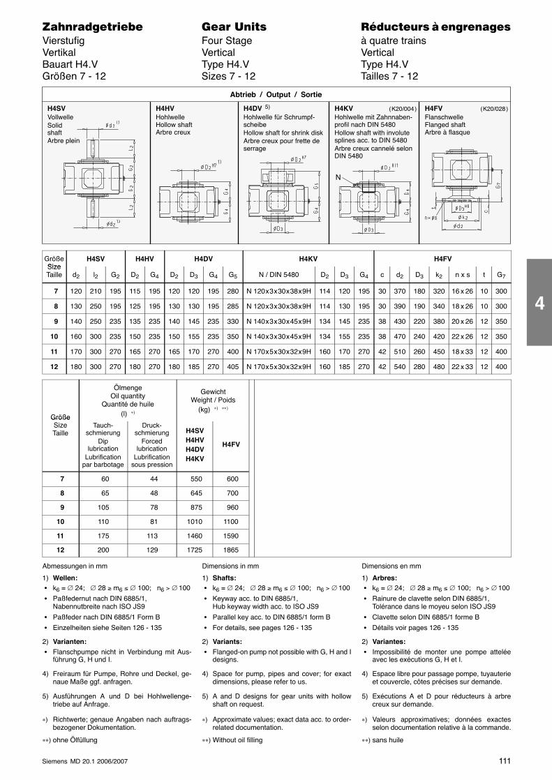
111Siemens MD 20.1 2006/2007
������������� ���� �� ��������� � ����������Vierstufig Four Stage à quatre trainsVertikal Vertical VerticalBauart H4.V Type H4.V Type H4.VGrößen 7 - 12 Sizes 7 - 12 Tailles 7 - 12
N
H4SVVollwelleSolidshaftArbre plein
H4HVHohlwelleHollow shaftArbre creux
H4DV 5)
Hohlwelle für Schrumpf-scheibeHollow shaft for shrink diskArbre creux pour frette deserrage
Abtrieb / Output / Sortie
H4KVHohlwelle mit Zahnnaben-profil nach DIN 5480Hollow shaft with involutesplines acc. to DIN 5480Arbre creux cannelé selonDIN 5480
H4FVFlanschwelleFlanged shaftArbre à flasque
( K20/004 ) ( K20/028 )
GrößeSize
H4SV H4HV H4DV H4KV H4FVSizeTaille d2 l2 G2 D2 G4 D2 D3 G4 G5 N / DIN 5480 D2 D3 G4 c d2 D3 k2 n x s t G7
7 120 210 195 115 195 120 120 195 280 N 120 x 3 x 30 x 38 x 9H 114 120 195 30 370 180 320 16 x 26 10 300
8 130 250 195 125 195 130 130 195 285 N 120 x 3 x 30 x 38 x 9H 114 130 195 30 390 190 340 18 x 26 10 300
9 140 250 235 135 235 140 145 235 330 N 140 x 3 x 30 x 45 x 9H 134 145 235 38 430 220 380 20 x 26 12 350
10 160 300 235 150 235 150 155 235 350 N 140 x 3 x 30 x 45 x 9H 134 155 235 38 470 240 420 22 x 26 12 350
11 170 300 270 165 270 165 170 270 400 N 170 x 5 x 30 x 32 x 9H 160 170 270 42 510 260 450 18 x 33 12 400
12 180 300 270 180 270 180 185 270 405 N 170 x 5 x 30 x 32 x 9H 160 185 270 42 540 280 480 22 x 33 12 400
Größe
ÖlmengeOil quantity
Quantité de huile(l) ∗)
GewichtWeight / Poids
(kg) ∗) ∗∗)
GrößeSizeTaille
Tauch-schmierung
Diplubrication
Lubrificationpar barbotage
Druck-schmierung
Forcedlubrication
Lubrificationsous pression
H4SVH4HVH4DVH4KV
H4FV
7 60 44 550 600
8 65 48 645 700
9 105 78 875 960
10 110 81 1010 1100
11 175 113 1460 1590
12 200 129 1725 1865
Abmessungen in mm
1) Wellen: � k6 = ∅ 24; ∅ 28 ≥ m6 ≤ ∅ 100; n6 > ∅ 100
� Paßfedernut nach DIN 6885/1,Nabennutbreite nach ISO JS9
� Paßfeder nach DIN 6885/1 Form B
� Einzelheiten siehe Seiten 126 - 135
2) Varianten: � Flanschpumpe nicht in Verbindung mit Aus-
führung G, H und I.
4) Freiraum für Pumpe, Rohre und Deckel, ge-naue Maße ggf. anfragen.
5) Ausführungen A und D bei Hohlwellenge-triebe auf Anfrage.
∗) Richtwerte; genaue Angaben nach auftrags-bezogener Dokumentation.
∗∗) ohne Ölfüllung
Dimensions in mm
1) Shafts: � k6 = ∅ 24; ∅ 28 ≥ m6 ≤ ∅ 100; n6 > ∅ 100
� Keyway acc. to DIN 6885/1,Hub keyway width acc. to ISO JS9
� Parallel key acc. to DIN 6885/1 form B
� For details, see pages 126 - 135
2) Variants: � Flanged-on pump not possible with G, H and I
designs.
4) Space for pump, pipes and cover; for exactdimensions, please refer to us.
5) A and D designs for gear units with hollowshaft on request.
∗) Approximate values; exact data acc. to order-related documentation.
∗∗) Without oil filling
Dimensions en mm
1) Arbres: � k6 = ∅ 24; ∅ 28 ≥ m6 ≤ ∅ 100; n6 > ∅ 100
� Rainure de clavette selon DIN 6885/1,Tolérance dans le moyeu selon ISO JS9
� Clavette selon DIN 6885/1 forme B
� Détails voir pages 126 - 135
2) Variantes: � Impossibilité de monter une pompe attelée
avec les exécutions G, H et I.
4) Espace libre pour passage pompe, tuyauterieet couvercle, côtes précises sur demande.
5) Exécutions A et D pour réducteurs à arbrecreux sur demande.
∗) Valeurs approximatives; données exactesselon documentation relative à la commande.
∗∗) sans huile
4
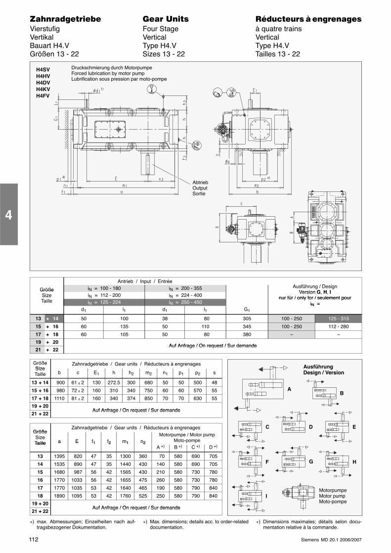
112 Siemens MD 20.1 2006/2007
������������� ���� �� ��������� � ����������Vierstufig Four Stage à quatre trainsVertikal Vertical VerticalBauart H4.V Type H4.V Type H4.VGrößen 13 - 22 Sizes 13 - 22 Tailles 13 - 22
H4SVH4HVH4DVH4KVH4FV
AbtriebOutputSortie
Druckschmierung durch MotorpumpeForced lubrication by motor pumpLubrification sous pression par moto-pompe
Antrieb / Input / EntréeA füh / D i
Größe iN = 100 - 180 iN = 200 - 355 Ausführung / DesignVersion G H IGröße
Size iN = 112 - 200 iN = 224 - 400Version G, H, I
nur für / only for / seulement pourSizeTaille iN = 125 - 224 iN = 250 - 450
nur für / only for / seulement pouriN =
d1 l1 d1 l1 G1
iN =
13 + 14 50 100 38 80 305 100 - 250 125 - 315
15 + 16 60 135 50 110 345 100 - 250 112 - 280
17 + 18 60 105 50 80 380 – –
19 + 20Auf Anfrage / On request / Sur demande
21 + 22Auf Anfrage / On request / Sur demande
GrößeSize
Zahnradgetriebe / Gear units / Réducteurs à engrenagesSizeTaille b c E1 h h2 m2 n1 p1 p2 s
13 + 14 900 61 ± 2 130 272.5 300 680 50 50 500 48
15 + 16 980 72 ± 2 160 310 340 750 60 60 570 55
17 + 18 1110 81 ± 2 160 340 374 850 70 70 630 55
19 + 20Auf Anfrage / On request / Sur demande
21 + 22Auf Anfrage / On request / Sur demande
GrößeZahnradgetriebe / Gear units / Réducteurs à engrenages
GrößeSizeTaille a E f1 f2 m1 n2
Motorpumpe / Motor pumpMoto-pompeTaille a E f1 f2 m1 n2
A +) B +) C +) D +)
13 1395 820 47 35 1300 360 70 580 690 705
14 1535 890 47 35 1440 430 140 580 690 705
15 1680 987 56 42 1565 430 210 580 730 780
16 1770 1033 56 42 1655 475 260 580 730 780
17 1770 1035 53 42 1640 465 190 580 790 840
18 1890 1095 53 42 1760 525 250 580 790 840
19 + 20Auf Anfrage / On request / Sur demande
21 + 22Auf Anfrage / On request / Sur demande
+) max. Abmessungen; Einzelheiten nach auf-tragsbezogener Dokumentation.
+) Max. dimensions; details acc. to order-relateddocumentation.
+) Dimensions maximales; détails selon docu-mentation relative à la commande.
4
B
C
A
D E
F
MotorpumpeMotor pumpMoto-pompe
G H
I
AusführungDesign / Version
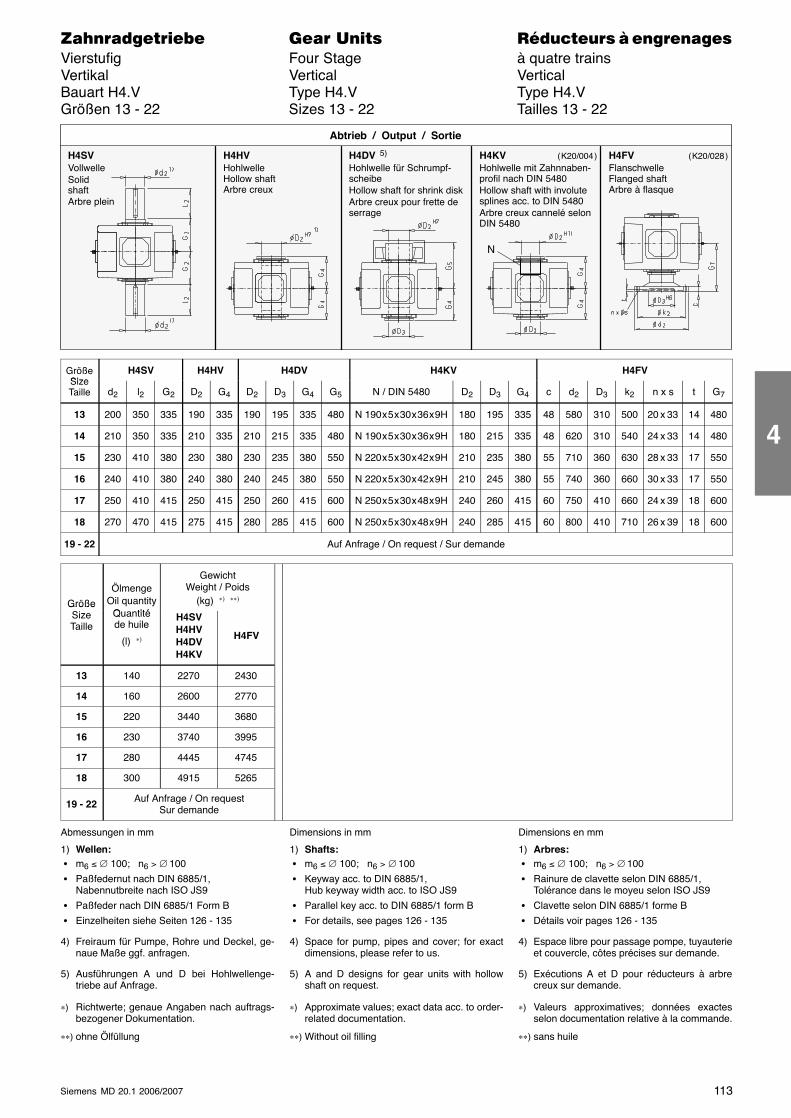
113Siemens MD 20.1 2006/2007
������������� ���� �� ��������� � ����������Vierstufig Four Stage à quatre trainsVertikal Vertical VerticalBauart H4.V Type H4.V Type H4.VGrößen 13 - 22 Sizes 13 - 22 Tailles 13 - 22
N
H4SVVollwelleSolidshaftArbre plein
H4HVHohlwelleHollow shaftArbre creux
H4DV 5)
Hohlwelle für Schrumpf-scheibeHollow shaft for shrink diskArbre creux pour frette deserrage
Abtrieb / Output / Sortie
H4KVHohlwelle mit Zahnnaben-profil nach DIN 5480Hollow shaft with involutesplines acc. to DIN 5480Arbre creux cannelé selonDIN 5480
H4FVFlanschwelleFlanged shaftArbre à flasque
( K20/004 ) ( K20/028 )
GrößeSize
H4SV H4HV H4DV H4KV H4FVSizeTaille d2 l2 G2 D2 G4 D2 D3 G4 G5 N / DIN 5480 D2 D3 G4 c d2 D3 k2 n x s t G7
13 200 350 335 190 335 190 195 335 480 N 190 x 5 x 30 x 36 x 9H 180 195 335 48 580 310 500 20 x 33 14 480
14 210 350 335 210 335 210 215 335 480 N 190 x 5 x 30 x 36 x 9H 180 215 335 48 620 310 540 24 x 33 14 480
15 230 410 380 230 380 230 235 380 550 N 220 x 5 x 30 x 42 x 9H 210 235 380 55 710 360 630 28 x 33 17 550
16 240 410 380 240 380 240 245 380 550 N 220 x 5 x 30 x 42 x 9H 210 245 380 55 740 360 660 30 x 33 17 550
17 250 410 415 250 415 250 260 415 600 N 250 x 5 x 30 x 48 x 9H 240 260 415 60 750 410 660 24 x 39 18 600
18 270 470 415 275 415 280 285 415 600 N 250 x 5 x 30 x 48 x 9H 240 285 415 60 800 410 710 26 x 39 18 600
19 - 22 Auf Anfrage / On request / Sur demande
Größe
ÖlmengeOil quantity
Q tité
GewichtWeight / Poids
(kg) ∗) ∗∗)GrößeSizeTaille
Quantitéde huile
(l) ∗)
H4SVH4HVH4DVH4KV
H4FV
13 140 2270 2430
14 160 2600 2770
15 220 3440 3680
16 230 3740 3995
17 280 4445 4745
18 300 4915 5265
19 - 22 Auf Anfrage / On requestSur demande
Abmessungen in mm
1) Wellen: � m6 ≤ ∅ 100; n6 > ∅ 100
� Paßfedernut nach DIN 6885/1,Nabennutbreite nach ISO JS9
� Paßfeder nach DIN 6885/1 Form B
� Einzelheiten siehe Seiten 126 - 135
4) Freiraum für Pumpe, Rohre und Deckel, ge-naue Maße ggf. anfragen.
5) Ausführungen A und D bei Hohlwellenge-triebe auf Anfrage.
∗) Richtwerte; genaue Angaben nach auftrags-bezogener Dokumentation.
∗∗) ohne Ölfüllung
Dimensions in mm
1) Shafts: � m6 ≤ ∅ 100; n6 > ∅ 100
� Keyway acc. to DIN 6885/1,Hub keyway width acc. to ISO JS9
� Parallel key acc. to DIN 6885/1 form B
� For details, see pages 126 - 135
4) Space for pump, pipes and cover; for exactdimensions, please refer to us.
5) A and D designs for gear units with hollowshaft on request.
∗) Approximate values; exact data acc. to order-related documentation.
∗∗) Without oil filling
Dimensions en mm
1) Arbres: � m6 ≤ ∅ 100; n6 > ∅ 100
� Rainure de clavette selon DIN 6885/1,Tolérance dans le moyeu selon ISO JS9
� Clavette selon DIN 6885/1 forme B
� Détails voir pages 126 - 135
4) Espace libre pour passage pompe, tuyauterieet couvercle, côtes précises sur demande.
5) Exécutions A et D pour réducteurs à arbrecreux sur demande.
∗) Valeurs approximatives; données exactesselon documentation relative à la commande.
∗∗) sans huile
4
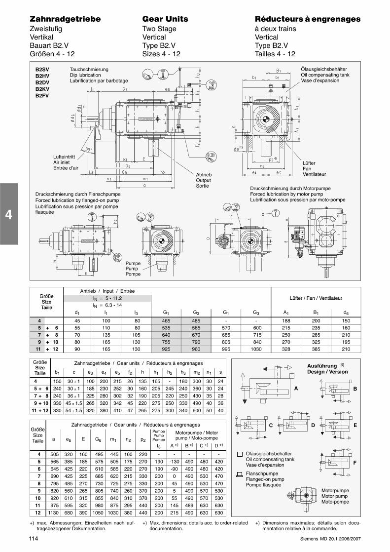
114 Siemens MD 20.1 2006/2007
������������� ���� �� ��������� � ����������Zweistufig Two Stage à deux trainsVertikal Vertical VerticalBauart B2.V Type B2.V Type B2.VGrößen 4 - 12 Sizes 4 - 12 Tailles 4 - 12
AbtriebOutputSortie
B2SVB2HVB2DVB2KVB2FV
ÖlausgleichsbehälterOil compensating tankVase d’expansion
PumpePumpPompe
TauchschmierungDip lubricationLubrification par barbotage
LüfterFanVentilateur
LufteintrittAir inletEntrée d’air
Druckschmierung durch FlanschpumpeForced lubrication by flanged-on pumpLubrification sous pression par pompeflasquée
Druckschmierung durch MotorpumpeForced lubrication by motor pumpLubrification sous pression par moto-pompe
G ößAntrieb / Input / Entrée
GrößeSize
iN = 5 - 11.2 Lüfter / Fan / VentilateurSizeTaille iN = 6.3 - 14
Lüfter / Fan / Ventilateur
Tailled1 l1 l3 G1 G3 G1 G3 A1 B1 d6
4 45 100 80 465 485 - - 188 200 1505 + 6 55 110 80 535 565 570 600 215 235 1607 + 8 70 135 105 640 670 685 715 250 285 2109 + 10 80 165 130 755 790 805 840 270 325 195
11 + 12 90 165 130 925 960 995 1030 328 385 210
GrößeSize
Zahnradgetriebe / Gear units / Réducteurs à engrenagesSizeTaille b1 c e3 e4 e5 f2 h h1 h2 h3 m2 n1 s
4 150 30 ± 1 100 200 215 26 135 165 - 180 300 30 245 + 6 240 30 ± 1 185 230 252 30 160 205 245 240 360 30 247 + 8 240 36 ± 1 225 280 302 32 190 205 220 250 430 35 289 + 10 330 45 ± 1.5 265 320 342 45 220 275 250 330 490 40 36
11 + 12 330 54 ± 1.5 320 380 410 47 265 275 300 340 600 50 40
GrößeZahnradgetriebe / Gear units / Réducteurs à engrenages
GrößeSizeTaille a e6 E G6 m1 n2 p2
PumpePumpPompe
Motorpumpe / Motorpump / Moto-pompeTaille 6 6 1 2 2
f3 A +) B +) C +) D +)
4 505 320 160 495 445 160 220 - - - - - 5 565 385 185 575 505 175 270 190 -130 490 480 420 6 645 425 220 610 585 220 270 190 -90 490 480 420 7 690 425 225 685 620 215 330 200 0 490 530 470 8 795 485 270 730 725 275 330 200 45 490 530 470 9 820 560 265 805 740 260 370 200 5 490 570 53010 920 610 315 855 840 310 370 200 55 490 570 53011 975 595 320 980 875 295 440 200 145 489 630 63012 1130 680 390 1050 1030 380 440 200 215 490 630 630
+) max. Abmessungen; Einzelheiten nach auf-tragsbezogener Dokumentation.
+) Max. dimensions; details acc. to order-relateddocumentation.
+) Dimensions maximales; détails selon docu-mentation relative à la commande.
4
Ausführung 3)
Design / Version
A B
C D E
F
ÖlausgleichsbehälterOil compensating tankVase d’expansion
FlanschpumpeFlanged-on pumpPompe flasquée
MotorpumpeMotor pumpMoto-pompe
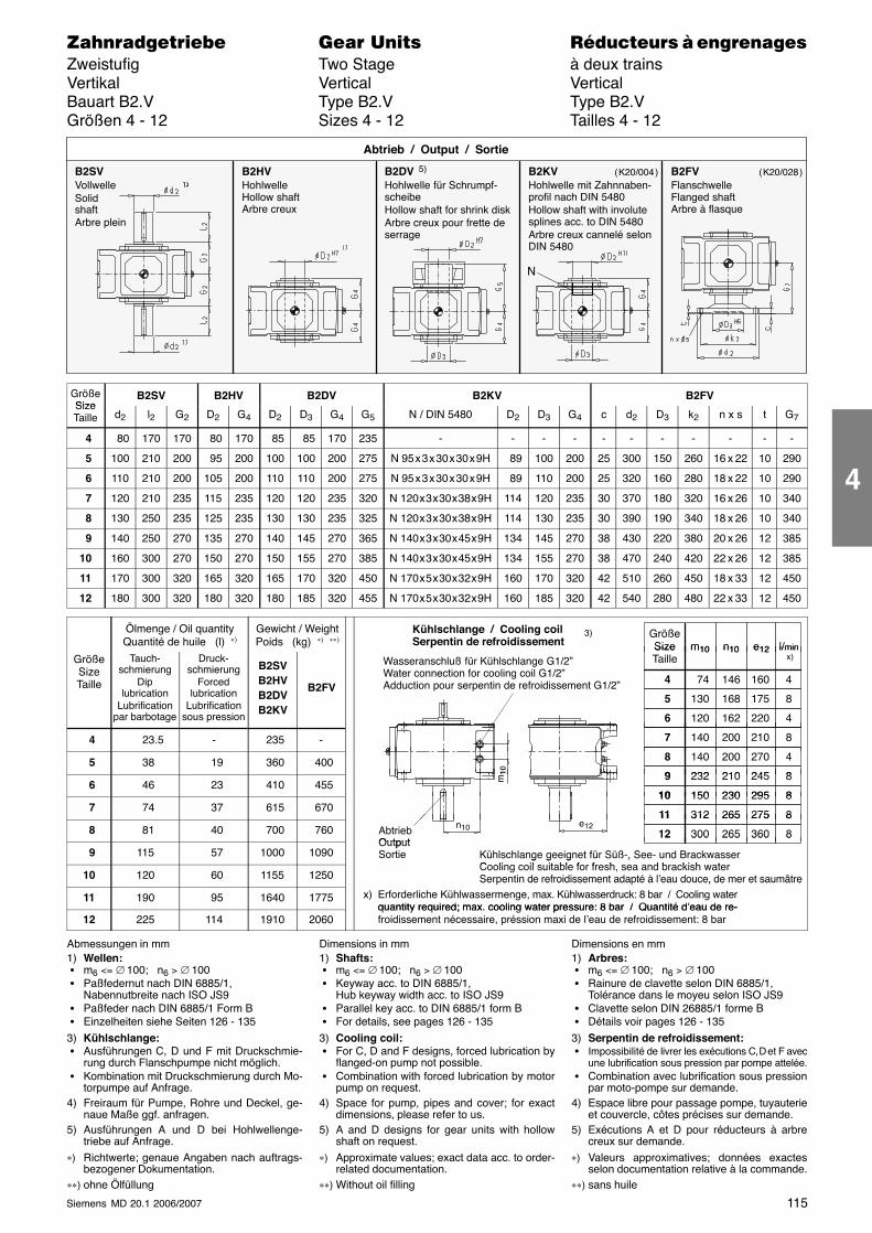
115Siemens MD 20.1 2006/2007
������������� ���� �� ��������� � ����������Zweistufig Two Stage à deux trainsVertikal Vertical VerticalBauart B2.V Type B2.V Type B2.VGrößen 4 - 12 Sizes 4 - 12 Tailles 4 - 12
B2SVVollwelleSolidshaftArbre plein
B2HVHohlwelleHollow shaftArbre creux
B2DV 5)
Hohlwelle für Schrumpf-scheibeHollow shaft for shrink diskArbre creux pour frette deserrage
Abtrieb / Output / Sortie
B2KVHohlwelle mit Zahnnaben-profil nach DIN 5480Hollow shaft with involutesplines acc. to DIN 5480Arbre creux cannelé selonDIN 5480
B2FVFlanschwelleFlanged shaftArbre à flasque
N
( K20/004 ) ( K20/028 )
GrößeSize
B2SV B2HV B2DV B2KV B2FVSizeTaille d2 l2 G2 D2 G4 D2 D3 G4 G5 N / DIN 5480 D2 D3 G4 c d2 D3 k2 n x s t G7
4 80 170 170 80 170 85 85 170 235 - - - - - - - - - - -
5 100 210 200 95 200 100 100 200 275 N 95 x 3 x 30 x 30 x 9H 89 100 200 25 300 150 260 16 x 22 10 290
6 110 210 200 105 200 110 110 200 275 N 95 x 3 x 30 x 30 x 9H 89 110 200 25 320 160 280 18 x 22 10 290
7 120 210 235 115 235 120 120 235 320 N 120 x 3 x 30 x 38 x 9H 114 120 235 30 370 180 320 16 x 26 10 340
8 130 250 235 125 235 130 130 235 325 N 120 x 3 x 30 x 38 x 9H 114 130 235 30 390 190 340 18 x 26 10 340
9 140 250 270 135 270 140 145 270 365 N 140 x 3 x 30 x 45 x 9H 134 145 270 38 430 220 380 20 x 26 12 385
10 160 300 270 150 270 150 155 270 385 N 140 x 3 x 30 x 45 x 9H 134 155 270 38 470 240 420 22 x 26 12 385
11 170 300 320 165 320 165 170 320 450 N 170 x 5 x 30 x 32 x 9H 160 170 320 42 510 260 450 18 x 33 12 450
12 180 300 320 180 320 180 185 320 455 N 170 x 5 x 30 x 32 x 9H 160 185 320 42 540 280 480 22 x 33 12 450
Ölmenge / Oil quantityQuantité de huile (l) ∗)
Gewicht / WeightPoids (kg) ∗) ∗∗)
GrößeSize l/minm10 n10 e12
Kühlschlange / Cooling coilSerpentin de refroidissement
3)
GrößeSizeTaille
Tauch-schmierung
Diplubrication
Lubrificationpar barbotage
Druck-schmierung
Forcedlubrication
Lubrificationsous pression
B2SVB2HVB2DVB2KV
B2FV
SizeTaille
74 160
l/min x)
4 146
m10 n10 e12
4
130 175 5 168 8
120 220 6 162 4
p
Wasseranschluß für Kühlschlange G1/2”Water connection for cooling coil G1/2”Adduction pour serpentin de refroidissement G1/2”
4 23.5 - 235 - 140 210 7 200 8
5 38 19 360 400 140 270 8 200 4
232 2459 210 810
6 46 23 410 455232 245 9 210 8
150 29510 230 8
m10
7 74 37 615 670150 29510 230 8
312 27511 265 8 8 81 40 700 760 Abtrieb
Output
312 27511 265 8
300 36012 265 8e12n10
9 115 57 1000 1090OutputSortie
300 36012 265 8
Kühlschlange geeignet für Süß-, See- und BrackwasserC li il it bl f f h d b ki h t
10 120 60 1155 1250
g g g ,Cooling coil suitable for fresh, sea and brackish waterSerpentin de refroidissement adapté à l’eau douce, de mer et saumâtre
11 190 95 1640 1775
Ser entin de refroidissement ada té à l eau douce, de mer et saumâtrex) Erforderliche Kühlwassermenge, max. Kühlwasserdruck: 8 bar / Cooling water
quantity required; max. cooling water pressure: 8 bar / Quantité d’eau de re-12 225 114 1910 2060
quantity required; max. cooling water pressure: 8 bar / Quantité d’eau de re-froidissement nécessaire, préssion maxi de l’eau de refroidissement: 8 bar
Abmessungen in mm1) Wellen: � m6 <= ∅ 100; n6 > ∅ 100 � Paßfedernut nach DIN 6885/1,
Nabennutbreite nach ISO JS9 � Paßfeder nach DIN 6885/1 Form B � Einzelheiten siehe Seiten 126 - 135
3) Kühlschlange: � Ausführungen C, D und F mit Druckschmie-
rung durch Flanschpumpe nicht möglich. � Kombination mit Druckschmierung durch Mo-
torpumpe auf Anfrage.4) Freiraum für Pumpe, Rohre und Deckel, ge-
naue Maße ggf. anfragen.5) Ausführungen A und D bei Hohlwellenge-
triebe auf Anfrage.∗) Richtwerte; genaue Angaben nach auftrags-
bezogener Dokumentation.∗∗) ohne Ölfüllung
Dimensions in mm1) Shafts: � m6 <= ∅ 100; n6 > ∅ 100 � Keyway acc. to DIN 6885/1,
Hub keyway width acc. to ISO JS9 � Parallel key acc. to DIN 6885/1 form B � For details, see pages 126 - 135
3) Cooling coil: � For C, D and F designs, forced lubrication by
flanged-on pump not possible. � Combination with forced lubrication by motor
pump on request.4) Space for pump, pipes and cover; for exact
dimensions, please refer to us.5) A and D designs for gear units with hollow
shaft on request.∗) Approximate values; exact data acc. to order-
related documentation.∗∗) Without oil filling
Dimensions en mm1) Arbres: � m6 <= ∅ 100; n6 > ∅ 100 � Rainure de clavette selon DIN 6885/1,
Tolérance dans le moyeu selon ISO JS9 � Clavette selon DIN 26885/1 forme B � Détails voir pages 126 - 135
3) Serpentin de refroidissement: � Impossibilité de livrer les exécutions C, D et F avec
une lubrification sous pression par pompe attelée. � Combination avec lubrification sous pression
par moto-pompe sur demande.4) Espace libre pour passage pompe, tuyauterie
et couvercle, côtes précises sur demande.5) Exécutions A et D pour réducteurs à arbre
creux sur demande.∗) Valeurs approximatives; données exactes
selon documentation relative à la commande.∗∗) sans huile
4
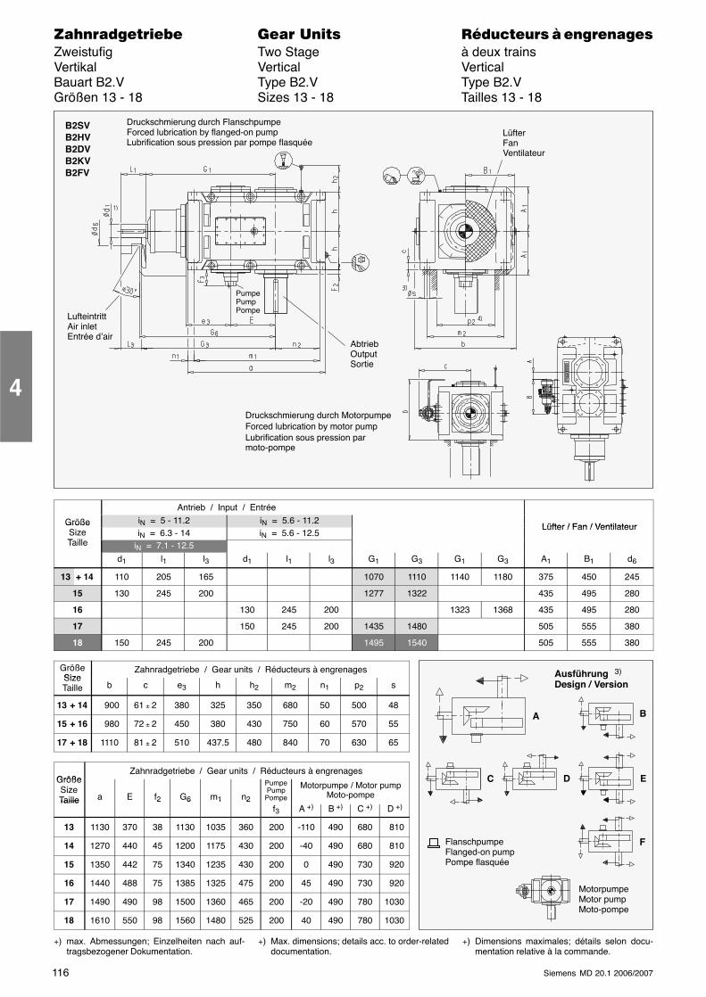
116 Siemens MD 20.1 2006/2007
������������� ���� �� ��������� � ����������Zweistufig Two Stage à deux trainsVertikal Vertical VerticalBauart B2.V Type B2.V Type B2.VGrößen 13 - 18 Sizes 13 - 18 Tailles 13 - 18
B2SVB2HVB2DVB2KVB2FV
PumpePumpPompe
Druckschmierung durch FlanschpumpeForced lubrication by flanged-on pumpLubrification sous pression par pompe flasquée
AbtriebOutputSortie
LüfterFanVentilateur
LufteintrittAir inletEntrée d’air
Druckschmierung durch MotorpumpeForced lubrication by motor pumpLubrification sous pression parmoto-pompe
Antrieb / Input / Entrée
Größe iN = 5 - 11.2 iN = 5.6 - 11.2Lüfter / Fan / VentilateurGröße
SizeT ill
iN = 6.3 - 14 iN = 5.6 - 12.5Lüfter / Fan / Ventilateur
Taille iN = 7.1 - 12.5d1 l1 l3 d1 l1 l3 G1 G3 G1 G3 A1 B1 d6
13 + 14 110 205 165 1070 1110 1140 1180 375 450 245
15 130 245 200 1277 1322 435 495 280
16 130 245 200 1323 1368 435 495 280
17 150 245 200 1435 1480 505 555 380
18 150 245 200 1495 1540 505 555 380
GrößeSize
Zahnradgetriebe / Gear units / Réducteurs à engrenagesSizeTaille b c e3 h h2 m2 n1 p2 s
13 + 14 900 61 ± 2 380 325 350 680 50 500 48
15 + 16 980 72 ± 2 450 380 430 750 60 570 55
17 + 18 1110 81 ± 2 510 437.5 480 840 70 630 65
GrößeZahnradgetriebe / Gear units / Réducteurs à engrenages
GrößeSizeTaille a E f2 G6 m1 n2
PumpePump
Pompe
Motorpumpe / Motor pumpMoto-pompeTaille 2 6 1 2
f3 A +) B +) C +) D +)
13 1130 370 38 1130 1035 360 200 -110 490 680 810
14 1270 440 45 1200 1175 430 200 -40 490 680 810
15 1350 442 75 1340 1235 430 200 0 490 730 920
16 1440 488 75 1385 1325 475 200 45 490 730 920
17 1490 490 98 1500 1360 465 200 -20 490 780 1030
18 1610 550 98 1560 1480 525 200 40 490 780 1030
+) max. Abmessungen; Einzelheiten nach auf-tragsbezogener Dokumentation.
+) Max. dimensions; details acc. to order-relateddocumentation.
+) Dimensions maximales; détails selon docu-mentation relative à la commande.
4
Ausführung 3)
Design / Version
A B
C D E
FFlanschpumpeFlanged-on pumpPompe flasquée
MotorpumpeMotor pumpMoto-pompe
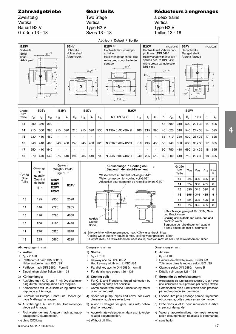
117Siemens MD 20.1 2006/2007
������������� ���� �� ��������� � ����������Zweistufig Two Stage à deux trainsVertikal Vertical VerticalBauart B2.V Type B2.V Type B2.VGrößen 13 - 18 Sizes 13 - 18 Tailles 13 - 18
B2SVVollwelleSolidshaftArbre plein
B2HVHohlwelleHollow shaftArbre creux
B2DV 5)
Hohlwelle für Schrumpf-scheibeHollow shaft for shrink diskArbre creux pour frette deserrage
Abtrieb / Output / Sortie
B2KVHohlwelle mit Zahnnaben-profil nach DIN 5480Hollow shaft with involutesplines acc. to DIN 5480Arbre creux cannelé selonDIN 5480
B2FVFlanschwelleFlanged shaftArbre à flasque
N
( K20/004 ) ( K20/028 )
GrößeSize
B2SV B2HV B2DV B2KV B2FVSizeTaille d2 l2 G2 D2 G4 D2 D3 G4 G5 N / DIN 5480 D2 D3 G4 c d2 D3 k2 n x s t G7
13 200 350 390 - - - - - - - - - - 48 580 310 500 20 x 33 14 525
14 210 350 390 210 390 210 215 390 535 N 190 x 5 x 30 x 36 x 9H 180 215 390 48 620 310 540 24 x 33 14 525
15 230 410 460 - - - - - - - - - - 55 710 360 630 28 x 33 17 625
16 240 410 460 240 450 240 245 450 620 N 220 x 5 x 30 x 42 x9H 210 245 450 55 740 360 660 30 x 33 17 625
17 250 410 540 - - - - - - - - - - 60 750 410 660 24 x 39 18 695
18 270 470 540 275 510 280 285 510 700 N 250 x 5 x 30 x 48 x 9H 240 285 510 60 800 410 710 26 x 39 18 695
Größe
ÖlmengeOil
quantity
GewichtWeight / Poids
(kg) ∗) ∗∗)
Kühlschlange / Cooling coilSerpentin de refroidissement
Wasseranschluß für Kühlschlange G1/2”
GrößeSizeTaille
l/min x)
m10 n10 e12
3)
GrößeSizeTaille
quantityQuantitéde huile
(l) ∗)
B2SVB2HVB2DVB2KV
B2FV
Wasseranschluß für Kühlschlange G1/2Water connection for cooling coil G1/2”Adduction pour serpentin de refroidissement G1/2”
324 33513 300 8
324 40514 300 8
396 39015 345 8
396 43516 345 8
13 125 2350 2520
396 43516 345 8
324 42517 395 8m10
14 140 2725 2905324 48518 395 8
Kühlschlange geeignet für Süß- See-15 190 3795 4050
Abtrieb
Kühlschlange geeignet für Süß-, See-und BrackwasserCooling coil suitable for fresh, sea and
16 200 4160 4430
AbtriebOutputSortie
Cooling coil suitable for fresh, sea andbrackish waterSerpentin de refroidissement adaptéà l’eau douce de mer et saumâtre
e12n10
17 270 5320 5640
So eà l’eau douce, de mer et saumâtre
x) Erforderliche Kühlwassermenge, max. Kühlwasserdruck: 8 barCooling water quantity required; max cooling water pressure: 8 bar
18 295 5860 6230
gCooling water quantity required; max. cooling water pressure: 8 barQuantité d’eau de refroidissement nécessaire, préssion maxi de l’eau de refroidissement: 8 bar
Abmessungen in mm
1) Wellen: � n6 > ∅ 100 � Paßfedernut nach DIN 6885/1,
Nabennutbreite nach ISO JS9 � Paßfeder nach DIN 6885/1 Form B � Einzelheiten siehe Seiten 126 - 135
3) Kühlschlange: � Ausführungen C, D und F mit Druckschmie-
rung durch Flanschpumpe nicht möglich. � Kombination mit Druckschmierung durch Mo-
torpumpe auf Anfrage.
4) Freiraum für Pumpe, Rohre und Deckel, ge-naue Maße ggf. anfragen.
5) Ausführungen A und D bei Hohlwellenge-triebe auf Anfrage.
∗) Richtwerte; genaue Angaben nach auftrags-bezogener Dokumentation.
∗∗) ohne Ölfüllung
Dimensions in mm
1) Shafts: � n6 > ∅ 100 � Keyway acc. to DIN 6885/1,
Hub keyway width acc. to ISO JS9 � Parallel key acc. to DIN 6885/1 form B � For details, see pages 126 - 135
3) Cooling coil: � For C, D and F designs, forced lubrication by
flanged-on pump not possible. � Combination with forced lubrication by motor
pump on request.
4) Space for pump, pipes and cover; for exactdimensions, please refer to us.
5) A and D designs for gear units with hollowshaft on request.
∗) Approximate values; exact data acc. to order-related documentation.
∗∗) Without oil filling
Dimensions en mm
1) Arbres: � n6 > ∅ 100 � Rainure de clavette selon DIN 6885/1,
Tolérance dans le moyeu selon ISO JS9 � Clavette selon DIN 6885/1 forme B � Détails voir pages 126 - 135
3) Serpentin de refroidissement: � Impossibilité de livrer les exécutions C, D et F avec
une lubrification sous pression par pompe attelée. � Combination avec lubrification sous pression
par moto-pompe sur demande.
4) Espace libre pour passage pompe, tuyauterieet couvercle, côtes précises sur demande.
5) Exécutions A et D pour réducteurs à arbrecreux sur demande.
∗) Valeurs approximatives; données exactesselon documentation relative à la commande.
∗∗) sans huile
4
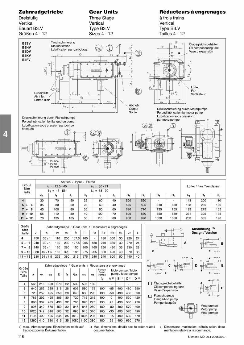
118 Siemens MD 20.1 2006/2007
������������� ���� �� ��������� � ����������Dreistufig Three Stage à trois trainsVertikal Vertical VerticalBauart B3.V Type B3.V Type B3.VGrößen 4 - 12 Sizes 4 - 12 Tailles 4 - 12
LüfterFanVentilateurLufteintritt
Air inletEntrée d’air
AbtriebOutputSortie
B3SVB3HVB3DVB3KVB3FV
ÖlausgleichsbehälterOil compensating tankVase d’expansion
Druckschmierung durch FlanschpumpeForced lubrication by flanged-on pumpLubrification sous pression par pompeflasquée
TauchschmierungDip lubricationLubrification par barbotage
PumpePumpPompe
Druckschmierung durch MotorpumpeForced lubrication by motor pumpLubrification sous pressionpar moto-pompe
G ößAntrieb / Input / Entrée
GrößeSize
iN = 12.5 - 45 iN = 50 - 71 Lüfter / Fan / VentilateurSizeTaille iN = 16 - 56 iN = 63 - 90
Lüfter / Fan / Ventilateur
Tailled1 l1 l3 d1 l1 l3 G1 G3 G1 G3 A1 B1 d6
4 30 70 50 25 60 40 500 520 - - 143 200 1105 + 6 35 80 60 28 60 40 575 595 610 630 168 235 1307 + 8 45 100 80 35 80 60 690 710 735 755 193 275 1659 + 10 55 110 80 40 100 70 800 830 850 880 231 325 175
11 + 12 70 135 105 50 110 80 960 990 1030 1060 263 385 190
GrößeSize
Zahnradgetriebe / Gear units / Réducteurs à engrenagesSizeTaille b1 c e3 e4 h h1 h2 h3 m2 n1 p2 s
4 150 30 ± 1 110 200 107.5 165 - 180 300 30 220 245 + 6 240 30 ± 1 130 230 127.5 205 180 240 360 30 270 247 + 8 240 36 ± 1 160 280 150 205 165 250 430 35 330 289 + 10 330 45 ± 1.5 185 320 185 275 205 330 490 40 370 36
11 + 12 330 54 ± 1.5 225 380 215 275 240 340 600 50 440 40
GrößeZahnradgetriebe / Gear units / Réducteurs à engrenages
GrößeSizeTaille a e5 e6 E f2 G6 m1 n2
PumpePump
Pompe
Motorpumpe / Motorpump / Moto-pompeTaille 5 6 2 6 1 2
f3 A +) B +) C +) D +)
4 565 215 320 270 22 530 505 160 - - - - - 5 640 252 385 315 28 605 580 175 190 -85 490 480 390 6 720 252 425 350 28 640 660 220 190 -50 490 480 390 7 785 292 425 385 30 720 715 215 190 0 490 530 420 8 890 302 485 430 32 765 820 275 190 45 490 530 420 9 925 342 560 450 32 845 845 260 180 -80 490 570 49010 1025 342 610 500 32 895 945 310 180 -30 490 570 49011 1105 402 595 545 35 1010 1005 295 180 -15 490 630 57012 1260 410 680 615 35 1080 1160 380 180 55 490 630 570
+) max. Abmessungen; Einzelheiten nach auf-tragsbezogener Dokumentation.
+) Max. dimensions; details acc. to order-relateddocumentation.
+) Dimensions maximales; détails selon docu-mentation relative à la commande.
4
Ausführung 3)
Design / Version
A B
C D E
FÖlausgleichsbehälterOil compensating tankVase d’expansion
FlanschpumpeFlanged-on pumpPompe flasquée
MotorpumpeMotor pumpMoto-pompe
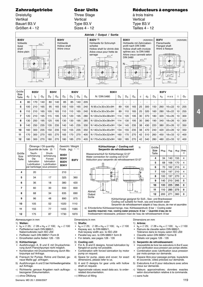
119Siemens MD 20.1 2006/2007
������������� ���� �� ��������� � ����������Dreistufig Three Stage à trois trainsVertikal Vertical VerticalBauart B3.V Type B3.V Type B3.VGrößen 4 - 12 Sizes 4 - 12 Tailles 4 - 12
B3SVVollwelleSolidshaftArbre plein
B3HVHohlwelleHollow shaftArbre creux
B3DV 5)
Hohlwelle für Schrumpf-scheibeHollow shaft for shrink diskArbre creux pour frette deserrage
Abtrieb / Output / Sortie
B3KVHohlwelle mit Zahnnaben-profil nach DIN 5480Hollow shaft with involutesplines acc. to DIN 5480Arbre creux cannelé selonDIN 5480
B3FVFlanschwelleFlanged shaftArbre à flasque
N
( K20/004 ) ( K20/028 )
GrößeSize
B3SV B3HV B3DV B3KV B3FVSizeTaille d2 l2 G2 D2 G4 D2 D3 G4 G5 N / DIN 5480 D2 D3 G4 c d2 D3 k2 n x s t G7
4 80 170 140 80 140 85 85 140 205 - - - - - - - - - - -
5 100 210 165 95 165 100 100 165 240 N 95 x 3 x 30 x 30 x 9H 89 100 165 25 300 150 260 16 x 22 10 255
6 110 210 165 105 165 110 110 165 240 N 95 x 3 x 30 x 30 x 9H 89 110 165 25 320 160 280 18 x 22 10 255
7 120 210 195 115 195 120 120 195 280 N 120 x 3 x 30 x 38 x 9H 114 120 195 30 370 180 320 16 x 26 10 300
8 130 250 195 125 195 130 130 195 285 N 120 x 3 x 30 x 38 x 9H 114 130 195 30 390 190 340 18 x 26 10 300
9 140 250 235 135 235 140 145 235 330 N 140 x 3 x 30 x 45 x 9H 134 145 235 38 430 220 380 20 x 26 12 350
10 160 300 235 150 235 150 155 235 350 N 140 x 3 x 30 x 45 x 9H 134 155 235 38 470 240 420 22 x 26 12 350
11 170 300 270 165 270 165 170 270 400 N 170 x 5 x 30 x 32 x 9H 160 170 270 42 510 260 450 18 x 33 12 400
12 180 300 270 180 270 180 185 270 405 N 170 x 5 x 30 x 32 x 9H 160 185 270 42 540 280 480 22 x 33 12 400
Ölmenge / Oil quantityQuantité de huile (l) ∗)
Gewicht / WeightPoids (kg) ∗) ∗∗)
GrößeSize l/minm10 n10 e12
Kühlschlange / Cooling coilSerpentin de refroidissement
3)
GrößeSizeTaille
Tauch-schmierung
Diplubrication
Lubrificationpar barbotage
Druck-schmierung
Forcedlubrication
Lubrificationsous pression
B3SVB3HVB3DVB3KV
B3FV
SizeTaille
34 155
l/min x)
4 140
m10 n10 e12
4
68 170 5 168 4
70 215 6 162 4
p
Wasseranschluß für Kühlschlange G1/2”Water connection for cooling coil G1/2”Adduction pour serpentin de refroidissement G1/2”
4 20 - 210 - 100 210 7 197 4
5 34 17 325 360 100 270 8 197 4
140 2459 210 8m10
6 36 18 380 420140 245 9 210 8
100 29510 225 8
m1
7 60 30 550 600Ab i b
100 29510 225 8
110 27511 285 8e
8 68 34 635 690AbtriebOutput
110 27511 285 8
200 36012 271 8e12n10
9 96 48 890 975
Out utSortie
200 36012 271 8
Kühlschlange geeignet für Süß-, See- und BrackwasserC li il it bl f f h d b ki h t
10 105 52 1020 1110
g g g ,Cooling coil suitable for fresh, sea and brackish waterSerpentin de refroidissement adapté à l’eau douce, de mer et saumâtre
11 155 77 1455 1585
Ser entin de refroidissement ada té à l eau douce, de mer et saumâtrex) Erforderliche Kühlwassermenge, max. Kühlwasserdruck: 8 bar / Cooling water
quantity required; max. cooling water pressure: 8 bar / Quantité d’eau de re-12 175 87 1730 1870
quantity required; max. cooling water pressure: 8 bar / Quantité d eau de re-froidissement nécessaire, préssion maxi de l’eau de refroidissement: 8 bar
Abmessungen in mm1) Wellen: � k6 = ∅ 25; ∅ 28 ≥ m6 ≤ ∅ 100; n6 > ∅ 100 � Paßfedernut nach DIN 6885/1,
Nabennutbreite nach ISO JS9 � Paßfeder nach DIN 6885/1 Form B � Einzelheiten siehe Seiten 126 - 135
3) Kühlschlange: � Ausführungen A, B und E mit Druckschmie-
rung durch Flanschpumpe nicht möglich. � Kombination mit Druckschmierung durch Mo-
torpumpe auf Anfrage.4) Freiraum für Pumpe, Rohre und Deckel, ge-
naue Maße ggf. anfragen.5) Ausführungen A und D bei Hohlwellengetriebe
auf Anfrage.∗) Richtwerte; genaue Angaben nach auftrags-
bezogener Dokumentation.∗∗) ohne Ölfüllung
Dimensions in mm1) Shafts: � k6 = ∅ 25; ∅ 28 ≥ m6 ≤ ∅ 100; n6 > ∅ 100 � Keyway acc. to DIN 6885/1,
Hub keyway width acc. to ISO JS9 � Parallel key acc. to DIN 6885/1 form B � For details, see pages 126 - 135
3) Cooling coil: � For A, B and E designs, forced lubrication by
flanged-on pump not possible. � Combination with forced lubrication by motor
pump on request.4) Space for pump, pipes and cover; for exact
dimensions, please refer to us.5) A and D designs for gear units with hollow
shaft on request.∗) Approximate values; exact data acc. to order-
related documentation.∗∗) Without oil filling
Dimensions en mm1) Arbres: � k6 = ∅ 25; ∅ 28 ≥ m6 ≤ ∅ 100; n6 > ∅ 100 � Rainure de clavette selon DIN 6885/1,
Tolérance dans le moyeu selon ISO JS9 � Clavette selon DIN 6885/1 forme B � Détails voir pages 126 - 135
3) Serpentin de refroidissement: � Impossibilité de livrer les exécutions A, B et E avec
une lubrification sous pression par pompe attelée. � Combination avec lubrification sous pression
par moto-pompe sur demande.4) Espace libre pour passage pompe, tuyauterie
et couvercle, côtes précises sur demande.5) Exécutions A et D pour réducteurs avec arbre
creux sur demande.∗) Valeurs approximatives; données exactes
selon documentation relative à la commande.∗∗) sans huile
4
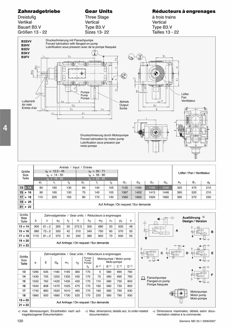
120 Siemens MD 20.1 2006/2007
������������� ���� �� ��������� � ����������Dreistufig Three Stage à trois trainsVertikal Vertical VerticalBauart B3.V Type B3.V Type B3.VGrößen 13 - 22 Sizes 13- 22 Tailles 13 - 22
LufteintrittAir inletEntrée d’air
B3SVVB3HVB3DVB3KVB3FV
LüfterFanVentilateurAbtrieb
OutputSortie
Druckschmierung mit FlanschpumpeForced lubrication with flanged-on pumpLubrification sous pression avec de la pompe flasquée
PumpePumpPompe
Druckschmierung durch MotorpumpeForced lubrication by motor pumpLubrification sous pression parmoto-pompe
Antrieb / Input / EntréeGröße iN = 12.5 - 45 iN = 50 - 71
Lüfter / Fan / VentilateurGrößeSize iN = 14 - 50 iN = 56 - 80
Lüfter / Fan / VentilateurSizeTaille iN = 16 - 56 iN = 63 - 90
d1 l1 l3 d1 l1 l3 G1 G3 G1 G3 A1 B1 d6
13 + 14 80 165 130 60 140 105 1125 1160 1195 1230 325 475 210
15 + 16 90 165 130 70 140 105 1367 1402 1413 1448 365 520 210
17 + 18 110 205 165 80 170 130 1560 1600 1620 1660 395 570 230
19 + 20Auf Anfrage / On request / Sur demande
21 + 22Auf Anfrage / On request / Sur demande
GrößeSize
Zahnradgetriebe / Gear units / Réducteurs à engrenagesSizeTaille b c e3 f2 h h2 m2 n1 p2 s
13 + 14 900 61 ± 2 265 35 272.5 300 680 50 500 48
15 + 16 980 72 ± 2 320 42 310 340 750 60 570 55
17 + 18 1110 81 ± 2 370 42 340 380 850 70 630 55
19 + 20Auf Anfrage / On request / Sur demande
21 + 22Auf Anfrage / On request / Sur demande
GrößeZahnradgetriebe / Gear units / Réducteurs à engrenages
GrößeSizeTaille a E G6 m1 n2
PumpePump
Pompe
Motorpumpe / Motor pumpMoto-pompeTaille 6 1 2
f3 A +) B +) C +) D +)
13 1290 635 1180 1195 360 170 5 580 690 760
14 1430 705 1250 1335 430 170 75 580 690 760
15 1550 762 1420 1435 430 170 110 580 730 850
16 1640 808 1470 1525 475 170 160 580 730 850
17 1740 860 1620 1610 465 170 160 580 790 930
18 1860 920 1680 1730 525 170 220 580 790 930
19 + 20Auf Anfrage / On request / Sur demande
21 + 22Auf Anfrage / On request / Sur demande
+) max. Abmessungen; Einzelheiten nach auf-tragsbezogener Dokumentation.
+) Max. dimensions; details acc. to order-relateddocumentation.
+) Dimensions maximales; détails selon docu-mentation relative à la commande.
4
Ausführung 3)
Design / Version
A B
C D E
FFlanschpumpeFlanged-on pumpPompe flasquée
MotorpumpeMotor pumpMoto-pompe
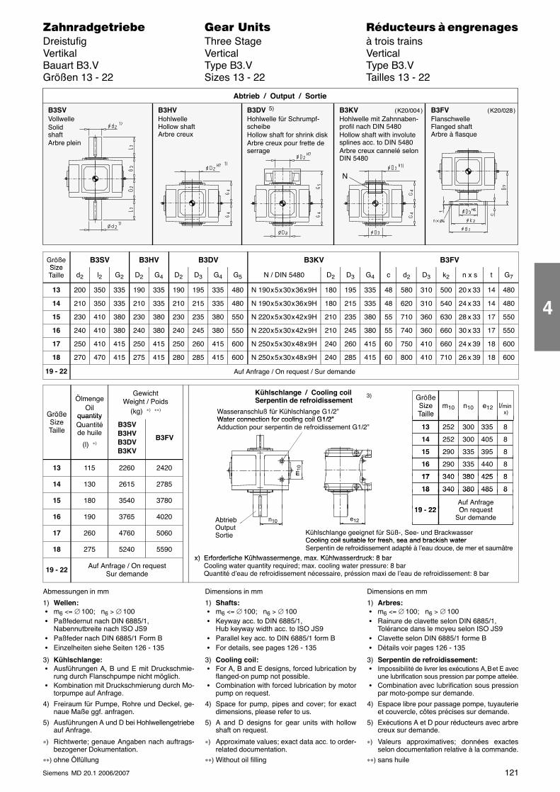
121Siemens MD 20.1 2006/2007
������������� ���� �� ��������� � ����������Dreistufig Three Stage à trois trainsVertikal Vertical VerticalBauart B3.V Type B3.V Type B3.VGrößen 13 - 22 Sizes 13 - 22 Tailles 13 - 22
B3SVVollwelleSolidshaftArbre plein
B3HVHohlwelleHollow shaftArbre creux
B3DV 5)
Hohlwelle für Schrumpf-scheibeHollow shaft for shrink diskArbre creux pour frette deserrage
Abtrieb / Output / Sortie
B3KVHohlwelle mit Zahnnaben-profil nach DIN 5480Hollow shaft with involutesplines acc. to DIN 5480Arbre creux cannelé selonDIN 5480
B3FVFlanschwelleFlanged shaftArbre à flasque
N
( K20/004 ) ( K20/028 )
GrößeSize
B3SV B3HV B3DV B3KV B3FVSizeTaille d2 l2 G2 D2 G4 D2 D3 G4 G5 N / DIN 5480 D2 D3 G4 c d2 D3 k2 n x s t G7
13 200 350 335 190 335 190 195 335 480 N 190 x 5 x 30 x 36 x 9H 180 195 335 48 580 310 500 20 x 33 14 480
14 210 350 335 210 335 210 215 335 480 N 190 x 5 x 30 x 36 x 9H 180 215 335 48 620 310 540 24 x 33 14 480
15 230 410 380 230 380 230 235 380 550 N 220 x 5 x 30 x 42 x 9H 210 235 380 55 710 360 630 28 x 33 17 550
16 240 410 380 240 380 240 245 380 550 N 220 x 5 x 30 x 42 x 9H 210 245 380 55 740 360 660 30 x 33 17 550
17 250 410 415 250 415 250 260 415 600 N 250 x 5 x 30 x 48 x 9H 240 260 415 60 750 410 660 24 x 39 18 600
18 270 470 415 275 415 280 285 415 600 N 250 x 5 x 30 x 48 x 9H 240 285 415 60 800 410 710 26 x 39 18 600
19 - 22 Auf Anfrage / On request / Sur demande
Größe
ÖlmengeOil
quantity
GewichtWeight / Poids
(kg) ∗) ∗∗)
GrößeSizeTaille
l/min x)
m10 n10 e12
Kühlschlange / Cooling coilSerpentin de refroidissement
Wasseranschluß für Kühlschlange G1/2”Water connection for cooling coil G1/2”
3)
GrößeSizeTaille
quantityQuantitéde huile
(l) ∗)
B3SVB3HVB3DVB3KV
B3FV
Taille
252 335
13 300 8
252 40514 300 8
290 39515 335 8
Water connection for cooling coil G1/2”Adduction pour serpentin de refroidissement G1/2”
13 115 2260 2420 290 44016 335 8
340 42517 380 8m10
14 130 2615 2785340 42517 380 8
340 48518 380 8
m
15 180 3540 3780
340 48518 380 8
19 22Auf AnfrageOn request
16 190 3765 4020 AbtriebO
19 - 22g
On requestSur demandee12n10
17 260 4760 5060
AbtriebOutputSortie Kühlschlange geeignet für Süß-, See- und Brackwasser
Cooling coil suitable for fresh sea and brackish water
1210
18 275 5240 5590Cooling coil suitable for fresh, sea and brackish waterSerpentin de refroidissement adapté à l’eau douce, de mer et saumâtre
x) Erforderliche Kühlwassermenge max Kühlwasserdruck: 8 bar
19 - 22 Auf Anfrage / On requestSur demande
x) Erforderliche Kühlwassermenge, max. Kühlwasserdruck: 8 barCooling water quantity required; max. cooling water pressure: 8 barQuantité d’eau de refroidissement nécessaire, préssion maxi de l’eau de refroidissement: 8 bar
Abmessungen in mm
1) Wellen: � m6 <= ∅ 100; n6 > ∅ 100 � Paßfedernut nach DIN 6885/1,
Nabennutbreite nach ISO JS9 � Paßfeder nach DIN 6885/1 Form B � Einzelheiten siehe Seiten 126 - 135
3) Kühlschlange: � Ausführungen A, B und E mit Druckschmie-
rung durch Flanschpumpe nicht möglich. � Kombination mit Druckschmierung durch Mo-
torpumpe auf Anfrage.
4) Freiraum für Pumpe, Rohre und Deckel, ge-naue Maße ggf. anfragen.
5) Ausführungen A und D bei Hohlwellengetriebeauf Anfrage.
∗) Richtwerte; genaue Angaben nach auftrags-bezogener Dokumentation.
∗∗) ohne Ölfüllung
Dimensions in mm
1) Shafts: � m6 <= ∅ 100; n6 > ∅ 100 � Keyway acc. to DIN 6885/1,
Hub keyway width acc. to ISO JS9 � Parallel key acc. to DIN 6885/1 form B � For details, see pages 126 - 135
3) Cooling coil: � For A, B and E designs, forced lubrication by
flanged-on pump not possible. � Combination with forced lubrication by motor
pump on request.
4) Space for pump, pipes and cover; for exactdimensions, please refer to us.
5) A and D designs for gear units with hollowshaft on request.
∗) Approximate values; exact data acc. to order-related documentation.
∗∗) Without oil filling
Dimensions en mm
1) Arbres: � m6 <= ∅ 100; n6 > ∅ 100 � Rainure de clavette selon DIN 6885/1,
Tolérance dans le moyeu selon ISO JS9 � Clavette selon DIN 6885/1 forme B � Détails voir pages 126 - 135
3) Serpentin de refroidissement: � Impossibilité de livrer les exécutions A, B et E avec
une lubrification sous pression par pompe attelée. � Combination avec lubrification sous pression
par moto-pompe sur demande.
4) Espace libre pour passage pompe, tuyauterieet couvercle, côtes précises sur demande.
5) Exécutions A et D pour réducteurs avec arbrecreux sur demande.
∗) Valeurs approximatives; données exactesselon documentation relative à la commande.
∗∗) sans huile
4
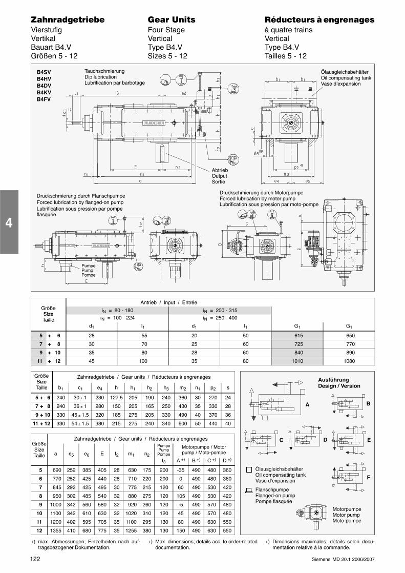
122 Siemens MD 20.1 2006/2007
������������� ���� �� ��������� � ����������Vierstufig Four Stage à quatre trainsVertikal Vertical VerticalBauart B4.V Type B4.V Type B4.VGrößen 5 - 12 Sizes 5 - 12 Tailles 5 - 12
AbtriebOutputSortie
B4SVB4HVB4DVB4KVB4FV
ÖlausgleichsbehälterOil compensating tankVase d’expansion
Druckschmierung durch FlanschpumpeForced lubrication by flanged-on pumpLubrification sous pression par pompeflasquée
TauchschmierungDip lubricationLubrification par barbotage
PumpePumpPompe
Druckschmierung durch MotorpumpeForced lubrication by motor pumpLubrification sous pression par moto-pompe
G ößAntrieb / Input / Entrée
GrößeSize
iN = 80 - 180 iN = 200 - 315SizeTaille iN = 100 - 224 iN = 250 - 400Taille
d1 l1 d1 l1 G1 G1
5 + 6 28 55 20 50 615 650
7 + 8 30 70 25 60 725 770
9 + 10 35 80 28 60 840 890
11 + 12 45 100 35 80 1010 1080
GrößeSize
Zahnradgetriebe / Gear units / Réducteurs à engrenagesSizeTaille b1 c1 e4 h h1 h2 h3 m2 n1 p2 s
5 + 6 240 30 ± 1 230 127.5 205 190 240 360 30 270 24
7 + 8 240 36 ± 1 280 150 205 165 250 430 35 330 28
9 + 10 330 45 ± 1.5 320 185 275 205 330 490 40 370 36
11 + 12 330 54 ± 1.5 380 215 275 240 340 600 50 440 40
GrößeZahnradgetriebe / Gear units / Réducteurs à engrenages
GrößeSizeTaille a e5 e6 E f2 m1 n2
PumpePumpPompe
Motorpumpe / Motorpump / Moto-pompeTaille 5 6 2 1 2
f3 A +) B +) C +) D +)
5 690 252 385 405 28 630 175 200 -35 490 480 360
6 770 252 425 440 28 710 220 200 0 490 480 360
7 845 292 425 495 30 775 215 120 60 490 530 420
8 950 302 485 540 32 880 275 120 105 490 530 420
9 1000 342 560 580 32 920 260 120 -5 490 570 480
10 1100 342 610 630 32 1020 310 120 45 490 570 480
11 1200 402 595 705 35 1100 295 130 80 490 630 550
12 1355 410 680 775 35 1255 380 130 150 490 630 550
+) max. Abmessungen; Einzelheiten nach auf-tragsbezogener Dokumentation.
+) Max. dimensions; details acc. to order-relateddocumentation.
+) Dimensions maximales; détails selon docu-mentation relative à la commande.
4
AusführungDesign / Version
A B
C E
F
ÖlausgleichsbehälterOil compensating tankVase d’expansion
FlanschpumpeFlanged-on pumpPompe flasquée
D
MotorpumpeMotor pumpMoto-pompe
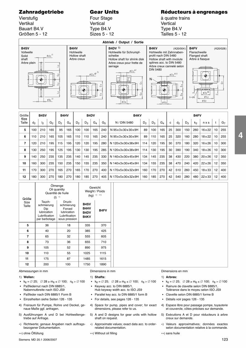
123Siemens MD 20.1 2006/2007
������������� ���� �� ��������� � ����������Vierstufig Four Stage à quatre trainsVertikal Vertical VerticalBauart B4.V Type B4.V Type B4.VGrößen 5 - 12 Sizes 5 - 12 Tailles 5 - 12
N
B4SVVollwelleSolidshaftArbre plein
B4HVHohlwelleHollow shaftArbre creux
B4DV 5)
Hohlwelle für Schrumpf-scheibeHollow shaft for shrink diskArbre creux pour frette deserrage
Abtrieb / Output / Sortie
B4KVHohlwelle mit Zahnnaben-profil nach DIN 5480Hollow shaft with involutesplines acc. to DIN 5480Arbre creux cannelé selonDIN 5480
B4FVFlanschwelleFlanged shaftArbre à flasque
( K20/004 ) ( K20/028 )
GrößeSize
B4SV B4HV B4DV B4KV B4FVSizeTaille d2 l2 G2 D2 G4 D2 D3 G4 G5 N / DIN 5480 D2 D3 G4 c d2 D3 k2 n x s t G7
5 100 210 165 95 165 100 100 165 240 N 95 x 3 x 30 x 30 x 9H 89 100 165 25 300 150 260 16 x 22 10 255
6 110 210 165 105 165 110 110 165 240 N 95 x 3 x 30 x 30 x 9H 89 110 165 25 320 160 280 18 x 22 10 255
7 120 210 195 115 195 120 120 195 280 N 120 x 3 x 30 x 38 x 9H 114 120 195 30 370 180 320 16 x 26 10 300
8 130 250 195 125 195 130 130 195 285 N 120 x 3 x 30 x 38 x 9H 114 130 195 30 390 190 340 18 x 26 10 300
9 140 250 235 135 235 140 145 235 330 N 140 x 3 x 30 x 45 x 9H 134 145 235 38 430 220 380 20 x 26 12 350
10 160 300 235 150 235 150 155 235 350 N 140 x 3 x 30 x 45 x 9H 134 155 235 38 470 240 420 22 x 26 12 350
11 170 300 270 165 270 165 170 270 400 N 170 x 5 x 30 x 32 x 9H 160 170 270 42 510 260 450 18 x 33 12 400
12 180 300 270 180 270 180 185 270 405 N 170 x 5 x 30 x 32 x 9H 160 185 270 42 540 280 480 22 x 33 12 400
Größe
ÖlmengeOil quantity
Quantité de huile(l) ∗)
GewichtWeight / Poids
(kg) ∗) ∗∗)
GrößeSizeTaille
Tauch-schmierung
Diplubrication
Lubrificationpar barbotage
Druck-schmierung
Forcedlubrication
Lubrificationsous pression
B4SVB4HVB4DVB4KV
B4FV
5 36 18 335 370
6 40 20 385 425
7 65 32 555 605
8 73 36 655 710
9 105 52 890 975
10 110 55 1025 1115
11 175 87 1485 1615
12 200 100 1750 1890
Abmessungen in mm
1) Wellen: � k6 = ∅ 25; ∅ 28 ≥ m6 ≤ ∅ 100; n6 > ∅ 100
� Paßfedernut nach DIN 6885/1,Nabennutbreite nach ISO JS9
� Paßfeder nach DIN 6885/1 Form B
� Einzelheiten siehe Seiten 126 - 135
4) Freiraum für Pumpe, Rohre und Deckel, ge-naue Maße ggf. anfragen.
5) Ausführungen A und D bei Hohlwellenge-triebe auf Anfrage.
∗) Richtwerte; genaue Angaben nach auftrags-bezogener Dokumentation.
∗∗) ohne Ölfüllung
Dimensions in mm
1) Shafts: � k6 = ∅ 25; ∅ 28 ≥ m6 ≤ ∅ 100; n6 > ∅ 100
� Keyway acc. to DIN 6885/1,Hub keyway width acc. to ISO JS9
� Parallel key acc. to DIN 6885/1 form B
� For details, see pages 126 - 135
4) Space for pump, pipes and cover; for exactdimensions, please refer to us.
5) A and D designs for gear units with hollowshaft on request.
∗) Approximate values; exact data acc. to order-related documentation.
∗∗) Without oil filling
Dimensions en mm
1) Arbres: � k6 = ∅ 25; ∅ 28 ≥ m6 ≤ ∅ 100; n6 > ∅ 100
� Rainure de clavette selon DIN 6885/1,Tolérance dans le moyeu selon ISO JS9
� Clavette selon DIN 6885/1 forme B
� Détails voir pages 126 - 135
4) Espace libre pour passage pompe, tuyauterieet couvercle, côtes précises sur demande.
5) Exécutions A et D pour réducteurs à arbrecreux sur demande.
∗) Valeurs approximatives; données exactesselon documentation relative à la commande.
∗∗) sans huile
4
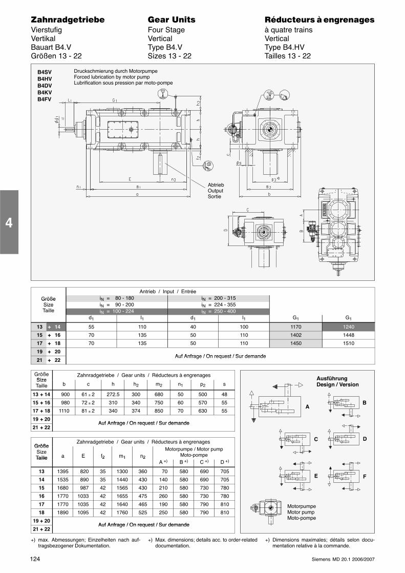
124 Siemens MD 20.1 2006/2007
������������� ���� �� ��������� � ����������Vierstufig Four Stage à quatre trainsVertikal Vertical VerticalBauart B4.V Type B4.V Type B4.HVGrößen 13 - 22 Sizes 13 - 22 Tailles 13 - 22
B4SVB4HVB4DVB4KVB4FV
AbtriebOutputSortie
Druckschmierung durch MotorpumpeForced lubrication by motor pumpLubrification sous pression par moto-pompe
Antrieb / Input / EntréeGröße iN = 80 - 180 iN = 200 - 315GrößeSize iN = 90 - 200 iN = 224 - 355SizeTaille iN = 100 - 224 iN = 250 - 400
d1 l1 d1 l1 G1 G1
13 + 14 55 110 40 100 1170 1240
15 + 16 70 135 50 110 1402 1448
17 + 18 70 135 50 110 1450 1510
19 + 20Auf Anfrage / On request / Sur demande
21 + 22Auf Anfrage / On request / Sur demande
GrößeSize
Zahnradgetriebe / Gear units / Réducteurs à engrenagesSizeTaille b c h h2 m2 n1 p2 s
13 + 14 900 61 ± 2 272.5 300 680 50 500 48
15 + 16 980 72 ± 2 310 340 750 60 570 55
17 + 18 1110 81 ± 2 340 374 850 70 630 55
19 + 20Auf Anfrage / On request / Sur demande
21 + 22Auf Anfrage / On request / Sur demande
GrößeZahnradgetriebe / Gear units / Réducteurs à engrenages
GrößeSizeTaille a E f2 m1 n2
Motorpumpe / Motor pumpMoto-pompeTaille a E f2 m1 n2
A +) B +) C +) D +)
13 1395 820 35 1300 360 70 580 690 705
14 1535 890 35 1440 430 140 580 690 705
15 1680 987 42 1565 430 210 580 730 780
16 1770 1033 42 1655 475 260 580 730 780
17 1770 1035 42 1640 465 190 580 790 810
18 1890 1095 42 1760 525 250 580 790 810
19 + 20Auf Anfrage / On request / Sur demande
21 + 22Auf Anfrage / On request / Sur demande
+) max. Abmessungen; Einzelheiten nach auf-tragsbezogener Dokumentation.
+) Max. dimensions; details acc. to order-relateddocumentation.
+) Dimensions maximales; détails selon docu-mentation relative à la commande.
4
AusführungDesign / Version
AB
C
E F
D
MotorpumpeMotor pumpMoto-pompe

125Siemens MD 20.1 2006/2007
������������� ���� �� ��������� � ����������Vierstufig Four Stage à quatre trainsVertikal Vertical VerticalBauart B4.V Type B4.V Type B4.VGrößen 13 - 22 Sizes 13 - 22 Tailles 13 - 22
N
B4SVVollwelleSolidshaftArbre plein
B4HVHohlwelleHollow shaftArbre creux
B4DV 5)
Hohlwelle für Schrumpf-scheibeHollow shaft for shrink diskArbre creux pour frette deserrage
Abtrieb / Output / Sortie
B4KVHohlwelle mit Zahnnaben-profil nach DIN 5480Hollow shaft with involutesplines acc. to DIN 5480Arbre creux cannelé selonDIN 5480
B4FVFlanschwelleFlanged shaftArbre à flasque
( K20/004 ) ( K20/028 )
GrößeSize
B4SV B4HV B4DV B4KV B4FVSizeTaille d2 l2 G2 D2 G4 D2 D3 G4 G5 N / DIN 5480 D2 D3 G4 c d2 D3 k2 n x s t G7
13 200 350 335 190 335 190 195 335 480 N 190 x 5 x 30 x 36 x 9H 180 195 335 48 580 310 500 20 x 33 14 480
14 210 350 335 210 335 210 215 335 480 N 190 x 5 x 30 x 36 x 9H 180 215 335 48 620 310 540 24 x 33 14 480
15 230 410 380 230 380 230 235 380 550 N 220 x 5 x 30 x 42 x 9H 210 235 380 55 710 360 630 28 x 33 17 550
16 240 410 380 240 380 240 245 380 550 N 220 x 5 x 30 x 42 x 9H 210 245 380 55 740 360 660 30 x 33 17 550
17 250 410 415 250 415 250 260 415 600 N 250 x 5 x 30 x 48 x 9H 240 260 415 60 750 410 660 24 x 39 18 600
18 270 470 415 275 415 280 285 415 600 N 250 x 5 x 30 x 48 x 9H 240 285 415 60 800 410 710 26 x 39 18 600
19 - 22 Auf Anfrage / On request / Sur demande
Größe
ÖlmengeOil quantity
Q tité
GewichtWeight / Poids
(kg) ∗) ∗∗)GrößeSizeTaille
Quantitéde huile
(l) ∗)
B4SVB4HVB4DVB4KV
B4FV
13 135 2280 2440
14 150 2605 2775
15 210 3435 3675
16 220 3765 4020
17 270 4460 4760
18 285 4930 5280
19 - 22 Auf Anfrage / On requestSur demande
Abmessungen in mm
1) Wellen:m6 ≤ ∅ 100; n6 > ∅ 100
� Paßfedernut nach DIN 6885/1,Nabennutbreite nach ISO JS9
� Paßfeder nach DIN 6885/1 Form B
� Einzelheiten siehe Seiten 126 - 135
4) Freiraum für Pumpe, Rohre und Deckel, ge-naue Maße ggf. anfragen.
5) Ausführungen A und D bei Hohlwellenge-triebe auf Anfrage.
∗) Richtwerte; genaue Angaben nach auftrags-bezogener Dokumentation.
∗∗) ohne Ölfüllung
Dimensions in mm
1) Shafts: � m6 ≤ ∅ 100; n6 > ∅ 100
� Keyway acc. to DIN 6885/1,Hub keyway width acc. to ISO JS9
� Parallel key acc. to DIN 6885/1 form B
� For details, see pages 126 - 135
4) Space for pump, pipes and cover; for exactdimensions, please refer to us.
5) A and D designs for gear units with hollowshaft on request.
∗) Approximate values; exact data acc. to order-related documentation.
∗∗) Without oil filling
Dimensions en mm
1) Arbres: � m6 ≤ ∅ 100; n6 > ∅ 100
� Rainure de clavette selon DIN 6885/1,Tolérance dans le moyeu selon ISO JS9
� Clavette selon DIN 6885/1 forme B
� Détails voir pages 126 - 135
4) Espace libre pour passage pompe, tuyauterieet couvercle, côtes précises sur demande.
5) Exécutions A et D pour réducteurs à arbrecreux sur demande.
∗) Valeurs approximatives; données exactesselon documentation relative à la commande.
∗∗) sans huile
4
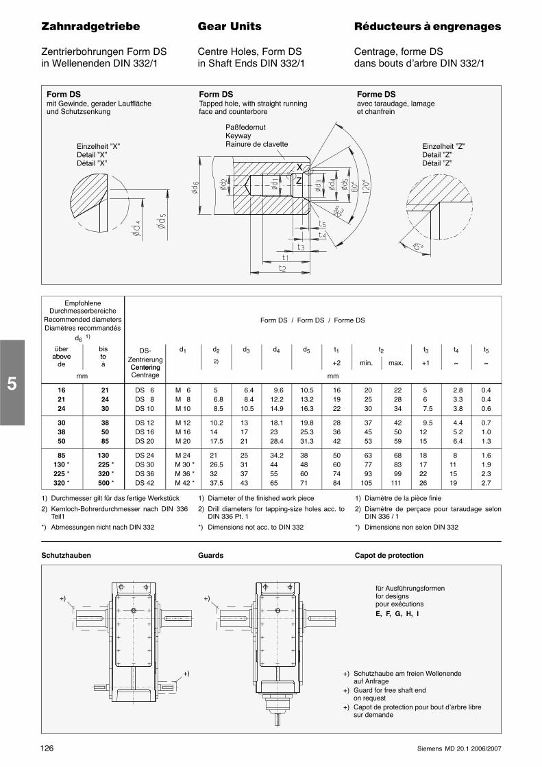
126 Siemens MD 20.1 2006/2007
������������� ���� �� ��������� � ����������
Zentrierbohrungen Form DS Centre Holes, Form DS Centrage, forme DSin Wellenenden DIN 332/1 in Shaft Ends DIN 332/1 dans bouts d’arbre DIN 332/1
PaßfedernutKeywayRainure de clavetteEinzelheit ”X”
Detail ”X”Détail ”X”
Form DSmit Gewinde, gerader Laufflächeund Schutzsenkung
Forme DSavec taraudage, lamageet chanfrein
Form DSTapped hole, with straight runningface and counterbore
Einzelheit ”Z”Detail ”Z”Détail ”Z”
ZX
EmpfohleneDurchmesserbereiche
Recommended diametersDiamètres recommandés
d6 1)
Form DS / Form DS / Forme DS
überabove
bisto
DS- d1 d2 d3 d4 d5 t1 t2 t3 t4 t5above
detoà
ZentrierungCentering
2) +2 min. max. +1 ≈ ≈
mmCenteringCentrage mm
162124
21 24 30
DS 6DS 8DS 10
M 6M 8M 10
5 6.8 8.5
6.4 8.410.5
9.612.214.9
10.513.216.3
16 19 22
20 25 30
22 28 34
5 6 7.5
2.8 3.3 3.8
0.40.40.6
303850
38 50 85
DS 12DS 16DS 20
M 12M 16M 20
10.214 17.5
13 17 21
18.123 28.4
19.825.331.3
28 36 42
37 45 53
42 50 59
9.512 15
4.4 5.2 6.4
0.71.01.3
85130 *225 *320 *
130 225 * 320 * 500 *
DS 24DS 30DS 36DS 42
M 24 M 30 * M 36 * M 42 *
21 26.532 37.5
25 31 37 43
34.244 55 65
38 48 60 71
50 60 74 84
63 77 93105
68 83 99111
18 17 22 26
8 11 15 19
1.61.92.32.7
1) Durchmesser gilt für das fertige Werkstück
2) Kernloch-Bohrerdurchmesser nach DIN 336Teil1
*) Abmessungen nicht nach DIN 332
1) Diameter of the finished work piece
2) Drill diameters for tapping-size holes acc. toDIN 336 Pt. 1
*) Dimensions not acc. to DIN 332
1) Diamètre de la pièce finie
2) Diamètre de perçace pour taraudage selonDIN 336 / 1
*) Dimensions non selon DIN 332
Schutzhauben Guards Capot de protection
für Ausführungsformenfor designspour exécutionsE, F, G, H, I
+) Schutzhaube am freien Wellenendeauf Anfrage
+) Guard for free shaft endon request
+) Capot de protection pour bout d’arbre libresur demande
+)
+)+)
5
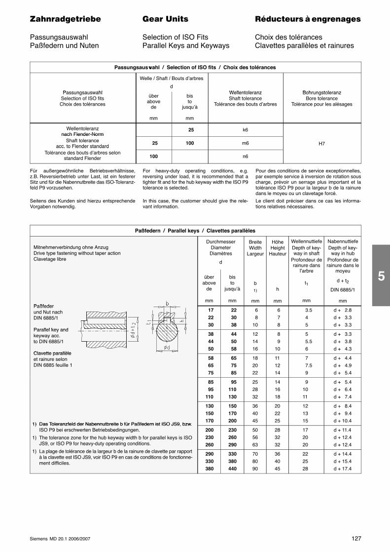
127Siemens MD 20.1 2006/2007
������������� ���� �� ��������� � ����������
Passungsauswahl Selection of ISO Fits Choix des tolérancesPaßfedern und Nuten Parallel Keys and Keyways Clavettes parallèles et rainures
Passungsauswahl / Selection of ISO fits / Choix des tolérances
Passungsauswahl
Welle / Shaft / Bouts d’arbres
dWellentoleranz BohrungstoleranzPassungsauswahl
Selection of ISO fitsChoix des tolérances
überabove
de
mm
bisto
jusqu’à
mm
WellentoleranzShaft tolerance
Tolérance des bouts d’arbres
BohrungstoleranzBore tolerance
Tolérance pour les alésages
Wellentoleranznach Flender-Norm
25 k6nach Flender-Norm
Shaft toleranceacc. to Flender standard
25 100 m6 H7acc. to Flender standardTolérance des bouts d’arbres selon
standard Flender 100 n6
Für außergewöhnliche Betriebsverhältnisse,z.B. Reversierbetrieb unter Last, ist ein festererSitz und für die Nabennutbreite das ISO-Toleranz-feld P9 vorzusehen.
Seitens des Kunden sind hierzu entsprechendeVorgaben notwendig.
For heavy-duty operating conditions, e.g.reversing under load, it is recommended that atighter fit and for the hub keyway width the ISO P9tolerance is selected.
In this case, the customer should give the rele-vant information.
Pour des conditions de service exceptionnelles,par exemple service à inversion de rotation souscharge, prévoir un serrage plus important et latolérance ISO P9 pour la largeur b de la rainuredans le moyeu ou un clavetage forcé.
Le client doit préciser dans ce cas les informa-tions relatives nécessaires.
Paßfedern / Parallel keys / Clavettes parallèles
Mitnehmerverbindung ohne Anzug Drive type fastening without taper action Clavetage libre
DurchmesserDiameterDiamètres
d
BreiteWidth
Largeur
HöheHeight
Hauteur
WellennuttiefeDepth of key-way in shaft
Profondeur derainure dans
l’ b
NabennuttiefeDepth of key-
way in hubProfondeur derainure dans le
Paßfeder
überabove
de
mm
bisto
jusqu’à
mm
b1)
mm
h
mm
l’arbre
t1
mm
moyeu
d + t2
DIN 6885/1
mm Paßfeder und Nut nach DIN 6885/1
Parallel key and
17 22 30
22 30 38
6 810
6 7 8
3.5 4 5
d + 2.8d + 3.3d + 3.3
Parallel key and keyway acc. to DIN 6885/1
Clavette parallèle
38 44 50
44 50 58
121416
8 910
5 5.5 6
d + 3.3d + 3.8d + 4.3
Clavette parallèle et rainure selon DIN 6885 feuille 1
58 65 75
65 75 85
182022
111214
7 7.5 9
d + 4.4d + 4.9d + 5.4
85 95110
95110130
252832
141618
91011
d + 5.4d + 6.4d + 7.4
1) Das Toleranzfeld der Nabennutbreite b für Paßfedern ist ISO JS9, bzw.
130150170
150170200
364045
20 2225
121315
d + 8.4d + 9.4d + 10.4
1) Das Toleranzfeld der Nabennutbreite b für Paßfedern ist ISO JS9, bzw.ISO P9 bei erschwerten Betriebsbedingungen.
1) The tolerance zone for the hub keyway width b for parallel keys is ISOJS9, or ISO P9 for heavy-duty operating conditions.
200230260
230260290
505663
283232
172020
d + 11.4d + 12.4d + 12.4
1) La plage de tolérance de la largeur b de la rainure de clavette par rapportà la clavette est ISO JS9, voir ISO P9 en cas de conditions de fonctionne-ment difficiles.
290330380
330380440
708090
364045
222528
d + 14.4d + 15.4d + 17.4
5
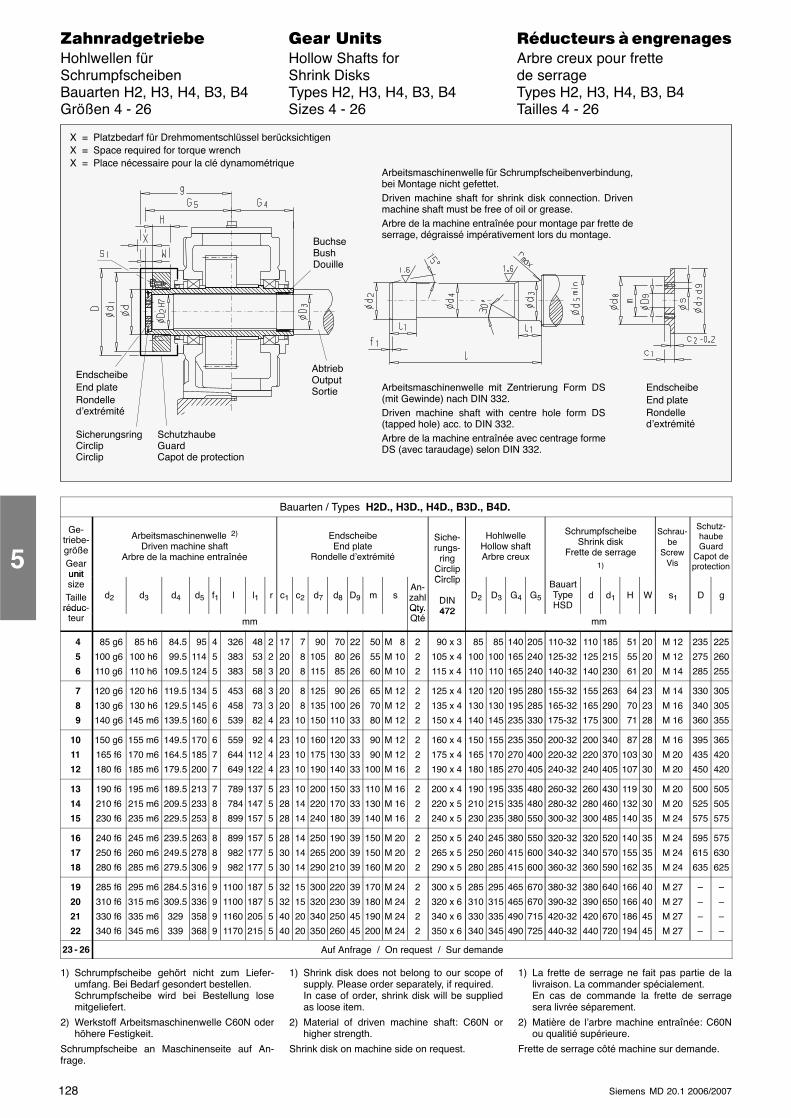
128 Siemens MD 20.1 2006/2007
������������� ���� �� ��������� � ����������Hohlwellen für Hollow Shafts for Arbre creux pour fretteSchrumpfscheiben Shrink Disks de serrageBauarten H2, H3, H4, B3, B4 Types H2, H3, H4, B3, B4 Types H2, H3, H4, B3, B4Größen 4 - 26 Sizes 4 - 26 Tailles 4 - 26
EndscheibeEnd plateRondelled’extrémité
SicherungsringCirclipCirclip
X = Platzbedarf für Drehmomentschlüssel berücksichtigenX = Space required for torque wrenchX = Place nécessaire pour la clé dynamométrique
Arbeitsmaschinenwelle für Schrumpfscheibenverbindung,bei Montage nicht gefettet.Driven machine shaft for shrink disk connection. Drivenmachine shaft must be free of oil or grease.Arbre de la machine entraînée pour montage par frette deserrage, dégraissé impérativement lors du montage.
BuchseBushDouille
EndscheibeEnd plateRondelled’extrémité
AbtriebOutputSortie Arbeitsmaschinenwelle mit Zentrierung Form DS
(mit Gewinde) nach DIN 332.Driven machine shaft with centre hole form DS(tapped hole) acc. to DIN 332.Arbre de la machine entraînée avec centrage formeDS (avec taraudage) selon DIN 332.
SchutzhaubeGuardCapot de protection
Bauarten / Types H2D., H3D., H4D., B3D., B4D.
Ge-triebe-größeGearunit
Arbeitsmaschinenwelle 2)
Driven machine shaftArbre de la machine entraînée
EndscheibeEnd plate
Rondelle d’extrémité
Siche-rungs-
ringCirclipCi li
HohlwelleHollow shaftArbre creux
SchrumpfscheibeShrink disk
Frette de serrage1)
Schrau-be
ScrewVis
Schutz-haubeGuard
Capot deprotection
unitsizeTaille
réduc-d2 d3 d4 d5 f1 l l1 r c1 c2 d7 d8 D9 m s
An-zahlQty.
Circlip
DIN472
D2 D3 G4 G5
BauartTypeHSD
d d1 H W s1 D gréduc
teur mmQty.Qté
472mm
4
5
6
85 g6
100 g6
110 g6
85 h6
100 h6
110 h6
84.5
99.5
109.5
95
114
124
4
5
5
326
383
383
48
53
58
2
2
3
17
20
20
7
8
8
90
105
115
70
80
85
22
26
26
50
55
60
M 8
M 10
M 10
2
2
2
90 x 3
105 x 4
115 x 4
85
100
110
85
100
110
140
165
165
205
240
240
110-32
125-32
140-32
110
125
140
185
215
230
51
55
61
20
20
20
M 12
M 12
M 14
235
275
285
225
260
255
7
8
9
120 g6
130 g6
140 g6
120 h6
130 h6
145 m6
119.5
129.5
139.5
134
145
160
5
6
6
453
458
539
68
73
82
3
3
4
20
20
23
8
8
10
125
135
150
90
100
110
26
26
33
65
70
80
M 12
M 12
M 12
2
2
2
125 x 4
135 x 4
150 x 4
120
130
140
120
130
145
195
195
235
280
285
330
155-32
165-32
175-32
155
165
175
263
290
300
64
70
71
23
23
28
M 14
M 16
M 16
330
340
360
305
305
355
10
11
12
150 g6
165 f6
180 f6
155 m6
170 m6
185 m6
149.5
164.5
179.5
170
185
200
6
7
7
559
644
649
92
112
122
4
4
4
23
23
23
10
10
10
160
175
190
120
130
140
33
33
33
90
90
100
M 12
M 12
M 16
2
2
2
160 x 4
175 x 4
190 x 4
150
165
180
155
170
185
235
270
270
350
400
405
200-32
220-32
240-32
200
220
240
340
370
405
87
103
107
28
30
30
M 16
M 20
M 20
395
435
450
365
420
420
13
14
15
190 f6
210 f6
230 f6
195 m6
215 m6
235 m6
189.5
209.5
229.5
213
233
253
7
8
8
789
784
899
137
147
157
5
5
5
23
28
28
10
14
14
200
220
240
150
170
180
33
33
39
110
130
140
M 16
M 16
M 16
2
2
2
200 x 4
220 x 5
240 x 5
190
210
230
195
215
235
335
335
380
480
480
550
260-32
280-32
300-32
260
280
300
430
460
485
119
132
140
30
30
35
M 20
M 20
M 24
500
525
575
505
505
575
16
17
18
240 f6
250 f6
280 f6
245 m6
260 m6
285 m6
239.5
249.5
279.5
263
278
306
8
8
9
899
982
982
157
177
177
5
5
5
28
30
30
14
14
14
250
265
290
190
200
210
39
39
39
150
150
160
M 20
M 20
M 20
2
2
2
250 x 5
265 x 5
290 x 5
240
250
280
245
260
285
380
415
415
550
600
600
320-32
340-32
360-32
320
340
360
520
570
590
140
155
162
35
35
35
M 24
M 24
M 24
595
615
635
575
630
625
19
20
21
22
285 f6
310 f6
330 f6
340 f6
295 m6
315 m6
335 m6
345 m6
284.5
309.5
329
339
316
336
358
368
9
9
9
9
1100
1100
1160
1170
187
187
205
215
5
5
5
5
32
32
40
40
15
15
20
20
300
320
340
350
220
230
250
260
39
39
45
45
170
180
190
200
M 24
M 24
M 24
M 24
2
2
2
2
300 x 5
320 x 6
340 x 6
350 x 6
285
310
330
340
295
315
335
345
465
465
490
490
670
670
715
725
380-32
390-32
420-32
440-32
380
390
420
440
640
650
670
720
166
166
186
194
40
40
45
45
M 27
M 27
M 27
M 27
–
–
–
–
–
–
–
–
23 - 26 Auf Anfrage / On request / Sur demande
1) Schrumpfscheibe gehört nicht zum Liefer-umfang. Bei Bedarf gesondert bestellen.Schrumpfscheibe wird bei Bestellung losemitgeliefert.
2) Werkstoff Arbeitsmaschinenwelle C60N oderhöhere Festigkeit.
Schrumpfscheibe an Maschinenseite auf An-frage.
1) Shrink disk does not belong to our scope ofsupply. Please order separately, if required.In case of order, shrink disk will be suppliedas loose item.
2) Material of driven machine shaft: C60N orhigher strength.
Shrink disk on machine side on request.
1) La frette de serrage ne fait pas partie de lalivraison. La commander spécialement.En cas de commande la frette de serragesera livrée séparement.
2) Matière de l’arbre machine entraînée: C60Nou qualitié supérieure.
Frette de serrage côté machine sur demande.
5
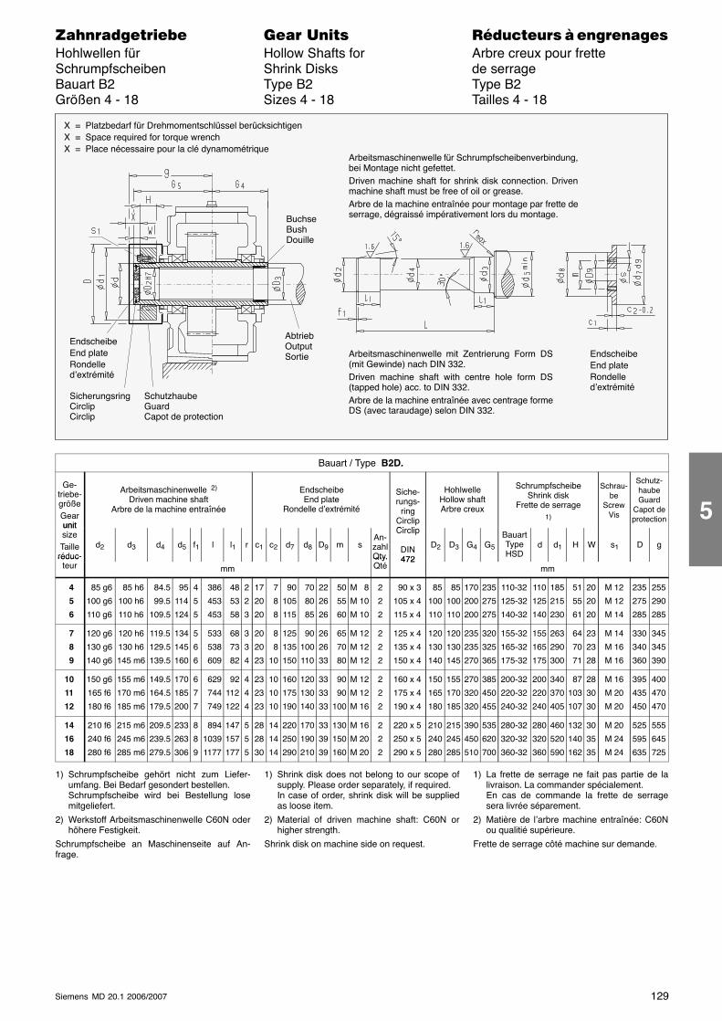
129Siemens MD 20.1 2006/2007
������������� ���� �� ��������� � ����������Hohlwellen für Hollow Shafts for Arbre creux pour fretteSchrumpfscheiben Shrink Disks de serrageBauart B2 Type B2 Type B2Größen 4 - 18 Sizes 4 - 18 Tailles 4 - 18
X = Platzbedarf für Drehmomentschlüssel berücksichtigenX = Space required for torque wrenchX = Place nécessaire pour la clé dynamométrique
Arbeitsmaschinenwelle für Schrumpfscheibenverbindung,bei Montage nicht gefettet.Driven machine shaft for shrink disk connection. Drivenmachine shaft must be free of oil or grease.Arbre de la machine entraînée pour montage par frette deserrage, dégraissé impérativement lors du montage.
EndscheibeEnd plateRondelled’extrémité
Arbeitsmaschinenwelle mit Zentrierung Form DS(mit Gewinde) nach DIN 332.Driven machine shaft with centre hole form DS(tapped hole) acc. to DIN 332.Arbre de la machine entraînée avec centrage formeDS (avec taraudage) selon DIN 332.
EndscheibeEnd plateRondelled’extrémité
SicherungsringCirclipCirclip
BuchseBushDouille
AbtriebOutputSortie
SchutzhaubeGuardCapot de protection
Bauart / Type B2D.
Ge-triebe-größeGearunit
Arbeitsmaschinenwelle 2)
Driven machine shaftArbre de la machine entraînée
EndscheibeEnd plate
Rondelle d’extrémité
Siche-rungs-
ringCirclipCi li
HohlwelleHollow shaftArbre creux
SchrumpfscheibeShrink disk
Frette de serrage1)
Schrau-be
ScrewVis
Schutz-haubeGuard
Capot deprotection
unitsizeTaille
réduc-d2 d3 d4 d5 f1 l l1 r c1 c2 d7 d8 D9 m s
An-zahlQty.
Circlip
DIN472
D2 D3 G4 G5
BauartTypeHSD
d d1 H W s1 D gréduc
teur mmQty.Qté
472mm
4
5
6
85 g6
100 g6
110 g6
85 h6
100 h6
110 h6
84.5
99.5
109.5
95
114
124
4
5
5
386
453
453
48
53
58
2
2
3
17
20
20
7
8
8
90
105
115
70
80
85
22
26
26
50
55
60
M 8
M 10
M 10
2
2
2
90 x 3
105 x 4
115 x 4
85
100
110
85
100
110
170
200
200
235
275
275
110-32
125-32
140-32
110
125
140
185
215
230
51
55
61
20
20
20
M 12
M 12
M 14
235
275
285
255
290
285
7
8
9
120 g6
130 g6
140 g6
120 h6
130 h6
145 m6
119.5
129.5
139.5
134
145
160
5
6
6
533
538
609
68
73
82
3
3
4
20
20
23
8
8
10
125
135
150
90
100
110
26
26
33
65
70
80
M 12
M 12
M 12
2
2
2
125 x 4
135 x 4
150 x 4
120
130
140
120
130
145
235
235
270
320
325
365
155-32
165-32
175-32
155
165
175
263
290
300
64
70
71
23
23
28
M 14
M 16
M 16
330
340
360
345
345
390
10
11
12
150 g6
165 f6
180 f6
155 m6
170 m6
185 m6
149.5
164.5
179.5
170
185
200
6
7
7
629
744
749
92
112
122
4
4
4
23
23
23
10
10
10
160
175
190
120
130
140
33
33
33
90
90
100
M 12
M 12
M 16
2
2
2
160 x 4
175 x 4
190 x 4
150
165
180
155
170
185
270
320
320
385
450
455
200-32
220-32
240-32
200
220
240
340
370
405
87
103
107
28
30
30
M 16
M 20
M 20
395
435
450
400
470
470
14
16
18
210 f6
240 f6
280 f6
215 m6
245 m6
285 m6
209.5
239.5
279.5
233
263
306
8
8
9
894
1039
1177
147
157
177
5
5
5
28
28
30
14
14
14
220
250
290
170
190
210
33
39
39
130
150
160
M 16
M 20
M 20
2
2
2
220 x 5
250 x 5
290 x 5
210
240
280
215
245
285
390
450
510
535
620
700
280-32
320-32
360-32
280
320
360
460
520
590
132
140
162
30
35
35
M 20
M 24
M 24
525
595
635
555
645
725
1) Schrumpfscheibe gehört nicht zum Liefer-umfang. Bei Bedarf gesondert bestellen.Schrumpfscheibe wird bei Bestellung losemitgeliefert.
2) Werkstoff Arbeitsmaschinenwelle C60N oderhöhere Festigkeit.
Schrumpfscheibe an Maschinenseite auf An-frage.
1) Shrink disk does not belong to our scope ofsupply. Please order separately, if required.In case of order, shrink disk will be suppliedas loose item.
2) Material of driven machine shaft: C60N orhigher strength.
Shrink disk on machine side on request.
1) La frette de serrage ne fait pas partie de lalivraison. La commander spécialement.En cas de commande la frette de serragesera livrée séparement.
2) Matière de l’arbre machine entraînée: C60Nou qualitié supérieure.
Frette de serrage côté machine sur demande.
5
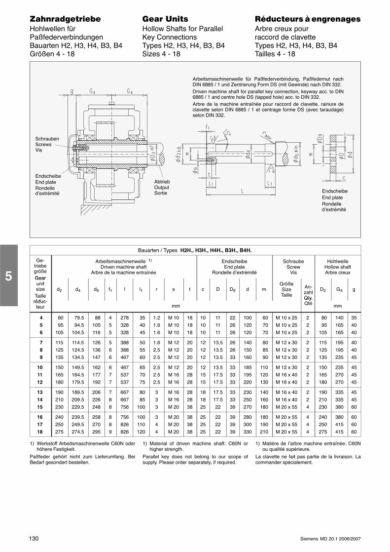
130 Siemens MD 20.1 2006/2007
������������� ���� �� ��������� � ����������Hohlwellen für Hollow Shafts for Parallel Arbre creux pourPaßfederverbindungen Key Connections raccord de clavetteBauarten H2, H3, H4, B3, B4 Types H2, H3, H4, B3, B4 Types H2, H3, H4, B3, B4Größen 4 - 18 Sizes 4 - 18 Tailles 4 - 18
SchraubenScrewsVis
EndscheibeEnd plateRondelled’extrémité
AbtriebOutputSortie
Arbeitsmaschinenwelle für Paßfederverbindung, Paßfedernut nachDIN 6885 / 1 und Zentrierung Form DS (mit Gewinde) nach DIN 332.Driven machine shaft for parallel key connection, keyway acc. to DIN6885 / 1 and centre hole DS (tapped hole) acc. to DIN 332.Arbre de la machine entraînée pour raccord de clavette, rainure declavette selon DIN 6885 / 1 et centrage forme DS (avec taraudage)selon DIN 332.
EndscheibeEnd plateRondelled’extrémité
Bauarten / Types H2H., H3H., H4H., B3H., B4H.
Ge-triebegrößeGear
Arbeitsmaschinenwelle 1)
Driven machine shaftArbre de la machine entraînée
EndscheibeEnd plate
Rondelle d’extrémité
SchraubeScrew
Vis
HohlwelleHollow shaftArbre creux
GearunitsizeTaille
réduc
d2 d4 d5 f1 l l1 r s t c D D9 d mGrößeSizeTaille
An-zahlQty.
D2 G4 g
réduc-teur mm
Qty.Qté mm
4 5 6
80 95105
79.5 94.5104.5
88105116
455
278328328
35 40 45
1.21.61.6
M 10M 10M 10
181818
101010
111111
222626
100120120
60 70 70
M 10 x 25M 10 x 25M 10 x 25
222
80 95105
140165165
354040
7 8 9
115125135
114.5124.5134.5
126136147
566
388388467
50 55 60
1.62.52.5
M 12M 12M 12
202020
121212
13.513.513.5
262633
140150160
80 85 90
M 12 x 30M 12 x 30M 12 x 30
222
115125135
195195235
404045
101112
150165180
149.5164.5179.5
162177192
677
467537537
65 70 75
2.52.52.5
M 12M 16M 16
202828
121515
13.517.517.5
333333
185195220
110120130
M 12 x 30M 16 x 40M 16 x 40
222
150165180
235270270
454545
131415
190210230
189.5209.5229.5
206226248
788
667667756
80 85100
333
M 16M 16M 20
282838
181825
17.517.522
333339
230250270
140160180
M 16 x 40M 16 x 40M 20 x 55
224
190210230
335335380
454560
161718
240250275
239.5249.5274.5
258270295
889
756826826
100110120
344
M 20M 20M 20
383838
252525
222222
393939
280300330
180190210
M 20 x 55M 20 x 55M 20 x 55
444
240250275
380415415
606060
1) Werkstoff Arbeitsmaschinenwelle C60N oderhöhere Festigkeit.
Paßfeder gehört nicht zum Lieferumfang. BeiBedarf gesondert bestellen.
1) Material of driven machine shaft: C60N orhigher strength.
Parallel key does not belong to our scope ofsupply. Please order separately, if required.
1) Matière de l’arbre machine entraînée: C60Nou qualitié supérieure.
La clavette ne fait pas partie de la livraison. Lacommander spécialement.
5
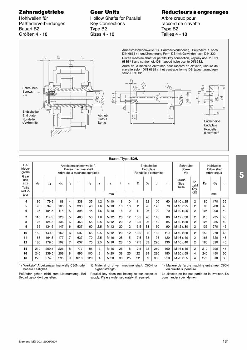
131Siemens MD 20.1 2006/2007
������������� ���� �� ��������� � ����������Hohlwellen für Hollow Shafts for Parallel Arbre creux pourPaßfederverbindungen Key Connections raccord de clavetteBauart B2 Type B2 Type B2Größen 4 - 18 Sizes 4 - 18 Tailles 4 - 18
SchraubenScrewsVis
EndscheibeEnd plateRondelled’extrémité
AbtriebOutputSortie
Arbeitsmaschinenwelle für Paßfederverbindung, Paßfedernut nachDIN 6885 / 1 und Zentrierung Form DS (mit Gewinde) nach DIN 332.Driven machine shaft for parallel key connection, keyway acc. to DIN6885 / 1 and centre hole DS (tapped hole) acc. to DIN 332.Arbre de la machine entraînée pour raccord de clavette, rainure declavette selon DIN 6885 / 1 et centrage forme DS (avec taraudage)selon DIN 332.
EndscheibeEnd plateRondelled’extrémité
Bauart / Type B2H.
Ge-triebe-größeGear
Arbeitsmaschinenwelle 1)
Driven machine shaftArbre de la machine entraînée
EndscheibeEnd plate
Rondelle d’extrémité
SchraubeScrew
Vis
HohlwelleHollow shaftArbre creux
GearunitsizeTaille
réduc
d2 d4 d5 f1 l l1 r s t c D D9 d mGrößeSizeTaille
An-zahlQty.
D2 G4 g
réduc-teur mm
Qty.Qté mm
4 5 6
80 95105
79.5 94.5104.5
88105116
455
338 398 398
35 40 45
1.21.61.6
M 10M 10M 10
181818
101010
111111
222626
100120120
60 70 70
M 10 x 25M 10 x 25M 10 x 25
222
80 95105
170200200
354040
7 8 9
115125135
114.5124.5134.5
126136147
566
468 468 537
50 55 60
1.62.52.5
M 12M 12M 12
202020
121212
13.513.513.5
262633
140150160
80 85 90
M 12 x 30M 12 x 30M 12 x 30
222
115125135
235235270
404045
101112
150165180
149.5164.5179.5
162177192
677
537 637 637
65 70 75
2.52.52.5
M 12M 16M 16
202828
121515
13.517.517.5
333333
185195220
110120130
M 12 x 30M 16 x 40M 16 x 40
222
150165180
270320320
454545
141618
210240275
209.5239.5274.5
226258295
889
777 8961016
85100120
334
M 16M 20M 20
283838
182525
17.52222
333939
250280330
160180210
M 16 x 40M 20 x 55M 20 x 55
244
210240275
390450510
456060
1) Werkstoff Arbeitsmaschinenwelle C60N oderhöhere Festigkeit.
Paßfeder gehört nicht zum Lieferumfang. BeiBedarf gesondert bestellen.
1) Material of driven machine shaft: C60N orhigher strength.
Parallel key does not belong to our scope ofsupply. Please order separately, if required.
1) Matière de l’arbre machine entraînée: C60Nou qualitié supérieure.
La clavette ne fait pas partie de la livraison. Lacommander spécialement.
5
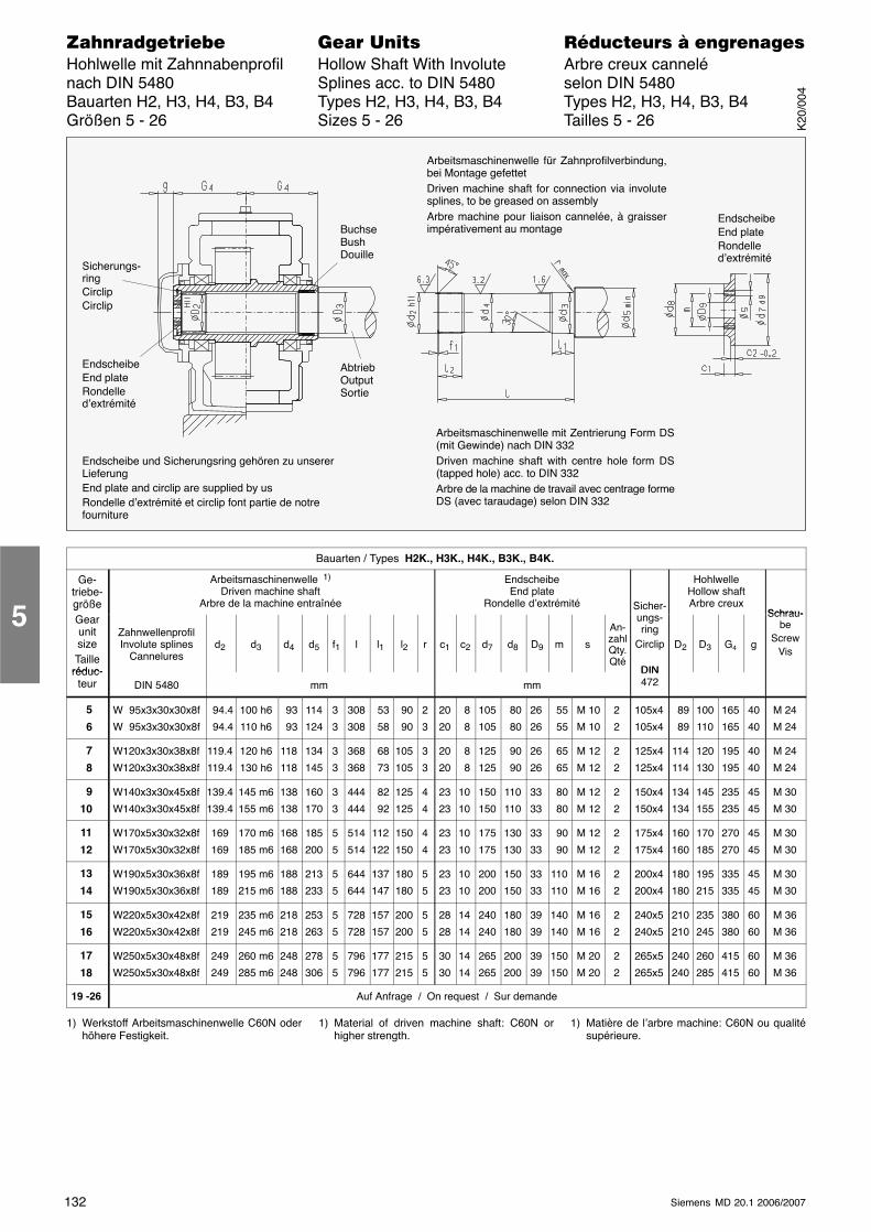
132 Siemens MD 20.1 2006/2007
������������� ���� �� ��������� � ����������Hohlwelle mit Zahnnabenprofil Hollow Shaft With Involute Arbre creux cannelénach DIN 5480 Splines acc. to DIN 5480 selon DIN 5480Bauarten H2, H3, H4, B3, B4 Types H2, H3, H4, B3, B4 Types H2, H3, H4, B3, B4Größen 5 - 26 Sizes 5 - 26 Tailles 5 - 26
Sicherungs-ringCirclipCirclip
EndscheibeEnd plateRondelled’extrémité
AbtriebOutputSortie
Arbeitsmaschinenwelle für Zahnprofilverbindung,bei Montage gefettetDriven machine shaft for connection via involutesplines, to be greased on assemblyArbre machine pour liaison cannelée, à graisserimpérativement au montage
EndscheibeEnd plateRondelled’extrémité
BuchseBushDouille
Endscheibe und Sicherungsring gehören zu unsererLieferungEnd plate and circlip are supplied by usRondelle d’extrémité et circlip font partie de notrefourniture
Arbeitsmaschinenwelle mit Zentrierung Form DS(mit Gewinde) nach DIN 332Driven machine shaft with centre hole form DS(tapped hole) acc. to DIN 332Arbre de la machine de travail avec centrage formeDS (avec taraudage) selon DIN 332
Bauarten / Types H2K., H3K., H4K., B3K., B4K.
Ge-triebe-größe
Arbeitsmaschinenwelle 1)
Driven machine shaftArbre de la machine entraînée
EndscheibeEnd plate
Rondelle d’extrémité Sicher-
HohlwelleHollow shaftArbre creux
Schrau-gGearunitsizeTaille
réduc-
ZahnwellenprofilInvolute splines
Canneluresd2 d3 d4 d5 f1 l l1 l2 r c1 c2 d7 d8 D9 m s
An-zahlQty.Qté
ungs-ring
Circlip
DIN
D2 D3 G4 g
Schrau-be
ScrewVis
réduc-teur DIN 5480 mm mm
DIN472
5
6
W 95x3x30x30x8f
W 95x3x30x30x8f
94.4
94.4
100 h6
110 h6
93
93
114
124
3
3
308
308
53
58
90
90
2
3
20
20
8
8
105
105
80
80
26
26
55
55
M 10
M 10
2
2
105x4
105x4
89
89
100
110
165
165
40
40
M 24
M 24
7
8
W120x3x30x38x8f
W120x3x30x38x8f
119.4
119.4
120 h6
130 h6
118
118
134
145
3
3
368
368
68
73
105
105
3
3
20
20
8
8
125
125
90
90
26
26
65
65
M 12
M 12
2
2
125x4
125x4
114
114
120
130
195
195
40
40
M 24
M 24
9
10
W140x3x30x45x8f
W140x3x30x45x8f
139.4
139.4
145 m6
155 m6
138
138
160
170
3
3
444
444
82
92
125
125
4
4
23
23
10
10
150
150
110
110
33
33
80
80
M 12
M 12
2
2
150x4
150x4
134
134
145
155
235
235
45
45
M 30
M 30
11
12
W170x5x30x32x8f
W170x5x30x32x8f
169
169
170 m6
185 m6
168
168
185
200
5
5
514
514
112
122
150
150
4
4
23
23
10
10
175
175
130
130
33
33
90
90
M 12
M 12
2
2
175x4
175x4
160
160
170
185
270
270
45
45
M 30
M 30
13
14
W190x5x30x36x8f
W190x5x30x36x8f
189
189
195 m6
215 m6
188
188
213
233
5
5
644
644
137
147
180
180
5
5
23
23
10
10
200
200
150
150
33
33
110
110
M 16
M 16
2
2
200x4
200x4
180
180
195
215
335
335
45
45
M 30
M 30
15
16
W220x5x30x42x8f
W220x5x30x42x8f
219
219
235 m6
245 m6
218
218
253
263
5
5
728
728
157
157
200
200
5
5
28
28
14
14
240
240
180
180
39
39
140
140
M 16
M 16
2
2
240x5
240x5
210
210
235
245
380
380
60
60
M 36
M 36
17
18
W250x5x30x48x8f
W250x5x30x48x8f
249
249
260 m6
285 m6
248
248
278
306
5
5
796
796
177
177
215
215
5
5
30
30
14
14
265
265
200
200
39
39
150
150
M 20
M 20
2
2
265x5
265x5
240
240
260
285
415
415
60
60
M 36
M 36
19 -26 Auf Anfrage / On request / Sur demande
1) Werkstoff Arbeitsmaschinenwelle C60N oderhöhere Festigkeit.
1) Material of driven machine shaft: C60N orhigher strength.
1) Matière de l’arbre machine: C60N ou qualitésupérieure.
5
K20
/004
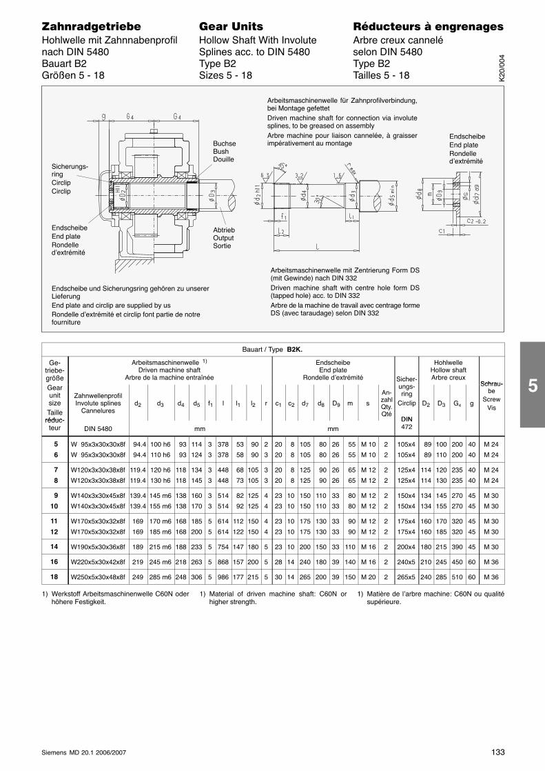
133Siemens MD 20.1 2006/2007
������������� ���� �� ��������� � ����������Hohlwelle mit Zahnnabenprofil Hollow Shaft With Involute Arbre creux cannelénach DIN 5480 Splines acc. to DIN 5480 selon DIN 5480Bauart B2 Type B2 Type B2Größen 5 - 18 Sizes 5 - 18 Tailles 5 - 18
Sicherungs-ringCirclipCirclip
EndscheibeEnd plateRondelled’extrémité
AbtriebOutputSortie
Arbeitsmaschinenwelle für Zahnprofilverbindung,bei Montage gefettetDriven machine shaft for connection via involutesplines, to be greased on assemblyArbre machine pour liaison cannelée, à graisserimpérativement au montage
EndscheibeEnd plateRondelled’extrémité
BuchseBushDouille
Endscheibe und Sicherungsring gehören zu unsererLieferungEnd plate and circlip are supplied by usRondelle d’extrémité et circlip font partie de notrefourniture
Arbeitsmaschinenwelle mit Zentrierung Form DS(mit Gewinde) nach DIN 332Driven machine shaft with centre hole form DS(tapped hole) acc. to DIN 332Arbre de la machine de travail avec centrage formeDS (avec taraudage) selon DIN 332
Bauart / Type B2K.
Ge-triebe-größe
Arbeitsmaschinenwelle 1)
Driven machine shaftArbre de la machine entraînée
EndscheibeEnd plate
Rondelle d’extrémité Sicher-
HohlwelleHollow shaftArbre creux
Schrau-gGearunitsizeTaille
réduc-
ZahnwellenprofilInvolute splines
Canneluresd2 d3 d4 d5 f1 l l1 l2 r c1 c2 d7 d8 D9 m s
An-zahlQty.Qté
ungs-ring
Circlip
DIN
D2 D3 G4 g
Schrau-be
ScrewVis
réduc-teur DIN 5480 mm mm
DIN472
5
6
W 95x3x30x30x8f
W 95x3x30x30x8f
94.4
94.4
100 h6
110 h6
93
93
114
124
3
3
378
378
53
58
90
90
2
3
20
20
8
8
105
105
80
80
26
26
55
55
M 10
M 10
2
2
105x4
105x4
89
89
100
110
200
200
40
40
M 24
M 24
7
8
W120x3x30x38x8f
W120x3x30x38x8f
119.4
119.4
120 h6
130 h6
118
118
134
145
3
3
448
448
68
73
105
105
3
3
20
20
8
8
125
125
90
90
26
26
65
65
M 12
M 12
2
2
125x4
125x4
114
114
120
130
235
235
40
40
M 24
M 24
9
10
W140x3x30x45x8f
W140x3x30x45x8f
139.4
139.4
145 m6
155 m6
138
138
160
170
3
3
514
514
82
92
125
125
4
4
23
23
10
10
150
150
110
110
33
33
80
80
M 12
M 12
2
2
150x4
150x4
134
134
145
155
270
270
45
45
M 30
M 30
11
12
W170x5x30x32x8f
W170x5x30x32x8f
169
169
170 m6
185 m6
168
168
185
200
5
5
614
614
112
122
150
150
4
4
23
23
10
10
175
175
130
130
33
33
90
90
M 12
M 12
2
2
175x4
175x4
160
160
170
185
320
320
45
45
M 30
M 30
14 W190x5x30x36x8f 189 215 m6 188 233 5 754 147 180 5 23 10 200 150 33 110 M 16 2 200x4 180 215 390 45 M 30
16 W220x5x30x42x8f 219 245 m6 218 263 5 868 157 200 5 28 14 240 180 39 140 M 16 2 240x5 210 245 450 60 M 36
18 W250x5x30x48x8f 249 285 m6 248 306 5 986 177 215 5 30 14 265 200 39 150 M 20 2 265x5 240 285 510 60 M 36
1) Werkstoff Arbeitsmaschinenwelle C60N oderhöhere Festigkeit.
1) Material of driven machine shaft: C60N orhigher strength.
1) Matière de l’arbre machine: C60N ou qualitésupérieure.
K20
/004
5
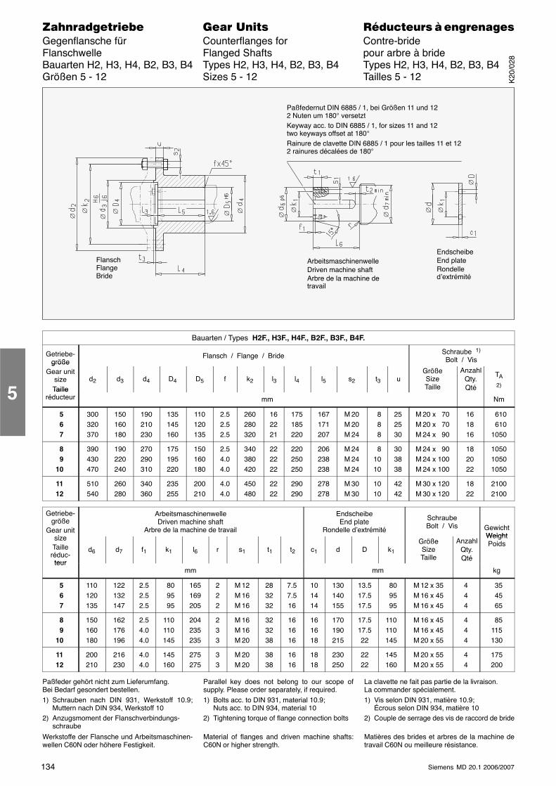
134 Siemens MD 20.1 2006/2007
������������� ���� �� ��������� � ����������Gegenflansche für Counterflanges for Contre-brideFlanschwelle Flanged Shafts pour arbre à brideBauarten H2, H3, H4, B2, B3, B4 Types H2, H3, H4, B2, B3, B4 Types H2, H3, H4, B2, B3, B4Größen 5 - 12 Sizes 5 - 12 Tailles 5 - 12
Paßfedernut DIN 6885 / 1, bei Größen 11 und 122 Nuten um 180° versetztKeyway acc. to DIN 6885 / 1, for sizes 11 and 12two keyways offset at 180°
Rainure de clavette DIN 6885 / 1 pour les tailles 11 et 122 rainures décalées de 180°
FlanschFlangeBride
ArbeitsmaschinenwelleDriven machine shaftArbre de la machine detravail
EndscheibeEnd plateRondelled’extrémité
∅
∅
∅
∅ ∅ ∅
∅ ∅
∅
∅
∅ ∅
Bauarten / Types H2F., H3F., H4F., B2F., B3F., B4F.
Getriebe-größe
Flansch / Flange / Bride Schraube 1)
Bolt / VisgrößeGear unit
sizeTaille
d2 d3 d4 D4 D5 f k2 l3 l4 l5 s2 t3 uGrößeSizeTaille
AnzahlQty.Qté
TA
2)Taille
réducteur mm Nm
5 6 7
300320370
150160180
190210230
135145160
110120135
2.52.52.5
260280320
162221
175185220
167171207
M 20M 20M 24
8 8 8
252530
M 20 x 70M 20 x 70M 24 x 90
161816
610 6101050
8 910
390430470
190220240
270290310
175195220
150160180
2.54.04.0
340380420
222222
220250250
206238238
M 24M 24M 24
81010
303838
M 24 x 90M 24 x 100M 24 x 100
182022
105010501050
1112
510540
260280
340360
235255
200210
4.04.0
450480
2222
290290
278278
M 30M 30
1010
4242
M 30 x 120M 30 x 120
1822
21002100
Getriebe-größe
Gear uniti
ArbeitsmaschinenwelleDriven machine shaft
Arbre de la machine de travail
EndscheibeEnd plate
Rondelle d’extrémité
SchraubeBolt / Vis Gewicht
WeightsizeTaille
réduc-teur
d6 d7 f1 k1 l6 r s1 t1 t2 c1 d D k1
GrößeSizeTaille
AnzahlQty.Qté
WeightPoids
teurmm mm kg
5 6 7
110120135
122132147
2.52.52.5
80 95 95
165169205
222
M 12M 16M 16
283232
7.57.516
101414
130140155
13.517.517.5
80 95 95
M 12 x 35M 16 x 45M 16 x 45
444
35 45 65
8 910
150160180
162176196
2.54.04.0
110110145
204235235
233
M 16M 16M 20
323238
161616
161618
170190215
17.517.522
110110145
M 16 x 45M 16 x 45M 20 x 55
444
85115130
1112
200210
216230
4.04.0
145160
275275
33
M 20M 20
3838
1616
1818
230250
2222
145160
M 20 x 55M 20 x 55
44
175200
Paßfeder gehört nicht zum Lieferumfang.Bei Bedarf gesondert bestellen.1) Schrauben nach DIN 931, Werkstoff 10.9;
Muttern nach DIN 934, Werkstoff 102) Anzugsmoment der Flanschverbindungs-
schraube
Werkstoffe der Flansche und Arbeitsmaschinen-wellen C60N oder höhere Festigkeit.
Parallel key does not belong to our scope ofsupply. Please order separately, if required.1) Bolts acc. to DIN 931, material 10.9;
Nuts acc. to DIN 934, material 102) Tightening torque of flange connection bolts
Material of flanges and driven machine shafts:C60N or higher strength.
La clavette ne fait pas partie de la livraison.La commander spécialement.1) Vis selon DIN 931, matière 10.9;
Écrous selon DIN 934, matière 102) Couple de serrage des vis de raccord de bride
Matières des brides et arbres de la machine detravail C60N ou meilleure résistance.
5
K20
/028
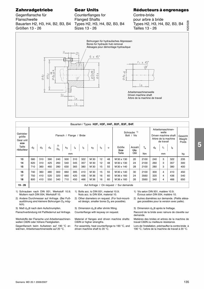
135Siemens MD 20.1 2006/2007
������������� ���� �� ��������� � ����������Gegenflansche für Counterflanges for Contre-brideFlanschwelle Flanged Shafts pour arbre à brideBauarten H2, H3, H4, B2, B3, B4 Types H2, H3, H4, B2, B3, B4 Types H2, H3, H4, B2, B3, B4Größen 13 - 26 Sizes 13 - 26 Tailles 13 - 26
ArbeitsmaschinenwelleDriven machine shaftArbre de la machine de travail
Bohrungen für hydraulisches AbpressenBores for hydraulic hub removalAlésages pour démontage hydraulique
∅ ∅ ∅ ∅ ∅ ∅
Bauarten / Types H2F., H3F., H4F., B2F., B3F., B4F.
Getriebe-größe
Gear unitsize
Flansch / Flange / BrideSchraube 1)
Bolt / Vis
Arbeitsmaschinen-welle
Driven machine shaftArbre de la machine
de travail
GewichtWeightPoidssize
Tailleréducteur
d2 d3 d42)
D5k2 l4 l5 s2 t3 u Größe
SizeAnzahl
Qty.Ta d6 f1 l6réducteur
mmSizeTaille
Qty.Qté Nm mm kg
131415
580620710
310310360
390425460
240260280
500540630
310345365
322357380
M 30M 30M 30
121215
484855
M 30 x 130M 30 x 130M 30 x 140
202428
210021002100
240260280
333
322357380
235300400
161718
740750800
360410410
480520550
300320340
660660710
395420450
410436466
M 30M 36M 36
151616
556060
M 30 x 140M 36 x 160M 36 x 160
302426
210035603560
300320340
444
410436466
450540650
19 - 26 Auf Anfrage / On request / Sur demande
1) Schrauben nach DIN 931, Werkstoff 10.9;Muttern nach DIN 934, Werkstoff 10.
2) Andere Durchmesser auf Anfrage. (Bei Fuß-ausführung sind kleinere Bohrungen D5 mög-lich).
3) Maß d3 j6 nach dem Aufschrumpfen.
Flanschverbindung mit Paßfedernut auf Anfrage.
Werkstoffe der Flansche und Arbeitsmaschinen-wellen C60N oder höhere Festigkeiten.
Gegenflansch beim Aufsetzen auf 190 °C er-wärmen, Arbeitsmaschinenwelle auf 20 °C.
1) Bolts acc. to DIN 931, material 10.9;Nuts acc. to DIN 934, material 10.
2) Other diameters on request. (For foot-mount-ed design, smaller bores D5 are possible).
3) Dimension d3 j6 after shrink fitting.
Counterflange with keyway on request.
Material of flanges and driven machine shafts:C60N or higher strengths.
For assembly, heat counterflange to 190 °C, anddriven machine shaft to 20 °C.
1) Vis selon DIN 931, matière 10.9;Écrous selon DIN 934, matière 10.
2) Autres diamètres sur demande. (Petits alésa-ges possibles pour la version avec patte).
3) Dimension d3 j6 après le frettage.
Raccord de la bride avec rainure de clavette surdemande.
Matières des brides et arbres de la machine detravail C60N ou meilleure résistance.
Lors de l’installation, préchauffez la contre-bride à190 °C, l’arbre de la machine de travail à 20 °C.
K20
/028
5
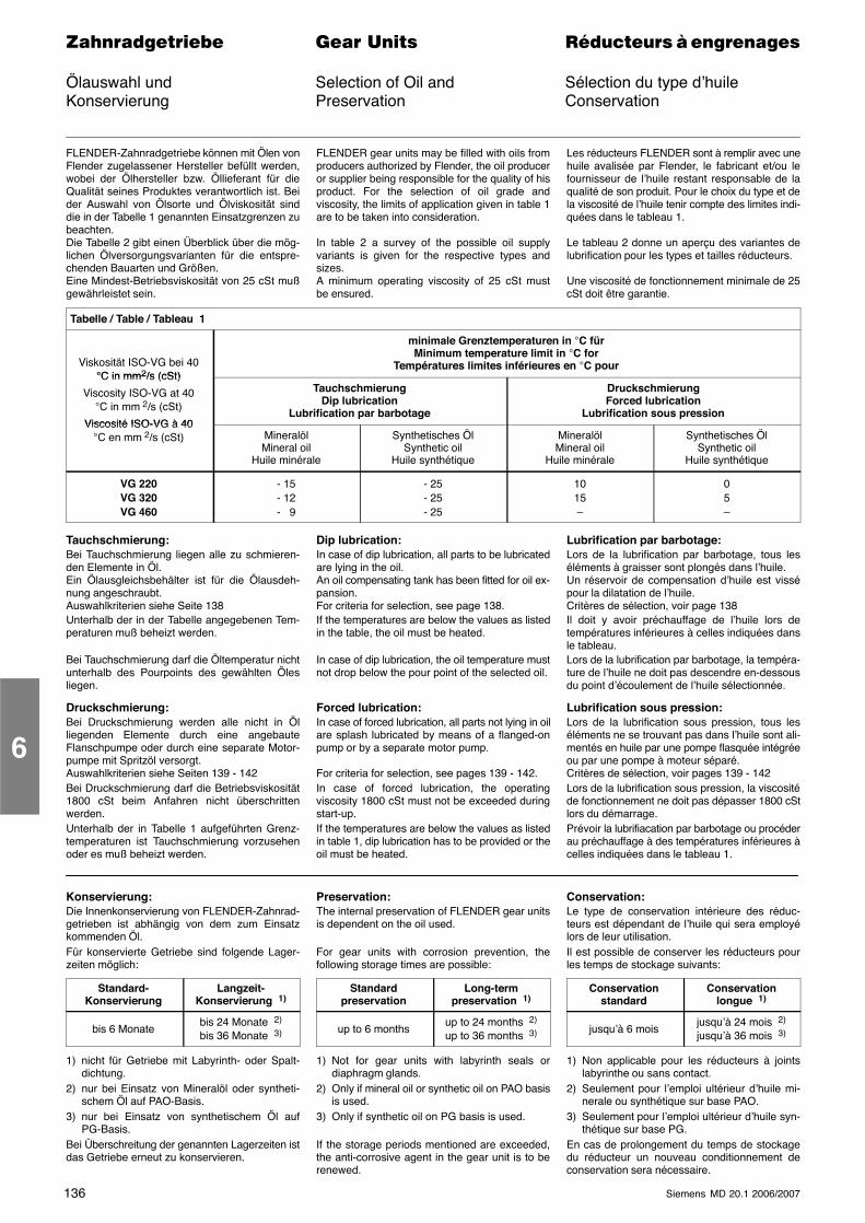
136 Siemens MD 20.1 2006/2007
������������� ���� �� ��������� � ����������
Ölauswahl und Selection of Oil and Sélection du type d’huileKonservierung Preservation Conservation
FLENDER-Zahnradgetriebe können mit Ölen vonFlender zugelassener Hersteller befüllt werden,wobei der Ölhersteller bzw. Öllieferant für dieQualität seines Produktes verantwortlich ist. Beider Auswahl von Ölsorte und Ölviskosität sinddie in der Tabelle 1 genannten Einsatzgrenzen zubeachten.Die Tabelle 2 gibt einen Überblick über die mög-lichen Ölversorgungsvarianten für die entspre-chenden Bauarten und Größen.Eine Mindest-Betriebsviskosität von 25 cSt mußgewährleistet sein.
FLENDER gear units may be filled with oils fromproducers authorized by Flender, the oil produceror supplier being responsible for the quality of hisproduct. For the selection of oil grade andviscosity, the limits of application given in table 1are to be taken into consideration.
In table 2 a survey of the possible oil supplyvariants is given for the respective types andsizes.A minimum operating viscosity of 25 cSt mustbe ensured.
Les réducteurs FLENDER sont à remplir avec unehuile avalisée par Flender, le fabricant et/ou lefournisseur de l’huile restant responsable de laqualité de son produit. Pour le choix du type et dela viscosité de l’huile tenir compte des limites indi-quées dans le tableau 1.
Le tableau 2 donne un aperçu des variantes delubrification pour les types et tailles réducteurs.
Une viscosité de fonctionnement minimale de 25cSt doit être garantie.
Tabelle / Table / Tableau 1
Viskosität ISO-VG bei 40°C in mm2/s (cSt)
minimale Grenztemperaturen in °C fürMinimum temperature limit in °C for
Températures limites inférieures en °C pour°C in mm2/s (cSt)
Viscosity ISO-VG at 40°C in mm 2/s (cSt)
Viscosité ISO-VG à 40
TauchschmierungDip lubrication
Lubrification par barbotage
DruckschmierungForced lubrication
Lubrification sous pressionViscosité ISO-VG à 40
°C en mm 2/s (cSt) MineralölMineral oil
Huile minérale
Synthetisches ÖlSynthetic oil
Huile synthétique
MineralölMineral oil
Huile minérale
Synthetisches ÖlSynthetic oil
Huile synthétique
VG 220VG 320VG 460
- 15- 12- 9
- 25- 25- 25
1015–
05–
Tauchschmierung:Bei Tauchschmierung liegen alle zu schmieren-den Elemente in Öl.Ein Ölausgleichsbehälter ist für die Ölausdeh-nung angeschraubt.Auswahlkriterien siehe Seite 138Unterhalb der in der Tabelle angegebenen Tem-peraturen muß beheizt werden.
Bei Tauchschmierung darf die Öltemperatur nichtunterhalb des Pourpoints des gewählten Ölesliegen.
Druckschmierung:Bei Druckschmierung werden alle nicht in Ölliegenden Elemente durch eine angebauteFlanschpumpe oder durch eine separate Motor-pumpe mit Spritzöl versorgt.Auswahlkriterien siehe Seiten 139 - 142Bei Druckschmierung darf die Betriebsviskosität1800 cSt beim Anfahren nicht überschrittenwerden.Unterhalb der in Tabelle 1 aufgeführten Grenz-temperaturen ist Tauchschmierung vorzusehenoder es muß beheizt werden.
Dip lubrication:In case of dip lubrication, all parts to be lubricatedare lying in the oil.An oil compensating tank has been fitted for oil ex-pansion.For criteria for selection, see page 138.If the temperatures are below the values as listedin the table, the oil must be heated.
In case of dip lubrication, the oil temperature mustnot drop below the pour point of the selected oil.
Forced lubrication:In case of forced lubrication, all parts not lying in oilare splash lubricated by means of a flanged-onpump or by a separate motor pump.
For criteria for selection, see pages 139 - 142.In case of forced lubrication, the operatingviscosity 1800 cSt must not be exceeded duringstart-up.If the temperatures are below the values as listedin table 1, dip lubrication has to be provided or theoil must be heated.
Lubrification par barbotage:Lors de la lubrification par barbotage, tous leséléments à graisser sont plongés dans l’huile.Un réservoir de compensation d’huile est vissépour la dilatation de l’huile.Critères de sélection, voir page 138Il doit y avoir préchauffage de l’huile lors detempératures inférieures à celles indiquées dansle tableau.Lors de la lubrification par barbotage, la tempéra-ture de l’huile ne doit pas descendre en-dessousdu point d’écoulement de l’huile sélectionnée.
Lubrification sous pression:Lors de la lubrification sous pression, tous leséléments ne se trouvant pas dans l’huile sont ali-mentés en huile par une pompe flasquée intégréeou par une pompe à moteur séparé.Critères de sélection, voir pages 139 - 142Lors de la lubrification sous pression, la viscositéde fonctionnement ne doit pas dépasser 1800 cStlors du démarrage.Prévoir la lubrifiacation par barbotage ou procéderau préchauffage à des températures inférieures àcelles indiquées dans le tableau 1.
Konservierung:Die Innenkonservierung von FLENDER-Zahnrad-getrieben ist abhängig von dem zum Einsatzkommenden Öl.Für konservierte Getriebe sind folgende Lager-zeiten möglich:
Standard-Konservierung
Langzeit-Konservierung 1)
bis 6 Monatebis 24 Monate 2)
bis 36 Monate 3)
1) nicht für Getriebe mit Labyrinth- oder Spalt-dichtung.
2) nur bei Einsatz von Mineralöl oder syntheti-schem Öl auf PAO-Basis.
3) nur bei Einsatz von synthetischem Öl aufPG-Basis.
Bei Überschreitung der genannten Lagerzeiten istdas Getriebe erneut zu konservieren.
Preservation:The internal preservation of FLENDER gear unitsis dependent on the oil used.
For gear units with corrosion prevention, thefollowing storage times are possible:
Standardpreservation
Long-termpreservation 1)
up to 6 monthsup to 24 months 2)
up to 36 months 3)
1) Not for gear units with labyrinth seals ordiaphragm glands.
2) Only if mineral oil or synthetic oil on PAO basisis used.
3) Only if synthetic oil on PG basis is used.
If the storage periods mentioned are exceeded,the anti-corrosive agent in the gear unit is to berenewed.
Conservation:Le type de conservation intérieure des réduc-teurs est dépendant de l’huile qui sera employélors de leur utilisation.Il est possible de conserver les réducteurs pourles temps de stockage suivants:
Conservationstandard
Conservationlongue 1)
jusqu’à 6 moisjusqu’à 24 mois 2)
jusqu’à 36 mois 3)
1) Non applicable pour les réducteurs à jointslabyrinthe ou sans contact.
2) Seulement pour l’emploi ultérieur d’huile mi-nerale ou synthétique sur base PAO.
3) Seulement pour l’emploi ultérieur d’huile syn-thétique sur base PG.
En cas de prolongement du temps de stockagedu réducteur un nouveau conditionnement deconservation sera nécessaire.
6
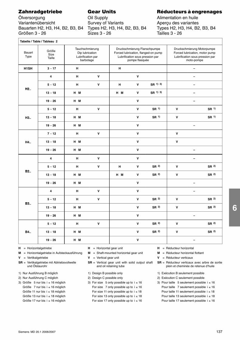
137Siemens MD 20.1 2006/2007
������������� ���� �� ��������� � ����������Ölversorgung Oil Supply Alimentation en huileVariantenübersicht Survey of Variants Aperçu des variantesBauarten H2, H3, H4, B2, B3, B4 Types H2, H3, H4, B2, B3, B4 Types H2, H3, H4, B2, B3, B4Größen 3 - 26 Sizes 3 - 26 Tailles 3 - 26
Tabelle / Table / Tableau 2
BauartType
GrößeSizeTaille
TauchschmierungDip lubrication
Lubrification parbarbotage
Druckschmierung FlanschpumpeForced lubrication, flanged-on pump
Lubrification sous pression parpompe flasquée
Druckschmierung MotorpumpeForced lubrication, motor pumpLubrification sous pression par
moto-pompe
H1SH 3 - 17 H H –
4 H V V –
H2 5 - 12 H V H V SR 1) 3) –
H2..13 - 18 H M H M V SR 1) 3) –
19 - 26 H M V –
5 - 12 H V V SR 1) V SR 1)
H3.. 13 - 18 H M V SR 1) V SR 1)
19 - 26 H M V –
7 - 12 H V V V
H4.. 13 - 18 H M V V
19 - 26 H M V –
4 H V V –
B2 5 - 12 H V H V SR 2) V SR 2)
B2..13 - 18 H M H M V SR 2) V SR 2)
19 - 26 H M V –
4 H V V –
B3 5 - 12 H V V SR 2) V SR 2)
B3..13 - 18 H M V SR 2) V SR 2)
19 - 26 H M V –
5 - 12 H V V SR 2) V SR 2)
B4.. 13 - 18 H M V SR 2) V SR 2)
19 - 26 H M V –
H = Horizontalgetriebe
M = Horizontalgetriebe in Aufsteckausführung
V = Vertikalgetriebe
SR = Vertikalgetriebe mit Abtriebsvollwelleund Ölstaurohr
1) Nur Ausführung B möglich
2) Nur Ausführung C möglich
3) Größe 5 nur bis i ≤ 16 möglichGröße 7 nur bis i ≤ 16 möglichGröße 11 nur bis i ≤ 18 möglichGröße 13 nur bis i ≤ 18 möglichGröße 17 nur bis i ≤ 16 möglich
H = Horizontal gear unit
M = Shaft-mounted horizontal gear unit
V = Vertical gear unit
SR = Vertical gear unit with solid output shaftand oil retaining tube
1) Design B possible only
2) Design C possible only
3) For size 5 only possible up to i ≤ 16For size 7 only possible up to i ≤ 16For size 11 only possible up to i ≤ 18For size 13 only possible up to i ≤ 18For size 17 only possible up to i ≤ 16
H = Réducteur horizontal
M = Réducteur horizontal flottant
V = Réducteur verticaux
SR = Réducteur verticaux avec arbre de sortieplein et cheminée de retenue d’huile
1) Exécution B seulement possible
2) Exécution C seulement possible
3) Pour taille 5 seulement possible i ≤ 16Pour taille 7 seulement possible i ≤ 16Pour taille 11 seulement possible i ≤ 18Pour taille 13 seulement possible i ≤ 18Pour taille 17 seulement possible i ≤ 16
6
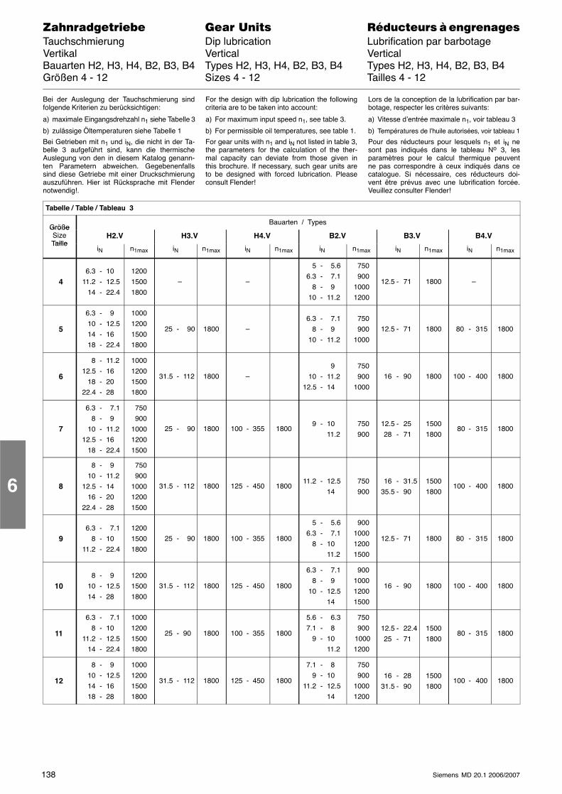
138 Siemens MD 20.1 2006/2007
������������� ���� �� ��������� � ����������Tauchschmierung Dip lubrication Lubrification par barbotageVertikal Vertical VerticalBauarten H2, H3, H4, B2, B3, B4 Types H2, H3, H4, B2, B3, B4 Types H2, H3, H4, B2, B3, B4Größen 4 - 12 Sizes 4 - 12 Tailles 4 - 12
Bei der Auslegung der Tauchschmierung sindfolgende Kriterien zu berücksichtigen:
a) maximale Eingangsdrehzahl n1 siehe Tabelle 3
b) zulässige Öltemperaturen siehe Tabelle 1
Bei Getrieben mit n1 und iN, die nicht in der Ta-belle 3 aufgeführt sind, kann die thermischeAuslegung von den in diesem Katalog genann-ten Parametern abweichen. Gegebenenfallssind diese Getriebe mit einer Druckschmierungauszuführen. Hier ist Rücksprache mit Flendernotwendig!.
For the design with dip lubrication the followingcriteria are to be taken into account:
a) For maximum input speed n1, see table 3.
b) For permissible oil temperatures, see table 1.
For gear units with n1 and iN not listed in table 3,the parameters for the calculation of the ther-mal capacity can deviate from those given inthis brochure. If necessary, such gear units areto be designed with forced lubrication. Pleaseconsult Flender!
Lors de la conception de la lubrification par bar-botage, respecter les critères suivants:
a) Vitesse d’entrée maximale n1, voir tableau 3
b) Températures de l’huile autorisées, voir tableau 1
Pour des réducteurs pour lesquels n1 et iN nesont pas indiqués dans le tableau No 3, lesparamètres pour le calcul thermique peuventne pas correspondre à ceux indiqués dans cecatalogue. Si nécessaire, ces réducteurs doi-vent être prévus avec une lubrification forcée.Veuillez consulter Flender!
Tabelle / Table / Tableau 3
GrößeBauarten / Types
GrößeSizeTaille
H2.V H3.V H4.V B2.V B3.V B4.VTaille
iN n1max iN n1max iN n1max iN n1max iN n1max iN n1max
46.3 - 10
11.2 - 12.514 - 22.4
120015001800
– –
5 - 5.66.3 - 7.1
8 - 910 - 11.2
750 90010001200
12.5 - 71 1800 –
5
6.3 - 910 - 12.514 - 1618 - 22.4
1000120015001800
25 - 90 1800 –6.3 - 7.1
8 - 910 - 11.2
750 9001000
12.5 - 71 1800 80 - 315 1800
6
8 - 11.212.5 - 16
18 - 2022.4 - 28
1000120015001800
31.5 - 112 1800 – 9
10 - 11.212.5 - 14
750 9001000
16 - 90 1800 100 - 400 1800
7
6.3 - 7.18 - 9
10 - 11.212.5 - 16
18 - 22.4
750 900100012001500
25 - 90 1800 100 - 355 18009 - 10
11.2 750 900
12.5 - 2528 - 71
15001800
80 - 315 1800
8
8 - 910 - 11.2
12.5 - 1416 - 20
22.4 - 28
750 900100012001500
31.5 - 112 1800 125 - 450 180011.2 - 12.5
14 750 900
16 - 31.535.5 - 90
15001800
100 - 400 1800
96.3 - 7.1
8 - 1011.2 - 22.4
120015001800
25 - 90 1800 100 - 355 1800
5 - 5.66.3 - 7.1
8 - 1011.2
900100012001500
12.5 - 71 1800 80 - 315 1800
108 - 9
10 - 12.514 - 28
120015001800
31.5 - 112 1800 125 - 450 1800
6.3 - 7.18 - 9
10 - 12.514
900100012001500
16 - 90 1800 100 - 400 1800
11
6.3 - 7.18 - 10
11.2 - 12.514 - 22.4
1000120015001800
25 - 90 1800 100 - 355 1800
5.6 - 6.37.1 - 8
9 - 1011.2
750 900 10001200
12.5 - 22.425 - 71
15001800
80 - 315 1800
12
8 - 910 - 12.514 - 1618 - 28
1000120015001800
31.5 - 112 1800 125 - 450 1800
7.1 - 89 - 10
11.2 - 12.514
750 90010001200
16 - 2831.5 - 90
15001800
100 - 400 1800
6
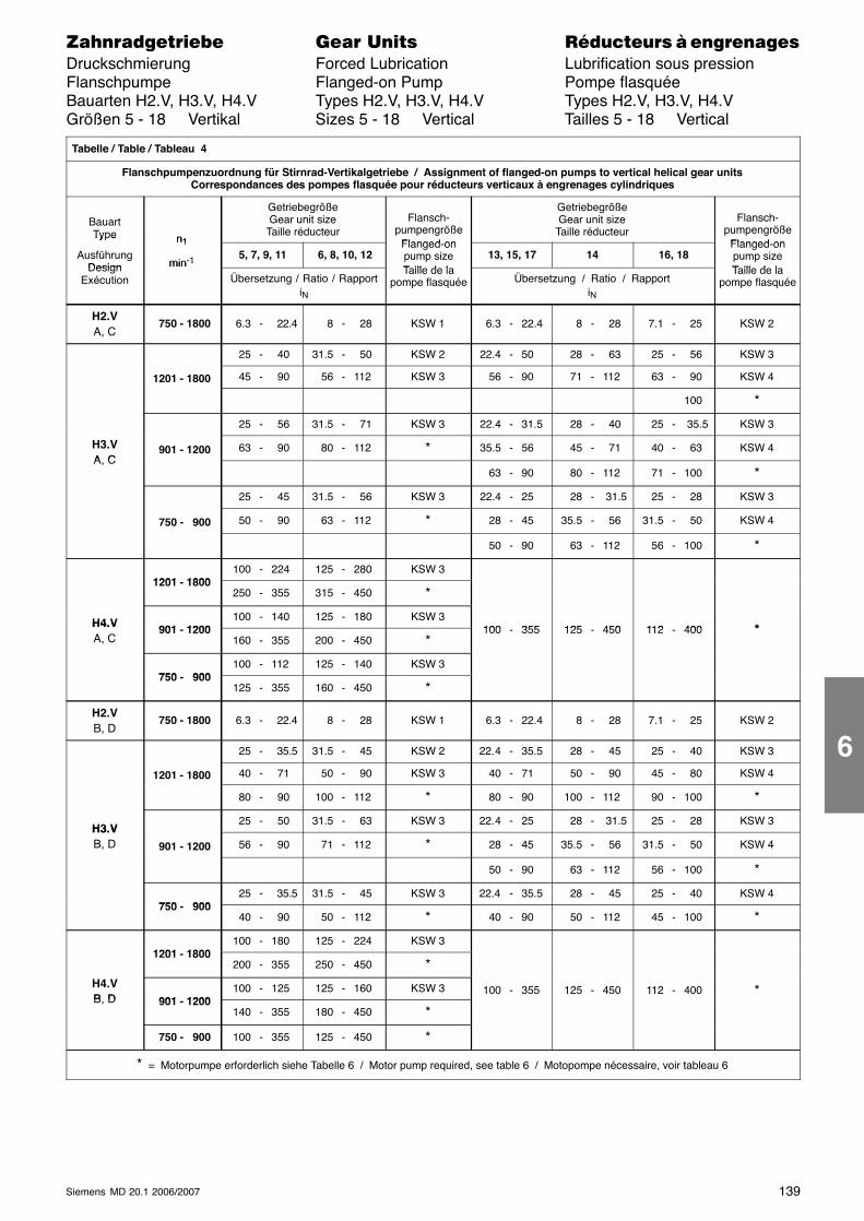
139Siemens MD 20.1 2006/2007
������������� ���� �� ��������� � ����������Druckschmierung Forced Lubrication Lubrification sous pressionFlanschpumpe Flanged-on Pump Pompe flasquéeBauarten H2.V, H3.V, H4.V Types H2.V, H3.V, H4.V Types H2.V, H3.V, H4.VGrößen 5 - 18 Vertikal Sizes 5 - 18 Vertical Tailles 5 - 18 Vertical
Tabelle / Table / Tableau 4
Flanschpumpenzuordnung für Stirnrad-Vertikalgetriebe / Assignment of flanged-on pumps to vertical helical gear unitsCorrespondances des pompes flasquée pour réducteurs verticaux à engrenages cylindriques
BauartType n1
GetriebegrößeGear unit size
Taille réducteurFlansch-
pumpengrößeFlanged on
GetriebegrößeGear unit size
Taille réducteurFlansch-
pumpengrößeFlanged on
Ty e
AusführungDesign
n1
min-1 5, 7, 9, 11 6, 8, 10, 12Flanged-onpump sizeT ill d l
13, 15, 17 14 16, 18Flanged-onpump sizeT ill d lDesign
Exécution
min 1
Übersetzung / Ratio / RapportiN
Taille de lapompe flasquée Übersetzung / Ratio / Rapport
iN
Taille de lapompe flasquée
H2.VA, C
750 - 1800 6.3 - 22.4 8 - 28 KSW 1 6.3 - 22.4 8 - 28 7.1 - 25 KSW 2
25 - 40 31.5 - 50 KSW 2 22.4 - 50 28 - 63 25 - 56 KSW 3
1201 - 1800 45 - 90 56 - 112 KSW 3 56 - 90 71 - 112 63 - 90 KSW 4
100 *
25 - 56 31.5 - 71 KSW 3 22.4 - 31.5 28 - 40 25 - 35.5 KSW 3
H3.VA C
901 - 1200 63 - 90 80 - 112 * 35.5 - 56 45 - 71 40 - 63 KSW 4A, C
63 - 90 80 - 112 71 - 100 *
25 - 45 31.5 - 56 KSW 3 22.4 - 25 28 - 31.5 25 - 28 KSW 3
750 - 900 50 - 90 63 - 112 * 28 - 45 35.5 - 56 31.5 - 50 KSW 4
50 - 90 63 - 112 56 - 100 *
1201 1800100 - 224 125 - 280 KSW 3
1201 - 1800250 - 355 315 - 450 *
H4.V 901 1200100 - 140 125 - 180 KSW 3
100 355 125 450 112 400 *H4.VA, C
901 - 1200160 - 355 200 - 450 *
100 - 355 125 - 450 112 - 400 *
750 900100 - 112 125 - 140 KSW 3
750 - 900125 - 355 160 - 450 *
H2.VB, D
750 - 1800 6.3 - 22.4 8 - 28 KSW 1 6.3 - 22.4 8 - 28 7.1 - 25 KSW 2
25 - 35.5 31.5 - 45 KSW 2 22.4 - 35.5 28 - 45 25 - 40 KSW 3
1201 - 1800 40 - 71 50 - 90 KSW 3 40 - 71 50 - 90 45 - 80 KSW 4
80 - 90 100 - 112 * 80 - 90 100 - 112 90 - 100 *
H3.V25 - 50 31.5 - 63 KSW 3 22.4 - 25 28 - 31.5 25 - 28 KSW 3
H3.VB, D 901 - 1200 56 - 90 71 - 112 * 28 - 45 35.5 - 56 31.5 - 50 KSW 4
50 - 90 63 - 112 56 - 100 *
750 90025 - 35.5 31.5 - 45 KSW 3 22.4 - 35.5 28 - 45 25 - 40 KSW 4
750 - 90040 - 90 50 - 112 * 40 - 90 50 - 112 45 - 100 *
1201 1800100 - 180 125 - 224 KSW 3
1201 - 1800200 - 355 250 - 450 *
H4.VB D 901 1200
100 - 125 125 - 160 KSW 3 100 - 355 125 - 450 112 - 400 *B, D 901 - 1200
140 - 355 180 - 450 *
750 - 900 100 - 355 125 - 450 *
* = Motorpumpe erforderlich siehe Tabelle 6 / Motor pump required, see table 6 / Motopompe nécessaire, voir tableau 6
6
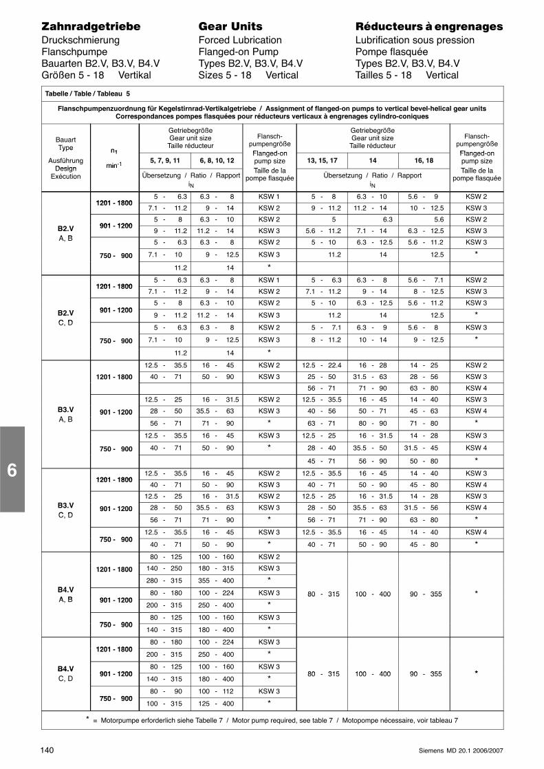
140 Siemens MD 20.1 2006/2007
������������� ���� �� ��������� � ����������Druckschmierung Forced Lubrication Lubrification sous pressionFlanschpumpe Flanged-on Pump Pompe flasquéeBauarten B2.V, B3.V, B4.V Types B2.V, B3.V, B4.V Types B2.V, B3.V, B4.VGrößen 5 - 18 Vertikal Sizes 5 - 18 Vertical Tailles 5 - 18 Vertical
Tabelle / Table / Tableau 5
Flanschpumpenzuordnung für Kegelstirnrad-Vertikalgetriebe / Assignment of flanged-on pumps to vertical bevel-helical gear unitsCorrespondances pompes flasquées pour réducteurs verticaux à engrenages cylindro-coniques
BauartType n1
GetriebegrößeGear unit size
Taille réducteurFlansch-
pumpengrößeFlanged on
GetriebegrößeGear unit size
Taille réducteurFlansch-
pumpengrößeFlanged on
Ty e
AusführungDesign
n1
min-1 5, 7, 9, 11 6, 8, 10, 12Flanged-onpump sizeT ill d l
13, 15, 17 14 16, 18Flanged-onpump sizeT ill d lDesign
Exécution
min 1
Übersetzung / Ratio / RapportiN
Taille de lapompe flasquée Übersetzung / Ratio / Rapport
iN
Taille de lapompe flasquée
1201 18005 - 6.3 6.3 - 8 KSW 1 5 - 8 6.3 - 10 5.6 - 9 KSW 2
1201 - 18007.1 - 11.2 9 - 14 KSW 2 9 - 11.2 11.2 - 14 10 - 12.5 KSW 3
901 12005 - 8 6.3 - 10 KSW 2 5 6.3 5.6 KSW 2
B2.VA B
901 - 12009 - 11.2 11.2 - 14 KSW 3 5.6 - 11.2 7.1 - 14 6.3 - 12.5 KSW 3
A, B 5 - 6.3 6.3 - 8 KSW 2 5 - 10 6.3 - 12.5 5.6 - 11.2 KSW 3
750 - 900 7.1 - 10 9 - 12.5 KSW 3 11.2 14 12.5 * 11.2 14 *
1201 18005 - 6.3 6.3 - 8 KSW 1 5 - 6.3 6.3 - 8 5.6 - 7.1 KSW 2
1201 - 18007.1 - 11.2 9 - 14 KSW 2 7.1 - 11.2 9 - 14 8 - 12.5 KSW 3
901 12005 - 8 6.3 - 10 KSW 2 5 - 10 6.3 - 12.5 5.6 - 11.2 KSW 3
B2.VC D
901 - 12009 - 11.2 11.2 - 14 KSW 3 11.2 14 12.5 *
C, D5 - 6.3 6.3 - 8 KSW 2 5 - 7.1 6.3 - 9 5.6 - 8 KSW 3
750 - 900 7.1 - 10 9 - 12.5 KSW 3 8 - 11.2 10 - 14 9 - 12.5 * 11.2 14 *
12.5 - 35.5 16 - 45 KSW 2 12.5 - 22.4 16 - 28 14 - 25 KSW 2
1201 - 1800 40 - 71 50 - 90 KSW 3 25 - 50 31.5 - 63 28 - 56 KSW 3
56 - 71 71 - 90 63 - 80 KSW 4
12.5 - 25 16 - 31.5 KSW 2 12.5 - 35.5 16 - 45 14 - 40 KSW 3B3.VA B
901 - 1200 28 - 50 35.5 - 63 KSW 3 40 - 56 50 - 71 45 - 63 KSW 4A, B
901 1200
56 - 71 71 - 90 * 63 - 71 80 - 90 71 - 80 *12.5 - 35.5 16 - 45 KSW 3 12.5 - 25 16 - 31.5 14 - 28 KSW 3
750 - 900 40 - 71 50 - 90 * 28 - 40 35.5 - 50 31.5 - 45 KSW 4
45 - 71 56 - 90 50 - 80 *
1201 180012.5 - 35.5 16 - 45 KSW 2 12.5 - 35.5 16 - 45 14 - 40 KSW 3
1201 - 180040 - 71 50 - 90 KSW 3 40 - 71 50 - 90 45 - 80 KSW 4
12.5 - 25 16 - 31.5 KSW 2 12.5 - 25 16 - 31.5 14 - 28 KSW 3B3.VC D
901 - 1200 28 - 50 35.5 - 63 KSW 3 28 - 50 35.5 - 63 31.5 - 56 KSW 4C, D
901 1200
56 - 71 71 - 90 * 56 - 71 71 - 90 63 - 80 *
750 90012.5 - 35.5 16 - 45 KSW 3 12.5 - 35.5 16 - 45 14 - 40 KSW 4
750 - 90040 - 71 50 - 90 * 40 - 71 50 - 90 45 - 80 *80 - 125 100 - 160 KSW 2
1201 - 1800 140 - 250 180 - 315 KSW 3
B4 V
1201 1800
280 - 315 355 - 400 *B4.VA B 901 1200
80 - 180 100 - 224 KSW 3 80 - 315 100 - 400 90 - 355 *A, B 901 - 1200
200 - 315 250 - 400 *80 315 100 400 90 355
750 90080 - 125 100 - 160 KSW 3
750 - 900140 - 315 180 - 400 *
1201 180080 - 180 100 - 224 KSW 3
1201 - 1800200 - 315 250 - 400 *
B4.V901 1200
80 - 125 100 - 160 KSW 380 315 100 400 90 355 *
B4.VC, D
901 - 1200140 - 315 180 - 400 *
80 - 315 100 - 400 90 - 355 *
750 90080 - 90 100 - 112 KSW 3
750 - 900100 - 315 125 - 400 *
* = Motorpumpe erforderlich siehe Tabelle 7 / Motor pump required, see table 7 / Motopompe nécessaire, voir tableau 7
6
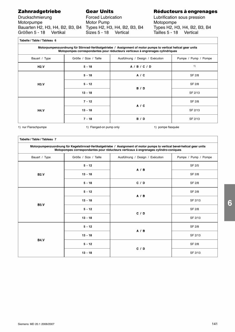
141Siemens MD 20.1 2006/2007
������������� ���� �� ��������� � ����������Druckschmierung Forced Lubrication Lubrification sous pressionMotorpumpe Motor Pump MotopompeBauarten H2, H3, H4, B2, B3, B4 Types H2, H3, H4, B2, B3, B4 Types H2, H3, H4, B2, B3, B4Größen 5 - 18 Vertikal Sizes 5 - 18 Vertical Tailles 5 - 18 Vertical
Tabelle / Table / Tableau 6
Motorpumpenzuordnung für Stirnrad-Vertikalgetriebe / Assignment of motor pumps to vertical helical gear unitsMotopompes correspondantes pour réducteurs verticaux à engrenages cylindriques
Bauart / Type Größe / Size / Taille Ausführung / Design / Exécution Pumpe / Pump / Pompe
H2.V 5 - 18 A / B / C / D 1)
5 - 18 A / C SF 2/8
H3.V 5 - 12B / D
SF 2/8
13 - 18B / D
SF 2/13
7 - 12A / C
SF 2/8
H4.V 13 - 18A / C
SF 2/13
7 - 18 B / D SF 2/13
1) nur Flanschpumpe 1) Flanged-on pump only 1) pompe flasquée
Tabelle / Table / Tableau 7
Motorpumpenzuordnung für Kegelstirnrad-Vertikalgetriebe / Assignment of motor pumps to vertical bevel-helical gear unitsMotopompes correspondantes pour réducteurs verticaux à engrenages cylindro-coniques
Bauart / Type Größe / Size / Taille Ausführung / Design / Exécution Pumpe / Pump / Pompe
5 - 12A / B
SF 2/5
B2.V 13 - 18A / B
SF 2/8
5 - 18 C / D SF 2/8
5 - 12A / B
SF 2/8
B3 V13 - 18
A / B SF 2/13
B3.V 5 - 12
C / DSF 2/8
13 - 18C / D
SF 2/13
5 - 12A / B
SF 2/8
B4 V
13 - 18A / B
SF 2/13
B4.V 5 - 12
C / D
SF 2/8
13 - 18C / D
SF 2/13
6
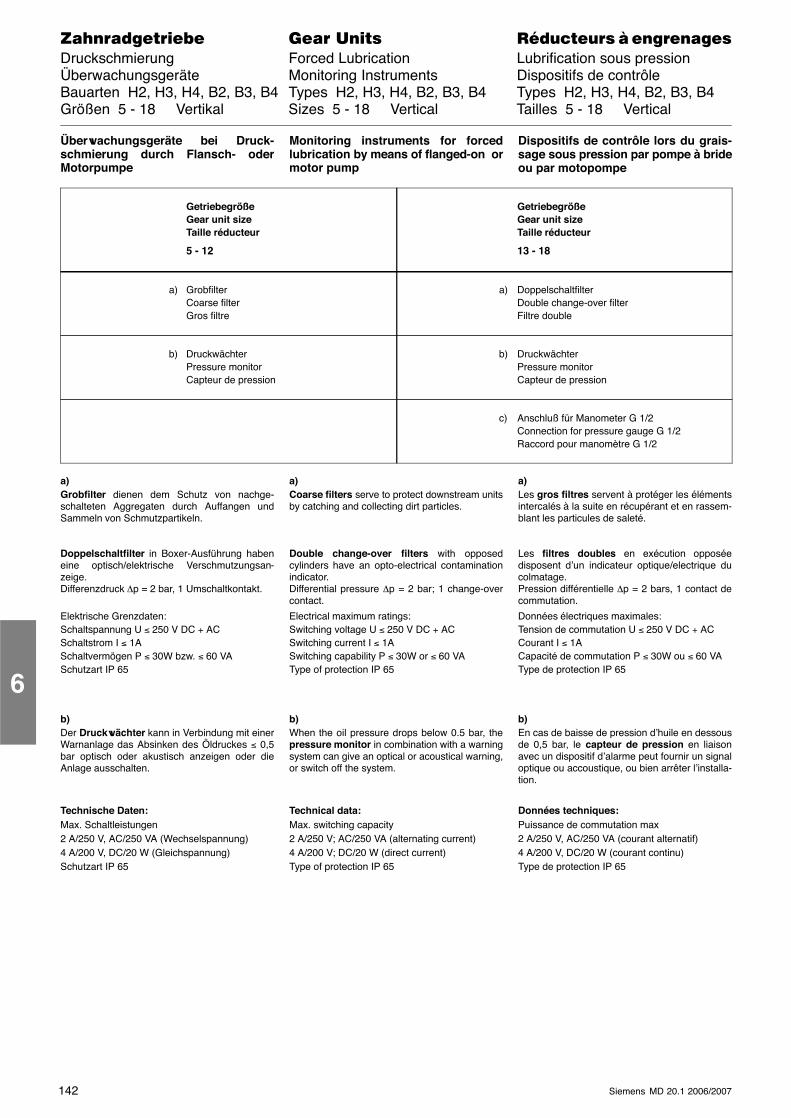
142 Siemens MD 20.1 2006/2007
������������� ���� �� ��������� � ����������Druckschmierung Forced Lubrication Lubrification sous pressionÜberwachungsgeräte Monitoring Instruments Dispositifs de contrôleBauarten H2, H3, H4, B2, B3, B4 Types H2, H3, H4, B2, B3, B4 Types H2, H3, H4, B2, B3, B4Größen 5 - 18 Vertikal Sizes 5 - 18 Vertical Tailles 5 - 18 Vertical
Überwachungsgeräte bei Druck-schmierung durch Flansch- oderMotorpumpe
Monitoring instruments for forcedlubrication by means of flanged-on ormotor pump
Dispositifs de contrôle lors du grais-sage sous pression par pompe à brideou par motopompe
GetriebegrößeGear unit sizeTaille réducteur
5 - 12
GetriebegrößeGear unit sizeTaille réducteur
13 - 18
a) GrobfilterCoarse filterGros filtre
a) Doppelschaltfilter Double change-over filterFiltre double
b) Druckwächter Pressure monitorCapteur de pression
b) DruckwächterPressure monitorCapteur de pression
c) Anschluß für Manometer G 1/2 Connection for pressure gauge G 1/2Raccord pour manomètre G 1/2
a)Grobfilter dienen dem Schutz von nachge-schalteten Aggregaten durch Auffangen undSammeln von Schmutzpartikeln.
Doppelschaltfilter in Boxer-Ausführung habeneine optisch/elektrische Verschmutzungsan-zeige.Differenzdruck ∆p = 2 bar, 1 Umschaltkontakt.
Elektrische Grenzdaten:Schaltspannung U ≤ 250 V DC + ACSchaltstrom I ≤ 1ASchaltvermögen P ≤ 30W bzw. ≤ 60 VASchutzart IP 65
b)Der Druckwächter kann in Verbindung mit einerWarnanlage das Absinken des Öldruckes ≤ 0,5bar optisch oder akustisch anzeigen oder dieAnlage ausschalten.
Technische Daten:Max. Schaltleistungen2 A/250 V, AC/250 VA (Wechselspannung)4 A/200 V, DC/20 W (Gleichspannung)Schutzart IP 65
a)Coarse filters serve to protect downstream unitsby catching and collecting dirt particles.
Double change-over filters with opposedcylinders have an opto-electrical contaminationindicator.Differential pressure ∆p = 2 bar; 1 change-overcontact.
Electrical maximum ratings:Switching voltage U ≤ 250 V DC + ACSwitching current I ≤ 1ASwitching capability P ≤ 30W or ≤ 60 VAType of protection IP 65
b)When the oil pressure drops below 0.5 bar, thepressure monitor in combination with a warningsystem can give an optical or acoustical warning,or switch off the system.
Technical data:Max. switching capacity2 A/250 V; AC/250 VA (alternating current)4 A/200 V; DC/20 W (direct current)Type of protection IP 65
a)Les gros filtres servent à protéger les élémentsintercalés à la suite en récupérant et en rassem-blant les particules de saleté.
Les filtres doubles en exécution opposéedisposent d’un indicateur optique/electrique ducolmatage.Pression différentielle ∆p = 2 bars, 1 contact decommutation.
Données électriques maximales:Tension de commutation U ≤ 250 V DC + ACCourant I ≤ 1ACapacité de commutation P ≤ 30W ou ≤ 60 VAType de protection IP 65
b)En cas de baisse de pression d’huile en dessousde 0,5 bar, le capteur de pression en liaisonavec un dispositif d’alarme peut fournir un signaloptique ou accoustique, ou bien arrêter l’installa-tion.
Données techniques:Puissance de commutation max2 A/250 V, AC/250 VA (courant alternatif)4 A/200 V, DC/20 W (courant continu)Type de protection IP 65
6
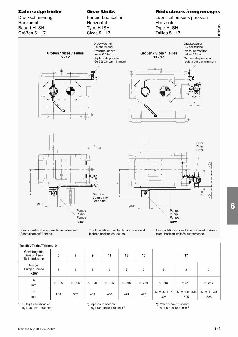
143Siemens MD 20.1 2006/2007
������������� ���� �� ��������� � ����������Druckschmierung Forced Lubrication Lubrification sous pressionHorizontal Horizontal HorizontalBauart H1SH Type H1SH Type H1SHGrößen 5 - 17 Sizes 5 - 17 Tailles 5 - 17
Fundament muß waagerecht und eben sein,Schräglage auf Anfrage.
Druckwächter0.5 bar fallendPressure monitor,below 0.5 barCapteur de pression réglé à 0,5 bar minimum
GrobfilterCoarse filterGros filtre
The foundation must be flat and horizontal.Inclined position on request.
Les fondations doivent être planes et horizon-tales. Position inclinée sur demande.
FilterFilterFiltre
PumpePumpPompe
KSW
PumpePumpPompe
KSW
Größen / Sizes / Tailles5 - 12
Größen / Sizes / Tailles13 - 17
Druckwächter0.5 bar fallendPressure monitor,below 0.5 barCapteur de pressionréglé à 0,5 bar minimum
Tabelle / Table / Tableau 9
GetriebegrößeGear unit size
Taille réducteur5 7 9 11 13 15 17
Pumpe *Pump / Pompe
KSW1 2 2 2 3 3 3 3 3
A
mm≈ 115 ≈ 105 ≈ 105 ≈ 125 ≈ 240 ≈ 240 ≈ 240 ≈ 240 ≈ 240
E
mm283 337 400 430 474 479
iN = 3.15 - 4
525
iN = 4.5 - 5.6
525
iN = 2 - 2.8
525
*) Gültig für Drehzahlen:n1 ≥ 900 bis 1800 min-1
*) Applies to speeds:n1 ≥ 900 up to 1800 min-1
*) Valable pour vitesses:n1 ≥ 900 à 1800 min-1
K20
/019
6
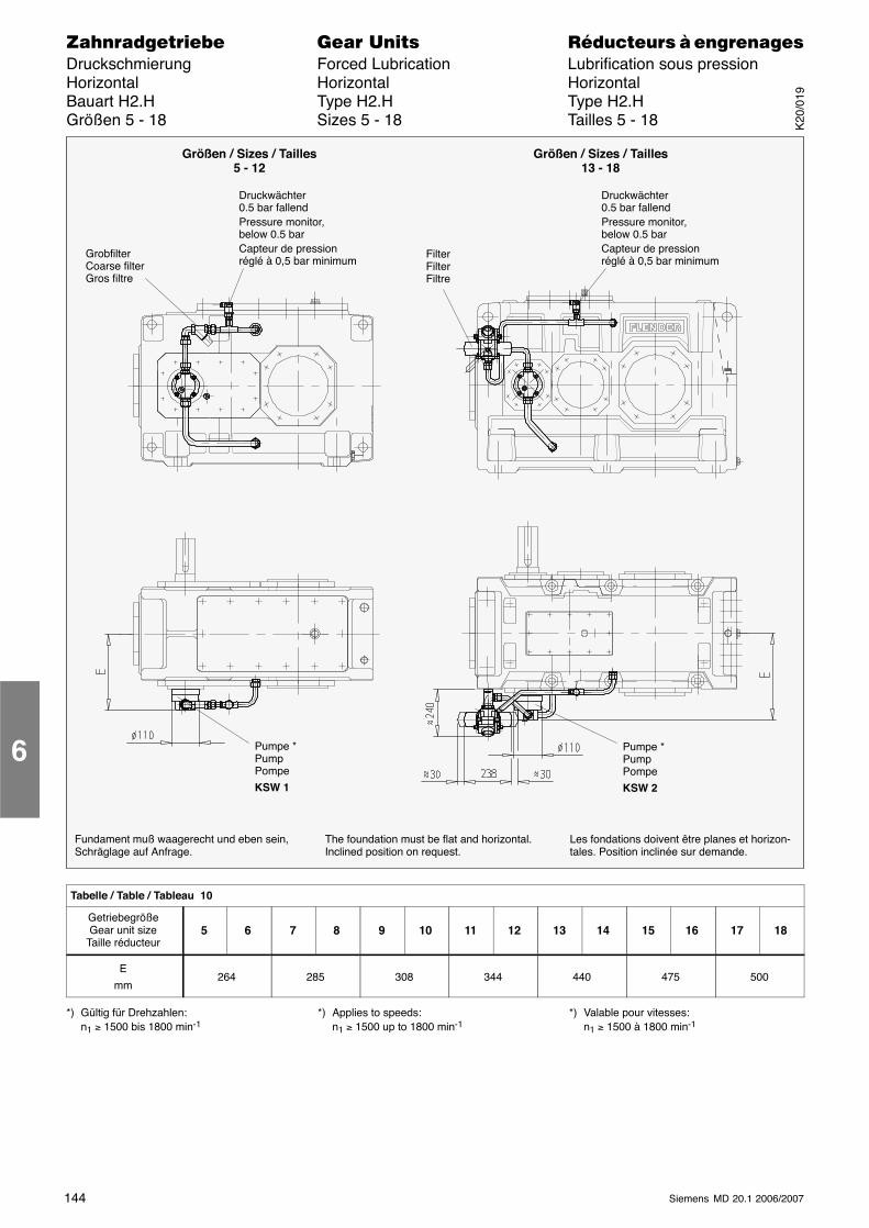
144 Siemens MD 20.1 2006/2007
������������� ���� �� ��������� � ����������Druckschmierung Forced Lubrication Lubrification sous pressionHorizontal Horizontal HorizontalBauart H2.H Type H2.H Type H2.HGrößen 5 - 18 Sizes 5 - 18 Tailles 5 - 18
Fundament muß waagerecht und eben sein,Schräglage auf Anfrage.
GrobfilterCoarse filterGros filtre
Pumpe *PumpPompe
KSW 1
The foundation must be flat and horizontal.Inclined position on request.
Les fondations doivent être planes et horizon-tales. Position inclinée sur demande.
FilterFilterFiltre
Pumpe *PumpPompe
KSW 2
Größen / Sizes / Tailles5 - 12
Größen / Sizes / Tailles13 - 18
Druckwächter0.5 bar fallendPressure monitor,below 0.5 barCapteur de pressionréglé à 0,5 bar minimum
Druckwächter0.5 bar fallendPressure monitor,below 0.5 barCapteur de pressionréglé à 0,5 bar minimum
Tabelle / Table / Tableau 10
GetriebegrößeGear unit size
Taille réducteur5 6 7 8 9 10 11 12 13 14 15 16 17 18
E
mm264 285 308 344 440 475 500
*) Gültig für Drehzahlen:n1 ≥ 1500 bis 1800 min-1
*) Applies to speeds:n1 ≥ 1500 up to 1800 min-1
*) Valable pour vitesses:n1 ≥ 1500 à 1800 min-1
6K
20/0
19
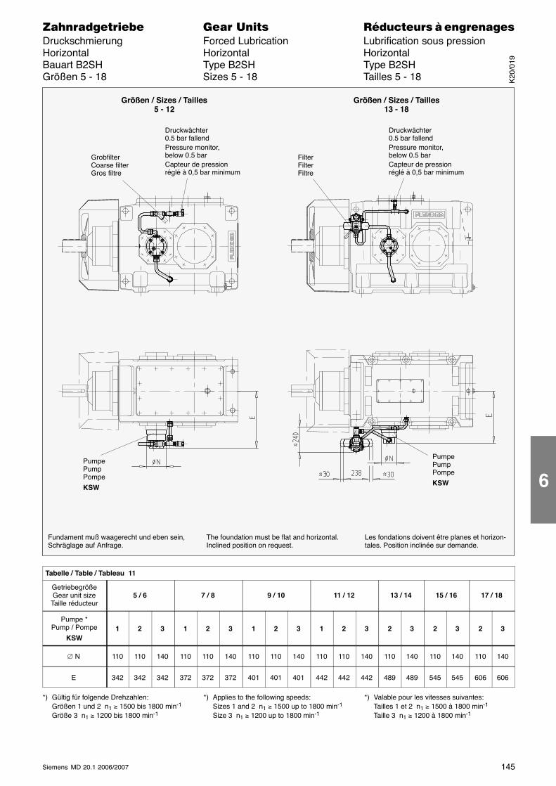
145Siemens MD 20.1 2006/2007
������������� ���� �� ��������� � ����������Druckschmierung Forced Lubrication Lubrification sous pressionHorizontal Horizontal HorizontalBauart B2SH Type B2SH Type B2SHGrößen 5 - 18 Sizes 5 - 18 Tailles 5 - 18
Fundament muß waagerecht und eben sein,Schräglage auf Anfrage.
Les fondations doivent être planes et horizon-tales. Position inclinée sur demande.
The foundation must be flat and horizontal.Inclined position on request.
GrobfilterCoarse filterGros filtre
FilterFilterFiltre
PumpePumpPompe
KSW
PumpePumpPompe
KSW
Größen / Sizes / Tailles5 - 12
Größen / Sizes / Tailles13 - 18
Druckwächter0.5 bar fallendPressure monitor,below 0.5 barCapteur de pressionréglé à 0,5 bar minimum
Druckwächter0.5 bar fallendPressure monitor,below 0.5 barCapteur de pressionréglé à 0,5 bar minimum
Tabelle / Table / Tableau 11
GetriebegrößeGear unit size
Taille réducteur5 / 6 7 / 8 9 / 10 11 / 12 13 / 14 15 / 16 17 / 18
Pumpe *Pump / Pompe
KSW1 2 3 1 2 3 1 2 3 1 2 3 2 3 2 3 2 3
∅ N 110 110 140 110 110 140 110 110 140 110 110 140 110 140 110 140 110 140
E 342 342 342 372 372 372 401 401 401 442 442 442 489 489 545 545 606 606
*) Gültig für folgende Drehzahlen:Größen 1 und 2 n1 ≥ 1500 bis 1800 min-1
Größe 3 n1 ≥ 1200 bis 1800 min-1
*) Applies to the following speeds:Sizes 1 and 2 n1 ≥ 1500 up to 1800 min-1
Size 3 n1 ≥ 1200 up to 1800 min-1
*) Valable pour les vitesses suivantes:Tailles 1 et 2 n1 ≥ 1500 à 1800 min-1
Taille 3 n1 ≥ 1200 à 1800 min-1
K20
/019
6
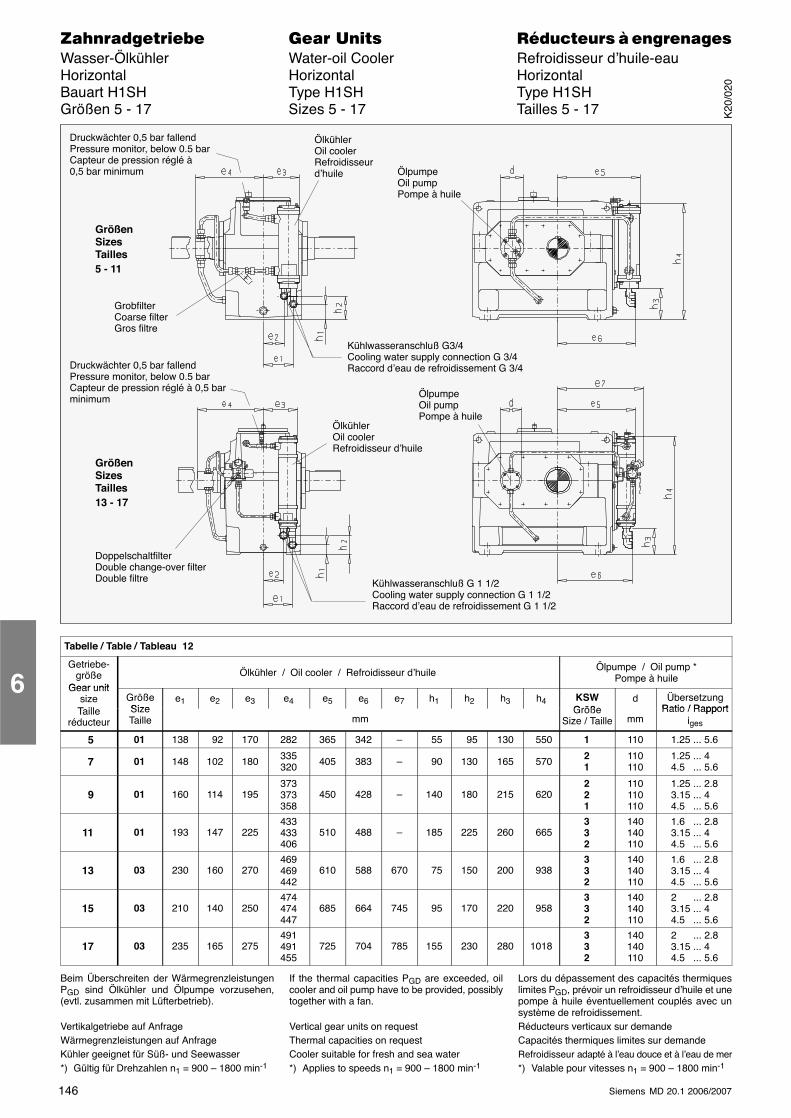
146 Siemens MD 20.1 2006/2007
������������� ���� �� ��������� � ����������Wasser-Ölkühler Water-oil Cooler Refroidisseur d’huile-eauHorizontal Horizontal HorizontalBauart H1SH Type H1SH Type H1SHGrößen 5 - 17 Sizes 5 - 17 Tailles 5 - 17
ÖlkühlerOil coolerRefroidisseurd’huile
GrobfilterCoarse filterGros filtre
GrößenSizesTailles5 - 11
GrößenSizesTailles13 - 17
ÖlpumpeOil pumpPompe à huile
Kühlwasseranschluß G3/4Cooling water supply connection G 3/4Raccord d’eau de refroidissement G 3/4
DoppelschaltfilterDouble change-over filterDouble filtre
ÖlkühlerOil coolerRefroidisseur d’huile
Kühlwasseranschluß G 1 1/2Cooling water supply connection G 1 1/2Raccord d’eau de refroidissement G 1 1/2
ÖlpumpeOil pumpPompe à huile
Druckwächter 0,5 bar fallendPressure monitor, below 0.5 barCapteur de pression réglé à0,5 bar minimum
Druckwächter 0,5 bar fallendPressure monitor, below 0.5 barCapteur de pression réglé à 0,5 barminimum
Tabelle / Table / Tableau 12
Getriebe-größe
Gear unit
Ölkühler / Oil cooler / Refroidisseur d’huile Ölpumpe / Oil pump *Pompe à huile
Gear unitsizeT ill
GrößeSize
e1 e2 e3 e4 e5 e6 e7 h1 h2 h3 h4 KSWGröße
d ÜbersetzungRatio / RapportTaille
réducteurSizeTaille mm
GrößeSize / Taille mm
Ratio / Rapportiges
5 01 138 92 170 282 365 342 – 55 95 130 550 1 110 1.25 ... 5.6
7 01 148 102 180 335320 405 383 – 90 130 165 570 2
1110110
1.25 ... 44.5 ... 5.6
9 01 160 114 195373373358
450 428 – 140 180 215 620221
110110110
1.25 ... 2.83.15 ... 44.5 ... 5.6
11 01 193 147 225433433406
510 488 – 185 225 260 665332
140140110
1.6 ... 2.83.15 ... 44.5 ... 5.6
13 03 230 160 270469469442
610 588 670 75 150 200 938332
140140110
1.6 ... 2.83.15 ... 44.5 ... 5.6
15 03 210 140 250474474447
685 664 745 95 170 220 958332
140140110
2 ... 2.83.15 ... 44.5 ... 5.6
17 03 235 165 275491491455
725 704 785 155 230 280 1018332
140140110
2 ... 2.83.15 ... 44.5 ... 5.6
Beim Überschreiten der WärmegrenzleistungenPGD sind Ölkühler und Ölpumpe vorzusehen,(evtl. zusammen mit Lüfterbetrieb).
Vertikalgetriebe auf AnfrageWärmegrenzleistungen auf AnfrageKühler geeignet für Süß- und Seewasser*) Gültig für Drehzahlen n1 = 900 – 1800 min-1
If the thermal capacities PGD are exceeded, oilcooler and oil pump have to be provided, possiblytogether with a fan.
Vertical gear units on requestThermal capacities on requestCooler suitable for fresh and sea water*) Applies to speeds n1 = 900 – 1800 min-1
Lors du dépassement des capacités thermiqueslimites PGD, prévoir un refroidisseur d’huile et unepompe à huile éventuellement couplés avec unsystème de refroidissement.Réducteurs verticaux sur demandeCapacités thermiques limites sur demandeRefroidisseur adapté à l’eau douce et à l’eau de mer*) Valable pour vitesses n1 = 900 – 1800 min-1
6K
20/0
20
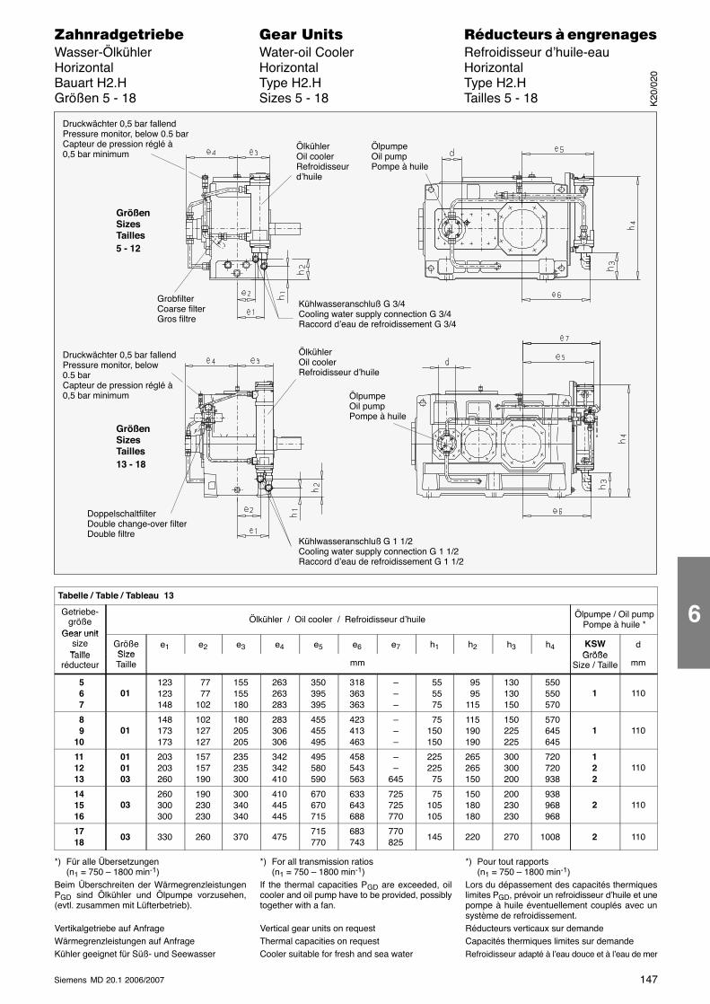
147Siemens MD 20.1 2006/2007
������������� ���� �� ��������� � ����������Wasser-Ölkühler Water-oil Cooler Refroidisseur d’huile-eauHorizontal Horizontal HorizontalBauart H2.H Type H2.H Type H2.HGrößen 5 - 18 Sizes 5 - 18 Tailles 5 - 18
ÖlpumpeOil pumpPompe à huile
Kühlwasseranschluß G 3/4Cooling water supply connection G 3/4Raccord d’eau de refroidissement G 3/4
GrobfilterCoarse filterGros filtre
GrößenSizesTailles5 - 12
GrößenSizesTailles13 - 18
Kühlwasseranschluß G 1 1/2Cooling water supply connection G 1 1/2Raccord d’eau de refroidissement G 1 1/2
ÖlkühlerOil coolerRefroidisseurd’huile
ÖlpumpeOil pumpPompe à huile
ÖlkühlerOil coolerRefroidisseur d’huile
DoppelschaltfilterDouble change-over filterDouble filtre
Druckwächter 0,5 bar fallendPressure monitor, below 0.5 barCapteur de pression réglé à0,5 bar minimum
Druckwächter 0,5 bar fallendPressure monitor, below0.5 barCapteur de pression réglé à 0,5 bar minimum
Tabelle / Table / Tableau 13
Getriebe-größe
Gear unit
Ölkühler / Oil cooler / Refroidisseur d’huile Ölpumpe / Oil pumpPompe à huile *
Gear unitsizeTaille
GrößeSize
e1 e2 e3 e4 e5 e6 e7 h1 h2 h3 h4 KSWGröße
dTaille
réducteurSizeTaille mm
GrößeSize / Taille mm
5 6 7
01123123148
77 77102
155155180
263263283
350395395
318363363
–––
55 55 75
95 95115
130130150
550 550 570
1 110
8 910
01148173173
102127127
180205205
283306306
455455495
423413463
–––
75150150
115190190
150225225
570 645 645
1 110
111213
010103
203203260
157157190
235235300
342342410
495580590
458543563
––
645
225225 75
265265150
300300200
720 720 938
122
110
141516
03260300300
190230230
300340340
410445445
670670715
633643688
725725770
75105105
150180180
200230230
938 968 968
2 110
1718
03 330 260 370 475715770
683743
770825
145 220 270 1008 2 110
*) Für alle Übersetzungen(n1 = 750 – 1800 min-1)
Beim Überschreiten der WärmegrenzleistungenPGD sind Ölkühler und Ölpumpe vorzusehen,(evtl. zusammen mit Lüfterbetrieb).
Vertikalgetriebe auf AnfrageWärmegrenzleistungen auf AnfrageKühler geeignet für Süß- und Seewasser
*) For all transmission ratios(n1 = 750 – 1800 min-1)
If the thermal capacities PGD are exceeded, oilcooler and oil pump have to be provided, possiblytogether with a fan.
Vertical gear units on requestThermal capacities on requestCooler suitable for fresh and sea water
*) Pour tout rapports(n1 = 750 – 1800 min-1)
Lors du dépassement des capacités thermiqueslimites PGD, prévoir un refroidisseur d’huile et unepompe à huile éventuellement couplés avec unsystème de refroidissement.Réducteurs verticaux sur demandeCapacités thermiques limites sur demandeRefroidisseur adapté à l’eau douce et à l’eau de mer
K20
/020
6
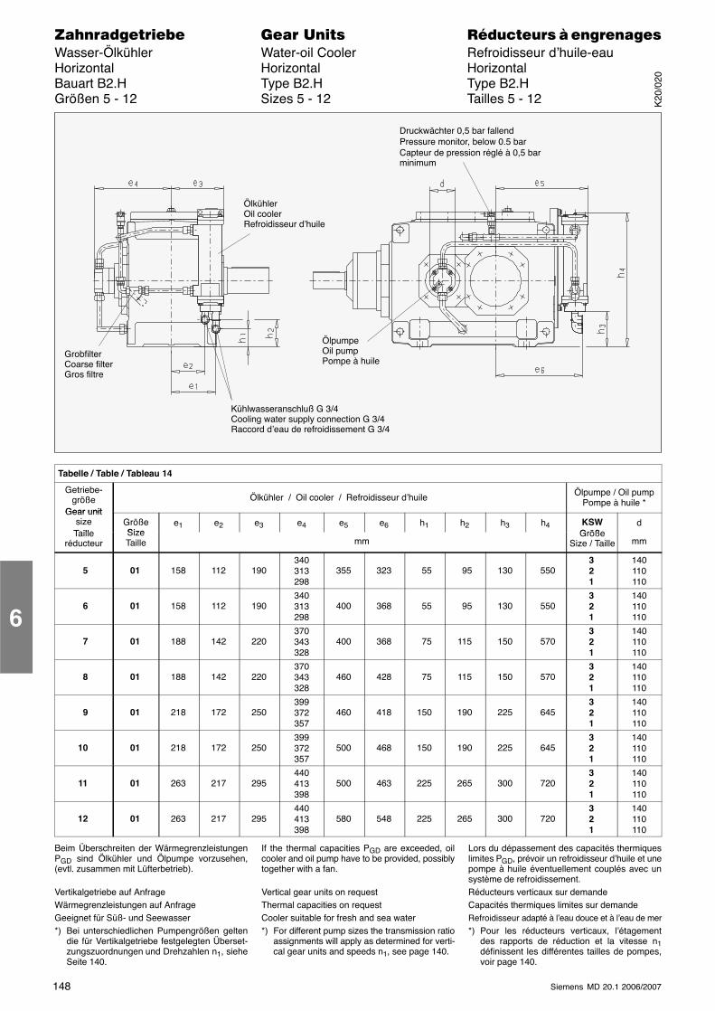
148 Siemens MD 20.1 2006/2007
������������� ���� �� ��������� � ����������Wasser-Ölkühler Water-oil Cooler Refroidisseur d’huile-eauHorizontal Horizontal HorizontalBauart B2.H Type B2.H Type B2.HGrößen 5 - 12 Sizes 5 - 12 Tailles 5 - 12
ÖlkühlerOil coolerRefroidisseur d’huile
Kühlwasseranschluß G 3/4Cooling water supply connection G 3/4Raccord d’eau de refroidissement G 3/4
GrobfilterCoarse filterGros filtre
ÖlpumpeOil pumpPompe à huile
Druckwächter 0,5 bar fallendPressure monitor, below 0.5 barCapteur de pression réglé à 0,5 barminimum
Tabelle / Table / Tableau 14
Getriebe-größe
Gear unit
Ölkühler / Oil cooler / Refroidisseur d’huile Ölpumpe / Oil pumpPompe à huile *
Gear unitsizeTaille
GrößeSize
e1 e2 e3 e4 e5 e6 h1 h2 h3 h4 KSWGröße
dTaille
réducteurSizeTaille mm
GrößeSize / Taille mm
5 01 158 112 190340313298
355 323 55 95 130 550321
140110110
6 01 158 112 190340313298
400 368 55 95 130 550321
140110110
7 01 188 142 220370343328
400 368 75 115 150 570321
140110110
8 01 188 142 220370343328
460 428 75 115 150 570321
140110110
9 01 218 172 250399372357
460 418 150 190 225 645321
140110110
10 01 218 172 250399372357
500 468 150 190 225 645321
140110110
11 01 263 217 295440413398
500 463 225 265 300 720321
140110110
12 01 263 217 295440413398
580 548 225 265 300 720321
140110110
Beim Überschreiten der WärmegrenzleistungenPGD sind Ölkühler und Ölpumpe vorzusehen,(evtl. zusammen mit Lüfterbetrieb).
Vertikalgetriebe auf AnfrageWärmegrenzleistungen auf AnfrageGeeignet für Süß- und Seewasser*) Bei unterschiedlichen Pumpengrößen gelten
die für Vertikalgetriebe festgelegten Überset-zungszuordnungen und Drehzahlen n1, sieheSeite 140.
If the thermal capacities PGD are exceeded, oilcooler and oil pump have to be provided, possiblytogether with a fan.
Vertical gear units on requestThermal capacities on requestCooler suitable for fresh and sea water*) For different pump sizes the transmission ratio
assignments will apply as determined for verti-cal gear units and speeds n1, see page 140.
Lors du dépassement des capacités thermiqueslimites PGD, prévoir un refroidisseur d’huile et unepompe à huile éventuellement couplés avec unsystème de refroidissement.Réducteurs verticaux sur demandeCapacités thermiques limites sur demandeRefroidisseur adapté à l’eau douce et à l’eau de mer*) Pour les réducteurs verticaux, l’étagement
des rapports de réduction et la vitesse n1définissent les différentes tailles de pompes,voir page 140.
6K
20/0
20
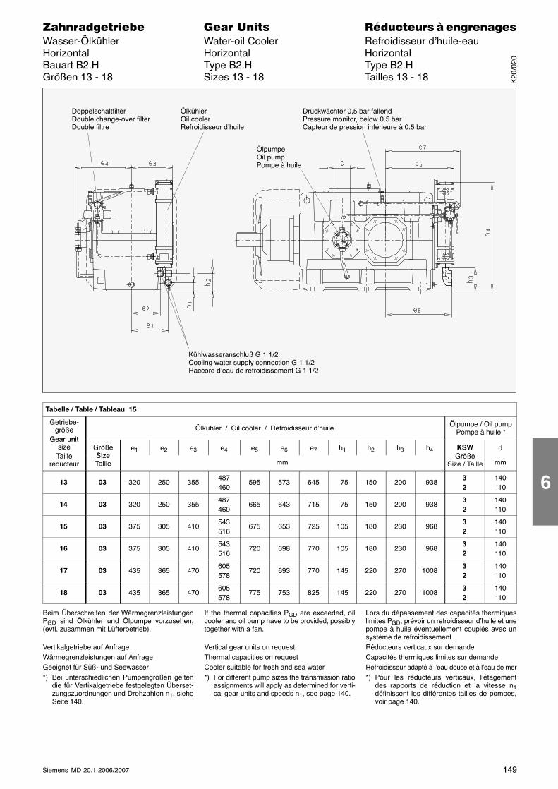
149Siemens MD 20.1 2006/2007
������������� ���� �� ��������� � ����������Wasser-Ölkühler Water-oil Cooler Refroidisseur d’huile-eauHorizontal Horizontal HorizontalBauart B2.H Type B2.H Type B2.HGrößen 13 - 18 Sizes 13 - 18 Tailles 13 - 18
ÖlkühlerOil coolerRefroidisseur d’huile
Kühlwasseranschluß G 1 1/2Cooling water supply connection G 1 1/2Raccord d’eau de refroidissement G 1 1/2
DoppelschaltfilterDouble change-over filterDouble filtre
ÖlpumpeOil pumpPompe à huile
Druckwächter 0,5 bar fallendPressure monitor, below 0.5 barCapteur de pression inférieure à 0.5 bar
Tabelle / Table / Tableau 15
Getriebe-größe
Gear unit
Ölkühler / Oil cooler / Refroidisseur d’huile Ölpumpe / Oil pumpPompe à huile *
Gear unitsizeTaille
GrößeSize
e1 e2 e3 e4 e5 e6 e7 h1 h2 h3 h4 KSWGröße
dTaille
réducteurSizeTaille mm
GrößeSize / Taille mm
13 03 320 250 355487460
595 573 645 75 150 200 93832
140110
14 03 320 250 355487460
665 643 715 75 150 200 93832
140110
15 03 375 305 410543516
675 653 725 105 180 230 96832
140110
16 03 375 305 410543516
720 698 770 105 180 230 96832
140110
17 03 435 365 470605578
720 693 770 145 220 270 100832
140110
18 03 435 365 470605578
775 753 825 145 220 270 100832
140110
Beim Überschreiten der WärmegrenzleistungenPGD sind Ölkühler und Ölpumpe vorzusehen,(evtl. zusammen mit Lüfterbetrieb).
Vertikalgetriebe auf AnfrageWärmegrenzleistungen auf AnfrageGeeignet für Süß- und Seewasser*) Bei unterschiedlichen Pumpengrößen gelten
die für Vertikalgetriebe festgelegten Überset-zungszuordnungen und Drehzahlen n1, sieheSeite 140.
If the thermal capacities PGD are exceeded, oilcooler and oil pump have to be provided, possiblytogether with a fan.
Vertical gear units on requestThermal capacities on requestCooler suitable for fresh and sea water*) For different pump sizes the transmission ratio
assignments will apply as determined for verti-cal gear units and speeds n1, see page 140.
Lors du dépassement des capacités thermiqueslimites PGD, prévoir un refroidisseur d’huile et unepompe à huile éventuellement couplés avec unsystème de refroidissement.Réducteurs verticaux sur demandeCapacités thermiques limites sur demandeRefroidisseur adapté à l’eau douce et à l’eau de mer*) Pour les réducteurs verticaux, l’étagement
des rapports de réduction et la vitesse n1définissent les différentes tailles de pompes,voir page 140.
K20
/020
6
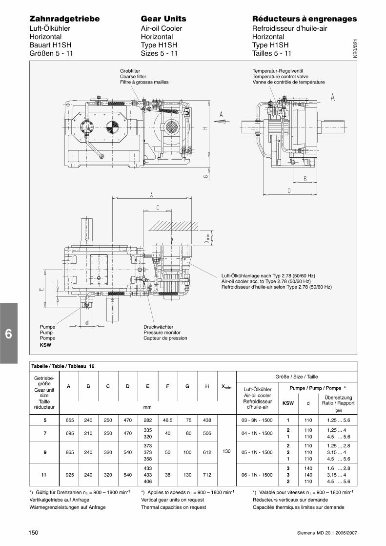
150 Siemens MD 20.1 2006/2007
������������� ���� �� ��������� � ����������Luft-Ölkühler Air-oil Cooler Refroidisseur d’huile-airHorizontal Horizontal HorizontalBauart H1SH Type H1SH Type H1SHGrößen 5 - 11 Sizes 5 - 11 Tailles 5 - 11
GrobfilterCoarse filterFiltre à grosses mailles
Temperatur-RegelventilTemperature control valveVanne de contrôle de température
Luft-Ölkühlanlage nach Typ 2.78 (50/60 Hz)Air-oil cooler acc. to Type 2.78 (50/60 Hz)Refroidisseur d’huile-air selon Type 2.78 (50/60 Hz)
DruckwächterPressure monitorCapteur de pression
PumpePumpPompeKSW
d
Tabelle / Table / Tableau 16
Getriebe-öß
Größe / Size / Taillegröße
GA B C D E F G H Xmin L ft Ölkühl Pumpe / Pump / Pompe *
gGear unit
i
A B C D E F G H Xmin Luft-Ölkühler Pumpe / Pump / Pompe *Gear unitsizeTaille
Air-oil coolerRefroidisseur
ÜbersetzungTaille
réducteur mmRefroidisseur
d’huile-airKSW d
ÜbersetzungRatio / Rapport
iges
5 655 240 250 470 282 46.5 75 438 03 - 3N - 1500 1 110 1.25 ... 5.6
7 695 210 250 470335320
40 80 506 04 - 1N - 150021
110110
1.25 ... 44.5 ... 5.6
9 865 240 320 540373373358
50 100 612 130 05 - 1N - 1500221
110110110
1.25 ... 2.83.15 ... 44.5 ... 5.6
11 925 240 320 540433433406
38 130 712 06 - 1N - 1500332
140140110
1.6 ... 2.83.15 ... 44.5 ... 5.6
*) Gültig für Drehzahlen n1 = 900 – 1800 min-1
Vertikalgetriebe auf Anfrage
Wärmegrenzleistungen auf Anfrage
*) Applies to speeds n1 = 900 – 1800 min-1
Vertical gear units on request
Thermal capacities on request
*) Valable pour vitesses n1 = 900 – 1800 min-1
Réducteurs verticaux sur demande
Capacités thermiques limites sur demande
6K
20/0
21
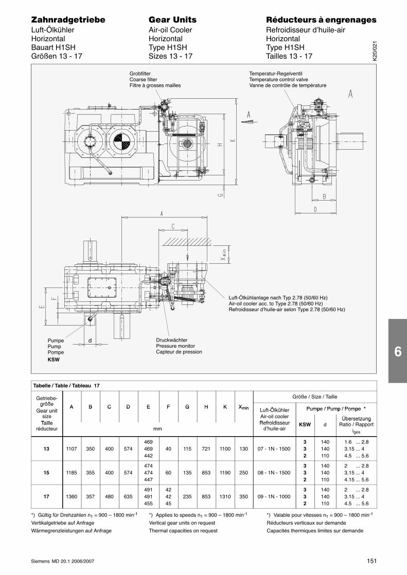
151Siemens MD 20.1 2006/2007
������������� ���� �� ��������� � ����������Luft-Ölkühler Air-oil Cooler Refroidisseur d’huile-airHorizontal Horizontal HorizontalBauart H1SH Type H1SH Type H1SHGrößen 13 - 17 Sizes 13 - 17 Tailles 13 - 17
DruckwächterPressure monitorCapteur de pression
PumpePumpPompeKSW
d
GrobfilterCoarse filterFiltre à grosses mailles
Temperatur-RegelventilTemperature control valveVanne de contrôle de température
Luft-Ölkühlanlage nach Typ 2.78 (50/60 Hz)Air-oil cooler acc. to Type 2.78 (50/60 Hz)Refroidisseur d’huile-air selon Type 2.78 (50/60 Hz)
Tabelle / Table / Tableau 17
Getriebe-öß
Größe / Size / Taillegröße
GA B C D E F G H K Xmin L ft Ölkühl Pumpe / Pump / Pompe *
gGear unit
i
A B C D E F G H K Xmin Luft-Ölkühler Pumpe / Pump / Pompe *Gear unitsizeTaille
Air-oil coolerRefroidisseur
ÜbersetzungTaille
réducteur mmRefroidisseur
d’huile-airKSW d
ÜbersetzungRatio / Rapport
iges
13 1107 350 400 574469469442
40 115 721 1100 130 07 - 1N - 1500332
140140110
1.6 ... 2.83.15 ... 44.5 ... 5.6
15 1185 355 400 574474474447
60 135 853 1190 250 08 - 1N - 1500332
140140110
2 ... 2.83.15 ... 44.15 ... 5.6
17 1360 357 480 635491491455
424245
235 853 1310 350 09 - 1N - 1000332
140140110
2 ... 2.83.15 ... 44.5 ... 5.6
*) Gültig für Drehzahlen n1 = 900 – 1800 min-1
Vertikalgetriebe auf Anfrage
Wärmegrenzleistungen auf Anfrage
*) Applies to speeds n1 = 900 – 1800 min-1
Vertical gear units on request
Thermal capacities on request
*) Valable pour vitesses n1 = 900 – 1800 min-1
Réducteurs verticaux sur demande
Capacités thermiques limites sur demande
K20
/021
6
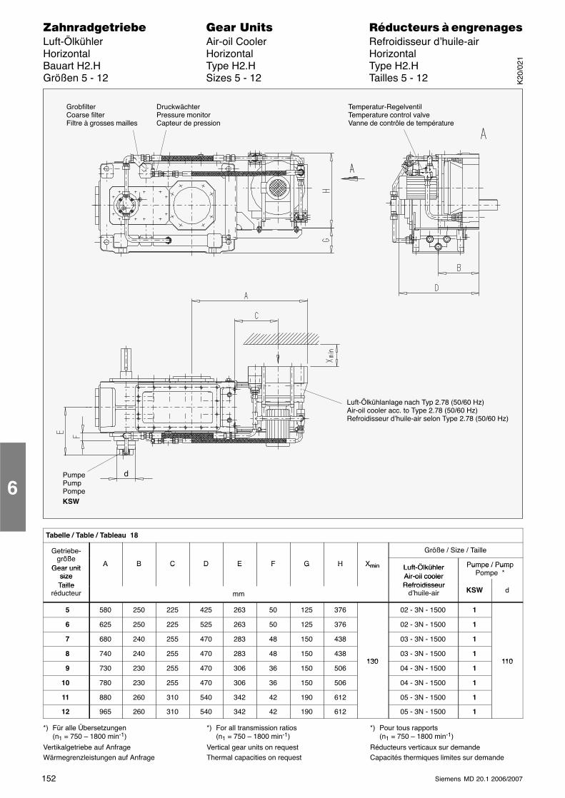
152 Siemens MD 20.1 2006/2007
������������� ���� �� ��������� � ����������Luft-Ölkühler Air-oil Cooler Refroidisseur d’huile-airHorizontal Horizontal HorizontalBauart H2.H Type H2.H Type H2.HGrößen 5 - 12 Sizes 5 - 12 Tailles 5 - 12
PumpePumpPompeKSW
DruckwächterPressure monitorCapteur de pression
d
GrobfilterCoarse filterFiltre à grosses mailles
Temperatur-RegelventilTemperature control valveVanne de contrôle de température
Luft-Ölkühlanlage nach Typ 2.78 (50/60 Hz)Air-oil cooler acc. to Type 2.78 (50/60 Hz)Refroidisseur d’huile-air selon Type 2.78 (50/60 Hz)
Tabelle / Table / Tableau 18
Getriebe-größe
Größe / Size / Taillegröße
Gear unitA B C D E F G H Xmin Luft-Ölkühler Pumpe / PumpGear unit
size
A B C D E F G H Xmin Luft-ÖlkühlerAir-oil cooler
Pum e / PumPompe *size
TailleAir-oil coolerRefroidisseurTaille
réducteur mmRefroidisseur
d’huile-air KSW d
5 580 250 225 425 263 50 125 376 02 - 3N - 1500 1
6 625 250 225 525 263 50 125 376 02 - 3N - 1500 1
7 680 240 255 470 283 48 150 438 03 - 3N - 1500 1
8 740 240 255 470 283 48 150 438130
03 - 3N - 1500 1110
9 730 230 255 470 306 36 150 506130
04 - 3N - 1500 1110
10 780 230 255 470 306 36 150 506 04 - 3N - 1500 1
11 880 260 310 540 342 42 190 612 05 - 3N - 1500 1
12 965 260 310 540 342 42 190 612 05 - 3N - 1500 1
*) Für alle Übersetzungen(n1 = 750 – 1800 min-1)
Vertikalgetriebe auf AnfrageWärmegrenzleistungen auf Anfrage
*) For all transmission ratios(n1 = 750 – 1800 min-1)
Vertical gear units on requestThermal capacities on request
*) Pour tous rapports(n1 = 750 – 1800 min-1)
Réducteurs verticaux sur demandeCapacités thermiques limites sur demande
6K
20/0
21
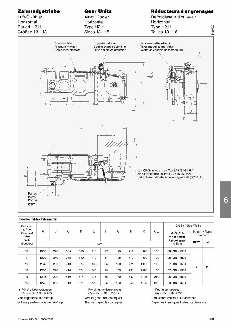
153Siemens MD 20.1 2006/2007
������������� ���� �� ��������� � ����������Luft-Ölkühler Air-oil Cooler Refroidisseur d’huile-airHorizontal Horizontal HorizontalBauart H2.H Type H2.H Type H2.HGrößen 13 - 18 Sizes 13 - 18 Tailles 13 - 18
DoppelschaltfilterDouble change-over filterFiltre double commutable
PumpePumpPompeKSW
DruckwächterPressure monitorCapteur de pression
d
Temperatur-RegelventilTemperature control valveVanne de contrôle de température
Luft-Ölkühlanlage nach Typ 2.78 (50/60 Hz)Air-oil cooler acc. to Type 2.78 (50/60 Hz)Refroidisseur d’huile-air selon Type 2.78 (50/60 Hz)
Tabelle / Table / Tableau 19
Getriebe-größe
Größe / Size / Taillegröße
Gear unitA B C D E F G H K Xmin Luft-Ölkühler Pumpe / PumpGear unit
size
A B C D E F G H K Xmin Luft-ÖlkühlerAir-oil cooler
Pum e / PumPompe *size
TailleAir-oil coolerRefroidisseurTaille
réducteur mmRefroidisseur
d’huile-air KSW d
13 1000 270 365 540 410 37 95 712 990 130 06 - 3N - 1500
14 1070 270 365 540 410 37 95 712 990 130 06 - 3N - 1500
15 1175 290 410 574 445 35 150 721 1090 130 07 - 3N - 15002 110
16 1220 290 410 574 445 35 150 721 1090 130 07 - 3N - 15002 110
17 1215 290 410 574 475 35 170 853 1195 250 08 - 3N - 1500
18 1275 290 410 574 475 35 170 853 1195 250 08 - 3N - 1500
*) Für alle Übersetzungen(n1 = 750 – 1800 min-1)
Vertikalgetriebe auf Anfrage
Wärmegrenzleistungen auf Anfrage
*) For all transmission ratios(n1 = 750 – 1800 min-1)
Vertical gear units on request
Thermal capacities on request
*) Pour tous rapports(n1 = 750 – 1800 min-1)
Réducteurs verticaux sur demande
Capacités thermiques limites sur demande
K20
/021
6
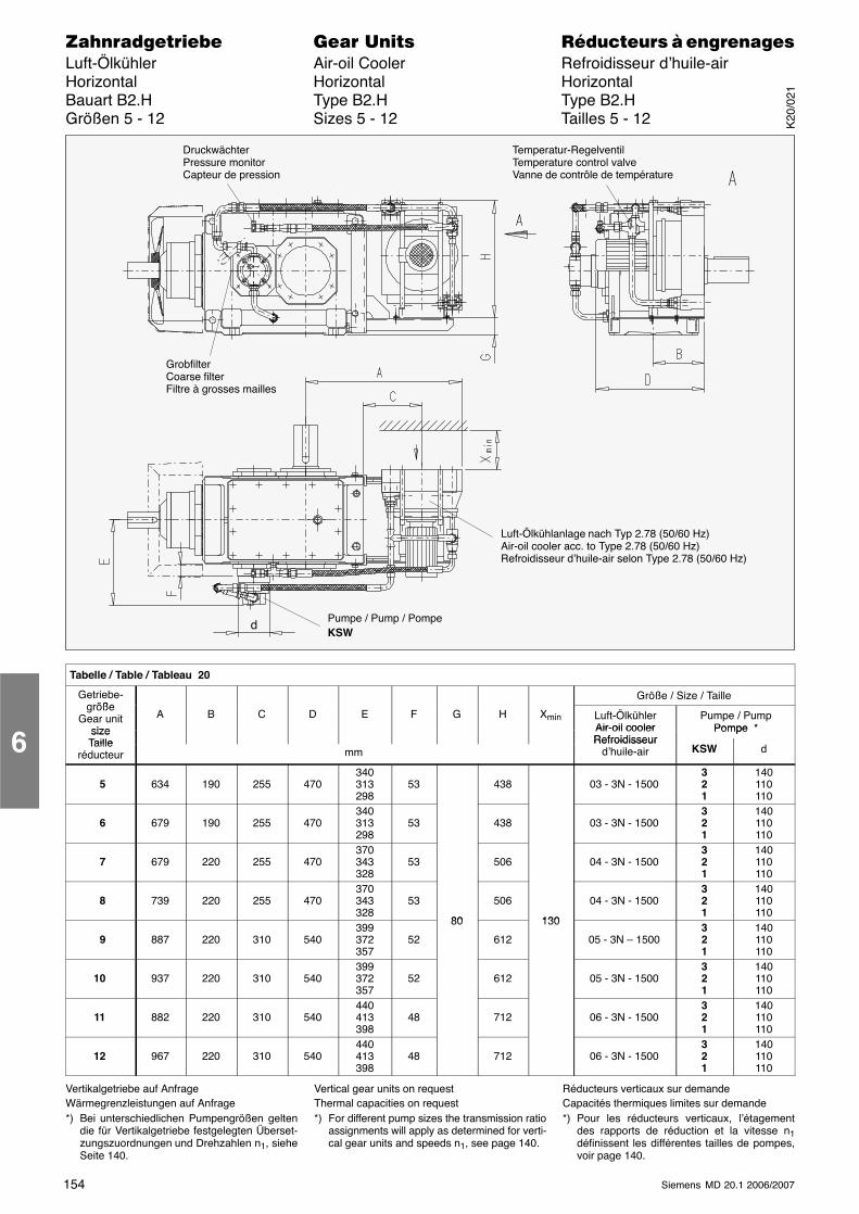
154 Siemens MD 20.1 2006/2007
������������� ���� �� ��������� � ����������Luft-Ölkühler Air-oil Cooler Refroidisseur d’huile-airHorizontal Horizontal HorizontalBauart B2.H Type B2.H Type B2.HGrößen 5 - 12 Sizes 5 - 12 Tailles 5 - 12
GrobfilterCoarse filterFiltre à grosses mailles
Pumpe / Pump / PompeKSW
DruckwächterPressure monitorCapteur de pression
d
Temperatur-RegelventilTemperature control valveVanne de contrôle de température
Luft-Ölkühlanlage nach Typ 2.78 (50/60 Hz)Air-oil cooler acc. to Type 2.78 (50/60 Hz)Refroidisseur d’huile-air selon Type 2.78 (50/60 Hz)
Tabelle / Table / Tableau 20
Getriebe-größe
Größe / Size / Taillegröße
Gear unitsize
A B C D E F G H Xmin Luft-ÖlkühlerAir-oil cooler
Pumpe / PumpPompe *size Air-oil cooler
RefroidisseurPompe *size
Taille RefroidisseurTailleréducteur mm
Refroidisseurd’huile-air KSW d
5 634 190 255 470340313298
53 438 03 - 3N - 1500321
140110110
6 679 190 255 470340313298
53 438 03 - 3N - 1500321
140110110
7 679 220 255 470370343328
53 506 04 - 3N - 1500321
140110110
8 739 220 255 470370343328
53
80
506
130
04 - 3N - 1500321
140110110
9 887 220 310 540399372357
52
80
612
130
05 - 3N – 1500321
140110110
10 937 220 310 540399372357
52 612 05 - 3N - 1500321
140110110
11 882 220 310 540440413398
48 712 06 - 3N - 1500321
140110110
12 967 220 310 540440413398
48 712 06 - 3N - 1500321
140110110
Vertikalgetriebe auf AnfrageWärmegrenzleistungen auf Anfrage*) Bei unterschiedlichen Pumpengrößen gelten
die für Vertikalgetriebe festgelegten Überset-zungszuordnungen und Drehzahlen n1, sieheSeite 140.
Vertical gear units on requestThermal capacities on request*) For different pump sizes the transmission ratio
assignments will apply as determined for verti-cal gear units and speeds n1, see page 140.
Réducteurs verticaux sur demandeCapacités thermiques limites sur demande*) Pour les réducteurs verticaux, l’étagement
des rapports de réduction et la vitesse n1définissent les différentes tailles de pompes,voir page 140.
6K
20/0
21
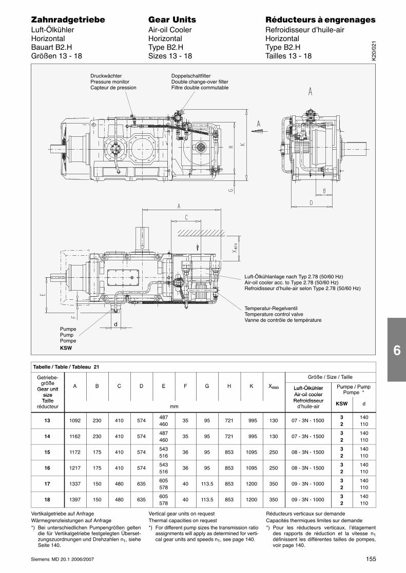
155Siemens MD 20.1 2006/2007
������������� ���� �� ��������� � ����������Luft-Ölkühler Air-oil Cooler Refroidisseur d’huile-airHorizontal Horizontal HorizontalBauart B2.H Type B2.H Type B2.HGrößen 13 - 18 Sizes 13 - 18 Tailles 13 - 18
DoppelschaltfilterDouble change-over filterFiltre double commutable
PumpePumpPompeKSW
DruckwächterPressure monitorCapteur de pression
d
Temperatur-RegelventilTemperature control valveVanne de contrôle de température
Luft-Ölkühlanlage nach Typ 2.78 (50/60 Hz)Air-oil cooler acc. to Type 2.78 (50/60 Hz)Refroidisseur d’huile-air selon Type 2.78 (50/60 Hz)
Tabelle / Table / Tableau 21
Getriebe-größe
Größe / Size / Taillegröße
Gear unitA B C D E F G H K Xmin Luft-Ölkühler Pumpe / PumpGear unit
size
A B C D E F G H K Xmin Luft-ÖlkühlerAir-oil cooler
Pum e / PumPompe *size
TailleAir-oil coolerRefroidisseurTaille
réducteur mmRefroidisseur
d’huile-air KSW d
13 1092 230 410 574487460
35 95 721 995 130 07 - 3N - 150032
140110
14 1162 230 410 574487460
35 95 721 995 130 07 - 3N - 150032
140110
15 1172 175 410 574543516
36 95 853 1095 250 08 - 3N - 150032
140110
16 1217 175 410 574543516
36 95 853 1095 250 08 - 3N - 150032
140110
17 1337 150 480 635605578
40 113.5 853 1200 350 09 - 3N - 100032
140110
18 1397 150 480 635605578
40 113.5 853 1200 350 09 - 3N - 100032
140110
Vertikalgetriebe auf AnfrageWärmegrenzleistungen auf Anfrage*) Bei unterschiedlichen Pumpengrößen gelten
die für Vertikalgetriebe festgelegten Überset-zungszuordnungen und Drehzahlen n1, sieheSeite 140.
Vertical gear units on requestThermal capacities on request*) For different pump sizes the transmission ratio
assignments will apply as determined for verti-cal gear units and speeds n1, see page 140.
Réducteurs verticaux sur demandeCapacités thermiques limites sur demande*) Pour les réducteurs verticaux, l’étagement
des rapports de réduction et la vitesse n1définissent les différentes tailles de pompes,voir page 140.
K20
/021
6
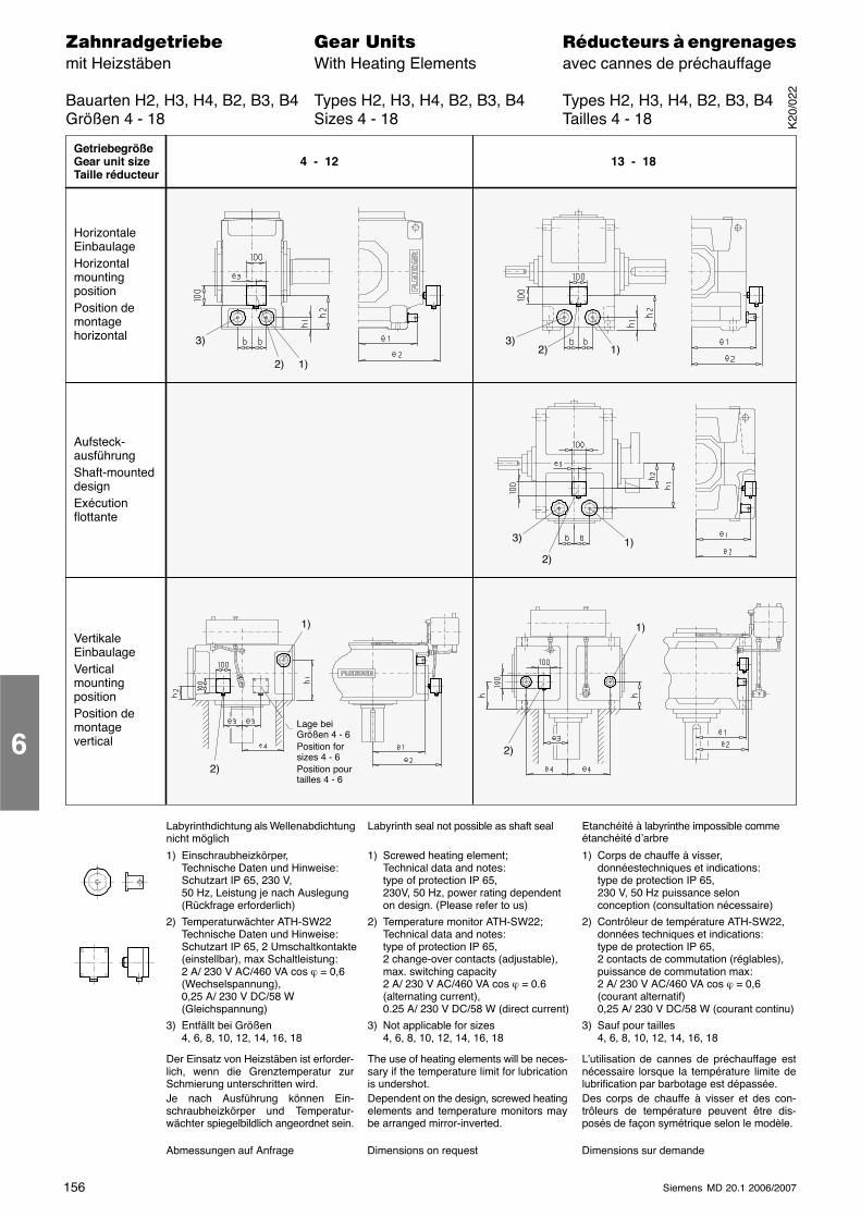
156 Siemens MD 20.1 2006/2007
������������� ���� �� ��������� � ����������mit Heizstäben With Heating Elements avec cannes de préchauffage
Bauarten H2, H3, H4, B2, B3, B4 Types H2, H3, H4, B2, B3, B4 Types H2, H3, H4, B2, B3, B4Größen 4 - 18 Sizes 4 - 18 Tailles 4 - 18
1) Einschraubheizkörper,Technische Daten und Hinweise:Schutzart IP 65, 230 V,50 Hz, Leistung je nach Auslegung(Rückfrage erforderlich)
2) Temperaturwächter ATH-SW22Technische Daten und Hinweise:Schutzart IP 65, 2 Umschaltkontakte(einstellbar), max Schaltleistung:2 A/ 230 V AC/460 VA cos ϕ = 0,6(Wechselspannung),0,25 A/ 230 V DC/58 W(Gleichspannung)
3) Entfällt bei Größen4, 6, 8, 10, 12, 14, 16, 18
1) Screwed heating element;Technical data and notes:type of protection IP 65,230V, 50 Hz, power rating dependenton design. (Please refer to us)
2) Temperature monitor ATH-SW22;Technical data and notes:type of protection IP 65,2 change-over contacts (adjustable),max. switching capacity2 A/ 230 V AC/460 VA cos ϕ = 0.6(alternating current),0.25 A/ 230 V DC/58 W (direct current)
3) Not applicable for sizes4, 6, 8, 10, 12, 14, 16, 18
1) Corps de chauffe à visser,donnéestechniques et indications:type de protection IP 65,230 V, 50 Hz puissance selonconception (consultation nécessaire)
2) Contrôleur de température ATH-SW22,données techniques et indications:type de protection IP 65,2 contacts de commutation (réglables),puissance de commutation max:2 A/ 230 V AC/460 VA cos ϕ = 0,6(courant alternatif)0,25 A/ 230 V DC/58 W (courant continu)
3) Sauf pour tailles4, 6, 8, 10, 12, 14, 16, 18
Labyrinthdichtung als Wellenabdichtungnicht möglich
Labyrinth seal not possible as shaft seal Etanchéité à labyrinthe impossible commeétanchéité d’arbre
Der Einsatz von Heizstäben ist erforder-lich, wenn die Grenztemperatur zurSchmierung unterschritten wird.Je nach Ausführung können Ein-schraubheizkörper und Temperatur-wächter spiegelbildlich angeordnet sein.
The use of heating elements will be neces-sary if the temperature limit for lubricationis undershot.Dependent on the design, screwed heatingelements and temperature monitors maybe arranged mirror-inverted.
L’utilisation de cannes de préchauffage estnécessaire lorsque la température limite delubrification par barbotage est dépassée.Des corps de chauffe à visser et des con-trôleurs de température peuvent être dis-posés de façon symétrique selon le modèle.
Lage beiGrößen 4 - 6Position forsizes 4 - 6Position pourtailles 4 - 6
GetriebegrößeGear unit sizeTaille réducteur
4 - 12 13 - 18
Abmessungen auf Anfrage Dimensions on request Dimensions sur demande
HorizontaleEinbaulageHorizontalmountingpositionPosition demontagehorizontal
Aufsteck-ausführungShaft-mounteddesignExécutionflottante
VertikaleEinbaulageVerticalmountingpositionPosition demontagevertical
1)
2)
1)
2)
3) 1)
2)
1)2)3)
1)2)
3)
6K
20/0
22
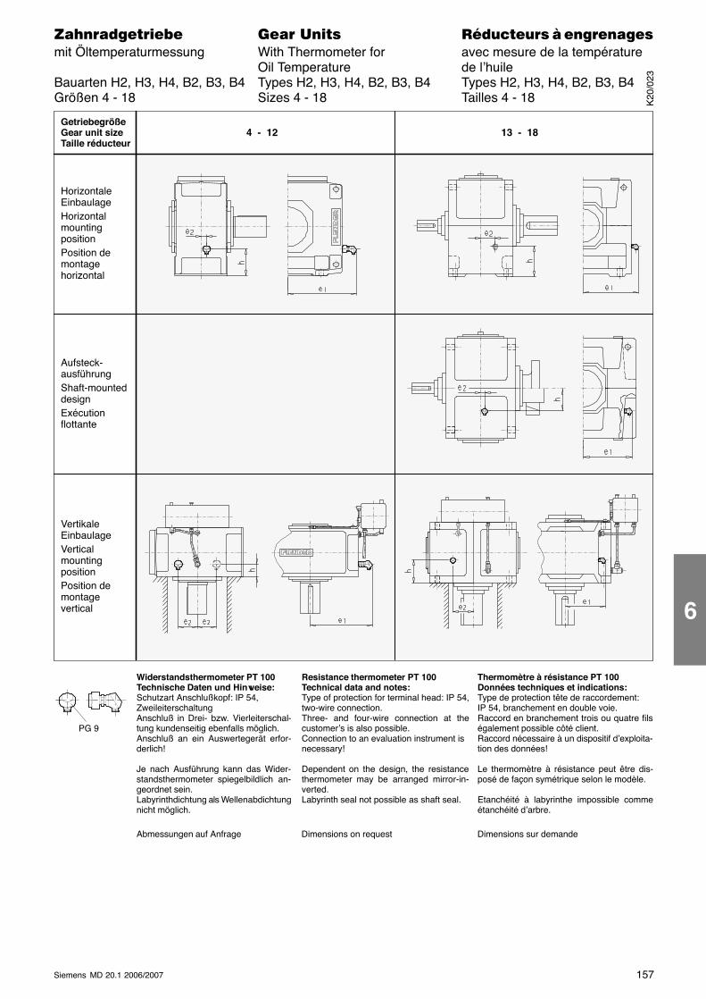
157Siemens MD 20.1 2006/2007
������������� ���� �� ��������� � ����������mit Öltemperaturmessung With Thermometer for avec mesure de la température
Oil Temperature de l’huileBauarten H2, H3, H4, B2, B3, B4 Types H2, H3, H4, B2, B3, B4 Types H2, H3, H4, B2, B3, B4Größen 4 - 18 Sizes 4 - 18 Tailles 4 - 18
GetriebegrößeGear unit sizeTaille réducteur
4 - 12 13 - 18
Abmessungen auf Anfrage Dimensions on request Dimensions sur demande
HorizontaleEinbaulageHorizontalmountingpositionPosition demontagehorizontal
Aufsteck-ausführungShaft-mounteddesignExécutionflottante
VertikaleEinbaulageVerticalmountingpositionPosition demontagevertical
Widerstandsthermometer PT 100Technische Daten und Hinweise:Schutzart Anschlußkopf: IP 54,ZweileiterschaltungAnschluß in Drei- bzw. Vierleiterschal-tung kundenseitig ebenfalls möglich.Anschluß an ein Auswertegerät erfor-derlich!
Resistance thermometer PT 100Technical data and notes:Type of protection for terminal head: IP 54,two-wire connection.Three- and four-wire connection at thecustomer’s is also possible.Connection to an evaluation instrument isnecessary!
Thermomètre à résistance PT 100Données techniques et indications:Type de protection tête de raccordement:IP 54, branchement en double voie.Raccord en branchement trois ou quatre filségalement possible côté client.Raccord nécessaire à un dispositif d’exploita-tion des données!
Je nach Ausführung kann das Wider-standsthermometer spiegelbildlich an-geordnet sein.Labyrinthdichtung als Wellenabdichtungnicht möglich.
Dependent on the design, the resistancethermometer may be arranged mirror-in-verted.Labyrinth seal not possible as shaft seal.
Le thermomètre à résistance peut être dis-posé de façon symétrique selon le modèle.
Etanchéité à labyrinthe impossible commeétanchéité d’arbre.
PG 9
K20
/023
6
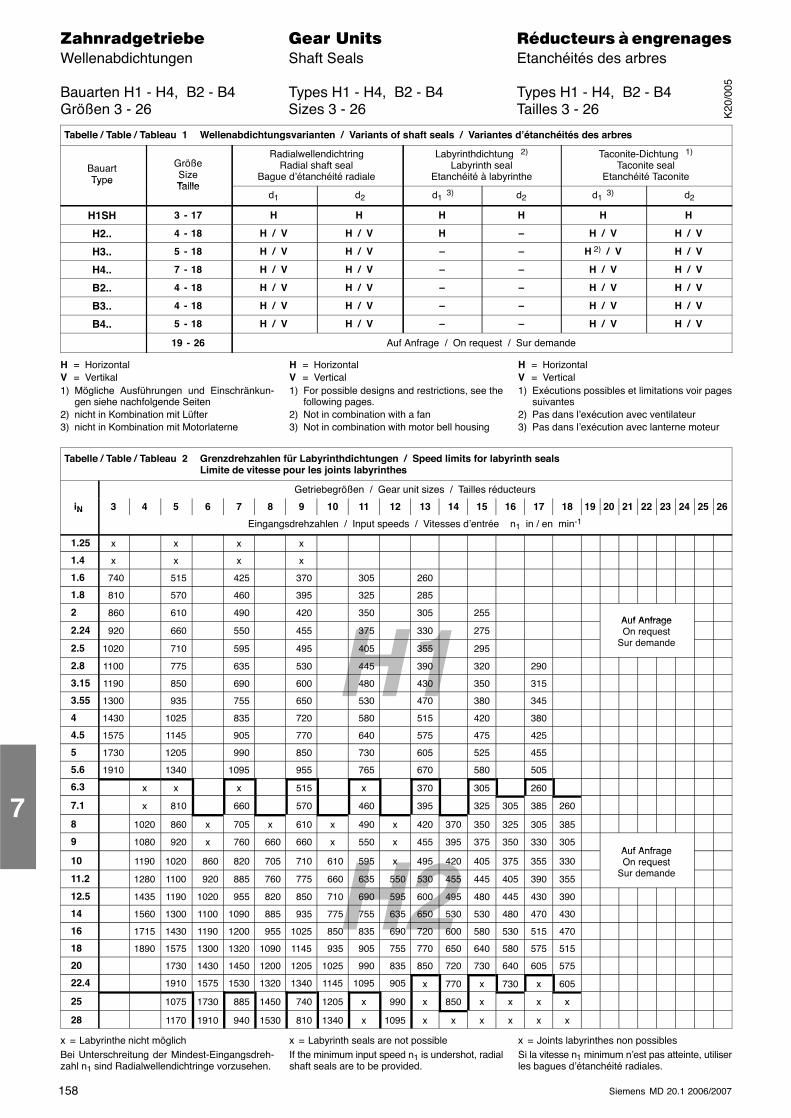
H1
H2
158 Siemens MD 20.1 2006/2007
������������� ���� �� ��������� � ����������Wellenabdichtungen Shaft Seals Etanchéités des arbres
Bauarten H1 - H4, B2 - B4 Types H1 - H4, B2 - B4 Types H1 - H4, B2 - B4Größen 3 - 26 Sizes 3 - 26 Tailles 3 - 26
Tabelle / Table / Tableau 1 Wellenabdichtungsvarianten / Variants of shaft seals / Variantes d’étanchéités des arbres
BauartType
GrößeSizeTaille
RadialwellendichtringRadial shaft seal
Bague d’étanchéité radiale
Labyrinthdichtung 2)
Labyrinth sealEtanchéité à labyrinthe
Taconite-Dichtung 1)
Taconite sealEtanchéité TaconiteTy e
Tailled1 d2 d1 3) d2 d1 3) d2
H1SH 3 - 17 H H H H H H
H2.. 4 - 18 H / V H / V H – H / V H / V
H3.. 5 - 18 H / V H / V – – H 2) / V H / V
H4.. 7 - 18 H / V H / V – – H / V H / V
B2.. 4 - 18 H / V H / V – – H / V H / V
B3.. 4 - 18 H / V H / V – – H / V H / V
B4.. 5 - 18 H / V H / V – – H / V H / V
19 - 26 Auf Anfrage / On request / Sur demande
H = HorizontalV = Vertikal1) Mögliche Ausführungen und Einschränkun-
gen siehe nachfolgende Seiten2) nicht in Kombination mit Lüfter3) nicht in Kombination mit Motorlaterne
H = HorizontalV = Vertical1) For possible designs and restrictions, see the
following pages.2) Not in combination with a fan3) Not in combination with motor bell housing
H = HorizontalV = Vertical1) Exécutions possibles et limitations voir pages
suivantes2) Pas dans l’exécution avec ventilateur3) Pas dans l’exécution avec lanterne moteur
Tabelle / Table / Tableau 2 Grenzdrehzahlen für Labyrinthdichtungen / Speed limits for labyrinth sealsLimite de vitesse pour les joints labyrinthes
Getriebegrößen / Gear unit sizes / Tailles réducteurs
iN 3 4 5 6 7 8 9 10 11 12 13 14 15 16 17 18 19 20 21 22 23 24 25 26N
Eingangsdrehzahlen / Input speeds / Vitesses d’entrée n1 in / en min-1
1.25 x x x x
1.4 x x x x
1.6 740 515 425 370 305 260
1.8 810 570 460 395 325 285
2 860 610 490 420 350 305 255Auf Anfrage
2.24 920 660 550 455 375 330 275Auf AnfrageOn request
S d d2.5 1020 710 595 495 405 355 295
O equestSur demande
2.8 1100 775 635 530 445 390 320 290
3.15 1190 850 690 600 480 430 350 315
3.55 1300 935 755 650 530 470 380 345
4 1430 1025 835 720 580 515 420 380
4.5 1575 1145 905 770 640 575 475 425
5 1730 1205 990 850 730 605 525 455
5.6 1910 1340 1095 955 765 670 580 505
6.3 x x x 515 x 370 305 260
7.1 x 810 660 570 460 395 325 305 385 260
8 1020 860 x 705 x 610 x 490 x 420 370 350 325 305 385
9 1080 920 x 760 660 660 x 550 x 455 395 375 350 330 305Auf Anfrage
10 1190 1020 860 820 705 710 610 595 x 495 420 405 375 355 330Auf AnfrageOn request
S d d11.2 1280 1100 920 885 760 775 660 635 550 530 455 445 405 390 355
O equestSur demande
12.5 1435 1190 1020 955 820 850 710 690 595 600 495 480 445 430 390
14 1560 1300 1100 1090 885 935 775 755 635 650 530 530 480 470 430
16 1715 1430 1190 1200 955 1025 850 835 690 720 600 580 530 515 470
18 1890 1575 1300 1320 1090 1145 935 905 755 770 650 640 580 575 515
20 1730 1430 1450 1200 1205 1025 990 835 850 720 730 640 605 575
22.4 1910 1575 1530 1320 1340 1145 1095 905 x 770 x 730 x 605
25 1075 1730 885 1450 740 1205 x 990 x 850 x x x x
28 1170 1910 940 1530 810 1340 x 1095 x x x x x x
x = Labyrinthe nicht möglichBei Unterschreitung der Mindest-Eingangsdreh-zahl n1 sind Radialwellendichtringe vorzusehen.
x = Labyrinth seals are not possibleIf the minimum input speed n1 is undershot, radialshaft seals are to be provided.
x = Joints labyrinthes non possiblesSi la vitesse n1 minimum n’est pas atteinte, utiliserles bagues d’étanchéité radiales.
7
K20
/005
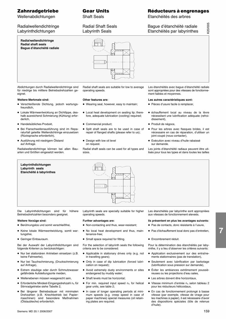
159Siemens MD 20.1 2006/2007
������������� ���� �� ��������� � ����������Wellenabdichtungen Shaft Seals Etanchéités des arbres
Radialwellendichtringe Radial Shaft Seals Bague d’étanchéité radialeLabyrinthdichtungen Labyrinth Seals Etanchéités par labyrinthes
RadialwellendichtringeRadial shaft sealsBague d’étanchéité radiale
Abdichtungen durch Radialwellendichtringe sindfür niedrige bis mittlere Betriebsdrehzahlen ge-eignet.
Weitere Merkmale sind:
� Verschleißende Dichtung, jedoch wartungs-freundlich,
� Lokale Wärmeentwicklung an Dichtlippe, des-halb ausreichend Schmierung (Kühlung) erfor-derlich,
� Handelsübliches Produkt,
� Bei Flanschwellenausführung sind im Repa-raturfall geteilte Wellendichtringe einzusetzen(Rücksprache erforderlich),
� Ausführung mit niedrigem Ölstandauf Anfrage.
Radialwellendichtringe können bei allen Bau-arten und Größen eingesetzt werden.
Radial shaft seals are suitable for low to averageoperating speeds.
Other features are:
� Wearing seal, however, easy to maintain;
� Local heat development on sealing lip; there-fore, adequate lubrication (cooling) required;
� Commercial product;
� Split shaft seals are to be used in case ofrepair of flanged shafts (please refer to us);
� Design with low oil levelon request.
Radial shaft seals can be used for all types andsizes.
Les étanchéités avec bague d’étanchéité radialesont appropriées pour des vitesses de fonctionne-ment faibles et moyennes.
Les autres caractéristiques sont:
� Pièces d’usure facile à remplacer,
� échauffement local au niveau de la lèvrenécessitant une lubrification adéquate (refroi-dissement),
� Produit de négoce,
� Pour les arbres avec flasques brides, il estnécessaire en cas de réparation, d’utiliser unjoint coupé (nous contacter),
� Exécution avec niveau d’huile rabaissésur demande.
Les joints d’étanchéité radiaux peuvent être uti-lisés pour tous les types et dans toutes les tailles
LabyrinthdichtungenLabyrinth sealsEtanchéité à labyrinthes
Die Labyrinthdichtungen sind für höhereBetriebsdrehzahlen besonders geeignet.
Weitere Vorzüge sind:
� Berührungslos und somit verschleißfrei,
� Keine lokale Wärmeentwicklung, somit war-tungsfrei,
� Geringer Einbauraum.
Bei der Auswahl der Labyrinthdichtungen sindfolgende Kriterien zu berücksichtigen:
� Nur bei stationären Antrieben einsetzen (z.B.keine Fahrwerke),
� Nur bei Tauchschmierung, (Druckschmierungauf Anfrage),
� Extrem staubige oder durch Schmutzwassergefährdete Aufstellungsorte meiden,
� Wellenebenen müssen waagerecht sein,
� Erforderliche Mindest-Eingangsdrehzahl n1 fürStirnradgetriebe siehe Tabelle 2,
� Bei längerer Betriebsdauer mit minimalenDrehzahlen (z.B. Kriechbetrieb bei Papier-maschinen) sind besondere Maßnahmen(Ölstaubleche) erforderlich.
Labyrinth seals are specially suitable for higheroperating speeds.
Further advantages are:
� Non-contacting and thus, wear-resistant;
� No local heat development and thus, main-tenance-free;
� Small space required for fitting.
For the selection of labyrinth seals the followingcriteria are to be considered:
� Applicable in stationary drives only (e.g. notin travelling gears);
� Only in case of dip lubrication (forced lubri-cation on request);
� Avoid extremely dusty environments or sitesendangered by muddy water;
� Shaft levels must be horizontal;
� For min. required input speed n1 for helicalgear units, see table 2;
� In case of longer operating periods at mini-mum speeds (e.g. creep speed in case ofpaper machines) special measures (oil retain-ing plates are required.
Les étanchéités par labyrinthe sont appropriéesaux vitesses de fonctionnement eleveés.
Ils présentent en plus les avantages suivants:
� Pas de contacts, donc résistants à l’usure,
� Pas d’échauffement local donc pas d’entretien,
� Encombrement réduit.
Pour la détermination des étanchéités par laby-rinthe, il y a lieu d’observer les critères suivants:
� Application exclusivement sur des entraîne-ments stationnaires (pas de translation),
� Seulement avec lubrification par barbotage(lubrification sous pression sur demande),
� Éviter les ambiances extrêmement poussiè-reuses ou les projections d’eau sales,
� Les arbres doivent être horizontaux,
� Vitesse minimum d’entrée n1 selon tableau 2pour les réducteurs hélicoidaux,
� En cas de fonctionnement prolongé à bassevitesse (par exemple, vitesse de virage pourles machines à papier), il est nécessaire d’avoirdes dispositions spéciales (tôle de retenued’huile).
K20
/005
7
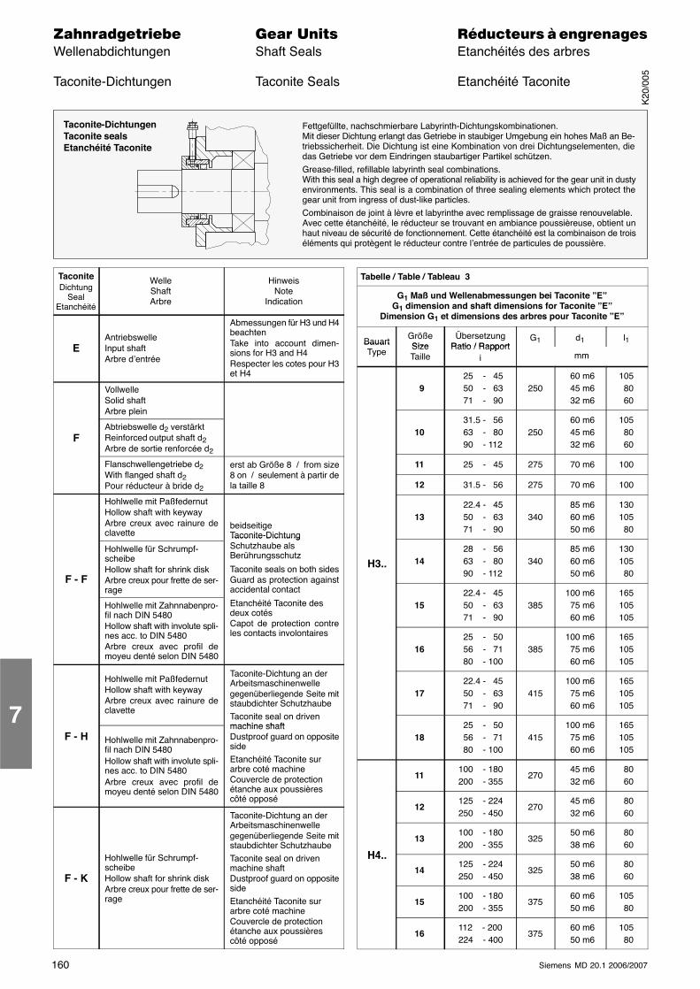
160 Siemens MD 20.1 2006/2007
������������� ���� �� ��������� � ����������Wellenabdichtungen Shaft Seals Etanchéités des arbres
Taconite-Dichtungen Taconite Seals Etanchéité Taconite
Taconite-DichtungenTaconite sealsEtanchéité Taconite
Fettgefüllte, nachschmierbare Labyrinth-Dichtungskombinationen.Mit dieser Dichtung erlangt das Getriebe in staubiger Umgebung ein hohes Maß an Be-triebssicherheit. Die Dichtung ist eine Kombination von drei Dichtungselementen, diedas Getriebe vor dem Eindringen staubartiger Partikel schützen.Grease-filled, refillable labyrinth seal combinations.With this seal a high degree of operational reliability is achieved for the gear unit in dustyenvironments. This seal is a combination of three sealing elements which protect thegear unit from ingress of dust-like particles.Combinaison de joint à lèvre et labyrinthe avec remplissage de graisse renouvelable.Avec cette étanchéité, le réducteur se trouvant en ambiance poussièreuse, obtient unhaut niveau de sécurité de fonctionnement. Cette étanchéité est la combinaison de troiséléments qui protègent le réducteur contre l’entrée de particules de poussière.
TaconiteDichtung
SealEtanchéité
WelleShaftArbre
HinweisNote
Indication
EAntriebswelleInput shaftArbre d’entrée
Abmessungen für H3 und H4beachtenTake into account dimen-sions for H3 and H4Respecter les cotes pour H3et H4
VollwelleSolid shaftArbre plein
FAbtriebswelle d2 verstärktReinforced output shaft d2Arbre de sortie renforcée d2
Flanschwellengetriebe d2With flanged shaft d2Pour réducteur à bride d2
erst ab Größe 8 / from size8 on / seulement à partir dela taille 8
Hohlwelle mit PaßfedernutHollow shaft with keywayArbre creux avec rainure declavette
beidseitigeTaconite-Dichtung
F - F
Hohlwelle für Schrumpf-scheibeHollow shaft for shrink diskArbre creux pour frette de ser-rage
Taconite DichtungSchutzhaube alsBerührungsschutz
Taconite seals on both sidesGuard as protection againstaccidental contact
Hohlwelle mit Zahnnabenpro-fil nach DIN 5480Hollow shaft with involute spli-nes acc. to DIN 5480Arbre creux avec profil demoyeu denté selon DIN 5480
Etanchéité Taconite desdeux cotésCapot de protection contreles contacts involontaires
Hohlwelle mit PaßfedernutHollow shaft with keywayArbre creux avec rainure declavette
Taconite-Dichtung an derArbeitsmaschinenwellegegenüberliegende Seite mitstaubdichter SchutzhaubeTaconite seal on drivenmachine shaft
F - H Hohlwelle mit Zahnnabenpro-fil nach DIN 5480Hollow shaft with involute spli-nes acc. to DIN 5480Arbre creux avec profil demoyeu denté selon DIN 5480
machine shaftDustproof guard on oppositesideEtanchéité Taconite surarbre coté machineCouvercle de protectionétanche aux poussièrescôté opposé
F - K
Hohlwelle für Schrumpf-scheibeHollow shaft for shrink diskArbre creux pour frette de ser-rage
Taconite-Dichtung an derArbeitsmaschinenwellegegenüberliegende Seite mitstaubdichter SchutzhaubeTaconite seal on drivenmachine shaftDustproof guard on oppositesideEtanchéité Taconite surarbre coté machineCouvercle de protectionétanche aux poussièrescôté opposé
Tabelle / Table / Tableau 3
G1 Maß und Wellenabmessungen bei Taconite ”E”G1 dimension and shaft dimensions for Taconite ”E”
Dimension G1 et dimensions des arbres pour Taconite ”E”
BauartGrößeSize
ÜbersetzungRatio / Rapport
G1 d1 l1BauartType
SizeTaille
Ratio / Rapporti mm
9 25 - 45 50 - 63 71 - 90
250 60 m6 45 m6 32 m6
105 80 60
10 31.5 - 56 63 - 80 90 - 112
250 60 m6 45 m6 32 m6
105 80 60
11 25 - 45 275 70 m6 100
12 31.5 - 56 275 70 m6 100
13 22.4 - 45 50 - 63 71 - 90
340 85 m6 60 m6 50 m6
130105 80
H3.. 14 28 - 56 63 - 80 90 - 112
340 85 m6 60 m6 50 m6
130105 80
15 22.4 - 45 50 - 63 71 - 90
385100 m6 75 m6 60 m6
165105105
16 25 - 50 56 - 71 80 - 100
385100 m6 75 m6 60 m6
165105105
17 22.4 - 45 50 - 63 71 - 90
415100 m6 75 m6 60 m6
165105105
18 25 - 50 56 - 71 80 - 100
415100 m6 75 m6 60 m6
165105105
11100 - 180200 - 355
270 45 m6 32 m6
80 60
12125 - 224250 - 450
270 45 m6 32 m6
80 60
H4
13100 - 180200 - 355
325 50 m6 38 m6
80 60
H4..14
125 - 224250 - 450
325 50 m6 38 m6
80 60
15100 - 180200 - 355
375 60 m6 50 m6
105 80
16112 - 200224 - 400
375 60 m6 50 m6
105 80
7
K20
/005
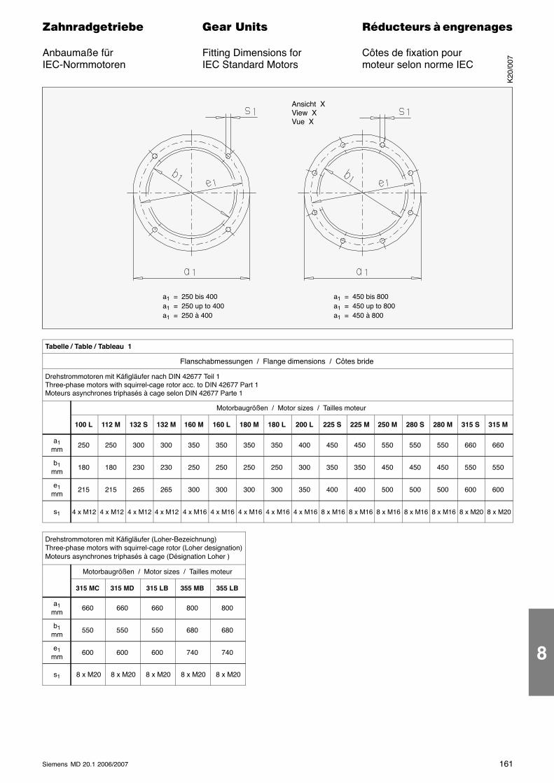
161Siemens MD 20.1 2006/2007
������������� ���� �� ��������� � ����������
Anbaumaße für Fitting Dimensions for Côtes de fixation pourIEC-Normmotoren IEC Standard Motors moteur selon norme IEC
a1 = 250 bis 400a1 = 250 up to 400a1 = 250 à 400
a1 = 450 bis 800a1 = 450 up to 800a1 = 450 à 800
Ansicht XView XVue X
Tabelle / Table / Tableau 1
Flanschabmessungen / Flange dimensions / Côtes bride
Drehstrommotoren mit Käfigläufer nach DIN 42677 Teil 1Three-phase motors with squirrel-cage rotor acc. to DIN 42677 Part 1Moteurs asynchrones triphasés à cage selon DIN 42677 Parte 1
Motorbaugrößen / Motor sizes / Tailles moteur
100 L 112 M 132 S 132 M 160 M 160 L 180 M 180 L 200 L 225 S 225 M 250 M 280 S 280 M 315 S 315 M
a1mm
250 250 300 300 350 350 350 350 400 450 450 550 550 550 660 660
b1mm
180 180 230 230 250 250 250 250 300 350 350 450 450 450 550 550
e1mm
215 215 265 265 300 300 300 300 350 400 400 500 500 500 600 600
s1 4 x M12 4 x M12 4 x M12 4 x M12 4 x M16 4 x M16 4 x M16 4 x M16 4 x M16 8 x M16 8 x M16 8 x M16 8 x M16 8 x M16 8 x M20 8 x M20
Drehstrommotoren mit Käfigläufer (Loher-Bezeichnung)Three-phase motors with squirrel-cage rotor (Loher designation)Moteurs asynchrones triphasés à cage (Désignation Loher )
Motorbaugrößen / Motor sizes / Tailles moteur
315 MC 315 MD 315 LB 355 MB 355 LB
a1mm
660 660 660 800 800
b1mm
550 550 550 680 680
e1mm
600 600 600 740 740
s1 8 x M20 8 x M20 8 x M20 8 x M20 8 x M20
K20
/007
8
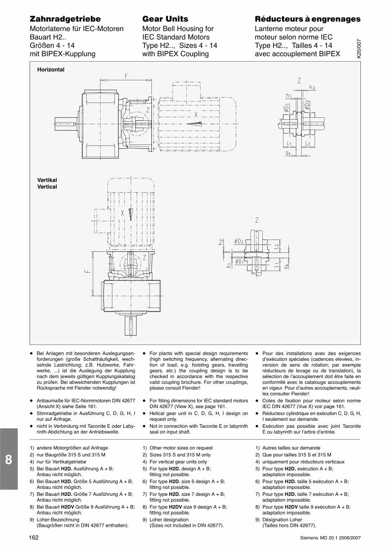
162 Siemens MD 20.1 2006/2007
������������� ���� �� ��������� � ����������Motorlaterne für IEC-Motoren Motor Bell Housing for Lanterne moteur pourBauart H2.. IEC Standard Motors moteur selon norme IECGrößen 4 - 14 Type H2.., Sizes 4 - 14 Type H2.., Tailles 4 - 14mit BIPEX-Kupplung with BIPEX Coupling avec accouplement BIPEX
Horizontal
VertikalVertical
� Bei Anlagen mit besonderen Auslegungsan-forderungen (große Schalthäufigkeit, wech-selnde Lastrichtung; z.B. Hubwerke, Fahr-werke, ...) ist die Auslegung der Kupplungnach dem jeweils gültigen Kupplungskatalogzu prüfen. Bei abweichenden Kupplungen istRücksprache mit Flender notwendig!
� Anbaumaße für IEC-Normmotoren DIN 42677(Ansicht X) siehe Seite 161.
� Stirnradgetriebe in Ausführung C, D, G, H, Inur auf Anfrage.
� nicht in Verbindung mit Taconite E oder Laby-rinth-Abdichtung an der Antriebswelle.
� For plants with special design requirements(high switching frequency, alternating direc-tion of load; e.g. hoisting gears, travellinggears, etc.) the coupling design is to bechecked in accordance with the respectivevalid coupling brochure. For other couplings,please consult Flender!
� For fitting dimensions for IEC standard motorsDIN 42677 (View X), see page 161.
� Helical gear unit in C, D, G, H, I design onrequest only.
� Not in connection with Taconite E or labyrinthseal on input shaft.
� Pour des installations avec des exigencesd’exécution spéciales (cadences elevées, in-version de sens de rotation; par exempleréducteurs de levage ou de translation), lasélection de l’accouplement doit être faite enconformité avec le catalouge accouplementsen vigeur. Pour d’autres accouplements, veuil-lex consulter Flender!
� Cotes de fixation pour moteur selon normeIEC DIN 42677 (Vue X) voir page 161.
� Réducteur cylindrique en exécution C, D, G, H,I seulement sur demande.
� Exécution pas possible avec joint TaconiteE ou labyrinth sur l’arbre d’entrée.
1) andere Motorgrößen auf Anfrage2) nur Baugröße 315 S und 315 M4) nur für Vertikalgetriebe5) Bei Bauart H2D. Ausführung A + B;
Anbau nicht möglich.6) Bei Bauart H2D. Größe 5 Ausführung A + B;
Anbau nicht möglich.7) Bei Bauart H2D. Größe 7 Ausführung A + B;
Anbau nicht möglich.8) Bei Bauart H2DV Größe 9 Ausführung A + B;
Anbau nicht möglich.9) Loher-Bezeichnung
(Baugrößen nicht in DIN 42677 enthalten).
1) Other motor sizes on request2) Sizes 315 S and 315 M only4) For vertical gear units only5) For type H2D. design A + B;
fitting not possible.6) For type H2D. size 5 design A + B;
fitting not possible.7) For type H2D. size 7 design A + B;
fitting not possible.8) For type H2DV size 9 design A + B;
fitting not possible.9) Loher designation
(Sizes not included in DIN 42677).
1) Autres tailles sur demande2) Que pour tailles 315 S et 315 M4) uniquement pour réducteurs verticaux5) Pour type H2D. exécution A + B;
adaptation impossible.6) Pour type H2D. taille 5 exécution A + B;
adaptation impossible.7) Pour type H2D. taille 7 exécution A + B;
adaptation impossible.8) Pour type H2DV taille 9 exécution A + B;
adaptation impossible.9) Désignation Loher
(Tailles hors DIN 42677).
8
K20
/007
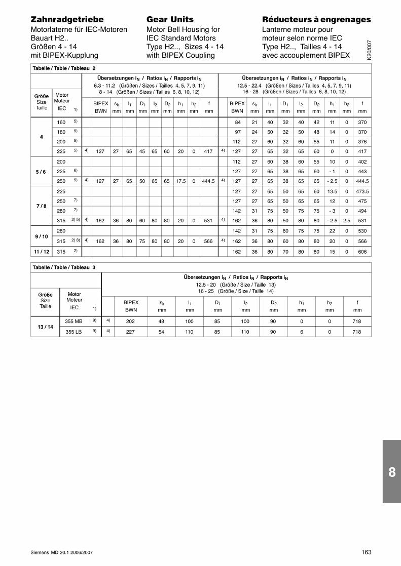
163Siemens MD 20.1 2006/2007
������������� ���� �� ��������� � ����������Motorlaterne für IEC-Motoren Motor Bell Housing for Lanterne moteur pourBauart H2.. IEC Standard Motors moteur selon norme IECGrößen 4 - 14 Type H2.., Sizes 4 - 14 Type H2.., Tailles 4 - 14mit BIPEX-Kupplung with BIPEX Coupling avec accouplement BIPEX
Tabelle / Table / Tableau 2
Übersetzungen iN / Ratios iN / Rapports iN6.3 - 11.2 (Größen / Sizes / Tailles 4, 5, 7, 9, 11)
Übersetzungen iN / Ratios iN / Rapports iN12.5 - 22.4 (Größen / Sizes / Tailles 4, 5, 7, 9, 11)
Größe Motor
6.3 11.2 (Größen / Sizes / Tailles 4, 5, 7, 9, 11)8 - 14 (Größen / Sizes / Tailles 6, 8, 10, 12)
12.5 22.4 (Größen / Sizes / Tailles 4, 5, 7, 9, 11)16 - 28 (Größen / Sizes / Tailles 6, 8, 10, 12)
GrößeSizeTaille
MotorMoteur
IEC 1)BIPEXBWN
sk
mml1
mmD1
mml2
mmD2
mmh1
mmh2
mmf
mmBIPEXBWN
sk
mml1
mmD1
mml2
mmD2
mmh1
mmh2
mmf
mm
160 5) 84 21 40 32 40 42 11 0 370
4180 5) 97 24 50 32 50 48 14 0 370
4200 5) 112 27 60 32 60 55 11 0 376
225 5) 4) 127 27 65 45 65 60 20 0 417 4) 127 27 65 32 65 60 0 0 417
200 112 27 60 38 60 55 10 0 402
5 / 6 225 6) 127 27 65 38 65 60 - 1 0 443
250 5) 4) 127 27 65 50 65 65 17.5 0 444.5 4) 127 27 65 38 65 65 - 2.5 0 444.5
225 127 27 65 50 65 60 13.5 0 473.5
7 / 8250 7) 127 27 65 50 65 65 12 0 475
7 / 8280 7) 142 31 75 50 75 75 - 3 0 494
315 2) 5) 4) 162 36 80 60 80 80 20 0 531 4) 162 36 80 50 80 80 - 2.5 2.5 531
9 / 10280 142 31 75 60 75 75 22 0 530
9 / 10315 2) 8) 4) 162 36 80 75 80 80 20 0 566 4) 162 36 80 60 80 80 20 0 566
11 / 12 315 2) 162 36 80 70 80 80 15 0 606
Tabelle / Table / Tableau 3
Übersetzungen iN / Ratios iN / Rapports iN12.5 - 20 (Größe / Size / Taille 13)
Größe Motor
12.5 20 (Größe / Size / Taille 13)16 - 25 (Größe / Size / Taille 14)
GrößeSizeTaille
MotorMoteur
IEC 1)BIPEXBWN
sk
mml1
mmD1
mml2
mmD2
mmh1
mmh2
mmf
mm
13 / 14355 MB 9) 4) 202 48 100 85 100 90 0 0 718
13 / 14355 LB 9) 4) 227 54 110 85 110 90 6 0 718
K20
/007
8
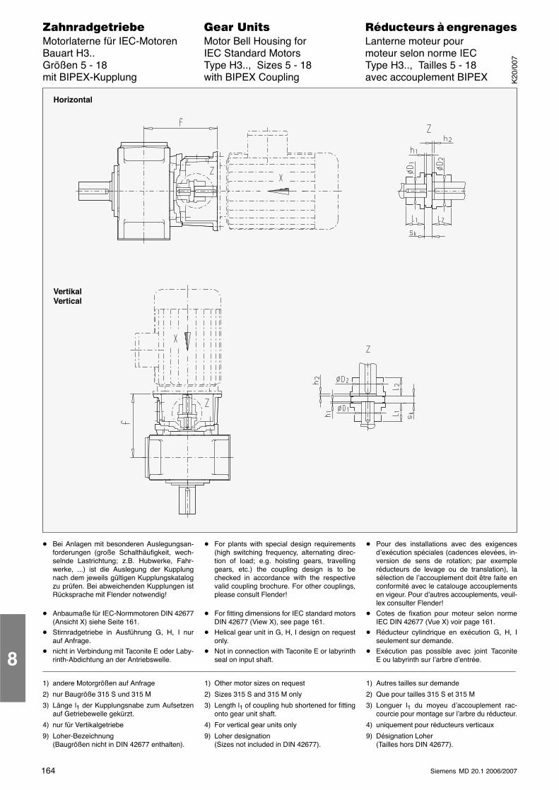
164 Siemens MD 20.1 2006/2007
������������� ���� �� ��������� � ����������Motorlaterne für IEC-Motoren Motor Bell Housing for Lanterne moteur pourBauart H3.. IEC Standard Motors moteur selon norme IECGrößen 5 - 18 Type H3.., Sizes 5 - 18 Type H3.., Tailles 5 - 18mit BIPEX-Kupplung with BIPEX Coupling avec accouplement BIPEX
Horizontal
VertikalVertical
� Bei Anlagen mit besonderen Auslegungsan-forderungen (große Schalthäufigkeit, wech-selnde Lastrichtung; z.B. Hubwerke, Fahr-werke, ...) ist die Auslegung der Kupplungnach dem jeweils gültigen Kupplungskatalogzu prüfen. Bei abweichenden Kupplungen istRücksprache mit Flender notwendig!
� Anbaumaße für IEC-Normmotoren DIN 42677(Ansicht X) siehe Seite 161.
� Stirnradgetriebe in Ausführung G, H, I nurauf Anfrage.
� nicht in Verbindung mit Taconite E oder Laby-rinth-Abdichtung an der Antriebswelle.
� For plants with special design requirements(high switching frequency, alternating direc-tion of load; e.g. hoisting gears, travellinggears, etc.) the coupling design is to bechecked in accordance with the respectivevalid coupling brochure. For other couplings,please consult Flender!
� For fitting dimensions for IEC standard motorsDIN 42677 (View X), see page 161.
� Helical gear unit in G, H, I design on requestonly.
� Not in connection with Taconite E or labyrinthseal on input shaft.
� Pour des installations avec des exigencesd’exécution spéciales (cadences elevées, in-version de sens de rotation; par exempleréducteurs de levage ou de translation), lasélection de l’accouplement doit être faite enconformité avec le catalouge accouplementsen vigeur. Pour d’autres accouplements, veuil-lex consulter Flender!
� Cotes de fixation pour moteur selon normeIEC DIN 42677 (Vue X) voir page 161.
� Réducteur cylindrique en exécution G, H, Iseulement sur demande.
� Exécution pas possible avec joint TaconiteE ou labyrinth sur l’arbre d’entrée.
1) andere Motorgrößen auf Anfrage
2) nur Baugröße 315 S und 315 M
3) Länge l1 der Kupplungsnabe zum Aufsetzenauf Getriebewelle gekürzt.
4) nur für Vertikalgetriebe
9) Loher-Bezeichnung(Baugrößen nicht in DIN 42677 enthalten).
1) Other motor sizes on request
2) Sizes 315 S and 315 M only
3) Length l1 of coupling hub shortened for fittingonto gear unit shaft.
4) For vertical gear units only
9) Loher designation(Sizes not included in DIN 42677).
1) Autres tailles sur demande
2) Que pour tailles 315 S et 315 M
3) Longuer l1 du moyeu d’accouplement rac-courcie pour montage sur l’arbre du réducteur.
4) uniquement pour réducteurs verticaux
9) Désignation Loher(Tailles hors DIN 42677).
8
K20
/007
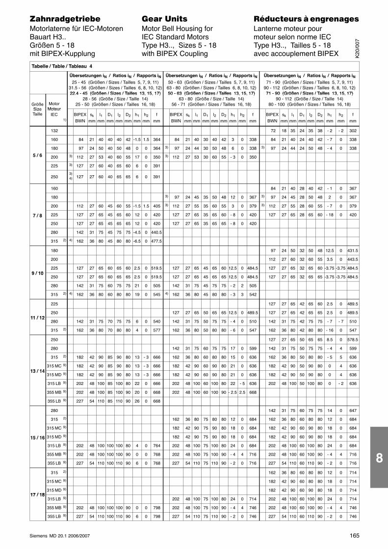
165Siemens MD 20.1 2006/2007
������������� ���� �� ��������� � ����������Motorlaterne für IEC-Motoren Motor Bell Housing for Lanterne moteur pourBauart H3.. IEC Standard Motors moteur selon norme IECGrößen 5 - 18 Type H3.., Sizes 5 - 18 Type H3.., Tailles 5 - 18mit BIPEX-Kupplung with BIPEX Coupling avec accouplement BIPEX
Tabelle / Table / Tableau 4
Übersetzungen iN / Ratios iN / Rapports iN25 - 45 (Größen / Sizes / Tailles 5, 7, 9, 11)
31.5 - 56 (Größen / Sizes / Tailles 6, 8, 10, 12)22 4 - 45 (Größen / Sizes / Tailles 13 15 17)
Übersetzungen iN / Ratios iN / Rapports iN50 - 63 (Größen / Sizes / Tailles 5, 7, 9, 11)
63 - 80 (Größen / Sizes / Tailles 6, 8, 10, 12)50 - 63 (Größen / Sizes / Tailles 13 15 17)
Übersetzungen iN / Ratios iN / Rapports iN71 - 90 (Größen / Sizes / Tailles 5, 7, 9, 11)
90 - 112 (Größen / Sizes / Tailles 6, 8, 10, 12)71 - 90 (Größen / Sizes / Tailles 13 15 17)
GrößeSize
MotorMoteur
22.4 - 45 (Größen / Sizes / Tailles 13, 15, 17)28 - 56 (Größe / Size / Taille 14)
25 - 50 (Größen / Sizes / Tailles 16, 18)
50 - 63 (Größen / Sizes / Tailles 13, 15, 17)63 - 80 (Größe / Size / Taille 14)
56 - 71 (Größen / Sizes / Tailles 16, 18)
71 - 90 (Größen / Sizes / Tailles 13, 15, 17)90 - 112 (Größe / Size / Taille 14)
80 - 100 (Größen / Sizes / Tailles 16, 18)SizeTaille
MoteurIEC
1)BIPEXBWN
sk
mml1
mmD1
mml2
mmD2
mmh1
mmh2
mmf
mmBIPEXBWN
sk
mml1
mmD1
mml2
mmD2
mmh1
mmh2
mmf
mmBIPEXBWN
sk
mml1
mmD1
mml2
mmD2
mmh1
mmh2
mmf
mm
132 72 18 35 24 35 38 - 2 - 2 302
160 84 21 40 40 40 42 -1.5 1.5 364 84 21 40 30 40 42 3 0 338 84 21 40 24 40 42 - 7 0 338
180 97 24 50 40 50 48 0 0 364 3) 97 24 44 30 50 48 6 0 338 3) 97 24 44 24 50 48 - 4 0 338
5 / 6 200 3) 112 27 53 40 60 55 17 0 350 3) 112 27 53 30 60 55 - 3 0 350
225 3) 127 27 60 40 65 60 6 0 391
2503)4) 127 27 60 40 65 65 6 0 391
160 84 21 40 28 40 42 - 1 0 367
180 3) 97 24 45 35 50 48 12 0 367 3) 97 24 45 28 50 48 2 0 367
200 112 27 60 45 60 55 -1.5 1.5 405 3) 112 27 55 35 60 55 3 0 379 3) 112 27 55 28 60 55 - 7 0 379
7 / 8 225 127 27 65 45 65 60 12 0 420 127 27 65 35 65 60 - 8 0 420 127 27 65 28 65 60 - 18 0 4207 / 8
250 127 27 65 45 65 65 12 0 420 127 27 65 35 65 65 - 8 0 420
280 142 31 75 45 75 75 -4.5 0 440.5
315 2) 4) 162 36 80 45 80 80 -6.5 0 477.5
180 97 24 50 32 50 48 12.5 0 431.5
200 112 27 60 32 60 55 3.5 0 443.5
9 / 10225 127 27 65 60 65 60 2.5 0 519.5 127 27 65 45 65 60 12.5 0 484.5 127 27 65 32 65 60 -3.75 -3.75 484.5
9 / 10250 127 27 65 60 65 65 2.5 0 519.5 127 27 65 45 65 65 12.5 0 484.5 127 27 65 32 65 65 -3.75 -3.75 484.5
280 142 31 75 60 75 75 21 0 505 142 31 75 45 75 75 - 2 2 505
315 2) 4) 162 36 80 60 80 80 19 0 545 4) 162 36 80 45 80 80 - 3 3 542
225 127 27 65 42 65 60 2.5 0 489.5
11 / 12250 127 27 65 50 65 65 12.5 0 489.5 127 27 65 42 65 65 2.5 0 489.5
11 / 12280 142 31 75 70 75 75 6 0 540 142 31 75 50 75 75 - 4 0 510 142 31 75 42 75 75 - 7 - 7 510
315 2) 162 36 80 70 80 80 4 0 577 162 36 80 50 80 80 - 6 0 547 162 36 80 42 80 80 - 16 0 547
250 127 27 65 50 65 65 8.5 0 578.5
280 142 31 75 60 75 75 17 0 599 142 31 75 50 75 75 - 4 4 599
315 2) 182 42 90 85 90 80 13 - 3 666 162 36 80 60 80 80 15 0 636 162 36 80 50 80 80 - 5 5 636
13 / 14315 MC 9) 182 42 90 85 90 80 13 - 3 666 182 42 90 60 90 80 21 0 636 182 42 90 50 90 80 0 4 636
13 / 14315 MD 9) 182 42 90 85 90 80 13 - 3 666 182 42 90 60 90 80 21 0 636 182 42 90 50 90 80 0 4 636
315 LB 9) 202 48 100 85 100 80 22 0 666 202 48 100 60 100 80 22 - 5 636 202 48 100 50 100 80 0 - 2 636
355 MB 9) 202 48 100 85 100 90 20 0 668 202 48 100 60 100 90 - 2.5 2.5 668
355 LB 9) 227 54 110 85 110 90 26 0 668
280 142 31 75 60 75 75 14 0 647
315 2) 162 36 80 75 80 80 12 0 684 162 36 80 60 80 80 12 0 684
315 MC 9) 182 42 90 75 90 80 18 0 684 182 42 90 60 90 80 18 0 684
15 / 16 315 MD 9) 182 42 90 75 90 80 18 0 684 182 42 90 60 90 80 18 0 68415 / 16
315 LB 9) 202 48 100 100 100 80 4 0 764 202 48 100 75 100 80 24 0 684 202 48 100 60 100 80 24 0 684
355 MB 9) 202 48 100 100 100 90 0 0 768 202 48 100 75 100 90 - 4 4 716 202 48 100 60 100 90 - 4 4 716
355 LB 9) 227 54 110 100 110 90 6 0 768 227 54 110 75 110 90 - 2 0 716 227 54 110 60 110 90 - 2 0 716
315 2) 162 36 80 60 80 80 12 0 714
315 MC 9) 182 42 90 60 80 80 18 0 714
17 / 18315 MD 9) 182 42 90 60 90 80 18 0 714
17 / 18315 LB 9) 202 48 100 75 100 80 24 0 714 202 48 100 60 100 80 24 0 714
355 MB 9) 202 48 100 100 100 90 0 0 798 202 48 100 75 100 90 - 4 4 746 202 48 100 60 100 90 - 4 4 746
355 LB 9) 227 54 110 100 110 90 6 0 798 227 54 110 75 110 90 - 2 0 746 227 54 110 60 110 90 - 2 0 746
K20
/007
8
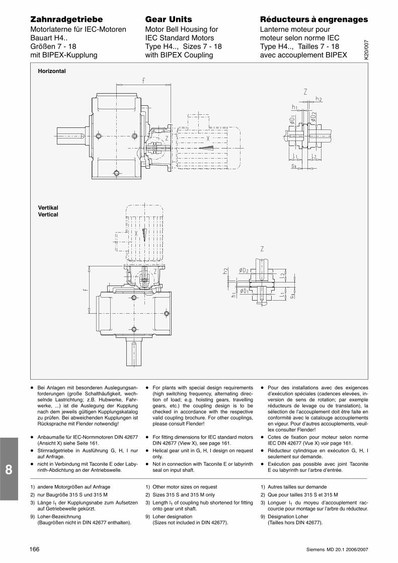
166 Siemens MD 20.1 2006/2007
������������� ���� �� ��������� � ����������Motorlaterne für IEC-Motoren Motor Bell Housing for Lanterne moteur pourBauart H4.. IEC Standard Motors moteur selon norme IECGrößen 7 - 18 Type H4.., Sizes 7 - 18 Type H4.., Tailles 7 - 18mit BIPEX-Kupplung with BIPEX Coupling avec accouplement BIPEX
Horizontal
VertikalVertical
� Bei Anlagen mit besonderen Auslegungsan-forderungen (große Schalthäufigkeit, wech-selnde Lastrichtung; z.B. Hubwerke, Fahr-werke, ...) ist die Auslegung der Kupplungnach dem jeweils gültigen Kupplungskatalogzu prüfen. Bei abweichenden Kupplungen istRücksprache mit Flender notwendig!
� Anbaumaße für IEC-Normmotoren DIN 42677(Ansicht X) siehe Seite 161.
� Stirnradgetriebe in Ausführung G, H, I nurauf Anfrage.
� nicht in Verbindung mit Taconite E oder Laby-rinth-Abdichtung an der Antriebswelle.
� For plants with special design requirements(high switching frequency, alternating direc-tion of load; e.g. hoisting gears, travellinggears, etc.) the coupling design is to bechecked in accordance with the respectivevalid coupling brochure. For other couplings,please consult Flender!
� For fitting dimensions for IEC standard motorsDIN 42677 (View X), see page 161.
� Helical gear unit in G, H, I design on requestonly.
� Not in connection with Taconite E or labyrinthseal on input shaft.
� Pour des installations avec des exigencesd’exécution spéciales (cadences elevées, in-version de sens de rotation; par exempleréducteurs de levage ou de translation), lasélection de l’accouplement doit être faite enconformité avec le catalouge accouplementsen vigeur. Pour d’autres accouplements, veuil-lex consulter Flender!
� Cotes de fixation pour moteur selon normeIEC DIN 42677 (Vue X) voir page 161.
� Réducteur cylindrique en exécution G, H, Iseulement sur demande.
� Exécution pas possible avec joint TaconiteE ou labyrinth sur l’arbre d’entrée.
1) andere Motorgrößen auf Anfrage
2) nur Baugröße 315 S und 315 M
3) Länge l1 der Kupplungsnabe zum Aufsetzenauf Getriebewelle gekürzt.
9) Loher-Bezeichnung(Baugrößen nicht in DIN 42677 enthalten).
1) Other motor sizes on request
2) Sizes 315 S and 315 M only
3) Length l1 of coupling hub shortened for fittingonto gear unit shaft.
9) Loher designation(Sizes not included in DIN 42677).
1) Autres tailles sur demande
2) Que pour tailles 315 S et 315 M
3) Longuer l1 du moyeu d’accouplement rac-courcie pour montage sur l’arbre du réducteur.
9) Désignation Loher(Tailles hors DIN 42677).
8
K20
/007
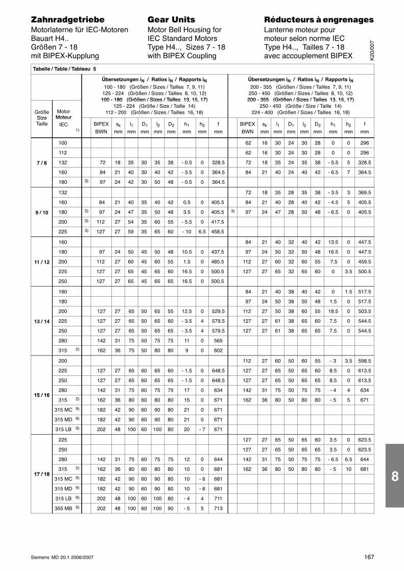
167Siemens MD 20.1 2006/2007
������������� ���� �� ��������� � ����������Motorlaterne für IEC-Motoren Motor Bell Housing for Lanterne moteur pourBauart H4.. IEC Standard Motors moteur selon norme IECGrößen 7 - 18 Type H4.., Sizes 7 - 18 Type H4.., Tailles 7 - 18mit BIPEX-Kupplung with BIPEX Coupling avec accouplement BIPEX
Tabelle / Table / Tableau 5
Übersetzungen iN / Ratios iN / Rapports iN100 - 180 (Größen / Sizes / Tailles 7, 9, 11)
125 - 224 (Größen / Sizes / Tailles 8, 10, 12)100 - 180 (Größen / Sizes / Tailles 13 15 17)
Übersetzungen iN / Ratios iN / Rapports iN200 - 355 (Größen / Sizes / Tailles 7, 9, 11)
250 - 450 (Größen / Sizes / Tailles 8, 10, 12)200 - 355 (Größen / Sizes / Tailles 13 15 17)
GrößeSize
MotorMoteur
100 - 180 (Größen / Sizes / Tailles 13, 15, 17)125 - 224 (Größe / Size / Taille 14)
112 - 200 (Größen / Sizes / Tailles 16, 18)
200 - 355 (Größen / Sizes / Tailles 13, 15, 17)250 - 450 (Größe / Size / Taille 14)
224 - 400 (Größen / Sizes / Tailles 16, 18)SizeTaille
MoteurIEC
1)BIPEXBWN
sk
mml1
mmD1
mml2
mmD2
mmh1
mmh2
mmf
mmBIPEXBWN
sk
mml1
mmD1
mml2
mmD2
mmh1
mmh2
mmf
mm
100 62 16 30 24 30 28 0 0 296
112 62 16 30 24 30 28 0 0 296
7 / 8 132 72 18 35 30 35 38 - 0.5 0 328.5 72 18 35 24 35 38 - 5.5 5 328.5
160 84 21 40 30 40 42 - 3.5 0 364.5 84 21 40 24 40 42 - 6.5 7 364.5
180 3) 97 24 42 30 50 48 - 0.5 0 364.5
132 72 18 35 28 35 38 - 3.5 3 369.5
160 84 21 40 35 40 42 0.5 0 405.5 84 21 40 28 40 42 - 4.5 5 405.5
9 / 10 180 3) 97 24 47 35 50 48 3.5 0 405.5 3) 97 24 47 28 50 48 - 6.5 0 405.5
200 3) 112 27 54 35 60 55 - 5.5 0 417.5
225 3) 127 27 59 35 65 60 - 10 6.5 458.5
160 84 21 40 32 40 42 13.5 0 447.5
180 97 24 50 45 50 48 10.5 0 437.5 97 24 50 32 50 48 16.5 0 447.5
11 / 12 200 112 27 60 45 60 55 1.5 0 485.5 112 27 60 32 60 55 7.5 0 459.5
225 127 27 65 45 65 60 16.5 0 500.5 127 27 65 32 65 60 0 3.5 500.5
250 127 27 65 45 65 65 16.5 0 500.5
160 84 21 40 38 40 42 0 1.5 517.5
180 97 24 50 38 50 48 1.5 0 517.5
200 127 27 65 50 65 55 12.5 0 529.5 112 27 50 38 60 55 18.5 0 503.5
13 / 14 225 127 27 65 50 65 60 - 3.5 4 579.5 127 27 61 38 65 60 7.5 0 544.5
250 127 27 65 50 65 65 - 3.5 4 579.5 127 27 61 38 65 65 7.5 0 544.5
280 142 31 75 50 75 75 11 0 565
315 2) 162 36 75 50 80 80 9 0 602
200 112 27 60 50 60 55 - 3 3.5 598.5
225 127 27 65 60 65 60 - 1.5 0 648.5 127 27 65 50 65 60 8.5 0 613.5
250 127 27 65 60 65 65 - 1.5 0 648.5 127 27 65 50 65 65 8.5 0 613.5
15 / 16280 142 31 75 60 75 75 17 0 634 142 31 75 50 75 75 - 4 4 634
15 / 16315 2) 162 36 80 60 80 80 15 0 671 162 36 80 50 80 80 - 5 5 671
315 MC 9) 182 42 90 60 90 80 21 0 671
315 MD 9) 182 42 90 60 90 80 21 0 671
315 LB 9) 202 48 100 60 100 80 20 - 7 671
225 127 27 65 50 65 60 3.5 0 623.5
250 127 27 65 50 65 65 3.5 0 623.5
280 142 31 75 60 75 75 12 0 644 142 31 75 50 75 75 - 6.5 6.5 644
17 / 18315 2) 162 36 80 60 80 80 10 0 681 162 36 80 50 80 80 - 5 10 681
17 / 18315 MC 9) 182 42 90 60 90 80 10 - 6 681
315 MD 9) 182 42 90 60 90 80 10 - 6 681
315 LB 9) 202 48 100 60 100 80 - 4 4 711
355 MB 9) 202 48 100 60 100 90 - 5 5 713
K20
/007
8
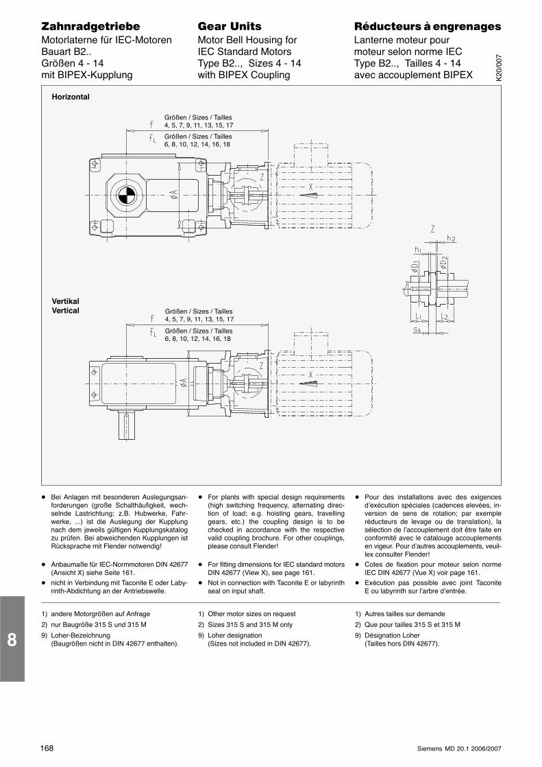
168 Siemens MD 20.1 2006/2007
������������� ���� �� ��������� � ����������Motorlaterne für IEC-Motoren Motor Bell Housing for Lanterne moteur pourBauart B2.. IEC Standard Motors moteur selon norme IECGrößen 4 - 14 Type B2.., Sizes 4 - 14 Type B2.., Tailles 4 - 14mit BIPEX-Kupplung with BIPEX Coupling avec accouplement BIPEX
Horizontal
VertikalVertical
Größen / Sizes / Tailles4, 5, 7, 9, 11, 13, 15, 17
Größen / Sizes / Tailles6, 8, 10, 12, 14, 16, 18
Größen / Sizes / Tailles4, 5, 7, 9, 11, 13, 15, 17
Größen / Sizes / Tailles6, 8, 10, 12, 14, 16, 18
� Bei Anlagen mit besonderen Auslegungsan-forderungen (große Schalthäufigkeit, wech-selnde Lastrichtung; z.B. Hubwerke, Fahr-werke, ...) ist die Auslegung der Kupplungnach dem jeweils gültigen Kupplungskatalogzu prüfen. Bei abweichenden Kupplungen istRücksprache mit Flender notwendig!
� Anbaumaße für IEC-Normmotoren DIN 42677(Ansicht X) siehe Seite 161.
� nicht in Verbindung mit Taconite E oder Laby-rinth-Abdichtung an der Antriebswelle.
� For plants with special design requirements(high switching frequency, alternating direc-tion of load; e.g. hoisting gears, travellinggears, etc.) the coupling design is to bechecked in accordance with the respectivevalid coupling brochure. For other couplings,please consult Flender!
� For fitting dimensions for IEC standard motorsDIN 42677 (View X), see page 161.
� Not in connection with Taconite E or labyrinthseal on input shaft.
� Pour des installations avec des exigencesd’exécution spéciales (cadences elevées, in-version de sens de rotation; par exempleréducteurs de levage ou de translation), lasélection de l’accouplement doit être faite enconformité avec le catalouge accouplementsen vigeur. Pour d’autres accouplements, veuil-lex consulter Flender!
� Cotes de fixation pour moteur selon normeIEC DIN 42677 (Vue X) voir page 161.
� Exécution pas possible avec joint TaconiteE ou labyrinth sur l’arbre d’entrée.
1) andere Motorgrößen auf Anfrage
2) nur Baugröße 315 S und 315 M
9) Loher-Bezeichnung(Baugrößen nicht in DIN 42677 enthalten).
1) Other motor sizes on request
2) Sizes 315 S and 315 M only
9) Loher designation(Sizes not included in DIN 42677).
1) Autres tailles sur demande
2) Que pour tailles 315 S et 315 M
9) Désignation Loher(Tailles hors DIN 42677).8
K20
/007
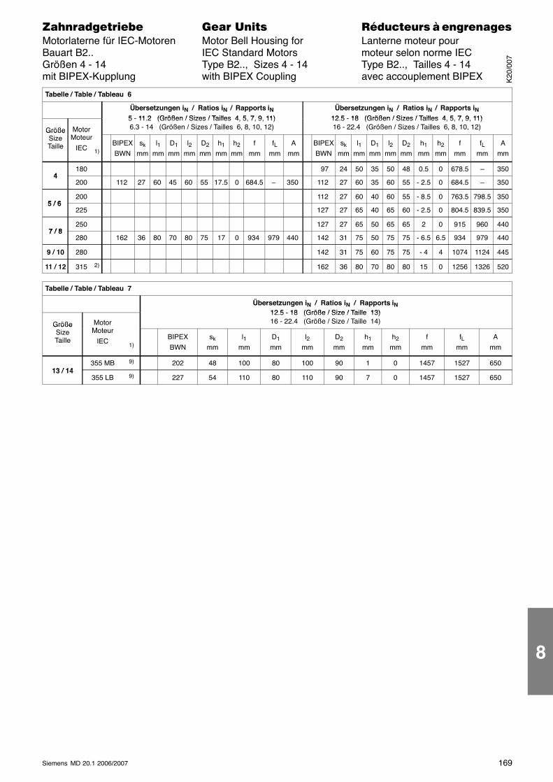
169Siemens MD 20.1 2006/2007
������������� ���� �� ��������� � ����������Motorlaterne für IEC-Motoren Motor Bell Housing for Lanterne moteur pourBauart B2.. IEC Standard Motors moteur selon norme IECGrößen 4 - 14 Type B2.., Sizes 4 - 14 Type B2.., Tailles 4 - 14mit BIPEX-Kupplung with BIPEX Coupling avec accouplement BIPEX
Tabelle / Table / Tableau 6
Übersetzungen iN / Ratios iN / Rapports iN5 - 11 2 (Größen / Sizes / Tailles 4 5 7 9 11)
Übersetzungen iN / Ratios iN / Rapports iN12 5 - 18 (Größen / Sizes / Tailles 4 5 7 9 11)
Größe Motor
5 - 11.2 (Größen / Sizes / Tailles 4, 5, 7, 9, 11)6.3 - 14 (Größen / Sizes / Tailles 6, 8, 10, 12)
12.5 - 18 (Größen / Sizes / Tailles 4, 5, 7, 9, 11)16 - 22.4 (Größen / Sizes / Tailles 6, 8, 10, 12)Größe
SizeTaille
MotorMoteur
IEC 1)BIPEXBWN
sk
mml1
mmD1
mml2
mmD2
mmh1
mmh2
mmf
mmfL
mmA
mmBIPEXBWN
sk
mml1
mmD1
mml2
mmD2
mmh1
mmh2
mmf
mmfL
mmA
mm
4180 97 24 50 35 50 48 0.5 0 678.5 – 350
4200 112 27 60 45 60 55 17.5 0 684.5 – 350 112 27 60 35 60 55 - 2.5 0 684.5 – 350
5 / 6200 112 27 60 40 60 55 - 8.5 0 763.5 798.5 350
5 / 6225 127 27 65 40 65 60 - 2.5 0 804.5 839.5 350
7 / 8250 127 27 65 50 65 65 2 0 915 960 440
7 / 8280 162 36 80 70 80 75 17 0 934 979 440 142 31 75 50 75 75 - 6.5 6.5 934 979 440
9 / 10 280 142 31 75 60 75 75 - 4 4 1074 1124 445
11 / 12 315 2) 162 36 80 70 80 80 15 0 1256 1326 520
Tabelle / Table / Tableau 7
Übersetzungen iN / Ratios iN / Rapports iN12 5 18 (Größe / Size / Taille 13)
Größe MotorM t
12.5 - 18 (Größe / Size / Taille 13)16 - 22.4 (Größe / Size / Taille 14)Größe
SizeTaille
Moteur
IEC1)
BIPEXBWN
sk
mml1
mmD1
mml2
mmD2
mmh1
mmh2
mmf
mmfL
mmA
mm
13 / 14355 MB 9) 202 48 100 80 100 90 1 0 1457 1527 650
13 / 14355 LB 9) 227 54 110 80 110 90 7 0 1457 1527 650
K20
/007
8
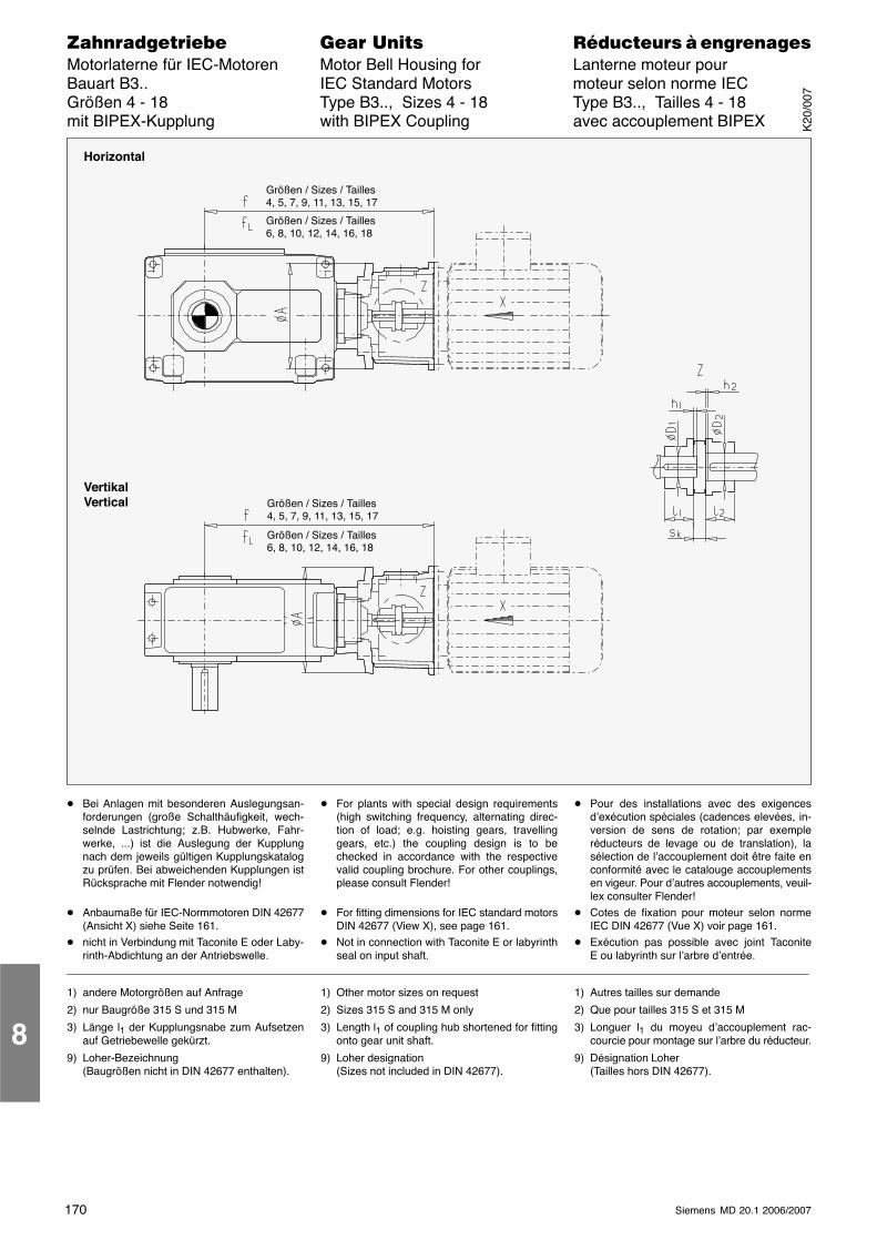
170 Siemens MD 20.1 2006/2007
������������� ���� �� ��������� � ����������Motorlaterne für IEC-Motoren Motor Bell Housing for Lanterne moteur pourBauart B3.. IEC Standard Motors moteur selon norme IECGrößen 4 - 18 Type B3.., Sizes 4 - 18 Type B3.., Tailles 4 - 18mit BIPEX-Kupplung with BIPEX Coupling avec accouplement BIPEX
Horizontal
VertikalVertical
Größen / Sizes / Tailles4, 5, 7, 9, 11, 13, 15, 17
Größen / Sizes / Tailles6, 8, 10, 12, 14, 16, 18
Größen / Sizes / Tailles4, 5, 7, 9, 11, 13, 15, 17
Größen / Sizes / Tailles6, 8, 10, 12, 14, 16, 18
� Bei Anlagen mit besonderen Auslegungsan-forderungen (große Schalthäufigkeit, wech-selnde Lastrichtung; z.B. Hubwerke, Fahr-werke, ...) ist die Auslegung der Kupplungnach dem jeweils gültigen Kupplungskatalogzu prüfen. Bei abweichenden Kupplungen istRücksprache mit Flender notwendig!
� Anbaumaße für IEC-Normmotoren DIN 42677(Ansicht X) siehe Seite 161.
� nicht in Verbindung mit Taconite E oder Laby-rinth-Abdichtung an der Antriebswelle.
� For plants with special design requirements(high switching frequency, alternating direc-tion of load; e.g. hoisting gears, travellinggears, etc.) the coupling design is to bechecked in accordance with the respectivevalid coupling brochure. For other couplings,please consult Flender!
� For fitting dimensions for IEC standard motorsDIN 42677 (View X), see page 161.
� Not in connection with Taconite E or labyrinthseal on input shaft.
� Pour des installations avec des exigencesd’exécution spéciales (cadences elevées, in-version de sens de rotation; par exempleréducteurs de levage ou de translation), lasélection de l’accouplement doit être faite enconformité avec le catalouge accouplementsen vigeur. Pour d’autres accouplements, veuil-lex consulter Flender!
� Cotes de fixation pour moteur selon normeIEC DIN 42677 (Vue X) voir page 161.
� Exécution pas possible avec joint TaconiteE ou labyrinth sur l’arbre d’entrée.
1) andere Motorgrößen auf Anfrage
2) nur Baugröße 315 S und 315 M
3) Länge l1 der Kupplungsnabe zum Aufsetzenauf Getriebewelle gekürzt.
9) Loher-Bezeichnung(Baugrößen nicht in DIN 42677 enthalten).
1) Other motor sizes on request
2) Sizes 315 S and 315 M only
3) Length l1 of coupling hub shortened for fittingonto gear unit shaft.
9) Loher designation(Sizes not included in DIN 42677).
1) Autres tailles sur demande
2) Que pour tailles 315 S et 315 M
3) Longuer l1 du moyeu d’accouplement rac-courcie pour montage sur l’arbre du réducteur.
9) Désignation Loher(Tailles hors DIN 42677).
8
K20
/007
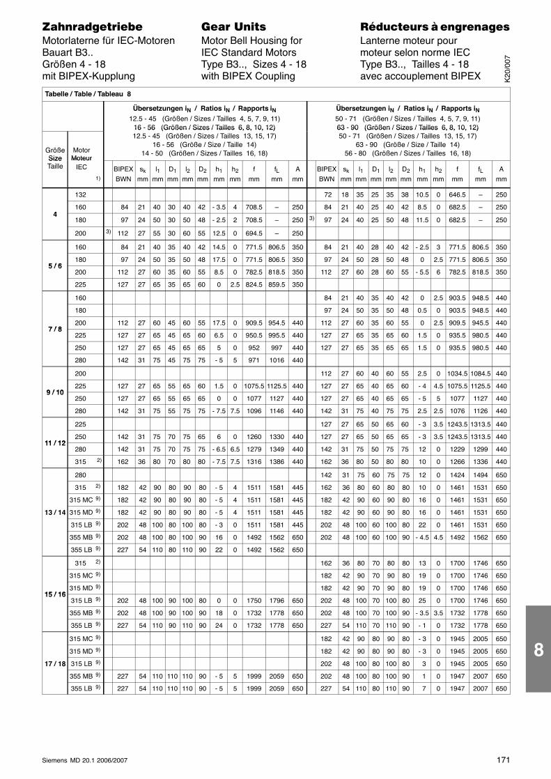
171Siemens MD 20.1 2006/2007
������������� ���� �� ��������� � ����������Motorlaterne für IEC-Motoren Motor Bell Housing for Lanterne moteur pourBauart B3.. IEC Standard Motors moteur selon norme IECGrößen 4 - 18 Type B3.., Sizes 4 - 18 Type B3.., Tailles 4 - 18mit BIPEX-Kupplung with BIPEX Coupling avec accouplement BIPEX
Tabelle / Table / Tableau 8
Übersetzungen iN / Ratios iN / Rapports iN12.5 - 45 (Größen / Sizes / Tailles 4, 5, 7, 9, 11)
16 - 56 (Größen / Sizes / Tailles 6, 8, 10, 12)
Übersetzungen iN / Ratios iN / Rapports iN50 - 71 (Größen / Sizes / Tailles 4, 5, 7, 9, 11)63 - 90 (Größen / Sizes / Tailles 6, 8, 10, 12)
GrößeSize
MotorMoteur
16 56 (Größen / Sizes / Tailles 6, 8, 10, 12)12.5 - 45 (Größen / Sizes / Tailles 13, 15, 17)
16 - 56 (Größe / Size / Taille 14)14 - 50 (Größen / Sizes / Tailles 16, 18)
63 90 (Größen / Sizes / Tailles 6, 8, 10, 12)50 - 71 (Größen / Sizes / Tailles 13, 15, 17)
63 - 90 (Größe / Size / Taille 14)56 - 80 (Größen / Sizes / Tailles 16, 18)
SizeTaille
MoteurIEC
1)
BIPEXBWN
sk
mml1
mmD1
mml2
mmD2
mmh1
mmh2
mmf
mmfL
mmA
mmBIPEXBWN
sk
mml1
mmD1
mml2
mmD2
mmh1
mmh2
mmf
mmfL
mmA
mm
132 72 18 35 25 35 38 10.5 0 646.5 – 250
4160 84 21 40 30 40 42 - 3.5 4 708.5 – 250 84 21 40 25 40 42 8.5 0 682.5 – 250
4180 97 24 50 30 50 48 - 2.5 2 708.5 – 250 3) 97 24 40 25 50 48 11.5 0 682.5 – 250
200 3) 112 27 55 30 60 55 12.5 0 694.5 – 250
160 84 21 40 35 40 42 14.5 0 771.5 806.5 350 84 21 40 28 40 42 - 2.5 3 771.5 806.5 350
5 / 6180 97 24 50 35 50 48 17.5 0 771.5 806.5 350 97 24 50 28 50 48 0 2.5 771.5 806.5 350
5 / 6200 112 27 60 35 60 55 8.5 0 782.5 818.5 350 112 27 60 28 60 55 - 5.5 6 782.5 818.5 350
225 127 27 65 35 65 60 0 2.5 824.5 859.5 350
160 84 21 40 35 40 42 0 2.5 903.5 948.5 440
180 97 24 50 35 50 48 0.5 0 903.5 948.5 440
7 / 8200 112 27 60 45 60 55 17.5 0 909.5 954.5 440 112 27 60 35 60 55 0 2.5 909.5 945.5 440
7 / 8225 127 27 65 45 65 60 6.5 0 950.5 995.5 440 127 27 65 35 65 60 1.5 0 935.5 980.5 440
250 127 27 65 45 65 65 5 0 952 997 440 127 27 65 35 65 65 1.5 0 935.5 980.5 440
280 142 31 75 45 75 75 - 5 5 971 1016 440
200 112 27 60 40 60 55 2.5 0 1034.5 1084.5 440
9 / 10225 127 27 65 55 65 60 1.5 0 1075.5 1125.5 440 127 27 65 40 65 60 - 4 4.5 1075.5 1125.5 440
9 / 10250 127 27 65 55 65 65 0 0 1077 1127 440 127 27 65 40 65 65 - 5 5 1077 1127 440
280 142 31 75 55 75 75 - 7.5 7.5 1096 1146 440 142 31 75 40 75 75 2.5 2.5 1076 1126 440
225 127 27 65 50 65 60 - 3 3.5 1243.5 1313.5 440
11 / 12250 142 31 75 70 75 65 6 0 1260 1330 440 127 27 65 50 65 65 - 3 3.5 1243.5 1313.5 440
11 / 12280 142 31 75 70 75 75 - 6.5 6.5 1279 1349 440 142 31 75 50 75 75 12 0 1229 1299 440
315 2) 162 36 80 70 80 80 - 7.5 7.5 1316 1386 440 162 36 80 50 80 80 10 0 1266 1336 440
280 142 31 75 60 75 75 12 0 1424 1494 650
315 2) 182 42 90 80 90 80 - 5 4 1511 1581 445 162 36 80 60 80 80 10 0 1461 1531 650
315 MC 9) 182 42 90 80 90 80 - 5 4 1511 1581 445 182 42 90 60 90 80 16 0 1461 1531 650
13 / 14 315 MD 9) 182 42 90 80 90 80 - 5 4 1511 1581 445 182 42 90 60 90 80 16 0 1461 1531 650
315 LB 9) 202 48 100 80 100 80 - 3 0 1511 1581 445 202 48 100 60 100 80 22 0 1461 1531 650
355 MB 9) 202 48 100 80 100 90 16 0 1492 1562 650 202 48 100 60 100 90 - 4.5 4.5 1492 1562 650
355 LB 9) 227 54 110 80 110 90 22 0 1492 1562 650
315 2) 162 36 80 70 80 80 13 0 1700 1746 650
315 MC 9) 182 42 90 70 90 80 19 0 1700 1746 650
15 / 16315 MD 9) 182 42 90 70 90 80 19 0 1700 1746 650
15 / 16315 LB 9) 202 48 100 90 100 80 0 0 1750 1796 650 202 48 100 70 100 80 25 0 1700 1746 650
355 MB 9) 202 48 100 90 100 90 18 0 1732 1778 650 202 48 100 70 100 90 - 3.5 3.5 1732 1778 650
355 LB 9) 227 54 110 90 110 90 24 0 1732 1778 650 227 54 110 70 110 90 - 1 0 1732 1778 650
315 MC 9) 182 42 90 80 90 80 - 3 0 1945 2005 650
315 MD 9) 182 42 90 80 90 80 - 3 0 1945 2005 650
17 / 18 315 LB 9) 202 48 100 80 100 80 3 0 1945 2005 650
355 MB 9) 227 54 110 110 110 90 - 5 5 1999 2059 650 202 48 100 80 100 90 1 0 1947 2007 650
355 LB 9) 227 54 110 110 110 90 - 5 5 1999 2059 650 227 54 110 80 110 90 7 0 1947 2007 650
K20
/007
8

172 Siemens MD 20.1 2006/2007
������������� ���� �� ��������� � ����������Motorlaterne für IEC-Motoren Motor Bell Housing for Lanterne moteur pourBauart B4.. IEC Standard Motors moteur selon norme IECGrößen 5 - 18 Type B4.., Sizes 5 - 18 Type B4.., Tailles 5 - 18mit BIPEX-Kupplung with BIPEX Coupling avec accouplement BIPEX
Horizontal
VertikalVertical
Größen / Sizes / Tailles4, 5, 7, 9, 11, 13, 15, 17
Größen / Sizes / Tailles6, 8, 10, 12, 14, 16, 18
Größen / Sizes / Tailles4, 5, 7, 9, 11, 13, 15, 17
Größen / Sizes / Tailles6, 8, 10, 12, 14, 16, 18
� Bei Anlagen mit besonderen Auslegungsan-forderungen (große Schalthäufigkeit, wech-selnde Lastrichtung; z.B. Hubwerke, Fahr-werke, ...) ist die Auslegung der Kupplungnach dem jeweils gültigen Kupplungskatalogzu prüfen. Bei abweichenden Kupplungen istRücksprache mit Flender notwendig!
� Anbaumaße für IEC-Normmotoren DIN 42677(Ansicht X) siehe Seite 161.
� nicht in Verbindung mit Taconite E oder Laby-rinth-Abdichtung an der Antriebswelle.
� For plants with special design requirements(high switching frequency, alternating direc-tion of load; e.g. hoisting gears, travellinggears, etc.) the coupling design is to bechecked in accordance with the respectivevalid coupling brochure. For other couplings,please consult Flender!
� For fitting dimensions for IEC standard motorsDIN 42677 (View X), see page 161.
� Not in connection with Taconite E or labyrinthseal on input shaft.
� Pour des installations avec des exigencesd’exécution spéciales (cadences elevées, in-version de sens de rotation; par exempleréducteurs de levage ou de translation), lasélection de l’accouplement doit être faite enconformité avec le catalouge accouplementsen vigeur. Pour d’autres accouplements, veuil-lex consulter Flender!
� Cotes de fixation pour moteur selon normeIEC DIN 42677 (Vue X) voir page 161.
� Exécution pas possible avec joint TaconiteE ou labyrinth sur l’arbre d’entrée.
1) andere Motorgrößen auf Anfrage
2) nur Baugröße 315 S und 315 M
3) Länge l1 der Kupplungsnabe zum Aufsetzenauf Getriebewelle gekürzt.
9) Loher-Bezeichnung(Baugrößen nicht in DIN 42677 enthalten).
1) Other motor sizes on request
2) Sizes 315 S and 315 M only
3) Length l1 of coupling hub shortened for fittingonto gear unit shaft.
9) Loher designation(Sizes not included in DIN 42677).
1) Autres tailles sur demande
2) Que pour tailles 315 S et 315 M
3) Longuer l1 du moyeu d’accouplement rac-courcie pour montage sur l’arbre du réducteur.
9) Désignation Loher(Tailles hors DIN 42677).
8
K20
/007
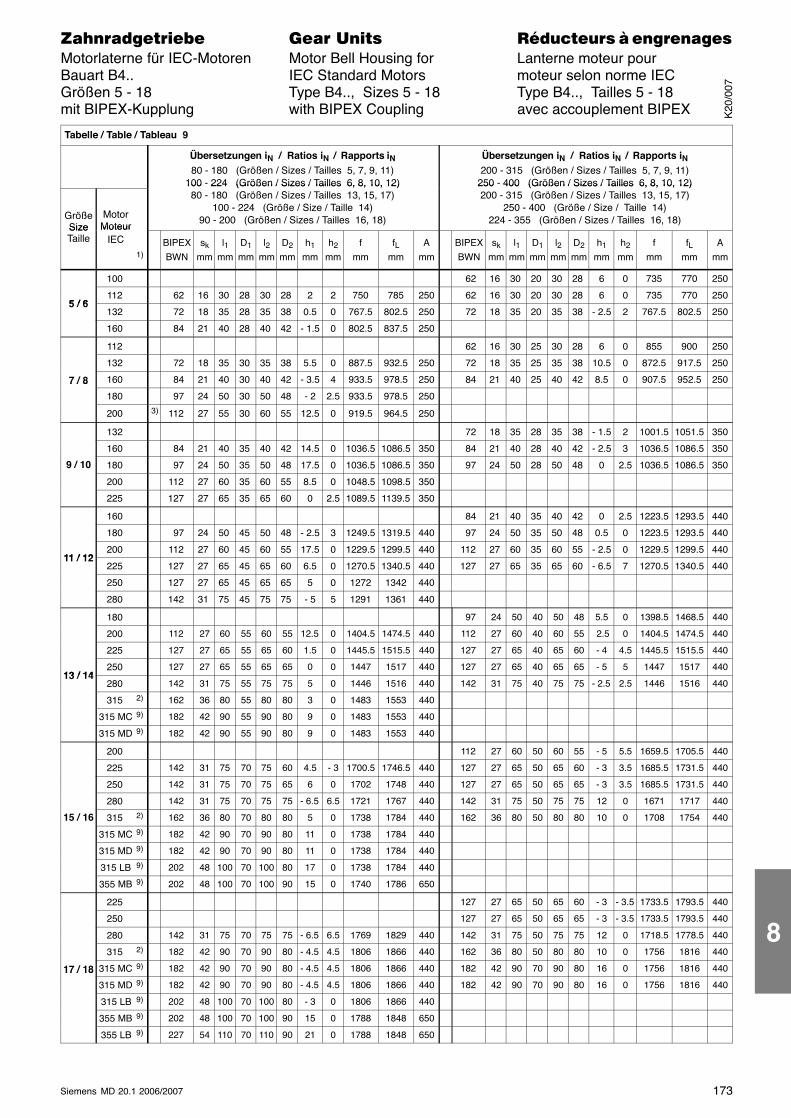
173Siemens MD 20.1 2006/2007
������������� ���� �� ��������� � ����������Motorlaterne für IEC-Motoren Motor Bell Housing for Lanterne moteur pourBauart B4.. IEC Standard Motors moteur selon norme IECGrößen 5 - 18 Type B4.., Sizes 5 - 18 Type B4.., Tailles 5 - 18mit BIPEX-Kupplung with BIPEX Coupling avec accouplement BIPEX
Tabelle / Table / Tableau 9
Übersetzungen iN / Ratios iN / Rapports iN80 - 180 (Größen / Sizes / Tailles 5, 7, 9, 11)
100 - 224 (Größen / Sizes / Tailles 6, 8, 10, 12)
Übersetzungen iN / Ratios iN / Rapports iN200 - 315 (Größen / Sizes / Tailles 5, 7, 9, 11)
250 - 400 (Größen / Sizes / Tailles 6, 8, 10, 12)
GrößeSize
MotorMoteur
100 224 (Größen / Sizes / Tailles 6, 8, 10, 12)80 - 180 (Größen / Sizes / Tailles 13, 15, 17)
100 - 224 (Größe / Size / Taille 14)90 - 200 (Größen / Sizes / Tailles 16, 18)
250 400 (Größen / Sizes / Tailles 6, 8, 10, 12)200 - 315 (Größen / Sizes / Tailles 13, 15, 17)
250 - 400 (Größe / Size / Taille 14)224 - 355 (Größen / Sizes / Tailles 16, 18)
SizeTaille
MoteurIEC
1)BIPEXBWN
sk
mml1
mmD1
mml2
mmD2
mmh1
mmh2
mmf
mmfL
mmA
mmBIPEXBWN
sk
mml1
mmD1
mml2
mmD2
mmh1
mmh2
mmf
mmfL
mmA
mm
100 62 16 30 20 30 28 6 0 735 770 250
5 / 6112 62 16 30 28 30 28 2 2 750 785 250 62 16 30 20 30 28 6 0 735 770 250
5 / 6132 72 18 35 28 35 38 0.5 0 767.5 802.5 250 72 18 35 20 35 38 - 2.5 2 767.5 802.5 250
160 84 21 40 28 40 42 - 1.5 0 802.5 837.5 250
112 62 16 30 25 30 28 6 0 855 900 250
132 72 18 35 30 35 38 5.5 0 887.5 932.5 250 72 18 35 25 35 38 10.5 0 872.5 917.5 250
7 / 8 160 84 21 40 30 40 42 - 3.5 4 933.5 978.5 250 84 21 40 25 40 42 8.5 0 907.5 952.5 2507 / 8
180 97 24 50 30 50 48 - 2 2.5 933.5 978.5 250
200 3) 112 27 55 30 60 55 12.5 0 919.5 964.5 250
132 72 18 35 28 35 38 - 1.5 2 1001.5 1051.5 350
160 84 21 40 35 40 42 14.5 0 1036.5 1086.5 350 84 21 40 28 40 42 - 2.5 3 1036.5 1086.5 350
9 / 10 180 97 24 50 35 50 48 17.5 0 1036.5 1086.5 350 97 24 50 28 50 48 0 2.5 1036.5 1086.5 350
200 112 27 60 35 60 55 8.5 0 1048.5 1098.5 350
225 127 27 65 35 65 60 0 2.5 1089.5 1139.5 350
160 84 21 40 35 40 42 0 2.5 1223.5 1293.5 440
180 97 24 50 45 50 48 - 2.5 3 1249.5 1319.5 440 97 24 50 35 50 48 0.5 0 1223.5 1293.5 440
11 / 12200 112 27 60 45 60 55 17.5 0 1229.5 1299.5 440 112 27 60 35 60 55 - 2.5 0 1229.5 1299.5 440
11 / 12225 127 27 65 45 65 60 6.5 0 1270.5 1340.5 440 127 27 65 35 65 60 - 6.5 7 1270.5 1340.5 440
250 127 27 65 45 65 65 5 0 1272 1342 440
280 142 31 75 45 75 75 - 5 5 1291 1361 440
180 97 24 50 40 50 48 5.5 0 1398.5 1468.5 440
200 112 27 60 55 60 55 12.5 0 1404.5 1474.5 440 112 27 60 40 60 55 2.5 0 1404.5 1474.5 440
225 127 27 65 55 65 60 1.5 0 1445.5 1515.5 440 127 27 65 40 65 60 - 4 4.5 1445.5 1515.5 440
13 / 14250 127 27 65 55 65 65 0 0 1447 1517 440 127 27 65 40 65 65 - 5 5 1447 1517 440
13 / 14280 142 31 75 55 75 75 5 0 1446 1516 440 142 31 75 40 75 75 - 2.5 2.5 1446 1516 440
315 2) 162 36 80 55 80 80 3 0 1483 1553 440
315 MC 9) 182 42 90 55 90 80 9 0 1483 1553 440
315 MD 9) 182 42 90 55 90 80 9 0 1483 1553 440
200 112 27 60 50 60 55 - 5 5.5 1659.5 1705.5 440
225 142 31 75 70 75 60 4.5 - 3 1700.5 1746.5 440 127 27 65 50 65 60 - 3 3.5 1685.5 1731.5 440
250 142 31 75 70 75 65 6 0 1702 1748 440 127 27 65 50 65 65 - 3 3.5 1685.5 1731.5 440
280 142 31 75 70 75 75 - 6.5 6.5 1721 1767 440 142 31 75 50 75 75 12 0 1671 1717 440
15 / 16 315 2) 162 36 80 70 80 80 5 0 1738 1784 440 162 36 80 50 80 80 10 0 1708 1754 440
315 MC 9) 182 42 90 70 90 80 11 0 1738 1784 440
315 MD 9) 182 42 90 70 90 80 11 0 1738 1784 440
315 LB 9) 202 48 100 70 100 80 17 0 1738 1784 440
355 MB 9) 202 48 100 70 100 90 15 0 1740 1786 650
225 127 27 65 50 65 60 - 3 - 3.5 1733.5 1793.5 440
250 127 27 65 50 65 65 - 3 - 3.5 1733.5 1793.5 440
280 142 31 75 70 75 75 - 6.5 6.5 1769 1829 440 142 31 75 50 75 75 12 0 1718.5 1778.5 440
315 2) 182 42 90 70 90 80 - 4.5 4.5 1806 1866 440 162 36 80 50 80 80 10 0 1756 1816 440
17 / 18 315 MC 9) 182 42 90 70 90 80 - 4.5 4.5 1806 1866 440 182 42 90 70 90 80 16 0 1756 1816 44017 / 18
315 MD 9) 182 42 90 70 90 80 - 4.5 4.5 1806 1866 440 182 42 90 70 90 80 16 0 1756 1816 440
315 LB 9) 202 48 100 70 100 80 - 3 0 1806 1866 440
355 MB 9) 202 48 100 70 100 90 15 0 1788 1848 650
355 LB 9) 227 54 110 70 110 90 21 0 1788 1848 650
K20
/007
8
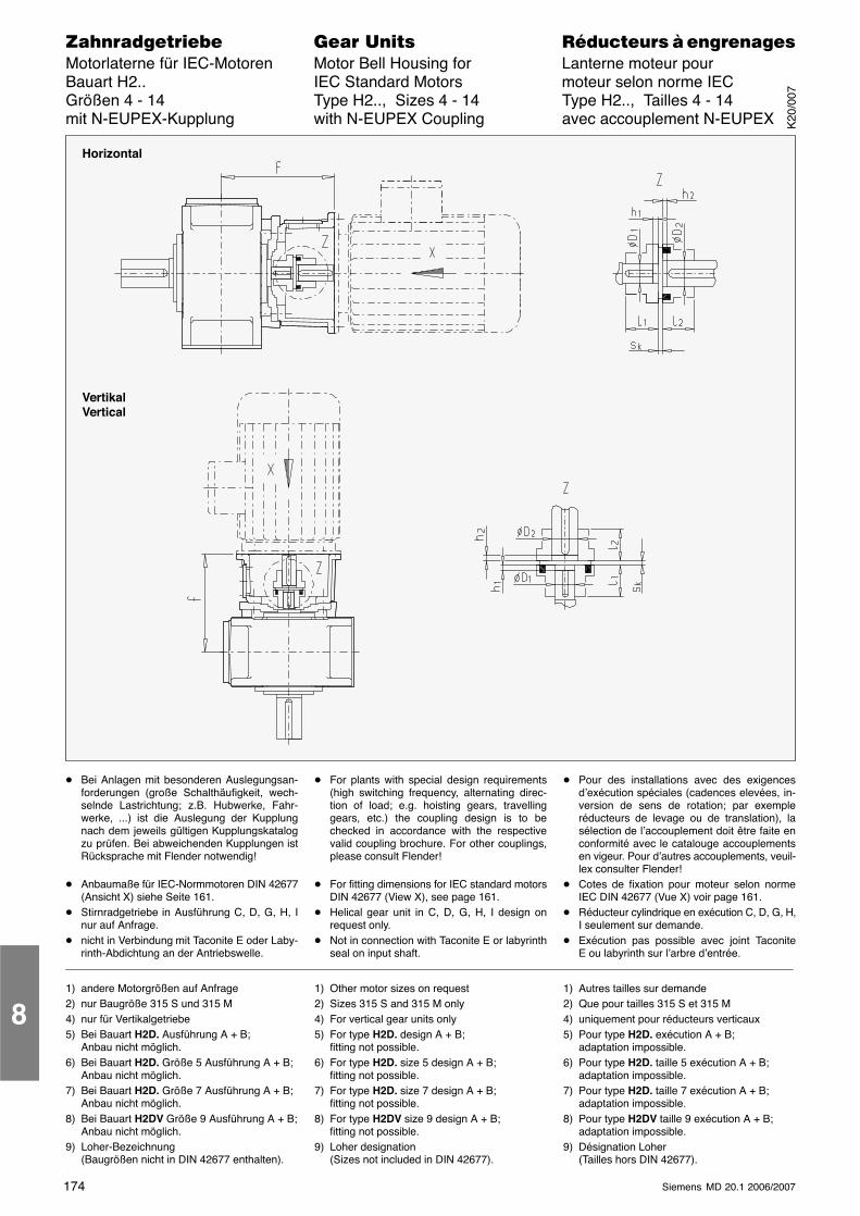
174 Siemens MD 20.1 2006/2007
������������� ���� �� ��������� � ����������Motorlaterne für IEC-Motoren Motor Bell Housing for Lanterne moteur pourBauart H2.. IEC Standard Motors moteur selon norme IECGrößen 4 - 14 Type H2.., Sizes 4 - 14 Type H2.., Tailles 4 - 14mit N-EUPEX-Kupplung with N-EUPEX Coupling avec accouplement N-EUPEX
Horizontal
VertikalVertical
� Bei Anlagen mit besonderen Auslegungsan-forderungen (große Schalthäufigkeit, wech-selnde Lastrichtung; z.B. Hubwerke, Fahr-werke, ...) ist die Auslegung der Kupplungnach dem jeweils gültigen Kupplungskatalogzu prüfen. Bei abweichenden Kupplungen istRücksprache mit Flender notwendig!
� Anbaumaße für IEC-Normmotoren DIN 42677(Ansicht X) siehe Seite 161.
� Stirnradgetriebe in Ausführung C, D, G, H, Inur auf Anfrage.
� nicht in Verbindung mit Taconite E oder Laby-rinth-Abdichtung an der Antriebswelle.
� For plants with special design requirements(high switching frequency, alternating direc-tion of load; e.g. hoisting gears, travellinggears, etc.) the coupling design is to bechecked in accordance with the respectivevalid coupling brochure. For other couplings,please consult Flender!
� For fitting dimensions for IEC standard motorsDIN 42677 (View X), see page 161.
� Helical gear unit in C, D, G, H, I design onrequest only.
� Not in connection with Taconite E or labyrinthseal on input shaft.
� Pour des installations avec des exigencesd’exécution spéciales (cadences elevées, in-version de sens de rotation; par exempleréducteurs de levage ou de translation), lasélection de l’accouplement doit être faite enconformité avec le catalouge accouplementsen vigeur. Pour d’autres accouplements, veuil-lex consulter Flender!
� Cotes de fixation pour moteur selon normeIEC DIN 42677 (Vue X) voir page 161.
� Réducteur cylindrique en exécution C, D, G, H,I seulement sur demande.
� Exécution pas possible avec joint TaconiteE ou labyrinth sur l’arbre d’entrée.
1) andere Motorgrößen auf Anfrage2) nur Baugröße 315 S und 315 M4) nur für Vertikalgetriebe5) Bei Bauart H2D. Ausführung A + B;
Anbau nicht möglich.6) Bei Bauart H2D. Größe 5 Ausführung A + B;
Anbau nicht möglich.7) Bei Bauart H2D. Größe 7 Ausführung A + B;
Anbau nicht möglich.8) Bei Bauart H2DV Größe 9 Ausführung A + B;
Anbau nicht möglich.9) Loher-Bezeichnung
(Baugrößen nicht in DIN 42677 enthalten).
1) Other motor sizes on request2) Sizes 315 S and 315 M only4) For vertical gear units only5) For type H2D. design A + B;
fitting not possible.6) For type H2D. size 5 design A + B;
fitting not possible.7) For type H2D. size 7 design A + B;
fitting not possible.8) For type H2DV size 9 design A + B;
fitting not possible.9) Loher designation
(Sizes not included in DIN 42677).
1) Autres tailles sur demande2) Que pour tailles 315 S et 315 M4) uniquement pour réducteurs verticaux5) Pour type H2D. exécution A + B;
adaptation impossible.6) Pour type H2D. taille 5 exécution A + B;
adaptation impossible.7) Pour type H2D. taille 7 exécution A + B;
adaptation impossible.8) Pour type H2DV taille 9 exécution A + B;
adaptation impossible.9) Désignation Loher
(Tailles hors DIN 42677).
8
K20
/007

175Siemens MD 20.1 2006/2007
������������� ���� �� ��������� � ����������Motorlaterne für IEC-Motoren Motor Bell Housing for Lanterne moteur pourBauart H2.. IEC Standard Motors moteur selon norme IECGrößen 4 - 14 Type H2.., Sizes 4 - 14 Type H2.., Tailles 4 - 14mit N-EUPEX-Kupplung with N-EUPEX Coupling avec accouplement N-EUPEX
Tabelle / Table / Tableau 10
Übersetzungen iN / Ratios iN / Rapports iN6.3 - 11.2 (Größen / Sizes / Tailles 4, 5, 7, 9, 11)
Übersetzungen iN / Ratios iN / Rapports iN12.5 - 22.4 (Größen / Sizes / Tailles 4, 5, 7, 9, 11)
Größe Motor
6.3 11.2 (Größen / Sizes / Tailles 4, 5, 7, 9, 11)8 - 14 (Größen / Sizes / Tailles 6, 8, 10, 12)
12.5 22.4 (Größen / Sizes / Tailles 4, 5, 7, 9, 11)16 - 28 (Größen / Sizes / Tailles 6, 8, 10, 12)
GrößeSizeTaille
MotorMoteur
IEC 1)N-
EUPEXsk
mml1
mmD1
mml2
mmD2
mmh1
mmh2
mmf
mmN-
EUPEXsk
mml1
mmD1
mml2
mmD2
mmh1
mmh2
mmf
mm
160 5) A125 3 50 32 50 42 0 7 370
4180 5) A140 3 55 32 55 48 0 7 370
4200 5) A160 4 60 32 60 55 0 12 376
225 5) 4) A180 4 70 45 70 60 0 3 417 4) A180 4 70 32 70 60 0 8 402
200 A160 4 60 38 60 55 0 13 402
5 / 6 225 6)
250 5) 4) A180 4 70 50 70 65 0 5.5 444.5 4) A180 4 70 38 70 65 0 9 428
225 A180 4 70 50 70 60 0 9.5 473.5
7 / 8250 7) A180 4 70 50 70 65 0 11 475
7 / 8280 7) A200 4 80 50 80 75 0 10 474
315 2) 5) 4) A225 4 90 60 90 80 0 12 531 4) A250 5.5 100 50 100 80 0 15.5 511
9 / 10280 A200 4 80 60 80 75 0 5 530
9 / 10315 2) 8) 4) A225 4 90 75 90 80 3 9 566 4) A225 4 90 60 90 80 0 12 566
11 / 12 315 2) A225 4 90 70 90 80 0 17 606
Tabelle / Table / Tableau 11
Übersetzungen iN / Ratios iN / Rapports iN12.5 - 20 (Größe / Size / Taille 13)
Größe Motor
12.5 20 (Größe / Size / Taille 13)16 - 25 (Größe / Size / Taille 14)
GrößeSizeTaille
MotorMoteur
IEC 1) N-EUPEXsk
mml1
mmD1
mml2
mmD2
mmh1
mmh2
mmf
mm
13 / 14355 MB 9) 4) A280 5.5 110 85 110 90 1 16.5 693
13 / 14355 LB 9) 4) A280 5.5 110 85 110 90 1 16.5 693
K20
/007
8
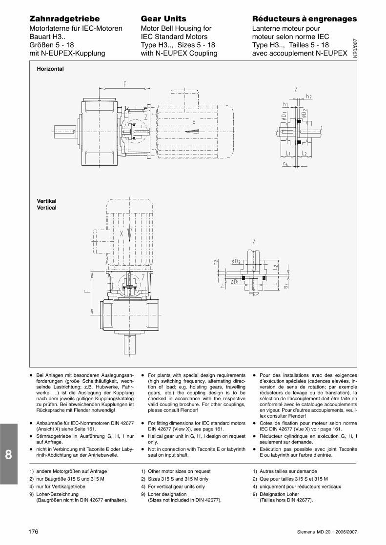
176 Siemens MD 20.1 2006/2007
������������� ���� �� ��������� � ����������Motorlaterne für IEC-Motoren Motor Bell Housing for Lanterne moteur pourBauart H3.. IEC Standard Motors moteur selon norme IECGrößen 5 - 18 Type H3.., Sizes 5 - 18 Type H3.., Tailles 5 - 18mit N-EUPEX-Kupplung with N-EUPEX Coupling avec accouplement N-EUPEX
Horizontal
VertikalVertical
� Bei Anlagen mit besonderen Auslegungsan-forderungen (große Schalthäufigkeit, wech-selnde Lastrichtung; z.B. Hubwerke, Fahr-werke, ...) ist die Auslegung der Kupplungnach dem jeweils gültigen Kupplungskatalogzu prüfen. Bei abweichenden Kupplungen istRücksprache mit Flender notwendig!
� Anbaumaße für IEC-Normmotoren DIN 42677(Ansicht X) siehe Seite 161.
� Stirnradgetriebe in Ausführung G, H, I nurauf Anfrage.
� nicht in Verbindung mit Taconite E oder Laby-rinth-Abdichtung an der Antriebswelle.
� For plants with special design requirements(high switching frequency, alternating direc-tion of load; e.g. hoisting gears, travellinggears, etc.) the coupling design is to bechecked in accordance with the respectivevalid coupling brochure. For other couplings,please consult Flender!
� For fitting dimensions for IEC standard motorsDIN 42677 (View X), see page 161.
� Helical gear unit in G, H, I design on requestonly.
� Not in connection with Taconite E or labyrinthseal on input shaft.
� Pour des installations avec des exigencesd’exécution spéciales (cadences elevées, in-version de sens de rotation; par exempleréducteurs de levage ou de translation), lasélection de l’accouplement doit être faite enconformité avec le catalouge accouplementsen vigeur. Pour d’autres accouplements, veuil-lex consulter Flender!
� Cotes de fixation pour moteur selon normeIEC DIN 42677 (Vue X) voir page 161.
� Réducteur cylindrique en exécution G, H, Iseulement sur demande.
� Exécution pas possible avec joint TaconiteE ou labyrinth sur l’arbre d’entrée.
1) andere Motorgrößen auf Anfrage
2) nur Baugröße 315 S und 315 M
4) nur für Vertikalgetriebe
9) Loher-Bezeichnung(Baugrößen nicht in DIN 42677 enthalten).
1) Other motor sizes on request
2) Sizes 315 S and 315 M only
4) For vertical gear units only
9) Loher designation(Sizes not included in DIN 42677).
1) Autres tailles sur demande
2) Que pour tailles 315 S et 315 M
4) uniquement pour réducteurs verticaux
9) Désignation Loher(Tailles hors DIN 42677).
8
K20
/007
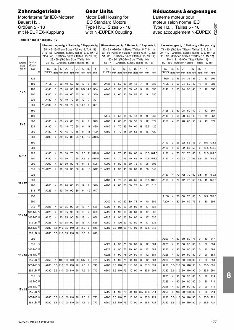
177Siemens MD 20.1 2006/2007
������������� ���� �� ��������� � ����������Motorlaterne für IEC-Motoren Motor Bell Housing for Lanterne moteur pourBauart H3.. IEC Standard Motors moteur selon norme IECGrößen 5 - 18 Type H3.., Sizes 5 - 18 Type H3.., Tailles 5 - 18mit N-EUPEX-Kupplung with N-EUPEX Coupling avec accouplement N-EUPEX
Tabelle / Table / Tableau 12
Übersetzungen iN / Ratios iN / Rapports iN25 - 45 (Größen / Sizes / Tailles 5, 7, 9, 11)
31.5 - 56 (Größen / Sizes / Tailles 6, 8, 10, 12)22 4 - 45 (Größen / Sizes / Tailles 13 15 17)
Übersetzungen iN / Ratios iN / Rapports iN50 - 63 (Größen / Sizes / Tailles 5, 7, 9, 11)
63 - 80 (Größen / Sizes / Tailles 6, 8, 10, 12)50 - 63 (Größen / Sizes / Tailles 13 15 17)
Übersetzungen iN / Ratios iN / Rapports iN71 - 90 (Größen / Sizes / Tailles 5, 7, 9, 11)
90 - 112 (Größen / Sizes / Tailles 6, 8, 10, 12)71 - 90 (Größen / Sizes / Tailles 13 15 17)
GrößeSize
MotorMoteur
22.4 - 45 (Größen / Sizes / Tailles 13, 15, 17)28 - 56 (Größe / Size / Taille 14)
25 - 50 (Größen / Sizes / Tailles 16, 18)
50 - 63 (Größen / Sizes / Tailles 13, 15, 17)63 - 80 (Größe / Size / Taille 14)
56 - 71 (Größen / Sizes / Tailles 16, 18)
71 - 90 (Größen / Sizes / Tailles 13, 15, 17)90 - 112 (Größe / Size / Taille 14)
80 - 100 (Größen / Sizes / Tailles 16, 18)SizeTaille
MoteurIEC
1)N-
EUPEXsk
mml1
mmD1
mml2
mmD2
mmh1
mmh2
mmf
mmN-
EUPEXsk
mml1
mmD1
mml2
mmD2
mmh1
mmh2
mmf
mmN-
EUPEXsk
mml1
mmD1
mml2
mmD2
mmh1
mmh2
mmf
mm
132 B95 3 35 24 35 38 7 12 302
160 A125 3 50 40 50 42 12 9 364 A125 3 50 30 50 42 7 8 338 A125 3 50 24 50 42 17 8 338
5 / 6180 A140 3 55 40 55 48 6.5 14.5 364 A140 3 55 30 55 48 5 10 338 A140 3 55 24 55 48 15 10 338
5 / 6200 A160 4 60 40 60 55 0 6 350 A160 4 60 30 60 55 17 9 350
225 A180 4 70 40 70 60 10 7 391
250 4) A180 4 70 40 70 65 11.5 5 391
160 A125 3 50 28 50 42 7 12 367
180 A140 3 55 35 55 48 0 9 367 A140 3 55 28 55 48 10 9 367
7 / 8200 A160 4 60 45 60 55 0 0 379 A160 4 60 35 60 55 9 12 379 A160 4 60 28 60 55 17 13 379
7 / 8225 A180 4 70 45 70 60 0 11 420 A180 4 70 35 70 60 18 12.5 420
250 A180 4 70 45 70 65 0 11 420 A180 4 70 35 70 65 15 16 420
280 A200 4 80 45 80 75 14.5 17 440.5
180 A140 3 55 32 55 48 0 8.5 431.5
200 A160 4 60 32 60 55 0 19.5 443.5
9 / 10225 A180 4 70 60 70 60 13.5 7 519.5 A180 4 70 45 70 60 0 10.5 484.5 A180 4 70 32 70 60 9 21.5 484.5
9 / 10250 A180 4 70 60 70 65 11.5 9 519.5 A180 4 70 45 70 65 0 10.5 484.5 A180 4 70 32 70 65 5.5 25 484.5
280 A200 4 80 60 80 75 0 6 505 A200 4 80 45 80 75 5 26 505
315 2) 4) A225 4 90 60 90 80 0 13 542 4) A225 4 90 45 90 80 12 26 542
225 A180 4 70 42 70 60 9.5 11 489.5
11 / 12250 A180 4 70 65 70 65 0 10.5 489.5 A180 4 70 42 70 65 9.5 11 489.5
11 / 12280 A200 4 80 70 80 75 12 9 540 A200 4 80 75 80 75 14 17 510
315 2) A225 4 90 70 90 80 0 - 2 547
250 A180 4 70 50 70 65 5 9.5 578.5
280 A200 4 80 60 80 75 0 10 599 A200 4 80 50 80 75 5 30 599
315 2) A225 4 90 85 90 80 18 4 666 A225 4 90 60 90 80 0 17 636
13 / 14315 MC 9) A225 4 90 85 90 80 18 4 666 A225 4 90 60 90 80 0 17 636
13 / 14315 MD 9) A225 4 90 85 90 80 18 4 666 A225 4 90 60 90 80 0 17 636
315 LB 9) A225 4 90 85 90 80 18 4 666 A250 4 100 60 100 80 0 17 636
355 MB 9) A280 5.5 110 85 110 90 -2.5 0 643 A280 5.5 110 60 110 90 0 22.5 643
355 LB 9) A280 5.5 110 85 110 90 -2.5 0 643
280 A200 4 80 60 80 75 0 13 647
315 2) A225 4 90 75 90 80 8 12 684 A225 4 90 60 90 80 0 20 684
315 MC 9) A225 4 90 75 90 80 8 12 684 A225 4 90 60 90 80 0 20 684
15 / 16 315 MD 9) A225 4 90 75 90 80 8 12 684 A225 4 90 60 90 80 0 20 68415 / 16
315 LB 9) A250 4 100 100 100 80 8.5 0 764 A225 4 90 75 90 80 8 12 684 A250 4 100 60 100 80 0 20 684
355 MB 9) A280 5.5 110 100 110 90 17.5 0 743 A280 5.5 110 75 110 90 0 25.5 691 A280 5.5 110 60 110 90 0 25.5 691
355 LB 9) A280 5.5 110 100 110 90 17.5 0 743 A280 5.5 110 75 110 90 0 25.5 691 A280 5.5 110 60 110 90 0 25.5 691
315 2) A225 4 90 60 90 80 0 20 714
315 MC 9) A225 4 90 60 90 80 0 20 714
17 / 18315 MD 9) A225 4 90 60 90 80 0 20 714
17 / 18315 LB 9) A225 4 90 75 90 80 6.5 13.5 714 A250 4 100 60 100 80 0 20 714
355 MB 9) A280 5.5 110 100 110 90 17.5 0 773 A280 5.5 110 75 110 90 0 25.5 721 A280 5.5 110 60 110 90 0 25.5 721
355 LB 9) A280 5.5 110 100 110 90 17.5 0 773 A280 5.5 110 75 110 90 0 25.5 721 A280 5.5 110 60 110 90 0 25.5 721
K20
/007
8
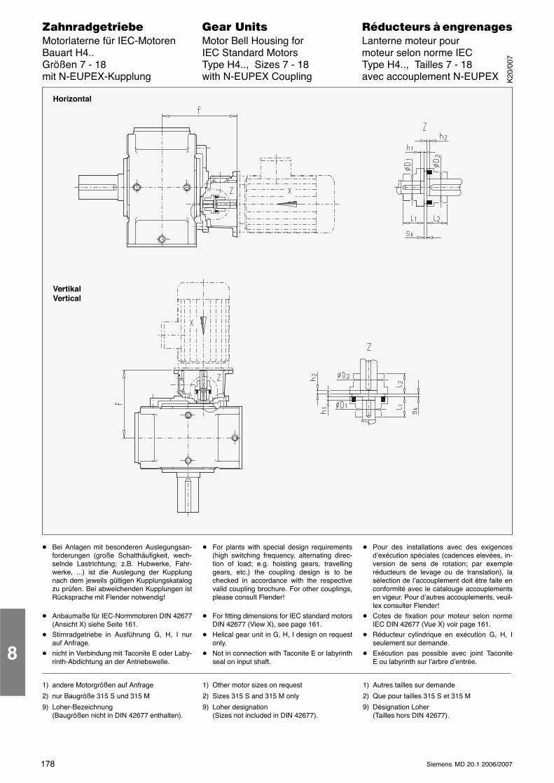
178 Siemens MD 20.1 2006/2007
������������� ���� �� ��������� � ����������Motorlaterne für IEC-Motoren Motor Bell Housing for Lanterne moteur pourBauart H4.. IEC Standard Motors moteur selon norme IECGrößen 7 - 18 Type H4.., Sizes 7 - 18 Type H4.., Tailles 7 - 18mit N-EUPEX-Kupplung with N-EUPEX Coupling avec accouplement N-EUPEX
Horizontal
VertikalVertical
� Bei Anlagen mit besonderen Auslegungsan-forderungen (große Schalthäufigkeit, wech-selnde Lastrichtung; z.B. Hubwerke, Fahr-werke, ...) ist die Auslegung der Kupplungnach dem jeweils gültigen Kupplungskatalogzu prüfen. Bei abweichenden Kupplungen istRücksprache mit Flender notwendig!
� Anbaumaße für IEC-Normmotoren DIN 42677(Ansicht X) siehe Seite 161.
� Stirnradgetriebe in Ausführung G, H, I nurauf Anfrage.
� nicht in Verbindung mit Taconite E oder Laby-rinth-Abdichtung an der Antriebswelle.
� For plants with special design requirements(high switching frequency, alternating direc-tion of load; e.g. hoisting gears, travellinggears, etc.) the coupling design is to bechecked in accordance with the respectivevalid coupling brochure. For other couplings,please consult Flender!
� For fitting dimensions for IEC standard motorsDIN 42677 (View X), see page 161.
� Helical gear unit in G, H, I design on requestonly.
� Not in connection with Taconite E or labyrinthseal on input shaft.
� Pour des installations avec des exigencesd’exécution spéciales (cadences elevées, in-version de sens de rotation; par exempleréducteurs de levage ou de translation), lasélection de l’accouplement doit être faite enconformité avec le catalouge accouplementsen vigeur. Pour d’autres accouplements, veuil-lex consulter Flender!
� Cotes de fixation pour moteur selon normeIEC DIN 42677 (Vue X) voir page 161.
� Réducteur cylindrique en exécution G, H, Iseulement sur demande.
� Exécution pas possible avec joint TaconiteE ou labyrinth sur l’arbre d’entrée.
1) andere Motorgrößen auf Anfrage
2) nur Baugröße 315 S und 315 M
9) Loher-Bezeichnung(Baugrößen nicht in DIN 42677 enthalten).
1) Other motor sizes on request
2) Sizes 315 S and 315 M only
9) Loher designation(Sizes not included in DIN 42677).
1) Autres tailles sur demande
2) Que pour tailles 315 S et 315 M
9) Désignation Loher(Tailles hors DIN 42677).
8
K20
/007
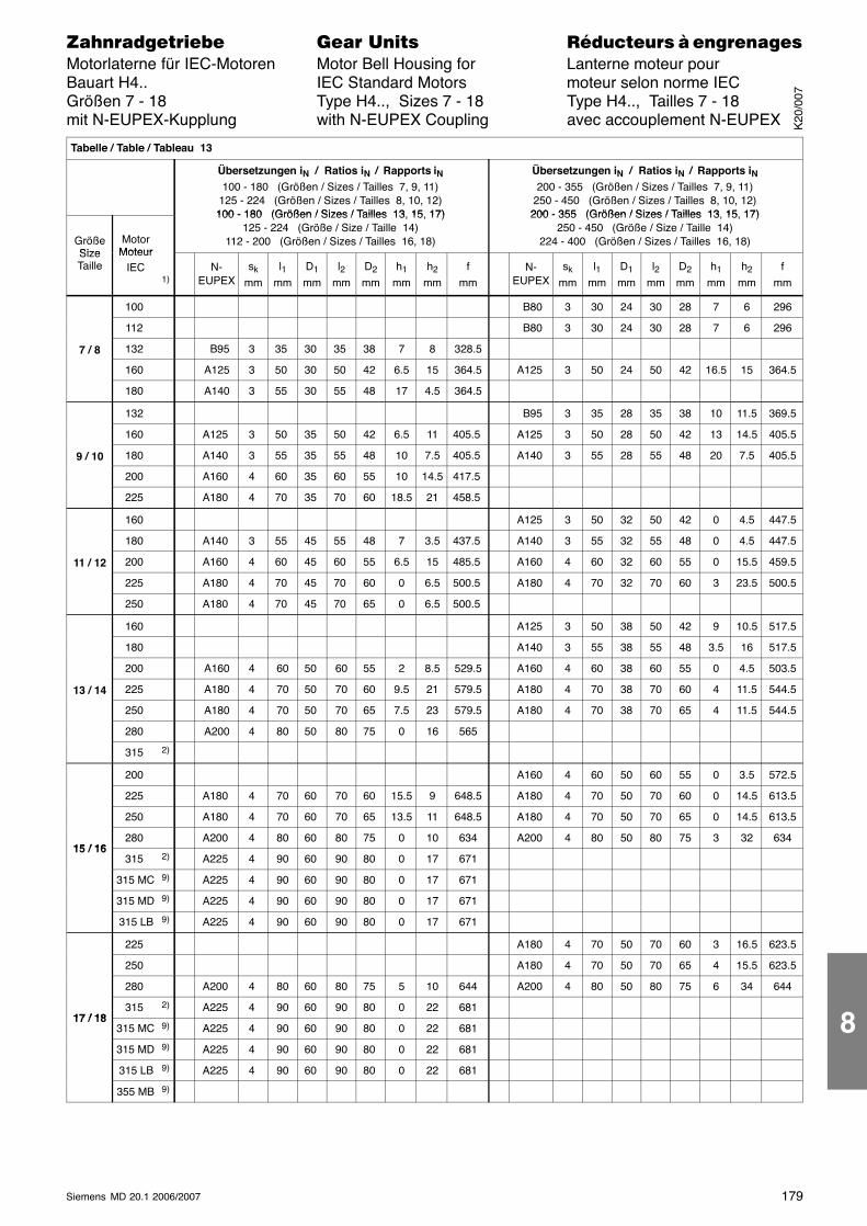
179Siemens MD 20.1 2006/2007
������������� ���� �� ��������� � ����������Motorlaterne für IEC-Motoren Motor Bell Housing for Lanterne moteur pourBauart H4.. IEC Standard Motors moteur selon norme IECGrößen 7 - 18 Type H4.., Sizes 7 - 18 Type H4.., Tailles 7 - 18mit N-EUPEX-Kupplung with N-EUPEX Coupling avec accouplement N-EUPEX
Tabelle / Table / Tableau 13
Übersetzungen iN / Ratios iN / Rapports iN100 - 180 (Größen / Sizes / Tailles 7, 9, 11)
125 - 224 (Größen / Sizes / Tailles 8, 10, 12)100 - 180 (Größen / Sizes / Tailles 13 15 17)
Übersetzungen iN / Ratios iN / Rapports iN200 - 355 (Größen / Sizes / Tailles 7, 9, 11)
250 - 450 (Größen / Sizes / Tailles 8, 10, 12)200 - 355 (Größen / Sizes / Tailles 13 15 17)
GrößeSize
MotorMoteur
100 - 180 (Größen / Sizes / Tailles 13, 15, 17)125 - 224 (Größe / Size / Taille 14)
112 - 200 (Größen / Sizes / Tailles 16, 18)
200 - 355 (Größen / Sizes / Tailles 13, 15, 17)250 - 450 (Größe / Size / Taille 14)
224 - 400 (Größen / Sizes / Tailles 16, 18)SizeTaille
MoteurIEC
1)N-
EUPEXsk
mml1
mmD1
mml2
mmD2
mmh1
mmh2
mmf
mmN-
EUPEXsk
mml1
mmD1
mml2
mmD2
mmh1
mmh2
mmf
mm
100 B80 3 30 24 30 28 7 6 296
112 B80 3 30 24 30 28 7 6 296
7 / 8 132 B95 3 35 30 35 38 7 8 328.5
160 A125 3 50 30 50 42 6.5 15 364.5 A125 3 50 24 50 42 16.5 15 364.5
180 A140 3 55 30 55 48 17 4.5 364.5
132 B95 3 35 28 35 38 10 11.5 369.5
160 A125 3 50 35 50 42 6.5 11 405.5 A125 3 50 28 50 42 13 14.5 405.5
9 / 10 180 A140 3 55 35 55 48 10 7.5 405.5 A140 3 55 28 55 48 20 7.5 405.5
200 A160 4 60 35 60 55 10 14.5 417.5
225 A180 4 70 35 70 60 18.5 21 458.5
160 A125 3 50 32 50 42 0 4.5 447.5
180 A140 3 55 45 55 48 7 3.5 437.5 A140 3 55 32 55 48 0 4.5 447.5
11 / 12 200 A160 4 60 45 60 55 6.5 15 485.5 A160 4 60 32 60 55 0 15.5 459.5
225 A180 4 70 45 70 60 0 6.5 500.5 A180 4 70 32 70 60 3 23.5 500.5
250 A180 4 70 45 70 65 0 6.5 500.5
160 A125 3 50 38 50 42 9 10.5 517.5
180 A140 3 55 38 55 48 3.5 16 517.5
200 A160 4 60 50 60 55 2 8.5 529.5 A160 4 60 38 60 55 0 4.5 503.5
13 / 14 225 A180 4 70 50 70 60 9.5 21 579.5 A180 4 70 38 70 60 4 11.5 544.5
250 A180 4 70 50 70 65 7.5 23 579.5 A180 4 70 38 70 65 4 11.5 544.5
280 A200 4 80 50 80 75 0 16 565
315 2)
200 A160 4 60 50 60 55 0 3.5 572.5
225 A180 4 70 60 70 60 15.5 9 648.5 A180 4 70 50 70 60 0 14.5 613.5
250 A180 4 70 60 70 65 13.5 11 648.5 A180 4 70 50 70 65 0 14.5 613.5
15 / 16280 A200 4 80 60 80 75 0 10 634 A200 4 80 50 80 75 3 32 634
15 / 16315 2) A225 4 90 60 90 80 0 17 671
315 MC 9) A225 4 90 60 90 80 0 17 671
315 MD 9) A225 4 90 60 90 80 0 17 671
315 LB 9) A225 4 90 60 90 80 0 17 671
225 A180 4 70 50 70 60 3 16.5 623.5
250 A180 4 70 50 70 65 4 15.5 623.5
280 A200 4 80 60 80 75 5 10 644 A200 4 80 50 80 75 6 34 644
17 / 18315 2) A225 4 90 60 90 80 0 22 681
17 / 18315 MC 9) A225 4 90 60 90 80 0 22 681
315 MD 9) A225 4 90 60 90 80 0 22 681
315 LB 9) A225 4 90 60 90 80 0 22 681
355 MB 9)
K20
/007
8

180 Siemens MD 20.1 2006/2007
������������� ���� �� ��������� � ����������Motorlaterne für IEC-Motoren Motor Bell Housing for Lanterne moteur pourBauart B2.. IEC Standard Motors moteur selon norme IECGrößen 4 - 14 Type B2.., Sizes 4 - 14 Type B2.., Tailles 4 - 14mit N-EUPEX-Kupplung with N-EUPEX Coupling avec accouplement N-EUPEX
Horizontal
VertikalVertical
Größen / Sizes / Tailles4, 5, 7, 9, 11, 13, 15, 17
Größen / Sizes / Tailles6, 8, 10, 12, 14, 16, 18
Größen / Sizes / Tailles4, 5, 7, 9, 11, 13, 15, 17
Größen / Sizes / Tailles6, 8, 10, 12, 14, 16, 18
� Bei Anlagen mit besonderen Auslegungsan-forderungen (große Schalthäufigkeit, wech-selnde Lastrichtung; z.B. Hubwerke, Fahr-werke, ...) ist die Auslegung der Kupplungnach dem jeweils gültigen Kupplungskatalogzu prüfen. Bei abweichenden Kupplungen istRücksprache mit Flender notwendig!
� Anbaumaße für IEC-Normmotoren DIN 42677(Ansicht X) siehe Seite 161.
� nicht in Verbindung mit Taconite E oder Laby-rinth-Abdichtung an der Antriebswelle.
� For plants with special design requirements(high switching frequency, alternating direc-tion of load; e.g. hoisting gears, travellinggears, etc.) the coupling design is to bechecked in accordance with the respectivevalid coupling brochure. For other couplings,please consult Flender!
� For fitting dimensions for IEC standard motorsDIN 42677 (View X), see page 161.
� Not in connection with Taconite E or labyrinthseal on input shaft.
� Pour des installations avec des exigencesd’exécution spéciales (cadences elevées, in-version de sens de rotation; par exempleréducteurs de levage ou de translation), lasélection de l’accouplement doit être faite enconformité avec le catalouge accouplementsen vigeur. Pour d’autres accouplements, veuil-lex consulter Flender!
� Cotes de fixation pour moteur selon normeIEC DIN 42677 (Vue X) voir page 161.
� Exécution pas possible avec joint TaconiteE ou labyrinth sur l’arbre d’entrée.
1) andere Motorgrößen auf Anfrage
2) nur Baugröße 315 S und 315 M
9) Loher-Bezeichnung(Baugrößen nicht in DIN 42677 enthalten).
1) Other motor sizes on request
2) Sizes 315 S and 315 M only
9) Loher designation(Sizes not included in DIN 42677).
1) Autres tailles sur demande
2) Que pour tailles 315 S et 315 M
9) Désignation Loher(Tailles hors DIN 42677).8
K20
/007
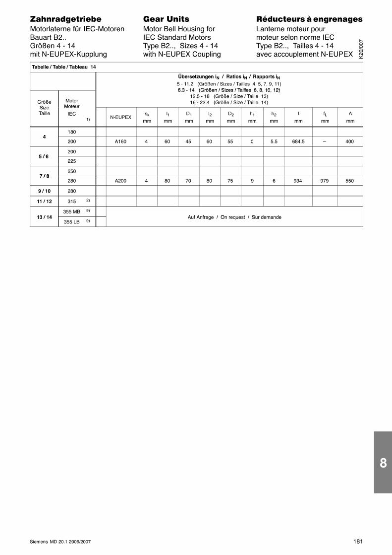
181Siemens MD 20.1 2006/2007
������������� ���� �� ��������� � ����������Motorlaterne für IEC-Motoren Motor Bell Housing for Lanterne moteur pourBauart B2.. IEC Standard Motors moteur selon norme IECGrößen 4 - 14 Type B2.., Sizes 4 - 14 Type B2.., Tailles 4 - 14mit N-EUPEX-Kupplung with N-EUPEX Coupling avec accouplement N-EUPEX
Tabelle / Table / Tableau 14
Übersetzungen iN / Ratios iN / Rapports iN5 - 11.2 (Größen / Sizes / Tailles 4, 5, 7, 9, 11)6 3 - 14 (Größen / Sizes / Tailles 6 8 10 12)
GrößeSize
MotorMoteur
6.3 - 14 (Größen / Sizes / Tailles 6, 8, 10, 12)12.5 - 18 (Größe / Size / Taille 13)16 - 22.4 (Größe / Size / Taille 14)
SizeTaille
Moteur
IEC1) N-EUPEX
sk
mml1
mmD1
mml2
mmD2
mmh1
mmh2
mmf
mmfL
mmA
mm
4180
4200 A160 4 60 45 60 55 0 5.5 684.5 – 400
5 / 6200
5 / 6225
7 / 8250
7 / 8280 A200 4 80 70 80 75 9 6 934 979 550
9 / 10 280
11 / 12 315 2)
13 / 14355 MB 9)
Auf Anfrage / On request / Sur demande13 / 14355 LB 9)
Auf Anfrage / On request / Sur demande
K20
/007
8

182 Siemens MD 20.1 2006/2007
������������� ���� �� ��������� � ����������Motorlaterne für IEC-Motoren Motor Bell Housing for Lanterne moteur pourBauart B3.. IEC Standard Motors moteur selon norme IECGrößen 4 - 18 Type B3.., Sizes 4 - 18 Type B3.., Tailles 4 - 18mit N-EUPEX-Kupplung with N-EUPEX Coupling avec accouplement N-EUPEX
Horizontal
VertikalVertical
Größen / Sizes / Tailles4, 5, 7, 9, 11, 13, 15, 17
Größen / Sizes / Tailles6, 8, 10, 12, 14, 16, 18
Größen / Sizes / Tailles4, 5, 7, 9, 11, 13, 15, 17
Größen / Sizes / Tailles6, 8, 10, 12, 14, 16, 18
� Bei Anlagen mit besonderen Auslegungsan-forderungen (große Schalthäufigkeit, wech-selnde Lastrichtung; z.B. Hubwerke, Fahr-werke, ...) ist die Auslegung der Kupplungnach dem jeweils gültigen Kupplungskatalogzu prüfen. Bei abweichenden Kupplungen istRücksprache mit Flender notwendig!
� Anbaumaße für IEC-Normmotoren DIN 42677(Ansicht X) siehe Seite 161.
� nicht in Verbindung mit Taconite E oder Laby-rinth-Abdichtung an der Antriebswelle.
� For plants with special design requirements(high switching frequency, alternating direc-tion of load; e.g. hoisting gears, travellinggears, etc.) the coupling design is to bechecked in accordance with the respectivevalid coupling brochure. For other couplings,please consult Flender!
� For fitting dimensions for IEC standard motorsDIN 42677 (View X), see page 161.
� Not in connection with Taconite E or labyrinthseal on input shaft.
� Pour des installations avec des exigencesd’exécution spéciales (cadences elevées, in-version de sens de rotation; par exempleréducteurs de levage ou de translation), lasélection de l’accouplement doit être faite enconformité avec le catalouge accouplementsen vigeur. Pour d’autres accouplements, veuil-lex consulter Flender!
� Cotes de fixation pour moteur selon normeIEC DIN 42677 (Vue X) voir page 161.
� Exécution pas possible avec joint TaconiteE ou labyrinth sur l’arbre d’entrée.
1) andere Motorgrößen auf Anfrage
2) nur Baugröße 315 S und 315 M
9) Loher-Bezeichnung(Baugrößen nicht in DIN 42677 enthalten).
1) Other motor sizes on request
2) Sizes 315 S and 315 M only
9) Loher designation(Sizes not included in DIN 42677).
1) Autres tailles sur demande
2) Que pour tailles 315 S et 315 M
9) Désignation Loher(Tailles hors DIN 42677).8
K20
/007
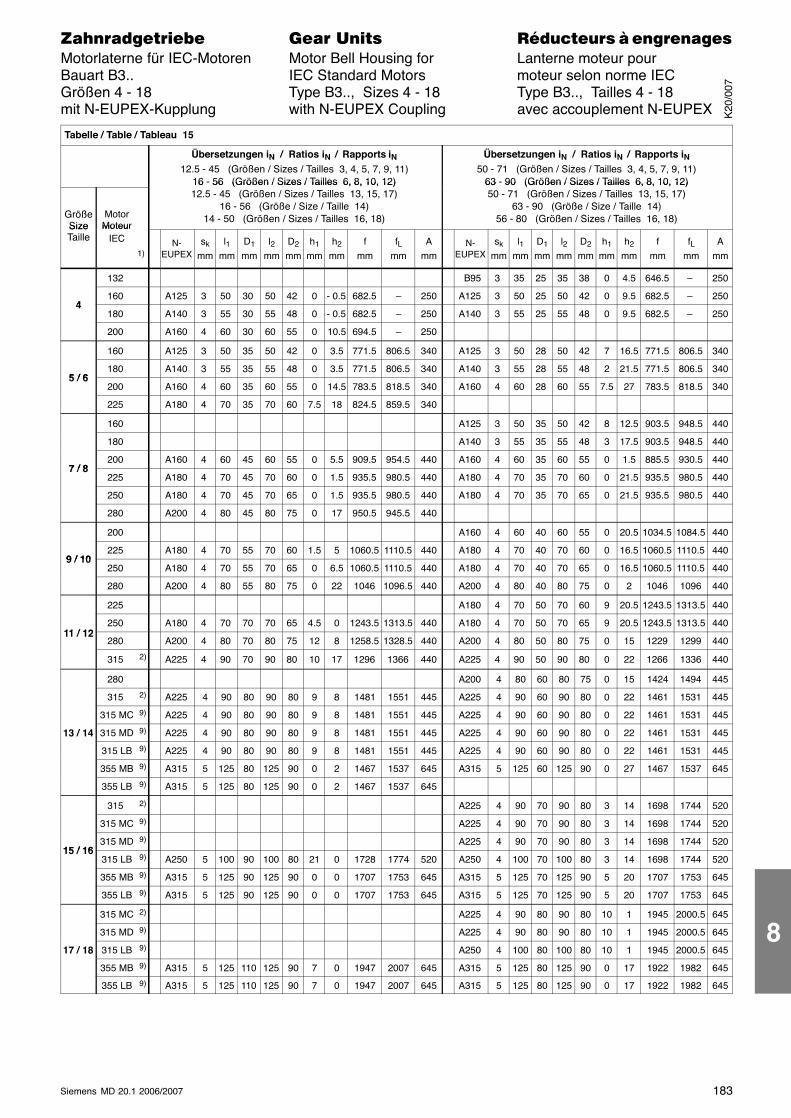
183Siemens MD 20.1 2006/2007
������������� ���� �� ��������� � ����������Motorlaterne für IEC-Motoren Motor Bell Housing for Lanterne moteur pourBauart B3.. IEC Standard Motors moteur selon norme IECGrößen 4 - 18 Type B3.., Sizes 4 - 18 Type B3.., Tailles 4 - 18mit N-EUPEX-Kupplung with N-EUPEX Coupling avec accouplement N-EUPEX
Tabelle / Table / Tableau 15
Übersetzungen iN / Ratios iN / Rapports iN12.5 - 45 (Größen / Sizes / Tailles 3, 4, 5, 7, 9, 11)
16 - 56 (Größen / Sizes / Tailles 6, 8, 10, 12)
Übersetzungen iN / Ratios iN / Rapports iN50 - 71 (Größen / Sizes / Tailles 3, 4, 5, 7, 9, 11)
63 - 90 (Größen / Sizes / Tailles 6, 8, 10, 12)
GrößeSize
MotorMoteur
16 56 (Größen / Sizes / Tailles 6, 8, 10, 12)12.5 - 45 (Größen / Sizes / Tailles 13, 15, 17)
16 - 56 (Größe / Size / Taille 14)14 - 50 (Größen / Sizes / Tailles 16, 18)
63 90 (Größen / Sizes / Tailles 6, 8, 10, 12)50 - 71 (Größen / Sizes / Tailles 13, 15, 17)
63 - 90 (Größe / Size / Taille 14)56 - 80 (Größen / Sizes / Tailles 16, 18)
SizeTaille
MoteurIEC
1)N-
EUPEXsk
mml1
mmD1
mml2
mmD2
mmh1
mmh2
mmf
mmfL
mmA
mmN-
EUPEXsk
mml1
mmD1
mml2
mmD2
mmh1
mmh2
mmf
mmfL
mmA
mm
132 B95 3 35 25 35 38 0 4.5 646.5 – 250
4160 A125 3 50 30 50 42 0 - 0.5 682.5 – 250 A125 3 50 25 50 42 0 9.5 682.5 – 250
4180 A140 3 55 30 55 48 0 - 0.5 682.5 – 250 A140 3 55 25 55 48 0 9.5 682.5 – 250
200 A160 4 60 30 60 55 0 10.5 694.5 – 250
160 A125 3 50 35 50 42 0 3.5 771.5 806.5 340 A125 3 50 28 50 42 7 16.5 771.5 806.5 340
5 / 6180 A140 3 55 35 55 48 0 3.5 771.5 806.5 340 A140 3 55 28 55 48 2 21.5 771.5 806.5 340
5 / 6200 A160 4 60 35 60 55 0 14.5 783.5 818.5 340 A160 4 60 28 60 55 7.5 27 783.5 818.5 340
225 A180 4 70 35 70 60 7.5 18 824.5 859.5 340
160 A125 3 50 35 50 42 8 12.5 903.5 948.5 440
180 A140 3 55 35 55 48 3 17.5 903.5 948.5 440
7 / 8200 A160 4 60 45 60 55 0 5.5 909.5 954.5 440 A160 4 60 35 60 55 0 1.5 885.5 930.5 440
7 / 8225 A180 4 70 45 70 60 0 1.5 935.5 980.5 440 A180 4 70 35 70 60 0 21.5 935.5 980.5 440
250 A180 4 70 45 70 65 0 1.5 935.5 980.5 440 A180 4 70 35 70 65 0 21.5 935.5 980.5 440
280 A200 4 80 45 80 75 0 17 950.5 945.5 440
200 A160 4 60 40 60 55 0 20.5 1034.5 1084.5 440
9 / 10225 A180 4 70 55 70 60 1.5 5 1060.5 1110.5 440 A180 4 70 40 70 60 0 16.5 1060.5 1110.5 440
9 / 10250 A180 4 70 55 70 65 0 6.5 1060.5 1110.5 440 A180 4 70 40 70 65 0 16.5 1060.5 1110.5 440
280 A200 4 80 55 80 75 0 22 1046 1096.5 440 A200 4 80 40 80 75 0 2 1046 1096 440
225 A180 4 70 50 70 60 9 20.5 1243.5 1313.5 440
11 / 12250 A180 4 70 70 70 65 4.5 0 1243.5 1313.5 440 A180 4 70 50 70 65 9 20.5 1243.5 1313.5 440
11 / 12280 A200 4 80 70 80 75 12 8 1258.5 1328.5 440 A200 4 80 50 80 75 0 15 1229 1299 440
315 2) A225 4 90 70 90 80 10 17 1296 1366 440 A225 4 90 50 90 80 0 22 1266 1336 440
280 A200 4 80 60 80 75 0 15 1424 1494 445
315 2) A225 4 90 80 90 80 9 8 1481 1551 445 A225 4 90 60 90 80 0 22 1461 1531 445
315 MC 9) A225 4 90 80 90 80 9 8 1481 1551 445 A225 4 90 60 90 80 0 22 1461 1531 445
13 / 14 315 MD 9) A225 4 90 80 90 80 9 8 1481 1551 445 A225 4 90 60 90 80 0 22 1461 1531 445
315 LB 9) A225 4 90 80 90 80 9 8 1481 1551 445 A225 4 90 60 90 80 0 22 1461 1531 445
355 MB 9) A315 5 125 80 125 90 0 2 1467 1537 645 A315 5 125 60 125 90 0 27 1467 1537 645
355 LB 9) A315 5 125 80 125 90 0 2 1467 1537 645
315 2) A225 4 90 70 90 80 3 14 1698 1744 520
315 MC 9) A225 4 90 70 90 80 3 14 1698 1744 520
15 / 16315 MD 9) A225 4 90 70 90 80 3 14 1698 1744 520
15 / 16315 LB 9) A250 5 100 90 100 80 21 0 1728 1774 520 A250 4 100 70 100 80 3 14 1698 1744 520
355 MB 9) A315 5 125 90 125 90 0 0 1707 1753 645 A315 5 125 70 125 90 5 20 1707 1753 645
355 LB 9) A315 5 125 90 125 90 0 0 1707 1753 645 A315 5 125 70 125 90 5 20 1707 1753 645
315 MC 2) A225 4 90 80 90 80 10 1 1945 2000.5 645
315 MD 9) A225 4 90 80 90 80 10 1 1945 2000.5 645
17 / 18 315 LB 9) A250 4 100 80 100 80 10 1 1945 2000.5 645
355 MB 9) A315 5 125 110 125 90 7 0 1947 2007 645 A315 5 125 80 125 90 0 17 1922 1982 645
355 LB 9) A315 5 125 110 125 90 7 0 1947 2007 645 A315 5 125 80 125 90 0 17 1922 1982 645
K20
/007
8
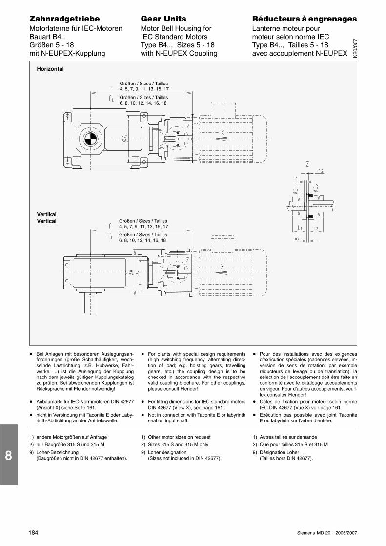
184 Siemens MD 20.1 2006/2007
������������� ���� �� ��������� � ����������Motorlaterne für IEC-Motoren Motor Bell Housing for Lanterne moteur pourBauart B4.. IEC Standard Motors moteur selon norme IECGrößen 5 - 18 Type B4.., Sizes 5 - 18 Type B4.., Tailles 5 - 18mit N-EUPEX-Kupplung with N-EUPEX Coupling avec accouplement N-EUPEX
Horizontal
VertikalVertical
Größen / Sizes / Tailles4, 5, 7, 9, 11, 13, 15, 17
Größen / Sizes / Tailles6, 8, 10, 12, 14, 16, 18
Größen / Sizes / Tailles4, 5, 7, 9, 11, 13, 15, 17
Größen / Sizes / Tailles6, 8, 10, 12, 14, 16, 18
� Bei Anlagen mit besonderen Auslegungsan-forderungen (große Schalthäufigkeit, wech-selnde Lastrichtung; z.B. Hubwerke, Fahr-werke, ...) ist die Auslegung der Kupplungnach dem jeweils gültigen Kupplungskatalogzu prüfen. Bei abweichenden Kupplungen istRücksprache mit Flender notwendig!
� Anbaumaße für IEC-Normmotoren DIN 42677(Ansicht X) siehe Seite 161.
� nicht in Verbindung mit Taconite E oder Laby-rinth-Abdichtung an der Antriebswelle.
� For plants with special design requirements(high switching frequency, alternating direc-tion of load; e.g. hoisting gears, travellinggears, etc.) the coupling design is to bechecked in accordance with the respectivevalid coupling brochure. For other couplings,please consult Flender!
� For fitting dimensions for IEC standard motorsDIN 42677 (View X), see page 161.
� Not in connection with Taconite E or labyrinthseal on input shaft.
� Pour des installations avec des exigencesd’exécution spéciales (cadences elevées, in-version de sens de rotation; par exempleréducteurs de levage ou de translation), lasélection de l’accouplement doit être faite enconformité avec le catalouge accouplementsen vigeur. Pour d’autres accouplements, veuil-lex consulter Flender!
� Cotes de fixation pour moteur selon normeIEC DIN 42677 (Vue X) voir page 161.
� Exécution pas possible avec joint TaconiteE ou labyrinth sur l’arbre d’entrée.
1) andere Motorgrößen auf Anfrage
2) nur Baugröße 315 S und 315 M
9) Loher-Bezeichnung(Baugrößen nicht in DIN 42677 enthalten).
1) Other motor sizes on request
2) Sizes 315 S and 315 M only
9) Loher designation(Sizes not included in DIN 42677).
1) Autres tailles sur demande
2) Que pour tailles 315 S et 315 M
9) Désignation Loher(Tailles hors DIN 42677).8
K20
/007
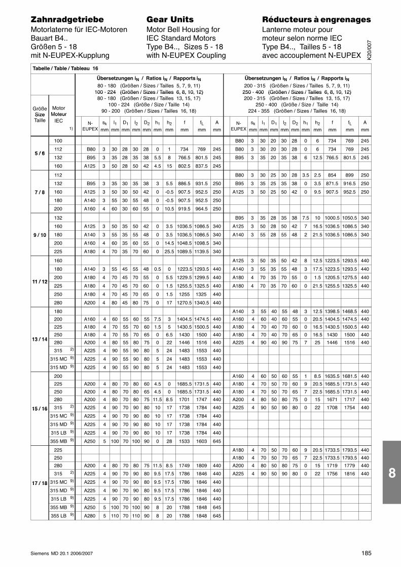
185Siemens MD 20.1 2006/2007
������������� ���� �� ��������� � ����������Motorlaterne für IEC-Motoren Motor Bell Housing for Lanterne moteur pourBauart B4.. IEC Standard Motors moteur selon norme IECGrößen 5 - 18 Type B4.., Sizes 5 - 18 Type B4.., Tailles 5 - 18mit N-EUPEX-Kupplung with N-EUPEX Coupling avec accouplement N-EUPEX
Tabelle / Table / Tableau 16
Übersetzungen iN / Ratios iN / Rapports iN80 - 180 (Größen / Sizes / Tailles 5, 7, 9, 11)
100 - 224 (Größen / Sizes / Tailles 6, 8, 10, 12)
Übersetzungen iN / Ratios iN / Rapports iN200 - 315 (Größen / Sizes / Tailles 5, 7, 9, 11)
250 - 400 (Größen / Sizes / Tailles 6, 8, 10, 12)
GrößeSize
MotorMoteur
100 224 (Größen / Sizes / Tailles 6, 8, 10, 12)80 - 180 (Größen / Sizes / Tailles 13, 15, 17)
100 - 224 (Größe / Size / Taille 14)90 - 200 (Größen / Sizes / Tailles 16, 18)
250 400 (Größen / Sizes / Tailles 6, 8, 10, 12)200 - 315 (Größen / Sizes / Tailles 13, 15, 17)
250 - 400 (Größe / Size / Taille 14)224 - 355 (Größen / Sizes / Tailles 16, 18)
SizeTaille
MoteurIEC
1)N-
EUPEXsk
mml1
mmD1
mml2
mmD2
mmh1
mmh2
mmf
mmfL
mmA
mmN-
EUPEXsk
mml1
mmD1
mml2
mmD2
mmh1
mmh2
mmf
mmfL
mmA
mm
100 B80 3 30 20 30 28 0 6 734 769 245
5 / 6112 B80 3 30 28 30 28 0 1 734 769 245 B80 3 30 20 30 28 0 6 734 769 245
5 / 6132 B95 3 35 28 35 38 5.5 8 766.5 801.5 245 B95 3 35 20 35 38 6 12.5 766.5 801.5 245
160 A125 3 50 28 50 42 4.5 15 802.5 837.5 245
112 B80 3 30 25 30 28 3.5 2.5 854 899 250
132 B95 3 35 30 35 38 3 5.5 886.5 931.5 250 B95 3 35 25 35 38 0 3.5 871.5 916.5 250
7 / 8 160 A125 3 50 30 50 42 0 -0.5 907.5 952.5 250 A125 3 50 25 50 42 0 9.5 907.5 952.5 2507 / 8
180 A140 3 55 30 55 48 0 -0.5 907.5 952.5 250
200 A160 4 60 30 60 55 0 10.5 919.5 964.5 250
132 B95 3 35 28 35 38 7.5 10 1000.5 1050.5 340
160 A125 3 50 35 50 42 0 3.5 1036.5 1086.5 340 A125 3 50 28 50 42 7 16.5 1036.5 1086.5 340
9 / 10 180 A140 3 55 35 55 48 0 3.5 1036.5 1086.5 340 A140 3 55 28 55 48 2 21.5 1036.5 1086.5 3409 / 10
200 A160 4 60 35 60 55 0 14.5 1048.5 1098.5 340
225 A180 4 70 35 70 60 0 25.5 1089.5 1139.5 340
160 A125 3 50 35 50 42 8 12.5 1223.5 1293.5 440
180 A140 3 55 45 55 48 0.5 0 1223.5 1293.5 440 A140 3 55 35 55 48 3 17.5 1223.5 1293.5 440
11 / 12200 A180 4 70 45 70 55 0 5.5 1229.5 1299.5 440 A180 4 70 35 70 55 0 1.5 1205.5 1275.5 440
11 / 12225 A180 4 70 45 70 60 0 1.5 1255.5 1325.5 440 A180 4 70 35 70 60 0 21.5 1255.5 1325.5 440
250 A180 4 70 45 70 65 0 1.5 1255 1325 440
280 A200 4 80 45 80 75 0 17 1270.5 1340.5 440
180 A140 3 55 40 55 48 3 12.5 1398.5 1468.5 440
200 A160 4 60 55 60 55 7.5 3 1404.5 1474.5 440 A160 4 60 40 60 55 0 20.5 1404.5 1474.5 440
225 A180 4 70 55 70 60 1.5 5 1430.5 1500.5 440 A180 4 70 40 70 60 0 16.5 1430.5 1500.5 440
13 / 14250 A180 4 70 55 70 65 0 6.5 1430 1500 440 A180 4 70 40 70 65 0 16.5 1430 1500 440
13 / 14280 A200 4 80 55 80 75 0 22 1446 1516 440 A225 4 90 40 90 75 7 25 1446 1516 440
315 2) A225 4 90 55 90 80 5 24 1483 1553 440
315 MC 9) A225 4 90 55 90 80 5 24 1483 1553 440
315 MD 9) A225 4 90 55 90 80 5 24 1483 1553 440
200 A160 4 60 50 60 55 1 8.5 1635.5 1681.5 440
225 A200 4 80 70 80 60 4.5 0 1685.5 1731.5 440 A180 4 70 50 70 60 9 20.5 1685.5 1731.5 440
250 A200 4 80 70 80 65 4.5 0 1685.5 1731.5 440 A180 4 70 50 70 65 7 22.5 1685.5 1731.5 440
280 A200 4 80 70 80 75 11.5 8.5 1701 1747 440 A200 4 80 50 80 75 0 15 1671 1717 440
15 / 16 315 2) A225 4 90 70 90 80 10 17 1738 1784 440 A225 4 90 50 90 80 0 22 1708 1754 44015 / 16315 MC 9) A225 4 90 70 90 80 10 17 1738 1784 440
315 MD 9) A225 4 90 70 90 80 10 17 1738 1784 440
315 LB 9) A225 4 90 70 90 80 10 17 1738 1784 440
355 MB 9) A250 5 100 70 100 90 0 28 1533 1603 645
225 A180 4 70 50 70 60 9 20.5 1733.5 1793.5 440
250 A180 4 70 50 70 65 7 22.5 1733.5 1793.5 440
280 A200 4 80 70 80 75 11.5 8.5 1749 1809 440 A200 4 80 50 80 75 0 15 1719 1779 440
315 2) A225 4 90 70 90 80 9.5 17.5 1786 1846 440 A225 4 90 50 90 80 0 22 1756 1816 440
17 / 18 315 MC 9) A225 4 90 70 90 80 9.5 17.5 1786 1846 44017 / 18315 MD 9) A225 4 90 70 90 80 9.5 17.5 1786 1846 440
315 LB 9) A225 4 90 70 90 80 9.5 17.5 1786 1846 440
355 MB 9) A250 5 100 70 100 90 8 20 1788 1848 645
355 LB 9) A280 5 110 70 110 90 8 20 1788 1848 645
K20
/007
8
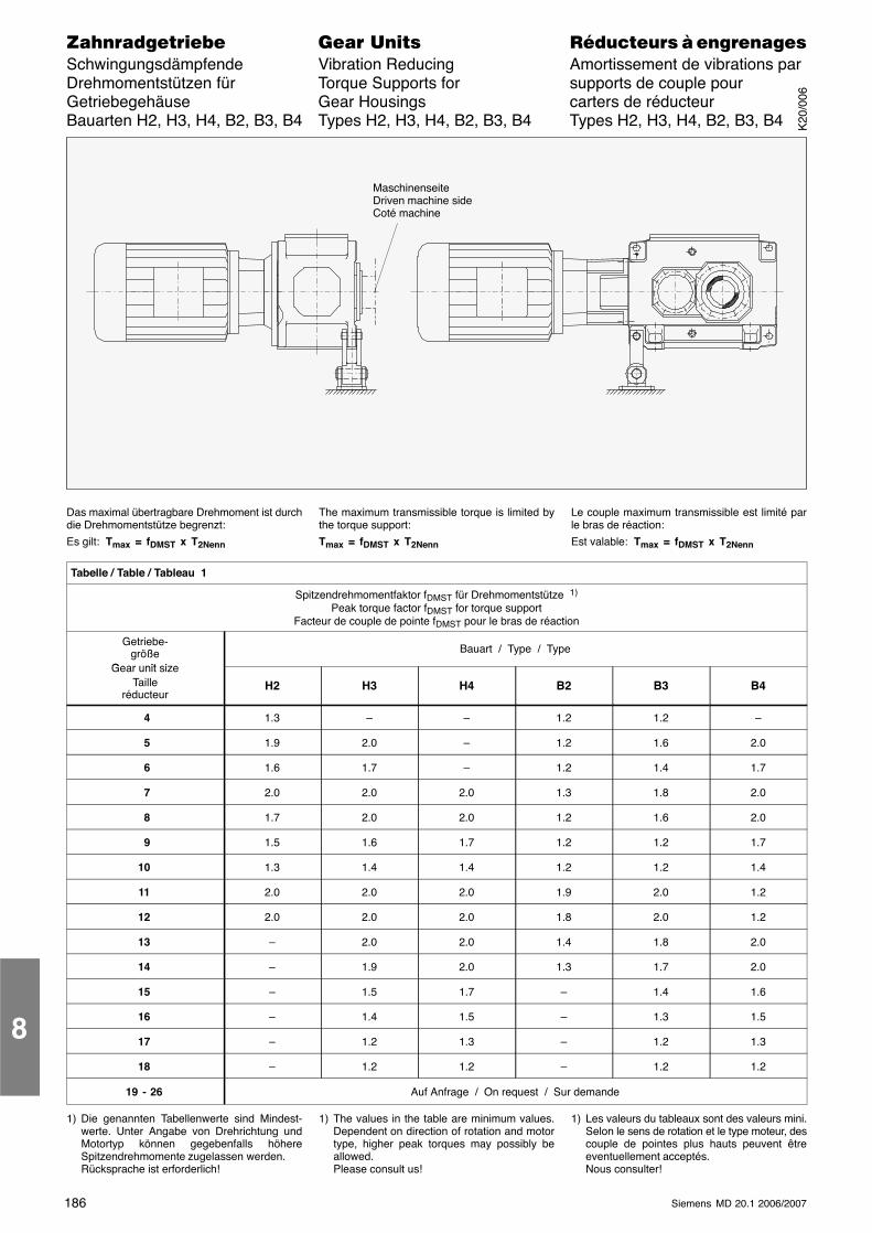
186 Siemens MD 20.1 2006/2007
������������� ���� �� ��������� � ����������Schwingungsdämpfende Vibration Reducing Amortissement de vibrations parDrehmomentstützen für Torque Supports for supports de couple pourGetriebegehäuse Gear Housings carters de réducteurBauarten H2, H3, H4, B2, B3, B4 Types H2, H3, H4, B2, B3, B4 Types H2, H3, H4, B2, B3, B4
MaschinenseiteDriven machine sideCoté machine
Das maximal übertragbare Drehmoment ist durchdie Drehmomentstütze begrenzt:
Es gilt: Tmax = fDMST x T2Nenn
The maximum transmissible torque is limited bythe torque support:
Tmax = fDMST x T2Nenn
Le couple maximum transmissible est limité parle bras de réaction:
Est valable: Tmax = fDMST x T2Nenn
Tabelle / Table / Tableau 1
Spitzendrehmomentfaktor fDMST für Drehmomentstütze 1)
Peak torque factor fDMST for torque supportFacteur de couple de pointe fDMST pour le bras de réaction
Getriebe-größe
Gear unit size
Bauart / Type / Type
Gear unit sizeTaille
réducteurH2 H3 H4 B2 B3 B4
4 1.3 – – 1.2 1.2 –
5 1.9 2.0 – 1.2 1.6 2.0
6 1.6 1.7 – 1.2 1.4 1.7
7 2.0 2.0 2.0 1.3 1.8 2.0
8 1.7 2.0 2.0 1.2 1.6 2.0
9 1.5 1.6 1.7 1.2 1.2 1.7
10 1.3 1.4 1.4 1.2 1.2 1.4
11 2.0 2.0 2.0 1.9 2.0 1.2
12 2.0 2.0 2.0 1.8 2.0 1.2
13 – 2.0 2.0 1.4 1.8 2.0
14 – 1.9 2.0 1.3 1.7 2.0
15 – 1.5 1.7 – 1.4 1.6
16 – 1.4 1.5 – 1.3 1.5
17 – 1.2 1.3 – 1.2 1.3
18 – 1.2 1.2 – 1.2 1.2
19 - 26 Auf Anfrage / On request / Sur demande
1) Die genannten Tabellenwerte sind Mindest-werte. Unter Angabe von Drehrichtung undMotortyp können gegebenfalls höhereSpitzendrehmomente zugelassen werden.Rücksprache ist erforderlich!
1) The values in the table are minimum values.Dependent on direction of rotation and motortype, higher peak torques may possibly beallowed.Please consult us!
1) Les valeurs du tableaux sont des valeurs mini.Selon le sens de rotation et le type moteur, descouple de pointes plus hauts peuvent êtreeventuellement acceptés.Nous consulter!
8
K20
/006
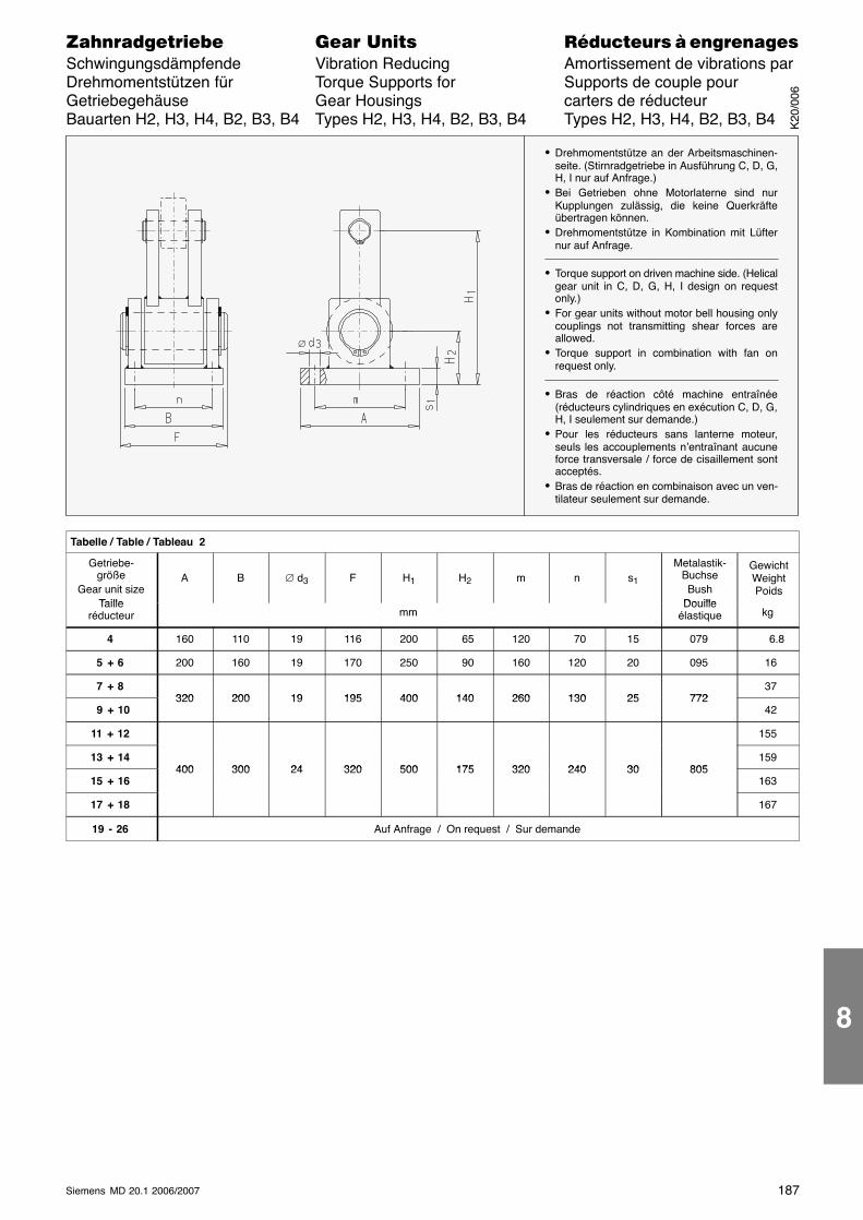
187Siemens MD 20.1 2006/2007
������������� ���� �� ��������� � ����������Schwingungsdämpfende Vibration Reducing Amortissement de vibrations parDrehmomentstützen für Torque Supports for Supports de couple pourGetriebegehäuse Gear Housings carters de réducteurBauarten H2, H3, H4, B2, B3, B4 Types H2, H3, H4, B2, B3, B4 Types H2, H3, H4, B2, B3, B4
∅
� Drehmomentstütze an der Arbeitsmaschinen-seite. (Stirnradgetriebe in Ausführung C, D, G,H, I nur auf Anfrage.)
� Bei Getrieben ohne Motorlaterne sind nurKupplungen zulässig, die keine Querkräfteübertragen können.
� Drehmomentstütze in Kombination mit Lüfternur auf Anfrage.
� Torque support on driven machine side. (Helicalgear unit in C, D, G, H, I design on requestonly.)
� For gear units without motor bell housing onlycouplings not transmitting shear forces areallowed.
� Torque support in combination with fan onrequest only.
� Bras de réaction côté machine entraînée(réducteurs cylindriques en exécution C, D, G,H, I seulement sur demande.)
� Pour les réducteurs sans lanterne moteur,seuls les accouplements n’entraînant aucuneforce transversale / force de cisaillement sontacceptés.
� Bras de réaction en combinaison avec un ven-tilateur seulement sur demande.
Tabelle / Table / Tableau 2
Getriebe-größe
Gear unit sizeTaille
A B ∅ d3 F H1 H2 m n s1
Metalastik-BuchseBush
Douille
GewichtWeightPoids
Tailleréducteur mm
Douilleélastique kg
4 160 110 19 116 200 65 120 70 15 079 6.8
5 + 6 200 160 19 170 250 90 160 120 20 095 16
7 + 8320 200 19 195 400 140 260 130 25 772
37
9 + 10320 200 19 195 400 140 260 130 25 772
42
11 + 12 155
13 + 14400 300 24 320 500 175 320 240 30 805
159
15 + 16400 300 24 320 500 175 320 240 30 805
163
17 + 18 167
19 - 26 Auf Anfrage / On request / Sur demande
K20
/006
8
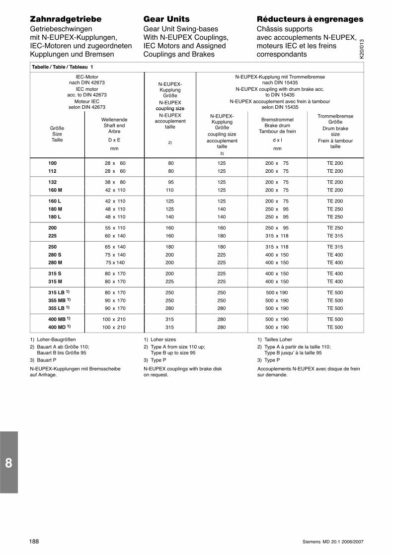
188 Siemens MD 20.1 2006/2007
������������� ���� �� ��������� � ����������Getriebeschwingen Gear Unit Swing-bases Châssis supportsmit N-EUPEX-Kupplungen, With N-EUPEX Couplings, avec accouplements N-EUPEX,IEC-Motoren und zugeordneten IEC Motors and Assigned moteurs IEC et les freinsKupplungen und Bremsen Couplings and Brakes correspondants
ÁÁÁÁÁÁÁÁÁÁÁÁÁÁÁÁÁÁÁÁÁÁÁÁÁÁÁÁÁÁÁÁÁÁÁÁÁÁÁÁÁÁÁÁÁÁÁÁÁÁÁÁÁÁÁÁÁÁÁÁÁÁÁÁÁÁÁÁ
Tabelle / Table / Tableau 1
ÁÁÁÁÁÁÁÁÁÁÁÁÁÁÁÁÁÁÁÁÁÁÁÁÁÁÁÁÁÁÁÁÁÁÁÁÁÁÁÁÁÁÁÁÁÁÁÁÁÁÁÁÁÁÁÁÁÁÁÁ
IEC-Motornach DIN 42673
IEC motoracc. to DIN 42673
Moteur IECselon DIN 42673
ÁÁÁÁÁÁÁÁÁÁÁÁÁÁÁÁÁÁÁÁÁÁÁÁÁÁÁÁÁÁÁÁÁÁÁ
N-EUPEX-Kupplung
GrößeN-EUPEX
coupling size
ÁÁÁÁÁÁÁÁÁÁÁÁÁÁÁÁÁÁÁÁÁÁÁÁÁÁÁÁÁÁÁÁÁÁÁÁÁÁÁÁÁÁÁÁÁÁÁÁÁÁÁÁÁÁÁÁÁÁÁÁÁÁÁÁÁÁÁÁÁÁÁÁÁÁÁÁÁÁÁÁÁÁÁÁÁ
N-EUPEX-Kupplung mit Trommelbremsenach DIN 15435
N-EUPEX coupling with drum brake acc.to DIN 15435
N-EUPEX accouplement avec frein à tambourselon DIN 15435
ÁÁÁÁÁÁÁÁÁÁÁÁÁÁÁÁÁÁÁÁÁÁÁÁÁÁÁÁÁÁÁÁÁÁÁ
GrößeSizeTaille
ÁÁÁÁÁÁÁÁÁÁÁÁÁÁÁÁÁÁÁÁÁÁÁÁÁÁÁÁÁÁ
WellenendeShaft end
Arbre
D x E
mm
ÁÁÁÁÁÁÁÁÁÁÁÁÁÁÁÁÁÁÁÁÁÁÁÁÁÁÁÁÁÁÁÁÁÁÁ
cou ling sizeN-EUPEX
accouplementtaille
2)
ÁÁÁÁÁÁÁÁÁÁÁÁÁÁÁÁÁÁÁÁÁÁÁÁÁÁÁÁÁÁ
N-EUPEX-Kupplung
Größecoupling sizeaccouplement
taille3)
ÁÁÁÁÁÁÁÁÁÁÁÁÁÁÁÁÁÁÁÁÁÁÁÁÁÁÁÁÁÁÁÁÁÁ
BremstrommelBrake drum
Tambour de frein
d x l
mm
ÁÁÁÁÁÁÁÁÁÁÁÁÁÁÁÁÁÁÁÁÁÁÁÁÁÁÁÁÁÁ
TrommelbremseGröße
Drum brakesize
Frein à tambourtaille
ÁÁÁÁÁÁÁÁÁÁÁÁÁÁ
100ÁÁÁÁÁÁÁÁÁÁÁÁ
28 x 60ÁÁÁÁÁÁÁÁÁÁÁÁÁÁ
80ÁÁÁÁÁÁÁÁÁÁÁÁ
125ÁÁÁÁÁÁÁÁÁÁÁÁ
200 x 75ÁÁÁÁÁÁÁÁÁÁÁÁ
TE 200ÁÁÁÁÁÁÁÁÁÁÁÁÁÁ
112 ÁÁÁÁÁÁÁÁÁÁÁÁ
28 x 60 ÁÁÁÁÁÁÁÁÁÁÁÁÁÁ
80 ÁÁÁÁÁÁÁÁÁÁÁÁ
125 ÁÁÁÁÁÁÁÁÁÁÁÁ
200 x 75 ÁÁÁÁÁÁÁÁÁÁÁÁ
TE 200
ÁÁÁÁÁÁÁÁÁÁÁÁÁÁ
132 ÁÁÁÁÁÁÁÁÁÁÁÁ
38 x 80 ÁÁÁÁÁÁÁÁÁÁÁÁÁÁ
95 ÁÁÁÁÁÁÁÁÁÁÁÁ
125 ÁÁÁÁÁÁÁÁÁÁÁÁ
200 x 75 ÁÁÁÁÁÁÁÁÁÁÁÁ
TE 200
ÁÁÁÁÁÁÁÁÁÁÁÁÁÁ
160 M ÁÁÁÁÁÁÁÁÁÁÁÁ
42 x 110 ÁÁÁÁÁÁÁÁÁÁÁÁÁÁ
110 ÁÁÁÁÁÁÁÁÁÁÁÁ
125 ÁÁÁÁÁÁÁÁÁÁÁÁ
200 x 75 ÁÁÁÁÁÁÁÁÁÁÁÁ
TE 200
ÁÁÁÁÁÁÁÁÁÁÁÁÁÁ
160 L ÁÁÁÁÁÁÁÁÁÁÁÁ
42 x 110 ÁÁÁÁÁÁÁÁÁÁÁÁÁÁ
125 ÁÁÁÁÁÁÁÁÁÁÁÁ
125 ÁÁÁÁÁÁÁÁÁÁÁÁ
200 x 75 ÁÁÁÁÁÁÁÁÁÁÁÁ
TE 200
ÁÁÁÁÁÁÁÁÁÁÁÁÁÁ
180 M ÁÁÁÁÁÁÁÁÁÁÁÁ
48 x 110 ÁÁÁÁÁÁÁÁÁÁÁÁÁÁ
125 ÁÁÁÁÁÁÁÁÁÁÁÁ
140 ÁÁÁÁÁÁÁÁÁÁÁÁ
250 x 95 ÁÁÁÁÁÁÁÁÁÁÁÁ
TE 250
ÁÁÁÁÁÁÁÁÁÁÁÁÁÁ
180 L ÁÁÁÁÁÁÁÁÁÁÁÁ
48 x 110 ÁÁÁÁÁÁÁÁÁÁÁÁÁÁ
140 ÁÁÁÁÁÁÁÁÁÁÁÁ
140 ÁÁÁÁÁÁÁÁÁÁÁÁ
250 x 95 ÁÁÁÁÁÁÁÁÁÁÁÁ
TE 250
ÁÁÁÁÁÁÁ200 ÁÁÁÁÁÁ 55 x 110 ÁÁÁÁÁÁÁ160 ÁÁÁÁÁÁ160 ÁÁÁÁÁÁ250 x 95 ÁÁÁÁÁÁTE 250ÁÁÁÁÁÁÁÁÁÁÁÁÁÁ225
ÁÁÁÁÁÁÁÁÁÁÁÁ 60 x 140
ÁÁÁÁÁÁÁÁÁÁÁÁÁÁ160
ÁÁÁÁÁÁÁÁÁÁÁÁ180
ÁÁÁÁÁÁÁÁÁÁÁÁ315 x 118
ÁÁÁÁÁÁÁÁÁÁÁÁTE 315ÁÁÁÁÁÁÁ
ÁÁÁÁÁÁÁ250ÁÁÁÁÁÁÁÁÁÁÁÁ 65 x 140
ÁÁÁÁÁÁÁÁÁÁÁÁÁÁ180
ÁÁÁÁÁÁÁÁÁÁÁÁ180
ÁÁÁÁÁÁÁÁÁÁÁÁ315 x 118
ÁÁÁÁÁÁÁÁÁÁÁÁTE 315ÁÁÁÁÁÁÁ
ÁÁÁÁÁÁÁ280 S
ÁÁÁÁÁÁÁÁÁÁÁÁ
75 x 140ÁÁÁÁÁÁÁÁÁÁÁÁÁÁ
200ÁÁÁÁÁÁÁÁÁÁÁÁ
225ÁÁÁÁÁÁÁÁÁÁÁÁ
400 x 150ÁÁÁÁÁÁÁÁÁÁÁÁ
TE 400ÁÁÁÁÁÁÁÁÁÁÁÁÁÁ
280 M ÁÁÁÁÁÁÁÁÁÁÁÁ
75 x 140 ÁÁÁÁÁÁÁÁÁÁÁÁÁÁ
200 ÁÁÁÁÁÁÁÁÁÁÁÁ
225 ÁÁÁÁÁÁÁÁÁÁÁÁ
400 x 150 ÁÁÁÁÁÁÁÁÁÁÁÁ
TE 400
ÁÁÁÁÁÁÁÁÁÁÁÁÁÁ
315 S ÁÁÁÁÁÁÁÁÁÁÁÁ
80 x 170 ÁÁÁÁÁÁÁÁÁÁÁÁÁÁ
200 ÁÁÁÁÁÁÁÁÁÁÁÁ
225 ÁÁÁÁÁÁÁÁÁÁÁÁ
400 x 150 ÁÁÁÁÁÁÁÁÁÁÁÁ
TE 400
ÁÁÁÁÁÁÁÁÁÁÁÁÁÁ
315 M ÁÁÁÁÁÁÁÁÁÁÁÁ
80 x 170 ÁÁÁÁÁÁÁÁÁÁÁÁÁÁ
225 ÁÁÁÁÁÁÁÁÁÁÁÁ
225 ÁÁÁÁÁÁÁÁÁÁÁÁ
400 x 150 ÁÁÁÁÁÁÁÁÁÁÁÁ
TE 400
ÁÁÁÁÁÁÁÁÁÁÁÁÁÁ
315 LB 1) ÁÁÁÁÁÁÁÁÁÁÁÁ
80 x 170 ÁÁÁÁÁÁÁÁÁÁÁÁÁÁ
250 ÁÁÁÁÁÁÁÁÁÁÁÁ
250 ÁÁÁÁÁÁÁÁÁÁÁÁ
500 x 190 ÁÁÁÁÁÁÁÁÁÁÁÁ
TE 500
ÁÁÁÁÁÁÁÁÁÁÁÁÁÁ
355 MB 1) ÁÁÁÁÁÁÁÁÁÁÁÁ
90 x 170 ÁÁÁÁÁÁÁÁÁÁÁÁÁÁ
250 ÁÁÁÁÁÁÁÁÁÁÁÁ
250 ÁÁÁÁÁÁÁÁÁÁÁÁ
500 x 190 ÁÁÁÁÁÁÁÁÁÁÁÁ
TE 500
ÁÁÁÁÁÁÁÁÁÁÁÁÁÁ
355 LB 1) ÁÁÁÁÁÁÁÁÁÁÁÁ
90 x 170 ÁÁÁÁÁÁÁÁÁÁÁÁÁÁ
280 ÁÁÁÁÁÁÁÁÁÁÁÁ
280 ÁÁÁÁÁÁÁÁÁÁÁÁ
500 x 190 ÁÁÁÁÁÁÁÁÁÁÁÁ
TE 500
ÁÁÁÁÁÁÁÁÁÁÁÁÁÁ
400 MB 1) ÁÁÁÁÁÁÁÁÁÁÁÁ
100 x 210 ÁÁÁÁÁÁÁÁÁÁÁÁÁÁ
315 ÁÁÁÁÁÁÁÁÁÁÁÁ
280 ÁÁÁÁÁÁÁÁÁÁÁÁ
500 x 190 ÁÁÁÁÁÁÁÁÁÁÁÁ
TE 500
ÁÁÁÁÁÁÁ400 MD 1)ÁÁÁÁÁÁ100 x 210 ÁÁÁÁÁÁÁ315 ÁÁÁÁÁÁ280 ÁÁÁÁÁÁ500 x 190 ÁÁÁÁÁÁTE 500
1) Loher-Baugrößen2) Bauart A ab Größe 110;
Bauart B bis Größe 953) Bauart P
N-EUPEX-Kupplungen mit Bremsscheibeauf Anfrage.
1) Loher sizes2) Type A from size 110 up;
Type B up to size 953) Type P
N-EUPEX couplings with brake diskon request.
1) Tailles Loher2) Type A à partir de la taille 110;
Type B jusqu’ à la taille 953) Type P
Accouplements N-EUPEX avec disque de freinsur demande.
8
K20
/013
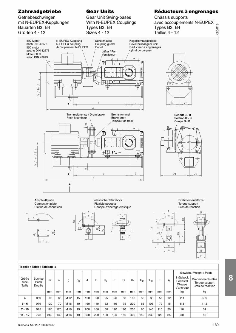
189Siemens MD 20.1 2006/2007
������������� ���� �� ��������� � ����������Getriebeschwingen Gear Unit Swing-bases Châssis supportsmit N-EUPEX-Kupplungen With N-EUPEX Couplings avec accouplements N-EUPEXBauarten B3, B4 Types B3, B4 Types B3, B4Größen 4 - 12 Sizes 4 - 12 Tailles 4 - 12
IEC-Motornach DIN 42673IEC motoracc. to DIN 42673Moteur IECselon DIN 42673
N-EUPEX-KupplungN-EUPEX couplingAccouplement N-EUPEX
KegelstirnradgetriebeBevel-helical gear unitRéducteur à engrenagescylindro-coniques
Trommelbremse / Drum brakeFrein à tambour
BremstrommelBrake drumTambour de frein
Schnitt B - BSection B - BCoupe B - B
SchutzhaubeCoupling guardCapot
Lüfter / FanVentilateur
�
�
�
AnschlußplatteConnection platePlatine de connexion
elastischer StützbockFlexible pedestalChappe d’ancrage élastique
DrehmomentstützeTorque supportBras de réaction
Tabelle / Table / Tableau 2
Gewicht / Weight / Poids
GrößeSizeTaille
BuchseBush
Douille
m n g d3 A B d5 F G H1 H2 H3 l s1StützbockPedestalChappe
d’ancrage
DrehmomentstützeTorque support
Bras de réaction
mm mm mm mm mm mm mm mm mm mm mm mm mm mm kg kg
4 069 95 65 M 12 15 120 90 25 96 60 180 50 80 56 12 2.1 5.8
5 - 6 079 120 70 M 16 19 160 110 32 116 75 200 65 105 72 15 5.3 11.8
7 - 10 095 160 120 M 16 19 200 160 50 170 110 250 90 145 110 20 16 34
11 - 12 772 260 130 M 16 19 320 200 100 195 180 400 140 230 120 25 50 82
K20
/013
8
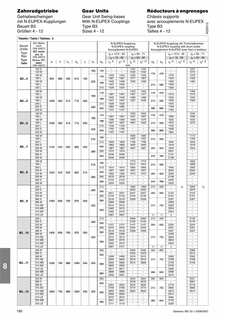
190 Siemens MD 20.1 2006/2007
������������� ���� �� ��������� � ����������Getriebeschwingen Gear Unit Swing-bases Châssis supportsmit N-EUPEX-Kupplungen With N-EUPEX Couplings avec accouplements N-EUPEXBauart B3 Type B3 Type B3Größen 4 - 12 Sizes 4 - 12 Tailles 4 - 12
Tabelle / Table / Tableau 3
BauartGrößeT
IEC-Motornach
DIN 42673IEC motor
N-EUPEX-KupplungN-EUPEX coupling
Accouplement N-EUPEX
N-EUPEX-Kupplung mit TrommelbremseN-EUPEX coupling with drum brake
Accouplement N-EUPEX avec frein à tambourTypeSize
IEC motoracc. to iN = 12.5 - 45 iN = 50 - 71 iN = 12.5 - 45 iN = 50 - 71
SizeType
acc. toDIN 42673M t IEC
iN = 16 - 56 iN = 63 - 90 iN = 16 - 56 iN = 63 - 90TypeTaille
Moteur IECselon e h h1 h2 l1 b1 b2 l2 2) l2� 2) l2 2) l2� 2) b3 b4 l3 2) l3� 2) l3 2) l3� 2)
Taille selonDIN 42673 mm
132 S160 145
– – 1194 1194 – 1237132 M 160 145 – – 1232 1232
170 470– 1275
160 M 170 1343 1343 1333 1333170 470
1376 1376B3 .. 4 160 L 950 380 430 610 190
1701387 1387 1377 1387 1420 1420B3 .. 4
180 M950 380 430 610 190
200 185 1409 1409 1399 1409 1465 1465180 L
200 1851447 1452 – – 210 590 1503 –
200 L 215 1529 1534 – –210 590
1585 –160 M
170– – 1423 1423
170 470– 1466
160 L185
170 1487 1487 1467 1477 170 470 1515 1510180 M 185
185 1509 1509 1489 1499 1555 1555B3 .. 5 180 L 1000 450 515 715 205
1851547 1547 1527 1542 210 590 1593 1593B3 .. 5
200 L1000 450 515 715 205
215 1629 1629 – –210 590
1675 –225 S 220 240
1682 1682 – –260 665
1759 –225 M
220 2401707 1707 – –
260 6651784 –
160 M170
– – 1503 1503170 470
– 1546160 L
185170 1567 1567 1547 1557 170 470 1595 1590
180 M 185185 1589 1589 1569 1579 1635 1635
B3 .. 6 180 L 1050 450 515 715 250185
1627 1627 1607 1622 210 590 1673 1673B3 .. 6200 L
1050 450 515 715 250215 1709 1709 – –
210 5901755 –
225 S 220 2401762 1762 – –
260 6651839 –
225 M220 240
1787 1787 – –260 665
1864 –180 M
185– – 1669 1669 – 1715
180 L 215 185 – – 1707 1707 210 590 – 1753200 L
215215 1809 1809 1789 1789
210 5901840 1835
B3 7225 S
1150 540 630 880 250 2401862 1862 1842 1842 1919 1919
B3 .. 7 225 M 1150 540 630 880 250 2401887 1887 1867 1867 260 665 1944 1944
250 M 280 265 1974 1974 –260 665
2031 –280 S
280
3002048 2048 –
310 7652147 –
280 M300
2099 2099 –310 765
2198 –180 M
185– – 1774 1774 – 1820
180 L 215 185 – – 1812 1812 210 590 – 1858200 L
215215 1914 1914 1894 1894
210 5901945 1940
B3 8225 S
1200 540 630 880 310 2401967 1967 1947 1947 2024 2024
B3 .. 8 225 M 1200 540 630 880 310 2401992 1992 1972 1972 260 665 2049 2049
250 M 280 265 2079 2079 – –260 665
2136 –280 S
280
3002153 2153 – –
310 7652252 –
280 M300
2204 2204 – –310 765
2303 –200 L 215 – – 1969 1969 210 590 – 1) 2000 1)225 S 260 240
– – 2022 2022 –1)
20791)
225 M260 240
2057 2057 2047 2047 260 665 2104 2104250 M 265 2144 2144 2134 2134
260 6652191 2191
B3 9280 S
1350 630 720 970 300 300 2218 2218 2208 2208 2307 2307B3 .. 9 280 M 1350 630 720 970 300 300
2269 2269 – – 2358 –315 SB 305 2414 2414 – – 310 765 2503 –315 MB
305
3302465 2475 – –
310 7652554 –
315 MD330
2465 2475 – – 2554 –315 LB 2587 2607 – – 1) 1) 1) –200 L 215 – – 2069 2069 210 590 – 2100225 S 260 240
– – 2122 2122 – 2179225 M
260 2402157 2157 2147 2147 260 665 2204 2204
250 M 265 2244 2244 2234 2234260 665
2291 2291
B3 10280 S
1400 630 720 970 350 300 2318 2318 2308 2308 2407 2407B3 .. 10 280 M 1400 630 720 970 350 300
2369 2369 – – 2458 –315 SB 305 2514 2514 – – 310 765 2603 –315 MB
305
3302565 2575 – –
310 7652654 –
315 MD330
2565 2575 – – 2654 –315 LB 2687 2707 – – 1) 1) 1) –250 M 265 – – 2349 2349 260 665 – 2396280 S
300– – 2423 2423 – 2512
280 M300
2499 2499 2474 2474 2563 2563315 SB 2644 2644 2619 2619 310 765 2708 2708
B3 .. 11 315 MB 1550 740 880 1280 345 355 330 2695 2695 2670 2680310 765
2759 2759B3 .. 11315 MD
1550 740 880 1280 345 355 3302695 2695 – – 2759 –
315 LB 2817 2817 – – 2929 –355 MB
3802886 2886 – – 385 840 2998 –
355 LB380
2956 2961 – –385 840
3073 –250 M 265 – – 2504 2504 260 665 – 2551280 S
300– – 2578 2578 – 2667
280 M300
2654 2654 2679 2629 2718 2718315 SB 2799 2799 2774 2774 310 765 2863 2863
B3 .. 12 315 MB 1600 740 880 1280 430 355 330 2850 2850 2825 2835310 765
2914 2914B3 .. 12315 MD
1600 740 880 1280 430 355 3302850 2850 – – 2914 –
315 LB 2972 2972 – – 3084 –355 MB
3803041 3041 – – 385 840 3153 –
355 LB380
3111 3116 – –385 840
3228 –
8
K20
/013
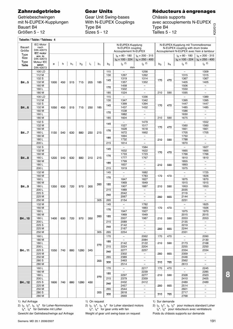
191Siemens MD 20.1 2006/2007
������������� ���� �� ��������� � ����������Getriebeschwingen Gear Unit Swing-bases Châssis supportsmit N-EUPEX-Kupplungen With N-EUPEX Couplings avec accouplements N-EUPEXBauart B4 Type B4 Type B4Größen 5 - 12 Sizes 5 - 12 Tailles 5 - 12
Tabelle / Table / Tableau 4
BauartGrößeT
IEC-Motornach
DIN 42673IEC motor
N-EUPEX-KupplungN-EUPEX coupling
Accouplement N-EUPEX
N-EUPEX-Kupplung mit TrommelbremseN-EUPEX coupling with drum brake
Accouplement N-EUPEX avec frein à tambourTypeSize
IEC motoracc. to iN = 80 - 180 iN = 200 - 315 iN = 80 - 180 iN = 200 - 315
SizeType
acc. toDIN 42673M t IEC
iN = 100 - 224 iN = 250 - 400 iN = 100 - 224 iN = 250 - 400TypeTaille
Moteur IECselon e h h1 h2 l1 b1 b2 l2 2) l2 2) b3 b4 l3 2) l3 2)
Taille selonDIN 42673 mm
100 LD 115 – 1256 – 1309112 M 130 1267 1262 1315 1315132 S
1451319 1314
170 4701367 1367
B4 .. 5 132 M 1000 450 515 715 205 185145
1357 1352170 470
1405 1405B4 .. 5160 M
1000 450 515 715 205 185
1701458 – 1506 –
160 L 170 1502 – 1550 –180 M 185 1524 – 210 590 1595 –
100 LD 115 – 1336 – 1389112 M 130 1347 1342 1395 1395132 S
1451399 1394
170 4701447 1447
B4 .. 6 132 M 1050 450 515 715 250 185145
1437 1432170 470
1485 1485B4 .. 6160 M
1050 450 515 715 250 185
1701538 – 1586 –
160 L 170 1882 – 1630 –180 M 185 1604 – 210 590 1675 –
132 S145
– 1479 – 1552132 M 145 1527 1517
170 4701560 1560
160 M170
1628 1618 170 470 1661 1661B4 .. 7 160 L 1150 540 630 880 250 215
1701672 1662 1705 1705B4 .. 7
180 M1150 540 630 880 250 215
1851694 – 1750 –
180 L 185 1732 – 210 590 1788 –200 L 215 1814 –
210 5901870 –
132 S145
– 1584 – 1627132 M 145 1632 1622
170 4701665 1665
160 M170
1733 1723 170 470 1766 1766B4 .. 8 160 L 1200 540 630 880 310 215
1701777 1767 1810 1810B4 .. 8
180 M1200 540 630 880 310 215
1851799 – 1855 –
180 L 185 1837 – 210 590 1893 –200 L 215 1919 –
210 5901975 –
132 M 145 – 1682 – 1725160 M
170– 1783 170 470 – 1826
160 L 170 1847 1827170 470
1875 1870180 M
260 1851969 1849 1915 1915
B4 .. 9 180 L 1350 630 720 970 300260 185
1907 1887 210 590 1953 1953B4 .. 9200 L
1350 630 720 970 300215 1989 –
210 5902035 –
225 S240
2042 – 2119 –225 M 240 2067 – 260 665 2144 –250 M 305 265 2154 –
260 6652231 –
132 M 145 – 1782 – 1825160 M
170– 1883 170 470 – 1926
160 L 170 1947 1927170 470
1975 1970180 M
260 1851969 1949 2015 2015
B4 .. 10 180 L 1400 630 720 970 350260 185
2007 1987 210 590 2053 2053B4 .. 10200 L
1400 630 720 970 350215 2089 –
210 5902135 –
225 S240
2142 – 2219 –225 M 240 2167 – 260 665 2244 –250 M 305 265 2254 –
260 6652331 –
160 L 170 – 2062 170 470 – 2090180 M
185– 2084 – 2130
180 L270
185 2142 2122 210 590 2173 2168200 L 270 215 2224 2204
210 5902255 2250
B4 .. 11 225 S 1550 740 880 1280 345 240 2277 2257 2334 2334B4 .. 11225 M
1550 740 880 1280 345 2402302 – 260 665 2359 –
250 M 265 2389 –260 665
2446 –280 S 355 300
2463 –310 765
2562 –280 M
355 3002514 –
310 7652613 –
160 L 170 – 2217 170 470 – 2245180 M
185– 2239 – 2285
180 L270
185 2297 2277 210 590 2328 2323200 L 270 215 2379 2359
210 5902410 2405
B4 .. 12 225 S 1600 740 880 1280 430 240 2432 2412 2489 2489B4 .. 12225 M
1600 740 880 1280 430 2402457 – 260 665 2514 –
250 M 265 2544 –260 665
2601 –280 S 355
3002618 –
310 7652717 –
280 M355
3002669 –
310 7652768 –
1) Auf Anfrage2) l2, l2�, l3, l3� für Loher-Normmotoren
l2�, l3� für Getriebe mit LüfterGewicht der Getriebeschwinge auf Anfrage
1) On request2) l2, l2�, l3, l3� for Loher standard motors
l2�, l3� for gear units with fanWeight of gear unit swing-base on request
1) Sur demande2) l2, l2�, l3, l3� pour moteurs standard Loher
l2�, l3� pour réducteurs avec ventilateursPoids du châssis supports sur demande
K20
/013
8
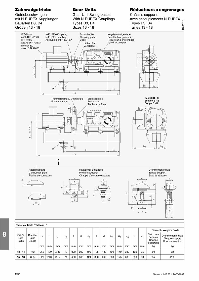
192 Siemens MD 20.1 2006/2007
������������� ���� �� ��������� � ����������Getriebeschwingen Gear Unit Swing-bases Châssis supportsmit N-EUPEX-Kupplungen With N-EUPEX Couplings avec accouplements N-EUPEXBauarten B3, B4 Types B3, B4 Types B3, B4Größen 13 - 18 Sizes 13 - 18 Tailles 13 - 18
IEC-Motornach DIN 42673IEC motoracc. to DIN 42673Moteur IECselon DIN 42673
N-EUPEX-KupplungN-EUPEX couplingAccouplement N-EUPEX
KegelstirnradgetriebeBevel-helical gear unitRéducteur à engrenagescylindro-coniques
Trommelbremse / Drum brakeFrein à tambour
BremstrommelBrake drumTambour de frein
Schnitt B - BSection B - BCoupe B - B
SchutzhaubeCoupling guardCapot
Lüfter / FanVentilateur
�
�
�
AnschlußplatteConnection platePlatine de connexion
elastischer StützbockFlexible pedestalChappe d’ancrage élastique
DrehmomentstützeTorque supportBras de réaction
Tabelle / Table / Tableau 5
Gewicht / Weight / Poids
GrößeSizeTaille
BuchseBush
Douille
m n g d3 A B d5 F G H1 H2 H3 l s1StützbockPedestalChappe
d’ancrage
DrehmomentstützeTorque support
Bras de réaction
mm mm mm mm mm mm mm mm mm mm mm mm mm mm kg kg
13 - 14 772 260 130 ∅ 19 19 320 200 100 195 180 400 140 230 120 25 50 82
15 - 18 805 320 240 ∅ 24 24 400 300 124 320 240 500 175 285 230 30 95 220
8
K20
/013
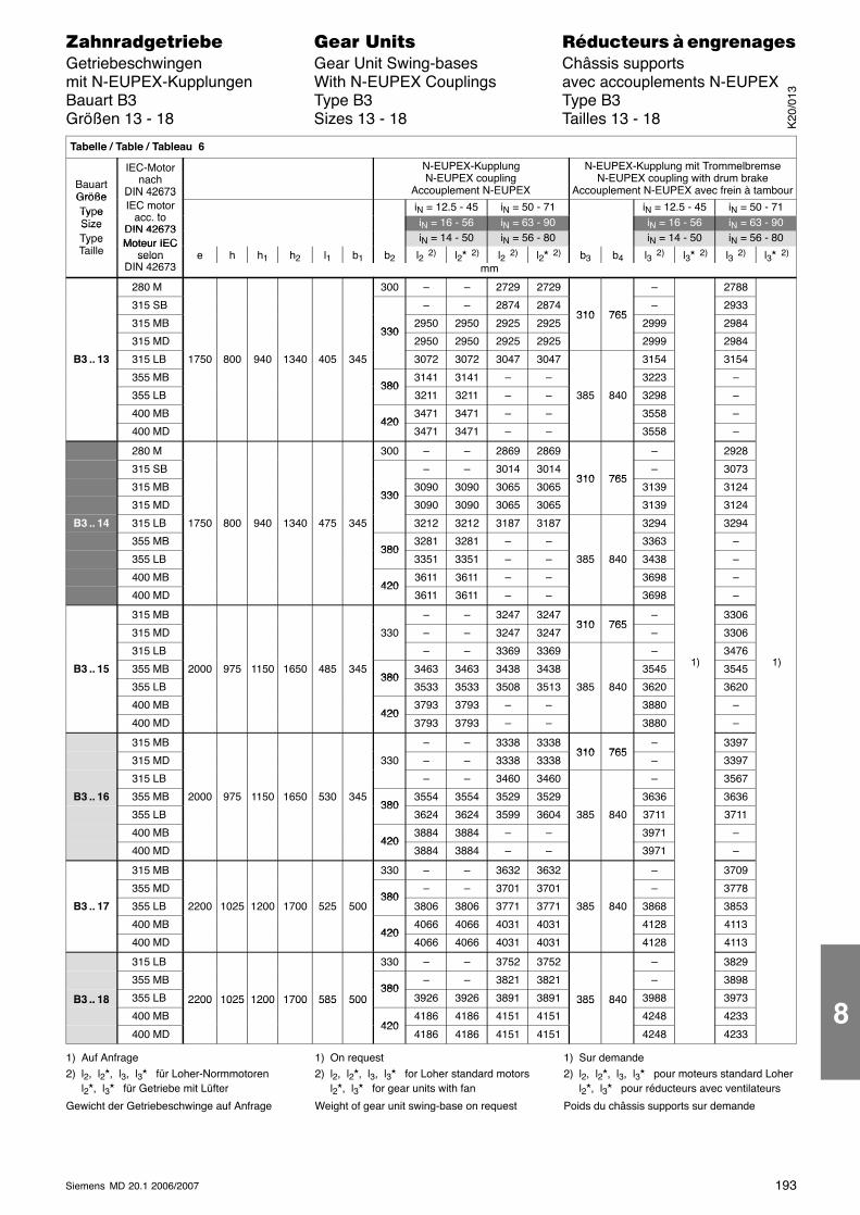
193Siemens MD 20.1 2006/2007
������������� ���� �� ��������� � ����������Getriebeschwingen Gear Unit Swing-bases Châssis supportsmit N-EUPEX-Kupplungen With N-EUPEX Couplings avec accouplements N-EUPEXBauart B3 Type B3 Type B3Größen 13 - 18 Sizes 13 - 18 Tailles 13 - 18
Tabelle / Table / Tableau 6
BauartGröße
IEC-Motornach
DIN 42673
N-EUPEX-KupplungN-EUPEX coupling
Accouplement N-EUPEX
N-EUPEX-Kupplung mit TrommelbremseN-EUPEX coupling with drum brake
Accouplement N-EUPEX avec frein à tambourGrößeType
DIN 42673IEC motor
acc toiN = 12.5 - 45 iN = 50 - 71 iN = 12.5 - 45 iN = 50 - 71Ty e
Size acc. toDIN 42673
iN = 16 - 56 iN = 63 - 90 iN = 16 - 56 iN = 63 - 90SizeType
DIN 42673Moteur IEC iN = 14 - 50 iN = 56 - 80 iN = 14 - 50 iN = 56 - 80Ty e
TailleMoteur IEC
selonDIN 426 3
e h h1 h2 l1 b1 b2 l2 2) l2� 2) l2 2) l2� 2) b3 b4 l3 2) l3� 2) l3 2) l3� 2)selonDIN 42673 mm
280 M 300 – – 2729 2729 – 2788
315 SB – – 2874 2874310 765
– 2933
315 MB330
2950 2950 2925 2925310 765
2999 2984
315 MD330
2950 2950 2925 2925 2999 2984
B3 .. 13 315 LB 1750 800 940 1340 405 345 3072 3072 3047 3047 3154 3154
355 MB380
3141 3141 – – 3223 –
355 LB380
3211 3211 – – 385 840 3298 –
400 MB420
3471 3471 – – 3558 –
400 MD420
3471 3471 – – 3558 –
280 M 300 – – 2869 2869 – 2928
315 SB – – 3014 3014310 765
– 3073
315 MB330
3090 3090 3065 3065310 765
3139 3124
315 MD330
3090 3090 3065 3065 3139 3124
B3 .. 14 315 LB 1750 800 940 1340 475 345 3212 3212 3187 3187 3294 3294
355 MB380
3281 3281 – – 3363 –
355 LB380
3351 3351 – – 385 840 3438 –
400 MB420
3611 3611 – – 3698 –
400 MD420
3611 3611 – – 3698 –
315 MB – – 3247 3247310 765
– 3306
315 MD 330 – – 3247 3247310 765
– 3306
315 LB – – 3369 3369 –1)
34761)
B3 .. 15 355 MB 2000 975 1150 1650 485 345380
3463 3463 3438 3438 35451)
35451)
355 LB380
3533 3533 3508 3513 385 840 3620 3620
400 MB420
3793 3793 – – 3880 –
400 MD420
3793 3793 – – 3880 –
315 MB – – 3338 3338310 765
– 3397
315 MD 330 – – 3338 3338310 765
– 3397
315 LB – – 3460 3460 – 3567
B3 .. 16 355 MB 2000 975 1150 1650 530 345380
3554 3554 3529 3529 3636 3636
355 LB380
3624 3624 3599 3604 385 840 3711 3711
400 MB420
3884 3884 – – 3971 –
400 MD420
3884 3884 – – 3971 –
315 MB 330 – – 3632 3632 – 3709
355 MD380
– – 3701 3701 – 3778
B3 .. 17 355 LB 2200 1025 1200 1700 525 500380
3806 3806 3771 3771 385 840 3868 3853
400 MB420
4066 4066 4031 4031 4128 4113
400 MD420
4066 4066 4031 4031 4128 4113
315 LB 330 – – 3752 3752 – 3829
355 MB380
– – 3821 3821 – 3898
B3 .. 18 355 LB 2200 1025 1200 1700 585 500380
3926 3926 3891 3891 385 840 3988 3973B3 .. 18
400 MB
2200 1025 1200 1700 585 500
4204186 4186 4151 4151
385 840
4248 4233
400 MD420
4186 4186 4151 4151 4248 4233
1) Auf Anfrage2) l2, l2�, l3, l3� für Loher-Normmotoren
l2�, l3� für Getriebe mit Lüfter
Gewicht der Getriebeschwinge auf Anfrage
1) On request2) l2, l2�, l3, l3� for Loher standard motors
l2�, l3� for gear units with fan
Weight of gear unit swing-base on request
1) Sur demande2) l2, l2�, l3, l3� pour moteurs standard Loher
l2�, l3� pour réducteurs avec ventilateurs
Poids du châssis supports sur demande
K20
/013
8
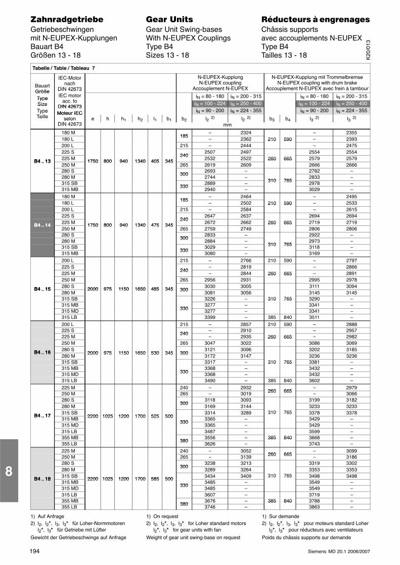
194 Siemens MD 20.1 2006/2007
������������� ���� �� ��������� � ����������Getriebeschwingen Gear Unit Swing-bases Châssis supportsmit N-EUPEX-Kupplungen With N-EUPEX Couplings avec accouplements N-EUPEXBauart B4 Type B4 Type B4Größen 13 - 18 Sizes 13 - 18 Tailles 13 - 18
Tabelle / Table / Tableau 7
BauartGröße
IEC-Motornach
DIN 42673
N-EUPEX-KupplungN-EUPEX coupling
Accouplement N-EUPEX
N-EUPEX-Kupplung mit TrommelbremseN-EUPEX coupling with drum brake
Accouplement N-EUPEX avec frein à tambourGrößeType
DIN 42673IEC motor
acc toiN = 80 - 180 iN = 200 - 315 iN = 80 - 180 iN = 200 - 315Ty e
Size acc. toDIN 42673
iN = 100 - 224 iN = 250 - 400 iN = 100 - 224 iN = 250 - 400SizeType
DIN 42673Moteur IEC iN = 90 - 200 iN = 224 - 355 iN = 90 - 200 iN = 224 - 355Ty e
TailleMoteur IEC
selonDIN 426 3
e h h1 h2 l1 b1 b2 l2 2) l2 2) b3 b4 l3 2) l3 2)selonDIN 42673 mm
180 M185
– 2324 – 2355180 L
185– 2362 210 590 – 2393
200 L 215 – 2444210 590
– 2475225 S
2402507 2497 2554 2554
B4 13 225 M 1750 800 940 1340 405 345240
2532 2522 260 665 2579 2579B4 .. 13250 M
1750 800 940 1340 405 345265 2619 2609
260 6652666 2666
280 S300
2693 – 2782 –280 M
3002744 –
310 7652833 –
315 SB330
2889 – 310 765 2978 –315 MB
3302940 – 3029 –
180 M185
– 2464 – 2495180 L
185– 2502 210 590 – 2533
200 L 215 – 2584210 590
– 2615225 S
2402647 2637 2694 2694
B4 14 225 M 1750 800 940 1340 475 345240
2672 2662 260 665 2719 2719B4 .. 14250 M
1750 800 940 1340 475 345265 2759 2749
260 6652806 2806
280 S300
2833 – 2922 –280 M
3002884 –
310 7652973 –
315 SB330
3029 – 310 765 3118 –315 MB
3303080 – 3169 –
200 L 215 – 2766 210 590 – 2797225 S
240– 2819 – 2866
225 M240
– 2844 260 665 – 2891250 M 265 2956 2931
260 6652995 2978
B4 15 280 S 2000 975 1150 1650 485 345 3003030 3005 3111 3094B4 .. 15
280 M2000 975 1150 1650 485 345 300
3081 3056 3145 3145315 SB 3226 – 310 765 3290 –315 MB
3303277 –
310 7653341 –
315 MD 330 3277 – 3341 –315 LB 3399 – 385 840 3511 –200 L 215 – 2857 210 590 – 2888225 S
240– 2910 – 2957
225 M240
– 2935 260 665 – 2982250 M 265 3047 3022
260 6653086 3069
B4 16 280 S2000 975 1150 1650 530 345 300
3121 3096 3202 3185B4 .. 16280 M
2000 975 1150 1650 530 345 3003172 3147 3236 3236
315 SB 3317 – 310 765 3381 –315 MB
3303368 –
310 7653432 –
315 MD 330 3368 – 3432 –315 LB 3490 – 385 840 3602 –225 M 240 – 2932
260 665– 2979
250 M 265 – 3019 260 665 – 3066280 S
3003118 3093 3199 3182
280 M300
3169 3144 3233 3233
B4 17 315 SB2200 1025 1200 1700 525 500
3314 3289 310 765 3378 3378B4 .. 17315 MB 2200 1025 1200 1700 525 500
3303365 –
310 7653429 –
315 MD330
3365 – 3429 –315 LB 3487 – 3599 –355 MB
3803556 – 385 840 3668 –
355 LB380
3626 –385 840
3743 –225 M 240 – 3052
260 665– 3099
250 M 265 – 3139 260 665 – 3186280 S
3003238 3213 3319 3302
280 M300
3289 3264 3353 3353
B4 18 315 SB 2200 1025 1200 1700 585 500 3434 3409 310 765 3498 3498B4 .. 18315 MB
2200 1025 1200 1700 585 500330
3485 –310 765
3549 –315 MD
3303485 – 3549 –
315 LB 3607 – 3719 –355 MB
3803676 – 385 840 3788 –
355 LB 380 3746 –385 840
3863 –
1) Auf Anfrage2) l2, l2�, l3, l3� für Loher-Normmotoren
l2�, l3� für Getriebe mit Lüfter
Gewicht der Getriebeschwinge auf Anfrage
1) On request2) l2, l2�, l3, l3� for Loher standard motors
l2�, l3� for gear units with fan
Weight of gear unit swing-base on request
1) Sur demande2) l2, l2�, l3, l3� pour moteurs standard Loher
l2�, l3� pour réducteurs avec ventilateurs
Poids du châssis supports sur demande
8
K20
/013
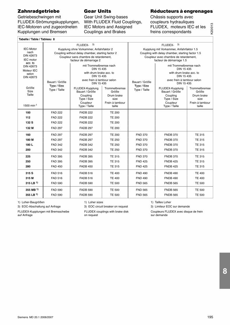
195Siemens MD 20.1 2006/2007
������������� ���� �� ��������� � ����������Getriebeschwingen mit Gear Unit Swing-bases Châssis supports avecFLUDEX-Strömungskupplungen, With FLUDEX Fluid Couplings, coupleurs hydrauliquesIEC-Motoren und zugeordneten IEC Motors and Assigned FLUDEX, moteurs IEC et lesKupplungen und Bremsen Couplings and Brakes freins correspondants
ÁÁÁÁÁÁÁÁÁÁÁÁÁÁÁÁÁÁÁÁÁÁÁÁÁÁÁÁÁÁÁÁÁÁÁÁÁÁÁÁÁÁÁÁÁÁÁÁÁÁÁÁÁÁÁÁÁÁÁÁÁÁÁÁÁÁÁÁ
Tabelle / Table / Tableau 8
ÁÁÁÁÁÁÁÁÁÁÁÁÁÁÁÁÁÁÁÁÁÁÁÁ
IEC-Motornach
DIN 42673IEC motor
acc to
ÁÁÁÁÁÁÁÁÁÁÁÁÁÁÁÁÁÁÁÁÁÁÁÁÁÁÁÁÁÁÁÁÁÁÁÁÁÁÁÁÁÁÁÁÁÁÁÁÁÁÁÁÁÁÁÁÁÁÁÁ
FLUDEX- 3)
Kupplung ohne Vorkammer, Anfahrfaktor 2Coupling without delay chamber, starting factor 2
Coupleur sans chambre de retardement,facteur de démarrage 2
ÁÁÁÁÁÁÁÁÁÁÁÁÁÁÁÁÁÁÁÁÁÁÁÁÁÁÁÁÁÁÁÁÁÁÁÁÁÁÁÁÁÁÁÁÁÁÁÁÁÁÁÁÁÁÁÁÁÁÁÁ
FLUDEX- 3)
Kupplung mit Vorkammer, Anfahrfaktor 1.5Coupling with delay chamber, starting factor 1.5
Coupleur avec chambre de retardement,facteur de démarrage 1.5
ÁÁÁÁÁÁÁÁÁÁÁÁÁÁÁÁÁÁÁÁÁÁÁÁÁÁÁÁÁÁ
acc. toDIN 42673Moteur IEC
selonDIN 42673
ÁÁÁÁÁÁÁÁÁÁÁÁÁÁÁÁÁÁÁÁÁÁÁÁÁ
Bauart / GrößeType / Size
ÁÁÁÁÁÁÁÁÁÁÁÁÁÁÁÁÁÁÁÁÁÁÁÁÁÁÁÁÁÁÁÁÁÁÁÁÁÁÁÁÁÁÁÁÁÁÁÁÁÁÁÁÁÁÁ
mit Trommelbremse nachDIN 15 435
with drum brake acc. toDIN 15 435
avec frein à tambour selonDIN 15 435
ÁÁÁÁÁÁÁÁÁÁÁÁÁÁÁÁÁÁÁÁÁÁÁÁÁÁÁÁÁÁ
Bauart / GrößeType / Size
ÁÁÁÁÁÁÁÁÁÁÁÁÁÁÁÁÁÁÁÁÁÁÁÁÁÁÁÁÁÁÁÁÁÁÁÁÁÁÁÁÁÁÁÁÁÁÁÁÁÁ
mit Trommelbremse nachDIN 15 435
with drum brake acc. toDIN 15 435
avec frein à tambour selonDIN 15 435
ÁÁÁÁÁÁÁÁÁÁÁÁÁÁÁÁÁÁÁÁÁÁÁÁÁÁÁÁÁÁ
GrößeSizeTaille
1500 min-1
ÁÁÁÁÁÁÁÁÁÁÁÁÁÁÁÁÁÁÁÁÁÁÁÁÁ
Type / SizeType / Taille
ÁÁÁÁÁÁÁÁÁÁÁÁÁÁÁÁÁÁÁÁÁÁÁÁÁÁÁÁÁÁÁÁÁÁÁ
FLUDEX-KupplungBauart / Größe
CouplingType / SizeCoupleur
Type / Taille
ÁÁÁÁÁÁÁÁÁÁÁÁÁÁÁÁÁÁÁÁÁÁÁÁÁ
TrommelbremseGröße
Drum brakesize
Frein à tambourtaille
ÁÁÁÁÁÁÁÁÁÁÁÁÁÁÁÁÁÁÁÁÁÁÁÁÁÁÁÁÁÁ
Type / SizeType / Taille
ÁÁÁÁÁÁÁÁÁÁÁÁÁÁÁÁÁÁÁÁÁÁÁÁÁÁÁÁÁÁ
FLUDEX-KupplungBauart / Größe
CouplingType / SizeCoupleur
Type / Taille
ÁÁÁÁÁÁÁÁÁÁÁÁÁÁÁÁÁÁÁÁÁÁÁÁÁ
TrommelbremseGröße
Drum brakesize
Frein à tambourtaille
ÁÁÁÁÁÁÁÁÁÁÁÁ
100 ÁÁÁÁÁÁÁÁÁÁ
FAD 222 ÁÁÁÁÁÁÁÁÁÁÁÁÁÁ
FADB 222 ÁÁÁÁÁÁÁÁÁÁ
TE 200 ÁÁÁÁÁÁÁÁÁÁÁÁ
ÁÁÁÁÁÁÁÁÁÁÁÁ
ÁÁÁÁÁÁÁÁÁÁÁÁÁÁÁÁ
ÁÁÁÁÁÁ112 ÁÁÁÁÁ
ÁÁÁÁÁFAD 222 ÁÁÁÁÁÁÁ
ÁÁÁÁÁÁÁFADB 222 ÁÁÁÁÁ
ÁÁÁÁÁTE 200 ÁÁÁÁÁÁ
ÁÁÁÁÁÁÁÁÁÁÁÁÁÁÁÁÁÁ
ÁÁÁÁÁÁÁÁÁÁÁÁÁÁÁÁ
ÁÁÁÁÁÁ132 S ÁÁÁÁÁ
ÁÁÁÁÁFAD 222 ÁÁÁÁÁÁÁ
ÁÁÁÁÁÁÁFADB 222 ÁÁÁÁÁ
ÁÁÁÁÁTE 200 ÁÁÁÁÁÁ
ÁÁÁÁÁÁÁÁÁÁÁÁÁÁÁÁÁÁ
ÁÁÁÁÁÁÁÁÁÁÁÁÁÁÁÁ
ÁÁÁÁÁÁ132 M ÁÁÁÁÁ
ÁÁÁÁÁFAD 297 ÁÁÁÁÁÁÁ
ÁÁÁÁÁÁÁFADB 297 ÁÁÁÁÁ
ÁÁÁÁÁTE 200 ÁÁÁÁÁÁ
ÁÁÁÁÁÁÁÁÁÁÁÁÁÁÁÁÁÁ
ÁÁÁÁÁÁÁÁÁÁÁÁÁÁÁÁ
ÁÁÁÁÁÁ160 ÁÁÁÁÁ
ÁÁÁÁÁFAD 297 ÁÁÁÁÁÁÁ
ÁÁÁÁÁÁÁFADB 297 ÁÁÁÁÁ
ÁÁÁÁÁTE 200 ÁÁÁÁÁÁ
ÁÁÁÁÁÁFND 370 ÁÁÁÁÁÁ
ÁÁÁÁÁÁFNDB 370 ÁÁÁÁÁ
ÁÁÁÁÁTE 315
ÁÁÁÁÁÁÁÁÁÁÁÁ
180 M ÁÁÁÁÁÁÁÁÁÁ
FAD 297 ÁÁÁÁÁÁÁÁÁÁÁÁÁÁ
FADB 297 ÁÁÁÁÁÁÁÁÁÁ
TE 250 ÁÁÁÁÁÁÁÁÁÁÁÁ
FND 370 ÁÁÁÁÁÁÁÁÁÁÁÁ
FNDB 370 ÁÁÁÁÁÁÁÁÁÁ
TE 315
ÁÁÁÁÁÁ180 L ÁÁÁÁÁFAD 342 ÁÁÁÁÁÁÁFADB 342 ÁÁÁÁÁTE 250 ÁÁÁÁÁÁFND 370 ÁÁÁÁÁÁFNDB 370 ÁÁÁÁÁTE 315ÁÁÁÁÁÁÁÁÁÁÁÁ
200ÁÁÁÁÁÁÁÁÁÁ
FAD 342ÁÁÁÁÁÁÁÁÁÁÁÁÁÁ
FADB 342ÁÁÁÁÁÁÁÁÁÁ
TE 250ÁÁÁÁÁÁÁÁÁÁÁÁ
FND 370ÁÁÁÁÁÁÁÁÁÁÁÁ
FNDB 370ÁÁÁÁÁÁÁÁÁÁ
TE 315ÁÁÁÁÁÁÁÁÁÁÁÁ225
ÁÁÁÁÁÁÁÁÁÁFAD 395
ÁÁÁÁÁÁÁÁÁÁÁÁÁÁFADB 395
ÁÁÁÁÁÁÁÁÁÁTE 315
ÁÁÁÁÁÁÁÁÁÁÁÁFND 370
ÁÁÁÁÁÁÁÁÁÁÁÁFNDB 370
ÁÁÁÁÁÁÁÁÁÁTE 315ÁÁÁÁÁÁ
ÁÁÁÁÁÁ250
ÁÁÁÁÁÁÁÁÁÁ
FAD 395ÁÁÁÁÁÁÁÁÁÁÁÁÁÁ
FADB 395ÁÁÁÁÁÁÁÁÁÁ
TE 315ÁÁÁÁÁÁÁÁÁÁÁÁ
FND 425ÁÁÁÁÁÁÁÁÁÁÁÁ
FNDB 425ÁÁÁÁÁÁÁÁÁÁ
TE 315ÁÁÁÁÁÁÁÁÁÁÁÁ
280 ÁÁÁÁÁÁÁÁÁÁ
FAD 450ÁÁÁÁÁÁÁÁÁÁÁÁÁÁ
FADB 450ÁÁÁÁÁÁÁÁÁÁ
TE 315ÁÁÁÁÁÁÁÁÁÁÁÁ
FND 425ÁÁÁÁÁÁÁÁÁÁÁÁ
FNDB 425ÁÁÁÁÁÁÁÁÁÁ
TE 315ÁÁÁÁÁÁÁÁÁÁÁÁ
315 SÁÁÁÁÁÁÁÁÁÁ
FAD 516ÁÁÁÁÁÁÁÁÁÁÁÁÁÁ
FADB 516ÁÁÁÁÁÁÁÁÁÁ
TE 400ÁÁÁÁÁÁÁÁÁÁÁÁ
FND 490ÁÁÁÁÁÁÁÁÁÁÁÁ
FNDB 490ÁÁÁÁÁÁÁÁÁÁ
TE 400ÁÁÁÁÁÁÁÁÁÁÁÁ
315 M ÁÁÁÁÁÁÁÁÁÁ
FAD 516 ÁÁÁÁÁÁÁÁÁÁÁÁÁÁ
FADB 516 ÁÁÁÁÁÁÁÁÁÁ
TE 400 ÁÁÁÁÁÁÁÁÁÁÁÁ
FND 490 ÁÁÁÁÁÁÁÁÁÁÁÁ
FNDB 490 ÁÁÁÁÁÁÁÁÁÁ
TE 400
ÁÁÁÁÁÁÁÁÁÁÁÁ
315 LB 1) ÁÁÁÁÁÁÁÁÁÁ
FAD 590 ÁÁÁÁÁÁÁÁÁÁÁÁÁÁ
FADB 590 ÁÁÁÁÁÁÁÁÁÁ
TE 500 ÁÁÁÁÁÁÁÁÁÁÁÁ
FND 565 ÁÁÁÁÁÁÁÁÁÁÁÁ
FNDB 565 ÁÁÁÁÁÁÁÁÁÁ
TE 500
ÁÁÁÁÁÁÁÁÁÁÁÁ
355 MB 1) ÁÁÁÁÁÁÁÁÁÁ
FAD 590 ÁÁÁÁÁÁÁÁÁÁÁÁÁÁ
FADB 590 ÁÁÁÁÁÁÁÁÁÁ
TE 500 ÁÁÁÁÁÁÁÁÁÁÁÁ
FND 565 ÁÁÁÁÁÁÁÁÁÁÁÁ
FNDB 565 ÁÁÁÁÁÁÁÁÁÁ
TE 500
ÁÁÁÁÁÁÁÁÁÁÁÁ
355 LB 1) ÁÁÁÁÁÁÁÁÁÁ
FAD 590 ÁÁÁÁÁÁÁÁÁÁÁÁÁÁ
FADB 590 ÁÁÁÁÁÁÁÁÁÁ
TE 500 ÁÁÁÁÁÁÁÁÁÁÁÁ
FND 565 ÁÁÁÁÁÁÁÁÁÁÁÁ
FNDB 565 ÁÁÁÁÁÁÁÁÁÁ
TE 500
1) Loher-Baugrößen3) EOC-Abschaltung auf Anfrage
FLUDEX-Kupplungen mit Bremsscheibeauf Anfrage
1) Loher sizes3) EOC circuit breaker on request
FLUDEX couplings with brake diskon request
1) Tailles Loher3) Limiteur EOC sur demande
Coupleurs FLUDEX avec disque de freinsur demande
K20
/013
8
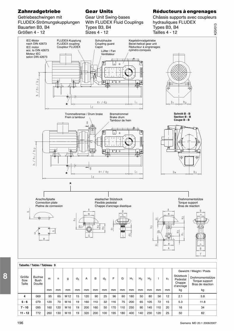
196 Siemens MD 20.1 2006/2007
������������� ���� �� ��������� � ����������Getriebeschwingen mit Gear Unit Swing-bases Châssis supports avec coupleursFLUDEX-Strömungskupplungen With FLUDEX Fluid Couplings hydrauliques FLUDEXBauarten B3, B4 Types B3, B4 Types B3, B4Größen 4 - 12 Sizes 4 - 12 Tailles 4 - 12
IEC-Motornach DIN 42673IEC motoracc. to DIN 42673Moteur IECselon DIN 42673
FLUDEX-KupplungFLUDEX couplingCoupleur FLUDEX
KegelstirnradgetriebeBevel-helical gear unitRéducteur à engrenagescylindro-coniques
Trommelbremse / Drum brakeFrein à tambour
BremstrommelBrake drumTambour de frein
Schnitt B - BSection B - BCoupe B - B
SchutzhaubeCoupling guardCapot
Lüfter / FanVentilateur
�
�
�
AnschlußplatteConnection platePlatine de connexion
elastischer StützbockFlexible pedestalChappe d’ancrage élastique
DrehmomentstützeTorque supportBras de réaction
Tabelle / Table / Tableau 9
Gewicht / Weight / Poids
GrößeSizeTaille
BuchseBush
Douille
m n g d3 A B d5 F G H1 H2 H3 l s1StützbockPedestalChappe
d’ancrage
DrehmomentstützeTorque support
Bras de réaction
mm mm mm mm mm mm mm mm mm mm mm mm mm mm kg kg
4 069 95 65 M 12 15 120 90 25 96 60 180 50 80 56 12 2.1 5.8
5 - 6 079 120 70 M 16 19 160 110 32 116 75 200 65 105 72 15 5.3 11.8
7 - 10 095 160 120 M 16 19 200 160 50 170 110 250 90 145 110 20 16 34
11 - 12 772 260 130 M 16 19 320 200 100 195 180 400 140 230 120 25 50 82
8
K20
/013
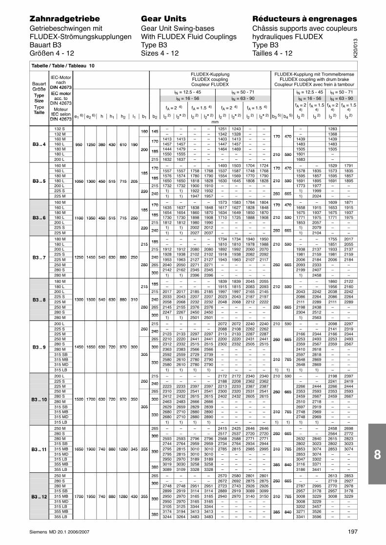
197Siemens MD 20.1 2006/2007
������������� ���� �� ��������� � ����������Getriebeschwingen mit Gear Unit Swing-bases Châssis supports avec coupleursFLUDEX-Strömungskupplungen With FLUDEX Fluid Couplings hydrauliques FLUDEXBauart B3 Type B3 Type B3Größen 4 - 12 Sizes 4 - 12 Tailles 4 - 12
Tabelle / Table / Tableau 10
BauartGröße
IEC-Motornach
DIN 42673
FLUDEX-KupplungFLUDEX couplingCoupleur FLUDEX
FLUDEX-Kupplung mit TrommelbremseFLUDEX coupling with drum brake
Coupleur FLUDEX avec frein à tambourGrößeType
DIN 42673IEC motor iN = 12.5 - 45 iN = 50 - 71 iN = 12.5 - 45 iN = 50 - 71
TypeSize
IEC motoracc. to
DIN 42673iN = 16 - 56 iN = 63 - 90 iN = 16 - 56 iN = 63 - 90Size
TypeTaille
acc. toDIN 42673
MoteurIEC selon
fA = 2 4) fA = 1.5 4) fA = 2 4) fA = 1.5 4) fA = 24)
fA = 1.54)
fA = 24)
fA = 1.54)
Taille IEC selonDIN 42673
e1 6) e2 6) h h1 h2 l1 b1 b2 l2 2) l2� 2) l2 2) l2� 2) l2 2) l2� 2) l2 2) l2� 2) b3 5) b4 5) l3 2) l3 2) l3 2) l3 2)DIN 42673
mm
132 S160 145
– – – – 1251 1243 – – – 1283132 M
160 145– – – – 1342 1328 – – 170 470 – 1368
160 M 170 1413 1413 – – 1403 1413 – –170 470
1439 1439B3 .. 4 160 L 950 1250 380 430 610 190
1701457 1457 – – 1447 1457 – – 1483 1483B3 .. 4
180 M950 1250 380 430 610 190
200 185 1444 1479 – – 1464 1469 – – 1505 1505180 L
200 1851550 1555 – – – – – – 210 590 1601 –
200 L 215 1632 1637 – – – – – –210 590
1683 –
160 M170
– – – – 1493 1503 1704 1724170 470
– – 1529 1791160 L 185
1701557 1557 1758 1768 1537 1587 1748 1768
170 4701578 1835 1573 1835
180 M185
185 1576 1574 1780 1790 1554 1569 1770 1790 1595 1857 1595 1857B3 .. 5 180 L 1050 1300 450 515 715 205
1851650 1650 1818 1828 1630 1645 1808 1828 210 590 1691 1895 1691 1895B3 .. 5
200 L1050 1300 450 515 715 205
215 1732 1732 1900 1910 – – – –210 590
1773 1977 – –225 S 220
2401) 1) 1922 1932 – – – –
260 6651) 1999 – –
225 M220
240 1) 1) 1947 1957 – – – – 260 665 1) 2024 – –
160 M170
– – – – 1573 1583 1784 1804170 470
– – 1609 1871160 L 185
1701635 1637 1838 1848 1617 1627 1828 1848
170 4701658 1915 1653 1915
180 M185
185 1654 1654 1860 1870 1634 1649 1850 1870 1675 1937 1675 1937B3 .. 6 180 L 1100 1350 450 515 715 250
1851730 1730 1898 1908 1710 1725 1888 1908 210 590 1771 1975 1771 1975B3 .. 6
200 L1100 1350 450 515 715 250
215 1812 1812 1980 1990 – – – –210 590
1853 2057 – –225 S 220
2401) 1) 2002 2012 – – – –
260 6651) 2079 – –
225 M220
240 1) 1) 2027 2037 – – – – 260 665 1) 2104 – –
180 M185
– – – – 1734 1734 1940 1950 – – 1755 2017180 L 215
185– – – – 1810 1810 1978 1988 210 590 – – 1851 2055
200 L215
215 1912 1912 2080 2080 1892 1992 2060 2070210 590
1938 2137 1933 2137
B3 7225 S
1250 1450 540 630 880 250 2401928 1938 2102 2102 1918 1938 2082 2092 1981 2159 1981 2159
B3 .. 7 225 M 1250 1450 540 630 880 250 240 1953 1963 2127 2127 1943 1963 2107 2117 2006 2184 2006 2184250 M 280 265 2040 2050 2271 2271 – – – – 260 665 2093 2333 – –280 S
280
3002142 2162 2345 2345 – – – –
260 6652199 2407 – –
280 M 300 1) 1) 2396 2396 – – – – 1) 2458 – –
180 M185
– – – – 1839 1839 2045 2055 – – 1860 2122180 L 215
185– – – – 1915 1815 2083 2093 210 590 – – 1956 2160
200 L215
215 2017 2017 2185 2185 1997 1997 2165 2145210 590
2043 2242 2038 2242
B3 8225 S
1300 1500 540 630 880 310 2402033 2043 2207 2207 2023 2043 2187 2197 2086 2264 2086 2264
B3 .. 8 225 M 1300 1500 540 630 880 310 240 2058 2068 2232 2232 2048 2068 2212 2222 2111 2289 2111 2289250 M 280 265 2145 2155 2376 2376 – – – – 260 665 2198 2438 – –280 S
280
3002247 2267 2450 2450 – – – –
260 6652304 2512 – –
280 M 300 1) 1) 2501 2501 – – – – 1) 2563 – –
200 L 215 – – – – 2072 2072 2240 2240 210 590 – – 2098 2297225 S 260
240 – – – – 2088 2108 2262 2262 – – 2141 2319225 M
260240
2123 2133 2297 2297 2113 2133 2287 2287 2166 2344 2166 2344250 M 265 2210 2220 2441 2441 2200 2220 2431 2441 260 665 2253 2493 2253 2493
B3 9280 S
1450 1650 630 720 970 300 3002312 2332 2515 2515 2302 2332 2505 2515
260 6652359 2567 2359 2567
B3 .. 9 280 M 1450 1650 630 720 970 300 300 2363 2383 2566 2566 – – – – 2410 2618 – –315 SB 305 2592 2559 2729 2739 – – – – 2597 2818 – –315 MB
305
3302580 2610 2780 2790 – – – – 310 765 2648 2869 – –
315 MD 330 2580 2610 2780 2790 – – – –310 765
2648 2869 – –315 LB 1) 1) 1) 1) – – – – 1) 1) 1) 1) – –
200 L 215 – – – – 2172 2172 2340 2340 210 590 – – 2198 2397225 S 260
240 – – – – 2188 2208 2362 2362 – – 2241 2419225 M
260240
2223 2233 2397 2397 2213 2233 2387 2387 2266 2444 2266 2444250 M 265 2310 2320 2541 2541 2300 2320 2531 2541 260 665 2353 2593 2353 2593
B3 10280 S
1500 1700 630 720 970 350 3002412 2432 2615 2615 2402 2432 2605 2615
260 6652459 2667 2459 2667
B3 .. 10 280 M 1500 1700 630 720 970 350 300 2463 2483 2666 2666 – – – – 2510 2718 – –315 SB 305 2629 2659 2829 2839 – – – – 2697 2919 – –315 MB
305
3302680 2710 2880 2890 – – – – 310 765 2748 2969 – –
315 MD 330 2680 2710 2880 2890 – – – –310 765
2748 2969 – –315 LB 1) 1) 1) 1) – – – – 1) 1) 1) 1) – –
250 M 265 – – – – 2415 2425 2646 2646 – – 2458 2698280 S 300 – – – – 2517 2537 2720 2720 260 665 – – 2564 2772280 M
3002593 2593 2796 2796 2568 2588 2771 2771
260 6652632 2840 2615 2823
315 SB 2744 2764 2959 2959 2734 2764 2934 2944 2802 3023 2802 3023B3 .. 11 315 MB 1650 1900 740 880 1280 345 355
3302795 2815 3010 3010 2785 2815 2985 2995 310 765 2853 3074 2853 3074B3 .. 11
315 MD1650 1900 740 880 1280 345 355
3302795 2815 3010 3010 – – – –
310 7652853 3074 – –
315 LB 2950 2970 3189 3189 – – – – 3047 3302 – –355 MB
3803019 3030 3258 3258 – – – – 385 840 3116 3371 – –
355 LB 380 3089 3109 3328 3328 – – – –385 840
3186 3441 – –
250 M 265 – – – – 2570 2580 2801 2801 – – 2613 2853280 S 300 – – – – 2672 2692 2875 2875 260 665 – – 2719 2927280 M
3002748 2748 2951 2951 2723 2743 2926 2926
260 6652787 2995 2770 2978
315 SB 2899 2919 3114 3114 2889 2919 3089 3099 2957 3178 2957 3178B3 .. 12 315 MB 1700 1950 740 880 1280 430 355
3302950 2970 3165 3165 2940 2970 3140 3150 310 765 3008 3229 3008 3229B3 .. 12
315 MD1700 1950 740 880 1280 430 355
3302950 2970 3165 3165 – – – –
310 7653008 3229 – –
315 LB 3105 3125 3344 3344 – – – – 3202 3457 – –355 MB
3803174 3194 3413 3413 – – – – 385 840 3271 3526 – –
355 LB 380 3244 3264 3483 3483 – – – –385 840
3341 3596 – –
K20
/013
8
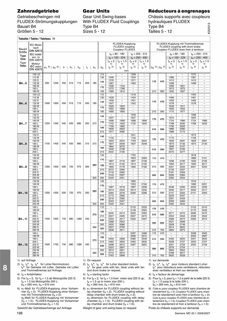
198 Siemens MD 20.1 2006/2007
������������� ���� �� ��������� � ����������Getriebeschwingen mit Gear Unit Swing-bases Châssis supports avec coupleursFLUDEX-Strömungskupplungen With FLUDEX Fluid Couplings hydrauliques FLUDEXBauart B4 Type B4 Type B4Größen 5 - 12 Sizes 5 - 12 Tailles 5 - 12
Tabelle / Table / Tableau 11
BauartGröße
IEC-Motornach
DIN 42673
FLUDEX-KupplungFLUDEX couplingCoupleur FLUDEX
FLUDEX-Kupplung mit TrommelbremseFLUDEX coupling with drum brake
Coupleur FLUDEX avec frein à tambourGrößeType
DIN 42673IEC motor iN = 80 - 180 iN = 200 - 315 iN = 80 - 180 iN = 200 - 315
TypeSize
IEC motoracc. to
DIN 42673iN = 100 - 224 iN = 250 - 400 iN = 100 - 224 iN = 250 - 400Size
TypeTaille
DIN 42673Moteur
IEC selon
fA = 24)
fA = 1.54)
fA = 24)
fA = 1.54)
fA = 24)
fA = 1.54)
fA = 24)
fA = 1.54)
Taille IEC selonDIN 42673
e1 6) e2 6) h h1 h2 l1 b1 b2 l2 2) l2 2) l2 2) l2 2) b3 5) b4 5) l3 2) l3 2) l3 2) l3 2)DIN 42673 mm
100 LD 115 – – 1338 – – – 1375 –112 M 130 1349 – 1344 – 1386 – 1381 –132 S
1451376 – 1371 – 170 470 1413 – 1413 –
B4 .. 5 132 M 950 1250 450 515 715 205 185 145 1467 – 1462 –170 470
1498 – 1498 –B4 .. 5160 M
950 1250 450 515 715 205 185
170 1528 1744 – – 1569 1831 – –160 L 170 1572 1788 – – 1613 1875 – –180 M 185 1589 1810 – – 210 590 1635 1897 – –100 LD 115 – – 1418 – – – 1455 –112 M 130 1429 – 1424 – 1466 – 1461 –132 S
1451456 – 1451 – 170 470 1493 – 1493 –
B4 .. 6 132 M 1000 1300 450 515 715 250 185 145 1547 – 1542 –170 470
1578 – 1578 –B4 .. 6160 M
1000 1300 450 515 715 250 185
170 1626 1824 – – 1649 1911 – –160 L 170 1652 1868 – – 1693 1955 – –180 M 185 1669 1890 – – 210 590 1715 1977 – –132 S
145– – 1536 – – – 1568 –
132 M 145 1637 – 1627 –170 470
1670 – 1653 –160 M
1701698 1899 1688 1899 170 470 1724 1986 1724 1986
B4 .. 7 160 L 1050 1350 540 630 880 250 215 170 1742 1943 1732 1943 1768 2030 1768 2030B4 .. 7180 M
1050 1350 540 630 880 250 215
185 1759 1965 – – 1790 2052 – –180 L 185 1835 2003 – – 210 590 1886 2090 – –200 L 215 1917 2085 – –
210 5901968 2172 – –
132 S145
– – 1641 – – – 1673 –132 M 145 1742 – 1732 –
170 4701775 – 1758 –
160 M170
1803 2004 1793 2004 170 470 1829 2091 1829 2091B4 .. 8 160 L 1100 1400 540 630 880 310 215 170 1847 2048 1837 2048 1873 2135 1873 2135B4 .. 8
180 M1100 1400 540 630 880 310 215
185 1864 2070 – – 1895 2157 – –180 L 185 1940 2108 – – 210 590 1991 2195 – –200 L 215 2022 2190 – –
210 5902073 2277 – –
132 M 145 – – 1792 – – – 1818 –160 M
170– – 1853 2064 170 470 – – 1889 2151
160 L 170 1897 2118 1897 2108170 470
1938 2195 1933 2195180 M 260 185
1914 2140 1914 2130 1955 2217 1955 2217B4 .. 9 180 L 1250 1500 630 720 970 300
260 185 1990 2178 1990 2168 210 590 2051 2255 2051 2255B4 .. 9200 L
1250 1500 630 720 970 300215 2072 2260 – –
210 5902133 2337 – –
225 S 240 2118 2282 – – 2181 2359 – –225 M
2402143 2307 – – 260 665 2206 2384 – –
250 M 305 265 2229 2451 – –260 665
2292 2533 – –132 M 145 – – 1892 – – – 1918 –160 M
170– – 1953 2164 170 470 – – 1989 2251
160 L 170 1997 2218 1997 2208170 470
2038 2295 2033 2295180 M 260 185
2014 2240 2014 2230 2055 2317 2055 2317B4 .. 10 180 L 1300 1550 630 720 970 350
260 185 2090 2278 2090 2268 210 590 2151 2355 2151 2355B4 .. 10200 L
1300 1550 630 720 970 350215 2172 2360 – –
210 5902233 2437 – –
225 S 240 2218 2382 – – 2281 2459 – –225 M
2402243 2407 – – 260 665 2306 2484 – –
250 M 305 265 2329 2551 – –260 665
2392 2633 – –160 L 170 – – 2132 2333
170 470– – 2153 2410
180 M185
– – 2149 2355 170 470 – – 2170 2432180 L
270185 2245 2413 2225 2393
210 5902271 2470 2266 2470
200 L 270 215 2227 2495 2307 2475 210 590 2353 2552 2348 2552B4 .. 11 225 S 1450 1650 740 880 1280 345
240 2343 2517 2332 2497 2396 2574 2395 2574B4 .. 11225 M
1450 1650 740 880 1280 345240
2368 2542 – – 260 665 2421 2599 – –250 M 265 2455 2686 – – 260 665 2508 2748 – –280 S 355
300 2557 2760 – – 2614 2822 – –280 M
355300 2608 2811 – – 310 765 2665 2873 – –
160 L 170 – – 2287 2488 170 470 – – 2308 2565180 M 185 – – 2306 2510 – – 2325 2587180 L
270185 2400 2568 2380 2548 210 590 2426 2625 2421 2625
200 L 270 215 2482 2650 2462 2630210 590
2508 2707 2503 2707B4 .. 12 225 S 1500 1700 740 880 1280 430
240 2498 2672 2487 2652 2551 2729 2550 2729B4 .. 12225 M
1500 1700 740 880 1280 430240
2523 2697 – – 260 665 2576 2754 – –250 M 265 2610 2841 – – 260 665 2663 2903 – –280 S 355
300 2712 2915 – – 2769 2977 – –280 M
355300 2763 2966 – – 310 765 2820 3028 – –
1) auf Anfrage2) l2, l2�, l3, l3� für Loher-Normmotoren
l2� für Getriebe mit Lüfter. Getriebe mit Lüfterund Trommelbremse auf Anfrage.
4) fA = Anfahrfaktor5) Für fA = 2, für fA = 1.5 ab Motorgröße 225 S;
fA = 1.5 bis Motorgröße 200 L:b3 = 260 mm, b4 = 610 mm
6) e1-Maß für FLUDEX-Kupplung ohne Vorkam-mer (fA = 2); FLUDEX-Kupplung ohne Vorkam-mer mit Trommelbremse (fA = 2);e2-Maß für FLUDEX-Kupplung mit Vorkammer(fA = 1.5); FLUDEX-Kupplung mit Vorkammerund Trommelbremse (fA = 1.5);
Gewicht der Getriebeschwinge auf Anfrage
1) On request2) l2, l2�, l3, l3� for Loher standard motors
l2� for gear units with fan. Gear units with fanand drum brake on request.
4) fA = starting factor5) For fA = 2; for fA = 1.5 from motor size 225 S up;
fA = 1.5 up to motor size 200 L:b3 = 260 mm, b4 = 610 mm
6) e1 dimension for FLUDEX coupling without de-lay chamber (fA = 2); FLUDEX coupling withoutdelay chamber with drum brake (fA = 2);e2 dimension for FLUDEX coupling with delaychamber (fA = 1.5); FLUDEX coupling with de-lay chamber and drum brake (fA = 1.5);
Weight of gear unit swing-base on request
1) sur demande2) l2, l2�, l3, l3� pour moteurs standard Loher
l2� pour réducteurs avec ventilateurs, réducteuravec ventilateur et frein sur demande.
4) fA = facteur de démarrage5) Pour fA = 2, pour fA = 1.5 à partir de la taille 225 S;
fA = 1.5 jusqu’à la taille 200 L:b3 = 260 mm, b4 = 610 mm
6) Cote e1 pour coupleur FLUDEX sans chambre deretardement (fA = 2); Coupleur FLUDEX sans cham-bre de retardement avec frein à tambour (fA = 2);Cote e2 pour coupleur FLUDEX avec chambre de re- tardement (fA = 1.5); Coupleur FLUDEX avec cham-bre de retardement et frein à tambour (fA = 1.5);
Poids du châssis supports sur demande
8
K20
/013
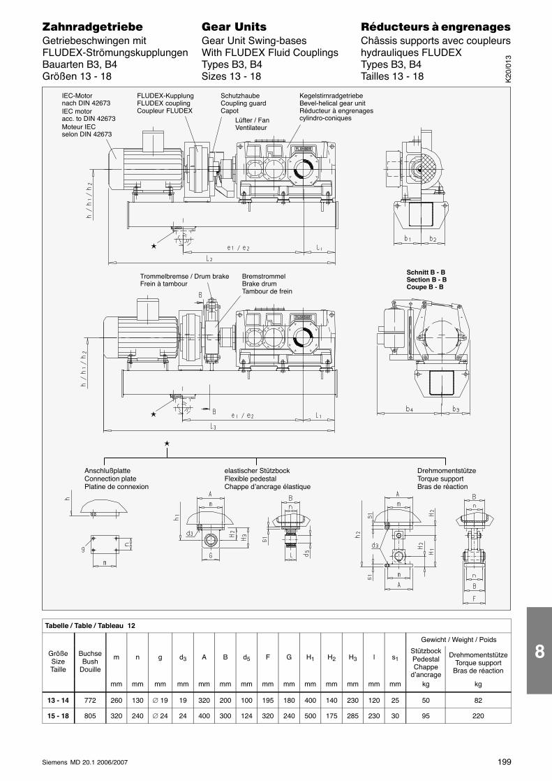
199Siemens MD 20.1 2006/2007
������������� ���� �� ��������� � ����������Getriebeschwingen mit Gear Unit Swing-bases Châssis supports avec coupleursFLUDEX-Strömungskupplungen With FLUDEX Fluid Couplings hydrauliques FLUDEXBauarten B3, B4 Types B3, B4 Types B3, B4Größen 13 - 18 Sizes 13 - 18 Tailles 13 - 18
IEC-Motornach DIN 42673IEC motoracc. to DIN 42673Moteur IECselon DIN 42673
FLUDEX-KupplungFLUDEX couplingCoupleur FLUDEX
KegelstirnradgetriebeBevel-helical gear unitRéducteur à engrenagescylindro-coniques
Trommelbremse / Drum brakeFrein à tambour
BremstrommelBrake drumTambour de frein
Schnitt B - BSection B - BCoupe B - B
SchutzhaubeCoupling guardCapot
Lüfter / FanVentilateur
�
�
�
AnschlußplatteConnection platePlatine de connexion
elastischer StützbockFlexible pedestalChappe d’ancrage élastique
DrehmomentstützeTorque supportBras de réaction
Tabelle / Table / Tableau 12
Gewicht / Weight / Poids
GrößeSizeTaille
BuchseBush
Douille
m n g d3 A B d5 F G H1 H2 H3 l s1StützbockPedestalChappe
d’ancrage
DrehmomentstützeTorque support
Bras de réaction
mm mm mm mm mm mm mm mm mm mm mm mm mm mm kg kg
13 - 14 772 260 130 ∅ 19 19 320 200 100 195 180 400 140 230 120 25 50 82
15 - 18 805 320 240 ∅ 24 24 400 300 124 320 240 500 175 285 230 30 95 220
K20
/013
8
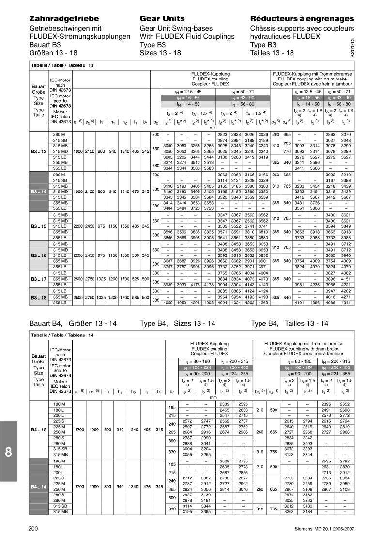
200 Siemens MD 20.1 2006/2007
������������� ���� �� ��������� � ����������Getriebeschwingen mit Gear Unit Swing-bases Châssis supports avec coupleursFLUDEX-Strömungskupplungen With FLUDEX Fluid Couplings hydrauliques FLUDEXBauart B3 Type B3 Type B3Größen 13 - 18 Sizes 13 - 18 Tailles 13 - 18
Tabelle / Table / Tableau 13
BauartIEC-Motor
nachDIN
FLUDEX-KupplungFLUDEX couplingCoupleur FLUDEX
FLUDEX-Kupplung mit TrommelbremseFLUDEX coupling with drum brake
Coupleur FLUDEX avec frein à tambourBauartGröße
nachDIN 42673IEC t
iN = 12.5 - 45 iN = 50 - 71 iN = 12.5 - 45 iN = 50 - 71GrößeType IEC motor
acc toiN = 16 - 56 iN = 63 - 90 iN = 16 - 56 iN = 63 - 90Ty e
Size acc. toDIN 42673 iN = 14 - 50 iN = 56 - 80 iN = 14 - 50 iN = 56 - 80
TypeTaille
DIN 42673Moteur
IEC selonfA = 2 4) fA = 1.5 4) fA = 2 4) fA = 1.5 4) fA = 2
4)fA = 1.5
4)fA = 2
4)fA = 1.5
4)IEC selonDIN 42673 e1 6) e2 6) h h1 h2 l1 b1 b2 l2 2) l2� 2) l2 2) l2� 2) l2 2) l2� 2) l2 2) l2� 2) b3 5) b4 5) l3 2) l3 2) l3 2) l3 2)DIN 42673
mm
280 M 300 – – – – 2823 2823 3026 3026 260 665 – – 2862 3070315 SB – – – – 2974 2994 3189 3189
765– – 3027 3248
315 MB330
3050 3050 3265 3265 3025 3045 3240 3240 310 7653093 3314 3078 3299
B3 .. 13 315 MD 1900 2150 800 940 1340 405 345 3303050 3050 3265 3265 3025 3045 3240 3240
310776 3093 3314 3078 3299B3 .. 13
315 LB1900 2150 800 940 1340 405 345
3205 3205 3444 3444 3180 3200 3419 3419 3272 3527 3272 3527355 MB
3803274 3274 3513 3513 – – – 385 840 3341 3596 – –
355 LB380
3344 3344 3583 3583 – – –385 840
3411 3666 – –
280 M 300 – – – – 2963 2963 3166 3166 260 665 – – 3002 3210315 SB – – – – 3114 3134 3329 3329 – – 3167 3388315 MB
3303190 3190 3405 3405 3165 3185 3380 3380 310 765 3233 3454 3218 3439
B3 .. 14 315 MD 1900 2150 800 940 1340 475 345 3303190 3190 3405 3405 3165 3185 3380 3380
310 7653233 3454 3218 3439B3 .. 14
315 LB1900 2150 800 940 1340 475 345
3345 3345 3584 3584 3320 3340 3559 3559 3412 3667 3412 3667355 MB
3803414 3414 3653 3653 – – – – 385 840 3481 3736 – –
355 LB380
3484 3484 3723 3723 – – – –385 840
3551 3806 – –
315 MB – – – – 3347 3367 3562 3562310 765
– – 3400 3621315 MD 330 – – – – 3347 3367 2562 3562
310 765– – 3400 3621
B3 .. 15 315 LB 2200 2450 975 1150 1650 485 345330
– – – – 3502 3522 3741 3741 – – 3594 3849B3 .. 15355 MB
2200 2450 975 1150 1650 485 345
3803596 3596 3835 3835 3571 3591 3810 3810 385 840 3663 3918 3663 3918
355 LB380
3666 3666 3905 3905 3641 3661 3880 3880385 840
3733 3988 3733 3988
315 MB – – – – 3438 3458 3653 3653310 765
– – 3491 3712315 MD 330 – – – – 3438 3458 3653 3653
310 765– – 3491 3712
B3 .. 16 315 LB 2200 2450 975 1150 1650 530 345330
– – – – 3593 3613 3832 3832 – – 3685 3940B3 .. 16355 MB
2200 2450 975 1150 1650 530 345
3803687 3687 3926 3926 3662 3682 3901 3901 385 840 3754 4009 3754 4009
355 LB380
3757 3757 3996 3996 3732 3752 3971 3971385 840
3824 4079 3824 4079
315 LB 330 – – – – 3765 3765 4004 4004 – – 3827 4082B3 .. 17 355 MB 2500 2750 1025 1200 1700 525 500
380– – – – 3834 3834 4073 4073 385 840 – – 3896 4151B3 .. 17
355 LB2500 2750 1025 1200 1700 525 500
3803939 3939 4178 4178 3904 3904 4143 4143
385 8403981 4236 3966 4221
315 LB 330 – – – – 3885 3885 4124 4124 – – 3947 4202
B3 .. 18 355 MB 2500 2750 1025 1200 1700 585 500 380– – – – 3954 3954 4193 4193 385 840 – – 4016 4271B3 .. 18
355 LB2500 2750 1025 1200 1700 585 500 380
4059 4059 4298 4298 4024 4024 4263 4263385 840
4101 4356 4086 4341
Bauart B4, Größen 13 - 14 Type B4, Sizes 13 - 14 Type B4, Tailles 13 - 14
Tabelle / Table / Tableau 14
BauartIEC-Motor
nach
FLUDEX-KupplungFLUDEX couplingCoupleur FLUDEX
FLUDEX-Kupplung mit TrommelbremseFLUDEX coupling with drum brake
Coupleur FLUDEX avec frein à tambourBauartGröße
nachDIN 42673IEC t
iN = 80 - 180 iN = 200 - 315 iN = 80 - 180 iN = 200 - 315GrößeType IEC motor
acc toiN = 100 - 224 iN = 250 - 400 iN = 100 - 224 iN = 250 - 400Ty e
Size acc. toDIN 42673 iN = 90 - 200 iN = 224 - 355 iN = 90 - 200 iN = 224 - 355
TypeTaille
DIN 42673Moteur
IEC selonfA = 2
4)fA = 1.5
4)fA = 2
4)fA = 1.5
4)fA = 2
4)fA = 1.5
4)fA = 2
4)fA = 1.5
4)IEC selonDIN 42673 e1 6) e2 6) h h1 h2 l1 b1 b2 l2 2) l2 2) l2 2) l2 2) b3 5) b4 5) l3 2) l3 2) l3 2) l3 2)DIN 42673
mm
180 M185
– – 2389 2595 – – 2395 2652180 L
185– – 2465 2633 210 590 – – 2491 2690
200 L 215 – – 2547 2715210 590
– – 2573 2772225 S
2402572 2747 2562 2737 2615 2794 2615 2794
B4 13225 M
1700 1900 800 940 1340 405 345240
2597 2772 2587 2762 2640 2819 2640 2819B4 .. 13 250 M
1700 1900 800 940 1340 405 345265 2684 2916 2674 2906 260 665 2727 2968 2727 2968
280 S300
2787 2990 – –260 665
2834 3042 – –280 M
3002838 3041 – – 2885 3093 – –
315 SB330
3004 3204 – –310 765
3072 3293 – –315 MB
3303055 3255 – –
310 7653123 3344 – –
180 M185
– – 2529 2735 – – 2535 2792180 L
185– – 2605 2773 210 590 – – 2631 2830
200 L 215 – – 2687 2855210 590
– – 2713 2912225 S
2402712 2887 2702 2877 2755 2934 2755 2934
B4 14225 M
1700 1900 800 940 1340 475 345240
2737 2912 2727 2902 2780 2959 2780 2959B4 .. 14 250 M
1700 1900 800 940 1340 475 345365 2824 3056 2814 3046 260 665 2867 3108 2867 3108
280 S300
2927 3130 – –260 665
2974 3182 – –280 M
3002978 3181 – – 3025 3233 – –
315 SB330
3114 3344 – –310 765
3212 3433 – –315 MB
3303195 3395 – –
310 7653263 3484 – –
8
K20
/013
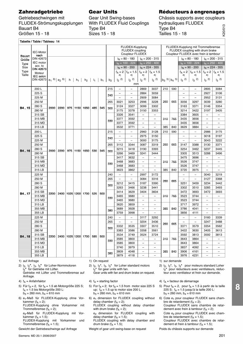
201Siemens MD 20.1 2006/2007
������������� ���� �� ��������� � ����������Getriebeschwingen mit Gear Unit Swing-bases Châssis supports avec coupleursFLUDEX-Strömungskupplungen With FLUDEX Fluid Couplings hydrauliques FLUDEXBauart B4 Type B4 Type B4Größen 15 - 18 Sizes 15 - 18 Tailles 15 - 18
Tabelle / Table / Tableau 14
BauartIEC-Motor
nach
FLUDEX-KupplungFLUDEX couplingCoupleur FLUDEX
FLUDEX-Kupplung mit TrommelbremseFLUDEX coupling with drum brake
Coupleur FLUDEX avec frein à tambourBauartGröße
nachDIN 42673 iN = 80 - 180 iN = 200 - 315 iN = 80 - 180 iN = 200 - 315Größe
Type IEC motoracc to
iN = 100 - 224 iN = 250 - 400 iN = 100 - 224 iN = 250 - 400Ty eSize acc. to
DIN 42673 iN = 90 - 200 iN = 224 - 355 iN = 90 - 200 iN = 224 - 355TypeTaille
DIN 42673Moteur
IEC selonfA = 2
4)fA = 1.5
4)fA = 2
4)fA = 1.5
4)fA = 2
4)fA = 1.5
4)fA = 2
4)fA = 1.5
4)IEC selonDIN 42673 e1 6) e2 6) h h1 h2 l1 b1 b2 l2 2) l2 2) l2 2) l2 2) b3 5) b4 5) l3 2) l3 2) l3 2) l3 2)
mm
200 L 215 – – 2869 3037 210 590 – – 2895 3084225 S
240– – 2884 3059 – – 2927 3106
225 M240
– – 2909 3084 – – 2952 3131250 M 265 3021 3253 2996 3228 260 665 3056 3297 3039 3280
B4 15280 S
2000 2200 975 1150 1650 485 345 3003124 3327 3099 3302
260 665
3163 3371 3146 3354B4 .. 15
280 M2000 2200 975 1150 1650 485 345 300
3175 3378 3150 3353 3214 3422 3197 3405315 SB 3326 3541 – – 3384 3605 – –315 MB
3303377 3592 – – 310 765 3435 3656 – –
315 MD330
3377 3592 – –310 765
3435 3656 – –315 LB 3532 3771 – – 385 840 3629 3884 – –
200 L 215 – – 2960 3128 210 590 – – 2986 3175225 S
240– – 2975 3150 – – 3018 3197
225 M240
– – 3000 3175 – – 3043 3222250 M 265 3112 3344 3087 3319 260 665 3147 3388 3130 3371
B4 16280 S
2000 2200 975 1150 1650 530 345 3003215 3418 3190 3393
260 665
3254 3462 3237 3445B4 .. 16
280 M2000 2200 975 1150 1650 530 345 300
3266 3469 3241 3444 3305 3513 3288 3496315 SB 3417 3632 – – 3475 3696 – –315 MB
3303468 3683 – – 310 765 3526 3747 – –
315 MD330
3468 3683 – –310 765
3526 3747 – –315 LB 3623 3862 – – 385 840 3720 3975 – –
225 M 240 – – 2997 3172 – – 3040 3219250 M 265 – – 3084 3316
260 665– – 3127 3368
280 S300
3212 3415 3187 3390260 665
3251 3459 3234 3442280 M
3003263 3466 3238 3441 3302 3510 3285 3493
B4 17315 SB
2200 2400 1025 1200 1700 525 5003414 3629 3404 3604 3472 3693 3472 3693
B4 .. 17315 MB
2200 2400 1025 1200 1700 525 500330
3465 3680 – – 310 765 3523 3744 – –315 MD
3303465 3680 – –
310 7653523 3744 – –
315 LB 3620 3859 – – 3717 3972 – –355 MB
3803689 3928 – – 385 840 3786 4041 – –
355 LB380
3759 3998 – –385 840
3856 4111 – –
225 M 240 – – 3117 3292 – – 3160 3339250 M 265 – – 3204 3436
260 665– – 3247 3488
280 S300
3332 3535 3307 3510260 665
3371 3579 3354 3562280 M
3003383 3586 3358 3561 3422 3630 3405 3613
B4 18315 SB
2200 2400 1025 1200 1700 585 5003534 3749 3524 3724 3592 3813 3592 3813
B4 .. 18315 MB
2200 2400 1025 1200 1700 585 500330
3585 3800 – – 310 765 3643 3864 – –315 MD
3303585 3800 – –
310 7653643 3864 – –
315 LB 3740 3979 – – 3837 4092 – –355 MB
3803809 4048 – – 385 840 3906 4161 – –
355 LB380
3879 4118 – –385 840
3976 4231 – –
1) auf Anfrage2) l2, l2�, l3, l3� für Loher-Normmotoren
l2� für Getriebe mit Lüfter.Getriebe mit Lüfter und Trommelbremse aufAnfrage.
4) fA = Anfahrfaktor
5) Für fA = 2, für fA = 1.5 ab Motorgröße 225 S;fA = 1.5 bis Motorgröße 200 L:b3 = 260 mm, b4 = 610 mm
6) e1-Maß für FLUDEX-Kupplung ohne Vor-kammer (fA = 2);FLUDEX-Kupplung ohne Vorkammer mitTrommelbremse (fA = 2);e2-Maß für FLUDEX-Kupplung mit Vor-kammer (fA = 1.5);FLUDEX-Kupplung mit Vorkammer undTrommelbremse (fA = 1.5);
Gewicht der Getriebeschwinge auf Anfrage
1) On request2) l2, l2�, l3, l3� for Loher standard motors
l2� for gear units with fan.Gear units with fan and drum brake on request.
4) fA = starting factor
5) For fA = 2; for fA = 1.5 from motor size 225 Sup; fA = 1.5 up to motor size 200 L:b3 = 260 mm, b4 = 610 mm
6) e1 dimension for FLUDEX coupling withoutdelay chamber (fA = 2);FLUDEX coupling without delay chamberwith drum brake (fA = 2);e2 dimension for FLUDEX coupling withdelay chamber (fA = 1.5);FLUDEX coupling with delay chamber anddrum brake (fA = 1.5);
Weight of gear unit swing-base on request
1) sur demande2) l2, l2�, l3, l3� pour moteurs standard Loher
l2� pour réducteurs avec ventilateurs, réduc-teur avec ventilateur et frein sur demande.
4) fA = facteur de démarrage
5) Pour fA = 2, pour fA = 1.5 à partir de la taille225 S; fA = 1.5 jusqu’à la taille 200 L:b3 = 260 mm, b4 = 610 mm
6) Cote e1 pour coupleur FLUDEX sans cham-bre de retardement (fA = 2);Coupleur FLUDEX sans chambre de retar-dement avec frein à tambour (fA = 2);Cote e2 pour coupleur FLUDEX avec cham-bre de retardement (fA = 1.5);Coupleur FLUDEX avec chambre de retar-dement et frein à tambour (fA = 1.5);
Poids du châssis supports sur demande
K20
/013
8
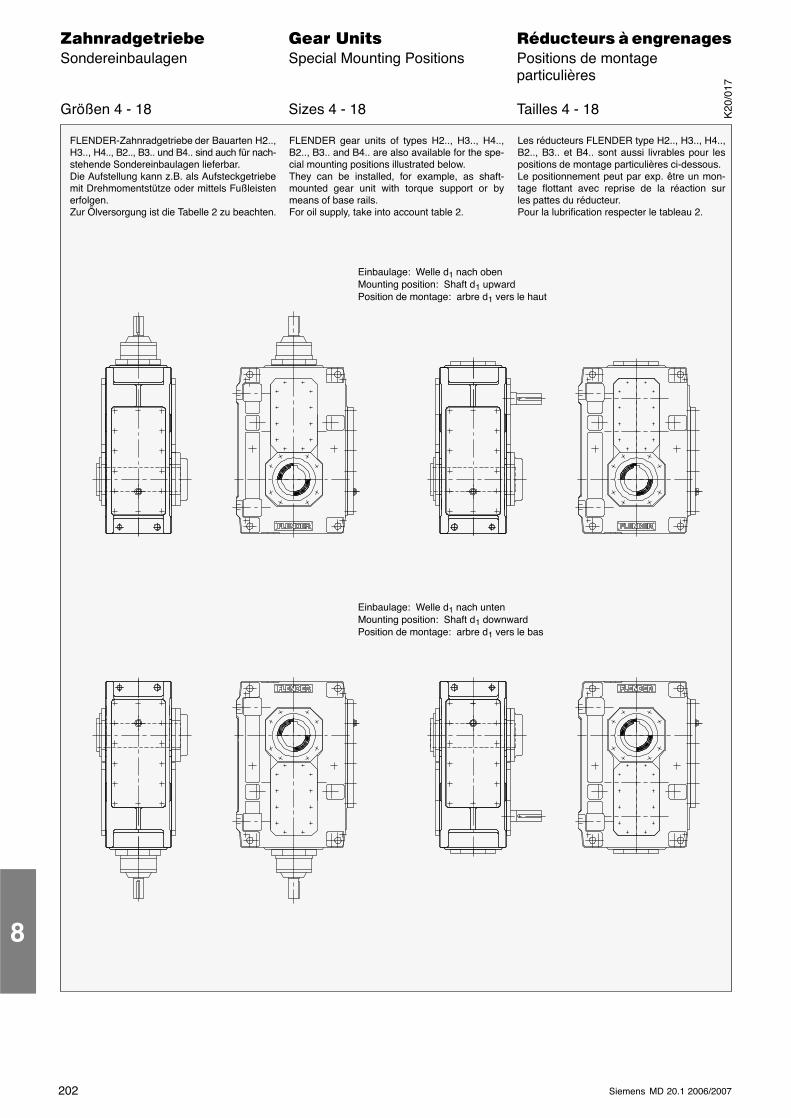
202 Siemens MD 20.1 2006/2007
������������� ���� �� ��������� � ����������Sondereinbaulagen Special Mounting Positions Positions de montage
particulières
Größen 4 - 18 Sizes 4 - 18 Tailles 4 - 18
FLENDER-Zahnradgetriebe der Bauarten H2..,H3.., H4.., B2.., B3.. und B4.. sind auch für nach-stehende Sondereinbaulagen lieferbar.Die Aufstellung kann z.B. als Aufsteckgetriebemit Drehmomentstütze oder mittels Fußleistenerfolgen.Zur Ölversorgung ist die Tabelle 2 zu beachten.
Einbaulage: Welle d1 nach obenMounting position: Shaft d1 upwardPosition de montage: arbre d1 vers le haut
Einbaulage: Welle d1 nach untenMounting position: Shaft d1 downwardPosition de montage: arbre d1 vers le bas
FLENDER gear units of types H2.., H3.., H4..,B2.., B3.. and B4.. are also available for the spe-cial mounting positions illustrated below.They can be installed, for example, as shaft-mounted gear unit with torque support or bymeans of base rails.For oil supply, take into account table 2.
Les réducteurs FLENDER type H2.., H3.., H4..,B2.., B3.. et B4.. sont aussi livrables pour lespositions de montage particulières ci-dessous.Le positionnement peut par exp. être un mon-tage flottant avec reprise de la réaction surles pattes du réducteur.Pour la lubrification respecter le tableau 2.
8
K20
/017
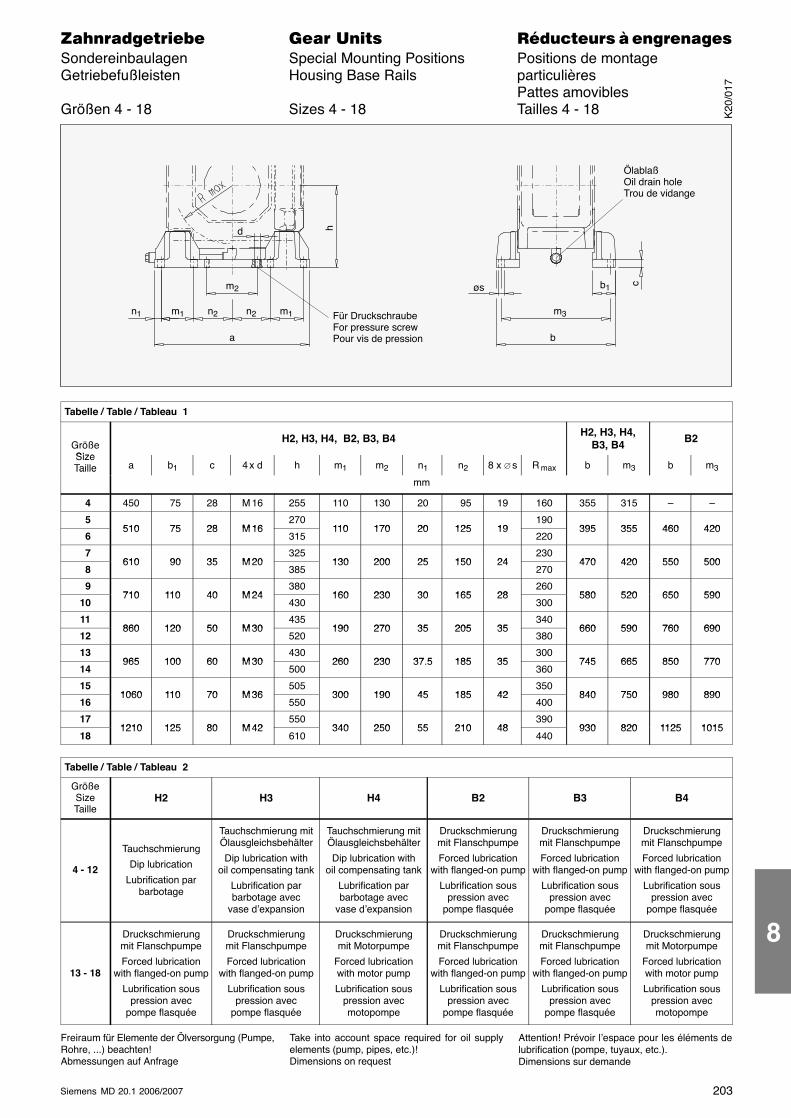
203Siemens MD 20.1 2006/2007
������������� ���� �� ��������� � ����������Sondereinbaulagen Special Mounting Positions Positions de montageGetriebefußleisten Housing Base Rails particulières
Pattes amoviblesGrößen 4 - 18 Sizes 4 - 18 Tailles 4 - 18
Für DruckschraubeFor pressure screwPour vis de pression
ÖlablaßOil drain holeTrou de vidange
n1 m1 n2 n2 m1
a
m2
b
m3
b1
d
øs
h
c
Tabelle / Table / Tableau 1
GrößeSize
H2, H3, H4, B2, B3, B4 H2, H3, H4,B3, B4 B2
SizeTaille a b1 c 4 x d h m1 m2 n1 n2 8 x ∅ s R max b m3 b m3Taille
mm
4 450 75 28 M 16 255 110 130 20 95 19 160 355 315 – –
5510 75 28 M 16
270110 170 20 125 19
190395 355 460 420
6510 75 28 M 16
315110 170 20 125 19
220395 355 460 420
7610 90 35 M 20
325130 200 25 150 24
230470 420 550 500
8610 90 35 M 20
385130 200 25 150 24
270470 420 550 500
9710 110 40 M 24
380160 230 30 165 28
260580 520 650 590
10710 110 40 M 24
430160 230 30 165 28
300580 520 650 590
11860 120 50 M 30
435190 270 35 205 35
340660 590 760 690
12860 120 50 M 30
520190 270 35 205 35
380660 590 760 690
13965 100 60 M 30
430260 230 37 5 185 35
300745 665 850 770
14965 100 60 M 30
500260 230 37.5 185 35
360745 665 850 770
151060 110 70 M 36
505300 190 45 185 42
350840 750 980 890
161060 110 70 M 36
550300 190 45 185 42
400840 750 980 890
171210 125 80 M 42
550340 250 55 210 48
390930 820 1125 1015
181210 125 80 M 42
610340 250 55 210 48
440930 820 1125 1015
Tabelle / Table / Tableau 2
GrößeSizeTaille
H2 H3 H4 B2 B3 B4
4 - 12
Tauchschmierung
Dip lubrication
Lubrification parbarbotage
Tauchschmierung mitÖlausgleichsbehälter
Dip lubrication withoil compensating tank
Lubrification parbarbotage avec
vase d’expansion
Tauchschmierung mitÖlausgleichsbehälter
Dip lubrication withoil compensating tank
Lubrification parbarbotage avec
vase d’expansion
Druckschmierungmit Flanschpumpe
Forced lubricationwith flanged-on pump
Lubrification souspression avec
pompe flasquée
Druckschmierungmit Flanschpumpe
Forced lubricationwith flanged-on pump
Lubrification souspression avec
pompe flasquée
Druckschmierungmit Flanschpumpe
Forced lubricationwith flanged-on pump
Lubrification souspression avec
pompe flasquée
13 - 18
Druckschmierungmit Flanschpumpe
Forced lubricationwith flanged-on pump
Lubrification souspression avec
pompe flasquée
Druckschmierungmit Flanschpumpe
Forced lubricationwith flanged-on pump
Lubrification souspression avec
pompe flasquée
Druckschmierungmit Motorpumpe
Forced lubricationwith motor pump
Lubrification souspression avecmotopompe
Druckschmierungmit Flanschpumpe
Forced lubricationwith flanged-on pump
Lubrification souspression avec
pompe flasquée
Druckschmierungmit Flanschpumpe
Forced lubricationwith flanged-on pump
Lubrification souspression avec
pompe flasquée
Druckschmierungmit Motorpumpe
Forced lubricationwith motor pump
Lubrification souspression avecmotopompe
Freiraum für Elemente der Ölversorgung (Pumpe,Rohre, ...) beachten!Abmessungen auf Anfrage
Take into account space required for oil supplyelements (pump, pipes, etc.)!Dimensions on request
Attention! Prévoir l’espace pour les éléments delubrification (pompe, tuyaux, etc.).Dimensions sur demande
K20
/017
8
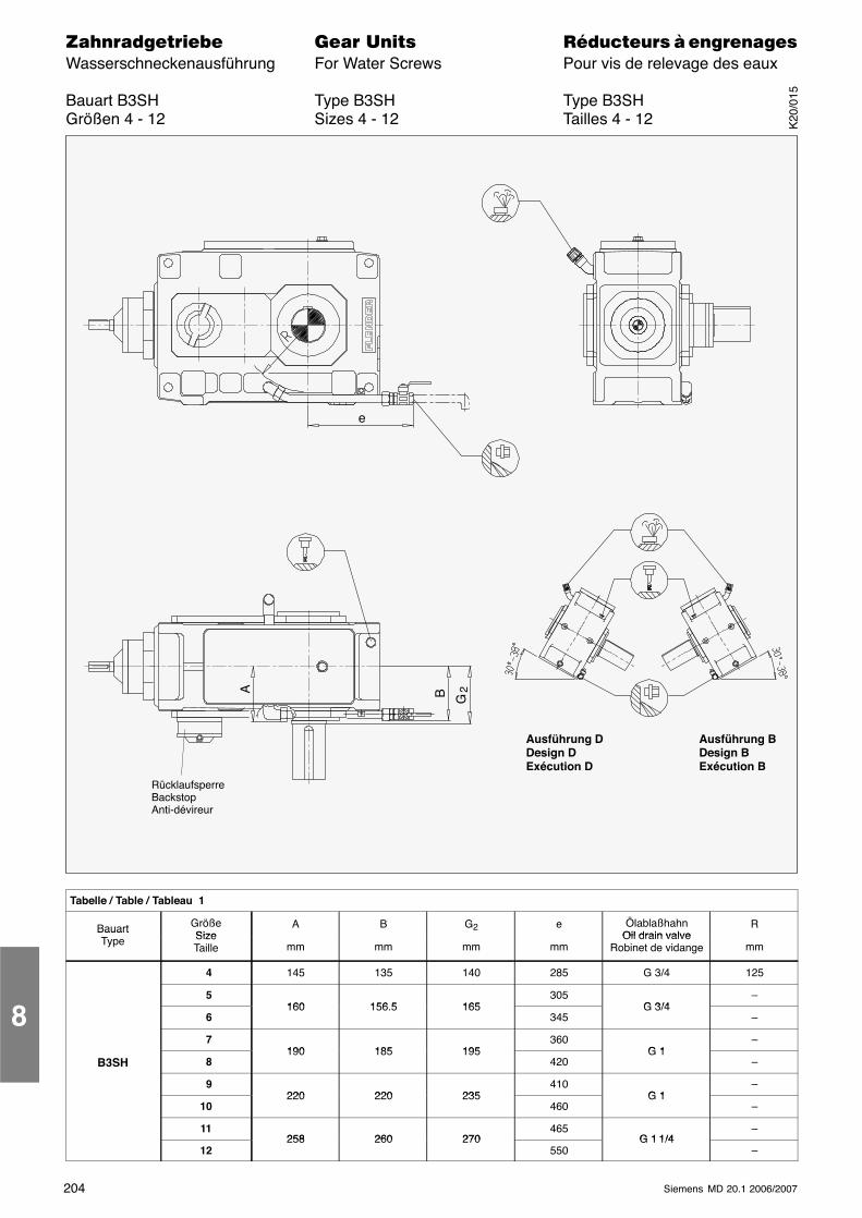
204 Siemens MD 20.1 2006/2007
������������� ���� �� ��������� � ����������Wasserschneckenausführung For Water Screws Pour vis de relevage des eaux
Bauart B3SH Type B3SH Type B3SHGrößen 4 - 12 Sizes 4 - 12 Tailles 4 - 12
RücklaufsperreBackstopAnti-dévireur
e
Ausführung DDesign DExécution D
Ausführung BDesign BExécution B
B G
A 2
Tabelle / Table / Tableau 1
Bauart GrößeSize
A B G2 e ÖlablaßhahnOil drain valve
RBauartType Size
Taille mm mm mm mmOil drain valve
Robinet de vidange mm
4 145 135 140 285 G 3/4 125
5160 156 5 165
305G 3/4
–
6160 156.5 165
345G 3/4
–
7190 185 195
360G 1
–
B3SH 8190 185 195
420G 1
–
9220 220 235
410G 1
–
10220 220 235
460G 1
–
11258 260 270
465G 1 1/4
–
12258 260 270
550G 1 1/4
–
8
K20
/015
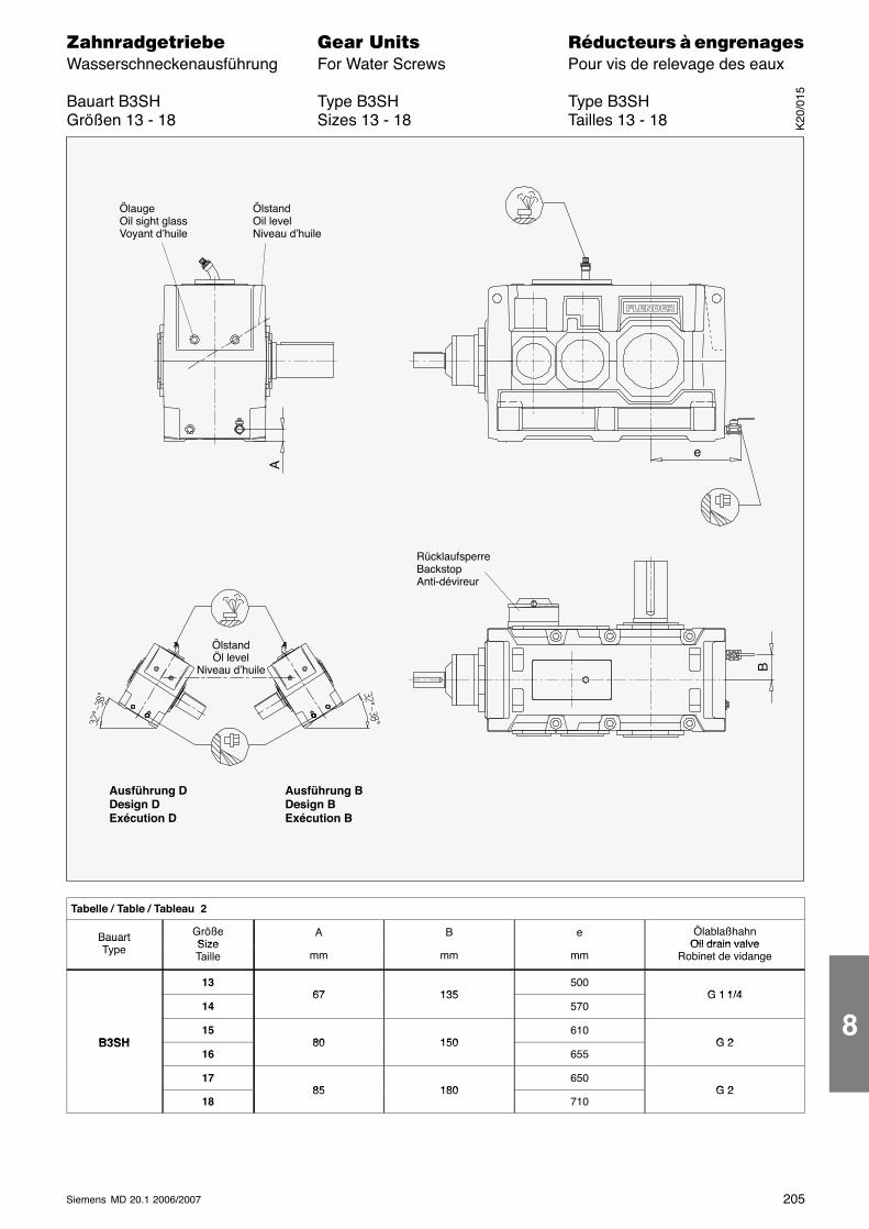
205Siemens MD 20.1 2006/2007
������������� ���� �� ��������� � ����������Wasserschneckenausführung For Water Screws Pour vis de relevage des eaux
Bauart B3SH Type B3SH Type B3SHGrößen 13 - 18 Sizes 13 - 18 Tailles 13 - 18
RücklaufsperreBackstopAnti-dévireur
ÖlaugeOil sight glassVoyant d’huile
ÖlstandOil levelNiveau d’huile
Ausführung DDesign DExécution D
Ausführung BDesign BExécution B
A
e
B
ÖlstandÖl level
Niveau d’huile
Tabelle / Table / Tableau 2
Bauart GrößeSize
A B e ÖlablaßhahnOil drain valve
BauartType Size
Taille mm mm mmOil drain valve
Robinet de vidange
1367 135
500G 1 1/4
1467 135
570G 1 1/4
B3SH15
80 150610
G 2B3SH16
80 150655
G 2
1785 180
650G 2
1885 180
710G 2
K20
/015
8
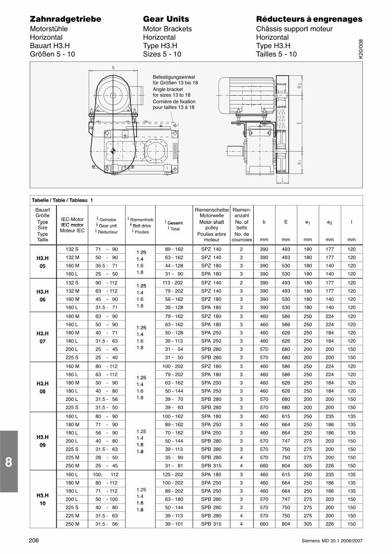
206 Siemens MD 20.1 2006/2007
������������� ���� �� ��������� � ����������Motorstühle Motor Brackets Châssis support moteurHorizontal Horizontal HorizontalBauart H3.H Type H3.H Type H3.HGrößen 5 - 10 Sizes 5 - 10 Tailles 5 - 10
Befestigungswinkelfür Größen 13 bis 18Angle bracketfor sizes 13 to 18Cornière de fixationpour tailles 13 à 18
ÁÁÁÁÁÁÁÁÁÁÁÁÁÁÁÁÁÁÁÁÁÁÁÁÁÁÁÁÁÁÁÁÁÁÁÁÁÁÁÁÁÁÁÁÁÁÁÁÁÁÁÁÁÁÁÁÁÁÁÁÁÁÁÁÁÁÁÁ
Tabelle / Table / Tableau 1
ÁÁÁÁÁÁÁÁÁÁÁÁ
BauartGrößeType
ÁÁÁÁÁÁÁÁÁÁÁÁ
IEC-MotorIEC motor
ÁÁÁÁÁÁÁÁÁÁÁÁÁÁÁ
i Getriebei Gear unit
ÁÁÁÁÁÁÁÁÁÁÁÁ
i Riementriebi Belt drive
ÁÁÁÁÁÁÁÁÁÁÁÁ
i Gesamt
ÁÁÁÁÁÁÁÁÁÁÁÁÁÁÁ
RiemenscheibeMotorwelleMotor shaft
ÁÁÁÁÁÁÁÁÁ
Riemen-anzahlNo. of
ÁÁÁÁÁÁÁÁÁ
b
ÁÁÁÁÁÁÁÁÁÁÁÁ
E
ÁÁÁÁÁÁÁÁÁ
e1
ÁÁÁÁÁÁÁÁÁ
e2
ÁÁÁÁÁÁÁÁÁ
l
ÁÁÁÁÁÁÁÁÁÁÁÁ
Ty eSizeTypeTaille
ÁÁÁÁÁÁÁÁÁÁÁÁ
IEC motorMoteur IECÁÁÁÁÁ
ÁÁÁÁÁÁÁÁÁÁ
i Gear uniti Réducteur ÁÁÁÁ
ÁÁÁÁÁÁÁÁ
i Belt drivei Poulies ÁÁÁÁ
ÁÁÁÁÁÁÁÁ
Gesamti Total ÁÁÁÁÁÁÁÁÁÁÁÁÁÁÁ
Motor shaftpulley
Poulies arbremoteur
ÁÁÁÁÁÁÁÁÁ
No. ofbelts
No. decourroies
ÁÁÁÁÁÁÁÁÁ
mm
ÁÁÁÁÁÁÁÁÁÁÁÁ
mm
ÁÁÁÁÁÁÁÁÁ
mm
ÁÁÁÁÁÁÁÁÁ
mm
ÁÁÁÁÁÁÁÁÁ
mm
ÁÁÁÁÁÁÁÁ
ÁÁÁÁÁÁÁÁ
132 S ÁÁÁÁÁÁÁÁÁÁ
71 - 90 ÁÁÁÁÁÁÁÁ
1 25 ÁÁÁÁÁÁÁÁ
89 - 162ÁÁÁÁÁÁÁÁÁÁ
SPZ 140 ÁÁÁÁÁÁ
2 ÁÁÁÁÁÁ
390ÁÁÁÁÁÁÁÁ
493 ÁÁÁÁÁÁ
180 ÁÁÁÁÁÁ
177 ÁÁÁÁÁÁ
120
ÁÁÁÁH3.H ÁÁÁÁ132 M ÁÁÁÁÁ 50 - 90 ÁÁÁÁ1.251.4 ÁÁÁÁ 63 - 162ÁÁÁÁÁSPZ 140 ÁÁÁ3 ÁÁÁ390ÁÁÁÁ493 ÁÁÁ180 ÁÁÁ177 ÁÁÁ120ÁÁÁÁ
ÁÁÁÁH3.H
05ÁÁÁÁÁÁÁÁ160 M
ÁÁÁÁÁÁÁÁÁÁ 35.5 - 71
ÁÁÁÁÁÁÁÁ
1.41.6ÁÁÁÁÁÁÁÁ 44 - 128
ÁÁÁÁÁÁÁÁÁÁSPZ 180
ÁÁÁÁÁÁ3ÁÁÁÁÁÁ390ÁÁÁÁÁÁÁÁ530
ÁÁÁÁÁÁ180ÁÁÁÁÁÁ140ÁÁÁÁÁÁ120ÁÁÁÁ
ÁÁÁÁ
05 ÁÁÁÁÁÁÁÁ
160 LÁÁÁÁÁÁÁÁÁÁ
25 - 50ÁÁÁÁÁÁÁÁ
1.8 ÁÁÁÁÁÁÁÁ
31 - 90ÁÁÁÁÁÁÁÁÁÁ
SPA 180ÁÁÁÁÁÁ
3ÁÁÁÁÁÁ
390ÁÁÁÁÁÁÁÁ
530ÁÁÁÁÁÁ
180ÁÁÁÁÁÁ
140ÁÁÁÁÁÁ
120ÁÁÁÁÁÁÁÁ
ÁÁÁÁÁÁÁÁ
132 S ÁÁÁÁÁÁÁÁÁÁ
90 - 112 ÁÁÁÁÁÁÁÁ1 25
ÁÁÁÁÁÁÁÁ
113 - 202ÁÁÁÁÁÁÁÁÁÁ
SPZ 140 ÁÁÁÁÁÁ
2 ÁÁÁÁÁÁ
390ÁÁÁÁÁÁÁÁ
493 ÁÁÁÁÁÁ
180 ÁÁÁÁÁÁ
177 ÁÁÁÁÁÁ
120
ÁÁÁÁÁÁÁÁ
H3.H ÁÁÁÁÁÁÁÁ
132 M ÁÁÁÁÁÁÁÁÁÁ
63 - 112 ÁÁÁÁÁÁÁÁ
1.251.4 ÁÁÁÁÁÁÁÁ
79 - 202ÁÁÁÁÁÁÁÁÁÁ
SPZ 140 ÁÁÁÁÁÁ
3 ÁÁÁÁÁÁ
390ÁÁÁÁÁÁÁÁ
493 ÁÁÁÁÁÁ
180 ÁÁÁÁÁÁ
177 ÁÁÁÁÁÁ
120
ÁÁÁÁÁÁÁÁ
H3.H06 ÁÁÁÁÁÁÁÁ
160 M ÁÁÁÁÁÁÁÁÁÁ
45 - 90 ÁÁÁÁÁÁÁÁ
1.41.6 ÁÁÁÁÁÁÁÁ
56 - 162ÁÁÁÁÁÁÁÁÁÁ
SPZ 180 ÁÁÁÁÁÁ
3 ÁÁÁÁÁÁ
390ÁÁÁÁÁÁÁÁ
530 ÁÁÁÁÁÁ
180 ÁÁÁÁÁÁ
140 ÁÁÁÁÁÁ
120
ÁÁÁÁ06
ÁÁÁÁ160 L ÁÁÁÁÁ 31.5 - 71 ÁÁÁÁ1.8ÁÁÁÁ 39 - 128ÁÁÁÁÁSPA 180 ÁÁÁ3 ÁÁÁ390ÁÁÁÁ530 ÁÁÁ180 ÁÁÁ140 ÁÁÁ120ÁÁÁÁ
ÁÁÁÁÁÁÁÁÁÁÁÁ160 M
ÁÁÁÁÁÁÁÁÁÁ 63 - 90
ÁÁÁÁÁÁÁÁ
ÁÁÁÁÁÁÁÁ 79 - 162
ÁÁÁÁÁÁÁÁÁÁSPZ 180
ÁÁÁÁÁÁ3ÁÁÁÁÁÁ460ÁÁÁÁÁÁÁÁ586
ÁÁÁÁÁÁ250ÁÁÁÁÁÁ224ÁÁÁÁÁÁ120ÁÁÁÁ
ÁÁÁÁÁÁÁÁÁÁÁÁ
160 LÁÁÁÁÁÁÁÁÁÁ
50 - 90ÁÁÁÁÁÁÁÁ1 25
ÁÁÁÁÁÁÁÁ
63 - 162ÁÁÁÁÁÁÁÁÁÁ
SPA 180ÁÁÁÁÁÁ
3ÁÁÁÁÁÁ
460ÁÁÁÁÁÁÁÁ
586ÁÁÁÁÁÁ
250ÁÁÁÁÁÁ
224ÁÁÁÁÁÁ
120ÁÁÁÁÁÁÁÁ
H3.H ÁÁÁÁÁÁÁÁ
180 M ÁÁÁÁÁÁÁÁÁÁ
40 - 71 ÁÁÁÁÁÁÁÁ
1.251.4 ÁÁÁÁÁÁÁÁ
50 - 128ÁÁÁÁÁÁÁÁÁÁ
SPA 250 ÁÁÁÁÁÁ
3 ÁÁÁÁÁÁ
460ÁÁÁÁÁÁÁÁ
626 ÁÁÁÁÁÁ
250 ÁÁÁÁÁÁ
184 ÁÁÁÁÁÁ
120
ÁÁÁÁÁÁÁÁ
H3.H07 ÁÁÁÁÁÁÁÁ
180 L ÁÁÁÁÁÁÁÁÁÁ
31.5 - 63 ÁÁÁÁÁÁÁÁ
1.41.6 ÁÁÁÁÁÁÁÁ
39 - 113ÁÁÁÁÁÁÁÁÁÁ
SPA 250 ÁÁÁÁÁÁ
3 ÁÁÁÁÁÁ
460ÁÁÁÁÁÁÁÁ
626 ÁÁÁÁÁÁ
250 ÁÁÁÁÁÁ
184 ÁÁÁÁÁÁ
120
ÁÁÁÁÁÁÁÁ
07
ÁÁÁÁÁÁÁÁ
200 L ÁÁÁÁÁÁÁÁÁÁ
25 - 45 ÁÁÁÁÁÁÁÁ
1.8 ÁÁÁÁÁÁÁÁ
31 - 54ÁÁÁÁÁÁÁÁÁÁ
SPB 280 ÁÁÁÁÁÁ
3 ÁÁÁÁÁÁ
570ÁÁÁÁÁÁÁÁ
680 ÁÁÁÁÁÁ
200 ÁÁÁÁÁÁ
200 ÁÁÁÁÁÁ
150
ÁÁÁÁÁÁÁÁ225 S ÁÁÁÁÁ 25 - 40 ÁÁÁÁÁÁÁÁ 31 - 50ÁÁÁÁÁSPB 280 ÁÁÁ3 ÁÁÁ570ÁÁÁÁ680 ÁÁÁ200 ÁÁÁ200 ÁÁÁ150ÁÁÁÁÁÁÁÁ
ÁÁÁÁÁÁÁÁ
160 MÁÁÁÁÁÁÁÁÁÁ
80 - 112ÁÁÁÁÁÁÁÁ
ÁÁÁÁÁÁÁÁ
100 - 202ÁÁÁÁÁÁÁÁÁÁ
SPZ 180ÁÁÁÁÁÁ
3ÁÁÁÁÁÁ
460ÁÁÁÁÁÁÁÁ
586ÁÁÁÁÁÁ
250ÁÁÁÁÁÁ
224ÁÁÁÁÁÁ
120ÁÁÁÁÁÁÁÁ
ÁÁÁÁÁÁÁÁ
160 L ÁÁÁÁÁÁÁÁÁÁ
63 - 112 ÁÁÁÁÁÁÁÁ1 25
ÁÁÁÁÁÁÁÁ
79 - 202ÁÁÁÁÁÁÁÁÁÁ
SPA 180 ÁÁÁÁÁÁ
3 ÁÁÁÁÁÁ
460ÁÁÁÁÁÁÁÁ
586 ÁÁÁÁÁÁ
250 ÁÁÁÁÁÁ
224 ÁÁÁÁÁÁ
120
ÁÁÁÁÁÁÁÁ
H3.H ÁÁÁÁÁÁÁÁ
180 M ÁÁÁÁÁÁÁÁÁÁ
50 - 90 ÁÁÁÁÁÁÁÁ
1.251.4 ÁÁÁÁÁÁÁÁ
63 - 162ÁÁÁÁÁÁÁÁÁÁ
SPA 250 ÁÁÁÁÁÁ
3 ÁÁÁÁÁÁ
460ÁÁÁÁÁÁÁÁ
626 ÁÁÁÁÁÁ
250 ÁÁÁÁÁÁ
184 ÁÁÁÁÁÁ
120
ÁÁÁÁÁÁÁÁ
H3.H08 ÁÁÁÁÁÁÁÁ
180 L ÁÁÁÁÁÁÁÁÁÁ
40 - 80 ÁÁÁÁÁÁÁÁ
1.41.6 ÁÁÁÁÁÁÁÁ
50 - 144ÁÁÁÁÁÁÁÁÁÁ
SPA 250 ÁÁÁÁÁÁ
3 ÁÁÁÁÁÁ
460ÁÁÁÁÁÁÁÁ
626 ÁÁÁÁÁÁ
250 ÁÁÁÁÁÁ
184 ÁÁÁÁÁÁ
120
ÁÁÁÁ08
ÁÁÁÁ200 L ÁÁÁÁÁ 31.5 - 56 ÁÁÁÁ1.8 ÁÁÁÁ 39 - 70ÁÁÁÁÁSPB 280 ÁÁÁ3 ÁÁÁ570ÁÁÁÁ680 ÁÁÁ200 ÁÁÁ200 ÁÁÁ150ÁÁÁÁÁÁÁÁ
ÁÁÁÁÁÁÁÁ225 S
ÁÁÁÁÁÁÁÁÁÁ 31.5 - 50
ÁÁÁÁÁÁÁÁ
ÁÁÁÁÁÁÁÁ 39 - 63
ÁÁÁÁÁÁÁÁÁÁSPB 280
ÁÁÁÁÁÁ3ÁÁÁÁÁÁ570ÁÁÁÁÁÁÁÁ680
ÁÁÁÁÁÁ200ÁÁÁÁÁÁ200ÁÁÁÁÁÁ150ÁÁÁÁ
ÁÁÁÁÁÁÁÁÁÁÁÁ
160 LÁÁÁÁÁÁÁÁÁÁ
80 - 90ÁÁÁÁÁÁÁÁ
ÁÁÁÁÁÁÁÁ
100 - 162ÁÁÁÁÁÁÁÁÁÁ
SPA 180ÁÁÁÁÁÁ
3ÁÁÁÁÁÁ
460ÁÁÁÁÁÁÁÁ
615ÁÁÁÁÁÁ
250ÁÁÁÁÁÁ
235ÁÁÁÁÁÁ
135ÁÁÁÁÁÁÁÁ
ÁÁÁÁÁÁÁÁ
180 M ÁÁÁÁÁÁÁÁÁÁ
71 - 90 ÁÁÁÁÁÁÁÁ
ÁÁÁÁÁÁÁÁ
89 - 162ÁÁÁÁÁÁÁÁÁÁ
SPA 250 ÁÁÁÁÁÁ
3 ÁÁÁÁÁÁ
460ÁÁÁÁÁÁÁÁ
664 ÁÁÁÁÁÁ
250 ÁÁÁÁÁÁ
186 ÁÁÁÁÁÁ
135
ÁÁÁÁÁÁÁÁ
H3 HÁÁÁÁÁÁÁÁ
180 L ÁÁÁÁÁÁÁÁÁÁ
56 - 90 ÁÁÁÁÁÁÁÁ
1.251 4ÁÁÁÁÁÁÁÁ
70 - 162ÁÁÁÁÁÁÁÁÁÁ
SPA 250 ÁÁÁÁÁÁ
3 ÁÁÁÁÁÁ
460ÁÁÁÁÁÁÁÁ
664 ÁÁÁÁÁÁ
250 ÁÁÁÁÁÁ
186 ÁÁÁÁÁÁ
135
ÁÁÁÁÁÁÁÁ
H3.H09 ÁÁÁÁÁÁÁÁ
200 L ÁÁÁÁÁÁÁÁÁÁ
40 - 80 ÁÁÁÁÁÁÁÁ
1.41 6 ÁÁÁÁÁÁÁÁ
50 - 144ÁÁÁÁÁÁÁÁÁÁ
SPB 280 ÁÁÁÁÁÁ
3 ÁÁÁÁÁÁ
570ÁÁÁÁÁÁÁÁ
747 ÁÁÁÁÁÁ
275 ÁÁÁÁÁÁ
203 ÁÁÁÁÁÁ
150
ÁÁÁÁ09ÁÁÁÁ225 S ÁÁÁÁÁ 31.5 - 63 ÁÁÁÁ
1.61.8 ÁÁÁÁ 39 - 113ÁÁÁÁÁSPB 280 ÁÁÁ3 ÁÁÁ570ÁÁÁÁ750 ÁÁÁ275 ÁÁÁ200 ÁÁÁ150ÁÁÁÁ
ÁÁÁÁÁÁÁÁÁÁÁÁ
225 MÁÁÁÁÁÁÁÁÁÁ
28 - 50ÁÁÁÁÁÁÁÁ
1.8 ÁÁÁÁÁÁÁÁ
35 - 90ÁÁÁÁÁÁÁÁÁÁ
SPB 280ÁÁÁÁÁÁ
4ÁÁÁÁÁÁ
570ÁÁÁÁÁÁÁÁ
750ÁÁÁÁÁÁ
275ÁÁÁÁÁÁ
200ÁÁÁÁÁÁ
150ÁÁÁÁÁÁÁÁ
ÁÁÁÁÁÁÁÁ
250 M ÁÁÁÁÁÁÁÁÁÁ
25 - 45 ÁÁÁÁÁÁÁÁ
ÁÁÁÁÁÁÁÁ
31 - 81ÁÁÁÁÁÁÁÁÁÁ
SPB 315 ÁÁÁÁÁÁ
4 ÁÁÁÁÁÁ
660ÁÁÁÁÁÁÁÁ
804 ÁÁÁÁÁÁ
305 ÁÁÁÁÁÁ
226 ÁÁÁÁÁÁ
150ÁÁÁÁÁÁÁÁ
ÁÁÁÁÁÁÁÁ
160 L ÁÁÁÁÁÁÁÁÁÁ
100; 112 ÁÁÁÁÁÁÁÁ
ÁÁÁÁÁÁÁÁ
125 - 202ÁÁÁÁÁÁÁÁÁÁ
SPA 180 ÁÁÁÁÁÁ
3 ÁÁÁÁÁÁ
460ÁÁÁÁÁÁÁÁ
615 ÁÁÁÁÁÁ
250 ÁÁÁÁÁÁ
235 ÁÁÁÁÁÁ
135
ÁÁÁÁÁÁÁÁ
ÁÁÁÁÁÁÁÁ
180 M ÁÁÁÁÁÁÁÁÁÁ
80 - 112 ÁÁÁÁÁÁÁÁ
ÁÁÁÁÁÁÁÁ
100 - 202ÁÁÁÁÁÁÁÁÁÁ
SPA 250 ÁÁÁÁÁÁ
3 ÁÁÁÁÁÁ
460ÁÁÁÁÁÁÁÁ
664 ÁÁÁÁÁÁ
250 ÁÁÁÁÁÁ
186 ÁÁÁÁÁÁ
135
ÁÁÁÁÁÁÁÁ
H3 H ÁÁÁÁÁÁÁÁ
180 L ÁÁÁÁÁÁÁÁÁÁ
71 - 112 ÁÁÁÁÁÁÁÁ
1.251 4ÁÁÁÁÁÁÁÁ
89 - 202ÁÁÁÁÁÁÁÁÁÁ
SPA 250 ÁÁÁÁÁÁ
3 ÁÁÁÁÁÁ
460ÁÁÁÁÁÁÁÁ
664 ÁÁÁÁÁÁ
250 ÁÁÁÁÁÁ
186 ÁÁÁÁÁÁ
135
ÁÁÁÁH3.H
10 ÁÁÁÁ200 L ÁÁÁÁÁ 50 - 100 ÁÁÁÁ1.41 6 ÁÁÁÁ 63 - 180ÁÁÁÁÁSPB 280 ÁÁÁ3 ÁÁÁ570ÁÁÁÁ747 ÁÁÁ275 ÁÁÁ203 ÁÁÁ150ÁÁÁÁ
ÁÁÁÁ10 ÁÁÁÁÁÁÁÁ
225 SÁÁÁÁÁÁÁÁÁÁ
40 - 80ÁÁÁÁÁÁÁÁ
1.61.8ÁÁÁÁÁÁÁÁ
50 - 144ÁÁÁÁÁÁÁÁÁÁ
SPB 280ÁÁÁÁÁÁ
3ÁÁÁÁÁÁ
570ÁÁÁÁÁÁÁÁ
750ÁÁÁÁÁÁ
275ÁÁÁÁÁÁ
200ÁÁÁÁÁÁ
150ÁÁÁÁÁÁÁÁ
ÁÁÁÁÁÁÁÁ
225 M ÁÁÁÁÁÁÁÁÁÁ
31.5 - 63 ÁÁÁÁÁÁÁÁ
1.8 ÁÁÁÁÁÁÁÁ
39 - 113ÁÁÁÁÁÁÁÁÁÁ
SPB 280 ÁÁÁÁÁÁ
4 ÁÁÁÁÁÁ
570ÁÁÁÁÁÁÁÁ
750 ÁÁÁÁÁÁ
275 ÁÁÁÁÁÁ
200 ÁÁÁÁÁÁ
150
ÁÁÁÁÁÁÁÁ
ÁÁÁÁÁÁÁÁ
250 M ÁÁÁÁÁÁÁÁÁÁ
31.5 - 56 ÁÁÁÁÁÁÁÁ
ÁÁÁÁÁÁÁÁ
39 - 101ÁÁÁÁÁÁÁÁÁÁ
SPB 315 ÁÁÁÁÁÁ
4 ÁÁÁÁÁÁ
660ÁÁÁÁÁÁÁÁ
804 ÁÁÁÁÁÁ
305 ÁÁÁÁÁÁ
226 ÁÁÁÁÁÁ
150
8
K20
/008
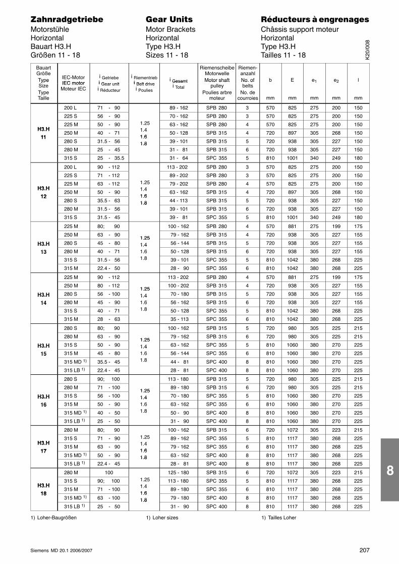
207Siemens MD 20.1 2006/2007
������������� ���� �� ��������� � ����������Motorstühle Motor Brackets Châssis support moteurHorizontal Horizontal HorizontalBauart H3.H Type H3.H Type H3.HGrößen 11 - 18 Sizes 11 - 18 Tailles 11 - 18
ÁÁÁÁÁÁÁÁÁÁÁÁ
BauartGrößeType
ÁÁÁÁÁÁÁÁÁÁÁÁ
IEC-MotorIEC motor
ÁÁÁÁÁÁÁÁÁÁÁÁÁÁÁ
i Getriebei Gear unit
ÁÁÁÁÁÁÁÁÁÁÁÁ
i Riementriebi Belt drive
ÁÁÁÁÁÁÁÁÁÁÁÁÁÁÁ
i Gesamt
ÁÁÁÁÁÁÁÁÁÁÁÁ
RiemenscheibeMotorwelleMotor shaft
ÁÁÁÁÁÁÁÁÁÁÁÁ
Riemen-anzahlNo. of
ÁÁÁÁÁÁÁÁÁ
b
ÁÁÁÁÁÁÁÁÁ
E
ÁÁÁÁÁÁÁÁÁ
e1
ÁÁÁÁÁÁÁÁÁ
e2
ÁÁÁÁÁÁÁÁÁ
l
ÁÁÁÁÁÁÁÁÁÁÁÁ
Ty eSizeTypeTaille
ÁÁÁÁÁÁÁÁÁÁÁÁ
IEC motorMoteur IECÁÁÁÁÁ
ÁÁÁÁÁÁÁÁÁÁ
i Gear uniti Réducteur ÁÁÁÁ
ÁÁÁÁÁÁÁÁ
i Belt drivei PouliesÁÁÁÁÁÁÁÁÁÁÁÁÁÁÁ
Gesamti Total ÁÁÁÁ
ÁÁÁÁÁÁÁÁ
Motor shaftpulley
Poulies arbremoteur
ÁÁÁÁÁÁÁÁÁÁÁÁ
No. ofbelts
No. decourroies
ÁÁÁÁÁÁÁÁÁ
mm
ÁÁÁÁÁÁÁÁÁ
mm
ÁÁÁÁÁÁÁÁÁ
mm
ÁÁÁÁÁÁÁÁÁ
mm
ÁÁÁÁÁÁÁÁÁ
mm
ÁÁÁÁÁÁÁÁ200 L ÁÁÁÁÁ71 - 90 ÁÁÁÁÁÁÁÁÁ 89 - 162 ÁÁÁÁSPB 280ÁÁÁÁ3 ÁÁÁ570 ÁÁÁ825ÁÁÁ275ÁÁÁ200ÁÁÁ150ÁÁÁÁÁÁÁÁ
ÁÁÁÁÁÁÁÁ225 S
ÁÁÁÁÁÁÁÁÁÁ56 - 90
ÁÁÁÁÁÁÁÁ
ÁÁÁÁÁÁÁÁÁÁ 70 - 162
ÁÁÁÁÁÁÁÁSPB 280
ÁÁÁÁÁÁÁÁ3
ÁÁÁÁÁÁ570ÁÁÁÁÁÁ825ÁÁÁÁÁÁ275ÁÁÁÁÁÁ200ÁÁÁÁÁÁ150ÁÁÁÁ
ÁÁÁÁH3 H
ÁÁÁÁÁÁÁÁ
225 MÁÁÁÁÁÁÁÁÁÁ
50 - 90ÁÁÁÁÁÁÁÁ
1.251 4
ÁÁÁÁÁÁÁÁÁÁ
63 - 162ÁÁÁÁÁÁÁÁ
SPB 280ÁÁÁÁÁÁÁÁ
4ÁÁÁÁÁÁ
570ÁÁÁÁÁÁ
825ÁÁÁÁÁÁ
275ÁÁÁÁÁÁ
200ÁÁÁÁÁÁ
150ÁÁÁÁÁÁÁÁ
H3.H11ÁÁÁÁÁÁÁÁ
250 M ÁÁÁÁÁÁÁÁÁÁ
40 - 71 ÁÁÁÁÁÁÁÁ
1.41 6ÁÁÁÁÁÁÁÁÁÁ
50 - 128 ÁÁÁÁÁÁÁÁ
SPB 315ÁÁÁÁÁÁÁÁ
4 ÁÁÁÁÁÁ
720 ÁÁÁÁÁÁ
897ÁÁÁÁÁÁ
305ÁÁÁÁÁÁ
268ÁÁÁÁÁÁ
150
ÁÁÁÁÁÁÁÁ
11 ÁÁÁÁÁÁÁÁ
280 S ÁÁÁÁÁÁÁÁÁÁ
31.5 - 56 ÁÁÁÁÁÁÁÁ
1.61.8 ÁÁÁÁÁÁÁÁÁÁ
39 - 101 ÁÁÁÁÁÁÁÁ
SPB 315ÁÁÁÁÁÁÁÁ
5 ÁÁÁÁÁÁ
720 ÁÁÁÁÁÁ
938ÁÁÁÁÁÁ
305ÁÁÁÁÁÁ
227ÁÁÁÁÁÁ
150
ÁÁÁÁÁÁÁÁ
ÁÁÁÁÁÁÁÁ
280 M ÁÁÁÁÁÁÁÁÁÁ
25 - 45 ÁÁÁÁÁÁÁÁ
1.8
ÁÁÁÁÁÁÁÁÁÁ
31 - 81 ÁÁÁÁÁÁÁÁ
SPB 315ÁÁÁÁÁÁÁÁ
6 ÁÁÁÁÁÁ
720 ÁÁÁÁÁÁ
938ÁÁÁÁÁÁ
305ÁÁÁÁÁÁ
227ÁÁÁÁÁÁ
150
ÁÁÁÁÁÁÁÁ315 S ÁÁÁÁÁ25 - 35.5ÁÁÁÁÁÁÁÁÁ 31 - 64 ÁÁÁÁSPC 355ÁÁÁÁ5 ÁÁÁ810 ÁÁÁ1001ÁÁÁ340ÁÁÁ249ÁÁÁ180ÁÁÁÁÁÁÁÁ
ÁÁÁÁÁÁÁÁ
200 LÁÁÁÁÁÁÁÁÁÁ
90 - 112ÁÁÁÁÁÁÁÁ
ÁÁÁÁÁÁÁÁÁÁ
113 - 202ÁÁÁÁÁÁÁÁ
SPB 280ÁÁÁÁÁÁÁÁ
3ÁÁÁÁÁÁ
570ÁÁÁÁÁÁ
825ÁÁÁÁÁÁ
275ÁÁÁÁÁÁ
200ÁÁÁÁÁÁ
150ÁÁÁÁÁÁÁÁ
ÁÁÁÁÁÁÁÁ
225 SÁÁÁÁÁÁÁÁÁÁ
71 - 112ÁÁÁÁÁÁÁÁ
ÁÁÁÁÁÁÁÁÁÁ
89 - 202ÁÁÁÁÁÁÁÁ
SPB 280ÁÁÁÁÁÁÁÁ
3ÁÁÁÁÁÁ
570ÁÁÁÁÁÁ
825ÁÁÁÁÁÁ
275ÁÁÁÁÁÁ
200ÁÁÁÁÁÁ
150ÁÁÁÁÁÁÁÁH3 H
ÁÁÁÁÁÁÁÁ
225 M ÁÁÁÁÁÁÁÁÁÁ
63 - 112 ÁÁÁÁÁÁÁÁ
1.251 4ÁÁÁÁÁÁÁÁÁÁ
79 - 202 ÁÁÁÁÁÁÁÁ
SPB 280ÁÁÁÁÁÁÁÁ
4 ÁÁÁÁÁÁ
570 ÁÁÁÁÁÁ
825ÁÁÁÁÁÁ
275ÁÁÁÁÁÁ
200ÁÁÁÁÁÁ
150
ÁÁÁÁÁÁÁÁ
H3.H12ÁÁÁÁÁÁÁÁ
250 M ÁÁÁÁÁÁÁÁÁÁ
50 - 90 ÁÁÁÁÁÁÁÁ
1.41 6 ÁÁÁÁÁÁÁÁÁÁ
63 - 162 ÁÁÁÁÁÁÁÁ
SPB 315ÁÁÁÁÁÁÁÁ
4 ÁÁÁÁÁÁ
720 ÁÁÁÁÁÁ
897ÁÁÁÁÁÁ
305ÁÁÁÁÁÁ
268ÁÁÁÁÁÁ
150
ÁÁÁÁ12ÁÁÁÁ280 S ÁÁÁÁÁ35.5 - 63 ÁÁÁÁ
1.61.8 ÁÁÁÁÁ 44 - 113 ÁÁÁÁSPB 315ÁÁÁÁ5 ÁÁÁ720 ÁÁÁ938ÁÁÁ305ÁÁÁ227ÁÁÁ150ÁÁÁÁ
ÁÁÁÁÁÁÁÁÁÁÁÁ280 M
ÁÁÁÁÁÁÁÁÁÁ31.5 - 56
ÁÁÁÁÁÁÁÁ
1.8 ÁÁÁÁÁÁÁÁÁÁ 39 - 101
ÁÁÁÁÁÁÁÁSPB 315
ÁÁÁÁÁÁÁÁ6
ÁÁÁÁÁÁ720ÁÁÁÁÁÁ938ÁÁÁÁÁÁ305ÁÁÁÁÁÁ227ÁÁÁÁÁÁ150ÁÁÁÁ
ÁÁÁÁÁÁÁÁÁÁÁÁ
315 SÁÁÁÁÁÁÁÁÁÁ
31.5 - 45ÁÁÁÁÁÁÁÁ
ÁÁÁÁÁÁÁÁÁÁ
39 - 81ÁÁÁÁÁÁÁÁ
SPC 355ÁÁÁÁÁÁÁÁ
5ÁÁÁÁÁÁ
810ÁÁÁÁÁÁ
1001ÁÁÁÁÁÁ
340ÁÁÁÁÁÁ
249ÁÁÁÁÁÁ
180ÁÁÁÁÁÁÁÁ
ÁÁÁÁÁÁÁÁ
225 M ÁÁÁÁÁÁÁÁÁÁ
80; 90 ÁÁÁÁÁÁÁÁ
ÁÁÁÁÁÁÁÁÁÁ
100 - 162 ÁÁÁÁÁÁÁÁ
SPB 280ÁÁÁÁÁÁÁÁ
4 ÁÁÁÁÁÁ
570 ÁÁÁÁÁÁ
881ÁÁÁÁÁÁ
275ÁÁÁÁÁÁ
199ÁÁÁÁÁÁ
175
ÁÁÁÁÁÁÁÁ
ÁÁÁÁÁÁÁÁ
250 M ÁÁÁÁÁÁÁÁÁÁ
63 - 90 ÁÁÁÁÁÁÁÁ
1 25ÁÁÁÁÁÁÁÁÁÁ
79 - 162 ÁÁÁÁÁÁÁÁ
SPB 315ÁÁÁÁÁÁÁÁ
4 ÁÁÁÁÁÁ
720 ÁÁÁÁÁÁ
938ÁÁÁÁÁÁ
305ÁÁÁÁÁÁ
227ÁÁÁÁÁÁ
155
ÁÁÁÁÁÁÁÁ
H3.HÁÁÁÁÁÁÁÁ
280 S ÁÁÁÁÁÁÁÁÁÁ
45 - 80 ÁÁÁÁÁÁÁÁ
1.251.4 ÁÁÁÁÁÁÁÁÁÁ
56 - 144 ÁÁÁÁÁÁÁÁ
SPB 315ÁÁÁÁÁÁÁÁ
5 ÁÁÁÁÁÁ
720 ÁÁÁÁÁÁ
938ÁÁÁÁÁÁ
305ÁÁÁÁÁÁ
227ÁÁÁÁÁÁ
155
ÁÁÁÁH3.H
13 ÁÁÁÁ280 M ÁÁÁÁÁ40 - 71 ÁÁÁÁ1.41.6 ÁÁÁÁÁ 50 - 128 ÁÁÁÁSPB 315ÁÁÁÁ6 ÁÁÁ720 ÁÁÁ938ÁÁÁ305ÁÁÁ227ÁÁÁ155ÁÁÁÁ
ÁÁÁÁ
13 ÁÁÁÁÁÁÁÁ
315 SÁÁÁÁÁÁÁÁÁÁ
31.5 - 56ÁÁÁÁÁÁÁÁ
1.8ÁÁÁÁÁÁÁÁÁÁ
39 - 101ÁÁÁÁÁÁÁÁ
SPC 355ÁÁÁÁÁÁÁÁ
5ÁÁÁÁÁÁ
810ÁÁÁÁÁÁ
1042ÁÁÁÁÁÁ
380ÁÁÁÁÁÁ
268ÁÁÁÁÁÁ
225ÁÁÁÁÁÁÁÁ
ÁÁÁÁÁÁÁÁ
315 MÁÁÁÁÁÁÁÁÁÁ
22.4 - 50ÁÁÁÁÁÁÁÁ
ÁÁÁÁÁÁÁÁÁÁ
28 - 90ÁÁÁÁÁÁÁÁ
SPC 355ÁÁÁÁÁÁÁÁ
6ÁÁÁÁÁÁ
810ÁÁÁÁÁÁ
1042ÁÁÁÁÁÁ
380ÁÁÁÁÁÁ
268ÁÁÁÁÁÁ
225ÁÁÁÁÁÁÁÁ
ÁÁÁÁÁÁÁÁ
225 M ÁÁÁÁÁÁÁÁÁÁ
90 - 112 ÁÁÁÁÁÁÁÁ
ÁÁÁÁÁÁÁÁÁÁ
113 - 202 ÁÁÁÁÁÁÁÁ
SPB 280ÁÁÁÁÁÁÁÁ
4 ÁÁÁÁÁÁ
570 ÁÁÁÁÁÁ
881ÁÁÁÁÁÁ
275ÁÁÁÁÁÁ
199ÁÁÁÁÁÁ
175
ÁÁÁÁÁÁÁÁ
ÁÁÁÁÁÁÁÁ
250 M ÁÁÁÁÁÁÁÁÁÁ
80 - 112 ÁÁÁÁÁÁÁÁ
1 25ÁÁÁÁÁÁÁÁÁÁ
100 - 202 ÁÁÁÁÁÁÁÁ
SPB 315ÁÁÁÁÁÁÁÁ
4 ÁÁÁÁÁÁ
720 ÁÁÁÁÁÁ
938ÁÁÁÁÁÁ
305ÁÁÁÁÁÁ
227ÁÁÁÁÁÁ
155
ÁÁÁÁÁÁÁÁ
H3.HÁÁÁÁÁÁÁÁ
280 S ÁÁÁÁÁÁÁÁÁÁ
56 - 100 ÁÁÁÁÁÁÁÁ
1.251.4 ÁÁÁÁÁÁÁÁÁÁ
70 - 180 ÁÁÁÁÁÁÁÁ
SPB 315ÁÁÁÁÁÁÁÁ
5 ÁÁÁÁÁÁ
720 ÁÁÁÁÁÁ
938ÁÁÁÁÁÁ
305ÁÁÁÁÁÁ
227ÁÁÁÁÁÁ
155
ÁÁÁÁH3.H
14 ÁÁÁÁ280 M ÁÁÁÁÁ45 - 90 ÁÁÁÁ1.41.6 ÁÁÁÁÁ 56 - 162 ÁÁÁÁSPB 315ÁÁÁÁ6 ÁÁÁ720 ÁÁÁ938ÁÁÁ305ÁÁÁ227ÁÁÁ155ÁÁÁÁ
ÁÁÁÁ
14 ÁÁÁÁÁÁÁÁ
315 SÁÁÁÁÁÁÁÁÁÁ
40 - 71ÁÁÁÁÁÁÁÁ
1.8 ÁÁÁÁÁÁÁÁÁÁ
50 - 128ÁÁÁÁÁÁÁÁ
SPC 355ÁÁÁÁÁÁÁÁ
5ÁÁÁÁÁÁ
810ÁÁÁÁÁÁ
1042ÁÁÁÁÁÁ
380ÁÁÁÁÁÁ
268ÁÁÁÁÁÁ
225ÁÁÁÁÁÁÁÁ
ÁÁÁÁÁÁÁÁ
315 M ÁÁÁÁÁÁÁÁÁÁ
28 - 63 ÁÁÁÁÁÁÁÁ
ÁÁÁÁÁÁÁÁÁÁ
35 - 113 ÁÁÁÁÁÁÁÁ
SPC 355ÁÁÁÁÁÁÁÁ
6 ÁÁÁÁÁÁ
810 ÁÁÁÁÁÁ
1042ÁÁÁÁÁÁ
380ÁÁÁÁÁÁ
268ÁÁÁÁÁÁ
225
ÁÁÁÁÁÁÁÁ
ÁÁÁÁÁÁÁÁ
280 S ÁÁÁÁÁÁÁÁÁÁ
80; 90 ÁÁÁÁÁÁÁÁ
ÁÁÁÁÁÁÁÁÁÁ
100 - 162 ÁÁÁÁÁÁÁÁ
SPB 315ÁÁÁÁÁÁÁÁ
5 ÁÁÁÁÁÁ
720 ÁÁÁÁÁÁ
980ÁÁÁÁÁÁ
305ÁÁÁÁÁÁ
225ÁÁÁÁÁÁ
215
ÁÁÁÁÁÁÁÁ
ÁÁÁÁÁÁÁÁ
280 M ÁÁÁÁÁÁÁÁÁÁ
63 - 90 ÁÁÁÁÁÁÁÁ
1 25 ÁÁÁÁÁÁÁÁÁÁ
79 - 162 ÁÁÁÁÁÁÁÁ
SPB 315ÁÁÁÁÁÁÁÁ
6 ÁÁÁÁÁÁ
720 ÁÁÁÁÁÁ
980ÁÁÁÁÁÁ
305ÁÁÁÁÁÁ
225ÁÁÁÁÁÁ
215
ÁÁÁÁH3.HÁÁÁÁ315 S ÁÁÁÁÁ50 - 90 ÁÁÁÁ1.251.4 ÁÁÁÁÁ 63 - 162 ÁÁÁÁSPC 355ÁÁÁÁ5 ÁÁÁ810 ÁÁÁ1060ÁÁÁ380ÁÁÁ270ÁÁÁ225ÁÁÁÁ
ÁÁÁÁH3.H
15ÁÁÁÁÁÁÁÁ315 M
ÁÁÁÁÁÁÁÁÁÁ45 - 80
ÁÁÁÁÁÁÁÁ
1.41.6ÁÁÁÁÁÁÁÁÁÁ 56 - 144
ÁÁÁÁÁÁÁÁSPC 355
ÁÁÁÁÁÁÁÁ6
ÁÁÁÁÁÁ810ÁÁÁÁÁÁ1060ÁÁÁÁÁÁ380ÁÁÁÁÁÁ270ÁÁÁÁÁÁ225ÁÁÁÁ
ÁÁÁÁ
15 ÁÁÁÁÁÁÁÁ
315 MD 1)ÁÁÁÁÁÁÁÁÁÁ
35.5 - 45ÁÁÁÁÁÁÁÁ
1.8 ÁÁÁÁÁÁÁÁÁÁ
44 - 81ÁÁÁÁÁÁÁÁ
SPC 400ÁÁÁÁÁÁÁÁ
8ÁÁÁÁÁÁ
810ÁÁÁÁÁÁ
1060ÁÁÁÁÁÁ
380ÁÁÁÁÁÁ
270ÁÁÁÁÁÁ
225ÁÁÁÁÁÁÁÁ
ÁÁÁÁÁÁÁÁ
315 LB 1)ÁÁÁÁÁÁÁÁÁÁ
22.4 - 45 ÁÁÁÁÁÁÁÁ
ÁÁÁÁÁÁÁÁÁÁ
28 - 81 ÁÁÁÁÁÁÁÁ
SPC 400ÁÁÁÁÁÁÁÁ
8 ÁÁÁÁÁÁ
810 ÁÁÁÁÁÁ
1060ÁÁÁÁÁÁ
380ÁÁÁÁÁÁ
270ÁÁÁÁÁÁ
225
ÁÁÁÁÁÁÁÁ
ÁÁÁÁÁÁÁÁ
280 S ÁÁÁÁÁÁÁÁÁÁ
90; 100 ÁÁÁÁÁÁÁÁ
ÁÁÁÁÁÁÁÁÁÁ
113 - 180 ÁÁÁÁÁÁÁÁ
SPB 315ÁÁÁÁÁÁÁÁ
5 ÁÁÁÁÁÁ
720 ÁÁÁÁÁÁ
980ÁÁÁÁÁÁ
305ÁÁÁÁÁÁ
225ÁÁÁÁÁÁ
215
ÁÁÁÁÁÁÁÁ
ÁÁÁÁÁÁÁÁ
280 M ÁÁÁÁÁÁÁÁÁÁ
71 - 100 ÁÁÁÁÁÁÁÁ
1 25 ÁÁÁÁÁÁÁÁÁÁ
89 - 180 ÁÁÁÁÁÁÁÁ
SPB 315ÁÁÁÁÁÁÁÁ
6 ÁÁÁÁÁÁ
720 ÁÁÁÁÁÁ
980ÁÁÁÁÁÁ
305ÁÁÁÁÁÁ
225ÁÁÁÁÁÁ
215
ÁÁÁÁH3.HÁÁÁÁ315 S ÁÁÁÁÁ56 - 100 ÁÁÁÁ1.251.4 ÁÁÁÁÁ 70 - 180 ÁÁÁÁSPC 355ÁÁÁÁ5 ÁÁÁ810 ÁÁÁ1060ÁÁÁ380ÁÁÁ270ÁÁÁ225ÁÁÁÁ
ÁÁÁÁH3.H
16ÁÁÁÁÁÁÁÁ
315 MÁÁÁÁÁÁÁÁÁÁ
50 - 90ÁÁÁÁÁÁÁÁ
1.41.6ÁÁÁÁÁÁÁÁÁÁ
63 - 162ÁÁÁÁÁÁÁÁ
SPC 355ÁÁÁÁÁÁÁÁ
6ÁÁÁÁÁÁ
810ÁÁÁÁÁÁ
1060ÁÁÁÁÁÁ
380ÁÁÁÁÁÁ
270ÁÁÁÁÁÁ
225ÁÁÁÁÁÁÁÁ
16 ÁÁÁÁÁÁÁÁ
315 MD 1)ÁÁÁÁÁÁÁÁÁÁ
40 - 50ÁÁÁÁÁÁÁÁ
1.8 ÁÁÁÁÁÁÁÁÁÁ
50 - 90ÁÁÁÁÁÁÁÁ
SPC 400ÁÁÁÁÁÁÁÁ
8ÁÁÁÁÁÁ
810ÁÁÁÁÁÁ
1060ÁÁÁÁÁÁ
380ÁÁÁÁÁÁ
270ÁÁÁÁÁÁ
225ÁÁÁÁÁÁÁÁ
ÁÁÁÁÁÁÁÁ
315 LB 1)ÁÁÁÁÁÁÁÁÁÁ
25 - 50 ÁÁÁÁÁÁÁÁ
ÁÁÁÁÁÁÁÁÁÁ
31 - 90 ÁÁÁÁÁÁÁÁ
SPC 400ÁÁÁÁÁÁÁÁ
8 ÁÁÁÁÁÁ
810 ÁÁÁÁÁÁ
1060ÁÁÁÁÁÁ
380ÁÁÁÁÁÁ
270ÁÁÁÁÁÁ
225
ÁÁÁÁÁÁÁÁ
ÁÁÁÁÁÁÁÁ
280 M ÁÁÁÁÁÁÁÁÁÁ
80; 90 ÁÁÁÁÁÁÁÁ
ÁÁÁÁÁÁÁÁÁÁ
100 - 162 ÁÁÁÁÁÁÁÁ
SPB 315ÁÁÁÁÁÁÁÁ
6 ÁÁÁÁÁÁ
720 ÁÁÁÁÁÁ
1072ÁÁÁÁÁÁ
305ÁÁÁÁÁÁ
223ÁÁÁÁÁÁ
215
ÁÁÁÁÁÁÁÁ
H3 HÁÁÁÁÁÁÁÁ
315 S ÁÁÁÁÁÁÁÁÁÁ
71 - 90 ÁÁÁÁÁÁÁÁ
1.251 4ÁÁÁÁÁÁÁÁÁÁ
89 - 162 ÁÁÁÁÁÁÁÁ
SPC 355ÁÁÁÁÁÁÁÁ
5 ÁÁÁÁÁÁ
810 ÁÁÁÁÁÁ
1117ÁÁÁÁÁÁ
380ÁÁÁÁÁÁ
268ÁÁÁÁÁÁ
225
ÁÁÁÁH3.H
17 ÁÁÁÁ315 M ÁÁÁÁÁ63 - 90 ÁÁÁÁ1.41 6 ÁÁÁÁÁ 79 - 162 ÁÁÁÁSPC 355ÁÁÁÁ6 ÁÁÁ810 ÁÁÁ1117ÁÁÁ380ÁÁÁ268ÁÁÁ225ÁÁÁÁ
ÁÁÁÁ17 ÁÁÁÁÁÁÁÁ
315 MD 1)ÁÁÁÁÁÁÁÁÁÁ
50 - 90ÁÁÁÁÁÁÁÁ
1.61.8ÁÁÁÁÁÁÁÁÁÁ
63 - 162ÁÁÁÁÁÁÁÁ
SPC 400ÁÁÁÁÁÁÁÁ
8ÁÁÁÁÁÁ
810ÁÁÁÁÁÁ
1117ÁÁÁÁÁÁ
380ÁÁÁÁÁÁ
268ÁÁÁÁÁÁ
225ÁÁÁÁÁÁÁÁ
ÁÁÁÁÁÁÁÁ
315 LB 1)ÁÁÁÁÁÁÁÁÁÁ
22.4 - 45 ÁÁÁÁÁÁÁÁ
1.8 ÁÁÁÁÁÁÁÁÁÁ
28 - 81 ÁÁÁÁÁÁÁÁ
SPC 400ÁÁÁÁÁÁÁÁ
8 ÁÁÁÁÁÁ
810 ÁÁÁÁÁÁ
1117ÁÁÁÁÁÁ
380ÁÁÁÁÁÁ
268ÁÁÁÁÁÁ
225
ÁÁÁÁÁÁÁÁ
ÁÁÁÁÁÁÁÁ
280 M ÁÁÁÁÁÁÁÁÁÁ
100 ÁÁÁÁÁÁÁÁ
ÁÁÁÁÁÁÁÁÁÁ
125 - 180 ÁÁÁÁÁÁÁÁ
SPB 315ÁÁÁÁÁÁÁÁ
6 ÁÁÁÁÁÁ
720 ÁÁÁÁÁÁ
1072ÁÁÁÁÁÁ
305ÁÁÁÁÁÁ
223ÁÁÁÁÁÁ
215
ÁÁÁÁÁÁÁÁ
H3 HÁÁÁÁÁÁÁÁ
315 S ÁÁÁÁÁÁÁÁÁÁ
90; 100 ÁÁÁÁÁÁÁÁ
1.251 4ÁÁÁÁÁÁÁÁÁÁ
113 - 180 ÁÁÁÁÁÁÁÁ
SPC 355ÁÁÁÁÁÁÁÁ
5 ÁÁÁÁÁÁ
810 ÁÁÁÁÁÁ
1117ÁÁÁÁÁÁ
380ÁÁÁÁÁÁ
268ÁÁÁÁÁÁ
225
ÁÁÁÁH3.H
18 ÁÁÁÁ315 M ÁÁÁÁÁ71 - 100 ÁÁÁÁ1.41 6 ÁÁÁÁÁ 89 - 180 ÁÁÁÁSPC 355ÁÁÁÁ6 ÁÁÁ810 ÁÁÁ1117ÁÁÁ380ÁÁÁ268ÁÁÁ225ÁÁÁÁ
ÁÁÁÁ18 ÁÁÁÁÁÁÁÁ315 MD 1)
ÁÁÁÁÁÁÁÁÁÁ63 - 100
ÁÁÁÁÁÁÁÁ
1.61.8
ÁÁÁÁÁÁÁÁÁÁ 79 - 180
ÁÁÁÁÁÁÁÁSPC 400
ÁÁÁÁÁÁÁÁ8
ÁÁÁÁÁÁ810ÁÁÁÁÁÁ1117ÁÁÁÁÁÁ380ÁÁÁÁÁÁ268ÁÁÁÁÁÁ225ÁÁÁÁ
ÁÁÁÁÁÁÁÁÁÁÁÁ
315 LB 1)ÁÁÁÁÁÁÁÁÁÁ
25 - 50ÁÁÁÁÁÁÁÁ
1.8 ÁÁÁÁÁÁÁÁÁÁ
31 - 90ÁÁÁÁÁÁÁÁ
SPC 400ÁÁÁÁÁÁÁÁ
8ÁÁÁÁÁÁ
810ÁÁÁÁÁÁ
1117ÁÁÁÁÁÁ
380ÁÁÁÁÁÁ
268ÁÁÁÁÁÁ
225
1) Loher-Baugrößen 1) Loher sizes 1) Tailles Loher
K20
/008
8
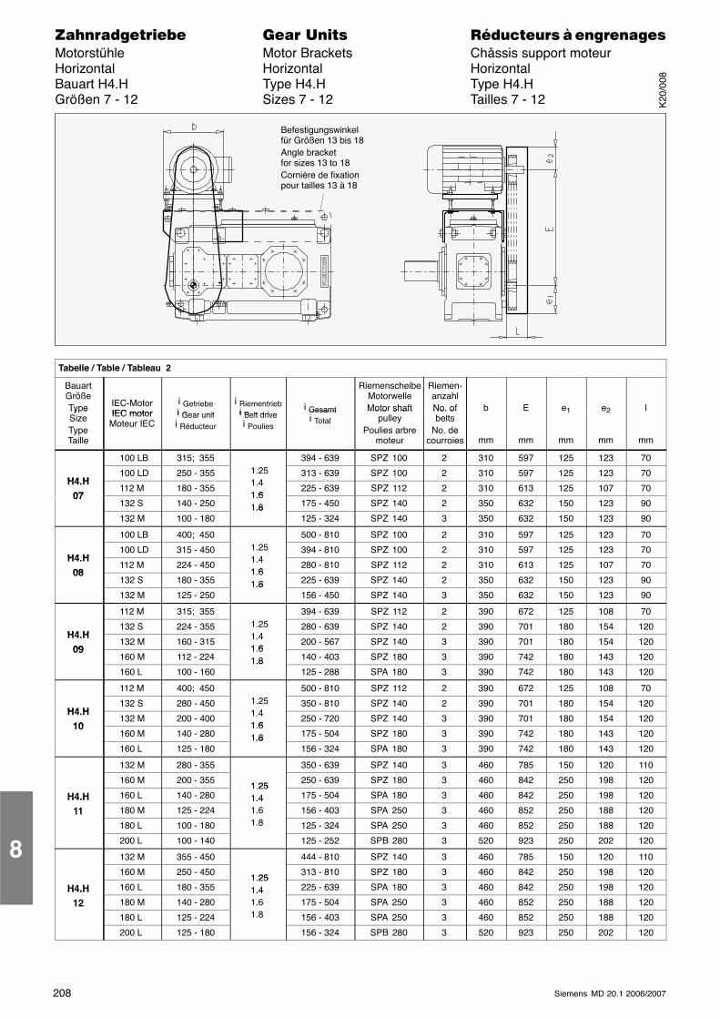
208 Siemens MD 20.1 2006/2007
������������� ���� �� ��������� � ����������Motorstühle Motor Brackets Châssis support moteurHorizontal Horizontal HorizontalBauart H4.H Type H4.H Type H4.HGrößen 7 - 12 Sizes 7 - 12 Tailles 7 - 12
Befestigungswinkelfür Größen 13 bis 18Angle bracketfor sizes 13 to 18Cornière de fixationpour tailles 13 à 18
ÁÁÁÁÁÁÁÁÁÁÁÁÁÁÁÁÁÁÁÁÁÁÁÁÁÁÁÁÁÁÁÁÁÁÁÁÁÁÁÁÁÁÁÁÁÁÁÁÁÁÁÁÁÁÁÁÁÁÁÁÁÁÁÁÁÁÁÁ
Tabelle / Table / Tableau 2
ÁÁÁÁÁÁÁÁÁÁÁÁ
BauartGrößeType
ÁÁÁÁÁÁÁÁÁÁÁÁ
IEC-MotorIEC motor
ÁÁÁÁÁÁÁÁÁÁÁÁÁÁÁ
i Getriebei Gear unit
ÁÁÁÁÁÁÁÁÁÁÁÁ
i Riementriebi Belt drive
ÁÁÁÁÁÁÁÁÁÁÁÁ
i Gesamt
ÁÁÁÁÁÁÁÁÁÁÁÁÁÁÁ
RiemenscheibeMotorwelleMotor shaft
ÁÁÁÁÁÁÁÁÁ
Riemen-anzahlNo. of
ÁÁÁÁÁÁÁÁÁ
b
ÁÁÁÁÁÁÁÁÁÁÁÁ
E
ÁÁÁÁÁÁÁÁÁ
e1
ÁÁÁÁÁÁÁÁÁ
e2
ÁÁÁÁÁÁÁÁÁ
l
ÁÁÁÁÁÁÁÁÁÁÁÁ
Ty eSizeTypeTaille
ÁÁÁÁÁÁÁÁÁÁÁÁ
IEC motorMoteur IECÁÁÁÁÁ
ÁÁÁÁÁÁÁÁÁÁ
i Gear uniti Réducteur ÁÁÁÁ
ÁÁÁÁÁÁÁÁ
i Belt drivei Poulies ÁÁÁÁ
ÁÁÁÁÁÁÁÁ
Gesamti Total ÁÁÁÁÁÁÁÁÁÁÁÁÁÁÁ
Motor shaftpulley
Poulies arbremoteur
ÁÁÁÁÁÁÁÁÁ
No. ofbelts
No. decourroies
ÁÁÁÁÁÁÁÁÁ
mm
ÁÁÁÁÁÁÁÁÁÁÁÁ
mm
ÁÁÁÁÁÁÁÁÁ
mm
ÁÁÁÁÁÁÁÁÁ
mm
ÁÁÁÁÁÁÁÁÁ
mm
ÁÁÁÁÁÁÁÁ
ÁÁÁÁÁÁÁÁ
100 LB ÁÁÁÁÁÁÁÁÁÁ
315; 355 ÁÁÁÁÁÁÁÁ
ÁÁÁÁÁÁÁÁ
394 - 639ÁÁÁÁÁÁÁÁÁÁ
SPZ 100 ÁÁÁÁÁÁ
2ÁÁÁÁÁÁ
310ÁÁÁÁÁÁÁÁ
597 ÁÁÁÁÁÁ
125 ÁÁÁÁÁÁ
123ÁÁÁÁÁÁ
70
ÁÁÁÁH4 H ÁÁÁÁ100 LDÁÁÁÁÁ250 - 355 ÁÁÁÁ1.251 4 ÁÁÁÁ313 - 639ÁÁÁÁÁSPZ 100 ÁÁÁ2ÁÁÁ310ÁÁÁÁ597 ÁÁÁ125 ÁÁÁ123ÁÁÁ70ÁÁÁÁ
ÁÁÁÁH4.H
07
ÁÁÁÁÁÁÁÁ112 M
ÁÁÁÁÁÁÁÁÁÁ180 - 355
ÁÁÁÁÁÁÁÁ
1.41 6
ÁÁÁÁÁÁÁÁ225 - 639
ÁÁÁÁÁÁÁÁÁÁSPZ 112
ÁÁÁÁÁÁ2ÁÁÁÁÁÁ310ÁÁÁÁÁÁÁÁ613
ÁÁÁÁÁÁ125ÁÁÁÁÁÁ107ÁÁÁÁÁÁ70ÁÁÁÁ
ÁÁÁÁ07 ÁÁÁÁÁÁÁÁ
132 SÁÁÁÁÁÁÁÁÁÁ
140 - 250ÁÁÁÁÁÁÁÁ
1.61.8ÁÁÁÁÁÁÁÁ
175 - 450ÁÁÁÁÁÁÁÁÁÁ
SPZ 140ÁÁÁÁÁÁ
2ÁÁÁÁÁÁ
350ÁÁÁÁÁÁÁÁ
632ÁÁÁÁÁÁ
150ÁÁÁÁÁÁ
123ÁÁÁÁÁÁ
90ÁÁÁÁÁÁÁÁ
ÁÁÁÁÁÁÁÁ
132 M ÁÁÁÁÁÁÁÁÁÁ
100 - 180 ÁÁÁÁÁÁÁÁ
1.8 ÁÁÁÁÁÁÁÁ
125 - 324ÁÁÁÁÁÁÁÁÁÁ
SPZ 140 ÁÁÁÁÁÁ
3ÁÁÁÁÁÁ
350ÁÁÁÁÁÁÁÁ
632 ÁÁÁÁÁÁ
150 ÁÁÁÁÁÁ
123ÁÁÁÁÁÁ
90
ÁÁÁÁÁÁÁÁ
ÁÁÁÁÁÁÁÁ
100 LB ÁÁÁÁÁÁÁÁÁÁ
400; 450 ÁÁÁÁÁÁÁÁ
ÁÁÁÁÁÁÁÁ
500 - 810ÁÁÁÁÁÁÁÁÁÁ
SPZ 100 ÁÁÁÁÁÁ
2ÁÁÁÁÁÁ
310ÁÁÁÁÁÁÁÁ
597 ÁÁÁÁÁÁ
125 ÁÁÁÁÁÁ
123ÁÁÁÁÁÁ
70
ÁÁÁÁÁÁÁÁ
H4 H ÁÁÁÁÁÁÁÁ
100 LDÁÁÁÁÁÁÁÁÁÁ
315 - 450 ÁÁÁÁÁÁÁÁ
1.251 4ÁÁÁÁÁÁÁÁ
394 - 810ÁÁÁÁÁÁÁÁÁÁ
SPZ 100 ÁÁÁÁÁÁ
2ÁÁÁÁÁÁ
310ÁÁÁÁÁÁÁÁ
597 ÁÁÁÁÁÁ
125 ÁÁÁÁÁÁ
123ÁÁÁÁÁÁ
70
ÁÁÁÁH4.H
08 ÁÁÁÁ112 M ÁÁÁÁÁ224 - 450 ÁÁÁÁ1.41 6 ÁÁÁÁ280 - 810ÁÁÁÁÁSPZ 112 ÁÁÁ2ÁÁÁ310ÁÁÁÁ613 ÁÁÁ125 ÁÁÁ107ÁÁÁ70ÁÁÁÁ
ÁÁÁÁ08 ÁÁÁÁÁÁÁÁ
132 SÁÁÁÁÁÁÁÁÁÁ
180 - 355ÁÁÁÁÁÁÁÁ
1.61.8ÁÁÁÁÁÁÁÁ
225 - 639ÁÁÁÁÁÁÁÁÁÁ
SPZ 140ÁÁÁÁÁÁ
2ÁÁÁÁÁÁ
350ÁÁÁÁÁÁÁÁ
632ÁÁÁÁÁÁ
150ÁÁÁÁÁÁ
123ÁÁÁÁÁÁ
90ÁÁÁÁÁÁÁÁ
ÁÁÁÁÁÁÁÁ
132 M ÁÁÁÁÁÁÁÁÁÁ
125 - 250 ÁÁÁÁÁÁÁÁ
1.8 ÁÁÁÁÁÁÁÁ
156 - 450ÁÁÁÁÁÁÁÁÁÁ
SPZ 140 ÁÁÁÁÁÁ
3ÁÁÁÁÁÁ
350ÁÁÁÁÁÁÁÁ
632 ÁÁÁÁÁÁ
150 ÁÁÁÁÁÁ
123ÁÁÁÁÁÁ
90
ÁÁÁÁÁÁÁÁ
ÁÁÁÁÁÁÁÁ
112 M ÁÁÁÁÁÁÁÁÁÁ
315; 355 ÁÁÁÁÁÁÁÁ
ÁÁÁÁÁÁÁÁ
394 - 639ÁÁÁÁÁÁÁÁÁÁ
SPZ 112 ÁÁÁÁÁÁ
2ÁÁÁÁÁÁ
390ÁÁÁÁÁÁÁÁ
672 ÁÁÁÁÁÁ
125 ÁÁÁÁÁÁ
108ÁÁÁÁÁÁ
70
ÁÁÁÁÁÁÁÁ
H4 HÁÁÁÁÁÁÁÁ
132 S ÁÁÁÁÁÁÁÁÁÁ
224 - 355 ÁÁÁÁÁÁÁÁ
1.251 4ÁÁÁÁÁÁÁÁ
280 - 639ÁÁÁÁÁÁÁÁÁÁ
SPZ 140 ÁÁÁÁÁÁ
2ÁÁÁÁÁÁ
390ÁÁÁÁÁÁÁÁ
701 ÁÁÁÁÁÁ
180 ÁÁÁÁÁÁ
154ÁÁÁÁÁÁ
120
ÁÁÁÁÁÁÁÁ
H4.H09 ÁÁÁÁÁÁÁÁ
132 M ÁÁÁÁÁÁÁÁÁÁ
160 - 315 ÁÁÁÁÁÁÁÁ
1.41 6 ÁÁÁÁÁÁÁÁ
200 - 567ÁÁÁÁÁÁÁÁÁÁ
SPZ 140 ÁÁÁÁÁÁ
3ÁÁÁÁÁÁ
390ÁÁÁÁÁÁÁÁ
701 ÁÁÁÁÁÁ
180 ÁÁÁÁÁÁ
154ÁÁÁÁÁÁ
120
ÁÁÁÁ09
ÁÁÁÁ160 M ÁÁÁÁÁ112 - 224 ÁÁÁÁ1.61.8 ÁÁÁÁ140 - 403ÁÁÁÁÁSPZ 180 ÁÁÁ3ÁÁÁ390ÁÁÁÁ742 ÁÁÁ180 ÁÁÁ143ÁÁÁ120ÁÁÁÁ
ÁÁÁÁÁÁÁÁÁÁÁÁ
160 LÁÁÁÁÁÁÁÁÁÁ
100 - 160ÁÁÁÁÁÁÁÁ
1.8 ÁÁÁÁÁÁÁÁ
125 - 288ÁÁÁÁÁÁÁÁÁÁ
SPA 180ÁÁÁÁÁÁ
3ÁÁÁÁÁÁ
390ÁÁÁÁÁÁÁÁ
742ÁÁÁÁÁÁ
180ÁÁÁÁÁÁ
143ÁÁÁÁÁÁ
120ÁÁÁÁÁÁÁÁ
ÁÁÁÁÁÁÁÁ
112 M ÁÁÁÁÁÁÁÁÁÁ
400; 450 ÁÁÁÁÁÁÁÁ
ÁÁÁÁÁÁÁÁ
500 - 810ÁÁÁÁÁÁÁÁÁÁ
SPZ 112 ÁÁÁÁÁÁ
2ÁÁÁÁÁÁ
390ÁÁÁÁÁÁÁÁ
672 ÁÁÁÁÁÁ
125 ÁÁÁÁÁÁ
108ÁÁÁÁÁÁ
70
ÁÁÁÁÁÁÁÁH4 H
ÁÁÁÁÁÁÁÁ
132 S ÁÁÁÁÁÁÁÁÁÁ
280 - 450 ÁÁÁÁÁÁÁÁ
1.251 4ÁÁÁÁÁÁÁÁ
350 - 810ÁÁÁÁÁÁÁÁÁÁ
SPZ 140 ÁÁÁÁÁÁ
2ÁÁÁÁÁÁ
390ÁÁÁÁÁÁÁÁ
701 ÁÁÁÁÁÁ
180 ÁÁÁÁÁÁ
154ÁÁÁÁÁÁ
120
ÁÁÁÁÁÁÁÁ
H4.H10ÁÁÁÁÁÁÁÁ
132 M ÁÁÁÁÁÁÁÁÁÁ
200 - 400 ÁÁÁÁÁÁÁÁ
1.41 6 ÁÁÁÁÁÁÁÁ
250 - 720ÁÁÁÁÁÁÁÁÁÁ
SPZ 140 ÁÁÁÁÁÁ
3ÁÁÁÁÁÁ
390ÁÁÁÁÁÁÁÁ
701 ÁÁÁÁÁÁ
180 ÁÁÁÁÁÁ
154ÁÁÁÁÁÁ
120
ÁÁÁÁ10ÁÁÁÁ160 M ÁÁÁÁÁ140 - 280 ÁÁÁÁ
1.61.8 ÁÁÁÁ175 - 504ÁÁÁÁÁSPZ 180 ÁÁÁ3ÁÁÁ390ÁÁÁÁ742 ÁÁÁ180 ÁÁÁ143ÁÁÁ120ÁÁÁÁ
ÁÁÁÁÁÁÁÁÁÁÁÁ160 L
ÁÁÁÁÁÁÁÁÁÁ125 - 180
ÁÁÁÁÁÁÁÁ
1.8 ÁÁÁÁÁÁÁÁ156 - 324
ÁÁÁÁÁÁÁÁÁÁSPA 180
ÁÁÁÁÁÁ3ÁÁÁÁÁÁ390ÁÁÁÁÁÁÁÁ742
ÁÁÁÁÁÁ180ÁÁÁÁÁÁ143ÁÁÁÁÁÁ120ÁÁÁÁ
ÁÁÁÁÁÁÁÁÁÁÁÁ
132 MÁÁÁÁÁÁÁÁÁÁ
280 - 355ÁÁÁÁÁÁÁÁ
ÁÁÁÁÁÁÁÁ
350 - 639ÁÁÁÁÁÁÁÁÁÁ
SPZ 140ÁÁÁÁÁÁ
3ÁÁÁÁÁÁ
460ÁÁÁÁÁÁÁÁ
785ÁÁÁÁÁÁ
150ÁÁÁÁÁÁ
120ÁÁÁÁÁÁ
110ÁÁÁÁÁÁÁÁ
ÁÁÁÁÁÁÁÁ
160 M ÁÁÁÁÁÁÁÁÁÁ
200 - 355 ÁÁÁÁÁÁÁÁ1 25
ÁÁÁÁÁÁÁÁ
250 - 639ÁÁÁÁÁÁÁÁÁÁ
SPZ 180 ÁÁÁÁÁÁ
3ÁÁÁÁÁÁ
460ÁÁÁÁÁÁÁÁ
842 ÁÁÁÁÁÁ
250 ÁÁÁÁÁÁ
198ÁÁÁÁÁÁ
120
ÁÁÁÁÁÁÁÁ
H4.H ÁÁÁÁÁÁÁÁ
160 L ÁÁÁÁÁÁÁÁÁÁ
140 - 280 ÁÁÁÁÁÁÁÁ
1.251.4 ÁÁÁÁÁÁÁÁ
175 - 504ÁÁÁÁÁÁÁÁÁÁ
SPA 180 ÁÁÁÁÁÁ
3ÁÁÁÁÁÁ
460ÁÁÁÁÁÁÁÁ
842 ÁÁÁÁÁÁ
250 ÁÁÁÁÁÁ
198ÁÁÁÁÁÁ
120
ÁÁÁÁÁÁÁÁ
H4.H11 ÁÁÁÁÁÁÁÁ
180 M ÁÁÁÁÁÁÁÁÁÁ
125 - 224 ÁÁÁÁÁÁÁÁ
1.41.6 ÁÁÁÁÁÁÁÁ
156 - 403ÁÁÁÁÁÁÁÁÁÁ
SPA 250 ÁÁÁÁÁÁ
3ÁÁÁÁÁÁ
460ÁÁÁÁÁÁÁÁ
852 ÁÁÁÁÁÁ
250 ÁÁÁÁÁÁ
188ÁÁÁÁÁÁ
120
ÁÁÁÁ11
ÁÁÁÁ180 L ÁÁÁÁÁ100 - 180 ÁÁÁÁ1.8ÁÁÁÁ125 - 324ÁÁÁÁÁSPA 250 ÁÁÁ3ÁÁÁ460ÁÁÁÁ852 ÁÁÁ250 ÁÁÁ188ÁÁÁ120ÁÁÁÁ
ÁÁÁÁÁÁÁÁÁÁÁÁ
200 LÁÁÁÁÁÁÁÁÁÁ
100 - 140ÁÁÁÁÁÁÁÁ
ÁÁÁÁÁÁÁÁ
125 - 252ÁÁÁÁÁÁÁÁÁÁ
SPB 280ÁÁÁÁÁÁ
3ÁÁÁÁÁÁ
520ÁÁÁÁÁÁÁÁ
923ÁÁÁÁÁÁ
250ÁÁÁÁÁÁ
202ÁÁÁÁÁÁ
120ÁÁÁÁÁÁÁÁ
ÁÁÁÁÁÁÁÁ
132 MÁÁÁÁÁÁÁÁÁÁ
355 - 450ÁÁÁÁÁÁÁÁ
ÁÁÁÁÁÁÁÁ
444 - 810ÁÁÁÁÁÁÁÁÁÁ
SPZ 140ÁÁÁÁÁÁ
3ÁÁÁÁÁÁ
460ÁÁÁÁÁÁÁÁ
785ÁÁÁÁÁÁ
150ÁÁÁÁÁÁ
120ÁÁÁÁÁÁ
110ÁÁÁÁÁÁÁÁ
ÁÁÁÁÁÁÁÁ
160 M ÁÁÁÁÁÁÁÁÁÁ
250 - 450 ÁÁÁÁÁÁÁÁ
1 25ÁÁÁÁÁÁÁÁ
313 - 810ÁÁÁÁÁÁÁÁÁÁ
SPZ 180 ÁÁÁÁÁÁ
3ÁÁÁÁÁÁ
460ÁÁÁÁÁÁÁÁ
842 ÁÁÁÁÁÁ
250 ÁÁÁÁÁÁ
198ÁÁÁÁÁÁ
120
ÁÁÁÁÁÁÁÁ
H4.H ÁÁÁÁÁÁÁÁ
160 L ÁÁÁÁÁÁÁÁÁÁ
180 - 355 ÁÁÁÁÁÁÁÁ
1.251.4 ÁÁÁÁÁÁÁÁ
225 - 639ÁÁÁÁÁÁÁÁÁÁ
SPA 180 ÁÁÁÁÁÁ
3ÁÁÁÁÁÁ
460ÁÁÁÁÁÁÁÁ
842 ÁÁÁÁÁÁ
250 ÁÁÁÁÁÁ
198ÁÁÁÁÁÁ
120
ÁÁÁÁÁÁÁÁ
H4.H12 ÁÁÁÁÁÁÁÁ
180 M ÁÁÁÁÁÁÁÁÁÁ
140 - 280 ÁÁÁÁÁÁÁÁ
1.41.6 ÁÁÁÁÁÁÁÁ
175 - 504ÁÁÁÁÁÁÁÁÁÁ
SPA 250 ÁÁÁÁÁÁ
3ÁÁÁÁÁÁ
460ÁÁÁÁÁÁÁÁ
852 ÁÁÁÁÁÁ
250 ÁÁÁÁÁÁ
188ÁÁÁÁÁÁ
120
ÁÁÁÁ12
ÁÁÁÁ180 L ÁÁÁÁÁ125 - 224 ÁÁÁÁ1.8ÁÁÁÁ156 - 403ÁÁÁÁÁSPA 250 ÁÁÁ3ÁÁÁ460ÁÁÁÁ852 ÁÁÁ250 ÁÁÁ188ÁÁÁ120ÁÁÁÁ
ÁÁÁÁÁÁÁÁÁÁÁÁ
200 LÁÁÁÁÁÁÁÁÁÁ
125 - 180ÁÁÁÁÁÁÁÁ
ÁÁÁÁÁÁÁÁ
156 - 324ÁÁÁÁÁÁÁÁÁÁ
SPB 280ÁÁÁÁÁÁ
3ÁÁÁÁÁÁ
520ÁÁÁÁÁÁÁÁ
923ÁÁÁÁÁÁ
250ÁÁÁÁÁÁ
202ÁÁÁÁÁÁ
120
8
K20
/008
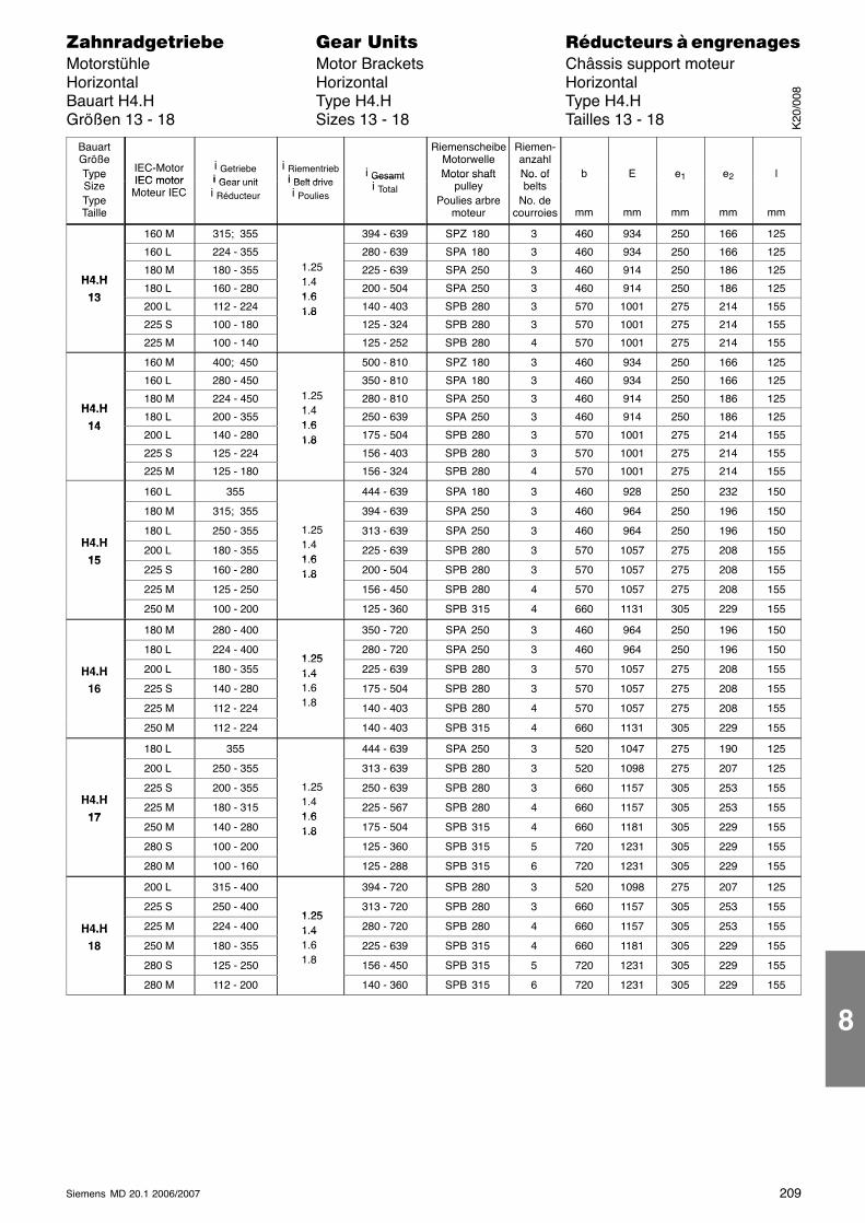
209Siemens MD 20.1 2006/2007
������������� ���� �� ��������� � ����������Motorstühle Motor Brackets Châssis support moteurHorizontal Horizontal HorizontalBauart H4.H Type H4.H Type H4.HGrößen 13 - 18 Sizes 13 - 18 Tailles 13 - 18
ÁÁÁÁÁÁÁÁÁÁÁÁ
BauartGrößeType
ÁÁÁÁÁÁÁÁÁÁÁÁ
IEC-MotorIEC motor
ÁÁÁÁÁÁÁÁÁÁÁÁÁÁÁ
i Getriebei Gear unit
ÁÁÁÁÁÁÁÁÁÁÁÁ
i Riementriebi Belt drive
ÁÁÁÁÁÁÁÁÁÁÁÁÁÁÁ
i Gesamt
ÁÁÁÁÁÁÁÁÁÁÁÁ
RiemenscheibeMotorwelleMotor shaft
ÁÁÁÁÁÁÁÁÁÁÁÁ
Riemen-anzahlNo. of
ÁÁÁÁÁÁÁÁÁ
b
ÁÁÁÁÁÁÁÁÁ
E
ÁÁÁÁÁÁÁÁÁ
e1
ÁÁÁÁÁÁÁÁÁ
e2
ÁÁÁÁÁÁÁÁÁ
l
ÁÁÁÁÁÁÁÁÁÁÁÁ
Ty eSizeTypeTaille
ÁÁÁÁÁÁÁÁÁÁÁÁ
IEC motorMoteur IECÁÁÁÁÁ
ÁÁÁÁÁÁÁÁÁÁ
i Gear uniti Réducteur ÁÁÁÁ
ÁÁÁÁÁÁÁÁ
i Belt drivei Poulies ÁÁÁÁÁÁÁÁÁÁÁÁÁÁÁ
Gesamti Total ÁÁÁÁ
ÁÁÁÁÁÁÁÁ
Motor shaftpulley
Poulies arbremoteur
ÁÁÁÁÁÁÁÁÁÁÁÁ
No. ofbelts
No. decourroies
ÁÁÁÁÁÁÁÁÁ
mm
ÁÁÁÁÁÁÁÁÁ
mm
ÁÁÁÁÁÁÁÁÁ
mm
ÁÁÁÁÁÁÁÁÁ
mm
ÁÁÁÁÁÁÁÁÁ
mm
ÁÁÁÁÁÁÁÁ160 MÁÁÁÁÁ315; 355 ÁÁÁÁÁÁÁÁÁ394 - 639 ÁÁÁÁSPZ 180ÁÁÁÁ3 ÁÁÁ460 ÁÁÁ934 ÁÁÁ250ÁÁÁ166ÁÁÁ125ÁÁÁÁÁÁÁÁ
ÁÁÁÁÁÁÁÁ160 L
ÁÁÁÁÁÁÁÁÁÁ224 - 355
ÁÁÁÁÁÁÁÁ
ÁÁÁÁÁÁÁÁÁÁ280 - 639
ÁÁÁÁÁÁÁÁSPA 180
ÁÁÁÁÁÁÁÁ3
ÁÁÁÁÁÁ460ÁÁÁÁÁÁ934ÁÁÁÁÁÁ250ÁÁÁÁÁÁ166ÁÁÁÁÁÁ125ÁÁÁÁ
ÁÁÁÁH4 H
ÁÁÁÁÁÁÁÁ
180 MÁÁÁÁÁÁÁÁÁÁ
180 - 355ÁÁÁÁÁÁÁÁ
1.251 4
ÁÁÁÁÁÁÁÁÁÁ
225 - 639ÁÁÁÁÁÁÁÁ
SPA 250ÁÁÁÁÁÁÁÁ
3ÁÁÁÁÁÁ
460ÁÁÁÁÁÁ
914ÁÁÁÁÁÁ
250ÁÁÁÁÁÁ
186ÁÁÁÁÁÁ
125ÁÁÁÁÁÁÁÁ
H4.H13ÁÁÁÁÁÁÁÁ
180 L ÁÁÁÁÁÁÁÁÁÁ
160 - 280 ÁÁÁÁÁÁÁÁ
1.41 6ÁÁÁÁÁÁÁÁÁÁ
200 - 504 ÁÁÁÁÁÁÁÁ
SPA 250ÁÁÁÁÁÁÁÁ
3 ÁÁÁÁÁÁ
460 ÁÁÁÁÁÁ
914 ÁÁÁÁÁÁ
250ÁÁÁÁÁÁ
186ÁÁÁÁÁÁ
125
ÁÁÁÁÁÁÁÁ
13 ÁÁÁÁÁÁÁÁ
200 L ÁÁÁÁÁÁÁÁÁÁ
112 - 224 ÁÁÁÁÁÁÁÁ
1.61.8 ÁÁÁÁÁÁÁÁÁÁ
140 - 403 ÁÁÁÁÁÁÁÁ
SPB 280ÁÁÁÁÁÁÁÁ
3 ÁÁÁÁÁÁ
570 ÁÁÁÁÁÁ
1001ÁÁÁÁÁÁ
275ÁÁÁÁÁÁ
214ÁÁÁÁÁÁ
155
ÁÁÁÁÁÁÁÁ
ÁÁÁÁÁÁÁÁ
225 S ÁÁÁÁÁÁÁÁÁÁ
100 - 180 ÁÁÁÁÁÁÁÁ
1.8
ÁÁÁÁÁÁÁÁÁÁ
125 - 324 ÁÁÁÁÁÁÁÁ
SPB 280ÁÁÁÁÁÁÁÁ
3 ÁÁÁÁÁÁ
570 ÁÁÁÁÁÁ
1001ÁÁÁÁÁÁ
275ÁÁÁÁÁÁ
214ÁÁÁÁÁÁ
155
ÁÁÁÁÁÁÁÁ225 MÁÁÁÁÁ100 - 140 ÁÁÁÁÁÁÁÁÁ125 - 252 ÁÁÁÁSPB 280ÁÁÁÁ4 ÁÁÁ570 ÁÁÁ1001ÁÁÁ275ÁÁÁ214ÁÁÁ155ÁÁÁÁÁÁÁÁ
ÁÁÁÁÁÁÁÁ
160 MÁÁÁÁÁÁÁÁÁÁ
400; 450ÁÁÁÁÁÁÁÁ
ÁÁÁÁÁÁÁÁÁÁ
500 - 810ÁÁÁÁÁÁÁÁ
SPZ 180ÁÁÁÁÁÁÁÁ
3ÁÁÁÁÁÁ
460ÁÁÁÁÁÁ
934ÁÁÁÁÁÁ
250ÁÁÁÁÁÁ
166ÁÁÁÁÁÁ
125ÁÁÁÁÁÁÁÁ
ÁÁÁÁÁÁÁÁ
160 LÁÁÁÁÁÁÁÁÁÁ
280 - 450ÁÁÁÁÁÁÁÁ
ÁÁÁÁÁÁÁÁÁÁ
350 - 810ÁÁÁÁÁÁÁÁ
SPA 180ÁÁÁÁÁÁÁÁ
3ÁÁÁÁÁÁ
460ÁÁÁÁÁÁ
934ÁÁÁÁÁÁ
250ÁÁÁÁÁÁ
166ÁÁÁÁÁÁ
125ÁÁÁÁÁÁÁÁH4 H
ÁÁÁÁÁÁÁÁ
180 MÁÁÁÁÁÁÁÁÁÁ
224 - 450 ÁÁÁÁÁÁÁÁ
1.251 4ÁÁÁÁÁÁÁÁÁÁ
280 - 810 ÁÁÁÁÁÁÁÁ
SPA 250ÁÁÁÁÁÁÁÁ
3 ÁÁÁÁÁÁ
460 ÁÁÁÁÁÁ
914 ÁÁÁÁÁÁ
250ÁÁÁÁÁÁ
186ÁÁÁÁÁÁ
125
ÁÁÁÁÁÁÁÁ
H4.H14ÁÁÁÁÁÁÁÁ
180 L ÁÁÁÁÁÁÁÁÁÁ
200 - 355 ÁÁÁÁÁÁÁÁ
1.41 6 ÁÁÁÁÁÁÁÁÁÁ
250 - 639 ÁÁÁÁÁÁÁÁ
SPA 250ÁÁÁÁÁÁÁÁ
3 ÁÁÁÁÁÁ
460 ÁÁÁÁÁÁ
914 ÁÁÁÁÁÁ
250ÁÁÁÁÁÁ
186ÁÁÁÁÁÁ
125
ÁÁÁÁ14ÁÁÁÁ200 L ÁÁÁÁÁ140 - 280 ÁÁÁÁ
1.61.8 ÁÁÁÁÁ175 - 504 ÁÁÁÁSPB 280ÁÁÁÁ3 ÁÁÁ570 ÁÁÁ1001ÁÁÁ275ÁÁÁ214ÁÁÁ155ÁÁÁÁ
ÁÁÁÁÁÁÁÁÁÁÁÁ225 S
ÁÁÁÁÁÁÁÁÁÁ125 - 224
ÁÁÁÁÁÁÁÁ
1.8 ÁÁÁÁÁÁÁÁÁÁ156 - 403
ÁÁÁÁÁÁÁÁSPB 280
ÁÁÁÁÁÁÁÁ3
ÁÁÁÁÁÁ570ÁÁÁÁÁÁ1001ÁÁÁÁÁÁ275ÁÁÁÁÁÁ214ÁÁÁÁÁÁ155ÁÁÁÁ
ÁÁÁÁÁÁÁÁÁÁÁÁ
225 MÁÁÁÁÁÁÁÁÁÁ
125 - 180ÁÁÁÁÁÁÁÁ
ÁÁÁÁÁÁÁÁÁÁ
156 - 324ÁÁÁÁÁÁÁÁ
SPB 280ÁÁÁÁÁÁÁÁ
4ÁÁÁÁÁÁ
570ÁÁÁÁÁÁ
1001ÁÁÁÁÁÁ
275ÁÁÁÁÁÁ
214ÁÁÁÁÁÁ
155ÁÁÁÁÁÁÁÁ
ÁÁÁÁÁÁÁÁ
160 L ÁÁÁÁÁÁÁÁÁÁ
355 ÁÁÁÁÁÁÁÁ
ÁÁÁÁÁÁÁÁÁÁ
444 - 639 ÁÁÁÁÁÁÁÁ
SPA 180ÁÁÁÁÁÁÁÁ
3 ÁÁÁÁÁÁ
460 ÁÁÁÁÁÁ
928 ÁÁÁÁÁÁ
250ÁÁÁÁÁÁ
232ÁÁÁÁÁÁ
150ÁÁÁÁÁÁÁÁ
ÁÁÁÁÁÁÁÁ
180 MÁÁÁÁÁÁÁÁÁÁ
315; 355 ÁÁÁÁÁÁÁÁ
ÁÁÁÁÁÁÁÁÁÁ
394 - 639 ÁÁÁÁÁÁÁÁ
SPA 250ÁÁÁÁÁÁÁÁ
3 ÁÁÁÁÁÁ
460 ÁÁÁÁÁÁ
964 ÁÁÁÁÁÁ
250ÁÁÁÁÁÁ
196ÁÁÁÁÁÁ
150
ÁÁÁÁÁÁÁÁH4 H
ÁÁÁÁÁÁÁÁ
180 L ÁÁÁÁÁÁÁÁÁÁ
250 - 355 ÁÁÁÁÁÁÁÁ
1.251 4ÁÁÁÁÁÁÁÁÁÁ
313 - 639 ÁÁÁÁÁÁÁÁ
SPA 250ÁÁÁÁÁÁÁÁ
3 ÁÁÁÁÁÁ
460 ÁÁÁÁÁÁ
964 ÁÁÁÁÁÁ
250ÁÁÁÁÁÁ
196ÁÁÁÁÁÁ
150
ÁÁÁÁÁÁÁÁ
H4.H15ÁÁÁÁÁÁÁÁ
200 L ÁÁÁÁÁÁÁÁÁÁ
180 - 355 ÁÁÁÁÁÁÁÁ
1.41 6ÁÁÁÁÁÁÁÁÁÁ
225 - 639 ÁÁÁÁÁÁÁÁ
SPB 280ÁÁÁÁÁÁÁÁ
3 ÁÁÁÁÁÁ
570 ÁÁÁÁÁÁ
1057ÁÁÁÁÁÁ
275ÁÁÁÁÁÁ
208ÁÁÁÁÁÁ
155
ÁÁÁÁÁÁÁÁ
15ÁÁÁÁÁÁÁÁ
225 S ÁÁÁÁÁÁÁÁÁÁ
160 - 280 ÁÁÁÁÁÁÁÁ
1.61.8 ÁÁÁÁÁÁÁÁÁÁ
200 - 504 ÁÁÁÁÁÁÁÁ
SPB 280ÁÁÁÁÁÁÁÁ
3 ÁÁÁÁÁÁ
570 ÁÁÁÁÁÁ
1057ÁÁÁÁÁÁ
275ÁÁÁÁÁÁ
208ÁÁÁÁÁÁ
155
ÁÁÁÁÁÁÁÁ225 MÁÁÁÁÁ125 - 250 ÁÁÁÁ1.8
ÁÁÁÁÁ156 - 450 ÁÁÁÁSPB 280ÁÁÁÁ4 ÁÁÁ570 ÁÁÁ1057ÁÁÁ275ÁÁÁ208ÁÁÁ155ÁÁÁÁÁÁÁÁ
ÁÁÁÁÁÁÁÁ250 M
ÁÁÁÁÁÁÁÁÁÁ100 - 200
ÁÁÁÁÁÁÁÁ
ÁÁÁÁÁÁÁÁÁÁ125 - 360
ÁÁÁÁÁÁÁÁSPB 315
ÁÁÁÁÁÁÁÁ4
ÁÁÁÁÁÁ660ÁÁÁÁÁÁ1131ÁÁÁÁÁÁ305ÁÁÁÁÁÁ229ÁÁÁÁÁÁ155ÁÁÁÁ
ÁÁÁÁÁÁÁÁÁÁÁÁ
180 MÁÁÁÁÁÁÁÁÁÁ
280 - 400ÁÁÁÁÁÁÁÁ
ÁÁÁÁÁÁÁÁÁÁ
350 - 720ÁÁÁÁÁÁÁÁ
SPA 250ÁÁÁÁÁÁÁÁ
3ÁÁÁÁÁÁ
460ÁÁÁÁÁÁ
964ÁÁÁÁÁÁ
250ÁÁÁÁÁÁ
196ÁÁÁÁÁÁ
150ÁÁÁÁÁÁÁÁ
ÁÁÁÁÁÁÁÁ
180 LÁÁÁÁÁÁÁÁÁÁ
224 - 400ÁÁÁÁÁÁÁÁ1 25
ÁÁÁÁÁÁÁÁÁÁ
280 - 720ÁÁÁÁÁÁÁÁ
SPA 250ÁÁÁÁÁÁÁÁ
3ÁÁÁÁÁÁ
460ÁÁÁÁÁÁ
964ÁÁÁÁÁÁ
250ÁÁÁÁÁÁ
196ÁÁÁÁÁÁ
150ÁÁÁÁÁÁÁÁ
H4.HÁÁÁÁÁÁÁÁ
200 L ÁÁÁÁÁÁÁÁÁÁ
180 - 355 ÁÁÁÁÁÁÁÁ
1.251.4ÁÁÁÁÁÁÁÁÁÁ
225 - 639 ÁÁÁÁÁÁÁÁ
SPB 280ÁÁÁÁÁÁÁÁ
3 ÁÁÁÁÁÁ
570 ÁÁÁÁÁÁ
1057ÁÁÁÁÁÁ
275ÁÁÁÁÁÁ
208ÁÁÁÁÁÁ
155
ÁÁÁÁÁÁÁÁ
H4.H16 ÁÁÁÁÁÁÁÁ
225 S ÁÁÁÁÁÁÁÁÁÁ
140 - 280 ÁÁÁÁÁÁÁÁ
1.41.61 8ÁÁÁÁÁÁÁÁÁÁ
175 - 504 ÁÁÁÁÁÁÁÁ
SPB 280ÁÁÁÁÁÁÁÁ
3 ÁÁÁÁÁÁ
570 ÁÁÁÁÁÁ
1057ÁÁÁÁÁÁ
275ÁÁÁÁÁÁ
208ÁÁÁÁÁÁ
155
ÁÁÁÁÁÁÁÁ
ÁÁÁÁÁÁÁÁ
225 MÁÁÁÁÁÁÁÁÁÁ
112 - 224 ÁÁÁÁÁÁÁÁ
1.8 ÁÁÁÁÁÁÁÁÁÁ
140 - 403 ÁÁÁÁÁÁÁÁ
SPB 280ÁÁÁÁÁÁÁÁ
4 ÁÁÁÁÁÁ
570 ÁÁÁÁÁÁ
1057ÁÁÁÁÁÁ
275ÁÁÁÁÁÁ
208ÁÁÁÁÁÁ
155
ÁÁÁÁÁÁÁÁ
ÁÁÁÁÁÁÁÁ
250 MÁÁÁÁÁÁÁÁÁÁ
112 - 224 ÁÁÁÁÁÁÁÁ
ÁÁÁÁÁÁÁÁÁÁ
140 - 403 ÁÁÁÁÁÁÁÁ
SPB 315ÁÁÁÁÁÁÁÁ
4 ÁÁÁÁÁÁ
660 ÁÁÁÁÁÁ
1131ÁÁÁÁÁÁ
305ÁÁÁÁÁÁ
229ÁÁÁÁÁÁ
155
ÁÁÁÁÁÁÁÁ
ÁÁÁÁÁÁÁÁ
180 L ÁÁÁÁÁÁÁÁÁÁ
355 ÁÁÁÁÁÁÁÁ
ÁÁÁÁÁÁÁÁÁÁ
444 - 639 ÁÁÁÁÁÁÁÁ
SPA 250ÁÁÁÁÁÁÁÁ
3 ÁÁÁÁÁÁ
520 ÁÁÁÁÁÁ
1047ÁÁÁÁÁÁ
275ÁÁÁÁÁÁ
190ÁÁÁÁÁÁ
125
ÁÁÁÁÁÁÁÁ200 L ÁÁÁÁÁ250 - 355 ÁÁÁÁÁÁÁÁÁ313 - 639 ÁÁÁÁSPB 280ÁÁÁÁ3 ÁÁÁ520 ÁÁÁ1098ÁÁÁ275ÁÁÁ207ÁÁÁ125ÁÁÁÁÁÁÁÁH4 H
ÁÁÁÁÁÁÁÁ225 S
ÁÁÁÁÁÁÁÁÁÁ200 - 355
ÁÁÁÁÁÁÁÁ
1.251 4
ÁÁÁÁÁÁÁÁÁÁ250 - 639
ÁÁÁÁÁÁÁÁSPB 280
ÁÁÁÁÁÁÁÁ3
ÁÁÁÁÁÁ660ÁÁÁÁÁÁ1157ÁÁÁÁÁÁ305ÁÁÁÁÁÁ253ÁÁÁÁÁÁ155ÁÁÁÁ
ÁÁÁÁH4.H
17
ÁÁÁÁÁÁÁÁ
225 MÁÁÁÁÁÁÁÁÁÁ
180 - 315ÁÁÁÁÁÁÁÁ
1.41 6
ÁÁÁÁÁÁÁÁÁÁ
225 - 567ÁÁÁÁÁÁÁÁ
SPB 280ÁÁÁÁÁÁÁÁ
4ÁÁÁÁÁÁ
660ÁÁÁÁÁÁ
1157ÁÁÁÁÁÁ
305ÁÁÁÁÁÁ
253ÁÁÁÁÁÁ
155ÁÁÁÁÁÁÁÁ
17 ÁÁÁÁÁÁÁÁ
250 MÁÁÁÁÁÁÁÁÁÁ
140 - 280 ÁÁÁÁÁÁÁÁ
1.61.8ÁÁÁÁÁÁÁÁÁÁ
175 - 504 ÁÁÁÁÁÁÁÁ
SPB 315ÁÁÁÁÁÁÁÁ
4 ÁÁÁÁÁÁ
660 ÁÁÁÁÁÁ
1181ÁÁÁÁÁÁ
305ÁÁÁÁÁÁ
229ÁÁÁÁÁÁ
155ÁÁÁÁÁÁÁÁ
ÁÁÁÁÁÁÁÁ
280 S ÁÁÁÁÁÁÁÁÁÁ
100 - 200 ÁÁÁÁÁÁÁÁ
1.8ÁÁÁÁÁÁÁÁÁÁ
125 - 360 ÁÁÁÁÁÁÁÁ
SPB 315ÁÁÁÁÁÁÁÁ
5 ÁÁÁÁÁÁ
720 ÁÁÁÁÁÁ
1231ÁÁÁÁÁÁ
305ÁÁÁÁÁÁ
229ÁÁÁÁÁÁ
155
ÁÁÁÁÁÁÁÁ
ÁÁÁÁÁÁÁÁ
280 MÁÁÁÁÁÁÁÁÁÁ
100 - 160 ÁÁÁÁÁÁÁÁ
ÁÁÁÁÁÁÁÁÁÁ
125 - 288 ÁÁÁÁÁÁÁÁ
SPB 315ÁÁÁÁÁÁÁÁ
6 ÁÁÁÁÁÁ
720 ÁÁÁÁÁÁ
1231ÁÁÁÁÁÁ
305ÁÁÁÁÁÁ
229ÁÁÁÁÁÁ
155
ÁÁÁÁÁÁÁÁ
ÁÁÁÁÁÁÁÁ
200 L ÁÁÁÁÁÁÁÁÁÁ
315 - 400 ÁÁÁÁÁÁÁÁ
ÁÁÁÁÁÁÁÁÁÁ
394 - 720 ÁÁÁÁÁÁÁÁ
SPB 280ÁÁÁÁÁÁÁÁ
3 ÁÁÁÁÁÁ
520 ÁÁÁÁÁÁ
1098ÁÁÁÁÁÁ
275ÁÁÁÁÁÁ
207ÁÁÁÁÁÁ
125
ÁÁÁÁÁÁÁÁ
ÁÁÁÁÁÁÁÁ
225 S ÁÁÁÁÁÁÁÁÁÁ
250 - 400 ÁÁÁÁÁÁÁÁ
1 25 ÁÁÁÁÁÁÁÁÁÁ
313 - 720 ÁÁÁÁÁÁÁÁ
SPB 280ÁÁÁÁÁÁÁÁ
3 ÁÁÁÁÁÁ
660 ÁÁÁÁÁÁ
1157ÁÁÁÁÁÁ
305ÁÁÁÁÁÁ
253ÁÁÁÁÁÁ
155
ÁÁÁÁH4.HÁÁÁÁ225 MÁÁÁÁÁ224 - 400 ÁÁÁÁ1.251.4 ÁÁÁÁÁ280 - 720 ÁÁÁÁSPB 280ÁÁÁÁ4 ÁÁÁ660 ÁÁÁ1157ÁÁÁ305ÁÁÁ253ÁÁÁ155ÁÁÁÁ
ÁÁÁÁH4.H
18ÁÁÁÁÁÁÁÁ250 M
ÁÁÁÁÁÁÁÁÁÁ180 - 355
ÁÁÁÁÁÁÁÁ
1.41.6ÁÁÁÁÁÁÁÁÁÁ225 - 639
ÁÁÁÁÁÁÁÁSPB 315
ÁÁÁÁÁÁÁÁ4
ÁÁÁÁÁÁ660ÁÁÁÁÁÁ1181ÁÁÁÁÁÁ305ÁÁÁÁÁÁ229ÁÁÁÁÁÁ155ÁÁÁÁ
ÁÁÁÁÁÁÁÁÁÁÁÁ
280 SÁÁÁÁÁÁÁÁÁÁ
125 - 250ÁÁÁÁÁÁÁÁ
1.8 ÁÁÁÁÁÁÁÁÁÁ
156 - 450ÁÁÁÁÁÁÁÁ
SPB 315ÁÁÁÁÁÁÁÁ
5ÁÁÁÁÁÁ
720ÁÁÁÁÁÁ
1231ÁÁÁÁÁÁ
305ÁÁÁÁÁÁ
229ÁÁÁÁÁÁ
155ÁÁÁÁÁÁÁÁ
ÁÁÁÁÁÁÁÁ
280 MÁÁÁÁÁÁÁÁÁÁ
112 - 200ÁÁÁÁÁÁÁÁ
ÁÁÁÁÁÁÁÁÁÁ
140 - 360ÁÁÁÁÁÁÁÁ
SPB 315ÁÁÁÁÁÁÁÁ
6ÁÁÁÁÁÁ
720ÁÁÁÁÁÁ
1231ÁÁÁÁÁÁ
305ÁÁÁÁÁÁ
229ÁÁÁÁÁÁ
155
K20
/008
8
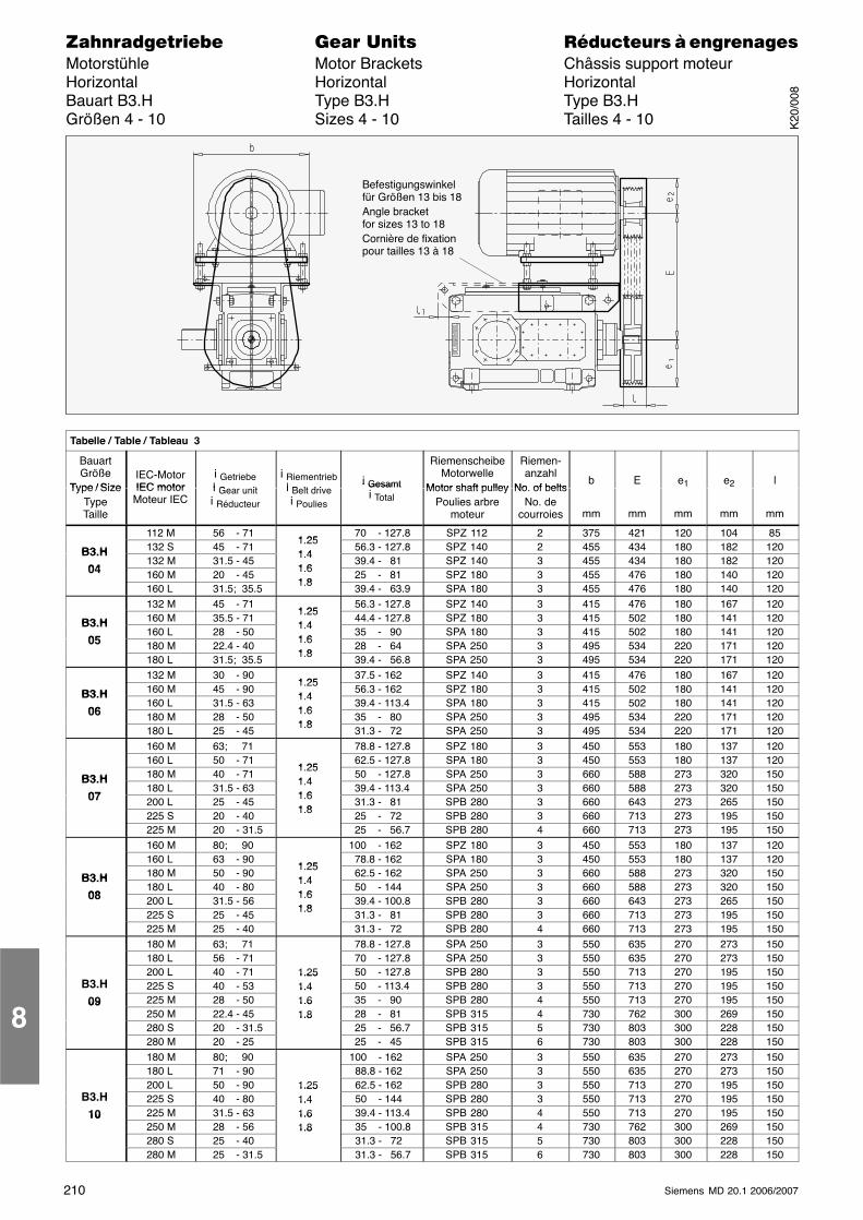
210 Siemens MD 20.1 2006/2007
������������� ���� �� ��������� � ����������Motorstühle Motor Brackets Châssis support moteurHorizontal Horizontal HorizontalBauart B3.H Type B3.H Type B3.HGrößen 4 - 10 Sizes 4 - 10 Tailles 4 - 10
Befestigungswinkelfür Größen 13 bis 18Angle bracketfor sizes 13 to 18Cornière de fixationpour tailles 13 à 18
ÁÁÁÁÁÁÁÁÁÁÁÁÁÁÁÁÁÁÁÁÁÁÁÁÁÁÁÁÁÁÁÁÁÁÁÁÁÁÁÁÁÁÁÁÁÁÁÁÁÁÁÁÁÁÁÁÁÁÁÁÁÁÁÁÁÁÁÁ
Tabelle / Table / Tableau 3
ÁÁÁÁÁÁÁÁÁÁÁÁ
BauartGröße
Type / Size
ÁÁÁÁÁÁÁÁÁÁÁÁ
IEC-MotorIEC motor
ÁÁÁÁÁÁÁÁÁÁÁÁÁÁÁ
i Getriebei G it
ÁÁÁÁÁÁÁÁÁÁÁ
i Riementriebi B lt d i
ÁÁÁÁÁÁÁÁÁÁÁÁ
i Gesamt
ÁÁÁÁÁÁÁÁÁÁÁÁÁÁÁ
RiemenscheibeMotorwelle
Motor shaft pulley
ÁÁÁÁÁÁÁÁÁÁÁÁ
Riemen-anzahl
No of belts
ÁÁÁÁÁÁÁÁÁ
b
ÁÁÁÁÁÁÁÁÁ
E
ÁÁÁÁÁÁÁÁÁ
e1
ÁÁÁÁÁÁÁÁÁ
e2
ÁÁÁÁÁÁÁÁÁ
l
ÁÁÁÁÁÁÁÁ
Type / SizeTypeTailleÁÁÁÁÁÁÁÁ
IEC motorMoteur IECÁÁÁÁÁ
ÁÁÁÁÁ
i Gear uniti Réducteur ÁÁÁ
ÁÁÁ
i Belt drivei Poulies ÁÁÁÁ
ÁÁÁÁ
i Gesamti Total ÁÁÁÁÁÁÁÁÁÁ
Motor shaft pulleyPoulies arbre
moteurÁÁÁÁÁÁÁÁ
No. of beltsNo. de
courroiesÁÁÁÁÁÁ
mmÁÁÁÁÁÁ
mmÁÁÁÁÁÁ
mmÁÁÁÁÁÁ
mmÁÁÁÁÁÁ
mmÁÁÁÁÁÁÁÁ
ÁÁÁÁÁÁÁÁ
112 M ÁÁÁÁÁÁÁÁÁÁ
56 - 71 ÁÁÁÁÁÁ
1 25ÁÁÁÁÁÁÁÁ
70 - 127.8ÁÁÁÁÁÁÁÁÁÁ
SPZ 112 ÁÁÁÁÁÁÁÁ
2 ÁÁÁÁÁÁ
375 ÁÁÁÁÁÁ
421 ÁÁÁÁÁÁ
120ÁÁÁÁÁÁ
104ÁÁÁÁÁÁ
85
ÁÁÁÁB3 H ÁÁÁÁ132 S ÁÁÁÁÁ45 - 71 ÁÁÁ1.251 4 ÁÁÁÁ 56.3 - 127.8ÁÁÁÁÁSPZ 140 ÁÁÁÁ2 ÁÁÁ455 ÁÁÁ434 ÁÁÁ180ÁÁÁ182ÁÁÁ120ÁÁÁÁ
ÁÁÁÁB3.H
04
ÁÁÁÁÁÁÁÁ
132 MÁÁÁÁÁÁÁÁÁÁ
31.5 - 45ÁÁÁÁÁÁ
1.41 6
ÁÁÁÁÁÁÁÁ
39.4 - 81ÁÁÁÁÁÁÁÁÁÁ
SPZ 140ÁÁÁÁÁÁÁÁ
3ÁÁÁÁÁÁ
455ÁÁÁÁÁÁ
434ÁÁÁÁÁÁ
180ÁÁÁÁÁÁ
182ÁÁÁÁÁÁ
120ÁÁÁÁÁÁÁÁ
04 ÁÁÁÁÁÁÁÁ
160 M ÁÁÁÁÁÁÁÁÁÁ
20 - 45 ÁÁÁÁÁÁ
1.61 8ÁÁÁÁÁÁÁÁ
25 - 81ÁÁÁÁÁÁÁÁÁÁ
SPZ 180 ÁÁÁÁÁÁÁÁ
3 ÁÁÁÁÁÁ
455 ÁÁÁÁÁÁ
476 ÁÁÁÁÁÁ
180ÁÁÁÁÁÁ
140ÁÁÁÁÁÁ
120
ÁÁÁÁÁÁÁÁ160 L ÁÁÁÁÁ31.5; 35.5 ÁÁÁ1.8ÁÁÁÁ 39.4 - 63.9ÁÁÁÁÁSPA 180 ÁÁÁÁ3 ÁÁÁ455 ÁÁÁ476 ÁÁÁ180ÁÁÁ140ÁÁÁ120ÁÁÁÁ
ÁÁÁÁÁÁÁÁÁÁÁÁ
132 MÁÁÁÁÁÁÁÁÁÁ
45 - 71ÁÁÁÁÁÁ1 25
ÁÁÁÁÁÁÁÁ
56.3 - 127.8ÁÁÁÁÁÁÁÁÁÁ
SPZ 140ÁÁÁÁÁÁÁÁ
3ÁÁÁÁÁÁ
415ÁÁÁÁÁÁ
476ÁÁÁÁÁÁ
180ÁÁÁÁÁÁ
167ÁÁÁÁÁÁ
120ÁÁÁÁÁÁÁÁ
B3 H ÁÁÁÁÁÁÁÁ
160 M ÁÁÁÁÁÁÁÁÁÁ
35.5 - 71 ÁÁÁÁÁÁ
1.251 4ÁÁÁÁÁÁÁÁ
44.4 - 127.8ÁÁÁÁÁÁÁÁÁÁ
SPZ 180 ÁÁÁÁÁÁÁÁ
3 ÁÁÁÁÁÁ
415 ÁÁÁÁÁÁ
502 ÁÁÁÁÁÁ
180ÁÁÁÁÁÁ
141ÁÁÁÁÁÁ
120
ÁÁÁÁB3.H
05 ÁÁÁÁ160 L ÁÁÁÁÁ28 - 50 ÁÁÁ1.41 6 ÁÁÁÁ 35 - 90ÁÁÁÁÁSPA 180 ÁÁÁÁ3 ÁÁÁ415 ÁÁÁ502 ÁÁÁ180ÁÁÁ141ÁÁÁ120ÁÁÁÁ
ÁÁÁÁ05 ÁÁÁÁÁÁÁÁ
180 M ÁÁÁÁÁÁÁÁÁÁ
22.4 - 40 ÁÁÁÁÁÁ
1.61 8ÁÁÁÁÁÁÁÁ
28 - 64ÁÁÁÁÁÁÁÁÁÁ
SPA 250 ÁÁÁÁÁÁÁÁ
3 ÁÁÁÁÁÁ
495 ÁÁÁÁÁÁ
534 ÁÁÁÁÁÁ
220ÁÁÁÁÁÁ
171ÁÁÁÁÁÁ
120
ÁÁÁÁÁÁÁÁ
ÁÁÁÁÁÁÁÁ
180 L ÁÁÁÁÁÁÁÁÁÁ
31.5; 35.5 ÁÁÁÁÁÁ
1.8 ÁÁÁÁÁÁÁÁ
39.4 - 56.8ÁÁÁÁÁÁÁÁÁÁ
SPA 250 ÁÁÁÁÁÁÁÁ
3 ÁÁÁÁÁÁ
495 ÁÁÁÁÁÁ
534 ÁÁÁÁÁÁ
220ÁÁÁÁÁÁ
171ÁÁÁÁÁÁ
120
ÁÁÁÁÁÁÁÁ132 M ÁÁÁÁÁ30 - 90 ÁÁÁ1 25 ÁÁÁÁ 37.5 - 162ÁÁÁÁÁSPZ 140 ÁÁÁÁ3 ÁÁÁ415 ÁÁÁ476 ÁÁÁ180ÁÁÁ167ÁÁÁ120ÁÁÁÁÁÁÁÁ
B3 HÁÁÁÁÁÁÁÁ
160 M ÁÁÁÁÁÁÁÁÁÁ
45 - 90 ÁÁÁÁÁÁ
1.251 4ÁÁÁÁÁÁÁÁ
56.3 - 162ÁÁÁÁÁÁÁÁÁÁ
SPZ 180 ÁÁÁÁÁÁÁÁ
3 ÁÁÁÁÁÁ
415 ÁÁÁÁÁÁ
502 ÁÁÁÁÁÁ
180ÁÁÁÁÁÁ
141ÁÁÁÁÁÁ
120
ÁÁÁÁB3.H
06 ÁÁÁÁ160 L ÁÁÁÁÁ31.5 - 63 ÁÁÁ1.41 6 ÁÁÁÁ 39.4 - 113.4ÁÁÁÁÁSPA 180 ÁÁÁÁ3 ÁÁÁ415 ÁÁÁ502 ÁÁÁ180ÁÁÁ141ÁÁÁ120ÁÁÁÁ
ÁÁÁÁ06 ÁÁÁÁÁÁÁÁ
180 MÁÁÁÁÁÁÁÁÁÁ
28 - 50ÁÁÁÁÁÁ
1.61 8
ÁÁÁÁÁÁÁÁ
35 - 80ÁÁÁÁÁÁÁÁÁÁ
SPA 250ÁÁÁÁÁÁÁÁ
3ÁÁÁÁÁÁ
495ÁÁÁÁÁÁ
534ÁÁÁÁÁÁ
220ÁÁÁÁÁÁ
171ÁÁÁÁÁÁ
120ÁÁÁÁÁÁÁÁ
ÁÁÁÁÁÁÁÁ
180 L ÁÁÁÁÁÁÁÁÁÁ
25 - 45 ÁÁÁÁÁÁ
1.8 ÁÁÁÁÁÁÁÁ
31.3 - 72ÁÁÁÁÁÁÁÁÁÁ
SPA 250 ÁÁÁÁÁÁÁÁ
3 ÁÁÁÁÁÁ
495 ÁÁÁÁÁÁ
534 ÁÁÁÁÁÁ
220ÁÁÁÁÁÁ
171ÁÁÁÁÁÁ
120
ÁÁÁÁÁÁÁÁ160 M ÁÁÁÁÁ63; 71 ÁÁÁÁÁÁÁ 78.8 - 127.8ÁÁÁÁÁSPZ 180 ÁÁÁÁ3 ÁÁÁ450 ÁÁÁ553 ÁÁÁ180ÁÁÁ137ÁÁÁ120ÁÁÁÁÁÁÁÁ
ÁÁÁÁÁÁÁÁ
160 LÁÁÁÁÁÁÁÁÁÁ
50 - 71ÁÁÁÁÁÁ1 25
ÁÁÁÁÁÁÁÁ
62.5 - 127.8ÁÁÁÁÁÁÁÁÁÁ
SPA 180ÁÁÁÁÁÁÁÁ
3ÁÁÁÁÁÁ
450ÁÁÁÁÁÁ
553ÁÁÁÁÁÁ
180ÁÁÁÁÁÁ
137ÁÁÁÁÁÁ
120ÁÁÁÁÁÁÁÁ
B3 H ÁÁÁÁÁÁÁÁ
180 M ÁÁÁÁÁÁÁÁÁÁ
40 - 71 ÁÁÁÁÁÁ
1.251 4ÁÁÁÁÁÁÁÁ
50 - 127.8ÁÁÁÁÁÁÁÁÁÁ
SPA 250 ÁÁÁÁÁÁÁÁ
3 ÁÁÁÁÁÁ
660 ÁÁÁÁÁÁ
588 ÁÁÁÁÁÁ
273ÁÁÁÁÁÁ
320ÁÁÁÁÁÁ
150
ÁÁÁÁB3.H
07 ÁÁÁÁ180 L ÁÁÁÁÁ31.5 - 63 ÁÁÁ1.41 6 ÁÁÁÁ 39.4 - 113.4ÁÁÁÁÁSPA 250 ÁÁÁÁ3 ÁÁÁ660 ÁÁÁ588 ÁÁÁ273ÁÁÁ320ÁÁÁ150ÁÁÁÁ
ÁÁÁÁ07 ÁÁÁÁÁÁÁÁ
200 L ÁÁÁÁÁÁÁÁÁÁ
25 - 45 ÁÁÁÁÁÁ
1.61 8ÁÁÁÁÁÁÁÁ
31.3 - 81ÁÁÁÁÁÁÁÁÁÁ
SPB 280 ÁÁÁÁÁÁÁÁ
3 ÁÁÁÁÁÁ
660 ÁÁÁÁÁÁ
643 ÁÁÁÁÁÁ
273ÁÁÁÁÁÁ
265ÁÁÁÁÁÁ
150
ÁÁÁÁÁÁÁÁ
ÁÁÁÁÁÁÁÁ
225 S ÁÁÁÁÁÁÁÁÁÁ
20 - 40 ÁÁÁÁÁÁ
1.8 ÁÁÁÁÁÁÁÁ
25 - 72ÁÁÁÁÁÁÁÁÁÁ
SPB 280 ÁÁÁÁÁÁÁÁ
3 ÁÁÁÁÁÁ
660 ÁÁÁÁÁÁ
713 ÁÁÁÁÁÁ
273ÁÁÁÁÁÁ
195ÁÁÁÁÁÁ
150
ÁÁÁÁÁÁÁÁ225 MÁÁÁÁÁ
20 - 31.5ÁÁÁÁÁÁÁ
25 - 56.7ÁÁÁÁÁ
SPB 280ÁÁÁÁ
4ÁÁÁ
660ÁÁÁ
713ÁÁÁ
273ÁÁÁ
195ÁÁÁ
150ÁÁÁÁÁÁÁÁ
ÁÁÁÁÁÁÁÁ
160 M ÁÁÁÁÁÁÁÁÁÁ
80; 90 ÁÁÁÁÁÁ
ÁÁÁÁÁÁÁÁ
100 - 162ÁÁÁÁÁÁÁÁÁÁ
SPZ 180 ÁÁÁÁÁÁÁÁ
3 ÁÁÁÁÁÁ
450 ÁÁÁÁÁÁ
553 ÁÁÁÁÁÁ
180ÁÁÁÁÁÁ
137ÁÁÁÁÁÁ
120
ÁÁÁÁÁÁÁÁ160 L ÁÁÁÁÁ63 - 90 ÁÁÁ1 25 ÁÁÁÁ 78.8 - 162ÁÁÁÁÁSPA 180 ÁÁÁÁ3 ÁÁÁ450 ÁÁÁ553 ÁÁÁ180ÁÁÁ137ÁÁÁ120ÁÁÁÁÁÁÁÁB3 H
ÁÁÁÁÁÁÁÁ
180 MÁÁÁÁÁÁÁÁÁÁ
50 - 90ÁÁÁÁÁÁ
1.251 4
ÁÁÁÁÁÁÁÁ
62.5 - 162ÁÁÁÁÁÁÁÁÁÁ
SPA 250ÁÁÁÁÁÁÁÁ
3ÁÁÁÁÁÁ
660ÁÁÁÁÁÁ
588ÁÁÁÁÁÁ
273ÁÁÁÁÁÁ
320ÁÁÁÁÁÁ
150ÁÁÁÁÁÁÁÁ
B3.H08ÁÁÁÁÁÁÁÁ
180 L ÁÁÁÁÁÁÁÁÁÁ
40 - 80 ÁÁÁÁÁÁ
1.41 6ÁÁÁÁÁÁÁÁ
50 - 144ÁÁÁÁÁÁÁÁÁÁ
SPA 250 ÁÁÁÁÁÁÁÁ
3 ÁÁÁÁÁÁ
660 ÁÁÁÁÁÁ
588 ÁÁÁÁÁÁ
273ÁÁÁÁÁÁ
320ÁÁÁÁÁÁ
150
ÁÁÁÁ08ÁÁÁÁ200 L ÁÁÁÁÁ31.5 - 56 ÁÁÁ
1.61 8 ÁÁÁÁ 39.4 - 100.8ÁÁÁÁÁSPB 280 ÁÁÁÁ3 ÁÁÁ660 ÁÁÁ643 ÁÁÁ273ÁÁÁ265ÁÁÁ150ÁÁÁÁ
ÁÁÁÁÁÁÁÁÁÁÁÁ
225 SÁÁÁÁÁÁÁÁÁÁ
25 - 45ÁÁÁÁÁÁ
1.8 ÁÁÁÁÁÁÁÁ
31.3 - 81ÁÁÁÁÁÁÁÁÁÁ
SPB 280ÁÁÁÁÁÁÁÁ
3ÁÁÁÁÁÁ
660ÁÁÁÁÁÁ
713ÁÁÁÁÁÁ
273ÁÁÁÁÁÁ
195ÁÁÁÁÁÁ
150ÁÁÁÁÁÁÁÁ
ÁÁÁÁÁÁÁÁ
225 M ÁÁÁÁÁÁÁÁÁÁ
25 - 40 ÁÁÁÁÁÁ
ÁÁÁÁÁÁÁÁ
31.3 - 72ÁÁÁÁÁÁÁÁÁÁ
SPB 280 ÁÁÁÁÁÁÁÁ
4 ÁÁÁÁÁÁ
660 ÁÁÁÁÁÁ
713 ÁÁÁÁÁÁ
273ÁÁÁÁÁÁ
195ÁÁÁÁÁÁ
150
ÁÁÁÁÁÁÁÁ180 M ÁÁÁÁÁ63; 71 ÁÁÁÁÁÁÁ 78.8 - 127.8ÁÁÁÁÁSPA 250 ÁÁÁÁ3 ÁÁÁ550 ÁÁÁ635 ÁÁÁ270ÁÁÁ273ÁÁÁ150ÁÁÁÁÁÁÁÁ
ÁÁÁÁÁÁÁÁ
180 L ÁÁÁÁÁÁÁÁÁÁ
56 - 71 ÁÁÁÁÁÁ
ÁÁÁÁÁÁÁÁ
70 - 127.8ÁÁÁÁÁÁÁÁÁÁ
SPA 250 ÁÁÁÁÁÁÁÁ
3 ÁÁÁÁÁÁ
550 ÁÁÁÁÁÁ
635 ÁÁÁÁÁÁ
270ÁÁÁÁÁÁ
273ÁÁÁÁÁÁ
150
ÁÁÁÁÁÁÁÁ
ÁÁÁÁÁÁÁÁ
200 L ÁÁÁÁÁÁÁÁÁÁ
40 - 71 ÁÁÁÁÁÁ
1.25 ÁÁÁÁÁÁÁÁ
50 - 127.8ÁÁÁÁÁÁÁÁÁÁ
SPB 280 ÁÁÁÁÁÁÁÁ
3 ÁÁÁÁÁÁ
550 ÁÁÁÁÁÁ
713 ÁÁÁÁÁÁ
270ÁÁÁÁÁÁ
195ÁÁÁÁÁÁ
150
ÁÁÁÁB3.HÁÁÁÁ
225 SÁÁÁÁÁ
40 - 53ÁÁÁ
1.251.4 ÁÁÁÁ
50 - 113.4ÁÁÁÁÁ
SPB 280ÁÁÁÁ
3ÁÁÁ
550ÁÁÁ
713ÁÁÁ
270ÁÁÁ
195ÁÁÁ
150ÁÁÁÁÁÁÁÁ
09 ÁÁÁÁÁÁÁÁ
225 M ÁÁÁÁÁÁÁÁÁÁ
28 - 50 ÁÁÁÁÁÁ
1.41.6 ÁÁÁÁÁÁÁÁ
35 - 90ÁÁÁÁÁÁÁÁÁÁ
SPB 280 ÁÁÁÁÁÁÁÁ
4 ÁÁÁÁÁÁ
550 ÁÁÁÁÁÁ
713 ÁÁÁÁÁÁ
270ÁÁÁÁÁÁ
195ÁÁÁÁÁÁ
150
ÁÁÁÁ09
ÁÁÁÁ250 M ÁÁÁÁÁ22.4 - 45 ÁÁÁ1.61.8 ÁÁÁÁ 28 - 81ÁÁÁÁÁSPB 315 ÁÁÁÁ4 ÁÁÁ730 ÁÁÁ762 ÁÁÁ300ÁÁÁ269ÁÁÁ150ÁÁÁÁ
ÁÁÁÁÁÁÁÁÁÁÁÁ
280 SÁÁÁÁÁÁÁÁÁÁ
20 - 31.5ÁÁÁÁÁÁ
1.8 ÁÁÁÁÁÁÁÁ
25 - 56.7ÁÁÁÁÁÁÁÁÁÁ
SPB 315ÁÁÁÁÁÁÁÁ
5ÁÁÁÁÁÁ
730ÁÁÁÁÁÁ
803ÁÁÁÁÁÁ
300ÁÁÁÁÁÁ
228ÁÁÁÁÁÁ
150ÁÁÁÁÁÁÁÁ
ÁÁÁÁÁÁÁÁ
280 M ÁÁÁÁÁÁÁÁÁÁ
20 - 25 ÁÁÁÁÁÁ
ÁÁÁÁÁÁÁÁ
25 - 45ÁÁÁÁÁÁÁÁÁÁ
SPB 315 ÁÁÁÁÁÁÁÁ
6 ÁÁÁÁÁÁ
730 ÁÁÁÁÁÁ
803 ÁÁÁÁÁÁ
300ÁÁÁÁÁÁ
228ÁÁÁÁÁÁ
150
ÁÁÁÁÁÁÁÁ180 M ÁÁÁÁÁ80; 90 ÁÁÁÁÁÁÁ100 - 162ÁÁÁÁÁSPA 250 ÁÁÁÁ3 ÁÁÁ550 ÁÁÁ635 ÁÁÁ270ÁÁÁ273ÁÁÁ150ÁÁÁÁÁÁÁÁ
ÁÁÁÁÁÁÁÁ
180 LÁÁÁÁÁÁÁÁÁÁ
71 - 90ÁÁÁÁÁÁ
ÁÁÁÁÁÁÁÁ
88.8 - 162ÁÁÁÁÁÁÁÁÁÁ
SPA 250ÁÁÁÁÁÁÁÁ
3ÁÁÁÁÁÁ
550ÁÁÁÁÁÁ
635ÁÁÁÁÁÁ
270ÁÁÁÁÁÁ
273ÁÁÁÁÁÁ
150ÁÁÁÁÁÁÁÁ
ÁÁÁÁÁÁÁÁ
200 L ÁÁÁÁÁÁÁÁÁÁ
50 - 90 ÁÁÁÁÁÁ
1.25 ÁÁÁÁÁÁÁÁ
62.5 - 162ÁÁÁÁÁÁÁÁÁÁ
SPB 280 ÁÁÁÁÁÁÁÁ
3 ÁÁÁÁÁÁ
550 ÁÁÁÁÁÁ
713 ÁÁÁÁÁÁ
270ÁÁÁÁÁÁ
195ÁÁÁÁÁÁ
150
ÁÁÁÁB3.HÁÁÁÁ225 S ÁÁÁÁÁ40 - 80 ÁÁÁ
1.251.4 ÁÁÁÁ 50 - 144ÁÁÁÁÁSPB 280 ÁÁÁÁ3 ÁÁÁ550 ÁÁÁ713 ÁÁÁ270ÁÁÁ195ÁÁÁ150ÁÁÁÁ
ÁÁÁÁ10 ÁÁÁÁÁÁÁÁ
225 M ÁÁÁÁÁÁÁÁÁÁ
31.5 - 63 ÁÁÁÁÁÁ
1.41.6 ÁÁÁÁÁÁÁÁ
39.4 - 113.4ÁÁÁÁÁÁÁÁÁÁ
SPB 280 ÁÁÁÁÁÁÁÁ
4 ÁÁÁÁÁÁ
550 ÁÁÁÁÁÁ
713 ÁÁÁÁÁÁ
270ÁÁÁÁÁÁ
195ÁÁÁÁÁÁ
150
ÁÁÁÁ10ÁÁÁÁ250 M ÁÁÁÁÁ28 - 56 ÁÁÁ
1.61.8 ÁÁÁÁ 35 - 100.8ÁÁÁÁÁSPB 315 ÁÁÁÁ4 ÁÁÁ730 ÁÁÁ762 ÁÁÁ300ÁÁÁ269ÁÁÁ150ÁÁÁÁ
ÁÁÁÁÁÁÁÁÁÁÁÁ
280 SÁÁÁÁÁÁÁÁÁÁ
25 - 40ÁÁÁÁÁÁ
1.8 ÁÁÁÁÁÁÁÁ
31.3 - 72ÁÁÁÁÁÁÁÁÁÁ
SPB 315ÁÁÁÁÁÁÁÁ
5ÁÁÁÁÁÁ
730ÁÁÁÁÁÁ
803ÁÁÁÁÁÁ
300ÁÁÁÁÁÁ
228ÁÁÁÁÁÁ
150ÁÁÁÁÁÁÁÁ
ÁÁÁÁÁÁÁÁ
280 M ÁÁÁÁÁÁÁÁÁÁ
25 - 31.5 ÁÁÁÁÁÁ
ÁÁÁÁÁÁÁÁ
31.3 - 56.7ÁÁÁÁÁÁÁÁÁÁ
SPB 315 ÁÁÁÁÁÁÁÁ
6 ÁÁÁÁÁÁ
730 ÁÁÁÁÁÁ
803 ÁÁÁÁÁÁ
300ÁÁÁÁÁÁ
228ÁÁÁÁÁÁ
150
8
K20
/008
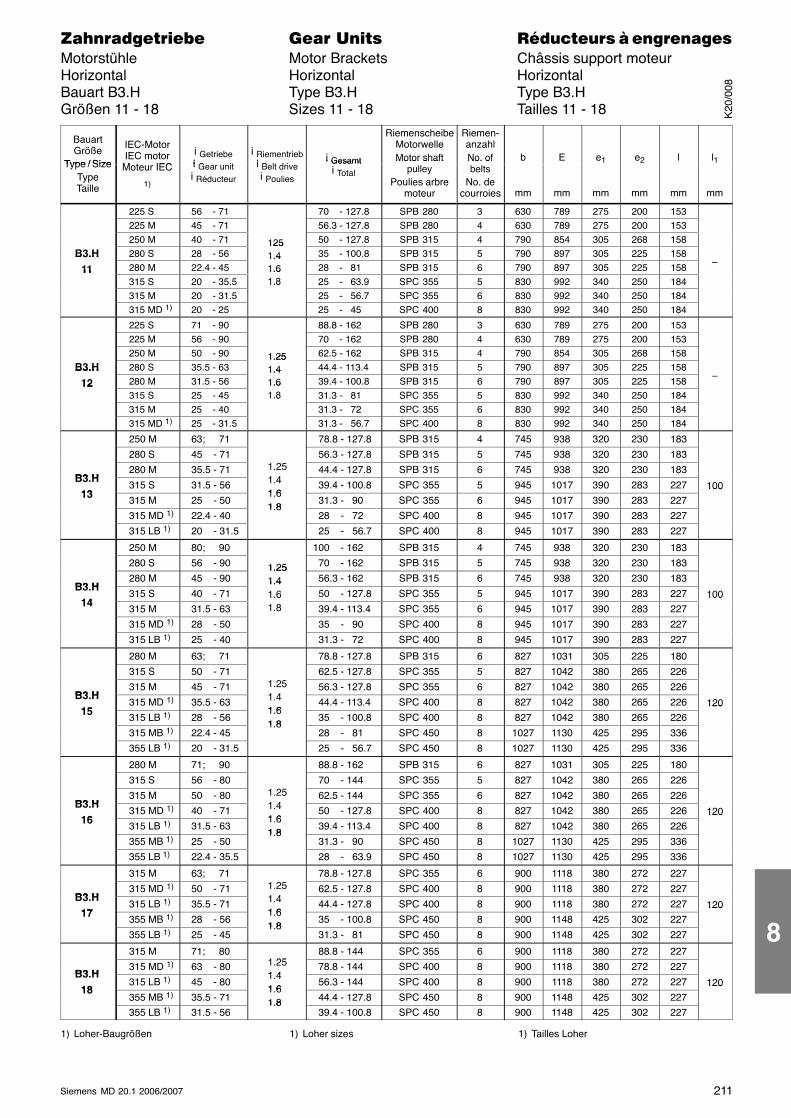
211Siemens MD 20.1 2006/2007
������������� ���� �� ��������� � ����������Motorstühle Motor Brackets Châssis support moteurHorizontal Horizontal HorizontalBauart B3.H Type B3.H Type B3.HGrößen 11 - 18 Sizes 11 - 18 Tailles 11 - 18
ÁÁÁÁÁÁÁÁÁÁÁÁ
BauartGröße
Type / Size
ÁÁÁÁÁÁÁÁÁÁÁÁ
IEC-MotorIEC motor
M t IEC
ÁÁÁÁÁÁÁÁÁÁÁÁÁÁÁ
i Getriebei G it
ÁÁÁÁÁÁÁÁÁ
i Riementriebi B lt d i
ÁÁÁÁÁÁÁÁÁÁÁÁÁÁÁ
i Gesamt
ÁÁÁÁÁÁÁÁÁÁÁÁÁÁÁ
RiemenscheibeMotorwelleMotor shaft
ÁÁÁÁÁÁÁÁÁ
Riemen-anzahlNo. of
ÁÁÁÁÁÁÁÁÁ
b
ÁÁÁÁÁÁÁÁÁ
E
ÁÁÁÁÁÁÁÁÁ
e1
ÁÁÁÁÁÁÁÁÁ
e2
ÁÁÁÁÁÁÁÁÁ
l
ÁÁÁÁÁÁ
l1
ÁÁÁÁÁÁÁÁÁÁÁÁ
Type / SizeTypeTailleÁÁÁÁÁÁÁÁÁÁÁÁ
Moteur IEC
1)ÁÁÁÁÁÁÁÁÁÁÁÁÁÁÁ
i Gear uniti Réducteur ÁÁÁ
ÁÁÁÁÁÁ
i Belt drivei PouliesÁÁÁÁÁÁÁÁÁÁÁÁÁÁÁ
i Gesamti Total ÁÁÁÁÁÁÁÁÁÁÁÁÁÁÁ
Motor shaftpulley
Poulies arbremoteur
ÁÁÁÁÁÁÁÁÁ
No. ofbelts
No. decourroies
ÁÁÁÁÁÁÁÁÁ
mmÁÁÁÁÁÁÁÁÁ
mmÁÁÁÁÁÁÁÁÁ
mmÁÁÁÁÁÁÁÁÁ
mmÁÁÁÁÁÁÁÁÁ
mmÁÁÁÁÁÁ
mm
ÁÁÁÁÁÁÁÁ225 S ÁÁÁÁÁ56 - 71 ÁÁÁÁÁÁÁÁ 70 - 127.8ÁÁÁÁÁSPB 280 ÁÁÁ3 ÁÁÁ630ÁÁÁ789ÁÁÁ275ÁÁÁ200 ÁÁÁ153 ÁÁÁÁÁÁÁÁÁÁ
ÁÁÁÁÁÁÁÁ
225 MÁÁÁÁÁÁÁÁÁÁ
45 - 71ÁÁÁÁÁÁÁÁÁÁÁÁÁÁÁÁ
56.3 - 127.8ÁÁÁÁÁÁÁÁÁÁ
SPB 280ÁÁÁÁÁÁ
4ÁÁÁÁÁÁ
630ÁÁÁÁÁÁ
789ÁÁÁÁÁÁ
275ÁÁÁÁÁÁ
200ÁÁÁÁÁÁ
153ÁÁÁÁÁÁÁÁ
ÁÁÁÁÁÁÁÁÁÁÁÁ
250 M ÁÁÁÁÁÁÁÁÁÁ
40 - 71 ÁÁÁÁÁÁ
125ÁÁÁÁÁÁÁÁÁÁ
50 - 127.8ÁÁÁÁÁÁÁÁÁÁ
SPB 315 ÁÁÁÁÁÁ
4 ÁÁÁÁÁÁ
790ÁÁÁÁÁÁ
854ÁÁÁÁÁÁ
305ÁÁÁÁÁÁ
268 ÁÁÁÁÁÁ
158 ÁÁÁÁÁÁÁÁB3.HÁÁÁÁ280 S ÁÁÁÁÁ28 - 56 ÁÁÁ
1251.4ÁÁÁÁÁ 35 - 100.8ÁÁÁÁÁSPB 315 ÁÁÁ5 ÁÁÁ790ÁÁÁ897ÁÁÁ305ÁÁÁ225 ÁÁÁ158 ÁÁÁÁÁÁ
ÁÁÁÁ
B3.H11ÁÁÁÁÁÁÁÁ
280 MÁÁÁÁÁÁÁÁÁÁ
22.4 - 45ÁÁÁÁÁÁ
1.41.6ÁÁÁÁÁÁÁÁÁÁ
28 - 81ÁÁÁÁÁÁÁÁÁÁ
SPB 315ÁÁÁÁÁÁ
6ÁÁÁÁÁÁ
790ÁÁÁÁÁÁ
897ÁÁÁÁÁÁ
305ÁÁÁÁÁÁ
225ÁÁÁÁÁÁ
158ÁÁÁÁ
–
ÁÁÁÁÁÁÁÁ
11ÁÁÁÁÁÁÁÁ
315 S ÁÁÁÁÁÁÁÁÁÁ
20 - 35.5 ÁÁÁÁÁÁ
1.61.8ÁÁÁÁÁÁÁÁÁÁ
25 - 63.9ÁÁÁÁÁÁÁÁÁÁ
SPC 355 ÁÁÁÁÁÁ
5 ÁÁÁÁÁÁ
830ÁÁÁÁÁÁ
992ÁÁÁÁÁÁ
340ÁÁÁÁÁÁ
250 ÁÁÁÁÁÁ
184 ÁÁÁÁÁÁÁÁÁÁÁÁ315 M ÁÁÁÁÁ20 - 31.5 ÁÁÁ
1.8
ÁÁÁÁÁ 25 - 56.7ÁÁÁÁÁSPC 355 ÁÁÁ6 ÁÁÁ830ÁÁÁ992ÁÁÁ340ÁÁÁ250 ÁÁÁ184 ÁÁÁÁÁÁÁÁÁÁ
ÁÁÁÁÁÁÁÁ
315 MD 1)ÁÁÁÁÁÁÁÁÁÁ
20 - 25ÁÁÁÁÁÁÁÁÁÁÁÁÁÁÁÁ
25 - 45ÁÁÁÁÁÁÁÁÁÁ
SPC 400ÁÁÁÁÁÁ
8ÁÁÁÁÁÁ
830ÁÁÁÁÁÁ
992ÁÁÁÁÁÁ
340ÁÁÁÁÁÁ
250ÁÁÁÁÁÁ
184ÁÁÁÁÁÁÁÁ
ÁÁÁÁÁÁÁÁÁÁÁÁ
225 S ÁÁÁÁÁÁÁÁÁÁ
71 - 90 ÁÁÁÁÁÁÁÁÁÁÁÁÁÁÁÁ
88.8 - 162 ÁÁÁÁÁÁÁÁÁÁ
SPB 280 ÁÁÁÁÁÁ
3 ÁÁÁÁÁÁ
630ÁÁÁÁÁÁ
789ÁÁÁÁÁÁ
275ÁÁÁÁÁÁ
200 ÁÁÁÁÁÁ
153 ÁÁÁÁÁÁÁÁ
ÁÁÁÁÁÁÁÁÁÁÁÁ
225 M ÁÁÁÁÁÁÁÁÁÁ
56 - 90 ÁÁÁÁÁÁÁÁÁÁÁÁÁÁÁÁ
70 - 162 ÁÁÁÁÁÁÁÁÁÁ
SPB 280 ÁÁÁÁÁÁ
4 ÁÁÁÁÁÁ
630ÁÁÁÁÁÁ
789ÁÁÁÁÁÁ
275ÁÁÁÁÁÁ
200 ÁÁÁÁÁÁ
153 ÁÁÁÁÁÁÁÁÁÁÁÁ250 M ÁÁÁÁÁ50 - 90 ÁÁÁ1.25ÁÁÁÁÁ 62.5 - 162 ÁÁÁÁÁSPB 315 ÁÁÁ4 ÁÁÁ790ÁÁÁ854ÁÁÁ305ÁÁÁ268 ÁÁÁ158 ÁÁÁÁÁÁ
ÁÁÁÁB3.HÁÁÁÁÁÁÁÁ
280 S ÁÁÁÁÁÁÁÁÁÁ
35.5 - 63 ÁÁÁÁÁÁ
1.251.4ÁÁÁÁÁÁÁÁÁÁ
44.4 - 113.4ÁÁÁÁÁÁÁÁÁÁ
SPB 315 ÁÁÁÁÁÁ
5 ÁÁÁÁÁÁ
790ÁÁÁÁÁÁ
897ÁÁÁÁÁÁ
305ÁÁÁÁÁÁ
225 ÁÁÁÁÁÁ
158 ÁÁÁÁÁÁÁÁ
ÁÁÁÁ
B3.H12 ÁÁÁÁÁÁÁÁ
280 M ÁÁÁÁÁÁÁÁÁÁ
31.5 - 56 ÁÁÁÁÁÁ
1.41.6ÁÁÁÁÁÁÁÁÁÁ
39.4 - 100.8ÁÁÁÁÁÁÁÁÁÁ
SPB 315 ÁÁÁÁÁÁ
6 ÁÁÁÁÁÁ
790ÁÁÁÁÁÁ
897ÁÁÁÁÁÁ
305ÁÁÁÁÁÁ
225 ÁÁÁÁÁÁ
158 ÁÁÁÁ
–
ÁÁÁÁ12
ÁÁÁÁ315 S ÁÁÁÁÁ25 - 45 ÁÁÁ1.61.8ÁÁÁÁÁ 31.3 - 81 ÁÁÁÁÁSPC 355 ÁÁÁ5 ÁÁÁ830ÁÁÁ992ÁÁÁ340ÁÁÁ250 ÁÁÁ184 ÁÁÁÁÁÁ
ÁÁÁÁÁÁÁÁÁÁÁÁ
315 MÁÁÁÁÁÁÁÁÁÁ
25 - 40ÁÁÁÁÁÁ
1.8ÁÁÁÁÁÁÁÁÁÁ
31.3 - 72ÁÁÁÁÁÁÁÁÁÁ
SPC 355ÁÁÁÁÁÁ
6ÁÁÁÁÁÁ
830ÁÁÁÁÁÁ
992ÁÁÁÁÁÁ
340ÁÁÁÁÁÁ
250ÁÁÁÁÁÁ
184ÁÁÁÁÁÁÁÁ
ÁÁÁÁÁÁÁÁÁÁÁÁ
315 MD 1)ÁÁÁÁÁÁÁÁÁÁ
25 - 31.5 ÁÁÁÁÁÁÁÁÁÁÁÁÁÁÁÁ
31.3 - 56.7ÁÁÁÁÁÁÁÁÁÁ
SPC 400 ÁÁÁÁÁÁ
8 ÁÁÁÁÁÁ
830ÁÁÁÁÁÁ
992ÁÁÁÁÁÁ
340ÁÁÁÁÁÁ
250 ÁÁÁÁÁÁ
184 ÁÁÁÁÁÁÁÁÁÁÁÁ250 M ÁÁÁÁÁ63; 71 ÁÁÁÁÁÁÁÁ 78.8 - 127.8ÁÁÁÁÁSPB 315 ÁÁÁ4 ÁÁÁ745ÁÁÁ938ÁÁÁ320ÁÁÁ230 ÁÁÁ183 ÁÁÁÁÁÁ
ÁÁÁÁÁÁÁÁÁÁÁÁ280 S
ÁÁÁÁÁÁÁÁÁÁ45 - 71
ÁÁÁÁÁÁÁÁÁÁÁÁÁÁÁÁ 56.3 - 127.8
ÁÁÁÁÁÁÁÁÁÁSPB 315
ÁÁÁÁÁÁ5ÁÁÁÁÁÁ745ÁÁÁÁÁÁ938ÁÁÁÁÁÁ320ÁÁÁÁÁÁ230ÁÁÁÁÁÁ183ÁÁÁÁÁÁÁÁ
ÁÁÁÁB3 HÁÁÁÁÁÁÁÁ
280 M ÁÁÁÁÁÁÁÁÁÁ
35.5 - 71 ÁÁÁÁÁÁ
1.251 4
ÁÁÁÁÁÁÁÁÁÁ
44.4 - 127.8ÁÁÁÁÁÁÁÁÁÁ
SPB 315 ÁÁÁÁÁÁ
6 ÁÁÁÁÁÁ
745ÁÁÁÁÁÁ
938ÁÁÁÁÁÁ
320ÁÁÁÁÁÁ
230 ÁÁÁÁÁÁ
183 ÁÁÁÁÁÁÁÁ
ÁÁÁÁ
B3.H13ÁÁÁÁÁÁÁÁ
315 S ÁÁÁÁÁÁÁÁÁÁ
31.5 - 56 ÁÁÁÁÁÁ
1.41 6ÁÁÁÁÁÁÁÁÁÁ
39.4 - 100.8ÁÁÁÁÁÁÁÁÁÁ
SPC 355 ÁÁÁÁÁÁ
5 ÁÁÁÁÁÁ
945ÁÁÁÁÁÁ
1017ÁÁÁÁÁÁ
390ÁÁÁÁÁÁ
283 ÁÁÁÁÁÁ
227 ÁÁÁÁ
100
ÁÁÁÁ13ÁÁÁÁ315 M ÁÁÁÁÁ25 - 50 ÁÁÁ
1.61 8ÁÁÁÁÁ 31.3 - 90ÁÁÁÁÁSPC 355 ÁÁÁ6 ÁÁÁ945ÁÁÁ1017ÁÁÁ390ÁÁÁ283 ÁÁÁ227 ÁÁ
100
ÁÁÁÁÁÁÁÁ
ÁÁÁÁÁÁÁÁ315 MD 1)
ÁÁÁÁÁÁÁÁÁÁ22.4 - 40
ÁÁÁÁÁÁ
1.8ÁÁÁÁÁÁÁÁÁÁ 28 - 72
ÁÁÁÁÁÁÁÁÁÁSPC 400
ÁÁÁÁÁÁ8ÁÁÁÁÁÁ945ÁÁÁÁÁÁ1017ÁÁÁÁÁÁ390ÁÁÁÁÁÁ283ÁÁÁÁÁÁ227ÁÁÁÁÁÁÁÁ
ÁÁÁÁÁÁÁÁÁÁÁÁ
315 LB 1)ÁÁÁÁÁÁÁÁÁÁ
20 - 31.5 ÁÁÁÁÁÁÁÁÁÁÁÁÁÁÁÁ
25 - 56.7ÁÁÁÁÁÁÁÁÁÁ
SPC 400 ÁÁÁÁÁÁ
8 ÁÁÁÁÁÁ
945ÁÁÁÁÁÁ
1017ÁÁÁÁÁÁ
390ÁÁÁÁÁÁ
283 ÁÁÁÁÁÁ
227 ÁÁÁÁÁÁÁÁ
ÁÁÁÁÁÁÁÁÁÁÁÁ
250 M ÁÁÁÁÁÁÁÁÁÁ
80; 90 ÁÁÁÁÁÁÁÁÁÁÁÁÁÁÁÁ
100 - 162ÁÁÁÁÁÁÁÁÁÁ
SPB 315 ÁÁÁÁÁÁ
4 ÁÁÁÁÁÁ
745ÁÁÁÁÁÁ
938ÁÁÁÁÁÁ
320ÁÁÁÁÁÁ
230 ÁÁÁÁÁÁ
183 ÁÁÁÁÁÁÁÁ
ÁÁÁÁÁÁÁÁÁÁÁÁ
280 S ÁÁÁÁÁÁÁÁÁÁ
56 - 90 ÁÁÁÁÁÁ
1.25ÁÁÁÁÁÁÁÁÁÁ
70 - 162ÁÁÁÁÁÁÁÁÁÁ
SPB 315 ÁÁÁÁÁÁ
5 ÁÁÁÁÁÁ
745ÁÁÁÁÁÁ
938ÁÁÁÁÁÁ
320ÁÁÁÁÁÁ
230 ÁÁÁÁÁÁ
183 ÁÁÁÁÁÁÁÁB3 HÁÁÁÁ280 M ÁÁÁÁÁ45 - 90 ÁÁÁ
1.251.4ÁÁÁÁÁ 56.3 - 162ÁÁÁÁÁSPB 315 ÁÁÁ6 ÁÁÁ745ÁÁÁ938ÁÁÁ320ÁÁÁ230 ÁÁÁ183 ÁÁÁÁÁÁ
ÁÁÁÁB3.H
14ÁÁÁÁÁÁÁÁ
315 SÁÁÁÁÁÁÁÁÁÁ
40 - 71ÁÁÁÁÁÁ
1.41.6ÁÁÁÁÁÁÁÁÁÁ
50 - 127.8ÁÁÁÁÁÁÁÁÁÁ
SPC 355ÁÁÁÁÁÁ
5ÁÁÁÁÁÁ
945ÁÁÁÁÁÁ
1017ÁÁÁÁÁÁ
390ÁÁÁÁÁÁ
283ÁÁÁÁÁÁ
227ÁÁÁÁ
100ÁÁÁÁÁÁÁÁ
14 ÁÁÁÁÁÁÁÁ
315 M ÁÁÁÁÁÁÁÁÁÁ
31.5 - 63 ÁÁÁÁÁÁ
1.61.8ÁÁÁÁÁÁÁÁÁÁ
39.4 - 113.4ÁÁÁÁÁÁÁÁÁÁ
SPC 355 ÁÁÁÁÁÁ
6 ÁÁÁÁÁÁ
945ÁÁÁÁÁÁ
1017ÁÁÁÁÁÁ
390ÁÁÁÁÁÁ
283 ÁÁÁÁÁÁ
227 ÁÁÁÁ
100
ÁÁÁÁÁÁÁÁ
ÁÁÁÁÁÁÁÁ
315 MD 1)ÁÁÁÁÁÁÁÁÁÁ
28 - 50 ÁÁÁÁÁÁÁÁÁÁÁÁÁÁÁÁ
35 - 90ÁÁÁÁÁÁÁÁÁÁ
SPC 400 ÁÁÁÁÁÁ
8 ÁÁÁÁÁÁ
945ÁÁÁÁÁÁ
1017ÁÁÁÁÁÁ
390ÁÁÁÁÁÁ
283 ÁÁÁÁÁÁ
227 ÁÁÁÁÁÁÁÁÁÁÁÁ315 LB 1)
ÁÁÁÁÁ25 - 40 ÁÁÁÁÁÁÁÁ 31.3 - 72ÁÁÁÁÁSPC 400 ÁÁÁ8 ÁÁÁ945ÁÁÁ1017ÁÁÁ390ÁÁÁ283 ÁÁÁ227 ÁÁÁÁÁÁÁÁÁÁ
ÁÁÁÁÁÁÁÁ
280 MÁÁÁÁÁÁÁÁÁÁ
63; 71ÁÁÁÁÁÁÁÁÁÁÁÁÁÁÁÁ
78.8 - 127.8ÁÁÁÁÁÁÁÁÁÁ
SPB 315ÁÁÁÁÁÁ
6ÁÁÁÁÁÁ
827ÁÁÁÁÁÁ
1031ÁÁÁÁÁÁ
305ÁÁÁÁÁÁ
225ÁÁÁÁÁÁ
180ÁÁÁÁÁÁÁÁ
ÁÁÁÁÁÁÁÁÁÁÁÁ
315 S ÁÁÁÁÁÁÁÁÁÁ
50 - 71 ÁÁÁÁÁÁÁÁÁÁÁÁÁÁÁÁ
62.5 - 127.8ÁÁÁÁÁÁÁÁÁÁ
SPC 355 ÁÁÁÁÁÁ
5 ÁÁÁÁÁÁ
827ÁÁÁÁÁÁ
1042ÁÁÁÁÁÁ
380ÁÁÁÁÁÁ
265 ÁÁÁÁÁÁ
226 ÁÁÁÁÁÁÁÁ
ÁÁÁÁB3 HÁÁÁÁÁÁÁÁ
315 M ÁÁÁÁÁÁÁÁÁÁ
45 - 71 ÁÁÁÁÁÁ
1.251 4ÁÁÁÁÁÁÁÁÁÁ
56.3 - 127.8ÁÁÁÁÁÁÁÁÁÁ
SPC 355 ÁÁÁÁÁÁ
6 ÁÁÁÁÁÁ
827ÁÁÁÁÁÁ
1042ÁÁÁÁÁÁ
380ÁÁÁÁÁÁ
265 ÁÁÁÁÁÁ
226 ÁÁÁÁÁÁÁÁ
B3.H15 ÁÁÁÁ315 MD 1)ÁÁÁÁÁ35.5 - 63 ÁÁÁ
1.41 6ÁÁÁÁÁ 44.4 - 113.4ÁÁÁÁÁSPC 400 ÁÁÁ8 ÁÁÁ827ÁÁÁ1042ÁÁÁ380ÁÁÁ265 ÁÁÁ226 ÁÁ120ÁÁÁÁ
ÁÁÁÁ15 ÁÁÁÁÁÁÁÁ
315 LB 1)ÁÁÁÁÁÁÁÁÁÁ
28 - 56ÁÁÁÁÁÁ
1.61 8ÁÁÁÁÁÁÁÁÁÁ
35 - 100.8ÁÁÁÁÁÁÁÁÁÁ
SPC 400ÁÁÁÁÁÁ
8ÁÁÁÁÁÁ
827ÁÁÁÁÁÁ
1042ÁÁÁÁÁÁ
380ÁÁÁÁÁÁ
265ÁÁÁÁÁÁ
226ÁÁÁÁ
120
ÁÁÁÁÁÁÁÁ
ÁÁÁÁÁÁÁÁ
315 MB 1)ÁÁÁÁÁÁÁÁÁÁ
22.4 - 45 ÁÁÁÁÁÁ
1.8ÁÁÁÁÁÁÁÁÁÁ
28 - 81ÁÁÁÁÁÁÁÁÁÁ
SPC 450 ÁÁÁÁÁÁ
8 ÁÁÁÁÁÁ
1027ÁÁÁÁÁÁ
1130ÁÁÁÁÁÁ
425ÁÁÁÁÁÁ
295 ÁÁÁÁÁÁ
336 ÁÁÁÁÁÁÁÁ
ÁÁÁÁÁÁÁÁÁÁÁÁ
355 LB 1)ÁÁÁÁÁÁÁÁÁÁ
20 - 31.5 ÁÁÁÁÁÁÁÁÁÁÁÁÁÁÁÁ
25 - 56.7ÁÁÁÁÁÁÁÁÁÁ
SPC 450 ÁÁÁÁÁÁ
8 ÁÁÁÁÁÁ
1027ÁÁÁÁÁÁ
1130ÁÁÁÁÁÁ
425ÁÁÁÁÁÁ
295 ÁÁÁÁÁÁ
336 ÁÁÁÁÁÁÁÁÁÁÁÁ280 M ÁÁÁÁÁ71; 90 ÁÁÁÁÁÁÁÁ 88.8 - 162ÁÁÁÁÁSPB 315 ÁÁÁ6 ÁÁÁ827ÁÁÁ1031ÁÁÁ305ÁÁÁ225 ÁÁÁ180 ÁÁÁÁÁÁ
ÁÁÁÁÁÁÁÁÁÁÁÁ
315 SÁÁÁÁÁÁÁÁÁÁ
56 - 80ÁÁÁÁÁÁÁÁÁÁÁÁÁÁÁÁ
70 - 144ÁÁÁÁÁÁÁÁÁÁ
SPC 355ÁÁÁÁÁÁ
5ÁÁÁÁÁÁ
827ÁÁÁÁÁÁ
1042ÁÁÁÁÁÁ
380ÁÁÁÁÁÁ
265ÁÁÁÁÁÁ
226ÁÁÁÁÁÁÁÁ
ÁÁÁÁB3 HÁÁÁÁÁÁÁÁ
315 M ÁÁÁÁÁÁÁÁÁÁ
50 - 80 ÁÁÁÁÁÁ
1.251 4ÁÁÁÁÁÁÁÁÁÁ
62.5 - 144ÁÁÁÁÁÁÁÁÁÁ
SPC 355 ÁÁÁÁÁÁ
6 ÁÁÁÁÁÁ
827ÁÁÁÁÁÁ
1042ÁÁÁÁÁÁ
380ÁÁÁÁÁÁ
265 ÁÁÁÁÁÁ
226 ÁÁÁÁÁÁÁÁ
ÁÁÁÁ
B3.H16ÁÁÁÁÁÁÁÁ
315 MD 1)ÁÁÁÁÁÁÁÁÁÁ
40 - 71 ÁÁÁÁÁÁ
1.41 6ÁÁÁÁÁÁÁÁÁÁ
50 - 127.8ÁÁÁÁÁÁÁÁÁÁ
SPC 400 ÁÁÁÁÁÁ
8 ÁÁÁÁÁÁ
827ÁÁÁÁÁÁ
1042ÁÁÁÁÁÁ
380ÁÁÁÁÁÁ
265 ÁÁÁÁÁÁ
226 ÁÁÁÁ
120
ÁÁÁÁ16ÁÁÁÁ315 LB 1)ÁÁÁÁÁ31.5 - 63 ÁÁÁ
1.61 8ÁÁÁÁÁ 39.4 - 113.4ÁÁÁÁÁSPC 400 ÁÁÁ8 ÁÁÁ827ÁÁÁ1042ÁÁÁ380ÁÁÁ265 ÁÁÁ226 ÁÁ
120
ÁÁÁÁÁÁÁÁ
ÁÁÁÁÁÁÁÁ
355 MB 1)ÁÁÁÁÁÁÁÁÁÁ
25 - 50ÁÁÁÁÁÁ
1.8ÁÁÁÁÁÁÁÁÁÁ
31.3 - 90ÁÁÁÁÁÁÁÁÁÁ
SPC 450ÁÁÁÁÁÁ
8ÁÁÁÁÁÁ
1027ÁÁÁÁÁÁ
1130ÁÁÁÁÁÁ
425ÁÁÁÁÁÁ
295ÁÁÁÁÁÁ
336ÁÁÁÁÁÁÁÁ
ÁÁÁÁÁÁÁÁÁÁÁÁ
355 LB 1)ÁÁÁÁÁÁÁÁÁÁ
22.4 - 35.5 ÁÁÁÁÁÁÁÁÁÁÁÁÁÁÁÁ
28 - 63.9ÁÁÁÁÁÁÁÁÁÁ
SPC 450 ÁÁÁÁÁÁ
8 ÁÁÁÁÁÁ
1027ÁÁÁÁÁÁ
1130ÁÁÁÁÁÁ
425ÁÁÁÁÁÁ
295 ÁÁÁÁÁÁ
336 ÁÁÁÁÁÁÁÁ
ÁÁÁÁÁÁÁÁÁÁÁÁ
315 M ÁÁÁÁÁÁÁÁÁÁ
63; 71 ÁÁÁÁÁÁÁÁÁÁÁÁÁÁÁÁ
78.8 - 127.8ÁÁÁÁÁÁÁÁÁÁ
SPC 355 ÁÁÁÁÁÁ
6 ÁÁÁÁÁÁ
900ÁÁÁÁÁÁ
1118ÁÁÁÁÁÁ
380ÁÁÁÁÁÁ
272 ÁÁÁÁÁÁ
227 ÁÁÁÁÁÁÁÁB3 HÁÁÁÁ315 MD 1)ÁÁÁÁÁ50 - 71 ÁÁÁ1.25
1 4ÁÁÁÁÁ 62.5 - 127.8ÁÁÁÁÁSPC 400 ÁÁÁ8 ÁÁÁ900ÁÁÁ1118ÁÁÁ380ÁÁÁ272 ÁÁÁ227 ÁÁÁÁÁÁÁÁÁÁ
B3.H17
ÁÁÁÁÁÁÁÁ315 LB 1)
ÁÁÁÁÁÁÁÁÁÁ35.5 - 71
ÁÁÁÁÁÁ
1.41 6
ÁÁÁÁÁÁÁÁÁÁ 44.4 - 127.8
ÁÁÁÁÁÁÁÁÁÁSPC 400
ÁÁÁÁÁÁ8ÁÁÁÁÁÁ900ÁÁÁÁÁÁ1118ÁÁÁÁÁÁ380ÁÁÁÁÁÁ272ÁÁÁÁÁÁ227ÁÁÁÁ120ÁÁÁÁ
ÁÁÁÁ17 ÁÁÁÁÁÁÁÁ
355 MB 1)ÁÁÁÁÁÁÁÁÁÁ
28 - 56 ÁÁÁÁÁÁ
1.61 8ÁÁÁÁÁÁÁÁÁÁ
35 - 100.8ÁÁÁÁÁÁÁÁÁÁ
SPC 450 ÁÁÁÁÁÁ
8 ÁÁÁÁÁÁ
900ÁÁÁÁÁÁ
1148ÁÁÁÁÁÁ
425ÁÁÁÁÁÁ
302 ÁÁÁÁÁÁ
227 ÁÁÁÁ
120
ÁÁÁÁÁÁÁÁ
ÁÁÁÁÁÁÁÁ
355 LB 1)ÁÁÁÁÁÁÁÁÁÁ
25 - 45 ÁÁÁÁÁÁ
1.8ÁÁÁÁÁÁÁÁÁÁ
31.3 - 81ÁÁÁÁÁÁÁÁÁÁ
SPC 450 ÁÁÁÁÁÁ
8 ÁÁÁÁÁÁ
900ÁÁÁÁÁÁ
1148ÁÁÁÁÁÁ
425ÁÁÁÁÁÁ
302 ÁÁÁÁÁÁ
227 ÁÁÁÁÁÁÁÁ
ÁÁÁÁÁÁÁÁÁÁÁÁ
315 M ÁÁÁÁÁÁÁÁÁÁ
71; 80 ÁÁÁÁÁÁ
1 25ÁÁÁÁÁÁÁÁÁÁ
88.8 - 144ÁÁÁÁÁÁÁÁÁÁ
SPC 355 ÁÁÁÁÁÁ
6 ÁÁÁÁÁÁ
900ÁÁÁÁÁÁ
1118ÁÁÁÁÁÁ
380ÁÁÁÁÁÁ
272 ÁÁÁÁÁÁ
227 ÁÁÁÁÁÁÁÁB3 HÁÁÁÁ315 MD 1)
ÁÁÁÁÁ63 - 80 ÁÁÁ1.251 4ÁÁÁÁÁ 78.8 - 144ÁÁÁÁÁSPC 400 ÁÁÁ8 ÁÁÁ900ÁÁÁ1118ÁÁÁ380ÁÁÁ272 ÁÁÁ227 ÁÁÁÁÁÁ
ÁÁÁÁB3.H
18ÁÁÁÁÁÁÁÁ
315 LB 1)ÁÁÁÁÁÁÁÁÁÁ
45 - 80ÁÁÁÁÁÁ
1.41 6ÁÁÁÁÁÁÁÁÁÁ
56.3 - 144ÁÁÁÁÁÁÁÁÁÁ
SPC 400ÁÁÁÁÁÁ
8ÁÁÁÁÁÁ
900ÁÁÁÁÁÁ
1118ÁÁÁÁÁÁ
380ÁÁÁÁÁÁ
272ÁÁÁÁÁÁ
227ÁÁÁÁ
120ÁÁÁÁÁÁÁÁ
18 ÁÁÁÁÁÁÁÁ
355 MB 1)ÁÁÁÁÁÁÁÁÁÁ
35.5 - 71 ÁÁÁÁÁÁ
1.61.8ÁÁÁÁÁÁÁÁÁÁ
44.4 - 127.8ÁÁÁÁÁÁÁÁÁÁ
SPC 450 ÁÁÁÁÁÁ
8 ÁÁÁÁÁÁ
900ÁÁÁÁÁÁ
1148ÁÁÁÁÁÁ
425ÁÁÁÁÁÁ
302 ÁÁÁÁÁÁ
227 ÁÁÁÁ
120
ÁÁÁÁÁÁÁÁ
ÁÁÁÁÁÁÁÁ
355 LB 1)ÁÁÁÁÁÁÁÁÁÁ
31.5 - 56 ÁÁÁÁÁÁ
1.8ÁÁÁÁÁÁÁÁÁÁ
39.4 - 100.8ÁÁÁÁÁÁÁÁÁÁ
SPC 450 ÁÁÁÁÁÁ
8 ÁÁÁÁÁÁ
900ÁÁÁÁÁÁ
1148ÁÁÁÁÁÁ
425ÁÁÁÁÁÁ
302 ÁÁÁÁÁÁ
227 ÁÁÁÁ1) Loher-Baugrößen 1) Loher sizes 1) Tailles Loher
K20
/008
8
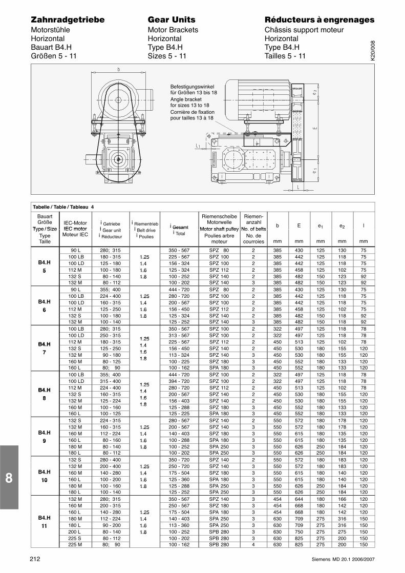
212 Siemens MD 20.1 2006/2007
������������� ���� �� ��������� � ����������Motorstühle Motor Brackets Châssis support moteurHorizontal Horizontal HorizontalBauart B4.H Type B4.H Type B4.HGrößen 5 - 11 Sizes 5 - 11 Tailles 5 - 11
Befestigungswinkelfür Größen 13 bis 18Angle bracketfor sizes 13 to 18Cornière de fixationpour tailles 13 à 18
ÁÁÁÁÁÁÁÁÁÁÁÁÁÁÁÁÁÁÁÁÁÁÁÁÁÁÁÁÁÁÁÁÁÁÁÁÁÁÁÁÁÁÁÁÁÁÁÁÁÁÁÁÁÁÁÁÁÁÁÁÁÁÁÁÁÁÁÁ
Tabelle / Table / Tableau 4
ÁÁÁÁÁÁÁÁÁÁÁÁ
BauartGröße
Type / Size
ÁÁÁÁÁÁÁÁÁÁÁÁ
IEC-MotorIEC motor
ÁÁÁÁÁÁÁÁÁÁÁÁÁÁÁ
i Getriebei G it
ÁÁÁÁÁÁÁÁÁÁÁ
i Riementriebi B lt d i
ÁÁÁÁÁÁÁÁÁÁÁÁ
i Gesamt
ÁÁÁÁÁÁÁÁÁÁÁÁÁÁÁ
RiemenscheibeMotorwelle
Motor shaft pulley
ÁÁÁÁÁÁÁÁÁÁÁÁ
Riemen-anzahl
No of belts
ÁÁÁÁÁÁÁÁÁ
b
ÁÁÁÁÁÁÁÁÁ
E
ÁÁÁÁÁÁÁÁÁ
e1
ÁÁÁÁÁÁÁÁÁ
e2
ÁÁÁÁÁÁÁÁÁ
l
ÁÁÁÁÁÁÁÁ
Type / SizeTypeTailleÁÁÁÁÁÁÁÁ
IEC motorMoteur IECÁÁÁÁÁ
ÁÁÁÁÁ
i Gear uniti Réducteur ÁÁÁ
ÁÁÁ
i Belt drivei Poulies ÁÁÁÁ
ÁÁÁÁ
i Gesamti Total ÁÁÁÁÁÁÁÁÁÁ
Motor shaft pulleyPoulies arbre
moteurÁÁÁÁÁÁÁÁ
No. of beltsNo. de
courroiesÁÁÁÁÁÁ
mmÁÁÁÁÁÁ
mmÁÁÁÁÁÁ
mmÁÁÁÁÁÁ
mmÁÁÁÁÁÁ
mmÁÁÁÁÁÁÁÁ
ÁÁÁÁÁÁÁÁ
90 L ÁÁÁÁÁÁÁÁÁÁ
280; 315 ÁÁÁÁÁÁ
ÁÁÁÁÁÁÁÁ
350 - 567ÁÁÁÁÁÁÁÁÁÁ
SPZ 80 ÁÁÁÁÁÁÁÁ
2 ÁÁÁÁÁÁ
385 ÁÁÁÁÁÁ
430 ÁÁÁÁÁÁ
125ÁÁÁÁÁÁ
130ÁÁÁÁÁÁ
75
ÁÁÁÁÁÁÁÁ100 LBÁÁÁÁÁ180 - 315 ÁÁÁ1.25 ÁÁÁÁ225 - 567ÁÁÁÁÁSPZ 100 ÁÁÁÁ2 ÁÁÁ385 ÁÁÁ442 ÁÁÁ125ÁÁÁ118ÁÁÁ75ÁÁÁÁÁÁÁÁ
B4.HÁÁÁÁÁÁÁÁ
100 LDÁÁÁÁÁÁÁÁÁÁ
125 - 180ÁÁÁÁÁÁ
1.251.4ÁÁÁÁÁÁÁÁ
156 - 324ÁÁÁÁÁÁÁÁÁÁ
SPZ 100ÁÁÁÁÁÁÁÁ
2ÁÁÁÁÁÁ
385ÁÁÁÁÁÁ
442ÁÁÁÁÁÁ
125ÁÁÁÁÁÁ
118ÁÁÁÁÁÁ
75ÁÁÁÁÁÁÁÁ
5 ÁÁÁÁÁÁÁÁ
112 M ÁÁÁÁÁÁÁÁÁÁ
100 - 180 ÁÁÁÁÁÁ
1.41.6 ÁÁÁÁÁÁÁÁ
125 - 324ÁÁÁÁÁÁÁÁÁÁ
SPZ 112 ÁÁÁÁÁÁÁÁ
2 ÁÁÁÁÁÁ
385 ÁÁÁÁÁÁ
458 ÁÁÁÁÁÁ
125ÁÁÁÁÁÁ
102ÁÁÁÁÁÁ
75
ÁÁÁÁ5
ÁÁÁÁ132 S ÁÁÁÁÁ 80 - 140 ÁÁÁ1.61.8 ÁÁÁÁ100 - 252ÁÁÁÁÁSPZ 140 ÁÁÁÁ2 ÁÁÁ385 ÁÁÁ482 ÁÁÁ150ÁÁÁ123ÁÁÁ92ÁÁÁÁ
ÁÁÁÁÁÁÁÁÁÁÁÁ
132 M ÁÁÁÁÁÁÁÁÁÁ
80 - 112 ÁÁÁÁÁÁ
1.8 ÁÁÁÁÁÁÁÁ
100 - 202ÁÁÁÁÁÁÁÁÁÁ
SPZ 140 ÁÁÁÁÁÁÁÁ
3 ÁÁÁÁÁÁ
385 ÁÁÁÁÁÁ
482 ÁÁÁÁÁÁ
150ÁÁÁÁÁÁ
123ÁÁÁÁÁÁ
92
ÁÁÁÁÁÁÁÁ
ÁÁÁÁÁÁÁÁ
90 L ÁÁÁÁÁÁÁÁÁÁ
355; 400 ÁÁÁÁÁÁ
ÁÁÁÁÁÁÁÁ
444 - 720ÁÁÁÁÁÁÁÁÁÁ
SPZ 80 ÁÁÁÁÁÁÁÁ
2 ÁÁÁÁÁÁ
385 ÁÁÁÁÁÁ
430 ÁÁÁÁÁÁ
125ÁÁÁÁÁÁ
130ÁÁÁÁÁÁ
75
ÁÁÁÁÁÁÁÁ100 LBÁÁÁÁÁ224 - 400 ÁÁÁ1.25 ÁÁÁÁ280 - 720ÁÁÁÁÁSPZ 100 ÁÁÁÁ2 ÁÁÁ385 ÁÁÁ442 ÁÁÁ125ÁÁÁ118ÁÁÁ75ÁÁÁÁÁÁÁÁ
B4.H ÁÁÁÁÁÁÁÁ
100 LDÁÁÁÁÁÁÁÁÁÁ
160 - 315 ÁÁÁÁÁÁ
1.251.4 ÁÁÁÁÁÁÁÁ
200 - 567ÁÁÁÁÁÁÁÁÁÁ
SPZ 100 ÁÁÁÁÁÁÁÁ
2 ÁÁÁÁÁÁ
385 ÁÁÁÁÁÁ
442 ÁÁÁÁÁÁ
125ÁÁÁÁÁÁ
118ÁÁÁÁÁÁ
75
ÁÁÁÁ6 ÁÁÁÁ112 M ÁÁÁÁÁ125 - 250 ÁÁÁ1.41.6 ÁÁÁÁ156 - 450ÁÁÁÁÁSPZ 112 ÁÁÁÁ2 ÁÁÁ385 ÁÁÁ458 ÁÁÁ125ÁÁÁ102ÁÁÁ75ÁÁÁÁ
ÁÁÁÁ6 ÁÁÁÁÁÁÁÁ
132 SÁÁÁÁÁÁÁÁÁÁ
100 - 180ÁÁÁÁÁÁ
1.61.8ÁÁÁÁÁÁÁÁ
125 - 324ÁÁÁÁÁÁÁÁÁÁ
SPZ 140ÁÁÁÁÁÁÁÁ
2ÁÁÁÁÁÁ
385ÁÁÁÁÁÁ
482ÁÁÁÁÁÁ
150ÁÁÁÁÁÁ
118ÁÁÁÁÁÁ
92ÁÁÁÁÁÁÁÁ
ÁÁÁÁÁÁÁÁ
132 M ÁÁÁÁÁÁÁÁÁÁ
100 - 140 ÁÁÁÁÁÁ
1.8ÁÁÁÁÁÁÁÁ
125 - 252ÁÁÁÁÁÁÁÁÁÁ
SPZ 140 ÁÁÁÁÁÁÁÁ
3 ÁÁÁÁÁÁ
385 ÁÁÁÁÁÁ
482 ÁÁÁÁÁÁ
150ÁÁÁÁÁÁ
118ÁÁÁÁÁÁ
92
ÁÁÁÁÁÁÁÁ100 LBÁÁÁÁÁ280; 315 ÁÁÁÁÁÁÁ350 - 567ÁÁÁÁÁSPZ 100 ÁÁÁÁ2 ÁÁÁ322 ÁÁÁ497 ÁÁÁ125ÁÁÁ118ÁÁÁ78ÁÁÁÁÁÁÁÁ
ÁÁÁÁÁÁÁÁ
100 LDÁÁÁÁÁÁÁÁÁÁ
250 - 315ÁÁÁÁÁÁ1 25
ÁÁÁÁÁÁÁÁ
313 - 567ÁÁÁÁÁÁÁÁÁÁ
SPZ 100ÁÁÁÁÁÁÁÁ
2ÁÁÁÁÁÁ
322ÁÁÁÁÁÁ
497ÁÁÁÁÁÁ
125ÁÁÁÁÁÁ
118ÁÁÁÁÁÁ
78ÁÁÁÁÁÁÁÁ
B4 H ÁÁÁÁÁÁÁÁ
112 M ÁÁÁÁÁÁÁÁÁÁ
180 - 315 ÁÁÁÁÁÁ
1.251 4 ÁÁÁÁÁÁÁÁ
225 - 567ÁÁÁÁÁÁÁÁÁÁ
SPZ 112 ÁÁÁÁÁÁÁÁ
2 ÁÁÁÁÁÁ
450 ÁÁÁÁÁÁ
513 ÁÁÁÁÁÁ
125ÁÁÁÁÁÁ
102ÁÁÁÁÁÁ
78
ÁÁÁÁB4.H
7 ÁÁÁÁ132 S ÁÁÁÁÁ125 - 250 ÁÁÁ1.41 6 ÁÁÁÁ156 - 450ÁÁÁÁÁSPZ 140 ÁÁÁÁ2 ÁÁÁ450 ÁÁÁ530 ÁÁÁ180ÁÁÁ155ÁÁÁ120ÁÁÁÁ
ÁÁÁÁ7 ÁÁÁÁÁÁÁÁ
132 M ÁÁÁÁÁÁÁÁÁÁ
90 - 180 ÁÁÁÁÁÁ
1.61 8ÁÁÁÁÁÁÁÁ
113 - 324ÁÁÁÁÁÁÁÁÁÁ
SPZ 140 ÁÁÁÁÁÁÁÁ
3 ÁÁÁÁÁÁ
450 ÁÁÁÁÁÁ
530 ÁÁÁÁÁÁ
180ÁÁÁÁÁÁ
155ÁÁÁÁÁÁ
120
ÁÁÁÁÁÁÁÁ160 M ÁÁÁÁÁ 80 - 125 ÁÁÁ1.8 ÁÁÁÁ100 - 225ÁÁÁÁÁSPZ 180 ÁÁÁÁ3 ÁÁÁ450 ÁÁÁ552 ÁÁÁ180ÁÁÁ133ÁÁÁ120ÁÁÁÁÁÁÁÁ
ÁÁÁÁÁÁÁÁ
160 LÁÁÁÁÁÁÁÁÁÁ
80; 90ÁÁÁÁÁÁ
ÁÁÁÁÁÁÁÁ
100 - 162ÁÁÁÁÁÁÁÁÁÁ
SPA 180ÁÁÁÁÁÁÁÁ
3ÁÁÁÁÁÁ
450ÁÁÁÁÁÁ
552ÁÁÁÁÁÁ
180ÁÁÁÁÁÁ
133ÁÁÁÁÁÁ
120ÁÁÁÁÁÁÁÁ
ÁÁÁÁÁÁÁÁ
100 LBÁÁÁÁÁÁÁÁÁÁ
355; 400 ÁÁÁÁÁÁ
ÁÁÁÁÁÁÁÁ
444 - 720ÁÁÁÁÁÁÁÁÁÁ
SPZ 100 ÁÁÁÁÁÁÁÁ
2 ÁÁÁÁÁÁ
322 ÁÁÁÁÁÁ
497 ÁÁÁÁÁÁ
125ÁÁÁÁÁÁ
118ÁÁÁÁÁÁ
78
ÁÁÁÁÁÁÁÁ100 LDÁÁÁÁÁ315 - 400 ÁÁÁ1 25 ÁÁÁÁ394 - 720ÁÁÁÁÁSPZ 100 ÁÁÁÁ2 ÁÁÁ322 ÁÁÁ497 ÁÁÁ125ÁÁÁ118ÁÁÁ78ÁÁÁÁÁÁÁÁB4 H
ÁÁÁÁÁÁÁÁ
112 MÁÁÁÁÁÁÁÁÁÁ
224 - 400ÁÁÁÁÁÁ
1.251 4ÁÁÁÁÁÁÁÁ
280 - 720ÁÁÁÁÁÁÁÁÁÁ
SPZ 112ÁÁÁÁÁÁÁÁ
2ÁÁÁÁÁÁ
450ÁÁÁÁÁÁ
513ÁÁÁÁÁÁ
125ÁÁÁÁÁÁ
102ÁÁÁÁÁÁ
78ÁÁÁÁÁÁÁÁ
B4.H8ÁÁÁÁÁÁÁÁ
132 S ÁÁÁÁÁÁÁÁÁÁ
160 - 315 ÁÁÁÁÁÁ
1.41 6 ÁÁÁÁÁÁÁÁ
200 - 567ÁÁÁÁÁÁÁÁÁÁ
SPZ 140 ÁÁÁÁÁÁÁÁ
2 ÁÁÁÁÁÁ
450 ÁÁÁÁÁÁ
530 ÁÁÁÁÁÁ
180ÁÁÁÁÁÁ
155ÁÁÁÁÁÁ
120
ÁÁÁÁ8ÁÁÁÁ132 M ÁÁÁÁÁ125 - 224 ÁÁÁ
1.61 8 ÁÁÁÁ156 - 403ÁÁÁÁÁSPZ 140 ÁÁÁÁ2 ÁÁÁ450 ÁÁÁ530 ÁÁÁ180ÁÁÁ155ÁÁÁ120ÁÁÁÁ
ÁÁÁÁÁÁÁÁÁÁÁÁ
160 M ÁÁÁÁÁÁÁÁÁÁ
100 - 160 ÁÁÁÁÁÁ
1.8 ÁÁÁÁÁÁÁÁ
125 - 288ÁÁÁÁÁÁÁÁÁÁ
SPZ 180 ÁÁÁÁÁÁÁÁ
3 ÁÁÁÁÁÁ
450 ÁÁÁÁÁÁ
552 ÁÁÁÁÁÁ
180ÁÁÁÁÁÁ
133ÁÁÁÁÁÁ
120
ÁÁÁÁÁÁÁÁ160 L ÁÁÁÁÁ100 - 125 ÁÁÁÁÁÁÁ125 - 225ÁÁÁÁÁSPA 180 ÁÁÁÁ3 ÁÁÁ450 ÁÁÁ552 ÁÁÁ180ÁÁÁ133ÁÁÁ120ÁÁÁÁÁÁÁÁ
ÁÁÁÁÁÁÁÁ
132 SÁÁÁÁÁÁÁÁÁÁ
224 - 315ÁÁÁÁÁÁ
ÁÁÁÁÁÁÁÁ
280 - 567ÁÁÁÁÁÁÁÁÁÁ
SPZ 140ÁÁÁÁÁÁÁÁ
2ÁÁÁÁÁÁ
550ÁÁÁÁÁÁ
572ÁÁÁÁÁÁ
180ÁÁÁÁÁÁ
178ÁÁÁÁÁÁ
120ÁÁÁÁÁÁÁÁ
ÁÁÁÁÁÁÁÁ
132 M ÁÁÁÁÁÁÁÁÁÁ
160 - 315 ÁÁÁÁÁÁ
1.25 ÁÁÁÁÁÁÁÁ
200 - 567ÁÁÁÁÁÁÁÁÁÁ
SPZ 140 ÁÁÁÁÁÁÁÁ
3 ÁÁÁÁÁÁ
550 ÁÁÁÁÁÁ
572 ÁÁÁÁÁÁ
180ÁÁÁÁÁÁ
178ÁÁÁÁÁÁ
120
ÁÁÁÁB4.H ÁÁÁÁ160 M ÁÁÁÁÁ112 - 224 ÁÁÁ1.251.4 ÁÁÁÁ140 - 403ÁÁÁÁÁSPZ 180 ÁÁÁÁ3 ÁÁÁ550 ÁÁÁ615 ÁÁÁ180ÁÁÁ135ÁÁÁ120ÁÁÁÁ
ÁÁÁÁ9ÁÁÁÁÁÁÁÁ
160 LÁÁÁÁÁÁÁÁÁÁ
80 - 160ÁÁÁÁÁÁ
1.41.6ÁÁÁÁÁÁÁÁ
100 - 288ÁÁÁÁÁÁÁÁÁÁ
SPA 180ÁÁÁÁÁÁÁÁ
3ÁÁÁÁÁÁ
550ÁÁÁÁÁÁ
615ÁÁÁÁÁÁ
180ÁÁÁÁÁÁ
135ÁÁÁÁÁÁ
120ÁÁÁÁÁÁÁÁ
9ÁÁÁÁÁÁÁÁ
180 M ÁÁÁÁÁÁÁÁÁÁ
80 - 140 ÁÁÁÁÁÁ
1.61.8 ÁÁÁÁÁÁÁÁ
100 - 252ÁÁÁÁÁÁÁÁÁÁ
SPA 250 ÁÁÁÁÁÁÁÁ
3 ÁÁÁÁÁÁ
550 ÁÁÁÁÁÁ
626 ÁÁÁÁÁÁ
250ÁÁÁÁÁÁ
184ÁÁÁÁÁÁ
120
ÁÁÁÁÁÁÁÁ180 L ÁÁÁÁÁ 80 - 112 ÁÁÁ1.8
ÁÁÁÁ100 - 202ÁÁÁÁÁSPA 250 ÁÁÁÁ3 ÁÁÁ550 ÁÁÁ626 ÁÁÁ250ÁÁÁ184ÁÁÁ120ÁÁÁÁÁÁÁÁ
ÁÁÁÁÁÁÁÁ
132 S ÁÁÁÁÁÁÁÁÁÁ
280 - 400 ÁÁÁÁÁÁ
ÁÁÁÁÁÁÁÁ
350 - 720ÁÁÁÁÁÁÁÁÁÁ
SPZ 140 ÁÁÁÁÁÁÁÁ
2 ÁÁÁÁÁÁ
550 ÁÁÁÁÁÁ
572 ÁÁÁÁÁÁ
180ÁÁÁÁÁÁ
183ÁÁÁÁÁÁ
120
ÁÁÁÁÁÁÁÁ132 M ÁÁÁÁÁ200 - 400 ÁÁÁ1.25 ÁÁÁÁ250 - 720ÁÁÁÁÁSPZ 140 ÁÁÁÁ3 ÁÁÁ550 ÁÁÁ572 ÁÁÁ180ÁÁÁ183ÁÁÁ120ÁÁÁÁÁÁÁÁ
B4.HÁÁÁÁÁÁÁÁ
160 MÁÁÁÁÁÁÁÁÁÁ
140 - 280ÁÁÁÁÁÁ
1.251.4ÁÁÁÁÁÁÁÁ
175 - 504ÁÁÁÁÁÁÁÁÁÁ
SPZ 180ÁÁÁÁÁÁÁÁ
3ÁÁÁÁÁÁ
550ÁÁÁÁÁÁ
615ÁÁÁÁÁÁ
180ÁÁÁÁÁÁ
140ÁÁÁÁÁÁ
120ÁÁÁÁÁÁÁÁ
10 ÁÁÁÁÁÁÁÁ
160 L ÁÁÁÁÁÁÁÁÁÁ
100 - 200 ÁÁÁÁÁÁ
1.41.6 ÁÁÁÁÁÁÁÁ
125 - 360ÁÁÁÁÁÁÁÁÁÁ
SPA 180 ÁÁÁÁÁÁÁÁ
3 ÁÁÁÁÁÁ
550 ÁÁÁÁÁÁ
615 ÁÁÁÁÁÁ
180ÁÁÁÁÁÁ
140ÁÁÁÁÁÁ
120
ÁÁÁÁ10
ÁÁÁÁ180 M ÁÁÁÁÁ100 - 160 ÁÁÁ1.61.8 ÁÁÁÁ125 - 288ÁÁÁÁÁSPA 250 ÁÁÁÁ3 ÁÁÁ550 ÁÁÁ626 ÁÁÁ250ÁÁÁ184ÁÁÁ120ÁÁÁÁ
ÁÁÁÁÁÁÁÁÁÁÁÁ
180 L ÁÁÁÁÁÁÁÁÁÁ
100 - 140 ÁÁÁÁÁÁ
1.8 ÁÁÁÁÁÁÁÁ
125 - 252ÁÁÁÁÁÁÁÁÁÁ
SPA 250 ÁÁÁÁÁÁÁÁ
3 ÁÁÁÁÁÁ
550 ÁÁÁÁÁÁ
626 ÁÁÁÁÁÁ
250ÁÁÁÁÁÁ
184ÁÁÁÁÁÁ
120
ÁÁÁÁÁÁÁÁ
ÁÁÁÁÁÁÁÁ
132 M ÁÁÁÁÁÁÁÁÁÁ
280; 315 ÁÁÁÁÁÁ
ÁÁÁÁÁÁÁÁ
350 - 567ÁÁÁÁÁÁÁÁÁÁ
SPZ 140 ÁÁÁÁÁÁÁÁ
3 ÁÁÁÁÁÁ
454 ÁÁÁÁÁÁ
644 ÁÁÁÁÁÁ
180ÁÁÁÁÁÁ
166ÁÁÁÁÁÁ
120
ÁÁÁÁÁÁÁÁ160 M ÁÁÁÁÁ200 - 315 ÁÁÁÁÁÁÁ250 - 567ÁÁÁÁÁSPZ 180 ÁÁÁÁ3 ÁÁÁ454 ÁÁÁ668 ÁÁÁ180ÁÁÁ142ÁÁÁ120ÁÁÁÁÁÁÁÁ
ÁÁÁÁÁÁÁÁ
160 L ÁÁÁÁÁÁÁÁÁÁ
140 - 280 ÁÁÁÁÁÁ
1.25 ÁÁÁÁÁÁÁÁ
175 - 504ÁÁÁÁÁÁÁÁÁÁ
SPA 180 ÁÁÁÁÁÁÁÁ
3 ÁÁÁÁÁÁ
454 ÁÁÁÁÁÁ
668 ÁÁÁÁÁÁ
180ÁÁÁÁÁÁ
142ÁÁÁÁÁÁ
120
ÁÁÁÁB4.H ÁÁÁÁ180 M ÁÁÁÁÁ112 - 224 ÁÁÁ1.251.4 ÁÁÁÁ140 - 403ÁÁÁÁÁSPA 250 ÁÁÁÁ3 ÁÁÁ630 ÁÁÁ709 ÁÁÁ275ÁÁÁ316ÁÁÁ150ÁÁÁÁ
ÁÁÁÁ11ÁÁÁÁÁÁÁÁ
180 LÁÁÁÁÁÁÁÁÁÁ
90 - 200ÁÁÁÁÁÁ
1.41.6ÁÁÁÁÁÁÁÁ
113 - 360ÁÁÁÁÁÁÁÁÁÁ
SPA 250ÁÁÁÁÁÁÁÁ
3ÁÁÁÁÁÁ
630ÁÁÁÁÁÁ
709ÁÁÁÁÁÁ
275ÁÁÁÁÁÁ
316ÁÁÁÁÁÁ
150ÁÁÁÁÁÁÁÁ
11 ÁÁÁÁÁÁÁÁ
200 L ÁÁÁÁÁÁÁÁÁÁ
80 - 140 ÁÁÁÁÁÁ
1.61.8 ÁÁÁÁÁÁÁÁ
100 - 252ÁÁÁÁÁÁÁÁÁÁ
SPB 280 ÁÁÁÁÁÁÁÁ
3 ÁÁÁÁÁÁ
630 ÁÁÁÁÁÁ
750 ÁÁÁÁÁÁ
275ÁÁÁÁÁÁ
275ÁÁÁÁÁÁ
150
ÁÁÁÁÁÁÁÁ225 S ÁÁÁÁÁ 80 - 112 ÁÁÁ1.8
ÁÁÁÁ100 - 202ÁÁÁÁÁSPB 280 ÁÁÁÁ3 ÁÁÁ630 ÁÁÁ825 ÁÁÁ275ÁÁÁ200ÁÁÁ150ÁÁÁÁÁÁÁÁ
ÁÁÁÁÁÁÁÁ
225 M ÁÁÁÁÁÁÁÁÁÁ
80; 90 ÁÁÁÁÁÁ
ÁÁÁÁÁÁÁÁ
100 - 162ÁÁÁÁÁÁÁÁÁÁ
SPB 280 ÁÁÁÁÁÁÁÁ
4 ÁÁÁÁÁÁ
630 ÁÁÁÁÁÁ
825 ÁÁÁÁÁÁ
275ÁÁÁÁÁÁ
200ÁÁÁÁÁÁ
150
8
K20
/008
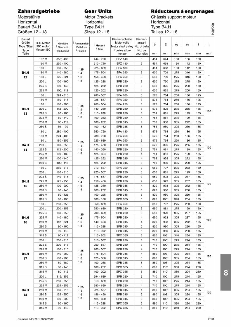
213Siemens MD 20.1 2006/2007
������������� ���� �� ��������� � ����������Motorstühle Motor Brackets Châssis support moteurHorizontal Horizontal HorizontalBauart B4.H Type B4.H Type B4.HGrößen 12 - 18 Sizes 12 - 18 Tailles 12 - 18
ÁÁÁÁÁÁÁÁ
BauartGröße
Type / Size
ÁÁÁÁÁÁÁÁ
IEC-MotorIEC motor
ÁÁÁÁÁÁÁÁÁÁ
i Getriebei G it
ÁÁÁÁÁÁi Riementriebi B lt d i
ÁÁÁÁÁÁÁÁÁÁi Gesamt
ÁÁÁÁÁÁÁÁÁÁ
RiemenscheibeMotorwelle
Motor shaft pulley
ÁÁÁÁÁÁ
Riemen-anzahl
No of belts
ÁÁÁÁbÁÁÁÁÁÁEÁÁÁÁÁÁe1
ÁÁÁÁÁÁe2
ÁÁÁÁÁÁlÁÁÁÁl1ÁÁÁÁ
ÁÁÁÁÁÁÁÁ
Type / SizeTypeTaille
ÁÁÁÁÁÁÁÁÁÁÁÁ
IEC motorMoteur IEC
ÁÁÁÁÁÁÁÁÁÁÁÁÁÁÁ
i Gear uniti Réducteur
ÁÁÁÁÁÁÁÁÁ
i Belt drivei Poulies
ÁÁÁÁÁÁÁÁÁÁÁÁÁÁÁ
i Gesamti TotalÁÁÁÁÁÁÁÁÁÁÁÁÁÁÁ
Motor shaft pulleyPoulies arbre
moteur
ÁÁÁÁÁÁÁÁÁÁÁ
No. of beltsNo. de
courroies
ÁÁÁÁÁÁ
mm
ÁÁÁÁÁÁÁÁÁ
mm
ÁÁÁÁÁÁÁÁÁ
mm
ÁÁÁÁÁÁÁÁÁ
mm
ÁÁÁÁÁÁÁÁÁ
mm
ÁÁÁÁÁÁ
mm
ÁÁÁÁÁÁÁÁ
ÁÁÁÁÁÁÁÁ
132 MÁÁÁÁÁÁÁÁÁÁ
355; 400 ÁÁÁÁÁÁÁÁÁÁÁÁÁÁÁÁ
444 - 720 ÁÁÁÁÁÁÁÁÁÁ
SPZ 140 ÁÁÁÁÁÁ
3 ÁÁÁÁ
454ÁÁÁÁÁÁ
644ÁÁÁÁÁÁ
180ÁÁÁÁÁÁ
166ÁÁÁÁÁÁ
120 ÁÁÁÁÁÁÁÁ
ÁÁÁÁÁÁÁÁÁÁÁÁ
160 MÁÁÁÁÁÁÁÁÁÁ
250 - 400 ÁÁÁÁÁÁÁÁÁÁÁÁÁÁÁÁ
313 - 720 ÁÁÁÁÁÁÁÁÁÁ
SPZ 180 ÁÁÁÁÁÁ
3 ÁÁÁÁ
454ÁÁÁÁÁÁ
668ÁÁÁÁÁÁ
180ÁÁÁÁÁÁ
142ÁÁÁÁÁÁ
120 ÁÁÁÁÁÁÁÁÁÁÁÁ160 LÁÁÁÁÁ180 - 355 ÁÁÁ1.25ÁÁÁÁÁ225 - 639 ÁÁÁÁÁSPA 180 ÁÁÁ3 ÁÁ454ÁÁÁ668ÁÁÁ180ÁÁÁ142ÁÁÁ120 ÁÁÁÁÁÁ
ÁÁÁÁB4.HÁÁÁÁÁÁÁÁ
180 MÁÁÁÁÁÁÁÁÁÁ
140 - 280ÁÁÁÁÁÁ
1.251.4ÁÁÁÁÁÁÁÁÁÁ
175 - 504ÁÁÁÁÁÁÁÁÁÁ
SPA 250ÁÁÁÁÁÁ
3ÁÁÁÁ
630ÁÁÁÁÁÁ
709ÁÁÁÁÁÁ
275ÁÁÁÁÁÁ
316ÁÁÁÁÁÁ
150ÁÁÁÁÁÁÁÁ
ÁÁÁÁ
B4.H12 ÁÁÁÁÁÁÁÁ
180 LÁÁÁÁÁÁÁÁÁÁ
125 - 224 ÁÁÁÁÁÁ
1.41.6ÁÁÁÁÁÁÁÁÁÁ
156 - 403 ÁÁÁÁÁÁÁÁÁÁ
SPA 250 ÁÁÁÁÁÁ
3 ÁÁÁÁ
630ÁÁÁÁÁÁ
709ÁÁÁÁÁÁ
275ÁÁÁÁÁÁ
316ÁÁÁÁÁÁ
150 ÁÁÁÁ
–
ÁÁÁÁÁÁÁÁ
12ÁÁÁÁÁÁÁÁ
200 LÁÁÁÁÁÁÁÁÁÁ
100 - 160 ÁÁÁÁÁÁ
1.61.8ÁÁÁÁÁÁÁÁÁÁ
125 - 288 ÁÁÁÁÁÁÁÁÁÁ
SPB 280 ÁÁÁÁÁÁ
3 ÁÁÁÁ
630ÁÁÁÁÁÁ
750ÁÁÁÁÁÁ
275ÁÁÁÁÁÁ
275ÁÁÁÁÁÁ
150 ÁÁÁÁÁÁÁÁÁÁÁÁ225 SÁÁÁÁÁ100 - 140 ÁÁÁÁÁÁÁÁ125 - 252 ÁÁÁÁÁSPB 280 ÁÁÁ3 ÁÁ630ÁÁÁ825ÁÁÁ275ÁÁÁ200ÁÁÁ150 ÁÁÁÁÁÁ
ÁÁÁÁÁÁÁÁÁÁÁÁ
225 MÁÁÁÁÁÁÁÁÁÁ
100; 112ÁÁÁÁÁÁÁÁÁÁÁÁÁÁÁÁ
125 - 202ÁÁÁÁÁÁÁÁÁÁ
SPB 280ÁÁÁÁÁÁ
4ÁÁÁÁ
630ÁÁÁÁÁÁ
825ÁÁÁÁÁÁ
275ÁÁÁÁÁÁ
200ÁÁÁÁÁÁ
150ÁÁÁÁÁÁÁÁ
ÁÁÁÁÁÁÁÁÁÁÁÁ
160 LÁÁÁÁÁÁÁÁÁÁ
224 - 315 ÁÁÁÁÁÁÁÁÁÁÁÁÁÁÁÁ
280 - 567 ÁÁÁÁÁÁÁÁÁÁ
SPA 180 ÁÁÁÁÁÁ
3 ÁÁÁÁ
575ÁÁÁÁÁÁ
764ÁÁÁÁÁÁ
250ÁÁÁÁÁÁ
186ÁÁÁÁÁÁ
125 ÁÁÁÁÁÁÁÁ
ÁÁÁÁÁÁÁÁÁÁÁÁ
180 MÁÁÁÁÁÁÁÁÁÁ
180 - 315 ÁÁÁÁÁÁÁÁÁÁÁÁÁÁÁÁ
225 - 567 ÁÁÁÁÁÁÁÁÁÁ
SPA 250 ÁÁÁÁÁÁ
3 ÁÁÁÁ
575ÁÁÁÁÁÁ
764ÁÁÁÁÁÁ
250ÁÁÁÁÁÁ
186ÁÁÁÁÁÁ
125 ÁÁÁÁÁÁÁÁÁÁÁÁ180 LÁÁÁÁÁ160 - 280 ÁÁÁ1.25ÁÁÁÁÁ200 - 504 ÁÁÁÁÁSPA 250 ÁÁÁ3 ÁÁ575ÁÁÁ764ÁÁÁ250ÁÁÁ186ÁÁÁ125 ÁÁÁÁÁÁ
ÁÁÁÁB4.HÁÁÁÁÁÁÁÁ
200 LÁÁÁÁÁÁÁÁÁÁ
112 - 200ÁÁÁÁÁÁ
1.251.4ÁÁÁÁÁÁÁÁÁÁ
140 - 360ÁÁÁÁÁÁÁÁÁÁ
SPB 280ÁÁÁÁÁÁ
3ÁÁÁÁ
575ÁÁÁÁÁÁ
825ÁÁÁÁÁÁ
275ÁÁÁÁÁÁ
255ÁÁÁÁÁÁ
155ÁÁÁÁ100ÁÁÁÁ
ÁÁÁÁ
B4.H13 ÁÁÁÁÁÁÁÁ
225 SÁÁÁÁÁÁÁÁÁÁ
90 - 160 ÁÁÁÁÁÁ
1.41.6ÁÁÁÁÁÁÁÁÁÁ
113 - 288 ÁÁÁÁÁÁÁÁÁÁ
SPB 280 ÁÁÁÁÁÁ
3 ÁÁÁÁ
751ÁÁÁÁÁÁ
881ÁÁÁÁÁÁ
275ÁÁÁÁÁÁ
199ÁÁÁÁÁÁ
155 ÁÁÁÁ
100
ÁÁÁÁÁÁÁÁ
13ÁÁÁÁÁÁÁÁ
225 MÁÁÁÁÁÁÁÁÁÁ
80 - 140 ÁÁÁÁÁÁ
1.61.8ÁÁÁÁÁÁÁÁÁÁ
100 - 252 ÁÁÁÁÁÁÁÁÁÁ
SPB 280 ÁÁÁÁÁÁ
4 ÁÁÁÁ
751ÁÁÁÁÁÁ
881ÁÁÁÁÁÁ
275ÁÁÁÁÁÁ
199ÁÁÁÁÁÁ
155 ÁÁÁÁÁÁÁÁÁÁÁÁ250 MÁÁÁÁÁ 80 - 112 ÁÁÁÁÁÁÁÁ100 - 202 ÁÁÁÁÁSPB 315 ÁÁÁ4 ÁÁ753ÁÁÁ938ÁÁÁ305ÁÁÁ272ÁÁÁ155 ÁÁÁÁÁÁ
ÁÁÁÁÁÁÁÁÁÁÁÁ
280 SÁÁÁÁÁÁÁÁÁÁ
80 - 90ÁÁÁÁÁÁÁÁÁÁÁÁÁÁÁÁ
100 - 162ÁÁÁÁÁÁÁÁÁÁ
SPB 315ÁÁÁÁÁÁ
5ÁÁÁÁ
753ÁÁÁÁÁÁ
980ÁÁÁÁÁÁ
305ÁÁÁÁÁÁ
230ÁÁÁÁÁÁ
155ÁÁÁÁÁÁÁÁ
ÁÁÁÁÁÁÁÁÁÁÁÁ
160 LÁÁÁÁÁÁÁÁÁÁ
280 - 400 ÁÁÁÁÁÁÁÁÁÁÁÁÁÁÁÁ
350 - 720 ÁÁÁÁÁÁÁÁÁÁ
SPA 180 ÁÁÁÁÁÁ
3 ÁÁÁÁ
575ÁÁÁÁÁÁ
764ÁÁÁÁÁÁ
250ÁÁÁÁÁÁ
186ÁÁÁÁÁÁ
125 ÁÁÁÁÁÁÁÁ
ÁÁÁÁÁÁÁÁÁÁÁÁ
180 MÁÁÁÁÁÁÁÁÁÁ
224 - 400 ÁÁÁÁÁÁÁÁÁÁÁÁÁÁÁÁ
280 - 720 ÁÁÁÁÁÁÁÁÁÁ
SPA 250 ÁÁÁÁÁÁ
3 ÁÁÁÁ
575ÁÁÁÁÁÁ
764ÁÁÁÁÁÁ
250ÁÁÁÁÁÁ
186ÁÁÁÁÁÁ
125 ÁÁÁÁÁÁÁÁÁÁÁÁ180 LÁÁÁÁÁ180 - 355 ÁÁÁ1.25ÁÁÁÁÁ225 - 639 ÁÁÁÁÁSPA 250 ÁÁÁ3 ÁÁ575ÁÁÁ764ÁÁÁ250ÁÁÁ186ÁÁÁ125 ÁÁÁÁÁÁ
ÁÁÁÁB4.HÁÁÁÁÁÁÁÁ200 L
ÁÁÁÁÁÁÁÁÁÁ140 - 250
ÁÁÁÁÁÁ
1.251.4ÁÁÁÁÁÁÁÁÁÁ175 - 450
ÁÁÁÁÁÁÁÁÁÁSPB 280
ÁÁÁÁÁÁ3
ÁÁÁÁ575ÁÁÁÁÁÁ825ÁÁÁÁÁÁ275ÁÁÁÁÁÁ255ÁÁÁÁÁÁ155ÁÁÁÁ100ÁÁÁÁ
ÁÁÁÁ
B4.H14ÁÁÁÁÁÁÁÁ
225 SÁÁÁÁÁÁÁÁÁÁ
112 - 200 ÁÁÁÁÁÁ
1.41.6ÁÁÁÁÁÁÁÁÁÁ
140 - 360 ÁÁÁÁÁÁÁÁÁÁ
SPB 280 ÁÁÁÁÁÁ
3 ÁÁÁÁ
751ÁÁÁÁÁÁ
881ÁÁÁÁÁÁ
275ÁÁÁÁÁÁ
199ÁÁÁÁÁÁ
155 ÁÁÁÁ
100
ÁÁÁÁÁÁÁÁ
14ÁÁÁÁÁÁÁÁ
225 MÁÁÁÁÁÁÁÁÁÁ
100 - 180 ÁÁÁÁÁÁ
1.61.8ÁÁÁÁÁÁÁÁÁÁ
125 - 324 ÁÁÁÁÁÁÁÁÁÁ
SPB 280 ÁÁÁÁÁÁ
4 ÁÁÁÁ
751ÁÁÁÁÁÁ
881ÁÁÁÁÁÁ
275ÁÁÁÁÁÁ
199ÁÁÁÁÁÁ
155 ÁÁÁÁÁÁÁÁÁÁÁÁ250 MÁÁÁÁÁ100 - 140 ÁÁÁÁÁÁÁÁ125 - 252 ÁÁÁÁÁSPB 315 ÁÁÁ4 ÁÁ753ÁÁÁ938ÁÁÁ305ÁÁÁ272ÁÁÁ155 ÁÁÁÁÁÁ
ÁÁÁÁÁÁÁÁÁÁÁÁ280 S
ÁÁÁÁÁÁÁÁÁÁ100; 112
ÁÁÁÁÁÁÁÁÁÁÁÁÁÁÁÁ125 - 202
ÁÁÁÁÁÁÁÁÁÁSPB 315
ÁÁÁÁÁÁ5
ÁÁÁÁ753ÁÁÁÁÁÁ980ÁÁÁÁÁÁ305ÁÁÁÁÁÁ230ÁÁÁÁÁÁ155ÁÁÁÁÁÁÁÁ
ÁÁÁÁÁÁÁÁÁÁÁÁ
180 LÁÁÁÁÁÁÁÁÁÁ
250 - 315ÁÁÁÁÁÁÁÁÁÁÁÁÁÁÁÁ
313 - 567ÁÁÁÁÁÁÁÁÁÁ
SPA 250ÁÁÁÁÁÁ
3ÁÁÁÁ
650ÁÁÁÁÁÁ
797ÁÁÁÁÁÁ
275ÁÁÁÁÁÁ
283ÁÁÁÁÁÁ
150ÁÁÁÁÁÁÁÁ
ÁÁÁÁÁÁÁÁÁÁÁÁ
200 LÁÁÁÁÁÁÁÁÁÁ
180 - 315 ÁÁÁÁÁÁÁÁÁÁÁÁÁÁÁÁ
225 - 567 ÁÁÁÁÁÁÁÁÁÁ
SPB 280 ÁÁÁÁÁÁ
3 ÁÁÁÁ
650ÁÁÁÁÁÁ
881ÁÁÁÁÁÁ
275ÁÁÁÁÁÁ
199ÁÁÁÁÁÁ
150 ÁÁÁÁÁÁÁÁ
ÁÁÁÁÁÁÁÁÁÁÁÁ
225 SÁÁÁÁÁÁÁÁÁÁ
140 - 315 ÁÁÁÁÁÁ
1.25ÁÁÁÁÁÁÁÁÁÁ
175 - 567 ÁÁÁÁÁÁÁÁÁÁ
SPB 280 ÁÁÁÁÁÁ
3 ÁÁÁÁ
650ÁÁÁÁÁÁ
923ÁÁÁÁÁÁ
305ÁÁÁÁÁÁ
287ÁÁÁÁÁÁ
155 ÁÁÁÁÁÁÁÁB4.HÁÁÁÁ225 MÁÁÁÁÁ125 - 250 ÁÁÁ
1.251.4ÁÁÁÁÁ156 - 450 ÁÁÁÁÁSPB 280 ÁÁÁ4 ÁÁ650ÁÁÁ923ÁÁÁ305ÁÁÁ287ÁÁÁ155 ÁÁ120ÁÁÁÁ
ÁÁÁÁ
B4.H15ÁÁÁÁÁÁÁÁ
250 MÁÁÁÁÁÁÁÁÁÁ
100 - 200ÁÁÁÁÁÁ
1.41.6ÁÁÁÁÁÁÁÁÁÁ
125 - 360ÁÁÁÁÁÁÁÁÁÁ
SPB 315ÁÁÁÁÁÁ
4ÁÁÁÁ
820ÁÁÁÁÁÁ
938ÁÁÁÁÁÁ
305ÁÁÁÁÁÁ
272ÁÁÁÁÁÁ
155ÁÁÁÁ
120
ÁÁÁÁÁÁÁÁ
15ÁÁÁÁÁÁÁÁ
280 SÁÁÁÁÁÁÁÁÁÁ
80 - 140 ÁÁÁÁÁÁ
1.61.8ÁÁÁÁÁÁÁÁÁÁ
100 - 252 ÁÁÁÁÁÁÁÁÁÁ
SPB 315 ÁÁÁÁÁÁ
5 ÁÁÁÁ
820ÁÁÁÁÁÁ
980ÁÁÁÁÁÁ
305ÁÁÁÁÁÁ
230ÁÁÁÁÁÁ
155 ÁÁÁÁÁÁÁÁ
ÁÁÁÁÁÁÁÁÁÁÁÁ
280 MÁÁÁÁÁÁÁÁÁÁ
80 - 125 ÁÁÁÁÁÁÁÁÁÁÁÁÁÁÁÁ
100 - 225 ÁÁÁÁÁÁÁÁÁÁ
SPB 315 ÁÁÁÁÁÁ
6 ÁÁÁÁ
820ÁÁÁÁÁÁ
980ÁÁÁÁÁÁ
305ÁÁÁÁÁÁ
230ÁÁÁÁÁÁ
155 ÁÁÁÁÁÁÁÁÁÁÁÁ315 SÁÁÁÁÁ 80 - 100 ÁÁÁÁÁÁÁÁ100 - 180 ÁÁÁÁÁSPC 355 ÁÁÁ5 ÁÁ820ÁÁÁ1051ÁÁÁ340ÁÁÁ254ÁÁÁ185 ÁÁÁÁÁÁ
ÁÁÁÁÁÁÁÁÁÁÁÁ
180 LÁÁÁÁÁÁÁÁÁÁ
280 - 355ÁÁÁÁÁÁÁÁÁÁÁÁÁÁÁÁ
350 - 639ÁÁÁÁÁÁÁÁÁÁ
SPA 250ÁÁÁÁÁÁ
3ÁÁÁÁ
650ÁÁÁÁÁÁ
797ÁÁÁÁÁÁ
275ÁÁÁÁÁÁ
283ÁÁÁÁÁÁ
150ÁÁÁÁÁÁÁÁ
ÁÁÁÁÁÁÁÁÁÁÁÁ
200 LÁÁÁÁÁÁÁÁÁÁ
200 - 355 ÁÁÁÁÁÁÁÁÁÁÁÁÁÁÁÁ
250 - 639 ÁÁÁÁÁÁÁÁÁÁ
SPB 280 ÁÁÁÁÁÁ
3 ÁÁÁÁ
650ÁÁÁÁÁÁ
881ÁÁÁÁÁÁ
275ÁÁÁÁÁÁ
199ÁÁÁÁÁÁ
150 ÁÁÁÁÁÁÁÁ
ÁÁÁÁÁÁÁÁÁÁÁÁ
225 SÁÁÁÁÁÁÁÁÁÁ
160 - 355 ÁÁÁÁÁÁ
1.25ÁÁÁÁÁÁÁÁÁÁ
200 - 639 ÁÁÁÁÁÁÁÁÁÁ
SPB 280 ÁÁÁÁÁÁ
3 ÁÁÁÁ
650ÁÁÁÁÁÁ
923ÁÁÁÁÁÁ
305ÁÁÁÁÁÁ
287ÁÁÁÁÁÁ
155 ÁÁÁÁÁÁÁÁB4.HÁÁÁÁ225 MÁÁÁÁÁ140 - 180 ÁÁÁ
1.251.4ÁÁÁÁÁ175 - 504 ÁÁÁÁÁSPB 280 ÁÁÁ4 ÁÁ650ÁÁÁ923ÁÁÁ305ÁÁÁ287ÁÁÁ155 ÁÁ120ÁÁÁÁ
ÁÁÁÁ
B4.H16ÁÁÁÁÁÁÁÁ
250 MÁÁÁÁÁÁÁÁÁÁ
112 - 224ÁÁÁÁÁÁ
1.41.6ÁÁÁÁÁÁÁÁÁÁ
140 - 403ÁÁÁÁÁÁÁÁÁÁ
SPB 315ÁÁÁÁÁÁ
4ÁÁÁÁ
820ÁÁÁÁÁÁ
938ÁÁÁÁÁÁ
305ÁÁÁÁÁÁ
272ÁÁÁÁÁÁ
155ÁÁÁÁ
120
ÁÁÁÁÁÁÁÁ
16ÁÁÁÁÁÁÁÁ
280 SÁÁÁÁÁÁÁÁÁÁ
90 - 160 ÁÁÁÁÁÁ
1.61.8ÁÁÁÁÁÁÁÁÁÁ
113 - 288 ÁÁÁÁÁÁÁÁÁÁ
SPB 315 ÁÁÁÁÁÁ
5 ÁÁÁÁ
820ÁÁÁÁÁÁ
980ÁÁÁÁÁÁ
305ÁÁÁÁÁÁ
230ÁÁÁÁÁÁ
155 ÁÁÁÁÁÁÁÁ
ÁÁÁÁÁÁÁÁÁÁÁÁ
280 MÁÁÁÁÁÁÁÁÁÁ
90 - 140 ÁÁÁÁÁÁÁÁÁÁÁÁÁÁÁÁ
113 - 252 ÁÁÁÁÁÁÁÁÁÁ
SPB 315 ÁÁÁÁÁÁ
6 ÁÁÁÁ
820ÁÁÁÁÁÁ
980ÁÁÁÁÁÁ
305ÁÁÁÁÁÁ
230ÁÁÁÁÁÁ
155 ÁÁÁÁÁÁÁÁÁÁÁÁ315 SÁÁÁÁÁ 90 - 112 ÁÁÁÁÁÁÁÁ113 - 202 ÁÁÁÁÁSPC 355 ÁÁÁ5 ÁÁ820ÁÁÁ1051ÁÁÁ340ÁÁÁ254ÁÁÁ185 ÁÁÁÁÁÁ
ÁÁÁÁÁÁÁÁÁÁÁÁ
200 LÁÁÁÁÁÁÁÁÁÁ
250 - 315ÁÁÁÁÁÁÁÁÁÁÁÁÁÁÁÁ
313 - 567ÁÁÁÁÁÁÁÁÁÁ
SPB 280ÁÁÁÁÁÁ
3ÁÁÁÁ
710ÁÁÁÁÁÁ
1001ÁÁÁÁÁÁ
275ÁÁÁÁÁÁ
214ÁÁÁÁÁÁ
155ÁÁÁÁÁÁÁÁ
ÁÁÁÁÁÁÁÁÁÁÁÁ
225 SÁÁÁÁÁÁÁÁÁÁ
200 - 315 ÁÁÁÁÁÁÁÁÁÁÁÁÁÁÁÁ
250 - 567 ÁÁÁÁÁÁÁÁÁÁ
SPB 280 ÁÁÁÁÁÁ
3 ÁÁÁÁ
710ÁÁÁÁÁÁ
1001ÁÁÁÁÁÁ
275ÁÁÁÁÁÁ
214ÁÁÁÁÁÁ
155 ÁÁÁÁÁÁÁÁ
ÁÁÁÁÁÁÁÁÁÁÁÁ
225 MÁÁÁÁÁÁÁÁÁÁ
160 - 315 ÁÁÁÁÁÁ
1.25ÁÁÁÁÁÁÁÁÁÁ
200 - 567 ÁÁÁÁÁÁÁÁÁÁ
SPB 280 ÁÁÁÁÁÁ
4 ÁÁÁÁ
710ÁÁÁÁÁÁ
1001ÁÁÁÁÁÁ
275ÁÁÁÁÁÁ
214ÁÁÁÁÁÁ
155 ÁÁÁÁÁÁÁÁB4.HÁÁÁÁ250 MÁÁÁÁÁ140 - 280 ÁÁÁ
1.251.4ÁÁÁÁÁ175 - 504 ÁÁÁÁÁSPB 315 ÁÁÁ4 ÁÁ880ÁÁÁ1031ÁÁÁ305ÁÁÁ284ÁÁÁ155 ÁÁ120ÁÁÁÁ
ÁÁÁÁB4.H
17ÁÁÁÁÁÁÁÁ
280 SÁÁÁÁÁÁÁÁÁÁ
100 - 200ÁÁÁÁÁÁ
1.41.6ÁÁÁÁÁÁÁÁÁÁ
125 - 360ÁÁÁÁÁÁÁÁÁÁ
SPB 315ÁÁÁÁÁÁ
5ÁÁÁÁ
880ÁÁÁÁÁÁ
1081ÁÁÁÁÁÁ
305ÁÁÁÁÁÁ
234ÁÁÁÁÁÁ
155ÁÁÁÁ
120
ÁÁÁÁÁÁÁÁ
17 ÁÁÁÁÁÁÁÁ
280 MÁÁÁÁÁÁÁÁÁÁ
80 - 160 ÁÁÁÁÁÁ
1.61.8ÁÁÁÁÁÁÁÁÁÁ
100 - 288 ÁÁÁÁÁÁÁÁÁÁ
SPB 315 ÁÁÁÁÁÁ
6 ÁÁÁÁ
880ÁÁÁÁÁÁ
1081ÁÁÁÁÁÁ
305ÁÁÁÁÁÁ
234ÁÁÁÁÁÁ
155 ÁÁÁÁÁÁÁÁ
ÁÁÁÁÁÁÁÁÁÁÁÁ
315 SÁÁÁÁÁÁÁÁÁÁ
80 - 140 ÁÁÁÁÁÁÁÁÁÁÁÁÁÁÁÁ
100 - 252 ÁÁÁÁÁÁÁÁÁÁ
SPC 355 ÁÁÁÁÁÁ
5 ÁÁÁÁ
880ÁÁÁÁÁÁ
1101ÁÁÁÁÁÁ
380ÁÁÁÁÁÁ
294ÁÁÁÁÁÁ
230 ÁÁÁÁÁÁÁÁÁÁÁÁ315 MÁÁÁÁÁ 80 - 112 ÁÁÁÁÁÁÁÁ100 - 202 ÁÁÁÁÁSPC 355 ÁÁÁ6 ÁÁ880ÁÁÁ1101ÁÁÁ380ÁÁÁ294ÁÁÁ230 ÁÁÁÁÁÁ
ÁÁÁÁÁÁÁÁÁÁÁÁ200 L
ÁÁÁÁÁÁÁÁÁÁ315; 355
ÁÁÁÁÁÁÁÁÁÁÁÁÁÁÁÁ394 - 639
ÁÁÁÁÁÁÁÁÁÁSPB 280
ÁÁÁÁÁÁ3
ÁÁÁÁ710ÁÁÁÁÁÁ1001ÁÁÁÁÁÁ275ÁÁÁÁÁÁ214ÁÁÁÁÁÁ155ÁÁÁÁÁÁÁÁ
ÁÁÁÁÁÁÁÁÁÁÁÁ
225 SÁÁÁÁÁÁÁÁÁÁ
250 - 355ÁÁÁÁÁÁÁÁÁÁÁÁÁÁÁÁ
313 - 639ÁÁÁÁÁÁÁÁÁÁ
SPB 280ÁÁÁÁÁÁ
3ÁÁÁÁ
710ÁÁÁÁÁÁ
1001ÁÁÁÁÁÁ
275ÁÁÁÁÁÁ
214ÁÁÁÁÁÁ
155ÁÁÁÁÁÁÁÁ
ÁÁÁÁÁÁÁÁÁÁÁÁ
225 MÁÁÁÁÁÁÁÁÁÁ
224 - 355 ÁÁÁÁÁÁ
1.25ÁÁÁÁÁÁÁÁÁÁ
280 - 639 ÁÁÁÁÁÁÁÁÁÁ
SPB 280 ÁÁÁÁÁÁ
4 ÁÁÁÁ
710ÁÁÁÁÁÁ
1001ÁÁÁÁÁÁ
275ÁÁÁÁÁÁ
214ÁÁÁÁÁÁ
155 ÁÁÁÁÁÁÁÁB4.HÁÁÁÁ250 MÁÁÁÁÁ180 - 315 ÁÁÁ
1.251.4ÁÁÁÁÁ225 - 567 ÁÁÁÁÁSPB 315 ÁÁÁ4 ÁÁ880ÁÁÁ1031ÁÁÁ305ÁÁÁ284ÁÁÁ155 ÁÁ120ÁÁÁÁ
ÁÁÁÁB4.H
18ÁÁÁÁÁÁÁÁ280 S
ÁÁÁÁÁÁÁÁÁÁ125 - 250
ÁÁÁÁÁÁ
1.41.6ÁÁÁÁÁÁÁÁÁÁ156 - 450
ÁÁÁÁÁÁÁÁÁÁSPB 315
ÁÁÁÁÁÁ5
ÁÁÁÁ880ÁÁÁÁÁÁ1081ÁÁÁÁÁÁ305ÁÁÁÁÁÁ234ÁÁÁÁÁÁ155ÁÁÁÁ
120
ÁÁÁÁÁÁÁÁ
18 ÁÁÁÁÁÁÁÁ
280 MÁÁÁÁÁÁÁÁÁÁ
100 - 200ÁÁÁÁÁÁ
1.61.8ÁÁÁÁÁÁÁÁÁÁ
125 - 360ÁÁÁÁÁÁÁÁÁÁ
SPB 315ÁÁÁÁÁÁ
6ÁÁÁÁ
880ÁÁÁÁÁÁ
1081ÁÁÁÁÁÁ
305ÁÁÁÁÁÁ
234ÁÁÁÁÁÁ
155ÁÁÁÁÁÁÁÁ
ÁÁÁÁÁÁÁÁÁÁÁÁ
315 SÁÁÁÁÁÁÁÁÁÁ
90 - 160 ÁÁÁÁÁÁÁÁÁÁÁÁÁÁÁÁ
113 - 288 ÁÁÁÁÁÁÁÁÁÁ
SPC 355 ÁÁÁÁÁÁ
5 ÁÁÁÁ
880ÁÁÁÁÁÁ
1101ÁÁÁÁÁÁ
380ÁÁÁÁÁÁ
294ÁÁÁÁÁÁ
230 ÁÁÁÁÁÁÁÁÁÁÁÁ315 MÁÁÁÁÁ 90 - 140 ÁÁÁÁÁÁÁÁ113 - 252 ÁÁÁÁÁSPC 355 ÁÁÁ6 ÁÁ880ÁÁÁ1101ÁÁÁ340ÁÁÁ254ÁÁÁ230 ÁÁ
K20
/008
8
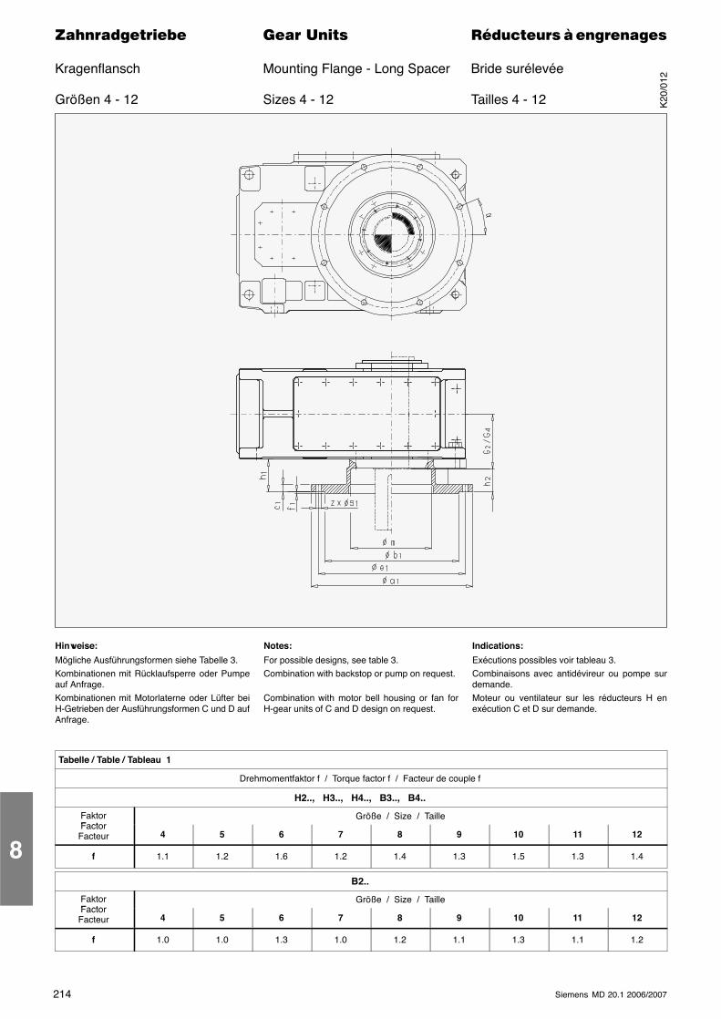
214 Siemens MD 20.1 2006/2007
������������� ���� �� ��������� � ����������
Kragenflansch Mounting Flange - Long Spacer Bride surélevée
Größen 4 - 12 Sizes 4 - 12 Tailles 4 - 12
Hinweise:
Mögliche Ausführungsformen siehe Tabelle 3.Kombinationen mit Rücklaufsperre oder Pumpeauf Anfrage.Kombinationen mit Motorlaterne oder Lüfter beiH-Getrieben der Ausführungsformen C und D aufAnfrage.
Notes:
For possible designs, see table 3.Combination with backstop or pump on request.
Combination with motor bell housing or fan forH-gear units of C and D design on request.
Indications:
Exécutions possibles voir tableau 3.Combinaisons avec antidévireur ou pompe surdemande.Moteur ou ventilateur sur les réducteurs H enexécution C et D sur demande.
Tabelle / Table / Tableau 1
Drehmomentfaktor f / Torque factor f / Facteur de couple f
H2.., H3.., H4.., B3.., B4..
FaktorFactor
Größe / Size / TailleFactorFacteur 4 5 6 7 8 9 10 11 12
f 1.1 1.2 1.6 1.2 1.4 1.3 1.5 1.3 1.4
B2..
FaktorFactor
Größe / Size / TailleFactorFacteur 4 5 6 7 8 9 10 11 12
f 1.0 1.0 1.3 1.0 1.2 1.1 1.3 1.1 1.2
8
K20
/012
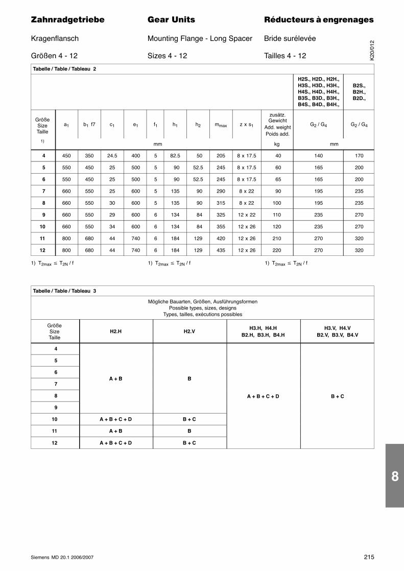
215Siemens MD 20.1 2006/2007
������������� ���� �� ��������� � ����������
Kragenflansch Mounting Flange - Long Spacer Bride surélevée
Größen 4 - 12 Sizes 4 - 12 Tailles 4 - 12
Tabelle / Table / Tableau 2
H2S., H2D., H2H.,H3S., H3D., H3H.,H4S., H4D., H4H.,B3S., B3D., B3H.,B4S., B4D., B4H.,
B2S.,B2H.,B2D.,
GrößeSizeTaille
a1 b1 f7 c1 e1 f1 h1 h2 mmax z x s1
zusätz.Gewicht
Add. weightPoids add.
G2 / G4 G2 / G4
1)mm kg mm
4 450 350 24.5 400 5 82.5 50 205 8 x 17.5 40 140 170
5 550 450 25 500 5 90 52.5 245 8 x 17.5 60 165 200
6 550 450 25 500 5 90 52.5 245 8 x 17.5 65 165 200
7 660 550 25 600 5 135 90 290 8 x 22 90 195 235
8 660 550 30 600 5 135 90 315 8 x 22 100 195 235
9 660 550 29 600 6 134 84 325 12 x 22 110 235 270
10 660 550 34 600 6 134 84 355 12 x 26 120 235 270
11 800 680 44 740 6 184 129 420 12 x 26 210 270 320
12 800 680 44 740 6 184 129 435 12 x 26 220 270 320
1) T2max � T2N / f 1) T2max � T2N / f 1) T2max � T2N / f
Tabelle / Table / Tableau 3
Mögliche Bauarten, Größen, AusführungsformenPossible types, sizes, designs
Types, tailles, exécutions possibles
GrößeSizeTaille
H2.H H2.VH3.H, H4.H
B2.H, B3.H, B4.HH3.V, H4.V
B2.V, B3.V, B4.V
4
5
6A + B B
7A + B B
8 A + B + C + D B + C
9
10 A + B + C + D B + C
11 A + B B
12 A + B + C + D B + C
K20
/012
8
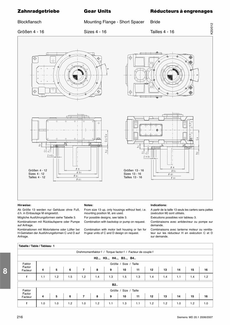
216 Siemens MD 20.1 2006/2007
������������� ���� �� ��������� � ����������
Blockflansch Mounting Flange - Short Spacer Bride
Größen 4 - 16 Sizes 4 - 16 Tailles 4 - 16
Größen 4 - 12Sizes 4 - 12Tailles 4 - 12
Größen 13 - 16Sizes 13 - 16Tailles 13 - 16
Hinweise:
Ab Größe 13 werden nur Gehäuse ohne Fuß,d.h. in Einbaulage M eingesetzt.Mögliche Ausführungsformen siehe Tabelle 3.Kombinationen mit Rücklaufsperre oder Pumpeauf Anfrage.Kombinationen mit Motorlaterne oder Lüfter beiH-Getrieben der Ausführungsformen C und D aufAnfrage.
Notes:
From size 13 up, only housings without feet, i.e.mounting position M, are used.For possible designs, see table 3.Combination with backstop or pump on request.
Combination with motor bell housing or fan forH-gear units of C and D design on request.
Indications:
A partir de la taille 13 seuls les carters sans pattes(exécution M) sont utilisés.Exécutions possibles voir tableau 3.Combinaisons avec antidevireur ou pompe surdemande.Combinaisons avec lanterne moteur ou ventila-teur sur les réducteur H en exécution C et Dsur demande.
Tabelle / Table / Tableau 1
Drehmomentfaktor f / Torque factor f / Facteur de couple f
H2.., H3.., H4.., B3.., B4..
FaktorFactor
Größe / Size / TailleFactorFacteur 4 5 6 7 8 9 10 11 12 13 14 15 16
f 1.1 1.2 1.5 1.2 1.4 1.3 1.5 1.3 1.4 1.4 1.1 1.4 1.2
B2..
FaktorFactor
Größe / Size / TailleFactorFacteur 4 5 6 7 8 9 10 11 12 13 14 15 16
f 1.0 1.0 1.2 1.0 1.2 1.1 1.3 1.1 1.2 1.2 1.0 1.2 1.0
8
K20
/012
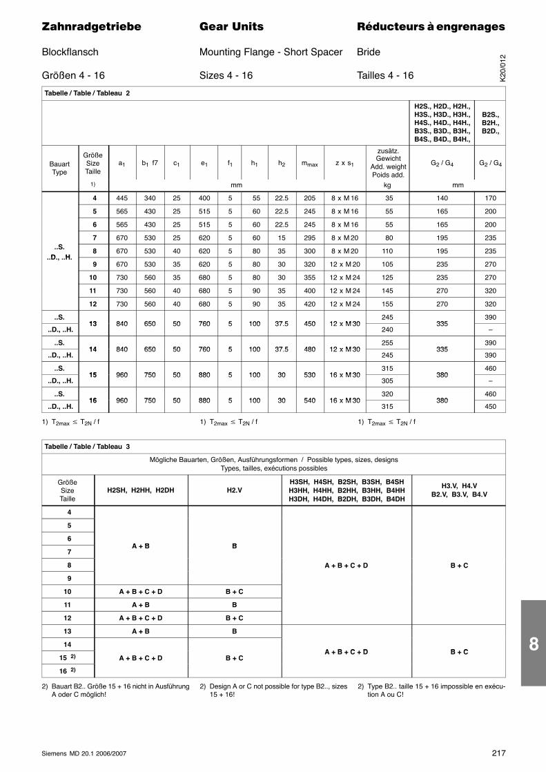
217Siemens MD 20.1 2006/2007
������������� ���� �� ��������� � ����������
Blockflansch Mounting Flange - Short Spacer Bride
Größen 4 - 16 Sizes 4 - 16 Tailles 4 - 16
Tabelle / Table / Tableau 2
H2S., H2D., H2H.,H3S., H3D., H3H.,H4S., H4D., H4H.,B3S., B3D., B3H.,B4S., B4D., B4H.,
B2S.,B2H.,B2D.,
BauartType
GrößeSizeTaille
a1 b1 f7 c1 e1 f1 h1 h2 mmax z x s1
zusätz.Gewicht
Add. weightPoids add.
G2 / G4 G2 / G4
1) mm kg mm
4 445 340 25 400 5 55 22.5 205 8 x M 16 35 140 170
5 565 430 25 515 5 60 22.5 245 8 x M 16 55 165 200
6 565 430 25 515 5 60 22.5 245 8 x M 16 55 165 200
7 670 530 25 620 5 60 15 295 8 x M 20 80 195 235..S.
D H 8 670 530 40 620 5 80 35 300 8 x M 20 110 195 235
..D., ..H. 9 670 530 35 620 5 80 30 320 12 x M 20 105 235 270
10 730 560 35 680 5 80 30 355 12 x M 24 125 235 270
11 730 560 40 680 5 90 35 400 12 x M 24 145 270 320
12 730 560 40 680 5 90 35 420 12 x M 24 155 270 320
..S.13 840 650 50 760 5 100 37 5 450 12 x M 30
245335
390
..D., ..H.13 840 650 50 760 5 100 37.5 450 12 x M 30
240335
–
..S.14 840 650 50 760 5 100 37 5 480 12 x M 30
255335
390
..D., ..H.14 840 650 50 760 5 100 37.5 480 12 x M 30
245335
390
..S.15 960 750 50 880 5 100 30 530 16 x M 30
315380
460
..D., ..H.15 960 750 50 880 5 100 30 530 16 x M 30
305380
–
..S.16 960 750 50 880 5 100 30 540 16 x M 30
320380
460
..D., ..H.16 960 750 50 880 5 100 30 540 16 x M 30
315380
450
1) T2max � T2N / f 1) T2max � T2N / f 1) T2max � T2N / f
Tabelle / Table / Tableau 3
Mögliche Bauarten, Größen, Ausführungsformen / Possible types, sizes, designsTypes, tailles, exécutions possibles
GrößeSizeTaille
H2SH, H2HH, H2DH H2.VH3SH, H4SH, B2SH, B3SH, B4SHH3HH, H4HH, B2HH, B3HH, B4HHH3DH, H4DH, B2DH, B3DH, B4DH
H3.V, H4.VB2.V, B3.V, B4.V
4
5
6A + B B
7A + B B
8 A + B + C + D B + C
9
10 A + B + C + D B + C
11 A + B B
12 A + B + C + D B + C
13 A + B B
14A + B + C + D B + C
15 2) A + B + C + D B + CA + B + C + D B + C
16 2)
2) Bauart B2.. Größe 15 + 16 nicht in AusführungA oder C möglich!
2) Design A or C not possible for type B2.., sizes15 + 16!
2) Type B2.. taille 15 + 16 impossible en exécu-tion A ou C!
K20
/012
8
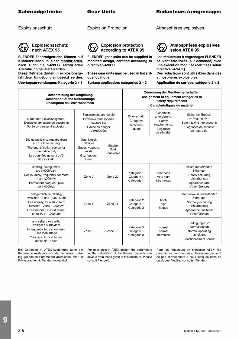
218 Siemens MD 20.1 2006/2007
������������� ���� �� ��������� � ����������
Explosionsschutz Explosion Protection Atmosphères explosives
Explosionsschutznach ATEX 95
FLENDER-Zahnradgetriebe können aufKundenwunsch in einer modifizierten,nach Richtlinie 94/9/EG zertifiziertenAusführung geliefert werden.Diese Getriebe dürfen in explosionsge-fährdeter Umgebung eingesetzt werden.
Übertageanwendungen: Kategorie 2 + 3
Explosion protectionaccording to ATEX 95
FLENDER gear units can be supplied inmodified design, certified according todirective 94/9/EC.
These gear units may be used in hazard-ous locations.
Surface application: categories 2 + 3
Atmosphères explosivesselon ATEX 95
Les réducteurs à engrenages FLENDERpeuvent être livrés (sur demande) avecune exécution modifiée (certifiées selondirective 94/9/CE).Ces réducteurs sont utilisables dans desatmosphères explosibles.
Application de surface: catégorie 2 + 3
Beschreibung der UmgebungDescription of the surroundingsDescription de l’environnement
Zuordnung der GeräteeigenschaftenAssignment of equipment categories to
safety requirementsCaractéristiques du matériel
Dauer der Explosionsgefahr:Explosive atmospheres occurring:
Durée du danger d’explosion:
Explosionsgefahr durch:Explosive atmospheres
caused by:Cause du danger
d’explosión:
Eigenschaft:Category:
Caractéris-tiques:
Sicherheits-anforderung:
Safetyrequirements:
Exigencesde sécurité:
Sicher bei Berück-sichtigung von:
Safe if taking into account:Exigences de sécurité
en regard de:
Die quantifizierte Angabe dientnur zur Orientierung
The quantification serves fororientation only.
Les données ne sont qu’àtitre indicatif
Gas, Nebel,Dämpfe
Gases, vapours,mists
Gaz, Vapeur,Buée
StäubeDust
Poussières
ständig, häufig, mehrals 1.000h/Jahr
Continuously, frequently, for morethan 1,000h/yr
Permanent, fréquent, plusde 1.000h/an
Zone 0 Zone 20Kategorie 1Category 1Catégorie 1
sehr hochvery high
très hautes
selten auftretendenStörungen
Rarely occurringdisturbances
Apparence rared’interférences
gelegentlich, kurzzeitig,zwischen 10 und 1.000h/JahrOccasionally, for a short term,
between 10 and 1,000h/yrOccassionnel, à court terme,
entre 10 et 1.000h/an
Zone 1 Zone 21Kategorie 2Category 2Catégorie 2
hochhigh
hautes
üblicherweise auftretendenStörungen
Normally occurringdisturbances
Apparence habituelled’interférences
sehr selten, kurzzeitig,weniger als 10h/Jahr
Infrequently, for a short term,less than 10h/yr
Très rare, à court terme,moins de 10h/an
Zone 2 Zone 22Kategorie 3Category 3Catégorie 3
normalnormal
normales
Bedingungen imNormalbetrieb
Normal operatingconditions
Fonctionnement normal
Bei Getrieben in ATEX-Ausführung kann diethermische Auslegung von den in diesem Kata-log genannten Parametern abweichen. Hier istRücksprache mit Flender notwendig!
For gear units in ATEX design, the parametersfor the calculation of the thermal capacity candeviate from those given in this brochure. Pleaseconsult Flender!
Pour les réducteurs en exécution ATEX, lesparamètres pour le calcul thermique peuventne pas correspondre à ceux indiqués dans cecatalogue. Veuillez consulter Flender!
9
219Siemens MD 20.1 2006/2007
������������� ���� �� ��������� � ����������
Tochterprogramme Subranges Programmes secondairesInformationen auf Anfrage Information on Request Informations sur demande
TochterprogrammeSubrangesProgrammes secondaires
Hubwerksantriebe / Hoisting gear drives / Entraînements de dispositifs de levage
Förderbandantriebe / Conveyor drives / Entraînements de convoyeurs
Fahrwerksantriebe / Travelling gear drives / Entraînements de mécanismes de translation
Becherwerksantriebe / Bucket elevator drives / Elévateurs à godets
Wasserturbinenantriebe / Water turbine drives / Entraînements de turbines hydrauliques
Kühlturmantriebe / Cooling tower drives / Entraînements de tour refroidissement
Papiermaschinenantriebe / Paper machine drives / Entraînements de machines à papier
Rührwerksantriebe / Agitator drives / Entraînements d’agitateurs
Belüfterantriebe / Aerator drives / Entraînements d’aérateurs
Bürstenbelüfterantriebe / Drives for brush ventilating devicesEntraînements d’aérateur à brosses
Pulperantriebe / Pulper drives / Entraînements de pulpeur
Sichterantriebe / Separator drives / Entraînements de séparateur
Läuterbottichantriebe / Lauter tun drives / Entraînements de cuve de filtration
Sandpumpenantriebe / Sludger drives / Entraînements de pompe à sable
Einschneckenextruder-Getriebe / Single screw extruder gear unitsRéducteurs d’extrudeur à une vis
Ca
talo
gM
D2
0.1
•2
00
6/2
00
7
ZahnradgetriebeGear UnitsRéducteurs à engrenages
Ca
talo
gM
D2
0.1
•2
00
6/2
00
7Fl
ende
rG
ear
Un
its
Die Informationen in diesem Katalog enthalten Beschreibungenbzw. Leistungsmerkmale, welche im konkreten Anwendungsfallnicht immer in der beschriebenen Form zutreffen bzw. welchesich durch Weiterentwicklung der Produkte ändern können. Diegewünschten Leistungsmerkmale sind nur dann verbindlich,wenn sie bei Vertragsabschluss ausdrücklich vereinbart werden.Liefermöglichkeiten und technische Änderungen vorbehalten.Alle Erzeugnisbezeichnungen können Marken oder Erzeugnis-namen der Siemens AG oder anderer, zuliefernder Unternehmensein, deren Benutzung durch Dritte für deren Zwecke die Rechteder Inhaber verletzen kann.
The information provided in this catalog contains descriptions orcharacteristics of performance which in case of actual use do notalways apply as described or which may change as a result offurther development of the products. An obligation to providethe respective characteristics shall only exist if expressly agreedin the terms of contract. Availability and technical specificationsare subject to change without notice.All product designations may be trademarks or product names ofSiemens AG or supplier companies whose use by third parties fortheir own purposes could violate the rights of the owners.
Les informations de ce catalogue contiennent des descriptionsou des caractéristiques qui, dans des cas d’utilisation concrets, nesont pas toujours applicables dans la forme décrite ou qui, enraison d’un développement ultérieur des produits, sontsusceptibles d’être modifiées. Les caractéristiques particulièressouhaitées ne sont obligatoires que si elles sont expressémentstipulées en conclusion du contrat. Sous réserve des possibilitésde livraison et de modifications techniques.Toutes les désignations de produits peuvent être des marques oudes noms de produits de Siemens AG ou de sociétés tiercesagissant en qualité de fournisseurs, dont l'utilisation par des tiers à leurs propres fins peut enfreindre les droits de leurspropriétaires respectifs.
A. Friedr. Flender AG
P.O. Box 1364
46393 Bocholt
Alfred-Flender-Strasse 77
46395 Bocholt
www.flender.com Order No. E86060-K5720-A111-A1-6300
flender gear unitsSubj
ect
toch
ange
|D
ispo
18
50
0|
KG0
90
75
.0RO
22
0D
e/En
/Fr
|Pr
inte
din
Ger
man
y|
©Si
emen
sA
G2
00
7