High Q-factor Metamaterial Duplex Filters in Suspended Stripline Technology q-factor... ·...
153
High Q-factor Metamaterial Duplex Filters in Suspended Stripline Technology Der Technischen Fakult¨ at der Universit¨ at Erlangen-N¨ urnberg zur Erlangung des Grades DOKTOR-INGENIEUR Shaik Geelani Erlangen, M¨arz 2009
Transcript of High Q-factor Metamaterial Duplex Filters in Suspended Stripline Technology q-factor... ·...
High Q-factor MetamaterialDuplex Filters
in Suspended StriplineTechnology
Der Technischen Fakultatder Universitat Erlangen-Nurnberg
zur Erlangung des Grades
D O K T O R - I N G E N I E U R
Shaik Geelani
Erlangen, Marz 2009
Metamaterial Duplex Filterhoher Gute mit
hangenden Streifenleitungen
Als Dissertation genehmigt vonder Technischen Fakultat
der Universitat Erlangen-Nurnberg
Tag der Einreichung : 22.12.2008Tag der Promotion : 05.03.2009
Dekan:
Prof.Dr.-Ing. habil. Johannes Huber
Berichterstatter:
Prof.Dr.-Ing. Georg Fischer
Prof. Dr.-Ing. Jurgen Detlefsen
Contents
1 Introduction 11.1 Aims of this work . . . . . . . . . . . . . . . . . . . . . . . . . . . 21.2 Thesis Structure . . . . . . . . . . . . . . . . . . . . . . . . . . . . 3
2 EM Theory of Left Handed Materials 52.1 Metamaterials . . . . . . . . . . . . . . . . . . . . . . . . . . . . . 52.2 Wave Propagation in Left-Handed Media . . . . . . . . . . . . . . 7
2.2.1 Energy Density and Group Velocity . . . . . . . . . . . . . 112.2.2 Inverse Doppler Effect . . . . . . . . . . . . . . . . . . . . 122.2.3 Backward Cerenkov Radiation . . . . . . . . . . . . . . . . 142.2.4 Negative Refraction - Reverse Snell’s Law . . . . . . . . . 152.2.5 Negative Goos-Hanchen Shift . . . . . . . . . . . . . . . . 162.2.6 Transmission and Reflection Coefficients in LH Media . . . 172.2.7 Losses and Dispersion . . . . . . . . . . . . . . . . . . . . 19
2.3 Composite Right-Left Handed Metamaterials (CRLH) MTM’s . . 20
3 Transmission Line theory of Metamaterials 233.1 Introduction . . . . . . . . . . . . . . . . . . . . . . . . . . . . . . 233.2 Loss Less CRLH TLs . . . . . . . . . . . . . . . . . . . . . . . . . 243.3 Dispersion/Attenuation . . . . . . . . . . . . . . . . . . . . . . . . 263.4 CRLH TL equivalent MTM Constitutive Parameters . . . . . . . 30
3.4.1 CRLH TL Balanced and Unbalanced Resonances . . . . . 313.4.2 Lossy CRLH TL Case . . . . . . . . . . . . . . . . . . . . 33
3.5 LC Network Implementation . . . . . . . . . . . . . . . . . . . . . 363.5.1 Difference with conventional filters . . . . . . . . . . . . . 38
3.6 Symmetric and Asymmetric Structures . . . . . . . . . . . . . . . 38
4 MTM CRLH TL Applications for Filters 404.1 CRLH Metamaterial theory on Filter Application . . . . . . . . . 404.2 Microstrip Implementation of MTM . . . . . . . . . . . . . . . . . 424.3 Negative Refractive Index Narrow bandwidth Bandpass Filter . . 464.4 Metamaterial TL Narrow bandpass filter structures using Microstrip
Gaps and Open stubs . . . . . . . . . . . . . . . . . . . . . . . . . 484.4.1 Using λ/2 resonators . . . . . . . . . . . . . . . . . . . . . 48
i
CONTENTS ii
4.4.2 Microstrip Open Stub and Gap Equivalent CRLH Structure-Tx Filter . . . . . . . . . . . . . . . . . . . . . . . . . . . 50
4.4.3 Microstrip Open Stub and Gap Equivalent CRLH Structure-Rx Filter . . . . . . . . . . . . . . . . . . . . . . . . . . . 52
5 Left Handed TX RF bandpass filter design 555.1 Introduction . . . . . . . . . . . . . . . . . . . . . . . . . . . . . . 555.2 RF Frequency Agile Systems . . . . . . . . . . . . . . . . . . . . . 555.3 Left Handed MTM RF Tx Filter Design . . . . . . . . . . . . . . 57
5.3.1 Requirements . . . . . . . . . . . . . . . . . . . . . . . . . 575.3.2 Lumped Circuit Design and Quality Factor . . . . . . . . . 595.3.3 Series/Shunt Resonant Element Verification . . . . . . . . 615.3.4 Zero-Order Resonance/Bandgap definition by serial and
parallel resonance frequency - 3 unit cells . . . . . . . . . . 645.4 Microstrip Shielded Suspended Substrate . . . . . . . . . . . . . . 67
5.4.1 Symmetric shielded suspended substrate . . . . . . . . . . 695.4.2 Suspended Substrate Implementation . . . . . . . . . . . . 70
5.5 Lumped to Microstrip Transmission Line Conversion . . . . . . . 725.6 3 Unit Cells TX Filter Design . . . . . . . . . . . . . . . . . . . . 73
5.6.1 Circuit Simulator Results . . . . . . . . . . . . . . . . . . 755.7 conclusion . . . . . . . . . . . . . . . . . . . . . . . . . . . . . . . 83
6 MTM RX bandpass filter design 846.1 Introduction . . . . . . . . . . . . . . . . . . . . . . . . . . . . . . 846.2 RX - Series/Shunt Resonant Element Verification - Lumped . . . 856.3 RX-Lumped Circuit Design and Quality Factor . . . . . . . . . . 86
6.3.1 Unit Cells-Simulation Results, Q-Factor . . . . . . . . . . 866.3.2 Three Unit Cells-Simulation Results,Zero-order Resonance 86
6.4 Lumped to Microstrip Transmission Line Conversion . . . . . . . 906.5 3 Unit Cells RX Filter Design . . . . . . . . . . . . . . . . . . . . 93
6.5.1 Circuit Simulator Results . . . . . . . . . . . . . . . . . . 936.5.2 Momentum Simulator Results . . . . . . . . . . . . . . . . 946.5.3 Measurement Results . . . . . . . . . . . . . . . . . . . . . 95
6.6 conclusion . . . . . . . . . . . . . . . . . . . . . . . . . . . . . . . 100
7 Conclusions and Discussion 1017.1 conclusions . . . . . . . . . . . . . . . . . . . . . . . . . . . . . . 101
7.1.1 Things learned and New . . . . . . . . . . . . . . . . . . . 1027.2 Advantages and Drawbacks . . . . . . . . . . . . . . . . . . . . . 1027.3 future work . . . . . . . . . . . . . . . . . . . . . . . . . . . . . . 103
Bibliography 104
Publications 110
List of Figures
2.1 Permittivity-Permeability Diagram [16] . . . . . . . . . . . . . . . 62.2 Electric - Magnetic Field wave vector (a)Right-Handed Medium
(b)Left-Handed Medium [3] . . . . . . . . . . . . . . . . . . . . . . 102.3 Inverse Doppler Effect [17] . . . . . . . . . . . . . . . . . . . . . . 132.4 Illustration of the formation of Cerenkov shock waves: (a) in an
ordinary medium, and (b) in a left-handed medium [33]. . . . . . . 142.5 Negative Refractive Index [6]. . . . . . . . . . . . . . . . . . . . . 162.6 (a) Ordinary media (b) Left-Handed media [17]. . . . . . . . . . . 172.7 Determination of Transverse Transmission Matrix [17] . . . . . . . 182.8 (a)Illustration of the perfect lens (b)Amplitude Pattern for an
evanescent Fourier harmonic of the perfect lens [27]. . . . . . . . . 202.9 (a)Unit Cell (b)LH and RH comparision [16]. . . . . . . . . . . . . 21
3.1 Ideal CRLH TL [16] . . . . . . . . . . . . . . . . . . . . . . . . . . 243.2 Dispersion/Attenuation Curves: (a)Energy propagation along +z
and -z directions. (b) Comparison of the CRLH, PLH (βPLH) andPRH (βPRH) TLs for energy propagation along the +z direction(vg > 0) [16] . . . . . . . . . . . . . . . . . . . . . . . . . . . . . . 27
3.3 Characteristic Impedance [9] . . . . . . . . . . . . . . . . . . . . . 293.4 (a)PLH TL Properties (b)CRLH Properties [16] . . . . . . . . . . 293.5 Parallel Plate wave guide filled with CRLH Material [16] . . . . . 303.6 (a)Balanced unit Cell (b)Unbalanced unit cell [16] . . . . . . . . . 323.7 Lossy CRLH TL . . . . . . . . . . . . . . . . . . . . . . . . . . . 333.8 Effects of losses in the ideal balanced CRLH TL. (a) Dispersion and
attenuation. (b) Characteristic impedance. The indexes 0, 1, 2 referto a loss-less, weakly lossy, and strongly lossy TL, respectively [17]. 35
3.9 Effects of losses in the ideal unbalanced CRLH TL for ωsh < ωse.(a) Dispersion and attenuation. (b) Characteristic impedance. Theindexes 0, 1, 2 refer to a loss-less, weakly lossy, and strongly lossyTL, respectively. [16]. . . . . . . . . . . . . . . . . . . . . . . . . . 36
3.10 Unit cell of an LC CRLH TL. (a) General (unbalanced). (b) Bal-anced (LRCL = LLCR) [5] . . . . . . . . . . . . . . . . . . . . . . 36
3.11 Symmetric CRLH TL Structure . . . . . . . . . . . . . . . . . . . 393.12 Asymmetric CRLH TL Structure . . . . . . . . . . . . . . . . . . 39
iii
LIST OF FIGURES iv
4.1 Ideal lossless CRLH TL . . . . . . . . . . . . . . . . . . . . . . . 414.2 Lossless symmetric Unit Cell . . . . . . . . . . . . . . . . . . . . . 424.3 Microstrip CRLH TL using interdigital capacitors and shorted stub
inductors [5] . . . . . . . . . . . . . . . . . . . . . . . . . . . . . . 434.4 Circuit models for the parameters extraction of the unit cell (a)
Equivalent circuit. (b) Auxiliary equivalent T and π networks [11] 444.5 CRLH MTM TL Unit Cell with Interdigital Capacitor and stub
inductor [16] . . . . . . . . . . . . . . . . . . . . . . . . . . . . . . 454.6 Caloz/Itoh practical board [16] . . . . . . . . . . . . . . . . . . . . 454.7 Caloz/Itoh practical board Results(a) Balanced circuit(b) Unbal-
anced [16] . . . . . . . . . . . . . . . . . . . . . . . . . . . . . . . 464.8 Islam/Eleftheriades structure with Interdigital Capacitors and Open-
stubs [24] . . . . . . . . . . . . . . . . . . . . . . . . . . . . . . . . 464.9 Islam/Eleftheriades Structure [11] . . . . . . . . . . . . . . . . . . 474.10 CRLH MTM TL structure with Gaps and open stubs . . . . . . . 494.11 λ/2 resonator equivalence . . . . . . . . . . . . . . . . . . . . . . 494.12 Equivalent (a)Gap capacitor (b)Open stub Inductor . . . . . . . . 514.13 MTM CRLH TL Unit cell . . . . . . . . . . . . . . . . . . . . . . 524.14 Rx BPF - Structure . . . . . . . . . . . . . . . . . . . . . . . . . . 534.15 Series Resonant Circuit Equivalent . . . . . . . . . . . . . . . . . 534.16 Shunt Resonant Circuit Equivalent . . . . . . . . . . . . . . . . . 544.17 Rx BPF Unit Cell . . . . . . . . . . . . . . . . . . . . . . . . . . . 54
5.1 Applications of Metamaterials in RF Systems [18] . . . . . . . . . 565.2 Duplex Filter Block . . . . . . . . . . . . . . . . . . . . . . . . . . 575.3 Duplex Filter [Alcatel-Lucent] . . . . . . . . . . . . . . . . . . . . 585.4 E-GSM 900 Band . . . . . . . . . . . . . . . . . . . . . . . . . . . 585.5 TX MTM unit cell . . . . . . . . . . . . . . . . . . . . . . . . . . 595.6 Series Resonant Circuit Verification . . . . . . . . . . . . . . . . . 615.7 Series Resonant Q-Factor . . . . . . . . . . . . . . . . . . . . . . . 625.8 Shunt Resonant Circuit Verification . . . . . . . . . . . . . . . . . 625.9 MTM Unit Cell Lumped . . . . . . . . . . . . . . . . . . . . . . . 635.10 Unit Cell - Quality Factor . . . . . . . . . . . . . . . . . . . . . . 635.11 Left Handed TX Unit Cell - Insertion Loss . . . . . . . . . . . . . 645.12 Three Unit Cell - Lumped . . . . . . . . . . . . . . . . . . . . . . 655.13 Lumped Circuit-Simulation Results - Three Unit Cells . . . . . . 665.14 Zero-Order Resonance Proof . . . . . . . . . . . . . . . . . . . . . 665.15 Zero-Order location . . . . . . . . . . . . . . . . . . . . . . . . . . 675.16 Line Configurations . . . . . . . . . . . . . . . . . . . . . . . . . . 675.17 Symmetric Shielded Suspended Substrate structure . . . . . . . . 695.18 Shielded Suspended Substrate 40 mm spacing . . . . . . . . . . . 715.19 Substrate Test - 30 cm TL Line . . . . . . . . . . . . . . . . . . . 715.20 Substrate Simulation Results - 30cm TLine . . . . . . . . . . . . . 715.21 Lumped Series Equivalent Microstrip TL . . . . . . . . . . . . . . 72
LIST OF FIGURES v
5.22 Lumped Shunt Equivalent Microstrip TL . . . . . . . . . . . . . . 735.23 MTM TL Unit Cell . . . . . . . . . . . . . . . . . . . . . . . . . . 745.24 MTM TL Unit Cell- Quality Factor . . . . . . . . . . . . . . . . . 745.25 3 unit cell Left-handed Tx-Filter . . . . . . . . . . . . . . . . . . . 755.26 Electromagnetic Current Distributions . . . . . . . . . . . . . . . 765.27 Left-handed 3 unit cell Tx BPF-Simulation Results . . . . . . . . 765.28 Simulation Results - Closer View . . . . . . . . . . . . . . . . . . 775.29 3-Dimensional Suspended Housing . . . . . . . . . . . . . . . . . . 775.30 TX Filer - Momentum Simulator - Results . . . . . . . . . . . . . 785.31 Momentum Results - Closer View . . . . . . . . . . . . . . . . . . 785.32 MTM TX-BPF - Measurement Board . . . . . . . . . . . . . . . . 805.33 Board Cross-Section . . . . . . . . . . . . . . . . . . . . . . . . . 805.34 Conductive Closed View . . . . . . . . . . . . . . . . . . . . . . . 815.35 MTM TX-BPF- Measurement Board Results . . . . . . . . . . . . 815.36 MTM TX-BPF- Measurement Board Results -(925MHz-960MHz) 825.37 Result Comparison . . . . . . . . . . . . . . . . . . . . . . . . . . 82
6.1 Rx BPF Unit Cell - MTM Structure . . . . . . . . . . . . . . . . 846.2 MTM Unit Cell Lumped . . . . . . . . . . . . . . . . . . . . . . . 856.3 Q-Factor - unit cell . . . . . . . . . . . . . . . . . . . . . . . . . . 876.4 Insertion Loss dB[S21] - unit cell . . . . . . . . . . . . . . . . . . 876.5 Three Unit Cell - Lumped . . . . . . . . . . . . . . . . . . . . . . 886.6 Three Unit Cell - Lumped - Simulation Results . . . . . . . . . . 886.7 Zero-Order Resonance Location . . . . . . . . . . . . . . . . . . . 896.8 Zero-Order Resonance Proof . . . . . . . . . . . . . . . . . . . . . 896.9 RX BPF Unit Cell - MTM Structure . . . . . . . . . . . . . . . . 906.10 Series Resonance - Equivalent . . . . . . . . . . . . . . . . . . . . 916.11 Shunt Resonance - Equivalent . . . . . . . . . . . . . . . . . . . . 916.12 Meta RX TL - unit cell- Simulation . . . . . . . . . . . . . . . . . 926.13 Q-Factor - unit cell . . . . . . . . . . . . . . . . . . . . . . . . . . 926.14 RX BPF Three Unit Cell . . . . . . . . . . . . . . . . . . . . . . . 936.15 Rx BPF - CS results . . . . . . . . . . . . . . . . . . . . . . . . . 946.16 RX BPF - MoM results . . . . . . . . . . . . . . . . . . . . . . . . 956.17 Electric current Field Distribution . . . . . . . . . . . . . . . . . . 966.18 3-Dimensional Housing Figure . . . . . . . . . . . . . . . . . . . . 966.19 Meta RX-Filter -PCB Board . . . . . . . . . . . . . . . . . . . . . 976.20 Meta RX-Filter - Side View . . . . . . . . . . . . . . . . . . . . . 986.21 Meta RX-Filter - Closed View . . . . . . . . . . . . . . . . . . . . 986.22 Meta RX-Filter - Measurement Results . . . . . . . . . . . . . . . 996.23 Meta RX-Filter - Measurement board Results - Clear View . . . . 99
List of Tables
5.1 TX-Result Comparison Table . . . . . . . . . . . . . . . . . . . . 83
6.1 RX-Result Comparison Table . . . . . . . . . . . . . . . . . . . . 100
vi
Acknowledgements
”In the Name of God, the most Beneficent, and Merciful”. The work presented
was supported by Alcatel-Lucent, Bell Labs Research, Nuremberg, Germany in co-
operation with Friedrich-Alexander-University of Erlangen-Nuremberg and Tech-
nical University of Munich, HFS department. My sincere thanks to Prof.Georg
Fischer who has given me this opportunity for making my doctoral thesis, his
guidance, his appreciation throughout the work is unforgettable, without him I
would have never got such an opportunity to work under the supervision of no-
table world class researcher Prof. Jurgen Detlefsen from Technical University of
Munich, Germany. Their initial ideas, their interest and initiativeness gave me
much interest and knowledge from beginning of the work till end at each and
every point. I would say, without them I could not have make this thesis work.
My special thanks to Michael Doubrava, Dr.Michael Sollner and Horst Schenkel
for their kind suggestions and help throughout the work. I also thank ALU team
Erwin Ruttmann for housing design, Uwe Schacht for PCB support who made
this thesis work easy and fast. Also, thanks to the German ministry of research
and education (BMBF) for funding part of my thesis work under MARIO project
(Metamaterial based flexible duplex filters).
I would like to take this opportunity to thank my parents Mr&MrsT.S.Abdul Ra-
haman, my sister and brother-in-law Mr& MrsR.M.N.Rasool, my brother Shaik
Fakhruddin, who supported me morally in any situation during my thesis work.
vii

Abstract
This Doctoral thesis work describes the design of highly selective, low ripple meta-
material (MTM) based microstrip duplex filter (TX Band/RX Band) design for
E-GSM 900 base stations. As the requirement for base stations, that are more
flexible and their tendency to reduce unwanted transmitted/received signals, leads
to the need of sharp edge, low ripple RF bandpass filters. These designs have been
implemented using microstrip suspended substrate technology to reach good in-
sertion loss and sharp stopbands. To compare with other microstrip technologies,
we have kept our MTM research focussed on exploring suspended substrates for
better result achievements. By designing a bandpass filter in microstrip suspended
substrate, it is shown that metamaterial structures can be of great advantage for
frequency agile RF systems.
During this doctoral thesis, we have proposed a new metamaterial transmission
line filter structure with microstrip gap capacitors and open stub inductors (L, C,
Quasi-Lumped). This structure is effectively homogenous (means, unitcell <λ/10)
and hence satisfies the principle of metamaterials. At first, we have designed a
balanced case of MTM Left-handed (LH) bandpass filter (TX-Band) with three unit
cells in a microstrip shielded suspended substrate. This filter is designed for the
application of E-GSM 900 base stations within 925MHz - 960MHz passband and
915MHz stopband. The design was done with Agilent’s ADS (Advance Design
System) software simulator. Simulations are carried out both with circuit simu-
lator (CS) as well with method of moments simulator (MOM). Their respective
results are compared. Later, the designed TX-BPF printed circuit board (PCB)
is manufactured on ROGERS RO4003 substrate material in a suspended sub-
strate housing to measure and compare with the simulated results. Focus is kept
in achieving passband attenuation less than -1 dB maintaining sharp stopbands
within narrow range of 35MHz.
Secondly, we have designed an RX (Receiver) bandpass filter (BPF) with 880MHz -
915MHz passband and 925MHz in stopband using MTM structure in suspended
substrate configuration. For the RX filter design, we have used a different struc-
ture in comparison with TX-Filter design but focussing on the same goals. This
thesis work confines to show the state of art balanced left-handed metamaterial
structures and its possible applications in designing RF building blocks like duplex
filters within given area of specification. In this research, in contrast to the pre-
vious works on metamaterial filter designs with lambda/4 resonators, these have
been replaced with lamda/2 resonators. Also, the importance/implications of bal-
anced conditions in metamaterial structures are shown. Hence this thesis work is
treated as a scientific approach.
Abstract
Diese Doktorarbeit befasst sich mit dem Entwurf von hochselektiven, welligkeit-
sarmen Metamaterial basierten Mikrostreifen Duplex Filtern fur E-GSM 900 Ba-
sisstationen.
Da die Forderung nach mehr Flexibilitat und der Wunsch nach Unterdruckung
unerwnschter Storaussendungen zu steilflankingen, welligkeitsarmen Bandpassfil-
tern fuhrt, haben wir solche Filterentwurfe auf Basis hangender Streifenleitungen
implementiert, um gute Werte fur die Einfugedampfung und steile Flanken zu er-
reichen. Im Hinblick auf die verschiedenen Mikrostreifen Technologien haben wir
unsere Metamaterial Forschung auf die Untersuchung hangender Streifenleitun-
gen konzentriert um bessere Ergebnisse zu erzielen.
Mit dem Entwurf eines Bandpass Filters unter Nutzung hangender Streifenleitun-
gen konnen wir zeigen, dass Metamaterial Strukturen von großem Nutzen fur
frequenzagile Hochfrequenz-Systeme sein konnen. In dieser Doktorarbeit schla-
gen wir neue Metamaterial Leitungsstrukturen auf Basis quasi-konzentrierter El-
emente (L C Abmessungen < λ/10) mit Mikrostreifen Schlitz-Kondensatoren
und offenen Stichleitungen als Spule vor. Zunachst haben wir ein balanciertes
linkshandisches Metamaterial Bandpass Filter fur das Sendeband mit 3 Einheit-
szellen unter Nutzung hangender Streifenleitungen entworfen.
Dieses Filter wurde entworfen fur den Einsatz in E-GSM 900 Basisstationen mit
einem Durchlassbereich von 925 MHz bis 960 MHz und einem Stoppband unter-
halb 915 MHz. Der Entwurf wurde ausgefuhrt mit Agilents ADS (Advance Design
System) Software Simulator. Die Simulationen wurden sowohl mit dem Schal-
tungssimulator (CS) als auch mit dem Momentensimulator (MOM) durchgefuhrt.
Die Ergebnisse werden verglichen. Spater wird das entworfene Sender Band-
pass Filter auf Basis ROGERS RO4003 Substratmaterial gefertigt zusammen
mit einem Gehause fur hangende Streifenleitungen und die Mess-und Simula-
tionsergebnissen verglichen.
Der Schwerpunkt lag darauf, die Durchgangsdampfung kleiner als -1 dB zu halten
und gleichzeitig scharfe Stoppbandkanten innerhalb schmaler Ubergangsbereiche
von 35MHz sicherzustellen. Zweitens haben wir einen Empfanger Bandpass mit
einem Durchlassbereich von 880MHz-915MHz und einem Stoppband ab 925 MHz
entworfen. Fur den Entwurf des Empfangsfilters haben wir eine andere Struktur
im Vergleich zum Senderfilter eingesetzt, aber unter Berucksichtigung der gleichen
Optimierungsziele.
Diese Arbeit beschrankt sich darauf den neuesten Stand der Technik bei bal-
ancierten linkshandischen Metamaterial Strukturen und ihre potentiellen Anwen-
dungen beim Entwurf von HF Baugruppen wie Duplex Filtern unter Einhaltung
der Spezifikation zu zeigen. In dieser Forschung wurden im Gegensatz zu fruheren
Arbeiten zu Metamaterial Filtern mit λ/4 Resonatoren diese mit λ/2 Resonatoren
ersetzt. Zudem wird die Wichtigkeit/Anwendung balancierter Betriebsbedingungen
bei Metamaterial-Strukturen gezeigt.
Infolgedessen wird diese Doktorarbeit als wissenschaftliche Studie betrieben.
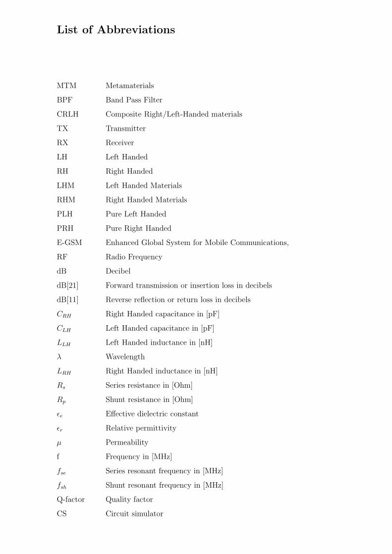
List of Abbreviations
MTM Metamaterials
BPF Band Pass Filter
CRLH Composite Right/Left-Handed materials
TX Transmitter
RX Receiver
LH Left Handed
RH Right Handed
LHM Left Handed Materials
RHM Right Handed Materials
PLH Pure Left Handed
PRH Pure Right Handed
E-GSM Enhanced Global System for Mobile Communications,
RF Radio Frequency
dB Decibel
dB[21] Forward transmission or insertion loss in decibels
dB[11] Reverse reflection or return loss in decibels
CRH Right Handed capacitance in [pF]
CLH Left Handed capacitance in [pF]
LLH Left Handed inductance in [nH]
λ Wavelength
LRH Right Handed inductance in [nH]
Rs Series resistance in [Ohm]
Rp Shunt resistance in [Ohm]
εe Effective dielectric constant
εr Relative permittivity
µ Permeability
f Frequency in [MHz]
fse Series resonant frequency in [MHz]
fsh Shunt resonant frequency in [MHz]
Q-factor Quality factor
CS Circuit simulator
i
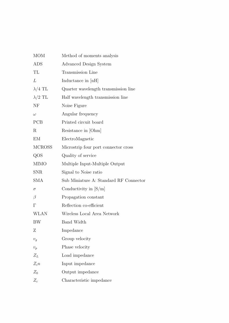
MOM Method of moments analysis
ADS Advanced Design System
TL Transmission Line
L Inductance in [nH]
λ/4 TL Quarter wavelength transmission line
λ/2 TL Half wavelength transmission line
NF Noise Figure
ω Angular frequency
PCB Printed circuit board
R Resistance in [Ohm]
EM ElectroMagnetic
MCROSS Microstrip four port connector cross
QOS Quality of service
MIMO Multiple Input-Multiple Output
SNR Signal to Noise ratio
SMA Sub Miniature A: Standard RF Connector
σ Conductivity in [S/m]
β Propagation constant
Γ Reflection co-efficient
WLAN Wireless Local Area Network
BW Band Width
Z Impedance
vg Group velocity
vp Phase velocity
ZL Load impedance
Zin Input impedance
Z0 Output impedance
Zc Characteristic impedance
Chapter 1
Introduction
During the years of infancy for metamaterials (MTMs), which emerged from the
first experimental demonstration of a left-handed (LH) structure in 2000, the vast
majority of the groups involved in research on MTMs have been focusing on in-
vestigation from a physics point of view. The fundamental properties of LH media
was predicted by Veselago in 1967 [15]. Not following this trend, the researchers
adopted as engineering approach based on a generalized transmission line (TL)
theory, with systematic emphasis on developing practical applications. Exhibiting
resulted in the elaboration of the powerful composite right/left-handed (CRLH)
MTM concept, which has led to novel guided-wave, radiated-wave and refractive-
wave devices and structures.
Metamaterials are artificial structures that can be designed to exhibit specific
electromagnetic properties that are not commonly found in nature [22]. These
metamaterials, which in principle can be synthesized by embedding or including
various constituents of novel geometrical shapes and forms in some host media,
possess exciting features and interesting electromagnetic properties. Metamateri-
als with negative permittivity ”ε” and negative permeability ”µ” are commonly
referred as left handed materials (LHM) [1]. The general transmission line (TL)
approach provides the physical approach of LHM‘s and hence an efficient tool for
LH (Left hand) applications. LHM‘s are considered to be a more general model
1
CHAPTER 1. INTRODUCTION 2
of composite right/left (CRLH) materials, which also occurs naturally as right
handed (RH) effects in practical LHM‘s [5]. A homogenous negative index trans-
mission line (TL) or left-handed (LH) transmission line does not exist in nature,
it has to be approached by an artificial structure, which is usually constructed
from a series of discontinuous sections operating in a restricted frequency range.
A typical realization is found in a quasi-lumped transmission line [50] with ele-
mentary cells consisting of a series capacitors and shunt inductors. The unique
properties of LHM‘s have allowed RF and Microwave applications, concepts and
devices to be developed.
Precisely, we are implementing a metamaterial structure in the applications of
RF duplex filters taking cost and size reductions into consideration as well to
prove the state of art. The main task of the duplex filter is to separate transmit
and receive frequencies at the antenna port. A typical duplex filter thus has three
ports, one for the antenna, the other two for transmitter and receiver respectively.
A typical duplex filter is composed of coaxial resonators that require advanced
fabrication techniques and materials to achieve high Q-factor (e.g 5000) that
are needed to provide high filter selectivity. Filter selectivity is critical in a base
station, because very sensitive receivers are operated simultaneously parallel with
strong transmitters. In some applications, MIMO systems have proven to ease the
cost prohibitive, because of the cost of the duplex filters alone.
1.1 Aims of this work
The requirement for base stations that are more flexible and their multi-band
capability leads to the need of RF functional blocks and duplex filters [16]. In
base stations, transmit and receive paths have to be separated by a duplexer,
which has to handle high power up to 200 W peak and at the same time the
sensitivity of the receiver path should not be degraded [23]. For a frequency agile
base station, it is required that not only radio and power amplifier are frequency
CHAPTER 1. INTRODUCTION 3
agile, but also the duplex filter (TX BPP+RX BPF) and the antenna to facilitate
a remote alteration of the operating frequency band.
This doctoral thesis includes the design and characterization of MTM RF Du-
plex filters for the application of E-GSM 900 base stations i.e TX-band (925MHz-
960 MHz) and RX-band (880MHz-915 MHz) respectively. At first, TX MTM BPF
is realized using lumped components and then simulated in Agilent‘s ADS simu-
lation software. Later, we have implemented the lumped elements in CRLH TL
approach with three unit cells in shielded suspended substrate. In this thesis
work we have worked using both circuit simulator and method of moments sim-
ulators of ADS software and hence compared with the fabricated printed circuit
boardPCB. A similar approach was followed for the RX BPF design.
In our both designs, we have proposed a new filter structure with microstrip gap
capacitors and open stub inductors in context with the previous works [11,24],
which includes interdigital capacitors, short stubs and open stubs. Our main goal
in this thesis work has been attributed towards achievement of low insertion
losses (ripple) and sharp stopband (Edges) and hence to prove the state of art
CRLH MTM structures. Also we have kept focus on suspended substrate tech-
nology to see the result comparison with the other microstrip technologies and
hence to choose the goal oriented suitable technology.
1.2 Thesis Structure
• The second chapter describes, the electromagnetic theory on left handed
materials, their basic properties involved and required in designing filters.
• In the third chapter, implementation of transmission line theory on metama-
terial structures is explained with respect to their importance in designing
bandpass filters.
• In chapter four, we discuss CRLH metamaterial theory on filter applications
CHAPTER 1. INTRODUCTION 4
along with our new proposed bandpass filter structure in comparison with
previously published and practically implemented structures.
• In chapter five, we explain the motivation and application of MTMs in
frequency agile RF systems, we introduce theoretical introduction of sus-
pended substrate technology on metamaterial filters. We present a TX Filter
design with simulation, measurement board results along with comparisons.
• In the sixth chapter, an RX filter design with simulation and measurement
board results is shown.
At the end of the thesis work, we discuss the conclusions along with recommen-
dations on future work.
Chapter 2
Electromagnetic Theory of Left
Handed Materials
2.1 Metamaterials
Electromagnetic metamaterials are broadly defined as artificial effectively homo-
geneous structures with unusual properties not readily available in nature [6].
Where homogeneous structures corresponds to those, whose structural cell size
”p” is much smaller than guided wavelength ”λg” (Typically λ/10). The nature
of the unit cell depends on the constitutive parameters which are related to the
refractive index ”n” by equation,
n = ±√εrµr. (2.1)
Where εr and µr are the relative permittivity and permeability related to free
space permittivity and permeability by ε0=ε/εr = 8.854x10⁻¹²and µ0=µ/µr =
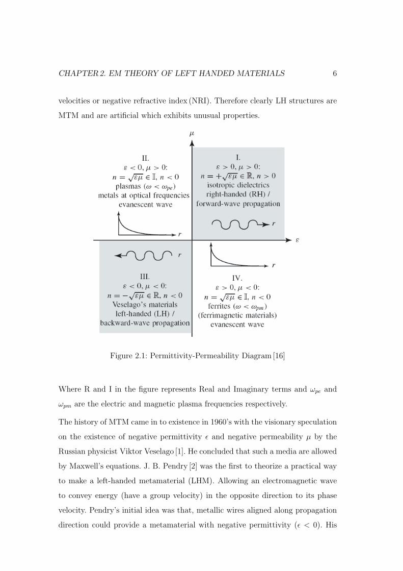
4πx10−7 respectively. The four possible sign combinations in the pair (ε,µ) are
(+,+),(+,-),(-,+),(-,-) and are shown in the fig. 2.1. The first three duplets present
conventional materials whereas, negative negative combination is referred to as
Left handed (LH) materials and are characterized as antiparallel phase and group
5
CHAPTER2. EM THEORY OF LEFT HANDED MATERIALS 6
velocities or negative refractive index (NRI). Therefore clearly LH structures are
MTM and are artificial which exhibits unusual properties.
Figure 2.1: Permittivity-Permeability Diagram [16]
Where R and I in the figure represents Real and Imaginary terms and ωpe and
ωpm are the electric and magnetic plasma frequencies respectively.
The history of MTM came in to existence in 1960’s with the visionary speculation
on the existence of negative permittivity ε and negative permeability µ by the
Russian physicist Viktor Veselago [1]. He concluded that such a media are allowed
by Maxwell’s equations. J. B. Pendry [2] was the first to theorize a practical way
to make a left-handed metamaterial (LHM). Allowing an electromagnetic wave
to convey energy (have a group velocity) in the opposite direction to its phase
velocity. Pendry’s initial idea was that, metallic wires aligned along propagation
direction could provide a metamaterial with negative permittivity (ε < 0). His
CHAPTER2. EM THEORY OF LEFT HANDED MATERIALS 7
challenge was to construct a material which also showed negative permeability
(µ < 0). In 1999, Pendry demonstrated that an open ring (’C’ shape) with axis
along the propagation direction could provide a negative permeability [3]. In the
same paper, he showed that a periodic array of wires and ring could give rise to
a negative refractive index.
C.Caloz et al., Iyer and Eleftheriades followed with a transmission line [TL]
approach on metamaterials [5], [6] and further theoretical expansions on CRLH
(Composite Right/Left Handed) MTM (Metamaterial) structures [9]-[11]. The
Caloz/Ithoh research group also applied these results in [9],[11] for bandpass fil-
ters (BPF). By taking their ideas into consideration, in this thesis work we have
extended metamaterial filter application for high selectivity and high power han-
dling.
2.2 Wave Propagation in Left-Handed Media
In order to show wave propagation in left-handed media, let us reduce Maxwell’s
equations [39]:
∇XE = −∂B
∂t−Ms......(Faraday′sLaw) (2.2)
∇XH =∂D
∂t+ Js......(Ampere′s Law) (2.3)
∇.D = Qe......(Electric Gauss Law) (2.4)
∇.B = Qm......(Magnetic Gauss Law) (2.5)
Where E (V/m) is the electric field intensity, H (A/m) is the magnetic field
intensity, D (C/m2) is the electric flux density, B (W/m2) is the magnetic flux
density. And M s (V/m2) is the fictitious magnetic current density, Js (A/m2) is
CHAPTER2. EM THEORY OF LEFT HANDED MATERIALS 8
the electric current density, Qe (C/m3) is the electric charge density, Qm (C/m3)
is the magnetic charge density.
If the medium is linear and non-anisotropic (ε, µ doesn’t depend on E, H), then
the vector pairs of [D, E] and [B, H] are related as [28].
D = ε0E + P = ε0(1 + χe)E = ε0εrE = εE (2.6)
B = µ0H + M = µ0(1 + χm)H = µ0µrH = µE (2.7)
where, P =ε0χe and M =µ0χm are the electric and magnetic polarizations re-
spectively and χe,χm are the electric and magnetic susceptibilities. Also εr=1+χe
and µr=1+χm are the permittivity and permeability of the material considered
and can be written as.
εr = ε′ − jε′′ = ε′(1− j tan δe), tan δe =ωε′′ + σe
ωε′(2.8)
µr = µ′ − jµ′′ = µ′(1− j tan δm), tan δm =ωµ′′ + σm
ωµ′(2.9)
Where σm and σe are the electrical and magnetic conductivities respectively. The
imaginary parts in the above equation represents losses. Assuming harmonic fields
with the time dependence e+jwt and defining the corresponding generic phasor
F (r) as [17]
F (r, t) = Re[F (r)e+jwt] (2.10)
where F can represent any physical quantity in eqn. 2.10. Maxwell’s equations
and the constitutive equations can be written as
∇XE = −jωµH −Ms (2.11)
∇XH = −jωεE − Js (2.12)
∇.D = −ρe (2.13)
∇.B = ρm (2.14)
CHAPTER2. EM THEORY OF LEFT HANDED MATERIALS 9
and
D = εE (2.15)
B = µH (2.16)
For a plane wave,
E = E0e−jβ.r (2.17)
H =E0
ηe−jβ.r (2.18)
Where η=[E]/[H]is the wave impedance. Let us assume the medium is loss-less
then the above equations can be reduced for our simplicity. i.e ε′′=µ′′=0 and
Hs=Js=0.
Then
βXE = +ωµH (2.19)
βXH = −ωεE (2.20)
Which is familiar right-handed triad (E, H, β) shown in the below figure. In case
of left-handed traid as ε,µ<0, and therefore[ε]=-ε>0 and [µ]=-µ>0,[8]
βXE = −ω |µ|H (2.21)
βXH = +ω |ε|E (2.22)
As the frequency being always a positive quantity, the phase velocity is [16]
νp =ω
ββ, where
(β = β/
∣∣∣β∣∣∣)
(2.23)
Then,
RHMedium : β > 0(νp > 0) (2.24)
CHAPTER2. EM THEORY OF LEFT HANDED MATERIALS 10
E H
S
E H
S
(a) (b)
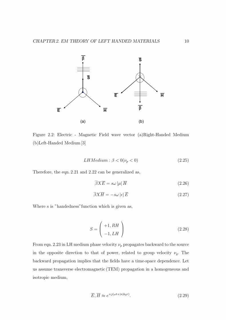
Figure 2.2: Electric - Magnetic Field wave vector (a)Right-Handed Medium
(b)Left-Handed Medium [3]
LHMedium : β < 0(νp < 0) (2.25)
Therefore, the eqn. 2.21 and 2.22 can be generalized as,
βXE = sω |µ|H (2.26)
βXH = −sω |ε|E (2.27)
Where s is ”handedness”function which is given as,
S =
+1, RH
−1, LH
(2.28)
From eqn. 2.23 in LH medium phase velocity νp propagates backward to the source
in the opposite direction to that of power, related to group velocity νg. The
backward propagation implies that the fields have a time-space dependence. Let
us assume transverse electromagnetic (TEM) propagation in a homogeneous and
isotropic medium,
E, H ≈ e+j(ωt+|n|k0r). (2.29)

CHAPTER2. EM THEORY OF LEFT HANDED MATERIALS 11
The propagation constant has only one component that is equal to the wave
number kn in the medium
β = kn = nk0 = nω
c(2.30)
where,
n = ±√εrµr (2.31)
In a LH medium, since β<0, eqn. 2.30 and 2.31 reveals that a negative refrac-
tive index (NRI), n<0. Which states that the index of refraction is negative in
a medium with negative permittivity and permeability. Then in general, the re-
fractive index can be written as,
n = s√
εrµr (2.32)
2.2.1 Energy Density and Group Velocity
If the negative values for ε and µ are introduced in the usual expression for the
time-average density of energy in transparent nondispersive media [26], then Un
is given by
Un =1
4ε|E|2 + µ|H|2 (2.33)
which produces the nonphysical result of negative density of energy. It is well
known that any physical media other than vaccum must be dispersive[16] and
the above equation is valid for very weakly dispersive media. The quasi mono-
chromatic wave packet traveling in a dispersive media is given by [26]
U =1
4∂(ωε)
∂ω|E|2 +
∂(ωµ)
∂ω|H|2 (2.34)
Where the derivatives are evaluated at the central frequency of the wavepacket.
Thus, the physical requirement of positive energy density implies, that
CHAPTER2. EM THEORY OF LEFT HANDED MATERIALS 12
∂(ωε)
∂ω> 0,
∂(ωµ)
∂ω> 0 (2.35)
Which are compatible with ε<0 and µ<0, provided ∂(ωε)∂ω
> |ε|/ω and ∂(ωµ)∂ω
> |µ|/ω.
Therefore, physical left-handed media must be highly dispersive. This fact is in
agreement with the low-loss Drude-Lorentz model for ε and µ, which predicts
negative values for ε and/or µ in the highly dispersive regions just above reso-
nances.
Backward-wave propagation implies opposite signs between phase and group ve-
locities [32]. In fact,∂k2
∂ω= 2k
∂k
∂ω≡ 2
ω
νpνg
(2.36)
where νp = ω/k and νg = ∂ω/∂k are the phase and group velocities respectively.
In addition, from k2 = ω2εµ and eqn. 2.35:
∂k2
∂ω= ωε
∂(ωµ)
∂ω+ ωµ
∂(ωε)
∂ω< 0. (2.37)
Finally,
νpνg < 0. (2.38)
2.2.2 Inverse Doppler Effect
When a moving reflector detects the radiation coming from a source at rest in a
uniform medium, the detected frequency of the radiation depends on the relative
velocity of the emitter and the receiver which is known as Doppler Effect. If this
relative velocity is much smaller than the velocity of light, a non-relativistic analy-
sis suffices to describe such an effect. If the receiver moves towards the source,
wavefronts and receiver move in opposite directions. Therefore, the frequency
seen by the receiver will be higher than the frequency measured by an observer
at rest. If the medium is a left-handed material, then the wave propagation is
backward and wavefronts move towards the source. Therefore, both the reflector
and the wavefronts move in the same direction, and the frequency measured at
CHAPTER2. EM THEORY OF LEFT HANDED MATERIALS 13
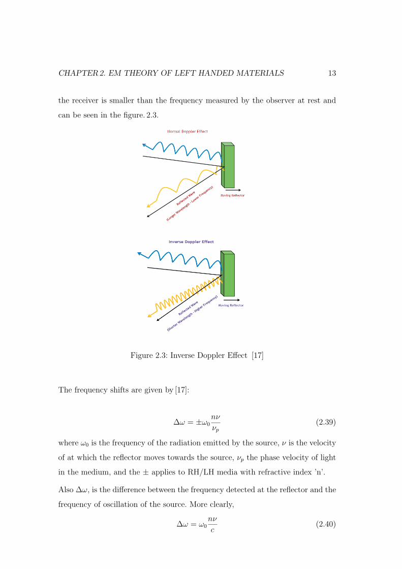
the receiver is smaller than the frequency measured by the observer at rest and
can be seen in the figure. 2.3.
Figure 2.3: Inverse Doppler Effect [17]
The frequency shifts are given by [17]:
∆ω = ±ω0nν
νp
(2.39)
where ω0 is the frequency of the radiation emitted by the source, ν is the velocity
of at which the reflector moves towards the source, νp the phase velocity of light
in the medium, and the ± applies to RH/LH media with refractive index ’n’.
Also ∆ω, is the difference between the frequency detected at the reflector and the
frequency of oscillation of the source. More clearly,
∆ω = ω0nν
c(2.40)
CHAPTER2. EM THEORY OF LEFT HANDED MATERIALS 14
For n<0, the frequency shift becomes negative for positive ν.
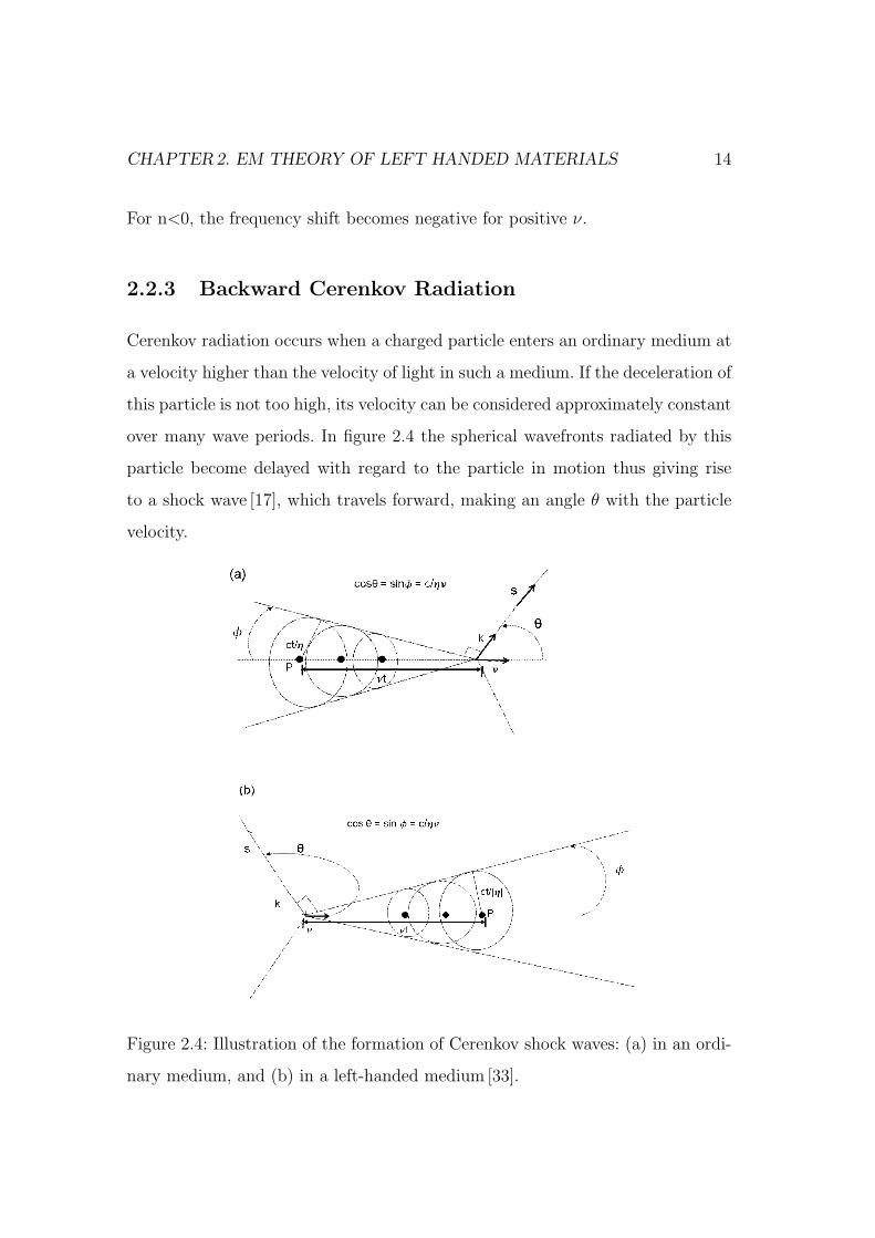
2.2.3 Backward Cerenkov Radiation
Cerenkov radiation occurs when a charged particle enters an ordinary medium at
a velocity higher than the velocity of light in such a medium. If the deceleration of
this particle is not too high, its velocity can be considered approximately constant
over many wave periods. In figure 2.4 the spherical wavefronts radiated by this
particle become delayed with regard to the particle in motion thus giving rise
to a shock wave [17], which travels forward, making an angle θ with the particle
velocity.
Figure 2.4: Illustration of the formation of Cerenkov shock waves: (a) in an ordi-
nary medium, and (b) in a left-handed medium [33].

CHAPTER2. EM THEORY OF LEFT HANDED MATERIALS 15
This angle is given by,
cos θ =c
nν(2.41)
where c/n is the velocity of light in the medium and ν is the velocity of the parti-
cle. If the medium has a negative refractive index, wave propagation is backward
and the spherical wavefronts corresponding to each frequency harmonic of the
radiation move inwards to the source, at a velocity c/[nω]. Therefore each wave-
front collapses at the advanced position of the particle shown in the above figure.
Thus, the resulting shock wave travels backward at an obtuse angle from the
particle motion. The angle is given in eqn. 2.41 as illustrated in the fig. 2.4. Any
left-handed medium must be highly dispersive [33], as being restricted to some
frequency range. Because the particle radiates at all frequencies, the Cerenkov
radiation spectra must show wavefronts moving in both forward and backward
directions [6].
2.2.4 Negative Refraction - Reverse Snell’s Law
Consider the refraction of an incident optical ray at the interface between or-
dinary (ε>0, µ>0) and the left-handed media. Boundary conditions impose the
continuity of the tangential components of the wavevector along the interface. As
the left-handed region is considered, the angles of incidence, refraction must have
opposite signs and can be seen in the fig. 2.5.
Illustrating Snell’s law in left-handed region,
sin θi
sin θr
=− |k2|
k1
=n2
n1
< 0 (2.42)
where n1 and n2 are the refractive indices of the ordinary and left-handed media
respectively. Assuming n1>0 and from the above equation it follows n2<0 i.e the
sign of the square root in the refractive index definition must be chosen to be
negative [29]:
n = −c√
εµ < 0 (2.43)
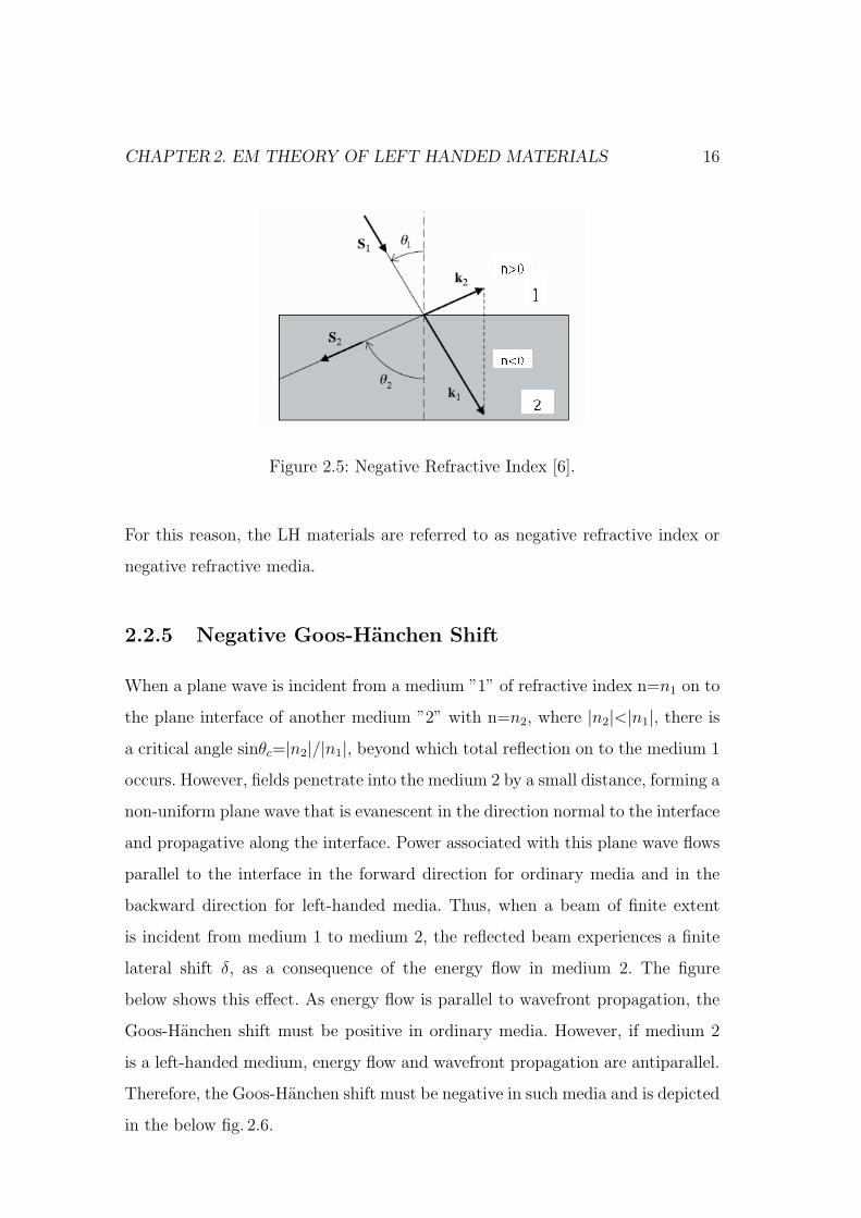
CHAPTER2. EM THEORY OF LEFT HANDED MATERIALS 16
Figure 2.5: Negative Refractive Index [6].
For this reason, the LH materials are referred to as negative refractive index or
negative refractive media.
2.2.5 Negative Goos-Hanchen Shift
When a plane wave is incident from a medium ”1” of refractive index n=n1 on to
the plane interface of another medium ”2” with n=n2, where |n2|<|n1|, there is
a critical angle sinθc=|n2|/|n1|, beyond which total reflection on to the medium 1
occurs. However, fields penetrate into the medium 2 by a small distance, forming a
non-uniform plane wave that is evanescent in the direction normal to the interface
and propagative along the interface. Power associated with this plane wave flows
parallel to the interface in the forward direction for ordinary media and in the
backward direction for left-handed media. Thus, when a beam of finite extent
is incident from medium 1 to medium 2, the reflected beam experiences a finite
lateral shift δ, as a consequence of the energy flow in medium 2. The figure
below shows this effect. As energy flow is parallel to wavefront propagation, the
Goos-Hanchen shift must be positive in ordinary media. However, if medium 2
is a left-handed medium, energy flow and wavefront propagation are antiparallel.
Therefore, the Goos-Hanchen shift must be negative in such media and is depicted
in the below fig. 2.6.

CHAPTER2. EM THEORY OF LEFT HANDED MATERIALS 17
(a) (b)
Figure 2.6: (a) Ordinary media (b) Left-Handed media [17].
The Goos-Hanchen shift ”∆” can be calculated by expanding the incident beam
in the plane waves, and studying the reflection of these waves at the interface. If
the angular spectrum of the beam is not too wide,and the angle of incidence is
sufficiently away from the critical and grazing angles, the Goos-Hanchen shift is
given by [17]:
∆ =∂φr
∂k‖. (2.44)
Where φr is the phase of the reflection coefficient and k‖ is the component of the
wave-vector parallel to the interface i.e. for lossless left-handed media |r|=1, and
φr=-j log r. Therefore by above predictions, the sign of Goos-Hanchen shift agrees
with predictions of left-handed media.
2.2.6 Transmission and Reflection Coefficients in LH Me-
dia
In this section, transmission and guidance of electromagnetic waves through left-
handed side will be analyzed. The method of analysis will be a straight forward
extension of the transverse transmission matrix technique [27], the same applies
for multilayered structures. For this purpose, plane waves at both sides of a plane
interface will be decomposed into propagative positive(+) and negative (-)waves,
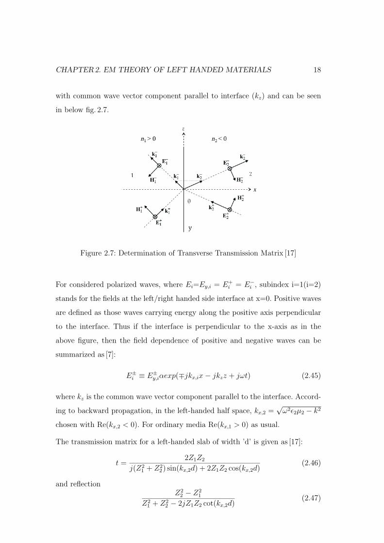
CHAPTER2. EM THEORY OF LEFT HANDED MATERIALS 18
with common wave vector component parallel to interface (kz) and can be seen
in below fig. 2.7.
Figure 2.7: Determination of Transverse Transmission Matrix [17]
For considered polarized waves, where Ei=Ey,i = E+i = E−
i , subindex i=1(i=2)
stands for the fields at the left/right handed side interface at x=0. Positive waves
are defined as those waves carrying energy along the positive axis perpendicular
to the interface. Thus if the interface is perpendicular to the x-axis as in the
above figure, then the field dependence of positive and negative waves can be
summarized as [7]:
E±i ≡ E±
y,iαexp(∓jkx,ix− jkzz + jωt) (2.45)
where kz is the common wave vector component parallel to the interface. Accord-
ing to backward propagation, in the left-handed half space, kx,2 =√
ω2ε2µ2 − k2
chosen with Re(kx,2 < 0). For ordinary media Re(kx,1 > 0) as usual.
The transmission matrix for a left-handed slab of width ’d’ is given as [17]:
t =2Z1Z2
j(Z21 + Z2
2) sin(kx,2d) + 2Z1Z2 cos(kx,2d)(2.46)
and reflectionZ2
2 − Z21
Z21 + Z2
2 − 2jZ1Z2 cot(kx,2d)(2.47)
CHAPTER2. EM THEORY OF LEFT HANDED MATERIALS 19
Note that (kx,2d < 0), so the phase advance through the slab is positive for small
values of kx,2d, which corrosponds to the propagation of a backward wave inside
the slab.
2.2.7 Losses and Dispersion
After showing the propagation in left-handed media, it was claimed that losses
and dispersion will destroy many of the previously reported effects. Specifically,
negative refraction [6] and super-resolution in Pendry’s perfect lens [3] were criti-
cized. The analysis of the refraction of a Gaussian beam at the interface between
an ordinary and a left-handed medium showed, without doubt, that negative re-
fraction occurs in such a situation, thus confirming the Veselago analysis [1]. Of
more interest are the effects of losses on the perfect lens proposed by Pendry [27].
Let us examine the analysis briefly.
The transmission coefficient of the LH media [17] is given as,
t =4Z
(1 + Z)2exp(jkx,2d)− (1− Z)2exp(−jkx,2d)(2.48)
where Z=Z1/Z2. If ε/ε0→ -1 and µ/µ0→ -1, also the wave impedance Z is given
as [17]:
Zi =E+
i
H+i
=ωµi
kx,i
. (2.49)
Where E+i ≡E+
y,i, is the electric field component of the positive wave [Refer above
section]. It follows that Z=1, if Kx,2=-|Kx,2| is real, and Z=-1, if Kx,2=α is imag-
inary. Therefore, t→ exp(j|Kx,2|d) for propagative waves and t→ exp (αd) for
evanescent waves. In both cases, the phase and amplitude of the incident waves
change along the slab just by the amount necessary to produce Fourier harmonics
restoration at a distance ’2d’ from any source which can be seen in below figure.
Let us introduce a small amount of losses in the left-handed slab [30], so that
ε → −ε0(1+jδε) and µ → −µ0(1+jδµ)and also suppose that kz À k0, so that
CHAPTER2. EM THEORY OF LEFT HANDED MATERIALS 20
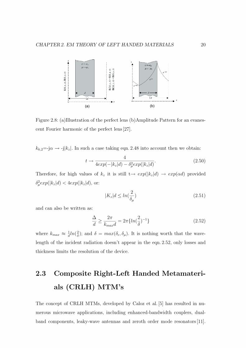
(a) (b)
Figure 2.8: (a)Illustration of the perfect lens (b)Amplitude Pattern for an evanes-
cent Fourier harmonic of the perfect lens [27].
kk,2=-jα → -j|kz|. In such a case taking eqn. 2.48 into account then we obtain:
t → 4
4exp(−|kz|d)− δ2µexp(|kz|d)
. (2.50)
Therefore, for high values of kz it is still t→ exp(|kz|d) → exp(αd) provided
δ2µexp(|kz|d) < 4exp(|kz|d), or:
|Kz|d ≤ ln(2
δµ
) (2.51)
and can also be written as:
∆
d≥ 2π
kmaxd= 2πln(
2
δ)−1 (2.52)
where kmax ≈ 1dln(2
δ); and δ = max(δε, δµ). It is nothing worth that the wave-
length of the incident radiation doesn’t appear in the eqn. 2.52, only losses and
thickness limits the resolution of the device.
2.3 Composite Right-Left Handed Metamateri-
als (CRLH) MTM’s
The concept of CRLH MTMs, developed by Caloz et al. [5] has resulted in nu-
merous microwave applications, including enhanced-bandwidth couplers, dual-
band components, leaky-wave antennas and zeroth order mode resonators [11].
CHAPTER2. EM THEORY OF LEFT HANDED MATERIALS 21
However, the wide passband property of CRLH structures, inherent to their
(artificial) TL nature, has not been exploited yet beyond their long-wavelength
(MTM) frequency band located around the transition frequency between the left-
handed (LH) and right-handed (RH) bands. This wideband property turns out to
be very suitable for filter applications. In this thesis work we have exploited this
structure for narrow band filters which fills the lack.
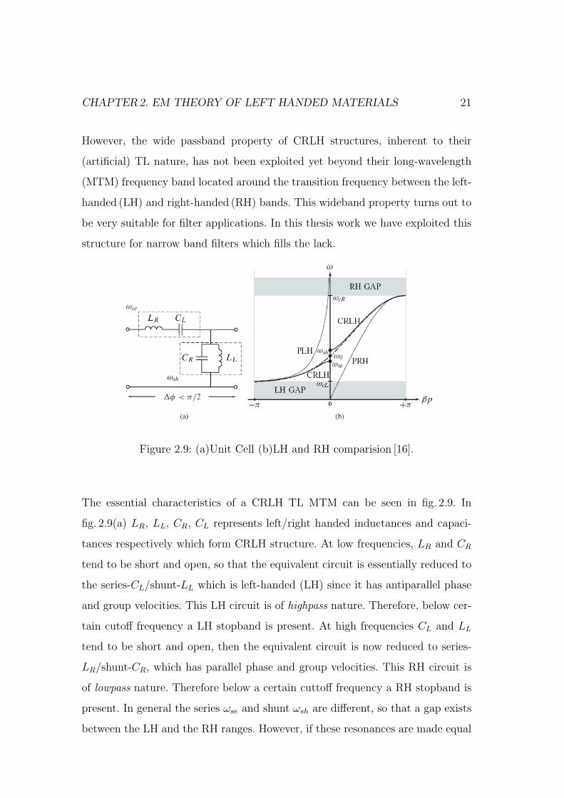
Figure 2.9: (a)Unit Cell (b)LH and RH comparision [16].
The essential characteristics of a CRLH TL MTM can be seen in fig. 2.9. In
fig. 2.9(a) LR, LL, CR, CL represents left/right handed inductances and capaci-
tances respectively which form CRLH structure. At low frequencies, LR and CR
tend to be short and open, so that the equivalent circuit is essentially reduced to
the series-CL/shunt-LL which is left-handed (LH) since it has antiparallel phase
and group velocities. This LH circuit is of highpass nature. Therefore, below cer-
tain cutoff frequency a LH stopband is present. At high frequencies CL and LL
tend to be short and open, then the equivalent circuit is now reduced to series-
LR/shunt-CR, which has parallel phase and group velocities. This RH circuit is
of lowpass nature. Therefore below a certain cuttoff frequency a RH stopband is
present. In general the series ωse and shunt ωsh are different, so that a gap exists
between the LH and the RH ranges. However, if these resonances are made equal
CHAPTER2. EM THEORY OF LEFT HANDED MATERIALS 22
or balanced, this gap disappears and an infinite wavelength λg = 2π/|β| (where
|β| → 0) propagation is achieved at ω0. Despite its filter behavior, the CRLH
structure is never operated at the edges of Brillouin zone, where p≈ λg/2 but only
at the transition frequency where effective homogeneity is ensured p< λg/4 [16]
(where ”p” is cell size). Also, as the CRLH structure has both LH and RH range,
their dispersion curve in each case differs from PLH (Pure Left-Handed) and PRH
(Pure Right-Handed) as shown in the fig. 2.9b. This happens due to the combined
effects of LH and RH contributions at all frequencies.

Chapter 3
Transmission Line theory of
Metamaterials
3.1 Introduction
A transmission line (TL) is perfectly uniform and homogenous [9], which means
it has an invariant cross section along the direction of propagation. It can trans-
mit signals from zero to infinite frequencies. RH homogenous TLs are commonly
used as coaxial or microstrip lines, but LH and CRLH is not possible due to un-
availability of real homogeneous LH or CRLH materials, but can be possible to
construct effectively homogeneous artificial LC TL structures or MTM TLs, that
perfectly behave as ideal TLs in a restricted range of frequencies. The difference
between a perfectly homogeneous TL and an effectively homogeneous TL is that
in the former case we have an incremental length ∆Z → 0, whereas in the latter
case we must consider the restriction [16]
∆z ¿ λg
[∆z <
λg
4
]Typically
λg
10(3.1)
where λg represents the guided wavelength and ∆z is typically equal the average
unit cell size p. Loss-Less and Lossy CRLH TLs are discussed further in the next
section.
23
CHAPTER3. TRANSMISSION LINE THEORY OF METAMATERIALS 24
3.2 Loss Less CRLH TLs
The below figure is a loss less ideal CRLH TL model consisting of per-unit length
impedance Z ′(Ω/m) constituted by per-unit length inductance L′R (H/m) in se-
ries with a LH times-unit length capacitance C ′L(Fxm) and a per-unit length
admittance Y ′ (S/m) constituted by a RH per-unit-length capacitance C ′R(F/m)
in parallel with a LH times-unit length inductance L′L (Hxm) and is:
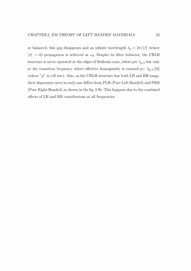
Figure 3.1: Ideal CRLH TL [16]
Z ′ = j
(ωL′R −
1
ωC ′L
)(3.2)
Y ′ = j
(ωC ′
R −1
ωL′L
). (3.3)
If LH immittances are zero, Z ′L = −j/(ωC ′
L)=0 or C ′L = ∞ and Y ′
L = −j/(ωL′L)=0
or L′L = ∞, only the RH immittances Z ′R = jωL′R and Y ′
R = jωC ′R are present
which reduces to the conventional RH TL model otherwise LH TL model.
The behavior of the CRLH TL can be detailed by the asymptotic consideration.
At low frequencies (ω → 0), Z ′R → 0, Y ′
R → 0 so that the CRLH TL becomes
equivalent to a PLH (Pure Left-Handed) TL (L′R = C ′R = 0). At high frequencies

CHAPTER3. TRANSMISSION LINE THEORY OF METAMATERIALS 25
(ω →∞), Z ′L → 0, Y ′
L → 0, So that CRLH TL becomes equivalent to a PRH (Pure
Right-Handed) TL (L′L = C ′L = ∞). At all other frequencies the transmission
characteristics depend on the combination of LH and RH contributions.
Let us generalize CRLH TLs using the Telegraphist’s equations, For a steady-
state sinusoidal waves based on cosine phasors:
dU
dz= −Z ′I = −jω
(L′R− 1
ω2C ′L
)I (3.4)
dI
dz= −Y ′U = −jω
(C ′R− 1
ω2L′L
)U (3.5)
Where U and I are the position-dependent voltage and currents [V=V(z)] and
[I=I(z)] along the line respectively. By solving eqn. 3.4 and 3.5, we get the follow-
ing wave equations for U and I[11]:
d2V
dz2= −γ2 = 0 (3.6)
d2I
dz2= −γ2 = 0. (3.7)
Where γ (l/m) is the complex propagation constant and can be expressed in
terms of the per-unit-length immittances Z ′ and Y ′ as:
γ = α + jβ =√
Z ′Y ′. (3.8)
The characteristic impedance Zc (Ω), relating to voltage and currents on the line
(propagating wave equations with +ve and -ve voltages and currents) is:
ZC = RC + jXc =Z ′
γ=
√Z ′
Y ′ = Zc(ω). (3.9)
Let us use variables:
ω′R =1√
L′RC ′R
(radxm)/s. (3.10)
CHAPTER3. TRANSMISSION LINE THEORY OF METAMATERIALS 26
ω′L =1√
L′LC ′L
rad(mxs). (3.11)
κ = L′RC ′L + L′LC ′
L(s/rad)2. (3.12)
and the series and shunt resonance frequencies are[5]
ω′se =1√
L′RC ′L
rad/s. (3.13)
ω′sh =1√
L′LC ′R
rad/s. (3.14)
respectively. By inserting eqn. 3.2 into eqn. 3.8 and using eqn. 3.10, we get the
following expression for complex propagation constant[16]:
γ = α + jβ = js(ω)
√√√√(
ω
ω′R
)+
(ω′Lω′
)2
− κω2L. (3.15)
Where s(ω) is the following sign function:
s(ω) = −1 ; If ω < min(ωse, ωsh) ..... LH Range (3.16)
s(ω) = +1 ; If ω > max(ωse, ωsh) ..... RH range (3.17)
The negative term in the eqn. 3.15 shows that the propagation constant γ is not
necessarily purely imaginary [5] γ = jβ (Pass band); it can be purely real γ = α
(stop band) in some frequency ranges despite the fact that the line is loss-less.
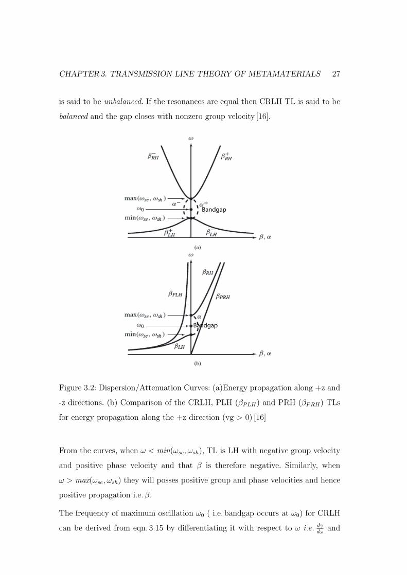
3.3 Dispersion/Attenuation
The dispersion/attenuation curve is in fig. 3.2a shows the CRLH dispersion and
attenuation curves for energy propagation along both the positive and negative
z direction, whereas, fig. 3.2b shows the CRLH dispersion comparison with PRH
and PLH at lower and higher frequencies. The gap is due to the different series
and shunt resonances (ωse, ωsh) respectively, if this happens then the CRLH TL
CHAPTER3. TRANSMISSION LINE THEORY OF METAMATERIALS 27
is said to be unbalanced. If the resonances are equal then CRLH TL is said to be
balanced and the gap closes with nonzero group velocity [16].
Bandgap
Bandgap
Figure 3.2: Dispersion/Attenuation Curves: (a)Energy propagation along +z and
-z directions. (b) Comparison of the CRLH, PLH (βPLH) and PRH (βPRH) TLs
for energy propagation along the +z direction (vg > 0) [16]
From the curves, when ω < min(ωse, ωsh), TL is LH with negative group velocity
and positive phase velocity and that β is therefore negative. Similarly, when
ω > max(ωse, ωsh) they will posses positive group and phase velocities and hence
positive propagation i.e. β.
The frequency of maximum oscillation ω0 ( i.e. bandgap occurs at ω0) for CRLH
can be derived from eqn. 3.15 by differentiating it with respect to ω i.e. dγdω
and
CHAPTER3. TRANSMISSION LINE THEORY OF METAMATERIALS 28
this yields to:
ω0 =√
ω′Rω′L =1
4√
L′RC ′RL′LC ′
L
(3.18)
.
The CRLH characteristic impedance is obtained by inserting eqn. 3.13 and 3.14
in eqn. 3.9, then we get:
Zc = ZL
√√√√ (ω/ωse)2 − 1
(ω/ωsh)2 − 1
. (3.19)
Where PLH (pure left handed) and PRH (pure right handed) impedances are,
ZL =
√L′LC ′
L
(3.20)
and
ZR =
√L′RC ′
R
. (3.21)
From eqn. 3.19, it can be noted that the characteristic impedance has a zero and
a pole at ω = ωse and ω = ωsh respectively,
Zc(ω = ωse = 0) (3.22)
Zc(ω = ωsh = ∞) (3.23)
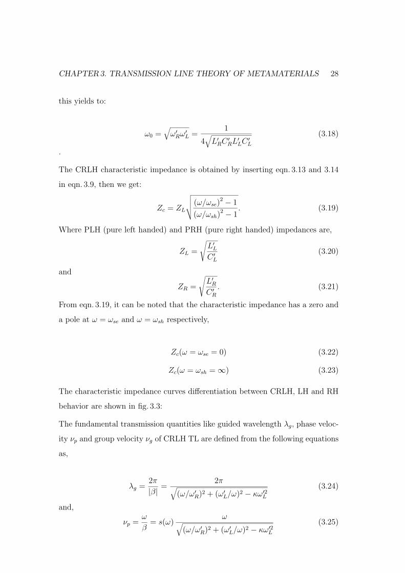
The characteristic impedance curves differentiation between CRLH, LH and RH
behavior are shown in fig. 3.3:
The fundamental transmission quantities like guided wavelength λg, phase veloc-
ity νp and group velocity νg of CRLH TL are defined from the following equations
as,
λg =2π
|β| =2π√
(ω/ω′R)2 + (ω′L/ω)2 − κω′2L(3.24)
and,
νp =ω
β= s(ω)
ω√(ω/ω′R)2 + (ω′L/ω)2 − κω′2L
(3.25)
CHAPTER3. TRANSMISSION LINE THEORY OF METAMATERIALS 29
Figure 3.3: Characteristic Impedance [9]
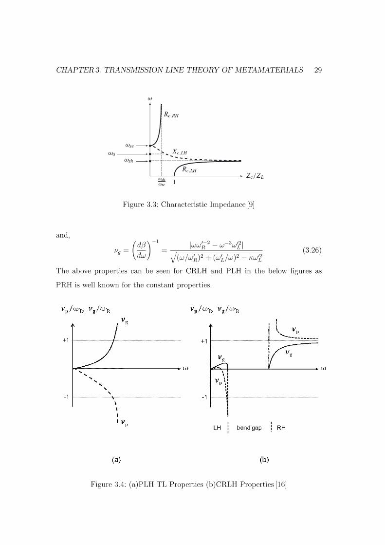
and,
νg =
(dβ
dω
)−1
=|ωω′−2
R − ω−3ω′2L |√(ω/ω′R)2 + (ω′L/ω)2 − κω′2L
(3.26)
The above properties can be seen for CRLH and PLH in the below figures as
PRH is well known for the constant properties.
Figure 3.4: (a)PLH TL Properties (b)CRLH Properties [16]
CHAPTER3. TRANSMISSION LINE THEORY OF METAMATERIALS 30
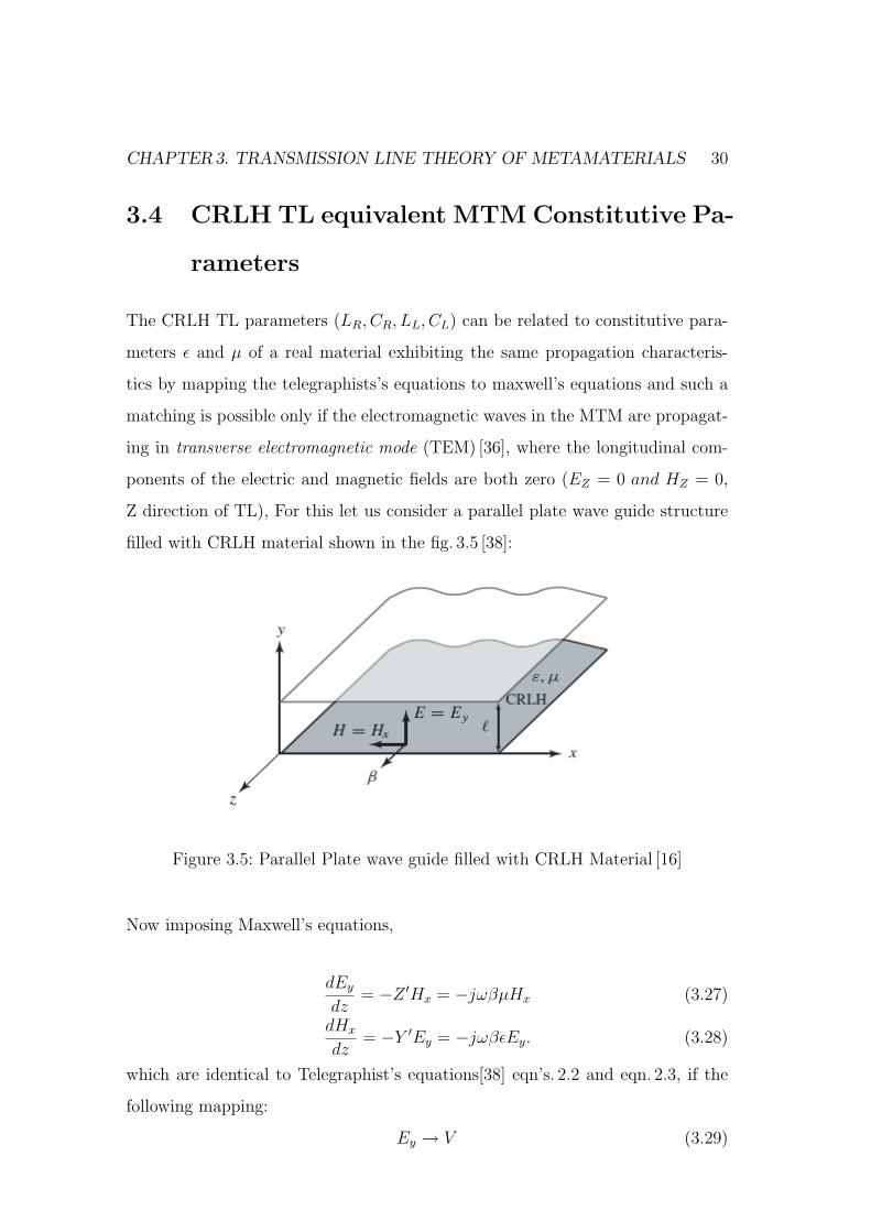
3.4 CRLH TL equivalent MTM Constitutive Pa-
rameters
The CRLH TL parameters (LR, CR, LL, CL) can be related to constitutive para-
meters ε and µ of a real material exhibiting the same propagation characteris-
tics by mapping the telegraphists’s equations to maxwell’s equations and such a
matching is possible only if the electromagnetic waves in the MTM are propagat-
ing in transverse electromagnetic mode (TEM) [36], where the longitudinal com-
ponents of the electric and magnetic fields are both zero (EZ = 0 and HZ = 0,
Z direction of TL), For this let us consider a parallel plate wave guide structure
filled with CRLH material shown in the fig. 3.5 [38]:
Figure 3.5: Parallel Plate wave guide filled with CRLH Material [16]
Now imposing Maxwell’s equations,
dEy
dz= −Z ′Hx = −jωβµHx (3.27)
dHx
dz= −Y ′Ey = −jωβεEy. (3.28)
which are identical to Telegraphist’s equations[38] eqn’s. 2.2 and eqn. 2.3, if the
following mapping:
Ey → V (3.29)
CHAPTER3. TRANSMISSION LINE THEORY OF METAMATERIALS 31
Hx → I (3.30)
and,
µ = µ(ω) = L′R −1
ω2C ′L
(3.31)
ε = ε(ω) = C ′R −
1
ω2L′L. (3.32)
where ε = εrε) (H/m) and (µ = µrµ0) (F/m). Which represents equivalent consti-
tutive parameters of CRLH TL MTM. Finally we can derive CRLH TL equivalent
refractive index as:
n = n(ω) =√
µrεr = c√
µε. (3.33)
This equivalent refractive index is related to TEM propagation constant β by
β = nk0 (3.34)
where k0 = ω/c.
3.4.1 CRLH TL Balanced and Unbalanced Resonances
Considering fig. 3.1, the CRLH TL is said to be balanced, when their resonance
frequencies are equal [16], .i.e:
ωse = ωsh (3.35)
The characteristic impedances of series and shunt cancel each other suppressing
resonance effect.
L′RC ′L = C ′
LL′L (3.36)
As a consequence the gap between them closes and the characteristic impedance
becomes a frequency-independent quantity
Zc = ZL = ZR (3.37)
which means, that the balanced condition allows matching over an infinite band-
width. And the transition frequency is given as:
ω0 =√
ω′Rω′L (3.38)
CHAPTER3. TRANSMISSION LINE THEORY OF METAMATERIALS 32
where ω′R, ω′L are LH and RH resonant frequencies. Also the propagation constant:
β =ω
ω′R− ω′L
ω. (3.39)
On the other side, if the series and the shunt resonances are unequal then the
CRLH TL is unbalanced where,
ωse 6= ωsh (3.40)
Which means we have zero immittances when the TL is fed by a signal with either
frequency ω = ωse or ω = ωsh. Introducing a pole and a zero in the characteristic
impedance, i.e.:
Zc(ω = ωse) = 0 (3.41)
and
Zc(ω = ωsh) = ∞. (3.42)
This impedance conditions corresponds to the zero group velocities i.e. vg = 0
where there is no power transfer and propagation. The TL resonances result in
the emergence of stopband or bandgap.
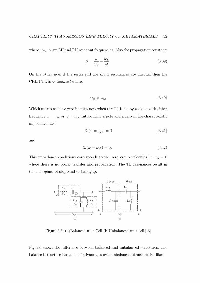
Figure 3.6: (a)Balanced unit Cell (b)Unbalanced unit cell [16]
Fig. 3.6 shows the difference between balanced and unbalanced structures. The
balanced structure has a lot of advantages over unbalanced structure [40] like:
CHAPTER3. TRANSMISSION LINE THEORY OF METAMATERIALS 33
• It is simpler because of series combined LH and RH contributions are de-
coupled from each other.
• The balanced TL is gapless which facts Zc and β from eqn’s. 3.37 and 3.39
are real at all frequencies from ω = 0 to ω = ∞.
• The balanced TL has non zero phase and group velocities, where unbalanced
TL has zero phase and group velocities.
• The characteristic impedance Zc of the balanced TL is a constant frequency
independent quantity, for which the balanced TL can be matched over a
broad bandwidth. Where in unbalanced case, it matches to a single fre-
quency.
In this thesis work we have preferred balanced structure over unbalanced due to
the advantages.
3.4.2 Lossy CRLH TL Case
Z
Y
∆φ
RΖ
LΖ
RΥ
LΥ
RHL
R1
R2LHL
LHC
RHC
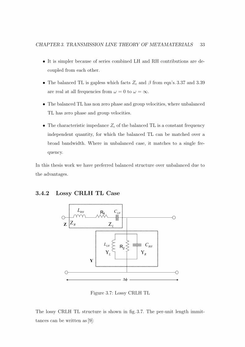
Figure 3.7: Lossy CRLH TL
The lossy CRLH TL structure is shown in fig. 3.7. The per-unit length immit-
tances can be written as [9]:
CHAPTER3. TRANSMISSION LINE THEORY OF METAMATERIALS 34
Z ′ = R′ + jX ′; X ′ =
(ωL′R −
1
ωC ′L
)(3.43)
Y ′ = G′ + jB′; B′ =
(ωC ′
R −1
ωL′L
). (3.44)
Here the complex propagation constant and characteristic impedance are given
as:
γ = α + jβ =√
Z ′Y ′ =√
(R′G′ −X ′B′)− j(R′B′ + G′X ′) (3.45)
Zc = R0 + jX0 =Z ′
Y ′ =R′ + jX ′
G′ + jB′ (3.46)
.
To obtain some insight into the lossy effects, let us consider PLH TL. Using
equation (3.45) with L′R = C ′R = 0 in (3.43), we obtain the propagation constant
γL for the PLH lossy TL.
γL = −j
√1−R′G′(ω/ω′L)2 + jω(C ′
LR′ + L′LG′)
ω/ω′L= γL + jβL (3.47)
Which has both a real and imaginary part at all frequencies (α 6= 0, β 6= 0 ∨ ω).
In practical low-frequency microwave structures, ohmic and dielectric losses are
relatively small [41], and the parameters
A = R′G′(ω/ω′)2 (3.48)
B = ω(C ′LR′ + L′LG′) (3.49)
are typicall such that A ¿ B < 1. Therefore A can be neglected and the re-
maining square root may be approximated by its first order Taylor expansion, so
that
γL = −j1
ω/ω′L
[1 +
j
2(C ′
LR′ + L′LG′)]
(3.50)
from which
βL ≈ −ω′Lω
(3.51)
CHAPTER3. TRANSMISSION LINE THEORY OF METAMATERIALS 35
αL ≈ 1
2[R′Y0 + G′Zc] (3.52)
Where Zc = ZL =√
L′L/C ′L and Y0 = YL = 1/Zc, We observe that a weakly
lossy LH TL exhibits the same propagation constant as a loss-less LH TL and
same attenuation factor as that of the conventional RH TL [16]. Which facts that,
the loss mechanism is the same in both LH TL and RH TL. From eqn. 3.46, the
characteristic impedance is,
Zc =
√√√√R′ − j/ωC ′L
G′ + jωL′Lω → 0 ≈ L′L
C ′L
. (3.53)
which is identically equal to eqn. (3.37) of loss-less LH TL and essentially behaves
in the same manner and hence the same applies to CRLH TL including both
LH and RH contributions. It has been observed that, the reduction of group
velocity over a bandwidth is due to the introduction of losses. Which increases,
as the amount of losses is increased and nullifies the real part of the characteristic
impedance at the transition frequency.
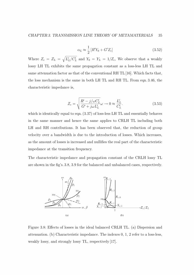
The characteristic impedance and propagation constant of the CRLH lossy TL
are shown in the fig’s. 3.8, 3.9 for the balanced and unbalanced cases, respectively.
Figure 3.8: Effects of losses in the ideal balanced CRLH TL. (a) Dispersion and
attenuation. (b) Characteristic impedance. The indexes 0, 1, 2 refer to a loss-less,
weakly lossy, and strongly lossy TL, respectively [17].
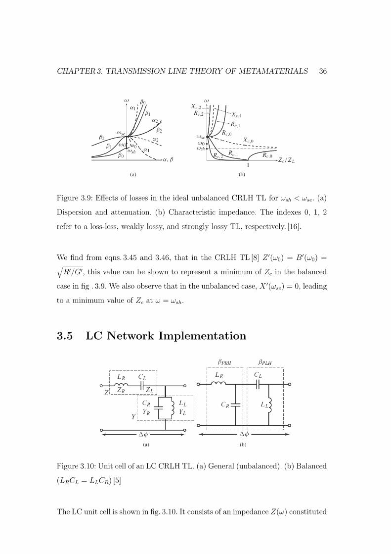
CHAPTER3. TRANSMISSION LINE THEORY OF METAMATERIALS 36
Figure 3.9: Effects of losses in the ideal unbalanced CRLH TL for ωsh < ωse. (a)
Dispersion and attenuation. (b) Characteristic impedance. The indexes 0, 1, 2
refer to a loss-less, weakly lossy, and strongly lossy TL, respectively. [16].
We find from eqns. 3.45 and 3.46, that in the CRLH TL [8] Z ′(ω0) = B′(ω0) =√
R′/G′, this value can be shown to represent a minimum of Zc in the balanced
case in fig . 3.9. We also observe that in the unbalanced case, X ′(ωse) = 0, leading
to a minimum value of Zc at ω = ωsh.
3.5 LC Network Implementation
Figure 3.10: Unit cell of an LC CRLH TL. (a) General (unbalanced). (b) Balanced
(LRCL = LLCR) [5]
The LC unit cell is shown in fig. 3.10. It consists of an impedance Z(ω) constituted
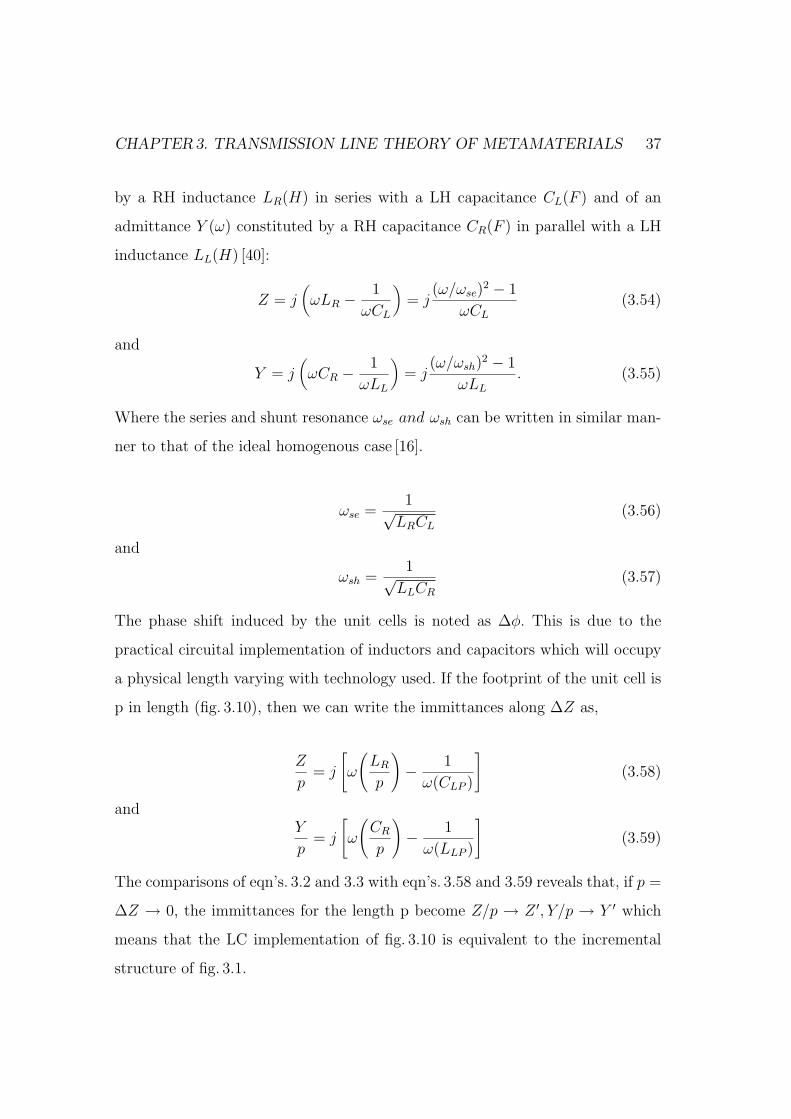
CHAPTER3. TRANSMISSION LINE THEORY OF METAMATERIALS 37
by a RH inductance LR(H) in series with a LH capacitance CL(F ) and of an
admittance Y (ω) constituted by a RH capacitance CR(F ) in parallel with a LH
inductance LL(H) [40]:
Z = j(ωLR − 1
ωCL
)= j
(ω/ωse)2 − 1
ωCL
(3.54)
and
Y = j(ωCR − 1
ωLL
)= j
(ω/ωsh)2 − 1
ωLL
. (3.55)
Where the series and shunt resonance ωse and ωsh can be written in similar man-
ner to that of the ideal homogenous case [16].
ωse =1√
LRCL
(3.56)
and
ωsh =1√
LLCR
(3.57)
The phase shift induced by the unit cells is noted as ∆φ. This is due to the
practical circuital implementation of inductors and capacitors which will occupy
a physical length varying with technology used. If the footprint of the unit cell is
p in length (fig. 3.10), then we can write the immittances along ∆Z as,
Z
p= j
[ω
(LR
p
)− 1
ω(CLP )
](3.58)
andY
p= j
[ω
(CR
p
)− 1
ω(LLP )
](3.59)
The comparisons of eqn’s. 3.2 and 3.3 with eqn’s. 3.58 and 3.59 reveals that, if p =
∆Z → 0, the immittances for the length p become Z/p → Z ′, Y/p → Y ′ which
means that the LC implementation of fig. 3.10 is equivalent to the incremental
structure of fig. 3.1.
CHAPTER3. TRANSMISSION LINE THEORY OF METAMATERIALS 38
3.5.1 Difference with conventional filters
The difference between MTM bandpass filters and conventional filters are:
• MTM filters are quasi-lumped, while conventaional filters are directly con-
verted TLines.
• CRLH TL in the balanced case, can be regarded as the central section part
of a low-ripple high order chebyshev BPF [13].
• In MTM filters, only passband is directly useful the stopbands are usually
parasitics.
• MTM filters usually satisfies effective homogenous condition ( unit cell order
of lamda/10 and unit cell phase shift less than π/2), but in conventional
filters there may be node to node phase shifters of order larger than π/2.
• A MTM structures can be 1D, 2D, 3D and behave as bulk media, but
conventional are 1D and behave as a electric circuits.
• A MTM filter can be made up of identical cells repeating and hence periodic,
where as in conventional filters each cell has generally different LC values
to match the specification of given prototype.
3.6 Symmetric and Asymmetric Structures
Lossless symmetric and asymmetric CRLH TL structures are shown in fig. 3.11
and 3.12 respectively. Symmetric configuration has the same input and output
impedances i.e Zin=Zin, therefore symmetric network is preferred. Asymmetric
configuration has different input and output impedances i.e Zin 6= Zin, therefore it
requires different port impedances for matching, which is impractical. Also, there
are mismatch effects at the connections with external ports. In this thesis, we
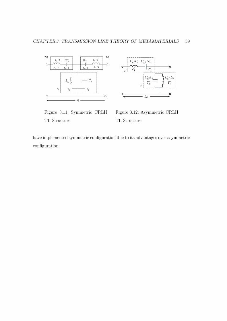
CHAPTER3. TRANSMISSION LINE THEORY OF METAMATERIALS 39
Z/2
Y
2/R
LL
C2
RC
LL
fD
2/R
Z 2/L
Z
RU
LU
Z/2
LC2 2/
RL
2/L
Z 2/R
Z
Figure 3.11: Symmetric CRLH
TL Structure
Figure 3.12: Asymmetric CRLH
TL Structure
have implemented symmetric configuration due to its advantages over asymmetric
configuration.

Chapter 4
Metamaterial CRLH TL
Applications for Filters
4.1 CRLH Metamaterial theory on Filter Ap-
plication
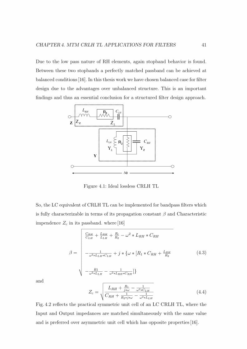
Fig. 4.1, shows the LC equivalent circuit model for an ideal unit cell of an CRLH
TL (Transmission Line). Considering the balanced condition of the circuit where
the series resonance equals the shunt resonance i.e ωse = ωsh [42],
the series resonance frequency of the unit cell is
fse =1
2π√
LRHCLH
(4.1)
and the shunt resonance is
fsh =1
2π√
LLHCRH
. (4.2)
On the left handed side (LHS) when ω → 0, then |Z| → 1ωCLH
+ R1 → ∞ and
|Y | → 1ωLLH
+ 1R2→∞ therefore, we have a stop band due to the high pass nature
of LH elements. On the other side which is right handed side(RHS), as ω → ∞,
|Z| → ωLRH→∞ and |Y | → ωCRH
→∞
40
CHAPTER4. MTM CRLH TL APPLICATIONS FOR FILTERS 41
Due to the low pass nature of RH elements, again stopband behavior is found.
Between these two stopbands a perfectly matched passband can be achieved at
balanced conditions [16]. In this thesis work we have chosen balanced case for filter
design due to the advantages over unbalanced structure. This is an important
findings and thus an essential conclusion for a structured filter design approach.
Z
Y
∆φ
RΖ
LΖ
RΥ
LΥ
RHL
R1
R2LHL
LHC
RHC
Figure 4.1: Ideal lossless CRLH TL
So, the LC equivalent of CRLH TL can be implemented for bandpass filters which
is fully characterizable in terms of its propagation constant β and Characteristic
impendence Zc in its passband. where [16]
β =
√√√√√√√√√√√√√√√√√
CRH
CLH+ LRH
LLH+ Rl
R2− ω2 ∗ LRH ∗ CRH
− 1ω2∗LLH∗CLH
+ j ∗ ω ∗ [R1 ∗ CRH + LRH
R2
− R1ω2∗LLH
− 1ω2∗LRH∗CRH
]
(4.3)
and
Zc =
√√√√√LRH + R1
j∗ω − 1ω2∗CLH
CRH + 1R2∗j∗ω − 1
ω2∗LLH
(4.4)
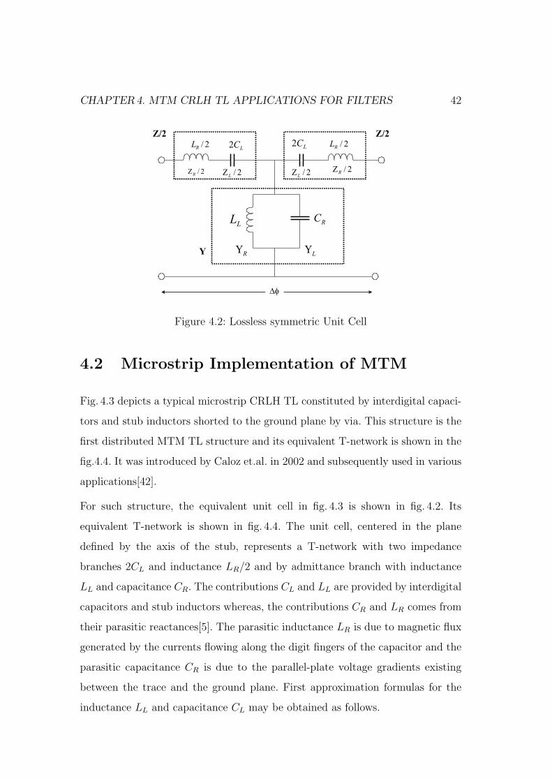
Fig. 4.2 reflects the practical symmetric unit cell of an LC CRLH TL, where the
Input and Output impedances are matched simultaneously with the same value
and is preferred over asymmetric unit cell which has opposite properties [16].
CHAPTER4. MTM CRLH TL APPLICATIONS FOR FILTERS 42
Z/2
Y
2/R
LL
C2
RC
LL
fD
2/R
Z 2/L
Z
RU
LU
Z/2
LC2 2/
RL
2/L
Z 2/R
Z
Figure 4.2: Lossless symmetric Unit Cell
4.2 Microstrip Implementation of MTM
Fig. 4.3 depicts a typical microstrip CRLH TL constituted by interdigital capaci-
tors and stub inductors shorted to the ground plane by via. This structure is the
first distributed MTM TL structure and its equivalent T-network is shown in the
fig.4.4. It was introduced by Caloz et.al. in 2002 and subsequently used in various
applications[42].
For such structure, the equivalent unit cell in fig. 4.3 is shown in fig. 4.2. Its
equivalent T-network is shown in fig. 4.4. The unit cell, centered in the plane
defined by the axis of the stub, represents a T-network with two impedance
branches 2CL and inductance LR/2 and by admittance branch with inductance
LL and capacitance CR. The contributions CL and LL are provided by interdigital
capacitors and stub inductors whereas, the contributions CR and LR comes from
their parasitic reactances[5]. The parasitic inductance LR is due to magnetic flux
generated by the currents flowing along the digit fingers of the capacitor and the
parasitic capacitance CR is due to the parallel-plate voltage gradients existing
between the trace and the ground plane. First approximation formulas for the
inductance LL and capacitance CL may be obtained as follows.
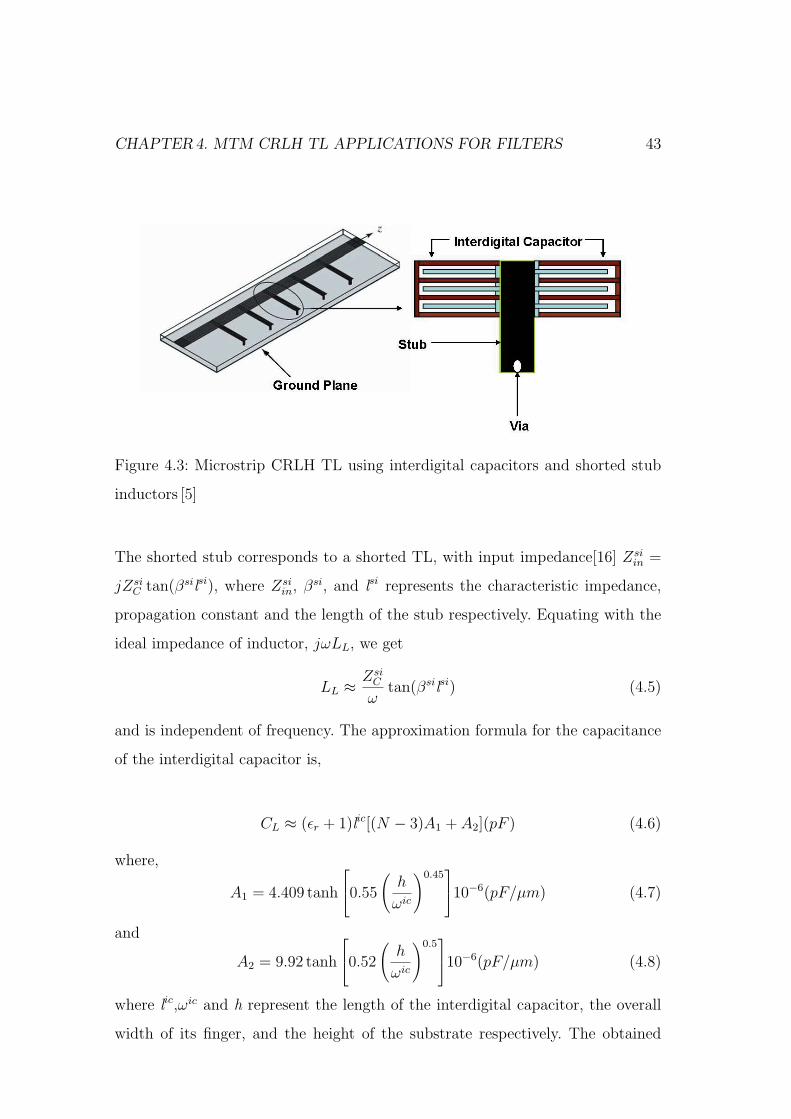
CHAPTER4. MTM CRLH TL APPLICATIONS FOR FILTERS 43
Figure 4.3: Microstrip CRLH TL using interdigital capacitors and shorted stub
inductors [5]
The shorted stub corresponds to a shorted TL, with input impedance[16] Zsiin =
jZsiC tan(βsilsi), where Zsi
in, βsi, and lsi represents the characteristic impedance,
propagation constant and the length of the stub respectively. Equating with the
ideal impedance of inductor, jωLL, we get
LL ≈ ZsiC
ωtan(βsilsi) (4.5)
and is independent of frequency. The approximation formula for the capacitance
of the interdigital capacitor is,
CL ≈ (εr + 1)lic[(N − 3)A1 + A2](pF ) (4.6)
where,
A1 = 4.409 tanh
0.55
(h
ωic
)0.4510−6(pF/µm) (4.7)
and
A2 = 9.92 tanh
0.52
(h
ωic
)0.510−6(pF/µm) (4.8)
where lic,ωic and h represent the length of the interdigital capacitor, the overall
width of its finger, and the height of the substrate respectively. The obtained
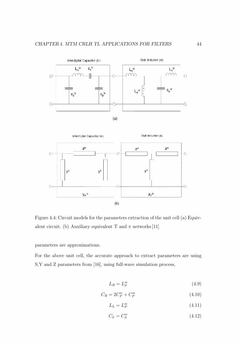
CHAPTER4. MTM CRLH TL APPLICATIONS FOR FILTERS 44
Figure 4.4: Circuit models for the parameters extraction of the unit cell (a) Equiv-
alent circuit. (b) Auxiliary equivalent T and π networks [11]
parameters are approximations.
For the above unit cell, the accurate approach to extract parameters are using
S,Y and Z parameters from [16], using full-wave simulation process,
LR = LsiS (4.9)
CR = 2CicP + Csi
P (4.10)
LL = LsiP (4.11)
CL = CicS (4.12)
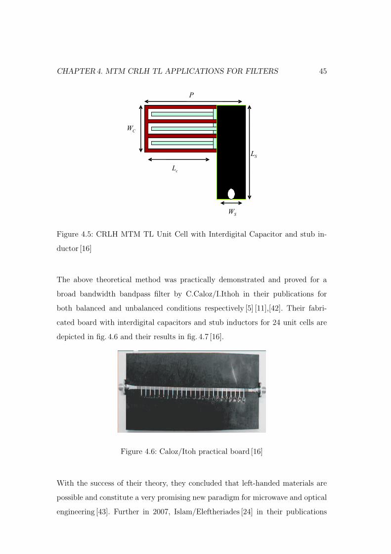
CHAPTER4. MTM CRLH TL APPLICATIONS FOR FILTERS 45
SL
cL
CW
P
SW
Figure 4.5: CRLH MTM TL Unit Cell with Interdigital Capacitor and stub in-
ductor [16]
The above theoretical method was practically demonstrated and proved for a
broad bandwidth bandpass filter by C.Caloz/I.Ithoh in their publications for
both balanced and unbalanced conditions respectively [5] [11],[42]. Their fabri-
cated board with interdigital capacitors and stub inductors for 24 unit cells are
depicted in fig. 4.6 and their results in fig. 4.7 [16].
Figure 4.6: Caloz/Itoh practical board [16]
With the success of their theory, they concluded that left-handed materials are
possible and constitute a very promising new paradigm for microwave and optical
engineering [43]. Further in 2007, Islam/Eleftheriades [24] in their publications
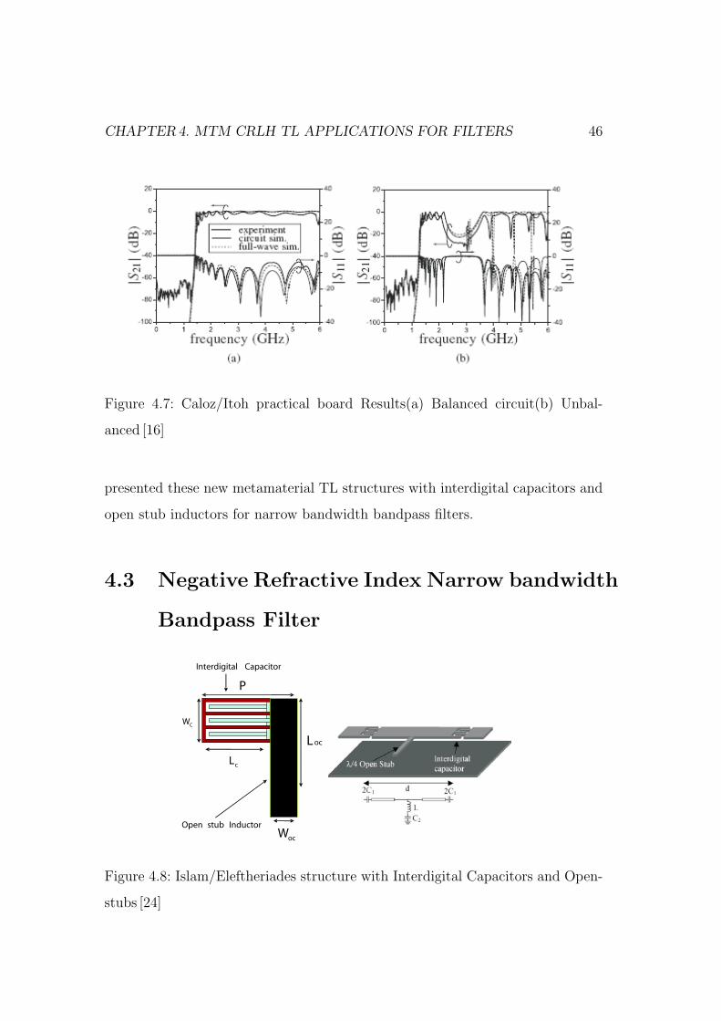
CHAPTER4. MTM CRLH TL APPLICATIONS FOR FILTERS 46
Figure 4.7: Caloz/Itoh practical board Results(a) Balanced circuit(b) Unbal-
anced [16]
presented these new metamaterial TL structures with interdigital capacitors and
open stub inductors for narrow bandwidth bandpass filters.
4.3 Negative Refractive Index Narrow bandwidth
Bandpass Filter
ocL
cL
CW
P
ocW
Open stub Inductor
Interdigital Capacitor
Figure 4.8: Islam/Eleftheriades structure with Interdigital Capacitors and Open-
stubs [24]
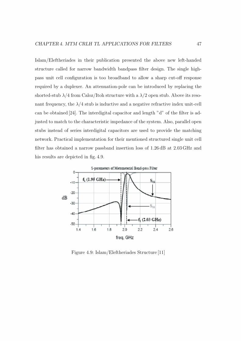
CHAPTER4. MTM CRLH TL APPLICATIONS FOR FILTERS 47
Islam/Eleftheriades in their publication presented the above new left-handed
structure called for narrow bandwidth bandpass filter design. The single high-
pass unit cell configuration is too broadband to allow a sharp cut-off response
required by a duplexer. An attenuation-pole can be introduced by replacing the
shorted-stub λ/4 from Caloz/Itoh structure with a λ/2 open stub. Above its reso-
nant frequency, the λ/4 stub is inductive and a negative refractive index unit-cell
can be obtained [24]. The interdigital capacitor and length ”d” of the filter is ad-
justed to match to the characteristic impedance of the system. Also, parallel open
stubs instead of series interdigital capacitors are used to provide the matching
network. Practical implementation for their mentioned structured single unit cell
filter has obtained a narrow passband insertion loss of 1.26 dB at 2.03 GHz and
his results are depicted in fig. 4.9.
Figure 4.9: Islam/Eleftheriades Structure [11]
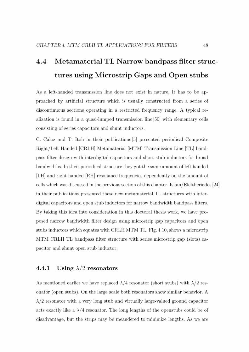
CHAPTER4. MTM CRLH TL APPLICATIONS FOR FILTERS 48
4.4 Metamaterial TL Narrow bandpass filter struc-
tures using Microstrip Gaps and Open stubs
As a left-handed transmission line does not exist in nature, It has to be ap-
proached by artificial structure which is usually constructed from a series of
discontinuous sections operating in a restricted frequency range. A typical re-
alization is found in a quasi-lumped transmission line [50] with elementary cells
consisting of series capacitors and shunt inductors.
C. Caloz and T. Itoh in their publications [5] presented periodical Composite
Right/Left Handed [CRLH] Metamaterial [MTM] Transmission Line [TL] band-
pass filter design with interdigital capacitors and short stub inductors for broad
bandwidths. In their periodical structure they got the same amount of left handed
[LH] and right handed [RH] resonance frequencies dependently on the amount of
cells which was discussed in the previous section of this chapter. Islam/Eleftheriades [24]
in their publications presented these new metamaterial TL structures with inter-
digital capacitors and open stub inductors for narrow bandwidth bandpass filters.
By taking this idea into consideration in this doctoral thesis work, we have pro-
posed narrow bandwidth filter design using microstrip gap capacitors and open
stubs inductors which equates with CRLH MTM TL. Fig. 4.10, shows a microstrip
MTM CRLH TL bandpass filter structure with series microstrip gap (slots) ca-
pacitor and shunt open stub inductor.
4.4.1 Using λ/2 resonators
As mentioned earlier we have replaced λ/4 resonator (short stubs) with λ/2 res-
onator (open stubs). On the large scale both resonators show similar behavior. A
λ/2 resonator with a very long stub and virtually large-valued ground capacitor
acts exactly like a λ/4 resonator. The long lengths of the openstubs could be of
disadvantage, but the strips may be meandered to minimize lengths. As we are
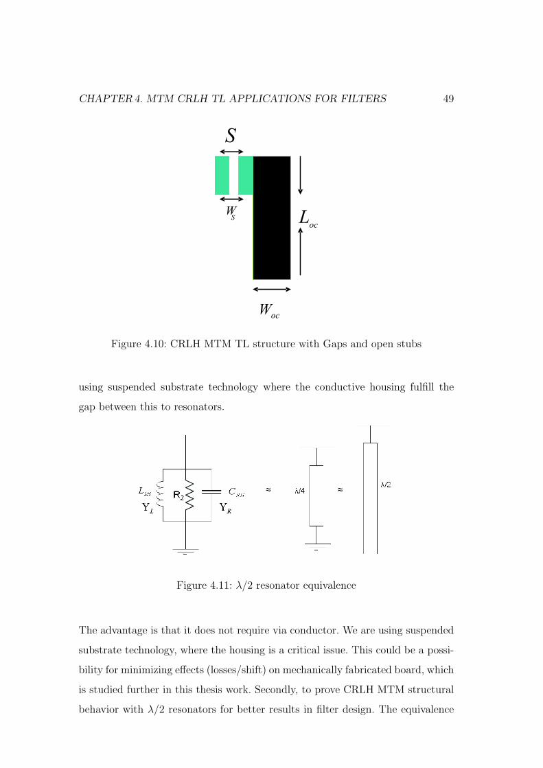
CHAPTER4. MTM CRLH TL APPLICATIONS FOR FILTERS 49
ocL
ocW
SW
S
Figure 4.10: CRLH MTM TL structure with Gaps and open stubs
using suspended substrate technology where the conductive housing fulfill the
gap between this to resonators.
Figure 4.11: λ/2 resonator equivalence
The advantage is that it does not require via conductor. We are using suspended
substrate technology, where the housing is a critical issue. This could be a possi-
bility for minimizing effects (losses/shift) on mechanically fabricated board, which
is studied further in this thesis work. Secondly, to prove CRLH MTM structural
behavior with λ/2 resonators for better results in filter design. The equivalence
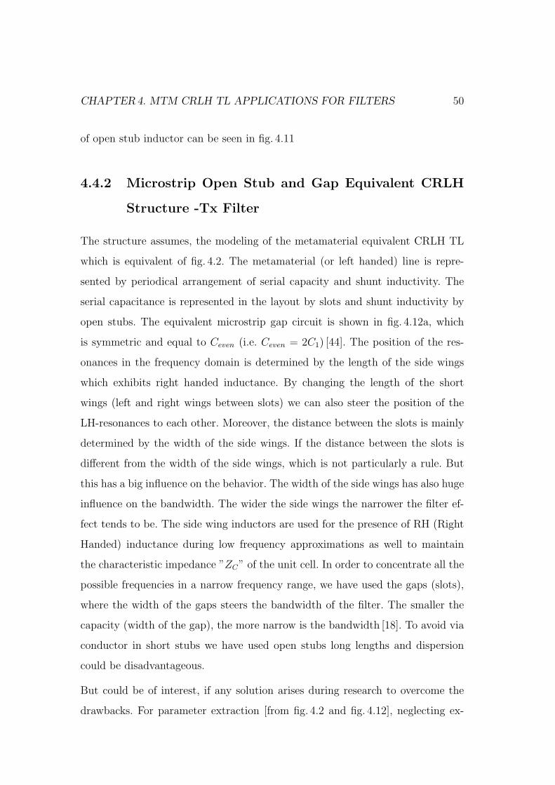
CHAPTER4. MTM CRLH TL APPLICATIONS FOR FILTERS 50
of open stub inductor can be seen in fig. 4.11
4.4.2 Microstrip Open Stub and Gap Equivalent CRLH
Structure -Tx Filter
The structure assumes, the modeling of the metamaterial equivalent CRLH TL
which is equivalent of fig. 4.2. The metamaterial (or left handed) line is repre-
sented by periodical arrangement of serial capacity and shunt inductivity. The
serial capacitance is represented in the layout by slots and shunt inductivity by
open stubs. The equivalent microstrip gap circuit is shown in fig. 4.12a, which
is symmetric and equal to Ceven (i.e. Ceven = 2C1) [44]. The position of the res-
onances in the frequency domain is determined by the length of the side wings
which exhibits right handed inductance. By changing the length of the short
wings (left and right wings between slots) we can also steer the position of the
LH-resonances to each other. Moreover, the distance between the slots is mainly
determined by the width of the side wings. If the distance between the slots is
different from the width of the side wings, which is not particularly a rule. But
this has a big influence on the behavior. The width of the side wings has also huge
influence on the bandwidth. The wider the side wings the narrower the filter ef-
fect tends to be. The side wing inductors are used for the presence of RH (Right
Handed) inductance during low frequency approximations as well to maintain
the characteristic impedance ”ZC” of the unit cell. In order to concentrate all the
possible frequencies in a narrow frequency range, we have used the gaps (slots),
where the width of the gaps steers the bandwidth of the filter. The smaller the
capacity (width of the gap), the more narrow is the bandwidth [18]. To avoid via
conductor in short stubs we have used open stubs long lengths and dispersion
could be disadvantageous.
But could be of interest, if any solution arises during research to overcome the
drawbacks. For parameter extraction [from fig. 4.2 and fig. 4.12], neglecting ex-
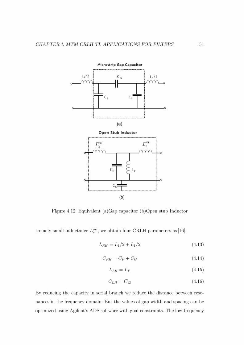
CHAPTER4. MTM CRLH TL APPLICATIONS FOR FILTERS 51
(a)
(b)
Figure 4.12: Equivalent (a)Gap capacitor (b)Open stub Inductor
tremely small inductance Losis , we obtain four CRLH parameters as [16],
LRH = L1/2 + L1/2 (4.13)
CRH = CP + CG (4.14)
LLH = LP (4.15)
CLH = C12 (4.16)
By reducing the capacity in serial branch we reduce the distance between reso-
nances in the frequency domain. But the values of gap width and spacing can be
optimized using Agilent’s ADS software with goal constraints. The low-frequency
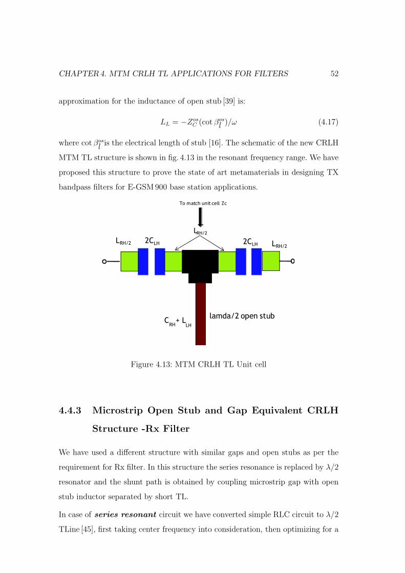
CHAPTER4. MTM CRLH TL APPLICATIONS FOR FILTERS 52
approximation for the inductance of open stub [39] is:
LL = −ZosC (cot βos
l )/ω (4.17)
where cot βosl is the electrical length of stub [16]. The schematic of the new CRLH
MTM TL structure is shown in fig. 4.13 in the resonant frequency range. We have
proposed this structure to prove the state of art metamaterials in designing TX
bandpass filters for E-GSM900 base station applications.
•LRH/2
•CRH
+ L
LH
•To match unit cell Zc
•LRH/2
LRH/2
•2C
lamda/2 open stubLH
LH•2C
Figure 4.13: MTM CRLH TL Unit cell
4.4.3 Microstrip Open Stub and Gap Equivalent CRLH
Structure -Rx Filter
We have used a different structure with similar gaps and open stubs as per the
requirement for Rx filter. In this structure the series resonance is replaced by λ/2
resonator and the shunt path is obtained by coupling microstrip gap with open
stub inductor separated by short TL.
In case of series resonant circuit we have converted simple RLC circuit to λ/2
TLine [45], first taking center frequency into consideration, then optimizing for a
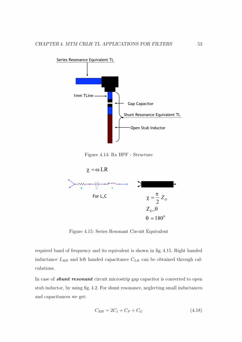
CHAPTER4. MTM CRLH TL APPLICATIONS FOR FILTERS 53
•Series Resonance Equivalent TL
•Open Stub Inductor
•Gap Capacitor
•1mm TLine
Shunt Resonance Equivalent TL
Figure 4.14: Rx BPF - Structure
Figure 4.15: Series Resonant Circuit Equivalent
required band of frequency and its equivalent is shown in fig. 4.15. Right handed
inductance LRH and left handed capacitance CLH can be obtained through cal-
culations.
In case of shunt resonant circuit microstrip gap capacitor is converted to open
stub inductor, by using fig. 4.2. For shunt resonance, neglecting small inductances
and capacitances we get:
CRH = 2C1 + CP + CG (4.18)
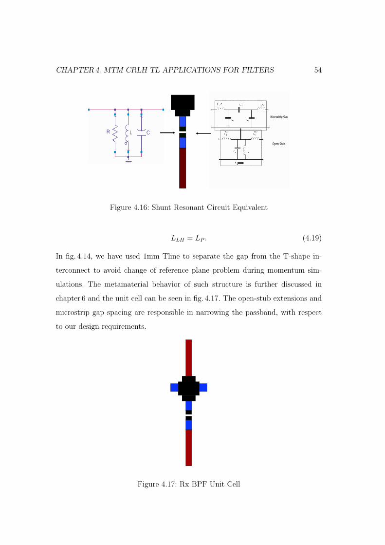
CHAPTER4. MTM CRLH TL APPLICATIONS FOR FILTERS 54
•Microstrip Gap
•Open Stub
Figure 4.16: Shunt Resonant Circuit Equivalent
LLH = LP . (4.19)
In fig. 4.14, we have used 1mm Tline to separate the gap from the T-shape in-
terconnect to avoid change of reference plane problem during momentum sim-
ulations. The metamaterial behavior of such structure is further discussed in
chapter 6 and the unit cell can be seen in fig. 4.17. The open-stub extensions and
microstrip gap spacing are responsible in narrowing the passband, with respect
to our design requirements.
Figure 4.17: Rx BPF Unit Cell

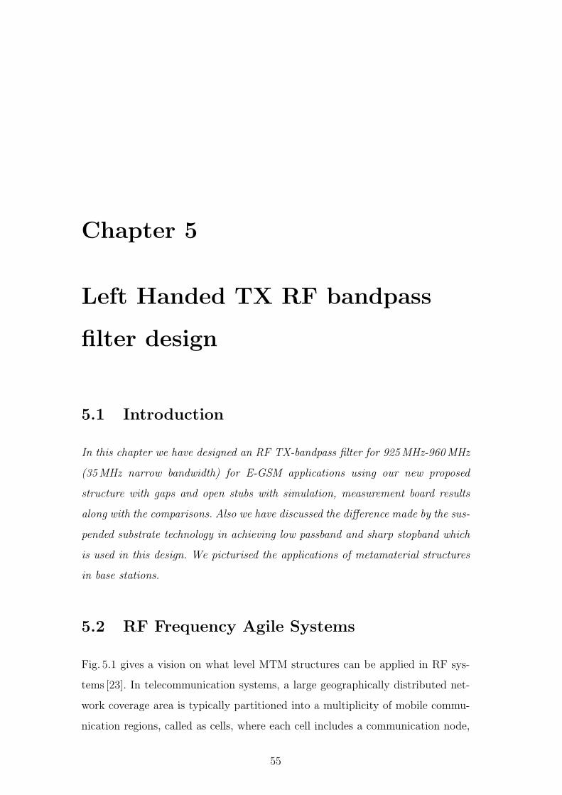
Chapter 5
Left Handed TX RF bandpass
filter design
5.1 Introduction
In this chapter we have designed an RF TX-bandpass filter for 925MHz-960MHz
(35MHz narrow bandwidth) for E-GSM applications using our new proposed
structure with gaps and open stubs with simulation, measurement board results
along with the comparisons. Also we have discussed the difference made by the sus-
pended substrate technology in achieving low passband and sharp stopband which
is used in this design. We picturised the applications of metamaterial structures
in base stations.
5.2 RF Frequency Agile Systems
Fig. 5.1 gives a vision on what level MTM structures can be applied in RF sys-
tems [23]. In telecommunication systems, a large geographically distributed net-
work coverage area is typically partitioned into a multiplicity of mobile commu-
nication regions, called as cells, where each cell includes a communication node,
55
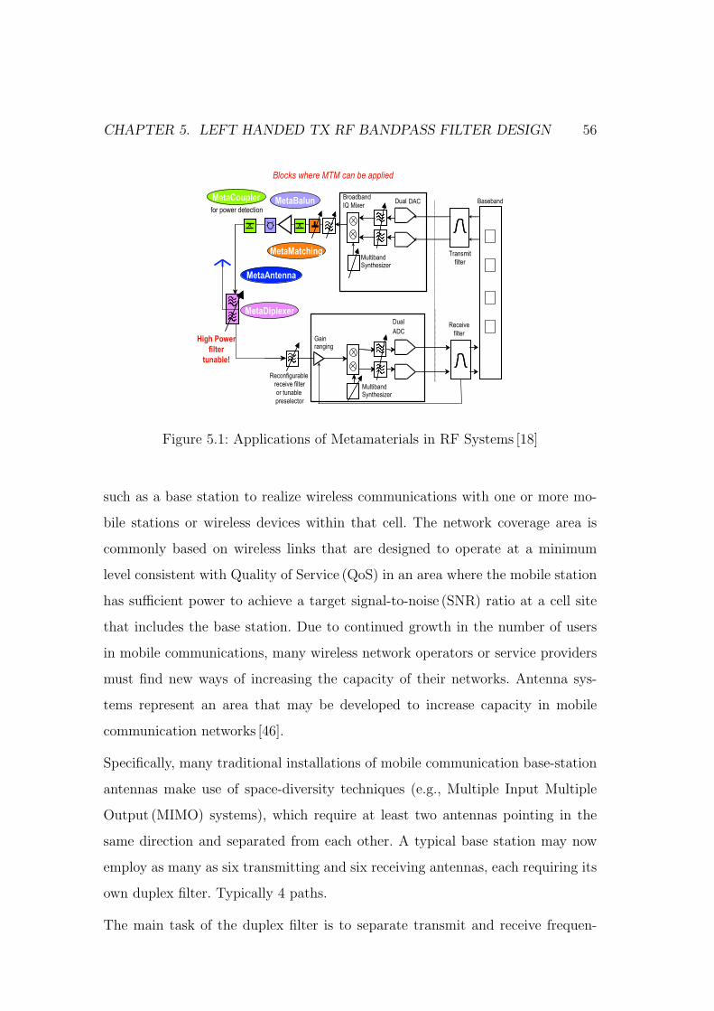
CHAPTER 5. LEFT HANDED TX RF BANDPASS FILTER DESIGN 56
Broadband
IQ Mixer
Multiband Synthesizer
Dual DAC
Dual
ADC
Reconfigurable
receive filter
or tunable
preselector
Multiband Synthesizer
Gainranging
MetaMatching
MetaAntenna
MetaCoupler MetaBalun Baseband
Transmit
filter
Receive
filter
MetaDiplexer
for power detection
Blocks where MTM can be applied
High Power
filter
tunable!
Figure 5.1: Applications of Metamaterials in RF Systems [18]
such as a base station to realize wireless communications with one or more mo-
bile stations or wireless devices within that cell. The network coverage area is
commonly based on wireless links that are designed to operate at a minimum
level consistent with Quality of Service (QoS) in an area where the mobile station
has sufficient power to achieve a target signal-to-noise (SNR) ratio at a cell site
that includes the base station. Due to continued growth in the number of users
in mobile communications, many wireless network operators or service providers
must find new ways of increasing the capacity of their networks. Antenna sys-
tems represent an area that may be developed to increase capacity in mobile
communication networks [46].
Specifically, many traditional installations of mobile communication base-station
antennas make use of space-diversity techniques (e.g., Multiple Input Multiple
Output (MIMO) systems), which require at least two antennas pointing in the
same direction and separated from each other. A typical base station may now
employ as many as six transmitting and six receiving antennas, each requiring its
own duplex filter. Typically 4 paths.
The main task of the duplex filter is to separate transmit and receive frequen-
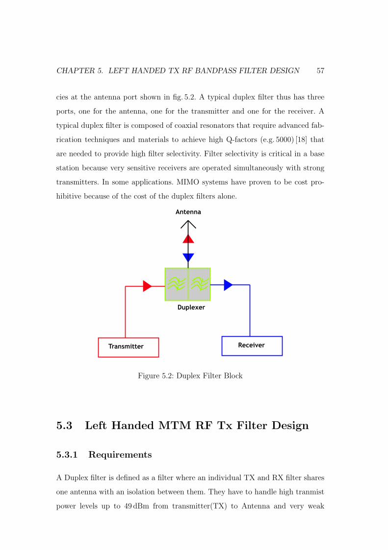
CHAPTER 5. LEFT HANDED TX RF BANDPASS FILTER DESIGN 57
cies at the antenna port shown in fig. 5.2. A typical duplex filter thus has three
ports, one for the antenna, one for the transmitter and one for the receiver. A
typical duplex filter is composed of coaxial resonators that require advanced fab-
rication techniques and materials to achieve high Q-factors (e.g. 5000) [18] that
are needed to provide high filter selectivity. Filter selectivity is critical in a base
station because very sensitive receivers are operated simultaneously with strong
transmitters. In some applications. MIMO systems have proven to be cost pro-
hibitive because of the cost of the duplex filters alone.
•Transmitter •Receiver
•
Antenna
•Duplexer
Figure 5.2: Duplex Filter Block
5.3 Left Handed MTM RF Tx Filter Design
5.3.1 Requirements
A Duplex filter is defined as a filter where an individual TX and RX filter shares
one antenna with an isolation between them. They have to handle high tranmist
power levels up to 49 dBm from transmitter(TX) to Antenna and very weak
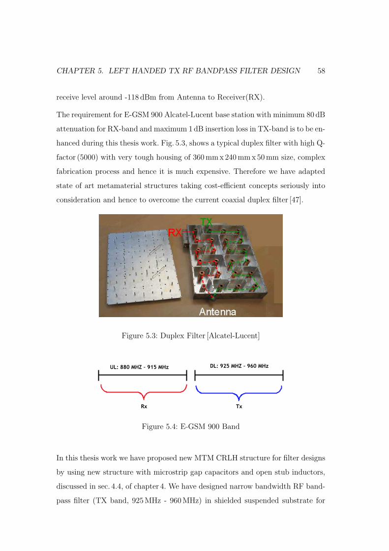
CHAPTER 5. LEFT HANDED TX RF BANDPASS FILTER DESIGN 58
receive level around -118 dBm from Antenna to Receiver(RX).
The requirement for E-GSM 900 Alcatel-Lucent base station with minimum 80 dB
attenuation for RX-band and maximum 1dB insertion loss in TX-band is to be en-
hanced during this thesis work. Fig. 5.3, shows a typical duplex filter with high Q-
factor (5000) with very tough housing of 360mmx240 mmx50mm size, complex
fabrication process and hence it is much expensive. Therefore we have adapted
state of art metamaterial structures taking cost-efficient concepts seriously into
consideration and hence to overcome the current coaxial duplex filter [47].
Figure 5.3: Duplex Filter [Alcatel-Lucent]
•UL: 880 MHZ – 915 MHz •DL: 925 MHZ – 960 MHz
•Rx •Tx
Figure 5.4: E-GSM 900 Band
In this thesis work we have proposed new MTM CRLH structure for filter designs
by using new structure with microstrip gap capacitors and open stub inductors,
discussed in sec. 4.4, of chapter 4. We have designed narrow bandwidth RF band-
pass filter (TX band, 925MHz - 960MHz) in shielded suspended substrate for
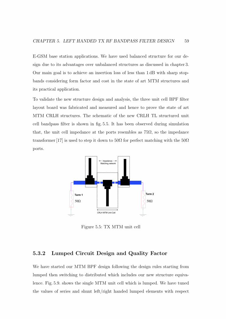
CHAPTER 5. LEFT HANDED TX RF BANDPASS FILTER DESIGN 59
E-GSM base station applications. We have used balanced structure for our de-
sign due to its advantages over unbalanced structures as discussed in chapter 3.
Our main goal is to achieve an insertion loss of less than 1 dB with sharp stop-
bands considering form factor and cost in the state of art MTM structures and
its practical application.
To validate the new structure design and analysis, the three unit cell BPF filter
layout board was fabricated and measured and hence to prove the state of art
MTM CRLH structures. The schematic of the new CRLH TL structured unit
cell bandpass filter is shown in fig. 5.5. It has been observed during simulation
that, the unit cell impedance at the ports resembles as 75Ω, so the impedance
transformer [17] is used to step it down to 50Ω for perfect matching with the 50Ω
ports.
Ω50 Ω50
Term 1 Term 2
CRLH MTM Unit Cell
Impedence
Matching network
Figure 5.5: TX MTM unit cell
5.3.2 Lumped Circuit Design and Quality Factor
We have started our MTM BPF design following the design rules starting from
lumped then switching to distributed which includes our new structure equiva-
lence. Fig. 5.9. shows the single MTM unit cell which is lumped. We have tuned
the values of series and shunt left/right handed lumped elements with respect
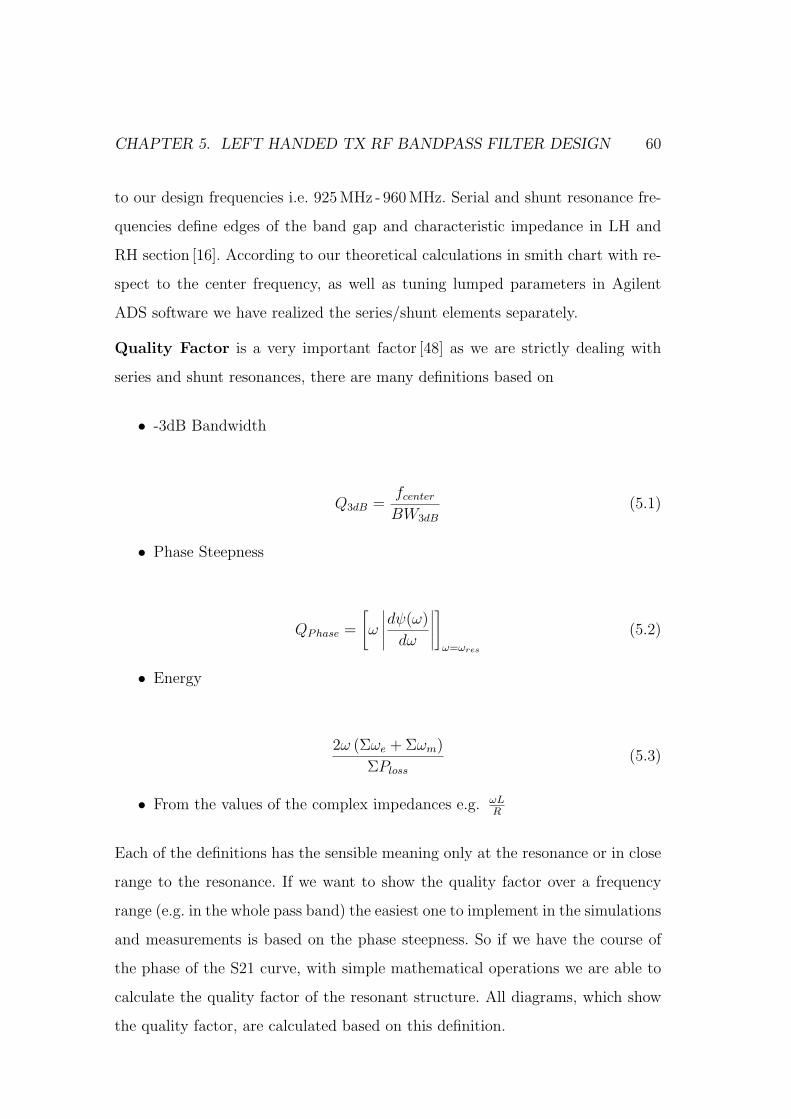
CHAPTER 5. LEFT HANDED TX RF BANDPASS FILTER DESIGN 60
to our design frequencies i.e. 925 MHz - 960MHz. Serial and shunt resonance fre-
quencies define edges of the band gap and characteristic impedance in LH and
RH section [16]. According to our theoretical calculations in smith chart with re-
spect to the center frequency, as well as tuning lumped parameters in Agilent
ADS software we have realized the series/shunt elements separately.
Quality Factor is a very important factor [48] as we are strictly dealing with
series and shunt resonances, there are many definitions based on
• -3dB Bandwidth
Q3dB =fcenter
BW3dB
(5.1)
• Phase Steepness
QPhase =
[ω
∣∣∣∣∣dψ(ω)
dω
∣∣∣∣∣
]
ω=ωres
(5.2)
• Energy
2ω (Σωe + Σωm)
ΣPloss
(5.3)
• From the values of the complex impedances e.g. ωLR
Each of the definitions has the sensible meaning only at the resonance or in close
range to the resonance. If we want to show the quality factor over a frequency
range (e.g. in the whole pass band) the easiest one to implement in the simulations
and measurements is based on the phase steepness. So if we have the course of
the phase of the S21 curve, with simple mathematical operations we are able to
calculate the quality factor of the resonant structure. All diagrams, which show
the quality factor, are calculated based on this definition.
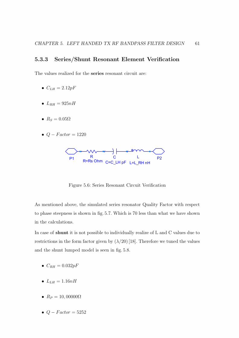
CHAPTER 5. LEFT HANDED TX RF BANDPASS FILTER DESIGN 61
5.3.3 Series/Shunt Resonant Element Verification
The values realized for the series resonant circuit are:
• CLH = 2.12pF
• LRH = 925nH
• RS = 0.05Ω
• Q− Factor = 1220
P2P1 L
L=L_RH nH
RR=Rs Ohm
C
C=C_LH pF
Figure 5.6: Series Resonant Circuit Verification
As mentioned above, the simulated series resonator Quality Factor with respect
to phase steepness is shown in fig. 5.7. Which is 70 less than what we have shown
in the calculations.
In case of shunt it is not possible to individually realize of L and C values due to
restrictions in the form factor given by (λ/20) [18]. Therefore we tuned the values
and the shunt lumped model is seen in fig. 5.8.
• CRH = 0.032pF
• LLH = 1.16nH
• RP = 10, 00000Ω
• Q− Factor = 5252
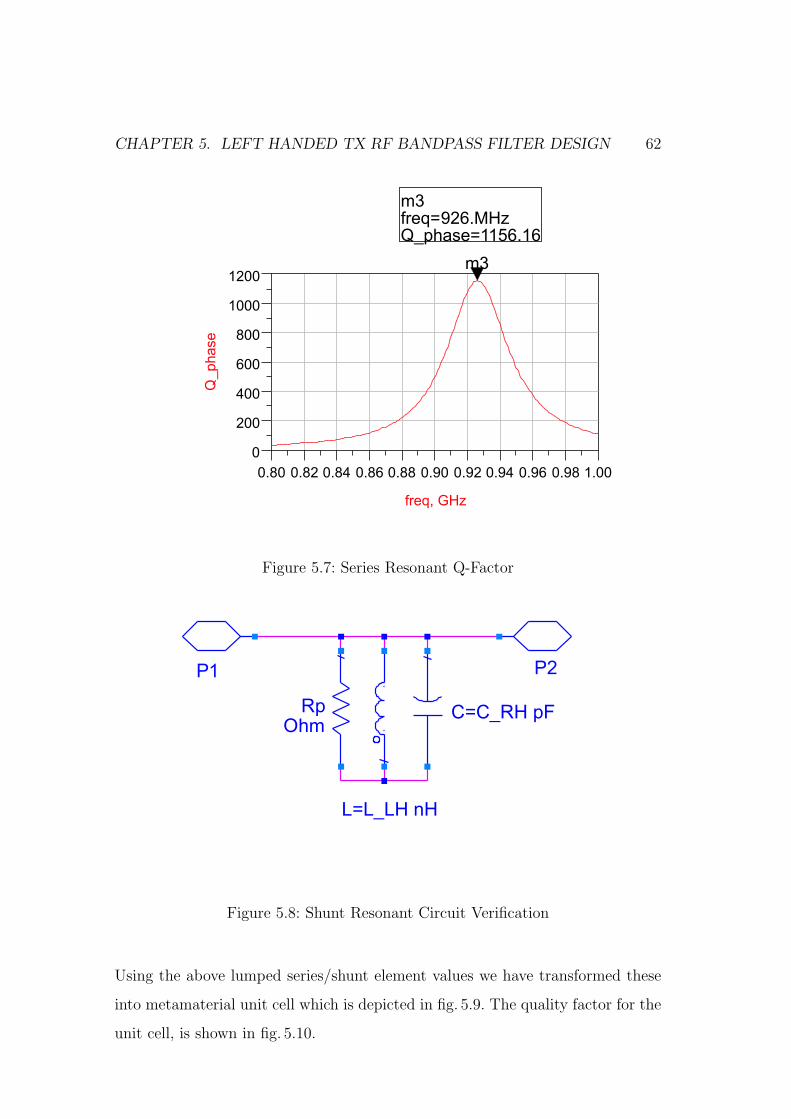
CHAPTER 5. LEFT HANDED TX RF BANDPASS FILTER DESIGN 62
Figure 5.7: Series Resonant Q-Factor
C=C_RH pF
L=L_LH nH
RpOhm
P2P1
Figure 5.8: Shunt Resonant Circuit Verification
Using the above lumped series/shunt element values we have transformed these
into metamaterial unit cell which is depicted in fig. 5.9. The quality factor for the
unit cell, is shown in fig. 5.10.
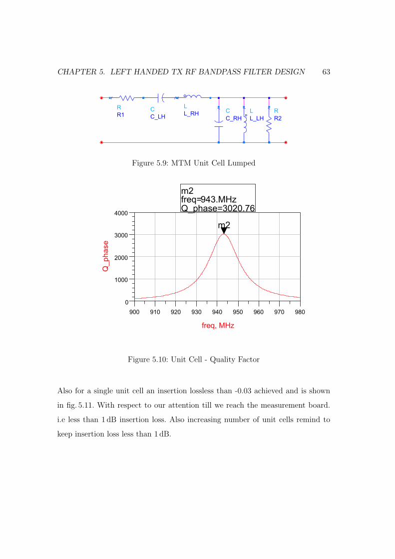
CHAPTER 5. LEFT HANDED TX RF BANDPASS FILTER DESIGN 63
R
R2
L
L_LH
C
C_RH
L
L_RHC
C_LH
R
R1
Figure 5.9: MTM Unit Cell Lumped
Figure 5.10: Unit Cell - Quality Factor
Also for a single unit cell an insertion lossless than -0.03 achieved and is shown
in fig. 5.11. With respect to our attention till we reach the measurement board.
i.e less than 1 dB insertion loss. Also increasing number of unit cells remind to
keep insertion loss less than 1 dB.
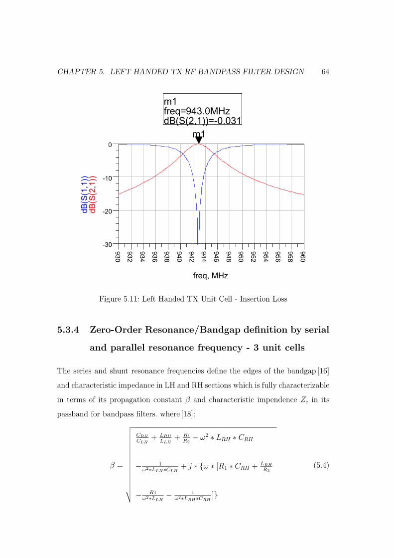
CHAPTER 5. LEFT HANDED TX RF BANDPASS FILTER DESIGN 64
Figure 5.11: Left Handed TX Unit Cell - Insertion Loss
5.3.4 Zero-Order Resonance/Bandgap definition by serial
and parallel resonance frequency - 3 unit cells
The series and shunt resonance frequencies define the edges of the bandgap [16]
and characteristic impedance in LH and RH sections which is fully characterizable
in terms of its propagation constant β and characteristic impendence Zc in its
passband for bandpass filters. where [18]:
β =
√√√√√√√√√√√√√√√√√
CRH
CLH+ LRH
LLH+ Rl
R2− ω2 ∗ LRH ∗ CRH
− 1ω2∗LLH∗CLH
+ j ∗ ω ∗ [R1 ∗ CRH + LRH
R2
− R1ω2∗LLH
− 1ω2∗LRH∗CRH
]
(5.4)
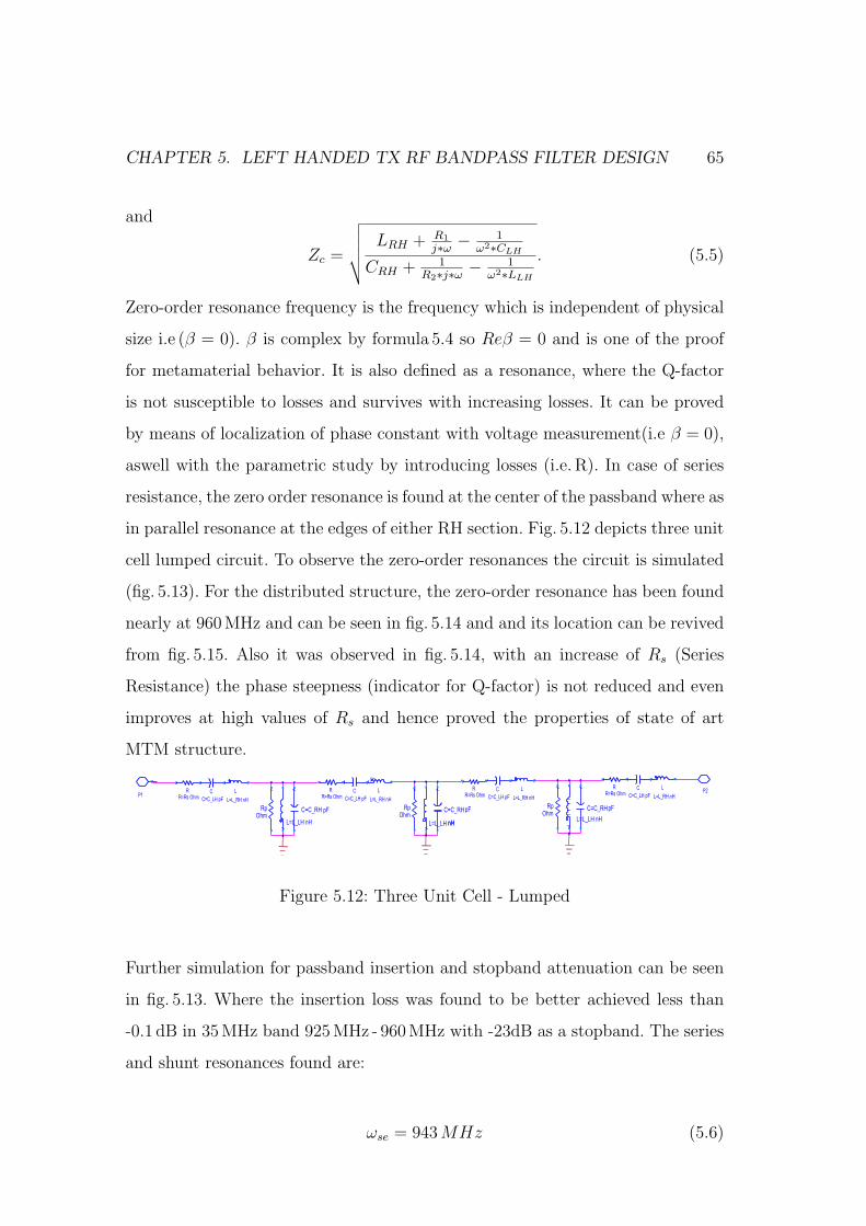
CHAPTER 5. LEFT HANDED TX RF BANDPASS FILTER DESIGN 65
and
Zc =
√√√√√LRH + R1
j∗ω − 1ω2∗CLH
CRH + 1R2∗j∗ω − 1
ω2∗LLH
. (5.5)
Zero-order resonance frequency is the frequency which is independent of physical
size i.e (β = 0). β is complex by formula 5.4 so Reβ = 0 and is one of the proof
for metamaterial behavior. It is also defined as a resonance, where the Q-factor
is not susceptible to losses and survives with increasing losses. It can be proved
by means of localization of phase constant with voltage measurement(i.e β = 0),
aswell with the parametric study by introducing losses (i.e. R). In case of series
resistance, the zero order resonance is found at the center of the passband where as
in parallel resonance at the edges of either RH section. Fig. 5.12 depicts three unit
cell lumped circuit. To observe the zero-order resonances the circuit is simulated
(fig. 5.13). For the distributed structure, the zero-order resonance has been found
nearly at 960MHz and can be seen in fig. 5.14 and and its location can be revived
from fig. 5.15. Also it was observed in fig. 5.14, with an increase of Rs (Series
Resistance) the phase steepness (indicator for Q-factor) is not reduced and even
improves at high values of Rs and hence proved the properties of state of art
MTM structure.
P2 L
L=L_RH nH
RR=Rs Ohm
C
C=C_LH pF
C=C_RH pF
L=L_LH nH
RpOhm
L
L=L_RH nH
RR=Rs Ohm
C
C=C_LH pF
C=C_RH
L=L_LH nH
RpOhm
pF
nH
L
L=L_RH nH
RR=Rs Ohm
C
C=C_LH pF
C=C_RH
L=L_LH nH
RpOhm
pF
L
L=L_RH nH
RR=Rs Ohm
C
C=C_LH pF
P1
P1
Figure 5.12: Three Unit Cell - Lumped
Further simulation for passband insertion and stopband attenuation can be seen
in fig. 5.13. Where the insertion loss was found to be better achieved less than
-0.1 dB in 35 MHz band 925MHz - 960 MHz with -23dB as a stopband. The series
and shunt resonances found are:
ωse = 943 MHz (5.6)
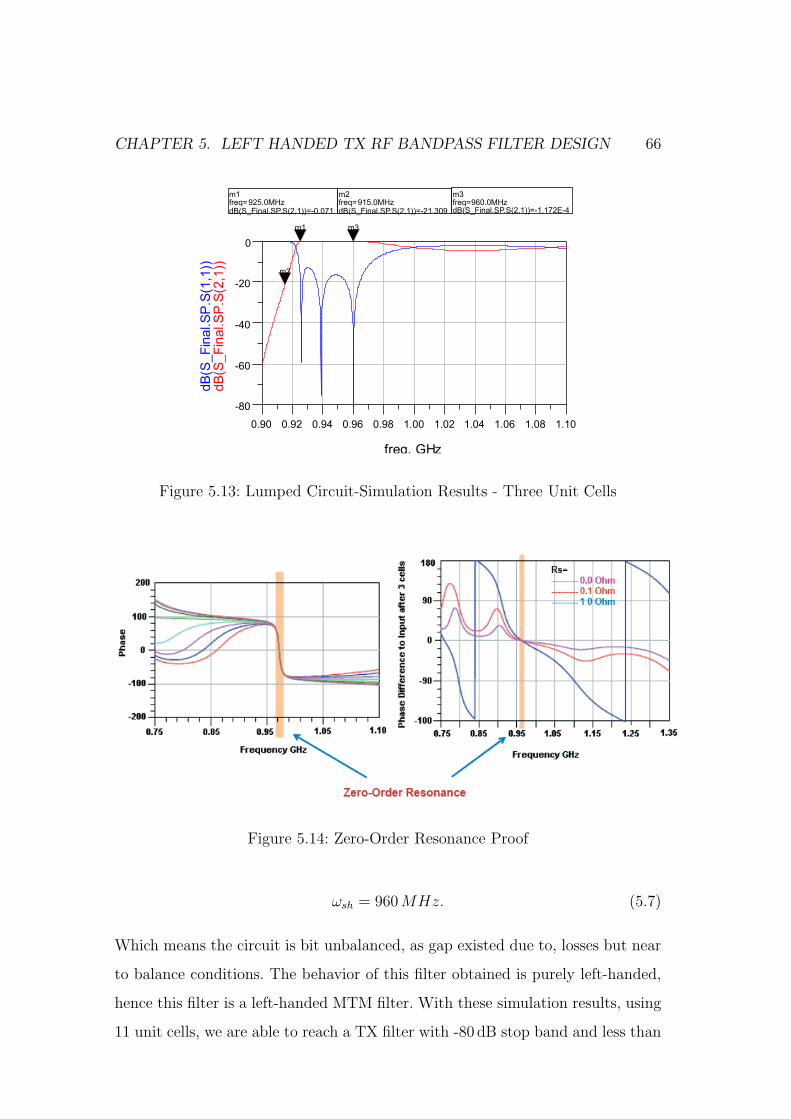
CHAPTER 5. LEFT HANDED TX RF BANDPASS FILTER DESIGN 66
Figure 5.13: Lumped Circuit-Simulation Results - Three Unit Cells
Figure 5.14: Zero-Order Resonance Proof
ωsh = 960 MHz. (5.7)
Which means the circuit is bit unbalanced, as gap existed due to, losses but near
to balance conditions. The behavior of this filter obtained is purely left-handed,
hence this filter is a left-handed MTM filter. With these simulation results, using
11 unit cells, we are able to reach a TX filter with -80 dB stop band and less than
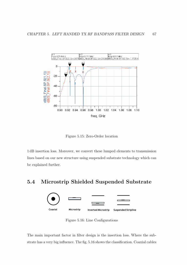
CHAPTER 5. LEFT HANDED TX RF BANDPASS FILTER DESIGN 67
Figure 5.15: Zero-Order location
1 dB insertion loss. Moreover, we convert these lumped elements to transmission
lines based on our new structure using suspended substrate technology which can
be explained further.
5.4 Microstrip Shielded Suspended Substrate
Coaxial Microstrip Inverted Microstrip Suspended Stripline
Figure 5.16: Line Configurations
The main important factor in filter design is the insertion loss. Where the sub-
strate has a very big influence. The fig. 5.16 shows the classification. Coaxial cables
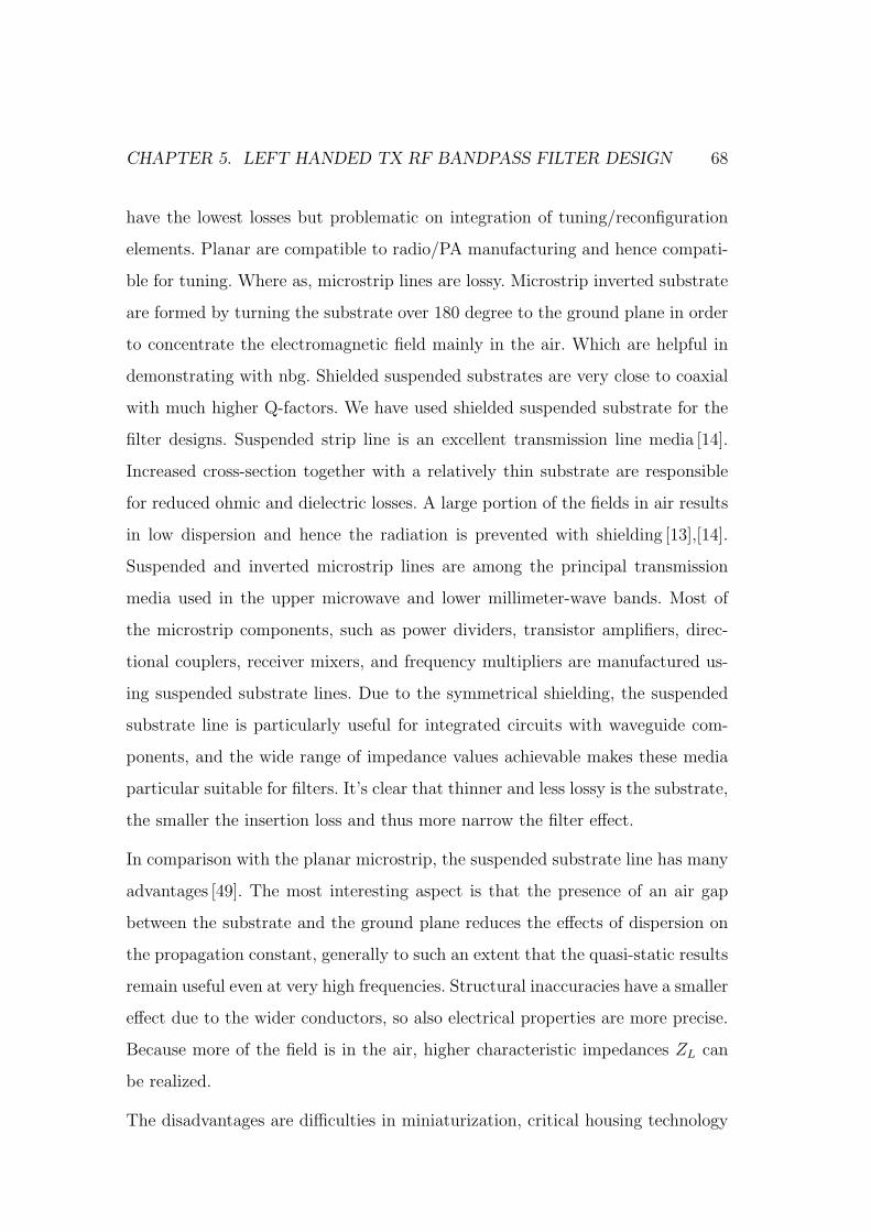
CHAPTER 5. LEFT HANDED TX RF BANDPASS FILTER DESIGN 68
have the lowest losses but problematic on integration of tuning/reconfiguration
elements. Planar are compatible to radio/PA manufacturing and hence compati-
ble for tuning. Where as, microstrip lines are lossy. Microstrip inverted substrate
are formed by turning the substrate over 180 degree to the ground plane in order
to concentrate the electromagnetic field mainly in the air. Which are helpful in
demonstrating with nbg. Shielded suspended substrates are very close to coaxial
with much higher Q-factors. We have used shielded suspended substrate for the
filter designs. Suspended strip line is an excellent transmission line media [14].
Increased cross-section together with a relatively thin substrate are responsible
for reduced ohmic and dielectric losses. A large portion of the fields in air results
in low dispersion and hence the radiation is prevented with shielding [13],[14].
Suspended and inverted microstrip lines are among the principal transmission
media used in the upper microwave and lower millimeter-wave bands. Most of
the microstrip components, such as power dividers, transistor amplifiers, direc-
tional couplers, receiver mixers, and frequency multipliers are manufactured us-
ing suspended substrate lines. Due to the symmetrical shielding, the suspended
substrate line is particularly useful for integrated circuits with waveguide com-
ponents, and the wide range of impedance values achievable makes these media
particular suitable for filters. It’s clear that thinner and less lossy is the substrate,
the smaller the insertion loss and thus more narrow the filter effect.
In comparison with the planar microstrip, the suspended substrate line has many
advantages [49]. The most interesting aspect is that the presence of an air gap
between the substrate and the ground plane reduces the effects of dispersion on
the propagation constant, generally to such an extent that the quasi-static results
remain useful even at very high frequencies. Structural inaccuracies have a smaller
effect due to the wider conductors, so also electrical properties are more precise.
Because more of the field is in the air, higher characteristic impedances ZL can
be realized.
The disadvantages are difficulties in miniaturization, critical housing technology

CHAPTER 5. LEFT HANDED TX RF BANDPASS FILTER DESIGN 69
(because the housing also acts as an electrode) and the increased complexity of
utilizing hybrid elements. So, although suspended and inverted microstrip lines
have many good properties, they are large and difficult to produce. In this thesis
work we have worked with symmetric shielded microstrip line for better results
and high Q-factor.
5.4.1 Symmetric shielded suspended substrate
The structure of the suspended substrate microstrip line with side walls is pre-
sented in fig. 5.17. These equations from [21] are used when the structure is sym-
metric.
The equations are divided into two ranges. For narrow strips (0 < ω < a/2),
Z0 =η0
2π
V + R ln
6
ω/b+
√√√√1 +4
ω/b
2
(5.8)
Figure 5.17: Symmetric Shielded Suspended Substrate structure
εeff =1
[1 +
(E − F ln ω
b
) (1√εr
)]2 (5.9)
Where,
V = 1.7866− 0.2035h
b+ 0.4750
a
b(5.10)
CHAPTER 5. LEFT HANDED TX RF BANDPASS FILTER DESIGN 70
R = 1.0835 + 0.1007h
b− 0.09457
a
b(5.11)
E = 0.2077 + 1.2177h
b− 0.08364
a
b(5.12)
F = 0.03451− 0.1031h
b+ 0.01742
a
b(5.13)
For wider strips, (a/2 < ω < a)
Z0 = η0
V +
Rωb
+ 1.3930 + 0.6670 ln(
ωb
+ 1.444)
(5.14)
and
εeff =1
[1 +
(E − F ln ω
b
) (1√εr
)]2 (5.15)
Where,
V = −0.6301− 0.07082h
b+ 0.247
a
b(5.16)
R = 1.9492 + 0.1553h
b− 0.5123
a
b(5.17)
E = 0.464 + 0.9647h
b− 0.2063
a
b(5.18)
F = −0.1424 + 0.3017h
b− 0.02411
a
b(5.19)
The above relations are valid for 1.0 ≤ a/b ≤ 2.5, 1.0 ≤ ω ≤ 4, and 0.1 ≤ h/b ≤0.5. The results of the wide strip equations agree with those obtained using finite
differential techniques to ±3%, the narrow strip agreement is ±2%.
5.4.2 Suspended Substrate Implementation
To achieve less insertion low we have implemented suspended substrate whose
quality is described previously. We have tested planar, shielded and inverted
substrate models to choose the least insertion loss model at our design frequency
level.
Fig. 5.19 shows a 30 cm long microstrip line of Rogers RO4003 substrate material
with thickness of 0.813mm simulated in Agilent’s ADS environment to choose the
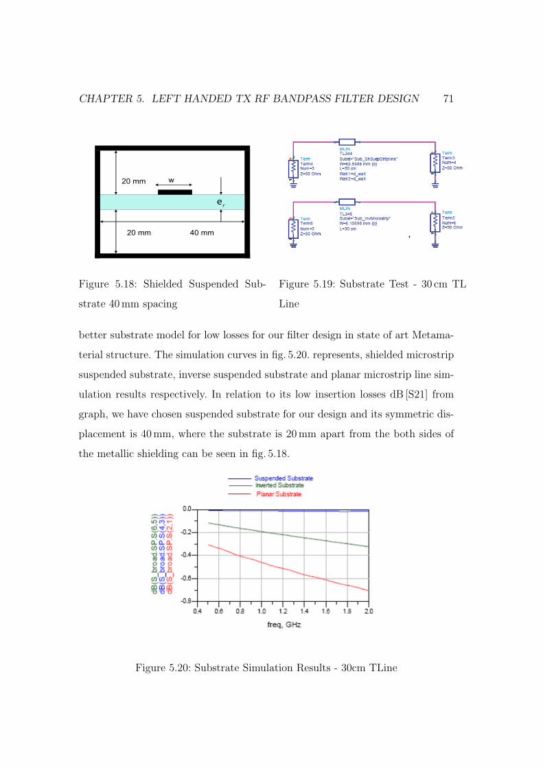
CHAPTER 5. LEFT HANDED TX RF BANDPASS FILTER DESIGN 71
20 mm
20 mm
w
re
40 mm
Figure 5.18: Shielded Suspended Sub-
strate 40mm spacing
Figure 5.19: Substrate Test - 30 cm TL
Line
better substrate model for low losses for our filter design in state of art Metama-
terial structure. The simulation curves in fig. 5.20. represents, shielded microstrip
suspended substrate, inverse suspended substrate and planar microstrip line sim-
ulation results respectively. In relation to its low insertion losses dB [S21] from
graph, we have chosen suspended substrate for our design and its symmetric dis-
placement is 40 mm, where the substrate is 20mm apart from the both sides of
the metallic shielding can be seen in fig. 5.18.
Figure 5.20: Substrate Simulation Results - 30cm TLine
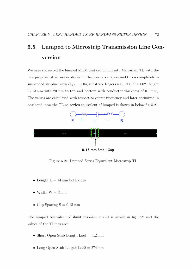
CHAPTER 5. LEFT HANDED TX RF BANDPASS FILTER DESIGN 72
5.5 Lumped to Microstrip Transmission Line Con-
version
We have converted the lumped MTM unit cell circuit into Microstrip TL with the
new proposed structure explained in the previous chapter and this is completely in
suspended stripline with Eeff = 1.04, substrate Rogers 4003, Tanδ=0.0021 height
0.813mm with 20mm to top and bottom with conductor thickness of 0.1 mm,.
The values are calculated with respect to center frequency and later optimized in
passband, now the TLine series equivalent of lumped is shown in below fig. 5.21.
P2P1 LR C
0.15 mm Small Gap
Figure 5.21: Lumped Series Equivalent Microstrip TL
• Length L = 14 mm both sides
• Width W = 3 mm
• Gap Spacing S = 0.15mm
The lumped equivalent of shunt resonant circuit is shown in fig. 5.22 and the
values of the TLines are:
• Short Open Stub Length Loc1 = 1.2mm
• Long Open Stub Length Loc2 = 274mm
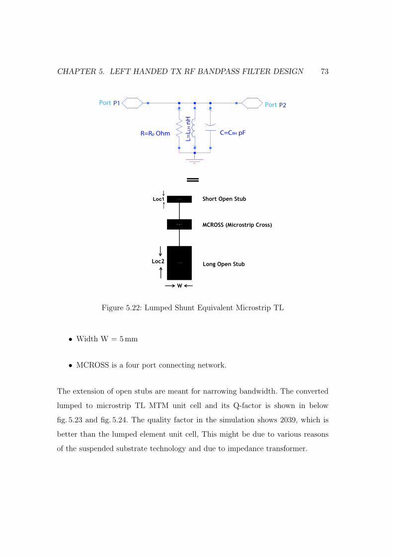
CHAPTER 5. LEFT HANDED TX RF BANDPASS FILTER DESIGN 73
C=CRH pF
L=
LL
H n
H
R=Rp Ohm
Port P2Port P1
•Short Open Stub
•Long Open Stub
•MCROSS (Microstrip Cross)
=
Loc1
Loc2
W
Figure 5.22: Lumped Shunt Equivalent Microstrip TL
• Width W = 5 mm
• MCROSS is a four port connecting network.
The extension of open stubs are meant for narrowing bandwidth. The converted
lumped to microstrip TL MTM unit cell and its Q-factor is shown in below
fig. 5.23 and fig. 5.24. The quality factor in the simulation shows 2039, which is
better than the lumped element unit cell, This might be due to various reasons
of the suspended substrate technology and due to impedance transformer.
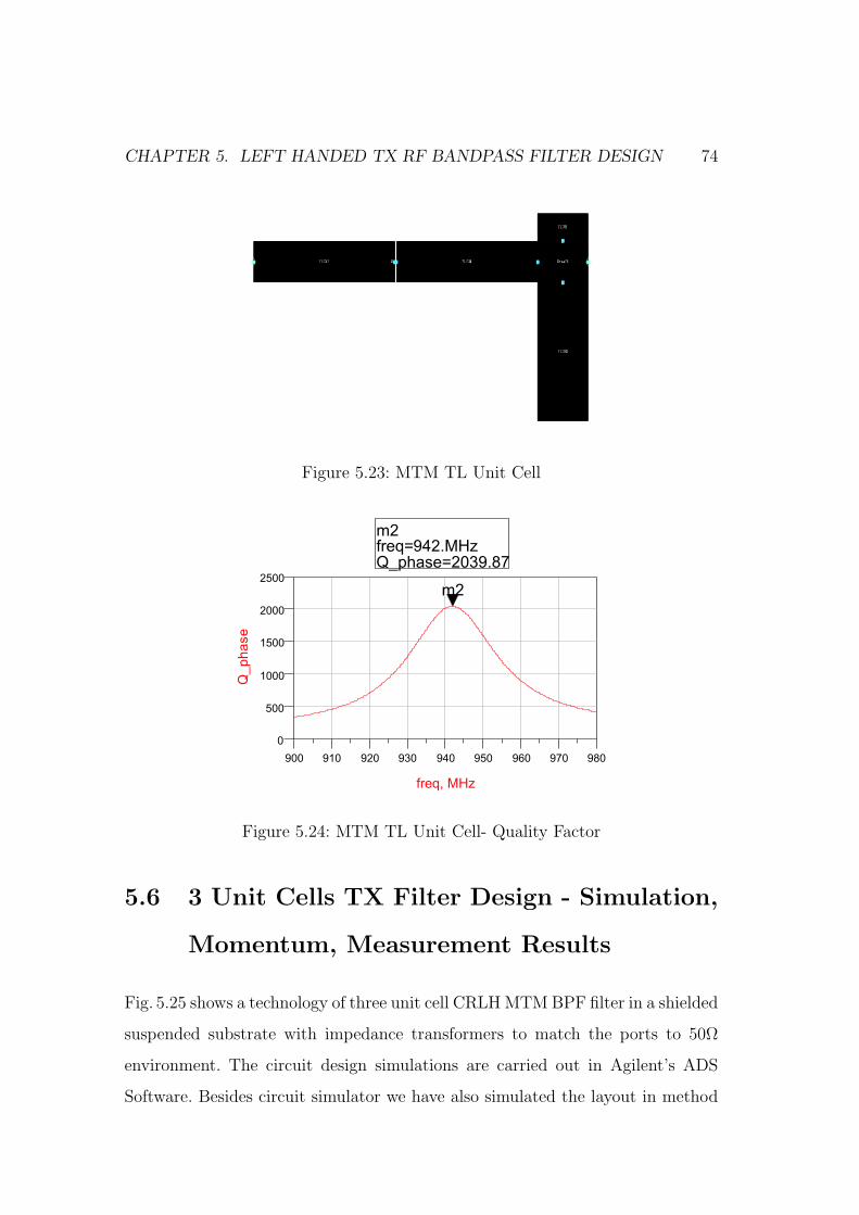
CHAPTER 5. LEFT HANDED TX RF BANDPASS FILTER DESIGN 74
Figure 5.23: MTM TL Unit Cell
Figure 5.24: MTM TL Unit Cell- Quality Factor
5.6 3 Unit Cells TX Filter Design - Simulation,
Momentum, Measurement Results
Fig. 5.25 shows a technology of three unit cell CRLH MTM BPF filter in a shielded
suspended substrate with impedance transformers to match the ports to 50Ω
environment. The circuit design simulations are carried out in Agilent’s ADS
Software. Besides circuit simulator we have also simulated the layout in method
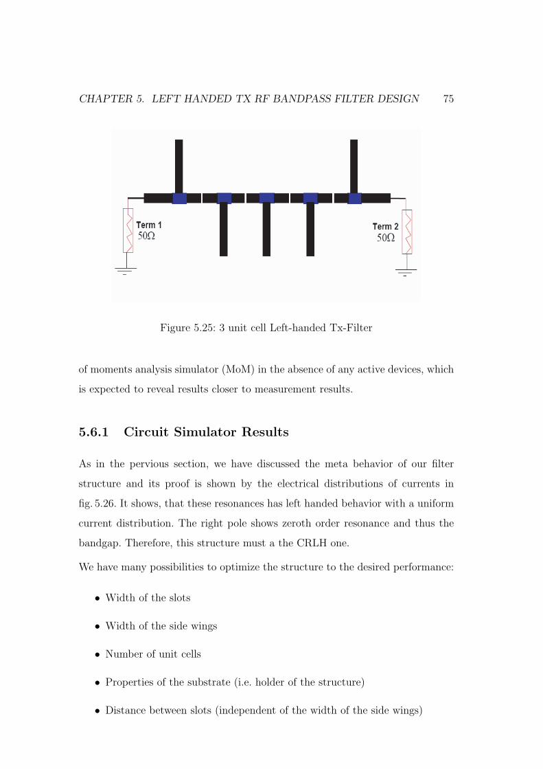
CHAPTER 5. LEFT HANDED TX RF BANDPASS FILTER DESIGN 75
Figure 5.25: 3 unit cell Left-handed Tx-Filter
of moments analysis simulator (MoM) in the absence of any active devices, which
is expected to reveal results closer to measurement results.
5.6.1 Circuit Simulator Results
As in the pervious section, we have discussed the meta behavior of our filter
structure and its proof is shown by the electrical distributions of currents in
fig. 5.26. It shows, that these resonances has left handed behavior with a uniform
current distribution. The right pole shows zeroth order resonance and thus the
bandgap. Therefore, this structure must a the CRLH one.
We have many possibilities to optimize the structure to the desired performance:
• Width of the slots
• Width of the side wings
• Number of unit cells
• Properties of the substrate (i.e. holder of the structure)
• Distance between slots (independent of the width of the side wings)
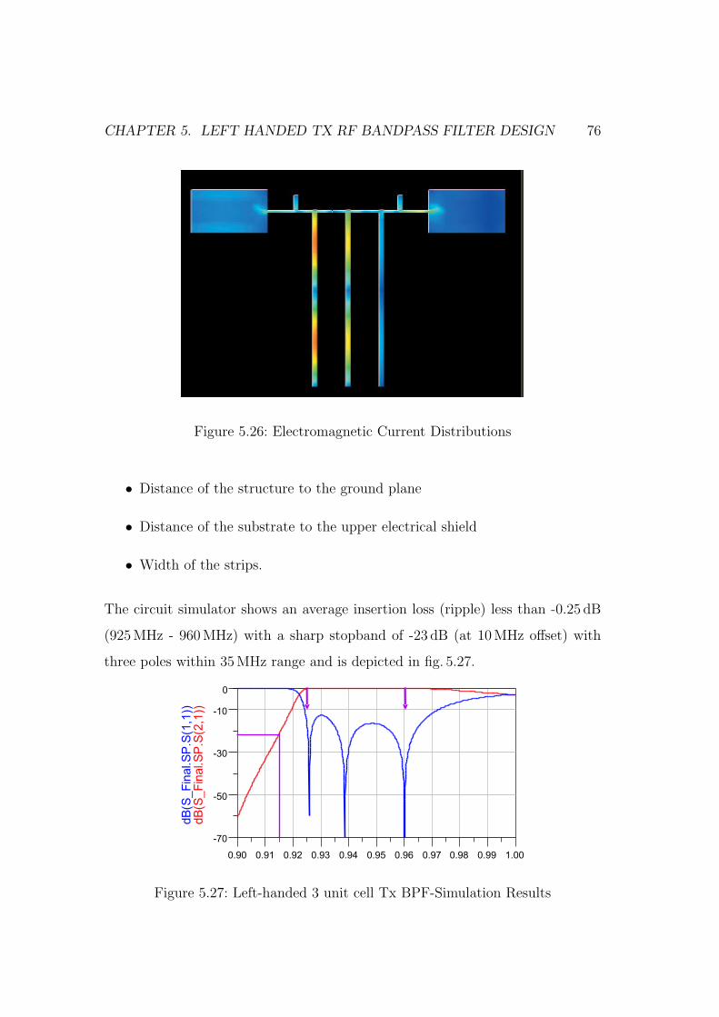
CHAPTER 5. LEFT HANDED TX RF BANDPASS FILTER DESIGN 76
Figure 5.26: Electromagnetic Current Distributions
• Distance of the structure to the ground plane
• Distance of the substrate to the upper electrical shield
• Width of the strips.
The circuit simulator shows an average insertion loss (ripple) less than -0.25 dB
(925MHz - 960MHz) with a sharp stopband of -23 dB (at 10 MHz offset) with
three poles within 35MHz range and is depicted in fig. 5.27.
0.91 0.92 0.93 0.94 0.95 0.96 0.97 0.98 0.990.90 1.00
-50
-30
-10
-70
0
dB
(S_F
inal.S
P.S
(2,1
))dB
(S_F
inal.S
P.S
(1,1
))
Figure 5.27: Left-handed 3 unit cell Tx BPF-Simulation Results
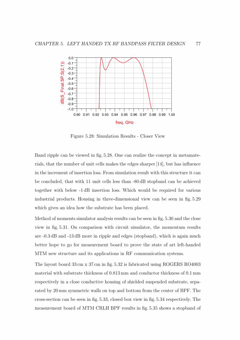
CHAPTER 5. LEFT HANDED TX RF BANDPASS FILTER DESIGN 77
0.91 0.92 0.93 0.94 0.95 0.96 0.97 0.98 0.990.90 1.00
-0.9
-0.8
-0.7
-0.6
-0.5
-0.4
-0.3
-0.2
-0.1
-1.0
0.0
freq, GHz
dB
(S_
Fin
al.S
P.S
(2,1
))
Figure 5.28: Simulation Results - Closer View
Band ripple can be viewed in fig. 5.28. One can realize the concept in metamate-
rials, that the number of unit cells makes the edges sharper [14], but has influence
in the increment of insertion loss. From simulation result with this structure it can
be concluded, that with 11 unit cells less than -80 dB stopband can be achieved
together with below -1 dB insertion loss. Which would be required for various
industrial products. Housing in three-dimensional view can be seen in fig. 5.29
which gives an idea how the substrate has been placed.
Method of moments simulator analysis results can be seen in fig. 5.30 and the close
view in fig. 5.31. On comparison with circuit simulator, the momentum results
are -0.3 dB and -13 dB more in ripple and edges (stopband), which is again much
better hope to go for measurement board to prove the state of art left-handed
MTM new structure and its applications in RF communication systems.
The layout board 33 cm x 37 cm in fig. 5.32 is fabricated using ROGERS RO4003
material with substrate thickness of 0.813mm and conductor thickness of 0.1 mm
respectively in a close conductive housing of shielded suspended substrate, sepa-
rated by 20mm symmetric walls on top and bottom from the center of BPF. The
cross-section can be seen in fig. 5.33, closed box view in fig. 5.34 respectively. The
measurement board of MTM CRLH BPF results in fig. 5.35 shows a stopband of
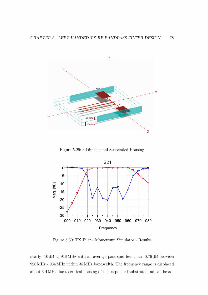
CHAPTER 5. LEFT HANDED TX RF BANDPASS FILTER DESIGN 78
Figure 5.29: 3-Dimensional Suspended Housing
910 920 930 940 950 960 970900 980
-25
-20
-15
-10
-5
-30
0
Frequency
Mag.[d
B]
S21
Figure 5.30: TX Filer - Momentum Simulator - Results
nearly -10 dB at 918MHz with an average passband less than -0.76 dB between
928MHz - 964MHz within 35MHz bandwidth. The frequency range is displaced
about 3-4MHz due to critical housing of the suspended substrate, and can be ad-
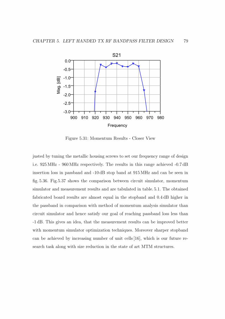
CHAPTER 5. LEFT HANDED TX RF BANDPASS FILTER DESIGN 79
910 920 930 940 950 960 970900 980
-2.5
-2.0
-1.5
-1.0
-0.5
-3.0
0.0
Frequency
Mag.[d
B]
S21
Figure 5.31: Momentum Results - Closer View
justed by tuning the metallic housing screws to set our frequency range of design
i.e. 925MHz - 960MHz respectively. The results in this range achieved -0.7 dB
insertion loss in passband and -10 dB stop band at 915MHz and can be seen in
fig. 5.36. Fig.5.37 shows the comparison between circuit simulator, momentum
simulator and measurement results and are tabulated in table. 5.1. The obtained
fabricated board results are almost equal in the stopband and 0.4 dB higher in
the passband in comparison with method of momentum analysis simulator than
circuit simulator and hence satisfy our goal of reaching passband loss less than
-1 dB. This gives an idea, that the measurement results can be improved better
with momentum simulator optimization techniques. Moreover sharper stopband
can be achieved by increasing number of unit cells [16], which is our future re-
search task along with size reduction in the state of art MTM structures.
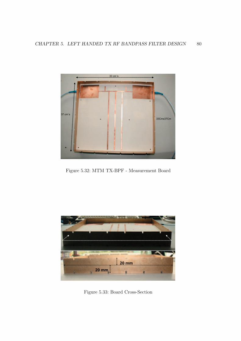
CHAPTER 5. LEFT HANDED TX RF BANDPASS FILTER DESIGN 80
37 cm`s
33 cm`s
33Cmx37Cm
Figure 5.32: MTM TX-BPF - Measurement Board
20 mm
20 mm
Figure 5.33: Board Cross-Section
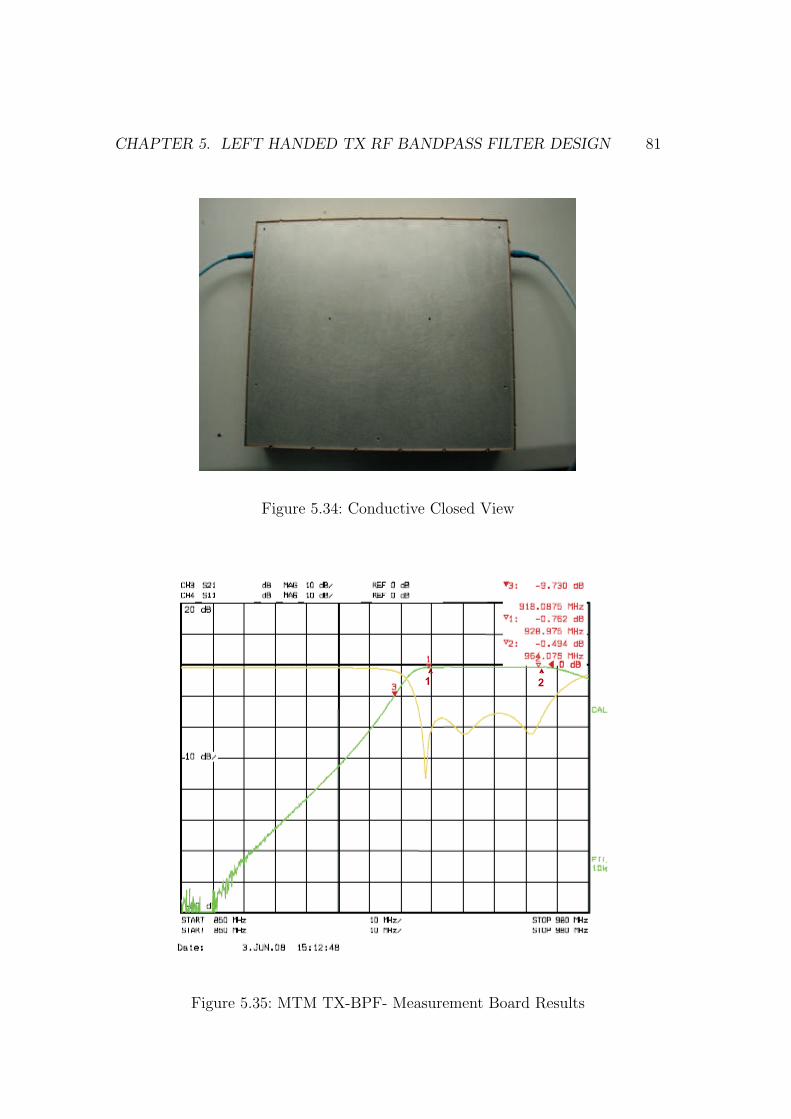
CHAPTER 5. LEFT HANDED TX RF BANDPASS FILTER DESIGN 81
Figure 5.34: Conductive Closed View
1 2
Figure 5.35: MTM TX-BPF- Measurement Board Results
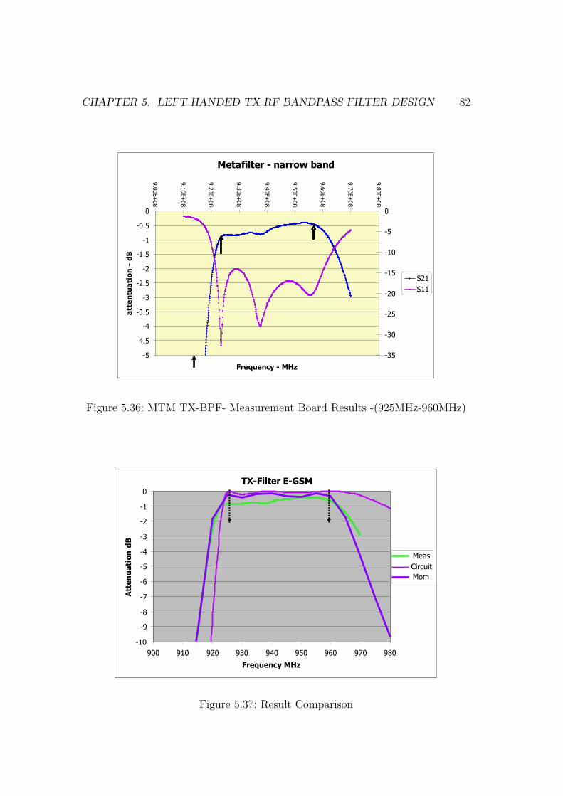
CHAPTER 5. LEFT HANDED TX RF BANDPASS FILTER DESIGN 82
Metafilter - narrow band
-5
-4.5
-4
-3.5
-3
-2.5
-2
-1.5
-1
-0.5
0
9.0
0E+
08
9.1
0E+
08
9.2
0E+
08
9.3
0E+
08
9.4
0E+
08
9.5
0E+
08
9.6
0E+
08
9.7
0E+
08
9.8
0E+
08
Frequency - MHz
att
en
tua
tio
n-
dB
-35
-30
-25
-20
-15
-10
-5
0
S21
S11
Figure 5.36: MTM TX-BPF- Measurement Board Results -(925MHz-960MHz)
TX-Filter E-GSM
-10
-9
-8
-7
-6
-5
-4
-3
-2
-1
0
900 910 920 930 940 950 960 970 980
Frequency MHz
AttenuationdB
Meas
Circuit
Mom
Figure 5.37: Result Comparison
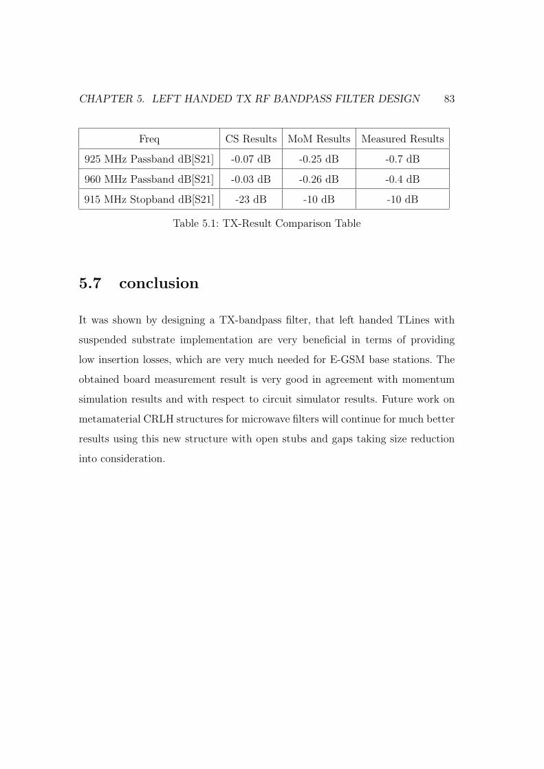
CHAPTER 5. LEFT HANDED TX RF BANDPASS FILTER DESIGN 83
Freq CS Results MoM Results Measured Results
925 MHz Passband dB[S21] -0.07 dB -0.25 dB -0.7 dB
960 MHz Passband dB[S21] -0.03 dB -0.26 dB -0.4 dB
915 MHz Stopband dB[S21] -23 dB -10 dB -10 dB
Table 5.1: TX-Result Comparison Table
5.7 conclusion
It was shown by designing a TX-bandpass filter, that left handed TLines with
suspended substrate implementation are very beneficial in terms of providing
low insertion losses, which are very much needed for E-GSM base stations. The
obtained board measurement result is very good in agreement with momentum
simulation results and with respect to circuit simulator results. Future work on
metamaterial CRLH structures for microwave filters will continue for much better
results using this new structure with open stubs and gaps taking size reduction
into consideration.

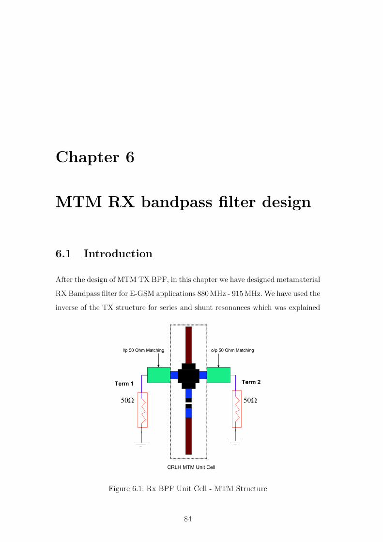
Chapter 6
MTM RX bandpass filter design
6.1 Introduction
After the design of MTM TX BPF, in this chapter we have designed metamaterial
RX Bandpass filter for E-GSM applications 880MHz - 915MHz. We have used the
inverse of the TX structure for series and shunt resonances which was explained
Ω50
Term 2
Ω50
Term 1
CRLH MTM Unit Cell
o/p 50 Ohm MatchingI/p 50 Ohm Matching
Figure 6.1: Rx BPF Unit Cell - MTM Structure
84
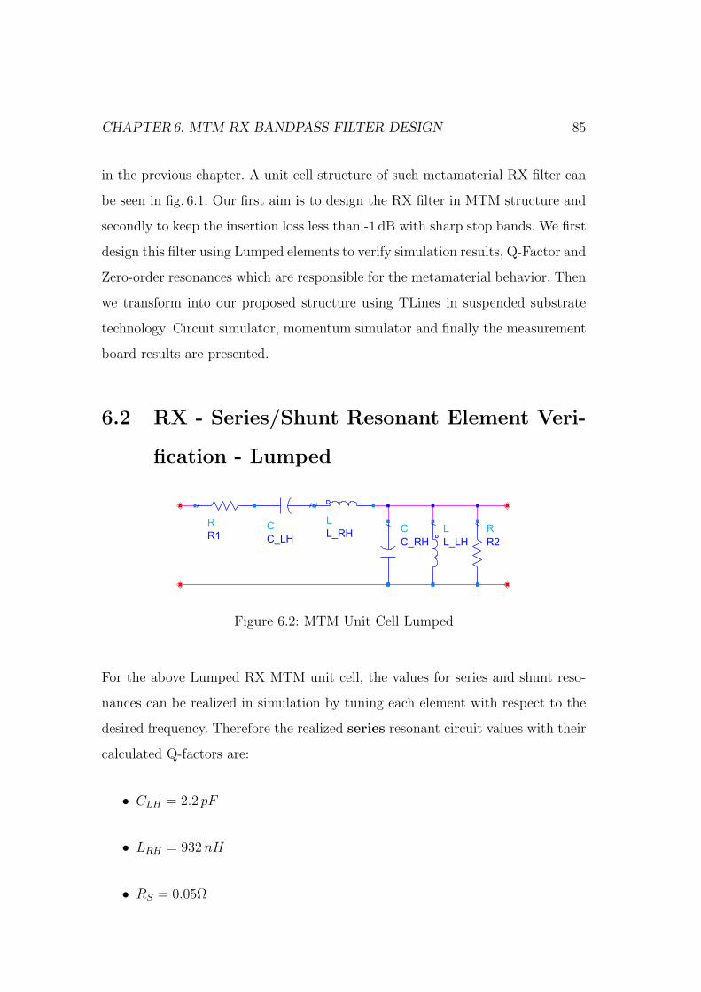
CHAPTER6. MTM RX BANDPASS FILTER DESIGN 85
in the previous chapter. A unit cell structure of such metamaterial RX filter can
be seen in fig. 6.1. Our first aim is to design the RX filter in MTM structure and
secondly to keep the insertion loss less than -1 dB with sharp stop bands. We first
design this filter using Lumped elements to verify simulation results, Q-Factor and
Zero-order resonances which are responsible for the metamaterial behavior. Then
we transform into our proposed structure using TLines in suspended substrate
technology. Circuit simulator, momentum simulator and finally the measurement
board results are presented.
6.2 RX - Series/Shunt Resonant Element Veri-
fication - Lumped
R
R2
L
L_LH
C
C_RH
L
L_RHC
C_LH
R
R1
Figure 6.2: MTM Unit Cell Lumped
For the above Lumped RX MTM unit cell, the values for series and shunt reso-
nances can be realized in simulation by tuning each element with respect to the
desired frequency. Therefore the realized series resonant circuit values with their
calculated Q-factors are:
• CLH = 2.2 pF
• LRH = 932 nH
• RS = 0.05Ω
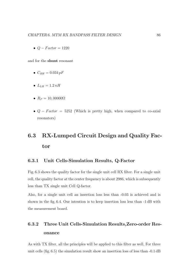
CHAPTER6. MTM RX BANDPASS FILTER DESIGN 86
• Q− Factor = 1220
and for the shunt resonant
• CRH = 0.034 pF
• LLH = 1.2 nH
• RP = 10, 00000Ω
• Q − Factor = 5252 (Which is pretty high, when compared to co-axial
resonators)
6.3 RX-Lumped Circuit Design and Quality Fac-
tor
6.3.1 Unit Cells-Simulation Results, Q-Factor
Fig. 6.3 shows the quality factor for the single unit cell RX filter. For a single unit
cell, the quality factor at the center frequency is about 2986, which is subsequently
less than TX single unit Cell Q-factor.
Also, for a single unit cell an insertion loss less than -0.03 is achieved and is
shown in the fig. 6.4. Our intention is to keep insertion loss less than -1 dB with
the measurement board.
6.3.2 Three Unit Cells-Simulation Results,Zero-order Res-
onance
As with TX filter, all the principles will be applied to this filter as well, For three
unit cells (fig. 6.5) the simulation result show an insertion loss of less than -0.1 dB
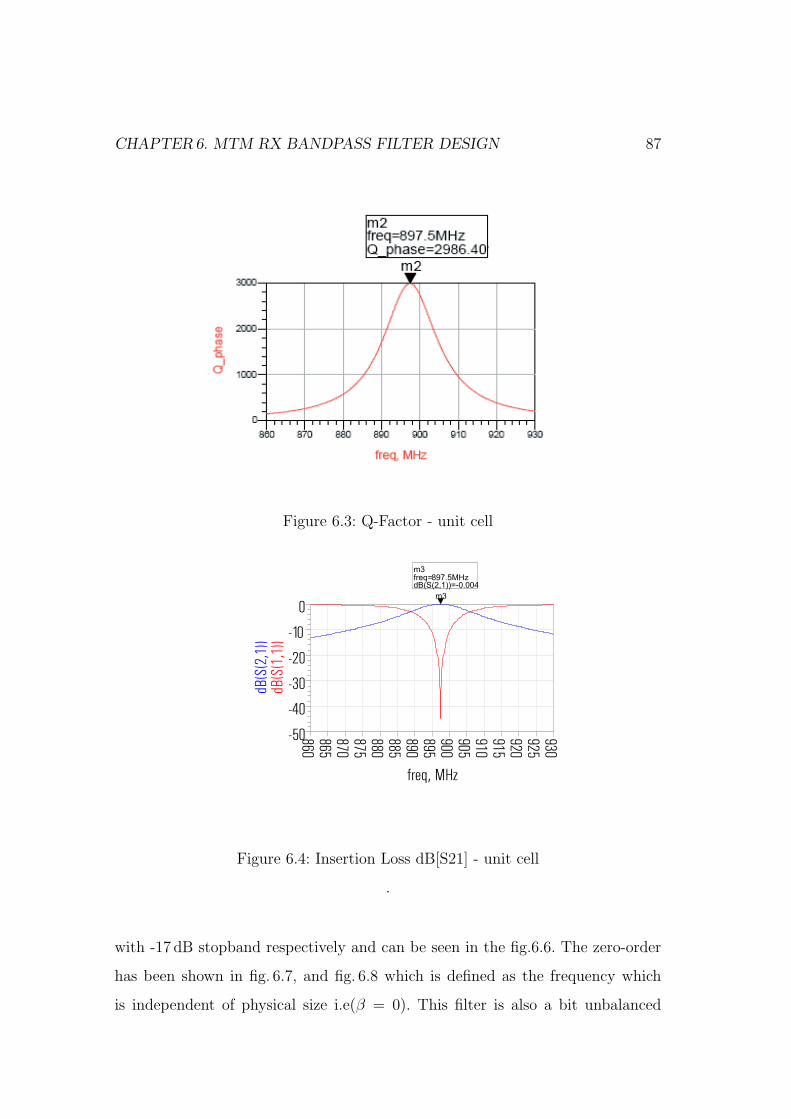
CHAPTER6. MTM RX BANDPASS FILTER DESIGN 87
Figure 6.3: Q-Factor - unit cell
Figure 6.4: Insertion Loss dB[S21] - unit cell
.
with -17 dB stopband respectively and can be seen in the fig.6.6. The zero-order
has been shown in fig. 6.7, and fig. 6.8 which is defined as the frequency which
is independent of physical size i.e(β = 0). This filter is also a bit unbalanced
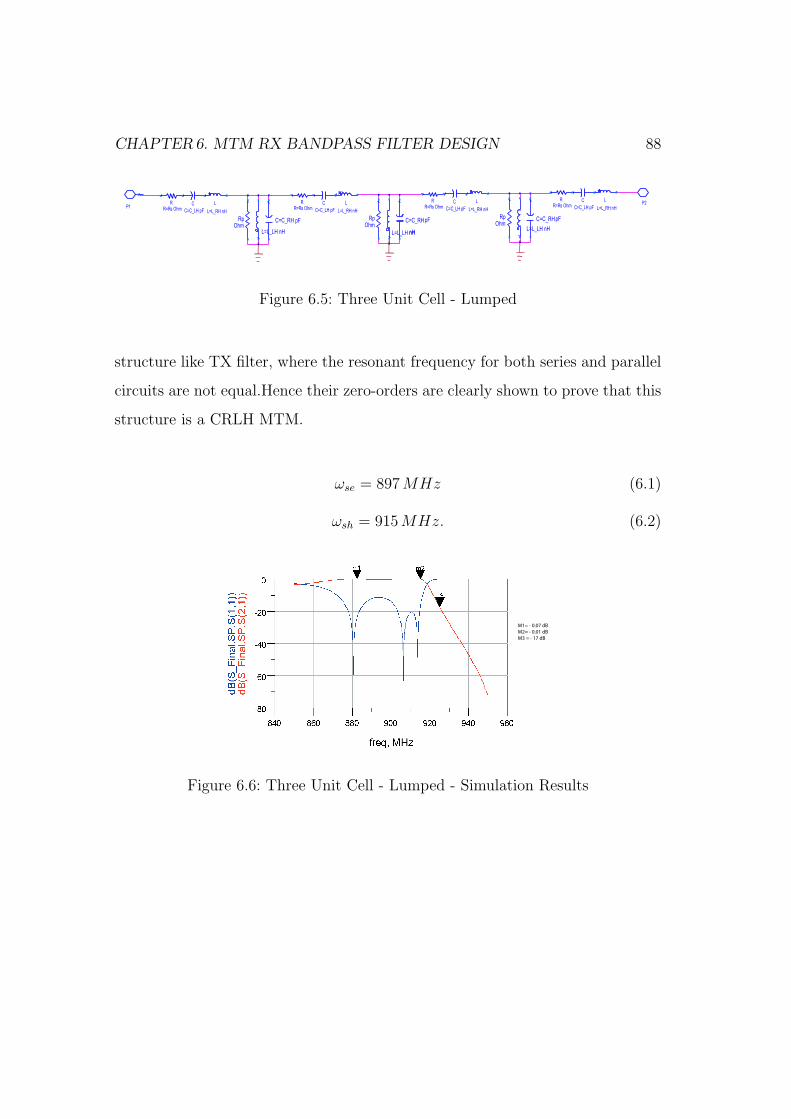
CHAPTER6. MTM RX BANDPASS FILTER DESIGN 88
P2 L
L=L_RH nH
RR=Rs Ohm
C
C=C_LH pF
C=C_RH pF
L=L_LH nH
RpOhm
L
L=L_RH nH
RR=Rs Ohm
C
C=C_LH pF
C=C_RH
L=L_LH nH
RpOhm
pF
nH
L
L=L_RH nH
RR=Rs Ohm
C
C=C_LH pF
C=C_RH
L=L_LH nH
RpOhm
pF
L
L=L_RH nH
RR=Rs Ohm
C
C=C_LH pF
P1
P1
Figure 6.5: Three Unit Cell - Lumped
structure like TX filter, where the resonant frequency for both series and parallel
circuits are not equal.Hence their zero-orders are clearly shown to prove that this
structure is a CRLH MTM.
ωse = 897 MHz (6.1)
ωsh = 915 MHz. (6.2)
M1= - 0.07 dB
M2= - 0.01 dB
M3 = - 17 dB
Figure 6.6: Three Unit Cell - Lumped - Simulation Results
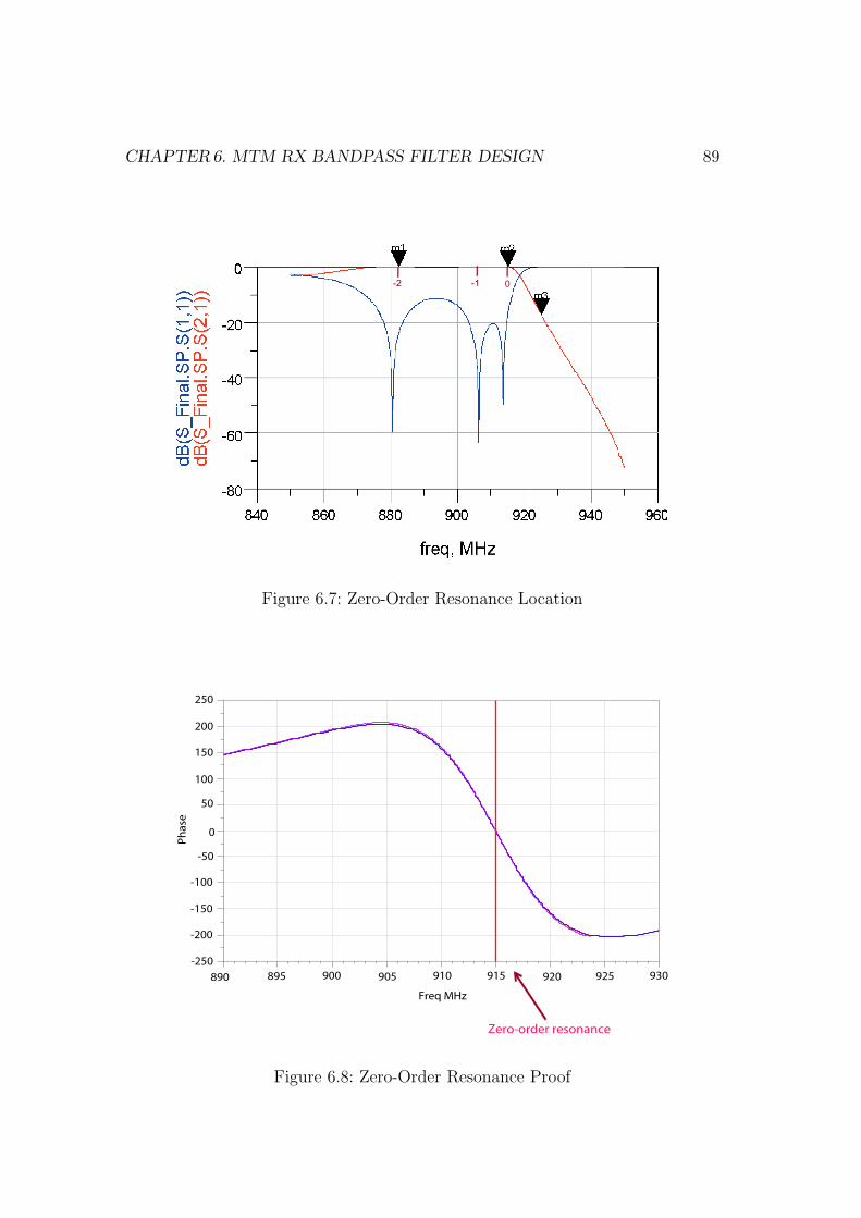
CHAPTER6. MTM RX BANDPASS FILTER DESIGN 89
0-1-2
Figure 6.7: Zero-Order Resonance Location
Ph
ase
0
50
100
150
200
250
-50
-100
-150
-200
-250
890 895 900 930925905 915910 920
Freq MHz
Zero-order resonance
Figure 6.8: Zero-Order Resonance Proof
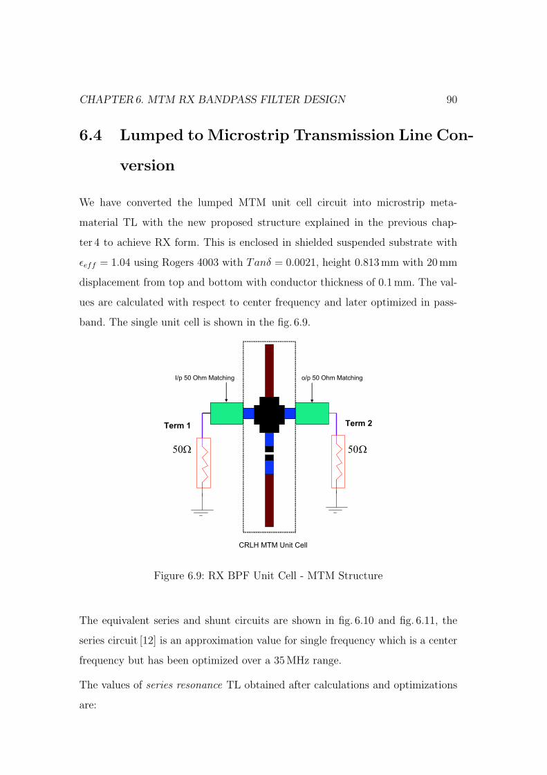
CHAPTER6. MTM RX BANDPASS FILTER DESIGN 90
6.4 Lumped to Microstrip Transmission Line Con-
version
We have converted the lumped MTM unit cell circuit into microstrip meta-
material TL with the new proposed structure explained in the previous chap-
ter 4 to achieve RX form. This is enclosed in shielded suspended substrate with
εeff = 1.04 using Rogers 4003 with Tanδ = 0.0021, height 0.813mm with 20 mm
displacement from top and bottom with conductor thickness of 0.1mm. The val-
ues are calculated with respect to center frequency and later optimized in pass-
band. The single unit cell is shown in the fig. 6.9.
Ω50
Term 2
Ω50
Term 1
CRLH MTM Unit Cell
o/p 50 Ohm MatchingI/p 50 Ohm Matching
Figure 6.9: RX BPF Unit Cell - MTM Structure
The equivalent series and shunt circuits are shown in fig. 6.10 and fig. 6.11, the
series circuit [12] is an approximation value for single frequency which is a center
frequency but has been optimized over a 35MHz range.
The values of series resonance TL obtained after calculations and optimizations
are:
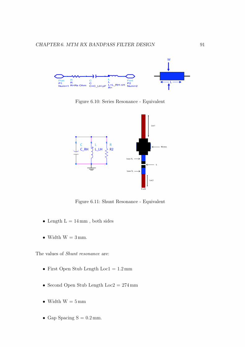
CHAPTER6. MTM RX BANDPASS FILTER DESIGN 91
Port
P2
Num=2
Port
P1
Num=1
L
L
R=
L=L_RH nH
R
R
R=Rs Ohm
C
C
C=C_LH pF
W
L
Figure 6.10: Series Resonance - Equivalent
R
R2
L
L_LH
C
C_RH
Loc1
S
Loc2
1mm TL
1mm TL
Mcross
w
Figure 6.11: Shunt Resonance - Equivalent
• Length L = 14 mm , both sides
• Width W = 3 mm.
The values of Shunt resonance are:
• First Open Stub Length Loc1 = 1.2mm
• Second Open Stub Length Loc2 = 274mm
• Width W = 5 mm
• Gap Spacing S = 0.2mm.
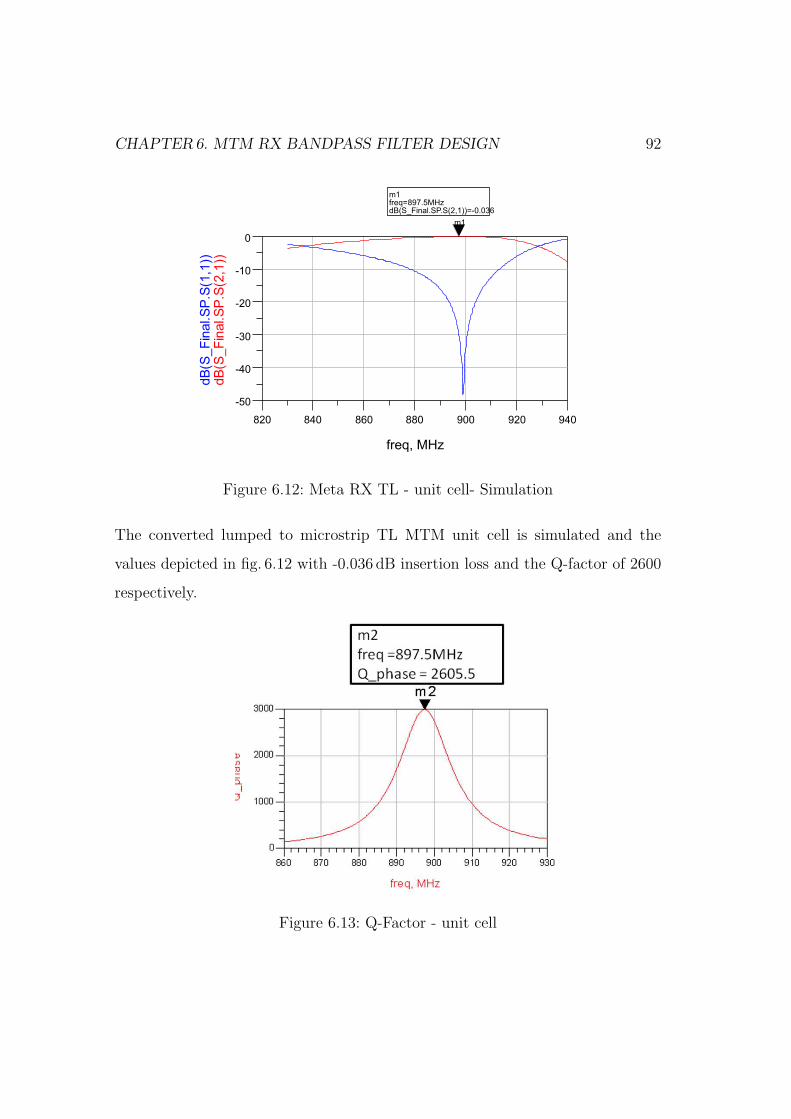
CHAPTER6. MTM RX BANDPASS FILTER DESIGN 92
Figure 6.12: Meta RX TL - unit cell- Simulation
The converted lumped to microstrip TL MTM unit cell is simulated and the
values depicted in fig. 6.12 with -0.036 dB insertion loss and the Q-factor of 2600
respectively.
Figure 6.13: Q-Factor - unit cell
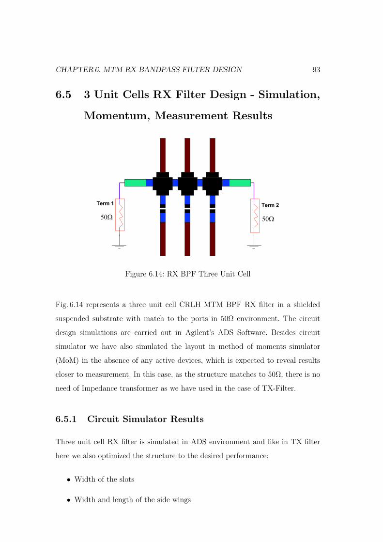
CHAPTER6. MTM RX BANDPASS FILTER DESIGN 93
6.5 3 Unit Cells RX Filter Design - Simulation,
Momentum, Measurement Results
Ω50
Term 2
Ω50
Term 1
Figure 6.14: RX BPF Three Unit Cell
Fig. 6.14 represents a three unit cell CRLH MTM BPF RX filter in a shielded
suspended substrate with match to the ports in 50Ω environment. The circuit
design simulations are carried out in Agilent’s ADS Software. Besides circuit
simulator we have also simulated the layout in method of moments simulator
(MoM) in the absence of any active devices, which is expected to reveal results
closer to measurement. In this case, as the structure matches to 50Ω, there is no
need of Impedance transformer as we have used in the case of TX-Filter.
6.5.1 Circuit Simulator Results
Three unit cell RX filter is simulated in ADS environment and like in TX filter
here we also optimized the structure to the desired performance:
• Width of the slots
• Width and length of the side wings
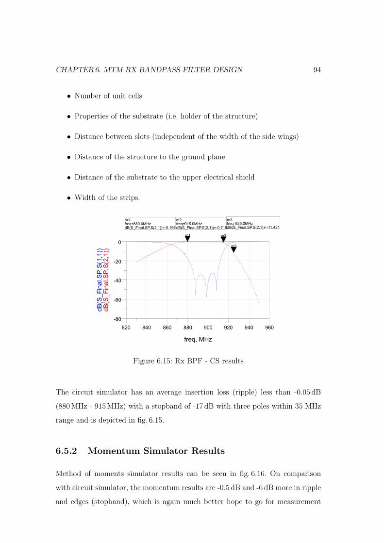
CHAPTER6. MTM RX BANDPASS FILTER DESIGN 94
• Number of unit cells
• Properties of the substrate (i.e. holder of the structure)
• Distance between slots (independent of the width of the side wings)
• Distance of the structure to the ground plane
• Distance of the substrate to the upper electrical shield
• Width of the strips.
Figure 6.15: Rx BPF - CS results
The circuit simulator has an average insertion loss (ripple) less than -0.05 dB
(880MHz - 915MHz) with a stopband of -17 dB with three poles within 35 MHz
range and is depicted in fig. 6.15.
6.5.2 Momentum Simulator Results
Method of moments simulator results can be seen in fig. 6.16. On comparison
with circuit simulator, the momentum results are -0.5 dB and -6 dB more in ripple
and edges (stopband), which is again much better hope to go for measurement
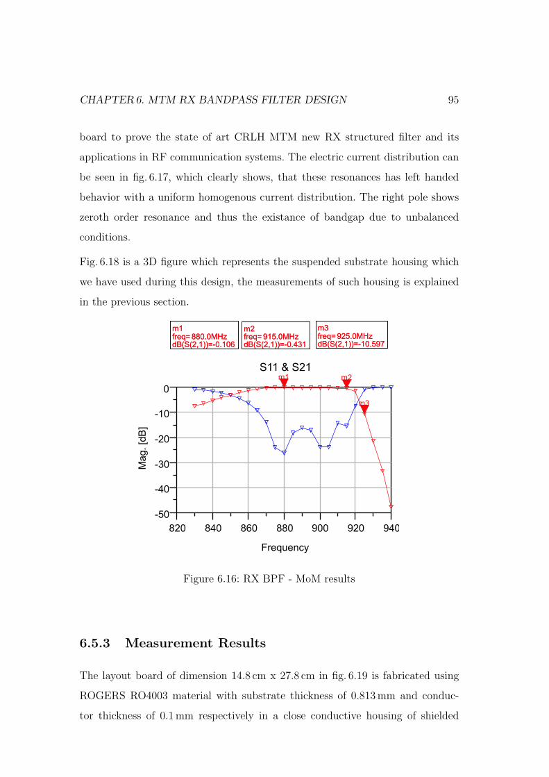
CHAPTER6. MTM RX BANDPASS FILTER DESIGN 95
board to prove the state of art CRLH MTM new RX structured filter and its
applications in RF communication systems. The electric current distribution can
be seen in fig. 6.17, which clearly shows, that these resonances has left handed
behavior with a uniform homogenous current distribution. The right pole shows
zeroth order resonance and thus the existance of bandgap due to unbalanced
conditions.
Fig. 6.18 is a 3D figure which represents the suspended substrate housing which
we have used during this design, the measurements of such housing is explained
in the previous section.
S11 & S21
Figure 6.16: RX BPF - MoM results
6.5.3 Measurement Results
The layout board of dimension 14.8 cm x 27.8 cm in fig. 6.19 is fabricated using
ROGERS RO4003 material with substrate thickness of 0.813mm and conduc-
tor thickness of 0.1 mm respectively in a close conductive housing of shielded
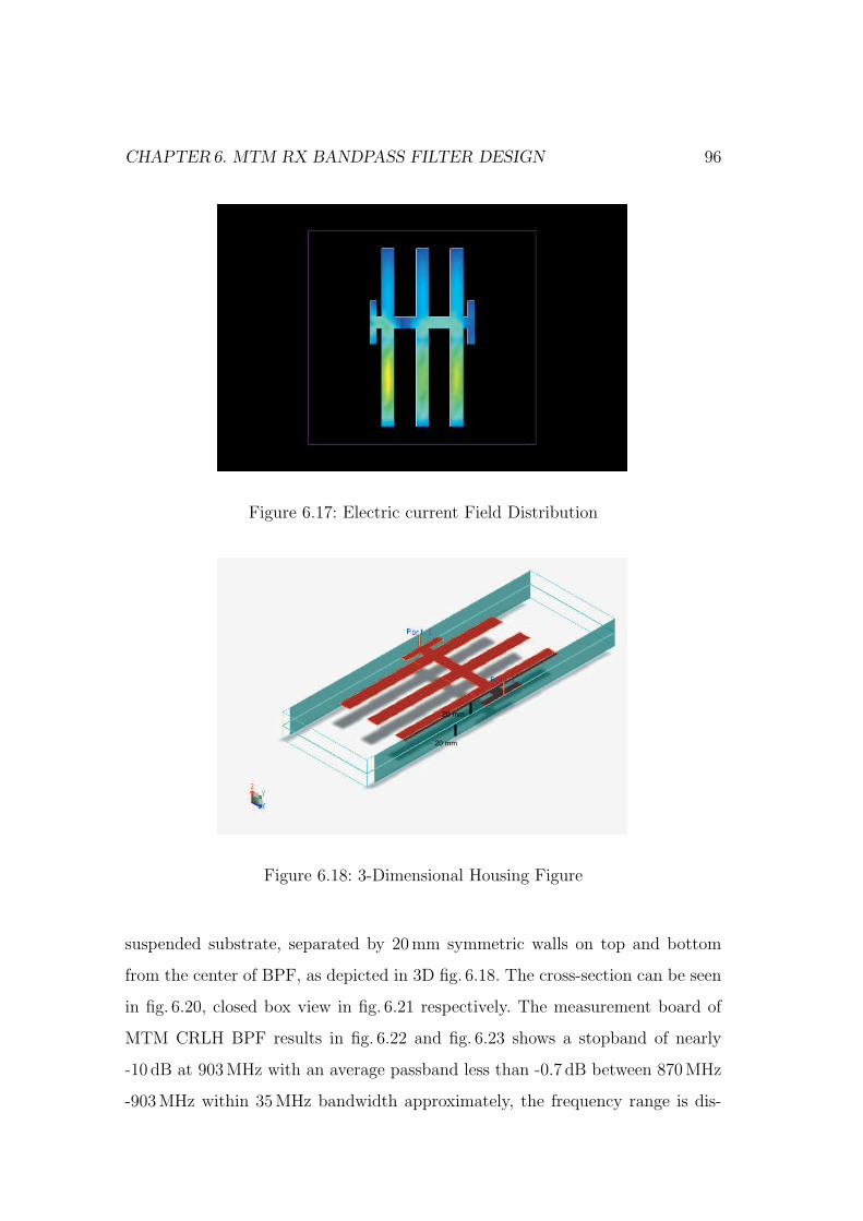
CHAPTER6. MTM RX BANDPASS FILTER DESIGN 96
Figure 6.17: Electric current Field Distribution
20 mm
20 mm
Figure 6.18: 3-Dimensional Housing Figure
suspended substrate, separated by 20mm symmetric walls on top and bottom
from the center of BPF, as depicted in 3D fig. 6.18. The cross-section can be seen
in fig. 6.20, closed box view in fig. 6.21 respectively. The measurement board of
MTM CRLH BPF results in fig. 6.22 and fig. 6.23 shows a stopband of nearly
-10 dB at 903MHz with an average passband less than -0.7 dB between 870MHz
-903MHz within 35MHz bandwidth approximately, the frequency range is dis-
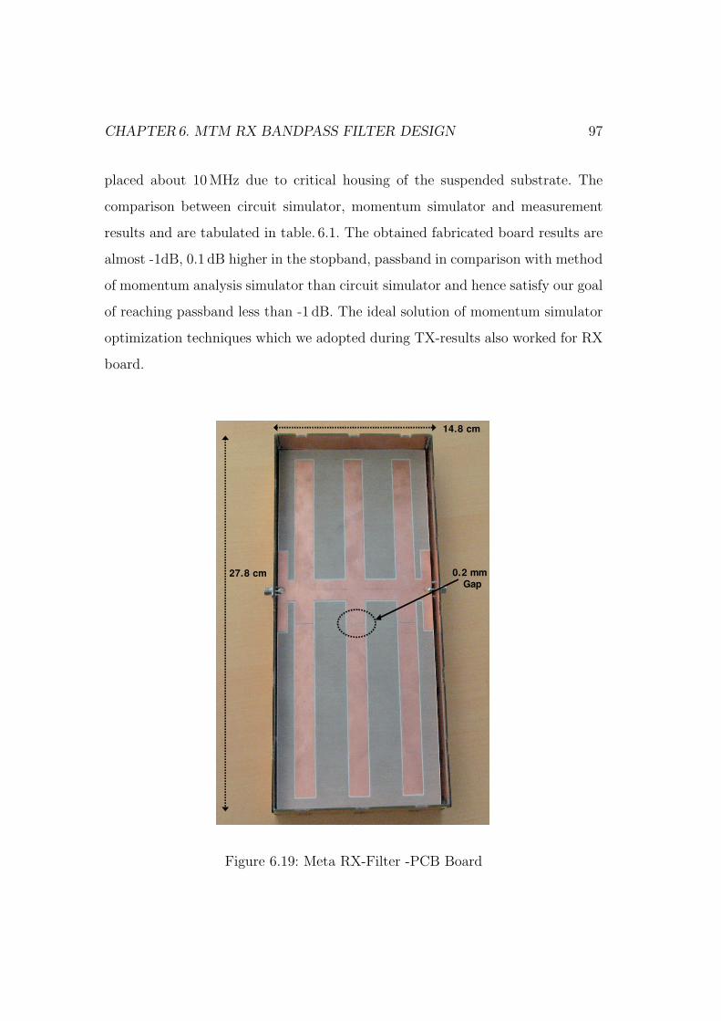
CHAPTER6. MTM RX BANDPASS FILTER DESIGN 97
placed about 10MHz due to critical housing of the suspended substrate. The
comparison between circuit simulator, momentum simulator and measurement
results and are tabulated in table. 6.1. The obtained fabricated board results are
almost -1dB, 0.1 dB higher in the stopband, passband in comparison with method
of momentum analysis simulator than circuit simulator and hence satisfy our goal
of reaching passband less than -1 dB. The ideal solution of momentum simulator
optimization techniques which we adopted during TX-results also worked for RX
board.
0.2
14.8 cm
27.8 cm 0.2 mm Gap
14.8 cm
27.8 cm
Figure 6.19: Meta RX-Filter -PCB Board
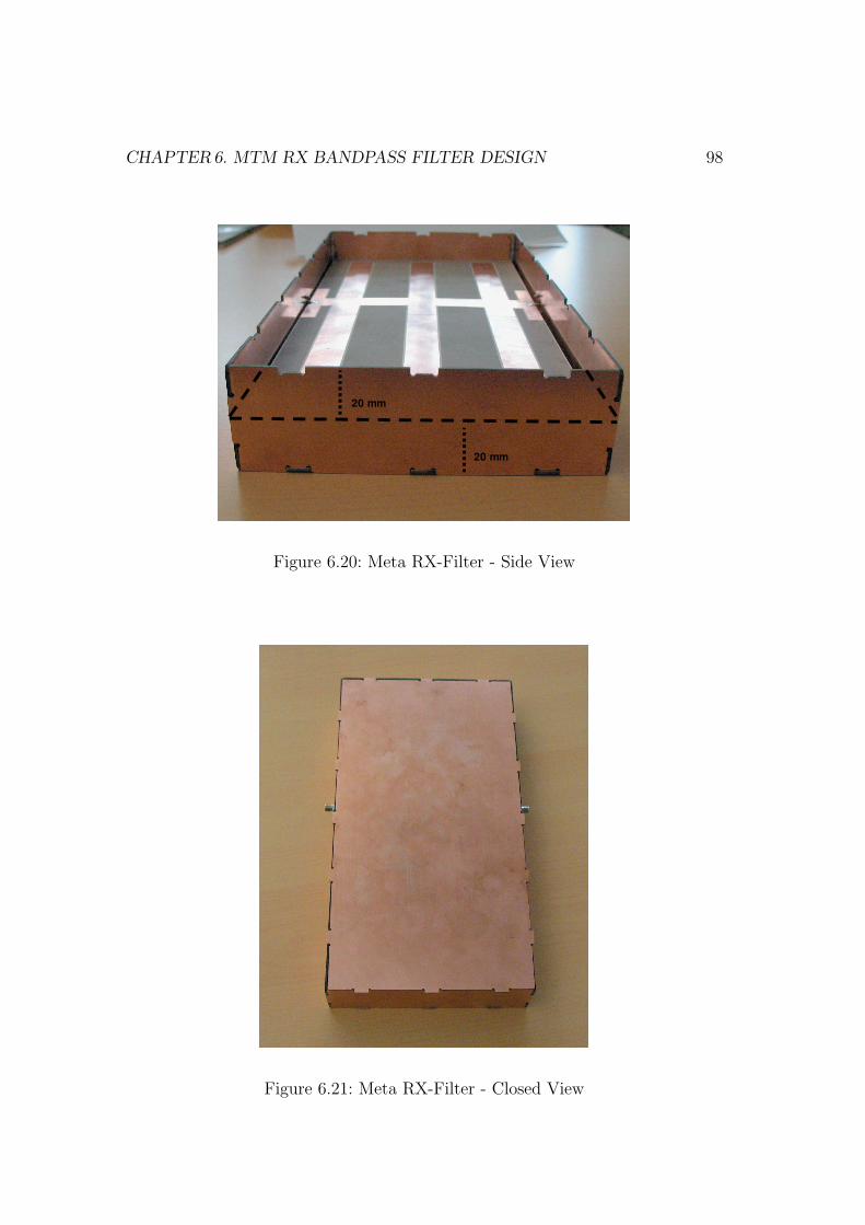
CHAPTER6. MTM RX BANDPASS FILTER DESIGN 98
20 mm
20 mm
Figure 6.20: Meta RX-Filter - Side View
Figure 6.21: Meta RX-Filter - Closed View
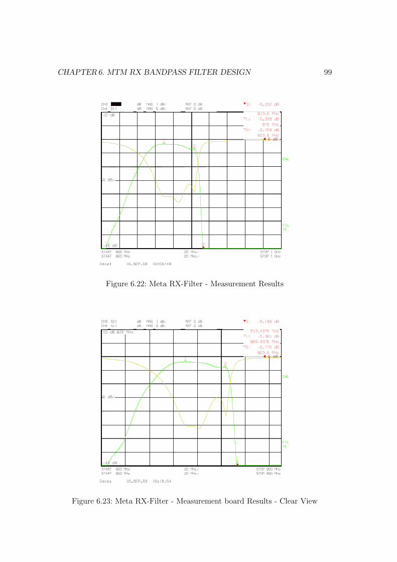
CHAPTER6. MTM RX BANDPASS FILTER DESIGN 99
Figure 6.22: Meta RX-Filter - Measurement Results
Figure 6.23: Meta RX-Filter - Measurement board Results - Clear View
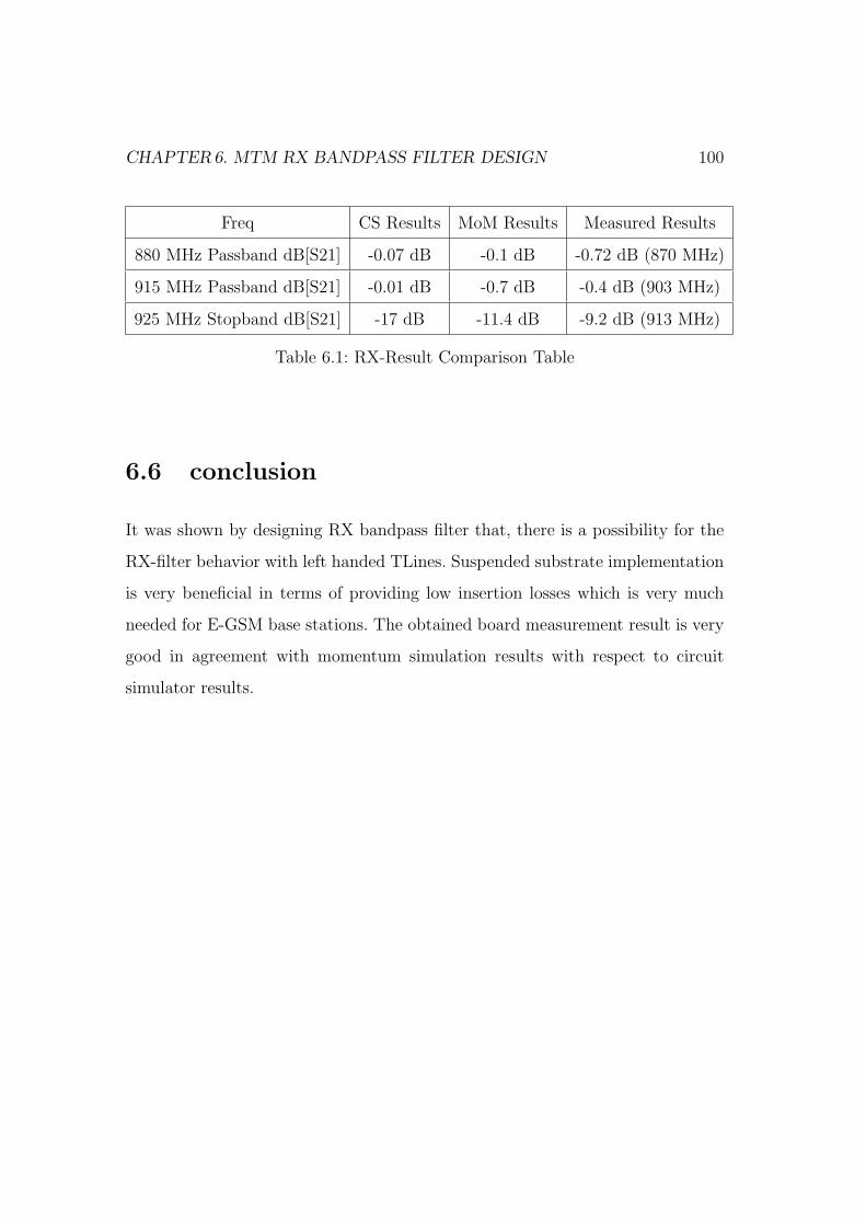
CHAPTER6. MTM RX BANDPASS FILTER DESIGN 100
Freq CS Results MoM Results Measured Results
880 MHz Passband dB[S21] -0.07 dB -0.1 dB -0.72 dB (870 MHz)
915 MHz Passband dB[S21] -0.01 dB -0.7 dB -0.4 dB (903 MHz)
925 MHz Stopband dB[S21] -17 dB -11.4 dB -9.2 dB (913 MHz)
Table 6.1: RX-Result Comparison Table
6.6 conclusion
It was shown by designing RX bandpass filter that, there is a possibility for the
RX-filter behavior with left handed TLines. Suspended substrate implementation
is very beneficial in terms of providing low insertion losses which is very much
needed for E-GSM base stations. The obtained board measurement result is very
good in agreement with momentum simulation results with respect to circuit
simulator results.

Chapter 7
Conclusions and Discussion
7.1 conclusions
This thesis work has been carried out for the laid out objectives. The results and
the comparisons have been discussed in the previous chapter. Now in this chapter,
conclusions and the future opportunities by this work done are discussed.
The main objectives of the thesis are:
1. To Design duplex filters for the application of E-GSM900 base stations
using CRLH Metamaterial Structures.
2. To propose a different MTM filter structure with gaps and open stubs in
comparison with the previously published MTM filter structures.
3. To impose microstrip suspended substrate technology for the design.
4. To prove the state of art Metamaterial structure and its applications at
RF/Microwave frequencies.
As it was discussed earlier that LH transmission lines do not exist in real nature,
we have used the quasi-lumped transmission lines (Artificial Structures) with
elementary cells consisting of series capacitors and shunt inductors. We can design
101
CHAPTER7. CONCLUSIONS AND DISCUSSION 102
filters by using numerous methods, but in this thesis work we have worked to prove
that, there is a possibility to design RF filters using metamaterial structures.
7.1.1 Things learned and New
Things learned and new during this thesis work are:
1. Possibility to design TX/RX narrow bandpass filters with Left-Handed
metamaterials in a planar microstrip technology.
2. Combination of microstrip gap capacitors and open stub inductors leads to
CRLH MTM structures.
3. Proved the state of art balanced-structure metamaterials and its appli-
cations at RF/Microwave frequencies. Which clarifies the question that,
whether balanced or unbalanced structures should be used.
4. Shortstubs (λ/4 Tlines) can be replaced with long openstubs (λ/2 Tlines),
which has a virtually large-valued ground capacitor. Hence provides similar
results.
5. Suspended substrate technology is an added advantage for achieving good
results like reduced losses and enhances Q-factor.
6. Using planar microstrip technology for filter designs, we have attained Q-
factors of nearly 5000. which is very high.
7. High power handling in comparison with coaxial filters.
7.2 Advantages and Drawbacks
We have met the goals successfully. But the accuracy has been compromised at
some places as a matter of fact. This compromisation is unavoidable.
CHAPTER7. CONCLUSIONS AND DISCUSSION 103
Advantages: During TX-BPF design . We have proved the new LH TL
filter structure with microstrip gap capacitors and λ/2 TLines. For the three unit
cells, we have successfully met our goal i.e insertion loss is less than -1 dB. The
momentum simulator results are very near to fabricated board results (i.e. 1% -
2% deviation). Also suspended substrate technology implementation played an
important role in attaining good results. Finally, we have shown the advantages
of balanced structures in left-handed materials for TX BPF design.
Drawbacks: TX-BPF design . For three unit cells, the board size achieved is
33 cm x 37 cm, it means for more than 3 unit cells the size matters. Housing is
critical. Stop band should still be sharper than what was achieved.
Advantages: During RX-BPF design . The proposed left-handed TL struc-
ture worked in showing RX filter characteristics. The measured results obtained
with three unit cells are very close to simulation results and hence in meeting goal.
In this case as well, suspended substrate implementation has given good results.
Therefore, we have shown the advantages of balanced structures in Left-Handed
materials for RX BPF design.
Drawbacks: RX-BPF design . There is a displacement of 10MHz in the mea-
surement results in comparison with the simulation results. Still the board size
has to be reduced in order to fit on increase in number of unit cells. Housing
is critical and hence the stop band needs to be sharper than achieved. Finally
a duplexer cannot be made with two different sized bandpass filters, where the
sizes need to fit.
7.3 future work
The left-handed bandpass filter design work can be continued by increasing the
number of unit cells, decreasing the board size, goal with same sizes for TX and
RX bandpass filters (for a perfect duplexer). Also the future work can be contin-
ued showing various RF applications using balanced structure CRLH metamate-
rials and hence to prove the state of art.

Bibliography
[1]. V.G.Veselago,”The electrodynamics of substances with simultaneously neg-
ative values of ε and µ” , Sov. Phys.-Usp., vol. 10, pp. 509-514, Jan-Feb.
1968.
[2]. J.B.Pendry, A.J.Holden, W.J.Stewart and I.Youngs ”Extremely low fre-
quency Plasmons in metallic structures” Phys. Rev. Lett., vol. 76, no. 25,
pp. 4773-4776, June.1996
[3]. J.B.Pendry,A.J.Holden,D.J.Robbins,W.J.Stewart, ”Magnetism from conduc-
tors and enhanced nonlinear phenomena”,IEEE Trans.Microw. Theory Tech.,
vol.47, no.11, pp.2075-2084, Nov.1999.
[4]. D.R.Smith, W.J.Padilla, D.C.Vier, S.C.Nemat-Nasser, and S.Schultz, ”Com-
posite medium with simultaneously negative permeability and permittivity”,
Phys. Rev. Lett., vol.84, no.18, pp.4184-4187, May 2000.
[5]. C.Caloz, H.Okabe, T.Iwai, and T.Itoh, ”Transmission line approach of left-
handed (LH) materials”, in USNC/URSI Nat.Radio Science Meeting, vol.1,
Jun.2002, p.39.
[6]. G.V.Eleftheriades and k.G.Balmain ”Negative refraction Metamaterials, Fun-
damental Principles and Applications”, in IEEE press, Wiley, Hoboken NJ
2005.
[7]. A.K.Iyer and G.V.Eleftheriades, ”Negative refractive index Metamaterial
104
supporting 2-D waves”, in IEEE MTT-S Int.Microwave Symp.Dig.,vol.2,
Jun.2002, pp.1067 1070.
[8]. D.R.Smith and N.Kroll, ”Negative refractive index in left-handed materi-
als”, Phys.Rev.Lett.,vol.85, no.14, pp.2933-2936, Oct.2000.
[9]. A.Lai, T.Itoh, ”Composite Right/Left-Handed Transmission Line Metama-
terials”, IEEE Microwave Magazine, pp.34-50, Sept.2004.
[10]. I-H.Lin, M.DeVincentis, C.Caloz, T.Itoh, ”Arbitrary Dual-Band Compo-
nents Using Composite Right/Left-Handed Transmission Lines”, IEEE Trans-
actions on Microwave Theory and Technique, Vol.52, No.4, April 2004.
[11]. C.Caloz, A.Sanada, T.Itoh, ”A novel Composite Right-/Left-Handed Coupled-
Line Directional Coupler With Arbitrary Coupling Level and Broad Band-
width”, IEEE Transactions on Microwave Theory and Techniques, Vol.52,
No.3, March 2004.
[12]. H.Okabe, C.Caloz, T.Itoh, ”A Compact Enhanced-Bandwidth Hybrid Ring
Using an Artificial Lumped-Element Left-Handed Transmission-Line Sec-
tion”, IEEE Transactions on Microwave Theory and Technique, Vol.52,
No.3, March 2004.
[13]. W.Menzel, A.Balalem ”Quasi-Lumped Suspended Stripline Filters and Diplex-
ers”, IEEE Trans. on MTT, vol.MTT-53, Oct.2005, pp.3230 3237.
[14]. J.E.Dean ”Suspended substrate stripline filters for ESM applications”, IEE
Proc.,Vol.132, Pt.F, July 1985, pp.257 - 266.
[15]. G.Fischer, ”Architectural benefits of wide band gap RF power transistors for
frequency agile base station systems”, IEEE MTT, 6th annual Wireless and
Microwave Technology Conference, Clearwater, Florida, April.2004.
[16]. C.Caloz, T.Itoh ”Electromagnetic Metamaterials”, IEEE press, Wiley, Hobo-
ken NJ, 2006.
[17]. Ricardo Marques, Ferran Martin, Mario Sorolla ”Metamaterials with Neg-
ative Parameters”, IEEE press, Wiley, Hoboken NJ, 2007.
[18]. Gunther Dehm-Andone, Grzegorz Adamiuk, Georg Fischer ”Using Meta-
material structures with frequency agile base stations”, IEEE GEMIC 2006
[19]. Lei Zhu, Huamin Shi, Menzel.W, ”Coupling behaviors of quarter-wavelength
impedance transformers for wideband CPW bandpass filter”, Microwave and
Wireless Components Letters, IEEE Volume.15, Issue.1, Jan.2005 Page(s)1315.
[20]. Bekheit, Amari, Menzel.W, ” Modelling and Optimization of Compact Mi-
crowave Bandpass Filters. Microwave Theory and Techniques”, IEEE Trans-
actions on Volume 56, Issue 2, Feb.2008 Page(s).420430
[21]. Anu Lehtovuori, Luis Costa, ” Model for Shielded Suspended Substrate Mi-
crostrip Line”, Circuit Theory Laboratory Report Series, Helsinki Univer-
sity of Technology 1998.
[22]. Wen Zhang”Optical activity and applications of planar chiral metamateri-
als”, PhD thesis at University of Southampton, 2006.
[23]. Gunther Dehm, Grzegorz Adamiuk, Georg Fischer, Schenkel Horst ”Meta-
material Filter for use in a base station of a wireless communication sys-
tems”, US patent WO2007/100324
[24]. Islam, R.; Eleftheriades, G.V ”Compact Negative-Refractive-Index Transmission-
Line (NRI-TL) coupler, filter and diplexer ”, Antennas and Propagation
International Symposium, 2007 IEEE 9-15 June 2007 Page(s):4957 - 4960
[25]. R. A. Shelby, D. R. Smith, and S. Schultz ”Experimental verification of a
negative index of refraction”, Science, 77:292, 2001.
[26]. J. Pacheco, T. M. Grzegorczyk, B.-I. Wu, Y. Zhang, and J. A. Kong. ”Power
propagation in homogeneous isotropic frequency dispersive left-handed me-
dia”, Phys. Rev.Lett., 89:257401, 2002.
[27]. J. B. Pendry. ”Negative refraction makes a perfect lens”. Phys. Rev. Lett.,
85:3966,2000.
[28]. R. Ziolkowski and E. Heyman ”Wave propagation in media having negative
permittivity and permeability”. Phys. Rev. E, 64:056625, 2001.
[29]. C. G Parazzoli, R. B. Greegor, K. Li, B. E. C. Koltenbah, and M. Tanielian.
”Experimental verification and simulation of negative index of refraction
using Snell’s law ”.Phys. Rev. Lett., 90:107401, 2003.
[30]. J. A. Kong, B.I.Wu, and Y. Zhang. ”A unique lateral displacement of a
Gaussian beam transmitted through a slab with negative permittivity and
permeability ”. Microwave Opt. Technol. Lett., 33(2):136139, April 2002.
[31]. J. Gerardin and A. Lakhtakia. ”Negative index of refraction and distributed
Bragg reflectors”. Microwave Opt. Technol. Lett., 34(6):409411, 2002.
[32]. A. Grbic and G. V. Eleftheriades. ”Experimental verification of backward-
wave radiation from a negative refractive index metamaterial”. J. Appl.
Phys., 92(10):59305935,2002.
[33]. J. Lu, T. M. Grzegorczyk, Y. Zhang, J. Pacheco, B.-I. Wu, and J. A. Kong.
”Cerenkov radiation in materials with negative permittivity and permeabil-
ity”. Optics Express, 11(7):723734, 2003.
[34]. Hoang Van Nguyen, Christophe Caloz, ”Broadband Highly Selective Band-
pass Filter based on a Tapered Coupled-Resonator CRLH Structure”IEEE
Transactions on Microwave Theory and Techniques, Vol.52, No.3, March
2004.
[35]. R. A. Shelby, D. R. Smith, S. C. Nemat-Nasser, and S. Schultz. ”Microwave
transmission through a two-dimensional, isotropic, left-handed metamater-
ial ”. Appl. Phys.Lett., 78(4):489, 2001.
[36]. C. Caloz, A. Sanada, and T. Itoh. ”Microwave applications of transmission-
line based negative refractive index structures ”. Proc. of Asia-Pacific Mi-
crowave Conf., Seoul, Korea, vol. 3, pp. 17081713, Nov. 2003.
[37]. A.Grbic and G. V. Eleftheriades.”Growing evanescent waves in negativere-
fractive index transmission line media ”. Appl. Phys. Lett.82(12):181517,
2003.
[38]. C. Caloz and T. Itoh.”Novel microwave devices and structures based on the
transmission line approach of meta-materials”. IEEE-MTT Intl Symp., vol.
1, pp. 195198, Philadelphia, PA, June 2003.
[39]. M. D. Pozar ”Microwave Engineering”. Third Edition, John Wiley & Sons,
2004.
[40]. A. Sanada, C. Caloz, and T. Itoh.”Characteristics of the composite right/left-
handed transmission lines,”. IEEE Microwave Wireless Compon. Lett., vol.
14, no. 2, pp. 6870, February 2004.
[41]. G. L. Matthaei, L. Young, and E. M. T. Jones.”Microwave Filters, Impedance-
Matching Networks, and Coupling Structures”. Artech House, Dedham,
1964.
[42]. C. Caloz and T. Itoh. ”Transmission line approach of left-handed (LH)
structures and microstrip realization of a low-loss broadband LH filter”
A.IEEE Trans. Antennas Propagat., vol. 52, no. 5, May 2004
[43]. Lai, C. Caloz and T. Itoh. ”Transmission line based metamaterials and their
microwave applications” Microwave Mag., vol. 5, no. 3,pp. 3450, Sept. 2004.
[44]. Benedek, P. Silvester, P., ”Equivalent Capacitances for Microstrip Gaps and
Steps Microwave Theory and Techniques”, IEEE Transactions on Volume
20, Issue 11, Nov 1972 Page(s):729 733.
[45]. Reinhold Ludwig, Pavel Bretchko, Gene Bogdanov, ”RF Circuit Design:
Theory and Applications” Published by Pearson Prentice Hall, 2008.
[46]. Qizheng Gu ”RF system design of transceivers for wireless communica-
tions” Published by Springer, 2005.
[47]. Wolfgang Sieber, Franz Rottmoser ”High frequency filter in a coaxial con-
struction” Patent No:20080024248, US patent 2008.
[48]. V. K. Varadan, Kalarickaparambil Joseph Vinoy, K. A. Jose ”RF MEMS
and Their Applications” John Wiley and Sons October 2002.
[49]. Shu, Yong-hui, Xiao-xia Qi. and Yun-ji Wang, ”Analysis Equation for Shielded
Suspended Substrate Microstrip Line and Broadside-Coupled Stripline”, IEEE
MTT-S International Microwave Symposium Digest,
[50]. Changjun Lui, Wolfgang Menzel ”on the relation between a negative refrac-
tive index transmission line and chebyshev filter”, IEEE International 37th
European Microwave Conference, Munich, Germany Oct-2007.
Publications
[1]. Shaik Geelani, Georg Fischer, Jurgen Detlefsen, Horst Schenkel, ”Metama-
terial Based Filters in Suspended Substrate”, International Metamaterial
Conference Pamplona Spain, September 2008.
[2]. Shaik Geelani, Georg Fischer, Jurgen Detlefsen, Horst Schenkel ”Composite
Right/Left Handed Metamaterial Structures for RF Narrow Bandpass Filter
Design”, IEEE 2008 International Workshop on Metamaterials, Nanjing
China, November 2008.
[3]. Shaik Geelani, Georg Fischer, Jurgen Detlefsen, Horst Schenkel, ”Metama-
terial Based RF Narrow Bandpass Filter Design in Microstrip Suspended
Substrate”,EEE, RFM08 Malaysia, December 2008.
[4]. Shaik Geelani, Georg Fischer, Jurgen Detlefsen, ”Metamaterial RF Tx-
Bandpass Filter Design for EGSM-900 Base stations”, IEEE National work-
shop on Metamaterials and special materilas for electromagnetic applica-
tions and TLC - MMSM08, Naples. Italy Dec 2008.
[5]. Shaik Geelani, Horst Schenkel, ”Metafilter with asymmetric structure”, Alcatel-
Lucent, Bell-Labs, Germany - German patent DE SA00474EP, June 2008.
110
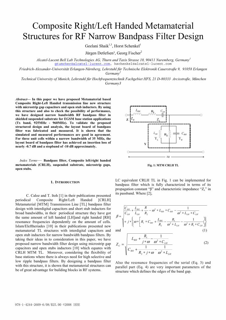
Composite Right/Left Handed Metamaterial Structures for RF Narrow Bandpass Filter Design
Geelani Shaik1,3, Horst Schenkel1
Jürgen Detlefsen³, Georg Fischer2 Alcatel-Lucent Bell Lab Technologies AG, Thurn and Taxis Strasse 10, 90411 Nuremberg, Germany1
[email protected], [email protected]
Friedrich-Alexander-Universität Erlangen-Nürnberg, Lehrstuhl für Technische Elektronik Cauerstraße 9, 91058 Erlangen Germany2
Technical University of Munich, Lehrstuhl für Hochfrequenztechnik Fachgebiet HFS, 21 D-80333 Arcisstraße, München Germany3
Abstract— In this paper we have proposed Metamaterial based Composite Right-Left Handed transmission line new structure with microstrip gap capacitors and open stub inductors. By using this structure and also to check the possibility of performance, we have designed narrow bandwidth RF bandpass filter in shielded suspended substrate for EGSM base station applications (Tx band, 925MHz - 960MHz). To validate the proposed structured design and analysis, the layout board of bandpass filter was fabricated and measured. It is shown that the simulated and measured performances are good in agreement. For three unit cells within a narrow bandwidth of 35 MHz, the layout board of bandpass filter has achieved an insertion loss of nearly -0.7 dB and a stopband of -10 dB approximately. Index Terms— Bandpass filter, Composite left/right handed metamaterials (CRLH), suspended substrate, microstrip gaps, open stubs.
1. INTRODUCTION
C. Caloz and T. Itoh [1] in their publications presented periodical Composite Right/Left Handed [CRLH] Metamaterial [MTM] Transmission Line [TL] bandpass filter design with interdigital capacitors and short stub inductors for broad bandwidths, in their periodical structure they have got the same amount of left handed [LH]and right handed [RH] resonance frequencies dependently on the amount of cells. Islam/Eleftheriades [10] in their publications presented new metamaterial TL structures with interdigital capacitors and open stub inductors for narrow bandwidth bandpass filters. By taking their ideas in to consideration in this paper, we have proposed narrow bandwidth filter design using microstrip gap capacitors and open stubs inductors [10] which equates with CRLH MTM TL. Moreover, considering the flexibility of base stations where there is always need for high selective and low ripple bandpass filters. By designing a bandpass filter with this structure, it is shown that metamaterial structures can be of great advantage for building blocks in RF systems.
Fig. 1: MTM CRLH TL
LC equivalent CRLH TL in Fig. 1 can be implemented for bandpass filter which is fully characterized in terms of its propagation constant “β” and characteristic impedance “Zc” in its passband. Where [2],
⎪⎭
⎪⎬⎫
⎪⎩
⎪⎨⎧
⎥⎦
⎤⎢⎣
⎡∗∗
−∗
−+∗∗∗+
∗∗−∗∗−++
=
LHLH
RHRH
LHLHRHRH
LH
RH
LH
RH
CRLR
RLCRj
CLCL
RR
LL
CC
122
1
21
22
2
1
1
ωωω
ωω
β
and (1)
LHRH
LHRH
C
LjRC
CjR
LZ
∗−
∗∗+
∗−
∗+
=
22
21
11
1
ωω
ωω (2)
Also the resonance frequencies of the serial (Eq. 3) and parallel part (Eq. 4) are very important parameters of the structure which defines the edges of the band gap.
978-1-4244-2609-6/08/$25.00 ©2008 IEEE
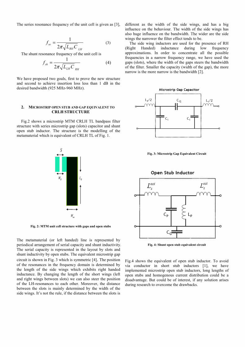
The series resonance frequency of the unit cell is given as [3],
LHRH
se CLf
π21= (3)
The shunt resonance frequency of the unit cell is
RHLH
sh CLf
π21= (4)
We have proposed two goals, first to prove the new structure and second to achieve insertion loss less than 1 dB in the desired bandwidth (925 MHz-960 MHz).
2. MICROSTRIP OPEN STUB AND GAP EQUIVALENT TO CRLH STRUCTURE Fig.2 shows a microstrip MTM CRLH TL bandpass filter
structure with series microstrip gap (slots) capacitor and shunt open stub inductor. The structure is the modelling of the metamaterial which is equivalent of CRLH TL of Fig. 1.
Fig. 2: MTM unit cell structure with gaps and open stubs
The metamaterial (or left handed) line is represented by periodical arrangement of serial capacity and shunt inductivity. The serial capacity is represented in the layout by slots and shunt inductivity by open stubs. The equivalent microstrip gap circuit is shown in Fig. 3 which is symmetric [4]. The position of the resonances in the frequency domain is determined by the length of the side wings which exhibits right handed inductance. By changing the length of the short wings (left and right wings between slots) we can also steer the position of the LH-resonances to each other. Moreover, the distance between the slots is mainly determined by the width of the side wings. It’s not the rule, if the distance between the slots is
different as the width of the side wings, and has a big influence on the behaviour. The width of the side wings has also huge influence on the bandwidth. The wider are the side wings the narrower the filter effect tends to be.
The side wing inductors are used for the presence of RH (Right Handed) inductance during low frequency approximations. In order to concentrate all the possible frequencies in a narrow frequency range, we have used the gaps (slots), where the width of the gaps steers the bandwidth of the filter. Smaller the capacity (width of the gap), the more narrow is the more narrow is the bandwidth [2].
Fig. 3: Microstrip Gap Equivalent Circuit
Fig. 4: Shunt open stub equivalent circuit
Fig.4 shows the equivalent of open stub inductor. To avoid via conductor in short stub inductors [1], we have implemented microstrip open stub inductors, long lengths of open stubs and homogenous current distribution could be a disadvantage. But could be of interest, if any solution arises during research to overcome the drawbacks.
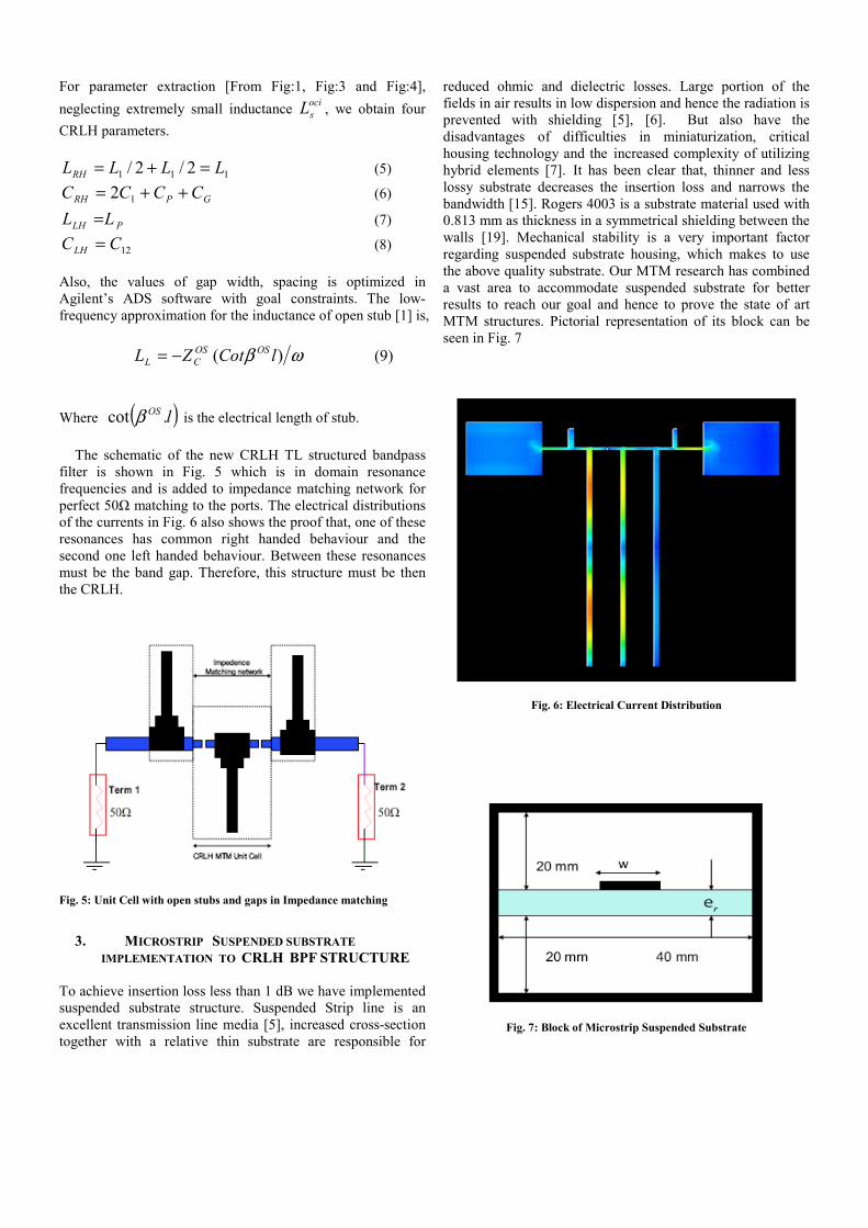
For parameter extraction [From Fig:1, Fig:3 and Fig:4], neglecting extremely small inductance oci
sL , we obtain four CRLH parameters.
111 2/2/ LLLLRH =+= (5)
GPRH CCCC ++= 12 (6)
PLH LL = (7)
12CCLH = (8) Also, the values of gap width, spacing is optimized in Agilent’s ADS software with goal constraints. The low-frequency approximation for the inductance of open stub [1] is, ωβ )( lCotZL OSOS
CL −= (9) Where ( )lOS .cot β is the electrical length of stub.
The schematic of the new CRLH TL structured bandpass filter is shown in Fig. 5 which is in domain resonance frequencies and is added to impedance matching network for perfect 50Ω matching to the ports. The electrical distributions of the currents in Fig. 6 also shows the proof that, one of these resonances has common right handed behaviour and the second one left handed behaviour. Between these resonances must be the band gap. Therefore, this structure must be then the CRLH.
Fig. 5: Unit Cell with open stubs and gaps in Impedance matching
3. MICROSTRIP SUSPENDED SUBSTRATE
IMPLEMENTATION TO CRLH BPF STRUCTURE
To achieve insertion loss less than 1 dB we have implemented suspended substrate structure. Suspended Strip line is an excellent transmission line media [5], increased cross-section together with a relative thin substrate are responsible for
reduced ohmic and dielectric losses. Large portion of the fields in air results in low dispersion and hence the radiation is prevented with shielding [5], [6]. But also have the disadvantages of difficulties in miniaturization, critical housing technology and the increased complexity of utilizing hybrid elements [7]. It has been clear that, thinner and less lossy substrate decreases the insertion loss and narrows the bandwidth [15]. Rogers 4003 is a substrate material used with 0.813 mm as thickness in a symmetrical shielding between the walls [19]. Mechanical stability is a very important factor regarding suspended substrate housing, which makes to use the above quality substrate. Our MTM research has combined a vast area to accommodate suspended substrate for better results to reach our goal and hence to prove the state of art MTM structures. Pictorial representation of its block can be seen in Fig. 7
Fig. 6: Electrical Current Distribution
Fig. 7: Block of Microstrip Suspended Substrate
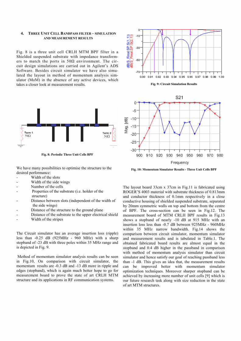
4. THREE UNIT CELL BANDPASS FILTER – SIMULATION AND MEASUREMENT RESULTS
Fig. 8 is a three unit cell CRLH MTM BPF filter in a Shielded suspended substrate with impedance transform- ers to match the ports in 50Ω environment. The cir- cuit design simulations are carried out in Agilent’s ADS Software. Besides circuit simulator we have also simu- lated the layout in method of momentum analysis sim- ulator (MoM) in the absence of any active devices, which takes a closer look at measurement results.
Fig. 8: Periodic Three Unit Cells BPF
We have many possibilities to optimise the structure to the desired performance: - Width of the slots - Width of the side wings - Number of the cells - Properties of the substrate (i.e. holder of the structure) - Distance between slots (independent of the width of the side wings) - Distance of the structure to the ground plane - Distance of the substrate to the upper electrical shield - Width of the stripes The Circuit simulator has an average insertion loss (ripple) less than -0.25 dB (925MHz - 960 MHz) with a sharp stopband of -23 dB with three poles within 35 MHz range and is depicted in Fig. 9. Method of momentum simulator analysis results can be seen in Fig.10, On comparison with circuit simulator, the momentum results are -0.3 dB and -13 dB more in ripple and edges (stopband), which is again much better hope to go for measurement board to prove the state of art CRLH MTM structure and its applications in RF communication systems.
Fig. 9: Circuit Simulation Results
Fig. 10: Momentum Simulator Results - Three Unit Cells BPF
The layout board 33cm x 37cm in Fig.11 is fabricated using ROGER’S 4003 material with substrate thickness of 0.813mm and conductor thickness of 0.1mm respectively in a close conductive housing of shielded suspended substrate, separated by 20mm symmetric walls on top and bottom from the centre of BPF. The cross-section can be seen in Fig.12. The measurement board of MTM CRLH BPF results in Fig.13 shows a stopband of nearly -10 dB at 915 MHz with an insertion loss less than -0.7 dB between 925MHz - 960MHz within 35 MHz narrow bandwidth. Fig.14 shows the comparison between circuit simulator, momentum simulator and measurement results and is tabulated in Table.1. The obtained fabricated board results are almost equal in the stopband and 0.4 dB higher in the passband in comparison with method of momentum analysis simulator than circuit simulator and hence satisfy our goal of reaching passband less than -1 dB. This gives an idea that, the measurement results can be improved better with momentum simulator optimization techniques. Moreover sharper stopband can be achieved by increasing more number of unit cells [9] which is our future research task along with size reduction in the state of art MTM structures.
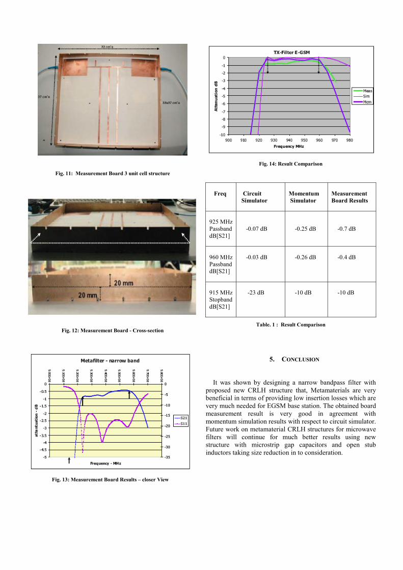
Fig. 11: Measurement Board 3 unit cell structure
Fig. 12: Measurement Board - Cross-section
Fig. 13: Measurement Board Results – closer View
Fig. 14: Result Comparison
Freq
Circuit Simulator
Momentum Simulator
Measurement Board Results
925 MHz Passband dB[S21]
-0.07 dB
-0.25 dB
-0.7 dB
960 MHz Passband dB[S21]
-0.03 dB
-0.26 dB
-0.4 dB
915 MHz Stopband dB[S21]
-23 dB
-10 dB
-10 dB
Table. 1 : Result Comparison
5. CONCLUSION It was shown by designing a narrow bandpass filter with
proposed new CRLH structure that, Metamaterials are very beneficial in terms of providing low insertion losses which are very much needed for EGSM base station. The obtained board measurement result is very good in agreement with momentum simulation results with respect to circuit simulator. Future work on metamaterial CRLH structures for microwave filters will continue for much better results using new structure with microstrip gap capacitors and open stub inductors taking size reduction in to consideration.
6. ACKNOWLEDGEMENT The author Shaik Geelani would like to thank his co-author,
Prof. Georg Fischer for the creation of Doctorate opportunity as well to gain professional experience at Bell Labs Europe. He also would like to thank Bell Labs Nuremberg Team, especially Michael Doubrava and Dr. Michael Sollner for their support during the research.
Further he wants to thank the German Ministry of research
and education (BMBF) for funding part of this work under MARIO project (Metamaterial based flexible duplex filters).
REFERENCES
[1] C. Caloz, T. Itoh, Electromagnetic Metamaterial, IEEE press, Wiley, Hoboken NJ, 2006
[2] Gunther Dehm-Andone, Grzegorz Adamiuk, Georg Fischer; Using Metamaterial structures with frequency agile base stations, IEEE GEMIC 2006.
[3] C. Caloz, H. Okabe, T. Iwai, and T. Itoh, “Transmission line approach of left-handed (LH) materials”, in USNC/URSI Nat. Radio Science Meeting, vol. 1, Jun. 2002, p. 39
[4] Benedek, P. Silvester, P., Equivalent Capacitances for Microstrip Gaps and Steps Microwave Theory and Techniques, IEEE Transactions on Volume 20, Issue 11, Nov 1972 Page(s):729 – 733.
[5] Bekheit, M.; Amari, S.; Menzel, W, Modelling and Optimization of Compact Microwave Bandpass Filters. Microwave Theory and Techniques, IEEE Transactions on Volume 56, Issue 2, Feb. 2008 Page(s):420 – 430
[6] W. Menzel, A. Balalem: Quasi-Lumped Suspended Stripline Filters and Diplexers. IEEE Trans. on MTT, vol.MTT-53, Oct. 2005, pp. 3230 – 3237
[7] Anu Lehtovuori and Luis Costa, Model for Shielded Suspended Substrate Microstrip Line, Circuit Theory Laboratory Report Series, Helsinki University of Technology 1998.
[8] A. Lai, T. Itoh, "Composite Right/Left-Handed Transmission Line Metamaterials", IEEE Microwave Magazine, pp.34-50, Sept. 2004.
[9] I-H. Lin, M. DeVincentis, C. Caloz, T. Itoh, "Arbitrary Dual-Band Components Using Composite Right/Left-Handed Transmission Lines", IEEE Transactions on Microwave Theory and Technique, Vol. 52, No.4, April 2004.
[10] Islam, R.; Eleftheriades, G.V.; Antennas and Propagation International Symposium, 2007 IEEE 9-15 June 2007 Page(s):4957 - 4960Compact Negative-Refractive-Index Transmission-Line (NRI-TL) coupler, filter and diplexer
[11] C. Caloz, A. Sanada, T. Itoh, "A novel Composite Right-/Left-Handed Coupled-Line Directional Coupler With Arbitrary Coupling Level and Broad Bandwidth", IEEE Transactions on Microwave Theory and Techniques, Vol. 52, No.3, March 2004.
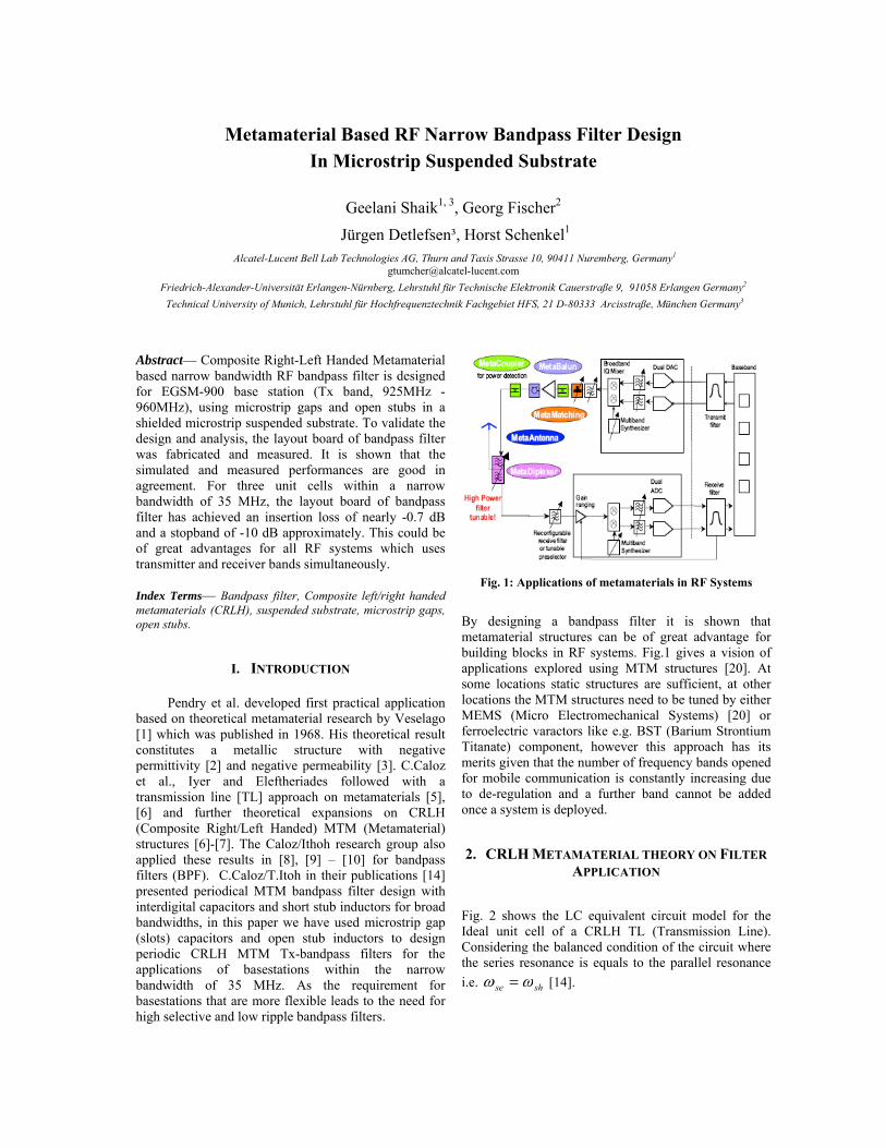
Metamaterial Based RF Narrow Bandpass Filter Design In Microstrip Suspended Substrate
Geelani Shaik1, 3, Georg Fischer2
Jürgen Detlefsen³, Horst Schenkel1 Alcatel-Lucent Bell Lab Technologies AG, Thurn and Taxis Strasse 10, 90411 Nuremberg, Germany1
[email protected] Friedrich-Alexander-Universität Erlangen-Nürnberg, Lehrstuhl für Technische Elektronik Cauerstraße 9, 91058 Erlangen Germany2 Technical University of Munich, Lehrstuhl für Hochfrequenztechnik Fachgebiet HFS, 21 D-80333 Arcisstraße, München Germany3
Abstract— Composite Right-Left Handed Metamaterial based narrow bandwidth RF bandpass filter is designed for EGSM-900 base station (Tx band, 925MHz - 960MHz), using microstrip gaps and open stubs in a shielded microstrip suspended substrate. To validate the design and analysis, the layout board of bandpass filter was fabricated and measured. It is shown that the simulated and measured performances are good in agreement. For three unit cells within a narrow bandwidth of 35 MHz, the layout board of bandpass filter has achieved an insertion loss of nearly -0.7 dB and a stopband of -10 dB approximately. This could be of great advantages for all RF systems which uses transmitter and receiver bands simultaneously. Index Terms— Bandpass filter, Composite left/right handed metamaterials (CRLH), suspended substrate, microstrip gaps, open stubs.
I. INTRODUCTION
Pendry et al. developed first practical application based on theoretical metamaterial research by Veselago [1] which was published in 1968. His theoretical result constitutes a metallic structure with negative permittivity [2] and negative permeability [3]. C.Caloz et al., Iyer and Eleftheriades followed with a transmission line [TL] approach on metamaterials [5], [6] and further theoretical expansions on CRLH (Composite Right/Left Handed) MTM (Metamaterial) structures [6]-[7]. The Caloz/Ithoh research group also applied these results in [8], [9] – [10] for bandpass filters (BPF). C.Caloz/T.Itoh in their publications [14] presented periodical MTM bandpass filter design with interdigital capacitors and short stub inductors for broad bandwidths, in this paper we have used microstrip gap (slots) capacitors and open stub inductors to design periodic CRLH MTM Tx-bandpass filters for the applications of basestations within the narrow bandwidth of 35 MHz. As the requirement for basestations that are more flexible leads to the need for high selective and low ripple bandpass filters.
Fig. 1: Applications of metamaterials in RF Systems
By designing a bandpass filter it is shown that metamaterial structures can be of great advantage for building blocks in RF systems. Fig.1 gives a vision of applications explored using MTM structures [20]. At some locations static structures are sufficient, at other locations the MTM structures need to be tuned by either MEMS (Micro Electromechanical Systems) [20] or ferroelectric varactors like e.g. BST (Barium Strontium Titanate) component, however this approach has its merits given that the number of frequency bands opened for mobile communication is constantly increasing due to de-regulation and a further band cannot be added once a system is deployed.
2. CRLH METAMATERIAL THEORY ON FILTER APPLICATION
Fig. 2 shows the LC equivalent circuit model for the Ideal unit cell of a CRLH TL (Transmission Line). Considering the balanced condition of the circuit where the series resonance is equals to the parallel resonance i.e. shse ωω = [14].
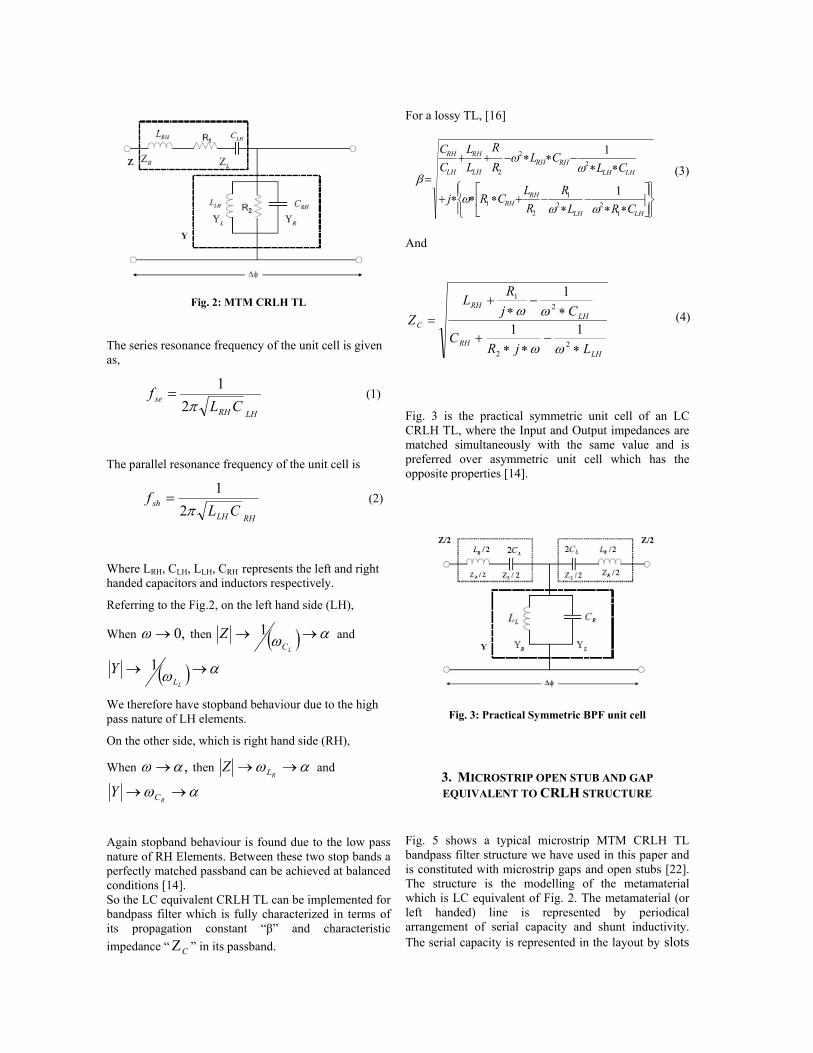
Fig. 2: MTM CRLH TL
The series resonance frequency of the unit cell is given as,
LHRH
se CLf
π21
= (1)
The parallel resonance frequency of the unit cell is
RHLH
sh CLf
π21
= (2)
Where LRH, CLH, LLH, CRH represents the left and right handed capacitors and inductors respectively.
Referring to the Fig.2, on the left hand side (LH),
When ,0→ω then ( ) αω →→LC
Z 1 and
( ) αω →→LL
Y 1
We therefore have stopband behaviour due to the high pass nature of LH elements.
On the other side, which is right hand side (RH),
When ,αω → then αω →→RLZ and
αω →→RCY
Again stopband behaviour is found due to the low pass nature of RH Elements. Between these two stop bands a perfectly matched passband can be achieved at balanced conditions [14]. So the LC equivalent CRLH TL can be implemented for bandpass filter which is fully characterized in terms of its propagation constant “β” and characteristic impedance “ CΖ ” in its passband.
For a lossy TL, [16]
⎪⎭
⎪⎬⎫
⎪⎩
⎪⎨⎧
⎥⎦
⎤⎢⎣
⎡
∗∗−
∗−+∗∗∗+
∗∗−∗∗−++
=
LHLH
RHRH
LHLHRHRH
LH
RH
LH
RH
CRLR
RL
CRj
CLCL
RR
LL
CC
122
1
21
22
2
1
1
ωωω
ωω
β (3)
And
LHRH
LHRH
C
LjRC
CjRL
Z
∗−
∗∗+
∗−
∗+
=
22
21
11
1
ωω
ωω (4)
Fig. 3 is the practical symmetric unit cell of an LC CRLH TL, where the Input and Output impedances are matched simultaneously with the same value and is preferred over asymmetric unit cell which has the opposite properties [14].
Fig. 3: Practical Symmetric BPF unit cell
3. MICROSTRIP OPEN STUB AND GAP EQUIVALENT TO CRLH STRUCTURE
Fig. 5 shows a typical microstrip MTM CRLH TL bandpass filter structure we have used in this paper and is constituted with microstrip gaps and open stubs [22]. The structure is the modelling of the metamaterial which is LC equivalent of Fig. 2. The metamaterial (or left handed) line is represented by periodical arrangement of serial capacity and shunt inductivity. The serial capacity is represented in the layout by slots
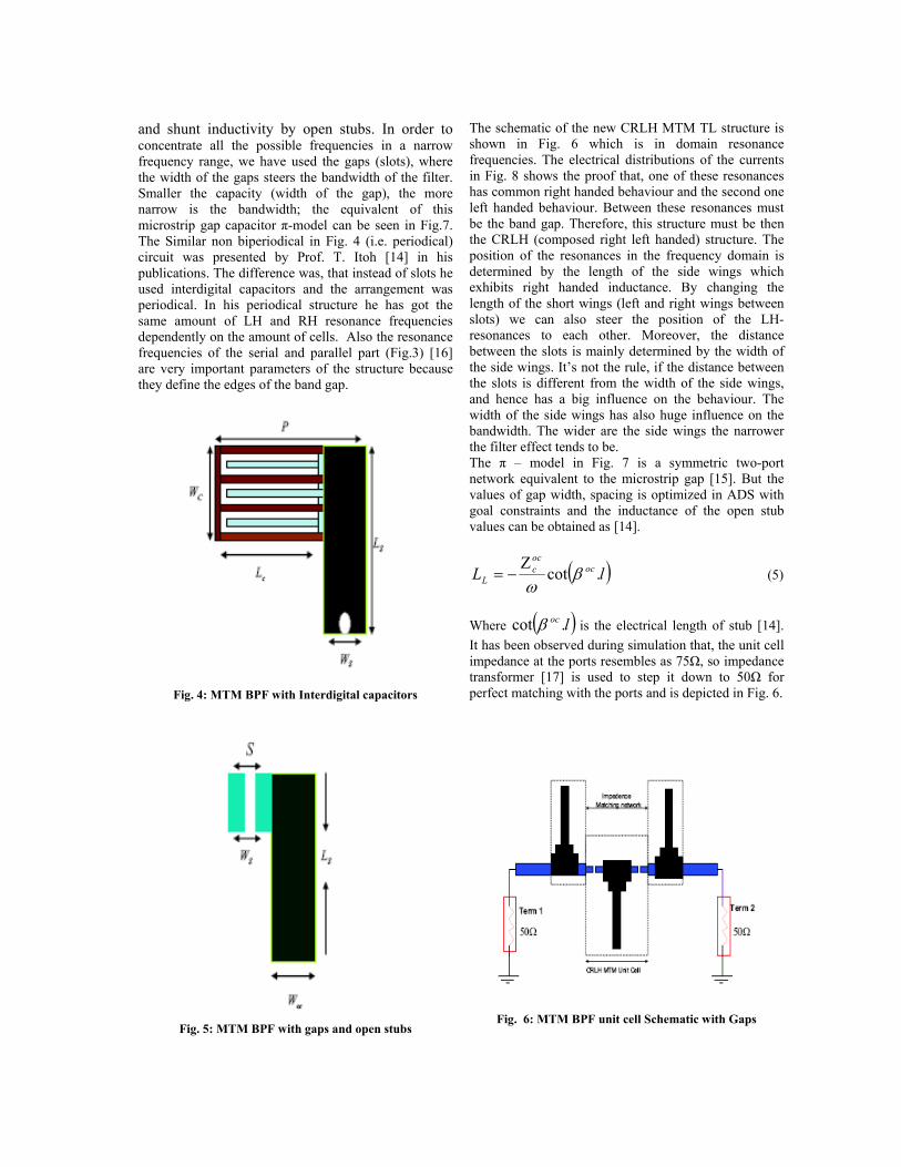
and shunt inductivity by open stubs. In order to concentrate all the possible frequencies in a narrow frequency range, we have used the gaps (slots), where the width of the gaps steers the bandwidth of the filter. Smaller the capacity (width of the gap), the more narrow is the bandwidth; the equivalent of this microstrip gap capacitor π-model can be seen in Fig.7. The Similar non biperiodical in Fig. 4 (i.e. periodical) circuit was presented by Prof. T. Itoh [14] in his publications. The difference was, that instead of slots he used interdigital capacitors and the arrangement was periodical. In his periodical structure he has got the same amount of LH and RH resonance frequencies dependently on the amount of cells. Also the resonance frequencies of the serial and parallel part (Fig.3) [16] are very important parameters of the structure because they define the edges of the band gap.
Fig. 4: MTM BPF with Interdigital capacitors
Fig. 5: MTM BPF with gaps and open stubs
The schematic of the new CRLH MTM TL structure is shown in Fig. 6 which is in domain resonance frequencies. The electrical distributions of the currents in Fig. 8 shows the proof that, one of these resonances has common right handed behaviour and the second one left handed behaviour. Between these resonances must be the band gap. Therefore, this structure must be then the CRLH (composed right left handed) structure. The position of the resonances in the frequency domain is determined by the length of the side wings which exhibits right handed inductance. By changing the length of the short wings (left and right wings between slots) we can also steer the position of the LH-resonances to each other. Moreover, the distance between the slots is mainly determined by the width of the side wings. It’s not the rule, if the distance between the slots is different from the width of the side wings, and hence has a big influence on the behaviour. The width of the side wings has also huge influence on the bandwidth. The wider are the side wings the narrower the filter effect tends to be. The π – model in Fig. 7 is a symmetric two-port network equivalent to the microstrip gap [15]. But the values of gap width, spacing is optimized in ADS with goal constraints and the inductance of the open stub values can be obtained as [14].
( )lL ococc
L .cot βωΖ
−= (5)
Where ( )loc .cot β is the electrical length of stub [14]. It has been observed during simulation that, the unit cell impedance at the ports resembles as 75Ω, so impedance transformer [17] is used to step it down to 50Ω for perfect matching with the ports and is depicted in Fig. 6.
Fig. 6: MTM BPF unit cell Schematic with Gaps
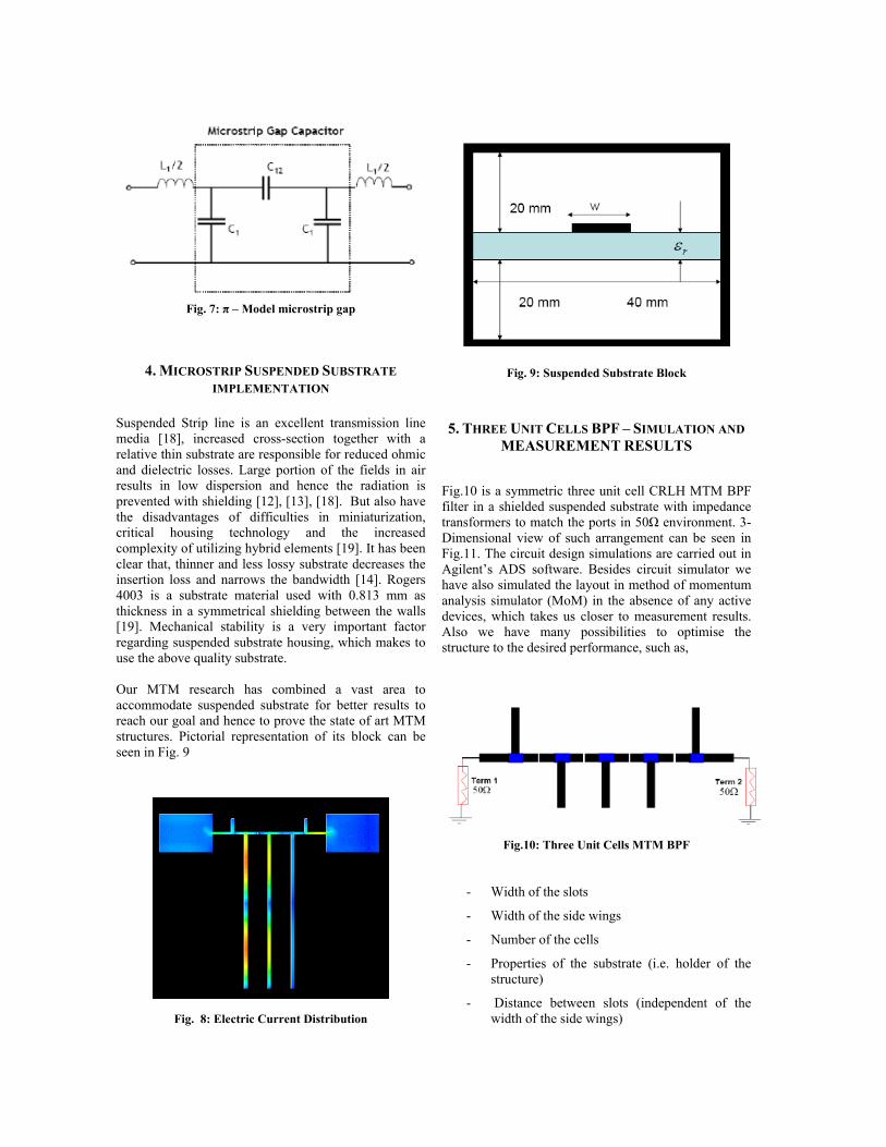
Fig. 7: π – Model microstrip gap
4. MICROSTRIP SUSPENDED SUBSTRATE IMPLEMENTATION
Suspended Strip line is an excellent transmission line media [18], increased cross-section together with a relative thin substrate are responsible for reduced ohmic and dielectric losses. Large portion of the fields in air results in low dispersion and hence the radiation is prevented with shielding [12], [13], [18]. But also have the disadvantages of difficulties in miniaturization, critical housing technology and the increased complexity of utilizing hybrid elements [19]. It has been clear that, thinner and less lossy substrate decreases the insertion loss and narrows the bandwidth [14]. Rogers 4003 is a substrate material used with 0.813 mm as thickness in a symmetrical shielding between the walls [19]. Mechanical stability is a very important factor regarding suspended substrate housing, which makes to use the above quality substrate. Our MTM research has combined a vast area to accommodate suspended substrate for better results to reach our goal and hence to prove the state of art MTM structures. Pictorial representation of its block can be seen in Fig. 9
Fig. 8: Electric Current Distribution
Fig. 9: Suspended Substrate Block
5. THREE UNIT CELLS BPF – SIMULATION AND
MEASUREMENT RESULTS
Fig.10 is a symmetric three unit cell CRLH MTM BPF filter in a shielded suspended substrate with impedance transformers to match the ports in 50Ω environment. 3-Dimensional view of such arrangement can be seen in Fig.11. The circuit design simulations are carried out in Agilent’s ADS software. Besides circuit simulator we have also simulated the layout in method of momentum analysis simulator (MoM) in the absence of any active devices, which takes us closer to measurement results. Also we have many possibilities to optimise the structure to the desired performance, such as,
Fig.10: Three Unit Cells MTM BPF
- Width of the slots
- Width of the side wings
- Number of the cells
- Properties of the substrate (i.e. holder of the structure)
- Distance between slots (independent of the width of the side wings)
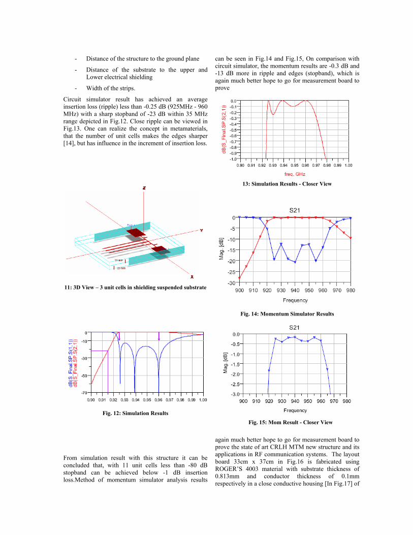
- Distance of the structure to the ground plane
- Distance of the substrate to the upper and Lower electrical shielding
- Width of the strips.
Circuit simulator result has achieved an average insertion loss (ripple) less than -0.25 dB (925MHz - 960 MHz) with a sharp stopband of -23 dB within 35 MHz range depicted in Fig.12. Close ripple can be viewed in Fig.13. One can realize the concept in metamaterials, that the number of unit cells makes the edges sharper [14], but has influence in the increment of insertion loss.
11: 3D View – 3 unit cells in shielding suspended substrate
Fig. 12: Simulation Results
From simulation result with this structure it can be concluded that, with 11 unit cells less than -80 dB stopband can be achieved below -1 dB insertion loss.Method of momentum simulator analysis results
can be seen in Fig.14 and Fig.15, On comparison with circuit simulator, the momentum results are -0.3 dB and -13 dB more in ripple and edges (stopband), which is again much better hope to go for measurement board to prove
13: Simulation Results - Closer View
Fig. 14: Momentum Simulator Results
Fig. 15: Mom Result - Closer View
again much better hope to go for measurement board to prove the state of art CRLH MTM new structure and its applications in RF communication systems. The layout board 33cm x 37cm in Fig.16 is fabricated using ROGER’S 4003 material with substrate thickness of 0.813mm and conductor thickness of 0.1mm respectively in a close conductive housing [In Fig.17] of
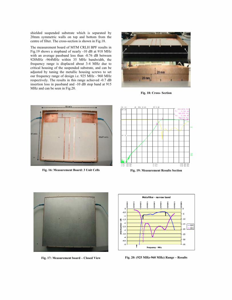
shielded suspended substrate which is separated by 20mm symmetric walls on top and bottom from the centre of filter. The cross-section is shown in Fig.18.
The measurement board of MTM CRLH BPF results in Fig.19 shows a stopband of nearly -10 dB at 918 MHz with an average passband less than -0.76 dB between 928MHz -964MHz within 35 MHz bandwidth, the frequency range is displaced about 3-4 MHz due to critical housing of the suspended substrate, and can be adjusted by tuning the metallic housing screws to set our frequency range of design i.e. 925 MHz - 960 MHz respectively. The results in this range achieved -0.7 dB insertion loss in passband and -10 dB stop band at 915 MHz and can be seen in Fig.20.
Fig. 16: Measurement Board: 3 Unit Cells
Fig. 17: Measurement board – Closed View
Fig. 18: Cross- Section
Fig. 19: Measurement Results Section
Fig. 20: (925 MHz-960 MHz) Range – Results
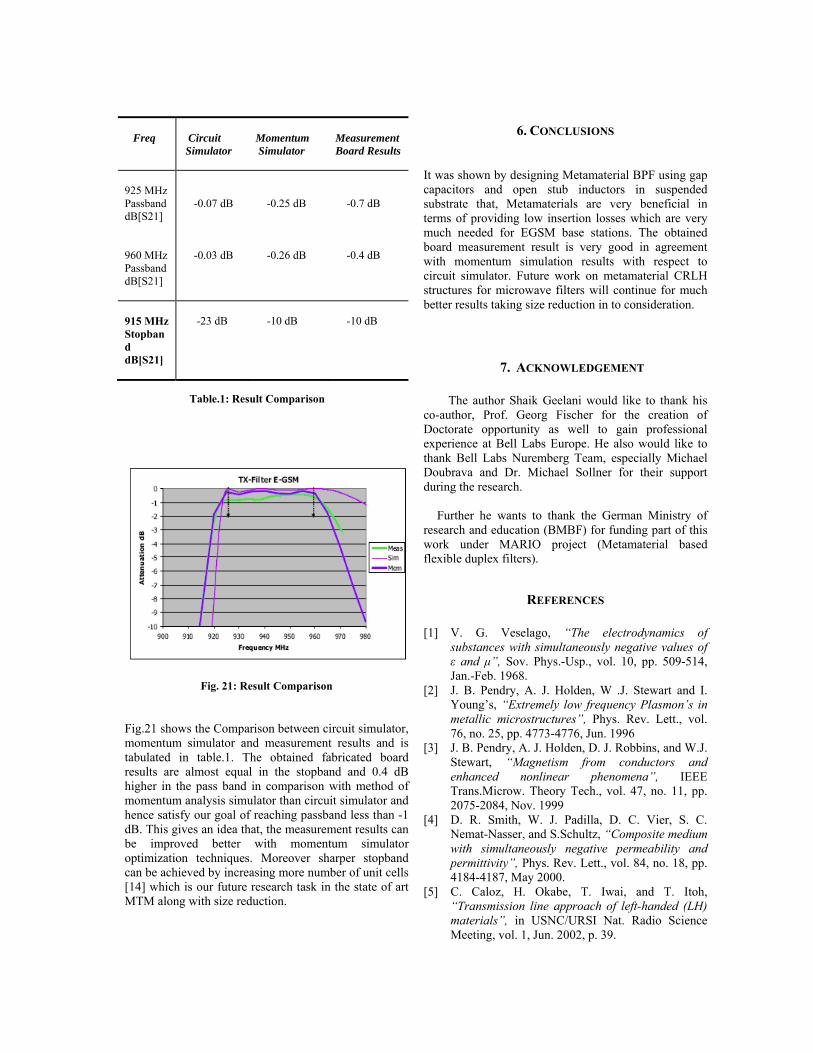
Fig. 21: Result Comparison Fig.21 shows the Comparison between circuit simulator, momentum simulator and measurement results and is tabulated in table.1. The obtained fabricated board results are almost equal in the stopband and 0.4 dB higher in the pass band in comparison with method of momentum analysis simulator than circuit simulator and hence satisfy our goal of reaching passband less than -1 dB. This gives an idea that, the measurement results can be improved better with momentum simulator optimization techniques. Moreover sharper stopband can be achieved by increasing more number of unit cells [14] which is our future research task in the state of art MTM along with size reduction.
6. CONCLUSIONS
It was shown by designing Metamaterial BPF using gap capacitors and open stub inductors in suspended substrate that, Metamaterials are very beneficial in terms of providing low insertion losses which are very much needed for EGSM base stations. The obtained board measurement result is very good in agreement with momentum simulation results with respect to circuit simulator. Future work on metamaterial CRLH structures for microwave filters will continue for much better results taking size reduction in to consideration.
7. ACKNOWLEDGEMENT
The author Shaik Geelani would like to thank his co-author, Prof. Georg Fischer for the creation of Doctorate opportunity as well to gain professional experience at Bell Labs Europe. He also would like to thank Bell Labs Nuremberg Team, especially Michael Doubrava and Dr. Michael Sollner for their support during the research.
Further he wants to thank the German Ministry of
research and education (BMBF) for funding part of this work under MARIO project (Metamaterial based flexible duplex filters).
REFERENCES
[1] V. G. Veselago, “The electrodynamics of substances with simultaneously negative values of ε and μ”, Sov. Phys.-Usp., vol. 10, pp. 509-514, Jan.-Feb. 1968.
[2] J. B. Pendry, A. J. Holden, W .J. Stewart and I. Young’s, “Extremely low frequency Plasmon’s in metallic microstructures”, Phys. Rev. Lett., vol. 76, no. 25, pp. 4773-4776, Jun. 1996
[3] J. B. Pendry, A. J. Holden, D. J. Robbins, and W.J. Stewart, “Magnetism from conductors and enhanced nonlinear phenomena”, IEEE Trans.Microw. Theory Tech., vol. 47, no. 11, pp. 2075-2084, Nov. 1999
[4] D. R. Smith, W. J. Padilla, D. C. Vier, S. C. Nemat-Nasser, and S.Schultz, “Composite medium with simultaneously negative permeability and permittivity”, Phys. Rev. Lett., vol. 84, no. 18, pp. 4184-4187, May 2000.
[5] C. Caloz, H. Okabe, T. Iwai, and T. Itoh, “Transmission line approach of left-handed (LH) materials”, in USNC/URSI Nat. Radio Science Meeting, vol. 1, Jun. 2002, p. 39.
Table.1: Result Comparison
Freq
Circuit Simulator
Momentum Simulator
Measurement Board Results
925 MHz Passband dB[S21]
-0.07 dB
-0.25 dB
-0.7 dB
960 MHz Passband dB[S21]
-0.03 dB
-0.26 dB
-0.4 dB
915 MHz Stopband dB[S21]
-23 dB
-10 dB
-10 dB
[6] A. K. Iyer and G. V. Eleftheriades, “Negative refractive index Metamaterial supporting 2-D waves”, in IEEE MTT-S Int. Microwave Symp. Dig., vol. 2, Jun. 2002, pp. 1067 1070.
[7] D. R. Smith and N. Kroll, “Negative refractive index in left-handed materials”, Phys. Rev. Lett., vol. 85, no. 14, pp. 2933-2936, Oct. 2000.
[8] A. Lai, T. Itoh, "Composite Right/Left-Handed Transmission Line Metamaterials", IEEE Microwave Magazine, pp.34-50, Sept. 2004.
[9] I-H. Lin, M. DeVincentis, C. Caloz, T. Itoh, "Arbitrary Dual-Band Components Using Composite Right/Left-Handed Transmission Lines", IEEE Transactions on Microwave Theory and Technique, Vol. 52, No.4, April 2004.
[10] C. Caloz, A. Sanada, T. Itoh, "A novel Composite Right-/Left-Handed Coupled-Line Directional Coupler With Arbitrary Coupling Level and broad bandwidth", IEEE Transactions on Microwave Theory and Techniques, Vol. 52, No.3, March 2004.
[11] H. Okabe, C. Caloz, T. Itoh, "A Compact Enhanced-Bandwidth Hybrid Ring Using an Artificial Lumped-Element Left-Handed Transmission-Line Section", IEEE Transactions on Microwave Theory and Technique, Vol. 52, No.3, March 2004.
[12] W. Menzel, A. Balalem: "Quasi-Lumped Suspended Stripline Filters and Diplexers", IEEE Trans. on MTT, vol.MTT-53, Oct. 2005, pp. 3230 – 3237.
[13] J. E. Dean: "Suspended substrate stripline filters for ESM applications". IEE Proc., Vol. 132, Pt. F, July 1985, pp.257 - 266.
[14] C. Caloz, T. Itoh, "Electromagnetic Metamaterial", IEEE press, Wiley, Hoboken NJ, 2006
[15] Benedek, P. Silvester, P., "Equivalent Capacitances for Microstrip Gaps and Steps Microwave Theory and Techniques", IEEE Transactions on Volume 20, Issue 11, Nov 1972 Page(s):729 – 733.
[16] Gunther Dehm-Andone, Grzegorz Adamiuk, Georg Fischer; "Using Metamaterial structures with frequency agile base stations", IEEE GEMIC 2006.
[17] Lei Zhu, Huamin Shi; Menzel:, "W Coupling behaviours’ of quarter-wavelength impedance transformers for wideband CPW bandpass filte"., Microwave and Wireless Components Letters, IEEE Volume 15, Issue 1, Jan. 2005 Page(s):13 – 15.
[18] Bekheit, M.; Amari, S.; Menzel, "W, Modelling and Optimization of Compact Microwave Bandpass Filters. Microwave Theory and Techniques", IEEE Transactions on Volume 56, Issue 2, Feb. 2008 Page(s):420 – 430.
[19] Anu Lehtovuori and Luis Costa, "Model for Shielded Suspended Substrate Microstrip Line", Circuit Theory Laboratory Report Series, Helsinki University of Technology 1998.
[20] G. Fischer, “Architectural benefits of wide band gap RF power transistors for frequency agile base station systems ", IEEE MTT, 6th annual Wireless and Microwave Technology Conference, Clearwater, Florida, April 2004.
[21] Islam, R.; Eleftheriades, G.V, "Compact-Negative-Refractive-IndexTransmission-Line (NRI-TL) coupler, filter and diplexer", Antennas and Propagation International Symposium, 2007 IEEE 9-15 June 2007 Page(s):4957 - 4960
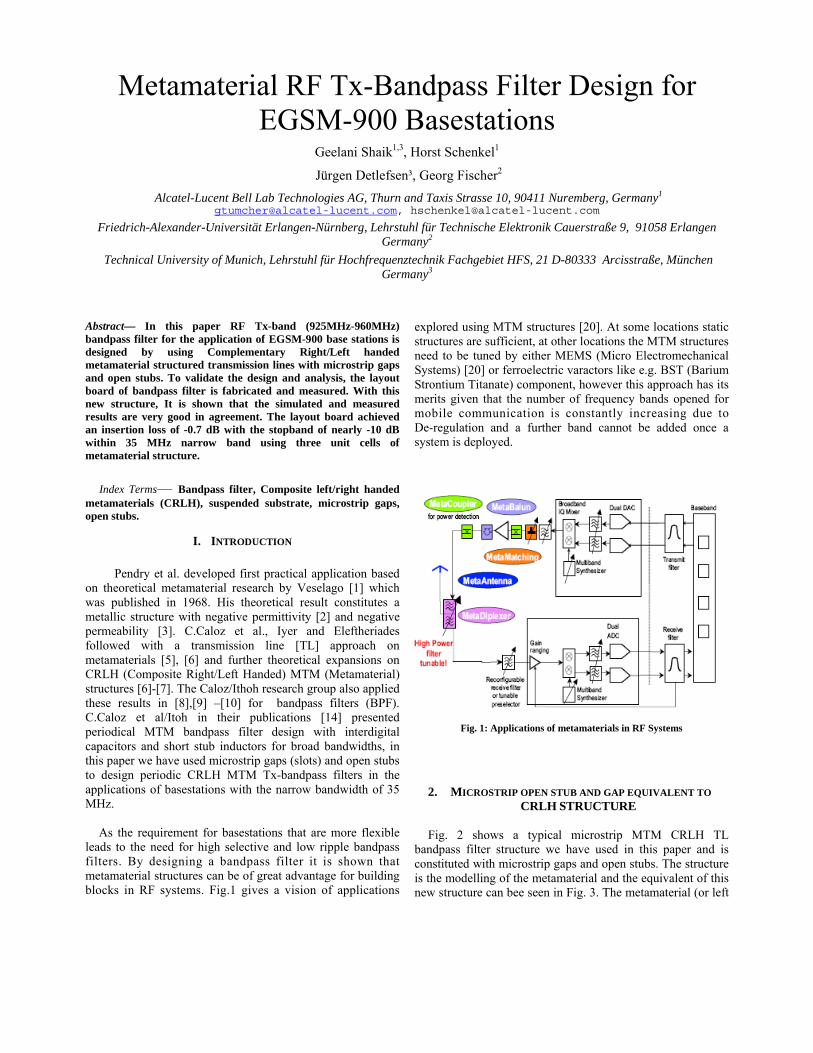
Metamaterial RF Tx-Bandpass Filter Design for EGSM-900 Basestations
Geelani Shaik1,3, Horst Schenkel1
Jürgen Detlefsen³, Georg Fischer2 Alcatel-Lucent Bell Lab Technologies AG, Thurn and Taxis Strasse 10, 90411 Nuremberg, Germany1
[email protected], [email protected]
Friedrich-Alexander-Universität Erlangen-Nürnberg, Lehrstuhl für Technische Elektronik Cauerstraße 9, 91058 Erlangen Germany2
Technical University of Munich, Lehrstuhl für Hochfrequenztechnik Fachgebiet HFS, 21 D-80333 Arcisstraße, München Germany3
Abstract— In this paper RF Tx-band (925MHz-960MHz) bandpass filter for the application of EGSM-900 base stations is designed by using Complementary Right/Left handed metamaterial structured transmission lines with microstrip gaps and open stubs. To validate the design and analysis, the layout board of bandpass filter is fabricated and measured. With this new structure, It is shown that the simulated and measured results are very good in agreement. The layout board achieved an insertion loss of -0.7 dB with the stopband of nearly -10 dB within 35 MHz narrow band using three unit cells of metamaterial structure. Index Terms— Bandpass filter, Composite left/right handed metamaterials (CRLH), suspended substrate, microstrip gaps, open stubs.
I. INTRODUCTION Pendry et al. developed first practical application based
on theoretical metamaterial research by Veselago [1] which was published in 1968. His theoretical result constitutes a metallic structure with negative permittivity [2] and negative permeability [3]. C.Caloz et al., Iyer and Eleftheriades followed with a transmission line [TL] approach on metamaterials [5], [6] and further theoretical expansions on CRLH (Composite Right/Left Handed) MTM (Metamaterial) structures [6]-[7]. The Caloz/Ithoh research group also applied these results in [8],[9] –[10] for bandpass filters (BPF). C.Caloz et al/Itoh in their publications [14] presented periodical MTM bandpass filter design with interdigital capacitors and short stub inductors for broad bandwidths, in this paper we have used microstrip gaps (slots) and open stubs to design periodic CRLH MTM Tx-bandpass filters in the applications of basestations with the narrow bandwidth of 35 MHz.
As the requirement for basestations that are more flexible
leads to the need for high selective and low ripple bandpass filters. By designing a bandpass filter it is shown that metamaterial structures can be of great advantage for building blocks in RF systems. Fig.1 gives a vision of applications
explored using MTM structures [20]. At some locations static structures are sufficient, at other locations the MTM structures need to be tuned by either MEMS (Micro Electromechanical Systems) [20] or ferroelectric varactors like e.g. BST (Barium Strontium Titanate) component, however this approach has its merits given that the number of frequency bands opened for mobile communication is constantly increasing due to De-regulation and a further band cannot be added once a system is deployed.
Fig. 1: Applications of metamaterials in RF Systems
2. MICROSTRIP OPEN STUB AND GAP EQUIVALENT TO CRLH STRUCTURE
Fig. 2 shows a typical microstrip MTM CRLH TL
bandpass filter structure we have used in this paper and is constituted with microstrip gaps and open stubs. The structure is the modelling of the metamaterial and the equivalent of this new structure can bee seen in Fig. 3. The metamaterial (or left
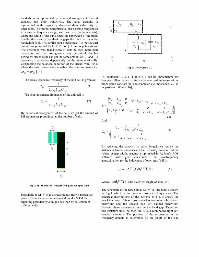
handed) line is represented by periodical arrangement of serial capacity and shunt inductivity. The serial capacity is represented in the layout by slots and shunt inductivity by open stubs. In order to concentrate all the possible frequencies in a narrow frequency range, we have used the gaps (slots), where the width of the gaps steers the bandwidth of the filter. Smaller the capacity (width of the gap), the more narrow is the bandwidth [16]. The similar non biperiodical (i.e. periodical) circuit was presented by Prof. T. Itoh [14] in his publications. The difference was, that instead of slots he used interdigital capacitors and the arrangement was periodical. In his periodical structure he has got the same amount of LH and RH resonance frequencies dependently on the amount of cells. Considering the balanced condition of the circuit from Fig.3, where the series resonance is equals to the shunt resonance i.e.
shse ωω = [14] The series resonance frequency of the unit cell is given as,
LHRH
se CLf
π21
= (1)
The shunt resonance frequency of the unit cell is
RHLH
sh CLf
π21
= (2)
By periodical arrangement of the cells we get the amount of LH-resonances propotional to the number of cells.
Fig. 2: MTM unit cell structure with gaps and open stubs
Periodicity in MTM is just convenience, from a fabrication point of view its easier to design and build a MTM by repeating periodically a unique cell than by collection of different cells.
Fig. 3: Lossy CRLH TL
LC equivalent CRLH TL in Fig. 2 can be implemented for bandpass filter which is fully characterized in terms of its propagation constant “β” and characteristic impedance “Zc” in its passband. Where [16],
⎪⎭
⎪⎬⎫
⎪⎩
⎪⎨⎧
⎥⎦
⎤⎢⎣
⎡∗∗
−∗
−+∗∗∗+
∗∗−∗∗−++
=
LHLH
RHRH
LHLHRHRH
LH
RH
LH
RH
CRLR
RLCRj
CLCL
RR
LL
CC
122
1
21
22
2
1
1
ωωω
ωω
β
(3) And
LHRH
LHRH
C
LjRC
CjRL
Z
∗−
∗∗+
∗−
∗+
=
22
21
11
1
ωω
ωω (4)
By reducing the capacity in serial branch we reduce the distance between resonances in the frequency domain. But the values of gap width, spacing is optimized in Agilent’s ADS software with goal constraints. The low-frequency approximation for the inductance of open stub [14] is, ωβ )( lCotZL OSOS
CL −= (5) Where ( )lOSβcot is the electrical length of stub [14]. The schematic of the new CRLH MTM TL structure is shown in Fig.4 which is in domain resonance frequencies. The electrical distributions of the currents in Fig. 5 shows the proof that, one of these resonances has common right handed behaviour and the second one left handed behaviour. Between these resonances must be the band gap. Therefore, this structure must be then the CRLH (composed right left handed) structure. The position of the resonances in the frequency domain is determined by the length of the side
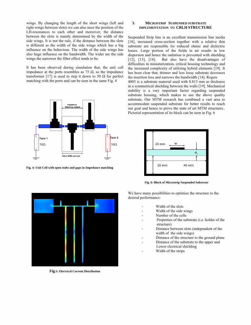
wings. By changing the length of the short wings (left and right wings between slots) we can also steer the position of the LH-resonances to each other and moreover, the distance between the slots is mainly determined by the width of the side wings. It is not the rule, if the distance between the slots is different as the width of the side wings which has a big influence on the behaviour. The width of the side wings has also huge influence on the bandwidth. The wider are the side wings the narrower the filter effect tends to be. It has been observed during simulation that, the unit cell impedance at the ports resembles as 75 Ω, so the impedance transformer [17] is used to step it down to 50 Ω for perfect matching with the ports and can be seen in the same Fig. 4
Fig. 4: Unit Cell with open stubs and gaps in Impedance matching
Fig.5: Electrical Current Distribution
3. MICROSTRIP SUSPENDED SUBSTRATE IMPLEMENTATION TO CRLH STRUCTURE
Suspended Strip line is an excellent transmission line media [18], increased cross-section together with a relative thin substrate are responsible for reduced ohmic and dielectric losses. Large portion of the fields in air results in low dispersion and hence the radiation is prevented with shielding [12], [13], [18]. But also have the disadvantages of difficulties in miniaturization, critical housing technology and the increased complexity of utilizing hybrid elements [19]. It has been clear that, thinner and less lossy substrate decreases the insertion loss and narrows the bandwidth [14]. Rogers 4003 is a substrate material used with 0.813 mm as thickness in a symmetrical shielding between the walls [19]. Mechanical stability is a very important factor regarding suspended substrate housing, which makes to use the above quality substrate. Our MTM research has combined a vast area to accommodate suspended substrate for better results to reach our goal and hence to prove the state of art MTM structures.. Pictorial representation of its block can be seen in Fig. 6
Fig. 6: Block of Microstrip Suspended Substrate
We have many possibilities to optimise the structure to the desired performance:
- Width of the slots - Width of the side wings - Number of the cells - Properties of the substrate (i.e. holder of the
structure) - Distance between slots (independent of the width of the side wings) - Distance of the structure to the ground plane - Distance of the substrate to the upper and Lower electrical shielding - Width of the strips
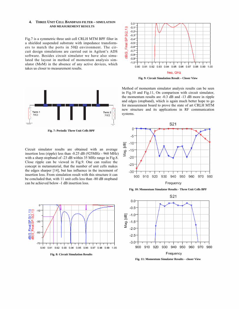
4. THREE UNIT CELL BANDPASS FILTER – SIMULATION AND MEASUREMENT RESULTS
Fig.7 is a symmetric three unit cell CRLH MTM BPF filter in a shielded suspended substrate with impedance transform- ers to match the ports in 50Ω environment. The cir- cuit design simulations are carried out in Agilent’s ADS software. Besides circuit simulator we have also simu- lated the layout in method of momentum analysis sim- ulator (MoM) in the absence of any active devices, which takes us closer to measurement results.
Fig. 7: Periodic Three Unit Cells BPF
Circuit simulator results are obtained with an average insertion loss (ripple) less than -0.25 dB (925MHz - 960 MHz) with a sharp stopband of -23 dB within 35 MHz range in Fig.8. Close ripple can be viewed in Fig.9. One can realize the concept in metamaterial, that the number of unit cells makes the edges sharper [14], but has influence in the increment of insertion loss. From simulation result with this structure it can be concluded that, with 11 unit cells less than -80 dB stopband can be achieved below -1 dB insertion loss.
Fig. 8: Circuit Simulation Results
Fig. 9: Circuit Simulation Result – Closer View
Method of momentum simulator analysis results can be seen in Fig.10 and Fig.11, On comparison with circuit simulator, the momentum results are -0.3 dB and -13 dB more in ripple and edges (stopband), which is again much better hope to go for measurement board to prove the state of art CRLH MTM new structure and its applications in RF communication systems.
Fig. 10: Momentum Simulator Results - Three Unit Cells BPF
Fig. 11: Momentum Simulator Results – closer View
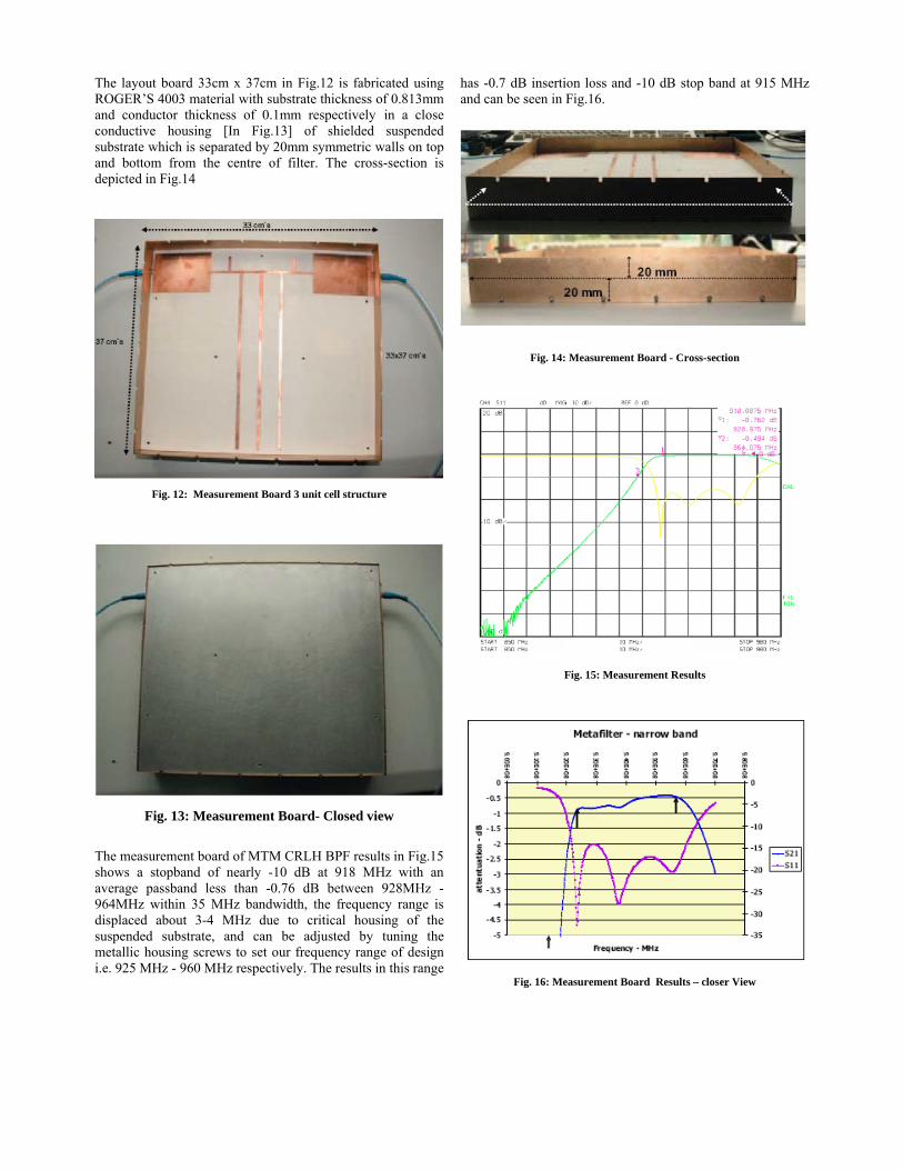
The layout board 33cm x 37cm in Fig.12 is fabricated using ROGER’S 4003 material with substrate thickness of 0.813mm and conductor thickness of 0.1mm respectively in a close conductive housing [In Fig.13] of shielded suspended substrate which is separated by 20mm symmetric walls on top and bottom from the centre of filter. The cross-section is depicted in Fig.14
Fig. 12: Measurement Board 3 unit cell structure
Fig. 13: Measurement Board- Closed view
The measurement board of MTM CRLH BPF results in Fig.15 shows a stopband of nearly -10 dB at 918 MHz with an average passband less than -0.76 dB between 928MHz -964MHz within 35 MHz bandwidth, the frequency range is displaced about 3-4 MHz due to critical housing of the suspended substrate, and can be adjusted by tuning the metallic housing screws to set our frequency range of design i.e. 925 MHz - 960 MHz respectively. The results in this range
has -0.7 dB insertion loss and -10 dB stop band at 915 MHz and can be seen in Fig.16.
Fig. 14: Measurement Board - Cross-section
Fig. 15: Measurement Results
Fig. 16: Measurement Board Results – closer View
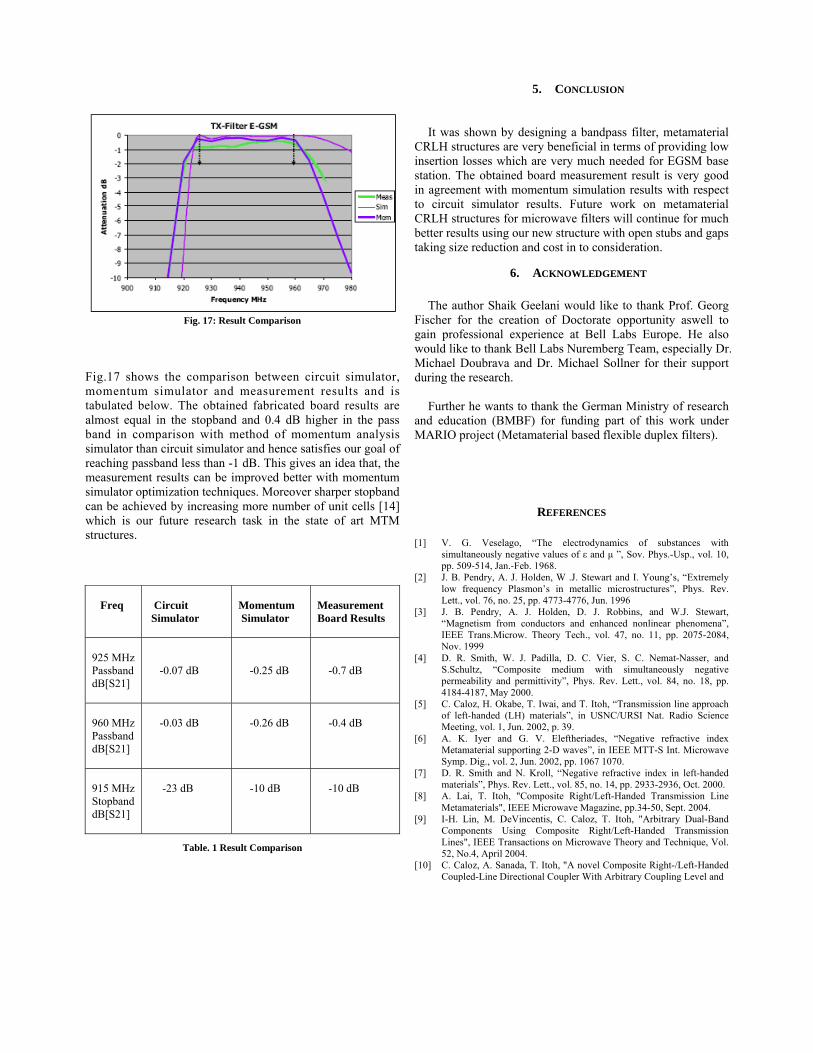
Fig. 17: Result Comparison
Fig.17 shows the comparison between circuit simulator, momentum simulator and measurement results and is tabulated below. The obtained fabricated board results are almost equal in the stopband and 0.4 dB higher in the pass band in comparison with method of momentum analysis simulator than circuit simulator and hence satisfies our goal of reaching passband less than -1 dB. This gives an idea that, the measurement results can be improved better with momentum simulator optimization techniques. Moreover sharper stopband can be achieved by increasing more number of unit cells [14] which is our future research task in the state of art MTM structures.
Freq
Circuit Simulator
Momentum Simulator
Measurement Board Results
925 MHz Passband dB[S21]
-0.07 dB
-0.25 dB
-0.7 dB
960 MHz Passband dB[S21]
-0.03 dB
-0.26 dB
-0.4 dB
915 MHz Stopband dB[S21]
-23 dB
-10 dB
-10 dB
Table. 1 Result Comparison
5. CONCLUSION
It was shown by designing a bandpass filter, metamaterial
CRLH structures are very beneficial in terms of providing low insertion losses which are very much needed for EGSM base station. The obtained board measurement result is very good in agreement with momentum simulation results with respect to circuit simulator results. Future work on metamaterial CRLH structures for microwave filters will continue for much better results using our new structure with open stubs and gaps taking size reduction and cost in to consideration.
6. ACKNOWLEDGEMENT The author Shaik Geelani would like to thank Prof. Georg
Fischer for the creation of Doctorate opportunity aswell to gain professional experience at Bell Labs Europe. He also would like to thank Bell Labs Nuremberg Team, especially Dr. Michael Doubrava and Dr. Michael Sollner for their support during the research.
Further he wants to thank the German Ministry of research
and education (BMBF) for funding part of this work under MARIO project (Metamaterial based flexible duplex filters).
REFERENCES
[1] V. G. Veselago, “The electrodynamics of substances with simultaneously negative values of ε and μ ”, Sov. Phys.-Usp., vol. 10, pp. 509-514, Jan.-Feb. 1968.
[2] J. B. Pendry, A. J. Holden, W .J. Stewart and I. Young’s, “Extremely low frequency Plasmon’s in metallic microstructures”, Phys. Rev. Lett., vol. 76, no. 25, pp. 4773-4776, Jun. 1996
[3] J. B. Pendry, A. J. Holden, D. J. Robbins, and W.J. Stewart, “Magnetism from conductors and enhanced nonlinear phenomena”, IEEE Trans.Microw. Theory Tech., vol. 47, no. 11, pp. 2075-2084, Nov. 1999
[4] D. R. Smith, W. J. Padilla, D. C. Vier, S. C. Nemat-Nasser, and S.Schultz, “Composite medium with simultaneously negative permeability and permittivity”, Phys. Rev. Lett., vol. 84, no. 18, pp. 4184-4187, May 2000.
[5] C. Caloz, H. Okabe, T. Iwai, and T. Itoh, “Transmission line approach of left-handed (LH) materials”, in USNC/URSI Nat. Radio Science Meeting, vol. 1, Jun. 2002, p. 39.
[6] A. K. Iyer and G. V. Eleftheriades, “Negative refractive index Metamaterial supporting 2-D waves”, in IEEE MTT-S Int. Microwave Symp. Dig., vol. 2, Jun. 2002, pp. 1067 1070.
[7] D. R. Smith and N. Kroll, “Negative refractive index in left-handed materials”, Phys. Rev. Lett., vol. 85, no. 14, pp. 2933-2936, Oct. 2000.
[8] A. Lai, T. Itoh, "Composite Right/Left-Handed Transmission Line Metamaterials", IEEE Microwave Magazine, pp.34-50, Sept. 2004.
[9] I-H. Lin, M. DeVincentis, C. Caloz, T. Itoh, "Arbitrary Dual-Band Components Using Composite Right/Left-Handed Transmission Lines", IEEE Transactions on Microwave Theory and Technique, Vol. 52, No.4, April 2004.
[10] C. Caloz, A. Sanada, T. Itoh, "A novel Composite Right-/Left-Handed Coupled-Line Directional Coupler With Arbitrary Coupling Level and
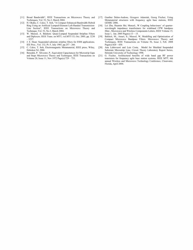
[11] Broad Bandwidth", IEEE Transactions on Microwave Theory and Techniques, Vol. 52, No.3, March 2004.
[12] H. Okabe, C. Caloz, T. Itoh, "A Compact Enhanced-Bandwidth Hybrid Ring Using an Artificial Lumped-Element Left-Handed Transmission-Line Section", IEEE Transactions on Microwave Theory and Technique, Vol. 52, No.3, March 2004.
[13] W. Menzel, A. Balalem: Quasi-Lumped Suspended Stripline Filters and Diplexers. IEEE Trans. on MTT, vol.MTT-53, Oct. 2005, pp. 3230 – 3237.
[14] J. E. Dean: Suspended substrate stripline filters for ESM applications. IEE Proc., Vol. 132, Pt. F, July 1985, pp.257 - 266.
[15] C. Caloz, T. Itoh, Electromagnetic Metamaterial, IEEE press, Wiley, Hoboken NJ, 2006
[16] Benedek, P. Silvester, P., Equivalent Capacitances for Microstrip Gaps and Steps Microwave Theory and Techniques, IEEE Transactions on Volume 20, Issue 11, Nov 1972 Page(s):729 – 733.
[17] Gunther Dehm-Andone, Grzegorz Adamiuk, Georg Fischer; Using Metamaterial structures with frequency agile base stations, IEEE GEMIC 2006.
[18] Lei Zhu, Huamin Shi; Menzel:, W Coupling behaviours’ of quarter-wavelength impedance transformers for wideband CPW bandpass filter., Microwave and Wireless Components Letters, IEEE Volume 15, Issue 1, Jan. 2005 Page(s):13 – 15.
[19] Bekheit, M.; Amari, S.; Menzel, W, Modelling and Optimization of Compact Microwave Bandpass Filters. Microwave Theory and Techniques, IEEE Transactions on Volume 56, Issue 2, Feb. 2008 Page(s):420 – 430.
[20] Anu Lehtovuori and Luis Costa, Model for Shielded Suspended Substrate Microstrip Line, Circuit Theory Laboratory Report Series, Helsinki University of Technology 1998.
[21] G. Fischer, Architectural benefits of wide band gap RF power transistors for frequency agile base station systems, IEEE MTT, 6th annual Wireless and Microwave Technology Conference, Clearwater, Florida, April 2004.

Resume
Educational Qualifications PhD in Electrical/Electronics Engineering March 2009 Friedrich-Alexander-University, Erlangen – Nurnberg (Title “High Q-factor Metamaterial duplex filters in suspended substrate technology”) M.S., Electronics and Telecommunication Engineering Aug. 2005 University of Gavle, Sweden - Specialization in RF/Microwave Engineering Masters, Physics Sep. 1998 University of Bhopal, Bhopal, India - Specialization in Electronics. Bachelor of Science, Electronics June 1996 Sri Krishna Devaraya University, Anantapur, India
Working Experience Alcatel-Lucent Bell-Labs, Nuremberg, Germany Sep. 2006 – Nov. 2008 PhD, Research Engineer RF Design Maxplanck Institute for semiconductors, Munich, Germany Jan. 2006 – April. 2006 Research Assistant Infineon Technologies, Munich, Germany Sep. 2004 - Sep. 2005 Research Student RF Design Syed Hashim College of Science and Technology, Dec. 1998 - March 2003 Hyderabad, India Teaching Assistant
Personal Data Nationality : Indian Date of Birth : 17 June 1976 Contact : [email protected]