Humanoid robot using Petri Nets as tool for decision making
6
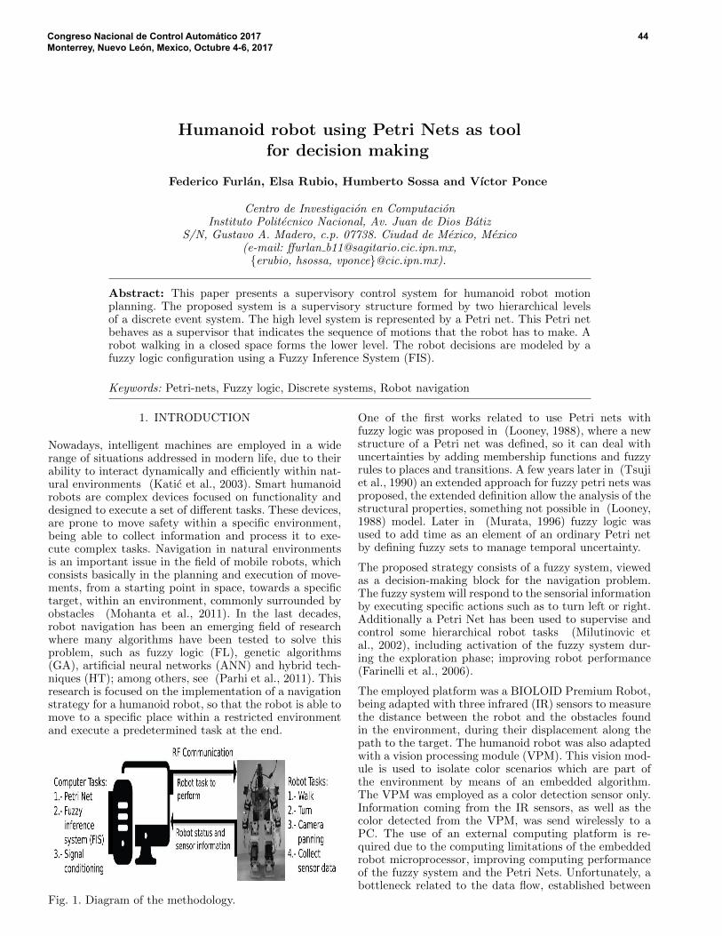
Humanoid robot using Petri Nets as tool for decision making Federico Furl´ an, Elsa Rubio, Humberto Sossa and V´ ıctor Ponce Centro de Investigaci´on en Computaci´on Instituto Polit´ ecnico Nacional, Av. Juan de Dios B´ atiz S/N, Gustavo A. Madero, c.p. 07738. Ciudad de M´ exico, M´ exico (e-mail: ffurlan [email protected], {erubio, hsossa, vponce}@cic.ipn.mx). Abstract: This paper presents a supervisory control system for humanoid robot motion planning. The proposed system is a supervisory structure formed by two hierarchical levels of a discrete event system. The high level system is represented by a Petri net. This Petri net behaves as a supervisor that indicates the sequence of motions that the robot has to make. A robot walking in a closed space forms the lower level. The robot decisions are modeled by a fuzzy logic configuration using a Fuzzy Inference System (FIS). Keywords: Petri-nets, Fuzzy logic, Discrete systems, Robot navigation 1. INTRODUCTION Nowadays, intelligent machines are employed in a wide range of situations addressed in modern life, due to their ability to interact dynamically and efficiently within nat- ural environments (Kati´ c et al., 2003). Smart humanoid robots are complex devices focused on functionality and designed to execute a set of different tasks. These devices, are prone to move safety within a specific environment, being able to collect information and process it to exe- cute complex tasks. Navigation in natural environments is an important issue in the field of mobile robots, which consists basically in the planning and execution of move- ments, from a starting point in space, towards a specific target, within an environment, commonly surrounded by obstacles (Mohanta et al., 2011). In the last decades, robot navigation has been an emerging field of research where many algorithms have been tested to solve this problem, such as fuzzy logic (FL), genetic algorithms (GA), artificial neural networks (ANN) and hybrid tech- niques (HT); among others, see (Parhi et al., 2011). This research is focused on the implementation of a navigation strategy for a humanoid robot, so that the robot is able to move to a specific place within a restricted environment and execute a predetermined task at the end. Fig. 1. Diagram of the methodology. One of the first works related to use Petri nets with fuzzy logic was proposed in (Looney, 1988), where a new structure of a Petri net was defined, so it can deal with uncertainties by adding membership functions and fuzzy rules to places and transitions. A few years later in (Tsuji et al., 1990) an extended approach for fuzzy petri nets was proposed, the extended definition allow the analysis of the structural properties, something not possible in (Looney, 1988) model. Later in (Murata, 1996) fuzzy logic was used to add time as an element of an ordinary Petri net by defining fuzzy sets to manage temporal uncertainty. The proposed strategy consists of a fuzzy system, viewed as a decision-making block for the navigation problem. The fuzzy system will respond to the sensorial information by executing specific actions such as to turn left or right. Additionally a Petri Net has been used to supervise and control some hierarchical robot tasks (Milutinovic et al., 2002), including activation of the fuzzy system dur- ing the exploration phase; improving robot performance (Farinelli et al., 2006). The employed platform was a BIOLOID Premium Robot, being adapted with three infrared (IR) sensors to measure the distance between the robot and the obstacles found in the environment, during their displacement along the path to the target. The humanoid robot was also adapted with a vision processing module (VPM). This vision mod- ule is used to isolate color scenarios which are part of the environment by means of an embedded algorithm. The VPM was employed as a color detection sensor only. Information coming from the IR sensors, as well as the color detected from the VPM, was send wirelessly to a PC. The use of an external computing platform is re- quired due to the computing limitations of the embedded robot microprocessor, improving computing performance of the fuzzy system and the Petri Nets. Unfortunately, a bottleneck related to the data flow, established between Congreso Nacional de Control Automático 2017 Monterrey, Nuevo León, Mexico, Octubre 4-6, 2017 44
Transcript of Humanoid robot using Petri Nets as tool for decision making
Humanoid robot using Petri Nets as toolfor decision making
Federico Furlan, Elsa Rubio, Humberto Sossa and Vıctor Ponce
Centro de Investigacion en ComputacionInstituto Politecnico Nacional, Av. Juan de Dios Batiz
S/N, Gustavo A. Madero, c.p. 07738. Ciudad de Mexico, Mexico(e-mail: ffurlan [email protected],{erubio, hsossa, vponce}@cic.ipn.mx).
Abstract: This paper presents a supervisory control system for humanoid robot motionplanning. The proposed system is a supervisory structure formed by two hierarchical levelsof a discrete event system. The high level system is represented by a Petri net. This Petri netbehaves as a supervisor that indicates the sequence of motions that the robot has to make. Arobot walking in a closed space forms the lower level. The robot decisions are modeled by afuzzy logic configuration using a Fuzzy Inference System (FIS).
Keywords: Petri-nets, Fuzzy logic, Discrete systems, Robot navigation
1. INTRODUCTION
Nowadays, intelligent machines are employed in a widerange of situations addressed in modern life, due to theirability to interact dynamically and efficiently within nat-ural environments (Katic et al., 2003). Smart humanoidrobots are complex devices focused on functionality anddesigned to execute a set of different tasks. These devices,are prone to move safety within a specific environment,being able to collect information and process it to exe-cute complex tasks. Navigation in natural environmentsis an important issue in the field of mobile robots, whichconsists basically in the planning and execution of move-ments, from a starting point in space, towards a specifictarget, within an environment, commonly surrounded byobstacles (Mohanta et al., 2011). In the last decades,robot navigation has been an emerging field of researchwhere many algorithms have been tested to solve thisproblem, such as fuzzy logic (FL), genetic algorithms(GA), artificial neural networks (ANN) and hybrid tech-niques (HT); among others, see (Parhi et al., 2011). Thisresearch is focused on the implementation of a navigationstrategy for a humanoid robot, so that the robot is able tomove to a specific place within a restricted environmentand execute a predetermined task at the end.
Fig. 1. Diagram of the methodology.
One of the first works related to use Petri nets withfuzzy logic was proposed in (Looney, 1988), where a newstructure of a Petri net was defined, so it can deal withuncertainties by adding membership functions and fuzzyrules to places and transitions. A few years later in (Tsujiet al., 1990) an extended approach for fuzzy petri nets wasproposed, the extended definition allow the analysis of thestructural properties, something not possible in (Looney,1988) model. Later in (Murata, 1996) fuzzy logic wasused to add time as an element of an ordinary Petri netby defining fuzzy sets to manage temporal uncertainty.
The proposed strategy consists of a fuzzy system, viewedas a decision-making block for the navigation problem.The fuzzy system will respond to the sensorial informationby executing specific actions such as to turn left or right.Additionally a Petri Net has been used to supervise andcontrol some hierarchical robot tasks (Milutinovic etal., 2002), including activation of the fuzzy system dur-ing the exploration phase; improving robot performance(Farinelli et al., 2006).
The employed platform was a BIOLOID Premium Robot,being adapted with three infrared (IR) sensors to measurethe distance between the robot and the obstacles foundin the environment, during their displacement along thepath to the target. The humanoid robot was also adaptedwith a vision processing module (VPM). This vision mod-ule is used to isolate color scenarios which are part ofthe environment by means of an embedded algorithm.The VPM was employed as a color detection sensor only.Information coming from the IR sensors, as well as thecolor detected from the VPM, was send wirelessly to aPC. The use of an external computing platform is re-quired due to the computing limitations of the embeddedrobot microprocessor, improving computing performanceof the fuzzy system and the Petri Nets. Unfortunately, abottleneck related to the data flow, established between
Congreso Nacional de Control Automático 2017Monterrey, Nuevo León, Mexico, Octubre 4-6, 2017
44
the humanoid robot and the external PC platform isunavoidable under this approach.
2. THEORETICAL FRAMEWORK
2.1 Petri Nets
Petri Nets (PN) is a formal and graphical appealing lan-guage which is appropriate for modelling systems withconcurrency, characterized by being asynchronous, dis-tributed, parallel, non-deterministic and stochastic (Mu-rata, 1989), (David et al., 2010). PN can be used as agraphic tool in the description of this system, similarto flux and block diagrams. In PN, tokens are used tosimulate dynamical and concurrent system activities. Asa mathematical description tool, with PN it is possible todefine a state equation, an algebraic equation and othermathematical models governing a certain system.
2.2 Fuzzy Systems
A fuzzy system can be used to solve human-like challeng-ing problems if there is some heuristic knowledge aboutthe solution in the form of linguistic rules of the form if-then rules. A fuzzy inference system (FIS) is a system thatuses the fuzzy set theory to map inputs to outputs. A FISis partitioned in three main blocks: Fuzzification, wherecrisp inputs are converted to fuzzy values by assigningthem a membership value, in all the fuzzy sets defined ineach input variable. It follows a fuzzy inference process,where fuzzy rules are computed. Then, a defuzzificationprocess is defined to disambiguate the output fuzzy setsobtained as a result of computing the fuzzy rules. Fuzzycontrollers are designed taking into account computingefficiency issues when they are implemented in mobilerobots, due to the inherent limitations in power comput-ing. Therefore, the use of trapezoidal shapes for the inputsets, as well as fuzzy singletons for the fuzzy sets definedat the output variables is preferred. Also, fuzzy operatorslike MIN and MAX, are more convenient, due to theircomputational simplicity. Fuzzy inference systems havebeen successfully applied in fields such as automatic con-trol, data classification, decision analysis, expert systems,and computer vision. (Lee, 2004).
3. DEVELOPMENT
3.1 Sensors and camera
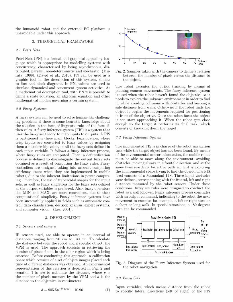
IR sensors used, are able to operate in an interval ofdistances ranging from 20 cm to 130 cm. To calculatethe distance between the robot and a specific object, theVPM is used. The approach consists in retrieving thenumber of pixels found in the color region which is beingsearched. Before conducting this approach, a calibrationphase which consists of a set of object images placed eachtime at different distances was obtained. An experimentalrepresentation of this relation is depicted in Fig. 2 andecuation 1 is use to calculate the distance, where p isthe number of pixels mesuare by the VPM and d is thedistance to the objective in centimeters.
d = 905.5p−0.4162 − 10.96 (1)
Fig. 2. Samples taken with the camera to define a relationbetween the number of pixels versus the distance tothe object.
The robot executes the object tracking by means ofpanning camera movements. The fuzzy inference systemis used when the robot haven’t found the objective so itneeds to explore the unknown environment in order to findit, while avoiding collisions with obstacles and keeping asafe distance from walls. Otherwise if the robot finds theobject it begins the movements required for positioningin front of the objective. Once the robot faces the objectit can start approaching it. When the robot gets closeenough to the target it performs its final task, whichconsists of knocking down the target.
3.2 Fuzzy Inference System
The implemented FIS is in charge of the robot navigationtask while the target object has not been found. By meansof the environmental sensor information, the mobile robotmust be able to move along the environment, avoidingobstacles, moving always in a frontal direction, and at thesame time searching for a free path while it is exploringthe environmental space trying to find the object. The FISused consists of a Mamndani FIS. Three input variableswere defined, corresponding with the frontal, left and rightdistances measured by the robot sensors. Under theseconditions, fuzzy set rules were designed to conduct therobot as a wall follower. Fuzzy inference process concludeswith an output command, indicating to the robot the nextmovement to execute, for example, a left or right turn ora short or long walk. In special situations, a 180 degreesturn can be commanded.
Fig. 3. Diagram of the Fuzzy Inference System used forthe robot navigation.
3.3 Fuzzy Sets
Input variables, which means distance from the robotto specific lateral directions (left or right) of the FIS
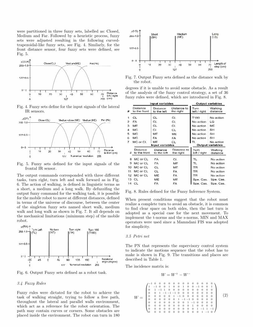
were partitioned in three fuzzy sets, labelled as: Closed,Medium and Far. Followed by a heuristic process, fuzzysets were adjusted resulting in the following curved-trapezoidal-like fuzzy sets, see Fig. 4. Similarly, for thefront distance sensor, four fuzzy sets were defined, seeFig. 5.
Fig. 4. Fuzzy sets define for the input signals of the lateralIR sensors.
Fig. 5. Fuzzy sets defined for the input signals of thefrontal IR sensor.
The output commands corresponded with three differenttasks, turn right, turn left and walk forward as in Fig.6. The action of walking, is defined in linguistic terms asa short, a medium and a long walk. By defuzzifing theoutput fuzzy command for the walking task, it is possiblefor the mobile robot to move at different distances, definedin terms of the universe of discourse, between the centerof the singleton fuzzy sets named short walk, mediumwalk and long walk as shown in Fig. 7. It all depends onthe mechanical limitations (minimum step) of the mobilerobot.
Fig. 6. Output Fuzzy sets defined as a robot task.
3.4 Fuzzy Rules
Fuzzy rules were dictated for the robot to achieve thetask of walking straight, trying to follow a free path,throughout the lateral and parallel walls environment,which act as a reference for the robot orientation. Thepath may contain curves or corners. Some obstacles areplaced inside the environment. The robot can turn in 180
Fig. 7. Output Fuzzy sets defined as the distance walk bythe robot.
degrees if it is unable to avoid some obstacle. As a resultof the analysis of the fuzzy control strategy, a set of 36fuzzy rules were defined, which are introduced in Fig. 8.
Fig. 8. Rules defined for the Fuzzy Inference System.
When present conditions suggest that the robot mustrealize a complete turn to avoid an obstacle, it is commonto find clear space on both sides, then the last turn isadopted as a special case for the next movement. Toimplement the t-norms and the s-norms, MIN and MAXoperators were used since a Mamndani FIS was adoptedfor simplicity.
3.5 Petri net
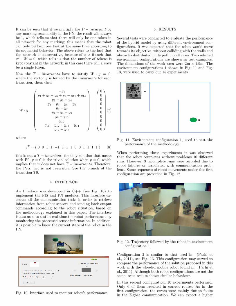
The PN that represents the supervisory control systemto indicate the motions sequence that the robot has tomake is shown in Fig. 9. The transitions and places aredescribed in Table 1.
The incidence matrix is:
W = W+ −W−
W =
−1 0 0 0 0 0 0 0 0 0 0 0 0 0
1 −1 0 0 1 0 0 1 0 0 −1 0 0 1
0 1 −1 1 0 0 0 0 0 0 0 0 0 0
0 0 1 −1 −1 −1 0 0 0 0 0 0 0 0
0 0 0 0 0 1 −1 0 0 0 0 0 0 0
0 0 0 0 0 0 1 −1 −1 0 0 0 0 0
0 0 0 0 0 0 0 0 1 −1 0 0 0 0
0 0 0 0 0 0 0 0 0 1 0 0 0 0
0 0 0 0 0 0 0 0 0 0 1 −1 1 −1
0 0 0 0 0 0 0 0 0 0 0 1 −1 0
(2)
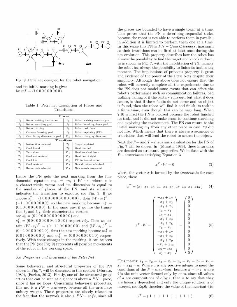
Fig. 9. Petri net designed for the robot navigation.
and its initial marking is givenby mT
0 = (1 0 0 0 0 0 0 0 0 0).
Table 1. Petri net description of Places andTransitions
Places
P1 Robot waiting instruction P6 Robot walking towards goal
P2 Robot searching goal P7 Robot knocking down goal
P3 Robot turning P8 Robot task done
P4 Camera focusing goal P9 Robot exploring (FIS)
P5 Calculating distance to goal P10 Robot changing direction
Transitions
T1 Instruction recieved T8 Step completed
T2 Goal found T9 Goal reached
T3 Turn done T10 Goal knocked down
T4 Goal not centered T11 Goal out of sight
T5 Goal lost T12 FIS indicated action
T6 Goal centered T13 New direction adquired
T7 Robot task selected T14 New search requested
Hence the PN gets the next marking from the fun-damental equation mk = mi + W · s; where s isa characteristic vector and its dimension is equal tothe number of places of the PN, and its subscriptindicates the transition to execute, see Fig. 9. If we
choose sT1 = (1 0 0 0 0 0 0 0 0 0 0 0 0 0) , then (W · s1)T
=(−1 1 0 0 0 0 0 0 0 0), so the new marking become mT
1 =(0 1 0 0 0 0 0 0 0 0). In the same way, if we fire the transi-tion t2 and t11, their characteristic vectorsare sT2 = (0 1 0 0 0 0 0 0 0 0 0 0 0 0) andsT11 = (0 0 0 0 0 0 0 0 0 0 1 0 0 0) respectively. Then we ob-
tain (W · s2)T
= (0−1 1 0 0 0 0 0 0 0) and (W · s11)T
=(0−1 0 0 0 0 0 0 1 0), thus the new marking become mT
2 =(0 0 1 0 0 0 0 0 0 0) and mT
11 = (0 0 0 0 0 0 0 0 1 0) respec-tively. With these changes in the marking, it can be seenthat the PN (see Fig. 9) represents all possible movementsof the robot in the working space.
3.6 Properties and invariants of the Petri Net
Some behavioral and structural properties of the PNshown in Fig. 7, will be discussed in this section (Murata,1989), (Furlan, 2013). Firstly, one of the structural prop-erties that can be seen at a glance is about a PN − pure,since it has no loops. Concerning behavioral properties,this net is a PN − ordinary, because all the arcs haveunitary weight. These properties are closely related tothe fact that the network is also a PN − safe, since all
the places are bounded to have a single token at a time.This proves that the PN is describing sequential tasks,because the robot is not able to perform them in parallel;in addition it is limited to perform them one at a time.In this sense this PN is PN −QuasiLiveness, inasmuchas their transitions can be fired at least once during thenet evolution. This property describes how the robot hasalways the possibility to find the target and knock it down,as is shown in Fig. 7, with the habilitation of T9; namelythe robot has always the possibility to finish its task in anymoment. The implications of previous property is greatand evidence of the power of the Petri Nets despite theirsimplicity. Although the above does not ensure that therobot will correctly complete all the experiments due tothe PN does not model some events that can affect therobot’s performance such as communication failures, badwalking, falling or if the battery runs out; but what it doesassure, is that if these faults do not occur and an objectis found, then the robot will find it and finish its task ina finite time, even though this can be very long. WhenT10 is fired the PN is blocked because the robot finishedits tasks and it did not make sense to continue searchingand exploring the environment. The PN can return to theinitial marking m1 from any other place in case T9 didnot fire. Which means that there is always a sequence oftransitions that will lead the robot to search the object.
Next the P− and T −invariants evaluation for the PN ofFig. 7 will be shown. In (Murata, 1989), these invariantsare denoted as structural properties. We initiate with theP − invariants satisfying Equation 3
xT ·W = 0 (3)
where the vector x is formed by the invariants for eachplace, then:
xT = (x1 x2 x3 x4 x5 x6 x7 x8 x9 x10 ) (4)
xT ·W =
−x1 + x2
−x2 + x3
−x3 + x4
x3 − x4
x2 − x4
−x4 + x5
−x5 + x6
x2 − x6
−x6 + x7
−x7 + x8
−x2 + x9
−x9 + x10
x9 − x10
x2 − x9
=
00000000000000
(5)
This means: x1 = x2 = x3 = x4 = x5 = x6 = x7 = x8 =x9 = x10 = a. Where a is any positive integer to meet theconditions of the P − invariant, because a = c · i, wherei is the unit vector formed only by ones. since all valuesof a are compositions of c by i, that is to say that theyare linearly dependent and only the unique solution is ofinterest, see Eq.6; therefore the value of the invariant i is:
xT = ( 1 1 1 1 1 1 1 1 1 1 ) (6)
It can be seen that if we multiply the P − invariant byany marking reachability in the PN, the result will alwaysbe 1, which tells us that there will only be one token inall network for any marking; this means that the robotcan only perform one task at the same time according toits sequential behavior. The above refers to the fact thatthe network is conservative, because of x > 0 such thatxT ·W = 0, which tells us that the number of tokens iskept constant in the network; in this case there will alwaysbe a single token.
Now the T − invariants have to satisfy W · y = 0,where the vector y is formed by the invariants for eachtransition, then: then
W · y =
−y1y1 + y2 + y5 + y8 − y11 + y14
y2 − y3 + y4y3 − y4 − y5 − y6
y6 − y7y7 − y8 − y9y9 − y10
y10y11 − y12 + y13 − y14
y12 − y13
=
0000000000
(7)
where
yT = ( 0 0 1 1 −1 1 1 1 0 0 1 1 1 1 ) (8)
this is not a T − invariant; the only solution that meetswith W · y = 0 is the trivial solution when y = 0, whichimplies that it does not have T − invariants. Therefore,the Petri net is not reversible. See the branch of thetransition T9.
4. INTERFACE
An Interface was developed in C++ (see Fig. 10) toimplement the FIS and PN modules. This interface ex-ecutes all the communication tasks in order to retrieveinformation from robot sensors and sending back outputcommands according to the robot situation, based onthe methodology explained in this paper. The interfaceis also used to test in real-time the robot performance, bymonitoring the processed sensor information. In addition,it is possible to know the current state of the robot in thePN.
Fig. 10. Interface used to monitor robot’s performance.
5. RESULTS
Several tests were conducted to evaluate the performanceof the hybrid model by using different environment con-figurations. It was expected that the robot would movetowards its objective, without colliding with the walls andobstacles distributed in its path, in all cases. Two selectedenvironment configurations are shown as test examples.The dimensions of the work area were 2m x 1.9m. Theenvironment configurations 1 shown in Fig. 11 and Fig.13, were used to carry out 15 experiments.
Fig. 11. Environment configuration 1, used to test theperformance of the methodology.
When performing these experiments it was observedthat the robot completes without problems 10 differentruns. However, 3 incomplete runs were recorded due torobot failures or associated with communication prob-lems. Some sequences of robot movements under this firstconfiguration are presented in Fig. 12.
Fig. 12. Trajectory followed by the robot in environmentconfiguration 1.
Configuration 2 is similar to that used in (Parhi etal., 2011), see Fig. 13. This configuration may served tocompare the performance of the solution proposed in thiswork with the wheeled mobile robot found in (Parhi etal., 2011). Although both robot configurations are not thesame, tests results shown similar behaviour.
In this second configuration, 10 experiments performed.Only 6 of them resulted in correct routes. As in thefirst configuration, the errors were mainly due to faultsin the Zigbee communication. We can expect a higher
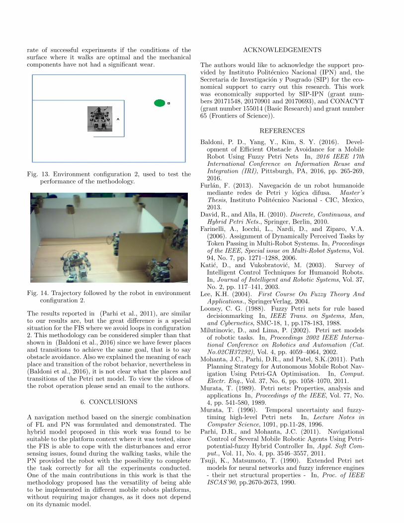
rate of successful experiments if the conditions of thesurface where it walks are optimal and the mechanicalcomponents have not had a significant wear.
Fig. 13. Environment configuration 2, used to test theperformance of the methodology.
Fig. 14. Trajectory followed by the robot in environmentconfiguration 2.
The results reported in (Parhi et al., 2011), are similarto our results are, but the great difference is a specialsituation for the FIS where we avoid loops in configuration2. This methodology can be considered simpler than thatshown in (Baldoni et al., 2016) since we have fewer placesand transitions to achieve the same goal, that is to sayobstacle avoidance. Also we explained the meaning of eachplace and transition of the robot behavior, nevertheless in(Baldoni et al., 2016), it is not clear what the places andtransitions of the Petri net model. To view the videos ofthe robot operation please send an email to the authors.
6. CONCLUSIONS
A navigation method based on the sinergic combinationof FL and PN was formulated and demonstrated. Thehybrid model proposed in this work was found to besuitable to the platform context where it was tested, sincethe FIS is able to cope with the disturbances and errorsensing issues, found during the walking tasks, while thePN provided the robot with the possibility to completethe task correctly for all the experiments conducted.One of the main contributions in this work is that themethodology proposed has the versatility of being ableto be implemented in different mobile robots platforms,without requiring major changes, as it does not dependon its dynamic model.
ACKNOWLEDGEMENTS
The authors would like to acknowledge the support pro-vided by Instituto Politecnico Nacional (IPN) and, theSecretaria de Investigacion y Posgrado (SIP) for the eco-nomical support to carry out this research. This workwas economically supported by SIP-IPN (grant num-bers 20171548, 20170901 and 20170693), and CONACYT(grant number 155014 (Basic Research) and grant number65 (Frontiers of Science)).
REFERENCES
Baldoni, P. D., Yang, Y., Kim, S. Y. (2016). Devel-opment of Efficient Obstacle Avoidance for a MobileRobot Using Fuzzy Petri Nets In, 2016 IEEE 17thInternational Conference on Information Reuse andIntegration (IRI), Pittsburgh, PA, 2016, pp. 265-269,2016.
Furlan, F. (2013). Navegacion de un robot humanoidemediante redes de Petri y logica difusa. Master’sThesis, Instituto Politecnico Nacional - CIC, Mexico,2013.
David, R., and Alla, H. (2010). Discrete, Continuous, andHybrid Petri Nets., Springer, Berlin, 2010.
Farinelli, A., Iocchi, L., Nardi, D., and Ziparo, V.A.(2006). Assignment of Dynamically Perceived Tasks byToken Passing in Multi-Robot Systems. In, Proceedingsof the IEEE, Special issue on Multi-Robot Systems, Vol.94, No. 7, pp. 1271–1288, 2006.
Katic, D., and Vukobratovic, M. (2003). Survey ofIntelligent Control Techniques for Humanoid Robots.In, Journal of Intelligent and Robotic Systems, Vol. 37,No. 2, pp. 117–141, 2003.
Lee, K.H. (2004). First Course On Fuzzy Theory AndApplications., SpringerVerlag, 2004.
Looney, C. G. (1988). Fuzzy Petri nets for rule baseddecisionmarking In, IEEE Trans. on Systems, Man,and Cybernetics, SMC-18, 1, pp.178-183, 1988.
Milutinovic, D., and Lima, P. (2002). Petri net modelsof robotic tasks. In, Proceedings 2002 IEEE Interna-tional Conference on Robotics and Automation (Cat.No.02CH37292), Vol. 4, pp. 4059–4064, 2002.
Mohanta, J.C., Parhi, D.R., and Patel, S.K.(2011). PathPlanning Strategy for Autonomous Mobile Robot Nav-igation Using Petri-GA Optimisation. In, Comput.Electr. Eng., Vol. 37, No. 6, pp. 1058–1070, 2011.
Murata, T. (1989). Petri nets: Properties, analysis andapplications In, Proceedings of the IEEE, Vol. 77, No.4, pp. 541-580, 1989.
Murata, T. (1996). Temporal uncertainty and fuzzy-timing high-level Petri nets In, Lecture Notes inComputer Science, 1091, pp.11-28, 1996.
Parhi, D.R., and Mohanta, J.C. (2011). NavigationalControl of Several Mobile Robotic Agents Using Petri-potential-fuzzy Hybrid Controller In, Appl. Soft Com-put., Vol. 11, No. 4, pp. 3546–3557, 2011.
Tsuji, K., Matsumoto, T. (1990). Extended Petri netmodels for neural networks and fuzzy inference engines- their net structural properties - In, Proc. of IEEEISCAS’90, pp.2670-2673, 1990.