
F h t lt fü W ldök l i d F t i t h ftForschungsanstalt für ...
T U MI N S T I T U T F U R I N F O R M A T I K
Proceedings of the 1st Workshop on SoftwareDevelopment Patterns (SDPP’02)
Michael Gnatz, Frank Marschall, Gerhard Popp, AndreasRausch, Maura Rodenberg-Ruiz, Wolfgang Schwerin (Eds.)
TUM-I0213Dezember 02
T E C H N I S C H E U N I V E R S I T A T M U N C H E N
TUM-INFO-12-I0213-0/1.-FIAlle Rechte vorbehaltenNachdruck auch auszugsweise verboten
c�2002
Druck: Institut fur Informatik derTechnischen Universitat Munchen
Michael Gnatz, Frank Marschall, Gerhard Popp, Andreas Rausch, Maura Rodenberg-Ruiz, Wolfgang Schwerin (Eds.)
Proceedings of the 1st Workshop on Software Development Process Patterns (SDPP’02)
held at the 17th Annual ACM Conference on Object-Oriented Programming, Systems, Languages, and Applications (OOPSLA 2002)
Seattle, Washington, USA, November 4-8, 2002 (http://oopsla.acm.org) Contents
v Call for Papers of the 1st Workshop on Software Development Process Patterns
v Michael Gnatz, Frank Marschall, Gerhard Popp, Andreas Rausch, Wolfgang Schwerin: Common Template for Software Development Process Patterns
v Martin Orehek: Model-Based Real-Time Systems Development
v Klaus Bergner, Andreas Rausch: Test Suite Bootstrapping
v Kendall Scott: Class and Method Documentation
v Sergio Soares, Paulo Borba: PIP: Progressive Implementation Pattern
v Traugott Dittmann, Volker Gruhn, Mariele Hagen: Improved Support for the Description and Usage of Process
v Philippe Kruchten: A Process Engineering Metamodel
v Hajimu Iida, Yasushi Tanaka: A Compositional Process Pattern Framework for Component-based Process Modeling Assistance
v Michael Gnatz, Frank Marschall, Gerhard Popp, Andreas Rausch, Wolfgang Schwerin: Common Meta-Model for a Living Software Development Processes

CALL FOR PAPERS
for the
1st Workshop on Software Development Process Patterns (SDPP’02)
(http://www.forsoft.de/zen/sdpp02/)
to be held at the
17th Annual ACM Conference on Object-Oriented Programming,
Systems, Languages, and Applications (OOPSLA 2002) Seattle, Washington, USA, November 4-8, 2002
(http://oopsla.acm.org)
Themes and Goals Industrial software engineers need a flexible and modular process model that enables them to combine the benefits of existing process models, methods, techniques, and best practices in a project-specific way. To devise such a process model, a comprehensive and clear notion of software development processes and the corresponding process artifacts is required. Over the last years, we have been working on the concept of process patterns. The underlying meta model and the corresponding description techniques provide a common understanding of all kinds of software development processes and their artifacts, respectively. The workshop harvests best practices, techniques, methods, and development process fragments presented as software development process patterns. The purpose of this workshop is then to combine and relate these patterns, thus making a first step towards a comprehensive process pattern language. This language will be based on a common software development process framework, and it will include methodical guidelines on the selection of the appropriate process pattern for a specific situation. Our mid- and long-term goal is to continually evolve the language in order to gain a general basis for the integration, communication, and evolution of process knowledge from different software engineering communities. The workshop may thus result in the establishment of an international community for software development processes based on process patterns. The interest of this community will be to collect, document, and improve software engineering and development process knowledge.
Topics The workshop will elicit submissions of a large range of established best practices, techniques, methods, and development process fragments to support the software development process. To ease communication among the participants, submissions are recommend to be documented as a process patterns. For this, a process pattern template, a sample process pattern, and a rough sketch of a conceptual framework for process patterns are provided at the workshop’s website (http://www.forsoft.de/zen/sdpp02/). Ideally, a paper might also reflect about the template or framework that was used to document a process pattern and argue why it is appropriate or not. Besides a sound description of the proposed process pattern(s) itself, the paper should also discuss why the presented process fragment is a good candidate for a process pattern. This
comprises a discussion of how the proposed pattern can be reused in different development processes and how it could possibly be combined with other patterns. Topics that are relevant to the workshop are, guidelines, best practices, experience reports, techniques, methods, or development process fragments that describe how to be better in:
• teamwork and collaboration • project management and planning • requirements engineering and business analysis • design, modeling, using tools, elaborating documentation • using UML and other notations • programming • testing • quality assurance • redesign and refactoring • customers and contracts • cost estimation and measurement • other software development process relevant topics
During the workshop the authors will present their papers and answer questions that relate directly to their presentation. Subsequently, the participants will discuss how the presented patterns may fit into a common process pattern language and how a process pattern framework must look like to provide an appropriate base for such a pattern language. The main goal of the workshop is to establish an ongoing discussion on process patterns and thereby to agree on an appropriate conceptual framework for these patterns to enhance flexibility and evolution of software development processes.
Submissions Paper submission is required for participation in the workshop. Submission deadline is the 19th September 2002. Papers should not exceed a length of 10 - 15 pages. Authors are invited to send their papers to the organizers of the workshop (mailto:[email protected]) in Postscript or PDF format. All submitted papers will be peer-reviewed by a minimum of three people. The accepted papers will be published on the workshop website already before the workshop. Workshop proceedings including all papers will be published as Technical Report of the Technische Universität München.
Workshop Organization Chairs
• Klaus Bergner, 4Soft GmbH, Germany • Philippe Kruchten, Rational Software, Canada • Andreas Rausch, Technische Universität München, Germany
Organizing Committee
• Michael Gnatz, Technische Universität München, Germany • Frank Marschall, Technische Universität München, Germany • Gerhard Popp, Technische Universität München, Germany • Wolfgang Schwerin, Technische Universität München, Germany
Program Committee
• Scott Ambler, Ronin International, Colorado, USA • Klaus Bergner, 4Soft GmbH, Germany • Barry Boehm, USC Center for Software Engineering, USA • Manfred Broy, Technische Universität München, Germany • Michael Gnatz, Technische Universität München, Germany
• Hajimu Iida, Nara Institute of Science and Technology, Japan • Philippe Kruchten, Rational Software, Canada • Frank Marschall, Technische Universität München, Germany • Jürgen Münch, Fraunhofer Institut, Germany • Gerhard Popp, Technische Universität München, Germany • Rodrigo Quites Reis, Universidade Federal do Pará, Brazil • Andreas Rausch, Technische Universität München, Germany • Dieter Rombach, Fraunhofer Institut, Germany • Wolfgang Schwerin, Technische Universität München, Germany • Louise Scott, University of New South Wales, Australia
Important Dates September, 19th 2002 Submission Deadline October, 10th 2002 Notification of Acceptance November, 4th -8th, 2002 OOPSLA’02 November, 5th 2002 1st Workshop on Software Development Process Patterns

1
Common Template for Software Development Process Patterns1
Michael Gnatz, Frank Marschall, Gerhard Popp, Andreas Rausch, Wolfgang Schwerin Institut für Informatik
Technische Universität München Arcisstraße 21
80290 München, Germany (gnatzm|marschal|popp|rausch|schwerin)@in.tum.de
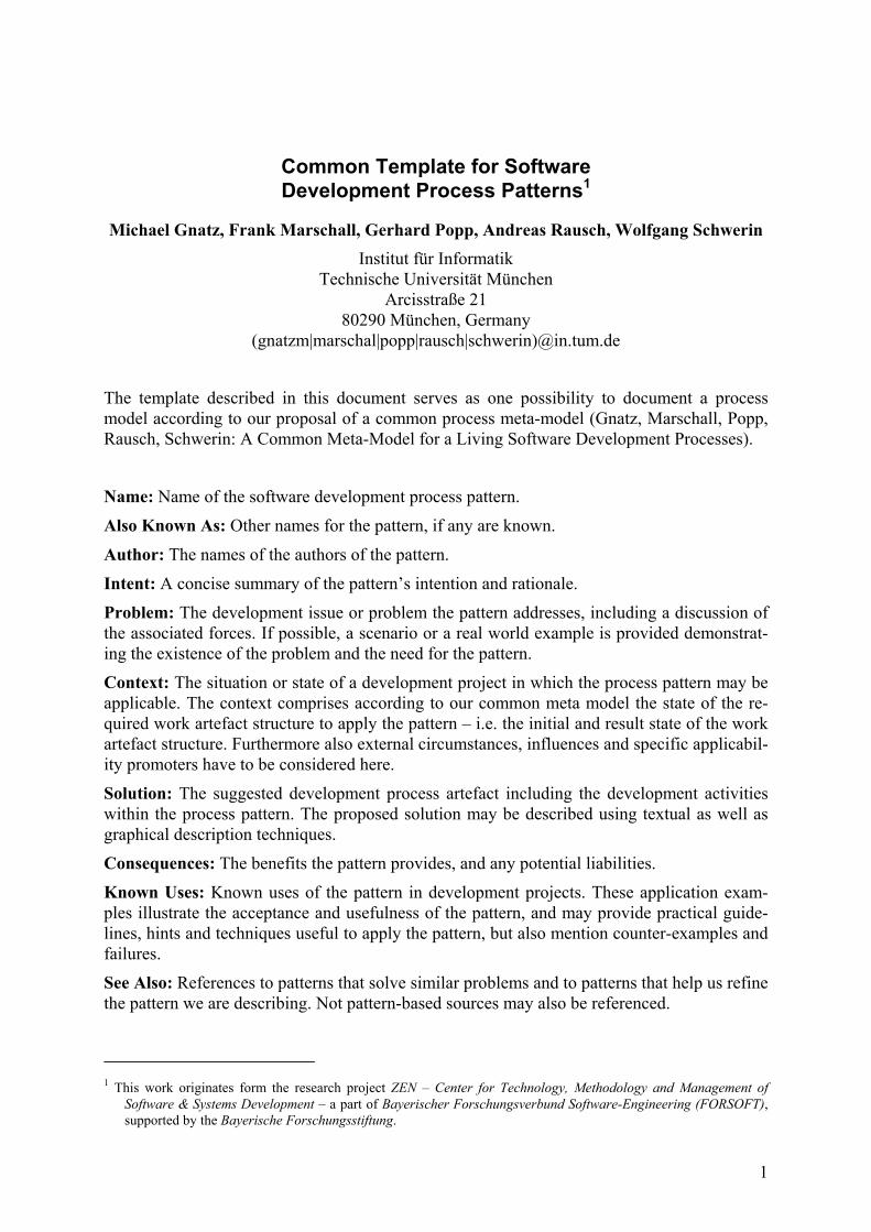
The template described in this document serves as one possibility to document a process model according to our proposal of a common process meta-model (Gnatz, Marschall, Popp, Rausch, Schwerin: A Common Meta-Model for a Living Software Development Processes).
Name: Name of the software development process pattern.
Also Known As: Other names for the pattern, if any are known.
Author: The names of the authors of the pattern.
Intent: A concise summary of the pattern’s intention and rationale.
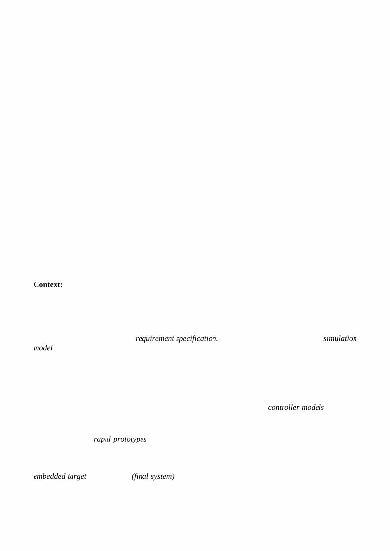
Problem: The development issue or problem the pattern addresses, including a discussion of the associated forces. If possible, a scenario or a real world example is provided demonstrat-ing the existence of the problem and the need for the pattern. Context: The situation or state of a development project in which the process pattern may be applicable. The context comprises according to our common meta model the state of the re-quired work artefact structure to apply the pattern – i.e. the initial and result state of the work artefact structure. Furthermore also external circumstances, influences and specific applicabil-ity promoters have to be considered here.
Solution: The suggested development process artefact including the development activities within the process pattern. The proposed solution may be described using textual as well as graphical description techniques. Consequences: The benefits the pattern provides, and any potential liabilities.
Known Uses: Known uses of the pattern in development projects. These application exam-ples illustrate the acceptance and usefulness of the pattern, and may provide practical guide-lines, hints and techniques useful to apply the pattern, but also mention counter-examples and failures.
See Also: References to patterns that solve similar problems and to patterns that help us refine the pattern we are describing. Not pattern-based sources may also be referenced.
1 This work originates form the research project ZEN – Center for Technology, Methodology and Management of
Software & Systems Development – a part of Bayerischer Forschungsverbund Software-Engineering (FORSOFT), supported by the Bayerische Forschungsstiftung.

Process Pattern: Model Based Real-Time Systems Development1
1 This work originates from the research project HRS – Entwurf hybrider Realzeit Systeme – a part of Bayerischer For-schungsverbund Software-Engineering (FORSOFT), supported by the Bayerische Forschungstiftung.
Martin Orehek
Institute for Real-Time Computer Systems Prof. Dr.–Ing. Georg Färber
Technische Universität München, D–80290 München, Germany
Name: Model Based Real-Time Systems Development
Also Known As: Model Based Design of Embedded Real-Time Systems
Author: The here presented process pattern was developed within the project HRS in collaboration with the company Vodafone Pilotentwicklung (former: Mannesmann Pilotentwicklung) and the Insti-tute for Real-Time Computer Systems at the Technische Universität München.
Intent:
Development of embedded systems with hard real-time constraints using a central graphical model to describe the different functional aspects of the design. The model is used as an executable specifica-tion in a virtual environment. In the three phases of the development process, special aspects like the physical behavior simulation of new designed components, the associated control system design task and the final implementation, considering real-time aspects are covered.
Problem:
The evolution in micro controller technology and control system design science is characterized by the extensive integration of embedded components in systems used in various application areas (automo-tive, telecommunication, manufacturing, medical etc.). In most cases, the embedded components are real-time systems that continuously interact with other systems and the physical world. They realize innovative functions and are composed of closely coupled, specialized hardware and software parts.
The here presented process pattern describes the development process for embedded components where the physical system and the corresponding electronic control unit are not yet developed or exist as technological prototypes. The control strategy is the core function of the final software system. The challenges are on the one hand to develop and construct the new physical components and on the other hand to design the corresponding control system, considering the required control dynamics and accuracy. The final control law is implemented in software onto an embedded target, considering not only functional but also non-functional requirements like real-time software issues.
The main challenges of the software development for such systems result from their close integration within a complex environment. Parts of the physical components (e.g. actors) and even the final con-troller hardware (e.g. micro controller board) are developed during the overall design process. The functional software design must therefore be decoupled from such steadily evolving aspects, avoiding unnecessary restrictions and costs.
The final software implementation has to consider beside the functional also non-functional require-ments, like the worst case response times to certain events. These real-time aspects are strongly con-nected to the adopted software architecture and the computational power (worst case execution times) of the final target. In most cases they have to be analyzed and their compliance with the requirements has to be proven with special methods (e.g. scheduling analysis).
An example of such an innovative component is an electrically heated vaporizer used in a fuel-processing system. The vaporizer, as first component of the system, has to vaporize and overheat a water-gasoline mix without droplets for the following gas reformation process. The quite complex thermodynamic laws have to be considered, designing the physical component and control system theories are needed to design an adequate control strategy to meet the dynamic requirements. Finally this algorithms are implemented onto an electronic control unit (ECU) using software and electronic hardware design techniques.
Other possible example is the development of a new electronic gear control system. The different ac-tors and even the gear box must be developed and optimized to achieve the desired dynamics and the controlling software and electronic hardware have to fulfill the required timing constraints.
Context:
In Figure 1 the highest level of the process pattern map is depicted. During the product development cycle (activity: develop embedded real-time system) all the necessary physical components of the product, their corresponding control strategies and their software implementations are developed and optimized.
The starting work artifact is the requirement specification. For each physical components a simulation model is realized as result of the activity: specify environment. These models are used to simulate the behavior and to iteratively optimize the designed physical components, minimizing turn around times and expensive physical prototyping. Only satisfying solutions are realized as prototypes and then vali-dated by means of real experiments.
As the physical components evolve also the controller strategies have to be refined during the activity: design control system. Before implementing them, their quality has to be evaluated. This is also done by means of simulations designing the different control strategies also as controller models and using the already mentioned mathematical models of the physical components.
The activity: implement controller model is divided in two steps. In a first step, the simulated control-ler are realized as rapid prototypes and allow to gain real world measurements of the achieved per-formance. These measured data are fed back in the design process to refine the physical models and increase the confidence and knowledge of the developed components. The experiences made with the prototypes let estimate the requirements for the final hardware platform, and in the second step, the embedded target development (final system) can be started. The possibly necessary software tool sup-
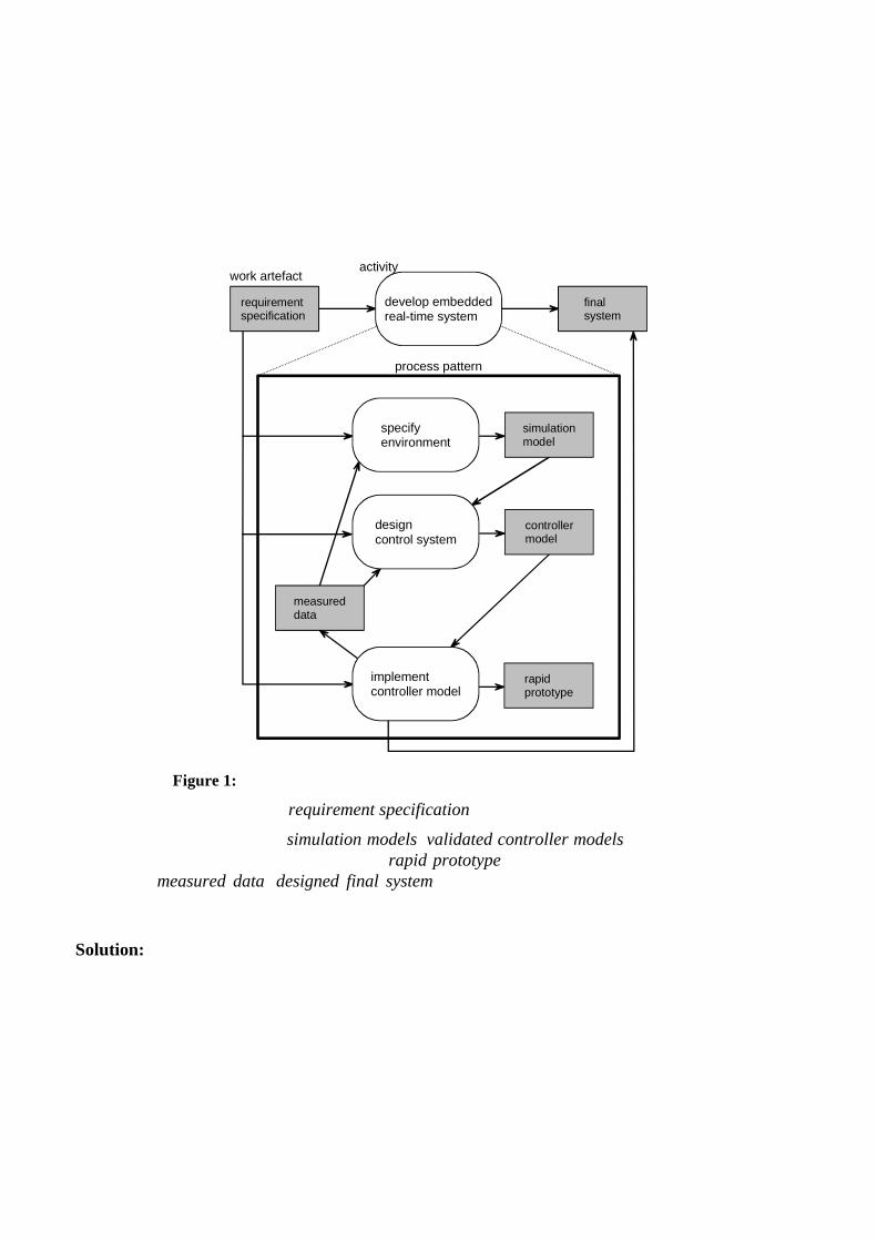
port (e.g. driver library, run-time-environment) can be build concurrently with all the other ongoing refinement tasks. For the final implementation a measurement and estimation of the used target re-sources is provided, making available the necessary parameters for the real-time analysis. This ensures the compliance of the software solution with the worst case timing requirements of the specification.
activitywork artefact
final system
requirement specification
develop embeddedreal-time system
process pattern
simulationmodel
controllermodel
specify environment
design control system
implementcontroller model
rapidprototype
measureddata
Figure 1: Work artifacts and high level activities of the presented process pattern
Necessary work products are: requirement specification (functional and non-functional part).
Produced work products are: simulation models, validated controller models (with corresponding sta-bility analysis and quality estimation etc.), rapid prototype (measured data, embedded target estima-tion, etc.), measured data, designed final system (embedded target solution with real-time analysis results).
Solution:
The activities mentioned in the context chapter composing the main process pattern (see Figure 1) are now described in more detail. They build three different and timely overlapping phases of the devel-opment process. The activities are executed iteratively, refining the outgoing work artifacts and pro-viding new, more detailed inputs to the following activities. For example, after a first run through the
specify environment activity, first simulation models of the physical components for the activity: de-sign control system are available.
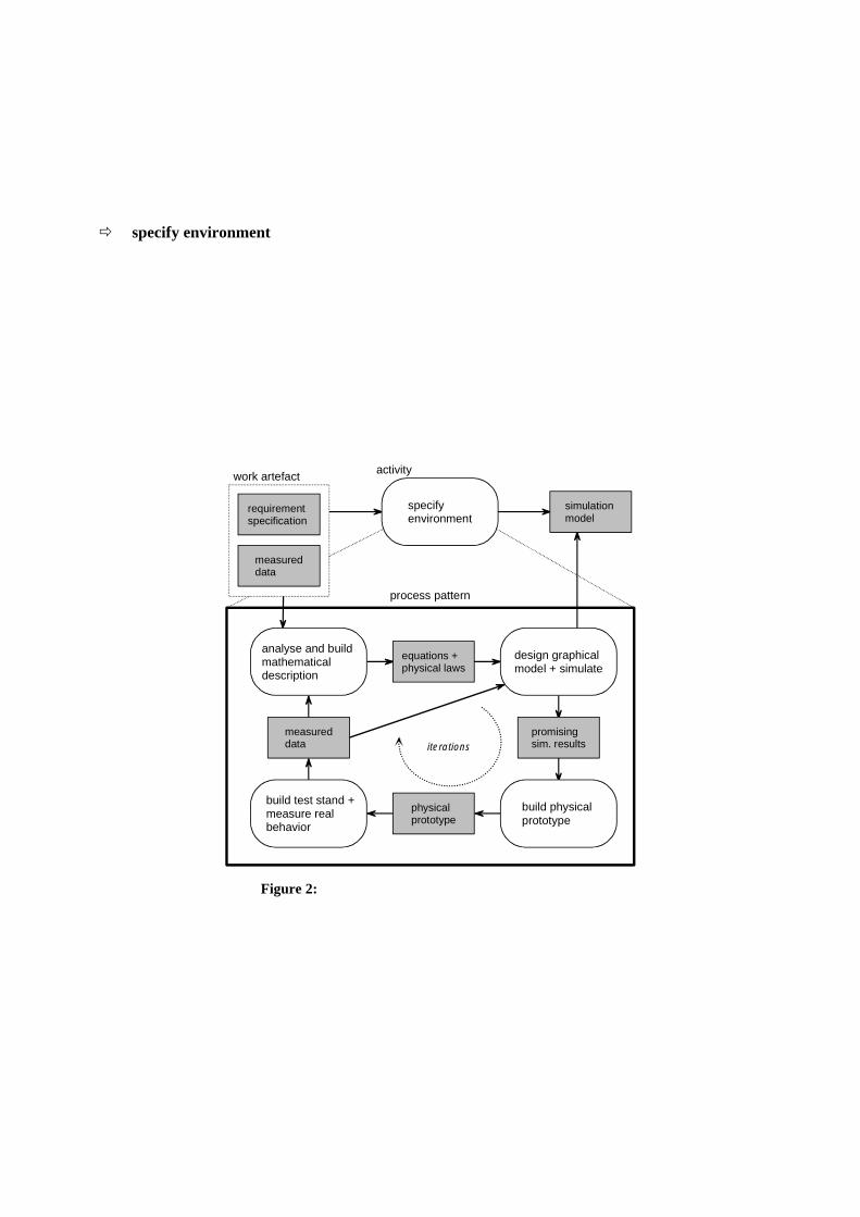
�� specify environment
As starting point of the development process a requirement specification is available. This initial work product can be divided in two parts, the functional and non-functional specification. The functional requirements describe for instance the desired behavior of the final system, whereas the non-functional requirements define aspects like the worst case response time for events or the maximal weight of the product. In the first phase (see Figure 2), after an accurate analysis a graphical model reflecting the physical relationships of the different hardware components is built. This model allows the simulation of the physical system and the analysis of its dynamics, before building a real hardware prototype. Important is that this model is also used during the following activity: design control system for simulation and control design validation.
process pattern
equations +physical laws
promisingsim. results
analyse and build mathematical description
design graphical model + simulate
build test stand +measure realbehavior
build physical prototype
physicalprototype
measureddata iterations
activitywork artefact
simulation model
specifyenvironment
requirement specification
measureddata
Figure 2: process pattern for activity: specify environment
A real prototype is manufactured when the simulation results are promising. Then the physical com-ponent prototype is integrated in a test stand, measurements and tests are run to iteratively refine the corresponding simulation model. The simulation model, based on physical equations and parameterized using these measurements can be used to quickly simulate und evaluate different new hardware constructions, reducing the amount of physical prototypes needed for the final design. This not only reduces the costs but also the iteration time because of a faster evaluation of new ideas. Due to the validation and the contemporaneous
documentation of the different hardware design decisions, this phase leads to qualitative higher and better understood hardware components. In addition the central model used to simulate the physical behavior can be used for the next activity of the design process: design control system.
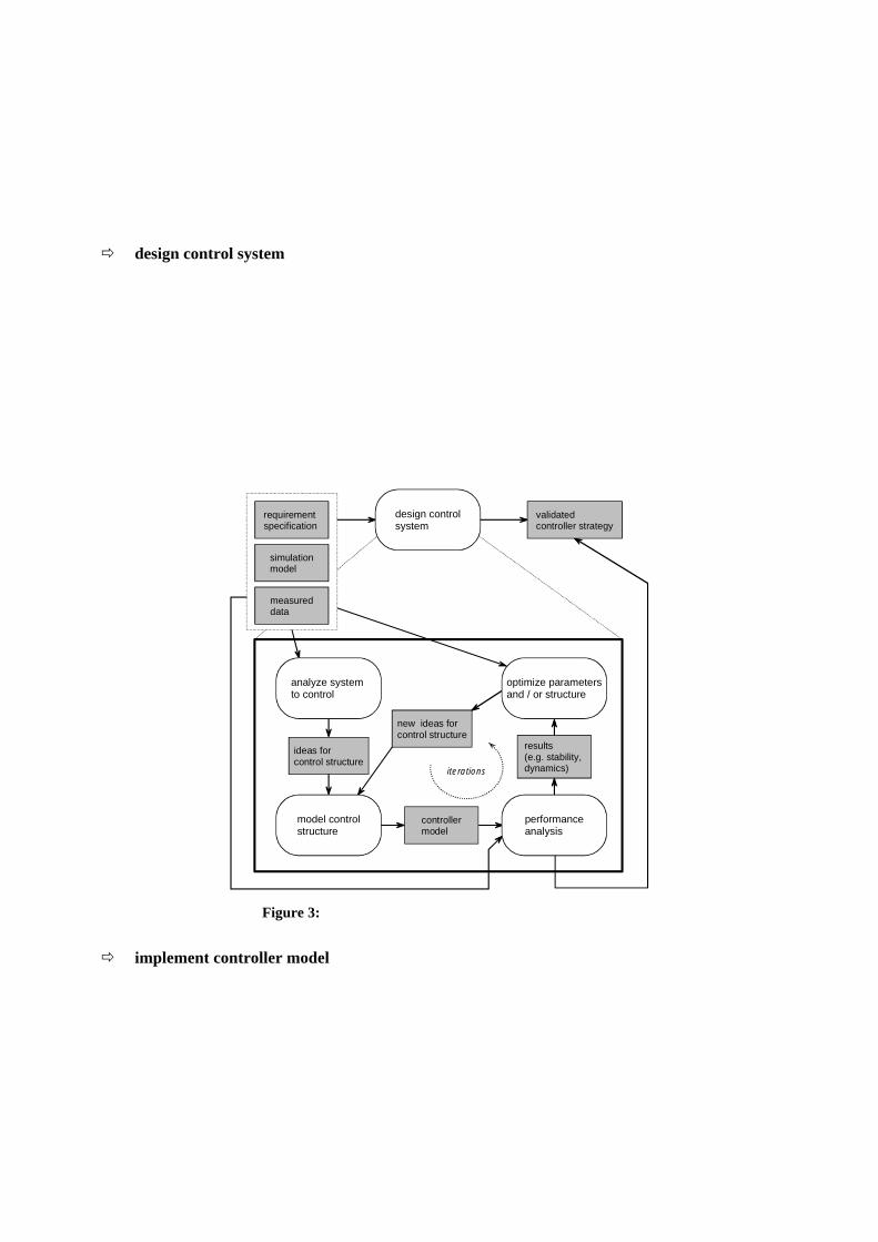
�� design control system
Finding an adequate controller strategy for different plant structures is a well known task and there are many different approaches to solve this problem. But all of them need at least some knowledge about the plant, here provided by the former design phase (activity). Using the facilities of a computer aided control system design tool (CACSD tool, e.g. Matlab/Simulink/Stateflow and the Toolboxes) the de-sign of complex control structures is supported. The different approaches can be analyzed, simulated and optimized using the simulation models of phase 1. The activity: design control system is also iteratively executed (see Figure 3), on the on hand due to new more refined models coming from the specify environment activity, and on the other hand due to the evolving hardware components. This changes can be quite considerable at the beginning of the project, but should become more and more stable approaching the end.
new ideas forcontrol structure
controllermodel
analyze system to control
optimize parametersand / or structure
model controlstructure
performanceanalysis
results(e.g. stability, dynamics)iterations
ideas forcontrol structure
validatedcontroller strategy
requirement specification
design controlsystem
simulationmodel
measureddata
Figure 3: process pattern for activity: design control system
�� implement controller model
The activity: implement controller model is subdivided in two main activities: implement a rapid pro-totype and implement the final embedded target. The input work artifacts of the implement a rapid prototype activity (see Figure 4) are the functional requirement specification and a validated control design. The output artifacts are a full functional prototype of the system, measured data for further refinements of the former phases, knowledge of the
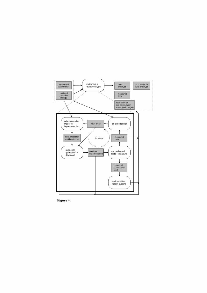
totype of the system, measured data for further refinements of the former phases, knowledge of the minimal resources needed to achieve the required functions and a controller model adapted for a real-time software implementation. The goal is to test the control design in reality, using a rapid prototyping platform and physical com-ponent prototypes, providing measured data to phase 1 and 2, and making a parameter adaptation and refinement of the simulation and controller model possible. Other outputs of this activity are estima-tions of the necessary computation power and peripheral resources of the final embedded target solu-tion.
implement arapid prototype
requirement specification
validatedcontrollerstrategy
estimation for final computationpower (emb. target)
rapid prototype
measureddata
new ideas
real-timeimplementation
adapt controller model for implementation
analyse results
auto code generation + download
run dedicatedtests + measure
measureddataiterations
cont. model forrapid prototype
measuredcomputationload
estimate final target system
cont. model forrapid prototype
Figure 4: process pattern for activity: implement a rapid prototype
In the second sub-activity, implement the final embedded target (see Figure 5), the different tasks can start when the final target hardware was defined. Tasks which depend on the chosen micro controller hardware but not on the control design, can be started very early and be executed contemporaneously with the design control system and implement a rapid prototype activities. Such activities are: provide SW frame, provide device driver blocks and build extension hardware. When the resulting work artifacts (e.g. control model) of the different activities are sufficiently re-fined, the preparatory tasks provide software frame must be finished. The results are used to realize the controller model for the real-time analysis, using in the first approach an evaluation board with the chosen micro controller. The goal is to execute the designed software architecture on the target within a virtual environment, provided by means of a co-simulation between target and host PC. This simula-
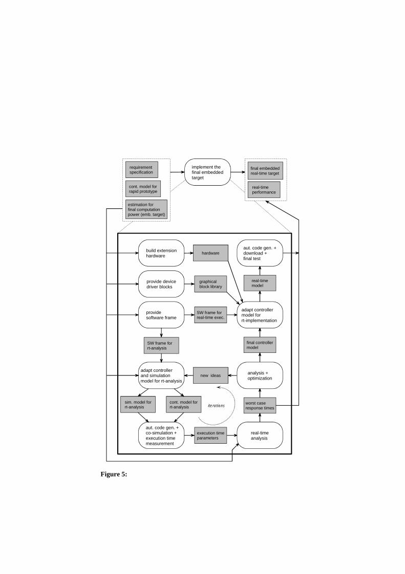
tion allows to measure dedicated execution time parameters during a representative stimulation of the software. The parameter are then used to calculate the worst case response time for special events, claimed by the non-functional requirement specification. In the case, that required response times are not met, a re-design of the control system becomes necessary. Due to quantitative results of the men-tioned real-time analysis, a selective optimization can be carried out.
In the case, that all timing requirements can be met, the used model is adapted for the final real-time implementation, using graphical blocks to connect software signals to hardware interfaces. After a final test, the developed embedded system is available.
SW frame forreal-time exec.
provide software frame
final controllermodel
new ideas
execution timeparameters
adapt controller and simulation model for rt-analysis
analysis +optimization
aut. code gen. + co-simulation +execution timemeasurement
real-timeanalysis
worst caseresponse timesiterations
cont. model forrt-analysis
graphicalblock library
provide devicedriver blocks
adapt controllermodel for rt-implementation
SW frame for rt-analysis
hardwarebuild extensionhardware
sim. model forrt-analysis
real-timemodel
aut. code gen. +download +final test
implement thefinal embeddedtarget
final embeddedreal-time target
real-timeperformance
requirement specification
estimation for final computationpower (emb. target)
cont. model forrapid prototype
Figure 5: process pattern for activity: implement the final embedded target

Consequences:
The here presented model based development process pattern provides the following benefits:
• Using a central and uniform description (model within one tool chain) facilitates the exchange of information between different engineering teams and allows easy reuse and feedback of new information but still allowing to concentrate on different aspects of the system design (e.g. modeling the physical laws in phase 1, control design in phase 2).
• Due to the simulation feature within the first phases the turn around times can be minimized and the number of realized prototypes can be diminished. New ideas can be evaluated more quickly leading to new efficient solution and better understood hardware components.
• Applying rapid prototypes to evaluate the control system design allows the functional verifica-tion using real physical component prototypes. For example, developing a new vaporizer in this phase over 32 different temperature sensors were used, which allowed to analyze different resulting temperature profiles over the component, providing the real system behavior to physical engineers. After this phase not only the control system was verified but also the ther-modynamic hardware component was optimized and due to the gained knowledge, the final implementation onto the embedded target could be minimized in terms of sensors and actua-tors.
• An efficient implementation, guaranteeing all the required timing constrains, can be achieved by:
- adopting an analyzable software architecture to map the graphical controller model onto the real-time embedded system
- providing the necessary mathematical equations for the analysis
- measuring respectively deducing the necessary model specific parameters (e.g. execu-tion times, priorities of model parts, etc.).
The here presented model based development process pattern leads to the following liabilities:
• The model based approach presented can only be applied efficiently with an adequate tool sup-port.
• There is a slightly higher effort in the first approach to provide a reusable SW support (graphi-cal block library for embedded target) for the chosen hardware target but on the other hand it allows to fasten up future projects with the same final target ( this is the case in our project) or to move from on target to another.
Known Uses: Starting first Vodafone Pilotentwicklung GmbH and now the new hive of company P21 GmbH are using the described process pattern within there development efforts. P21 is now concen-trate to design other physical components for the fuel processing system.
See Also: model based design
1
Process Pattern
Test Suite Bootstrapping1
Klaus Bergner
4Soft GmbH Mittererstraße 3
80336 München, Germany [email protected]
Andreas Rausch
Institut für Informatik Technische Universität München
Boltzmannstraße 3 85748 Garching, Germany
Name: Test Suite Bootstrapping
Also Known As: –
Author: SDPP02 team
Intent: Validate the correctness of a data-centric business application by building a regression test suite. Use full database snapshots as the basis for the initial input, the result and the ex-pected result of each test case in order to rule out unwanted side effects. Minimize the effort for creating the needed database snapshots by reusing the result snapshots of test cases as ini-tial input snapshots for other test cases.
Problem: The correctness and consistency of the data managed by a business application are usually of utmost importance for the concerned enterprise. For example, a bank with a bank-ing system that unintentionally loses money on accounts from time to time would be out of business very soon.
Therefore, it is essential to run a sufficient number of test cases during the development of a business application in order to guarantee the required correctness and robustness. As the number of necessary test cases is usually very high, and as the test cases have to be executed many times during the development, an automated regression testing facility is indispensable.
To ensure the reproducibility of a regression test case, the system first has to be initialised with a clearly defined initial system state. Then, the test scenario – a sequence of user interac-tions – is executed. Finally, the resulting system state has to be compared with the expected system state. For data-centric business applications, all of these system states – the initial, the result, and the expected result system state – should include a complete database snapshot. This is necessary to rule out unwanted side effects which cannot be detected by resorting only to the observable results of the operations executed by the test case.
Hence, to create a data-centric regression test case that is ready to be used for testing, an initial database snapshot and an expected result database snapshot have to be created. Elaborating and maintaining these snapshots for a large business application with some thousand test cases is a painful and costly task.
1 This work originates form the research project ZEN – Center for Technology, Methodology and Management of
Software & Systems Development – a part of Bayerischer Forschungsverbund Software-Engineering (FORSOFT), supported by the Bayerische Forschungsstiftung.
2
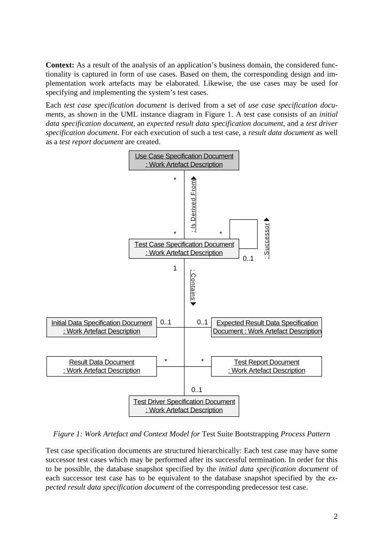
Context: As a result of the analysis of an application’s business domain, the considered func-tionality is captured in form of use cases. Based on them, the corresponding design and im-plementation work artefacts may be elaborated. Likewise, the use cases may be used for specifying and implementing the system’s test cases.
Each test case specification document is derived from a set of use case specification docu-ments, as shown in the UML instance diagram in Figure 1. A test case consists of an initial data specification document, an expected result data specification document, and a test driver specification document. For each execution of such a test case, a result data document as well as a test report document are created.
Use Case Specification Document: Work Artefact Description
Test Case Specification Document: Work Artefact Description
Initial Data Specification Document: Work Artefact Description
Result Data Document: Work Artefact Description
Expected Result Data SpecificationDocument : Work Artefact Description
Test Report Document: Work Artefact Description
:C
on
tain
s
*
*
*
0..11
0..1 0..1
* *
Test Driver Specification Document: Work Artefact Description
0..1
:Is
De
rive
dF
rom
:S
ucc
ess
or
Figure 1: Work Artefact and Context Model for Test Suite Bootstrapping Process Pattern
Test case specification documents are structured hierarchically: Each test case may have some successor test cases which may be performed after its successful termination. In order for this to be possible, the database snapshot specified by the initial data specification document of each successor test case has to be equivalent to the database snapshot specified by the ex-pected result data specification document of the corresponding predecessor test case.
3
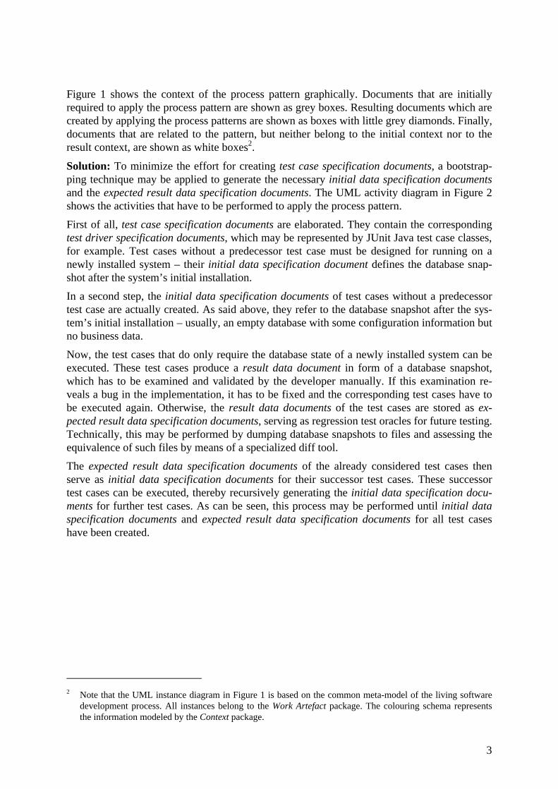
Figure 1 shows the context of the process pattern graphically. Documents that are initially required to apply the process pattern are shown as grey boxes. Resulting documents which are created by applying the process patterns are shown as boxes with little grey diamonds. Finally, documents that are related to the pattern, but neither belong to the initial context nor to the result context, are shown as white boxes2.
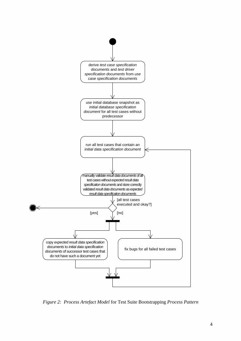
Solution: To minimize the effort for creating test case specification documents, a bootstrap-ping technique may be applied to generate the necessary initial data specification documents and the expected result data specification documents. The UML activity diagram in Figure 2 shows the activities that have to be performed to apply the process pattern.
First of all, test case specification documents are elaborated. They contain the corresponding test driver specification documents, which may be represented by JUnit Java test case classes, for example. Test cases without a predecessor test case must be designed for running on a newly installed system – their initial data specification document defines the database snap-shot after the system’s initial installation.
In a second step, the initial data specification documents of test cases without a predecessor test case are actually created. As said above, they refer to the database snapshot after the sys-tem’s initial installation – usually, an empty database with some configuration information but no business data.
Now, the test cases that do only require the database state of a newly installed system can be executed. These test cases produce a result data document in form of a database snapshot, which has to be examined and validated by the developer manually. If this examination re-veals a bug in the implementation, it has to be fixed and the corresponding test cases have to be executed again. Otherwise, the result data documents of the test cases are stored as ex-pected result data specification documents, serving as regression test oracles for future testing. Technically, this may be performed by dumping database snapshots to files and assessing the equivalence of such files by means of a specialized diff tool.
The expected result data specification documents of the already considered test cases then serve as initial data specification documents for their successor test cases. These successor test cases can be executed, thereby recursively generating the initial data specification docu-ments for further test cases. As can be seen, this process may be performed until initial data specification documents and expected result data specification documents for all test cases have been created.
2 Note that the UML instance diagram in Figure 1 is based on the common meta-model of the living software
development process. All instances belong to the Work Artefact package. The colouring schema represents the information modeled by the Context package.
4
Figure 2: Process Artefact Model for Test Suite Bootstrapping Process Pattern
derive test case specificationdocuments and test driver
specification documents from usecase specification documents
run all test cases that contain aninitial data specification document
use initial database snapshot asinitial database specification
document for all test cases withoutpredecessor
[all test casesexecuted and okay?]
copy expected result data specificationdocuments to initial data specification
documents of successor test cases thatdo not have such a document yet
[no]
manually validate result data documents of alltest cases without expected result data
specification documents and store correctlyvalidated result data documents as expected
result data specification documents
fix bugs for all failed test cases
[yes]
5
Consequences: The Test Suite Bootstrapping process pattern provides the following benefits:
• It makes it possible to detect unwanted side effects by resorting to database snapshots as the basis for the initial test inputs as well as the actual and expected test results.
• It eases the elaboration of a regression test suite by minimizing the effort needed for the creation of initial and expected result database snapshots.
• It provides guidance for the structuring of a test suite by means of the successor rela-tionships between the test cases.
• It leads to complete test cases that may be executed stand-alone or as a suite.
The Test Suite Bootstrapping leads to the following liabilities:
• The developer must take care not to forget important test cases that can not be added as successors to already existing test cases.
• Initially, the developer has to perform the test cases in the order given by the successor relationship.
• If the database schema changes, the developer must adapt and re-run all corresponding test cases.
Known Uses: The concept of using database snapshots as the basis for test input and results is practiced in many development companies (German examples known to the authors include the software house Healy Hudson AG, HypoVereinsbank AG, sd&m AG, and the 4Soft GmbH). An article about the test environment GOAL describes the use of data-centric test cases combined with test suite bootstrapping at Healy Hudson AG, a German procurement software provider (c.f. Thomas Bonfig, Rainer Frömming, Andreas Rausch: Goal – Eine Tes-tinfrastuktur für unternehmensweite Anwendungen, OBJEKTspektrum 4/2000). The corre-sponding test framework has been further developed, integrated into the JUnit test framework, and applied in some projects at the German software development company 4Soft GmbH.
See Also: –

1
Process Pattern
Class and Method Documentation
Kendall Scott13113 Eldridge Rd.Harrison, TN 37343
Name: Class and Method Documentation
Also Known As: –
Author: Kendall Scott
Intent: Provide “just enough” documentation for the classes and methods of a system. Link the various aspects of the documentation together such that the reader can get a reasonably complete picture of what the classes are about and what the methods do.
Problem: All software development teams wrestle with the problem of documentation at some point during or after a project. The usual results include the following:
• No one writes any documentation, because it’s considered a deeply unpleasant task that takes developers away from their “real” work.
• Some documentation gets produced, but it’s inadequate because it’s done by people who don’t have adequate understanding of the system.
• The team produces reams of documentation that no one ever reads.
Also, claims that code is “self-documenting” are all too often overstated. Overall, the time that developers coming up to speed on a project is considerably greater than it would be if “good enough” documentation was in place.
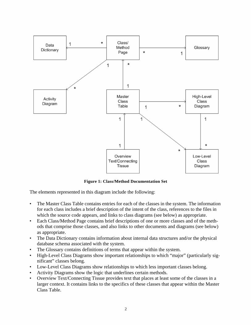
Context: Figure 1 shows the minimal yet sufficient set of documents that effectively and effi-ciently capture the information necessary to understand an arbitrarily large set of classes and asso-ciated methods.
2
Figure 1: Class/Method Documentation Set
The elements represented in this diagram include the following:
• The Master Class Table contains entries for each of the classes in the system. The information for each class includes a brief description of the intent of the class, references to the files in which the source code appears, and links to class diagrams (see below) as appropriate.
• Each Class/Method Page contains brief descriptions of one or more classes and of the meth-ods that comprise those classes, and also links to other documents and diagrams (see below) as appropriate.
• The Data Dictionary contains information about internal data structures and/or the physical database schema associated with the system.
• The Glossary contains definitions of terms that appear within the system.• High-Level Class Diagrams show important relationships to which “major” (particularly sig-
nificant” classes belong.• Low-Level Class Diagrams show relationships to which less important classes belong.• Activity Diagrams show the logic that underlines certain methods.• Overview Text/Connecting Tissue provides text that places at least some of the classes in a
larger context. It contains links to the specifics of these classes that appear within the Master Class Table.
3
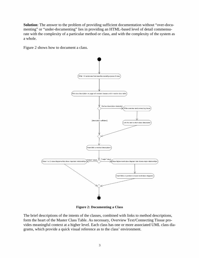
Solution: The answer to the problem of providing sufficient documentation without “over-docu-menting” or “under-documenting” lies in providing an HTML-based level of detail commensu-rate with the complexity of a particular method or class, and with the complexity of the system as a whole.
Figure 2 shows how to document a class.
Figure 2: Documenting a Class
The brief descriptions of the intents of the classes, combined with links to method descriptions, form the heart of the Master Class Table. As necessary, Overview Text/Connecting Tissue pro-vides meaningful context at a higher level. Each class has one or more associated UML class dia-grams, which provide a quick visual reference as to the class’ environment.
4
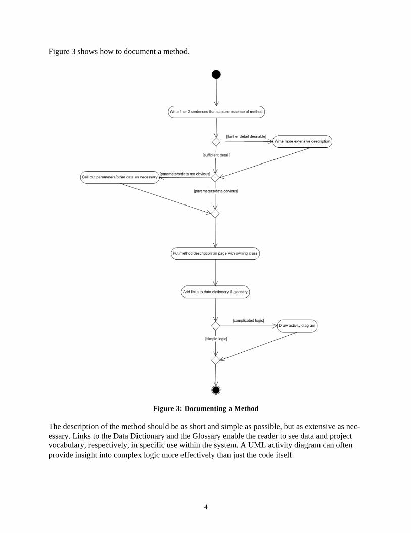
Figure 3 shows how to document a method.
Figure 3: Documenting a Method
The description of the method should be as short and simple as possible, but as extensive as nec-essary. Links to the Data Dictionary and the Glossary enable the reader to see data and project vocabulary, respectively, in specific use within the system. A UML activity diagram can often provide insight into complex logic more effectively than just the code itself.
5
Consequences: The Class and Method Documentation process pattern provides the following benefits:
• It provides readers with various complementary views on the classes and methods that make up a system; taken together, the documentation is “good enough.”
• It makes minimal demands on the people doing the documentation.• It results in a flexible and scalable documentation set that’s easy to maintain.
The Class and Method Documentation pattern has the following liabilities:
• It requires a certain amount of judgment as to what is sufficient documentation in a given sit-uation. It’s very easy to underestimate or overestimate what’s required if the writer doesn’t know the intended audience.
• It calls for patience and persistence from the writer, which can be in short supply under typical development project conditions.
• It works best if one person (for a small or medium-sized project) or a small group of people (for a large project) do all of the writing; the role of documentation specialist is not yet a well-defined one.
Known Uses: The pattern is receiving its first usage on a documentation project the author is cur-rently working on. The system contains roughly 400 C++ classes and several thousand methods. Initial response to the documentation set, which includes 94 Class/Method Pages, 104 Low-Level Class Diagrams, and 10 High-Level Class Diagrams, has been favorable.
See Also: –

PIP: Progressive Implementation Pattern
Sergio Soares∗ and Paulo Borba†
Informatics Center
Federal University of Pernambuco
Intent
Tame complexity and improve development productivity. Reduce the impact caused by require-ments changes during development.
Context
When developing a persistent, distributed, and concurrent system, implementation and testsare usually hard. During tests, database, distribution, concurrency, and functional errors mightappear at the same time, increasing debugging complexity.
When using EJB [10] as the persistence and distribution technology, the deployment timemight be very high. To fix errors — including functional, persistence, and concurrency controlerrors — we might waste a lot of time by compiling the code and them deploying the system intothe application server. Another problem happens when using a database to persist data. Wemight have to write specific programs to check if the data stored into the database conforms tothe expected results. Similarly, if the system can be concurrently accessed, programmers shouldworry about concurrent executions when implementing functional requirements, increasing pro-gramming complexity.
Problem
It is difficult and expensive to validate and test a concurrent, distributed, and persistent sys-tem. Furthermore, system validation usually can only be done latter in the development phase.This delay to validate system requirements increases costs to fix detected errors, since develop-ers might dedicate considerable effort to implement non-functional requirements to incorrectlyimplemented system services.
To implement a persistent, distributed, and concurrent system, PIP balances the followingforces:
• Early validation of functional requirements. This reduces changes cost and prevents delaysin project schedule.
• Simplify tests by testing each aspect (persistence, distribution, and concurrency control)separately. This separation allows testing the functional version of the system withoutthe impact of database, network, or concurrent environments errors. In fact, each non-functional requirement will also be gradually implemented and tested, which avoids thaterrors of one aspect affects tests of another.
∗Supported by CAPES. Also affiliated to Catholic University of Pernambuco. Email: [email protected]†Partially supported by CNPq, grant 521994/96–9. Partially supported by Qualiti Software Processes
(www.qualiti.com.br). Email: [email protected]
1
• Data storage transparency. This is crucial to initially provide a non-persistent version ofthe system in order to validate functional requirements without implementing persistence.After that, the system evolves to a persistent version.
• Independence of communication API and middleware. Similar to the persistence aspect,in an early version of the system there is no distribution code, in order to allow earlyvalidation of functional requirements. However, the system should evolve to a distributedversion, without affecting the requirements already implemented.
Solution
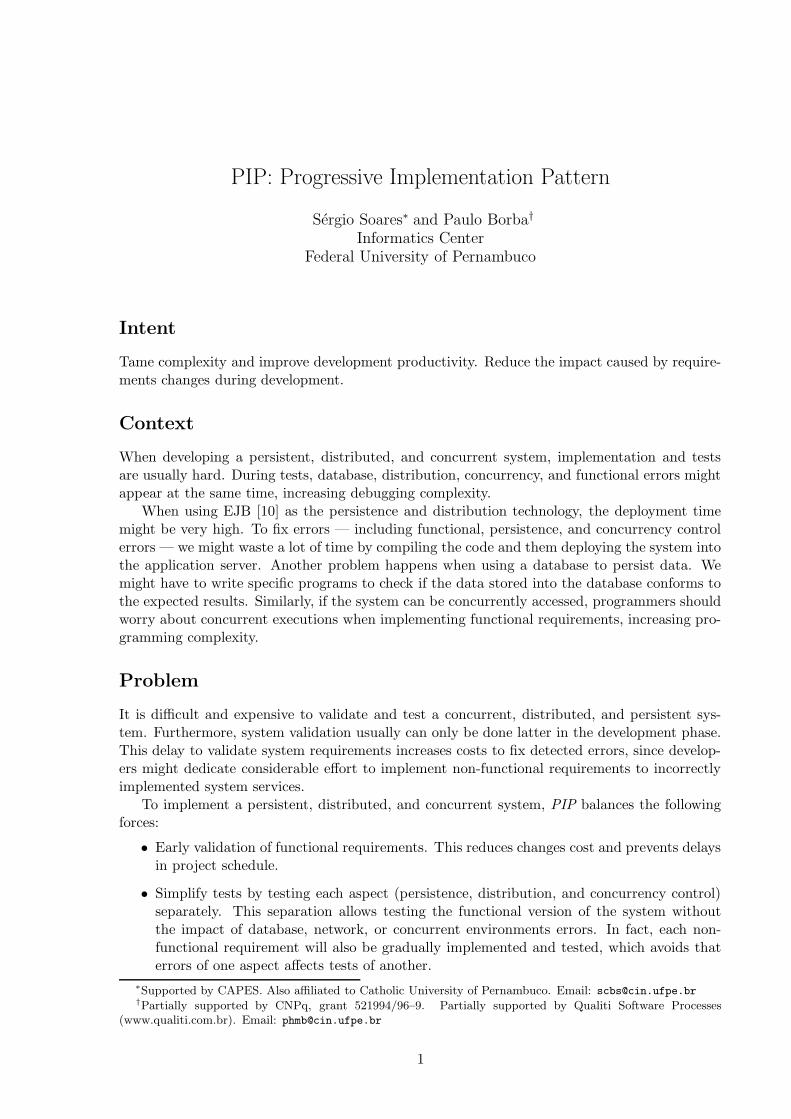
In order to solve the mentioned problem, we should implement functional, persistence, distri-bution, and concurrency control requirements in a progressive way. In fact, we should firstimplement the functional requirements, user interface, and non-persistent storage, in order toprovide a completely functional prototype, and then implement the others aspects, as illus-trated in Figure 1. Although the figure suggests an order for implementing and testing thenon-functional requirements, this is not demanded by the process pattern. In fact, PIP onlyrequires the different aspects to be implemented and tested in a progressive way.
Figure 1: Progressive Implementation Method.
By initially abstracting from the non-functional code, developers can, for example, quicklydevelop and test local, sequential and non-persistent prototypes useful for capturing and vali-dating user requirements. As functional requirements become well understood and stable, thoseprototypes are used to derive the final version of the application, by gradually implementingand testing the persistence, distribution, and concurrency control code.
In order to support this progressive implementation, separation of concerns [11] principlesmust be applied during design activities. The software architecture must support the modu-lar addressing of functional and non-functional aspects during coding activities. This can beachieved by using specific architectural and design patterns [1, 7, 12].
Alternatively, this separation of concerns can be achieved by using aspect-oriented program-ming [2]. For instance, we could separate persistence, distribution, and concurrency controlaspects from the business code, by using AspectJ [5], an aspect-oriented language, and weavethem and the functional prototype into a persistent, distributed, and correct application [14, 13].
Consequences
PIP provides the following benefits:
• Increased productivity. Due to the early validation of functional requirements and thesimplification of tests, the development productivity is increased. Data collected in a simplecase study [9] shows that this increasing is about 10% and there were a 50% reduction
2
on the requirements changes effort. Those numbers can be higher by providing codegeneration.
• Tests and debugging are easier. PIP naturally helps to tackle the complexity inherentto persistent and distributed applications, by allowing the gradual testing of the variousintermediate versions of the application, which benefits system correctness.
• Early functional prototype. In the simple case study [9] previously mentioned, there isanother metric showing that the functional prototype is obtained 30% earlier by using aprogressive approach.
This pattern has the following drawbacks:
• Reduced team motivation. Programmers might feel that they are generating more codethan necessary, for instance, by first generating non-persistent versions of data storageclasses and then their persistent versions. To avoid this, the development team should beconvinced of the benefits.
• Limited functional tests. The progressive approach does not allow to test situations weretransactions would be rolled back, with the functional prototype.
• Additional classes. When implementing persistence we should create classes to store ob-jects in a persistent medium. However, in order to implement the functional prototype,before implementing persistence, we have to create classes to store the objects in a non-persistence structure. This affects productivity, since programmers should implement twoclasses to store instances of an object. Code generation tools could solve this drawback byautomatically providing part of the implementation of the non-persistent and persistentdata storage classes. In fact, even in a non-progressive approach, some non-persistentstorage classes should be generated to retrieve data in response to system searches.
• Additional modifications to classes. To implement functional requirements, classes areusually modified several times. When using the progressive implementation approach thisnumber increases, since some classes should be modified to implement persistence, thendistribution, and finally, concurrency control, decreasing productivity.
Known Uses
Some systems that were developed using this pattern are presented as follows:
• A system to manage clients of a telecommunication company. The system is able to registermobile telephones and manage client information and telephone services configuration.
• A system for registering health system complaints. The system allows citizens to complainabout health problems and to retrieve information about the public health system, suchas the location or the specialties of a health unit.
• Several small systems developed as undergraduate and graduate projects on object-orientedprogramming at our institution. Several kinds of systems, such as games, academic controlsystems, and sales systems, have been developed in these courses.
Besides the mentioned systems that were developed in a progressive way, we can mentionsome potential uses of the pattern in systems that use the same software architecture and specificdesign patterns [1, 7, 12] that allow progressive implementation. These systems are the following
3
• A system for performing online exams. This system has been used to offer different kindsof exams, such as simulations based on previous university entry exams, helping studentsto evaluate their knowledge before the real exams.
• A complex point of sale system. This system will be used in several supermarkets and isalready being used in other kinds of stores.
See Also
• Use Case Driven Development [3]. This development technique states that system devel-opment should be driven by functional requirements. Therefore, developers should createanalyzes, design, and implementation models that conform to the functional requirements,and make tests to ensure that the system correctly implement functional requirements.Next section presents how PIP interacts with this technique.
• PDC: Persistent Data Collections [7]. This pattern provides a set of classes and interfacesin order to separate data access code from business and user-interface code, promotingmodularity. The pattern defines a structure to archive storage transparency. This structureallows implementing persistence after the functional requirements implementation.
• DAP: Distributed Adapters Pattern [1]. This pattern provides a structure for implementingremote communication between two components, decoupling them from specific commu-nication Application Programming Interface (API). This pattern’s structure also allowsimplementation of distribution after the functional requirements implementation.
• PaDA: A Pattern for Distribution Aspects [13]. This pattern is similar to DAP in the sensethat provides a structure for implementing distribution code. However, PaDA achievesbetter separation of concerns, through the use of aspect-oriented programming (AOP) [2].
• Concurrency Manager [12]. This pattern provides an alternative to method synchroniza-tion with the aim of increasing system performance. Concurrency Manager uses knowledgeabout the semantics of the methods in order to block only conflicting execution flows, allow-ing the non–conflicting ones to execute concurrently. It can be used to improve concurrencycontrol.
There are variations of PDC and DAP that use EJB to implement persistence and distribu-tion [6].
Interactions with other patterns
Based in RUPim [8, 9], a RUP extension that defines how to extend the Rational process withthe Progressive implementation method (Pim), this section describes how PIP interacts withUse Case Driven Development [3], a well know and used development technique, which is usedby the Rational Unified Process (RUP) [4] and other processes. In fact, we suggest this kindof section to be added to the process patterns template, in order to explicitly describe how thepattern interacts with other process patterns. As design patterns have a well-defined structure,it is easier to understand how they interact with each other. We think that a major challengefor the widespread use of process patterns is to dearly define how they depend on and interactwith each other. Most of the related patterns are actually design patterns that are necessary tosupporting the use of the Progressive Implementation Process Pattern.
A use case defines what interactions occur between a system and its users, capturing systemrequirements. The use cases of a system constitute a use case model. In Use Case Driven
4
Development (UCDD), developers create design and implementation models that realize the usecases. Moreover, other models should comply with the use case model, and tests should ensurethat the use cases are correctly implemented.
In order to combine UCDD with PIP, providing a use case driven progressive development,we should define how and when non-functional requirements are to be considered and imple-mented. In UCDD a system is designed, implemented, and tested based on its use cases. Whenconsidering a progressive implementation, design models should favor the progressive implemen-tation, as mentioned in the forces of the Section Problem.
To implement a use case, programmers should implement parts of the system that are neces-sary to realize the use case. However, when planning development combining UCDD with PIP,non-functional requirements implementation should be schedule after implementing the func-tional part of the use cases and the user interface code. Therefore, use cases will be partiallyimplemented in functional iterations, until a functional prototype is finished. At this moment,this prototype should be validated and, if necessary, changes should be made. After validat-ing the implemented functional code, the prototype will evolve to a persistent and distributedapplication, with concurrency control.
Another alternative to combine PIP with UCDD is to plan interchanged functional and non-functional implementation during use case implementation. Contrasting with the first alterna-tive, use cases are completely implemented, in their corresponding functional and non-functionalrequirements implementation activities. As an advantage, use cases are developed only once inthe lifecycle. Furthermore, the implementation effort for the non-functional code can be frag-mented in several points. However, changing requirements will result in greater impact to thecode, since part of the non-functional code will be implemented earlier in the process, alsoincreasing tests complexity.
References
[1] Vander Alves and Paulo Borba. Distributed Adapters Pattern: A Design Pattern forObject-Oriented Distributed Applications. In First Latin American Conference on PatternLanguages Programming — SugarLoafPLoP, Rio de Janeiro, Brazil, October 2001. UERJMagazine: Special Issue on Software Patterns.
[2] Tzilla Elrad, Robert E. Filman, and Atef Bader. Aspect–Oriented Programming. Commu-nications of the ACM, 44(10):29–32, October 2001.
[3] Ivar Jacobson. Object-oriented development in an industrial environment. In Proceedingsof the OOPSLA’87 conference on Object-oriented programming systems, languages and ap-plications, pages 183–191. ACM Press, December 1987.
[4] Ivar Jacobson, Grady Booch, and James Rumbaugh. The Unified Software DevelopmentProcess. Addison-Wesley, 1999.
[5] Cristina Lopes and Gregor Kiczales. Recent developments in AspectJ. Workshop on Aspect–Oriented Programming at ECOOP’98, July 1998.
[6] Klissiomara Lopes and Paulo Borba. Design Patterns to Structure Enterprise JavaBeansDistributed Applications (in portuguese). In Second Latin American Conference on PatternLanguages Programming — SugarLoafPLoP, Itaipava, Rio de Janeiro, Brazil, August 2002.
[7] Tiago Massoni, Vander Alves, Sergio Soares, and Paulo Borba. PDC: Persistent Data Col-lections pattern. In First Latin American Conference on Pattern Languages Programming— SugarLoafPLoP, Rio de Janeiro, Brazil, October 2001. UERJ Magazine: Special Issueon Software Patterns.
5
[8] Tiago Massoni, Augusto Sampaio, and Paulo Borba. Progressive Implementation of As-pects. In Workshop on Advanced Separation of Concerns in Object-Oriented Systems —OOPSLA’01, Tampa Bay, USA, 14th-18th October 2001.
[9] Tiago Massoni, Augusto Sampaio, and Paulo Borba. A RUP-based Software Process Sup-porting Progressive Implementation. In Idea Group Publishing, editor, 2002 InformationResources Management Association International Conference (IRMA 2002), pages 480–483,Seattle, USA, 19th-22nd May 2002.
[10] Richard Monson-Haefel. Enterprise JavaBeans. Oreilly, second edition, 2000.
[11] David L. Parnas et al. On the criteria to be used in decomposing systems modules. Com-munications of the ACM, 15(12):1053–158, December 1972.
[12] Sergio Soares and Paulo Borba. Concurrency Manager. In First Latin American Conferenceon Pattern Languages Programming — SugarLoafPLoP, Rio de Janeiro, Brazil, October2001. UERJ Magazine: Special Issue on Software Patterns.
[13] Sergio Soares and Paulo Borba. PaDA: A Pattern for Distribution Aspects. In Second LatinAmerican Conference on Pattern Languages Programming — SugarLoafPLoP, Itaipava, Riode Janeiro, Brazil, August 2002.
[14] Sergio Soares, Eduardo Laureano, and Paulo Borba. Implementing distribution and persis-tence aspects with AspectJ. In Proceedings of OOPSLA’02, Object Oriented ProgrammingSystems Languages and Applications. ACM Press, November 2002. To appear.
6
Improved Support for the Description and Usage of Process Patterns Page 1 of 12
Improved Support for the Description and Usage of Process Patterns
Traugott Dittmann�, Volker Gruhn**, Mariele Hagen***
Abstract. Process Patterns are a valuable means to model and execute processes. However, present process patterns have deficiencies with respect to their description. These deficiencies might prove to be an obstacle for process patterns to become a strong and useful approach for process management, since they cause ambiguity. Therefore, in this paper we propose the Process Pattern Description Language (PPDL), which embodies concepts to overcome the mentioned deficiencies. These concepts are the explicit definition of the pattern’s problem, the modularity of process patterns, the more formal definition of the pattern’s process and relationships and the specializing of process patterns. The PPDL is based on the UML and supports the everyday work of miners and users of process patterns in providing notational elements for process patterns. An example illustrates our approach.
1 Introduction
1.1 Patterns and Process Patterns A pattern represents a proven solution to a recurring problem (cf. [Cop96] for an in depth introduction). Patterns are not restricted to a certain domain to be applied in or to emerge of. They have been developed for several domains like Architecture (the first domain in which thy appeared in) [Ale79], Software Engineering (especially for the design phase) [GHJ95], [BMR96], Organization ([Cop94], [Har95]), Pedagogics [Ped02] etc. There are two types of patterns, namely result and process patterns [Stö01]. Result patterns describe how the solution for the problem looks like (the solution is the result) (cf. [GHJ95] for typical result patterns), whereas process patterns describe which process leads to the desired result (the solution is the process) (cf. [Amb98], [Stö00] for typical process patterns). Result and process patterns can further be classified according to the application domain (e.g. Software Design) and the level of abstraction (e.g. Architectural, Design and Idiom level, cf. [BMR96]).
Irrespective of the application domain or the pattern type, the main benefits of patterns are
�� the presentation of proven and helpful knowledge,
�� the abstraction of problem and solution and
�� the basis for communication and understanding.
� ip value GmbH, Stockholmer Allee 24, 44269 Dortmund, Germany, [email protected]
** University of Leipzig, Faculty of Mathematics and Computer Science, Department of e-business/telematic, PB 920, D-04009 Leipzig, [email protected]
*** adesso AG, Stockholmer Allee 24, 44269 Dortmund, Germany, [email protected]
Improved Support for the Description and Usage of Process Patterns Page 2 of 12
Using process patterns provides the additional advantage of allowing to perform a more flexible, dynamically adapting process than traditional processes do ([Stö01], [BRS98], [LRS00]). Process patterns are selected according to the existing problem and context. If there is no matching process pattern the user has the freedom to perform an individual process. The application sequence of patterns is therefore determined in a “just-in-time” fashion: As soon a problem has been faced an appropriate process pattern is searched, selected (if available) and then performed.
1.2 Deficiencies of present Process Pattern Descriptions Although the recent focus of the software engineering community has mainly been on design patterns, the interest in process patterns is rising. In the recent past the amount of publications with respect to process patterns has increased. By presenting pattern catalogues a lot of useful implicit (“tacit”) knowledge was externalized and kept for reuse. Besides pattern catalogues1 (cf. [BRS98], [Mar99], [GG99]) there also were new concepts for presentation (cf. [Stö01]). Despite this increasing attention patterns of all types bear shortcomings with respect to their description [Hag02]. These deficiencies might prove to be an obstacle for process patterns to become a strong and useful approach for process management, since they cause ambiguity. We will explain these deficiencies with respect to process patterns.
Ambiguity because of lacking precision
Patterns – also called a “literary form” [Cop96] - are mostly described in an informal way by natural language. This can be considered as an advantage, since understanding a pattern does not require the knowledge about notation, semantics or syntax. However, there is a limitation to precision in natural language. Eden examined the semantic ambiguity of Gamma’s design patterns and revealed vast deficiencies concerning precision [Ede97]. The informal description of a process pattern leads to an ambiguous interpretation and execution of a pattern’s process.
Consequently, the premises for combining patterns into another one are unknown. Under which conditions is a pattern a variant of another pattern and in which cases can patterns be executed sequentially? Finally, in many cases maybe not the most adequate pattern is chosen. The perfect degree of precision may differ from pattern to pattern, but textual notations should be replaced or at least enhanced by more precise alternatives.
Ambiguity because of non-standard description of pattern interfaces and pattern relationships
It is widely accepted that patterns should not be considered as isolated solutions, but be a part of a more complex structure (like pattern languages, catalogues, handbooks or systems)2 to “achieve their fullest power” [Cop96]. This requirement is important especially for process patterns. It is necessary to know, which patterns might work together or even depend on each other to build up a software process. We need to know the entry and exit conditions (i.e. the interfaces) of a process pattern to glue it together with other process patterns. Present process pattern descriptions contain textual context definitions, but they are not accurately described in a standardized way.
1 Although the authors call them pattern languages.
2 Structured sets of patterns with different meaning, cf. for pattern catalogues, or pattern systems, for pattern languages and for pattern handbooks.
[GHJ95] [BMR96] f[AIS77] [RZ96]
Improved Support for the Description and Usage of Process Patterns Page 3 of 12
In addition to a more accurate context definition, pattern relationships have to be defined more precisely. Although several publications bother with pattern relationships, they provide mostly a textual, nonformal and unprecise description like “A variant pattern refines a more well-known pattern” [Nob98]. Relationships defined without precise criteria are questionable, as they do not give reliable implications for their usage.
2 Key ideas of the Process Pattern Description Language (PPDL) To overcome the deficiencies of present process patterns descriptions explained above, we developed a language for describing process patterns in a more precise way, the Process Pattern Description Language (PPDL). The PPDL contains several approaches augmenting the expressiveness of process patterns as described beneath.
2.1 Explicit definition of problems Instead of specifying a problem merely by its name or a question phrase and eventually giving some hints by means of natural language, PPDL explicitly defines a problem by its input and output:
- a problem’s input is the situation before the application of a solving pattern
- a problem’s output is the situation after the application of a solving pattern
So every pattern addressing a certain problem solves this problem by transforming the input situation into the output situation. The problem’s input and output may consist of physical objects, like documents created or used within the software process, and an arbitrary set of additional information. For example, this additional information may concern the timeframe, size of work force or relationship to clients.
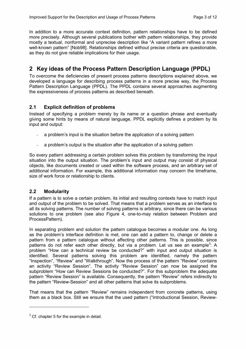
2.2 Modularity If a pattern is to solve a certain problem, its initial and resulting contexts have to match input and output of the problem to be solved. That means that a problem serves as an interface to all its solving patterns. The number of solving patterns is arbitrary, since there can be various solutions to one problem (see also Figure 4, one-to-may relation between Problem and ProcessPattern).
In separating problem and solution the pattern catalogue becomes a modular one. As long as the problem’s interface definition is met, one can add a pattern to, change or delete a pattern from a pattern catalogue without affecting other patterns. This is possible, since patterns do not refer each other directly, but via a problem. Let us see an example3: A problem “How can a technical review be conducted?” with input and output situation is identified. Several patterns solving this problem are identified, namely the pattern “Inspection”, “Review” and “Walkthrough”. Now the process of the pattern “Review” contains an activity “Review Session”. The activity “Review Session” can now be assigned the subproblem “How can Review Sessions be conducted?”. For this subproblem the adequate pattern “Review Session” is available. Consequently, the pattern “Review” refers indirectly to the pattern “Review-Session” and all other patterns that solve its subproblems.
That means that the pattern “Review” remains independent from concrete patterns, using them as a black box. Still we ensure that the used pattern (“Introductional Session, Review-
3 Cf. chapter 5 for the example in detail.
Improved Support for the Description and Usage of Process Patterns Page 4 of 12
Session and “Release” - which ever is chosen by the user of the catalogue) works in the context of the pattern ”Review”. The user of the catalogue is guided to the detailed descriptions of all possibly applicable patterns.
Problem Solution
Activity
1 1
0..*
1..*
1 0..*
0..1
1
ProcessPattern
Figure 1: Modularity of Process Patterns
2.3 More formal definition of processes The PPDL allows presenting the solutions graphically and forces the documenter to a higher degree of formality than natural language would do. The solution provided by a process pattern is a process. So we need to offer notations for modeling processes, such as activities, results of activities, objects, states, roles, parallel action and non-determinism.
As mentioned above, patterns can be linked to other problem definitions inside the catalogue. The link is not added to the whole pattern (pointing from the pattern to the problem), but from a single activity (posing the problem, pointing from that activity to the problem). The input and output of such an activity must also match the interface definition of the linked problem. For attaining this there are syntactic rules in PPDL. Thus there is a consistent implementation of the interface definition.
2.4 Specializing and generalizing patterns The fewer input is required by a pattern, the larger is its scope of application. Contrariwise more input means having access to more information and documents, which can lead to quicker, more efficient or more elegant solutions. Obviously we have contradictory goals.
The PPDL solves this dilemma by defining a relationship between more general and more specialized patterns solving the same problem. A diagram provides an overview of all solving patterns and illustrates the specializations. The user can easily pick the most specialized pattern fitting his situation.
3 Relationships – What glues Process Patterns together Besides the need of a standard description of process patterns also process pattern relationships need to be defined in a standardized way. After having defined the relationships conceptually, we formalized them in adding metaclasses and constraints to the UML.
All relationship definitions are specified with respect to – initial and resulting - contexts of related patterns. Contexts are the glue of process patterns and therefore determine the patterns’ relationships.
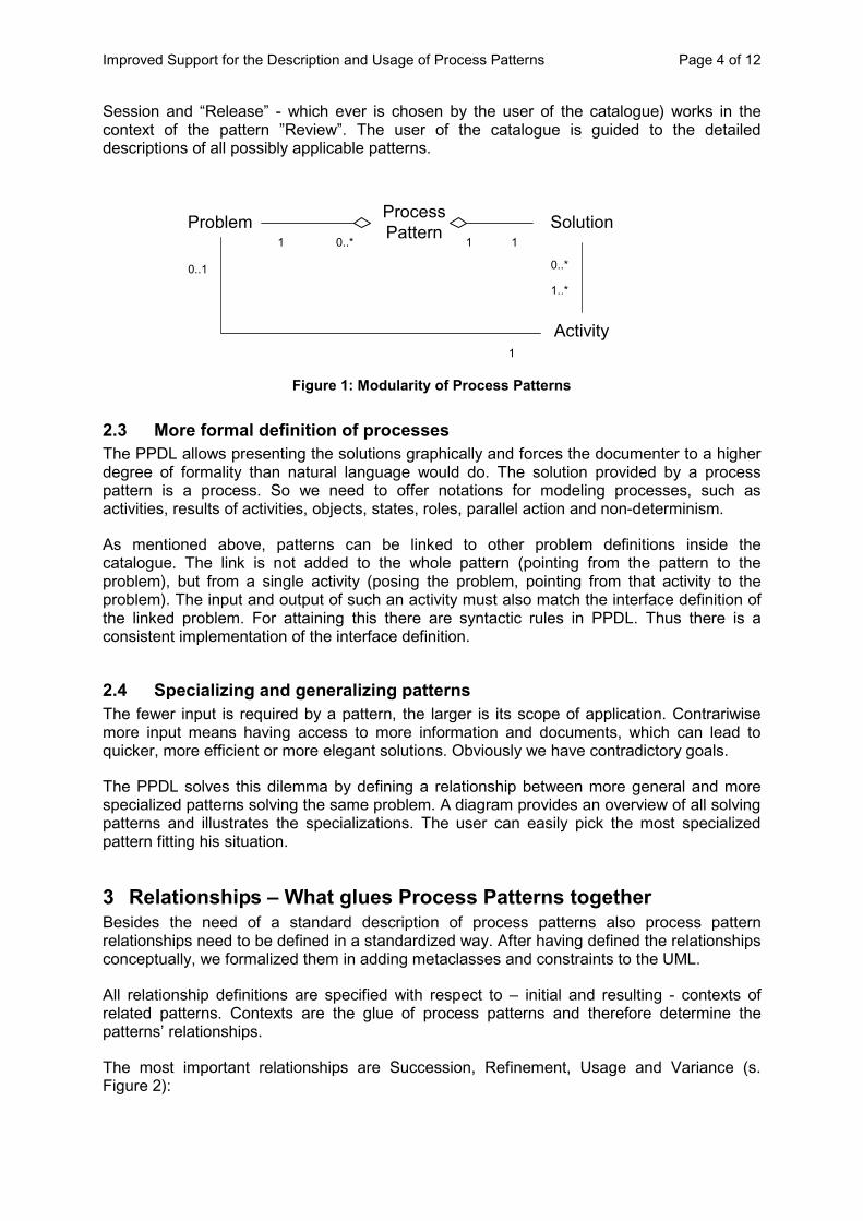
The most important relationships are Succession, Refinement, Usage and Variance (s. Figure 2):
Improved Support for the Description and Usage of Process Patterns Page 5 of 12
ComponentPattern
Superpattern
refines
Subpattern
Predecessor Successor
CompositePattern
usessucceeds
(a) (b) (c)
Variant 1 Variant 2varies to
(d)
Figure 2: Process Pattern Relationships (a: Succession, b: Refinement, c: Usage, d: Variance)
Definition 1: Pattern A (Predecessor) and Pattern B (Successor) are related by SUCCESSION, if Pattern A produces all artifacts, which Pattern B consumes, i.e. the initial context of Pattern B is a subset of the resulting context of Pattern A.
Definition 2: Pattern A (Superpattern) and Pattern B (Subpattern) are related by REFINEMENT, if Pattern B is a specialization of Pattern A, i.e. the initial and the resulting contexts of Pattern A and B match, whereas Pattern B’s process is described more detailed than the process of Pattern A.
The (initial / resulting) contexts of the two pattern match, if the subpattern’s context completely includes the superpattern’s context. It may well be real superset.
Definition 3: Pattern A (Composite Pattern) and Pattern B (Component Pattern) are related by USAGE, if Pattern B represents a sub-process of Pattern A, i.e. Pattern B describes part of the solution of Pattern A. This requires that the problem of Pattern A can be decomposed into subproblems, of which one addresses Pattern B. The initial context of Pattern B then corresponds to the input states of the using activity of Pattern A; the resulting context of Pattern B then corresponds to the output states of the using activity of Pattern A.4
4 This relationship is expressed indirectly. The composite pattern’s activity is linked to a problem and the catalogue may contain several solving patterns to the problem.
Improved Support for the Description and Usage of Process Patterns Page 6 of 12
Definition 4: Pattern A (Variant1) and Pattern B (Variant2) are related by VARIANCE, if they solve the same problem within the same context with mutual exclusive solutions.
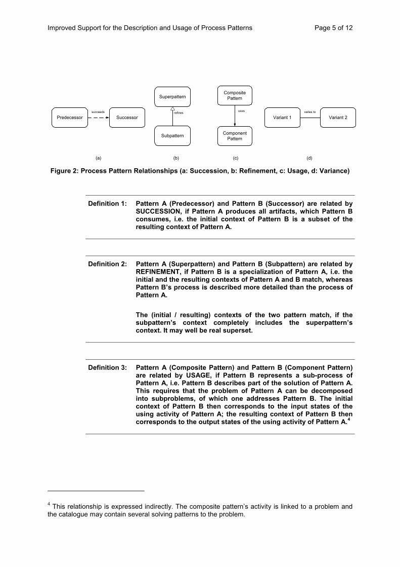
Figure 3 shows examples for the relationships defined above. The “Design” pattern is the predecessor of the pattern “Implement”, which is succeeded by the pattern “Test”. The specialization of the pattern “Design” is the pattern “OO Design”. The composite pattern “Design” uses two component patterns “Design components” and “Design Database”. If a pattern is composed of other patterns as in this case the pattern “Design”, the pattern’s symbol is cross hatched. The two patterns “Design Components” and “Design Realtime Components” are variants of each other.
Design
refines
OO Design
DesignComponents
DesignRealtime
Components
DesignComponents
Design
DesignDatabase
(a)
(b)
(c) (d)
Design Implement Test
Figure 3: Example Relationships (a: Succession, b: Refinement, c: Usage, d: Variance)
4 The Process Pattern Description Language
4.1 Choosing UML as the language foundation For adding precision and unequivocalness to process patterns, we have to use a language to model the processes inside the patterns. As discussed above, we do not develop a new language from scratch but use and extend an existing one. There are several languages that provide graphic notations for processes from which we choose UML [UML01] as a foundation for the Process Pattern Description Language (PPDL) for several reasons:
�� UML is the lingua franca of software engineering. Thus, the amount of new notations to learn for people mining and applying process patterns is small.
�� UML Activity Diagrams offer the necessary elements for modeling processes including activities, artifacts and parallel action. We additionally introduced concepts for representing roles connected to activities and concepts for representing composition of process patterns.
Improved Support for the Description and Usage of Process Patterns Page 7 of 12
�� UML allows extending its syntax and semantics by defining UML profiles, even to add new diagrams (see [BGJ99] for different degrees of extension). E.g. for expressing all kinds of relations we define new diagram types.
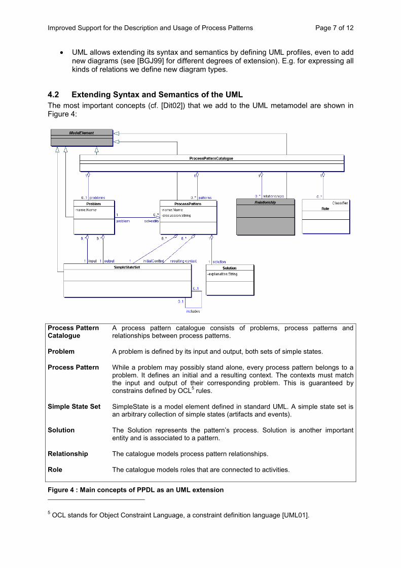
4.2 Extending Syntax and Semantics of the UML The most important concepts (cf. [Dit02]) that we add to the UML metamodel are shown in Figure 4:
Process Pattern Catalogue
A process pattern catalogue consists of problems, process patterns and relationships between process patterns.
Problem A problem is defined by its input and output, both sets of simple states.
Process Pattern While a problem may possibly stand alone, every process pattern belongs to a problem. It defines an initial and a resulting context. The contexts must match the input and output of their corresponding problem. This is guaranteed by constrains defined by OCL5 rules.
Simple State Set SimpleState is a model element defined in standard UML. A simple state set is an arbitrary collection of simple states (artifacts and events).
Solution The Solution represents the pattern’s process. Solution is another important entity and is associated to a pattern.
Relationship The catalogue models process pattern relationships.
Role The catalogue models roles that are connected to activities.
Figure 4 : Main concepts of PPDL as an UML extension 5 OCL stands for Object Constraint Language, a constraint definition language . [UML01]

Improved Support for the Description and Usage of Process Patterns Page 8 of 12
4.3 Choosing an appropriate Notation The PPDL provides different diagram types for problems and patterns and furthermore for relationships. The main diagram types are (included diagram types in brackets):
�� Problem diagram (includes Solution diagram) and
�� Process pattern diagram (includes Process diagram and Usage diagram)
The Problem Diagram represents a problem and its input and output. Input and output must be matched by its solving patterns. Then there is an overview of its solving patterns (i.e. the Solution diagram) and their relations. Refinement associations may be commented by the difference of their contexts, as shown below (cf. Figure 5).
Problem How can a technical review be conducted?
Input object to be reviewed
Output object reviewed and released Review Protocol
Process Patterns
Technical Review
ReviewInspection Walkthrough
Formal ReviewInspection Planand InspectionRules needed
Semiformal ReviewReview criteria
neededInformal Review
Figure 5: Problem Diagram (Solution diagram in the “Process Patterns” section)
A process pattern diagram (Figure 6) represents a process pattern and its initial and resulting context, followed by a process description (the process diagram) and the discussion (pros and cons forces, rationale, example).
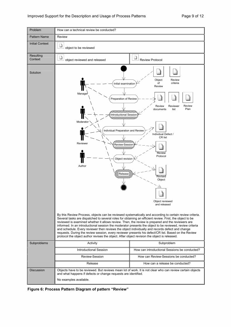
Improved Support for the Description and Usage of Process Patterns Page 9 of 12
Problem How can a technical review be conducted?
Pattern Name Review
Initial Context object to be reviewed
Resulting Context
object reviewed and released Review Protocol
Solution
By this Review Process, objects can be reviewed systematically and according to certain review criteria. Several tasks are dispatched to several roles for obtaining an efficient review. First, the object to be reviewed is examined whether it allows review. Then, the review is prepared and the reviewers are informed. In an introductional session the moderator presents the object to be reviewed, review criteria and schedule. Every reviewer then reviews the object individually and records defect and change requests. During the review session, every reviewer presents his defect/CR list. Based on the Review protocol the object author revises the object. After object revision the object is released.
Activity Subproblem
Introductional Session How can introductional Sessions be conducted?
Review-Session How can Review-Sessions be conducted?
Subproblems
Release How can a release be conducted?
Discussion Objects have to be reviewed. But reviews mean lot of work. It is not clear who can review certain objects and what happens if defects or change requests are identified.
No examples available.
Preparation of Review
Objectof
ReviewInitial examination
Manager
Reviewer
Introductional Session
Individual Preparation and Review
Review-Session
Object revision
Release
Moderator
Author
ReviewPlan
Reviewcriteria
Individual Defect /CR list
ReviewProtocol
RevisedObject
Object reviewedand released
Reviewdocuments
Reviewerlist
Figure 6: Process Pattern Diagram of pattern “Review”

Improved Support for the Description and Usage of Process Patterns Page 10 of 12
PPDL Process Diagrams provide - compared to the UML Activity Diagram – the possibility to show if there are possibly other patterns that can be used to perform certain activities (in the sense of the Usage relationship). In this case activities are hatched (see activities “Introductional Session”, “Review-Session“ and „Release“). The table “Subproblems” below the Process Diagram redirects the reader to the referred problem. Figure 7 then shows the process pattern “Review Session”, which is used by the process pattern “Review”. That means that the pattern “Review” and “Review Session” are related by a Usage relationship.
Problem How can Review-Sessions be conducted?
Pattern Name Review-Session
Initial Context Individual Defect / CR list
Resulting Context
technical review protocol
Solution
The review session serves to gather all review information (defects and change requests) that has been detected by the reviewers. First, the moderator explains how the review session is going to proceed. Then, every reviewer presents defects and CRs detected. Then the defects / CRs have to be evaluated (e.g. high, middle low priority or effort) to determine how to handle them. After evaluation the results are summarized in the review protocol.
Activity Subproblem Subproblems
Evaluation of Defects/CRs How Defects and CRs be evalutated?
Discussion A review needs a review session. This session must be systematically and efficiently in that sense that defects and CRs are gathered but not discussed. The review session is not to be misused for discussing the proper solution.
No examples available.
Presentation of Defects / CRs
Explication ofReview Session Process
Moderator
ReviewerEvaluation of Defects / CRs
Protocol Result
Individual Defect /CR list
ReviewProtocol
Defects/CRsevaluated
Figure 7: Process Pattern Diagram of pattern “Review Session”
To get an even quicker survey of Usage relations of a process pattern, take a look at the Usage Diagram (Figure 8):
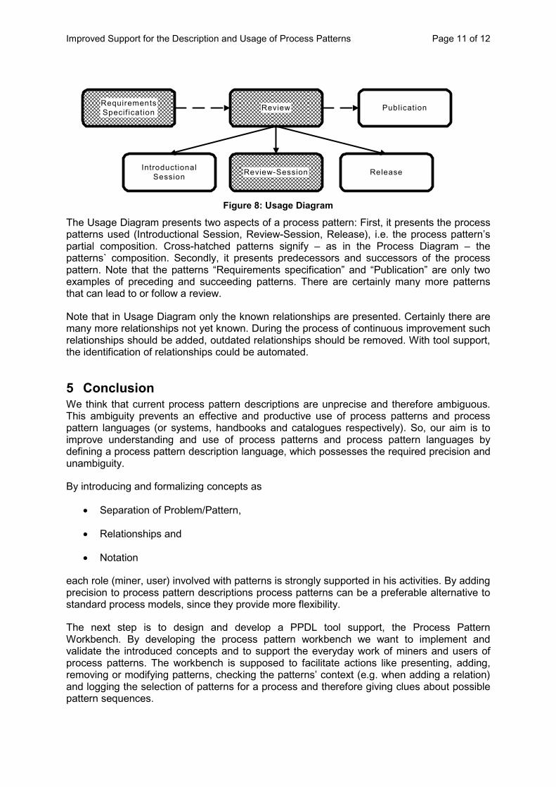
Improved Support for the Description and Usage of Process Patterns Page 11 of 12
Review
IntroductionalSession Review-Session Release
RequirementsSpecif ication Publication
Figure 8: Usage Diagram
The Usage Diagram presents two aspects of a process pattern: First, it presents the process patterns used (Introductional Session, Review-Session, Release), i.e. the process pattern’s partial composition. Cross-hatched patterns signify – as in the Process Diagram – the patterns` composition. Secondly, it presents predecessors and successors of the process pattern. Note that the patterns “Requirements specification” and “Publication” are only two examples of preceding and succeeding patterns. There are certainly many more patterns that can lead to or follow a review.
Note that in Usage Diagram only the known relationships are presented. Certainly there are many more relationships not yet known. During the process of continuous improvement such relationships should be added, outdated relationships should be removed. With tool support, the identification of relationships could be automated.
5 Conclusion We think that current process pattern descriptions are unprecise and therefore ambiguous. This ambiguity prevents an effective and productive use of process patterns and process pattern languages (or systems, handbooks and catalogues respectively). So, our aim is to improve understanding and use of process patterns and process pattern languages by defining a process pattern description language, which possesses the required precision and unambiguity.
By introducing and formalizing concepts as
�� Separation of Problem/Pattern,
�� Relationships and
�� Notation
each role (miner, user) involved with patterns is strongly supported in his activities. By adding precision to process pattern descriptions process patterns can be a preferable alternative to standard process models, since they provide more flexibility.
The next step is to design and develop a PPDL tool support, the Process Pattern Workbench. By developing the process pattern workbench we want to implement and validate the introduced concepts and to support the everyday work of miners and users of process patterns. The workbench is supposed to facilitate actions like presenting, adding, removing or modifying patterns, checking the patterns’ context (e.g. when adding a relation) and logging the selection of patterns for a process and therefore giving clues about possible pattern sequences.
Improved Support for the Description and Usage of Process Patterns Page 12 of 12
6 References [AIS77] Alexander, C.; Ishikawa, S.; Silverstein, M.: A Pattern Language. New York:
Oxford University Press, 1977. [Ale79] Alexander, C.: The Timeless Way of Building. Oxford University Press, 1979. [Amb98] Ambler, S.: Process Patterns. Cambridge University Press, 1998. [BGJ99] Berner, S.; Glinz, M.; Joos, S.: A Classification of Stereotypes for Object-
Oriented Modeling Languages. In: Proceedings of UML 1999, LNCS 1723, 1999, pp. 249-264.
[BMR96] Buschmann, F.; Meunier, R; Rohnert, H. et al. : Pattern-Oriented Software Architecture - A System of Patterns. Wiley and Sons, 1996
[BRS98] Bergner, K.; Rausch, A.; Sihling, M.: A Component Methodology based on Process Patterns. In: Proceedings of the 5th Annual Conference on the Pattern Languages of Programs (PLoP), 1998. Available at www4.informatik.tu-muenchen.de/rausch/publications/.
[Cop94] Coplien, J.: A Development Process Generative Pattern Language. In: Proceedings of PLoP 94, 1994.
[Cop96] Coplien, J.: Software Patterns. SIGS Book & Multimedia, 1996. [Dit02] Dittmann, T.: PPDL – Eine Beschreibungssprache für Process Patterns,
2002, University of Dortmund [Ede97] Eden, A.: Giving The Quality a Name: Precise Specification of Design
Patterns: A Second Look at the Manuscripts. In: Journal of Object Oriented Programming, SIGS Publications, http://www.math.tau.ac.il/~eden/bibliography.html#giving_the_quality_a_name, May 1997.
[GG99] Gabriel, P.; Goldmann, R.: Jini Community Pattern Language, 1999. [GHJ95] Gamma, E.; Helm, R.; Johnson, R. et. al.: Design Patterns. Addison-Wesley,
1995. [Hag02] Hagen, M.: Support for the definition and usage of process patterns. Focus
Group “What makes Pattern Languages work well”, EuroPloP 2002, to appear.
[Har95] Harrison, N. B.. Organizational Patterns for Teams. In: Coplien, J., & Schmidt, D. C. (Eds): Pattern Languages of Program Design, Reading, Massachusetts, Addison-Wesley, 1995. Available via http://st-www.cs.uiuc.edu/˜plop/.
[LRS00] Lesny, C.; Rumpe, B.; Schwerin, W. et.al.: Prozessmuster und Produktmodell. Available via http://www4.in.tum.de/~rumpe/ProcessPattern.Handout6.pdf, 2000.
[Mar99] Marzolf, T.R.: A System Composition Pattern Language, 1999. [Nob98] Noble, J.: Classifying Relationships Between Object-Oriented Patterns,
Microsoft Research Institute, 1998 [Ped02] The Paedagogical Patterns Project, http://www.pedagogicalpatterns.org/. [RZ96] Riehle, D.; Züllighoven, H.: Understanding and Using Patterns in Software
Development, Theory and Practice of Object Systems, Vol. 2(1), pp. 3-13. [Stö00] Störrle, H.: Models of Software Architecture. Design and Analysis with UML.
PhD-Thesis, Universität München, 2000. [Stö01] Störrle, H.: Describing Process Patterns with UML. In: Software Process
Technology, LNCS 2077, Springer, 2001, pp. 173-181. [UML01] Unified Modelling Language 1.4, Object Management Group,
http://www.omg.org/technology/documents/formal/uml.htm.
A Process Engineering Metamodel Philippe Kruchten Rational Software April 17, 2001 Note: this paper was published (with minor modifications) as chapter 13 in the book:
Pierre N. Robillard and Philippe Kruchten (2003), Software Processes with the Unified Process for Education (UP/EDU), Addison Wesley Longman 350 pp, ISBN: 0-201-75454-1 (see http://www.aw.com/info/robillard/)
1. Introduction Lee Osterweil wrote in 1987: “Software processes are software, too.” Indeed, a software development process is a complex artifact, not unlike a complex, distributed, concurrent software program. It is after all, the program run by the software project team members. In order to design a process, to compare and assess different processes, to reason about processes and their shortcomings, to deliver a process to the people who use it, process engineers and methods gurus have found that some level of formalism and modeling capabilities are useful. Moreover, once you have a process model, it becomes easier to interface a process with CASE tools, such as a planning tool or an activity management tool, to interchange process components, and to offer some visualization of the process. This section introduces the Unified Software Process Metamodel (USPM). This object-oriented model, expressed in UML, is the common model underlying a family of software engineering processes, including at least the UP/Edu [Robillard 2002], the Unified Software Development Process [Jacobson et al. 1999] and the Rational Unified Process® (RUP®) [Kruchten 2000].
2. The conceptual model At the core of the USPM, is the notion that a software development process is a collaboration between abstract active entities called process roles that perform operations called activities on concrete, tangible entities called artifacts. Figure 1 depicts this concept using a UML class.
Roleactivity1(Artifact_1)activity2(Artifact_2)
Figure 1—Conceptual model
1 © 2001 Rational Software
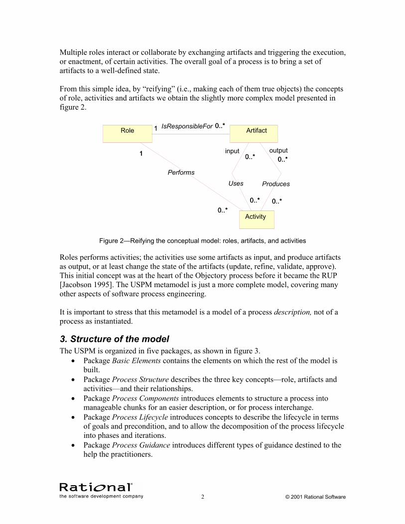
Multiple roles interact or collaborate by exchanging artifacts and triggering the execution, or enactment, of certain activities. The overall goal of a process is to bring a set of artifacts to a well-defined state. From this simple idea, by “reifying” (i.e., making each of them true objects) the concepts of role, activities and artifacts we obtain the slightly more complex model presented in figure 2.
Role
Activity0..*
1
0..*
1
Performs
Artifact0..*1 0..*1 IsResponsibleFor
0..*
0..*
0..*
input0..*
Uses
0..*
0..*
0..*
output 0..*
Produces
Figure 2—Reifying the conceptual model: roles, artifacts, and activities
Roles performs activities; the activities use some artifacts as input, and produce artifacts as output, or at least change the state of the artifacts (update, refine, validate, approve). This initial concept was at the heart of the Objectory process before it became the RUP [Jacobson 1995]. The USPM metamodel is just a more complete model, covering many other aspects of software process engineering. It is important to stress that this metamodel is a model of a process description, not of a process as instantiated.
3. Structure of the model The USPM is organized in five packages, as shown in figure 3.
• Package Basic Elements contains the elements on which the rest of the model is built.
• Package Process Structure describes the three key concepts—role, artifacts and activities—and their relationships.
• Package Process Components introduces elements to structure a process into manageable chunks for an easier description, or for process interchange.
• Package Process Lifecycle introduces concepts to describe the lifecycle in terms of goals and precondition, and to allow the decomposition of the process lifecycle into phases and iterations.
• Package Process Guidance introduces different types of guidance destined to the help the practitioners.
2 © 2001 Rational Software
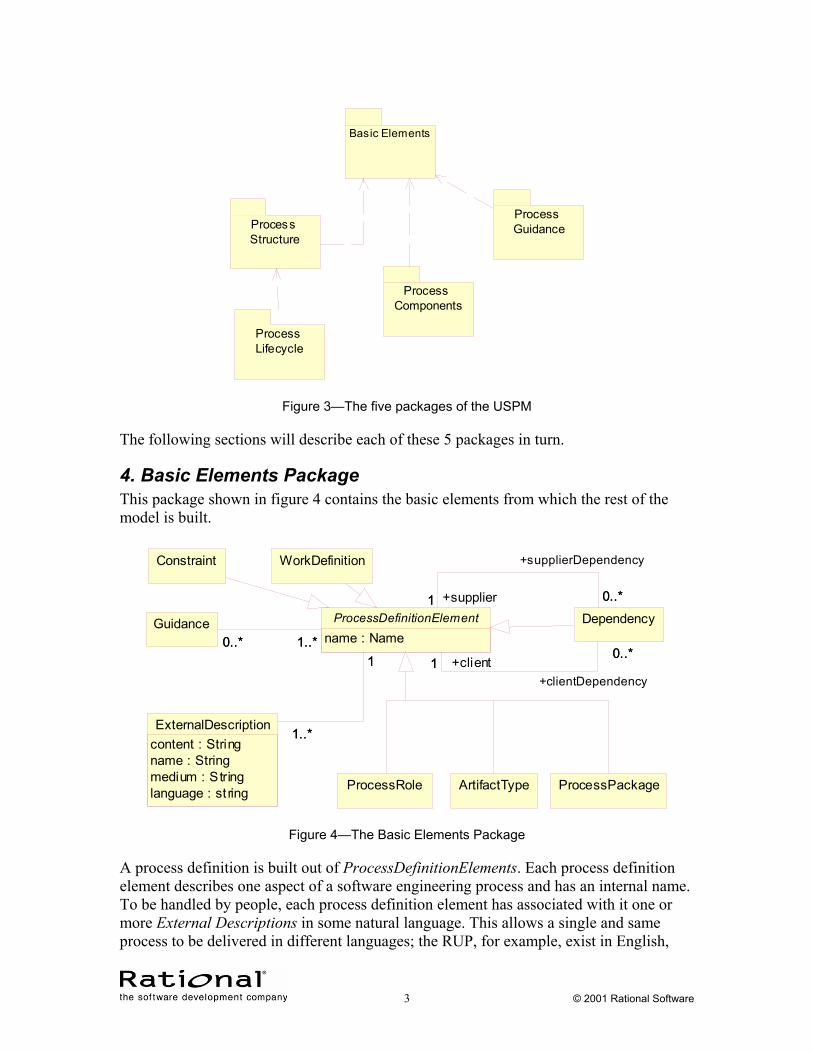
Basic Elements
Process Structure
Process Components
Process Lifecycle
Process Guidance
Figure 3—The five packages of the USPM
The following sections will describe each of these 5 packages in turn.
4. Basic Elements Package This package shown in figure 4 contains the basic elements from which the rest of the model is built.
ArtifactTypeProcessRole
WorkDefinition
Guidance DependencyProcessDefinitionElementname : Name0..* 1..*0..* 1..*
0..*1
+supplierDependency
0..*+supplier1
0..*1
+clientDependency
0..*+client1
ExternalDescriptioncontent : Stringname : Stringmedium : Stringlanguage : st ring
1
1..*
1
1..*
ProcessPackage
Constraint
Figure 4—The Basic Elements Package
A process definition is built out of ProcessDefinitionElements. Each process definition element describes one aspect of a software engineering process and has an internal name. To be handled by people, each process definition element has associated with it one or more External Descriptions in some natural language. This allows a single and same process to be delivered in different languages; the RUP, for example, exist in English,
3 © 2001 Rational Software
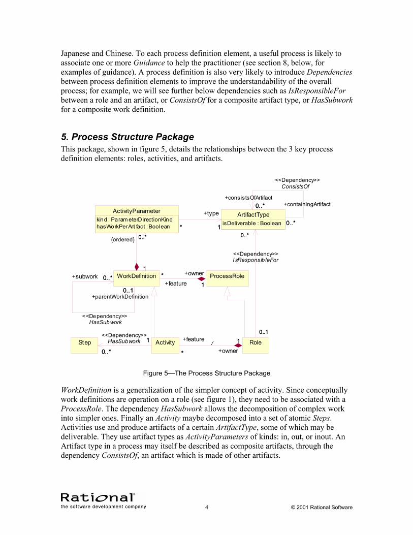
Japanese and Chinese. To each process definition element, a useful process is likely to associate one or more Guidance to help the practitioner (see section 8, below, for examples of guidance). A process definition is also very likely to introduce Dependencies between process definition elements to improve the understandability of the overall process; for example, we will see further below dependencies such as IsResponsibleFor between a role and an artifact, or ConsistsOf for a composite artifact type, or HasSubwork for a composite work definition.
5. Process Structure Package This package, shown in figure 5, details the relationships between the 3 key process definition elements: roles, activities, and artifacts.
ProcessRoleWorkDefinition *1+feature
* +owner
10..1
0..*
+parentWorkDefinition0..1
HasSubwork<<Dependency>>
+subwork 0..*
ActivityParameterkind : Param eterDirectionKindhasWorkPerArti fact : Boolean
0..*
1
0..*{ordered}
1
ArtifactTypeisDeliverable : Boolean
0..*
0..*
+consistsOfArtifact0..*
ConsistsOf<<Dependency>>
+containingArtifact
0..*1*
+type
1*
Step Role
0..1
0..*
0..1
0..*
I sResponsib leFor<<Dependency>>
Activity1
0..*
1
0..*
HasSubwork<<Dependency>>
1
* +owner1+feature
*/
Figure 5—The Process Structure Package
WorkDefinition is a generalization of the simpler concept of activity. Since conceptually work definitions are operation on a role (see figure 1), they need to be associated with a ProcessRole. The dependency HasSubwork allows the decomposition of complex work into simpler ones. Finally an Activity maybe decomposed into a set of atomic Steps. Activities use and produce artifacts of a certain ArtifactType, some of which may be deliverable. They use artifact types as ActivityParameters of kinds: in, out, or inout. An Artifact type in a process may itself be described as composite artifacts, through the dependency ConsistsOf, an artifact which is made of other artifacts.
4 © 2001 Rational Software
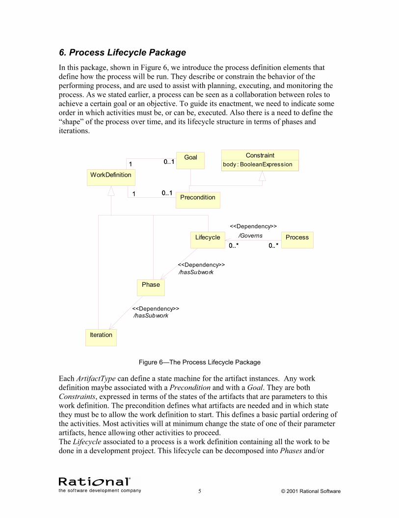
6. Process Lifecycle Package In this package, shown in Figure 6, we introduce the process definition elements that define how the process will be run. They describe or constrain the behavior of the performing process, and are used to assist with planning, executing, and monitoring the process. As we stated earlier, a process can be seen as a collaboration between roles to achieve a certain goal or an objective. To guide its enactment, we need to indicate some order in which activities must be, or can be, executed. Also there is a need to define the “shape” of the process over time, and its lifecycle structure in terms of phases and iterations.
Constraintbody : BooleanExpression
Precondition
Goal
WorkDefinition
0..11 0..11
0..11 0..11
ProcessLifecycle0..* 0..*0..* 0..*
/Governs<<Dependency>>
Phase
Iteration
/hasSubwork<<Dependency>>
/hasSubwork<<Dependency>>
Figure 6—The Process Lifecycle Package
Each ArtifactType can define a state machine for the artifact instances. Any work definition maybe associated with a Precondition and with a Goal. They are both Constraints, expressed in terms of the states of the artifacts that are parameters to this work definition. The precondition defines what artifacts are needed and in which state they must be to allow the work definition to start. This defines a basic partial ordering of the activities. Most activities will at minimum change the state of one of their parameter artifacts, hence allowing other activities to proceed. The Lifecycle associated to a process is a work definition containing all the work to be done in a development project. This lifecycle can be decomposed into Phases and/or
5 © 2001 Rational Software
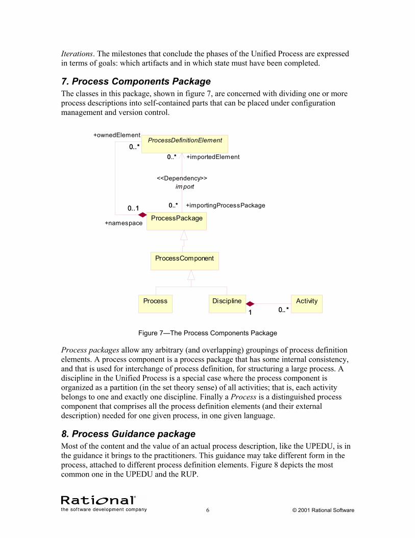
Iterations. The milestones that conclude the phases of the Unified Process are expressed in terms of goals: which artifacts and in which state must have been completed.
7. Process Components Package The classes in this package, shown in figure 7, are concerned with dividing one or more process descriptions into self-contained parts that can be placed under configuration management and version control.
ProcessComponent
Process
ProcessPackage
ProcessDefinitionElement0..*
0..1
+ownedElement
0..*
+namespace
0..1
0..*
0..* +importingProcessPackage
0..* +importedElement
0..*
im port<<Dependency>>
ActivityDiscipline0..*1 0..*1
Figure 7—The Process Components Package
Process packages allow any arbitrary (and overlapping) groupings of process definition elements. A process component is a process package that has some internal consistency, and that is used for interchange of process definition, for structuring a large process. A discipline in the Unified Process is a special case where the process component is organized as a partition (in the set theory sense) of all activities; that is, each activity belongs to one and exactly one discipline. Finally a Process is a distinguished process component that comprises all the process definition elements (and their external description) needed for one given process, in one given language.
8. Process Guidance package Most of the content and the value of an actual process description, like the UPEDU, is in the guidance it brings to the practitioners. This guidance may take different form in the process, attached to different process definition elements. Figure 8 depicts the most common one in the UPEDU and the RUP.
6 © 2001 Rational Software
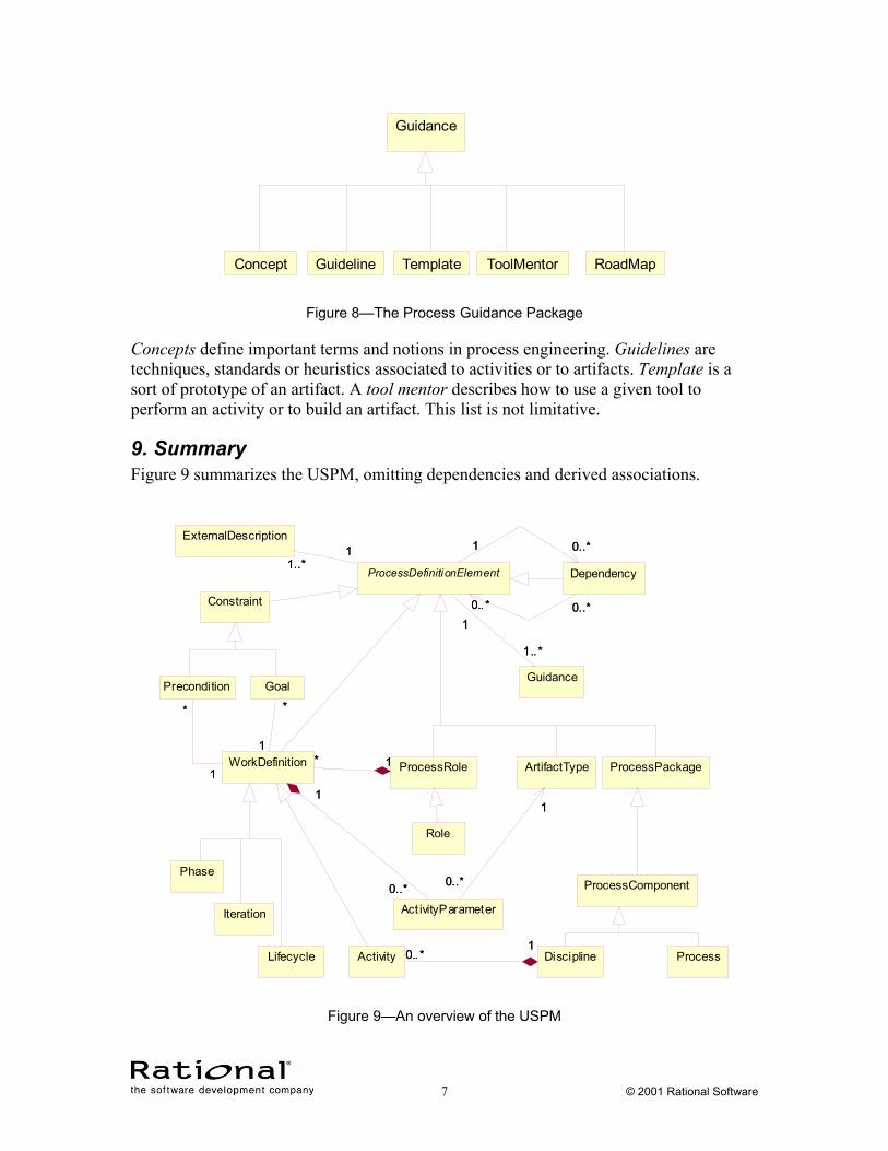
Guidance
ToolMentorConcept Guideline Template RoadMap
Figure 8—The Process Guidance Package
Concepts define important terms and notions in process engineering. Guidelines are techniques, standards or heuristics associated to activities or to artifacts. Template is a sort of prototype of an artifact. A tool mentor describes how to use a given tool to perform an activity or to build an artifact. This list is not limitative.
9. Summary Figure 9 summarizes the USPM, omitting dependencies and derived associations.
ProcessLifecycle
PhaseProcessComponent
ProcessPackage
Iteration
Role
Activity Discipline0..*1
0..*1
Constraint
ExternalDescription
Guidance
ProcessDefinitionElement1..*
11..*
1
1..*
0..*
1..*
0..*
Dependency
0..*1 0..*1
10..*
10..*
ArtifactType
Act ivityParameter
1
0..*
1
0..*
ProcessRole
GoalPrecondition
WorkDefinition
0..*
1
0..*
1
1* 1*
*
1
*
1
*
1
*
1
Figure 9—An overview of the USPM
7 © 2001 Rational Software
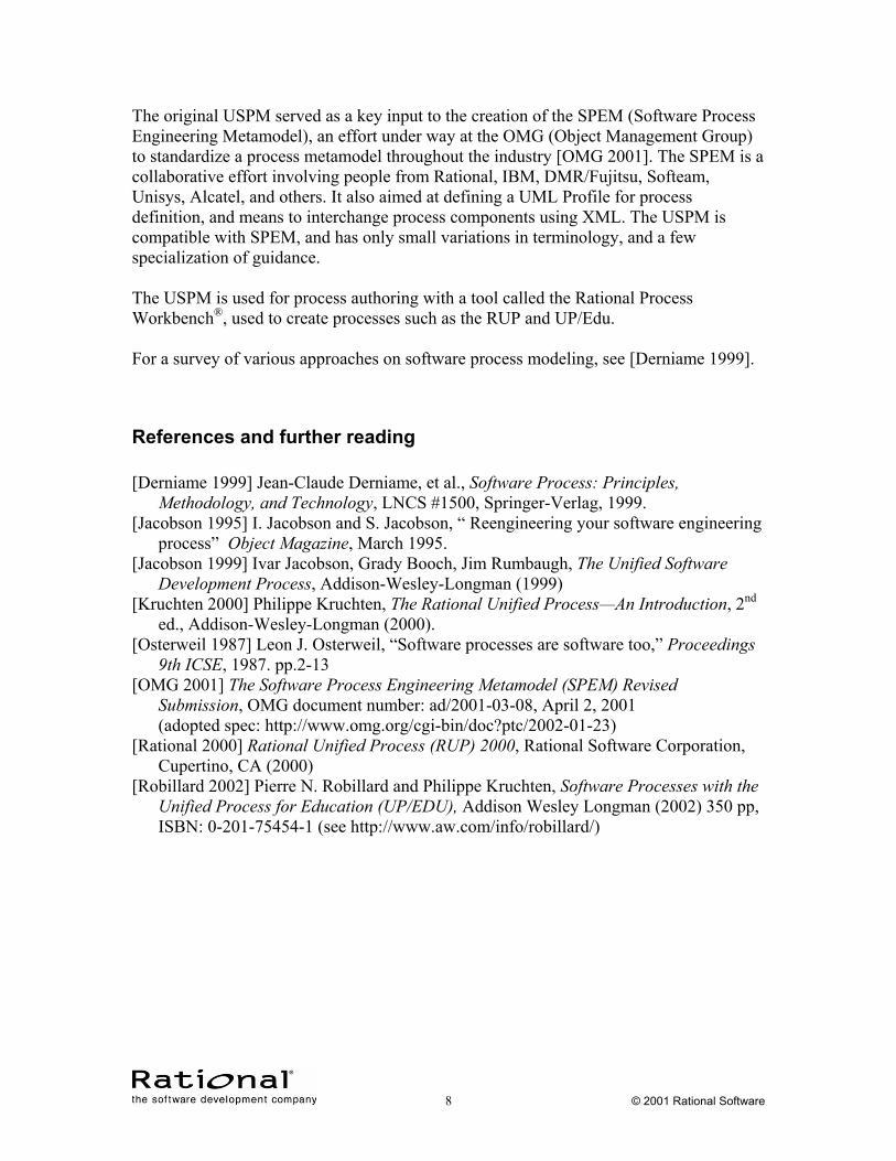
The original USPM served as a key input to the creation of the SPEM (Software Process Engineering Metamodel), an effort under way at the OMG (Object Management Group) to standardize a process metamodel throughout the industry [OMG 2001]. The SPEM is a collaborative effort involving people from Rational, IBM, DMR/Fujitsu, Softeam, Unisys, Alcatel, and others. It also aimed at defining a UML Profile for process definition, and means to interchange process components using XML. The USPM is compatible with SPEM, and has only small variations in terminology, and a few specialization of guidance. The USPM is used for process authoring with a tool called the Rational Process Workbench®, used to create processes such as the RUP and UP/Edu. For a survey of various approaches on software process modeling, see [Derniame 1999].
References and further reading [Derniame 1999] Jean-Claude Derniame, et al., Software Process: Principles,
Methodology, and Technology, LNCS #1500, Springer-Verlag, 1999. [Jacobson 1995] I. Jacobson and S. Jacobson, “ Reengineering your software engineering
process” Object Magazine, March 1995. [Jacobson 1999] Ivar Jacobson, Grady Booch, Jim Rumbaugh, The Unified Software
Development Process, Addison-Wesley-Longman (1999) [Kruchten 2000] Philippe Kruchten, The Rational Unified Process—An Introduction, 2nd
ed., Addison-Wesley-Longman (2000). [Osterweil 1987] Leon J. Osterweil, “Software processes are software too,” Proceedings
9th ICSE, 1987. pp.2-13 [OMG 2001] The Software Process Engineering Metamodel (SPEM) Revised
Submission, OMG document number: ad/2001-03-08, April 2, 2001 (adopted spec: http://www.omg.org/cgi-bin/doc?ptc/2002-01-23)
[Rational 2000] Rational Unified Process (RUP) 2000, Rational Software Corporation, Cupertino, CA (2000)
[Robillard 2002] Pierre N. Robillard and Philippe Kruchten, Software Processes with the Unified Process for Education (UP/EDU), Addison Wesley Longman (2002) 350 pp, ISBN: 0-201-75454-1 (see http://www.aw.com/info/robillard/)
8 © 2001 Rational Software
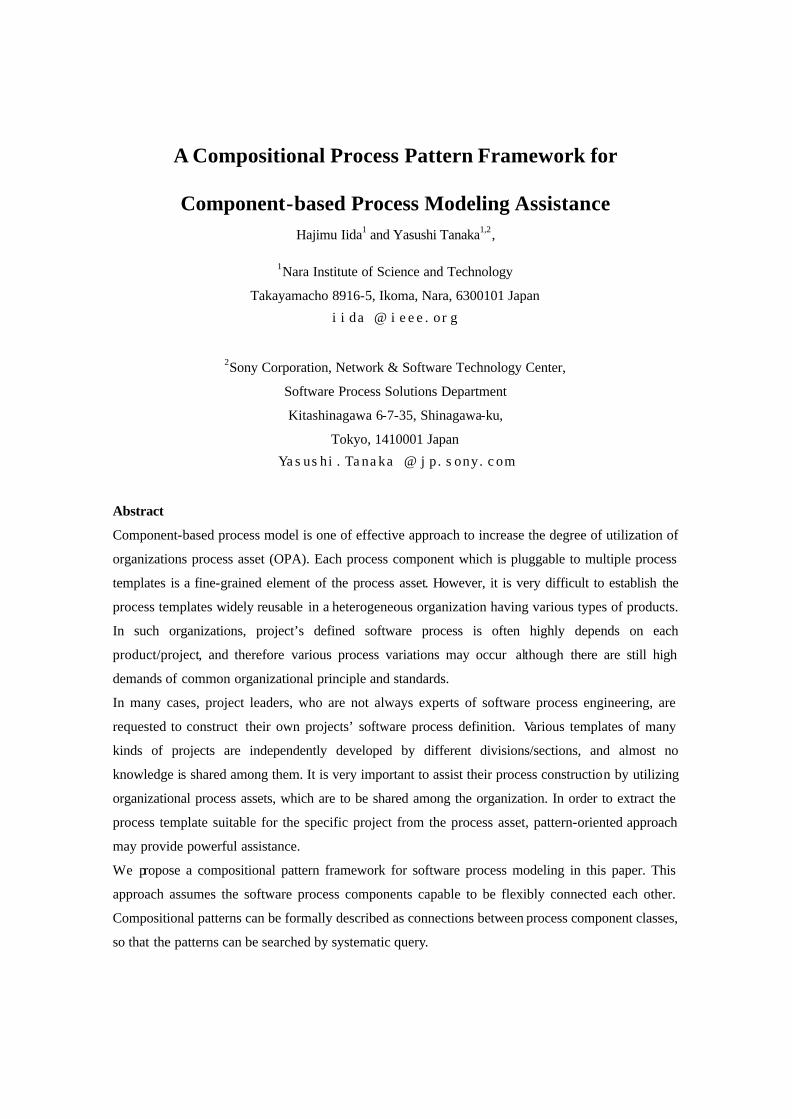
A Compositional Process Pattern Framework for
Component-based Process Modeling Assistance Hajimu Iida1 and Yasushi Tanaka1,2,
1Nara Institute of Science and Technology
Takayamacho 8916-5, Ikoma, Nara, 6300101 Japan
iida @ ieee.org
2Sony Corporation, Network & Software Technology Center,
Software Process Solutions Department
Kitashinagawa 6-7-35, Shinagawa-ku,
Tokyo, 1410001 Japan
Yasushi.Tanaka @ jp.sony.com
Abstract
Component-based process model is one of effective approach to increase the degree of utilization of
organizations process asset (OPA). Each process component which is pluggable to multiple process
templates is a fine-grained element of the process asset. However, it is very difficult to establish the
process templates widely reusable in a heterogeneous organization having various types of products.
In such organizations, project’s defined software process is often highly depends on each
product/project, and therefore various process variations may occur although there are still high
demands of common organizational principle and standards.
In many cases, project leaders, who are not always experts of software process engineering, are
requested to construct their own projects’ software process definition. Various templates of many
kinds of projects are independently developed by different divisions/sections, and almost no
knowledge is shared among them. It is very important to assist their process construction by utilizing
organizational process assets, which are to be shared among the organization. In order to extract the
process template suitable for the specific project from the process asset, pattern-oriented approach
may provide powerful assistance.
We propose a compositional pattern framework for software process modeling in this paper. This
approach assumes the software process components capable to be flexibly connected each other.
Compositional patterns can be formally described as connections between process component classes,
so that the patterns can be searched by systematic query.
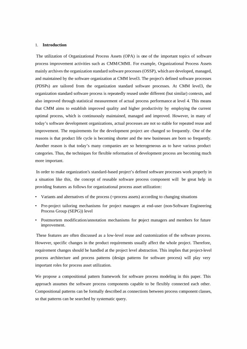
1. Introduction
The utilization of Organizational Process Assets (OPA) is one of the important topics of software
process improvement activities such as CMM/CMMI. For example, Organizational Process Assets
mainly archives the organization standard software processes (OSSP), which are developed, managed,
and maintained by the software organization at CMM level3. The project's defined software processes
(PDSPs) are tailored from the organization standard software processes. At CMM level3, the
organization standard software process is repeatedly reused under different (but similar) contexts, and
also improved through statistical measurement of actual process performance at level 4. This means
that CMM aims to establish improved quality and higher productivity by employing the current
optimal process, which is continuously maintained, managed and improved. However, in many of
today’s software development organizations, actual processes are not so stable for repeated reuse and
improvement. The requirements for the development project are changed so frequently. One of the
reasons is that product life cycle is becoming shorter and the new businesses are born so frequently.
Another reason is that today’s many companies are so heterogeneous as to have various product
categories. Thus, the techniques for flexible reformation of development process are becoming much
more important.
In order to make organization’s standard-based project’s defined software processes work properly in
a situation like this, the concept of reusable software process component will be great help in
providing features as follows for organizational process asset utilization:
• Variants and alternatives of the process (=process assets) according to changing situations
• Pre-project tailoring mechanisms for project managers at end-user (non-Software Engineering Process Group (SEPG)) level
• Postmortem modification/annotation mechanisms for project managers and members for future improvement.
These features are often discussed as a low-level reuse and customization of the software process.
However, specific changes in the product requirements usually affect the whole project. Therefore,
requirement changes should be handled at the project level abstraction. This implies that project-level
process architecture and process patterns (design patterns for software process) will play very
important roles for process asset utilization.
We propose a compositional pattern framework for software process modeling in this paper. This
approach assumes the software process components capable to be flexibly connected each other.
Compositional patterns can be formally described as connections between process component classes,
so that patterns can be searched by systematic query.
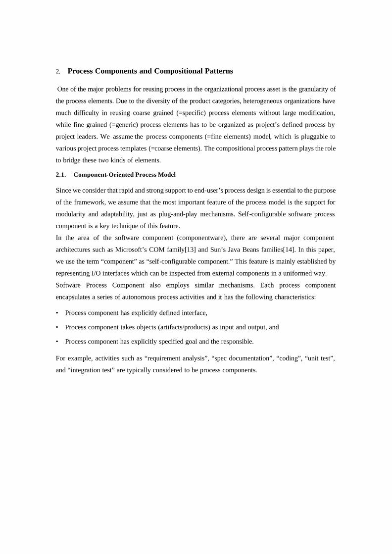
2. Process Components and Compositional Patterns
One of the major problems for reusing process in the organizational process asset is the granularity of
the process elements. Due to the diversity of the product categories, heterogeneous organizations have
much difficulty in reusing coarse grained (=specific) process elements without large modification,
while fine grained (=generic) process elements has to be organized as project’s defined process by
project leaders. We assume the process components (=fine elements) model, which is pluggable to
various project process templates (=coarse elements). The compositional process pattern plays the role
to bridge these two kinds of elements.
2.1. Component-Oriented Process Model
Since we consider that rapid and strong support to end-user’s process design is essential to the purpose
of the framework, we assume that the most important feature of the process model is the support for
modularity and adaptability, just as plug-and-play mechanisms. Self-configurable software process
component is a key technique of this feature.
In the area of the software component (componentware), there are several major component
architectures such as Microsoft’s COM family[13] and Sun’s Java Beans families[14]. In this paper,
we use the term “component” as “self-configurable component.” This feature is mainly established by
representing I/O interfaces which can be inspected from external components in a uniformed way.
Software Process Component also employs similar mechanisms. Each process component
encapsulates a series of autonomous process activities and it has the following characteristics:
• Process component has explicitly defined interface,
• Process component takes objects (artifacts/products) as input and output, and
• Process component has explicitly specified goal and the responsible.
For example, activities such as “requirement analysis”, “spec documentation”, “coding”, “unit test”,
and “integration test” are typically considered to be process components.
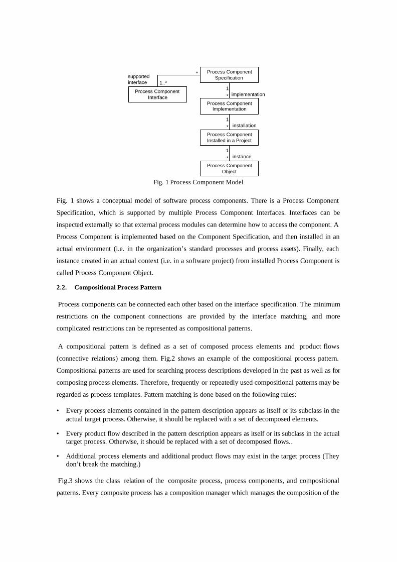
Fig. 1 shows a conceptual model of software process components. There is a Process Component
Specification, which is supported by multiple Process Component Interfaces. Interfaces can be
inspected externally so that external process modules can determine how to access the component. A
Process Component is implemented based on the Component Specification, and then installed in an
actual environment (i.e. in the organization’s standard processes and process assets). Finally, each
instance created in an actual context (i.e. in a software project) from installed Process Component is
called Process Component Object.
2.2. Compositional Process Pattern
Process components can be connected each other based on the interface specification. The minimum
restrictions on the component connections are provided by the interface matching, and more
complicated restrictions can be represented as compositional patterns.
A compositional pattern is defined as a set of composed process elements and product flows
(connective relations) among them. Fig.2 shows an example of the compositional process pattern.
Compositional patterns are used for searching process descriptions developed in the past as well as for
composing process elements. Therefore, frequently or repeatedly used compositional patterns may be
regarded as process templates. Pattern matching is done based on the following rules:
• Every process elements contained in the pattern description appears as itself or its subclass in the actual target process. Otherwise, it should be replaced with a set of decomposed elements.
• Every product flow described in the pattern description appears as itself or its subclass in the actual target process. Otherwise, it should be replaced with a set of decomposed flows..
• Additional process elements and additional product flows may exist in the target process (They don’t break the matching.)
Fig.3 shows the class relation of the composite process, process components, and compositional
patterns. Every composite process has a composition manager which manages the composition of the
Process ComponentSpecification
Process ComponentImplementation
Process ComponentInstalled in a Project
Process ComponentObject
Process ComponentInterface
supportedinterface 1..*
*
1*
1*
1*
implementation
installation
instance
Fig. 1 Process Component Model
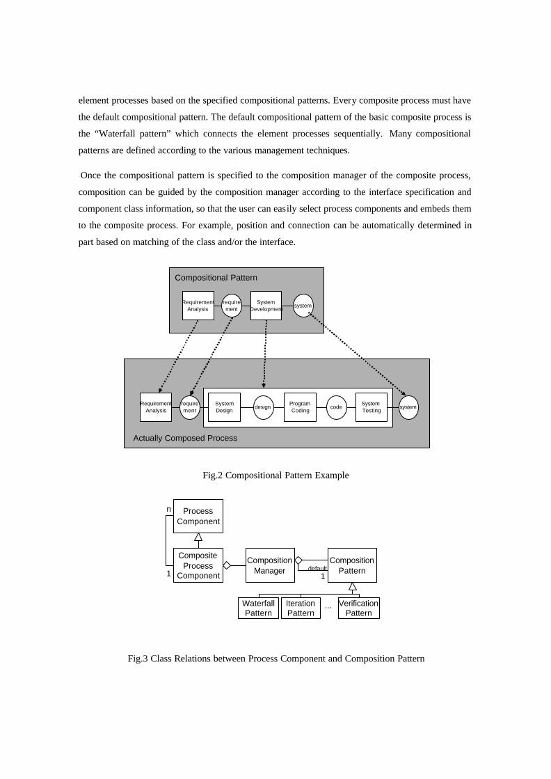
element processes based on the specified compositional patterns. Every composite process must have
the default compositional pattern. The default compositional pattern of the basic composite process is
the “Waterfall pattern” which connects the element processes sequentially. Many compositional
patterns are defined according to the various management techniques.
Once the compositional pattern is specified to the composition manager of the composite process,
composition can be guided by the composition manager according to the interface specification and
component class information, so that the user can easily select process components and embeds them
to the composite process. For example, position and connection can be automatically determined in
part based on matching of the class and/or the interface.
RequirementAnalysis
requirement
SystemDesign
designProgramCoding
codeSystemTesting
system
SystemDevelopment
systemRequirement
Analysisrequirement
Actually Composed Process
Compositional Pattern
Fig.2 Compositional Pattern Example
ProcessComponent
CompositeProcess
Component
CompositionManager
CompositionPattern1
n
1default
WaterfallPattern
IterationPattern
VerificationPattern
...
Fig.3 Class Relations between Process Component and Composition Pattern

2.3. Process Composition Tool
We are developing a tool which supports project leaders in project’s defined software process
implementation work. The process definition is composed as a set of process components, which are
graphically drawn on the window (see Fig. 2.) Project templates are also provided as process
components. Each component provides its interfaces to connect with each other, but there are types of
interfaces that only allow the valid combinations of the components. Project templates can be searched
by specifying the compositional patterns. User can browse each component’s description, which is
fundamentally documented in XML. User also can search process components which can be
connected specific components based on the component interface specification and the component
class tree.
3. Discussion There are many work related to the underlying software process component technology. For example,
there is the Software Process Engineering Metamodel (SPEM) published by OMG[14], which defines
metamodel of Process Modeling Parts as a profile of UML. There are researches of object-oriented
mechanisms for process execution. For example, Di Nitto et al. have developed a system which can
generate executable process description from UML description. For another example, Taylor et al.
have developed Endeavors system[3] which can build executable process description visually by
connecting process elements, which are represented as component objects. These researches treat
interesting and highly technical issues for process execution and reuse. However, most of them are
hard to apply directly to industry’s actual process improvement activity. We consider that executable
Process Designer: Development process with parallel testing
Begin PJ
Process Inspector
Property Event
Brainstorm
Unit Test
Cording
Process Recommender
Debug
Debug
AcceptanceTest
MakeSpecification
Review
Component Palette
Requirem
entD
evelopment
Testin
gE
valuatio
nO
thers
Coding
Debug
Review
ConfirmSpecification
OverhaulConfirm
Specification
Name: Review
Members: 5
Man-hour: 10
Term: 16h
Cost: $1,500
Method: Walk thro
Files: 12
Language: Java
RiskEvaluation
ProgressEvaluation
ReviewInheritance Interfaces PropertiesEvents Usage References
Improvement of member’s understanding about entered product.
CategoryDevelopment
DetailReview is one of the activities in the development phase.
Review improves understanding among participants of the activityabout entered product, so that the participants’ short-term productivities are increased.
HintGenerally, multiple short time reviews are more effective than along time review.
Process Designer Help
Fig. 2 Process Composition Tool
process code is not mandatory for software process improvement, although it is very interesting and
challenging issue.
There are several works on software process patterns[2,7,8,9,10,11], For example, Gnats et. al. tries to
represent process patterns as a kind of component, which can adapt to changing context.[8]. However,
too much complex semantic may be exposed to end users without further assistance mechanisms. Our
approach aims additional mechanism for end-users’ utilization.
As a view point of software process modeling assistance, our approach is similar to that of the
Spearmint/EPG system[1], which is developed by Fraunhofer IESE. Spearmint/EPG is a process
modeling and documentation tool that eases process description work by supporting multiple
representational views such as E-R diagram like product flow view, tree-formed structural view, and
“electronic guidebook” style HTML view. Spearmint is a process modeling tool for process engineers.
Although Spearmint’s process models are stored in an object-oriented database, there is no explicit
support for reuse of process elements. Our focus is process modeling/authoring support for end-users
(non-SEPG project leaders), and we introduce component and pattern handling mechanism into our
framework in order to explicitly support the reuse of process assets.
4. Conclusion There are so many activities of software process improvement reported. Most of them reports that they
didn’t use highly functional process centered environments (PCEs) for their activity. Large software
manufacturers such as mainframe industry could construct detailed process standards and process
asset, which are shared and reused in entire of the company. Smaller organizations having narrow
product area may not be able to take the same approach due to high cost for huge standard process, but
they may take anyhow simplified approach for process definition and reuse. In some cases, simply
semi-formal documents such as Microsoft Word or Excel files are used as templates of process
descriptions. They use these documents mainly because end-users can easily view/edit them.
However, it is very hard to share such process documents as it is in heterogeneous organizations
manufacturing various kinds of products containing some software, for example, PC, video camera
and mobile phone. Still, they also have motivation to establish process assets shareable and reusable in
entire of the company. In this case, developing huge standard process documents or using just simple
template documents of process may not work either. They need to store fine grained generic process
elements, which can be reused in each division by re-organizing them into the project specific process
definition.
In this paper, we have proposed the use of compositional patterns in component-based software
process modeling. This approach helps the utilization of component-based organizational process
asset (OPA). We have outline of our approach and plans for support tools. We are now developing the
pilot implementation of support tools.
References
1. Becker-Kornstaedt et al. "Support for the Process Engineer: The Spearmint Approach to Software Process Definition and Process Guidance". Matthias Jarke, Andreas Oberweis (Eds.): Advanced Information Systems Engineering, Proceedings of the 11th International Conference CAiSE'99, Lecture Notes in Computer Science, Vol. 1626, pp. 119-133. Springer, 1999.
2. Bergner, K., Rausch, A., Sihling, M., Vilbig, A., “A Componentware Development Methodology based on Process Patterns.” in Proceedings of the 5th Annual Conference on the Pattern Languages of Programs. 1998.
3. Bolcer, G., and Taylor, R., “ Endeavors: A Process System Integration Infrastructure,” in Proceedings of the International Conference on Software Process (ICSP4) , December, 2-6, 1996, Brighton, U.K
4. Cheesman, J. and Daniels, J., UML Components: A Simple Process for Specifying Component-Based Software, Addison Wesley, 2001.
5. CMMI Product Team, “CMMI: CMMI-SE/SW/IPPD Version 1.1,” CMU/SEI, 2001. http://www.sei.cmu.edu/cmmi/
6. Conradi, R., Fernström, C., Fuggetta, A., Snowdon, R.: Towards a Reference Framework for Process Concepts. In Lecture Notes in Computer Science 635, Software Process Technology, Proceedings of the second European Workshop EWSPT’92, Trondheim, Norway, September, 1992, pp. 3-20, J.C. Derniame (Ed.), Springer Verlag, 1992.
7. Coplien, J. and Schmidt, D., (ed.). Pattern Languages of Program Design, Addison-Wesley, pp.183-238, 1999.
8. Finkelstein, A., Kramer, J., Nuseibeh B. “Software Process Modelling and Technology.” ResearchStudies Press Ltd, JohnWiley & Sons Inc, Taunton, England,1994.
9. Gary, K., Derniame , J.C., Lindquist, T., and Koehnemann, H. “Component-Based Software Process Support”, in Proceedings of the 13th Conference on Automated Software Engineering (ASE'98), Honolulu, Hawaii, October, 1998.
10. Gnatz, M., Marschall, F. Popp, G. Rausch, A. and Schwerin, W., “Towards a Living Software Development Process based on Process Patterns,” In Proceedings of PROFES2001,
11. Iida, H., “Pattern-Oriented Approach to Software Process Evolution,” in Proceedings of IWPSE'99, pp.55-59, 1999.
12. Kellner, M.I., “Connecting reusable software process elements and components ,” in Proceedings of the 10th International Software Process Workshop (ISPW '96), IEEE press, 1996.
13. Di Nitto et al., “Deriving executable process descriptions from UML,” in Proceedings of the 24th International Conference on Software Engineering (ICSE2002), pp.155-165, ACM, 2002.
14. Open Management Group, The Software Process Engineering Metamodel (SPEM), OMG document number: ad/2001-03-08, 2001.
15. Paulk, M. et. al., “CMM: Key Practice of the Capability Maturity Model, Version 1.1,” CMU/SEI -93-TR-25, CMU/SEI, 1993.
16. Rogerson, D., Inside COM, Microsoft Press, 1997.
17. Sun Microsystems, JavaBeans Documentations, http://java.sun.com/products/javabeans/
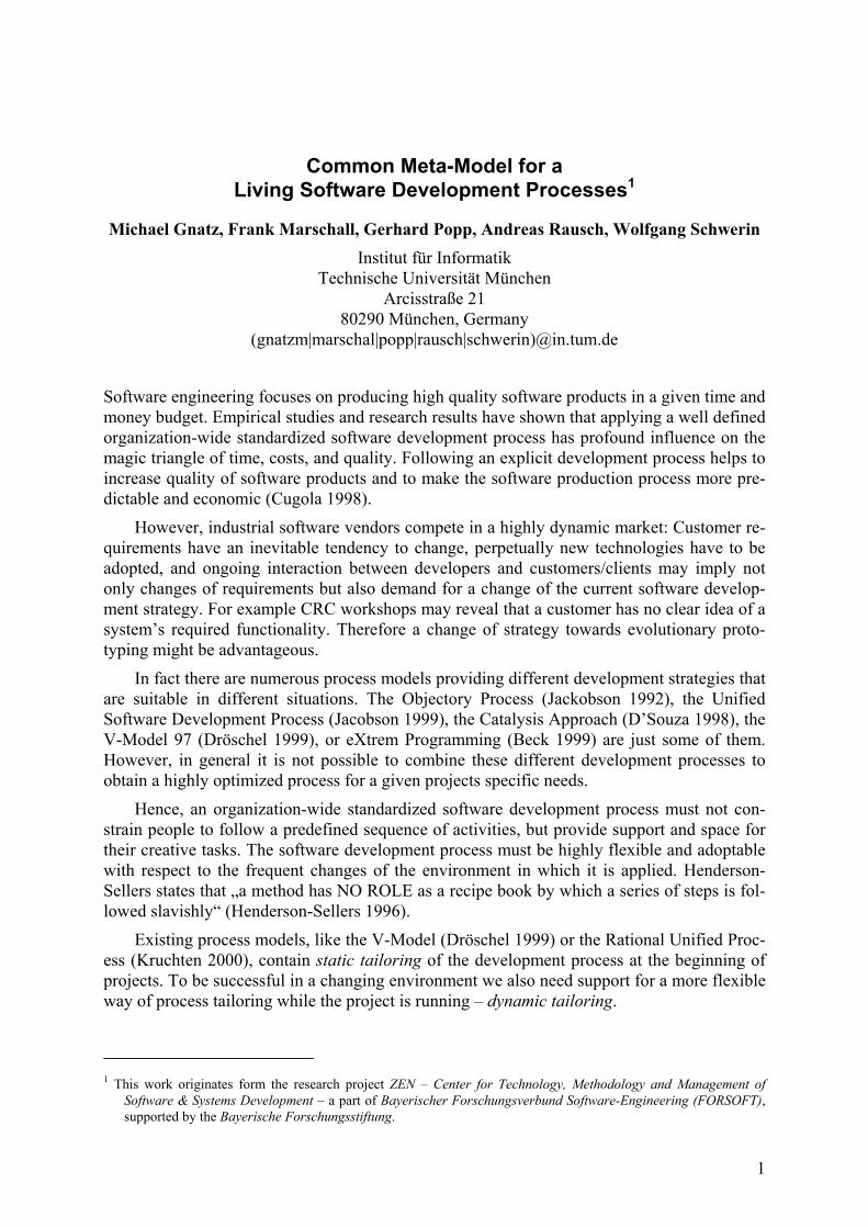
1
Common Meta-Model for a Living Software Development Processes1
Michael Gnatz, Frank Marschall, Gerhard Popp, Andreas Rausch, Wolfgang Schwerin Institut für Informatik
Technische Universität München Arcisstraße 21
80290 München, Germany (gnatzm|marschal|popp|rausch|schwerin)@in.tum.de
Software engineering focuses on producing high quality software products in a given time and money budget. Empirical studies and research results have shown that applying a well defined organization-wide standardized software development process has profound influence on the magic triangle of time, costs, and quality. Following an explicit development process helps to increase quality of software products and to make the software production process more pre-dictable and economic (Cugola 1998).
However, industrial software vendors compete in a highly dynamic market: Customer re-quirements have an inevitable tendency to change, perpetually new technologies have to be adopted, and ongoing interaction between developers and customers/clients may imply not only changes of requirements but also demand for a change of the current software develop-ment strategy. For example CRC workshops may reveal that a customer has no clear idea of a system’s required functionality. Therefore a change of strategy towards evolutionary proto-typing might be advantageous.
In fact there are numerous process models providing different development strategies that are suitable in different situations. The Objectory Process (Jackobson 1992), the Unified Software Development Process (Jacobson 1999), the Catalysis Approach (D’Souza 1998), the V-Model 97 (Dröschel 1999), or eXtrem Programming (Beck 1999) are just some of them. However, in general it is not possible to combine these different development processes to obtain a highly optimized process for a given projects specific needs.
Hence, an organization-wide standardized software development process must not con-strain people to follow a predefined sequence of activities, but provide support and space for their creative tasks. The software development process must be highly flexible and adoptable with respect to the frequent changes of the environment in which it is applied. Henderson-Sellers states that „a method has NO ROLE as a recipe book by which a series of steps is fol-lowed slavishly“ (Henderson-Sellers 1996).
Existing process models, like the V-Model (Dröschel 1999) or the Rational Unified Proc-ess (Kruchten 2000), contain static tailoring of the development process at the beginning of projects. To be successful in a changing environment we also need support for a more flexible way of process tailoring while the project is running – dynamic tailoring.
1 This work originates form the research project ZEN – Center for Technology, Methodology and Management of
Software & Systems Development – a part of Bayerischer Forschungsverbund Software-Engineering (FORSOFT), supported by the Bayerische Forschungsstiftung.
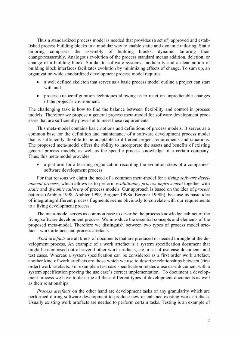
2
Thus a standardized process model is needed that provides (a set of) approved and estab-lished process building blocks in a modular way to enable static and dynamic tailoring. Static tailoring comprises the assembly of building blocks, dynamic tailoring their change/reassembly. Analogous evolution of the process standard means addition, deletion, or change of a building block. Similar to software systems, modularity and a clear notion of building block interfaces facilitates evolution by minimizing effects of change. To sum up, an organization-wide standardized development process model requires
• a well defined skeleton that serves as a basic process model outline a project can start with and
• process (re-)configuration techniques allowing us to react on unpredictable changes of the project’s environment.
The challenging task is how to find the balance between flexibility and control in process models. Therefore we propose a general process meta-model for software development proc-esses that are sufficiently powerful to meet these requirements.
This meta-model contains basic notions and definitions of process models. It serves as a common base for the definition and maintenance of a software development process model that is sufficiently flexible to be adaptable to different project requirements and situations. The proposed meta-model offers the ability to incorporate the assets and benefits of existing generic process models, as well as the specific process knowledge of a certain company. Thus, this meta-model provides
• a platform for a learning organization recording the evolution steps of a companies’ software development process.
For that reasons we claim the need of a common meta-model for a living software devel-opment process, which allows us to perform evolutionary process improvement together with static and dynamic tailoring of process models. Our approach is based on the idea of process patterns (Ambler 1998, Ambler 1999, Bergner 1998a, Bergner 1998b), because its basic idea of integrating different process fragments seems obviously to correlate with our requirements to a living development process.
The meta-model serves as common base to describe the process knowledge cabinet of the living software development process. We introduce the essential concepts and elements of the proposed meta-model. Therefore we distinguish between two types of process model arte-facts: work artefacts and process artefacts.
Work artefacts are all kinds of documents that are produced or needed throughout the de-velopment process. An example of a work artefact is a system specification document that might be composed out of several other work artefacts, e.g. a set of use case documents and test cases. Whereas a system specification can be considered as a first order work artefact, another kind of work artefacts are those which we use to describe relationships between (first order) work artefacts. For example a test case specification relates a use case document with a system specification proving the use case’s correct implementation. To document a develop-ment process we have to describe all these different types of development documents as well as their relationships.
Process artefacts on the other hand are development tasks of any granularity which are performed during software development to produce new or enhance existing work artefacts. Usually existing work artefacts are needed to perform certain tasks. Testing is an example of
3
a process artefact that needs a component implementation and a test specification document as input and generates a test report as output. Similarly to work artefacts we have to describe process artefacts in terms of a process artefact description.
Thus, process artefact descriptions and work artefact descriptions are key elements of the proposed meta-model. Figure 1 shows an UML class diagram which captures an overview of the proposed meta-model. The Work Artefacts package contains the class Work Artefact De-scription. An instance of this class represents a description or a template of a certain work artefact type. Since we also regard associations among documents as work artefacts we can use work artefact descriptions to define the complete product model of a software develop-ment process.
Whereas Work Artefacts can be seen as the static part of a development process, that is the documents worked on, Process Artefacts cover dynamic aspects. The Process Artefacts package in Figure 1 contains the class Process Artefact Description. Process artefact descrip-tions define various types of process artefacts, e.g. whole processes, sub-processes or even atomic development activities. A process artefact description explains how a process artefact is applied.
Process ElementDescription
Common Model Basis
Work ArtefactDescription
Work Artefacts
Work ArtefactContext Description
Work ArtefactContext Description
Element
1 1
* *initial result
Context
Process ArtefactDescription
Process Artefacts
works on1 *
is of type *
1
Figure 1: Conceptual Overview over the Common Process Meta-Model
In order to support tailoring, and dynamic tailoring in particular, a clear and well-defined interface between process artefacts is required. We can understand tailoring as (re-) composition of process artefacts. Hence, a process artefact’s interface must provide us with the information being necessary to build sensible compositions. Therefore a process artefact’s interface must state in which project situation this artefact is a suitable “next step” and to which situation this step leads us to.
The Context package contains the concepts to define process artefact interfaces by relat-ing process artefacts with work artefacts. With these concepts we can describe how a set of work artefacts is affected by the application of a process artefact. Each process artefact de-scription refers to exactly one Work Artefact Context Description which relates an initial con-text with a result context. A work artefact context description (or context description for short) determines which work artefacts are required, changed or produced when a given proc-ess artefact is executed. For example a process artefact description “Validate Use Cases”
4
might require the work artefact descriptions “Use Case Document” and “Test Specification” as input. The result of the application might be a new work artefact description “Test Report”.
Context Descriptions must enable the project leader to reconfigure the development proc-ess by choosing different process artefacts based on already elaborated work artefacts during project execution. Therefore we have to be able to build complex context descriptions, stating for instance in which way states of work artefacts are changed, and how newly created work artefacts are related with work artefacts of the initial context. Hence the Context package, allowing us to define complex structures and dependencies between required, produced or modified work artefacts.
Some process model information is relevant for both work artefact descriptions and proc-ess artefact descriptions, like for instance a categorization of process model elements. There-fore we introduce an additional package Common Model Basis. This package contains the Process Element Description class which encapsulates all common properties of process model elements. As depicted in Figure 1 the process element description, and thus all its properties, are inherited by the process artefact description and the work artefact description.
References
Ambler S. 1998. Process Patterns: Building Large-Scale Systems Using Object Technology. Cambridge University Press. Ambler S. 1999. More Process Patterns: Delivering Large-Scale Systems Using Object Te-chnology. Cambridge University Press. Beck K. 1999. Extreme Programming Explained: Embrace Change. Addison-Wesley. Bergner K., Rausch A., Sihling M. and Vilbig A. 1998. A Componentware Development Methodology based on Process Patterns. Proceedings of the 5th Annual Conference on the Pattern Languages of Programs. Bergner K., Rausch A., Sihling M. and Vilbig A. 1998. A Componentware Methodology based on Process Patterns. Technical Report TUM-I9823, Technische Universität München. Cugola, G. and C. Ghezzi. 1998. Software Processes: a Retrospective and a Path to the Fu-ture. In Software Process - Improvement and Practice, 4, 101-123. Dröschel, W. and Wiemers M. 1999. Das V-Modell 97. Oldenburg. Gamma E., Helm R., Johnson R. and Vlissides J. 1994. Design Patterns – Elements of Re-usalbe Object Oriented Software. Addison Wesley. Gnatz M., Marschall F., Popp G., Rausch A. and Schwerin W. 2001. Towards a Living Soft-ware Development Process Bases on Process Patterns. In Lecture Notes in Computer Science 2077, 8th European Workshop on Software Process Technology EWSPT, Witten, Germany. pp. 182-202. Ambriola V. (Ed.). Springer. Henderson-Sellers, B. 1996. The need for process. In Object Currents – The monthly On-Line Magazine, December, http://www.sigs.com/publications/docs/oc/9612/oc9612.sellers.html. Kruchten P. 2000. The Rational Unified Process, An Introduction, Second Edition. Addison Wesley Longman Inc. Object Management Group (OMG). 1999. Meta Object Facility (MOF) Specification.
5
http://www.omg.org, document number: 99-06-05.pdf. Finkelstein A., Kramer J. and Nuseibeh B. 1994. Software Process Modelling and Technol-ogy. Research Studies Press Ltd, JohnWiley & Sons Inc. Conradi R., Fernström C., Fuggetta A. and Snowdon R. 1992. Towards a Reference Frame-work for Process Concepts. In Lecture Notes in Computer Science 635, Software Process Technology. Proceedings of the second European Workshop EWSPT’92, Trondheim, Nor-way, September 1992, pp. 3-20, J.C. Derniame (Ed.), Springer Verlag. Derniame J.-C., Ali Kaba B. and Wastell D. (eds.). 1999. Software Process, Principles, Meth-odology, and Technology. Lecture Notes in Computer Science 1500, Springer. Royce W. 1970. Managing the Development of Large Software Systems: Concepts and Tech-niques. In WESCON Technical Papers, Western Electronic Show and Convention, Los Ange-les, Aug. 25-28, number 14. Reprinted in Proceedings of the Ninth International Conference on Software Engineering, Pittsburgh, PA, USA, ACM Press, 1989, pp. 328-338. Boehm. B. 1986. A Spiral Model of Software Development and Enhancement. ACM Sigsoft Software Engineering Notes, Vol. 11, No. 4. Jacobson I. 1992. Object-Oriented Software Engineering: A Use Case Driven Approach. Ad-dison Wesley Publishing Company. Jacobson I., Booch G., and Rumbaugh J. 1999. The Unified Software Development Process. Addison Wesley Publishing Company. Paulk M., Curtis B., Chrissis M.-B. and Weber C. 1993. Capability Maturity Model for Soft-ware, Version 1.1. Software Engineering Institute, CMU/SEI-93-TR-24, DTIC Number ADA263403. D'Souza D., Wills A. 1998. Objects, Components, and Frameworks With Uml: The Catalysis Approach. Addison Wesley Publishing Company.