
INAUGURAL-DISSERTATION Zur Erlangung des Grades eines...
72
Flussmodulierende Stents zur Behandlung intrakranieller Aneurysmen INAUGURAL-DISSERTATION Zur Erlangung des Grades eines Dr. med. vet. Fachbereich Veterinärmedizin der Justus-Liebig-Universität Gießen Andrea Nonn
Transcript of INAUGURAL-DISSERTATION Zur Erlangung des Grades eines...
Flussmodulierende Stents zur Behandlung intrakranieller Aneurysmen
INAUGURAL-DISSERTATION
Zur Erlangung des Grades eines
Dr. med. vet.
Fachbereich Veterinärmedizin
der Justus-Liebig-Universität Gießen
Andrea Nonn

2
Aus dem Klinikum für Veterinärmedizin
Klinik für Kleintiere (Chirurgie) der Justus-Liebig-Universität Gießen
Betreuer: Prof. Dr. Dr. h.c. M. Kramer
und
Uniklinik RWTH Aachen
Klinik für Diagnostische und Interventionelle Neuroradiologie
Betreuer: Prof. Dr. M. A. Brockmann, MSc
Flussmodulierende Stents zur Behandlung intrakranieller Aneurysmen
INAUGURAL-DISSERTATION
zur Erlangung des Grades eines
Dr. med. vet.
Fachbereich Veterinärmedizin
der Justus-Liebig-Universität Gießen
Eingereicht von
Andrea Nonn
Tierärztin aus Malberg
Gießen 2015

3
Mit Genehmigung des Fachbereiches Veterinärmedizin
der Justus-Liebig-Universität Gießen
Dekan:
Gutachter:
Tag der Disputation:
Univ.-Prof. Dr. Dr. h.c. M. Kramer
Univ.-Prof. Dr. Dr. h.c. M. Kramer
Univ.-Prof. Dr. med. M. A. Brockmann
Univ.-Prof. Dr. med. vet. S. Wenisch
11.01.2016
4
Auszüge der Arbeit wurden im Rahmen der Tagung der Deutschen Gesellschaft für
Neuroradiologie (DGNR, Köln 2014) vorgestellt und mit dem Interventionspreis der
DGNR 2014 ausgezeichnet.
Die folgenden Arbeiten wurden publiziert:
1) A. Nonn, S. Kirschner, G. Figueiredo, M. Kramer, O. Nikoubashman, R.
Pjontek, M. Wiesmann and M. A. Brockmann (2015). Feasibility, Safety,
and Efficacy of Flow-Diverting Stent-Assisted Microsphere Embolization of
Fusiform and Sidewall Aneurysms. Neurosurgery DOI:
10.1227/NEU.0000000000000687
2) H. U. Kerl, H. Boll, T. Fiebig, G. Figueiredo, A. Förster, I. S. Nölte, A.
Nonn, C. Groden and M. A. Brockmann (2014). Implantation of Pipeline
Flow-Diverting Stents Reduces Aneurysm Inflow Without Relevantly
Affecting Static Intra-Aneurysmal Pressure. Neurosurgery 74(3):321-334.

5
Inhaltsverzeichnis Seite
I. Einleitung und Literaturübersicht 8-17
II. Publikation 1: „Feasibility, Safety, and Efficacy of Flow-diverting
Stent-assisted Microsphere Embolization of Fusiform and
Sidewall Aneurysms“
Abstract 19
III. Publikation 2: "Implantation of Pipeline Flow-Diverting Stents Reduces
Aneurysm Inflow Without Relevantly Affecting Static
Intra-Aneurysmal Pressure."
Abstract 21
IV. Übergreifende Diskussion 22 - 29
V. Zusammenfassung 30 - 32
VI. Summary 33 - 35
VII. Literaturverzeichnis 36 - 41
VIII. Anhang I zusätzliches Material 42 - 43
IX. Anhang II Publikation 1 44 - 54
X. Anhang III Publikation 2 55 - 68
XI. Danksagung 70
XII. Erklärung 71

6
Abkürzungsverzeichnis 3-D
Dreidimensional
A. Arteria Abb. Abbildung ADPKD Autosomal Dominate Polycystic Kidney Disease AVI Audio Video Interleave BMEL Bundesministeriums für Ernährung und Landwirtschaft bpm beats per minute bzw. Beziehungsweise CAMEO Cerebral Aneurysm Multicenter European Onyx trial CE Symbol CE-Kennzeichnung CT Computertomographie CTA computertomographische Angiographie d.h. das heißt DICOM Digital Imaging and Communication in Medicine DIND Delayed Ischemic Neurological Deficit DSA digitale Subtraktionsangiographie et al. et alii F French FDS Flow Diverting Stent FELASA Federation of Laboratory Animal Science Associations Fps frames per second G Gauge i.d.R. in der Regel i.m. intramuskulär i.v. intravenös IE Internationale Einheiten ISAT International Subarachnoid Aneurysm Trial kg Kilogramm KG Körpergewicht kV Kilovolt m Meter MAP Mean Arterial Pressure MCA Middle Cerebral Artery micro-CT micro-computed tomography ml Milliliter ml/min Milliliter per minute mm Millimeter mm Hg millimeter mercury mPA/s millipascal per second MRA Magnetresonanzangiographie MRT Magnetresonanztomographie MTRA Medizinisch-Technischer Radiologieassistent NO Stickstoffmonoxid NRW Nordrhein-Westfalen P Signifikanzwert PED Pipeline embolization device R2 Bestimmtheitsmaß ROI Region Of Interest RWTH Rheinisch-Westfälische Technische Hochschule s Second s.o. siehe oben SAB Subarachnoidalblutung SAH Subarachnoid Hemorrhage

7
SD Standard Deviation u.a. unter anderem V. Vena WSS wall shear stress µA Microampere µm Micrometer

8
I. Einleitung und erweiterte Literaturübersicht
Zerebrale Aneurysmen sind fokale Gefäßdilatationen, die u.a. nach Morphologie und
Ätiologie klassifiziert werden und überwiegend im Circulus Willisii zu finden sind [1, 3, 4].
Der histologische Aufbau intrakranieller Arterien zeichnet sich durch eine dünnere Tunica
media, teils mit physiologischer Fenestrierung aus. Die Lamina elastica externa fehlt im
Vergleich zu extrakraniellen Arterien, des Weiteren ist die Lamina elastica interna verdickt [5,
6]. Endothel und Adventitia sind analog zu extrakraniellen Arterien entwickelt.
Bei zerebralen Aneurysmen enden die Tunica media sowie die Lamina elastica interna am
Übergang des gesunden Trägergefäßes zur Aneurysmabasis, Residuen der Schichten
können im Randbereich noch vorhanden sein [7]. Die Aneurysmawand besteht somit aus
Intima, Adventitia und variablen Mengen fibrohyalinen Gewebes zwischen diesen Schichten
[8, 9] (Abb. 1).
Zerebrale Aneurysmen sind vorwiegend in der vorderen Zirkulation des Circulus arteriosus
cerebri (75-87%) [1, 8, 10, 11] an den in Abbildung 2 [1] ersichtlichen Prädilektionsstellen
lokalisiert.
Eine Klassifizierung zerebraler Aneurysmen erfolgt nach Morphologie in sakkuläre (82%),
bläschenförmige (7%) und fusiforme (11%) Aneurysmen, [12] sowie nach der Größe in kleine
(< 10mm), große (≥ 10mm - ≤ 25mm) und Riesenaneurysmen (> 25mm) [12-14]. Die meisten
Aneurysmen sind sakkulär und bis 10mm groß (63,2%) [14]. Zusätzlich kann eine Einteilung
in breitbasige Aneurysmen mit > 4mm Basisweite und einem Verhältnis der Weite von
Aneurysmensack zu Basis < 2 sowie schmalbasige Aneurysmen (< 4mm, Verhältnis > 2)
erfolgen [11, 15].
Abb. 1: Aufbau intrakranieller Arterien sowie Darstellung der Veränderungen im Gefäßwandaufbau durch Ausbildung eines Aneurysmas. Die Gefäß-wand im Bereich des Aneurysmadoms besteht nur aus der Endothel-schicht sowie Adventitia. Die Membrana elastica interna sowie Tunica media mit glatten Muskelzellen sind rudimentär an der Aneurysmabasis erhalten.

9
Anhand der Lokalisation am Trägergefäß werden Aneurysmen zudem in Seitenwand-,
Bifurkationsaneurysmen und fusiforme Aneurysmen eingeteilt [16].
Die Inzidenz zerebraler Aneurysmen liegt laut Studien zwischen 7,8-10,5/100.000
Menschen/Jahr und die Prävalenz bei 2-5% [3, 17-20]. Das Durchschnittsalter der Patienten
mit intrakraniellen Aneurysmen beträgt 50-60 Jahre [4, 8, 18], das Risiko ein Aneurysma zu
entwickeln steigt mit dem Alter an. Frauen sind doppelt so häufig betroffen und 20-30% der
Patienten weisen multiple Aneurysmen auf [3, 8].
50-80% der inzidentellen Aneurysmen verbleiben asymptomatisch, das durchschnittliche
jährliche Rupturrisiko liegt bei 0,05-2% [1, 8, 21]. Die Ruptur-Inzidenz liegt bei 6-8/100.000
Menschen/Jahr in westlichen Ländern, ausgenommen Finnland und Japan [22], hier liegen
die Inzidenzen deutlich höher. Grundsätzlich rupturieren Aneurysmen von > 10mm Größe
(2,6-40%) und mit Lokalisation im vertebrobasilären Stromgebiet (14,5-50%) häufiger [4, 23].
Die Relevanz der zerebralen Aneurysmen liegt in den gravierenden Folgen einer Ruptur
begründet, da diese i.d.R. zu einer arteriellen Blutung in den Subarachnoidalraum führt.
Subarachnoidalblutungen (SAB) äußern sich klinisch in stärksten Kopfschmerzen
(„Vernichtungskopfschmerz“) sowie Nausea, Vomitus, Blutdruckfluktuation, Hyperhidrose,
Meningismus, Vigilanzminderung [1, 8]. 10-12% der Patienten versterben vor Erstversorgung
[4, 8], die Mortalität liegt insgesamt bei 45-60% [4, 17]. Bei 30% der Überlebenden bleiben
moderate bis hochgradige Folgeschäden zurück. Nur 30% der Patienten erlangen eine
Restitutio ad integrum. In Folge der SAB kann es zu Komplikationen wie Hydrozephalus (10-
Abb. 2: Die modifizierte Abbildung 2 nach Poeck et al. [1] zeigt Prädilektions-stellen zerebraler Aneurysmen im Circulus arteriosus cerebri. 80-85% der Aneurysmen sind im anterioren Circulus arteriosus cerebri lokalisiert. Nur 15-20% aller zerebralen Aneurysmen finden sich im vertebrobasilären Kreislauf.

10
35% [3]), Rezidivblutungen (20% innerhalb der ersten zwei Wochen post Initialblutung [1]),
epileptischen Anfällen (25%) und ab dem 3. bis 14. Tag nach der SAB bei 30% der Patienten
zu klinisch relevanten zerebralen Vasospasmen kommen. Letztere können zu einem
verzögerten ischämischen neurologischen Defizit oder einem ischämischen Territorialinfarkt
mit schweren neurologischen Ausfällen bis hin zum Tod führen [1, 3, 4, 24].
Die Entstehung zerebraler Aneurysmen ist multifaktoriell und es werden zahlreiche
Ätiologien diskutiert. Eine familiäre Häufung (15%) [1] sowie Hypertonie, Arteriosklerose,
Rauchen, Schwangerschaft, übermäßiger Alkoholkonsum und ethnische Zugehörigkeit
erhöhen sowohl das Risiko der Entstehung zerebraler Aneurysmen, als auch des
Wachstums eines bereits vorhandenen Aneurysmas [8, 18]. In der finnischen [18] und
japanischen Population [9] liegen Inzidenz und Prävalenz genetisch bedingt höher als in
anderen Ländern.
Des Weiteren sind bestimmte Krankheitsbilder mit der Entwicklung zerebraler Aneurysmen
assoziiert, hierzu zählen das Marfan-Syndrom, Ehlers-Danlos-Syndrom Typ IV,
fibromuskuläre Dysplasie, autosomal dominante polyzystische Nierenerkrankung (ADPKD),
Neurofibromatose Typ I, Moyamoya, arteriovenöse Malformationen oder infektiöse Ursachen
wie Syphilis [3, 4, 8, 18]. Partiell treten diese Krankheiten auch im Tier auf, wie z.B.
polycystic kidney disease (PKD) der Katze [25], die mit der ADPKD des Menschen
verglichen werden kann oder die Dermatosparaxie bei Hund, Katze, Nerz, Schaf, Rind,
Schwein, Pferd und Kaninchen, die mit dem Ehlers-Danlos-Syndrom des Menschen
verglichen werden können [26].
Der derzeitige Goldstandard der Diagnostik zerebraler Aneurysmen ist die digitale
Subtraktionsangiographie (DSA). Dabei werden zunächst nativ digitale Röntgenbilder erstellt,
diese werden Maske genannt. Nach Applikation eines jodhaltigen Kontrastmittels wird eine
Darstellung der Gefäße durch Subtraktion der Maske von den neuen kontrastierten
Aufnahmen erstellt. Störende Artefakte wie Knochen oder Gewebe werden durch die
Subtraktion im Wesentlichen eliminiert. Hierdurch ist eine räumlich und zeitlich
hochauflösende Darstellung der zerebralen Gefäße möglich [27].
Eine Alternative stellt die Computertomographie-Angiographie (CTA) dar, die eine hohe
Sensitivität (0,77-0,97) und Spezifität (0,87-1) für den Aneurysmanachweis besitzt [4].
Limitierender Faktor ist die Größe der Aneurysmen, Aneurysmen < 3 mm gelten als kritische
Größe mit einer Sensitivität um 0,4-0,91 [4].
Eine weitere Methode ist die Magnetresonanztomographie-Angiographie (MRA), die eine
ähnliche Sensitivität (0,69-0,99) und Spezifität (1) wie die CT aufweist. Auch hier sinkt die
Sensitivität bei einer Größe < 3mm (0,38) [4].
11
Der Nachweis einer SAB erfolgt zumeist mittels Computertomographie (CT) des Schädels,
die Wahrscheinlichkeit eines positiven Nachweises liegt hierbei innerhalb der ersten 24
Stunden bei 90-95%. Nach 5 Tagen beträgt die Sensitivität noch 70% und nimmt im Verlauf
weiter ab [8]. Bei fehlendem Nachweis einer SAB in CT und/oder MRT, jedoch eindeutiger
Symptomatik des Patienten ist eine Liquorpunktion indiziert. Eine Xanthochromie des Liquors
kann in einem Zeitraum von 12 Stunden bis 2 Wochen nach Initialblutung nachgewiesen
werden [8]. Bei Nachweis einer SAB wird i.d.R. eine ergänzende DSA zur Klärung der
Blutungsursache durchgeführt.
Um eine Rezidivblutung zu vermeiden, zielen therapeutische Ansätze auf die Ausschaltung
der Aneurysmen mit Rekonstruktion des Trägergefäßes. Die Therapie rupturierter
Aneurysmen sollte aufgrund der innerhalb der ersten 24 Stunden erhöhten
Wahrscheinlichkeit einer Rezidivblutung (4-20%) möglichst zeitnah erfolgen [8]. Dies ist
chirurgisch sowie endovaskulär möglich.
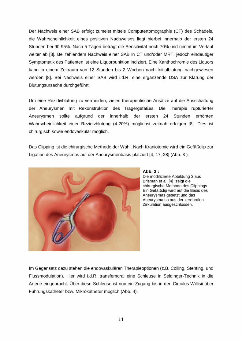
Das Clipping ist die chirurgische Methode der Wahl. Nach Kraniotomie wird ein Gefäßclip zur
Ligation des Aneurysmas auf der Aneurysmenbasis platziert [4, 17, 28] (Abb. 3 ).
Im Gegensatz dazu stehen die endovaskulären Therapieoptionen (z.B. Coiling, Stenting, und
Flussmodulation). Hier wird i.d.R. transfemoral eine Schleuse in Seldinger-Technik in die
Arterie eingebracht. Über diese Schleuse ist nun ein Zugang bis in den Circulus Willisii über
Führungskatheter bzw. Mikrokatheter möglich (Abb. 4).
Abb. 3 : Die modifizierte Abbildung 3 aus Brisman et al. [4] zeigt die chirurgische Methode des Clippings. Ein Gefäßclip wird auf die Basis des Aneurysmas gesetzt und das Aneurysma so aus der zerebralen Zirkulation ausgeschlossen.

12
Derzeitiger Gold-Standard in der Therapie ist das sog. Coiling, das in den 90er Jahren
etabliert wurde [29, 30]. Bei dieser Methode werden röntgendichte Platinspiralen, sog. Coils
mittels Mikrokatheter in das Aneurysma appliziert [30, 31] (Abb. 4). Aktuell verfügbare Coils
sind kontrolliert ablösbar, um über eine mehrmalige Repositionierung eine annähernd
vollständige Ausfüllung der Aneurysmen zu erzielen [32]. Besondere Konfigurationen wie
Spiral-, Helix- oder 3-D-Coils [32, 33] sowie thrombogene Beschichtungen (Nylon-/Polyester-
Abb. 4 : Die Abbildung von Brisman et al. [4] zeigt die endovaskuläre Versorgung eines Aneurysmas an der Arteria communicans posterior. Panel A zeigt hierbei die mit Führungs- und Mikrokatheter zurückgelegte Strecke von der A. femoralis über die Aorta, die Arteria carotis sinistra bis in das Aneurysma. In Panel B ist der Prozess des Coilings dargestellt, Panel C zeigt hierbei das vollständig gecoilte Aneurysma.
A B
C

13
Fasern) sollen die Thrombosierung und Okklusion der gecoilten Aneurysmen optimieren.
Besonders weiche Coils sollten sich der Morphologie des Aneurysmas anpassen, bioaktive
und Hydrogel-Coils fördern die Abheilung [32]. Coils werden je nach Morphologie des
Aneurysmas alleine, Ballon- oder Stent-assistiert appliziert.
Beim ballonassistierten Coiling (Abb. 5 A) wird ein nicht ablösbarer Ballon temporär über der
Aneurysmenbasis inflatiert. Hierdurch wird eine Applikation von Coils in das Aneurysma
ermöglicht, ohne das Teile der Coil in das Trägergefäß hineinragen, was zu
thrombembolischen Ereignissen oder Gefäßverschlüssen führen kann [20]. Zum Schutz des
Hirngewebes vor ischämischen Infarkten wird der Ballon i.d.R. während des
Embolisationsvorganges mehrfach deflatiert, um die Blutzirkulation und Versorgung des
Hirngewebes zu ermöglichen. Nach vollständigem Coiling wird der Ballon endgültig deflatiert
und entfernt.
Eine weitere unterstützende Maßnahme bzw. Alternative zum Coiling stellt das Mitte der
90er Jahre etablierte Stenting dar (Abb. 5 B) [34]. Initial werden hierfür relativ unflexible,
große ballonmontierte Koronar-Stents verwendet, die allerdings schlecht zu positionieren
sind bzw. aufgrund der Größe nicht ausreichend weit nach distal vorgeführt werden können.
Inzwischen werden flexiblere, selbstexpandierende intrakranielle Stents entwickelt, die
zusätzlich mittels Ballondilatation adaptiert werden können. Derzeit werden
selbstexpandierende open-cell Stents und retrahierbare closed-cell Stents eingesetzt (Abb.
6) [33].
A B
Abb. 5: In der schematischen Zeichnung ist in A das ballonassistierte Coiling dargestellt. Ein Ballonkatheter wird an der Aneurysmabasis positioniert und inflatiert. Durch einen gejailten Mikrokatheter werden Platinspiralen, die sich am Ballon abstützen, in das Aneurysma eingebracht. In Panel B ist das Stent-assistierte Coiling dargestellt. Ein Stent wird über der Aneurysmabasis positioniert und Coils werden entweder wie hier gezeigt durch die Stentmaschen in den Aneurysmadom eingebracht oder über einen gejailten Mikrokatheter.

14
Die Platzierung eines einzigen Stents über der Aneurysmabasis reicht jedoch i.d.R. nicht zur
Bildung eines stabilen Thrombus aus [4]. Aus diesem Grund werden Stent-assistiert
zusätzlich Coils eingebracht (Stent-assistiertes Coiling) (Abb. 5 B). Dabei wird ein Stent über
der Aneurysmenbasis platziert und durch die Stentmaschen mittels eines Mikrokatheters
Coils in den Aneurysmadom eingebracht. Die Stentmaschen verhindern dabei die Protusion
von Coils in das Trägergefäß. Vorteil dieser Technik ist die fehlende Ischämie-Zeit, die beim
ballonassistierten Coiling durch Inflation des Ballons auftritt. Nach Embolisation des
Aneurysmas wird der Stent falls möglich entfernt oder eben in Position belassen [20].
Alternativ werden Stents in überlappender Technik platziert, was durch die überlappenden
Stentmaschen zu einer Flussmodulation führt und den ersten Schritt zur Entwicklung eines
dritten großen Behandlungszweiges, des Konzepts der Flussmodulation durch sog. Flow
Diverting Stents (FDS) darstellt [35].
FDS sind niedrig-poröse Stents mit großer Metalloberfläche und initiieren eine Reduktion der
Abb. 6: Die Abbildung 6 modifiziert nach Peters et al. 2009 [3] zeigt das Prinzip der open cell bzw. closed cell Technik. Der Vorteil des closed cell Designs dezeit verwendeter Stents liegt darin, dass bei Expansion die Stentmaschen stabil in der Form und Größe bleiben im Gegensatz zum open cell Design. Hierdurch wird eine gute Steuerung des Stents ermöglicht sowie eine Retraktion und Repositionierung.
Abb.7: Abbildung 7 zeigt ein Aneurysmamodell aus Silikon während einer DSA (einzelne Röntgenaufnahme). Ein Flow Diverting Stent (FDS) wurde über der Aneurysmabasis freigesetzt. Im Aneurysmadom liegt ein gejailter Mikrokatheter.
15
Einflussgeschwindigkeit in das Aneurysma [29, 34]. Bei einer 70%igen Porosität sind die
Maschen einerseits eng genug um eine Modulation der Hämodynamik zu bewirken,
andererseits permeabel genug um kleine abgehende Gefäßäste offen zu halten [36, 37].
Flussmodulierende Stents funktionieren nach zwei Prinzipien [20]:
a) Blutflussmodulation: Mit Positionierung eines FDS über der Aneurysmenbasis werden
sowohl Einstrom in das Aneurysma als auch der Ausstrom aus dem Aneurysma in das
Trägergefäß sowie der turbulente intraaneurysmale Blutfluss und die einwirkenden
Scherkräfte reduziert. Konsekutiv ist die Verweildauer des Blutes im Aneurysmasack
verlängert, was optimalerweise im Verlauf über Stase des Blutes zu einer raschen oder
schrittweisen Thrombosierung des Aneurysmas führt.
b) Remodellierung des Trägergefäßbettes und Stimulation der Neoendothelialisierung
über der Aneurysmabasis.
Der erste FDS wird 2006 angewendet und stellt eine der jüngsten Therapieinnovationen dar
[34]. Derzeit werden FDS verwendet, die bei Freisetzung des Stents eine Verdichtung
bestimmter Stent-Zonen ermöglichen. Forschungen zur Hämodynamik zerebraler
Aneurysmen zeigen, dass die Blutflussmuster in verschiedene Zonen eingeteilt werden
können. Die Einstromzone, die zumeist im distalen Bereich der Aneurysmenbasis liegt, eine
Ausstromzone im proximalen Basisbereich sowie ein zentraler Vortex bis hin zu mehreren
Vortices mit teils komplexen Flussmustern im Aneurysmadom [16, 37]. Bei hoher
Maschendichte im distalen Basisbereich wird der Bluteinstrom in das Aneurysma
verlangsamt [37].
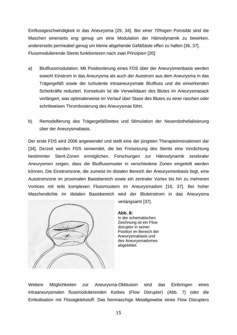
Weitere Möglichkeiten zur Aneurysma-Okklusion sind das Einbringen eines
intraaneurysmalen flussmodulierenden Korbes (Flow Disrupter) (Abb. 7) oder die
Embolisation mit Flüssigklebstoff. Das feinmaschige Metallgewebe eines Flow Disrupters
Abb. 8: In der schematischen Zeichnung ist ein Flow disruptor in seiner Position im Bereich der Aneurysmabasis und des Aneurysmadomes abgebildet.
16
formt einen Korb, der im Aneurysmasack abgelöst wird. Der Disrupter soll den Einstrom in
das Aneurysma vollständig unterbinden [20]. Onyx hingegen ist ein biokompatibles
nonadhäsives flüssiges Embolisat aus einem Ethylen-Vinyl-Alkohol Copolymer, das bei
Kontakt mit Blut innerhalb weniger Minuten aushärtet [32]. Im CAMEO (Cerebral Aneurysm
Multicenter European Onyx) trial wurde ein Ballon über der Aneurysmenbasis platziert und
das so überdeckte Aneurysma mit Onyx embolisiert [38].
Trotz der vorgestellten Techniken bleibt die Therapie zerebraler Aneurysmen aufgrund hoher
Rezidivraten (14,5-39%) schwierig, dies ist vor allem in breitbasigen und großen
Aneurysmen der Fall [4, 14, 28, 39, 40]. Daher wird kontinuierlich nach neuen Möglichkeiten
zur Optimierung der Aneurysmatherapie geforscht.
Im Gegensatz zur Humanmedizin existieren kaum Daten über zerebrale Aneurysmen im
Haussäugetier. Bertolini et al. (2013) berichten über ein inzidentelles zerebrales Aneurysma
an der Bifurkation der Arteria cerebri media (MCA) in einem Nova Scotia Duck Tolling
Retriever [19]. Stehbens (1963) obduziert einen Schimpansen und findet 8 zerebrale
Aneurysmen [41]. Mc Grath (1960) weist in seinem Buch auf einen Hund mit einer Blutung
im linken parietalen Lobus hin, die er mit einem rupturierten Aneurysma assoziiert [42]. Somit
ist diese Erkrankung für Haussäugetiere kaum als klinisch relevant anzusehen.
Allerdings ist zu bedenken, dass großangelegte Studien, die zu einer exakten Aussage
bezüglich der Inzidenz intrakranieller Aneurysmen bei bestimmten Tierspezies führen
könnten, fehlen. Betrachtet man die arterielle Gefäßversorgung der Haussäugetiere global,
stellt sich eine andere Situation dar. Es wird gehäuft von Aneurysmen der A. mesenterica
des Rindes berichtet [43, 44]. Im Pferd wird einerseits von infektiös bedingten Aneurysmen
der Umbilikalarterie berichtet [45], als auch von parasitär (Strongylus vulgaris) bedingten
Aneurysmen der A. mesenterica cranialis oder A. coeliaca [46, 47], mykotischen
Aneurysmen der Aorta [48] und idiopathischen Aortenaneurysmen [49]. Bei Hunden finden
sich parasitär bedingte Aorten-Aneurysmen (Dirofilaria immitis oder Spirocerca lupi) [50-53],
Aneurysmen der Pfortader [54], idiopathische oder stenotisch bedingte sekundäre
Aortenaneurysmen [50, 55, 56].
Mit Blick auf die humanmedizinische Forschung sind v.a. Aneurysmamodelle im Tier zur
Erprobung neuer Methoden bzw. zum Training von therapeutischen Techniken relevant [57,
58]. In der Forschung werden derzeit verschiedene Tiermodelle zur Evaluation von
Pathogenese, Hämodynamik sowie innovativen Therapieansätzen und zur präklinischen
Testung neuer Therapeutika verwendet. Den größten Teil (90%) der Tiermodelle machen
Mäuse, Ratten, Meerschweinchen und Kaninchen aus. Aber auch Hunde, Schweine und
Affen werden als Tiermodell genutzt [58].
17
Ratten- oder Mausmodelle werden vor allem für Fragestellung bezüglich der Pathogenese
und Ätiologie von Aneurysmen [57, 59] sowie für die Erforschung von SAB-assoziierten
Vasospasmen eingesetzt [60, 61]. Kaninchen, Schwein und Hund werden vor allem für
Langzeitversuche und zur Testung neuer Therapeutika herangezogen [57]. Grundsätzlich
wird zwischen chirurgisch und enzymatisch erzeugten Aneurysmen sowie endovaskuläre
generierten Aneurysmamodellen unterschieden.
In chirurgischen Modellen werden venöse Gefäß-Grafts in die A. carotis communis mit
verschiedenen Techniken eingesetzt [58]. Hier sind vor allem der Hund und das Schwein
aufgrund der ausreichend großen Gefäßdiameter, verlässlicher Anästhesie und bezogen auf
das Schwein, der dem Menschen ähnlichen Physiologie und Blutgerinnung von Bedeutung
[57, 62, 63].
Die Verwendung von Elastase ist bisher auf das Kaninchen begrenzt, eine Ausnahme stellt
das Rattenmodell nach Anidjar und Mitarbeitern dar [31, 57, 64-67]. Die Elastase baut das
Elastin in der Membrana elastica interna und der Tunica media ab. Durch hämodynamische
Prozesse kommt es im weiteren Verlauf zur Ausbildung einer aneurysmatischen Dilatation
der betroffenen Gefäßwand [68, 69]. Ebenfalls Verwendung findet das Enzym Papain, das
durch seine Esterase-Aktivität Elastin und Kollagen destruiert [58].
In einem rein endovaskulären Tiermodell ohne Enzymwirkung applizierten Mühlenbruch et
al. ein Gefäßverschlusssystem (Amplatzer), u.a. in die A. carotis externa. Der erzeugte
Gefäßstumpf simuliert ein breitbasiges Aneurysma [70]. Andere Arbeitsgruppen erzeugen
Aortenaneurysmen ebenfalls rein endovaskulär durch Applikation eines Palmaz-Stents [71-
73].
Das ideale Modell zerebraler Aneurysmen sollte möglichst zu keinen verfahrensbedingten
Folgeschäden an den Gefäßen führen, analoge Scherkräfte, Hämodynamik,
Gewebsreaktionen, homologe Dimensionen sowie longitudinale Perfusion der generierten
Aneurysmen zeigen. Keins der bestehenden Modelle weist alle Merkmale auf. Das Modell
muss derzeit entsprechend der jeweiligen Fragestellung passend ausgewählt werden [57].
Zusammenfassend ist somit festzustellen, dass weiterhin großer Forschungsbedarf sowohl
in Bezug auf die Optimierung von in vivo Modellen, als auch in der Therapie der zerebralen
Aneurysmen besteht.

18
II. Publikation 1:
„Feasibility, Safety, and Efficacy of Flow-diverting Stent-assisted
Microsphere Embolization of Fusiform and Sidewall Aneurysms“
19
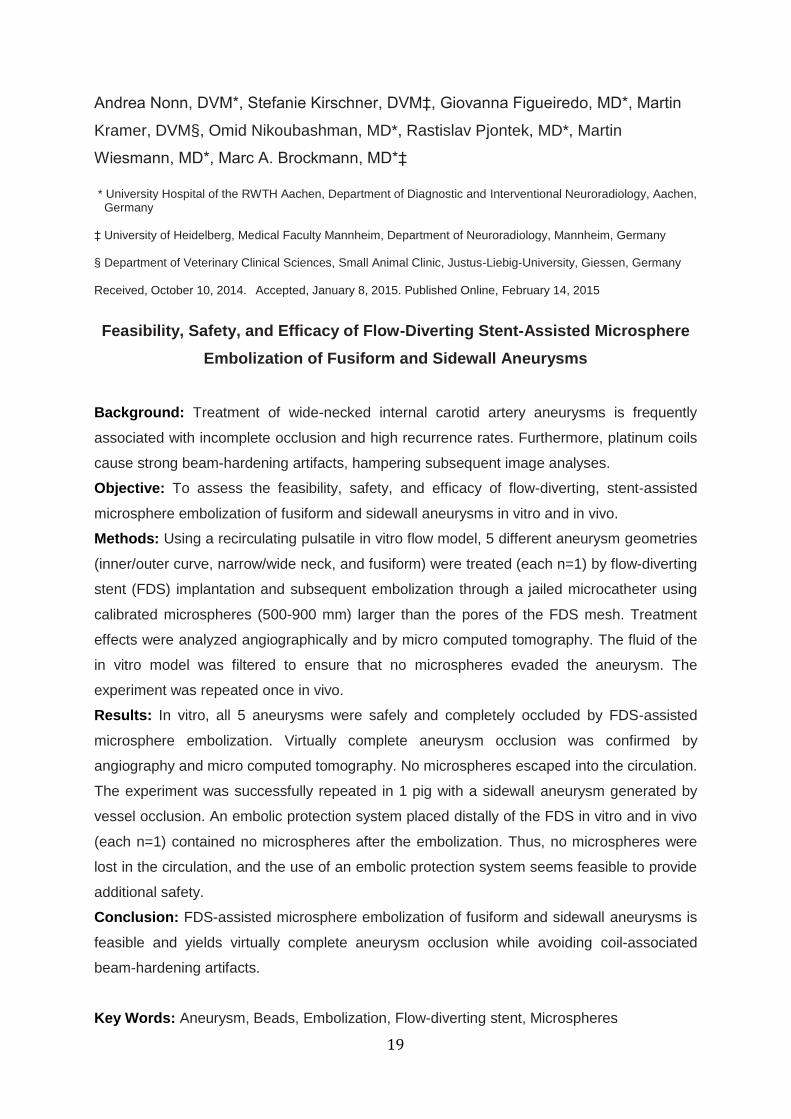
Andrea Nonn, DVM*, Stefanie Kirschner, DVM‡, Giovanna Figueiredo, MD*, Martin
Kramer, DVM§, Omid Nikoubashman, MD*, Rastislav Pjontek, MD*, Martin
Wiesmann, MD*, Marc A. Brockmann, MD*‡
* University Hospital of the RWTH Aachen, Department of Diagnostic and Interventional Neuroradiology, Aachen, Germany ‡ University of Heidelberg, Medical Faculty Mannheim, Department of Neuroradiology, Mannheim, Germany § Department of Veterinary Clinical Sciences, Small Animal Clinic, Justus-Liebig-University, Giessen, Germany Received, October 10, 2014. Accepted, January 8, 2015. Published Online, February 14, 2015
Feasibility, Safety, and Efficacy of Flow-Diverting Stent-Assisted Microsphere
Embolization of Fusiform and Sidewall Aneurysms
Background: Treatment of wide-necked internal carotid artery aneurysms is frequently
associated with incomplete occlusion and high recurrence rates. Furthermore, platinum coils
cause strong beam-hardening artifacts, hampering subsequent image analyses.
Objective: To assess the feasibility, safety, and efficacy of flow-diverting, stent-assisted
microsphere embolization of fusiform and sidewall aneurysms in vitro and in vivo.
Methods: Using a recirculating pulsatile in vitro flow model, 5 different aneurysm geometries
(inner/outer curve, narrow/wide neck, and fusiform) were treated (each n=1) by flow-diverting
stent (FDS) implantation and subsequent embolization through a jailed microcatheter using
calibrated microspheres (500-900 mm) larger than the pores of the FDS mesh. Treatment
effects were analyzed angiographically and by micro computed tomography. The fluid of the
in vitro model was filtered to ensure that no microspheres evaded the aneurysm. The
experiment was repeated once in vivo.
Results: In vitro, all 5 aneurysms were safely and completely occluded by FDS-assisted
microsphere embolization. Virtually complete aneurysm occlusion was confirmed by
angiography and micro computed tomography. No microspheres escaped into the circulation.
The experiment was successfully repeated in 1 pig with a sidewall aneurysm generated by
vessel occlusion. An embolic protection system placed distally of the FDS in vitro and in vivo
(each n=1) contained no microspheres after the embolization. Thus, no microspheres were
lost in the circulation, and the use of an embolic protection system seems feasible to provide
additional safety.
Conclusion: FDS-assisted microsphere embolization of fusiform and sidewall aneurysms is
feasible and yields virtually complete aneurysm occlusion while avoiding coil-associated
beam-hardening artifacts.
Key Words: Aneurysm, Beads, Embolization, Flow-diverting stent, Microspheres

20
III. Publikation 2:
"Implantation of Pipeline Flow-Diverting Stents Reduces Aneurysm
Inflow Without Relevantly Affecting Static Intra-Aneurysmal Pressure."

21
Hans U. Kerl, MD*, Hanne Boll, DVM* , Teresa Fiebig, DVM*, Giovanna
Figueiredo, MD*, Alex Förster, MD*, Ingo S. Nölte, MD*, Andrea Nonn, DVM‡,
Christoph Groden, MD*, Marc A. Brockmann, MD*‡
*University of Heidelberg, Medical Faculty Mannheim, Department of Neuroradiology, Mannheim, Germany;
‡University Hospital RWTH Aachen, Department of Diagnostic and Interventional Neuroradiology, Aachen, Germany
Received, February 7, 2013. Accepted, November 12, 2013. Neurosurgery, 2014. 74(3): p. 321-334.
Implantation of Pipeline Flow-Diverting Stents Reduces Aneurysm Inflow
Without Relevantly Affecting Static Intra-aneurysmal Pressure
Background: Flow-diverting stent (FDS) implantation is an endovascular treatment option
for intracranial aneurysms. However, little is known about the hemodynamic effects.
Objective: To assess the effect of stent compression on FDS porosity, to evaluate the
influence of single and overlapping implantation of FDS on intra-aneurysmal flow profiles,
and to correlate stent porosity with changes in static mean intra-aneurysmal pressure.
Methods: Intra-aneurysmal time-density curves were recorded in a pulsatile in vitro flow
model before and after implantation of FDSs (Pipeline Embolization Device; ev3) in 7
different types of aneurysm models. Reductions in the maximum contrast inflow and time to
maximum intra-aneurysmal contrast were calculated. Micro–computed tomography was
performed, and compression-related FDS porosity was measured. The influence of FDS
placement on mean static intra-aneurysmal pressure was measured.
Results: FDS compression resulted in an almost linear reduction in stent porosity. Stent
porosity (struts per 1 mm) correlated significantly with the reduction of aneurysm contrast
inflow (R2 = 0.81, P < .001) and delay until maximum contrast (R2 = 0.34, P = .001).
Circulating intra-aneurysmal high-velocity flow was terminated in all sidewall models after
implantation of a single stent. Superimposition of 2 stents reduced max- imum intra-
aneurysmal contrast by 69.1 ± 3.1% (mean ± SD) in narrow-necked sidewall aneurysm
models, whereas no substantial reduction in maximum intra-aneurysmal contrast was
observed in wide-necked sidewall aneurysm models. Intra-aneurysmal mean static pressure
did not correlate with FDS porosity or number of implanted stents.
Conclusion: Implantation of FDS effectively reduces aneurysm inflow in a porosity-
dependent way without relevantly affecting static mean intra-aneurysmal pressure.
Abbreviations: FDS, flow-diverting stent; MAP, mean arterial pressure; PED, Pipeline
Embolization Device

22
IV. Übergreifende Diskussion
Therapie
Relevante Faktoren für Größenprogredienz und Ruptur zerebraler Aneurysmen sind unter
anderem Hämodynamik und Scherkräfte (wall shear stress (WSS)). Der WSS variiert
physiologisch an Bifurkationen und Gefäßkurvaturen, an welchen turbulente Strömungen mit
lokaler Erhöhung des WSS entstehen. Rupturierte Aneurysmen weisen ein turbulentes
Strömungsmuster auf, d.h. kleine Einstromjets, multiple zentrale Vortices und ein Anprall
(impingement) des Jets im Bereich des Aneurysmadomes [16]. Bei einer physiologischen
Durchblutung, Strömungsverhältnissen und WSS wird im Endothel die vasoaktive Substanz
Stickstoffmonoxid (NO) ausgeschüttet [9]. NO reguliert den Blutdruck über die Relaxation der
glatten Muskelzellen in der Tunica media (Vasodilatation), hemmt die Leukozytenadhäsion
sowie Thrombozytenaggregation und unterdrückt die Zellteilung glatter Gefäßmuskelzellen
[74]. Nach Sforza et al. (2009) existieren zwei Hypothesen zu Wachstum und Ruptur von
Aneurysmen [9]:
1. Die high-flow Theorie:
Der WSS ist erhöht und stimuliert die Endothelzellen zur gesteigerten Expression von
NO mit konsekutiv reduziertem Gefäßwandtonus durch Relaxation der glatten
Muskelzellen/Myozyten in der Tunica media. Bei gleichbleibendem Druck und
Perfusion kommt es zu einer Apoptose der glatten Muskelzellen sowie zu
Remodellierungsprozessen mit potentieller Degeneration der Muskelzellen. Die
einwirkenden Kräfte (Blutdruck/WSS/impingement) dilatieren die Gefäßwand. Dies
resultiert in abnormalen Flussprofilen, welche ein weiteres Wachstum der
Aneurysmen durch Elongation der Kollagen- und Elastinfasern der Tunica media/
Adventitia bedingen. Durch diese Veränderung wird zudem eine zunehmende
Rigidität der Gefäßwand bedingt. Im Verlauf wird ein Zeitpunkt erreicht, an dem die
Wand den physiologisch einwirkenden Kräften nicht mehr standhält und rupturiert.
2. Die low-flow Theorie:
Langsame Einstromjets mit lokaler Stagnation des Blutflusses hemmen die
physiologische flussabhängige Expression von NO, wodurch eine Schädigung des
Endothels initiiert wird. Konsekutiv kommt es zur Fibrinbildung, Adhäsion und
Infiltration der Gefäßwand mit Leukozyten sowie zur Aggregation von Erythrozyten
und Thrombozyten. Durch diese Inflammationsreaktionen tritt eine lokale
Degeneration der Gefäßwand verbunden mit einer verminderten Resistenz
gegenüber den physiologischen Druckkräften und WSS auf. Die Gefäßwand dilatiert

23
zunehmend bei gleichzeitig abnehmender Wandstärke. Im Verlauf kann die dünnere
Gefäßwand den physiologischen Kräften nicht mehr standhalten und reißt ein.
Nach Meng et al. (2013), die beide Theorien kombinierten, ist entweder die high-flow oder
low-flow Theorie in Abhängigkeit von Morphologie bzw. Aneurysmatyp zutreffend [2].
Bisweilen initiiert ein hoher WSS (high-flow Theorie) die Bildung von Aneurysmen, das
weitere Wachstum erfolgt jedoch entsprechend der low-flow Theorie (Abb. 8).
Klinisch wird das Rupturrisiko sowie die Therapieindikation unter anderem anhand der
Größe, Morphologie, Lokalisation und des Wachstums zerebraler Aneurysmen beurteilt.
Aneurysmen von >10mm Größe mit Lokalisation im hinteren Stromgebiet (A. basilaris/A.
communicans posterior) zeigen ein erhöhtes Rupturrisiko [1, 4, 8, 21]. Breitbasige, große
sowie Riesenaneurysmen zeigen nicht nur eine erhöhte Rupturneigung, sondern auch hohe
Rezidivraten von 14,5-39% [4, 14, 28, 39, 40] und die Therapie kann sich als schwierig
erweisen.
Das chirurgische Clipping mit vollständigen Okklusionsraten von 93,2%-95,1% [4, 75, 76]
wird vorwiegend in Aneurysmen der vorderen Gefäßzirkulation und in Abhängigkeit von der
Morphologie angewendet. Die akute Mortalitäts- und Morbiditätsrate ist mit 18,5% im
Vergleich zum Coiling mit 10,6% [30] deutlich höher. Auch der „International Subarachnoid
Aneurysm Trial“ (ISAT) beweist, dass endovaskuläre Methoden (Coiling) der chirurgischen
Therapieoption (Clipping) bei bereits rupturierten Aneurysmen vorzuziehen sind. In ISAT liegt
Abb. 9: Die Abbildung von Meng et al. 2013 [2] zeigt in A den Einfluss des WSS auf die
Initiierung bzw. Wachstum/Ruptur eines Aneurysmas. In Panel B sind beide Hypothesen und deren Auswirkungen auf ein Aneurysma in Abhängigkeit des Aneurysmatyps dargestellt.

24
die Morbiditäts-und Mortalitätsrate für das Clipping rupturierter Aneurysmen bei 30,6%
gegenüber dem Coiling mit 23,7% [22], und auch langfristig haben Patienten nach
endovaskulärer Therapie ein besseres Outcome als nach Clipping [77].
Etwa 90% aller Patienten mit Aneurysmen, die für ein Coiling geeignet sind, können
erfolgreich therapiert werden [78]. Mittels Coiling können im Gegensatz zum Clipping
Aneurysmen in der vertebrobasilären Zirkulation mit geringerem Risiko erreicht werden,
allerdings liegt die Rekurrenz insgesamt bei 15-39% [4, 28, 36, 39]. Breitbasige und große
Aneurysmen zeigen eine deutlich höhere Wahrscheinlichkeit für Rezidive (20% in
breitbasigen, 35,5% in großen, 59,1% in Riesenaneurysmen) und geringere Okklusionsraten
zwischen 41,2-40,4% [14, 78]. Die Rate der Aneurysmen mit vollständiger Okklusion
optimiert sich im Laufe der Nachsorgezeit von 87,6% auf bis zu 95% [28, 79]. Der Füllgrad
(packing density = Verhältnis eingebrachter Coils zu Volumen des Aneurysmas [80]), der für
eine stabile Okklusion erreicht werden sollte, liegt in der Regel zwischen 24-30% [39, 80]. Mit
einem Coiling assoziierte drei Probleme sind:
a) Die Coil-Enkompaktierung ist eine Verdichtung der Coils aufgrund der Kontraktion
des Aneurysma-Narbengewebes und ermöglicht ein Rezidiv [79].
b) Die Protusion, d.h. das Hineinragen einzelner Platinspiralen in das Trägergefäß, vor
allem in breitbasigen Aneurysmen [17, 81] kann thrombembolische Ereignisse (4,3%)
[33] oder eine Stenose bis zur vollständigen Okklusion des Trägergefäßes
verursachen.
c) Nach Stent-assistiertem Coiling zeigen sich in 17-31% eine residuale Füllung der
Aneurysmen [82, 83], hohe Rezidivraten mit 7,4-13,2% [20, 33] oder Stent-assoziierte
Komplikationen wie in-stent Stenosen (3-6%) [33, 82, 83] und thrombembolische
Ereignisse (10%) [20].
Eine weitere therapeutische Option ist die Flussmodulation durch FDS, die u.a. in für das
alleinige Coiling ungeeigneten Aneurysmen angewendet werden kann. Ein direkter Vergleich
zwischen endovaskulärem Coiling und FDS-Therapie sollte aus diesem Grund nicht erfolgen,
sondern ein Vergleich mit anderen Alternativmethoden wie ballongestütztem Coiling,
Clipping oder alternativen Füllmaterialien wie Onyx [78].
Oft werden FDS ohne zusätzliche Embolisate angewendet (78-86%), additive Coils werden
nur in 14-21% der Fälle durch einen gejailten, d.h. vor Freisetzung des FDS im Aneurysma
platzierter Mikrokatheter appliziert [78]. Eine erfolgreiche technische Durchführung wird in
97-99% der Fälle erreicht [78]. Die resultierenden Okklusionsraten liegen zwischen 73,6-95%

25
[12, 20, 78, 84, 85]. Inzwischen kann so eine hohe Anzahl von früher nicht behandelbaren
Aneurysmen erfolgreich versorgt werden. Allerdings zeigt auch das Prinzip der
Flussmodulation Probleme auf:
a) Eine Okklusion erfolgt oft schrittweise über Tage bis Wochen, somit ist die
Aneurysmawand bis zur stabilen Okklusion weiter dem arteriellen Blutdruck und
physiologischen Abbau- und Umbauprozessen ausgeliefert [86].
b) Durch das engporige Maschenwerk des applizierten FDS ist der Zugang ins
Aneurysma blockiert, d.h. eine erneute Sondierung der Aneurysmen mittels eines
Mikrokatheters ist in der Regel nicht möglich.
c) Die Maschen sollten ausreichend weit sein, um einen Fluss in abzweigende
Gefäßäste zu erlauben. Ischämische Zwischenfälle, die unter anderem durch einen
Verschluss abzweigender Gefäße entstehen, werden in 6-17,8% der Fälle
beschrieben [28, 34].
d) Verzögerte Rupturen treten in 1-4,7% [12, 20] der Fälle, sowie in-Stent Stenosen in
7,1% [34] der Fälle auf.
Vier von fünf Patienten versterben dabei nach einer verzögerten Ruptur [87] eines eigentlich
effektiv mittels FDS behandelten Aneurysmas. Zur Rupturursache wurden verschiedene
Hypothesen aufgestellt. Zum einen kann der Blutstrom aufgrund einer fehlerhaften
Konfiguration des FDS vermehrt in das Aneurysma anstelle in das Trägergefäß umgeleitet
werden. Die Arbeitsgruppe von Dorn et al. (2011) bestätigt in vergleichenden in-vitro
Untersuchung von Stents und FDS, dass es bei einer Verdichtung der FDS Maschen im
distalen Bereich der Aneurysmenbasis und gleichzeitiger größerer Maschenweite im
proximalen Basisbereich (Ausflusszone) zu einer erhöhten Flussgeschwindigkeit im
Vergleich zum unbehandelten Aneurysma kommt [37]. Erhöhte Einstromgeschwindigkeiten
gehen jedoch mit einer Erhöhung des WSS einher [88], womit es der high-flow Theorie nach
zu Rupturen kommen könnte. Grundsätzlich führt der Einsatz von FDS jedoch zu einer
Reduktion der Einstromgeschwindigkeit wie in Dorn et al. und in Publikation 2 (siehe Seite
17) gezeigt werden konnte [37, 89]. Des Weiteren kann in Publikation 2 eine Tendenz zur
stärkeren Flussmodulation durch Verringerung der Maschenweite sowohl durch
überlappende Platzierung mehrerer FDS als auch durch Kompression der FDS
nachgewiesen werden. Eine graduelle Kompression führt zur beinahe linearen Reduktion der
Maschenweite [89].
26
Eine weitere Hypothese besagt, dass der entstandene Thrombus im Aneurysmasack durch
gesteigerte inflammatorische/proteolytische Prozesse lysiert wird [87, 90]. Turowski et al.
(2011) berichten von einem Fall verzögerter Ruptur nach Einsatz eines FDS und vermuteten
aufgrund gemessener Dichtewerte in CT-Bildern die Bildung eines unorganisierten, roten
Thrombus [90]. Rote Thromben sind instabiler als organisierte Thromben und weisen eine
höherer Aktivität lytischer Enzyme auf, die die Wand der Aneurysmen zusätzlich schwächen
könnten.
Eine andere Hypothese ist, dass eine lokale Steigerung des intraaneurysmalen Druckes
durch die Platzierung des FDS verursacht wird und für die Ruptur verantwortlich ist [86]. Es
konnte jedoch keine Erhöhung des statischen intraaneurysmalen Druckes sowohl von
Larrabide et al [91] als auch in Publikation 1 und 2 festgestellt werden. Insgesamt treten zu
5,6-14,1% FDS-assoziierte Komplikationen auf [12, 20, 28, 36, 78, 84] und die Mortalitätsrate
liegt zwischen 0,5-5% [12, 13, 34, 84].
Zusammengefasst sind die Bedenken bei der Therapie mittels FDS vor allem Okklusion
abzweigender Gefäße, Stenosen der Trägergefäße durch unvollständige Entfaltung des FDS
und verzögerte Aneurysmarupturen [20, 78, 84].
Keines der derzeit verfügbaren Therapieverfahren ist uneingeschränkt für jeden
Aneurysmatyp geeignet und es sind weitere Forschung und Entwicklung auf diesem Gebiet
notwendig. Aus diesem Grund sind innovative Ansätze bzw. die Optimierung bestehender
Techniken wie die Verwendung von Stents mit Formgedächtnis in Verbindung mit einem
Polymerschaum, Hydrogel als Embolisatmaterial [92, 93] oder wie in Publikation 1 der
Einsatz eines FDS in Verbindung mit kalibrierten Mikrosphären sinnvoll. Aufgrund des
größeren Durchmessers der Mikrosphären im Vergleich zur Größe der FDS-Maschen ist die
Durchführung sicher möglich. Die Mikrosphären, bestehend aus einem Polyvinylalkohol
(PVA) oder Hydrogelkern, ermöglichen eine quasi artefaktfreie Bildgebung verglichen mit
Platinspiralen [94]. Das Risiko der Technik liegt in einem potentiellen Verlust von
Mikrosphären in die zerebrale Zirkulation mit resultierender Okklusion distaler Gefäßäste und
zerebralen Infarkten.
In vivo Aneurysmamodell
In den letzten Jahren hat die Förderung und Entwicklung von Alternativmethoden zu
Tierversuchen stark zugenommen. Dies spiegelt sich auch in den Versuchstierzahlen des
Bundesministeriums für Ernährung und Landwirtschaft (BMEL) 2013 wieder, die eine
Reduktion der Anzahl der verwendeten Tiere insbesondere bei den Mäusen, Ratten,
Kaninchen, Hunden, Katzen, Schweinen und Vögeln im Vergleich zum Vorjahr zeigen.

27
Trotzdem kann in der Forschung für bestimmte Fragestellungen nicht auf Tierversuche
verzichtet werden. Zum Einen existiert derzeit kein Modell, das die komplexen
biophysiologischen Prozesse eines lebenden Organismus und deren Auswirkungen
nachbilden kann, zum anderen müssen neue Behandlungsmethoden, Medikamente und
Medizinprodukte vor dem klinischen Einsatz tierexperimentell auf unerwünschte Wirkungen,
Toxizität etc. überprüft werden bzw. CE zertifiziert werden [95-97]. Derzeit werden vor allem
das Kaninchen Elastase-Modell und das chirurgische oder endovaskuläre Schweinemodell
für die Erforschung von zerebralen Aneurysmen verwendet.
Nach Gorgels et al. [59] sollte ein Tiermodell folgende Anforderungen möglichst weitgehend
und vollständig erfüllen:
a) Simulation von Größe, Morphologie und Hämodynamik humaner
Aneurysmen
b) keine spontane Thrombosierung des Aneurysmas
c) vergleichbares Größenverhältnis des Trägergefäßes
d) intaktes Endothel
e) nahtlose Konstruktion zur Narben- und Fibroseprävention
f) Modellgefäß arteriellen Ursprungs mit reduzierter Wandstärke
g) kurzer und tierschonender Konstruktionsprozess
h) hohe Reproduzierbarkeit und Planbarkeit
i) Gerinnungssystem ähnlich dem Menschen
Diese Forderungen an ein ideales Tiermodell können jedoch nicht vollständig in den bereits
etablierten Modellen erfüllt werden. In der vorliegenden Arbeit wird das Schwein als
Versuchstier ausgewählt. Das Versuchstier Schwein kann in zahlreichen physiologischen
und anatomischen Parametern mit dem Menschen verglichen werden [57, 98]. Nach Höhle
(2000) [99] und Goericke et al. (2009) [100] weist das Gerinnungssystem große
Übereinstimmungen analog zu dem des Menschen auf. Unterschiede sind die höhere
Aktivität der Gerinnungsfaktoren, die analoge bis geringgradig reduzierte Aktivität des
fibrinolytischen Systems. Die Thrombozyten sind vergleichbar adhäsiv und die Bildung von
Thromben verläuft ebenfalls ähnlich wie im Menschen [99]. Aus diesem Grund ist das
Schwein ein gutes Langzeitmodell, um die Entwicklung von Stenosen platzierter Stents zu
untersuchen [57]. Das Schwein wird in operativen als auch interventionellen experimentellen
Ansätzen eingesetzt [99]. Unter anderem werden Schweine für die Prüfung neuer
therapeutischer Materialien und zur histopathologischen Überprüfung von Embolisaten
verwendet. Weiterhin werden endovaskuläre therapeutische Methoden [99] wie Coiling oder
Stenting von Aneurysmen [101], Embolisation arteriovenöser Malformationen [102, 103] oder

28
Thrombektomie [104] in Schweinen trainiert. Darüber hinaus ist die Größe der Gefäße
vergleichbar zum Menschen (A. carotis/Äste der A. axillaris), und ermöglicht sowohl eine
gute Konstruktion größenvergleichbarer Aneurysmen, als auch die Option mit mehreren
Kathetern oder großlumigen Devices am erzeugten Aneurysma zu arbeiten [105].
Allerdings ist keine Konstruktion und Therapie intrakranieller Aneurysmen im Schwein
aufgrund der Rete mirabile epidurale rostrale und caudale möglich [106], da die Rete nicht
mit dem Katheter passiert werden können. Die Wandstärke der Aneurysmen ist nicht
reduziert und differiert aufgrund der extrakraniellen Lage im histologischen Wandaufbau von
intrakraniellen humanen Aneurysmen. Zudem sind Schweine stressanfällig und durch das
schnelle Wachstum mit schneller Gewichtssteigerung ist das Handling der narkotisierten
Tiere problematisch. Dieses Problem kann durch den Einsatz von Minipigs reduziert werden.
Im Aneurysma-Modell Schwein wird zwischen chirurgischer und endovaskulärer Konstruktion
unterschieden:
1) Chirurgisch werden Aneurysmen durch eine Verbindung venöser Gefäß-Grafts
(Aneurysmadom) mit der A. carotis communis in verschiedenen Techniken
konstruiert [58, 105]. Vorteil der chirurgischen Methode ist die Möglichkeit zur
Bestimmung der Aneurysmagröße, Morphologie sowie Konstruktion abzweigender
Gefäßäste [57, 62]. Additiv kann die Behandlung der konstruierten Aneurysmen direkt
nach Konstruktion erfolgen [107]. Nachteile der chirurgischen Konstruktion liegen in
der spontanen Heilungstendenz [99, 108] oder Rupturgefahr [57] sowie der
Narbenbildung entlang der Gefäßnaht [59]. Des Weiteren unterscheiden sich
chirurgisch induzierte Aneurysmen histologisch von intrakraniellen Aneurysmen des
Menschen [105].
2) Mühlenbruch und Mitarbeiter (2013) entwickeln ein rein endovaskuläres
Aneurysmenmodell ohne Einsatz von Enzymen für die sofortige Verwendung zu
Übungszwecken [70]. Dabei applizieren sie einen Amplatzer (ein für die
endovaskuläre Okklusion von arteriellen Gefäßen entwickeltes Device) in die A.
renalis, A. subclavia, oder A. carotis externa. Die Gefäße werden nach Konfiguration
und Größe ausgewählt. Weitere Arbeitsgruppen entwickeln bereits früher rein
endovaskuläre Modelle für Aortenaneurysmen [71-73]. Vorteile dieser
endovaskulären Methoden sind Vermeidung von Narben am Gefäß, die hohe
Planbarkeit und Reproduzierbarkeit der Aneurysmen sowie Erzeugung von
breitbasigen Aneurysmen. Ein Defizit besteht darin, dass keine rein sakkulären bzw.
Aneurysmen mit einer im Verhältnis zum Aneurysmadom geringeren Breite der Basis

29
erzeugt werden können [70].
3) Goericke et al. 2009 kombinieren die chirurgische Präparation der Halsgefäße mit
endovaskulärer enzymatischer Methodik [100]. Eine Schleuse wird in die
freipräparierte ligierte A. carotis communis eingeführt und die Arterie durch Inflation
eines Ballonkatheters von der Zirkulation separiert. Porcine Elastase wird durch den
Ballonkatheter in die A. carotis communis injiziert und 20 Minuten inkubiert. Nach 8
Wochen haben sich Aneurysmen ausgebildet, die jedoch partiell thrombosiert sind.
Zusammengefasst wird in der vorliegenden Arbeit ein total endovaskuläres
Aneurysmamodell im Schwein zur Optimierung und Testung von flussmodulierenden
Techniken eingesetzt. Publikation 1 und 2, die beide die Technik der Flussmodulation zur
Therapie intrakranieller Aneurysmen behandeln, zeigen deutlich, dass bei Entfaltung
eines FDS eine deutliche Flussmodulation stattfindet. Die Einstromgeschwindigkeit in
den Aneurysmadom wird signifikant reduziert bei gleichzeitiger Zunahme der Transitzeit
des Blutes im Aneurysma. Folgend kommt es intraaneurysmal zur Stase des Blutes und
Thrombosierung der Aneurysmen. Des Weiteren konnte gezeigt werden, dass die
Entfaltung eines FDS keine relevanten Veränderungen des statischen intraaneurysmalen
Drucks in vitro bedingt und somit eine verzögerte Ruptur aufgrund von
Druckveränderungen eher unwahrscheinlich ist.
Eine Optimierung der Flussmodulation kann durch Kompression des FDS oder
überlappende Implantation mehrerer FDS über der Aneurysmabasis erreicht werden.
Beide Techniken erzielen eine Verdichtung des Maschenwerkes und konsekutiv einen
größeren flussmodulierenden Effekt. Wie in Publikation 1 gezeigt, kann dieser Effekt
durch in den Aneurysmadom applizierte Mikrosphären optimiert werden. Der Einstrom in
den Aneurysmadom wird nahezu vollständig unterbrochen, es verbleibt lediglich eine
Diffusion von Kontrastmittel in den Aneurysmadom (in vitro Versuche). Der zweite
wesentliche Vorteil dieser Methode besteht darin, dass mit anderen Techniken nur
schwierig auszufüllende Positionen im Aneurysma wie z.B. der Basisbereich mit dem
Einsatz von Mikrosphären vollständig ausgefüllt werden kann. Die Technik erweist sich in
vitro als realisierbar, sicher und zuverlässig. Derzeit ist eine weitere Optimierung der
therapeutischen Ansätze angestrebt, um eine sichere, verlässliche sowie dauerhafte
Versorgung für alle Konfigurationen von zerebralen Aneurysmen zu ermöglichen. In
diesem Zusammenhang sind auch tierexperimentelle Studien notwendig. Nur wenn
suffiziente Modelle zu Verfügung stehen, ist es möglich innovative
Behandlungsmethoden effizient zu erproben und weiterzuentwickeln. Dementsprechend
wird die FDS-assistierte Embolisation mit Mikrosphären derzeit im in-vivo
Langzeitversuch in Minipigs über mehrere Monate getestet.

30
V. Zusammenfassung
Flussmodulierende Stents zur Behandlung intrakranieller Aneurysmen
Zerebrale breitbasige, große sowie fusiforme Aneurysmen stellen eine Herausforderung an
die Therapie dar. Die vollständige Ausschaltung rupturgefährdeter Aneurysmen ist essentiell.
Bei einer Aneurysmaruptur tritt arterielles Blut vor allem in den Subarachnoidalraum aus. Die
Mortalitätsrate nach Subarachnoidalblutung (SAB) liegt bei 50-60% und häufig treten
Komplikationen wie Vasospasmen der zerebralen Gefäße mit ischämischen Defiziten oder
Hydrozephalus auf.
Etablierte endovaskuläre Behandlungsmethoden sind Coiling, Stent-assistiertes bzw. Ballon-
assistiertes Coiling und die Implantation flussmodulierender Stents. Die Alternative zu
endovaskulären Therapieansätzen ist das chirurgische Clipping.
Große Aneurysmen mit breiter Basis rezidivieren trotz Therapie mit Coils etc. häufiger als
kleinere Aneurysmen. In diesen Aneurysmen werden vor allem flussmodulierende Stents
(FDS) angewendet. Hierdurch wird der Einstrom von Blut in das Aneurysma durch das dichte
Maschenwerk des flussmodulierenden Stents reduziert und die intraaneurysmale Transitzeit
des Blutes verlängert. Dies führt zu einer Thrombosierung des Aneurysmas. Nachteile der
Flussmodulation sind selten auftretende verzögerte Rupturen, die während einer
schrittweisen Thrombosierung und intermittierendem Abbau von Thrombusmaterial auftreten
können. Eine der Hypothesen zur Ätiologie dieses Problems ist, dass Veränderungen des
intraaneurysmalen Druckes bedingt durch die Implantation des FDS zu einer Ruptur der
Aneurysmawand führen.
In dieser Arbeit wurden unter anderem Messungen des statischen intraaneurysmalen
Druckes während der Applikation eines flussmodulierenden Stents durchgeführt. Hierfür
erfolgten Versuche zunächst in vitro in sieben verschiedenen Aneurysmakonfigurationen bei
gleichem Durchmesser der Trägergefäße. Die Silikonaneurysmen wurden in einen
künstlichen Kreislauf eingebaut, in welchem physiologische Bedingungen wie Herzfrequenz,
Blutdruck sowie Blutviskosität durch Verwendung einer peristaltischen Pumpe und Blutersatz
simuliert wurden. Die Experimente wurden durch digitale Subtraktionsangiographie (DSA)
protokolliert. Die FDS wurden per Mikrokatheter über der jeweiligen Aneurysmabasis einzeln
oder überlappend freigesetzt. Der statische Druck wurde intraaneurysmal und im
Trägergefäß vor, während und nach der Implantation der FDS gemessen. Zur Evaluation der
Auswirkungen der Stent-Kompression auf die Stent-Porosität und damit auf die
flussmodulierenden Eigenschaften wurden des Weiteren Mikro-CT Aufnahmen von
stufenweise komprimierten FDS angefertigt.
In der Auswertung der DSA-Serien zeigte sich in allen unbehandelten
Seitenwandaneurysmen ein schneller turbulenter Einstrom von Kontrastmittel in den
Aneurysmadom mit einer raschen Auswaschphase (kurze Transitzeit). Nach Einsatz der
31
FDS zeigte sich eine deutliche Reduktion des Kontrastmitteleinstroms in den
Aneurysmadom, eine deutliche Verlängerung der Transitzeit, sowie der Zeit bis zur
maximalen Kontrastmittelanreicherung. Der überlappende Einsatz eines zweiten FDS
verstärkte diesen Effekt. In Aneurysmen mit schmaler Basis wird der Zeitpunkt der
maximalen Kontrastmittelanreicherung um 0,27±0,35s verzögert und insgesamt wird eine
Reduktion des Kontrastmitteleinstromes um 39,3±20,4% erreicht. Nach Implantation eines
weiteren überlappenden FDS steigt die Zeit bis zur maximalen Kontrastmittelanflutung auf
1,1±0,8s. Der Kontrastmitteleinstrom wird auf 69,1±3,1% reduziert. In Aneurysmen mit
breiter Basis erfolgt eine Verzögerung der Kontrastmittelanflutung um ebenfalls 0,27±0,09s,
der Einstrom wird um 0,7±0,9% reduziert. Ein weiterer FDS verzögert die Anflutung um 0,33
±0,28s und erreicht eine Reduktion um 0,23±12,4%.
Es konnten nur minimale nicht signifikante Fluktuationen (<10% der Basiswerte) des
statischen intraaneurysmalen Druckes gemessen werden. Eine Korrelation zwischen
Blutdruck und Stent-Porosität war nicht nachweisbar.
Bei Kompression des FDS resultiert eine fast lineare Reduktion der Stent-Porosität mit
korrelierender Reduktion des Kontrastmitteleinstroms und Verzögerung der maximalen
Kontrastmittelanreicherung.
Zusätzlich wurde in dieser Arbeit an einer Modifikation der FDS-Technik durch zusätzliche
Applikation von Mikrosphären gearbeitet, um eine sofortige Thrombosierung der
Aneurysmen zu erreichen. Die Versuche hierzu wurden ebenfalls in dem oben genannten in
vitro Kreislauf in fünf verschiedenen Aneurysmakonfigurationen getestet.
Durch einen gejailten Mikrokatheter wurden nach Implantation des FDS größenkalibirierte
Mikrosphären in den Aneurysmadom appliziert. Dabei ist der Durchmesser der Mikrosphären
größer zu wählen als die Porengröße der Stentmaschen. Eine Erfolgskontrolle und
Evaluation der Sicherheit der Technik wurde durch Filtration des vollständigen Blutersatzes
nach Spülung des Kreislaufsystems durchgeführt. Mit dem Blutstrom ausgeschwemmte
Mikrosphären könnten in der zerebralen Zirkulation zu partiellen oder vollständigen
Gefäßverschlüssen mit Folgen eines ischämischen Infarktes des betroffenen Hirnareales
führen (Schlaganfall). Aus diesem Grund ist die Überprüfung der Sicherheit der Technik
essentiell. Die Versuche wurden ebenfalls mittels DSA protokolliert. Zusätzlich wurden
exemplarisch Messungen des statischen intraaneurysmalen Druckes durchgeführt und
Mikro-CT Aufnahmen der embolisierten Aneurysmen angefertigt, um den Füllungsgrad der
Aneurysmen zu messen.
Zusätzlich wurde die neue Technik im Akutversuch in einem Schwein erprobt. Die
Erfolgskontrolle in vivo auf extraaneurysmal applizierte Mikrosphären erfolgte mittels eines
feinen Drahtfilters, der distal im Trägergefäß platziert wurde. Die Protokollierung erfolgte
auch hier mittels DSA.

32
Alle Aneurysmen wurden erfolgreich embolisiert und die Kontrolle erbrachte sowohl in vitro
als auch in vivo keine abgeschwemmten Mikrosphären. Des Weiteren stellte sich heraus,
dass bereits nach Applikation erster Mikrosphären eine signifikante Reduktion des
Kontrastmitteleinstroms in den Aneurysmadom eintrat. Die Mikrosphären zirkulierten nicht
mit der turbulenten Strömungen im Aneurysma, sondern sammelten sich im distalen
Basisbereich auf der Oberfläche des FDS und reduzierten so den Kontrastmittelausstrom.
Nach vollständiger Embolization ist in vitro nur noch eine pulssynchrone Diffusion von
Kontrastmittel in den Bereich der Aneurysmabasis nachzuweisen. Messungen des statischen
intraaneurysmalen Druckes vor, während und nach der Embolisation zeigten keine
nennenswerten Blutdruckfluktuationen. In der Mikro-CT konnte ein visueller Füllungsgrad
von 100% gezeigt werden, inklusive des Basisbereiches, der mit anderen Techniken nur
schwer erreichbar ist. Bei einem fusiformen Aneurysma wurden zwei FDS in vitro
überlappend eingesetzt und es kam durch die maschinelle Applikation von Kontrastmittel zu
einer Stauchung des proximalen FDS mit folgender Abschwemmung von Mikrosphären. In
vivo wird Kontrastmittel allerdings nicht mit diesem von uns für eine optimale Bilddarstellung
gewählten Druck und Geschwindigkeit appliziert.
Die von uns entwickelte Methode erlaubt einen vollständigen und sofortigen Verschluss des
Aneurysmadoms. Daher werden derzeit ergänzende longitudinale in vivo-Untersuchungen im
Tiermodell durchgeführt.

33
VI. Summary
Therapy of wide-necked, large to giant and fusiform cerebral aneurysm remains technically
challenging. Occlusion of aneurysms, which are prone to rupture, is highly relevant. In case
of rupture, arterial blood extravasates into the subarachnoid space. Subarachnoid
hemorrhage is associated with high morbidity and mortality rates and implicates
complications like hydrocephalus, vasospasm and delayed ischemic neurological deficits.
Only a few patients convalesce completely to premorbid status, the majority remains
disabled with neurological deficits.
Coiling and stent-assisted coiling are established techniques for treatment of intracranial
aneurysms, however for giant and wide-necked aneurysms high recurrence rates have been
reported. Flow diverting stents (FDS) are increasingly used especially in wide-necked
aneurysms. FDS reduce the inflow of blood into the aneurysms and result in immediate or
stepwise thrombosis. In a limited number of cases delayed rupture of aneurysms
unsuccessfully treated by implantation of FDS has been reported. One hypothesis states that
blood pressure changes during FDS implantation results in these aneurysm ruptures.
According to this we performed in vitro studies to further investigate the hypothesis that FDS
may lead to increased intra-aneurysmal pressure. In vitro studies were performed with a
circulatory experimental setup comprising a peristaltic roller pump to mimic physiological
conditions. Seven different types of silicon aneurysms were used. Experiments were
recorded with digital subtraction angiography (DSA). Intraaneurysmal pressure and flow
dynamics were evaluated before and after deployment of a single FDS and again after
implantation of further FDS. Furthermore a FDS was compressed stepwise to evaluate
influence of stent compression on stent porosity, results were recorded with repetitive micro-
CT.
In all tested aneurysms a strong and fast inflow of contrast agent into the aneurysm, along
with a rapid washout phase, was observed. After implantation of a FDS reductions in total
contrast inflow and time until maximum contrast density are reached. Implantation of a
second FDS further reduced contrast inflow. For narrow-necked sidewall aneurysms, the
time until maximum intra-aneurysmal contrast enhancement, after implantation of a first PED,
was prolonged by 0.27±0.35s, accompanied by a reduction of contrast enhancement of 39.3
±20.4%. Superimposition of a second FDS led to prolongation of the time until maximum
intra-aneurysmal contrast enhancement by 1.1±0.8s. and reduction of maximum contrast
enhancement by 69.1±3.1%. In wide-necked sidewall aneurysms, the time until maximum
intra-aneurysmal contrast enhancement was prolonged by 0.27±0.09s and maximum
contrast enhancement was reduced by 0.7±0.9%. Superimposition of a second FDS led to
prolongation of time until maximum intra-aneurysmal contrast enhancement by 0.33±0.28s
and reduction of maximum contrast enhancement by 0.23±12.4%.

34
Static intra-aneurysmal pressure changes in MAP in all models were <10% of baseline value.
No correlation between intra-aneurysmal MAP and stent porosity was found.
However, stepwise increase of FDS compression resulted in an almost linear reduction in
measured cell area of a stent. Stent compression correlated significantly with the reduction of
maximum intra-aneurysmal contrast enhancement.
Furthermore, to improve aneurysm occlusion rates in wide-necked, giant and fusiform
aneurysms we assessed the safety and feasibility of a novel approach for endovascular
aneurysm treatment combining FDS implantation with microsphere embolization. The
described in vitro circular flow model was used for experiments with five configurations of
cerebral aneurysm. All in vitro experiments were performed using a biplane angiography unit.
The FDS were placed over the aneurysm neck and size calibrated microspheres with
nonionic contrast agent were slowly injected into the aneurysm dome through a jailed
microcatheter. The critical point for safe microsphere embolization is a sufficient difference in
size of the microspheres and the pore size of the FDS mesh.
At first glance microsphere embolization of aneurysms may appear hazardous in the cerebral
circulation cause of the risk of ischemic infarcts through washed out microspheres. Following
to ensure that no microspheres were washed out of the aneurysm during the experiment the
fluid of the circular flow model was filtrated.
Additionally, the static intra-aneurysmal pressure was measured. To evaluate the distribution
of the microspheres and the degree of aneurysm occlusion micro-CT was performed. The
experiment was repeated in vivo once in a German landrace pig.
Control of safety and feasibility in vivo was performed through a filter wire placed distal in the
parent vessel.
All aneurysms were successfully embolized and no microspheres were detected within the
recirculating fluid neither in the filter wire. In some cases the injection of a small number of
microspheres already induced a strong reduction of contrast agent inflow. The microspheres
accumulated on the outside of the FDS mesh, as if being aspirated by the parent vessel,
hereby reducing the intra-aneurysmal flow. After complete microsphere embolization, only
minimal diffusion of contrast agent from the parent vessel into the aneurysm was observed.
Furthermore no relevant changes in mean static intra-aneurysmal pressure during
embolization were recorded.
Micro-CT showed a filling factor of the aneurysms of virtually 100%.
In one experiment with a fusiform aneurysm treated with a telescoping stent technique we
observed an accordion like compression of the proximal part of the distal FDS after
successful embolization. A high pressure contrast agent injection was performed and cause
of FDS compression. Thereby some microspheres got lost in circulation. However in vivo

35
proximal high pressure injections would not be applied and a fusiform aneurysm ideally
would be covered with one long FDS.
FDS assisted microsphere embolization of fusiform and sidewall aneurysms is feasible and
results in an immediate occlusion.
Longitudinal in vivo studies are required to gain further insights in this novel technical
approach.

36
VII. Literaturverzeichnis
1. Poeck K, Hacke W: Neurologie; 2007. 2. Meng H, Tutino V, Xiang J, Siddiqui A: High WSS or Low WSS? Complex
Interactions of Hemodynamics with Intracranial Aneurysm Initiation, Growth, and Rupture: Toward a Unifying Hypothesis. AJNR 2013.
3. Jansen O, Forsting M, Sartor K: Neuroradiologie: Thieme; 2008. 4. Brisman JL, Song JK, Newell DW: Cerebral aneurysms. N Engl J Med 2006,
355(9):928-939. 5. Liebich H-G: Funktionelle Histologie der Haussäugetiere: Lehrbuch und Farbatlas für
Studium und Praxis; mit 11 Tabellen: Schattauer Verlag; 2004. 6. Wanke I, Forsting M: Stents for intracranial wide-necked aneurysms: more than
mechanical protection. Neuroradiology 2008, 50(12):991-998. 7. Abruzzo T, Shengelaia G, Dawson R, Owens D, Cawley C, Gravanis M: Histologic
and morphologic comparison of experimental aneurysms with human intracranial aneurysms. AJNR 1998, 19(7):1309-1314.
8. Schievink WI: Intracranial aneurysms. N Engl J Med 1997, 336(1):28-40. 9. Sforza DM, Putman CM, Cebral JR: Hemodynamics of cerebral aneurysms. Annual
Review of Fluid Mechanics 2009, 41:91. 10. Briganti F, Napoli M, Tortora F, Solari D, Bergui M, Boccardi E, Cagliari E, Castellan
L, Causin F, Ciceri E: Italian multicenter experience with flow-diverter devices for intracranial unruptured aneurysm treatment with periprocedural complications—a retrospective data analysis. Neuroradiology 2012, 54(10):1145-1152.
11. Brinjikji W, Cloft H, Kallmes D: Difficult aneurysms for endovascular treatment: overwide or undertall? AJNR 2009, 30(8):1513-1517.
12. Cinar C, Bozkaya H, Oran I: Endovascular treatment of cranial aneurysms with the pipeline flow-diverting stent: preliminary mid-term results. Diagnostic and interventional radiology 2013, 19(2):154-164.
13. Brinjikji W, Murad MH, Lanzino G, Cloft HJ, Kallmes DF: Endovascular treatment of intracranial aneurysms with flow diverters a meta-analysis. Stroke 2013, 44(2):442-447.
14. Murayama Y, Nien YL, Duckwiler G, Gobin YP, Jahan R, Frazee J, Martin N, Viñuela F: Guglielmi detachable coil embolization of cerebral aneurysms: 11 years' experience. J Neurosurg 2003, 98(5):959-966.
15. Zubillaga AF, Guglielmi G, Vinuela F, Duckwiler GR: Endovascular occlusion of intracranial aneurysms with electrically detachable coils: correlation of aneurysm neck size and treatment results. AJNR 1994, 15(5):815-820.
16. Cebral JR, Castro MA, Burgess JE, Pergolizzi RS, Sheridan MJ, Putman CM: Characterization of cerebral aneurysms for assessing risk of rupture by using patient-specific computational hemodynamics models. AJNR 2005, 26(10):2550-2559.
17. Seshadhri S, Janiga G, Beuing O, Skalej M, Thevenin D: Impact of stents and flow diverters on hemodynamics in idealized aneurysm models. J Biomech Eng 2011, 133(7):071005.
18. Weir B: Unruptured intracranial aneurysms: a review. J Neurosurg 2002, 96(1):3-42. 19. Bertolini G: Incidental Intracranial Aneurysm in a Dog Detected by 16-Multidetector
Row Computed Tomography Angiography. Case Reports in Veterinary Medicine 2013, 2013.
20. Pierot L, Wakhloo AK: Endovascular Treatment of Intracranial Aneurysms Current Status. Stroke 2013, 44(7):2046-2054.
21. Inagawa T, Hirano A: Autopsy study of unruptured incidental intracranial aneurysms. Surg Neurol 1990, 34(6):361-365.
22. Molyneux A, Group ISATC: International Subarachnoid Aneurysm Trial (ISAT) of neurosurgical clipping versus endovascular coiling in 2143 patients with ruptured intracranial aneurysms: a randomised trial. The Lancet 2002, 360(9342):1267-1274.
37
23. Wiebers DO, Investigators ISoUIA: Unruptured intracranial aneurysms: natural history, clinical outcome, and risks of surgical and endovascular treatment. The Lancet 2003, 362(9378):103-110.
24. Leitlinie A: Subarachnoidalblutung. In., vol. Registernummer 030-073, 30.09.2012 edn. AWMF online Portal: AWMF; 2012.
25. Scalon MC, da Silva TF, Aquino LC, Carneiro FT, Lima MGdM, Lemos MdS, Paludo GR: Touchdown polymerase chain reaction detection of polycystic kidney disease and laboratory findings in different cat populations. J Vet Diagn Invest 2014, 26(4):542-546.
26. Dahme E, Weiss E: Grundriss der speziellen pathologischen Anatomie der Haustiere: Georg Thieme Verlag; 2007.
27. Tobis J, Nalcioglu O, Henry W: Digital subtraction angiography. Chest Journal 1983, 84(1):68-75.
28. Chalouhi N, Tjoumakaris S, Gonzalez L, Dumont A, Starke R, Hasan D, Wu C, Singhal S, Moukarzel L, Rosenwasser R: Coiling of Large and Giant Aneurysms: Complications and Long-Term Results of 334 Cases. AJNR 2013.
29. Augsburger L, Farhat M, Reymond P, Fonck E, Kulcsar Z, Stergiopulos N, Rüfenacht DA: Effect of flow diverter porosity on intraaneurysmal blood flow. Clin Neuroradiol 2009, 19(3):204-214.
30. Claiborne Johnston S, Wilson CB, Halbach VV, Higashida RT, Dowd CF, McDermott MW, Applebury CB, Farley TL, Gress DR: Endovascular and surgical treatment of unruptured cerebral aneurysms: comparison of risks. Ann Neurol 2000, 48(1):11-19.
31. Kühn AL, Roth C, Romeike B, Grunwald IQ: Treatment of elastase-induced intracranial aneurysms in New Zealand white rabbits by use of a novel neurovascular embolization stent device. Neuroradiology 2009:1-7.
32. Medsinge A, Zajko A, Orons P, Amesur N, Santos E: A Case-Based Approach to Common Embolization Agents Used in Vascular Interventional Radiology. American Journal of Roentgenology 2014, 203(4):699-708.
33. McLaughlin N, McArthur DL, Martin NA: Use of stent-assisted coil embolization for the treatment of wide-necked aneurysms: A systematic review. Surg Neurol Int 2013, 4.
34. Maimon S, Gonen L, Nossek E, Strauss I, Levite R, Ram Z: Treatment of intra-cranial aneurysms with the SILK flow diverter: 2 years’ experience with 28 patients at a single center. Acta Neurochir (Wien) 2012, 154(6):979-987.
35. Roszelle BN, Gonzalez LF, Babiker MH, Ryan J, Albuquerque FC, Frakes DH: Flow diverter effect on cerebral aneurysm hemodynamics: an in vitro comparison of telescoping stents and the Pipeline. Neuroradiology 2013, 55(6):751-758.
36. Byrne JV, Beltechi R, Yarnold JA, Birks J, Kamran M: Early experience in the treatment of intra-cranial aneurysms by endovascular flow diversion: a multicentre prospective study. PLoS One 2010, 5(9):e12492.
37. Dorn F, Niedermeyer F, Balasso A, Liepsch D, Liebig T: The effect of stents on intra-aneurysmal hemodynamics: in vitro evaluation of a pulsatile sidewall aneurysm using laser Doppler anemometry. Neuroradiology 2011, 53(4):267-272.
38. Molyneux AJ, Cekirge S, Saatci I, Gál G: Cerebral Aneurysm Multicenter European Onyx (CAMEO) trial: results of a prospective observational study in 20 European centers. AJNR 2004, 25(1):39-51.
39. Leng B, Zheng Y, Ren J, Xu Q, Tian Y, Xu F: Endovascular treatment of intracranial aneurysms with detachable coils: correlation between aneurysm volume, packing, and angiographic recurrence. J Neurointerv Surg 2013:neurintsurg-2013-010920.
40. Raymond J, Guilbert F, Weill A, Georganos SA, Juravsky L, Lambert A, Lamoureux J, Chagnon M, Roy D: Long-term angiographic recurrences after selective endovascular treatment of aneurysms with detachable coils. Stroke 2003, 34(6):1398-1403.
41. Stehbens W: Cerebral aneurysms of animals other than man. The Journal of pathology and bacteriology 1963, 86(1):161-168.

38
42. McGrath JT: Neurologic examination of the dog with clinico-pathologic observations: Philadelphia: Lea & Febiger (London: Henry Kimpton); 1960.
43. Angelos J, Anderson B, Waurzyniak B, Ames T, Turner T: Aneurysm of the cranial mesenteric artery in a cow. J Am Vet Med Assoc 1995, 207(5):623-625.
44. Steverink P, Kuiper R, Gruys E: Aneurysm of the cranial mesenteric artery in a cow. The Veterinary record 1995, 136(3):69-72.
45. Archer R, Gordon S, Carslake H, Collett M: Distal aortic aneurysm presumed to be secondary to an infected umbilical artery in a foal. N Z Vet J 2012, 60(1):65-68.
46. Greatorex J: Diagnosis and treatment of" verminous aneurysm" formation in the horse. The Veterinary record 1977, 101(10):184-187.
47. Oyamada T, Saigami K, Park C-H, KATAYAMA Y, OIKAWA M-a: Pathology of aortic-iliac thrombosis in two horses. Journal of Equine Science 2007, 18(2):59-65.
48. Okamoto M, Kamitani M, Tunoda N, Tagami M, Nagamine N, Kawata K, Itoh H, Kawasako K, Komine M, Akihara Y: Mycotic aneurysm in the aortic arch of a horse associated with invasive aspergillosis. Vet Rec 2007, 160(8):268-270.
49. Shirai W, Momotani E, Sato T, Kashima T, Saito T, Itoi Y: Dissecting aortic aneurysm in a horse. J Comp Pathol 1999, 120(3):307-311.
50. Miller DL, Schrecengost J, Kilgo J, Ray HS, Miller KV: Ruptured aortic aneurysm in a coyote (Canis latrans) from South Carolina. J Zoo Wildl Med 2007, 38(3):492-494.
51. Resende F, Fernandes C, Medeiros A, Cesarino M, de Ávila D, de Castro J, Amorim M: Thoracic aortic aneurysm resulting from the parasitism by Spirocerca lupi in a dog (Canis familiaris). PUBVET 2010, 4(32).
52. Roshini S, Sawale G, Patil G, Mustare A, Mhase A, Moregaonkar S, Kadam D, Rohi RR, Bharkad G: SPIROCERCA LUPI ASSOCIATED GRANULOMA IN A STRAY DOG: A CASE REPORT. Indian Journal of Canine Practice Volume 2013, 5(1):81.
53. Sabale S, Shinde P, Agarkar Y, Yerolkar A, Rathod S, Pawar Y, Mote C, Kakade S, Thomas P, Kadam D: Aortic form of Spirocerca lupi in a German shepherd dog. Journal of Bombay Veterinary College 2008, 16(1):67-68.
54. Bertolini G, Caldin M: Computed tomography findings in portal vein aneurysm of dogs. The Veterinary Journal 2012, 193(2):475-480.
55. Salmeri K, Bellah J, Ackerman N, Homer B: Unilateral congenital aneurysm of the jugular, linguofacial, and maxillary veins in a dog. J Am Vet Med Assoc 1991, 198(4):651-654.
56. Waldrop JE, Stoneham AE, Tidwell AS, Jakowski RM, Rozanski EA, Rush JE: Aortic dissection associated with aortic aneurysms and posterior paresis in a dog. J Vet Intern Med 2003, 17(2):223-229.
57. Bouzeghrane F, Naggara O, Kallmes D, Berenstein A, Raymond J: In vivo experimental intracranial aneurysm models: a systematic review. AJNR 2010, 31(3):418-423.
58. de Oliveira IA: Main Models of Experimental Saccular Aneurysm in Animals. 2012. 59. Gorgels P: Experimentell induziertes Elastase-Aneurysmamodell beim Kaninchen im
Vergleich zu anderen Aneurysma-Tiermodellen. In.; 2006. 60. Attia MS, Macdonald RL: Anterior Circulation Model of Subarachnoid Hemorrhage in
Mice. In: Neurovascular Events After Subarachnoid Hemorrhage. edn.: Springer; 2015: 311-314.
61. Sehba FA: The rat endovascular perforation model of subarachnoid hemorrhage. In: Neurovascular Events After Subarachnoid Hemorrhage. edn.: Springer; 2015: 321-324.
62. Massoud TF, Turjman F, Ji C, Vi F, Guglielmi G, Gobin YP, Duckwiler GR: Endovascular treatment of fusiform aneurysms with stents and coils: technical feasibility in a swine model. AJNR 1995, 16(10):1953-1963.
63. Shi W-Y, Li M-H, Yan L, Zhu Y-Q: Creation of Carotid Fusiform Aneurysm in a Canine Model: Comparison of the Surgical Venous-graft Model With the Model Induced by Porcine Elastase With or Without Balloon Assistance. Neurosurg Q 2012, 22(4):255-260.

39
64. Anidjar S, Salzmann J-L, Gentric D, Lagneau P, Camilleri J-P, Michel J-B: Elastase-induced experimental aneurysms in rats. Circulation 1990, 82(3):973-981.
65. Cloft HJ, Altes TA, Marx WF, Raible RJ, Hudson SB, Helm GA, Mandell JW, Jensen ME, Dion JE, Kallmes DF: Endovascular Creation of an in Vivo Bifurcation Aneurysm Model in Rabbits1. Radiology 1999, 213(1):223-238.
66. Ding Y, Dai D, Lewis D, Danielson M, Kadirvel R, Cloft H, Kallmes D: Long-term patency of elastase-induced aneurysm model in rabbits. AJNR 2006, 27(1):139-141.
67. Hoh B, Rabinov J, Pryor J, Ogilvy C: A modified technique for using elastase to create saccular aneurysms in animals that histologically and hemodynamically resemble aneurysms in human. Acta Neurochir (Wien) 2004, 146(7):705-711.
68. Kallmes DF, Fujiwara NH, Berr SS, Helm GA, Cloft HJ: Elastase-induced saccular aneurysms in rabbits: a dose-escalation study. AJNR 2002, 23(2):295-298.
69. Reinald N, Fournier B, Naveau A, Couty L, Lemitre M, Seguier S, Coulomb B, Gogly B, Lafont A, Durand E: Fusiform aneurysm model in rabbit carotid artery. J Vasc Res 2009, 47(1):61-68.
70. Mühlenbruch G, Nikoubashman O, Steffen B, Dadak M, Palmowski M, Wiesmann M: Endovascular Broad-Neck Aneurysm Creation in a Porcine Model Using a Vascular Plug. Cardiovasc Intervent Radiol 2013, 36(1):239-244.
71. Conn PM: Sourcebook of models for biomedical research: Springer Science & Business Media; 2007.
72. Hallisey MJ: A transluminally created abdominal aortic aneurysm model. J Vasc Interv Radiol 1997, 8(3):305-312.
73. Schoder M, Pavcnik D, Uchida BT, Corless C, Timmermans HA, Yin Q, Brountzos E, Nakata M, Hiraki T, Niyyati M: Small intestinal submucosa aneurysm sac embolization for endoleak prevention after abdominal aortic aneurysm endografting: a pilot study in sheep. J Vasc Interv Radiol 2004, 15(1):69-83.
74. Tousoulis D, Kampoli A-M, Tentolouris Nikolaos Papageorgiou C, Stefanadis C: The role of nitric oxide on endothelial function. Curr Vasc Pharmacol 2012, 10(1):4-18.
75. Molyneux AJ, Kerr RS, Birks J, Ramzi N, Yarnold J, Sneade M, Rischmiller J, collaborators I: Risk of recurrent subarachnoid haemorrhage, death, or dependence and standardised mortality ratios after clipping or coiling of an intracranial aneurysm in the International Subarachnoid Aneurysm Trial (ISAT): long-term follow-up. The Lancet Neurology 2009, 8(5):427-433.
76. Raftopoulos C, Goffette P, Vaz G, Ramzi N, Scholtes J-L, Wittebole X, Mathurin P: Surgical clipping may lead to better results than coil embolization: results from a series of 101 consecutive unruptured intracranial aneurysms. Neurosurgery 2003, 52(6):1280-1290.
77. Molyneux AJ, Birks J, Clarke A, Sneade M, Kerr RS: The durability of endovascular coiling versus neurosurgical clipping of ruptured cerebral aneurysms: 18 year follow-up of the UK cohort of the International Subarachnoid Aneurysm Trial (ISAT). The Lancet 2014.
78. Byrne JV, Szikora I: Flow diverters in the management of intracranial aneurysms: a review. EJMINT Orig Artic 2012, 1225000057:1-22.
79. Byrne JV, Sohn M-J, Molyneux AJ: Five-year experience in using coil embolization for ruptured intracranial aneurysms: outcomes and incidence of late rebleeding. J Neurosurg 1999, 90(4):656-663.
80. Morales H, Kim M, Vivas E, Villa-Uriol M-C, Larrabide I, Sola T, Guimaraens L, Frangi A: How do coil configuration and packing density influence intra-aneurysmal hemodynamics? AJNR 2011, 32(10):1935-1941.
81. Imbesi SG, Kerber CW: Analysis of slipstream flow in a wide-necked basilar artery aneurysm: evaluation of potential treatment regimens. AJNR 2001, 22(4):721-724.
82. Johnson AK, Heiferman DM, Lopes DK: Stent-assisted embolization of 100 middle cerebral artery aneurysms: Clinical article. J Neurosurg 2013, 118(5):950-955.

40
83. Fields JD, Brambrink L, Dogan A, Helseth EK, Liu KC, Lee DS, Nesbit GM, Petersen BD, Barnwell SL: Stent assisted coil embolization of unruptured middle cerebral artery aneurysms. J Neurointerv Surg 2013, 5(1):15-19.
84. Saatci I, Yavuz K, Ozer C, Geyik S, Cekirge H: Treatment of intracranial aneurysms using the pipeline flow-diverter embolization device: a single-center experience with long-term follow-up results. AJNR 2012, 33(8):1436-1446.
85. Trager AL, Sadasivan C, Lieber BB: Comparison of the in vitro hemodynamic performance of new flow diverters for bypass of brain aneurysms. J Biomech Eng 2012, 134(8):084505.
86. Cebral J, Mut F, Raschi M, Scrivano E, Ceratto R, Lylyk P, Putman C: Aneurysm rupture following treatment with flow-diverting stents: computational hemodynamics analysis of treatment. AJNR 2011, 32(1):27-33.
87. D'Urso PI, Lanzino G, Cloft HJ, Kallmes DF: Flow diversion for intracranial aneurysms a review. Stroke 2011, 42(8):2363-2368.
88. Kulcsár Z, Augsburger L, Reymond P, Pereira VM, Hirsch S, Mallik AS, Millar J, Wetzel SG, Wanke I, Rüfenacht DA: Flow diversion treatment: intra-aneurismal blood flow velocity and WSS reduction are parameters to predict aneurysm thrombosis. Acta Neurochir (Wien) 2012, 154(10):1827-1834.
89. Kerl HU, Boll H, Fiebig T, Figueiredo G, Förster A, Nölte IS, Nonn A, Groden C, Brockmann MA: Implantation of Pipeline Flow-Diverting Stents Reduces Aneurysm Inflow Without Relevantly Affecting Static Intra-Aneurysmal Pressure. Neurosurgery 2013.
90. Turowski B, Macht S, Kulcsár Z, Hänggi D, Stummer W: Early fatal hemorrhage after endovascular cerebral aneurysm treatment with a flow diverter (SILK-Stent). Neuroradiology 2011, 53(1):37-41.
91. Larrabide I, Aguilar M, Morales H, Geers A, Kulcsár Z, Rüfenacht D, Frangi A: Intra-Aneurysmal Pressure and Flow Changes Induced by Flow Diverters: Relation to Aneurysm Size and Shape. American Journal of Neuroradiology
2013, 34(4):816-822. 92. Barnett BP, Hughes AH, Lin S, Arepally A, Gailloud PH: In vitro assessment of
EmboGel and UltraGel radiopaque hydrogels for the endovascular treatment of aneurysms. J Vasc Interv Radiol 2009, 20(4):507-512.
93. Small W, Buckley PR, Wilson TS, Benett WJ, Hartman J, Saloner D, Maitland DJ: Shape memory polymer stent with expandable foam: a new concept for endovascular embolization of fusiform aneurysms. Biomedical Engineering, IEEE Transactions on 2007, 54(6):1157-1160.
94. Masaryk AM, Frayne R, Unal O, Rappe AH, Strother CM: Utility of CT angiography and MR angiography for the follow-up of experimental aneurysms treated with stents or Guglielmi detachable coils. AJNR 2000, 21(8):1523-1531.
95. der Europäischen Gemeinschaft A: Richtlinie 93/42/EWG des Rates vom 14. Juni 1993 über Medizinprodukte. Amtsblatt der Europäischen Gemeinschaften Nr L 1993, 1.
96. Parlament E, Rat E: Verordnung (EG) Nr. 726/2004 vom 31. März 2004 zur Festlegung von Gemeinschaftsverfahren für die Genehmigung und Überwachung von Human-und Tierarzneimitteln und zur Errichtung einer Europäischen Arzneimittelagentur. Amtsblatt der Europäischen Union L 2004, 136(1).
97. UNION E: Richtlinie 2004/27/EG des Europäischen Parlaments und des Rates vom 31. März 2004 zur Änderung der Richtlinie 2001/83/EG zur Schaffung eines Gemeinschaftskodexes für Humanarzneimittel. In.
98. Müller C: Computertomographisch gestützte Makro-und Mikromorphometrie von Blutgefäßen des Göttingen Minipigs®. Freie Universität Berlin, Germany; 2011.
99. Höhle P: Zur Übertragbarkeit tierexperimenteller endovaskulärer Studien: Unterschiede der Gerinnungs-und Fibrinolyse-Systeme bei häufig verwendeten Tierspezies im Vergleich zum Menschen. Universitätsbibliothek; 2000.
41
100. Goericke S, Parohl N, Albert J, Duddat M, Forsting M: Elastase-Induced Aneurysm in Swine: Proof of Feasibility in a First Case: A Technical Note. Interv Neuroradiol 2009, 15(4):413.
101. Murayama Y, Viñuela F, Suzuki Y, Do HM, Massoud TF, Guglielmi G, Ji C, Iwaki M, Kusakabe M, Kamio M: Ion implantation and protein coating of detachable coils for endovascular treatment of cerebral aneurysms: concepts and preliminary results in swine models. Neurosurgery 1997, 40(6):1233-1243; discussion 1243-1234.
102. Akin ED, Perkins E, Ross IB: Surgical handling characteristics of an ethylene vinyl alcohol copolymer compared with N-butyl cyanoacrylate used for embolization of vessels in an arteriovenous malformation resection model in swine. J Neurosurg 2003, 98(2):366-370.
103. Murayama Y, Viñuela F, Ulhoa A, Akiba Y, Ducwiler GR, Gobin YP, Vinters HV, Greff RJ: Nonadhesive liquid embolic agent for cerebral arteriovenous malformations: preliminary histopathological studies in swine rete mirabile. Neurosurgery 1998, 43(5):1164-1172.
104. Mordasini P, Frabetti N, Gralla J, Schroth G, Fischer U, Arnold M, Brekenfeld C: In vivo evaluation of the first dedicated combined flow-restoration and mechanical thrombectomy device in a swine model of acute vessel occlusion. AJNR 2011, 32(2):294-300.
105. Massoud TF, Ji C, Guglielmi G, Viñuela F, Robert J: Experimental models of bifurcation and terminal aneurysms: construction techniques in swine. AJNR 1994, 15(5):938-944.
106. Nickel R, Schummer A, Seiferle E: Lehrbuch der Anatomie der Haustiere, Band III: Kreislaufsysteme, Haut und Hautorgane. Schweiz Arch Tierheilkd 2005, 147(6):275-275.
107. Murayama Y, Viñuela F, Suzuki Y, Akiba Y, Ulihoa A, Duckwiler GR, Gobin YP, Vinters HV, Iwaki M, Abe T: Development of the biologically active Guglielmi detachable coil for the treatment of cerebral aneurysms. Part II: an experimental study in a swine aneurysm model. AJNR 1999, 20(10):1992-1999.
108. Guglielmi G, Ji C, Massoud T, Kurata A, Lownie S, Viñuela F, Robert J: Experimental saccular aneurysms. Neuroradiology 1994, 36(7):547-550.
42
VIII. Anhang I
Verwendet wurde ein weibliches Schwein der Deutschen Landrasse mit einem Gewicht von
50-60kg. Der Tierversuch wurde durch das Landesamt für Natur, Umwelt und
Verbraucherschutz NRW genehmigt. Die Haltung des Tieres erfolgte nach aktuellen FELASA
Richtlinien.
Das Tier wurde 14 Tage vor Versuchsbeginn zur Akklimatisierung an Umgebung und
Personal im Institut für Versuchstierkunde des Uniklinikums der RWTH Aachen FELASA
konform aufgestallt.
Nach 12-stündigem Futterentzug wurden intramuskulär 1 ml 1% Atropin und 2ml/10kg KG
Azaperon (Stresnil, Janssen-Cilag, Neuss) appliziert. Nach 15 Minuten wurde 1 ml/10kg KG
Ketamin (10% Ketamin, Ceva Tiergesundheit, Düsseldorf) ebenfalls intramuskulär injiziert.
Nach Eintritt der Narkose wurde das Tier in Seitenlage auf einen Untersuchungstisch
umgelagert und ein Venenverweilkatheter (18 G) in die Ohrrandvene (V. auricularis lateralis)
platziert. Das Tier wurde in Rückenlage verbracht und orotracheal unter Sichtkontrolle mittels
eines modifizierten Laryngoskops mit verlängertem Spachtel intubiert. Anschließend wurde
der Tubus geblockt und die korrekte Position verifiziert. Folgend wurde ein Urinkatheter
(Foley-Katheter) in die Blase eingelegt. Mit einem kleinen, vorgewärmten mit Gel benetztem
Spreizspekulum wurde die Öffnung der Urethra dargestellt. Das Ostium urethrae externum
stellte sich ventral zwischen Vagina und dem Vestibulum vaginae durch die Lagerung auf
dem Rücken geringgradig invertiert dar. Der Katheter wurde vorsichtig bis in die Blase
vorgeschoben. Der Mandrin wurde entfernt, der Ballon an der Spitze des Katheters mit
Kochsalzlösung inflatiert und ein Urinbeutel adaptiert. Das Schwein wurde in Rückenlage auf
den OP-Tisch umgelagert und die Hinterbeine in Extensions-Stellung sowie die
Vordergliedmaßen in abduzierter Haltung fixiert. Die Narkose wurde über eine kontinuierliche
i.v. Applikation Propofol (2% Propofol, MCT Fresenius, Fresenius Kabi Deutschland GmbH,
Bad Homburg) aufrechterhalten, zusätzlich wurde zur Analgesie Fentanyl (Fentanyl ratio,
Ratiopharm, Ulm) mit 20-30µg/kg/Std über einen Perfusor i.v. appliziert. Zur Antiaggregation
wurden 3000 IE Heparin i.v. sowie 500 mg Aspirin injiziert.
Die Haut im Leisten- und Oberschenkelbereich wurde lege artis geschoren und desinfiziert.
Die für den endovaskulären Zugang zu punktierende A. femoralis verläuft zwischen dem
Muskulus gracilis und M. sartorius, parallel zum Verlauf des M. pectineus unter der Lamina
femoralis zusammen mit der Vena femoralis und dem Nervus saphenus. Die A. femoralis
wurde ultraschallgesteuert 2cm kaudal der Leiste in einem Winkel von 45° dem Gefäßverlauf
folgend punktiert. Bei pulsatilem Rückfluss von Blut wurde in Seldinger Technik eine
Katheterschleuse (8 French) eingebracht. Eine heparinisierte Spülung (1000IE/l Heparin)
wurde luftblasenfrei angeschlossen und die Schleuse kontinuierlich gespült. Ein entlüfteter
Führungskatheter (6 F Envoy MPD, Codman Neuro, Raynham, USA) wurde mit einem

43
vorgelegtem Führungsdraht (Terumo/Microvention, Tustin, CA, USA) in die Schleuse
eingebracht. Der Katheter wurde unter Röntgensichtkontrolle (Axiom Sensis, Siemens
Healthcare, Forchheim) über die A. iliaca externa in die Aorta abdominalis bis zur
Zwerchfellkuppel vorgeführt. Die A. subclavia sinistra wurde mit dem Draht sondiert und der
Katheter bis in die A. axillaris nachgeführt. Der Draht wurde entfernt und mit einer
Kontrastmittelapplikation der Gefäßbaum der A. axillaris dargestellt. Ein passendes Gefäß
zur Erzeugung eines Aneurysmas wurde ausgewählt. Erzeugung der Aneurysmen und
Durchführung der FDS-assistierten Embolisation mittels Mikrosphären siehe Publikation 1
sowie Abbildung 10.
Abb. 10: Die Abbildung 10 zeigt die schematische Darstellung des Therapieprinzips eines sakkulären und fusiformen Aneurysmas mit der Technik der FDS-gestützten Mikrosphären Embolisation.

44
IX. Anhang II

45
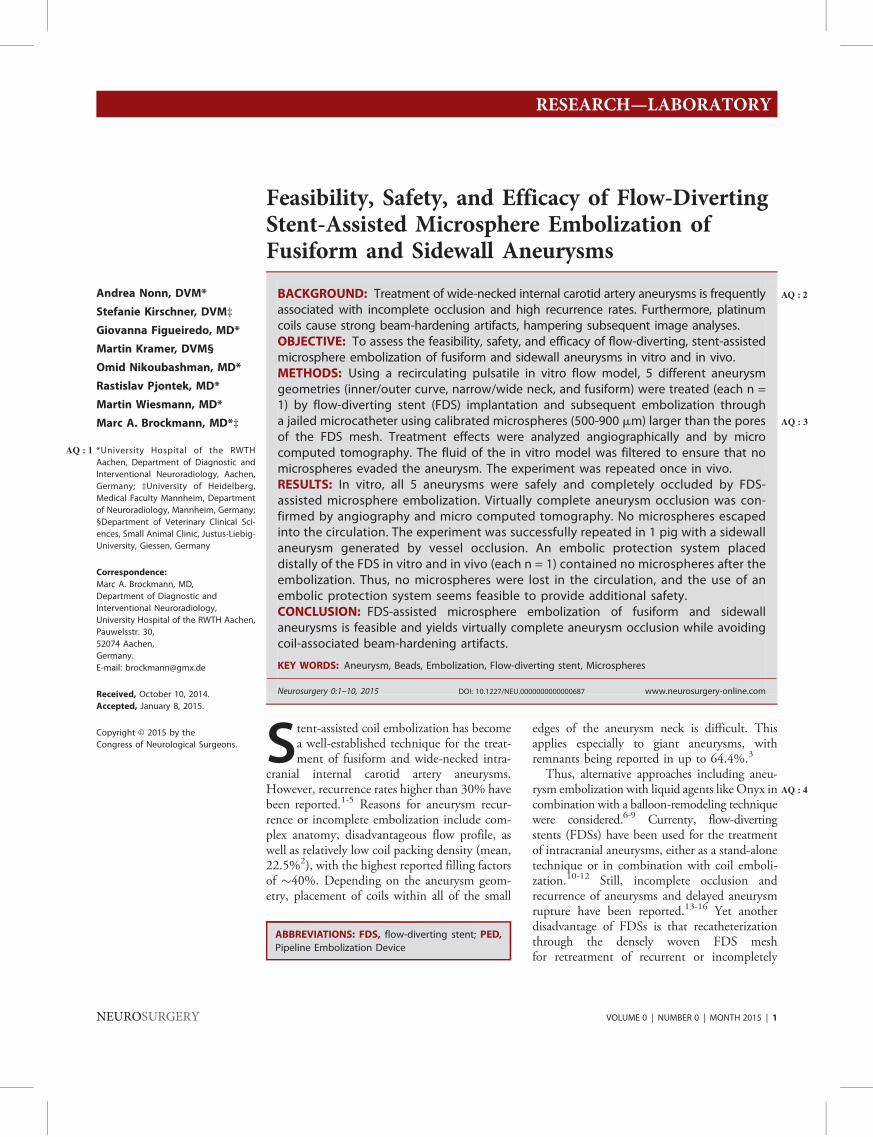
Feasibility, Safety, and Efficacy of Flow-DivertingStent-Assisted Microsphere Embolization ofFusiform and Sidewall Aneurysms
BACKGROUND: Treatment of wide-necked AQ : 2internal carotid artery aneurysms is frequentlyassociated with incomplete occlusion and high recurrence rates. Furthermore, platinumcoils cause strong beam-hardening artifacts, hampering subsequent image analyses.OBJECTIVE: To assess the feasibility, safety, and efficacy of flow-diverting, stent-assistedmicrosphere embolization of fusiform and sidewall aneurysms in vitro and in vivo.METHODS: Using a recirculating pulsatile in vitro flow model, 5 different aneurysmgeometries (inner/outer curve, narrow/wide neck, and fusiform) were treated (each n =1) by flow-diverting stent (FDS) implantation and subsequent embolization througha jailed microcatheter AQ : 3using calibrated microspheres (500-900 mm) larger than the poresof the FDS mesh. Treatment effects were analyzed angiographically and by microcomputed tomography. The fluid of the in vitro model was filtered to ensure that nomicrospheres evaded the aneurysm. The experiment was repeated once in vivo.RESULTS: In vitro, all 5 aneurysms were safely and completely occluded by FDS-assisted microsphere embolization. Virtually complete aneurysm occlusion was con-firmed by angiography and micro computed tomography. No microspheres escapedinto the circulation. The experiment was successfully repeated in 1 pig with a sidewallaneurysm generated by vessel occlusion. An embolic protection system placeddistally of the FDS in vitro and in vivo (each n = 1) contained no microspheres after theembolization. Thus, no microspheres were lost in the circulation, and the use of anembolic protection system seems feasible to provide additional safety.CONCLUSION: FDS-assisted microsphere embolization of fusiform and sidewallaneurysms is feasible and yields virtually complete aneurysm occlusion while avoidingcoil-associated beam-hardening artifacts.
KEY WORDS: Aneurysm, Beads, Embolization, Flow-diverting stent, Microspheres
Neurosurgery 0:1–10, 2015 DOI: 10.1227/NEU.0000000000000687 www.neurosurgery-online.com
Stent-assisted coil embolization has becomea well-established technique for the treat-ment of fusiform and wide-necked intra-
cranial internal carotid artery aneurysms.However, recurrence rates higher than 30% havebeen reported.1-5 Reasons for aneurysm recur-rence or incomplete embolization include com-plex anatomy, disadvantageous flow profile, aswell as relatively low coil packing density (mean,22.5%2), with the highest reported filling factorsof �40%. Depending on the aneurysm geom-etry, placement of coils within all of the small
edges of the aneurysm neck is difficult. Thisapplies especially to giant aneurysms, withremnants being reported in up to 64.4%.3
Thus, alternative approaches including aneu-rysm embolization with liquid agents like Onyx AQ : 4incombination with a balloon-remodeling techniquewere considered.6-9 Currenty, flow-divertingstents (FDSs) have been used for the treatmentof intracranial aneurysms, either as a stand-alonetechnique or in combination with coil emboli-zation.10-12 Still, incomplete occlusion andrecurrence of aneurysms and delayed aneurysmrupture have been reported.13-16 Yet anotherdisadvantage of FDSs is that recatheterizationthrough the densely woven FDS meshfor retreatment of recurrent or incompletely
Andrea Nonn, DVM*
Stefanie Kirschner, DVM‡
Giovanna Figueiredo, MD*
Martin Kramer, DVM§
Omid Nikoubashman, MD*
Rastislav Pjontek, MD*
Martin Wiesmann, MD*
Marc A. Brockmann, MD*‡
*University Hospital of the RWTHAQ : 1Aachen, Department of Diagnostic and
Interventional Neuroradiology, Aachen,
Germany; ‡University of Heidelberg,
Medical Faculty Mannheim, Department
of Neuroradiology, Mannheim, Germany;
§Department of Veterinary Clinical Sci-
ences, Small Animal Clinic, Justus-Liebig-
University, Giessen, Germany
Correspondence:
Marc A. Brockmann, MD,
Department of Diagnostic and
Interventional Neuroradiology,
University Hospital of the RWTH Aachen,
Pauwelsstr. 30,
52074 Aachen,
Germany.
E-mail: [email protected]
Received, October 10, 2014.
Accepted, January 8, 2015.
Copyright © 2015 by the
Congress of Neurological Surgeons.
ABBREVIATIONS: FDS, flow-diverting stent; PED,
Pipeline Embolization Device
RESEARCH—LABORATORYRESEARCH—LABORATORY
NEUROSURGERY VOLUME 0 | NUMBER 0 | MONTH 2015 | 1

embolized aneurysms is impossible. Furthermore, stenting requiressufficient platelet inhibition, which might counteract aneurysmthrombosis, thus supporting incomplete thrombosis and aneurysmrecurrence. Finally, embolization with platinum coils or Onyximpedes computed tomography–based evaluation of aneurysmsand adjacent vessels due to beam-hardening artifacts.17,18
To improve acute and chronic aneurysm occlusion rates inwide-necked, giant, or fusiform aneurysms; to achieve a ratherhigh filling factor; and to improve the assessability of the treatedparent vessel and aneurysm in cross-sectional CT imaging, weassessed the safety and feasibility of a novel approach forendovascular aneurysm treatment combining FDS implantationwith microsphere embolization. Results of the first in vitro andin vivo experiments are reported here, and the benefits, safetymeasures, and future perspectives of this method are discussed.
METHODS
Pulsatile In Vitro Circulation Model
A recently described in vitro circular flowmodel was used.19 The setupcomprised a programmable peristaltic pump to simulate physiologicalpulsatile blood flow with physiological arterial pressure curves. A mixtureof distilled water and 46% glycerin (glycerin 85%; Caesar & LoretzGmbH, Hilden, Germany) was used as a human blood substitute,mimicking a bloodlike viscosity of 3.75 mPA/s at room temperature. Foreach experiment, the solution was freshly prepared to avoid changes inviscosity due to contamination by saline solution/contrast agent.
In Vitro Aneurysm Models
Five different silicon aneurysm models (provided by Covidien/ev3,Irvine, California) with different morphologies (½T1� Table) were used for theexperiments. The parent vessel diameter was 4.3 mm in all models.
Flow-Diverting Stents
Experiments were performed with different types of FDSs, includingthe FRED (Flow Re-Direction Device; Terumo/Microvention, Tustin,California) and Pipeline Embolization Device (PED) (Covidien/ev3).FDSs were suited for a nominal parent vessel diameter of 4.5 mm and ofsufficient lengths.
Microspheres
Size-calibrated microspheres from different manufacturers were used.These included Bead Blockmicrospheres (diameters of 500-700 and 700-900 mm; Terumo/Microvention), Embozene Color-Advanced Micro-spheres (CeloNova BioSciences Inc, Newnan, Georgia) with diameters of700 and 900 mm, and Embosphere microspheres 500 to 700 mm and700 to 900 mm (Merit Medical, Roissy en France, France).
Technical Aspects: FDS-AssistedMicrosphere Embolization
In Vitro
All in vitro experiments were performed using a biplane angiographyunit (AxiomArtis Zee; SiemensHealthcare, Forchheim,Germany). Intra-aneurysmal flow dynamics were assessed by standardized contrastinjections (iomeprol, 40 mL/s; injection time, 0.2 s; maximal injectionvolume, 8 mL) into the flow model before and after FDS implantation, aswell as during and after microsphere embolization. The high injection ratewas chosen to provide a short bolus with strong contrast.A microcatheter (2.8-French Progreat; Terumo/Microvention or Rebar
027;Covidien/ev3) was advanced into the aneurysmdome via Synchro Softmicrowire (Stryker, West Valley City, Utah). A second microcatheter wasadvanced into the parent vessel distal to the aneurysm for subsequent FDSimplantation. The first microcatheter was jailed by AQ : 5implantation of theFDS. FDSs were placed providing sufficient overlap (minimum, 5 mm) ofthe aneurysm neck to both sides. The following combinations of FDSs andmicrocatheters for implantation were used: FRED (Flow Re-DirectionDevice) through a Headway 27 microcatheter (Terumo/Microvention)and PED through a Marksman microcatheter (Covidien/ev3). Forembolization of the fusiform aneurysm, 2 FDSs were implanted usinga telescoping technique.After confirming correct placement of the FDS and intra-aneurysmal
catheter position, microspheres mixed with nonionic contrast agent wereslowly injected through the jailed microcatheter into the aneurysm. Theembolization process was controlled by fluoroscopy during the injectionand repeated contrast applications into the parent vessel proximal to theaneurysm. Embolization was stopped when complete occlusion of theaneurysm with microspheres was achieved. The jailed microcatheter wasvery carefully flushed with 3mL of sodium chloride solution before slowlyremoving it while aspirating the microcatheter.
In Vivo
The experiment was repeated in vivo once using a C-arm x-ray unit(Axiom Sensis; SiemensHealthcare). The experiment was carried out afterreceiving approval of the local ethics committee. Institutional guidelinesfor animal welfare and experimental conduct were followed. A GermanLandrace pig (weighing 50 kg) received premedication with azaperone(Stresnil; Janssen-Cilag, Neuss, Germany) and ketamine (Ketamin 10%;Ceva Tiergesundheit, Düsseldorf, Germany) followed by intubation.The animal was mechanically ventilated with an oxygen-air mixture.Anesthesia was maintained with propofol (Propofol 2%MCT Fresenius;Fresenius Kabi Deutschland GmbH, Bad Homburg, Germany).Fentanyl (Fentanyl Ratio; Ratiopharm, Ulm, Germany) was continu-ously administered as analgesia. Acetylsalicylic acid (500 mg) and heparin(4000 IU) were administered intravenously to prevent thromboticevents. An aneurysm was generated by occlusion of a branching vessel ofthe forelimb using platinum coils.
TABLE. Geometry of Aneurysm Models Used for the In Vitro
Experiments
Aneurysm Morphology
Dome/Neck
Diameter, mm
Parent Vessel
Diameter, mm
Narrow-necked aneurysm
straight parent vessel
12/6.9 4.3
Narrow-necked aneurysm
outer curve
12.6/11.5 4.3
Wide-necked aneurysm inner
curve
13/19 4.3
Wide-necked aneurysm outer
curve
13/19 4.3
Fusiform aneurysm 18/31 length 4.3
NONN ET AL
2 | VOLUME 0 | NUMBER 0 | MONTH 2015 www.neurosurgery-online.com
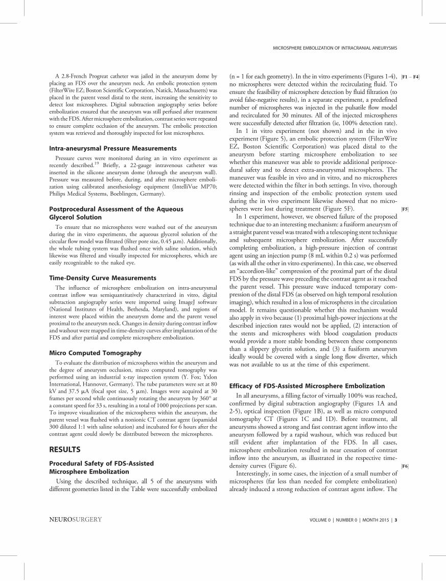
A 2.8-French Progreat catheter was jailed in the aneurysm dome byplacing an FDS over the aneurysm neck. An embolic protection system(FilterWire EZ; Boston Scientific Corporation, Natick, Massachusetts) wasplaced in the parent vessel distal to the stent, increasing the sensitivity todetect lost microspheres. Digital subtraction angiography series beforeembolization ensured that the aneurysm was still perfused after treatmentwith the FDS. Aftermicrosphere embolization, contrast series were repeatedto ensure complete occlusion of the aneurysm. The embolic protectionsystem was retrieved and thoroughly inspected for lost microspheres.
Intra-aneurysmal Pressure Measurements
Pressure curves were monitored during an in vitro experiment asrecently described.19 Briefly, a 22-gauge intravenous catheter wasinserted in the silicone aneurysm dome (through the aneurysm wall).Pressure was measured before, during, and after microsphere emboli-zation using calibrated anesthesiology equipment (IntelliVue MP70;Philips Medical Systems, Boeblingen, Germany).
Postprocedural Assessment of the AqueousGlycerol Solution
To ensure that no microspheres were washed out of the aneurysmduring the in vitro experiments, the aqueous glycerol solution of thecircular flow model was filtrated (filter pore size, 0.45 mm). Additionally,the whole tubing system was flushed once with saline solution, whichlikewise was filtered and visually inspected for microspheres, which areeasily recognizable to the naked eye.
Time-Density Curve Measurements
The influence of microsphere embolization on intra-aneurysmalcontrast inflow was semiquantitatively characterized in vitro, digitalsubtraction angiography series were imported using ImageJ software(National Institutes of Health, Bethesda, Maryland), and regions ofinterest were placed within the aneurysm dome and the parent vesselproximal to the aneurysm neck. Changes in density during contrast inflowandwashout weremapped in time-density curves after implantation of theFDS and after partial and complete microsphere embolization.
Micro Computed Tomography
To evaluate the distribution of microspheres within the aneurysm andthe degree of aneurysm occlusion, micro computed tomography wasperformed using an industrial x-ray inspection system (Y. Fox; YxlonInternational, Hannover, Germany). The tube parameters were set at 80kV and 37.5 mA (focal spot size, 5 mm). Images were acquired at 30frames per second while continuously rotating the aneurysm by 360� ata constant speed for 33 s, resulting in a total of 1000 projections per scan.To improve visualization of the microspheres within the aneurysm, theparent vessel was flushed with a nonionic CT contrast agent (iopamidol300 diluted 1:1 with saline solution) and incubated for 6 hours after thecontrast agent could slowly be distributed between the microspheres.
RESULTS
Procedural Safety of FDS-AssistedMicrosphere Embolization
Using the described technique, all 5 of the aneurysms withdifferent geometries listed in the Table were successfully embolized
(n = 1 for each geometry). In the in vitro experiments ( ½F1� F4�Figures 1-4),no microspheres were detected within the recirculating fluid. Toensure the feasibility of microsphere detection by fluid filtration (toavoid false-negative results), in a separate experiment, a predefinednumber of microspheres was injected in the pulsatile flow modeland recirculated for 30 minutes. All of the injected microsphereswere successfully detected after filtration (ie, 100% detection rate).In 1 in vitro experiment (not shown) and in the in vivo
experiment (Figure 5), an embolic protection system (FilterWireEZ, Boston Scientific Corporation) was placed distal to theaneurysm before starting microsphere embolization to seewhether this maneuver was able to provide additional periproce-dural safety and to detect extra-aneurysmal microspheres. Themaneuver was feasible in vivo and in vitro, and no microsphereswere detected within the filter in both settings. In vivo, thoroughrinsing and inspection of the embolic protection system usedduring the in vivo experiment likewise showed that no micro-spheres were lost during treatment (Figure ½F5�5F).In 1 experiment, however, we observed failure of the proposed
technique due to an interesting mechanism: a fusiform aneurysm ofa straight parent vessel was treatedwith a telescoping stent techniqueand subsequent microsphere embolization. After successfullycompleting embolization, a high-pressure injection of contrastagent using an injection pump (8 mL within 0.2 s) was performed(as with all the other in vitro experiments). In this case, we observedan “accordion-like” compression of the proximal part of the distalFDS by the pressure wave preceding the contrast agent as it reachedthe parent vessel. This pressure wave induced temporary com-pression of the distal FDS (as observed on high temporal resolutionimaging), which resulted in a loss of microspheres in the circulationmodel. It remains questionable whether this mechanism wouldalso apply in vivo because (1) proximal high-power injections at thedescribed injection rates would not be applied, (2) interaction ofthe stents and microspheres with blood coagulation productswould provide a more stable bonding between these componentsthan a slippery glycerin solution, and (3) a fusiform aneurysmideally would be covered with a single long flow diverter, whichwas not available to us at the time of this experiment.
Efficacy of FDS-Assisted Microsphere Embolization
In all aneurysms, a filling factor of virtually 100% was reached,confirmed by digital subtraction angiography (Figures 1A and2-5), optical inspection (Figure 1B), as well as micro computedtomography CT (Figures 1C and 1D). Before treatment, allaneurysms showed a strong and fast contrast agent inflow into theaneurysm followed by a rapid washout, which was reduced butstill evident after implantation of the FDS. In all cases,microsphere embolization resulted in near cessation of contrastinflow into the aneurysm, as illustrated in the respective time-density curves (Figure ½F6�6).Interestingly, in some cases, the injection of a small number of
microspheres (far less than needed for complete embolization)already induced a strong reduction of contrast agent inflow. The
MICROSPHERE EMBOLIZATION OF INTRACRANIAL ANEURYSMS
NEUROSURGERY VOLUME 0 | NUMBER 0 | MONTH 2015 | 3

microspheres accumulated on the outside of the FDS mesh, as ifbeing “aspirated” by the parent vessel (arrows in Figures 2 and 3),hereby reducing the intra-aneurysmal flow. After completemicrosphere embolization, only minimal diffusion of contrastagent from the parent vessel into the aneurysm was observed(Figures 2 and 4).
Influence on Intra-aneurysmal Blood Pressure
The static mean intra-aneurysmal pressure was recorded in 1wide-necked inner curve aneurysm. No relevant changes in meanstatic intra-aneurysmal pressure before (89mmHg) and after FDSplacement (89 mm Hg) as well as before and after embolizationwith microspheres were recorded (88 mm Hg).
DISCUSSION
The reported rates of complete aneurysm occlusion afterendovascular treatment are 26% to 40% directly after theintervention, increasing to 50% to 67% on follow-up examina-tions.1,3,20 Retreatment has been reported to be required in 4.7%to 6% of cases.1,20,21 For giant aneurysms, neck remnant rates ashigh as 64.4% and recurrence rates as high as 35% to 39% have
been reported.3,21 To improve occlusion rates, alternative techni-ques such as liquid embolization using Onyx in combination witha balloon-remodeling technique have been tested, and occlusionrates of 47% to 55% for large and giant aneurysms have beenreported.6 Embolization with Onyx, however, did not culminate inwidespread use. Furthermore, Onyx and platinum coils causestrong artifacts on CT imaging that hamper subsequent post-interventional assessment of the aneurysm and parent vessel.17,18
To improve vessel remodeling and occlusion rates, treatmentwith FDSs has been proposed.13,19,22 Complete aneurysmocclusion using FDSs has been reported in as many as 76%for giant aneurysms and in as many as 74% for large aneurysms.13
However, even if used in combination with coil embolization,complete and stable occlusion still is not feasible in quitea number of cases. One of the reasons for incomplete aneurysmocclusion is the difficulty to completely fill large aneurysms withplatinum coils, leaving no aneurysm remnant as a potentialsource for recurrence. Furthermore, the relatively low fillingfactors of usually less than 40% achievable by coil embolizationallow compaction of coil packages, which again is associated withaneurysm recurrence.23
FIGURE 1. Narrow-necked aneurysm emanating from a straight parent vessel after flow-diverting stent–assisted microsphereembolization. A, digital subtraction angiography indicates complete occlusion with no residual contrast inflow. Only diffusionof contrast agent from the parent vessel leads to a faint enhancement of the aneurysm neck. B, an inner curve wide-neckedaneurysm treated with a Pipeline Embolization Device (Covidien/ev3) and subsequent embolization with microspheres(700 mm, Embozene). C, D, micro CT of an embolized aneurysm showing that the microspheres are being held inside theaneurysm by the densely woven flow-diverting stent mesh. The microspheres fill the complete aneurysm without leavinga neck remnant (arrows in C).
NONN ET AL
4 | VOLUME 0 | NUMBER 0 | MONTH 2015 www.neurosurgery-online.com

To further improve occlusion rates of large, wide-necked orgiant, and fusiform aneurysms, we evaluated the use of FDS incombination with microspheres of defined diameters. Techni-cally, the injected microspheres will be held back inside theaneurysm by the FDS because they are larger than the pores ofthe densely woven FDSmesh. There are many advantages of thisapproach. First, we observed a virtually 100% completeembolization of the aneurysm, leaving no edges of the aneurysmunfilled. Accordingly, this would leave no aneurysm remnantsfrom which recurrent aneurysms could develop. This hypoth-esis, however, remains to be verified in longitudinal in vivoexperiments. Also, the high filling factors and stability of themicrospheres used should resist mechanisms comparable to coilcompaction. The use of nonmetallic microspheres preventsimaging artifacts as seen after coil embolization or treatmentwith Onyx, thereby allowing unhindered assessability of thestented parent vessel and the aneurysm. Another potentialbenefit of microsphere embolization is immediate completeaneurysm occlusion, even in patients treated with dual-plateletinhibition or in patients with blister-like aneurysms, which
might not be treated well using platinum coils. Definitecomplete aneurysm occlusion is also of relevance because afterplacement of an FDS, repeated coil embolizations are notfeasible because the dense FDS mesh usually prevents recathete-rization of the aneurysm domewith amicrocatheter. Finally, onecan speculate whether the reported subacute or delayed ruptureof aneurysms treated with FDS might be prevented by the use ofmicrospheres. Despite these issues, microsphere embolization isrelatively easy, fast, and less costly compared with embolizationusing platinum coils. Further modifications of this technique(eg, coating or loading of microspheres with therapeuticsubstances to reduce or increase local inflammatory responses,the use of biodegradable microspheres to reduce a possible masseffect) are conceivable.The use of spherical, calibrated, nonresorbable polyvinyl
alcohol microspheres has been described for embolization ofuterine leiomyomas,24-30 vascular malformations,31,32 andmalignant tumors (eg, renal tumors).29,33 Whereas the non-calibrated, irregularly shaped precursors of the microspheresused showed disadvantages such as promotion of catheter
FIGURE 2. Flow-diverting stent (FDS)–assisted microsphere embolization of a fusiform aneurysm (700-mm microsphere size).A, B, telescoping implantation of the FDS with jailing of a microcatheter in a fusiform aneurysm is shown. C-E, during earlyphases of embolization, an accumulation of microspheres on the outside of the FDS and in the proximal and distal edges of theaneurysm (arrows in D) is observed. F, continuous embolization leads to a reduction of contrast inflow. G, H, finally,only minimal contrast extravasation into the aneurysm is observed.
MICROSPHERE EMBOLIZATION OF INTRACRANIAL ANEURYSMS
NEUROSURGERY VOLUME 0 | NUMBER 0 | MONTH 2015 | 5

clogging, incomplete occlusion of target vessels, and unpredict-able behavior (in settings different from aneurysm emboliza-tion),29,34 the microspheres used in the substudy were ofa round to ovoid shape, slightly compressible, and of a calibratedsize, which is of importance to ensure that none of the spheresprotrude or migrate through the FDS mesh. Weak inflamma-tory and foreign body reactions have been reported in long-termstudies after experimental liver embolization.35-37 To date, thereare no long-term results for aneurysm embolization using theseparticles.
Although at first glance microsphere embolization of aneur-ysms may appear hazardous in the cerebral circulation, ourinvestigations showed the feasibility and safety of this technique.One critical point for safemicrosphere embolization is a sufficientdifference in size of themicrospheres and the pore size of the FDSmesh. In this context, it is of importance to know that calibrated
microspheres from most manufacturers are compressible by asmuch as 30% to optimize passage through a microcatheter.38
With the smallest microspheres used in our experimentsmeasuring 500 to 700 mm, the smallest possible size of thesemicrospheres is 350 mm, which is still larger than an FDS poresize less than 200 mm (depending on the FDS used). Anotherimportant technical aspect is the correct placement of the FDSwith a sufficient overlap proximal and distal to the aneurysmneck. Although we initially considered the gap between the FDSand the vessel wall at the side of the jailed microcatheter to bea potential “escape route” for microspheres, we found that nomicrospheres were lost during implantation. Thus, the ante-grade blood flow itself seems sufficient to prevent a loss ofmicrospheres in the circulation via this route. Thus, the use ofa proximal balloon for safety purposes might even bedisadvantageous because it would reduce the antegrade flow
FIGURE 3. Flow-diverting stent (FDS)–assisted microsphere embolization of a wide-necked outer curve aneurysm (900-mm microsphere size). Images were taken before andafter FDS implantation (A, B) as well as during (C, D) and after (E, F) embolization with microspheres through the jailed microcatheter. During the early phases of theembolization process, accumulation of microspheres on the outside the FDS was observed (arrows in C).
NONN ET AL
6 | VOLUME 0 | NUMBER 0 | MONTH 2015 www.neurosurgery-online.com

at the side of the jailed microcatheter. To further increase thesafety of this technique, we also evaluated the additional use ofan embolic protection system placed distal to the aneurysmwithin the parent vessel. We found this to be feasible in vitroand in vivo, but based on our current experience, it should notbe required because no microspheres were lost in the circulationin our experiments.
Technically, we did not notice any relevant differencesbetween the in vivo and in vitro experiments except that forthe in vivo experiment, we used an older angiography suite,which had, compared with the normally used state-of-the-artsuite, slightly reduced image quality. We thus were not able toreally see single microspheres as we did in vitro; however,intermittent contrast administration was sufficient to safelyjudge the progress of embolization. In this context, it might wellbe possible that aneurysm occlusion was reached earlier inin vivo than in the in vitro experiments because fewer micro-spheres were required to achieve intra-aneurysmal thrombosis.This point remains to be clarified in future experiments.Furthermore, we did not experience any significant differenceswhen deploying the microspheres in a fusiform or a sidewallaneurysm. Only the distribution of the spheres within the
differently shaped aneurysms varied, as shown in Figures 2through 4.The influence of an FDS on intra-aneurysmal pressure has
been discussed in several articles.19 The majority of studiesconclude that implantation of FDSs usually does not lead toacute changes in intra-aneurysmal pressure, whereas in specialsettings (eg distal FDS-induced stenosis), an increase in intra-aneurysmal pressure still might be conceivable.14 We per-formed pressure measurements in only 1 aneurysm (because inour setting, pressure measurement is associated with punctureof the silicone aneurysm wall). The mean arterial static bloodpressure did not notably change before, during, and afterembolization with microspheres in our in vitro model. An acutereduction of bleeding risk due to immediate thrombosis of theaneurysm, however, can be expected, but again remains to beverified in vivo.
Limitations
A general limitation of the proposed technique is thesomewhat restricted field of application: the technique can onlybe applied safely in sidewall or fusiform aneurysms with norelevant perforators or larger vessels emanating from the
FIGURE 4. Representative images of a digital subtraction angiography series show a vortical flow pattern in a wide-necked inner curve aneurysm after jailing a 027microcatheter within a narrow-necked inner curve sidewall aneurysm using a Pipeline Embolization Device (top). After partial embolization (middle), the contrast inflow intothe aneurysm is reduced. After complete embolization with microspheres (bottom), only minimal diffusion of contrast agent from the parent vessel into the aneurysm neck isobserved.
MICROSPHERE EMBOLIZATION OF INTRACRANIAL ANEURYSMS
NEUROSURGERY VOLUME 0 | NUMBER 0 | MONTH 2015 | 7

aneurysm or the aneurysm neck. Furthermore, for embolizationwith 500 to 900 mm microspheres, a 027 microcatheter isrequired. In most cases, however, targeted aneurysms would bequite large anyway, so that using a 027 microcatheter should notbe a problem. Another limitation of the study is the relativelysmall nonrepresentative sample size. In addition, more realisticin vivo models and ideally those that could be followed foraneurysm recurrence (including histological analyses of embol-ized aneurysms at different time points) would be needed tofurther show the safety and efficacy of this technique beforeexploring it in humans.
Regarding the use of microspheres for aneurysm embolization,other points should be kept in mind. Microspheres, for example,may occlude a catheter, thereby ending the embolization session.We experienced this problem in vitro once and solved it byadvancing a microwire carefully through the microcatheter.Although we noticed no problem during or after this procedure,we retrospectively hypothesized whether this maneuver may alsoresult in fragmentation of microspheres. In this context, fragmen-tation of microspheres likewise may also happen when injectingspheres through a not completely opened 3-way faucet at highshear forces.
FIGURE 5. Flow-diverting stent (FDS)–assisted microsphere embolization in a pig. A, an aneurysm was constructed by coilembolization of branching vessels in the animal’s forelimb. B, after FDS implantation, contrast agent inflow into the aneurysm isevident, although reduced by the FDS. A microcatheter was jailed with the FDS. An embolic protection system was placed distal tothe aneurysm (C, D). E, the aneurysm after embolization with microspheres through the jailed microcatheter. F, postproceduralassessment of the embolic protection system revealed that no microspheres escaped the aneurysm. To provide a positive control,microspheres were injected into a second smaller glass containing saline solution.
NONN ET AL
8 | VOLUME 0 | NUMBER 0 | MONTH 2015 www.neurosurgery-online.com

Another yet unsolved question is what would happen ifaneurysm rupture occurs during microsphere embolization.This scenario also needs to be tested by, for example, sub-arachnoid injection of particles in an animal model. One mayspeculate that some or most of the particles might spread
throughout the subarachnoid space or even might be kept inplace by a blood clot. However, in such a case, it should bepossible to switch from microsphere to coil embolizationthrough a 027 microcatheter using volume coils that can bedetached mechanically.
FIGURE 6. Time-density curves of regions of interest placed within the aneurysm dome and the parent vessel. Residual contrast inflow after flow-diverting stent implantationcan be observed in all aneurysm geometries. Microsphere embolization results in almost complete absence of detectable contrast inflow. FDS, flow-diverting stent; fps, frames persecond.
MICROSPHERE EMBOLIZATION OF INTRACRANIAL ANEURYSMS
NEUROSURGERY VOLUME 0 | NUMBER 0 | MONTH 2015 | 9
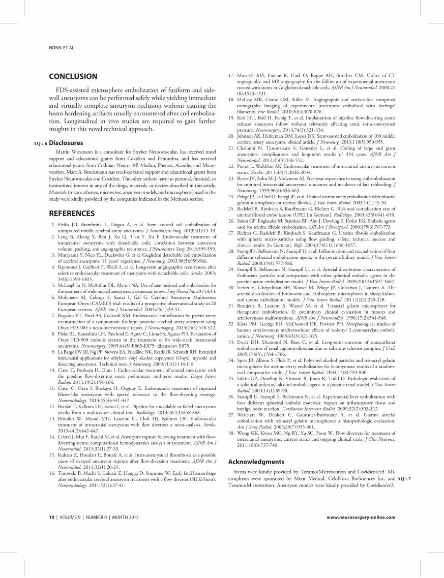
CONCLUSION
FDS-assisted microsphere embolization of fusiform and side-wall aneurysms can be performed safely while yielding immediateand virtually complete aneurysm occlusion without causing thebeam hardening artifacts usually encountered after coil emboliza-tion. Longitudinal in vivo studies are required to gain furtherinsights in this novel technical approach.
DisclosuresAQ : 6
Martin Wiesmann is a consultant for Stryker Neurovascular, has received travelsupport and educational grants from Covidien and Penumbra, and has receivededucational grants from Codman Neuro, AB Medica, Phenox, Acandis, and Micro-vention. Marc A. Brockmann has received travel support and educational grants fromStryker Neurovascular and Covidien. The other authors have no personal, financial, orinstitutional interest in any of the drugs, materials, or devices described in this article.Materials (microcatheters,microwires, aneurysmmodels, andmicrospheres) used in thisstudy were kindly provided by the companies indicated in the Methods section.
REFERENCES
1. Fields JD, Brambrink L, Dogan A, et al. Stent assisted coil embolization ofunruptured middle cerebral artery aneurysms. J Neurointerv Surg. 2013;5(1):15-19.
2. Leng B, Zheng Y, Ren J, Xu Q, Tian Y, Xu F. Endovascular treatment ofintracranial aneurysms with detachable coils: correlation between aneurysmvolume, packing, and angiographic recurrence. J Neurointerv Surg. 2013;595-599.
3. Murayama Y, Nien YL, Duckwiler G, et al. Guglielmi detachable coil embolizationof cerebral aneurysms: 11 years’ experience. J Neurosurg. 2003;98(5):959-966.
4. Raymond J, Guilbert F, Weill A, et al. Long-term angiographic recurrences afterselective endovascular treatment of aneurysms with detachable coils. Stroke. 2003;34(6):1398-1403.
5. McLaughlin N, McArthur DL, Martin NA. Use of stent-assisted coil embolization forthe treatment of wide-necked aneurysms: a systematic review. Surg Neurol Int. 2013;4:43.
6. Molyneux AJ, Cekirge S, Saatci I, Gál G. Cerebral Aneurysm MulticenterEuropean Onyx (CAMEO) trial: results of a prospective observational study in 20European centers. AJNR Am J Neuroradiol. 2004;25(1):39-51.
7. Bogason ET, Patel AS, Cockroft KM. Endovascular embolization by parent arteryreconstruction of a symptomatic fusiform posterior cerebral artery aneurysm usingOnyx HD-500: a neurointerventional report. J Neuroimaging. 2013;23(4):518-522.
8. Piske RL, Kanashiro LH, Paschoal E, Agner C, Lima SS, Aguiar PH. Evaluation ofOnyx HD-500 embolic system in the treatment of 84 wide-neck intracranialaneurysms. Neurosurgery. 2009;64(5):E865-E875; discussion E875.
9. La Barge DV III, Ng PP, Stevens EA, Friedline NK, Kestle JR, Schmidt RH. Extendedintracranial applications for ethylene vinyl alcohol copolymer (Onyx): mycotic anddissecting aneurysms. Technical note. J Neurosurg. 2009;111(1):114-118.
10. Cinar C, Bozkaya H, Oran I. Endovascular treatment of cranial aneurysms withthe pipeline flow-diverting stent: preliminary mid-term results. Diagn IntervRadiol. 2013;19(2):154-164.
11. Cinar C, Oran I, Bozkaya H, Ozgiray E. Endovascular treatment of rupturedblister-like aneurysms with special reference to the flow-diverting strategy.Neuroradiology. 2013;55(4):441-447.
12. Becske T, Kallmes DF, Saatci I, et al. Pipeline for uncoilable or failed aneurysms:results from a multicenter clinical trial. Radiology. 2013;267(3):858-868.
13. Brinjikji W, Murad MH, Lanzino G, Cloft HJ, Kallmes DF. Endovasculartreatment of intracranial aneurysms with flow diverters a meta-analysis. Stroke.2013;44(2):442-447.
14. Cebral J, Mut F, Raschi M, et al. Aneurysm rupture following treatment with flow-diverting stents: computational hemodynamics analysis of treatment. AJNR Am JNeuroradiol. 2011;32(1):27-33.
15. Kulcsar Z, Houdart E, Bonafe A, et al. Intra-aneurysmal thrombosis as a possiblecause of delayed aneurysm rupture after flow-diversion treatment. AJNR Am JNeuroradiol. 2011;32(1):20-25.
16. Turowski B, Macht S, Kulcsár Z, Hänggi D, Stummer W. Early fatal hemorrhageafter endovascular cerebral aneurysm treatment with a flow diverter (SILK-Stent).Neuroradiology. 2011;53(1):37-41.
17. Masaryk AM, Frayne R, Unal O, Rappe AH, Strother CM. Utility of CTangiography and MR angiography for the follow-up of experimental aneurysmstreated with stents or Guglielmi detachable coils. AJNR Am J Neuroradiol. 2000;21(8):1523-1531.
18. McCoy MR, Cruise GM, Killer M. Angiographic and artefact-free computedtomography imaging of experimental aneurysms embolised with hydrogelfilaments. Eur Radiol. 2010;20(4):870-876.
19. Kerl HU, Boll H, Fiebig T, et al. Implantation of pipeline flow-diverting stentsreduces aneurysm inflow without relevantly affecting static intra-aneurysmalpressure. Neurosurgery. 2014;74(3):321-334.
20. Johnson AK, Heiferman DM, Lopes DK. Stent-assisted embolization of 100 middlecerebral artery aneurysms: clinical article. J Neurosurg. 2013;118(5):950-955.
21. Chalouhi N, Tjoumakaris S, Gonzalez L, et al. Coiling of large and giantaneurysms: complications and long-term results of 334 cases. AJNR Am JNeuroradiol. 2014;35(3):546-552.
22. Pierot L, Wakhloo AK. Endovascular treatment of intracranial aneurysms currentstatus. Stroke. 2013;44(7):2046-2054.
23. Byrne JV, SohnM-J, Molyneux AJ. Five-year experience in using coil embolizationfor ruptured intracranial aneurysms: outcomes and incidence of late rebleeding. JNeurosurg. 1999;90(4):656-663.
24. Pelage JP, Le Dref O, Beregi JP, et al. Limited uterine artery embolization with trisacrylgelatin microspheres for uterine fibroids. J Vasc Interv Radiol. 2003;14(1):15-20.
25. Radeleff B, Rimbach S, Kauffmann G, Richter G. Risk and complication rate ofuterine fibroid embolization (UFE) [in German]. Radiologe. 2003;43(8):641-650.
26. Siskin GP, Englander M, Stainken BF, Ahn J, Dowling K, Dolen EG. Embolic agentsused for uterine fibroid embolization. AJR Am J Roentgenol. 2000;175(3):767-773.
27. Richter G, Radeleff B, Rimbach S, Kauffmann G. Uterine fibroid embolizationwith spheric micro-particles using flow guiding: safety, technical success andclinical results [in German]. Rofo. 2004;176(11):1648-1657.
28. Stampfl S, Bellemann N, Stampfl U, et al. Inflammation and recanalization of fourdifferent spherical embolization agents in the porcine kidney model. J Vasc IntervRadiol. 2008;19(4):577-586.
29. Stampfl S, Bellemann N, Stampfl U, et al. Arterial distribution characteristics ofEmbozene particles and comparison with other spherical embolic agents in theporcine acute embolization model. J Vasc Interv Radiol. 2009;20(12):1597-1607.
30. Verret V, Ghegediban SH, Wassef M, Pelage JP, Golzarian J, Laurent A. Thearterial distribution of Embozene and Embosphere microspheres in sheep kidneyand uterus embolization models. J Vasc Interv Radiol. 2011;22(2):220-228.
31. Beaujeux R, Laurent A, Wassef M, et al. Trisacryl gelatin microspheres fortherapeutic embolization, II: preliminary clinical evaluation in tumors andarteriovenous malformations. AJNR Am J Neuroradiol. 1996;17(3):541-548.
32. Klara PM, George ED, McDonnell DE, Pevsner PH. Morphological studies ofhuman arteriovenous malformations: effects of isobutyl 2-cyanoacrylate emboli-zation. J Neurosurg. 1985;63(3):421-425.
33. Ewalt DH, Diamond N, Rees C, et al. Long-term outcome of transcatheterembolization of renal angiomyolipomas due to tuberous sclerosis complex. J Urol.2005;174(5):1764-1766.
34. Spies JB, Allison S, Flick P, et al. Polyvinyl alcohol particles and tris-acryl gelatinmicrospheres for uterine artery embolization for leiomyomas: results of a random-ized comparative study. J Vasc Interv Radiol. 2004;15(8):793-800.
35. Siskin GP, Dowling K, Virmani R, Jones R, Todd D. Pathologic evaluation ofa spherical polyvinyl alcohol embolic agent in a porcine renal model. J Vasc IntervRadiol. 2003;14(1):89-98.
36. Stampfl U, Stampfl S, Bellemann N, et al. Experimental liver embolization withfour different spherical embolic materials: impact on inflammatory tissue andforeign body reaction. Cardiovasc Intervent Radiol. 2009;32(2):303-312.
37. Weichert W, Denkert C, Gauruder-Burmester A, et al. Uterine arterialembolization with tris-acryl gelatin microspheres: a histopathologic evaluation.Am J Surg Pathol. 2005;29(7):955-961.
38. Wong GK, Kwan MC, Ng RY, Yu SC, Poon W. Flow diverters for treatment ofintracranial aneurysms: current status and ongoing clinical trials. J Clin Neurosci.2011;18(6):737-740.
Acknowledgments
Stents were kindly provided by Terumo/Microvention and Covidien/ev3. Mi-crospheres were sponsored AQ : 7by Merit Medical, CeloNova BioSciences Inc, andTerumo/Microvention. Aneurysm models were kindly provided by Covidien/ev3.
NONN ET AL
10 | VOLUME 0 | NUMBER 0 | MONTH 2015 www.neurosurgery-online.com

55
X. Anhang III

Implantation of Pipeline Flow-Diverting StentsReduces Aneurysm Inflow Without RelevantlyAffecting Static Intra-aneurysmal Pressure
BACKGROUND: Flow-diverting stent (FDS) implantation is an endovascular treatmentoption for intracranial aneurysms. However, little is known about the hemodynamiceffects.OBJECTIVE: To assess the effect of stent compression on FDS porosity, to evaluate theinfluence of single and overlapping implantation of FDS on intra-aneurysmal flowprofiles, and to correlate stent porosity with changes in static mean intra-aneurysmalpressure.METHODS: Intra-aneurysmal time-density curves were recorded in a pulsatile in vitroflow model before and after implantation of FDSs (Pipeline Embolization Device; ev3) in7 different types of aneurysm models. Reductions in the maximum contrast inflowand time to maximum intra-aneurysmal contrast were calculated. Micro–computedtomography was performed, and compression-related FDS porosity was measured. Theinfluence of FDS placement on mean static intra-aneurysmal pressure was measured.RESULTS: FDS compression resulted in an almost linear reduction in stent porosity.Stent porosity (struts per 1 mm) correlated significantly with the reduction of aneurysmcontrast inflow (R2 = 0.81, P , .001) and delay until maximum contrast (R2 = 0.34,P = .001). Circulating intra-aneurysmal high-velocity flow was terminated in all sidewallmodels after implantation of a single stent. Superimposition of 2 stents reduced max-imum intra-aneurysmal contrast by 69.16 3.1% (mean6 SD) in narrow-necked sidewallaneurysm models, whereas no substantial reduction in maximum intra-aneurysmalcontrast was observed in wide-necked sidewall aneurysm models. Intra-aneurysmalmean static pressure did not correlate with FDS porosity or number of implanted stents.CONCLUSION: Implantation of FDS effectively reduces aneurysm inflow in a porosity-dependent way without relevantly affecting static mean intra-aneurysmal pressure.
KEY WORDS: Aneurysm, Intra-aneurysmal pressure, Micro-CT, Pipeline flow diverter stent, Stent porosity
Neurosurgery 0:1–14, 2014 DOI: 10.1227/NEU.0000000000000253 www.neurosurgery-online.com
Flow-diverting stents (FDSs) are used withincreasing frequency for endovascular treat-ment of intracranial aneurysms that are not
eligible for standard coiling procedures or thatshow a tendency toward recanalization.1-5
Despite reported successful aneurysm treatment
with densely woven FDSs, delayed aneurysmalhemorrhage after FDS implantation has beenreported.6-10 The hypothesis that flow divertersmay lead to an increase in intra-aneurysmal staticpressure was supported by Cebral et al,6 whofrom their computational fluid dynamic simu-lations found that a pressure increase may berelated to larger effective resistance in the parentartery from placement of the device. Larrabideet al,11 however, found no evidence suggestingthat FDSs might induce a pressure change thatcould, by itself, induce rupture of the aneurysmin their computational fluid dynamic simula-tions. Similarly, Schneiders et al12 measuredintra-aneurysmal pressure directly before,
Hans U. Kerl, MD*
Hanne Boll, DVM*
Teresa Fiebig, DVM*
Giovanna Figueiredo, MD*
Alex Forster, MD*
Ingo S. Nolte, MD*
Andrea Nonn, DVM‡
Christoph Groden, MD*
Marc A. Brockmann, MD*‡
*University of Heidelberg, Medical Faculty
Mannheim, Department of Neuroradiol-
ogy, Mannheim, GermanyAQ : 1 ; ‡University
Hospital of the RWTH Aachen, Depart-
ment of Diagnostic and Interventional
Neuroradiology, Aachen, Germany
Correspondence:
Marc A. Brockmann, MD,
University Hospital of the RWTH Aachen,
Department of Diagnostic and
Interventional Neuroradiology,
Pauwelsstrasse 30,
52074 Aachen, Germany.
E-mail: [email protected]
Received, February 7, 2013.
Accepted, November 12, 2013.
Published Online, November 22, 2013.
Copyright © 2013 by the
Congress of Neurological Surgeons.
WHAT IS THIS BOX?
A QR Code is a matrix
barcode readable by QR
scanners,mobilephones
with cameras, and
smartphones. The QR
Code above links to
Supplemental Digital
Content from this
article.
ABBREVIATIONS: FDS, flow-diverting stent; MAP,
mean arterial pressure; PED, Pipeline Embolization
Device
Supplemental digital content is available for this article.
Direct URL citations appear in the printed text and are
provided in the HTML and PDF versions of this article on
the journal’s Web site (www.neurosurgery-online.com).
RESEARCH—LABORATORYTOPIC RESEARCH—LABORATORY
NEUROSURGERY VOLUME 0 | NUMBER 0 | MONTH 2014 | 1

during, and after implantation of an FDS in a single patient andlikewise did not observe any relevant acuteAQ : 2 changes of intra-aneurysmal pressure. In this context, it might be of interest to notethat other work groups reported coil placement not to influencemean intra-aneurysmal fluid pressure13-15 but only to dampen thepressure amplitude during locally induced hypertension.
We performed in vitro studies to further investigate thehypothesis that flow diverters may lead to increased pressure and
to systematically investigate the effects of FDS implantation onintra-aneurysmal pressure changes and aneurysm hemodynamics.Because stent porosity has been reported to influence the efficacyof FDSs,16,17 we also analyzed the influence of stent compressionon stent porosity using a micro–computed tomography (micro-CT) and correlated FDS porosity with the level of maximumaneurysmal contrast enhancement reduction and time tomaximum intra-aneurysmal contrast.
FIGURE 1. Schematic drawing of the pulsatile in vitro flow model (A) and photographs of the silicone sidewall aneurysm modelsused for the underlying studies (B, straight parent vessel, C, inner-curve aneurysm model; D, outer-curve aneurysm model; E,fusiform aneurysm model).
KERL ET AL
2 | VOLUME 0 | NUMBER 0 | MONTH 2014 www.neurosurgery-online.com

PATIENTS AND METHODS
Experimental Setup
A circulatory experimental setup (½F1� Figure 1A
AQ : 3
) was used to investigateintra-aneurysmal hemodynamics in 4 different silicone modelsof cerebral aneurysms (Figure 1B-1E). The setup comprised a pro-grammable roller pump (MCP V5.12; ISMATEC, Glattbrugg,Switzerland), a fluid reservoir, 2 pressure transducers, and the testsection containing the silicone aneurysm model. The roller pump wasprogrammed to mimic a physiological, pulsatile blood flow profile ofa cerebral artery (pulse frequency, 86 bpm; flow volume, 286 mL/min).A transparent non-Newtonian aqueous glycerol solution was usedas a human blood substitute. The fluid was composed of a mixtureof distilled water and 40% glycerin (Glycerin 98%; Carl Roth GmbH,Karslruhe, Germany), yielding a bloodlike viscosity of 3.75 mPA/sat room temperature. To ensure proper viscosity of the glycerolsolution, a fresh solution without the injected contrast agent was usedwith each stent.
In Vitro Aneurysm Models
Six different silicon sidewall aneurysm models were used in the study(ev3 Neurovascular, Irvine, California), 3 narrow-necked and 3 wide-necked aneurysm models. The first model was a narrow-necked sidewallaneurysm emanating from a straight parent vessel (aneurysm domediameter, 12 mm; neck size, 6.9 mm; Figure 1B); the second model wasa narrow-necked sidewall aneurysm originating from the inner curve ofthe curved parent vessel (aneurysm dome, 12 mm; neck size, 9.6 mm;Figure 1C); and the third narrow-necked sidewall aneurysm originatedfrom the outer curve of the curved parent vessel (aneurysm dome,12 mm; neck size, 7.7 mm; Figure 1D). We furthermore tested a wide-necked sidewall aneurysm originating from a straight parent vessel(aneurysm dome diameter, 13 mm; neck size, 19 mm), a wide-neckedsidewall aneurysm emanating from the inner curve of the parent vessel(aneurysm dome diameter, 13 mm; neck size, 19 mm), and a wide-necked sidewall aneurysm originating from the outer curve of the curvedparent vessel (aneurysm dome diameter, 13 mm; neck size, 21 mm).Besides the sidewall aneurysm models, a seventh model consisting of
FIGURE 2. Representative images of a digital subtraction angiography series show the fast, turbulent, circulating aneurysm inflow (curved arrow) before implantation ofa flow-diverting stent. The observed high flow velocity is indicative of high wall shear stress in a sidewall aneurysm model with a straight parent vessel. Implantation of a singlestent reduces total contrast inflow and time until maximum contrast density is reached within the region of interest (ROI; exemplarily shown in 1 image). In addition, theturbulent aneurysm inflow is eliminated. Superimposition of a second stent results in further decreases in speed and amount of contrast agent inflow into the aneurysm. Thewhite arrows indicate blood flow direction of the parent vessel.
FLOW-DIVERTER HEMODYNAMICS
NEUROSURGERY VOLUME 0 | NUMBER 0 | MONTH 2014 | 3

a fusiform aneurysm (31-mm aneurysm length, 18-mm aneurysmdiameter; Figure 1E) was evaluated. The parent vessel always hada diameter of 4.3 mm.
Stent Placement and Angiographic Assessment
Intra-aneurysmal flow dynamics of the sidewall aneurysms wereevaluated before and after deployment of a single FDS and again afterimplantation of a second superimposed FDS. In the wide-neckedaneurysm model emanating from the straight parent vessel, a thirdsuperimposing stent was deployed (Pipeline Embolization Device [PED];Covidien/ev3). Because of the increased aneurysm neck length, flowdynamics of the wide-necked aneurysms originating from the outer curveof the curved parent vessel and the fusiform aneurysm model wereanalyzed before and after implantation of 2 telescoping FDSs and after thedeployment of a third superimposed FDS.The FDSswere implantedwitha microcatheter (Marksman; Covidien/ev3) covering the completeaneurysm neck of the sidewall aneurysms. Special care was given toreduce the porosity of the PED where it covered the aneurysm.With the use of an angiography system (for the narrow-necked
aneurysm models and the fusiform aneurysm model: Axiom Artis;Siemens Healthcare, Erlangen, Germany; for the wide-necked aneurysmmodels: Axiom Artis Zee, Siemens Healthcare), time-density curves
showing the aneurysm inflow and outflow at 15 frames per second wereacquired after injection of 4 mL undiluted contrast media (Imeron 300;Iomeprol, Bracco Imaging, Konstanz, Germany). Contrast agent injec-tions were standardized by use of an injection pump (for the narrow-necked aneurysm models and the fusiform aneurysm model: Mark VProVis, Model No. PPD, Medrad Inc, Warrendale, Pennsylvania; for thewide-necked aneurysm models: Angiomat 6000, Liebel-Flarsheim Co,Cincinnati, Ohio) with a flow rate of 30 mL/s. The contrast agent wasinjected approximately 1 m upstream AQ : 4of the aneurysm model to ensurethat the injection did not influence the flow profile within the parentvessel and aneurysm hemodynamics.
Time-Density Curve Measurements
To semiquantitatively characterize intra-aneurysmal flow patterns,DICOM (digital imaging and communication in medicine) images wereexported in AVI file format with OsiriX Imaging software (http://www.osirix-viewer.com/index.html). AVI files were imported in ImageJsoftware (ImageJ 1.44; National Institute of Health, Bethesda, Mary-land; http://imagej.nih.gov/ij). A region of interest was placed coveringthe whole aneurysm dome, and a second region of interest was placed inthe parent vessel proximal to the aneurysm neck to provide a referencevalue for the aneurysm flow measurements (regions of interest shown
FIGURE 3. Representative images of a digital subtraction angiography series show a circulating aneurysm inflow (curved arrow) before implantation of a flow-diverting stentover a narrow-necked inner-curve sidewall aneurysm. As in Figure 2, a single stent reduces total contrast inflow, time until maximum contrast density, and the turbulentaneurysm inflow. A second stent results in further decreases in speed and amount of contrast agent inflow. The white arrows indicate blood flow direction in the parent vessel.
KERL ET AL
4 | VOLUME 0 | NUMBER 0 | MONTH 2014 www.neurosurgery-online.com
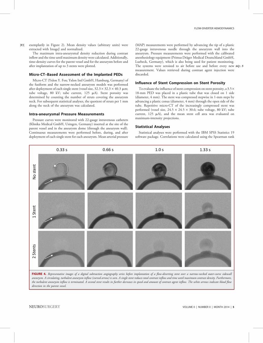
exemplarily in½F2� Figure 2). Mean density values (arbitrary units) wereextracted with ImageJ and normalized.The maximum intra-aneurysmal density reduction during contrast
inflow and the time until maximumdensity were calculated. Additionally,time-density curves for the parent vessel and for the aneurysm before andafter implantation of up to 3 stents were plotted.
Micro-CT–Based Assessment of the Implanted PEDs
Micro-CT (Yxlon Y. Fox; Yxlon Intl GmbH, Hamburg, Germany) ofthe fusiform and the narrow-necked aneurysm models was performedafter deployment of each single stent (voxel size, 32.3 · 32.3 · 40.3 mm;tube voltage, 80 kV; tube current, 125 mA). Stent porosity wasdetermined by counting the number of struts covering the aneurysmneck. For subsequent statistical analyses, the quotient of struts per 1 mmalong the neck of the aneurysm was calculated.
Intra-aneurysmal Pressure Measurements
Pressure curves were monitored with 22-gauge intravenous catheters(Klinika Medical GmbH, Usingen, Germany) inserted at the site of theparent vessel and in the aneurysm dome (through the aneurysm wall).Continuous measurements were performed before, during, and afterdeployment of each single stent for each aneurysm.Mean arterial pressure
(MAP) measurements were performed by advancing the tip of a plastic22-gauge intravenous needle through the aneurysm wall into theaneurysm. Pressure measurements were performed with the calibratedanesthesiology equipment (PrimusDräger Medical Deutschland GmbH,Luebeck, Germany), which is also being used for patient monitoring.The systems were zeroized AQ : 5to air before use and before every newmeasurement. Values retrieved during contrast agent injection werediscarded.
Influence of Stent Compression on Stent Porosity
To evaluate the influence of stent compression on stent porosity, a 3.5·18-mm PED was placed in a plastic tube that was closed on 1 side(diameter, 4 mm). The stent was compressed stepwise in 1-mm steps byadvancing a plastic conus (diameter, 4 mm) through the open side of thetube. Repetitive micro-CT of the increasingly compressed stent wasperformed (voxel size, 24.5 · 24.5 · 30.6; tube voltage, 80 kV; tubecurrent, 125 mA), and the mean stent cell area was evaluated onmaximum-intensity projections.
Statistical Analyses
Statistical analyses were performed with the IBM SPSS Statistics 19software package. Correlations were calculated using the Spearman rank
FIGURE 4. Representative images of a digital subtraction angiography series before implantation of a flow-diverting stent over a narrow-necked outer-curve sidewallaneurysm. A circulating, turbulent aneurysm inflow (curved arrow) is seen. A single stent reduces total contrast inflow and time until maximum contrast density. Furthermore,the turbulent aneurysm inflow is terminated. A second stent results in further decreases in speed and amount of contrast agent inflow. The white arrows indicate blood flowdirection in the parent vessel.
FLOW-DIVERTER HEMODYNAMICS
NEUROSURGERY VOLUME 0 | NUMBER 0 | MONTH 2014 | 5

correlation coefficient. A value of P , .05 was considered statisticallysignificant.
RESULTS
Efficacy of FDSs: Time-Density Curves
In all 6 tested sidewall aneurysm models and in the fusiformaneurysm model, a strong and fast inflow of contrast agent into theaneurysm, along with a rapid washout phase, was observed. Further-more, all sidewall aneurysms showed a circulating intra-aneurysmalflow pattern at high flow velocity (½F3� F7� Figures 2-7). A video file at hightemporal and spatial resolution visualizing intra-aneurysmal hemo-dynamics in an untreated and treated straight-vessel narrow-neckedsidewall aneurysm is provided (See Video 1, SupplementalDigital Content 1, http://links.lww.com/NEU/XXXX, which isa movie file of a digital subtraction angiography series showingthe effects of implantation of 1 or more pipeline stents onaneurysm hemodynamics. First, a sidewall aneurysm witha straight parent vessel before implantation of an FDS is shown.
A turbulent, circulating, high-velocity intra-aneurysmal flow profilecan be seen, indicating high wall shear stress. After implantation ofa single stent, reductions in total contrast inflow and time untilmaximum contrast density are reached. In addition, the turbulenthigh-velocity aneurysm inflow is scrambled. After superimpositionof a second PED, further decreases in inflow speed and intra-aneurysmal contrast are observed. Next, a digital subtractionangiography series of a fusiform aneurysm model before and afterFDS implantation is shown. Before treatment, a straddlingturbulent flow pattern is visualized at the distal aneurysm wallalong the outflow tract. After telescoping implantation of 2 stents,contrast flow into the aneurysm is reduced, and a pulsatile patternof contrast inflow through the stent mesh can be seen.Consequently, a reduction in total contrast inflow and time untilmaximum contrast density is reached. After superimposition ofa third PED, the contrast agent more homogeneously oozes out ofthe stent lumen into the aneurysm).The fusiform aneurysm model demonstrated a turbulent strad-
dling flow pattern in the distal aneurysm adjacent to the outflow
FIGURE 5. Representative images of a digital subtraction angiography series show the fast, turbulent, circulating aneurysm inflow (curved arrow) before implantation ofa flow-diverting stent in a wide-necked straight-parent-vessel aneurysm. The observed high flow velocity is indicative of high wall shear stress in a sidewall aneurysm model witha straight parent vessel. Implantation of a single stent reduced total contrast inflow and time until maximum contrast density. Furthermore, the intra-aneurysmal flow patternchanged from a turbulent circulating type to a more pulsating bulging flow character. Superimposition of a second and third stent resulted in further weak decreases in speed andamount of contrast agent inflow into the aneurysm. The white arrows indicate blood flow direction of the parent vessel.
KERL ET AL
6 | VOLUME 0 | NUMBER 0 | MONTH 2014 www.neurosurgery-online.com
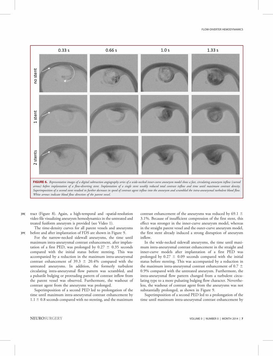
tract (½F8� Figure 8). Again, a high-temporal and -spatial-resolutionvideo file visualizing aneurysm hemodynamics in the untreated andtreated fusiform aneurysm is provided (see Video 1).
The time-density curves for all parent vessels and aneurysmsbefore and after implantation of FDS are shown in½F9� Figure 9.
For the narrow-necked sidewall aneurysms, the time untilmaximum intra-aneurysmal contrast enhancement, after implan-tation of a first PED, was prolonged by 0.27 6 0.35 secondscompared with the initial status before stenting. This wasaccompanied by a reduction in the maximum intra-aneurysmalcontrast enhancement of 39.3 6 20.4% compared with theuntreated aneurysms. In addition, the formerly turbulentcirculating intra-aneurysmal flow pattern was scrambled, anda pulsatile bulging or protruding pattern of contrast inflow fromthe parent vessel was observed. Furthermore, the washout ofcontrast agent from the aneurysms was prolonged.
Superimposition of a second PED led to prolongation of thetime until maximum intra-aneurysmal contrast enhancement by1.16 0.8 seconds compared with no stenting, and the maximum
contrast enhancement of the aneurysms was reduced by 69.1 63.1%. Because of insufficient compression of the first stent, thiseffect was stronger in the inner-curve aneurysm model, whereasin the straight parent vessel and the outer-curve aneurysm model,the first stent already induced a strong disruption of aneurysminflow.In the wide-necked sidewall aneurysms, the time until maxi-
mum intra-aneurysmal contrast enhancement in the straight andinner-curve models after implantation of a first PED wasprolonged by 0.27 6 0.09 seconds compared with the initialstatus before stenting. This was accompanied by a reduction inthe maximum intra-aneurysmal contrast enhancement of 0.7 60.9% compared with the untreated aneurysm. Furthermore, theintra-aneurysmal flow pattern changed from a turbulent circu-lating type to a more pulsating bulging flow character. Neverthe-less, the washout of contrast agent from the aneurysms was notsubstantially prolonged, as shown in Figure 9.Superimposition of a second PED led to a prolongation of the
time until maximum intra-aneurysmal contrast enhancement by
FIGURE 6. Representative images of a digital subtraction angiography series of a wide-necked inner-curve aneurysm model show a fast, circulating aneurysm inflow (curvedarrow) before implantation of a flow-diverting stent. Implantation of a single stent weakly reduced total contrast inflow and time until maximum contrast density.Superimposition of a second stent resulted in further decreases in speed of contrast agent inflow into the aneurysm and scrambled the intra-aneurysmal turbulent blood flow.White arrows indicate blood flow direction of the parent vessel.
FLOW-DIVERTER HEMODYNAMICS
NEUROSURGERY VOLUME 0 | NUMBER 0 | MONTH 2014 | 7
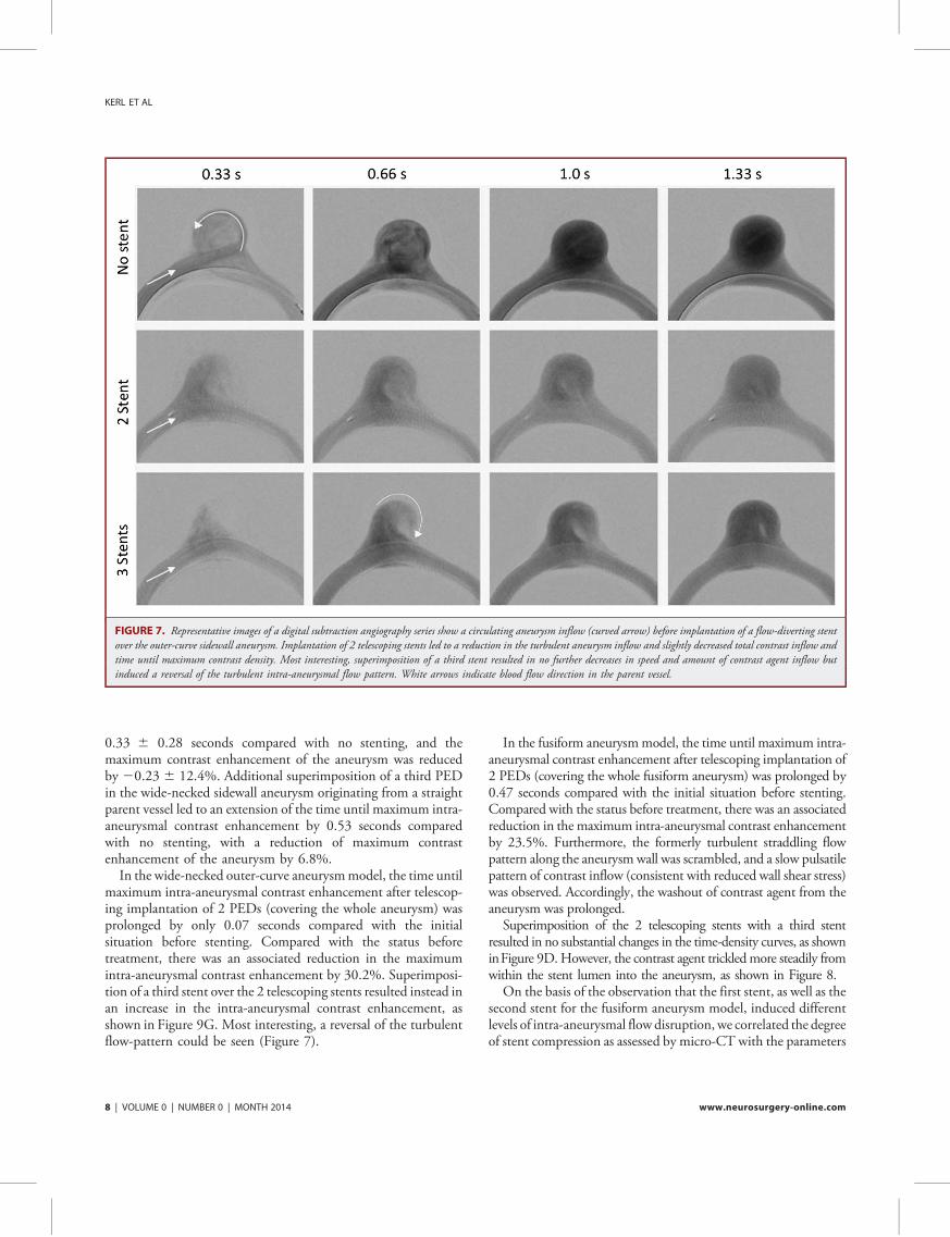
0.33 6 0.28 seconds compared with no stenting, and themaximum contrast enhancement of the aneurysm was reducedby 20.23 6 12.4%. Additional superimposition of a third PEDin the wide-necked sidewall aneurysm originating from a straightparent vessel led to an extension of the time until maximum intra-aneurysmal contrast enhancement by 0.53 seconds comparedwith no stenting, with a reduction of maximum contrastenhancement of the aneurysm by 6.8%.
In the wide-necked outer-curve aneurysmmodel, the time untilmaximum intra-aneurysmal contrast enhancement after telescop-ing implantation of 2 PEDs (covering the whole aneurysm) wasprolonged by only 0.07 seconds compared with the initialsituation before stenting. Compared with the status beforetreatment, there was an associated reduction in the maximumintra-aneurysmal contrast enhancement by 30.2%. Superimposi-tion of a third stent over the 2 telescoping stents resulted instead inan increase in the intra-aneurysmal contrast enhancement, asshown in Figure 9G. Most interesting, a reversal of the turbulentflow-pattern could be seen (Figure 7).
In the fusiform aneurysmmodel, the time until maximum intra-aneurysmal contrast enhancement after telescoping implantation of2 PEDs (covering the whole fusiform aneurysm) was prolonged by0.47 seconds compared with the initial situation before stenting.Compared with the status before treatment, there was an associatedreduction in the maximum intra-aneurysmal contrast enhancementby 23.5%. Furthermore, the formerly turbulent straddling flowpattern along the aneurysm wall was scrambled, and a slow pulsatilepattern of contrast inflow (consistent with reduced wall shear stress)was observed. Accordingly, the washout of contrast agent from theaneurysm was prolonged.Superimposition of the 2 telescoping stents with a third stent
resulted in no substantial changes in the time-density curves, as showninFigure 9D.However, the contrast agent trickledmore steadily fromwithin the stent lumen into the aneurysm, as shown in Figure 8.On the basis of the observation that the first stent, as well as the
second stent for the fusiform aneurysm model, induced differentlevels of intra-aneurysmal flow disruption, we correlated the degreeof stent compression as assessed by micro-CT with the parameters
FIGURE 7. Representative images of a digital subtraction angiography series show a circulating aneurysm inflow (curved arrow) before implantation of a flow-diverting stentover the outer-curve sidewall aneurysm. Implantation of 2 telescoping stents led to a reduction in the turbulent aneurysm inflow and slightly decreased total contrast inflow andtime until maximum contrast density. Most interesting, superimposition of a third stent resulted in no further decreases in speed and amount of contrast agent inflow butinduced a reversal of the turbulent intra-aneurysmal flow pattern. White arrows indicate blood flow direction in the parent vessel.
KERL ET AL
8 | VOLUME 0 | NUMBER 0 | MONTH 2014 www.neurosurgery-online.com

extracted from the time-density curves. Stent compression (ie, thenumber of struts per 1 mm aneurysm neck) correlated strongly(R2 = 0.806) and significantly (P , .001) with the reduction ofmaximum intra-aneurysmal contrast enhancement (F½F10� igure 10A).
The correlation between stent compression and time topeak aneurysm contrast was weaker (R2 = 0.338) but stillsignificant (P = .001; Figure 10B). As expected, the time untilmaximum intra-aneurysmal contrast and the reduction in themaximum intra-aneurysmal contrast density correlated positively(R2 = 0.226, P = .006; Figure 10C).
Influence of FDS Implantation on Intra-aneurysmalBlood Pressure
Static intra-aneurysmal MAP before implantation of stents was1266 17 mm Hg (mean6 SD; all models taken together). TheTable½T1� provides the MAP and peak systolic pressure values for alltested aneurysm models. No correlation between the intra-aneurysmal MAP and stent porosity was found (fusiform andnarrow-necked aneurysm: R2 = 0.044, P = .18AQ : 6 ; Figure 10D).Consistently, only minimal intra-aneurysmal changes in bloodpressure were observed (Table). Interestingly, we observed an
increase in the intra-aneurysmal static MAP and peak systolicpressure in the straight-parent-vessel models and a slight decrease orno change in the other tested aneurysm/parent vessel geometries(inner curve, outer curve, fusiform aneurysm). Because the straightand the curved parent vessels exhibit different types of flow (sheardriven and inertia driven, respectively), it may be that pressurechange after stent implantation is sensitive to parent vessel curvatureand flow type. However, the changes in MAP in all models were,10% of the baseline value. In addition, no significant changes inblood pressure were observed in the parent vessel.
Influence of Stent Compression on Stent Porosity
Because we found stent porosity to correlate with the flow-diverting efficacyof adevice (Figure 10A and 10B), we subsequentlyanalyzed to what degree compression of an FDS affects stentporosity. As illustrated in F ½F11�igure 11, a stepwise increase in FDScompression resulted in an almost linear reduction in the measuredmean cell area of a stent. However, there was a slight tendencytoward a stronger effect at lower compression rates. Therefore,a possibly stronger compression over the aneurysm neck seems tobe advantageous to optimize stent efficacy.
FIGURE 8. Representative images of digital subtraction angiography series of a fusiform aneurysm model showing a straddling turbulent flow pattern at both sides of theaneurysm wall along the outflow tract before implantation of a flow-diverting stent. Covering the aneurysm with 2 telescoping stents reduces total contrast inflow, time untilmaximum contrast density, and the turbulent intra-aneurysmal flow. Superimposition of a third stent results in no further substantial decreases in speed and amount of contrastagent inflow, but the contrast agent trickles more homogeneously through the pores of the flow diverters. White arrows indicate blood flow direction within the parent vessel.Regions of interest (ROIs) used to measure the density within the parent vessel and the aneurysm in the underlying study are shown in an image.
FLOW-DIVERTER HEMODYNAMICS
NEUROSURGERY VOLUME 0 | NUMBER 0 | MONTH 2014 | 9

KERL ET AL
10 | VOLUME 0 | NUMBER 0 | MONTH 2014 www.neurosurgery-online.com

DISCUSSION
Several studies on the flow-diverting effects of high and lowporosity stents have been published.16,18,19 In these studies,mainly particle imaging velocimetry16,20-25 and computationalfluid dynamic simulations6,10,11,26 were used to investigate theeffects of different types of flow diverters on various aneurysm
forms. Most frequently analyzed parameters were aneurysmhemodynamics (ie, velocity and direction of intra-aneurysmalflow before and after FDS implantation) and changes in intra-aneurysmal static (ie, blood pressure within the aneurysm),dynamic pressure, and kinetic energy. Intra-aneurysmal meankinetic energy as measured by particle imaging velocimetry hasbeen reported to correlate well with the concentration-time curve
FIGURE 10. Influence of stent compression on various parameters. A higher relative stent compression as measured over the aneurysm neck (struts per 1 mm) correlatespositively with a reduction in the maximally measurable intra-aneurysmal contrast (A). Likewise, stent compression correlated positively with the time until the maximumintra-aneurysmal density was reached (B). As expected, maximum intra-aneurysmal density was lower when the time to reach maximum density was longer (C). Stentcompression did not influence intra-aneurysmal blood pressure (D).
FIGURE 9. Time-density curves of aneurysms (A, straight model; B, inner-curve aneurysm model; C, outer-curve aneurysm model; D, fusiformaneurysm model; E, wide-necked straight aneurysm model; F, wide-necked inner-curve model; G, wide-necked outer-curve aneurysm model) beforeand after treatment with 1, 2, or 3 superimposed flow-diverting stents. The curves indicate that depending on the porosity-related efficacy of the firstimplanted Pipeline Embolization Device (PED), the second superimposed PED has variable effect on aneurysm inflow and outflow. Finally,a comparable reduction in the maximum intra-aneurysmal density values by approximately 70% is reached in all 3 narrow-necked sidewall aneurysmmodels after implantation of 2 stents. For the wide-necked sidewall aneurysm models, even after implantation of up to 3 superimposing stents, nosubstantial inflow reduction could be achieved.
FLOW-DIVERTER HEMODYNAMICS
NEUROSURGERY VOLUME 0 | NUMBER 0 | MONTH 2014 | 11
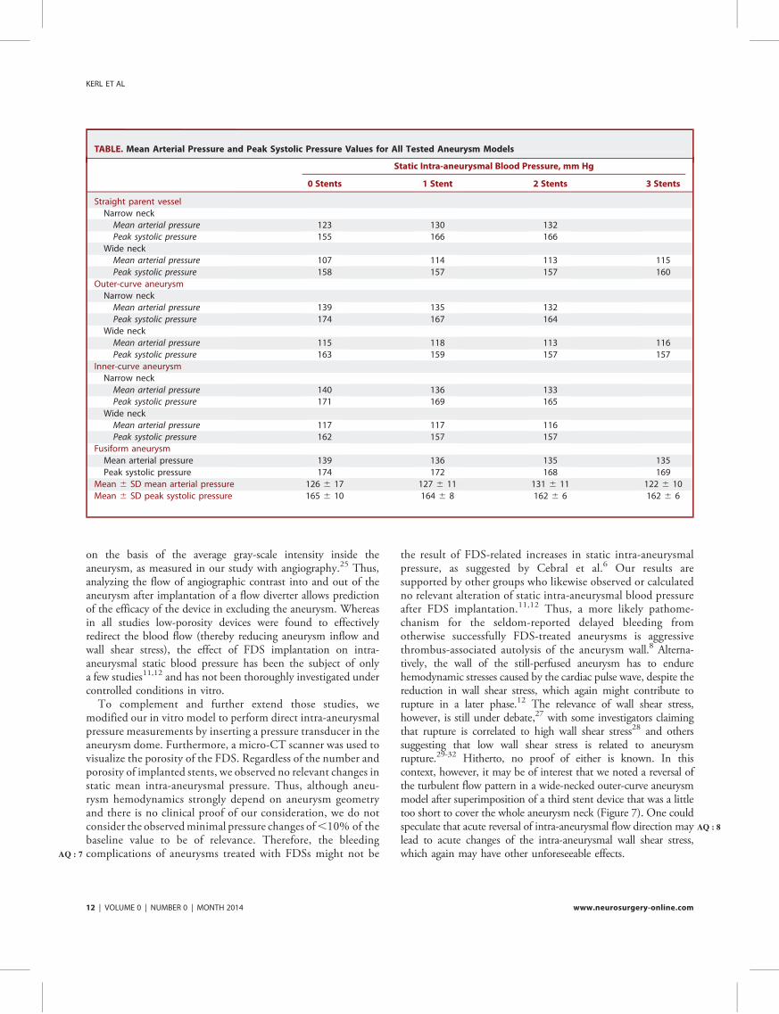
on the basis of the average gray-scale intensity inside theaneurysm, as measured in our study with angiography.25 Thus,analyzing the flow of angiographic contrast into and out of theaneurysm after implantation of a flow diverter allows predictionof the efficacy of the device in excluding the aneurysm. Whereasin all studies low-porosity devices were found to effectivelyredirect the blood flow (thereby reducing aneurysm inflow andwall shear stress), the effect of FDS implantation on intra-aneurysmal static blood pressure has been the subject of onlya few studies11,12 and has not been thoroughly investigated undercontrolled conditions in vitro.
To complement and further extend those studies, wemodified our in vitro model to perform direct intra-aneurysmalpressure measurements by inserting a pressure transducer in theaneurysm dome. Furthermore, a micro-CT scanner was used tovisualize the porosity of the FDS. Regardless of the number andporosity of implanted stents, we observed no relevant changes instatic mean intra-aneurysmal pressure. Thus, although aneu-rysm hemodynamics strongly depend on aneurysm geometryand there is no clinical proof of our consideration, we do notconsider the observedminimal pressure changes of,10% of thebaseline value to be of relevance. Therefore, the bleedingcomplicationsAQ : 7 of aneurysms treated with FDSs might not be
the result of FDS-related increases in static intra-aneurysmalpressure, as suggested by Cebral et al.6 Our results aresupported by other groups who likewise observed or calculatedno relevant alteration of static intra-aneurysmal blood pressureafter FDS implantation.11,12 Thus, a more likely pathome-chanism for the seldom-reported delayed bleeding fromotherwise successfully FDS-treated aneurysms is aggressivethrombus-associated autolysis of the aneurysm wall.8 Alterna-tively, the wall of the still-perfused aneurysm has to endurehemodynamic stresses caused by the cardiac pulse wave, despite thereduction in wall shear stress, which again might contribute torupture in a later phase.12 The relevance of wall shear stress,however, is still under debate,27 with some investigators claimingthat rupture is correlated to high wall shear stress28 and otherssuggesting that low wall shear stress is related to aneurysmrupture.29-32 Hitherto, no proof of either is known. In thiscontext, however, it may be of interest that we noted a reversal ofthe turbulent flow pattern in a wide-necked outer-curve aneurysmmodel after superimposition of a third stent device that was a littletoo short to cover the whole aneurysm neck (Figure 7). One couldspeculate that acute reversal AQ : 8of intra-aneurysmal flow direction maylead to acute changes of the intra-aneurysmal wall shear stress,which again may have other unforeseeable effects.
TABLE. Mean Arterial Pressure and Peak Systolic Pressure Values for All Tested Aneurysm Models
Static Intra-aneurysmal Blood Pressure, mm Hg
0 Stents 1 Stent 2 Stents 3 Stents
Straight parent vessel
Narrow neck
Mean arterial pressure 123 130 132
Peak systolic pressure 155 166 166
Wide neck
Mean arterial pressure 107 114 113 115
Peak systolic pressure 158 157 157 160
Outer-curve aneurysm
Narrow neck
Mean arterial pressure 139 135 132
Peak systolic pressure 174 167 164
Wide neck
Mean arterial pressure 115 118 113 116
Peak systolic pressure 163 159 157 157
Inner-curve aneurysm
Narrow neck
Mean arterial pressure 140 136 133
Peak systolic pressure 171 169 165
Wide neck
Mean arterial pressure 117 117 116
Peak systolic pressure 162 157 157
Fusiform aneurysm
Mean arterial pressure 139 136 135 135
Peak systolic pressure 174 172 168 169
Mean 6 SD mean arterial pressure 126 6 17 127 6 11 131 6 11 122 6 10
Mean 6 SD peak systolic pressure 165 6 10 164 6 8 162 6 6 162 6 6
KERL ET AL
12 | VOLUME 0 | NUMBER 0 | MONTH 2014 www.neurosurgery-online.com

From our experiments, we learned that aneurysm inflow can,especially in narrow-necked aneurysms, be reduced effectivelyby FDSs. Whereas in 2 narrow-necked sidewall aneurysmmodels (straight-parent-vessel and outer-curve aneurysms) highlevels of flow reduction were observed after insertion of a singlestent, a second stent was required in 1 system (inner-curvenarrow-necked aneurysm) to achieve a sufficient level of flowdiversion. For the fusiform aneurysm, the implantation of2 telescoping PEDs covering the whole aneurysm led to higherflow reduction, whereas the third stent did not lead to anyfurther substantial flow reduction. Further experiments usingwide-necked aneurysm models indicated that FDS implanta-tion is not as effective for flow diversion as in narrow-neckedsidewall aneurysm models. Even after implantation of a super-imposing PED, substantial inflow reduction could not beachieved.
Because measurements of the maximum contrast enhancementcan be easily transferred to a clinical setting, as a next step,information on this parameter might be used to decide whethera second overlapping stent should be implanted in a patient. At thispoint, however, further studies on the efficiency of flow-divertersin vivo are required.
Limitations
A limitation of the underlying study is that we performed partsof the experiment using idealized sidewall aneurysms with a dome-
to-neck ratio suitable for coil embolization. However, we obtainedsimilar results using the larger fusiform aneurysm model. Never-theless, it would also be of great interest to extend the in vitroinvestigations using even larger aneurysm models or to use modelswith patient-specific aneurysm geometries, as described by Roszelleand colleagues.21 The idea to generally use FDSs as a first-linestrategy has been discussed elsewhere.33 Whereas in our study wedid not observe relevant differences between the different positionsof the aneurysm in relation to the parent vessel (straight, innercurve, outer curve), previous publications indicated differences inaneurysmal hemodynamics for straight and curved parent vessels.34
A reason for our findings might be that the curvature of the parentvessel was not strong enough. On the other hand, there arenumerous possible aneurysm forms, of which only a small numbercan be used for experimental investigations.
CONCLUSION
From our experiments, we conclude that FDSs decreaseaneurysm inflow in a porosity-dependent manner. Furthermore,the implantation of FDSs in our study resulted in a nonsignificantdecrease in the static mean intra-aneurysmal pressure in fusiformand curved-parent-vessel aneurysms, whereas only a slight increasein intra-aneurysmal pressure was observed in the straight-parent-vessel aneurysm (,10% in all cases). Thus, in the aneurysmmodels used, implantation of FDSs does not significantly affectstatic intra-aneurysmal pressure.
Disclosure AQ : 9s
The study was sponsored by Covidien/ev3. The stents (Pipeline Flow Diverter,PED) and silicone aneurysms were kindly provided by Covidien/ev3. The authorshave no personal financial or institutional interest in any of the drugs, materials, ordevices described in this article.
REFERENCES
1. Tahtinen OI, Manninen HI, Vanninen RL, et al. The Silk flow-diverting stent inthe endovascular treatment of complex intracranial aneurysms: technical aspectsand midterm results in 24 consecutive patients. Neurosurgery. 2012;70(3):617-623; discussion 623-624.
2. Saatci I, Yavuz K, Ozer C, Geyik S, Cekirge HS. Treatment of intracranialaneurysms using the Pipeline flow-diverter embolization device: a single-centerexperience with long-term follow-up results. AJNR Am J Neuroradiol. 2012;33(8):1436-1446.
3. Maimon S, Gonen L, Nossek E, Strauss I, Levite R, Ram Z. Treatment of intra-cranial aneurysms with the SILK flow diverter: 2 years’ experience with 28 patientsat a single center. Acta Neurochir (Wien). 2012;154(6):979-987.
4. Briganti F, Napoli M, Tortora F, et al. Italian multicenter experience with flow-diverter devices for intracranial unruptured aneurysm treatment with periproce-dural complications: a retrospective data analysis. Neuroradiology. 2012;54(10):1145-1152.
5. Kulcsar Z, Wetzel SG, Augsburger L, Gruber A, Wanke I, Rufenacht DA. Effect offlow diversion treatment on very small ruptured aneurysms. Neurosurgery. 2010;67(3):789-793.
6. Cebral JR, Mut F, Raschi M, et al. Aneurysm rupture following treatment withflow-diverting stents: computational hemodynamics analysis of treatment. AJNRAm J Neuroradiol. 2011;32(1):27-33.
7. Lylyk P, Miranda C, Ceratto R, et al. Curative endovascular reconstruction ofcerebral aneurysms with the Pipeline Embolization Device: the Buenos Airesexperience. Neurosurgery. 2009;64(4):632-642; discussion 642-643; quiz N636.
FIGURE 11. Micro–computed tomography analyses show symmetric com-pression of the Pipeline Embolization Device (A), resulting in an almost lineardecrease in stent porosity (B).
FLOW-DIVERTER HEMODYNAMICS
NEUROSURGERY VOLUME 0 | NUMBER 0 | MONTH 2014 | 13

8. Kulcsar Z, Houdart E, Bonafe A, et al. Intra-aneurysmal thrombosis as a possiblecause of delayed aneurysm rupture after flow-diversion treatment. AJNR Am JNeuroradiol. 2011;32(1):20-25.
9. Hampton T, Walsh D, Tolias C, Fiorella D. Mural destabilization after aneurysmtreatment with a flow-diverting device: a report of two cases. J Neurointerv Surg.2011;3(2):167-171.
10. Zhang Y, Chong W, Qian Y. Investigation of intracranial aneurysm hemodynamicsfollowing flow diverter stent treatment. Med Eng Phys. 2013;35(5):608-615.
11. Larrabide I, Aguilar ML, Morales HG, et al. Intra-aneurysmal pressure and flowchanges induced by flow diverters: relation to aneurysm size and shape. AJNR Am JNeuroradiol. 2013;34(4):816-822.
12. Schneiders JJ, Vanbavel E, Majoie CB, Ferns SP, van den Berg R. A flow-divertingstent is not a pressure-diverting stent. AJNR Am J Neuroradiol. 2013;34(1):E1-E4.
13. Morales HG, Kim M, Vivas EE, et al. How do coil configuration and packingdensity influence intra-aneurysmal hemodynamics? AJNR Am J Neuroradiol. 2011;32(10):1935-1941.
14. Canton G, Levy DI, Lasheras JC. Changes in the intraaneurysmal pressure due toHydroCoil embolization. AJNR Am J Neuroradiol. 2005;26(4):904-907.
15. Sorteberg A, Sorteberg W, Turk AS, Rappe A, Nakstad PH, Strother CM. Effect ofGuglielmi detachable coil placement on intraaneurysmal pressure: experimentalstudy in canines. AJNR Am J Neuroradiol. 2001;22(9):1750-1756.
16. Augsburger L, Farhat M, Reymond P, et al. Effect of flow diverter porosity onintraaneurysmal blood flow. Klin Neuroradiol. 2009;19(3):204-214.
17. Suri H, Ionita CN, Baier RE, Rudin S. New variable porosity flow diverter(VPOD) stent design for treatment of cerebrovascular aneurysms. Conf Proc IEEEEng Med Biol Soc. 2011;2011:1105-1108.
18. Ionita CN, Natarajan SK, Wang W, et al. Evaluation of a second-generation self-expanding variable-porosity flow diverter in a rabbit elastase aneurysm model.AJNR Am J Neuroradiol. 2011;32(8):1399-1407.
19. Wang K, Huang Q, Hong B, Li Z, Fang X, Liu J. Correlation of aneurysmocclusion with actual metal coverage at neck after implantation of flow-divertingstent in rabbit models. Neuroradiology. 2012;54(6):607-613.
20. Dorn F, Niedermeyer F, Balasso A, Liepsch D, Liebig T. The effect of stents onintra-aneurysmal hemodynamics: in vitro evaluation of a pulsatile sidewallaneurysm using laser Doppler anemometry. Neuroradiology. 2011;53(4):267-272.
21. Roszelle BN, Gonzalez LF, Babiker MH, Ryan J, Albuquerque FC, Frakes DH.Flow diverter effect on cerebral aneurysm hemodynamics: an in vitro comparisonof telescoping stents and the Pipeline. Neuroradiology. 2013;55(6):751-758.
22. Seong J, Wakhloo AK, Lieber BB. In vitro evaluation of flow divertors in anelastase-induced saccular aneurysm model in rabbit. J Biomech Eng. 2007;129(6):863-872.
23. Seshadhri S, Janiga G, Beuing O, Skalej M, Thevenin D. Impact of stents and flowdiverters on hemodynamics in idealized aneurysm models. J Biomech Eng. 2011;133(7):071005.
24. Trager AL, Sadasivan C, Lieber BB. Comparison of the in vitro hemodynamicperformance of new flow diverters for bypass of brain aneurysms. J Biomech Eng.2012;134(8):084505.
25. Trager AL, Sadasivan C, Seong J, Lieber BB. Correlation between angiographicand particle image velocimetry quantifications of flow diverters in an in vitro modelof elastase-induced rabbit aneurysms. J Biomech Eng. 2009;131(3):034506.
26. Kulcsar Z, Augsburger L, Reymond P, et al. Flow diversion treatment: intra-aneurismal blood flow velocity and WSS reduction are parameters to predictaneurysm thrombosis. Acta Neurochir (Wien). 2012;154(10):1827-1834.
27. Meng H, Tutino VM, Xiang J, Siddiqui A. High WSS or low WSS? Complexinteractions of hemodynamics with intracranial aneurysm initiation, growth, andrupture: toward a unifying hypothesis [published online ahead of print July 4,2013]. AJNR Am J Neuroradiol. doi:10.3174/ajnr.A3558.
28. Castro MA, Putman CM, Sheridan MJ, Cebral JR. Hemodynamic patterns ofanterior communicating artery aneurysms: a possible association with rupture.AJNR Am J Neuroradiol. 2009;30(2):297-302.
29. Fukazawa K, Ishida F, Umeda Y, et al. Using computational fluid dynamicsanalysis to characterize local hemodynamic features of middle cerebral arteryaneurysm rupture points [published online ahead of print February 9, 2013].World Neurosurg. doi:10.1016/j.wneu.2013.02.012.
30. Kadasi LM, Dent WC, Malek AM. Colocalization of thin-walled dome regionswith low hemodynamic wall shear stress in unruptured cerebral aneurysms.J Neurosurg. 2013;119(1):172-179.
31. Miura Y, Ishida F, Umeda Y, et al. Low wall shear stress is independentlyassociated with the rupture status of middle cerebral artery aneurysms. Stroke.2013;44(2):519-521.
32. Xiang J, Natarajan SK, Tremmel M, et al. Hemodynamic-morphologic discrim-inants for intracranial aneurysm rupture. Stroke. 2011;42(1):144-152.
33. Wong GK, Lau JC, Poon WS. Flow diverting stents for cerebral aneurysmtreatment: time to replace coiling? J Clin Neurosci. 2011;18(8):1143.
34. Meng H, Wang Z, Kim M, Ecker RD, Hopkins LN. Saccular aneurysms onstraight and curved vessels are subject to different hemodynamics: implications ofintravascular stenting. AJNR Am J Neuroradiol. 2006;27(9):1861-1865.
Supplemental digital content is available for this article. Direct URL citationsappear in the printed text and are provided in the HTML and PDF versions of thisarticle on the journal’s Web site (www.neurosurgery-online.com).
KERL ET AL
14 | VOLUME 0 | NUMBER 0 | MONTH 2014 www.neurosurgery-online.com
70
XI. Danksagung
Mein besonderer Dank gilt meinem Betreuer Herrn Prof. Dr. med. Marc Brockmann für die
Überlassung des Themas, seine fortwährende Unterstützung sowie seine kreativen
Anregungen, die wesentlich zur Erstellung dieser Arbeit beigetragen haben. Ich danke ihm
für die stets professionelle Begleitung in allen Phasen der Arbeit, seinem kompetenten Rat
und Hilfe bei Planung, Durchführung und Auswertung der Experimente und nicht zuletzt für
die warmherzige Aufnahme in die Arbeitsgruppe.
Zu besonderem Dank bin ich ebenfalls Herrn Prof. Dr. med. vet. Martin
Annahme als Doktorandin an der Klinik für Kleintiere Chirurgie an der JLU Gießen sowie
die wertvolle Unterstützung und wissenschaftliche Anleitung verpflichtet.
Meiner Kollegin Lisa Kabelitz danke ich für ihre Unterstützung und die gute Zusammenarbeit.
Mein spezieller Dank geht auch an das gesamte Team der Klinik für Diagnostische und
Interventionelle Neuroradiologie der Uniklinik RWTH Aachen, insbesondere an Herrn Prof.
Dr. med. Martin Wiesmann, bei welchem ich mich für die fortwährende Unterstützung in der
Durchführung der Experimente bedanken möchte. Des Weiteren danke ich dem Team des
Instituts für Versuchstierkunde für den stets reibungslosen Ablauf und die Unterstützung
unserer Experimente.
Mein allerbester Dank gilt meiner Familie, insbesondere meinen Eltern für ihr
unerschütterliches Vertrauen in mich und die Unterstützung in Studium und Arbeit.
Meinen Freunden und Korrekturlesern möchte ich für ihren wiederholten Einsatz und
freundschaftlichen Zusammenhalt danken.

71
XII. Erklärung
Ich erkläre: Ich habe die vorgelegte Dissertation selbständig und ohne unerlaubte fremde
Hilfe und nur mit den Hilfen angefertigt, die ich in der Dissertation angegeben habe. Alle
Textstellen, die wörtlich oder sinngemäß aus veröffentlichten oder nicht
, sind
als solche kenntlich gemacht. Bei den von mir
erwähnten Untersuchungen habe ich die Grundsätze wissenschaftlicher Praxis, wie sie in
„ z J -Liebig-Universität Gießen zur Sicherung guter wissenschaftlicher
P x “ eingehalten.
Andrea Nonn


![Einbaumeister: Unterstützung auf der Baustelle5700].pdfBei Schöck gibt es einen neuen Extra-Service für Verarbeiter: Auf Wunsch kommen mit dem bestellten Produkt auch die Schöck-Einbaumeister](https://static.fdokument.com/doc/165x107/5e4dc1a09433da2e0747c9d8/einbaumeister-untersttzung-auf-der-baustelle-5700pdf-bei-schck-gibt-es-einen.jpg)