INSTALLATION MANUAL - Daikin · English Deutsch Français Español Italiano ... • Install drain...
23
INSTALLATION MANUAL SYSTEM Air Conditioners MODELS 〈BS unit〉 BS4Q14AV1 BS10Q14AV1 BS6Q14AV1 BS12Q14AV1 BS8Q14AV1 BS16Q14AV1 READ THESE INSTRUCTIONS CAREFULLY BEFORE INSTALLATION. KEEP THIS MANUAL IN A HANDY PLACE FOR FUTURE REFERENCE. LESEN SIE DIESE ANWEISUNGEN VOR DER INSTALLATION SORGFÄLTIG DURCH. BEWAHREN SIE DIESE ANLEITUNG FÜR SPÄTERE BEZUGNAHME GRIFFBEREIT AUF. LIRE SOIGNEUSEMENT CES INSTRUCTIONS AVANT L’INSTALLATION. CONSERVER CE MANUEL A PORTEE DE MAIN POUR REFERENCE ULTERIEURE. LEA CUIDADOSAMENTE ESTAS INSTRUCCIONES ANTES DE INSTALAR. GUARDE ESTE MANUAL EN UN LUGAR A MANO PARA LEER EN CASO DE TENER ALGUNA DUDA. PRIMA DELL’INSTALLAZIONE LEGGERE ATTENTAMENTE QUESTE ISTRUZIONI. TENERE QUESTO MANUALE A PORTATA DI MANO PER RIFERIMENTI FUTURI. ΔΙΑΒΑΣΤΕ ΠΡΟΣΕΚΤΙΚΑ ΑΥΤΕΣ ΤΙΣ ΟΔΗΓΙΕΣ ΠΡΙΝ ΑΠΟ ΤΗΝ ΕΓΚΑΤΑΣΤΑΣΗ ΕΧΕΤΕ ΑΥΤΟ ΤΟ ΕΓΧΕΙΡΙΔΙΟ ΕΥΚΑΙΡΟ ΓΙΑ ΝΑ ΤΟ ΣΥΜΒΟΥΛΕΥΕΣΤΕ ΣΤΟ ΜΕΛΛΟΝ. LEES DEZE INSTRUCTIES ZORGVULDIG DOOR VOOR INSTALLATIE. BEWAAR DEZE HANDLEINDING WAAR U HEM KUNT TERUGVINDEN VOOR LATERE NASLAG. LEIA COM ATENÇÃO ESTAS INSTRUÇÕES ANTES DE REALIZAR A INSTALAÇÃO. MANTENHA ESTE MANUAL AO SEU ALCANCE PARA FUTURAS CONSULTAS. ПЕРЕД НАЧАЛОМ МОНТАЖА ВНИМАТЕЛЬНО ОЗНАКОМЬТЕСЬ С ДАННЫМИ ИНСТРУКЦЯМИ. СОХРАНИТЕ ДАННОЕ РУКОВОДСТВО В МЕСТЕ, УДОБНОМ ДЛЯ ОБРАЩЕНИЯ В БУДУЩЕМ. MONTAJDAN ÖNCE BU TALİMATLARI DİKKATLİ BİR BİÇİMDE OKUYUN. GELECEKTE BAŞVURMAK ÜZERE BU ELKİTABINI KORAY ULAŞABİLECEĞİNİZ BİR YERDE MUHAFAZA EDİN. English Deutsch Français Español Italiano Ελληνικά Nederlands Português Русский Türkçe
Transcript of INSTALLATION MANUAL - Daikin · English Deutsch Français Español Italiano ... • Install drain...
INSTALLATION MANUAL
SYSTEM Air Conditioners
MODELS⟨BS unit⟩
BS4Q14AV1 BS10Q14AV1 BS6Q14AV1 BS12Q14AV1 BS8Q14AV1 BS16Q14AV1
READ THESE INSTRUCTIONS CAREFULLY BEFORE INSTALLATION. KEEP THIS MANUAL IN A HANDY PLACE FOR FUTURE REFERENCE.
LESEN SIE DIESE ANWEISUNGEN VOR DER INSTALLATION SORGFÄLTIG DURCH.BEWAHREN SIE DIESE ANLEITUNG FÜR SPÄTERE BEZUGNAHME GRIFFBEREIT AUF.
LIRE SOIGNEUSEMENT CES INSTRUCTIONS AVANT L’INSTALLATION. CONSERVER CE MANUEL A PORTEE DE MAIN POUR REFERENCE ULTERIEURE.
LEA CUIDADOSAMENTE ESTAS INSTRUCCIONES ANTES DE INSTALAR. GUARDE ESTE MANUAL EN UN LUGAR A MANO PARA LEER EN CASO DE TENER ALGUNA DUDA.
PRIMA DELL’INSTALLAZIONE LEGGERE ATTENTAMENTE QUESTE ISTRUZIONI. TENERE QUESTO MANUALE A PORTATA DI MANO PER RIFERIMENTI FUTURI.
ΔΙΑΒΑΣΤΕ ΠΡΟΣΕΚΤΙΚΑ ΑΥΤΕΣ ΤΙΣ ΟΔΗΓΙΕΣ ΠΡΙΝ ΑΠΟ ΤΗΝ ΕΓΚΑΤΑΣΤΑΣΗ ΕΧΕΤΕ ΑΥΤΟ ΤΟ ΕΓΧΕΙΡΙΔΙΟ ΕΥΚΑΙΡΟ ΓΙΑ ΝΑ ΤΟ ΣΥΜΒΟΥΛΕΥΕΣΤΕ ΣΤΟ ΜΕΛΛΟΝ.
LEES DEZE INSTRUCTIES ZORGVULDIG DOOR VOOR INSTALLATIE. BEWAAR DEZE HANDLEINDING WAAR U HEM KUNT TERUGVINDEN VOOR LATERE NASLAG.
LEIA COM ATENÇÃO ESTAS INSTRUÇÕES ANTES DE REALIZAR A INSTALAÇÃO. MANTENHA ESTE MANUAL AO SEU ALCANCE PARA FUTURAS CONSULTAS.
ПЕРЕД НАЧАЛОМ МОНТАЖА ВНИМАТЕЛЬНО ОЗНАКОМЬТЕСЬ С ДАННЫМИ ИНСТРУКЦЯМИ. СОХРАНИТЕ ДАННОЕ РУКОВОДСТВО В МЕСТЕ, УДОБНОМ ДЛЯ ОБРАЩЕНИЯ В БУДУЩЕМ.
MONTAJDAN ÖNCE BU TALİMATLARI DİKKATLİ BİR BİÇİMDE OKUYUN. GELECEKTE BAŞVURMAK ÜZERE BU ELKİTABINI KORAY ULAŞABİLECEĞİNİZ BİR YERDE MUHAFAZA EDİN.
English
Deutsch
Français
Español
Italiano
Ελληνικά
Nederlands
Português
Русский
Türkçe
00_CV_3P194121-8U.indd 1 2/15/2014 3:47:51 PM
English 1
BS4Q14AV1BS6Q14AV1BS8Q14AV1
BS10Q14AV1BS12Q14AV1BS16Q14AV1
VRVIV SYSTEM Air Conditioners Installation manual
CONTENTS1. SAFETY PRECAUTIONS ...............................................................................................12. BEFORE INSTALLATION ...............................................................................................33. SELECTING INSTALLATION SITE .................................................................................54. PREPARATIONS BEFORE INSTALLATION ...................................................................65. BS UNIT INSTALLATION ................................................................................................66. REFRIGERANT PIPING WORK .....................................................................................77. DRAIN PIPING WORK .................................................................................................128. ELECTRIC WIRING WORK ..........................................................................................149. INITIAL SETTING .........................................................................................................2010. ADDING AN ADDITIONAL CHARGE OF REFRIGERANT ..........................................2111. CHECK OPERATION AND TEST OPERATION ...........................................................21
The original instructions are written in English. All other languages are translations of the original instruc-tions.
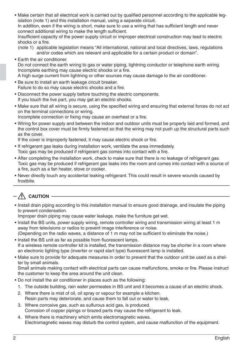
1. SAFETY PRECAUTIONSBe sure to follow this “SAFETY PRECAUTIONS”. This product comes under the term “appliances not accessible to the general public”.This is a class A product. In a domestic environment this product may cause radio interference in which case the user may be required to take adequate measures.
This manual classifies the precautions into WARNINGS and CAUTIONS.Be sure to follow all the precautions below: They are all important for ensuring safety.
WARNING ......... Indicates a potentially hazardous situation which, if not avoided, could result in death or serious injury.
CAUTION ......... Indicates a potentially hazardous situation which, if not avoided, may result in minor or moderate injury.It may also be used to alert against unsafe practices.
WARNING
• Ask your local dealer or qualified personnel to carry out installation work. Improper installation may result in water leakage, electric shocks or a fire.
• Perform installation work in accordance with this installation manual. Improper installation may result in water leakage, electric shocks or a fire.
• Consult your local dealer regarding what to do in case of refrigerant leakage. When the air conditioner is installed in a small room, it is necessary to take proper measures so that the amount of any leaked refrigerant does not exceed the concentration limit in the event of a leakage. Otherwise, this may lead to an accident due to oxygen deficiency.
• Be sure to use only the specified parts and accessories for installation work. Failure to use the specified parts may result in the air conditioner falling down, water leakage, electric shocks, a fire, etc.
• Install the air conditioner on a foundation that can withstand its mass. Insufficient strength may result in the air conditioner falling down and causing injury. In addition, it may lead to vibration of indoor units and cause unpleasant chattering noise.
• Carry out the specified installation work in consideration of strong winds, typhoons, or earthquakes. Improper installation may result in an accident such as air conditioner falling.
01_EN_3P194121-8U.indd 1 2/21/2014 3:31:04 PM
2 English
• Make certain that all electrical work is carried out by qualified personnel according to the applicable leg-islation (note 1) and this installation manual, using a separate circuit. In addition, even if the wiring is short, make sure to use a wiring that has sufficient length and never connect additional wiring to make the length sufficient. Insufficient capacity of the power supply circuit or improper electrical construction may lead to electric shocks or a fire.(note 1) applicable legislation means “All international, national and local directives, laws, regulations
and/or codes which are relevant and applicable for a certain product or domain”.• Earth the air conditioner.
Do not connect the earth wiring to gas or water piping, lightning conductor or telephone earth wiring. Incomplete earthing may cause electric shocks or a fire. A high surge current from lightning or other sources may cause damage to the air conditioner.
• Be sure to install an earth leakage circuit breaker. Failure to do so may cause electric shocks and a fire.
• Disconnect the power supply before touching the electric components. If you touch the live part, you may get an electric shocks.
• Make sure that all wiring is secure, using the specified wiring and ensuring that external forces do not act on the terminal connections or wiring. Incomplete connection or fixing may cause an overheat or a fire.
• Wiring for power supply and between the indoor and outdoor units must be properly laid and formed, and the control box cover must be firmly fastened so that the wiring may not push up the structural parts such as the cover. If the cover is improperly fastened, it may cause electric shock or fire.
• If refrigerant gas leaks during installation work, ventilate the area immediately. Toxic gas may be produced if refrigerant gas comes into contact with a fire.
• After completing the installation work, check to make sure that there is no leakage of refrigerant gas. Toxic gas may be produced if refrigerant gas leaks into the room and comes into contact with a source of a fire, such as a fan heater, stove or cooker.
• Never directly touch any accidental leaking refrigerant. This could result in severe wounds caused by frostbite.
CAUTION
• Install drain piping according to this installation manual to ensure good drainage, and insulate the piping to prevent condensation. Improper drain piping may cause water leakage, make the furniture get wet.
• Install the BS units, power supply wiring, remote controller wiring and transmission wiring at least 1 m away from televisions or radios to prevent image interference or noise. (Depending on the radio waves, a distance of 1 m may not be sufficient to eliminate the noise.)
• Install the BS unit as far as possible from fluorescent lamps. If a wireless remote controller kit is installed, the transmission distance may be shorter in a room where an electronic lighting type (inverter or rapid start type) fluorescent lamp is installed.
• Make sure to provide for adequate measures in order to prevent that the outdoor unit be used as a shel-ter by small animals. Small animals making contact with electrical parts can cause malfunctions, smoke or fire. Please instruct the customer to keep the area around the unit clean.
• Do not install the air conditioner in places such as the following:1. The outside building, rain water permeates in BS unit and it becomes a cause of an electric shock.2. Where there is mist of oil, oil spray or vapour for example a kitchen.
Resin parts may deteriorate, and cause them to fall out or water to leak.3. Where corrosive gas, such as sulfurous acid gas, is produced.
Corrosion of copper pipings or brazed parts may cause the refrigerant to leak.4. Where there is machinery which emits electromagnetic waves.
Electromagnetic waves may disturb the control system, and cause malfunction of the equipment.
01_EN_3P194121-8U.indd 2 2/21/2014 3:31:04 PM
English 3
5. Where flammable gases may leak, where carbon fibre or ignitable dust is suspended in the air or where volatile flammables, such as thinner or gasoline, are handled. If the gas should leak and remained around the air conditioner, it may cause ignition.
6. Do not use in areas where the air is salty, such as along seacoasts, in factories or other areas with significant voltage fluctuations, or in automobiles and watercraft. Doing so could result in a malfunction.
7. Where a wind may flow, the surface of BS unit body dews, and it becomes a cause of a leak.• The BS unit is not intended for use in a potentially explosive atmosphere.
2. BEFORE INSTALLATION
2-1 Precautions• Be sure to verify in advance that the refrigerant used in installation work is R410A.
The unit will not operate correctly with a different type of refrigerant.• When moving the unit during or after unpacking, hold it using the 4 hanging brackets and avoid
subjecting other parts, particularly refrigerant pipes and the control box, to force.• For more information about installation of outdoor and indoor units, refer to the installation manual
that came with each unit.
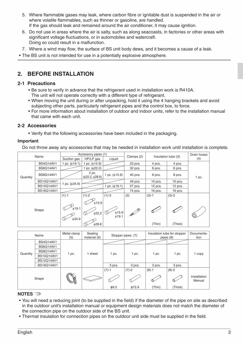
2-2 Accessories
• Verify that the following accessories have been included in the packaging.
Important Do not throw away any accessories that may be needed in installation work until installation is complete.
NameAccessory pipes (1)
Clamps (2) Insulation tube (3)Drain hoses
(4)Suction gas HP/LP gas Liquid
Quantity
BS4Q14AV1 1 pc. (f19.1) 1 pc. (f15.9) 23 pcs. 4 pcs. 4 pcs.
1 pc.
BS6Q14AV1 1 pc. (f22.2) 32 pcs. 6 pcs. 6 pcs.
BS8Q14AV12 pc.
(f22.2, f28.6)1 pc. (f15.9) 40 pcs. 8 pcs. 8 pcs.
BS10Q14AV11 pc. (f34.9)
49 pcs. 10 pcs. 10 pcs.BS12Q14AV1 1 pc. (f19.1) 57 pcs. 12 pcs. 12 pcs.BS16Q14AV1 74 pcs. 16 pcs. 16 pcs.
Shape
(1)-1 (1)-2 (1)-3 (2) (3)-1 (3)-2
f19.1
f34.9
f15.9
f22.2
f28.6
f15.9f19.1
(Thin) (Thick)
NameMetal clamp
(5)Sealing
material (6)Stopper pipes (7)
Insulation tube for stopper pipes (8)
Documenta-tion
Quantity
BS4Q14AV1
1 pc. 1 sheet 1 copy
BS6Q14AV1
1 pc. 1 pc. 1 pc. 1 pc.BS8Q14AV1BS10Q14AV1BS12Q14AV1BS16Q14AV1 3 pcs. 3 pcs. 3 pcs. 3 pcs.
Shape
(7)-1 (7)-2 (8)-1 (8)-2
Installation Manual
ϕ9.5 ϕ15.9 (Thin) (Thick)
NOTES • You will need a reducing joint (to be supplied in the field) if the diameter of the pipe on site as described
in the outdoor unit’s installation manual or equipment design materials does not match the diameter of the connection pipe on the outdoor side of the BS unit.
• Thermal insulation for connection pipes on the outdoor unit side must be supplied in the field.
01_EN_3P194121-8U.indd 3 2/21/2014 3:31:05 PM
4 English
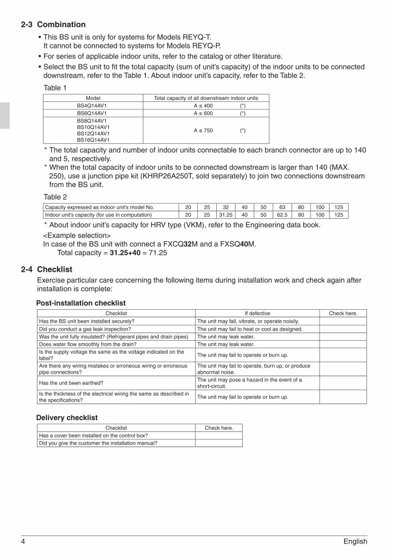
2-3 Combination
• This BS unit is only for systems for Models REYQ-T. It cannot be connected to systems for Models REYQ-P.
• For series of applicable indoor units, refer to the catalog or other literature.• Select the BS unit to fit the total capacity (sum of unit’s capacity) of the indoor units to be connected
downstream, refer to the Table 1. About indoor unit’s capacity, refer to the Table 2.
Table 1 Model Total capacity of all downstream indoor units
BS4Q14AV1 A ≤ 400 (*)BS6Q14AV1 A ≤ 600 (*)BS8Q14AV1 BS10Q14AV1 BS12Q14AV1 BS16Q14AV1
A ≤ 750 (*)
* The total capacity and number of indoor units connectable to each branch connector are up to 140 and 5, respectively.
* When the total capacity of indoor units to be connected downstream is larger than 140 (MAX. 250), use a junction pipe kit (KHRP26A250T, sold separately) to join two connections downstream from the BS unit.
Table 2 Capacity expressed as indoor unit’s model No. 20 25 32 40 50 63 80 100 125Indoor unit’s capacity (for use in computation) 20 25 31.25 40 50 62.5 80 100 125
* About indoor unit’s capacity for HRV type (VKM), refer to the Engineering data book.<Example selection>In case of the BS unit with connect a FXCQ32M and a FXSQ40M. Total capacity = 31.25+40 = 71.25
2-4 ChecklistExercise particular care concerning the following items during installation work and check again after installation is complete:
Post-installation checklistChecklist If defective Check here.
Has the BS unit been installed securely? The unit may fall, vibrate, or operate noisily.
Did you conduct a gas leak inspection? The unit may fail to heat or cool as designed.Was the unit fully insulated? (Refrigerant pipes and drain pipes) The unit may leak water.Does water flow smoothly from the drain? The unit may leak water.Is the supply voltage the same as the voltage indicated on the label?
The unit may fail to operate or burn up.
Are there any wiring mistakes or erroneous wiring or erroneous pipe connections?
The unit may fail to operate, burn up, or produce abnormal noise.
Has the unit been earthed?The unit may pose a hazard in the event of a short-circuit.
Is the thickness of the electrical wiring the same as described in the specifications?
The unit may fail to operate or burn up.
Delivery checklistChecklist Check here.
Has a cover been installed on the control box?Did you give the customer the installation manual?
01_EN_3P194121-8U.indd 4 2/21/2014 3:31:06 PM
English 5
3. SELECTING INSTALLATION SITE
Consider the following requirements when choosing the installation location and obtain the cus-tomer’s consent:• The location must be able to withstand the weight of the BS unit.• The location must allow reliable draining.• The location must allow inspection holes to be installed on the control box side. (A separate opening is
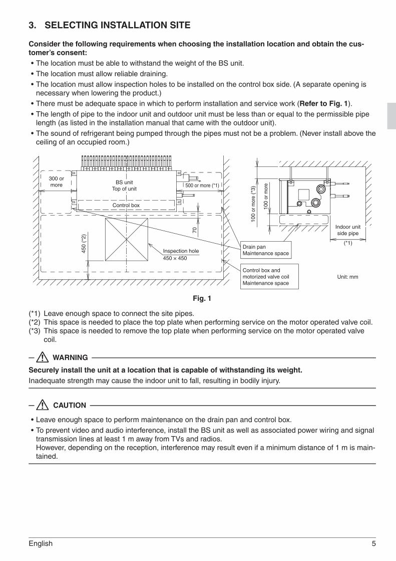
necessary when lowering the product.)• There must be adequate space in which to perform installation and service work (Refer to Fig. 1).• The length of pipe to the indoor unit and outdoor unit must be less than or equal to the permissible pipe
length (as listed in the installation manual that came with the outdoor unit).• The sound of refrigerant being pumped through the pipes must not be a problem. (Never install above the
ceiling of an occupied room.)
Inspection hole
BS unitTop of unit
450 × 450
70
300 or more 500 or more (*1)
450
(*2)
Control box
100
or m
ore
(*3)
100
or m
ore
Drain panMaintenance space
Control box and motorized valve coilMaintenance space
Indoor unit side pipe
(*1)
Unit: mm
Fig. 1
(*1) Leave enough space to connect the site pipes.(*2) This space is needed to place the top plate when performing service on the motor operated valve coil. (*3) This space is needed to remove the top plate when performing service on the motor operated valve
coil.
WARNING
Securely install the unit at a location that is capable of withstanding its weight.Inadequate strength may cause the indoor unit to fall, resulting in bodily injury.
CAUTION
• Leave enough space to perform maintenance on the drain pan and control box.• To prevent video and audio interference, install the BS unit as well as associated power wiring and signal
transmission lines at least 1 m away from TVs and radios. However, depending on the reception, interference may result even if a minimum distance of 1 m is main-tained.
01_EN_3P194121-8U.indd 5 2/21/2014 3:31:06 PM
6 English
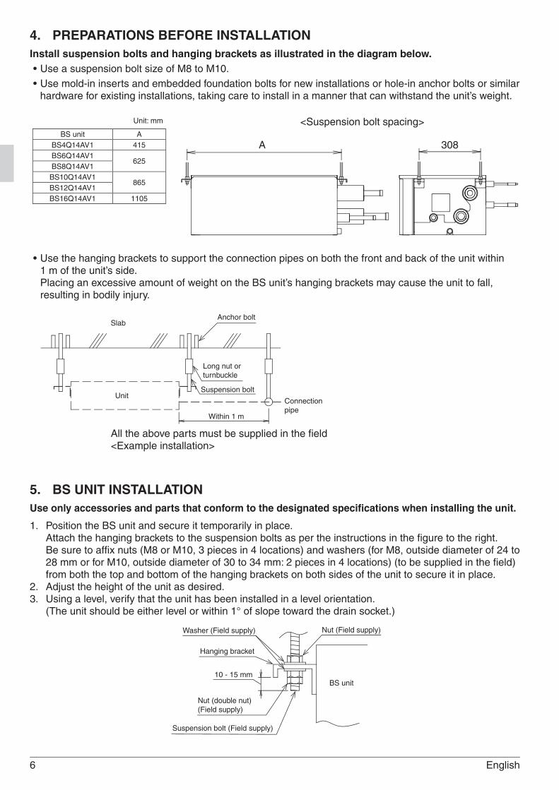
4. PREPARATIONS BEFORE INSTALLATIONInstall suspension bolts and hanging brackets as illustrated in the diagram below.• Use a suspension bolt size of M8 to M10.• Use mold-in inserts and embedded foundation bolts for new installations or hole-in anchor bolts or similar
hardware for existing installations, taking care to install in a manner that can withstand the unit’s weight.
Unit: mm
BS unit ABS4Q14AV1 415BS6Q14AV1
625BS8Q14AV1BS10Q14AV1
865BS12Q14AV1BS16Q14AV1 1105
A 308
<Suspension bolt spacing>
• Use the hanging brackets to support the connection pipes on both the front and back of the unit within 1 m of the unit’s side. Placing an excessive amount of weight on the BS unit’s hanging brackets may cause the unit to fall, resulting in bodily injury.
SlabAnchor bolt
Long nut or turnbuckle
Suspension bolt
Within 1 m
UnitConnection pipe
All the above parts must be supplied in the field<Example installation>
5. BS UNIT INSTALLATIONUse only accessories and parts that conform to the designated specifications when installing the unit.
1. Position the BS unit and secure it temporarily in place. Attach the hanging brackets to the suspension bolts as per the instructions in the figure to the right. Be sure to affix nuts (M8 or M10, 3 pieces in 4 locations) and washers (for M8, outside diameter of 24 to 28 mm or for M10, outside diameter of 30 to 34 mm: 2 pieces in 4 locations) (to be supplied in the field) from both the top and bottom of the hanging brackets on both sides of the unit to secure it in place.
2. Adjust the height of the unit as desired.3. Using a level, verify that the unit has been installed in a level orientation.
(The unit should be either level or within 1° of slope toward the drain socket.)
Nut (double nut) (Field supply)
Suspension bolt (Field supply)
10 - 15 mm
Hanging bracket
Washer (Field supply) Nut (Field supply)
BS unit
01_EN_3P194121-8U.indd 6 2/21/2014 3:31:06 PM
English 7
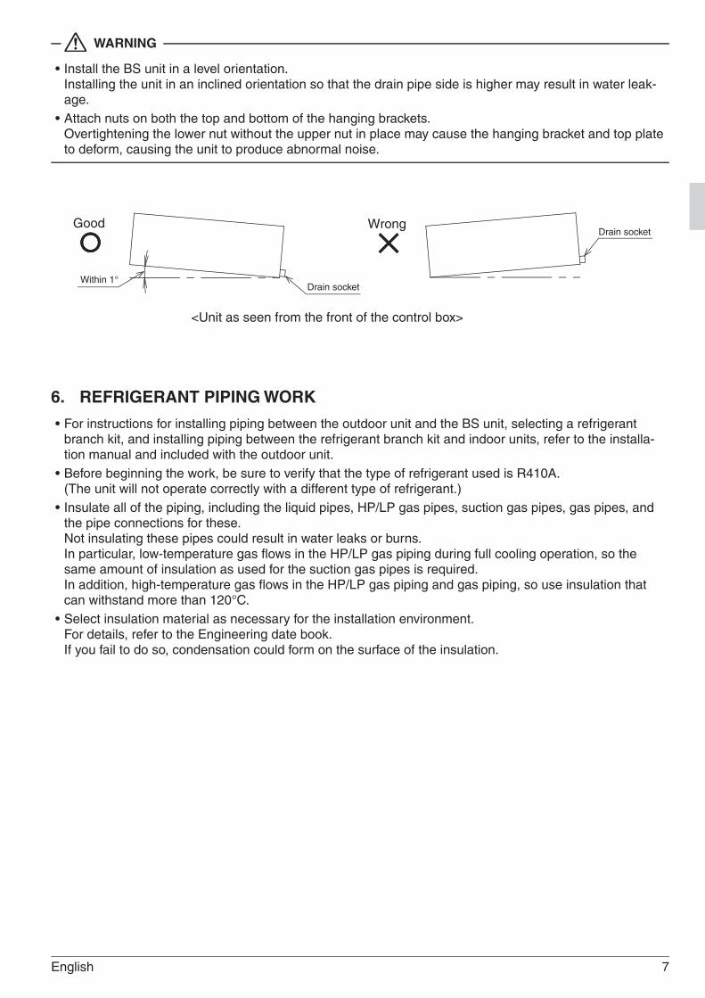
WARNING
• Install the BS unit in a level orientation. Installing the unit in an inclined orientation so that the drain pipe side is higher may result in water leak-age.
• Attach nuts on both the top and bottom of the hanging brackets. Overtightening the lower nut without the upper nut in place may cause the hanging bracket and top plate to deform, causing the unit to produce abnormal noise.
Within 1°Drain socket
Drain socket
<Unit as seen from the front of the control box>
Good Wrong
6. REFRIGERANT PIPING WORK
• For instructions for installing piping between the outdoor unit and the BS unit, selecting a refrigerant branch kit, and installing piping between the refrigerant branch kit and indoor units, refer to the installa-tion manual and included with the outdoor unit.
• Before beginning the work, be sure to verify that the type of refrigerant used is R410A. (The unit will not operate correctly with a different type of refrigerant.)
• Insulate all of the piping, including the liquid pipes, HP/LP gas pipes, suction gas pipes, gas pipes, and the pipe connections for these. Not insulating these pipes could result in water leaks or burns. In particular, low-temperature gas flows in the HP/LP gas piping during full cooling operation, so the same amount of insulation as used for the suction gas pipes is required. In addition, high-temperature gas flows in the HP/LP gas piping and gas piping, so use insulation that can withstand more than 120°C.
• Select insulation material as necessary for the installation environment. For details, refer to the Engineering date book. If you fail to do so, condensation could form on the surface of the insulation.
01_EN_3P194121-8U.indd 7 2/21/2014 3:31:07 PM
8 English
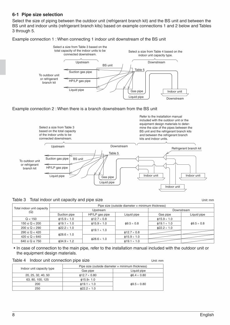
6-1 Pipe size selectionSelect the size of piping between the outdoor unit (refrigerant branch kit) and the BS unit and between the BS unit and indoor units (refrigerant branch kits) based on example connections 1 and 2 below and Tables 3 through 5.
Example connection 1 : When connecting 1 indoor unit downstream of the BS unit
Upstream Downstream
Downstream
Indoor unit
BS unit
Suction gas pipe
HP/LP gas pipe
Liquid pipe
Liquid pipe
Gas pipe
To outdoor unit or refrigerant
branch kit
Table 5
Select a size from Table 3 based on the total capacity of the indoor units to be
connected downstream. Select a size from Table 4 based on the
indoor unit capacity type.
Example connection 2 : When there is a branch downstream from the BS unit
Select a size from Table 3 based on the total capacity of the indoor units to be connected downstream.
Refer to the installation manual included with the outdoor unit or the equipment design materials to deter-mine the size of the pipes between the BS unit and the refrigerant branch kits and between the refrigerant branch kits and indoor units.
Upstream
Suction gas pipe
HP/LP gas pipe
Liquid pipe
BS unit
Downstream
Indoor unit Indoor unit
Indoor unit
Refrigerant branch kit
Liquid pipe
Gas pipe
Table 5
To outdoor unit or refrigerant
branch kit
Table 3 Total indoor unit capacity and pipe size Unit: mm
Total indoor unit capacity (Q)
Pipe size (outside diameter × minimum thickness)Upstream Downstream
Suction pipe HP/LP gas pipe Liquid pipe Gas pipe Liquid pipeQ < 150 ϕ15.9 × 1.0 ϕ12.7 × 0.8
ϕ9.5 × 0.8ϕ15.9 × 1.0
ϕ9.5 × 0.8150 ≤ Q < 200 ϕ19.1 × 1.0 ϕ15.9 × 1.0 ϕ19.1 × 1.0200 ≤ Q < 290 ϕ22.2 × 1.0
ϕ19.1 × 1.0ϕ22.2 × 1.0
290 ≤ Q < 420ϕ28.6 × 1.0
ϕ12.7 × 0.8420 ≤ Q < 640
ϕ28.6 × 1.0ϕ15.9 × 1.0
640 ≤ Q ≤ 750 ϕ34.9 × 1.2 ϕ19.1 × 1.0
• In case of connection to the main pipe, refer to the installation manual included with the outdoor unit or the equipment design materials.
Table 4 Indoor unit connection pipe size Unit: mm
Indoor unit capacity typePipe size (outside diameter × minimum thickness)
Gas pipe Liquid pipe20, 25, 32, 40, 50 ϕ12.7 × 0.80 ϕ6.4 × 0.8063, 80, 100, 125 ϕ15.9× 1.0
ϕ9.5 × 0.80200 ϕ19.1 × 1.0250 ϕ22.2 × 1.0
01_EN_3P194121-8U.indd 8 2/21/2014 3:31:07 PM
English 9
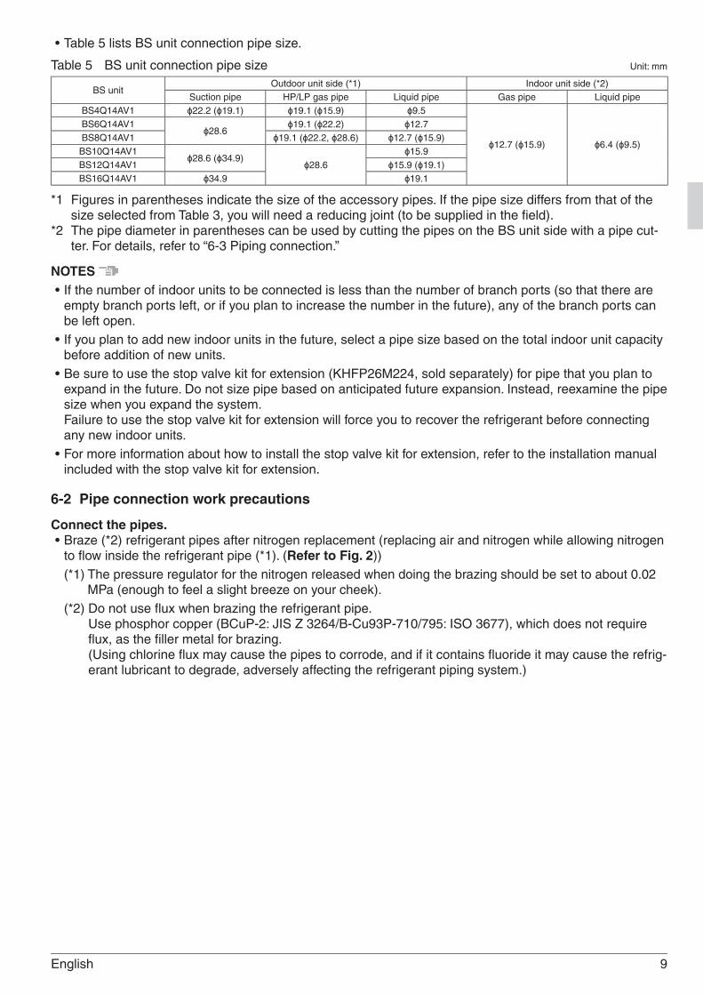
• Table 5 lists BS unit connection pipe size.
Table 5 BS unit connection pipe size Unit: mm
BS unitOutdoor unit side (*1) Indoor unit side (*2)
Suction pipe HP/LP gas pipe Liquid pipe Gas pipe Liquid pipeBS4Q14AV1 ϕ22.2 (ϕ19.1) ϕ19.1 (ϕ15.9) ϕ9.5
ϕ12.7 (ϕ15.9) ϕ6.4 (ϕ9.5)
BS6Q14AV1ϕ28.6
ϕ19.1 (ϕ22.2) ϕ12.7BS8Q14AV1 ϕ19.1 (ϕ22.2, ϕ28.6) ϕ12.7 (ϕ15.9)BS10Q14AV1
ϕ28.6 (ϕ34.9)ϕ28.6
ϕ15.9BS12Q14AV1 ϕ15.9 (ϕ19.1)BS16Q14AV1 ϕ34.9 ϕ19.1
*1 Figures in parentheses indicate the size of the accessory pipes. If the pipe size differs from that of the size selected from Table 3, you will need a reducing joint (to be supplied in the field).
*2 The pipe diameter in parentheses can be used by cutting the pipes on the BS unit side with a pipe cut-ter. For details, refer to “6-3 Piping connection.”
NOTES • If the number of indoor units to be connected is less than the number of branch ports (so that there are
empty branch ports left, or if you plan to increase the number in the future), any of the branch ports can be left open.
• If you plan to add new indoor units in the future, select a pipe size based on the total indoor unit capacity before addition of new units.
• Be sure to use the stop valve kit for extension (KHFP26M224, sold separately) for pipe that you plan to expand in the future. Do not size pipe based on anticipated future expansion. Instead, reexamine the pipe size when you expand the system. Failure to use the stop valve kit for extension will force you to recover the refrigerant before connecting any new indoor units.
• For more information about how to install the stop valve kit for extension, refer to the installation manual included with the stop valve kit for extension.
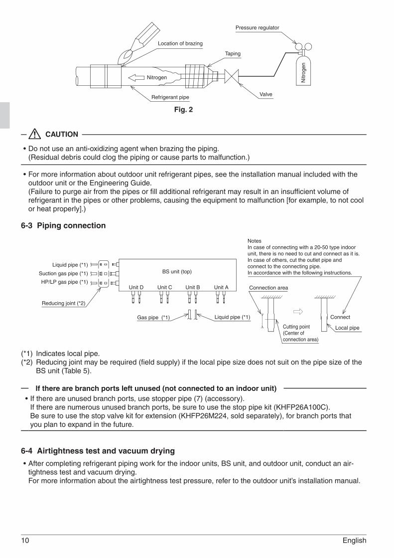
6-2 Pipe connection work precautions
Connect the pipes.• Braze (*2) refrigerant pipes after nitrogen replacement (replacing air and nitrogen while allowing nitrogen
to flow inside the refrigerant pipe (*1). (Refer to Fig. 2)) (*1) The pressure regulator for the nitrogen released when doing the brazing should be set to about 0.02
MPa (enough to feel a slight breeze on your cheek).(*2) Do not use flux when brazing the refrigerant pipe.
Use phosphor copper (BCuP-2: JIS Z 3264/B-Cu93P-710/795: ISO 3677), which does not require flux, as the filler metal for brazing. (Using chlorine flux may cause the pipes to corrode, and if it contains fluoride it may cause the refrig-erant lubricant to degrade, adversely affecting the refrigerant piping system.)
01_EN_3P194121-8U.indd 9 2/21/2014 3:31:07 PM
10 English
Location of brazing
Nitrogen
Refrigerant pipe Valve
Taping
Nitr
ogen
Pressure regulator
Fig. 2
CAUTION
• Do not use an anti-oxidizing agent when brazing the piping. (Residual debris could clog the piping or cause parts to malfunction.)
• For more information about outdoor unit refrigerant pipes, see the installation manual included with the outdoor unit or the Engineering Guide. (Failure to purge air from the pipes or fill additional refrigerant may result in an insufficient volume of refrigerant in the pipes or other problems, causing the equipment to malfunction [for example, to not cool or heat properly].)
6-3 Piping connection
Liquid pipe (*1)
Suction gas pipe (*1)
HP/LP gas pipe (*1)
BS unit (top)
Unit D Unit C Unit B Unit A
Liquid pipe (*1)Gas pipe (*1)
Reducing joint (*2)
NotesIn case of connecting with a 20-50 type indoor unit, there is no need to cut and connect as it is. In case of others, cut the outlet pipe and connect to the connecting pipe. In accordance with the following instructions.
Cutting point (Center of connection area)
Connect
Local pipe
Connection area
(*1) Indicates local pipe.(*2) Reducing joint may be required (field supply) if the local pipe size does not suit on the pipe size of the
BS unit (Table 5).
If there are branch ports left unused (not connected to an indoor unit)• If there are unused branch ports, use stopper pipe (7) (accessory).
If there are numerous unused branch ports, be sure to use the stop pipe kit (KHFP26A100C). Be sure to use the stop valve kit for extension (KHFP26M224, sold separately), for branch ports that you plan to expand in the future.
6-4 Airtightness test and vacuum drying
• After completing refrigerant piping work for the indoor units, BS unit, and outdoor unit, conduct an air-tightness test and vacuum drying. For more information about the airtightness test pressure, refer to the outdoor unit’s installation manual.
01_EN_3P194121-8U.indd 10 2/21/2014 3:31:08 PM
English 11
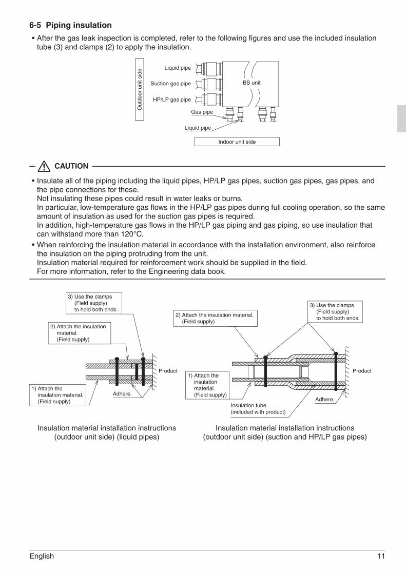
6-5 Piping insulation
• After the gas leak inspection is completed, refer to the following figures and use the included insulation tube (3) and clamps (2) to apply the insulation.
Liquid pipe
Suction gas pipe
HP/LP gas pipe
Gas pipe
Liquid pipe
Indoor unit sideO
utdo
or u
nit s
ide
BS unit
CAUTION
• Insulate all of the piping including the liquid pipes, HP/LP gas pipes, suction gas pipes, gas pipes, and the pipe connections for these. Not insulating these pipes could result in water leaks or burns. In particular, low-temperature gas flows in the HP/LP gas pipes during full cooling operation, so the same amount of insulation as used for the suction gas pipes is required. In addition, high-temperature gas flows in the HP/LP gas piping and gas piping, so use insulation that can withstand more than 120°C.
• When reinforcing the insulation material in accordance with the installation environment, also reinforce the insulation on the piping protruding from the unit. Insulation material required for reinforcement work should be supplied in the field. For more information, refer to the Engineering data book.
2) Attach the insulation material. (Field supply)
1) Attach the insulation material. (Field supply)
3) Use the clamps (Field supply) to hold both ends.
Product
Adhere.
Product
2) Attach the insulation material. (Field supply)
3) Use the clamps (Field supply) to hold both ends.
1) Attach the insulation material. (Field supply)
Insulation tube (included with product)
Adhere.
Insulation material installation instructions (outdoor unit side) (liquid pipes)
Insulation material installation instructions (outdoor unit side) (suction and HP/LP gas pipes)
01_EN_3P194121-8U.indd 11 2/21/2014 3:31:09 PM
12 English
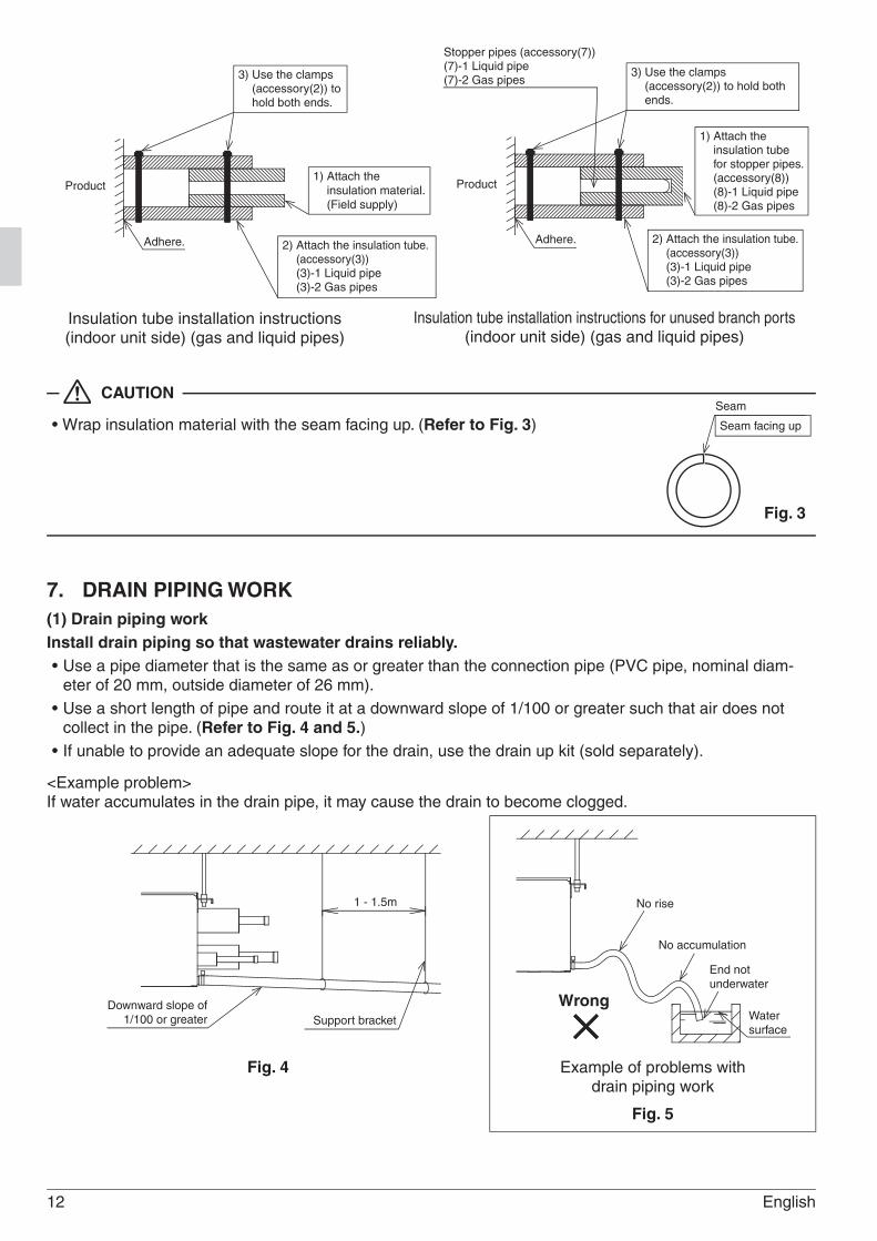
Product
2) Attach the insulation tube. (accessory(3)) (3)-1 Liquid pipe (3)-2 Gas pipes
1) Attach the insulation material. (Field supply)
3) Use the clamps (accessory(2)) to hold both ends.
Insulation tube installation instructions (indoor unit side) (gas and liquid pipes)
Adhere.
Product
2) Attach the insulation tube. (accessory(3)) (3)-1 Liquid pipe (3)-2 Gas pipes
3) Use the clamps (accessory(2)) to hold both ends.
Insulation tube installation instructions for unused branch ports (indoor unit side) (gas and liquid pipes)
Adhere.
Stopper pipes (accessory(7)) (7)-1 Liquid pipe (7)-2 Gas pipes
1) Attach the insulation tube for stopper pipes. (accessory(8)) (8)-1 Liquid pipe (8)-2 Gas pipes
CAUTION
• Wrap insulation material with the seam facing up. (Refer to Fig. 3)
7. DRAIN PIPING WORK(1) Drain piping workInstall drain piping so that wastewater drains reliably.• Use a pipe diameter that is the same as or greater than the connection pipe (PVC pipe, nominal diam-
eter of 20 mm, outside diameter of 26 mm).• Use a short length of pipe and route it at a downward slope of 1/100 or greater such that air does not
collect in the pipe. (Refer to Fig. 4 and 5.)• If unable to provide an adequate slope for the drain, use the drain up kit (sold separately).
<Example problem>If water accumulates in the drain pipe, it may cause the drain to become clogged.
1 - 1.5m
Downward slope of 1/100 or greater Support bracket
No rise
No accumulation
Water surface
End not underwater
Wrong
Fig. 4 Example of problems with drain piping work
Fig. 5
Seam
Seam facing up
Fig. 3
01_EN_3P194121-8U.indd 12 2/21/2014 3:31:10 PM
English 13
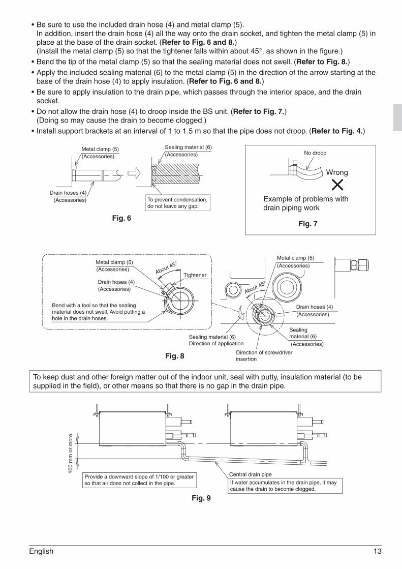
• Be sure to use the included drain hose (4) and metal clamp (5). In addition, insert the drain hose (4) all the way onto the drain socket, and tighten the metal clamp (5) in place at the base of the drain socket. (Refer to Fig. 6 and 8.) (Install the metal clamp (5) so that the tightener falls within about 45°, as shown in the figure.)
• Bend the tip of the metal clamp (5) so that the sealing material does not swell. (Refer to Fig. 8.)• Apply the included sealing material (6) to the metal clamp (5) in the direction of the arrow starting at the
base of the drain hose (4) to apply insulation. (Refer to Fig. 6 and 8.)• Be sure to apply insulation to the drain pipe, which passes through the interior space, and the drain
socket.• Do not allow the drain hose (4) to droop inside the BS unit. (Refer to Fig. 7.)
(Doing so may cause the drain to become clogged.)• Install support brackets at an interval of 1 to 1.5 m so that the pipe does not droop. (Refer to Fig. 4.)
Metal clamp (5) Sealing material (6)
(Accessories) (Accessories)
Drain hoses (4)(Accessories) To prevent condensation,
do not leave any gap.
Fig. 6
No droop
Wrong
Example of problems with drain piping work
Fig. 7
Metal clamp (5)(Accessories)
Drain hoses (4)(Accessories)
Bend with a tool so that the sealing material does not swell. Avoid putting a hole in the drain hoses.
About 45°
Tightener
About 45°
Sealing material (6)Direction of application
Drain hoses (4)(Accessories)
Sealing material (6)(Accessories)
Direction of screwdriver insertionFig. 8
Metal clamp (5)
(Accessories)
To keep dust and other foreign matter out of the indoor unit, seal with putty, insulation material (to be supplied in the field), or other means so that there is no gap in the drain pipe.
100
mm
or
mor
e
Provide a downward slope of 1/100 or greater so that air does not collect in the pipe.
Central drain pipe
If water accumulates in the drain pipe, it may cause the drain to become clogged.
Fig. 9
01_EN_3P194121-8U.indd 13 2/21/2014 3:31:11 PM
14 English
CAUTION
• To avoid subjecting the included drain hose (4) to excessive force, do not bend or twist. (Doing so may result in a water leak.)
• When using a central drain pipe, follow the instructions in Figure 9.
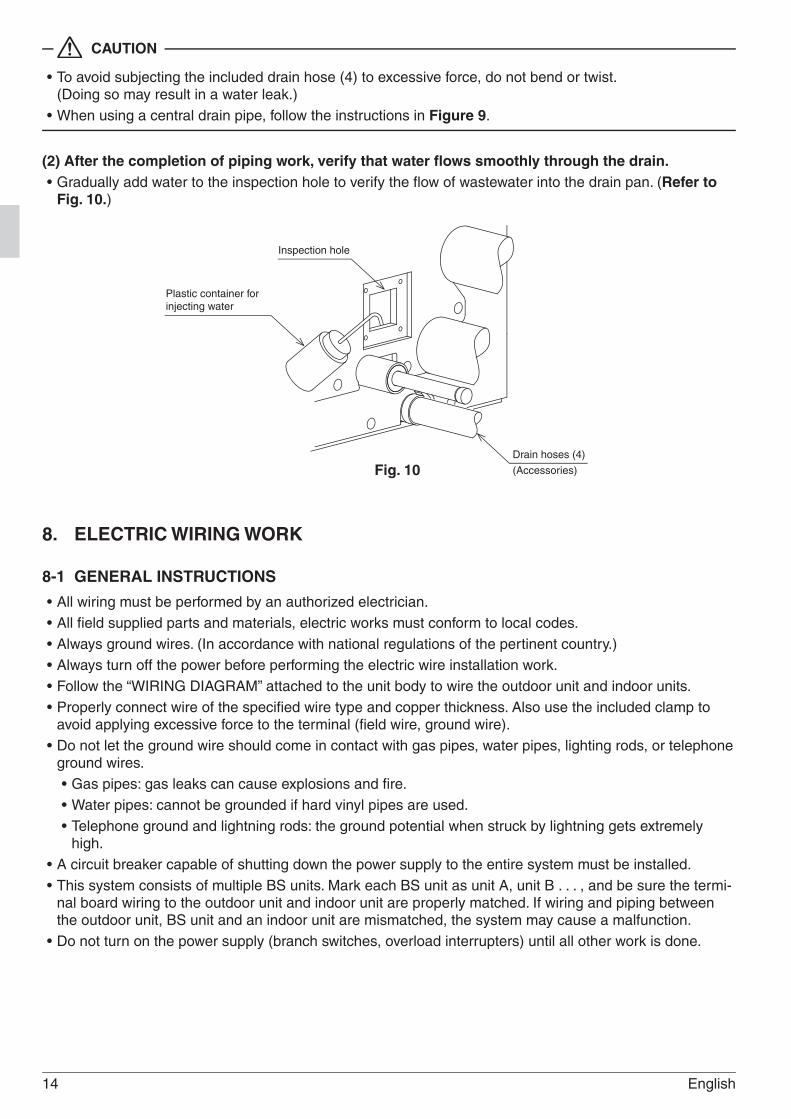
(2) After the completion of piping work, verify that water flows smoothly through the drain.• Gradually add water to the inspection hole to verify the flow of wastewater into the drain pan. (Refer to
Fig. 10.)
Drain hoses (4)
(Accessories)
Inspection hole
Plastic container for injecting water
Fig. 10
8. ELECTRIC WIRING WORK
8-1 GENERAL INSTRUCTIONS
• All wiring must be performed by an authorized electrician.• All field supplied parts and materials, electric works must conform to local codes.• Always ground wires. (In accordance with national regulations of the pertinent country.)• Always turn off the power before performing the electric wire installation work.• Follow the “WIRING DIAGRAM” attached to the unit body to wire the outdoor unit and indoor units.• Properly connect wire of the specified wire type and copper thickness. Also use the included clamp to
avoid applying excessive force to the terminal (field wire, ground wire).• Do not let the ground wire should come in contact with gas pipes, water pipes, lighting rods, or telephone
ground wires.• Gas pipes: gas leaks can cause explosions and fire.• Water pipes: cannot be grounded if hard vinyl pipes are used.• Telephone ground and lightning rods: the ground potential when struck by lightning gets extremely
high.• A circuit breaker capable of shutting down the power supply to the entire system must be installed.• This system consists of multiple BS units. Mark each BS unit as unit A, unit B . . . , and be sure the termi-
nal board wiring to the outdoor unit and indoor unit are properly matched. If wiring and piping between the outdoor unit, BS unit and an indoor unit are mismatched, the system may cause a malfunction.
• Do not turn on the power supply (branch switches, overload interrupters) until all other work is done.
01_EN_3P194121-8U.indd 14 2/21/2014 3:31:11 PM
English 15
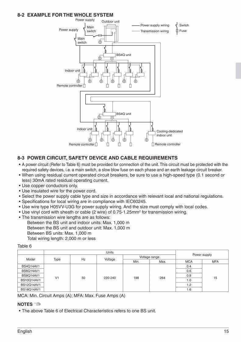
8-2 EXAMPLE FOR THE WHOLE SYSTEM
Power supply
Indoor unit
Indoor unit
Remote controller
Remote controller Remote controller
Power supply Outdoor unit
Main switch
Main switch
Power supply wiring
Transmission wiring
Switch
Fuse
BS4Q unit
BS4Q unit
Cooling-dedicated indoor unit
8-3 POWER CIRCUIT, SAFETY DEVICE AND CABLE REQUIREMENTS• A power circuit (Refer to Table 6) must be provided for connection of the unit. This circuit must be protected with the
required safety devices, i.e. a main switch, a slow blow fuse on each phase and an earth leakage circuit breaker.• When using residual current operated circuit breakers, be sure to use a high-speed type (0.1 second or
less) 30mA rated residual operating current.• Use copper conductors only.• Use insulated wire for the power cord.• Select the power supply cable type and size in accordance with relevant local and national regulations.• Specifications for local wiring are in compliance with IEC60245.• Use wire type H05VV-U3G for power supply wiring. And the size must comply with local codes.• Use vinyl cord with sheath or cable (2 wire) of 0.75-1.25mm2 for transmission wiring.• The transmission wire lengths are as follows:
Between the BS unit and indoor units: Max. 1,000 mBetween the BS unit and outdoor unit: Max. 1,000 mBetween BS units: Max. 1,000 mTotal wiring length: 2,000 m or less
Table 6 Units
Power supplyModel Type Hz Voltage
Voltage rangeMin. Max. MCA MFA
BS4Q14AV1
V1 50 220-240 198 264
0.4
15
BS6Q14AV1 0.6BS8Q14AV1 0.8BS10Q14AV1 1.0BS12Q14AV1 1.2BS16Q14AV1 1.6
MCA: Min. Circuit Amps (A); MFA: Max. Fuse Amps (A)
NOTES • The above Table 6 of Electrical Characteristics refers to one BS unit.
01_EN_3P194121-8U.indd 15 2/21/2014 3:31:12 PM
16 English
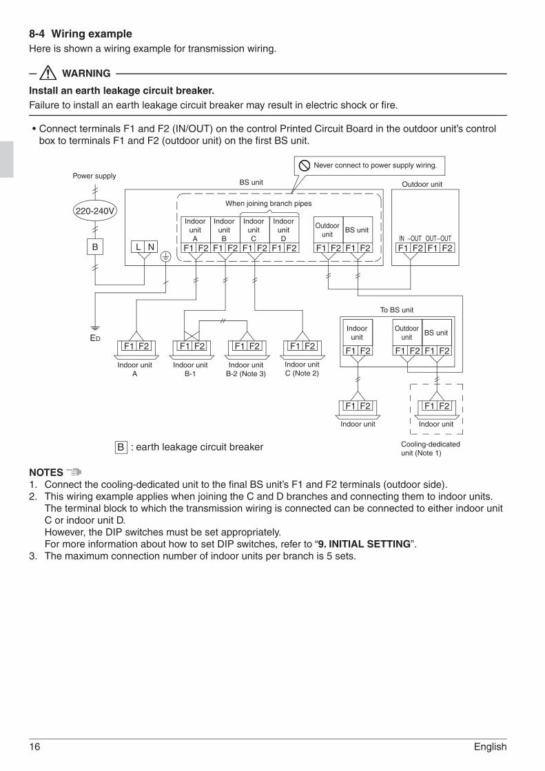
8-4 Wiring exampleHere is shown a wiring example for transmission wiring.
WARNING
Install an earth leakage circuit breaker.Failure to install an earth leakage circuit breaker may result in electric shock or fire.
• Connect terminals F1 and F2 (IN/OUT) on the control Printed Circuit Board in the outdoor unit’s control box to terminals F1 and F2 (outdoor unit) on the first BS unit.
F1 F2 F1 F2 F1 F2 F1 F2 F1 F2 F1 F2 F1 F2 F1 F2
F1 F2F1 F2
F1 F2F1 F2F1 F2F1 F2 F1 F2 F1 F2 F1 F2
LB
ED
220-240V
N
Indoor unit A
Indoor unit B
Indoor unit C
Indoor unit D
Outdoor unit
BS unit
BS unit Outdoor unit
To BS unit
Cooling-dedicated unit (Note 1)
Indoor unit A
Indoor unit B-1
Indoor unit B-2 (Note 3)
Indoor unit C (Note 2)
Indoor unit Indoor unit
OUTOUT OUTIN
Never connect to power supply wiring.
When joining branch pipes
Indoor unit
Outdoor unit
BS unit
B : earth leakage circuit breaker
Power supply
NOTES 1. Connect the cooling-dedicated unit to the final BS unit’s F1 and F2 terminals (outdoor side).2. This wiring example applies when joining the C and D branches and connecting them to indoor units.
The terminal block to which the transmission wiring is connected can be connected to either indoor unit C or indoor unit D. However, the DIP switches must be set appropriately. For more information about how to set DIP switches, refer to “9. INITIAL SETTING”.
3. The maximum connection number of indoor units per branch is 5 sets.
01_EN_3P194121-8U.indd 16 2/21/2014 3:31:12 PM
English 17
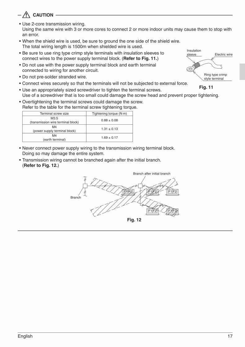
CAUTION
• Use 2-core transmission wiring. Using the same wire with 3 or more cores to connect 2 or more indoor units may cause them to stop with an error.
• When the shield wire is used, be sure to ground the one side of the shield wire. The total wiring length is 1500m when shielded wire is used.
• Be sure to use ring type crimp style terminals with insulation sleeves to connect wires to the power supply terminal block. (Refer to Fig. 11.)
• Do not use with the power supply terminal block and earth terminal connected to wiring for another circuit.
• Do not pre-solder stranded wire.• Connect wires securely so that the terminals will not be subjected to external force.• Use an appropriately sized screwdriver to tighten the terminal screws.
Use of a screwdriver that is too small could damage the screw head and prevent proper tightening.• Overtightening the terminal screws could damage the screw.
Refer to the table for the terminal screw tightening torque. Terminal screw size Tightening torque (N·m)
M3.5 (transmission wire terminal block)
0.88 ± 0.08
M4 (power supply terminal block)
1.31 ± 0.13
M4 (earth terminal)
1.69 ± 0.17
• Never connect power supply wiring to the transmission wiring terminal block. Doing so may damage the entire system.
• Transmission wiring cannot be branched again after the initial branch. (Refer to Fig. 12.)
F1 F2 F1 F2 F1 F2
F1 F2F1 F2
Branch after initial branch
Branch
Fig. 12
Ring type crimp style terminal
Electric wireInsulation sleeve
Fig. 11
01_EN_3P194121-8U.indd 17 2/21/2014 3:31:12 PM
18 English
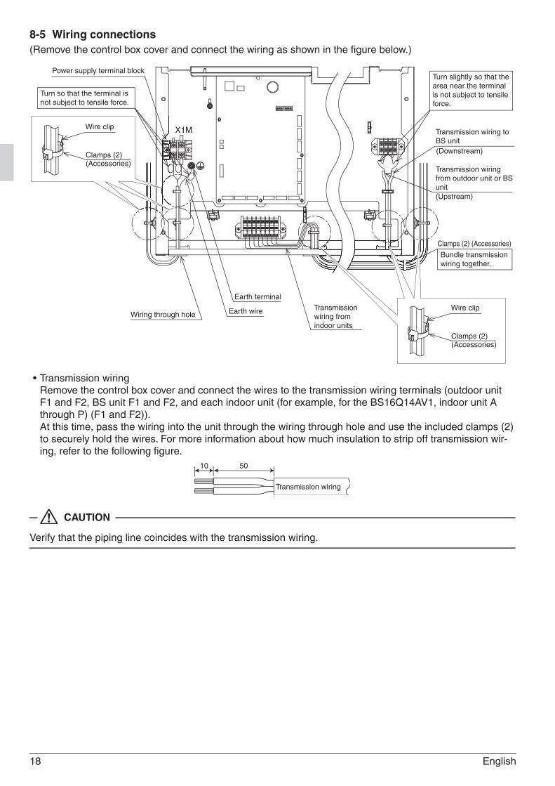
8-5 Wiring connections(Remove the control box cover and connect the wiring as shown in the fi gure below.)
X1M
Transmission wiring from outdoor unit or BS unit
Transmission wiring to BS unit
(Upstream)
(Downstream)
Wire clip
Clamps (2)(Accessories)
Wire clip
Clamps (2)(Accessories)
Power supply terminal block
Wiring through hole
Earth terminal
Earth wire Transmission wiring from indoor units
Turn so that the terminal is not subject to tensile force.
Turn slightly so that the area near the terminal is not subject to tensile force.
Bundle transmission wiring together.
Clamps (2) (Accessories)
• Transmission wiringRemove the control box cover and connect the wires to the transmission wiring terminals (outdoor unit F1 and F2, BS unit F1 and F2, and each indoor unit (for example, for the BS16Q14AV1, indoor unit A through P) (F1 and F2)).At this time, pass the wiring into the unit through the wiring through hole and use the included clamps (2) to securely hold the wires. For more information about how much insulation to strip off transmission wir-ing, refer to the following fi gure.
Transmission wiring
10 50
CAUTION
Verify that the piping line coincides with the transmission wiring.
01_EN_3P194121-8U.indd 18 2/21/2014 3:31:15 PM
English 19
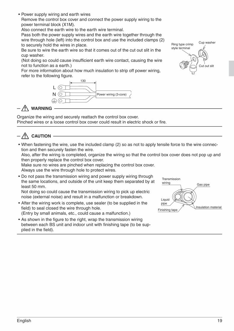
• Power supply wiring and earth wires Remove the control box cover and connect the power supply wiring to the power terminal block (X1M). Also connect the earth wire to the earth wire terminal. Pass both the power supply wires and the earth wire together through the wire through hole (left) into the control box and use the included clamps (2) to securely hold the wires in place. Be sure to wire the earth wire so that it comes out of the cut out slit in the cup washer. (Not doing so could cause insufficient earth wire contact, causing the wire not to function as a earth.) For more information about how much insulation to strip off power wiring, refer to the following figure.
L
N Power wiring (3-core)
130
Cut out slit
Cup washerRing type crimp style terminal
WARNING
Organize the wiring and securely reattach the control box cover. Pinched wires or a loose control box cover could result in electric shock or fire.
CAUTION
• When fastening the wire, use the included clamp (2) so as not to apply tensile force to the wire connec-tion and then securely fasten the wire. Also, after the wiring is completed, organize the wiring so that the control box cover does not pop up and then properly replace the control box cover. Make sure no wires are pinched when replacing the control box cover. Always use the wire through hole to protect wires.
• Do not pass the transmission wiring and power supply wiring through the same locations, and outside of the unit keep them separated by at least 50 mm. Not doing so could cause the transmission wiring to pick up electric noise (external noise) and result in a malfunction or breakdown.
• After the wiring work is complete, use sealer (to be supplied in the field) to seal closed the wire through hole. (Entry by small animals, etc., could cause a malfunction.)
• As shown in the figure to the right, wrap the transmission wiring between each BS unit and indoor unit with finishing tape (to be sup-plied in the field).
Gas pipe
Transmission wiring
Liquid pipe
Finishing tapeInsulation material
01_EN_3P194121-8U.indd 19 2/21/2014 3:31:15 PM
20 English
9. INITIAL SETTING
9-1 Settings in the fieldFollow the instructions below to set the DIP switches as necessary.
WARNING
Electric shock hazard! Before performing work, be sure to disconnect any power source connected to the unit.
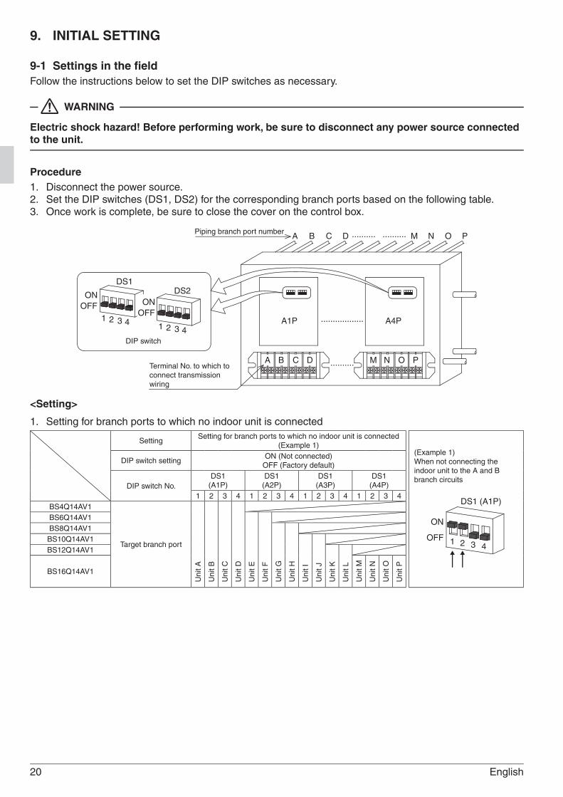
Procedure1. Disconnect the power source. 2. Set the DIP switches (DS1, DS2) for the corresponding branch ports based on the following table.3. Once work is complete, be sure to close the cover on the control box.
ONOFF
ONOFF
1A1P A4P
2 3 41 2
DS1DS2
3 4
A B C D M N O P
..................
..........
.......... ..........A B C D M N O PPiping branch port number
Terminal No. to which to connect transmission wiring
DIP switch
<Setting>
1. Setting for branch ports to which no indoor unit is connected
SettingSetting for branch ports to which no indoor unit is connected
(Example 1)(Example 1)When not connecting the indoor unit to the A and B branch circuits
ON
OFF 1 2
DS1 (A1P)
3 4
DIP switch settingON (Not connected)
OFF (Factory default)
DIP switch No.DS1
(A1P)DS1
(A2P)DS1
(A3P)DS1
(A4P)1 2 3 4 1 2 3 4 1 2 3 4 1 2 3 4
BS4Q14AV1
Target branch port
Uni
t A
Uni
t B
Uni
t C
Uni
t D
BS6Q14AV1
Uni
t E
Uni
t F
BS8Q14AV1
Uni
t G
Uni
t H
BS10Q14AV1
Uni
t I
Uni
t J
BS12Q14AV1
Uni
t K
Uni
t LBS16Q14AV1
Uni
t M
Uni
t N
Uni
t O
Uni
t P
01_EN_3P194121-8U.indd 20 2/21/2014 3:31:16 PM
English 21
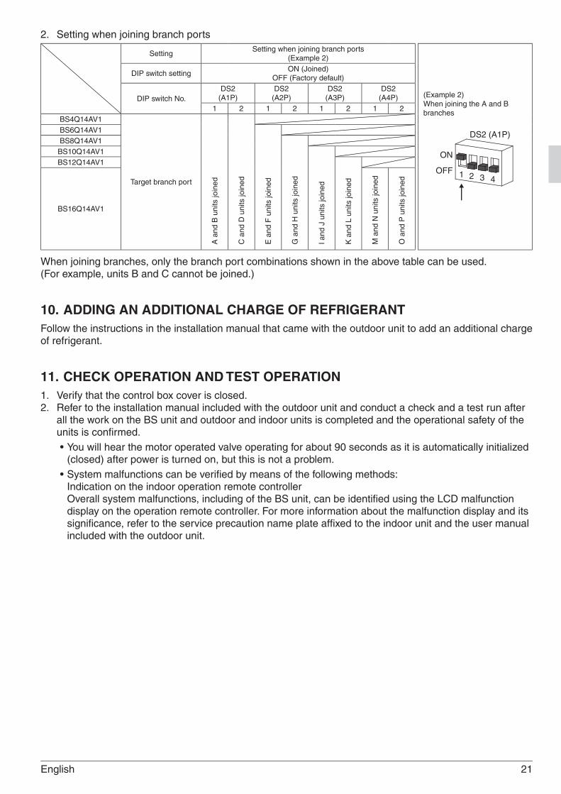
2. Setting when joining branch ports
SettingSetting when joining branch ports
(Example 2)
(Example 2)When joining the A and B branches
ON
OFF 1 2
DS2 (A1P)
3 4
DIP switch settingON (Joined)
OFF (Factory default)
DIP switch No.DS2
(A1P)DS2
(A2P)DS2
(A3P)DS2
(A4P)1 2 1 2 1 2 1 2
BS4Q14AV1
Target branch port
A a
nd B
uni
ts jo
ined
C a
nd D
uni
ts jo
ined
BS6Q14AV1
E a
nd F
uni
ts jo
ined
BS8Q14AV1
G a
nd H
uni
ts jo
ined
BS10Q14AV1
I and
J u
nits
join
ed
BS12Q14AV1
K a
nd L
uni
ts jo
ined
BS16Q14AV1
M a
nd N
uni
ts jo
ined
O a
nd P
uni
ts jo
ined
When joining branches, only the branch port combinations shown in the above table can be used.(For example, units B and C cannot be joined.)
10. ADDING AN ADDITIONAL CHARGE OF REFRIGERANTFollow the instructions in the installation manual that came with the outdoor unit to add an additional charge of refrigerant.
11. CHECK OPERATION AND TEST OPERATION1. Verify that the control box cover is closed.2. Refer to the installation manual included with the outdoor unit and conduct a check and a test run after
all the work on the BS unit and outdoor and indoor units is completed and the operational safety of the units is confirmed.• You will hear the motor operated valve operating for about 90 seconds as it is automatically initialized
(closed) after power is turned on, but this is not a problem. • System malfunctions can be verified by means of the following methods:
Indication on the indoor operation remote controller Overall system malfunctions, including of the BS unit, can be identified using the LCD malfunction display on the operation remote controller. For more information about the malfunction display and its significance, refer to the service precaution name plate affixed to the indoor unit and the user manual included with the outdoor unit.
01_EN_3P194121-8U.indd 21 2/21/2014 3:31:16 PM

3P194121-8U EM13A025A (1402) HT
00_CV_3P194121-8U.indd 2 2/15/2014 3:47:51 PM