INSTALLATION MANUAL - daikin.be · installation manual ... english 1 fxaq15pav1 fxaq20pav1...
24
MODELS Wall-mounted type FXAQ15PAV1 FXAQ20PAV1 FXAQ25PAV1 FXAQ32PAV1 FXAQ40PAV1 FXAQ50PAV1 FXAQ63PAV1 SYSTEM Inverter Air Conditioners INSTALLATION MANUAL READ THESE INSTRUCTIONS CAREFULLY BEFORE INSTALLATION. KEEP THIS MANUAL IN A HANDY PLACE FOR FUTURE REFERENCE. LESEN SIE DIESE ANWEISUNGEN VOR DER INSTALLATION SORGFÄLTIG DURCH. BEWAHREN SIE DIESE ANLEITUNG FÜR SPÄTERE BEZUGNAHME GRIFFBEREIT AUF. LIRE SOIGNEUSEMENT CES INSTRUCTIONS AVANT L’INSTALLATION. CONSERVER CE MANUEL A PORTEE DE MAIN POUR REFERENCE ULTERIEURE. LEA CUIDADOSAMENTE ESTAS INSTRUCCIONES ANTES DE INSTALAR. GUARDE ESTE MANUAL EN UN LUGAR A MANO PARA LEER EN CASO DE TENER ALGUNA DUDA. PRIMA DELL’INSTALLAZIONE LEGGERE ATTENTAMENTE QUESTE ISTRUZIONI. TENERE QUESTO MANUALE A PORTATA DI MANO PER RIFERIMENTI FUTURI. ÄΙΑΒΑΣΤΕ ΠΡΟΣΕΚΤΙΚΑ ΑΥΤΕΣ ΤΙΣ ΟÄΗΓΙΕΣ ΠΡΙΝ ΑΠΟ ΤΗΝ ΕΓΚΑΤΑΣΤΑΣΗ ΕΧΕΤΕ ΑΥΤΟ ΤΟ ΕΓΧΕΙΡΙÄΙΟ ΕΥΚΑΙΡΟ ΓΙΑ ΝΑ ΤΟ ΣΥΜΒΟΥΛΕΥΕΣΤΕ ΣΤΟ ΜΕΛΛΟΝ. LEES DEZE INSTRUCTIES ZORGVULDIG DOOR VOOR INSTALLATIE. BEWAAR DEZE HAN- DLEINDING WAAR U HEM KUNT TERUGVINDEN VOOR LATERE NASLAG. LEIA COM ATENÇÃO ESTAS INSTRUÇÕES ANTES DE REALIZAR A INSTALAÇÃO. MANTENHA ESTE MANUAL AO SEU ALCANCE PARA FUTURAS CONSULTAS. ПЕРЕД НАЧАЛОМ МОНТАЖА ВНИМАТЕЛЬНО ОЗНАКОМЬТЕСЬ С ДАННЫМИ ИНСТРУКЦИЯМИ. СОХРАНИТЕ ДАННОЕ РУКОВОДСТВО В МЕСТЕ, УДОБНОМ ДЛЯ ОБРАЩЕНИЯ В БУДУЩЕМ. MONTAJDAN ÖNCE BU TALÝMATLARI DÝKKATLÝ BÝR BÝÇÝMDE OKUYUN. GELECEKTE BAÞVURMAK ÜZERE BU ELKÝTABINI KOLAY ULAÞABÝLECEÐÝNÝZ BÝR YERDE MUHAFAZA EDÝN. English Deutsch Français Español Italiano Nederlands Portugues
Transcript of INSTALLATION MANUAL - daikin.be · installation manual ... english 1 fxaq15pav1 fxaq20pav1...
MODELSWall-mounted type
FXAQ15PAV1FXAQ20PAV1FXAQ25PAV1FXAQ32PAV1FXAQ40PAV1FXAQ50PAV1FXAQ63PAV1
SYSTEM Inverter Air Conditioners
INSTALLATION MANUAL
READ THESE INSTRUCTIONS CAREFULLY BEFORE INSTALLATION.KEEP THIS MANUAL IN A HANDY PLACE FOR FUTURE REFERENCE.
LESEN SIE DIESE ANWEISUNGEN VOR DER INSTALLATION SORGFÄLTIG DURCH.BEWAHREN SIE DIESE ANLEITUNG FÜR SPÄTERE BEZUGNAHME GRIFFBEREIT AUF.
LIRE SOIGNEUSEMENT CES INSTRUCTIONS AVANT L’INSTALLATION.CONSERVER CE MANUEL A PORTEE DE MAIN POUR REFERENCE ULTERIEURE.
LEA CUIDADOSAMENTE ESTAS INSTRUCCIONES ANTES DE INSTALAR.GUARDE ESTE MANUAL EN UN LUGAR A MANO PARA LEER EN CASO DE TENER ALGUNA DUDA.
PRIMA DELL’INSTALLAZIONE LEGGERE ATTENTAMENTE QUESTE ISTRUZIONI.TENERE QUESTO MANUALE A PORTATA DI MANO PER RIFERIMENTI FUTURI.
ÄΙΑΒΑΣΤΕ ΠΡΟΣΕΚΤΙΚΑ ΑΥΤΕΣ ΤΙΣ ΟÄΗΓΙΕΣ ΠΡΙΝ ΑΠΟ ΤΗΝ ΕΓΚΑΤΑΣΤΑΣΗ ΕΧΕΤΕ ΑΥΤΟ ΤΟ ΕΓΧΕΙΡΙÄΙΟ ΕΥΚΑΙΡΟ ΓΙΑ ΝΑ ΤΟ ΣΥΜΒΟΥΛΕΥΕΣΤΕ ΣΤΟ ΜΕΛΛΟΝ.
LEES DEZE INSTRUCTIES ZORGVULDIG DOOR VOOR INSTALLATIE. BEWAAR DEZE HAN-DLEINDING WAAR U HEM KUNT TERUGVINDEN VOOR LATERE NASLAG.
LEIA COM ATENÇÃO ESTAS INSTRUÇÕES ANTES DE REALIZAR A INSTALAÇÃO.MANTENHA ESTE MANUAL AO SEU ALCANCE PARA FUTURAS CONSULTAS.
ПЕРЕД НАЧАЛОМ МОНТАЖА ВНИМАТЕЛЬНО ОЗНАКОМЬТЕСЬ С ДАННЫМИ ИНСТРУКЦИЯМИ. СОХРАНИТЕ ДАННОЕ РУКОВОДСТВО В МЕСТЕ, УДОБНОМ ДЛЯ ОБРАЩЕНИЯ В БУДУЩЕМ.
MONTAJDAN ÖNCE BU TALÝMATLARI DÝKKATLÝ BÝR BÝÇÝMDE OKUYUN.GELECEKTE BAÞVURMAK ÜZERE BU ELKÝTABINI KOLAY ULAÞABÝLECEÐÝNÝZ BÝR YERDE MUHAFAZA EDÝN.
English
Deutsch
Français
Español
Italiano
Nederlands
Portugues
�������
��������
00_CV_3P156215-16W.fm Page 1 Tuesday, February 21, 2012 4:42 PM
Um
eda
Cen
ter
Bld
g., 2
-4-1
2, N
akaz
aki-N
ishi
,K
ita-k
u, O
saka
, 530
-832
3 Ja
pan
3P313807-1FX
AQ
15P
AV
1, F
XA
Q20
PA
V1,
FX
AQ
25P
AV
1, F
XA
Q32
PA
V1,
FX
AQ
40P
AV
1, F
XA
Q50
PA
V1,
FX
AQ
63P
AV
1
DA
IKIN
IND
US
TR
IES
, LT
D.
Mac
hine
ry 2
006/
42/E
CE
lect
rom
agne
tic C
ompa
tibili
ty 2
004/
108/
EC
***
DA
IKIN
.TC
F.02
4 E
15/0
2-20
12
TÜ
V R
hei
nla
nd
EP
S B
.V. (
NB
1856
)
0510
2601
01
Shi
nri S
ada
Man
ager
Qua
lity
Con
trol
Dep
artm
ent
21st
. of F
eb. 2
012
3P313807-1.fm Page 1 Wednesday, February 22, 2012 7:03 PM
English 1
FXAQ15PAV1FXAQ20PAV1FXAQ25PAV1
FXAQ32PAV1FXAQ40PAV1FXAQ50PAV1
FXAQ63PAV1 VRV SYSTEM Inverter Air Conditioners
Installationmanual
CONTENTS1. SAFETY PRECAUTIONS...............................................................................................1
2. BEFORE INSTALLATION ..............................................................................................3
3. SELECTING INSTALLATION SITE................................................................................5
4. INDOOR UNIT INSTALLATION .....................................................................................6
5. REFRIGERANT PIPING WORK ..................................................................................10
6. DRAIN PIPING WORK .................................................................................................12
7. ELECTRIC WIRING WORK .........................................................................................13
8. HOW TO CONNECT WIRINGS AND WIRING EXAMPLE ..........................................14
9. FIELD SETTINGS ........................................................................................................20
10. TEST RUN....................................................................................................................21
This English text is the original instruction. Other languages are translations of the original instructions.
1. SAFETY PRECAUTIONSPlease read these “SAFETY PRECAUTIONS” carefully before installing air conditioning equipment and be sure to install it correctly.
Meaning of WARNING and CAUTION notices. Both are important notices for safety. Be sure to follow them.
WARNING .........Failure to follow these instructions properly may result in personal injury or loss of life.
CAUTION ..........Failure to observe these instructions properly may result in property damage or per-sonal injury, which may be serious depending on the circumstances.
After completing installation, conduct a test run to confirm that the equipment operates without any problems. Then, explain to the customer how to operate the equipment and take care of it following the operation man-ual. Ask the customer to store the installation manual along with the operation manual for future reference. This air conditioner comes under the term “appliances not accessible to the general public”.This unit is a class A product. In a domestic environment this product may cause radio interference in which case the user may be required to take adequate measures.
WARNING• Ask your dealer or qualified personnel to carry out installation work.
Do not attempt to install the air conditioner yourself. Improper installation may result in water leakage, electric shocks or fire.
• Install the air conditioner in accordance with the instructions in this installation manual. Improper installation may result in water leakage, electric shocks or fire.
• When installing the unit in a small room, take measures so that the refrigerant may not exceed the limiting concentration in the event of refrigerant leakage.Contact your dealer for further information. If the refrigerant leaks and exceeds the limiting concentration, it may lead to oxygen deficiency.
• Be sure to use only the specified accessories and parts for installation work. Failure to use the specified parts may result in the unit falling, water leakage, electric shocks or fire.
01_EN_3P156215-16W.fm Page 1 Tuesday, February 21, 2012 4:46 PM
2 English
• Install the air conditioner on a foundation strong enough to withstand the weight of the unit. If a foundation does not have sufficient strength, the equipment may fall and cause injury.
• Carry out the required installation work in consideration of strong winds, typhoons or earthquakes.If the installation work is not properly carried out, the unit may fall down and cause accidents.
• The electrical work must be carried out by the qualified electrician in accordance with the local laws and regulations and this installation manual. Make sure to provide a dedicated power supply circuit and never connect additional wiring to the existing circuit.An insufficient power supply capacity or improper electrical work may lead to electric shocks or fire.
• Be sure to earth the air conditioner. Do not earth the unit to a utility pipe, lightning conductor or telephone earth lead. Imperfect earthing may result in electric shocks or fire. A high surge current from lightning or other sources may cause damage to the air conditioner.
• Be sure to install an earth leakage breaker. Failure to install an earth leakage breaker may result in electric shocks or fire.
• Be sure to switch off the unit before touching any electrical parts. Touching a live part may result in electric shock.
• For wiring, use the specified wires and connect and fasten them firmly so that no external force from the wires may be applied to the terminal connections.If the wires are not firmly connected and fastened, it may cause heating, fire or the like.
• Wiring for power supply and between the indoor and outdoor units must be properly laid and formed, and the control box cover must be firmly fastened so that the wiring may not push up the structural parts such as the cover.If the cover is improperly fastened, it may cause electric shock or fire.
• If refrigerant gas leaks during installation, ventilate the area immediately. Toxic gas may be produced if the refrigerant comes into contact with fire.
• After completing installation, check for refrigerant gas leakage. Toxic gas may be produced if the refrigerant gas leaks into the room and comes into contact with a source of fire, such as a fan heater, stove or cooker.
• Do not directly touch refrigerant that has leaked from refrigerant pipes or other areas, as there is a danger of frostbite.
CAUTION• Carry out drain piping properly following this installation manual and insulate the pipe to prevent conden-
sation.Improper drain piping may result in indoor water leakage and property damage.
• Install the indoor and outdoor units, power cord and connecting wires at least 1 meter away from televisions or radios to prevent picture interference and noise. (Depending on the incoming signal strength, a distance of 1 meter may not be sufficient to eliminate noise.)
• Install the indoor unit as far as possible from fluorescent lamps.If a wireless kit is installed in a room where the electronic lighting type (inverter or rapid start types) fluo-rescent lamps exist, the transmitting distance of a remote controller may be shorter.
• Do not install the air conditioner in the following locations:1. Where there is a high concentration of mineral oil spray or vapour (e.g. a kitchen).
Plastic parts may deteriorate and cause parts to fall off or water to leak.2. Where corrosive gas, such as sulphurous acid gas, is produced.
Corrosion of copper pipes or brazed parts may occur and cause refrigerant leakage.3. Where there is a machine that generates electromagnetic wave and where voltage fluctuation often occurs such
as a factory.Control system may malfunction and as a result the unit may not properly operate.
4. Where flammable gas may leak, where carbon fibre or ignitable dust is suspending in the air, or where volatile flammables such as paint thinner or gasoline are handled.Operating the unit in such conditions may result in fire.
• The air conditioner is not intended for use in a potentially explosive atmosphere.
01_EN_3P156215-16W.fm Page 2 Tuesday, February 21, 2012 4:46 PM

English 3
2. BEFORE INSTALLATIONDo not exert pressure on the resin parts when opening the unit or when moving it after openingBe sure to check the type of R410A refrigerant to be used before doing any work. (Using an incorrect refrigerant will prevent normal operation of the unit.)• When opening the unit or moving it after opening, be sure to lift it by holding on to the lifting lugs without
exerting any pressure on other parts, especially, drain piping, and other resin parts.• Decide upon a line of transport.• Leave the unit inside its packaging while moving, until reaching the installation site. Use a sling of soft mate-
rial, where unpacking is unavoidable or protective plates together with a rope when lifting, to avoid damage or scratches to the unit.
• Especially, do not unfasten packing case (top) guarding the control box until suspending the unit.• Refer to the installation manual of the outdoor unit for items not described in this manual.• Do not dispose of any parts necessary for installation until the installation is complete.
2-1 PRECAUTIONS• Be sure to read this manual before installing the indoor unit.• When selecting installation site, refer to the installation pattern.• This unit, both indoor and outdoor, is suitable for installation in a commercial and light industrial
environment. If installed as a household appliance it could cause electromagnetic interference.• Entrust installation to the place of purchase or a qualified serviceman. Improper installation could lead to
leaks and, in worse cases, electric shock of fire.• Use only parts provided with the unit or parts satisfying required specifications. Unspecified parts could
cause the unit to fall out of place, or could lead to leaks and, in worse cases, electric shock or fire.• Do not install or operate the unit in rooms mentioned below.
• Laden with mineral oil, or filled with oil vapor or spray like in kitchens. (Plastic parts may deteriorate which could eventually cause the unit to fall out of place, or could lead to leaks.)
• Where corrosive gas like sulfurous gas exists. (Copper tubing and brazed spots may corrode, which could eventually lead to refrigerant leaks.)
• Where volatile flammable gas like thinner or gasoline is used.• Where exposed to combustible gases and where volatile flammable gas like thinner or gasoline
is used. (Gas in the vicinity of the unit could ignite.)• Where machines can generate electromagnetic waves. (Control system may malfunction.)• Where the air contains high levels of salt such as that near the ocean and where voltage
fluctuates greatly such as that in factories. Also in vehicles or vessels.
2-2 ACCESSORIESCheck the following accessories are included with your unit.
Name(1) Installation
panel(2) Attachment screws
for the installation panel(3) Paper pattern
for installation(4) Insulating tape
Quantity 1 set8 pcs. → FXAQ15,20,25,32 type9 pcs. → FXAQ40,50,63 type
1 pc. 1 pc.
Shape
M4 × 25L
Name (5) Clamp (6) Securing screws
(Other)
• Operation manual• Installation manual
Quantity 1 large 3 small 2 pcs.
Shape
M4 × 12L
01_EN_3P156215-16W.fm Page 3 Tuesday, February 21, 2012 4:46 PM
4 English
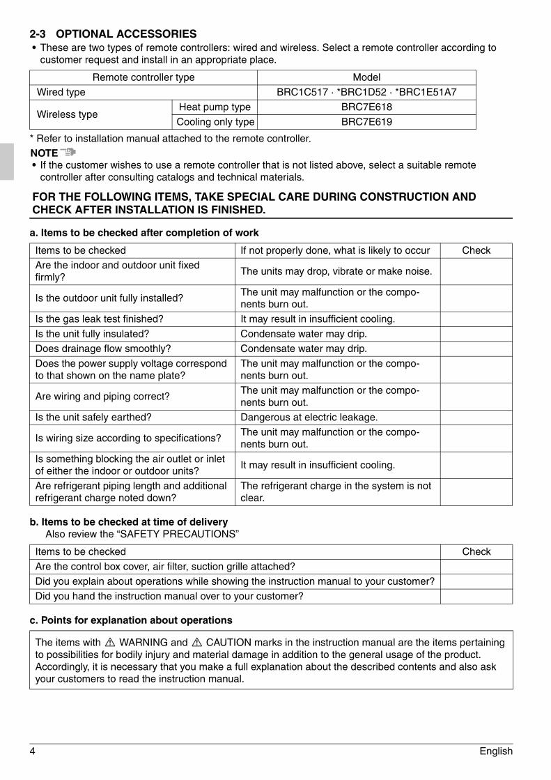
2-3 OPTIONAL ACCESSORIES• These are two types of remote controllers: wired and wireless. Select a remote controller according to
customer request and install in an appropriate place.
* Refer to installation manual attached to the remote controller.
NOTE• If the customer wishes to use a remote controller that is not listed above, select a suitable remote
controller after consulting catalogs and technical materials.
FOR THE FOLLOWING ITEMS, TAKE SPECIAL CARE DURING CONSTRUCTION AND CHECK AFTER INSTALLATION IS FINISHED.
a. Items to be checked after completion of work
b. Items to be checked at time of deliveryAlso review the “SAFETY PRECAUTIONS”
c. Points for explanation about operations
Remote controller type Model
Wired type BRC1C517 · *BRC1D52 · *BRC1E51A7
Wireless typeHeat pump type BRC7E618
Cooling only type BRC7E619
Items to be checked If not properly done, what is likely to occur Check
Are the indoor and outdoor unit fixed firmly?
The units may drop, vibrate or make noise.
Is the outdoor unit fully installed?The unit may malfunction or the compo-nents burn out.
Is the gas leak test finished? It may result in insufficient cooling.
Is the unit fully insulated? Condensate water may drip.
Does drainage flow smoothly? Condensate water may drip.
Does the power supply voltage correspond to that shown on the name plate?
The unit may malfunction or the compo-nents burn out.
Are wiring and piping correct?The unit may malfunction or the compo-nents burn out.
Is the unit safely earthed? Dangerous at electric leakage.
Is wiring size according to specifications?The unit may malfunction or the compo-nents burn out.
Is something blocking the air outlet or inlet of either the indoor or outdoor units?
It may result in insufficient cooling.
Are refrigerant piping length and additional refrigerant charge noted down?
The refrigerant charge in the system is not clear.
Items to be checked Check
Are the control box cover, air filter, suction grille attached?
Did you explain about operations while showing the instruction manual to your customer?
Did you hand the instruction manual over to your customer?
The items with WARNING and CAUTION marks in the instruction manual are the items pertaining to possibilities for bodily injury and material damage in addition to the general usage of the product. Accordingly, it is necessary that you make a full explanation about the described contents and also ask your customers to read the instruction manual.
01_EN_3P156215-16W.fm Page 4 Tuesday, February 21, 2012 4:46 PM
English 5
2-4 NOTE TO THE INSTALLERBe sure to instruct customers how to properly operate the unit (especially cleaning filters, operating different functions, and adjusting the temperature) by having them carry out operations themselves while looking at the manual.
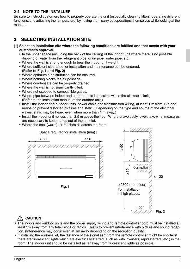
3. SELECTING INSTALLATION SITE(1) Select an installation site where the following conditions are fulfilled and that meets with your
customer’s approval.• In the upper space (including the back of the ceiling) of the indoor unit where there is no possible
dripping of water from the refrigerant pipe, drain pipe, water pipe, etc.• Where the wall is strong enough to bear the indoor unit weight.• Where sufficient clearance for installation and maintenance can be ensured.
(Refer to Fig. 1 and Fig. 2)• Where optimum air distribution can be ensured.• Where nothing blocks the air passage.• Where condensate can be properly drained.• Where the wall is not significantly tilted.• Where not exposed to combustible gases.• Where pipe between indoor and outdoor units is possible within the allowable limit.
(Refer to the installation manual of the outdoor unit.)• Install the indoor and outdoor units, power cable and transmission wiring, at least 1 m from TVs and
radios, to prevent distorted pictures and static. (Depending on the type and source of the electrical waves, static may be heard even when more than 1 m away.)
• Install the indoor unit no less than 2.5 m above the floor. Where unavoidably lower, take what measures are necessary to keep hands out of the air inlet.
• Where the cool (warm) air reaches all across the room.
CAUTION• The indoor and outdoor units and the power supply wiring and remote controller cord must be installed at
least 1m away from any televisions or radios. This is to prevent interference with picture and sound recep-tion. (Interference may occur even at 1m away depending on the reception quality.)
• If installing the wireless kit, the distance of the signal sent from the remote controller might be shorter if there are fluorescent lights which are electrically started (such as with inverters, rapid starters, etc.) in the room. The indoor unit should be installed as far away from fluorescent lights as possible.
Fig. 1
≥ 50 ≥ 50
[ Space required for installation (mm) ]
≥ 90
≥ 30
FloorFig. 2
Obstruction
≤ 120
≥ 2500 (from floor)For installation in high places.
01_EN_3P156215-16W.fm Page 5 Tuesday, February 21, 2012 4:46 PM
6 English
(2) Consider whether the place where the unit will be installed can support the full weight of the unit, and reinforce it with boards and beams, etc. if needed before proceeding with the installation. Also, reinforce the place to prevent vibration and noise before installing. (The installation pitch can be found on the paper pattern for installation (3), so refer to it when con-sidering the necessity for reinforcing the location.)
(3) The indoor unit may not be directly installed on the wall. Use the attached installation panel (1) before installing the unit.
4. INDOOR UNIT INSTALLATION• Use only accessories and parts which are of the designated specification when installing.
CAUTION• Install so that the unit does not tilt to either side or forward.• Do not hold the unit by the horizontal flaps when lifting it. (This may damage the horizontal flaps.)
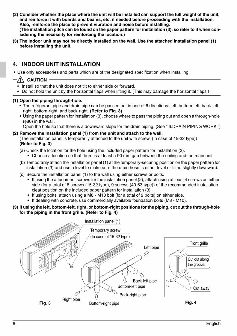
(1) Open the piping through-hole.• The refrigerant pipe and drain pipe can be passed out in one of 6 directions: left, bottom-left, back-left,
right, bottom-right, and back-right. (Refer to Fig. 3)• Using the paper pattern for installation (3), choose where to pass the piping out and open a through-hole
(φ80) in the wall.Open the hole so that there is a downward slope for the drain piping. (See “ 6.DRAIN PIPING WORK ”)
(2) Remove the installation panel (1) from the unit and attach to the wall.(The installation panel is temporarily attached to the unit with screw. (In case of 15-32 type)) (Refer to Fig. 3)
(a) Check the location for the hole using the included paper pattern for installation (3).• Choose a location so that there is at least a 90 mm gap between the ceiling and the main unit.
(b) Temporarily attach the installation panel (1) at the temporary-securing position on the paper pattern for installation (3) and use a level to make sure the drain hose is either level or tilted slightly downward.
(c) Secure the installation panel (1) to the wall using either screws or bolts.• If using the attachment screws for the installation panel (2), attach using at least 4 screws on either
side (for a total of 8 screws (15-32 type), 9 screws (40-63 type)) of the recommended installation cleat position on the included paper pattern for installation (3).
• If using bolts, attach using a M8 - M10 bolt (for a total of 2 bolts) on either side.• If dealing with concrete, use commercially available foundation bolts (M8 - M10).
(3) If using the left, bottom-left, right, or bottom-right positions for the piping, cut out the through-hole for the piping in the front grille. (Refer to Fig. 4)
Installation panel (1)
Temporary screw
(In case of 15-32 type)
Right pipe
Left pipe
Back-left pipe
Back-right pipe
Bottom-left pipe
Bottom-right pipe
Front grille
Cut out along the groove.
Cut away
Fig. 3 Fig. 4
01_EN_3P156215-16W.fm Page 6 Tuesday, February 21, 2012 4:46 PM

English 7
(4) Remove the front panel and the service cover. (Refer to Fig. 5)
< How to remove the front panel and service cover >
(1) Open the front panel to the point where it stops.
(2) Push the axes on either side of the front panel towards the center of the main unit and remove. (You can also remove it by sliding the front panel either to the left or right and pulling it forward.)
(3) Remove the screw from the service cover and pull the handle forward.
(5) Point the pipe in the direction it will be passed out.
For right, bottom-right, and back-right piping (Refer to Fig. 6)• Wrap the drain hose and the refrigerant piping together with the insulat-
ing tape (4) so that the drain hose is below the refrigerant piping.
For left, bottom-left, and left-back piping• Remove the front grille. (Refer to Fig. 7)< How to remove the front grille >Remove the front grille as described below when securing the indoor unit with screws or when attaching Optional Accessories (wireless remote controller, adapter PC board, etc.).
(1) Remove the front panel.
(2) Remove the screws (2 places in case of FXAQ15,20,25,32 type/3 places in case of FXAQ40,50,63 type) securing the front grille.
(3) Remove the tabs (3 places) securing the front grille by pushing them in the direction of the arrows.
(4) Making sure not to catch the horizontal flaps, remove the front grille by pulling in the direction of the arrow.
• Remove the drain plug, the insulation tubing, and the drain hose from the drain pan and replace. (Refer to Fig. 8)
• Connect the local refrigerant piping ahead of time, matching it to the liquid pipe and gas pipe marks engraved on the installation panel (1).
AxisAxis
Axis
Fig. 5
Handle
Screw
Service coverFront panel
(1)
(2) (2)
(3)
Insulating tape (4)
Drain hoseFig. 6
Refrigerant piping
Tab position Tab position
Front grille
Fig. 7
Tab
(2) (2) (2)
(3) (3)
(4)
(3)
Screw position
Screw position (In case of FXAQ40,50,63 type)
01_EN_3P156215-16W.fm Page 7 Tuesday, February 21, 2012 4:46 PM
8 English
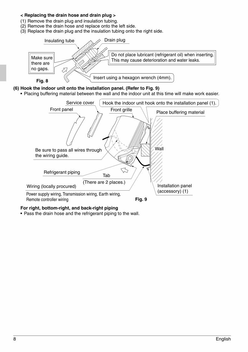
< Replacing the drain hose and drain plug >(1) Remove the drain plug and insulation tubing.(2) Remove the drain hose and replace onto the left side.(3) Replace the drain plug and the insulation tubing onto the right side.
(6) Hook the indoor unit onto the installation panel. (Refer to Fig. 9)• Placing buffering material between the wall and the indoor unit at this time will make work easier.
For right, bottom-right, and back-right piping• Pass the drain hose and the refrigerant piping to the wall.
Drain plugInsulating tube
Fig. 8
Do not place lubricant (refrigerant oil) when inserting. This may cause deterioration and water leaks.
Insert using a hexagon wrench (4mm).
Make sure there are no gaps.
Refrigerant piping
Be sure to pass all wires through the wiring guide.
Tab
(There are 2 places.)Wiring (locally procured)
Power supply wiring, Transmission wiring, Earth wiring, Remote controller wiring
Wall
Installation panel (accessory) (1)
Front panel Front grille
Service cover
Place buffering material
Hook the indoor unit hook onto the installation panel (1).
Fig. 9
01_EN_3P156215-16W.fm Page 8 Tuesday, February 21, 2012 4:46 PM
English 9
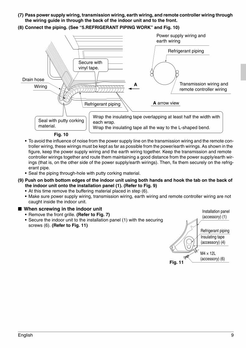
(7) Pass power supply wiring, transmission wiring, earth wiring, and remote controller wiring through the wiring guide in through the back of the indoor unit and to the front.
(8) Connect the piping. (See “5.REFRIGERANT PIPING WORK” and Fig. 10)
• To avoid the influence of noise from the power supply line on the transmission wiring and the remote con-troller wiring, these wirings must be kept as far as possible from the power/earth wirings. As shown in the figure, keep the power supply wiring and the earth wiring together. Keep the transmission and remote controller wirings together and route them maintaining a good distance from the power supply/earth wir-ings (that is, on the other side of the power supply/earth wirings). Then, fix them securely on the refrig-erant pipe.
• Seal the piping through-hole with putty corking material.
(9) Push on both bottom edges of the indoor unit using both hands and hook the tab on the back of the indoor unit onto the installation panel (1). (Refer to Fig. 9)• At this time remove the buffering material placed in step (6).• Make sure power supply wiring, transmission wiring, earth wiring and remote controller wiring are not
caught inside the indoor unit.
■ When screwing in the indoor unit• Remove the front grille. (Refer to Fig. 7)• Secure the indoor unit to the installation panel (1) with the securing
screws (6). (Refer to Fig. 11)
Secure with vinyl tape.
Wrap the insulating tape overlapping at least half the width with each wrap. Wrap the insulating tape all the way to the L-shaped bend.
Seal with putty corking material.
Drain hose
Wiring
Fig. 10
Refrigerant piping
A
A arrow view
Power supply wiring and earth wiring
Refrigerant piping
Transmission wiring and remote controller wiring
Installation panel (accessory) (1)
Refrigerant pipingInsulating tape (accessory) (4)
M4 × 12L (accessory) (6)
Fig. 11
01_EN_3P156215-16W.fm Page 9 Tuesday, February 21, 2012 4:46 PM
10 English
5. REFRIGERANT PIPING WORK⟨For refrigerant piping of outdoor units, see the installation manual attached to the outdoor unit.⟩ ⟨Execute heat insulation work completely on both sides of the gas piping and the liquid piping. Otherwise, a water leakage can result sometimes.⟩ (When using a heat pump, the temperature of the gas piping can reach up to approximately 120°C, so use insulation which is sufficiently resistant.)⟨Also, in cases where the temperature and humidity of the refrigerant piping sections might exceed 30°C or RH80 %, reinforce the refrigerant insulation. (20 mm or thicker) Condensation may form on the surface of the insulating material.⟩⟨Before refrigerant piping work, check which type of refrigerant is used. Proper operation is not pos-sible if the types of refrigerant are not the same.⟩
CAUTION• Use a pipe cutter and flare suitable for the type of refrigerant.• Apply ester oil or ether oil around the flare section before connecting.• To prevent dust, moisture or other foreign matter from infiltrating the tube, either pinch the end
or cover it with tape.• Do not allow anything other than the designated refrigerant to get mixed into the refrigerant
circuit, such as air, etc. If any refrigerant gas leaks while working on the unit, ventilate the room thoroughly right away.
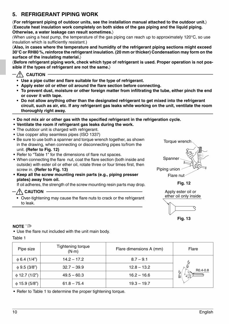
• Do not mix air or other gas with the specified refrigerant in the refrigeration cycle.• Ventilate the room if refrigerant gas leaks during the work.• The outdoor unit is charged with refrigerant.• Use copper alloy seamless pipes (ISO 1337)• Be sure to use both a spanner and torque wrench together, as shown
in the drawing, when connecting or disconnecting pipes to/from the unit. (Refer to Fig. 12)
• Refer to “Table 1” for the dimensions of flare nut spaces.• When connecting the flare nut, coat the flare section (both inside and
outside) with ester oil or ether oil, rotate three or four times first, then screw in. (Refer to Fig. 13)
• Keep all the screw mounting resin parts (e.g., piping presser plates) away from oil.If oil adheres, the strength of the screw mounting resin parts may drop.
CAUTION
• Over-tightening may cause the flare nuts to crack or the refrigerant to leak.
NOTE• Use the flare nut included with the unit main body.
Table 1
• Refer to Table 1 to determine the proper tightening torque.
Pipe sizeTightening torque
(N·m)Flare dimensions A (mm) Flare
φ 6.4 (1/4”) 14.2 – 17.2 8.7 – 9.1
φ 9.5 (3/8”) 32.7 – 39.9 12.8 – 13.2
φ 12.7 (1/2”) 49.5 – 60.3 16.2 – 16.6
φ 15.9 (5/8”) 61.8 – 75.4 19.3 – 19.7
Fig. 13
Apply ester oil or ether oil only inside
Torque wrench
Spanner
Piping union
Flare nut
Fig. 12
R0.4-0.8
A900± 2
0
450± 2
0
01_EN_3P156215-16W.fm Page 10 Tuesday, February 21, 2012 4:46 PM
English 11
Not recommendable but in case of emergency
You must use a torque wrench but if you are obliged to install the unit without a torque wrench, you mayfollow the installation method mentioned below.
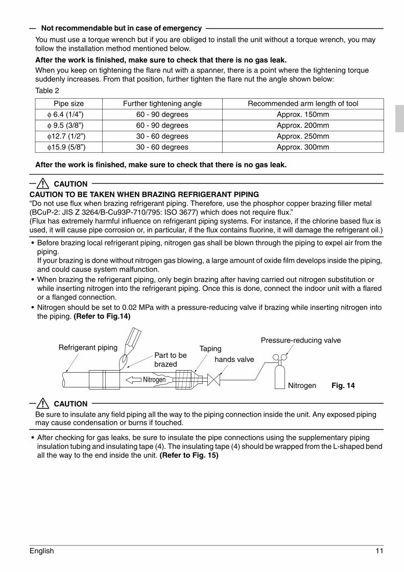
After the work is finished, make sure to check that there is no gas leak.When you keep on tightening the flare nut with a spanner, there is a point where the tightening torque suddenly increases. From that position, further tighten the flare nut the angle shown below:
Table 2
After the work is finished, make sure to check that there is no gas leak.
CAUTIONCAUTION TO BE TAKEN WHEN BRAZING REFRIGERANT PIPING“Do not use flux when brazing refrigerant piping. Therefore, use the phosphor copper brazing filler metal (BCuP-2: JIS Z 3264/B-Cu93P-710/795: ISO 3677) which does not require flux.”(Flux has extremely harmful influence on refrigerant piping systems. For instance, if the chlorine based flux is used, it will cause pipe corrosion or, in particular, if the flux contains fluorine, it will damage the refrigerant oil.)
• Before brazing local refrigerant piping, nitrogen gas shall be blown through the piping to expel air from the piping.If your brazing is done without nitrogen gas blowing, a large amount of oxide film develops inside the piping, and could cause system malfunction.
• When brazing the refrigerant piping, only begin brazing after having carried out nitrogen substitution or while inserting nitrogen into the refrigerant piping. Once this is done, connect the indoor unit with a flared or a flanged connection.
• Nitrogen should be set to 0.02 MPa with a pressure-reducing valve if brazing while inserting nitrogen into the piping. (Refer to Fig.14)
CAUTIONBe sure to insulate any field piping all the way to the piping connection inside the unit. Any exposed piping may cause condensation or burns if touched.
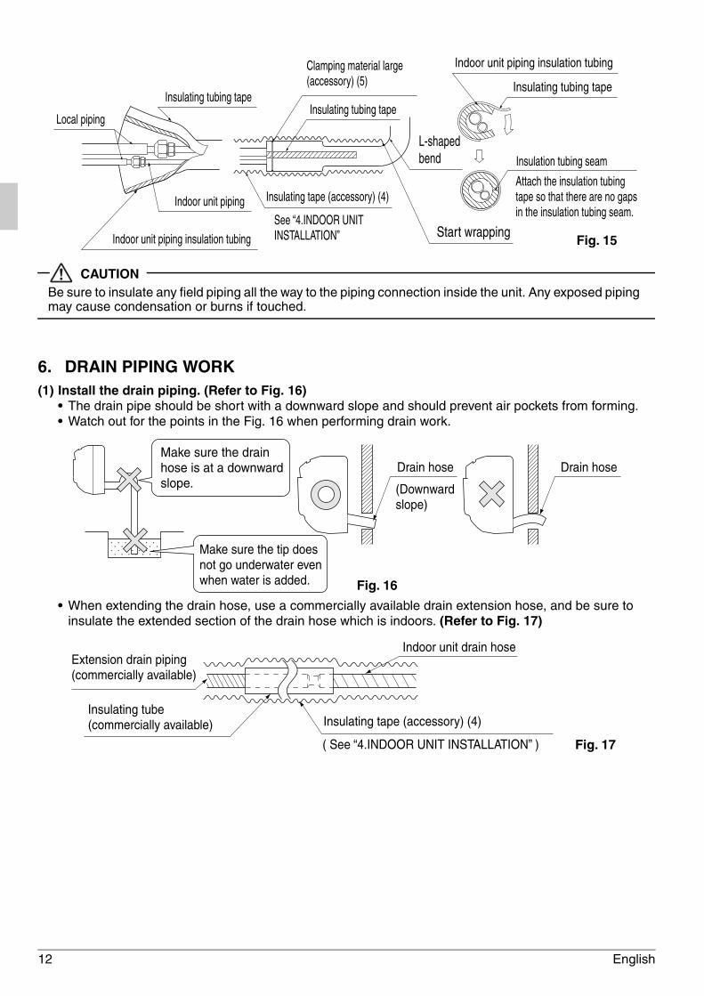
• After checking for gas leaks, be sure to insulate the pipe connections using the supplementary piping insulation tubing and insulating tape (4). The insulating tape (4) should be wrapped from the L-shaped bend all the way to the end inside the unit. (Refer to Fig. 15)
Pipe size Further tightening angle Recommended arm length of tool
φ 6.4 (1/4”) 60 - 90 degrees Approx. 150mm
φ 9.5 (3/8”) 60 - 90 degrees Approx. 200mm
φ12.7 (1/2”) 30 - 60 degrees Approx. 250mm
φ15.9 (5/8”) 30 - 60 degrees Approx. 300mm
Refrigerant pipingPart to be brazed
TapingPressure-reducing valve
hands valve
Nitrogen Fig. 14Nitrogen
01_EN_3P156215-16W.fm Page 11 Tuesday, February 21, 2012 4:46 PM
12 English
CAUTIONBe sure to insulate any field piping all the way to the piping connection inside the unit. Any exposed piping may cause condensation or burns if touched.
6. DRAIN PIPING WORK(1) Install the drain piping. (Refer to Fig. 16)
• The drain pipe should be short with a downward slope and should prevent air pockets from forming.• Watch out for the points in the Fig. 16 when performing drain work.
• When extending the drain hose, use a commercially available drain extension hose, and be sure to insulate the extended section of the drain hose which is indoors. (Refer to Fig. 17)
Insulating tubing tapeInsulating tubing tape
Local piping
Indoor unit piping
Indoor unit piping insulation tubing
Clamping material large (accessory) (5)
Insulating tape (accessory) (4)
L-shaped bend
Start wrappingSee “4.INDOOR UNIT INSTALLATION”
Indoor unit piping insulation tubing
Insulating tubing tape
Insulation tubing seam
Attach the insulation tubing tape so that there are no gaps in the insulation tubing seam.
Fig. 15
Fig. 16
Make sure the drain hose is at a downward slope.
Make sure the tip does not go underwater even when water is added.
Drain hose Drain hose
(Downward slope)
Indoor unit drain hoseExtension drain piping (commercially available)
Insulating tube (commercially available) Insulating tape (accessory) (4)
( See “4.INDOOR UNIT INSTALLATION” ) Fig. 17
01_EN_3P156215-16W.fm Page 12 Tuesday, February 21, 2012 4:46 PM
English 13
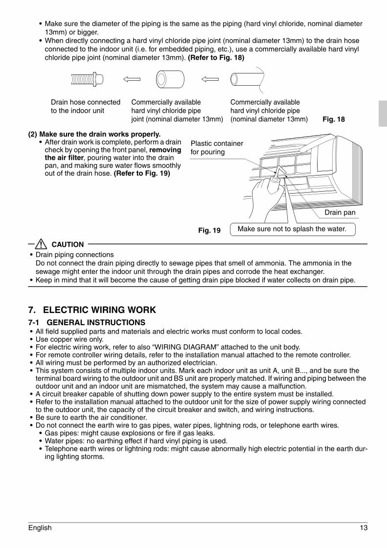
• Make sure the diameter of the piping is the same as the piping (hard vinyl chloride, nominal diameter 13mm) or bigger.
• When directly connecting a hard vinyl chloride pipe joint (nominal diameter 13mm) to the drain hose connected to the indoor unit (i.e. for embedded piping, etc.), use a commercially available hard vinyl chloride pipe joint (nominal diameter 13mm). (Refer to Fig. 18)
(2) Make sure the drain works properly.• After drain work is complete, perform a drain
check by opening the front panel, removing the air filter, pouring water into the drain pan, and making sure water flows smoothly out of the drain hose. (Refer to Fig. 19)
CAUTION• Drain piping connections
Do not connect the drain piping directly to sewage pipes that smell of ammonia. The ammonia in the sewage might enter the indoor unit through the drain pipes and corrode the heat exchanger.
• Keep in mind that it will become the cause of getting drain pipe blocked if water collects on drain pipe.
7. ELECTRIC WIRING WORK7-1 GENERAL INSTRUCTIONS• All field supplied parts and materials and electric works must conform to local codes.• Use copper wire only.• For electric wiring work, refer to also “WIRING DIAGRAM” attached to the unit body.• For remote controller wiring details, refer to the installation manual attached to the remote controller.• All wiring must be performed by an authorized electrician.• This system consists of multiple indoor units. Mark each indoor unit as unit A, unit B..., and be sure the
terminal board wiring to the outdoor unit and BS unit are properly matched. If wiring and piping between the outdoor unit and an indoor unit are mismatched, the system may cause a malfunction.
• A circuit breaker capable of shutting down power supply to the entire system must be installed.• Refer to the installation manual attached to the outdoor unit for the size of power supply wiring connected
to the outdoor unit, the capacity of the circuit breaker and switch, and wiring instructions.• Be sure to earth the air conditioner.• Do not connect the earth wire to gas pipes, water pipes, lightning rods, or telephone earth wires.
• Gas pipes: might cause explosions or fire if gas leaks.• Water pipes: no earthing effect if hard vinyl piping is used. • Telephone earth wires or lightning rods: might cause abnormally high electric potential in the earth dur-
ing lighting storms.
Drain hose connected to the indoor unit
Commercially available hard vinyl chloride pipe joint (nominal diameter 13mm)
Commercially available hard vinyl chloride pipe (nominal diameter 13mm) Fig. 18
Plastic container for pouring
Drain pan
Make sure not to splash the water.Fig. 19
01_EN_3P156215-16W.fm Page 13 Tuesday, February 21, 2012 4:46 PM
14 English
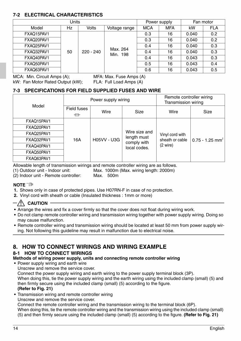
7-2 ELECTRICAL CHARACTERISTICS
MCA: Min. Circuit Amps (A); MFA: Max. Fuse Amps (A)kW: Fan Motor Rated Output (kW); FLA: Full Load Amps (A)
7-3 SPECIFICATIONS FOR FIELD SUPPLIED FUSES AND WIRE
Allowable length of transmission wirings and remote controller wiring are as follows.(1) Outdoor unit - Indoor unit: Max. 1000m (Max. wiring length: 2000m)(2) Indoor unit - Remote controller: Max. 500m
NOTE1. Shows only in case of protected pipes. Use H07RN-F in case of no protection.2. Vinyl cord with sheath or cable (Insulated thickness : 1mm or more)
CAUTION• Arrange the wires and fix a cover firmly so that the cover does not float during wiring work.• Do not clamp remote controller wiring and transmission wiring together with power supply wiring. Doing so
may cause malfunction.• Remote controller wiring and transmission wiring should be located at least 50 mm from power supply wir-
ing. Not following this guideline may result in malfunction due to electrical noise.
8. HOW TO CONNECT WIRINGS AND WIRING EXAMPLE8-1 HOW TO CONNECT WIRINGSMethods of wiring power supply, units and connecting remote controller wiring• Power supply wiring and earth wire
Unscrew and remove the service cover.Connect the power supply wiring and earth wiring to the power supply terminal block (3P).When doing this, tie the power supply wiring and the earth wiring using the included clamp (small) (5) and then firmly secure using the included clamp (small) (5) according to the figure.(Refer to Fig. 21)
• Transmission wiring and remote controller wiringUnscrew and remove the service cover.Connect the remote controller wiring and the transmission wiring to the terminal block (6P).When doing this, tie the remote controller wiring and the transmission wiring using the included clamp (small) (5) and then firmly secure using the included clamp (small) (5) according to the figure. (Refer to Fig. 21)
Units Power supply Fan motorModel Hz Volts Voltage range MCA MFA kW FLA
FXAQ15PAV1
50 220 - 240Max. 264Min. 198
0.3 16 0.040 0.2FXAQ20PAV1 0.3 16 0.040 0.2FXAQ25PAV1 0.4 16 0.040 0.3FXAQ32PAV1 0.4 16 0.040 0.3FXAQ40PAV1 0.4 16 0.043 0.3FXAQ50PAV1 0.5 16 0.043 0.4FXAQ63PAV1 0.6 16 0.043 0.5
ModelPower supply wiring
Remote controller wiringTransmission wiring
Field fuses Wire Size Wire Size
FXAQ15PAV1
16A H05VV - U3G
Wire size and length must comply with local codes.
Vinyl cord with sheath or cable(2 wire)
0.75 - 1.25 mm2
FXAQ20PAV1FXAQ25PAV1FXAQ32PAV1FXAQ40PAV1FXAQ50PAV1FXAQ63PAV1
01_EN_3P156215-16W.fm Page 14 Tuesday, February 21, 2012 4:46 PM
English 15
• Be sure to attach it to prevent the infiltration of water as well as any insects and other small creatures from the outside. Otherwise a short-circuit may occur inside the control box.
[PRECAUTIONS]Observe the notes mentioned below when wiring to the power supply terminal block and terminal block for remote controller.
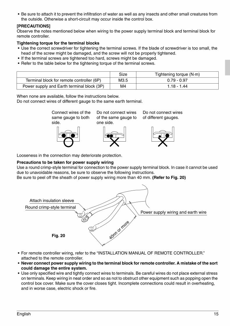
Tightening torque for the terminal blocks• Use the correct screwdriver for tightening the terminal screws. If the blade of screwdriver is too small, the
head of the screw might be damaged, and the screw will not be properly tightened.• If the terminal screws are tightened too hard, screws might be damaged.• Refer to the table below for the tightening torque of the terminal screws.
When none are available, follow the instructions below.Do not connect wires of different gauge to the same earth terminal.
Looseness in the connection may deteriorate protection.
Precautions to be taken for power supply wiringUse a round crimp-style terminal for connection to the power supply terminal block. In case it cannot be used due to unavoidable reasons, be sure to observe the following instructions.Be sure to peel off the sheath of power supply wiring more than 40 mm. (Refer to Fig. 20)
• For remote controller wiring, refer to the “INSTALLATION MANUAL OF REMOTE CONTROLLER.” attached to the remote controller.
• Never connect power supply wiring to the terminal block for remote controller. A mistake of the sort could damage the entire system.
• Use only specified wire and tightly connect wires to terminals. Be careful wires do not place external stress on terminals. Keep wiring in neat order and so as not to obstruct other equipment such as popping open the control box cover. Make sure the cover closes tight. Incomplete connections could result in overheating, and in worse case, electric shock or fire.
Size Tightening torque (N·m)Terminal block for remote controller (6P) M3.5 0.79 - 0.97
Power supply and Earth terminal block (3P) M4 1.18 - 1.44
Connect wires of the same gauge to both side.
Do not connect wires of the same gauge to one side.
Do not connect wires of different gauges.
Round crimp-style terminal
Attach insulation sleeve
Power supply wiring and earth wire
40mm or
mor
e
Fig. 20
01_EN_3P156215-16W.fm Page 15 Tuesday, February 21, 2012 4:46 PM
16 English
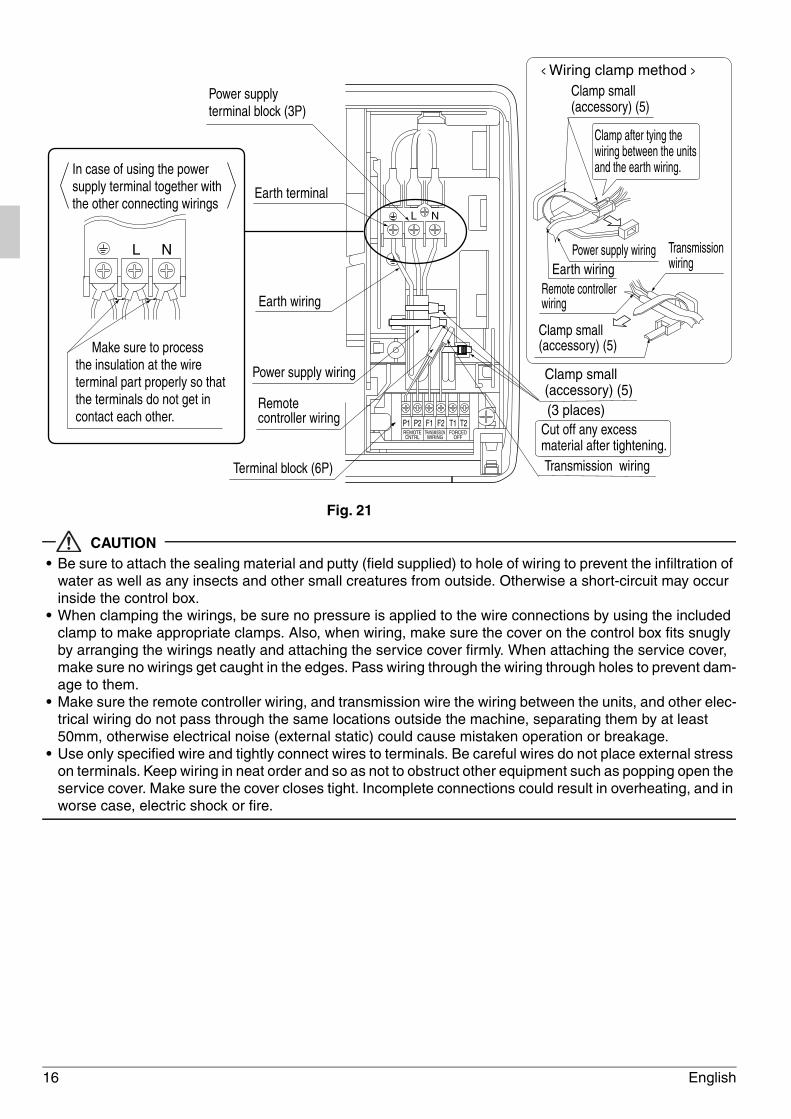
CAUTION• Be sure to attach the sealing material and putty (field supplied) to hole of wiring to prevent the infiltration of
water as well as any insects and other small creatures from outside. Otherwise a short-circuit may occur inside the control box.
• When clamping the wirings, be sure no pressure is applied to the wire connections by using the included clamp to make appropriate clamps. Also, when wiring, make sure the cover on the control box fits snugly by arranging the wirings neatly and attaching the service cover firmly. When attaching the service cover, make sure no wirings get caught in the edges. Pass wiring through the wiring through holes to prevent dam-age to them.
• Make sure the remote controller wiring, and transmission wire the wiring between the units, and other elec-trical wiring do not pass through the same locations outside the machine, separating them by at least 50mm, otherwise electrical noise (external static) could cause mistaken operation or breakage.
• Use only specified wire and tightly connect wires to terminals. Be careful wires do not place external stress on terminals. Keep wiring in neat order and so as not to obstruct other equipment such as popping open the service cover. Make sure the cover closes tight. Incomplete connections could result in overheating, and in worse case, electric shock or fire.
REMOTECNTRL
FORCEDOFF
TRANSMISSIONWIRING
F1 F2 T1 T2P1 P2
L N
Terminal block (6P)
Earth terminal
Earth wiring
Power supply wiring
Power supplyterminal block (3P)
In case of using the powersupply terminal together withthe other connecting wirings
Make sure to process the insulation at the wire terminal part properly so that the terminals do not get in contact each other.
Fig. 21
Remote controller wiring
L NEarth wiring
Power supply wiring
Transmission wiring
Transmission wiring
< Wiring clamp method >Clamp small (accessory) (5)
Clamp small (accessory) (5)
Clamp small (accessory) (5)
Clamp after tying the wiring between the units and the earth wiring.
Remote controller wiring
(3 places)Cut off any excess material after tightening.
01_EN_3P156215-16W.fm Page 16 Tuesday, February 21, 2012 4:46 PM
English 17
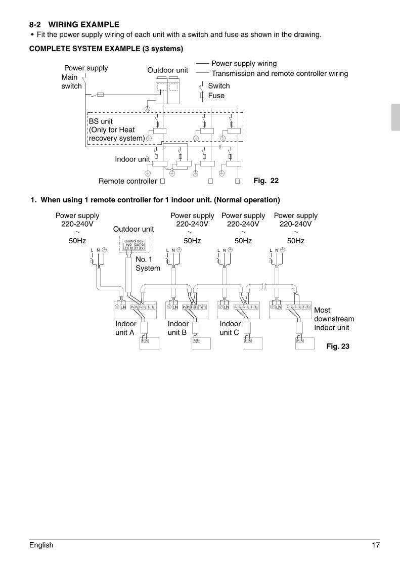
8-2 WIRING EXAMPLE• Fit the power supply wiring of each unit with a switch and fuse as shown in the drawing.
COMPLETE SYSTEM EXAMPLE (3 systems)
1. When using 1 remote controller for 1 indoor unit. (Normal operation)
Power supply wiringTransmission and remote controller wiring
SwitchFuse
Fig. 22
Power supplyMainswitch
Remote controller
Indoor unit
Outdoor unit
BS unit(Only for Heatrecovery system)
L N L NIN/D OUT/D
F1 F2 F1 F2
Control box
L N
LN P1 P2
P1 P2
F1 F2 T1 T2 P1 P2
P1 P2
F1 F2 T1 T2LN P1 P2
P1 P2
F1 F2 T1 T2LN LN P1 P2
P1 P2
F1 F2 T1 T2
L N
Outdoor unit
No. 1System
Indoor unit A
Indoor unit B
Indoor unit C
MostdownstreamIndoor unit
Power supply220-240V
50Hz
Power supply220-240V
50Hz
Power supply220-240V
50Hz
Power supply220-240V
50Hz
Fig. 23
01_EN_3P156215-16W.fm Page 17 Tuesday, February 21, 2012 4:46 PM
18 English
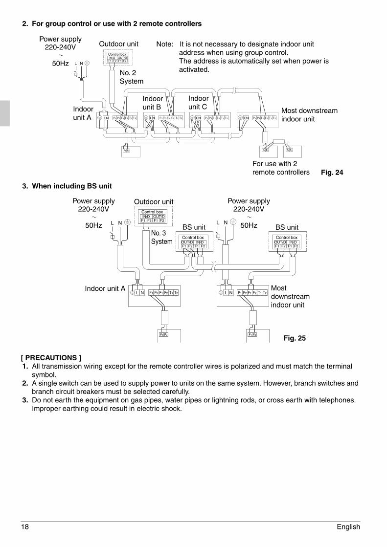
2. For group control or use with 2 remote controllers
3. When including BS unit
[ PRECAUTIONS ] 1. All transmission wiring except for the remote controller wires is polarized and must match the terminal
symbol.2. A single switch can be used to supply power to units on the same system. However, branch switches and
branch circuit breakers must be selected carefully. 3. Do not earth the equipment on gas pipes, water pipes or lightning rods, or cross earth with telephones.
Improper earthing could result in electric shock.
IN/D OUT/DF1 F2 F1 F2
Control box
LN P1 P2
P1 P2
F1 F2 T1 T2 LN P1 P2 F1 F2 T1 T2 LN P1 P2 F1 F2 T1 T2 LN P1 P2 F1 F2 T1 T2
P1 P2P1 P2
L N
Outdoor unit
No. 2System
Indoor unit A
Indoor unit B
Indoor unit C Most downstream
indoor unit
Fig. 24For use with 2remote controllers
Power supply220-240V
50Hz
Note: It is not necessary to designate indoor unit address when using group control. The address is automatically set when power is activated.
Fig. 25
IN/D OUT/DF1 F2 F1 F2
IN/DOUT/DF1 F2 F1 F2
L N
P1 P2
P1 P2 F1 F2 T1 T2
BS unitNo. 3System
Outdoor unit
Indoor unit A Most downstreamindoor unit
Control box
Control boxIN/DOUT/D
F1 F2 F1 F2
BS unitControl box
L N
P1 P2
P1 P2 F1 F2 T1 T2L N L N
Power supply220-240V
50Hz
Power supply220-240V
50Hz
01_EN_3P156215-16W.fm Page 18 Tuesday, February 21, 2012 4:46 PM
English 19
8-3 CONTROL BY 2 REMOTE CONTROLLERS (CONTROLLING 1 INDOOR UNIT BY 2 REMOTE CONTROLLERS)
• When using 2 remote controllers, one must be set to “MAIN” and the other to “SUB”.
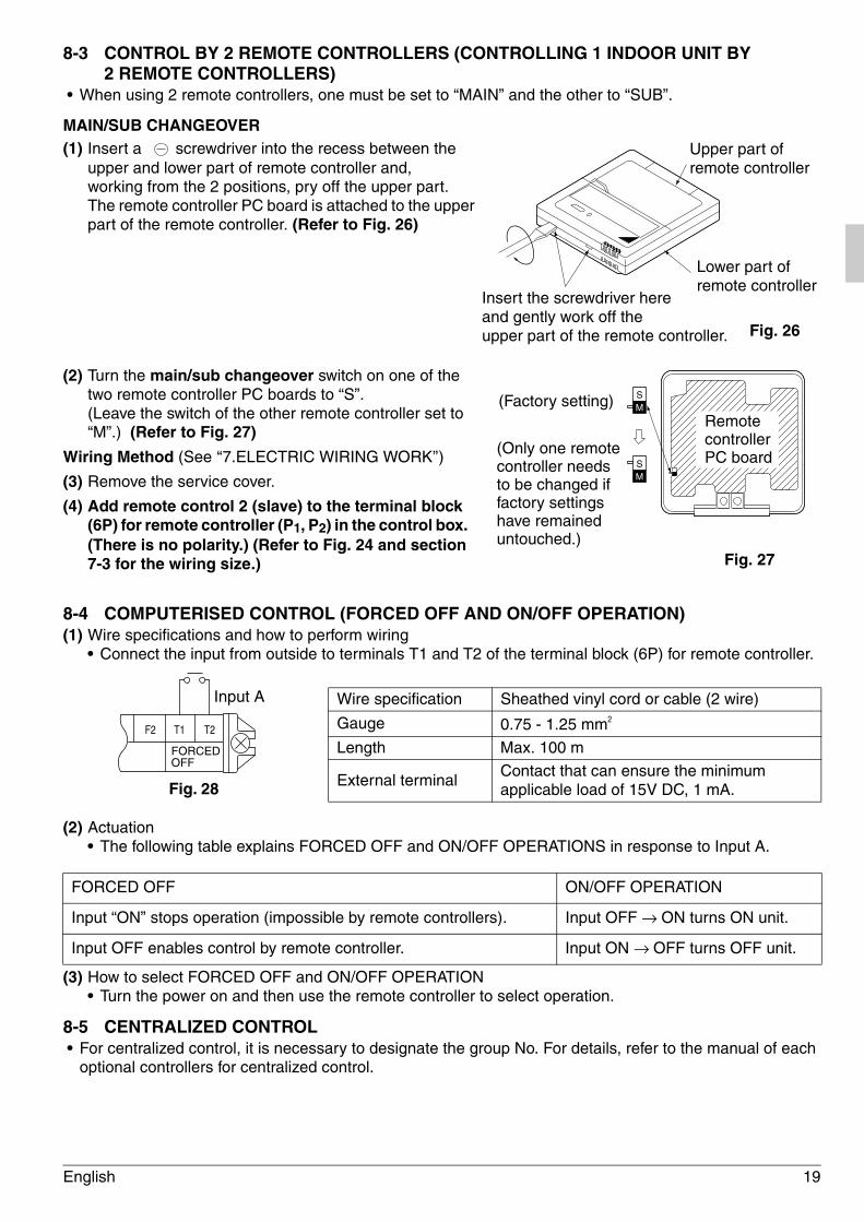
MAIN/SUB CHANGEOVER(1) Insert a screwdriver into the recess between the
upper and lower part of remote controller and, working from the 2 positions, pry off the upper part.The remote controller PC board is attached to the upper part of the remote controller. (Refer to Fig. 26)
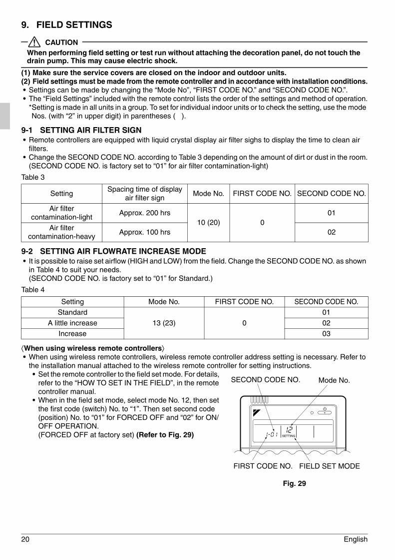
(2) Turn the main/sub changeover switch on one of the two remote controller PC boards to “S”. (Leave the switch of the other remote controller set to “M”.) (Refer to Fig. 27)
Wiring Method (See ‘‘7.ELECTRIC WIRING WORK’’)
(3) Remove the service cover.
(4) Add remote control 2 (slave) to the terminal block (6P) for remote controller (P1, P2) in the control box. (There is no polarity.) (Refer to Fig. 24 and section 7-3 for the wiring size.)
8-4 COMPUTERISED CONTROL (FORCED OFF AND ON/OFF OPERATION) (1) Wire specifications and how to perform wiring
• Connect the input from outside to terminals T1 and T2 of the terminal block (6P) for remote controller.
(2) Actuation • The following table explains FORCED OFF and ON/OFF OPERATIONS in response to Input A.
(3) How to select FORCED OFF and ON/OFF OPERATION • Turn the power on and then use the remote controller to select operation.
8-5 CENTRALIZED CONTROL • For centralized control, it is necessary to designate the group No. For details, refer to the manual of each
optional controllers for centralized control.
Wire specification Sheathed vinyl cord or cable (2 wire)
Gauge 0.75 - 1.25 mm2
Length Max. 100 m
External terminalContact that can ensure the minimum applicable load of 15V DC, 1 mA.
FORCED OFF ON/OFF OPERATION
Input “ON” stops operation (impossible by remote controllers). Input OFF → ON turns ON unit.
Input OFF enables control by remote controller. Input ON → OFF turns OFF unit.
Upper part of remote controller
Lower part of remote controller
Insert the screwdriver here and gently work off the upper part of the remote controller. Fig. 26
S
MS
SM
Remote controller PC board
(Factory setting)
(Only one remote controller needs to be changed if factory settings have remained untouched.)
Fig. 27
Input A
Fig. 28
F2 T1 T2
FORCEDOFF
01_EN_3P156215-16W.fm Page 19 Tuesday, February 21, 2012 4:46 PM
20 English
9. FIELD SETTINGS
CAUTIONWhen performing field setting or test run without attaching the decoration panel, do not touch the drain pump. This may cause electric shock.
(1) Make sure the service covers are closed on the indoor and outdoor units.(2) Field settings must be made from the remote controller and in accordance with installation conditions.• Settings can be made by changing the “Mode No”, “FIRST CODE NO.” and “SECOND CODE NO.”.• The “Field Settings” included with the remote control lists the order of the settings and method of operation.
*Setting is made in all units in a group. To set for individual indoor units or to check the setting, use the mode Nos. (with “2” in upper digit) in parentheses ( ).
9-1 SETTING AIR FILTER SIGN• Remote controllers are equipped with liquid crystal display air filter sighs to display the time to clean air
filters.• Change the SECOND CODE NO. according to Table 3 depending on the amount of dirt or dust in the room.
(SECOND CODE NO. is factory set to “01” for air filter contamination-light)
Table 3
9-2 SETTING AIR FLOWRATE INCREASE MODE• It is possible to raise set airflow (HIGH and LOW) from the field. Change the SECOND CODE NO. as shown
in Table 4 to suit your needs.(SECOND CODE NO. is factory set to “01” for Standard.)
Table 4
⟨When using wireless remote controllers⟩• When using wireless remote controllers, wireless remote controller address setting is necessary. Refer to
the installation manual attached to the wireless remote controller for setting instructions.• Set the remote controller to the field set mode. For details,
refer to the “HOW TO SET IN THE FIELD”, in the remote controller manual.
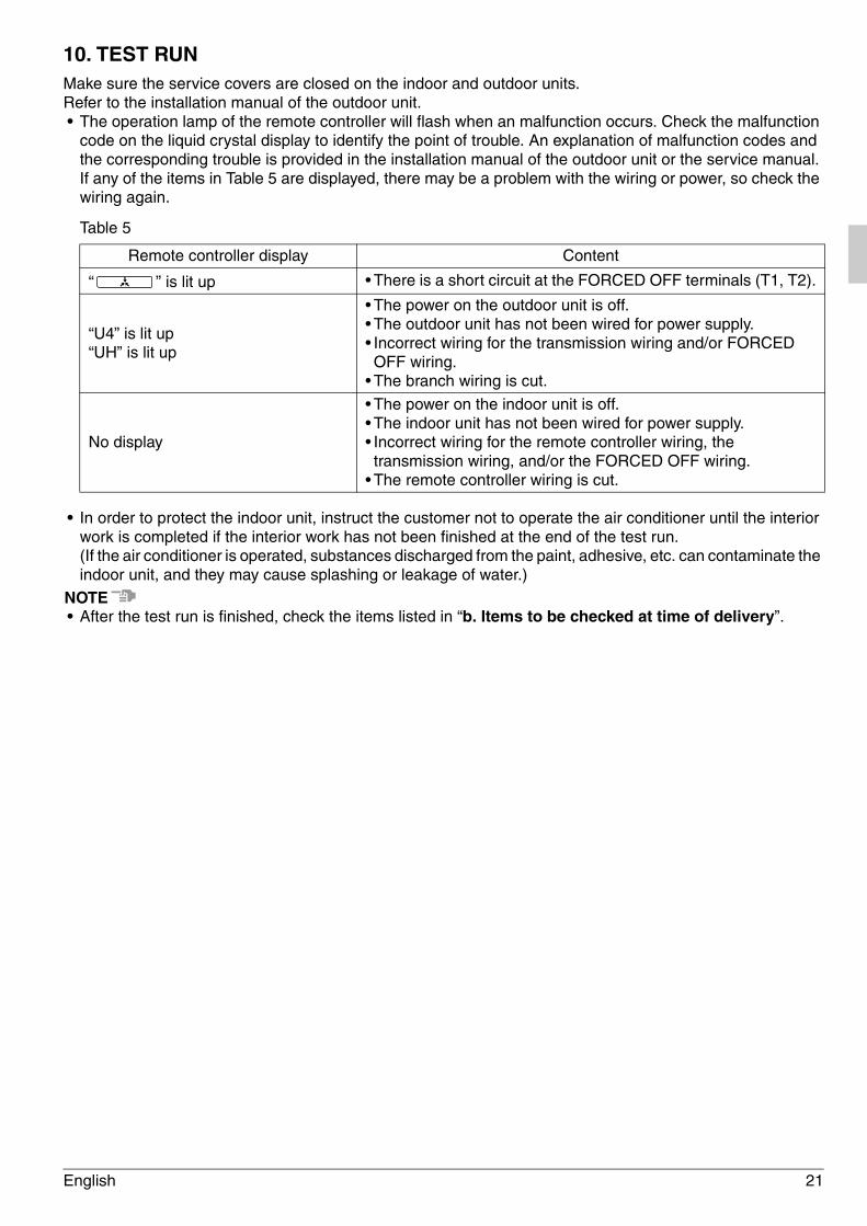
• When in the field set mode, select mode No. 12, then set the first code (switch) No. to “1”. Then set second code (position) No. to “01” for FORCED OFF and “02” for ON/OFF OPERATION. (FORCED OFF at factory set) (Refer to Fig. 29)
SettingSpacing time of display
air filter sign Mode No. FIRST CODE NO. SECOND CODE NO.
Air filter contamination-light
Approx. 200 hrs10 (20) 0
01
Air filter contamination-heavy
Approx. 100 hrs 02
Setting Mode No. FIRST CODE NO. SECOND CODE NO.
Standard
13 (23) 0
01
A little increase 02
Increase 03
SETTING
Mode No.SECOND CODE NO.
FIELD SET MODE
Fig. 29
FIRST CODE NO.
01_EN_3P156215-16W.fm Page 20 Tuesday, February 21, 2012 4:46 PM
English 21
10. TEST RUNMake sure the service covers are closed on the indoor and outdoor units.Refer to the installation manual of the outdoor unit.• The operation lamp of the remote controller will flash when an malfunction occurs. Check the malfunction
code on the liquid crystal display to identify the point of trouble. An explanation of malfunction codes and the corresponding trouble is provided in the installation manual of the outdoor unit or the service manual.If any of the items in Table 5 are displayed, there may be a problem with the wiring or power, so check the wiring again.
Table 5
• In order to protect the indoor unit, instruct the customer not to operate the air conditioner until the interior work is completed if the interior work has not been finished at the end of the test run.(If the air conditioner is operated, substances discharged from the paint, adhesive, etc. can contaminate the indoor unit, and they may cause splashing or leakage of water.)
NOTE• After the test run is finished, check the items listed in “b. Items to be checked at time of delivery”.
Remote controller display Content
“ ” is lit up • There is a short circuit at the FORCED OFF terminals (T1, T2).
“U4” is lit up“UH” is lit up
• The power on the outdoor unit is off.• The outdoor unit has not been wired for power supply.• Incorrect wiring for the transmission wiring and/or FORCED OFF wiring.
• The branch wiring is cut.
No display
• The power on the indoor unit is off.• The indoor unit has not been wired for power supply.• Incorrect wiring for the remote controller wiring, the transmission wiring, and/or the FORCED OFF wiring.
• The remote controller wiring is cut.
01_EN_3P156215-16W.fm Page 21 Tuesday, February 21, 2012 4:46 PM

(1203) HT3P156215-16W EM11A084
00_CV_3P156215-16W.fm Page 2 Tuesday, February 21, 2012 4:42 PM