
Koller Tower Yarder K301-T - kollerna.comkollerna.com/pdf/K301-TUserManual.pdf · Koller Tower...
26
Koller Tower Yarder K301-T Edition 2009 www.kollergmbh.com Koller GmbH Kufsteiner Wald 26 6334 Schwoich bei Kufstein Tel: +43 (0) 5372 63257 Fax: + 43 (0) 5372 63257-7 [email protected]
Transcript of Koller Tower Yarder K301-T - kollerna.comkollerna.com/pdf/K301-TUserManual.pdf · Koller Tower...

Koller Tower Yarder
K301-T
Edition 2009
www.kollergmbh.com
Koller GmbH Kufsteiner Wald 26
6334 Schwoich bei Kufstein
Tel: +43 (0) 5372 63257 Fax: + 43 (0) 5372 63257-7

1
General Prior to the first operation the personnel must be instructed regarding safety regulations, rigging and operation manuals. Only qualified personnel may operate a cable yarding system. It is recommended to attend a training course.
2
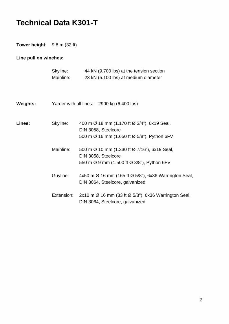
Technical Data K301-T Tower height: 9,8 m (32 ft) Line pull on winches:
Skyline: 44 kN (9.700 lbs) at the tension section Mainline: 23 kN (5.100 lbs) at medium diameter
Weights: Yarder with all lines: 2900 kg (6.400 lbs) Lines: Skyline: 400 m Ø 18 mm (1.170 ft Ø 3/4”), 6x19 Seal, DIN 3058, Steelcore 500 m Ø 16 mm (1.650 ft Ø 5/8”), Python 6FV Mainline: 500 m Ø 10 mm (1.330 ft Ø 7/16”), 6x19 Seal, DIN 3058, Steelcore 550 m Ø 9 mm (1.500 ft Ø 3/8”), Python 6FV Guyline: 4x50 m Ø 16 mm (165 ft Ø 5/8“), 6x36 Warrington Seal, DIN 3064, Steelcore, galvanized Extension: 2x10 m Ø 16 mm (33 ft Ø 5/8"), 6x36 Warrington Seal, DIN 3064, Steelcore, galvanized
3
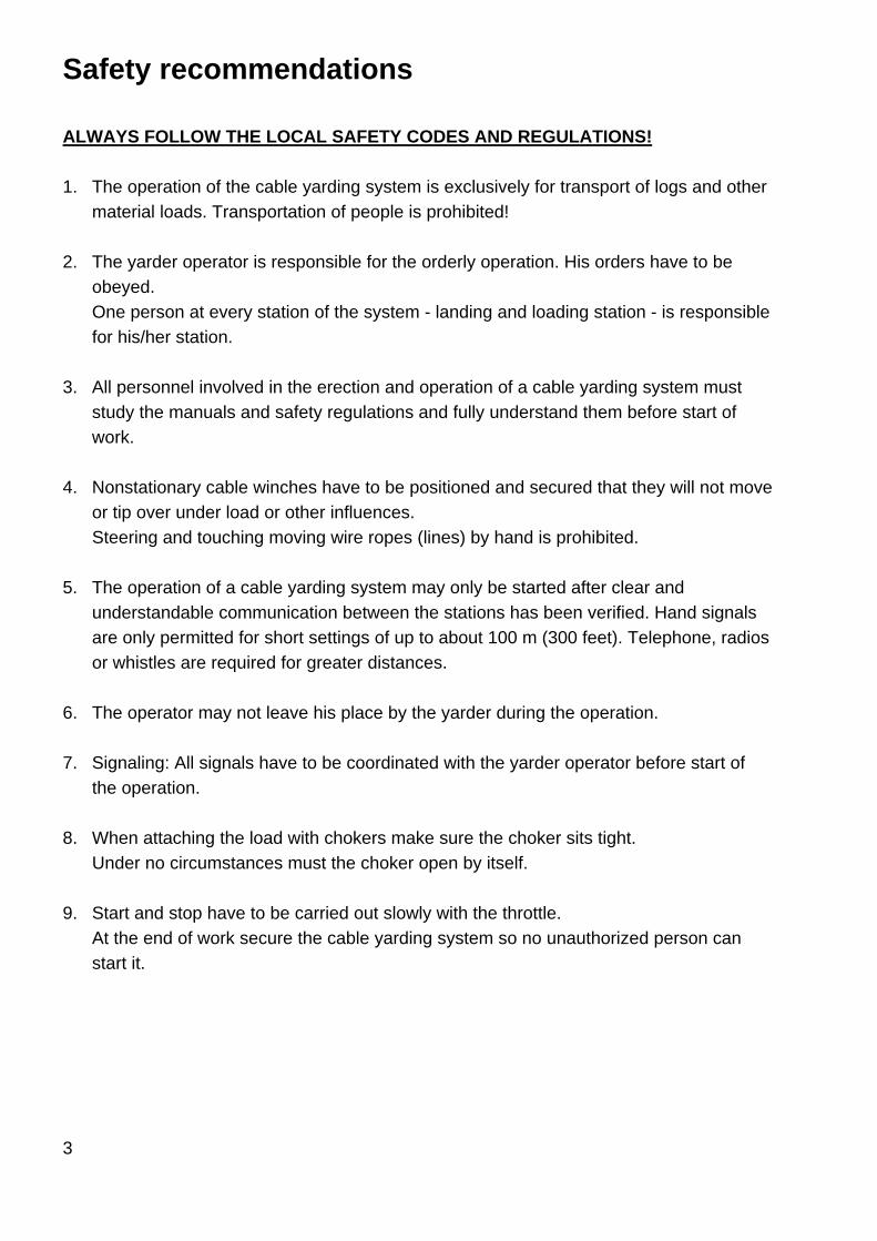
Safety recommendations ALWAYS FOLLOW THE LOCAL SAFETY CODES AND REGULATIONS! 1. The operation of the cable yarding system is exclusively for transport of logs and other
material loads. Transportation of people is prohibited!
2. The yarder operator is responsible for the orderly operation. His orders have to be obeyed. One person at every station of the system - landing and loading station - is responsible for his/her station.
3. All personnel involved in the erection and operation of a cable yarding system must study the manuals and safety regulations and fully understand them before start of work.
4. Nonstationary cable winches have to be positioned and secured that they will not move or tip over under load or other influences. Steering and touching moving wire ropes (lines) by hand is prohibited.
5. The operation of a cable yarding system may only be started after clear and understandable communication between the stations has been verified. Hand signals are only permitted for short settings of up to about 100 m (300 feet). Telephone, radios or whistles are required for greater distances.
6. The operator may not leave his place by the yarder during the operation.
7. Signaling: All signals have to be coordinated with the yarder operator before start of the operation.
8. When attaching the load with chokers make sure the choker sits tight. Under no circumstances must the choker open by itself.
9. Start and stop have to be carried out slowly with the throttle. At the end of work secure the cable yarding system so no unauthorized person can start it.
4
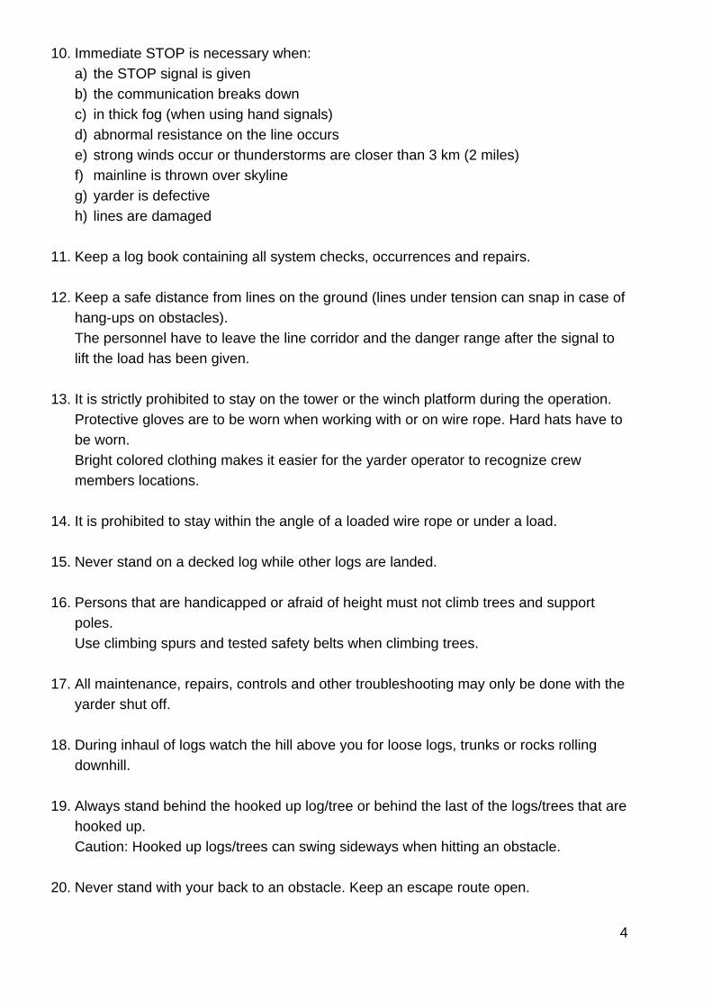
10. Immediate STOP is necessary when: a) the STOP signal is given b) the communication breaks down c) in thick fog (when using hand signals) d) abnormal resistance on the line occurs e) strong winds occur or thunderstorms are closer than 3 km (2 miles) f) mainline is thrown over skyline g) yarder is defective h) lines are damaged
11. Keep a log book containing all system checks, occurrences and repairs.
12. Keep a safe distance from lines on the ground (lines under tension can snap in case of hang-ups on obstacles). The personnel have to leave the line corridor and the danger range after the signal to lift the load has been given.
13. It is strictly prohibited to stay on the tower or the winch platform during the operation. Protective gloves are to be worn when working with or on wire rope. Hard hats have to be worn. Bright colored clothing makes it easier for the yarder operator to recognize crew members locations.
14. It is prohibited to stay within the angle of a loaded wire rope or under a load.
15. Never stand on a decked log while other logs are landed.
16. Persons that are handicapped or afraid of height must not climb trees and support poles. Use climbing spurs and tested safety belts when climbing trees.
17. All maintenance, repairs, controls and other troubleshooting may only be done with the yarder shut off.
18. During inhaul of logs watch the hill above you for loose logs, trunks or rocks rolling downhill.
19. Always stand behind the hooked up log/tree or behind the last of the logs/trees that are hooked up. Caution: Hooked up logs/trees can swing sideways when hitting an obstacle.
20. Never stand with your back to an obstacle. Keep an escape route open.
5
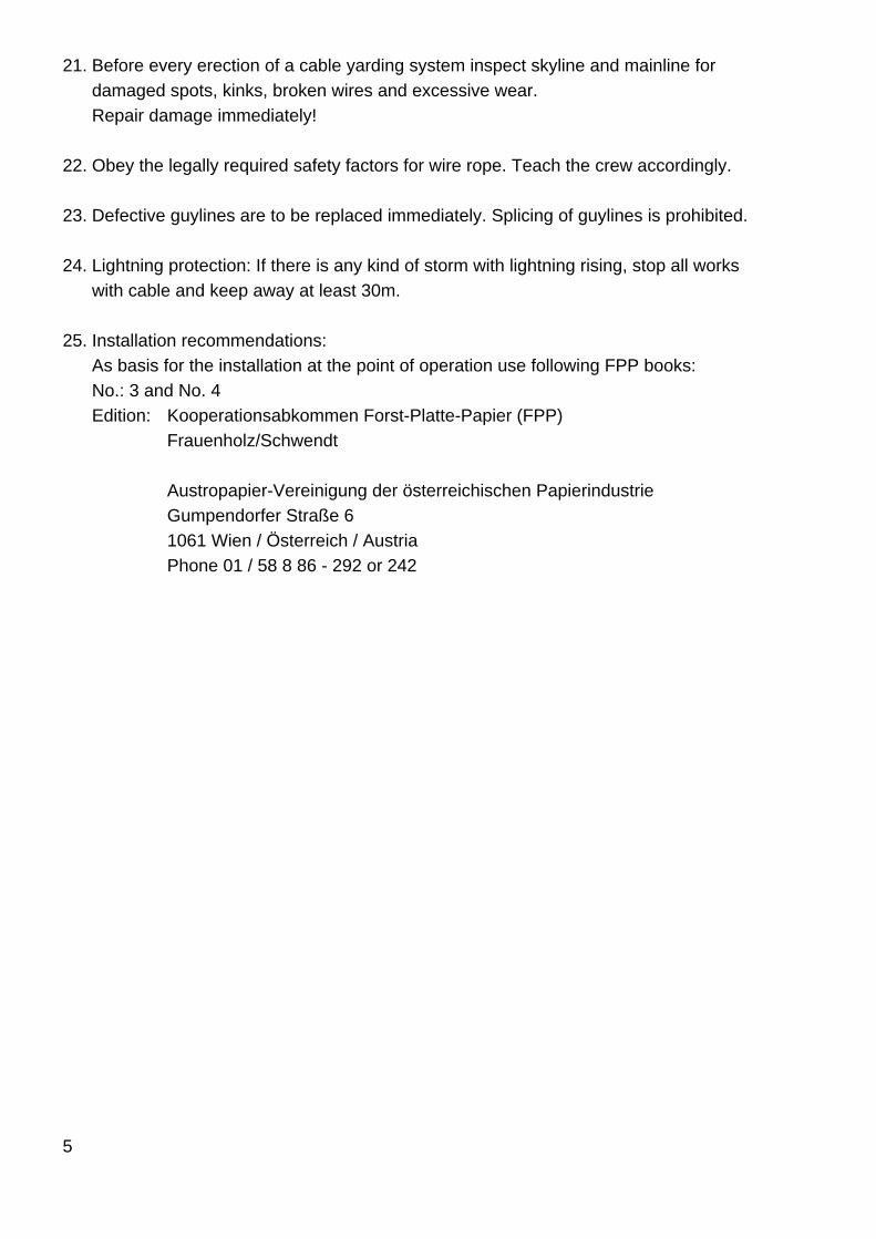
21. Before every erection of a cable yarding system inspect skyline and mainline for damaged spots, kinks, broken wires and excessive wear. Repair damage immediately!
22. Obey the legally required safety factors for wire rope. Teach the crew accordingly.
23. Defective guylines are to be replaced immediately. Splicing of guylines is prohibited.
24. Lightning protection: If there is any kind of storm with lightning rising, stop all works with cable and keep away at least 30m.
25. Installation recommendations: As basis for the installation at the point of operation use following FPP books: No.: 3 and No. 4 Edition: Kooperationsabkommen Forst-Platte-Papier (FPP) Frauenholz/Schwendt Austropapier-Vereinigung der österreichischen Papierindustrie Gumpendorfer Straße 6 1061 Wien / Österreich / Austria Phone 01 / 58 8 86 - 292 or 242

6
Starting Operating rpm-range (at the input shaft of the worm gear) Unloaded: max. 2,500 rpm Loaded: max. 1,500 rpm
7
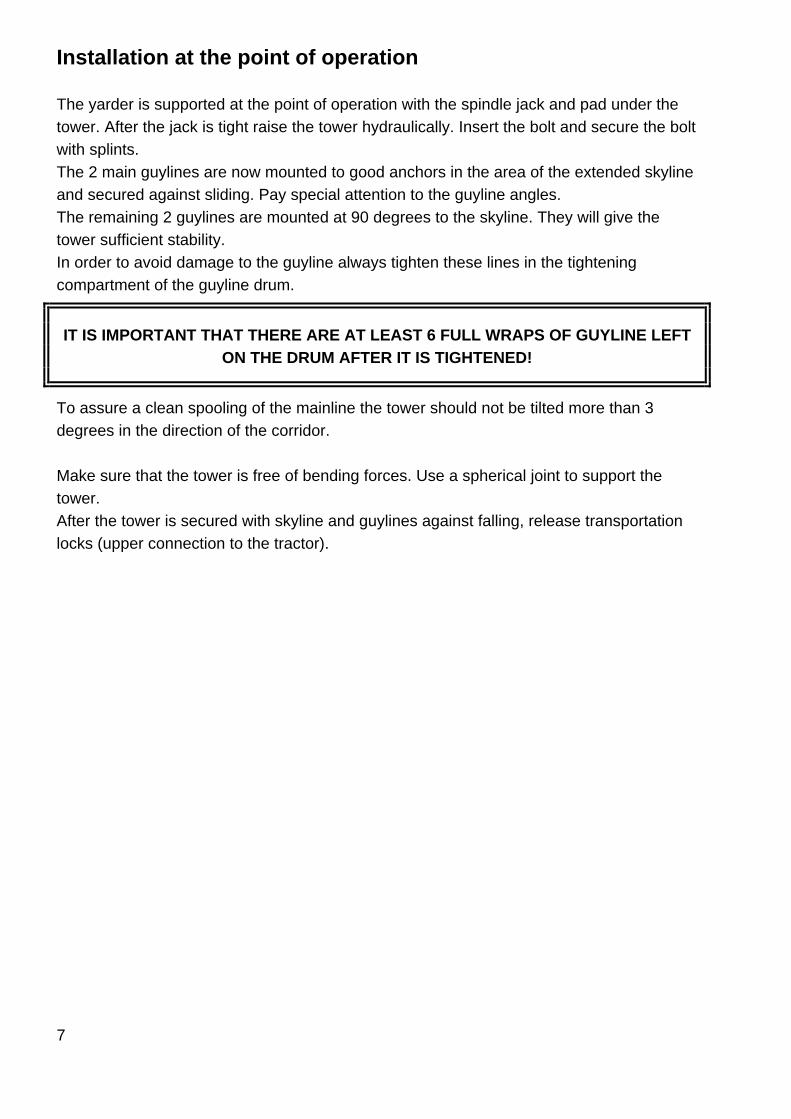
Installation at the point of operation The yarder is supported at the point of operation with the spindle jack and pad under the tower. After the jack is tight raise the tower hydraulically. Insert the bolt and secure the bolt with splints. The 2 main guylines are now mounted to good anchors in the area of the extended skyline and secured against sliding. Pay special attention to the guyline angles. The remaining 2 guylines are mounted at 90 degrees to the skyline. They will give the tower sufficient stability. In order to avoid damage to the guyline always tighten these lines in the tightening compartment of the guyline drum.
IT IS IMPORTANT THAT THERE ARE AT LEAST 6 FULL WRAPS OF GUYLINE LEFT ON THE DRUM AFTER IT IS TIGHTENED!
To assure a clean spooling of the mainline the tower should not be tilted more than 3 degrees in the direction of the corridor. Make sure that the tower is free of bending forces. Use a spherical joint to support the tower. After the tower is secured with skyline and guylines against falling, release transportation locks (upper connection to the tractor).
8
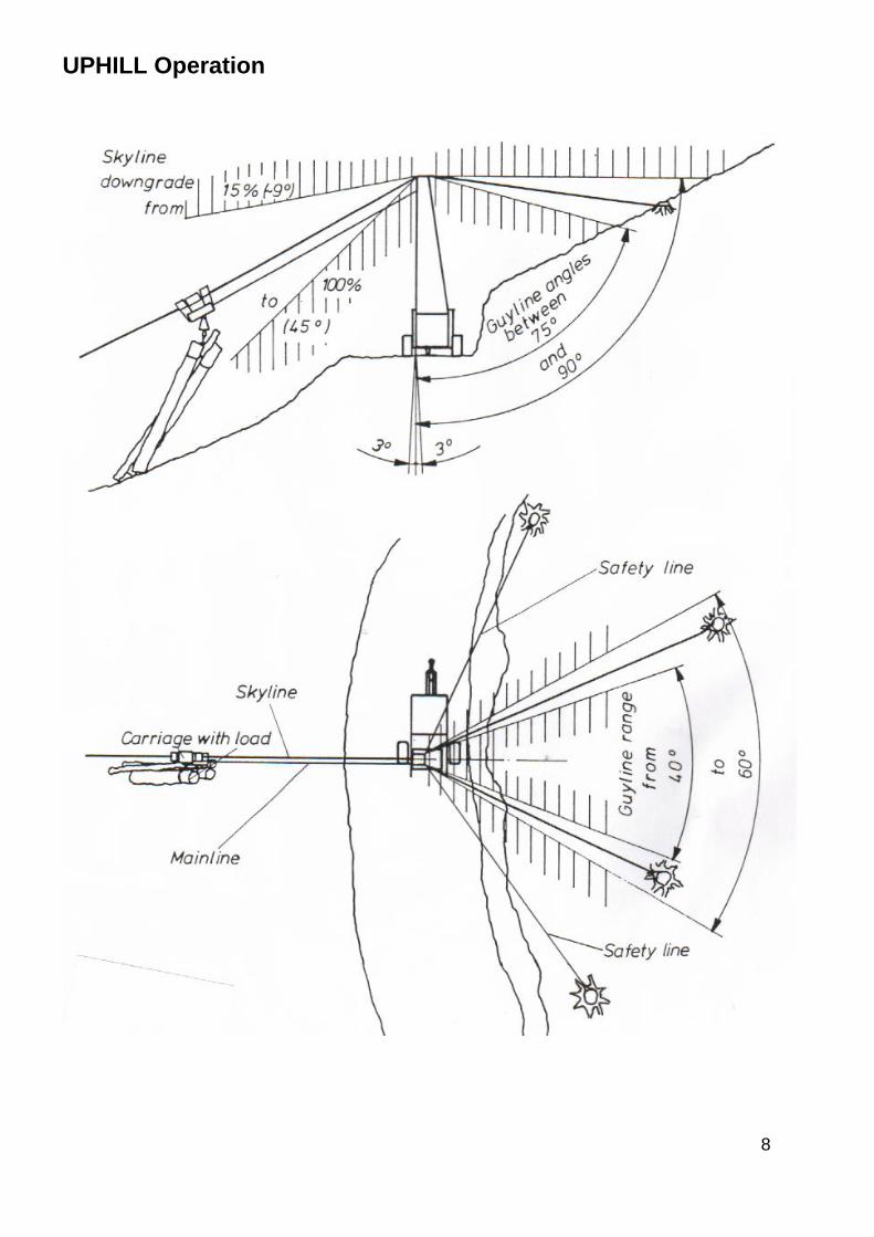
UPHILL Operation

9
Pulling of skyline The skyline is normally unspooled with the engine shut off and the drum in free spooling setting. The operator watches the unspooling of the skyline ready on the brake.
10
Rigging the corridor Skyline anchor
Only secure skyline anchors may be used. If no secure anchors are available multiple tree anchors or artificial anchors have to be used. The skyline or the anchor strap must be secured against slipping up (for example by feeding the line through root loops etc.). Intermediate support and tail spar
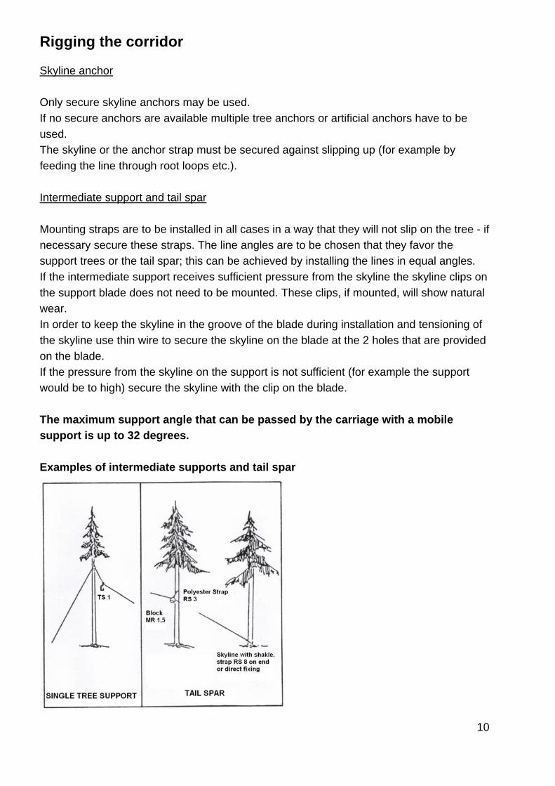
Mounting straps are to be installed in all cases in a way that they will not slip on the tree - if necessary secure these straps. The line angles are to be chosen that they favor the support trees or the tail spar; this can be achieved by installing the lines in equal angles. If the intermediate support receives sufficient pressure from the skyline the skyline clips on the support blade does not need to be mounted. These clips, if mounted, will show natural wear. In order to keep the skyline in the groove of the blade during installation and tensioning of the skyline use thin wire to secure the skyline on the blade at the 2 holes that are provided on the blade. If the pressure from the skyline on the support is not sufficient (for example the support would be to high) secure the skyline with the clip on the blade. The maximum support angle that can be passed by the carriage with a mobile support is up to 32 degrees. Examples of intermediate supports and tail spar
11
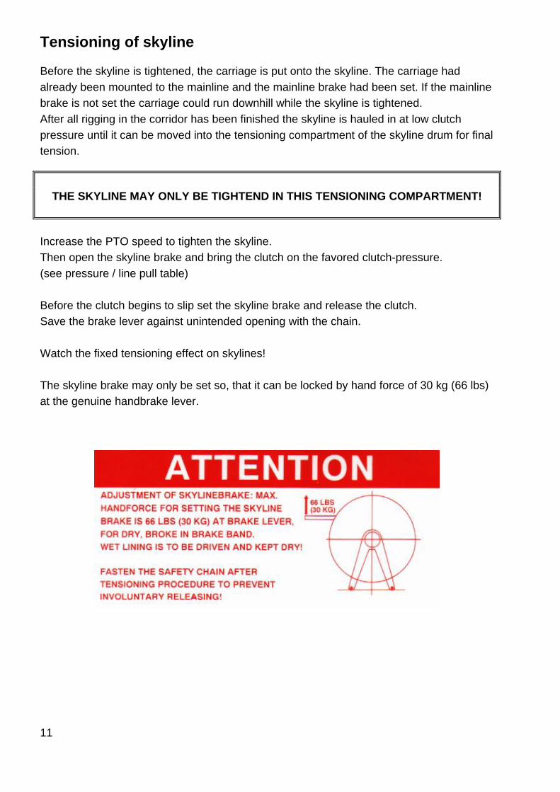
Tensioning of skyline Before the skyline is tightened, the carriage is put onto the skyline. The carriage had already been mounted to the mainline and the mainline brake had been set. If the mainline brake is not set the carriage could run downhill while the skyline is tightened. After all rigging in the corridor has been finished the skyline is hauled in at low clutch pressure until it can be moved into the tensioning compartment of the skyline drum for final tension.
THE SKYLINE MAY ONLY BE TIGHTEND IN THIS TENSIONING COMPARTMENT!
Increase the PTO speed to tighten the skyline. Then open the skyline brake and bring the clutch on the favored clutch-pressure. (see pressure / line pull table) Before the clutch begins to slip set the skyline brake and release the clutch. Save the brake lever against unintended opening with the chain. Watch the fixed tensioning effect on skylines! The skyline brake may only be set so, that it can be locked by hand force of 30 kg (66 lbs) at the genuine handbrake lever.
12
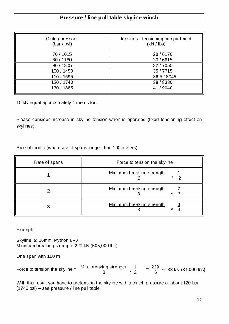
Pressure / line pull table skyline winch
Clutch pressure tension at tensioning compartment (bar / psi) (kN / lbs)
70 / 1015 28 / 6170 80 / 1160 30 / 6615 90 / 1305 32 / 7055
100 / 1450 35 / 7715 110 / 1595 36,5 / 8045 120 / 1740 38 / 8380 130 / 1885 41 / 9040
10 kN equal approximately 1 metric ton. Please consider increase in skyline tension when is operated (fixed tensioning effect on skylines). Rule of thumb (when rate of spans longer than 100 meters):
Rate of spans Force to tension the skyline
1 Minimum breaking strength 1 3 * 2
2 Minimum breaking strength 2 3 * 3
3 Minimum breaking strength 3 3 * 4
Example: Skyline: Ø 16mm, Python 6FV Minimum breaking strength: 229 kN (505,000 lbs) One span with 150 m Force to tension the skyline = Min. breaking strength 1
3 * 2 = 229 6 ≅ 38 kN (84,000 lbs)
With this result you have to pretension the skyline with a clutch pressure of about 120 bar (1740 psi) – see pressure / line pull table.
13
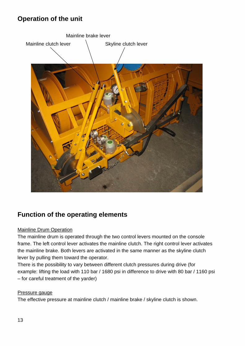
Operation of the unit
Mainline brake lever
Mainline clutch lever Skyline clutch lever
Function of the operating elements Mainline Drum Operation The mainline drum is operated through the two control levers mounted on the console frame. The left control lever activates the mainline clutch. The right control lever activates the mainline brake. Both levers are activated in the same manner as the skyline clutch lever by pulling them toward the operator. There is the possibility to vary between different clutch pressures during drive (for example: lifting the load with 110 bar / 1680 psi in difference to drive with 80 bar / 1160 psi – for careful treatment of the yarder) Pressure gauge The effective pressure at mainline clutch / mainline brake / skyline clutch is shown.
14
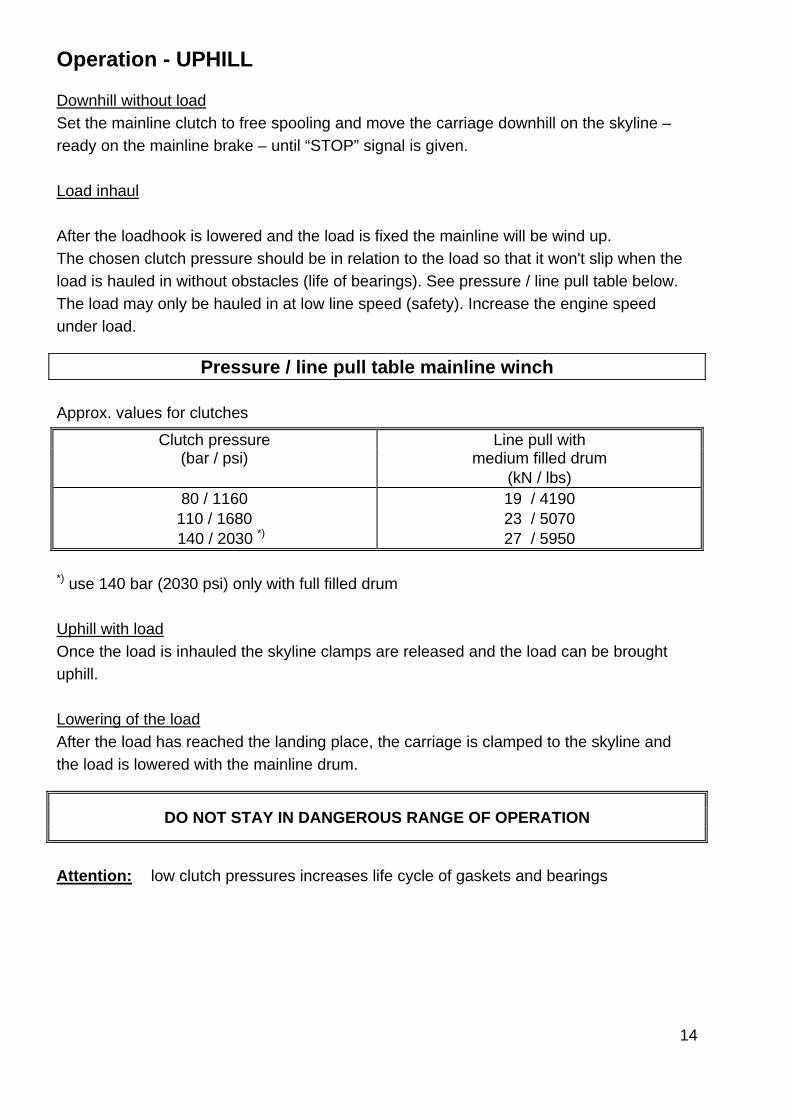
Operation - UPHILL Downhill without load Set the mainline clutch to free spooling and move the carriage downhill on the skyline – ready on the mainline brake – until “STOP” signal is given. Load inhaul After the loadhook is lowered and the load is fixed the mainline will be wind up. The chosen clutch pressure should be in relation to the load so that it won't slip when the load is hauled in without obstacles (life of bearings). See pressure / line pull table below. The load may only be hauled in at low line speed (safety). Increase the engine speed under load.
Pressure / line pull table mainline winch Approx. values for clutches
Clutch pressure Line pull with (bar / psi) medium filled drum
(kN / lbs) 80 / 1160 19 / 4190
110 / 1680 23 / 5070 140 / 2030 *) 27 / 5950
*) use 140 bar (2030 psi) only with full filled drum Uphill with load Once the load is inhauled the skyline clamps are released and the load can be brought uphill. Lowering of the load After the load has reached the landing place, the carriage is clamped to the skyline and the load is lowered with the mainline drum.
DO NOT STAY IN DANGEROUS RANGE OF OPERATION
Attention: low clutch pressures increases life cycle of gaskets and bearings
15
Dismantling The dismantling from the cable system happens opposite to the installation procedure. Slack the skyline slowly and carefully. Dismantle supports and tail spar. If the terrain is favorable, all rigging can be hauled to the landing place by tightening the skyline once again. The carriage should be more than 10 m (33 feet) away from the tower in order to avoid hitting the tower when the skyline is slacked. Take the carriage off the skyline. Dismantle the skyline anchor and reel in the skyline under a very low clutch pressure (40 – 50 bar). Should the skyline entangle during inhaul release it by hand. Never increase the clutch pressure. This could overload the winch axle. The incoming skyline can be steered with a stick to assure smooth spooling onto the drum.
NEVER TOUCH MOVING LINES WITH YOUR HANDS!
Open the pawl from the two backstage guyline drums when you lower the tower!
16
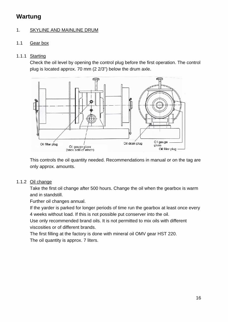
Wartung 1. SKYLINE AND MAINLINE DRUM 1.1 Gear box 1.1.1 Starting
Check the oil level by opening the control plug before the first operation. The control plug is located approx. 70 mm (2 2/3") below the drum axle.
This controls the oil quantity needed. Recommendations in manual or on the tag are only approx. amounts.
1.1.2 Oil change
Take the first oil change after 500 hours. Change the oil when the gearbox is warm and in standstill. Further oil changes annual. If the yarder is parked for longer periods of time run the gearbox at least once every 4 weeks without load. If this is not possible put conserver into the oil. Use only recommended brand oils. It is not permitted to mix oils with different viscosities or of different brands.
The first filling at the factory is done with mineral oil OMV gear HST 220. The oil quantity is approx. 7 liters.

17
Mineral oils CLP (DIN 51502 with min. requirements according to DIN 51517) resp. CC (ISO 3498) for these gear boxes are:
ISO Viscosity class 220 Kinematic viscosity at 40°C min. max.
198 242
SHELL Shell OMALA 220
MOBIL Mobilgear 630
BP BP Energol GR-XP 220
ARAL ARAL Degol BG 220
ESSO Spartan EP 220
OMV OMV Oil HST 220
AGIP AGIP BLASIA 220
TRIBOL ET 280 ISO 220
TEXACO MEROPA 220
18
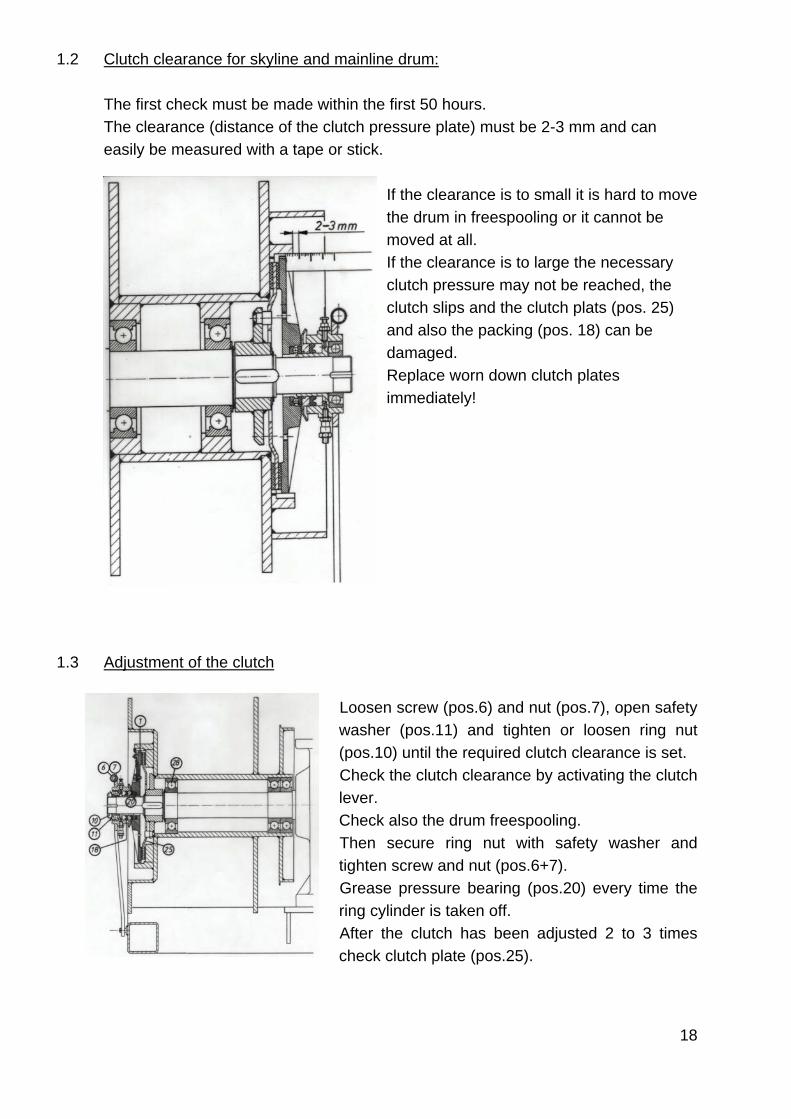
1.2 Clutch clearance for skyline and mainline drum: The first check must be made within the first 50 hours. The clearance (distance of the clutch pressure plate) must be 2-3 mm and can easily be measured with a tape or stick.
If the clearance is to small it is hard to move the drum in freespooling or it cannot be moved at all. If the clearance is to large the necessary clutch pressure may not be reached, the clutch slips and the clutch plats (pos. 25) and also the packing (pos. 18) can be damaged. Replace worn down clutch plates immediately!
1.3 Adjustment of the clutch
Loosen screw (pos.6) and nut (pos.7), open safety washer (pos.11) and tighten or loosen ring nut (pos.10) until the required clutch clearance is set. Check the clutch clearance by activating the clutch lever. Check also the drum freespooling. Then secure ring nut with safety washer and tighten screw and nut (pos.6+7). Grease pressure bearing (pos.20) every time the ring cylinder is taken off. After the clutch has been adjusted 2 to 3 times check clutch plate (pos.25).
19
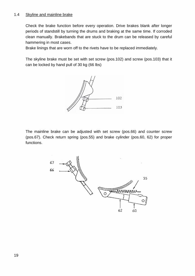
1.4 Skyline and mainline brake
Check the brake function before every operation. Drive brakes blank after longer periods of standstill by turning the drums and braking at the same time. If corroded clean manually. Brakebands that are stuck to the drum can be released by careful hammering in most cases. Brake linings that are worn off to the rivets have to be replaced immediately. The skyline brake must be set with set screw (pos.102) and screw (pos.103) that it can be locked by hand pull of 30 kg (66 lbs)
The mainline brake can be adjusted with set screw (pos.66) and counter screw (pos.67). Check return spring (pos.55) and brake cylinder (pos.60, 62) for proper functions.
20
1.5 Trouble shooting Problem possible cause Mainline has no or 1.5.1 / 1.5.2 / 1.5.3 / 1.5.4 insufficient freespooling 1.5.5 / 1.5.6 / 1.5.7 / 1.5.8 1.5.9 Skyline and mainline drum lack line pull 1.5.2 / 1.5.10 / 1.5.12 Control levers have to be pumped to activate clutch or brake or to reach sufficient pressure 1.5.4 / 1.5.11 Slight knocking from drum during operation 1.5.13 Loud noise from worm wheel gearbox 1.5.14 Possible cause:
1.5.1 Mainline brake needs adjustment 1.5.2 Clutch needs adjustment 1.5.3 Plunger (K3-6-20-16) has to be adjusted with 1 mm (1/32”) play 1.5.4 Gasket (pos.18) in the master cylinder (K3-6-23-00) is worn or defective 1.5.5 Clutch pressure plate (pos.1) stuck in the drum rails 1.5.6 Gasket (pos.18) is out of the cylinder and stuck, clutch pressure plate is not
returned to free position 1.5.7 Drum jammed by a foreign thing 1.5.8 Brake cylinder jammed 1.5.9 Drum bearing defective 1.5.10 New clutch needs time to reach the full line pull 1.5.11 Hydraulic system needs bleeding 1.5.12 Oil or grease on friction surface of clutch plate (defective gasket etc.) 1.5.13 If noise disappears when clutch is engaged slightly, noise comes from play of
clutch pressure plate - no defect! 1.5.14 Check the worm wheel gearbox
21
1.6 Hydraulic operation of the winches
Mainline break, mainline clutch and skyline clutch are hydraulically remote controlled, hydraulic pressure unit is manual.
1.6.1 Control of the function
Check the function of the hydraulic controls and the hydraulic hoses before first start. Defects have to be corrected immediately. Bending radius less than 100 mm (4”) on hydraulic hoses are not permitted! This check of the controls has to include also a check of the control levers, locking rods, springs and toothed plates for wear or damages. Oil the joints of the linkage monthly.
1.6.2 Oil for the hydraulic controls The hydraulic controls are filled with mineral oil Shell C5. Comparable brand mineral oils (for example BP Energol HP 5) can be used also. Oil change
Change the oil once a year before frost period to avoid problems caused by freezing condensation and corrosion.
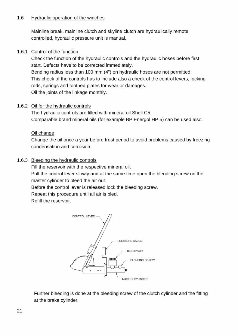
1.6.3 Bleeding the hydraulic controls Fill the reservoir with the respective mineral oil.
Pull the control lever slowly and at the same time open the blending screw on the master cylinder to bleed the air out. Before the control lever is released lock the bleeding screw. Repeat this procedure until all air is bled. Refill the reservoir.
Further bleeding is done at the bleeding screw of the clutch cylinder and the fitting at the brake cylinder.
22
1.6.4 Trouble shooting Problem possible cause Multiple pumping is necessary to reach the max. pressure 1.6.4.1 / 1.6.4.2 / 1.6.4.3 Pressure drops 1.6.4.4 / 1.6.4.5 / 1.6.4.6 Pressure does not completely drop after lever is released (limited freespooling of drum) 1.6.4.7 / 1.6.4.8 / 1.6.4.9 Possible cause: 1.6.4.1 Hydraulic system not completely blend 1.6.4.2 Not enough oil in reservoir 1.6.4.3 Clutch or break needs adjustment 1.6.4.4 Gasket in master cylinder K3-6-23-00 defective 1.6.4.5 Packing in clutch cylinder defective or o-ring of break cylinder defective; oil leaks
at cylinder 1.6.4.6 Leak in the hydraulic system (hoses, fittings) 1.6.4.7 Plunger K3-6-20-16 presses piston of master cylinder when control lever is in 0 - position 1.6.4.8 Piston in master cylinder jammed (dirt, corrosion, ice, ...) 1.6.4.9 Piston of break cylinder jammed
23
2. TOWER Check the condition of the tower, of all lines and line anchoring before each operation.
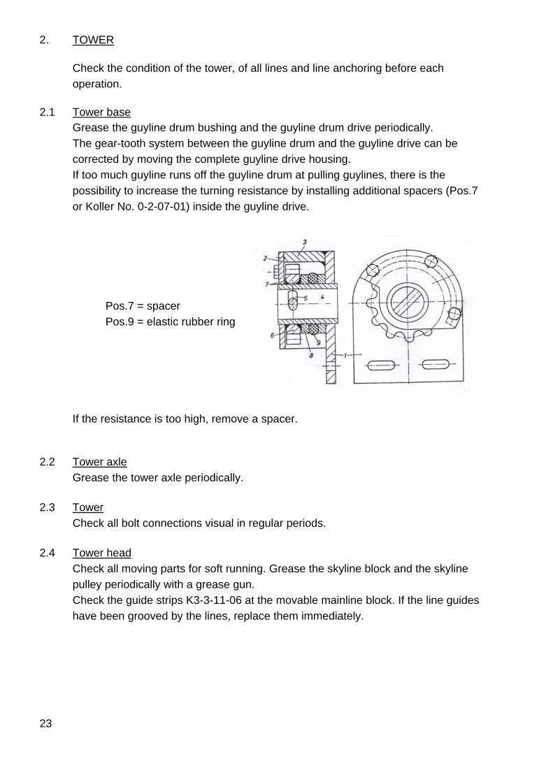
2.1 Tower base Grease the guyline drum bushing and the guyline drum drive periodically.
The gear-tooth system between the guyline drum and the guyline drive can be corrected by moving the complete guyline drive housing. If too much guyline runs off the guyline drum at pulling guylines, there is the possibility to increase the turning resistance by installing additional spacers (Pos.7 or Koller No. 0-2-07-01) inside the guyline drive.
Pos.7 = spacer Pos.9 = elastic rubber ring
If the resistance is too high, remove a spacer. 2.2 Tower axle Grease the tower axle periodically. 2.3 Tower Check all bolt connections visual in regular periods. 2.4 Tower head
Check all moving parts for soft running. Grease the skyline block and the skyline pulley periodically with a grease gun. Check the guide strips K3-3-11-06 at the movable mainline block. If the line guides have been grooved by the lines, replace them immediately.
24
3. LINES
Lines must be replaced when 4 broken wires within 1m (3 ½ feet) occur on the worst spot of the line. The line has to be replaced immediately when extensive wire breaks, swelling, heavy corrosion or excessive wear occur.
Splicing on skylines and mainlines may only be done with longsplices by qualified personnel.
3.1 Skyline
Check the skyline visually every time it is spooled in or out. Also check the part of the skyline that leads into the tensioning compartment of the skyline drum as well as the eye at the end of the skyline.
3.2 Mainline
Check the condition of the mainline daily during spooling in or out. The line needs to be cut in the area of the loadhook as soon as the first broken wire is found. As a precaution the mainline should be cut in this area every 2-3 days. Caution: Spool the new mainline only under pretension to the drum. Loose line spooling reduces the life of the line to a minimum extend.
3.3 Guylines and extensions
Check guylines, guyline extensions and shackles closely before every setup of the yarder. Replace these lines when any kind of damage has been detected.
Splicing of guylines is not permitted!
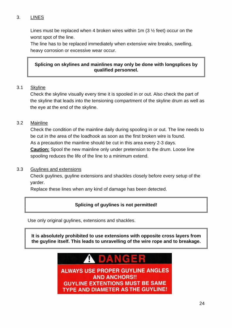
Use only original guylines, extensions and shackles.
It is absolutely prohibited to use extensions with opposite cross layers from the guyline itself. This leads to unravelling of the wire rope and to breakage.
25
4. CARRIAGE Look at the respective operation manual 5. ACCESSORIES 5.1 Intermediate support
Grease the hub on the blade and the axle of the sheave on the jack before installation. Check for wear.
Check the connection of jack and blade as well as the skyline bed on the blade. 5.2 Rigging blocks, tail spar blocks, corner blocks
Check all blocks for condition and function before installation. 5.3 Straps
Check all straps for damage before installation. Polyester straps have a maximum life span of 5 years even if they don't show any damage.
5.4 Come-along
Clean by dripping some motor oil into the come-along every 2 month if not excessively dirty. Check the come-along cable for damage and replace immediately if damage is detected.
The come-along is to be tested yearly by an expert.