LA 17TU LA 25TU LA 40TU - Wärmepumpen und … · Luft/Wasser-Wärmepumpe für Außenaufstellung LA...
27
Luft/Wasser- Wärmepumpe für Außenaufstellung LA 17TU LA 25TU LA 40TU Air-to-Water Heat Pump for Outdoor Installation Pompe à chaleur air-eau pour installation extérieure Montage- und Gebrauchsanweisung Deutsch English Français Instructions d’installation et d’utilisation Installation and Operating Instructions Bestell-Nr. / Order no. / N o de commande : 452163.66.10 FD 8904
Transcript of LA 17TU LA 25TU LA 40TU - Wärmepumpen und … · Luft/Wasser-Wärmepumpe für Außenaufstellung LA...

Luft/Wasser-Wärmepumpe für Außenaufstellung
LA 17TULA 25TULA 40TU
Air-to-Water Heat Pump for Outdoor Installation
Pompe à chaleur air-eau pour installation extérieure
Montage- und Gebrauchsanweisung D
euts
chEn
glis
hFr
ança
isInstructions d’installation et d’utilisation
Installation andOperating Instructions
Bestell-Nr. / Order no. / No de commande : 452163.66.10 FD 8904

www.dimplex.de E-1
Engl
ish
Table of contents1 Please Read Immediately .............................................................................................................E-2
1.1 Important Information..............................................................................................................................E-21.2 Intended Use ..........................................................................................................................................E-21.3 Legal Regulations and Directives ...........................................................................................................E-21.4 Energy-Efficient Use of the Heat Pump ..................................................................................................E-2
2 Purpose of the Heat Pump ...........................................................................................................E-32.1 Application ..............................................................................................................................................E-32.2 Operating Principle .................................................................................................................................E-3
3 Scope of supply.............................................................................................................................E-33.1 Basic Device ...........................................................................................................................................E-33.2 Switch box ..............................................................................................................................................E-43.3 Heat pump controller ..............................................................................................................................E-4
4 Transport........................................................................................................................................E-4
5 Set-up .............................................................................................................................................E-45.1 General ...................................................................................................................................................E-45.2 Condensed Water Pipe...........................................................................................................................E-4
6 Installation .....................................................................................................................................E-56.1 General ...................................................................................................................................................E-56.2 Heating system connection.....................................................................................................................E-56.3 Electrical Connection ..............................................................................................................................E-5
7 Start-Up ..........................................................................................................................................E-67.1 General ...................................................................................................................................................E-67.2 Preparation .............................................................................................................................................E-67.3 Procedure ...............................................................................................................................................E-6
8 Maintenance / Cleaning ................................................................................................................E-68.1 Maintenance ...........................................................................................................................................E-68.2 Cleaning the Heating System .................................................................................................................E-68.3 Cleaning the Air System .........................................................................................................................E-78.4 Maintenance ...........................................................................................................................................E-7
9 Faults / Trouble-Shooting.............................................................................................................E-7
10 Decommissioning / Disposal .......................................................................................................E-7
11 Device Information ........................................................................................................................E-8
Anhang / Appendix / Annexes ............................................................................................................ A-I

English
1
1 Please Read Immediately
1.1 Important Information
ATTENTION!For devices with a refrigerant quantity of 6 kg or more, the refrigeratingcircuit must be checked for leaks each year in compliance with regulation(EC) No. 842/2006.
ATTENTION!The device is not suitable for operation with a frequency converter.
ATTENTION!When transporting the heat pump, ensure that it is not tilted more than45° (in any direction).
ATTENTION!The transport securing device is to be removed prior to commissioning.
ATTENTION!Do not restrict or block up the area around the air inlet or outlet.
ATTENTION!Ensure that there is a clockwise rotating field: With incorrect wiring thestarting of the heat pump is prevented. A corresponding warning isindicated on the display of the heat pump manager (adjust wiring).
ATTENTION!Never use cleaning agents containing sand, soda, acid or chloride asthese can damage the surfaces.
ATTENTION!We recommend the installation of a suitable corrosion protection systemto prevent the formation of deposits (e.g. rust) in the condenser of theheat pump.
ATTENTION!Before opening the device, ensure that all circuits are isolated from thepower supply.
ATTENTION!Any work on the heat pump may only be performed by authorised andqualified after-sales service technicians.
1.2 Intended UseThis device is only intended for use as specified by the manufac-turer. Any other use beyond that intended by the manufacturer isprohibited. This requires the user to abide by the manufacturersproduct information. Please refrain from tampering with or alter-ing the device.
1.3 Legal Regulations and Directives
The construction and design of the heat pump complies with allrelevant EU directives, DIN/VDE regulations (see CE declarationof conformity).When connecting the heat pump to the power supply, the rele-vant VDE, EN and IEC standards are to be fulfilled. Any furtherconnection requirements stipulated by the network operatorsmust also be observed.When connecting the heating system, all applicable regulationsmust also be adhered to.Persons, especially children, who are not capable of operatingthe device safely due to their physical, sensory or mental abilitiesor due to their inexperience or lack of knowledge, must not oper-ate this device without supervision or instruction by the person incharge.Children must be supervised to ensure that they do not play withthe device.
ATTENTION!For devices with a refrigerant quantity of 6 kg or more, the refrigeratingcircuit must be checked for leaks each year in compliance with regulation(EC) No. 842/2006.
More information can be found in the chapter Maintenance /Cleaning.
1.4 Energy-Efficient Use of the Heat Pump
With the purchase of this heat pump you are helping to protectthe environment. A prerequisite for energy-efficient operation isthe correct design of the heat source system and heating system.It is particularly important for the efficiency of a heat pump tokeep the temperature difference between heating water and heatsource as small as possible. For this reason, it is advisable to de-sign the heat source and heating system very carefully. A tem-perature difference of approx. one Kelvin increases thepower consumption by around 2.5%. When designing the he-ating system, it should be borne in mind that special consumerssuch as e.g. domestic hot water preparation should also be takeninto consideration and dimensioned for low temperatures. Un-derfloor heating systems (panel heating) are optimally suitedfor heat pump use on account of the low flow temperatures(30 °C to 40 °C).It is important to ensure that the heat exchangers are not conta-minated during operation because this increases the tempera-ture difference, in turn reducing the COP.Correct adjustment of the heat pump manager is also importantfor energy-efficient use of the heat pump. Further information canbe found in the operating instructions of the heat pump manager.
E-2

Engl
ish
3.1
2 Purpose of the Heat Pump
2.1 ApplicationThe air-to-water heat pump is to be used exclusively for the hea-ting of heating water. It can be used in new or previously existingheating systems.The heat pump is suitable for mono energy and bivalent opera-tion down to an external temperature of -25 °C.Proper defrosting of the evaporator is guaranteed by maintaininga heating water return flow temperature of more than 18 °C du-ring continuous operation.The heat pump is not designed for the increased heat consump-tion required when a building is being dried out. The additionalheat consumption should be met using special devices providedby the customer. If a building is to be dried out in autumn or win-ter, we recommend installing an additional electric heating ele-ment (available as an accessory).
ATTENTION!The device is not suitable for operation with a frequency converter.
2.2 Operating PrincipleSurrounding air is drawn in by the ventilator and fed via the eva-porator (heat exchanger). The evaporator cools the air, i.e. it ex-tracts heat from it. This extracted heat is then transferred to theworking medium (refrigerant) in the evaporator.The heat is “pumped” to a higher temperature level by increasingits pressure with the aid of the electrically driven compressors. Itis then transferred to the heating water using the liquefier (heatexchanger).Electrical energy is used to raise the temperature of the heat inthe environment to a higher level. As the energy extracted fromthe air is transferred to the heating water, this type of device iscalled an air-to-water heat pump.The air-to-water heat pump consists of the main componentsevaporator, ventilator and expansion valve, as well as the low-noise compressors, the liquefier and the electrical control sys-tem.At low ambient temperatures, humidity accumulates on the eva-porator in the form of frost reducing the transfer of heat. The eva-porator is defrosted automatically by the heat pump as required.Steam may be emitted from the air outlet depending on the at-mospheric conditions.
3 Scope of supply
3.1 Basic DeviceThe heat pump is of compact design and is supplied completewith the components listed below.The refrigerating circuit contains the Kyoto protocol approved flu-orinated refrigerant R404A with a GWP value of 3260. The refri-gerant is CFC-free, non-ozone depleting and non-combustible.
1) Evaporator2) Liquefier3) Ventilator4) Switch box5) Compressor 16) Compressor 27) Filter dryer8) Expansion valve9) Collector
www.dimplex.de E-3
English
3.2
3.2 Switch boxThe switch box is located in the heat pump. It can be swung outafter removing the lower front cover and loosening the fasteningscrew located in the upper right-hand corner.The switch box contains the supply connection terminals as wellthe power contactors and the soft starter unit.The plug connectors for the control line are located on the switchbox panel near the pivotal point.
3.3 Heat pump controllerThe heat pump manager included in the scope of supply must beused to operate the air-to-water heat pump.The heat pump manager is a convenient electronic regulationand control device. It controls and monitors the entire heatingsystem based on the external temperature, as well as domestichot water preparation and safety systems.The customer must install the external temperature sensor,which is included in the scope of supply together with fixing.The functions and usage of the heat pump manager are descri-bed in the operating instructions (supplied).
4 TransportATTENTION!
When transporting the heat pump, ensure that it is not tilted more than45° (in any direction).
A wooden pallet should be used to transport the heat pump to itsfinal installation location. The heat pump is fixed to the transportpallet by four transit bolts. These must be removed (only in thecase of the LA17-25TU). The basic device can be transportedwith a lift truck, a crane, or by means of 3/4" pipes fed through theholes in the base plate. The holes are to be covered at the instal-lation location using the 8 black dust caps, which are suppliedwith the device. (only in the case of the LA 17-25TU):The transport eyebolts must be removed after transportation,and the sheet metal openings must be closed using the 4 ventplugs supplied.After transportation, the transport fastening in the device is to beremoved from both sides of the base.
ATTENTION!The transport securing device is to be removed prior to commissioning.
5 Set-up
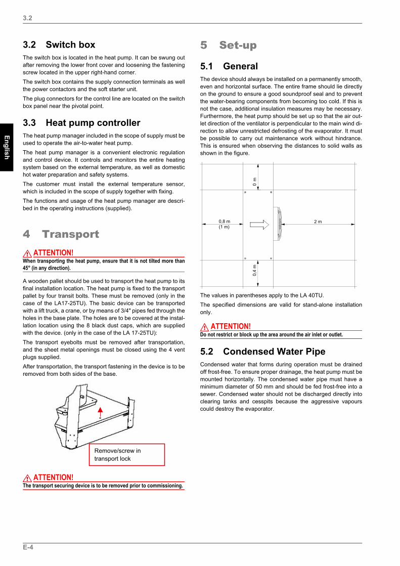
5.1 GeneralThe device should always be installed on a permanently smooth,even and horizontal surface. The entire frame should lie directlyon the ground to ensure a good soundproof seal and to preventthe water-bearing components from becoming too cold. If this isnot the case, additional insulation measures may be necessary.Furthermore, the heat pump should be set up so that the air out-let direction of the ventilator is perpendicular to the main wind di-rection to allow unrestricted defrosting of the evaporator. It mustbe possible to carry out maintenance work without hindrance.This is ensured when observing the distances to solid walls asshown in the figure.
The values in parentheses apply to the LA 40TU.The specified dimensions are valid for stand-alone installationonly.
ATTENTION!Do not restrict or block up the area around the air inlet or outlet.
5.2 Condensed Water PipeCondensed water that forms during operation must be drainedoff frost-free. To ensure proper drainage, the heat pump must bemounted horizontally. The condensed water pipe must have aminimum diameter of 50 mm and should be fed frost-free into asewer. Condensed water should not be discharged directly intoclearing tanks and cesspits because the aggressive vapourscould destroy the evaporator.
E-4

Engl
ish
6.3
6 Installation
6.1 GeneralThe following connections need to be established on the heatpump:
Flow and return flow of the heating system Condensate drainControl line to the heat pump managerPower supply
6.2 Heating system connectionThe heating system connections on the heat pump are to bemade inside the device. Refer to the device information for theconnection sizes. Route the connection hoses out of the devicein a downwards direction. Use a spanner to firmly grip the transi-tions when connecting the heat pump.Before connecting the heating water system to the heat pump,the heating system must be flushed to remove any impurities, re-sidue from sealants, etc. Any accumulation of deposits in the li-quefier could cause the heat pump to completely break down. Once the heating system has been installed, it must be filled, de-aerated and pressure-tested.
Minimum heating water flowThe minimum heating water flow through the heat pump must beassured in all operating states of the heating system. This can beaccomplished, for example, by installing a manifold without diffe-rential pressure.
AntifreezeA method of manual drainage (see illustration) should be provi-ded for heat pumps which are exposed to frost. The antifreezefunction of the heat pump manager is active whenever the mana-ger and the heat circulating pump are ready for operation. If theheat pump is taken out of service or in the event of a power fai-lure, the system has to be drained. The heating circuit should beoperated with a suitable antifreeze if heat pump systems are im-plemented in buildings where a power failure can not be detected(holiday home).
6.3 Electrical ConnectionA standard four-core cable is used for connecting the heat pumpto the power supply.The cable must be provided by the customer. The conductorcross section is selected in accordance with the power consump-tion of the heat pump (see Appendix Device Information) and theapplicable VDE (EN) and VNB regulations.An all-pole disconnecting device with a contact gap of at least3 mm (e.g. utility blocking contactor or power contactor) as wellas a 3-pole circuit breaker with common tripping for all externalconductors must be installed in the power supply (tripping currentin compliance with the Device Information). When connecting,ensure that the incoming supply has a clockwise rotating field.Phase sequence: L1, L2, L3.
ATTENTION!Ensure that there is a clockwise rotating field: With incorrect wiring thestarting of the heat pump is prevented. A corresponding warning isindicated on the display of the heat pump manager (adjust wiring).
The control voltage is supplied via the heat pump manager.The heat pump manager has a 230 V AC-50 Hz power supplyand is connected in compliance with its own operating instruc-tions (16 A fuse).The control lines (not included in the scope of supply) have rec-tangular plug connectors on both ends. One end is connected tothe heat pump manager, and the other end is connected to theswitch box in the heat pump. The plug connections to the heatpump are located on the bottom of the switch box.Two separate lines are used as control lines. One of the lines isdesigned for the 230 V control voltage level, the other for the si-gnal and/or extra-low voltage level.More detailed information can be found in the operating instruc-tions of the heat pump manager.For detailed information, see circuit diagrams in the Appendix.
www.dimplex.de E-5

English
7
7 Start-Up
7.1 GeneralTo ensure that start-up is performed correctly, it should only becarried out by an after-sales service technician authorised by themanufacturer. This may be a condition for extending the guaran-tee (see Warranty Service).
7.2 PreparationThe following items need to be checked prior to start-up:
The heat pump must be fully connected, as described inChapter 6.All valves that could impair the proper flow of the heatingwater in the heating circuit must be open.The air intake and air outlet paths must be clear.The ventilator must turn in the direction indicated by the ar-row.The settings of the heat pump manager must be adapted tothe heating system in accordance with the managers’s oper-ating instructions.Ensure the condensate outflow functions properly.
7.3 ProcedureThe heat pump is started up via the heat pump controller. Adjust-ments should be made in compliance with the instructions.Any faults occurring during operation are also displayed on theheat pump manager and can be corrected as described in theoperating instructions of the heat pump manager.At hot water temperatures under 7 °C, start-up is not possible.The water in the buffer tank must be heated to a minimum of18 °C with the second heat generator.To ensure a problem-free start-up, the following procedure is tobe implemented:1) Close all consumer circuits.2) Ensure that the heat pump has the correct water flow rate.3) Use the controller to select the automatic operating mode.4) In the special functions menu, start the “Start-up” pro-
gramme.5) Wait until a return flow temperature of at least 25 °C has
been reached.6) Now slowly reopen the heating circuit valves in succession
so that the heating water flow is constantly raised by slightlyopening the respective heating circuit. The heating watertemperature in the buffer tank must not be allowed to dropbelow 20 °C during this process. This ensures that the heatpump can be defrosted at any time.
7) When all heat circuits are fully open and a return flow tem-perature of at least 18 °C is maintained, set a minimum vol-ume flow quantity on the overflow valve (where present) andon the heat circulating pump.
8 Maintenance / Cleaning
8.1 MaintenanceTo protect the paintwork, avoid leaning anything against the de-vice or putting objects on the device. External heat pump partscan be wiped with a damp cloth and domestic cleaner.
ATTENTION!Never use cleaning agents containing sand, soda, acid or chloride asthese can damage the surfaces.
To prevent faults due to sediment in the heat exchanger of theheat pump, ensure that the heat exchanger in the heating systemcan not be contaminated. In the event that operating malfunc-tions due to contamination still occur, the system should be clea-ned as described below.
8.2 Cleaning the Heating SystemThe ingress of oxygen into the heating water circuit may result inthe formation of oxidation products (rust), particularly if steelcomponents are used. These products enter the heating systemvia the valves, the circulating pumps and/or plastic pipes. It istherefore essential - in particular with respect to the piping of un-derfloor heating systems - that only diffusion-proof materials areused.
ATTENTION!We recommend the installation of a suitable corrosion protection systemto prevent the formation of deposits (e.g. rust) in the condenser of theheat pump.
Residue from lubricants and sealants may also contaminate theheating water.In the case of severe contamination leading to a reduction in theperformance of the liquefier in the heat pump, the system mustbe cleaned by a heating technician.According to current information, we recommend using a 5%phosphoric acid solution for cleaning purposes. However, if clea-ning needs to be performed more frequently, a 5% formic acidsolution should be used.In either case, the cleaning fluid should be at room temperature.We recommend flushing the heat exchanger in the direction op-posite to the normal flow direction.To prevent acidic cleaning agents from entering the heating sys-tem circuit, we recommend connecting the flushing device di-rectly to the flow and return flow of the liquefier of the heat pump.It is important that the system be thoroughly flushed using appro-priate neutralising agents to prevent damage caused by cleaningagent residue remaining in the system.Acids must be used with great care and all relevant regulations ofthe employers’ liability insurance associations must be adheredto.If in doubt, contact the manufacturer of the chemicals!
E-6
Engl
ish
10
8.3 Cleaning the Air SystemEvaporator, ventilator and condensate outflow should be cleanedof contamination (leaves, twigs, etc.) before each new heatingperiod.
ATTENTION!Before opening the device, ensure that all circuits are isolated from thepower supply.
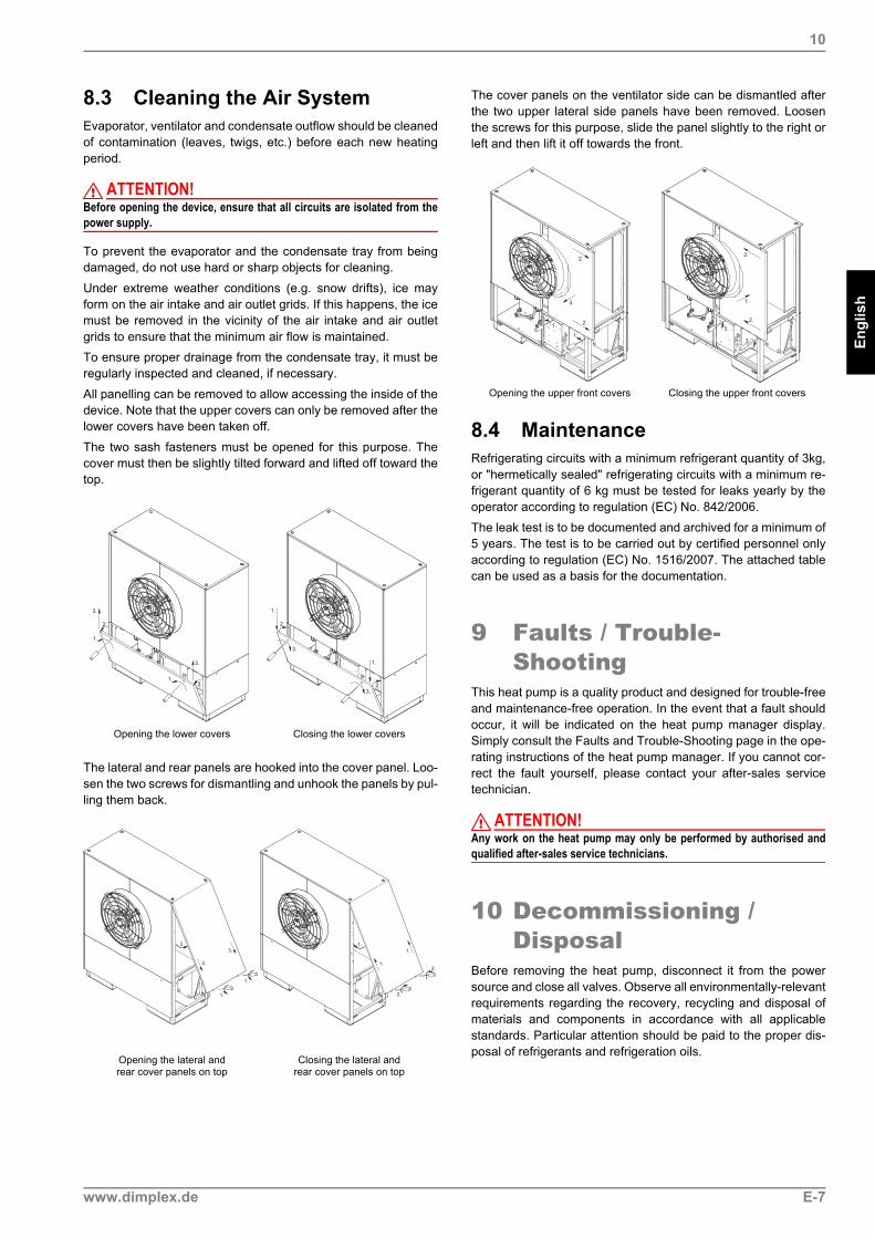
To prevent the evaporator and the condensate tray from beingdamaged, do not use hard or sharp objects for cleaning.Under extreme weather conditions (e.g. snow drifts), ice mayform on the air intake and air outlet grids. If this happens, the icemust be removed in the vicinity of the air intake and air outletgrids to ensure that the minimum air flow is maintained.To ensure proper drainage from the condensate tray, it must beregularly inspected and cleaned, if necessary.All panelling can be removed to allow accessing the inside of thedevice. Note that the upper covers can only be removed after thelower covers have been taken off.The two sash fasteners must be opened for this purpose. Thecover must then be slightly tilted forward and lifted off toward thetop.
The lateral and rear panels are hooked into the cover panel. Loo-sen the two screws for dismantling and unhook the panels by pul-ling them back.
The cover panels on the ventilator side can be dismantled afterthe two upper lateral side panels have been removed. Loosenthe screws for this purpose, slide the panel slightly to the right orleft and then lift it off towards the front.
8.4 MaintenanceRefrigerating circuits with a minimum refrigerant quantity of 3kg,or "hermetically sealed" refrigerating circuits with a minimum re-frigerant quantity of 6 kg must be tested for leaks yearly by theoperator according to regulation (EC) No. 842/2006.The leak test is to be documented and archived for a minimum of5 years. The test is to be carried out by certified personnel onlyaccording to regulation (EC) No. 1516/2007. The attached tablecan be used as a basis for the documentation.
9 Faults / Trouble-Shooting
This heat pump is a quality product and designed for trouble-freeand maintenance-free operation. In the event that a fault shouldoccur, it will be indicated on the heat pump manager display.Simply consult the Faults and Trouble-Shooting page in the ope-rating instructions of the heat pump manager. If you cannot cor-rect the fault yourself, please contact your after-sales servicetechnician.
ATTENTION!Any work on the heat pump may only be performed by authorised andqualified after-sales service technicians.
10 Decommissioning / Disposal
Before removing the heat pump, disconnect it from the powersource and close all valves. Observe all environmentally-relevantrequirements regarding the recovery, recycling and disposal ofmaterials and components in accordance with all applicablestandards. Particular attention should be paid to the proper dis-posal of refrigerants and refrigeration oils.
Opening the lower covers Closing the lower covers
Opening the lateral andrear cover panels on top
Closing the lateral andrear cover panels on top
1.
1.
3.
3.
2.
2.
3.
3.
1.
1.
2.
2.
2.
3.
3.
1.
1.
1.
1.
1.
2.
2.
Opening the upper front covers Closing the upper front covers
1.
1. 2.
3.
2.
3.
3.2.
1.
2.
www.dimplex.de E-7

English
11
11 Device Information1 Type and order code LA 17TU LA 25TU
2 Design2.1 Model / controller Universal / external Universal / external
2.2 Thermal heat metering Integrated Integrated
2.3 Installation location / degree of protection according to EN 60529 Outdoor / IP24 Outdoor / IP24
2.4 Antifreeze condensate tray / heating water Heated / yes1 Heated / yes1
2.5 Performance levels 2 2
3 operating limits3.1 Heating water flow / return flow °C up to 58 ± 2 / from 18 up to 58 ± 2 / from 18
Air (heat source) °C -25 to +35 -25 to +35
4 Performance data / flow rate4.1 Heating water flow rate /
internal pressure differential A7/W35/30 m³/h / Pa 3,4 / 9900 4,5 / 8300
A7/W45/38 m³/h / Pa 2,3 / 5000 3,1 / 4000
A7/W55/45 m³/h / Pa 1,72 / 2900 2,22 / 2100
4.2 Heat output / COP 3 EN 255 EN 14511 EN 255 EN 14511
at A-7 / W35 kW / --- 4 11,2 / 3,0 10,3 / 2,9 17,0 / 3,1 16,7 / 3,0
kW / --- 5 5,5 / 3,1 5,4 / 3,0 9,3 / 3,1 9,1 / 3,0
at A2 / W35 kW / --- 4 14,7 / 3,8 14,6 / 3,7 19,7 / 3,8 19,6 / 3,7
kW / --- 5 8,4 / 3,9 8,2 / 3,8 11,4 / 3,9 11,3 / 3,8
at A7 / W35 kW / --- 4 19,6 / 4,4 26,1 / 4,4
kW / --- 5 10,0 / 4,5 13,9 / 4,5
at A7 / W55 kW / --- 4 18,8 / 2,9 25,0 / 2,9
kW / --- 5 9,2 / 2,8 12,4 / 2,8
at A10 / W35 kW / --- 4 20,9 / 4,9 20,5 / 4,8 28,4 / 4,9 28,2 / 4,8
kW / --- 5 11,1 / 5,0 10,5 / 4,9 15,3 / 5,0 15,0 / 4,9
4.3 Sound power level dB(A) 65 67
4.4 Sound pressure level at a distance of 10 m( air outlet side) 6 dB(A)
37 40
4.5 Air flow m³/h 5500 7500
5 Dimensions, connections and weight5.1 Device dimensions without connections H x W x L mm 1940 x 1600 x 955 (750) 1940 x 1600 x 955 (750)
5.2 Device connections for heating system Inch Thread 1 1/4" flat sealing Thread 1 1/2" flat sealing
5.3 Weight of the transportable unit(s) incl. packaging kg 436 510
5.4 Refrigerant; total filling weight type / kg R404A / 8.2 R404A / 10.2
5.5 Lubricant; total filling quantity type / litres Polyolester (POE) / 2.9 Polyolester (POE) / 3.8
6 Electrical connection6.1 Nominal voltage; fuse protection V / A 400 / 16 400 / 25
6.2 Starting current with soft starter A 17 22
6.3 Nominal power consumption A2 W35/ max. consumption 3 ,4kW 3,9 / 7,5 5,3 / 9,2
6.4 Nominal current A2 W35 / cosϕ4 A / --- 8,6 / 0,8 11,8 / 0,8
6.5 Max. power consumption of compressor protection(per compressor) W 70, thermostatically controlled 70, thermostatically controlled
7 Complies with the European safety regulations 7 7
8 Additional model featuresType of defrosting (according to need) Reverse circulation Reverse circulation
1. The heat circulating pump and the heat pump controller must always be ready for operation.2. Minimum heating water flow rate
3. These data indicate the size and capacity of the system according to EN 255 (10K at A2) and EN 14511 (5K at A7) without weather-proof protective cover. For an analysis of theeconomic and energy efficiency of the system, other parameters, in particular the defrosting capacity, the bivalence point and the regulation, should also be taken into consideration.The specified values have the following meaning, e.g. A7 / W35: External air temperature 7 °C and heating water flow temperature 35 °C.
4. 2-compressor operating mode
5. 1-compressor operating mode6. The specified sound pressure level corresponds to the operating noise of the heat pump in heating operation with a flow temperature of 35°C.
7. See CE declaration of conformity
E-8
Engl
ish
11
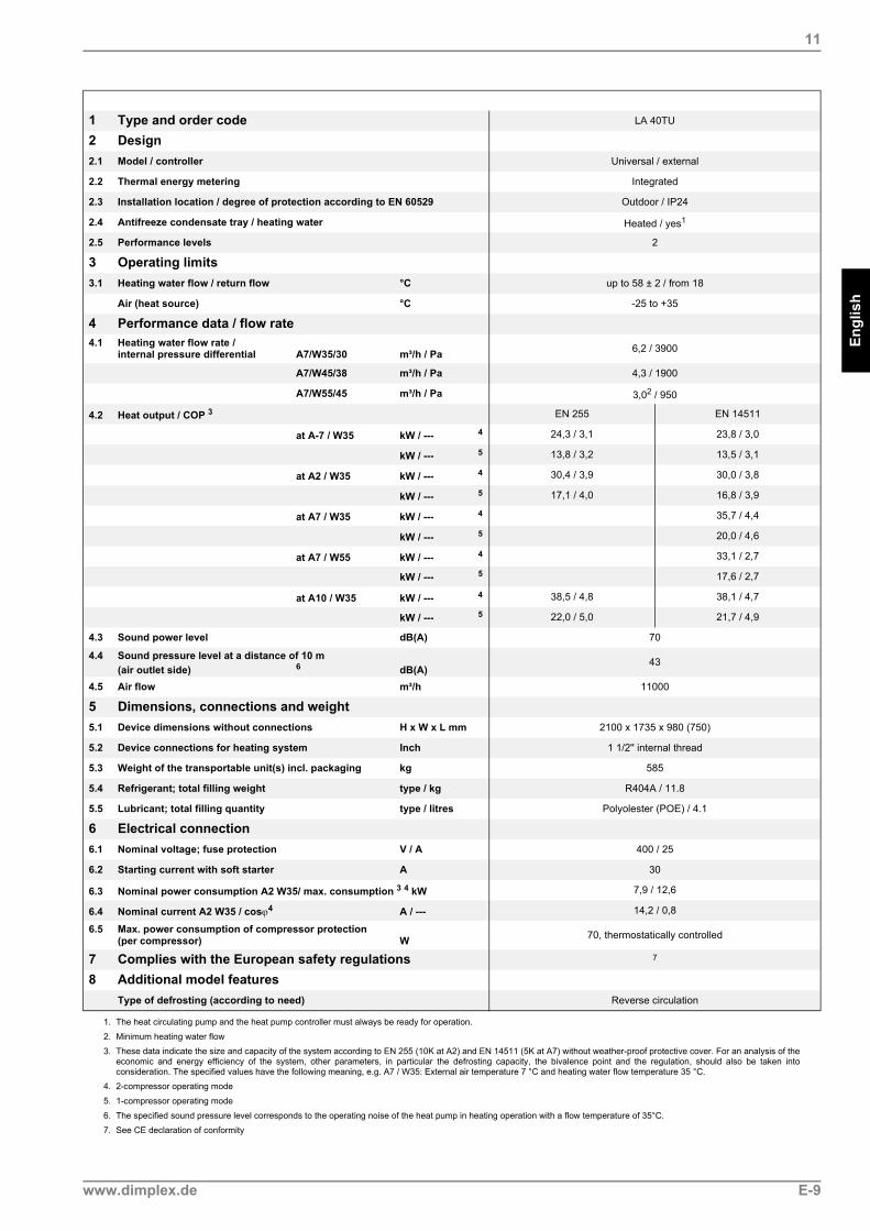
1 Type and order code LA 40TU
2 Design2.1 Model / controller Universal / external
2.2 Thermal energy metering Integrated
2.3 Installation location / degree of protection according to EN 60529 Outdoor / IP24
2.4 Antifreeze condensate tray / heating water Heated / yes1
2.5 Performance levels 2
3 Operating limits3.1 Heating water flow / return flow °C up to 58 ± 2 / from 18
Air (heat source) °C -25 to +35
4 Performance data / flow rate4.1 Heating water flow rate /
internal pressure differential A7/W35/30 m³/h / Pa 6,2 / 3900
A7/W45/38 m³/h / Pa 4,3 / 1900
A7/W55/45 m³/h / Pa 3,02 / 950
4.2 Heat output / COP 3 EN 255 EN 14511
at A-7 / W35 kW / --- 4 24,3 / 3,1 23,8 / 3,0
kW / --- 5 13,8 / 3,2 13,5 / 3,1
at A2 / W35 kW / --- 4 30,4 / 3,9 30,0 / 3,8
kW / --- 5 17,1 / 4,0 16,8 / 3,9
at A7 / W35 kW / --- 4 35,7 / 4,4
kW / --- 5 20,0 / 4,6
at A7 / W55 kW / --- 4 33,1 / 2,7
kW / --- 5 17,6 / 2,7
at A10 / W35 kW / --- 4 38,5 / 4,8 38,1 / 4,7
kW / --- 5 22,0 / 5,0 21,7 / 4,9
4.3 Sound power level dB(A) 70
4.4 Sound pressure level at a distance of 10 m(air outlet side) 6 dB(A)
43
4.5 Air flow m³/h 11000
5 Dimensions, connections and weight5.1 Device dimensions without connections H x W x L mm 2100 x 1735 x 980 (750)
5.2 Device connections for heating system Inch 1 1/2'' internal thread
5.3 Weight of the transportable unit(s) incl. packaging kg 585
5.4 Refrigerant; total filling weight type / kg R404A / 11.8
5.5 Lubricant; total filling quantity type / litres Polyolester (POE) / 4.1
6 Electrical connection6.1 Nominal voltage; fuse protection V / A 400 / 25
6.2 Starting current with soft starter A 30
6.3 Nominal power consumption A2 W35/ max. consumption 3 4 kW 7,9 / 12,6
6.4 Nominal current A2 W35 / cosϕ4 A / --- 14,2 / 0,8
6.5 Max. power consumption of compressor protection(per compressor) W 70, thermostatically controlled
7 Complies with the European safety regulations 7
8 Additional model featuresType of defrosting (according to need) Reverse circulation
1. The heat circulating pump and the heat pump controller must always be ready for operation.
2. Minimum heating water flow3. These data indicate the size and capacity of the system according to EN 255 (10K at A2) and EN 14511 (5K at A7) without weather-proof protective cover. For an analysis of the
economic and energy efficiency of the system, other parameters, in particular the defrosting capacity, the bivalence point and the regulation, should also be taken intoconsideration. The specified values have the following meaning, e.g. A7 / W35: External air temperature 7 °C and heating water flow temperature 35 °C.
4. 2-compressor operating mode
5. 1-compressor operating mode
6. The specified sound pressure level corresponds to the operating noise of the heat pump in heating operation with a flow temperature of 35°C.7. See CE declaration of conformity
www.dimplex.de E-9

www.dimplex.de A-I
Anh
ang
· App
endi
x · A
nnex
es
Anhang / Appendix / Annexes1 Maßbilder / Dimension Drawings / Schémas cotés................................................................... A-II
1.1 Maßbild / Dimension Drawing / Schéma coté LA 17TU..........................................................................A-II1.2 Maßbild / Dimension Drawing / Schéma coté LA 25TU.........................................................................A-III1.3 Maßbild / Dimension Drawing / Schéma coté LA 40TU.........................................................................A-IV
2 Diagramme / Diagrams / Diagrammes........................................................................................ A-V2.1 Kennlinien / Characteristic Curves / Courbes caractéristiques LA 17TU................................................A-V2.2 Kennlinien / Characteristic Curves / Courbes caractéristiques LA 25TU...............................................A-VI2.3 Kennlinien / Characteristic Curves / Courbes caractéristiques LA 40TU..............................................A-VII
3 Stromlaufpläne / Circuit Diagrams / Schémas électriques.................................................... A-VIII3.1 Steuerung / Control / Commande LA 17TU - LA 40TU .......................................................................A-VIII3.2 Last / Load / Charge LA 17TU - LA 40TU..............................................................................................A-IX3.3 Anschlussplan / Circuit Diagram / Schéma électrique LA 17TU - LA 40TU ...........................................A-X3.4 Legende / Legend / Légende LA 17TU - LA 40TU ................................................................................A-XI
4 Hydraulische Prinzipschemen / Hydraulic Plumbing Diagram / Schémas hydrauliques.... A-XII4.1 Monoenergetische Anlage mit doppelt differenzdrucklosem Verteiler..................................................A-XII4.2 Monoenergetische Anlage mit zwei Heizkreisen und Warmwasserbereitung .....................................A-XIII4.3 Legende / Legend / Légende.............................................................................................................. A-XIV
5 Konformitätserklärung / Declaration of Conformity / Déclaration de conformité ................A-XV
6 Wartungsarbeiten / Maintenance work / Opérations de maintenance..................................A-XVI

Anhang · A
ppendix · Annexes
1
1 Maßbilder / Dimension Drawings / Schémas cotés
1.1 Maßbild / Dimension Drawing / Schéma coté LA 17TU
A-II

Anh
ang
· App
endi
x · A
nnex
es
1.2
1.2 Maßbild / Dimension Drawing / Schéma coté LA 25TU
www.dimplex.de A-III

Anhang · A
ppendix · Annexes
1.3
1.3 Maßbild / Dimension Drawing / Schéma coté LA 40TU
A (
1 :
5 )
A
1734
2100
105
682
1676
Hau
ptw
indr
icht
ung
bei f
reie
r A
ufst
ellu
ngM
ain
win
d di
rect
ion
with
free
-sta
ndin
g in
stal
latio
nD
irect
ion
des
vent
s do
min
ants
en
cas
d’in
stal
latio
n su
r em
plac
emen
t dég
agé
Rin
gsch
raub
en fü
r K
rant
rans
port
nac
h A
ufst
ellu
ng a
ussc
hrau
ben!
Rem
ove
eyeb
olts
for
cran
e tr
ansp
ort a
fter
set-
up!
Apr
ès in
stal
latio
n, d
évis
ser
les
anne
aux
de le
vage
ser
vant
au
grut
age
!
Luftr
icht
ung
Dire
ctio
n of
air
flow
Sen
s de
l’ai
rS
tand
fläch
e un
d M
inde
stab
stän
deB
ase
area
and
min
imum
cle
aran
ces
Sur
face
de
pose
et é
cart
emen
ts m
inim
aux
1032
716
Luftr
icht
ung
Dire
ctio
n of
air
flow
Sen
s de
l’ai
r
569
748
690
29
0
89
159
249
479
69,5
43
12
Leg
end
e O
pti
on
sei
tlic
he
An
sch
lüss
e:L
egen
d -
op
tio
nal
sid
e co
nn
ecti
on
s:L
égen
de
racc
ord
emen
ts la
téra
ux
en o
pti
on
:
1 3 42
824 n
8191220
1467
180,
586
,5
980
081146236
492
0
113
209
313
1,66
m
0,67m
0,03m
0,03m
0,68
m
0 m
0,4
m
1m2m
0,08m
0,2m
0,05
m
0,41
m
897
Dur
chfü
hrun
gsbe
reic
hK
onde
nsat
abla
ufE
lekt
role
itung
en
Fee
dthr
ough
are
aC
onde
nsat
e ou
tflow
,E
lect
ric c
able
s
Zon
e de
pas
sage
Éco
ulem
ent d
es c
onde
nsat
s,co
ndui
tes
élec
triq
ues
Hei
zung
srüc
klau
fE
inga
ng in
die
WP
1 1/
2" In
neng
ewin
de
Hea
t ret
urn
flow
Inpu
t int
o th
e H
P1
1/2"
inte
rnal
thre
ad
Circ
uit d
e ch
auffa
ge r
etou
rE
ntré
e da
ns la
PA
CF
ileta
ge in
térie
ur 1
1/2
"
Hei
zung
svor
lauf
Aus
gang
aus
der
WP
1 1/
2" In
neng
ewin
de
Hea
t flo
wO
utpu
t fro
m th
e H
P1
1/2"
inte
rnal
thre
ad
Circ
uit d
e ch
auffa
ge a
ller
Sor
tie d
e la
PA
CF
ileta
ge in
térie
ur 1
1/2
"
LuftrichtungDirection of air flow
Sens de l’air
Hea
t ret
urn
flow
inpu
t int
o H
P1
1/2"
inte
rnal
thre
ad
Hea
t flo
w o
utpu
t fro
m H
P1
1/2"
inte
rnal
thre
ad
Feed
thro
ugh
area
for c
onde
nsat
e ou
tflow
Feed
thro
ugh
area
for e
lect
ric c
able
s
Hei
zung
srüc
klau
f Ein
gang
in d
ie W
P1
1/2"
Inne
ngew
inde
Hei
zung
svor
lauf
Aus
gang
aus
der
WP
1 1/
2" In
neng
ewin
de
Dur
chfü
hrun
gsbe
reic
h K
onde
nsat
abla
uf
Dur
chfü
hrun
gsbe
reic
h E
lekt
role
itung
en
Circ
uit d
e ch
auffa
ge re
tour
, ent
rée
dans
la P
AC
File
tage
inté
rieur
1 1
/2"
Circ
uit d
e ch
auffa
ge a
ller,
sorti
e de
la P
AC
File
tage
inté
rieur
1 1
/2"
Pas
sage
de
la c
ondu
ite d
’éco
ulem
ent d
es c
onde
nsat
s
Pas
sage
des
con
duite
s él
ectri
ques
A-IV
Anh
ang
· App
endi
x · A
nnex
es
2.1
2 Diagramme / Diagrams / Diagrammes
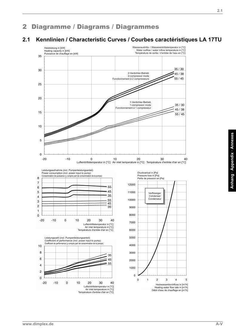
2.1 Kennlinien / Characteristic Curves / Courbes caractéristiques LA 17TU
www.dimplex.de A-V
Anhang · A
ppendix · Annexes
2.2
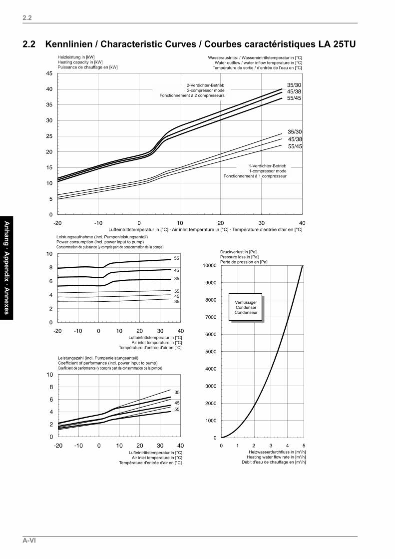
2.2 Kennlinien / Characteristic Curves / Courbes caractéristiques LA 25TU
A-VI
Anh
ang
· App
endi
x · A
nnex
es
2.3
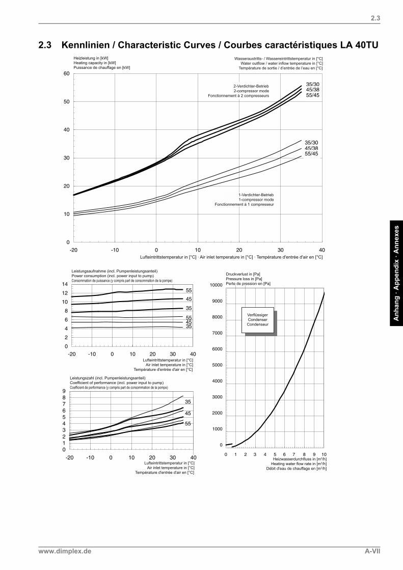
2.3 Kennlinien / Characteristic Curves / Courbes caractéristiques LA 40TU
www.dimplex.de A-VII

Anhang · A
ppendix · Annexes
3
3 Stromlaufpläne / Circuit Diagrams / Schémas électriques
3.1 Steuerung / Control / Commande LA 17TU - LA 40TU
A-VIII
Anh
ang
· App
endi
x · A
nnex
es
3.2
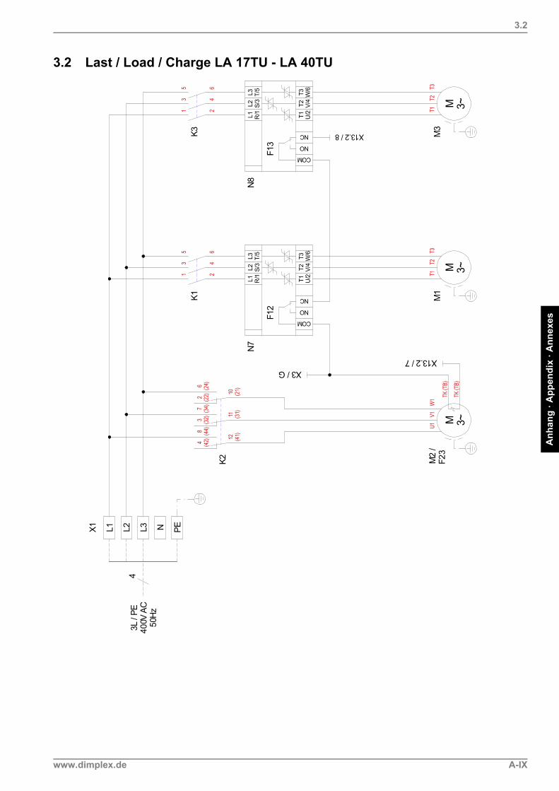
3.2 Last / Load / Charge LA 17TU - LA 40TU
www.dimplex.de A-IX

Anhang · A
ppendix · Annexes
3.3
3.3 Anschlussplan / Circuit Diagram / Schéma électrique LA 17TU - LA 40TU
A-X

Anh
ang
· App
endi
x · A
nnex
es
3.4
3.4 Legende / Legend / Légende LA 17TU - LA 40TUE1 Ölsumpfheizung Verdichter 1 Oil sump heater for compressor 1 Chauffage à carter d'huile compresseur 1E2 Ölsumpfheizung Verdichter 2 Oil sump heater for compressor 2 Chauffage à carter d'huile compresseur 2E4 Düsenringheizung Ventilator Nozzle ring heater for ventilator Chauffage à couronne perforée ventilateur
F4 Pressostat Hochdruck High-pressure controller Pressostat haute pressionF5 Pressostat Niederdruck Low-pressure controller Pressostat basse pressionF7 Thermostat Heißgasüberwachung Thermostat for hot gas monitoring Thermostat surveillance gaz de chauffageF12 Störung N7 Fault N7 Défaut N7F13 Störung N8 Fault N8 Défaut N8F23 Störung Ventilator Ventilator fault Défaut ventilateur
K1 Schütz Verdichter 1 Contactor compressor 1 Contacteur compresseur 1K2 Lastrelais Ventilator Load relay for fan Relais de charge ventilateurK3 Schütz Verdichter 2 Contactor compressor 2 Contacteur compresseur 2
M1 Verdichter 1 Compressor 1 Compresseur 1M2 Ventilator Ventilator VentilateurM3 Verdichter 2 Compressor 2 Compresseur 2
N1 Wärmepumpenmanager Heat pump manager Gestionnaire de pompe à chaleurN7 Sanftanlaufsteuerung Verdichter 1 Soft start control for compressor 1 Commande de démarrage progressif
compresseur 1N8 Sanftanlaufsteuerung Verdichter 2 Soft start control for compressor 2 Commande de démarrage progressif
compresseur 2
R2 Rücklauffühler Return flow sensor Sonde sur circuit de retourR9 Vorlauffühler Flow sensor Sonde du circuit allerR25 Drucksensor Kältekreis - Niederdruck (p0) Pressure sensor for refrigerating circuit - low
pressure (p0)Capteur de pression circuit réfrigérant - basse pression (p0)
R26 Drucksensor Kältekreis - Hochdruck (pc) Pressure sensor for refrigerating circuit - high pressure (pc)
Capteur de pression circuit réfrigérant - haute pression (pc)
W1 Verbindungsleitung Wärmepumpe - Manager 230V Connecting cable, heat pump - Manager 230 V Câble de raccordement gestionnaire de pompeà chaleur 230 V
W2 Verbindungsleitung Wärmepumpe - Manager <25V Connecting cable, heat pump - Manager <25 V Câble de raccordement gestionnaire de pompeà chaleur <25 V
X1 Klemmenleiste: Lasteinspeisung Terminal strip: Incoming supply Bornier : alimentation de chargeX2 Klemmenleiste: interne Verdrahtung = 230V Terminal strip: internal wiring = 230 V Bornier : câblage interne = 230 VX3 Klemmenleiste: interne Verdrahtung < 25V Terminal strip: internal wiring < 25V Bornier : câblage interne < 25 VX6 Klemmenleiste: Ölsumpfheizung Terminal strip: oil sump heater Bornier : chauffage à carter d’huileX12 Stecker Verbindungsleitung
Wärmepumpe - Manager = 230VConnecting cable plugheat pump - Manager = 230 V
Connecteur câble de raccordementgestionnaire de pompe à chaleur = 230 V
X13.1 Stecker VerbindungsleitungWärmepumpe - Manager < 25V
Connecting cable plugheat pump - Manager < 25 V
Connecteur câble de raccordementgestionnaire de pompe à chaleur < 25 V
X13.2 Stecker VerbindungsleitungWärmepumpe - Manager < 25V
Connecting cable plugheat pump - Manager < 25 V
Connecteur câble de raccordementgestionnaire de pompe à chaleur < 25 V
Y1 4-Wege-Umschaltventil Four-way reversing valve Vanne d'inversion 4 voies
# Adernummer Core number Numéro du fil
_____ werkseitig verdrahtet Wired ready for use Câblé en usine_ _ _ _ bauseits nach Bedarf anzuschliessen To be connected by the customer as required à raccorder par le client si besoin
www.dimplex.de A-XI

Anhang · A
ppendix · Annexes
4
4 Hydraulische Prinzipschemen / Hydraulic Plumbing Diagram / Schémas hydrauliques
4.1 Monoenergetische Anlage mit doppelt differenzdrucklosem Verteiler
A-XII

Anh
ang
· App
endi
x · A
nnex
es
4.2
4.2 Monoenergetische Anlage mit zwei Heizkreisen und Warmwasserbereitung
www.dimplex.de A-XIII

Anhang · A
ppendix · Annexes
4.3
4.3 Legende / Legend / Légende
Absperrventil Shutoff valve Vanne d'arrêt
Überstromventil Overflow valve Soupape différentielle
Sicherheitsventilkombination Safety valve combination Jeu de vannes de sécurité
Umwälzpumpe Circulating pump Circulateur
Ausdehnungsgefäß Expansion vessel Vase d'expansion
Raumtemperaturgesteuertes Ventil Room temperature-controlled valve Vanne commandée partempérature ambiante
Absperrventil mit Rückschlagventil Shutoff valve with check valve Vanne d'arrêt avec clapet anti-retour
Absperrventil mit Entwässerung Shutoff valve with drainage Vanne d’arrêt avec vidange
Wärmeverbraucher Heat consumer Consommateur de chaleur
Temperaturfühler Temperature sensor Sonde de température
Flexibler Anschlussschlauch Flexible connection hose Tuyau de raccordement flexible
Rückschlagklappe Check valve Clapet anti-retour
Dreiwegemischer Three-way mixer Mélangeur 3 voies
Luft/Wasser-Wärmepumpe Air-to-water heat pump Pompe à chaleur air/eau
Wärmepumpenmanager Heat pump manager Gestionnaire de pompe à chaleur
Reihen-Pufferspeicher Buffer tank connected in series Réservoir tampon en série
Warmwasserspeicher Hot water cylinder Réservoir d’eau chaude sanitaire
E9 Flanschheizung Warmwasser Hot water flange heater Cartouche chauffante eauchaude sanitaire
E10.1 Tauchheizkörper Immersion heater Résistance immergée
K20 Schütz 2. Wärmeerzeuger Contactor for HG2 Contacteur du 2ème générateurde chaleur
K21 Schütz Flanschheizung Contactor for flange heater Contacteur cartouche chauffante
M13 Heizungsumwälzpumpe Hauptkreis Heat circulating pump for main circuit Circulateur de chauffage circuit principal
M15 Heizungsumwälzpumpe 2. Heizkreis Heat circulating pump for heatingcircuit 2
Circulateur de chauffage 2ème circuitde chauffage
M16 Zusatzumwälzpumpe Auxiliary circulating pump Circulateur supplémentaire
M18 Warmwasserumwälzpumpe Hot water circulating pump Circulateur d'eau chaude sanitaire
M22 Mischer 2. Heizkreis Mixer for heating circuit 2 Mélangeur 2ème circuit de chauffage
N1 Wärmepumpenmanager Heat pump manager Gestionnaire de pompe à chaleur
R1 Außenwandfühler External wall sensor Sonde sur mur extérieur
R2.1 Zusatzrücklauffühler Additional return flow sensor Sonde supplémentaire sur circuitde retour
R3 Warmwasserfühler Hot water sensor Sonde sur circuit d'eau chaude sanitaire
R5 Temperaturfühler 2. Heizkreis Temperature sensor for heating circuit 2 Sonde de température 2ème circuitde chauffage
A-XIV
Anh
ang
· App
endi
x · A
nnex
es
5
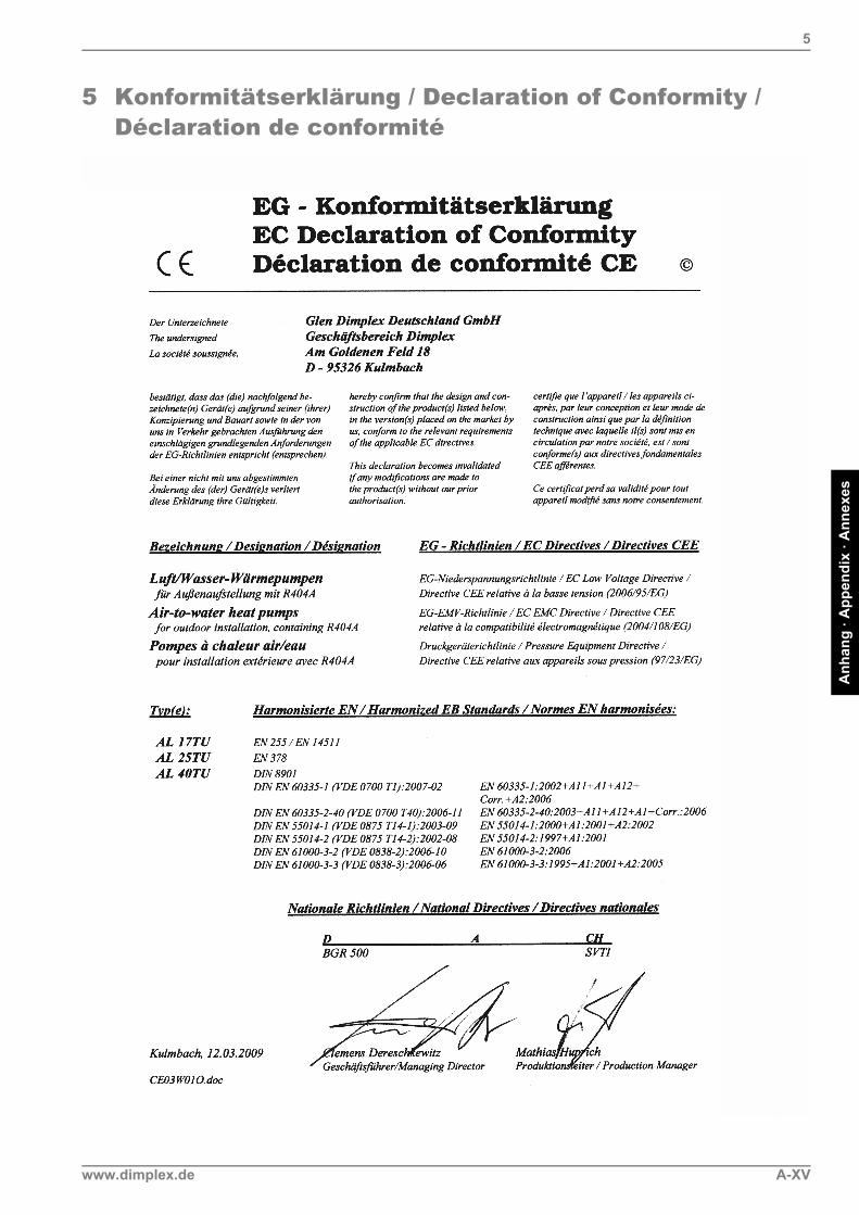
5 Konformitätserklärung / Declaration of Conformity / Déclaration de conformité
www.dimplex.de A-XV
Anhang · A
ppendix · Annexes
6
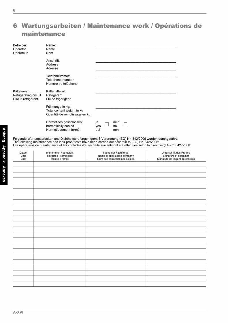
6 Wartungsarbeiten / Maintenance work / Opérations de maintenance
Betreiber: Name: __________________________________________Operator NameOpérateur Nom
Anschrift: __________________________________________AddressAdresse __________________________________________
Telefonnummer: __________________________________________Telephone numberNuméro de téléphone
Kältekreis: Kältemittelart: __________________________________________Refrigerating circuit RefrigerantCircuit réfrigérant Fluide frigorigène
Füllmenge in kg: __________________________________________Total content weight in kgQuantité de remplissage en kg
Hermetisch geschlossen: ja neinhermetically sealed yes noHermétiquement fermé oui non
Folgende Wartungsarbeiten und Dichtheitsprüfungen gemäß Verordnung (EG) Nr. 842/2006 wurden durchgeführt:The following maintenance and leak-proof tests have been carried out accordin to (EG) Nr. 842/2006:Les opérations de maintenance et les contrôles d’étanchéité suivants ont été effectués selon la directive (EG) n° 84272006:
DatumDateDate
entnommen / aufgefülltextracted / completed
prélevé / rempli
Name der Fachfirma:Name of specialised companyNom de l’entreprise spécialisée
Unterschrift des PrüfersSignature of examiner
Signature de l’agent de contrôle
A-XVI

Glen Dimplex Deutschland GmbHGeschäftsbereich DimplexAm Goldenen Feld 18D-95326 Kulmbach
Irrtümer und Änderungen vorbehalten.Subject to alterations and errors.
Sous réserve d’erreurs et modifications. +49 (0) 9221 709 565
www.dimplex.de