LA LO LR LS LY E6SF Pb-free · LS E6SF, LR E6SF, LA E6SF, LO E6SF, LY E6SF Power TOPLED Enhanced...
18
LS E6SF, LR E6SF, LA E6SF, LO E6SF, LY E6SF Power TOPLED Enhanced thin film LED Lead (Pb) Free Product - RoHS Compliant 2010-12-09 1 Besondere Merkmale • Gehäusetyp: weißes P-LCC-4 Gehäuse, farbloser klarer Silikon - Verguss • Besonderheit des Bauteils: mehr Licht durch erhöhten optischen Wirkungsgrad • Wellenlänge: 633 nm (super-red), 625 nm (rot), 617 nm (amber), 606 nm (orange), 590 nm (gelb) • Abstrahlwinkel: Lambertscher Strahler (120°) • Technologie: InGaAlP • optischer Wirkungsgrad: 38 lm/W (super-red), 49 lm/W (red), 69 lm/W (amber, orange), 44 lm/W (yellow) • Gruppierungsparameter: Lichtstärke, Durchflussspannung, Wellenlänge • Verarbeitungsmethode: für alle SMT-Bestücktechniken geeignet • Lötmethode: Reflow Löten und Wellenlöten (TTW) • Vorbehandlung: nach JEDEC Level 2 • Gurtung: 8 mm Gurt mit 2000/Rolle, ø180 mm oder 8000/Rolle, ø330 mm • ESD-Festigkeit: ESD-sicher bis 2 kV nach JESD22-A114-D Anwendungen • Ampelanwendung • Hinterleuchtung (LCD, Schalter, Tasten, Displays, Werbebeleuchtung) • Innen- und Außenbeleuchtung im Auto- mobilbereich (z.B. Instrumentenbeleuchtung und Bremslichter) • Ersatz von Kleinst-Glühlampen • Markierungsbeleuchtung (z.B. Stufen, Fluchtwege, u.ä.) • Signal- und Symbolleuchten Features • package: white P-LCC-4 package, colorless clear silicone resin • feature of the device: more light due to higher optical efficiency • wavelength: 633 nm (super-red), 625 nm (red), 617 nm (amber), 606 nm (orange), 590 nm (yellow) • viewing angle: Lambertian Emitter (120°) • technology: InGaAlP • optical efficiency: 38 lm/W (super-red), 49 lm/W (red), 69 lm/W (amber, orange), 44 lm/W (yellow) • grouping parameter: luminous intensity, forward voltage, wavelength • assembly methods: suitable for all SMT assembly methods • soldering methods: reflow soldering and TTW soldering • preconditioning: acc. to JEDEC Level 2 • taping: 8 mm tape with 2000/reel, ø180 mm or 8000/reel, ø330 mm • ESD-withstand voltage: up to 2 kV acc. to JESD22-A114-D Applications • traffic lights • backlighting (LCD, switches, keys, displays, illuminated advertising) • interior and exterior automotive lighting (e.g. dashboard backlighting and brake lights) • substitution of micro incandescent lamps • marker lights (e.g. steps, exit ways, etc.) • signal and symbol luminaire
Transcript of LA LO LR LS LY E6SF Pb-free · LS E6SF, LR E6SF, LA E6SF, LO E6SF, LY E6SF Power TOPLED Enhanced...

LS E6SF, LR E6SF, LA E6SF, LO E6SF, LY E6SF
Power TOPLED Enhanced thin film LED Lead (Pb) Free Product - RoHS Compliant
Besondere Merkmale• Gehäusetyp: weißes P-LCC-4 Gehäuse, farbloser
klarer Silikon - Verguss• Besonderheit des Bauteils: mehr Licht durch
erhöhten optischen Wirkungsgrad• Wellenlänge: 633 nm (super-red), 625 nm (rot),
617 nm (amber), 606 nm (orange), 590 nm (gelb)• Abstrahlwinkel: Lambertscher Strahler (120°)• Technologie: InGaAlP • optischer Wirkungsgrad: 38 lm/W (super-red),
49 lm/W (red), 69 lm/W (amber, orange), 44 lm/W (yellow)
• Gruppierungsparameter: Lichtstärke, Durchflussspannung, Wellenlänge
• Verarbeitungsmethode: für alle SMT-Bestücktechniken geeignet
• Lötmethode: Reflow Löten und Wellenlöten (TTW)
• Vorbehandlung: nach JEDEC Level 2• Gurtung: 8 mm Gurt mit 2000/Rolle, ø180 mm
oder 8000/Rolle, ø330 mm• ESD-Festigkeit: ESD-sicher bis 2 kV nach
JESD22-A114-D
Anwendungen• Ampelanwendung• Hinterleuchtung (LCD, Schalter, Tasten, Displays,
Werbebeleuchtung)• Innen- und Außenbeleuchtung im Auto-
mobilbereich (z.B. Instrumentenbeleuchtung und Bremslichter)
• Ersatz von Kleinst-Glühlampen• Markierungsbeleuchtung (z.B. Stufen, Fluchtwege,
u.ä.)• Signal- und Symbolleuchten
2010-12-09
Features• package: white P-LCC-4 package, colorless clear
silicone resin• feature of the device: more light due to higher
optical efficiency• wavelength: 633 nm (super-red), 625 nm (red),
617 nm (amber), 606 nm (orange), 590 nm (yellow)
• viewing angle: Lambertian Emitter (120°)• technology: InGaAlP • optical efficiency: 38 lm/W (super-red),
49 lm/W (red), 69 lm/W (amber, orange), 44 lm/W (yellow)
• grouping parameter: luminous intensity, forward voltage, wavelength
• assembly methods: suitable for all SMT assembly methods
• soldering methods: reflow soldering and TTW soldering
• preconditioning: acc. to JEDEC Level 2• taping: 8 mm tape with 2000/reel, ø180 mm or
8000/reel, ø330 mm• ESD-withstand voltage: up to 2 kV acc. to
JESD22-A114-D
Applications• traffic lights• backlighting (LCD, switches, keys, displays,
illuminated advertising)• interior and exterior automotive lighting
(e.g. dashboard backlighting and brake lights)• substitution of micro incandescent lamps• marker lights (e.g. steps, exit ways, etc.)• signal and symbol luminaire
1

LS E6SF, LR E6SF, LA E6SF, LO E6SF, LY E6SF
Anm.: Die oben genannten Typbezeichnungen umfassen die bestellbaren Selektionen. Diese bestehen aus wenigen Helligkeitsgruppen (siehe Seite 7 für nähere Informationen). Es wird nur eine einzige Helligkeitsgruppe pro Gurt geliefert. Z.B.: LY E6SF-AABA-46-1 bedeutet, dass auf dem Gurt nur eine der Helligkeitsgruppen AA, AB oder BA enthalten ist. Um die Liefersicherheit zu gewährleisten, können einzelne Helligkeitsgruppen nicht bestellt werden. Gleiches gilt für die Farben, bei denen Wellenlängengruppen gemessen und gruppiert werden. Pro Gurt wird nur eine Wellenlängengruppe geliefert. Z.B.: LY E6SF-AABA-46-1 bedeutet, dass auf dem Gurt nur eine der Wellenlängengruppen -4, -5 oder -6 enthalten ist (siehe Seite 6 für nähere Information). Z.B.: LS E6SF-V2BA-1-1 bedeutet, dass das Bauteil innerhalb der auf Seite 5 spezifizierten Grenzen geliefert wird. Um die Liefersicherheit zu gewährleisten, können einzelne Wellenlängengruppen nicht bestellt werden. Gleiches gilt für die LEDs, bei denen die Durchlassspannungsgruppen gemessen und gruppiert werden. Pro Gurt wird nur eine Durchlassspannungsgruppe geliefert. Z.B.: LY E6SF-AABA-46-1 bedeutet, dass nach Durchlassspannung gruppiert wird. Auf einem Gurt ist nur eine der Durchlasspannungsgruppen -3B, -4A, -4B oder -5A enthalten (siehe Seite 6 für nähere Information). Um die Liefersicherheit zu gewährleisten, können einzelne Durchlassspannungsgruppen nicht direkt bestellt werden.
Note: The above Type Numbers represent the order groups which include only a few brightness groups (see page 7 for explanation). Only one group will be shipped on each reel (there will be no mixing of two groups on each reel). E.g. LY E6SF-AABA-46-1 means that only one group AA, AB or BA will be shippable for any one reel. In order to ensure availability, single brightness groups will not be orderable. In a similar manner for colors where wavelength groups are measured and binned, single wavelength groups will be shipped on any one reel. E.g. LY E6SF-AABA-46-1 means that only 1 wavelength group -4, -5 or -6 will be shippable (see page 6 for explanation). E.g. LS E6SF-V2BA-1-1 means that the device will be shiped within the specified limits as stated on page 5. In order to ensure availability, single wavelength groups will not be orderable. In a similar manner for LED, where forward voltage groups are measured and binned, single forward voltage groups will be shipped on any one reel. E.g. LY E6SF-AABA-46-1 means that only 1 forward voltage group -3B, -4A, 4B or -5A will be shippable. In order to ensure availability, single forward voltage groups will not be orderable (see page 6 for explanation)
Bestellinformation für Standardselektion Ordering Information for Standard Selection
Typ Type
Emissions- farbe Color of Emission
Lichtstärke1) Seite 18
Luminous Intensity1) page 18
IF = 50 mA IV (mcd)
Lichtstrom2) Seite 18
Luminous Flux2) page 18
IF = 50 mA ΦV (mlm)
Bestellnummer Ordering Code
LS E6SF-V2BA-1-1 super-red 900 … 2240 4650 (typ.) Q65110A4135
LR E6SF-ABCA-1-1 red 1400 … 3550 7425 (typ.) Q65111A0958
LA E6SF-BBCB-24-1 amber 2240 … 4500 10110 (typ.) Q65110A6262
LO E6SF-ABCB-24-1 orange 1400 … 4500 8800 (typ.) Q65110A7524
LY E6SF-V2AB-35-1 LY E6SF-AABA-46-1
yellow 900 … 1800 1120 … 2240
4030 (typ.) 4980 (typ.)
Q65110A7525 Q65110A6209
2010-12-09 2

LS E6SF, LR E6SF, LA E6SF, LO E6SF, LY E6SF
Bestellinformation für Stop-Bremslicht-Selektion Ordering Information for Stop / Tail light Selection
Typ Type
Emissions- farbe Color of Emission
Lichtstärke2) Seite 18
Luminous Intensity2) page 18
Bestellnummer Ordering CodeIF = 4 mA
ΙV (mcd)IF = 50 mA ΙV (mcd)
LA E6SF-Q2S1-1-2A2B +BW-24-3A4B
amber
90 … 224 1800 … 2800
Q65110A7987
Anm.: Die oben genannten Typbezeichnungen umfassen die bestellbaren Selektionen. Diese bestehen aus wenigen Helligkeitsgruppen (siehe Seite 7 für nähere Informationen). Es wird nur eine einzige Helligkeitsgruppe pro Gurt und Gruppierungsstrom geliefert. Z.B.: LA E6SF-Q2S1-1-2A2B+BW-24-3A4B bedeutet, dass auf dem Gurt nur eine der Helligkeitsgruppen Q2, R1, R2 oder S1 enthalten ist. Um die Liefersicherheit zu gewährleisten, können einzelne Helligkeitsgruppen nicht bestellt werden. Gleiches gilt für die Farben, bei denen Wellenlängengruppen gemessen und gruppiert werden. Pro Gurt wird nur eine Wellenlängengruppe geliefert. Z.B.: LA E6SF-Q2S1-1-2A2B+BW-24-3A4B bedeutet, dass auf dem Gurt nur eine der Wellenlängengruppen -2, -3, oder -4 enthalten ist. (siehe Seite 6 für nähere Information). Um die Liefersicherheit zu gewährleisten, können einzelne Wellenlängengruppen nicht bestellt werden. Gleiches gilt für die LEDs, bei denen die Durchlassspannungsgruppen gemessen und gruppiert werden. Pro Gurt und Gruppierungsstrom wird nur eine Durchlassspannungsgruppe geliefert. Z.B.: LA E6SF-Q2S1-1-2A2B+BW-24-3A4B bedeutet, dass nach Durchlassspannung gruppiert wird. Auf einem Gurt ist nur eine der Durchlasspannungsgruppen -2A oder -2B enthalten (siehe Seite 6 für nähere Information). Um die Liefersicherheit zu gewährleisten, können einzelne Durchlassspannungsgruppen nicht direkt bestellt werden.
Note: The above Type Numbers represent the order groups which include only a few brightness groups (see page 7 for explanation). Only one group will be shipped on each reel and grouping current (there will be no mixing of two groups on each reel). E.g. LA E6SF-Q2S1-1-2A2B+BW-24-3A4B means that only one group Q2, R1, R2 or S1 will be shippable for any one reel. In order to ensure availability, single brightness groups will not be orderable. In a similar manner for colors where wavelength groups are measured and binned, single wavelength groups will be shipped on any one reel. E.g. LA E6SF-Q2S1-1-2A2B+BW-24-3A4B means that only 1 wavelength group -2, -3 or -4 will be shippable. (see page 6 for explanation). In order to ensure availability, single wavelength groups will not be orderable. In a similar manner for LED, where forward voltage groups are measured and binned, single forward voltage groups will be shipped on any one reel and grouping current. E.g. LA E6SF-Q2S1-1-2A2B+BW-24-3A4B means that only 1 forward voltage group -2A or -2B will be shippable. In order to ensure availability, single forward voltage groups will not be orderable (see page 6 for explanation)
2010-12-09 3

LS E6SF, LR E6SF, LA E6SF, LO E6SF, LY E6SF
Grenzwerte Maximum Ratings
Bezeichnung Parameter
Symbol Symbol
Wert Value
Einheit Unit
Betriebstemperatur Operating temperature range
Top – 40 … + 110 °C
Lagertemperatur Storage temperature range
Tstg – 40 … + 110 °C
Sperrschichttemperatur Junction temperature
Tj + 125 °C
Sperrschichttemperatur Junction temperature
Tj >150 for short term applications
°C
Durchlassstrom Forward current (TA=25°C)
IF 70 mA
Stoßstrom Surge current t ≤ 10 μs, D = 0.1, TA=25°C
IFM 100 mA
Sperrspannung3) Seite 18
Reverse voltage3) page 18
(TA=25°C)
VR 12 V
Wärmewiderstand Thermal resistance Sperrschicht/Umgebung4) Seite 18
Junction/ambient4) page 18
Sperrschicht/Lötpad Junction/soldering point
Rth JA Rth JS
300 130
K/W K/W
2010-12-09 4

LS E6SF, LR E6SF, LA E6SF, LO E6SF, LY E6SF
Kennwerte Characteristics (TS = 25 °C)
Bezeichnung Parameter
Symbol Symbol
WerteValues
Einheit Unit
LS LR LA LO LY
Wellenlänge des emittierten Lichtes (typ.) Wavelength at peak emission IF = 50 mA
λpeak 645 634 624 610 597 nm
Dominantwellenlänge5) Seite 18 Dominant wavelength5) page 18
IF = 50 mA
λdom 633 ± 6
625 ± 5
617* –5/+7
606* –6/+3
590* –7/+5
nm
Spektrale Bandbreite bei 50 % Irel max (typ.) Spectral bandwidth at 50 % Irel max IF = 50 mA
Δλ 16 19 18 17 18 nm
Abstrahlwinkel bei 50 % IV (Vollwinkel) (typ.) Viewing angle at 50 % IV
2ϕ 120 120 120 120 120 Grad deg.
Durchlassspannung6) Seite 18 (min.) Forward voltage6) page 18 (typ.) IF = 50 mA (max.)
VF VF VF
1.90* 2.15 2.50
1.90* 2.15 2.50
1.90* 2.15 2.50
1.90* 2.15 2.50
2.05* 2.15 2.65
V V V
Sperrstrom (typ.) Reverse current (max.) VR = 12 V
IR IR
0.2 10
0.2 10
0.2 10
0.2 10
0.2 10
μA μA
Temperaturkoeffizient von λpeak (typ.) Temperature coefficient of λpeak IF = 50 mA; –10°C ≤ T ≤ 100°C
TCλpeak 0.15 0.14 0.14 0.12 0.12 nm/K
Temperaturkoeffizient von λdom (typ.) Temperature coefficient of λdom IF = 50 mA; –10°C ≤ T ≤ 100°C
TCλdom 0.05 0.07 0.08 0.08 0.10 nm/K
Temperaturkoeffizient von VF (typ.) Temperature coefficient of VF IF = 50 mA; –10°C ≤ T ≤ 100°C
TCV – 2.5 – 2.5 – 2.5 – 2.5 – 2.5 mV/K
Optischer Wirkungsgrad (typ.) Optical efficiency IF = 50 mA
ηopt 38 49 69 69 44 lm/W
* Einzelgruppen siehe Seite 5 Individual groups on page 5
2010-12-09 5

LS E6SF, LR E6SF, LA E6SF, LO E6SF, LY E6SF
Wellenlängengruppen für Standardselektion(Dominantwellenlänge)5)Seite 18
Wavelength Groups for Standard Selection(Dominant Wavelength)5) page 18
Gruppe Group
amber orange yellow Einheit Unit
min. max. min. max. min. max.
2 612 616 600 603 nm
3 616 620 603 606 583 586 nm
4 620 624 606 609 586 589 nm
5 589 592 nm
6 592 595 nm
Wellenlängengruppen für Stop-Bremslicht-Selektion (Dominantwellenlänge)5)Seite 18
Wavelength Groups for Stop / Tail light Selection (Dominant Wavelength)5) page 18
Gruppe Group
amber @4 mA amber @50 mA Einheit Unit
min. max. min. max.
2 611 616 612 616 nm
3 615 620 616 620 nm
4 619 624 620 624 nm
Durchlassspannungsgruppen für Standardselektion6) Seite 18
Forward Voltage Groups for Standard Selection6) page 18
Gruppe Group
super-red red amber orange yellow Einheit Unit
min. max. min. max. min. max. min. max. min. max.
3A 1.90 2.05 1.90 2.05 1.90 2.05 1.90 2.05 V
3B 2.05 2.20 2.05 2.20 2.05 2.20 2.05 2.20 2.05 2.20 V
4A 2.20 2.35 2.20 2.35 2.20 2.35 2.20 2.35 2.20 2.35 V
4B 2.35 2.50 2.35 2.50 2.35 2.50 2.35 2.50 2.35 2.50 V
5A 2.50 2.65 V
Durchlassspannungsgruppen für Stop-Bremslicht-Selektion6) Seite 18
Forward Voltage Groups for Stop / Tail light Selection6) page 18
Gruppe Group
amber @4 mA amber @50 mA Einheit Unit
min. max. min. max.
2A 1.65 1.80 V
2B 1.80 1.95 V
3A 1.90 2.05 V
3B 2.05 2.20 V
4A 2.20 2.35 V
4B 2.35 2.50 V
2010-12-09 6

LS E6SF, LR E6SF, LA E6SF, LO E6SF, LY E6SF
Helligkeits-Gruppierungsschema für Standardselektion Brightness Groups for Standard Selection
Helligkeitsgruppe Brightness Group
Lichtstärke1) Seite 18
Luminous Intensity1) page 18
IV (mcd)
Lichtstrom2) Seite 18
Luminous Flux2) page 18
ΦV (mlm)
V2 AA AB BA BB CA CB
900 … 1120 1120 … 1400 1400 … 1800 1800 … 2240 2240 … 2800 2800 … 3550 3550 … 4500
3000 (typ.) 3700 (typ.) 4800 (typ.) 6050 (typ.) 7500 (typ.) 9500 (typ.)
12000 (typ.)
Anm.: Die Standardlieferform von Serientypen beinhaltet eine Familiengruppe. Diese besteht aus nur wenigen Helligkeitsgruppen. Einzelne Helligkeitsgruppen sind nicht bestellbar.
Note: The standard shipping format for serial types includes a family group of only a few individual brightness groups. Individual brightness groups cannot be ordered.
Helligkeits-Gruppierungsschema für Stop-Bremslicht-Selektion Brightness Groups for Stop / Tail light Selection
Helligkeitsgruppe Brightness Group
Lichtstärke 1) Seite 18
Luminous Intensity1) page 18
ΙV (mcd)
Lichtstrom 2) Seite 18
Luminous Flux 2) page 18
ΦV (mlm)
Helligkeitsgruppe Brightness Group
Lichtstärke 1) Seite 18
Luminous Intensity1) page 18
ΙV (mcd)
Lichtstrom 2) Seite 18
Luminous Flux 2) page 18
ΦV (mlm)
amber @4 mA amber @50 mA
Q2 R1 R2 S1
90 … 112 112 … 140 140 … 180 180 … 224
275 (typ.) 350 (typ.) 440 (typ.) 550 (typ.)
BW 1800 … 2800 6870 (typ.)
Anm.: Die Standardlieferform von Serientypen beinhaltet eine Familiengruppe. Diese besteht aus wenigen Helligkeitsgruppen. Einzelne Helligkeitsgruppen sind nicht bestellbar.
Note: The standard shipping format for serial types includes a family group of a few individual brightness groups. Individual brightness groups cannot be ordered.
2010-12-09 7

LS E6SF, LR E6SF, LA E6SF, LO E6SF, LY E6SF
Gruppenbezeichnung auf Etikett für Standardselektion Group Name on Label for Standard Selection Example: AB-3-4A
Helligkeitsgruppe Brightness Group
Wellenlänge Wavelength
Durchlassspannung Forward Voltage
AB 3 4A
Anm.: In einer Verpackungseinheit / Gurt ist immer nur eine Gruppe für jede Selektion enthalten.
Note: No packing unit / tape ever contains more than one group for each selection.
Gruppenbezeichnung auf Etikett für Stop-Bremslicht-Selektion Group Name on Label for Stop / Tail light Selection Beispiel: Q2-2A + BW-3-3A Example: Q2-2A + BW-3-3A
Helligkeitsgruppe Brightness Group
Durchlassspannung Forward Voltage
Helligkeitsgruppe Brightness Group
Wellenlänge Wavelength
Durchlassspannung Forward Voltage
amber @4 mA amber @50 mA
Q2 2A BW 3 3A
Anm.: In einer Verpackungseinheit / Gurt ist immer nur eine Gruppe für jede Selektion enthalten.Note: No packing unit / tape ever contains more than one group for each selection.
2010-12-09 8

LS E6SF, LR E6SF, LA E6SF, LO E6SF, LY E6SF
Relative spektrale Emission2) Seite 18
Relative Spectral Emission2) page 18
V(λ) = spektrale Augenempfindlichkeit / Standard eye response curve Irel = f (λ); TS = 25 °C; IF = 50 mA
Abstrahlcharakteristik2) Seite 18
Radiation Characteristic2) page 18
Irel = f (ϕ); TS = 25 °C
OHL02654
4000
20
40
60
80
100
450 500 550 600 650 700nm
%
λ
Vλ
yelloworangeamber
super-redred
relΙ
0
0.2
0.4
1.0
0.8
0.6
ϕ
1.0 0.8 0.6 0.4
0˚10˚20˚40˚ 30˚ OHL01660
50˚
60˚
70˚
80˚
90˚
100˚0˚ 20˚ 40˚ 60˚ 80˚ 100˚ 120˚
2010-12-09 9

LS E6SF, LR E6SF, LA E6SF, LO E6SF, LY E6SF
Durchlassstrom2) Seite 18
Forward Current2) page 18
IF = f (VF); TS = 25 °C
Relative Vorwärtsspannung2) Seite 18
Relative Forward Voltage2) page 18
ΔVF = VF - VF(25 °C) = f (Tj); IF = 50 mA
Relative Lichtstärke2) 7) Seite 18
Relative Luminous Intensity2) 7) page 18
IV/IV(grouping current) = f (IF); TS = 25 °C
Relative Lichtstärke2) Seite 18
Relative Luminous Intensity2) page 18
IV/IV(25 °C) = f (Tj); IF = 50 mA
OHL02665
mA
100
V
101
210
IF
VF
2.31.5 1.7 1.9 2.1 2.5
amber, orangeyellow
super red, red
OHL02667
T
FV
j
-40-0.2
-20 0 20 40
0.25
˚C60 100-60
V
-0.15
-0.1
-0.05
0
0.05
0.1
0.15
Δ
OHL03815
IF
100 5 10 1 10mA 2
102
-110
(gro
upin
g cu
rren
t)VI
VI 010
5
110
5
5
10-2
(4 mA)VIIV /
(50 mA)/I IV V
5
0-40 ˚C
T
V
IV
0.5
1.0
1.5
2.0
-20 0 20 40 60 10
super red
j
-60
amberredorange
yellow
(25 ˚C)I
2010-12-09 10

LS E6SF, LR E6SF, LA E6SF, LO E6SF, LY E6SF
Maximal zulässiger Durchlassstrom Max. Permissible Forward Current IF = f (T)
Zulässige Impulsbelastbarkeit IF = f (tp) Permissible Pulse Handling Capability Duty cycle D = parameter, TA = 25 °C
Zulässige Impulsbelastbarkeit IF = f (tp) Permissible Pulse Handling Capability Duty cycle D = parameter, TA = 85 °C
OHL01413
00 20 40 60 80 ˚C 100
T
IF
20
40
60
80mA
AT ST
temp. ambienttemp. solder point
A
SΤΤ
10
30
70
50
0
A
OHL02046
pt
FI
-5 110-410 10-3 -2 1010-1 0 10 10s 210
0.02
0.04
0.06
0.08
0.10
0.12
PtD T=T
tP
IF
0.2
10.5
D =0.1
0.0050.01
=
0.020.05
D
Angestrebte mittlere Lebensdauer2) Seite 18
für mittlere Helligkeitsgruppe Target median Lifetime2) page 18
for median Brightness Group
Bedingungen Conditions
mittlere Lebensdauer median Lifetime
Einheit Unit
IF = 25mA TA = 25°C
50’000 Betriebsstunden operating hours
IF = 30mA TA = 85°C
30’000 Betriebsstunden operating hours
IF = 70 mATS = 125°C TJ = 150°C
500 Betriebsstunden operating hours
0
A
OHL02045
pt
FI
-5 110-410 10-3 -2 1010-1 0 10 10s 210
0.02
0.04
0.06
0.08
0.10
0.12
PtD T=T
tP
IF
0.0050.01
=
0.020.05
D
0.10.20.51
2010-12-09 11

LS E6SF, LR E6SF, LA E6SF, LO E6SF, LY E6SF
Maßzeichnung8) Seite 18
Package Outlines8) page 18
Anm.: Das Gehäuse ist für Ultraschallreinigung nicht geeignet
Note: Package not suitalbe for ultra sonic cleaning
Gewicht / Approx. weight: 35 mg
Gurtung / Polarität und Lage8) Seite 18 Verpackungseinheit 2000/Rolle, ø180 mm oder 8000/Rolle, ø330 mm
Method of Taping / Polarity and Orientation8) page 18 Packing unit 2000/reel, ø180 mm or 8000/reel, ø330 mm
GPLY6084
0.7 (0.028)0.9 (0.035)
1.7 (0.067)
2.1 (0.083)
0.12 (0.005)0.18 (0.007)
0.5
(0.0
20)
1.1
(0.0
43)
3.3
(0.1
30)
3.7
(0.1
46)
0.4 (0.016)0.6 (0.024)
2.6 (0.102)3.0 (0.118)
2.1 (0.083)
2.3 (0.091)
Package marking
3.0
(0.1
18)
3.4
(0.1
34)
(2.4
) (0.
095)
0.1 (0.004) (typ.)
4˚±1
0.6 (0.024)
0.8 (0.031)
A A
CA A C
A A
OHAY06674 (0.157)
2.9 (0.114)
1.5 (0.059) 4 (0.157)
3.6
(0.1
42)
3.5
(0.1
38)
2 (0.079)
1.75
(0.0
69)
8 (0
.315
)
Cathode/Collector Marking
2010-12-09 12

LS E6SF, LR E6SF, LA E6SF, LO E6SF, LY E6SF
Empfohlenes Lötpaddesign verwendbar für TOPLED und Power TOPLED
Reflow Löten8) Seite 18
Recommended Solder Pad useable for TOPLED and Power TOPLED
Reflow Soldering8) page 18
Empfohlenes Lötpaddesign8) Seite 18 Wellenlöten (TTW) Recommended Solder Pad8) page 18 TTW Soldering
OHLPY440
Padgeometrie fürverbesserte Wärmeableitung
improved heat dissipationPaddesign for
LötstoplackSolder resist
0.8 (0.031)
3.7
(0.1
46)
1.1
(0.0
43)
2.3 (0.091)
3.3 (0.130)
1.5
(0.0
59)
11.1
(0.4
37)
Cu Fläche / 16 mm per pad2
Cu-area_<
3.3 (0.130)
Kathode/Cathode
Anode
Fläche darf elektrisch nicht beschaltet werden.Do not use this area for electrical contact.
0.7 (0.028)
Fläche darf elektrisch nicht beschaltet werden.Do not use this area for electrical contact.
OHAY1583
6.1 (0.240)
2.8 (0.110)
2 (0
.079
)
3 (0
.118
)
6 (0
.236
)
2 (0
.079
)
1 (0
.039
)
2.8 (0.110) 0.5 (0.020)
Solder resistLötstoplack
PCB-
dire
ctio
n
Bewe
gung
srich
tung
der P
latin
e2 (0
.079
)
Padgeometrie für
improved heat dissipation
verbesserte Wärmeableitung
Paddesign for
2Cu Fläche / > 16 mm per padCu-area
AnodeFläche darf elektrisch nicht beschaltet werden.Do not use this area for electrical contact.
Fläche darf elektrisch nicht beschaltet werden.Do not use this area for electrical contact.
CathodeKathode/
2010-12-09 13
LS E6SF, LR E6SF, LA E6SF, LO E6SF, LY E6SF
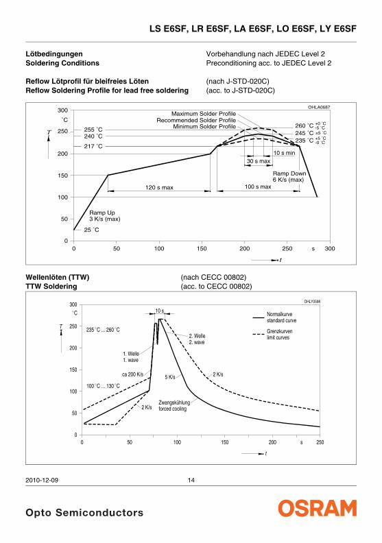
Lötbedingungen Vorbehandlung nach JEDEC Level 2 Soldering Conditions Preconditioning acc. to JEDEC Level 2 Reflow Lötprofil für bleifreies Löten (nach J-STD-020C) Reflow Soldering Profile for lead free soldering (acc. to J-STD-020C)
Wellenlöten (TTW) (nach CECC 00802) TTW Soldering (acc. to CECC 00802)
OHLA0687
00
T
t
˚C
s
120 s max
50
100
150
200
250
300
Ramp Up
100 s max
50 100 150 200 250 300
Ramp Down6 K/s (max)
3 K/s (max)
25 ˚C
30 s max
260 ˚C +0 ˚C-5 ˚C
245 ˚C ±5 ˚C240 ˚C255 ˚C
217 ˚C
Maximum Solder ProfileRecommended Solder Profile
235 ˚C -0 ˚C+5 ˚C
Minimum Solder Profile
10 s min
OHLY0598
00
50 100 150 200 250
50
100
150
200
250
300
T
t
C
s
235 C
10 s
C... 260
1. Welle1. wave
2. Welle2. wave
5 K/s 2 K/sca 200 K/s
C C... 130100
2 K/sZwangskühlungforced cooling
Normalkurvestandard curve
Grenzkurvenlimit curves
2010-12-09 14

LS E6SF, LR E6SF, LA E6SF, LO E6SF, LY E6SF
Barcode-Produkt-Etikett (BPL) Barcode-Product-Label (BPL)
Gurtverpackung Tape and Reel
Tape dimensions in mm (inch)
W P0 P1 P2 D0 E F
4 ± 0.1 (0.157 ± 0.004)
4 ± 0.1 (0.157 ± 0.004)
2 ± 0.05 (0.079 ± 0.002)
1.5 + 0.1 (0.059 + 0.004)
1.75 ± 0.1 (0.069 ± 0.004)
3.5 ± 0.05 (0.138 ± 0.002)
Reel dimensions in mm (inch)
A W Nmin W1 W2 max
180 (7) 8 (0.315) 60 (2.362) 8.4 + 2 (0.331 + 0.079) 14.4 (0.567)
330 (13) 8 (0.315) 60 (2.362) 8.4 + 2 (0.331 + 0.079) 14.4 (0.567)
OHA04563
(G) GROUP:
1234567890(1T) LOT NO: (9D) D/C: 1013
(X) PROD NO: 11058300
(6P) BATCH NO: 1004067407
LMW CNAP
OSLON
RoHS Compliant
BIN1: EA-5O-0-140-D
ML2
Temp ST260 ˚C R
Pack: R18
DEMY 022
B_R999_1880.1642 R
2000(Q)QTY:
SemiconductorsOSRAM Opto
EA-5O-0-D
D0
2P
P0
1P
WFE
Direction of unreeling
N
W1
2W
A
OHAY0324
Label
Gurtvorlauf:Leader:
Trailer:Gurtende:
13.0
Direction of unreeling
±0.2
5
160 mm160 mm
400 mm400 mm
8 + 0.3– 0.1
2010-12-09 15

LS E6SF, LR E6SF, LA E6SF, LO E6SF, LY E6SF
Trockenverpackung und Materialien Dry Packing Process and Materials
Anm.: Feuchteempfindliche Produkte sind verpackt in einem Trockenbeutel zusammen mit einem Trockenmittel und einer Feuchteindikatorkarte Bezüglich Trockenverpackung finden Sie weitere Hinweise im Internet und in unserem Short Form Catalog im Kapitel “Gurtung und Verpackung” unter dem Punkt “Trockenverpackung”. Hier sind Normenbezüge, unter anderem ein Auszug der JEDEC-Norm, enthalten.
Note: Moisture-senisitve product is packed in a dry bag containing desiccant and a humidity card. Regarding dry pack you will find further information in the internet and in the Short Form Catalog in chapter “Tape and Reel” under the topic “Dry Pack”. Here you will also find the normative references like JEDEC.
Kartonverpackung und Materialien Transportation Packing and Materials
Dimensions of transportation box in mm (inch)
Breite / Width Länge / length Höhe / height
200 ±5 (7,874 ±0,1968±) 200 ±5 (7,874 ±0,1968) 30 ±5 (1,1811 ±0,1968)
352 ±5 (13,858 ±0,1968±) 352 ±5 (13,858 ±0,1968) 33 ±5 (1,3 ±0,1968)
OHA00539
OSRAM
Moisture-sensitive label or print
Barcode label
Desiccant
Humidity indicator
Barcode label
OSRAM
Please check the HIC immidiately afterbag opening.
Discard if circles overrun.Avoid metal contact.
WET
Do not eat.
Comparatorcheck dot
parts still adequately dry.
examine units, if necessary
examine units, if necessary
5%
15%
10%bake units
bake units
If wet,
change desiccant
If wet,
Humidity IndicatorMIL-I-8835
If wet,
Mois
ture
Level 3
Flo
or tim
e 168 H
ours
Mois
ture
Level 6
Flo
or tim
e 6
Hours
a) H
umid
ity In
dicato
r C
ard is
> 1
0% w
hen read a
t 23 ˚
C ±
5 ˚C
, or
reflo
w, v
apor-phase r
eflow
, or equiv
alent p
rocessin
g (peak p
ackage
2. Afte
r th
is b
ag is o
pened, devic
es that w
ill b
e subje
cted to
infrare
d
1. Shelf
life in
seale
d bag: 2
4 month
s at <
40 ˚
C a
nd < 9
0% rela
tive h
umid
ity (R
H).
Mois
ture
Level 5
a
at facto
ry c
onditions o
f
(if b
lank, s
eal date
is id
entical w
ith d
ate c
ode).
a) M
ounted w
ithin
b) S
tore
d at
body tem
p.
3. Devic
es require
bakin
g, befo
re m
ounting, i
f:
Bag s
eal date
Mois
ture
Level 1
Mois
ture
Level 2
Mois
ture
Level 2
a4. If b
aking is
require
d,
b) 2a o
r 2b is
not m
et.
Date
and ti
me o
pened:
refe
rence IP
C/J
ED
EC
J-S
TD
-033 fo
r bake p
rocedure
.
Flo
or tim
e see b
elow
If bla
nk, see b
ar code la
bel
Flo
or tim
e > 1
Year
Flo
or tim
e 1
Year
Flo
or tim
e 4
Weeks10%
RH
.
_<
Mois
ture
Level 4
Mois
ture
Level 5
˚C).
OPTO
SEM
ICO
NDUCTORS
MO
ISTURE S
ENSITIV
E
This b
ag conta
ins
CAUTION
Flo
or tim
e 72 H
ours
Flo
or tim
e 48 H
ours
Flo
or tim
e 24 H
ours
30 ˚C
/60%
RH
.
_<
LE
VE
L
If bla
nk, see
bar code la
bel
OHA02044
PACKVAR:
R077Additional TEXT
P-1+Q-1
Multi TOPLED
Muste
r
OSRAM Opto
Semiconductors
(6P) BATCH NO:
(X) PROD NO:
10
(9D) D/C:
11(1T) LOT NO:
210021998
123GH1234
024 5
(Q)QTY: 2000
0144
(G) GROUP:
260 C RT240 C R
3
220 C R
MLBin3:Bin2: Q
-1-20
Bin1: P-1-20
LSY T6762
2a
Temp ST
R18DEMY
PACKVAR:
R077Additional TEXT
P-1+Q-1
Multi TOPLED
Muste
r
OSRAM Opto
Semiconductors
(6P) BATCH NO:
(X) PROD NO:
10
(9D) D/C:
11(1T) LOT NO:
210021998
123GH1234
024 5
(Q)QTY: 2000
0144
(G) GROUP:
260 C RT240 C R
3
220 C R
MLBin3:Bin2: Q
-1-20
Bin1: P-1-20
LSY T6762
2a
Temp ST
R18DEMY
OSRAM
Packing
Sealing label
Barcode label
Mois
ture
Level 3
Flo
or tim
e 168 H
ours
Mois
ture
Level 6
Flo
or tim
e 6
Hours
a) H
umid
ity In
dicato
r C
ard is
> 1
0% w
hen read a
t 23 ˚
C ±
5 ˚C
, or
reflo
w, v
apor-phase r
eflow
, or equiv
alent p
rocessin
g (peak p
ackage
2. Afte
r th
is b
ag is o
pened, devic
es that w
ill b
e subje
cted to
infrare
d
1. Shelf
life in
seale
d bag: 2
4 month
s at <
40 ˚
C a
nd < 9
0% rela
tive h
umid
ity (R
H).
Mois
ture
Level 5
a
at facto
ry c
onditions o
f
(if b
lank, s
eal date
is id
entical w
ith d
ate c
ode).
a) M
ounted w
ithin
b) S
tore
d at
body tem
p.
3. Devic
es require
bakin
g, befo
re m
ounting, i
f:
Bag s
eal date
Mois
ture
Level 1
Mois
ture
Level 2
Mois
ture
Level 2
a4. If b
aking is
require
d,
b) 2a o
r 2b is
not m
et.
Date
and ti
me o
pened:
refe
rence IP
C/J
ED
EC
J-S
TD
-033 fo
r bake p
rocedure
.
Flo
or tim
e see b
elow
If bla
nk, see b
ar code la
bel
Flo
or tim
e > 1
Year
Flo
or tim
e 1
Year
Flo
or tim
e 4
Weeks10%
RH
.
_<
Mois
ture
Level 4
Mois
ture
Level 5
˚C).
OPTO
SEM
ICO
NDUCTORS
MO
ISTURE S
ENSITIV
E
This b
ag conta
ins
CAUTION
Flo
or tim
e 72 H
ours
Flo
or tim
e 48 H
ours
Flo
or tim
e 24 H
ours
30 ˚C
/60%
RH
.
_<
LE
VE
L
If bla
nk, see
bar code la
bel
Barcode label
2010-12-09 16

LS E6SF, LR E6SF, LA E6SF, LO E6SF, LY E6SF
Attention please!The information describes the type of component and shall not be considered as assured characteristics. Terms of delivery and rights to change design reserved. Due to technical requirements components may contain dangerous substances. For information on the types in question please contact our Sales Organization. If printed or downloaded, please find the latest version in the Internet.PackingPlease use the recycling operators known to you. We can also help you – get in touch with your nearest sales office. By agreement we will take packing material back, if it is sorted. You must bear the costs of transport. For packing material that is returned to us unsorted or which we are not obliged to accept, we shall have to invoice you for any costs incurred.Components used in life-support devices or systems must be expressly authorized for such purpose! Critical components9) page 18 may only be used in life-support devices or systems10) page 18 with the express written approval of OSRAM OS.
Revision History: 2010-12-09 Previous Version: 2010-10-04
Page Subjects (major changes since last revision) Date of change
1; 4 Dominant wavelength, typical Value for yellow 2005-11-02
2 Ordering Information 2005-12-19
all OS-PCN-2006-027 2007-11-26
3 Junction temperature >150 °C for short term applications added 2007-12-13
8 Target median Lifetime table added 2007-12-13
17 laser warning removed; new classification regarding CIE S009/E:2002 ("photobiological safety of lamps and lamp systems")-IEC 62471 (1st edition 2006-07).
2008-04-28
all Dual binning for Stop/Tail Light application added 2008-04-28
1 product photo updated 2009-08-19
2 Ordering code (amber, red) changed 2010-01-15
11 measurement condition corrected (TA = 25 °C) 2010-05-19
15 New Barcode Label (OS-IN-2010-32) 2010-10-04
2 Ordering code (red) changed 2010-12-09
2010-12-09 17

LS E6SF, LR E6SF, LA E6SF, LO E6SF, LY E6SF
Fußnoten:1) Helligkeitswerte werden mit einer
Stromeinprägedauer von 25 ms und einer Genauigkeit von ± 11% ermittelt.
2) Wegen der besonderen Prozessbedingungen bei der Herstellung von LED können typische oder abgeleitete technische Parameter nur aufgrund statistischer Werte wiedergegeben werden. Diese stimmen nicht notwendigerweise mit den Werten jedes einzelnen Produktes überein, dessen Werte sich von typischen und abgeleiteten Werten oder typischen Kennlinien unterscheiden können. Falls erforderlich, z.B. aufgrund technischer Verbesserungen, werden diese typischen Werte ohne weitere Ankündigung geändert.
3) Die LED kann kurzzeitig in Sperrichtung betrieben werden.
4) RthJA ergibt sich bei Montage auf PC-Board FR 4 (Padgröße ≥ 16 mm2 je Pad)
5) Wellenlängen werden mit einer Stromeinprägedauer von 25 ms und einer Genauigkeit von ±1 nm ermittelt.
6) Spannungswerte werden mit einer Stromeinprägedauer von 1 ms und einer Genauigkeit von ±0,05 V ermittelt.
7) Im gestrichelten Bereich der Kennlinien muss mit erhöhten Helligkeitsunterschieden zwischen Leuchtdioden innerhalb einer Verpackungseinheit gerechnet werden. Dimmverhältnis im Gleichstrom-Betrieb max. 5:1
8) Maße werden wie folgt angegeben: mm (inch) 9) Ein kritisches Bauteil ist ein Bauteil, das in
lebenserhaltenden Apparaten oder Systemen eingesetzt wird und dessen Defekt voraussichtlich zu einer Fehlfunktion dieses lebenserhaltenden Apparates oder Systems führen wird oder die Sicherheit oder Effektivität dieses Apparates oder Systems beeinträchtigt.
10) Lebenserhaltende Apparate oder Systeme sind für (a) die Implantierung in den menschlichen Körper oder (b) für die Lebenserhaltung bestimmt. Falls sie versagen, kann davon ausgegangen werden, dass die Gesundheit und das Leben des Patienten in Gefahr ist.
Published by OSRAM Opto Semiconductors GmbH Leibnizstraße 4, D-93055 Regensburg www.osram-os.com © All Rights Reserved.
Remarks:1) Brightness groups are tested at a current pulse
duration of 25 ms and a tolerance of ± 11%.
2) Due to the special conditions of the manufacturing processes of LED, the typical data or calculated correlations of technical parameters can only reflect statistical figures. These do not necessarily correspond to the actual parameters of each single product, which could differ from the typical data and calculated correlations or the typical characteristic line. If requested, e.g. because of technical improvements, these typ. data will be changed without any further notice.
3) Driving the LED in reverse direction is suitable for short term application.
4) RthJA results from mounting on PC board FR 4 (pad size ≥ 16 mm2 per pad)
5) Wavelengths are tested at a current pulse duration of 25 ms and a tolerance of ±1 nm.
6) Forward voltages are tested at a current pulse duration of 1 ms and a tolerance of ±0.05 V.
7) In the range where the line of the graph is broken, you must expect higher brightness differences between single LEDs within one packing unit. Dimming range for direct current mode max. 5:1
8) Dimensions are specified as follows: mm (inch)9) A critical component is a component used in a
life-support device or system whose failure can reasonably be expected to cause the failure of that life-support device or system, or to affect its safety or the effectiveness of that device or system.
10) Life support devices or systems are intended (a) to be implanted in the human body, or (b) to support and/or maintain and sustain human life. If they fail, it is reasonable to assume that the health and the life of the user may be endangered.
2010-12-09 18