LIGHT GENIE - faller.de · for use on a model installation. It may exclusively be operated together...
12
Sa. Nr. 180 703 1 LIGHT GENIE LIGHT GENIE LIGHT GENIE LIGHT GENIE Art. Nr. 180703 Vor Beginn des Bastelns sollten Sie sich mit den Spritzlingen und der Anleitung vertraut machen. Sollte es einmal vorkommen, dass ein Teil im Bausatz fehlt, kreuzen Sie bitte das fehlende Teil in der Anleitung an und schicken Sie diese bitte an Fa. Gebr. FALLER GmbH, Abt. Kundendienst, [email protected], Kreuzstraße 9, 78148 Gütenbach. Sie erhalten dann umgehend Ersatz. Es kann vorkommen, dass bei einem Bausatz Einzelteile übrig sind. Before beginning with the assembly please familiarize yourself with the parts and read the instructions carefully. In case of missing parts please indicate these on the instructions leaflet with a circle and return the leaflet to Gebr. FALLER GmbH, [email protected], Kreuzstraße 9, D-78148 Gütenbach, Germany. You will receive the replacement by return. It may happen in a kit that some parts are not required. Avant de commencer le montage de votre maquette bien lire la notice et repérer les grappes. Si une pièce manque dans une boîte, cochez la pièce correspondante sur la notice et renvoyez-la-nous à Gebr. FALLER GmbH, [email protected], Kreuzstraße 9, D-78148 Gütenbach (R.F.A.). Nous vous ferons parvenir la pièce par retour. Dans certains kits, il est possible que certaines pièces ne soient pas utilisées. Vóór het bouwen zou men de gietstukken en de handleiding moeten bestuderen. Indien onverhoopt een onderdeel aan het bouwpakket ontbreekt, gelieve men het ontbrekende deel in de handleiding aan te kruisen en deze te zenden aan Gebr. FALLER GmbH, [email protected], Kreuzstraße 9, D-78148 Gütenbach. U ontvangt dan omgaand en gratis het ontbrekende onderdeel. Het kan voorkomen dat u bij bepaalde bouwdozen onderdelen overhoudt. D F GB NL Art. Nr. 170688 SPEZIAL-SEITENSCHNEIDER zum gratfreien Abtrennen von feinsten Spritzteilen. Nur für Polystyrol geeignet. Special side cutter for cutting off ultra-fine moulded parts without burrs. Only suitable for polystyrene. Pince coupante spéciale pour couper sans bavure les pièces miniatures moulées par injection. Convient uniquement au polystyrène. Speciale zijkniptang voor het braamloos afknippen van de fijnste gietstukdelen. Alleen geschikt voor polystyrol. Für den Zusammenbau des Modells empfehlen wir folgende FALLER-Artikel (sind nicht im Bausatz enthalten): For the assembly of the kit we recommend following FALLER products (not included in the kit): Pour l’assemblage du modèle, nous vous recommandons les articles FALLER suivants (non inclus dans le kit): Om dit model te bouwen adviseren wij de volgende FALLER producten (maken geen deel uit van deze bouwset): Art. Nr. 170492 FALLER-EXPERT Flüssigkleber in Plastikflasche mit Spezialkanüle für feinste Klebstoffdosierung. Liquid cement in plastic bottle with canule for very fine dosage. Colle liquide en bouteille plastique avec bec verseur pour un dosage précis. Vloeibare lijm in plastic-flacon met doseerbuisje om nauwkeurig te lijmen.
-
Upload
nguyentuyen -
Category
Documents
-
view
213 -
download
0
Transcript of LIGHT GENIE - faller.de · for use on a model installation. It may exclusively be operated together...

Sa. Nr. 180 703 1
LIGHT GENIELIGHT GENIELIGHT GENIELIGHT GENIE Art. Nr. 180703
Vor Beginn des Bastelns sollten Sie sich mit den Spritzlingen und der Anleitung vertraut machen.Sollte es einmal vorkommen, dass ein Teil im Bausatz fehlt, kreuzen Sie bitte das fehlende Teil inder Anleitung an und schicken Sie diese bitte an Fa. Gebr. FALLER GmbH, Abt. Kundendienst,[email protected], Kreuzstraße 9, 78148 Gütenbach. Sie erhalten dann umgehend Ersatz.Es kann vorkommen, dass bei einem Bausatz Einzelteile übrig sind.
Before beginning with the assembly please familiarize yourself with the parts and read the instructions carefully.In case of missing parts please indicate these on the instructions leaflet with a circle and returnthe leaflet to Gebr. FALLER GmbH, [email protected], Kreuzstraße 9, D-78148 Gütenbach, Germany.You will receive the replacement by return.It may happen in a kit that some parts are not required.
Avant de commencer le montage de votre maquette bien lire la notice et repérer les grappes.Si une pièce manque dans une boîte, cochez la pièce correspondante sur la notice et renvoyez-la-nous àGebr. FALLER GmbH, [email protected], Kreuzstraße 9, D-78148 Gütenbach (R.F.A.).Nous vous ferons parvenir la pièce par retour.Dans certains kits, il est possible que certaines pièces ne soient pas utilisées.
Vóór het bouwen zou men de gietstukken en de handleiding moeten bestuderen.Indien onverhoopt een onderdeel aan het bouwpakket ontbreekt, gelieve men het ontbrekende deelin de handleiding aan te kruisen en deze te zenden aan Gebr. FALLER GmbH, [email protected],Kreuzstraße 9, D-78148 Gütenbach. U ontvangt dan omgaand en gratis het ontbrekende onderdeel.Het kan voorkomen dat u bij bepaalde bouwdozen onderdelen overhoudt.
D
F
GB
NL
Art. Nr. 170688SPEZIAL-SEITENSCHNEIDER
zum gratfreien Abtrennen von feinstenSpritzteilen.Nur für Polystyrol geeignet.
Special side cutter for cutting off ultra-finemoulded parts without burrs.Only suitable for polystyrene.
Pince coupante spéciale pour couper sans bavureles pièces miniatures moulées parinjection. Convient uniquement au polystyrène.
Speciale zijkniptang voor het braamloosafknippen van de fijnste gietstukdelen.Alleen geschikt voor polystyrol.
Für den Zusammenbau des Modells empfehlen wir folgende FALLER-Artikel (sind nicht im Bausatz enthalten):For the assembly of the kit we recommend following FALLER products (not included in the kit):Pour l’assemblage du modèle, nous vous recommandons les articles FALLER suivants (non inclus dans le kit):Om dit model te bouwen adviseren wij de volgende FALLER producten (maken geen deel uit van deze bouwset):
Art. Nr. 170492FALLER-EXPERT
Flüssigkleber in Plastikflasche mit Spezialkanülefür feinste Klebstoffdosierung.
Liquid cement in plastic bottle with canulefor very fine dosage.
Colle liquide en bouteille plastiqueavec bec verseur pour un dosage précis.
Vloeibare lijm in plastic-flacon met doseerbuisjeom nauwkeurig te lijmen.
2 Art. 180703 Light Genie
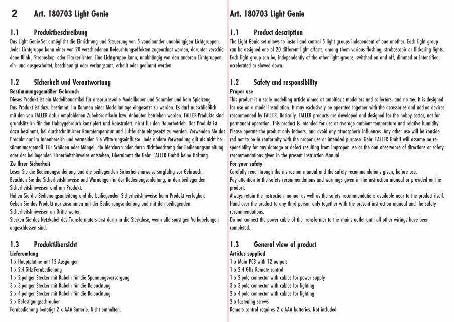
1.1 ProduktbeschreibungDas Light Genie-Set ermöglicht die Einrichtung und Steuerung von 5 voneinander unabhängigen Lichtgruppen.Jeder Lichtgruppe kann einer von 20 verschiedenen Beleuchtungseffekten zugeordnet werden, darunter verschie-dene Blink-, Stroboskop- oder Flackerlichter. Eine Lichtgruppe kann, unabhängig von den anderen Lichtgruppen,ein- und ausgeschaltet, beschleunigt oder verlangsamt, erhellt oder gedimmt werden.
1.2 Sicherheit und VerantwortungBestimmungsgemäßer GebrauchDieses Produkt ist ein Modellbauartikel für anspruchsvolle Modellbauer und Sammler und kein Spielzeug.Das Produkt ist dazu bestimmt, im Rahmen einer Modellanlage eingesetzt zu werden. Es darf ausschließlichmit den von FALLER dafür empfohlenen Zubehörartikeln bzw. Anbauten betrieben werden. FALLER-Produkte sindgrundsätzlich für den Hobbygebrauch konzipiert und konstruiert, nicht für den Dauerbetrieb. Das Produkt istdazu bestimmt, bei durchschnittlicher Raumtemperatur und Luftfeuchte eingesetzt zu werden. Verwenden Sie dasProdukt nur im Innenbereich und vermeiden Sie Witterungseinflüsse. Jede andere Verwendung gilt als nicht be-stimmungsgemäß. Für Schäden oder Mängel, die hierdurch oder durch Nichtbeachtung der Bedienungsanleitungoder der beiliegenden Sicherheitshinweise entstehen, übernimmt die Gebr. FALLER GmbH keine Haftung.Zu Ihrer SicherheitLesen Sie die Bedienungsanleitung und die beiliegenden Sicherheitshinweise sorgfältig vor Gebrauch.Beachten Sie die Sicherheitshinweise und Warnungen in der Bedienungsanleitung, in den beiliegendenSicherheitshinweisen und am Produkt.Halten Sie die Bedienungsanleitung und die beiliegenden Sicherheitshinweise beim Produkt verfügbar.Geben Sie das Produkt nur zusammen mit der Bedienungsanleitung und mit den beiliegendenSicherheitshinweisen an Dritte weiter.Stecken Sie das Netzkabel des Transformators erst dann in die Steckdose, wenn alle sonstigen Verkabelungenabgeschlossen sind.
1.3 ProduktübersichtLieferumfang 1 x Hauptplatine mit 12 Ausgängen1 x 2,4-GHz-Fernbedienung1 x 2-poliger Stecker mit Kabeln für die Spannungsversorgung3 x 3-poliger Stecker mit Kabeln für die Beleuchtung2 x 4-poliger Stecker mit Kabeln für die Beleuchtung2 x BefestigungsschraubenFernbedienung benötigt 2 x AAA-Batterie. Nicht enthalten.
Art. 180703 Light Genie
1.1 Product descriptionThe Light Genie set allows to install and control 5 light groups independent of one another. Each light groupcan be assigned one of 20 different light effects, among them various flashing, stroboscopic or flickering lights.Each light group can be, independently of the other light groups, switched on and off, dimmed or intensified,accelerated or slowed down.
1.2 Safety and responsibilityProper useThis product is a scale modelling article aimed at ambitious modellers and collectors, and no toy. It is designedfor use on a model installation. It may exclusively be operated together with the accessories and add-on devicesrecommended by FALLER. Basically, FALLER products are developed and designed for the hobby sector, not forpermanent operation. This product is intended for use at average ambient temperature and relative humidity.Please operate the product only indoors, and avoid any atmospheric influences. Any other use will be conside-red not to be in conformity with the proper use or intended purpose. Gebr. FALLER GmbH will assume no re-sponsibility for any damage or defect resulting from improper use or the non observance of directions or safetyrecommendations given in the present Instruction Manual.For your safetyCarefully read through the instruction manual and the safety recommendations given, before use.Pay attention to the safety recommendations and warnings given in the instruction manual or provided on theproduct.Always retain the instruction manual as well as the safety recommendations available near to the product itself.Hand over the product to any third person only together with the present instruction manual and the safetyrecommendations.Do not connect the power cable of the transformer to the mains outlet until all other wirings have beencompleted.
1.3 General view of productArticles supplied1 x Main PCB with 12 outputs1 x 2.4 GHz Remote control1 x 2-pole connector with cables for power supply3 x 3-pole connector with cables for lighting2 x 4-pole connector with cables for lighting2 x fastening screwsRemote control requires 2 x AAA batteries. Not included.
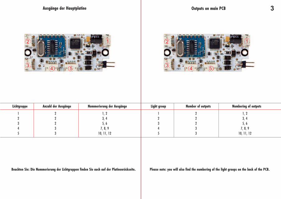
3Ausgänge der Hauptplatine
Lichtgruppe Anzahl der Ausgänge Nummerierung der Ausgänge
12345
22233
1, 23, 45, 6
7, 8, 910, 11, 12
Beachten Sie: Die Nummerierung der Lichtgruppen finden Sie auch auf der Platinenrückseite.
Outputs on main PCB
Light group Number of outputs Numbering of outputs
12345
22233
1, 23, 45, 6
7, 8, 910, 11, 12
Please note: you will also find the numbering of the light groups on the back of the PCB.
2
3 4 5
1 2
3 4 5
1
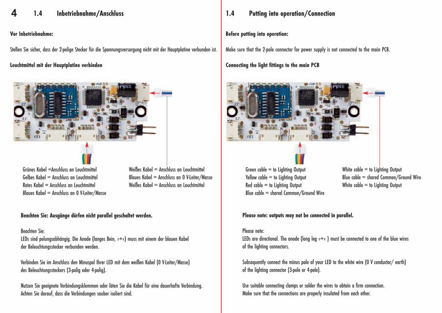
4 1.4 Inbetriebnahme/Anschluss
Vor Inbetriebnahme:
Stellen Sie sicher, dass der 2-polige Stecker für die Spannungsversorgung nicht mit der Hauptplatine verbunden ist.
Leuchtmittel mit der Hauptplatine verbinden
Beachten Sie: Ausgänge dürfen nicht parallel geschaltet werden.
Beachten Sie:LEDs sind polungsabhängig. Die Anode (langes Bein, »+«) muss mit einem der blauen Kabelder Beleuchtungsstecker verbunden werden.
Verbinden Sie im Anschluss den Minuspol Ihrer LED mit dem weißen Kabel (0 V-Leiter/Masse)des Beleuchtungssteckers (3-polig oder 4-polig).
Nutzen Sie geeignete Verbindungsklemmen oder löten Sie die Kabel für eine dauerhafte Verbindung.Achten Sie darauf, dass die Verbindungen sauber isoliert sind.
Weißes Kabel = Anschluss an Leuchtmittel Blaues Kabel = Anschluss an 0 V-Leiter/MasseWeißes Kabel = Anschluss an Leuchtmittel
Grünes Kabel =Anschluss an LeuchtmittelGelbes Kabel = Anschluss an LeuchtmittelRotes Kabel = Anschluss an LeuchtmittelBlaues Kabel = Anschluss an 0 V-Leiter/Masse
1.4 Putting into operation/Connection
Before putting into operation:
Make sure that the 2-pole connector for power supply is not connected to the main PCB.
Connecting the light fittings to the main PCB
Please note: outputs may not be connected in parallel.
Please note:LEDs are directional. The anode (long leg »+« ) must be connected to one of the blue wiresof the lighting connectors.
Subsequently connect the minus pole of your LED to the white wire (0 V conductor/ earth)of the lighting connector (3-pole or 4-pole).
Use suitable connecting clamps or solder the wires to obtain a firm connection.Make sure that the connections are properly insulated from each other.
White cable = to Lighting OutputBlue cable = shared Common/Ground WireWhite cable = to Lighting Output
Green cable = to Lighting OutputYellow cable = to Lighting OutputRed cable = to Lighting OutputBlue cable = shared Common/Ground Wire
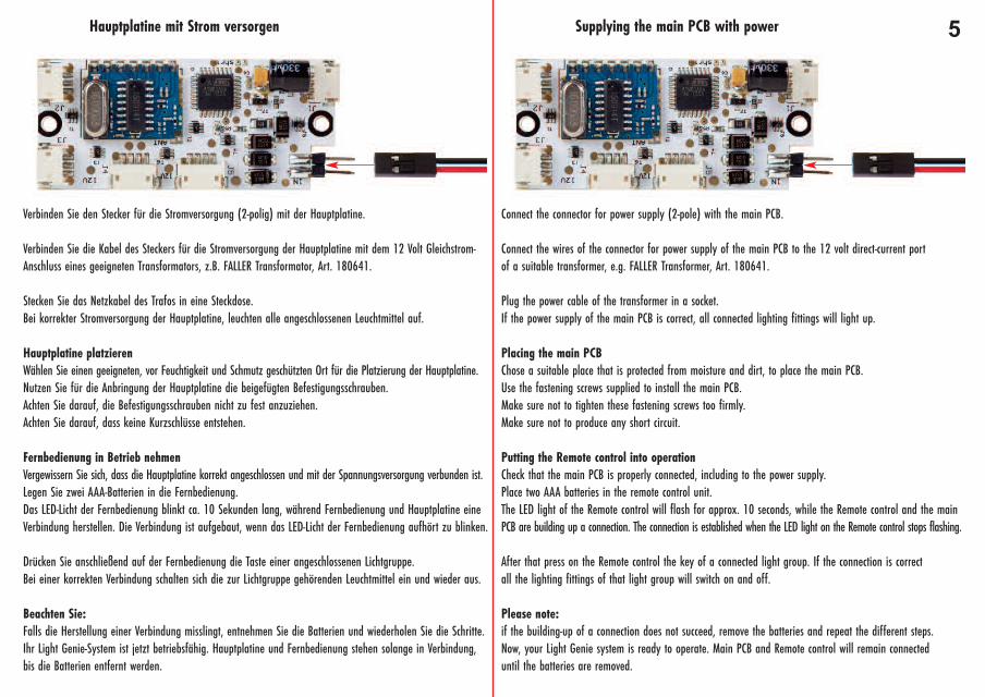
5Hauptplatine mit Strom versorgen
Verbinden Sie den Stecker für die Stromversorgung (2-polig) mit der Hauptplatine.
Verbinden Sie die Kabel des Steckers für die Stromversorgung der Hauptplatine mit dem 12 Volt Gleichstrom-Anschluss eines geeigneten Transformators, z.B. FALLER Transformator, Art. 180641.
Stecken Sie das Netzkabel des Trafos in eine Steckdose.Bei korrekter Stromversorgung der Hauptplatine, leuchten alle angeschlossenen Leuchtmittel auf.
Hauptplatine platzierenWählen Sie einen geeigneten, vor Feuchtigkeit und Schmutz geschützten Ort für die Platzierung der Hauptplatine.Nutzen Sie für die Anbringung der Hauptplatine die beigefügten Befestigungsschrauben.Achten Sie darauf, die Befestigungsschrauben nicht zu fest anzuziehen.Achten Sie darauf, dass keine Kurzschlüsse entstehen.
Fernbedienung in Betrieb nehmenVergewissern Sie sich, dass die Hauptplatine korrekt angeschlossen und mit der Spannungsversorgung verbunden ist.Legen Sie zwei AAA-Batterien in die Fernbedienung.Das LED-Licht der Fernbedienung blinkt ca. 10 Sekunden lang, während Fernbedienung und Hauptplatine eineVerbindung herstellen. Die Verbindung ist aufgebaut, wenn das LED-Licht der Fernbedienung aufhört zu blinken.
Drücken Sie anschließend auf der Fernbedienung die Taste einer angeschlossenen Lichtgruppe.Bei einer korrekten Verbindung schalten sich die zur Lichtgruppe gehörenden Leuchtmittel ein und wieder aus.
Beachten Sie:Falls die Herstellung einer Verbindung misslingt, entnehmen Sie die Batterien und wiederholen Sie die Schritte.Ihr Light Genie-System ist jetzt betriebsfähig. Hauptplatine und Fernbedienung stehen solange in Verbindung,bis die Batterien entfernt werden.
Supplying the main PCB with power
Connect the connector for power supply (2-pole) with the main PCB.
Connect the wires of the connector for power supply of the main PCB to the 12 volt direct-current portof a suitable transformer, e.g. FALLER Transformer, Art. 180641.
Plug the power cable of the transformer in a socket.If the power supply of the main PCB is correct, all connected lighting fittings will light up.
Placing the main PCBChose a suitable place that is protected from moisture and dirt, to place the main PCB.Use the fastening screws supplied to install the main PCB.Make sure not to tighten these fastening screws too firmly.Make sure not to produce any short circuit.
Putting the Remote control into operationCheck that the main PCB is properly connected, including to the power supply.Place two AAA batteries in the remote control unit.The LED light of the Remote control will flash for approx. 10 seconds, while the Remote control and the mainPCB are building up a connection. The connection is established when the LED light on the Remote control stops flashing.
After that press on the Remote control the key of a connected light group. If the connection is correctall the lighting fittings of that light group will switch on and off.
Please note:if the building-up of a connection does not succeed, remove the batteries and repeat the different steps.Now, your Light Genie system is ready to operate. Main PCB and Remote control will remain connecteduntil the batteries are removed.
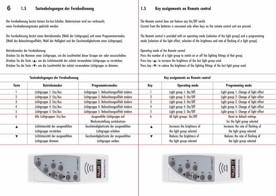
6 1.5 Tastenbelegungen der Fernbedienung
Die Fernbedienung besitzt keinen Ein-Aus-Schalter. Batteriestrom wird nur verbraucht,wenn Fernbedienungstasten gedrückt werden.
Die Fernbedienung besitzt einen Betriebsmodus (Wahl der Lichtgruppe) und einen Programmiermodus(Wahl des Beleuchtungseffekts, Wahl der Helligkeit und der Geschwindigkeitsrate einer Lichtgruppe).
Betriebsmodus der FernbedienungDrücken Sie die Nummer einer Lichtgruppe, um die Leuchtmittel dieser Gruppe ein- oder auszuschalten.Drücken Sie die Taste »▲« um die Lichtintensität der zuletzt verwendeten Lichtgruppe zu verstärken.Drücken Sie die Taste »▼« um die Leuchtmittel der zuletzt verwendeten Lichtgruppe zu dimmen.
Taste Betriebsmodus
Tastenbelegungen der Fernbedienung
Programmiermodus
123456
▲
▼
123456
▲
▼
Lichtgruppe 1: Ein/AusLichtgruppe 2: Ein/AusLichtgruppe 3: Ein/AusLichtgruppe 4: Ein/AusLichtgruppe 5: Ein/AusAlle Lichtgruppen: Ein/Aus
Lichtintensität der ausgewähltenLichtgruppe verstärkenLichtintensität der ausgewähltenLichtgruppe dimmen
Lichtgruppe 1: Beleuchtungseffekt ändernLichtgruppe 2: Beleuchtungseffekt ändernLichtgruppe 3: Beleuchtungseffekt ändernLichtgruppe 4: Beleuchtungseffekt ändernLichtgruppe 5: Beleuchtungseffekt ändern
Ausgewählte Lichtgruppe aufWerkseinstellung zurücksetzen
Geschwindigkeitsrate der ausgewähltenLichtgruppe erhöhen
Geschwindigkeitsrate der ausgewähltenLichtgruppe senken
1.5 Key assignments on Remote control
The Remote control does not feature any On/Off switch.Current from the batteries is consumed only when keys on the remote control unit are pressed.
The Remote control is provided with an operating mode (selection of the light group) and a programmingmode (selection of the light effect, selection of the brightness and rate of flashing of a light group).
Operating mode of the Remote controlPress the number of a light group to switch on or off the lighting fittings of that group.Press key »▲« to increase the brightness of the last light group used.Press key »▼« to reduce the brightness of the lighting fittings of the last light group used.
Key Operating mode
Key assignments on Remote control
Programming mode
Light group 1: On/OffLight group 2: On/OffLight group 3: On/OffLight group 4: On/OffLight group 5: On/OffAll light groups: On/Off
Increases the brightness of the light group selectedReduces the brightness of the light group selected
Light group 1: Change of light effectLight group 2: Change of light effectLight group 3: Change of light effectLight group 4: Change of light effectLight group 5: Change of light effect
Reset to default settings for the light group selected
Increases the rate of flashing of the light group selected
Reduces the rate of flashing of the light group selected
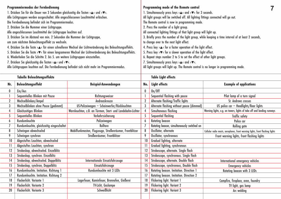
7Programmiermodus der Fernbedienung1. Drücken Sie für die Dauer von 3 Sekunden gleichzeitig die Tasten »▲« und »▼«.Alle Lichtgruppen werden ausgeschaltet. Alle angeschlossenen Leuchtmittel erlöschen.Die Fernbedienung befindet sich im Programmiermodus.2. Drücken Sie die Nummer einer Lichtgruppe.Alle angeschlossenen Leuchtmittel der Lichtgruppe leuchten auf.3. Drücken Sie im Abstand von min. 2 Sekunden die Nummer der Lichtgruppe,um zum nächsten Beleuchtungseffekt zu wechseln.4. Drücken Sie die Taste »▲« für einen schnelleren Wechsel der Lichtveränderung des Beleuchtungseffekts.5. Drücken Sie die Taste »▼« für einen langsameren Wechsel der Lichtveränderung des Beleuchtungseffekts.6. Wiederholen Sie die Schritte 2. bis 5. um weitere Lichtgruppen einzustellen.7. Drücken Sie gleichzeitig die Tasten »▲« und »▼«.Alle Lichtgruppen leuchten auf. Die Fernbedienung befindet sich nicht mehr im Programmiermodus.
Nr. Beleuchtungseffekt
Tabelle Beleuchtungseffekte
Beispiel-Anwendungen
01234567891011121314151617181920
Ein/AusSequentielles Blinken mit PauseWechselblinken/AmpelWechselblinken ohne Pause (gedimmt)Gleichzeitiges BlinkenSequentielles BlinkenRundumleuchteRundumleuchte, gleichzeitig eingeschaltetSchwingen abwechselndSchwingen synchronAbgestuftes Leuchten, abwechselndAbgestuftes Leuchten, synchronStroboskop, abwechselnd. EinzelblitzStroboskop, synchron. EinzelblitzStroboskop, abwechselnd. DoppelblitzStroboskop, synchron, DoppelblitzRundumleuchte. Imitation. Richtung 1Rundumleuchte. Imitation. Richtung 2Flackerlicht. Variante 1Flackerlicht. Variante 2Flackerlicht. Variante 3
RichtungsweiserAndreaskreuze
US-Polizeiwagen – Scheinwerfer/RückleuchtenWarnleuchten, z.B. an Türmen, Start- und Landebahn-Lichter
VerkehrssicherungPolizeiwagen
RolltoreMobilfunkmasten, Flugzeuge, Straßenräumer, Frontblitzer
Straßenräumer, Frontblitzer
Internationale EinsatzfahrzeugeEinsatzfahrzeuge
Rundumleuchte mit 3 LEDs
Lagerfeuer, Kaminfeuer, Brennofen, GießereiTV-Licht, Gaslampe
Schweißlicht
Programming mode of the Remote control1. Simultaneously press keys »▲« and »▼« for 3 seconds.All light groups will be switched off. All lighting fittings connected will go out.The Remote control is now in programming mode.2. Press the number of a light group.All connected lighting fittings of that light group will light up.3. Briefly press the number of the light group, while keeping a time interval of at least 2 seconds,to change over to the next light effect.4. Press key »▲« for a faster operation of the light effect.5. Press key »▼« for a slower operation of the light effect.6. Repeat steps number 2 to 5 to set the effect of other light groups.7. Simultaneously press keys »▲« and »▼«.All light groups will light up. The Remote control is no longer in programming mode.
No. Light effects
Table Light effects
Example of applications
01234567891011121314151617181920
On/OffSequential flashing with pauseAlternate flashing/Traffic lightsAlternate flashing without pause (dimmed)Simultaneous flashingSequential flashingRotating beaconRotating beacon, simultaneously switched onOscillator, alternateOscillator, synchronousGradual lighting, alternateGradual lighting, synchronousStroboscope, alternate. Single flashStroboscope, synchronous. Single flashStroboscope, alternate. Double flashStroboscope, synchronous, Double flashRotating beacon. Imitation. Direction 1Rotating beacon. Imitation. Direction 2Flickering light. Variant 1Flickering light. Variant 2Flickering light. Variant 3
Pilot lamp of a turn signalSt. Andrews crosses
US police car – Headlights/Rear lightsWarning lights, e.g. on towers, lights of take off and landing runways
Traffic safetyPolice car
Rolling gateCellular radio masts, aeroplanes, front warning lights, front flashing lights
Front warning lights, front flashing lights
International emergency vehiclesEmergency vehicles
Rotating beacon with 3 LEDs
Campfire, fireplace, oven, foundryTV light, gas lamp
Arc welding
8 1.6 Wissenswertes
Vorwiderstände
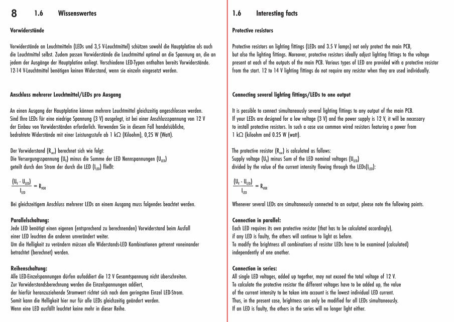
Vorwiderstände an Leuchtmitteln (LEDs und 3,5 V-Leuchtmittel) schützen sowohl die Hauptplatine als auchdie Leuchtmittel selbst. Zudem passen Vorwiderstände die Leuchtmittel optimal an die Spannung an, die anjedem der Ausgänge der Hauptplatine anliegt. Verschiedene LED-Typen enthalten bereits Vorwiderstände.12-14 V-Leuchtmittel benötigen keinen Widerstand, wenn sie einzeln eingesetzt werden.
Anschluss mehrerer Leuchtmittel/LEDs pro Ausgang
An einen Ausgang der Hauptplatine können mehrere Leuchtmittel gleichzeitig angeschlossen werden.Sind Ihre LEDs für eine niedrige Spannung (3 V) ausgelegt, ist bei einer Anschlussspannung von 12 Vder Einbau von Vorwiderständen erforderlich. Verwenden Sie in diesem Fall handelsübliche,bedrahtete Widerstände mit einer Leistungsstufe ab 1 kΩ (Kiloohm), 0,25 W (Watt).
Der Vorwiderstand (Rvor) berechnet sich wie folgt:Die Versorgungsspannung (UV) minus die Summe der LED Nennspannungen (ULED)geteilt durch den Strom der durch die LED (ILED) fließt:
(UV - ULED)______ILED
= RVOR
Bei gleichzeitigem Anschluss mehrerer LEDs an einem Ausgang muss folgendes beachtet werden.
Parallelschaltung:Jede LED benötigt einen eigenen (entsprechend zu berechnenden) Vorwiderstand beim Ausfalleiner LED leuchten die anderen unverändert weiter.Um die Helligkeit zu verändern müssen alle Widerstands-LED Kombinationen getrennt voneinanderbetrachtet (berechnet) werden.
Reihenschaltung:Alle LED-Einzelspannungen dürfen aufaddiert die 12 V Gesamtspannung nicht überschreiten.Zur Vorwiderstandsberechnung werden die Einzelspannungen addiert,der hierfür heranzuziehende Stromwert richtet sich nach dem geringsten Einzel LED-Strom.Somit kann die Helligkeit hier nur für alle LEDs gleichzeitig geändert werden.Wenn eine LED ausfällt leuchtet keine mehr in dieser Reihe.
The protective resistor (Rvor) is calculated as follows:Supply voltage (UV) minus Sum of the LED nominal voltages (ULED)divided by the value of the current intensity flowing through the LEDs(ILED):
(UV - ULED)______ILED
= RVOR
Whenever several LEDs are simultaneously connected to an output, please note the following points.
Connection in parallel:Each LED requires its own protective resistor (that has to be calculated accordingly),if any LED is faulty, the others will continue to light as before.To modify the brightness all combinations of resistor LEDs have to be examined (calculated)independently of one another.
Connection in series:All single LED voltages, added up together, may not exceed the total voltage of 12 V.To calculate the protective resistor the different voltages have to be added up, the valueof the current intensity to be taken into account is the lowest individual LED current.Thus, in the present case, brightness can only be modified for all LEDs simultaneously.If an LED is faulty, the others in the series will no longer light either.
1.6 Interesting facts
Protective resistors
Protective resistors on lighting fittings (LEDs and 3.5 V lamps) not only protect the main PCB,but also the lighting fittings. Moreover, protective resistors ideally adjust lighting fittings to the voltagepresent at each of the outputs of the main PCB. Various types of LED are provided with a protective resistorfrom the start. 12 to 14 V lighting fittings do not require any resistor when they are used individually.
Connecting several lighting fittings/LEDs to one output
It is possible to connect simultaneously several lighting fittings to any output of the main PCB.If your LEDs are designed for a low voltage (3 V) and the power supply is 12 V, it will be necessaryto install protective resistors. In such a case use common wired resistors featuring a power from1 kΩ (kiloohm and 0.25 W (watt).
91.7 Anwendungsbeispiele
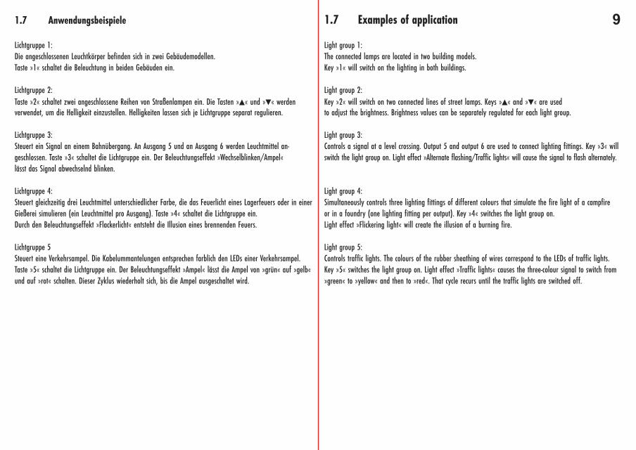
Lichtgruppe 1:Die angeschlossenen Leuchtkörper befinden sich in zwei Gebäudemodellen.Taste »1« schaltet die Beleuchtung in beiden Gebäuden ein.
Lichtgruppe 2:Taste »2« schaltet zwei angeschlossene Reihen von Straßenlampen ein. Die Tasten »▲« und »▼« werdenverwendet, um die Helligkeit einzustellen. Helligkeiten lassen sich je Lichtgruppe separat regulieren.
Lichtgruppe 3:Steuert ein Signal an einem Bahnübergang. An Ausgang 5 und an Ausgang 6 werden Leuchtmittel an-geschlossen. Taste »3« schaltet die Lichtgruppe ein. Der Beleuchtungseffekt »Wechselblinken/Ampel«lässt das Signal abwechselnd blinken.
Lichtgruppe 4:Steuert gleichzeitig drei Leuchtmittel unterschiedlicher Farbe, die das Feuerlicht eines Lagerfeuers oder in einerGießerei simulieren (ein Leuchtmittel pro Ausgang). Taste »4« schaltet die Lichtgruppe ein.Durch den Beleuchtungseffekt »Flackerlicht« entsteht die Illusion eines brennenden Feuers.
Lichtgruppe 5Steuert eine Verkehrsampel. Die Kabelummantelungen entsprechen farblich den LEDs einer Verkehrsampel.Taste »5« schaltet die Lichtgruppe ein. Der Beleuchtungseffekt »Ampel« lässt die Ampel von »grün« auf »gelb«und auf »rot« schalten. Dieser Zyklus wiederholt sich, bis die Ampel ausgeschaltet wird.
1.7 Examples of application
Light group 1:The connected lamps are located in two building models.Key »1« will switch on the lighting in both buildings.
Light group 2:Key »2« will switch on two connected lines of street lamps. Keys »▲« and »▼« are usedto adjust the brightness. Brightness values can be separately regulated for each light group.
Light group 3:Controls a signal at a level crossing. Output 5 and output 6 are used to connect lighting fittings. Key »3« willswitch the light group on. Light effect »Alternate flashing/Traffic lights« will cause the signal to flash alternately.
Light group 4:Simultaneously controls three lighting fittings of different colours that simulate the fire light of a campfireor in a foundry (one lighting fitting per output). Key »4« switches the light group on.Light effect »Flickering light« will create the illusion of a burning fire.
Light group 5:Controls traffic lights. The colours of the rubber sheathing of wires correspond to the LEDs of traffic lights.Key »5« switches the light group on. Light effect »Traffic lights« causes the three-colour signal to switch from»green« to »yellow« and then to »red«. That cycle recurs until the traffic lights are switched off.
10
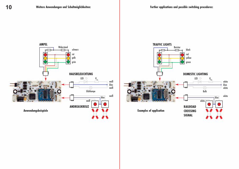
WiderstandAMPEL
HAUSBELEUCHTUNG
ANDREASKREUZ
schwarz
weiß
weiß
LED
Glühlampe
Rvor
blauweiß
blauweiß
rot
grün
gelb
Weitere Anwendungen und Schaltmöglichkeiten:
Resistor TRAFFIC LIGHTS
DOMESTIC LIGHTING
RAILROADCROSSINGSIGNAL
black
white
white
LED
Bulb
RPro
bluewhite
bluewhite
red
green
yellow
Further applications and possible switching procedures:
Anwendungsbeispiele Examples of application
111.8 Zubehörprodukte
Transformator 50 VA 50-60Hz, Art. 18064110 Verbindungsklemmen, werkzeuglos, Art. 180709FALLER Beleuchtungsprodukte
1.9 Technische Daten
Technische Spezifikationen
Maximale Ausgangsleistung pro Hauptplatine (gesamt): 1 Ampere. Max 100 mA pro Ausgang
Versorgungsspannung: 12 - 16 V DC/AC
Ausgangsspannung an allen Ausgängen: 12 V
Die Hauptplatine ist zum Schutze der Leuchtmittel mit einem Leistungsregler versehen. Der Einsatz einer höhe-ren Spannungsversorgung (höher als 13 V, max. 18 V) wird die Helligkeit der Leuchtmittel nicht erhöhen.
Reichweite der Fernbedienung: ca. 30 m
Funkfrequenz der Fernbedienung: 2,4 GHz
Hinweis:
Dieses Produkt entspricht den Anforderungen im Abschnitt 15 der Vorschriften des nordamerikanischen Bundes-ausschusses für Fernmeldewesen FCC (Federal Communications Commission). Es dürfen keine Veränderungen ander Platine vorgenommen werden, die diese beeinflussen.
Dieses Produkt ist konform zu folgenden Harmonisierungsrichtlinien der EU:
2014/30/EU (EMV)2014/53/EU (RED)2011/65/EU (RoHS)
1.8 Accessories
Transformer 50 VA, 50 to 60 Hz, Art. 18064110 Connecting clamps, no tool needed, Art. 180709FALLER Lighting products
1.9 Technical data
Technical specifications
Maximum output per PCB (total): 1 ampere. Maximum 100 mA per output
Supply voltage: 12 to 16 V DC/AC
Output voltage on all outputs: 12 V
The main PCB is provided with an output regulator to protect the lighting fittings. Thus, using a higher supplyvoltage (higher than 13 V, max. 18 V) will not increase the brightness of the lighting fittings.
Working range of Remote control: approx. 30 m
Radio frequency of Remote control: 2.4 GHz
Note:
The present product meets the requirements stated in Section 15 of the regulations laid down by the AmericanFederal Communications Commission FCC. No modification may be performed on the PCB that may affect theserequirements.
The present product complies with the following directives aiming at harmonization withinthe European Community:
2014/30/EU (EMC)2014/53/EU (RED)2011/65/EU (RoHS)
12 1. Art. 180703 Light Genie...........................Seite 2
1.1 Produktbeschreibung.................................Seite 2
1.2 Sicherheit und Verantwortung....................Seite 2
1.3 Produktübersicht........................................Seite 2
1.4 Inbetriebnahme/Anschluss.........................Seite 4
1.5 Tastenbelegungen der Fernbedienung........Seite 6
1.6 Wissenswertes............................................Seite 8
1.7 Anwendungsbeispiele.................................Seite 9
1.8 Zubehörprodukte.......................................Seite 11
1.9 Technische Daten......................................Seite 11
1. Art. 180703 Light Genie...........................Page 2
1.1 Product description....................................Page 2
1.2 Safety and responsibility...........................Page 2
1.3 General view of product............................Page 2
1.4 Putting into operation/Connection.............Page 4
1.5 Key assignments on Remote control..........Page 6
1.6 Interesting facts........................................Page 8
1.7 Examples of application............................Page 9
1.8 Accessories................................................Page 11
1.9 Technical data...........................................Page 11