LINOS Microbench, Bench and Rail Systems - qioptiq-shop.com · Q-Shop: . There you can conveniently...
48
LINOS Microbench, Bench and Rail Systems
Transcript of LINOS Microbench, Bench and Rail Systems - qioptiq-shop.com · Q-Shop: . There you can conveniently...
LINOS Microbench,Bench and Rail Systems

About this Brochure
Seit nunmehr 50 Jahren befindet sich die LINOS Mikrobank™ in Serienproduktion. Zu diesem Jubiläum freuen wir uns ganz besonders, Ihnen eine Neuauflage unserer bewährten Applikations-broschüre zu den LINOS Banksystemen anzubieten.
Ein wichtiges Anliegen ist uns, Ihnen einen detaillierten Überblick über die Systeme zu geben und deren Kompatibilität untereinander zu erläutern. Zahlreiche Anwendungs- und Aufbaubeispiele werden Ihnen bei der Lösung Ihrer individuellen Applikationsaufgaben helfen.
Weiterhin enthält diese Ausgabe neue Produkte und erstmals unsere Reihe an Q-Sets, den kompakten Baugruppen aus Katalog Einzelkompo-nenten für vollständige optische Teilsysteme. Außerdem wird die Kompatibilität mit den Qioptiq Licht- und Lasersystemen sowie mit den Excelitas Detektoren anschaulich erläutert.
Auf den letzten Seiten wird Ihnen ein Anwender-beispiel vorgestellt, in dem die Mikrobank™ die schnelle Entwicklung eines komplexen optischen Messgerätes – ein Durchflusszytometer Prototyp - ermöglicht hat.
Weiterführende Informationen finden Sie sowohl im LINOS Hauptkatalog als auch auf unserem Webshop, dem Qioptiq Q-Shop: www.qioptiq-shop.com. Dort können Sie bequem online Bestellungen aufgeben, neueste Produkte einsehen und aktuelle Informationen erhalten.
Das Qioptiq Katalogteam wünscht Ihnen viel Spaß beim Lesen und steht Ihnen für weitere Beratun-gen gerne zur Verfügung unter [email protected] oder telefonisch unter +49 551 6935-0.
The LINOS Microbench™ system has been providing optical solutions for over 50 years. On this occasion, we are particularly pleased to present you a new edition of our Application brochure for LINOS bench systems.
Our primary focus is to provide you with a clear overview of the various systems as well as their compatibility with one another. Numerous photographs illustrate the variety of applications and setups, providing useful solutions for your applications.
Furthermore, this edition also contains our latest product offerings. For the first time we introduce our series of Q-Sets, compact optical subsystems built from standard catalog components. In addition, the brochure highlights the inter-compa-tibility of the LINOS Microbench™ with Qioptiq light sources and laser systems as well as Excelitas detectors.
Last but not least, you will find an application example in which the Microbench™ system enabled the rapid development of a complex optical measurement device - a flow cytometer prototype.
For further information please refer to the LINOS catalog as well as to our webshop, the Qioptiq Q-Shop: www.qioptiq-shop.com. There you can conveniently place orders online, view the latest products and receive the most up-to-date information.
Enjoy reading this brochure and don’t hesitate to contact the Qioptiq catalog team for further technical advice at [email protected] or by phone at +49 551 6935-0.
Zu dieser Broschüre
1990
Introduction
History of Microbench Brochures
2002
2009
2011
NEW Edition 2018
1877
Rodenstockfounded
1966
Pilkington PE Ltd. founded, which later becomes THALES Optics
1898
Spindler & Hoyerfounded
1969
GsängerOptoelektronikfounded
19961991
LINOS founded through the merger of Spindler & Hoyer, Steeg & Reuter Präzisionsoptik, Franke Optik and Gsänger Optoelektronik
Point Sourcefounded
1984
OptemInternationalfounded

Inhalt Content
Content
The Microbench Concept 4Microbench Manufacturing Line 7
LINOS Bench Systems First of its Kind: The Microbench 9Microbench's Little Sister: Nanobench 9Well-rounded Product Line: Tube System C 10Getting on Track: Flat Rail Systems FLS 10Basic Components of the different Bench Systems 11
Frequently Asked QuestionsHow Do I Begin With My Experiment? 16How Do I Integrate Spherical Optics? 18How Do I Integrate Plano Optics? 19How Do I Apply Adhesives? 20How Do I Integrate Optics into Existing Setups? 21How Do I Adjust Optics along the X and Y Axis? 22What Options Are Available for Rotation of Optics? 23How Do I Adjust Optics along the Z Axis? 24How Can I Realize Different Angles in My Setup? 26What Adapters are Available? 27How Do I Mount My Assembly on e.g. Optical Tables? 28What Light Sources Are Available? 30How Can I Combine Systems? 32How Do I Mount Bench Systems in My Instrument? 33How do I connect Photon Counters to the Microbench? 34How Do I Integrate Motorized Positioners? 36
Q-SetsQ-Sets – How to Save Time in the Lab 37Q-Set Vertical Adjustment 37Q-Set Variable Attenuator / Beamsplitter 38Q-Set Spatial Filter 38Q-Set Filter Cascade 39Q-Set Fiber Coupler 39Q-Set Spectroscopy Liquids 39Q-Set Spectroscopy Plates 40Q-Set Retroreflector 40Q-Set Prism Stage 41
Applications Creating a Spatial Filter System 42Creating an Expansion System 43Creating a Fiber Coupler 44
Prototype SetupSetup of a Modular Flow Cytometer 45
Die Idee der Mikrobank 4Mikrobank Produktion 6
LINOS Banksysteme Das Original: Die Mikrobank 9Die kleine Schwester: Die Nanobank 9Eine runde Sache: Das Tubus System C 10Auf die Schiene: Flachschienensysteme FLS 10Basiskomponenten der verschiedenen Banksysteme 11
Fragen und Lösungen Wie starte ich mein Experiment? 16Wie integriere ich Rundoptiken? 18Wie integriere ich Planoptiken? 19Was muss ich beim Kleben von Optiken beachten? 20Wie kann ich Optiken nachträglich integrieren? 21Wie kann ich Optiken in XY-Richtung justieren? 22Welche Möglichkeiten zur Rotation von Optiken gibt es? 23Wie kann ich Optiken in Z-Richtung verschieben? 24Wie realisiere ich andere Aufbauwinkel? 26Welche Adapter gibt es? 27Wie montiere ich meinen Aufbau, z.B. auf optischen Tischen? 28Welche Lichtquellen gibt es? 30Wie kombiniere ich Systeme miteinander? 32Wie montiere ich Banksysteme in mein Gerät? 33Wie kombiniere ich Photonenzähler mit der Mikrobank? 34Wie integriere ich Motorische Positionierer? 36
Q-SetsQ-Sets – Wie Sie im Labor Zeit sparen 37Q-Set Höhenverstellung 37Q-Set Variabler Abschwächer / Strahlteiler 38Q-Set Raumfilter 38Q-Set Filterkaskade 39Q-Set Faserkoppler 39Q-Set Spektroskopie Flüssigkeiten 39Q-Set Spektroskopie Platte 40Q-Set Retroreflektor 40Q-Set Prismenbühne 41
ApplikationsbeispieleRealisierung eines Raumfiltersystems 42Realisierung eines Aufweitungssystems 43Realisierung einer Fasereinkopplung 44
Entwicklung eines PrototypenAufbau eines Modularen Durchflusszytometers 45
2000
Rodenstock Präzisionsoptikacquiredby LINOS
2001
AVIMO Group acquired by THALES
2005
Qioptiqfounded as THALES sellsHigh TechOptics Group
2006 / 2007
Qioptiq acquiresLINOS and Point Source as “members of the Qioptiq group”
2010
The new Qioptiq consolidates allgroup membersunder one brand
Qioptiq is aquired by Excelitas Technologies
2013

4 Phone +49(0).551 69 35-0 Fax +49(0).551 69 35-166 [email protected]
LINOS (the Catalog line of Qioptiq) – formerly Spindler & Hoyer – and the MicrobenchTM system are bound together inseparably, and have been so for more than 50 years now. The long-established Spindler & Hoyer company began production of the compact 4-rod MicrobenchTM system, the innovative successor to the triangular rail system, as early as 1968.
Until well into the 1960s, optical test assemblies were typically set up on triangular profile, or "Zeiss profile", optical benches. These were heavy and relatively large constructions that permitted only linear, level optical arrangements. Those systems that did allow spatial expansion were not sufficiently torsion-resistant for metro logical applications and thus were only suitable for demonstration purposes. The dimensions of the accessories for these earlier model benches made it impossible to achieve the compactness often sought-after in an optical setup. Furthermore, the insertion of microscope assemblies such as polarization, interference or measuring micro-scopes was exceedingly complex with conventio-nal optical benches. The logical step was the development of a novel micro-optical bench.
The distinctive feature of the new system was its high stability and precision. Since its introduction, optical and mechanical components of the MicrobenchTM system have become indispensable in optical laboratory experiments and are built into a large number of optomechanical devices.
Instruments made up of MicrobenchTM components are also ideal for demonstrations and practical training: the exposed design makes it not easy only to observe the entire system but also to alter or expand its most basic workings by simply adding components, such as grids, prisms, mirrors or other accessories.
The Microbench ConceptDie Idee der MikrobankMikrobankTM und Spindler & Hoyer, heute Qioptiq, sind untrennbar miteinander verbunden – und das seit nunmehr über 50 Jahren. Bereits 1968 wurde das kompakte 4-Stangen-Aufbausystem für Optiken bei dem Göttinger Traditionsunternehmen Spindler & Hoyer als innovatives Nachfolgeprodukt des Dreikantschienensystems in Serie gefertigt.
Bis weit in die 60er Jahre wurden optische Versuchsaufbauten nach dem Prinzip der Optischen Bank auf Dreikantschienen mit dem so genannten "Zeiss-Profil" aufgebaut. Mit diesen schweren und relativ groß dimensionierten Konstruktionen waren nur lineare und ebene optische Aufbauten durchführbar. Systeme, die auch die Realisierung räumlicher Aufbauten zuließen, waren für messtechnische Ansprüche nicht genügend verwindungssteif und daher nur für Demonstrationsversuche geeignet. Diese bisher bekannten Bänke gestatteten es wegen der Abmessungen ihrer Zusatzteile nicht, einen Aufbau in beliebig gedrängter Form vorzunehmen. Auch das Einfügen mikroskopischer Anordnungen wie z.B. Polarisations-, Interferenz- oder Mess-Mikros-kope in einen Versuchsaufbau war bei der klassischen Optischen Bank recht umständlich. Logische Konsequenz war daher die Entwicklung einer neuartigen Mikro-Optischen Bank.
Das neue System zeichnete sich insbesondere durch seine hohe Stabilität und Präzision aus. Seitdem sind die optischen und mechanischen Komponenten des MikrobankTM Systems unentbehrliche Helfer bei optischen Laborexperi-menten sowie fester Bestandteil in zahlreichen optomechanischen Geräten.
Aus MikrobankTM Komponenten zusammengesetz-te Instrumente eignen sich auch hervorragend für Demonstration und Praktikum: Sie lassen durch die offene Bauweise jederzeit das System erkennen und sind in ihrem Grundtyp durch Einfügen zusätzlicher Bauelemente (Gitter, Prismen, Spiegel etc.) leicht zu verändern oder zu erweitern.
Julius Adolf Hoyer und August Spindler, die Gründer von SPINDLER & HOYER, heute Qioptiq. Julius Adolf Hoyer and August Spindler, founders
of Spindler & Hoyer (now Qioptiq)
Vorstudie MikrobankTM (ca. 1960):Die wichtigsten Elemente wie Aufnahmeplatten, Verbindungsstangen und Halter sind bereits zu erkennen.Draft design of the MicrobenchTM (about 1960): mounting plates, connecting rods and mounts are still recognizable today
Introduction
5Phone +49(0).551 69 35-0 Fax +49(0).551 69 35-166 [email protected]
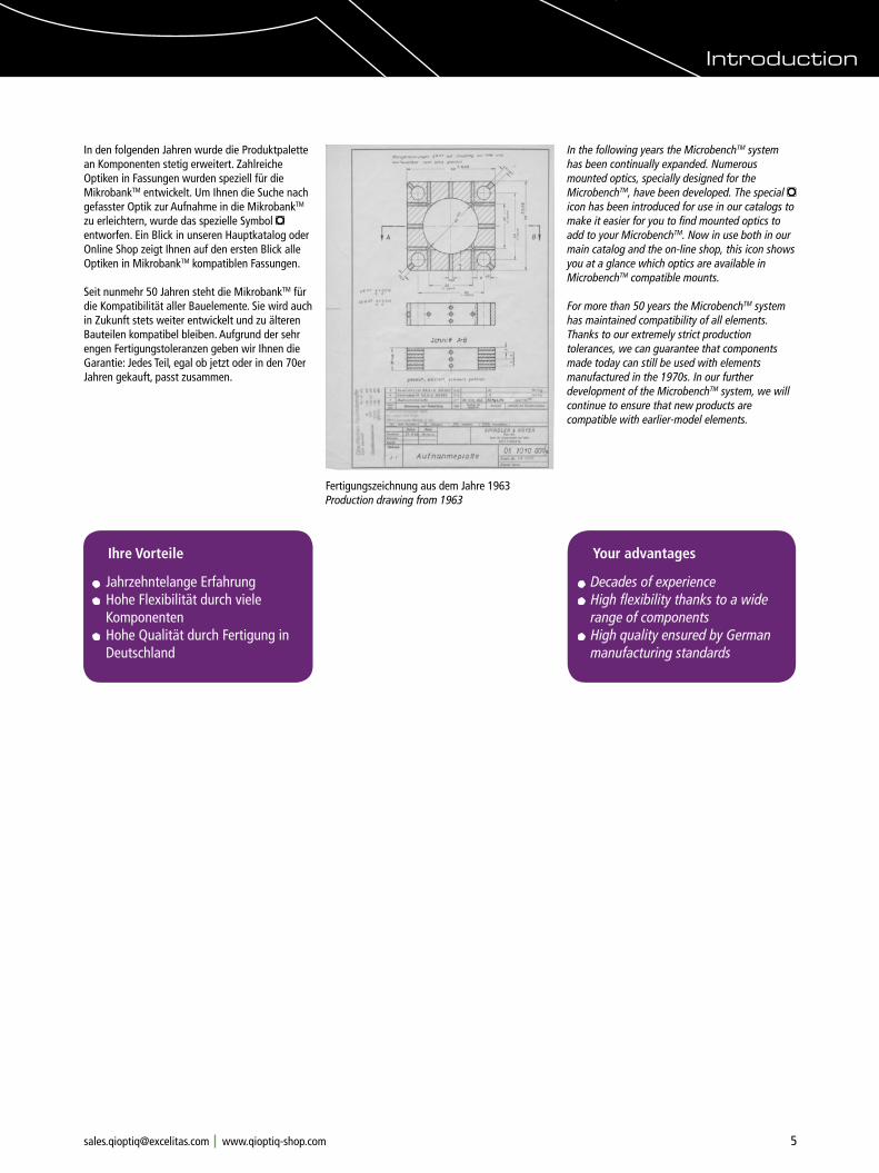
The Microbench ConceptIn the following years the MicrobenchTM system has been continually expanded. Numerous mounted optics, specially designed for the MicrobenchTM, have been developed. The special m icon has been introduced for use in our catalogs to make it easier for you to find mounted optics to add to your MicrobenchTM. Now in use both in our main catalog and the on-line shop, this icon shows you at a glance which optics are available in MicrobenchTM compatible mounts.
For more than 50 years the MicrobenchTM system has maintained compatibility of all elements. Thanks to our extremely strict production tolerances, we can guarantee that components made today can still be used with elements manufactured in the 1970s. In our further development of the MicrobenchTM system, we will continue to ensure that new products are compatible with earlier-model elements.
Fertigungszeichnung aus dem Jahre 1963 Production drawing from 1963
In den folgenden Jahren wurde die Produktpalette an Komponenten stetig erweitert. Zahlreiche Optiken in Fassungen wurden speziell für die MikrobankTM entwickelt. Um Ihnen die Suche nach gefasster Optik zur Aufnahme in die MikrobankTM zu erleichtern, wurde das spezielle Symbol m entworfen. Ein Blick in unseren Hauptkatalog oder Online Shop zeigt Ihnen auf den ersten Blick alle Optiken in MikrobankTM kompatiblen Fassungen.
Seit nunmehr 50 Jahren steht die MikrobankTM für die Kompatibilität aller Bauelemente. Sie wird auch in Zukunft stets weiter entwickelt und zu älteren Bauteilen kompatibel bleiben. Aufgrund der sehr engen Fertigungstoleranzen geben wir Ihnen die Garantie: Jedes Teil, egal ob jetzt oder in den 70er Jahren gekauft, passt zusammen.
Ihre Vorteile
Jahrzehntelange Erfahrung Hohe Flexibilität durch viele
Komponenten Hohe Qualität durch Fertigung in
Deutschland
Your advantages
Decades of experience High flexibility thanks to a wide
range of components High quality ensured by German manufacturing standards
Introduction

6 Phone +49(0).551 69 35-0 Fax +49(0).551 69 35-166 [email protected]
Mikrobank Produktion Excellentes Material
RoHS-konforme Materialien Spezielle Legierungen
für höchste Ansprüche
Optimierte Fertigung
Teilefertigung in einem Arbeitsablauf Höchste Präzision für unsere sehr engen Toleranzen
für höchste Genauigkeit
Qualitätskontrolle am Koordinatenmessplatz
100 % Endkontrolle aller Toleranzen Prüfen der Passgenauigkeit aller Komponenten Sicherstellung der Kompatibilität aller Mikrobank Komponenten
für gleichbleibende Qualität seit mehr als 50 Jahren!
Oberflächenveredelungmit Präzisionseloxal
Hohe Verschleißfestigkeit Höchste Abriebfestigkeit sichert die gefertigten strengen Toleranzen Mattschwarzes Eloxal verhindert Reflexe
fürbesteOberflächengüte
Material aus hochwertigsterAluminium-Legierung,Beispiel: Rundmaterialfür Aufnahmeplatten
9-Achs-CNC-Fräsmaschinebearbeitet alle Produktionsstufen,von der Aluminium-Rundstangebis zur fertigen Aufnahmeplatte mit allen Bohrungen undGewinden
Endkontrolle derToleranzen einerAufnahmeplatte miteiner Koordinaten-Messmaschine
Mikrobank Würfel inHalterung nach derOberflächenveredelungim Eloxalbad
ò
ò
ò
... und das Beste:Alle LINOS Komponenten sind und RoHS und WEEE konform
Introduction
7Phone +49(0).551 69 35-0 Fax +49(0).551 69 35-166 [email protected]
Microbench Manufacturing Line
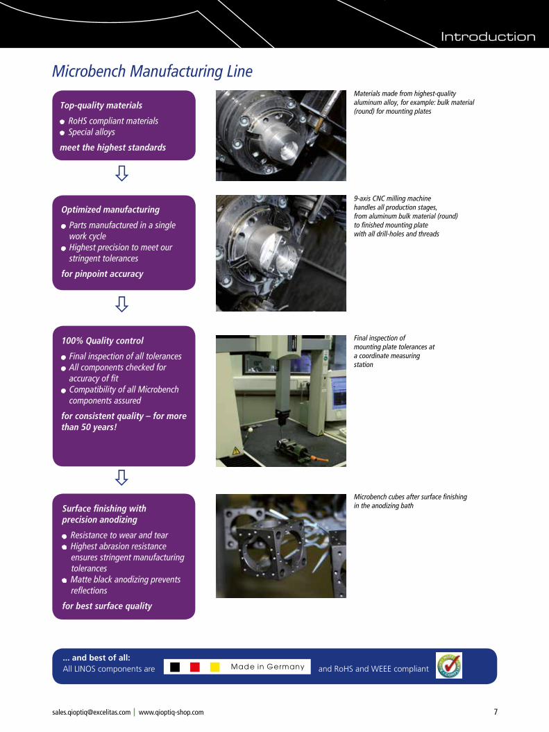
Top-quality materials
RoHS compliant materials Special alloys
meet the highest standards
Optimized manufacturing
Parts manufactured in a single work cycle Highest precision to meet our stringent tolerances
for pinpoint accuracy
100% Quality control
Final inspection of all tolerances All components checked for accuracy of fit Compatibility of all Microbench components assured
for consistent quality – for more than 50 years!
Surface finishing with precision anodizing
Resistance to wear and tear Highest abrasion resistance
ensures stringent manufacturing tolerances
Matte black anodizing prevents reflections
for best surface quality
Materials made from highest-qualityaluminum alloy, for example: bulk material(round) for mounting plates
9-axis CNC milling machine handles all production stages, from aluminum bulk material (round) to finished mounting plate with all drill-holes and threads
Final inspection ofmounting plate tolerances at a coordinate measuringstation
Microbench cubes after surface finishing in the anodizing bath
ò
ò
ò
... and best of all:All LINOS components are and RoHS and WEEE compliant
Introduction

8 Phone +49(0).551 69 35-0 Fax +49(0).551 69 35-166 [email protected]
LINOS Bench SystemsLINOS BanksystemeLINOS bench and rail systems for experimental set-ups and measuring / inspection equipment offer high precision, excellent mechanical stability and flexibility in use. Our Microbench system has stood the test of time for more than five decades, and we are constantly expanding the system to make sure all your requirements are met. At the same time, we continue to specialize in trend-setting developments.
Several years ago, in response to the growing demand for smaller systems, Qioptiq introduced the LINOS Nanobench system. Compared to the 40-mm edge length of the Microbench system, the Nanobench edge length is just 25 mm.
Another product line is our modular, closed component Tube System C. It enables fast set-ups of enclosed optical systems. The tubes have outer diameters of 30 mm and 35 mm. The system features a wide variety of lens mounts, dia-phragms and adjustment units. The universal 1-32 UN mounting unit (C-Mount) enables direct connection to CCD cameras, lasers and micro-scopes.
When searching for mechanical systems for micro-optical applications, look no farther than to our Rail Systems FLS, including the FLS 40 series specially developed for the LINOS Microbench. This flat rail system can be used with individual components, such as mounted optics or positioners. It can also be used to fasten complex Microbench structures to optical tables.
No matter which products you choose from our modular bench and rail systems, excellent compatibility of the systems with one another is guaranteed. And many other of our products, from mounted optics to lasers, can be directly integrated as well. This gives you the advantage of fast implementation, whether for experimental set-ups or permanent installation of complex measuring equipment. Whatever your photonic application is, you can find the optimum system or combination of systems for your particular specifications and spatial conditions within the extensive range of our bench and rail systems.
Microbench
Nanobench
Tube System C
Rail System FLS 40
Die LINOS Bank- und Schienensysteme für optische Versuchsaufbauten oder Mess- und Prüfgeräte zeichnen sich durch hohe Präzision, hervorragende mechanische Stabilität sowie ihre Vielseitigkeit aus. Die Mikrobank hat sich schon seit über fünf Jahrzehnten in der Praxis bewährt und wird von uns kontinuierlich um neue Komponenten erweitert, um Ihre Anforderungen zu erfüllen. Darüber hinaus liegt unser Augenmerk selbstver-ständlich auch auf zukunftsweisenden Entwicklun-gen.
Bedingt durch den wachsenden Bedarf an kleineren Systemen, bietet Qioptiq das LINOS Nanobank System an. Die Kantenlänge der Aufnahmeplatten wurde im Vergleich zur Mikrobank von 40 auf 25 mm reduziert.
Auch ein modulares geschlossenes Komponenten-bausystem gehört zu unserer Produktpalette: das Tubus System C zum schnellen Aufbau eigener optischer Systeme. Die Grundlage bilden Tuben, wahlweise mit den Außendurchmessern 30 und 35 mm. Komplettiert wird dieses System durch zahlreiche Optikfassungen, Blenden und Verstelleinheiten. Der universelle Fassungsan-schluss 1-32 UN (C-Mount) gewährleistet den direkten Anschluss an CCD-Kameras, Laser und Mikroskope.
Im Bereich der mechanischen Aufbausysteme für mikrooptische Anwendungen hat unsere konsequente Weiterentwicklung einen Namen: die Schienensysteme FLS, auch erhältlich in der Variante FLS 40 für die Mikrobank. Mit Hilfe dieses Flachschienensystems können sowohl einzelne Komponenten, wie gefasste Optiken oder Positionierer, als auch komplexe Mikrobank-Auf-bauten z.B. auf optischen Tischen befestigt werden.
Für alle modularen Bank- und Schienensysteme gilt: eine hohe Kompatibilität der Systeme untereinander - und nicht nur das - zahlreiche unserer Produkte, von gefasster Optik bis zum passenden Laser, werden direkt in die Systeme integriert. Ihr Vorteil: schnelle Umsetzung sowohl experimenteller Aufbauten als auch komplexer Messvorrichtungen für den dauerhaften Gebrauch. Je nach Ihren individuellen Spezifikationen und räumlichen Voraussetzungen, wählen Sie das optimale System bzw. die optimale Systemkombi-nation aus dem vielseitigen Angebot unserer Bank- und Schienensysteme.
m n Microbench and Nanobench: optomechanical bench systems
t Tube System C: modular and closed component system
M Rail System FLS: flat rails and carriers for high-
stability structures
Introduction

9Phone +49(0).551 69 35-0 Fax +49(0).551 69 35-166 [email protected]
Die Mikrobank ist ein kompaktes Komponenten-system für zahlreiche Einsatzgebiete wie z.B. für Beleuchtungs- oder Abbildungsaufbauten, optische Versuchs-, Mess- und Prüfgeräte und interferomet-rische Anwendungen, um nur einige zu nennen.
Die herausragenden Merkmale der LINOS Mikrobank sind ihre hohe mechanische Stabilität - garantiert durch die Verwendung hochwertigster Materialien - und ihre hohe axiale Präzision durch niedrigste Fertigungstoleranzen. Die Mikrobank ist auch für Einsteiger unkompliziert in der Handha-bung.
Die Komponentenvielfalt des LINOS Mikrobank Systems, das auch zahlreiche Justierelemente beinhaltet, sowie ihr modulares Prinzip garantieren ein hohes Maß an Flexibilität.
Das Grundprinzip liegt in der Kombination genorm-ter Aufnahmeplatten zur Integration von Optiken aller Art, die durch Edelstahlstangen miteinander verbunden werden. Neben zweidimensionalen sind auch räumliche, dreidimensionale Aufbauten schnell verwirklicht.
Wir liefern Ihnen speziell für die Mikrobank entwickelte, gefasste Optiken unterschiedlicher Durchmesser von 18 bis 31.5 mm. Zur schnellen Optikauswahl für Ihre Applikation haben wir ein m Symbol eingeführt, das Sie sowohl in unserem Katalog als auch im Online Shop finden.
First of its Kind:The Microbench
Das Original: Die Mikrobank
Microbench is a compact component system for numerous areas of application – from lighting and imaging structures to optical experimental setups, measurement / inspection equipment and interferometric applications, to name just a few.
The outstanding characteristics of the LINOS Microbench products include their high mechanical stability - thanks to the use of highest quality materials - , as well as their high axial precision due to narrow production tolerances. The Microbench is easy to handle, even for first-time users.
A high degree of flexibility is ensured not only through the wide variety of components available for LINOS Microbench systems, but also by the range of adjustment elements and the system's modular design.
The basic principle lies in the combination of standardized mounting plates for integrating optics of all types, connected by stainless steel rods. Both linear and spatial three-dimensional setups can be implemented quickly and easily.
We offer mounted optics developed specially for the Microbench with diameters from 18 mm to 31.5 mm. The special m icon, seen in both our main catalog and the online shop, shows you at a glance which optics are available for your Microbench system.
Ideal system for optics with
ø 18 to 31.5 mm Modular design ensures greatest
flexibility Extensive range of optics in
Microbench mounts
Microbench's Little Sister: Nanobench
Die kleine Schwester: Die Nanobank
The Nanobench is an extremely compact construction system for optics with diameters of up to 12.7 mm, and features exceptionally high precision. As with the Microbench system, mounted optics are fastened in mounting plates, which are connected by four rods to ensure extremely precise adherence to the optical axis.
A variety of base plates make it easy to fasten Nanobench components directly onto optical tables, mounting plates and support rods. With its compact dimensions and flexibility in three-dimen-sional structures, the Nanobench is ideal for applications in micro-optics and fiber optics. Here, too, Qioptiq offers a broad selection of mounted optics that can be directly attached to the Nanobench. The n icon helps to make it easy to find Nanobench-compatible products and accessories when ordering
Adapters are available for fitting Microbench and Tube Mounting System C elements to your Nanobench system (please look on page 27).
Die Nanobank ist ein sehr kompaktes Aufbausys-tem für Optiken mit Durchmessern bis zu 12.7 mm und zeichnet sich durch seine hohe Präzision aus. Wie beim Mikrobank System werden die gefassten Optiken in Aufnahmeplatten gehalten. Die Aufnahmeplatten werden mit vier Stangen verbunden und gewährleisten damit eine sehr genaue Einhaltung der optischen Achse.
Über verschiedene Basisplatten lassen sich die Nanobank Komponenten direkt auf optischen Tischen, Montageplatten und Stativstiften befestigen. Durch ihre Dimensionen und Vielseitigkeit im dreidimensionalen Aufbau ist die Nanobank hervorragend für Anwendungenz.B. in der Mikro- und Faseroptik geeignet. Qioptiq bietet ein breites Sortiment von Optiken, die gefasst direkt in die Nanobank einsetzbar sind. Auch bei der Nanobank hilft Ihnen unser spezielles n Symbol bei der Optikauswahl.
Adapter ermöglichen die Kombination mit den Systemen Mikrobank und Tubus System C (siehe Seite 27).
Ideal system for optics with ø 3 to 12.7 mm
Modular design ensures greatest flexibility
Extensive range of optics in Nanobench mounts
Introduction
10 Phone +49(0).551 69 35-0 Fax +49(0).551 69 35-166 [email protected]
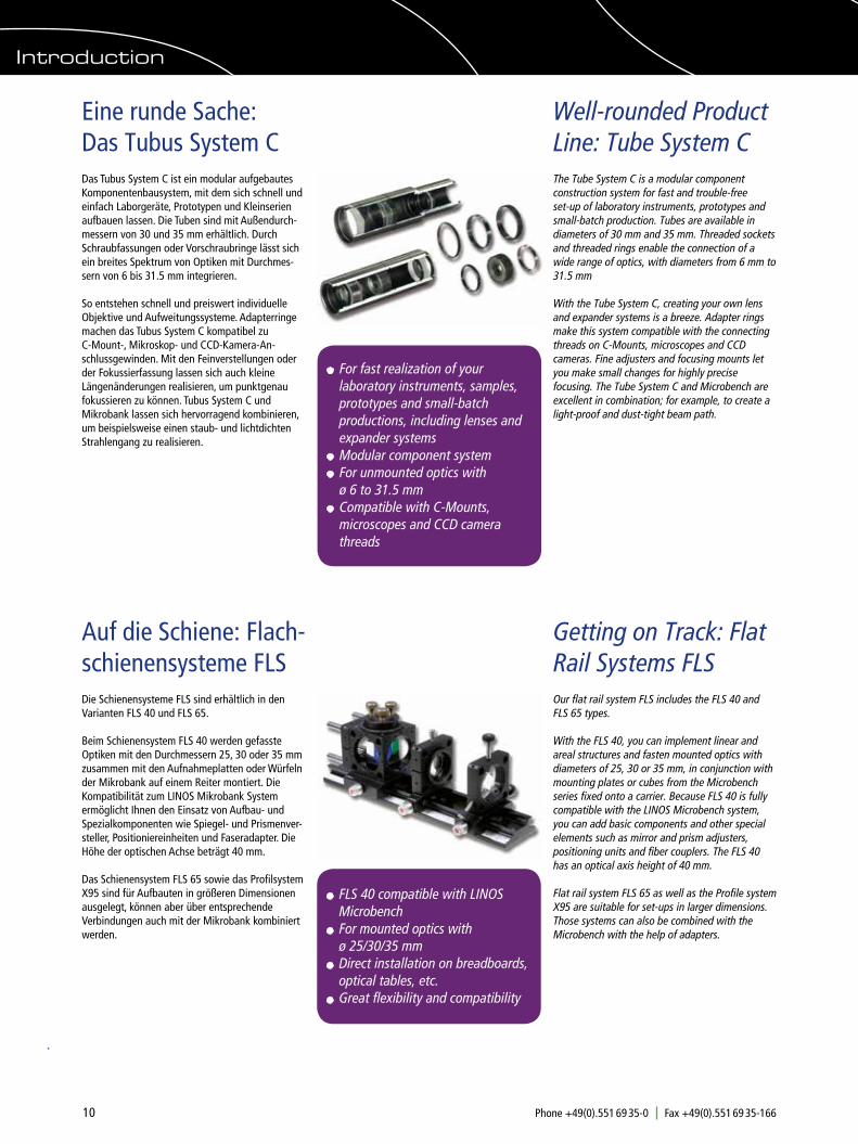
Das Tubus System C ist ein modular aufgebautes Komponentenbausystem, mit dem sich schnell und einfach Laborgeräte, Prototypen und Kleinserien aufbauen lassen. Die Tuben sind mit Außendurch-messern von 30 und 35 mm erhältlich. Durch Schraubfassungen oder Vorschraubringe lässt sich ein breites Spektrum von Optiken mit Durchmes-sern von 6 bis 31.5 mm integrieren.
So entstehen schnell und preiswert individuelle Objektive und Aufweitungssysteme. Adapterringe machen das Tubus System C kompatibel zu C-Mount-, Mikroskop- und CCD-Kamera-An-schlussgewinden. Mit den Feinverstellungen oder der Fokussierfassung lassen sich auch kleine Längenänderungen realisieren, um punktgenaufokussieren zu können. Tubus System C und Mikrobank lassen sich hervorragend kombinieren, um beispielsweise einen staub- und lichtdichten Strahlengang zu realisieren.
Well-rounded Product Line: Tube System C
Eine runde Sache: Das Tubus System C
The Tube System C is a modular component construction system for fast and trouble-free set-up of laboratory instruments, prototypes and small-batch production. Tubes are available in diameters of 30 mm and 35 mm. Threaded sockets and threaded rings enable the connection of a wide range of optics, with diameters from 6 mm to 31.5 mm
With the Tube System C, creating your own lens and expander systems is a breeze. Adapter rings make this system compatible with the connecting threads on C-Mounts, microscopes and CCD cameras. Fine adjusters and focusing mounts let you make small changes for highly precise focusing. The Tube System C and Microbench are excellent in combination; for example, to create a light-proof and dust-tight beam path.
For fast realization of your laboratory instruments, samples,
prototypes and small-batch productions, including lenses and expander systems
Modular component system For unmounted optics with
ø 6 to 31.5 mm Compatible with C-Mounts, microscopes and CCD camera threads
Die Schienensysteme FLS sind erhältlich in den Varianten FLS 40 und FLS 65.
Beim Schienensystem FLS 40 werden gefasste Optiken mit den Durchmessern 25, 30 oder 35 mm zusammen mit den Aufnahmeplatten oder Würfeln der Mikrobank auf einem Reiter montiert. Die Kompatibilität zum LINOS Mikrobank System ermöglicht Ihnen den Einsatz von Aufbau- und Spezialkomponenten wie Spiegel- und Prismenver-steller, Positioniereinheiten und Faseradapter. Die Höhe der optischen Achse beträgt 40 mm.
Das Schienensystem FLS 65 sowie das Profilsystem X95 sind für Aufbauten in größeren Dimensionen ausgelegt, können aber über entsprechende Verbindungen auch mit der Mikrobank kombiniert werden.
Getting on Track: Flat Rail Systems FLS
Auf die Schiene: Flach-schienensysteme FLS
Our flat rail system FLS includes the FLS 40 and FLS 65 types.
With the FLS 40, you can implement linear and areal structures and fasten mounted optics with diameters of 25, 30 or 35 mm, in conjunction with mounting plates or cubes from the Microbench series fixed onto a carrier. Because FLS 40 is fully compatible with the LINOS Microbench system, you can add basic components and other special elements such as mirror and prism adjusters, positioning units and fiber couplers. The FLS 40 has an optical axis height of 40 mm.
Flat rail system FLS 65 as well as the Profile system X95 are suitable for set-ups in larger dimensions. Those systems can also be combined with the Microbench with the help of adapters.
FLS 40 compatible with LINOS
Microbench For mounted optics with ø 25/30/35 mm Direct installation on breadboards,
optical tables, etc. Great flexibility and compatibility
Introduction
11Phone +49(0).551 69 35-0 Fax +49(0).551 69 35-166 [email protected]
Basic Components: Microbench
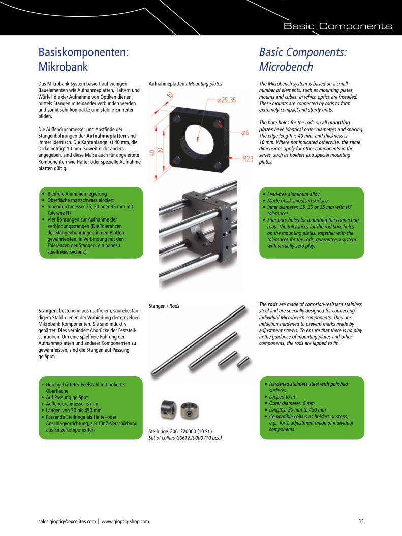
Das Mikrobank System basiert auf wenigen Bauelementen wie Aufnahmeplatten, Haltern und Würfel, die der Aufnahme von Optiken dienen, mittels Stangen miteinander verbunden werden und somit sehr kompakte und stabile Einheiten bilden.
Die Außendurchmesser und Abstände der Stangenbohrungen der Aufnahmeplatten sind immer identisch. Die Kantenlänge ist 40 mm, die Dicke beträgt 10 mm. Soweit nicht anders angegeben, sind diese Maße auch für abgeleitete Komponenten wie Halter oder spezielle Aufnahme-platten gültig.
Stangen, bestehend aus rostfreiem, säurebestän-digem Stahl, dienen der Verbindung der einzelnen Mikrobank Komponenten. Sie sind induktiv gehärtet. Dies verhindert Abdrücke der Feststell-schrauben. Um eine spielfreie Führung der Aufnahmeplatten und anderer Komponenten zu gewährleisten, sind die Stangen auf Passung geläppt.
Basiskomponenten: Mikrobank
Aufnahmeplatten / Mounting plates
• Bleifreie Aluminiumlegierung• Oberfläche mattschwarz eloxiert• Innendurchmesser 25, 30 oder 35 mm mit
Toleranz H7• Vier Bohrungen zur Aufnahme der
Verbindungsstangen (Die Toleranzen der Stangenbohrungen in den Platten gewährleisten, in Verbindung mit den Toleranzen der Stangen, ein nahezu spielfreies System.)
• Lead-free aluminum alloy• Matte black anodized surfaces• Inner diameter: 25, 30 or 35 mm with H7
tolerances • Four bore holes for mounting the connecting
rods. The tolerances for the rod bore holes on the mounting plates, together with the tolerances for the rods, guarantee a system with virtually zero play.
• Durchgehärteter Edelstahl mit polierter Oberfläche
• Auf Passung geläppt• Außendurchmesser 6 mm • Längen von 20 bis 450 mm• Passende Stellringe als Halte- oder
Anschlagvorrichtung, z.B. für Z-Verschiebung aus Einzelkomponenten
The Microbench system is based on a small number of elements, such as mounting plates, mounts and cubes, in which optics are installed. These mounts are connected by rods to form extremely compact and sturdy units.
The bore holes for the rods on all mounting plates have identical outer diameters and spacing. The edge length is 40 mm, and thickness is 10 mm. Where not indicated otherwise, the same dimensions apply for other components in the series, such as holders and special mounting plates.
The rods are made of corrosion-resistant stainless steel and are specially designed for connecting individual Microbench components. They are induction-hardened to prevent marks made by adjustment screws. To ensure that there is no play in the guidance of mounting plates and other components, the rods are lapped to fit.
• Hardened stainless steel with polished surfaces
• Lapped to fit• Outer diameter: 6 mm• Lengths: 20 mm to 450 mm• Compatible collars as holders or stops;
e.g., for Z-adjustment made of individual components
Stangen / Rods
Stellringe G061220000 (10 St.) Set of collars G061220000 (10 pcs.)
Basic Components
12 Phone +49(0).551 69 35-0 Fax +49(0).551 69 35-166 [email protected]
Basic Components: Microbench
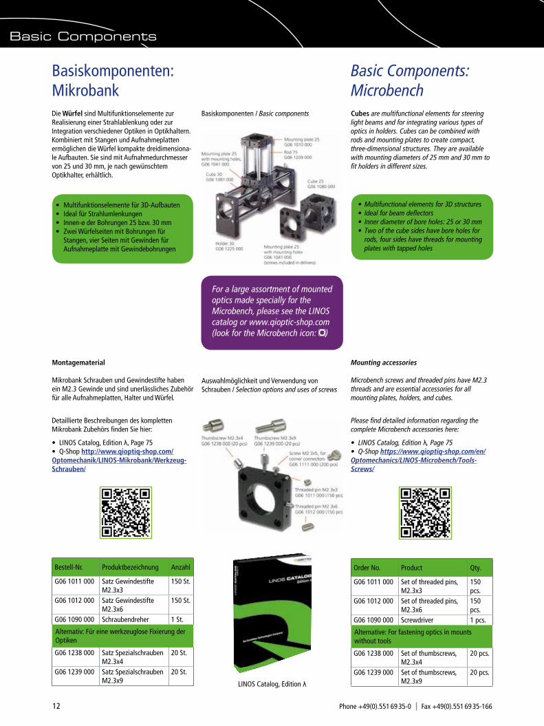
Die Würfel sind Multifunktionselemente zur Realisierung einer Strahlablenkung oder zur Integration verschiedener Optiken in Optikhaltern. Kombiniert mit Stangen und Aufnahmeplatten ermöglichen die Würfel kompakte dreidimensiona-le Aufbauten. Sie sind mit Aufnahmedurchmesser von 25 und 30 mm, je nach gewünschtem Optikhalter, erhältlich.
Basiskomponenten: Mikrobank
Cubes are multifunctional elements for steering light beams and for integrating various types of optics in holders. Cubes can be combined with rods and mounting plates to create compact, three-dimensional structures. They are available with mounting diameters of 25 mm and 30 mm to fit holders in different sizes.
• Multifunktionselemente für 3D-Aufbauten• Ideal für Strahlumlenkungen• Innen-ø der Bohrungen 25 bzw. 30 mm• Zwei Würfelseiten mit Bohrungen für
Stangen, vier Seiten mit Gewinden für Aufnahmeplatte mit Gewindebohrungen
• Multifunctional elements for 3D structures• Ideal for beam deflectors• Inner diameter of bore holes: 25 or 30 mm• Two of the cube sides have bore holes for
rods, four sides have threads for mounting plates with tapped holes
Auswahlmöglichkeit und Verwendung von Schrauben / Selection options and uses of screws
For a large assortment of mounted optics made specially for the Microbench, please see the LINOS catalog or www.qioptic-shop.com
(look for the Microbench icon: m)
Montagematerial
Mikrobank Schrauben und Gewindestifte haben ein M2.3 Gewinde und sind unerlässliches Zubehör für alle Aufnahmeplatten, Halter und Würfel.
Mounting accessories
Microbench screws and threaded pins have M2.3 threads and are essential accessories for all mounting plates, holders, and cubes.
Please find detailed information regarding the complete Microbench accessories here:
• LINOS Catalog, Edition λ, Page 75• Q-Shop https://www.qioptiq-shop.com/en/Optomechanics/LINOS-Microbench/Tools-Screws/
Detaillierte Beschreibungen des kompletten Mikrobank Zubehörs finden Sie hier:
• LINOS Catalog, Edition λ, Page 75• Q-Shop http://www.qioptiq-shop.com/Optomechanik/LINOS-Mikrobank/Werkzeug-Schrauben/
Basic Components
LINOS Catalog, Edition λ
Basiskomponenten / Basic components
Bestell-Nr. Produktbezeichnung Anzahl
G06 1011 000 Satz Gewindestifte M2.3x3
150 St.
G06 1012 000 Satz Gewindestifte M2.3x6
150 St.
G06 1090 000 Schraubendreher 1 St.
G06 1238 000 Satz Spezialschrauben M2.3x4
20 St.
G06 1239 000 Satz Spezialschrauben M2.3x9
20 St.
Alternativ: Für eine werkzeuglose Fixierung der Optiken
Order No. Product Qty.
G06 1011 000 Set of threaded pins, M2.3x3
150 pcs.
G06 1012 000 Set of threaded pins, M2.3x6
150 pcs.
G06 1090 000 Screwdriver 1 pcs.
G06 1238 000 Set of thumbscrews, M2.3x4
20 pcs.
G06 1239 000 Set of thumbscrews, M2.3x9
20 pcs.
Alternative: For fastening optics in mounts without tools
13Phone +49(0).551 69 35-0 Fax +49(0).551 69 35-166 [email protected]
Würfel / Cube G050175000
Aufnahmeplatte N16Mounting plate N16 G050125000
Basic Components: Nanobench
Basiskomponenten: Nanobank
Aufnahmeplatten / Mounting plates
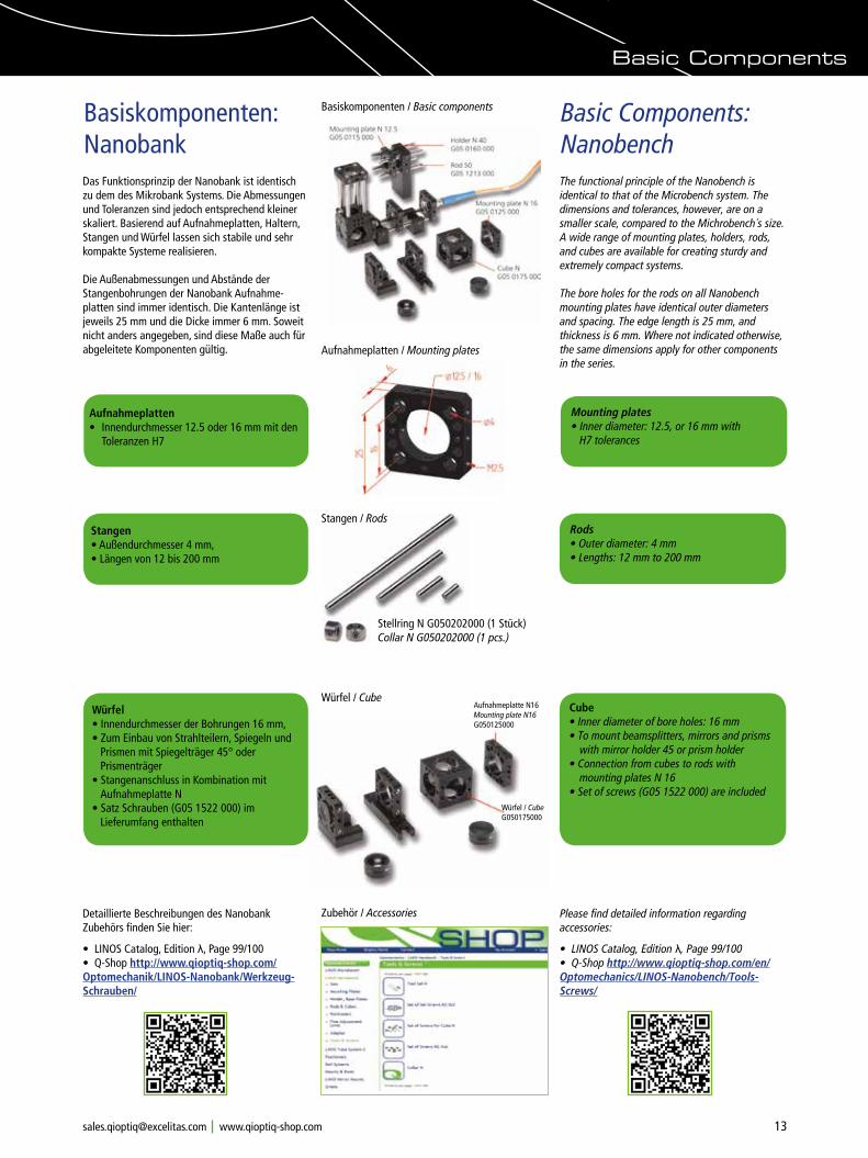
Das Funktionsprinzip der Nanobank ist identisch zu dem des Mikrobank Systems. Die Abmessungen und Toleranzen sind jedoch entsprechend kleiner skaliert. Basierend auf Aufnahmeplatten, Haltern, Stangen und Würfel lassen sich stabile und sehr kompakte Systeme realisieren.
Die Außenabmessungen und Abstände der Stangenbohrungen der Nanobank Aufnahme-platten sind immer identisch. Die Kantenlänge ist jeweils 25 mm und die Dicke immer 6 mm. Soweit nicht anders angegeben, sind diese Maße auch für abgeleitete Komponenten gültig.
The functional principle of the Nanobench is identical to that of the Microbench system. The dimensions and tolerances, however, are on a smaller scale, compared to the Michrobench´s size. A wide range of mounting plates, holders, rods, and cubes are available for creating sturdy and extremely compact systems.
The bore holes for the rods on all Nanobench mounting plates have identical outer diameters and spacing. The edge length is 25 mm, and thickness is 6 mm. Where not indicated otherwise, the same dimensions apply for other components in the series.
Aufnahmeplatten• Innendurchmesser 12.5 oder 16 mm mit den
Toleranzen H7
Mounting plates• Inner diameter: 12.5, or 16 mm with
H7 tolerances
Würfel• Innendurchmesser der Bohrungen 16 mm, • Zum Einbau von Strahlteilern, Spiegeln und
Prismen mit Spiegelträger 45° oder Prismenträger
• Stangenanschluss in Kombination mit Aufnahmeplatte N
• Satz Schrauben (G05 1522 000) im Lieferumfang enthalten
Cube• Inner diameter of bore holes: 16 mm• To mount beamsplitters, mirrors and prisms
with mirror holder 45 or prism holder• Connection from cubes to rods with mounting plates N 16• Set of screws (G05 1522 000) are included
Würfel / Cube
Zubehör / Accessories
Stangen• Außendurchmesser 4 mm, • Längen von 12 bis 200 mm
Rods• Outer diameter: 4 mm• Lengths: 12 mm to 200 mm
Stangen / Rods
Stellring N G050202000 (1 Stück) Collar N G050202000 (1 pcs.)
Please find detailed information regarding accessories:
• LINOS Catalog, Edition λ, Page 99/100• Q-Shop http://www.qioptiq-shop.com/en/Optomechanics/LINOS-Nanobench/Tools-Screws/
Detaillierte Beschreibungen des Nanobank Zubehörs finden Sie hier:
• LINOS Catalog, Edition λ, Page 99/100• Q-Shop http://www.qioptiq-shop.com/Optomechanik/LINOS-Nanobank/Werkzeug-Schrauben/
Basic Components
Basiskomponenten / Basic components
14 Phone +49(0).551 69 35-0 Fax +49(0).551 69 35-166 [email protected]
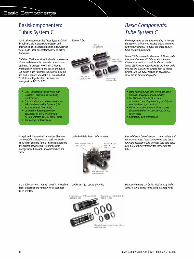
Basiskomponenten: Tubus System CSchlüsselkomponenten des Tubus Systems C sind die Tuben C, die in zwei Durchmessern und unterschiedlichen Längen erhältlich sind. Gefertigt werden alle Tuben aus mattschwarz eloxiertem Aluminium.
Die Tuben C30 haben einen Außendurchmesser von 30 mm und einen freien Innendurchmesser von 22.4 mm. Sie besitzen jeweils ein C-Mount Anschlussgewinde innen und außen. Die Tuben C35 haben einen Außendurchmesser von 35 mm und sind in Längen von 20 bis 80 mm erhältlich. Zur Optikmontage besitzen die Tuben ein Innengewinde M32.5x0.75.
Key components of the tube mounting system are the Tubes C, which are available in two diameters and various lengths. All tubes are made of matt black anodized aluminum.
Tubes C30 have an outer diameter of 30 mm and a free inner diameter of 22.4 mm. Each features C-Mount connection threads inside and outside. Tubes C35 have an outer diameter of 35 mm and a free and are available in lengths from 20 mm to 80 mm. The C35 tubes feature an M32.5x0.75 inner thread for mounting optics.
Basic Components: Tube System C
Tuben / Tubes
Umlenkwürfel / Beam deflector cubes
Optikmontage / Optics mounting
• Licht- und staubdichtes System zum Einsatz in Forschung, Entwicklung und Industrie• Zum schnellen und preiswerten Aufbau
individueller optischer Systeme (z.B. Prototypen und Kleinserien)
• Universeller Fassungsanschluss gewährleistet direkte Verbindung zu CCD Kameras, Lasern, Mikroskopen• Kompatibel zur Mikrobank
• Light-tight and dust-tight system for use in
research, development and industry• For fast and economical set-up of
customized optical systems (e.g. prototypes and small-batch production)
• Universal mounting unit enables enables direct connection to CCD cameras, lasers, microscopes
• Compatible with Microbench
In das Tubus System C können ungefasste Optiken direkt eingesetzt und mittels Vorschraubringen fixiert werden.
Unmounted optics can be installed directly in the Tube system C and secured using threaded rings.
Spiegel- und Prismeneinsätze werden über den Umlenkwürfel C integriert. Sie besitzen jeweils eine 30 mm Bohrung für die Prismeneinsätze und drei beziehungsweise fünf Bohrungen mit Innengewinde C-Mount zum Anschrauben der Tuben.
Beam deflector Cube C lets you connect mirror and prism accessories. These have 30 mm bore holes for prism accessories and three (or five) bore holes with C-Mount inner threads for connecting the tubes
Basic Components
Adjustable prism insert 30G06 3731 000

15Phone +49(0).551 69 35-0 Fax +49(0).551 69 35-166 [email protected]
Basiskomponenten: Flachschienensysteme FLS 40Kompatibel zum Mikrobank System sind die Flachschienen und Reiter des Systems FLS 40. Das System verfügt über hohe Geradheit und Ebenheit bei geringer Torsion.
Die Langlöcher in den Schienen ermöglichen eine rasterunabhängige Montage auf Breadboards und optischen Tischen.
Die Reiter verfügen über einen federvorgespannten Hebel. Bei gelöster Rändelschraube lässt sich der Reiter aufgrund der Federspannung leicht und ruckelfrei verschieben. Durch Anziehen der Rändelschraube wird der Reiter in seiner Position fixiert.
Präzise gefräste Führungsflächen und das abriebfeste Eloxal garantieren ein gleichmäßigesVerschieben der Komponenten auf der Schiene.
FLS 40Flat rail System FLS 40 is compatible with our Microbench systems with the corresponding dimensions and beam heights. The system features excellent straightness and evenness with low torsion.
The slotted holes in the rails enable mounting on breadboards and optical tables independent of existing hole patterns.
The carriers have a spring-loaded lever. Just loosen the knurled screw, and the spring tension makes it easy to move the carriers smoothly to the desired position. Then tighten the knurled screw again to affix the carrier in position.
Precision milling of bearing surfaces together with abrasion-resistant anodizing ensure that components slide smoothly and evenly on the rail.
Basic Components: Flat Rail Systems
Schienensystem FLS 40 / Flat rail system FLS 40
• Präzise Führungsflächen• Abriebfestes Eloxal• Längen 40 mm bis 1000 mm• Maßskala• Langlöcher der Schiene ermöglichen eine
rasterunabhängige Montage auf Tischen• Kompatibel zum Mikrobank System• Reiter mit federnder Klemmung• Höhe der optischen Achse ist 40 mm
• Precise bearing surfaces• Abrasion-resistant anodizing• Lengths: 40 mm to 1000 mm• Scale• Slotted holes on the rail enable table
mounting independent of existing hole patterns
• Compatible with Microbench system• Carrier with spring-loaded clamp• Optical axis height of 40 mm
Basic Components
FLS 65Die flache, stranggepresste Schiene besticht durch hohe Geradheit und geringe Torsion. Die Führungsflächen sind präzise bearbeitet und ermöglichen eine gleichmäßige Verschiebung der Reiter.
Die Schiene besitzt eine matt schwarz eloxierte, abriebfeste Oberfläche. Durch die Langlöcher ist eine rasterunabhängige Befestigung auf optischen Tischen, sowohl mit M6 oder ¼" gewährleistet. Die Schiene ist in Längen von 200 mm bis 1500 mm erhältlich.
Die Reiter FLR 65 sind in drei verschiedenen Breiten verfügbar und besitzen ein universelles Bohrraster zur Aufnahme von Optikhalterungen. Durch die federnde Klemmung ist eine leichtgängi-ge, gleichmäßige Verschiebung der Reiter auf der Schiene möglich. Fixiert wird die Position mit der Rändelschraube. Die Reiter sind ebenfalls mit einem matt schwarzem, abriebfesten Eloxal versehen. Zusammen mit der Schiene befindet sich die Oberfläche des Reiters 25 mm über der Basis.
Die optische Achse befindet sich auf 65 mm Höhe, wenn die für das FLS 65 System vorgesehenen Optikhalter montiert werden (siehe Aufbau-beispiel).
FLS 65 The flat, extruded rail features excellent straightness properties and low torsion. Bearing surfaces are precision processed for smooth movement of the carrier.
The rail features a matte black anodized, abrasion-resistant surface. Slotted holes make it easy to fasten the rail to optical tables indepen-dent of existing hole patterns, using either M6 or ¼" screws. The FLS 65 rail is available in lengths from 200 mm to 1500 mm.
The carriers FLR 65 are available in three widths and feature a universal bore hole pattern for attaching optical mounts. The spring-loaded clamp ensures smooth movement of the carrier along the rail, and a knurled screw fixes the carrier in position. Just like the rails, the carriers feature matte black, abrasion-resistant anodizing. Together with the rail, the surface of the carrier is 25 mm above the base.
The optical axis height is 65 mm above the working surface when standard optic holders for the FLS 65 system are used (please see the mounting example).
Aufbaubeispiel Schienensystem FLS 65 mit OptikhalterMounting example Flat rail system FLS 65 with optic holders
Schienensystem FLS 65 / Flat rail system FLS 65
Aufbaubeispiel Schienensystem FLS 40 / Mounting example Flat rail system FLS 40

16 Phone +49(0).551 69 35-0 Fax +49(0).551 69 35-166 [email protected]
How Do I Begin My Experiment?
Wie starte ich mein Experiment?
The following pages serve as a checklist for a structured planning and design of your setup, to help you reach an optimum, economical solution for your requirements. This example describes the construction of a basic alignment telescope.
Die folgenden Seiten helfen Ihnen, Ihren Aufbau strukturiert zu planen, um schnell und einfach ein optimales und kostengünstiges Ergebnis zu erzielen. Beispielhaft wird der Aufbau eines einfachen Fluchtfernrohrs dargestellt.
Sinnvoll ist hier die Simulation in einem Optikdesign-Programm. Wir empfehlen Ihnen als Vorbereitung des Aufbaus die Verwendung unseres Optikdesign-Programms Winlens™. Mit dieser Software können Sie den gewünschten Strahlen-gang simulieren, das Ergebnis direkt analysieren und gegebenenfalls optimieren.
Für WinLens™ 3D spricht auch eine integrierte Datenbank die u.a. unsere Standardoptiken enthält. Deren Verwendung reduziert die Kosten und die erhältlichen Optiken in Fassung können Sie direkt in die LINOS Bausysteme integrieren.
Steht das Optikdesign fest?
We recommend using an optical design software, such as WinLens™ 3D from Qioptiq, to create a simulation. This can be a tremendous help in preparing your optical assembly. This software lets you simulate the desired beam path and analyzes the results directly. You are able to optimize the setup as needed before finalizing your design.
Furthermore, WinLens™ 3D comes with an integrated database that contains all of our standard optics. Using standard optics helps to keep costs to a minimum, and mounted optics for direct integration in our construction systems are also available.
How do I design my optical assembly?
Simluation of the beam path of a basic alignment telescope with Qioptiq WinLens™
For detailed information and a
free version of the WinLensTM 3D software have a look at: www.qioptiq-shop.com/Optik-Software/Winlens-Optical-Design-Software/
We offer WinLens Webinars in English with our Specialist. Please have a look regarding available training dates.
Welche Optiken werden benötigt und welches LINOS Bausystem ist das Optimale?
Wählen Sie zunächst je nach verwendetem Optikdurchmesser und Anwendungsbereich das optimale Bausystem aus.
In unserem Beispiel fiel die Entscheidung auf die Verwendung des Mikrobank Systems. Auf eine Kapselung des Strahlengangs wird bei dieser Variante verzichtet. Alternativ ist für einen geschlossenen Aufbau die Verwendung des Tubus Systems C zu empfehlen.
Als Optiken werden benötigt: Eine Plankonvexlinse f=80/22,4 (G312317000), eine Strichplatte 19 mm (G391130000), eine weitere Plankonvexlinse f=40/22,4 (G312314000) und ein Achromat f=60/25,4 (G322306322).
Für den Einbau in die Mikrobank Aufnahmeplatten gibt es passende Fassungen für die Linsen: Fassung CL 19 (G063661000), Fassung CL 25,4 (G063663000) und 2x Fassung CL 22,4 (G063651000).
Die Kombination dieser Auswahl an Optiken für das Fluchtfernrohr erzeugt ein umgekehrtes Bild mit einer 3-fachen Vergrößerung. Die Entfernungs-einstellung ist im Bereich von 300 mm bis ∞ variabel, wobei die eingebaute Strichplatte als nützliche Orientierungshilfe fungiert, wenn Abweichungen in Bezug auf eine Referenzlinie bestimmt werden.
What optics do I need and which construction system is the best?
Your optic diameters and areas of application will play a role in determining the optimum construc-tion system for your requirements.
In our example, the Microbench system was chosen. In this example, we have decided not to enclose the beam path. As an alternative, we can recommend the use of the Tube System C for a closed construction. The following optics are required for this project: A plano-convex lens f=80/22.4 (G312317000), a reticle 19 mm (G391130000), a second plano-convex lens f=40/22.4 (G312314000) and an achromat f=60/25.4 (G322306322).
For mounting in the Microbench mounting plates, there are suitable mechanical mounts for the optics and lenses: Mount CL 19 (G063661000), Mount CL 25.4 (G063663000) and 2x Mount CL 22.4 (G063651000).
The combination of this choice of optics for the alignment telescope creates an inverse image with a 3x magnification. The distance setting (focus) is adjustable in the range of 300 mm to ∞, with the built in line reticle plate as a useful alignment aid when measuring distance deviations with respect to a reference line.
Reticle crosshair, unmountedG391130000
Required optics in different mounts depending on the outer diameter of the lens
Frequently Asked Questions
Optic mounts for lenses and achromats
17Phone +49(0).551 69 35-0 Fax +49(0).551 69 35-166 [email protected]
An welchen Positionen stehen die Optiken und ist eine Justierung erforderlich?
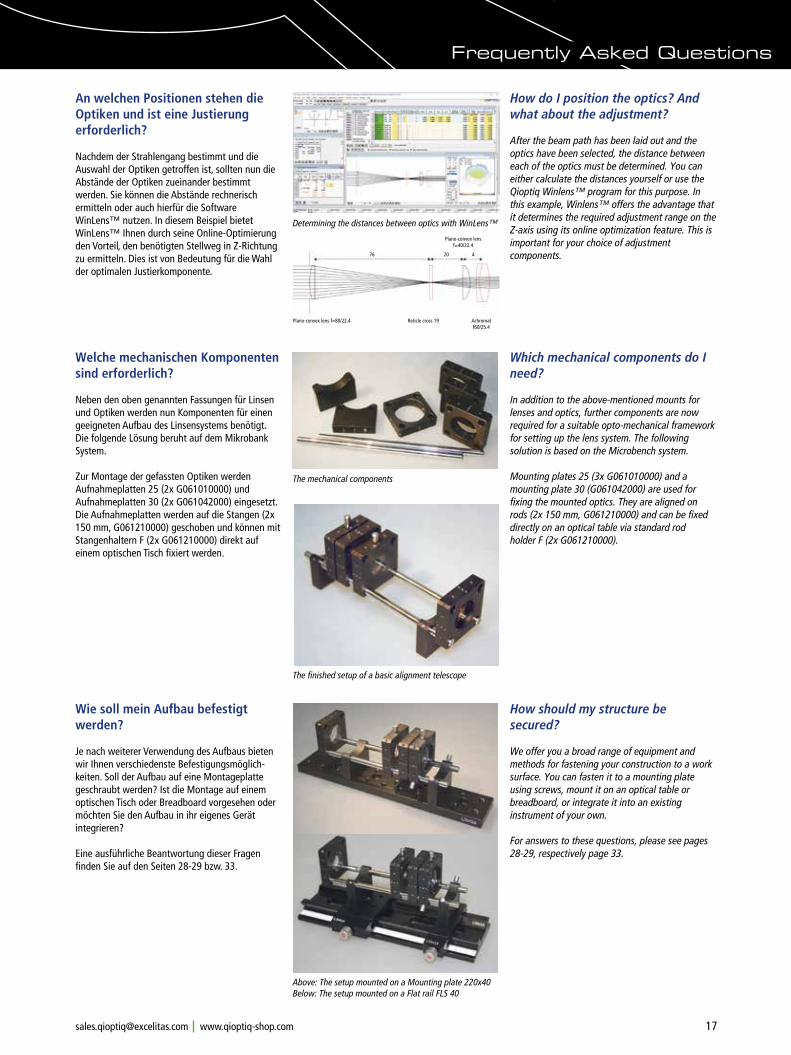
Nachdem der Strahlengang bestimmt und die Auswahl der Optiken getroffen ist, sollten nun die Abstände der Optiken zueinander bestimmt werden. Sie können die Abstände rechnerisch ermitteln oder auch hierfür die Software WinLens™ nutzen. In diesem Beispiel bietet WinLens™ Ihnen durch seine Online-Optimierung den Vorteil, den benötigten Stellweg in Z-Richtung zu ermitteln. Dies ist von Bedeutung für die Wahl der optimalen Justierkomponente.
How do I position the optics? And what about the adjustment?
After the beam path has been laid out and the optics have been selected, the distance between each of the optics must be determined. You can either calculate the distances yourself or use the Qioptiq Winlens™ program for this purpose. In this example, Winlens™ offers the advantage that it determines the required adjustment range on the Z-axis using its online optimization feature. This is important for your choice of adjustment components.
Plano-convex lens f=40/22.4
Plano-convex lens f=80/22.4 Reticle cross 19 Achromat f60/25.4
76 20 4
Determining the distances between optics with WinLens™
Welche mechanischen Komponenten sind erforderlich?
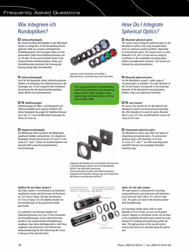
Neben den oben genannten Fassungen für Linsen und Optiken werden nun Komponenten für einen geeigneten Aufbau des Linsensystems benötigt. Die folgende Lösung beruht auf dem Mikrobank System.
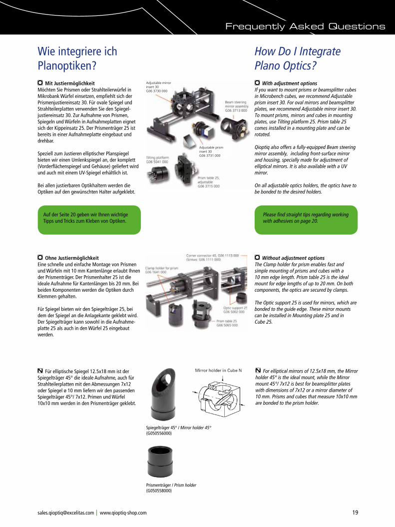
Zur Montage der gefassten Optiken werden Aufnahmeplatten 25 (2x G061010000) und Aufnahmeplatten 30 (2x G061042000) eingesetzt. Die Aufnahmeplatten werden auf die Stangen (2x 150 mm, G061210000) geschoben und können mit Stangenhaltern F (2x G061210000) direkt auf einem optischen Tisch fixiert werden.
Which mechanical components do I need?
In addition to the above-mentioned mounts for lenses and optics, further components are now required for a suitable opto-mechanical framework for setting up the lens system. The following solution is based on the Microbench system.
Mounting plates 25 (3x G061010000) and a mounting plate 30 (G061042000) are used for fixing the mounted optics. They are aligned on rods (2x 150 mm, G061210000) and can be fixed directly on an optical table via standard rod holder F (2x G061210000).
The mechanical components
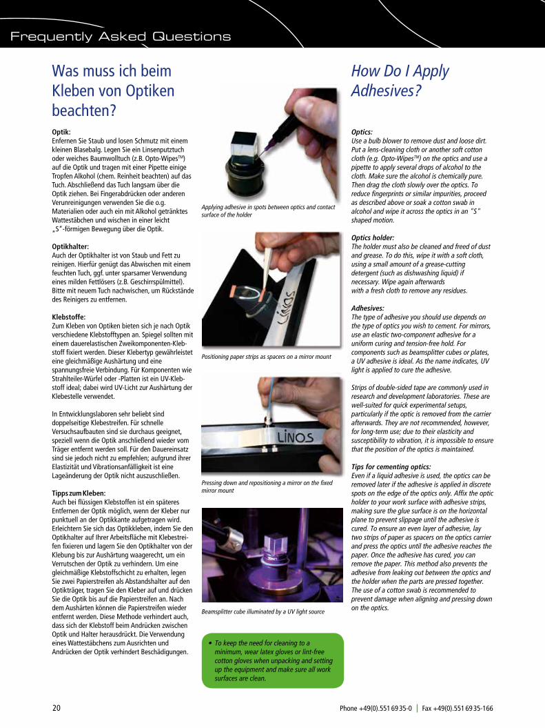
Above: The setup mounted on a Mounting plate 220x40Below: The setup mounted on a Flat rail FLS 40
Frequently Asked Questions
Wie soll mein Aufbau befestigt werden?
Je nach weiterer Verwendung des Aufbaus bieten wir Ihnen verschiedenste Befestigungsmöglich-keiten. Soll der Aufbau auf eine Montageplatte geschraubt werden? Ist die Montage auf einem optischen Tisch oder Breadboard vorgesehen oder möchten Sie den Aufbau in ihr eigenes Gerät integrieren?
Eine ausführliche Beantwortung dieser Fragenfinden Sie auf den Seiten 28-29 bzw. 33.
How should my structure be secured?
We offer you a broad range of equipment and methods for fastening your construction to a work surface. You can fasten it to a mounting plate using screws, mount it on an optical table or breadboard, or integrate it into an existing instrument of your own.
For answers to these questions, please see pages 28-29, respectively page 33.
The finished setup of a basic alignment telescope
18 Phone +49(0).551 69 35-0 Fax +49(0).551 69 35-166 [email protected]
Frequently Asked Questions
How Do I Integrate Spherical Optics?
Wie integriere ich Rundoptiken?
m Mounted spherical opticsThe easiest way to integrate spherical optics in the Microbench system is by using mounted optics from our extensive product portfolio. Depending on the particular optics, the mounts have an outer diameter of 25, 30 or 35 mm and are ready for installation in the compatible mounting plates, holders and adjustment elements. The mounts are fastened by using threaded pins.
m Gefasste Rundoptik Der einfachste Weg, Rundoptiken in das Mikrobank System zu integrieren, ist die Verwendung bereits gefasster Optik aus unserem umfangreichen Produktprogramm. Die Fassungen haben je nach verwendeter Optik einen Außendurchmesser von 25, 30 oder 35 mm und sind damit direkt in die entsprechenden Aufnahmeplatten, Halter und Verstellelemente einsetzbar. Die Fixierung der Fassung erfolgt über Gewindestifte.
Gefasste Linsen, Achromate und Farbfilter / Mounted lenses, achromatic lenses and color filters n Mounted spherical optics
For the Nanobench system, a wide range of mounted optics is available. The outer diameter of the 16 mm mounts corresponds to the mounting diameter of the Nanobench mounting plates, holders, cubes and adjustment elements.
n Gefasste Rundoptik Auch für die Nanobank stehen zahlreiche gefasste Optiken zur Verfügung. Der Außendurchmesser der Fassungen von 16 mm entspricht dem Aufnahme-durchmesser der Nanobank Aufnahmeplatten, Halter, Würfel und Justierelemente.
m Unmounted spherical opticsThe Microbench system also offers the option of integrating unmounted optics. For unmounted spherical optics with diameters of 25 mm, 31.5 mm, 0.5“ and 1“ we offer mounting plates with M35 threads and compatible threaded retaining rings.
m Ungefasste Rundoptik Die Mikrobank bietet zusätzlich die Möglichkeit, ungefasste Optiken aufzunehmen. Für ungefasste Rundoptik mit den Durchmessern 25 und 31.5 mm sowie 0.5“ und 1“ bieten wir Aufnahmeplatten mit Gewinde M35 sowie die entsprechenden Vorschraubringe.
For a large assortment of mounted optics made for the Microbench and Nanobench, please see the LINOS catalog or www.qioptiq-shop.com (please have a look for the icons m and n)
Ungefasste Rundoptiken mit verschiedenen Durchmessern in Vorschraubringen gefasst und in Aufnahmeplatten M35x0.5 der Mikrobank geschraubt.Unmounted spherical optics with different diameters integrated into threaded retaining rings and screwed into Microbench mounting plates M35x0.5.
Optics for the tube systemThe tube system is constructed for mounting unmounted lenses and achromats with diameters of 22.4 mm (in Tube C30) or 31.5 mm (in Tube C35). The optics are fixed in the desired position with threaded rings.
For mounting smaller optics with an outer diameter of 6 to 19 mm, you can use threaded mounts. Regular or achromatic lenses can be fixed in the compatible threaded mount which has outer threads for installing and positioning within the tube. The high precision of the overall system ensures that lenses are centered along the optical axis.
Optiken für das Tubus System CDas Tubus System C ist konstruiert zur Aufnahme ungefasster Linsen und Achromate mit Durchmes-ser 22.4 mm in Tubus C30 oder Durchmesser 31.5 mm in Tubus C35. Die Optiken werden mit Vorschraubringen an die gewünschte Stelle geschraubt.
Zur Aufnahme von kleineren Optiken mit Außendurchmessern von 6 bis 19 mm verwenden Sie Schraubfassungen. Linsen oder Achromate werden in die entsprechende Schraubfassung eingebaut, über deren Außengewinde in den Tubus eingesetzt und positioniert. Die Präzision der komponentensorgt für die Zentrierung der Linsen in Bezug auf die optische Achse.
m n Lens mountsOf course, lens mounts for the Microbench and Nanobench system can be purchased separately. We offer Nanobench mounts for optics diameter from 3 up to 12.7 mm and Microbench mounts for 18 up to 25.4 mm.
m n OptikfassungenOptikfassungen für Mikro- und Nanobank sind selbstverständlich auch separat erhältlich. Wir bieten Nanobank Fassungen für Optikdurchmesser von 3 bis 12.7 mm und Mikrobank Fassungen für 18 bis 25.4 mm an.
19Phone +49(0).551 69 35-0 Fax +49(0).551 69 35-166 [email protected]
Frequently Asked Questions
How Do I Integrate Plano Optics?
Wie integriere ich Planoptiken?
m With adjustment optionsIf you want to mount prisms or beamsplitter cubes in Microbench cubes, we recommend Adjustable prism insert 30. For oval mirrors and beamsplitter plates, we recommend Adjustable mirror insert 30. To mount prisms, mirrors and cubes in mounting plates, use Tilting platform 25. Prism table 25 comes installed in a mounting plate and can be rotated.
Qioptiq also offers a fully-equipped Beam steering mirror assembly, including front-surface mirror and housing, specially made for adjustment of elliptical mirrors. It is also available with a UV mirror.
On all adjustable optics holders, the optics have to be bonded to the desired holders.
m Mit JustiermöglichkeitMöchten Sie Prismen oder Strahlteilerwürfel in Mikrobank Würfel einsetzen, empfiehlt sich der Prismenjustiereinsatz 30. Für ovale Spiegel und Strahlteilerplatten verwenden Sie den Spiegel-justiereinsatz 30. Zur Aufnahme von Prismen, Spiegeln und Würfeln in Aufnahmeplatten eignet sich der Kippeinsatz 25. Der Prismenträger 25 ist bereits in einer Aufnahmeplatte eingebaut und drehbar.
Speziell zum Justieren elliptischer Planspiegel bieten wir einen Umlenkspiegel an, der komplett (Vorderflächenspiegel und Gehäuse) geliefert wird und auch mit einem UV-Spiegel erhältlich ist.
Bei allen justierbaren Optikhaltern werden die Optiken auf den gewünschten Halter aufgeklebt.
Adjustable mirror insert 30G06 3730 000
Adjustable prism insert 30G06 3731 000
m Without adjustment optionsThe Clamp holder for prism enables fast and simple mounting of prisms and cubes with a 10 mm edge length. Prism table 25 is the ideal mount for edge lengths of up to 20 mm. On both components, the optics are secured by clamps.
The Optic support 25 is used for mirrors, which are bonded to the guide edge. These mirror mounts can be installed in Mounting plate 25 and in Cube 25.
m Ohne JustiermöglichkeitEine schnelle und einfache Montage von Prismen und Würfeln mit 10 mm Kantenlänge erlaubt Ihnen der Prismenträger. Der Prismenhalter 25 ist die ideale Aufnahme für Kantenlängen bis 20 mm. Bei beiden Komponenten werden die Optiken durch Klemmen gehalten.
Für Spiegel bieten wir den Spiegelträger 25, bei dem der Spiegel an die Anlagekante geklebt wird. Der Spiegelträger kann sowohl in die Aufnahme- platte 25 als auch in den Würfel 25 eingebaut werden.
n For elliptical mirrors of 12.5x18 mm, the Mirror holder 45° is the ideal mount, while the Mirror mount 45°/ 7x12 is best for beamsplitter plates with dimensions of 7x12 or a mirror diameter of 10 mm. Prisms and cubes that measure 10x10 mm are bonded to the prism holder.
n Für elliptische Spiegel 12.5x18 mm ist derSpiegelträger 45° die ideale Aufnahme, auch für Strahlteilerplatten mit den Abmessungen 7x12 oder Spiegel ø 10 mm liefern wir den passenden Spiegelträger 45°/ 7x12. Primen und Würfel 10x10 mm werden in den Prismenträger geklebt.
Spiegelträger 45° / Mirror holder 45° (G050556000)
Prismenträger / Prism holder (G050558000)
Auf der Seite 20 geben wir Ihnen wichtige Tipps und Tricks zum Kleben von Optiken.
Please find straight tips regarding working
with adhesives on page 20.
20 Phone +49(0).551 69 35-0 Fax +49(0).551 69 35-166 [email protected]
How Do I Apply Adhesives?
Was muss ich beim Kleben von Optiken beachten?
Optics: Use a bulb blower to remove dust and loose dirt. Put a lens-cleaning cloth or another soft cotton cloth (e.g. Opto-WipesTM) on the optics and use a pipette to apply several drops of alcohol to the cloth. Make sure the alcohol is chemically pure. Then drag the cloth slowly over the optics. To reduce fingerprints or similar impurities, proceed as described above or soak a cotton swab in alcohol and wipe it across the optics in an "S" shaped motion.
Optics holder: The holder must also be cleaned and freed of dust and grease. To do this, wipe it with a soft cloth, using a small amount of a grease-cutting detergent (such as dishwashing liquid) if necessary. Wipe again afterwards with a fresh cloth to remove any residues.
Adhesives:The type of adhesive you should use depends on the type of optics you wish to cement. For mirrors, use an elastic two-component adhesive for a uniform curing and tension-free hold. For components such as beamsplitter cubes or plates, a UV adhesive is ideal. As the name indicates, UV light is applied to cure the adhesive.
Strips of double-sided tape are commonly used in research and development laboratories. These are well-suited for quick experimental setups, particularly if the optic is removed from the carrier afterwards. They are not recommended, however, for long-term use; due to their elasticity and susceptibility to vibration, it is impossible to ensure that the position of the optics is maintained.
Tips for cementing optics:Even if a liquid adhesive is used, the optics can be removed later if the adhesive is applied in discrete spots on the edge of the optics only. Affix the optic holder to your work surface with adhesive strips, making sure the glue surface is on the horizontal plane to prevent slippage until the adhesive is cured. To ensure an even layer of adhesive, lay two strips of paper as spacers on the optics carrier and press the optics until the adhesive reaches the paper. Once the adhesive has cured, you can remove the paper. This method also prevents the adhesive from leaking out between the optics and the holder when the parts are pressed together. The use of a cotton swab is recommended to prevent damage when aligning and pressing down on the optics.
Optik: Enfernen Sie Staub und losen Schmutz mit einem kleinen Blasebalg. Legen Sie ein Linsenputztuch oder weiches Baumwolltuch (z.B. Opto-WipesTM) auf die Optik und tragen mit einer Pipette einige Tropfen Alkohol (chem. Reinheit beachten) auf das Tuch. Abschließend das Tuch langsam über die Optik ziehen. Bei Fingerabdrücken oder anderen Verunreinigungen verwenden Sie die o.g. Materialien oder auch ein mit Alkohol getränktes Wattestäbchen und wischen in einer leicht „S“-förmigen Bewegung über die Optik.
Optikhalter: Auch der Optikhalter ist von Staub und Fett zu reinigen. Hierfür genügt das Abwischen mit einemfeuchten Tuch, ggf. unter sparsamer Verwendung eines milden Fettlösers (z.B. Geschirrspülmittel).Bitte mit neuem Tuch nachwischen, um Rückstände des Reinigers zu entfernen.
Klebstoffe:Zum Kleben von Optiken bieten sich je nach Optik verschiedene Klebstofftypen an. Spiegel sollten mit einem dauerelastischen Zweikomponenten-Kleb-stoff fixiert werden. Dieser Klebertyp gewährleistet eine gleichmäßige Aushärtung und eine spannungsfreie Verbindung. Für Komponenten wie Strahlteiler-Würfel oder -Platten ist ein UV-Kleb-stoff ideal; dabei wird UV-Licht zur Aushärtung der Klebestelle verwendet.
In Entwicklungslaboren sehr beliebt sind doppelseitige Klebestreifen. Für schnelle Versuchsaufbauten sind sie durchaus geeignet, speziell wenn die Optik anschließend wieder vom Träger entfernt werden soll. Für den Dauereinsatz sind sie jedoch nicht zu empfehlen; aufgrund ihrer Elastizität und Vibrationsanfälligkeit ist eine Lageänderung der Optik nicht auszuschließen.
Tipps zum Kleben:Auch bei flüssigen Klebstoffen ist ein späteres Entfernen der Optik möglich, wenn der Kleber nur punktuell an der Optikkante aufgetragen wird. Erleichtern Sie sich das Optikkleben, indem Sie den Optikhalter auf Ihrer Arbeitsfläche mit Klebestrei-fen fixieren und lagern Sie den Optikhalter von der Klebung bis zur Aushärtung waagerecht, um ein Verrutschen der Optik zu verhindern. Um eine gleichmäßige Klebstoffschicht zu erhalten, legen Sie zwei Papierstreifen als Abstandshalter auf den Optikträger, tragen Sie den Kleber auf und drücken Sie die Optik bis auf die Papierstreifen an. Nach dem Aushärten können die Papierstreifen wieder entfernt werden. Diese Methode verhindert auch, dass sich der Klebstoff beim Andrücken zwischen Optik und Halter herausdrückt. Die Verwendung eines Wattestäbchens zum Ausrichten und Andrücken der Optik verhindert Beschädigungen.
Applying adhesive in spots between optics and contact surface of the holder
Positioning paper strips as spacers on a mirror mount
Pressing down and repositioning a mirror on the fixed mirror mount
Beamsplitter cube illuminated by a UV light source
• To keep the need for cleaning to a minimum, wear latex gloves or lint-free cotton gloves when unpacking and setting up the equipment and make sure all work surfaces are clean.
Frequently Asked Questions
21Phone +49(0).551 69 35-0 Fax +49(0).551 69 35-166 [email protected]
How Do I Integrate Optics into Existing Setups?
Wie kann ich Optiken nachträglich integrieren?
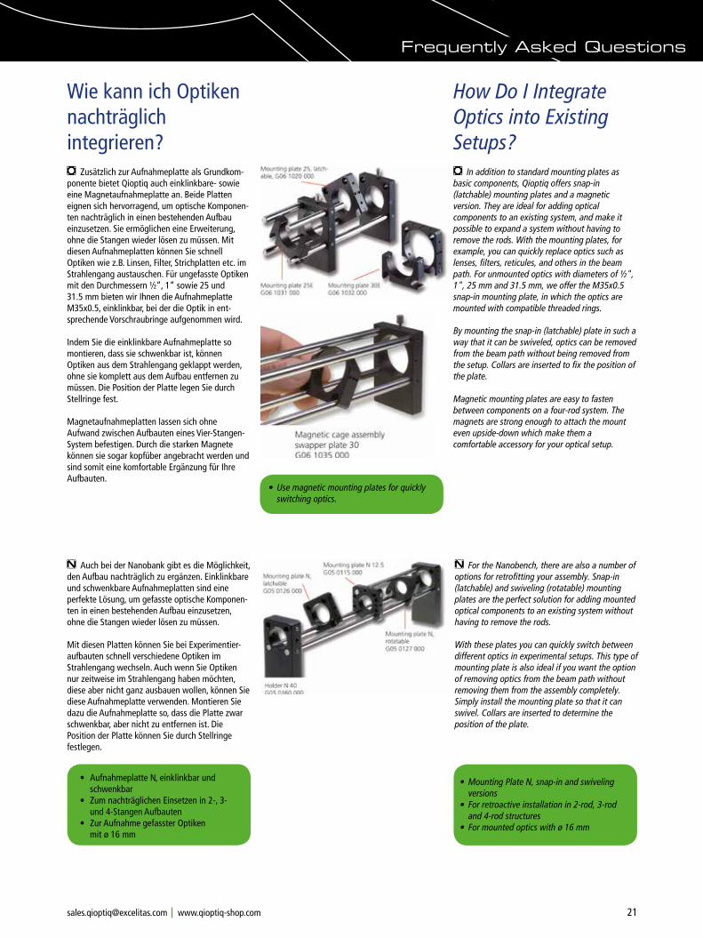
m In addition to standard mounting plates as basic components, Qioptiq offers snap-in (latchable) mounting plates and a magnetic version. They are ideal for adding optical components to an existing system, and make it possible to expand a system without having to remove the rods. With the mounting plates, for example, you can quickly replace optics such as lenses, filters, reticules, and others in the beam path. For unmounted optics with diameters of ½", 1", 25 mm and 31.5 mm, we offer the M35x0.5 snap-in mounting plate, in which the optics are mounted with compatible threaded rings.
By mounting the snap-in (latchable) plate in such a way that it can be swiveled, optics can be removed from the beam path without being removed from the setup. Collars are inserted to fix the position of the plate.
Magnetic mounting plates are easy to fasten between components on a four-rod system. The magnets are strong enough to attach the mount even upside-down which make them a comfortable accessory for your optical setup.
m Zusätzlich zur Aufnahmeplatte als Grundkom-ponente bietet Qioptiq auch einklinkbare- sowie eine Magnetaufnahmeplatte an. Beide Platten eignen sich hervorragend, um optische Komponen-ten nachträglich in einen bestehenden Aufbau einzusetzen. Sie ermöglichen eine Erweiterung, ohne die Stangen wieder lösen zu müssen. Mit diesen Aufnahmeplatten können Sie schnell Optiken wie z.B. Linsen, Filter, Strichplatten etc. im Strahlengang austauschen. Für ungefasste Optiken mit den Durchmessern ½“, 1“ sowie 25 und 31.5 mm bieten wir Ihnen die Aufnahmeplatte M35x0.5, einklinkbar, bei der die Optik in ent- sprechende Vorschraubringe aufgenommen wird.
Indem Sie die einklinkbare Aufnahmeplatte so montieren, dass sie schwenkbar ist, können Optiken aus dem Strahlengang geklappt werden, ohne sie komplett aus dem Aufbau entfernen zu müssen. Die Position der Platte legen Sie durch Stellringe fest.
Magnetaufnahmeplatten lassen sich ohne Aufwand zwischen Aufbauten eines Vier-Stangen-System befestigen. Durch die starken Magnete können sie sogar kopfüber angebracht werden und sind somit eine komfortable Ergänzung für Ihre Aufbauten.
n For the Nanobench, there are also a number of options for retrofitting your assembly. Snap-in (latchable) and swiveling (rotatable) mounting plates are the perfect solution for adding mounted optical components to an existing system without having to remove the rods.
With these plates you can quickly switch between different optics in experimental setups. This type of mounting plate is also ideal if you want the option of removing optics from the beam path without removing them from the assembly completely. Simply install the mounting plate so that it can swivel. Collars are inserted to determine the position of the plate.
n Auch bei der Nanobank gibt es die Möglichkeit, den Aufbau nachträglich zu ergänzen. Einklinkbare und schwenkbare Aufnahmeplatten sind eine perfekte Lösung, um gefasste optische Komponen-ten in einen bestehenden Aufbau einzusetzen, ohne die Stangen wieder lösen zu müssen.
Mit diesen Platten können Sie bei Experimentier-aufbauten schnell verschiedene Optiken im Strahlengang wechseln. Auch wenn Sie Optiken nur zeitweise im Strahlengang haben möchten, diese aber nicht ganz ausbauen wollen, können Sie diese Aufnahmeplatte verwenden. Montieren Sie dazu die Aufnahmeplatte so, dass die Platte zwar schwenkbar, aber nicht zu entfernen ist. Die Position der Platte können Sie durch Stellringe festlegen.
• Use magnetic mounting plates for quickly switching optics.
• Aufnahmeplatte N, einklinkbar und schwenkbar
• Zum nachträglichen Einsetzen in 2-, 3- und 4-Stangen Aufbauten
• Zur Aufnahme gefasster Optiken mit ø 16 mm
• Mounting Plate N, snap-in and swiveling
versions • For retroactive installation in 2-rod, 3-rod
and 4-rod structures • For mounted optics with ø 16 mm
Frequently Asked Questions
22 Phone +49(0).551 69 35-0 Fax +49(0).551 69 35-166 [email protected]
How Do I Adjust Optics along the X and Y Axis?
Wie kann ich Optiken in XY-Richtung justieren?
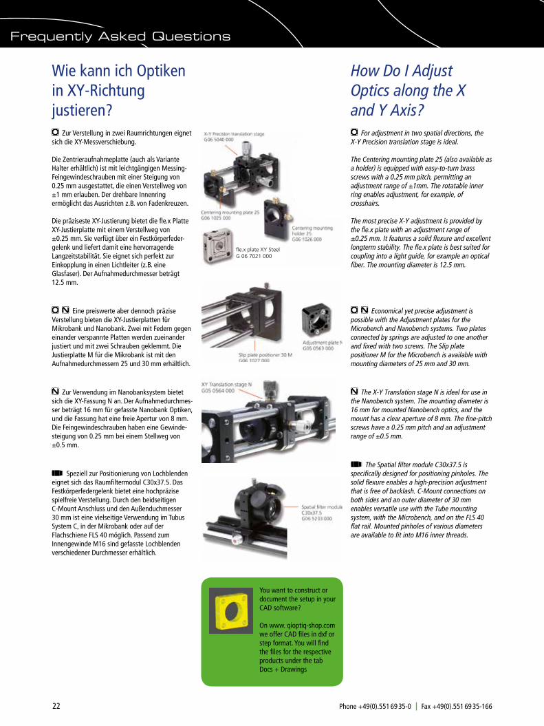
m For adjustment in two spatial directions, the X-Y Precision translation stage is ideal.
The Centering mounting plate 25 (also available as a holder) is equipped with easy-to-turn brass screws with a 0.25 mm pitch, permitting an adjustment range of ±1mm. The rotatable inner ring enables adjustment, for example, of crosshairs.
The most precise X-Y adjustment is provided by the fle.x plate with an adjustment range of ±0.25 mm. It features a solid flexure and excellent longterm stability. The fle.x plate is best suited for coupling into a light guide, for example an optical fiber. The mounting diameter is 12.5 mm.
m n Economical yet precise adjustment is possible with the Adjustment plates for the Microbench and Nanobench systems. Two plates connected by springs are adjusted to one another and fixed with two screws. The Slip plate positioner M for the Microbench is available with mounting diameters of 25 mm and 30 mm.
n The X-Y Translation stage N is ideal for use in the Nanobench system. The mounting diameter is 16 mm for mounted Nanobench optics, and the mount has a clear aperture of 8 mm. The fine-pitch screws have a 0.25 mm pitch and an adjustment range of ±0.5 mm.
t The Spatial filter module C30x37.5 is specifically designed for positioning pinholes. The solid flexure enables a high-precision adjustment that is free of backlash. C-Mount connections on both sides and an outer diameter of 30 mm enables versatile use with the Tube mounting system, with the Microbench, and on the FLS 40 flat rail. Mounted pinholes of various diameters are available to fit into M16 inner threads.
m Zur Verstellung in zwei Raumrichtungen eignet sich die XY-Messverschiebung.
Die Zentrieraufnahmeplatte (auch als Variante Halter erhältlich) ist mit leichtgängigen Messing-Feingewindeschrauben mit einer Steigung von 0.25 mm ausgestattet, die einen Verstellweg von ±1 mm erlauben. Der drehbare Innenring ermöglicht das Ausrichten z.B. von Fadenkreuzen.
Die präziseste XY-Justierung bietet die fle.x Platte XY-Justierplatte mit einem Verstellweg von ±0.25 mm. Sie verfügt über ein Festkörperfeder-gelenk und liefert damit eine hervorragende Langzeitstabilität. Sie eignet sich perfekt zur Einkopplung in einen Lichtleiter (z.B. eine Glasfaser). Der Aufnahmedurchmesser beträgt 12.5 mm.
m n Eine preiswerte aber dennoch präzise Verstellung bieten die XY-Justierplatten für Mikrobank und Nanobank. Zwei mit Federn gegen einander verspannte Platten werden zueinander justiert und mit zwei Schrauben geklemmt. Die Justierplatte M für die Mikrobank ist mit den Aufnahmedurchmessern 25 und 30 mm erhältlich.
n Zur Verwendung im Nanobanksystem bietet sich die XY-Fassung N an. Der Aufnahmedurchmes-ser beträgt 16 mm für gefasste Nanobank Optiken, und die Fassung hat eine freie Apertur von 8 mm. Die Feingewindeschrauben haben eine Gewinde-steigung von 0.25 mm bei einem Stellweg von ±0.5 mm.
t Speziell zur Positionierung von Lochblenden eignet sich das Raumfiltermodul C30x37.5. Das Festkörperfedergelenk bietet eine hochpräzise spielfreie Verstellung. Durch den beidseitigen C-Mount Anschluss und den Außenduchmesser 30 mm ist eine vielseitige Verwendung im Tubus System C, in der Mikrobank oder auf der Flachschiene FLS 40 möglich. Passend zum Innengewinde M16 sind gefasste Lochblenden verschiedener Durchmesser erhältlich.
Frequently Asked Questions
You want to construct or document the setup in your CAD software?
On www. qioptiq-shop.com we offer CAD files in dxf or step format. You will find the files for the respective products under the tab Docs + Drawings
fle.x plate XY SteelG 06 7021 000

23Phone +49(0).551 69 35-0 Fax +49(0).551 69 35-166 [email protected]
What Options Are Available for Rotation of Optics?
Welche Möglichkeiten zur Rotation von Optiken gibt es?
m We offer two Rotary supports for mounting components that require rotational alignment, such as slits, reticles and polarizers. The first is a mounting plate with an integrated rotary mount, which features a scale with 5° intervals and a rotation range of 360°. The inner ring can be fixed with a locking screw.
For higher precision requirements we recommend the Rotary support 20°, with a micrometer screw for adjustment. The adjustment range is ±10° with a sensitivity of 10". Both rotary supports have mounting diameters of 25 mm.
m Motorized rotation mounts are specifically designed for fast rotation of construction elements with 25 mm diameter. You can choose from either servomotor or stepper motor models. In the servomotor model, the motor speed can be adjusted from 10 to 200 rpm. The maximum speed of the stepper motor model is 400 rpm, and the smallest step angle is 1.8°. The servomotor requires a supply voltage of 0-12 V for activation, while the stepper motor requires a controller. An optional reflected-light barrier is available separately.
n For the Nanobench system the Rotary support N is most suited. This component is designed to be clipped into Mounting Plate N 16 and is tensioned by a disc spring to ensure a rotation without backlash. A lateral bore hole with a diameter of 1.1 mm is provided for insertion of an optional lever to facilitate turning the support.
The Rotary support N can also be used as a quick-change adapter for optics in mounts with a diameter of 16 mm, as the mounted optics are simply clipped into place.
m Zur Aufnahme rotationsorientierter Komponen-ten wie Spalte, Strichplatten oder Polarisatoren eignen sich diese beiden Drehfassungen. Die Aufnahmeplatte mit integrierter Drehfassung besitzt eine Skala mit 5°-Teilung und einen Rotationsbereich von 360°. Der Innenring kann mit einer Klemmschraube fixiert werden.
Für genauere Anforderungen empfehlen wir die Drehfassung 20° mit Verstellmöglichkeit über eine Messschraube. Der Verstellbereich beträgt ±10° bei einer Einstellempfindlichkeit von 10“. Beide Drehfassungen haben einen Aufnahmedurch-messer von 25 mm.
m Speziell zur schnellen Rotation von Bauelemen-ten mit 25 mm Durchmesser wurde die motorisier-te Rotationsfassung entwickelt. Die Drehzahl der Servomotorvariante ist von 10 bis 200 U/min regelbar. Die maximale Drehzahl der Schrittmotor-variante beträgt 400 U/min, die kleinste Schrittweite 1,8°. Zur Ansteuerung des Servo-motors genügt eine Spannung von 0 bis 12 V. Für den Schrittmotor wird eine Schrittmotorsteuerung benötigt. Optional ist eine Reflexlichtschranke zur Drehzahlmessung erhältlich.
n Zum Einsatz im Nanobank System eignet sich die Drehfassung N. Die Drehfassung wird in eine Aufnahmeplatte N 16 geklemmt und mit einer Tellerfeder unter Spannung gehalten, was ein spiel-freies Drehen gewährleistet. Eine seitliche Bohrung mit 1.1 mm Durchmesser ermöglicht die Aufnahme eines Hebels, der das Drehen der Fassung erleichtert.
Die Drehfassung N ist auch als Schnellwechsel-einsatz für Optiken in Fassung mit 16 mm Durchmesser verwendbar, in die die gefassten Optiken einfach eingeklickt werden.
• Drehfassung zur 360°-Rotation und Dreh- fassung 20° für höchste Anforderungen
• Motorisierte Drehfassung mit Schritt- oder Servomotor
• Rotary Support for 360° rotation and
Rotary Support 20° for more stringent requirements
• Motorized rotary mount with stepper motor or servomotor
Frequently Asked Questions
24 Phone +49(0).551 69 35-0 Fax +49(0).551 69 35-166 [email protected]
How Do I Adjust Optics along the Z Axis?
Wie kann ich Optiken in Z-Richtung verschieben?
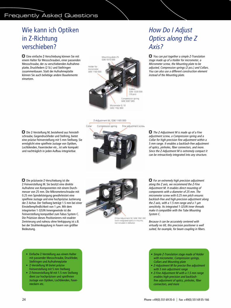
m You can put together a simple Z-Translation stage made up of a Holder for micrometer, a Micrometer screw, the Mounting plate to be adjusted, Compression springs (2 pcs.) and Collars. You can also use a different construction element instead of the Mounting plate.
m Eine einfache Z-Verschiebung können Sie mit einem Halter für Messschrauben, einer passenden Messschraube, der zu verschiebenden Aufnahme-platte, Druckfedern (2 St.) und Stellringen zusammenbauen. Statt der Aufnahmeplatte können Sie auch beliebige andere Bauelemente einsetzen.
m Die Z-Verstellung M, bestehend aus Feinstell-schraube, Gegendruckfeder und Stellring, bietet eine präzise Feinverstellung mit 5 mm Stellweg. Sie ermöglicht eine spielfreie Justage von Optiken, Lochblenden, Faserstecker etc., ist sehr kompakt und nachträglich in jeden Aufbau integrierbar.
m The Z-Adjustment M is made up of a Fine adjustment screw, a Compression spring and a Collar for high-precision fine adjustment within a 5 mm range. It enables a backlash-free adjustment of optics, pinholes, fiber connectors, and more. Since the Z-Adjustment M is extremely compact it can be retroactively integrated into any structure.
• Einfache Z-Verstellung aus einem Halter mit passender Messschraube, Druckfeder, Stellringen und Aufnahmeplatte
• Z-Verstellung M bietet präzise Feinverstellung mit 5 mm Stellweg
• Z-Feinverstellung M mit 1.5 mm Stellweg dient zur hochpräzisen und spielfreien Justage von Optiken, Lochblenden, Faser- steckern etc.
• Simple Z-Translation stage made of Holder
with micrometer, Compression springs, Collars and Mounting plate
• Z-Adjustment M for precise fine adjustment with 5 mm adjustment range
• Z-Fine Adjustment M with a 1.5 mm range enables high-precision and backlash-free adjustment of optics, pinholes, fiber connectors, and more
m Die präziseste Z-Verschiebung ist die Z-Feinverstellung M. Sie besitzt eine direkte Aufnahme von Komponenten mit einem Durch- messer von 25 mm. Die Mikrometerschraube mit 0.25 mm Spindelsteigung gewährleistet eine spielfreie Justage und eine hochpräzise Justierung der Z-Achse. Der Stellweg beträgt 1.5 mm bei einer Einstellempfindlichkeit von 1 µm. Mit dem integrierten 1-32UN Innengewinde ist die Feinverstellung kompatibel zum Tubus System C.Die Präzision dieses Positionierers mit exakter Zentrierung und nahezu ohne Verkippung ist z.B. bei der Strahleinkopplung in Fasern von größter Bedeutung.
m For an extremely high precision adjustment along the Z axis, we recommend the Z-Fine Adjustment M. It enables direct mounting of components with a diameter of 25 mm. The micrometer screw with 0.25 mm pitch ensures backlash-free and high-precision adjustment along the Z axis, with a 1.5 mm range and a 1 µm sensitivity. Its integrated 1-32UN inner threads make it compatible with the Tube Mounting System C.
Because it can be accurately centered with virtually no tilt, this precision positioner is well suited, for example, for beam coupling in fibers.
Frequently Asked Questions

25Phone +49(0).551 69 35-0 Fax +49(0).551 69 35-166 [email protected]
Frequently Asked Questions
n The Z-Adjuster N consists of a Fine adjustment screw, a Collar and a Compression spring. You can combine it with the Mounting Plate N to create a simple Z-Translation stage. Instead of a Nanobench Mounting plate, you can use the Holder N 40 or Adjustment plate N.
The Z-Adjustment N has a range of 5 mm and provides a backlash-free adjustment of optics, pinholes, fiber connectors and more. It is extremely compact and can be retroactively integrated into Nanobench structures.
t Our Fine adjustment C30 and Focusing mount C35 let you alter the spacing between Tube System C elements along the Z-axis.
The Fine adjustment C30 is available with an adjustment range of 3 or 6 mm (with different thread pitches). The overall length of the Fine adjustment C30 changes with adjustment.
The Focusing mount C35 enables the linear adjustment of optics in threaded mounts or of directly installed optics with a diameter of 22.4 mm, without changing the overall length of the mount. If you wish to adjust the zoom lens in an objective from individual components, the Focusing mount C35 is the ideal component.
Both, the Fine adjustment C30 and the Focusing mount C35 feature C-Mount threads and can be fitted directly between the tubes.
n Die Z-Verstellung N besteht aus einer Feinstellschraube und einer Gegendruckfeder. Durch Kombination mit einer Aufnahmeplatte N sind Sie in der Lage, sich eine einfache Z-Verschie-bung zusammenzustellen. Anstatt einer Nanobank Aufnahmeplatte können Sie auch z.B. den Halter N 40 oder die Justierplatte N einsetzen.
Die Z-Verstellung N bietet bei einem Stellweg von 5 mm eine spielfreie Justage von Optiken, Lochblenden, Fasersteckern etc., ist sehr kompakt und nachträglich in Nanobank Aufbauten integrierbar.
t Mit der Feinverstellung C30 und der Fokussierfassung C35 können Sie Abstände im Tubus System C in Z-Richtung verändern.
Die Feinverstellung C30 ist mit Stellwegen von 3 oder 6 mm (mit unterschiedlichen Gewinde- steigungen) lieferbar. Die Gesamtlänge der Fein-verstellung C30 ändert sich mit der Justierung.
Mit der Fokussierfassung C35 können Sie Optiken in Schraubfassung oder direkt eingesetzte Optik mit Durchmesser 22.4 mm linear verschieben, ohne die Gesamtlänge der Fokussierfassung zu verändern. Möchten Sie z.B. die Zoom-Linse eines Objektivs aus Einzelkomponenten justieren, empfiehlt sich die Verwendung der Fokussier-fassung C35.
Sowohl die Feinverstellung als auch die Fokussier-fassung besitzen beidseitige C-Mount Gewinde, um direkt zwischen die Tuben geschraubt werden zu können.
• Feinverstellung C30 zur Z-Justierung von Optiken mit einem Stellweg von 3 oder 6 mm
• Fokussierfassung C35 zum linearen Verschieben von Optiken in Schraubfassungen bei konstant bleibender Gesamtlänge
• Fine adjustment C30 for Z-adjustment of optics with a range of 3 mm or 6 mm
• Focusing mount C35 for linear adjustment of optics in threaded mounts. The total length of the mount remains constant
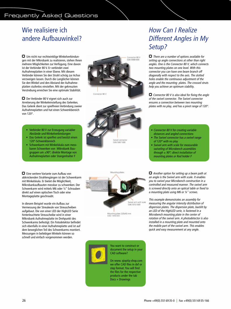
26 Phone +49(0).551 69 35-0 Fax +49(0).551 69 35-166 [email protected]
Frequently Asked Questions
How Can I Realize Different Angles in My Setup?
Wie realisiere ich andere Aufbauwinkel?
m There are a number of options available for setting up angle connections at other than right angles. One is the Connector 80 V, which connects two mounting plates on one level. With this connector you can have one beam branch off diagonally with respect to the axis. The slotted holes enable the continuous adjustment of the angle and the mounting plates. The crossed struts help you achieve an optimum stability.
m Connector 80 V is also ideal for fixing the angle of the swivel connector. The Swivel connector ensures a connection between two mounting plates with no play, and has a pivot range of 120°.
m Um nicht nur rechtwinklige Winkelverbindun-gen mit der Mikrobank zu realisieren, stehen Ihnen mehrere Möglichkeiten zur Verfügung. Eine davon ist der Verbinder 80 V. Er verbindet zwei Aufnahmeplatten in einer Ebene. Mit diesem Verbinder können Sie den Strahl schräg zur Achse verzweigen lassen. Durch die Langlöcher können Sie den Winkel und den Abstand der Aufnahme-platten stufenlos einstellen. Mit der gekreuzten Verstrebung erreichen Sie eine optimale Stabilität.
m Der Verbinder 80 V eignet sich auch zur Arretierung der Winkeleinstellung des Gelenkes. Das Gelenk dient zur spielfreien Verbindung zweier Aufnahmeplatten und hat einen Schwenkbereich von 120°.
• Verbinder 80 V zur Erzeugung variabler Abstände und Winkelverbindungen
• Das Gelenk ist spielfrei und besitzt einen 120°-Schwenkbereich
• Schwenkarm mit Winkelskala zum mess- baren Schwenken von Mikrobank Bau-gruppen um ±90°; direkte Montage von Aufnahmeplatten oder Stangenhalter F
• Connector 80 V for creating variable
distances and angled connections • The Swivel connector has a swivel range
of 120° with no play• Swivel arm with scale for measurable
swiveling of Microbench assemblies through ± 90°; direct installation of mounting plates or Rod holder F
m Eine weitere Variante zum Aufbau von abknickenden Strahlengängen ist der Schwenkarm mit Winkelskala. Er bietet die Möglichkeit, Mikrobankaufbauten messbar zu schwenken. Der Schwenkarm wird mittels M6 oder ¼“ Schrauben direkt auf einen optischen Tisch oder eine Montageplatte geschraubt.
In diesem Beispiel wurde ein Aufbau zur Vermessung der Streukeule von Streuscheiben aufgebaut. Die von einer LED der HighLED Serie hinterleuchtete Streuscheibe wird in einer Mikrobank Aufnahmeplatte im Drehpunkt des Schwenkarms befestigt. Ein Fotodetektor befindet sich ebenfalls in einer Aufnahmeplatte und ist auf dem beweglichen Teil des Schwenkarms montiert. Messungen in beliebigen Winkeln können so schnell und einfach vorgenommen werden.
m Another option for setting up a beam path at an angle is the Swivel arm with scale. It enables you to swivel your Microbench construction in a controlled and measured manner. The swivel arm is screwed directly onto an optical table or fixed to a mounting plate using M6 or ¼" screws.
This example demonstrates an assembly for measuring the angular intensity distribution of dispersion plates. The dispersion plate, backlit by an LED of the HighLED serie, is fastened in a Microbench mounting plate in the center of rotation of the swivel arm. A photodetector is also installed in a mounting plate and mounted onto the mobile part of the swivel arm. This enables quick and easy measurement at any angle.
You want to construct or document the setup in your CAD software?
On www. qioptiq-shop.com we offer CAD files in dxf or step format. You will find the files for the respective products under the tab Docs + Drawings

27Phone +49(0).551 69 35-0 Fax +49(0).551 69 35-166 [email protected]
Frequently Asked Questions
Welche Adapter gibt es?
What Adapters are Available?Because there are so many different optic diameters and threads on the various construc-tion elements, it is not always possible to install the desired components directly into the Microbench, Nanobench or Tube Mounting System C. Please take a look at the table below to find the adapters you need.
Aufgrund der verschiedenen verfügbaren Optikdurchmesser und unterschiedlichen Gewinde ist es nicht immer möglich, die gewünschten Komponenten direkt in Mikrobank, Nanobank oder Tubus System C einzubauen. Die folgende Tabelle hilft Ihnen, schnell den passenden Adapter zu finden.
Artikel-Nr. Außen-ø (mm) bzw. Gewinde
Inneanschluss bzw. ø (mm)
Länge (mm)
Order No Outer ø (mm) or thread
Inner connector or ø (mm)
Length (mm)
G067023000 12.5 FC 8G067024000 12.5 SMAG050310000 16 FC 8G050311000 16 SMAG038855000 25 23.2 10G050305000 25 16 10G061626000 25 15 12G065042000 25 25 20G067054000 25 FC 10G067055000 25 SMA 10G067065000 25 FC 3.5° 10G038857000 30 C-mount/FC 3.5° 6.3G038851000 30 C-Mount 10G061602000 30 25 16G061634000 30 23.2 20G061658000 30 C-Mount 16G061637000 35 30 16G061674000 50 For MB mounting plates 13G061601000 25/30 Solid material 20G061621000 25/30 W0.8”x1/36“ 20G061622000 25/30 16 20G061623000 25/30 19 20G061636000 25/30 23.2 20G061664000 25/30 C-Mount 22G061661000 25/C-Mount 16 / W0.8”x1/36“ 34G061659000 C-Mount Connector for
Microbench rods21
G061667000 C-Mount M23.2x0.75 8G061668000 C-Mount W0.8”x1/36“ 8G038878000 M17x0.75 C-Mount 11G061638000 M35x0.5 30 16G061662000 W0.8”x1/36“ C-Mount 14
G061085000 40x40, Adapter plate for FLS 40 carrier
Solid material
G061005000 40x40, Adapter plate Connector for Microbench and Nanobench rods
10
G050309000 25 16 10
G060407000 30/C-Mount M23.2x0.75 13
G061168000 30 1.035''-40 UN 10
G173013000 30/50 C-Mount 14.5
Selection of adapters from the table
For details and technical drawings, refer to the listing for the specific system in the LINOS catalog or on our website www.qioptiq-shop. com.
Adapter 30&1.035''-40 UNG06 0407 000
Adapter 23.2 to Ø 25G 03 8855 000
Adapter C-mount / MicrobenchG06 1659 000
Microbench - Nanobench Adapter G06 1005 000
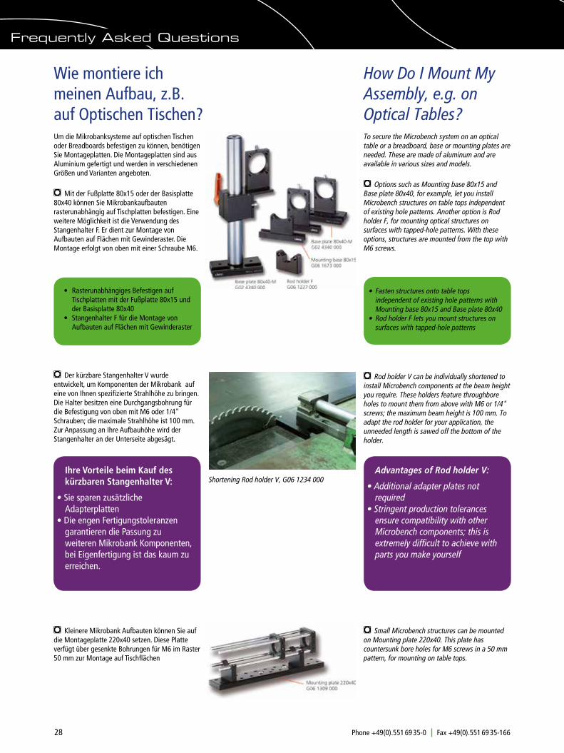
28 Phone +49(0).551 69 35-0 Fax +49(0).551 69 35-166 [email protected]
How Do I Mount My Assembly, e.g. on Optical Tables?
Wie montiere ich meinen Aufbau, z.B. auf Optischen Tischen?
To secure the Microbench system on an optical table or a breadboard, base or mounting plates are needed. These are made of aluminum and are available in various sizes and models.
m Options such as Mounting base 80x15 and Base plate 80x40, for example, let you install Microbench structures on table tops independent of existing hole patterns. Another option is Rod holder F, for mounting optical structures on surfaces with tapped-hole patterns. With these options, structures are mounted from the top with M6 screws.
Um die Mikrobanksysteme auf optischen Tischen oder Breadboards befestigen zu können, benötigen Sie Montageplatten. Die Montageplatten sind aus Aluminium gefertigt und werden in verschiedenen Größen und Varianten angeboten.
m Mit der Fußplatte 80x15 oder der Basisplatte 80x40 können Sie Mikrobankaufbauten rasterunabhängig auf Tischplatten befestigen. Eine weitere Möglichkeit ist die Verwendung des Stangenhalter F. Er dient zur Montage von Aufbauten auf Flächen mit Gewinderaster. Die Montage erfolgt von oben mit einer Schraube M6.
m Der kürzbare Stangenhalter V wurde entwickelt, um Komponenten der Mikrobank auf eine von Ihnen spezifizierte Strahlhöhe zu bringen. Die Halter besitzen eine Durchgangsbohrung für die Befestigung von oben mit M6 oder 1/4" Schrauben; die maximale Strahlhöhe ist 100 mm. Zur Anpassung an Ihre Aufbauhöhe wird der Stangenhalter an der Unterseite abgesägt.
m Rod holder V can be individually shortened to install Microbench components at the beam height you require. These holders feature throughbore holes to mount them from above with M6 or 1/4" screws; the maximum beam height is 100 mm. To adapt the rod holder for your application, the unneeded length is sawed off the bottom of the holder.
• Rasterunabhängiges Befestigen auf Tischplatten mit der Fußplatte 80x15 und der Basisplatte 80x40
• Stangenhalter F für die Montage von Aufbauten auf Flächen mit Gewinderaster
• Fasten structures onto table tops
independent of existing hole patterns with Mounting base 80x15 and Base plate 80x40
• Rod holder F lets you mount structures on surfaces with tapped-hole patterns
Shortening Rod holder V, G06 1234 000 Advantages of Rod holder V:
• Additional adapter plates not required
• Stringent production tolerances ensure compatibility with other Microbench components; this is extremely difficult to achieve with parts you make yourself
m Small Microbench structures can be mounted on Mounting plate 220x40. This plate has countersunk bore holes for M6 screws in a 50 mm pattern, for mounting on table tops.
m Kleinere Mikrobank Aufbauten können Sie auf die Montageplatte 220x40 setzen. Diese Platte verfügt über gesenkte Bohrungen für M6 im Raster 50 mm zur Montage auf Tischflächen
Ihre Vorteile beim Kauf des kürzbaren Stangenhalter V:
• Sie sparen zusätzliche Adapterplatten
• Die engen Fertigungstoleranzen garantieren die Passung zu weiteren Mikrobank Komponenten, bei Eigenfertigung ist das kaum zu erreichen.
Frequently Asked Questions
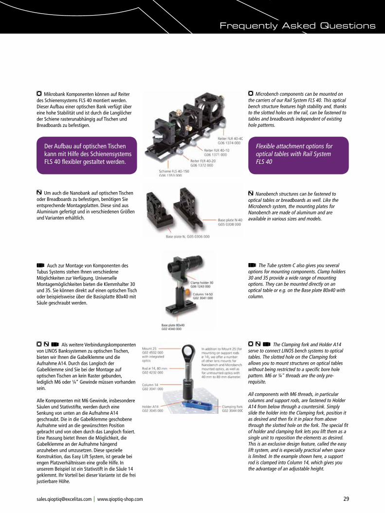
29Phone +49(0).551 69 35-0 Fax +49(0).551 69 35-166 [email protected]
m Mikrobank Komponenten können auf Reiter des Schienensystems FLS 40 montiert werden. Dieser Aufbau einer optischen Bank verfügt über eine hohe Stabilität und ist durch die Langlöcher der Schiene rasterunabhängig auf Tischen und Breadboards zu befestigen.
m Microbench components can be mounted on the carriers of our Rail System FLS 40. This optical bench structure features high stability and, thanks to the slotted holes on the rail, can be fastened to tables and breadboards independent of existing hole patterns.
n Um auch die Nanobank auf optischen Tischen oder Breadboards zu befestigen, benötigen Sie entsprechende Montageplatten. Diese sind aus Aluminium gefertigt und in verschiedenen Größen und Varianten erhältlich.
n Nanobench structures can be fastened to optical tables or breadboards as well. Like the Microbench system, the mounting plates for Nanobench are made of aluminum and are available in various sizes and models.
Flexible attachment options for optical tables with Rail System FLS 40
Der Aufbau auf optischen Tischen kann mit Hilfe des Schienensystems FLS 40 flexibler gestaltet werden.
t Auch zur Montage von Komponenten des Tubus Systems stehen Ihnen verschiedene Möglichkeiten zur Verfügung. Universelle Montagemöglichkeiten bieten die Klemmhalter 30 und 35. Sie können direkt auf einen optischen Tisch oder beispielsweise über die Basisplatte 80x40 mit Säule geschraubt werden.
t The Tube system C also gives you several options for mounting components. Clamp holders 30 and 35 provide a wide range of mounting options. They can be mounted directly on an optical table or e.g. on the Base plate 80x40 with column.
m n t Als weitere Verbindungskomponenten von LINOS Banksystemen zu optischen Tischen, bieten wir Ihnen die Gabelklemme und die Aufnahme A14. Durch das Langloch der Gabelklemme sind Sie bei der Montage auf optischen Tischen an kein Raster gebunden, lediglich M6 oder ¼“ Gewinde müssen vorhanden sein.
Alle Komponenten mit M6 Gewinde, insbesondere Säulen und Stativstifte, werden durch eine Senkung von unten an die Aufnahme A14 geschraubt. Die in die Gabelklemme geschobene Aufnahme wird an die gewünschten Position gebracht und von oben durch das Langloch fixiert. Eine Passung bietet Ihnen die Möglichkeit, die Gabelklemme an der Aufnahme hängend anzuheben und umzusetzen. Diese spezielle Konstruktion, das Easy Lift System, ist gerade bei engen Platzverhältnissen eine große Hilfe. In unserem Beispiel ist ein Stativstift in die Säule 14 geklemmt. Ihr Vorteil bei dieser Variante ist die frei justierbare Höhe.
m n t The Clamping fork and Holder A14 serve to connect LINOS bench systems to optical tables. The slotted hole on the Clamping fork allows you to mount structures on optical tables without being restricted to a specific bore hole pattern. M6 or ¼" threads are the only pre- requisite.
All components with M6 threads, in particular columns and support rods, are fastened to Holder A14 from below through a countersink. Simply slide the holder into the Clamping fork, position it as desired and then fix it in place from above through the slotted hole on the fork. The special fit of holder and clamping fork lets you lift them as a single unit to reposition the elements as desired. This is an exclusive design feature, called the easy lift system, and is especially practical when space is limited. In the example shown here, a support rod is clamped into Column 14, which gives you the advantage of an adjustable height.
Frequently Asked Questions
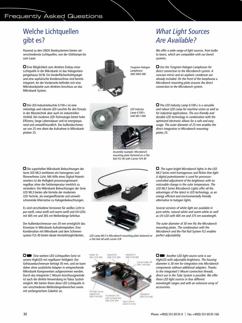
30 Phone +49(0).551 69 35-0 Fax +49(0).551 69 35-166 [email protected]
What Light Sources Are Available?
Welche Lichtquellen gibt es?
We offer a wide range of light sources, from bulbs to lasers, which are compatible with our bench systems.
m Use the Tungsten-Halogen Lamphouse for direct connection to the Microbench system. A concave mirror and an aspheric condenser are already included. On the front of the lamphouse a Microbench mounting plate ensures the direct connection to the Microbench system.
Passend zu den LINOS Banksystemen bieten wir verschiedenste Lichtquellen, von der Glühlampe bis zum Laser.
m Eine Möglichkeit zum direkten Einbau einer Lichtquelle in die Mikrobank ist das Halogenlam-pengehäuse 50 W. Ein Vorderflächenhohlspiegel und eine asphärische Kondensorlinse sind bereits integriert. An der Vorderseite befindet sich eine Mikrobankplatte zum direkten Anschluss an das Mikrobank System.
Tungsten-Halogen Lamphouse G06 5005 000
m The LED Industry Lamp IL100-c is a versatile and robust LED Lamp for machine vision as well as for industrial applications. The eco-friendly and durable LED technology in combination with the optimized electronic allows for a safe and easy usage. The outer diameter of 25 mm enables the direct integration in Microbench mounting plates 25.
LED Industry Lamp IL100-c G40 5817 000
m Die superhellen Mikrobank Beleuchtungen der Serie LED ML3 emittieren ein homogenes und flimmerfreies Licht. Mit Hilfe eines Digital-Potenti-ometers ist die Helligkeit prozessorgesteuert regelbar, ohne die Farbtemperatur merklich zu verändern. Die Mikrobank Beleuchtungen der Serie LED ML3 bieten alle Vorteile der modernen LED-Technik, als energieeffiziente und umwelt-schonende Alternative zu Halogenbeleuchtungen.
Es sind verschiedene Versionen für weißes Licht in pur-weiß, natur-weiß und warm-weiß und UV-LEDs mit 405 nm und 365 nm Wellenlänge lieferbar.
Der Außendurchmesser von 30 mm ermöglicht das Einsetzen in Mikrobank Aufnahmeplatten. Eine Kombination mit Mikrobank und dem Schienen-system FLS 40 bietet ideale Verstellmöglichkeiten.
m Die LED-Industrieleuchte IL100-c ist eine vielseitige und robuste LED-Leuchte für den Einsatz in der Messtechnik aber auch im industriellen Umfeld. Die moderne LED-Technologie bietet hohe Effizienz, lange Lebensdauer und ist energiespa-rend und umweltfreundlich. Der Außendurchmes-ser von 25 mm dient der Aufnahme in Mikrobank-platten 25.
m The super-bright Microbench lights in the LED ML3 Series emit homogenous and flicker-free light. A digital potentiometer is used for processor-controlled adjustment of the brightness with no noticeable change in the color temperature. The LED ML3 Series Microbench Lights offer all the advantages of the latest in LED technology, as an energy efficient and environmentally friendly alternative to halogen lights.
Several versions of white light are available in pure-white, natural-white and warm-white as well as UV-LED with 405 nm and 375 nm wavelength.
The outer diameter of 30 mm fits the Microbench mounting plates. The combination with the Microbench and the Flat Rail System FLS enables perfect adjustability. LED Lamp ML3 in Microbench mounting plate fastened on
a Flat Rail 40 with carrier FLR
m t Eine weitere LED Lichtquellen Serie ist unsere HighLED mit regelbarer Helligkeit. Der Gehäusedurchmesser beträgt 30 mm, und sie kann daher ohne zusätzliche Adapter in entsprechende Mikrobank Komponenten aufgenommen werden. Durch das integrierte C-Mount-Anschlussgewinde ist auch die direkte Verwendung im Tubus System möglich. Wir bieten Ihnen diese LED Lichtquelle in vier verschiedenen Wellenlängenbereichen sowie mit umfangreichem Zubehör an.
m t Another LED light source serie is our HighLED with adjustable brightness. The housing diameter is 30 mm for integration into Microbench components without additional adapters. Thanks to the integrated C-Mount connection threads, direct use in the Tube System is possible. We offer these LED light sources in four different wavelength ranges and with an extensive array of accessories.
Frequently Asked Questions
Assembly example: Microbench mounting plate fastened on a Flat Rail FLS 40 with Carrier FLR 40
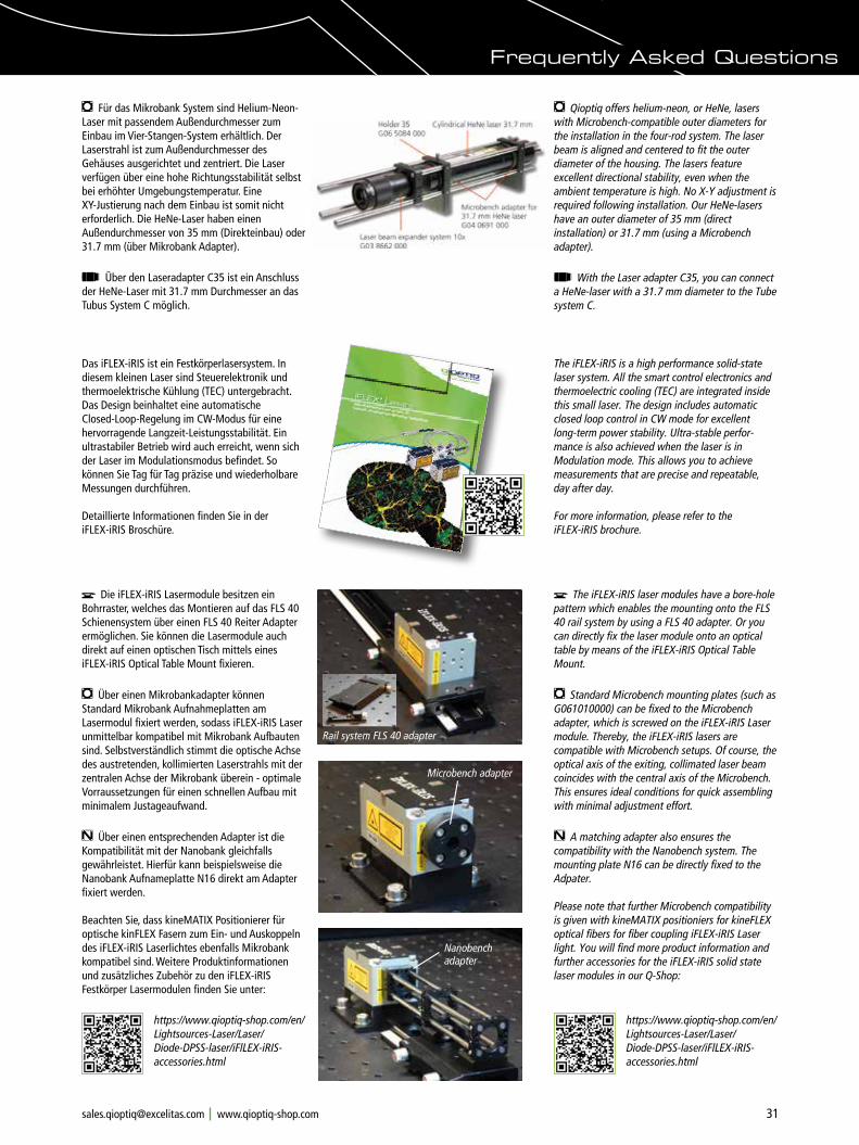
31Phone +49(0).551 69 35-0 Fax +49(0).551 69 35-166 [email protected]
m Für das Mikrobank System sind Helium-Neon-Laser mit passendem Außendurchmesser zum Einbau im Vier-Stangen-System erhältlich. Der Laserstrahl ist zum Außendurchmesser des Gehäuses ausgerichtet und zentriert. Die Laser verfügen über eine hohe Richtungsstabilität selbst bei erhöhter Umgebungstemperatur. Eine XY-Justierung nach dem Einbau ist somit nicht erforderlich. Die HeNe-Laser haben einen Außendurchmesser von 35 mm (Direkteinbau) oder 31.7 mm (über Mikrobank Adapter).
m Qioptiq offers helium-neon, or HeNe, lasers with Microbench-compatible outer diameters for the installation in the four-rod system. The laser beam is aligned and centered to fit the outer diameter of the housing. The lasers feature excellent directional stability, even when the ambient temperature is high. No X-Y adjustment is required following installation. Our HeNe-lasers have an outer diameter of 35 mm (direct installation) or 31.7 mm (using a Microbench adapter).
t Über den Laseradapter C35 ist ein Anschluss der HeNe-Laser mit 31.7 mm Durchmesser an das Tubus System C möglich.
t With the Laser adapter C35, you can connect a HeNe-laser with a 31.7 mm diameter to the Tube system C.
Frequently Asked Questions
Das iFLEX-iRIS ist ein Festkörperlasersystem. In diesem kleinen Laser sind Steuerelektronik und thermoelektrische Kühlung (TEC) untergebracht. Das Design beinhaltet eine automatische Closed-Loop-Regelung im CW-Modus für eine hervorragende Langzeit-Leistungsstabilität. Ein ultrastabiler Betrieb wird auch erreicht, wenn sich der Laser im Modulationsmodus befindet. So können Sie Tag für Tag präzise und wiederholbare Messungen durchführen.
Detaillierte Informationen finden Sie in der iFLEX-iRIS Broschüre.
The iFLEX-iRIS is a high performance solid-state laser system. All the smart control electronics and thermoelectric cooling (TEC) are integrated inside this small laser. The design includes automatic closed loop control in CW mode for excellent long-term power stability. Ultra-stable perfor-mance is also achieved when the laser is in Modulation mode. This allows you to achieve measurements that are precise and repeatable, day after day.
For more information, please refer to the iFLEX-iRIS brochure.
M Die iFLEX-iRIS Lasermodule besitzen ein Bohrraster, welches das Montieren auf das FLS 40 Schienensystem über einen FLS 40 Reiter Adapter ermöglichen. Sie können die Lasermodule auch direkt auf einen optischen Tisch mittels eines iFLEX-iRIS Optical Table Mount fixieren.
m Über einen Mikrobankadapter können Standard Mikrobank Aufnahmeplatten am Lasermodul fixiert werden, sodass iFLEX-iRIS Laser unmittelbar kompatibel mit Mikrobank Aufbauten sind. Selbstverständlich stimmt die optische Achse des austretenden, kollimierten Laserstrahls mit der zentralen Achse der Mikrobank überein - optimale Vorraussetzungen für einen schnellen Aufbau mit minimalem Justageaufwand.
n Über einen entsprechenden Adapter ist die Kompatibilität mit der Nanobank gleichfalls gewährleistet. Hierfür kann beispielsweise die Nanobank Aufnameplatte N16 direkt am Adapter fixiert werden.
Beachten Sie, dass kineMATIX Positionierer für optische kinFLEX Fasern zum Ein- und Auskoppeln des iFLEX-iRIS Laserlichtes ebenfalls Mikrobank kompatibel sind. Weitere Produktinformationen und zusätzliches Zubehör zu den iFLEX-iRIS Festkörper Lasermodulen finden Sie unter:
M The iFLEX-iRIS laser modules have a bore-hole pattern which enables the mounting onto the FLS 40 rail system by using a FLS 40 adapter. Or you can directly fix the laser module onto an optical table by means of the iFLEX-iRIS Optical Table Mount.
m Standard Microbench mounting plates (such as G061010000) can be fixed to the Microbench adapter, which is screwed on the iFLEX-iRIS Laser module. Thereby, the iFLEX-iRIS lasers are compatible with Microbench setups. Of course, the optical axis of the exiting, collimated laser beam coincides with the central axis of the Microbench. This ensures ideal conditions for quick assembling with minimal adjustment effort.
n A matching adapter also ensures the compatibility with the Nanobench system. The mounting plate N16 can be directly fixed to the Adpater.
Please note that further Microbench compatibility is given with kineMATIX positioniers for kineFLEX optical fibers for fiber coupling iFLEX-iRIS Laser light. You will find more product information and further accessories for the iFLEX-iRIS solid state laser modules in our Q-Shop:
https://www.qioptiq-shop.com/en/Lightsources-Laser/Laser/Diode-DPSS-laser/iFlLEX-iRIS-accessories.html
Rail system FLS 40 adapter
Nanobench adapter
Microbench adapter
https://www.qioptiq-shop.com/en/Lightsources-Laser/Laser/Diode-DPSS-laser/iFlLEX-iRIS-accessories.html

32 Phone +49(0).551 69 35-0 Fax +49(0).551 69 35-166 [email protected]
How Can I Combine Systems?
Wie kombiniere ich Systeme miteinander?
m ð With Optic Holder 63
With the Mounting ring for Microbench, the Microbench is compatible with Optic holder 63-M and can thus be integrated in this mount system as well.
m ð Mit Optikhalter 63
Mit dem Rundeinsatz für Mikrobank kann die Mikrobank auch mit dem Optikhalter 63-M kombiniert werden und fügt sich somit in das Fassungssystem ein.
m ó n
The Microbench adapter creates a connection between the Microbench and Nanobench systems by means of Mounting plate 30 and Mounting plate N 16. This adapter has through holes for Nanobench rods.
Another solution is the Microbench-Nanobench adapter. This adapter offers bore holes for Microbench as well as for Nanobench rods.
Adapter 16/25 enables the use of mounted Nanobench optics in Microbench mounting components with a 25 mm inner diameter.
m ó n
Der Mikrobankadapter schafft eine Verbindung der Systeme Mikrobank und Nanobank über Mikrobank Aufnahmeplatte 30 und Aufnahme-platte N 16. Dieser Adapter verfügt über Durchgangsbohrungen für die Nanobank Stangen.
Eine weitere Möglichkeit bietet der Mikrobank-Nanobank Adapter. Er verfügt über Bohrungen sowohl für Nanobank- als auch für Mikrobank Stangen.
Die Reduzierfassung 16/25 ermöglicht das Einsetzen gefasster Nanobank Optiken in Mikrobank Aufnahmekomponenten mit 25 mm Innendurchmesser.
t ó m
Adapters are available for the Tube system C as well, such as the Adapter C-Mount/Microbench, for example. You can combine the Tube system with the Microbench, lasers, CCD cameras, fibers and your choice of other instruments.
t ó m
Für das Tubus System C sind ebenso Adapter wie z.B. der Adapter C-Mount/Mikrobank erhältlich. Sie können das Tubus System mit der Mikrobank, mit Lasern, CCD Kameras, Fasern sowie Geräten Ihrer Wahl kombinieren.
Frequently Asked Questions
You want to construct or document the setup in your CAD software?
On www. qioptiq-shop.com we offer CAD files in dxf or step format. You will find the files for the respective products under the tab Docs + Drawings
Microbench-Nanobench adapter G06 1005 000
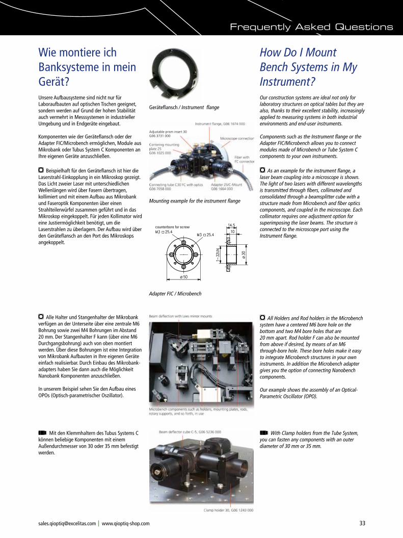
33Phone +49(0).551 69 35-0 Fax +49(0).551 69 35-166 [email protected]
How Do I Mount Bench Systems in My Instrument?
Wie montiere ich Banksysteme in mein Gerät?
Our construction systems are ideal not only for laboratory structures on optical tables but they are also, thanks to their excellent stability, increasingly applied to measuring systems in both industrial environments and end-user instruments.
Components such as the Instrument flange or the Adapter FIC/Microbench allows you to connect modules made of Microbench or Tube System C components to your own instruments.
Unsere Aufbausysteme sind nicht nur für Laboraufbauten auf optischen Tischen geeignet, sondern werden auf Grund der hohen Stabilität auch vermehrt in Messsystemen in industrieller Umgebung und in Endgeräte eingebaut.
Komponenten wie der Geräteflansch oder der Adapter FIC/Microbench ermöglichen, Module aus Mikrobank oder Tubus System C Komponenten an Ihre eigenen Geräte anzuschließen.
m Beispielhaft für den Geräteflansch ist hier die Laserstrahl-Einkopplung in ein Mikroskop gezeigt. Das Licht zweier Laser mit unterschiedlichen Wellenlängen wird über Fasern übertragen, kollimiert und mit einem Aufbau aus Mikrobank und Faseroptik Komponenten über einen Strahlteilerwürfel zusammen geführt und in das Mikroskop eingekoppelt. Für jeden Kollimator wird eine Justiermöglichkeit benötigt, um die Laserstrahlen zu überlagern. Der Aufbau wird über den Geräteflansch an den Port des Mikroskops angekoppelt.
m As an example for the instrument flange, a laser beam coupling into a microscope is shown. The light of two lasers with different wavelengths is transmitted through fibers, collimated and consolidated through a beamsplitter cube with a structure made from Microbench and fiber optics components, and coupled in the microscope. Each collimator requires one adjustment option for superimposing the laser beams. The structure is connected to the microscope port using the Instrument flange.
Geräteflansch / Instrument flange
Adjustable prism insert 30G06 3731 000
m Alle Halter und Stangenhalter der Mikrobank verfügen an der Unterseite über eine zentrale M6 Bohrung sowie zwei M4 Bohrungen im Abstand 20 mm. Der Stangenhalter F kann (über eine M6 Durchgangsbohrung) auch von oben montiert werden. Über diese Bohrungen ist eine Integration von Mikrobank Aufbauten in Ihre eigenen Geräte einfach realisierbar. Durch Einbau des Mikrobank-adapters haben Sie dann auch die Möglichkeit Nanobank Komponenten anzuschließen.
In unserem Beispiel sehen Sie den Aufbau eines OPOs (Optisch-parametrischer Oszillator).
m All Holders and Rod holders in the Microbench system have a centered M6 bore hole on the bottom and two M4 bore holes that are 20 mm apart. Rod holder F can also be mounted from above if desired, by means of an M6 through-bore hole. These bore holes make it easy to integrate Microbench structures in your own instruments. In addition the Microbench adapter gives you the option of connecting Nanobench components.
Our example shows the assembly of an Optical-Parametric Oscillator (OPO).
t Mit den Klemmhaltern des Tubus Systems C können beliebige Komponenten mit einem Außendurchmesser von 30 oder 35 mm befestigt werden.
t With Clamp holders from the Tube System, you can fasten any components with an outer diameter of 30 mm or 35 mm.
Frequently Asked Questions
Mounting example for the instrument flange
Adapter FIC / Microbench
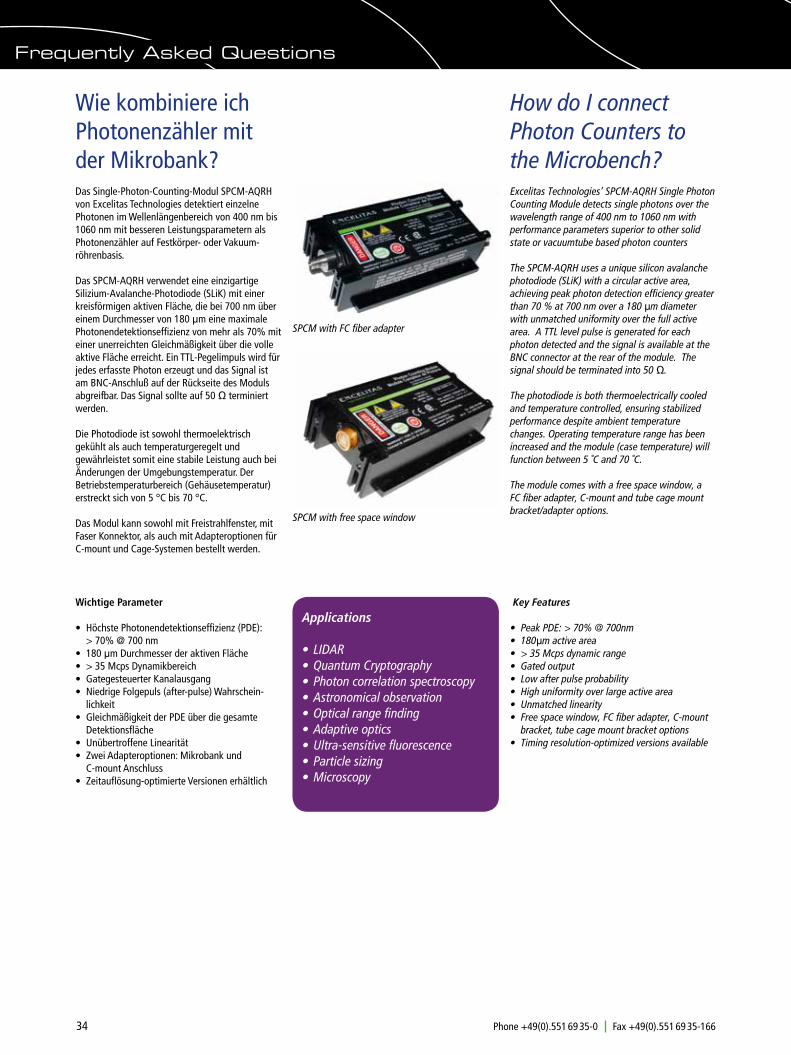
34 Phone +49(0).551 69 35-0 Fax +49(0).551 69 35-166 [email protected]
How do I connect Photon Counters to the Microbench?
Wie kombiniere ich Photonenzähler mit der Mikrobank?
Excelitas Technologies’ SPCM-AQRH Single Photon Counting Module detects single photons over the wavelength range of 400 nm to 1060 nm with performance parameters superior to other solid state or vacuumtube based photon counters
The SPCM-AQRH uses a unique silicon avalanche photodiode (SLiK) with a circular active area, achieving peak photon detection efficiency greater than 70 % at 700 nm over a 180 µm diameter with unmatched uniformity over the full active area. A TTL level pulse is generated for each photon detected and the signal is available at the BNC connector at the rear of the module. The signal should be terminated into 50 Ω.
The photodiode is both thermoelectrically cooled and temperature controlled, ensuring stabilized performance despite ambient temperature changes. Operating temperature range has been increased and the module (case temperature) will function between 5 ˚C and 70 ˚C.
The module comes with a free space window, a FC fiber adapter, C-mount and tube cage mount bracket/adapter options.
Das Single-Photon-Counting-Modul SPCM-AQRH von Excelitas Technologies detektiert einzelne Photonen im Wellenlängenbereich von 400 nm bis 1060 nm mit besseren Leistungsparametern als Photonenzähler auf Festkörper- oder Vakuum-röhrenbasis.
Das SPCM-AQRH verwendet eine einzigartige Silizium-Avalanche-Photodiode (SLiK) mit einer kreisförmigen aktiven Fläche, die bei 700 nm über einem Durchmesser von 180 μm eine maximale Photonendetektionseffizienz von mehr als 70% mit einer unerreichten Gleichmäßigkeit über die volle aktive Fläche erreicht. Ein TTL-Pegelimpuls wird für jedes erfasste Photon erzeugt und das Signal ist am BNC-Anschluß auf der Rückseite des Moduls abgreifbar. Das Signal sollte auf 50 Ω terminiert werden.
Die Photodiode ist sowohl thermoelektrisch gekühlt als auch temperaturgeregelt und gewährleistet somit eine stabile Leistung auch bei Änderungen der Umgebungstemperatur. Der Betriebstemperaturbereich (Gehäusetemperatur) erstreckt sich von 5 °C bis 70 °C.
Das Modul kann sowohl mit Freistrahlfenster, mit Faser Konnektor, als auch mit Adapteroptionen für C-mount und Cage-Systemen bestellt werden.
Frequently Asked Questions
Wichtige Parameter
• Höchste Photonendetektionseffizienz (PDE): > 70% @ 700 nm • 180 μm Durchmesser der aktiven Fläche • > 35 Mcps Dynamikbereich • Gategesteuerter Kanalausgang • Niedrige Folgepuls (after-pulse) Wahrschein- lichkeit • Gleichmäßigkeit der PDE über die gesamte Detektionsfläche • Unübertroffene Linearität • Zwei Adapteroptionen: Mikrobank und C-mount Anschluss • Zeitauflösung-optimierte Versionen erhältlich
Key Features
• Peak PDE: > 70% @ 700nm • 180μm active area • > 35 Mcps dynamic range • Gated output • Low after pulse probability • High uniformity over large active area • Unmatched linearity • Free space window, FC fiber adapter, C-mount bracket, tube cage mount bracket options • Timing resolution-optimized versions available
Applications
• LIDAR • Quantum Cryptography • Photon correlation spectroscopy • Astronomical observation • Optical range finding • Adaptive optics • Ultra-sensitive fluorescence • Particle sizing • Microscopy
SPCM with FC fiber adapter
SPCM with free space window

35Phone +49(0).551 69 35-0 Fax +49(0).551 69 35-166 [email protected]
Frequently Asked Questions
Adapter für Optische Bänke
Für das Modul stehen zwei Adapteroptionen zur Verfügung. Diese Montagehalterungen sind für C-Mount- und Cage-Systeme nach Industriestan-dard vorgesehen, wie das Tubus System C und die Mikrobank. Zusätzlich kann das große Portfolio an optischen Komponenten in diese Systeme integriert werden. Natürlich können an diese SPCM Adapter weitere Standardadapter (siehe dazu Seite 27) angebracht werden, um die Kompatibilität mit verschiedensten Anwendungen zu gewährleisten.
Hinweis: Die Montagehalterungen sind werkseitig installiert und können vom Endbenutzer nicht entfernt werden, ohne das Risiko einer Beschädi-gung einzugehen.
Optical Mount Bracket Options
There are two optical mounting bracket options available to the module. These mounting brackets are for industry standard C-mount and Cage Mount systems, such as the tube system C and the Microbench. In addition, the large portfolio of optical components can be integrated into these systems. Of course, other standard adapters (see page 27) can be attached to these SPCM adapters to ensure compatibility with a wide variety of applications.
Note: The mounting brackets are factory installed and cannot be removed by end users without risk of damaging the detector.
SPCM-AQRH-WX-BR1 with bracket for 1" Tube (no threading) and 30mm Cage-System.Mounting example with Microbench assembly
SPCM-AQRH-WX-BR2 with bracket for C-mount and 30 mm Cage-System:Mounting example with Tube System C assembly
Bracket BR1 adapter for Microbench Mounting plates 30 and Tubes with 1" Tube outer diameter
For more information, prices e.g. please contact:
Für weitere Informationen, Preise etc. wenden Sie sich bitte an:

36 Phone +49(0).551 69 35-0 Fax +49(0).551 69 35-166 [email protected]
Mit unserer Serie der hochpräzisen Piezopositio-nierer steht Ihnen eine Auswahl an Miniatur- positionierern zur Kombination mit LINOS Banksystemen zur Verfügung.
M Der Positionierer MS 30 ist ein Miniatur-Verschiebetisch mit Stellwegen von 8, 18 oder 30 mm. Der MS 30 ist aus einer verzugsarmen Aluminiumlegierung gefertigt, verfügt über Präzisionskugelbuchsenführungen und kann zu XY- oder XYZ Kombinationen montiert werden. Bei dem Miniaturpositionierer MX 25 handelt es sich um eine 3-Achsen Verstelleinheit mit 2 mm Stellweg.
Die Bohrbilder beider Positionierer sind auf die Reiter FLR 40 (ab Breite 34 mm) abgestimmt. Sie benötigen zur Verwendung der Schiene FLS 40 keine weiteren Komponenten.
Our series of high-precision piezoelectric positioning systems gives you a wide selection of miniature positioners in combination with the LINOS bench systems.
M Positioner MS 30 is a miniature translation stage with an adjustment range of 8, 18 or 30 mm. The MS 30 is made of a warp-resistant aluminum alloy, has precision ball lining channels and can be mounted in XY or XYZ combination. The Miniature positioner MX 25 is a 3-axis adjustment unit with a 2 mm range.
The bore hole pattern of both positioners fit onto FLR 40 carriers (width: 34 mm and up). No further components are required for a combination with FLS 40 rails.
How Do I Integrate Motorized Positioners?
Wie integriere ich Motorische Positionierer?
m Die kinematische Spiegeljustierung MT 25 lässt sich über den Außendurchmesser von 25 mm sowohl in Mikrobank Aufnahmeplatten als auch in Würfel mit dem entsprechenden Aufnahmedurch-messer einsetzen. Je nach Anwendung dient die MT 25 zur Positionierung von Spiegeln oder Stahlteilerwürfeln.
Eine freie Durchgangsbohrung von 9 mm erlaubt auch den Einsatz teildurchlässiger Spiegel.
Zur Ansteuerung steht die manuelle Steuerung CN 30 (G40 3513 000) zur Verfügung. Sie ermöglicht die Verstellung in drei Geschwindig-keitsstufen mittels Drucktasten.
m The Kinematic mirror tilting stage MT 25 with an outer diameter of 25 mm can be used in Microbench mounting plates and in cubes with the corresponding mounting diameter. Depending on your application, the MT 25 can be used for positioning mirrors or beamsplitter cubes.
A free through hole of 9 mm also permits the use of partially transmitting mirrors.
A manual controller is available. This controller CN 30 (G40 3513 000) enables the adjustment in three speeds using push buttons.
MT 25 Kinematic Mirror Tilting Stage in Microbench mounting plate
Kinematic Mirror Adjustment MT 25 in Microbench Cubes
Detailed information on all piezoelectric positioning systems is available in the Chapter entitled „Positioning Systems“ in the LINOS catalog and at www.qioptiq-shop.com.
Detaillierte Informationen zu allen Piezopositionierern finden Sie im Kapitel Positioniersysteme im LINOS Katalog und unter www.qioptiq-shop.com.
Frequently Asked Questions
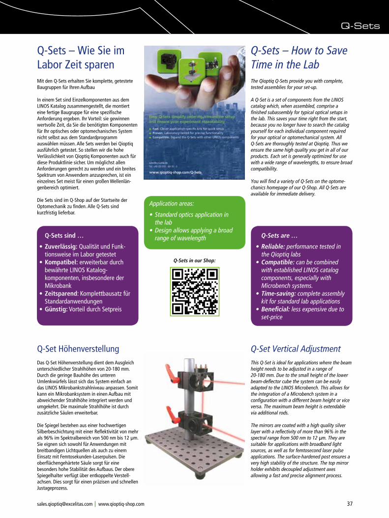
37Phone +49(0).551 69 35-0 Fax +49(0).551 69 35-166 [email protected]
Q-Sets
Q-Sets – How to Save Time in the Lab
Q-Sets – Wie Sie im Labor Zeit sparenMit den Q-Sets erhalten Sie komplette, getestete Baugruppen für Ihren Aufbau
In einem Set sind Einzelkomponenten aus dem LINOS Katalog zusammengestellt, die montiert eine fertige Baugruppe für eine spezifische Anforderung ergeben. Ihr Vorteil: sie gewinnen wertvolle Zeit, da Sie die benötigten Komponenten für Ihr optisches oder optomechanisches System nicht selbst aus dem Standardprogramm auswählen müssen. Alle Sets werden bei Qioptiq ausführlich getestet. So stellen wir die hohe Verlässlichkeit von Qioptiq Komponenten auch für diese Produktlinie sicher. Um möglichst allen Anforderungen gerecht zu werden und ein breites Spektrum von Anwendern anzusprechen, ist ein einzelnes Set meist für einen großen Wellenlän-genbereich optimiert.
Die Sets sind im Q-Shop auf der Startseite der Optomechanik zu finden. Alle Q-Sets sind kurzfristig lieferbar.
Q-Sets are …
• Reliable: performance tested in the Qioptiq labs
• Compatible: can be combined with established LINOS catalog components, especially with Microbench systems.
• Time-saving: complete assembly kit for standard lab applications
• Beneficial: less expensive due to set-price
Q-Sets sind …
• Zuverlässig: Qualität und Funk- tionsweise im Labor getestet
• Kompatibel: erweiterbar durch bewährte LINOS Katalog- komponenten, insbesondere der Mikrobank
• Zeitsparend: Komplettbausatz für Standardanwendungen
• Günstig: Vorteil durch Setpreis
The Qioptiq Q-Sets provide you with complete, tested assemblies for your set-up.
A Q-Set is a set of components from the LINOS catalog which, when assembled, comprise a finished subassembly for typical optical setups in the lab. This saves your time right from the start, because you no longer have to search the catalog yourself for each individual component required for your optical or optomechanical system. All Q-Sets are thoroughly tested at Qioptiq. Thus we ensure the same high quality you get in all of our products. Each set is generally optimized for use with a wide range of wavelengths, to ensure broad compatibility.
You will find a variety of Q-Sets on the optome-chanics homepage of our Q-Shop. All Q-Sets are available for immediate delivery.
Q-Set Vertical AdjustmentThis Q-Set is ideal for applications where the beam height needs to be adjusted in a range of 20-180 mm. Due to the small height of the lower beam-deflector cube the system can be easily adapted to the LINOS Microbench. This allows for the integration of a Microbench system in a configuration with a different beam height or vice versa. The maximum beam height is extendable via additional rods.
The mirrors are coated with a high quality silver layer with a reflectivity of more than 96% in the spectral range from 500 nm to 12 µm. They are suitable for applications with broadband light sources, as well as for femtosecond laser pulse applications. The surface-hardened post ensures a very high stability of the structure. The top mirror holder exhibits decoupled adjustment axes allowing a fast and precise alignment process.
Q-Set HöhenverstellungDas Q-Set Höhenverstellung dient dem Ausgleich unterschiedlicher Strahlhöhen von 20-180 mm.Durch die geringe Bauhöhe des unteren Umlenkwürfels lässt sich das System einfach an das LINOS Mikrobankstrahlniveau anpassen. Somit kann ein Mikrobanksystem in einen Aufbau mit abweichender Strahlhöhe integriert werden und umgekehrt. Die maximale Strahlhöhe ist durch zusätzliche Säulen erweiterbar.
Die Spiegel bestehen aus einer hochwertigen Silberbeschichtung mit einer Reflektivität von mehr als 96% im Spektralbereich von 500 nm bis 12 µm. Sie eignen sich sowohl für Anwendungen mit breitbandigen Lichtquellen als auch zu einem Einsatz mit Femtosekunden-Laserpulsen. Die oberflächengehärtete Säule sorgt für eine besonders hohe Stabilität des Aufbaus. Der obere Spiegelhalter verfügt über entkoppelte Verstell-achsen. Dies sorgt für einen präzisen und schnellen Justageprozess.
Application areas:
• Standard optics application in the lab
• Design allows applying a broad range of wavelength
Q-Sets in our Shop:
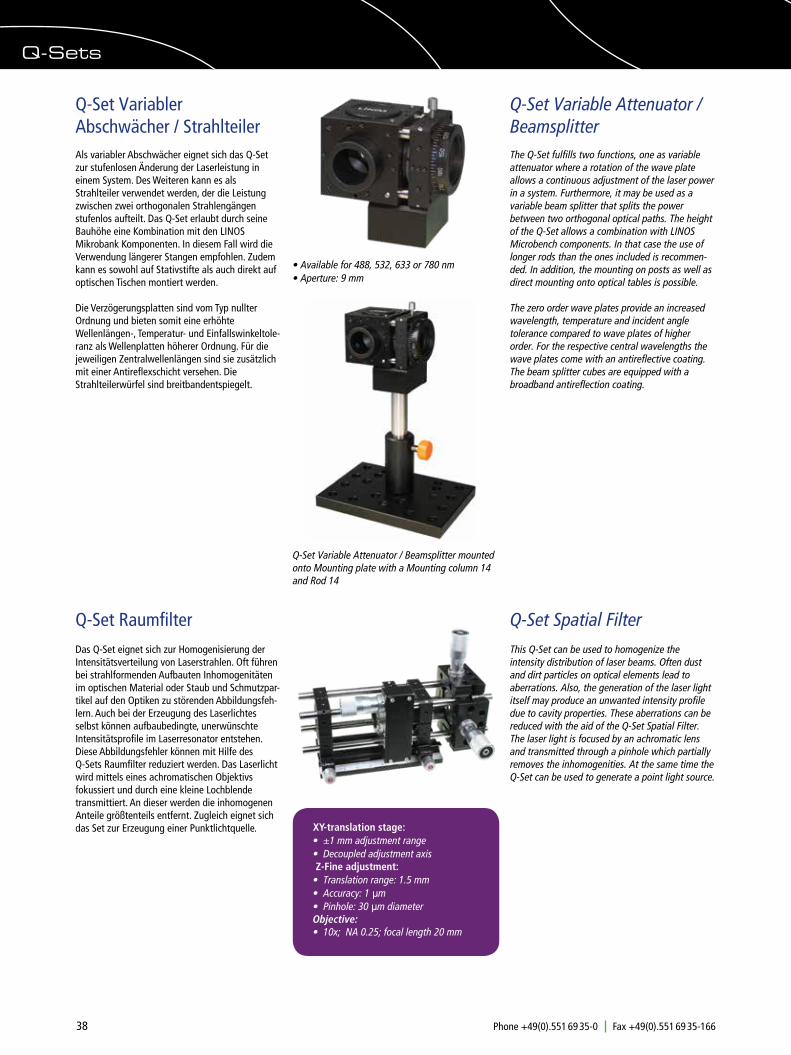
38 Phone +49(0).551 69 35-0 Fax +49(0).551 69 35-166 [email protected]
Q-Set Variabler Abschwächer / StrahlteilerAls variabler Abschwächer eignet sich das Q-Set zur stufenlosen Änderung der Laserleistung in einem System. Des Weiteren kann es als Strahlteiler verwendet werden, der die Leistung zwischen zwei orthogonalen Strahlengängen stufenlos aufteilt. Das Q-Set erlaubt durch seine Bauhöhe eine Kombination mit den LINOS Mikrobank Komponenten. In diesem Fall wird die Verwendung längerer Stangen empfohlen. Zudem kann es sowohl auf Stativstifte als auch direkt auf optischen Tischen montiert werden.
Die Verzögerungsplatten sind vom Typ nullter Ordnung und bieten somit eine erhöhte Wellenlängen-, Temperatur- und Einfallswinkeltole-ranz als Wellenplatten höherer Ordnung. Für die jeweiligen Zentralwellenlängen sind sie zusätzlich mit einer Antireflexschicht versehen. Die Strahlteilerwürfel sind breitbandentspiegelt.
Q-Set Variable Attenuator / BeamsplitterThe Q-Set fulfills two functions, one as variable attenuator where a rotation of the wave plate allows a continuous adjustment of the laser power in a system. Furthermore, it may be used as a variable beam splitter that splits the power between two orthogonal optical paths. The height of the Q-Set allows a combination with LINOS Microbench components. In that case the use of longer rods than the ones included is recommen-ded. In addition, the mounting on posts as well as direct mounting onto optical tables is possible.
The zero order wave plates provide an increased wavelength, temperature and incident angle tolerance compared to wave plates of higher order. For the respective central wavelengths the wave plates come with an antireflective coating. The beam splitter cubes are equipped with a broadband antireflection coating.
• Available for 488, 532, 633 or 780 nm • Aperture: 9 mm
Q-Set Variable Attenuator / Beamsplitter mounted onto Mounting plate with a Mounting column 14 and Rod 14
Q-Sets
Das Q-Set eignet sich zur Homogenisierung der Intensitätsverteilung von Laserstrahlen. Oft führen bei strahlformenden Aufbauten Inhomogenitäten im optischen Material oder Staub und Schmutzpar-tikel auf den Optiken zu störenden Abbildungsfeh-lern. Auch bei der Erzeugung des Laserlichtes selbst können aufbaubedingte, unerwünschte Intensitätsprofile im Laserresonator entstehen. Diese Abbildungsfehler können mit Hilfe des Q-Sets Raumfilter reduziert werden. Das Laserlicht wird mittels eines achromatischen Objektivs fokussiert und durch eine kleine Lochblende transmittiert. An dieser werden die inhomogenen Anteile größtenteils entfernt. Zugleich eignet sich das Set zur Erzeugung einer Punktlichtquelle.
Q-Set Raumfilter Q-Set Spatial FilterThis Q-Set can be used to homogenize the intensity distribution of laser beams. Often dust and dirt particles on optical elements lead to aberrations. Also, the generation of the laser light itself may produce an unwanted intensity profile due to cavity properties. These aberrations can be reduced with the aid of the Q-Set Spatial Filter. The laser light is focused by an achromatic lens and transmitted through a pinhole which partially removes the inhomogenities. At the same time the Q-Set can be used to generate a point light source.
XY-translation stage: • ±1 mm adjustment range • Decoupled adjustment axis Z-Fine adjustment: • Translation range: 1.5 mm • Accuracy: 1 µm • Pinhole: 30 µm diameter Objective: • 10x; NA 0.25; focal length 20 mm
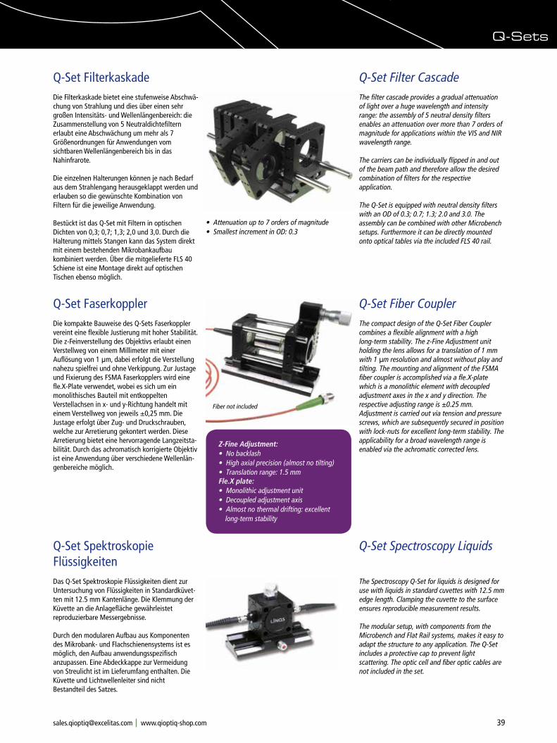
39Phone +49(0).551 69 35-0 Fax +49(0).551 69 35-166 [email protected]
Q-Sets
Q-Set Filter CascadeThe filter cascade provides a gradual attenuation of light over a huge wavelength and intensity range: the assembly of 5 neutral density filters enables an attenuation over more than 7 orders of magnitude for applications within the VIS and NIR wavelength range.
The carriers can be individually flipped in and out of the beam path and therefore allow the desired combination of filters for the respective application.
The Q-Set is equipped with neutral density filters with an OD of 0.3; 0.7; 1.3; 2.0 and 3.0. The assembly can be combined with other Microbench setups. Furthermore it can be directly mounted onto optical tables via the included FLS 40 rail.
Q-Set FilterkaskadeDie Filterkaskade bietet eine stufenweise Abschwä-chung von Strahlung und dies über einen sehr großen Intensitäts- und Wellenlängenbereich: die Zusammenstellung von 5 Neutraldichtefiltern erlaubt eine Abschwächung um mehr als 7 Größenordnungen für Anwendungen vom sichtbaren Wellenlängenbereich bis in das Nahinfrarote.
Die einzelnen Halterungen können je nach Bedarf aus dem Strahlengang herausgeklappt werden und erlauben so die gewünschte Kombination von Filtern für die jeweilige Anwendung.
Bestückt ist das Q-Set mit Filtern in optischen Dichten von 0,3; 0,7; 1,3; 2,0 und 3,0. Durch die Halterung mittels Stangen kann das System direkt mit einem bestehenden Mikrobankaufbau kombiniert werden. Über die mitgelieferte FLS 40 Schiene ist eine Montage direkt auf optischen Tischen ebenso möglich.
Q-Set Fiber CouplerThe compact design of the Q-Set Fiber Coupler combines a flexible alignment with a high long-term stability. The z-Fine Adjustment unit holding the lens allows for a translation of 1 mm with 1 µm resolution and almost without play and tilting. The mounting and alignment of the FSMA fiber coupler is accomplished via a fle.X-plate which is a monolithic element with decoupled adjustment axes in the x and y direction. The respective adjusting range is ±0.25 mm. Adjustment is carried out via tension and pressure screws, which are subsequently secured in position with lock-nuts for excellent long-term stability. The applicability for a broad wavelength range is enabled via the achromatic corrected lens.
Q-Set FaserkopplerDie kompakte Bauweise des Q-Sets Faserkoppler vereint eine flexible Justierung mit hoher Stabilität. Die z-Feinverstellung des Objektivs erlaubt einen Verstellweg von einem Millimeter mit einer Auflösung von 1 µm, dabei erfolgt die Verstellung nahezu spielfrei und ohne Verkippung. Zur Justage und Fixierung des FSMA Faserkopplers wird eine fle.X-Plate verwendet, wobei es sich um ein monolithisches Bauteil mit entkoppelten Verstellachsen in x- und y-Richtung handelt mit einem Verstellweg von jeweils ±0,25 mm. Die Justage erfolgt über Zug- und Druckschrauben, welche zur Arretierung gekontert werden. Diese Arretierung bietet eine hervorragende Langzeitsta-bilität. Durch das achromatisch korrigierte Objektiv ist eine Anwendung über verschiedene Wellenlän-genbereiche möglich.
• Attenuation up to 7 orders of magnitude• Smallest increment in OD: 0.3
Z-Fine Adjustment: • No backlash • High axial precision (almost no tilting) • Translation range: 1.5 mm Fle.X plate: • Monolithic adjustment unit • Decoupled adjustment axis • Almost no thermal drifting: excellent long-term stability
Fiber not included
Q-Set Spektroskopie FlüssigkeitenDas Q-Set Spektroskopie Flüssigkeiten dient zur Untersuchung von Flüssigkeiten in Standardküvet-ten mit 12.5 mm Kantenlänge. Die Klemmung der Küvette an die Anlagefläche gewährleistet reproduzierbare Messergebnisse.
Durch den modularen Aufbau aus Komponenten des Mikrobank- und Flachschienensystems ist es möglich, den Aufbau anwendungsspezifisch anzupassen. Eine Abdeckkappe zur Vermeidung von Streulicht ist im Lieferumfang enthalten. Die Küvette und Lichtwellenleiter sind nicht Bestandteil des Satzes.
Q-Set Spectroscopy Liquids
The Spectroscopy Q-Set for liquids is designed for use with liquids in standard cuvettes with 12.5 mm edge length. Clamping the cuvette to the surface ensures reproducible measurement results.
The modular setup, with components from the Microbench and Flat Rail systems, makes it easy to adapt the structure to any application. The Q-Set includes a protective cap to prevent light scattering. The optic cell and fiber optic cables are not included in the set.
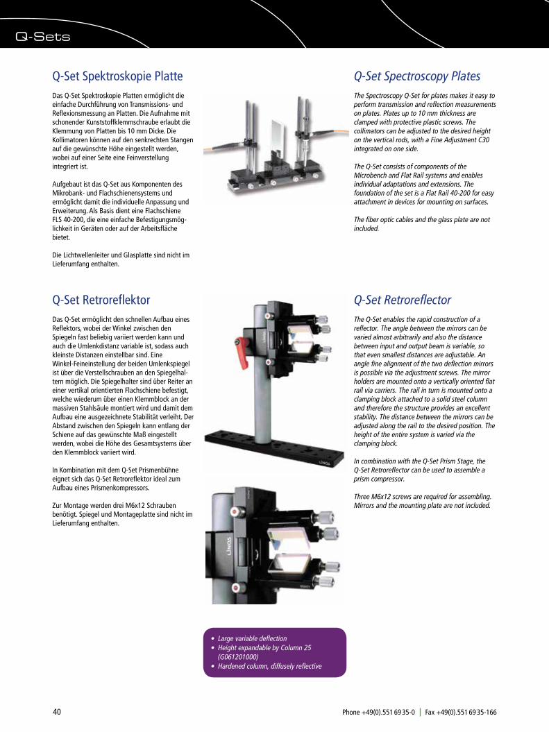
40 Phone +49(0).551 69 35-0 Fax +49(0).551 69 35-166 [email protected]
Q-Set Spektroskopie PlatteDas Q-Set Spektroskopie Platten ermöglicht die einfache Durchführung von Transmissions- und Reflexionsmessung an Platten. Die Aufnahme mit schonender Kunststoffklemmschraube erlaubt die Klemmung von Platten bis 10 mm Dicke. Die Kollimatoren können auf den senkrechten Stangen auf die gewünschte Höhe eingestellt werden, wobei auf einer Seite eine Feinverstellung integriert ist.
Aufgebaut ist das Q-Set aus Komponenten des Mikrobank- und Flachschienensystems und ermöglicht damit die individuelle Anpassung und Erweiterung. Als Basis dient eine Flachschiene FLS 40-200, die eine einfache Befestigungsmög-lichkeit in Geräten oder auf der Arbeitsfläche bietet.
Die Lichtwellenleiter und Glasplatte sind nicht im Lieferumfang enthalten.
Q-Set Spectroscopy PlatesThe Spectroscopy Q-Set for plates makes it easy to perform transmission and reflection measurements on plates. Plates up to 10 mm thickness are clamped with protective plastic screws. The collimators can be adjusted to the desired height on the vertical rods, with a Fine Adjustment C30 integrated on one side.
The Q-Set consists of components of the Microbench and Flat Rail systems and enables individual adaptations and extensions. The foundation of the set is a Flat Rail 40-200 for easy attachment in devices for mounting on surfaces.
The fiber optic cables and the glass plate are not included.
Q-Set RetroreflectorThe Q-Set enables the rapid construction of a reflector. The angle between the mirrors can be varied almost arbitrarily and also the distance between input and output beam is variable, so that even smallest distances are adjustable. An angle fine alignment of the two deflection mirrors is possible via the adjustment screws. The mirror holders are mounted onto a vertically oriented flat rail via carriers. The rail in turn is mounted onto a clamping block attached to a solid steel column and therefore the structure provides an excellent stability. The distance between the mirrors can be adjusted along the rail to the desired position. The height of the entire system is varied via the clamping block.
In combination with the Q-Set Prism Stage, the Q-Set Retroreflector can be used to assemble a prism compressor.
Three M6x12 screws are required for assembling. Mirrors and the mounting plate are not included.
Q-Set RetroreflektorDas Q-Set ermöglicht den schnellen Aufbau eines Reflektors, wobei der Winkel zwischen den Spiegeln fast beliebig variiert werden kann und auch die Umlenkdistanz variable ist, sodass auch kleinste Distanzen einstellbar sind. Eine Winkel-Feineinstellung der beiden Umlenkspiegel ist über die Verstellschrauben an den Spiegelhal-tern möglich. Die Spiegelhalter sind über Reiter an einer vertikal orientierten Flachschiene befestigt, welche wiederum über einen Klemmblock an der massiven Stahlsäule montiert wird und damit dem Aufbau eine ausgezeichnete Stabilität verleiht. Der Abstand zwischen den Spiegeln kann entlang der Schiene auf das gewünschte Maß eingestellt werden, wobei die Höhe des Gesamtsystems über den Klemmblock variiert wird.
In Kombination mit dem Q-Set Prismenbühne eignet sich das Q-Set Retroreflektor ideal zum Aufbau eines Prismenkompressors.
Zur Montage werden drei M6x12 Schrauben benötigt. Spiegel und Montageplatte sind nicht im Lieferumfang enthalten.
• Large variable deflection • Height expandable by Column 25 (G061201000) • Hardened column, diffusely reflective
Q-Sets
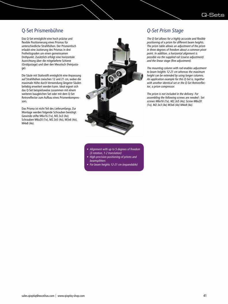
41Phone +49(0).551 69 35-0 Fax +49(0).551 69 35-166 [email protected]
Q-Set Prism StageThe Q-Set allows for a highly accurate and flexible positioning of a prism for different beam heights. The prism table allows an adjustment of the prism in three degrees of freedom about a common pivot point. In addition, a horizontal alignment is possible via the supplied rail (coarse adjustment) and the linear stage (fine adjustment).
The mounting column with rod enables adjustment to beam heights 12-21 cm whereas the maximum height can be extended by using longer columns. An application example for this Q-Set is, together with another identical set or the Q-Set Retroreflec-tor, a prism compressor.
The prism is not included in the delivery. For assembling the following screws are needed : Set screws M6x16 (1x), M2.3x5 (4x); Screw M6x20 (1x), M2.3x3 (4x) M3x6 (4x) M4x8 (4x).
Q-Set PrismenbühneDas Q-Set ermöglicht eine hoch präzise und flexible Positionierung eines Prismas für unterschiedliche Strahlhöhen. Der Prismentisch erlaubt eine Justierung des Prismas in drei Freiheitsgraden um einen gemeinsamen Drehpunkt. Zusätzlich erfolgt eine horizontale Ausrichtung über die mitgelieferte Schiene (Grobjustage) und über den Messtisch (Feinjusta-ge).
Die Säule mit Stativstift ermöglicht eine Anpassung auf Strahlhöhen zwischen 12 und 21 cm, wobei die maximale Höhe durch Verwendung längerer Säulen beliebig erweitert werden kann. Ideal eignet sich das Q-Set beispielsweise zusammen mit einem weiteren baugleichen Set oder mit dem Q-Set Retroreflector zum Aufbau eines Prismenkompres-sors.
Das Prisma ist nicht Teil des Lieferumfangs. Zur Montage werden folgende Schrauben benötigt: Gewinde-stifte M6x16 (1x), M2.3x3 (4x); Schrauben M6x20 (1x), M2.3x5 (4x), M3x6 (4x), M4x8 (4x).
• Alignment with up to 5 degrees of freedom (3 rotation, 1-2 translation) • High-precision positioning of prisms and beamsplitters• For beam heights 12-21 cm (expandable)
Q-Sets
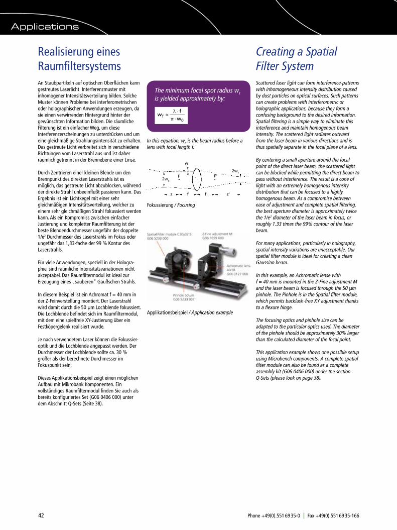
42 Phone +49(0).551 69 35-0 Fax +49(0).551 69 35-166 [email protected]
Creating a Spatial Filter System
Realisierung eines Raumfiltersystems
Scattered laser light can form interference-patterns with inhomogeneous intensity distribution caused by dust particles on optical surfaces. Such patterns can create problems with interferometric or holographic applications, because they form a confusing background to the desired information. Spatial filtering is a simple way to eliminate this interference and maintain homogenous beam intensity. The scattered light radiates outward from the laser beam in various directions and is thus spatially separate in the focal plane of a lens.
By centering a small aperture around the focal point of the direct laser beam, the scattered light can be blocked while permitting the direct beam to pass without interference. The result is a cone of light with an extremely homogenous intensity distribution that can be focused to a highly homogenous beam. As a compromise between ease of adjustment and complete spatial filtering, the best aperture diameter is approximately twice the 1/e2 diameter of the laser beam in focus, or roughly 1.33 times the 99% contour of the laser beam.
For many applications, particularly in holography, spatial intensity variations are unacceptable. Our spatial filter module is ideal for creating a clean Gaussian beam.
In this example, an Achromatic lense with f = 40 mm is mounted in the Z-Fine adjustment M and the laser beam is focused through the 50 µm pinhole. The Pinhole is in the Spatial filter module, which permits backlash-free XY adjustment thanks to a flexure hinge.
The focusing optics and pinhole size can be adapted to the particular optics used. The diameter of the pinhole should be approximately 30% larger than the calculated diameter of the focal point.
This application example shows one possible setup using Microbench components. A complete spatial filter module can also be found as a complete assembly kit (G06 0406 000) under the section Q-Sets (please look on page 38).
An Staubpartikeln auf optischen Oberflächen kann gestreutes Laserlicht Interferenzmuster mit inhomogener Intensitätsverteilung bilden. Solche Muster können Probleme bei interferometrischen oder holographischen Anwendungen erzeugen, da sie einen verwirrenden Hintergrund hinter der gewünschten Information bilden. Die räumliche Filterung ist ein einfacher Weg, um diese Interferenzerscheinungen zu unterdrücken und um eine gleichmäßige Strahlungsintensität zu erhalten. Das gestreute Licht verbreitet sich in verschiedene Richtungen vom Laserstrahl aus und ist daher räumlich getrennt in der Brennebene einer Linse.
Durch Zentrieren einer kleinen Blende um den Brennpunkt des direkten Laserstrahls ist es möglich, das gestreute Licht abzublocken, während der direkte Strahl unbeeinflußt passieren kann. Das Ergebnis ist ein Lichtkegel mit einer sehr gleichmäßigen Intensitätsverteilung, welcher zu einem sehr gleichmäßigen Strahl fokussiert werden kann. Als ein Kompromiss zwischen einfacher Justierung und kompletter Raumfilterung ist der beste Blendendurchmesser ungefähr der doppelte 1/e2 Durchmesser des Laserstrahls im Fokus oder ungefähr das 1,33-fache der 99 % Kontur des Laserstrahls.
Für viele Anwendungen, speziell in der Hologra-phie, sind räumliche Intensitätsvariationen nicht akzeptabel. Das Raumfiltermodul ist ideal zur Erzeugung eines „sauberen“ Gaußschen Strahls.
In diesem Beispiel ist ein Achromat f = 40 mm in der Z-Feinverstellung montiert. Der Laserstrahl wird damit durch die 50 µm Lochblende fokussiert. Die Lochblende befindet sich im Raumfiltermodul, mit dem eine spielfreie XY-Justierung über ein Festköpergelenk realisiert wurde.
Je nach verwendetem Laser können die Fokussier-optik und die Lochblende angepasst werden. Der Durchmesser der Lochblende sollte ca. 30 % größer als der berechnete Durchmesser im Fokuspunkt sein.
Dieses Applikationsbeispiel zeigt einen möglichen Aufbau mit Mikrobank Komponenten. Ein vollständiges Raumfiltermodul finden Sie auch als bereits konfiguriertes Set (G06 0406 000) unter dem Abschnitt Q-Sets (Seite 38).
The minimum focal spot radius wf is yielded approximately by:
In this equation, w0 is the beam radius before a lens with focal length f.
z ff z'
F2w0
2wf
Θ
F'
Fokussierung / Focusing
Applications
Applikationsbeispiel / Application example

43Phone +49(0).551 69 35-0 Fax +49(0).551 69 35-166 [email protected]
Creating an Expansion System
Realisierung eines Aufweitungssystems
The Tube system C lets you set up simple expansion systems in accordance with the desired expansion ratio. With the Spatial filter module, you can add pinholes to the system as well.
Our example demonstrates a 16x expansion system. The structure of the optical system is simulated using the WinLensTM program from Qioptiq. The expansion system consists of two achromatic lenses, f=10 mm and f=160 mm. These are positioned at a distance of their focal lengths, which forms a Kepler telescope. The pinhole is placed in the focal point.
Mit dem Tubusbausystem lassen sich unkompliziert Aufweitungssysteme mit dem gewünschten Aufweitungsverhältnis aufbauen. Durch das Raumfiltermodul ist auch der Einbau von Pinholes problemlos möglich.
In unserem Beispiel ist der Aufbau eines 16x Aufweitungssystems dargestellt. Der Aufbau des optischen Systems wurde hier mit WinLensTM simuliert. Das Aufweitungssystem besteht aus zwei Achromaten, f=10 mm und f= 160 mm. Diese sind im Abstand der Brennweiten zueinander ange- ordnet und bilden ein Keplersches Teleskop. Im Brennpunkt wird die Lochblende platziert. Simulation of beam path with Qioptiq WinLensTM
For detailed information and a free version of the WinLensTM 3D software, point your browser to www.qioptiq-shop.com
Order No Product
G32 2206 000 Achromat 10/6G32 2270 322 Achromat 160/31.5G06 5223 000 Connecting Tube C20 with
Adjustable Mount 6G06 5233 000 Spatial Filter ModulG06 5233 905 Pinhole 20 µmG06 5233 902 Tube WrenchG06 5226 000 Focusing MountG06 5241 000 Lens Tube C35x50G06 5211 000 Tube C30x10G06 5244 000 Tube 35x30G06 3668 000 Mount CL 31.5G06 5251 000 Retaining Ring M32.5x0.75-8
Artikel-Nr. Produkt
G32 2206 000 Achromat 10/6G32 2270 322 Achromat 160/31.5G06 5223 000 Anschlusstubus C20 mit
Zentrierfassung 6G06 5233 000 RaumfiltermodulG06 5233 905 Lochblende 20 µmG06 5233 902 RohrschlüsselG06 5226 000 VerstelltubusG06 5241 000 Objektivtubus C35x50G06 5211 000 Tubus C30x10G06 5244 000 Tubus 35x30G06 3668 000 Fassung CL 31.5G06 5251 000 Vorschraubring M32.5x0.75-8
Selbstverständlich ist dieser Aufbau auch mit Komponenten der Mikrobank zu realisieren. Verwenden Sie dazu einen 4-Stangen-Aufbau, gefasste Mikrobank Linsen, eine Lochblende eingesetzt in die XY-Justierplatte sowie die Z-Verstellung M.
This structure can also be realized with Microbench components. To do this, use the 4-rod structure, mounted Microbench lenses, a pinhole installed in a XY Adjustment plate, and the Z-Adjustment M.
Applications
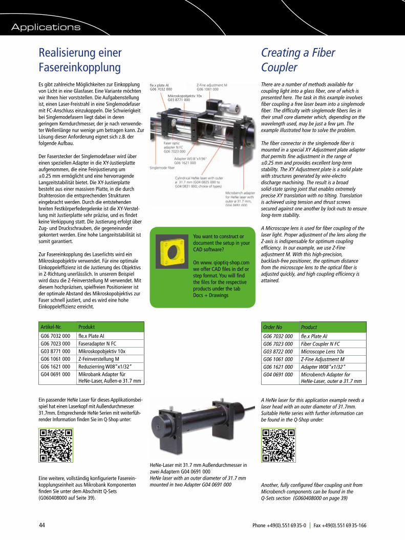
44 Phone +49(0).551 69 35-0 Fax +49(0).551 69 35-166 [email protected]
Creating a Fiber Coupler
Realisierung einer Fasereinkopplung
There are a number of methods available for coupling light into a glass fiber, one of which is presented here. The task in this example involves fiber coupling a free laser beam into a singlemode fiber. The difficulty with singlemode fibers lies in their small core diameter which, depending on the wavelength used, may be just a few µm. The example illustrated how to solve the problem.
The fiber connector in the singlemode fiber is mounted in a special XY Adjustment plate adapter that permits fine adjustment in the range of ±0.25 mm and provides excellent long-term stability. The XY Adjustment plate is a solid plate with structures generated by wire-electro discharge machining. The result is a broad solid-state spring joint that enables extremely precise XY translation with no tilting. Translation is achieved using tension and thrust screws secured against one another by lock-nuts to ensure long-term stability.
A Microscope lens is used for fiber coupling of the laser light. Proper adjustment of the lens along the Z-axis is indispensable for optimum coupling efficiency. In our example, we use Z-Fine adjustment M. With this high-precision, backlash-free positioner, the optimum distance from the microscope lens to the optical fiber is adjusted quickly, and high coupling efficiency is attained.
Es gibt zahlreiche Möglichkeiten zur Einkopplung von Licht in eine Glasfaser. Eine Variante möchten wir Ihnen hier vorststellen. Die Aufgabenstellung ist, einen Laser-Freistrahl in eine Singlemodefaser mit FC-Anschluss einzukoppeln. Die Schwierigkeit bei Singlemodefasern liegt dabei in deren geringem Kerndurchmesser, der je nach verwende-ter Wellenlänge nur wenige µm betragen kann. Zur Lösung dieser Anforderung eignet sich z.B. der folgende Aufbau.
Der Faserstecker der Singlemodefaser wird über einen speziellen Adapter in die XY-Justierplatte aufgenommen, die eine Feinjustierung um ±0.25 mm ermöglicht und eine hervorragende Langzeitstabilität bietet. Die XY-Justierplatte besteht aus einer massiven Platte, in die durch Drahterosion die entsprechenden Strukturen eingebracht werden. Durch die entstehenden breiten Festkörperfedergelenke ist die XY-Verstel-lung mit Justierplatte sehr präzise, und es findet keine Verkippung statt. Die Justierung erfolgt über Zug- und Druckschrauben, die gegeneinander gekontert werden. Eine hohe Langzeitstabilität ist somit garantiert.
Zur Fasereinkopplung des Laserlichts wird ein Mikroskopobjektiv verwendet. Für eine optimale Einkoppeleffizienz ist die Justierung des Objektivs in Z-Richtung unerlässlich. In unserem Beispiel wird dazu die Z-Feinverstellung M verwendet. Mit diesem hochpräzisen, spielfreien Positionierer ist der optimale Abstand des Mikroskopobjektivs zur Faser schnell justiert, und es wird eine hohe Einkoppeleffizienz erreicht.
Order No Product
G06 7032 000 fle.x Plate AIG06 7023 000 Fiber Coupler N FCG03 8722 000 Microscope Lens 10xG06 1061 000 Z-Fine Adjustment MG06 1621 000 Adapter W08“x1/32“G04 0691 000 Microbench Adapter for
HeNe-Laser, outer ø 31.7 mm
A HeNe laser for this application example needs a laser head with an outer diameter of 31.7mm. Suitable HeNe series with further information can be found in the Q-Shop under:
Another, fully configured fiber coupling unit from Microbench components can be found in the Q-Sets section (G060408000 on page 39)
Artikel-Nr. Produkt
G06 7032 000 fle.x Plate AIG06 7023 000 Faseradapter N FCG03 8771 000 Mikroskopobjektiv 10xG06 1061 000 Z-Feinverstellung MG06 1621 000 Reduzierring W08“x1/32“G04 0691 000 Mikrobank Adapter für
HeNe-Laser, Außen-ø 31.7 mm
Ein passender HeNe Laser für dieses Applikationsbei-spiel hat einen Laserkopf mit Außendurchmesser 31.7mm. Entsprechende HeNe Serien mit weiterfüh-render Information finden Sie im Q-Shop unter:
Eine weitere, vollständig konfigurierte Faserein-kopplungseinheit aus Mikrobank Komponenten finden Sie unter dem Abschnitt Q-Sets (G060408000 auf Seite 39).
Mikroskopobjektiv 10xG03 8771 000
fle.x plate AlG06 7032 000
You want to construct or document the setup in your CAD software?
On www. qioptiq-shop.com we offer CAD files in dxf or step format. You will find the files for the respective products under the tab Docs + Drawings
Applications
HeNe-Laser mit 31.7 mm Außendurchmesser in zwei Adaptern G04 0691 000HeNe laser with an outer diameter of 31.7 mm mounted in two Adapter G04 0691 000

45Phone +49(0).551 69 35-0 Fax +49(0).551 69 35-166 [email protected]
Setup of a Modular Flow Cytometer
Aufbau eines Modularen DurchflusszytometersWie man einen Prototypen eines komplexen photo-nischen Systems mithilfe der LINOS Mikrobank
schnell entwickelt: Ein Gemeinschaftsprojekt von Excelitas, Qioptiq und Kinetic River.
How to rapidly prototype a complex photonic system by using the LINOS Microbench: A joint project of Excelitas, Qioptiq and Kinetic River.
ÜberDurchflusszytometer
Durchflusszytometer sind Instrumente, die Zellen in einer flüssigen Suspension messen und Zellpopulationen mit Lichtstreuungs- und Fluoreszenzparametern charakterisieren. Diese Life-Science Instrumente spielen eine wichtige Rolle für die Forschung in der Immunologie und Zellbiologie und werden im klinischen Labor zur Diagnose und Überwachung von Krankheiten wie HIV / AIDS und Blutkrebs eingesetzt.
In einem Durchflusszytometer werden einzelne Zellen, die oft mit Antikörpern und fluoreszierenden Farbstoffen gekoppelt sind, in einem Probenstrahl von Laserlicht angeregt. Verschiedene Sammeloptiken und Farbfilter lenken das gestreute und fluoreszierende Licht zu den Detektoren. Diese Signale werden digitalisiert und zur Visualisierung und Analyse weiterverarbeitet.
Aboutflowcytometers
Flow cytometers are instruments that measure cells in a liquid suspension, characterizing cell populations using light scatter and fluorescence parameters. These life science instruments play an important research role in immunology and cell biology, and they are used in the clinical lab for diagnosis and monitoring of diseases such as HIV / AIDS and blood cancer.
In a flow cytometer, samples of cells, often mixed with antibodies and fluorescent dyes, travel through a fluidic path to a glass flow cell, where each individual cell is intercepted by light, generally from laser sources. Collection optics and filters direct the scattered and fluorescent light to the detectors. The signals are digitized for visualization and analysis.
Das violette Laserlicht induziert einen fluoreszie-rende Probenstrahl.
The violet laser light generates a fluorescent sample stream.
Ausschnitt des fertigen Protypen, der zum größten Teil aus Standardkomponenten von Qioptiq und Excelitas besteht und in nur 8 Wochen realisiert wurde.Detail of the completed prototype predominantly designed with Qioptiq and Excelitas components, and realized in just 8 weeks.
Complex Prototype Setup

46 Phone +49(0).551 69 35-0 Fax +49(0).551 69 35-166 [email protected]
Kinetic River Corp., ein führendes Unternehmen im Bereich biophotonischer Design-, Beratungs- und Produktentwicklung, hat diesen 4-Farben-Durch-flusszytometer-Prototypen in weniger als 8 Wochen von Grund auf neu entwickelt und getestet, wobei fast ausschließlich handelsübliche Excelitas und photonische Qioptiq Komponenten verwendet wurden. Die Entwicklung dieses voll funktionsfähi-gen Messgerätes zeigt die Leichtigkeit und Zweckmäßigkeit des Entwerfens und Bauens komplexer biowissenschaftlicher und analytischer Instrumente unter Verwendung von photonischen Standardkomponenten, wie beispielsweise die LINOS Mikrobank.
Kinetic River Corp., a leader in biophotonic design, consulting, and product development, designed and built this 4-color flow cytometer prototype from scratch in less than 8 weeks, using almost exclusively off-the-shelf Excelitas and Qioptiq photonic components. The development of this fully functional instrument prototype demonstrates the ease and expediency of designing and building life science and analytical instruments from the ground up using the LINOS Microbench system.
Entwurf / DraftErster Entwurf im Dezember 2014First sketch in December 2014
Designentwicklung des kompletten AufbausDesign developement of the complete setup
Components• 2 fiber-coupled Qioptiq iFLEX-iRIS™ excitation lasers• 6 Excelitas LynX™ SiPM detection modules• Qioptiq kineMATIX™ 4-axis micromanipulators• Qioptiq OPTEM microscope objective• LINOS Microbench and rail systems
Applications• OEM instrumentation development• Platform design• Rapid prototyping for feasibility testing
Komponenten• 2 Fasergekoppelte Qioptiq iFLEX-iRIS Anregungslaser• 6 Excelitas LynX SiPM Detektor Module • 4 Qioptiq kineMATIX 4-axis Justage- einheiten • 1 Qioptiq OPTEM Mikroskop Objektiv• LINOS Mikrobank und FLS 40 Flachschienen Komponenten
Anwendungen:• OEM Geräteentwicklung• Plattform Design• Schnelle Prototypenentwicklung für Machbarkeitsstudien
Anordnung der Laser, der Optiken und der DetektorenArrangement of lasers, optics and detectors
Setup of a Modular Flow CytometerAufbau eines Modularen Durchflusszytometers
Anordnung der benötigten Qioptiq iFLEX-iRIS Festkörperlaser (inklusive Faserkopplungen) für die Streuung an der Partikeln und zur Anregung der daran gekoppelten Farbstoffe. Sechs Excelitas LynX Silizium Photomultiplier Module ermöglichen die Detektion der Vorwärtsstreuung und der Seitswärtsstreuung sowie die Realisierung von 4-Fluoreszenzkanälen. Zum gesamten optischen System gehören außderdem verschiedene Farbfilter, Strahlformungslinsen, Sammellinsen, Blenden, dichroitische Strahlteiler und ein Mikroskopobjektiv.
Arrangement of the required Qioptiq iFLEX-iRIS solid-state lasers (including fiber couplings) for the light scattering at the sample particles and for the excitation of the dyes coupled thereto. Six Excelitas LynX silicon photomultiplier modules enable the detection of forward scattering and sidewards light scattering as well as the realization of 4-fluorescence channels. The entire optical system also includes various color filters, beamforming lenses, collecting lenses, dia-phragms, dichroic beamsplitters, and a microscope objective.
Laser, Detektoren und Optiken in Mikrobank integriert und auf Flachschienensystem FLS 40 montiert.
Lasers, detectors, and optics integrated in Microbench components and mounted on the Railsystem FLS 40.
Complex Prototype Setup

47Phone +49(0).551 69 35-0 Fax +49(0).551 69 35-166 [email protected]
Finaler Prototyp / Finalized Prototype
8 Wochen später:Vollständig zusammengebauter und getesteter Prototyp, später auf der Photonics West in Kalifornien im Februar 2015 vorgestellt.
8 weeks later:Fully assembled and tested prototype presented later at Photonics West, California, in February 2015.
FazitDie offene und modulare Mikrobank Bauform dieses Prototypen gewährleistet den Entwicklern eine hohe Flexibilität in Bezug auf Layout und Komponentenauswahl. Durch die Wahl von Standardprodukten reduzieren sich sowohl die Entwicklungszeit als auch die Kosten erheblich.
Conclusion The open, modular Microbench architecture of this prototype enables great flexibility in system layout and component selection for designers. Using off-the-shelf components significantly reduces the development time and costs.
Optomechanik / Optomechanics
Entwickeltes Gerüst zur Montage der Durchfluss-zelle (1), zur Einstellung des optischen Weges des Laserlichts (2) und des Streulichts (3) und zur Befestigung des Digitalmikroskops (4).
Developed framework for mounting the flow cell (1), for adjusting the optical path of the laser light (2) and the scattered light (3) and for attaching the monitoring digital microscope (4).
1
2
3
3
4
Weitere Informationen zum Design, zur Modularität und zur Funktionsweise finden Sie im YouTube-Video.
Have a look at the YouTube video for more information about the design, modularity and the functionality of the finalized prototype.
Complex Prototype Setup

Discover the Q! Qioptiq stands for products of the highest quality,
whether off-the-shelf optical and mechanical
equipment or customerspecific components and
modules. Qioptiq designs and manufactures
photonic products and solutions that serve a wide
range of markets and applications in the areas of
medical and life sciences, industrial manufacturing,
defense, and aerospace, as well as in research and
development.
Since 2013, Qioptiq has been an Excelitas
Technologies company. Excelitas supplies innovative
solutions for illumination, detection and other
high-performance electrooptic technologies. The
portfolios of these two companies complement one
another perfectly, and together they employ more
than 6000 people worldwide.
Photonics for Innovation
Contact Qioptiq today:
North America+1 (800) 429 0257
Asia/Pacific+65 64 99 77 77
Europe+49 (0) 551 69 35-0
qioptiq.comqioptiq-shop.com
© 2018 Qioptiq Photonics GmbH&Co KG. All rights reserved. Qioptiq reserves the right to change this document at any time without notice and disclaims liability for editorial, pictorial or typographical errors.
O-CA_BR-Microbench-DE-EN_2018.02