manual cb-mobile-minicom V2Qixiang Layout 1€¦ · manual_cb-mobile-minicom_V2Qixiang:Layout 1...
27
Bedienungsanleitung Operating Instruction Manual de Instrucción Manuale d’istruzioni Mode d’emploi Handleiding - Full Multi Norm DE / PL / EC / EI / UK - hp CB Mobile MiniCom CB-Mobilfunkgerät CB Mobile Radio Transmisor móvil CB Cb émetteur récepteur Ricetrasmettitori CB mobile zender 12 Volt
Transcript of manual cb-mobile-minicom V2Qixiang Layout 1€¦ · manual_cb-mobile-minicom_V2Qixiang:Layout 1...

BedienungsanleitungOperating InstructionManual de InstrucciónManuale d’istruzioniMode d’emploiHandleiding
- Full Multi NormDE / PL / EC / EI / UK
- hp
CB Mobile MiniCom
CB-MobilfunkgerätCB Mobile Radio
Transmisor móvil CBCb émetteur récepteur
RicetrasmettitoriCB mobile zender
12 Volt
manual_cb-mobile-minicom_V2Qixiang:Layout 1 5/13/2016 2:27 PM Page 1

Bedienelemente - elements - éléments - elementen - elementos - elementi
2 3
manual_cb-mobile-minicom_V2Qixiang:Layout 1 5/13/2016 2:27 PM Page 2

INBETRIEBNAHME
Montage einer CB-Funkantenne Die Wahl der Antenne und des Montageortes ist von großer Bedeu-tung für die maximale Reichweite Ihrer Funkanlage. Die folgendenKriterien sollten Sie bei der Wahl des Antennenstandortes und derMontage berücksichtigen.
Allgemein gilt:
> Die Antenne muss für den Funkbetrieb auf 27 MHz geeignet sein. > Der Standort der Antenne sollte möglichst hoch und unverbaut sein. >Das Antennenkabel muss unbeschädigt, und die Stecker
ordnungsgemäß angeschlossen sein. > Das Antennenkabel darf nicht zu stark geknickt werden. > Antennen mit einer größeren mechanischen Länge erzielen
bessere Reichweiten.
Bei der Montage von Mobilantennen ist folgendes zu beachten:
> Die Antenne sollte in der Mitte eines größeren Karosserieteils montiert werden.
> Der Antennenfuß von Mobilantennen sollte besten Kontakt zu einer metallisch gut leitenden Fläche des Karosseriebleches haben.
Außer der "festen Montage" einer Mobilantenne, bei der ein Loch indie Karosserie Ihres Fahrzeuges gebohrt werden muss, gibt es nochweitere Möglichkeiten, z. B. die Dachrinnen- oder Kofferraumdeckel-Montage, sowie die Befestigung mit Magnetfuß oder Scheibenan-tenne.
> Alle angeschlossenen Leitungen, einschließlich der Antennenlei- tung, dürfen nur eine Länge von max. 4,5 Metern haben.
AntennenanschlussDer PL-Stecker (Typ PL259) des Antennenkabels (Koaxialkabel) wirdmit der Buchse (8) an der Geräterückseite verbunden. Für eine ein-wandfreie Verbindung muss der Überwurf des Steckers gut festge-dreht werden.
INHALTSVERZEICHNIS
Elemente 2
Inbetriebnahme Montage einer CB-Funkantenne 5Antennenanschluss 5 - 6Montage des Gerätes im Fahrzeug 6Mikrofon 6Stromversorgung 7
Funkbetrieb Einschalten [Vol] 7Rauschsperre [SQ/ASQ] 7 - 8Kanalwahl [UP] [DN] 8Umschaltung der Modulationsarten [A/F] 8Kanalsuchlauf [A/F] 8Umschaltung der Normen 8 - 9Senden 9Vorrangkanal 9/19 [EMG] 9Tastatursperre [EMG] 9Empfangsempfindlichkeit [RFG] 10Anschlussbuchse für ext. Zusatzlautsprecher 10S-Meter Anzeige 10
HinweiseSicherheitshinweis 11 Allgemeine Hinweise 11Service 11Konformität 11Entsorgung 11
Kanalfrequenztabelle 51Technische Daten 27
4 5
manual_cb-mobile-minicom_V2Qixiang:Layout 1 5/13/2016 2:27 PM Page 4

Stromversorgung Vor dem Anschluss der Stromversorgung schalten Sie das Gerät aus,indem Sie den Lautstärkeregler (5) [VOL] bis zum Einrasten nachlinks drehen. Verbinden Sie die beiden blanken Anschlüsse am Ende des Ka-bels mit dem 12 V Bordnetz Ihres Fahrzeuges. Das Stromversor-gungskabel sollte möglichst weit von störenden Aggregaten verlegtwerden. Achten Sie beim Anschluss auf die richtige Polarität:
SCHWARZ wird mit "-" ( = MINUS / Masse ) des KFZ verbunden. ROT wird mit "12 Volt +" ( = PLUS ) des KFZ-Bordnetzes verbunden.
Bei Verwendung von Dauerplus bleiben die letzten Einstellungenauch nach dem Ausschalten des Gerätes und dem Abstellen des Mo-tors gespeichert.
Nachdem die Antenne und die Stromversorgung sorgfältig ange-schlossen sind, kann der Funkbetrieb aufgenommen werden.
FUNKBETRIEB Einschalten [VOL]Zum Ein- bzw. Ausschalten des Gerätes, den Lautstärkeregler (5)[Vol] nach rechts bzw. nach links drehen.
Rauschsperre [SQ]Das Gerät verfügt über eine automatische (ASQ) und eine manuelleRauschsperre (SQ). Beide Schwellwerte können eingestellt werden.
SQ Rauschunterdrückung (O.F. - 2.8)Nach kurzem Drücken der SQ-Taste (1) erscheint in der Anzeige Sqgefolgt vom dem aktuellen Wert (O.F. (Aus) - 2.8). Stellen Sie den ge-wünschten Wert mit Hilfe der Kanalwahltasten am Mikrofon ein.
ASQ Rauschunterdrückung (A.1 - A.9)Die ASQ Rauschunterdrückung aktivieren Sie durch langes Drückender SQ-Taste (1). Der aktive Zustand wird durch das Symbol AQ ange-zeigt. Der aktuelle Wert (A.1 - A.9) erscheint nur kurz nach dem Drückender Taste. Es ist möglich den Wert mit Hilfe der Kanalwahltasten am
Ebenso ist auf eine ordentliche Verbindung des Antennenkabels mitdem Antennenfuß zu achten. Nicht einwandfreie Verbindungen kön-nen zu einem Defekt des Gerätes führen und die Funkreichweite er-heblich verringern. Die Antennenanlage (nicht im Lieferumfangenthalten) sollte gut an das Funkgerät angepasst sein, ansonstenwird ein Teil der Sendeleistung an der Antenne reflektiert und nichtabgestrahlt. Das führt zu einer geringeren Reichweite der Funkan-lage. Die Anpassung der Antenne erfolgt durch Längenabgleich desAntennenstrahlers bzw. seiner Anpassungsvorrichtung auf ein mini-males Stehwellenverhältnis, welches mit einem Stehwellenmessge-rät (z.B. TEAM SWR 1180 P) gemessen werden kann. DasStehwellenmessgerät muss nach der Messung wieder aus der Anten-nenleitung entfernt werden.
Montage des Gerätes im FahrzeugDas Gerät kann mit dem beiliegenden Montagebügel-Set z.B. unterdem Armaturenbrett befestigt werden. Bei der Wahl der optimalenPosition für die Montage des Gerätes in Ihrem Fahrzeug sind auchdie folgenden Kriterien zu berücksichtigen:
> keine Beeinträchtigung der Verkehrssicherheit, > gute Erreichbarkeit der Bedienelemente, > ausreichende Luftzirkulation, um eine Überhitzung des Gerätes
im Sendebetrieb zu verhindern.
Darüber hinaus sollten Sie auch sicherstellen, dass die LCD-Kanal-anzeige (6) gut ablesbar ist. Bei direkter Sonneneinstrahlung kanndie Lesbarkeit der Anzeige beeinträchtigt werden. Die günstigsteMontageposition sollte vor dem endgültigen Einbau überprüft wer-den. Mit Hilfe des beiliegenden Montagebügels, ist eine schnelleMontage bzw. Demontage an verschiedenen Stellen im Fahrzeugmöglich.
Mikrofon Das Mikrofon ist fest mit dem Gerät verbunden. Es ist mit einer Sen-detaste (PTT), sowie den Kanalwahltasten Hoch/Runter ausgerüstet.
6 7
manual_cb-mobile-minicom_V2Qixiang:Layout 1 5/13/2016 2:27 PM Page 6
Zum Einstellen bzw. Umschalten der Normen halten Sie bitte den Be-triebsarten-Umschalter (2) [A/F] während dem Einschalten des Gerä-tes gedrückt. In der Anzeige erscheint das Kürzel der aktuellen Norm.Die gewünschte Norm wird mit Hilfe der Kanalwahl-Taste am Mikrofoneingestellt. Zum Bestätigen der Norm das Gerät kurz aus- und wiedereinschalten.
Bei der Frequenznorm UK schaltet man durch langes Drücken derRFG-Taste (3) [RFG] zwischen den Frequenzbändern EU (26,965-27,405 MHz - AM/FM) und UK (27,60125-27,99125 MHz - NUR FM) um.
Für die Erlaubnis und die Auflagen zum Betrieb der verschiede-nen Normen in den einzelnen Ländern sehen Sie in den Geräte-pass. Der Benutzer ist für die richtige Einstellung der gültigenNorm im jeweiligen Land eigenverantwortlich.
Hinweis: Die Ausführung CB Mobile MiniCom hp (Mono Band)ist fest auf 40 Kanäle AM/FM, 4 Watt/4 Watt eingestellt.
SendenZum Senden wird die im Mikrofon eingebaute Sendetaste gedrückt undfür die Dauer der Durchsage gehalten. In dieser Zeit leuchtet das TX-Symbol in der Anzeige. Nach Beendigung der Durchsage die Sprechtasteloslassen. Das Gerät schaltet automatisch in den Empfangsbetrieb zu-rück. Die Bedienelemente sind während des Sendens gesperrt.
Vorrangkanal 9/19 [EMG] Das Gerät verfügt über die Vorrangkanäle 9 und 19. Einmaliges Drük-ken der Vorrangkanaltaste (4) [EMG] aktiviert Kanal 9. ErneutesDrücken schaltet auf Kanal 19. Drücken Sie die Taste noch einmal,schaltet das Gerät wieder in den ursprünglichen Kanal um.
Tastatursperre [EMG] Durch langes Drücken der EMG-Taste (4) wird die Tastatursperre ak-tiviert. In der Anzeige erscheint kurzzeitig das Symbol LC. Bis aufden kombinierten Ein-/Ausschalter, sowie der Sendetastetaste amMikrofon sind alle anderen Bedienelemente gesperrt. 8 9
Mikrofon zu ändern. Nach kurzer Zeit erscheint in der Anzeige der ak-tuelle Kanal. Um den ASQ-Wert anzuzeigen genügt ein kurzes Drückender SQ-Taste (1).
Hinweis: Je höher der Wert, desto stärker muss das Empfangssignalsein um die Rauchsperre zu deaktivieren.
Kanalwahl [UP] [DN]Die Kanäle können durch Drücken der Kanalwahltasten [UP] und [DN]am Mikrofon eingestellt werden. In der LCD Anzeige ( 6 ) wird die Ka-nalnummer dargestellt.
Umschaltung der Modulationsarten [A/F]Das CB Mobile MiniCom arbeitet in den Modulationsarten AM und FM.Falls das Gerät auf dem aktuellen Kanal auch die Betriebsart AM ak-zeptiert, können Sie durch Drücken der Taste (2) [ A/F ] zwischen AMund FM umschalten. Hinweis: das Full Multi Norm Frequenzband EC arbeitet nur auf FM.Dies ist auch zu beachten bei der Einstellung der Frequenznorm UK,welche durch langes Drücken der RFG Taste (3) [RFG] zwischen denBändern EU (26,965-27,405 MHz - AM/FM) und UK (27,60125-27,99125MHz - NUR FM) umschaltet.
Kanalsuchlauf [A/F]Durch langes Drücken der Taste [A/F] (2) wird der Kanalsuchlauf ak-tiviert. In der Anzeige erscheint das Symbol SC und alle Kanäle desgewählten Frequenzbandes werden solange durchsucht bis ein be-setzer Kanal gefunden wird.
Umschaltung der NormenDie Geräteversion CB Mobile MiniCom Full Multi Norm kann vomBenutzer auf eine der folgenden Normen eingestellt werden:
Norm Kanäle und FrequenzenDE 80 FM (26,565-27,405 MHz) / 40 AM (26,965-27,405 MHz) UK 40 FM (27,60125-27,99125 MHz) / 40 AM/FM (26,965-27,405 MHz)EI 40 FM (26,965-27,405 MHz) / 40 AM (26,965-27,405 MHz)EC 40 FM (26,965-27,405 MHz)PL 40 FM (26,960-27,400 MHz) / 40 AM (26,960-27,400 MHz)
*alle Normen 4 W
manual_cb-mobile-minicom_V2Qixiang:Layout 1 5/13/2016 2:27 PM Page 8

HINWEISESicherheitshinweisBitte beachten Sie als KFZ-Fahrer beim Funkbetrieb auch die Bestim-mungen der jeweils gültigen Straßenverkehrsordnung. Bei dem Betriebdes Gerätes wird Hochfrequenzenergie freigesetzt. Es muss daher einentsprechender Sicherheitsabstand zur Antenne eingehalten werden.
Allgemeine HinweiseDas Gerät ist vor Feuchtigkeit und Staub zu schützen, niemals anOrten aufbewahren, die einer starken Erhitzung und/oder direkter Son-neneinstrahlung ausgesetzt sind. Zur Gehäusereinigung ein weiches,fusselfreies Tuch verwenden, niemals Lösungsmittel verwenden.
ServiceDas Gerät darf nicht geöffnet werden. Eigenhändige Reparaturenoder Abgleich sind nicht vorzunehmen, denn jede Veränderung, bzw.Fremdabgleich, können zum Erlöschen der Betriebserlaubnis sowieder Gewährleistungs- und Reparaturansprüche führen. Bei Betriebs-störungen sollte das Gerät nicht benutzt werden. Trennen Sie in die-sem Fall die Stromversorgung ab. Liegt ein Defekt vor, sollte aufjeden Fall der autorisierte TEAM-Fachhändler kontaktiert werden.
KonformitätDas CB-Mobilsprechfunkgerät TEAM CB Mobile MiniCom entsprichtder europäischen R&TTE Direktive und hält die europäischen Nor-men EN 300 135-1/-2, EN 300 433-2, EN 301 489-1/-13 und EN60950-1 ein. Die genauen Länderbestimmungen der verschiedenenVersionen entnehmen Sie bitte dem beiliegenden Gerätepass.
EntsorgungBitte werfen Sie Ihr TEAM-Altgerät nicht einfach auf den Müll, sondernsenden Sie Ihr Altgerät bitte portofrei zur fachgerechten Entsorgung anTEAM ein. TEAM wird anschließend die umweltschonende EntsorgungIhres Altgerätes für Sie kostenlos veranlassen. Bitte machen Sie mit -der Umwelt zuliebe.
- Änderung der technischen Daten und der Ausführung sind ohne Vorankündigung vorbehalten. -
Empfangsempfindlichkeit [RFG]Signale, die aus unmittelbarer Nähe empfangen werden, können unterUmständen zu stark sein - das Signal verzerrt.Mit der RFG-Funktion [ RFG ] ( 3 ) wird die Empfangssignalstärke re-duziert durch Schwächung der Empfangsempfindlichkeit. Im aktivenZustand erscheint der Buchstabe R in der Anzeige. Nach dem Drückender RFG-Taste erscheint der aktuelle Wert (6/12/18/24/30/36/42/48/54dBm Dämpfung) blinkend in der Anzeige. Mit Hilfe der Kanalwahltastenam Mikrofon kann der gewünschte Wert angepasst werden.
Anschlussbuchse für einen externen Zusatzlautsprecher An der Rückseite befindet sich die Klinkenbuchse (7) (3,5 mm ø) zumAnschluss eines ext. Lautsprechers mit 4 - 8 Ohm Impedanz, wie z.B.dem TEAM TS-500. Bei 4 Ohm sollte die Belastbarkeit des Lautspre-chers 4 Watt betragen. Bei Anschluss des externen Lautsprecherswird der interne Lautsprecher abgeschaltet.
S-Meter The LCD Anzeige beinhaltet eine S-Meter Anzeige, welche die Stärkedes Sende- und Empfangssignals anzeigt.
10 11
manual_cb-mobile-minicom_V2Qixiang:Layout 1 5/13/2016 2:27 PM Page 10

SETUP
Installation of a CB antenna The antenna is one of the most critical parts in the setup. The typeof antenna and its location has a great effect on the range of opera-tion. Please consider the following criteria for selection of the bestlocation and the installation of your antenna:
> Make sure that the antenna is designed for radio operation on 27 MHz. > The position of the antenna should be elevated without any
obstacles nearby. > The aerial cable should not be damaged and the plugs should be
properly connected. > Make sure that the antenna cable is not bent. > The bigger the mechanical size of the antenna, the higher the
range of operation.
When you install a mobile antenna please note the following advices:
> The antenna should be fixed in the center of a big body-part, e.g. the trunk.
> The mobile antenna coil should have the closest possible contact with a conducting metallic surface of the bodywork of the car.
There are other possibilities to fix the antenna onto the car withouthaving to drill a hole into the bodywork of your car, e.g. mounting theantenna with a antenna holder onto the gutter or the trunk. Magneticmount antennas (with an magnetic base) or windshield antennas,which are glued onto the glass, are also alternatives.
> Please don't mount the CB antenna nearby a radio or TV antenna to prevent interference of radio or TV reception.
> DANGER: Keep an eye on power lines running along nearby when mounting the antenna on the roof.
> All connected cables including the antenna cable must not exceed a length of 4.5 m.
12 13
TABLE OF CONTENTS
Elements 2
SetupInstallation of a CB antenna 13Aerial Connection 14Installation in the car 14Microphone 14Power source 15
Operation On / Off [VOL] 16Squelch [SQ/ASQ] 16Channel selection [UP] [DN] 16Modulation selection [A/F] 16 - 17Scan [A/F] 17Norm selection 17Transmitting 18Priority Channels 9 / 19 [EMG] 18Key lock [EMG] 18Receipt-Signal Sensitivity [RFG] 18External speaker jack 18Internal s-meter 18
Additional InformationSafety Instructions 19General Precautions 19Servicing 19Conformity 19
Channel Frequencies 51Specifications 27
manual_cb-mobile-minicom_V2Qixiang:Layout 1 5/13/2016 2:27 PM Page 12

Power source Before connecting the unit to a suitable power source via the fusedDC power cable, the device must be switched off by turning the vo-lume control (5) [VOL] counterclockwise to the very end, beyond thethreshold, until you hear a click. Then, connect the two naked leads at the end of the cable with thesupply voltage of the vehicle’s battery. The unit is designed to ope-rate with 12 volts and a negative ground electrical system. Lay thecable as far as possible away from aggregates which can cause in-terference. Watch for the correct polarity during the connection.
BLACK connect to - MINUS / ground of the car battery.RED connect to 12 volts + PLUS of the vehicle’s battery.
After proper connection of the aerial and the power source, radiooperation can be started.
Aerial Connection Before pressing the transmit key, a suitable aerial must be con-nected. The PL259 plug of the aerial cable (coax) is connected tothe SO239 socket (8) on the rear panel. Make sure, that all plugs arefirmly tightened and properly soldered. Insufficient connections candamage the radio and will reduce the range of operation. The antenna should be configured with the radio, otherwise a partof the transmit power will be reflected at the antenna and will not beradiated. This reduces the range of operation. The configuration ofan antenna to a radio, is performed by a length adjustment of the an-tenna’s radial for a minimal SWR ratio which can be measured by aSWR meter, e.g. TEAM SWR 1180P. After the measurement the SWR meter should be removed from theantenna line.
Installation in the carWhen you want to install the radio in your vehicle, use the includedmounting kit, including the u-bracket. Always mount the transceiver ina location where the buttons are easily accessible. Other importantpoints to consider for a correct mounting position are:
> roadworthiness, > good access to the controls of the car, > sufficient air circulation to prevent overheating of the radio in
transmit mode.
Please consider your point of view onto the display while driving.Starting from a certain angle of view, the readability of the display di-minishes. An intensive solar irradiation can also affect the readabilityof the display. So it is recommended to check the best position beforethe final installation.
Microphone The microphone is fixed to the radio, it cannot be removed. It containsthe PTT key, as well as the channel selectors UP and DOWN.
14 15
manual_cb-mobile-minicom_V2Qixiang:Layout 1 5/13/2016 2:27 PM Page 14

16 17
Please note, that the frequency norm EC operates on FM only.
With the frequency norm UK of the Full Multi Norm version, you tog-gle between the CEPT band and the UK band by pressing the RFGkey (3) [RFG] for approximately 2 seconds. The display will shortlyshow the symbol UK or EU when switching the band. Please note that the UK frequencies are in FM only. The CEPT fre-quencies are in AM and FM.
Scan [A/F]Pressing the A/F key for approximately 1 second will activate thechannel scan, indicated by the symbol SC in the display. The currentfrequency band will be scanned until a signal has been detected.
Norm Selection The version Full Multi Norm has these frequency bands available:
DE 80 FM (26.565-27.405 MHz) / 40 AM (26.965-27.405 MHz)EC 40 FM (26.965-27.405 MHz)UK 40 FM (27.60125-27.99125 MHz) / 40 AM/FM (26.965-27.405 MHz)PL 40 FM (26.960-27.400 MHz) / 40 AM (26.960-27.400 MHz)EI 40 FM (26.965-27.405 MHz) / 40 AM (26.965-27.405 MHz)
tx-power with all norms: 4 W
For changing the current norm, please hold the mode key (2) [A/F] whileturning the radio on. The current norm appears in the display. Use thechannel selectors UP and DN of the microphone to set a different normand confirm your selection by turning the radio off and on again. In the frequency norm UK, switch between the 40 CEPT frequencies and theUK frequencies by pressing the RFG key (3) for approximately 2 seconds.The display will shortly show the symbol UK or EU when switching the band.
Regarding the permissions and restrictions of the individual norms inthe various european countries, please check the radio passport,which is included in the scope of delivery. The user is solely responsi-ble for the selection of the permissible norm in the country of operation.
Note: the radio mono band version hp operates on 40 FM, 4 W /40 AM, 4 W only.
OPERATION
On/Off [ VOL ]To switch on/off the radio, turn the volume switch (5) [VOL] clockwise /counterclockwise over the threshold.
Squelch [ SQ ]The radio is equipped with an automatic (ASQ) and a manual squelch(SQ). Both can be adjusted.
SQ Squelch (O.F. - 2.8)After shortly pressing the SQ key (1), the symbol Sq followed by actualsetting (O.F. - 2.8) is displayed. Change the according value with thechannel selector keys UP and DN at the microphone.
ASQ Squelch (A.1 - A.9)The ASQ squelch is activated by a long press of the SQ key (1). Thesymbol AQ is displayed. The present value (A.1 - A.9) appears onlyshorty after pressing the SQ key. During this short time, you can adjust the setting with the channel selectors UP and DN of the microphone.After a short period the channel number will appear. To return to thesquelch setting mode, press the SQ key (1) shortly. Note: The higher the level of the squelch setting, the stronger the signalhas to be, in order to deactivate the squelch.
Channel selection [UP] [DN]User the channel selector keys [UP] and [DN] at the microphone forchannel selection. The actual channel is displayed on the LCD (6). For communication, the same channel and the same modulation type(AM/FM) has to be selected.
Modulation selection [A/F]For the CB Mobile MiniCom Full Multi Norm, the modulation modesAM and FM are available. The selected modulation type is indicatedby the AM/FM symbol. To toggle between the modes press the modekey (2) [A/F].
manual_cb-mobile-minicom_V2Qixiang:Layout 1 5/13/2016 2:27 PM Page 16

18 19
Additional informationSafety instructionDrivers must obey traffic rules regarding the use of transceivers in avehicle. The unit radiates RF energy in transmit mode. Please beaware about the safety distance to the antenna.
General precautionsProtect the mobile radio from humidity and dust. Do not expose the radio to direct sunlight and other sources of heat.The radio can be cleaned by wiping with a soft cloth. Do not usechemical products for cleaning.
ServicingThe device must not be opened. Independent repairs or modificationsmust not be performed, it will forfeit warranty and repair claims. Do not use the mobile radio if it seems not to function correctly. Dis-connect the radio from the DC power source immediately. If there isa defect, the authorized TEAM specialist dealer or TEAM must becontacted immediately.
ConformityThe CB mobile transceiver TEAM CB Mobile MiniCom complies to theEuropean directive R&TTE and meets the European standards EN 300135-1/-2, EN 300 433-2, EN 301 489-1/-13 and EN 60950-1.
The specific regulations of the different versions in the different euro-pean countries can be found in the radio passport that is included inthis manual.
- specifications are subject to change without any prior notice -
Transmitting For signal transmission, press and hold the PTT key at the microphone.The TX symbol appears in the LCD. For best quality, speak normally ata distance of 2 - 4 inches. Speaking too loudly will cause distortion andmakes the signal difficult to understand. While the set is in the transmitmode there is no key entry possible and the receiver is muted. On completion of the transmission release the PTT key and the radiowill switch back to receiving mode.
Priority Channel 9 / 19 [EMG] To switch to priority channel 9 press the EMG key (4) once. To switchto priority channel 19 press the EMG key (4) twice. And to return tothe originally selected channel, press the EMG key one more time.
Key lock [EMG] Pressing the EMG key for approximately 1 second will activate/de-activate the key lock. The symbol LC will be shown shortly. Exceptfor the PTT key and the combined volume and on/off control, all ele-ments are blocked.
Receipt-Signal Sensitivity [RFG]Signals received from immediate proximity may be too strong, they willbe received distorted. With the RFG control [RFG] (3), the strength ofthe received signal will be diminished by reducing the receiver’s sen-sitivity. In active RFG mode the symbol RFG is displayed. After pressing the RFG key (3), the actual value is displayed, i.e.6/12/18/24/30/36/42/48/54 dBm. During this short period the value canbe changed with the microphone#s channel selector key UP and DN.
External speaker jack The CB Mobile MIniCom is equipped with a 3.5 mm socket (7) at therear panel to connect an external speaker of 4-8 ohm impedance, e.g.TEAM TS-500. At 4 ohms, the speaker load can be 4 watts. When theexternal speaker is connected, the internal speaker is muted.
S-Meter The LCD display contains an s-meter, which indicates the strengthof the transmitted and received signal.
manual_cb-mobile-minicom_V2Qixiang:Layout 1 5/13/2016 2:27 PM Page 18

20 21
ÍNDICE
Elementos 2 - 3
InstalaciónInstalación de una antena CB 21Conexión aérea 21 - 22Instalación en el coche 22Micrófono 22Fuente de alimentación 22 - 23
FuncionamientoEncendido [Vol] 23Silenciador [SQ/ASQ] 23 Selección de canal [UP] [DN] 23Selección de modulación [A/F] 24Exploración de canal [A/F] 24Tipos de modelo 24Transmisión 25Canal prioritario 9/19 [EMG] 25Bloqueo de teclas [EMG] 25RF Gain [RFG] 25S-meter 25Jack de altavoces externos 26
Información adicionalInstrucciones de seguridad 26Precauciones generales 26Revisión 26Conformidad 26
Tabla de canales y frecuencias 51Características técnicas 27
Instalación
Instalación de una antena CBLa antena es una de las partes más importantes del equipo, siendola clase de antena utilizada la que determina el alcance del funcio-namiento. Para seleccionar el lugar y la instalación apropiada de éstale aconsejamos que sigan los siguientes criterios:
> Asegúrese que la antena esté diseñada para instalación de radio de 27 MHz.
> Coloque la antena lo más alto posible y sin que haya ningún obstá-culo, despejada al máximo.
> El cable aéreo debe estar en buen estado y los conectores conec-tados satisfactoriamente.
> Asegúrese que el cable de la antena no esté muy doblado ni ha-ciendo demasiados ángulos.
> Cuanto más grande sea el tamaño físico de la antena, mayor será el rendimiento del equipo.
Al instalar la antena móvil, por favor siga los siguientes consejos:
> Fijar la antena en el centro de la parte más grande de la carrocería. > Colocar la bobina de carga de la antena lo más cerca posible a la
superficie metálica conductora de la carrocería del coche.
Existen otras posibilidades para fijar la antena en el coche sin nece-sidad de taladrar la carrocería, como por ejemplo, montando la an-tena en el canalillo, en el maletero, o utilizando la antena con basemagnética o antena de cristal.> Todos los cables conectados, incluyendo el cable de la antena, no
pueden superar los 4,5m de longitud.
Conexión aéreaAntes de pulsar el botón de transmisión, conectar la antena adecuada.El conector PL259 del cable (coaxial) se conecta al conector SO239(8) en el panel trasero. Asegúrese que todas las clavijas estén apreta-das y soldadas correctamente, ya que si las conexiones no se realizandebidamente podrían dañar la radio y reducir el alcance del equipo.
manual_cb-mobile-minicom_V2Qixiang:Layout 1 5/13/2016 2:27 PM Page 20

22 23
Una vez instalados equipo y antena, deberá medirse el R.O.E.(SWR) para un correcto funcionamiento del conjunto. Una R.O.E.(SWR) elevada disminuye la potencia radiada y podría causar dañosen la parte final (transistores).
Instalación en el cochePara ajustar el equipo en su coche, puede utilizar la abrazadera quese incluye por debajo del salpicadero. Montar siempre el transmisoren un lugar de fácil acceso a los conectores.
Otros puntos importantes para realizar el montaje correcto son:> que no haya interferencias técnicas,> tener buen acceso a los controles del coche,> que haya una circulación de aire suficiente para prevenir el reca-
lentamiento de la radio en modo transmisión.Hay que tener en cuenta que el indicador LC sólo se puede leerdesde un cierto ángulo.
Una radiación solar intensiva podría afectar a la legibilidad del indi-cador. Por eso, se recomienda comprobar la posición adecuada antesde la instalación final. La emisora se puede fijar fácilmente en el cocheen diferentes posiciones utilizando la abrazadera que se incluye.
Micrófono El micrófono está conectado a la radio móvil. El micrófono está equi-pado con el botón PTT y las teclas de selección de canal [UP]/[DN].
Fuente de alimentación Antes de conectar la fuente de alimentación al cable de corriente DC,el dispositivo debe estar desenchufado. Para ello girar la tecla de con-trol de volumen (5) [VOL] en el sentido contrario a las agujas del relojhasta que se pare y se oiga un sonido de desconexión.
Conectar los dos cables descubiertos a los 12 voltios DC de la bate-ría del coche. Esta unidad esta diseñada para operar con un sistemaeléctrico negativo a masa. Tender el cable lo más lejos posible delconjunto, ya que puede producir interferencias. Vigilar la polaridadcorrecta durante la conexión.
BLACK (Negativo) conectar a - MINUS / tierra de la batería del coche.RED (Positivo) conectar a 12 voltios + PLUS de la batería del coche.
Si la alimentación no está desconectada después de apagar el motor,los últimos ajustes se guardarán hasta que la unidad se apague.La alimentación debería estar diseñada para operar con un transmi-sor, de lo contrario pueden surgir interferencias desde la línea de al-terna o sobretensiones. Después de haber conectado correctamente el cable y la fuente dealimentación, se puede empezar la operación.
Funcionamiento del TEAM CB Mobile MiniCom
Encendido [ VOL ]Para encender la radio, gire el control de volumen hacia la derecha.Para apagar la radio, gire el control de volumen a la izquierda.Todoslos ajustes que se hagan durante la operación del transmisor que-darán memorizados después de que la unidad se apague y mientrasno se interrumpa el suministro de energía.
Silenciador [ SQ ]La radio está equipada con un silenciador automático (ASQ) y un si-lenciador manual (SQ). Ambos pueden ser ajustados.
SQ silenciador (O.F. - 2.8)Pulse la tecla SQ (1) breve. El símbolo Sq aparece primero y luego elvalor (O.F. - 2.8). Seleccione el valor con las teclas de selección decanal (UP/DN) en el micrófono.
ASQ silenciador (A.1 - A.9)Pulse la tecla SQ (1) largo. El símbolo AQ aparece en la pantalla porun corto tiempo, el valor (A.1 - A.9) puede ser seleccionado con las te-clas de selección de canal (UP/DN) en el micrófono.
Selección de canal [DN] [UP]Todos los canales se pueden seleccionar pulsando los botones de se-lector de canal [UP] y [DN] en el micrófono.
manual_cb-mobile-minicom_V2Qixiang:Layout 1 5/13/2016 2:27 PM Page 22

TransmisiónPara transmisión pulsar y mantener el botón PTT del micrófono. Apa-recerá en el LCD el símbolo TX. La sensibilidad del micrófono se ha ajustado para hablar a una dis-tancia de 2-4 pulgadas (equivalente a 20 cms). Si se habla en un tonoelevado se pueden producir sobremodulaciones. Mientras el ajusteesté en modo de transmisión, no habrá ninguna entrada posible debotón y el auricular permanecerá en silencio. Al terminarse la trans-misión soltar el botón PTT y el aparato volverá al modo recepción.
Canal de Prioridad 9 / 19 [EMG] La radio dispone de los canales de prioridad 9 y 19. El canal de priori-dad 9 se selecciona pulsando la tecla (4) [EMG] solo una vez. Para se-leccionar el canal de prioridad 19, pulse la tecla (4) [EMG] dos veces.
Bloqueo de teclas [EMG] Para activar la función bloqueo de teclas, pulse el botón EMG poraproximadamente un segundo. El símbolo SL aparecerá en al pan-talla. Ahora la unidad ignorará cualquier entrada procedente de cual-quier botón, excepto la función PTT y la funciones del interruptorEncendido/ Apagado (5).
RFGLas señales que se reciben de las inmediaciones, pueden ser aveces demasiado - distorsionan la señal. Es una ventaja para debi-litar las señales muy fuertes, ya que estos pueden ser difíciles de en-tender a veces debido a la distorsión pesada. El control de [ RFG ](3) la intensidad de la señal recibida se reducirá en un debilitamientode la sensibilidad del receptor. En el modo activo la letra R apareceen la pantalla. Después de pulsar la tecla RFG (3), el valor real(6/12/18/24/30/36/42/48/54 dBm) se muestra. Durante este breve pe-ríodo el valor se puede cambiar con las teclas selecciónes de cana-les UP y DN en el micrófono.
S-MeterEl S-meter interno muestra la potencia de campo de la señal detransmisión y de recepción.
Selección de modulación [A/F]El CB Mobile MiniCom puede funcionar en modulación AM o FM.Ésta se puede cambiar pulsando el botón (2) [A/F] entre los tipos demodulación AM y FM. El modo seleccionado AM/FM se indicará me-diante el símbolo AM/FM.La norma EC está disponible sólo en FM. En la norma UK, pulse labotón RFG (3) por 2 segundos para cambiar entre las bandas UK(sólo FM) y EU (AM/FM).
Exploración de canal [A/F]Si esta función está activa, la unidad buscará los canales ocupados.Pulse el botón (2) [A/F] por aproximadamente un segundo para empezarla exploración de canal. El símbolo SC aparece en la pantalla LCD.Para desactivar la función exploración, volver a pulsar el botón (2) [A/F].
Tipos de modelo El modelo CB Mobile MiniCom Full Multi Norm se puede entregaren diferentes versiones con diferentes canales y tipos de modulación,todas con la potencia de transmisión de 4 W. .
DE 80 FM (26.565-27.405 MHz) / 40 AM (26.965-27.405 MHz)EC 40 FM (26.965-27.405 MHz)UK 40 FM (27.60125-27.99125 MHz) / 40 AM/FM (26.965-27.405 MHz)PL 40 FM (26.960-27.400 MHz) / 40 AM (26.960-27.400 MHz)EI 40 FM (26.965-27.405 MHz) / 40 AM (26.965-27.405 MHz)
Para cambiar la norma actual, lleve a cabo por favor la llave de selecciónde modulación (2) [ A/F ] mientras que gira la radio. En la illuminación defondo LCD, el símbolo de la norma actual aparece. Seleccione la normacon los botones de selector de canal UP y DN en el micrófono.
En relación con los permisos y las restricciones de las normas indivi-duales en los varios países europeos, compruebe por favor el pasa-porte de radio, que se incluye en el alcance de la entrega. El usuariotiene la responsabilidad exclusiva de la configuración correcta de lanorma, válida en el país.
El tipo CB Mobile MiniCom hp (mono banda) sólo funciona conlos canales 40 CEPT y con la modulación tipo FM y AM. La po-tencia de transmisión es 4 W.
24 25
manual_cb-mobile-minicom_V2Qixiang:Layout 1 5/13/2016 2:27 PM Page 24
26 27
Jack de altavoces externosEl radio está equipado con una toma jack de 3,5 mm (7) en el panelposterior para conectar un altavoz externo de impedancia de 4 - 8Ohm. A 4 Ohms la carga de altavoz puede ser de 4 watios (p. Ej.TEAM TS-500). Cuando los altavoces externos estén conectados,quedan silenciados los altavoces internos.
Información adicional
Instrucciones de seguridadLos conductores deberán obedecer las normas de circulación entodo lo que respecta al uso del transmisor en un vehículo.La unidad irradia energía RF en modo transmisión. También tenganen cuenta la distancia de seguridad respecto a la antena.
Precauciones generalesProteger el equipo de la humedad y el polvo. No almacenar en luga-res donde se produzcan aumentos de temperatura y se pueda dañar,como por ejemplo no exponerlo al sol. El equipo se puede limpiarcon un trapo suave sin utilizar ningún tipo de producto químico.
RevisiónNo se puede abrir el aparato, ni realizar reparaciones o ajustes poste-riores, ya que cada modificación o intervención no autorizada darácomo resultado la cancelación del permiso de explotación y la pérdidade garantía. No utilizarlo si parece que no funciona bien. En este caso,desconectar inmediatamente el equipo de la fuente de alimentaciónDC. En caso de encontrarse algún defecto, podrán contactar con elespecialista autorizado o el equipo TEAM.
ConformidadEl transmisor móvil TEAM CB Mobile MiniCom cumple con todas lasdirectrices Europeas R&TTE y estándares Europeos EN 300 135-1/-2,EN 300 433-2, EN 301 489-1/-13 und EN 60950-1.
Las especificaciones están sujetas a cambios sin previo aviso u obligación por parte del fabricante.
>
Technische Daten / specifications / Caractéristiques / Características técnicas / Technische gegevens
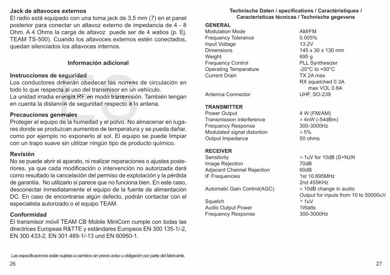
GENERALModulation Mode AM/FMFrequency Tolerance 0.005%Input Voltage 13.2VDimensions 145 x 30 x 130 mmWeight 695 gFrequency Control PLL SynthesizerOperating Temperature -20°C to +50°CCurrent Drain TX 2A max
RX squelched 0.3Amax VOL 0.8A
Antenna Connector UHF, SO-239
TRANSMITTERPower Output 4 W (FM/AM)Transmission interference 4nW (-54dBm)Frequency Response 300-3000HzModulated signal distortion 5%Output Impedance 50 ohms
RECEIVERSensitivity 1uV for 10dB (S+N)/NImage Rejection 70dBAdjacent Channel Rejection 60dBIF Frequencies 1st 10.695MHz
2nd 455KHzAutomatic Gain Control(AGC) 10dB change in audio
Output for inputs from 10 to 50000uVSquelch 1uVAudio Output Power 1WattsFrequency Response 300-3000Hz
>
>
>
>
manual_cb-mobile-minicom_V2Qixiang:Layout 1 5/13/2016 2:27 PM Page 26
28 29
Installazione del Team CB Mobile MiniCom
Installazione di un'antenna CbL'Antenna è una delle parti più importanti dell'applicazione. Il tipo diantenna e la sua posizione hanno una grande importanza sul funzio-namento del sistema. Per favore considerare i seguenti criteri di se-lezione della migliore posizione ed installazione della vostra antenna:
> Assicuratevi che l'antenna sia progettata per le operazioni radio a 27 Mhz.
> La posizione dell'antenna deve essere tanto più alta possibile e senza ostacoli nelle vicinanze.
> Il cavo volante non deve essere danneggiato e le spine devono essere collegate correttamente.
> Assicuratevi che il cavo dell'antenna non sia piegato con curve troppo strette.
> Tanto più è lunga l'antenna, maggiore è il rendimento nel funziona-mento.
Quando installate un'antenna per CB, per favore seguite il seguenteconsiglio:
> L'antenna dovrebbe essere fissata al centro della parte più grande della carrozzeria(capote).
> L'antenna deve essere a massa con la parte metallica dell'auto-mezzo.
Ci sono anche alcune alter possibilità per fissare l'antenna sulla mac-china senza la necessità di forare la carrozzeria, per esempio mon-tando l'antenna sulla gronda, montando l'antenna su appositisupporti, o usando un'antenna con una base magnetica.
> Tutti I cavi alimentazione collegati, compreso il cavo antenna non devono essere di lunghezza superiore ai 4,5m.
INDICE
Elementi 2 - 3
Installazione del Team CB Mobile MiniCom Installazione di un'antenna Cb 29 Connessione volante 30Installazione sull'auto 30Microfono 31Alimentazione 31
Funzionamento dell'apparato Team CB Mobile MiniComAccensione [Vol] 32Squelch [SQ] 32Selezione canale[UP] [DN] 32Selettore di Modalità [A/F] 32Scansione canali [A/F] 33Tipologia Modelli 33Trasmissione 33Priorità canale 9 / 19 [EMG] 34Funzione blocco tasti [EMG] 34RF Gain [RFG] 34Presa esterna per altoparlante 34S-Meter 35
Informazioni supplementariaIstruzioni di sicurezza 35Precauzioni generali 35Assistenza 35
Tabelle Canali & Frequenza 51Caratteristiche 27
manual_cb-mobile-minicom_V2Qixiang:Layout 1 5/13/2016 2:27 PM Page 28

30 31
Microfono Il microfono è costantemente collegato alla radio. Esso contiene il tastoPTT, così come i selettori di canale UP e DN.
AlimentazionePrima di collegare alimentazione al cavo con fusibile,verificare chela radio sia spenta, ruotando il controllo del volume (5) [ VOL ] insenso antiorario,fino a sentire il suono che ne indica lo spegnimento.
Poi collegare i due conduttori spelati all'altra estremità del cavo, con il13,8 volt DC della batteria del veicolo. L'unità è stata progettata per fun-zionare con un sistema elettrico terreno negativo. Appoggiare il cavo,per quanto possibile, lontano da particolari, che possono causare inter-ferenze. Guardare la corretta polarità durante la connessione.
NERO Collegare a -MENO/ massa della batteriaROSSO Collegare a 12 Volts+ Più della batteria auto.
L'alimentazione deve essere progettata per il funzionamento con untrasmettitore, altrimenti possono verificarsi interferenze dalla rete o ec-cessiva tensione. Dopo aver collegato correttamente le parti volanti e la fonte di ali-mentazione, si possono iniziare le operazioni radio.
Connessione volantePrima di premere il tasto di trasmissione, dev'essere stabilita un'ade-guata connessione volante. La spina PL259 del cavo (coassiale) ècollegato alla presa SO239 (8) sul pannello posteriore. Assicurarsiche tutti i connettori siano fermamente chiusi e correttamente saldati.Connessioni inadeguate possono danneggiare la radio e ridurne difunzionamento.
L'antenna deve essere collegata alla radio, altrimenti una parte dellatrasmissione di potenza si rifletterà sull'antenna e non sarà irradiata.Ciò determina anche un calo nel numero di operazioni. L'abbina-mento antenna/linea/radio va verificato prima di trasmettere (tramiteRosmetro interposto tra la radio e la linea, verificando il minimo rap-porto SWR, ed eventualmente tarando l'antenna per arrivare ad unrisultato ottimale). Dopo la misurazione della SWR, il Rosmetro deveessere rimosso dalla linea di antenna.
Installazione sull'autoQuando si vuole fissare la radio sulla vostra auto, potete fissarlasotto il cruscotto,con l'aiuto della staffa di montaggio inclusa. Dovretesempre montare il transceiver dove gli interruttori sono facilmente ac-cessibili. Altri importanti accortezze per la corretta posizione di mon-taggio sono:
> nessuna interferenza al veicolo, > buon accesso ai controlli della vettura, > sufficiente circolazione d'aria per evitare il surriscaldamento della
radio nella modalità di trasmissione.
Si prega di tener conto che l'LC Display (6) è ben leggibile solo daun certo punto di vista. Un intenso irraggiamento solare può influen-zare la leggibilità del display. Quindi, si raccomanda di scegliere lamigliore posizione prima dell'installazione finale. L'unità può esserefacilmente fissata in diverse posizioni sull'auto utilizzando l'acclusastaffa di montaggio.
manual_cb-mobile-minicom_V2Qixiang:Layout 1 5/13/2016 2:27 PM Page 30

32 33
Scansione canali [A/F] Se questa funzione è attiva, l'unità ricerca i canali occupati. Premereil tasto (2) [A/F] per circa un secondo per avviare la scansione deicanali. La funzione di scansione si ferma sul prossimo canale su cuisi apre un segnale dello squelch.
Tipologia ModelliL'apparato CB Mobile MiniCom può essere fornito in modelli diversicon differenti canali e tipi di modulazione. La potenza di trasmissioneè sempre 4W.
DE 80 FM (26.565-27.405 MHz) / 40 AM (26.965-27.405 MHz)EC 40 FM (26.965-27.405 MHz)UK 40 FM (27.60125-27.99125 MHz) / 40 AM/FM (26.965-27.405 MHz)PL 40 FM (26.960-27.400 MHz) / 40 AM (26.960-27.400 MHz)EI 40 FM (26.965-27.405 MHz) / 40 AM (26.965-27.405 MHz)
Per regolare o cambiare il regolamento, si prega di avere il selettore dimodalità (2) [A/F] mentre si accende il dispositivo verso il basso. Ildisplay lampeggia la sigla dello standard attuale. Tutti gli altri simbolinon sono visibili. La norma desiderata viene impostata con il inter-ruttore a rotazione per selezione canale (8). Per confermare la normail dispositivo e di nuovo a breve.La norma UK: premere il pulsante RFG (3) per 2 secondi per passaretra le bande EU (AM/FM) e UK (solo FM).
Per quanto riguarda i permessi e le limitazioni di diverse normenei vari paesi europei, controlli prego il passaporto radiofonico,che è incluso nella portata della consegna. L'utente ha la respon-sabilità esclusiva per l'impostazione corretta della norma, validanel paese.
Nota: CB Mobile MiniCom hp (mono banda) internamente è rego-lato a 40 AM/ FM, 4 watt soltanto.
TrasmissionePer trasmettere mantenere premuto il tasto PTT sul microfono. Sul dis-play LCD appare il simbolo TX. Al termine della trasmissione rilasciareil tasto PTT (4) e si ritorna alla modalità di ricezione.
Funzionamento dell'apparato TEAM CB Mobile MiniCom
Accensione [VOL]L'apparato si accende, ruotando il tasto controllo del volume (5) [VOL]in senso orario, verso il centro posizione. Una volta acceso,i simboliappaiono sul display LCD (6) e la retroilluminazione LCD è accesa.
Squelch [SQ] La radio è dotata di un squelch automatico (ASQ) e un squelch ma-nuale (SQ). Entrambi possono essere regolati.
SQ Squelch (O.F. - 2.8)Dopo aver premuto brevemente il tasto SQ (1), il simbolo Sq seguitadalla regolazione attuale (O.F. - 2.8) viene visualizzato. Modificare ilvalore con i tasti di selezione dei canali UP e DN al microfono.
ASQ Squelch (A.1 - A.9)Lo squelch ASQ è attivato da una pressione prolungata del tasto SQ(1). Viene visualizzato il simbolo AQ. Il valore attuale (A.1 - A.9) ap-pare solo dopo aver premuto il tasto SQ. Durante questo breve peri-odo di tempo, è possibile regolare l'impostazione con i selettori dicanale UP e DN del microfono. Dopo un breve periodo appare il nu-mero del canale. Per tornare alla modalità di impostazione squelch,premere il tasto SQ (1) poco.
Nota: Più alto è il valore dell'impostazione squelch, più forte è il seg-nale deve essere per disattivare il silenziamento.
Selezione canale [UP] [DN]Tutti i canali possono essere selezionati premendo il tasto selezionecanale UP e DN sul microfono.
Selettore di Modalità [A/F]Il CB Mobile MiniCom può lavorare in Modalità AM o FM. Premendoil tasto (2) [A/F] puoi selezionare tra la modalità AM e FM. La modalitàAM e FM selezionata sarà indicata con il simbolo AM e FM.La norma EC è solo FM.
manual_cb-mobile-minicom_V2Qixiang:Layout 1 5/13/2016 2:27 PM Page 32

34 35
S-MeterIl display LCD contiene un s-meter, che indica la forza del segnaletrasmesso e ricevuto.
Informazioni supplementaria
Istruzioni di sicurezzaGli autisti devono mantenere l'attenzione alle regole del trafficousando il ricetrasmettitore in un veicolo. L'apparato, quando in mo-dalità TX, irradia energia RF. Mantenere l'antenna ad una distanzadi sicurezza.
Precauzioni generali Proteggere l'apparato da umidità e da polvere. Non immagazzinarenei punti dove la temperatura può aumentare e causare danni, peresempio al sole. L'apparato può essere pulito utilizzando un pannomorbido. Non usare i prodotti chimici per pulire l'apparato.
AssistenzaL'apparato non deve essere aperto. Le riparazioni o regolazioni "faida te" non devono essere effettuate, poiché ogni modifica o inter-vento non autorizzato provocherà l'annullamento del permesso di uti-lizzo, della garanzia e renderà nulli i reclami. Non usare l'apparatose sembra non funzionare correttamente. In questo caso staccareimmediatamente l'apparato dalla fonte di alimentazione. Se riscon-trato un difetto, il rivenditore autorizzato/specializzato Team,o Teamdevono essere avvisati con in ogni caso.
Priorità canale 9 / 19 [EMG]La CB Mobile MiniCom è dotata di un canale prioritario 9 e 19. Il ca-nale prioritario 9 è selezionato premendo il tasto (4) [EMG] una volta.Per selezionare il canale 19, premere il tasto (4) [EMG] due volte.Quando la priorità canale è settata, il canale e la frequenza lampeg-giano sul display e tutti i tasti di funzione compreso il selettore canalerotatoriosono disabilitati. Per ritornare al canale precedente, premere il tasto (4) [EMG] una volta.
Funzione blocco tasti [EMG]Premendo il tasto (4) EMG e mantenendolo premuto per circa 1 se-condo. Tale funzione è indicata con il simbolo LC sul display LCD.Ora l'unità ignorerà qualsiasi selezione tasto tranne l'interruttoreOn/Off (5) il tasto UP / DN e il tasto PTT. E' possibile solo la trasmis-sione. La funzione rimane attiva se l'unità rimarrà alimentata.Per disattivare la funzione blocco premere il tasto (4) EMG un'altravolta per un breve periodo di circa 1 secondo all'icona oF appare.
RFGSegnali che vengono ricevuti dalle immediate vicinanze, può esserea volte troppo - distorcere il segnale. E 'un vantaggio per indebolire isegnali molto forti, in quanto questi possono essere difficili da capire a volte a causa di una distorsione pesante. Il controllo [RFG] (3) lapotenza del segnale ricevuto sarà ridotto, indebolendo la sensibilitàdel ricevitore. In modalità RFG viene visualizzata la lettera R. Dopoaver premuto il tasto RFG (3), viene visualizzato il valore reale, cioè6/12/18/24/30/36/42/48/54 dBm. Durante questo breve periodo, il va-lore può essere modificato con il tasto UP selettore di canale e DN almicrofono.
Presa esterna per altoparlanteIl CB Mobile MiniCom è fornito di una presa da 3,5 millimetri (8) postasul pannello posteriore per collegare un altoparlante esterno dall'im-pedenza di 4 - 8 Ohm. Per 4 Ohm di impedenza l'altoparlante puòessere di 4 watt. Quando l'altoparlante esterno è collegato lo speakerinterno sarà spento.
manual_cb-mobile-minicom_V2Qixiang:Layout 1 5/13/2016 2:27 PM Page 34
36 37
Mise en service du TEAM CB Mobile MiniCom
Montage d'une antenne CB L'antenne est une partie très importante d'une station émettrice. Letype d'antenne et le lieu de placement sont d'une grande importancepour la portée de votre émetteur récepteur. Les critères suivants sontdéterminants pour le choix du lieu de placement et le montage del'antenne:
> Faites attention de maintenir une certaine distance de sécurité à l'antenne à cause de la radiation radioélectrique.
> Utilisez une antenne prévue pour 27 MHz. > Choisissez l'endroit de l'antenne le plus haut que possible et le
moins barré que possible. > Le câble d'antenne ne doit être pas endommagé et les connecteurs
doivent être raccordés en bonne forme. > Le câble d'antenne ne doit être coudé pas trop fort. > Les antennes avec une longueur plus grande atteindrent une
portée plus grande.
Prenez en considération les conseils suivants pour le montage desantennes mobiles:
> Placez l'antenne au milieu d'une part plus grande de la carrosserie. > Le pied d'antenne mobile doit avoir le contact le mieux possible à
une surface bien conductible de la carrosserie.
En dehors de la "montage fixe" de l'antenne mobile, qui demande laperçage d'un trou dans la carrosserie de votre voiture, il y a des au-tres possibilités pour l'installation, par exemple l'utilisation d'une an-tenne de gouttière ou une antenne de fenêtre d'auto, la montage àun support sur le coffre ou la montage avec un pied magnétique.
> Tous câbles reliés peuvent avoir une longueur de 4,5 m au maximum.
CONTENU
Éléments 2 - 3
Mise en service du TEAM CB Mobile MiniCom Montage d'une antenne CB 37Connexion de l'antenne 38Montage dans la voiture 38Microphone 39Connexion de l'alimentation 39
Le fonctionnement de votre TEAM CB Mobile MiniComMise en marche [Off/Vol] 39Réglage du squelch [SQ/ASQ] 39-40Choix du canal [UP] [DN] 40Choix de la modulation [A/F] 40Recherche des canaux [A/F] 40S-mètre 40Espèces de modèles 41Emettre 41Canal 9/19 prioritaire [EMG] 41Verrouillage du clavier [EMG] 42RFG [RFG] 42Connexion d'un haut-parleur externe 42
Informations additionnellesSécurité 42Service 42
Tableaux Canaux & Frequence 51Caractéristiques 27
manual_cb-mobile-minicom_V2Qixiang:Layout 1 5/13/2016 2:27 PM Page 36

38 39
Connexion de l'alimentation Avant de brancher le CB Mobile MiniCom sur une source d'alimen-tation, il faut mettre l'appareil hors service en tournant le réglage duvolume et l'interrupteur marche / arrêt (5) [VOL] vers la gauche, jus-qu'à ce qu'il s'enclenche. Puis reliez les deux bouts dénudés du câble à l'alimentation de lavoiture. En outre le câble est protégé par un fusible. L'émetteur ré-cepteur est prévu pour fonctionner en courant continu de 12 V, le né-gatif à la masse. Le câble d'alimentation doit être installé plus loinque possible des agrégats gênants. Veillez bien à la correcte polaritépendant la connexion du câble d'alimentation.
NOIR sera branché à la borne négative ( - ) ou masse ROUGE sera branché à la borne positive ( + ) ou 12 Volt.
Il est recommandé d'utiliser une borne pas coupée automatiquementavec le contact, sinon les dernières ajustements ne resteront pas em-magasinés quand l'appareil et la voiture soient état hors service. L'alimentation régulée doit être qualifiée pour le service à un émetteurrécepteur, sinon on risque des dérangements par ronflement dû au cou-rant alternatif en émission et réception ou surtension en émission.Après la connexion de l'antenne et de l'alimentation, votre émetteurrécepteur est maintenant prêt à fonctionner.
Le fonctionnement de votre TEAM CB Mobile MiniCom
Mise en marche [VOL]Pour allumer l'appareil, tournez le réglage du volume (5) vers la droite.Pour l'éteindre, tournez le réglage du volume (5) vers la gauche.
Réglage du squelch [SQ]La radio est équipée avec un squelch automatique (ASQ) et unsquelch manuel (SQ). Les deux peuvent être réglés.
SQ (O.F. - 2,8)Après une brève pression sur la touche SQ (1), le symbole Sq suiviede la valeur actuelle (O.F. (désactiver) - 2,8) est affiché. Modifiez la va-leur avec les touches de sélection de canaux UP et DN au microphone.
Connexion de l'antenneAvant d'émettre il faut brancher une antenne à l'appareil. Le connecteurPL du type PL259 du câble d'antenne (coax) doit être raccordé à laprise d'antenne (8) placé au panneau arrière. L'écrou à raccord doit êtrevissé à fond pour une bonne jonction. Il faut également veiller au bonraccordement du câble coaxial à l'antenne. Un mauvais raccord peutentraîner des pertes et peut également endommager l'appareil. En outre l'antenne doit être adaptée bien au émetteur récepteur,sinon une part de la puissance d'émission soit reflétée à l'antenne etne soit pas rayonnée. Ça réduit aussi la portée de l'appareil. L'accordd'antenne est réalisé par l'adaptation de la longueur du radiateur ouson dispositif d'accord au minimum du rapport d'amplitude de puis-sance, qui peut être mesuré avec un mesureur de réflexions (parexemple TEAM SWR 1180P). Après avoir fini la mesure le mesureurde réflexions doit être enlevé du câble entre l'appareil et l'antenne.
Montage dans la voiturePour la fixation de l'appareil dans votre voiture, vous pouvez ou attacherl'un support de montage livré sous le tableau de bord et visser l'appareilsur celui. Veillez bien de fixer l'appareil à des endroits où les élémentsde commande soient bien accessibles et l'afficheur soit bien visible.Prenez aussi en considération les aspects suivants pour le choix de laposition dans votre voiture:
> aucune atteinte de la sécurité routière, > bonne accessibilité des éléments de manipulation de la voiture, > suffisante circulation d'air pour empêcher un surchauffage de l'appa-
reil en cas de transmission.
Faites attention que l'affichage LCD ne soit que bien lisible d'un anglecertain. Une insolation forte peut aussi porter atteinte à la lisibilité del'afficheur. Vérifiez la position plus avantageuse avant le montage dé-finitif. A l'aide du support de montage livré vous pouvez installer votreappareil facilement à plusieurs places dans la voiture.
Microphone Le microphone est fermement connecté à l'appareil. Il est équipé d'unbouton PTT et des boutons de sélection de canaux UP et DN.
manual_cb-mobile-minicom_V2Qixiang:Layout 1 5/13/2016 2:27 PM Page 38
40 41
Espèces de modèles
L'appareil CB Mobile MiniCom Full Multi Norm peut être fourni en plu-sieurs types, qui se distinguent par les canaux disponibles et les mo-dulations possibles. La puissance d'émission est 4 W.
DE 80 FM (26.565-27.405 MHz) / 40 AM (26.965-27.405 MHz)EC 40 FM (26.965-27.405 MHz)UK 40 FM (27.60125-27.99125 MHz) / 40 AM/FM (26.965-27.405 MHz)PL 40 FM (26.960-27.400 MHz) / 40 AM (26.960-27.400 MHz)EI 40 FM (26.965-27.405 MHz) / 40 AM (26.965-27.405 MHz)
D'ajuster ou de changer de règles, s'il vous plaît avoir le changeur dechoix de la modulation (2) [A/F] tout en tournant sur le périphériquevers le bas. L'écran va clignoter l'abréviation de la norme actuelle. Lanorme souhaitée est réglée avec les sélecteurs de canaux. Éteindre laradio pour confirmation.
Concernant les permissions et les restrictions des différentes normesdans les divers pays européens, vérifiez le passeport de radio, qui estinclus dans la portée de la livraison. L'utilisateur est seul responsablede la configuration adéquate de la norme, valable dans le pays.
Le type CB Mobile MiniCom hp marche seulement sur les 40 ca-naux AM et FM. La puissance d'émission est toujours 4 W.
Emettre Pour émettre on actionne durant toute la communication la touched'émission [PTT] du microphone. L'afficheur indique TX. Vous parlez àvoix normale à environ 5 à 10 cm du microphone. Parler à voix plusforte ou plus douce peut diminuer la compréhension chez votre corres-pondant. En position émission la plupart des éléments de commandeest verrouillée. A la fin de votre message relâchez la touche [PTT].L'appareil se remet alors en position réception.
Les canaux prioritaires 9/19 [EMG] L'appareil dispose dans toutes ses versions des canaux prioritaires 9 et 19. Le canal 9 est activé via un appui unique sur la touche canal prioritaire(4) [EMG]. Pour activer le canal 19 comme canal prioritaire, la touchecanal prioritaire doit être appuyée deux fois.
ASQ (A.1 - A.9)Le squelch automatique (ASQ) est activé par un appui long sur latouche SQ (1). Le symbole AQ est affichée. La valeur actuelle (A.1 -A.9) apparaît pour une courte période après avoir appuyé sur latouche SQ. Durant cette courte période, vous pouvez ajuster la valeur(A.1 - A.9) avec les sélecteurs de canaux UP et DN du microphone.Après une courte période, le nombre de chaînes s'affiche. Pour re-venir au mode de réglage du squelch, appuyez sur la touche SQ (1).
Remarque: la plus haute est la valeur, la plus forte le signal doit être.ésactiver le silencieux.
Choix du canal [UP] [DN]Tous les canaux peuvent être choisis avec des boutons UP et DN au mi-crophone. La sélection de canaux n'est pas possible en position émission.
Choix de la modulation [A/F]L'appareil CB Mobile MiniCom Full Multi Norm peut travailler avec lamodulation FM ou la modulation AM. Vous pouvez changer la modu-lation AM/FM en appuyant sur la touche [A/F] (2). La norm EC travailleavec la modulation FM seulement. Dans la norm UK, vous selectez entre les bandes fréquences EU(40 FM - 27.60125-27.99125 MHz) et UK (40 AM/FM - 26.965-27.405MHz) en appuyant sur la touche [RFG] (3) pour 2 secondes.
Recherche des canaux [A/F]Lorsque la fonction est active, l'appareil balaye sur tous les canaux pourtrouver un canal occupé. L'écran affiche le symbole SC. Pouractiver/annuler la recherche des canaux pressez la touche [A/F] (2) ap-proximativement pour une seconde.
S-Mètre L'écran LCD contient une s-mètre, ce qui indique la force du signaltransmis et reçu.
manual_cb-mobile-minicom_V2Qixiang:Layout 1 5/13/2016 2:27 PM Page 40

INHOUD
Elementen 2 - 3
Het opzetten van de TEAM CB Mobile MiniComInstalleren van een CB antenne 44Antenne aansluiting 44 - 45Installatie in de auto 45Microfoon 45Spanning bron 45 - 46
De werking van TEAM CB Mobile MiniComInschakelen [VOL] 46Ruisonderdrukking [SQ/ASQ] 46Kanaalkeuze [UP] [DN] 47Omschakelen van de modulatie [A/F] 47Kanalen zoeken [A/F] 47Omschakelen van de versies 47 - 48Zenden 48Voorrang kanaal 9/19 [EMG] 48Toetsen blokkering [EMG] 49RFG [RFG] 49 Externe luidspreker aansluiting 49S-Meter 49
Toegevoegde informatieVeiligheids instructies 50Algemene richtlijnen 50Service 50Conformiteit 50
Kanalen en frequentietabellen 51Technische gegevens 27
42 43
Verrouillage du clavier [EMG] Pressez la touche (2) EMG aproximativement pour une seconde. Lesymbole LC apparaît brièvement à l'écran. Dans cet état l'appareilne réagit pas à la pression sauf la touche PTT et les touches UP etDN pour la sélection de canal.
RF GAINLa sensibilité de réception peut être diminuée en réglant le potentio-mètre RF-GAIN. Les signaux qui sont reçus dans le voisinage immé-diat, mai être trop parfois - déforment le signal. C'est un avantaged'affaiblir des signaux très forts, car ils peuvent être difficiles à com-prendre parfois en raison de lourdes distorsions. Après avoir appuyé sur la touche RFG (3), la valeur réelle est affi-chée, c'est à dire 6/12/18/24/30/36/42/48/54 dBm. Pendant cettecourte période, la valeur peut être modifiée avec les touches UP etDN de sélecteurs de canaux au microphone.
Connexion d'un haut-parleur externeL'appareil CB Mobile MiniCom est fourni avec une prise du type jack3,5 mm (7) au panneau arrière pour la connexion d'un haut-parleurexterne avec une fiche 3,5 mm. L'impédance peut être entre 4 et 8Ohm. Un haut-parleur avec 4 Ohm consomme au maximum 5 Watt.L'haut-parleur incorporé est coupé lorsque la prise est utilisée.
Informations additionnelles Sécurité Les chauffeurs doivent obéir la réglementation des transports en utili-sant l'appareil en voiture. L'appareil rayonne en position émission de la puissance à haute fré-quence. Faites attention que l'antenne se trouve dans une distancede sécurité de vous et des autres personnes.
ServiceL'appareil ne peut pas être ouvert. Toute modification ou manipulationde l'appareil aura pour conséquence une annulation de l'autorisationde service et la non-conformité avec les dispositions. Toute perturbationne peut être supprimé que par du personnel spécialisé et autorisé.
manual_cb-mobile-minicom_V2Qixiang:Layout 1 5/13/2016 2:27 PM Page 42

deel van het zend vermogen in de antenne worden gereflecteerd. Ditzorgt ook voor een gereduceerde afstand. De lengte van de antennemoet worden aangepast, dit wordt gemeten met een SWR (TeamSWR 1180P). Na de meting moet de SWR meter worden verwijderd.
Installatie in de autoWanneer u het apparaat in de auto wilt bevestigen, dan kunt u demobiele houder voor onder het dashboard gebruiken.De zender altijd op een plaats monteren waar u makkelijk bij de be-diening kunt. Andere belangrijke punten voor een goede bevestigingvan het apparaat:
> geen beperking van het gezichtveld > Goed bereik van de bedieningselementen. > Een goede lucht circulatie om oververhitting van het apparaat te
verhinderen.
Let erop dat het LC display ( 6) alleen onder een bepaalde hoek goedzichtbaar is. Ook het zonlicht zorgt voor een slecht afleesbaarscherm. Het is aan te bevelen om de beste positie te controlerenvoordat u gaat inbouwen. Het apparaat kan eenvoudig in verschil-lende posities worden gemonteerd door gebruik te maken van demontage beugel.
Microfoon De microfoon is bevestigd. Het is uitgerust met de PTT-knop en dekanaal toetsen UP en DN.
Spanning bron.Voordat u de spanning aansluit op de DC kabel moet de zendontvan-ger zijn uitgeschakeld. Sluit dan de twee kale uiteinden van de kabel op de accu van de autoaan. De zender is geschikt voor werking met negatieve massa op hetelektrische systeem 12 volt DC. Legt de kabel zover mogelijk wegvan aggregaten die interferentie kunnen verzorgen. Let bij het aan-sluiten op de correcte polariteit.
Het opzetten van de TEAM CB Mobile MiniCom
Installeren van een CB antenneDe antenne is een van de meest belangrijke onderdelen van de in-stallatie. Het type antenne en de montageplaats heeft een groot ef-fect op de afstand. Volg de volgende criteria voor de beste locatieen installatie van uw antenne.
> Verzeker u ervan dat de antenne voor de 27MHz is ontworpen. > De locatie van de antenne moet zo hoog mogelijk zijn, zonder
naaste obstakels.> De antenne kabel mag niet zijn beschadigd en vanaf de fabriek voor
zien zijn van een connector> De kabel mag niet strak liggen. > De afstand die u kunt overbruggen is afhankelijk van mechanische
lengte van de antenne.
Wanneer u een mobile antenne installeert let dan op de volgendeadviezen. > De antenne moet in het midden van de carrosserie worden bevestigd. > De spoel van de mobiel antenne moet zo dicht mogelijk bij het
metaal van de carrosserie worden bevestigd.
Er zijn ook andere mogelijkheden van bevestigingen zonder een gatte boren in de carrosserie van de auto, bijvoorbeeld de bevestigingmet een beugel op een dakgoot of kofferdeksel of gebruik makenvan een magneetvoet of een on-glass antenne.
> Alle aangesloten kabels moeten zo kort mogelijk worden gehou-den. In ieder geval niet langer dan 4,5 mtr.
Antenne aansluiting Voordat u de zendtoets indrukt moet de antenne worden aangesloten.De PL259 plug van de antenne kabel (coax) wordt aan SO239 (8)aan de achterzijde aangesloten. Zorg ervoor dat alle pluggen goedzijn aangesloten en gesoldeerd. Slecht aangesloten pluggen kunnenuw radio beschadigen en de afstand zal worden gereduceerd.De antenne moet met de radio worden aangepast anders zal een
44 45
manual_cb-mobile-minicom_V2Qixiang:Layout 1 5/13/2016 2:27 PM Page 44

46 47
Kanaalkeuze [UP] [DN]De Kanalen kunnen door het drukken op de kanaal toetsen [UP] en [ DN ] op de microfoon. In het LC-Display ( 6 ) verschijnt de aanduidingvan de kanalen met grote cijfers. Tijdens het zenden kan een ander kanaal worden ingesteld. Er kan alleen op een overeenstemmend kanaalnummer en modulatiemet het tegenstation worden gecommuniceerd.
Omschakeling van de modulatiesoorten [A/F]De CB Mobile MiniCom werkt in de modulatiesoorten AM en FM. Inde norm EC de versie Full Multi Norm en staan in alle gebruikssoor-ten de mode FM tot je beschikking. In het geval dat het apparaat ophet aktuele kanaal ook de mode AM accepteerd , kunt u door het in-drukken van de toets (2) [A/F] tussen AM en FM heen- en weer scha-kelen.
De norm UK beschikt over 40 kanalen FM UK (27,60125-27,99125MHz) en 40 kanalen AM/FM EC (26,965-27,405 MHz). Om te scha-kelen tussen de bands UK en EU, druk op de RFG toets (3) 2 secon-den.
Kanalen zoeken [A/F]Wanneer deze functie actief is, zoekt het apparaat naar bezette kana-len. Een lange druk op de toets (2) [A/F] start het kanaal zoeken. Degeactiveerde scan-funktie wordt door het symbool SC aangegeven.Om het kanaal zoeken voortijdig te beeindigen, drukt u nogmaals opde toets (2) [A/F].
Omschakelen van de versies De Selectie van de versie Full Multi Norm kan door de gebruiker aande volgende normen worden geplaatst. Het zendvermogen is altijd4W.
DE 80 FM (26.565-27.405 MHz) / 40 AM (26.965-27.405 MHz)EC 40 FM (26.965-27.405 MHz)UK 40 FM (27.60125-27.99125 MHz) / 40 AM/FM (26.965-27.405 MHz)PL 40 FM (26.960-27.400 MHz) / 40 AM (26.960-27.400 MHz)EI 40 FM (26.965-27.405 MHz) / 40 AM (26.965-27.405 MHz)
ZWART Sluit deze aan op de - MIN/ massa van de auto accu. ROOD Sluit deze aan op de 12 volt + PLUS van de auto accu.
Bij het verwijderen van de plus blijven de laatste instellingen na hetuitschakelen van de zender bewaard. De netvoeding moet geschikt zijn voor het gebruik met een zender,anders zal interferentie van de voeding of overspanning de zenderbeschadigen. Nadat de microfoon. Antenne en voeding correct zijn aangeslotenkunt u met starten met de verbindingen.
De werking van TEAM CB Mobile MiniCom
Inschakelen [Off/Vol]Voor het inschakelen van de radio, draai de volumeknop naar rechts.Om de radio uit te schakelen, draai de volume knop naar links.
Ruis onderdrukking [SQ]De radio is uitgerust met een automatische (ASQ) en een handma-tige squelch (SQ). Beide kunnen worden aangepast.
SQ Squelch (O.F. - 2.8)Na het kort indrukken van de SQ-toets (1), het symbool Sq gevolgddoor de eigenlijke instelling (O.F. - 2.8) wordt weergegeven. Wijzigde waarde met de kanaal toetsen UP en DN bij de microfoon.
ASQ Squelch (A.1 - A.9)De ASQ squelch wordt geactiveerd door lang indrukken van de SQ-toets (1). Het symbool AQ wordt weergegeven. De contante waarde(A.1 - A.9) verschijnt alleen na het indrukken van de SQ-toets. Ge-durende deze korte tijd, kunt u de instelling van het kanaal selectorsUP en DN van de microfoon aan te passen. Na een korte periode hetkanaalnummer verschijnt. Om terug te keren naar de squelch instel-ling modus, drukt u op de SQ-toets (1) kort.
Opmerking: Hoe hoger de waarde van de squelch instelling, hoe ster-ker het signaal moet zijn om de squelch schakelen.lezing verdwijnenin de handmatige ruis onderdrukking.
manual_cb-mobile-minicom_V2Qixiang:Layout 1 5/13/2016 2:27 PM Page 46

48 49
Toetsen blokkering [EMG]Druk op de toets (2) [ A/F ] voor ongeveer een seconde. Binnenkortverschijnt het symbool LC in het display. In de actieve toestand rea-geert het apparaat alleen op de toets PTT. om uit te schakelen, druk op de toets (2) [ A/F ] nogmaals voorongeveer een seconde. Binnenkort verschijnt het symbool Of in hetdisplay.
Ontvangst gevoeligheid regelaar [ RFG ]Signalen ontvangen van uit de directe omgeving kan te sterk zijn, zul-len ze ontvangen worden vervormd.Met RFG control [RFG] (3), de sterkte van het ontvangen signaalwordt verminderd doordat de ontvanger gevoeligheid. In de actievemodus RFG de letter R wordt weergegeven.Na het indrukken van de RFG-toets (3), wordt de actuele waardeweergegeven, dwz 6/12/18/24/30/36/42/48/54 dBm. Gedurende dezekorte periode de waarde kan worden gewijzigd met de kanaal-toetsUP en DN bij de microfoon.
Externe luidspreker aansluitingDe CB Mobile MiniCom is op achterzijde uitgerust met een 3.5 mmjack aansluiting (7) om een externe luidspreker van 4 - 8 ohm impe-dantie aan te sluiten. Bij 4 ohm zal de belasting van de luidspreker4watt bedragen (TEAM TS-500). Wanneer de externe luidspreker isaangesloten zal de interne luidspreker worden uitgeschakeld.
S-MeterHet LCD scherm bevat een s-meter, die de sterkte van het verzondenen ontvangen signaal aangeeft.
Voor het instellen of het omschakelen van de normen houdt u demodulatiesoorten schakelaar (2) [A/F] tijdens het inschakelen van hetapparaat ingedrukt. In de uitlezing verschijnt knipperend de afkortingvan de aktuele norm. Alle andere symbolen zijn niet zichtbaar. Detoets gewenste norm word ingesteld door met de kanalen toets.
Betreffende de toestemmingen en de beperkingen van de indivi-duele normen in de diverse Europese landen, te controleren ge-lieve het radiopaspoort, dat in het werkingsgebied van leveringinbegrepen is. De gebruiker is verantwoordelijk voor de juiste in-stelling van de norm, geldig in het land.
Nota: De norm CB Mobile MiniCom hp (mono band) beschikt over40 kanalen FM/AM, 4 Watt.
ZendenVoor het zenden wordt de op de microfoon ingebouwde zend toets[PTT] ingedrukt en voor de duur van het spreken ingedrukt. Het zendsymbool TX verschijnt in de uitlezing. De microfoon moet ca. 5 cm van uw mond worden gehouden en opnormale toon spreken. Te hard spreken bemoeilijkt het verstaan. Nahet beindigen van het gesprek moet de PTT toets weer worden los-gelaten en het apparaat schakelt terug op ontvangst. De toetsenfunctioneren niet tijdens het zenden.
Voorkeuzekanaal 9/19 [EMG]Het apparaat beschikt in alle uitvoeringen over het voorkeuzekanaal 9 en 19. Door het eenmalig indrukken van de voorkeuzetoets (4) [ CH9 / 19 ] wordt het kanaal 9 ingesteld. Om kanaal 19 alsvoorkeuze kanaal in te stellen, moet de voorrangskanaal toets tweemaal worden ingedrukt. Wanneer het voorkeuzekanaal geactiveert is, wordt het kanaalnum-mer en frequentie knipperent in het scherm aangegeven. De kanaalschakelaar, alle functie toetsen, oproep toon zijn buiten werking.Door het nogmaals indrukken van de toets (4) [ CH9 / 19 ] word desnel keuze van het kanaal 9 opgeheven. Het apparaat schakeltterug op het ingestelde kanaal.
manual_cb-mobile-minicom_V2Qixiang:Layout 1 5/13/2016 2:27 PM Page 48
50 51
Toegevoegde informatie
Veiligheids instructiesRijders moeten opletten op de verkeersregels bij het gebruik van dezender in een (vracht) auto.Het apparaat geeft tijdens het zenden hoog frequent energie af. Ermoet dan ook voldoende afstand van de antenne worden gehouden.
Algemene richtlijnenBescherm het apparaat van vocht en stof. Het apparaat nooit op eenplaats bewaren met hoge temperaturen bijvoorbeeld: In direct zonlicht.Het apparaat schoonmaken met een zachte doek, maak geen gebruikvan chemische producten om het apparaat schoon te maken.
ServiceHet apparaat mag niet worden geopend. Zelf repareren of afregelenzijn niet aan te bevelen. Omdat elke verandering of ingreep de be-drijfs zekerheid kan verliezen en geen aanspraak op garantie kanworden gemaakt. Gebruik het apparaat niet wanneer het defect ismaar haal de 12volt kabel los en breng uw apparaat naar een ge-specialiseerde Team dealer.
ConformiteitDe CB mobile zender TEAM CB Mobile MiniCom voldoet aan de Eu-ropese richtlijnen R&TTE en de Europese standaard EN 300 135-1/-2, EN 300 433-2, EN 301 489-1/-13 und EN 60950-1.
Veranderingen van de technische gegevens zijn zonder voorafkondigen voor-behouden.
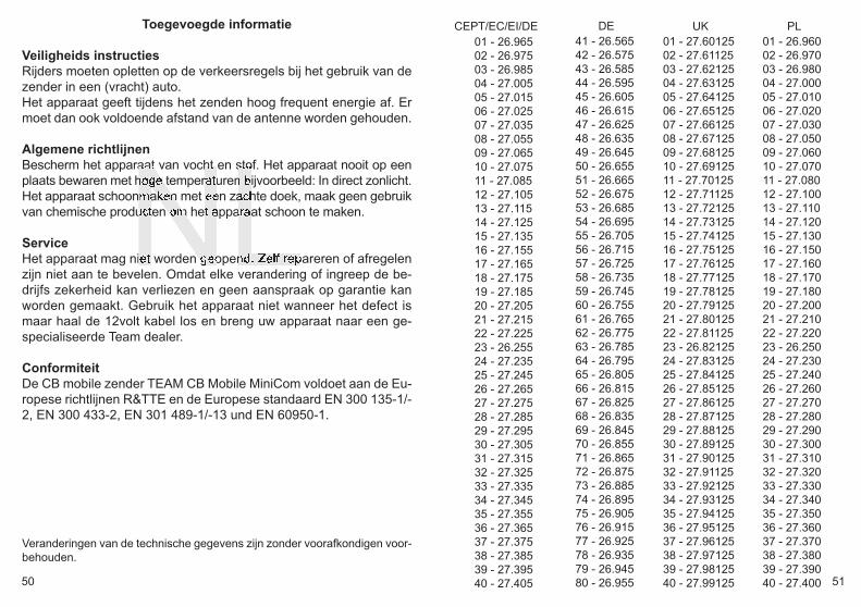
01 - 26.96502 - 26.97503 - 26.98504 - 27.00505 - 27.01506 - 27.02507 - 27.03508 - 27.05509 - 27.06510 - 27.07511 - 27.08512 - 27.10513 - 27.11514 - 27.12515 - 27.13516 - 27.15517 - 27.16518 - 27.17519 - 27.18520 - 27.20521 - 27.21522 - 27.22523 - 26.25524 - 27.23525 - 27.24526 - 27.26527 - 27.27528 - 27.28529 - 27.29530 - 27.30531 - 27.31532 - 27.32533 - 27.33534 - 27.34535 - 27.35536 - 27.36537 - 27.37538 - 27.38539 - 27.39540 - 27.405
41 - 26.56542 - 26.57543 - 26.58544 - 26.59545 - 26.60546 - 26.61547 - 26.62548 - 26.63549 - 26.64550 - 26.65551 - 26.66552 - 26.67553 - 26.68554 - 26.69555 - 26.70556 - 26.71557 - 26.72558 - 26.73559 - 26.74560 - 26.75561 - 26.76562 - 26.77563 - 26.78564 - 26.79565 - 26.80566 - 26.81567 - 26.82568 - 26.83569 - 26.84570 - 26.85571 - 26.86572 - 26.87573 - 26.88574 - 26.89575 - 26.90576 - 26.91577 - 26.92578 - 26.93579 - 26.94580 - 26.955
DECEPT/EC/EI/DE01 - 26.96002 - 26.97003 - 26.98004 - 27.00005 - 27.01006 - 27.02007 - 27.03008 - 27.05009 - 27.06010 - 27.07011 - 27.08012 - 27.10013 - 27.11014 - 27.12015 - 27.13016 - 27.15017 - 27.16018 - 27.17019 - 27.18020 - 27.20021 - 27.21022 - 27.22023 - 26.25024 - 27.23025 - 27.24026 - 27.26027 - 27.27028 - 27.28029 - 27.29030 - 27.30031 - 27.31032 - 27.32033 - 27.33034 - 27.34035 - 27.35036 - 27.36037 - 27.37038 - 27.38039 - 27.39040 - 27.400
PL01 - 27.6012502 - 27.6112503 - 27.6212504 - 27.6312505 - 27.6412506 - 27.6512507 - 27.6612508 - 27.6712509 - 27.6812510 - 27.6912511 - 27.7012512 - 27.7112513 - 27.7212514 - 27.7312515 - 27.7412516 - 27.7512517 - 27.7612518 - 27.7712519 - 27.7812520 - 27.7912521 - 27.8012522 - 27.8112523 - 26.8212524 - 27.8312525 - 27.8412526 - 27.8512527 - 27.8612528 - 27.8712529 - 27.8812530 - 27.8912531 - 27.9012532 - 27.9112533 - 27.9212534 - 27.9312535 - 27.9412536 - 27.9512537 - 27.9612538 - 27.9712539 - 27.9812540 - 27.99125
UK
manual_cb-mobile-minicom_V2Qixiang:Layout 1 5/13/2016 2:27 PM Page 50

TEAM CB Mobile MiniCom for sale and use in:
Service: TEAM Electronic GmbHBolongarostrasse 88
D-65929 Frankfurt am MainGERMANY
Tel. ++49 - 69 - 300 9 500Fax ++49 - 69 - 314382
Länder Version Vertrieb Betrieb Anmelde- & GebührenfreiCountries Distribution Operation Registration- & Chargefree
AT FMN -EI √ √ √CH -hp- √ √ -CZ FMN -EC √ √ -DE FMN -DE √ √ √DK FMN -EC √ √ √ES FMN -EI √ √ -FR FMN -EI √ √ -FIN FMN -EU √ √ √GB FMN -UK √ √ -GR FMN -EI √ √ -IT FMN -EI √ √ -LT FMN -EU √ √ √LU -hp- √ √ √NO -hp- √ √ √NL FMN -EU √ √ √PT FMN -EU √ √ -PL FMN -EI √ √ -PL FMN -PL √ √ -SE -hp- √ √ √
R&TTE NOTIFICATION
Hersteller / ManufacturerTEAM Electronic Ges.m.b.H.
Kleßheimer Allee 47A-5020 Salzburg
AUSTRIA
V 2.0
manual_cb-mobile-minicom_V2Qixiang:Layout 1 5/13/2016 2:27 PM Page 52