Modell der Diesellokomotive V 162 001 D GB USA F 16274 Getriebe für 130 km/h (nach Bremsanpassung...
48
Modell der Diesellokomotive V 162 001 16274 D GB USA F
-
Upload
phungthuan -
Category
Documents
-
view
212 -
download
0
Transcript of Modell der Diesellokomotive V 162 001 D GB USA F 16274 Getriebe für 130 km/h (nach Bremsanpassung...

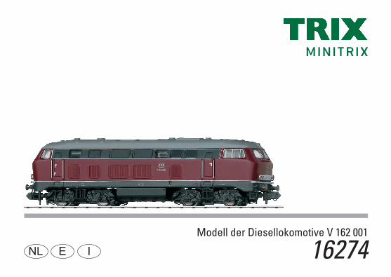
Modell der Diesellokomotive V 162 001
16274D GB USA F

2
3
Inhaltsverzeichnis: SeiteInformationen zum Vorbild 4Sicherheitshinweise 6 Wichtige Hinweise 6Funktionen 6Hinweis zum Digitalbetrieb 6Schaltbare Funktionen 7Configurations Variablen (CVs) 8Wartung und Instandhaltung 18Ersatzteile 22
Table of Contents: Page Information about the prototype 5Safety Notes 10Important Notes 10Functions 10Note on digital operation 10Controllable Functions 11Configuration Variables (CVs) 12Service and maintenance 18Spare Parts 22
Sommaire : PageInformations concernant le modèle réelle 5Remarques importantes sur la sécurité 14Information importante 14Fonctionnement 14Remarques relatives au fonctionement en mode digital 14Fonctions commutables 15Variables de configuration (CVs) 16Entretien et maintien 18Pièces de rechange 22
4
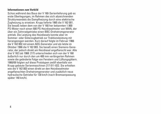
Informationen zum Vorbild Schon während des Baus der V 160-Serienlieferung gab es erste Überlegungen, im Rahmen des sich abzeichnenden Strukturwandels die Dampfheizung durch eine elektrische Zugheizung zu ersetzen. Krupp lieferte 1965 die V 162 001. Sie besaß neben dem von der V 160 her bekannten 1.900 PS-Motor noch einen 500 PS-Heizdieselmotor von MAN, der über ein Zahnradgetriebe einen BBC-Drehstromgenerator antrieb. Die Leistung des Heizdiesels konnte aber im Sommer- oder Güterzugbetrieb zur Traktionsleistung mit herangezogen werden. Kurz darauf folgte im Februar 1966 die V 162 002 mit einem AEG-Generator und als letzte im Oktober 1966 die V 162 003. Sie besaß einen Siemens-Gene-rator, der jedoch direkt am Heizdiesel angeflanscht war. Alle drei V 162 (ab 1968: 217) unterschieden sich von der V 160 äußerlich nur durch den um 400 mm verlängerten Rahmen sowie die geänderte Folge von Fenstern und Lüftungsgittern. 1968/69 folgten auf diese Prototypen zwölf ebenfalls von Krupp gebaute Serienmaschinen 217 011-022. Sie erhielten wie die V 162 003 einen direkt an den Heizdieselmotor angeflanschten Drehstromgenerator und zusätzlich neue hydraulische Getriebe für 130 km/h (nach Bremsanpassung später 140 km/h).
5
Information about the prototypeDuring the building of the regular production V 160, there were already initial thoughts about replacing the steam heating with electric train heating as part of emerging structural changes. In 1965, Krupp delivered road number V 162 001. In addition to the 1,900 horsepower motor known from the V 160, it also had a 500 horsepower MAN diesel motor for heating. This motor powered a BBC 3-phase generator by means of a gear drive. The output of the diesel motor for heating could be used however in the summer or with freight train service to boost motive power output. Shortly after that came road number V 162 002 in February of 1966 with an AEG generator and road number V 162 003 as the last unit in October of 1966. It had a Siemens generator that was flange-mounted directly to the diesel motor for heating. All three of the V 162 (starting in 1968: 217) differed from the V 160 externally only in the framed lengthened by 400 mm / 15-3/4” as well as the altered window and cooling grill arrangement. In 1968/69, Krupp delivered twelve regular production units like these prototypes, road numbers 217 011-022. Like road number V 162 003, they were equipped with a diesel motor for heating with a three-phase generator flange-mounted directly to it and also new hydraulic gearing for 130 km/h / 81 mph (140 km/h / 87 mph after subsequent changes to the brakes).
Informations concernant le modèle réel Dans le cadre de la restructuration qui s’annonçait, on commença déjà à réfléchir au remplacement du chauffage à vapeur par un chauffage de train électrique pendant la construction en série de la V 160. Krupp livra la V 162 001 en 1965. Outre le moteur de 1900 ch connu de la V 160, elle était également équipée d’un moteur diesel pour le chauffage de 500 ch de MAN qui, via un engrenage, entraînait un alter-nateur BBC. Pour l’exploitation estivale ou de trains mar-chandises, le rendement du moteur diesel supplémentaire pouvait toutefois être mis à contribution pour la traction Peu après, en février 1966, suivit la V 162 002 avec un générateur AEG, puis la dernière, la V 162 003, en octobre 1966. Elle était équipée d’un générateur Siemens, toutefois directement bridé sur le moteur diesel. Les trois V 1623 (à partir de 1968 : 217) se distinguaient extérieurement de la V 160 uniquement par leur châssis rallongé de 400 mm ainsi que par la disposition des fenêtres et grilles d’aération. En 1968/69, ces prototypes furent suivis de 12 machines de série également construites par Krupp, 217 011 à 022. Tout comme la V 162 003, elle furent dotées d’un alternateur directement bridé sur le moteur diesel de chauffe ainsi que de nouvelles transmissions hydrauliques pour une vitesse de 130 km/h (puis, après adaptation des freins, 140 km/h).
6
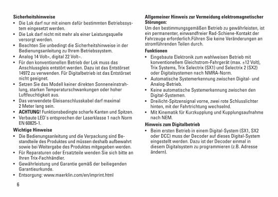
Sicherheitshinweise• DieLokdarfnurmiteinemdafürbestimmtenBetriebssys-
tem eingesetzt werden.• DieLokdarfnichtmitmehralseinerLeistungsquelle
versorgt werden.• BeachtenSieunbedingtdieSicherheitshinweiseinder
Bedienungsanleitung zu Ihrem Betriebssystem.• Analog14Volt=,digital22Volt~.• FürdenkonventionellenBetriebderLokmussdas
Anschlussgleis entstört werden. Dazu ist das Entstörset 14972 zu verwenden. Für Digitalbetrieb ist das Entstörset nicht geeignet.
• SetzenSiedasModellkeinerdirektenSonneneinstrah-lung, starken Temperaturschwankungen oder hoher Luftfeuchtigkeit aus.
• DasverwendeteGleisanschlusskabeldarfmaximal 2 Meter lang sein.
• ACHTUNG! Funktionsbedingte scharfe Kanten und Spitzen. • VerbauteLED`sentsprechenderLaserklasse1nachNorm
EN 60825-1.Wichtige Hinweise• DieBedienungsanleitungunddieVerpackungsindBe-
standteile des Produktes und müssen deshalb aufbewahrt sowie bei Weitergabe des Produktes mitgegeben werden.
• FürReparaturenoderErsatzteilewendenSiesichbitteanIhren Trix-Fachhändler.
• GewährleistungundGarantiegemäßderbeiliegendenGarantieurkunde.
• Entsorgung:www.maerklin.com/en/imprint.html
Allgemeiner Hinweis zur Vermeidung elektromagnetischer Störungen: Um den bestimmungsgemäßen Betrieb zu gewährleisten, ist ein permanenter, einwandfreier Rad-Schiene-Kontakt der Fahrzeuge erforderlich.Führen Sie keine Veränderungen an stromführenden Teilen durch.Funktionen• EingebauteElektronikzumwahlweisenBetriebmit
konventionellem Gleichstrom-Fahrgerät (max. ±12 Volt), Trix Systems, Trix Selectrix (SX1) und Selectrix 2 (SX2) oder Digitalsystemen nach NMRA-Norm.
• AutomatischeSystemerkennungzwischenDigital-undAnalog-Betrieb.
• KeineautomatischeSystemerkennungzwischendenDigital-Systemen.
• Dreilicht-Spitzensignalvorne,zweiroteSchlusslichterhinten, mit der Fahrtrichtung wechselnd.
• MitKinematikfürKurzkupplungundKupplungsaufnahmenach NEM.
Hinweis zum Digitalbetrieb • BeimerstenBetriebineinemDigital-System(SX1,SX2
oder DCC) muss der Decoder auf dieses Digital-System eingestellt werden. Dazu ist der Decoder einmal in diesem Digitalsystem zu programmieren (z.B. Adresse ändern).
7
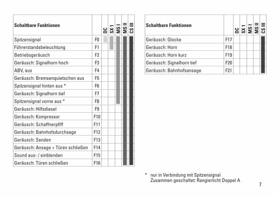
Schaltbare Funktionen
DC
SX 1
MS
IM
S II
CS II
I
Spitzensignal F0
Führerstandsbeleuchtung F1
Betriebsgeräusch F2
Geräusch: Signalhorn hoch F3
ABV, aus F4
Geräusch: Bremsenquietschen aus F5
Spitzensignal hinten aus * F6
Geräusch: Signalhorn tief F7
Spitzensignal vorne aus * F8
Geräusch: Hilfsdiesel F9
Geräusch: Kompressor F10
Geräusch: Schaffnerpfiff F11
Geräusch: Bahnhofsdurchsage F12
Geräusch: Sanden F13
Geräusch: Ansage + Türen schließen F14
Sound aus- / einblenden F15
Geräusch: Türen schließen F16
Schaltbare Funktionen
DC
SX 1
MS
IM
S II
CS II
I
Geräusch: Glocke F17
Geräusch: Horn F18
Geräusch: Horn kurz F19
Geräusch: Signalhorn tief F20
Geräusch: Bahnhofsansage F21
* nur in Verbindung mit Spitzensignal Zusammen geschaltet: Rangierlicht Doppel A
8
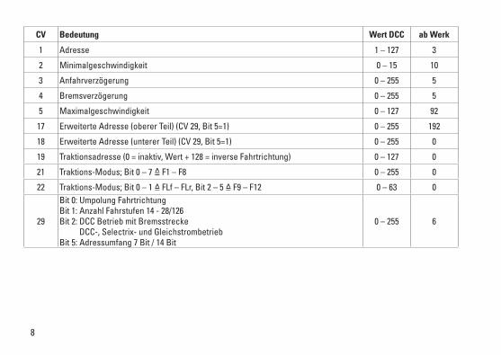
CV Bedeutung Wert DCC ab Werk
1 Adresse 1 – 127 3
2 Minimalgeschwindigkeit 0 – 15 10
3 Anfahrverzögerung 0 – 255 5
4 Bremsverzögerung 0 – 255 5
5 Maximalgeschwindigkeit 0 – 127 92
17 ErweiterteAdresse(obererTeil)(CV29,Bit5=1) 0 – 255 192
18 ErweiterteAdresse(untererTeil)(CV29,Bit5=1) 0 – 255 0
19 Traktionsadresse(0=inaktiv,Wert+128=inverseFahrtrichtung) 0 – 127 0
21 Traktions-Modus; Bit 0 – 7 =̂ F1 – F8 0 – 255 0
22 Traktions-Modus; Bit 0 – 1 =̂ FLf – FLr, Bit 2 – 5 =̂ F9 – F12 0 – 63 0
29
Bit 0: Umpolung Fahrtrichtung Bit 1: Anzahl Fahrstufen 14 - 28/126 Bit 2: DCC Betrieb mit Bremsstrecke DCC-, Selectrix- und Gleichstrombetrieb Bit 5: Adressumfang 7 Bit / 14 Bit
0 – 255 6
9
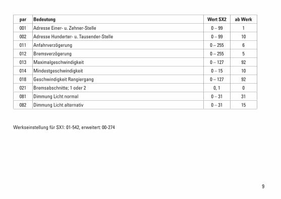
par Bedeutung Wert SX2 ab Werk
001 Adresse Einer- u. Zehner-Stelle 0 – 99 1
002 Adresse Hunderter- u. Tausender-Stelle 0 – 99 10
011 Anfahrverzögerung 0 – 255 6
012 Bremsverzögerung 0 – 255 5
013 Maximalgeschwindigkeit 0 – 127 92
014 Mindestgeschwindigkeit 0 – 15 10
018 Geschwindigkeit Rangiergang 0 – 127 92
021 Bremsabschnitte; 1 oder 2 0, 1 0
081 Dimmung Licht normal 0 – 31 31
082 Dimmung Licht alternativ 0 – 31 15
Werkseinstellung für SX1: 01-542, erweitert: 00-274
10
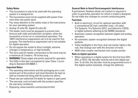
General Note to Avoid Electromagnetic Interference: A permanent, flawless wheel-rail contact is required in order to guarantee operation for which a model is designed.Do not make any changes to current-conducting parts.Functions • Built-inelectroniccircuitforoptionaloperationwith
a conventional DC train controller (max. ±12 volts), Trix Systems, Trix Selectrix (SX1), and Selectrix 2 (SX2), or digital systems adhering to the NMRA standards.
• Automaticsystemrecognitionbetweendigitalandanalogoperation.
• Noautomaticsystemrecognitionbetweenthedigitalsystems.
• Tripleheadlightsinthefront,dualredmarkerlightsintherear, that change over with the direction of travel.
• NEMclosecouplermechanismandcouplerpocket.Note on digital operation • Whenoperatinginadigitalsystemforthefirsttime(SX1,
SX2, or DCC), the decoder must be set to this digital sys-tem. To do this, the decoder must be programmed once in this digital system (example: change the address).
Safety Notes• Thislocomotiveisonlytobeusedwiththeoperating
system it is designed for.• Thislocomotivemustnotbesuppliedwithpowerfrom
more than one power pack.• Paycloseattentiontothesafetynotesintheinstructions
for your operating system.• Analog14voltsDC,digital22voltsAC.• Thefeedertrackmustbeequippedtopreventinter-
ference with radio and television reception, when the locomotive is to be run in conventional operation. The 14972 interference suppression set is to be used for this purpose. The interference suppression set is not suitable for digital operation.
• Donotexposethemodeltodirectsunlight,extremechanges in temperature, or high humidity.
• Thewireusedforfeederconnectionstothetrackmaybea maximum of 2 meters / 78 inches long.
• WARNING! Sharp edges and points required for operation. • TheLEDsinthisitemcorrespondtoLaserClass1accor-
ding to Standard EN 60825-1.Important Notes• Theoperatinginstructionsandthepackagingareacom-
ponent part of the product and must therefore be kept as well as transferred along with the product to others.
• Please see your authorized Trix dealer for repairs or spare parts. • Thewarrantycardincludedwiththisproductspecifies
the warranty conditions.• Disposing:www.maerklin.com/en/imprint.html
11
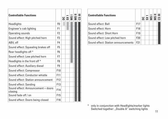
Controllable Functions
DC
SX 1
MS
IM
S II
CS II
I
Headlights F0
Engineer‘s cab lighting F1
Operating sounds F2
Sound effect: High pitched horn F3
ABV, off F4
Sound effect: Squealing brakes off F5
Rear headlights off * F6
Sound effect: Low pitched horn F7
Headlights in the front off * F8
Sound effect: Auxiliary diesel F9
Sound effect: Compressor F10
Sound effect: Conductor whistle F11
Sound effect: Station announcement F12
Sound effect: Sanding F13Sound effect: Announcement + doors closing F14
Sound fade off / on F15
Sound effect: Doors being closed F16
Controllable Functions
DC
SX 1
MS
IM
S II
CS II
I
Sound effect: Bell F17
Sound effect: Horn F18
Sound effect: Short Horn F19
Sound effect: Low pitched horn F20
Sound effect: Station announcements F21
* only in conjunction with Headlights/marker lights Switched together: „Double A“ switching lights

12
CV Discription DCC Value Factory Setting
1 Address 1 – 127 3
2 Minimum Speed 0 – 15 10
3 Acceleration delay 0 – 255 5
4 Braking delay 0 – 255 5
5 Maximum speed 0 – 127 92
17 Extendetaddress(upperpart)(CV29,Bit5=1) 0 – 255 192
18 Extendetaddress(lowerpart)(CV29,Bit5=1) 0 – 255 0
19 Consistaddress(0=inactive,Value+128=inversedirection) 0 – 127 0
21 Motive Power Mode; Bit 0 – 7 =̂ F1 – F8 0 – 255 0
22 Motive Power Mode; Bit 0 – 1 =̂ FLf – FLr, Bit 2 – 5 =̂ F9 – F12 0 – 63 0
29
Bit 0: Travel direction polarity reversal Bit 1: number of speed levels 14 – 28/126 Bit 2: DCC Operation with braking Block DCC-, Selectrix and DC power operation Bit 5: address size 7 Bit / 14 Bit
0 – 255 6

13
par Discription SX2 Value Factory Setting
001 Address for one and ten placeholder 0 – 99 1
002 Address for hundred and thousand placeholder 0 – 99 10
011 Acceleration delay 0 – 255 6
012 Braking delay 0 – 255 5
013 Maximum speed 0 – 127 92
014 Minimum speed 0 – 15 10
018 Speed for switching range 0 – 127 92
021 Braking section; 1 or 2 0, 1 0
081 Dimming of lights, normal 0 – 31 31
082 Dimming of lights, alternative 0 – 31 15
Factory setting for SX1: 01-542, advanced: 00-274
14
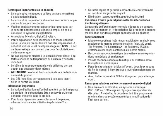
Remarques importantes sur la sécurité• Lalocomotivenepeutêtreutiliséequ‘aveclesystème
d‘exploitation indiqué.• Lalocomotivenepeutêtrealimentéeencourantquepar
une seule source de courant.• Veuillezimpérativementrespecterlesremarquessur
la sécurité décrites dans le mode d’emploi en ce qui concerne le système d’exploitation.
• Analogique14volts=,digital22volts~.• Pourl’exploitationdelalocomotiveenmodeconventi-
onnel, la voie de raccordement doit être déparasitée. A cet effet, utiliser le set de déparasitage réf. 14972. Le set de déparasitage ne convient pas pour l’exploitation en mode numérique.
• Nepasexposerlemodèleàunensoleillementdirect,àdefortes variations de température ou à un taux d‘humidité important.
• Lecâblederaccordementàlavoieutilisénedoitenaucun cas dépasser deux mètres.
• ATTENTION! Pointes et bords coupants lors du fonction-nement du produit.
• LesDELinstalléescorrespondentàlaclasselaser1selon la norme EN 60825-1.
Information importante• Lanoticed‘utilisationetl’emballagefontpartieintégrante
du produit ; ils doivent donc être conservés et, le cas échéant, transmis avec le produit.
• Pourtouteréparationouremplacementdepièces,adressez vous à votre détaillant-spécialiste Trix.
• Garantielégaleetgarantiecontractuelleconformémentau certificat de garantie ci-joint.
• Elimination:www.maerklin.com/en/imprint.htmlIndication d‘ordre général pour éviter les interférences électromagnétiques: La garantie de l‘exploitation normale nécessite un contact roue-rail permanent et irréprochable. Ne procédez à aucune modification sur des éléments conducteurs de courant.Fonctionnement• Module électronique intégré pour exploitation au choix avec
régulateur de marche conventionnel c.c. (max. ±12 volts), Trix Systems, Trix Selectrix (SX1) et Selectrix 2 (SX2) ou systèmes numériques conformes à la norme NMRA.
• Reconnaissanceautomatiquedusystèmeentreexploita-tions numérique et analogique.
• Pasdereconnaissanceautomatiquedusystèmeentreles systèmes numériques.
• Feuxdesignalisationtriplesàl‘avant,deuxfeuxrougesde fin de convoi à l‘arrière avec inversion selon sens de marche.
• AvecboîtiernormaliséNEMàélongationpourattelagecourt.
Remarques relatives au fonctionnement en mode digital • Unepremièreexploitationensystèmenumérique
(SX1, SX2 ou DCC) exige un réglage correspondant du décodeur. A cet effet, le décodeur doit être programmé une fois dans ce système numérique (modification de l’adresse par ex.).
15
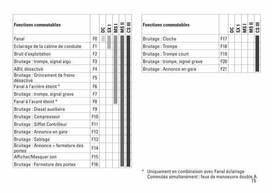
Fonctions commutables
DC
SX 1
MS
IM
S II
CS II
I
Fanal F0
Eclairage de la cabine de conduite F1
Bruit d’exploitation F2
Bruitage : trompe, signal aigu F3
ABV, désactivé F4Bruitage : Grincement de freins désactivé F5
Fanal à l’arrière éteint * F6
Bruitage : trompe, signal grave F7
Fanal à l’avant éteint * F8
Bruitage : Diesel auxiliaire F9
Bruitage : Compresseur F10
Bruitage : Sifflet Contrôleur F11
Bruitage : Annonce en gare F12
Bruitage : Sablage F13Bruitage : Annonce + fermeture des portes F14
Afficher/Masquer son F15
Bruitage : Fermeture des portes F16
Fonctions commutables
DC
SX 1
MS
IM
S II
CS II
I
Bruitage : Cloche F17
Bruitage : Trompe F18
Bruitage : Trompe court F19
Bruitage : trompe, signal grave F20
Bruitage : Annonce en gare F21
* Uniquement en combinaison avec Fanal éclairage Commutés simultanément : feux de manoeuvre double A
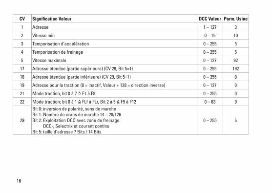
16
CV Signification Valeur DCC Valeur Parm. Usine
1 Adresse 1 – 127 3
2 Vitesse min 0 – 15 10
3 Temporisation d‘accélération 0 – 255 5
4 Temporisation de freinage 0 – 255 5
5 Vitesse maximale 0 – 127 92
17 Adresseétendue(partiesupérieure)(CV29,Bit5=1) 0 – 255 192
18 Adresseétendue(partieinférieure)(CV29,Bit5=1) 0 – 255 0
19 Adressepourlatraction(0=inactif,Valeur+128=directioninverse) 0 – 127 0
21 Mode traction, bit 0 à 7 =̂ F1 à F8 0 – 255 0
22 Mode traction; bit 0 à 1 =̂ FLf à FLr, Bit 2 à 5 =̂ F9 à F12 0 – 63 0
29
Bit 0: inversion de polarité, sens de marcheBit 1: Nombre de crans de marche 14 – 28/126 Bit 2: Exploitation DCC avec zone de freinage. DCC-, Selectrix et courant continu Bit 5: taille d‘adresse 7 Bits / 14 Bits
0 – 255 6
17
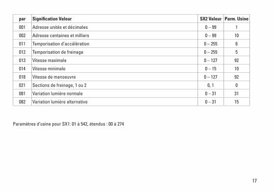
par Signification Valeur SX2 Valeur Parm. Usine
001 Adresse unités et décimales 0 – 99 1
002 Adresse centaines et milliers 0 – 99 10
011 Temporisation d’accélération 0 – 255 6
012 Temporisation de freinage 0 – 255 5
013 Vitesse maximale 0 – 127 92
014 Vitesse minimale 0 – 15 10
018 Vitesse de manoeuvre 0 – 127 92
021 Sections de freinage, 1 ou 2 0, 1 0
081 Variation lumière normale 0 – 31 31
082 Variation lumière alternative 0 – 31 15
Paramètres d’usine pour SX1: 01 à 542, étendus : 00 à 274
18
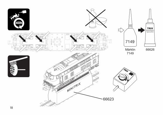
66626Märklin7149
7149
OIL 40h
66623

19
20
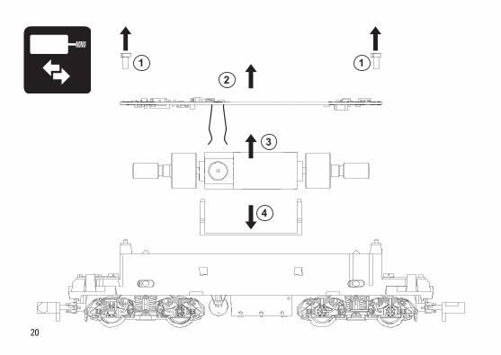
1 12
3
4

21
2
1

22
7
8
6
10
7
8
14
12
11
5
4
31
2
4
2
14
13
9
Det
ails
der
Dar
stel
-lu
ng k
önne
n vo
n de
m
Mod
ell a
bwei
chen
23
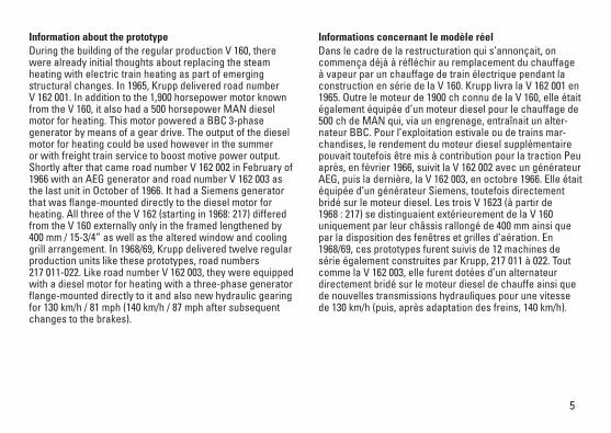
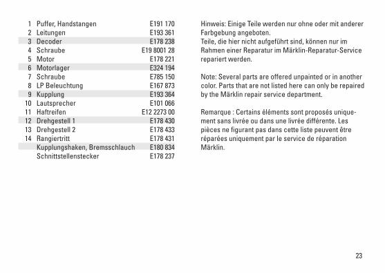
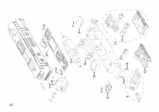
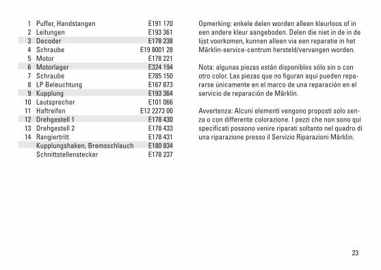
1 Puffer, Handstangen E191 170 2 Leitungen E193 361 3 Decoder E178 238 4 Schraube E19 8001 28 5 Motor E178 221 6 Motorlager E324 194 7 Schraube E785 150 8 LP Beleuchtung E167 873 9 Kupplung E193 364 10 Lautsprecher E101 066 11 Haftreifen E12 2273 00 12 Drehgestell 1 E178 430 13 Drehgestell 2 E178 433 14 Rangiertritt E178 431 Kupplungshaken, Bremsschlauch E180 834 Schnittstellenstecker E178 237
Hinweis: Einige Teile werden nur ohne oder mit anderer Farbgebung angeboten. Teile, die hier nicht aufgeführt sind, können nur im Rahmen einer Reparatur im Märklin-Reparatur-Service repariert werden.
Note: Several parts are offered unpainted or in another color. Parts that are not listed here can only be repaired by the Märklin repair service department.
Remarque : Certains éléments sont proposés unique-ment sans livrée ou dans une livrée différente. Les pièces ne figurant pas dans cette liste peuvent être réparées uniquement par le service de réparation Märklin.
Gebr. Märklin & Cie. GmbH Stuttgarter Straße 55 - 57 73033 Göppingen Germanywww.trix.de
278744/0617/Sm1ClÄnderungen vorbehalten
© Gebr. Märklin & Cie. GmbH
Due to different legal requirements regarding electro-magnetic compatibility, this item may be used in the USA only after separate certification for FCC com-pliance and an adjustment if necessary. Use in the USA without this certification is not permitted and absolves us of any liability. If you should want such certification to be done, please contact us – also due to the additional costs incurred for this.
www.maerklin.com/en/imprint.html
NL
Modell der Diesellokomotive V 162 001
16274

2
3
Índice: PáginaInformaciones sobre el modelo real 5Aviso de seguridad 10Notas importantes 10Funciones 10Indicaciones para el funcionamiento digital 10Funciones commutables 11Variables de Configuración (CVs) 12Mantenimiento y conservación 18Piezas de repuesto 22
Elenco del contenuto: Pagina Informazioni sul prototipo 5Avvertenze di sicurezza 14Avvertenze importanti 14Funzioni 14Instruzioni per la funzione digitale 14Funzioni commutabili 15Variabili di configurazione (CV) 16Assistenza e manutenzione 18Parti di ricambio 22
Inhoudsopgave: PaginaInformatie van het voorbeeld 4Veiligheidsvoorschriften 6Belangrijke aanwijzing 6Functies 6Aanwijzingen voor digitale besturing 6Schakelbare functies 7Configuratie variabelen (CV’s) 8Onderhoud en handhaving 18Onderdelen 22

4
Informatie over het voorbeeldAl tijdens de bouw van de V 160-serie werd voor het eerst overwogen om, in het kader van de zich aftekenende structuurverandering, de stoomverwarming te vervangen door elektrische treinverwarming. Krupp leverde in 1965 de V 162 001. Deze had, naast de uit de V 160 bekende 1.900 pk motor, nog een 500 pk MAN-dieselmotor voor verwarming, die via een tandwielaandrijving een BBC-dynamo aandreef. Het vermogen van de verwarmingsdiesel kon echter bij gebruik in de zomer of in het goederenvervoer worden in-geschakeld voor extra tractievermogen. Kort daarop volgde in februari 1966 de V 162 002 met een AEG-dynamo en ten slotte in oktober 1966 de V 162 003. Deze was voorzien van een Siemens-dynamo, die echter met een flensverbinding direct op de verwarmingsdiesel was aangebracht. Alle drie de versies van de V 162 (vanaf 1968: 217) verschilden uiterlijk alleen van de V 160 door het 400 mm langere frame en door de veranderde volgorde van ruiten en ventilatieroosters. In 1968/69 volgden op deze prototypes twaalf eveneens door Krupp gebouwde seriemachines, de 217 011-022. Deze kregen, net zoals de V 162 003, een met een flensverbinding direct op de verwarmingsdieselmotor bevestigde dynamo en bovendien nieuwe hydraulische aandrijvingen, om snelhe-den van 130 km/u (na een aanpassing van de remmen later 140 km/u) te bereiken.

5
Informaciones sobre el modelo realYa durante la construcción del suministro de serie de la V 160 se produjeron las primeras consideraciones para sustituir la calefacción a vapor por una calefacción de tren eléctrica en el marco del cambio estructural que se per-filaba. En 1965, Krupp suministró la V 162 001. Ésta poseía, además del motor de 1.900 CV conocido de la V 160, también un motor diésel de calefacción de 500 CV de la firma MAN, el cual accionaba un generador trifásico BBC a través de un reductor de engranajes. Sin embargo, la potencia del motor diésel de calefacción se podía aprovechar como potencia de tracción de apoyo durante el servicio de verano o en el servicio de trenes mercancías.Poco después, en febrero de 1966, llegó la V 162 002 con un generador AEG y, en último lugar, en octubre de 1966 la V 162 003. Ésta incorporaba un generador Siemens, el cual, sin embargo, estaba embridado directamente al motor diésel de calefacción. Las tres V 162 (a partir de 1968:217) se diferencian de la V 160 externa-mente únicamente por su bastidor prolongado en 400 mm así como por la sucesión modificada de ventanas y rejillas de ventilación.Tras estos prototipos, en 1968/69 llegaron doce máquinas de serie 217 011-022 también fabricadas por Krupp. Al igual que la V 162 003, fueron dotadas de un gene-rador trifásico embridado directamente al motor diésel de calefacción y, además, nuevos reductores hidráulicos para 130 km/h (tras la adaptación de los frenos posteriormente 140 km/h).
Informazioni sul prototipo Già durante la costruzione della fornitura di serie della V 160 si ebbero le prime considerazioni, nel quadro delle trasfor-mazioni strutturali che si delineavano, sulla sostituzione del riscaldamento a vapore tramite un riscaldamento elettrico del treno. Krupp consegnò nel 1965 la V 162 001. Essa possedeva, accanto al ben noto motore da 1.900 CV (1.400 kW) proveniente dalla V 160, anche un apposito motore Diesel da riscaldamento di 500 CV (368 kW) della MAN, il quale mediante una trasmissione a ingranaggi azionava un generatore di corrente trifase della BBC. La potenza del Diesel da riscaldamento nell‘esercizio estivo oppure con treni merci poteva tuttavia venire aggiunta per accrescere la potenza di trazione. Poco dopo questa, seguì nel febbraio 1966 la V 162 002 con un generatore AEG e come ultima nell‘ottobre 1966 la V 162 003. Essa possedeva un generatore Siemens, il quale però era direttamente flangiato sul Diesel da riscaldamento. Tutte e tre le V 162 (a partire dal 1968: 217) si differenziavano esteriormente dalla V 160 soltanto a causa del telaio, allungato di 400 mm, nonché dalla sequen-za modificata di finestrini e griglie di aerazione. Nel 1968/69 a questi prototipi fecero seguito dodici macchine di serie, ugualmente costruite da Krupp, 217 011-022. Come la V 162 003, esse ricevettero un generatore a corrente trifase direttamente flangiato sul motore Diesel da riscaldamento ed in aggiunta una nuova trasmissione idraulica per 130 km/h (in seguito, dopo adeguamento della frenatura, 140 km/h).
6
Veiligheidsvoorschriften• Delocmagalleenmeteendaarvoorbestemdbedrijfssys-
teem gebruikt worden.• Delocmagnietvanuitmeerdaneenstroomvoorziening
gelijktijdig gevoed worden.• Leesookaandachtigdeveiligheidsvoorschrifteninde
gebruiksaanwijzing van uw bedrijfssysteem. • Analoog14Volt=,digitaal22Volt~.• Voorhetconventionelebedrijfmetdelocdientde
aansluitrail te worden ontstoort. Hiervoor dient men de ontstoor-set 14972 te gebruiken. Voor het digitale bedrijf is deze ontstoor-set niet geschikt.
• Stelhetmodelnietblootaanindirectezonnestraling,sterke temperatuurwisselingen of hoge luchtvochtigheid.
• Degebruikteaansluitkabelmagmaximaal2meterlangzijn.• OPGEPAST! Functionele scherpe kanten en punten. • IngebouwdeLED’skomenovereenmetdelaserklasse1
volgens de norm EN 60825-1.Belangrijke aanwijzing• Degebruiksaanwijzingendeverpakkingzijneenbe-
standdeel van het product en dienen derhalve bewaard en meegeleverd te worden bij het doorgeven van het product.
• VoorreparatiesenonderdelenkuntzichtotUwTrixhandelaar wenden.
• Vrijwaringengarantieovereenkomstighetbijgevoegdegarantiebewijs.
• Afdanken:www.maerklin.com/en/imprint.html
Algemene aanwijzing voor het vermijden van elektroma-gnetische storingen:Om een betrouwbaar bedrijf te garanderen is een per-manent, vlekkeloos wielas - rail contact van het voertuig noodzakelijk. Voer geen wijzigingen uit aan de stroomvoe-rende delen.Functies• Ingebouwdeelektronicanaarkeuzetoepasbaarmet
conventionele gelijkstroomregelaar (max. ±12 volt), Trix Systems, Trix Selectrix (SX1) en Selectrix 2 (SX2) of digitaalsystemen volgens NMRA-norm.
• Automatischesysteemherkenningtussendigitaal-enanaloogbedrijf.
• Geenautomatischeherkenningtussendedigitalesyste-men.
• Drie-lichtsfrontseinvoor,tweerodesluitseinenachter,wisselend met de rijrichting.
• Metkortkoppelingsmechaniekenkoppelingsopname-schacht volgens NEM.
Aanwijzingen voor digitale besturing • Bijhetvoorheteerstinbedrijfnemenineendigitaalsy-
steem (Sx1, Sx2 of DCC) moet de decoder ingesteld op dit digitale systeem. Hiervoor moet de decoder éénmaal in dat digitale systeem geprogrammeerd worden (bijv. het adres wijzigen).
7
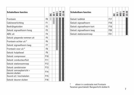
Schakelbare functies
DC
SX 1
MS
IM
S II
CS II
I
Frontsein F0
Cabineverlichting F1
Bedrijfsgeluiden F2
Geluid: signaalhoorn hoog F3
ABV, uit F4
Geluid: piepende remmen uit F5
Frontsein achter uit * F6
Geluid: signaalhoorn laag F7
Frontsein voor uit * F8
Geluid: hulpdiesel F9
Geluid: compressor F10
Geluid: conducteurfluit F11
Geluid: stationsomroep F12
Geluid: zandstrooier F13Geluid: omroepbericht + deuren sluiten F14
Sound uit / inschakelen F15
Geluid: deuren sluiten F16
Schakelbare functies
DC
SX 1
MS
IM
S II
CS II
I
Geluid: luidklok F17
Geluid: signaalhoorn F18
Geluid: signaalhoorn kort F19
Geluid: signaalhoorn laag F20
Geluid: stationsomroep F21
* alleen in combinatie met Frontsein Tezamen geschakeld: Rangeerlicht dubbel A
8
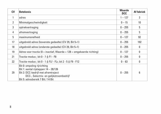
CV Betekenis Waarde DCC Af fabriek
1 adres 1 – 127 3
2 Minimalgeschwindigkeit 0 – 15 10
3 optrekvertraging 0 – 255 5
4 afremvertraging 0 – 255 5
5 maximumsnelheid 0 – 127 92
17 uitgebreldadres(bovenstegedeelte)(CV29,Bit5=1) 0 – 255 192
18 uitgebreldadres(onderstegedeelte)(CV29,Bit5=1) 0 – 255 0
19 Adresvoortractie(0=inactief,Waarde+128=omgekeerderichting) 0 – 127 0
21 Tractie-modus ; bit 0 - 7 =̂ F1 - F8 0 – 255 0
22 Tractie-modus ; bit 0 - 1 =̂ FLf - FLr, bit 2 - 5 =̂ F9 - F12 0 – 63 0
29
Bit 0: ompoling rijrichting Bit 1: aantal rijstappen 14 – 28/126 Bit 2: DCC-bedrijf met afremtraject DCC-, Selectrix- en gelijkstroombedrijf Bit 5: adresbereik 7 Bit / 14 Bit
0 – 255 6
9
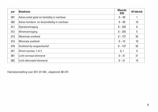
par Betekenis Waarde SX2 Af fabriek
001 Adres enkel getal en tientallig in voerbaar 0 – 99 1
002 Adres honderd- en duizendtallig in voerbaar 0 – 99 10
011 Optrekvertraging 0 – 255 6
012 Afremvertraging 0 – 255 5
013 Maximale snelheid 0 – 127 92
014 Minimale snelheid 0 – 15 10
018 Snelheid bij rangeerbedrijf 0 – 127 92
021 Afrem secties; 1 of 2 0, 1 0
081 Licht normaal dimmend 0 – 31 31
082 Licht alternatief dimmend 0 – 31 15
Fabrieksinstelling voor SX1: 01-542 , uitgebreid: 00-274
10
Aviso de seguridad• Lalocomotorasolamentedebefuncionarenelsistema
que le corresponda.• Laalimentacióndelalocomotoradeberárealizarse
desde una sola fuente de suminitro.• Observebajotodoslosconceptos,lasmedidasde
seguridad indicadas en las instrucciones de su sistema de funcionamiento.
• Analógico14voltios=,digital22voltios~.• Paraelfuncionamientoconvencionaldelalocomotora,
deben eliminarse las corrientes parasitarias de la vía de conexión. Para tal fin se debe utilizar el set antiparasi-tario 14972. Para funcionamiento en modo digital, el set antiparasitario no es adecuado.
• Noexponerelmodeloenminiaturaalaradiaciónsolardirecta, a oscilaciones fuertes de temperatura o a una humedad del aire elevada.
• Elcabledeconexiónalavíautilizadodebetenerunalongitud máxima de 2 metros.
• ¡ATENCIÓN! Esquinas y puntas afiladas condicionadas a la función.
• LosLEDsincorporadoscorrespondenalaclasedeláser1 según la norma europea EN 60825-1.
Notas importantes• Lasinstruccionesdeempleoyelembalajeformanparte
íntegra del producto y, por este motivo, deben guardarse y entregarse junto con el producto en el caso de venderlo o transmitirlo a otro.
• Encasodeprecisarunareparaciónopiezasderecambio,rogamos ponerse en contacto con su distribuidor Trix.
• Responsabilidadygarantíaconformealdocumentodegarantía que se adjunta.
• Eliminación:www.maerklin.com/en/imprint.htmlConsejo general para evitar las interferencias electroma-gnéticas: Para garantizar un funcionamiento según las previsiones se requiere un contacto rueda-carril de los vehículos permanente sin anomalías.No realice ninguna modificación en piezas conductoras de la corriente.Funciones• Electrónicaintegradaparafuncionamientoopcionalconel
aparato de conducción de corriente continua convencio-nal (máx. ±12 voltios), Trix Systems, Trix Selectrix (SX1) y Selectrix 2 (SX2) o sistemas digitales según norma NMRA.
• Reconocimientoautomáticodelsistemaentrefunciona-miento digital y analógico.
• Noexistereconocimientoautomáticodelsistemaentrelos sistemas digitales.
• Señaldecabezadetresluces,doslucesdecolarojasatrás, con alternancia en función del sentido de la mar-cha.
• Concinemáticaparaenganchecortoyfijacióndelenga-nche conforme a NEM.
Indicaciones para el funcionamiento digital• Enelfuncionamientoporprimeravezconunsistema
digital (SX1, SX2 o DCC), el decoder se debe configurar para este sistema digital. Para tal fin, se debe programar el decoder una vez en este sistema digital (p. ej., cambiar la dirección).

11
Funciones posibles
DC
SX 1
MS
IM
S II
CS II
I
Señaldecabeza F0
Alumbrado interior de la cabina F1
ruido de explotación F2
Ruido: Bocina de aviso, sonido agudo F3
ABV, apagado F4Ruido: Desconectar chirrido de los frenos F5
Señaldecabezatraseraapagada* F6
Ruido: Bocina de aviso, sonido grave F7
Señaldecabezadelanteraapagada* F8
Ruido: Diesel auxiliar F9
Ruido: Compresor F10
Ruido: Silbato de Revisor F11
Ruido: Locución en estación F12
Ruido: Arenado F13
Ruido: Locución y cerrar puertas F14
Mostrar/ocultar sonido F15
Ruido: Cerrar puertas F16
Funciones posibles
DC
SX 1
MS
IM
S II
CS II
I
Ruido: Campana F17
Ruido: Bocina F18
Ruido: Bocina corta F19
Ruido: Bocina de aviso, sonido grave F20
Ruido: Locución hablada en estaciones F21
* SólojuntoconSeñaldecabeza Interconectados: Luz de maniobra Doble A

12
CV Significado Valor DCC Preselec-ción
1 Códigos 1 – 127 3
2 Velocidad mínima 0 – 15 10
3 Arranque progresivo 0 – 255 5
4 Frenado progresivo 0 – 255 5
5 Velocidad máxima 0 – 127 92
17 Direcciónampliada(partesuperior)(CV29,bit5=1) 0 – 255 192
18 Direcciónampliada(parteinferior)(CV29,bit5=1) 0 – 255 0
19 Direccióndetracción(0=inactiva,valor+128=sentidodemarchainverso) 0 – 127 0
21 Modo de tracción; bit 0 – 7 =̂ F1 – F8 0 – 255 0
22 Modo de tracción; bit 0 – 1 =̂ FLf – FLr, Bit 2 – 5 =̂ F9 – F12 0 – 63 0
29
Bit 0: Cambio de sendido de marcha Bit 1: Número de niveles de marcha 14 - 28/126 Bit 2: Modo DCC con tramo de frenado Modo DCC, Selectrix y corriente continua Bit 5: Alcance de direcciones 7 bits / 14 bits
0 – 255 6
13
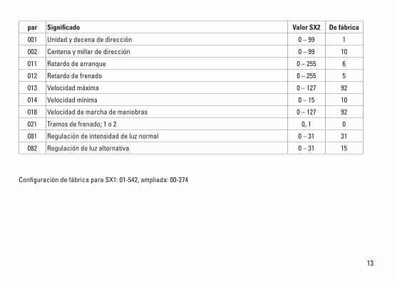
par Significado Valor SX2 De fábrica
001 Unidadydecenadedirección 0 – 99 1
002 Centena y millar de dirección 0 – 99 10
011 Retardo de arranque 0 – 255 6
012 Retardo de frenado 0 – 255 5
013 Velocidad máxima 0 – 127 92
014 Velocidad mínima 0 – 15 10
018 Velocidad de marcha de maniobras 0 – 127 92
021 Tramos de frenado; 1 o 2 0, 1 0
081 Regulación de intensidad de luz normal 0 – 31 31
082 Regulación de luz alternativa 0 – 31 15
Configuración de fábrica para SX1: 01-542, ampliada: 00-274
14
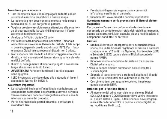
Avvertenze per la sicurezza• Talelocomotivadevevenireimpiegatasoltantoconun
sistema di esercizio prestabilito a questo scopo.• Lalocomotivanondevevenirealimentatanellostesso
tempo con più di una sorgente di potenza.• Vogliateprestareassolutamenteattenzionealleavverten-
ze di sicurezza nelle istruzioni di impiego per il Vostro sistema di funzionamento.
• Analogica14Volt=,digitale22Volt~.• Per l’esercizio tradizionale della locomotiva il binario di
alimentazione deve venire liberato dai disturbi. A tale scopo si deve impiegare il corredo anti-disturbi 14972. Per il funzi-onamento Digital tale corredo anti-disturbi non è adatto.
• Nonesponetetalemodelloadalcunirraggiamentosolarediretto, a forti escursioni di temperatura oppure a elevata umidità dell’aria.
• Ilcavodicollegamentoalbinarioimpiegatodeveesserelungo al massimo soltanto 2 metri.
• AVVERTENZA! Per motivi funzionali i bordi e le punte sono spigolosi.
• ILEDincorporaticorrispondonoallacategoriadilaser1secondo la Norma EN 60825-1.
Avvertenze importanti• Leistruzionidiimpiegoel’imballaggiocostituisconoun
componente sostanziale del prodotto e devono pertanto venire conservati nonché consegnati insieme in caso di ulteriore cessione del prodotto.
• Perleriparazioniolepartidiricambio,contrattareilrivenditore Trix.
• Prestazionidigaranziaegaranziainconformitàall’accluso certificato di garanzia.
• Smaltimento:www.maerklin.com/en/imprint.htmlAvvertenza generale per la prevenzione di disturbi elettro-magnetici: Per garantire l’esercizio conforme alla destinazione è necessario un contatto ruota-rotaia dei rotabili permanente, esente da interruzioni. Non eseguite alcuna modificazione ai componenti conduttori di corrente.Funzioni• Moduloelettronicoincorporatoperilfunzionamentoa
scelta con un tradizionale regolatore di marcia a corrente continua (max. ±12 Volt), Trix Systems, Trix Selectrix (SX1) e Selectrix 2 (SX2) oppure sistemi Digital secondo le norme NMRA.
• RiconoscimentoautomaticodelsistematraesercizioDigital ed analogico.
•Nessunriconoscimentoautomaticodelsistematraisistemi digitali.
• Segnaleditestaanterioreatrefanali,duefanalidicodarossi dietro, commutati con la direzione di marcia.
• Concinematismiperagganciocortoedinnestopergancio secondo NEM.
Istruzioni per la funzione digitale • AlmomentodelprimoesercizioinunsistemaDigital
(SX1, SX2 oppure DCC) il Decoder deve venire impostato su questo sistema Digital. A tale scopo si deve program-mare il Decoder una volta in questo sistema Digital (ad es. modificare l’indirizzo).
15
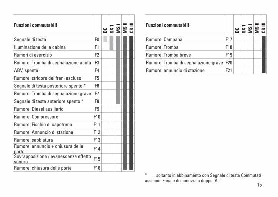
Funzioni commutabili
DC
SX 1
MS
IM
S II
CS II
I
Segnale di testa F0
Illuminazione della cabina F1
Rumori di esercizio F2
Rumore: Tromba di segnalazione acuta F3
ABV, spente F4
Rumore: stridore dei freni escluso F5
Segnale di testa posteriore spento * F6
Rumore: Tromba di segnalazione grave F7
Segnale di testa anteriore spento * F8
Rumore: Diesel ausiliario F9
Rumore: Compressore F10
Rumore: Fischio di capotreno F11
Rumore: Annuncio di stazione F12
Rumore: sabbiatura F13Rumore: annuncio + chiusura delle porte F14Sovrapposizione / evanescenza effetto sonoro F15
Rumore: chiusura delle porte F16
Funzioni commutabili
DC
SX 1
MS
IM
S II
CS II
I
Rumore: Campana F17
Rumore: Tromba F18
Rumore: Tromba breve F19
Rumore: Tromba di segnalazione grave F20
Rumore: annuncio di stazione F21
* soltanto in abbinamento con Segnale di testa Commutati assieme: Fanale di manovra a doppia A
16
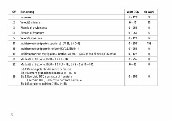
CV Bedeutung Wert DCC ab Werk
1 Indirizzo 1 – 127 3
2 Velocità minima 0 – 15 10
3 Ritardo di avviamento 0 – 255 5
4 Ritardo di frenatura 0 – 255 5
5 Velocità massima 0 – 127 92
17 Indirizzoesteso(partesuperiore)(CV29,Bit5=1) 0 – 255 192
18 Indirizzoesteso(parteinferiore)(CV29,Bit5=1) 0 – 255 0
19 Indirizzotrazionemultipla(0=inattiva,valore+128=sensodimarciainverso) 0 – 127 0
21 Modalità di trazione; Bit 0 – 7 =̂ F1 – F8 0 – 255 0
22 Modalità di trazione; Bit 0 – 1 =̂ FLf – FLr, Bit 2 – 5 =̂ F9 – F12 0 – 63 0
29
Bit 0: Cambio polarità del senso di marcia Bit 1: Numero gradazioni di marcia 14 - 28/126 Bit 2: Esercizio DCC con tratta di frenatura Esercizio DCC, Selectrix e corrente continua Bit 5: Estensione indirizzo 7 Bit / 14 Bit
0 – 255 6
17
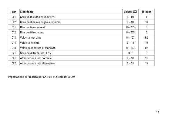
par Significato Valore SX2 di fabbr.
001 Cifra unità e decine indirizzo 0 – 99 1
002 Cifra centinaia e migliaia indirizzo 0 – 99 10
011 Ritardo di avviamento 0 – 255 6
012 Ritardo di frenatura 0 – 255 5
013 Velocità massima 0 – 127 92
014 Velocità minima 0 – 15 10
018 Velocità andatura di manovra 0 – 127 92
021 Sezione di frenatura; 1 o 2 0, 1 0
081 Attenuazione luci normale 0 – 31 31
082 Attenuazione luci alternativa 0 – 31 15
Impostazione di fabbrica per SX1: 01-542, esteso: 00-274

18
66626Märklin7149
7149
OIL 40h
66623
19

20
1 12
3
4
21
2
1
22
7
8
6
10
7
8
14
12
11
5
4
31
2
4
2
14
13
9
23
Opmerking: enkele delen worden alleen kleurloos of in een andere kleur aangeboden. Delen die niet in de in de lijst voorkomen, kunnen alleen via een reparatie in het Märklin-service-centrum hersteld/vervangen worden.
Nota: algunas piezas están disponibles sólo sin o con otro color. Las piezas que no figuran aquí pueden repa-rarse únicamente en el marco de una reparación en el servicio de reparación de Märklin.
Avvertenza: Alcuni elementi vengono proposti solo sen-za o con differente colorazione. I pezzi che non sono qui specificati possono venire riparati soltanto nel quadro di una riparazione presso il Servizio Riparazioni Märklin.
1 Puffer, Handstangen E191 170 2 Leitungen E193 361 3 Decoder E178 238 4 Schraube E19 8001 28 5 Motor E178 221 6 Motorlager E324 194 7 Schraube E785 150 8 LP Beleuchtung E167 873 9 Kupplung E193 364 10 Lautsprecher E101 066 11 Haftreifen E12 2273 00 12 Drehgestell 1 E178 430 13 Drehgestell 2 E178 433 14 Rangiertritt E178 431 Kupplungshaken, Bremsschlauch E180 834 Schnittstellenstecker E178 237

Gebr. Märklin & Cie. GmbH Stuttgarter Straße 55 - 57 73033 Göppingen Germanywww.trix.de
278745/0617/Sm1ClÄnderungen vorbehalten
© Gebr. Märklin & Cie. GmbH
Due to different legal requirements regarding electro-magnetic compatibility, thisitemmaybeusedintheUSAonlyafterseparatecertificationforFCCcom-pliance and an adjustment if necessary. UseintheUSAwithoutthiscertificationisnotpermittedandabsolvesusofanyliability. If you should want such certification to be done, please contact us – also due to the additional costs incurred for this.
www.maerklin.com/en/imprint.html