Modell der Elektrolokomotive BB 9291 D GB USA F …...Marseille, on pouvait les rencontrer aussi...
48
Modell der Elektrolokomotive BB 9291 16691 D GB USA F
Transcript of Modell der Elektrolokomotive BB 9291 D GB USA F …...Marseille, on pouvait les rencontrer aussi...
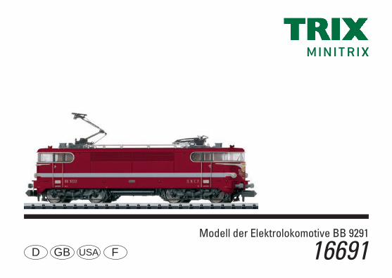
Modell der Elektrolokomotive BB 9291
16691D GB USA F

2

3
Inhaltsverzeichnis: SeiteInformationen zum Vorbild 4Sicherheitshinweise 6 Wichtige Hinweise 6Funktionen 6Hinweise zum Digitalbetrieb 6Schaltbare Funktionen 7Configurations Variablen (CVs) 8Wartung und Instandhaltung 18Ersatzteile 22
Table of Contents: Page Information about the prototype 5Safety Notes 10Important Notes 10Functions 10Notes on digital operation 10Controllable Functions 11Configuration Variables (CVs) 12Service and maintenance 18Spare Parts 22
Sommaire : PageInformations concernant le modèle réelle 5Remarques importantes sur la sécurité 14Information importante 14Fonctionnement 14Remarques relatives au fonctionement en mode digital 14Fonctions commutables 15Variables de configuration (CVs) 16Entretien et maintien 18Pièces de rechange 22

4
Informationen zum Vorbild Die Erfolgsgeschichte der sogenannten „Jacquemins“ als quasi erste französische „Einheitsellok“ der 1938 gegründe-ten SNCF begann mit der Baureihe BB-9200, welche in den Jahren 1957-1964 in insgesamt 92 Exemplaren bei Creusot-Loire, Jeumont-Schneider und CEM beschafft wurde. Ausgerüstet war sie mit vier Gleichstrommotoren des Typs GLM 931 B von Alsthom und einer elektrischen Steuerung der Bauart JH (= Jeumont Heidmann) mit Nockenschalt-werk. Sie fuhr auf neu entwickelten Drehgestellen der Bauart „Jacquemin“, welche eine hervorragende Laufruhe mit geringen Vibrationen bei der Bewältigung hoher Anfahr-zugkräfte gewährleisteten. Neu waren die Kardan-Gelenk-übertragung mittels Hohlwelle sowie die Tiefanlenkung der Drehgestelle über Zugstangen, welche das Drehmoment der Motoren auf mehrere Angriffspunkte im Lokomotivrahmen aufteilte. Für die äußere Gestaltung der „Jacquemins“ zeichnete der bekannte SNCF-Designer Paul Arzens verant-wortlich, welcher den charakteristischen, vorne abgerun-deten Lokkasten mit seinen verspielten Applikationen wie Scheinwerfer und Frontsignet entwarf.Die BB-9200 bedienten von Paris ausgehend vor allem im schnellen Reiseverkehr den Südwesten Frankreichs. Doch neben dem Führen des prestigeträchtigen „Mistrals“ zwischen Paris und Marseille konnte man sie auch vor 1.800 Tonnen schweren Güterzügen finden. Ab 2003 begann der Stern der Loks drastisch zu sinken und bis September 2011 hatte das letzte Exemplar seinen Dienst quittiert.

5
Information about the prototypeThe success story of the so-called “Jacquemins” as the first quasi French “standard design locomotive” for the SNCF established in 1938 began with the class BB-9200, of which 92 units were purchased from Creusot-Loire, Jeumont-Sch-neider, and CEM in the years 1957-1964. They were equipped with four type GLM 931 B DC motors from Alsthom and JH (= Jeumont Heidmann) type electrical controls with a cam control mechanism. They ran on newly developed “Jacquemin” design trucks, which ensured outstandingly quiet running with little vibration at the same time managing higher levels of startup power. The cardan joint transmis-sion by means of hollow shafts as well as the low mounted coupling of the trucks by means of drawbars were new, which distributed the torque from the motors to several contact points in the locomotive frame. The well- known SNCF designer Paul Arzens was responsible for the external design of the “Jacquemins”, and he created the charac-teristic locomotive body with its rounded ends and playful applications such as headlights and end emblem.The class BB-9200 units worked from Paris going out chiefly in express passenger service to the Southwest of France. Yet in addition to pulling the prestigious “Mistrals” between Paris and Marseille, they could also be seen pulling 1,800 metric ton freight trains. Starting in 2003, the star for the locomotives began to sink drastically and by September 2011 the last unit had been taken out of service.
Informations concernant le modèle réel La « success story » des « Jacquemin » - qui fut quasi la pre-mière locomotive électrique „unifiée“ de la SNCF, fondée en 1938, débuta avec la série BB 9200, acquise dans les années 1957-1964 en 92 exemplaires au total auprès de Creusot-Loire, Jeumont-Schneider et CEM. Elle était équipée de quatre moteurs à courant continu du type GLM 931 B par Alsthom et d‘une distribution électrique du type JH (Jeumont Heidmann) avec combinateur à cames. Elle roulait sur des bogies nouvellement conçus du type „Jacquemin“, qui garantissaient un excellent roulement silencieux avec peu de vibrations, tout en assumant des forces de traction élevées lors du démarrage. Nouveaux: les transmissions articulées à cardans au moyen d‘un arbre creux, ainsi que le dispositif de traction basse des bogies par des barres de traction qui répartissaient le couple de rotation des moteurs sur plusieurs points d‘attaque dans le châssis de la locomotive. C‘est Paul Arzens, le très connu designer de la SNCF, qui signa le design des « Jaquemins » avec la caisse caractéristique, arrondie à l‘avant et ses applications originales telles que phares et signet frontal.Les BB 9200 assuraient, au départ de Paris, surtout le trafic voyageurs rapide desservant le Sud-Ouest de la France. Mais outre en tête du prestigieux „Mistral“ entre Paris et Marseille, on pouvait les rencontrer aussi devant des trains marchandises de 1800 tonnes. A partir de 2003 s‘amorça le déclin rapide de ces locos et jusqu‘à septembre 2011, la dernière avait quitté le service.

6
Sicherheitshinweise• Die Lok darf nur mit einem dafür bestimmten Betriebssys-
tem eingesetzt werden.• Die Lok darf nicht mit mehr als einer Leistungsquelle
versorgt werden.• Beachten Sie unbedingt die Sicherheitshinweise in der
Bedienungsanleitung zu Ihrem Betriebssystem.• Analog 14 Volt=, digital 19 Volt~.• Für den konventionellen Betrieb der Lok muss das
Anschlussgleis entstört werden. Dazu ist das Entstörset 14972 zu verwenden. Für Digitalbetrieb ist das Entstörset nicht geeignet.
• Setzen Sie das Modell keiner direkten Sonneneinstrah-lung, starken Temperaturschwankungen oder hoher Luftfeuchtigkeit aus.
• Das verwendete Gleisanschlusskabel darf maximal 2 Meter lang sein.
• ACHTUNG! Funktionsbedingte scharfe Kanten und Spitzen. • Verbaute LED`s entsprechen der Laserklasse 1 nach Norm
EN 60825-1.Allgemeiner Hinweis zur Vermeidung elektromagnetischer Störungen: Um den bestimmungsgemäßen Betrieb zu gewährleisten, ist ein permanenter, einwandfreier Rad-Schiene-Kontakt der Fahrzeuge erforderlich. Führen Sie keine Veränderungen an stromführenden Teilen durch.
Wichtige Hinweise• Die Bedienungsanleitung und die Verpackung sind
Bestandteile des Produktes und müssen deshalb aufbe-wahrt sowie bei Weitergabe des Produktes mitgegeben werden.
• Für Reparaturen oder Ersatzteile wenden Sie sich bitte an Ihren Trix-Fachhändler.
• Gewährleistung und Garantie gemäß der beiliegenden Garantieurkunde.
• Entsorgung: www.maerklin.com/en/imprint.html Funktionen• Eingebaute Elektronik zum wahlweisen Betrieb mit
konventionellem Gleichstrom-Fahrgerät (max. ±14 Volt), Trix Systems, Trix Selectrix (SX) oder Digitalsystemen nach NMRA-Norm.
• Automatische Systemerkennung zwischen Digital- und Analog-Betrieb.
• Keine automatische Systemerkennung zwischen den Digital-Systemen.
• Zweilicht-Spitzensignal vorne, zwei rote Schlusslichter hinten, mit der Fahrtrichtung wechselnd.
Hinweise zum Digitalbetrieb • Beim ersten Betrieb in einem Digital-System (SX oder
DCC) muss der Decoder auf dieses Digital-System ein-gestellt werden. Dazu ist der Decoder einmal in diesem Digitalsystem zu programmieren (z.B. Adresse ändern).

7
1 mit Zufallsgeräuschen2 nur in Verbindung mit Spitzensignal
Zusammen geschaltet: Rangierlicht Doppel A3 nur ohne F0
Schaltbare Funktionen
DC
SX
DCC
Geräusch: Türen schließen F17
Geräusch: Ankuppeln F18
Geräusch: Pantograph F19
Schaltbare Funktionen
DC
SX
DCC
Spitzensignal fahrtrichtungsabhängig F0
Spitzensignal, nur vorn 3 F1
Geräusch: Betriebsgeräusch 1 F2
Geräusch: Signalhorn F3
Direktsteuerung (ABV) F4
Geräusch: Bremsenquietschen aus F5
Spitzensignal Führerstand 2 2 F6
Geräusch: Rangierhorn F7
Spitzensignal Führerstand 1 2 F8
Geräusch: Signalhorn F9
Geräusch: Schaffnerpfiff F10
Geräusch: Kompressor F11
Geräusch: Lüfter F12
Geräusch: Druckluft ablassen F13
Führerstandsbeleuchtung F14
Sound ausblenden/einblenden F15
Geräusch: Sanden F16

8
CV Bedeutung Wert DCC ab Werk
1 Adresse 1 – 127 3
2 Minimalgeschwindigkeit 0 – 15 12
3 Anfahrverzögerung 0 – 255 5
4 Bremsverzögerung 0 – 255 5
5 Maximalgeschwindigkeit 0 – 127 88
17 Erweiterte Adresse (oberer Teil) (CV 29, Bit 5=1) 0 – 255 192
18 Erweiterte Adresse (unterer Teil) (CV 29, Bit 5=1) 0 – 255 0
19 Traktionsadresse (0 = inaktiv, Wert + 128 = inverse Fahrtrichtung) 0 – 127 0
21 Traktions-Modus; Bit 0 – 7 =̂ F1 – F8 0 – 255 0
22 Traktions-Modus; Bit 0 – 1 =̂ FLf – FLr, Bit 2 – 5 =̂ F9 – F12 0 – 63 0
29
Bit 0: Umpolung Fahrtrichtung Bit 1: Anzahl Fahrstufen 14 - 28/126 Bit 2: DCC Betrieb mit Bremsstrecke DCC-, Selectrix- und Gleichstrombetrieb Bit 5: Adressumfang 7 Bit / 14 Bit
0 – 255 14
Werkseinstellung für SX1: 01-632, erweitert: 00-234

9

10
Important Notes• The operating instructions and the packaging are a com-
ponent part of the product and must therefore be kept as well as transferred along with the product to others.
• Please see your authorized Trix dealer for repairs or spare parts.
• The warranty card included with this product specifies the warranty conditions.
• Disposing: www.maerklin.com/en/imprint.html Functions • Built-in electronic circuit for optional operation with
a conventional DC train controller (max. ±14 volts), Trix Systems, Trix Selectrix (SX), or digital systems adhe-ring to the NMRA standards.
• Automatic system recognition between digital and analog operation.
• No automatic system recognition between the digital systems.
• Dual headlights in the front, dual red marker lights in the rear, that change over with the direction of travel.
Notes on digital operation • When operating in a digital system for the first time (SX or
DCC), the decoder must be set to this digital system. To do this, the decoder must be programmed once in this digital system (example: change the address).
Safety Notes• This locomotive is only to be used with the operating
system it is designed for.• This locomotive must not be supplied with power from
more than one power pack.• Pay close attention to the safety notes in the instructions
for your operating system.• Analog 14 volts DC, digital 19 volts AC.• The feeder track must be equipped to prevent inter-
ference with radio and television reception, when the locomotive is to be run in conventional operation. The 14972 interference suppression set is to be used for this purpose. The interference suppression set is not suitable for digital operation.
• Do not expose the model to direct sunlight, extreme changes in temperature, or high humidity.
• The wire used for feeder connections to the track may be a maximum of 2 meters / 78 inches long.
• WARNING! Sharp edges and points required for operation. • The LEDs in this item correspond to Laser Class 1 accor-
ding to Standard EN 60825-1.General Note to Avoid Electromagnetic Interference: A permanent, flawless wheel-rail contact is required in order to guarantee operation for which a model is designed. Do not make any changes to current-conducting parts.

11
1 with random sounds2 only in conjunction with Headlights/marker lights
Switched together: „Double A“ switching lights3 only without F0
Controllable Functions
DC
SX
DCC
Sound effect: Doors being closed F17
Sound effect: Coupling together F18
Sound effect: Pantograph F19
Controllable Functions
DC
SX
DCC
Headlights F0
Headlights, only on the front 3 F1
Sound effect: Operating sounds 1 F2
Sound effect: Horn F3
Direct control (ABV) F4
Sound effect: Squealing brakes off F5
Headlights Engineer‘s Cab 2 2 F6
Sound effect: Switching horn F7
Headlights Engineer‘s Cab 1 2 F8
Sound effect: Horn F9
Sound effect: Conductor whistle F10
Sound effect: Compressor F11
Sound effect: Blower F12
Sound effect: Letting off air F13
Engineer‘s cab lighting F14
Blending sound in and out F15
Sound effect: Sanding F16

12
CV Discription DCC Value Factory Setting
1 Address 1 – 127 3
2 Minimum Speed 0 – 15 12
3 Acceleration delay 0 – 255 5
4 Braking delay 0 – 255 5
5 Maximum speed 0 – 127 88
17 Extendet address (upper part) (CV 29, Bit 5=1) 0 – 255 192
18 Extendet address (lower part) (CV 29, Bit 5=1) 0 – 255 0
19 Consist address (0 = inactive, Value + 128 = inverse direction) 0 – 127 0
21 Motive Power Mode; Bit 0 – 7 =̂ F1 – F8 0 – 255 0
22 Motive Power Mode; Bit 0 – 1 =̂ FLf – FLr, Bit 2 – 5 =̂ F9 – F12 0 – 63 0
29
Bit 0: Travel direction polarity reversal Bit 1: number of speed levels 14 – 28/126 Bit 2: DCC Operation with braking Block DCC-, Selectrix and DC power operation Bit 5: address size 7 Bit / 14 Bit
0 – 255 14
Factory setting for SX1: 01-632, advanced: 00-234

13

14
Remarques importantes sur la sécurité• La locomotive ne peut être utilisée qu‘avec le système
d‘exploitation indiqué.• La locomotive ne peut être alimentée en courant que par
une seule source de courant.• Veuillez impérativement respecter les remarques sur
la sécurité décrites dans le mode d’emploi en ce qui concerne le système d’exploitation.
• Analogique 14 volts=, digital 19 volts ~.• Pour l’exploitation de la locomotive en mode conventi-
onnel, la voie de raccordement doit être déparasitée. A cet effet, utiliser le set de déparasitage réf. 14972. Le set de déparasitage ne convient pas pour l’exploitation en mode numérique.
• Ne pas exposer le modèle à un ensoleillement direct, à de fortes variations de température ou à un taux d‘humidité important.
• Le câble de raccordement à la voie utilisé ne doit en aucun cas dépasser deux mètres.
• ATTENTION! Pointes et bords coupants lors du fonction-nement du produit.
• Les DEL installées correspondent à la classe laser 1 selon la norme EN 60825-1.
Indication d‘ordre général pour éviter les interférences électromagnétiques: La garantie de l‘exploitation normale nécessite un contact roue-rail permanent et irréprochable. Ne procédez à aucune modification sur des éléments conducteurs de courant.
Information importante• La notice d‘utilisation et l’emballage font partie intégrante
du produit ; ils doivent donc être conservés et, le cas échéant, transmis avec le produit.
• Pour toute réparation ou remplacement de pièces, adressez vous à votre détaillant-spécialiste Trix.
• Garantie légale et garantie contractuelle conformément au certificat de garantie ci-joint.
• Elimination : www.maerklin.com/en/imprint.html Fonctionnement• Module électronique intégré pour exploitation au choix avec
régulateur de marche conventionnel c.c. (max. ±14 volts), Trix Systems, Trix Selectrix (SX) ou systèmes numériques conformes à la norme NMRA.
• Reconnaissance automatique du système entre exploita-tions numérique et analogique.
• Pas de reconnaissance automatique du système entre les systèmes numériques.
• Feux de signalisation doubles à l‘avant, deux feux rouges de fin de convoi à l‘arrière avec inversion selon sens de marche.
Remarques relatives au fonctionnement en mode digital • Une première exploitation en système numérique (SX ou
DCC) exige un réglage correspondant du décodeur. A cet effet, le décodeur doit être programmé une fois dans ce système numérique (modification de l’adresse par ex.).

15
Fonctions commutables
DC
SX
DCC
Bruitage : Fermeture des portes F17
Bruitage : Attelage F18
Bruitage : pantographe F19
1 avec bruits aléatoires2 Uniquement en combinaison avec Fanal éclairage
Commutés simultanément : feux de manoeuvre double A3 uniquement sans F0
Fonctions commutables
DC
SX
DCC
Fanal éclairage F0
Fanal éclairage, uniquement à l’avant 3 F1
Bruitage : Bruit d’exploitation 1 F2
Bruitage : trompe, signal F3
Temporisation d’accélération et de freinage F4
Bruitage : Grincement de freins désactivé F5
Fanal cabine de conduite 2 2 F6
Bruitage : Trompe de manœuvre F7
Fanal cabine de conduite 1 2 F8
Bruitage : trompe, signal F9
Bruitage : Sifflet Contrôleur F10
Bruitage : Compresseur F11
Bruitage : ventilateur F12
Bruitage : Échappement de l‘air comprimé F13
Eclairage de la cabine de conduite F14
Désactiver/activer son F15
Bruitage : Sablage F16

16
CV Signification Valeur DCC Valeur Parm. Usine
1 Adresse 1 – 127 3
2 Vitesse min 0 – 15 12
3 Temporisation d‘accélération 0 – 255 5
4 Temporisation de freinage 0 – 255 5
5 Vitesse maximale 0 – 127 88
17 Adresse étendue (partie supérieure) (CV 29, Bit 5=1) 0 – 255 192
18 Adresse étendue (partie inférieure) (CV 29, Bit 5=1) 0 – 255 0
19 Adresse pour la traction (0 = inactif, Valeur + 128 = direction inverse) 0 – 127 0
21 Mode traction, bit 0 à 7 =̂ F1 à F8 0 – 255 0
22 Mode traction; bit 0 à 1 =̂ FLf à FLr, Bit 2 à 5 =̂ F9 à F12 0 – 63 0
29
Bit 0: inversion de polarité, sens de marcheBit 1: Nombre de crans de marche 14 – 28/126 Bit 2: Exploitation DCC avec zone de freinage. DCC-, Selectrix et courant continu Bit 5: taille d‘adresse 7 Bits / 14 Bits
0 – 255 14
Paramètres d’usine pour SX1: 01 à 632, étendus : 00 à 234

17

18
66626Märklin7149
7149
66623

19

20
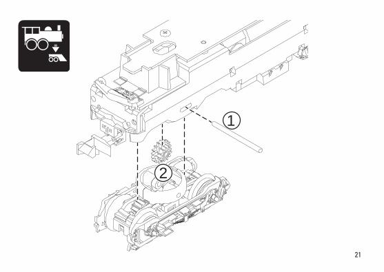
1
2
3

21
1
2

22
Det
ails
der
Dar
stel
-lu
ng k
önne
n vo
n de
m
Mod
ell a
bwei
chen
4
7
6
5
3
2
1
1
3
9
8
7
6
35

23
1 Scherenstromabnehmer E319 154 2 Puffer grau E12 2662 00 3 Schraube E278 103 4 Motor E319 116 5 Leiterplatte Licht E319 118 6 Kupplung E323 104 7 Drehgestell E323 106 8 Lautsprecher E321 205 9 Haftreifen E12 2258 00
Einige Teile werden nur ohne oder mit anderer Farbgebung angeboten. Teile, die hier nicht aufgeführt sind, können nur im Rahmen einer Reparatur im Märklin-Reparatur-Service repariert werden.
Several parts are offered unpainted or in another color. Parts that are not listed here can only be repaired by the Märklin repair service department.
Certains éléments sont proposés uniquement sans livrée ou dans une livrée différente. Les pièces ne figurant pas dans cette liste peuvent être réparées uniquement par le service de réparation Märklin.

Gebr. Märklin & Cie. GmbH Stuttgarter Straße 55 - 57 73033 Göppingen Germanywww.trix.de
321474/1019/Sm1ClÄnderungen vorbehalten
© Gebr. Märklin & Cie. GmbHwww.maerklin.com/en/imprint.html

NL
Modell der Elektrolokomotive BB 9291
16691

2

3
Índice: PáginaInformaciones sobre el modelo real 5Aviso de seguridad 10Notas importantes 10Funciones 10Indicacione para el funcionamiento digital 10Funciones conmutables 11Variables de Configuración (CVs) 12Mantenimiento y conservación 18Piezas de repuesto 22
Elenco del contenuto: Pagina Informazioni sul prototipo 5Avvertenze per la sicurezza 14Avvertenze importanti 14Funzioni 14Istruzioni per la funzione digitale 14Funzioni commutabili 15Variabili di configurazione (CV) 16Assistenza e manutenzione 18Parti di ricambio 22
Inhoudsopgave: PaginaInformatie van het voorbeeld 4Veiligheidsvoorschriften 6Belangrijke aanwijzing 6Functies 6Aanwijzing voor digitale besturing 6Schakelbare functies 7Configuratie variabelen (CV’s) 8Onderhoud en handhaving 18Onderdelen 22
4
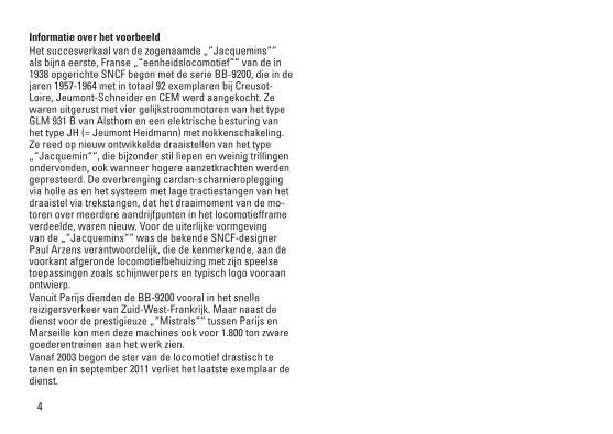
Informatie over het voorbeeldHet succesverkaal van de zogenaamde „“Jacquemins““ als bijna eerste, Franse „“eenheidslocomotief““ van de in 1938 opgerichte SNCF begon met de serie BB-9200, die in de jaren 1957-1964 met in totaal 92 exemplaren bij Creusot-Loire, Jeumont-Schneider en CEM werd aangekocht. Ze waren uitgerust met vier gelijkstroommotoren van het type GLM 931 B van Alsthom en een elektrische besturing van het type JH (= Jeumont Heidmann) met nokkenschakeling. Ze reed op nieuw ontwikkelde draaistellen van het type „“Jacquemin““, die bijzonder stil liepen en weinig trillingen ondervonden, ook wanneer hogere aanzetkrachten werden gepresteerd. De overbrenging cardan-scharnieroplegging via holle as en het systeem met lage tractiestangen van het draaistel via trekstangen, dat het draaimoment van de mo-toren over meerdere aandrijfpunten in het locomotiefframe verdeelde, waren nieuw. Voor de uiterlijke vormgeving van de „“Jacquemins““ was de bekende SNCF-designer Paul Arzens verantwoordelijk, die de kenmerkende, aan de voorkant afgeronde locomotiefbehuizing met zijn speelse toepassingen zoals schijnwerpers en typisch logo vooraan ontwierp.Vanuit Parijs dienden de BB-9200 vooral in het snelle reizigersverkeer van Zuid-West-Frankrijk. Maar naast de dienst voor de prestigieuze „“Mistrals““ tussen Parijs en Marseille kon men deze machines ook voor 1.800 ton zware goederentreinen aan het werk zien. Vanaf 2003 begon de ster van de locomotief drastisch te tanen en in september 2011 verliet het laatste exemplaar de dienst.
5
Informaciones sobre el modelo realLa historia de éxito de las denominadas „Jacquemins“, prácticamente la primera „locomotora unificada“ francesa de la SNCF, fundada en 1938, comenzó con la serie BB-9200, que se adquirió en los años 1957-1964 en un total de 92 ejemplares a Creusot-Loire, Jeumont-Schneider y CEM. Esta locomotora ha estado equipada con cuatro motores de cor-riente continua del tipo GLM 931 B de Alsthom y un mando eléctrico del tipo constructivo JH (= Jeumont Heidmann) con secuenciador de levas. Circuló sobre bogies de nuevo desarrollo del tipo constructivo „Jacquemin“, que garan-tizaban una excelente suavidad de marcha con escasas vibraciones a la hora de hacer frente a esfuerzos tractores elevados en la puesta en movimiento. Como novedad destacaban la transmisión con árboles Cardan mediante árbol hueco así como la articulación a bajo nivel de los bogies mediante tirantes que repartían el par motor de los motores entre varios puntos de ataque en el bastidor de la locomotora. El diseño exterior de las „Jacquemins“ corrió a cargo del conocido diseñador de la SNCF Paul Arzens, que desarrolló la característica caja de locomotora de morro redondeado con sus elementos aplicados juguetones como los faros y el emblema frontal.Las BB-9200 servían, con salida desde París, sobre todo el tráfico rápido hacia el suroeste de Francia. Sin embargo, además de arrastrar el prestigioso „Mistral“ entre París y Marsella, se la veía también al frente de trenes mercancías de 1.800 toneladas de peso. A partir de 2003, comenzó a caer la fortuna de estas loco-motoras y en septiembre de 2011 abandonó el servicio el último ejemplar.
Informazioni sul prototipo La storia coronata dal successo della cosiddetta „Jacque-mins“, come quasi prima „locomotiva unificata“ francese della SNCF fondata nel 1938, incominciò con il Gruppo BB-9200, il quale negli anni 1957-1964 venne acquisito in complessivi 92 esemplari presso Creusot-Loire, Jeumont-Schneider e CEM. Essa era equipaggiata con quattro motori a corrente continua del tipo GLM 931 B di Alsthom ed un comando elettrico del tipo costruttivo JH (= Jeumont Heidmann) con combinatore a camme. Essa viaggiava su dei carrelli di nuova elaborazione del tipo costruttivo „Jacquemin“, i quali garantivano una eccellente scorre-volezza con modeste vibrazioni durante la prestazione di elevati sforzi di trazione in avviamento. Nuove erano la trasmissione cardanica articolata per mezzo di albero cavo nonché l’accoppiamento basso dei carrelli tramite aste di trazione, il quale ripartiva la coppia di rotazione dei motori tra parecchi punti di attacco nel telaio della locomotiva. Per la modellazione esteriore della „Jacquemins“ si assunse la responsabilità il famoso progettista SNCF Paul Arzens, il quale disegnò la caratteristica cassa della locomotiva, arrotondata anteriormente con le sue sportive applicazioni come fari e marchio frontale.Le BB-9200 fecero servizio a partire da Parigi soprattutto nel traffico passeggeri rapido del Sud-Ovest della Francia. Comunque accanto alla guida del prestigioso „Mistral“ tra Parigi e Marsiglia si poteva trovarle anche in testa a treni merci pesanti 1.800 tonnellate. A partire dal 2003 la stella di tali locomotive incominciò a declinare drasticamente ed entro settembre 2011 l’ultimo esemplare aveva abbandonato il suo servizio.

6
Veiligheidsvoorschriften• De loc mag alleen met een daarvoor bestemd bedrijfssys-
teem gebruikt worden.• De loc mag niet vanuit meer dan een stroomvoorziening
gelijktijdig gevoed worden.• Analoog max. 14 Volt=, digitaal max. 19 Volt~.• Lees ook aandachtig de veiligheidsvoorschriften in de
gebruiksaanwijzing van uw bedrijfssysteem. • Voor het conventionele bedrijf met de loc dient de
aansluitrail te worden ontstoort. Hiervoor dient men de ontstoor-set 14972 te gebruiken. Voor het digitale bedrijf is deze ontstoor-set niet geschikt.
• Stel het model niet bloot aan in directe zonnestraling, sterke temperatuurwisselingen of hoge luchtvochtigheid.
• De gebruikte aansluitkabel mag maximaal 2 meter lang zijn.• OPGEPAST! Functionele scherpe kanten en punten. • Ingebouwde LED’s komen overeen met de laserklasse 1
volgens de norm EN 60825-1.Algemene aanwijzing voor het vermijden van elektroma-gnetische storingen:Om een betrouwbaar bedrijf te garanderen is een per-manent, vlekkeloos wielas - rail contact van het voertuig noodzakelijk. Voer geen wijzigingen uit aan de stroomvoe-rende delen.
Belangrijke aanwijzing• De gebruiksaanwijzing en de verpakking zijn een bestand-
deel van het product en dienen derhalve bewaard en meegeleverd te worden bij het doorgeven van het product.
• Voor reparaties en onderdelen kunt zich tot Uw Trix handelaar wenden.
• Vrijwaring en garantie overeenkomstig het bijgevoegde garantiebewijs.
• Afdanken: www.maerklin.com/en/imprint.html Functies• Ingebouwde elektronica naar keuze toepasbaar met
conventionele gelijkstroomregelaar (max. ±14 volt), Trix Systems, Trix Selectrix (SX) of digitaalsystemen volgens NMRA-norm.
• Automatische systeemherkenning tussen digitaal- en analoogbedrijf.
• Geen automatische herkenning tussen de digitale systemen.• Tweevoudige frontverlichting, twee rode sluitseinen
achter, wisselend met de rijrichting.Aanwijzingen voor digitale besturing • Bij het voor het eerst in bedrijf nemen in een digitaal-
systeem (Sx of DCC) moet de decoder ingesteld op dit digitale systeem. Hiervoor moet de decoder éénmaal in dat digitale systeem geprogrammeerd worden (bijv. het adres wijzigen).

7
Schakelbare functies
DC
SX
DCC
Geluid: deuren sluiten F17
Geluid: aankoppelen F18
Geluid: pantograaf F19
1 met toevalsgeluiden2 alleen in combinatie met Frontsein
Tezamen geschakeld: Rangeerlicht dubbel A3 alleen zonder F0
Schakelbare functies
DC
SX
DCC
Frontsein rijrichtingafhankelijk F0
Frontsein, alleen voorzijde 3 F1
Geluid: bedrijfsgeluiden 1 F2
Geluid: signaalhoorn F3Directe aansturing optrek- afrem vertraging (ABV) F4
Geluid: piepende remmen uit F5
Frontsein cabine 2 2 F6
Geluid: rangeerhoorn F7
Frontsein cabine 1 2 F8
Geluid: signaalhoorn F9
Geluid: conducteurfluit F10
Geluid: compressor F11
Geluid: ventilator F12
Geluid: perslucht afblazen F13
Cabineverlichting F14
Geluid langzaam zachter/harder F15
Geluid: zandstrooier F16
8
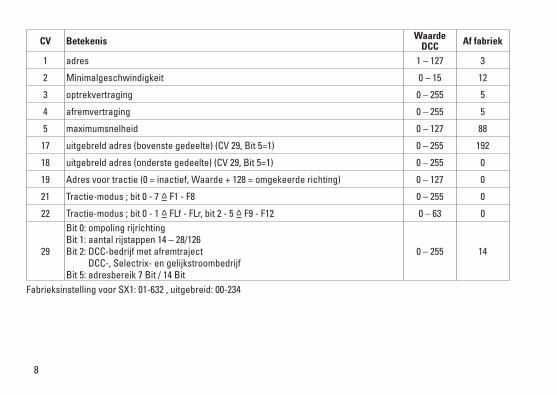
CV Betekenis Waarde DCC Af fabriek
1 adres 1 – 127 3
2 Minimalgeschwindigkeit 0 – 15 12
3 optrekvertraging 0 – 255 5
4 afremvertraging 0 – 255 5
5 maximumsnelheid 0 – 127 88
17 uitgebreld adres (bovenste gedeelte) (CV 29, Bit 5=1) 0 – 255 192
18 uitgebreld adres (onderste gedeelte) (CV 29, Bit 5=1) 0 – 255 0
19 Adres voor tractie (0 = inactief, Waarde + 128 = omgekeerde richting) 0 – 127 0
21 Tractie-modus ; bit 0 - 7 =̂ F1 - F8 0 – 255 0
22 Tractie-modus ; bit 0 - 1 =̂ FLf - FLr, bit 2 - 5 =̂ F9 - F12 0 – 63 0
29
Bit 0: ompoling rijrichting Bit 1: aantal rijstappen 14 – 28/126 Bit 2: DCC-bedrijf met afremtraject DCC-, Selectrix- en gelijkstroombedrijf Bit 5: adresbereik 7 Bit / 14 Bit
0 – 255 14
Fabrieksinstelling voor SX1: 01-632 , uitgebreid: 00-234

9
10
Aviso de seguridad• La locomotora solamente debe funcionar en el sistema
que le corresponda.• La alimentación de la locomotora deberá realizarse
desde una sola fuente de suminitro.• Observe bajo todos los conceptos, las medidas de
seguridad indicadas en las instrucciones de su sistema de funcionamiento.
• Analógico 14 voltios=, digital 19 voltios~.• Para el funcionamiento convencional de la locomotora,
deben eliminarse las corrientes parasitarias de la vía de conexión. Para tal fin se debe utilizar el set antiparasi-tario 14972. Para funcionamiento en modo digital, el set antiparasitario no es adecuado.
• No exponer el modelo en miniatura a la radiación solar directa, a oscilaciones fuertes de temperatura o a una humedad del aire elevada.
• El cable de conexión a la vía utilizado debe tener una longitud máxima de 2 metros.
• ¡ATENCIÓN! Esquinas y puntas afiladas condicionadas a la función.
• Los LEDs incorporados corresponden a la clase de láser 1 según la norma europea EN 60825-1.
Consejo general para evitar las interferencias electroma-gnéticas: Para garantizar un funcionamiento según las previsiones se requiere un contacto rueda-carril de los vehículos permanente sin anomalías. No realice ninguna modificación en piezas conductoras de la corriente.
Notas importantes• Las instrucciones de empleo y el embalaje forman parte
íntegra del producto y, por este motivo, deben guardarse y entregarse junto con el producto en el caso de venderlo o transmitirlo a otro.
• En caso de precisar una reparación o piezas de recambio, rogamos ponerse en contacto con su distribuidor Trix.
• Responsabilidad y garantía conforme al documento de garantía que se adjunta.
• Eliminación: www.maerklin.com/en/imprint.html Funciones• Electrónica integrada para funcionamiento opcional con el
aparato de conducción de corriente continua convenci-onal (máx. ±14 voltios), Trix Systems, Trix Selectrix (SX) o sistemas digitales según norma NMRA.
• Reconocimiento automático del sistema entre funciona-miento digital y analógico.
• No existe reconocimiento automático del sistema entre los sistemas digitales.
• Señal de cabeza de dos luces delante, dos luces de cola rojas detrás, con alternancia en función del sentido de la marcha.
Indicaciones para el funcionamiento digital• En el funcionamiento por primera vez con un sistema
digital (SX o DCC), el decoder se debe configurar para este sistema digital. Para tal fin, se debe programar el decoder una vez en este sistema digital (p. ej., cambiar la dirección).

11
Funciones conmutables
DC
SX
DCC
Ruido: Cerrar puertas F17
Ruido: Enganche de coches/vagones F18
Ruido: Pantógrafo F19
1 con ruidos aleatorios 2 Sólo junto con Señal de cabeza
Interconectados: Luz de maniobra Doble A3 solo sin F0
Funciones conmutables
DC
SX
DCC
Señal de cabeza en función del sentido de la marcha F0
Señal de cabeza, solo delante 3 F1
Ruido: Ruido de explotación 1 F2
Ruido: Bocina de aviso F3
Control directo (ABV) F4
Ruido: Desconectar chirrido de los frenos F5
Señal de cabeza cabina de conducción 2 2 F6
Ruido: Bocina de maniobras F7
Señal de cabeza cabina de conducción 1 2 F8
Ruido: Bocina de aviso F9
Ruido: Silbato de Revisor F10
Ruido: Compresor F11
Ruido: Ventilador F12
Ruido: Purgar aire comprimido F13
Alumbrado interior de la cabina F14
Suprimir/activar sonido F15
Ruido: Arenado F16

12
CV Significado Valor DCC Preselec-ción
1 Códigos 1 – 127 3
2 Velocidad mínima 0 – 15 12
3 Arranque progresivo 0 – 255 5
4 Frenado progresivo 0 – 255 5
5 Velocidad máxima 0 – 127 88
17 Dirección ampliada (parte superior) (CV 29, bit 5=1) 0 – 255 192
18 Dirección ampliada (parte inferior) (CV 29, bit 5=1) 0 – 255 0
19 Dirección de tracción (0 = inactiva, valor + 128 = sentido de marcha inverso) 0 – 127 0
21 Modo de tracción; bit 0 – 7 =̂ F1 – F8 0 – 255 0
22 Modo de tracción; bit 0 – 1 =̂ FLf – FLr, Bit 2 – 5 =̂ F9 – F12 0 – 63 0
29
Bit 0: Cambio de sendido de marcha Bit 1: Número de niveles de marcha 14 - 28/126 Bit 2: Modo DCC con tramo de frenado Modo DCC, Selectrix y corriente continua Bit 5: Alcance de direcciones 7 bits / 14 bits
0 – 255 14
Configuración de fábrica para SX1: 01-632, ampliada: 00-234

13

14
Avvertenze per la sicurezza• Tale locomotiva deve venire impiegata soltanto con un
sistema di esercizio prestabilito a questo scopo.• La locomotiva non deve venire alimentata nello stesso
tempo con più di una sorgente di potenza.• Vogliate prestare assolutamente attenzione alle avverten-
ze di sicurezza nelle istruzioni di impiego per il Vostro sistema di funzionamento.
• Analogica 14 Volt=, digitale 19 Volt~.• Per l’esercizio tradizionale della locomotiva il binario di
alimentazione deve venire liberato dai disturbi. A tale scopo si deve impiegare il corredo anti-disturbi 14972. Per il funzionamento Digital tale corredo anti-disturbi non è adatto.
• Non esponete tale modello ad alcun irraggiamento solare diretto, a forti escursioni di temperatura oppure a elevata umidità dell’aria.
• Il cavo di collegamento al binario impiegato deve essere lungo al massimo soltanto 2 metri.
• AVVERTENZA! Per motivi funzionali i bordi e le punte sono spigolosi.
• I LED incorporati corrispondono alla categoria di laser 1 secondo la Norma EN 60825-1.
Avvertenza generale per la prevenzione di disturbi elettro-magnetici: Per garantire l’esercizio conforme alla destinazione è necessario un contatto ruota-rotaia dei rotabili permanente, esente da interruzioni. Non eseguite alcuna modificazione ai componenti conduttori di corrente.
Avvertenze importanti• Le istruzioni di impiego e l’imballaggio costituiscono un
componente sostanziale del prodotto e devono pertanto venire conservati nonché consegnati insieme in caso di ulteriore cessione del prodotto.
• Per le riparazioni o le parti di ricambio, contrattare il rivenditore Trix.
• Prestazioni di garanzia e garanzia in conformità all’accluso certificato di garanzia.
• Smaltimento: www.maerklin.com/en/imprint.htmlFunzioni• Modulo elettronico incorporato per il funzionamento a
scelta con un tradizionale regolatore di marcia a corrente continua (max. ±14 Volt), Trix Systems, Trix Selectrix (SX) oppure sistemi Digital secondo le norme NMRA.
• Riconoscimento automatico del sistema tra esercizio Digital ed analogico.
• Nessun riconoscimento automatico del sistema tra i sistemi digitali.
• Segnale di testa anteriore a due fanali, due fanali di coda rossi dietro, commutati secondo il senso di marcia.
Istruzioni per la funzione digitale • Al momento del primo esercizio in un sistema Digital
(SX oppure DCC) il Decoder deve venire impostato su questo sistema Digital. A tale scopo si deve programmare il Decoder una volta in questo sistema Digital (ad es. modificare l’indirizzo).

15
1 con rumori casuali 2 soltanto in abbinamento con Segnale di testa
Commutati assieme: Fanale di manovra a doppia A3 soltanto senza F0
Funzioni commutabili
DC
SX
DCC
Rumore: chiusura delle porte F17
Rumore: agganciamento F18
Rumore: Pantografo F19
Funzioni commutabili
DC
SX
DCC
Segnale di testa dipendente dal senso di marcia F0
Segnale di testa, solo anteriori 3 F1
Rumore: rumori di esercizio 1 F2
Rumore: Tromba di segnalazione F3
Comando diretto (ABV) F4
Rumore: stridore dei freni escluso F5
Segnale di testa cabina di guida 2 2 F6
Rumore: Tromba da manovra F7
Segnale di testa cabina di guida 1 2 F8
Rumore: Tromba di segnalazione F9
Rumore: Fischio di capotreno F10
Rumore: Compressore F11
Rumore: Ventilatori F12
Rumore: scarico dell‘aria compressa F13
Illuminazione della cabina F14
Dissolvenza sonora uscente /entrante F15
Rumore: sabbiatura F16

16
CV Bedeutung Wert DCC ab Werk
1 Indirizzo 1 – 127 3
2 Velocità minima 0 – 15 12
3 Ritardo di avviamento 0 – 255 5
4 Ritardo di frenatura 0 – 255 5
5 Velocità massima 0 – 127 88
17 Indirizzo esteso (parte superiore) (CV 29, Bit 5=1) 0 – 255 192
18 Indirizzo esteso (parte inferiore) (CV 29, Bit 5=1) 0 – 255 0
19 Indirizzo trazione multipla (0 = inattiva, valore + 128 = senso di marcia inverso) 0 – 127 0
21 Modalità di trazione; Bit 0 – 7 =̂ F1 – F8 0 – 255 0
22 Modalità di trazione; Bit 0 – 1 =̂ FLf – FLr, Bit 2 – 5 =̂ F9 – F12 0 – 63 0
29
Bit 0: Cambio polarità del senso di marcia Bit 1: Numero gradazioni di marcia 14 - 28/126 Bit 2: Esercizio DCC con tratta di frenatura Esercizio DCC, Selectrix e corrente continua Bit 5: Estensione indirizzo 7 Bit / 14 Bit
0 – 255 14
Impostazione di fabbrica per SX1: 01-632, esteso: 00-234

17

18
66626Märklin7149
7149
66623

19

20
1
2
3
21
1
2

22
Det
ails
der
Dar
stel
-lu
ng k
önne
n vo
n de
m
Mod
ell a
bwei
chen
4
7
6
5
3
2
1
1
3
9
8
7
6
35

23
Enkele delen worden alleen kleurloos of in een andere kleur aan-geboden. Delen die niet in de in de lijst voorkomen, kunnen alleen via een reparatie in het Märklin-service-centrum hersteld/vervan-gen worden. Details in de tekening kunnen afwijken van het model.
Algunas piezas están disponibles sólo sin o con otro color. Las piezas que no figuran aquí pueden repararse únicamente en el marco de una reparación en el servicio de reparación de Märklin. Los detalles mostrados pueden presentar discrepancias respecto al modelo en miniatura.
Alcuni elementi vengono proposti solo senza o con differente colorazione. I pezzi che non sono qui specificati possono venire riparati soltanto nel quadro di una riparazione presso il Servizio Riparazioni Märklin. I dettagli della raffigurazione possono differire dal modello.
1 Scherenstromabnehmer E319 154 2 Puffer grau E12 2662 00 3 Schraube E278 103 4 Motor E319 116 5 Leiterplatte Licht E319 118 6 Kupplung E323 104 7 Drehgestell E323 106 8 Lautsprecher E321 205 9 Haftreifen E12 2258 00

Gebr. Märklin & Cie. GmbH Stuttgarter Straße 55 - 57 73033 Göppingen Germanywww.trix.de
323296/1019/Sm1ClÄnderungen vorbehalten
© Gebr. Märklin & Cie. GmbHwww.maerklin.com/en/imprint.html


![La revue Electronique de L’Université Hassan 1 2016.pdf · 2021. 2. 26. · e-Trait d’Union N°36 La revue électronique L’Université Hassan 1 36]: Mars 2016 rencontrer les](https://static.fdokument.com/doc/165x107/6115523fd0a85b62840fc0b3/la-revue-electronique-de-launiversit-hassan-1-2016pdf-2021-2-26-e-trait.jpg)