Monitoring the Setting of Calcium Sulfate Bone-Graft ...
9
1658 IEEE TRANSACTIONS ON ULTRASONICS, FERROELECTRICS, AND FREQUENCY CONTROL, VOL. 66, NO. 10, OCTOBER 2019 Monitoring the Setting of Calcium Sulfate Bone-Graft Substitute Using Ultrasonic Backscattering Josep Rodríguez-Sendra , Noé Jiménez , Rubén Picó, Joan Faus, and Francisco Camarena Abstract—We report a method to monitor the setting process of bone-graft substitutes (calcium sulfate) using ultrasonic backscattering techniques. Analyzing the backscattered fields using a pulse-echo technique, we show that it is possible to dynamically describe the acoustic properties of the material which are linked to its setting state. Several experiments were performed to control the setting process of calcium sulfate using a 3.5-MHz transducer. The variation of the apparent integrated backscatter (AIB) with time during the setting process is analyzed and compared with measurements of the speed of sound (SOS) and temperature of the sample. The correlation of SOS and AIB allows us to clearly identify two different states of the samples, liquid and solid, in addition to the transition period. Results show that using backscattering analysis, the setting state of the material can be estimated with a threshold of 15 dB. This ultrasonic technique is indeed the first step to develop real-time monitoring systems for time-varying complex media as those present in bone regeneration for dental implantology applications. Index Terms— Bone-graft substitute, guided bone regenera- tion (GBR), implantology, synthetic bone substitutes, ultrasonic backscattering. I. I NTRODUCTION D ENTAL implants require sufficient bone volume to achieve stability and durability. The loss of tooth affects the quality and thickness of the bone. In the cases where bone volume is insufficient, guided bone regeneration (GBR) techniques are applied [1]. In particular, GBR by maxillary sinus floor augmentation procedures are used since 50 years and were first proposed by Tatum: he started to use the technique in 1974 and the procedure description was published Manuscript received March 26, 2019; accepted July 1, 2019. Date of publication July 3, 2019; date of current version September 25, 2019. This work was supported in part by Universitat Politècnica de València (UPV) and Fundación para el Fomento de la Investigación Sanitaria y Biomédica de la Comunitat Valenciana (FISABIO) through the project OSEODENT under Grant POLISABIO 2018, in part by the European Union, in part by Generalitat Valenciana through the European Regional Development Fund Program under Grant IDIFEDER/2018/022, and in part by the Agència Valenciana de la Innovació through the Unitat Científica d’Innovació Empre- sarial under Grant INNCON00/18/9. The work of N. Jiménez was supported by Generalitat Valenciana under Grant APOSTD/2017/042. (Corresponding author: Josep Rodríguez-Sendra.) J. Rodríguez-Sendra, N. Jiménez, and F. Camarena are with the Instituto de Instrumentación para Imagen Molecular (i3M), Consejo Superior de Investigaciones Científicas (CSIC)–Universitat Politècnica de València (UPV), 46022 València, Spain (e-mail: [email protected]). R. Picó is with Instituto para la Gestión Integrada de Zonas Costeras (IGIC), Universitat Politècnica de València (UPV), 46730 Grau de Gandia, Spain. J. Faus is with the Instituto Valenciano de Investigaciones Odontológicas (IVIO), 46701 Gandia, Spain. Digital Object Identifier 10.1109/TUFFC.2019.2926827 a decade after [2]. This operation, also termed sinus lift or sinus graft, is a surgical procedure which aims to increase the amount of bone in the posterior maxilla (upper jaw bone), in the area of the premolar and molar teeth. A window in the lateral area of the gingival is performed, the Schneider membrane is lifted, and a bone graft inserted. The window is coated with a pericardium membrane. The goal of the sinus augmentation is to graft extra bone into the maxillary sinus to increase the bone available to support a dental implant. Full bone regeneration process has a typical healing dura- tion of approximately six months. The procedure sometimes fails [3] and different complications may appear postopera- tively, e.g., soft tissue growth or failed osseointegration [4]. Odontologists make use of X-ray radiological techniques in order to evaluate the bone regeneration process [5]. However, monitoring the full regeneration process using these techniques implies potential risks, such as excessive exposure to ionizing radiation [5], [6]. In this sense, noninvasive ultrasonic tech- niques are desirable to monitor bone-regeneration during the healing time since they are non-ionizing. Conventional ultrasonic imaging has been proposed in odontology to image tooth and asses alveolar bone struc- tures and their morphology [7]–[10], or to detect fractured tooth, e.g., using nonlinear elastic wave spectroscopy [11]. However, these techniques do not offer quantitative indexes about the bone, as required for monitoring guided bone regeneration. On the contrary, quantitative ultrasound has been used fruitfully to characterize the physical properties of bone. Technology for bone density estimation is nowadays mature [12]–[15]. Many commercial devices exist in the mar- ket used for the diagnosis of osteoporosis, e.g., for calcaneus or phalanx [16], [17]. Acoustic and elastic parameters are correlated with the physical properties of bone for diagnostic purposes. The speed of sound (SOS) is one of the most used para- meters for quantitative ultrasound [12, Chapter 3]. It consists in estimating the effective traveling velocity of a pulsed excitation, associated with the group speed of longitudinal waves in a given frequency band. Remark that bone tissue is a heterogeneous biphasic medium composed of a multiple-scale porous viscoelastic matrix, soft-solids, and viscous fluids [12]. Therefore, acoustic propagation through these complex media is strongly dispersive and SOS, given as a single value, should be interpreted as an effective parameter rather than an intrinsic physical parameter locally related to the mechanical properties 0885-3010 © 2019 IEEE. Personal use is permitted, but republication/redistribution requires IEEE permission. See http://www.ieee.org/publications_standards/publications/rights/index.html for more information.
Transcript of Monitoring the Setting of Calcium Sulfate Bone-Graft ...
1658 IEEE TRANSACTIONS ON ULTRASONICS, FERROELECTRICS, AND FREQUENCY CONTROL, VOL. 66, NO. 10, OCTOBER 2019
Monitoring the Setting of CalciumSulfate Bone-Graft Substitute Using
Ultrasonic BackscatteringJosep Rodríguez-Sendra , Noé Jiménez , Rubén Picó, Joan Faus, and Francisco Camarena
Abstract— We report a method to monitor the setting processof bone-graft substitutes (calcium sulfate) using ultrasonicbackscattering techniques. Analyzing the backscattered fieldsusing a pulse-echo technique, we show that it is possible todynamically describe the acoustic properties of the materialwhich are linked to its setting state. Several experiments wereperformed to control the setting process of calcium sulfate usinga 3.5-MHz transducer. The variation of the apparent integratedbackscatter (AIB) with time during the setting process is analyzedand compared with measurements of the speed of sound (SOS)and temperature of the sample. The correlation of SOS and AIBallows us to clearly identify two different states of the samples,liquid and solid, in addition to the transition period. Results showthat using backscattering analysis, the setting state of the materialcan be estimated with a threshold of 15 dB. This ultrasonictechnique is indeed the first step to develop real-time monitoringsystems for time-varying complex media as those present in boneregeneration for dental implantology applications.
Index Terms— Bone-graft substitute, guided bone regenera-tion (GBR), implantology, synthetic bone substitutes, ultrasonicbackscattering.
I. INTRODUCTION
DENTAL implants require sufficient bone volume toachieve stability and durability. The loss of tooth affects
the quality and thickness of the bone. In the cases wherebone volume is insufficient, guided bone regeneration (GBR)techniques are applied [1]. In particular, GBR by maxillarysinus floor augmentation procedures are used since 50 yearsand were first proposed by Tatum: he started to use thetechnique in 1974 and the procedure description was published
Manuscript received March 26, 2019; accepted July 1, 2019. Date ofpublication July 3, 2019; date of current version September 25, 2019. Thiswork was supported in part by Universitat Politècnica de València (UPV)and Fundación para el Fomento de la Investigación Sanitaria y Biomédicade la Comunitat Valenciana (FISABIO) through the project OSEODENTunder Grant POLISABIO 2018, in part by the European Union, in part byGeneralitat Valenciana through the European Regional Development FundProgram under Grant IDIFEDER/2018/022, and in part by the AgènciaValenciana de la Innovació through the Unitat Científica d’Innovació Empre-sarial under Grant INNCON00/18/9. The work of N. Jiménez was supportedby Generalitat Valenciana under Grant APOSTD/2017/042. (Correspondingauthor: Josep Rodríguez-Sendra.)
J. Rodríguez-Sendra, N. Jiménez, and F. Camarena are with the Institutode Instrumentación para Imagen Molecular (i3M), Consejo Superior deInvestigaciones Científicas (CSIC)–Universitat Politècnica de València (UPV),46022 València, Spain (e-mail: [email protected]).
R. Picó is with Instituto para la Gestión Integrada de Zonas Costeras (IGIC),Universitat Politècnica de València (UPV), 46730 Grau de Gandia, Spain.
J. Faus is with the Instituto Valenciano de Investigaciones Odontológicas(IVIO), 46701 Gandia, Spain.
Digital Object Identifier 10.1109/TUFFC.2019.2926827
a decade after [2]. This operation, also termed sinus lift orsinus graft, is a surgical procedure which aims to increase theamount of bone in the posterior maxilla (upper jaw bone),in the area of the premolar and molar teeth. A window inthe lateral area of the gingival is performed, the Schneidermembrane is lifted, and a bone graft inserted. The window iscoated with a pericardium membrane. The goal of the sinusaugmentation is to graft extra bone into the maxillary sinusto increase the bone available to support a dental implant.Full bone regeneration process has a typical healing dura-tion of approximately six months. The procedure sometimesfails [3] and different complications may appear postopera-tively, e.g., soft tissue growth or failed osseointegration [4].Odontologists make use of X-ray radiological techniques inorder to evaluate the bone regeneration process [5]. However,monitoring the full regeneration process using these techniquesimplies potential risks, such as excessive exposure to ionizingradiation [5], [6]. In this sense, noninvasive ultrasonic tech-niques are desirable to monitor bone-regeneration during thehealing time since they are non-ionizing.
Conventional ultrasonic imaging has been proposed inodontology to image tooth and asses alveolar bone struc-tures and their morphology [7]–[10], or to detect fracturedtooth, e.g., using nonlinear elastic wave spectroscopy [11].However, these techniques do not offer quantitative indexesabout the bone, as required for monitoring guided boneregeneration. On the contrary, quantitative ultrasound hasbeen used fruitfully to characterize the physical properties ofbone. Technology for bone density estimation is nowadaysmature [12]–[15]. Many commercial devices exist in the mar-ket used for the diagnosis of osteoporosis, e.g., for calcaneusor phalanx [16], [17]. Acoustic and elastic parameters arecorrelated with the physical properties of bone for diagnosticpurposes.
The speed of sound (SOS) is one of the most used para-meters for quantitative ultrasound [12, Chapter 3]. It consistsin estimating the effective traveling velocity of a pulsedexcitation, associated with the group speed of longitudinalwaves in a given frequency band. Remark that bone tissue is aheterogeneous biphasic medium composed of a multiple-scaleporous viscoelastic matrix, soft-solids, and viscous fluids [12].Therefore, acoustic propagation through these complex mediais strongly dispersive and SOS, given as a single value, shouldbe interpreted as an effective parameter rather than an intrinsicphysical parameter locally related to the mechanical properties
0885-3010 © 2019 IEEE. Personal use is permitted, but republication/redistribution requires IEEE permission.See http://www.ieee.org/publications_standards/publications/rights/index.html for more information.
RODRÍGUEZ-SENDRA et al.: MONITORING THE SETTING OF CALCIUM SULFATE BONE-GRAFT SUBSTITUTE 1659
of the bone. In fact, both group and phase speed in bone area function of frequency. For example, in high mass densitysamples of bovine trabecular bones, the phase speed of thefast modes can vary 250 m/s in the frequency range of 0.5–3 MHz [18], while in cortical bovine bone samples it hasbeen observed a variation of the phase speed of 20 m/s inthe frequency range of 3.5–4.5 MHz [19].
In essence, SOS can be measured in pulse-echo modeusing one transducer and a sample of known thickness, or intransmission mode using one emitter and one receiver trans-ducer separated a known distance. When a single value ofSOS is used to characterize the medium, a simple approachis to use the ratio between the total path traveled by theultrasonic pulse and the total time-of-flight [20]. Other tech-niques include ultrasound axial transmission that has beenapplied to asses bone mineralization as a diagnostic techniquefor the evaluation of fracture healing [21]. In odontology,ultrasound transmission velocity has been proposed to evaluatebone quality before dental implantation, where they observedvalues of 1538 ± 177 m/s for female maxilla, 1713 ± 153 m/sfor female mandible [22]. Clinical studies include the use ofquantitative ultrasound to evaluate the loss of mandibular bone,where the good correlation was found between SOS values,alveolar bone density, and the attachment level around teethin women with periodontitis [23].
Due to their complex heterogeneous microstructure,ultrasonic waves traveling in bones are microscattered in a dif-fuse way, as can be observed in bone-tissue simulations [24].In this way, the interference of multiple scattered wavesfrom internal microstructures can be received at sourceposition offering information about the material composi-tion. During last two decades, different techniques basedon the backscatter energy evaluation have been proposedfor bone characterization [25], [26]. Ultrasonic backscatterenergy can be linked to the physical properties of bonetissue such as bone volume fraction or bone mineraldensity [12], [27], [28], enabling quantitative ultrasound tech-niques for bone characterization.
Many ultrasonic backscattering techniques are based on themeasurements of the apparent backscatter transfer function(ABTF) [12]. It represents the backscattered power from thesample corrected for the frequency response of the measure-ment system. Two parameters without explicit dependence offrequency are obtained from ABTF. The apparent integratedbackscatter (AIB) is one of the most spread. It consists of ameasure of the frequency-averaged (integrated) backscatteredpower contained in some portion of a backscattered ultra-sonic signal [29]. The frequency slope of apparent backscat-ter (FSAB) is determined by fitting a line in the frequencydomain to the spatially averaged backscattered ultrasonic sig-nals over the analysis bandwidth [30]. Both AIB and FSABare determined in a logarithmic scale and are referenced tothe measured reflected energy of a reference flat panel, e.g.,a steel sample. In order to remove this reference, Hoffmeisterproposed in [31] a set parameters that compare the backscatterenergy from two different parts of the sample. The mean ofthe backscatter difference spectrum (MBD) is obtained byfrequency averaging the difference between the backscatter
spectra over the analysis bandwidth from two consecutive win-dows of the ultrasonic signal. In the context of clinical studies,other parameters, as the integrated reflection coefficient or theapparent cortical thickness, have been used to characterize theproperties of bone [28], [32], [33]. In odontology, quantitativeultrasound techniques have been applied to assess the stabilityof dental implants [34], [35], to quantify the amount of bonein contact with dental implants [36] or to asses osseointegra-tion of a implants in vitro during bone healing [37].
During the bone regeneration process, its mechanicalproperties are modified from the initial bone graft to the con-solidated bone. A change of state is produced as a consequenceof osseointegration. Thus, a solution for detecting possibleanomalies during the healing of bone in GBR applicationsconsists of monitoring the ultrasonic properties of tissueduring the time. In this sense, ultrasound techniques havebeen applied for the characterization of slowly time-varyingmaterials. One relevant example is cement that has beencharacterized by ultrasonic methods for more than 80 years,e.g., [38], [39]. In particular, pulse-echo ultrasonic techniquescan be used to characterize the time dependence of SOS andthe acoustic impedance during their setting process [40]–[42].Cement starts to set when mixed with water and a series ofhydration chemical reactions are produced. The constituentsslowly hydrate and the mineral solidifies. In particular, the typ-ical setting duration time for bone-graft materials based oncalcium sulfate ranges from 30 to 60 min [43], [44]. Same ascement setting, the GBR is a process in which the mechanical(and acoustical) properties of the material vary with timeand a change of state is produced. The advantage of using abone-graft substitute as a phantom for monitoring GBR is thatthe duration of the process is reduced from six months’ timeof healing, to less than an hour in a controlled environment.
In this work, we propose a proof of concept to monitorthe GBR by sinus augmentation using ultrasonic backscat-tering methods. Thus, the time-varying acoustical proper-ties of the material under inspection are obtained using anecho-impulse technique. In particular, we use a phantom ofcalcium sulfate [45], [46], which has already been used forGBR in the past [47], [48]. The change of state from a viscousfluid to a porous solid during the setting mimics the GBRin a much shorter duration that can be studied under labora-tory conditions. We report that ultrasonic backscatter energycan be linked to the physical properties of tissue. In GBRapplications, the transmission mode using a pair of ultrasonictransducers is not allowed as a receiver transducer cannot beplaced behind the area under inspection. Thus, we propose theuse of a single sensor improving the accessibility of medicalinstrumentation for tissue characterization.
II. METHODS
A. Phantom Preparation
Calcium sulfate type IV (Ventura Pinkmod) is the syntheticbone substitute used to perform the experiments. In particular,in its powder state the material is calcium sulfate hemihydrate(CaSO4· 1
2 H2O) in its α form. When the hemihydrate is mixedwith water, calcium sulfate dihydrate is formed in a moderate
1660 IEEE TRANSACTIONS ON ULTRASONICS, FERROELECTRICS, AND FREQUENCY CONTROL, VOL. 66, NO. 10, OCTOBER 2019
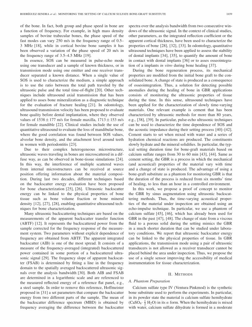
Fig. 1. (a) Block diagram of the experimental setup. (b) Photograph of oneexperiment.
exothermic reaction as [48]
CaSO4 · 1
2H2O + 1
1
2H2O → CaSO4 · 2H2O + Heat.
In this way, during the setting process, the material showsa change of phase from a viscous liquid to porous solid. Thetotal setting time is around 20 min. To study repeatability,four experiments were performed with samples composed of23 mL of water and 50 g of calcium sulfate. The powderwas dissolved in water at 20.0 ± 0.2 ◦C and mixed up toget homogeneous samples. The material was deposited in acylindrical plastic container with a diameter of 36 mm toprovide samples of approximately 18 mm of thickness. Thethickness of the sample was measured with a Vernier caliperat different locations along the sample. The mean value was18.3 ± 0.2 mm where the error was obtained from the standarddeviation of 7 measurements.
B. Ultrasonic Measurement
An Olympus V382 transducer with a nominal central fre-quency of 3.5 MHz and a bandwidth of 2.34 MHz (−6 dB) wasused as emitter and receiver using a pulse-echo technique. Thissource presents a diameter of D = 13 mm and a ratio betweenthe diameter and the wavelength of D/λ = 30.3 wave-lengths per aperture in water. The choice of the source is acompromise between a small physical dimension mandatoryfor the particular dental application and a high ratio D/λto enhance the acoustic energy collected by the transducer.Fig. 1 shows the block diagram and a photograph of theexperimental setup. The transducer was placed in contact to thebottom of the recipient in order to minimize the decoupling.Vaseline was applied between the transducer and the containerand the sample to avoid decoupling during the solidificationprocess. At the opposite side, the sample is free enhancingthe reflection of the ultrasonic waves at the top interface withair. An ultrasonic pulser–receiver (Panametrics Model 5072)was used for emitting and receiving the acoustic pulses. Thereceived signal was digitized with a data acquisition platform(Red Pitaya) at a sampling frequency of 125 MHz. For eachexperiment, a total of 1600 acquisitions were performed,each one every 2 s. The total duration of each experimenttook 53 min, enough to cover the full setting process of thesamples. The temperature was registered with thermistor probe(Tinytag Temperature Logger TK 4023) located externally in
contact with the container. Measurements were postprocessedto provide the acoustic parameters during the setting process.
C. Speed of Sound
The SOS was calculated as the distance ratio between twotimes the thickness of the sample and the time of flightbetween the first two echoes from the end of the sample as
c = 2L
�t(1)
where L is the thickness of the sample, and �t is the time offlight, estimated as the times corresponding to the peak valueof first two echoes. SOS was estimated during setting time,and a purely phenomenological model was fit. The proposedmodel describes a smooth and asymmetric transition betweentwo phases, fluid and solid, and is given by
c(t) = c1 + (c2 − c1) tan−1[
γ
π(t − tm) + 1
2
]β
(2)
where c1 is the SOS in liquid state, c2 is the SOS in solidphase, γ models the speed of the transition from liquid to solidphase, t is the setting time, tm is the half-time of the settingprocess, and β is related to the symmetry of the function.Remark that this simple model is purely phenomenological:it was chosen because it accurately describes the variation ofthe SOS during the phase transition of the samples. The fitof parameters has a physical interpretation and using themwe can quantitatively compare the setting process of severalexperiments.
D. Backscatter Parameters
Two quantitative parameters based on the backscatter energywere considered in this work: the ABTF and the AIB energy.Both have been proven to be reliable and robust to characterizebone tissue [49]. On the one hand, the ABTF is given bythe transfer function between the backscatter signal and areference signal as
ABTF = 10 log10
(Ps( f )
Pref ( f )
)(3)
where Ps( f ) is the frequency-dependent power of a backscat-ter signal ps(t) using a time window of duration τw , andPref( f ) is the frequency-dependent power of the first echofrom a reference reflector, e.g., steel plate [49]. On the otherhand, the AIB is obtained as the frequency-averaged ABTF as
AIB = 1
� f
∫ f2
f1
ABTF( f )d f (4)
where � f = f2 − f1, and f1 and f2 are given by the−6-dB bandwidth of the transducer. The reference pulse andits spectrum are shown in Fig. 2(b) and (c), respectively. Thecorresponding values for the effective limiting frequencies aref1 = 3.4 MHz and f2 = 4.6 MHz.
RODRÍGUEZ-SENDRA et al.: MONITORING THE SETTING OF CALCIUM SULFATE BONE-GRAFT SUBSTITUTE 1661
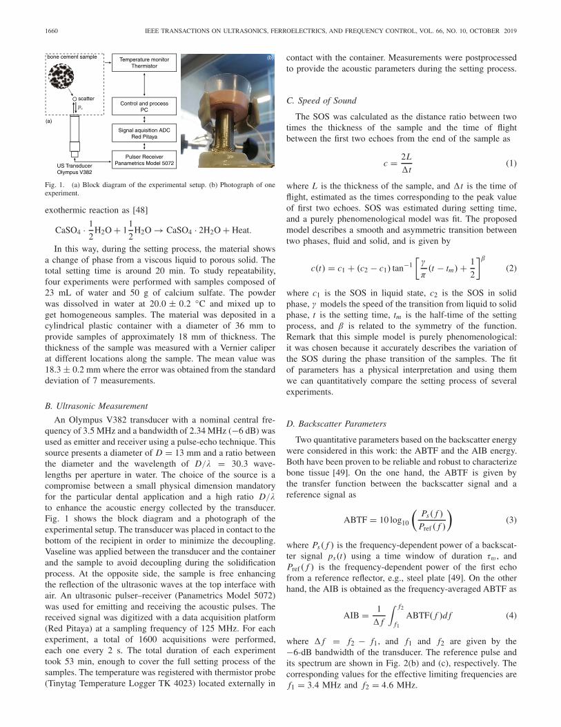
Fig. 2. (a) Representation of all the experimental signals (RAW data) as a function of the setting time. Colormap in the normalized dB scale. The whitedashed lines mark the temporal window used to calculate the AIB energy. (b) Reference signal and (c) corresponding spectrum. (d) Example of a backscattersignal measured at t = 25 min and its (e) corresponding spectrum. (f) Zoomed in view of the experimental data over the transition period. (g) ABTF andrepresentation of the AIB energy (shaded area).
III. RESULTS
A. Description of Backscatter Signals
The experimental signals of one experiment are shownin Fig. 2. First, in Fig. 2(a), the A-lines are presented asa function of the setting time. Here, the amplitude of theultrasonic signal registered by the transducer is represented inlogarithmic scale normalized to the maximum value for visual-ization. The vertical axis represents the time of the experimentduring the setting process (in minutes) and the horizontal axisrepresents the time of the ultrasonic signal (in μs). As bothscales are very different (∼106), they are decoupled and eachultrasonic capture is assumed to be instantaneous.
From t = 0 μs to t = 2 μs, all ultrasonic signals have amaximum value of 0 dB corresponding to the emission pulse.Then, vertical gray traces appear corresponding to the receivedbackscattered waves. First, when the experiment is started,the sample presents a viscous fluid state. At the beginningof the experiment time, at the top of Fig. 2(a), the echo fromthe end of the sample is visible at t = 23 μs. Up to about15 min, the backscatter signals are stable and only smallchanges are visible, as shown by the straight vertical tracesin the map. However, from about 18 to 27 min a sudden anddrastic change in the signal is observed: the line correspondingto the echo from the back of the sample is shifted towardthe beginning of the signal. This temporal compression of thesignal is related to the increase of SOS in the material: the echofrom the back is arriving sooner, as we will see after. Then,
at 27 min, the signals become stable again and, therefore,SOS may present a stable value at the end of the experiment.At 50 min, the sample is physically a porous solid material.
Dashed lines in Fig. 2(a) show the limits for the temporalwindow used for the postprocessing of the backscattering. Fortheir estimation, both the initial and final temporal values werecorrected using the SOS in order to capture a constant spatialwindow. Fig. 2(f) shows in detail the tracking of lines duringthe transition from the liquid state to solid state in the settingprocess. Here, the traces of the captured backscattered wavesmatch the analysis window marked by the dashed white lines.
Backscatter parameters have been referenced to a signalobtained from a flat steel plate, shown in Fig. 2(b). An exam-ple of A-scan signal registered by the transducer using thebone-graft substitute sample (at t = 25 min) is shownin Fig. 2(d). Both the initial electrical contribution and thefirst echo caused at the end of the sample can be observedat t = 0 μs and t = 15 μs, respectively. In comparison,backscattered energy is very low and spreads all along thesignal. We consider a window of the duration of τw =2.8 μs, i.e., 10 times the period corresponding of the centralfrequency of the transducer at the beginning of the experiment,according to [29]. The window was set initially centered at8 μs. Note that this value is shifted at 25 min [Fig. 2(d)] to5 μs due to the change of SOS with the setting time [seewhite dashed lines in Fig. 2(a)]. The spectra of the refer-ence signal and the example backscattered signal are shownin Fig. 2(c) and (e), respectively. Then, for each temporal
1662 IEEE TRANSACTIONS ON ULTRASONICS, FERROELECTRICS, AND FREQUENCY CONTROL, VOL. 66, NO. 10, OCTOBER 2019
TABLE I
FIT PARAMETERS FOR THE PHENOMENOLOGICAL MODEL GIVEN BY (2)
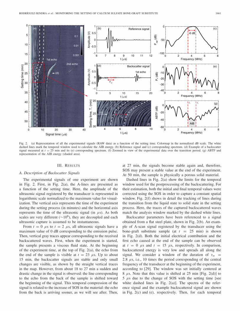
Fig. 3. (a) Evolution of the SOS, experiment (dots), and fit model (reddashed) using (2). (b) Evolution of the temperature (black) and temperaturevariation (red). (c) AIB energy (dots) and peak amplitude of the first echo(red), as a function of the setting time.
signal ABTF is calculated using (3), as shown in Fig. 2(f).Finally, AIB is estimated using (4) by averaging ABTF overthe interest bandwidth, shown in Fig. 2(f) as the shaded region.
B. Evolution of Speed of Sound
The evolution of the SOS with the setting timeis shown in Fig. 3(a). In addition, the evolutionof the temperature and its variation, i.e., ∂T/∂ t ,
are shown in Fig. 3(b). The initial value measuredfor the SOS corresponds to c1 = 1477 ± 50 m/sclose to the value of liquid water at same temperature(1495 m/s). The value estimated for the error is the standarddeviation of seven consecutive pulse-echo measurements.Up to t1 = 17.32 min, temperature is approximately stable andits rate of variation is small, about 0.1 ◦C/min. However, afterthis time (t1), the chemical reaction between the calcium sul-fate and water suddenly increases. When the temperature startsto increase small variations of SOS were already detected.
The maximum temperature variation is achieved at21.6 min, corresponding to 1.9 ◦C/min. This point correspondsto the maximum exothermic chemical activation [50]. Notethis time almost corresponds to the time tm = 20.7 mingiven by the SOS model fit. After that moment, there is moreconsolidated material than calcium sulfate hemihydrate andwater available to maintain the chemical reaction at this rateand, therefore, the exothermic activity is smoothly reduced.Then, at t2 = 27.6 min the temperature reaches its maximumvalue, 35.5 ◦C. The sample starts to cool smoothly due to heatdiffusion processes and the lack of chemical activity. Oncethe change of state is completed, the sample is transformedfrom a viscous liquid to porous solid material. When thematerial is solidified, the SOS reaches a stable value closeto c2 = 2731.5 m/s. The behavior of this synthetic bonesubstitute agrees the one reported for other cements measuredusing an emission/reception mode [40]–[42].
As expected, it can be observed that the change of the stateof the material corresponds to an abrupt increase of the SOS.This particular smooth transition was measured in all samplesand can be described by three different phases: the liquid state,the transition, and the solid state. The experimental SOS datawere fit to the phenomenological model given by (2). Theparameters of the fit model describe quantitatively the settingprocess. These parameters are listed in Table I for the foursamples, showing similar values between experiments.
First, the parameter c1 is linked to the physical SOS at theinitial viscous-liquid state of the sample. The mean value of c1over the four experiments is 1514 ± 98 m/s. As the materialat the initial process is mainly water with the undissolvedpowder, the SOS measured for the sample is close to the SOSof the water. The final value of the SOS in the experiment isrelated to c2, i.e., the SOS of the material in the solid state.The mean value of c2 is 2858 ± 155 m/s.
The transition time for the setting process is given bythe parameter tm . This parameter takes a mean value oftm = 20.4 min, very close to the peak of maximum exothermicchemical activity (21.6 min for sample 1). The factor γ isrelated to the duration of the transition from liquid to solid
RODRÍGUEZ-SENDRA et al.: MONITORING THE SETTING OF CALCIUM SULFATE BONE-GRAFT SUBSTITUTE 1663
state, its mean value is 1.8 ± 0.3 min−1. Finally, the factor β isrelated to the symmetry of the function and takes a mean valueof 0.345 ± 0.016. The dispersion of the parameters is low,and all experiments present similar transition curves. However,some discrepancies are observed in SOS values, that can beassociated with uncertainness on estimating the thickness ofthe sample L.
C. Evolution of Apparent Integrated Backscatter Energy
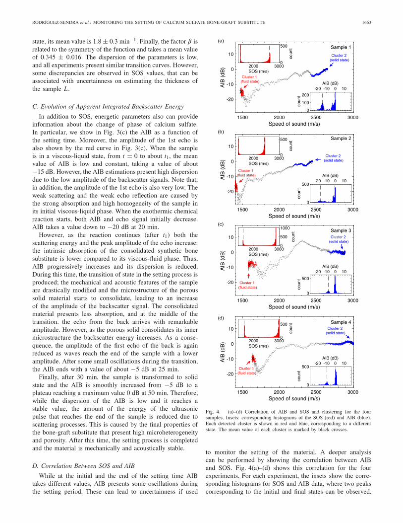
In addition to SOS, energetic parameters also can provideinformation about the change of phase of calcium sulfate.In particular, we show in Fig. 3(c) the AIB as a function ofthe setting time. Moreover, the amplitude of the 1st echo isalso shown by the red curve in Fig. 3(c). When the sampleis in a viscous-liquid state, from t = 0 to about t1, the meanvalue of AIB is low and constant, taking a value of about−15 dB. However, the AIB estimations present high dispersiondue to the low amplitude of the backscatter signals. Note that,in addition, the amplitude of the 1st echo is also very low. Theweak scattering and the weak echo reflection are caused bythe strong absorption and high homogeneity of the sample inits initial viscous-liquid phase. When the exothermic chemicalreaction starts, both AIB and echo signal initially decrease.AIB takes a value down to −20 dB at 20 min.
However, as the reaction continues (after t1) both thescattering energy and the peak amplitude of the echo increase:the intrinsic absorption of the consolidated synthetic bonesubstitute is lower compared to its viscous-fluid phase. Thus,AIB progressively increases and its dispersion is reduced.During this time, the transition of state in the setting process isproduced; the mechanical and acoustic features of the sampleare drastically modified and the microstructure of the poroussolid material starts to consolidate, leading to an increaseof the amplitude of the backscatter signal. The consolidatedmaterial presents less absorption, and at the middle of thetransition. the echo from the back arrives with remarkableamplitude. However, as the porous solid consolidates its innermicrostructure the backscatter energy increases. As a conse-quence, the amplitude of the first echo of the back is againreduced as waves reach the end of the sample with a loweramplitude. After some small oscillations during the transition,the AIB ends with a value of about −5 dB at 25 min.
Finally, after 30 min, the sample is transformed to solidstate and the AIB is smoothly increased from −5 dB to aplateau reaching a maximum value 0 dB at 50 min. Therefore,while the dispersion of the AIB is low and it reaches astable value, the amount of the energy of the ultrasonicpulse that reaches the end of the sample is reduced due toscattering processes. This is caused by the final properties ofthe bone-graft substitute that present high microheterogeneityand porosity. After this time, the setting process is completedand the material is mechanically and acoustically stable.
D. Correlation Between SOS and AIB
While at the initial and the end of the setting time AIBtakes different values, AIB presents some oscillations duringthe setting period. These can lead to uncertainness if used
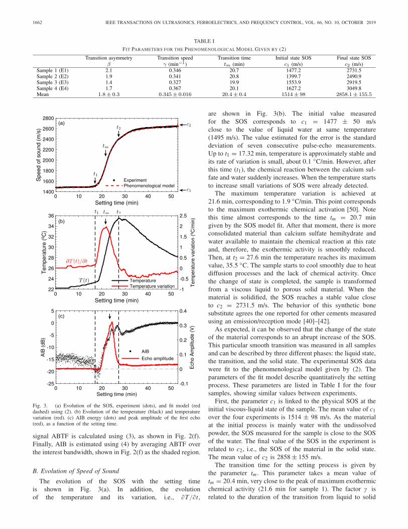
Fig. 4. (a)–(d) Correlation of AIB and SOS and clustering for the foursamples. Insets: corresponding histograms of the SOS (red) and AIB (blue).Each detected cluster is shown in red and blue, corresponding to a differentstate. The mean value of each cluster is marked by black crosses.
to monitor the setting of the material. A deeper analysiscan be performed by showing the correlation between AIBand SOS. Fig. 4(a)–(d) shows this correlation for the fourexperiments. For each experiment, the insets show the corre-sponding histograms for SOS and AIB data, where two peakscorresponding to the initial and final states can be observed.
1664 IEEE TRANSACTIONS ON ULTRASONICS, FERROELECTRICS, AND FREQUENCY CONTROL, VOL. 66, NO. 10, OCTOBER 2019
While there exists a positive correlation between AIB andSOS, the data show some oscillations.
A concentration of experimental points can be observed intwo zones, marked by arrows. On the one hand, when thematerial is in its viscous liquid phase is when the values ofSOS are minimum. On the other hand, when the materialis a porous solid both SOS and AIB present maximumvalues. As experimental data concentrates in these two limits,we can apply clustering techniques to identify them. A density-based spatial clustering of applications with noise (DBSCAN)technique [51] was employed here to discern between thedata corresponding to the two concentration points and thetransition. This gives us the corresponding clusters marked inred and blue in Fig. 4(a)–(d), helping to monitor the settingprocess: when a cluster is clearly populated, the sample hasreached a stable phase. Note that using only the histogram forthe AIB some of the signals corresponding to the transitionpoint can present the same AIB than in the final state due tothe oscillations of this parameter, e.g., Fig. 4(c).
IV. CONCLUSION
The change of state of a bone-graft substitute (calciumsulfate) has been monitored and characterized by ultrasonicbackscattering analysis. Temperature, SOS, and AIB energywere measured during the setting process of the sampleusing a pulse-echo technique. The evolution of SOS shows asmooth transition between two limiting values, correspondingto the viscous-fluid and porous solid state of the calciumsulfate samples. An excellent agreement is found between theevolution of the SOS and a simple phenomenological model todescribe the setting process. The experiments also show goodrepeatability.
In addition, the evolution of AIB is shown to be correlatedwith SOS. The AIB energy is proven to be an appropriateparameter to describe the transition from a viscous-liquid state,with values around −15 dB, to a complex porous solid, withvalues around 0 dB. The technique based on acoustic scatteringmeasurements of AIB is proven more robust that the SOStechnique in which the imprecise measurement of the samplethickness is required.
In addition, the evolution of AIB is shown to be correlatedwith SOS. The AIB energy is proven to be an appropriateparameter to describe the transition from a viscous-liquidstate, with values around −15 dB, to a complex poroussolid, with values around 0 dB. While all experiments showedsimilar dynamics, in the case of the SOS differences in theinitial and final values are notable. This might be causedby the uncertainties in the estimation of the thickness ofthe sample in the viscous-liquid phase of the bone-cement.For the AIB, there exist also discrepancies between samples,but in all the cases, the magnitude of the parameter at thefinal state is at least 10 dB higher than at the beginning ofthe experiment, and this parameter is remarkably constant atthe end of the experiment. The technique based on energeticbackscattering is proven more robust that ultrasonic velocitytechnique. Remark that for the parameter used, i.e., AIB,the measurement of the thickness is not required. This relation
confirms that the backscattering analysis with ultrasound is apowerful tool to monitor complex materials with time-varyingmechanical properties using an appropriate single transducerand pulse-echo techniques.
This study represents a contribution to the use of ultra-sound for the monitoring of GBR, which is necessary forthe successful placement of dental implants. A syntheticbone substitute has been used as a bone phantom becauseits mechanical properties change during the setting processfrom a viscous liquid to a rigid porous material, as, underreasonable simplifications, occurs in GBR applications. Thetechnique using an appropriate single transducer might providea low-cost system, but indeed it presents some limitations. In aclinical scenario, it will be difficult to locate the ultrasonicprobe in the same point during the six-months monitoringprocess. Possible mitigations to this limitation can be the useof a portable low-cost phased array system to incorporatein the backscattering analysis the spatial information or theuse of patient-specific dental splint to control the locationof a single-element ultrasonic transducer. Therefore, manypractical questions remain open and should be explored. Theseinclude the effect of the varying coupling of the transducerand the tissue between acquisitions, the mechanical/acousticalbehavior of real tissue during bone regeneration, the scatteringproperties of these unconsolidated and consolidated tissues,patient variability, or the impact of the intrinsic propertiesof real bones during regeneration, e.g., porosity, viscosity,in the estimated parameters. These issues should be explored infuture studies. The technique proposed here for dental implantsmay be also explored to survey other implant sites like thefemoral neck. Of course, an appropriate transducer must beused in order to fit with the requirements for the sound fieldimposed by the penetration depth from the surface to the zoneof inspection.
Finally, it is worth to mention that one advantage ofbackscattering analysis with respect to SOS is that usingbackscattering techniques it is not needed to know the thick-ness of the sample. Note using an appropriate single transducerthe estimation of the thickness of the sample is critical toaccurately estimate SOS and, therefore, scattering techniquesmight be preferred. This is a significant benefit to envisagedimplant applications in vivo where the GBR can be monitored.
ACKNOWLEDGMENT
This work has been developed within the framework of theIVIO-UPV Chair of the research project of the UniversitatPolitècnica de València “Desarrollo de tecnologías aplicadas alcampo de la odontología” and is the result of the collaborationof researchers from the Universitat Politècnica de Valènciaand the Instituto Valenciano de Investigaciones Odontológicas(IVIO) in the field of dental implantology with ultrasonictechnology.
REFERENCES
[1] F. Bodic, L. Hamel, E. Lerouxel, M. F. Baslé, and D. Chappard, “Boneloss and teeth,” Joint Bone Spine, vol. 72, no. 3, pp. 215–221, May 2005.
[2] H. Tatum, “Maxillary and sinus implant reconstructions,” Dental ClinicsNorth Amer., vol. 30, no. 2, pp. 207–229, Apr. 1986.
RODRÍGUEZ-SENDRA et al.: MONITORING THE SETTING OF CALCIUM SULFATE BONE-GRAFT SUBSTITUTE 1665
[3] S. Annibali, M. Ripari, G. La Monaca, F. Tonoli, and M. P. Cristalli,“Local complications in dental implant surgery: Prevention and treat-ment,” ORAL Implantol., vol. 1, no. 1, pp. 21–33, Apr./Jun. 2008.
[4] J. Acero, “Maxillary sinus grafting for implant insertion,” in Prepros-thetic Maxillofacial Surgery. Amsterdam, The Netherlands: Elsevier,2011, pp. 54–75.
[5] A. Memon, S. Godward, D. Williams, I. Siddique, and K. Al-Saleh,“Dental X-rays and the risk of thyroid cancer: A case-control study,”Acta Oncologica, vol. 49, no. 4, pp. 447–453, Apr. 2010.
[6] J. B. Ludlow, L. E. Davies-Ludlow, and S. C. White, “Patient risk relatedto common dental radiographic examinations: The impact of 2007international commission on radiological protection recommendationsregarding dose calculation,” J. Amer. Dental Assoc., vol. 139, no. 9,pp. 1237–1243, Sep. 2008.
[7] F. I. Tsiolis, I. G. Needleman, and G. S. Griffiths, “Periodontal ultra-sonography,” J. Clin. Periodontology, vol. 30, no. 10, pp. 849–854,Oct. 2003.
[8] S. R. Ghorayeb, C. A. Bertoncini, and M. K. Hinders, “Ultrasonographyin dentistry,” IEEE Trans. Ultrason., Ferroelectr., Freq. Control, vol. 55,no. 6, pp. 1256–1266, Jun. 2008.
[9] D. Hughes et al., “Investigation of dental samples using a 35 MHzfocussed ultrasound piezocomposite transducer,” Ultrason., vol. 49,no. 2, pp. 212–218, Feb. 2009.
[10] J. Marotti et al., “Recent advances of ultrasound imaging in dentistry—A review of the literature,” Oral Surg., Oral Med., Oral Pathol. OralRadiol., vol. 115, no. 6, pp. 819–832, Jun. 2013.
[11] S. Dos Santos and Z. Prevorovsky, “Imaging of human tooth using ultra-sound based chirp-coded nonlinear time reversal acoustics,” Ultrasonics,vol. 51, no. 6, pp. 667–674, Apr. 2011.
[12] P. Laugier and G. Haïat, Bone Quantitative Ultrasound. Berlin,Germany: Springer, 2011, vol. 576.
[13] M. L. Frost, G. M. Blake, and I. Fogelman, “Quantitative ultrasound andbone mineral density are equally strongly associated with risk factorsfor osteoporosis,” J. Bone Mineral Res., vol. 16, no. 2, pp. 406–416,Feb. 2001.
[14] K. Raum, Q. Grimal, P. Varga, R. Barkmann, C. C. Glüer, and P. Laugier,“Ultrasound to assess bone quality,” Current Osteoporosis Rep., vol. 12,no. 2, pp. 154–162, Jun. 2014.
[15] D. Hans and S. Baim, “Quantitative ultrasound (QUS) in the man-agement of osteoporosis and assessment of fracture risk,” J. Clin.Densitometry, vol. 20, no. 3, pp. 322–333, Jul. 2017.
[16] C. M. Langton, S. B. Palmer, and R. W. Porter, “The measurement ofbroadband ultrasonic attenuation in cancellous bone,” Eng. Med., vol. 13,no. 2, pp. 89–91, Apr. 1984.
[17] C. M. Langton and C. F. Njeh, “The measurement of broadbandultrasonic attenuation in cancellous bone—A review of the science andtechnology,” IEEE Trans. Ultrason., Ferroelectr., Freq. Control, vol. 55,no. 7, pp. 1546–1554, Jul. 2008.
[18] K. R. Waters and B. K. Hoffmeister, “Kramers-Kronig analysis ofattenuation and dispersion in trabecular bone,” J. Acoust. Soc. Amer.,vol. 118, no. 6, pp. 3912–3920, Dec. 2005.
[19] G. Haïat, M. Sasso, S. Naili, and M. Matsukawa, “Ultrasonic velocitydispersion in bovine cortical bone: An experimental study,” J. Acoust.Soc. Amer., vol. 124, no. 3, pp. 1811–1821, Sep. 2008.
[20] P. H. F. Nicholson, G. Lowet, C. M. Langton, J. Dequeker, andG. Van der Perre, “A comparison of time-domain and frequency-domainapproaches to ultrasonic velocity measurement in trabecular bone,” Phys.Med. Biol., vol. 41, no. 11, p. 2421, Nov. 1996.
[21] C. B. Machado, W. C. de A. Pereira, M. Granke, M. Talmant,F. Padilla, and P. Laugier, “Experimental and simulation results on theeffect of cortical bone mineralization in ultrasound axial transmissionmeasurements: A model for fracture healing ultrasound monitoring,”Bone, vol. 48, no. 5, pp. 1202–1209, May 2011.
[22] M. Klein, K. Grötz, B. Manefeld, P. H. Kann, and B. Al-Nawas,“Ultrasound transmission velocity for noninvasive evaluation of jawbone quality in vivo before dental implantation,” Ultrasound Med. Biol.,vol. 34, no. 12, pp. 1966–1971, Dec. 2008.
[23] Y. Takaishi et al., “Correlations between periodontitis and loss ofmandibular bone in relation to systemic bone changes in postmenopausalJapanese women,” Osteoporosis Int., vol. 16, no. 12, pp. 1875–1882,Dec. 2005.
[24] J. J. Kaufman, G. Luo, and R. S. Siffert, “Ultrasound simulation inbone,” IEEE Trans. Ultrason., Ferroelectr., Freq. Control, vol. 55, no. 6,pp. 1205–1218, Jun. 2008.
[25] K. A. Wear and B. S. Garra, “Assessment of bone density usingultrasonic backscatter,” Ultrasound Med. Biol., vol. 24, no. 5,pp. 689–695, Jun. 1998.
[26] S. Chaffaí, F. Peyrin, S. Nuzzo, R. Porcher, G. Berger, and P. Laugier,“Ultrasonic characterization of human cancellous bone using trans-mission and backscatter measurements: Relationships to density andmicrostructure,” Bone, vol. 30, no. 1, pp. 229–237, Jan. 2002.
[27] F. Padilla, F. Jenson, V. Bousson, F. Peyrin, and P. Laugier, “Relation-ships of trabecular bone structure with quantitative ultrasound para-meters: In vitro study on human proximal femur using transmissionand backscatter measurements,” Bone, vol. 42, no. 6, pp. 1193–1202,Jun. 2008.
[28] J. P. Karjalainen, J. Töyräs, O. Riekkinen, M. Hakulinen, andJ. S. Jurvelin, “Ultrasound backscatter imaging provides frequency-dependent information on structure, composition and mechanical prop-erties of human trabecular bone,” Ultrasound Med. Biol., vol. 35, no. 8,pp. 1376–1384, Aug. 2009.
[29] B. K. Hoffmeister, C. Jones III, G. Caldwell, and S. C. Kaste, “Ultrasoniccharacterization of cancellous bone using apparent integrated backscat-ter,” Phys. Med. Biol., vol. 51, no. 11, p. 2715, May 2006.
[30] B. K. Hoffmeister, A. P. Holt, and S. C. Kaste, “Effect of the cortexon ultrasonic backscatter measurements of cancellous bone,” Phys. Med.Biol., vol. 56, no. 19, p. 6243, Sep. 2011.
[31] B. K. Hoffmeister, A. R. Wilson, M. J. Gilbert, and M. E. Sellers,“A backscatter difference technique for ultrasonic bone assessment,”J. Acoust. Soc. Amer., vol. 132, no. 6, pp. 4069–4076, Dec. 2012.
[32] J. P. Karjalainen, O. Riekkinen, J. Töyräs, M. Hakulinen, H. Kröger,T. Rikkonen, K. Salovaara, and J. S. Jurvelin, “Multi-site bone ultra-sound measurements in elderly women with and without previous hipfractures,” Osteoporosis Int., vol. 23, no. 4, pp. 1287–1295, Apr. 2012.
[33] J. T. Schousboe, O. Riekkinen, and J. Karjalainen, “Prediction of hiposteoporosis by DXA using a novel pulse-echo ultrasound device,”Osteoporosis Int., vol. 28, no. 1, pp. 85–93, Jan. 2017.
[34] V. Mathieu et al., “Biomechanical determinants of the stability ofdental implants: Influence of the bone–implant interface properties,”J. Biomech., vol. 47, no. 1, pp. 3–13, Jan. 2014.
[35] R. Vayron, E. Soffer, F. Anagnostou, and G. Haïat, “Ultrasonic evalu-ation of dental implant osseointegration,” J. Biomech., vol. 47, no. 14,pp. 3562–3568, Nov. 2014.
[36] V. Mathieu, F. Anagnostou, E. Soffer, and G. Haïat, “Ultrasonic eval-uation of dental implant biomechanical stability: An in vitro study,”Ultrasound Med. Biol., vol. 37, no. 2, pp. 262–270, Feb. 2011.
[37] V. Mathieu, R. Vayron, E. Soffer, F. Anagnostou, and G. Haïat, “Influ-ence of healing time on the ultrasonic response of the bone-implantinterface,” Ultrasound Med. Biol., vol. 38, no. 4, pp. 611–618, Apr. 2012.
[38] T. R. Naik, V. M. Malhotra, and J. S. Popovics, “The ultrasonic pulsevelocity method,” in Handbook on Nondestructive Testing of Concrete.Boca Raton, FL, USA: CRC Press, 2003, pp. 182–200.
[39] T. P. Philippidis and D. G. Aggelis, “Experimental study of wavedispersion and attenuation in concrete,” Ultrasonics, vol. 43, no. 7,pp. 584–595, Jun. 2005.
[40] J. Keating, D. J. Hannant, and A. P. Hibbert, “Comparison of shearmodulus and pulse velocity techniques to measure the build-up ofstructure in fresh cement pastes used in oil well cementing,” CementConcrete Res., vol. 19, no. 4, pp. 554–566, Jul. 1989.
[41] C. M. Sayers and R. L. Grenfell, “Ultrasonic propagation throughhydrating cements,” Ultrasonics, vol. 31, no. 3, pp. 147–153, May 1993.
[42] A. Boumiz, C. Vernet, and F. C. Tenoudji, “Mechanical properties ofcement pastes and mortars at early ages: Evolution with time and degreeof hydration,” Adv. Cement Based Mater., vol. 3, nos. 3–4, pp. 94–106,Apr./May 1996.
[43] J. Carlson, M. Nilsson, E. Fernández, and J. A. Planell, “An ultrasonicpulse-echo technique for monitoring the setting of CaSO4-based bonecement,” Biomaterials, vol. 24, no. 1, pp. 71–77, Jan. 2003.
[44] M. D. Vlad, L. González, S. Gómez, J. López, J. E. Carlson, andE. Fernández, “Ultrasound monitoring of the setting of calcium-based bone cements,” J. Mater. Sci., Mater. Med., vol. 23, no. 7,pp. 1563–1568, Jul. 2012.
[45] C. G. Finkemeier, “Bone-grafting and bone-graft substitutes,” J. BoneJoint Surg., vol. 84, no. 3, pp. 454–464, Mar. 2002.
[46] W. Wang and K. W. K. Yeung, “Bone grafts and biomaterials substitutesfor bone defect repair: A review,” Bioactive Mater., vol. 2, no. 4,pp. 224–247, Dec. 2017.
[47] D. De Leonardis and G. E. Pecora, “Prospective study on the augmen-tation of the maxillary sinus with calcium sulfate: Histological results,”J. Periodontol., vol. 71, no. 6, pp. 940–947, Jun. 2000.
1666 IEEE TRANSACTIONS ON ULTRASONICS, FERROELECTRICS, AND FREQUENCY CONTROL, VOL. 66, NO. 10, OCTOBER 2019
[48] M. V. Thomas and D. A. Puleo, “Calcium sulfate: Properties and clinicalapplications,” J. Biomed. Mater. Res. B, Appl. Biomater, Off. J. Soc.Biomater., Jpn. Soc. Biomater., Austral. Soc. Biomater. Korean Soc.Biomater., vol. 88, no. 2, pp. 597–610, Feb. 2009.
[49] B. K. Hoffmeister, J. A. McPherson, M. R. Smathers, P. L. Spinolo, andM. E. Sellers, “Ultrasonic backscatter from cancellous bone: The appar-ent backscatter transfer function,” IEEE Trans. Ultrason., Ferroelectr.,Freq. Control, vol. 62, no. 12, pp. 2115–2125, Dec. 2015.
[50] C. Liu, W. Gai, S. Pan, and Z. Liu, “The exothermal behavior in thehydration process of calcium phosphate cement,” Biomaterials, vol. 24,no. 18, pp. 2995–3003, Aug. 2003.
[51] M. Ester, H.-P. Kriegel, J. Sander, and X. Xu, “A density-based algorithmfor discovering clusters in large spatial databases with noise,” in Proc.KDD, vol. 96, 1996, pp. 226–231.
Josep Rodríguez-Sendra received the B.Sc. degreein telecommunication and the M.Sc. degree inacoustics from the Universitat Politècnica de Valèn-cia (UPV) in 2014 and 2015, respectively, wherehe is currently pursuing the Ph.D. degree with theInstituto de Instrumentación para Imagen Molecular(i3M).
In 2016, he enrolled in the team Ultrasound Med-ical and Industrial Laboratory (UMIL) , València,Spain, at i3M to conduct research on ultrasonic tech-nology applied to odontology. His research interest
concerns new technologies for biomedical ultrasound applications.
Noé Jiménez received the B.Sc. degree in telecom-munication, and the M.Sc. and Ph.D. degreesin acoustics from the Universitat Politècnica deValència (UPV), València, Spain, in 2015.
In 2014, under funding of the European SpaceAgency, he worked at UPV for noise control atthe launch pad using periodic structures. In 2015,he joined the Centre National de la RechercheScientifique (CNRS UMR 6613), Le Mans, France,for a Posdoctoral Position to conduct researchon deep-subwavelength metamaterials. In 2017,
he enrolled in the Spanish National Research Council (CSIC) to conductresearch on biomedical ultrasound applications at Instituto de Instrumentaciónpara Imagen Molecular (i3M), UPV. He has been a Visiting Researcher atColumbia University, New York, NY, USA, and at the University of Salford,Manchester, U.K. Since 2013, he has authored or coauthored 29 journal papersand participated in more than 100 conferences. His research interests rangefrom fundamental research in waves in complex and structured media tobiomedical ultrasound applications.
Rubén Picó received the Ph.D. degree in physicsfrom the Universitat Politècnica de València (UPV),València, Spain, and the Université du Maine,Le Mans, France, in 2004.
He was a Permanent Researcher and the Leaderof the Acoustics Group in Complex Media, Institutode Investigación para la Gestión Integrada de ZonasCosteras, UPV. He has participated in 20 researchand development projects of national and interna-tional scope and leads as principal investigator sixof them, among which two projects are included
with the European Space Agency. He has supervised three doctoral thesesand four on-going doctoral theses. He has authored or coauthored more than40 scientific works in high impact journals and has participated in more than100 national and international congresses.
Dr. Picó has been a member of the Technical committee of UltrasoundEuropean Association since 2018. He is a reviewer of ten Journal CitationReports in acoustics, ultrasound, and vibrations.
Joan Faus received the Ph.D. degree in odontologyfrom the Universitat de Valéncia, Valéncia, Spain, in2008.
He was an Associate Professor at the UniversidadCEU Cardenal Herrera, Valéncia, Spain, between2004 and 2012. He is the Founder and the Directorof Instituto Valenciano de Investigaciones Odon-tológicas (IVIO), which is dedicated to teaching,research, and treatment in odontology. He is theDirector of the IVIO Master in Periodontics andOsseointegration.
Dr. Faus is a member of the Sociedad Española de Periodoncia (SEPA), theSociedad Española de Laser Odontologico (SELO), the International Teamfor Implantology (ITI), and the International Federation of dental educatorsand associations (IFDEA). He is the impeller of the IVIO-UPV Chair, whichdevelops research and promotes odontology technology. He is the Co-Founderand a Coordinator of the surgery area V-BOPT in the Vertical ImplantologyGroup.
Francisco Camarena received the Ph.D. degree inphysics from the Universidad de València, València,Spain, in 2003.
He was a Founder Member and is the Head ofthe team Ultrasound Medical and Industrial Labora-tory (UMIL) in 2009, which has formed part of thei3M since 2016. He was a Permanent Researcher atInstituto de Instrumentación para Imagen Molecular(i3M), Consejo Superior de Investigaciones Cien-tíficas (CSIC)-Universitat Politècnica de València(UPV), València, and a Professor with the Depart-
ment of Applied Physics, UPV, València. He has participated in more than80 national and international conferences related to acoustics and ultrasonics.He has authored or coauthored around 90 articles in national and internationalpeer-reviewed journals.
Dr. Camarena is the Head of the Chair (Instituto Valenciano de Investiga-ciones Odontológicas) IVIO-UPV, dedicated to the promotion and develop-ment of training activities, research, dissemination, and technology transfer inthe field of odontology. He is the Director of the Scientific Unit of BusinessInnovation (UCIE, i3M).