Montageanleitung Assembly instructionCLAAS Axion 810, 820, 830, 840, 850 1082 - 40 - 1...
13
Sauter GmbH D-87778 Stetten Tel.: ++49 (82 61) 7 59 94 - 0 Fax:++49 (82 61) 7 59 94 - 20 Front linkage Frontkraftheber and spare parts list und Ersatzteilliste Assembly instruction Montageanleitung Nr. / No.: 006-1082 Stand / Update: 12.11 CLAAS Axion 810, 820, 830, 840, 850
Transcript of Montageanleitung Assembly instructionCLAAS Axion 810, 820, 830, 840, 850 1082 - 40 - 1...

Sauter GmbHD-87778 StettenTel ++49 (82 61) 7 59 94 - 0Fax++49 (82 61) 7 59 94 - 20
Front linkageFrontkraftheber
and spare parts listund Ersatzteilliste
Assembly instructionMontageanleitung
Nr No 006-1082Stand Update 1211
CLAAS
Axion 810 820 830 840 850
3
Axion 810-850Frontkraftheber Front linkage
Ballasttraumlger Abdeckplatte am Vorderund Seitenverkleidungen
Falls notwendig Batteriekasten loumlsen
Falls notwendig Tankhalterung loumlsenund Tank etwas nach auszligen zieheneth Traumlgerrahmen unterbauen
Auflageflaumlchen am Vorderachsbock und an der Kupplungsglocke entlacken
bull
bull
bull
bull
achsbockdemontieren
Disassemble ballast support sheet cover at the support of front axle and lateral coverings
If necessary loosen accumulator box
If necessary loosen tank fixing device and pull tank a little outsideeth support frame
Clean surfaces of support of front axle andof clutch housing from colour
MONTAGEVORBEREITUNGENPREPARATION FOR MOUNTING
INDICATION bull
bull
bull
bull
If mounting front linkage and front PTO start with mounting of front PTO
When fixing mounting parts first apply all bolts then tighten them with atorque wrench
The tightening torques indicated apply to dry threads and support surfaces(if not indicated otherwise)
To make mounting easier please use the spare parts lists
HINWEISE bull Bei der Montage von Frontkraftheber und Frontzapfwelle mit der Montage derFrontzapfwelle beginnen
bull Beim Befestigen von Montageteilen zuerst alle Schrauben ansetzen dann erstfestschrauben und mit Drehmomentschluumlssel anziehen
bull
bull
Die angegebenen Anzugsdrehmomente fuumlr Verschraubungen gelten fuumlr trockeneGewinde und Auflageflaumlchen (falls nicht anders angegeben)
Als Montagehilfe nehmen Sie bitte die Ersatzteillisten zur Hand
4
Axion 810-850Frontkraftheber Front linkage
1082 - 60 - 1siehe Ersatzteillistesee spare parts list
42
1
25
2726
25
2422
1617
2423
18
20-
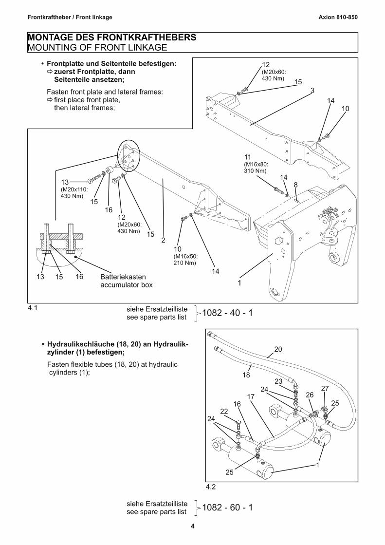
zylinder (1) befestigenbull Hydraulikschlaumluche (18 20) an Hydraulik
Fasten flexible tubes (18 20) at hydraulic cylinders (1)
1082 - 40 - 1siehe Ersatzteillistesee spare parts list
41
814
11(M16x80310 Nm)
1014
315
12(M20x60430 Nm)
14
10(M16x50210 Nm)
215
12(M20x60430 Nm)
1615
13(M20x110430 Nm)
113 15 16 Batteriekasten
accumulator box
eth
eth
bull Frontplatte und Seitenteile befestigenzuerst Frontplatte dann Seitenteile ansetzen
Fasten front plate and lateral framesfirst place front platethen lateral frames
MONTAGE DES FRONTKRAFTHEBERSMOUNTING OF FRONT LINKAGE
5
Axion 810-850Frontkraftheber Front linkage
1082-40-1 1082-60-1siehe Ersatzteillistesee spare parts list
52
18 20
193018
unter der Kabine nach hinten verlegen
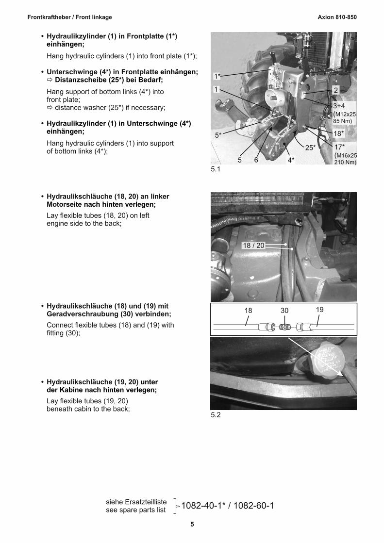
bull Hydraulikschlaumluche (19 20)
Lay flexible tubes (19 20) beneath cabin to the back
bull Hydraulikschlaumluche (18) und (19) mit Geradverschraubung (30) verbinden
Connect flexible tubes (18) and (19) withfitting (30)
seite nach hinten verlegenbull Hydraulikschlaumluche (18 20) an linker
Motor
Lay flexible tubes (18 20) on left engine side to the back
514
1
1
2
3+4(M12x2585 Nm)
18
17(M16x25210 Nm)
25
65
5
einhaumlngen
einhaumlngeneth Distanzscheibe (25) bei Bedarf
eth
Hydraulikzylinder (1) in Unterschwinge (4)einhaumlngen
bull Hydraulikzylinder (1) in Frontplatte (1)
Hang hydraulic cylinders (1) into front plate (1)
bull Unterschwinge (4) in Frontplatte
Hang support of bottom links (4) intofront plate
distance washer (25) if necessary
bull
Hang hydraulic cylinders (1) into supportof bottom links (4)
6
Axion 810-850Frontkraftheber Front linkage
1082 - 60 - 1siehe Ersatzteillistesee spare parts list
63
31
Senkenlowering
Hebenlifting
32 33
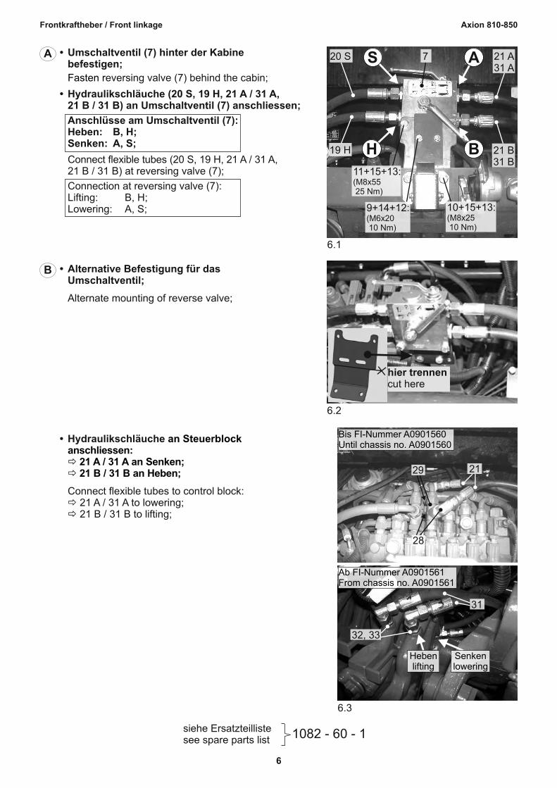
Ab FI-Nummer A0901561From chassis no A0901561
28
29 21
Bis FI-Nummer A0901560Until chassis no A0901560
an Steuerblockanschliesseneth 21 A 31 A an Senkeneth 21 B 31 B an Heben
etheth
bull Hydraulikschlaumluche
Connect flexible tubes to control block 21 A 31 A to lowering 21 B 31 B to lifting
62
hier trennencut here
bull Alternative Befestigung fuumlr das
Umschaltventil
Alternate mounting of reverse valve
B
61
10+15+13(M8x25 10 Nm)
9+14+12(M6x20 10 Nm)
11+15+13(M8x55 25 Nm)
21 B31 B
19 H
21 A31 A
720 S
BH
ASFasten r
bull Umschaltventil (7) hinter der Kabinebefestigen
eversing valve (7) behind the cabin
bull Hydraulikschlaumluche (20 S 19 H 21 A 31 A 21 B 31 B) an Umschaltventil (7) anschliessen
Anschluumlsse am Umschaltventil (7)Heben B HSenken A S
Connect flexible tubes (20 S 19 H 21 A 31 A 21 B 31 B) at reversing valve (7)
Connection at reversing valve (7)Lifting B HLowering A S
A
7
Axion 810-850Frontkraftheber Front linkage
1082 - 40 - 1siehe Ersatzteillistesee spare parts list
72
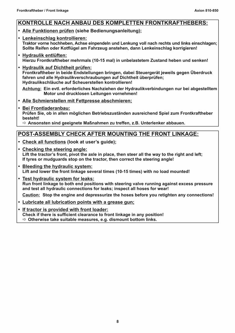
19
206
7
4
befestigenbull Unterlenker (6 7) an Unterschwinge (4)
Fasten bottom links (6 7) at support ofbottom links (4)
Secure hydraulic conduits to exclude following risksbull chafing bull squeezing bull influence of heat
Sichern Sie die Hydraulikschlaumluche mit Kabelbindern gegen folgende Gefahrenquellenbull Scheuern bull Einquetschen bull Hitzeeinwirkung
G
1082 - 60 - 1siehe Ersatzteillistesee spare parts list
71
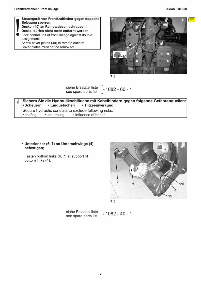
40
Lock control unit of front linkage against double assignmentScrew cover plates (40) to remote outletsCover plates must not be removed
Steuergeraumlt von Frontkraftheber gegen doppelteBelegung sperrenDeckel (40) an Remotedosen schraubenDeckel duumlrfen nicht mehr entfernt werden
darabos
Notiz
Aumlnderung zum Stand 090813Hinweistext und Bild 71 neu13-gt Deckel (40) hinzugefuumlgt
8
Axion 810-850Frontkraftheber Front linkage
POST-ASSEMBLY CHECK AFTER MOUNTING THE FRONT LINKAGE
ŸCheck all functions (look at userrsquos guide)
ŸChecking the steering angleLift the tractorrsquos front pivot the axle in place then steer all the way to the right and leftIf tyres or mudguards stop on the tractor then correct the steering angle
ŸBleeding the hydraulic systemLift and lower the front linkage several times (10-15 times) with no load mounted
ŸTest hydraulic system for leaksRun front linkage to both end positions with steering valve running against excess pressure and test all hydraulic connections for leaks inspect all hoses for wear
Caution Stop the engine and depressurize the hoses before you retighten any connections
ŸLubricate all lubrication points with a grease gun
ŸIf tractor is provided with front loaderCheck if there is sufficient clearance to front linkage in any positioneth Otherwise take suitable measures eg dismount bottom links
KONTROLLE NACH ANBAU DES KOMPLETTEN FRONTKRAFTHEBERS
ŸAlle Funktionen pruumlfen (siehe Bedienungsanleitung)
ŸLenkeinschlag kontrollierenTraktor vorne hochheben Achse einpendeln und Lenkung voll nach rechts und links einschlagenSollte Reifen oder Kotfluumlgel am Fahrzeug anstehen dann Lenkeinschlag korrigieren
ŸHydraulik entluumlftenHierzu Frontkraftheber mehrmals (10-15 mal) in unbelastetem Zustand heben und senken
ŸHydraulik auf Dichtheit pruumlfenFrontkraftheber in beide Endstellungen bringen dabei Steuergeraumlt jeweils gegen Uumlberdruckfahren und alle Hydraulikverschraubungen auf Dichtheit uumlberpruumlfenHydraulikschlaumluche auf Scheuerstellen kontrollieren
Achtung Ein evtl erforderliches Nachziehen der Hydraulikverbindungen nur bei abgestelltemMotor und drucklosen Leitungen vornehmen
ŸAlle Schmierstellen mit Fettpresse abschmieren
ŸBei FrontladeranbauPruumlfen Sie ob in allen moumlglichen Betriebszustaumlnden ausreichend Spiel zum Frontkraftheberbestehteth Ansonsten sind geeignete Maszlignahmen zu treffen zB Unterlenker abbauen
Sauter GmbHD-87778 StettenTel ++49 (82 61) 7 59 94 - 0Fax++49 (82 61) 7 59 94 - 20
Front linkageFrontkraftheber
Spare parts listErsatzteilliste
Nr No 006-1082
CLAAS
Axion 810 820 830 840 850
1082 - 40 - 1
Ersatzteilliste Frontkraftheber (ohne Hydraulik) 1082 - 40 - 1
Spare parts list Front linkage (without hydraulic parts)
Axion 810 - 850 Stand Update 0908
Pos No
Menge Quant
Teile-Nr No of part
Bezeichnung Designation Norm Abmessung Standard Dimension
01 1 040-801000 Frontplatte front plate
02 1 040-505300 Seitenteil rechts lateral frame rh
03 1 040-505400 Seitenteil links lateral frame lh
04 1 040-054300 Unterschwinge support of bottom links
05 1 040-066300 Unterschwingenwelle axle of support
06 1 040-242800-05 Unterlenker rechts bottom link rh Kat 3L
07 1 040-242900-05 Unterlenker links bottom link lh Kat 3L
08 2 101-0313 Zylinderstift cylindrical pin DIN 6325 - 16x30
09 2 200-7001 Unterlenkerkugel bottom link ball Kat 3L Oslash64
10 14 100-4556 Sechskantschraube hexagon bolt DIN 933-M16x50-88-210 Nm
11 10 100-3905 Sechskantschraube hexagon bolt DIN 933-M16x80-109-310 Nm
12 8 100-4656 Sechskantschraube hexagon bolt DIN 933-M20x60-88-430 Nm
13 4 100-3410 Sechskantschraube hexagon bolt DIN 931-M20x110-88-430 Nm
14 24 100-0508 Scheibe washer DIN 125 - 17x30x3
15 12 100-0510 Scheibe washer DIN 125 - 21x37x3
16 4 040-152700 Buchse bush 40x205x35
17 1 100-4551 Sechskantschraube hexagon bolt DIN 933-M16x25-88-210 Nm
18 1 040-066900 Scheibe washer 164x60x5
19 4 050-600100 Unterlenkerbolzen bottom link bolt
20 4 200-4102 Klappsplint folding split pin 75x42
21 1 215-0103 Spindeloberlenker top link Kat 2 M36x3 550-760
22 1 050-600700 Oberlenkerbolzen top link pin
23 1 200-4109 Formclip folding split pin 12x75
24 1 050-601700 Zugnagel tie bolt
25 4 200-2613 Buchse bush 452x50x30
26 2 200-1335 Distanzscheibe washer 45x65x1
1082 - 60 - 1
Ersatzteilliste Hydraulikteile Allgemein 1082 - 60 - 1
Spare parts list Hydraulic parts In general
Axion 810-850 Stand Update 1211
Pos No
Menge Quant
Teile-Nr No of part
Bezeichnung Designation Norm Abmessung Technical no Dimension
01 2 615-0025 Hydraulikzylinder hydraulic cylinder 90x36x160x325 01 A 6 200-2610 Buchse bush 35x39x40 01 B 2 209-0207 Dichtsatz Hydraulikzylinder seal kit hydraulic cylinder
02 2 060-021900 Hydraulikzylinder-Bolzen oben
hydraulic cylinder bolt on the top
03 2 100-4452 Sechskantschraube hexagon bolt DIN 933-M12x25-88-85 Nm
04 2 100-0506 Scheibe washer DIN 125-13x24x25
05 2 050-600300 Hydraulikzylinder-Bolzen unten
hydraulic cylinder bolt on the bottom
06 2 100-8809 Spannhuumllse adapter sleeve 12x60
07 1 615-0098 Umschaltventil reversing valve
08 1 050-017500 Halter fuumlr Umschaltventil support for reversing valve
09 2 100-4302 Sechskantschraube hexagon bolt DIN 933-M6x20-88-10 Nm
10 2 100-4353 Sechskantschraube hexagon bolt DIN 933-M8x25-88-25 Nm
11 2 100-3104 Sechskantschraube hexagon bolt DIN 931-M8x55-88-25 Nm
12 2 100-5552 Sechskantmutter nut DIN 934-M6
13 4 100-5553 Sechskantmutter nut DIN 934-M8
14 4 100-0503 Scheibe washer DIN 125-64x12x16
15 8 100-0504 Scheibe washer DIN 125-84x16x16
16 1 201-0158 Hydraulikschlauch flexible tube NW10x705 2xRG16x40deg
17 1 201-0166 Hydraulikschlauch flexible tube NW10x390 DK12L DK12Lx90deg
18 1 201-0169 Hydraulikschlauch flexible tube NW10x2240 DK12L DK12Lx90deg
19 1 201-0134 Hydraulikschlauch flexible tube NW10x2850 2xDK12L
20 1 201-0143 Hydraulikschlauch flexible tube NW10x4700 2xDK12L
22 1 205-0105 Hohlschraube hollow screw HS10-M16x15
23 1 060-067500 Hohlschraubstutzen hollow connection plug 12CE-M16x15
24 4 205-0607 U-Seal U-Seal 16x227x15
25 2 203-0370 Geradverschraubung fitting XGE 12LM - M16x15
26 1 204-0753 L-Verschraubung fitting XEV 12L
27 1 203-0852 Winkelverschraubung fitting XEVW 12 L
30 1 203-0153 Geradverschraubung fitting XG 12L
40 2 050-306100 Deckel cover plate
Bis FI-Nummer A0901560 Until chassis no A0901560
21 2 201-0175 Hydraulikschlauch flexible tube NW10x640 DK12L JIC 78NJ
28 2 203-0871 Winkelverschraubung fitting 78rdquo
29 2 204-0781 L-Verschraubung fitting 78rdquo
Ab FI-Nummer A0901561 From chassis no A0901561
31 2 201-0266 Hydraulikschlauch flexible tube NW10x900 DK12L DK12Lx90deg
32 2 203-0354 Geradverschraubung fitting XGE 12L - M18x15
33 2 205-0696 O-Ring gasket
- Seite 1
- Seite 2
- Seite 3
- Seite 4
- Seite 5
- Seite 6
- Seite 7
- Seite 8
- Seite 9
- Seite 10
- Seite 11
- Seite 12
- Seite 13
-

3
Axion 810-850Frontkraftheber Front linkage
Ballasttraumlger Abdeckplatte am Vorderund Seitenverkleidungen
Falls notwendig Batteriekasten loumlsen
Falls notwendig Tankhalterung loumlsenund Tank etwas nach auszligen zieheneth Traumlgerrahmen unterbauen
Auflageflaumlchen am Vorderachsbock und an der Kupplungsglocke entlacken
bull
bull
bull
bull
achsbockdemontieren
Disassemble ballast support sheet cover at the support of front axle and lateral coverings
If necessary loosen accumulator box
If necessary loosen tank fixing device and pull tank a little outsideeth support frame
Clean surfaces of support of front axle andof clutch housing from colour
MONTAGEVORBEREITUNGENPREPARATION FOR MOUNTING
INDICATION bull
bull
bull
bull
If mounting front linkage and front PTO start with mounting of front PTO
When fixing mounting parts first apply all bolts then tighten them with atorque wrench
The tightening torques indicated apply to dry threads and support surfaces(if not indicated otherwise)
To make mounting easier please use the spare parts lists
HINWEISE bull Bei der Montage von Frontkraftheber und Frontzapfwelle mit der Montage derFrontzapfwelle beginnen
bull Beim Befestigen von Montageteilen zuerst alle Schrauben ansetzen dann erstfestschrauben und mit Drehmomentschluumlssel anziehen
bull
bull
Die angegebenen Anzugsdrehmomente fuumlr Verschraubungen gelten fuumlr trockeneGewinde und Auflageflaumlchen (falls nicht anders angegeben)
Als Montagehilfe nehmen Sie bitte die Ersatzteillisten zur Hand
4
Axion 810-850Frontkraftheber Front linkage
1082 - 60 - 1siehe Ersatzteillistesee spare parts list
42
1
25
2726
25
2422
1617
2423
18
20-
zylinder (1) befestigenbull Hydraulikschlaumluche (18 20) an Hydraulik
Fasten flexible tubes (18 20) at hydraulic cylinders (1)
1082 - 40 - 1siehe Ersatzteillistesee spare parts list
41
814
11(M16x80310 Nm)
1014
315
12(M20x60430 Nm)
14
10(M16x50210 Nm)
215
12(M20x60430 Nm)
1615
13(M20x110430 Nm)
113 15 16 Batteriekasten
accumulator box
eth
eth
bull Frontplatte und Seitenteile befestigenzuerst Frontplatte dann Seitenteile ansetzen
Fasten front plate and lateral framesfirst place front platethen lateral frames
MONTAGE DES FRONTKRAFTHEBERSMOUNTING OF FRONT LINKAGE
5
Axion 810-850Frontkraftheber Front linkage
1082-40-1 1082-60-1siehe Ersatzteillistesee spare parts list
52
18 20
193018
unter der Kabine nach hinten verlegen
bull Hydraulikschlaumluche (19 20)
Lay flexible tubes (19 20) beneath cabin to the back
bull Hydraulikschlaumluche (18) und (19) mit Geradverschraubung (30) verbinden
Connect flexible tubes (18) and (19) withfitting (30)
seite nach hinten verlegenbull Hydraulikschlaumluche (18 20) an linker
Motor
Lay flexible tubes (18 20) on left engine side to the back
514
1
1
2
3+4(M12x2585 Nm)
18
17(M16x25210 Nm)
25
65
5
einhaumlngen
einhaumlngeneth Distanzscheibe (25) bei Bedarf
eth
Hydraulikzylinder (1) in Unterschwinge (4)einhaumlngen
bull Hydraulikzylinder (1) in Frontplatte (1)
Hang hydraulic cylinders (1) into front plate (1)
bull Unterschwinge (4) in Frontplatte
Hang support of bottom links (4) intofront plate
distance washer (25) if necessary
bull
Hang hydraulic cylinders (1) into supportof bottom links (4)
6
Axion 810-850Frontkraftheber Front linkage
1082 - 60 - 1siehe Ersatzteillistesee spare parts list
63
31
Senkenlowering
Hebenlifting
32 33
Ab FI-Nummer A0901561From chassis no A0901561
28
29 21
Bis FI-Nummer A0901560Until chassis no A0901560
an Steuerblockanschliesseneth 21 A 31 A an Senkeneth 21 B 31 B an Heben
etheth
bull Hydraulikschlaumluche
Connect flexible tubes to control block 21 A 31 A to lowering 21 B 31 B to lifting
62
hier trennencut here
bull Alternative Befestigung fuumlr das
Umschaltventil
Alternate mounting of reverse valve
B
61
10+15+13(M8x25 10 Nm)
9+14+12(M6x20 10 Nm)
11+15+13(M8x55 25 Nm)
21 B31 B
19 H
21 A31 A
720 S
BH
ASFasten r
bull Umschaltventil (7) hinter der Kabinebefestigen
eversing valve (7) behind the cabin
bull Hydraulikschlaumluche (20 S 19 H 21 A 31 A 21 B 31 B) an Umschaltventil (7) anschliessen
Anschluumlsse am Umschaltventil (7)Heben B HSenken A S
Connect flexible tubes (20 S 19 H 21 A 31 A 21 B 31 B) at reversing valve (7)
Connection at reversing valve (7)Lifting B HLowering A S
A
7
Axion 810-850Frontkraftheber Front linkage
1082 - 40 - 1siehe Ersatzteillistesee spare parts list
72
19
206
7
4
befestigenbull Unterlenker (6 7) an Unterschwinge (4)
Fasten bottom links (6 7) at support ofbottom links (4)
Secure hydraulic conduits to exclude following risksbull chafing bull squeezing bull influence of heat
Sichern Sie die Hydraulikschlaumluche mit Kabelbindern gegen folgende Gefahrenquellenbull Scheuern bull Einquetschen bull Hitzeeinwirkung
G
1082 - 60 - 1siehe Ersatzteillistesee spare parts list
71
40
Lock control unit of front linkage against double assignmentScrew cover plates (40) to remote outletsCover plates must not be removed
Steuergeraumlt von Frontkraftheber gegen doppelteBelegung sperrenDeckel (40) an Remotedosen schraubenDeckel duumlrfen nicht mehr entfernt werden
darabos
Notiz
Aumlnderung zum Stand 090813Hinweistext und Bild 71 neu13-gt Deckel (40) hinzugefuumlgt
8
Axion 810-850Frontkraftheber Front linkage
POST-ASSEMBLY CHECK AFTER MOUNTING THE FRONT LINKAGE
ŸCheck all functions (look at userrsquos guide)
ŸChecking the steering angleLift the tractorrsquos front pivot the axle in place then steer all the way to the right and leftIf tyres or mudguards stop on the tractor then correct the steering angle
ŸBleeding the hydraulic systemLift and lower the front linkage several times (10-15 times) with no load mounted
ŸTest hydraulic system for leaksRun front linkage to both end positions with steering valve running against excess pressure and test all hydraulic connections for leaks inspect all hoses for wear
Caution Stop the engine and depressurize the hoses before you retighten any connections
ŸLubricate all lubrication points with a grease gun
ŸIf tractor is provided with front loaderCheck if there is sufficient clearance to front linkage in any positioneth Otherwise take suitable measures eg dismount bottom links
KONTROLLE NACH ANBAU DES KOMPLETTEN FRONTKRAFTHEBERS
ŸAlle Funktionen pruumlfen (siehe Bedienungsanleitung)
ŸLenkeinschlag kontrollierenTraktor vorne hochheben Achse einpendeln und Lenkung voll nach rechts und links einschlagenSollte Reifen oder Kotfluumlgel am Fahrzeug anstehen dann Lenkeinschlag korrigieren
ŸHydraulik entluumlftenHierzu Frontkraftheber mehrmals (10-15 mal) in unbelastetem Zustand heben und senken
ŸHydraulik auf Dichtheit pruumlfenFrontkraftheber in beide Endstellungen bringen dabei Steuergeraumlt jeweils gegen Uumlberdruckfahren und alle Hydraulikverschraubungen auf Dichtheit uumlberpruumlfenHydraulikschlaumluche auf Scheuerstellen kontrollieren
Achtung Ein evtl erforderliches Nachziehen der Hydraulikverbindungen nur bei abgestelltemMotor und drucklosen Leitungen vornehmen
ŸAlle Schmierstellen mit Fettpresse abschmieren
ŸBei FrontladeranbauPruumlfen Sie ob in allen moumlglichen Betriebszustaumlnden ausreichend Spiel zum Frontkraftheberbestehteth Ansonsten sind geeignete Maszlignahmen zu treffen zB Unterlenker abbauen
Sauter GmbHD-87778 StettenTel ++49 (82 61) 7 59 94 - 0Fax++49 (82 61) 7 59 94 - 20
Front linkageFrontkraftheber
Spare parts listErsatzteilliste
Nr No 006-1082
CLAAS
Axion 810 820 830 840 850
1082 - 40 - 1
Ersatzteilliste Frontkraftheber (ohne Hydraulik) 1082 - 40 - 1
Spare parts list Front linkage (without hydraulic parts)
Axion 810 - 850 Stand Update 0908
Pos No
Menge Quant
Teile-Nr No of part
Bezeichnung Designation Norm Abmessung Standard Dimension
01 1 040-801000 Frontplatte front plate
02 1 040-505300 Seitenteil rechts lateral frame rh
03 1 040-505400 Seitenteil links lateral frame lh
04 1 040-054300 Unterschwinge support of bottom links
05 1 040-066300 Unterschwingenwelle axle of support
06 1 040-242800-05 Unterlenker rechts bottom link rh Kat 3L
07 1 040-242900-05 Unterlenker links bottom link lh Kat 3L
08 2 101-0313 Zylinderstift cylindrical pin DIN 6325 - 16x30
09 2 200-7001 Unterlenkerkugel bottom link ball Kat 3L Oslash64
10 14 100-4556 Sechskantschraube hexagon bolt DIN 933-M16x50-88-210 Nm
11 10 100-3905 Sechskantschraube hexagon bolt DIN 933-M16x80-109-310 Nm
12 8 100-4656 Sechskantschraube hexagon bolt DIN 933-M20x60-88-430 Nm
13 4 100-3410 Sechskantschraube hexagon bolt DIN 931-M20x110-88-430 Nm
14 24 100-0508 Scheibe washer DIN 125 - 17x30x3
15 12 100-0510 Scheibe washer DIN 125 - 21x37x3
16 4 040-152700 Buchse bush 40x205x35
17 1 100-4551 Sechskantschraube hexagon bolt DIN 933-M16x25-88-210 Nm
18 1 040-066900 Scheibe washer 164x60x5
19 4 050-600100 Unterlenkerbolzen bottom link bolt
20 4 200-4102 Klappsplint folding split pin 75x42
21 1 215-0103 Spindeloberlenker top link Kat 2 M36x3 550-760
22 1 050-600700 Oberlenkerbolzen top link pin
23 1 200-4109 Formclip folding split pin 12x75
24 1 050-601700 Zugnagel tie bolt
25 4 200-2613 Buchse bush 452x50x30
26 2 200-1335 Distanzscheibe washer 45x65x1
1082 - 60 - 1
Ersatzteilliste Hydraulikteile Allgemein 1082 - 60 - 1
Spare parts list Hydraulic parts In general
Axion 810-850 Stand Update 1211
Pos No
Menge Quant
Teile-Nr No of part
Bezeichnung Designation Norm Abmessung Technical no Dimension
01 2 615-0025 Hydraulikzylinder hydraulic cylinder 90x36x160x325 01 A 6 200-2610 Buchse bush 35x39x40 01 B 2 209-0207 Dichtsatz Hydraulikzylinder seal kit hydraulic cylinder
02 2 060-021900 Hydraulikzylinder-Bolzen oben
hydraulic cylinder bolt on the top
03 2 100-4452 Sechskantschraube hexagon bolt DIN 933-M12x25-88-85 Nm
04 2 100-0506 Scheibe washer DIN 125-13x24x25
05 2 050-600300 Hydraulikzylinder-Bolzen unten
hydraulic cylinder bolt on the bottom
06 2 100-8809 Spannhuumllse adapter sleeve 12x60
07 1 615-0098 Umschaltventil reversing valve
08 1 050-017500 Halter fuumlr Umschaltventil support for reversing valve
09 2 100-4302 Sechskantschraube hexagon bolt DIN 933-M6x20-88-10 Nm
10 2 100-4353 Sechskantschraube hexagon bolt DIN 933-M8x25-88-25 Nm
11 2 100-3104 Sechskantschraube hexagon bolt DIN 931-M8x55-88-25 Nm
12 2 100-5552 Sechskantmutter nut DIN 934-M6
13 4 100-5553 Sechskantmutter nut DIN 934-M8
14 4 100-0503 Scheibe washer DIN 125-64x12x16
15 8 100-0504 Scheibe washer DIN 125-84x16x16
16 1 201-0158 Hydraulikschlauch flexible tube NW10x705 2xRG16x40deg
17 1 201-0166 Hydraulikschlauch flexible tube NW10x390 DK12L DK12Lx90deg
18 1 201-0169 Hydraulikschlauch flexible tube NW10x2240 DK12L DK12Lx90deg
19 1 201-0134 Hydraulikschlauch flexible tube NW10x2850 2xDK12L
20 1 201-0143 Hydraulikschlauch flexible tube NW10x4700 2xDK12L
22 1 205-0105 Hohlschraube hollow screw HS10-M16x15
23 1 060-067500 Hohlschraubstutzen hollow connection plug 12CE-M16x15
24 4 205-0607 U-Seal U-Seal 16x227x15
25 2 203-0370 Geradverschraubung fitting XGE 12LM - M16x15
26 1 204-0753 L-Verschraubung fitting XEV 12L
27 1 203-0852 Winkelverschraubung fitting XEVW 12 L
30 1 203-0153 Geradverschraubung fitting XG 12L
40 2 050-306100 Deckel cover plate
Bis FI-Nummer A0901560 Until chassis no A0901560
21 2 201-0175 Hydraulikschlauch flexible tube NW10x640 DK12L JIC 78NJ
28 2 203-0871 Winkelverschraubung fitting 78rdquo
29 2 204-0781 L-Verschraubung fitting 78rdquo
Ab FI-Nummer A0901561 From chassis no A0901561
31 2 201-0266 Hydraulikschlauch flexible tube NW10x900 DK12L DK12Lx90deg
32 2 203-0354 Geradverschraubung fitting XGE 12L - M18x15
33 2 205-0696 O-Ring gasket
- Seite 1
- Seite 2
- Seite 3
- Seite 4
- Seite 5
- Seite 6
- Seite 7
- Seite 8
- Seite 9
- Seite 10
- Seite 11
- Seite 12
- Seite 13
-
4
Axion 810-850Frontkraftheber Front linkage
1082 - 60 - 1siehe Ersatzteillistesee spare parts list
42
1
25
2726
25
2422
1617
2423
18
20-
zylinder (1) befestigenbull Hydraulikschlaumluche (18 20) an Hydraulik
Fasten flexible tubes (18 20) at hydraulic cylinders (1)
1082 - 40 - 1siehe Ersatzteillistesee spare parts list
41
814
11(M16x80310 Nm)
1014
315
12(M20x60430 Nm)
14
10(M16x50210 Nm)
215
12(M20x60430 Nm)
1615
13(M20x110430 Nm)
113 15 16 Batteriekasten
accumulator box
eth
eth
bull Frontplatte und Seitenteile befestigenzuerst Frontplatte dann Seitenteile ansetzen
Fasten front plate and lateral framesfirst place front platethen lateral frames
MONTAGE DES FRONTKRAFTHEBERSMOUNTING OF FRONT LINKAGE
5
Axion 810-850Frontkraftheber Front linkage
1082-40-1 1082-60-1siehe Ersatzteillistesee spare parts list
52
18 20
193018
unter der Kabine nach hinten verlegen
bull Hydraulikschlaumluche (19 20)
Lay flexible tubes (19 20) beneath cabin to the back
bull Hydraulikschlaumluche (18) und (19) mit Geradverschraubung (30) verbinden
Connect flexible tubes (18) and (19) withfitting (30)
seite nach hinten verlegenbull Hydraulikschlaumluche (18 20) an linker
Motor
Lay flexible tubes (18 20) on left engine side to the back
514
1
1
2
3+4(M12x2585 Nm)
18
17(M16x25210 Nm)
25
65
5
einhaumlngen
einhaumlngeneth Distanzscheibe (25) bei Bedarf
eth
Hydraulikzylinder (1) in Unterschwinge (4)einhaumlngen
bull Hydraulikzylinder (1) in Frontplatte (1)
Hang hydraulic cylinders (1) into front plate (1)
bull Unterschwinge (4) in Frontplatte
Hang support of bottom links (4) intofront plate
distance washer (25) if necessary
bull
Hang hydraulic cylinders (1) into supportof bottom links (4)
6
Axion 810-850Frontkraftheber Front linkage
1082 - 60 - 1siehe Ersatzteillistesee spare parts list
63
31
Senkenlowering
Hebenlifting
32 33
Ab FI-Nummer A0901561From chassis no A0901561
28
29 21
Bis FI-Nummer A0901560Until chassis no A0901560
an Steuerblockanschliesseneth 21 A 31 A an Senkeneth 21 B 31 B an Heben
etheth
bull Hydraulikschlaumluche
Connect flexible tubes to control block 21 A 31 A to lowering 21 B 31 B to lifting
62
hier trennencut here
bull Alternative Befestigung fuumlr das
Umschaltventil
Alternate mounting of reverse valve
B
61
10+15+13(M8x25 10 Nm)
9+14+12(M6x20 10 Nm)
11+15+13(M8x55 25 Nm)
21 B31 B
19 H
21 A31 A
720 S
BH
ASFasten r
bull Umschaltventil (7) hinter der Kabinebefestigen
eversing valve (7) behind the cabin
bull Hydraulikschlaumluche (20 S 19 H 21 A 31 A 21 B 31 B) an Umschaltventil (7) anschliessen
Anschluumlsse am Umschaltventil (7)Heben B HSenken A S
Connect flexible tubes (20 S 19 H 21 A 31 A 21 B 31 B) at reversing valve (7)
Connection at reversing valve (7)Lifting B HLowering A S
A
7
Axion 810-850Frontkraftheber Front linkage
1082 - 40 - 1siehe Ersatzteillistesee spare parts list
72
19
206
7
4
befestigenbull Unterlenker (6 7) an Unterschwinge (4)
Fasten bottom links (6 7) at support ofbottom links (4)
Secure hydraulic conduits to exclude following risksbull chafing bull squeezing bull influence of heat
Sichern Sie die Hydraulikschlaumluche mit Kabelbindern gegen folgende Gefahrenquellenbull Scheuern bull Einquetschen bull Hitzeeinwirkung
G
1082 - 60 - 1siehe Ersatzteillistesee spare parts list
71
40
Lock control unit of front linkage against double assignmentScrew cover plates (40) to remote outletsCover plates must not be removed
Steuergeraumlt von Frontkraftheber gegen doppelteBelegung sperrenDeckel (40) an Remotedosen schraubenDeckel duumlrfen nicht mehr entfernt werden
darabos
Notiz
Aumlnderung zum Stand 090813Hinweistext und Bild 71 neu13-gt Deckel (40) hinzugefuumlgt
8
Axion 810-850Frontkraftheber Front linkage
POST-ASSEMBLY CHECK AFTER MOUNTING THE FRONT LINKAGE
ŸCheck all functions (look at userrsquos guide)
ŸChecking the steering angleLift the tractorrsquos front pivot the axle in place then steer all the way to the right and leftIf tyres or mudguards stop on the tractor then correct the steering angle
ŸBleeding the hydraulic systemLift and lower the front linkage several times (10-15 times) with no load mounted
ŸTest hydraulic system for leaksRun front linkage to both end positions with steering valve running against excess pressure and test all hydraulic connections for leaks inspect all hoses for wear
Caution Stop the engine and depressurize the hoses before you retighten any connections
ŸLubricate all lubrication points with a grease gun
ŸIf tractor is provided with front loaderCheck if there is sufficient clearance to front linkage in any positioneth Otherwise take suitable measures eg dismount bottom links
KONTROLLE NACH ANBAU DES KOMPLETTEN FRONTKRAFTHEBERS
ŸAlle Funktionen pruumlfen (siehe Bedienungsanleitung)
ŸLenkeinschlag kontrollierenTraktor vorne hochheben Achse einpendeln und Lenkung voll nach rechts und links einschlagenSollte Reifen oder Kotfluumlgel am Fahrzeug anstehen dann Lenkeinschlag korrigieren
ŸHydraulik entluumlftenHierzu Frontkraftheber mehrmals (10-15 mal) in unbelastetem Zustand heben und senken
ŸHydraulik auf Dichtheit pruumlfenFrontkraftheber in beide Endstellungen bringen dabei Steuergeraumlt jeweils gegen Uumlberdruckfahren und alle Hydraulikverschraubungen auf Dichtheit uumlberpruumlfenHydraulikschlaumluche auf Scheuerstellen kontrollieren
Achtung Ein evtl erforderliches Nachziehen der Hydraulikverbindungen nur bei abgestelltemMotor und drucklosen Leitungen vornehmen
ŸAlle Schmierstellen mit Fettpresse abschmieren
ŸBei FrontladeranbauPruumlfen Sie ob in allen moumlglichen Betriebszustaumlnden ausreichend Spiel zum Frontkraftheberbestehteth Ansonsten sind geeignete Maszlignahmen zu treffen zB Unterlenker abbauen
Sauter GmbHD-87778 StettenTel ++49 (82 61) 7 59 94 - 0Fax++49 (82 61) 7 59 94 - 20
Front linkageFrontkraftheber
Spare parts listErsatzteilliste
Nr No 006-1082
CLAAS
Axion 810 820 830 840 850
1082 - 40 - 1
Ersatzteilliste Frontkraftheber (ohne Hydraulik) 1082 - 40 - 1
Spare parts list Front linkage (without hydraulic parts)
Axion 810 - 850 Stand Update 0908
Pos No
Menge Quant
Teile-Nr No of part
Bezeichnung Designation Norm Abmessung Standard Dimension
01 1 040-801000 Frontplatte front plate
02 1 040-505300 Seitenteil rechts lateral frame rh
03 1 040-505400 Seitenteil links lateral frame lh
04 1 040-054300 Unterschwinge support of bottom links
05 1 040-066300 Unterschwingenwelle axle of support
06 1 040-242800-05 Unterlenker rechts bottom link rh Kat 3L
07 1 040-242900-05 Unterlenker links bottom link lh Kat 3L
08 2 101-0313 Zylinderstift cylindrical pin DIN 6325 - 16x30
09 2 200-7001 Unterlenkerkugel bottom link ball Kat 3L Oslash64
10 14 100-4556 Sechskantschraube hexagon bolt DIN 933-M16x50-88-210 Nm
11 10 100-3905 Sechskantschraube hexagon bolt DIN 933-M16x80-109-310 Nm
12 8 100-4656 Sechskantschraube hexagon bolt DIN 933-M20x60-88-430 Nm
13 4 100-3410 Sechskantschraube hexagon bolt DIN 931-M20x110-88-430 Nm
14 24 100-0508 Scheibe washer DIN 125 - 17x30x3
15 12 100-0510 Scheibe washer DIN 125 - 21x37x3
16 4 040-152700 Buchse bush 40x205x35
17 1 100-4551 Sechskantschraube hexagon bolt DIN 933-M16x25-88-210 Nm
18 1 040-066900 Scheibe washer 164x60x5
19 4 050-600100 Unterlenkerbolzen bottom link bolt
20 4 200-4102 Klappsplint folding split pin 75x42
21 1 215-0103 Spindeloberlenker top link Kat 2 M36x3 550-760
22 1 050-600700 Oberlenkerbolzen top link pin
23 1 200-4109 Formclip folding split pin 12x75
24 1 050-601700 Zugnagel tie bolt
25 4 200-2613 Buchse bush 452x50x30
26 2 200-1335 Distanzscheibe washer 45x65x1
1082 - 60 - 1
Ersatzteilliste Hydraulikteile Allgemein 1082 - 60 - 1
Spare parts list Hydraulic parts In general
Axion 810-850 Stand Update 1211
Pos No
Menge Quant
Teile-Nr No of part
Bezeichnung Designation Norm Abmessung Technical no Dimension
01 2 615-0025 Hydraulikzylinder hydraulic cylinder 90x36x160x325 01 A 6 200-2610 Buchse bush 35x39x40 01 B 2 209-0207 Dichtsatz Hydraulikzylinder seal kit hydraulic cylinder
02 2 060-021900 Hydraulikzylinder-Bolzen oben
hydraulic cylinder bolt on the top
03 2 100-4452 Sechskantschraube hexagon bolt DIN 933-M12x25-88-85 Nm
04 2 100-0506 Scheibe washer DIN 125-13x24x25
05 2 050-600300 Hydraulikzylinder-Bolzen unten
hydraulic cylinder bolt on the bottom
06 2 100-8809 Spannhuumllse adapter sleeve 12x60
07 1 615-0098 Umschaltventil reversing valve
08 1 050-017500 Halter fuumlr Umschaltventil support for reversing valve
09 2 100-4302 Sechskantschraube hexagon bolt DIN 933-M6x20-88-10 Nm
10 2 100-4353 Sechskantschraube hexagon bolt DIN 933-M8x25-88-25 Nm
11 2 100-3104 Sechskantschraube hexagon bolt DIN 931-M8x55-88-25 Nm
12 2 100-5552 Sechskantmutter nut DIN 934-M6
13 4 100-5553 Sechskantmutter nut DIN 934-M8
14 4 100-0503 Scheibe washer DIN 125-64x12x16
15 8 100-0504 Scheibe washer DIN 125-84x16x16
16 1 201-0158 Hydraulikschlauch flexible tube NW10x705 2xRG16x40deg
17 1 201-0166 Hydraulikschlauch flexible tube NW10x390 DK12L DK12Lx90deg
18 1 201-0169 Hydraulikschlauch flexible tube NW10x2240 DK12L DK12Lx90deg
19 1 201-0134 Hydraulikschlauch flexible tube NW10x2850 2xDK12L
20 1 201-0143 Hydraulikschlauch flexible tube NW10x4700 2xDK12L
22 1 205-0105 Hohlschraube hollow screw HS10-M16x15
23 1 060-067500 Hohlschraubstutzen hollow connection plug 12CE-M16x15
24 4 205-0607 U-Seal U-Seal 16x227x15
25 2 203-0370 Geradverschraubung fitting XGE 12LM - M16x15
26 1 204-0753 L-Verschraubung fitting XEV 12L
27 1 203-0852 Winkelverschraubung fitting XEVW 12 L
30 1 203-0153 Geradverschraubung fitting XG 12L
40 2 050-306100 Deckel cover plate
Bis FI-Nummer A0901560 Until chassis no A0901560
21 2 201-0175 Hydraulikschlauch flexible tube NW10x640 DK12L JIC 78NJ
28 2 203-0871 Winkelverschraubung fitting 78rdquo
29 2 204-0781 L-Verschraubung fitting 78rdquo
Ab FI-Nummer A0901561 From chassis no A0901561
31 2 201-0266 Hydraulikschlauch flexible tube NW10x900 DK12L DK12Lx90deg
32 2 203-0354 Geradverschraubung fitting XGE 12L - M18x15
33 2 205-0696 O-Ring gasket
- Seite 1
- Seite 2
- Seite 3
- Seite 4
- Seite 5
- Seite 6
- Seite 7
- Seite 8
- Seite 9
- Seite 10
- Seite 11
- Seite 12
- Seite 13
-
5
Axion 810-850Frontkraftheber Front linkage
1082-40-1 1082-60-1siehe Ersatzteillistesee spare parts list
52
18 20
193018
unter der Kabine nach hinten verlegen
bull Hydraulikschlaumluche (19 20)
Lay flexible tubes (19 20) beneath cabin to the back
bull Hydraulikschlaumluche (18) und (19) mit Geradverschraubung (30) verbinden
Connect flexible tubes (18) and (19) withfitting (30)
seite nach hinten verlegenbull Hydraulikschlaumluche (18 20) an linker
Motor
Lay flexible tubes (18 20) on left engine side to the back
514
1
1
2
3+4(M12x2585 Nm)
18
17(M16x25210 Nm)
25
65
5
einhaumlngen
einhaumlngeneth Distanzscheibe (25) bei Bedarf
eth
Hydraulikzylinder (1) in Unterschwinge (4)einhaumlngen
bull Hydraulikzylinder (1) in Frontplatte (1)
Hang hydraulic cylinders (1) into front plate (1)
bull Unterschwinge (4) in Frontplatte
Hang support of bottom links (4) intofront plate
distance washer (25) if necessary
bull
Hang hydraulic cylinders (1) into supportof bottom links (4)
6
Axion 810-850Frontkraftheber Front linkage
1082 - 60 - 1siehe Ersatzteillistesee spare parts list
63
31
Senkenlowering
Hebenlifting
32 33
Ab FI-Nummer A0901561From chassis no A0901561
28
29 21
Bis FI-Nummer A0901560Until chassis no A0901560
an Steuerblockanschliesseneth 21 A 31 A an Senkeneth 21 B 31 B an Heben
etheth
bull Hydraulikschlaumluche
Connect flexible tubes to control block 21 A 31 A to lowering 21 B 31 B to lifting
62
hier trennencut here
bull Alternative Befestigung fuumlr das
Umschaltventil
Alternate mounting of reverse valve
B
61
10+15+13(M8x25 10 Nm)
9+14+12(M6x20 10 Nm)
11+15+13(M8x55 25 Nm)
21 B31 B
19 H
21 A31 A
720 S
BH
ASFasten r
bull Umschaltventil (7) hinter der Kabinebefestigen
eversing valve (7) behind the cabin
bull Hydraulikschlaumluche (20 S 19 H 21 A 31 A 21 B 31 B) an Umschaltventil (7) anschliessen
Anschluumlsse am Umschaltventil (7)Heben B HSenken A S
Connect flexible tubes (20 S 19 H 21 A 31 A 21 B 31 B) at reversing valve (7)
Connection at reversing valve (7)Lifting B HLowering A S
A
7
Axion 810-850Frontkraftheber Front linkage
1082 - 40 - 1siehe Ersatzteillistesee spare parts list
72
19
206
7
4
befestigenbull Unterlenker (6 7) an Unterschwinge (4)
Fasten bottom links (6 7) at support ofbottom links (4)
Secure hydraulic conduits to exclude following risksbull chafing bull squeezing bull influence of heat
Sichern Sie die Hydraulikschlaumluche mit Kabelbindern gegen folgende Gefahrenquellenbull Scheuern bull Einquetschen bull Hitzeeinwirkung
G
1082 - 60 - 1siehe Ersatzteillistesee spare parts list
71
40
Lock control unit of front linkage against double assignmentScrew cover plates (40) to remote outletsCover plates must not be removed
Steuergeraumlt von Frontkraftheber gegen doppelteBelegung sperrenDeckel (40) an Remotedosen schraubenDeckel duumlrfen nicht mehr entfernt werden
darabos
Notiz
Aumlnderung zum Stand 090813Hinweistext und Bild 71 neu13-gt Deckel (40) hinzugefuumlgt
8
Axion 810-850Frontkraftheber Front linkage
POST-ASSEMBLY CHECK AFTER MOUNTING THE FRONT LINKAGE
ŸCheck all functions (look at userrsquos guide)
ŸChecking the steering angleLift the tractorrsquos front pivot the axle in place then steer all the way to the right and leftIf tyres or mudguards stop on the tractor then correct the steering angle
ŸBleeding the hydraulic systemLift and lower the front linkage several times (10-15 times) with no load mounted
ŸTest hydraulic system for leaksRun front linkage to both end positions with steering valve running against excess pressure and test all hydraulic connections for leaks inspect all hoses for wear
Caution Stop the engine and depressurize the hoses before you retighten any connections
ŸLubricate all lubrication points with a grease gun
ŸIf tractor is provided with front loaderCheck if there is sufficient clearance to front linkage in any positioneth Otherwise take suitable measures eg dismount bottom links
KONTROLLE NACH ANBAU DES KOMPLETTEN FRONTKRAFTHEBERS
ŸAlle Funktionen pruumlfen (siehe Bedienungsanleitung)
ŸLenkeinschlag kontrollierenTraktor vorne hochheben Achse einpendeln und Lenkung voll nach rechts und links einschlagenSollte Reifen oder Kotfluumlgel am Fahrzeug anstehen dann Lenkeinschlag korrigieren
ŸHydraulik entluumlftenHierzu Frontkraftheber mehrmals (10-15 mal) in unbelastetem Zustand heben und senken
ŸHydraulik auf Dichtheit pruumlfenFrontkraftheber in beide Endstellungen bringen dabei Steuergeraumlt jeweils gegen Uumlberdruckfahren und alle Hydraulikverschraubungen auf Dichtheit uumlberpruumlfenHydraulikschlaumluche auf Scheuerstellen kontrollieren
Achtung Ein evtl erforderliches Nachziehen der Hydraulikverbindungen nur bei abgestelltemMotor und drucklosen Leitungen vornehmen
ŸAlle Schmierstellen mit Fettpresse abschmieren
ŸBei FrontladeranbauPruumlfen Sie ob in allen moumlglichen Betriebszustaumlnden ausreichend Spiel zum Frontkraftheberbestehteth Ansonsten sind geeignete Maszlignahmen zu treffen zB Unterlenker abbauen
Sauter GmbHD-87778 StettenTel ++49 (82 61) 7 59 94 - 0Fax++49 (82 61) 7 59 94 - 20
Front linkageFrontkraftheber
Spare parts listErsatzteilliste
Nr No 006-1082
CLAAS
Axion 810 820 830 840 850
1082 - 40 - 1
Ersatzteilliste Frontkraftheber (ohne Hydraulik) 1082 - 40 - 1
Spare parts list Front linkage (without hydraulic parts)
Axion 810 - 850 Stand Update 0908
Pos No
Menge Quant
Teile-Nr No of part
Bezeichnung Designation Norm Abmessung Standard Dimension
01 1 040-801000 Frontplatte front plate
02 1 040-505300 Seitenteil rechts lateral frame rh
03 1 040-505400 Seitenteil links lateral frame lh
04 1 040-054300 Unterschwinge support of bottom links
05 1 040-066300 Unterschwingenwelle axle of support
06 1 040-242800-05 Unterlenker rechts bottom link rh Kat 3L
07 1 040-242900-05 Unterlenker links bottom link lh Kat 3L
08 2 101-0313 Zylinderstift cylindrical pin DIN 6325 - 16x30
09 2 200-7001 Unterlenkerkugel bottom link ball Kat 3L Oslash64
10 14 100-4556 Sechskantschraube hexagon bolt DIN 933-M16x50-88-210 Nm
11 10 100-3905 Sechskantschraube hexagon bolt DIN 933-M16x80-109-310 Nm
12 8 100-4656 Sechskantschraube hexagon bolt DIN 933-M20x60-88-430 Nm
13 4 100-3410 Sechskantschraube hexagon bolt DIN 931-M20x110-88-430 Nm
14 24 100-0508 Scheibe washer DIN 125 - 17x30x3
15 12 100-0510 Scheibe washer DIN 125 - 21x37x3
16 4 040-152700 Buchse bush 40x205x35
17 1 100-4551 Sechskantschraube hexagon bolt DIN 933-M16x25-88-210 Nm
18 1 040-066900 Scheibe washer 164x60x5
19 4 050-600100 Unterlenkerbolzen bottom link bolt
20 4 200-4102 Klappsplint folding split pin 75x42
21 1 215-0103 Spindeloberlenker top link Kat 2 M36x3 550-760
22 1 050-600700 Oberlenkerbolzen top link pin
23 1 200-4109 Formclip folding split pin 12x75
24 1 050-601700 Zugnagel tie bolt
25 4 200-2613 Buchse bush 452x50x30
26 2 200-1335 Distanzscheibe washer 45x65x1
1082 - 60 - 1
Ersatzteilliste Hydraulikteile Allgemein 1082 - 60 - 1
Spare parts list Hydraulic parts In general
Axion 810-850 Stand Update 1211
Pos No
Menge Quant
Teile-Nr No of part
Bezeichnung Designation Norm Abmessung Technical no Dimension
01 2 615-0025 Hydraulikzylinder hydraulic cylinder 90x36x160x325 01 A 6 200-2610 Buchse bush 35x39x40 01 B 2 209-0207 Dichtsatz Hydraulikzylinder seal kit hydraulic cylinder
02 2 060-021900 Hydraulikzylinder-Bolzen oben
hydraulic cylinder bolt on the top
03 2 100-4452 Sechskantschraube hexagon bolt DIN 933-M12x25-88-85 Nm
04 2 100-0506 Scheibe washer DIN 125-13x24x25
05 2 050-600300 Hydraulikzylinder-Bolzen unten
hydraulic cylinder bolt on the bottom
06 2 100-8809 Spannhuumllse adapter sleeve 12x60
07 1 615-0098 Umschaltventil reversing valve
08 1 050-017500 Halter fuumlr Umschaltventil support for reversing valve
09 2 100-4302 Sechskantschraube hexagon bolt DIN 933-M6x20-88-10 Nm
10 2 100-4353 Sechskantschraube hexagon bolt DIN 933-M8x25-88-25 Nm
11 2 100-3104 Sechskantschraube hexagon bolt DIN 931-M8x55-88-25 Nm
12 2 100-5552 Sechskantmutter nut DIN 934-M6
13 4 100-5553 Sechskantmutter nut DIN 934-M8
14 4 100-0503 Scheibe washer DIN 125-64x12x16
15 8 100-0504 Scheibe washer DIN 125-84x16x16
16 1 201-0158 Hydraulikschlauch flexible tube NW10x705 2xRG16x40deg
17 1 201-0166 Hydraulikschlauch flexible tube NW10x390 DK12L DK12Lx90deg
18 1 201-0169 Hydraulikschlauch flexible tube NW10x2240 DK12L DK12Lx90deg
19 1 201-0134 Hydraulikschlauch flexible tube NW10x2850 2xDK12L
20 1 201-0143 Hydraulikschlauch flexible tube NW10x4700 2xDK12L
22 1 205-0105 Hohlschraube hollow screw HS10-M16x15
23 1 060-067500 Hohlschraubstutzen hollow connection plug 12CE-M16x15
24 4 205-0607 U-Seal U-Seal 16x227x15
25 2 203-0370 Geradverschraubung fitting XGE 12LM - M16x15
26 1 204-0753 L-Verschraubung fitting XEV 12L
27 1 203-0852 Winkelverschraubung fitting XEVW 12 L
30 1 203-0153 Geradverschraubung fitting XG 12L
40 2 050-306100 Deckel cover plate
Bis FI-Nummer A0901560 Until chassis no A0901560
21 2 201-0175 Hydraulikschlauch flexible tube NW10x640 DK12L JIC 78NJ
28 2 203-0871 Winkelverschraubung fitting 78rdquo
29 2 204-0781 L-Verschraubung fitting 78rdquo
Ab FI-Nummer A0901561 From chassis no A0901561
31 2 201-0266 Hydraulikschlauch flexible tube NW10x900 DK12L DK12Lx90deg
32 2 203-0354 Geradverschraubung fitting XGE 12L - M18x15
33 2 205-0696 O-Ring gasket
- Seite 1
- Seite 2
- Seite 3
- Seite 4
- Seite 5
- Seite 6
- Seite 7
- Seite 8
- Seite 9
- Seite 10
- Seite 11
- Seite 12
- Seite 13
-
7
Axion 810-850Frontkraftheber Front linkage
1082 - 40 - 1siehe Ersatzteillistesee spare parts list
72
19
206
7
4
befestigenbull Unterlenker (6 7) an Unterschwinge (4)
Fasten bottom links (6 7) at support ofbottom links (4)
Secure hydraulic conduits to exclude following risksbull chafing bull squeezing bull influence of heat
Sichern Sie die Hydraulikschlaumluche mit Kabelbindern gegen folgende Gefahrenquellenbull Scheuern bull Einquetschen bull Hitzeeinwirkung
G
1082 - 60 - 1siehe Ersatzteillistesee spare parts list
71
40
Lock control unit of front linkage against double assignmentScrew cover plates (40) to remote outletsCover plates must not be removed
Steuergeraumlt von Frontkraftheber gegen doppelteBelegung sperrenDeckel (40) an Remotedosen schraubenDeckel duumlrfen nicht mehr entfernt werden
darabos
Notiz
Aumlnderung zum Stand 090813Hinweistext und Bild 71 neu13-gt Deckel (40) hinzugefuumlgt
8
Axion 810-850Frontkraftheber Front linkage
POST-ASSEMBLY CHECK AFTER MOUNTING THE FRONT LINKAGE
ŸCheck all functions (look at userrsquos guide)
ŸChecking the steering angleLift the tractorrsquos front pivot the axle in place then steer all the way to the right and leftIf tyres or mudguards stop on the tractor then correct the steering angle
ŸBleeding the hydraulic systemLift and lower the front linkage several times (10-15 times) with no load mounted
ŸTest hydraulic system for leaksRun front linkage to both end positions with steering valve running against excess pressure and test all hydraulic connections for leaks inspect all hoses for wear
Caution Stop the engine and depressurize the hoses before you retighten any connections
ŸLubricate all lubrication points with a grease gun
ŸIf tractor is provided with front loaderCheck if there is sufficient clearance to front linkage in any positioneth Otherwise take suitable measures eg dismount bottom links
KONTROLLE NACH ANBAU DES KOMPLETTEN FRONTKRAFTHEBERS
ŸAlle Funktionen pruumlfen (siehe Bedienungsanleitung)
ŸLenkeinschlag kontrollierenTraktor vorne hochheben Achse einpendeln und Lenkung voll nach rechts und links einschlagenSollte Reifen oder Kotfluumlgel am Fahrzeug anstehen dann Lenkeinschlag korrigieren
ŸHydraulik entluumlftenHierzu Frontkraftheber mehrmals (10-15 mal) in unbelastetem Zustand heben und senken
ŸHydraulik auf Dichtheit pruumlfenFrontkraftheber in beide Endstellungen bringen dabei Steuergeraumlt jeweils gegen Uumlberdruckfahren und alle Hydraulikverschraubungen auf Dichtheit uumlberpruumlfenHydraulikschlaumluche auf Scheuerstellen kontrollieren
Achtung Ein evtl erforderliches Nachziehen der Hydraulikverbindungen nur bei abgestelltemMotor und drucklosen Leitungen vornehmen
ŸAlle Schmierstellen mit Fettpresse abschmieren
ŸBei FrontladeranbauPruumlfen Sie ob in allen moumlglichen Betriebszustaumlnden ausreichend Spiel zum Frontkraftheberbestehteth Ansonsten sind geeignete Maszlignahmen zu treffen zB Unterlenker abbauen
Sauter GmbHD-87778 StettenTel ++49 (82 61) 7 59 94 - 0Fax++49 (82 61) 7 59 94 - 20
Front linkageFrontkraftheber
Spare parts listErsatzteilliste
Nr No 006-1082
CLAAS
Axion 810 820 830 840 850
1082 - 40 - 1
Ersatzteilliste Frontkraftheber (ohne Hydraulik) 1082 - 40 - 1
Spare parts list Front linkage (without hydraulic parts)
Axion 810 - 850 Stand Update 0908
Pos No
Menge Quant
Teile-Nr No of part
Bezeichnung Designation Norm Abmessung Standard Dimension
01 1 040-801000 Frontplatte front plate
02 1 040-505300 Seitenteil rechts lateral frame rh
03 1 040-505400 Seitenteil links lateral frame lh
04 1 040-054300 Unterschwinge support of bottom links
05 1 040-066300 Unterschwingenwelle axle of support
06 1 040-242800-05 Unterlenker rechts bottom link rh Kat 3L
07 1 040-242900-05 Unterlenker links bottom link lh Kat 3L
08 2 101-0313 Zylinderstift cylindrical pin DIN 6325 - 16x30
09 2 200-7001 Unterlenkerkugel bottom link ball Kat 3L Oslash64
10 14 100-4556 Sechskantschraube hexagon bolt DIN 933-M16x50-88-210 Nm
11 10 100-3905 Sechskantschraube hexagon bolt DIN 933-M16x80-109-310 Nm
12 8 100-4656 Sechskantschraube hexagon bolt DIN 933-M20x60-88-430 Nm
13 4 100-3410 Sechskantschraube hexagon bolt DIN 931-M20x110-88-430 Nm
14 24 100-0508 Scheibe washer DIN 125 - 17x30x3
15 12 100-0510 Scheibe washer DIN 125 - 21x37x3
16 4 040-152700 Buchse bush 40x205x35
17 1 100-4551 Sechskantschraube hexagon bolt DIN 933-M16x25-88-210 Nm
18 1 040-066900 Scheibe washer 164x60x5
19 4 050-600100 Unterlenkerbolzen bottom link bolt
20 4 200-4102 Klappsplint folding split pin 75x42
21 1 215-0103 Spindeloberlenker top link Kat 2 M36x3 550-760
22 1 050-600700 Oberlenkerbolzen top link pin
23 1 200-4109 Formclip folding split pin 12x75
24 1 050-601700 Zugnagel tie bolt
25 4 200-2613 Buchse bush 452x50x30
26 2 200-1335 Distanzscheibe washer 45x65x1
1082 - 60 - 1
Ersatzteilliste Hydraulikteile Allgemein 1082 - 60 - 1
Spare parts list Hydraulic parts In general
Axion 810-850 Stand Update 1211
Pos No
Menge Quant
Teile-Nr No of part
Bezeichnung Designation Norm Abmessung Technical no Dimension
01 2 615-0025 Hydraulikzylinder hydraulic cylinder 90x36x160x325 01 A 6 200-2610 Buchse bush 35x39x40 01 B 2 209-0207 Dichtsatz Hydraulikzylinder seal kit hydraulic cylinder
02 2 060-021900 Hydraulikzylinder-Bolzen oben
hydraulic cylinder bolt on the top
03 2 100-4452 Sechskantschraube hexagon bolt DIN 933-M12x25-88-85 Nm
04 2 100-0506 Scheibe washer DIN 125-13x24x25
05 2 050-600300 Hydraulikzylinder-Bolzen unten
hydraulic cylinder bolt on the bottom
06 2 100-8809 Spannhuumllse adapter sleeve 12x60
07 1 615-0098 Umschaltventil reversing valve
08 1 050-017500 Halter fuumlr Umschaltventil support for reversing valve
09 2 100-4302 Sechskantschraube hexagon bolt DIN 933-M6x20-88-10 Nm
10 2 100-4353 Sechskantschraube hexagon bolt DIN 933-M8x25-88-25 Nm
11 2 100-3104 Sechskantschraube hexagon bolt DIN 931-M8x55-88-25 Nm
12 2 100-5552 Sechskantmutter nut DIN 934-M6
13 4 100-5553 Sechskantmutter nut DIN 934-M8
14 4 100-0503 Scheibe washer DIN 125-64x12x16
15 8 100-0504 Scheibe washer DIN 125-84x16x16
16 1 201-0158 Hydraulikschlauch flexible tube NW10x705 2xRG16x40deg
17 1 201-0166 Hydraulikschlauch flexible tube NW10x390 DK12L DK12Lx90deg
18 1 201-0169 Hydraulikschlauch flexible tube NW10x2240 DK12L DK12Lx90deg
19 1 201-0134 Hydraulikschlauch flexible tube NW10x2850 2xDK12L
20 1 201-0143 Hydraulikschlauch flexible tube NW10x4700 2xDK12L
22 1 205-0105 Hohlschraube hollow screw HS10-M16x15
23 1 060-067500 Hohlschraubstutzen hollow connection plug 12CE-M16x15
24 4 205-0607 U-Seal U-Seal 16x227x15
25 2 203-0370 Geradverschraubung fitting XGE 12LM - M16x15
26 1 204-0753 L-Verschraubung fitting XEV 12L
27 1 203-0852 Winkelverschraubung fitting XEVW 12 L
30 1 203-0153 Geradverschraubung fitting XG 12L
40 2 050-306100 Deckel cover plate
Bis FI-Nummer A0901560 Until chassis no A0901560
21 2 201-0175 Hydraulikschlauch flexible tube NW10x640 DK12L JIC 78NJ
28 2 203-0871 Winkelverschraubung fitting 78rdquo
29 2 204-0781 L-Verschraubung fitting 78rdquo
Ab FI-Nummer A0901561 From chassis no A0901561
31 2 201-0266 Hydraulikschlauch flexible tube NW10x900 DK12L DK12Lx90deg
32 2 203-0354 Geradverschraubung fitting XGE 12L - M18x15
33 2 205-0696 O-Ring gasket
- Seite 1
- Seite 2
- Seite 3
- Seite 4
- Seite 5
- Seite 6
- Seite 7
- Seite 8
- Seite 9
- Seite 10
- Seite 11
- Seite 12
- Seite 13
-
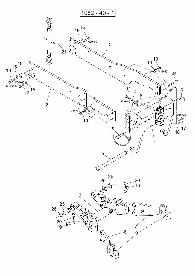
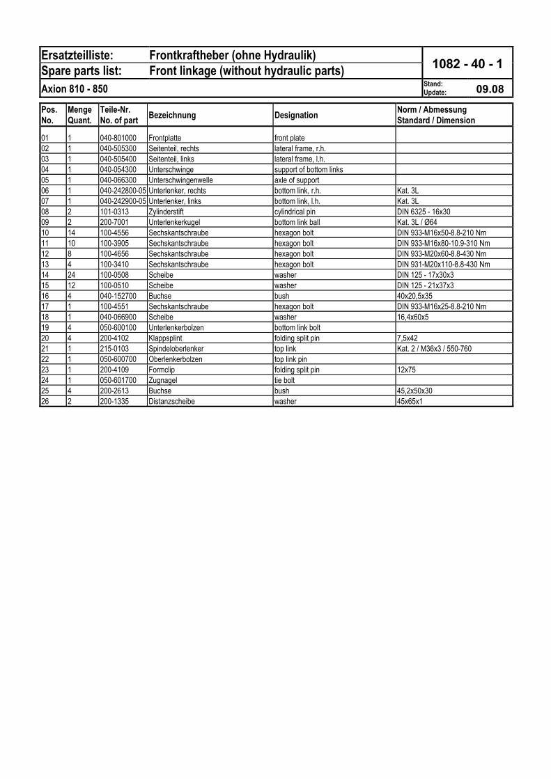
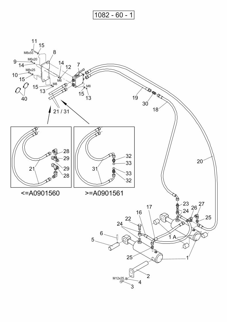