November 2010 # 11 · welding heat-resistant prec ipitation-hardening nickel alloys is a problem of...
50
CONTENTS SCIENTIFIC AND TECHNICAL Yushchenko K.A., Ustinov A.I., Zadery B.A., Savchenko V.S., Melnichenko T.V., Kurenkova V.V., Zvyagintseva A.V. and Gakh I.S. Effect of nanofoil of the Ni—NbC system on structure of electron beam welds in heat-resistant alloys ..................................... 2 Zhdanov S.L., Poznyakov V.D., Maksimenko A.A., Dovzhenko V.A., Vasiliev V.G., Vysokolyan N.V. and Korobka V.A. Structure and properties of arc-welded joints on steel 10G2FB ............. 8 Khorunov V.F., Maksymova S.V., Butenko Yu.V. and Maly A.B. Strength of brazed joints on heat-resistant nickel alloy Inconel 718 produced by using palladium brazing filler metals ............. 12 Bondarev A.A. and Ternovoj E.G. Features of weld formation and properties of aluminium and magnesium alloy joints under simulated space conditions ................................................................. 16 Makhnenko O.V., Timoshenko A.N., Muzhichenko A.F. and Goncharov P.V. Improvement of the technology for arc spot welding of overlap joints based on the results of mathematical modelling ........................................................................................... 21 Stepanov G.V., Babutsky A.I., Mameev I.A., Chizhik A.V., Savitsky V.V., Tkachuk G.I. and Pashchin N.A. Improvement of cyclic fatigue life of metallic materials and welded joints by treatment by pulsed electric current .................................................... 27 INDUSTRIAL Lebedev V.A., Lendel I.V., Lendel V.I. and Pichak V.G. Trends in improvement of auxiliary equipment for welding production .............. 31 Seyffarth P. and Gaede R. Image processing for automated robotic welding ................................................................................... 35 Koleda V.N. and Ilyushenko V.M. Optimisation of parameters of additional gas shielding in submerged arc welding and surfacing of copper and its alloys ........................................................ 38 Kornienko A.N. Half-century anniversary of the first exhibition of achievements of welding production ................................................ 41 BRIEF INFORMATION Nazarenko O.K. and Shevchuk S.A. Selection of current sensor position in high-voltage power sources of welding guns ............ 45 Theses for a scientific degree ............................................................. 46 NEWS News .................................................................................................. 48 International Conference «MEE-2010» ................................................. 49 Technical Seminar «Aircraft Construction – Technologies and Equipment for Welding» ...................................................................... 50 © PWI, International Association «Welding», 2010 English translation of the monthly «Avtomaticheskaya Svarka» (Automatic Welding) journal published in Russian since 1948 International Scientific-Technical and Production Journal Founders: E.O. Paton Electric Welding Institute of the NAS of Ukraine Publisher: International Association «Welding» International Association «Welding» Editor-in-Chief B.E.Paton Editorial board: Yu.S.Borisov V.F.Khorunov A.Ya.Ishchenko I.V.Krivtsun B.V.Khitrovskaya L.M.Lobanov V.I.Kirian A.A.Mazur S.I.Kuchuk-Yatsenko Yu.N.Lankin I.K.Pokhodnya V.N.Lipodaev V.D.Poznyakov V.I.Makhnenko K.A.Yushchenko O.K.Nazarenko A.T.Zelnichenko I.A.Ryabtsev International editorial council: N.P.Alyoshin (Russia) U.Diltey (Germany) Guan Qiao (China) D. von Hofe (Germany) V.I.Lysak (Russia) N.I.Nikiforov (Russia) B.E.Paton (Ukraine) Ya.Pilarczyk (Poland) G.A.Turichin (Russia) Zhang Yanmin (China) A.S.Zubchenko (Russia) Promotion group: V.N.Lipodaev, V.I.Lokteva A.T.Zelnichenko (exec. director) Translators: A.A.Fomin, O.S.Kurochko, I.N.Kutianova, T.K.Vasilenko Editor: N.A.Dmitrieva Electron galley: D.I.Sereda, T.Yu.Snegiryova Address: E.O. Paton Electric Welding Institute, International Association «Welding», 11, Bozhenko str., 03680, Kyiv, Ukraine Tel.: (38044) 287 67 57, 200 82 77 Fax: (38044) 528 04 86, 200 82 77 E-mail: [email protected] http://www.nas.gov.ua/pwj State Registration Certificate KV 4790 of 09.01.2001 Subscriptions: $324, 12 issues per year, postage and packaging included. Back issues available. All rights reserved. This publication and each of the articles contained herein are protected by copyright. Permission to reproduce material contained in this journal must be obtained in writing from the Publisher. Copies of individual articles may be obtained from the Publisher. November 2010 # 11
Transcript of November 2010 # 11 · welding heat-resistant prec ipitation-hardening nickel alloys is a problem of...
CONTENTS
SCIENTIFIC AND TECHNICALYushchenko K.A., Ustinov A.I., Zadery B.A., Savchenko V.S.,Melnichenko T.V., Kurenkova V.V., Zvyagintseva A.V. andGakh I.S. Effect of nanofoil of the Ni—NbC system on structureof electron beam welds in heat-resistant alloys ..................................... 2
Zhdanov S.L., Poznyakov V.D., Maksimenko A.A., DovzhenkoV.A., Vasiliev V.G., Vysokolyan N.V. and Korobka V.A.Structure and properties of arc-welded joints on steel 10G2FB ............. 8
Khorunov V.F., Maksymova S.V., Butenko Yu.V. and Maly A.B.Strength of brazed joints on heat-resistant nickel alloyInconel 718 produced by using palladium brazing filler metals ............. 12
Bondarev A.A. and Ternovoj E.G. Features of weld formationand properties of aluminium and magnesium alloy joints undersimulated space conditions ................................................................. 16
Makhnenko O.V., Timoshenko A.N., Muzhichenko A.F. andGoncharov P.V. Improvement of the technology for arc spotwelding of overlap joints based on the results of mathematicalmodelling ........................................................................................... 21
Stepanov G.V., Babutsky A.I., Mameev I.A., Chizhik A.V.,Savitsky V.V., Tkachuk G.I. and Pashchin N.A. Improvement ofcyclic fatigue life of metallic materials and welded joints bytreatment by pulsed electric current .................................................... 27
INDUSTRIALLebedev V.A., Lendel I.V., Lendel V.I. and Pichak V.G. Trendsin improvement of auxiliary equipment for welding production .............. 31
Seyffarth P. and Gaede R. Image processing for automatedrobotic welding ................................................................................... 35
Koleda V.N. and Ilyushenko V.M. Optimisation of parametersof additional gas shielding in submerged arc welding andsurfacing of copper and its alloys ........................................................ 38
Kornienko A.N. Half-century anniversary of the first exhibitionof achievements of welding production ................................................ 41
BRIEF INFORMATIONNazarenko O.K. and Shevchuk S.A. Selection of currentsensor position in high-voltage power sources of welding guns ............ 45
Theses for a scientific degree ............................................................. 46
NEWSNews .................................................................................................. 48
International Conference «MEE-2010» ................................................. 49
Technical Seminar «Aircraft Construction – Technologies andEquipment for Welding» ...................................................................... 50
© PWI, International Association «Welding», 2010
English translation of the monthly «Avtomaticheskaya Svarka» (Automatic Welding) journal published in Russian since 1948
International Scientific-Technical and Production Journal
Founders: E.O. Paton Electric Welding Institute of the NAS of Ukraine Publisher: International Association «Welding» International Association «Welding»
Editor-in-Chief B.E.Paton
Editorial board:Yu.S.Borisov V.F.Khorunov
A.Ya.Ishchenko I.V.KrivtsunB.V.Khitrovskaya L.M.Lobanov
V.I.Kirian A.A.MazurS.I.Kuchuk-Yatsenko
Yu.N.Lankin I.K.PokhodnyaV.N.Lipodaev V.D.Poznyakov
V.I.Makhnenko K.A.YushchenkoO.K.Nazarenko A.T.Zelnichenko
I.A.Ryabtsev
International editorial council:N.P.Alyoshin (Russia)
U.Diltey (Germany)Guan Qiao (China)
D. von Hofe (Germany)V.I.Lysak (Russia)
N.I.Nikiforov (Russia)B.E.Paton (Ukraine)
Ya.Pilarczyk (Poland)G.A.Turichin (Russia)
Zhang Yanmin (China)A.S.Zubchenko (Russia)
Promotion group:V.N.Lipodaev, V.I.Lokteva
A.T.Zelnichenko (exec. director)Translators:
A.A.Fomin, O.S.Kurochko,I.N.Kutianova, T.K.Vasilenko
Editor:N.A.Dmitrieva
Electron galley:D.I.Sereda, T.Yu.Snegiryova
Address:E.O. Paton Electric Welding Institute,International Association «Welding»,
11, Bozhenko str., 03680, Kyiv, UkraineTel.: (38044) 287 67 57, 200 82 77Fax: (38044) 528 04 86, 200 82 77
E-mail: [email protected]://www.nas.gov.ua/pwj
State Registration CertificateKV 4790 of 09.01.2001
Subscriptions:$324, 12 issues per year,
postage and packaging included.Back issues available.
All rights reserved.This publication and each of the articles
contained herein are protected by copyright.Permission to reproduce material contained inthis journal must be obtained in writing from
the Publisher.Copies of individual articles may be obtained
from the Publisher.
November2010# 11
EFFECT OF NANOFOIL OF THE Ni—NbC SYSTEMON STRUCTURE OF ELECTRON BEAM WELDS
IN HEAT-RESISTANT ALLOYS
K.A. YUSHCHENKO, A.I. USTINOV, B.A. ZADERY, V.S. SAVCHENKO, T.V. MELNICHENKO,V.V. KURENKOVA, A.V. ZVYAGINTSEVA and I.S. GAKHE.O. Paton Electric Welding Institute, NASU, Kiev, Ukraine
The effect of niobium carbide nanoparticles on structure and properties of electron beam welds in nickel alloys wasstudied. Alloying of the weld metal with niobium carbide nanoparticles was performed by adding composite nanostructuredfoil of the Ni—NbC system into the weld pool. The foil was produced by electron beam evaporation of the componentsin vacuum, followed by combined deposition of their vapour flows on the substrate. Adding the niobium carbidenanoparticles into the weld pool was shown to lead to formation of crystalline grains with a cellular structure withinthe weld zone, with the NbC particles located along the boundaries of the above grains. The effect of this structure ofthe welds on their mechanical properties was analysed.
Keywo rd s : electron beam welding, electron beam evapora-tion, nickel alloy, weld, foil, alloying, modification, niobiummonocarbide, nanoparticles, intragranular substructure
Main difficulties in welding heat-resistant precipita-tion-hardening nickel-base alloys are associated withthe need to prevent hot cracking of the welds andprovide the welded joints with a required set of me-chanical, technological and service properties. One ofthe ways of addressing these problems is optimisationof alloying of the weld metal. The alloying elementsof choice in this case are those that improve high-tem-perature ductility of the weld (even at the expense ofdecreasing its strength compared to that of the basemetal). Cracking of the weld metal and HAZ can beavoided by adding molybdenum, vanadium, cobalt,manganese, titanium, boron, rhenium, hafnium andyttrium, as well as their borides, oxides and carbidesto the weld metal, and by controlling the weldingprocess [1—5].
However, traditional methods used for alloyingthe welds have a number of drawbacks. For example,alloying the weld metal with molybdenum and tung-sten decreases high-temperature corrosion resistance,presence of boron reduces heat resistance, and addingrhenium, hafnium and yttrium is difficult to imple-ment in terms of technology. In this connection, op-timisation of a method of alloying the weld metal inwelding heat-resistant precipitation-hardening nickelalloys is a problem of current importance.
One of the most common metallurgical methodsfor preventing hot cracking is refining of structure ofthe weld metal and HAZ by alloying the weld poolwith modifiers [6—8]. Adding small amounts of ni-trides, carbides, oxides and other elements promotesformation of fine-grained structure of the weld metalowing to heterogeneous solidification [9]. Modifica-tion also contributes to the intensity of the diffusion
processes in the melt and promotes lowering of thelevel of liquation in the weld metal [7].
Positive results were obtained from using thin com-posite foils consisting of components of a nanosizedscale as a filler metal in fusion welding or as a tran-sition element in pressure welding [10, 11]. Such foilsproduced by combined condensation of various com-ponents from the vapour phase and containingnanoparticles provide activation of the diffusion proc-esses during welding [12—15]. Supposedly, adding re-fractory nanoparticles to the weld pool will also pro-mote increase in the number of solidification centresand, eventually, grain refining, formation of equiaxedstructure and uniform distribution of alloying ele-ments in the weld metal.
By an example of model materials (nickel), thisstudy considers the possibility of modifying structureof the welds by using fillers in the form of foils thatcontain nanosized carbide phases, and gives estimationof strength properties of the resulting welded joints.
Pure nickel being the base of heat-resistant alloyswas used as a model material to evaluate the effect ofnanoparticles added to the weld pool on structure ofthe weld metal. Chemical composition of alloyingfiller metals was selected allowing for the requirementof filler and base metal matching. From this stand-point, the preference was given to niobium monocar-bide, which is characterised by high thermodynamicstability and used as a structural component of manyheat-resistant alloys.
The filler metal based on a composite of the Ni—NbC system in the form of foil 50—150 μm thick wasproduced by electron beam evaporation of componentsin vacuum using two ingots, followed by combineddeposition of their vapour flows on the substrate at apreset temperature. The flow diagram of the deposi-tion process is given in [10, 11]. A layer of CaF2 was
© K.A. YUSHCHENKO, A.I. USTINOV, B.A. ZADERY, V.S. SAVCHENKO, T.V. MELNICHENKO, V.V. KURENKOVA, A.V. ZVYAGINTSEVA and I.S. GAKH, 2010
2 11/2010

preliminarily deposited on the substrate, which pro-vided easy detachment of the foil. Pressure in thechamber during deposition was maintained at a levelof 5⋅10—3 Pa. The temperature of the substrate duringdeposition was 550—600 °C.
Nickel specimens for the experiment were cut fromthe billets by the electric spark method. They werepolished and then degreased before welding. The fillerin the form of foils of different thicknesses and com-positions (Figure 1, Table) was butt added betweenthe two halves of the billet to be welded.
The choice of electron beam welding (EBW) wasbased on the possibility of regulating temperature-time conditions of the process, volume and shape ofthe weld, and limiting the negative effect of residualatmosphere on the weld metal. EBW was performedby using installation U-212m with a capacity of 30and 14 kW. For intensive stirring of the filler materialwith the base metal, welding was carried out at a lowspeed (about 8—12 m/h) with transverse scanning ofthe electron beam.
Specimens of the filler foil and welded joints wereprepared for metallographic analysis by a standardprocedure using grinding-and-polishing machine«Abramin» of the «Struers» Company. Structure andchemical composition of the foil and weld zone wereanalysed by using scanning microscope «SamScan»equipped with energy-dispersive local analysis system«Energy 200». Microhardness of the weld was meas-ured by using the microhardness measuring attach-ment to optical microscope «Polyvar-Met» under aload of 0.49 N by the Vickers method. Structure ofthe filler foil and weld metal in the planar and trans-verse sections was analysed by using transmission elec-tron microscope «Hitachi H-800» at an acceleratingvoltage of 200 kV. The foils for these examinationswere subjected to mechanical thinning and polishingby using machine «GATAN 656», and then to thinningby bombarding the surface at an angle of 3° with argonions at the energy of 5 keV and ion gun current of20 mA using machine «PIPS 691».
X-ray diffraction analysis of the composite fillerfoil was carried out by using standard geometry θ—2θwith diffractometer «DRON-4» in CuKα
radiation.
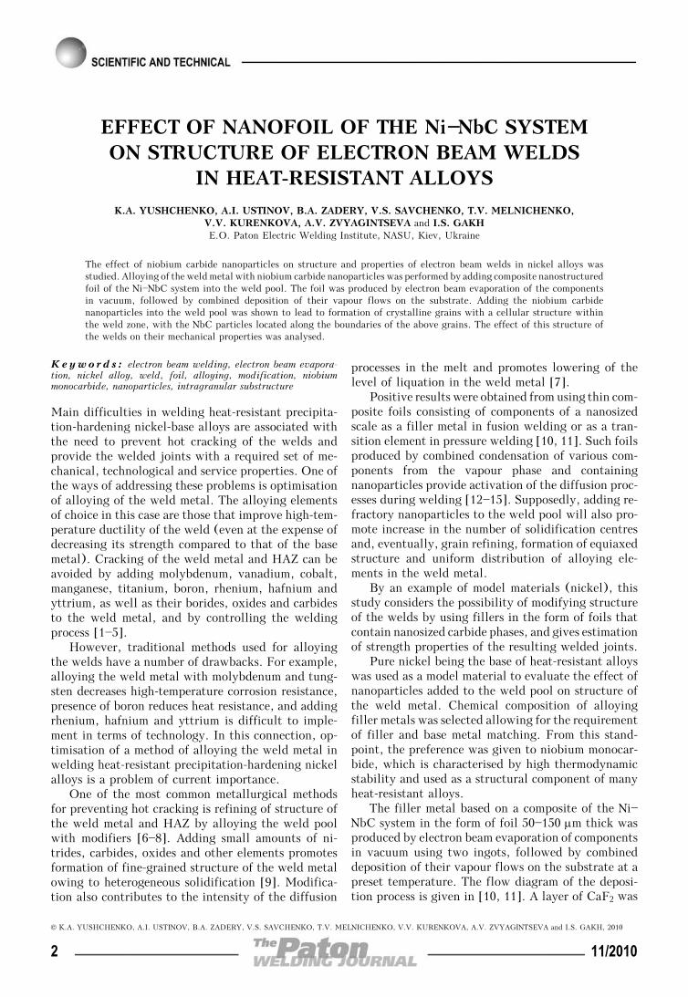
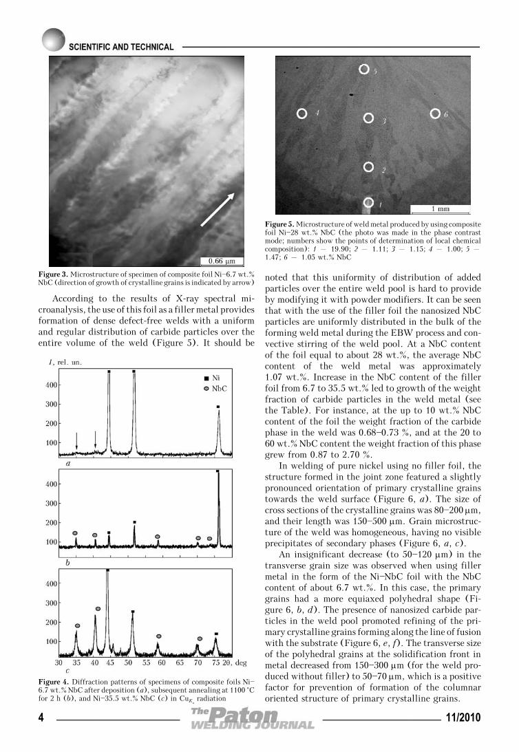
Composite filler foil Ni—(6.7—35.5) wt.% NbC pro-duced by the electron beam evaporation method hada uniform distribution of components through thick-ness δ (Figure 2). Cross section of the filler foil inthe initial state had a columnar structure, width ofthe columnar crystalline grains being approximately300 nm (Figure 3). The low condensation temperatureprovided formation of nano-scale carbide particles inthe condensate, which was confirmed by the presenceof wide diffraction peaks (indicated by arrows in Fi-gure 4, a) of NbC in the diffraction pattern of a speci-men of foil Ni—6.7 wt.% NbC after deposition. Narrowpeaks of NbC appeared in the diffraction pattern onlyafter annealing of the foil at a temperature of 1100 °Cfor 2 h, this being indicative of coarsening of thecarbide particles (Figure 4, b).
The clearly pronounced peaks of nickel and nio-bium carbide appeared in the diffraction pattern afterthe content of NbC grew to 35.5 wt.% (Figure 4, c),i.e. increase in the niobium carbide content of thecomposite was accompanied by coarsening of the car-bide particles.
Figure 1. Flow diagram of the EBW process using nanostructuredfoil as filler metal: 1 – base metal; 2 – filler foil; 3 – electronbeam; 4 – weld
Microhardness of welds made on nickel by using filler foils ofdifferent chemical compositions
NbC in foil NbC in weld metal HV, MPa
Without foil 0 1200
6.7 0.68 1310
8.8 0.73 1385
20.0 0.87 1475
26.0 0.96 1495
28.0 1.07 1515
35.5 1.37 1735
60.0 2.70 1865
Figure 2. Distribution of elements through thickness δ of compositefoil of the Ni—NbC system
11/2010 3
According to the results of X-ray spectral mi-croanalysis, the use of this foil as a filler metal providesformation of dense defect-free welds with a uniformand regular distribution of carbide particles over theentire volume of the weld (Figure 5). It should be
noted that this uniformity of distribution of addedparticles over the entire weld pool is hard to provideby modifying it with powder modifiers. It can be seenthat with the use of the filler foil the nanosized NbCparticles are uniformly distributed in the bulk of theforming weld metal during the EBW process and con-vective stirring of the weld pool. At a NbC contentof the foil equal to about 28 wt.%, the average NbCcontent of the weld metal was approximately1.07 wt.%. Increase in the NbC content of the fillerfoil from 6.7 to 35.5 wt.% led to growth of the weightfraction of carbide particles in the weld metal (seethe Table). For instance, at the up to 10 wt.% NbCcontent of the foil the weight fraction of the carbidephase in the weld was 0.68—0.73 %, and at the 20 to60 wt.% NbC content the weight fraction of this phasegrew from 0.87 to 2.70 %.
In welding of pure nickel using no filler foil, thestructure formed in the joint zone featured a slightlypronounced orientation of primary crystalline grainstowards the weld surface (Figure 6, a). The size ofcross sections of the crystalline grains was 80—200 μm,and their length was 150—500 μm. Grain microstruc-ture of the weld was homogeneous, having no visibleprecipitates of secondary phases (Figure 6, a, c).
An insignificant decrease (to 50—120 μm) in thetransverse grain size was observed when using fillermetal in the form of the Ni—NbC foil with the NbCcontent of about 6.7 wt.%. In this case, the primarygrains had a more equiaxed polyhedral shape (Fi-gure 6, b, d). The presence of nanosized carbide par-ticles in the weld pool promoted refining of the pri-mary crystalline grains forming along the line of fusionwith the substrate (Figure 6, e, f). The transverse sizeof the polyhedral grains at the solidification front inmetal decreased from 150—300 μm (for the weld pro-duced without filler) to 50—70 μm, which is a positivefactor for prevention of formation of the columnaroriented structure of primary crystalline grains.
Figure 3. Microstructure of specimen of composite foil Ni—6.7 wt.%NbC (direction of growth of crystalline grains is indicated by arrow)
Figure 5. Microstructure of weld metal produced by using compositefoil Ni—28 wt.% NbC (the photo was made in the phase contrastmode; numbers show the points of determination of local chemicalcomposition): 1 – 19.90; 2 – 1.11; 3 – 1.15; 4 – 1.00; 5 –1.47; 6 – 1.05 wt.% NbC
Figure 4. Diffraction patterns of specimens of composite foils Ni—6.7 wt.% NbC after deposition (a), subsequent annealing at 1100 °Cfor 2 h (b), and Ni—35.5 wt.% NbC (c) in CuKα
radiation
4 11/2010
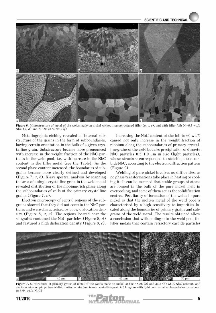
Metallographic etching revealed an internal sub-structure of the grains in the form of subboundaries,having certain orientation in the bulk of a given crys-talline grain. Substructure became more pronouncedwith increase in the weight fraction of the NbC par-ticles in the weld pool, i.e. with increase in the NbCcontent in the filler metal (see the Table). As thesecond phase content increased, the boundaries of sub-grains became more clearly defined and developed(Figure 7, a, b). X-ray spectral analysis by scanningthe area of a single crystalline grain in the weld metalrevealed distribution of the niobium-rich phase alongthe subboundaries of cells of the primary crystallinegrains (Figure 7, c).
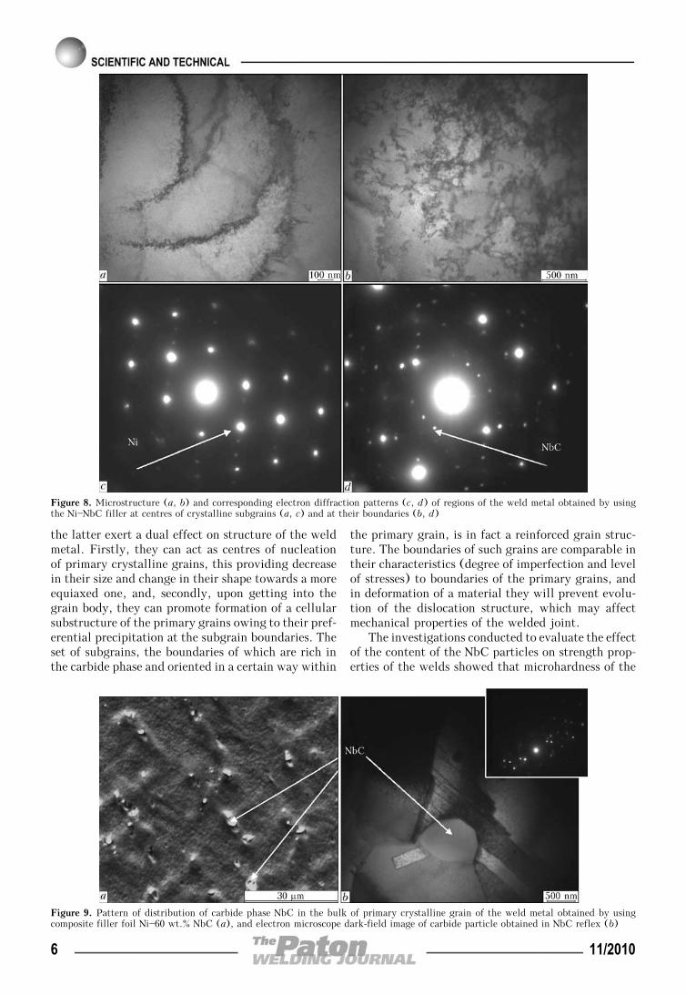
Electron microscopy of central regions of the sub-grains showed that they did not contain the NbC par-ticles and were characterised by a low dislocation den-sity (Figure 8, a, c). The regions located near thesubgrains contained the NbC particles (Figure 8, d)and featured a high dislocation density (Figure 8, c).
Increasing the NbC content of the foil to 60 wt.%caused not only increase in the weight fraction ofniobium along the subboundaries of primary crystal-line grains of the weld but also precipitation of discreteNbC particles 0.5—1.0 μm in size (light particles),whose structure corresponded to stoichiometric car-bide NbC, according to the electron diffraction pattern(Figure 9).
Welding of pure nickel involves no difficulties, asno phase transformations take place in heating or cool-ing it. It can be assumed that stable groups of atomsare formed in the bulk of the pure nickel melt inovercooling, and some of them act as the solidificationcentres. Peculiarity of formation of the welds in purenickel is that the molten metal of the weld pool ischaracterised by a high sensitivity to impurities lo-cated along the boundaries of primary grains and sub-grains of the weld metal. The results obtained allowa conclusion that with adding into the weld pool thefiller metals that contain refractory carbide particles
Figure 6. Microstructure of metal of the welds made on nickel without nanostructured filler (a, c, e), and with filler foils Ni—6.7 wt.%NbC (b, d) and Ni—20 wt.% NbC (f)
Figure 7. Substructure of primary grains of metal of the welds made on nickel at their 8.86 (a) and 35.5 (b) wt.% NbC content, andelectron microscopic picture of distribution of niobium in one crystalline grain (c) (regions with light contrast at subboundaries correspondto 3.04 wt.% NbC)
11/2010 5
the latter exert a dual effect on structure of the weldmetal. Firstly, they can act as centres of nucleationof primary crystalline grains, this providing decreasein their size and change in their shape towards a moreequiaxed one, and, secondly, upon getting into thegrain body, they can promote formation of a cellularsubstructure of the primary grains owing to their pref-erential precipitation at the subgrain boundaries. Theset of subgrains, the boundaries of which are rich inthe carbide phase and oriented in a certain way within
the primary grain, is in fact a reinforced grain struc-ture. The boundaries of such grains are comparable intheir characteristics (degree of imperfection and levelof stresses) to boundaries of the primary grains, andin deformation of a material they will prevent evolu-tion of the dislocation structure, which may affectmechanical properties of the welded joint.
The investigations conducted to evaluate the effectof the content of the NbC particles on strength prop-erties of the welds showed that microhardness of the
Figure 8. Microstructure (a, b) and corresponding electron diffraction patterns (c, d) of regions of the weld metal obtained by usingthe Ni—NbC filler at centres of crystalline subgrains (a, c) and at their boundaries (b, d)
Figure 9. Pattern of distribution of carbide phase NbC in the bulk of primary crystalline grain of the weld metal obtained by usingcomposite filler foil Ni—60 wt.% NbC (a), and electron microscope dark-field image of carbide particle obtained in NbC reflex (b)
6 11/2010
material in the weld zone increased from 1200 (forpure nickel) to 1865 MPa (when using the Ni—35.5 wt.% NbC filler foil) with increase in theirweight fraction in the weld pool. The mean value ofshort-time strength of the welded joints produced byusing the Ni—NbC filler foil increases to 343 MPa,compared with strength of the welds (325 MPa) madewithout the filler foil, whereas the value of yieldstrength σ0.2 increases two times (to 248 MPa) com-pared with pure nickel (σ0.2 = 126 MPa). Therefore,the modifying effect of the niobium carbide nanopar-ticles on structure of the welds as a whole providesincrease in short-time strength of the welded jointsin the as-welded condition at a small decrease in tough-ness of the joints.
As shown by structural analysis, the highest modi-fying effect of the niobium carbide particles shows upat their content of the filler foil equal to 15—20 wt.%.Increase in the NbC content of the filler foil to morethan 35.5 wt.% leads to precipitation of coarse niobiumcarbide particles along the primary grain boundariesin the weld metal, which form carbide chains afterannealing of the material, while this may have a nega-tive effect on mechanical properties of the weldedjoints at high temperatures and applied stresses.
Mechanical tests of the EI698 nickel alloy weldedjoints produced by using composite filler Ni—NbC,which were conducted at a temperature of 600 °C,showed that σt = 805 MPa and σ0.2 = 440 MPa cor-responded to the level of properties of the base metal.
Therefore, the preferential distribution of the nio-bium carbide nanoparticles along the subgrain bounda-ries promotes strengthening of the weld and increase inits microhardness. Also, it may affect increase in heatand crack resistance of the welded joints [16].
1. Bagryansky, K.V., Kuzmin, G.S. (1963) Welding of nickeland its alloys. Moscow: Mashgiz.
2. Yushchenko, K.A., Kvasnitsky, V.F. (1985) Current prob-lems of welding and brazing of heat-resistant alloys. In:Abstr. of Papers of 2nd All-Union Conf. on Problems ofTechnology for Welding of Thermostable, High-Tempera-ture and Heat-Resistant Steels and Alloys (Nikolaev, 24—26Sept. 1985). Kiev: PWI.
3. Morochko, V.P., Yakushin, B.F., Fedorov, V.G. (1976) Ef-fect of alloying on properties of welded joint on heat-resis-tant alloy KhN73MBTYu. Svarochn. Proizvodstvo, 8, 24—27.
4. Yushchenko, K.A., Savchenko, V.S., Zvyagintseva, A.V.(2004) Effect of heat treatment and degree of alloying onstructural changes in nickel alloys. The Paton Welding J.,7, 12—14.
5. Zaks, I.A. (1996) Electrodes for arc welding of steels andnickel alloys: Refer. Book. St-Petersburg: Welcome.
6. Furman, E.L., Zherebtsov, S.N., Gurdin, V.I. (2007) Modi-fication of heat-resistant nickel alloys by ultra-dispersedpowders of refractory particles. Tekhnologiya Mashino-stroeniya, 1, 7—9.
7. Eryomin, E.N. (2007) Modification of weld metal in elec-troslag welding of KhN77TYuR refractory alloy. The PatonWelding J., 9, 38—41.
8. Yushchenko, K.A., Yarovitsyn, A.V., Zvyagintseva, A.V.(2008) Properties of microplasma powder welded joints onheat-resistant nickel alloys. Ibid., 9, 5—9.
9. Efimenko, N.G. (2002) Modifying, refining and alloyingwith yttrium in welding of steels. Ibid., 6, 8—12.
10. Paton, B.E., Ishchenko, A.Ya., Ustinov, A.I. (2008) Appli-cation of nanotechnology of permanent joining of advancedlight-weight metallic materials for aerospace engineering.Ibid., 12, 2—8.
11. Ishchenko, A.Ya., Falchenko, Yu.V., Ustinov, A.I. et al.(2007) Diffusion welding of finely-dispersed AMg5 + 27 %Al2O3 composite with application of nanolayered Ni/Al foil.Ibid., 7, 2—5.
12. Ryabtsev, I.A., Kondratiev, I.A., Gadzyra, N.F. et al.(2009) Effect of ultra-dispersed carbides contained in flux-cored wires on properties of heat-resistant deposited metal.Ibid., 6, 10—13.
13. Gleiter, H. (2000) Nanostructured materials. Basic conceptsand microstructure. Acta Mater., 48(1), 1—29.
14. Andrievsky, R.A., Glezer, A.M. (1999) Dimensional effectsin nanocrystalline materials. Peculiarities of structure. Fiz.Met. i Metallovedenie, 88(1), 50—73.
15. Gusev, A.I. (1998) Effects of nanostructural state in com-pact metals and joints. Uspekhi Fizich. Nauk, 168, 29—58.
16. Valiev, R.Z., Kajbyshev, O.A. (1987) Grain boundariesand properties of metals. Moscow: Metallurgiya.
11/2010 7

STRUCTURE AND PROPERTIESOF ARC-WELDED JOINTS ON STEEL 10G2FB
S.L. ZHDANOV1, V.D. POZNYAKOV1, A.A. MAKSIMENKO1, V.A. DOVZHENKO1, V.G. VASILIEV1,N.V. VYSOKOLYAN2 and V.A. KOROBKA2
1E.O. Paton Electric Welding Institute, NASU, Kiev, Ukraine2OJSC «Kryukovsky railway car building works», Kremenchug, Ukraine
Structural transformations in the HAZ metal of steel 10G2FB under the impact of the arc welding thermal cycles andtheir effects on the mechanical properties of this region of a welded joint were investigated. The range of permissiblecooling rates of the HAZ metal at temperatures of 600—500 °C, providing properties of the welded joints at a level ofrequirements to the base metal and their high resistance to delayed, brittle and laminated fractures, was identified.
Keywo rd s : arc welding, high-strength steels, weldedjoints, CCT diagram, martensite and bainite transformations,cooling rate, hardness, diffusion hydrogen, cold cracks
Intensive development of a container shipment, con-ditioned by establishment of the international trans-porting corridors, resulted in a necessity of designingand mastering of a production of special container carplatforms which should completely fulfill the require-ments on load-carrying capacity and type of transport-ing containers of a carrier. Besides, such a rollingstock should have an advanced reliability and beingeconomical in running. 72 t load-carrying capacityand 22 t light weight are the optimum parameters forthis car taking into account 23.5 t of an allowableaxle load.
The shaped and sheet rolled products of 09G2,09G2D, 16D, St3 and other steels with up to 350 MPayield strength are used in manufacture of the load-carrying welded structures of a freight rolling stockin Ukraine and CIS countries up to present time. How-ever, an application of higher strength steels is nec-essary for manufacture of new generation freight cars.The specialists of VNIIZhT [1] believe that the steelswith more than 390 MPa yield strength which arecharacterized by higher ductility (δ5 > 19 %) andimpact toughness (KCU—60 > 29.4 J/cm2, KCV—60 >> 19.6 J/cm2) are to be perspective for manufactureof load-carrying welded structures of the rolling stock.Such steels should have good weldability and beingmass produced at the domestic metallurgical com-plexes.
10G2FB grade steel mostly fulfills specified re-quirements as shown by analysis of roll metal producedby Ukrainian metallurgical enterprises. This steel iswidely used in manufacture of large diameter pipesfor the main pipelines [2, 3] and produced in accord-ance with TT 227-21—2008 specification. The require-ments to chemical composition of sheets of 10G2FBsteel are the following, not more, wt.%: 0.15 C;0.35 Si; 1.70 Mn; 0.02 P; 0.01 S; 0.02—0.03 Al overall;0.01—0.03 Ti; 0.08 Nb; 0.01 W; 0.30 Mo. The me-
chanical properties of 10G2FB steel sheets make notless than σy = 490 MPa; σt = 565 MPa; δ5 = 28.5 %;KCV—60 = 69 J/cm2; KCU—60 = 59 J/cm2.
The aim of the present paper consisted in an in-vestigation of weldability of high strength 10G2FBgrade steel taking into account special requirementsto a steel rolled metal designed for freight car building[1]. Structural transformations in the HAZ metal of10G2FB steel under the impact of the welding thermalcycles and their influence on the mechanical propertiesof given region of the welded joint, steel susceptibilityto formation of cold and laminated cracks, steel reac-tion to burnian, and brittle fracture resistance of thewelded joints were studied in accordance with theserequirements.
The samples cutout from 18.7 mm thick sheets ofthe following chemical composition, wt.%: 0.08 C;0.249 Si; 1.57 Mn; 0.05 V; 0.05 Nb; 0.006 [N]; 0.007 S;0.013 P, were used in the investigations. Such indicesas σy = 531—581 MPa; σt = 610—660 MPa; δ5 = 24.8—26.3 %; ψ = 62.0—64.8 %, KCU—60 = 220—324 J/cm2;KCV—60 = 204—300 J/cm2 are characteristic for themechanical properties of steel in as received conditionsafter thermomechanical treatment. The extreme valuesof mechanical property indices correspond to tests ofthe samples cutout across and along the rolled metal,respectively. It should be noted that the steel hassufficiently high indices of ductility (ψz = 65.0—69.7 %) in the axis z direction indicating its highresistance to the laminated fracture.
10G2FB steel differs by high ductile properties.An evidence of this fact is the results of the traditionalimpact toughness tests as well as steel reaction toburning by welding arc in accordance with GOST23240—78. The main point of the latter test method,regulated by normative documents for selection ofrolled metal in car building, lied in obtaining of alow-plastic lens on the surface of sample under theeffect of arc burning and determining its influence onsteel susceptibility to transion in a brittle state underthe impact load application. The shape and dimensions
© S.L. ZHDANOV, V.D. POZNYAKOV, A.A. MAKSIMENKO, V.A. DOVZHENKO, V.G. VASILIEV, N.V. VYSOKOLYAN and V.A. KOROBKA, 2010
8 11/2010
of the sample corresponded to a notched specimen forimpact bend tests.
The results of given tests correlate with the sameindices obtained for the O-notched base metal speci-mens for impact bend and make KCU—60 = 346 J/cm2,i.e. critical temperature of 10G2FB steel transition inthe brittle state are below —60 °C.
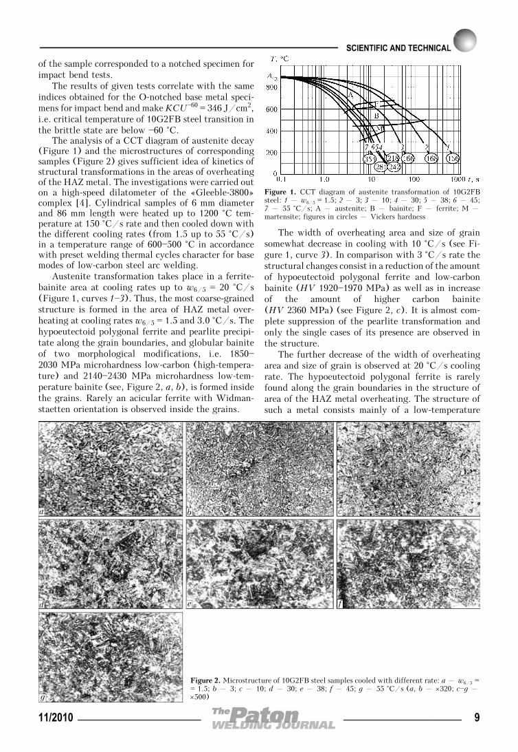
The analysis of a CCT diagram of austenite decay(Figure 1) and the microstructures of correspondingsamples (Figure 2) gives sufficient idea of kinetics ofstructural transformations in the areas of overheatingof the HAZ metal. The investigations were carried outon a high-speed dilatometer of the «Gleeble-3800»complex [4]. Cylindrical samples of 6 mm diameterand 86 mm length were heated up to 1200 °C tem-perature at 150 °C/s rate and then cooled down withthe different cooling rates (from 1.5 up to 55 °C/s)in a temperature range of 600—500 °C in accordancewith preset welding thermal cycles character for basemodes of low-carbon steel arc welding.
Austenite transformation takes place in a ferrite-bainite area at cooling rates up to w6/5 = 20 °C/s(Figure 1, curves 1—3). Thus, the most coarse-grainedstructure is formed in the area of HAZ metal over-heating at cooling rates w6/5 = 1.5 and 3.0 °C/s. Thehypoeutectoid polygonal ferrite and pearlite precipi-tate along the grain boundaries, and globular bainiteof two morphological modifications, i.e. 1850—2030 MPa microhardness low-carbon (high-tempera-ture) and 2140—2430 MPa microhardness low-tem-perature bainite (see, Figure 2, a, b), is formed insidethe grains. Rarely an acicular ferrite with Widman-staetten orientation is observed inside the grains.
The width of overheating area and size of grainsomewhat decrease in cooling with 10 °C/s (see Fi-gure 1, curve 3). In comparison with 3 °C/s rate thestructural changes consist in a reduction of the amountof hypoeutectoid polygonal ferrite and low-carbonbainite (HV 1920—1970 MPa) as well as in increaseof the amount of higher carbon bainite(HV 2360 MPa) (see Figure 2, c). It is almost com-plete suppression of the pearlite transformation andonly the single cases of its presence are observed inthe structure.
The further decrease of the width of overheatingarea and size of grain is observed at 20 °C/s coolingrate. The hypoeutectoid polygonal ferrite is rarelyfound along the grain boundaries in the structure ofarea of the HAZ metal overheating. The structure ofsuch a metal consists mainly of a low-temperature
Figure 1. CCT diagram of austenite transformation of 10G2FBsteel: 1 – w6/5 = 1.5; 2 – 3; 3 – 10; 4 – 30; 5 – 38; 6 – 45;7 – 55 °C/s; A – austenite; B – bainite; F – ferrite; M –martensite; figures in circles – Vickers hardness
Figure 2. Microstructure of 10G2FB steel samples cooled with different rate: a – w6/5 == 1.5; b – 3; c – 10; d – 30; e – 38; f – 45; g – 55 °C/s (a, b – ×320; c—g –×500)
11/2010 9
bainite (globular with HV 2100—2360 MPa) plushigh-temperature low-carbon bainite (HV 1850—2030 MPa) in smaller amount.
The width of overheating area and size of grain atcooling with 30 °C/s rate (see Figure 1, curve 4) arethe same as at w6/5 = 20 °C/s. The hypoeutectoidpolygonal ferrite is absent in the structure of over-heating area and high-temperature bainite (HV 1750—2000 MPa) is rarely found. The structure almost com-
pletely consists of the globular bainite (HV 2140—2280 MPa) (see Figure 2, d).
An increase of cooling rate from w6/5 = 30 up to55 °C/s (see Figure 1, curves 4—7) develops the con-ditions for increasing a level of austenite overcoolingand decreasing a temperature of its transformation,respectively. At that the diffusion processes arestopped and austenite transformation takes place ona shear mechanism with formation of a bainite- marten-site structure. The temperature of beginning ofmartensite transformation virtually does not changeand makes 440 °C while the temperature of transfor-mation ending decreases from 370 to 310 °C at increaseof cooling rates. As a result, it can be claimed thatthe overcooled austenite has a high strength in10G2FB steel HAZ metal.
The structural components also change in a per-centage ratio. Thus, if at w6/5 = 30 °C/s cooling ratethe metal structure includes 83 % of bainite, 12 % ofmartensite and non-equiaxed being the rest withHV 218 hardness (see Figure 2, d) than the structurewill consist of 35 % of martinsite and 65 % of bainitewith HV 354 hardness at maximum cooling ratew6/5 = 55 °C/s (see Figure 2, g).
The structural transformation differences in10G2FB steel set depending on welding thermal cycleshave an influence on the mechanical properties ofwelded joints as well as their resistance to brittle anddelayed fracture.
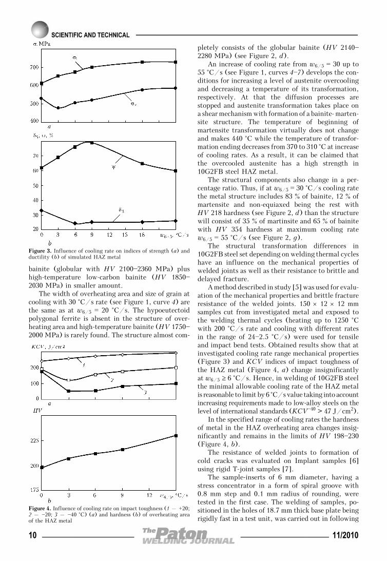
A method described in study [5] was used for evalu-ation of the mechanical properties and brittle fractureresistance of the welded joints. 150 × 12 × 12 mmsamples cut from investigated metal and exposed tothe welding thermal cycles (heating up to 1250 °Cwith 200 °C/s rate and cooling with different ratesin the range of 24—2.5 °C/s) were used for tensileand impact bend tests. Obtained results show that atinvestigated cooling rate range mechanical properties(Figure 3) and KCV indices of impact toughness ofthe HAZ metal (Figure 4, a) change insignificantlyat w6/5 ≥ 6 °C/s. Hence, in welding of 10G2FB steelthe minimal allowable cooling rate of the HAZ metalis reasonable to limit by 6 °C/s value taking into accountincreasing requirements made to low-alloy steels on thelevel of international standards (KCV—40 > 47 J/cm2).
In the specified range of cooling rates the hardnessof metal in the HAZ overheating area changes insig-nificantly and remains in the limits of HV 198—230(Figure 4, b).
The resistance of welded joints to formation ofcold cracks was evaluated on Implant samples [6]using rigid T-joint samples [7].
The sample-inserts of 6 mm diameter, having astress concentrator in a form of spiral groove with0.8 mm step and 0.1 mm radius of rounding, weretested in the first case. The welding of samples, po-sitioned in the holes of 18.7 mm thick base plate beingrigidly fast in a test unit, was carried out in following
Figure 3. Influence of cooling rate on indices of strength (a) andductility (b) of simulated HAZ metal
Figure 4. Influence of cooling rate on impact toughness (1 – +20;2 – —20; 3 – —40 °C) (a) and hardness (b) of overheating areaof the HAZ metal
10 11/2010
mode: Iw = 160 A, Ua = 25 V, vw = 9 m/h using 4 mmdiameter ANP-10 electrodes. The rate of welded jointcooling was varied by changing a preheating tempera-ture of the base plate. Its values were determined onthe oscillograms of welding thermal cycles for high-temperature areas of the HAZ metal in the sample-in-serts. The amount of diffusion hydrogen in the depos-ited metal was determined by a pencil test methodusing a water glycerine solution as a locking liquid.Loading of the sample was performed in a course ofits cooling to 100—50 °C temperature after welding.
The welding of «rigid T-joint» samples from18.7 mm thick steel was performed with ANP-10 elec-trodes of 4.0 mm diameter as well as in CO2 withflux-cored wire Megafil 821R of 1.2 mm diameter inmodes providing close values of energy input for speci-fied welding methods. The temperature of the samplesbefore welding was changed in the range of 20—90 °C.
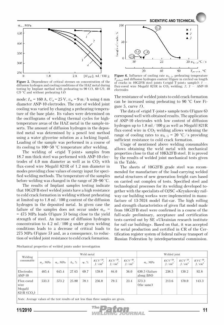
The results of Implant samples testing indicatethat 10G2FB steel welded joints have a high resistanceto cold crack formation in welding without preheatingat limited up to 1.8 ml/100 g content of the diffusionhydrogen in the deposited metal. In given case thefailure of the samples does not occur under σcr == 475 MPa loads (Figure 5) being close to the yieldstrength of steel. An increase of diffusion hydrogenconcentration to 4.2 ml/100 g under given weldingconditions leads to a decrease of critical loads to275 MPa (Figure 5) and, as a consequence, to reduc-tion of welded joint resistance to cold crack formation.
The resistance of welded joints to cold crack formationcan be increased using preheating to 90 °C (see Fi-gure 5, curve 1).
The data of «rigid T-joint» sample tests (Figure 6)correspond well with obtained results. The applicationof ANP-10 electrodes with low content of diffusionhydrogen up to 1.8 ml/100 g as well as Megafil 821Rflux-cored wire in CO2 welding allows widening therange of cooling rates to w6/5 = 20 °C/s providingsufficient resistance to cold crack formation.
Usage of mentioned above welding consumablesallows obtaining the weld metal with mechanicalproperties close to that of 10Kh2FB steel. It is provedby the results of welded joint mechanical tests givenin the Table.
The sheets of 10G2FB grade steel was recom-mended for manufacture of the load-carrying weldedmetal structures of new generation freight cars basedon carried out complex of tests. Specified steel andtechnological processes for its welding developed to-gether with the specialists of OJSC «Kryukovsky rail-way car building works» were implemented in manu-facture of 13-7024 model flat-car. The high rollingand strength characteristics of given flat model madefrom 10G2FB steel were confirmed in a course of thefull-scale preliminary, acceptance and certificationtests carried out by SE «Ukrainian research institutefor rail car building». Based on that, it was acceptedfor serial production and certified in CR of the Cer-tification register system of federal railway transport ofRussian Federation by interdepartmental commission.
Figure 5. Dependence of critical stresses on concentration of thediffusion hydrogen and cooling conditions of the HAZ metal duringtesting by Implant method with preheating to 90 (1), 60 (2), 40(3) °C and without preheating (4)
Mechanical properties of welded joints under investigation
Weldingconsumable
Weld metal Welded joint
σy, MPa σt, MPa δ5, % ψ, %KCV+20,J/cm2
KCV—20,J/cm2
KCV—40,J/cm2 σt, MPa
KCV+20,J/cm2
KCV—20,J/cm2
KVC—40,J/cm2
ElectrodesANP-10
485.4 645.4 27.65 69.7 159.0 84.0 56.0 630.5 (failurealong BM)
238.5 150.2 92.8
Flux-coredwireMegafil821R (CO2)
533.3 573.2 25.80 78.1 256.0 79.5 23.4 573.3(the same)
213.6 170.0 143.3
Note. Average values of the test results of not less than three samples are given.
Figure 6. Influence of cooling rate w6/5, preheating temperatureTpreheat and diffusion hydrogen content (figure in circles) on lengthof cracks in 10G2FB steel joints («rigid T-joint» sample): 1 –flux-cored wire Megafil 821R in CO2 welding; 2, 3 – ANP-10electrodes
11/2010 11
More than 1500 flat-cars, manufactured on OJSC«Kryukovsky railway car building works» are succes-sfully used at the railways of CIS and Baltic countriesat present time.
1. OST 32.153—2000: Rolled metal for freight car bodies ofnew generation. Introd. 18.09.2000.
2. Semyonov, S.E., Rybakov, A.A., Goncharenko, L.V. et al.(2005) Deformation ageing of pipes of controlled rolling steel.Tekhnich. Diagnostika i Nerazrush. Kontrol, 4, 39—43.
3. Efron, L.I., Nastich, S.Yu. (2006) State of production ofsheet and coiled stocks for spiral-welded pipes of strengthcategory up to X1000. Chyorn. Metallurgiya, 11, 68—81.
4. Grigorenko, G.M., Kostin, V.A., Orlovsky, V.Yu. (2008)Current capabilities of simulation of austenite transformationsin low-alloyed steel welds. The Paton Welding J., 3, 22—24.
5. Sarzhevsky, V.A., Sazonov, V.Ya. (1981) Unit for simula-tion of welding thermal cycles on the base of MSR-75 ma-chine. Avtomatich. Svarka, 5, 69—70.
6. Makarov, E.L. (1981) Cold cracks in welding of alloysteels. Moscow: Mashinostroenie.
7. Hrivnak, I. (1984) Weldability of steels. Ed. by E.L.Makarov. Moscow: Mashinostroenie.
STRENGTH OF BRAZED JOINTS ON HEAT-RESISTANTNICKEL ALLOY INCONEL 718 PRODUCED
BY USING PALLADIUM BRAZING FILLER METALS
V.F. KHORUNOV1, S.V. MAKSYMOVA1, Yu.V. BUTENKO2 and A.B. MALY2
1E.O. Paton Electric Welding Institute, NASU, Kiev, Ukraine2State Enterprise «Zarya-Mashproekt», Nikolaev, Ukraine
Comparative investigations were carried out to study strength of high-temperature vacuum brazed joints on heat-resistantnickel alloy Inconel 718, made by using filler metals of the Pd—Ni—Cr—Si, Pd—Ni—Co—Cr—Si and Pd—Ni—Cr—B systemsand experimental filler metal of the Pd—Ni—Cr—Ge system. The experimental filler metal was shown to have a highpotential for ensuring specified short- and long-time strength of the brazed joints.
Keywo rd s : brazing, heat-resistant precipitation-hardeningnickel alloy Inconel 718, brazing filler metal, nickel, palladium,short- and long-time strength
Materials for high-temperature applications includeheat-resistant high nickel-based alloys (superalloys),whose high mechanical properties are achieved pri-marily as a result of solid-solution strengthening andintermetallic and carbide reinforcement. The maincontribution is made by dispersed inclusions of thephase based on Ni3Al intermetallic, i.e. the so-calledγ′-phase, the amount of which depends on the alu-minium and titanium content of an alloy. Alloys witha low content of the γ′-phase have good weldability,whereas those with a high content of the γ′-phase (e.g.over 60 %) are considered unweldable [1]. It is thisfact that usually determines the choice of a joiningmethod for this structure or the other.
However, in practice there may be situations wherethe choice of the joining method is determined not bya material, but by design peculiarities of a product.Such a case is considered in this article.
A workpiece (centrifugal wheel) is a structure ofthe cylindrical shape with complex-configurationblades milled out on its external surface, and it wasnecessary to join a 3 mm thick covering disk to thetop surface of the blade by the permanent joiningmethods. The workpiece material was Inconel 718,which is a well-weldable alloy. However, it was im-possible to manufacture a product by arc or electronbeam welding because of the absence of access insidethe workpiece to perform welding. A variant of weld-
ing to the blade through the covering disk by itsthrough penetration with the arc or electron beam wasunfeasible, as the width of the blade in the zone whereit adjoins the covering disk was only 2 mm. A variantof electron beam heating of the surface of the coveringdisk to melt the filler metal placed in the gap betweenthe sheet and blade was not approved either. As aresult, brazing was chosen as the most promising join-ing method for this application.
Much research efforts in different countries all overthe world have been dedicated to development of fillermetals for brazing high alloys, and brazing filler met-als of different system have been suggested. Thesefiller metals have one feature in common, consistingin the fact that they are the eutectic-containing alloys.Therefore, to achieve high mechanical properties, itis necessary to apply diffusion holding at high tem-peratures. Moreover, most of these filler metals areintended for repair brazing, rather than for fabricationof complex structures. So, it was desirable to have afiller metal with a solid solution structure, whichwould have high strength characteristics at any braz-ing cycle.
Available are such filler metals based on the Mn—Niand Ni—Pd systems. The second system holds morepromise for vacuum brazing, where it is necessary toprovide high corrosion resistance of the brazed joints.Known in the art is filler metal PZhK-1000, which isused in industry to braze high-temperature applicationparts. This filler metal was applied to make specimensfor short-time tensile strength tests at 20 and 550 °C,
© V.F. KHORUNOV, S.V. MAKSYMOVA, Yu.V. BUTENKO and A.B. MALY, 2010
12 11/2010
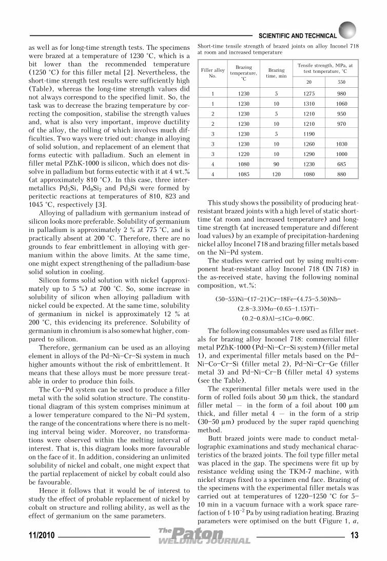
as well as for long-time strength tests. The specimenswere brazed at a temperature of 1230 °C, which is abit lower than the recommended temperature(1250 °C) for this filler metal [2]. Nevertheless, theshort-time strength test results were sufficiently high(Table), whereas the long-time strength values didnot always correspond to the specified limit. So, thetask was to decrease the brazing temperature by cor-recting the composition, stabilise the strength valuesand, what is also very important, improve ductilityof the alloy, the rolling of which involves much dif-ficulties. Two ways were tried out: change in alloyingof solid solution, and replacement of an element thatforms eutectic with palladium. Such an element infiller metal PZhK-1000 is silicon, which does not dis-solve in palladium but forms eutectic with it at 4 wt.%(at approximately 810 °C). In this case, three inter-metallics Pd5Si, Pd9Si2 and Pd3Si were formed byperitectic reactions at temperatures of 810, 823 and1045 °C, respectively [3].
Alloying of palladium with germanium instead ofsilicon looks more preferable. Solubility of germaniumin palladium is approximately 2 % at 775 °C, and ispractically absent at 200 °C. Therefore, there are nogrounds to fear embrittlement in alloying with ger-manium within the above limits. At the same time,one might expect strengthening of the palladium-basesolid solution in cooling.
Silicon forms solid solution with nickel (approxi-mately up to 5 %) at 700 °C. So, some increase insolubility of silicon when alloying palladium withnickel could be expected. At the same time, solubilityof germanium in nickel is approximately 12 % at200 °C, this evidencing its preference. Solubility ofgermanium in chromium is also somewhat higher, com-pared to silicon.
Therefore, germanium can be used as an alloyingelement in alloys of the Pd—Ni—Cr—Si system in muchhigher amounts without the risk of embrittlement. Itmeans that these alloys must be more pressure treat-able in order to produce thin foils.
The Co—Pd system can be used to produce a fillermetal with the solid solution structure. The constitu-tional diagram of this system comprises minimum ata lower temperature compared to the Ni—Pd system,the range of the concentrations where there is no melt-ing interval being wider. Moreover, no transforma-tions were observed within the melting interval ofinterest. That is, this diagram looks more favourableon the face of it. In addition, considering an unlimitedsolubility of nickel and cobalt, one might expect thatthe partial replacement of nickel by cobalt could alsobe favourable.
Hence it follows that it would be of interest tostudy the effect of probable replacement of nickel bycobalt on structure and rolling ability, as well as theeffect of germanium on the same parameters.
This study shows the possibility of producing heat-resistant brazed joints with a high level of static short-time (at room and increased temperature) and long-time strength (at increased temperature and differentload values) by an example of precipitation-hardeningnickel alloy Inconel 718 and brazing filler metals basedon the Ni—Pd system.
The studies were carried out by using multi-com-ponent heat-resistant alloy Inconel 718 (IN 718) inthe as-received state, having the following nominalcomposition, wt.%:
(50—55)Ni—(17—21)Cr—18Fe—(4.75—5.50)Nb—
(2.8—3.3)Mo—(0.65—1.15)Ti—
(0.2—0.8)Al—≤1Co—0.06C.
The following consumables were used as filler met-als for brazing alloy Inconel 718: commercial fillermetal PZhK-1000 (Pd—Ni—Cr—Si system) (filler metal1), and experimental filler metals based on the Pd—Ni—Co—Cr—Si (filler metal 2), Pd—Ni—Cr—Ge (fillermetal 3) and Pd—Ni—Cr—B (filler metal 4) systems(see the Table).
The experimental filler metals were used in theform of rolled foils about 50 μm thick, the standardfiller metal – in the form of a foil about 100 μmthick, and filler metal 4 – in the form of a strip(30—50 μm) produced by the super rapid quenchingmethod.
Butt brazed joints were made to conduct metal-lographic examinations and study mechanical charac-teristics of the brazed joints. The foil type filler metalwas placed in the gap. The specimens were fit up byresistance welding using the TKM-7 machine, withnickel straps fixed to a specimen end face. Brazing ofthe specimens with the experimental filler metals wascarried out at temperatures of 1220—1250 °C for 5—10 min in a vacuum furnace with a work space rare-faction of 1⋅10—2 Pa by using radiation heating. Brazingparameters were optimised on the butt (Figure 1, a,
Short-time tensile strength of brazed joints on alloy Inconel 718at room and increased temperature
Filler alloyNo.
Brazingtemperature,
°C
Brazingtime, min
Tensile strength, MPa, attest temperature, °C
20 550
1 1230 5 1275 980
1 1230 10 1310 1060
2 1230 5 1210 950
2 1230 10 1210 970
3 1230 5 1190
3 1230 10 1260 1030
3 1220 10 1290 1000
4 1080 90 1230 685
4 1085 120 1080 880
11/2010 13

b) and T-joint specimens (Figure 1, c). Standard me-chanical test specimens (according to GOST 1497,GOST 9651 and GOST 10145) were turned from thebutt joints. The time of brazing using filler metal 4was increased to 90 and 120 min to ensure diffusionof boron from the seam to the base metal and decreasethe amount of borides in the seam.
After brazing and before the mechanical tests thespecimens were subjected to heat treatment, leadingto strengthening of alloy Inconel 718 as a result ofprecipitation of the strengthening phases. The heattreatment parameters were as follows: hardening at1050 °C and holding for 1.5 h, air cooling, ageing at760 °C and holding for 10.5 h, cooling with furnaceto 650 °C at a rate of 55 °C/h, holding at this tem-perature for 8.5 h, and air cooling. In the strengthenedstate, the value of tensile strength of alloy Inconel718 at room temperature was 1338 MPa, and at
650 °C – 965 MPa. Tensile testing machine IMCh-30was used for short-time tensile tests at room tempera-ture, and machine IM 12A – at 550 °C. MachineMP-3 was used for long-time tensile tests. In the long-time tensile tests the specimens were heated to 550 °Cand held for 2 h. And then the required load wasapplied to them.
As shown by examinations of the brazed butt andT-joint specimens, filler metals 1—3 at a temperatureof 1250 °C featured good fluidity and spread well overthe substrate of Inconel 718. Flowing out of the fillermetal from the brazing gap and its spreading over thesurface of the base material was observed. No filletswere formed at the given temperature, and porosityof the brazed seams could be visually observed (seeFigure 1, a).
The brazing conditions were optimised on butt andT-joint specimens. Decreasing the brazing temperature
Figure 2. Microstructure of the brazed seam (a) and distribution of palladium (b), nickel (c) and chromium (d) in it
Figure 1. Appearance of butt brazed joints produced, respectively, at Tbr = 1250, 1230 °C (a, b), and of T-joint produced at Tbr == 1230 °C (c)
14 11/2010

when making the butt joints with brazing filler metals1 and 2 to 1230 °C, and with brazing filler metal 3 to1210—1230 °C led to formation of the minimal sizesof the fillets, and caused no erosion of the base metal(see Figure 1, b). Brazing of the T-joints featuredgood formation of thin and dense fillet regions (Fi-gure 1, c).
The brazed seams had a homogeneous structure(Figure 2, a), nickel was uniformly distributed in thebase and seam metals (Figure 2, c), the amount ofpalladium gradually increased in width of the seamfrom the base metal to the central part of the seam(Figure 2, b), and the base metal contained a bit morechromium (Figure 2, d).
Results of the short-time tensile strength tests ofthe brazed joints at room temperature showed that allthe brazing filler metals under investigation providedhigh strength of the joints (from 1080 to 1310 MPa,see the Table). Fracture of the brazed joints occurredin the base metal. The maximal mean values of tensilestrength (1292.5 MPa) were obtained by using fillermetal 1. The 5 min increase in the brazing time ledto a 2.7 and 4.7 % increase in the mean tensile strengthvalues when using filler metals 1 and 3, respectively,the mean tensile strength value for brazing filler metal3 being 1290 MPa. Filler metal 2 provided the suffi-ciently consistent strength values, but at a lower level(1210 MPa), independently of the brazing time.
Alloying the Pd—Ni—Cr—Si system filler metal withcobalt increased ductility of the brazed joints approxi-mately twice, this being evidenced by the values ofelongation (15.2—16.0 %) and reduction in area (18.0—19.7 %). The high values of ductility and, correspond-ingly, reduction in area (22.5 %) and elongation(10 %) were obtained by using experimental fillermetal 3.
The trend in distribution of strength propertiesbetween the filler metals used persisted in the high-temperature tests, which were carried out at a tem-perature of 550 °C (see the Table). The mean tensilestrength values in brazing with filler metals 1 and 3was approximately identical and equal to 1020 and1015 MPa, respectively. The lower mean values wereobtained when using filler metals 2 (960 MPa) and4 (783 MPa). The minimal values of strength of thejoints brazed with the Pd—Ni—Cr—B system filler metalwere caused by the presence of boron, which is char-
acterised by low solubility in nickel. During isother-mal brazing it diffused from the seam into the basemetal and precipitated along the grain boundaries ofthe base metal in the form of borides, this having anegative effect on the strength properties.
Maximal ductility at a temperature of 550 °C wasprovided by the filler metal alloyed with cobalt, theelongation of the brazed specimens ensured by it rang-ing from 10 to 80 %. Ductility of the brazed jointsproduced by using the experimental filler metal wasa bit lower and equal to 4—12 %.
In the long-time strength tests conducted at a tem-perature of 550 °C and load of 785 MPa the specimensfractured in the base metal in brazing with filler metal1 after 29 h, and with filler metal 2 after 75 h (Fi-gure 3, a), as well as in the seam metal brazed withfiller metals 2—4 (Figure 3, b).
The best results were exhibited by the brazed jointsproduced by using experimental filler metal 3 (Fi-gure 4). Two specimens out of the four ones fracturedafter the 42 and 60 h tests. Specimens 9 and 10 didnot fracture after 112 and 130 h (Figure 4), this beingmore than two times higher than the required lifetime.
Filler metal 3 was used to produce the T-jointspecimens, which successfully passed the tests undera load of 220 and 300 MPa, their conventional endur-ance limit being 6.2⋅106 and 8.7⋅106 cycles.
CONCLUSIONS
1. As proved by investigations of the brazed joints onheat-resistant nickel alloy Inconel 718, the boron-con-taining Pd—Ni—Cr—B filler metal does not allowachieving the required strength and ductility of thebrazed joint both at room and increased temperatures.
2. In evaluation of short-time tensile strength atroom temperature, an increase in the brazing time(from 5 to 10 min) was found to lead to a 2.7 and4.7 % increase in mean tensile strength when using
Figure 3. Fracture of brazed specimens after long-time tensilestrength tests: a – base metal; b – seam metal
Figure 4. Long-time strength of brazed joints produced by usingcommercial filler metal Pd—Ni—Cr—Si (specimens 1 and 2) and ex-perimental filler metals Pd—Ni—Co—Cr—Si (3, 4), Pd—Ni—Cr—B (5,6) and Pd—Ni—Cr—Ge (7—10)
11/2010 15
the commercial 1 and experimental 3 filler metals,respectively.
3. The maximal value of short-time tensile strengthequal to 1310 MPa (at Ttest = 20 °C) was achieved inbrazing heat-resistant alloy Inconel 718 with the com-mercial filler metal based on the Pd—Ni—Cr—Si system.However, the brazed joints tested to long-time tensilestrength had an insufficient life time within a rangeof 29—60 h.
4. The experimental Pd—Ni—Cr—Ge filler metalprovides the short-time tensile strength value at alevel of that of the base metal equal to 1230—
1290 MPa, and ensures the consistent results in long-time tensile strength tests at a temperature of 550 °Cand load of 785 MPa. The brazed specimens did notfracture after the tests even for 112 and 132 h, thisbeing more than two times in excess of the requiredlife time.
1. Seams, Ch., Hagel, V. (1976) Heat-resistant alloys. Mos-cow: Metallurgiya.
2. (2003) Reference book on brazing. Ed. by I.E. Petrunin.Moscow: Mashinostroenie.
3. (1999) Constitutional diagrams of binary metal system:Refer. Book. Vol. 3. Ed. by N.P. Lyakishev. Moscow: Ma-shinostroenie.
FEATURES OF WELD FORMATION AND PROPERTIESOF ALUMINIUM AND MAGNESIUM ALLOY JOINTS
UNDER SIMULATED SPACE CONDITIONS
A.A. BONDAREV and E.G. TERNOVOJE.O. Paton Electric Welding Institute, NASU, Kiev, Ukraine
Features of weld formation in welded joints of aluminium and magnesium alloys made by electron beam welding underthe influence of varying gravity forces and low temperatures are given. Influence of the above factors and content ofdissolved hydrogen in the base metal on joint strength, defect formation and loss of alloying elements from the weldmetal is shown.
Keywo rd s : electron beam welding, flying laboratory, alu-minium alloys, magnesium alloys, gravity conditions, low tempera-ture, liquid nitrogen, dissolved hydrogen, porosity, strength, al-loying element evaporation, X-ray microprobe analysis
Aluminium and magnesium alloys are the main struc-tural materials for aerospace vehicle construction [1—4]. It is probable that already in the near future a realneed may arise for application of welding under theconditions of near-earth space or on the Moon surface[5, 6]. These can be mounting-assembly operations inconstruction of space complexes or repair-preventiveoperations, associated with guaranteeing long-termservice of operating systems [7]. Analysis of the rangeof welding operations performed in space shows thatit will be most often necessary to join materials from0.5 up to 4.0 mm thick. In this connection, selectionof the welding process is an important factor in ob-taining an objective assessment of welded joints ofaluminium alloys of the mentioned thickness underthese conditions. Here it is necessary to apply such abasic criterion as producing high quality welded jointsequivalent to the base metal, without pores or cracks,without lowering the ductility of weld or near-weldzone at minimum losses of alloying elements in thewelded joint [8]. Taking the above-said into account,application of EBW is the most effective in construc-tion of space structures requiring a high reliability ofjoints, minimum weight and volume of the used hard-
ware, complete automation of the welding process andits low energy intensity [5].
In fusion welding of aluminium alloys on theground, the weld and HAZ develop various macro-and microdefects [9], which lead to lowering of jointstrength and ductility, and sometimes also to a lossof their tightness [10, 11]. Development of such de-fects is also possible in welding of these materialsunder the space flight conditions (presence of micro-gravity, low temperature, deep vacuum). In addition,initial composition of the used material has a certaininfluence [12]. The nature of running of a number ofphysical processes changes significantly: gravity forcesare completely or partially absent, role of thermo-capillary and chemical convection rises abruptly,phase separation is practically completely absent be-cause of the difference in density, influence of surfacetension forces and adhesion increases greatly [13—15].
The purpose of the conducted research consisted instudying the influence of the enumerated factors on thequality of weld formation and properties of welded jointsof AD0, AMg3, AMg6, 1201 aluminium alloys and IMV-2 magnesium alloy. Investigations were performed atthe change of gravity in the range of g/g0 from 1⋅10—2
up to 2 (where g0 is the free fall acceleration, and g isthe effective acceleration) and fixed sample temperatureof +20, —100, —120 and —196 °C.
During investigations through-thickness penetra-tion beads on plates and welding of butt joints of theabove alloys 2.0 and 2.5 mm thick were performed.
© A.A. BONDAREV and E.G. TERNOVOJ, 2010
16 11/2010
Composition and ultimate tensile strength of thestudied alloys are given in Table 1.
AMg6 alloy was taken from different melts withdissolved hydrogen concentration of 0.2, 0.3, 0.5 and0.6 cm3/100 g. Before loading into the chamber thesamples to be welded were scraped to the depth of0.05 mm. Time of sample soaking in air did not exceed10 min. Then they were rigidly fixed to a stationarytable, which was cooled by liquid nitrogen after cham-ber pumping down. Absolute pressure in the chamber,which did not exceed 1.33⋅10—3 Pa, was maintained bya cryogenic sorption pump. The following parameterswere recorded during welding: beam current, focusingcurrent, voltage of powering the power unit from on-board DC system, welding speed, acceleration appliedto the weld pool, sample temperature and absolute pres-sure in the chamber. Welding was performed in themodes given in Table 2 at accelerating voltage of 15 kVand not more than 1.5 mm beam diameter, distance fromgun edge to sample surface was 120 mm.
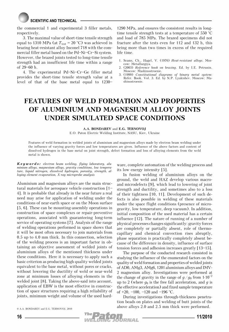
Short-time microgravity conditions were providedby Tu-104A flying laboratory (FL), which carriedA-1084M system with high-frequency electron beampower source and small-sized OB 717 gun movingalong two coordinates (Figure 1).
During experiments the following accelerationswere applied to the weld pool: —g/g0 ≤ 1⋅102 (micro-gravity), 1/6 (free fall acceleration on the Moon sur-face), 1 (free fall acceleration on the Earth surface),not less than 2 (more than two-fold acceleration).
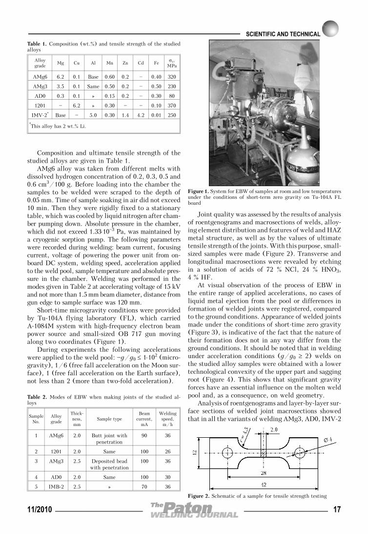
Joint quality was assessed by the results of analysisof roentgenograms and macrosections of welds, alloy-ing element distribution and features of weld and HAZmetal structure, as well as by the values of ultimatetensile strength of the joints. With this purpose, small-sized samples were made (Figure 2). Transverse andlongitudinal macrosections were revealed by etchingin a solution of acids of 72 % NCl, 24 % HNO3,4 % HF.
At visual observation of the process of EBW inthe entire range of applied accelerations, no cases ofliquid metal ejection from the pool or differences information of welded joints were registered, comparedto the ground conditions. Appearance of welded jointsmade under the conditions of short-time zero gravity(Figure 3), is indicative of the fact that the nature oftheir formation does not in any way differ from theground conditions. It should be noted that in weldingunder acceleration conditions (g/g0 ≥ 2) welds onthe studied alloy samples were obtained with a lowertechnological convexity of the upper part and saggingroot (Figure 4). This shows that significant gravityforces have an essential influence on the molten weldpool and, as a consequence, on weld geometry.
Analysis of roentgenograms and layer-by-layer sur-face sections of welded joint macrosections showedthat in all the variants of welding AMg3, AD0, IMV-2
Figure 2. Schematic of a sample for tensile strength testing
Table 2. Modes of EBW when making joints of the studied al-loys
SampleNo.
Alloygrade
Thick-ness,mm
Sample typeBeam
current,mA
Weldingspeed,m/h
1 AMg6 2.0 Butt joint withpenetration
90 36
2 1201 2.0 Same 100 26
3 AMg3 2.5 Deposited beadwith penetration
100 36
4 AD0 2.0 Same 100 30
5 IMB-2 2.5 » 70 36
Figure 1. System for EBW of samples at room and low temperaturesunder the conditions of short-term zero gravity on Tu-104A FLboard
Table 1. Composition (wt.%) and tensile strength of the studiedalloys
Alloygrade
Mg Cu Al Mn Zn Cd Feσt,
MPa
AMg6 6.2 0.1 Base 0.60 0.2 — 0.40 320
AMg3 3.5 0.1 Same 0.50 0.2 — 0.50 230
AD0 0.3 0.1 » 0.15 0.2 — 0.30 80
1201 — 6.2 » 0.30 — — 0.10 370
IMV-2* Base — 5.0 0.30 1.4 4.2 0.01 250
*This alloy has 2 wt.% Li.
11/2010 17

and AMg6 alloys with dissolved hydrogen concentra-tion of 0.2 cm3/100 g, porosity in weld metal is lessthan 0.1⋅10—2 cm3/100 g or is completely absent. Inwelding AMg6 alloy with dissolved hydrogen concen-tration of 0.3 cm3/100 g and higher, an increase ofporosity is found in welds, which is manifested par-ticularly at lowering of the level of gravity forces(g/g0 = 1/6 and ≤ 1⋅10—2) (Figure 5). Under theseconditions, the total volume of pores sometimesreaches 4.42 cm3/100 g. In addition, the size of in-dividual pores increases considerably, and they canreach 2.0—2.5 mm in diameter (Figure 6, b).
Welded joints of heat-hardenable alloy 1201 madeunder the conditions close to zero gravity (g/g0 ≤≤ 1⋅10—2) feature an increased number of microporescompared to welded joints made on the ground. These
Figure 4. Macrosections of welded joints of AMg6 alloy made byEBW in the same mode at g/g0 ≤ 1⋅10
—2 (left) and ≥ 2 (right)
Figure 6. Surface longitudinal section on a joint of AMg6 alloy withhydrogen concentration of 0.4 cm3/100 g made by EBW at g/g0 ≥≥ 2 and ≤ 1⋅10—2 at acceleration forces (a) and zero gravity (b)
Figure 5. Diagram of susceptibility to porosity, vp, of welded jointsof AMg6 alloy with hydrogen concentration of 0.6 (white bar), 0.4(hatched) and 0.2 cm3/100 g (gray) at different accelerations:1 – g/g0 ≤ 1⋅10
—2; 2 – 1/6; 3 – 1; 4 – ≥ 2
Figure 8. Diagram of ultimate tensile strength σt of welded jointof alloys AMg6 (with hydrogen concentration of 0.3 cm3/100 g)(white bar), IMV-2 (hatched) and AMg3 (gray) made at T = 20(a) and —196 (b) °C depending on gravity level: 1 – g/g0 ≤≤ 1⋅10—2; 2 – 1/6; 3 – 1; 4 – ≥ 2
Figure 7. Microstructure (×150) with characteristic porosity inpartial melting zone of welded joint of 1201 alloy made by EBWat g/g0 ≤ 1⋅10
—2
Figure 3. Appearance of welded joints of alloys AMg6 (a), 1201(b), AMg3 (c), AD0 (d) and IMV-2 (e) made by EBW under theconditions of short-time zero gravity in Tu-104A FL
18 11/2010
micropores are located predominantly in the partialmelting section (Figure 7).
It is determined that the density of metal of weldedjoints made on the studied materials does not dependon temperature conditions of welding. Comparingstrength values of welded joints of alloys AMg6 (withhydrogen concentration 0.3 cm3/100 g) and IMV-2made at the temperature of 20 °C and various valuesof g/g0 (Figure 8, a), a tendency to lowering ofstrength at g/g0 = 1/6 and ≤ 1⋅10—2 should be noted,while these values remained unchanged for AMg3 al-loy. In welding under the conditions of low tempera-ture and different g/g0 values (Figure 8, b) a regu-larity of strength rise with increase of gravity level isalso observed. Here, similar strength values are pre-served.
Testing for ultimate tensile strength of base metalof heat-hardenable alloy 1201 was performed in as-delivered condition (without heat treatment). Welded
joints were tested with heat treatment (T = 180 °Cfor 12 h) and without it. Values of ultimate tensilestrength of 1201 alloy joints are given in Table 3.
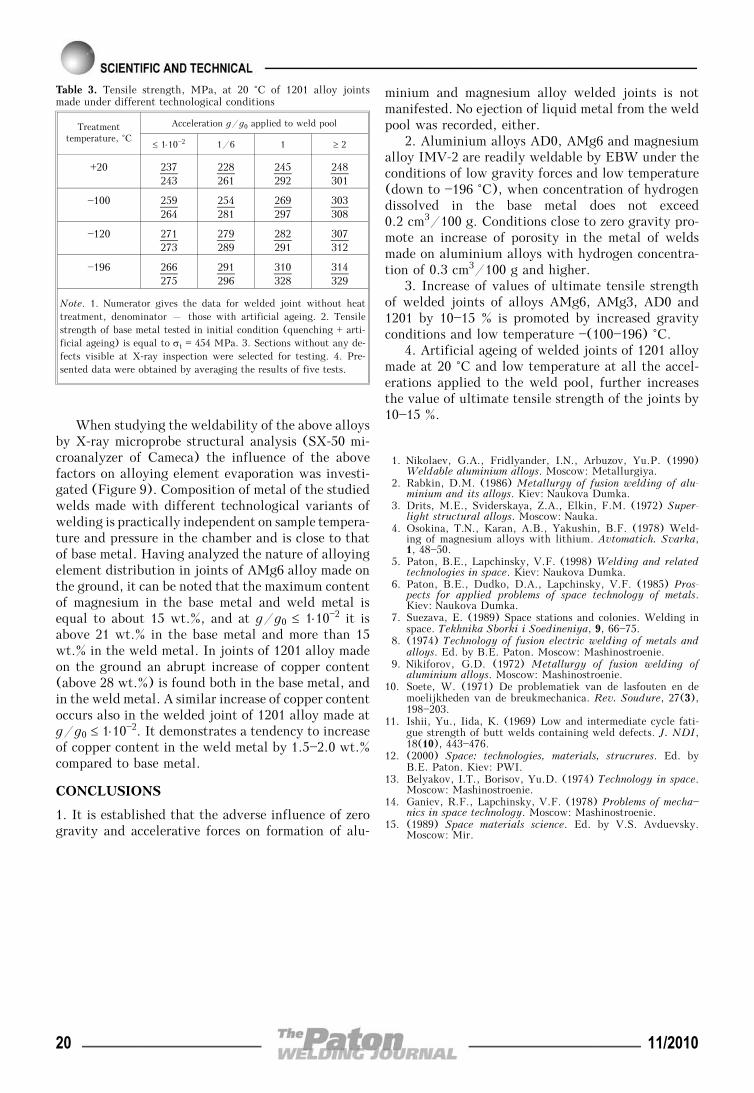
Analysis of the results of mechanical testing of1201 alloy shows that welded joints made under theconditions close to zero gravity (g/g0 ≤ 1⋅10—2) arecharacterized by the lowest strength values (see Ta-ble 3). With increase of acceleration the strength ofwelded joints obtained at the temperature of 20 °Crises from 230 up to 250 MPa, and after artificialageing – from 240 to 300 MPa. In welding withsample cooling to the temperature of —196 °C strengthof joints made at g/g0 ≤ 1⋅10—2 also rises up to270 MPa, and at g/g0 ≥ 2 it rises considerably (upto 320 MPa). Thus, increase of gravity and presenceof low temperatures promote an increase of the levelof ultimate tensile strength of 1201 alloy joints afterwelding up to 315 MPa, and as a result of artificialageing – up to 330 MPa.
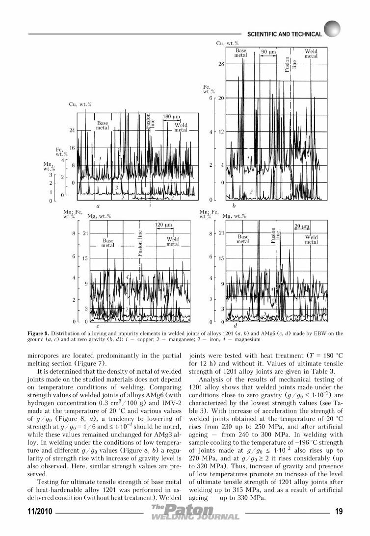
Figure 9. Distribution of alloying and impurity elements in welded joints of alloys 1201 (a, b) and AMg6 (c, d) made by EBW on theground (a, c) and at zero gravity (b, d): 1 – copper; 2 – manganese; 3 – iron, 4 – magnesium
11/2010 19
When studying the weldability of the above alloysby X-ray microprobe structural analysis (SX-50 mi-croanalyzer of Cameca) the influence of the abovefactors on alloying element evaporation was investi-gated (Figure 9). Composition of metal of the studiedwelds made with different technological variants ofwelding is practically independent on sample tempera-ture and pressure in the chamber and is close to thatof base metal. Having analyzed the nature of alloyingelement distribution in joints of AMg6 alloy made onthe ground, it can be noted that the maximum contentof magnesium in the base metal and weld metal isequal to about 15 wt.%, and at g/g0 ≤ 1⋅10—2 it isabove 21 wt.% in the base metal and more than 15wt.% in the weld metal. In joints of 1201 alloy madeon the ground an abrupt increase of copper content(above 28 wt.%) is found both in the base metal, andin the weld metal. A similar increase of copper contentoccurs also in the welded joint of 1201 alloy made atg/g0 ≤ 1⋅10—2. It demonstrates a tendency to increaseof copper content in the weld metal by 1.5—2.0 wt.%compared to base metal.
CONCLUSIONS
1. It is established that the adverse influence of zerogravity and accelerative forces on formation of alu-
minium and magnesium alloy welded joints is notmanifested. No ejection of liquid metal from the weldpool was recorded, either.
2. Aluminium alloys AD0, AMg6 and magnesiumalloy IMV-2 are readily weldable by EBW under theconditions of low gravity forces and low temperature(down to —196 °C), when concentration of hydrogendissolved in the base metal does not exceed0.2 cm3/100 g. Conditions close to zero gravity pro-mote an increase of porosity in the metal of weldsmade on aluminium alloys with hydrogen concentra-tion of 0.3 cm3/100 g and higher.
3. Increase of values of ultimate tensile strengthof welded joints of alloys AMg6, AMg3, AD0 and1201 by 10—15 % is promoted by increased gravityconditions and low temperature —(100—196) °C.
4. Artificial ageing of welded joints of 1201 alloymade at 20 °C and low temperature at all the accel-erations applied to the weld pool, further increasesthe value of ultimate tensile strength of the joints by10—15 %.
Table 3. Tensile strength, MPa, at 20 °C of 1201 alloy jointsmade under different technological conditions
Treatmenttemperature, °C
Acceleration g/g0 applied to weld pool
≤ 1⋅10—2 1/6 1 ≥ 2
+20 237243
228261
245292
248301
—100 259264
254281
269297
303308
—120 271273
279289
282291
307312
—196 266275
291296
310328
314329
Note. 1. Numerator gives the data for welded joint without heattreatment, denominator – those with artificial ageing. 2. Tensilestrength of base metal tested in initial condition (quenching + arti-ficial ageing) is equal to σt = 454 MPa. 3. Sections without any de-fects visible at X-ray inspection were selected for testing. 4. Pre-sented data were obtained by averaging the results of five tests.
1. Nikolaev, G.A., Fridlyander, I.N., Arbuzov, Yu.P. (1990)Weldable aluminium alloys. Moscow: Metallurgiya.
2. Rabkin, D.M. (1986) Metallurgy of fusion welding of alu-minium and its alloys. Kiev: Naukova Dumka.
3. Drits, M.E., Sviderskaya, Z.A., Elkin, F.M. (1972) Super-light structural alloys. Moscow: Nauka.
4. Osokina, T.N., Karan, A.B., Yakushin, B.F. (1978) Weld-ing of magnesium alloys with lithium. Avtomatich. Svarka,1, 48—50.
5. Paton, B.E., Lapchinsky, V.F. (1998) Welding and relatedtechnologies in space. Kiev: Naukova Dumka.
6. Paton, B.E., Dudko, D.A., Lapchinsky, V.F. (1985) Pros-pects for applied problems of space technology of metals.Kiev: Naukova Dumka.
7. Suezava, E. (1989) Space stations and colonies. Welding inspace. Tekhnika Sborki i Soedineniya, 9, 66—75.
8. (1974) Technology of fusion electric welding of metals andalloys. Ed. by B.E. Paton. Moscow: Mashinostroenie.
9. Nikiforov, G.D. (1972) Metallurgy of fusion welding ofaluminium alloys. Moscow: Mashinostroenie.
10. Soete, W. (1971) De problematiek van de lasfouten en demoelijkheden van de breukmechanica. Rev. Soudure, 27(3),198—203.
11. Ishii, Yu., Iida, K. (1969) Low and intermediate cycle fati-gue strength of butt welds containing weld defects. J. NDI,18(10), 443—476.
12. (2000) Space: technologies, materials, strucrures. Ed. byB.E. Paton. Kiev: PWI.
13. Belyakov, I.T., Borisov, Yu.D. (1974) Technology in space.Moscow: Mashinostroenie.
14. Ganiev, R.F., Lapchinsky, V.F. (1978) Problems of mecha—nics in space technology. Moscow: Mashinostroenie.
15. (1989) Space materials science. Ed. by V.S. Avduevsky.Moscow: Mir.
20 11/2010
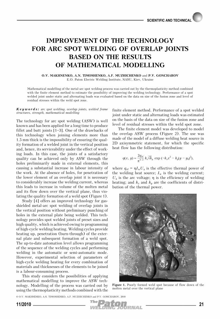
IMPROVEMENT OF THE TECHNOLOGYFOR ARC SPOT WELDING OF OVERLAP JOINTS
BASED ON THE RESULTSOF MATHEMATICAL MODELLING
O.V. MAKHNENKO, A.N. TIMOSHENKO, A.F. MUZHICHENKO and P.V. GONCHAROVE.O. Paton Electric Welding Institute, NASU, Kiev, Ukraine
Mathematical modelling of the metal-arc spot welding process was carried out by the thermoplasticity method combinedwith the finite element method to estimate the possibility of improving the welding technology. Performance of a spotwelded joint under static and alternating loads was evaluated based on the data on size of the fusion zone and level ofresidual stresses within the weld spot zone.
Keywo rd s : arc spot welding, overlap joints, welded framestructures, strength, mathematical modelling
The technology for arc spot welding (ASW) is wellknown and has been applied for a long time to producefillet and butt joints [1—3]. One of the drawbacks ofthis technology when joining elements more than1.5 mm thick is the impossibility of ensuring the qual-ity formation of a welded joint in the vertical positionand, hence, its serviceability under the effect of work-ing loads. In this case, the joints of a satisfactoryquality can be achieved only by ASW through theholes preliminarily made in external elements, thiscausing a substantial increase in labour intensity ofthe work. At the absence of holes, for penetration ofthe lower element of an overlap joint it is necessaryto considerably increase the welding current, whereasthis leads to increase in volume of the molten metaland its flow down over the vertical plane, thus vio-lating the quality formation of a weld spot (Figure 1).
Study [4] offers an improved technology for gas-shielded metal-arc spot welding of overlap joints inthe vertical position without preliminary punching ofholes in the external plate being welded. This tech-nology provides spot welded joints of preset sizes andhigh quality, which is achieved owing to programmingof high-cycle welding heating. Welding cycles provideheating up, penetration (burn-through) of the exter-nal plate and subsequent formation of a weld spot.The up-to-date automation level allows programmingof the sequence of the welding cycles and performingwelding in the automatic or semi-automatic mode.However, experimental selection of parameters ofhigh-cycle welding heating for every combination ofmaterials and thicknesses of the elements to be joinedis a labour-consuming process.
This study considers the possibilities of applyingmathematical modelling to improve the ASW tech-nology. Modelling of the process was carried out byusing the thermoplasticity methods combined with the
finite element method. Performance of a spot weldedjoint under static and alternating loads was estimatedon the basis of the data on size of the fusion zone andlevel of residual stresses within the weld spot zone.
The finite element model was developed to modelthe overlap ASW process (Figure 2). The use wasmade of the model of a diffuse welding heat source in2D axisymmetric statement, for which the specificheat flow has the following distribution:
q(x, y) = 2qef
π3/2 kx√⎯⎯⎯ky exp (—kxx2 — ky(y — y0)
2),
where qef = ηIwUa is the effective thermal power ofthe welding heat source; Iw is the welding current;Ua is the arc voltage; η is the efficiency of weldingheating; and kx and ky are the coefficients of distri-bution of the thermal power.
Figure 1. Poorly formed weld spot because of flow down of themolten metal over the vertical plane
© O.V. MAKHNENKO, A.N. TIMOSHENKO, A.F. MUZHICHENKO and P.V. GONCHAROV, 2010
11/2010 21
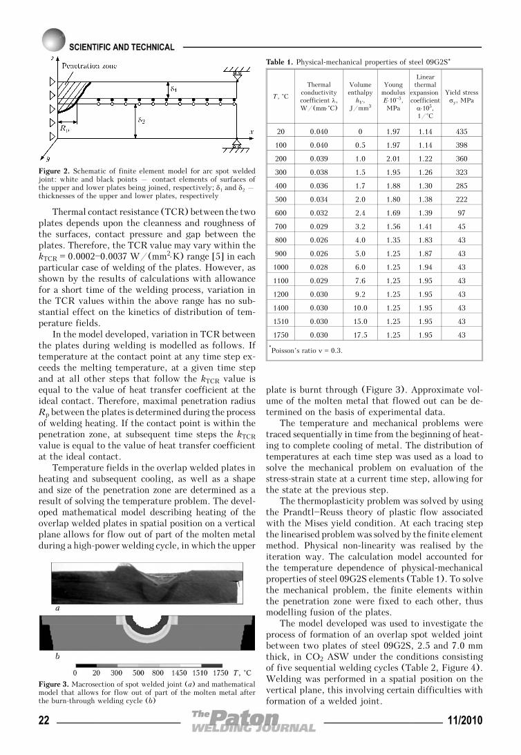
Thermal contact resistance (TCR) between the twoplates depends upon the cleanness and roughness ofthe surfaces, contact pressure and gap between theplates. Therefore, the TCR value may vary within thekTCR = 0.0002—0.0037 W/(mm2⋅K) range [5] in eachparticular case of welding of the plates. However, asshown by the results of calculations with allowancefor a short time of the welding process, variation inthe TCR values within the above range has no sub-stantial effect on the kinetics of distribution of tem-perature fields.
In the model developed, variation in TCR betweenthe plates during welding is modelled as follows. Iftemperature at the contact point at any time step ex-ceeds the melting temperature, at a given time stepand at all other steps that follow the kTCR value isequal to the value of heat transfer coefficient at theideal contact. Therefore, maximal penetration radiusRp between the plates is determined during the processof welding heating. If the contact point is within thepenetration zone, at subsequent time steps the kTCR
value is equal to the value of heat transfer coefficientat the ideal contact.
Temperature fields in the overlap welded plates inheating and subsequent cooling, as well as a shapeand size of the penetration zone are determined as aresult of solving the temperature problem. The devel-oped mathematical model describing heating of theoverlap welded plates in spatial position on a verticalplane allows for flow out of part of the molten metalduring a high-power welding cycle, in which the upper
plate is burnt through (Figure 3). Approximate vol-ume of the molten metal that flowed out can be de-termined on the basis of experimental data.
The temperature and mechanical problems weretraced sequentially in time from the beginning of heat-ing to complete cooling of metal. The distribution oftemperatures at each time step was used as a load tosolve the mechanical problem on evaluation of thestress-strain state at a current time step, allowing forthe state at the previous step.
The thermoplasticity problem was solved by usingthe Prandtl—Reuss theory of plastic flow associatedwith the Mises yield condition. At each tracing stepthe linearised problem was solved by the finite elementmethod. Physical non-linearity was realised by theiteration way. The calculation model accounted forthe temperature dependence of physical-mechanicalproperties of steel 09G2S elements (Table 1). To solvethe mechanical problem, the finite elements withinthe penetration zone were fixed to each other, thusmodelling fusion of the plates.
The model developed was used to investigate theprocess of formation of an overlap spot welded jointbetween two plates of steel 09G2S, 2.5 and 7.0 mmthick, in CO2 ASW under the conditions consistingof five sequential welding cycles (Table 2, Figure 4).Welding was performed in a spatial position on thevertical plane, this involving certain difficulties withformation of a welded joint.
Figure 2. Schematic of finite element model for arc spot weldedjoint: white and black points – contact elements of surfaces ofthe upper and lower plates being joined, respectively; δ1 and δ2 –thicknesses of the upper and lower plates, respectively
Figure 3. Macrosection of spot welded joint (a) and mathematicalmodel that allows for flow out of part of the molten metal afterthe burn-through welding cycle (b)
Table 1. Physical-mechanical properties of steel 09G2S*
T, °С
Thermalconductivitycoefficient λ,W/(mm⋅°C)
Volumeenthalpy
hV,J/mm3
YoungmodulusE⋅10—5,MPa
Linearthermal
expansion coefficient
α⋅105,1/°C
Yield stressσy, MPa
20 0.040 0 1.97 1.14 435
100 0.040 0.5 1.97 1.14 398
200 0.039 1.0 2.01 1.22 360
300 0.038 1.5 1.95 1.26 323
400 0.036 1.7 1.88 1.30 285
500 0.034 2.0 1.80 1.38 222
600 0.032 2.4 1.69 1.39 97
700 0.029 3.2 1.56 1.41 45
800 0.026 4.0 1.35 1.83 43
900 0.026 5.0 1.25 1.87 43
1000 0.028 6.0 1.25 1.94 43
1100 0.029 7.6 1.25 1.95 43
1200 0.030 9.2 1.25 1.95 43
1400 0.030 10.0 1.25 1.95 43
1510 0.030 15.0 1.25 1.95 43
1750 0.030 17.5 1.25 1.95 43
*Poisson’s ratio ν = 0.3.
22 11/2010

The efficiency of welding heating was chosen tobe η = 0.7, based on the data of study [6], as well ason the condition of matching of size of the penetrationzone on macrosection of the spot welded joint andcalculation results (Figure 5). Thermal power distri-bution coefficient kx = 3.0 1/mm2 was also correctedon the same condition. Adding a filler material wasnot modelled in the first heating up welding cyclebecause of its very short duration and subsequent flowout of the molten metal during the second weldingcycle. Volume of the molten metal that flowed outduring the second welding cycle was determined fromthe condition of subsequent filling up with the fillermaterial during the third and fourth welding cycles.
Comparison of the calculation and experimentalresults shows that the developed mathematical modelis adequate for evaluation of formation of the overlapspot welded joint between two plates in ASW in aspatial position on the vertical plane and can be ap-plied to develop the technology for welding such jointswith a complex welding cycle.
This mathematical model allowed obtaining thecalculation results on the distribution of residualstresses within the welded joint zone. This informationcan be helpful for estimation of strength of the spotwelded joints.
Figure 4. Scheme of variations in parameters of ASW in verticalposition: t1—t8 – durations of pulses and pauses; ttotal – total timeof ASW cycle
Table 2. ASW parameters
No. ofweldingcycle
ArcvoltageUa, V
Weldingcurrent Iw,
A
Weldingwire feed
speed vfeed,m/h
Weldingpulse
durationtw, s
Durationof pausebetweenpulsestpause, s
1 28 200 120 0.4—0.5 0.1
2 42 450 276 1.0—1.3 2.0
3 30 250 138 0.8—1.0 1.5
4 30 250 138 0.8—1.0 1.0
5 26 190 120 0.5 —
Figure 5. Comparison of size of the penetration zone on macrosection of the spot welded joint (a) and calculation results (b)
Figure 6. Appearance of samples of spot welded joints before tensile tests (a) and after fracture of the weld spots by shear mechanism (b)
11/2010 23
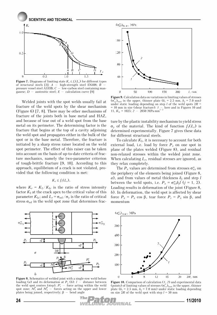
Welded joints with the spot welds usually fail atfracture of the weld spots by the shear mechanism(Figure 6) [7, 8]. There may be other mechanisms offracture of the joints both in base metal and HAZ,and because of tear out of a weld spot from the basemetal on its perimeter. The determining factor is thefracture that begins at the top of a cavity adjoiningthe weld spot and propagates either in the bulk of thespot or in the base metal. Therefore, the fracture isinitiated by a sharp stress raiser located on the weldspot perimeter. The effect of this raiser can be takeninto account on the basis of up-to-date criteria of frac-ture mechanics, namely the two-parameter criterionof tough-brittle fracture [9, 10]. According to thisapproach, equilibrium of a crack is not violated, pro-vided that the following condition is met:
Kr ≤ f1(Lr),
where Kr = KI/KIc is the ratio of stress intensityfactor KI at the crack apex to the critical value of thisparameter KIc; and Lr = σref/σy is the ratio of criticalstress σref in the weld spot zone that determines frac-
ture by the plastic instability mechanism to yield stressσy of the material. The kind of function f1(Lr) isdetermined experimentally. Figure 7 gives these datafor different structural steels.
To calculate KI, it is necessary to account for bothexternal load, i.e. load by force Px on one spot inplane of the plates welded (Figure 8), and residualnon-relaxed stresses within the welded joint zone.When calculating Lr, residual stresses are ignored, asthey relax completely.
The Px values are determined from stresses σxx∞ on
the periphery of the elements being joined (Figure 8,a), and from values of metal thickness δj and step lbetween the weld spots, i.e. Px = σxx
∞ δjl (j = 1, 2).Loading results in deformation of the joint (Figure 8,b). In deformation, the weld spot is affected by shearforce Px = Px cos β, tear force Pz = Px sin β, andmomentum
Figure 7. Diagrams of limiting state Kr ≤ f1(Lr) for different typesof structural steels [3]: A – high-strength steel EN408; B –pressure vessel steel A533B; C – low-carbon steel containing man-ganese; D – austenitic steel; E – calculation curve [9]
Figure 9. Calculation data on variations in limiting values of stresses(σxx
∞ )limit in the upper, thinner plate (δ1 = 2.5 mm, δ2 = 7.0 mm)under static loading depending on step l of the weld spots 2R == 10 mm in size (shear fracture): 1 – here and in Figures 10 and11, KIc = 1025; 2 – 2050 MPa⋅mm1/2
Figure 8. Schematics of welded joint with a single-row weld beforeloading (a) and its deformation at Px (b): l – distance betweenthe weld spot centres (step); Px′ – force acting within the weldspot zone; M1
0 and M20 – forces acting on the upper and lower
plates being joined, respectively; β – bend angle
Figure 10. Comparison of calculation (1, 2) and experimental data(points) of limiting values of stresses (σxx
∞ )limit in the upper, thinnerplate (δ1 = 2.5 mm, δ2 = 7.0 mm) under static loading dependingon size 2R of the weld spot with step l = 50 mm
24 11/2010
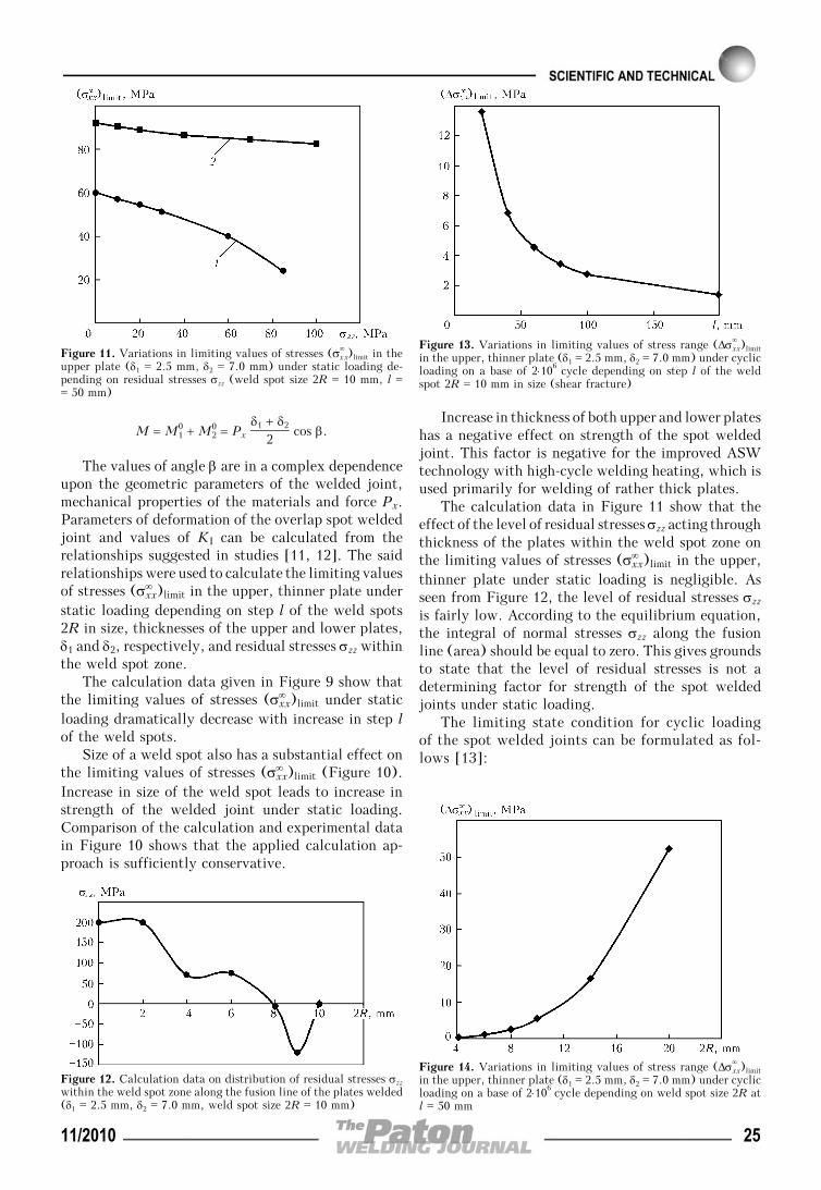
M = M10 + M2
0 = Px δ1 + δ2
2 cos β.
The values of angle β are in a complex dependenceupon the geometric parameters of the welded joint,mechanical properties of the materials and force Px.Parameters of deformation of the overlap spot weldedjoint and values of KI can be calculated from therelationships suggested in studies [11, 12]. The saidrelationships were used to calculate the limiting valuesof stresses (σxx
∞ )limit in the upper, thinner plate understatic loading depending on step l of the weld spots2R in size, thicknesses of the upper and lower plates,δ1 and δ2, respectively, and residual stresses σzz withinthe weld spot zone.
The calculation data given in Figure 9 show thatthe limiting values of stresses (σxx
∞ )limit under staticloading dramatically decrease with increase in step lof the weld spots.
Size of a weld spot also has a substantial effect onthe limiting values of stresses (σxx
∞ )limit (Figure 10).Increase in size of the weld spot leads to increase instrength of the welded joint under static loading.Comparison of the calculation and experimental datain Figure 10 shows that the applied calculation ap-proach is sufficiently conservative.
Increase in thickness of both upper and lower plateshas a negative effect on strength of the spot weldedjoint. This factor is negative for the improved ASWtechnology with high-cycle welding heating, which isused primarily for welding of rather thick plates.
The calculation data in Figure 11 show that theeffect of the level of residual stresses σzz acting throughthickness of the plates within the weld spot zone onthe limiting values of stresses (σxx
∞ )limit in the upper,thinner plate under static loading is negligible. Asseen from Figure 12, the level of residual stresses σzz
is fairly low. According to the equilibrium equation,the integral of normal stresses σzz along the fusionline (area) should be equal to zero. This gives groundsto state that the level of residual stresses is not adetermining factor for strength of the spot weldedjoints under static loading.
The limiting state condition for cyclic loadingof the spot welded joints can be formulated as fol-lows [13]:
Figure 11. Variations in limiting values of stresses (σxx∞ )limit in the
upper plate (δ1 = 2.5 mm, δ2 = 7.0 mm) under static loading de-pending on residual stresses σzz (weld spot size 2R = 10 mm, l == 50 mm)
Figure 13. Variations in limiting values of stress range (Δσxx∞ )limit
in the upper, thinner plate (δ1 = 2.5 mm, δ2 = 7.0 mm) under cyclicloading on a base of 2⋅106 cycle depending on step l of the weldspot 2R = 10 mm in size (shear fracture)
Figure 12. Calculation data on distribution of residual stresses σzz
within the weld spot zone along the fusion line of the plates welded(δ1 = 2.5 mm, δ2 = 7.0 mm, weld spot size 2R = 10 mm)
Figure 14. Variations in limiting values of stress range (Δσxx∞ )limit
in the upper, thinner plate (δ1 = 2.5 mm, δ2 = 7.0 mm) under cyclicloading on a base of 2⋅106 cycle depending on weld spot size 2R atl = 50 mm
11/2010 25
ΔKω∗max
= Kω∗max
— Kω∗min
= ΔKth0 (1 — αrσ),
where the maximal and minimal values Kω∗max
and
Kω∗min
are determined at Px = Pxmax and Px = Px
min,respectively; rσ is the coefficient of asymmetry of thecycle of variation in force Px; ΔKth
0 is the thresholdvalue of a range of stress intensity factor KI (rσ = 0),at which a normal tear crack does not practicallypropagate; and α is the experimental characteristic ofthe material (α ≈ 0.50—0.85) [13].
Strength of the spot welded joint under cyclic load-ing was calculated depending on step l and size 2R ofa weld spot, as well as thickness of the upper andlower plates, δ1 and δ2, respectively, at a conservativevalue of cycle asymmetry coefficient rσ = 0 and Δkth
0 == 190 MPa⋅mm1/2. As seen from the calculation datashown in Figures 13 and 14, this dependence is of thesame character as under static loading. However, asto the limiting values, the stress range under cyclicloading on a base of 2⋅106 cycle is approximately anorder of magnitude lower (at a level of 10—20 MPa)than under static loading, this being in agreementwith the up-to-date notions of cyclic strength of thewelded joints.
CONCLUSIONS
1. High-quality spot welded joints can be providedby regulating parameters of welding cycles in ASWof thin-sheet metal in vertical position. The improvedtechnology offers new possibilities for applying ASWfor fabrication of structures in different industries, inparticular for fabrication of frame structures of mod-ern freight and passenger railway cars.
2. The developed mathematical model can be effi-ciently used to develop the technologies for overlapASW, including with complex welding cycles.
3. As shown by the calculation data, the level ofresidual stresses σzz acting through thickness of the
plates within the weld spot zone is rather low. Ac-cording to the equilibrium equation, the integral ofnormal stresses σzz along the fusion line (area) is equalto zero. Therefore, the level of residual stresses is nota determining factor for strength of the spot weldedjoints under static loading.
4. The limiting values of stresses (σxx∞ )limit under
static loading and stress range (Δσxx∞ )limit under cyclic
loading dramatically decrease with increase in step ofthe weld spots.
5. Increase in size of the weld spot leads to a sub-stantial increase in strength of the welded joint bothunder static and cyclic loading.
1. Tereshchenko, V.I., Sharovolsky, A.N., Sidorenko, K.A. etal. (1983) Peculiarities of CO2 metal-arc spot welding. Av-tomatich. Svarka, 9, 51—53.
2. Tkachenko, A.N., Voskresensky, A.S. (2005) Application ofarc spot welding in fabrication of car bodies. The PatonWelding J., 12, 22—24.
3. GOST 14776—79: Arc welding. Spot welded joints. Maintypes, design elements and sizes. Introd. 01.07.80.
4. Lobanov, L.M., Timoshenko, A.N., Goncharov, P.V. (2009)Arc spot welding of overlap joints in vertical position. ThePaton Welding J., 1, 26—28.
5. Lienhard, J. et al. (2002) Heat transfer textbook. Cambrid-ge, Massachusetts: Phlogiston Press.
6. Rykalin, N.N. (1951) Calculations of thermal processes inwelding. Moscow: Mashgiz.
7. Dorofeev, A.N. (1964) Calculation of strength of spotwelds. Moscow: Mashinostroenie.
8. Serenko, A.I., Krumboldt, M.N., Bagryansky, K.V. (1977)Calculation of welded joints and structures. Kyiv: VyshchaShkola.
9. Harrison, R.P., Looscmore, K., Milne, J. et al. (1980) As-sessment of the integrity of structure containing defects.Central Electricity Generating Board Rep. 6, Rev. 2. Berk-ley.
10. Makhnenko, V.I., Pochinok, V.E. (1982) Application offracture mechanics criteria in calculation of strength of wel-ded joints with specified discontinuities of the crack-liketype. Avtomatich. Svarka, 1, 1—6.
11. Makhnenko, V.I., Ryabchuk, T.G., Pochinok, V.E. (1990)Improvement of the strength design procedure for spot wel-ded joints. Ibid., 1, 9—14.
12. Cherepanov, G.P. (1974) Brittle fracture mechanics. Mos-cow: Nauka.
13. Makhnenko, V.I., Pochinok, V.E. (1984) Cyclic loads resis-tance of welded joints with incomplete penetration welds.Avtomatich. Svarka, 10, 33—40.
26 11/2010

IMPROVEMENT OF CYCLIC FATIGUE LIFEOF METALLIC MATERIALS AND WELDED JOINTSBY TREATMENT BY PULSED ELECTRIC CURRENT
G.V. STEPANOV1, A.I. BABUTSKY1, I.A. MAMEEV1, A.V. CHIZHIK1, V.V. SAVITSKY2,G.I. TKACHUK2 and N.A. PASHCHIN2
1G.S. Pisarenko Institute for Problems of Strength, NASU, Kiev, Ukraine2E.O. Paton Electric Welding Institute, NASU, Kiev, Ukraine
The paper presents experimental data on improvement of cyclic fatigue life of stainless steel and aluminium alloy samplesas a result of treatment based on direct passage of electric current through the material, as well as data of calculation-experimental studies of residual welding stress relaxation under the impact of induced electric current. Results ofinvestigation of the influence of current treatment on residual stresses in the coating and in the material after grindingare given.
Keywo rd s : metallic materials, welded joints, protectivecoatings, pulsed electric current, fatigue, residual stresses, re-laxation, cyclic fatigue life
Results of investigation of the influence of treatmentby pulsed electric current (PEC) on mechanical prop-erties of metallic materials are indicative of its positiveimpact on fatigue resistance characteristics [1—3].However, no significant progress has been achievedin understanding the mechanism of the influence ofPEC treatment on these characteristics, so that ob-taining new experimental data is urgent.
Also known is the influence of residual stresses (RS),in particular, residual welding stresses (RWS), on fa-tigue of structural elements: under the conditions ofcyclic loading, particularly at loading with a low stresslevel, RWS influence is manifested in an essential low-ering of endurance limit of welded joint material andincrease of fatigue crack propagation rate [4, 5].
Operations on lowering of RWS in structures usu-ally are difficult to perform, require considerable ex-penses, and are reduced mainly to thermal and force(mechanical) impact on welded joint metal or to acombination of these impacts. Each of these methodshas certain drawbacks. For instance, local applicationof high-temperature tempering leads to formation ofareas with high residual stresses in the structure afterits complete cooling, as such treatment essentially re-produces the thermal cycle of welding. A similar situ-ation arises at heat treatment of some kinds of coat-ings. Thus, development of new methods to lower RS,devoid of the drawbacks inherent to the currentlyavailable methods, also is an urgent task.
This work gives the results of investigation of theinfluence of PEC treatment on fatigue of 10Kh18N10Tsteel and D16T aluminium alloy, as well as results ofexperimental assessment of PEC influence on RWSand RS relaxation in the coating and ground material.
PEC influence on fatigue of 10Kh18N10T steeland D16T aluminium alloy. Investigations were per-
formed on samples of 10Kh18N10T stainless steel (Fi-gure 1, a) and similar samples of aluminium alloyD16T 3.7 mm thick (unlike 4 mm for steel). In fatiguetesting the sample was supported in cantilever (Fi-gure 1, b) in the grip of the machine (electrodynamicvibration testing facility) [6]. Nine sample groupswere tested altogether: one each – without treatment(as-delivered) and seven – after PEC treatment indifferent modes (Table).
At PEC treatment samples were connected to thetaps of pulsed current generator [7]. Three currentpulses were applied to each of the samples.
Testing results (Figure 2) are indicative of an es-sential influence of PEC on fracture resistance char-acteristics of the material. Treatment of steel samples
Figure 1. Sketch of a sample for fatigue testing (a) and its loadingschematic (b)
© G.V. STEPANOV, A.I. BABUTSKY, I.A. MAMEEV, A.V. CHIZHIK, V.V. SAVITSKY, G.I. TKACHUK and N.A. PASHCHIN, 2010
11/2010 27

at current density j = 1 kA/mm2 (mode 1) leads toa slight increase of these characteristics. At j == 2 kA/mm2 (mode 2) endurance limit of steel risesby 30 %. Increase of current density at treatment upto j = 4 kA/mm2 (mode 3) leads to an increase ofendurance limit by more than 50 %. However, furtherincrease of current density up to j = 5.75 kA/mm2
(mode 4) causes a lowering of fatigue resistance char-acteristics.
A similar tendency is observed also in the case oftreatment of D16T alloy: treatment at j == 1.35 kA/mm2 (mode 5) does not change the fatiguecharacteristics compared to the initial state of thematerial. At j = 2.60 kA/mm2 (mode 6) D16T alloyendurance limit increased by 40 %. Further increaseof current density up to j = 4.32 kA/mm2 (mode 7)does not cause any change of fatigue resistance char-acteristics compared to the initial condition.
It follows from the results of X-ray structuralanalysis of samples from steel that a certain changeof orientation of crystals making up the grains occursat treatment, which is indicative of ordering of thematerial crystalline structure in the direction of cur-rent action. In addition, according to the data of me-tallographic investigations, treatment results in pre-cipitation of carbides (complex carbides (Cr, Fe)7C3)in the metal grain bulk (Figure 3). Here, the maximumdensity of the precipitating carbides in the grain bodyis observed in mode 3 corresponding to a maximumincrease of endurance limit (Figure 3, c). Furtherincrease of current density leads to intensive evolution
Figure 2. Fatigue curves of samples from steel 10Kh18N10T (a) and aluminium alloy D16T (b) in the initial condition (light circle)and after PEC treatment in modes 1—7 according to the Table
Modes of PEC treatment of samples
Mode No. j, kA/mm2 С, μF U, kV I, kA
10Kh18N10T steel
1 1 150 1.8 20
2 2 150 3.63 40
3 4 600 3.46 80
4 5.75 600 5.0 115
D16T alloy
5 1.35 150 2.25 25
6 2.60 100 5.0 48
7 4.32 600 3.46 80
Figure 3. Microstructures (×1000) of a sample of steel 10Kh18N10T depending on PEC treatment parameters: a – initial state; b –I = 40; c – 80; d – 115 kA
28 11/2010
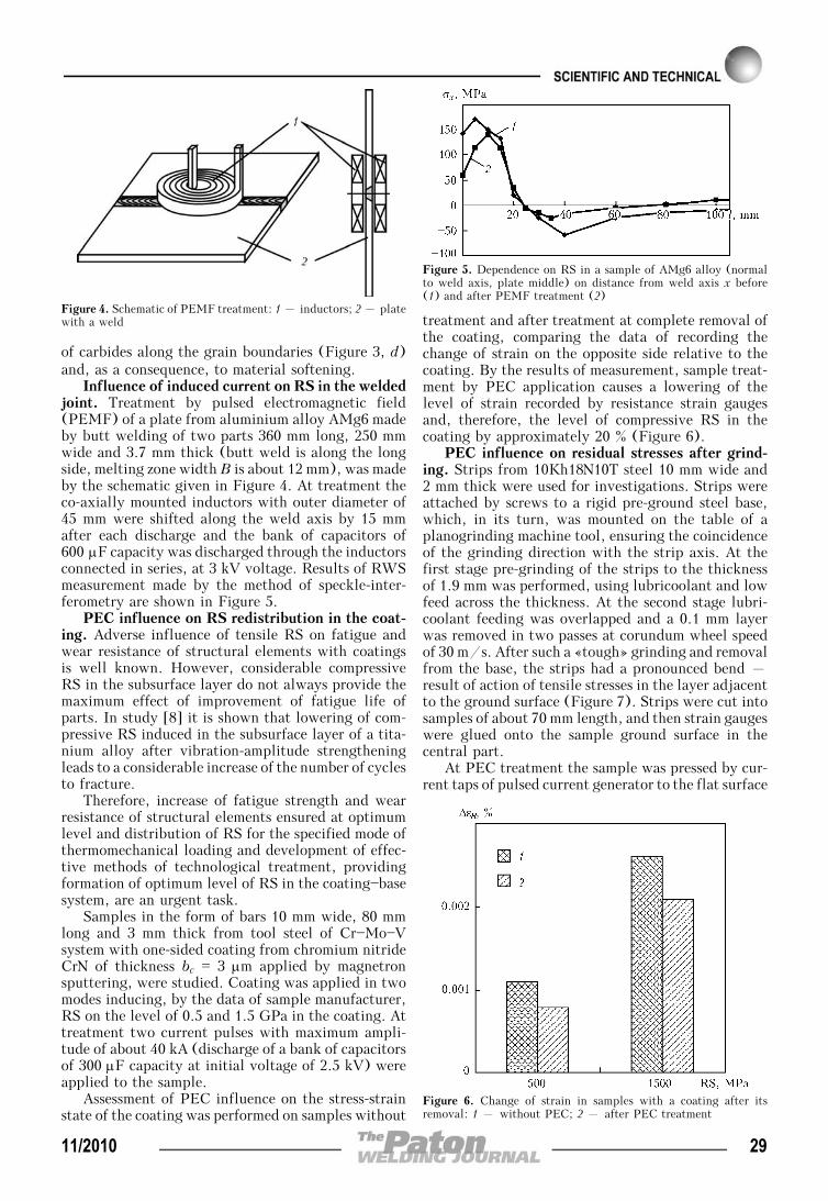
of carbides along the grain boundaries (Figure 3, d)and, as a consequence, to material softening.
Influence of induced current on RS in the weldedjoint. Treatment by pulsed electromagnetic field(PEMF) of a plate from aluminium alloy AMg6 madeby butt welding of two parts 360 mm long, 250 mmwide and 3.7 mm thick (butt weld is along the longside, melting zone width B is about 12 mm), was madeby the schematic given in Figure 4. At treatment theco-axially mounted inductors with outer diameter of45 mm were shifted along the weld axis by 15 mmafter each discharge and the bank of capacitors of600 μF capacity was discharged through the inductorsconnected in series, at 3 kV voltage. Results of RWSmeasurement made by the method of speckle-inter-ferometry are shown in Figure 5.
PEC influence on RS redistribution in the coat-ing. Adverse influence of tensile RS on fatigue andwear resistance of structural elements with coatingsis well known. However, considerable compressiveRS in the subsurface layer do not always provide themaximum effect of improvement of fatigue life ofparts. In study [8] it is shown that lowering of com-pressive RS induced in the subsurface layer of a tita-nium alloy after vibration-amplitude strengtheningleads to a considerable increase of the number of cyclesto fracture.
Therefore, increase of fatigue strength and wearresistance of structural elements ensured at optimumlevel and distribution of RS for the specified mode ofthermomechanical loading and development of effec-tive methods of technological treatment, providingformation of optimum level of RS in the coating—basesystem, are an urgent task.
Samples in the form of bars 10 mm wide, 80 mmlong and 3 mm thick from tool steel of Cr—Mo—Vsystem with one-sided coating from chromium nitrideCrN of thickness bc = 3 μm applied by magnetronsputtering, were studied. Coating was applied in twomodes inducing, by the data of sample manufacturer,RS on the level of 0.5 and 1.5 GPa in the coating. Attreatment two current pulses with maximum ampli-tude of about 40 kA (discharge of a bank of capacitorsof 300 μF capacity at initial voltage of 2.5 kV) wereapplied to the sample.
Assessment of PEC influence on the stress-strainstate of the coating was performed on samples without
treatment and after treatment at complete removal ofthe coating, comparing the data of recording thechange of strain on the opposite side relative to thecoating. By the results of measurement, sample treat-ment by PEC application causes a lowering of thelevel of strain recorded by resistance strain gaugesand, therefore, the level of compressive RS in thecoating by approximately 20 % (Figure 6).
PEC influence on residual stresses after grind-ing. Strips from 10Kh18N10T steel 10 mm wide and2 mm thick were used for investigations. Strips wereattached by screws to a rigid pre-ground steel base,which, in its turn, was mounted on the table of aplanogrinding machine tool, ensuring the coincidenceof the grinding direction with the strip axis. At thefirst stage pre-grinding of the strips to the thicknessof 1.9 mm was performed, using lubricoolant and lowfeed across the thickness. At the second stage lubri-coolant feeding was overlapped and a 0.1 mm layerwas removed in two passes at corundum wheel speedof 30 m/s. After such a «tough» grinding and removalfrom the base, the strips had a pronounced bend –result of action of tensile stresses in the layer adjacentto the ground surface (Figure 7). Strips were cut intosamples of about 70 mm length, and then strain gaugeswere glued onto the sample ground surface in thecentral part.
At PEC treatment the sample was pressed by cur-rent taps of pulsed current generator to the flat surface
Figure 4. Schematic of PEMF treatment: 1 – inductors; 2 – platewith a weld
Figure 5. Dependence on RS in a sample of AMg6 alloy (normalto weld axis, plate middle) on distance from weld axis x before(1) and after PEMF treatment (2)
Figure 6. Change of strain in samples with a coating after itsremoval: 1 – without PEC; 2 – after PEC treatment
11/2010 29
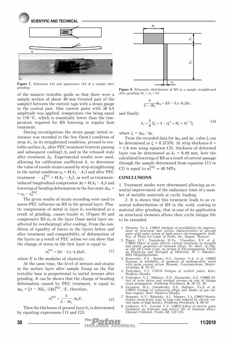
of the massive textolite guide so that there were asample section of about 40 mm (treated part of thesample) between the current taps with a strain gaugein the central part. One current pulse with 50 kAamplitude was applied, temperature rise being equalto 110 °C, which is essentially lower than the tem-perature required for RS lowering in regular heattreatment.
During investigations the strain gauge initial re-sistance was recorded in the free (bent) condition ofstrip A1, in its straightened condition, pressed to tex-tolite surface A2, after PEC treatment (current passingand subsequent cooling) A3 and in the released stateafter treatment A4. Experimental results were used,allowing for calibration coefficient k, to determinethe value of tensile strain caused by strip straighteningin the initial condition εb = k(A2 — A1) and after PECtreatment – εbPEC = k(A3 — A4), as well as treatment-induced longitudinal compression Δε = k(A2 — A3) andlowering of bending deformation in the free state Δεb == εb — εbPEC.
The given results of strain recording were used toassess PEC influence on RS in the ground layer. Plas-tic compression of metal in layer δ1 overheated as aresult of grinding, causes tensile σ1 (Figure 8) andcompressive RS σ2 in the layer (base metal layer un-affected by overheating) after cooling. From the con-dition of equality of forces in the layers before andafter treatment and compatibility of deformation ofthe layers as a result of PEC action we can show thatthe change of stress in the first layer is equal to
σ1PEC = [(δ — δ1)/δ1]ΔεE, (1)
where E is the modulus of elasticity.At the same time, the level of stresses and strains
in the surface layer after sample fixing on the flattextolite base is proportional to initial stresses aftergrinding. It can be shown that the change of bendingdeformation caused by PEC treatment, is equal toΔεb = [1 — 3(δ1/δ]σ1
PEC/E, therefore,
σ1PET =
δ
δ — 3δ1
ΔεbE. (2)
Then the thickness of ground layer δ1 is determinedby equating expressions (1) and (2):
δδ — 3δ1
Δεb = [(δ — δ1) ⁄ δ1]Δε,
and finally
δ1 = δ6 [ξ + 4 — (ξ2 + 8ξ + 4)1/2], (3)
where ξ = Δεb/Δε.From the recorded data for Δεb and Δε, value ξ can
be determined as ξ = 0.57576. At strip thickness δ == 1.8 mm using equation (3), thickness of deformedlayer can be determined as δ1 = 0.48 mm, here thecalculated lowering of RS as a result of current passagethrough the sample determined from equation (1) or(2) is equal to σ1
PEC ≈ 40 MPa.
CONCLUSIONS
1. Treatment modes were determined allowing an es-sential improvement of the endurance limit of a num-ber of metallic materials at cyclic loading.
2. It is shown that this treatment leads to an es-sential redistribution of RS in the weld, coating ormaterial after grinding, that in case of its applicationon structural elements allows their cyclic fatigue lifeto be extended.
1. Doronin, Yu.L. (1992) Analysis of possibilities for improve-ment of structural and service characteristics of aircraftparts with pulse action of high-power electromagnetic field:Syn. of Thesis for Cand. of Techn. Sci. Degree. Moscow.
2. Popov, O.V., Tanenberg, D.Yu., Vlasenkov, S.V. et al.(1990) Effect of pulse electric current treatment on strengthand plastic properties of titanium alloys. In: Abstr. of Pap.of 2nd All-Union Conf. on Action of Electromagnetic Fieldson Plasticity and Strength of Materisls. Pt 1. Nikolaev:RIO Oblpoligrafizdat.
3. Konovalov, S.V., Sosnin, O.I., Gronov, V.E. et al. (2002)Increase in reliability of products of medium-alloy steelswith pulse current action. Remont, Vosstanovlenie, Moder-nizatsiya, 3, 19—23.
4. Trufyakov, V.I. (1973) Fatigue of welded joints. Kiev:Naukova Dumka.
5. Trufyakov, V.I., Mikheev, P.P., Kuzmenko, A.Z. (1980) Ef-fect of scale factor and residual stresses on rate of fatiguecrack propagation. Problemy Prochnosti, 6, 20—22, 30.
6. Gryaznov, B.A., Gorodetsky, S.S., Nalimov, Yu.S. et al.(1992) Fatigue of refractory alloys and blades of gas tur-bine engines. Kiev: Naukova Dumka.
7. Stepanov, G.V., Babutsky, A.I., Mameev, I.A. (2004) Nonsta-tionary stress-strain state in long rods induced by electric cur-rent pulse of high density. Problemy Prochnosti, 4, 60—67.
8. Loskutov, S.V., Levitin, V.V. (2002) Effect of electric pulsetreatment on structure and service life of titanium alloys.Zhurnal Tekhnich. Fiziki, 72, 133—135.
Figure 7. Schematic (a) and appearance (b) of a sample aftergrinding Figure 8. Schematic distribution of RS in a sample straightened
after grinding (δ1 + δ2 = δ)
30 11/2010

TRENDS IN IMPROVEMENT OF AUXILIARY EQUIPMENTFOR WELDING PRODUCTION
V.A. LEBEDEV1, I.V. LENDEL2, V.I. LENDEL2 and V.G. PICHAK1
1E.O. Paton Electric Welding Institute, NASU, Kiev, Ukraine2Ilnitsa Plant of Mechanical Welding Equipment, Ilnitsa, Ukraine
Main trends in development of mechanized welding equipment for fabrication of structures made in and outside Ukraineare analyzed, and basic requirements to them are indicated. Versatile rotators comprising a new generation of driveswith computer numerical control and commutatorless motors are considered. Specific features of their operation arepointed out, and their advantages are noted. Also, the article analyzes the methods for reinstalling roller supports in adriving roller device, and considers some methods for elimination of drift of a workpiece in welding or surfacing.
Keywo rd s : welding, surfacing, cutting, workplace, organi-zation, equipment, rotator, manipulators, new solutions
Successful performance of operations of welding, re-conditioning and strengthening surfacing, as well ascutting of different metal structures, ensuring of theirquality and efficiency of operations greatly depend onarrangement and fitting of workplaces. Various meansand equipment making the welders’ work easier andallowing a considerable improvement of the efficiencyand accuracy of the performed operations have a greatrole here. As a rule, this equipment includes meansof welding production mechanization, in particular,various types of rotators, tilters, columns for weldingand surfacing automatic machines.
The purpose of this work is discussion of the di-rections of development and production of auxiliarymechanical equipment for welding and surfacing bothin Ukraine (specialized plant (Ilnitsa Plant of Me-chanical Welding Equipment), and beyond it (by thematerials of 2009 Essen Exhibition).
Technical publications have descriptions of variousmechanization means for organization of welding andsurfacing productions [1, 2], which provide guidelinesfor selection and design of various equipment of thistype.
As before, the main requirement made of mechani-cal auxiliary welding equipment, is the stability ofthe workpiece rotation, i.e. maintaining the weldingspeed. Great importance is attached to the smoothnessof the workpiece rotation (without vibrations, jerks,jamming, etc.) that is achieved, first of all, due torigidity of the rotator bed, accuracy of manufacturingthe tooth gears, minimum clearances in the seats, re-liability of fastening the workpiece in the rotator face-plate.
Recently much higher requirements have beenmade to the quality of work performed using mecha-nized arc processes, realized by semi-automatic andautomatic machines of varying degrees of technicalperfection, also with additional movements (degree
of automation, use of groove following, devices forarrangement of deposited beads, etc.). All this requireswidening the capabilities of equipment for organiza-tion of modern workplaces for welding, surfacing andcutting of steels and aluminium alloys in the followingdirections: stabilization of welding and surfacingspeed, solving the problems of positioning of the work-piece or welding tool, improvement of the processes,associated with making the weld start and crater weld-ing up. Most of these problems are solved withoutapplication of any additional equipment, for instance,without position sensors at positioning or organizingrepeated cycles in wide-band surfacing, etc. Equip-ment of this type should have systems of programmingand acquisition of data bases. Particularly urgent arethe problems of energy- and resource-saving, solvedby optimization of the systems of control and adjust-ment for them that provide optimum paths of motionof the workpiece or welding tool.
An interesting direction of improvement of the con-sidered type of equipment is that, which it directlyinvolves the modes of welding equipment operation(welding speed is functionally dependent on weldingcurrent) vw — f(Iw). Realization of this direction alsorequires the availability of a certain data base, pro-viding the following advantages:
• accurate setting and maintaining of the corre-spondence of energy characteristics of the arc andwelding displacement;
• mechanized welding and surfacing station beingindependent of the operator’s qualifications;
• quality performance of welding or surfacing witha uniformly formed bead, having a marketable appear-ance immediately after performance of the arc processcycle.
Realization of such capabilities in operation of aux-iliary equipment for welding and surfacing requiresapplication of adjustable electric drives of workingdisplacement with sufficiently large adjustmentrange, and, what is highly important, high response.Here the main problems for mechanical welding equip-ment remain to be ensuring rotation of the welded
© V.A. LEBEDEV, I.V. LENDEL, V.I. LENDEL and V.G. PICHAK, 2010
11/2010 31
(surfaced) workpiece with the set speed during auto-matic or semi-automatic welding (surfacing) and mov-ing the workpiece at travel speed into a position con-venient for welding.
At present the auxiliary equipment systems useelectric drives based on commutator and commutator-less (as a rule, valve) DC electric motors with thyris-tor or transistor regulators of the frequency of shaftrotation, and the recently becoming accepted asyn-chronous electric motors with frequency regulators.
Let us consider some types of modern mechanicalwelding equipment. In the Essen Exhibition thisequipment was presented by various manufacturingcompanies from Hong-Kong, Taiwan, China, as wellas Germany, France, Great Britain, Italy, Sweden,Greece, etc.
In mechanical welding equipment of the leadingcompanies (JAVAC, Germany; Key Plant, Great Brit-ain; ESAB, Sweden; Lambert Jouty, France, etc.)asynchronous motors in a set with standard reductiongears or reduction gears produced in-house, as well asmotor drives, are mainly applied as the rotation drive(Figure 1). Frequency converters of asynchronouselectric motors manufactured by different companiesare applied for adjustment of the speed of rotation.
Companies involved in manufacture of mechanicalwelding equipment also displayed in the exhibitionmanipulators, in which the rotation drive uses a valveelectric motor (Figure 2).
Valve electric motor is a synchronous motor theoperation of which is based on the principle of fre-quency regulation with self-synchronization. The con-troller of valve electric drive (Figure 3) controls themoment applied to the rotor, and unlike the DC brush-type motor, switching in the valve electric motor isperformed and controlled by electronic devices.
Valve electric motors with electronic control systemsoften combine the best properties of contactless motors:high response and dynamics; positioning accuracy; widerange of rotation frequency variation; absence of com-ponents requiring maintenance; high overload capacityby moment; high energy values (efficiency > 90 %, cosϕ > 0.95); long service life, high reliability and increasedoperating life owing to absence of sliding electric con-tacts; low heating of electric motor in operation in modeswith possible overloads.
Local manufacturer of diverse mechanical auxiliarywelding equipment – Ilnitsa Plant of Mechanical
Figure 1. All-purpose manipulators with asynchronous electric motor in the rotation drive
Figure 2. All-purpose manipulators with valve electric motors (1—3)
Figure 3. Control unit of valve electric motor
32 11/2010
Welding Equipment (IPMWE) pays a lot of attentionto various rotation drives. Starting from 2001, theplant during two years had transferred to applicationof converters of asynchronous motor rotation fre-quency (Figure 4). Foreign developments, in particu-lar, General Electric electric drive (VAT-200 model)are used as asynchronous electric drives.
IPMWE is working towards introduction of newgeneration electric drives of valve type. At the begin-ning of 2009, a number of experimental manipulatorswere developed which are based on local electricdrives. Today IPMWE is ready for commercial pro-duction of manipulators with new generation electricdrives (Figure 5) that will allow programming someelements of workpiece rotation both by rotation speed,and by angle of workpiece rotation. In addition, atall the same characteristics, the overall dimensions
and weight of valve electric drives are smaller thanthose of electric drives with an asynchronous electricmotor. Comparative technical characteristics of theserotators with adjustable electric drives based on asyn-chronous and valve electric motors are shown in theTable.
There exists a great diversity of driving roller de-vices (Figure 6) with the same requirements to thespeed of rotation, accuracy of mounting the rollersrelative to workpiece axis, time required for readjust-ment of the rollers for the required workpiece diame-ter. At inaccurate position of roller axis relative tothe axis of workpiece rotation, such a phenomenon asshifting of the workpiece being welded along its axis(drift) is observed, leading, in its turn to deviationof the weld from the welding position. Shifting de-pends on workpiece diameter and angle of non-paral-
Figure 4. All-purpose manipulators manufactured by IPMWE
Figure 5. New models of IPMWE manipulators based on drives with valve electric motors
Comparative technical characteristics of rotators with adjustable electric drives based on asynchronous and valve electric motors
Parameter SPS 150-150S (Figure 1) PRO 1 (Figure 2) М211080 (Figure 4)
Maximum lifting capacity, kg 125 120 125
Faceplate rotation frequency, min—1 0.5—9.0 0.5—5.0 0.16—5.0
Faceplate angle of inclination, deg 0—180 0—90 0—135
Faceplate diameter, mm 500 350 450
Rated welding current (duty cycle = 100 %), A 500 300 500
Mains voltage, voltage/frequency, Hz 230/50 230/50 230/50
Setting the inclination Manually
Overall dimensions (L × B × H), mm 1050 × 880 × 1080 480 × 325 × 470 850 × 695 × 400
Weight, kg, not more than 100 50 75
11/2010 33
lelism of the axes of workpiece and rollers. Differentcompanies have different solutions for this problem.Lampert Jouty mounts a system for following the de-viation of the workpiece and depending on this value,the system gives a signal in the automatic mode tothe drive of final rotation of roller axes.
IPMWE solves this problem by mounting mechani-cal rotating rests (Figure 7), as well as displacementof the actuator (weld following) of the welding head,using the following system (Figure 8).
There are several methods for reinstallation of theroller supports, the driving roller device sections intothe required position, but from those displayed in theexhibition, the following can be singled out:
• using screw—nut transmissions. It enables simul-taneous displacement of two roller supports and elimi-nation of small misalignments by height betweenroller support sections;
• using rests of different designs, the most widelyspread here is fixing of roller supports by holes anddisplacement of roller supports – a faster, but morelabour-consuming process.
Introduction of the new generation of roller sup-ports will be actively pursued further on, as they havea number of advantages, namely possibility of reduc-ing the power inputs and widening the capabilities ofmechanical auxiliary equipment, as well as consider-able improvement of the quality of manufacturedproducts. New systems of regulation with feedbacksby welding equipment parameters will be also devel-oped.
Figure 6. Driving roller rotators with different drive layouts
Figure 7. Retaining roller Figure 8. Working body of the following system mounted on thewelding head
1. Evstifeev, G.A., Veretennikov, I.S. (1977) Means of mecha-nization of welding production: design and calculation.Moscow: Mashinostroenie.
2. Kurkin, S.L., Khovov, V.M., Rybachuk, A.M. (1989) Tech-nology, mechanization and automation of production ofwelded structures: Atlas. Manual. Moscow: Mashino-stroenie.
34 11/2010

IMAGE PROCESSINGFOR AUTOMATED ROBOTIC WELDING
P. SEYFFARTH and R. GAEDEIngenieurtechnik und Maschinenbau GmbH, Rostock, Germany
The new developed by IMG and used by WADAN yards MTW image processing system for welding robots delivers avery fast automatically generated program. A laser line scanner with a scanning rate of 1 m/s and a fast workingcalculation unit gives a 3D picture in less than 3 min all over the 16 × 4 m panel. The accuracy of the robotic positioningis ±0.5 mm after the shake hand process between the image processing system and the robot programming system. Thisnew developed 3D geometrically recognising and robot programming system allows a very fast and flexible productionsystem for micropanels without any link to the central computer aided yard system. This «stand alone system» isindependent, more flexible and shows beside of other advantages a high productivity.
Keywo rd s : robot welding, fillet welding, image process-ing, robot programming, micropanel welding, welding in ship-building
The main parts in the prefabrication of ship hulls areflat and curved panels with dimensions up to 20 ×× 40 m or more and so named micropanels. We meetespecially the last one, the micropanels, in a largenumber of different forms an sizes beginning from 2 ×× 2 up to 4 × 16 m. In a medium sized containerfreighter for 2000 containers there are about 2500 ormore various micropanels. There are different produc-tion technologies for micropanels, consisting fromplates and stiffeners. A modern micropanel productionat a shipyard uses robots for mounting and weldingas well. This is shown as an example in Figures 1 and2. Due to the various construction types of micropanelsand their large range from unique single constructionup to minimum series there is a high demand on theprogramming of robot systems including the move-ment of the robots in the 3D coordinates and thevarious welding parameter. In shipbuilding each mi-cropanel needs its own welding program. All of the
known programming procedures require either addi-tional information on the workpiece in the shape ofCAD data or they need manual interaction. The clas-sical programming of weld robots for micropanelstakes places regardless of the really existing workpieceand production scenario by a partly automatic analysisof CAD data in combination with demanding manualinteractions. The programming takes place temporallyvery much in advance of the production and needs ahigh quality and relevance of the available construc-tion data. Unfortunately this is in contrast to theflexibility of the production flow and can not take inaccount some changes of construction. That means wehave to take in account that normally the program-ming is done a long time before production and veryoften the NC construction data are changed in themeantime.
Refitting of an existing micropanel line by imageprocessing. To meet the needs for a very high flexi-bility and for an automated programming on demandfor the existing panel line (see Figures 1 and 2), theenterprise Ingenieurtechnik und Maschinenbau
© P. SEYFFARTH and R. GAEDE, 2010
Figure 2. Welding station in micropanel line using two robotsbefore refittingFigure 1. Mounting gantry for stiffeners in micropanel line
11/2010 35
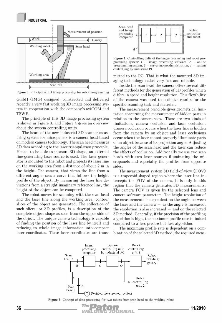
GmbH (IMG) designed, constructed and deliveredrecently a very fast working 3D image processing sys-tem in cooperation with the company’s aviCOM andTSWE.
The principle of this 3D image processing systemis shown in Figure 3, and Figure 4 gives an overviewabout the system controlling units.
The heart of the new industrial 3D scanner meas-uring system for micropanels is a camera head basedon modern camera technology. The scan head measures3D data according to the laser triangulation principle.Hence, to be able to measure 3D shape, an externalline-generating laser source is used. The laser gener-ator is mounted to the robot and projects its laser lineon the working area from a distance of about 2 m inthe height. The camera, that views the line from adifferent angle, sees a curve that follows the heightprofile of the object. By measuring the laser line de-viations from a straight imaginary reference line, theheight of the object can be computed.
The robot moves for scanning with the scan headand the laser line along the working area, contourslices of the object are generated. The collection ofsuch slices, or 3D profiles, is a description of thecomplete object shape as seen from the upper side ofthe object. The unique camera technology is capableof finding the position of the laser line by itself andreducing to whole image information into compactlaser coordinates. These laser coordinates are trans-
mitted to the PC. That is what the mounted 3D im-aging technology makes very fast and reliable.
Inside the scan head the camera offers several dif-ferent methods for the generation of 3D profiles whichdiffers in speed and height resolution. This flexibilityof the camera was used to optimize results for thespecific scanning task and material.
The measurement principle gives geometrical limi-tation concerning the measurement of hidden parts inrelation to the camera view. There are two kinds oflimitations, camera occlusion and laser occlusion.Camera occlusion occurs when the laser line is hiddenfrom the camera by an object and laser occlusionsoccur when the laser cannot properly illuminate partsof an object because of its projection angle. Adjustingthe angles of the scan head and the laser can reducethe effects of occlusion. Additionally we use two scanheads with two laser sources illuminating the mi-cropanels and especially the profiles from oppositesides.
The measurement system 3D field-of-view (FOV)is a trapezoid-shaped region where the laser line in-tercepts the FOV of the camera. It is only in thisregion that the camera generates 3D measurements.The camera FOV is given by the selected lens andcamera software parameters. The height resolution ofthe measurements is dependent on the angle betweenthe laser and the camera – as the angle is increased,the resolution is also increased – and on the selected3D method. Generally, if the precision of the profilingalgorithm is high, the maximum profile rate is limitedcompared to a less precise but fast algorithm.
The maximum profile rate is dependent on a com-bination of the selected 3D method, the required meas-
Figure 3. Principle of 3D image processing for robot programming
Figure 4. Controlling units of the image processing and robot pro-gramming system: 1 – image processing software; 2 – onlineprogramming system; 3 – server macroadministration; 4 – systemcontrolling by industrial PC
Figure 5. Concept of data processing for two robots from scan head to the welding robot
36 11/2010
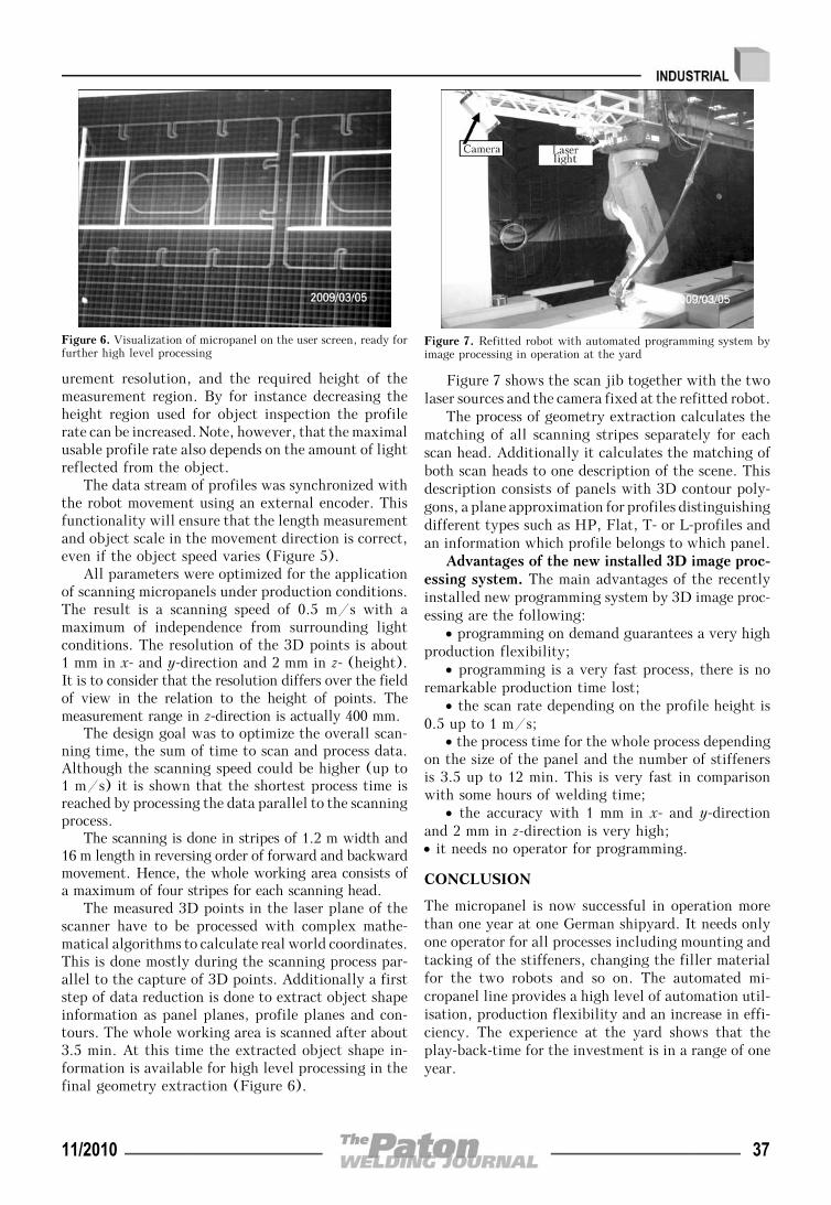
urement resolution, and the required height of themeasurement region. By for instance decreasing theheight region used for object inspection the profilerate can be increased. Note, however, that the maximalusable profile rate also depends on the amount of lightreflected from the object.
The data stream of profiles was synchronized withthe robot movement using an external encoder. Thisfunctionality will ensure that the length measurementand object scale in the movement direction is correct,even if the object speed varies (Figure 5).
All parameters were optimized for the applicationof scanning micropanels under production conditions.The result is a scanning speed of 0.5 m/s with amaximum of independence from surrounding lightconditions. The resolution of the 3D points is about1 mm in x- and y-direction and 2 mm in z- (height).It is to consider that the resolution differs over the fieldof view in the relation to the height of points. Themeasurement range in z-direction is actually 400 mm.
The design goal was to optimize the overall scan-ning time, the sum of time to scan and process data.Although the scanning speed could be higher (up to1 m/s) it is shown that the shortest process time isreached by processing the data parallel to the scanningprocess.
The scanning is done in stripes of 1.2 m width and16 m length in reversing order of forward and backwardmovement. Hence, the whole working area consists ofa maximum of four stripes for each scanning head.
The measured 3D points in the laser plane of thescanner have to be processed with complex mathe-matical algorithms to calculate real world coordinates.This is done mostly during the scanning process par-allel to the capture of 3D points. Additionally a firststep of data reduction is done to extract object shapeinformation as panel planes, profile planes and con-tours. The whole working area is scanned after about3.5 min. At this time the extracted object shape in-formation is available for high level processing in thefinal geometry extraction (Figure 6).
Figure 7 shows the scan jib together with the twolaser sources and the camera fixed at the refitted robot.
The process of geometry extraction calculates thematching of all scanning stripes separately for eachscan head. Additionally it calculates the matching ofboth scan heads to one description of the scene. Thisdescription consists of panels with 3D contour poly-gons, a plane approximation for profiles distinguishingdifferent types such as HP, Flat, T- or L-profiles andan information which profile belongs to which panel.
Advantages of the new installed 3D image proc-essing system. The main advantages of the recentlyinstalled new programming system by 3D image proc-essing are the following:
• programming on demand guarantees a very highproduction flexibility;
• programming is a very fast process, there is noremarkable production time lost;
• the scan rate depending on the profile height is0.5 up to 1 m/s;
• the process time for the whole process dependingon the size of the panel and the number of stiffenersis 3.5 up to 12 min. This is very fast in comparisonwith some hours of welding time;
• the accuracy with 1 mm in x- and y-directionand 2 mm in z-direction is very high;• it needs no operator for programming.
CONCLUSION
The micropanel is now successful in operation morethan one year at one German shipyard. It needs onlyone operator for all processes including mounting andtacking of the stiffeners, changing the filler materialfor the two robots and so on. The automated mi-cropanel line provides a high level of automation util-isation, production flexibility and an increase in effi-ciency. The experience at the yard shows that theplay-back-time for the investment is in a range of oneyear.
Figure 6. Visualization of micropanel on the user screen, ready forfurther high level processing
Figure 7. Refitted robot with automated programming system byimage processing in operation at the yard
11/2010 37
OPTIMISATION OF PARAMETERSOF ADDITIONAL GAS SHIELDING
IN SUBMERGED ARC WELDING AND SURFACINGOF COPPER AND ITS ALLOYS
V.N. KOLEDA and V.M. ILYUSHENKOE.O. Paton Electric Welding Institute, NASU, Kiev, Ukraine
The paper presents the results of evaluation of influence of a combined shielding on gas saturation of metal at the stageof a drop and a pool in welding and surfacing of copper and its alloys. Parameters of the process of submerged arcwelding and surfacing using an additional gas shielding were optimized. A new method of a pulsed supply of shieldinggas into the arc zone in submerged arc welding and surfacing was developed.
Keywo rd s : arc welding, submerged arc surfacing, copperand copper alloys, gas shielding, hydrogen, porosity prevention
Automatic submerged arc welding and surfacing ofcopper and its alloys is one of the prospective methodsof manufacturing both elements of metallurgy equip-ment as well as producing of bimetallic products fromcopper—bronze and steel—bronze [1—4].
Nowadays, for welding and surfacing of copper andcopper alloys the fused fluxes AN-60, AN-20P, AN-26P,AN-348-A, OSTs-45 and other, developed for weldingof steels, are used. However, even keeping all techno-logical recommendations (calcination of fluxes, me-chanical cleaning, degreasing of wire and base metal)they do not always provide the required density of metal.It is known that efficient measure of preventing porosityis the decrease of a partial pressure of hydrogen in thearc atmosphere. It can be achieved due to both its bindinginto compounds and also adding of other gases into thearc atmosphere [5, 6].
This wok evaluates the influence of additional gasshielding on gas saturation of metal at the stage of adrop and a pool, quality of welds of copper, copperwith steel and surfacing of copper alloys on steel andcopper.
To select the optimal scheme of gas supply to thearc zone, two methods were tested: through the coppernozzle and through a copper tube located horizontally.As an additional shielding the nitrogen was used (300—700 l/h consumption), which was supplied in a con-tinuous mode. During supply of shielding gas usingthe first method the diameter of a nozzle (from 10 to20 mm) and distance from its end to the base metal(from 10 to 30 mm) were changed, while at the secondmethod the diameter of tube (from 3 to 10 mm), in-clination angle (from 0 to 30°) to the horizon, distancefrom the outlet hole to the electrode (from 10 to30 mm), to the base metal (from 5 to 15 mm) werechanged. The external pores were determined visually.The presence and character of location of inner defects
were studied on macro- and microsections. Tendencyof deposited metal to the porosity was estimated ac-cording to the quantity of dense beads.
As the carried out experiments showed, during sup-ply of shielding gas through the nozzle the positiveeffect was achieved only when the lower edge of nozzlewas in a molten slag and favorable conditions werecreated for shielding gas to get into the zone of arc.However it leads to shunting of welding current, vio-lation of the process stability and deterioration of beadformation.
During supply of shielding gas through the gas-supplying copper tube the best results were obtainedwhen it was positioned ahead the arc or on the sideat the angle of not more than 5—10° to the horizon,its end was located in the molten slag. The optimaldiameter of the tube was 4—6 mm. While selectingthe most effective shielding environment the nitrogen,argon and carbon dioxide were tested.
To study mechanism of influence of additional gasshielding on the porosity, the gas saturation of metalat the stages of a drop and a pool was determined.For this purpose the content of hydrogen was deter-mined in drops of electrode metal, remaining at theends of electrode after interruption of welding, andin «pencil samples» after sampling by drain of a poolmetal through a hole in the specimen. The liquid metalentered the dismountable copper mould of 10 mm innerhole diameter. Fixation of gases dissolved in liquidmetal occurs as a result of high rate of samples crys-tallization. Specimens manufactured of «pencil sam-ples» and drops of electrode metal were analyzed inthe LECO unit RH-2 to determine the content ofresidual hydrogen in them. The surfacing was per-formed using wire of the BrAMts9-2 grade under fluxAN-26P on 10 mm thick plates of bronze of theBrAMts9-2 grade. During welding of copper of 10 mmthickness the wire of the BrKh07 grade and flux AN-348-A were used, in welding of copper with steel of10 mm thickness the wire of the MNZhKT5-1-0.2-0.2
© V.N. KOLEDA and V.M. ILYUSHENKO, 2010
38 11/2010
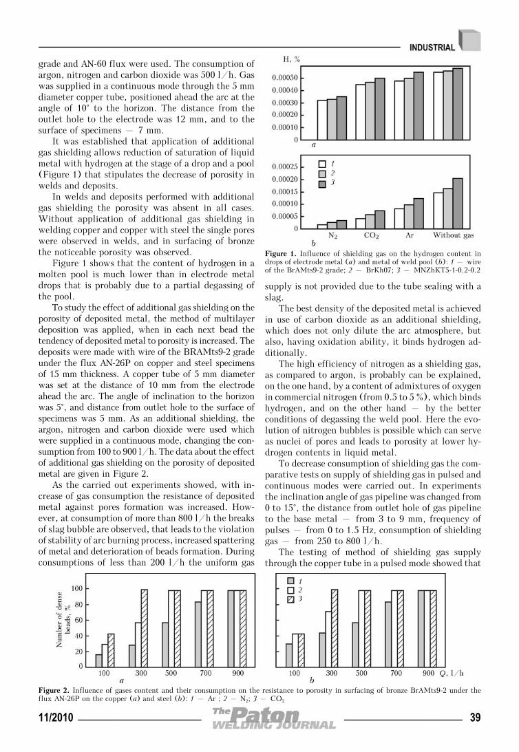
grade and AN-60 flux were used. The consumption ofargon, nitrogen and carbon dioxide was 500 l/h. Gaswas supplied in a continuous mode through the 5 mmdiameter copper tube, positioned ahead the arc at theangle of 10° to the horizon. The distance from theoutlet hole to the electrode was 12 mm, and to thesurface of specimens – 7 mm.
It was established that application of additionalgas shielding allows reduction of saturation of liquidmetal with hydrogen at the stage of a drop and a pool(Figure 1) that stipulates the decrease of porosity inwelds and deposits.
In welds and deposits performed with additionalgas shielding the porosity was absent in all cases.Without application of additional gas shielding inwelding copper and copper with steel the single poreswere observed in welds, and in surfacing of bronzethe noticeable porosity was observed.
Figure 1 shows that the content of hydrogen in amolten pool is much lower than in electrode metaldrops that is probably due to a partial degassing ofthe pool.
To study the effect of additional gas shielding on theporosity of deposited metal, the method of multilayerdeposition was applied, when in each next bead thetendency of deposited metal to porosity is increased. Thedeposits were made with wire of the BRAMts9-2 gradeunder the flux AN-26P on copper and steel specimensof 15 mm thickness. A copper tube of 5 mm diameterwas set at the distance of 10 mm from the electrodeahead the arc. The angle of inclination to the horizonwas 5°, and distance from outlet hole to the surface ofspecimens was 5 mm. As an additional shielding, theargon, nitrogen and carbon dioxide were used whichwere supplied in a continuous mode, changing the con-sumption from 100 to 900 l/h. The data about the effectof additional gas shielding on the porosity of depositedmetal are given in Figure 2.
As the carried out experiments showed, with in-crease of gas consumption the resistance of depositedmetal against pores formation was increased. How-ever, at consumption of more than 800 l/h the breaksof slag bubble are observed, that leads to the violationof stability of arc burning process, increased spatteringof metal and deterioration of beads formation. Duringconsumptions of less than 200 l/h the uniform gas
supply is not provided due to the tube sealing with aslag.
The best density of the deposited metal is achievedin use of carbon dioxide as an additional shielding,which does not only dilute the arc atmosphere, butalso, having oxidation ability, it binds hydrogen ad-ditionally.
The high efficiency of nitrogen as a shielding gas,as compared to argon, is probably can be explained,on the one hand, by a content of admixtures of oxygenin commercial nitrogen (from 0.5 to 5 %), which bindshydrogen, and on the other hand – by the betterconditions of degassing the weld pool. Here the evo-lution of nitrogen bubbles is possible which can serveas nuclei of pores and leads to porosity at lower hy-drogen contents in liquid metal.
To decrease consumption of shielding gas the com-parative tests on supply of shielding gas in pulsed andcontinuous modes were carried out. In experimentsthe inclination angle of gas pipeline was changed from0 to 15°, the distance from outlet hole of gas pipelineto the base metal – from 3 to 9 mm, frequency ofpulses – from 0 to 1.5 Hz, consumption of shieldinggas – from 250 to 800 l/h.
The testing of method of shielding gas supplythrough the copper tube in a pulsed mode showed that
Figure 1. Influence of shielding gas on the hydrogen content indrops of electrode metal (a) and metal of weld pool (b): 1 – wireof the BrAMts9-2 grade; 2 – BrKh07; 3 – MNZhKT5-1-0.2-0.2
Figure 2. Influence of gases content and their consumption on the resistance to porosity in surfacing of bronze BrAMts9-2 under theflux AN-26P on the copper (a) and steel (b): 1 – Ar ; 2 – N2; 3 – CO2
11/2010 39
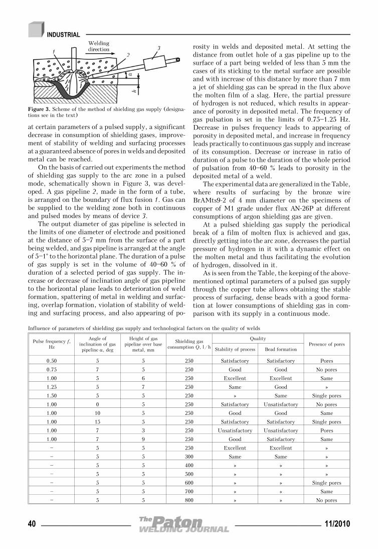
at certain parameters of a pulsed supply, a significantdecrease in consumption of shielding gases, improve-ment of stability of welding and surfacing processesat a guaranteed absence of pores in welds and depositedmetal can be reached.
On the basis of carried out experiments the methodof shielding gas supply to the arc zone in a pulsedmode, schematically shown in Figure 3, was devel-oped. A gas pipeline 2, made in the form of a tube,is arranged on the boundary of flux fusion 1. Gas canbe supplied to the welding zone both in continuousand pulsed modes by means of device 3.
The output diameter of gas pipeline is selected inthe limits of one diameter of electrode and positionedat the distance of 5—7 mm from the surface of a partbeing welded, and gas pipeline is arranged at the angleof 5—1° to the horizontal plane. The duration of a pulseof gas supply is set in the volume of 40—60 % ofduration of a selected period of gas supply. The in-crease or decrease of inclination angle of gas pipelineto the horizontal plane leads to deterioration of weldformation, spattering of metal in welding and surfac-ing, overlap formation, violation of stability of weld-ing and surfacing process, and also appearing of po-
rosity in welds and deposited metal. At setting thedistance from outlet hole of a gas pipeline up to thesurface of a part being welded of less than 5 mm thecases of its sticking to the metal surface are possibleand with increase of this distance by more than 7 mma jet of shielding gas can be spread in the flux abovethe molten film of a slag. Here, the partial pressureof hydrogen is not reduced, which results in appear-ance of porosity in deposited metal. The frequency ofgas pulsation is set in the limits of 0.75—1.25 Hz.Decrease in pulses frequency leads to appearing ofporosity in deposited metal, and increase in frequencyleads practically to continuous gas supply and increaseof its consumption. Decrease or increase in ratio ofduration of a pulse to the duration of the whole periodof pulsation from 40—60 % leads to porosity in thedeposited metal of a weld.
The experimental data are generalized in the Table,where results of surfacing by the bronze wireBrAMts9-2 of 4 mm diameter on the specimens ofcopper of M1 grade under flux AN-26P at differentconsumptions of argon shielding gas are given.
At a pulsed shielding gas supply the periodicalbreak of a film of molten flux is achieved and gas,directly getting into the arc zone, decreases the partialpressure of hydrogen in it with a dynamic effect onthe molten metal and thus facilitating the evolutionof hydrogen, dissolved in it.
As is seen from the Table, the keeping of the above-mentioned optimal parameters of a pulsed gas supplythrough the copper tube allows obtaining the stableprocess of surfacing, dense beads with a good forma-tion at lower consumptions of shielding gas in com-parison with its supply in a continuous mode.
Figure 3. Scheme of the method of shielding gas supply (designa-tions see in the text)
Influence of parameters of shielding gas supply and technological factors on the quality of welds
Pulse frequency f,Hz
Angle ofinclination of gaspipeline α, deg
Height of gaspipeline over base
metal, mm
Shielding gasconsumption Q, l/h
QualityPresence of pores
Stability of process Bead formation
0.50 5 5 250 Satisfactory Satisfactory Pores
0.75 7 5 250 Good Good No pores
1.00 5 6 250 Excellent Excellent Same
1.25 5 7 250 Same Good »
1.50 5 5 250 » Same Single pores
1.00 0 5 250 Satisfactory Unsatisfactory No pores
1.00 10 5 250 Good Good Same
1.00 15 5 250 Satisfactory Satisfactory Single pores
1.00 7 3 250 Unsatisfactory Unsatisfactory Pores
1.00 7 9 250 Good Satisfactory Same
— 5 5 250 Excellent Excellent »
— 5 5 300 Same Same »
— 5 5 400 » » »
— 5 5 500 » » »
— 5 5 600 » » Single pores
— 5 5 700 » » Same
— 5 5 800 » » No pores
40 11/2010
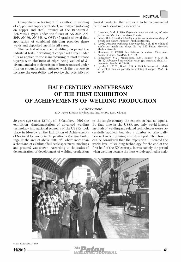
Comprehensive testing of this method in weldingof copper and copper with steel, multilayer surfacingon copper and steel, bronzes of the BrAMts9-2,BrKMts3-1 types under the fluxes of AN-26P, AN-20P, AN-60, AN-348-A, OSTs-45 grades showed thatapplication of combined shielding provides densewelds and deposited metal in all cases.
The method of combined shielding has passed theindustrial tests in welding of copper with steel underflux as applied to the manufacturing of blast furnacetuyeres with thickness of edges being welded of 5—10 mm, and also in deposition of bronze on steel underflux on circumferential surfaces with the purpose toincrease the operability and service characteristics of
bimetal products, that allows it to be recommendedfor the industrial implementation.
1. Gurevich, S.M. (1990) Reference book on welding of non-ferrous metals. Kiev: Naukova Dumka.
2. Paton, B.E. (1974) Technology of fusion electric welding ofmetals and alloys. Moscow: Mashinostroenie.
3. (2006) Machine building: Encyclopedia. Vol. 4: Welding ofnonferrous metals and alloys. Ed. by B.E. Paton. Moscow:Mashinostroenie.
4. Monnean, P. (2000) Les liaisons du cuivre. Vide Sci.,Techn. et Appl., 55(296), 147—158.
5. Podgaetsky, V.V., Mandelberg, S.M., Bender, V.S. et al.(1973) Submerged-arc welding using gas-saturated flux. Av-tomatich. Svarka, 6, 28—31.
6. Ilyushenko, V.M., Bosak, L.K. (1984) Influence of oxidati-on level of flux on porosity in welding of copper. Ibid., 4,67—68.
HALF-CENTURY ANNIVERSARYOF THE FIRST EXHIBITION
OF ACHIEVEMENTS OF WELDING PRODUCTION
A.N. KORNIENKOE.O. Paton Electric Welding Institute, NASU, Kiev, Ukraine
50 years ago (since 12 July till 3 October, 1960) theexhibition «Implementation of advanced weldingtechnology into national economy of the USSR» tookplace in Moscow at the Exhibition of Achievementsof National Economy in the pavilion «Machine build-ing» at the area of above 6000 m2, where more thana thousand of exhibits (full-scale specimens, mockupsand posters) was shown. According to the scales ofdemonstration of development of welding production
in the single country the exposition had no equals.By that time in the USSR not only world-famousmethods of welding and related technologies were suc-cessfully applied, but also a number of principallynew methods of joining were developed. Therefore, itcan be considered that the exposition illustrated theworld level of welding technology for the end of thefirst half of the XX century. It was namely the periodwhen welding became the most widely applied in mak-
© A.N. KORNIENKO, 2010
11/2010 41
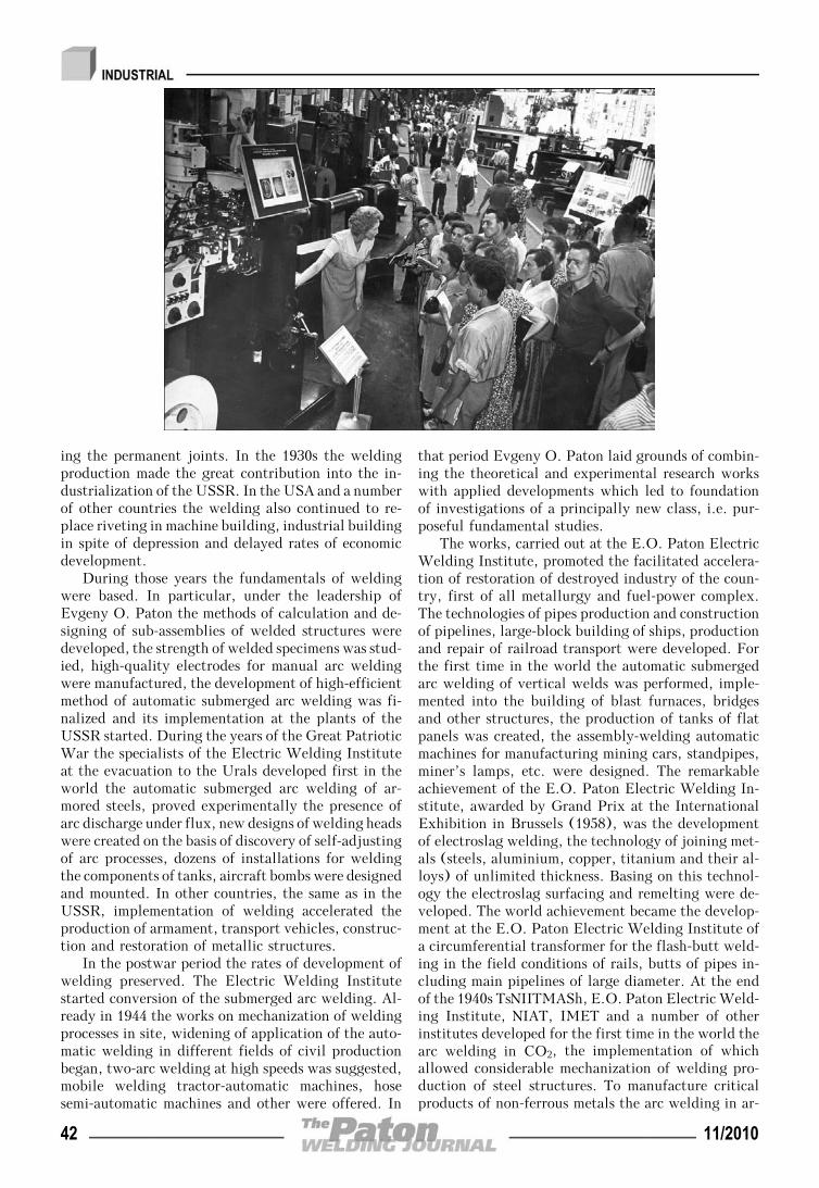
ing the permanent joints. In the 1930s the weldingproduction made the great contribution into the in-dustrialization of the USSR. In the USA and a numberof other countries the welding also continued to re-place riveting in machine building, industrial buildingin spite of depression and delayed rates of economicdevelopment.
During those years the fundamentals of weldingwere based. In particular, under the leadership ofEvgeny O. Paton the methods of calculation and de-signing of sub-assemblies of welded structures weredeveloped, the strength of welded specimens was stud-ied, high-quality electrodes for manual arc weldingwere manufactured, the development of high-efficientmethod of automatic submerged arc welding was fi-nalized and its implementation at the plants of theUSSR started. During the years of the Great PatrioticWar the specialists of the Electric Welding Instituteat the evacuation to the Urals developed first in theworld the automatic submerged arc welding of ar-mored steels, proved experimentally the presence ofarc discharge under flux, new designs of welding headswere created on the basis of discovery of self-adjustingof arc processes, dozens of installations for weldingthe components of tanks, aircraft bombs were designedand mounted. In other countries, the same as in theUSSR, implementation of welding accelerated theproduction of armament, transport vehicles, construc-tion and restoration of metallic structures.
In the postwar period the rates of development ofwelding preserved. The Electric Welding Institutestarted conversion of the submerged arc welding. Al-ready in 1944 the works on mechanization of weldingprocesses in site, widening of application of the auto-matic welding in different fields of civil productionbegan, two-arc welding at high speeds was suggested,mobile welding tractor-automatic machines, hosesemi-automatic machines and other were offered. In
that period Evgeny O. Paton laid grounds of combin-ing the theoretical and experimental research workswith applied developments which led to foundationof investigations of a principally new class, i.e. pur-poseful fundamental studies.
The works, carried out at the E.O. Paton ElectricWelding Institute, promoted the facilitated accelera-tion of restoration of destroyed industry of the coun-try, first of all metallurgy and fuel-power complex.The technologies of pipes production and constructionof pipelines, large-block building of ships, productionand repair of railroad transport were developed. Forthe first time in the world the automatic submergedarc welding of vertical welds was performed, imple-mented into the building of blast furnaces, bridgesand other structures, the production of tanks of flatpanels was created, the assembly-welding automaticmachines for manufacturing mining cars, standpipes,miner’s lamps, etc. were designed. The remarkableachievement of the E.O. Paton Electric Welding In-stitute, awarded by Grand Prix at the InternationalExhibition in Brussels (1958), was the developmentof electroslag welding, the technology of joining met-als (steels, aluminium, copper, titanium and their al-loys) of unlimited thickness. Basing on this technol-ogy the electroslag surfacing and remelting were de-veloped. The world achievement became the develop-ment at the E.O. Paton Electric Welding Institute ofa circumferential transformer for the flash-butt weld-ing in the field conditions of rails, butts of pipes in-cluding main pipelines of large diameter. At the endof the 1940s TsNIITMASh, E.O. Paton Electric Weld-ing Institute, NIAT, IMET and a number of otherinstitutes developed for the first time in the world thearc welding in CO2, the implementation of whichallowed considerable mechanization of welding pro-duction of steel structures. To manufacture criticalproducts of non-ferrous metals the arc welding in ar-
42 11/2010
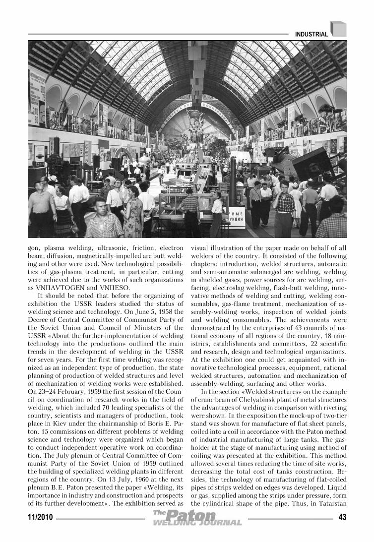
gon, plasma welding, ultrasonic, friction, electronbeam, diffusion, magnetically-impelled arc butt weld-ing and other were used. New technological possibili-ties of gas-plasma treatment, in particular, cuttingwere achieved due to the works of such organizationsas VNIIAVTOGEN and VNIIESO.
It should be noted that before the organizing ofexhibition the USSR leaders studied the status ofwelding science and technology. On June 5, 1958 theDecree of Central Committee of Communist Party ofthe Soviet Union and Council of Ministers of theUSSR «About the further implementation of weldingtechnology into the production» outlined the maintrends in the development of welding in the USSRfor seven years. For the first time welding was recog-nized as an independent type of production, the stateplanning of production of welded structures and levelof mechanization of welding works were established.On 23—24 February, 1959 the first session of the Coun-cil on coordination of research works in the field ofwelding, which included 70 leading specialists of thecountry, scientists and managers of production, tookplace in Kiev under the chairmanship of Boris E. Pa-ton. 15 commissions on different problems of weldingscience and technology were organized which beganto conduct independent operative work on coordina-tion. The July plenum of Central Committee of Com-munist Party of the Soviet Union of 1959 outlinedthe building of specialized welding plants in differentregions of the country. On 13 July, 1960 at the nextplenum B.E. Paton presented the paper «Welding, itsimportance in industry and construction and prospectsof its further development». The exhibition served as
visual illustration of the paper made on behalf of allwelders of the country. It consisted of the followingchapters: introduction, welded structures, automaticand semi-automatic submerged arc welding, weldingin shielded gases, power sources for arc welding, sur-facing, electroslag welding, flash-butt welding, inno-vative methods of welding and cutting, welding con-sumables, gas-flame treatment, mechanization of as-sembly-welding works, inspection of welded jointsand welding consumables. The achievements weredemonstrated by the enterprises of 43 councils of na-tional economy of all regions of the country, 18 min-istries, establishments and committees, 22 scientificand research, design and technological organizations.At the exhibition one could get acquainted with in-novative technological processes, equipment, rationalwelded structures, automation and mechanization ofassembly-welding, surfacing and other works.
In the section «Welded structures» on the exampleof crane beam of Chelyabinsk plant of metal structuresthe advantages of welding in comparison with rivetingwere shown. In the exposition the mock-up of two-tierstand was shown for manufacture of flat sheet panels,coiled into a coil in accordance with the Paton methodof industrial manufacturing of large tanks. The gas-holder at the stage of manufacturing using method ofcoiling was presented at the exhibition. This methodallowed several times reducing the time of site works,decreasing the total cost of tanks construction. Be-sides, the technology of manufacturing of flat-coiledpipes of strips welded on edges was developed. Liquidor gas, supplied among the strips under pressure, formthe cylindrical shape of the pipe. Thus, in Tatarstan
11/2010 43
the laying of 100 km of pipelines of these pipes allowedsaving more than thousands of tons of metal and re-ducing the cost of construction by 1700 thousand rou-bles. The results of implementation of new weldingtechnologies of critical engineering products were pre-sented at the exhibition. The unique sample of weldedstructure was also the exhibition pavilion itself, thedome of which consisted of rings connected betweeneach other in the meridian sections by stiffeners.
One of the most metal-intensive branches is shipbuilding where large block method of building iswidely used. At the exhibition the single sub-assem-blies, mockups of atomic ice-breaker «Lenin», large-tonnage tankers, dry cargo ships and others were pre-sented.
Electroslag welding was already applied in the1950s for manufacture of high-capacity power units,forge-press, hoisting-transport and other equipment,equipment for chemical, nuclear and other branchesat the Novo-Kramatorsk plant, Taganrog plant«Krasny Kotelshchik», Uralmashzavod, LeningradMetal plant and other plants and organizations, whichpresented over 80 exhibits-products and mockups.
CO2 welding found the wide spreading in our coun-try. The high economic effect of the process was provedby mockups and full-scale samples of products of auto-motive industry, turbo-generator and turbo-motorplants of Kharkov, Novosibirsk, Leningrad, shipbuild-ing yards of Kherson and Nikolaev, other machine- build-ing plants, mockups and units of blast furnaces, indus-trial constructions, etc. In the demonstration of achieve-ments in this field of welding technology more than 30organizations took part, including NIAT, VNIIESO,E.O. Paton Electric Welding Institute, TsNIITMASh,NIIKhIMMASh.
Maximum mechanization of assembly-weldingworks in transport machine building, boiler, instru-ment industries, and also in a number of other brancheswas provided due to application of all methods ofresistance welding. A wide application of repair tech-nologies of restoration of worn-out parts using hard-facing was also reflected at the exhibition. In thissection a series of special surfacing mechanized equip-ment attracted attention. With the development ofnew types of machinery and more strict requirementsto the quality of materials and their joints an attentionto related processes and special electric metallurgywas intensified. Surfacing and other technologies ofdeposition of coatings belong to the methods allowingconsiderable increasing of service properties of partsand mechanisms.
The successful implementation of new technologi-cal processes became possible due to an abrupt increaseof production of the modern welding equipment. Inthe section «Power sources for arc welding» manytypes of welding transformers, mechanic convertersof direct current and semi-conductor rectifiers, devel-oped by VNIIESO, E.O. Paton Electric Welding In-stitute, NIAT, plant «Elektrik» and other were pre-sented. Hundreds of models of machines for arc weld-ing, machines for resistance welding, machine-tools,holders, different machines of welding stations andother equipment were widely presented. At the exhi-bition the E.O. Paton Electric Welding Institute pre-sented a welding tractor TS-32 with a sliding water-cooled copper shoe, providing a forced formation ofa lower weld bead; tractor TS-33 for automatic weld-ing of butt and fillet welds of aluminium of thicknessof up to 40 mm using semi-open arc along the layerof flux with universal set up for layout of a weldbetween the wheels and near the tractor (includingalso circumferential welds on the vessels of diameterof 1000 mm and higher); rails machine A-372r andmagnetically-walking machine A-501M, which weresuccessfully demonstrated in Brussels and New York;gun A-564 for stud welding under flux in lower, ver-tical and overhead positions; universal tractor TS-17M, semi-automatic machines PSh-5 and other. Semi-automatic machine A-547r of the E.O. Paton ElectricWelding Institute was designed for CO2 welding ofmetal of small thickness in all spatial positions usingwire of 0.6—1.2 mm diameter at currents of 20—200 A.A set was demonstrated, consisting of a hose holder,feed mechanism together with a wire reel in a commoncasing, control panel, gas equipment and rectifier VS-200. For resistance spot welding the E.O. Paton Elec-tric Welding Institute developed small-sized tongs K-165 with a built-in transformer, suspended machinesfor flash-butt welding of rails (K-155) and pipes(KTSA-1). A large amount of versatile and specializedmachines and tongs for all methods of resistance weld-ing was presented by VNIIESO and plant «Elektrik».Other technological processes were also provided byhigh-efficient equipment. According to technical datathe domestic equipment was not inferior to the bestforeign models, and design solutions were the basisfor the development of the new equipment.
The exhibition attracted attention of specialistsof many branches of industry, demonstrated highlevel of welding production in the USSR and hadconsiderable influence on the further developmentof welding.
44 11/2010
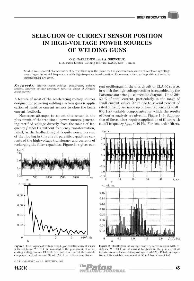
SELECTION OF CURRENT SENSOR POSITIONIN HIGH-VOLTAGE POWER SOURCES
OF WELDING GUNS
O.K. NAZARENKO and S.A. SHEVCHUKE.O. Paton Electric Welding Institute, NASU, Kiev, Ukraine
Studied were spectral characteristics of current flowing in the plus circuit of electron beam sources of accelerating voltageoperating on industrial frequency or with high-frequency transformation. Recommendations on the position of resistivecurrent sensor are given.
Keywo rd s : electron beam welding, accelerating voltagesources, inverter voltage converter, resistive sensor of electronbeam current
A feature of most of the accelerating voltage sourcesdesigned for powering welding electron guns is appli-cation of resistive current sensors to close the beamcurrent feedback.
Numerous attempts to mount this sensor in theplus circuit of the traditional power sources, generat-ing rectified voltage directly from the mains of fre-quency f = 50 Hz without frequency transformation,failed, as the feedback signal is quite noisy, becauseof the flowing in this circuit parasitic capacitive cur-rents of the high-voltage transformer and currents ofrecharging the filter capacities. Figure 1, a gives cur-
rent oscillogram in the plus circuit of ELA-60 source,in which the high-voltage rectifier is assembled by theLarionov star-triangle connection diagram. Up to 30—50 % of total current, particularly in the range ofsmall current values (from one to several percent ofrated current) are made up of low-frequency (f = 50—600 Hz) variable components, for which the resultsof Fourier analysis are given in Figure 1, b. Suppres-sion of these noises requires application of filters withcutoff frequency fcutoff < 10 Hz. For first order filters,
Figure 1. Oscillogram of voltage drop UR on resistive current sensorwith resistance R = 10 Ohm mounted in the plus circuit of accel-erating voltage source ELA-60 (a), and spectrum of its variablecomponent at load current 50 mA (b): A – voltage amplitude
Figure 2. Oscillogram of voltage drop UR across resistor with re-sistance R = 10 Ohm of current feedback in the plus circuit ofinverter source of accelerating voltage ELAI-120/18 (a), and spec-trum of its variable component at 50 mA load current (b)
© O.K. NAZARENKO and S.A. SHEVCHUK, 2010
11/2010 45
in which fcutoff = (2πfRC)—1 (here, R, C are the resis-tance and capacity of the component elements), timeconstant is not less than 100 ms [1]. Here it turns outto be impossible to achieve the required fast controlof beam current for welding with pulsed modulationof beam current, or apply secondary-electron systemsof following the butt of the edges being welded inreal time, when it is necessary to set and stabilizebeam current during 5 ms pulse.
When resistive current sensor is mounted in thehigh-voltage circuit of these power sources, the feed-back signal has a low noise level, the need for itsfiltration is eliminated, and fast control of beam cur-rent becomes possible. Such a solution, however,makes the equipment more complicated and less reli-able [2].
In inverter power sources with high-frequencytransformation of mains voltage mounting current
feedback resistor in the plus circuit of the power sourceis applicable due to the fact that frequencies of thevariable component lie in the high frequency region(f = 20—30 kHz) (Figure 2). Filters with 2—3 kHzcutoff frequency can be applied for filtering thesecomponents that corresponds to time constant t << 0.2 ms.
Thus, current feedback resistor in electron beamsources of accelerating voltage operating at industrialfrequency should be mounted in the rectifier high-voltage circuit, and in inverter power sources withhigh-frequency transformation of mains voltage, it isrational to place it in the rectifier plus circuit.
1. Moshits, G., Khorn, P. (1984) Design of active filters.Moscow: Mir.
2. Nazarenko, O.K., Lanbin, V.S. (2007) Investigation of high-voltage control circuits of welding electron beam current.The Paton Welding J., 5, 17—20.
THESES FOR A SCIENTIFIC DEGREE
E.O. Paton Electric Welding Institute of the NAS ofUkraine
On October 6, 2010, V.I. Dzykovich defended histhesis for Candidate of Sciences on «Investigationsand development of the materials for wear-resistantsurfacing based on spheroidized granules of the tung-sten carbides».
The analysis of existing materials for surfacing ofwear-resistant composite alloys based on fragmentedparticles of the tungsten carbide was carried out. Itis shown that the spherical shape of particles due tomaximum volume of spherical particle at minimumspecific surface area is the most perspective for im-provement of quality of deposited layer, decrease ofa level of dissolution of reinforcing particles duringsurfacing, enhancement of operating abilities of thecomposite coatings and increase of a volume fractionof wear-resistant granules in the deposited layer.
The thesis substantiates selection of a method ofthermocentrifugal sputtering of refractory materialsfor obtaining spherical tungsten carbide particlesfor their application as a wear-resistant phase in acomposition of the materials for composite surfac-ing.
Using mathematical modeling of a method of ther-mocentrifugal sputtering of tungsten carbide the cor-responding equations connecting the main parameters(thermal characteristics of heat source, speed of rota-tion) with the process efficiency and dimension of theforming tungsten carbide (relite) granules are pro-posed, and, as a result, the mechanism for control ofgranulometric composition of tungsten carbide WC—W2C spheroidized granules was developed. A formulafor calculation of a rotation speed of spindle assemblyof the unit for sputtering of material of the necessarygranulometric composition was obtained.
The technology for melting of source materialswith application of induction heating was developedthat allows obtaining the ingots for the thermocentri-fugal sputtering of high quality eutectic composition.
Investigations of influence of ingot quality forsputtering on structure, properties and stochiometriccomposition of obtained spherical particles of thetungsten carbides were carried out. In comparison ofthe spheroidized granules of tungsten carbides withanalogues of the well-known foreign companies it wasdetermined that the particles made using the thermo-centrifugal sputtering have the maximum values ofmicrohardness and uniformity of chemical and phasecomposition.
The technology for thermocentrifugal sputteringof refractory materials using plasma arc as a heatsource, and commercial equipment were developed onthe basis of obtained theoretical and experimental re-sults. The optimum mode for sputtering of tungstencarbide ingots is welding current of 550—600 A at arcvoltage of 38—40 V. At that, the optimum speed ofvertical feed for ingot makes 0.12—0.18 mm/s. A speedof ingot rotation is the basic parameter influencing
46 11/2010
granulometric composition of the spherical sputteringparticles. At that, a change of the frequency of rotationfrom 1200 up to 10000 rpm allows obtaining particlesof 1000—50 μm in size.
The investigations of morphometry characteristicsof spheroidized granules of the tungsten carbides WC—W2C were carried out for the first time, and it wasdetermined that all testing powders have very stableand uniform indices on shape of particles. A yield ofthe tungsten carbide spheroidized granules by 15—20 % higher than that of the source material in sepa-ration of a nonspheric constituent from the composi-tion of finished material that has positive influenceon the operation of dosing units in some methods ofsurfacing.
Surfacing materials for deposition by differentmethods of wear-resistant composite layers based onthe tungsten carbide spheroidized granules were de-veloped. The maximum concentration of reinforcingphase in the deposited layer (up to 50 %) was achievedin surfacing of the test samples owing to the biggestvolume of spherical particles at minimum specific sur-face area as compared to the fragmented particles. Theminimum dissolution of the particles (up to 5—10 %)in the deposited layer is achieved due to absence ofthe concentrators of non-uniform heating of particles(spherical shape has no sharp angles). At the sametime, there are no secondary iron-tungsten carbideswhich, significantly, embrittle deposited layer, in thealloy matrix, in particular, based on nickel and copper.Wear resistance of the samples, deposited by differentmethods using spheroidized granules, on average is25 % higher of that of the samples with fragmentedparticles of the tungsten carbides. This is explainedby increased microhardness of spheroidized granules,absence of the defects in a form of pores and cracksin them, as well as minimum content of the brittlephases in the alloy matrix.
E.O. Paton Electric Welding Institute of the NAS ofUkraine
On October 6, 2010, T.R. Ganeev (Chernigov StateUniversity of Technology) defended his thesis for
Candidate of Sciences on «Advancement of a technol-ogy for copper to molybdenum diffusion welding».
The thesis is dedicated to development of the tech-nology for a vacuum diffusion welding of molybdenumto copper.
The thesis proposes to apply a low-energy ion treat-ment in glow-discharge plasma to the molybdenumsurface preliminary coated with a copper layer fordevelopment of intermediate layer during it weldingwith copper. This will increase a static strength andheat resistance as well as reduce electric resistance ofthe welded assemblies.
The methods of molecular dynamics were used inthe thesis for detection of the ways of influence oflow-energy ions on properties of near-surface molyb-denum layers. A relationship between energy of ionsbombarding metal surface and location of displace-ment maximum of molybdenum atoms was determinedthrough mathematical modeling of the process thatallowed calculating a mode providing the best condi-tions for implantation of the atoms of covered withcopper layer in the molybdenum.
The thesis presents a mode of ionic etching deter-mined by the methods of polarization resistance andlimiting wetting angle allowing increasing the qualityof molybdenum surface preparation before thermalvacuum spraying on it of copper layer. The mode pro-viding spraying of a layer of necessary thickness isproposed.
A range of modes for the ion treatment of molyb-denum surface covered with copper layer was foundat which a modified layer with mechanical propertiesproviding welded sample with a smooth changing ofmicrohardness from copper to molybdenum is formed.
Series of investigations for determination of influ-ence of proposed series of operations on service char-acteristics of the welded joint was carried out. Atapplication of modified layer 15 % increase of thewidth of copper diffusion zone in molybdenum isshown with the help of a method of X-ray spectrumanalysis. The mode of copper to molybdenum weldingwas determined providing increase of shear strengthof the joint up to 110 MPa, i.e. full-strength copper.
Using experimental X-ray method and method ofmathematic modeling 30—35 % reduction of residualequivalent stresses in obtained welded joints, 5 timeincrease of strength at thermal cycling in comparisonwith pure Cu—Mo joint as well as 20 % reduction ofspecific electric resistance are shown in comparisonwith the welded joint obtained on traditional tech-nology with nickel interlayer application.
The technology for manufacture of the molybde-num anodes by vacuum diffusion welding method wasdeveloped on the basis of carried out investigations.
11/2010 47
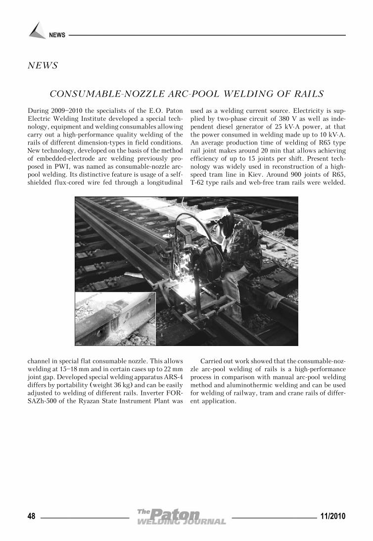
NEWS
CONSUMABLE-NOZZLE ARC-POOL WELDING OF RAILS
During 2009—2010 the specialists of the E.O. PatonElectric Welding Institute developed a special tech-nology, equipment and welding consumables allowingcarry out a high-performance quality welding of therails of different dimension-types in field conditions.New technology, developed on the basis of the methodof embedded-electrode arc welding previously pro-posed in PWI, was named as consumable-nozzle arc-pool welding. Its distinctive feature is usage of a self-shielded flux-cored wire fed through a longitudinal
channel in special flat consumable nozzle. This allowswelding at 15—18 mm and in certain cases up to 22 mmjoint gap. Developed special welding apparatus ARS-4differs by portability (weight 36 kg) and can be easilyadjusted to welding of different rails. Inverter FOR-SAZh-500 of the Ryazan State Instrument Plant was
used as a welding current source. Electricity is sup-plied by two-phase circuit of 380 V as well as inde-pendent diesel generator of 25 kV⋅A power, at thatthe power consumed in welding made up to 10 kV⋅A.An average production time of welding of R65 typerail joint makes around 20 min that allows achievingefficiency of up to 15 joints per shift. Present tech-nology was widely used in reconstruction of a high-speed tram line in Kiev. Around 900 joints of R65,T-62 type rails and web-free tram rails were welded.
Carried out work showed that the consumable-noz-zle arc-pool welding of rails is a high-performanceprocess in comparison with manual arc-pool weldingmethod and aluminothermic welding and can be usedfor welding of railway, tram and crane rails of differ-ent application.
48 11/2010
INTERNATIONAL CONFERENCE «MEE-2010»
The 6th International Conference «Materials and coat-ings under extreme conditions: investigation, appli-cation, environmentally appropriate technologies formanufacture and recycling of products» took place inBig Yalta, Crimea, Ukraine, in September 20—24,2010. It was dedicated to the 80th birth anniversaryof Viktor I. Trefilov, a well-known scientist and ma-terials engineer.
The Conference was organized by the NationalAcademy of Sciences of Ukraine (NASU), RussianAcademy of Sciences (RAS), National Academy ofSciences of Belarus (NASB), Ukrainian Society forMaterials Science, I.M. Frantsevich Institute of Prob-lems of Materials Science, Joint Institute of HighTemperatures of the RAS, A.A. Baykov Institute ofMetallurgy and Materials Science of the RAS, N.E.Bauman Moscow State Technical University, A.V.Lykov Institute of Heat and Mass Transfer of theNASB and INTERM Ltd. (Ukraine).
The Conference was held under the auspices of theHeadquarters of United Stated Air Force in Europe,Secretariat of European program EUREKA, JNRGlobal and Federation of European Societies for Ma-terials Science. European Office of Airspace Researchand Development, Air Force Office Scientific Re-search, United States Air Force Research Laboratory,U.S. Office of Naval Research Global, I.M. Frantse-vich Institute of Problems of Materials Science of theNASU, National Academy of Sciences of Ukraine,companies «Virial» (St.-Petersburg, Russia), «Dis-kom» (Kiev, Ukraine) and «Eltekhmash» (Vinnitsa,Ukraine) were sponsors of the Conference.
More than 150 scientists, researchers, post-gradu-ate students and engineers of world leading researchcentres, research institutes, universities, academies,branch laboratories and other organizations from 17countries participated in the Conference work.
The Conference was opened by a welcoming speechof academician of the NASU V.V. Skorokhod. Hewished all the participant a successful work and busi-ness-like co-operation as well as read out the tasks ofthe Conference and stated organizing issues.
The problems of the Conference were discussed innine sections:
• A: Principles of designing of the materials andcoatings for operation under extreme conditions;
• B: Scientific principles and computer modelingof the processes for obtaining materials and coatingsoperating under extreme conditions;
• C: Perspective technologies for obtaining andjoining of the materials and parts operating underextreme conditions;
• D: Structure and properties of the materials andcoatings for operation under extreme conditions;
• E: Special session «Heat-protection coatings»;• F: Experimental results of application of the ma-
terials and coatings under natural extreme conditions;• G: Possibilities and up-to-date technologies of
recycling of industrial waste in order to obtain struc-tural, heat-insulating, covering and other materials;
• H: Research and organization and information is-sues of cooperation of the materials engineer scientists;
• I: Round-table discussion «Effective transfer ofthe technologies – a catalyst of innovative develop-ment of the society».
The themes of papers, being under considerationin sections B and C, included the welding technologiesand technologies classified as related to welding aswell as structures of the materials and their properties,obtained through welding heating. The following pa-pers, in our opinion, can be interesting for the weldingspecialists: «Obtaining of titanium-based functionallygradient coatings by laser surfacing method» (V.K.Narva, A.V. Marani, Moscow Institute of Steel andAlloys, Russia); «Advantages of electron beam tech-nology in development of reinforcing coatings» (N.K.Galchenko, S.I. Belyuk, K.A. Kolesnikova, Instituteof Strength Physics and Materials Science of RAS SD,Tomsk, Russia); «Technology and equipment for dif-fusion welding of high-precision parts on dissimilarmaterials» (A.V. Lyushinsky, OJSC «Ramenskoe In-strument Engineering Design Bureau», Russia); «De-velopment of resource-saving repair technology forthe turbine rotor blades on alloy KhN65VMYuT(EI893)» (Yu.P. Tarasenko, O.B. Berdnik, V.A.Sorokin, Nizhny Novgorod Branch of the A.A. Blagon-ravov Institute of Machine Science of the RAS, Russia);«Damageability of long-term running welded joints ofthe steam lines» (V.V. Dmitrik, S.N. Bartash, NTU-KhPI, Kharkov, Ukraine) and series of others.
After plenary papers the participants of the Con-ference listened to oral presentations and examinedposter papers. In total around 200 papers and oralpresentations were made.
In course of the Conference work the ways of fur-ther development of the materials science for solvingspecific tasks on development of the structural mate-rials and coatings and their application under extremeconditions were discussed. The participants of theConference exchanged scientific information, estab-lished business contacts and drew up the plans of jointscientific activities.
In our opinion, the Conference was of interest notonly for the materials science researchers, but also forthe welders studying structure of the materials andcoatings made by means of welding as well as relatedtechnologies.
Prof. V.V. Dmitrik, KhPI
11/2010 49
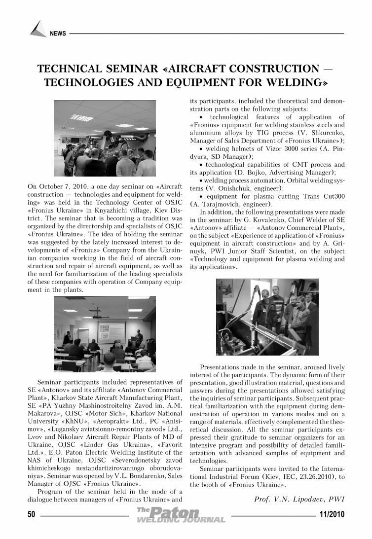
TECHNICAL SEMINAR «AIRCRAFT CONSTRUCTION –TECHNOLOGIES AND EQUIPMENT FOR WELDING»
On October 7, 2010, a one day seminar on «Aircraftconstruction – technologies and equipment for weld-ing» was held in the Technology Center of OSJC«Fronius Ukraine» in Knyazhichi village, Kiev Dis-trict. The seminar that is becoming a tradition wasorganized by the directorship and specialists of OSJC«Fronius Ukraine». The idea of holding the seminarwas suggested by the lately increased interest to de-velopments of «Fronius» Company from the Ukrain-ian companies working in the field of aircraft con-struction and repair of aircraft equipment, as well asthe need for familiarization of the leading specialistsof these companies with operation of Company equip-ment in the plants.
Seminar participants included representatives ofSE «Antonov» and its affiliate «Antonov CommercialPlant», Kharkov State Aircraft Manufacturing Plant,SE «PA Yuzhny Mashinostroitelny Zavod im. A.M.Makarova», OJSC «Motor Sich», Kharkov NationalUniversity «KhNU», «Aeroprakt» Ltd., PC «Anisi-mov», «Lugansky aviatsionno-remontny zavod» Ltd.,Lvov and Nikolaev Aircraft Repair Plants of MD ofUkraine, OJSC «Linder Gas Ukraina», «FavoritLtd.», E.O. Paton Electric Welding Institute of theNAS of Ukraine, OJSC «Severodonetsky zavodkhimicheskogo nestandartizirovannogo oborudova-niya». Seminar was opened by V.L. Bondarenko, SalesManager of OJSC «Fronius Ukraine».
Program of the seminar held in the mode of adialogue between managers of «Fronius Ukraine» and
its participants, included the theoretical and demon-stration parts on the following subjects:
• technological features of application of«Fronius» equipment for welding stainless steels andaluminium alloys by TIG process (V. Shkurenko,Manager of Sales Department of «Fronius Ukraine»);
• welding helmets of Vizor 3000 series (A. Pin-dyura, SD Manager);
• technological capabilities of CMT process andits application (D. Bojko, Advertising Manager);
• welding process automation. Orbital welding sys-tems (V. Onishchuk, engineer);
• equipment for plasma cutting Trans Cut300(A. Tarajmovich, engineer).
In addition, the following presentations were madein the seminar: by G. Kovalenko, Chief Welder of SE«Antonov» affiliate – «Antonov Commercial Plant»,on the subject «Experience of application of «Fronius»equipment in aircraft construction» and by A. Gri-nuyk, PWI Junior Staff Scientist, on the subject«Technology and equipment for plasma welding andits application».
Presentations made in the seminar, aroused livelyinterest of the participants. The dynamic form of theirpresentation, good illustration material, questions andanswers during the presentations allowed satisfyingthe inquiries of seminar participants. Subsequent prac-tical familiarization with the equipment during dem-onstration of operation in various modes and on arange of materials, effectively complemented the theo-retical discussion. All the seminar participants ex-pressed their gratitude to seminar organizers for anintensive program and possibility of detailed famili-arization with advanced samples of equipment andtechnologies.
Seminar participants were invited to the Interna-tional Industrial Forum (Kiev, IEC, 23.26.2010), tothe booth of «Fronius Ukraine».
Prof. V.N. Lipodaev, PWI
50 11/2010