Baudisch.MotionDetector · Checked PF Checked VT Checked ... 12.02.2010 1.0 0.1 First version for...
31
Vorlage erstellt am: 15.01.2010 Erstellt von: RB Änderung am: 23.02.2010 Änd.-Index: 00 Baudisch.MotionDetector_manual_current.doc Seite 1 von 31 Baudisch.MotionDetector Manual History: Version Date Name Change 1.0 23.02.2010 R. Bley Regenerated 1.1 27.04.2010 M. Siegele Enhancement parameter 1.2 19.11.2010 M. Maier Update 1.2 21.04.2011 E. Czeschka English translation 1.3 09.05.2011 U. Meinert Update Approval latest version: Date Name Division KZZ Signature Checked DD.MM.YYYY DEV Checked PF Checked VT Checked Kunde Checked FE Approved GL
Transcript of Baudisch.MotionDetector · Checked PF Checked VT Checked ... 12.02.2010 1.0 0.1 First version for...
Vorlage erstellt am: 15.01.2010 Erstellt von: RB Änderung am: 23.02.2010 Änd.-Index: 00
Baudisch.MotionDetector_manual_current.doc Seite 1 von 31
Baudisch.MotionDetector
Manual
History:
Version Date Name Change
1.0 23.02.2010 R. Bley Regenerated
1.1 27.04.2010 M. Siegele Enhancement parameter
1.2 19.11.2010 M. Maier Update
1.2 21.04.2011 E. Czeschka English translation
1.3 09.05.2011 U. Meinert Update
Approval latest version:
Date Name Division KZZ Signature
Checked DD.MM.YYYY DEV
Checked PF
Checked VT
Checked Kunde
Checked FE
Approved GL
Baudisch.MotionDetector_manual_current.doc Seite 2 von 31
Baudisch.MotionDetector
Manual
Version 1.3
As of 10.05.2011
Table of Content
TABLE OF CONTENT.................................................................................................................................. 2
1. GENERAL INFORMATION................................................................................................................ 4
1.1. Software History ..................................................................................................................... 4
1.2. Hardware History.................................................................................................................... 4
2. GENERAL INFORMATION................................................................................................................ 5
2.1. Symbols................................................................................................................................... 5
2.2. Product Description ............................................................................................................... 6
2.3. Fields of Application .............................................................................................................. 6
3. PRODUCT DESIGNS......................................................................................................................... 7
3.1. Versions................................................................................................................................... 7
3.2. Optional Accessories............................................................................................................. 7
4. MANUAL START-UP AND CONNECTIONS .................................................................................... 8
5. SETTINGS / CONFIGURATION ........................................................................................................ 9
5.1. Potentiometer Light, Time delay, Sensibility....................................................................... 9
5.2. LED Displays........................................................................................................................... 9
5.3. Jumper................................................................................................................................... 10
6. REMOTE CONFIGURATION PER EASYLAN ................................................................................ 11
6.1. EasyLan PC interface........................................................................................................... 11
6.2. Installing USB interface ....................................................................................................... 11
6.3. PC Software „WinControl_BWM“ ....................................................................................... 12
6.3.1. Main Window............................................................................................................. 12
6.3.2. Expanded Communication ........................................................................................ 15
6.3.3. Protocol Description EasyLan Interface.................................................................... 16
6.3.4. Configuration parameters.......................................................................................... 22
7. TECHNICAL DATA .......................................................................................................................... 26
7.1. Connections and Interfaces ................................................................................................ 26
7.2. Physical Characteristics ...................................................................................................... 26
7.3. Miscellaneous ....................................................................................................................... 27
7.4. Technical Drawings.............................................................................................................. 28
Baudisch.MotionDetector_manual_current.doc Seite 3 von 31
Baudisch.MotionDetector
Manual
Version 1.3
As of 10.05.2011
7.4.1. Baudisch.MotionDetector .......................................................................................... 28
7.5. Baudisch.MotionDetector V4A front................................................................................... 29
7.6. Declaration of Conformity ................................................................................................... 30
Baudisch.MotionDetector_manual_current.doc Seite 4 von 31
Baudisch.MotionDetector
Manual
Version 1.3
As of 10.05.2011
1. General Information
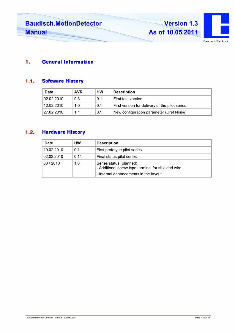
1.1. Software History
Date AVR HW Description
02.02.2010 0.3 0.1 First test version
12.02.2010 1.0 0.1 First version for delivery of the pilot series
27.02.2010 1.1 0.1 New configuration parameter (Uref Noise)
1.2. Hardware History
Date HW Description
10.02.2010 0.1 First prototype pilot series
02.02.2010 0.11 Final status pilot series
03 / 2010 1.0 Series status (planned)
- Additional screw type terminal for shielded wire
- Internal enhancements in the layout
Baudisch.MotionDetector_manual_current.doc Seite 5 von 31
Baudisch.MotionDetector
Manual
Version 1.3
As of 10.05.2011
2. General Information
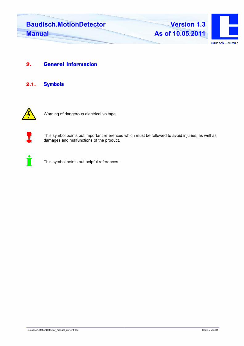
2.1. Symbols
Warning of dangerous electrical voltage.
This symbol points out important references which must be followed to avoid injuries, as well as
damages and malfunctions of the product.
This symbol points out helpful references.
Baudisch.MotionDetector_manual_current.doc Seite 6 von 31
Baudisch.MotionDetector
Manual
Version 1.3
As of 10.05.2011
2.2. Product Description
The Baudisch.MotionDetector works fully automatic based on electromagnetic waves by radar.
To adapt to individual structural conditions, several settings are available which parameters that
can be defined on site or remotely controlled by using additional modules. The motion detector
is suitable for a variety of applications in which motion or presence is registered to trigger
switching operations.
Due to an integrated light sensor, the Baudisch.MotionDetector responds additionally to light, so
you can adjust the motion detector to desired lighting conditions. The detection range is -
depending on the setting - between 3 m - 12 m.
The Baudisch.MotionDetector is thus the most reliable detection with a clearly defined and
individually adjusted radar field.
The Baudisch.MotionDetector offers an additional advantage: The motion detector can be
installed behind walls or doors, covered by virtually all non-metallic materials and is therefore
very protected against vandalism. In addition, this concealed mounting meets the requirements
of modern architectural apperances. The emitted radar waves register the slightest movement,
are heat independent and penetrate through media such as glass, wood or textile. The motion
detector can therefore be integrated into different building structures.
2.3. Fields of Application
The following applications are appropriate for the use of the Baudisch.MotionDetector:
• Automatic lighting control
• Automatic control of machinery, room technologies, sanitary areas or the opening of
doors and gates
• Alarm and security services
• In combination with the Baudisch.DoorModule
• Presence detector, building management systems and access control systems
• OEM application
Baudisch.MotionDetector_manual_current.doc Seite 7 von 31
Baudisch.MotionDetector
Manual
Version 1.3
As of 10.05.2011
3. Product Designs
3.1. Versions
The Baudisch.MotionDetector is available in two versions:
• Cost-efficient ECO version. Settings can be adjusted on site using a potentiometer.
• MAXI version, equipped with the Baudisch.EasyLan bus interface. With the support of
the EasyLan bus, the motion detector can be integrated into an EasyLan system to
securely link, configure, remotely control and manage the applicable devices.
Article number Name
36-0144 Baudisch.MotionDetector ECO (without front panel)
or
36-0145 Baudisch.MotionDetector MAXI (without front panel)
3.2. Optional Accessories
The switch modules allow the operation of relay contacts via the Baudisch.EasyLan bus.
Article number Name
33-1176 V4A front panel for motion detector
36-0113Field bus module ASB_2OutRelais for control of e.g. electrical door
openers in access control systems.
36-0130 Field bus module ASB_2In_2OutRelais for control of electrical door
openers in access control systems as well as the capture of feedback
e.g. door statuses.
For the integration into an EasyLan PC interface via the EasyLan bus.
Article number Name
36-0176 USB interface
36-0194 IP LAN for local network
36-0101 RS232 interface
Baudisch.MotionDetector_manual_current.doc Seite 8 von 31
Baudisch.MotionDetector
Manual
Version 1.3
As of 10.05.2011
4. Manual Start-up and Connections
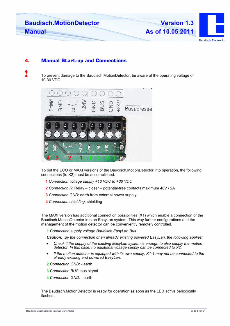
!! To prevent damage to the Baudisch.MotionDetector, be aware of the operating voltage of
10-30 VDC.
To put the ECO or MAXI versions of the Baudisch.MotionDetector into operation, the following
connections (to X2) must be accomplished.
1 Connection voltage supply +10 VDC to +30 VDC
2 Connection R: Relay – closer – potential-free contacts maximum 48V / 2A
3 Connection GND: earth from external power supply
4 Connection shielding: shielding
The MAXI version has additional connection possibilities (X1) which enable a connection of the
Baudisch.MotionDetector into an EasyLan system. This way further configurations and the
management of the motion detector can be conveniently remotely controlled.
1 Connection supply voltage Baudisch.EasyLan Bus
Caution: By the connection of an already existing powered EasyLan, the following applies:
• Check if the supply of the existing EasyLan system is enough to also supply the motion
detector. In this case, no additional voltage supply can be connected to X2.
• If the motion detector is equipped with its own supply, X1-1 may not be connected to the
already existing and powered EasyLan.
2 Connection GND: - earth
3 Connection BUS: bus signal
4 Connection GND: - earth
The Baudisch.MotionDetector is ready for operation as soon as the LED active periodically
flashes.
1234 24 3 1
Baudisch.MotionDetector_manual_current.doc Seite 9 von 31
Baudisch.MotionDetector
Manual
Version 1.3
As of 10.05.2011
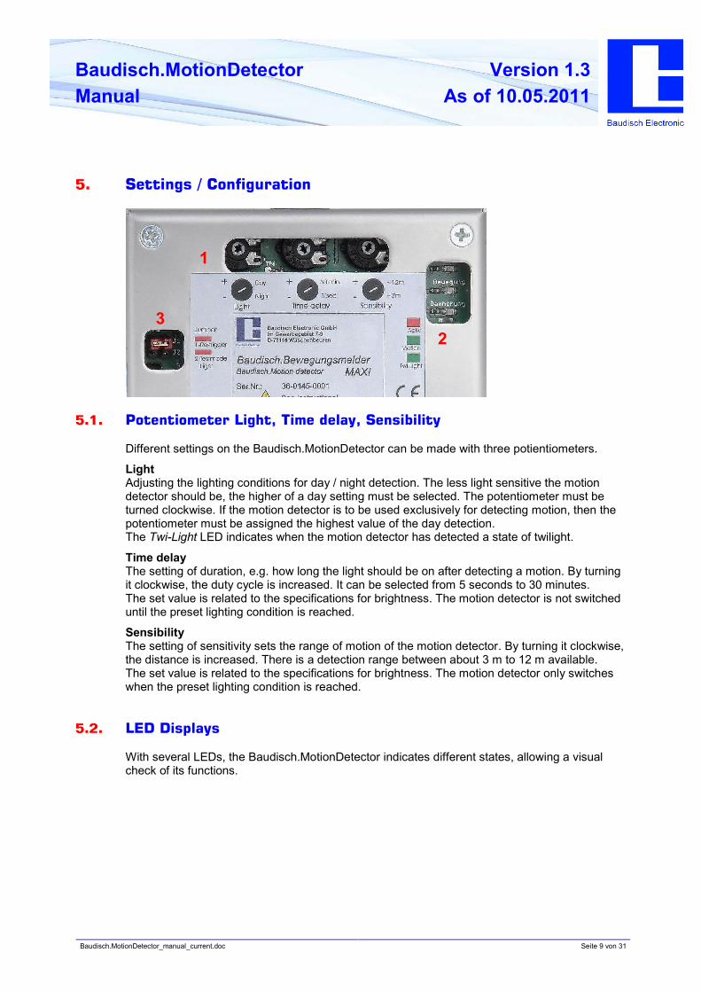
5. Settings / Configuration
5.1. Potentiometer Light, Time delay, Sensibility
Different settings on the Baudisch.MotionDetector can be made with three potientiometers.
Light
Adjusting the lighting conditions for day / night detection. The less light sensitive the motion
detector should be, the higher of a day setting must be selected. The potentiometer must be
turned clockwise. If the motion detector is to be used exclusively for detecting motion, then the
potentiometer must be assigned the highest value of the day detection.
The Twi-Light LED indicates when the motion detector has detected a state of twilight.
Time delay
The setting of duration, e.g. how long the light should be on after detecting a motion. By turning
it clockwise, the duty cycle is increased. It can be selected from 5 seconds to 30 minutes.
The set value is related to the specifications for brightness. The motion detector is not switched
until the preset lighting condition is reached.
Sensibility
The setting of sensitivity sets the range of motion of the motion detector. By turning it clockwise,
the distance is increased. There is a detection range between about 3 m to 12 m available.
The set value is related to the specifications for brightness. The motion detector only switches
when the preset lighting condition is reached.
5.2. LED Displays
With several LEDs, the Baudisch.MotionDetector indicates different states, allowing a visual
check of its functions.
1
2
3
Baudisch.MotionDetector_manual_current.doc Seite 10 von 31
Baudisch.MotionDetector
Manual
Version 1.3
As of 10.05.2011
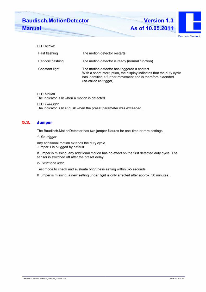
LED Active:
Fast flashing The motion detector restarts.
Periodic flashing The motion detector is ready (normal function).
Constant light The motion detector has triggered a contact.
With a short interruption, the display indicates that the duty cycle
has identified a further movement and is therefore extended
(so-called re-trigger).
LED Motion
The indicator is lit when a motion is detected.
LED Twi-Light
The indicator is lit at dusk when the preset parameter was exceeded.
5.3. Jumper
The Baudisch.MotionDetector has two jumper fixtures for one-time or rare settings.
1- Re-trigger
Any additional motion extends the duty cycle.
Jumper 1 is plugged by default.
If jumper is missing, any additional motion has no effect on the first detected duty cycle. The
sensor is switched off after the preset delay.
2- Testmode light
Test mode to check and evaluate brightness setting within 3-5 seconds.
If jumper is missing, a new setting under light is only affected after approx. 30 minutes.
Baudisch.MotionDetector_manual_current.doc Seite 11 von 31
Baudisch.MotionDetector
Manual
Version 1.3
As of 10.05.2011
6. Remote Configuration per EasyLan
The EasyLan Bus was developed by Baudisch Electronic GmbH to link together electronic
components, devices and systems in a simple manner. The data bus enables secure
communication between individual devices. A bus segment can consist of up to 2km shielded
cable 2 x 0.6mm² and can differentiate up to 64 participating devices. The
Baudisch.MotionDetector has the necessary connections and can be integrated into an
EasyLan system e.g. the door opener of a Baudisch.SIP DoorModule.
The protocol description of the EasyLan interface is not published. However, it can be handed
out by signing a confidentiality agreement (NDA).
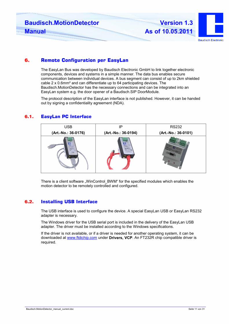
6.1. EasyLan PC Interface
USB
(Art.-No.: 36-0176)
IP
(Art.-No.: 36-0194)
RS232
(Art.-No.: 36-0101)
There is a client software „WinControl_BWM“ for the specified modules which enables the
motion detector to be remotely controlled and configured.
6.2. Installing USB Interface
The USB interface is used to configure the device. A special EasyLan USB or EasyLan RS232
adapter is necessary.
The Windows driver for the USB serial port is included in the delivery of the EasyLan USB
adapter. The driver must be installed according to the Windows specifications.
If the driver is not available, or if a driver is needed for another operating system, it can be
downloaded at www.ftdichip.com under Drivers, VCP. An FT232R chip compatible driver is
required.
Baudisch.MotionDetector_manual_current.doc Seite 12 von 31
Baudisch.MotionDetector
Manual
Version 1.3
As of 10.05.2011
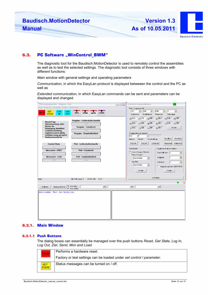
6.3. PC Software „WinControl_BWM“
The diagnostic tool for the Baudisch.MotionDetector is used to remotely control the assemblies
as well as to test the selected settings. The diagnostic tool consists of three windows with
different functions:
Main window with general settings and operating parameters
Communication, in which the EasyLan protocol is displayed betweeen the control and the PC as
well as
Extended communication, in which EasyLan commands can be sent and parameters can be
displayed and changed.
6.3.1. Main Window
6.3.1.1 Push Buttons
The dialog boxes can essentially be managed over the push buttons Reset, Get State, Log In,
Log Out, Ziel, Send, Mon and Load.
Performs a hardware reset.
Factory or test settings can be loaded under set control / parameter.
Status messages can be turned on / off.
Baudisch.MotionDetector_manual_current.doc Seite 13 von 31
Baudisch.MotionDetector
Manual
Version 1.3
As of 10.05.2011
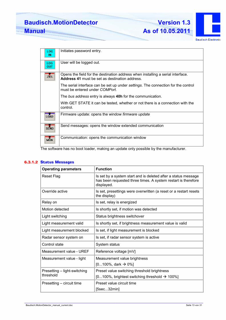
Initiates password entry.
User will be logged out.
Opens the field for the destination address when installing a serial interface.
Address 41 must be set as destination address.
The serial interface can be set up under settings. The connection for the control
must be entered under COMPort.
The bus address entry is always 40h for the communication.
With GET STATE it can be tested, whether or not there is a connection with the
control.
Firmware update: opens the window firmware update
Send messages: opens the window extended communication
Communication: opens the communication window
The software has no boot loader, making an update only possible by the manufacturer.
6.3.1.2 Status Messages
Operating parameters Function
Reset Flag Is set by a system start and is deleted after a status message
has been requested three times. A system restart is therefore
displayed.
Override active Is set, presettings were overwritten (a reset or a restart resets
the display)
Relay on Is set, relay is energized
Motion detected Is shortly set, if motion was detected
Light switching Status brightness switchover
Light measurement valid Is shortly set, if brightness measurement value is valid
Light measurement blocked Is set, if light measurement is blocked
Radar sensor system on Is set, if radar sensor system is active
Control state System status
Measurement value - UREF Reference voltage [mV]
Measurement value - light Measurement value brightness
[0...100%, dark à 0%]
Presetting – light-switching
threshold
Preset value switching threshold brightness
[0...100%, brightest switching threshold à 100%]
Presetting – circuit time Preset value circuit time
[5sec...32min]
Baudisch.MotionDetector_manual_current.doc Seite 14 von 31
Baudisch.MotionDetector
Manual
Version 1.3
As of 10.05.2011
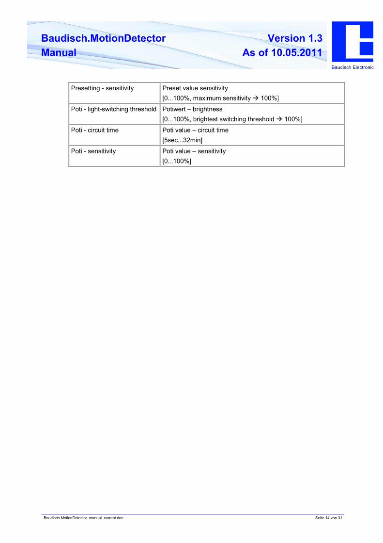
Presetting - sensitivity Preset value sensitivity
[0...100%, maximum sensitivity à 100%]
Poti - light-switching threshold Potiwert – brightness
[0...100%, brightest switching threshold à 100%]
Poti - circuit time Poti value – circuit time
[5sec...32min]
Poti - sensitivity Poti value – sensitivity
[0...100%]
Baudisch.MotionDetector_manual_current.doc Seite 15 von 31
Baudisch.MotionDetector
Manual
Version 1.3
As of 10.05.2011
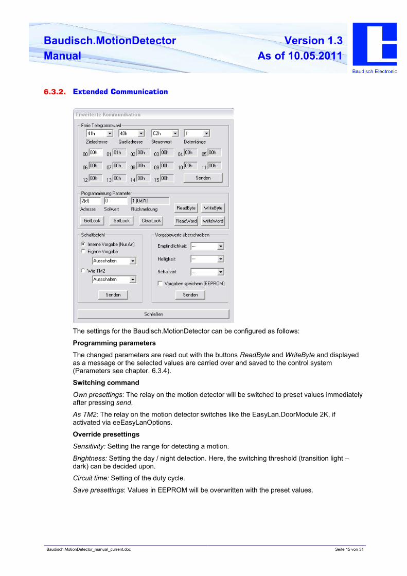
6.3.2. Extended Communication
The settings for the Baudisch.MotionDetector can be configured as follows:
Programming parameters
The changed parameters are read out with the buttons ReadByte and WriteByte and displayed
as a message or the selected values are carried over and saved to the control system
(Parameters see chapter. 6.3.4).
Switching command
Own presettings: The relay on the motion detector will be switched to preset values immediately
after pressing send.
As TM2: The relay on the motion detector switches like the EasyLan.DoorModule 2K, if
activated via eeEasyLanOptions.
Override presettings
Sensitivity: Setting the range for detecting a motion.
Brightness: Setting the day / night detection. Here, the switching threshold (transition light –
dark) can be decided upon.
Circuit time: Setting of the duty cycle.
Save presettings: Values in EEPROM will be overwritten with the preset values.

Baudisch.MotionDetector_manual_current.doc Seite 16 von 31
Baudisch.MotionDetector
Manual
Version 1.3
As of 10.05.2011
6.3.3. Protocol Description EasyLan Interface
6.3.3.1 Messages from PC to Device
Request ID
Control word 0xC5
Size of user data field 1
User data Byte 0 0x00
Status requirement
Control word 0xC2
Size of user data field 1
User data Byte 0 0x00
EEPROM-CMDs
Control word 0xF0
Size of user data field 5
Byte 0 Command
0xA0 = query lock status
0xA1 = read byte
0xA2 = read word (not implemented)
0x50 = change lock status
0x51 = write byte
0x52 = write word (not implemented)
Byte 1 Address – Highbyte
Byte 2 Address – Lowbyte
Byte 3 Date – Highbyte
User data
Byte 4 Date - Lowbyte
Triggering reset
Control word 0xC4
Size of user data field 3
Byte 0 0xFF
Byte 1 0x55
User data
Byte 2 0xAA
Baudisch.MotionDetector_manual_current.doc Seite 17 von 31
Baudisch.MotionDetector
Manual
Version 1.3
As of 10.05.2011
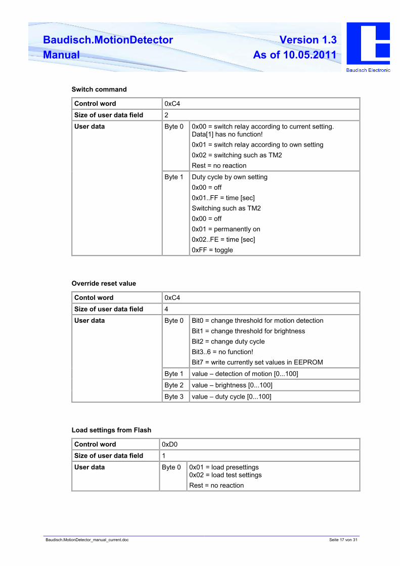
Switch command
Control word 0xC4
Size of user data field 2
Byte 0 0x00 = switch relay according to current setting.
Data[1] has no function!
0x01 = switch relay according to own setting
0x02 = switching such as TM2
Rest = no reaction
User data
Byte 1 Duty cycle by own setting
0x00 = off
0x01..FF = time [sec]
Switching such as TM2
0x00 = off
0x01 = permanently on
0x02..FE = time [sec]
0xFF = toggle
Override reset value
Contol word 0xC4
Size of user data field 4
Byte 0 Bit0 = change threshold for motion detection
Bit1 = change threshold for brightness
Bit2 = change duty cycle
Bit3..6 = no function!
Bit7 = write currently set values in EEPROM
Byte 1 value – detection of motion [0...100]
Byte 2 value – brightness [0...100]
User data
Byte 3 value – duty cycle [0...100]
Load settings from Flash
Control word 0xD0
Size of user data field 1
User data Byte 0 0x01 = load presettings
0x02 = load test settings
Rest = no reaction
Baudisch.MotionDetector_manual_current.doc Seite 18 von 31
Baudisch.MotionDetector
Manual
Version 1.3
As of 10.05.2011
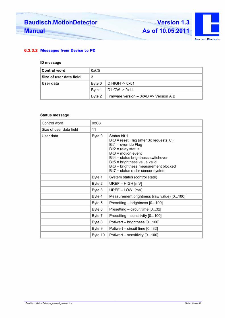
6.3.3.2 Messages from Device to PC
ID message
Control word 0xC5
Size of user data field 3
Byte 0 ID HIGH -> 0x01
Byte 1 ID LOW -> 0x11
User data
Byte 2 Firmware version – 0xAB => Version A.B
Status message
Control word 0xC3
Size of user data field 11
User data Byte 0 Status bit 1
Bit0 = reset Flag (after 3x requests ‚0’)
Bit1 = override Flag
Bit2 = relay status
Bit3 = motion event
Bit4 = status brightness switchover
Bit5 = brightness value valid
Bit6 = brightness measurement blocked
Bit7 = status radar sensor system
Byte 1 System status (control state)
Byte 2 UREF – HIGH [mV]
Byte 3 UREF – LOW [mV]
Byte 4 Measurement brightness (raw value) [0...100]
Byte 5 Presetting – brightness [0...100]
Byte 6 Presetting – circuit time [0...32]
Byte 7 Presetting – sensitivity [0...100]
Byte 8 Potiwert – brightness [0...100]
Byte 9 Potiwert – circuit time [0...32]
Byte 10 Potiwert – sensitivity [0...100]
Baudisch.MotionDetector_manual_current.doc Seite 19 von 31
Baudisch.MotionDetector
Manual
Version 1.3
As of 10.05.2011
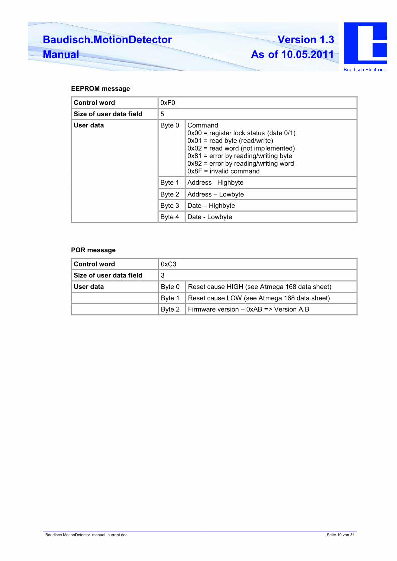
EEPROM message
Control word 0xF0
Size of user data field 5
Byte 0 Command
0x00 = register lock status (date 0/1)
0x01 = read byte (read/write)
0x02 = read word (not implemented)
0x81 = error by reading/writing byte
0x82 = error by reading/writing word
0x8F = invalid command
Byte 1 Address– Highbyte
Byte 2 Address – Lowbyte
Byte 3 Date – Highbyte
User data
Byte 4 Date - Lowbyte
POR message
Control word 0xC3
Size of user data field 3
User data Byte 0 Reset cause HIGH (see Atmega 168 data sheet)
Byte 1 Reset cause LOW (see Atmega 168 data sheet)
Byte 2 Firmware version – 0xAB => Version A.B
Baudisch.MotionDetector_manual_current.doc Seite 20 von 31
Baudisch.MotionDetector
Manual
Version 1.3
As of 10.05.2011
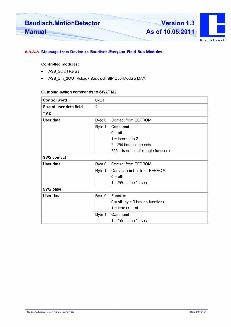
6.3.3.3 Message from Device to Baudisch.EasyLan Field Bus Modules
Controlled modules:
• ASB_2OUTRelais
• ASB_2In_2OUTRelais / Baudisch.SIP DoorModule MAXI
Outgoing switch commands to SW2/TM2
Control word 0xC4
Size of user data field 2
TM2
Byte 0 Contact from EEPROMUser data
Byte 1 Command
0 = off
1 = internal to 2
2...254 time in seconds
255 = is not sent! (toggle function)
SW2 contact
Byte 0 Contact from EEPROMUser data
Byte 1 Contact number from EEPROM
0 = off
1...255 = time * 2sec.
SW2 base
Byte 0 Function
0 = off (byte 0 has no function)
1 = time control
User data
Byte 1 Command
1...255 = time * 2sec
Baudisch.MotionDetector_manual_current.doc Seite 21 von 31
Baudisch.MotionDetector
Manual
Version 1.3
As of 10.05.2011
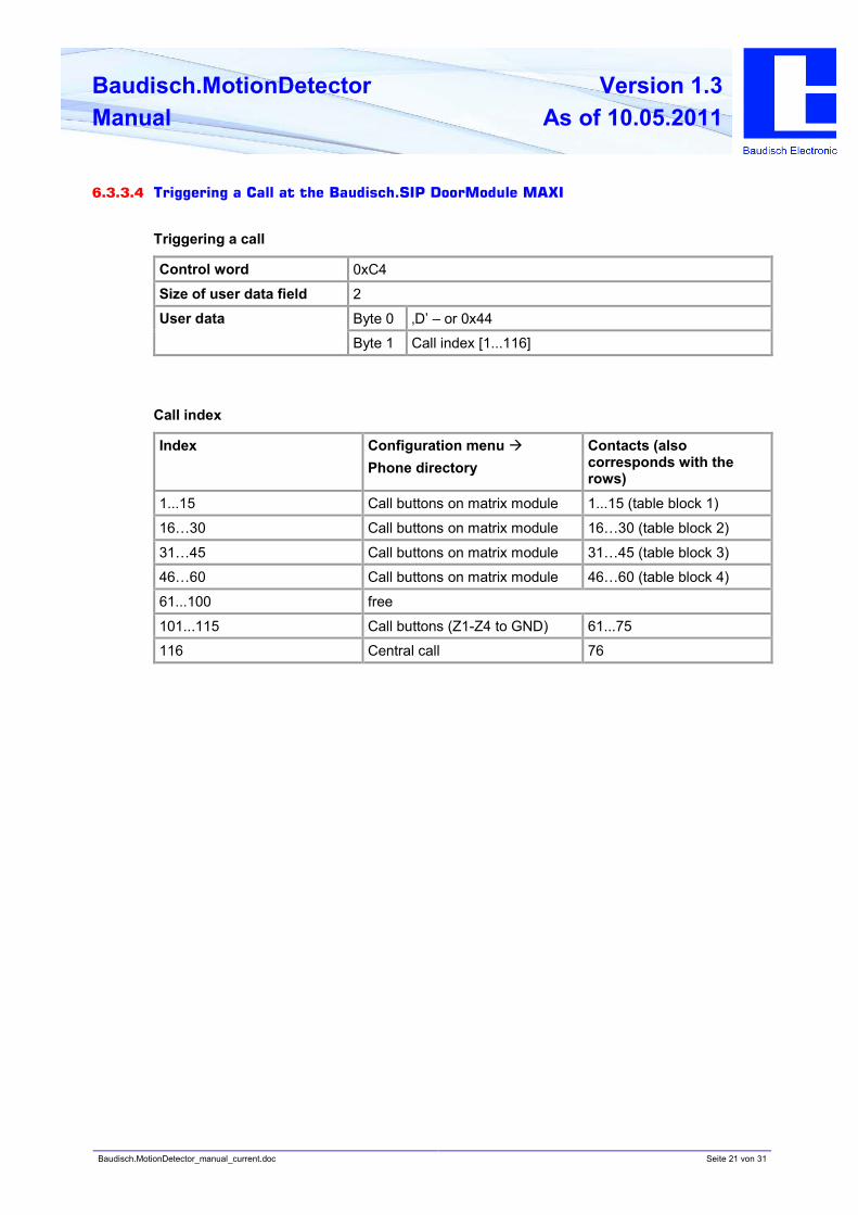
6.3.3.4 Triggering a Call at the Baudisch.SIP DoorModule MAXI
Triggering a call
Control word 0xC4
Size of user data field 2
Byte 0 ‚D’ – or 0x44User data
Byte 1 Call index [1...116]
Call index
Index Configuration menu à
Phone directory
Contacts (also
corresponds with the
rows)
1...15 Call buttons on matrix module 1...15 (table block 1)
16…30 Call buttons on matrix module 16…30 (table block 2)
31…45 Call buttons on matrix module 31…45 (table block 3)
46…60 Call buttons on matrix module 46…60 (table block 4)
61...100 free
101...115 Call buttons (Z1-Z4 to GND) 61...75
116 Central call 76

Baudisch.MotionDetector_manual_current.doc Seite 22 von 31
Baudisch.MotionDetector
Manual
Version 1.3
As of 10.05.2011
6.3.4. Configuration parameters
The control system contains various configuration data in an internal EEPROM.
As parameter number or address details are 2 to n allowed, values must be between 0 and 255.
System parameters
No[d] Name Description Default
2 eeSystemOptions System options:
Bit0 = send status message after reset
Bit1 = switch on relay after POR
Bit2 = retriggering of relay through event
Bit3 = release brightness measurement by
active relay
Bit4 = -- not used --
Bit5 = -- not used --
Bit6 = -- not used --
Bit7 = -- not used --
0x01
3 eeRelaisOnTime Duty cycle for relay (switching via sensor)
[0..32] à 5sec to approx. 30min
time[sec]=((REL_TIME_5_SEC/2)*(1.21^act
ualvalues[VALUE_TIME]))*2
0x00
4 eePowerOnRelaisTime Duty cycle for relay after POR [* 5sec] 0x01
5 EeSystemReserved1 0x00
6 EeSystemReserved2 0x00
7 EeSystemReserved3 0x00
8 EeSystemReserved4 0x00
9 EeSystemReserved5 0x00
10 EeSystemReserved6 0x00
11 EeSystemReserved7 0x00
12 EeSystemReserved8 0x00

Baudisch.MotionDetector_manual_current.doc Seite 23 von 31
Baudisch.MotionDetector
Manual
Version 1.3
As of 10.05.2011
EasyLan parameters
No Name Description Default
13 eeEasyLanAddress Bus address of the device at EasyLan bus 0x41
14 eeEasyLanHostAddress Address of the EasyLan hosts (PC) 0x40
15 eeEasyLanMaxRetries Indicates how often a data message is
repeated if no confirmation has been
received.
0x03
16 eeEasyLanOptions Bit0 = switch command format 0
Bit1 = switch command format 1
00 = no command by sending event
01 = send switch command to TM
10 = send switch command to SW2
contact
11 = send switch command to SW2
base
Bit2 = call initiation to SIP DoorModule
Bit3 = send status message after system
status change
Bit4 = send status message after bit status
change
Bit5 = send status message by motion event
Bit6 = send status message by analog
change (potis)
Bit7 = send status message by analog
change (light)
0x00
17 eeStatusIntervallTime Interval time for cyclical status message
0 = off
1...255 = [value*500ms]
20
18 eeEventLockTime Lock time for new event
0 à 100ms
1...255 = [value*100ms]
10
19 eeEasyLanCmdDestAddr Destination addres for TM2/SW2 command 0x52
20 eeEasyLanCmdKontakt Contact number for TM2/SW2 command 0x01
21 eeEasyLanTMCallIndex Destination call index for SIP DoorModule
001-100 = phone directory entry (matrix
modules)
101-115 = call buttons (Z1..Z4 to GND)
116 = central call
Rest = invalid!
0x00
Baudisch.MotionDetector_manual_current.doc Seite 24 von 31
Baudisch.MotionDetector
Manual
Version 1.3
As of 10.05.2011
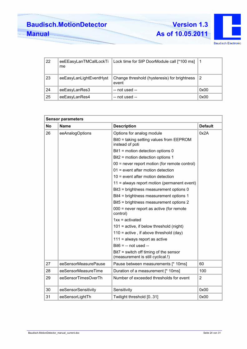
22 eeEEasyLanTMCallLockTi
me
Lock time for SIP DoorModule call [*100 ms] 1
23 eeEasyLanLightEventHyst Change threshold (hysteresis) for brightness
event
2
24 eeEasyLanRes3 -- not used -- 0x00
25 eeEasyLanRes4 -- not used -- 0x00
Sensor parameters
No Name Description Default
26 eeAnalogOptions Options for analog module
Bit0 = taking setting values from EEPROM
instead of poti
Bit1 = motion detection options 0
Bit2 = motion detection options 1
00 = never report motion (for remote control)
01 = event after motion detection
10 = event after motion detection
11 = always report motion (permanent event)
Bit3 = brightness measurement options 0
Bit4 = brightness measurement options 1
Bit5 = brightness measurement options 2
000 = never report as active (for remote
control)
1xx = activated
101 = active, if below threshold (night)
110 = active , if above threshold (day)
111 = always report as active
Bit6 = -- not used --
Bit7 = switch off timing of the sensor
(measurement is still cyclical.!)
0x2A
27 eeSensorMeasurePause Pause between measurements [* 10ms] 60
28 eeSensorMeasureTime Duration of a measurement [* 10ms] 100
29 eeSensorTimesOverTh Number of exceeded thresholds for event 2
30 eeSensorSensitivity Sensitivity 0x00
31 eeSensorLightTh Twilight threshold [0..31] 0x00
Baudisch.MotionDetector_manual_current.doc Seite 25 von 31
Baudisch.MotionDetector
Manual
Version 1.3
As of 10.05.2011
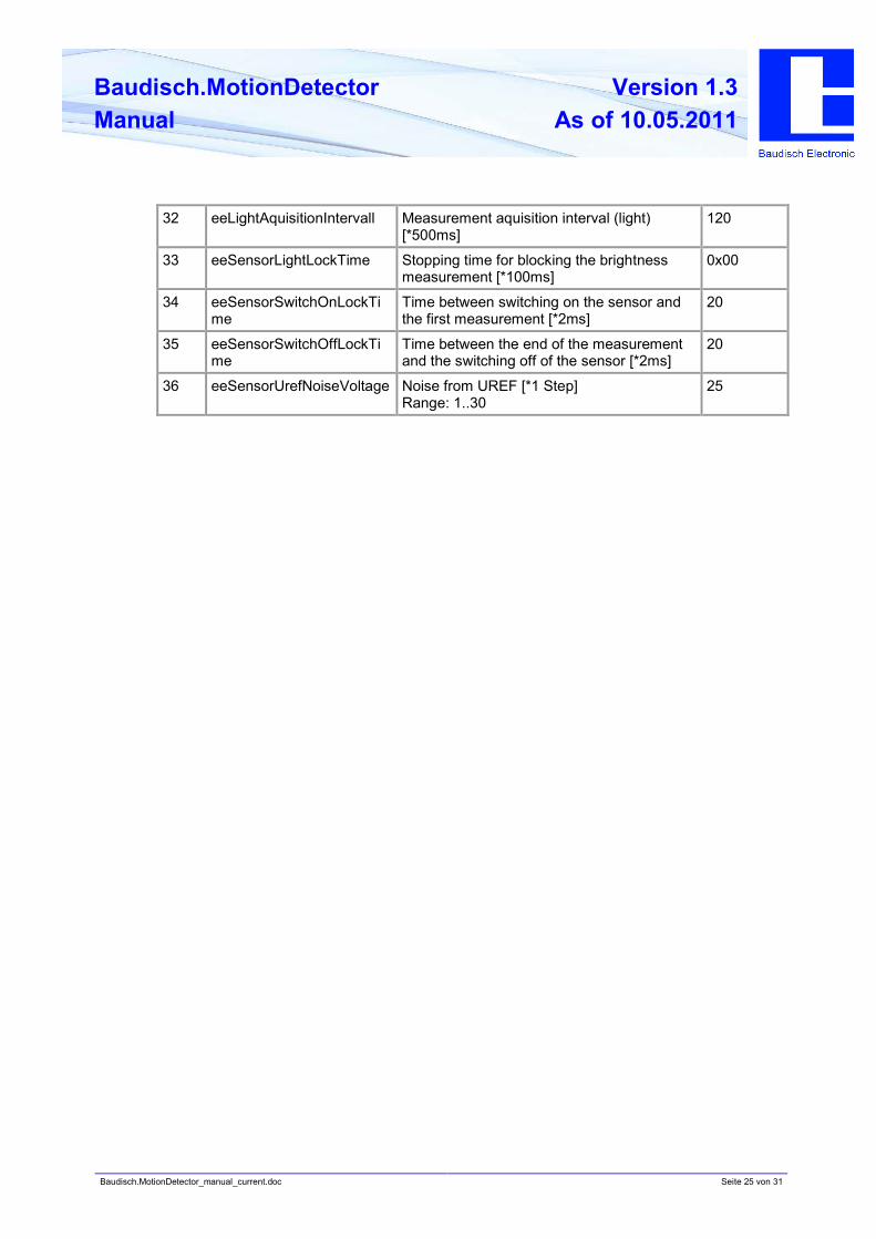
32 eeLightAquisitionIntervall Measurement aquisition interval (light)
[*500ms]
120
33 eeSensorLightLockTime Stopping time for blocking the brightness
measurement [*100ms]
0x00
34 eeSensorSwitchOnLockTi
me
Time between switching on the sensor and
the first measurement [*2ms]
20
35 eeSensorSwitchOffLockTi
me
Time between the end of the measurement
and the switching off of the sensor [*2ms]
20
36 eeSensorUrefNoiseVoltage Noise from UREF [*1 Step]
Range: 1..30
25
Baudisch.MotionDetector_manual_current.doc Seite 26 von 31
Baudisch.MotionDetector
Manual
Version 1.3
As of 10.05.2011
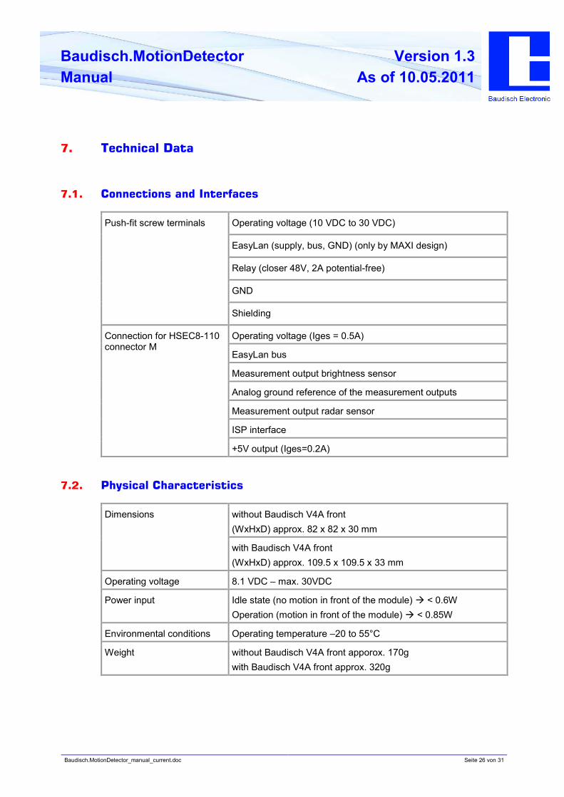
7. Technical Data
7.1. Connections and Interfaces
Operating voltage (10 VDC to 30 VDC)
EasyLan (supply, bus, GND) (only by MAXI design)
Relay (closer 48V, 2A potential-free)
GND
Push-fit screw terminals
Shielding
Operating voltage (Iges = 0.5A)
EasyLan bus
Measurement output brightness sensor
Analog ground reference of the measurement outputs
Measurement output radar sensor
ISP interface
Connection for HSEC8-110
connector M
+5V output (Iges=0.2A)
7.2. Physical Characteristics
without Baudisch V4A front
(WxHxD) approx. 82 x 82 x 30 mm
Dimensions
with Baudisch V4A front
(WxHxD) approx. 109.5 x 109.5 x 33 mm
Operating voltage 8.1 VDC – max. 30VDC
Power input Idle state (no motion in front of the module) à < 0.6W
Operation (motion in front of the module) à < 0.85W
Environmental conditions Operating temperature –20 to 55°C
Weight without Baudisch V4A front apporox. 170g
with Baudisch V4A front approx. 320g

Baudisch.MotionDetector_manual_current.doc Seite 27 von 31
Baudisch.MotionDetector
Manual
Version 1.3
As of 10.05.2011
7.3. Miscellaneous
Sending frequeny: 24.125 GHz
Transmission power (EIRP): 13 dBm
Sensor detection: horizontal 80°, vertical 32°
Detection range 3 - 10 m (0.5–12 m depending on space available)
Baudisch.MotionDetector_manual_current.doc Seite 28 von 31
Baudisch.MotionDetector
Manual
Version 1.3
As of 10.05.2011
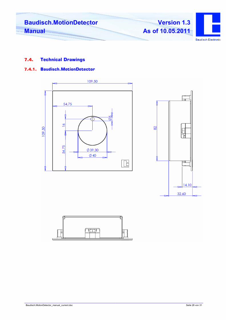
7.4. Technical Drawings
7.4.1. Baudisch.MotionDetector
Baudisch.MotionDetector_manual_current.doc Seite 29 von 31
Baudisch.MotionDetector
Manual
Version 1.3
As of 10.05.2011
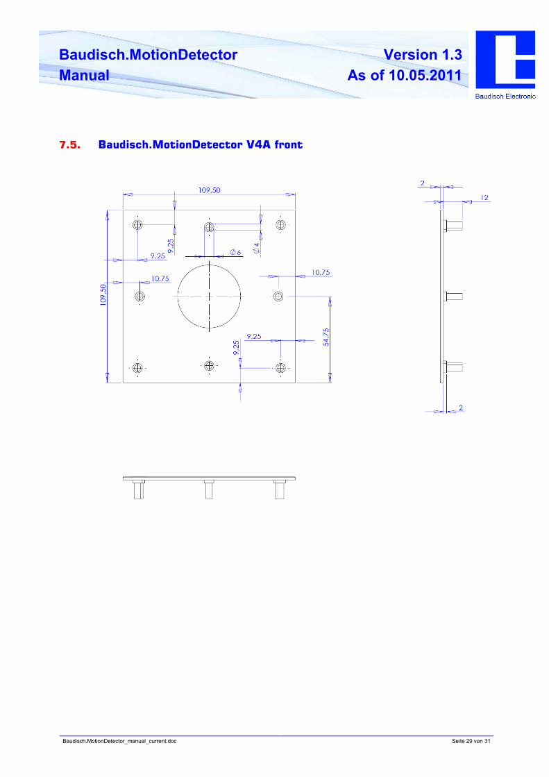
7.5. Baudisch.MotionDetector V4A front
Baudisch.MotionDetector_manual_current.doc Seite 30 von 31
Baudisch.MotionDetector
Manual
Version 1.3
As of 10.05.2011
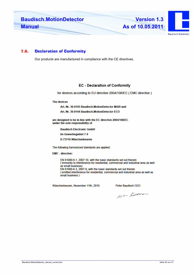
7.6. Declaration of Conformity
Our products are manufactured in compliance with the CE directives.
Baudisch.MotionDetector_manual_current.doc Seite 31 von 31
Baudisch.MotionDetector
Manual
Version 1.3
As of 10.05.2011
Herstellung und Vertrieb
Baudisch Electronic GmbH
Im Gewerbegebiet 7-9
D-73116 Wäschenbeuren
Tel.: +49 7172 / 92613-0
Fax: +49 7172 / 92613-30
Mail: [email protected]
Web: www.baudisch.de