PMP45 - Hilti · 2013-08-29 · PMP45 Bedienungsanleitung de Operating instructions en Mode...
14
PMP 45 Bedienungsanleitung de Operating instructions en Mode d’emploi fr Istruzioni d’uso it Manual de instrucciones es Manual de instruções pt Gebruiksaanwijzing nl Οδηγιες χρησεως el Kulllanma Talimatı tr ja ko cn Printed: 07.07.2013 | Doc-Nr: PUB / 5130578 / 000 / 00
Transcript of PMP45 - Hilti · 2013-08-29 · PMP45 Bedienungsanleitung de Operating instructions en Mode...

PMP 45
Bedienungsanleitung deOperating instructions enMode d’emploi frIstruzioni d’uso itManual de instrucciones esManual de instruções ptGebruiksaanwijzing nlΟδηγιες χρησεως elKulllanma Talimatı tr
jakocn
Printed: 07.07.2013 | Doc-Nr: PUB / 5130578 / 000 / 00
1
5
4
2 3
1
Printed: 07.07.2013 | Doc-Nr: PUB / 5130578 / 000 / 00

2
3
5
4
Printed: 07.07.2013 | Doc-Nr: PUB / 5130578 / 000 / 00

6
5m
d1
1
2
a c
b
7
max. 3mm
d1 d3
d2
7
5
6
d4
a
b
c
9
max. 3mm
d1 d3
d2
4
3
5
a c
b
8
Printed: 07.07.2013 | Doc-Nr: PUB / 5130578 / 000 / 00

ORIGINAL OPERATING INSTRUCTIONS
PMP 45 point laser
It is essential that the operating instructionsare read before the tool is operated for thefirst time.Always keep these operating instructions to-gether with the tool.Ensure that the operating instructions arewith the tool when it is given to other persons.
Contents Page1 General information 102 Description 113 Accessories 124 Technical data 125 Safety instructions 136 Before use 147 Operation 158 Care and maintenance 169 Troubleshooting 1610 Disposal 1711 Manufacturer’s warranty 1712 EC declaration of conformity (original) 18
1 These numbers refer to the corresponding illustra-tions. The illustrations can be found on the fold-out coverpages. Keep these pages open while studying the oper-ating instructions.In these operating instructions, the designation “the tool”always refers to the PMP 45 point laser.
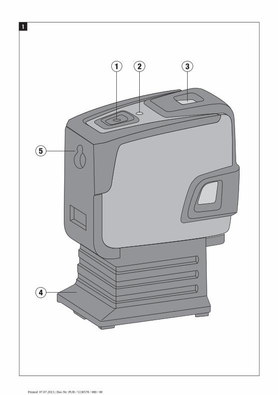
Component parts 1
@On/off button
;LED
=Pendulum
%Removable foot
&Mounting hole
1 General information1.1 Safety notices and their meaningDANGERDraws attention to imminent danger that will lead toserious bodily injury or fatality.
WARNINGDraws attention to a potentially dangerous situation thatcould lead to serious personal injury or fatality.
CAUTIONDraws attention to a potentially dangerous situation thatcould lead to slight personal injury or damage to theequipment or other property.
NOTEDraws attention to an instruction or other useful informa-tion.
1.2 Explanation of the pictograms and otherinformation
Warning signs
Generalwarning
en
10
Printed: 07.07.2013 | Doc-Nr: PUB / 5130578 / 000 / 00

Symbols
Read theoperatinginstructionsbefore use.
Disposal ofpower tools
orappliancesand batteriestogether withhouseholdwaste is notpermissible.
Laser class IIaccording to
CFR 21, § 1040(FDA)
Laser class 2according toEN 60825-3:2007
Location of identification data on the toolThe type designation and serial number can be found onthe type identification plate on the tool. Make a note ofthis data in your operating instructions and always referto it when making an enquiry to your Hilti representativeor service department.
Type:
Serial no.:
2 Description2.1 Use of the product as directedThe PMP 45 is a self-levelling point laser which allows a single person to level, plumb, align and transfer right anglesquickly and accurately. The tool features five coincident laser beams (beams that originate from the same point). Allbeams have the same range of 30m (range depends on the brightness of ambient light).The tool is designed for use mainly in interiors, for determining and checking vertical lines, alignment lines, and formarking plumb points.When used for outdoor applications, care must be taken to ensure that the general conditions are similar to thoseencountered indoors. For example:Marking the position of partition walls (at right angles and in the vertical plane).Aligning components to be installed or sections of a structure in three axes.Checking and transferring right angles.Transferring measuring marks from the floor to the ceiling.Modification of the tool is not permissible.Observe the information printed in the operating instructions concerning operation, care and maintenance.To avoid the risk of injury, use only genuine Hilti accessories and insert tools.The tool and its ancillary equipment may present hazards when used incorrectly by untrained personnel or when usednot as directed.
2.2 FeaturesHighly accurate horizontal and vertical beams (±3 mm at 10 m).Self-levelling to within ±5° in all directions.Short self-levelling time: ~3 secondsWhen the self-leveling range is exceeded, the laser beam blinks to warn the user.The PMP 45 is characterized by its ease of operation and use, its rugged plastic casing and ease of transport due toits compact dimensions and light weight.When in normal operating mode, the tool switches itself off after 15 minutes. Sustained operating mode can beselected by pressing the on/off button for four seconds.
en
11
Printed: 07.07.2013 | Doc-Nr: PUB / 5130578 / 000 / 00

2.3 Information displayed during operationLED The LED doesn’t light. The tool is switched off.
The LED doesn’t light. The batteries are exhausted.The LED doesn’t light. The batteries are inserted incorrectly.The LED lights constantly. The laser beam is switched on. The tool
is in operation.The LED blinks twice every10 seconds.
The batteries are almost exhausted.
Laser beam The laser beam blinks twiceevery 10 seconds.
The batteries are almost exhausted.
The laser beam blinks rapidly. The tool cannot level itself.
2.4 Items supplied with the point laser (cardboard box version)1 PMP 45 point laser1 Soft pouch4 Batteries1 Operating instructions1 Manufacturer’s certificate
3 AccessoriesDesignation Short designation DescriptionTripod PMA 20Target plate PMA 54/55Magnetic holder PMA 74Telescopic brace PUA 10Frame clamp PMA 25Universal adapter PMA 78Hilti toolbox PMA 62Laser visibility glasses PUA 60 The laser visibility glasses are not
protective glasses and thus do notprotect the eyes from laser beams.As the laser visibility glasses restrictcolor vision, they should be worn onlywhen working with this tool. Do notwear the laser visibility glasses whiledriving a vehicle on a public road.
4 Technical dataRight of technical changes reserved.
Range of the points 30 m (98 ft)Accuracy 1 ±2 mm at 10 m (±0.08 in at 33 ft)Self-leveling time 3 s (typical)1 Influences such as particularly high temperature fluctuations, dampness, shock, dropping, etc. can affect accuracy. Unless statedotherwise, the tool was adjusted or calibrated under standard ambient conditions (MIL-STD-810F).
en
12
Printed: 07.07.2013 | Doc-Nr: PUB / 5130578 / 000 / 00

Laser class Class 2, visible, 620 - 690 nm, ±10 nm (EN 60825-3:2007 / IEC 60825 - 3:2007); class II (CFR 21 §1040(FDA)
Beam diameter Distance 5 m: < 4 mmDistance 20 m: < 16 mm
Self-leveling range ±5° (typical)Automatic power-off Activated after: 15 minOperating status indicator LED and laser beamsPower supply AA‑size batteries, Alkaline batteries: 4Battery life Alkaline battery 2,500 mAh, Temperature +25°C
(+77°F): 30 h (Typical)Operating temperature range Min. -10°C / Max. +50°C (+14 to 122°F)Storage temperature Min. -25°C / Max. +63°C (-13 to 145°F)Dust and water spray protection (except battery com-partment)
IP 54 as per IEC 529
Tripod thread (tool) UNC¹⁄₄"Tripod thread (foot) BSW ⁵/₈" UNC ¹/₄"Weight With foot but without batteries: 0.413 kg ( 0.911 lbs)Dimensions With foot: 140 mm X 73 mm X 107 mm
Without foot: 96 mm X 65 mm X 107 mm1 Influences such as particularly high temperature fluctuations, dampness, shock, dropping, etc. can affect accuracy. Unless statedotherwise, the tool was adjusted or calibrated under standard ambient conditions (MIL-STD-810F).
5 Safety instructionsIn addition to the information relevant to safety givenin each of the sections of these operating instructions,the following points must be strictly observed at alltimes.
5.1 General safety rulesa) Check the accuracy of the tool before using it to
take measurements.b) The tool and its ancillary equipment may present
hazards when used incorrectly by untrained per-sonnel or when used not as directed.
c) To avoid the risk of injury, use only genuine Hiltiaccessories and additional equipment.
d) Modification of the tool is not permissible.e) Observe the information printed in the operat-
ing instructions concerning operation, care andmaintenance.
f) Do not render safety devices ineffective and donot remove information and warning notices.
g) Keep laser tools out of reach of children.h) Take the influences of the surrounding area into
account. Do not expose the tool to rain or snowand do not use it in damp or wet conditions. Donot use the tool where there is a risk of fire orexplosion.
i) Check the condition of the tool before use. If thetool is found to be damaged, have it repaired at aHilti service center.
j) The user must check the accuracy of the toolafter it has been dropped or subjected to othermechanical stresses.
k) When the tool is brought into a warm environmentfrom very cold conditions, or vice-versa, allow itto become acclimatized before use.
l) If mounting on an adapter, check that the tool isscrewed on securely.
m) Keep the laser exit aperture clean to avoid meas-urement errors.
n) Although the tool is designed for the tough condi-tions of jobsite use, aswith other optical and elec-tronic instruments (e.g. binoculars, spectacles,cameras) it should be treated with care.
o) Although the tool is protected to prevent entryof dampness, it should be wiped dry each timebefore being put away in its transport container.
p) Check the accuracy of the measurements severaltimes during use of the tool.
5.2 Proper organization of the work areaa) Secure the area in which you are working and
take care to avoid directing the beam towardsother persons or towards yourself when settingup the tool.
b) Avoid unfavorable body positions when workingfrom ladders. Make sure you work from a safestance and stay in balance at all times.
en
13
Printed: 07.07.2013 | Doc-Nr: PUB / 5130578 / 000 / 00

c) Measurements taken through panes of glass or otherobjects may be inaccurate.
d) Ensure that the tool is set up on a steady, levelsurface (not subject to vibration).
e) Use the tool only within its specified limits.f) If several laser tools are used in the sameworking
area, care must be taken to avoid confusing thebeams.
g) Magnetic fields may affect the accuracy of the tool. Itmust thus be kept away from magnetic objects. Thetool is not affected by the Hilti universal adapter.
h) Do not use the tool in the proximity of medical instru-ments.
5.3 Electromagnetic compatibilityAlthough the tool complies with the strict requirementsof the applicable directives, Hilti cannot entirely rule outthe possibility of the tool being subject to interferencecaused by powerful electromagnetic radiation, leadingto incorrect operation. Check the accuracy of the toolby taking measurements by other means when workingunder such conditions or if you are unsure. Likewise, Hilticannot rule out the possibility of interference with otherdevices (e.g. aircraft navigation equipment).
5.4 Laser classification for laser class 2 / class IIappliances
Depending on the version purchased, the tool complieswith Laser Class 2 in accordance with IEC825-3:2007 /EN60825-3:2007 and Class II in accordance with CFR21 § 1040 (FDA). This tool may be used without needfor further protective measures. The eyelid closure reflexprotects the eyes when a person looks into the beamunintentionally for a brief moment. This eyelid closurereflex, however, may be negatively affected bymedicines,alcohol or drugs. Nevertheless, as with the sun, one
should not look directly into sources of bright light. Donot direct the laser beam toward persons.
5.5 Electrical
a) Insulate or remove the batteries before shipping thetool.
b) To avoid pollution of the environment, the toolmust be disposed of in accordance with the cur-rently applicable national regulations. Consult themanufacturer if you are unsure of how to proceed.
c) Keep the batteries out of reach of children.d) Do not allow the batteries to overheat and do not
expose them to fire. The batteries may explode orrelease toxic substances.
e) Do not charge the batteries.f) Do not solder the batteries into the tool.g) Do not discharge the batteries by short circuiting
as this may cause them to overheat and presenta risk of personal injury (burns).
h) Do not attempt to open the batteries and do notsubject them to excessive mechanical stress.
i) Do not use damaged batteries.j) Do not mix old and new batteries. Do not mix
batteries of different makes or types.
5.6 LiquidsUnder abusive conditions, liquid may leak from the bat-tery. Avoid contact. If contact accidentally occurs,flush with water. In the event of the liquid coming intocontact with the eyes, rinse the eyes with plenty ofwater and consult a doctor. Liquid ejected from thebattery may cause irritation or burns.
6 Before use
6.1 Inserting the batteries 2
DANGERUse only new batteries.
1. Remove the foot from the tool.2. Open the battery compartment.3. Remove the batteries from the packaging and insert
them in the tool.NOTE Only batteries recommended by Hilti may beused to power the tool.
4. Check that the battery terminals are positioned cor-rectly as shown on the underside of the unit.
5. Close the battery compartment. Check that thecatch engages properly.
6. Refit the foot to the tool.
en
14
Printed: 07.07.2013 | Doc-Nr: PUB / 5130578 / 000 / 00

R = x (2)30
RH [ft](d1 + d2) [inch]
4
R = x (1)10
RH [m](d1 + d2) [mm]
4
7 Operation
7.1 Operation7.1.1 Switching the laser beams onPress the on/off button once.
7.1.2 Switching the tool / laser beams offPress the on/off button until the laser beam is no longervisible and the LED goes out.NOTEThe tool switches itself off automatically after approx. 15min.
7.1.3 Deactivating the automatic power-off featurePress and hold the on/off button for approx. 4 sec. untilthe laser beam blinks three times as confirmation.NOTEThe tool will be switched off when the on/off button ispressed or when the batteries are exhausted.
7.2 Examples of applications7.2.1 Setting out drywall track for a partition
wall 3
7.2.2 Marking out the position of light fittings 4
7.3 Checking7.3.1 Checking the plumb point 5
1. Make a mark on the floor (a cross) in a high room(e.g. in a stairwell or hallway with a height of 5–10m).
2. Place the tool on a smooth, level (horizontal) surface.3. Switch the tool on.4. Position the tool with the lower beam on the center
of the cross.5. Mark the position of the vertical beam on the ceiling.
Attach a piece of paper to the ceiling before makingthe mark.
6. Pivot the tool through 90°.NOTE The lower plumb beam must remain on thecenter of the cross.
7. Mark the position of the vertical beam on the ceiling.8. Repeat the procedure after pivoting the tool through
180° and 270°.NOTE The resulting 4 marks form a circle in whichthe intersection of the diagonals d1 (1-3) and d2(2-4) marks the exact center of the plumb point.
9. Calculate the accuracy as described in section7.3.1.1.
7.3.1.1 Calculation of accuracy
The result (R) provided by this formula (RH = room height)refers to the tool’s accuracy “in mm at 10 m” (formula(1)). This result (R) should be within the specification forthe tool (3 mm at 10 m).
7.3.2 Checking leveling of the forward beam 6
1. Place the tool on a smooth, level surface approx.20 cm from the wall (A) with the laser beam directedtoward the wall (A).
2. Mark the position of the laser point on the wall (A)with a cross.
3. Pivot the tool through 180° and mark the position ofthe laser point on the opposite wall (B) with a cross.
4. Place the tool on an even, level surface approx. 20cm from the wall (B) with the laser beam directedtoward the wall (B).
5. Mark the position of the laser point on the wall (B)with a cross.
6. Pivot the tool through 180° and mark the position ofthe laser point on the opposite wall (A) with a cross.
7. Measure the distances d1 between 1 and 4 and d2between 2 and 3.
8. Mark the mid points of d1 and d2.If the reference points 1 and 3 are located on dif-ferent sides of the mid point, then subtract d2 fromd1.If the reference points 1 and 3 are located on thesame side of the mid point, then add d1 and d2together.
9. Divide the result by twice the length of the room(room length x 2).The maximum permissible error is 3 mm at 10 m.
7.3.3 Checking perpendicularity (horizontal) 7 8 9
1. Position the tool with the lower plumb beam on thecenter of a reference cross in the middle of a roomat a distance of approx. 5 meters from the walls sothat the vertical laser line lies exactly in the center ofthe laser point.
2. Attach a second target plate or sheet of paper (b)to the wall at the half-way position (as shown in theillustration). Mark the mid point (d1) of the right-handperpendicular beam.
en
15
Printed: 07.07.2013 | Doc-Nr: PUB / 5130578 / 000 / 00
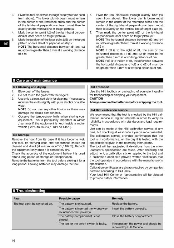
3. Pivot the tool clockwise through exactly 90° (as seenfrom above). The lower plumb beam must remainin the center of the reference cross and the centerof the left-hand perpendicular beam must then lieexactly on the vertical line of target plate (a).
4. Mark the center point (d2) of the right-hand perpen-dicular laser beam on target plate (c).
5. Mark the position of the laser point (d3) on the targetplate b or on a sheet of paper as at step 7.NOTE The horizontal distance between d1 and d3must be no greater than 3 mm at a working distanceof 5 m.
6. Pivot the tool clockwise through exactly 180° (asseen from above). The lower plumb beam mustremain in the center of the reference cross and thecenter of the right-hand perpendicular beam mustthen lie exactly on the vertical line of target plate (a).
7. Then mark the center point (d2) of the left-handperpendicular laser beam on target plate (c).NOTE The horizontal distance between d2 and d4must be no greater than 3 mm at a working distanceof 5 m.NOTE If d3 is to the right of d1, the sum of thehorizontal distances d1-d3 and d2-d4 must be nogreater than 3 mm at a working distance of 5m.NOTE If d3 is to the left of d1, the difference betweenthe horizontal distances d1-d3 and d2-d4 must beno greater than 3 mm at a working distance of 5m.
8 Care and maintenance8.1 Cleaning and drying1. Blow dust off the lenses.2. Do not touch the glass with the fingers.3. Use only a clean, soft cloth for cleaning. If necessary,
moisten the cloth slightly with pure alcohol or a littlewater.NOTE Do not use any other liquids as these maydamage the plastic components.
4. Observe the temperature limits when storing yourequipment. This is particularly important in winter/ summer if the equipment is kept inside a motorvehicle (-25°C to +63°C / -13°F to 145°F).
8.2 StorageRemove the tool from its case if it has become wet.The tool, its carrying case and accessories should becleaned and dried (at maximum 40°C / 104°F). Repackthe equipment only once it is completely dry.Check the accuracy of the equipment before it is usedafter a long period of storage or transportation.Remove the batteries from the tool before storing it for along period. Leaking batteries may damage the tool.
8.3 TransportUse the Hilti toolbox or packaging of equivalent qualityfor transporting or shipping your equipment.CAUTIONAlways remove the batteries before shipping the tool.
8.4 Hilti calibration serviceWe recommend that the tool is checked by the Hilti cal-ibration service at regular intervals in order to verify itsreliability in accordance with standards and legal require-ments.Use can be made of the Hilti calibration service at anytime, but checking at least once a year is recommended.The calibration service provides confirmation that thetool is in conformance, on the day it is tested, with thespecifications given in the operating instructions.The tool will be readjusted if deviations from the man-ufacturer’s specification are found. After checking andadjustment, a calibration sticker applied to the tool anda calibration certificate provide written verification thatthe tool operates in accordance with the manufacturer’sspecification.Calibration certificates are always required by companiescertified according to ISO 900x.Your local Hilti Center or representative will be pleasedto provide further information.
9 TroubleshootingFault Possible cause RemedyThe tool can’t be switched on. The battery is exhausted. Replace the battery.
The battery is inserted the wrong wayround (incorrect polarity).
Insert the battery correctly.
The battery compartment is notclosed.
Close the battery compartment.
The tool or the on/off switch is faulty. If necessary, the power tool should berepaired by Hilti Service.
en
16
Printed: 07.07.2013 | Doc-Nr: PUB / 5130578 / 000 / 00

Fault Possible cause RemedyIndividual laser beams don’tfunction.
The laser source or laser control unitis faulty.
If necessary, have the power tool re-paired by Hilti Service.
The tool can be switched on butno laser beam is visible.
The laser source or laser control unitis faulty.
If necessary, have the power tool re-paired by Hilti Service.
The temperature is too high or toolow.
Allow the tool to cool down or warmup.
Automatic leveling doesn’t func-tion.
The tool is set up on an excessivelyinclined surface.
Set up the tool on the level.
The tilt sensor is faulty. If necessary, have the power tool re-paired by Hilti Service.
10 DisposalWARNINGImproper disposal of the equipment may have serious consequences:The burning of plastic components generates toxic fumes which may present a health hazard.Batteries may explode if damaged or exposed to very high temperatures, causing poisoning, burns, acid burns orenvironmental pollution.Careless disposal may permit unauthorized and improper use of the equipment. This may result in serious personalinjury, injury to third parties and pollution of the environment.
Most of the materials from which Hilti tools or appliances are manufactured can be recycled. The materials must becorrectly separated before they can be recycled. In many countries, Hilti has already made arrangements for takingback old tools or appliances for recycling. Ask Hilti Customer Service or your Hilti representative for further information.
For EC countries onlyDisposal of electric tools together with household waste is not permissible.In observance of European Directive 2012/19/EU on waste electrical and electronic equipment and itsimplementation in accordance with national law, electrical appliances that have reached the end of theirlife must be collected separately and returned to an environmentally compatible recycling facility.
Dispose of the batteries in accordance with national regulations.
11 Manufacturer’s warrantyHilti warrants that the tool supplied is free of defects inmaterial and workmanship. This warranty is valid so longas the tool is operated and handled correctly, cleanedand serviced properly and in accordance with the HiltiOperating Instructions, and the technical system is main-tained. This means that only original Hilti consumables,components and spare parts may be used in the tool.
This warranty provides the free-of-charge repair or re-placement of defective parts only over the entire lifespanof the tool. Parts requiring repair or replacement as aresult of normal wear and tear are not covered by thiswarranty.
Additional claims are excluded, unless stringent na-tional rules prohibit such exclusion. In particular, Hiltiis not obligated for direct, indirect, incidental or con-sequential damages, losses or expenses in connec-tion with, or by reason of, the use of, or inability touse the tool for any purpose. Implied warranties ofmerchantability or fitness for a particular purpose arespecifically excluded.
For repair or replacement, send the tool or related partsimmediately upon discovery of the defect to the addressof the local Hilti marketing organization provided.
en
17
Printed: 07.07.2013 | Doc-Nr: PUB / 5130578 / 000 / 00

This constitutes Hilti’s entire obligation with regard towarranty and supersedes all prior or contemporaneous
comments and oral or written agreements concerningwarranties.
12 EC declaration of conformity (original)Designation: Point laserType: PMP 45Year of design: 2009
We declare, on our sole responsibility, that this productcomplies with the following directives and standards:2004/108/EC, 2006/95/EC, 2011/65/EU, EN ISO 12100.
Hilti Corporation, Feldkircherstrasse 100,FL‑9494 Schaan
Paolo Luccini Matthias GillnerHead of BA Quality and Process Man-agement
Executive Vice President
Business Area Electric Tools & Ac-cessories
Business Area ElectricTools & Accessories
01/2012 01/2012
Technical documentation filed at:Hilti Entwicklungsgesellschaft mbHZulassung ElektrowerkzeugeHiltistrasse 686916 KauferingDeutschland
en
18
FCC statement / IC statement-CAUTION-This equipment has been tested and found to complywith the limits for a class B digital device, pursuant topart 15 of the FCC rules. These limits are designed toprovide reasonable protection against harmful interfer-ence in a residential installation. This equipment gener-ates, uses, and can radiate radiofrequency energy and,if not installed and used in accordance with the instruc-tions, may cause harmful interference to radio com-munications.
However, there is no guarantee that interference will notoccur in a particular installation. If this equipment doescause harmful interference to radio or television recep-tion, which can be determined by turning the equipmenton and off, the user is encouraged to try to correct theinterference by one or more of the following measures:
• Re-orient or re-locate the receiving antenna.• Increase the distance between the equipment and
receiver.• Connect the equipment to an outlet on a circuit differ-
ent from that to which the receiver is connected.• Consult the dealer or an experienced TV/radio techni-
cian for assistance.
-NOTE-Changes or modifications not expressly approved bythe party responsible for compliance could void the user’sauthority to operate the equipment.
This device complies with part 15 of the FCC Rules.
Operation is subject to the following two conditions:
1) this device may not cause harmful interference, and2) this device must accept any interference received,
including interference that may cause undesired oper-ation.
This device complies with the requirements defined inRSS-210 of IC.
Operation is subject to the following two conditions:
1) this device may not cause harmful interference, and2) this device must accept any interference received,
including interference that may cause undesired oper-ation.
Printed: 07.07.2013 | Doc-Nr: PUB / 5130578 / 000 / 00

*413266*
4132
66
Hilti CorporationLI-9494 SchaanTel.: +423 / 234 21 11Fax:+423 / 234 29 65www.hilti.com
Hilti = registered trademark of Hilti Corp., Schaan W 3773 | 0213 | 00-Pos. 1 | 1 Printed in Germany © 2013Right of technical and programme changes reserved S. E. & O. 413266 / A3
Printed: 07.07.2013 | Doc-Nr: PUB / 5130578 / 000 / 00