Positorque Katalog 2005 2 - Sensor Positorque.pdf · PIV DRIVES POSITORQUE 605/1 DE EN FR. ......
31
www.piv-drives.com Industrie-Planetengetriebe Large industrial planetary gear reducers Réducteurs planétaire à fort couple PIV DRIVES POSITORQUE 605/1 DE EN FR
-
Upload
nguyenxuyen -
Category
Documents
-
view
216 -
download
4
Transcript of Positorque Katalog 2005 2 - Sensor Positorque.pdf · PIV DRIVES POSITORQUE 605/1 DE EN FR. ......

www.piv-drives.com
Industrie-PlanetengetriebeLarge industrial planetary gear reducersRéducteurs planétaire à fort couple
PIV DRIVESPOSITORQUE 605/1
DE
EN
FR

Vertriebsbüro Nord-Ost 04435 SchkeuditzTel. +49 (0) 3 42 05 - 4 44 [email protected]
Vertriebsbüro Nord-West 44227 DortmundTel. +49 (0) 231-12 20 [email protected]
Vertriebsbüro Mitte 40764 LangenfeldTel. +49 (0) 21 73 - 99 82 [email protected]
Vertriebsbüro Süd-West76877 Offenbach/PfalzTel. +49 (0) 63 48 - 95 92 [email protected]
Vertriebsbüro Süd-Ost70736 FellbachTel. +49(0)711-51 09 95 [email protected]
Brevini Getriebe 61352 Bad HomburgTel. +49 (0) 61 72- [email protected]
VERTRIEBS- UND SERVICENETZWERKSALES AND SERVICE NETWORK
Tochtergesellschaften und Vertriebsbüros in Deutschland Subsidiaries and Sales Offices in Germany
Brevini Australia Pty. Ltd. NSW 2148 AustraliaTel. +61 - 2 - 96 71 10 [email protected]
Brevini Canada Ltd.Toronto ON M9W 5R8Tel. +1 - 416 - 6 74 25 [email protected]
Brevini ChinaBeijing 100029Tel. +86 -10 -64 98 17 [email protected]
Brevini China200060 ShanghaiTel. +86 - 21 - 62 48 12 [email protected]
Brevini India Mumbai 400102Tel. +91 - 22 - 26 79 42 [email protected]
Brevini Japan Ltd.650-0047 KobeTel. +81 (0) 78 - 304 - 53 [email protected]
Brevini Korea Ltd. 1254 SeoulTel. +82 - 2 - 20 65 - 95 63/4/[email protected]
Brevini Latino Americana 13487-230 Limeira Sao PauloTel. +55 - 19 - 34 52-92 [email protected]
Brevini New Zealand Ltd. PO Box 58-418 Greenmount AucklandTel. +64 - 9 - 2 50 00 [email protected]
Brevini (S.E. Asia) Pte. Ltd. Singapore 319261 Tel. +65 - 63 56 - 89 [email protected]
Brevini South AfricaMr Cornè CrauseSprings 1560Cell number: [email protected]
Brevini USA, Inc.Vernon Hills, IL 60061Tel. +1 - 847 - 478 -10 [email protected] Drives national sales managerDan [email protected]
Niederlassungen Weltweit Subsidiaries Worldwide
Ägypten/EgyptHeavy Ind. Services Co.11361 CairoTel. +202 - 2 67 24 79 - [email protected]
Bosnia and HerzegovinaMacedoniaSerbia and MontenegroPORD Beograd d.o.o. 11000 BeogradTel. +381 -11 - 3 24 67 [email protected]
ChinaShanghai Deuchi Machinery201612 ShanghaiTel. +86 - 21- 57 64 - 35 [email protected]
Griechenland/GreeceVIOMER – T. Kotzabassiakos18535 PiraeusTel. +30 - 210 - 41 01 - [email protected]
IranSepidan Tejarat Eng. & Trad.15868 TehranTel. +98 - 21 - 8 75 76 [email protected]
IsraelTechnica J. Bokstein Co. Ltd.42504 NetanyaTel. +972 - 9 - 8 85 05 [email protected]
Italien/ItalyFavari Variatori SPA20157 MilanoTel. +39 - 02 - 3 57 04 41only [email protected]
KoreaDaeshin Precision Co.120-761 SeoulTel. +82 - (0) 502 - 3 79 08 33only [email protected]
Polen/PolandIOW TRADE Sp. z.o.o.04-761 WarszawaTel. +48 -22 - 6 15 81 21/[email protected]
Schweden/SwedenBronco Transmission AB75228 UppsalaTel. +46 (0) 18 51 20 00only [email protected]
Slowenien/Slovenia Sensor d.o.o. 2000 MariborTel. +386 -2 - 6 13 18 [email protected]
Spanien/SpainMecanica Moderna S.A.08005 BarcelonaTel. +34 - 93 - 3 00 03 57only [email protected]
TaiwanKCWEternal Enterprice Co. Ltd.702 TainanTel. +886 - 6 - 296 - 53 [email protected]
Tschechische Rep./Czech Rep.Mea Tech Ltd. 25091 ZelenecTel. [email protected]
Türkei/TürkeyOrteks Tekstil Sanayi Ticaretve Mümessillik A.S. 34730 Selamiçesme-IstanbulIstanbulTel. +90 - 216 - 4 78 22 [email protected]
Ungarn/HungaryTamker Muszaki Fejleszto ésKereskedelmi Kft.1148 Budapest,Fogarasi út 10-14Tel. +36 (1) 467 - 28 [email protected]
USAAC Compacting LLC North Brunswick, NJ 08902-7266Tel. +1 -732 - 2 49 69 00only [email protected]
HandelsvertretungenDistributors
Brevini Belgio S.A. 5000 Namur Tel. +32 - 81 - 22 91 [email protected]
Brevini Danmark A/S 2690 KarlslundeTel. +45 - 46 15 - 45 [email protected]
Brevini España, S.A.28350 Ciempozuelos
MadridTel. +34 - 91 - 8 01 51 [email protected]
Brevini Finland Oy. 02270 EspooTel. +358 - 20 -7 43 18 [email protected]
Brevini PT France 69516 Vaulx-en-Velin CedexTel. +33 - 472 - 81 25 [email protected]
Brevini Ireland LtdAllenwood, Naas, Co. KildareTel. +353 - 45 - 89 01 [email protected]
Brevini Nederland B.V. 2408 AB Alphen aan de RijnTel. +31 -172 - 47 64 [email protected]
Brevini Norge AS 3255 LarvikTel. +47- 33 11 - 71 [email protected]
Brevini Svenska AB. 60116 NorrköpingTel. +46 -11- 400 [email protected]
Brevini UK Ltd. Warrington WA1 1QXTel. +44 -19 25 - 63 66 [email protected]
PIV Drives UK Scunthorpe, N. LincolnshireDN158NJTel. +44 -17 24 - 28 18 [email protected]
PIV Drives Switzerland AG8153 Ruemlang/SchweizTel. +41 -1 - 8 1710 [email protected]
PIV Geschäftsstelle Österreich2384 BreitenfurtTel. +43 (1)2239/[email protected]
Brevini Hydrosam 40012 Calderara di Reno(BO)Tel. +39 - 051 - 72 54 [email protected]
Brevini Lombarda24050 Lurano (BG)Tel. +39 - 035 - 80 04 [email protected]
Brevini Piemonte10143 TorinoTel. +39 - 011 -7 49 20 [email protected]
Brevini Sud00012 Guidonia M. (Roma)Tel. +39 - 07 74 -36 52 [email protected]
Brevini Toscana 52100 ArezzoTel. +39 - 05 75 - 2 72 [email protected]
Brevini Veneta 45021 Badia Polesine (RO)Tel. +39 - 04 25 - 5 35 [email protected]
Niederlassungen ItalienSubsidiaries Italy
Niederlassungen EuropaSubsidiaries Europe
Inhaltsverzeichnis Index Index
Produktbeschreibung 2 Product description 2 Description du produit 2
Bestellbeispiel 3 Designation for order 3 Désignation pour commande 3
POSITORQUE Beispiele 4 POSITORQUE examples 4 POSITORQUE exemples 4
Getriebekombinationen 5 Gear unit combinations 5 Combinaisons des réducteurs 5
Bauarten, Übersetzungs-bereiche, Einbaulagen
6Construction types, mounting positions, ratio range
6Types de réducteurs, plage de rapports, positions de montage
6
Getriebeauswahl 7 Gear unit selection 8 Défi nition du réducteur 9
Getriebeauslegungsfaktoren 10 Gear unit application factor 11Facteurs de sélection de réducteur
12
Auslegungsfaktoren 13 Factors for rating 13 Facteurs de calcul 13
Auslegungsbeispiel 14 Design example 15 Exemple de détermination 16
Ist-Übersetzungen 20 Exact ratios 20 Rapports réels 20
Leistungsdaten 21 Power ratings 21 Charatéristiques techniques 21
Leistungsdaten GC 21 Power ratings GC 21 Charatéristiques techniques GC 21
Maßblatt GC 22 Dimensions GC 22 Encombrement GC 22
Leistungsdaten GD 23 Power ratings GD 23 Charatéristiques techniques GD 23
Maßblatt GD 24 Dimensions GC 24 Encombrement GD 24
Leistungsdaten GE 25 Power ratings GE 25 Charatéristiques techniques GE 25
Maßblatt GE 26 Dimensions GE 26 Encombrement GE 26
Maßblatt Hohlwelle mit Schrumpfscheibe
27Dimensions hollow-shaft with shrink disc
27Encombrement arbre creux avec frette de serrage
27
Maßblatt Vollwelle- / Hohlwelle mit Verzahnung nach DIN 5480
28Dimensions solid / hollow shaft with teeth acc. to DIN 5480
28Encombrement arbre plein / creux avec denture acc. toDIN 5480
28
Maßblatt Getriebefuß 28 Dimensions gear feet 28Encombrement pied de réducteur
28
Maßblatt Drehmomentstütze 29Dimensions torque reaction arm
29Encombrement bras de réaction
29
Anziehdrehmomente bei Flanschverbindung und Fußausführung
30Tightening torques for fl ange and foot attachment
30Couples de serrage pour les liasons par bride et les versions à pattes
30
1

Produktbeschreibung
Ergänzend zu den unterschiedlichs-ten Grössen und Ausführungsfor-men von Planetengetrieben aus dem Hause BREVINI RIDUTTORI fer-tigt PIV Drives Planetengetriebe im oberen Drehmomentbereich mit der Produktbezeichnung POSITORQUE.
Diese Baureihe besteht aus 5 Baugrössen.
Durch eine intelligente Gestaltung der Planetenträger und einer optima-len Verzahnungskorrektur wird eine gleichmässige Aufteilung der Kräfte auf die Verzahnungen und Lager er-reicht.
Technische Daten:
Drehmoment: T = 245 000 bis 1 000 000 Nm
Übersetzung: i = 20 bis 2240
Product description
In addition to the wide and compre-hensive range of planetary gears pro-duced by BREVINI RIDUTTORI, PIV Drives produces planetary gears with higher transmissible output torque in a product range called POSITORQUE.
This range comprises 5 sizes.
With a most modern and intelligent design of the planeton carrier, in combination with a high performance tooth geometry a perfect load distri-bution the gears and the bearings is being achieved.
Technical Data:
Torque: T = 245 000 to 1 000 000 Nm
Transmission Ratio: i = 20 to 2240
Description du produit
En complément aux différentes tail-les et exécutions de réducteurs planétaires de la societé BREVINI RIDUTTORI, la societé PIV Drives produit, sous la désignation POSITORQUE, des réducteurs pla-nétaires dans la gamme supérieure de couples transmissibles.
Cette série constructive 5 tailles.
Grâce à la confi guration judicieuse des porte-satellites aussi bien aussi bien qu´à l´optimisation de la cor-rection de la denture, on réalise une répartition uniforme des forces au ni-veau des dentures et des paliers.
Caractéristiques techniques:Caractéristiques techniques:
Couple transmissible: T = 245 000 à 1 000 000 Nm
Rapports de réduction: i = 20 à 2240
Positorque Planetengetriebe / Positorque Planetary reducers / Positorque Réducteurs planétaires
2

Zusatz / Addition / Additif 10 = Lüfterkühlung / Fan cooling / Refroid. avec ventilateur 40 = externe Kühl- und Schmieranlage / external cooling and lubrication unit / installation lubrificante et frigorifique externe 50 = Ölausgleichsbehälter / Expansion vessel / Vase d`expansion 99 = Sonderausführung / Special design / Configurations spéciales
Normübersetzung / Nominal ratio / Rapport réduction nominal
Antriebswelle / Input shaft / Arbre d‘entrée V = Vollwelle mit Paßfedernut / Solid shaft with key-way / Arbre plein avec rainure de clavatte H = Hohlwelle mit Paßfedernut / Hollow shaft with key-way / Arbre creux avec rainure de clavatte VP = Vollwelle mit Profil DIN 5480 / Solid shaft with involute Splines acc. to DIN 5480 / Arbre plein avec denture selon DIN 5480 HP = Hohlwelle mit Profil DIN 5480 / Hollow shaft with involute splines acc. to DIN 5480 / Arbre creux avec denture selon DIN 5480 S = Sonderausführung / Special design / Configurations spéciales
Abtriebswelle / Output shaft / Arbre de sortie V = Vollwelle mit Paßfedernut / Solid shaft with key-way / Arbre plein avec rainure de clavatte H = Hohlwelle mit Paßfedernut / Hollow shaft with key-way / Arbre creux avec rainure de clavatte G = Hohlwelle mit Schrumpfscheibe / Hollow shaft with shrink disc / Arbre creux avec frette de serrage F = Welle mit aufgeschrumpftem Flansch / Output shaft with shrinked flange / Arbre avec la bridge rétrécie VP = Vollwelle mit Profil DIN 5480 / Solid shaft with involute Splines acc. to DIN 5480 / Arbre plein avec denture selon DIN 5480 HP = Hohlwelle mit Profil DIN 5480 / Hollow shaft with involute splines acc. to DIN 5480 / Arbre creux avec denture selon DIN 5480 (mit oder ohne Schrumpfscheibe / with or without shrink disc / avec ou sans frette de serage) S = Sonderausführung / Special design / Configurations spéciales
Befestigungsart / Mounting arrangement / Type de montage 0 = Flanschbefestigung / Flange mounted / Montage à plateau 1 = Fußbefestigung / Foot mounted / Montage à pattes 2 = Aufsteckgetriebe mit Drehmomentstütze, zweiseitig / Shaft mount. with torque arm, double side / Montage flottant avec bras de réaction, bilatéral 3 = Aufsteckgetriebe mit Drehmomentstütze, einseitig / Shaft mount. with torque arm, single side / Montage flottant avec bras de réaction, unilatéral 4 = Aufsteckgetriebe mit Drehmomentstütze mit Torsionswelle / Shaft mount. with torsion shaft / Montage flottant avec bras de torsion 9 = Sonderausführung / Special design / Configurations spéciales
Einbaulage / Position of Planetary gear unit / Position des réducteurs planétaires R1 = horizontal / horizontal / horizontale U3 = vertikal, Antriebswelle oben / vertical, input shaft above / verticale, arbre d‘entrée en haut U4 = vertikal, Antriebswelle unten / vertical, input shaft below / verticale, arbre d‘entrée en bas S = Sonderausführung / Special design / Configurations spéciales
Getriebegröße Planetengetriebe / Size Planetary gear / Taille Réducteurs planétaires
Planetengetriebe POSITORQUE / Planetary gear unit / Réducteurs planétaires GC = 2 stufig / 2 stage / 2 trains GD = 3 stufig / 3 stage / 3 trains GE = 4 stufig / 4 stage / 4 trains
Anbauten, Antriebsseite / Add-on pieces, input side / Possibilités de montage, côte entraînement L = Kegelradstufe / Bevel stage / 1 train conique PLB = Kegel-Stirnradgetriebe / Bevel-helical gear units / Réducteurs à engrenages
Motoranbau / Motor attachment / Montage du moteur K = Kupplungsgehäuse / Motor bell housing / Carte d‘accouplement, lanterne pour moteur M = Motorstuhl, verstellbar für Riementrieb / Adjustable motor base / Support moteur ajustable pour transmission à courroies J = Motorkonsole, Rahmen / Motor bracket, base plate / Console pour moteur, châssis
Sonderausführung des Planetengetriebes / Special designe of planetary gear unit / Configurations spéciales des réducteurs planétaires
10 = Lüfterkühlung / Fan cooling / Refroid. avec ventilateur 40 = externe Kühl- und Schmieranlage / external cooling and lubrication unit / installation lubrificante et frigorifique externe 50 = Ölausgleichsbehälter / Expansion vessel / Vase d`expansion 99 = Sonderausführung / Special design / Configurations spéciales
V = Vollwelle mit Paßfedernut / Solid shaft with key-way / Arbre plein avec rainure de clavatte H = Hohlwelle mit Paßfedernut / Hollow shaft with key-way / Arbre creux avec rainure de clavatte VP = Vollwelle mit Profil DIN 5480 / Solid shaft with involute Splines acc. to DIN 5480 / Arbre plein avec denture selon DIN 5480 HP = Hohlwelle mit Profil DIN 5480 / Hollow shaft with involute splines acc. to DIN 5480 / Arbre creux avec denture selon DIN 5480 S = Sonderausführung / Special design / Configurations spéciales
V = Vollwelle mit Paßfedernut / Solid shaft with key-way / Arbre plein avec rainure de clavatte H = Hohlwelle mit Paßfedernut / Hollow shaft with key-way / Arbre creux avec rainure de clavatte G = Hohlwelle mit Schrumpfscheibe / Hollow shaft with shrink disc / Arbre creux avec frette de serrage F = Welle mit aufgeschrumpftem Flansch / Output shaft with shrinked flange / Arbre avec la bridge rétrécie VP = Vollwelle mit Profil DIN 5480 / Solid shaft with involute Splines acc. to DIN 5480 / Arbre plein avec denture selon DIN 5480 HP = Hohlwelle mit Profil DIN 5480 / Hollow shaft with involute splines acc. to DIN 5480 / Arbre creux avec denture selon DIN 5480 (mit oder ohne Schrumpfscheibe / with or without shrink disc / avec ou sans frette de serage) S = Sonderausführung / Special design / Configurations spéciales
0 = Flanschbefestigung / Flange mounted / Montage à plateau 1 = Fußbefestigung / Foot mounted / Montage à pattes 2 = Aufsteckgetriebe mit Drehmomentstütze, zweiseitig / Shaft mount. with torque arm, double side / Montage flottant avec bras de réaction, bilatéral 3 = Aufsteckgetriebe mit Drehmomentstütze, einseitig / Shaft mount. with torque arm, single side / Montage flottant avec bras de réaction, unilatéral 4 = Aufsteckgetriebe mit Drehmomentstütze mit Torsionswelle / Shaft mount. with torsion shaft / Montage flottant avec bras de torsion 9 = Sonderausführung / Special design / Configurations spéciales
R1 = horizontal / horizontal / horizontale U3 = vertikal, Antriebswelle oben / vertical, input shaft above / verticale, arbre d‘entrée en haut U4 = vertikal, Antriebswelle unten / vertical, input shaft below / verticale, arbre d‘entrée en bas S = Sonderausführung / Special design / Configurations spéciales
GC = 2 stufig / 2 stage / 2 trains GD = 3 stufig / 3 stage / 3 trains GE = 4 stufig / 4 stage / 4 trains
L = Kegelradstufe / Bevel stage / 1 train conique PLB = Kegel-Stirnradgetriebe / Bevel-helical gear units / Réducteurs à engrenages
K = Kupplungsgehäuse / Motor bell housing / Carte d‘accouplement, lanterne pour moteur M = Motorstuhl, verstellbar für Riementrieb / Adjustable motor base / Support moteur ajustable pour transmission à courroies J = Motorkonsole, Rahmen / Motor bracket, base plate / Console pour moteur, châssis
10 = Lüfterkühlung / Fan cooling / Refroid. avec ventilateur 40 = externe Kühl- und Schmieranlage / external cooling and lubrication unit / installation lubrificante et frigorifique externe 50 = Ölausgleichsbehälter / Expansion vessel / Vase d`expansion 99 = Sonderausführung / Special design / Configurations spéciales
V = Vollwelle mit Paßfedernut / Solid shaft with key-way / Arbre plein avec rainure de clavatte H = Hohlwelle mit Paßfedernut / Hollow shaft with key-way / Arbre creux avec rainure de clavatte VP = Vollwelle mit Profil DIN 5480 / Solid shaft with involute Splines acc. to DIN 5480 / Arbre plein avec denture selon DIN 5480 HP = Hohlwelle mit Profil DIN 5480 / Hollow shaft with involute splines acc. to DIN 5480 / Arbre creux avec denture selon DIN 5480 S = Sonderausführung / Special design / Configurations spéciales
V = Vollwelle mit Paßfedernut / Solid shaft with key-way / Arbre plein avec rainure de clavatte H = Hohlwelle mit Paßfedernut / Hollow shaft with key-way / Arbre creux avec rainure de clavatte G = Hohlwelle mit Schrumpfscheibe / Hollow shaft with shrink disc / Arbre creux avec frette de serrage F = Welle mit aufgeschrumpftem Flansch / Output shaft with shrinked flange / Arbre avec la bridge rétrécie VP = Vollwelle mit Profil DIN 5480 / Solid shaft with involute Splines acc. to DIN 5480 / Arbre plein avec denture selon DIN 5480 HP = Hohlwelle mit Profil DIN 5480 / Hollow shaft with involute splines acc. to DIN 5480 / Arbre creux avec denture selon DIN 5480 (mit oder ohne Schrumpfscheibe / with or without shrink disc / avec ou sans frette de serage) S = Sonderausführung / Special design / Configurations spéciales
0 = Flanschbefestigung / Flange mounted / Montage à plateau 1 = Fußbefestigung / Foot mounted / Montage à pattes 2 = Aufsteckgetriebe mit Drehmomentstütze, zweiseitig / Shaft mount. with torque arm, double side / Montage flottant avec bras de réaction, bilatéral 3 = Aufsteckgetriebe mit Drehmomentstütze, einseitig / Shaft mount. with torque arm, single side / Montage flottant avec bras de réaction, unilatéral 4 = Aufsteckgetriebe mit Drehmomentstütze mit Torsionswelle / Shaft mount. with torsion shaft / Montage flottant avec bras de torsion 9 = Sonderausführung / Special design / Configurations spéciales
R1 = horizontal / horizontal / horizontale U3 = vertikal, Antriebswelle oben / vertical, input shaft above / verticale, arbre d‘entrée en haut U4 = vertikal, Antriebswelle unten / vertical, input shaft below / verticale, arbre d‘entrée en bas S = Sonderausführung / Special design / Configurations spéciales
GC = 2 stufig / 2 stage / 2 trains GD = 3 stufig / 3 stage / 3 trains GE = 4 stufig / 4 stage / 4 trains
L = Kegelradstufe / Bevel stage / 1 train conique PLB = Kegel-Stirnradgetriebe / Bevel-helical gear units / Réducteurs à engrenages
10 = Lüfterkühlung / Fan cooling / Refroid. avec ventilateur 40 = externe Kühl- und Schmieranlage / external cooling and lubrication unit / installation lubrificante et frigorifique externe 50 = Ölausgleichsbehälter / Expansion vessel / Vase d`expansion 99 = Sonderausführung / Special design / Configurations spéciales
V = Vollwelle mit Paßfedernut / Solid shaft with key-way / Arbre plein avec rainure de clavatte H = Hohlwelle mit Paßfedernut / Hollow shaft with key-way / Arbre creux avec rainure de clavatte VP = Vollwelle mit Profil DIN 5480 / Solid shaft with involute Splines acc. to DIN 5480 / Arbre plein avec denture selon DIN 5480 HP = Hohlwelle mit Profil DIN 5480 / Hollow shaft with involute splines acc. to DIN 5480 / Arbre creux avec denture selon DIN 5480 S = Sonderausführung / Special design / Configurations spéciales
V = Vollwelle mit Paßfedernut / Solid shaft with key-way / Arbre plein avec rainure de clavatte H = Hohlwelle mit Paßfedernut / Hollow shaft with key-way / Arbre creux avec rainure de clavatte G = Hohlwelle mit Schrumpfscheibe / Hollow shaft with shrink disc / Arbre creux avec frette de serrage F = Welle mit aufgeschrumpftem Flansch / Output shaft with shrinked flange / Arbre avec la bridge rétrécie VP = Vollwelle mit Profil DIN 5480 / Solid shaft with involute Splines acc. to DIN 5480 / Arbre plein avec denture selon DIN 5480 HP = Hohlwelle mit Profil DIN 5480 / Hollow shaft with involute splines acc. to DIN 5480 / Arbre creux avec denture selon DIN 5480 (mit oder ohne Schrumpfscheibe / with or without shrink disc / avec ou sans frette de serage) S = Sonderausführung / Special design / Configurations spéciales
0 = Flanschbefestigung / Flange mounted / Montage à plateau 1 = Fußbefestigung / Foot mounted / Montage à pattes 2 = Aufsteckgetriebe mit Drehmomentstütze, zweiseitig / Shaft mount. with torque arm, double side / Montage flottant avec bras de réaction, bilatéral 3 = Aufsteckgetriebe mit Drehmomentstütze, einseitig / Shaft mount. with torque arm, single side / Montage flottant avec bras de réaction, unilatéral 4 = Aufsteckgetriebe mit Drehmomentstütze mit Torsionswelle / Shaft mount. with torsion shaft / Montage flottant avec bras de torsion 9 = Sonderausführung / Special design / Configurations spéciales
R1 = horizontal / horizontal / horizontale U3 = vertikal, Antriebswelle oben / vertical, input shaft above / verticale, arbre d‘entrée en haut U4 = vertikal, Antriebswelle unten / vertical, input shaft below / verticale, arbre d‘entrée en bas S = Sonderausführung / Special design / Configurations spéciales
GC = 2 stufig / 2 stage / 2 trains GD = 3 stufig / 3 stage / 3 trains GE = 4 stufig / 4 stage / 4 trains
10 = Lüfterkühlung / Fan cooling / Refroid. avec ventilateur 40 = externe Kühl- und Schmieranlage / external cooling and lubrication unit / installation lubrificante et frigorifique externe 50 = Ölausgleichsbehälter / Expansion vessel / Vase d`expansion 99 = Sonderausführung / Special design / Configurations spéciales
V = Vollwelle mit Paßfedernut / Solid shaft with key-way / Arbre plein avec rainure de clavatte H = Hohlwelle mit Paßfedernut / Hollow shaft with key-way / Arbre creux avec rainure de clavatte VP = Vollwelle mit Profil DIN 5480 / Solid shaft with involute Splines acc. to DIN 5480 / Arbre plein avec denture selon DIN 5480 HP = Hohlwelle mit Profil DIN 5480 / Hollow shaft with involute splines acc. to DIN 5480 / Arbre creux avec denture selon DIN 5480 S = Sonderausführung / Special design / Configurations spéciales
V = Vollwelle mit Paßfedernut / Solid shaft with key-way / Arbre plein avec rainure de clavatte H = Hohlwelle mit Paßfedernut / Hollow shaft with key-way / Arbre creux avec rainure de clavatte G = Hohlwelle mit Schrumpfscheibe / Hollow shaft with shrink disc / Arbre creux avec frette de serrage F = Welle mit aufgeschrumpftem Flansch / Output shaft with shrinked flange / Arbre avec la bridge rétrécie VP = Vollwelle mit Profil DIN 5480 / Solid shaft with involute Splines acc. to DIN 5480 / Arbre plein avec denture selon DIN 5480 HP = Hohlwelle mit Profil DIN 5480 / Hollow shaft with involute splines acc. to DIN 5480 / Arbre creux avec denture selon DIN 5480 (mit oder ohne Schrumpfscheibe / with or without shrink disc / avec ou sans frette de serage) S = Sonderausführung / Special design / Configurations spéciales
0 = Flanschbefestigung / Flange mounted / Montage à plateau 1 = Fußbefestigung / Foot mounted / Montage à pattes 2 = Aufsteckgetriebe mit Drehmomentstütze, zweiseitig / Shaft mount. with torque arm, double side / Montage flottant avec bras de réaction, bilatéral 3 = Aufsteckgetriebe mit Drehmomentstütze, einseitig / Shaft mount. with torque arm, single side / Montage flottant avec bras de réaction, unilatéral 4 = Aufsteckgetriebe mit Drehmomentstütze mit Torsionswelle / Shaft mount. with torsion shaft / Montage flottant avec bras de torsion 9 = Sonderausführung / Special design / Configurations spéciales
R1 = horizontal / horizontal / horizontale U3 = vertikal, Antriebswelle oben / vertical, input shaft above / verticale, arbre d‘entrée en haut U4 = vertikal, Antriebswelle unten / vertical, input shaft below / verticale, arbre d‘entrée en bas S = Sonderausführung / Special design / Configurations spéciales
10 = Lüfterkühlung / Fan cooling / Refroid. avec ventilateur 40 = externe Kühl- und Schmieranlage / external cooling and lubrication unit / installation lubrificante et frigorifique externe 50 = Ölausgleichsbehälter / Expansion vessel / Vase d`expansion 99 = Sonderausführung / Special design / Configurations spéciales
V = Vollwelle mit Paßfedernut / Solid shaft with key-way / Arbre plein avec rainure de clavatte H = Hohlwelle mit Paßfedernut / Hollow shaft with key-way / Arbre creux avec rainure de clavatte VP = Vollwelle mit Profil DIN 5480 / Solid shaft with involute Splines acc. to DIN 5480 / Arbre plein avec denture selon DIN 5480 HP = Hohlwelle mit Profil DIN 5480 / Hollow shaft with involute splines acc. to DIN 5480 / Arbre creux avec denture selon DIN 5480 S = Sonderausführung / Special design / Configurations spéciales
V = Vollwelle mit Paßfedernut / Solid shaft with key-way / Arbre plein avec rainure de clavatte H = Hohlwelle mit Paßfedernut / Hollow shaft with key-way / Arbre creux avec rainure de clavatte G = Hohlwelle mit Schrumpfscheibe / Hollow shaft with shrink disc / Arbre creux avec frette de serrage F = Welle mit aufgeschrumpftem Flansch / Output shaft with shrinked flange / Arbre avec la bridge rétrécie VP = Vollwelle mit Profil DIN 5480 / Solid shaft with involute Splines acc. to DIN 5480 / Arbre plein avec denture selon DIN 5480 HP = Hohlwelle mit Profil DIN 5480 / Hollow shaft with involute splines acc. to DIN 5480 / Arbre creux avec denture selon DIN 5480 (mit oder ohne Schrumpfscheibe / with or without shrink disc / avec ou sans frette de serage) S = Sonderausführung / Special design / Configurations spéciales
10 = Lüfterkühlung / Fan cooling / Refroid. avec ventilateur 40 = externe Kühl- und Schmieranlage / external cooling and lubrication unit / installation lubrificante et frigorifique externe 50 = Ölausgleichsbehälter / Expansion vessel / Vase d`expansion 99 = Sonderausführung / Special design / Configurations spéciales
V = Vollwelle mit Paßfedernut / Solid shaft with key-way / Arbre plein avec rainure de clavatte H = Hohlwelle mit Paßfedernut / Hollow shaft with key-way / Arbre creux avec rainure de clavatte VP = Vollwelle mit Profil DIN 5480 / Solid shaft with involute Splines acc. to DIN 5480 / Arbre plein avec denture selon DIN 5480 HP = Hohlwelle mit Profil DIN 5480 / Hollow shaft with involute splines acc. to DIN 5480 / Arbre creux avec denture selon DIN 5480 S = Sonderausführung / Special design / Configurations spéciales
10 = Lüfterkühlung / Fan cooling / Refroid. avec ventilateur 40 = externe Kühl- und Schmieranlage / external cooling and lubrication unit / installation lubrificante et frigorifique externe 50 = Ölausgleichsbehälter / Expansion vessel / Vase d`expansion 99 = Sonderausführung / Special design / Configurations spéciales
10 = Lüfterkühlung / Fan cooling / Refroid. avec ventilateur 40 = externe Kühl- und Schmieranlage / external cooling and lubrication unit / installation lubrificante et frigorifique externe 50 = Ölausgleichsbehälter / Expansion vessel / Vase d`expansion 99 = Sonderausführung / Special design / Configurations spéciales
S - K - PLB - G C 69 - R1 1 - VP V - 160 - Z 10
BestellbeispielExample / ExempleExample / Exemple
3

POSITORQUE BeispielePOSITORQUE Examples / POSITORQUE Exemples
POSITORQUE G..-R11-VPVPlanetary gear G..-R11-VPVRéducteurs planétaires G..-R11-VPV
POSITORQUE G..-R13-GVPlanetary gear G..-R13-GVRéducteurs planétaires G..-R13-GV
POSITORQUE G..-R11-VVPlanetary gear G..-R11-VVRéducteurs planétaires G..-R11-VV
POSITORQUE Examples / POSITORQUE Exemples
4
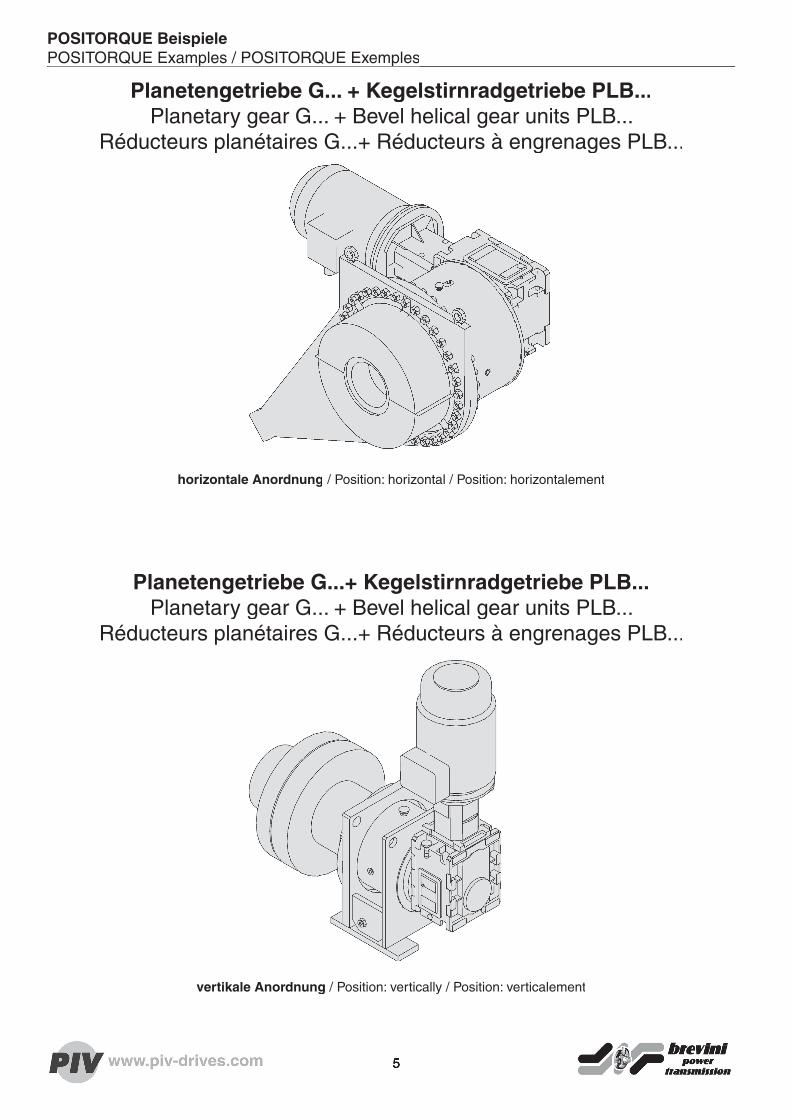
Planetengetriebe G... + Kegelstirnradgetriebe PLB...Planetary gear G... + Bevel helical gear units PLB...
Réducteurs planétaires G...+ Réducteurs à engrenages PLB...
horizontale Anordnung / Position: horizontal / Position: horizontalement
Planetengetriebe G...+ Kegelstirnradgetriebe PLB...Planetary gear G... + Bevel helical gear units PLB...
Réducteurs planétaires G...+ Réducteurs à engrenages PLB...
vertikale Anordnung / Position: vertically / Position: verticalement
5
POSITORQUE BeispielePOSITORQUE Examples / POSITORQUE ExemplesPOSITORQUE Examples / POSITORQUE Exemples
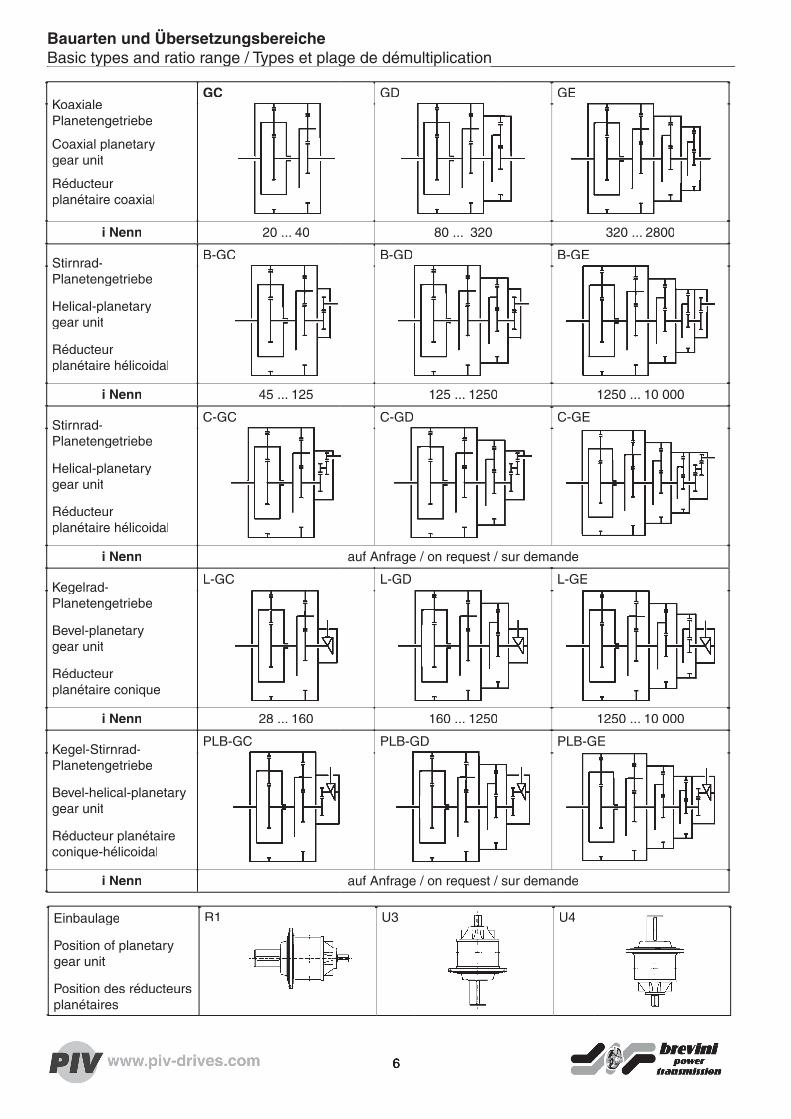
Bauarten und ÜbersetzungsbereicheBasic types and ratio range / Types et plage de démultiplication
Koaxiale Planetengetriebe
Coaxial planetary gear unit
Réducteur planétaire coaxial
GC GD GE
i Nenn 20 ... 40 80 ... 320 320 ... 2800
Stirnrad-Planetengetriebe
Helical-planetary gear unit
Réducteur planétaire hélicoidal
B-GC B-GD B-GE
i Nenn 45 ... 125 125 ... 1250 1250 ... 10 000
Stirnrad-Planetengetriebe
Helical-planetary gear unit
Réducteur planétaire hélicoidal
C-GC C-GD C-GE
i Nenn auf Anfrage / on request / sur demande
Kegelrad-Planetengetriebe
Bevel-planetary gear unit
Réducteur planétaire conique
L-GC L-GD L-GE
i Nenn 28 ... 160 160 ... 1250 1250 ... 10 000
Kegel-Stirnrad-Planetengetriebe
Bevel-helical-planetarygear unit
Réducteur planétaireconique-hélicoidal
PLB-GC PLB-GD PLB-GE
i Nenn auf Anfrage / on request / sur demande
Einbaulage
Position of planetary gear unit
Position des réducteurs planétaires
R1 U3 U4
Basic types and ratio range / Types et plage de démultiplication
6

Getriebeauswahl
Verwendete Begriffe und Kurzzeichenn1 [min-1] Getriebeantriebsdrehzahl Pt [kW] Wärmegrenzleistung
n2 [min-1] Getriebeabtriebsdrehzahl Pt0 [kW] Wärmegrenzleistung ohneZusatzkühlungisoll gewünschte Übersetzung
iN Nennübersetzung fk Getriebeauswahlfaktor
iW Ist-Übersetzung fE Einschalthäufi gkeitsfaktor
PM [kW] Motorleistung fM Anlauffaktor der Antr.-Masch.
PN erf. [kW] erforderliche Getriebe-Nennleistung fS Faktor für Hohlwellen-verbindung mit SchrumpfscheibePN [kW] Getriebe-Nennleistung
Pe [kW] eff. Leistg. Arbeitsmaschine fA Auslastungsfaktor
TM [Nm] Motormoment fW Temperaturfaktor
TN [Nm] Getriebe-Nennmoment ϑu [°C] Umgebungstemperatur
Te [Nm] eff. Drehmoment Arbeitsmaschine ED [%] Einschaltdauer pro Stunde
Tmax [Nm] Anfahr- oder max. Motor- oderBremsmoment
Lh10 [Std.] Nominelle Lagerlebendauer
fL Lagerlebensdauerfaktor
Auslegungskriterien• Festlegen der Getriebebauart und –bauform
• Übersetzung isoll
• Auswahl der entsprechenden Nennübersetzung iN
• Bestimmung der Getriebegrösse
Kontrolle der Getriebenennleistung PN > Pe x fK (fK = Getriebeauslegungsfaktor)
Bei Einsatzfällen mit sehr geringer Einschaltdauer und niedrigen Abtriebszahlen der Ge triebe ist auch eine Auswahl der Baugrössen in der Zeitfestigkeit möglich. Für diese spezi ellen Einsatzbedingungen bitten wir um Rücksprache
• Kontrolle des Spitzenmomentes
Tmax < 9550 x x fE (fE = Einschalthäufi gkeitsfaktor)
zusätzlich für Getriebe mit Hohlwelle und Schrumpfscheibe (wobei fS = 1.8)
Tmax < 9550 x x fS
• Kontrolle der Wärmebilanz
Pt > Pe
Pt = Pt0 x fW x fA
• Überprüfung der Lagerlebensdauer ohne Zusatzkräfte am An- und Abtrieb
Lh erf. > Lh 10 = (TN / Te)3,3 x
7

Gear unit selection
Used notions and notationsn1 [min-1] input speed of the gear unit Pt [kW] thermal capacity
n2 [min-1] output speed of the gear unit Pt0 [kW] thermal capacity withoutadditional cooling measuresinec necessary ratio
iN nominal ratio fk application factor for gear unit
iW actual ratio fE factor for starting frequency
PM [kW] motor power fM starting factor of driving engine
PN nec [kW] necessary power of gear unit fS factor for hollow shaft andshrink diskPN [kW] nominal power of gear unit
Pe [kW] actual machine power fA utilization factor
TM [Nm] motor torque fW thermal factor
TN [Nm] rated torque of the gear unit ϑu [°C] ambient temperature
Te [Nm] actual machine torque ED [%] duty cycle per hour
Tmax [Nm] starting torque, or maximal motor torque, or maximal braking torque
Lh10 [h] nominal bearing life duration
fL bearing life duration factor
Selection criteria• Determination of the type and the design of the gear unit
• Ratio inec
• Choice of the correspondent nominal ratio iN
• Determination of the size of the gear unit
Control of the gear unit’s rated power PN > Pe x fK (fK = application factor of the gear unit)
In case of applications with very short operating time and low output speed of the gear unit, it is possible to carry out the rating according to the fatigue diagrams, on the base of the effective needed life duration. Please note that in such special cases enquiries have to be made.
• Control of the peak torques
Tmax < 9550 x x fE (fE = starting factor)
Additionally, for gear units with hollow shaft and shrink disk (in which fS = 1.8)
Tmax < 9550 x x fS
• Control of the thermal balance
Pt > Pe
Pt = Pt0 x fW x fA
• Verifi cation of the bearing life duration, without external forces working onto the input or the output shafts
Lh nec. > Lh 10 = (TN / Te/ Te/ T )3,3 x
8

Défi nition du réducteur
Notions utilisées et notationsn1 [min-1] Vitesse d’entrée du réducteur Pt [kW] Puissance thermique
n2 [min-1] Vitesse de sortie du réducteur Pt0 [kW] Puissance thermique limitesans refroidissement additionnelisoll Rapport de réduction nécessaire
iN Rapport de réduction nominal fk Facteur de sélection du réducteur
iW Rapport de réduction réel fE Facteur de fréq. de démarrage
PM [kW] Puissance du moteur fM Facteur de démarrage de la machine d’entraînementPN erf. [kW] Puissance nécessaire du reducteur
PN [kW] Puissance nominale du réducteur fS Facteur pour arbre creux avec frette de serragePe [kW] Puissance effective de la machine
TM [Nm] Couple du moteur fA Facteur de charge
TN [Nm] Couple nominal du réducteur fW Facteur thermique
Te [Nm] Couple effectif de la machine ϑu [°C] Température ambiante
Tmax [Nm] Couple de démarrage, ou couplemaximum moteur, ou couple maximum de freinage
ED [%] Temps de service sous charge par heure
Lh10 [Std.] Durée de vie nominale desroulements
fL Facteur de la durée de vie de roulements
Critères de sélection• Défi nition du type et de la forme constructive du réducteur
• Rapport de réduction inec
• Choix du rapport de réduction nominal iN correspondant
• Défi nition de la taille du réducteur
Contrôle de la puissance nominale du réducteur PN > Pe x fK (fK = facteur de sélection du réducteur)
Dans le cas d’application à durée de service très courte et basse vitesse de sortie du réducteur,il est possible de faire le choix de la taille d’après les courbes de fatigue, sur la base de la durée effective de fonctionnement. Pour ces conditions spéciales de travail, nous vous prions de demander des précisions
• Contrôle du couple de pointe
Tmax < 9550 x x fE (fE = facteur de démarrage)
En plus pour réducteurs à arbre creux et frette de serrage: (ou fS = 1.8)
Tmax < 9550 x x fS
• Contrôle du bilan thermique
Pt > Pe
Pt = Pt0 x fW x fA
Vérifi cation de la durée de vie des roulements sans forces extérieures agissant sur les arbres d’entrée ou de sortie
Lh erf. > Lh 10 = (TN / Te/ Te/ T )3,3 x
9

Die Getriebeauswahlfaktoren sind im Ein-klang mit der DIN 3990 Teil 11 (Stand 2/89) und entsprechen unseren Erfahrungen für normale Betriebsweise.Änderungen des erforderlichen Getriebeaus-wahlfaktors kann ggf. nach Angabe der genauen Betriebsbedingungen erfolgen.
Tab. 1: Getriebeauswahlfaktor fK
1)
Ausetz-betriebs
(0.5 h)
Schicht-betrieb
2)
BaggerEimerkettenantriebe 1.75...1.85Fahrwerke (Raupe) 1.2 1.6...1.8Fahrwerke (Schiene) 1 1.25...1.5Kippwerke 1.3...1.5Saugpumpen 1 1.25...1.5Schaufelräder 1.75...2.2Schneidköpfe 2.2Schwenkwerke 3) 1.4...1.8Winden 1 1.25...1.5Bergbau, Steine, ErdenBackenbrecher 2Drehrohröfen 2Grubenlüfter 1.5Kegelbrecher 2Kettenbahnen 1.5Kreiselbrecher 2Rüttelmaschinen 1.5Sichter 1.5Stachelbrecher 2Wagenaufschieber 1.5Walzenbrecher 2ChemieKnetwerke 2Rührwerke für Rührgutmit gleichmäßiger Dichte 1 1.3...1,5mit ungleichmäßiger Dichte 1.2 1.4...1.6mit ungleichmäßiger Begasung 1.4 1.6...1.8Trockenöfen 1.5Toaster 1 1.3...1.5Zentrifugen 1 1.25...1.35FörderanlagenAbteufmaschinen 1.5 1.75...2.0Becherwerke 1.2...1.5Becherzellenbänder 1 1.25...1.5Fördermaschinen 1.5...1.8Gurtbandförderer 1.0..1.1 1.2...1.4Gurtbecherwerke 1 1.25...1.5Gurttaschenförderer 1 1.25...1.5Haspeln 1.4 1.6Kettenbecherwerke 1 1.25...1.5Kreisförderer 1 1.25...1.5Lastaufzüge 3) 1.2...1.5Personenaufzüge 3) 1.5...1.8Plattenbänder 1.2...1.5Rolltreppen 1 1.2...1.4Schienenfahrwerke 1.5Schneckenförderer 1 1.25...1.5Stahlbandförderer 1 1.25...1.5Trogkettenförderer 1 1.25...1.5Gebläse, LüfterAxialgebläse 0.8 1.0...1.25Drehkolbengebläse 1 1.25...1.5Kühlturmlüfter 1.6...1.7Luftkühler 1.4...1.5Saugzuggebläse 1 1.25...1.5Turbogebläse 0.8 1.0...1.25Wärmeaustauscher 1.5Generatoren, UmformerFrequenz-Umformer 1.8...2.0Generatoren 0.8 1.0...1.25Schweißgeneratoren 1.5 1.75...2.0Gummi- u. KunsstoffmaschinenExtruder 1.5Kalander 1.5Kühltrommeln 1.3...1.4Knetwerke 1.8Mischer 1.0...1.4 1.3...1.7Walzwerke 2
Tab. 1: Getriebeauswahlfaktor fK
1)
Ausetz-betriebs
(0.5 h)
Schicht-betrieb
2)
HolzbearbeitungsmaschinenEntrindungstrommeln 1.5 1.75...2.0Hobelmaschinen 1 1.25...1.5Gatter 1.5 1.75...2.0HüttenindustrieHochofengebläse 1.25...1.5Konverter 1.75...2.0Schrägaufzüge für Hochöfen 1.75...2.0Krananlagen Genaue Einstufung nach FEM 1001MetallbearbeitungBlechbiegemaschinen 1.25...1.5Blechrichtmaschinen 1.75...2.0Hämmer 1.75...2.0Kurbelpressen 1.75...2.0Rollenrichtmaschinen 1.6Schmiedepressen 1.75...2.0Stanzen 1.75...2.0MühlenHammermühlen 1.75...2.0Kugelmühlen 1.75...2.0Pendelmühlen 1.75...2.0Prallmühlen 1.75...2.0Rohrmühle 1.8Stabmühlen 1.75...2.0Walzenmühlen 2NahrungsmittelmaschinenAbfüllmaschinen 0.8 1.25...1.5Knetmaschinen 1 1.25...1.5Maischen 1 1.25...1.5Mehlbecherwerke 0.8 1.0...1.25Verpackungsmaschinen 0.8 1.0...1.25Zuckerrohr-Brecher 1.25...1.5Zuckerrohr-Messer 3) 1.7Zuckerrohr-Mühlen 3) 1.7Rübenzucker-HerstellungRübenwäsche, Schneidmasch. 1.5Schnitzelmaische 1.2Extraktionsanlage 1.4Kühl- u. Kochapparat 1.4ÖlindustrieFilterpressen 1.25...1.5Pipelinepumpen 1.25...1.5Rotary-Bohranlagen 1.5 1.75...2.0Spülpumpen 1.25...1.5Papiermaschinenindustrie für alle Arten 1.8...2.5Pressen 3) 1.0...1.1PumpenKolbenpumpen 1.2...1.3 1.4...1.8Kreiselpumpen 1 1.2...1.3Ladepumpen 1.5 1.75...2.0Plungerpumpen 2Sandpumpen 1 1.25...1.5SeilbahnenPendelbahnen 1.6...1.8Materialbahnen 1.3...1.4Schlepplifte 1.3...1.4Umlaufbahnen 1.4...1.6TextilmaschinenAufwickler 1 1.25...1.5Druckerei-Färbereimasch. 1 1.25...1.5Gerbfässer 1 1.25...1.5Kalander 1 1.25...1.5Reißwölfe 11.25...1.5Webstühle 1 1.25...1.5Verdichter, KompressorenKolbenverdichter 1.8...1.9Rotierende Verdichter 1.4...1.5Turbokompressoren 1 1.25...1.5WalzwerkeArbeitsrollgänge 2Bandhaspel 1 1.25...1.5Blechscheren 2Blechwender 1 1.0...1.2Blocktransportanlagen 2Block- und Brammenstraßen 2Blockdrücker 1 2Draht- und Bandhaspeln 1.5Drehkreuze 1.5Drehturm (Stranggieß)Drehturm (Stranggieß) 1.5
Tab. 1: Getriebeauswahlfaktor fK
1)
Ausetz-betriebs
(0.5 h)
Schicht-betrieb
2)
Entzunderbrecher 2Feinblechstraßen 2Grobblechstraßen 2Haspeln 1.6Hubbalkenförderer 2Kaltbandwalzwerke 3) 1.75...1.85Kettenschlepper 1.5Knüppelscheren 2Kühlbettschieber 1.5Querschlepper 1.5Richttransporteinrichtungen 1.5Rohr-Reversierer 1.8Rollgänge Durchlauf 1.5Rollgänge stoßartig 2Rollenrichtmaschine 1.6Saumscheren 1.5Scheren Kontischnitt 3) 1.5Scheren Kurbelschnitt 3) 1 1Schopfscheren 2Schlingenzieher 1.5Schlingenturm 1.5Sinterbandantrieb 1.5S-Rollen schnellaufend 1.5S-Rollen langsamlaufend 1.5Stranggußtreiber 3) 1.4Walzen Block-revers. 2.5Brammen-revers. 2.5Draht-revers. 1.8Feinblech-revers. 2Grobblech-revers. 1.8Walzenanstellungen 0.9 1Walzenverstellvorrichtungen 1.5Ziehbankantrieb 2WasseraufbereitungsanlagenEindicker 1.2Filterpressen 1 1.3...1.5Flockungsrührer 0.8 1.0...1.3Kreiselbelüfter 1.5...1.7Rechenanlagen 1 1.2...1.3Rund- u. Längsräumer 1 1.3...1.5Voreindicker 1.1...1.3Wasserschneckenpumpe 1.3...1.4Wasserturbinen 2ZementfabrikenBetonmischer 1.5Brecher 3) 1.2...1.4Drehöfen 2Rohrmühle 1.8Sichter 1.6Walzenmühlen 2
1) Auslegungsfaktoren gelten für folgende Antriebsmaschinen: Elektromotoren, Turbinen und Hydromotoren.Bei Antrieb durch Verbrennungsmotoren ist Rückfrage erforderlich.2) Unterer Tabellenwert gilt für Einschichtbe-trieb und für leichtere Anwendungen, oberer Tabellenwert gilt für Dauerbetrieb und bei schweren Anwendungen.3) Auslegung entsprechend dem Maximal-moment.
Tab. 2: Einschalthäufi gkeitsfaktor fTab. 2: Einschalthäufi gkeitsfaktor fTab. 2: Einschalthäufi gkeitsfaktor fTab. 2: Einschalthäufi gkeitsfaktor fE
2 1.6 1.4 1.2 1.1 1bei ... Belastungsspitzen pro Stunde
1 2-10 11-20 21-50 51-100 >100
Tab. 3: Reversierfaktor fR
1.0 0.85 0.7Gleichbleibende Wechselnde Reversierbetrieb
Lastrichtung Lastrichtung mitniedriger Häu-
fi gkeitfi gkeit
Getriebeauslegungsfaktoren
10

Gear unit application factors are in line with DIN standard no. 3990 part 11 (edition 2/89) and are based on our experience for normal operating conditions.Changes in the necessary drive selection may take place after stating the exact operating conditions.
Table 1: Gear unit application factor fK
1)
Intermitt.Use
(0.5 h)
Shifts
2)Blowers, VentilatorsAir cooler 1.4...1.5Axial blowers 0.8 1.0...1.25Cooling tower fans 1.2 1.6...1.7Heat exchangers 1.5Rotary piston blowers 1 1.25...1.5Suction draught blower 1 1.25...1.5Turbo exhauster 0.8 1.0...1.25Cableways Continuous ropeways 1.4...1.6Freight ways 1.3...1.4Shuttle cableways 1.4...1.8T-bar lifts 1.3...1.4Cement IndustryConcrete mixers 1.5Crushers 1.2...1.4Roller mills 2Rotary kilns 2Separators 1.6Tube mills 1.8Chemical industryAgitators for materialswith constant density 1 1.3...1.5with variable density 1.2 1.4...1.6Agitators with var. gas absorbt. 1.4 1.6...1.8Centrifuges 1 1.25...1.35Drying kilns 1.5Kneading machines 2Toasters 1 1.3...1.5Compressors Piston compressors 1.8...1.9Rotary compressors 1.4...1.5Turbo compressors 1 1.25...1.5ConveyorsApron conveyors 1.2...1.5Band elevators 1 1.25...1.5Belt conveyors 1.0...1.1 1.2...1.4Bucket conveyors 1.2...1.5Canvas belt elevators 1 1.25...1.5Cellular bucket belt conveyors 1 1.25...1.5Chain bucket elevators 1 1.25...1.5Circular conveyors 1 1.25...1.5Escalators 1 1.2...1.4Goods lifts 1.2...1.5Hoisting engines 1.5...1.8Passenger lifts 1.5...1.8Rail travelling devices 1.5Scraper chain conveyors 1 1.25...1.5Screw conveyors 1 1.25...1.5Sinking mine machines 1.5 1.75...2.0Steel belt conveyors 1 1.25...1.5Winders 1.4 1.6Cranes Classifi ed acc. to FEM 1001Crushers Ball crushers 1.75...2.0Hammer mills 1.75...2.0Rebound crushers 1.75...2.0Rod mills 1.75...2.0Roller mills 2Swinging crushers 1.75...2.0Tube mills 1.8DredgersBucket chain drives 1.75...1.85Bucket wheels 1.75...2.2Cutter heads 2.2Dumping devices 1.3...1.5Manoeuvring winches 1 1.25...1.5Slewing gears 1.4...1.8Sucking pumps 1 1.25...1.5Travelling gears (caterpillar) 1.2 1.6...1.8Travelling gears (rails)Travelling gears (rails) 1 1.25...1.5
Table 1: Gear unit application factor fK
1)
Intermitt.Use
(0.5 h)
Shifts
2)Food Industry Machinery Beet sugar productionBeet washing machines & cutters 1.5Slicing machines 1.2 1.2Juice boilers and refrigerators 1.4Bottling & container fi lling mach. 0.8 1.25...1.5Flour bucket elevators 0.8 1.0...1.25Kneading machines 1 1.25...1.5Mash tubs 1 1.25...1.5Packaging machines 0.8 1.0...1.25Sugar cane crushers 1.25...1.5Sugar cane knives 3) 1.7Sugar cane mills 3) 1.7Generators, Converters (3)Frequency converters 1.8...2.0Generators 0.8 1.0...1.25Welding generators 1.5 1.75...2.0Metal Working Machines Crank presses 1.75...2.0Forging presses 1.75...2.0Hammers 1.75...2.0Plate bending machines 1.25...1.5Plate straitening presses 1.75...2.0Roller levellers 1.6Stamping presses 1.75...2.0Metallurgical Industry Blast furnace blowers 1.25...1.5Converters 1.75...2.0Inclined furnace hoists 1.75...2.0Mining, Stone an Clay Working MachinesConical crushers 2Endless chain transporters 1.5Jaw breakers 2Jolters 1.5Mine ventilating fans 1.5Rolling crushers 1.5Rotary crushers 2Rotary kilns 2Separators 1.5Toothed roll crusher 2Tub-pushing devices 1.5Oil Industry Charging fi lter pumps 1.25...1.5Flush boring pumps 1.25...1.5Pipeline pumps 1.25...1.5Rotary drilling equipment 1.5 1.75...2.0Paper Machines for all types 1.8...2.5Presses 3) 1.0...1.1Pumps Centrifugal pumps 1 1.2...1.3Charge pumps 1.5 1.75...2.0Piston pumps 1.2...1.3 1.4...1.8Plunger pumps 2Sludgers 1 1.25...1.5Rolling MillsBelt winders 1 1.25...1.5Billet shears 2Blooming- and slabbing mills 2Capstan wheels 1.5Chain transfer 1.5Cold band rolling mills 3) 1.75...1.85Cooling bed transfer frames 1.5Continuous casting drivers 3) 1.4Continuous shears 3) 1.5Crank type shears 1 1Cropping shears 2De-scaling breakers 2Drawing bench drives 2High speed roller tables 1.5Ingot conveyors 2Ingot pushers 1.2Looper 1.5Loop lifter 1.5Low speed roller tables 1.5Plate rolling trains 2Plate shears 2Plate tilters 1 1.0...1.2Plate trimming shears 1.5Reversing blooming mills 2.5Reversing plate mills 1.8Reversing sheet millsReversing sheet mills 2
Table 1: Gear unit application factor fK
1)
Intermitt.Use
(0.5 h)
Shifts
2)Reversing slabbing mills 2 .52.5Reversing wire mills 1.8Rod reel & belt winders 1.5Roll adjustment devices 1.5Roll weighting drives 0.91Roller straighteners 1.6Roller tables continuous 1.5Roller tables intermittent 2Sintering belt drives 1.5Straightening & transp. equipment 1.5Thin sheet rolling trains 2Transfer skids 1.5Tube reverse equipment 1.8Turntables (continuous casting) 1.5Walking beam conveyors 2Winders 1.6Working roller tables 2Rubber and Plastic Industry Machinery Calenders 1.5Extruders 1.5Kneading machines 1.8Mixers 1.0...1.4 1.3...1.7Rolling mills 2Rotary cooler 1.3...1.4Textile MachinesCalender 1 1.25...1.5Looms 1 1.25...1.5Printing and dyeing machines 1 1.25...1.5Take-up rollers 1 1.25...1.5Willows 1 1.25...1.5Water Treatment Circular and longitudinal rakes 1 1.3...1.5Filter presses 1 1.3...1.5Flocculation agitators 0.8 1.0...1.3Pre-thickeners 1.1...1.3Raking equipment 1 1.2...1.3Rotary aerators 1.5...1.7Screw pumps 1.3...1.4Thickeners 1.2Water wheels 2Wood Working Machines Barkers 1.5 1.75...2.0Planing machines 1 1.25...1.5Saw frames 1.5 1.75...2.0
1) Application factors apply to the follow-ing driving motors: electric motors, turbines and fl uid power motors. When combustion engines are the driving force, enquiries have to be made.2) The lower table value is for single shift operation and for lighter applications, the upper table value is for continuous use and heavier applications.3) Design is in accordance with maximum torque.
Table 2: Operating frequency factor fTable 2: Operating frequency factor fTable 2: Operating frequency factor fTable 2: Operating frequency factor fE
2 1.6 1.4 1.2 1.1 1with ... load peaks per hour
1 2-10 11-20 21-50 51-100 >100
Table 3: Reversal factor fR
1.0 0.85 0.7Steady direction Alternating Reversing
of load direction of load operations
Gear unit application factors
11

Facteurs de sélection de réducteur
Les facteurs de sélection des réducteurs cor-respondent à la DIN 3990 - 11 (édition 2/89) et à notre expérience pour une utilisation normale. Il est possible de modifi er ces facteurs à réception de conditions d’utilisation précises.
Tableau 1: Facteur de sélectionde réducteur fK
1)
Serviceoccasionnel
(0.5 h)
Servicecontinu
2)
Boisraboteuses 1 1.25...1.5scies à rubans multiples 1.5 1.75...2.0tambours à décroûter 1.5 1.75...2.0Broyeursbroyeurs à barres 1.75...2.0broyeurs à boulets 1.75...2.0broyeurs à chocs 1.75...2.0broyeurs à cylindres 2broyeurs à marteaux 1.75...2.0broyeurs à pendules centrifuges 1.75...2.0tubes broyeurs 1.8Chimieagitateur, densité constante 1 1.3...1.5agitateur, densité variable 1.2 1.4...1.6agitateur, charge variable 1.4 1.6...1.8calcinateur 1 1.3...1.5centrifugeuse 1 1.25...1.35fours de séchage 1.5malaxeurs 2Cimenteriebétonnières 1.5broyeur à rouleaux 2concasseurs 1.2...1.4fours rotatifs 2séparateurs à air 1.6tubes broyeurs 1.8compresseurscompresseurs à piston 1.8...1.9compresseurs rotatif 1.4...1.5turbo-compresseurs 1 1.25...1.5Excavateursavec chaînes à godets 1.75...1.85commandes de pivotement 3) 1.4...1.8entraînement de chenilles 1.2 1.6...1.8entraînement sur rails 1 25...1.5fraises de taillage 2.2basculeur 1.3...1.5pompes aspirantes 1 1.25...1.5roues pelleteuses 1.75...2.2treuils 1 1.25...1.5Génératrices, convertisseursconvertisseurs de fréquence 1.8...2.0génératrices 0.8 1...1.25génératrices de postes de soudage 1.5 1.75...2.0Grues Selection exacte suivant FEM 1001Laminoirsbandes de frittage 1.5basculeurs de blocs forgés 2.5basculeurs de brames 2.5basculeurs de cables 1.8basculeurs de tôles ébauchées 1.8basculeurs de tôles fi nes 2bobineuses 1.7bobineuses pour bandes 1 1.25...1.5bobineuses de cables et des bandes 1.5boucleuses 1.5cisailles à billettes 2cisailles coupe continue 1.5cisailles coupe à manivelle 1 1cisailles à couper les bords 1.5cisailles à tôle 2décalamineuses 2dresseuses à rouleaux 1.6étireuses 2installations pour planage et transp. 1.5installation de réglage de cylindres 1.5laminoirs à froid 1.75...1.8laminoirs réversibles à tubes 1.5
Tableau 1: Facteur de sélectionde réducteur fK
1)
Serviceoccasionnel
(0.5 h)
Servicecontinu
2)
laminoirs à tôles épaisses 2laminoirs à tôles minces 2machines à ébouter 2pousseurs de brames 1 2pousseurs pour coulée continue 3) 1.4pousseurs pour lits refroidisseurs 1.5retourneurs de tôles 1 1.0...1.2rouleaux (service continue) 1.5rouleaux (service par à-coup) 2serrage des cylindres 0,9 1tourelles pour coulée continue 1.5tourniquets 1.5tours de bouclage 1.5tracteurs à chaînes 1.5tracteurs transversaux 1.5trains de rouleaux d’exploitation 2transporteurs de brames 2transporteurs de lingots 2transporteurs à longerons mobiles 2transporteurs à rouleaux (légers) 1.5transporteurs à rouleaux (lourds) 1.5Machines textilescalandres 1 1.25...1.5cuves de tannage 1 1.25...1.5déchiqueteuses 1 1.25...1.5enrouleurs 1 1.25...1.5imprimeuses - teintureries 1 1.25...1.5métiers à tisser 1 1.25...1.5Métauxestampeuses 1.75...2.0machines à dresser à rouleaux 1.6marteaux 1.75...2.0planeuses de tôles 1.75...2.0plieuses de tôles 1.25...1.5presses à manivelle 1.75...2.0presses à gorger 1.75...2.0Mines, roches, terreconcasseurs centrifuges 2concasseurs à cône 2concasseurs à machoires 3concasseurs à pointes 2concasseurs à rouleaux 1.5fours tournants 2pousseurs d’encagement 1.5séparateurs à air 1.5transporteurs à chaînes 1.5ventilateurs de puits 1.5vibreuses 2Papeteries tous les types 1.8...2.5Pétrochimiefi ltres - presses 1.25...1.5foreuses Rotary 1.5 1.75...2.0pompes d’injection d’eau 1.25...1.5pompes de pipeline 1.25...1.5Plastiques et caoutchoucscalandres 1.5extrudeuses 1.5laminoirs 2malaxeurs 1.8mélangeurs 1.0...1.4 1.3...1.7tambours de refroidissement 1.3...1.4Pompespompes à helices 1 1.2...1.3pompes à pistons 1.2...1.3 1.4...1.8pompes à pistons plongeurs 2pompes à sable 1 1.25...1.5pompes chargeuses 1.5 1.75...2.0Presses 3)Retraitement des eauxaérateurs rotatifs 1.5...1.7épaississeur 1.2presse à fi ltre 1 1.3...1.5mélangeur 0.8 1.0...1.3dispositif de ratissage 1 1.2...1.3déblayeurs rot. ou linéaire 1 1.3...1.5préepaississeurspréepaississeurs 1.1...1.3
Tableau 1: Facteur de sélectionde réducteur fK
1)
Serviceoccasionnel
(0.5 h)
Servicecontinu
2)
vis de relevage d’eau 1.3...1.4turbine hydraulique 2Secteur alimentairebroyeurs de canne à sucre 1.25...1.5convoyeurs à godets pour farine 0.8 1.0...1.25emballeuses 0.8 1.0...1.25ensacheuses 0.8 1.25...1.5hachoirs de cannes à sucre 3) 1.7malaxeurs 1 1.25...1.5moulins de cannes à sucre 3) 1.7pétrisseuses 1 1.25...1.5Poduct. de sucre de betteraveschaudières à cuire, refroidisseur 1.4installations d’extraction 1.4laveuses, coupeuses de betteraves 1.5malaxeurs de cossette 1.2Sidérurgieconvertisseurs 1.75...2.0élévateurs obliqu. (fourneaux) 1.75...2.0ventilateurs de hauts-fourneaux 1.25...1.5Transport par cabletélécabines 1.6...1.8transporteurs à matériaux 1.3...1.4transporteurs en continu 1.4...1.6Transporteursascenseurs pour personnes 3) 1.5...1.8bandes transporteuses en acier 1 1.25...1.5convoyeurs à bande cellulaires 1 1.25...1.5convoyeurs à bande souple 1...1.1 1.2...1.4convoyeurs circulaires 1 1.25...1.5convoyeurs à godets 1.2...1.5convoyeurs en masse 1 1.25...1.5convoyeurs à poches 1 1.25...1.5convoyeurs à ruban 1 1.25...1.5convoyeurs à tabliers 1.2...1.4convoyeurs à vis 1 1.25...1.5élévateurs de charges 1.2...1.5élévateurs à chaïnes à godets 1 1.25...1.5escaliers roulants 1 1.2...1.4machines de creusement 1.5 1.75...2.0machines d’extraction 1.5...1.8translation sur rail 1.5treuils de puits 1.4 1.6Ventilateursaéro-réfrigérants 1.4...1.5échangeurs thermiques 1.5souffl antes axifl ow, turbosouffl ant 0.8 1.0...1.25souffl antes à piston rotatif 1 1.25...1.5ventilateurs de tirage par aspiration 1.25...1.5ventilateurs pour tours de réfrigératventilateurs pour tours de réfrigératventilateurs pour tours de réfrigératventilateurs pour tours de réfrigérat 1.6...1.7
1) Les facteurs de sélection sont valables pour des entraînements par moteur électri-que, turbine ou moteur hydraulique. Pour les moteurs à combustion nous consul-ter.2) Les valeurs des tableaux sont valables pour un service quotidien en une équipe-charge - charge uniforme pour le premier chiffre et pour un service en continu avec charge lourde pour le chiffre le plus élevé.3) Détermination d’après le couple maximum.
Tableau 2: Facteur de fréquence de demarrage fTableau 2: Facteur de fréquence de demarrage fTableau 2: Facteur de fréquence de demarrage fTableau 2: Facteur de fréquence de demarrage fTableau 2: Facteur de fréquence de demarrage fTableau 2: Facteur de fréquence de demarrage fE
2 1.6 1.4 1.2 1.1 1avec ... points de charge par
1 2-10 11-20 21-50 51-100 >100
Tableau 3:Facteur d’inversion de couple fTableau 3:Facteur d’inversion de couple fTableau 3:Facteur d’inversion de couple fR
1.0 0.85 0.7Couple toujours Couple alternatif Inversion dedans le même
sensfréquence faible couple fréquent
12

AuslegungsfaktorenFactors for rating / Facteurs de calcul
Maximal-Moment-Faktor für Hohlwellenverbindungen mit SchrumpfscheibeFactor for maximal torque for hollow shaft with shrink discFacteur pour couple maximum pour arbre creux avex frette de serrage
fs=1.8
Auslegungsfaktor fA / Utilization factor fA / Facteur de charge fA
Auslastung / Utilization / Charge Pe/Pe/Pe N [%]
< 30 % 30 % 40 % 50 % 60 % 70 % 80 % 90 % 100 %
auf Anfrageon request
sur demande0.7 0.8 0.85 0.9 0.93 0.96 1.0 1.0
Temperaturfaktor fW / Thermal factor fW / Facteur thermique fW
ϑu [°C]ED %
100 80 60 40 20
10 1.14 1.21 1.34 1.53 2.03
20 1.00 1.06 1.17 1.34 1.78
30 0.86 0.91 1.00 1.15 1.53
40 0.71 0.76 0.84 0.96 1.27
50 0.57 0.61 0.67 0.77 1.02
Bestimmung der Lagerlebensdauer ohne Zusatzkräfte am An- und AbtriebDetermination of the bearing life duration without external additional forces on the input and outputDetermination de la durée de vie des roulements sans forces extérieures agissant sous les arbres GV et PV.
Lh 10 = (TN / Te/ Te/ T )3,3 x
BaugrösseFrame size
Taille
Lagerlebensdauerfaktor fL x 10³Life duration factor fL x 10³
Facteur de durée de vie fL x 10³
verstärktreinforcedrenforce
69 127
auf Anfrageon request
sur demande
80 107
89 83
100 112
109 108
Factors for rating / Facteurs de calcul
13
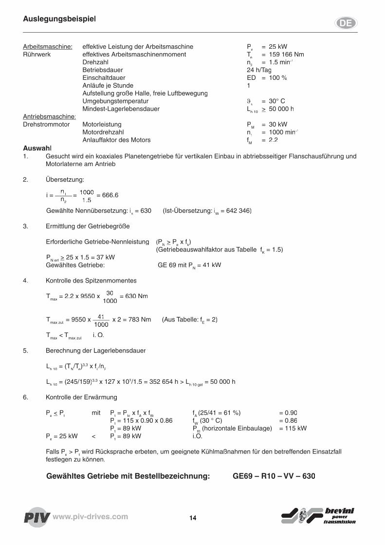
Arbeitsmaschine: effektive Leistung der Arbeitsmaschine Pe = 25 kWRührwerk effektives Arbeitsmaschinenmoment Te = 159 166 Nm Drehzahl n2 = 1.5 min-1
Betriebsdauer 24 h/Tag Einschaltdauer ED = 100 % Anläufe je Stunde 1 Aufstellung große Halle, freie Luftbewegung Umgebungstemperatur ϑu = 30° C Mindest-Lagerlebensdauer Lh 10 > 50 000 hAntriebsmaschine:Drehstrommotor Motorleistung PM = 30 kW Motordrehzahl n1 = 1000 min-1
Anlauffaktor des Motors fM = 2.2Auswahl1. Gesucht wird ein koaxiales Planetengetriebe für vertikalen Einbau in abtriebsseitiger Flanschausführung und
Motorlaterne am Antrieb
2. Übersetzung:
i = = = 666.6
Gewählte Nennübersetzung: in = 630 (Ist-Übersetzung: iW = 642 346)
3. Ermittlung der Getriebegröße
Erforderliche Getriebe-Nennleistung (PN > Pe x fk) (Getriebeauswahlfaktor aus Tabelle fK = 1.5) PN erf > 25 x 1.5 = 37 kW Gewähltes Getriebe: GE 69 mit PN = 41 kW
4. Kontrolle des Spitzenmomentes
Tmax = 2.2 x 9550 x = 630 Nm
Tmax zul. = 9550 x x 2 = 783 Nm (Aus Tabelle: fE = 2)
Tmax < Tmax zul. i. O.
5. Berechnung der Lagerlebensdauer
Lh 10 = (TN/Te/Te/T )3,3 x fL/nL/nL 2
Lh 10 = (245/159)3,3 x 127 x 103/1.5 = 352 654 h > Lh 10 gef = 50 000 h
6. Kontrolle der Erwärmung
Pe < Pt mit Pt = Pto x fA x fW fA (25/41 = 61 %) = 0.90 Pt = 115 x 0.90 x 0.86 fW (30 ° C) = 0.86 Pt = 89 kW Pt0 (horizontale Einbaulage) = 115 kW
Pe = 25 kW < Pt = 89 kW i.O.
Falls Pe > Pt wird Rücksprache erbeten, um geeignete Kühlmaßnahmen für den betreffenden Einsatzfall festlegen zu können.
Gewähltes Getriebe mit Bestellbezeichnung: GE69 – R10 – VV – 630
Auslegungsbeispiel
14
41 = 9550 x x 2 = 783 Nm (Aus Tabelle: f41 = 9550 x x 2 = 783 Nm (Aus Tabelle: f1000
= 9550 x x 2 = 783 Nm (Aus Tabelle: f1000
= 9550 x x 2 = 783 Nm (Aus Tabelle: f = 9550 x x 2 = 783 Nm (Aus Tabelle: f
30 = 2.2 x 9550 x = 630 Nm30 = 2.2 x 9550 x = 630 Nm1000
= 2.2 x 9550 x = 630 Nm
1000 i = = = 666.61000 i = = = 666.61.5
i = = = 666.6n
i = = = 666.6n
i = = = 666.6 i = = = 666.61 i = = = 666.6n2
i = = = 666.6
Design example
15
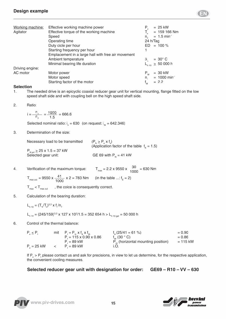
Working machine:Working machine: Effective working machine power Pe = 25 kWAgitator Effective torque of the working machine TeAgitator Effective torque of the working machine TeAgitator Effective torque of the working machine T = 159 166 Nm Speed n2 = 1.5 min-1
Operating time 24 h/Tag Duty cicle per hour ED = 100 % Starting frequency per hour 1 Emplacement in a large hall with free air movement Ambient temperature ϑu = 30° C Minimal bearing life duration Lh 10 > 50 000 hDriving engine:Driving engine:AC motor Motor power PM = 30 kW Motor speed n1 = 1000 min-1
Starting factor of the motor fM = 2.2Selection1. The needed drive is an epicyclic coaxial reducer gear unit for vertical mounting, fl ange fi tted on the low
speed shaft side and with coupling bell on the high speed shaft side.
2. Ratio:
i = = = 666.6
Selected nominal ratio: in = 630 (on request: iW = 642.346)
3. Determination of the size:
Necessary load to be transmitted (PN > Pe x fk) (Application factor of the table fK = 1.5) PN erf > 25 x 1.5 = 37 kW Selected gear unit: GE 69 with PN = 41 kW
4. Verifi cation of the maximum torque: Tmax = 2.2 x 9550 x = 630 Nm
Tmax zul. = 9550 x x 2 = 783 Nm (in the table ...: fE = 2)
Tmax < Tmax zul. , the coice is consequently correct.
5. Calculation of the bearing duration:
Lh 10 = (TN/Te)3,3 x fL/nL/nL 2
Lh 10 = (245/159)3,3 x 127 x 103/1.5 = 352 654 h > Lh 10 gef = 50 000 h
6. Control of the thermal balance:
Pe < Pt mit Pt = Pto x fA x fW fA (25/41 = 61 %) = 0.90 Pt = 115 x 0.90 x 0.86 fW (30 ° C) = 0.86 Pt = 89 kW Pt0 (horizontal mounting position) = 115 kW
Pe = 25 kW < Pt = 89 kW i.O.
If Pe > Pt please contact us and ask for precisions, in view to let us determine, for the respective application, the convenient cooling measures.
Selected reducer gear unit with designation for order: GE69 – R10 – VV – 630
41 = 9550 x x 2 = 783 Nm (in the table ...: f41 = 9550 x x 2 = 783 Nm (in the table ...: f1000
= 9550 x x 2 = 783 Nm (in the table ...: f1000
= 9550 x x 2 = 783 Nm (in the table ...: f = 9550 x x 2 = 783 Nm (in the table ...: f
30 = 2.2 x 9550 x = 630 Nm30 = 2.2 x 9550 x = 630 Nm1000
= 2.2 x 9550 x = 630 Nm
1000 i = = = 666.61000 i = = = 666.61.5
i = = = 666.6n
i = = = 666.6n
i = = = 666.6 i = = = 666.61 i = = = 666.6n2
i = = = 666.6
Exemple de determination
16
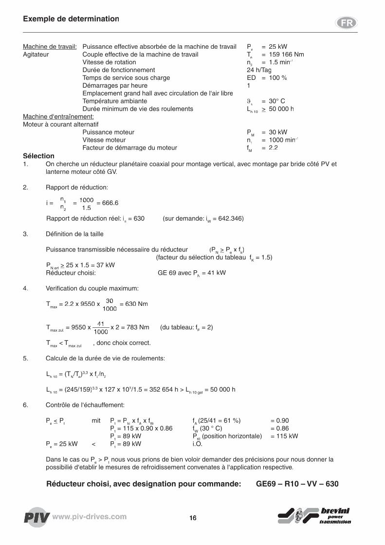
Machine de travail: Puissance effective absorbée de la machine de travail Pe = 25 kWAgitateur Couple effective de la machine de travail TeAgitateur Couple effective de la machine de travail TeAgitateur Couple effective de la machine de travail T = 159 166 Nm Vitesse de rotation n2 = 1.5 min-1
Durée de fonctionnement 24 h/Tag Temps de service sous charge ED = 100 % Démarrages par heure 1 Emplacement grand hall avec circulation de l‘air libre Température ambiante ϑu = 30° C Durée minimum de vie des roulements Lh 10 > 50 000 hMachine d‘entraînement:Moteur à courant alternatif Puissance moteur PM = 30 kW Vitesse moteur n1 = 1000 min-1
Facteur de démarrage du moteur fM = 2.2Sélection1. On cherche un réducteur planétaire coaxial pour montage vertical, avec montage par bride côté PV et
lanterne moteur côté GV.
2. Rapport de réduction:
i = = = 666.6
Rapport de réduction réel: in = 630 (sur demande: iW = 642.346)
3. Défi nition de la taille
Puissance transmissible nécessaiire du réducteur (PN > Pe x fk) (facteur du sélection du tableau fK = 1.5) PN erf > 25 x 1.5 = 37 kW Réducteur choisi: GE 69 avec PN = 41 kW
4. Verifi cation du couple maximum:
Tmax = 2.2 x 9550 x = 630 Nm
Tmax zul. = 9550 x x 2 = 783 Nm (du tableau: fE = 2)
Tmax < Tmax zul. , donc choix correct.
5. Calcule de la durée de vie de roulements:
Lh 10 = (TN/Te)3,3 x fL/nL/nL 2
Lh 10 = (245/159)3,3 x 127 x 103/1.5 = 352 654 h > Lh 10 gef = 50 000 h
6. Contrôle de l‘échauffement:
Pe < Pt mit Pt = Pto x fA x fW fA (25/41 = 61 %) = 0.90 Pt = 115 x 0.90 x 0.86 fW (30 ° C) = 0.86 Pt = 89 kW Pt0 (position horizontale) = 115 kW
Pe = 25 kW < Pt = 89 kW i.O.
Dans le cas ou Pe > Pt nous vous prions de bien voloir demander des précisions pour nous donner la possibilié d‘etablir le mesures de refroidissement convenates à l‘application respective.
Réducteur choisi, avec designation pour commande: GE69 – R10 – VV – 630
41 = 9550 x x 2 = 783 Nm (du tableau: f41 = 9550 x x 2 = 783 Nm (du tableau: f1000
= 9550 x x 2 = 783 Nm (du tableau: f1000
= 9550 x x 2 = 783 Nm (du tableau: f = 9550 x x 2 = 783 Nm (du tableau: f
30 = 2.2 x 9550 x = 630 Nm30 = 2.2 x 9550 x = 630 Nm1000
= 2.2 x 9550 x = 630 Nm
1000 i = = = 666.61000 i = = = 666.61.5
i = = = 666.6n
i = = = 666.6n
i = = = 666.6 i = = = 666.61 i = = = 666.6n2
i = = = 666.6

Ist-ÜbersetzungenExact ratios / Rapports réels
GC
Nennübersetzung
Nominal ratio
Rapport nominal
Ist-Übersetzung / Exact ratios / Rapports réels
Baugröße / Size / Taille
GC 6.. GC 8.. GC 10..
69 80 89 100 109
20 21.076 20.023 20.415 20.238 19.849
28 27.435 27.309 27.891 27.648 27.072
40 42.275 39.947 40.855 40.500 39.600
GD
Nennübersetzung
Nominal ratio
Rapport nominal
Ist-Übersetzung / Exact ratios / Rapports réels
Baugröße / Size / Taille
GD 6.. GD 8.. GD 10..
69 80 89 100 109
80 84.420 86.076 83.686 82.077
90 88.859 96.884
100 101.979 105.119 98.784 104.080 102.079
112 110.647 115.143 117.592 114.141 111.946
125 121.396 132.143 134.954 126.946 124.505
140 144.035 143.375 146.425 142.190 139.227
160 158.027 157.303 160.649 155.935 163.751
180 178.238 168.427 172.255 173.428 169.815
200 199.267 198.353 202.573 196.446 203.657
224 221.941 230.097 214.490 228.420 223.344
250 243.501 235.326 254.045 248.400
280 290.144 296.738 287.763 281.368
315 307.046
GE
Nennübersetzung
Nominal ratio
Rapport nominal
Ist-Übersetzung / Exact ratios / Rapports réels
Baugröße / Size / Taille
GE 6.. GE 8.. GE 10..
69 80 89 100 109
355 374.651 355.934 362.913 346.054 339.399
400 429.965 408.485 416.495 430.386 422.109
450 466.512 468.795 451.897 471.990 462.913
500 493.446 508.643 495.795 524.941 514.846
560 559.709 551.877 568.996 587.013 575.724
630 642.346 639.400 617.361 643.758 640.312
710 696.945 703.686 717.484 731.261 702.209
800 803.647 825.838 778.470 796.300 795.408
900 881.716 906.063 925.341 901.988 873.336
1000 964.195 1014.792 980.193 1021.702 989.248
1120 1147.777 1142.513 1166.822 1087.869 1084.875
1250 1278.381 1223.310 1251.113 1232.254 1259.660
1400 1447.307 1440.669 1435.830 1395.803 1400.976
1600 1611.994 1523.256 1557.876 1593.558 1586.918
1800 1768.587 1671.230 1709.212 1805.060 1764.947
2000 2107.362 2044.633 1999.197
2240 2230.127 2155.257
2800
Exact ratios / Rapports réels
17

Die Wärme-Grenzleistungen basieren auf folgenden Einsatzbedingungen: - horizontale Einbaulage / - Umgebungstemperatur: 20°C / - Auslastung des Getriebes: 90% bis 100%The thermal limit capacity is based on the following characteristics: - horizontal operating position / - ambient temperature: 20°C / - 90% to 100% rate of utilization
La puissance thermique limite est basée sur les caracteristiques suivantes: - Position horizontale / - Température ambiante: 20°C / - charge du réducteur: 90% à 100%
Planetengetriebe, zweistufi g / Planetary Gear Units, two-stage / Réducteurs planétaires à 2 trainsBauart / Type Getriebegrösse / Size / Taille
GC 69 80 89 100 109
iN
n1 n2 Getriebenennleistung / Nominal Power / Puissance nominale
( min-1) PN [ kW ]
201500 75.0 1924 2937 3997 - -1000 50.0 1283 1958 2665 - -
750 37.5 962 1469 1999 3059 3974
281500 53.6 1374 2098 2855 - -1000 35.7 916 1399 1904 2913 3785
750 26.8 687 1049 1428 2185 2838
401500 37.5 962 1469 1999 3059 39741000 25.0 641 979 1332 2039 2649
750 18.8 481 734 999 1529 1987
GCWärme-Grenzleistung / Thermal capacities / Puissance thermique limite
69 80 89 100 109Geschloss. kl. RaumSmall closed room / Petite salle fermée
125 150 180 240 290
Grosse Halle Large hall / Grand hall
175 210 250 335 400
Im Freien Outdoor / à l’air libre
225 265 320 425 525
Bauarten / TypesGetriebegrösse / Size / Taille
69 80 89 100 109
GC.. / GD.. / GE..Nennabtriebsdrehmoment / Nominal output torque / Couple nominal de sortie
T2N [kNm]
245 374 509 779 1012
LeistungsdatenPower ratings / Caractéristiques techniquesPower ratings / Caractéristiques techniques
18

Bauart GC 69...GC 109 GC 69...GC 109 ÜbersetzungÜbersetzung: 20...40: 20...40Type Nominal ratio / Rapport réduct. NominalType Nominal ratio / Rapport réduct. Nominal
Hohl- und Maschinenwelle / Getriebefuß siehe Maßblatt Hohl- und Maschinenwelle / Getriebefuß siehe Maßblatt 500-0203/0210-MB1Hollow shaft and machine shaft / Gear feet see dimension drawing 500-0203/0210-MB1Hollow shaft and machine shaft / Gear feet see dimension drawing 500-0203/0210-MB1L‘arbre creux et l‘arbre de la machine à entrainer / Pied de réducteur voir plan d’encombrement 500-0203/0210-MB1
Zentrierbohrung Wellenende
Tapped centre holes in shaft ends
Taraudage en bout d‘arbre
d1; d2
> 85
M 24
Paßfedern nach DIN 6885/1 gehören zum LieferumfangKeys to DIN 6885/1 supplied by PIV / Clavettes selon DIN 6885/1 livrées par PIV Schutzart entspricht IP 55 / Type of protection as per IP 55 / Protection similaire à IP 55
Bauart Nenn- Antriebswelle Abtriebswelle Abtriebsfl ansch / BefestigungType abtriebs- Input shaft Output shaft / Arbre de sortie Output fl ange / Fitting
drehmoment Arbre d‘ entrée Vollwelle Hohlwelle Bride de sortie / FixationNominal output Solid shaft Hollow shaft
torque Arbre plein Arbre creuxCouple nominal
de sortie
T2N [kNm] d1 m6 l1 dv2 m6 lv2 dH2 f7 LH2 w L a2 b2 e2 c2 h7 f2 ds n
GC69 245 110 180 260 410 340 185 95 910 942 80 890 800 20 33 30
GC80 374 120 210 310 500 390 196 158 1055 1115 62 1025 935 24 39 32
GC89 509 120 210 350 550 440 205 175 1114 1210 68 1120 1025 28 39 36
GC100 779 160 270 400 650 500 225 182 1424 1320 74 1220 1115 29 45 36
GC109 1012 160 270 450 750 560 256 197 1501 1460 81 1345 1215 31 52 32
Bauart Gewicht ÖlmengeType Weight Oil fi lling
Poids Cap. huile
D1 W1 D2 W2 WG ca. [kg] ca. [l]
GC69 685 568 ... ... 815 1450 45
GC80 800 620 ... ... 897 2100 65
GC89 930 647 ... ... 939 2700 110
GC100 1030 862 ... ... 1242 4150 150
GC109 1100 924 ... ... 1304 5400 180
Maßblatt 500-0200-MB1Dimensions / Encombrement 04.05
Öleinfüllung gelb / Filling plug yellow / Remplisage jaune
Ölstand blau / Oil level blue / Niveau d‘huile bleu
Ölablass rot / Oil drain red / vis de vidange rouge
Entlüftung / Breather / Aération
19
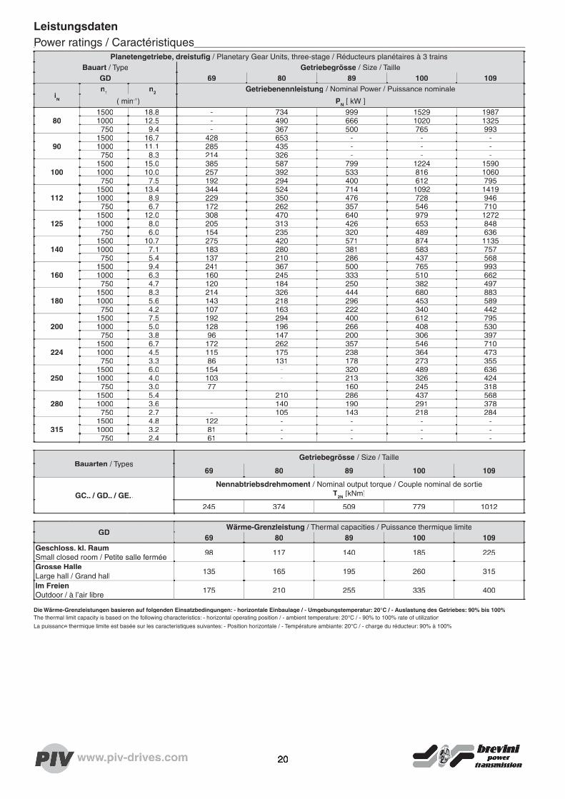
Die Wärme-Grenzleistungen basieren auf folgenden Einsatzbedingungen: - horizontale Einbaulage / - Umgebungstemperatur: 20°C / - Auslastung des Getriebes: 90% bis 100%The thermal limit capacity is based on the following characteristics: - horizontal operating position / - ambient temperature: 20°C / - 90% to 100% rate of utilization
La puissance thermique limite est basée sur les caracteristiques suivantes: - Position horizontale / - Température ambiante: 20°C / - charge du réducteur: 90% à 100%
Planetengetriebe, dreistufi g / Planetary Gear Units, three-stage / Réducteurs planétaires à 3 trainsBauart / Type Getriebegrösse / Size / Taille
GD 69 80 89 100 109
iN
n1 n2 Getriebenennleistung / Nominal Power / Puissance nominale
( min-1) PN [ kW ]
801500 18.8 - 734 999 1529 19871000 12.5 - 490 666 1020 1325750 9.4 - 367 500 765 993
901500 16.7 428 653 - - -1000 11.1 285 435 - - -750 8.3 214 326 - - -
1001500 15.0 385 587 799 1224 15901000 10.0 257 392 533 816 1060750 7.5 192 294 400 612 795
1121500 13.4 344 524 714 1092 14191000 8.9 229 350 476 728 946750 6.7 172 262 357 546 710
1251500 12.0 308 470 640 979 12721000 8.0 205 313 426 653 848750 6.0 154 235 320 489 636
1401500 10.7 275 420 571 874 11351000 7.1 183 280 381 583 757750 5.4 137 210 286 437 568
1601500 9.4 241 367 500 765 9931000 6.3 160 245 333 510 662750 4.7 120 184 250 382 497
1801500 8.3 214 326 444 680 8831000 5.6 143 218 296 453 589750 4.2 107 163 222 340 442
2001500 7.5 192 294 400 612 7951000 5.0 128 196 266 408 530750 3.8 96 147 200 306 397
2241500 6.7 172 262 357 546 7101000 4.5 115 175 238 364 473750 3.3 86 131 178 273 355
2501500 6.0 154 - 320 489 6361000 4.0 103 - 213 326 424750 3.0 77 - 160 245 318
2801500 5.4 - 210 286 437 5681000 3.6 - 140 190 291 378750 2.7 - 105 143 218 284
3151500 4.8 122 - - - -1000 3.2 81 - - - -750 2.4 61 - - - -
GDWärme-Grenzleistung / Thermal capacities / Puissance thermique limite
69 80 89 100 109Geschloss. kl. Raum Small closed room / Petite salle fermée
98 117 140 185 225
Grosse HalleLarge hall / Grand hall
135 165 195 260 315
Im Freien Outdoor / à l’air libre
175 210 255 335 400
Bauarten / TypesGetriebegrösse / Size / Taille
69 80 89 100 109
GC.. / GD.. / GE..Nennabtriebsdrehmoment / Nominal output torque / Couple nominal de sortie
T2N [kNm]
245 374 509 779 1012
LeistungsdatenPower ratings / CaractéristiquesPower ratings / Caractéristiques
20

Bauart GD 69...GD 109 GD 69...GD 109 ÜbersetzungÜbersetzung: 80...315: 80...315Type Nominal ratio / Rapport réduct. NominalType Nominal ratio / Rapport réduct. Nominal
Hohl- und Maschinenwelle / Getriebefuß siehe Maßblatt Hohl- und Maschinenwelle / Getriebefuß siehe Maßblatt 500-0203/0210-MB1Hollow shaft and machine shaft / Gear feet see dimension drawing 500-0203/0210-MB1Hollow shaft and machine shaft / Gear feet see dimension drawing 500-0203/0210-MB1L‘arbre creux et l‘arbre de la machine à entrainer / Pied de réducteur voir plan d’encombrement 500-0203/0210-MB1
Zentrierbohrung Wellenende
Tapped centre holes in shaft ends
Taraudage en bout d‘arbre
d1; d2
> 85
M 24
Paßfedern nach DIN 6885/1 gehören zum LieferumfangKeys to DIN 6885/1 supplied by PIV / Clavettes selon DIN 6885/1 livrées par PIV Schutzart entspricht IP 55 / Type of protection as per IP 55 / Protection similaire à IP 55
Bauart Nenn- Antriebswelle Abtriebswelle Abtriebsfl ansch / BefestigungType abtriebs- Input shaft Output shaft / Arbre de sortie Output fl ange / Fitting
drehmoment Arbre d‘ entrée Vollwelle Hohlwelle Bride de sortie / FixationNominal output Solid shaft Hollow shaft
torque Arbre plein Arbre creuxCouple nominal
de sortie
T2N [kNm] d1 m6 l1 dv2 m6 lv2 dH2 f7 LH2 w L a2 b2 e2 c2 h7 f2 ds n
GD69 245 90 160 260 410 340 185 95 1010 942 80 890 800 20 33 30
GD80 374 100 180 310 500 390 196 158 1201 1115 62 1025 935 24 39 32
GD89 509 100 180 350 550 440 205 175 1260 1210 68 1120 1025 28 39 36
GD100 779 140 200 400 650 500 225 182 1552 1320 74 1220 1115 29 45 36
GD109 1012 140 200 450 750 560 256 197 1624 1460 81 1345 1215 31 52 32
Bauart Gewicht ÖlmengeType Weight Oil fi lling
Poids Cap. huile
D1 W1 D2 W2 WG ca. [kg] ca. [l]
GD69 685 568 440 721 915 1530 50
GD80 800 620 580 795 1043 2200 70
GD89 930 647 580 857 1085 2850 115
GD100 1030 862 700 1116 1365 4400 160
GD109 1100 924 700 1178 1427 5700 200
Öleinfüllung gelb / Filling plug yellow / Remplisage jaune
Ölstand blau / Oil level blue / Niveau d‘huile bleu
Ölablass rot / Oil drain red / vis de vidange rouge
Entlüftung / Breather / Aération
Maßblatt 500-0300-MB1Dimensions / Encombrement 04.05
21

Die Wärme-Grenzleistungen basieren auf folgenden Einsatzbedingungen: - horizontale Einbaulage / - Umgebungstemperatur: 20°C / - Auslastung des Getriebes: 90% bis 100%The thermal limit capacity is based on the following characteristics: - horizontal operating position / - ambient temperature: 20°C / - 90% to 100% rate of utilization
La puissance thermique limite est basée sur les caracteristiques suivantes: - Position horizontale / - Température ambiante: 20°C / - charge du réducteur: 90% à 100%
Planetengetriebe, vierstufi g / Planetary Gear Units, four-stage / Réducteurs planétaires à 4 trainsBauart / Type Getriebegrösse / Size / Taille
GE 69 80 89 100 109
iN
n1 n2 Getriebenennleistung / Nominal Power / Puissance nominale
( min-1) PN [ kW ]
3551500 4.2 108 165 225 345 4481000 2.8 72 110 150 230 299750 2.1 54 83 113 172 224
4001500 3.8 96 147 200 306 3971000 2.5 64 98 133 204 265750 1.9 48 73 100 153 199
4501500 3.3 86 131 178 272 3531000 2.2 57 87 118 181 235750 1.7 43 65 89 136 177
5001500 3.0 77 117 160 245 3181000 2.0 51 78 107 163 212750 1.5 38 59 80 122 159
5601500 2.7 69 105 143 218 2841000 1.8 46 70 95 146 189750 1.3 34 52 71 109 142
6301500 2.4 61 93 127 194 2521000 1.6 41 62 85 129 168750 1.2 31 47 63 97 126
7101500 2.1 54 83 113 172 2241000 1.4 36 55 75 115 149750 1.1 27 41 56 86 112
8001500 1.9 48 73 100 153 1991000 1.3 32 49 67 102 132750 0.9 24 37 50 76 99
9001500 1.7 43 65 89 136 1771000 1.1 29 44 59 91 118750 0.8 21 33 44 68 88
1.0001500 1.5 38 59 80 122 1591000 1.0 26 39 53 82 106750 0.8 19 29 40 61 79
1.1201500 1.3 34 52 71 109 1421000 0.9 23 35 48 73 95750 0.7 17 26 36 55 71
1.2501500 1.2 31 47 64 98 1271000 0.8 21 31 43 65 85750 0.6 15 23 32 49 64
1.4001500 1.1 27 42 57 87 1141000 0.7 18 28 38 58 76750 0.5 14 21 29 44 57
1.6001500 0.9 24 37 50 76 991000 0.6 16 24 33 51 66750 0.5 12 18 25 38 50
1.8001500 0.8 21 33 44 68 881000 0.6 14 22 30 45 59750 0.4 11 16 22 34 44
2.0001500 0.8 - 29 - 61 791000 0.5 - 20 - 41 53750 0.4 - 15 - 31 40
2.2401500 0.7 17 - 36 - -1000 0.4 11 - 24 - -750 0.3 9 - 18 - -
GEWärme-Grenzleistung / Thermal capacities / Puissance thermique limite
69 80 89 100 109Geschloss. kl. Raum Small closed room / Petite salle fermée
82 98 117 157 190
Grosse Halle Large hall / Grand hall
115 137 165 220 265
Im FreienOutdoor / à l’air libre
150 180 215 290 350
Bauarten / TypesGetriebegrösse / Size / Taille
69 80 89 100 109
GC.. / GD.. / GE..Nennabtriebsdrehmoment / Nominal output torque / Couple nominal de sortie
T2N [kNm]
245 374 509 779 1012
LeistungsdatenPower ratings / CaractéristiquesPower ratings / Caractéristiques
22

Bauart GE 69...GE 109 GE 69...GE 109 ÜbersetzungÜbersetzung: 355...2240: 355...2240Type Nominal ratio / Rapport réduct. NominalType Nominal ratio / Rapport réduct. Nominal
Hohl- und Maschinenwelle / Getriebefuß siehe Maßblatt Hohl- und Maschinenwelle / Getriebefuß siehe Maßblatt 500-0203/0210-MB1Hollow shaft and machine shaft / Gear feet see dimension drawing 500-0203/0210-MB1Hollow shaft and machine shaft / Gear feet see dimension drawing 500-0203/0210-MB1L‘arbre creux et l‘arbre de la machine à entrainer / Pied de réducteur voir plan d’encombrement 500-0203/0210-MB1
Zentrierbohrung Wellenende
Tapped centre holes in shaft ends
Taraudage en bout d‘arbre
d1; d2
> 85
M 24
Paßfedern nach DIN 6885/1 gehören zum LieferumfangKeys to DIN 6885/1 supplied by PIV / Clavettes selon DIN 6885/1 livrées par PIV Schutzart entspricht IP 55 / Type of protection as per IP 55 / Protection similaire à IP 55
Bauart Nenn- Antriebswelle Abtriebswelle Abtriebsfl ansch / BefestigungType abtriebs- Input shaft Output shaft / Arbre de sortie Output fl ange / Fitting
drehmoment Arbre d‘ entrée Vollwelle Hohlwelle Bride de sortie / FixationNominal output Solid shaft Hollow shaft
torque Arbre plein Arbre creuxCouple nominal
de sortie
T2N [kNm] d1 m6 l1 dv2 m6 lv2 dH2 f7 LH2 w L a2 b2 e2 c2 h7 f2 ds n
GE69 245 90 160 260 410 340 185 95 1165 942 80 890 800 20 33 30
GE80 374 100 180 310 500 390 196 158 1365 1115 62 1025 935 24 39 32
GE89 509 100 180 350 550 440 205 175 1424 1210 68 1120 1025 28 39 36
GE100 779 140 200 400 650 500 225 182 1748 1320 74 1220 1115 29 45 36
GE109 1012 140 200 450 750 560 256 197 1825 1460 81 1345 1215 31 52 32
Bauart Gewicht ÖlmengeType Weight Oil fi lling
Poids Cap. huile
D1 W1 D2 W2 WG ca. [kg] ca. [l]
GE69 685 586 440 920 1070 1600 55
GE80 800 620 580 979 1207 2270 75
GE89 930 647 580 1021 1249 2940 120
GE100 1030 862 700 1317 1566 4500 165
GE109 1100 924 700 1379 1628 5850 205
Öleinfüllung gelb / Filling plug yellow / Remplisage jaune
Ölstand blau / Oil level blue / Niveau d‘huile bleu
Ölablass rot / Oil drain red / vis de vidange rouge
Entlüftung / Breather / Aération
Maßblatt 500-0400-MB1Dimensions / Encombrement 04.05
23

Maßblatt 500-0203-MB1Dimensions / Encombrement 04.05
Hohlwelle mit SchrumpfscheibeHohlwelle mit Schrumpfscheibe / Hollow-shaft design with shrink disc / Arbre creux avec frette de serrage / Hollow-shaft design with shrink disc / Arbre creux avec frette de serrage
Ausführung der MaschinenwelleDesign of machine shaftExécution de l‘arbre de la machine
Anbau der SchrumpfscheibeMounting of shrink discMontage de la frette de serrage
Getriebe-größeSizeTaille
T2N SchrumpfscheibeShrink disc
Frette de serrageFrette de serrage
HohlwelleHollow shaft
Arbre creux
MaschinenwelleMachine shaft
Arbre de la machineSchrauben
Screw
[kNm] df7 D Vis Ta1) w2H d1 g6g6 d3 g6 g6 l1 L a x 45°
69 245 340 570 M24 820 280 255 260 122.5 245 2.5
80 375 390 650 M27 1210 354 305 310 154.5 309 2.5
89 510 440 720 M27 1210 380 345 350 166.5 333 2.5
100 780 500 850 M30 1640 407 395 400 182.5 365 2.5
109 1015 560 940 M30 1640 453 445 450 193.5 387 2.5
1) Schraubenanziehdrehmoment / Screw tightening torque / Couple de serrage des vis
24
Voll / Hohlwelle mit Verzahnung nach DIN 5480Solid- / Hollow-shaft design with involute splines acc. to DIN 5480Arbre plein- / creux avec denture selon DIN 5480Arbre plein- / creux avec denture selon DIN 5480
Getriebe-größeSizeTaille
T2N Vollwelle / Solid shaft / Arbre plein
[kNm] DIN 5480 w l z v s t dk k6 dg k6 g ds z
69 245 W280x8x30x34x8m 95 300 225 35 40 240 290 170 190 6 x M20
80 375 W300x8x30x36x8m 158 320 245 35 40 250 310 190 200 6 x M20
89 510 W340x8x30x41x8m 175 350 275 35 40 280 350 220 230 6 x M20
100 780 W400x8x30x48x8m 182 370 295 35 40 340 410 240 280 6 x M24
109 1015 W450x8x30x55x8m 197 390 315 35 40 390 455 260 330 6 x M24
Getriebe-größeSizeTaille
T2N Hohlwelle / Hollow shaft / Arbre creux
[kNm] DIN 5480 w lH2 vH sH tH dz dH
69 245 N280x8x30x34x9H 95 * 170 * * 260 282
80 375 N300x8x30x36x9H 158 * 190 * * 280 302
89 510 N340x8x30x41x9H 175 * 220 * * 320 342
100 780 N400x8x30x48x9H 182 * 240 * * 380 402
109 1015 N450x8x30x55x9H 197 * 260 * * 430 452
* Auf Anfrage
On request
Sur demande
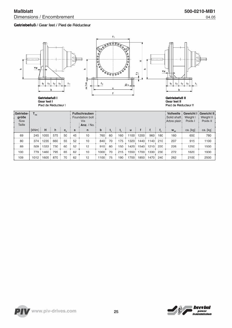
GetriebefußGetriebefuß / Gear feet / Pied de Réducteur / Gear feet / Pied de Réducteur
Getriebe-größeSizeTaille
T2N FußschraubenFoundation bolt
Vis
VollwelleSolid shaftArbre plein
Gewicht IWeight IPoids I
Gewicht IIWeight IIPoids II
Anz. / No.
[kNm] H h c3 s n b t1 t2 u f f1 f2 w3F ca. [kg] ca. [kg]
69 245 1055 575 50 45 10 760 60 160 1100 1200 960 180 160 650 780
80 374 1235 660 55 52 10 840 70 175 1320 1440 1140 210 207 915 1100
89 509 1333 730 60 52 12 910 80 150 1420 1540 1210 220 226 1250 1500
100 779 1460 795 65 62 10 1000 70 215 1550 1700 1330 230 272 1620 1930
109 1012 1605 870 70 62 12 1100 75 190 1700 1850 1470 240 262 2100 2500
Getriebefuß IGear feet I Pied de Réducteur IPied de Réducteur I
Getriebefuß IIGear feet IIPied de Réducteur IIPied de Réducteur II
Maßblatt 500-0210-MB1Dimensions / Encombrement 04.05
25
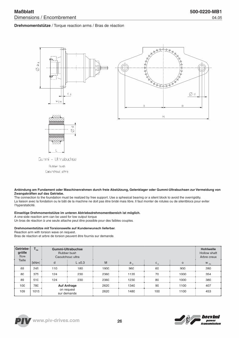
26
Maßblatt 500-0220-MB1Dimensions / Encombrement 04.05
Getriebe-größeSizeTaille
T2N Gummi-UltrabuchseRubber bush
Caoutchouc ultra
HohlwelleHollow shaftArbre creux
[kNm] d L ±0,3 M a 6 c 6 o w 2H
69 245 110 180 1900 960 60 900 280
80 375 124 230 2360 1135 70 1000 354
89 510 124 230 2360 1230 80 1000 380
100 780 Auf Anfrageon request
sur demande
2620 1340 90 1100 407
109 1015 2620 1480 100 1100 453
Drehmomentstütze / Torque reaction arms / Bras de réaction
Anbindung am Fundament oder Maschinenrahmen durch freie Abstützung, Gelenklager oder Gummi-Ultrabuchsen zur Vermeidung von Zwangskräften auf das Getriebe.The connection to the foundation must be realized by free support. Use a sphesical bearing or a silent block to avoid the overrigidity. La liaison avec la fondation ou le bâti de la machine ne doit pas être bridé mais libre. Il faut monter de rotules ou de silentblocs pour eviter l’hyperstaticité.
Einseitige Drehmomentstütze im unteren Abtriebsdrehmomentbereich ist möglich.A one-side reaction arm can be used for low output torqueUn bras de réaction à une seule attache peut être possible pour des faibles couples.
Drehmomentstütze mit Torsionswelle auf Kundenwunsch lieferbar.Reaction arm with torsion wave on request.Bras de réaction et arbre de torsion peuvent être fournis sur demande.

Maßblatt 500-0221-MB1Dimensions / Encombrement 04.05
Anziehdrehmomente bei Flanschverbindung und FussausführungTightening torques for fl ange and foot attachmentCouples de serrage pour les liaison pa bride et les version à pattes
Teilfl ächen entfettet und mit LOCTITE 640 gefügtParting lines degreased and bonded with LOCTITE 640surfaces dégraissées puis jiontoyées à la LOCTITE 640
Getriebe-größeSizeTaille
T2N FlanschverbindungFlange attachment Liaison pa bride
Fussverbindung 2) Foot attachmentLiaison au pied
[kNm]
Schraube 10.9Screw
Vis
Anziehdrehmoment 1)Tightening torquesCouples de serrage
[Nm]
Schraube 8.8Screw
Vis
AnziehdrehmomentTightening torquesCouples de serrage
[Nm]
69 245 M30 2000 M42 4050
80 375 M36 3500 M48 6100
89 510 M36 3500 M48 6100
100 780 M42 5700 M56 9800
109 1015 M48 8600 M56 9800
1) Anziehdrehmomente beziehen sich auf Reibwerte 0.14 im Gewinde und 90% Ausnutzung der Streckgrenze Tightening torques relate to friction values 0.14 in the thread and 90% utillization of yield strength Les couples de serrage s‘entendent indices de friction à 0.14 dans le vis et limite d‘etirage exploitée à 90%
2) Die Schrauben sind in Abhängigkeit der Fundamentkonstruktion vom Anwender zu überprüfen The bolts must be checked by the user to ensure that they are suitable for the foundation design L‘utillisateur devra vérifi er l‘adéquation des vis en fonction de la conception du massif de fondation
27

28
© PIV Drives 2005© PIV Drives 2005©
Toute communication ou reproduction de ce document, sous quelques forme que se soit, et toute exploitation ou communi-cation de son contenu sont interdites, sauf autorisation expresse. Tout manquement à cette règle est iIIicite et expose son auteur au versement de dommages et intérêts. Tous droits réservés pour le cas de la delivrance d’un brévet, d’un modèle d’utilité ou d’un modèle de présentation.
Les changements, qui servent le progrès technique, restent réservés.
© PIV Drives 2005© PIV Drives 2005©
Weitergabe sowie Vervielfältigung dieses Dokuments, Verwertung und Mitteilung seines Inhalts sind verboten, soweit nicht ausdrücklich gestattet. Zuwiderhandlun-gen verpfl ichten zum Schadensersatz. Alle Rechte für den Fall der Patent-, Ge-brauchsmuster- oder Geschmacksmuste-reintragung vorbehalten.
Änderungen, die dem technischen Fort-schritt dienen, bleiben vorbehalten.
© PIV Drives 2005
The reproduction, distribution and utili-zation of this document as well as the communication of its contents to others without explicid authorization is prohib-ited. Offenders will be held liable for the payment of damages. All rights reserved in the event of the grant of a patent, utility model or design.
PIV Drives reserves the right to make improvements at any time without prior notice.
Stirnrad- und KegelstirnradgetriebeHelical and bevel-helical gear reducersRiduttori ad assi paralleli e ortogonaliRéducteurs à engrenages cylindriques et cylindro-coniquesReductores de ejes paralelos y ortogonalesRedutores de eixos paralelos e ortogonais
POSIRED 2
DoppelwellengetriebeDouble shaft gear reducers Riduttori a doppio albero d'uscitaRéducteurs avec deux arbres de sortieReductores con doble eje de salidaRedutores com duplo eixo de saída
POSIRED TS
POSIRED N
Universelles und kompaktes Kegelstirnrad-GetriebeUniversal and compact right angle gear motorRiduttori compatti e universali ad assi ortogonaliRéducteurs à arbre perpendiculaire universel et compactReductores universales y compactos ortogonalesRedutores de eixos ortogonais universais e compactos
POSIRED D
VertikalgetriebeVertical shaft gear reducers Riduttori verticaliRéducteurs verticalesReductores verticalesRedutores verticales
POSIRED R
KegelradgetriebeBevel gear unitsRinvii angolariRenvoi d’angleReenvíos angularesRedutores de engrenagens cônicas
POSICROSS LN
Einwellen-Extrudergetriebe Single screw extruder drives Riduttori per estrusori monovite Réducteurs pour extrudeuse monovisReductores para extrusoras de un husilloRedutores para extrusoras monorosca
POSIREX/POSIREX I
Doppelwellen-ExtrudergetriebeTwin screw extruder drivesRiduttori per estrusori biviteRéducteurs pour extrudeuse double visReductores para extrusoras de dos husillosRedutores para extrusoras de dupla rosca
POSITWIN GL
Zahnstangengetriebe für SpritzgießmaschinenRack and pinion drive for injection moulding machinesAzionamenti a cremagliera per presse ad iniezioneRéducteurs à dentures crémaillères pour machines à injectionReductores de cremallera para maquinas de moldeo por inyecciónRedutores de cremalheira para máquinas de moldar por injeçâo
POSIRACK
Industrie-PlanetengetriebeLarge industrial planetary gear reducersRiduttori epicicloidali per l'industriaRéducteurs planétaires à fort coupleGrandes reductores planetarios para la industriaRedutores planetários industriais
POSITORQUE
CVT und IndustrievariatorenCVT and industrial variatorsCVT e variatori di velocità per l'industriaCVT et variateurs pour l'industrieCVT y variadores de velocidad por la industriaCVT e variadores de velocidade industriais
CVT/POSICHAIN/POSIDISC
Stirnradgetriebe mit großem AchsabstandParallel axis gear reducers with extended centre distanceRiduttori ad ingranaggi cilindrici e grandi interassiRéducteurs à arbres parallèles grands entraxesReductores de ejes paralelos con gran distancia entre ejesRedutores de eixos paralelos com entre centros estendidos
500/
6 TW
/LF
CC
250
0505
PIV Drives GmbHIndustriestrasse 361352 Bad Homburg/Germany Tel. +49 (0) 6172-102 0Fax +49 (0) 6172-102 [email protected]
www.piv-drives.com