Radialkolbenpumpen Radial Piston Pumps - bibus.hu · The radial pistons (5) in the cylinder block...
71
Radialkolbenpumpen Radial Piston Pumps
Transcript of Radialkolbenpumpen Radial Piston Pumps - bibus.hu · The radial pistons (5) in the cylinder block...
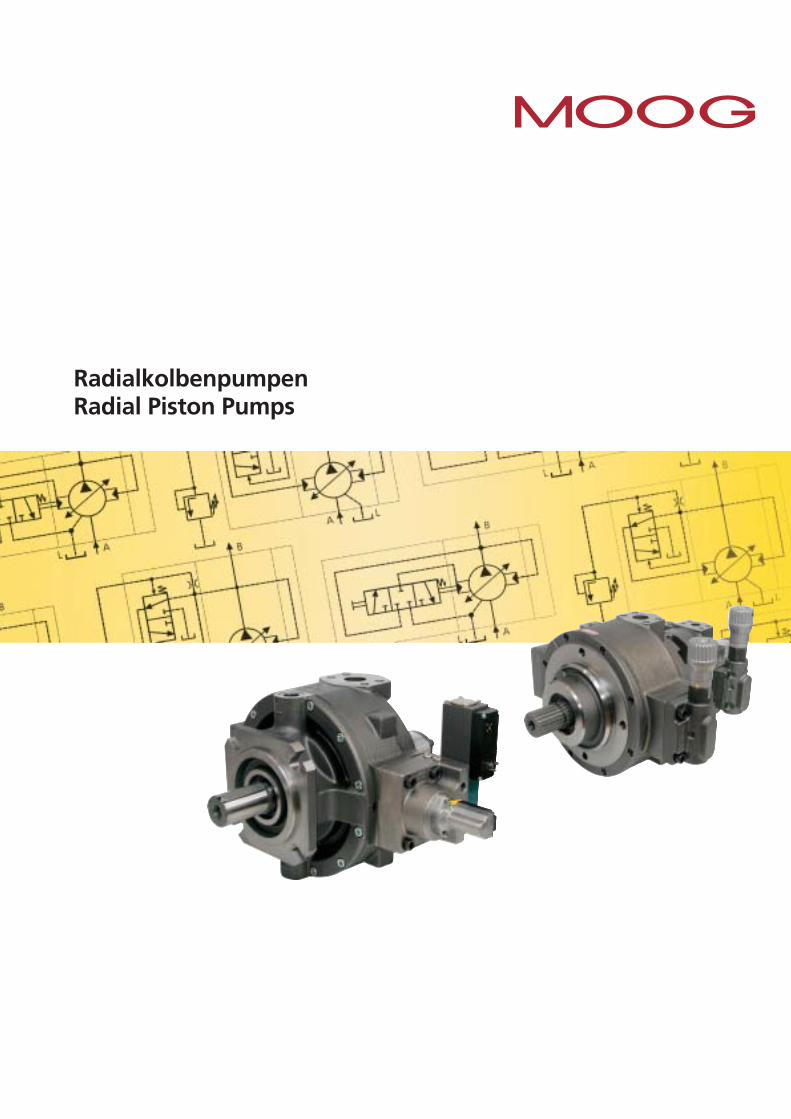
RadialkolbenpumpenRadial Piston Pumps
2 Moog • RKP
RADIALKOLBENPUMPENRADIAL PISTON PUMP RKP
1
9
8
6
3
2
5
4
7
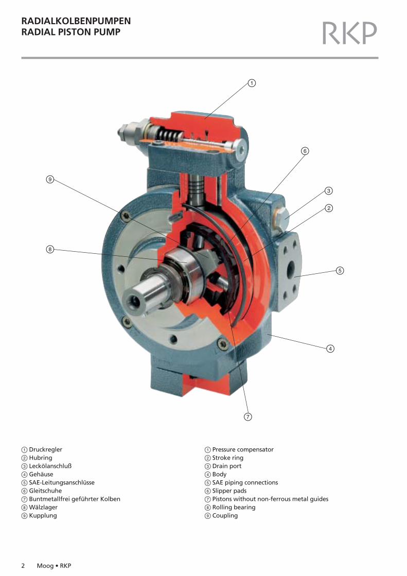
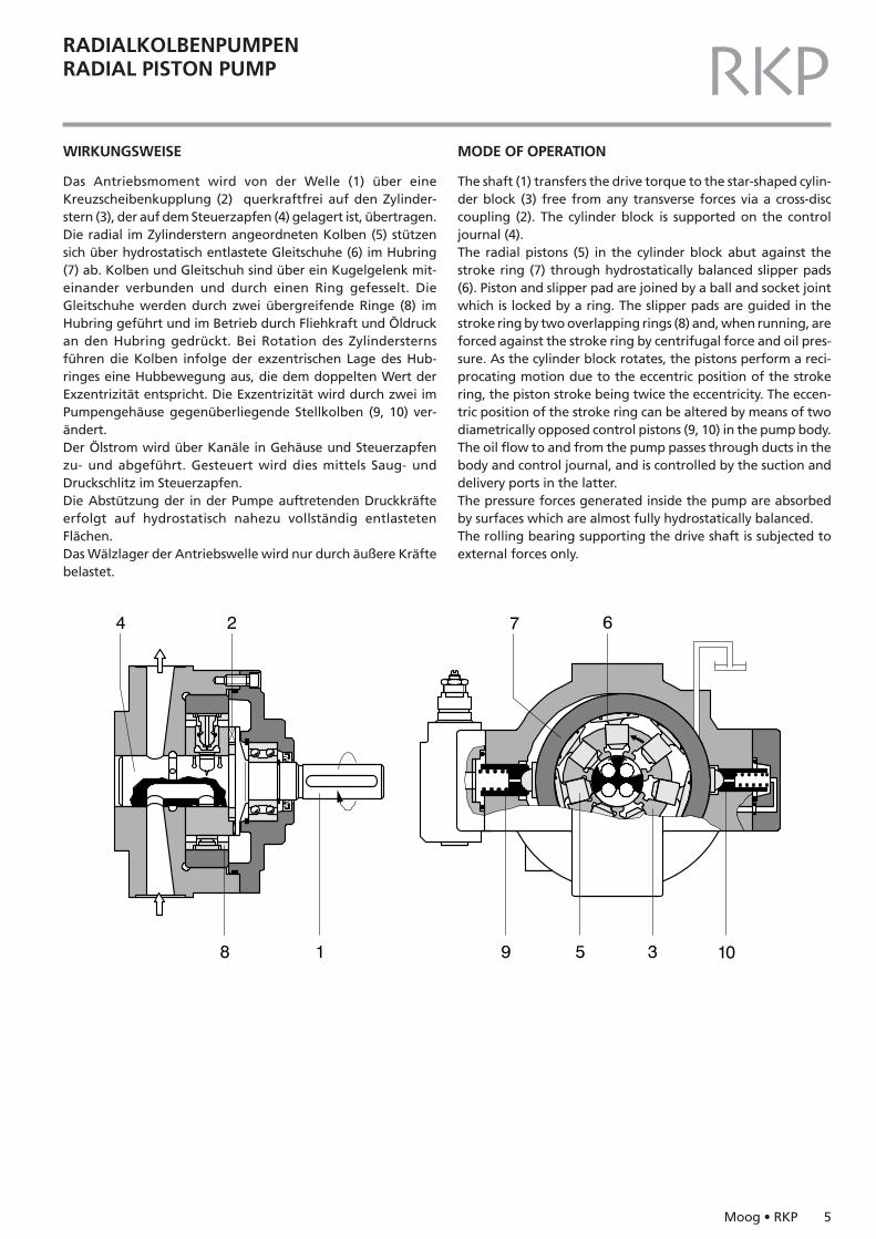
1 Pressure compensator2 Stroke ring3 Drain port4 Body5 SAE piping connections6 Slipper pads7 Pistons without non-ferrous metal guides8 Rolling bearing9 Coupling
1 Druckregler2 Hubring3 Leckölanschluß4 Gehäuse5 SAE-Leitungsanschlüsse6 Gleitschuhe7 Buntmetallfrei geführter Kolben8Wälzlager9 Kupplung
Moog • RKP 3
RADIALKOLBENPUMPENRADIAL PISTON PUMP RKPINHALT SEITE
AllgemeinesWirkungsweiseTypenschlüsselAuswahlreiheKenngrößenVerstellbereichKennlinienReglerMehrfachtechnikPumpengehäuse RKP 19 - 100Antriebsflansche RKP 19 - 100Regler RKP 19 - 100Pumpengehäuse RKP 140Antriebsflansche RKP 140Regler RKP 140Zahnradpumpen für Anbau an RKPDämpfungsflanschSteuerblöcke für RKPTechnische HinweiseErsatzteile – Auswahlreihe
CONTENTS PAGE
GeneralMode of operationModel CodeSelectionSpecificationsAdjustment rangePerformance curvesControllerMultiple arrangementsPump housings RKP 19 - 100Drive flanges RKP 19 - 100Compensators RKP 19 -100Pump housings RKP 140Drive flanges RKP 140Compensators RKP 140Gear pumps mounting on RKPAnti-vibration flangeControl blocks for RKPTechnical informationSelection of spare parts
456
1012141518283234405253566064656668
456
1013141518283234405253566064656668
4 Moog • RKP
RADIALKOLBENPUMPENRADIAL PISTON PUMP RKPALLGEMEINES
Die Moog-Radialkolbenpumpe steht für Zuverlässigkeit, gerin-ges Geräusch und lange Lebensdauer. Dies wird unterstrichendurch die erhöhte Gewährleistung. Diese beträgt unter den aufSeite 12 genannten Randbedingungen für Mineralöl 10.000Betriebsstunden oder 24 Monate (je nachdem, was zuersterreicht wird).
Das vorhandene Baukastensystem erlaubt die Auswahl einerauf die jeweilige Anwendung individuell zugeschnittenenPumpe bzw. Pumpenkombination.
Zur Verfügung stehen:
– Mitteldruckserie (280 bar) und Hochdruckserie (350 bar) für Mineralöl
– Sieben Baugrößen zwischen 19 und 140 cm3/U– Große Auswahl an Reglern, mechanischen, hydraulischen
und elektrohydraulischen (analog oder digital mit CAN Bus)– Mechanische Förderstrombegrenzung– Mehrfachpumpen durch axialen Anbau
(bis zu 5 Pumpen möglich)– Verschiedene Antriebsflansche – Eignung für verschiedene Hydrauliköle wie Mineralöl,
Getriebeöl, biologisch abbaubares Öl– Eignung für Sonderflüssigkeiten wie Öl in Wasser (HFA),
Wasserglycol (HFC), synthetische Ester (HFD), Bohremulsion, Isocyanat und Polyol (siehe Spezialkatalog)
Weitere Vorteile der Moog - Radialkolbenpumpe sind:
– Niederer Geräuschpegel– Kurze Stellzeiten– Kompakte Bauweise– Gutes Ansaugverhalten– Geringe Druckpulsation
GENERAL
The Moog Radial Piston Pump stands for reliability, low noiseand durability. This is underlined by its extended warranty.Under the conditions described on page 13, warranty for mine-ral oil is covered for 10,000 operating hours or 24 month, which-ever occurs first.
The modular nature of the system enables the selection of indi-vidually tailor-made pumps or pump combinations to suit theapplication in question.
The following features are available:
– Medium pressure series (280 bar) and high pressure series (350 bar) for mineral oil.
– Seven sizes between 19 and 140 cm3/rev– Large selection of controls, mechanically, hydraulically and
electric-hydraulically (analog or digital with CAN Bus)– Mechanical flow limitation– Multiple pumps by axial mounting
(up to 5 pumps possible)– Various mounting flanges– Suitable for various hydraulic oils like mineral oil,
transmission oil, bio-degradable oil– Suitable for special fluids such as oil in water (HFA),
water-glycol (HFC), synthetical ester (HFD),cutting emulsion, isocyanate and polyol (see special catalog)
Further advantages of the Moog Radial Piston Pump are:
– Low noise level– Rapid response time– Compact design– Good suction characteristics.– Low pressure ripple
Moog • RKP 5
RADIALKOLBENPUMPENRADIAL PISTON PUMP RKPWIRKUNGSWEISE
Das Antriebsmoment wird von der Welle (1) über eineKreuzscheibenkupplung (2) querkraftfrei auf den Zylinder-stern (3), der auf dem Steuerzapfen (4) gelagert ist, übertragen.Die radial im Zylinderstern angeordneten Kolben (5) stützensich über hydrostatisch entlastete Gleitschuhe (6) im Hubring(7) ab. Kolben und Gleitschuh sind über ein Kugelgelenk mit-einander verbunden und durch einen Ring gefesselt. DieGleitschuhe werden durch zwei übergreifende Ringe (8) imHubring geführt und im Betrieb durch Fliehkraft und Öldruckan den Hubring gedrückt. Bei Rotation des Zylindersternsführen die Kolben infolge der exzentrischen Lage des Hub-ringes eine Hubbewegung aus, die dem doppelten Wert derExzentrizität entspricht. Die Exzentrizität wird durch zwei imPumpengehäuse gegenüberliegende Stellkolben (9, 10) ver-ändert.Der Ölstrom wird über Kanäle in Gehäuse und Steuerzapfenzu- und abgeführt. Gesteuert wird dies mittels Saug- undDruckschlitz im Steuerzapfen.Die Abstützung der in der Pumpe auftretenden Druckkräfteerfolgt auf hydrostatisch nahezu vollständig entlastetenFlächen.Das Wälzlager der Antriebswelle wird nur durch äußere Kräftebelastet.
MODE OF OPERATION
The shaft (1) transfers the drive torque to the star-shaped cylin-der block (3) free from any transverse forces via a cross-disc coupling (2). The cylinder block is supported on the controljournal (4).The radial pistons (5) in the cylinder block abut against the stroke ring (7) through hydrostatically balanced slipper pads(6). Piston and slipper pad are joined by a ball and socket jointwhich is locked by a ring. The slipper pads are guided in thestroke ring by two overlapping rings (8) and, when running, areforced against the stroke ring by centrifugal force and oil pres-sure. As the cylinder block rotates, the pistons perform a reci-procating motion due to the eccentric position of the strokering, the piston stroke being twice the eccentricity. The eccen-tric position of the stroke ring can be altered by means of twodiametrically opposed control pistons (9, 10) in the pump body.The oil flow to and from the pump passes through ducts in thebody and control journal, and is controlled by the suction anddelivery ports in the latter.The pressure forces generated inside the pump are absorbedby surfaces which are almost fully hydrostatically balanced.The rolling bearing supporting the drive shaft is subjected toexternal forces only.
6 Moog • RKP
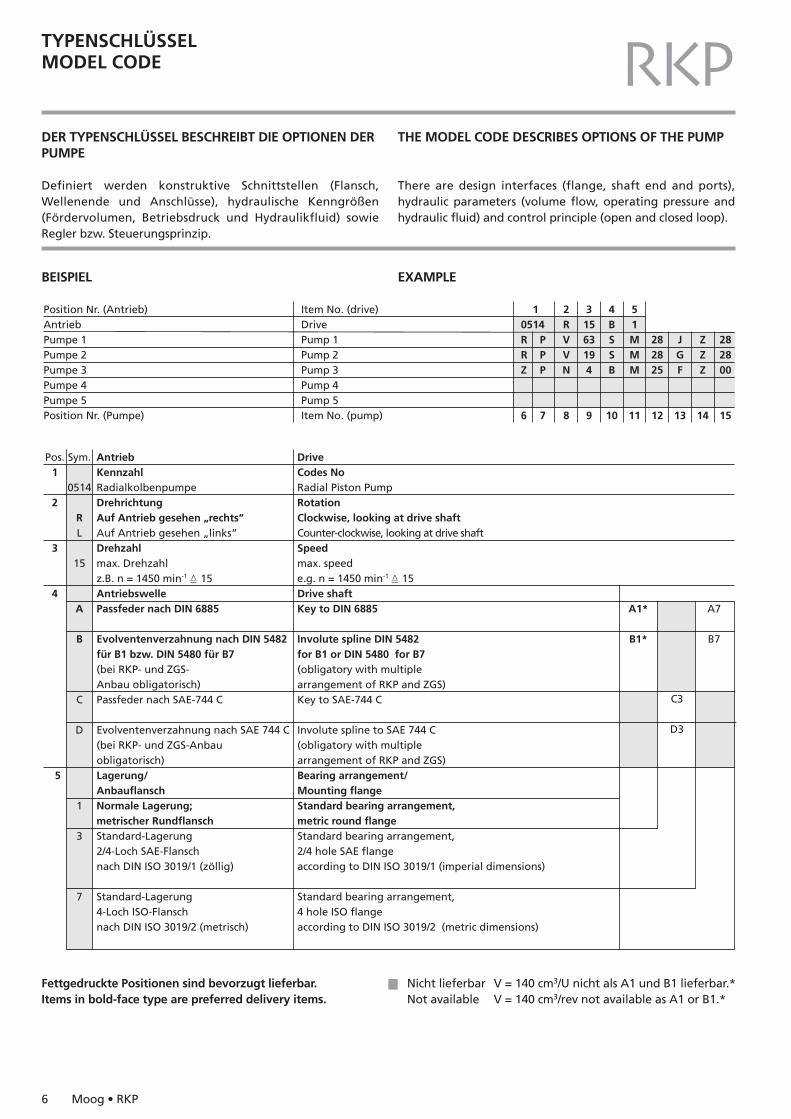
TYPENSCHLÜSSELMODEL CODE RKPDER TYPENSCHLÜSSEL BESCHREIBT DIE OPTIONEN DERPUMPE
Definiert werden konstruktive Schnittstellen (Flansch,Wellenende und Anschlüsse), hydraulische Kenngrößen(Fördervolumen, Betriebsdruck und Hydraulikfluid) sowieRegler bzw. Steuerungsprinzip.
THE MODEL CODE DESCRIBES OPTIONS OF THE PUMP
There are design interfaces (flange, shaft end and ports),hydraulic parameters (volume flow, operating pressure andhydraulic fluid) and control principle (open and closed loop).
Position Nr. (Antrieb)AntriebPumpe 1Pumpe 2Pumpe 3Pumpe 4Pumpe 5Position Nr. (Pumpe)
Item No. (drive)DrivePump 1Pump 2Pump 3Pump 4Pump 5Item No. (pump)
10514RRZ
6
PPP
7
2RVVN
8
31563194
9
4BSSB
10
51MMM
11
282825
12
JGF
13
ZZZ
14
282800
15
Pos.1
2
3
4
5
Sym.
0514
RL
15
A
B
C
D
1
3
7
AntriebKennzahlRadialkolbenpumpeDrehrichtungAuf Antrieb gesehen „rechts“Auf Antrieb gesehen „links”Drehzahlmax. Drehzahlz.B. n = 1450 min-1 � 15AntriebswellePassfeder nach DIN 6885
Evolventenverzahnung nach DIN 5482für B1 bzw. DIN 5480 für B7(bei RKP- und ZGS-Anbau obligatorisch)Passfeder nach SAE-744 C
Evolventenverzahnung nach SAE 744 C(bei RKP- und ZGS-Anbauobligatorisch)Lagerung/AnbauflanschNormale Lagerung;metrischer RundflanschStandard-Lagerung2/4-Loch SAE-Flanschnach DIN ISO 3019/1 (zöllig)
Standard-Lagerung4-Loch ISO-Flanschnach DIN ISO 3019/2 (metrisch)
DriveCodes NoRadial Piston PumpRotationClockwise, looking at drive shaftCounter-clockwise, looking at drive shaftSpeedmax. speede.g. n = 1450 min-1 � 15Drive shaftKey to DIN 6885
Involute spline DIN 5482for B1 or DIN 5480 for B7(obligatory with multiplearrangement of RKP and ZGS)Key to SAE-744 C
Involute spline to SAE 744 C(obligatory with multiplearrangement of RKP and ZGS)Bearing arrangement/Mounting flangeStandard bearing arrangement,metric round flangeStandard bearing arrangement,2/4 hole SAE flangeaccording to DIN ISO 3019/1 (imperial dimensions)
Standard bearing arrangement,4 hole ISO flangeaccording to DIN ISO 3019/2 (metric dimensions)
A1*
B1*
C3
D3
A7
B7
Fettgedruckte Positionen sind bevorzugt lieferbar.Items in bold-face type are preferred delivery items.
Nicht lieferbar V = 140 cm3/U nicht als A1 und B1 lieferbar.*Not available V = 140 cm3/rev not available as A1 or B1.*
BEISPIEL EXAMPLE
Moog • RKP 7
TYPENSCHLÜSSELMODEL CODE RKPPos.
6
7
8
9
10
11
12
Sym.
R
P
V
193245638090100140
S
H
S/H
MABCDEJP
28
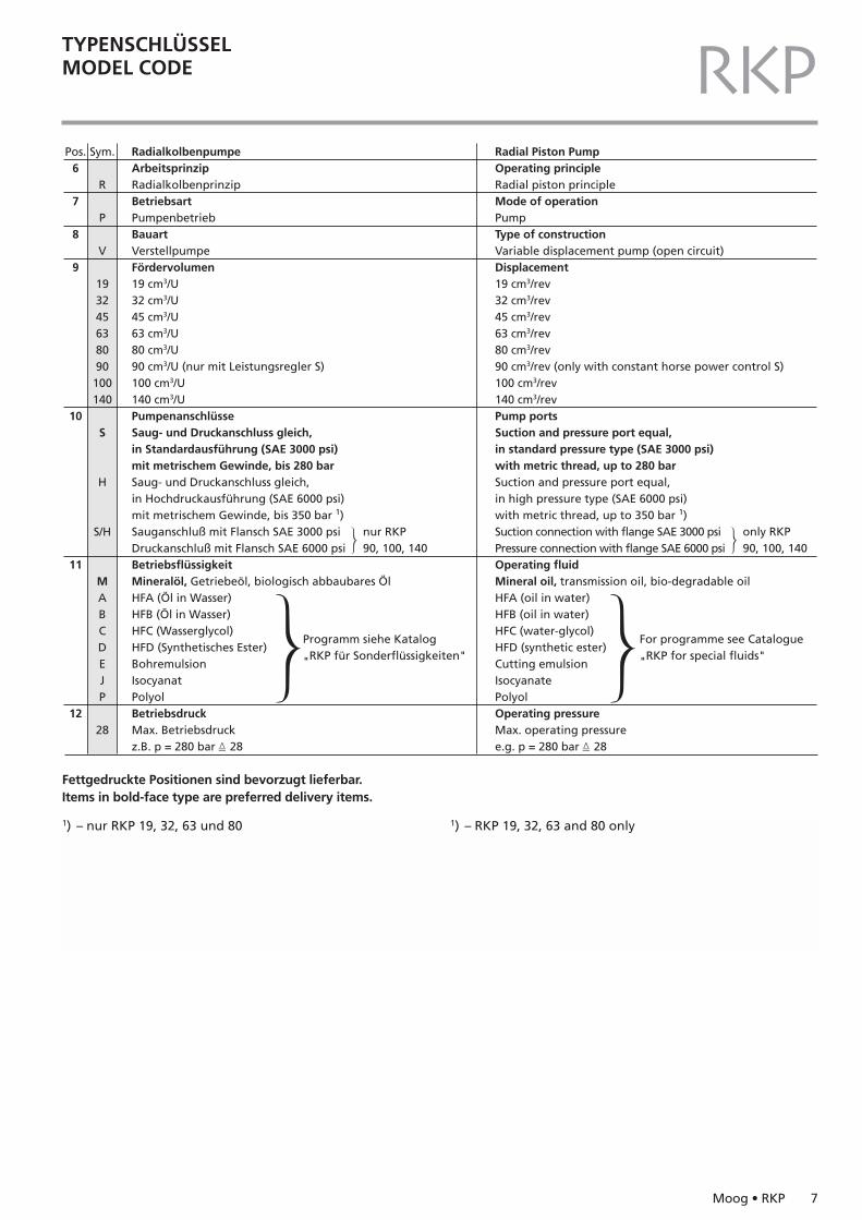
RadialkolbenpumpeArbeitsprinzipRadialkolbenprinzipBetriebsartPumpenbetriebBauartVerstellpumpeFördervolumen19 cm3/U32 cm3/U45 cm3/U63 cm3/U80 cm3/U90 cm3/U (nur mit Leistungsregler S)100 cm3/U140 cm3/UPumpenanschlüsseSaug- und Druckanschluss gleich,in Standardausführung (SAE 3000 psi)mit metrischem Gewinde, bis 280 barSaug- und Druckanschluss gleich,in Hochdruckausführung (SAE 6000 psi)mit metrischem Gewinde, bis 350 bar 1)Sauganschluß mit Flansch SAE 3000 psiDruckanschluß mit Flansch SAE 6000 psiBetriebsflüssigkeitMineralöl, Getriebeöl, biologisch abbaubares ÖlHFA (Öl in Wasser)HFB (Öl in Wasser)HFC (Wasserglycol)HFD (Synthetisches Ester)BohremulsionIsocyanatPolyolBetriebsdruckMax. Betriebsdruckz.B. p = 280 bar � 28
nur RKP90, 100, 140
Programm siehe Katalog
"RKP für Sonderflüssigkeiten"
Radial Piston PumpOperating principleRadial piston principleMode of operationPumpType of constructionVariable displacement pump (open circuit)Displacement19 cm3/rev32 cm3/rev45 cm3/rev63 cm3/rev80 cm3/rev90 cm3/rev (only with constant horse power control S)100 cm3/rev140 cm3/revPump portsSuction and pressure port equal,in standard pressure type (SAE 3000 psi)with metric thread, up to 280 barSuction and pressure port equal,in high pressure type (SAE 6000 psi)with metric thread, up to 350 bar 1)Suction connection with flange SAE 3000 psiPressure connection with flange SAE 6000 psiOperating fluidMineral oil, transmission oil, bio-degradable oilHFA (oil in water)HFB (oil in water)HFC (water-glycol)HFD (synthetic ester)Cutting emulsionIsocyanatePolyolOperating pressureMax. operating pressuree.g. p = 280 bar � 28
only RKP90, 100, 140
For programme see Catalogue
"RKP for special fluids"
Fettgedruckte Positionen sind bevorzugt lieferbar.Items in bold-face type are preferred delivery items.
1) – nur RKP 19, 32, 63 und 80 1) – RKP 19, 32, 63 and 80 only
8 Moog • RKP
TYPENSCHLÜSSELMODEL CODE RKP
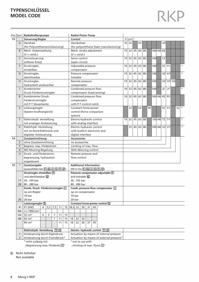
Additional information(fill in for F , G , J , S , T , V )Pressure compensator adjustable Fand lockable G30...105 bar80...280 barComb. pressure-flow compensator J∆p on compensator10 bar20 barConstant horse-power control S
Electric- hydraulic control Actuation by means of internal pressureActuation by means of external pressure1)
1) not to use with
"limiting of max. flows. Y "
Pos.13
14
15
Sym.
A
B
C
F
G
H
J
R
S
T
V
ZYXU
*
1128
-20
4bisto45
12
RadialkolbenpumpeSteuerung/ReglerHandrad(für Polyurethanverschäumung) Mech. Hubeinstellung(V = const.)Servosteuerung(offener Kreis)Druckregler,einstellbarDruckregler,abschliessbarDruckregler,hydraulisch ansteuerbarKombinierterDruck-FörderstromreglerKombinierter Druck-Förderstromreglermit P-T SteuerkanteLeistungsregler(System Kraftvergleich)
Elektrohydr. Verstellungmit analoger AnsteuerungElektrhydr. Verstellungmit on-bord-Elektronik unddigitaler AnsteuerungZusatzeinrichtungohne ZusatzeinrichtungBegrenz. max. FörderstromMit Mooring-RegelungDruck- und Förderstrom-begrenzung, hydraulischangesteuertZusatzangabe(auszufüllen bei F , G , J , S , T , V )Druckregler einstellbar Fund abschliessbar G30...105 bar80...280 barKomb. Druck- Förderstromregler J∆p am Regler10 bar20 barLeistungsregler SP1 [kW]n = 1450 min-1
32 cm3
63 cm3
90 cm3
Elektrohydr. Verstellung Ansteuerung durch EigendruckAnsteuerung durch Fremddruck1)
1) nicht zulässig mit
"Begrenzung max. Förderstr. Y "
Radial Piston PumpControlHandwheel(for polyurethane foam manufacturing)Mech. stroke adjustment(V = const.)Servo control(open circuit)Adjustable pressurecompensatorPressure compensatorlockableRemote pressurecompensatorCombined pressure flowcompensator (load sensing)Combined pressure flowcompensatorwith P-T control notchConstant horse-powercontrol (Force comparisonsystem)Electric-hydraulic controlwith analog interfaceElectric-hydraulic controlwith build-in electronic anddigital interfaceAccessoriesno accessoriesLimiting of max. flowWith Mooring controlRemote pressure andflow control
V [cm3]16
19
19
19
19
19
19
19
19
32
32
32
32
32
32
32
32
32
32
32
45
45
45
45
45
45
45
45
45
63
63
63
63
63
63
63
63
63
63
63
80
80
80
80
80
80
80
80
80
AZ
BZ
CZ
FZ
GZ
HZ
JZ
RZ
SZ
TZ
VZ
FY
GY
HY
JY
RY
SY
TY
VY
HX
SU
*
*
*
*
*
*
90
100
100
100
100
100
100
100
100
100
140
140
4
4
5,5
5
7,5
77
11
111111
15
151515
18,5
1818
22
2222
30
3030
37
37
45
45
140
140
T , V T , V
Nicht lieferbarNot available
Moog • RKP 9
TYPENSCHLÜSSELMODEL CODE RKPPos.
6
7
8
9
10
11
12
13
14
15
Sym.
Z
P
N
458111619223245
B
MC
18
FG
Z
00
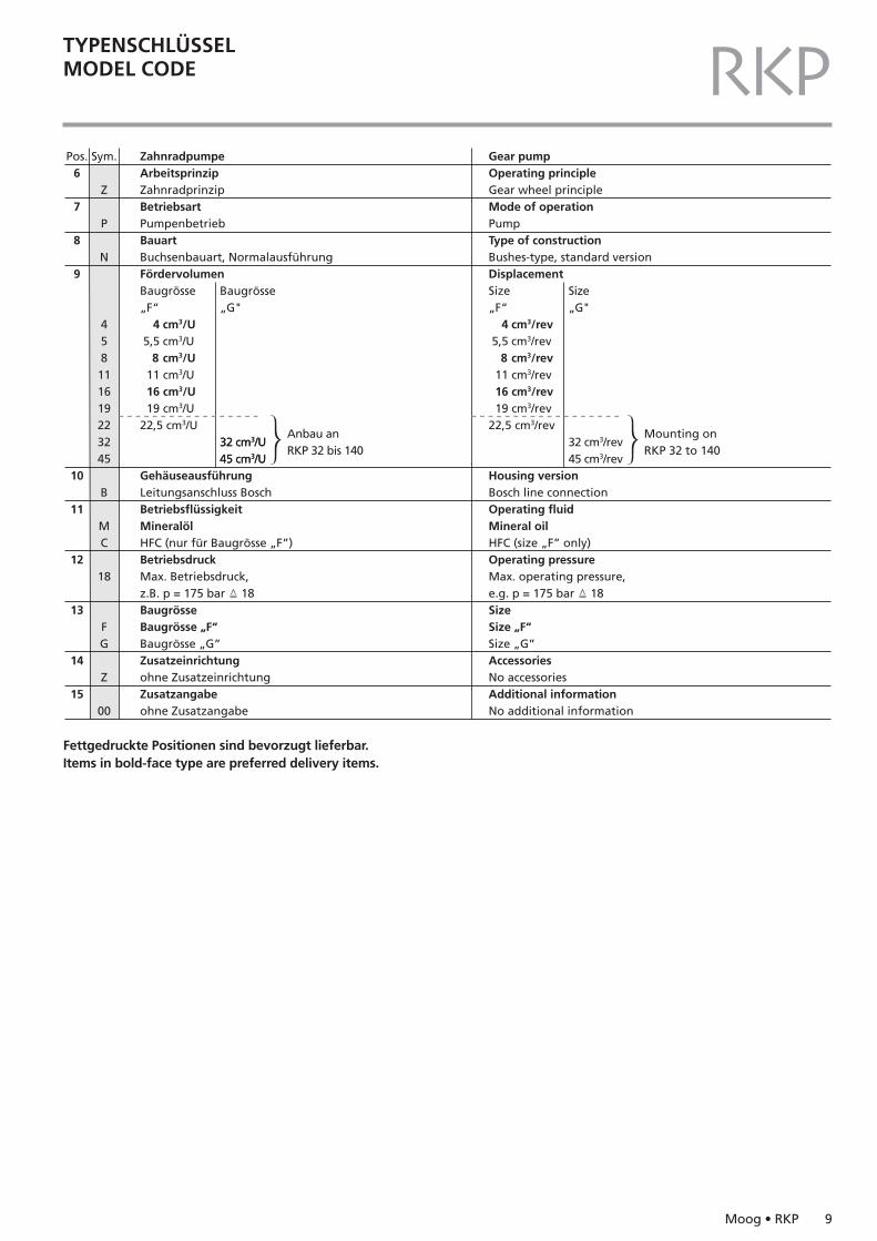
ZahnradpumpeArbeitsprinzipZahnradprinzipBetriebsartPumpenbetriebBauartBuchsenbauart, NormalausführungFördervolumenBaugrösse„F“ 4 cm3/U 5,5 cm3/U
8 cm3/U 11 cm3/U 16 cm3/U 19 cm3/U22,5 cm3/U
GehäuseausführungLeitungsanschluss BoschBetriebsflüssigkeitMineralölHFC (nur für Baugrösse „F”)BetriebsdruckMax. Betriebsdruck,z.B. p = 175 bar � 18BaugrösseBaugrösse „F“Baugrösse „G”Zusatzeinrichtungohne ZusatzeinrichtungZusatzangabeohne Zusatzangabe
32 cm3/U45 cm3/U
Baugrösse„G"
32 cm3/U45 cm3/U
Anbau anRKP 32 bis 140
Gear pumpOperating principleGear wheel principleMode of operationPumpType of constructionBushes-type, standard versionDisplacementSize„F“ 4 cm3/rev 5,5 cm3/rev
8 cm3/rev 11 cm3/rev 16 cm3/rev 19 cm3/rev22,5 cm3/rev
Housing versionBosch line connectionOperating fluidMineral oilHFC (size „F” only)Operating pressureMax. operating pressure,e.g. p = 175 bar � 18SizeSize „F“Size „G”AccessoriesNo accessoriesAdditional informationNo additional information
Size„G"
32 cm3/rev45 cm3/rev
Mounting onRKP 32 to 140
Fettgedruckte Positionen sind bevorzugt lieferbar.Items in bold-face type are preferred delivery items.
10 Moog • RKP
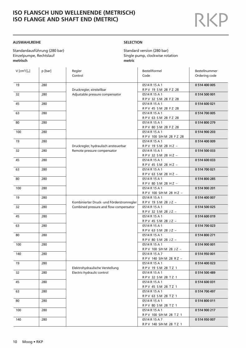
ISO FLANSCH UND WELLENENDE (METRISCH)ISO FLANGE AND SHAFT END (METRIC) RKPAUSWAHLREIHE
Standardausführung (280 bar)Einzelpumpe, Rechtslaufmetrisch
SELECTION
Standard version (280 bar)Single pump, clockwise rotationmetric
V [cm3/ ]
19
32
45
63
80
100
19
32
45
63
80
100
19
32
45
63
80
100
140
19
32
45
63
80
100
140
ReglerControl
Druckregler, einstellbarAdjustable pressure compensator
Druckregler, hydraulisch ansteuerbarRemote pressure compensator
Kombinierter Druck- und FörderstromreglerCombined pressure and flow compensator
Elektrohydraulische VerstellungElectric-hydraulic control
BestellformelCode
0514 R 15 A 1R P V 19 S M 28 F Z 280514 R 15 A 1R P V 32 S M 28 F Z 280514 R 15 A 1R P V 45 S M 28 F Z 280514 R 15 A 1R P V 63 S M 28 F Z 280514 R 15 A 1R P V 80 S M 28 F Z 280514 R 15 A 1R P V 100 S/H M 28 F Z 280514 R 15 A 1R P V 19 S M 28 H Z –0514 R 15 A 1R P V 32 S M 28 H Z –0514 R 15 A 1R P V 45 S M 28 H Z –0514 R 15 A 1R P V 63 S M 28 H Z –0514 R 15 A 1R P V 80 S M 28 H Z –0514 R 15 A 1R P V 100 S/H M 28 H Z –0514 R 15 A 1R P V 19 S M 28 J Z –0514 R 15 A 1R P V 32 S M 28 J Z –0514 R 15 A 1R P V 45 S M 28 J Z –0514 R 15 A 1R P V 63 S M 28 J Z –0514 R 15 A 1R P V 80 S M 28 J Z –0514 R 15 A 1R P V 100 S/H M 28 J Z –0514 R 15 A 7R P V 140 S/H M 28 R Z –0514 R 15 A 1R P V 19 S M 28 T Z 10514 R 15 A 1R P V 32 S M 28 T Z 10514 R 15 A 1R P V 45 S M 28 T Z 10514 R 15 A 1R P V 63 S M 28 T Z 10514 R 15 A 1R P V 80 S M 28 T Z 10514 R 15 A 1R P V 100 S/H M 28 T Z 10514 R 15 A 7R P V 140 S/H M 28 T Z 1
BestellnummerOrdering code
0 514 400 005
0 514 500 001
0 514 600 021
0 514 700 005
0 514 800 279
0 514 900 203
0 514 400 009
0 514 500 033
0 514 600 033
0 514 700 021
0 514 800 285
0 514 900 201
0 514 400 007
0 514 500 025
0 514 600 019
0 514 700 023
0 514 800 271
0 514 900 001
0 514 950 001
0 514 400 023
0 514 500 489
0 514 600 031
0 514 700 497
0 514 800 011
0 514 900 217
0 514 950 007
p [bar]
280
280
280
280
280
280
280
280
280
280
280
280
280
280
280
280
280
280
280
280
280
280
280
280
280
280
Urev
Moog • RKP 11
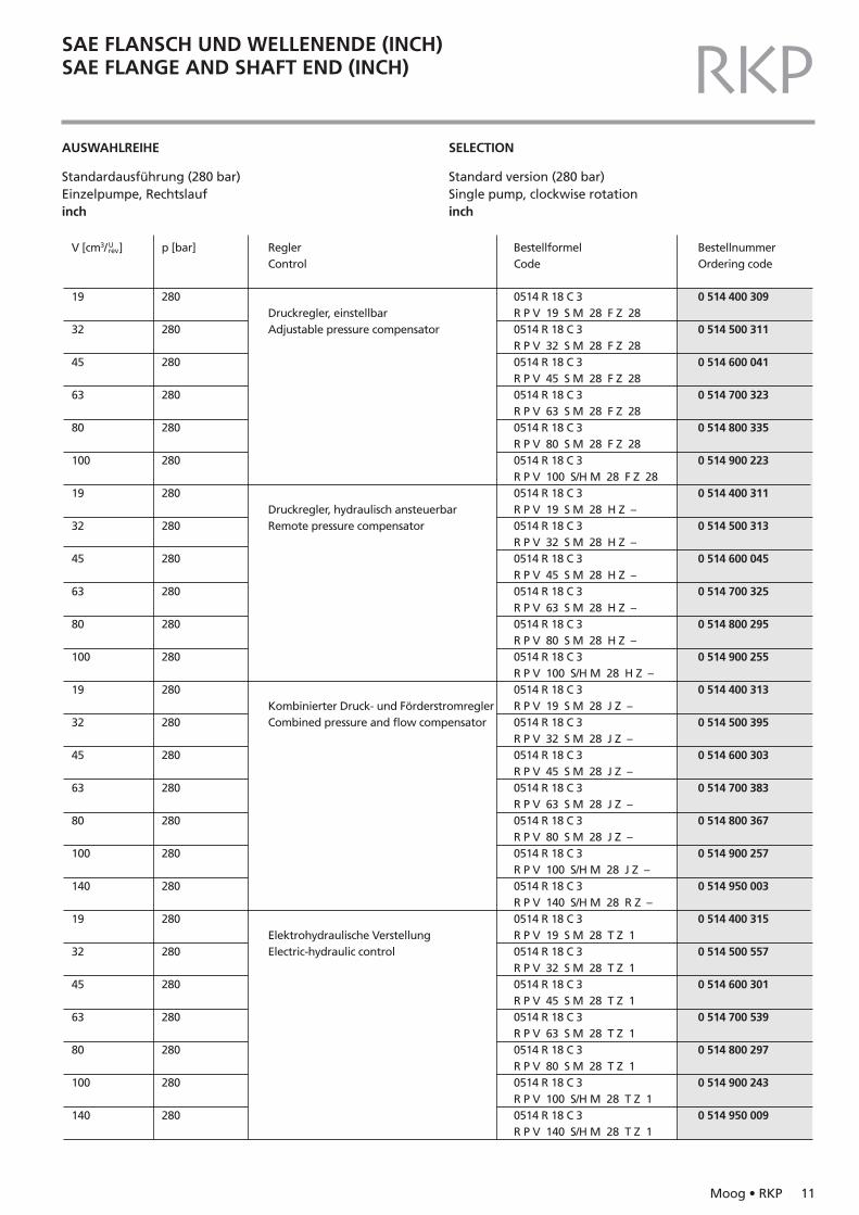
SAE FLANSCH UND WELLENENDE (INCH)SAE FLANGE AND SHAFT END (INCH) RKPAUSWAHLREIHE
Standardausführung (280 bar)Einzelpumpe, Rechtslaufinch
SELECTION
Standard version (280 bar)Single pump, clockwise rotationinch
V [cm3/ ]
19
32
45
63
80
100
19
32
45
63
80
100
19
32
45
63
80
100
140
19
32
45
63
80
100
140
ReglerControl
Druckregler, einstellbarAdjustable pressure compensator
Druckregler, hydraulisch ansteuerbarRemote pressure compensator
Kombinierter Druck- und FörderstromreglerCombined pressure and flow compensator
Elektrohydraulische VerstellungElectric-hydraulic control
BestellformelCode
0514 R 18 C 3R P V 19 S M 28 F Z 280514 R 18 C 3R P V 32 S M 28 F Z 280514 R 18 C 3R P V 45 S M 28 F Z 280514 R 18 C 3R P V 63 S M 28 F Z 280514 R 18 C 3R P V 80 S M 28 F Z 280514 R 18 C 3R P V 100 S/H M 28 F Z 280514 R 18 C 3R P V 19 S M 28 H Z –0514 R 18 C 3R P V 32 S M 28 H Z –0514 R 18 C 3R P V 45 S M 28 H Z –0514 R 18 C 3R P V 63 S M 28 H Z –0514 R 18 C 3R P V 80 S M 28 H Z –0514 R 18 C 3R P V 100 S/H M 28 H Z –0514 R 18 C 3R P V 19 S M 28 J Z –0514 R 18 C 3R P V 32 S M 28 J Z –0514 R 18 C 3R P V 45 S M 28 J Z –0514 R 18 C 3R P V 63 S M 28 J Z –0514 R 18 C 3R P V 80 S M 28 J Z –0514 R 18 C 3R P V 100 S/H M 28 J Z –0514 R 18 C 3R P V 140 S/H M 28 R Z –0514 R 18 C 3R P V 19 S M 28 T Z 10514 R 18 C 3R P V 32 S M 28 T Z 10514 R 18 C 3R P V 45 S M 28 T Z 10514 R 18 C 3R P V 63 S M 28 T Z 10514 R 18 C 3R P V 80 S M 28 T Z 10514 R 18 C 3R P V 100 S/H M 28 T Z 10514 R 18 C 3R P V 140 S/H M 28 T Z 1
BestellnummerOrdering code
0 514 400 309
0 514 500 311
0 514 600 041
0 514 700 323
0 514 800 335
0 514 900 223
0 514 400 311
0 514 500 313
0 514 600 045
0 514 700 325
0 514 800 295
0 514 900 255
0 514 400 313
0 514 500 395
0 514 600 303
0 514 700 383
0 514 800 367
0 514 900 257
0 514 950 003
0 514 400 315
0 514 500 557
0 514 600 301
0 514 700 539
0 514 800 297
0 514 900 243
0 514 950 009
p [bar]
280
280
280
280
280
280
280
280
280
280
280
280
280
280
280
280
280
280
280
280
280
280
280
280
280
280
Urev
12 Moog • RKP
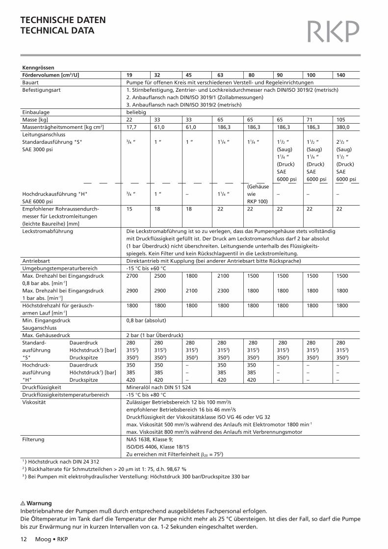
TECHNISCHE DATENTECHNICAL DATA RKPKenngrössenFördervolumen [cm3/U]BauartBefestigungsart
EinbaulageMasse [kg]Massenträgheitsmoment [kg cm2]LeitungsanschlussStandardausführung "S"SAE 3000 psi
Hochdruckausführung "H"SAE 6000 psiEmpfohlener Rohraussendurch-messer für Leckstromleitungen(leichte Baureihe) [mm]Leckstromabführung
AntriebsartUmgebungstemperaturbereichMax. Drehzahl bei Eingangsdruck0,8 bar abs. [min-1]Max. Drehzahl bei Eingangsdruck1 bar abs. [min-1]Höchstdrehzahl für geräusch-armen Lauf [min-1]Min. EingangsdruckSauganschlussMax. GehäusedruckStandard- Dauerdruckausführung Höchstdruck1) [bar]"S" DruckspitzeHochdruck- Dauerdruckausführung Höchstdruck1) [bar]"H" DruckspitzeDruckflüssigkeitDruckflüssigkeitstemperaturbereichViskosität
Filterung
1 ) Höchstdruck nach DIN 24 3122 ) Rückhalterate für Schmutzteilchen > 20 µm ist 1: 75, d.h. 98,67 %3 ) Bei Pumpen mit elektrohydraulischer Verstellung: Höchstdruck 300 bar/Druckspitze 330 bar
19Pumpe für offenen Kreis mit verschiedenen Verstell- und Regeleinrichtungen1. Stirnbefestigung, Zentrier- und Lochkreisdurchmesser nach DIN/ISO 3019/2 (metrisch)2. Anbauflansch nach DIN/ISO 3019/1 (Zollabmessungen)3. Anbauflansch nach DIN/ISO 3019/2 (metrisch)beliebig2217,7
3/4 “
3/4 “
15
Die Leckstromabführung ist so zu verlegen, dass das Pumpengehäuse stets vollständigmit Druckflüssigkeit gefüllt ist. Der Druck am Leckstromanschluss darf 2 bar absolut(1 bar Überdruck) nicht überschreiten. Leitungsende unterhalb des Flüssigkeits-spiegels. Kein Filter und kein Rückschlagventil in die Leckstromleitung.Direktantrieb mit Kupplung (bei anderer Antriebsart bitte Rücksprache)-15 °C bis +60 °C2700
2900
1800
0,8 bar (absolut)
2 bar (1 bar Überdruck)2803153)3503)350385420Mineralöl nach DIN 51 524-15 °C bis +80 °CZulässiger Betriebsbereich 12 bis 100 mm2/sempfohlener Betriebsbereich 16 bis 46 mm2/sDruckflüssigkeit der Viskositätsklasse ISO VG 46 oder VG 32max. Viskosität 500 mm2/s während des Anlaufs mit Elektromotor 1800 min-1
max. Viskosität 800 mm2/s während des Anlaufs mit VerbrennungsmotorNAS 1638, Klasse 9;ISO/DIS 4406, Klasse 18/15Zu erreichen mit Filterfeinheit �20 = 752)
32
3361,0
1 “
1 “
18
2500
2900
1800
2803153)3503)350385420
45
3361,0
1 “
–
18
1800
2100
1800
2803153)3503)–––
63
65186,3
11/4 “
11/4 “
22
2100
2300
1800
2803153)3503)350385420
80
65186,3
11/4 “
(GehäusewieRKP 100)22
1500
1800
1800
2803153)3503)350385420
90
65186,3
11/2 “(Saug)11/4 “(Druck)SAE6000 psi
–
22
1500
1800
1800
2803153)3503)–––
100
71186,3
11/2 “(Saug)11/4 “(Druck)SAE6000 psi
–
22
1500
1800
1800
2803153)3503)–––
140
105380,0
21/2 “(Saug)11/2 “(Druck)SAE6000 psi
–
22
1500
1800
1800
2803153)3503)–––
? WarnungInbetriebnahme der Pumpen muß durch entsprechend ausgebildetes Fachpersonal erfolgen.Die Öltemperatur im Tank darf die Temperatur der Pumpe nicht mehr als 25 °C übersteigen. Ist dies der Fall, so darf die Pumpebis zur Erwärmung nur in kurzen Intervallen von ca. 1-2 Sekunden eingeschaltet werden.
Moog • RKP 13
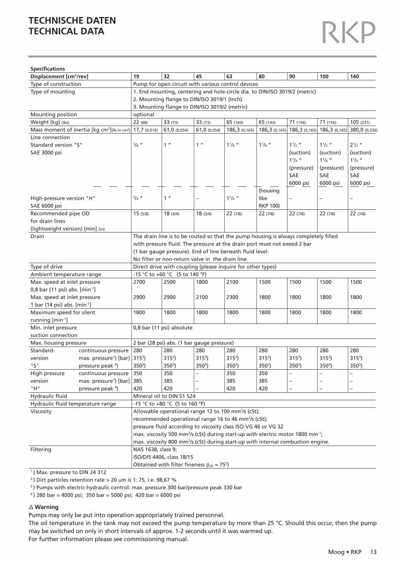
TECHNISCHE DATENTECHNICAL DATA RKPSpecificationsDisplacement [cm3/rev]Type of constructionType of mounting
Mounting positionWeight [kg] (lbs)
Mass moment of inertia [kg cm2](lb in cm2)
Line connectionStandard version "S"SAE 3000 psi
High-pressure version "H"SAE 6000 psiRecommended pipe ODfor drain lines(lightweight version) [mm] (in)
Drain
Type of driveAmbient temperature rangeMax. speed at inlet pressure0,8 bar (11 psi) abs. [min-1]Max. speed at inlet pressure1 bar (14 psi) abs. [min-1]Maximum speed for silentrunning [min-1]Min. inlet pressuresuction connectionMax. housing pressureStandard- continuous pressureversion max. pressure1) [bar]"S" pressure peak 4)High pressure continuous pressureversion max. pressure1) [bar]"H" pressure peak 4)Hydraulic fluidHydraulic fluid temperature rangeViscosity
Filtering
1 ) Max. pressure to DIN 24 3122 ) Dirt particles retention rate > 20 µm is 1: 75, i.e. 98,67 %3 ) Pumps with electric-hydraulic control: max. pressure 300 bar/pressure peak 330 bar4 ) 280 bar = 4000 psi; 350 bar = 5000 psi; 420 bar = 6000 psi
45
33 (73)
61,0 (0,054)
1 “
–
18 (3/4)
1800
2100
1800
2803153)3503)–––
63
65 (143)
186,3 (0,165)
11/4 “
11/4 “
22 (7/8)
2100
2300
1800
2803153)3503)350385420
80
65 (143)
186,3 (0,165)
11/4 “
(housinglikeRKP 100)22 (7/8)
1500
1800
1800
2803153)3503)350385420
100
71 (156)
186,3 (0,165)
11/2 “(suction)11/4 “(pressure)SAE6000 psi
–
22 (7/8)
1500
1800
1800
2803153)3503)–––
140
105 (231)
380,0 (0,336)
21/2 “(suction)11/2 “(pressure)SAE6000 psi
–
22 (7/8)
1500
1800
1800
2803153)3503)–––
32
33 (73)
61,0 (0,054)
1 “
1 “
18 (3/4)
2500
2900
1800
2803153)3503)350385420
90
71 (156)
186,3 (0,165)
11/2 “(suction)11/4 “(pressure)SAE6000 psi
–
22 (7/8)
1500
1800
1800
2803153)3503)–––
19Pump for open circuit with various control devices1. End mounting, centering and hole-circle dia. to DIN/ISO 3019/2 (metric)2. Mounting flange to DIN/ISO 3019/1 (Inch)3. Mounting flange to DIN/ISO 3019/2 (metric)optional22 (48)
17,7 (0,016)
3/4 “
3/4 “
15 (5/8)
The drain line is to be routed so that the pump housing is always completely filledwith pressure fluid. The pressure at the drain port must not exeed 2 bar(1 bar gauge pressure). End of line beneath fluid level.No filter or non-return valve in the drain line.Direct drive with coupling (please inquire for other types)-15 °C to +60 °C (5 to 140 °F)2700
2900
1800
0,8 bar (11 psi) absolute
2 bar (28 psi) abs. (1 bar gauge pressure)2803153)3503)350385420Mineral oil to DIN 51 524-15 °C to +80 °C (5 to 160 °F)Allowable operational range 12 to 100 mm2/s (cSt);recommended operational range 16 to 46 mm2/s (cSt);pressure fluid according to viscosity class ISO-VG 46 or VG 32max. viscosity 500 mm2/s (cSt) during start-up with electric motor 1800 min-1;max. viscosity 800 mm2/s (cSt) during start-up with internal combustion engine.NAS 1638, class 9;ISO/DIS 4406, class 18/15Obtained with filter fineness �20 = 752)
? WarningPumps may only be put into operation appropriately trained personnel.The oil temperature in the tank may not exceed the pump temperature by more than 25 °C. Should this occur, then the pumpmay be switched on only in short intervals of approx. 1-2 seconds until it was warmed up.For further information please see commissioning manual.
14 Moog • RKP
RKPTECHNISCHE DATENTECHNICAL DATA
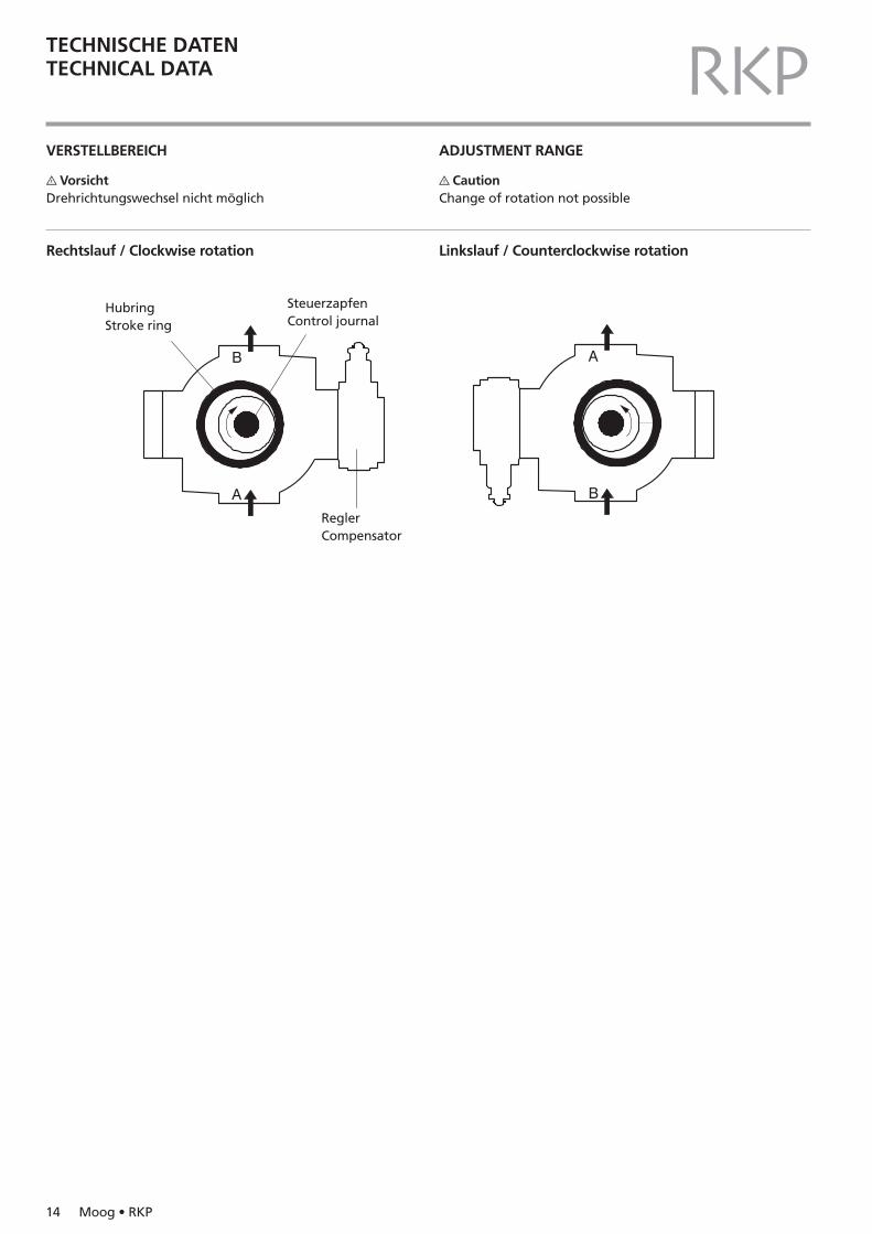
VERSTELLBEREICH
? VorsichtDrehrichtungswechsel nicht möglich
Rechtslauf / Clockwise rotation
ADJUSTMENT RANGE
? CautionChange of rotation not possible
Linkslauf / Counterclockwise rotation
HubringStroke ring
SteuerzapfenControl journal
ReglerCompensator
KENNLINIENPERFORMANCE CURVES
Moog • RKP 15
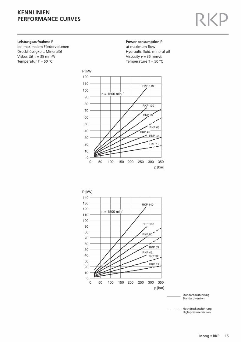
RKPLeistungsaufnahme Pbei maximalem FördervolumenDruckflüssigkeit: MineralölViskosität � = 35 mm2/sTemperatur T = 50 °C
Power consumption Pat maximum flowHydraulic fluid: mineral oilViscosity � = 35 mm2/sTemperature T = 50 °C
0 50 100 150 200 250 300 350
10
0
0 50 100 150 200 250 300 350
10
0
20
30
40
p [bar]
P [kW]
p [bar]
P [kW]
RKP 100
RKP 80
RKP 63
RKP 45RKP 32
RKP 19
RKP 140
50
80
60
70
90
120
100
110
RKP 80
RKP 45RKP 32
RKP 19
RKP 63
RKP 100
RKP 140
140
20
30
40
50
100
110
60
70
80
90
120
130
n = 1500 min -1
n = 1800 min -1
StandardausführungStandard version
HochdruckausführungHigh-pressure version
KENNLINIENPERFORMANCE CURVES
16 Moog • RKP
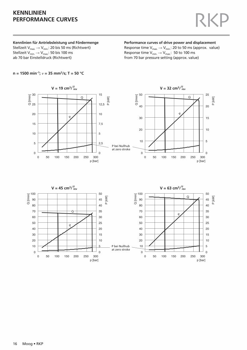
RKPKennlinien für Antriebsleistung und FördermengeStellzeit Vmax. � Vmin.: 20 bis 50 ms (Richtwert)Stellzeit Vmin. � Vmax.: 50 bis 100 ms ab 70 bar Einstelldruck (Richtwert)
Performance curves of drive power and displacementResponse time Vmax. � Vmin.: 20 to 50 ms (approx. value)Response time Vmin. � Vmax.: 50 to 100 msfrom 70 bar pressure setting (approx. value)
n = 1500 min–1; � = 35 mm2/s; T = 50 °C
0 50 100 150 200 250 300p [bar]
P
Q Q
P
Q [l
/min
]
P [k
W]
20
10
00 50 100 150 200 250 300
p [bar]
Q [l
/min
]
P [k
W]
15
10
5
0
30
25
20
15
10
5
00 50 100 150 200 250 300
p [bar]
Q [l
/min
]
P [k
W]15
12,5
10
7,5
5
2,5
0
30
50
40 20
25
10
0
20
30
40
50
60
70
80
90
100
5
0
10
15
20
25
30
35
40
50
45
0 50 100 150 200 250 300p [bar]
Q [l
/min
]
P [k
W]
10
0
20
30
40
50
60
70
80
90
100
5
0
10
15
20
25
30
35
40
50
45
P
Q
Q
P
P bei Nullhubat zero stroke
V = 45 cm3/Urev V = 63 cm3/U
rev
V = 19 cm3/Urev V = 32 cm3/U
rev
P bei Nullhubat zero stroke
KENNLINIENPERFORMANCE CURVES
Moog • RKP 17
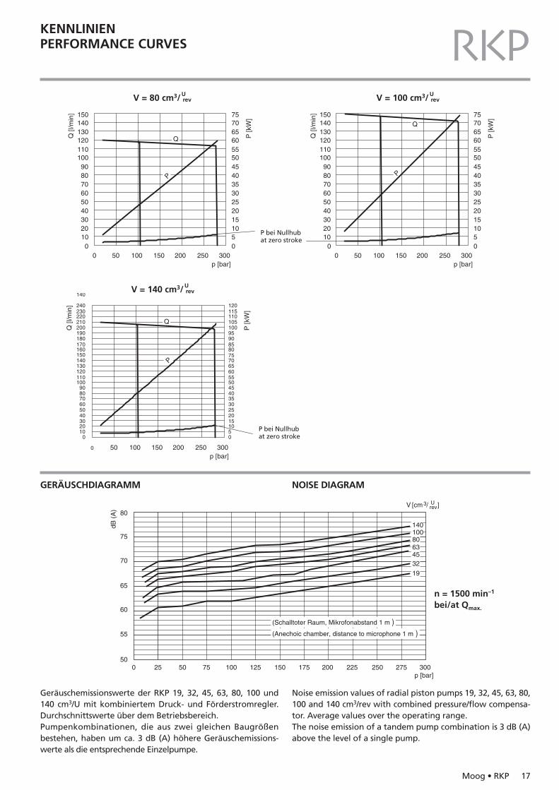
RKPV = 80 cm3/U
rev V = 100 cm3/Urev
0 50 100 150 200 250 300p [bar]
Q [l
/min
]
P [k
W]
100
2030405060
0
150
708090
140130120110100
5101520253035404550
7570656055
PP
Q
Q
0 50 100 150 200 250 300p [bar]
Q [l
/min
]
P [k
W]
100
2030405060
0
150
708090
140130120110100
5101520253035404550
7570656055
0 50 100 150 200 250 300p [bar]
Q [l
/min
]
P [k
W]
100
2030405060
150
708090
140130120110100
P
Q
140
210200190180170160
240230220
051015202530354045
5550
85807570
9590
120115110105100
6560
V = 140 cm3/Urev
P bei Nullhubat zero stroke
P bei Nullhubat zero stroke
GERÄUSCHDIAGRAMM NOISE DIAGRAM
0 25 50 75 100 125 150 175 200 225 250 275 30050
55
60
65
70
75
80
dB (
A)
(Schalltoter Raum, Mikrofonabstand 1 m )(Anechoic chamber, distance to microphone 1 m )
10080634532
19
V [cm /3revU ]
p [bar]
140
n = 1500 min–1
bei/at Qmax.
Geräuschemissionswerte der RKP 19, 32, 45, 63, 80, 100 und140 cm3/U mit kombiniertem Druck- und Förderstromregler.Durchschnittswerte über dem Betriebsbereich.Pumpenkombinationen, die aus zwei gleichen Baugrößenbestehen, haben um ca. 3 dB (A) höhere Geräuschemissions-werte als die entsprechende Einzelpumpe.
Noise emission values of radial piston pumps 19, 32, 45, 63, 80,100 and 140 cm3/rev with combined pressure/flow compensa-tor. Average values over the operating range.The noise emission of a tandem pump combination is 3 dB (A)above the level of a single pump.
REGLERCOMPENSATORS
18 Moog • RKP
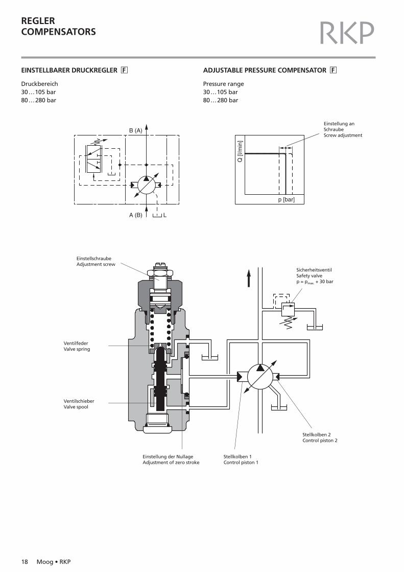
RKPEINSTELLBARER DRUCKREGLER �F ADJUSTABLE PRESSURE COMPENSATOR �F
Druckbereich30…105 bar80…280 bar
Pressure range30…105 bar80…280 bar
A (B) L
B (A)
p [bar]
Q [l
/min
]
Einstellung anSchraubeScrew adjustment
EinstellschraubeAdjustment screw
VentilfederValve spring
VentilschieberValve spool
Einstellung der NullageAdjustment of zero stroke
Stellkolben 1Control piston 1
Stellkolben 2Control piston 2
SicherheitsventilSafety valvep = pmax. + 30 bar
REGLERCOMPENSATORS
Moog • RKP 19
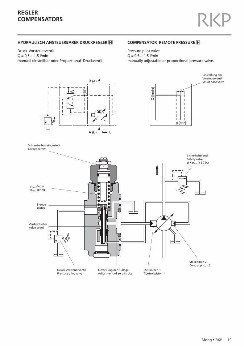
RKPHYDRAULISCH ANSTEUERBARER DRUCKREGLER �H COMPENSATOR REMOTE PRESSURE �H
Druck-VorsteuerventilQ = 0,5…1,5 l/min manuell einstellbar oder Proportional- Druckventil.
Pressure pilot valveQ = 0.5…1.5 l/min manually adjustable or proportional pressure valve.
A (B) L
B (A)
p [bar]
Q [l
/min
]
Einstellung am VorsteuerventilSet at pilot valve
Schraube fest eingestelltLocked screw
pmin.-Federpmin.-spring
BlendeOrifice
VentilschieberValve spool
Einstellung der NullageAdjustment of zero stroke
Druck-VorsteuerventilPressure pilot valve
Stellkolben 1Control piston 1
Stellkolben 2Control piston 2
SicherheitsventilSafety valvep = pmax. + 30 bar
REGLERCOMPENSATORS
20 Moog • RKP
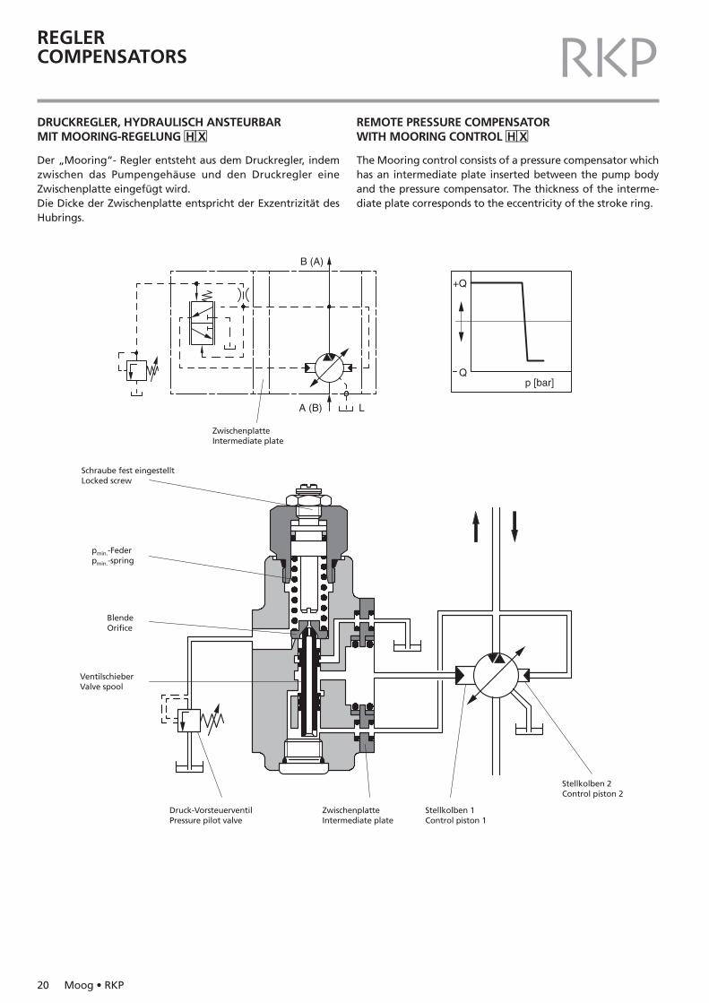
RKPDRUCKREGLER, HYDRAULISCH ANSTEURBARMIT MOORING-REGELUNG �H�X
REMOTE PRESSURE COMPENSATOR WITH MOORING CONTROL �H�X
Der „Mooring“- Regler entsteht aus dem Druckregler, indemzwischen das Pumpengehäuse und den Druckregler eine Zwischenplatte eingefügt wird.Die Dicke der Zwischenplatte entspricht der Exzentrizität desHubrings.
The Mooring control consists of a pressure compensator whichhas an intermediate plate inserted between the pump bodyand the pressure compensator. The thickness of the interme-diate plate corresponds to the eccentricity of the stroke ring.
B (A)
A (B) L
p [bar]
+Q
Q
ZwischenplatteIntermediate plate
Schraube fest eingestelltLocked screw
pmin.-Federpmin.-spring
BlendeOrifice
VentilschieberValve spool
ZwischenplatteIntermediate plate
Druck-VorsteuerventilPressure pilot valve
Stellkolben 1Control piston 1
Stellkolben 2Control piston 2
Moog • RKP 21
RKPREGLERCOMPENSATORS
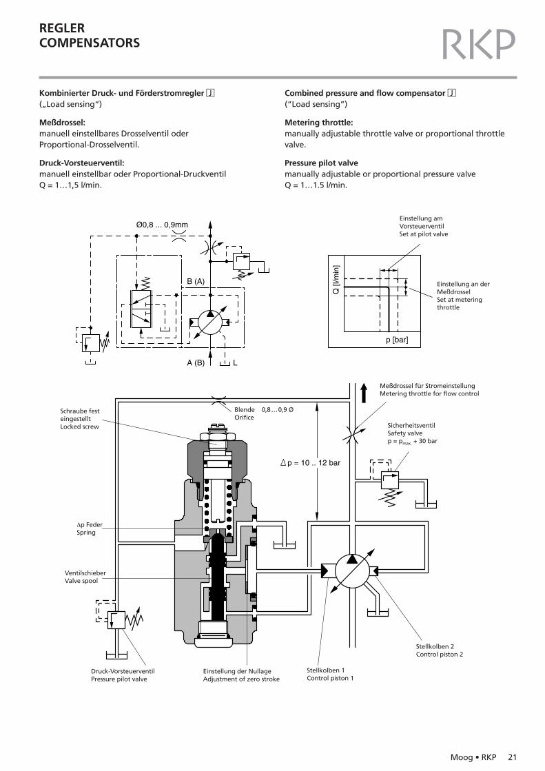
Kombinierter Druck- und Förderstromregler �J(„Load sensing“)
Meßdrossel:manuell einstellbares Drosselventil oderProportional-Drosselventil.
Druck-Vorsteuerventil:manuell einstellbar oder Proportional-DruckventilQ = 1…1,5 l/min.
Combined pressure and flow compensator �J(“Load sensing”)
Metering throttle:manually adjustable throttle valve or proportional throttlevalve.
Pressure pilot valvemanually adjustable or proportional pressure valveQ = 1…1.5 l/min.
p = 10 .. 12 bar
A (B) L
B (A)
p [bar]Q
[l/m
in]
Ø0,8 ... 0,9mmEinstellung amVorsteuerventilSet at pilot valve
Einstellung an derMeßdrosselSet at metering throttle
Schraube fest eingestelltLocked screw
∆p FederSpring
Blende 0,8…0,9 ØOrifice
Meßdrossel für StromeinstellungMetering throttle for flow control
SicherheitsventilSafety valvep = pmax. + 30 bar
VentilschieberValve spool
Einstellung der NullageAdjustment of zero stroke
Druck-VorsteuerventilPressure pilot valve
Stellkolben 1Control piston 1
Stellkolben 2Control piston 2
22 Moog • RKP
RKPREGLERCOMPENSATORS
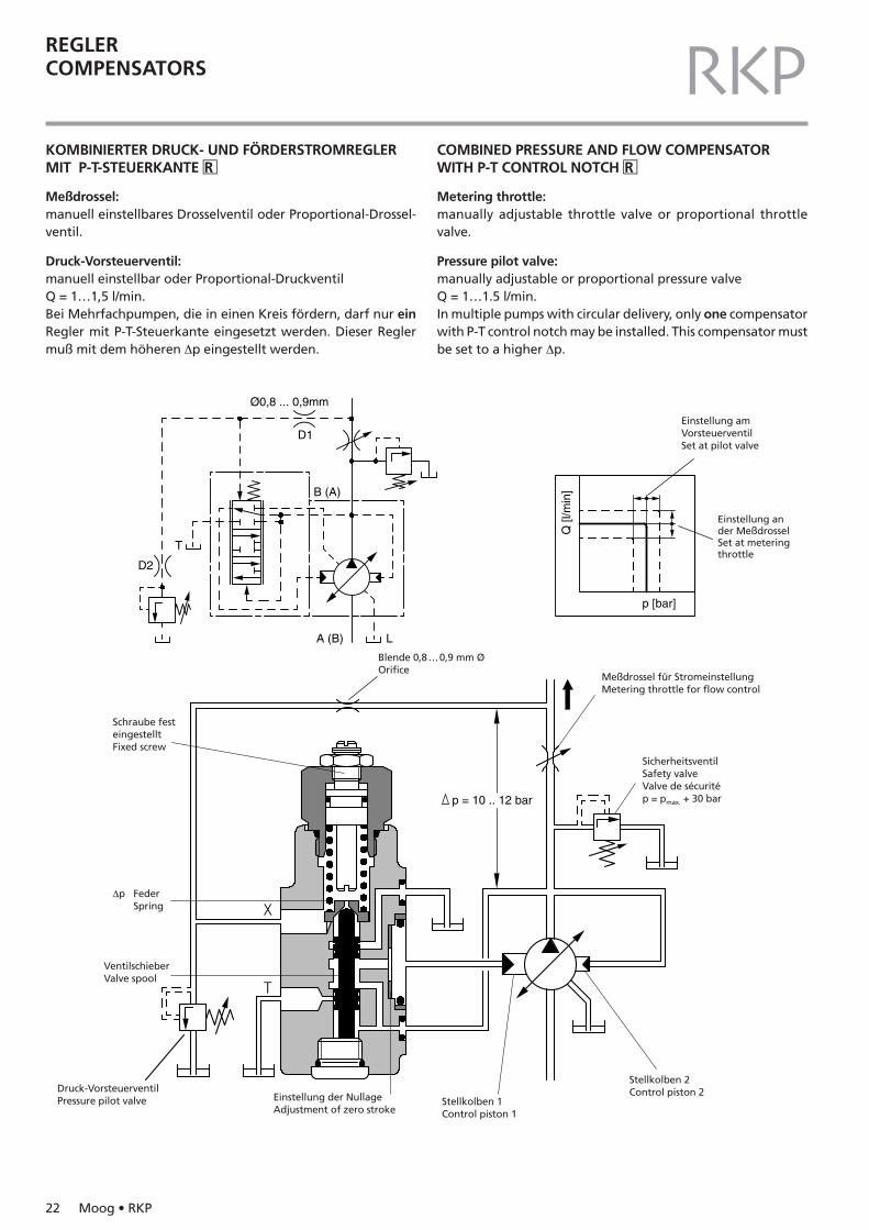
KOMBINIERTER DRUCK- UND FÖRDERSTROMREGLERMIT P-T-STEUERKANTE �R
COMBINED PRESSURE AND FLOW COMPENSATORWITH P-T CONTROL NOTCH �R
Meßdrossel:manuell einstellbares Drosselventil oder Proportional-Drossel-ventil.
Druck-Vorsteuerventil:manuell einstellbar oder Proportional-DruckventilQ = 1…1,5 l/min.Bei Mehrfachpumpen, die in einen Kreis fördern, darf nur einRegler mit P-T-Steuerkante eingesetzt werden. Dieser Reglermuß mit dem höheren ∆p eingestellt werden.
Metering throttle:manually adjustable throttle valve or proportional throttle valve.
Pressure pilot valve:manually adjustable or proportional pressure valve Q = 1…1.5 l/min.In multiple pumps with circular delivery, only one compensatorwith P-T control notch may be installed. This compensator mustbe set to a higher ∆p.
A (B) L
B (A)
D1
D2
p = 10 .. 12 bar
p [bar]
Q [l
/min
]
Ø0,8 ... 0,9mm
T
Einstellung amVorsteuerventilSet at pilot valve
Einstellung an der MeßdrosselSet at meteringthrottle
Schraube fest eingestelltFixed screw
∆p FederSpring
Blende 0,8…0,9 mm ØOrifice
Meßdrossel für StromeinstellungMetering throttle for flow control
SicherheitsventilSafety valveValve de sécuritép = pmax. + 30 bar
VentilschieberValve spool
Einstellung der NullageAdjustment of zero stroke
Druck-VorsteuerventilPressure pilot valve Stellkolben 1
Control piston 1
Stellkolben 2Control piston 2
Moog • RKP 23
RKPREGLERCOMPENSATORS
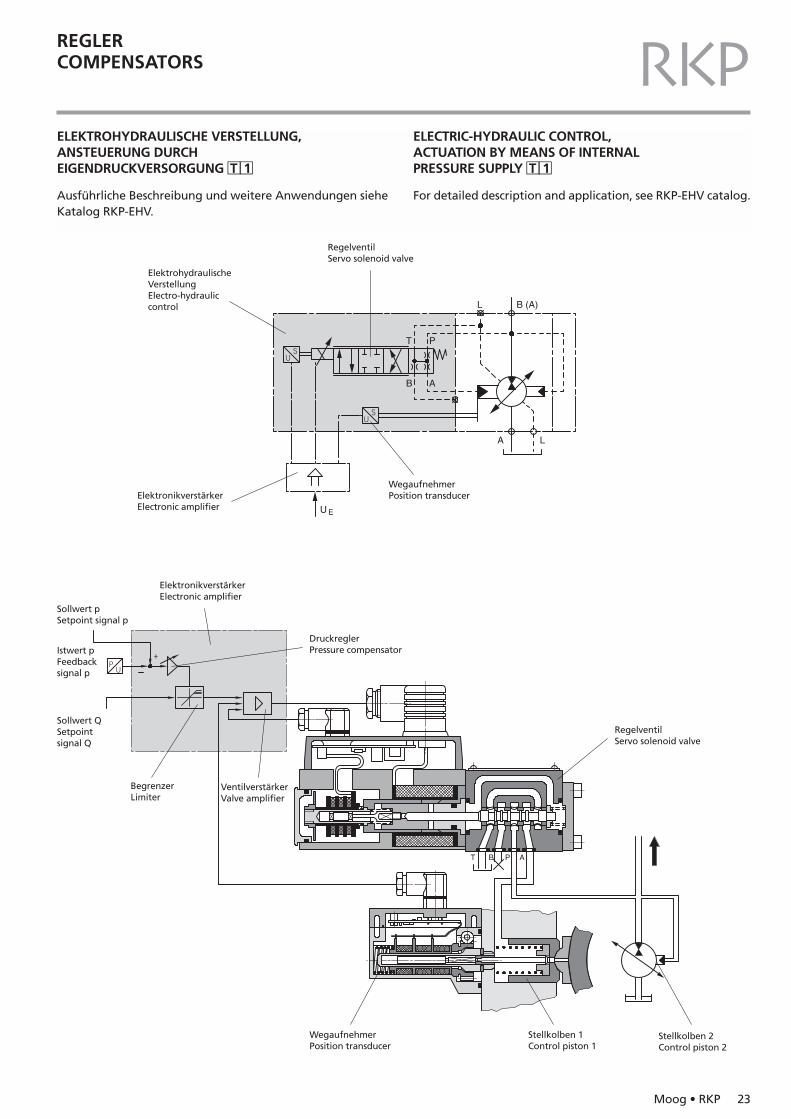
ELEKTROHYDRAULISCHE VERSTELLUNG,ANSTEUERUNG DURCH EIGENDRUCKVERSORGUNG �T �1
Ausführliche Beschreibung und weitere Anwendungen sieheKatalog RKP-EHV.
ELECTRIC-HYDRAULIC CONTROL, ACTUATION BY MEANS OF INTERNAL PRESSURE SUPPLY �T �1
For detailed description and application, see RKP-EHV catalog.
B (A)L
U E
A L
AB
T P
T PB A
ElektrohydraulischeVerstellungElectro-hydrauliccontrol
RegelventilServo solenoid valve
ElektronikverstärkerElectronic amplifier
ElektronikverstärkerElectronic amplifier
Sollwert pSetpoint signal p
Istwert pFeedbacksignal p
Sollwert QSetpointsignal Q
BegrenzerLimiter
VentilverstärkerValve amplifier
DruckreglerPressure compensator
RegelventilServo solenoid valve
WegaufnehmerPosition transducer
Stellkolben 1Control piston 1
Stellkolben 2Control piston 2
WegaufnehmerPosition transducer
24 Moog • RKP
RKPREGLERCOMPENSATORS
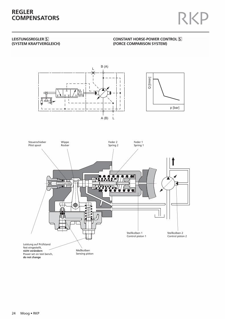
LEISTUNGSREGLER �S(SYSTEM KRAFTVERGLEICH)
CONSTANT HORSE-POWER CONTROL �S(FORCE COMPARISON SYSTEM)
A (B) L
LB (A)
p [bar]
Q [l
/min
]
WippeRocker
SteuerschieberPilot spool
MeßkolbenSensing piston
Stellkolben 1Control piston 1
Stellkolben 2Control piston 2
Leistung auf Prüfstandfest eingestellt,nicht verändernPower set on test bench,do not change
Feder 2Spring 2
Feder 1Spring 1
Moog • RKP 25
RKP
00
100 200 300p [bar]
Q [l
/min
]
n N = 1450min -1
50
0
40
30
20
10
0100 200 300
p [bar]
Q [l
/min
]n N = 1450min -1
00
100 200 300p [bar]
Q [l
/min
]
n N = 1450min -1
100
80
60
40
20
50
100
125
150
75
25
REGLERCOMPENSATORS
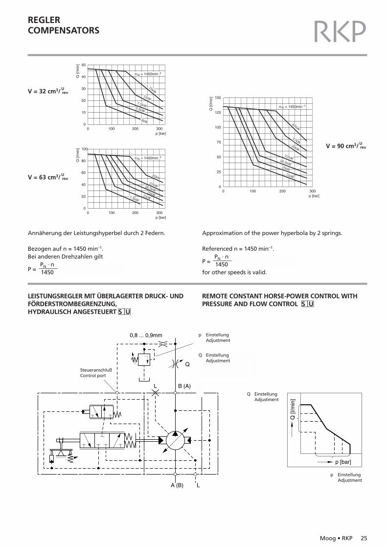
V = 32 cm3/Urev
V = 90 cm3/Urev
V = 63 cm3/Urev
Annäherung der Leistungshyperbel durch 2 Federn.
Bezogen auf n = 1450 min–1.Bei anderen Drehzahlen gilt
PN · nP = 1450
Approximation of the power hyperbola by 2 springs.
Referenced n = 1450 min–1.PN · n
P = 1450for other speeds is valid.
0,8 ... 0,9mm
B (A)
A (B) L
L
Q
p [bar]
Q [l
/min
]
p EinstellungAdjustment
p EinstellungAdjustment
Q EinstellungAdjustment
Q EinstellungAdjustment
SteueranschlußControl port
LEISTUNGSREGLER MIT ÜBERLAGERTER DRUCK- UNDFÖRDERSTROMBEGRENZUNG,HYDRAULISCH ANGESTEUERT �S �U
REMOTE CONSTANT HORSE-POWER CONTROL WITHPRESSURE AND FLOW CONTROL �S �U

26 Moog • RKP
RKPSERVOSTEUERUNG �C(offener Kreis)
Manuelle oder mechanische Betätigung über Verstellhebel.Das Fördervolumen der Pumpe wird über die Position desVerstellhebels gesteuert.
SERVO CONTROL �C(open circuit)
Actuated manually or mechanically by means of a lever. Thepump displacement is controlled by the position of the lever.
B (A)
A (B)L
e [mm]
Q [l
/min
]
Verstellhebelfür SteuerwelleLever for control shaft Stellkolben 1
Control piston 1
SchieberhülseSpool sleeve
SteuerschieberPilot spool
HubringStroke ring
Stellkolben 2Control piston 2
GleitsteinSlipper pad
REGLERCOMPENSATORS
V [cm3/ ]
1932, 4563, 80100
VerstellmomentControl torqueNullstellungNeutral position1,2 Nm1,2 Nm1,6 Nm1,6 Nm
EndstellungFinal position1,7 Nm1,7 Nm2,4 Nm2,5 Nm
max. zulässigmax. permissible8 Nm8 Nm8 Nm8 Nm
Urev
Moog • RKP 27
RKPREGLERCOMPENSATORS
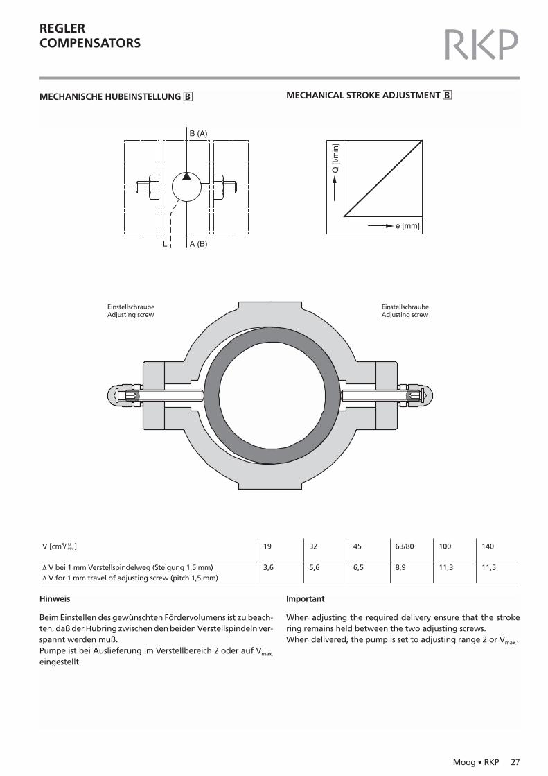
MECHANISCHE HUBEINSTELLUNG �B MECHANICAL STROKE ADJUSTMENT �B
B (A)
A (B)L
e [mm]
Q [l
/min
]
EinstellschraubeAdjusting screw
EinstellschraubeAdjusting screw
Hinweis
Beim Einstellen des gewünschten Fördervolumens ist zu beach-ten, daß der Hubring zwischen den beiden Verstellspindeln ver-spannt werden muß.Pumpe ist bei Auslieferung im Verstellbereich 2 oder auf Vmax.
eingestellt.
Important
When adjusting the required delivery ensure that the strokering remains held between the two adjusting screws.When delivered, the pump is set to adjusting range 2 or Vmax..
V [cm3/ ]
∆ V bei 1 mm Verstellspindelweg (Steigung 1,5 mm)∆ V for 1 mm travel of adjusting screw (pitch 1,5 mm)
19
3,6
32
5,6
45
6,5
63/80
8,9
100
11,3
140
11,5
Urev
28 Moog • RKP
RKP
Durchtrieb schwer leichtHeavy-duty through-drive Light-duty
Pumpenstufe 1 Pumpenstufe 2Pump stage 1 Pump stage 2
RKP RKP ZGS ZFSBaugröße 19 32 63 140 32 4…22,5 4…22,5Size (cm3/ ) 45 80 45
90100
19 90 Nm – – – – 65 Nm –32/45 185 Nm 185 Nm – – 185 Nm 65 Nm 30 Nm63/80/90/100 400 Nm 400 Nm 400 Nm – 300 Nm – 53 Nm140 400 Nm 400 Nm 400 Nm 620 Nm 300 Nm – 65 Nm
MEHRFACHTECHNIKMULTIPLE ARRANGEMENTS
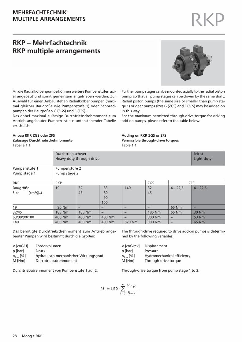
An die Radialkolbenpumpe können weitere Pumpenstufen axi-al angebaut und somit gemeinsam angetrieben werden. ZurAuswahl für einen Anbau stehen Radialkolbenpumpen (maxi-mal gleicher Baugröße wie Pumpenstufe 1) oder Zahnrad-pumpen der Baugrößen G (ZGS) und F (ZFS).Das dabei maximal zulässige Durchtriebsdrehmoment zumAntrieb angebauter Pumpen ist aus untenstehender Tabelleersichtlich.
Anbau RKP, ZGS oder ZFSZulässige DurchtriebsdrehmomenteTabelle 1.1
Further pump stages can be mounted axially to the radial pistonpump, so that all pump stages can be driven by the same shaft.Radial piston pumps (the same size or smaller than pump sta-ge 1) or gear pumps sizes G (ZGS) and F (ZFS) may be added onin this way.For the maximum permitted through-drive torque for drivingadd-on pumps, please refer to the table below.
Adding on RKP, ZGS or ZFSPermissible through-drive torquesTable 1.1
RKP – MehrfachtechnikRKP multiple arrangements
Das benötigte Durchtriebsdrehmoment zum Antrieb ange-bauter Pumpen wird bestimmt durch die Größen:
V [cm3/U] Fördervolumenp [bar] Druckηhm [%] hydraulisch-mechanischer Wirkungsgrad M [Nm] Durchtriebsdrehmoment
Durchtriebsdrehmoment von Pumpenstufe 1 auf 2:
The through-drive required to drive add-on pumps is determi-ned by the following variables:
V [cm3/rev] Displacementp [bar] Pressureηhm [%] Hydromechanical efficiencyM [Nm] Through-drive torque
Through-drive torque from pump stage 1 to 2:
n Vi · piM1 = 1,59 · Σi = 2 ηhmi
Urev
Moog • RKP 29
RKPMEHRFACHTECHNIKMULTIPLE ARRANGEMENTS
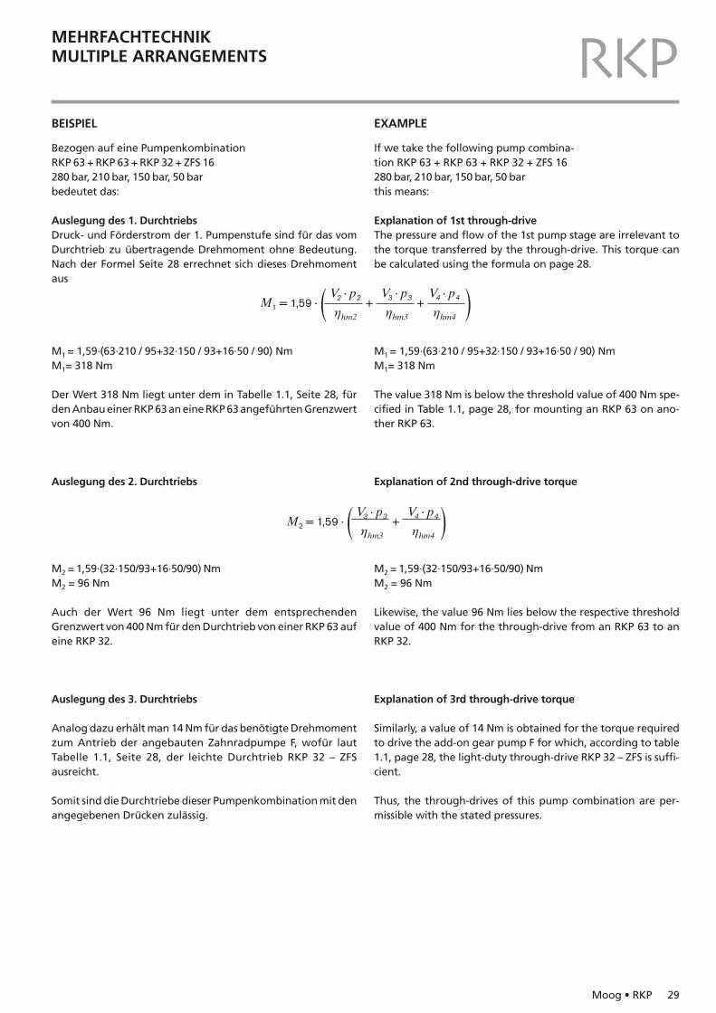
BEISPIEL
Bezogen auf eine PumpenkombinationRKP 63 + RKP 63 + RKP 32 + ZFS 16280 bar, 210 bar, 150 bar, 50 barbedeutet das:
Auslegung des 1. DurchtriebsDruck- und Förderstrom der 1. Pumpenstufe sind für das vomDurchtrieb zu übertragende Drehmoment ohne Bedeutung.Nach der Formel Seite 28 errechnet sich dieses Drehmoment aus
M1 = 1,59·(63·210 / 95+32·150 / 93+16·50 / 90) NmM1= 318 Nm
Der Wert 318 Nm liegt unter dem in Tabelle 1.1, Seite 28, fürden Anbau einer RKP 63 an eine RKP 63 angeführten Grenzwertvon 400 Nm.
Auslegung des 2. Durchtriebs
M2 = 1,59·(32·150/93+16·50/90) NmM2 = 96 Nm
Auch der Wert 96 Nm liegt unter dem entsprechendenGrenzwert von 400 Nm für den Durchtrieb von einer RKP 63 aufeine RKP 32.
Auslegung des 3. Durchtriebs
Analog dazu erhält man 14 Nm für das benötigte Drehmomentzum Antrieb der angebauten Zahnradpumpe F, wofür lautTabelle 1.1, Seite 28, der leichte Durchtrieb RKP 32 – ZFSausreicht.
Somit sind die Durchtriebe dieser Pumpenkombination mit denangegebenen Drücken zulässig.
EXAMPLE
If we take the following pump combina-tion RKP 63 + RKP 63 + RKP 32 + ZFS 16280 bar, 210 bar, 150 bar, 50 bar this means:
Explanation of 1st through-driveThe pressure and flow of the 1st pump stage are irrelevant tothe torque transferred by the through-drive. This torque canbe calculated using the formula on page 28.
M1 = 1,59·(63·210 / 95+32·150 / 93+16·50 / 90) NmM1= 318 Nm
The value 318 Nm is below the threshold value of 400 Nm spe-cified in Table 1.1, page 28, for mounting an RKP 63 on ano-ther RKP 63.
Explanation of 2nd through-drive torque
M2 = 1,59·(32·150/93+16·50/90) NmM2 = 96 Nm
Likewise, the value 96 Nm lies below the respective thresholdvalue of 400 Nm for the through-drive from an RKP 63 to anRKP 32.
Explanation of 3rd through-drive torque
Similarly, a value of 14 Nm is obtained for the torque requiredto drive the add-on gear pump F for which, according to table1.1, page 28, the light-duty through-drive RKP 32 – ZFS is suffi-cient.
Thus, the through-drives of this pump combination are per-missible with the stated pressures.
V2 · p2 V3 · p3 V4 · p4M1 = 1,59 · ( + + )ηhm2 ηhm3 ηhm4
V3 · p3 V4 · p4M2 = 1,59 · ( + )ηhm3 ηhm4
30 Moog • RKP
RKPMEHRFACHTECHNIKMULTIPLE ARRANGEMENTS
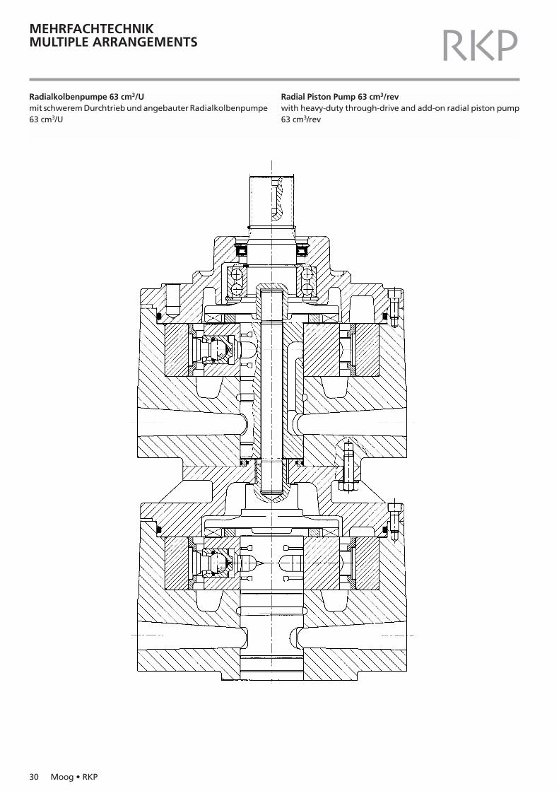
Radialkolbenpumpe 63 cm3/Umit schwerem Durchtrieb und angebauter Radialkolbenpumpe63 cm3/U
Radial Piston Pump 63 cm3/revwith heavy-duty through-drive and add-on radial piston pump63 cm3/rev
Moog • RKP 31
RKPMEHRFACHTECHNIKMULTIPLE ARRANGEMENTS
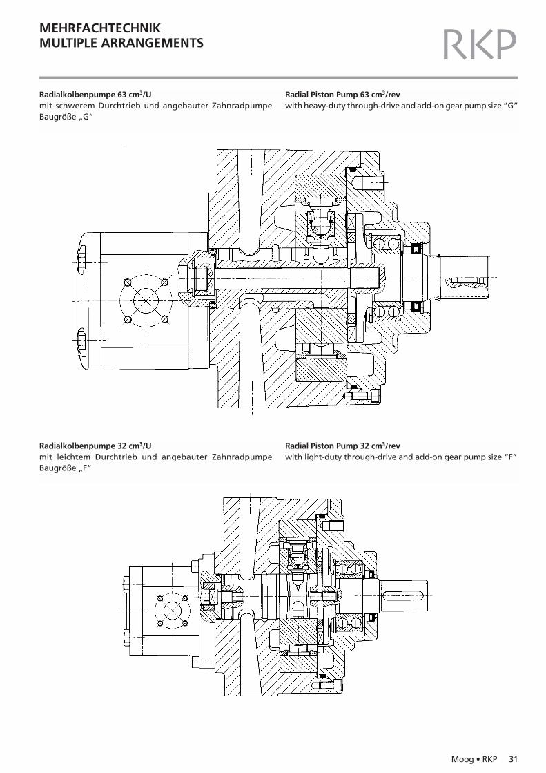
Radialkolbenpumpe 63 cm3/Umit schwerem Durchtrieb und angebauter ZahnradpumpeBaugröße „G“
Radial Piston Pump 63 cm3/revwith heavy-duty through-drive and add-on gear pump size “G”
Radialkolbenpumpe 32 cm3/Umit leichtem Durchtrieb und angebauter ZahnradpumpeBaugröße „F“
Radial Piston Pump 32 cm3/revwith light-duty through-drive and add-on gear pump size “F”
32 Moog • RKP
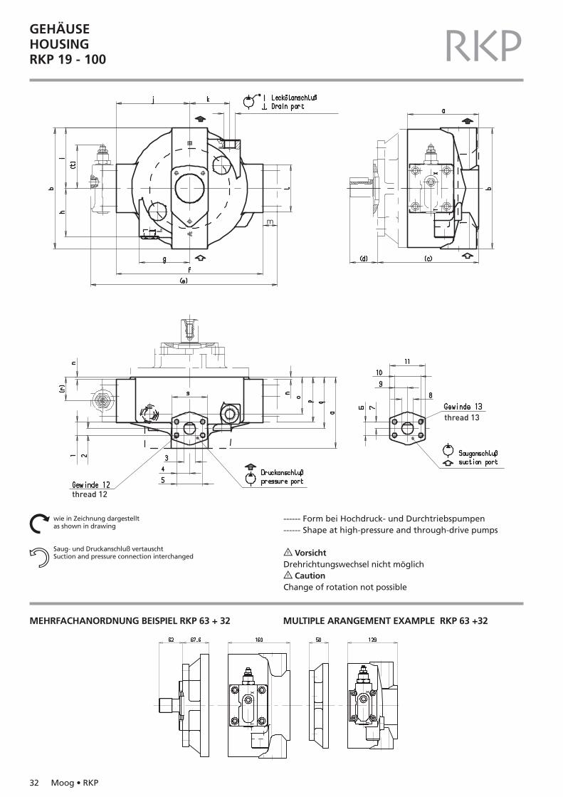
GEHÄUSEHOUSINGRKP 19 - 100 RKP
thread 12
thread 13
m
wie in Zeichnung dargestelltas shown in drawing
Saug- und Druckanschluß vertauschtSuction and pressure connection interchanged
Nn
MEHRFACHANORDNUNG BEISPIEL RKP 63 + 32 MULTIPLE ARANGEMENT EXAMPLE RKP 63 +32
------ Form bei Hochdruck- und Durchtriebspumpen------ Shape at high-pressure and through-drive pumps
? VorsichtDrehrichtungswechsel nicht möglich? CautionChange of rotation not possible
Moog • RKP 33
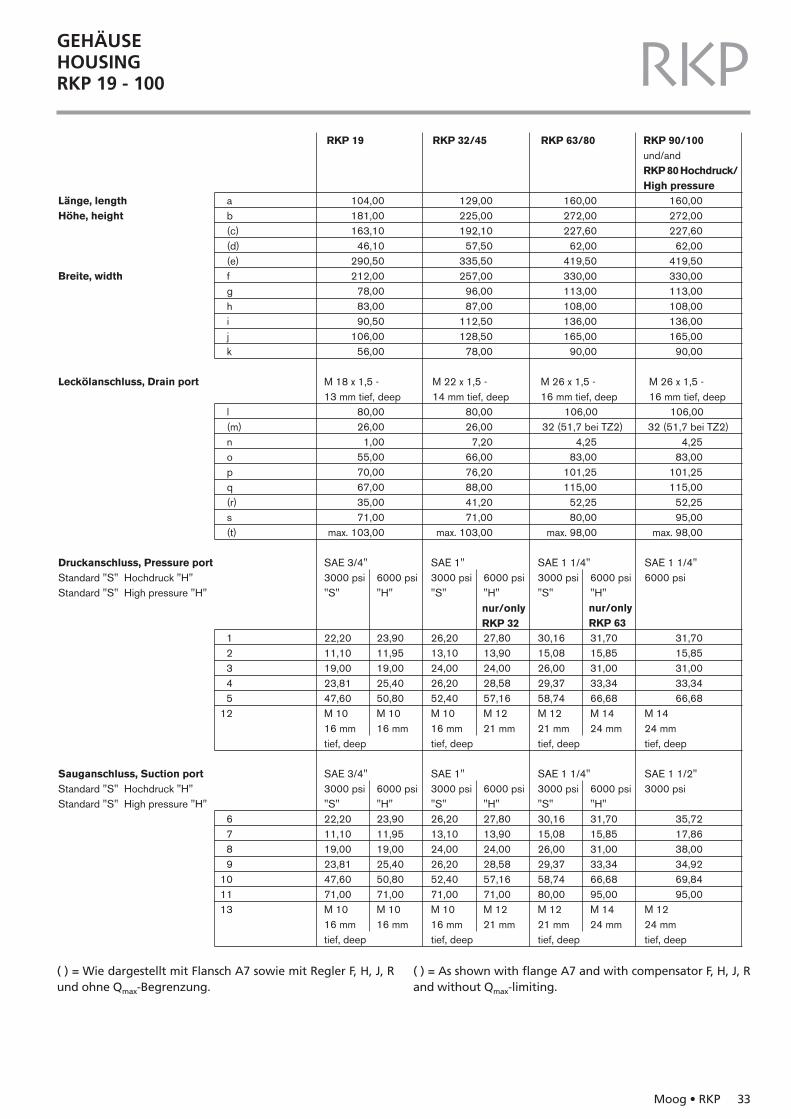
GEHÄUSEHOUSINGRKP 19 - 100 RKP
104,00181,00163,10
46,10290,50212,00
78,0083,0090,50
106,0056,00
ab(c)(d)(e)fghijk
l(m)nopq(r)s(t)
12345
12
6 7 8 9
10 11 13
RKP 19
Länge, lengthHöhe, height
Breite, width
Leckölanschluss, Drain port
Druckanschluss, Pressure portStandard "S" Hochdruck "H"Standard "S" High pressure "H"
Sauganschluss, Suction portStandard "S" Hochdruck "H"Standard "S" High pressure "H"
129,00225,00192,10
57,50335,50257,00
96,0087,00
112,50128,50
78,00
RKP 32/45
160,00272,00227,60
62,00419,50330,00113,00108,00136,00165,00
90,00
RKP 63/80
nur/onlyRKP 32
nur/onlyRKP 63
160,00 272,00 227,60
62,00 419,50 330,00 113,00 108,00 136,00 165,00
90,00
80,00 26,00
1,00 55,00 70,00 67,00 35,00 71,00
max. 103,00
80,00 26,00
7,20 66,00 76,20 88,00 41,20 71,00
max. 103,00
106,00 32 (51,7 bei TZ2)
4,25 83,00
101,25 115,00
52,25 80,00
max. 98,00
106,00 32 (51,7 bei TZ2)
4,25 83,00
101,25 115,00
52,25 95,00
max. 98,00
M 18 x 1,5 -13 mm tief, deep
M 22 x 1,5 -14 mm tief, deep
M 26 x 1,5 -16 mm tief, deep
M 26 x 1,5 -16 mm tief, deep
SAE 3/4"3000 psi 6000 psi"S" "H"
22,20 23,90 11,10 11,9519,00 19,00 23,81 25,40 47,60 50,80 M 10 M 1016 mm 16 mmtief, deep
RKP 90/100und/andRKP 80 Hochdruck/High pressure
SAE 1"3000 psi 6000 psi"S" "H"
26,20 27,80 13,10 13,90 24,00 24,00 26,20 28,58 52,40 57,16M 10 M 1216 mm 21 mmtief, deep
SAE 1 1/4"3000 psi 6000 psi"S" "H"
30,16 31,70 15,08 15,85 26,00 31,00 29,37 33,34 58,74 66,68M 12 M 1421 mm 24 mmtief, deep
SAE 1 1/4"6000 psi
M 1424 mmtief, deep
31,70 15,85 31,00 33,34 66,68
SAE 3/4"3000 psi 6000 psi"S" "H"22,20 23,90 11,10 11,95 19,00 19,00 23,81 25,40 47,60 50,8071,00 71,00 M 10 M 1016 mm 16 mmtief, deep
SAE 1"3000 psi 6000 psi"S" "H"26,20 27,80 13,10 13,90 24,00 24,00 26,20 28,58 52,40 57,1671,00 71,00M 10 M 1216 mm 21 mmtief, deep
SAE 1 1/4"3000 psi 6000 psi"S" "H"30,16 31,70 15,08 15,85 26,00 31,00 29,37 33,34 58,74 66,6880,00 95,00M 12 M 1421 mm 24 mmtief, deep
SAE 1 1/2"3000 psi
M 1224 mmtief, deep
35,7217,8638,0034,9269,8495,00
( ) = Wie dargestellt mit Flansch A7 sowie mit Regler F, H, J, Rund ohne Qmax-Begrenzung.
( ) = As shown with flange A7 and with compensator F, H, J, Rand without Qmax-limiting.
34 Moog • RKP
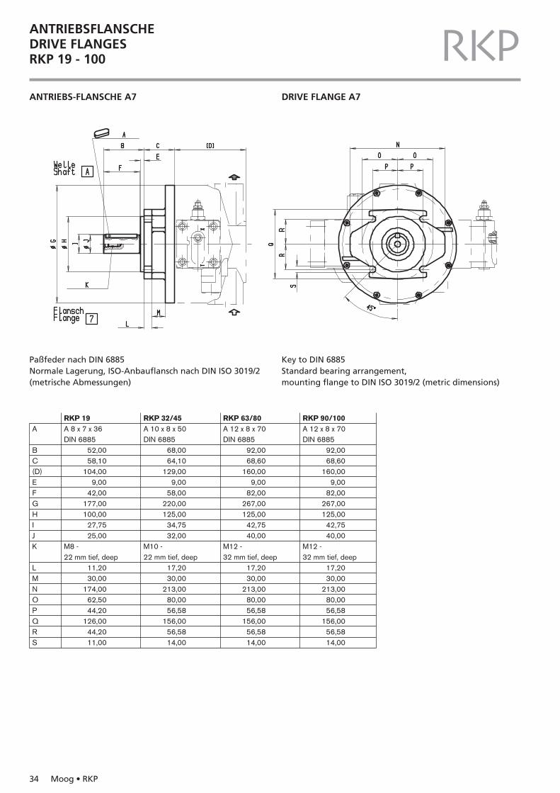
ANTRIEBSFLANSCHEDRIVE FLANGESRKP 19 - 100 RKPANTRIEBS-FLANSCHE A7 DRIVE FLANGE A7
Paßfeder nach DIN 6885Normale Lagerung, ISO-Anbauflansch nach DIN ISO 3019/2(metrische Abmessungen)
Key to DIN 6885Standard bearing arrangement, mounting flange to DIN ISO 3019/2 (metric dimensions)
A
BC(D)EFGHIJK
LMNOPQR S
RKP 19A 8 x 7 x 36DIN 6885
52,0058,10
104,009,00
42,00177,00100,00
27,7525,00
M8 -22 mm tief, deep
A 10 x 8 x 50DIN 6885
68,0064,10
129,009,00
58,00220,00125,00
34,7532,00
M10 -22 mm tief, deep
A 12 x 8 x 70DIN 6885
92,0068,60
160,009,00
82,00267,00125,00
42,7540,00
M12 -32 mm tief, deep
A 12 x 8 x 70DIN 6885
92,0068,60
160,009,00
82,00267,00125,00
42,7540,00
11,2030,00
174,0062,5044,20
126,0044,2011,00
17,2030,00
213,0080,0056,58
156,0056,5814,00
17,2030,00
213,0080,0056,58
156,0056,5814,00
17,2030,00
213,0080,0056,58
156,0056,5814,00
M12 -32 mm tief, deep
RKP 32/45 RKP 63/80 RKP 90/100
Moog • RKP 35
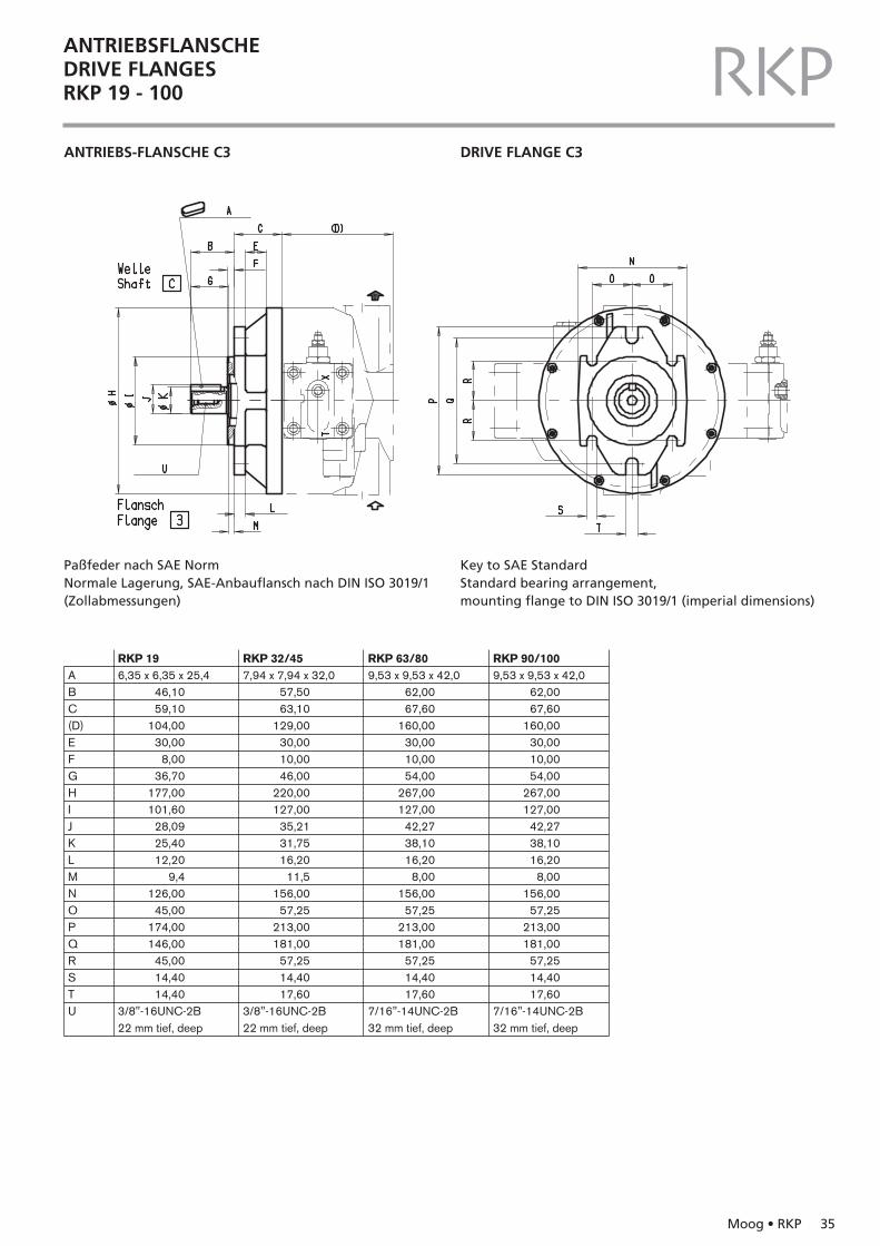
ANTRIEBSFLANSCHEDRIVE FLANGESRKP 19 - 100 RKPANTRIEBS-FLANSCHE C3 DRIVE FLANGE C3
Paßfeder nach SAE NormNormale Lagerung, SAE-Anbauflansch nach DIN ISO 3019/1(Zollabmessungen)
Key to SAE StandardStandard bearing arrangement, mounting flange to DIN ISO 3019/1 (imperial dimensions)
ABC(D)EFGHIJKLMNOPQRSTU
RKP 196,35 x 6,35 x 25,4
46,1059,10
104,0030,00
8,0036,70
177,00101,60
28,0925,4012,20
9,4126,00
45,00174,00146,00
45,0014,4014,40
3/8"-16UNC-2B22 mm tief, deep
7,94 x 7,94 x 32,057,5063,10
129,0030,0010,0046,00
220,00127,00
35,2131,7516,20
11,5156,00
57,25213,00181,00
57,2514,4017,60
3/8"-16UNC-2B22 mm tief, deep
9,53 x 9,53 x 42,062,0067,60
160,0030,0010,0054,00
267,00127,00
42,2738,1016,20
8,00156,00
57,25213,00181,00
57,2514,4017,60
7/16"-14UNC-2B32 mm tief, deep
9,53 x 9,53 x 42,062,0067,60
160,0030,0010,0054,00
267,00127,00
42,2738,1016,20
8,00156,00
57,25213,00181,00
57,2514,4017,60
7/16"-14UNC-2B32 mm tief, deep
RKP 32/45 RKP 63/80 RKP 90/100
36 Moog • RKP
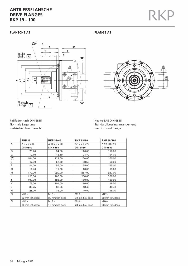
ANTRIEBSFLANSCHEDRIVE FLANGESRKP 19 - 100 RKPFLANSCHE A1 FLANGE A1
Paßfeder nach DIN 6885Normale Lagerung, metrischer Rundflansch
Key to SAE DIN 6885Standard bearing arrangement, metric round flange
A
BC(D)EFGHIJKLMN
O
RKP 19A 8 x 7 x 36DIN 6885
70,7017,10
104,0042,9041,2011,40
177,00125,00100,00
79,0030,7528,00
M10 -22 mm tief, deep
A 10 x 8 x 50DIN 6885
94,5018,10
129,0057,5055,0011,00
220,00160,00125,00101,00
37,8535,00
M10 -22 mm tief, deep
A 12 x 8 x 70DIN 6885
116,0024,70
160,0068,5065,0013,00
267,00200,00160,00116,00
48,4045,00
M12 -32 mm tief, deep
A 12 x 8 x 70DIN 6885
116,0024,70
160,0068,5065,0013,00
267,00200,00160,00116,00
48,4045,00
M12 -32 mm tief, deep
M10 -15 mm tief, deep
M12 -16 mm tief, deep
M16 -23 mm tief, deep
M16 -23 mm tief, deep
RKP 32/45 RKP 63/80 RKP 90/100
Moog • RKP 37
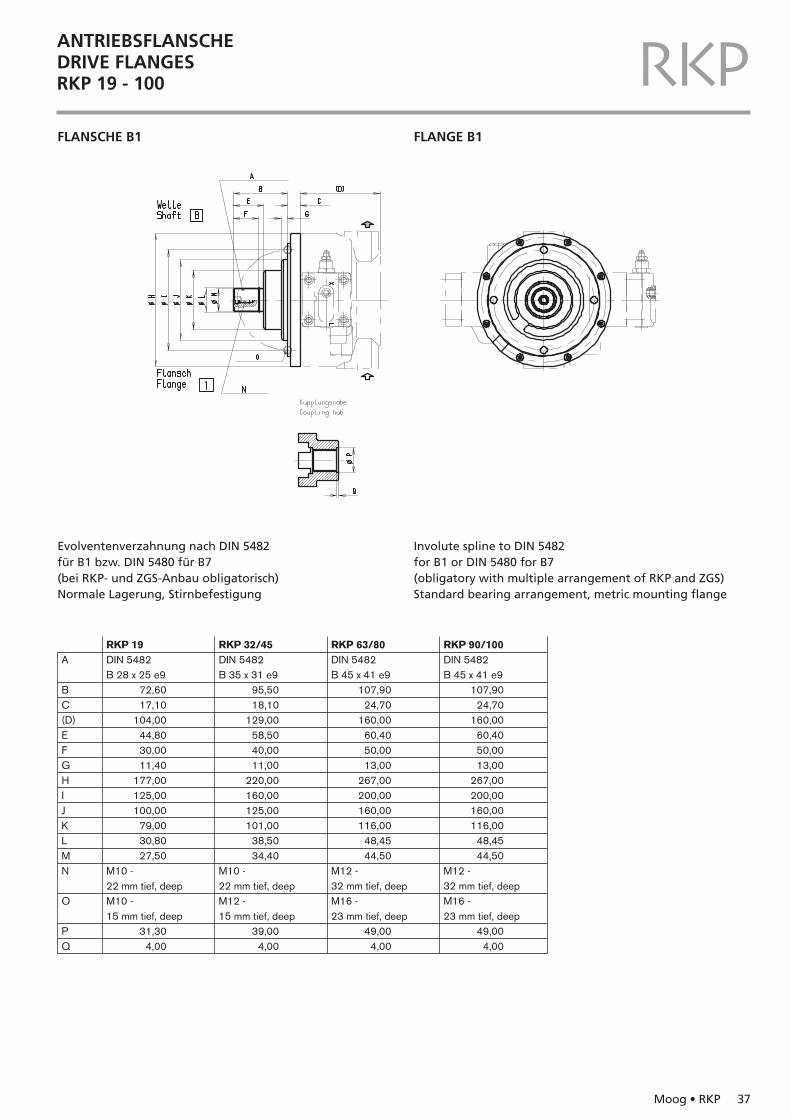
ANTRIEBSFLANSCHEDRIVE FLANGESRKP 19 - 100 RKPFLANSCHE B1 FLANGE B1
Evolventenverzahnung nach DIN 5482für B1 bzw. DIN 5480 für B7(bei RKP- und ZGS-Anbau obligatorisch)Normale Lagerung, Stirnbefestigung
Involute spline to DIN 5482for B1 or DIN 5480 for B7 (obligatory with multiple arrangement of RKP and ZGS)Standard bearing arrangement, metric mounting flange
A
BC(D)EFGHIJKLMN
O
PQ
RKP 19DIN 5482B 28 x 25 e9
72,6017,10
104,0044,8030,0011,40
177,00125,00100,00
79,0030,8027,50
M10 -22 mm tief, deep
DIN 5482B 35 x 31 e9
95,5018,10
129,0058,5040,0011,00
220,00160,00125,00101,00
38,5034,40
M10 -22 mm tief, deep
DIN 5482B 45 x 41 e9
107,9024,70
160,0060,4050,0013,00
267,00200,00160,00116,00
48,4544,50
M12 -32 mm tief, deep
DIN 5482B 45 x 41 e9
107,9024,70
160,0060,4050,0013,00
267,00200,00160,00116,00
48,4544,50
31,304,00
39,004,00
49,004,00
49,004,00
M12 -32 mm tief, deep
M10 -15 mm tief, deep
M12 -15 mm tief, deep
M16 -23 mm tief, deep
M16 -23 mm tief, deep
RKP 32/45 RKP 63/80 RKP 90/100
38 Moog • RKP
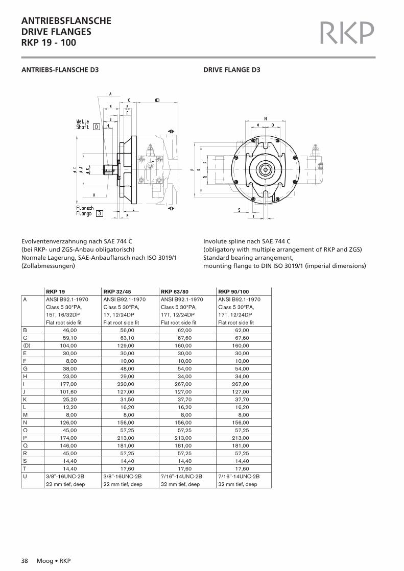
ANTRIEBSFLANSCHEDRIVE FLANGESRKP 19 - 100 RKPANTRIEBS-FLANSCHE D3 DRIVE FLANGE D3
Evolventenverzahnung nach SAE 744 C(bei RKP- und ZGS-Anbau obligatorisch)Normale Lagerung, SAE-Anbauflansch nach ISO 3019/1(Zollabmessungen)
Involute spline nach SAE 744 C(obligatory with multiple arrangement of RKP and ZGS)Standard bearing arrangement,mounting flange to DIN ISO 3019/1 (imperial dimensions)
A
BC(D)EFGHIJKLMNOPQRSTU
RKP 19ANSI B92.1-1970Class 5 30°PA,15T, 16/32DPFlat root side fit
46,0059,10
104,0030,00
8,0038,0023,00
177,00101,60
25,2012,20
8,00126,00
45,00174,00146,00
45,0014,4014,40
3/8"-16UNC-2B22 mm tief, deep
ANSI B92.1-1970Class 5 30°PA,17, 12/24DPFlat root side fit
56,0063,10
129,0030,0010,0048,0029,00
220,00127,00
31,5016,20
8,00156,00
57,25213,00181,00
57,2514,4017,60
3/8"-16UNC-2B22 mm tief, deep
ANSI B92.1-1970Class 5 30°PA,17T, 12/24DPFlat root side fit
62,0067,60
160,0030,0010,0054,0034,00
267,00127,00
37,7016,20
8,00156,00
57,25213,00181,00
57,2514,4017,60
7/16"-14UNC-2B32 mm tief, deep
ANSI B92.1-1970Class 5 30°PA,17T, 12/24DPFlat root side fit
62,0067,60
160,0030,0010,0054,0034,00
267,00127,00
37,7016,20
8,00156,00
57,25213,00181,00
57,2514,4017,60
7/16"-14UNC-2B32 mm tief, deep
RKP 32/45 RKP 63/80 RKP 90/100
Moog • RKP 39
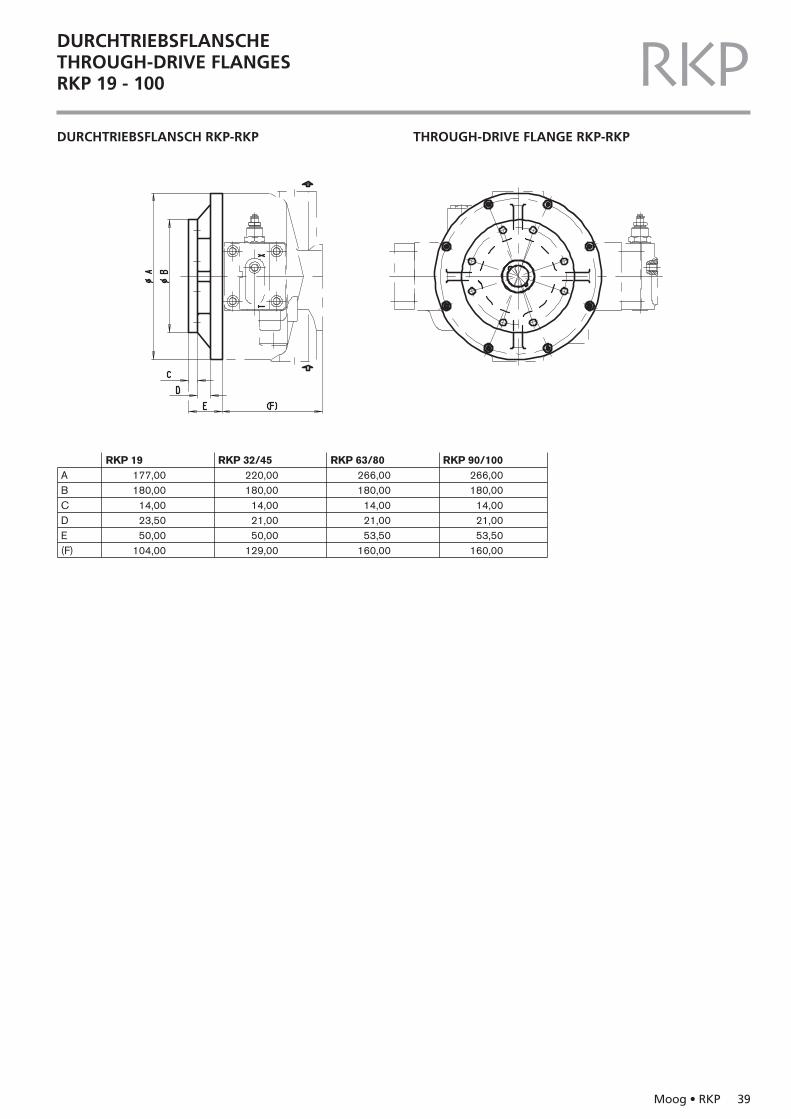
DURCHTRIEBSFLANSCHETHROUGH-DRIVE FLANGESRKP 19 - 100 RKPDURCHTRIEBSFLANSCH RKP-RKP THROUGH-DRIVE FLANGE RKP-RKP
ABCDE(F)
RKP 19177,00180,00
14,0023,5050,00
104,00
220,00180,00
14,0021,0050,00
129,00
266,00180,00
14,0021,0053,50
160,00
266,00180,00
14,0021,0053,50
160,00
RKP 32/45 RKP 63/80 RKP 90/100
40 Moog • RKP
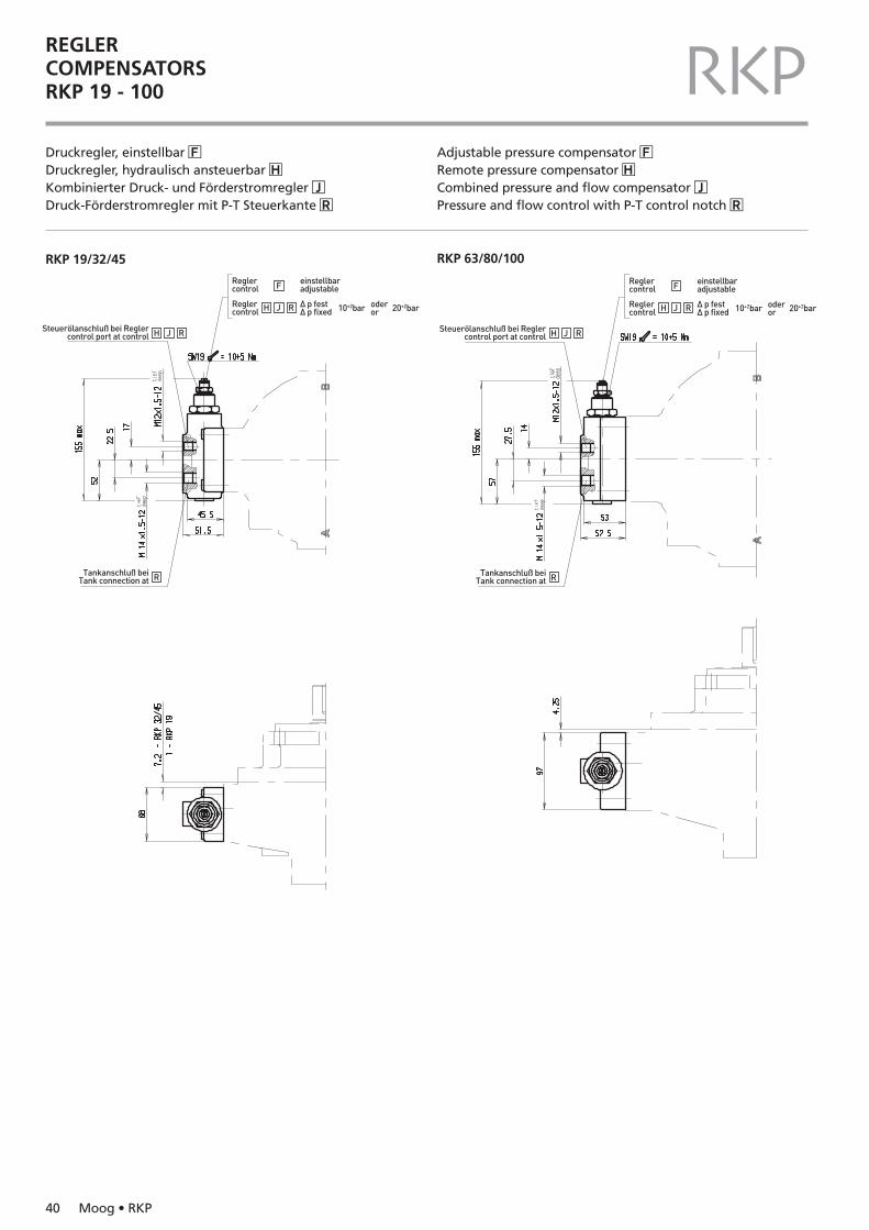
REGLERCOMPENSATORSRKP 19 - 100 RKPDruckregler, einstellbar �FDruckregler, hydraulisch ansteuerbar �HKombinierter Druck- und Förderstromregler �JDruck-Förderstromregler mit P-T Steuerkante �R
Adjustable pressure compensator �FRemote pressure compensator �HCombined pressure and flow compensator �JPressure and flow control with P-T control notch �R
Reglercontrol
Steuerölanschluß bei Reglercontrol port at control
Reglercontrol
einstellbaradjustable
∆ p fest∆ p fixed
F
H J R
H
Tankanschluß beiTank connection at R
J R
10+2bar 20+2bar oderor
RKP 19/32/45 RKP 63/80/100
Reglercontrol
Steuerölanschluß bei Reglercontrol port at control
Reglercontrol
einstellbaradjustable
∆ p fest∆ p fixed
F
H J R
H
Tankanschluß beiTank connection at R
J R
10+2bar 20+2bar oderor
Moog • RKP 41
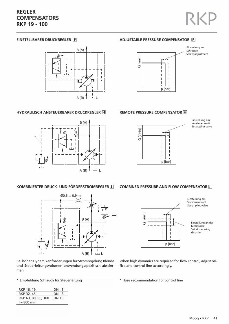
REGLERCOMPENSATORSRKP 19 - 100 RKPEINSTELLBARER DRUCKREGLER �F ADJUSTABLE PRESSURE COMPENSATOR �F
A (B) L
B (A)
p [bar]
Q [l
/min
]
Einstellung anSchraubeScrew adjustment
HYDRAULISCH ANSTEUERBARER DRUCKREGLER �H REMOTE PRESSURE COMPENSATOR �H
A (B) L
B (A)
p [bar]
Q [l
/min
]*
Einstellung am VorsteuerventilSet at pilot valve
* Empfehlung Schlauch für Steuerleitung
RKP 16, 19 DN 6RKP 32, 45 DN 8RKP 63, 80, 90, 100 DN 10I ≈ 800 mm
* Hose recommendation for control line
KOMBINIERTER DRUCK- UND FÖRDERSTROMREGLER �J COMBINED PRESSURE AND FLOW COMPENSATOR �J
A (B) L
B (A)
p [bar]
Q [l
/min
]
Ø0,8 ... 0,9mmEinstellung amVorsteuerventilSet at pilot valve
Einstellung an derMeßdrosselSet at metering throttle
Bei hohen Dynamikanforderungen für Stromregelung Blendeund Steuerleitungsvolumen anwendungsspezifisch abstim-men.
When high dynamics are required for flow control, adjust ori-fice and control line accordingly.
D1 D2RKP 16 … 45 DN 6 0,9 1,2RKP 63 … 100 DN 8 0,9 1,2RKP 140 DN 8 0,8 1,1I ≈ 800 mm
42 Moog • RKP
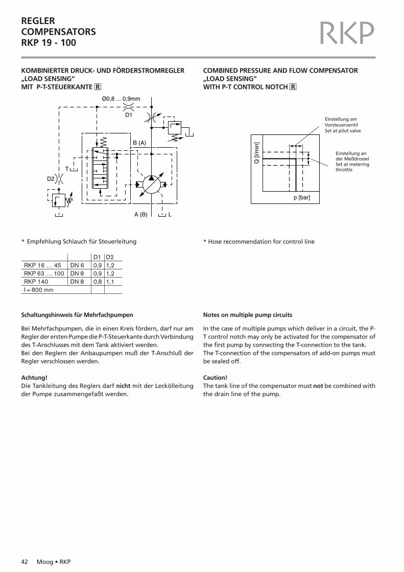
REGLERCOMPENSATORSRKP 19 - 100 RKPKOMBINIERTER DRUCK- UND FÖRDERSTROMREGLER „LOAD SENSING“MIT P-T-STEUERKANTE �R
COMBINED PRESSURE AND FLOW COMPENSATOR „LOAD SENSING“WITH P-T CONTROL NOTCH �R
A (B) L
B (A)
D1
D2
p [bar]
Q [l
/min
]
Ø0,8 ... 0,9mm
T
Einstellung amVorsteuerventilSet at pilot valve
Einstellung an der MeßdrosselSet at meteringthrottle
* Empfehlung Schlauch für Steuerleitung * Hose recommendation for control line
Schaltungshinweis für Mehrfachpumpen
Bei Mehrfachpumpen, die in einen Kreis fördern, darf nur amRegler der ersten Pumpe die P-T-Steuerkante durch Verbindungdes T-Anschlusses mit dem Tank aktiviert werden.Bei den Reglern der Anbaupumpen muß der T-Anschluß derRegler verschlossen werden.
Achtung!Die Tankleitung des Reglers darf nicht mit der Leckölleitungder Pumpe zusammengefaßt werden.
Notes on multiple pump circuits
In the case of multiple pumps which deliver in a circuit, the P-T control notch may only be activated for the compensator ofthe first pump by connecting the T-connection to the tank.The T-connection of the compensators of add-on pumps mustbe sealed off.
Caution!The tank line of the compensator must not be combined withthe drain line of the pump.
Moog • RKP 43
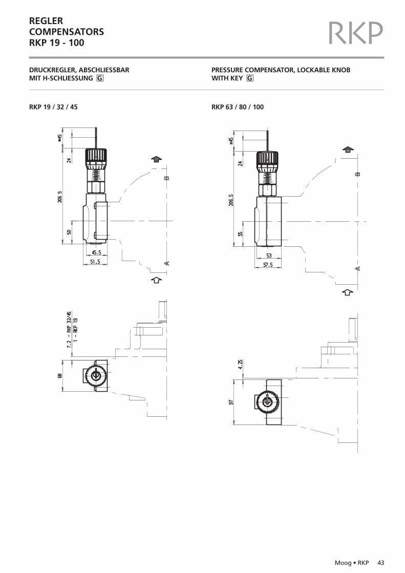
REGLERCOMPENSATORSRKP 19 - 100 RKPDRUCKREGLER, ABSCHLIESSBAR MIT H-SCHLIESSUNG �G
PRESSURE COMPENSATOR, LOCKABLE KNOBWITH KEY �G
RKP 19 / 32 / 45 RKP 63 / 80 / 100
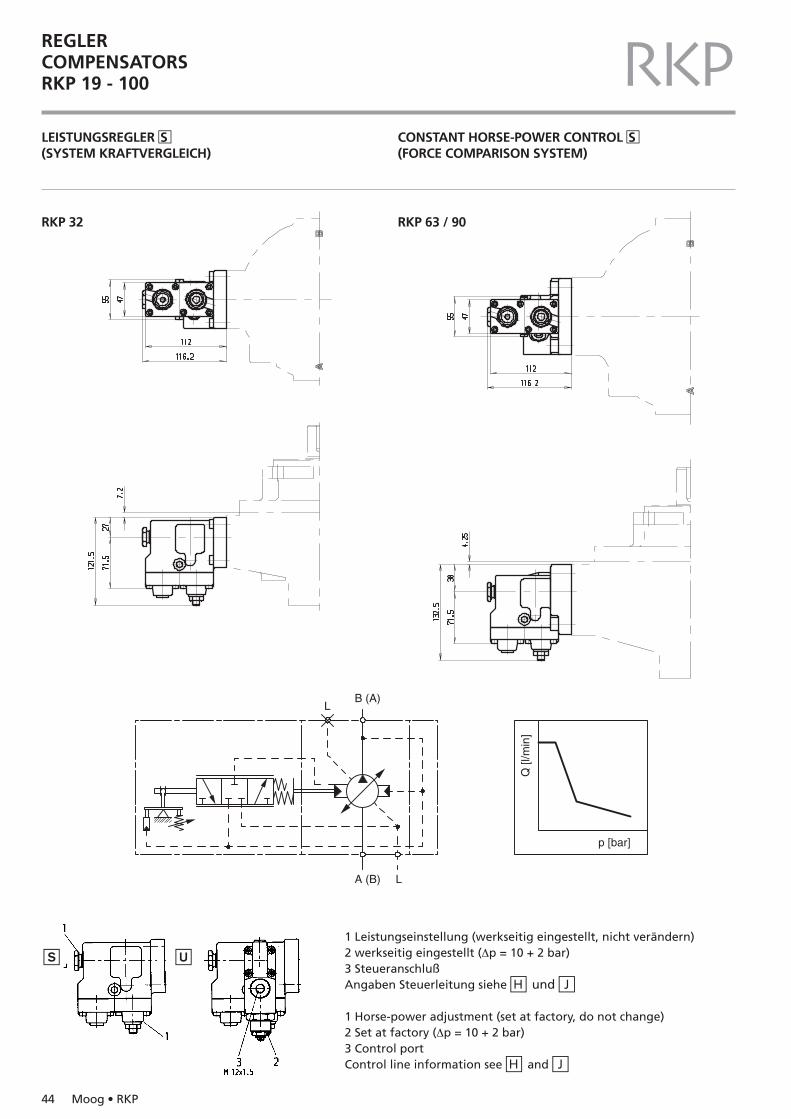
1 Leistungseinstellung (werkseitig eingestellt, nicht verändern)2 werkseitig eingestellt (∆p = 10 + 2 bar)3 SteueranschlußAngaben Steuerleitung siehe �H und �J
1 Horse-power adjustment (set at factory, do not change)2 Set at factory (∆p = 10 + 2 bar)3 Control portControl line information see �H and �J
�S �U
REGLERCOMPENSATORSRKP 19 - 100 RKPLEISTUNGSREGLER �S(SYSTEM KRAFTVERGLEICH)
CONSTANT HORSE-POWER CONTROL �S(FORCE COMPARISON SYSTEM)
A (B) L
LB (A)
p [bar]
Q [l
/min
]
RKP 32 RKP 63 / 90
44 Moog • RKP
Moog • RKP 45
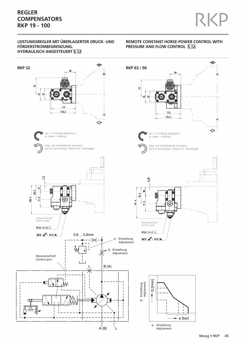
REGLERCOMPENSATORSRKP 19 - 100 RKPLEISTUNGSREGLER MIT ÜBERLAGERTER DRUCK- UNDFÖRDERSTROMBEGRENZUNG,HYDRAULISCH ANGESTEUERT �S �U
REMOTE CONSTANT HORSE-POWER CONTROL WITHPRESSURE AND FLOW CONTROL �S �U
RKP 32 RKP 63 / 90
0,8 ... 0,9mm
p [bar]
Q [l
/min
]
B (A)
A (B) L
L
Q
p EinstellungAdjustment
p EinstellungAdjustment
QEi
nst
ellu
ng
Ad
just
men
t
SteueranschlußControl port
Q EinstellungAdjustment
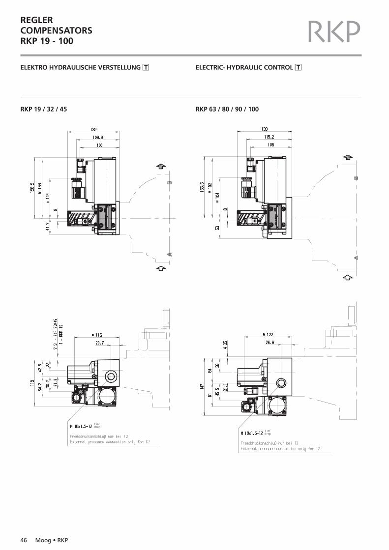
REGLERCOMPENSATORSRKP 19 - 100 RKPELEKTRO HYDRAULISCHE VERSTELLUNG �T ELECTRIC- HYDRAULIC CONTROL �T
RKP 19 / 32 / 45 RKP 63 / 80 / 90 / 100
46 Moog • RKP
Moog • RKP 47
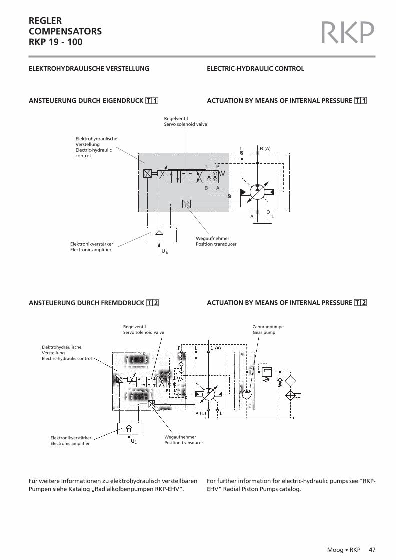
REGLERCOMPENSATORSRKP 19 - 100 RKPELEKTROHYDRAULISCHE VERSTELLUNG
ANSTEUERUNG DURCH EIGENDRUCK �T �1
ELECTRIC-HYDRAULIC CONTROL
ACTUATION BY MEANS OF INTERNAL PRESSURE �T �1
B (A)L
U E
A L
AB
T P
ElektrohydraulischeVerstellungElectric-hydrauliccontrol
RegelventilServo solenoid valve
ElektronikverstärkerElectronic amplifier
WegaufnehmerPosition transducer
RegelventilServo solenoid valve
ZahnradpumpeGear pump
ElektrohydraulischeVerstellungElectric-hydraulic control
WegaufnehmerPosition transducer
ElektronikverstärkerElectronic amplifier
ACTUATION BY MEANS OF INTERNAL PRESSURE �T �2
Für weitere Informationen zu elektrohydraulisch verstellbarenPumpen siehe Katalog „Radialkolbenpumpen RKP-EHV“.
For further information for electric-hydraulic pumps see "RKP-EHV" Radial Piston Pumps catalog.
ANSTEUERUNG DURCH FREMDDRUCK �T �2
48 Moog • RKP
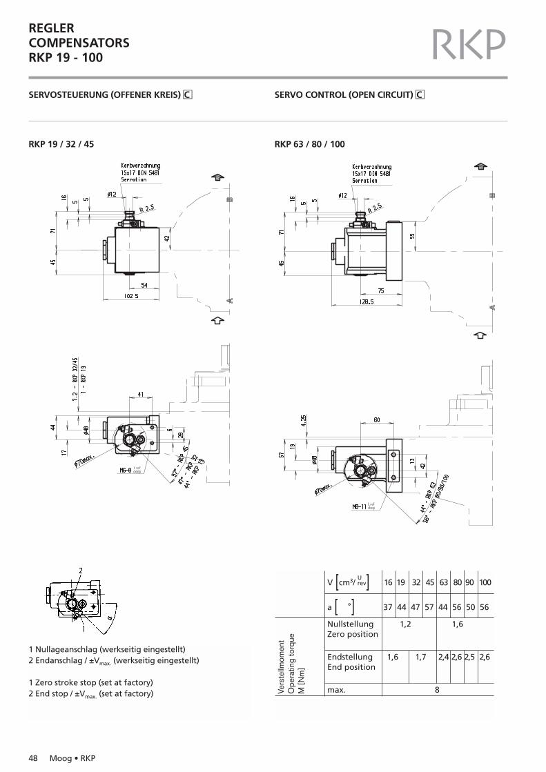
REGLERCOMPENSATORSRKP 19 - 100 RKPSERVOSTEUERUNG (OFFENER KREIS) �C SERVO CONTROL (OPEN CIRCUIT) �C
RKP 19 / 32 / 45 RKP 63 / 80 / 100
1 Nullageanschlag (werkseitig eingestellt)2 Endanschlag / ±Vmax. (werkseitig eingestellt)
1 Zero stroke stop (set at factory)2 End stop / ±Vmax. (set at factory)
V [cm3/U ] 16 19 32 45 63 80 90 100rev
a [ °] 37 44 47 57 44 56 50 56
Nullstellung 1,2 1,6Zero position
Endstellung 1,6 1,7 2,4 2,6 2,5 2,6End position
max. 8Vers
tellm
omen
tO
pera
ting
torq
ueM
[Nm
]
Moog • RKP 49
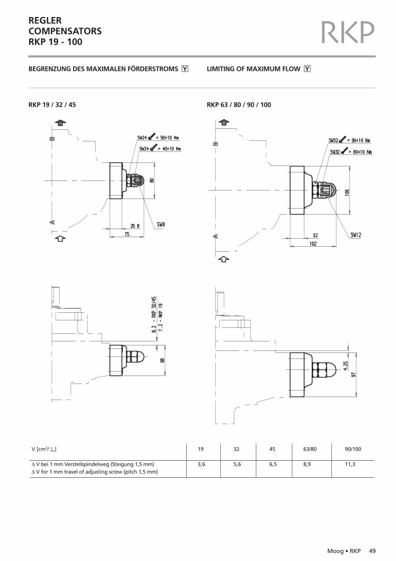
REGLERCOMPENSATORSRKP 19 - 100 RKPBEGRENZUNG DES MAXIMALEN FÖRDERSTROMS �Y LIMITING OF MAXIMUM FLOW �Y
RKP 19 / 32 / 45 RKP 63 / 80 / 90 / 100
V [cm3/ ]
∆ V bei 1 mm Verstellspindelweg (Steigung 1,5 mm)∆ V for 1 mm travel of adjusting screw (pitch 1,5 mm)
19
3,6
32
5,6
45
6,5
63/80
8,9
90/100
11,3
Urev
50 Moog • RKP
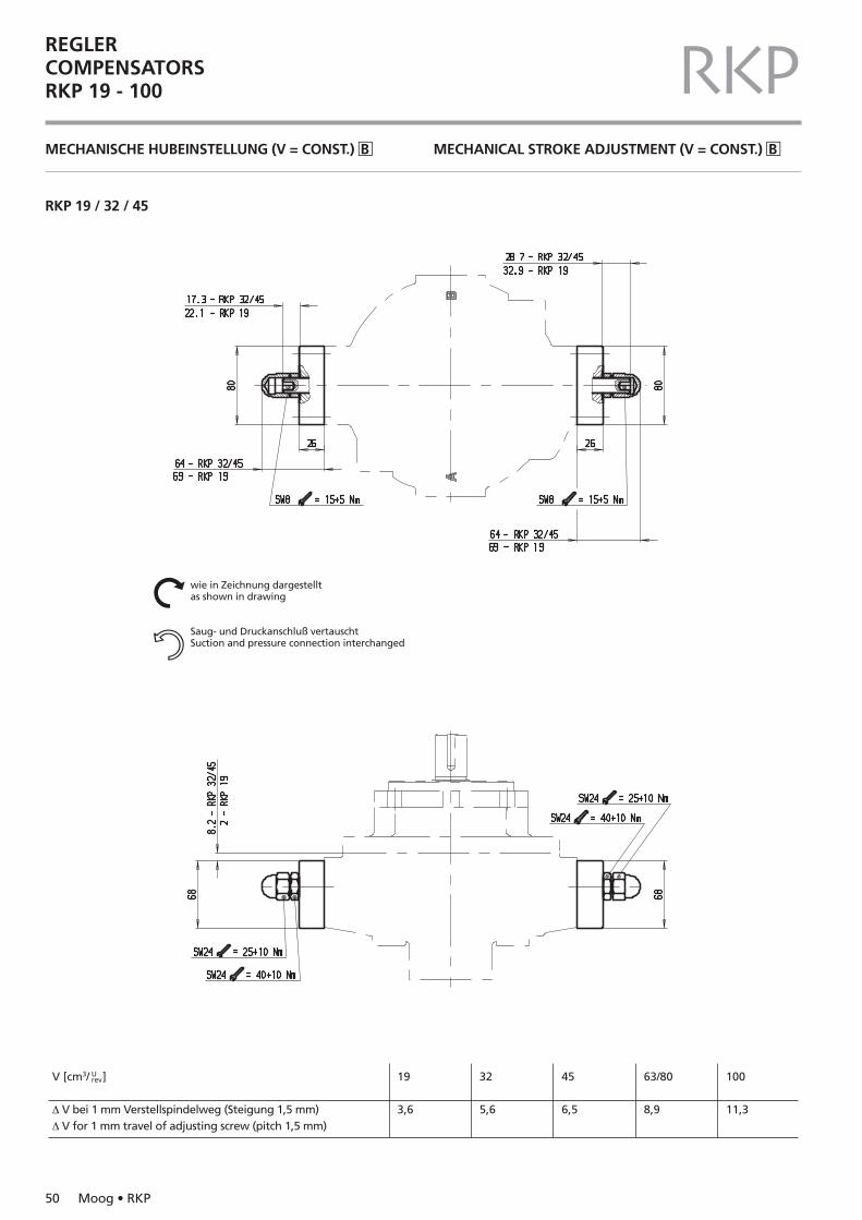
REGLERCOMPENSATORSRKP 19 - 100 RKPMECHANISCHE HUBEINSTELLUNG (V = CONST.) �B MECHANICAL STROKE ADJUSTMENT (V = CONST.) �B
RKP 19 / 32 / 45
V [cm3/ ]
∆ V bei 1 mm Verstellspindelweg (Steigung 1,5 mm)∆ V for 1 mm travel of adjusting screw (pitch 1,5 mm)
19
3,6
32
5,6
45
6,5
63/80
8,9
100
11,3
Urev
wie in Zeichnung dargestelltas shown in drawing
Saug- und Druckanschluß vertauschtSuction and pressure connection interchanged
Nn
Moog • RKP 51
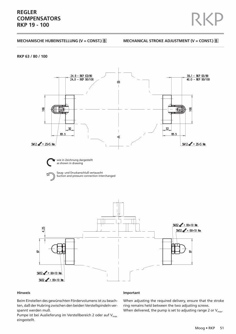
REGLERCOMPENSATORSRKP 19 - 100 RKPMECHANISCHE HUBEINSTELLUNG (V = CONST.) �B MECHANICAL STROKE ADJUSTMENT (V = CONST.) �B
RKP 63 / 80 / 100
Hinweis
Beim Einstellen des gewünschten Fördervolumens ist zu beach-ten, daß der Hubring zwischen den beiden Verstellspindeln ver-spannt werden muß.Pumpe ist bei Auslieferung im Verstellbereich 2 oder auf Vmax.
eingestellt.
Important
When adjusting the required delivery, ensure that the strokering remains held between the two adjusting screws.When delivered, the pump is set to adjusting range 2 or Vmax.
wie in Zeichnung dargestelltas shown in drawing
Saug- und Druckanschluß vertauschtSuction and pressure connection interchanged
Nn
52 Moog • RKP
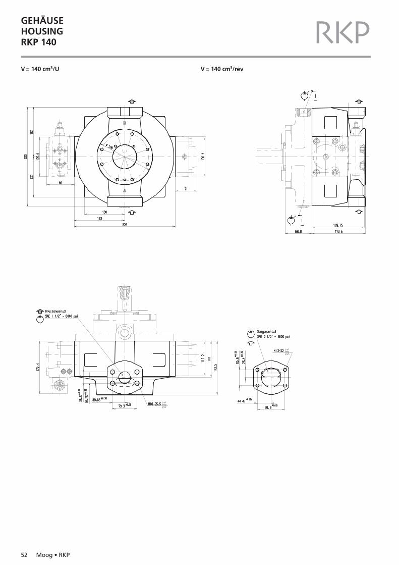
GEHÄUSEHOUSINGRKP 140 RKPV = 140 cm3/U V = 140 cm3/rev
Moog • RKP 53
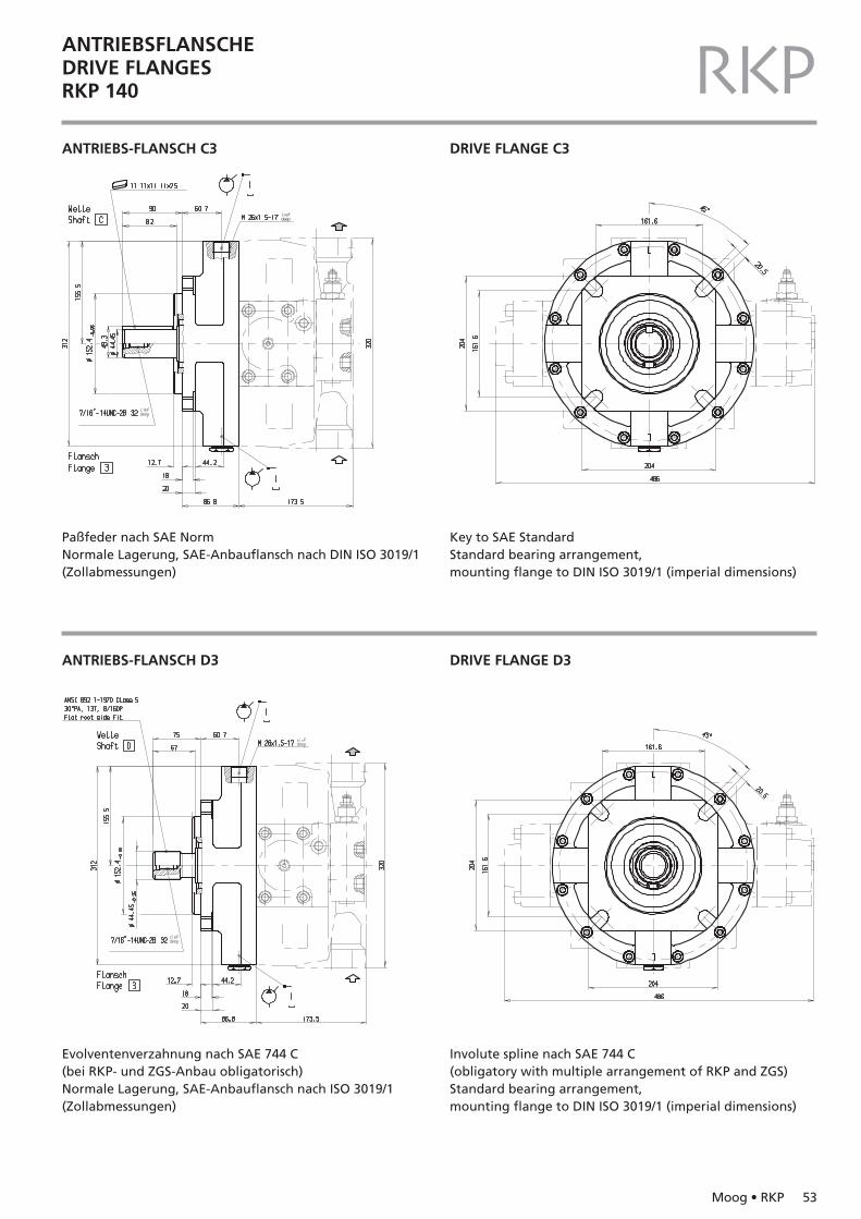
ANTRIEBSFLANSCHEDRIVE FLANGESRKP 140 RKPANTRIEBS-FLANSCH C3 DRIVE FLANGE C3
ANTRIEBS-FLANSCH D3 DRIVE FLANGE D3
Paßfeder nach SAE NormNormale Lagerung, SAE-Anbauflansch nach DIN ISO 3019/1(Zollabmessungen)
Key to SAE StandardStandard bearing arrangement, mounting flange to DIN ISO 3019/1 (imperial dimensions)
Evolventenverzahnung nach SAE 744 C(bei RKP- und ZGS-Anbau obligatorisch)Normale Lagerung, SAE-Anbauflansch nach ISO 3019/1(Zollabmessungen)
Involute spline nach SAE 744 C(obligatory with multiple arrangement of RKP and ZGS)Standard bearing arrangement,mounting flange to DIN ISO 3019/1 (imperial dimensions)
54 Moog • RKP
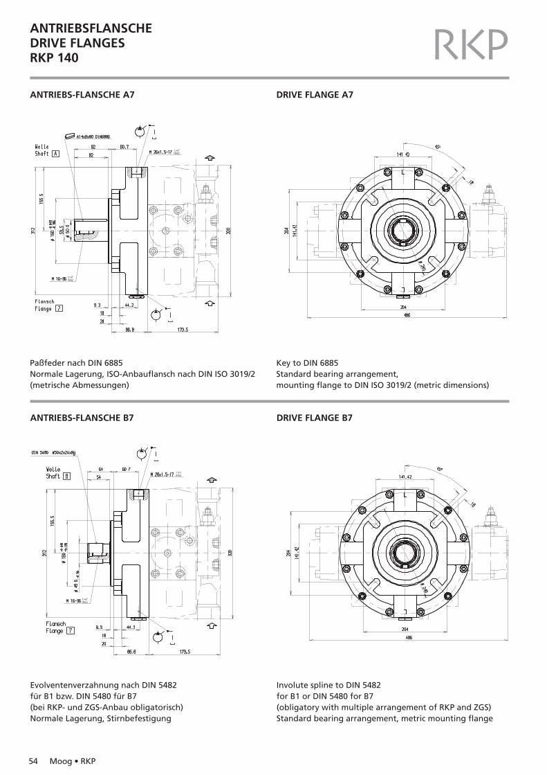
ANTRIEBSFLANSCHEDRIVE FLANGESRKP 140 RKPANTRIEBS-FLANSCHE A7 DRIVE FLANGE A7
Paßfeder nach DIN 6885Normale Lagerung, ISO-Anbauflansch nach DIN ISO 3019/2(metrische Abmessungen)
Key to DIN 6885Standard bearing arrangement, mounting flange to DIN ISO 3019/2 (metric dimensions)
ANTRIEBS-FLANSCHE B7 DRIVE FLANGE B7
Evolventenverzahnung nach DIN 5482für B1 bzw. DIN 5480 für B7(bei RKP- und ZGS-Anbau obligatorisch)Normale Lagerung, Stirnbefestigung
Involute spline to DIN 5482for B1 or DIN 5480 for B7 (obligatory with multiple arrangement of RKP and ZGS)Standard bearing arrangement, metric mounting flange
Moog • RKP 55
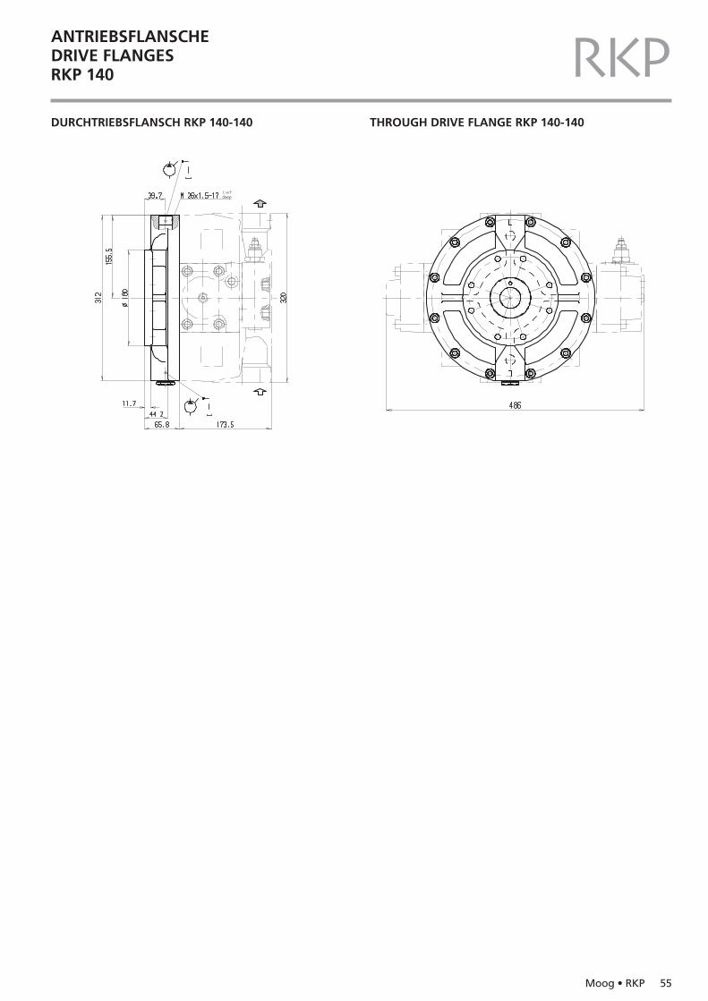
RKPDURCHTRIEBSFLANSCH RKP 140-140 THROUGH DRIVE FLANGE RKP 140-140
ANTRIEBSFLANSCHEDRIVE FLANGESRKP 140
56 Moog • RKP
REGLERCOMPENSATORSRKP 140 RKP
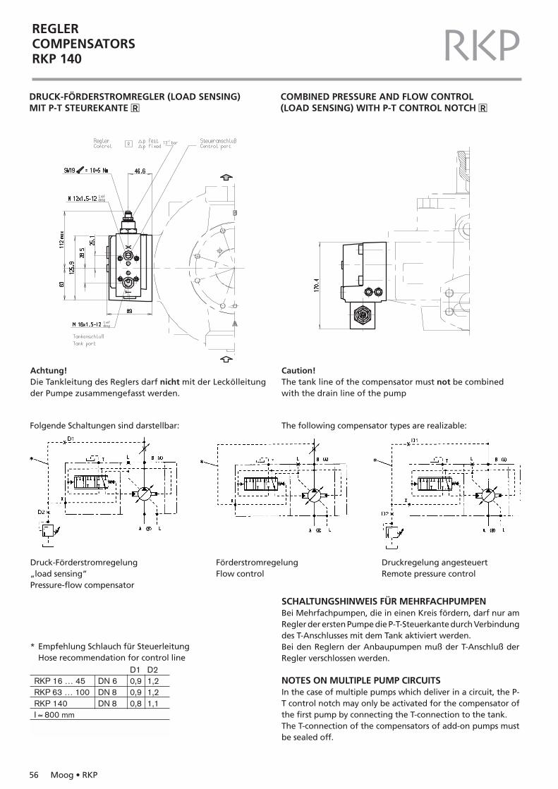
DRUCK-FÖRDERSTROMREGLER (LOAD SENSING) MIT P-T STEUREKANTE �R
COMBINED PRESSURE AND FLOW CONTROL (LOAD SENSING) WITH P-T CONTROL NOTCH �R
13+2 bar
D1 D2RKP 16 … 45 DN 6 0,9 1,2RKP 63 … 100 DN 8 0,9 1,2RKP 140 DN 8 0,8 1,1I ≈ 800 mm
Achtung!Die Tankleitung des Reglers darf nicht mit der Leckölleitungder Pumpe zusammengefasst werden.
Caution!The tank line of the compensator must not be combinedwith the drain line of the pump
* Empfehlung Schlauch für SteuerleitungHose recommendation for control line
Druck-Förderstromregelung„load sensing”Pressure-flow compensator
FörderstromregelungFlow control
Druckregelung angesteuertRemote pressure control
SCHALTUNGSHINWEIS FÜR MEHRFACHPUMPEN Bei Mehrfachpumpen, die in einen Kreis fördern, darf nur amRegler der ersten Pumpe die P-T-Steuerkante durch Verbindungdes T-Anschlusses mit dem Tank aktiviert werden.Bei den Reglern der Anbaupumpen muß der T-Anschluß derRegler verschlossen werden.
NOTES ON MULTIPLE PUMP CIRCUITSIn the case of multiple pumps which deliver in a circuit, the P-T control notch may only be activated for the compensator ofthe first pump by connecting the T-connection to the tank.The T-connection of the compensators of add-on pumps mustbe sealed off.
Folgende Schaltungen sind darstellbar: The following compensator types are realizable:
Moog • RKP 57
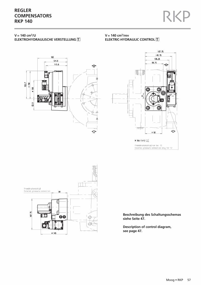
REGLERCOMPENSATORSRKP 140 RKPV = 140 cm3/UELEKTROHYDRAULISCHE VERSTELLUNG �T
V = 140 cm3/revELEKTRIC-HYDRAULIC CONTROL �T
Beschreibung des Schaltungsschemassiehe Seite 47.
Description of control diagram, see page 47.
58 Moog • RKP
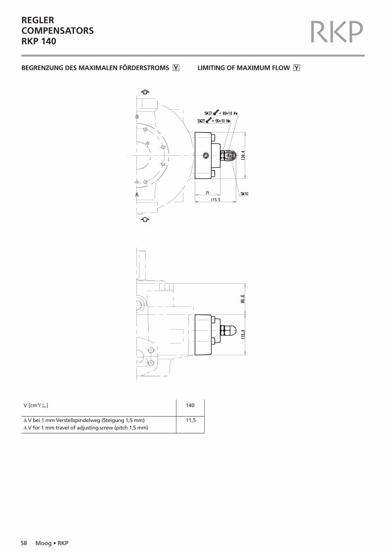
REGLERCOMPENSATORSRKP 140 RKPBEGRENZUNG DES MAXIMALEN FÖRDERSTROMS �Y LIMITING OF MAXIMUM FLOW �Y
V [cm3/ ]
∆ V bei 1 mm Verstellspindelweg (Steigung 1,5 mm)∆ V for 1 mm travel of adjusting screw (pitch 1,5 mm)
140
11,5
Urev
Moog • RKP 59
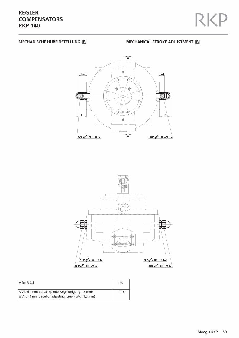
REGLERCOMPENSATORSRKP 140 RKPMECHANISCHE HUBEINSTELLUNG �B MECHANICAL STROKE ADJUSTMENT �B
V [cm3/ ]
∆ V bei 1 mm Verstellspindelweg (Steigung 1,5 mm)∆ V for 1 mm travel of adjusting screw (pitch 1,5 mm)
140
11,5
Urev
60 Moog • RKP
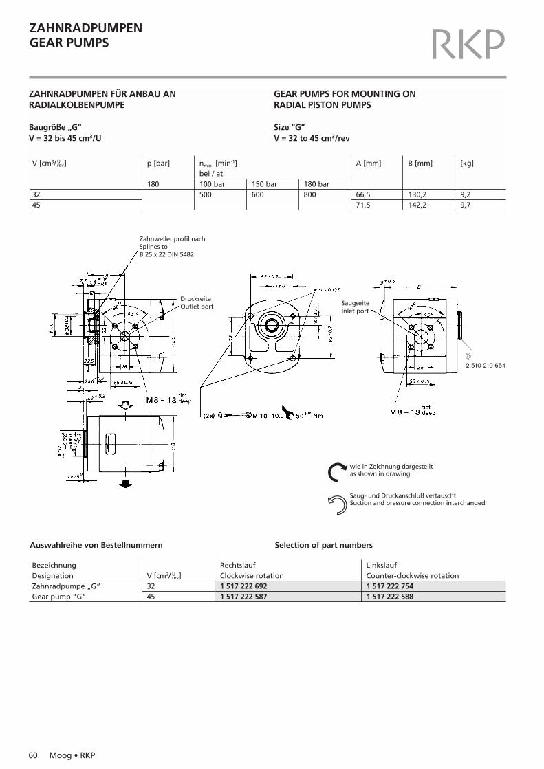
ZAHNRADPUMPENGEAR PUMPS RKPZAHNRADPUMPEN FÜR ANBAU ANRADIALKOLBENPUMPE
Baugröße „G“V = 32 bis 45 cm3/U
GEAR PUMPS FOR MOUNTING ON RADIAL PISTON PUMPS
Size “G”V = 32 to 45 cm3/rev
Zahnwellenprofil nachSplines toB 25 x 22 DIN 5482
DruckseiteOutlet port Saugseite
Inlet port
wie in Zeichnung dargestelltas shown in drawing
Saug- und Druckanschluß vertauschtSuction and pressure connection interchanged
Nn
V [cm3/ ]
3245
p [bar]
180 150 bar600
nmin [min-1]bei / at 100 bar500
180 bar800
A [mm]
66,571,5
B [mm]
130,2142,2
[kg]
9,29,7
Urev
BezeichnungDesignationZahnradpumpe „G“Gear pump “G“
RechtslaufClockwise rotation1 517 222 6921 517 222 587
LinkslaufCounter-clockwise rotation1 517 222 7541 517 222 588
V [cm3/ ]3245
Urev
Auswahlreihe von Bestellnummern Selection of part numbers
w2 510 210 654
Moog • RKP 61
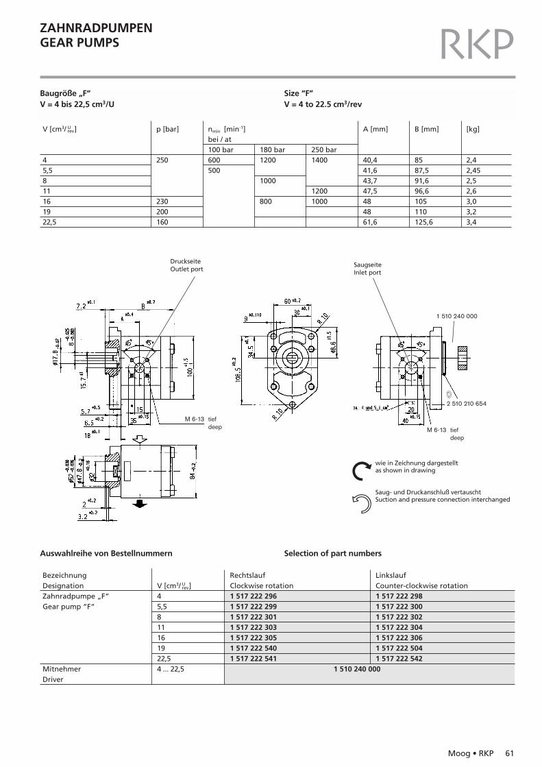
ZAHNRADPUMPENGEAR PUMPS RKPBaugröße „F“V = 4 bis 22,5 cm3/U
Size “F”V = 4 to 22.5 cm3/rev
DruckseiteOutlet port
SaugseiteInlet port
1 510 240 000
w2 510 210 654
M 6-13 tiefdeep
wie in Zeichnung dargestelltas shown in drawing
Saug- und Druckanschluß vertauschtSuction and pressure connection interchanged
Nn
Auswahlreihe von Bestellnummern Selection of part numbers
V [cm3/ ]
45,5811161922,5
p [bar]
250
230200160
180 bar1200
1000
800
nmin [min-1]bei / at 100 bar600500
250 bar1400
12001000
A [mm]
40,441,643,747,5484861,6
B [mm]
8587,591,696,6105110125,6
[kg]
2,42,452,52,63,03,23,4
Urev
BezeichnungDesignationZahnradpumpe „F“Gear pump “F“
MitnehmerDriver
RechtslaufClockwise rotation1 517 222 2961 517 222 2991 517 222 3011 517 222 3031 517 222 3051 517 222 5401 517 222 541
1 510 240 000
LinkslaufCounter-clockwise rotation1 517 222 2981 517 222 3001 517 222 3021 517 222 3041 517 222 3061 517 222 5041 517 222 542
V [cm3/ ]45,5811161922,54 ... 22,5
Urev
M 6-13 tiefdeep
62 Moog • RKP
ZAHNRADPUMPENGEAR PUMPS RKP
Auswahlreihe von Bestellnummern Selection of part numbers
V [cm3/ ]
Pumpe 1Pump 145,58
11
16
22,5
Pumpe 2Pump 245,55,5845,581145,5111622,5
Pumpe 2Pump 2250
160
p [bar]
Pumpe 1Pump 1250
160
180 bar
12001200120010001200
1000
1200
1000800800
nmin [min-1]bei / at100 bar
600500500
600500
600
500
500
250 bar14001400
12001400
12001000
A[mm]
40,441,643,743,747,547,547,547,547,5484861,6
B[mm]
122,1125,8129,9132133,7134,9137140,8142,1143,3149,2149,7185,7
D[mm]
165,4170,4174,5178,6177180184,1189,1185,4187,9197205,4249,7
[kg]
5,965,056,16,16,156,26,36,56,556,76,98
Urev
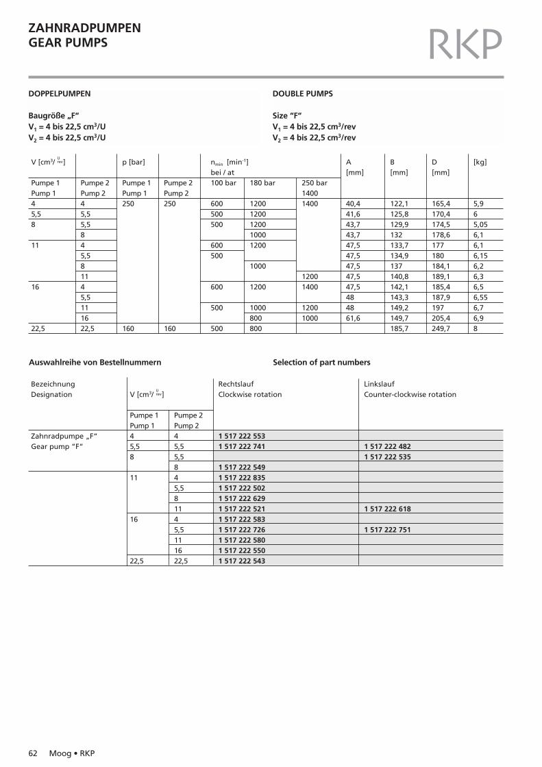
BezeichnungDesignation
Zahnradpumpe „F“Gear pump “F“
RechtslaufClockwise rotation
1 517 222 5531 517 222 741
1 517 222 5491 517 222 8351 517 222 5021 517 222 6291 517 222 5211 517 222 5831 517 222 7261 517 222 5801 517 222 5501 517 222 543
LinkslaufCounter-clockwise rotation
1 517 222 4821 517 222 535
1 517 222 618
1 517 222 751
V [cm3/ ]
Pumpe 1Pump 145,58
11
16
22,5
Pumpe 2Pump 245,55,5845,581145,5111622,5
Urev
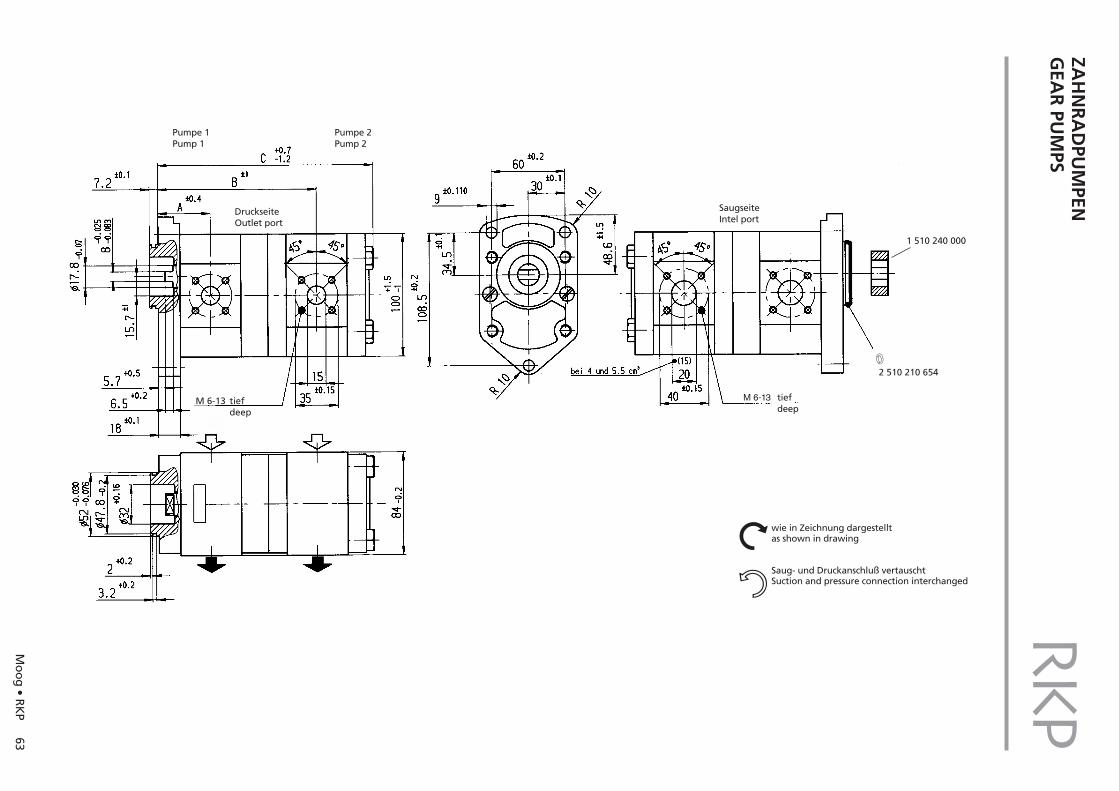
DOPPELPUMPEN
Baugröße „F“V1 = 4 bis 22,5 cm3/UV2 = 4 bis 22,5 cm3/U
DOUBLE PUMPS
Size “F“V1 = 4 bis 22,5 cm3/revV2 = 4 bis 22,5 cm3/rev
Mo
og
• RK
P63
ZAH
NR
AD
PUM
PENG
EAR
PUM
PSRKP
Pumpe 1Pump 1
DruckseiteOutlet port
Pumpe 2Pump 2
SaugseiteIntel port
M 6-13 tiefdeep
M 6-13 tiefdeep
w2 510 210 654
1 510 240 000
wie in Zeichnung dargestelltas shown in drawing
Saug- und Druckanschluß vertauschtSuction and pressure connection interchanged
Nn

64 Moog • RKP
RKPNOTIZENNOTES
Moog • RKP 65
STEUERBLÖCKECONTROL BLOCKS RKPSTEUERBLÖCKE FÜR RKPCONTROL BLOCKS FOR RKP
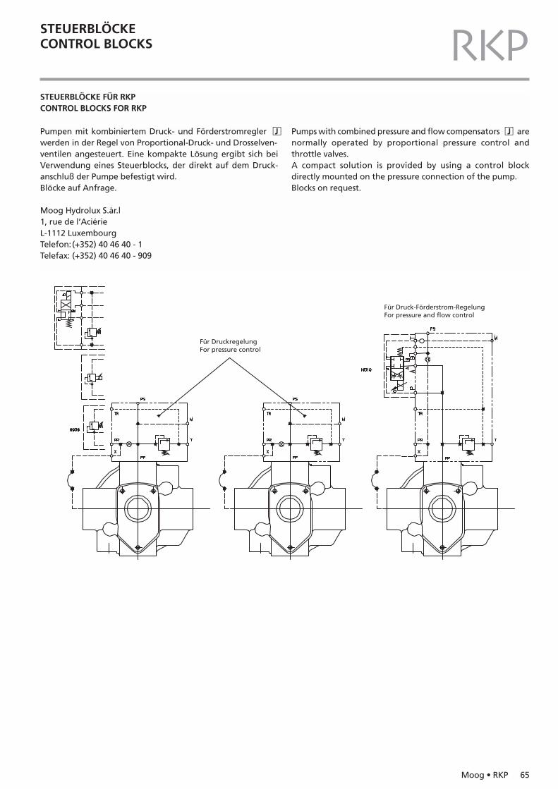
Pumpen mit kombiniertem Druck- und Förderstromregler �Jwerden in der Regel von Proportional-Druck- und Drosselven-ventilen angesteuert. Eine kompakte Lösung ergibt sich beiVerwendung eines Steuerblocks, der direkt auf dem Druck-anschluß der Pumpe befestigt wird. Blöcke auf Anfrage.
Moog Hydrolux S.àr.l1, rue de l’AciérieL-1112 LuxembourgTelefon:(+352) 40 46 40 - 1Telefax: (+352) 40 46 40 - 909
Pumps with combined pressure and flow compensators �J arenormally operated by proportional pressure control and throttle valves.A compact solution is provided by using a control block directly mounted on the pressure connection of the pump.Blocks on request.
Für Druckregelung For pressure control
Für Druck-Förderstrom-Regelung For pressure and flow control
66 Moog • RKP
TECHNISCHE HINWEISETECHNICAL INFORMATION RKPTECHNISCHE HINWEISE
! WarnungInbetriebnahme der Pumpen muß durch in Hydraulik ausgebilde-tes Fachpersonal erfolgen.
EinbauhinweiseDie Einbaulage der Radialkolbenpumpe ist beliebig.Angegebene Antriebsdrehrichtung unbedingt einhalten.Auf die Antriebswelle dürfen keine radialen und axialen Kräfte wir-ken. Deshalb muß der Antrieb über eine Ausgleichskupplung er-folgen.Alle Verschlußstopfen der Pumpe erst unmittelbar vor demAnschließen der Leitungen entfernen.Bei der Montage auf Sauberkeit achten.Es empfiehlt sich die Verwendung von nahtlosem Präzisionsstahl-rohr nach DIN 2391.
SaugleitungKurze Saugleitung mit großer lichter Weite notwendig, um kurzeStellzeit und niedriges Geräusch sicherzustellen. ScharfeUmlenkungen und Rohrverschraubungen vermeiden (Gefahr desLuftsaugens und der Luftausscheidung, hoher Durchflußwider-stand). Statt dessen gebogene Rohre oder Schläuche verwenden.Zulässigen minimalen Eingangsdruck einhalten.Reduzierung der Saugleitung erst am Pumpeneintritt vornehmen.Falls ein Saugfilter (min. 150 µm Maschenweite) oder einAbsperrhahn eingesetzt wird, Geräte unterhalb des Flüssig-keitsspiegels einbauen.
DruckleitungAuf ausreichende Festigkeit achten. Anzugsmomente derSchrauben prüfen.
Leckstromleitung (L)So verlegen, daß das Pumpengehäuse stets vollständig mitDruckflüssigkeit gefüllt ist (oben liegenden Anschluß verwenden).Getrennt von anderen Rücklaufleitungen direkt in den Tankführen.Leitungsende muß auch bei niedrigstem Flüssigkeitsstand im Tankunterhalb des Flüssigkeitsspiegels liegen.Entfernung zur Saugleitung möglichst groß. Kein Filter, keinenKühler und kein Rückschlagventil in der Leckstromleitung anord-nen. Max. Länge 3 m.Druck am Leckstromanschluß max. 2 bar absolut (1 bar Überdruck)bei Pumpen für offenen Kreis.Empfohlener Rohraußendurchmesser für Leckstromleitungen(leichte Baureihe) RKP 16 und 19: 15 mmRKP 32 und 45: 18 mmRKP 63, 80, 90, 100 und 140: 22 mm.
GehäusespülungWird die Pumpe über längere Zeit bei niedrigen Drücken im abge-regelten Zustand (t > 15 min, p < 30 bar, Q = 0 l/min) betrieben, istzur Wärmeabfuhr für die Pumpengröße 63 … 100 cm3/U eineSpülung mit ca. 4 … 6 l/min zu empfehlen. Für die Pumpengröße140 cm3/U ist diese Spülung notwendig. Die Spülstromleitung istam unten liegenden Leckölanschluß anzuschließen.
TECHNICAL INFORMATION
! WarningThe pump must be put into service by personnel trained in the fieldof hydraulics.
Mounting instructionsThe Radial Piston Pump can be mounted anywhere.The specified drive rotational direction must be complied with.The drive shaft must not be subject to radial or axial forces. For thisreason, drive must take place via a flexible coupling.All plugs on the pump should only be removed before lines areconnected.Please ensure cleanliness during installation. The use of seamlessprecision-cast steel pipes in accordance with DIN 2391 is recom-mended.
Suction lineA short suction line with large inside diameter is necessary to ensure a short response time and low noise level.Avoid sharp angles and screwed pipe joints (danger of air intakeand dispersion, high flow resistance). Use curved pipes or hosesinstead.The minimum allowable inlet pressure must be maintained.Reduction of the suction line should only take place at the pumpentry.If a suction filter (min. 150 mm mesh aperture) or an isolating valve are to be used, these must be installed below the fluid level.
Pressure lineEnsure ample stability.Check tightening torques of screws.
Drain line (L)Lay this in such a way that the pump housing is constantly filledwith fluid (use the upper connection).It should lead directly into the tank, separate from other returnlines. The end of the line must be below the fluid level in the tank,even when at its lowest.Distance from suction line should be as large as possible. Do notplace a filter, cooler or non-return valve in the drain line.Max. length 3 m.Pressure at drain port max. 2 bars absolute (1 bar gauge pressure)in pumps for open circuit.Recommended pipe outside diameter for drain lines (lightweightversion)RKP 16 and 19: 15 mmRKP 32 and 45: 18 mmRKP 63, 80, 90, 100 and 140: 22 mm.
Flushing the housingIf the pump is operated at low pressure without delivery for a longer period (t > 15 min, p < 30 bar, Q = 0 l/min), it is recommen-ded that pumps of sizes 63 … 100 cm3/rev are flushed at approx. 4 … 6 l/min to dissipate the heat. Pump size 140 cm3/rev must beflushed. The flushing line must be connected to the lower leakageconnection.
Moog • RKP 67
TECHNISCHE HINWEISETECHNICAL INFORMATION RKPGeräuschentwicklungRadialkolbenpumpen haben einen niedrigen primärenGeräuschpegel. Die Geräuschentwicklung des gesamten Hydrau-likaggregates ist jedoch stark vom Anbau der Pumpe und von derLeitungsverlegung abhängig. Körperschallübertragung aufabstrahlende großflächige Maschinenteile vermeiden durch:– Pumpe über Dämpfungsflansch anbauen– Schlauchleitungen statt Rohre verwenden– Rohrleitungen mit elastischen Schellen befestigen
InbetriebnahmePumpe nicht ohne Druckflüssigkeit in Gang setzen. Vor demEinschalten ist das Gehäuse der Pumpe über den Leckölanschlußmit der Druckflüssigkeit zu füllen.Nach Einschalten Drehrichtung des Antriebmotors kontrollieren.Bis zur Entlüftung der Hydraulikanlage mit niedrigem Druck fahren.Bei Inbetriebnahme von Pumpen für HF-Flüssigkeiten ist die An-Anlage ca. eine Stunde bei niedrigem Druck ( 30 … 50 bar) zubetreiben.
HinweisDie Öltemperatur im Tank darf die Temperatur der Pumpe nichtmehr als 25 °C übersteigen. Ist dies der Fall, so darf die Pumpe biszur Erwärmung nur in kurzen Intervallen von ca. 1 bis 2 Sekundeneingeschaltet werden.Bei Pumpenwechsel Leckölleitung, Saugleitung und Tank reinigenund nur gefiltertes Öl wieder einfüllen.
Noise developmentRadial Piston Pump have a low primary noise level. However, thenoise development of the entire hydraulic unit strongly dependson the pump attachment and the laying of the lines. Prevent bodysound transmission at energy-releasing, large-surface machineparts by:– connecting the pump by means of an anti-vibration flange– using hoses instead of pipes– securing tubes with elastic clamps
Putting into serviceDo not start up the pump without hydraulic fluid. Before switchingon, the pump housing must be filled with hydraulic fluid via thedrain port.After the pump has been switched on, check the direction of rota-tion of the drive motor.Run at low pressure until the hydraulic system has been deaerated.When putting pumps for HF fluids into operation, the system mustbe run at low pressure (30 ... 50 bar) for approx. 1 h.
ImportantThe oil temperature in the tank must not exceed the temperatureof the pump by more than 25 °C. If this should happen, the pumpshould only be switched on in short intervals of approx. 1 to 2seconds until it has heated up.At pump changing clean drain line, suction line and tank, and refillthe tank with filtered oil only.
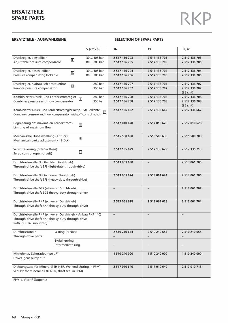
68 Moog • RKP
ERSATZTEILESPARE PARTS RKPERSATZTEILE - AUSWAHLREIHE SELECTION OF SPARE PARTS
Druckregler, einstellbarAdjustable pressure compensator
Druckregler, abschließbarPressure compensator, lockable
Druckregler, hydraulisch ansteuerbarRemote pressure compensator
Kombinierter Druck- und Förderstromregler Combines pressure and flow compensator
Kombinierter Druck- und Förderstromregler mit p-T-SteuerkanteCombines pressure and flow compensator with p-T control notch
Begrenzung des maximalen FörderstromsLimiting of maximum flow
Mechanische Hubeinstellung (1 Stück)Mechanical stroke adjustment (1 Stück)
Servosteuerung (offener Kreis)Servo control (open circuit)
Durchtriebswelle ZFS (leichter Durchtrieb)Through-drive shaft ZFS (light-duty through-drive)
Durchtriebswelle ZFS (schwerer Durchtrieb)Through-drive shaft ZFS (heavy-duty through-drive)
Durchtriebswelle ZGS (schwerer Durchtrieb)Through-drive shaft ZGS (heavy-duty through-drive)
Durchtriebswelle RKP (schwerer Durchtrieb)Through-drive shaft RKP (heavy-duty through-drive)
Durchtriebswelle RKP (schwerer Durchtrieb – Anbau RKP 140)Through-drive shaft RKP (heavy-duty through-drive –with RKP 140 mounted)
DurchtriebsteileThrough-drive parts
Mitnehmer, Zahnradpumpe „F“ Driver, gear pump “F“
Dichtungssatz für Mineralöl (H-NBR, Wellendichtring in FPM)Seal kit for mineral oil (H-NBR, shaft seal in FPM)
FPM � Viton® (Dupont)
16
2 517 136 7032 517 136 705
2 517 136 7042 517 136 706
2 517 136 7072 517 136 707
2 517 136 7082 517 136 708
2 517 136 662
2 517 010 628
2 515 500 630
2 517 135 629
2 513 061 630
2 513 061 624
–
2 513 061 628
–
2 510 210 654–
–
1 510 240 000
2 517 010 640
19
2 517 136 7032 517 136 705
2 517 136 7042 517 136 706
2 517 136 7072 517 136 707
2 517 136 7082 517 136 708
2 517 136 662
2 517 010 628
2 515 500 630
2 517 135 629
–
2 513 061 624
–
2 513 061 628
–
2 510 210 654–
–
1 510 240 000
2 517 010 640
32, 45
2 517 136 7032 517 136 705
2 517 136 7042 517 136 706
2 517 136 7072 517 136 707(32 cm3)2 517 136 7082 517 136 708(32 cm3)2 517 136 662
2 517 010 628
2 515 500 708
2 517 135 713
2 513 061 705
2 513 061 706
2 513 061 707
2 513 061 704
–
2 510 210 654–
–
1 510 240 000
2 517 010 713
V [cm3/ ]
30 ... 105 bar80 ... 280 bar
30 ... 105 bar80 ... 280 bar
280 bar 350 bar
280 bar 350 bar
O-Ring (H-NBR)
ZwischenringIntermediate ring
Urev
Y
B
C
R
J
H
G
F
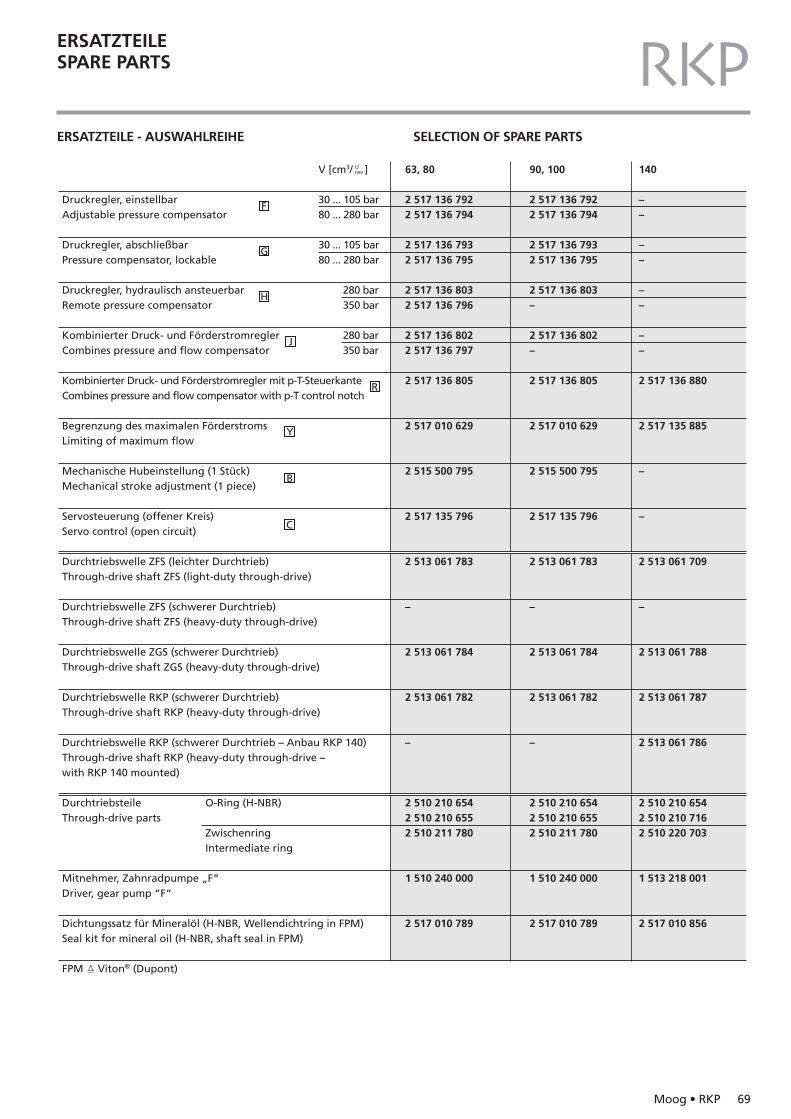
Moog • RKP 69
ERSATZTEILESPARE PARTS RKPERSATZTEILE - AUSWAHLREIHE SELECTION OF SPARE PARTS
Druckregler, einstellbarAdjustable pressure compensator
Druckregler, abschließbarPressure compensator, lockable
Druckregler, hydraulisch ansteuerbarRemote pressure compensator
Kombinierter Druck- und Förderstromregler Combines pressure and flow compensator
Kombinierter Druck- und Förderstromregler mit p-T-SteuerkanteCombines pressure and flow compensator with p-T control notch
Begrenzung des maximalen FörderstromsLimiting of maximum flow
Mechanische Hubeinstellung (1 Stück)Mechanical stroke adjustment (1 piece)
Servosteuerung (offener Kreis)Servo control (open circuit)
Durchtriebswelle ZFS (leichter Durchtrieb)Through-drive shaft ZFS (light-duty through-drive)
Durchtriebswelle ZFS (schwerer Durchtrieb)Through-drive shaft ZFS (heavy-duty through-drive)
Durchtriebswelle ZGS (schwerer Durchtrieb)Through-drive shaft ZGS (heavy-duty through-drive)
Durchtriebswelle RKP (schwerer Durchtrieb)Through-drive shaft RKP (heavy-duty through-drive)
Durchtriebswelle RKP (schwerer Durchtrieb – Anbau RKP 140)Through-drive shaft RKP (heavy-duty through-drive –with RKP 140 mounted)
DurchtriebsteileThrough-drive parts
Mitnehmer, Zahnradpumpe „F“ Driver, gear pump “F“
Dichtungssatz für Mineralöl (H-NBR, Wellendichtring in FPM)Seal kit for mineral oil (H-NBR, shaft seal in FPM)
FPM � Viton® (Dupont)
63, 80
2 517 136 7922 517 136 794
2 517 136 7932 517 136 795
2 517 136 8032 517 136 796
2 517 136 8022 517 136 797
2 517 136 805
2 517 010 629
2 515 500 795
2 517 135 796
2 513 061 783
–
2 513 061 784
2 513 061 782
–
2 510 210 6542 510 210 6552 510 211 780
1 510 240 000
2 517 010 789
90, 100
2 517 136 7922 517 136 794
2 517 136 7932 517 136 795
2 517 136 803–
2 517 136 802–
2 517 136 805
2 517 010 629
2 515 500 795
2 517 135 796
2 513 061 783
–
2 513 061 784
2 513 061 782
–
2 510 210 6542 510 210 6552 510 211 780
1 510 240 000
2 517 010 789
140
––
––
––
––
2 517 136 880
2 517 135 885
–
–
2 513 061 709
–
2 513 061 788
2 513 061 787
2 513 061 786
2 510 210 6542 510 210 7162 510 220 703
1 513 218 001
2 517 010 856
V [cm3/ ]
30 ... 105 bar80 ... 280 bar
30 ... 105 bar80 ... 280 bar
280 bar 350 bar
280 bar 350 bar
O-Ring (H-NBR)
ZwischenringIntermediate ring
Urev
Y
B
C
R
J
H
G
F

70 Moog • RKP
NOTIZENNOTES RKP

ArgentinaAustraliaAustriaBrazilChinaFinlandFranceGermanyIndia
IrelandItalyJapanKoreaLuxembourgNorwayPhilippinesRussiaSingaporeSouth AfricaSpainSwedenUnited KingdomUSA
Moog GmbHHanns-Klemm-Straße 2871034 Böblingenemail: [email protected] (0 70 31) 622-0Telefax (0 70 31) 622-191For the location nearest you,contact www.moog.com/worldwide K
sis
/ Wac
ker
/ 100
0Radialkolbenpumpen / Radial Piston PumpsMoog is a registered trademark of Moog. Inc. and its subsidiaries.
All trademarks as indicated herein are property of Moog. Inc. and its subsidiaries.©Moog Inc. 2003. All rights reserved.
All changes are reserved.For the most current information, visit www.moog.com/radial piston pumps
RKP / Rev 2 / de, en / 03.2003