RLF.3 02.12 DSW MIT ESQ ESQ-K 2Spr file4 ESQ.. und DSQ..-Standardgeräte Mit Seitenwand +...
16
Quickbox ESQ 25/4 ESQ 25/4 K ESQ 31/4 ESQ 31/4 K ESQ 35/4 ESQ 35/4 K ESQ 40/4 ESQ 40/4 K ESQ 45/4 ESQ 45/4 K DSQ 25/4 DSQ 25/4 K DSQ 31/4 DSQ 31/4 K DSQ 35/4 DSQ 35/4 K DSQ 40/4 DSQ 40/4 K DSQ 45/4 DSQ 45/4 K DSQ 45/6 DSQ 45/6 K DSQ 50/4 DSQ 50/4 K DSQ 50/6 DSQ 50/6 K DSQ 56/6 DSQ 63/6 Montage- und Betriebsanleitung Mounting and Operating instructions www.maico-ventilatoren.com D GB
Transcript of RLF.3 02.12 DSW MIT ESQ ESQ-K 2Spr file4 ESQ.. und DSQ..-Standardgeräte Mit Seitenwand +...

Quickbox
ESQ 25/4 ESQ 25/4 K ESQ 31/4 ESQ 31/4 K ESQ 35/4 ESQ 35/4 K ESQ 40/4 ESQ 40/4 K ESQ 45/4 ESQ 45/4 K
DSQ 25/4 DSQ 25/4 K DSQ 31/4 DSQ 31/4 K DSQ 35/4 DSQ 35/4 K DSQ 40/4 DSQ 40/4 K DSQ 45/4 DSQ 45/4 K DSQ 45/6 DSQ 45/6 K DSQ 50/4 DSQ 50/4 K DSQ 50/6 DSQ 50/6 K DSQ 56/6 DSQ 63/6
Montage- und Betriebsanleitung Mounting and Operating instructions
www. m a i c o -v e n t i l a t o r e n . c om
D GB

2
D GB

3
Quickbox
1. Lieferumfang
ESQ../DSQ..-Standardgeräte mit integriertem Ventilator, Betriebsanleitung.
ESQ../DSQ.. K-Geräte zusätzlich mit Kon-denswasser-Wanne und -Ablaufstutzen und 4 Standfüßen, alle Komponenten vormontiert.
2. Verwendete Symbole
Warnsymbole 2.1
GEFAHR
Lebensgefahr Eine Nichtbeachtung kann zum Tod oder zu schweren Körperverletzungen führen.
VORSICHT
Verletzungsgefahr Eine Nichtbeachtung kann zu leichten bis mittleren Körper-verletzungen führen.
Sonstige Symbole 2.2
INFO-Symbol: Mit diesem Symbol versehene Text-passagen geben Ihnen wichtige Informationen und Tipps.
● Aufzählungssymbol: Liste mit wichtigen Informatio- nen zum jeweiligen Thema.
Handlungssymbol: Liste mit durchzuführenden Tätigkeiten. Führen Sie die angegebenen Anweisungen der Reihe nach durch.
3. Produktinformationen
Geräteübersicht, Abb. A und B 3.1
ESQ.., DSQ.. 1 Seitenwand mit Ansaugstutzen 2 Seitenwand, verschraubt 3 Seitenwand, abnehmbar 3.1 Verriegelung 4 Seitenwand mit Ausblasstutzen 5 Flügelrad 6 Kabelverschraubung 7 Motor mit Klemmenkasten
ESQ.. K, DSQ.. K
8 Seitenwand, abnehmbar 8.1 Verriegelung 9 Kondenswasser-Wanne 10 Standfuß 11 Seitenwand mit Ansaugstutzen 12 Laufrad 13 Klemmenkasten 14 Kondenswasser-Ablaufstutzen
S Hinweisschild Drehrichtung Laufrad T Typenschild
Produktbeschreibung 3.2● Rohrventilatoren zur Förderung mittlerer
Volumenströme bis 11.000 m³/h.
● Als Abluft- oder Zuluftventilator einsetzbar.
● Würfelförmiges Gehäuse, doppelwandig, schall- und wärmegedämmt.
● Ventilator-Ein/Aus erfolgt mit separatem Schalter.
● Die Drehrichtung ist nicht umkehrbar (kein Reversierbetrieb).
i
●
Impressum: © Maico Elektroapparate-Fabrik GmbH. Deutsche Original-Betriebsanleitung. Druckfehler, Irrtümer und technische Änderungen vorbehalten.
D

4
● ESQ.. und DSQ..-Standardgeräte Mit Seitenwand + Ansaugstutzen, fest montiert. Die Seitenwand mit Ausblasstut-zen ist variabel montierbar (diese ist mit den geschlossenen Seitenwänden aus-tauschbar).
Dadurch sind 5 verschiedene Ausblas-richtungen möglich. Die Luft-Förderrichtung im Gerät ist geradlinig oder 90°.
● ESQ.. K und DSQ.. K-Geräte Mit Seitenwand + Ansaugstutzen, Ausblas-öffnung oben, Kondenswasser-Wanne und -ablaufstutzen und 4 Standfüßen. Luft-Förderrichtung im Gerät 90°.
ESQ 25/4 ... ESQ 45/4 ESQ 25/4 K … ESQ 45/4 K
● 230 V-Ausführung.
● Rohrventilatoren in den Nennweiten DN 250 bis DN 450.
● Drehzahlsteuerbar mit Transformator.
● Ein Motorüberlastungsschutz ist bauseitig bereitzustellen und vorgeschrieben.
DSQ 25/4 ... DSQ 63/6 DSQ 25/4 K … DSQ 50/6 K
● 400 V- Ausführung (3+PE).
● Rohrventilatoren in den Nennweiten DN 250 bis DN 630. K-Geräte mit Nennweiten DN 250 bis DN 500.
● Drehzahlsteuerbar mit Frequenzumrichter MFU oder Transformator.
● Ein Motorüberlastungsschutz ist bauseitig bereitzustellen und vorgeschrieben.
Bestimmungsgemäße 3.3Verwendung ● Ventilatoren zur Be- oder Entlüftung von
Betriebsstätten, Arbeitsplatzabsaugungen, Lagerräumen, Hallen etc.
● Für den Einbau in Rohrleitungen mit passender Nennweite (je nach Geräte-ausführung).
● Zur Montage an Decke, Wand, Konsole oder auf dem Boden stehend.
● Zulässige Einbaulagen: ● ESQ.. und DSQ..: Einbaulage beliebig. ● ESQ.. K und DSQ.. K: Stehende Mon-tage bei Anschluss an einen Kondens-wasserablauf. Ansonsten Einbaulage beliebig.
Vorhersehbare Fehlanwendungen 3.4Maico haftet nicht für Schäden durch bestim-mungswidrigen Gebrauch. Gerät auf keinen Fall einsetzen:
● in der Nähe von brennbaren Materialien, Flüssigkeiten oder Gasen.
● für die Förderung von Chemikalien, aggressiven Gasen oder Dämpfen.
● in explosionsfähiger Atmosphäre.
4. Technische Daten
Bemessungsspannung,ESQ.., ESQ.. K DSQ.., DSQ.. K
230 V AC 400 V, 3 + PE
Netzfrequenz 50 Hz
Schutzart IP 55
Gewicht
Standard- gerät
kg K-Gerät kg
ESQ 25/4 ESQ 31/4 ESQ 35/4 ESQ 40/4 ESQ 45/4
3032485282
ESQ 25/4 K ESQ 31/4 K ESQ 35/4 K ESQ 40/4 K ESQ 45/4 K
30 32 48 52 82
DSQ 25/4 DSQ 31/4 DSQ 35/4 DSQ 40/4 DSQ 45/4 DSQ 45/6 DSQ 50/4 DSQ 50/6 DSQ 56/6 DSQ 63/6
3032485282809085135146
DSQ 25/4 K DSQ 31/4 K DSQ 35/4 K DSQ 40/4 K DSQ 45/4 K DSQ 45/6 K DSQ 50/4 K DSQ 50/6 K
30 32 48 52 82 80 90 85
Für weitere technische Daten siehe Typen-schild, gültigen Katalog oder Internet
D

5
5. Umgebungsbedingungen und Grenzen für den Betrieb
● Zulässige Höchsttemperatur des Förder-mediums: ● ESQ.. und DSQ..: 50 °C ● ESQ.. K und DSQ.. K: 180 °C
6. Grundlegende Sicherheitshinweise
Allgemeine Sicherheitshinweise 6.1● Betriebsanleitung vor Inbetriebnahme
aufmerksam durchlesen.
● Anleitung aufbewahren.
● Das Gerät darf nicht als Spielzeug verwendet werden.
● Montage nur durch Fachkräfte zulässig.
● Elektrischer Anschluss und Repara-turen nur durch Elektrofachkräfte zulässig.
● Die auf dem Typenschild angegebene Schutzart ist nur gewährleistet ● bei bestimmungsgemäßem Einbau und ● bei ordnungsgemäßer Einführung der Leitungen in die vorgesehenen Kabel-verschraubung.
● Fest verlegte elektrische Zuleitung. Ventilator nur an einer fest verlegten elektrischen Installation (max. 1,5 mm²) anschließen. Diese muss mit einer Vorrichtung zur Trennung vom Netz mit min. 3 mm Kontaktöffnung an jedem Pol ausgerüstet sein.
● Gerät nur mit auf Typenschild angegebe-ner Spannung und Frequenz betreiben.
● Gerät nur komplett montiert betreiben.
● Gerät nur in Rohrleitungen mit mindestens 1 m Rohrlänge auf der Saug- und Druck-seite einbauen.
● Gerät und Rohrleitung gegen Hineinfallen und Ansaugung von Fremdkörpern sichern.
● Nie ohne Schutzgitter bei freier Ansaugung oder Ausblasung, z. B. Maico Schutzgitter SG montieren.
● Veränderungen und Umbauten am Gerät sind nicht zulässig und entbinden Maico von jeglicher Gewährleistung und Haftung.
Sicheres und korrektes Verhalten 6.2für den Betrieb Bei Fehlverhalten besteht Verletzungsgefahr!
● Keine Gegenstände in den Luftkanal oder das Gerät hineinstecken.
● Drehendes Laufrad. Bei Einbau mit freier Ansaugung nicht zu nahe an das Gerät gehen, damit Haare, Kleidung oder Schmuck nicht in das Gerät hineingezogen werden können.
7. Montagevorbereitungen
GEFAHR
Lebensgefahr durch Stromschlag. Netzsicherung ausschalten.
VORSICHT
Verletzungsgefahr bei unzu-reichender Befestigung der Quickbox. Ausreichend dimensioniertes
Befestigungsmaterial ist bauseitig bereitzustellen.
Gerät nur an Wänden, Decken oder Konsolen mit ausreichen-der Tragkraft anbringen.
VORSICHT
Schnittverletzungen durch scharfkantige Gehäusebleche. Schutzhandschuhe anziehen.
Montageort festlegen. Ausreichend Abstand zur Wand/Decke berücksichtigen, so dass sich auch die Seitenwand abnehmen lässt.
Im Bereich des Montageortes für einen ebenen Untergrund sorgen.
Netzleitung zum Montageort fest verlegen.
D

6
Rohrleitungen vorbereiten 7.1
Hinweise
● Nur zum Nenndurchmesser passende Wickelfalzrohre verwenden. Zulässig sind Rohre DN 250 bis DN 630, je nach Gerätevariante.
● Zur Vermeidung von Schwingungsüber-tragungen auf das Rohrsystem die Rohr-leitungen mit elastischen Manschetten mit der Quickbox verbinden, z. B. mit Maico EL.
● Bei Betrieb in staubhaltiger Umgebung Luftfilter in die Rohrleitung einbauen, z. B. Maico TFE.
Dämmen Sie die Kanäle bis zum Lüftungs-gerät von außen diffusionsdicht, um Kondensatbildung an der Außenseite des Abluftkanals zu verhindern.
Die Dämmung der Rohrleitungen muss nach den bestehenden Regeln der Technik ausgeführt werden.
Kleben Sie die Stoßstellen gut ab, entkoppeln Sie Wand- und Deckendurch-führungen durch Dämmstreifen.
Dämmen Sie Zu- und Abluftleitungen außerhalb der thermischen Gebäudehülle bzw. wenn die Leitungen durch einen kalten Bereich geführt werden.
Kondenswasserablauf vorbereiten 7.2(nur ESQ.. K und DSQ.. K-Geräte)
In der Quickbox anfallendes Kon- denswasser muss über einen Kondenswasserabfluss fachgerecht abgeführt werden.
Abflussschläuche und Siphon sind bauseitig bereitzustellen. Empfehlung: Verwenden Sie einen handelsüblichen ½“-Kugelsiphon.
8. Montage
Gerätemontage 8.1Quickbox möglichst schwingungs-entkoppelt zum Rohrsystem montieren, z. B. mit elastischer Manschette Maico EL und Schwingungsdämpfern.
Je nach Einbaulage dient die Quick-box zum Entlüften oder Belüften, beachten Sie auch die Hinweis-schilder auf dem Gehäuse.
ESQ.. und DSQ..-Standardgerät
Seitenwand [3] entriegeln und abnehmen. Falls gewünscht, auch die Seitenwände [2] und [4] entfernen.
Seitenwände gemäß Einbausituation in das Gehäuse einsetzen und verschrauben.
Darauf achten, dass die Seiten- wand [3] frei zugänglich ist.
Gerät fest mit Decke, Wand, Boden oder Konsole verschrauben. Stellen Sie hierfür ausreichend dimensioniertes Befestigungs-material bereit.
Passende Wickelfalzrohre montieren.
Sicherstellen, dass Rohrleitungen nicht verspannt angebracht sind.
ESQ.. K und DSQ.. K-Gerät
Darauf achten, dass die Seiten- wand [8] frei zugänglich ist.
Gerät vorsichtig auf die Seite kippen. Sicherstellen, dass Ablaufstutzen [14] nicht beschädigt wird.
½“-Kondensat-Abflussschlauch fach-gerecht am Ablaufstutzen [14] und einem handelsüblichen Kugelsiphon anschließen.
Gerät vorsichtig auf die Standfüße stellen.
i
i
i
i
i
i
i
D

7
Gerät mit Ausblasrichtung nach oben fest mit Decke, Wand, Boden oder Konsole verschrauben. Stellen Sie hierfür aus- reichend dimensioniertes Befestigungs-material bereit.
Passende Wickelfalzrohre montieren.
Sicherstellen, dass Rohrleitungen nicht verspannt angebracht sind.
Elektrischer Anschluss 8.2
GEFAHR
Lebensgefahr durch Stromschlag. Netzsicherung ausschalten. Warnschild gegen versehent-
liches Wiedereinschalten anbringen.
VORSICHT
Kurzschlussgefahr bei falscher Einführung der Netzleitung in den Klemmenkasten. Netzleitung ordnungsgemäß
durch die Kabelverschrau-bung führen.
Hinweise
● Bei Elektroinstallation und Gerätemontage unbedingt die einschlägigen Vorschriften beachten, in Deutschland insbesondere DIN VDE 0100 mit den entsprechenden Teilen.
● Die Anschlussleitung zwischen Netz und Klemmenkasten muss fest verlegt sein.
● Geräte sind drehzahlsteuerbar mit ● Frequenzumrichter (nur DSQ.. und DSQ.. K) oder ● Transformatoren. Die Auswahl erfolgt entsprechend der Stromaufnahme. Die Drehzahlregelung über Phasenanschnitt ist nicht zulässig!
Gerät elektrisch anschließen
Bei Standardgeräten die Seitenwand [3] abnehmen und die Netzleitung durch die Gehäuse-Kabelverschraubung [6] führen. Darauf achten, dass die Kabelverschrau-bung die Netzleitung dicht umschließt. Die Kabelverschraubung dient auch als Zugentlastung.
Klemmenkastendeckel entfernen.
VORSICHT
Kurzschluss durch Nässe bei nicht ordnungsgemäßer Einführung der Netzleitung in den Klemmenkasten. Netzleitung so in den Klem-
menkasten einführen, dass die Kabelverschraubung die Netzleitung dicht umschließt.
Netzleitung an Anschlussklemme [7.1] bzw. [13.1] gemäß Schaltbild auf der Innenseite des Klemmenkastendeckels anschließen.
Passenden Motorüberlastungsschutz anschließen.
Klemmenkastendeckel aufsetzen und verschrauben.
Bei Standardgeräten die Seitenwand [3] anbringen und mit den beiden Verriege-lungen [3.1] sichern.
i
i
D

8
Inbetriebnahme 8.3 Vor Inbetriebnahme sicherstellen, dass
sich keine Gegenstände, Kleinteile, Ver-unreinigungen etc. in den Rohrleitungen befinden.
Übereinstimmung mit den technischen Daten kontrollieren, siehe Typenschild.
Sicherstellen, dass die Luft ungehindert strömen kann.
Netzsicherung einschalten und Funktions-test durchführen. Dabei den ruhigen Lauf des Flügelrades prüfen.
9. Instandhaltung
Das Gerät ist wartungsfrei.
10. Störungsbehebung
● Bei jeder Störung eine Elektrofachkraft hinzuziehen.
● Reparaturen sind nur durch Elektrofach-kräfte zulässig.
GEFAHR
Lebensgefahr durch Stromschlag. Vor Reparaturen die
Netzsicherung ausschalten.
Störung Maßnahme
Gerätestillstand Prüfen, ob die Netzsiche-rung eingeschaltet ist.
Ablagerungen am Flügelrad und im Gehäuse durch staub-haltige Luft.
Fachkraft hinzuziehen. Luftfilter in Rohrsystem einbauen. Innenraum auf keinen Fall mit Wasser oder Hoch-druckreiniger reinigen.
11. Demontage
GEFAHR
Lebensgefahr durch Stromschlag. Netzsicherung ausschalten.
Die Demontage ist nur durch Elektrofachkräfte zulässig.
12. Entsorgung
Nicht in den Restmüll. Das Gerät enthält teils wiederver-wertbare Stoffe, teils Substanzen, die nicht in den Restmüll gelangen dürfen.
Entsorgen Sie das Gerät nach Ablauf seiner Lebensdauer nach den in Ihrem Land geltenden Bestimmungen.
i
i
D

9
Quickbox
1. Scope of delivery
ESQ.../DSQ...- standard units with integrated fan, operating instructions.
ESQ../DSQ.. K units are additionally pre-installed with a condensation tank and discharge outlet and 4 support feet.
2. Symbols used
Warning symbols 2.1
DANGER
Danger to life Non-observance can lead to death or serious bodily injuries.
CAUTION
Danger of injury Non-observance can lead to minor or more serious bodily injuries.
Other symbols 2.2
INFO symbol: Text passages marked with this symbol contain important information and tips.
● List symbol: List with important information about the corresponding subject.
Actio Action symbol: List of work to be carried out. Follow the instructions given in the order stated.
3. Product information
Equipment overview, Fig. A and B 3.1
ESQ.., DSQ.. 1 Side panel with intake socket 2 Side panel, screw-fitted 3 Side panel, removable 3.1 Catch 4 Side panel with exhaust socket 5 Impeller 6 Cable screw-connections 7 Motor with terminal box
ESQ.. K, DSQ.. K
8 Side panel, removable 8.1 Catch 9 Condensation tank 10 Support foot 11 Side panel with intake socket 12 Impeller 13 Terminal box 14 Condensation discharge outlet
S Rotation direction of impeller information sign T Rating plate
Product description 3.2● Duct fans for supplying medium volumes
of air up to 11,000 m³/h.
● Can be used as an exhaust air or supply air fan.
● Cube-shaped housing, double-walled, sound and thermally insulated.
● The fan is switched on/off with a separate switch.
● The direction of rotation cannot be changed (no reverse operation).
i
●
Acknowledgements: © Maico Elektroapparate-Fabrik GmbH. Translation of the original German Operating Instructions. We are not responsible for mistakes or printing errors and retain the right to make technical modifications without giving prior notice.
GB
10
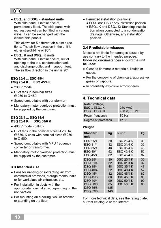
● ESQ.. and DSQ..- standard units With side panel + intake socket, permanently fitted. The side panel with exhaust socket can be fitted in various ways. It can be exchanged with the closed side panels.
This allows for 5 different air outlet direc-tions. The air flow direction in the unit is either straight-line or 90°.
● ESQ.. K and DSQ.. K units With side panel + intake socket, outlet opening at the top, condensation tank and discharge outlet and 4 support feet. The air flow direction in the unit is 90°.
ESQ 25/4 ... ESQ 45/4 ESQ 25/4 K … ESQ 45/4 K
● 230 V model.
● Duct fans in nominal sizes Ø 250 to Ø 450.
● Speed controllable with transformer.
● Mandatory motor overload protection must be supplied by the customer.
DSQ 25/4 ... DSQ 63/6 DSQ 25/4 K … DSQ 50/6 K
● 400 V model (3+PE).
● Duct fans in the nominal sizes Ø 250 to Ø 630. K units with nominal sizes Ø 250 to Ø 500.
● Speed controllable with MFU frequency converter or transformer.
● Mandatory motor overload protection must be supplied by the customer.
Intended use 3.3● Fans for venting or extracting air from
commercial premises, storage rooms, halls or for workplace air extraction, etc.
● For installation in ducts with the appropriate nominal size, depending on the unit version.
● For mounting on a ceiling, wall or bracket, or standing on the floor.
● Permitted installation positions: ● ESQ.. and DSQ.: Any installation position. ● ESQ.. K and DSQ.. K: Standing installa- tion when connected to a condensation drainage. Otherwise, any installation position.
Predictable misuses 3.4Maico is not liable for damages caused by use contrary to the intended purpose. Under no circumstances should the unit be used:
● Close to flammable materials, liquids or gases.
● For the conveying of chemicals, aggressive gases or vapours.
● In potentially explosive atmospheres
4. Technical data
Rated voltage, ESQ.., ESQ.. K DSQ.., DSQ.. K
230 VAC 400 V, 3 + PE
Power frequency 50 Hz
Degree of protection IP 55
Weight
Standard unit
kg K unit kg
ESQ 25/4 ESQ 31/4 ESQ 35/4 ESQ 40/4 ESQ 45/4
3032485282
ESQ 25/4 K ESQ 31/4 K ESQ 35/4 K ESQ 40/4 K ESQ 45/4 K
30 32 48 52 82
DSQ 25/4 DSQ 31/4 DSQ 35/4 DSQ 40/4 DSQ 45/4 DSQ 45/6 DSQ 50/4 DSQ 50/6 DSQ 56/6 DSQ 63/6
3032485282809085135146
DSQ 25/4 K DSQ 31/4 K DSQ 35/4 K DSQ 40/4 K DSQ 45/4 K DSQ 45/6 K DSQ 50/4 K DSQ 50/6 K
30 32 48 52 82 80 90 85
For more technical data, see the rating plate, current catalogue or the Internet.
GB

11
5. Environmental conditions and operating limits
● Maximum permitted temperature of the air medium: ● ESQ.. and DSQ..: 50 °C ● ESQ.. K and DSQ.. K: 180 °C
6. Essential safety instructions
General safety instructions 6.1● Read the operating instructions through
carefully before starting up.
● Keep the instructions.
● The unit must not be used as a toy.
● Installation is only permitted when carried out by trained specialists.
● Electrical connections and repairs are only permitted when carried out by trained specialists.
● The degree of protection stated on the rating plate is only guaranteed ● if installation is undertaken correctly and ● if the cables are correctly guided into the cable screw-connection.
● Permanent electrical supply cable. Only connect the fan to a permanent electrical installation (max. 1.5 mm²). This must be equipped with a mains isolation device with contact openings of at least 3 mm at each pole.
● The unit may only be operated using the voltage and frequency shown on the rating plate.
● Only operate the fan unit when it is completely installed.
● Only install unit in ducts with at least 1 m of duct on the inlet and outlet sides.
● Ensure that foreign bodies cannot fall into or be sucked into the unit and duct.
● With free inlet and outlet, never install without a protective grille, e.g. the Maico SG protective grille.
● Modifications and alterations to the unit are not permitted and release Maico from any guarantee obligations and liability.
Safe and correct practices during 6.2operation In the case of incorrect use there is the risk of injury!
● Do not insert any objects in the air channel or the unit.
● Rotating impeller. In the case of installation with free inlet, do not get too close to the unit, to avoid hair, clothing or jewellery being drawn into the unit.
7. Installation preparations
DANGER
Danger to life from electric shock. Switch the mains fuse off.
CAUTION
Danger of injury from failure to mount Quickbox securely. Sufficiently dimensioned
mounting material is to be supplied by the customer.
Only fit unit on walls, ceilings or brackets with sufficient load-bearing capacity.
CAUTION
Risk of cuts from metal housing plates with sharp edges. Wear protective gloves.
Decide on the installation location. Make sure there is sufficient distance to the wall/ceiling so that the side panel can also be removed.
Make sure there is a level surface at the installation location.
Lay a permanent power cable to the installation location.
GB
12
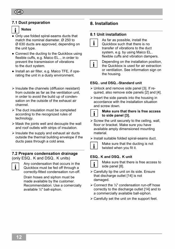
Duct preparation 7.1
Notes
● Only use folded spiral-seams ducts that match the nominal diameter. Ø 250 to Ø 630 ducts are approved, depending on the unit type.
● Connect the ducting to the Quickbox using flexible cuffs, e.g. Maico EL.., in order to prevent the transmission of vibrations to the duct system.
● Install an air filter, e.g. Maico TFE, if ope-rating the unit in a dusty environment.
Insulate the channels (diffusion resistant) from outside as far as the ventilation unit, in order to avoid the build up of conden-sation on the outside of the exhaust air channel.
The duct insulation must be completed according to the recognized rules of technology.
Mask the joints well and decouple the wall and roof outlets with strips of insulation.
Insulate the supply and exhaust air ducts outside the thermal building envelope if the ducts pass through a cold area.
Prepare condensation drainage 7.2(only ESQ.. K and DSQ.. K units)
Any condensation that occurs in the Quickbox must be fed off through a correctly-fitted condensation run-off.
Drain hoses and siphon must be made available by the customer. Recommendation: Use a comercially available ½" ball-siphon.
8. Installation
Unit installation 8.1As far as possible, install the Quickbox such that there is no transfer of vibrations to the duct system, e.g. by using Maico EL.. flexible cuffs and vibration dampers.
Depending on the installation position, the Quickbox is used for air extraction or ventilation. See information sign on the housing.
ESQ.. und DSQ..-Standard unit
Unlock and remove side panel [3]. If re-quired, also remove side panels [2] and [4].
Insert the side panels into the housing in accordance with the installation situation and screw down.
Make sure that there is free access to side panel [3].
Screw the unit securely to the ceiling, wall, floor or bracket. Make sure you have available amply dimensioned mounting material.
Install suitable folded spiral-seams duct.
Make sure that the ducting is not twisted when you fit it.
ESQ.. K and DSQ.. K unit
Make sure that there is free access to side panel [8].
Carefully tip the unit on its side. Ensure that discharge outlet [14] is not damaged.
Connect the ½" condensation run-off hose correctly to the discharge outlet [14] and to a commercially available ball-siphon.
Carefully set the unit on the support feet.
i
i
i
i
i
i i
GB

13
Screw the unit securely to the ceiling, wall, floor or bracket with the exhaust air outlet directed upwards. Make sure you have available amply dimensioned mounting material.
Install suitable folded spiral-seams duct.
Make sure that the ducting is not twisted when you fit it.
Electrical connection 8.2
DANGER
Danger to life from electric shock. Switch the mains fuse off. Position a warning notice to
avoid the unit being accidentally switched back on.
CAUTION
Danger of short-circuits through incorrect feeding of the power cable into the terminal box. Feed the power cable
correctly through the cable screw-connection.
Notes
● Always note the relevant specifications for electrical installations and when fitting equipment. In Germany observe DIN VDE 0100 and the corresponding parts in particular.
● The cabling between the power and the terminal box must be permanent.
● Units are speed controllable with ● frequency converters (only DSQ.. and DSQ.. K) or ● transformers. Select the best option depending on the current input. Speed control through the use of phase angles is not permitted!
Connect the unit electrically
In the case of standard units, remove the side panel [3] and feed the power cable through the cable screw-connection [6] in the housing. Ensure that the cable screw-connection seals off the power cable tightly. The cable screw-connection also serves as a tension relief.
Remove the terminal box cover.
CAUTION
Danger of short-circuits caused by damp if the power cable is not inserted correctly into the terminal box. Insert the power cable into the
terminal box such that the cable screw-connection fits tightly round the power cable.
Connect the power cable to the connection terminal [7.1] or [13.1] respectively, as shown on the inside of the terminal box cover.
Connect a suitable motor overload protect-tion device.
Put the terminal block cover on and screw it into place.
In the case of standard units, fit side panel [3] and secure with the two catches [3.1].
i
i
GB

14
Start-up 8.3 Before start-up, ensure that there are no
objects, small parts, dirt, etc., in the ducts.
Check that the technical data has been adhered to, by reference to the rating plate.
Ensure that the air can flow unhindered.
Switch the mains fuse on and carry out a function test. Check that the impeller runs quietly.
9. Maintenance
The unit is maintenance-free.
10. Fault rectification
● Call on the services of a trained electri-cian any time there is a fault.
● Repairs should only be carried out by a trained electrician.
DANGER
Danger to life from electric shock. Switch off mains fuse before
repairs.
Fault Countermeasure
Unit doesn’t run Check that the mains fuse is switched on.
Deposits on the impeller and in the housing caused by dust in the air.
Call on the services of a trained specialist. Fit air filter in duct system. Under no circumstances should the inside of the unit be cleaned with water or a high-pressure cleaner.
11. Dismantling
DANGER
Danger to life from electric shock. Switch the mains fuse off.
Dismantling should only be carried out by a trained electrician.
12. Disposal
Not in domestic waste. The unit contains in part material that can be recycled and in part substan-ces that should not end up as domestic waste.
Dispose of the unit once it has reached the end of its working life according to the regulations valid where you are.
i
i
GB

15

16
Maico Elektroapparate-Fabrik GmbH • Steinbeisstr. 20 • 78056 Villingen-Schwenningen • Germany • Service +49 7720 694 447 • [email protected]
tim
_W
S_D
1203
.3_
F.
LR
03.12