Spannsätze & Spannelemente - Amazon Web Services
92
Partner for performance www.ringfeder.com DE|EN 03|2013 Spannsätze & Spannelemente Locking Assemblies & Locking Elements
Transcript of Spannsätze & Spannelemente - Amazon Web Services

Partner for performancewww.ringfeder.com
DE|EN0 3 | 2 0 1 3
Spannsätze & SpannelementeLocking Assemblies &
Locking Elements
RIN
GF
ED
ER
SP
AN
NS
ÄT
ZE
& S
PA
NN
ELE
ME
NT
E ·
LOC
KIN
G A
SS
EM
BL
IES
& L
OC
KIN
G E
LE
ME
NTS
· D
E|E
N 0
3|2
01
3

Wir sind für Sie daA Global Presence For You
Die heutige RINGFEDER POWER TRANS MISSION GMBH wurde 1922 in Krefeld / Deutschland als Patentverwertungsgesellschaft für Reibungsfedern gegründet. Heute sind wir ein weltweiter An-bieter für Spitzenprodukte der Antriebs- und Dämpfungstechnik. Innovatives Denken in die Grenzbereiche des Möglichen zeichnet uns aus und hilft uns, mit progressiven und günstigen Lösungen den technischen Fortschritt unserer Kunden zu unterstützen.
The RINGFEDER POWER TRANSMISSION GMBH was founded in 1922 in Krefeld, Germany to fabricate and promote Friction Spring technology. Today we have expanded our offerings to top power transmission and damping products. Innovative thinking sets us apart and allows us to develop progressive and economical solu-tions to support our customers.
2

Besondere Anforderungen erfordern besondere AnstrengungenWir stehen Ihnen mit langjähriger Erfahrung und produktivem En-gineering zur Verfügung - ob mit Standardprodukten oder auf indi-viduelle Anfrage. Wir verste hen Dinge wie außer gewöhnlich hohe Belastbarkeit oder Montage-, Demontagefreund lichkeit von Bauteilen, aber auch die Senkung von Fertigungskosten als „Dienst am Kunden“ und entwickeln effiziente und technisch ausgereifte Lösungen.
Special applications require special solutionsOur extensive range of RINGFEDER POWER TRANSMISSION pro-ducts can be applied to solve most applications. We don´t just sell, but by understanding the individual requirements of our customers (e.g. loads on the components, easy installation/removal capability and reduction of production costs) assist you in every step with innovative engineering to plan efficient and technically mature solutions.
3
InhaltContent
Inhalt
Content
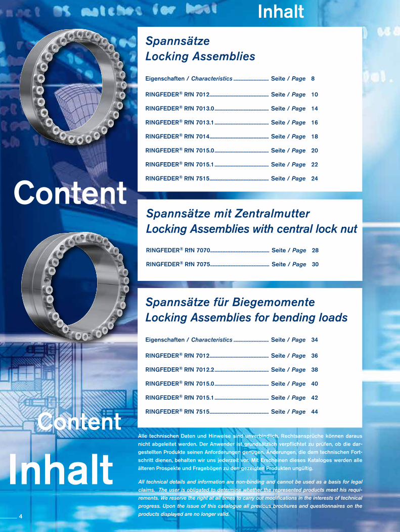
SpannsätzeLocking Assemblies
Eigenschaften / Characteristics ............................ Seite / Page 8
RINGFEDER® RfN 7012 ............................................... Seite / Page 10
RINGFEDER® RfN 7013.0 ........................................... Seite / Page 14
RINGFEDER® RfN 7013.1 ........................................... Seite / Page 16
RINGFEDER® RfN 7014 ............................................... Seite / Page 18
RINGFEDER® RfN 7015.0 ........................................... Seite / Page 20
RINGFEDER® RfN 7015.1 ........................................... Seite / Page 22
RINGFEDER® RfN 7515 ............................................... Seite / Page 24
All technical details and information are non-binding and cannot be used as a basis for legal
claims. The user is obligated to determine whether the represented products meet his requi-
rements. We reserve the right at all times to carry out modifications in the interests of technical
progress. Upon the issue of this catalogue all previous brochures and questionnaires on the
products displayed are no longer valid.
Alle technischen Daten und Hin weise sind unverbindlich, Rechts ansprüche können daraus
nicht abgeleitet werden. Der Anwender ist grundsätzlich verpflichtet zu prüfen, ob die dar-
gestellten Produkte seinen Anforderungen genügen. Änderungen, die dem technischen Fort-
schritt dienen, behalten wir uns jederzeit vor. Mit Erscheinen dieses Kataloges werden alle
älteren Prospekte und Fragebögen zu den gezeigten Produkten ungültig.
Spannsätze für BiegemomenteLocking Assemblies for bending loads
Eigenschaften / Characteristics ............................ Seite / Page 34
RINGFEDER® RfN 7012 ............................................... Seite / Page 36
RINGFEDER® RfN 7012.2 ........................................... Seite / Page 38
RINGFEDER® RfN 7015.0 ........................................... Seite / Page 40
RINGFEDER® RfN 7015.1 ........................................... Seite / Page 42
RINGFEDER® RfN 7515 ............................................... Seite / Page 44
Spannsätze mit ZentralmutterLocking Assemblies with central lock nut
RINGFEDER® RfN 7070 ............................................... Seite / Page 28
RINGFEDER® RfN 7075 ............................................... Seite / Page 30
4
Inhalt
Content
Inhalt
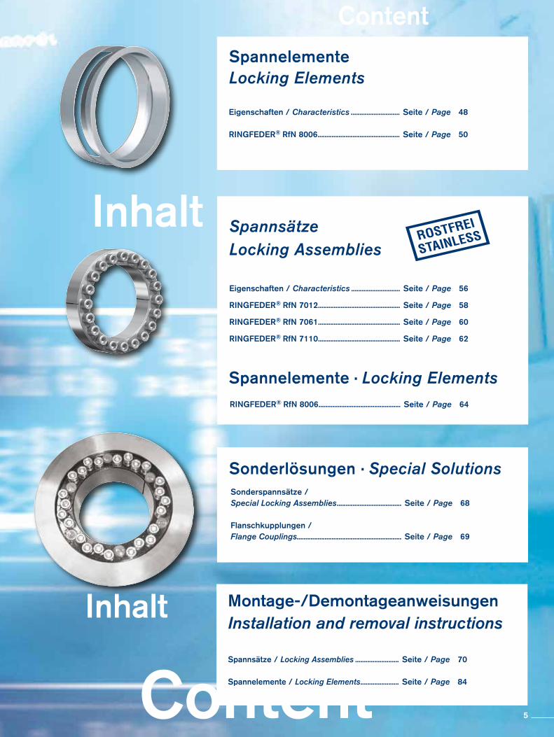
ContentSpannelementeLocking Elements
Eigenschaften / Characteristics ............................ Seite / Page 48
RINGFEDER® RfN 8006 ............................................... Seite / Page 50
Sonderlösungen · Special SolutionsSonderspannsätze / Special Locking Assemblies ..................................... Seite / Page 68
Flanschkupplungen / Flange Couplings............................................................ Seite / Page 69
Montage-/DemontageanweisungenInstallation and removal instructions
Spannsätze / Locking Assemblies ......................... Seite / Page 70
Spannelemente / Locking Elements ...................... Seite / Page 84
SpannsätzeLocking Assemblies
Eigenschaften / Characteristics ............................ Seite / Page 56
RINGFEDER® RfN 7012 ............................................... Seite / Page 58
RINGFEDER® RfN 7061 ............................................... Seite / Page 60
RINGFEDER® RfN 7110 ............................................... Seite / Page 62
RINGFEDER® RfN 8006 ............................................... Seite / Page 64
Spannelemente · Locking Elements
5
RINGFEDER® Spannsätze · Locking Assemblies
6
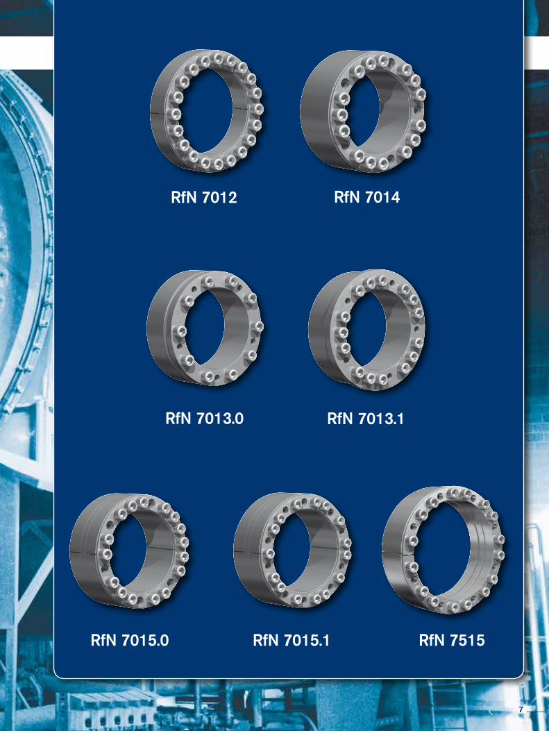
RfN 7012 RfN 7014
RfN 7013.0 RfN 7013.1
RfN 7015.0 RfN 7015.1 RfN 7515
7
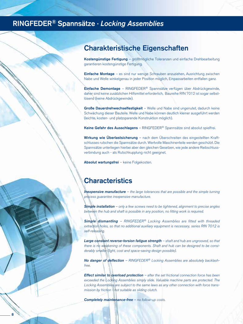
Charakteristische EigenschaftenKostengünstige Fertigung – größtmögliche Toleranzen und einfache Drehbearbeitung garantieren kostengünstige Fertigung.
Einfache Montage – es sind nur wenige Schrauben anzuziehen, Ausrichtung zwischen Nabe und Welle winkelgenau in jeder Position möglich, Einpassarbeiten entfallen ganz.
Einfache Demontage – RINGFEDER® Spannsätze verfügen über Abdrückgewinde, daher sind keine zusätzlichen Hilfsmittel erforderlich, Baureihe RfN 7012 ist sogar selbst-lösend (keine Abdrückgewinde).
Große Dauerdrehwechselfestigkeit – Welle und Nabe sind ungenutet, dadurch keine Schwächung dieser Bauteile. Welle und Nabe können deutlich kleiner ausgeführt werden (leichte, kosten- und platzsparende Konstruktion möglich).
Keine Gefahr des Ausschlagens – RINGFEDER® Spannsätze sind absolut spielfrei.
Wirkung wie Überlastsicherung – nach dem Überschreiten des eingestellten Kraft-schlusses rutschen die Spannsätze durch. Wertvolle Maschinenteile werden geschützt. Die Spannsätze unterliegen hierbei aber den gleichen Gesetzen, wie jede andere Reibschluss-verbindung auch - als Rutschkupplung nicht geeignet.
Absolut wartungsfrei – keine Folgekosten.
Characteristics
Inexpensive manufacture – the large tolerances that are possible and the simple turning process guarantee inexpensive manufacture.
Simple installation – only a few screws need to be tightened, alignment to precise angles between the hub and shaft is possible in any position, no fitting work is required.
Simple dismantling – RINGFEDER® Locking Assemblies are fitted with threaded extraction holes, so that no additional auxiliary equipment is necessary, series RfN 7012 is self-releasing.
Large constant reverse-torsion fatigue strength – shaft and hub are ungrooved, so that there is no weakening of these components. Shaft and hub can be designed to be consi-derably smaller (light, cost and space-saving design possible).
No danger of deflection – RINGFEDER® Locking Assemblies are absolutely backlash-free.
Effect similar to overload protection – after the set frictional connection force has been exceeded the Locking Assemblies simply slide. Valuable machine parts are protected. The Locking Assemblies are subject to the same laws as any other connection with force trans-mission by friction - not suitable as sliding clutch.
Completely maintenance-free – no follow-up costs.
RINGFEDER® Spannsätze · Locking Assemblies
8
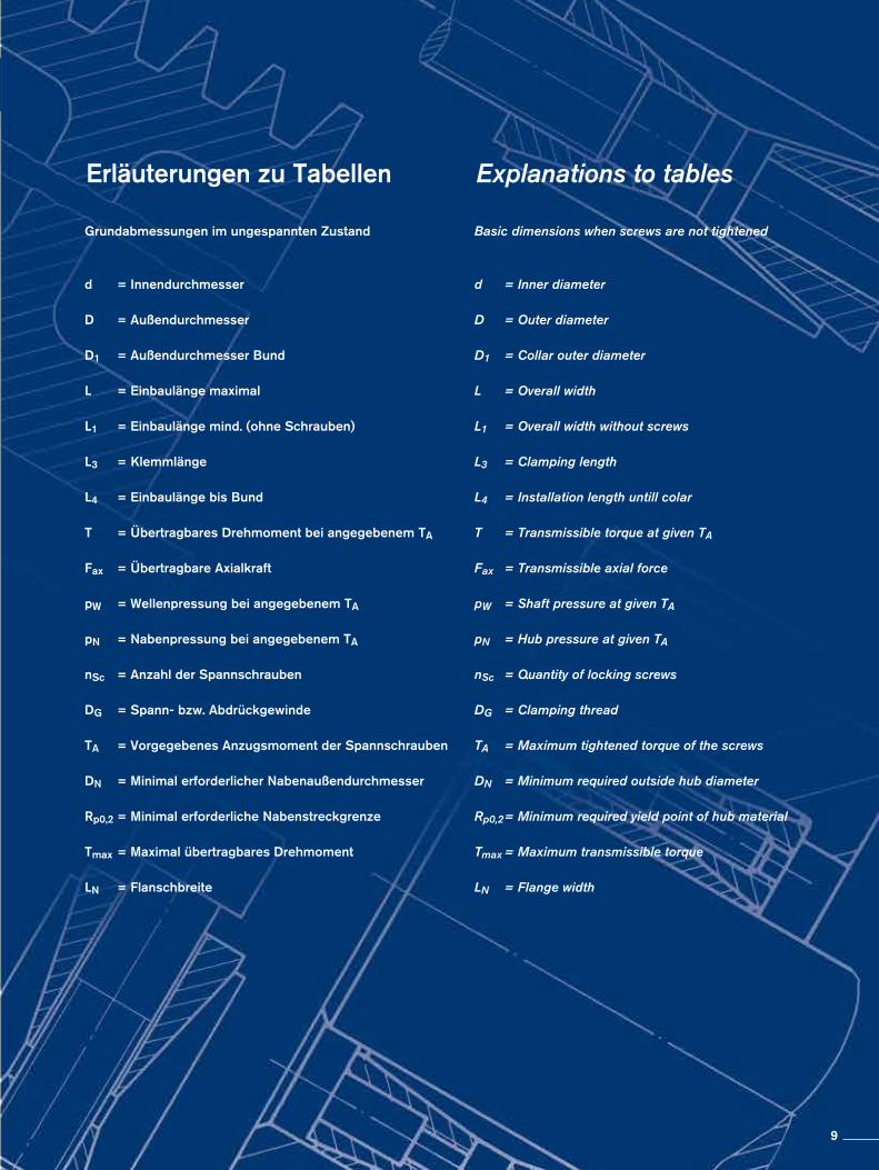
Erläuterungen zu Tabellen Explanations to tables
Grundabmessungen im ungespannten Zustand
d = Innendurchmesser
D = Außendurchmesser
D1 = Außendurchmesser Bund
L = Einbaulänge maximal
L1 = Einbaulänge mind. (ohne Schrauben)
L3 = Klemmlänge
L4 = Einbaulänge bis Bund
T = Übertragbares Drehmoment bei angegebenem TA
Fax = Übertragbare Axialkraft
pW = Wellenpressung bei angegebenem TA pN = Nabenpressung bei angegebenem TA nSc = Anzahl der Spannschrauben DG = Spann- bzw. Abdrückgewinde TA = Vorgegebenes Anzugsmoment der Spannschrauben
DN = Minimal erforderlicher Nabenaußendurchmesser Rp0,2 = Minimal erforderliche Nabenstreckgrenze
Tmax = Maximal übertragbares Drehmoment
LN = Flanschbreite
Basic dimensions when screws are not tightened
d = Inner diameter
D = Outer diameter
D1 = Collar outer diameter L = Overall width L1 = Overall width without screws L3 = Clamping length L4 = Installation length untill colar T = Transmissible torque at given TA
Fax = Transmissible axial force
pW = Shaft pressure at given TA
pN = Hub pressure at given TA
nSc = Quantity of locking screws
DG = Clamping thread
TA = Maximum tightened torque of the screws
DN = Minimum required outside hub diameter
Rp0,2 = Minimum required yield point of hub material
Tmax = Maximum transmissible torque
LN = Flange width
9
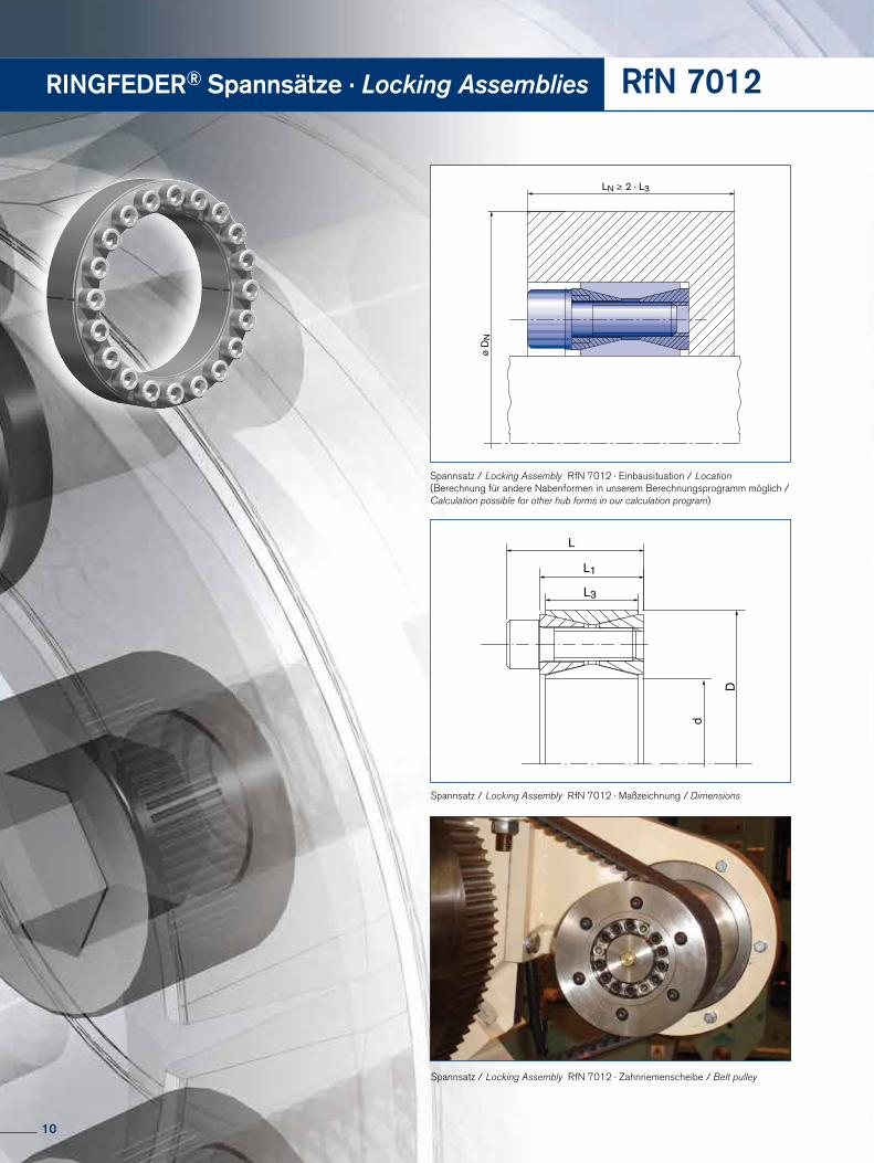
ø D
N
LN ≥ 2 · L3
Spannsatz / Locking Assembly RfN 7012 · Zahnriemenscheibe / Belt pulley
L
d
D
L3
L1
Spannsatz / Locking Assembly RfN 7012 · Maßzeichnung / Dimensions
Spannsatz / Locking Assembly RfN 7012 · Einbausituation / Location (Berechnung für andere Nabenformen in unserem Berechnungsprogramm möglich / Calculation possible for other hub forms in our calculation program)
RINGFEDER® Spannsätze · Locking Assemblies RfN 7012
10
Fortsetzung s. nächste Seite To continue see next page
RfN 7012
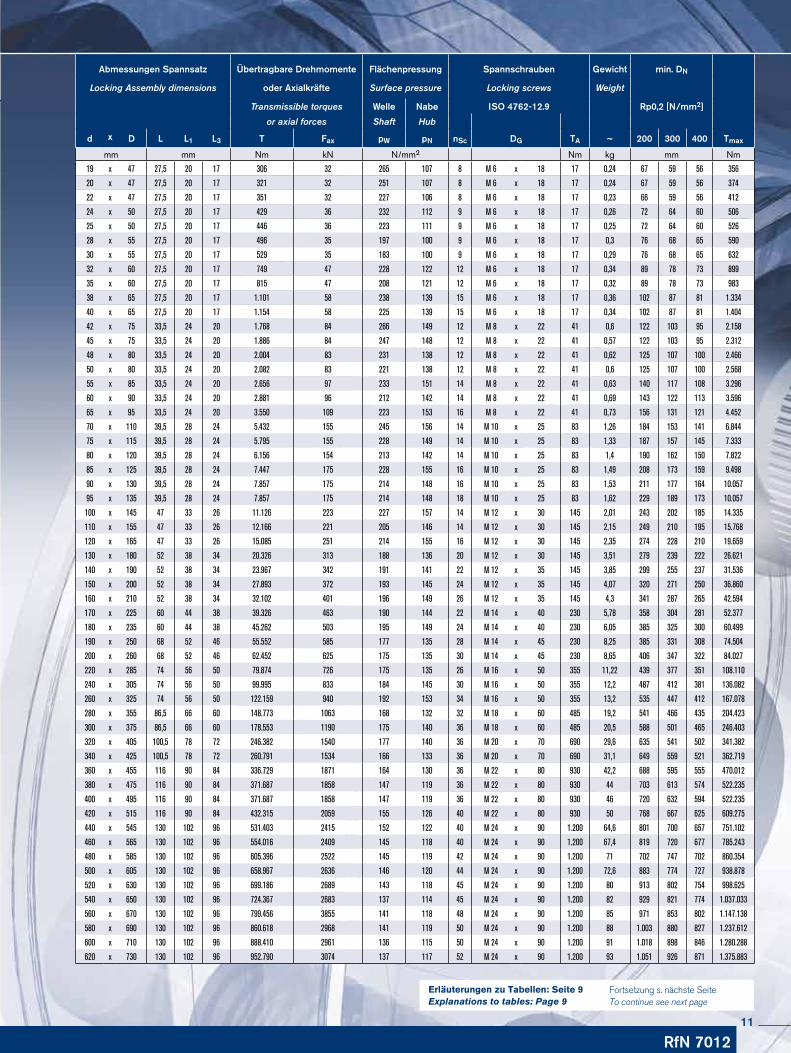
Abmessungen Spannsatz Übertragbare Drehmomente Flächenpressung Spannschrauben Gewicht min. DN
Locking Assembly dimensions oder Axialkräfte Surface pressure Locking screws Weight
Transmissible torques Welle Nabe ISO 4762-12.9 Rp0,2 [N/mm2]
or axial forces Shaft Hub
d x D L L1 L3 T Fax pW pN nSc DG TA ~ 200 300 400 Tmax
mm mm Nm kN N/mm2 Nm kg mm Nm
19 x 47 27,5 20 17 306 32 265 107 8 M 6 x 18 17 0,24 67 59 56 356
20 x 47 27,5 20 17 321 32 251 107 8 M 6 x 18 17 0,24 67 59 56 374
22 x 47 27,5 20 17 351 32 227 106 8 M 6 x 18 17 0,23 66 59 56 412
24 x 50 27,5 20 17 429 36 232 112 9 M 6 x 18 17 0,26 72 64 60 506
25 x 50 27,5 20 17 446 36 223 111 9 M 6 x 18 17 0,25 72 64 60 526
28 x 55 27,5 20 17 496 35 197 100 9 M 6 x 18 17 0,3 76 68 65 590
30 x 55 27,5 20 17 529 35 183 100 9 M 6 x 18 17 0,29 76 68 65 632
32 x 60 27,5 20 17 749 47 228 122 12 M 6 x 18 17 0,34 89 78 73 899
35 x 60 27,5 20 17 815 47 208 121 12 M 6 x 18 17 0,32 89 78 73 983
38 x 65 27,5 20 17 1.101 58 238 139 15 M 6 x 18 17 0,36 102 87 81 1.334
40 x 65 27,5 20 17 1.154 58 225 139 15 M 6 x 18 17 0,34 102 87 81 1.404
42 x 75 33,5 24 20 1.768 84 266 149 12 M 8 x 22 41 0,6 122 103 95 2.158
45 x 75 33,5 24 20 1.886 84 247 148 12 M 8 x 22 41 0,57 122 103 95 2.312
48 x 80 33,5 24 20 2.004 83 231 138 12 M 8 x 22 41 0,62 125 107 100 2.466
50 x 80 33,5 24 20 2.082 83 221 138 12 M 8 x 22 41 0,6 125 107 100 2.568
55 x 85 33,5 24 20 2.656 97 233 151 14 M 8 x 22 41 0,63 140 117 108 3.296
60 x 90 33,5 24 20 2.881 96 212 142 14 M 8 x 22 41 0,69 143 122 113 3.596
65 x 95 33,5 24 20 3.550 109 223 153 16 M 8 x 22 41 0,73 156 131 121 4.452
70 x 110 39,5 28 24 5.432 155 245 156 14 M 10 x 25 83 1,26 184 153 141 6.844
75 x 115 39,5 28 24 5.795 155 228 149 14 M 10 x 25 83 1,33 187 157 145 7.333
80 x 120 39,5 28 24 6.156 154 213 142 14 M 10 x 25 83 1,4 190 162 150 7.822
85 x 125 39,5 28 24 7.447 175 228 155 16 M 10 x 25 83 1,49 208 173 159 9.498
90 x 130 39,5 28 24 7.857 175 214 148 16 M 10 x 25 83 1,53 211 177 164 10.057
95 x 135 39,5 28 24 7.857 175 214 148 18 M 10 x 25 83 1,62 229 189 173 10.057
100 x 145 47 33 26 11.126 223 227 157 14 M 12 x 30 145 2,01 243 202 185 14.335
110 x 155 47 33 26 12.166 221 205 146 14 M 12 x 30 145 2,15 249 210 195 15.768
120 x 165 47 33 26 15.085 251 214 155 16 M 12 x 30 145 2,35 274 228 210 19.659
130 x 180 52 38 34 20.326 313 188 136 20 M 12 x 30 145 3,51 279 239 222 26.621
140 x 190 52 38 34 23.967 342 191 141 22 M 12 x 35 145 3,85 299 255 237 31.536
150 x 200 52 38 34 27.893 372 193 145 24 M 12 x 35 145 4,07 320 271 250 36.860
160 x 210 52 38 34 32.102 401 196 149 26 M 12 x 35 145 4,3 341 287 265 42.594
170 x 225 60 44 38 39.326 463 190 144 22 M 14 x 40 230 5,78 358 304 281 52.377
180 x 235 60 44 38 45.262 503 195 149 24 M 14 x 40 230 6,05 385 325 300 60.499
190 x 250 68 52 46 55.552 585 177 135 28 M 14 x 45 230 8,25 385 331 308 74.504
200 x 260 68 52 46 62.452 625 175 135 30 M 14 x 45 230 8,65 406 347 322 84.027
220 x 285 74 56 50 79.874 726 175 135 26 M 16 x 50 355 11,22 439 377 351 108.110
240 x 305 74 56 50 99.995 833 184 145 30 M 16 x 50 355 12,2 487 412 381 136.082
260 x 325 74 56 50 122.159 940 192 153 34 M 16 x 50 355 13,2 535 447 412 167.078
280 x 355 86,5 66 60 148.773 1063 168 132 32 M 18 x 60 485 19,2 541 466 435 204.423
300 x 375 86,5 66 60 178.553 1190 175 140 36 M 18 x 60 485 20,5 588 501 465 246.403
320 x 405 100,5 78 72 246.382 1540 177 140 36 M 20 x 70 690 29,6 635 541 502 341.382
340 x 425 100,5 78 72 260.791 1534 166 133 36 M 20 x 70 690 31,1 649 559 521 362.719
360 x 455 116 90 84 336.729 1871 164 130 36 M 22 x 80 930 42,2 688 595 555 470.012
380 x 475 116 90 84 371.687 1858 147 119 36 M 22 x 80 930 44 703 613 574 522.235
400 x 495 116 90 84 371.687 1858 147 119 36 M 22 x 80 930 46 720 632 594 522.235
420 x 515 116 90 84 432.315 2059 155 126 40 M 22 x 80 930 50 768 667 625 609.275
440 x 545 130 102 96 531.403 2415 152 122 40 M 24 x 90 1.200 64,6 801 700 657 751.102
460 x 565 130 102 96 554.016 2409 145 118 40 M 24 x 90 1.200 67,4 819 720 677 785.243
480 x 585 130 102 96 605.396 2522 145 119 42 M 24 x 90 1.200 71 702 747 702 860.354
500 x 605 130 102 96 658.967 2636 146 120 44 M 24 x 90 1.200 72,6 883 774 727 938.878
520 x 630 130 102 96 699.186 2689 143 118 45 M 24 x 90 1.200 80 913 802 754 998.625
540 x 650 130 102 96 724.367 2683 137 114 45 M 24 x 90 1.200 82 929 821 774 1.037.033
560 x 670 130 102 96 799.456 3855 141 118 48 M 24 x 90 1.200 85 971 853 802 1.147.138
580 x 690 130 102 96 860.618 2968 141 119 50 M 24 x 90 1.200 88 1.003 880 827 1.237.612
600 x 710 130 102 96 888.410 2961 136 115 50 M 24 x 90 1.200 91 1.018 898 846 1.280.288
620 x 730 130 102 96 952.790 3074 137 117 52 M 24 x 90 1.200 93 1.051 926 871 1.375.883
Erläuterungen zu Tabellen: Seite 9Explanations to tables: Page 9
11
RINGFEDER® Spannsätze · Locking Assemblies RfN 7012
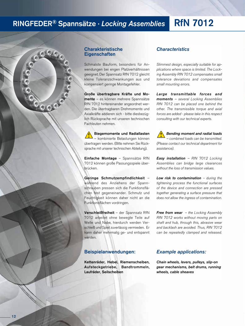
Charakteristische Eigenschaften
Schmalste Bauform, besonders für An-wendungen bei engen Platzverhältnissen geeignet. Der Spannsatz RfN 7012 gleicht kleine Toleranzschwankungen aus und kompensiert geringe Montagefehler.
Große übertragbare Kräfte und Mo-mente – es können mehrere Spannsätze RfN 7012 hintereinander angeordnet wer-den. Die übertragbaren Drehmomente und Axialkräfte addieren sich - bitte diesbezüg-lich Rücksprache mit unseren technischen Fachleuten nehmen.
Biegemomente und Radiallasten – kombinierte Belastungen können
übertragen werden. (Bitte nehmen Sie Rück-sprache mit unserer technischen Abteilung).
Einfache Montage – Spannsätze RfN 7012 können große Passungsspiele über-brücken.
Geringe Schmutzempfindlichkeit – während des Anziehens der Spann-schrauben pressen sich die Funktionsflä-chen fest gegeneinander. Schmutz und Feuchtigkeit können daher nicht an die Funktionsflächen vordringen.
Verschleißfreiheit – der Spannsatz RfN 7012 arbeitet ohne bewegte Teile auf Welle und Nabe, hierdurch werden Ver-schleiß und Spiel zuverlässig vermieden. Er kann daher mehrmalig ge- und entspannt werden.
Beispielanwendungen:
Kettenräder, Hebel, Riemenscheiben, Aufsteckgetriebe, Band trommeln, Laufräder, Seilscheiben
Characteristics
Slimmest design, especially suitable for ap-plications where space is limited. The Lock-ing Assembly RfN 7012 compensates small tolerance deviations and compensates small mounting errors.
Large transmittable forces and moments – several Locking Assemblies RfN 7012 can be placed one behind the other. The transmissible torque and axial forces are added - please take in this respect consulting with our technical experts.
Bending moment and radial loads – combined loads can be transmitted.
(Please contact our technical department for assistance).
Easy installation – RfN 7012 Locking Assemblies can bridge large clearances without the loss of transmission values.
Low risk to contamination – during the tightening process the functional surfaces of the device and connection are pressed together generating a surface pressure that does not allow the ingress of contamination.
Free from wear – the Locking AssemblyRfN 7012 works without moving parts onshaft and hub, through this, abrasive wearand backlash are avoided. Thus, RfN 7012can be repeatedly clamped and released.
Example applications:
Chain wheels, levers, pulleys, slip-on gear mechanisms, belt drums, running wheels, cable sheaves
12
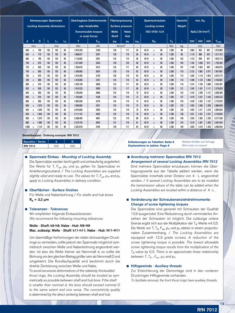
Abmessungen Spannsatz Übertragbare Drehmomente Flächenpressung Spannschrauben Gewicht min. DN
Locking Assembly dimensions oder Axialkräfte Surface pressure Locking screws Weight
Transmissible torques Welle Nabe ISO 4762-12.9 Rp0,2 [N/mm2]
or axial forces Shaft Hub
d x D L L1 L3 T Fax pW pN nSc DG TA ~ 200 300 400 Tmax
mm mm Nm kN N/mm2 Nm kg mm Nm
640 x 750 130 102 96 1.019.329 3185 138 117 54 M 24 x 90 1.200 96 1.083 953 897 1.474.892
660 x 770 130 102 96 1.088.021 3297 138 118 56 M 24 x 90 1.200 99 1.116 980 922 1.577.315
680 x 790 130 102 96 1.118.902 3291 134 115 56 M 24 x 90 1.200 102 1.133 999 941 1.625.113
700 x 810 130 102 96 1.231.849 3520 139 120 60 M 24 x 90 1.200 104 1.182 1.036 973 1.792.404
720 x 830 130 102 96 1.264.816 3513 135 117 60 M 24 x 90 1.200 107 1.199 1.054 992 1.843.615
740 x 850 130 102 96 1.340.983 3624 135 118 62 M 24 x 90 1.200 110 2.132 1.082 1.017 1.957.987
760 x 870 130 102 96 1.419.285 3735 136 119 64 M 24 x 90 1.200 113 1.265 1.110 1.043 2.075.774
780 x 890 130 102 96 1.476.995 3787 134 118 65 M 24 x 90 1.200 116 1.289 1.133 1.065 2.163.687
800 x 910 130 102 96 1.535.740 3839 133 117 66 M 24 x 90 1.200 118 1.314 1.156 1.088 2.253.307
820 x 930 130 102 96 1.619.333 3950 133 117 68 M 24 x 90 1.200 121 1.343 1.181 1.111 2.379.629
840 x 950 130 102 96 1.705.048 4060 134 118 70 M 24 x 90 1.200 124 1.376 1.209 1.137 2.509.365
860 x 970 130 102 96 1.792.882 4169 134 119 72 M 24 x 90 1.200 127 1.410 1.237 1.163 2.642.515
880 x 990 130 102 96 1.882.830 4279 134 119 74 M 24 x 90 1.200 129 1.439 1.263 1.187 2.779.079
900 x 1.010 130 102 96 1.948.904 4331 133 118 75 M 24 x 90 1.200 132 1.463 1.286 1.209 2.880.649
920 x 1.030 130 102 96 2.016.005 4383 132 118 76 M 24 x 90 1.200 135 1.492 1.311 1.233 2.983.925
940 x 1.050 130 102 96 2.111.197 4492 132 118 78 M 24 x 90 1.200 138 1.521 1.337 1.257 3.129.024
960 x 1.070 130 102 96 2.208.493 4601 132 119 80 M 24 x 90 1.200 140 1.555 1.365 1.283 3.277.538
980 x 1.090 130 102 96 2.279.745 4653 131 118 81 M 24 x 90 1.200 143 1.579 1.387 1.305 3.387.643
1.000 x 1.110 130 102 96 2.352.018 4704 130 117 82 M 24 x 90 1.200 146 1.603 1.410 1.326 3.499.454
Baureihe / Series d D
RfN 7012 200 260
Bestellbeispiel · Ordering example: RfN 7012
RfN 7012
Weitere Größen auf Anfrage More sizes on request
Erläuterungen zu Tabellen: Seite 9Explanations to tables: Page 9
Spannsatz-Einbau · Mounting of Locking Assembly Die Spannsätze werden leicht geölt und einbaufertig angeliefert. Die Werte für T, Fax, pW und pN gelten für Spann sätze im An liefe rungszustand. / The Locking Assemblies are supplied slightly oiled and ready-to-use. The values for T, Fax, pW and pN
apply to Locking Assemblies in delivery condition.
Oberflächen · Surface finishes Für Welle und Nabenbohrung / For shafts and hub bores Ra = 3,2 µm
Toleranzen · Tolerances Wir empfehlen folgende Einbautoleranzen We recommend the following mounting tolerances
Welle · Shaft: k9-h9; Nabe · Hub: N9-H9 Max. zulässig: Welle · Shaft: k11-h11; Nabe · Hub: N11-H11
Um übermäßige Verformungen der relativ dickwandigen Druck- ringe zu vermeiden, sollte jedoch der Spannsatz möglichst sym- metrisch zwischen Welle und Nabenbohrung angeordnet wer- den. Ist also die Welle kleiner als Nennmaß d, so sollte die Bohrung um den gleichen Betrag größer sein als Nennmaß D und umgekehrt. Die Rundlaufqualität wird bestimmt durch die direkte Zentrierung zwischen Welle und Nabe. To avoid excessive deformations of the relatively thickwalled thrust rings, the Locking Assembly should be located as sym- metrically as possible between shaft and hub bore. If the shaft is smaller than nominal d, the bore should exceed nominal D to the same extent and vice versa. The concentricity quality is determined by the direct centering between shaft and hub.
Anordnung mehrerer Spannsätze RfN 7012 Arrangement of several Locking Assemblies RfN 7012 Sind mehrere Spannsätze einzubauen, können die Über- tragungswerte aus der Tabelle addiert werden, wenn die Spannsätze innerhalb einer Distanz von 4 · L angeordnet werden. / If several Locking Assemblies are to be installed the transmission values of the table can be added when the Locking Assemblies are located within a distance of 4 · L .
Veränderung der Schraubenanziehdrehmomente Change of screw tightening torques Die Spannsätze sind generell mit Schrauben der Qualität 12.9 ausgerüstet. Eine Redu zierung durch vermindertes An- ziehen der Schrau ben ist möglich. Die zulässige untere Grenze ergibt sich aus der Multi plikation der TA-Werte mit 0,5. Die Werte von T, TA, Fax, pW und pN stehen in einem proportio- nalem Zusammenhang. / The Locking Assemblies are equipped with 12.9 grade screws. A reduction of the screw tightening torque is possible. The lowest allowable screw tightening torque results from the multiplication of the TA-value by 0,5. There is an approximate linear relationship between T, TA , Fax, pW and pN.
Hilfsgewinde · Auxiliary threads Zur Erleichterung der Demontage sind in den vorderen Druck ringen Hilfsgewinde vorhanden. To facilitate removal, the front thrust rings have auxiliary threads.
13
RINGFEDER® Spannsätze · Locking Assemblies RfN 7013.0
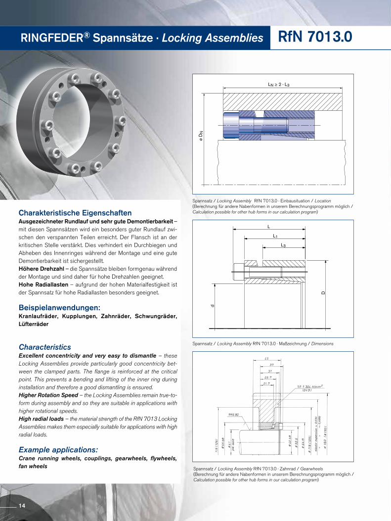
LN ≥ 2 · L3
ø D
N
Charakteristische EigenschaftenAusgezeichneter Rundlauf und sehr gute Demontierbarkeit – mit diesen Spannsätzen wird ein besonders guter Rundlauf zwi-schen den verspannten Teilen erreicht. Der Flansch ist an der kritischen Stelle verstärkt. Dies verhindert ein Durchbiegen und Abheben des Innenringes während der Montage und eine gute Demontierbarkeit ist sichergestellt.Höhere Drehzahl – die Spannsätze bleiben formgenau während der Montage und sind daher für hohe Drehzahlen geeignet.Hohe Radiallasten – aufgrund der hohen Materialfestigkeit ist der Spannsatz für hohe Radiallasten besonders geeignet.
Beispielanwendungen:Kranlaufräder, Kupplungen, Zahnräder, Schwungräder, Lüfterräder
CharacteristicsExcellent concentricity and very easy to dismantle – these Locking Assemblies provide particularly good concentricity bet-ween the clamped parts. The flange is reinforced at the critical point. This prevents a bending and lifting of the inner ring during installation and therefore a good dismantling is ensured.Higher Rotation Speed – the Locking Assemblies remain true-to-form during assembly and so they are suitable in applications with higher rotational speeds.High radial loads – the material strength of the RfN 7013 Locking Assemblies makes them especially suitable for applications with high radial loads.
Example applications:Crane running wheels, couplings, gearwheels, flywheels, fan wheels
L
L1
L3
d
D
Spannsatz / Locking Assembly RfN 7013.0 · Maßzeichnung / Dimensions
Spannsatz / Locking Assembly RfN 7013.0 · Einbausituation / Location(Berechnung für andere Nabenformen in unserem Berechnungsprogramm möglich / Calculation possible for other hub forms in our calculation program)
Spannsatz / Locking Assembly RfN 7013.0 · Zahnrad / Gearwheels (Berechnung für andere Nabenformen in unserem Berechnungsprogramm möglich / Calculation possible for other hub forms in our calculation program)
14
RfN 7013.0
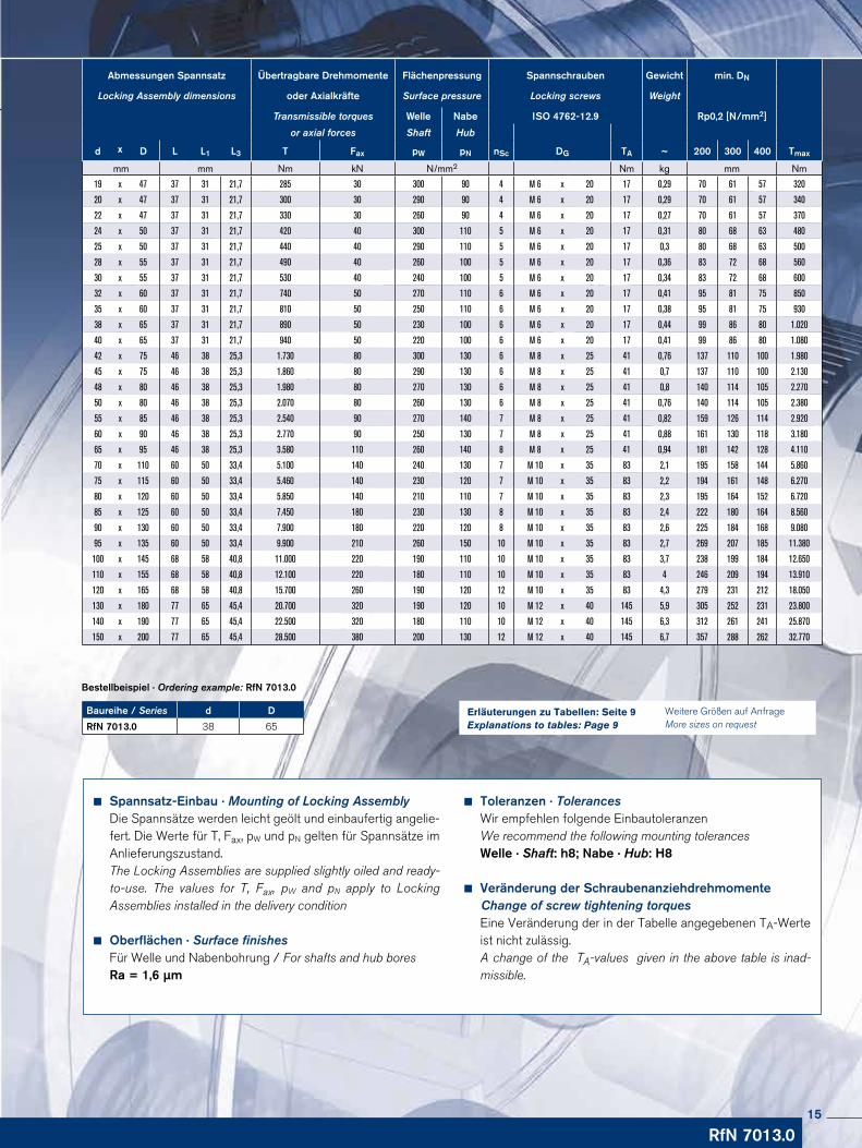
Baureihe / Series d D
RfN 7013.0 38 65
Bestellbeispiel · Ordering example: RfN 7013.0
Spannsatz-Einbau · Mounting of Locking AssemblyDie Spannsätze werden leicht geölt und einbaufertig angelie-fert. Die Werte für T, Fax, pW und pN gelten für Spann sätze im An liefe rungszustand. The Locking Assemblies are supplied slightly oiled and ready-to-use. The values for T, Fax, pW and pN apply to Locking Assemblies installed in the delivery condition
Oberflächen · Surface finishesFür Welle und Nabenbohrung / For shafts and hub boresRa = 1,6 µm
Toleranzen · TolerancesWir empfehlen folgende EinbautoleranzenWe recommend the following mounting tolerancesWelle · Shaft: h8; Nabe · Hub: H8
Veränderung der Schraubenanziehdrehmomente Change of screw tightening torques
Eine Veränderung der in der Tabelle angegebenen TA-Werte ist nicht zulässig.A change of the TA-values given in the above table is inad-missible.
Abmessungen Spannsatz Übertragbare Drehmomente Flächenpressung Spannschrauben Gewicht min. DN
Locking Assembly dimensions oder Axialkräfte Surface pressure Locking screws Weight
Transmissible torques Welle Nabe ISO 4762-12.9 Rp0,2 [N/mm2]
or axial forces Shaft Hub
d x D L L1 L3 T Fax pW pN nSc DG TA ~ 200 300 400 Tmax
mm mm Nm kN N/mm2 Nm kg mm Nm
19 x 47 37 31 21,7 285 30 300 90 4 M 6 x 20 17 0,29 70 61 57 320
20 x 47 37 31 21,7 300 30 290 90 4 M 6 x 20 17 0,29 70 61 57 340
22 x 47 37 31 21,7 330 30 260 90 4 M 6 x 20 17 0,27 70 61 57 370
24 x 50 37 31 21,7 420 40 300 110 5 M 6 x 20 17 0,31 80 68 63 480
25 x 50 37 31 21,7 440 40 290 110 5 M 6 x 20 17 0,3 80 68 63 500
28 x 55 37 31 21,7 490 40 260 100 5 M 6 x 20 17 0,36 83 72 68 560
30 x 55 37 31 21,7 530 40 240 100 5 M 6 x 20 17 0,34 83 72 68 600
32 x 60 37 31 21,7 740 50 270 110 6 M 6 x 20 17 0,41 95 81 75 850
35 x 60 37 31 21,7 810 50 250 110 6 M 6 x 20 17 0,38 95 81 75 930
38 x 65 37 31 21,7 890 50 230 100 6 M 6 x 20 17 0,44 99 86 80 1.020
40 x 65 37 31 21,7 940 50 220 100 6 M 6 x 20 17 0,41 99 86 80 1.080
42 x 75 46 38 25,3 1.730 80 300 130 6 M 8 x 25 41 0,76 137 110 100 1.980
45 x 75 46 38 25,3 1.860 80 290 130 6 M 8 x 25 41 0,7 137 110 100 2.130
48 x 80 46 38 25,3 1.980 80 270 130 6 M 8 x 25 41 0,8 140 114 105 2.270
50 x 80 46 38 25,3 2.070 80 260 130 6 M 8 x 25 41 0,76 140 114 105 2.380
55 x 85 46 38 25,3 2.540 90 270 140 7 M 8 x 25 41 0,82 159 126 114 2.920
60 x 90 46 38 25,3 2.770 90 250 130 7 M 8 x 25 41 0,88 161 130 118 3.180
65 x 95 46 38 25,3 3.580 110 260 140 8 M 8 x 25 41 0,94 181 142 128 4.110
70 x 110 60 50 33,4 5.100 140 240 130 7 M 10 x 35 83 2,1 195 158 144 5.860
75 x 115 60 50 33,4 5.460 140 230 120 7 M 10 x 35 83 2,2 194 161 148 6.270
80 x 120 60 50 33,4 5.850 140 210 110 7 M 10 x 35 83 2,3 195 164 152 6.720
85 x 125 60 50 33,4 7.450 180 230 130 8 M 10 x 35 83 2,4 222 180 164 8.560
90 x 130 60 50 33,4 7.900 180 220 120 8 M 10 x 35 83 2,6 225 184 168 9.080
95 x 135 60 50 33,4 9.900 210 260 150 10 M 10 x 35 83 2,7 269 207 185 11.380
100 x 145 68 58 40,8 11.000 220 190 110 10 M 10 x 35 83 3,7 238 199 184 12.650
110 x 155 68 58 40,8 12.100 220 180 110 10 M 10 x 35 83 4 246 209 194 13.910
120 x 165 68 58 40,8 15.700 260 190 120 12 M 10 x 35 83 4,3 279 231 212 18.050
130 x 180 77 65 45,4 20.700 320 190 120 10 M 12 x 40 145 5,9 305 252 231 23.800
140 x 190 77 65 45,4 22.500 320 180 110 10 M 12 x 40 145 6,3 312 261 241 25.870
150 x 200 77 65 45,4 28.500 380 200 130 12 M 12 x 40 145 6,7 357 288 262 32.770
Weitere Größen auf Anfrage More sizes on request
Erläuterungen zu Tabellen: Seite 9Explanations to tables: Page 9
15
RINGFEDER® Spannsätze · Locking Assemblies RfN 7013.1
LN ≥ 2 · L3
ø D
N
L
d
D
L1
L4
D1
L3
Spannsatz / Locking Assembly RfN 7013.1 · Einbausituation / Location(Berechnung für andere Nabenformen in unserem Berechnungsprogramm möglich / Calculation possible for other hub forms in our calculation program)
Spannsatz / Locking Assembly RfN 7013.1 · Kegelrad / Bevel gear wheel
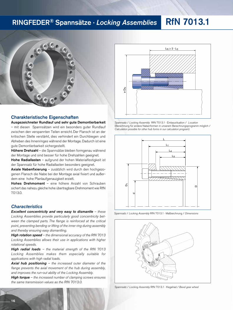
Charakteristische EigenschaftenAusgezeichneter Rundlauf und sehr gute Demontierbarkeit – mit diesen Spannsätzen wird ein besonders guter Rundlauf zwischen den verspannten Teilen erreicht. Der Flansch ist an der kritischen Stelle verstärkt, dies verhindert ein Durchbiegen und Abheben des Innenringes während der Montage. Dadurch ist eine gute Demontierbarkeit sichergestellt.Höhere Drehzahl – die Spannsätze bleiben formgenau während der Montage und sind besser für hohe Drehzahlen geeignet.Hohe Radiallasten – aufgrund der hohen Materialfestigkeit ist der Spannsatz für hohe Radiallasten besonders geeignet.Axiale Nabenfixierung – zusätzlich wird durch den hochgezo-genen Flansch die Nabe bei der Montage axial fixiert und außer-dem eine hohe Planlaufgenauigkeit erzielt.Hohes Drehmoment – eine höhere Anzahl von Schrauben sichert das nahezu gleiche hohe übertragbare Drehmoment wie RfN 7013.0.
CharacteristicsExcellent concentricity and very easy to dismantle – these Locking Assemblies provide particularly good concentricity bet-ween the clamped parts. The flange is reinforced at the critical point, preventing bending or lifting of the inner ring during assembly and thereby ensuring easy dismantling.High rotation speed – the dimensional accuracy of the RfN 7013 Locking Assemblies allows their use in applications with higher rotational speeds.High radial loads – the material strength of the RfN 7013 Locking Assemblies makes them especially suitable for applications with high radial loads.Axial hub positioning – the increased outer diameter of the flange prevents the axial movement of the hub during assembly, and improves the run-out ability of the Locking Assembly.High torque – the increased number of clamping screws ensures the same transmission values as the RfN 7013.0.
Spannsatz / Locking Assembly RfN 7013.1 · Maßzeichnung / Dimensions
16
RfN 7013.1
Spannsatz-Einbau · Mounting of Locking AssemblyDie Spannsätze werden leicht geölt und einbaufertig angelie-fert. Die Werte für T, Fax, pW und pN gelten für Spann sätze im An liefe rungszustand.The Locking Assemblies are supplied slightly oiled and ready-to-use. The values for T, Fax, pW and pN apply to Locking Assemblies installed in the delivery condition.
Oberflächen · Surface finishesFür Welle und Nabenbohrung / For shafts and hub boresRa = 1,6 µm
Toleranzen · TolerancesWir empfehlen folgende EinbautoleranzenWe recommend the following mounting tolerancesWelle · Shaft: h8; Nabe · Hub: H8
Anordnung mehrerer Spannsätze RfN 7013.1 Arrangement of several Locking Assemblies RfN 7013.1
Anordnung nur von 2 Seiten möglich. Bei Verwendung mehrerer Spannsätze zur Steigerung der Übertragungs-werte, ist der Verspannungssystematik Rechnung zu tragen.Arrangement only possible from 2 sides. If several Locking Assemblies are used to increase the transmission values the clamping systematization has to be considered.
Veränderung der Schraubenanziehdrehmomente Change of screw tightening torques
Eine Veränderung der in der Tabelle angegebenen TA-Werte ist nicht zulässig.A change of the TA-values given in the above table is not admissible.
Bestellbeispiel · Ordering example: RfN 7013.1
Baureihe / Series d D
RfN 7013.1 35 60
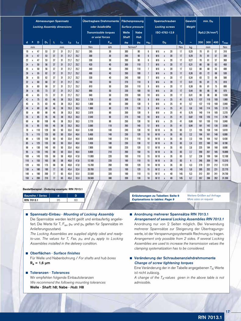
Abmessungen Spannsatz Übertragbare Drehmomente Flächenpressung Spannschrauben Gewicht min. DN
Locking Assembly dimensions oder Axialkräfte Surface pressure Locking screws Weight
Transmissible torques Welle Nabe ISO 4762-12.9 Rp0,2 [N/mm2]
or axial forces Shaft Hub
d x D D1 L L1 L3 L4 T Fax pW pN nSc DG TA ~ 200 300 400 Tmax
mm mm Nm kN N/mm2 Nm kg mm Nm
19 x 47 53 37 31 21,7 25,7 285 30 300 90 6 M 6 x 20 17 0,29 70 61 57 310
20 x 47 53 37 31 21,7 25,7 300 30 290 90 6 M 6 x 20 17 0,29 70 61 57 330
22 x 47 53 37 31 21,7 25,7 330 30 260 90 6 M 6 x 20 17 0,27 70 61 57 360
24 x 50 56 37 31 21,7 25,7 420 40 300 110 7 M 6 x 20 17 0,31 80 68 63 460
25 x 50 56 37 31 21,7 25,7 440 40 290 110 7 M 6 x 20 17 0,3 80 68 63 480
28 x 55 62 37 31 21,7 25,7 490 40 260 100 7 M 6 x 20 17 0,36 83 72 68 530
30 x 55 62 37 31 21,7 25,7 530 40 240 100 7 M 6 x 20 17 0,34 83 72 68 580
32 x 60 68 37 31 21,7 25,7 740 50 270 110 9 M 6 x 20 17 0,41 95 81 75 810
35 x 60 68 37 31 21,7 25,7 810 50 250 110 9 M 6 x 20 17 0,38 95 81 75 890
38 x 65 73 37 31 21,7 25,7 890 50 230 100 10 M 6 x 20 17 0,44 99 86 80 970
40 x 65 73 37 31 21,7 25,7 940 50 220 100 10 M 6 x 20 17 0,41 99 86 80 1.030
42 x 75 83 46 38 25,3 30,3 1.730 80 300 130 9 M 8 x 25 41 0,76 137 110 100 1.900
45 x 75 83 46 38 25,3 30,3 1.860 80 280 130 9 M 8 x 25 41 0,7 137 110 100 2.040
48 x 80 88 46 38 25,3 30,3 1.980 80 270 130 9 M 8 x 25 41 0,8 140 114 105 2.170
50 x 80 88 46 38 25,3 30,3 2.070 80 260 130 9 M 8 x 25 41 0,76 140 114 105 2.270
55 x 85 95 46 38 25,3 30,3 2.540 90 270 140 10 M 8 x 25 41 0,82 159 126 114 2.790
60 x 90 100 46 38 25,3 30,3 2.770 90 250 130 10 M 8 x 25 41 0,88 161 130 118 3.040
65 x 95 105 46 38 25,3 30,3 3.580 110 260 140 12 M 8 x 25 41 0,94 181 142 128 3.930
70 x 110 120 60 50 33,4 40,4 5.100 140 240 130 10 M 10 x 35 83 2,1 195 158 144 5.610
75 x 115 125 60 50 33,4 40,4 5.460 140 230 120 10 M 10 x 35 83 2,2 194 161 148 6.000
80 x 120 130 60 50 33,4 40,4 5.850 140 210 110 10 M 10 x 35 83 2,3 195 164 152 6.430
85 x 125 135 60 50 33,4 40,4 7.450 180 230 130 12 M 10 x 35 83 2,4 222 180 164 8.190
90 x 130 140 60 50 33,4 40,4 7.900 180 220 120 12 M 10 x 35 83 2,6 225 184 168 8.690
95 x 135 145 60 50 33,4 40,4 9.900 210 260 150 15 M 10 x 35 83 2,7 269 207 185 10.890
100 x 145 155 68 58 40,8 47,8 11.000 220 190 110 15 M 10 x 35 83 3,7 238 199 184 12.100
110 x 155 165 68 58 40,8 47,8 12.100 220 180 110 15 M 10 x 35 83 4 246 209 194 13.310
120 x 165 175 68 58 40,8 47,8 15.700 260 190 120 18 M 10 x 35 83 4,3 279 231 212 17.270
130 x 180 190 77 65 45,4 52,4 20.700 320 190 120 15 M 12 x 40 145 5,9 305 252 231 22.770
140 x 190 200 77 65 45,4 52,4 22.500 320 180 110 15 M 12 x 40 145 6,3 312 261 241 24.750
150 x 200 210 77 65 45,4 52,4 28.500 380 200 130 18 M 12 x 40 145 6,7 357 288 262 31.350
Weitere Größen auf Anfrage More sizes on request
Erläuterungen zu Tabellen: Seite 9Explanations to tables: Page 9
17
RINGFEDER® Spannsätze · Locking Assemblies RfN 7014
LN ≥ L1 + 2 · (L - L1)
ø D
N
L
L1
D
d
L3
Spannsatz / Locking Assembly RfN 7014 · Einbausituation / Location (Berechnung für andere Nabenformen in unserem Berechnungsprogramm möglich / Calculation possible for other hub forms in our calculation program)
Spannsatz / Locking Assembly RfN 7014 · ZahnradbefestigungGear wheel fastening
Spannsatz / Locking Assembly RfN 7014 · Maßzeichnung / Dimensions
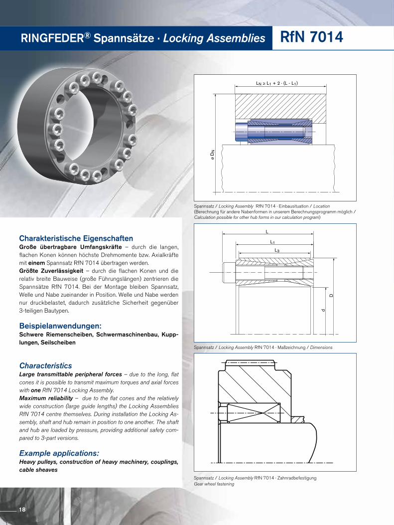
Charakteristische EigenschaftenGroße übertragbare Umfangskräfte – durch die langen, flachen Konen können höchste Drehmomente bzw. Axialkräfte mit einem Spannsatz RfN 7014 übertragen werden.Größte Zuverlässigkeit – durch die flachen Konen und die relativ breite Bauweise (große Führungslängen) zentrieren die Spannsätze RfN 7014. Bei der Montage bleiben Spannsatz, Welle und Nabe zueinander in Position. Welle und Nabe werden nur druckbelastet, dadurch zusätzliche Sicherheit gegenüber 3-teiligen Bautypen.
Beispielanwendungen:Schwere Riemenscheiben, Schwermaschinenbau, Kupp-lungen, Seilscheiben
CharacteristicsLarge transmittable peripheral forces – due to the long, flat cones it is possible to transmit maximum torques and axial forces with one RfN 7014 Locking Assembly.Maximum reliability – due to the flat cones and the relatively wide construction (large guide lengths) the Locking Assemblies RfN 7014 centre themselves. During installation the Locking As-sembly, shaft and hub remain in position to one another. The shaft and hub are loaded by pressure, providing additional safety com-pared to 3-part versions.
Example applications:Heavy pulleys, construction of heavy machinery, couplings, cable sheaves
18
Spannsatz-Einbau · Mounting of Locking AssemblyDie Werte für T, Fax, pW und pN gelten für geölt eingebaute Spannsätze.The values for T, Fax, pW and pN apply to Locking Assemblies installed in oiled condition.
Oberflächen · Surface finishesFür Welle und Nabenbohrung / For shafts and hub boresRa ≤ 3,2 µm
Toleranzen · TolerancesWir empfehlen folgende EinbautoleranzenWe recommend the following mounting tolerancesWelle · Shaft: k9-h9; Nabe · Hub: N9-H9
Anordnung mehrerer Spannsätze RfN 7014 Arrangement of several Locking Assemblies RfN 7014
Es können max. 2 Spannsätze unmittelbar hintereinander eingebaut werden. Hierbei verdoppeln sich die Übertragungs-werte aus der Tabelle.Two Locking Assemblies at most can be installed in series. In this case the transmission values of the above table are doubled.
Achtung: Zur Demontage ist ein Absatz in der Nabenboh-rung oder auf der Welle konstruktiv vorzusehen (wie in Ein bau situation auf S. 18 dargestellt).Pay attention: For the removal of the Locking Assembly a step in the hub or shaft is required (see location drawing page 18).
Veränderung der Schraubenanziehdrehmomente Change of screw tightening torques
Eine Reduzierung der Flächenpressung und Übertragungs-werte durch vermindertes Anziehen der Schrauben ist möglich. Die zulässige untere Grenze ergibt sich aus der Mul-tiplikation der TA-Werte nach obenstehender Tabelle mit 0,8. Die Werte von T, TA, Fax, pW und pN stehen in einem direkten Zu- sammenhang.A reduction of the contact pressures and the transmission va-lues by reducing the tightening torque of the screws is possible. The admissible lower limit results from the multiplication of the TA values of the above table by 0,8. There is an approximate linear relationship between T, TA, Fax, pW and pN.
Bestellbeispiel · Ordering example: RfN 7014
Baureihe / Series d D
RfN 7014 120 180
RfN 7014
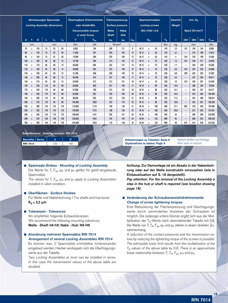
Abmessungen Spannsatz Übertragbare Drehmomente Flächenpressung Spannschrauben Gewicht min. DN
Locking Assembly dimensions oder Axialkräfte Surface pressure Locking screws Weight
Transmissible torques Welle Nabe ISO 4762-12.9 Rp0,2 [N/mm2]
or axial forces Shaft Hub
d x D L L1 L3 T Fax pW pN nSc DG TA ~ 200 300 400 Tmax
mm mm Nm kN N/mm2 Nm kg mm Nm
70 x 120 74 62 56 6.850 196 200 117 8 M 12 x 55 145 3,3 197 165 154 8.068
80 x 130 74 62 56 11.650 291 263 162 12 M 12 x 55 145 3,7 --- 215 189 13.813
90 x 140 74 62 56 13.000 289 234 150 12 M 12 x 55 145 4 310 220 196 15.505
100 x 160 94 80 74 19.700 394 213 133 12 M 14 x 70 230 7,2 312 239 217 23.620
110 x 170 94 80 74 26.600 484 242 157 14 M 14 x 70 230 7,7 --- 284 248 32.045
120 x 180 94 80 74 28.900 482 222 148 15 M 14 x 70 230 8,3 416 287 255 34.968
130 x 190 94 80 74 31.200 480 205 140 15 M 14 x 70 230 8,8 399 292 263 37.903
140 x 200 94 80 74 40.200 574 227 159 17 M 14 x 70 230 9,3 --- 337 294 49.017
150 x 210 94 80 74 42.900 572 212 151 18 M 14 x 70 230 10 510 340 301 52.489
160 x 230 110 94 88 64.000 800 227 158 17 M 16 x 80 355 14,9 --- 390 339 78.558
170 x 240 110 94 88 67.800 798 214 152 18 M 16 x 80 355 15,7 --- 394 347 83.477
180 x 250 110 94 88 83.000 922 235 169 20 M 16 x 80 355 16,4 --- 453 384 102.483
190 x 260 110 94 88 88.000 926 223 163 21 M 16 x 80 355 17,2 --- 454 390 108.947
200 x 270 110 94 88 105.000 1050 242 179 23 M 16 x 80 355 18,8 --- 524 431 130.330
220 x 300 134 116 110 123.000 1118 189 139 21 M 18 x 100 485 27,7 662 470 420 153.404
240 x 320 134 116 110 153.000 1275 198 148 24 M 18 x 100 485 29,8 --- 527 463 191.651
260 x 340 134 116 110 186.000 1431 205 157 26 M 18 x 100 485 32 --- 586 506 233.920
280 x 370 156 136 130 230.000 1643 192 145 24 M 20 x 120 690 46 --- 606 533 290.328
300 x 390 156 136 130 245.000 1633 179 138 24 M 20 x 120 690 49 874 614 548 310.335
Weitere Größen auf Anfrage More sizes on request
Erläuterungen zu Tabellen: Seite 9Explanations to tables: Page 9
19
RINGFEDER® Spannsätze · Locking Assemblies RfN 7015.0
LN ≥ L + 2 · (L - L1)
ø D
N
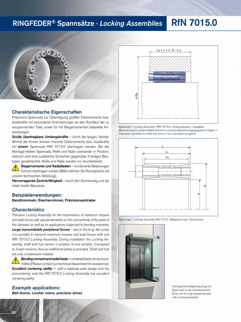
Spannsatz / Locking Assembly RfN 7015.0 · Einbausituation / Location(Berechnung für andere Nabenformen in unserem Berechnungsprogramm möglich / Calculation possible for other hub forms in our calculation program)
Hochgeschwindigkeitsaufzug mit Spannsatz in der AntriebseinheitDrive unit for high-speed elevatorwith Locking Assembly
L
L1
d
D
L3
Spannsatz / Locking Assembly RfN 7015 · Maßzeichnung / Dimensions
Charakteristische EigenschaftenPräzisions-Spannsatz zur Übertragung größter Drehmomente bzw. Axialkräfte mit besonderen Anforderungen an den Rundlauf der zu verspannenden Teile, sowie für mit Biegemomenten belastete An-wendungen.Große übertragbare Umfangskräfte – durch die langen, flachen Winkel der Konen können höchste Drehmomente bzw. Axialkräfte mit einem Spannsatz RfN 7015.0 übertragen werden. Bei der Montage bleiben Spannsatz, Welle und Nabe zueinander in Position, dadurch wird eine zusätzliche Sicherheit gegenüber 3-teiligen Bau-typen gewährleistet. Welle und Nabe werden nur druckbelastet.
Biegemomente und Radiallasten – kombinierte Belastun gen können übertragen werden (Bitte nehmen Sie Rücksprache mit
unserer technischen Abteilung). Hervorragende Zentrierfähigkeit – durch den Zentriersteg und die relativ breite Bauweise.
Beispielanwendungen: Bandtrommeln, Brecherrotoren, Präzisionsantriebe
CharacteristicsPrecision Locking Assembly for the transmission of maximum torques and axial forces with special demands on the concentricity of the parts of the clamped, as well as for applications subjected to bending moments.Large transmittable peripheral forces – due to the long, flat cones it is possible to transmit maximum torques and axial forces with one RfN 7015.0 Locking Assembly. During installation the Locking As-sembly, shaft and hub remain in position to one another. Compared to 3-part versions, thus an additional safety is provided. Shaft and hub are only compression-loaded.
Bending moment and radial loads – combined loads can be trans-mitted (Please contact our technical department for assistance).
Excellent centering ability – with a relatively wide design and the precentering web the RfN 7015.0 Locking Assembly has excellent centering ability.
Example applications: Belt drums, crusher rotors, precision drives
20
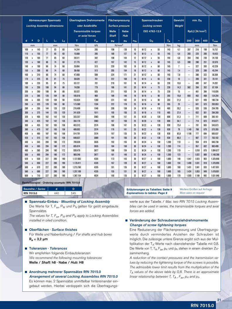
Spannsatz-Einbau · Mounting of Locking AssemblyDie Werte für T, Fax, PW und PN gelten für geölt eingebaute Spannsätze.The values for T, Fax, PW and PN apply to Locking Assemblies installed in oiled condition.
Oberflächen · Surface finishesFür Welle und Nabenbohrung / For shafts and hub boresRa ≤ 3,2 µm
Toleranzen · TolerancesWir empfehlen folgende EinbautoleranzenWe recommend the following mounting tolerancesWelle / Shaft: h8 · Nabe / Hub: H8
Anordnung mehrerer Spannsätze RfN 7015.0 Arrangement of several Locking Assemblies RfN 7015.0
Es können max. 2 Spannsätze unmittelbar hintereinander ein-gebaut werden. Hierbei verdoppeln sich die Übertragungs-
werte aus der Tabelle. / Max. two RfN 7015 Locking Assem-blies can be used in series, the trans missible torques and axial forces are added.
Veränderung der Schraubenanziehdrehmomente Change of screw tightening torques
Eine Reduzierung der Flächenpressung und Übertragungs-werte durch vermindertes Anziehen der Schrauben ist möglich. Die zulässige untere Grenze ergibt sich aus der Mul-tiplikation der TA-Werte nach obenstehender Tabelle mit 0,8. Die Werte von T, TA, Fax, pW und pN stehen in einem direkten Zu- sammenhang.A reduction of the contact pressures and the transmission va-lues by reducing the tightening torque of the screws is possible. The admissible lower limit results from the multiplication of the TA values of the above table by 0,8. There is an approximate linear relationship between T, TA , Fax, pW and pN.
Baureihe / Series d D
RfN 7015.0 440 545
Bestellbeispiel · Ordering example: RfN 7015.0
RfN 7015.0
Abmessungen Spannsatz Übertragbare Drehmomente Flächenpressung Spannschrauben Gewicht min. DN
Locking Assembly dimensions oder Axialkräfte Surface pressure Locking screws Weight
Transmissible torques Welle Nabe ISO 4762-12.9 Rp0,2 [N/mm2]
or axial forces Shaft Hub
d x D L L1 L3 T Fax pW pN nSc DG TA ~ 200 300 400 Tmax
mm mm Nm kN N/mm2 Nm kg mm Nm
100 x 145 77 65 60 14.244 285 198 136 10 M 12 x 55 145 4,1 287 218 198 16.757
110 x 155 77 65 60 15.668 285 180 127 10 M 12 x 55 145 4,4 283 225 206 18.433
120 x 165 77 65 60 20.511 342 198 144 12 M 12 x 55 145 4,8 354 256 230 24.130
130 x 180 86 74 68 27.775 427 197 142 15 M 12 x 60 145 6,5 390 280 251 32.676
140 x 190 86 74 68 35.894 513 220 162 18 M 12 x 60 145 7 --- 327 283 42.228
150 x 200 86 74 68 38.458 513 205 154 18 M 12 x 60 145 7,4 --- 329 289 45.244
160 x 210 86 74 68 47.858 598 224 171 21 M 12 x 60 145 7,8 --- 380 322 56.304
170 x 225 95 81 75 59.620 701 222 168 18 M 14 x 65 230 10 --- 399 341 70.141
180 x 235 95 81 75 63.127 701 210 161 18 M 14 x 65 230 10,6 --- 400 347 74.267
190 x 250 108 94 88 74.038 779 186 141 20 M 14 x 75 230 14,3 562 394 352 87.104
200 x 260 108 94 88 93.522 935 211 163 24 M 14 x 75 230 15 --- 461 394 110.026
220 x 285 120 104 98 105.616 960 189 146 18 M 16 x 90 355 19,8 693 462 408 124.254
240 x 305 120 104 98 153.624 1280 231 182 24 M 16 x 90 355 21,4 --- 621 499 180.734
260 x 325 120 104 98 173.360 1334 222 178 25 M 16 x 90 355 23 --- 641 523 203.953
280 x 355 144 126 120 216.499 1546 200 158 24 M 18 x 110 485 35,2 --- 626 536 254.705
300 x 375 144 126 120 241.629 1611 195 156 25 M 18 x 110 485 37,4 --- 652 561 284.269
320 x 405 162 142 135 333.337 2083 199 157 25 M 20 x 120 690 51,3 --- 711 609 392.161
340 x 425 162 142 135 354.170 2083 187 150 25 M 20 x 120 690 54,1 --- 714 623 416.671
360 x 455 187 165 158 463.312 2574 186 147 25 M 22 x 130 930 75,4 --- 761 665 545.073
380 x 475 187 165 158 489.052 2574 176 141 25 M 22 x 130 930 79 1.149 768 679 575.355
400 x 495 187 165 158 514.791 2574 167 135 25 M 22 x 130 930 82,8 1.100 777 694 605.637
420 x 515 187 165 158 648.637 3089 191 156 30 M 22 x 130 930 86,5 --- 907 777 763.102
440 x 545 204 180 172 799.628 3635 192 155 30 M 24 x 150 1.200 110 --- 954 819 940.738
460 x 565 204 180 172 835.974 3635 184 150 30 M 24 x 150 1.200 114 --- 957 832 983.499
480 x 585 204 180 172 930.476 3877 188 154 32 M 24 x 150 1.200 119 --- 1.018 876 1.094.677
500 x 605 204 180 172 969.246 3877 181 149 32 M 24 x 150 1.200 123 --- 1.022 889 1.140.289
520 x 630 227 200 190 1.127.063 4335 173 143 30 M 27 x 160 1.600 148 1.547 1.023 903 1.325.956
540 x 650 227 200 190 1.170.411 4335 167 139 30 M 27 x 160 1.600 154 1.490 1.031 918 1.376.955
560 x 670 227 200 190 1.213.760 4335 161 135 30 M 27 x 160 1.600 160 1.451 1.041 933 1.427.951
580 x 690 227 200 190 1.257.109 4335 155 131 30 M 27 x 160 1.600 165 1.424 1.053 949 1.478.951
600 x 710 227 200 190 1.387.154 4624 160 135 32 M 27 x 160 1.600 170 1.555 1.108 992 1.631.946
Weitere Größen auf Anfrage More sizes on request
Erläuterungen zu Tabellen: Seite 9Explanations to tables: Page 9
21
RINGFEDER® Spannsätze · Locking Assemblies RfN 7015.1
LN ≥ L + 2 · (L - L1)
ø D
N
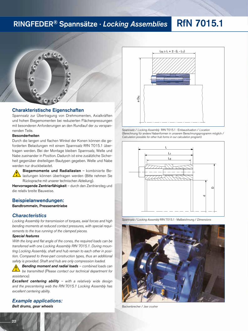
Spannsatz / Locking Assembly RfN 7015.1 · Einbausituation / Location(Berechnung für andere Nabenformen in unserem Berechnungsprogramm möglich / Calculation possible for other hub forms in our calculation program)
Backenbrecher / Jaw crusher
L
L1
d
D
L3
Spannsatz / Locking Assembly RfN 7015.1 · Maßzeichnung / Dimensions
Charakteristische EigenschaftenSpannsatz zur Übertragung von Drehmomenten, Axialkräften und hohen Biege momenten bei reduzierten Flächenpressungen mit besonderen Anforderungen an den Rundlauf der zu verspan-nenden Teile.BesonderheitenDurch die langen und flachen Winkel der Konen können die ge-forderten Belastungen mit einem Spannsatz RfN 7015.1 über-tragen werden. Bei der Montage bleiben Spannsatz, Welle und Nabe zueinander in Position. Dadurch ist eine zusätzliche Sicher-heit gegenüber dreiteiligen Bautypen gegeben. Welle und Nabe werden nur druckbelastet.
Biegemomente und Radiallasten – kombinierte Be-lastungen können übertragen werden (Bitte nehmen Sie Rücksprache mit unserer technischen Abteilung).
Hervorragende Zentrierfähigkeit – durch den Zentriersteg und die relativ breite Bauweise.
Beispielanwendungen:Bandtrommeln, Pressenantriebe
CharacteristicsLocking Assembly for transmission of torques, axial forces and high bending moments at reduced contact pressures, with special requi-rements to the true running of the clamped pieces.Special featuresWith the long and flat angle of the cones, the required loads can be transferred with one Locking Assembly RfN 7015.1. During moun-ting Locking Assembly, shaft and hub remain to each other in posi-tion. Compared to three-part construction types, thus an additional safety is provided. Shaft and hub are only compression loaded.
Bending moment and radial loads – combined loads can be transmitted (Please contact our technical department for
assistance).Excellent centering ability – with a relatively wide design and the precentering web the RfN 7015.1 Locking Assembly has excellent centering ability.
Example applications: Belt drums, gear wheels
22
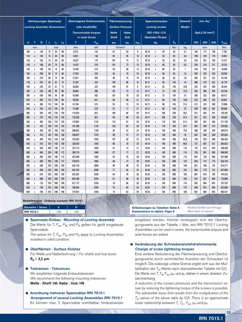
Spannsatz-Einbau · Mounting of Locking AssemblyDie Werte für T, Fax, PW und PN gelten für geölt eingebaute Spannsätze. The values for T, Fax, PW and PN apply to Locking Assemblies installed in oiled condition.
Oberflächen · Surface finishesFür Welle und Nabenbohrung / For shafts and hub boresRa ≤ 3,2 µm
Toleranzen · TolerancesWir empfehlen folgende EinbautoleranzenWe recommend the following mounting tolerancesWelle · Shaft: h8; Nabe · Hub: H8
Anordnung mehrerer Spannsätze RfN 7015.1 Arrangement of several Locking Assemblies RfN 7015.1
Es können max. 2 Spannsätze unmittelbar hintereinander
eingebaut werden. Hierbei verdoppeln sich die Übertra-gungswerte aus der Tabelle. / Max. two RfN 7015.1 Locking Assemblies can be used in series, the trans missible torques and axial forces are added.
Veränderung der Schraubenanziehdrehmomente Change of screw tightening torquesEine weitere Reduzierung der Flächenpressung und Übertra-gungswerte durch vermindertes Anziehen der Schrauben ist möglich. Die zulässige untere Grenze ergibt sich aus der Mul-tiplikation der TA-Werte nach obenstehender Tabelle mit 0,5.Die Werte von T, TA, Fax, pW und pN stehen in einem direkten Zu- sammenhang.A reduction of the contact pressures and the transmission va-lues by reducing the tightening torque of the screws is possible. The admissible lower limit results from the multiplication of the TA values of the above table by 0,5. There is an approximate linear relationship between T, TA , Fax, pW and pN.
Bestellbeispiel · Ordering example: RfN 7015.1
Baureihe / Series d D
RfN 7015.1 140 190
RfN 7015.1
Weitere Größen auf Anfrage More sizes on request
Erläuterungen zu Tabellen: Seite 9Explanations to tables: Page 9
Abmessungen Spannsatz Übertragbare Drehmomente Flächenpressung Spannschrauben Gewicht min. DN*
Locking Assembly dimesnsions oder Axialkräfte Surface Pressure Locking screws Weight
Transmissible troques Welle Nabe ISO 4762-12.9 Rp0,2 [N/mm2]
or axial forces Shaft Hub Gewinde/Thread
d x D L L1 L3 T Fax pW pN nSc dG TA ~ 200 300 400 Tmax
mm mm Nm kN N/mm2 Nm kg mm Nm
100 x 145 75 65 60 6.575 132 91 63 9 M 10 x 55 83 4,1 184 171 166 7.736
110 x 155 75 65 60 8.037 146 92 65 10 M 10 x 55 83 4,4 199 184 178 9.455
120 x 165 75 65 60 10.521 175 101 74 12 M 10 x 55 83 4,8 220 201 193 12.377
130 x 180 84 74 68 14.247 219 101 73 15 M 10 x 60 83 6,5 240 219 211 16.761
140 x 190 84 74 68 15.343 219 94 69 15 M 10 x 60 83 7 248 229 221 18.050
150 x 200 84 74 68 17.534 234 94 70 16 M 10 x 60 83 7,4 263 242 233 20.629
160 x 210 84 74 68 21.041 263 99 75 18 M 10 x 60 83 7,8 282 257 247 24.754
170 x 225 93 81 75 27.352 322 105 80 15 M 12 x 65 145 10 309 279 267 32.179
180 x 235 93 81 75 30.892 343 106 81 8 M 12 x 65 145 10,6 325 293 280 36.344
190 x 250 106 94 88 36.684 386 96 73 18 M 12 x 75 145 14,3 355 306 294 43.158
200 x 260 106 94 88 42.906 429 101 78 20 M 12 x 75 145 15 358 323 309 50.477
220 x 285 116 104 98 49.556 451 89 69 21 M 12 x 80 145 19,8 376 345 332 58.301
240 x 305 116 104 98 61.784 515 93 73 24 M 12 x 80 145 21,4 412 375 359 72.688
260 x 325 116 104 98 75.300 579 97 77 27 M 12 x 80 145 23 449 405 387 88.588
280 x 355 140 126 120 115.034 822 106 84 28 M 14 x 100 230 35,2 512 454 431 135.334
300 x 375 140 126 120 123.250 822 99 80 28 M 14 x 100 230 37,4 527 472 450 145.001
320 x 405 158 142 135 179.962 1125 110 87 28 M 16 x 110 355 51,3 593 522 495 211.720
340 x 425 158 142 135 191.209 1125 103 83 28 M 16 x 110 355 54,1 607 540 514 224.952
360 x 455 183 165 158 209.622 1165 84 67 24 M 18 x 140 485 75,4 598 550 529 246.615
380 x 475 183 165 158 248.927 1310 90 72 27 M 18 x 140 485 79 642 584 559 292.855
400 x 495 183 165 158 310.552 1553 101 82 32 M 18 x 140 485 82,8 706 629 598 365.355
420 x 515 183 165 158 326.079 1553 96 78 32 M 18 x 140 485 86,5 721 647 617 383.623
440 x 545 200 180 172 372.775 1694 91 74 27 M 20 x 140 690 110 742 673 644 438.558
460 x 565 200 180 172 389.719 1694 87 71 27 M 20 x 140 690 114 759 691 663 458.493
480 x 585 200 180 172 451.848 1883 93 76 30 M 20 x 140 690 119 807 728 696 531.586
500 x 605 200 180 172 470.675 1883 89 74 30 M 20 x 140 690 123 824 747 715 553.735
520 x 630 220 200 190 522.135 2008 80 66 32 M 20 x 150 690 148 827 760 732 614.277
540 x 650 220 200 190 542.218 2008 77 64 32 M 20 x 150 690 154 845 779 751 637.903
560 x 670 220 200 190 632.587 2259 84 70 36 M 20 x 150 690 160 897 818 785 744.220
580 x 690 220 200 190 655.180 2259 81 68 36 M 20 x 150 690 165 914 837 805 770.800
600 x 710 220 200 190 677.772 2259 78 66 36 M 20 x 150 690 170 932 856 824 797.379
620 x 730 220 200 190 700.364 2259 76 64 36 M 20 x 150 690 175 949 875 844 823.958
640 x 750 220 200 190 722.957 2259 73 63 36 M 20 x 150 690 180 967 894 863 850.537
23
RINGFEDER® Spannsätze · Locking Assemblies RfN 7515
LN ≥ L + 2 · (L - L1)
ø D
N
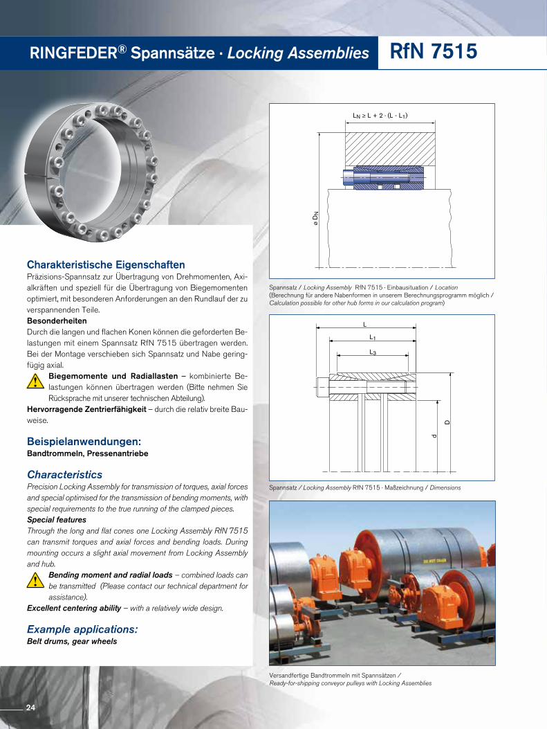
Spannsatz / Locking Assembly RfN 7515 · Einbausituation / Location(Berechnung für andere Nabenformen in unserem Berechnungsprogramm möglich / Calculation possible for other hub forms in our calculation program)
d
D
L
L1
L3
Spannsatz / Locking Assembly RfN 7515 · Maßzeichnung / Dimensions
Versandfertige Bandtrommeln mit Spannsätzen / Ready-for-shipping conveyor pulleys with Locking Assemblies
Charakteristische EigenschaftenPräzisions-Spannsatz zur Übertragung von Drehmomenten, Axi-alkräften und speziell für die Übertragung von Biege momenten optimiert, mit besonderen Anforderungen an den Rundlauf der zu verspannenden Teile. BesonderheitenDurch die langen und flachen Konen können die geforderten Be-lastungen mit einem Spannsatz RfN 7515 übertragen werden. Bei der Montage verschieben sich Spannsatz und Nabe gering-fügig axial.
Biegemomente und Radiallasten – kombinierte Be-lastungen können übertragen werden (Bitte nehmen Sie Rücksprache mit unserer technischen Abteilung).
Hervorragende Zentrierfähigkeit – durch die relativ breite Bau-weise.
Beispielanwendungen:Bandtrommeln, Pressenantriebe
CharacteristicsPrecision Locking Assembly for transmission of torques, axial forces and special optimised for the transmission of bending moments, with special requirements to the true running of the clamped pieces.Special featuresThrough the long and flat cones one Locking Assembly RfN 7515 can transmit torques and axial forces and bending loads. During mounting occurs a slight axial movement from Locking Assembly and hub.
Bending moment and radial loads – combined loads can be transmitted (Please contact our technical department for assistance).
Excellent centering ability – with a relatively wide design.
Example applications: Belt drums, gear wheels
24
RfN 7515
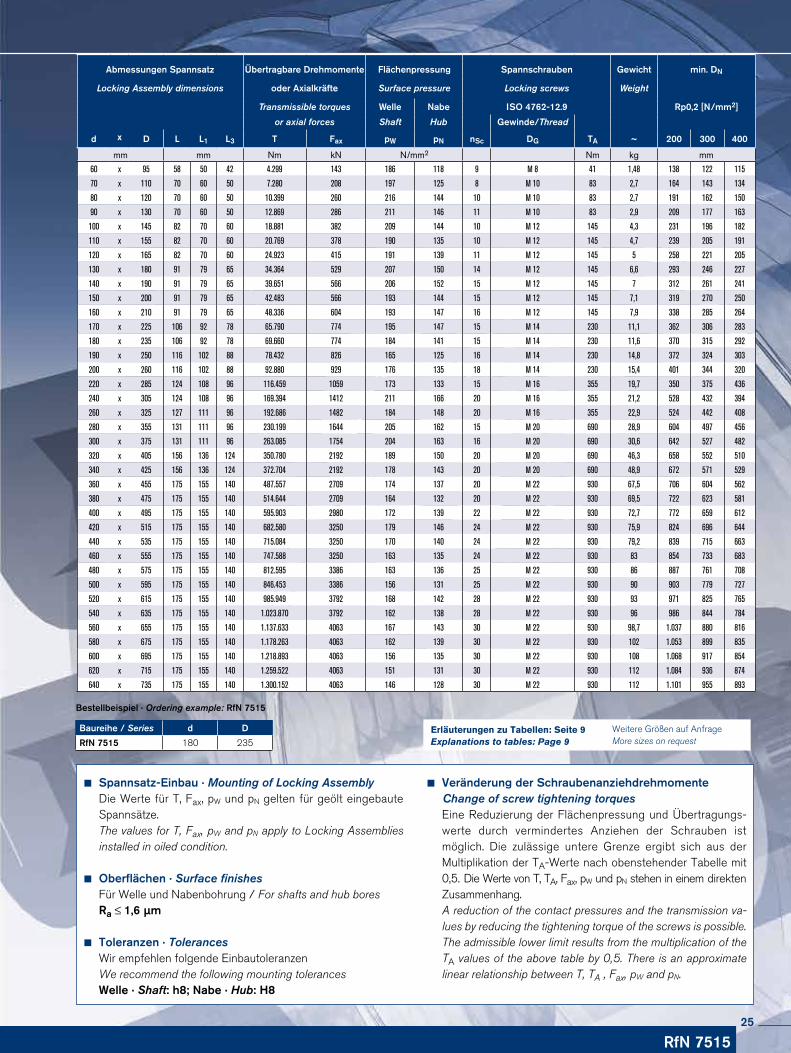
Veränderung der Schraubenanziehdrehmomente Change of screw tightening torquesEine Reduzierung der Flächenpressung und Übertragungs-werte durch vermindertes Anziehen der Schrauben ist möglich. Die zulässige untere Grenze ergibt sich aus der Multiplikation der TA-Werte nach obenstehender Tabelle mit 0,5. Die Werte von T, TA, Fax, pW und pN stehen in einem direkten Zusammenhang.A reduction of the contact pressures and the transmission va-lues by reducing the tightening torque of the screws is possible. The admissible lower limit results from the multiplication of the TA values of the above table by 0,5. There is an approximate linear relationship between T, TA , Fax, pW and pN.
Spannsatz-Einbau · Mounting of Locking AssemblyDie Werte für T, Fax, pW und pN gelten für geölt eingebaute Spannsätze. The values for T, Fax, pW and pN apply to Locking Assemblies installed in oiled condition.
Oberflächen · Surface finishesFür Welle und Nabenbohrung / For shafts and hub boresRa ≤ 1,6 µm
Toleranzen · TolerancesWir empfehlen folgende EinbautoleranzenWe recommend the following mounting tolerancesWelle · Shaft: h8; Nabe · Hub: H8
Baureihe / Series d D
RfN 7515 180 235
Bestellbeispiel · Ordering example: RfN 7515
Weitere Größen auf Anfrage More sizes on request
Erläuterungen zu Tabellen: Seite 9Explanations to tables: Page 9
Abmessungen Spannsatz Übertragbare Drehmomente Flächenpressung Spannschrauben Gewicht min. DN
Locking Assembly dimensions oder Axialkräfte Surface pressure Locking screws Weight
Transmissible torques Welle Nabe ISO 4762-12.9 Rp0,2 [N/mm2]
or axial forces Shaft Hub Gewinde/Thread
d x D L L1 L3 T Fax pW pN nSc DG TA ~ 200 300 400
mm mm Nm kN N/mm2 Nm kg mm
60 x 95 58 50 42 4.299 143 186 118 9 M 8 41 1,48 138 122 115
70 x 110 70 60 50 7.280 208 197 125 8 M 10 83 2,7 164 143 134
80 x 120 70 60 50 10.399 260 216 144 10 M 10 83 2,7 191 162 150
90 x 130 70 60 50 12.869 286 211 146 11 M 10 83 2,9 209 177 163
100 x 145 82 70 60 18.881 382 209 144 10 M 12 145 4,3 231 196 182
110 x 155 82 70 60 20.769 378 190 135 10 M 12 145 4,7 239 205 191
120 x 165 82 70 60 24.923 415 191 139 11 M 12 145 5 258 221 205
130 x 180 91 79 65 34.364 529 207 150 14 M 12 145 6,6 293 246 227
140 x 190 91 79 65 39.651 566 206 152 15 M 12 145 7 312 261 241
150 x 200 91 79 65 42.483 566 193 144 15 M 12 145 7,1 319 270 250
160 x 210 91 79 65 48.336 604 193 147 16 M 12 145 7,9 338 285 264
170 x 225 106 92 78 65.790 774 195 147 15 M 14 230 11,1 362 306 283
180 x 235 106 92 78 69.660 774 184 141 15 M 14 230 11,6 370 315 292
190 x 250 116 102 88 78.432 826 165 125 16 M 14 230 14,8 372 324 303
200 x 260 116 102 88 92.880 929 176 135 18 M 14 230 15,4 401 344 320
220 x 285 124 108 96 116.459 1059 173 133 15 M 16 355 19,7 350 375 436
240 x 305 124 108 96 169.394 1412 211 166 20 M 16 355 21,2 528 432 394
260 x 325 127 111 96 192.686 1482 184 148 20 M 16 355 22,9 524 442 408
280 x 355 131 111 96 230.199 1644 205 162 15 M 20 690 28,9 604 497 456
300 x 375 131 111 96 263.085 1754 204 163 16 M 20 690 30,6 642 527 482
320 x 405 156 136 124 350.780 2192 189 150 20 M 20 690 46,3 658 552 510
340 x 425 156 136 124 372.704 2192 178 143 20 M 20 690 48,9 672 571 529
360 x 455 175 155 140 487.557 2709 174 137 20 M 22 930 67,5 706 604 562
380 x 475 175 155 140 514.644 2709 164 132 20 M 22 930 69,5 722 623 581
400 x 495 175 155 140 595.903 2980 172 139 22 M 22 930 72,7 772 659 612
420 x 515 175 155 140 682.580 3250 179 146 24 M 22 930 75,9 824 696 644
440 x 535 175 155 140 715.084 3250 170 140 24 M 22 930 79,2 839 715 663
460 x 555 175 155 140 747.588 3250 163 135 24 M 22 930 83 854 733 683
480 x 575 175 155 140 812.595 3386 163 136 25 M 22 930 86 887 761 708
500 x 595 175 155 140 846.453 3386 156 131 25 M 22 930 90 903 779 727
520 x 615 175 155 140 985.949 3792 168 142 28 M 22 930 93 971 825 765
540 x 635 175 155 140 1.023.870 3792 162 138 28 M 22 930 96 986 844 784
560 x 655 175 155 140 1.137.633 4063 167 143 30 M 22 930 98,7 1.037 880 816
580 x 675 175 155 140 1.178.263 4063 162 139 30 M 22 930 102 1.053 899 835
600 x 695 175 155 140 1.218.893 4063 156 135 30 M 22 930 108 1.068 917 854
620 x 715 175 155 140 1.259.522 4063 151 131 30 M 22 930 112 1.084 936 874
640 x 735 175 155 140 1.300.152 4063 146 128 30 M 22 930 112 1.101 955 893
25
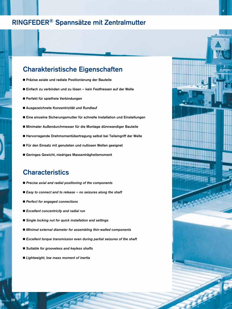
Charakteristische EigenschaftenPräzise axiale und radiale Positionierung der Bauteile
Einfach zu verbinden und zu lösen – kein Festfressen auf der Welle
Perfekt für spielfreie Verbindungen
Ausgezeichnete Konzentrizität und Rundlauf
Eine einzelne Sicherungsmutter für schnelle Installation und Einstellungen
Minimaler Außendurchmesser für die Montage dünnwandiger Bauteile
Hervorragende Drehmomentübertragung selbst bei Teileingriff der Welle
Für den Einsatz mit genuteten und nutlosen Wellen geeignet
Geringes Gewicht, niedriges Massenträgheitsmoment
Characteristics
Precise axial and radial positioning of the components
Easy to connect and to release – no seizures along the shaft
Perfect for engaged connections
Excellent concentricity and radial run
Single locking nut for quick installation and settings
Minimal external diameter for assembling thin-walled components
Excellent torque transmission even during partial seizures of the shaft
Suitable for grooveless and keyless shafts
Lightweight, low mass moment of inertia
RINGFEDER® Spannsätze mit Zentralmutter
26
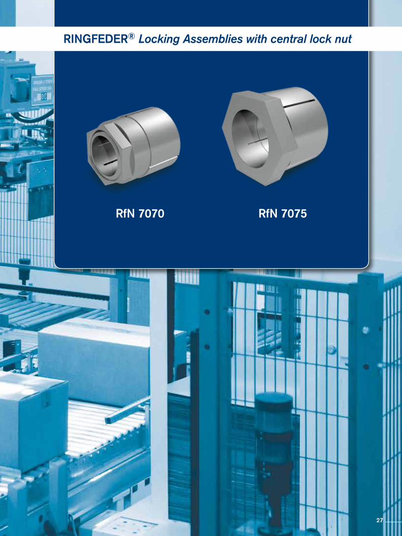
RINGFEDER® Locking Assemblies with central lock nut
RfN 7070 RfN 7075
27

RINGFEDER® Spannsätze · Locking Assemblies RfN 7070
Spannsatz / Locking Assembly RfN 7070 · Maßzeichnung / Dimensions
A
A
L
L3
SW
L1
d D
SW
A
A
L
L3
SW
L1
ød øD
SW
A
A
L
L3
SW
L1
ød øD
SW
Spannsatz / Locking Assembly RfN 7070 · Einbausituation / Location
Spannsatz / Locking Assembly RfN 7070 · Maßzeichnung / Dimensions
28
Baureihe / Series d D
RfN 7070 10 23
Bestellbeispiel · Ordering example: RfN 7070
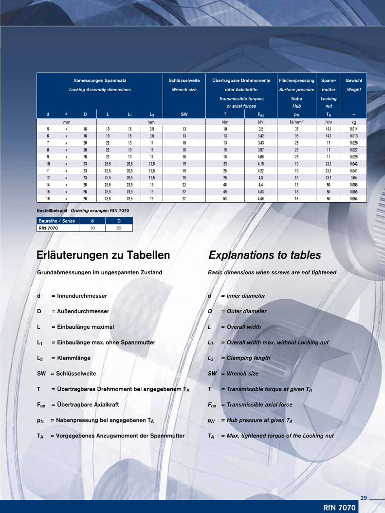
Erläuterungen zu Tabellen Grundabmessungen im ungespannten Zustand
d = Innendurchmesser
D = Außendurchmesser
L = Einbaulänge maximal
L1 = Einbaulänge max. ohne Spannmutter
L3 = Klemmlänge
SW = Schlüsselweite
T = Übertragbares Drehmoment bei angegebenem TA
Fax = Übertragbare Axialkraft pN = Nabenpressung bei angegebenen TA
TA = Vorgegebenes Anzugsmoment der Spannmutter
Explanations to tablesBasic dimensions when screws are not tightened
d = Inner diameter
D = Outer diameter L = Overall width L1 = Overall width max. without Locking nut L3 = Clamping length
SW = Wrench size
T = Transmissible torque at given TA
Fax = Transmissible axial force pN = Hub pressure at given TA
TA = Max. tightened torque of the Locking nut
RfN 7070
Abmessungen Spannsatz Schlüsselweite Übertragbare Drehmomente Flächenpressung Spann- Gewicht
Locking Assembly dimensions Wrench size oder Axialkräfte Surface pressure mutter Weight
Transmissible torques Nabe Locking
or axial forces Hub nut
d x D L L1 L3 SW T Fax pN TA ~
mm mm Nm kN N/mm2 Nm kg
5 x 16 19 16 9,5 13 10 3,2 36 14,1 0,014
6 x 16 19 16 9,5 13 13 3,42 36 14,1 0,013
7 x 20 22 19 11 16 13 3,43 26 17 0,028
8 x 20 22 19 11 16 15 3,97 26 17 0,027
9 x 20 22 19 11 16 18 4,06 26 17 0,026
10 x 23 25,5 20,5 12,5 19 23 4,15 19 23,1 0,042
11 x 23 25,5 20,5 12,5 19 25 4,22 19 23,1 0,041
12 x 23 25,5 20,5 12,5 19 28 4,3 19 23,1 0,04
14 x 26 28,5 23,5 16 22 46 4,4 13 50 0,056
15 x 26 28,5 23,5 16 22 49 4,43 13 50 0,055
16 x 26 28,5 23,5 16 22 53 4,46 13 50 0,054
29
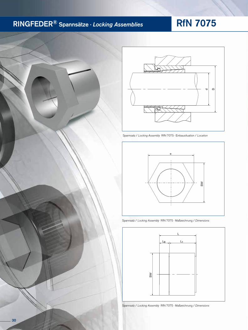
RINGFEDER® Spannsätze · Locking Assemblies RfN 7075
Spannsatz / Locking Assembly RfN 7075 · Maßzeichnung / Dimensions
L
SW
L1
e
d D
L8
SW
Spannsatz / Locking Assembly RfN 7075 · Einbausituation / Location
L
SW
L1
eød øD
L8
SW
L
SW
L1
e
ød øD
L8
SW
Spannsatz / Locking Assembly RfN 7075 · Maßzeichnung / Dimensions
30
RfN 7075
Baureihe / Series d D
RfN 7075 24 38
Bestellbeispiel · Ordering example: RfN 7075
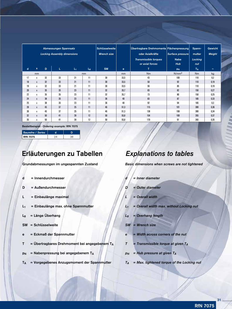
Erläuterungen zu Tabellen Grundabmessungen im ungespannten Zustand
d = Innendurchmesser
D = Außendurchmesser
L = Einbaulänge maximal
L1 = Einbaulänge max. ohne Spannmutter
L8 = Länge Überhang
SW = Schlüsselweite
e = Eckmaß der Spannmutter
T = Übertragbares Drehmoment bei angegebenem TA pN = Nabenpressung bei angegebenem TA
TA = Vorgegebenes Anzugsmoment der Spannmutter
Explanations to tablesBasic dimensions when screws are not tightened
d = Inner diameter
D = Outer diameter L = Overall width L1 = Overall width max. without Locking nut
L8 = Overhang length
SW = Wrench size
e = Width across corners of the nut
T = Transmissible torque at given TA
pN = Hub pressure at given TA
TA = Max. tightened torque of the Locking nut
Abmessungen Spannsatz Schlüsselweite Übertragbare Drehmomente Flächenpressung Spann- Gewicht
Locking Assembly dimensions Wrench size oder Axialkräfte Surface pressure mutter Weight
Transmissible torques Nabe Locking
or axial forces Hub nut
d x D L L1 L8 SW e T pN TA ~
mm mm mm Nm N/mm2 Nm kg
17 x 32 33 21 11 30 33,5 43 100 110 0,2
18 x 32 33 21 11 30 33,5 50 92 110 0,19
19 x 32 33 21 11 30 33,5 56 85 110 0,19
20 x 35 35 23 11 32 35,7 65 82 150 0,27
22 x 35 35 23 11 32 35,7 73 80 150 0,25
24 x 38 35 23 11 36 40 83 87 185 0,33
25 x 38 35 23 11 36 40 92 94 185 0,3
28 x 45 37 25 11 46 51,3 115 101 300 0,36
30 x 45 37 25 11 46 51,3 138 108 300 0,34
32 x 50 41 28 12 50 55,8 154 100 265 0,37
35 x 50 41 28 12 50 55,8 170 91 265 0,35
31
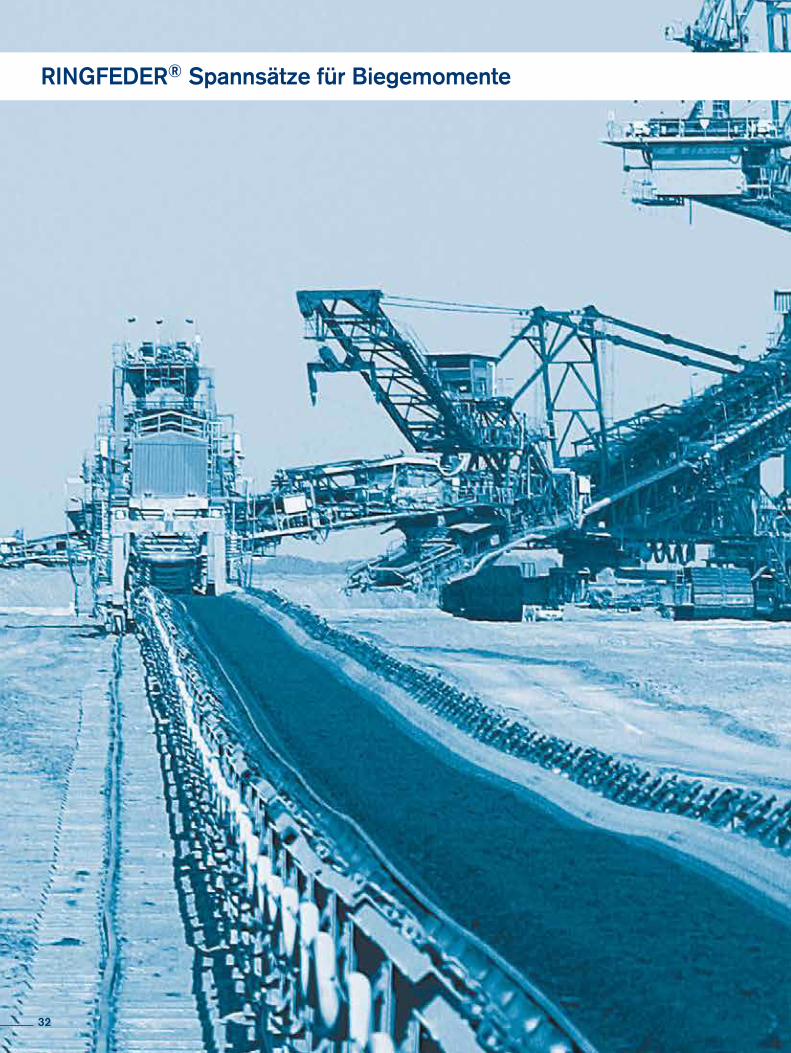
RINGFEDER® Spannsätze für Biegemomente
32
RINGFEDER® Locking Assemblies for Bending Moments
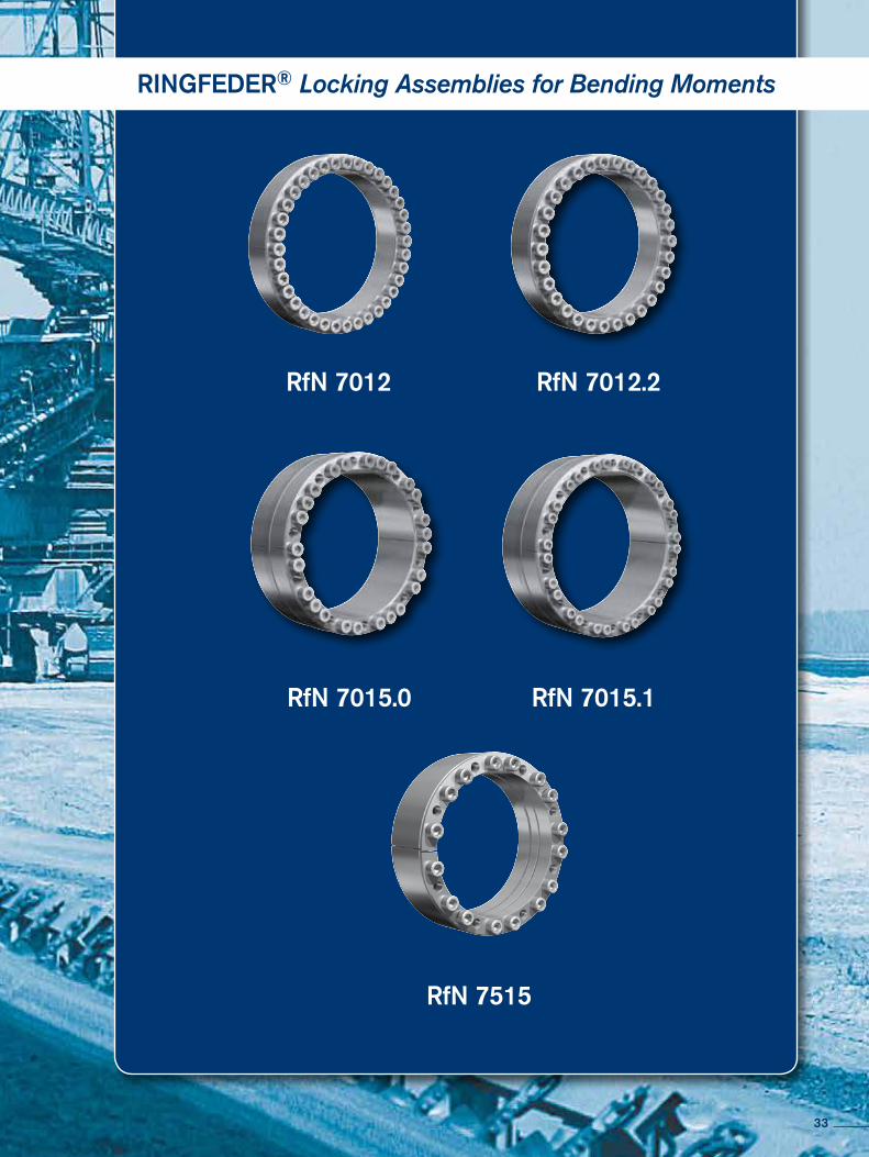
RfN 7012.2RfN 7012
RfN 7015.1RfN 7015.0
RfN 7515
33
RINGFEDER® Spannsätze für Biegemomente
Charakteristische EigenschaftenEine der anspruchvollsten Herausforderungen an unser Leistungsversprechen ist das An-wendungsgebiet der Bandtrommeln. Die extremen Belastungen, denen solche Bauteile ausgesetzt sind, insbesondere die hohen Biegemomente, ihre gleichzeitig unabdingbare Zu-verlässigkeit und eine möglichst lange Lebensdauer erfordern höchstes Ingenieurs-Know- How. Unser internationales Entwicklerteam, das bereits mit den Produkten RfN 7012 und RfN 7012.2 und RfN 7015.0 und RfN 7015.1 Benchmarks für Qualitäts-Spannsätze ge-schaffen hat, setzt hier einen weiteren Meilenstein.
Die Neuentwicklung des Spannsatzes RfN 7515 setzt mit seinem Qualitäts-, Leis-tungs- und Preisangebot einen neuen Maßstab in diesem Segment.
Qualität bedeutet: Hochwertige Materialien und Werkstoffoberflächen und präziseste Ver-arbeitung gewährleisten einen nachhaltigen Produkteinsatz.
Leistung bedeutet: Zuverlässigkeit und Langlebigkeit: Minimierung von Maschinenstillstän-den und Maximierung der Lebensdauer.
Preis bedeutet: Nicht nur das neueste, sondern auch das günstigste RINGFEDER Spannsatz Produkt bei gewohnt bester Performance.
Characteristics
One of the most demanding challenges of our promise of performance is the conveyor pulley application field. The extreme loads which such components are subject to, especially the high bending moment, coupled with the simultaneous indispensable reliability and longest possi-ble service life, require the highest of engineering know-how. Our international development team, which has already set benchmarks in quality Locking Assemblies for the RfN 7012, RfN 7012.2, RfN 7015.0 and RfN 7015.1 products, is here setting a further milestone.
The new development of the RfN 7515 Locking Assemblies has set a new benchmark in this segment with its quality, performance and price range.
Quality means: high-quality materials and material services, and the most precise workman-ship, guarantee sustainable product usage.
Performance means: reliability, and long service life means: minimization of machine down-time and maximization of service life.
Price means: not just the newest, but also the most economical RINGFEDER Locking Assem-blies product at the high level of performance you are used to.
34
RINGFEDER® Locking Assemblies for Bending Moments
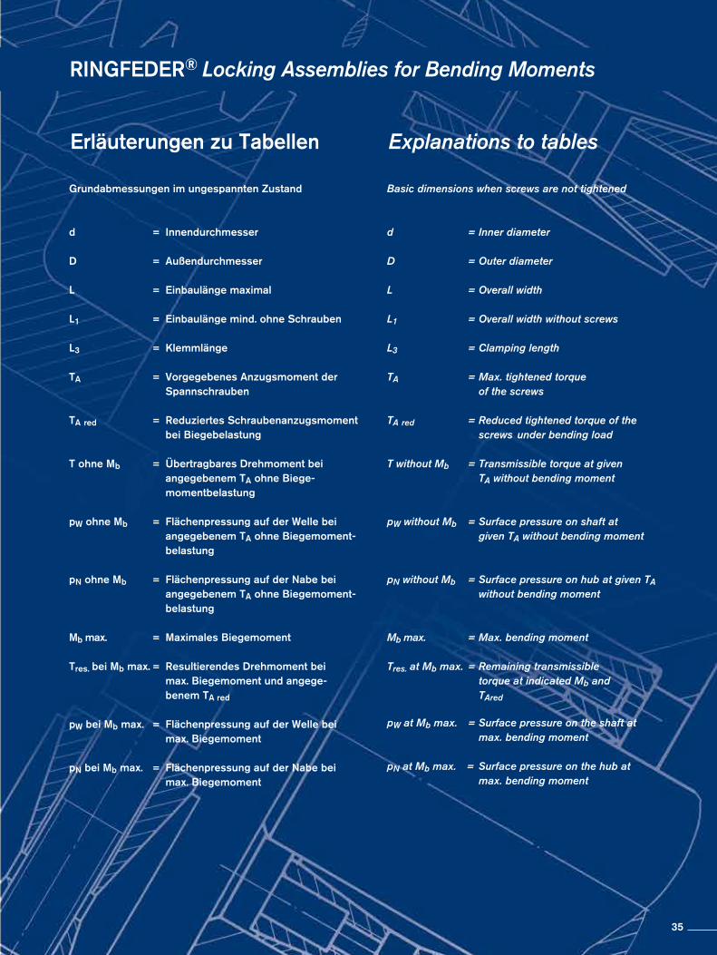
Erläuterungen zu Tabellen Explanations to tables Grundabmessungen im ungespannten Zustand
d = Innendurchmesser
D = Außendurchmesser
L = Einbaulänge maximal
L1 = Einbaulänge mind. ohne Schrauben
L3 = Klemmlänge
TA = Vorgegebenes Anzugsmoment der Spannschrauben
TA red = Reduziertes Schraubenanzugsmoment bei Biegebelastung
T ohne Mb = Übertragbares Drehmoment bei angegebenem TA ohne Biege- momentbelastung pW ohne Mb = Flächenpressung auf der Welle bei angegebenem TA ohne Biegemoment- belastung pN ohne Mb = Flächenpressung auf der Nabe bei angegebenem TA ohne Biegemoment- belastung
Mb max. = Maximales Biegemoment
Tres. bei Mb max. = Resultierendes Drehmoment bei max. Biegemoment und angege- benem TA red
pW bei Mb max. = Flächenpressung auf der Welle bei max. Biegemoment
pN bei Mb max. = Flächenpressung auf der Nabe bei max. Biegemoment
Basic dimensions when screws are not tightened
d = Inner diameter
D = Outer diameter
L = Overall width
L1 = Overall width without screws
L3 = Clamping length
TA = Max. tightened torque of the screws
TA red = Reduced tightened torque of the screws under bending load
T without Mb = Transmissible torque at given TA without bending moment
pW without Mb = Surface pressure on shaft at given TA without bending moment
pN without Mb = Surface pressure on hub at given TA without bending moment
Mb max. = Max. bending moment
Tres. at Mb max. = Remaining transmissible torque at indicated Mb and TAred
pW at Mb max. = Surface pressure on the shaft at max. bending moment
pN at Mb max. = Surface pressure on the hub at max. bending moment
35
RINGFEDER® Spannsätze für Biegemomente
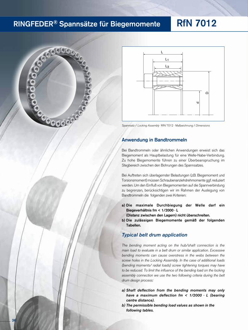
Anwendung in Bandtrommeln
Bei Bandtrommeln oder ähnlichen Anwendungen erweist sich das Biegemoment als Hauptbelastung für eine Welle-Nabe-Verbindung. Zu hohe Biegemomente führen zu einer Überbeanspruchung im Stegbereich zwischen den Bohrungen des Spannsatzes.
Bei Auftreten sich überlagernder Belastungen (z.B. Biegemoment und Torsionsmoment) müssen Schraubenanziehdrehmomente ggf. reduziert werden. Um den Einfluß von Biegemomenten auf die Spannverbindung zu begrenzen, berücksichtigen wir im Rahmen der Auslegung von Bandtrommeln die folgenden zwei Kriterien:
a) Die maximale Durchbiegung der Welle darf ein Biegeverhältnis fm < 1/2000 · L (Distanz zwischen den Lagern) nicht überschreiten.b) Die zulässigen Biegemomente gemäß der folgenden Tabellen.
Typical belt drum application
The bending moment acting on the hub/shaft connection is the main load to evaluate in a belt drum or similar application. Excessive bending moments can cause overstress in the webs between the screw holes in the Locking Assembly. In the case of additional loads (bending moments/ radial loads) screw tightening torques may have to be reduced. To limit the influence of the bending load on the locking assembly connection we use the two following criteria during the belt drum design process:
a) Shaft deflection from the bending moments may only have a maximum deflection fm < 1/2000 · L (bearing centre distance).b) The permissible bending load values as shown in the following tables.
RfN 7012
L
d
D
L3
L1
Spannsatz / Locking Assembly RfN 7012 · Maßzeichnung / Dimensions
36

HINWEIS! Die Werte zu den Wellen- und Nabenpressungen sind mit den in den Tabellen angegebenen Schraubenanzugsdrehmomenten errechnet. Bei Erhöhung bzw. Verminderung des Schraubenanziehdrehmomentes ergeben sich andere Berechnungswerte!
Remark! The values of the shaft- and hub pressures have been calculated with the screw tightening shown in the tables. Increase resp. reduction of the screw tightening torque results in different calculation values!
RINGFEDER® Locking Assemblies for Bending Moments
Baureihe / Series d D
RfN 7012 160 210
Bestellbeispiel · Ordering example: RfN 7012
RfN 7012
Abmessungen Spannsatz
Locking Assembly dimensions T pW pN pW pN
ohne ohne ohne bei / at bei / at
d x D L L1 L3 TAred. without Mb without Mb without Mb Mb max. Tres. Mb max. Mb max.
mm mm Nm Nm N/mm2 kNm N/mm2
100 x 145 47 33 26 125 9.591 196 135 2,6 9,2 245 169
110 x 155 47 33 26 125 10.488 177 126 2,7 10,1 223 158
120 x 165 47 33 26 125 13.004 184 134 3 12,6 231 168
130 x 180 52 38 34 125 17.522 162 117 5 16,8 216 156
140 x 190 52 38 34 125 20.661 164 121 5,3 19,9 218 161
150 x 200 52 38 34 125 24.046 167 125 5,9 23,3 223 167
160 x 210 52 38 34 125 27.674 169 129 6,2 26,9 224 170
170 x 225 60 44 38 190 32.486 157 119 7,8 31,5 206 155
180 x 235 60 44 38 190 37.391 161 123 8,6 36,3 212 162
190 x 250 68 52 46 190 45.890 147 111 12 44,3 194 148
200 x 260 68 52 46 190 51.590 149 114 12,7 50 197 151
220 x 285 74 56 50 295 64.290 146 112 16,5 64,2 194 150
240 x 305 74 56 50 295 81.617 153 120 15,6 81,6 195 154
260 x 325 74 56 50 295 100.624 159 127 13,4 100,6 193 154
280 x 355 86,5 66 60 405 120.825 140 111 28,9 120,8 188 148
300 x 375 86,5 66 60 405 147.726 146 117 20,2 147,7 178 142
320 x 405 100,5 78 72 580 204.771 149 118 31 204,8 181 143
340 x 425 100,5 78 72 580 213.851 140 112 48,2 213,8 187 150
360 x 455 116 90 84 780 275.438 138 109 62,4 275,4 181 143
380 x 475 116 90 84 780 288.145 130 104 72,4 288,1 178 142
400 x 495 116 90 84 780 302.974 123 99 73,4 302,9 169 137
420 x 515 116 90 84 780 355.142 130 106 73,1 355,1 173 141
440 x 545 130 102 96 1.000 432.613 126 102 94,6 432,6 168 136
460 x 565 130 102 96 1.000 449.347 121 98 106 449,3 165 135
480 x 585 130 102 96 1.000 492.134 121 99 111 492,1 166 136
500 x 605 130 102 96 1.000 538.414 121 100 108 538,4 163 135
520 x 630 130 102 96 1.000 570.164 119 98 120 570,1 164 135
540 x 650 130 102 96 1.000 591.591 114 95 120 591,6 158 131
560 x 670 130 102 96 1.000 654.571 117 98 124 654,6 160 134
580 x 690 130 102 96 1.000 705.667 118 99 128 705,7 161 135
600 x 710 130 102 96 1.000 728.298 114 96 133 728,3 157 132
620 x 730 130 102 96 1.000 782.083 114 97 137 782 157 133
640 x 750 130 102 96 1.000 838.483 115 98 136 838,5 156 133
Weitere Größen auf Anfrage More sizes on request
Erläuterungen zu Tabellen: Seite 35 Explanations to tables: Page 35
37
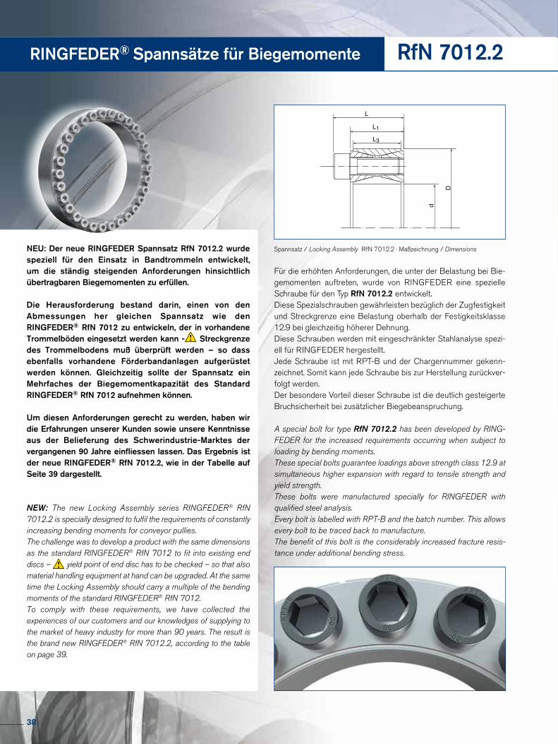
RINGFEDER® Spannsätze für Biegemomente RfN 7012.2
Für die erhöhten Anforderungen, die unter der Belastung bei Bie-gemomenten auftreten, wurde von RINGFEDER eine spezielle Schraube für den Typ RfN 7012.2 entwickelt.Diese Spezialschrauben gewährleisten bezüglich der Zugfestigkeit und Streckgrenze eine Belastung oberhalb der Festigkeitsklasse 12.9 bei gleichzeitig höherer Dehnung.Diese Schrauben werden mit eingeschränkter Stahlanalyse spezi-ell für RINGFEDER hergestellt.Jede Schraube ist mit RPT-B und der Chargennummer gekenn-zeichnet. Somit kann jede Schraube bis zur Herstellung zurückver-folgt werden.Der besondere Vorteil dieser Schraube ist die deutlich gesteigerte Bruchsicherheit bei zusätzlicher Biegebeanspruchung.
A special bolt for type RfN 7012.2 has been developed by RING-FEDER for the increased requirements occurring when subject to loading by bending moments.These special bolts guarantee loadings above strength class 12.9 at simultaneous higher expansion with regard to tensile strength and yield strength.These bolts were manufactured specially for RINGFEDER with qualified steel analysis.Every bolt is labelled with RPT-B and the batch number. This allows every bolt to be traced back to manufacture.The benefit of this bolt is the considerably increased fracture resis-tance under additional bending stress.
NEU: Der neue RINGFEDER Spannsatz RfN 7012.2 wurde speziell für den Einsatz in Bandtrommeln entwickelt, um die ständig steigenden Anforderungen hinsichtlich übertragbaren Biegemomenten zu erfüllen.
Die Herausforderung bestand darin, einen von den Abmessungen her gleichen Spannsatz wie den RINGFEDER® RfN 7012 zu entwickeln, der in vorhandene Trommelböden eingesetzt werden kann - Streckgrenze des Trommelbodens muß überprüft werden – so dass ebenfalls vorhandene Förderbandanlagen aufgerüstet werden können. Gleichzeitig sollte der Spannsatz ein Mehrfaches der Biegemomentkapazität des Standard RINGFEDER® RfN 7012 aufnehmen können.
Um diesen Anforderungen gerecht zu werden, haben wir die Erfahrungen unserer Kunden sowie unsere Kenntnisse aus der Belieferung des Schwerindustrie-Marktes der vergangenen 90 Jahre einfliessen lassen. Das Ergebnis ist der neue RINGFEDER® RfN 7012.2, wie in der Tabelle auf Seite 39 dargestellt.
NEW: The new Locking Assembly series RINGFEDER® RfN 7012.2 is specially designed to fulfil the requirements of constantly increasing bending moments for conveyor pullies. The challenge was to develop a product with the same dimensions as the standard RINGFEDER® RfN 7012 to fit into existing end discs – yield point of end disc has to be checked – so that also material handling equipment at hand can be upgraded. At the same time the Locking Assembly should carry a multiple of the bending moments of the standard RINGFEDER® RfN 7012.To comply with these requirements, we have collected the experiences of our customers and our knowledges of supplying to the market of heavy industry for more than 90 years. The result is the brand new RINGFEDER® RfN 7012.2, according to the table on page 39.
L
d
D
L3
L1
Spannsatz / Locking Assembly RfN 7012.2 · Maßzeichnung / Dimensions
38

RINGFEDER® Locking Assemblies for Bending Moments
Baureihe / Series d D
RfN 7012.2 200 260
Bestellbeispiel · Ordering example: RfN 7012.2
HINWEIS! Die Werte zu den Wellen- und Nabenpressungen sind mit den in den Tabellen angegebenen Schraubenanzugsdrehmomenten errechnet. Bei Erhöhung bzw. Verminderung des Schraubenanziehdrehmomentes ergeben sich andere Berechnungswerte!
Remark! The values of the shaft- and hub pressures have been calculated with the screw tightening shown in the tables. Increase resp. reduction of the screw tightening torque results in different calculation values!
RfN 7012.2
Abmessungen Spannsatz
Locking Assembly dimensions T pW pN pW pN
ohne ohne ohne bei / at
Mb max.
bei / at
Mb max.d x D L L1 L3 TAred. without Mb without Mb without Mb Mb max. Tres.
mm mm Nm Nm N/mm2 kNm N/mm2
100 x 145 47 33 26 125 10.409 212 146 10 2,9 400 276
110 x 155 47 33 26 125 11.382 192 136 10,3 4,8 368 261
120 x 165 47 33 26 125 14.249 202 147 11,8 7,9 387 281
130 x 180 52 38 34 125 19.455 180 130 15,2 12,1 346 250
140 x 190 52 38 34 125 23.050 184 135 16 16,6 346 255
150 x 200 52 38 34 125 26.933 187 140 14,6 22,6 325 244
160 x 210 52 38 34 125 31.101 190 144 13,3 28,1 308 234
170 x 225 60 44 38 190 36.243 175 132 25,9 25,4 337 254
180 x 235 60 44 38 190 41.880 180 138 28,5 30,7 348 267
190 x 250 68 52 46 190 51.719 165 126 37 36,1 312 237
200 x 260 68 52 46 190 56.277 162 125 40 39,6 313 241
220 x 285 74 56 50 295 74.592 164 126 50,4 54,9 313 241
240 x 305 74 56 50 295 84.169 155 122 51,9 66,3 296 233
260 x 325 74 56 50 295 104.686 164 131 48,9 92,6 287 229
280 x 355 86,5 66 60 405 131.586 148 117 82 102,9 285 225
300 x 375 86,5 66 60 405 145.219 143 114 83 119,2 272 217
320 x 405 100,5 78 72 580 201.713 145 115 126 157,5 276 218
340 x 425 100,5 78 72 580 220.626 141 113 132 176,8 270 216
360 x 455 116 90 84 780 293.404 143 113 178 233,2 267 211
380 x 475 116 90 84 780 318.305 139 111 194 252,4 267 213
400 x 495 116 90 84 780 344.106 136 110 202 278,6 262 212
420 x 515 116 90 84 780 391.995 140 114 195 340 256 209
440 x 545 130 102 96 1.000 478.752 137 110 251 407,7 247 200
460 x 565 130 102 96 1.000 512.615 134 109 282 428 253 206
480 x 585 130 102 96 1.000 547.520 131 108 295 461,3 251 206
500 x 605 130 102 96 1.000 598.054 132 109 304 515 250 207
520 x 630 130 102 96 1.000 635.586 130 107 315 552 247 204
540 x 650 130 102 96 1.000 674.155 128 106 324 591,2 244 203
560 x 670 130 102 96 1.000 729.980 129 108 339 646,5 246 206
580 x 690 130 102 96 1.000 787.923 129 109 353 704,4 248 208
600 x 710 130 102 96 1.000 830.673 128 108 366 745,7 246 208
620 x 730 130 102 96 1.000 874.450 126 107 365 794,6 240 204
640 x 750 130 102 96 1.000 956.024 129 110 364 884 239 204
Weitere Größen auf Anfrage More sizes on request
Erläuterungen zu Tabellen: Seite 35 Explanations to tables: Page 35
39
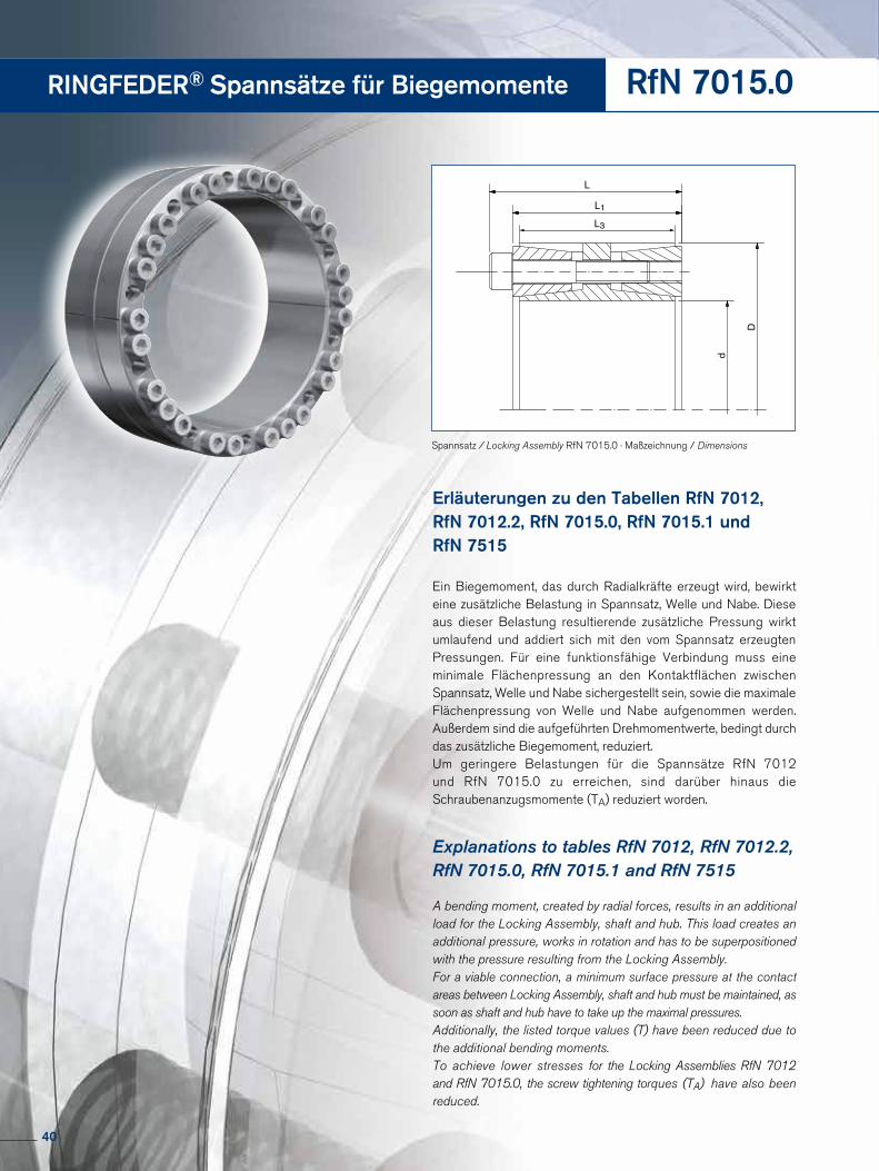
RINGFEDER® Spannsätze für Biegemomente RfN 7015.0
Explanations to tables RfN 7012, RfN 7012.2, RfN 7015.0, RfN 7015.1 and RfN 7515
A bending moment, created by radial forces, results in an additional load for the Locking Assembly, shaft and hub. This load creates an additional pressure, works in rotation and has to be superpositioned with the pressure resulting from the Locking Assembly.For a viable connection, a minimum surface pressure at the contact areas between Locking Assembly, shaft and hub must be maintained, as soon as shaft and hub have to take up the maximal pressures.Additionally, the listed torque values (T) have been reduced due to the additional bending moments. To achieve lower stresses for the Locking Assemblies RfN 7012 and RfN 7015.0, the screw tightening torques (TA) have also been reduced.
Erläuterungen zu den Tabellen RfN 7012, RfN 7012.2, RfN 7015.0, RfN 7015.1 und RfN 7515
Ein Biegemoment, das durch Radialkräfte erzeugt wird, bewirkt eine zusätzliche Belastung in Spannsatz, Welle und Nabe. Diese aus dieser Belastung resultierende zusätzliche Pressung wirkt umlaufend und addiert sich mit den vom Spannsatz erzeugten Pressungen. Für eine funktionsfähige Verbindung muss eine minimale Flächenpressung an den Kontaktflächen zwischen Spannsatz, Welle und Nabe sichergestellt sein, sowie die maximale Flächenpressung von Welle und Nabe aufgenommen werden. Außerdem sind die aufgeführten Drehmomentwerte, bedingt durch das zusätzliche Biegemoment, reduziert.Um geringere Belastungen für die Spannsätze RfN 7012 und RfN 7015.0 zu erreichen, sind darüber hinaus die Schraubenanzugsmomente (TA) reduziert worden.
L
L1
d
D
L3
Spannsatz / Locking Assembly RfN 7015.0 · Maßzeichnung / Dimensions
40

RINGFEDER® Locking Assemblies for Bending Moments
Baureihe / Series d D
RfN 7015.0 240 305
Bestellbeispiel · Ordering example: RfN 7015.0
HINWEIS! Die Werte zu den Wellen- und Nabenpressungen sind mit den in den Tabellen angegebenen Schraubenanzugsdrehmomenten errechnet. Bei Erhöhung bzw. Verminderung des Schraubenanziehdrehmomentes ergeben sich andere Berechnungswerte!
Remark! The values of the shaft- and hub pressures have been calculated with the screw tightening shown in the tables. Increase resp. reduction of the screw tightening torque results in different calculation values!
RfN 7015.0
Abmessungen Spannsatz
Locking Assembly dimensions T pW pN pW pN
ohne ohne ohne bei / at
Mb max.
bei / at
Mb max.d x D L L1 L3 TAred. without Mb without Mb without Mb Mb max. Tres.
mm mm Nm Nm N/mm2 kNm N/mm2
100 x 145 77 65 60 115 11.297 157 108 10,9 3 214 147
110 x 155 77 65 60 115 12.426 142 101 10,9 6 194 138
120 x 165 77 65 60 115 16.267 157 114 13 9,8 213 155
130 x 180 86 74 68 115 22.028 156 113 18 12,7 212 153
140 x 190 86 74 68 115 28.468 174 128 19 21,2 229 169
150 x 200 86 74 68 115 30.501 163 122 21,5 21,6 220 165
160 x 210 86 74 68 115 37.957 178 136 20 32,3 228 174
170 x 225 95 81 75 185 47.955 179 135 32 35,7 241 182
180 x 235 95 81 75 185 50.776 169 129 32,5 39 229 175
190 x 250 108 94 88 185 59.552 149 113 41,5 42,7 202 154
200 x 260 108 94 88 185 75.224 170 131 25 70,9 201 154
220 x 285 120 104 98 285 84.791 152 117 61 58,9 208 161
240 x 305 120 104 98 285 123.332 186 146 45 114,8 224 176
260 x 325 120 104 98 285 139.176 178 143 42,5 132,5 212 169
280 x 355 144 126 120 390 174.092 161 127 120 126,1 221 174
300 x 375 144 126 120 390 194.299 157 125 126 147,9 216 172
320 x 405 162 142 135 550 265.703 159 125 155 215,8 211 167
340 x 425 162 142 135 550 282.310 149 120 177 219,9 206 164
360 x 455 187 165 158 745 371.148 149 118 250 274,3 204 161
380 x 475 187 165 158 745 391.767 141 113 249 302,5 193 154
400 x 495 187 165 158 745 412.387 134 108 250 327,9 184 148
420 x 515 187 165 158 745 519.607 153 125 300 424,3 210 171
440 x 545 204 180 172 960 639.702 154 124 370 521,8 209 169
460 x 565 204 180 172 960 668.779 147 120 370 557,1 200 163
480 x 585 204 180 172 960 744.381 150 123 395 630,9 205 168
500 x 605 204 180 172 960 775.396 144 119 395 667,2 197 163
520 x 630 227 200 190 1.440 1.014.357 156 129 530 864,9 210 174
540 x 650 227 200 190 1.440 1.053.370 150 125 530 910,3 203 168
560 x 670 227 200 190 1.440 1.092.384 145 121 530 955,2 195 163
580 x 690 227 200 190 1.440 1.131.398 140 118 532 998,5 189 159
600 x 710 227 200 190 1.440 1.248.439 144 122 566 1.112,8 195 164
620 x 730 227 200 190 1.440 1.290.054 140 119 573 1.155,8 189 160
640 x 750 227 200 190 1.440 1.456.512 148 126 576 1.337,8 196 167
Weitere Größen auf Anfrage More sizes on request
Erläuterungen zu Tabellen: Seite 35 Explanations to tables: Page 35
41
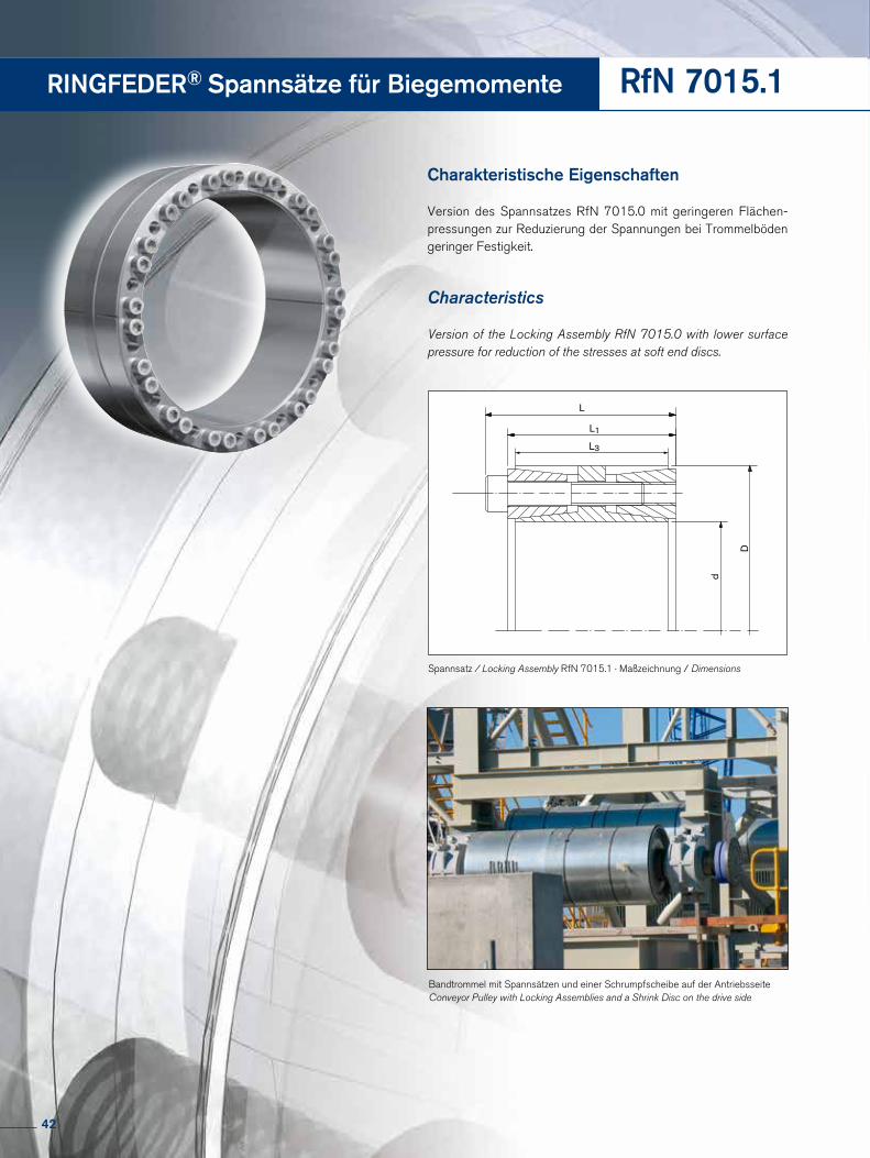
RINGFEDER® Spannsätze für Biegemomente RfN 7015.1
Charakteristische Eigenschaften
Version des Spannsatzes RfN 7015.0 mit geringeren Flächen-pressungen zur Reduzierung der Spannungen bei Trommelböden geringer Festigkeit.
Characteristics
Version of the Locking Assembly RfN 7015.0 with lower surface pressure for reduction of the stresses at soft end discs.
Bandtrommel mit Spannsätzen und einer Schrumpfscheibe auf der Antriebsseite Conveyor Pulley with Locking Assemblies and a Shrink Disc on the drive side
L
L1
d
D
L3
Spannsatz / Locking Assembly RfN 7015.1 · Maßzeichnung / Dimensions
42
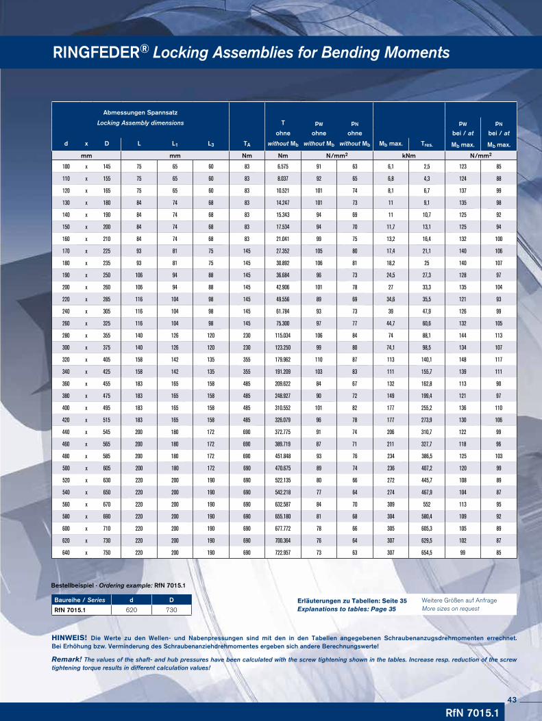
RINGFEDER® Locking Assemblies for Bending Moments
Baureihe / Series d D
RfN 7015.1 620 730
Bestellbeispiel · Ordering example: RfN 7015.1
HINWEIS! Die Werte zu den Wellen- und Nabenpressungen sind mit den in den Tabellen angegebenen Schraubenanzugsdrehmomenten errechnet. Bei Erhöhung bzw. Verminderung des Schraubenanziehdrehmomentes ergeben sich andere Berechnungswerte!
Remark! The values of the shaft- and hub pressures have been calculated with the screw tightening shown in the tables. Increase resp. reduction of the screw tightening torque results in different calculation values!
RfN 7015.1
Abmessungen Spannsatz
Locking Assembly dimensions T pW pN pW pN
ohne ohne ohne bei / at bei / at
d x D L L1 L3 TA without Mb without Mb without Mb Mb max. Tres. Mb max. Mb max.
mm mm Nm Nm N/mm2 kNm N/mm2
100 x 145 75 65 60 83 6.575 91 63 6,1 2,5 123 85
110 x 155 75 65 60 83 8.037 92 65 6,8 4,3 124 88
120 x 165 75 65 60 83 10.521 101 74 8,1 6,7 137 99
130 x 180 84 74 68 83 14.247 101 73 11 9,1 135 98
140 x 190 84 74 68 83 15.343 94 69 11 10,7 125 92
150 x 200 84 74 68 83 17.534 94 70 11,7 13,1 125 94
160 x 210 84 74 68 83 21.041 99 75 13,2 16,4 132 100
170 x 225 93 81 75 145 27.352 105 80 17,4 21,1 140 106
180 x 235 93 81 75 145 30.892 106 81 18,2 25 140 107
190 x 250 106 94 88 145 36.684 96 73 24,5 27,3 128 97
200 x 260 106 94 88 145 42.906 101 78 27 33,3 135 104
220 x 285 116 104 98 145 49.556 89 69 34,6 35,5 121 93
240 x 305 116 104 98 145 61.784 93 73 39 47,9 126 99
260 x 325 116 104 98 145 75.300 97 77 44,7 60,6 132 105
280 x 355 140 126 120 230 115.034 106 84 74 88,1 144 113
300 x 375 140 126 120 230 123.250 99 80 74,1 98,5 134 107
320 x 405 158 142 135 355 179.962 110 87 113 140,1 148 117
340 x 425 158 142 135 355 191.209 103 83 111 155,7 139 111
360 x 455 183 165 158 485 209.622 84 67 132 162,8 113 90
380 x 475 183 165 158 485 248.927 90 72 149 199,4 121 97
400 x 495 183 165 158 485 310.552 101 82 177 255,2 136 110
420 x 515 183 165 158 485 326.079 96 78 177 273,9 130 106
440 x 545 200 180 172 690 372.775 91 74 206 310,7 122 99
460 x 565 200 180 172 690 389.719 87 71 211 327,7 118 96
480 x 585 200 180 172 690 451.848 93 76 234 386,5 125 103
500 x 605 200 180 172 690 470.675 89 74 236 407,2 120 99
520 x 630 220 200 190 690 522.135 80 66 272 445,7 108 89
540 x 650 220 200 190 690 542.218 77 64 274 467,9 104 87
560 x 670 220 200 190 690 632.587 84 70 309 552 113 95
580 x 690 220 200 190 690 655.180 81 68 304 580,4 109 92
600 x 710 220 200 190 690 677.772 78 66 305 605,3 105 89
620 x 730 220 200 190 690 700.364 76 64 307 629,5 102 87
640 x 750 220 200 190 690 722.957 73 63 307 654,5 99 85
Weitere Größen auf Anfrage More sizes on request
Erläuterungen zu Tabellen: Seite 35 Explanations to tables: Page 35
43
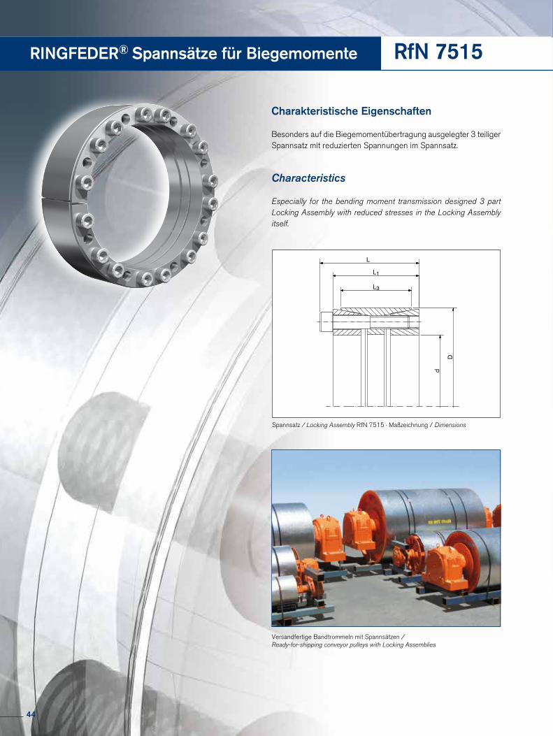
RINGFEDER® Spannsätze für Biegemomente RfN 7515
Charakteristische Eigenschaften
Besonders auf die Biegemomentübertragung ausgelegter 3 teiliger Spannsatz mit reduzierten Spannungen im Spannsatz.
Characteristics
Especially for the bending moment transmission designed 3 part Locking Assembly with reduced stresses in the Locking Assembly itself.
Versandfertige Bandtrommeln mit Spannsätzen / Ready-for-shipping conveyor pulleys with Locking Assemblies
d
D
L
L1
L3
Spannsatz / Locking Assembly RfN 7515 · Maßzeichnung / Dimensions
44
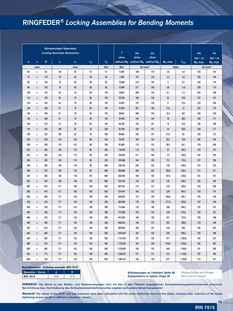
RINGFEDER® Locking Assemblies for Bending Moments
Baureihe / Series d D
RfN 7515 300 375
Bestellbeispiel · Ordering example: RfN 7515
HINWEIS! Die Werte zu den Wellen- und Nabenpressungen sind mit den in den Tabellen angegebenen Schraubenanzugsdrehmomenten errechnet. Bei Erhöhung bzw. Verminderung des Schraubenanziehdrehmomentes ergeben sich andere Berechnungswerte!
Remark! The values of the shaft- and hub pressures have been calculated with the screw tightening shown in the tables. Increase resp. reduction of the screw tightening torque results in different calculation values!
RfN 7515
Abmessungen Spannsatz
Locking Assembly dimensions T pW pN pW pN
ohne ohne ohne bei / at
Mb max.
bei / at
Mb max.d x D L L1 L3 TA without Mb without Mb without Mb Mb max. Tres.
mm mm Nm Nm N/mm2 kNm N/mm2
60 x 95 58 50 42 41 4.299 186 118 2,6 3,4 225 142
70 x 110 70 60 50 83 7.280 197 125 3,2 6,5 226 144
80 x 120 70 60 50 83 10.399 216 144 5 9,1 255 170
90 x 130 70 60 50 83 12.869 211 146 5,6 11,6 250 173
100 x 145 82 70 60 145 18.881 209 144 8,1 17,1 245 169
110 x 155 82 70 60 145 20.769 190 135 9,2 18,6 227 161
120 x 165 82 70 60 145 24.923 191 139 11 22,4 233 169
130 x 180 91 79 65 145 34.364 207 150 12,5 32 242 175
140 x 190 91 79 65 145 39.651 206 152 16,4 36,1 249 183
150 x 200 91 79 65 145 42.483 193 144 18 38,5 236 177
160 x 210 91 79 65 145 48.336 193 147 19 44,4 236 180
170 x 225 106 92 78 230 65.790 195 147 25 60,9 234 177
180 x 235 106 92 78 230 69.660 184 141 27,6 64 225 172
190 x 250 116 102 88 230 78.432 165 125 33,5 70,9 202 154
200 x 260 116 102 88 230 92.880 176 135 39,5 84,1 218 168
220 x 285 126 110 96 355 116.459 173 133 52 104,2 216 167
240 x 305 126 110 96 355 169.394 211 166 43 163,8 244 192
260 x 325 126 110 96 355 192.686 184 148 77,2 176,5 237 190
280 x 355 130 110 96 690 230.199 205 162 105 204,9 273 216
300 x 375 130 110 96 690 263.085 204 163 109,5 239,2 271 217
320 x 405 156 136 124 690 350.780 189 150 141,6 320,9 242 191
340 x 425 156 136 124 690 372.704 178 143 154 339,4 232 185
360 x 455 177 155 140 930 487.557 174 137 219 435,6 228 180
380 x 475 177 155 140 930 514.644 164 132 228 461,4 218 174
400 x 495 177 155 140 930 595.903 172 139 240,8 545,1 226 182
420 x 515 177 155 140 930 682.580 179 146 277,6 623,6 237 194
440 x 535 177 155 140 930 715.084 170 140 306 646,3 232 191
460 x 555 177 155 140 930 747.588 163 135 320 675,6 225 187
480 x 575 177 155 140 930 812.595 163 136 341 737,6 226 189
500 x 595 177 155 140 930 846.453 156 131 352 769,8 219 184
520 x 615 177 155 140 930 985.949 168 142 418 893 240 203
540 x 635 177 155 140 930 1.023.870 162 138 432 928,3 233 198
560 x 655 177 155 140 930 1.137.633 167 143 471 1.035,6 242 207
580 x 675 177 155 140 930 1.178.263 162 139 479,6 1.076,2 235 202
600 x 695 177 155 140 930 1.218.893 156 135 505 1.109,4 231 200
620 x 715 177 155 140 930 1.259.522 151 131 515 1.149,4 225 195
640 x 735 177 155 140 930 1.300.152 146 128 522 1.190,8 219 191
Weitere Größen auf Anfrage More sizes on request
Erläuterungen zu Tabellen: Seite 35 Explanations to tables: Page 35
45
RINGFEDER® Spannelemente · Locking Elements
46
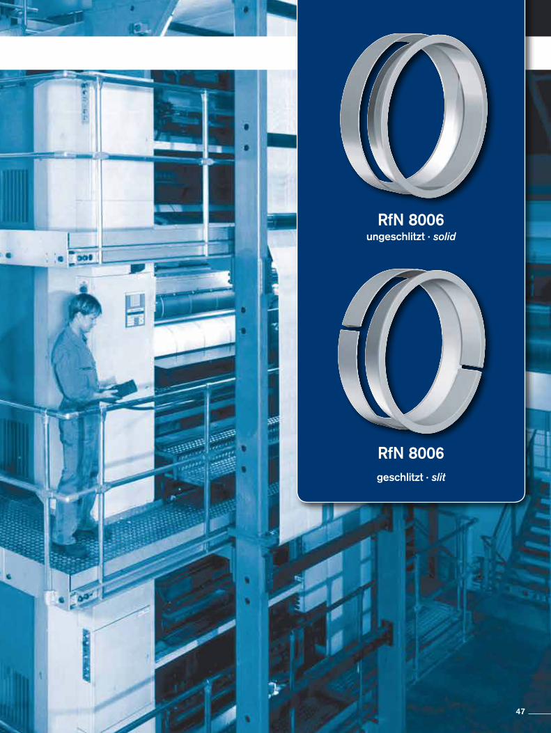
RfN 8006ungeschlitzt · solid
RfN 8006geschlitzt · slit
47
Charakteristische EigenschaftenIdeal anpassbar – in Bezug auf konstruktive Erfordernisse und Gegebenheiten, durch Anzahl der einzusetzenden Spannelemente, sowie Größe und Anzahl der Spannschrauben. Große übertragbare Umfangskräfte – zur Erhöhung der Drehmomente und Axialkräfte können bis zu 4 Spannelemente hintereinander geschaltet werden (siehe Seite 52).Größte Zuverlässigkeit – egal ob die Verbindung statisch, schwellend, dyna-misch oder stoß artig belastet wird.Einfache Fertigung – Wellen und Naben bleiben ungenutet. Außerdem können relativ große Toleranzen zugelassen werden.Leichte Einstellbarkeit – Spannelemente arbeiten ohne Formschluss. Die Naben lassen sich daher unter Beachtung der Montage- und Demontageanweisung an jeder beliebigen Stelle und in jeder beliebigen Lage spannen.Absolut spielfrei - keine Gefahr des Ausschlagens.Große Dauerdrehwechselfestigkeit – Welle und Nabe sind ungenutet, dadurch geringe Kerbwirkung und optimale Materialausnutzung.Einfache Montage – im Vergleich zu Querpresssitzen entfallen Temperaturbe-handlungen und Einpassarbeiten. Schrauben sind nur mit handelsüblichen Werk-zeugen anzuziehen.Einfache Demontage – nach dem Lösen der Spannschrauben sind die Spanne-lemente RfN 8006 entspannt. Welle und Nabe sind frei beweglich.Verschleiß- und wartungsfrei – bei korrekter Auslegung und Anwendung unbegrenzte Lebensdauer.
CharacteristicsCustomized application – by varying the number of Locking Elements, size and quantity of clamping screws, the connection can be adapted to fit most applications concerning surface pressures, materials, hub/shaft dimensions and available mounting space.Transmission of high loads – to increase the transmissible torque and axial forces up to 4 Locking Elements can be used in series (see page 52).Maximum reliability – no matter whether the connection is subjected to static, pulsating, dynamic or intermittent loads.Simple manufacture – shaft and hub are designed without keyway. Apart from this, rela-tively large tolerances are admissible.Easy adjustability – Locking Elements work without positive connection. So they can be adjusted at any place to any position by following the simple installation and removal instructions.Backlash-free – the Locking Element connection is a mechanical shrink fit and will not wear or loosen in service provided that the maximum transmissible values for the connection are not exceeded.High fatigue strength under alternating torsional stresses – as neither the shaft nor the hub have grooves the notch effect is minimized and a higher polar section modulus is given, enabling the use of smaller diameters.Simple installation – in comparison to cross-press fits temperature treatments and fitting are eliminated. Screws have to be tightened with standard tools.Easy removal – Locking Elements are self releasing no additional measures or auxiliary equipment is required.Wear and maintenance-free – unlimited lifetime if designed and used correctly.
RINGFEDER® Spannelemente · Locking Elements
48
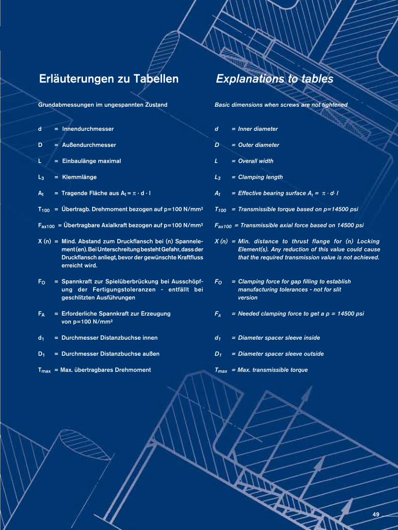
Erläuterungen zu Tabellen Grundabmessungen im ungespannten Zustand
d = Innendurchmesser
D = Außendurchmesser
L = Einbaulänge maximal
L3 = Klemmlänge
At = Tragende Fläche aus At = π · d · l
T100 = Übertragb. Drehmoment bezogen auf p=100 N/mm²
Fax100 = Übertragbare Axialkraft bezogen auf p=100 N/mm²
X (n) = Mind. Abstand zum Druckflansch bei (n) Spannele- ment (en). Bei Unterschreitung besteht Gefahr, dass der Druckflansch anliegt, bevor der gewünschte Kraftfluss erreicht wird.
FO = Spannkraft zur Spielüberbrückung bei Ausschöpf-
ung der Fertigungstoleranzen - entfällt bei geschlitzten Ausführungen
FA = Erforderliche Spannkraft zur Erzeugung von p=100 N/mm²
d1 = Durchmesser Distanzbuchse innen
D1 = Durchmesser Distanzbuchse außen
Tmax = Max. übertragbares Drehmoment
Explanations to tables
Basic dimensions when screws are not tightened
d = Inner diameter
D = Outer diameter
L = Overall width
L3 = Clamping length
At = Effective bearing surface At = π · d· l
T100 = Transmissible torque based on p=14500 psi
Fax100 = Transmissible axial force based on 14500 psi
X (n) = Min. distance to thrust flange for (n) Locking Element(s). Any reduction of this value could cause that the required transmission value is not achieved.
FO = Clamping force for gap filling to establish
manufacturing tolerances - not for slit version
FA = Needed clamping force to get a p = 14500 psi
d1 = Diameter spacer sleeve inside
D1 = Diameter spacer sleeve outside
Tmax = Max. transmissible torque
49
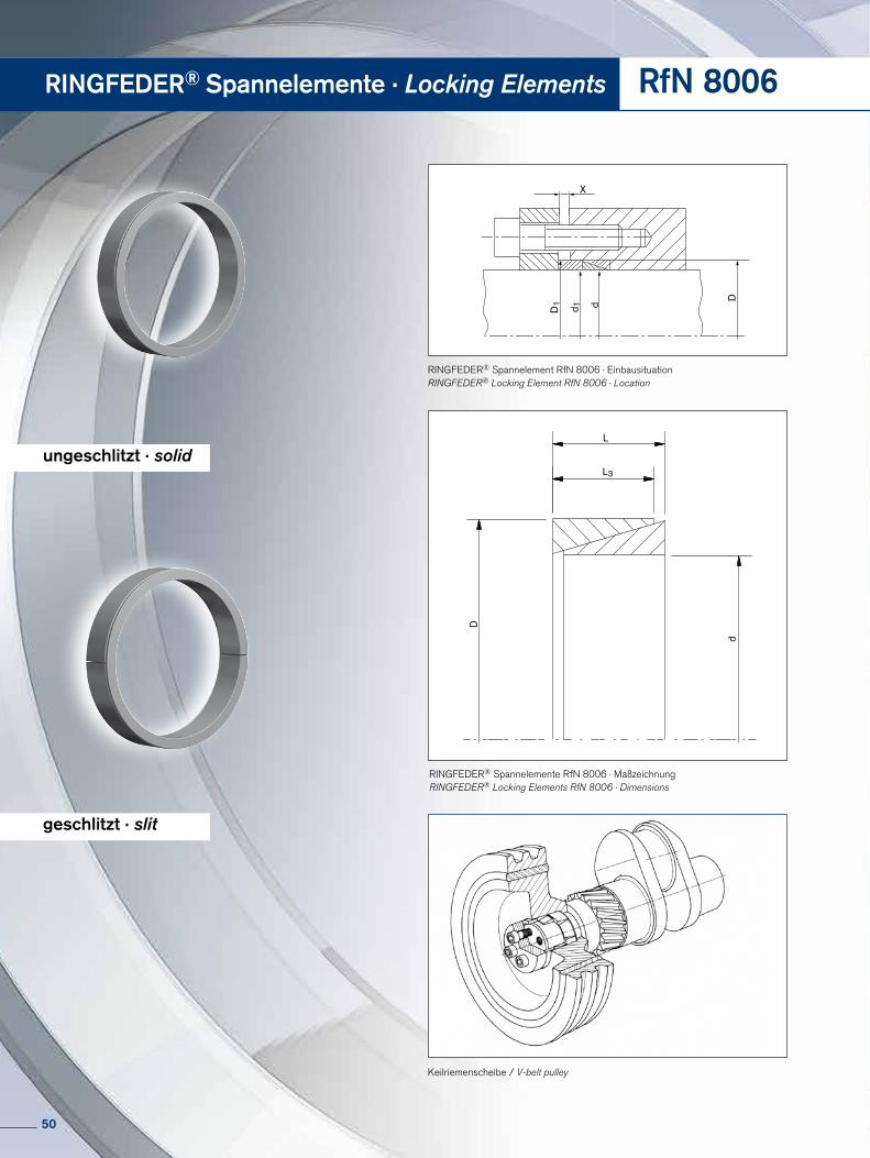
RINGFEDER® Spannelemente · Locking Elements RfN 8006
ungeschlitzt · solid
geschlitzt · slit
L
L3D
d
X
d 1D1 d
D
RINGFEDER® Spannelement RfN 8006 · EinbausituationRINGFEDER® Locking Element RfN 8006 · Location
RINGFEDER® Spannelemente RfN 8006 · MaßzeichnungRINGFEDER® Locking Elements RfN 8006 · Dimensions
Keilriemenscheibe / V-belt pulley
50
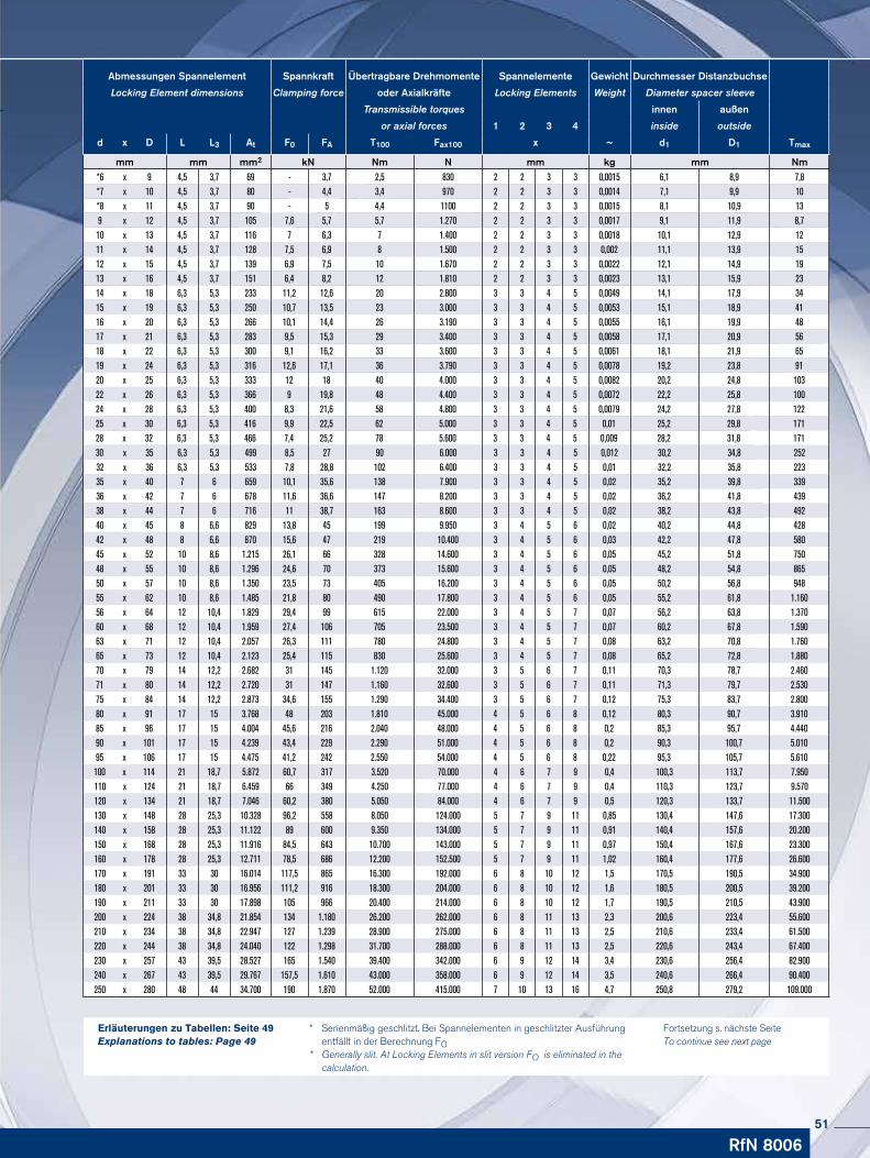
* Serienmäßig geschlitzt. Bei Spannelementen in geschlitzter Ausführung entfällt in der Berechnung FO* Generally slit. At Locking Elements in slit version FO is eliminated in the calculation.
Fortsetzung s. nächste Seite To continue see next page
RfN 8006
Abmessungen Spannelement Spannkraft Übertragbare Drehmomente Spannelemente Gewicht Durchmesser Distanzbuchse
Locking Element dimensions Clamping force oder Axialkräfte Locking Elements Weight Diameter spacer sleeve
Transmissible torques innen außen
or axial forces 1 2 3 4 inside outside
d x D L L3 At F0 FA T100 Fax100 x ~ d1 D1 Tmax
mm mm mm2 kN Nm N mm kg mm Nm*6 x 9 4,5 3,7 69 - 3,7 2,5 830 2 2 3 3 0,0015 6,1 8,9 7,8*7 x 10 4,5 3,7 80 - 4,4 3,4 970 2 2 3 3 0,0014 7,1 9,9 10*8 x 11 4,5 3,7 90 - 5 4,4 1100 2 2 3 3 0,0015 8,1 10,9 139 x 12 4,5 3,7 105 7,6 5,7 5,7 1.270 2 2 3 3 0,0017 9,1 11,9 8,710 x 13 4,5 3,7 116 7 6,3 7 1.400 2 2 3 3 0,0018 10,1 12,9 1211 x 14 4,5 3,7 128 7,5 6,9 8 1.500 2 2 3 3 0,002 11,1 13,9 1512 x 15 4,5 3,7 139 6,9 7,5 10 1.670 2 2 3 3 0,0022 12,1 14,9 1913 x 16 4,5 3,7 151 6,4 8,2 12 1.810 2 2 3 3 0,0023 13,1 15,9 2314 x 18 6,3 5,3 233 11,2 12,6 20 2.800 3 3 4 5 0,0049 14,1 17,9 3415 x 19 6,3 5,3 250 10,7 13,5 23 3.000 3 3 4 5 0,0053 15,1 18,9 4116 x 20 6,3 5,3 266 10,1 14,4 26 3.190 3 3 4 5 0,0055 16,1 19,9 4817 x 21 6,3 5,3 283 9,5 15,3 29 3.400 3 3 4 5 0,0058 17,1 20,9 5618 x 22 6,3 5,3 300 9,1 16,2 33 3.600 3 3 4 5 0,0061 18,1 21,9 6519 x 24 6,3 5,3 316 12,6 17,1 36 3.790 3 3 4 5 0,0078 19,2 23,8 9120 x 25 6,3 5,3 333 12 18 40 4.000 3 3 4 5 0,0082 20,2 24,8 10322 x 26 6,3 5,3 366 9 19,8 48 4.400 3 3 4 5 0,0072 22,2 25,8 10024 x 28 6,3 5,3 400 8,3 21,6 58 4.800 3 3 4 5 0,0079 24,2 27,8 12225 x 30 6,3 5,3 416 9,9 22,5 62 5.000 3 3 4 5 0,01 25,2 29,8 17128 x 32 6,3 5,3 466 7,4 25,2 78 5.600 3 3 4 5 0,009 28,2 31,8 17130 x 35 6,3 5,3 499 8,5 27 90 6.000 3 3 4 5 0,012 30,2 34,8 25232 x 36 6,3 5,3 533 7,8 28,8 102 6.400 3 3 4 5 0,01 32,2 35,8 22335 x 40 7 6 659 10,1 35,6 138 7.900 3 3 4 5 0,02 35,2 39,8 33936 x 42 7 6 678 11,6 36,6 147 8.200 3 3 4 5 0,02 36,2 41,8 43938 x 44 7 6 716 11 38,7 163 8.600 3 3 4 5 0,02 38,2 43,8 49240 x 45 8 6,6 829 13,8 45 199 9.950 3 4 5 6 0,02 40,2 44,8 42842 x 48 8 6,6 870 15,6 47 219 10.400 3 4 5 6 0,03 42,2 47,8 58045 x 52 10 8,6 1.215 26,1 66 328 14.600 3 4 5 6 0,05 45,2 51,8 75048 x 55 10 8,6 1.296 24,6 70 373 15.600 3 4 5 6 0,05 48,2 54,8 86550 x 57 10 8,6 1.350 23,5 73 405 16.200 3 4 5 6 0,05 50,2 56,8 94855 x 62 10 8,6 1.485 21,8 80 490 17.800 3 4 5 6 0,05 55,2 61,8 1.16056 x 64 12 10,4 1.829 29,4 99 615 22.000 3 4 5 7 0,07 56,2 63,8 1.37060 x 68 12 10,4 1.959 27,4 106 705 23.500 3 4 5 7 0,07 60,2 67,8 1.59063 x 71 12 10,4 2.057 26,3 111 780 24.800 3 4 5 7 0,08 63,2 70,8 1.76065 x 73 12 10,4 2.123 25,4 115 830 25.600 3 4 5 7 0,08 65,2 72,8 1.88070 x 79 14 12,2 2.682 31 145 1.120 32.000 3 5 6 7 0,11 70,3 78,7 2.46071 x 80 14 12,2 2.720 31 147 1.160 32.600 3 5 6 7 0,11 71,3 79,7 2.53075 x 84 14 12,2 2.873 34,6 155 1.290 34.400 3 5 6 7 0,12 75,3 83,7 2.80080 x 91 17 15 3.768 48 203 1.810 45.000 4 5 6 8 0,12 80,3 90,7 3.91085 x 96 17 15 4.004 45,6 216 2.040 48.000 4 5 6 8 0,2 85,3 95,7 4.44090 x 101 17 15 4.239 43,4 229 2.290 51.000 4 5 6 8 0,2 90,3 100,7 5.01095 x 10⁶ 17 15 4.475 41,2 242 2.550 54.000 4 5 6 8 0,22 95,3 105,7 5.610100 x 114 21 18,7 5.872 60,7 317 3.520 70.000 4 6 7 9 0,4 100,3 113,7 7.950110 x 124 21 18,7 6.459 66 349 4.250 77.000 4 6 7 9 0,4 110,3 123,7 9.570120 x 134 21 18,7 7.046 60,2 380 5.050 84.000 4 6 7 9 0,5 120,3 133,7 11.500130 x 148 28 25,3 10.328 96,2 558 8.050 124.000 5 7 9 11 0,85 130,4 147,6 17.300140 x 158 28 25,3 11.122 89 600 9.350 134.000 5 7 9 11 0,91 140,4 157,6 20.200150 x 168 28 25,3 11.916 84,5 643 10.700 143.000 5 7 9 11 0,97 150,4 167,6 23.300160 x 178 28 25,3 12.711 78,5 686 12.200 152.500 5 7 9 11 1,02 160,4 177,6 26.600170 x 191 33 30 16.014 117,5 865 16.300 192.000 6 8 10 12 1,5 170,5 190,5 34.900180 x 201 33 30 16.956 111,2 916 18.300 204.000 6 8 10 12 1,6 180,5 200,5 39.200190 x 211 33 30 17.898 105 966 20.400 214.000 6 8 10 12 1,7 190,5 210,5 43.900200 x 224 38 34,8 21.854 134 1.180 26.200 262.000 6 8 11 13 2,3 200,6 223,4 55.600210 x 234 38 34,8 22.947 127 1.239 28.900 275.000 6 8 11 13 2,5 210,6 233,4 61.500220 x 244 38 34,8 24.040 122 1.298 31.700 288.000 6 8 11 13 2,5 220,6 243,4 67.400230 x 257 43 39,5 28.527 165 1.540 39.400 342.000 6 9 12 14 3,4 230,6 256,4 82.900240 x 267 43 39,5 29.767 157,5 1.610 43.000 358.000 6 9 12 14 3,5 240,6 266,4 90.400250 x 280 48 44 34.700 190 1.870 52.000 415.000 7 10 13 16 4,7 250,8 279,2 109.000
Erläuterungen zu Tabellen: Seite 49Explanations to tables: Page 49
51
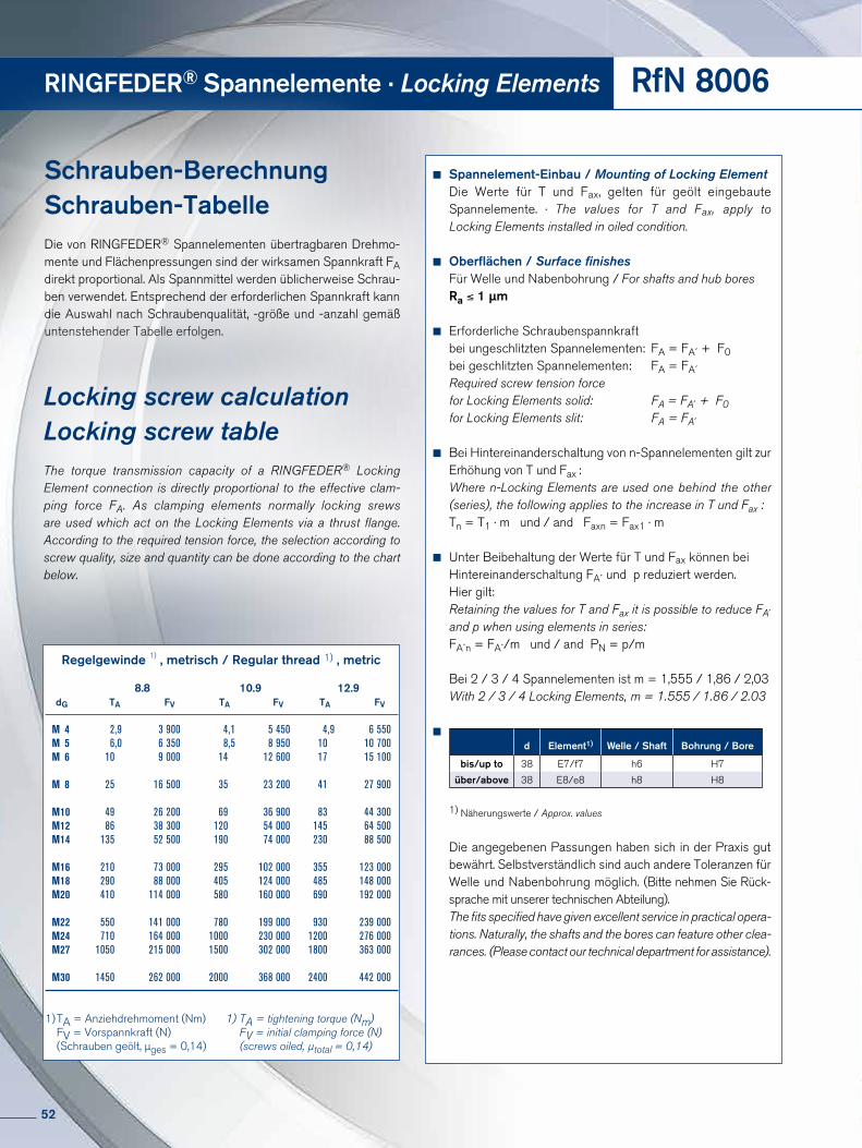
Schrauben-BerechnungSchrauben-TabelleDie von RINGFEDER® Spannelementen übertragbaren Dreh mo-mente und Flächenpressungen sind der wirksamen Spannkraft FA direkt proportional. Als Spannmittel werden üblicherweise Schrau-ben verwendet. Entsprechend der erforderlichen Spannkraft kann die Auswahl nach Schraubenqualität, -größe und -anzahl gemäß untenstehender Tabelle erfolgen.
Regelgewinde 1) , metrisch / Regular thread 1) , metric
8.8 10.9 12.9 dG TA FV TA FV TA FV
M 4 2,9 3 900 4,1 5 450 4,9 6 550 M 5 6,0 6 350 8,5 8 950 10 10 700 M 6 10 9 000 14 12 600 17 15 100
M 8 25 16 500 35 23 200 41 27 900
M 10 49 26 200 69 36 900 83 44 300 M 12 86 38 300 120 54 000 145 64 500 M 14 135 52 500 190 74 000 230 88 500
M 16 210 73 000 295 102 000 355 123 000 M 18 290 88 000 405 124 000 485 148 000 M 20 410 114 000 580 160 000 690 192 000
M 22 550 141 000 780 199 000 930 239 000 M 24 710 164 000 1000 230 000 1200 276 000 M 27 1050 215 000 1500 302 000 1800 363 000
M 30 1450 262 000 2000 368 000 2400 442 000
1) TA = Anziehdrehmoment (Nm) 1) TA = tightening torque (Nm) FV = Vorspannkraft (N) FV = initial clamping force (N) (Schrauben geölt, µges = 0,14) (screws oiled, µtotal = 0,14)
Locking screw calculationLocking screw tableThe torque transmission capacity of a RINGFEDER® Locking Element connection is directly proportional to the effective clam-ping force FA. As clamping elements normally locking srews are used which act on the Locking Elements via a thrust flange. According to the required tension force, the selection according to screw quality, size and quantity can be done according to the chart below.
Spannelement-Einbau / Mounting of Locking ElementDie Werte für T und Fax, gelten für geölt eingebaute Spannelemente. · The values for T and Fax, apply to Locking Elements installed in oiled condition.
Oberflächen / Surface finishesFür Welle und Nabenbohrung / For shafts and hub boresRa ≤ 1 µm
Erforderliche Schraubenspannkraft bei ungeschlitzten Spannelementen: FA = FA´ + F0bei geschlitzten Spannelementen: FA = FA´Required screw tension force for Locking Elements solid: FA = FA´ + F0for Locking Elements slit: FA = FA´
Bei Hintereinanderschaltung von n-Spannelementen gilt zur Erhöhung von T und Fax :
Where n-Locking Elements are used one behind the other (series), the following applies to the increase in T und Fax : Tn = T1 · m und / and Faxn = Fax1 · m
Unter Beibehaltung der Werte für T und Fax können bei Hintereinanderschaltung FA´ und p reduziert werden. Hier gilt:
Retaining the values for T and Fax it is possible to reduce FA´ and p when using elements in series:FA´n = FA´/m und / and PN = p/m
Bei 2 / 3 / 4 Spannelementen ist m = 1,555 / 1,86 / 2,03With 2 / 3 / 4 Locking Elements, m = 1.555 / 1.86 / 2.03
1) Näherungswerte / Approx. values
Die angegebenen Passungen haben sich in der Praxis gut be währt. Selbstverständlich sind auch andere Toleranzen für Welle und Naben bohrung möglich. (Bitte nehmen Sie Rück-sprache mit unserer technischen Abteilung). The fits specified have given excellent service in practical opera-tions. Naturally, the shafts and the bores can feature other clea-rances. (Please contact our technical department for assistance).
RINGFEDER® Spannelemente · Locking Elements RfN 8006
d Element1) Welle / Shaft Bohrung / Bore
bis/up to 38 E7/f7 h6 H7
über/above 38 E8/e8 h8 H8
52
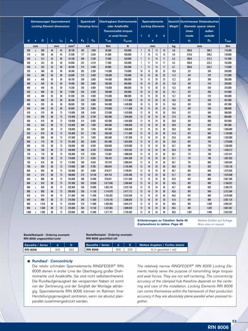
Weitere Größen auf Anfrage More sizes on request
Bestellbeispiel · Ordering example: RfN 8006 geschlitzt/slit
Baureihe / Series d D Weitere Angaben / Further details
RfN 8006 300 333 G (= geschlitzt / slit)
Bestellbeispiel · Ordering example: RfN 8006 ungeschlitzt/solid
Baureihe / Series d D
RfN 8006 300 333
Rundlauf · ConcentricityDie relativ schmalen Spannelemente RINGFEDER® RfN 8006 dienen in erster Linie der Übertragung großer Dreh-momente und Axialkräfte. Sie sind nicht selbstzentrierend. Die Rund lauf ge nauig keit der verspannten Naben ist somit von der Zentrierung und der Sorgfalt der Montage abhän-gig. Spann ele mente RfN 8006 können im Rahmen ihrer Her stellungs genauigkeit zentrieren, wenn sie absolut plan-parallel zusammengedrückt werden.
The relatively narrow RINGFEDER® RfN 8006 Locking Ele-ments mainly serve the purpose of transmitting large torques and axial forces. They are not self-centering. The concentricity accuracy of the clamped hub therefore depends on the cente-ring and care of the installation. Locking Elements RfN 8006 can centre themselves within the framework of their production accuracy if they are absolutely plane-parallel when pressed to-gether.
Abmessungen Spannelement Spannkraft Übertragbare Drehmomente Spannelemente Gewicht Durchmesser Distanzbuchse
Locking Element dimensions Clamping force oder Axialkräfte Locking Elements Weight Diameter spacer sleeve
Transmissible torques innen außen
or axial forces 1 2 3 4 inside outside
d x D L L3 At F0 FA T100 Fax100 x ~ d1 D1 Tmax
mm mm mm2 kN Nm N mm kg mm Nm260 x 290 48 44 36.100 182 1.950 56.500 435.000 7 10 13 16 4,8 260,8 289,2 118.300270 x 300 48 44 37.500 177 2.030 61.000 450.000 7 10 13 16 4,9 270,8 299,2 128.000280 x 313 53 49 43.100 206 2.330 72.500 520.000 7 11 14 17 6,3 280,8 312,2 151.000290 x 323 53 49 44.600 222 2.410 77.500 535.000 7 11 14 17 6,5 290,8 322,2 162.000300 x 333 53 49 46.200 214 2.490 83.000 555.000 7 11 14 17 6,7 300,8 332,2 173.000320 x 360 65 59 59.300 292 3.200 114.000 710.000 10 15 20 25 10,9 321 359 240.000340 x 380 65 59 63.000 272 3.400 128.500 755.000 10 15 20 25 11,5 341 379 272.000360 x 400 65 59 66.700 258 3.600 144.000 800.000 10 15 20 25 12,2 361 399 305.000380 x 420 65 59 70.400 269 3.800 160.500 845.000 10 15 20 25 12,8 381 419 339.000400 x 440 65 59 74.200 256 4.000 178.000 890.000 10 15 20 25 13,5 401 439 376.000420 x 460 65 59 77.800 244 4.200 196.000 935.000 10 15 20 25 14,1 421 459 414.000440 x 480 65 59 81.500 234 4.400 215.000 980.000 10 15 20 25 14,7 441 479 455.000460 x 500 65 59 85.300 224 5.000 256.000 1.111.000 10 15 20 25 16,6 501 539 497.000480 x 520 65 59 89.000 239 5.000 344.000 1.430.000 10 15 20 25 16,6 501 539 497.000500 x 540 65 59 92.600 229 5.000 278.000 1.111.000 10 15 20 25 16,6 501 539 586.000520 x 570 80 73 119.000 338 6.450 373.000 1.433.000 12 18 24 30 26,9 521 569 586.000540 x 590 80 73 124.000 326 6.700 402.000 7.026.000 12 18 24 30 27,9 541 589 859.000560 x 610 80 73 128.000 314 6.950 432.000 1.544.000 12 18 24 30 28,8 561 609 924.000580 x 630 80 73 133.000 304 7.200 464.000 1.599.000 12 18 24 30 29,8 581 629 991.000600 x 650 80 73 138.000 331 7.450 497.000 1.656.000 12 18 24 30 30,8 601 649 1.058.000620 x 670 80 73 142.000 321 7.700 530.430 1.711.000 12 18 24 30 31,8 621 669 1.129.000640 x 690 80 73 147.000 311 7.950 565.000 1.767.000 12 18 24 30 32,8 641 689 1.203.000660 x 710 80 73 151.000 302 8.200 601.000 1.822.000 12 18 24 30 33,8 661 709 1.279.000680 x 730 80 73 156.000 294 8.450 638.000 1.878.000 12 18 24 30 34,7 681 729 1.358.000700 x 750 80 73 160.000 286 8.700 676.649 1.933.282 12 18 24 30 35,8 701 749 1.439.212720 x 770 80 73 165.000 278 8.950 715.981 1.988.836 12 18 24 30 36,7 721 769 1.522.441740 x 790 80 73 170.000 271 9.200 756.424 2.044.390 12 18 24 30 37,7 741 789 1.607.925760 x 810 80 73 174.000 296 9.450 797.979 2.099.944 12 18 24 30 38,7 761 809 1.693.044780 x 830 80 73 179.000 289 9.700 840.644 2.155.498 12 18 24 30 39,9 781 829 1.783.128800 x 850 80 73 183.000 281 9.900 879.977 2.199.941 12 18 24 30 40,7 801 849 1.875.636820 x 870 80 73 188.000 275 10.150 924.753 2.255.496 12 18 24 30 41,7 821 869 1.970.300840 x 890 80 73 193.000 268 10.400 970.641 2.311.050 12 18 24 30 42,6 841 889 2.067.389860 x 910 80 73 197.000 263 10.650 1.017.640 2.366.604 12 18 24 30 43,6 861 909 2.166.622880 x 930 80 73 202.000 256 10.900 1.065.749 2.422.158 12 18 24 30 44,7 881 929 2.268.376900 x 950 80 73 206.000 250 11.150 1.114.970 2.477.712 12 18 24 30 45,6 901 949 2.372.364920 x 970 80 73 211.000 246 11.400 1.165.302 2.533.266 12 18 24 30 46,6 921 969 2.478.480940 x 990 80 73 216.000 240 11.650 1.216.745 2.588.820 12 18 24 30 47,6 941 989 2.587.125960 x 1.010 80 73 220.000 270 11.900 1.269.300 2.644.374 12 18 24 30 48,6 961 1.009 2.694.261980 x 1.030 80 73 225.000 264 12.150 1.322.965 2.699.928 12 18 24 30 49,5 981 1.029 2.807.487
1.000 x 1.050 80 73 229.000 259 12.400 1.377.741 2.755.482 12 18 24 30 50,6 1.001 1.049 2.922.933
RfN 8006
Erläuterungen zu Tabellen: Seite 49Explanations to tables: Page 49
53

RINGFEDER® Rostfreie Produkte · Stainless Products
54
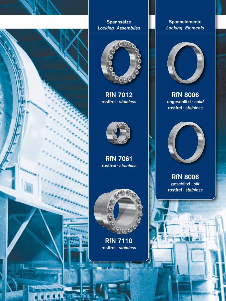
SpannsätzeLocking Assemblies
SpannelementeLocking Elements
RfN 7110rostfrei · stainless
RfN 7012rostfrei · stainless
RfN 7061rostfrei · stainless
RfN 8006ungeschlitzt · solidrostfrei · stainless
RfN 8006geschlitzt · slit
rostfrei · stainless
55
Charakteristische EigenschaftenKostengünstige Fertigung – größtmögliche Toleranzen und einfache Drehbearbeitung garantieren kostengünstige Fertigung.
Einfache Montage – es sind nur wenige Schrauben anzuziehen, Ausrichtung zwischen Nabe und Welle winkelgenau in jeder Position möglich, Einpassarbeiten entfallen ganz.
Einfache Demontage – RINGFEDER® Spannsätze verfügen über Abdrückgewinde, daher keine zusätzlichen Hilfsmittel erforderlich, Baureihe RfN 7012 ist sogar selbstlö-send (keine Abdrückgewinde).
Große Dauerdrehwechselfestigkeit – Welle und Nabe sind ungenutet, dadurch keine Schwächung dieser Bauteile. Welle und Nabe können deutlich kleiner ausgeführt werden (leichte, kosten- und platzsparende Konstruktion möglich).
Keine Gefahr des Ausschlagens – RINGFEDER® Spannsätze sind absolut spielfrei.
Wirkung wie Überlastsicherung – nach dem Überschreiten des eingestellten Kraft-schlusses rutschen die Spannsätze durch. Wertvolle Maschinenteile werden geschützt. Die Spannsätze unterliegen hierbei aber den gleichen Gesetzen, wie jede andere Reibschluss-verbindung auch - als Rutschkupplung nicht geeignet.
Absolut wartungsfrei – keine Folgekosten.
Characteristics
Inexpensive manufacture – the large tolerances that are possible and the simple turning process guarantee inexpensive manufacture.
Simple installation – only a few screws need to be tightened, alignment to precise angles between the hub and shaft is possible in any position, no fitting at assembly required.
Simple dismantling – RINGFEDER® Locking Assemblies are fitted with threaded ex-traction holes, so that no additional auxiliary equipment is necessary, series RfN 7012 is self-releasing.
Large constant reverse-torsion fatigue strength – shaft and hub are ungrooved, so that there is no weakening of these components. Shaft and hub can be designed to be consi-derably smaller (light, cost and space-saving design possible).
No danger of deflection – RINGFEDER® Locking Assemblies are absolutely backlash- free.
Effect similar to overload protection – after the set frictional connection force has been exceeded the Locking Assemblies simply slide. Valuable machine parts are protected. The Locking Assemblies are subject to the same laws as any other connection with force trans-mission by friction - not suitable as sliding clutch.
Completely maintenance-free – no follow-up costs.
RINGFEDER® Rostfreie Produkte · Stainless Products
56
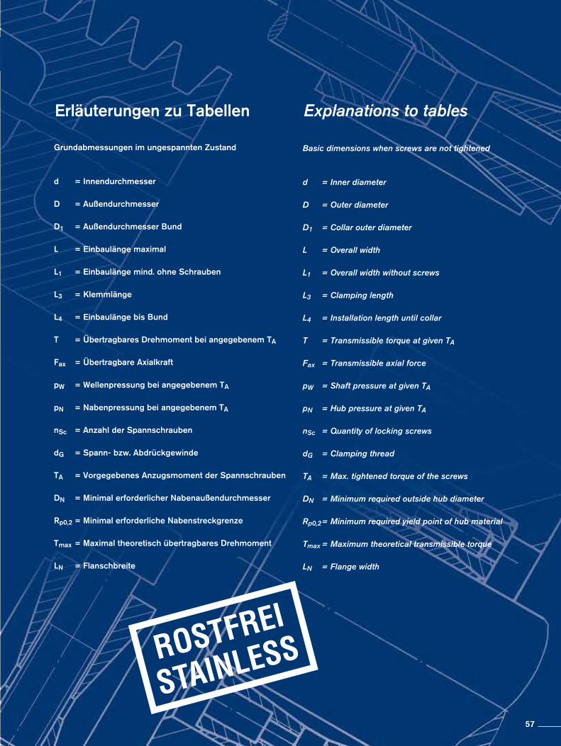
Erläuterungen zu Tabellen
Grundabmessungen im ungespannten Zustand
d = Innendurchmesser
D = Außendurchmesser
D1 = Außendurchmesser Bund
L = Einbaulänge maximal
L1 = Einbaulänge mind. ohne Schrauben
L3 = Klemmlänge
L4 = Einbaulänge bis Bund
T = Übertragbares Drehmoment bei angegebenem TA
Fax = Übertragbare Axialkraft
pW = Wellenpressung bei angegebenem TA pN = Nabenpressung bei angegebenem TA nSc = Anzahl der Spannschrauben dG = Spann- bzw. Abdrückgewinde TA = Vorgegebenes Anzugsmoment der Spannschrauben
DN = Minimal erforderlicher Nabenaußendurchmesser Rp0,2 = Minimal erforderliche Nabenstreckgrenze
Tmax = Maximal theoretisch übertragbares Drehmoment
LN = Flanschbreite
Explanations to tables
Basic dimensions when screws are not tightened
d = Inner diameter
D = Outer diameter
D1 = Collar outer diameter L = Overall width L1 = Overall width without screws L3 = Clamping length L4 = Installation length until collar
T = Transmissible torque at given TA
Fax = Transmissible axial force
pW = Shaft pressure at given TA
pN = Hub pressure at given TA
nSc = Quantity of locking screws
dG = Clamping thread
TA = Max. tightened torque of the screws
DN = Minimum required outside hub diameter
Rp0,2 = Minimum required yield point of hub material
Tmax = Maximum theoretical transmissible torque
LN = Flange width
57
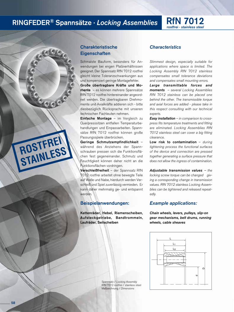
RINGFEDER® Spannsätze · Locking Assemblies RfN 7012rostfrei · stainless steel
Charakteristische Eigenschaften
Schmalste Bauform, besonders für An-wendungen bei engen Platzverhältnissen geeignet. Der Spannsatz RfN 7012 rostfrei gleicht kleine Toleranzschwankungen aus und kompensiert geringe Montagefehler.Große übertragbare Kräfte und Mo-mente – es können mehrere Spannsätze RfN 7012 rostfrei hintereinander angeord-net werden. Die übertragbaren Drehmo-mente und Axialkräfte addieren sich - bitte diesbezüglich Rücksprache mit unseren technischen Fachleuten nehmen.Einfache Montage – im Vergleich zu Querpresssitzen entfallen Temperaturbe-handlungen und Einpassarbeiten. Spann-sätze RfN 7012 rostfrei können große Passungsspiele überbrücken. Geringe Schmutzempfindlichkeit – während des Anziehens der Spann-schrauben pressen sich die Funktionsflä-chen fest gegeneinander. Schmutz und Feuchtigkeit können daher nicht an die Funktionsflächen vordringen.Verschleißfreiheit – der Spannsatz RfN 7012 rostfrei arbeitet ohne bewegte Teile auf Welle und Nabe, hierdurch werden Ver- schleiß und Spiel zuverlässig vermieden. Er kann daher mehrmalig ge- und entspannt werden.
Beispielanwendungen:
Kettenräder, Hebel, Riemenscheiben, Aufsteckgetriebe, Band trommeln, Laufräder, Seilscheiben
Characteristics
Slimmest design, especially suitable for applications where space is limited. The Locking Assembly RfN 7012 stainless compensates small tolerance deviations and compensates small mounting errors.Large transmittable forces and moments – several Locking Assemblies RfN 7012 stainless can be placed one behind the other. The transmissible torque and axial forces are added - please take in this respect consulting with our technical experts.Easy installation – in comparison to cross-press fits temperature treatments and fitting are eliminated. Locking Assemblies RfN 7012 stainless steel can cover a big fitting clearance.Low risk to contamination – during tightening process the functional surfaces of the device and connection are pressed together generating a surface pressure that does not allow the ingress of contamination.
Adjustable transmission values – the locking screw torque can be changed giv-ing a corresponding change in transmission values. RfN 7012 stainless Locking Assem-blies can be tightened and released repeat-edly.
Example applications:
Chain wheels, levers, pulleys, slip-on gear mechanisms, belt drums, running wheels, cable sheaves
L
d
D
L3
L1
Spannsatz / Locking Assembly RfN 7012 rostfrei / stainless steel Maßzeichnung / Dimensions
58
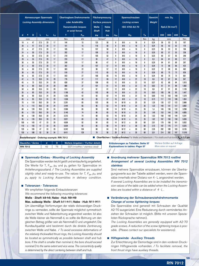
Baureihe / Series d D Weitere Angaben / Further details
RfN 7012 42 75 SST (=rostfrei / stainless steel)
Bestellbeispiel · Ordering example: RfN 7012
Anordnung mehrerer Spannsätze RfN 7012 rostfrei Arrangement of several Locking Assemblies RfN 7012 stainless
Sind mehrere Spannsätze einzubauen, können die Übertra-gungswerte aus der Tabelle addiert werden, wenn die Spann-sätze innerhalb einer Distanz von 4 · L angeordnet werden.If several Locking Assemblies are to be installed the transmis-sion values of the table can be added when the Locking Assem-blies are located within a distance of 4 · L .
Veränderung der Schraubenanziehdrehmomente Change of screw tightening torques
Die Spannsätze sind generell mit Schrauben der Qualität A2-70 ausgerüstet. Eine Redu zierung durch vermindertes An-ziehen der Schrau ben ist möglich. (Bitte mit unseren Spezia-listen Rück sprache nehmen).The Locking Assemblies are generally equipped with A2-70 grade screws. A reduction of the screw tightening torque is pos-sible. (Please contact our specialists for assistance).
Hilfsgewinde · Auxiliary ThreadsZur Erleichterung der Demontage sind in den vorderen Druck-ringen Hilfsgewinde vorhanden. / To facilitate removal, the front thrust rings have auxiliary threads.
RfN 7012
Abmessungen Spannsatz Übertragbare Drehmomente Flächenpressung Spannschrauben Gewicht min. DN
Locking Assembly dimensions oder Axialkräfte Surface pressure Locking screws Weight
Transmissible torques Welle Nabe ISO 4762-A2-70 Rp0,2 [N/mm2]
or axial forces Shaft Hub
d x D L L1 L3 T Fax pW pN nSc DG TA ~ 200 300 400 Tmax
mm mm Nm kN N/mm2 Nm kg mm Nm19 x 47 27,5 20 17 144 15 125 50 8 M 6 x 18 8 0,24 56 53 52 16720 x 47 27,5 20 17 151 15 118 50 8 M 6 x 18 8 0,24 56 53 52 17622 x 47 27,5 20 17 165 15 107 50 8 M 6 x 18 8 0,23 56 53 52 19424 x 50 27,5 20 17 202 17 109 52 9 M 6 x 18 8 0,26 60 57 55 23825 x 50 27,5 20 17 210 17 105 52 9 M 6 x 18 8 0,25 60 57 55 24828 x 55 27,5 20 17 233 17 93 47 9 M 6 x 18 8 0,3 64 61 60 27730 x 55 27,5 20 17 249 17 86 47 9 M 6 x 18 8 0,29 64 61 60 29732 x 60 27,5 20 17 352 22 107 57 12 M 6 x 18 8 0,34 72 68 66 42335 x 60 27,5 20 17 383 22 98 57 12 M 6 x 18 8 0,32 72 68 66 46238 x 65 27,5 20 17 518 27 112 65 15 M 6 x 18 8 0,36 80 75 73 62840 x 65 27,5 20 17 543 27 106 65 15 M 6 x 18 8 0,34 80 75 73 66142 x 75 33,5 24 20 776 37 117 65 12 M 8 x 22 18 0,6 92 87 84 94745 x 75 33,5 24 20 828 37 108 65 12 M 8 x 22 18 0,57 92 86 84 1.01548 x 80 33,5 24 20 880 37 101 61 12 M 8 x 22 18 0,62 97 91 89 1.08250 x 80 33,5 24 20 914 37 97 61 12 M 8 x 22 18 0,6 97 91 89 1.12655 x 85 33,5 24 20 1.166 42 102 66 14 M 8 x 22 18 0,63 105 98 95 1.44760 x 90 33,5 24 20 1.265 42 93 62 14 M 8 x 22 18 0,69 110 103 100 1.57965 x 95 33,5 24 20 1.558 48 98 67 16 M 8 x 22 18 0,73 117 110 106 1.95470 x 110 39,5 28 24 2.291 65 103 66 14 M 10 x 25 35 1,26 135 127 122 2.88675 x 115 39,5 28 24 2.444 65 96 63 14 M 10 x 25 35 1,33 140 131 127 3.09280 x 120 39,5 28 24 2.596 65 90 60 14 M 10 x 25 35 1,4 145 136 132 3.29885 x 125 39,5 28 24 3.140 74 96 65 16 M 10 x 25 35 1,49 153 144 139 4.00590 x 130 39,5 28 24 3.313 74 90 63 16 M 10 x 25 35 1,53 158 148 144 4.24195 x 135 39,5 28 24 3.921 83 96 68 18 M 10 x 25 35 1,62 167 156 150 5.036100 x 145 47 33 26 4.604 92 94 65 14 M 12 x 30 60 2,01 178 166 161 5.932110 x 155 47 33 26 5.034 92 85 60 14 M 12 x 30 60 2,15 187 176 171 6.525120 x 165 47 33 26 6.242 104 88 64 16 M 12 x 30 60 2,35 202 189 183 8.135130 x 180 52 38 34 8.411 129 78 56 20 M 12 x 35 60 3,51 214 202 197 11.016
Oberflächen / Surface finishes Für Welle und Nabenbohr. / For shafts and hub bores Ra = 3,2 µm
Weitere Größen auf Anfrage More sizes on request
Erläuterungen zu Tabellen: Seite 57 Explanations to tables: Page 57
Spannsatz-Einbau · Mounting of Locking Assembly Die Spannsätze werden leicht geölt und einbaufertig angeliefert. Die Werte für T, Fax, pW und pN gelten für Spann sätze im An liefe rungszustand. / The Locking Assemblies are supplied slightly oiled and ready-to-use. The values for T, Fax, pW and pN apply to Locking Assemblies in delivery condition.
Toleranzen · TolerancesWir empfehlen folgende EinbautoleranzenWe recommend the following mounting tolerancesWelle · Shaft: k9-h9; Nabe · Hub: N9-H9Max. zulässig: Welle · Shaft: k11-h11; Nabe · Hub: N11-H11Um übermäßige Verformungen der relativ dickwandigen Druck-ringe zu vermeiden, sollte der Spannsatz möglichst sym metrisch zwischen Welle und Nabenbohrung angeordnet werden. Ist also die Welle kleiner als Nennmaß d, so sollte die Bohrung um den gleichen Betrag größer sein als Nennmaß D und umgekehrt. Die Rundlaufqualität wird bestimmt durch die direkte Zentrierung zwischen Welle und Nabe. / To avoid excessive deformations of the relatively thickwalled thrust rings, the Locking Assembly should be located as symmetrically as possible between shaft and hub bore. If the shaft is smaller than nominal d, the bore should exceed nominal D to the same extent and vice versa. The concentricity quality is determined by the direct centering between shaft and hub.
59
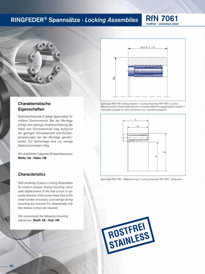
RINGFEDER® Spannsätze · Locking Assemblies RfN 7061rostfrei · stainless steel
LN ≥ 2 · L - L1
A
A
DN
Charakteristische Eigenschaften
Selbstzentrierende 2-teilige Spannsätze für mittlere Dreh momente. Bei der Montage erfolgt eine geringe Axial verschiebung der Nabe vom Schrau ben kopf weg. Aufgrund der geringen Schraubenzahl sind Kosten-ein spar ungen bei der Montage gewähr-leistet. Zur Demontage sind nur wenige Abdrück schrauben nötig.
Wir empfehlen folgende Einbautoleranzen: Welle: h8 · Nabe: H8
Characteristics
Self-centering 2-piece Locking Assem blies for medium torques. During mount ing, minor axial displacement of the hub occurs in op-posite direction of the screw head. Due to the small number of screws, cost savings during mounting are ensured. For disassembly only few release screws are required.
We recommend the following mounting tolerances: Shaft: h8 · Hub: H8
Spannsatz RfN 7061 Einbausituation / Locking Assembly RfN 7061 Location (Berechnung für andere Nabenformen in unserem Berechnungsprogramm möglich / Calculation possible for other hub forms in our calculation program)
L
L1
d
D
Spannsatz RfN 7061 · Maßzeichnung / Locking Assembly RfN 7061 · Dimensions
60
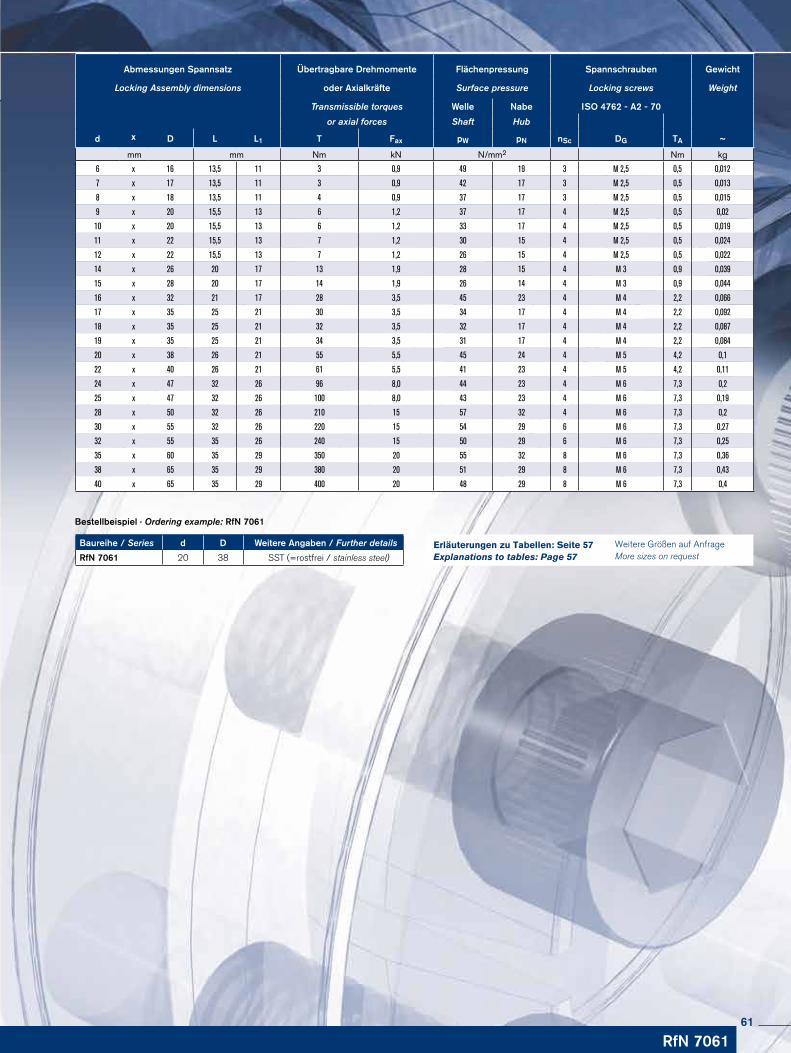
Baureihe / Series d D Weitere Angaben / Further details
RfN 7061 20 38 SST (=rostfrei / stainless steel)
Bestellbeispiel · Ordering example: RfN 7061
RfN 7061
Abmessungen Spannsatz Übertragbare Drehmomente Flächenpressung Spannschrauben Gewicht
Locking Assembly dimensions oder Axialkräfte Surface pressure Locking screws Weight
Transmissible torques Welle Nabe ISO 4762 - A2 - 70
or axial forces Shaft Hub
d x D L L1 T Fax pW pN nSc DG TA ~
mm mm Nm kN N/mm2 Nm kg
6 x 16 13,5 11 3 0,9 49 19 3 M 2,5 0,5 0,012
7 x 17 13,5 11 3 0,9 42 17 3 M 2,5 0,5 0,013
8 x 18 13,5 11 4 0,9 37 17 3 M 2,5 0,5 0,015
9 x 20 15,5 13 6 1,2 37 17 4 M 2,5 0,5 0,02
10 x 20 15,5 13 6 1,2 33 17 4 M 2,5 0,5 0,019
11 x 22 15,5 13 7 1,2 30 15 4 M 2,5 0,5 0,024
12 x 22 15,5 13 7 1,2 26 15 4 M 2,5 0,5 0,022
14 x 26 20 17 13 1,9 28 15 4 M 3 0,9 0,039
15 x 28 20 17 14 1,9 26 14 4 M 3 0,9 0,044
16 x 32 21 17 28 3,5 45 23 4 M 4 2,2 0,066
17 x 35 25 21 30 3,5 34 17 4 M 4 2,2 0,092
18 x 35 25 21 32 3,5 32 17 4 M 4 2,2 0,087
19 x 35 25 21 34 3,5 31 17 4 M 4 2,2 0,084
20 x 38 26 21 55 5,5 45 24 4 M 5 4,2 0,1
22 x 40 26 21 61 5,5 41 23 4 M 5 4,2 0,11
24 x 47 32 26 96 8,0 44 23 4 M 6 7,3 0,2
25 x 47 32 26 100 8,0 43 23 4 M 6 7,3 0,19
28 x 50 32 26 210 15 57 32 4 M 6 7,3 0,2
30 x 55 32 26 220 15 54 29 6 M 6 7,3 0,27
32 x 55 35 26 240 15 50 29 6 M 6 7,3 0,25
35 x 60 35 29 350 20 55 32 8 M 6 7,3 0,36
38 x 65 35 29 380 20 51 29 8 M 6 7,3 0,43
40 x 65 35 29 400 20 48 29 8 M 6 7,3 0,4
Weitere Größen auf Anfrage More sizes on request
Erläuterungen zu Tabellen: Seite 57 Explanations to tables: Page 57
61
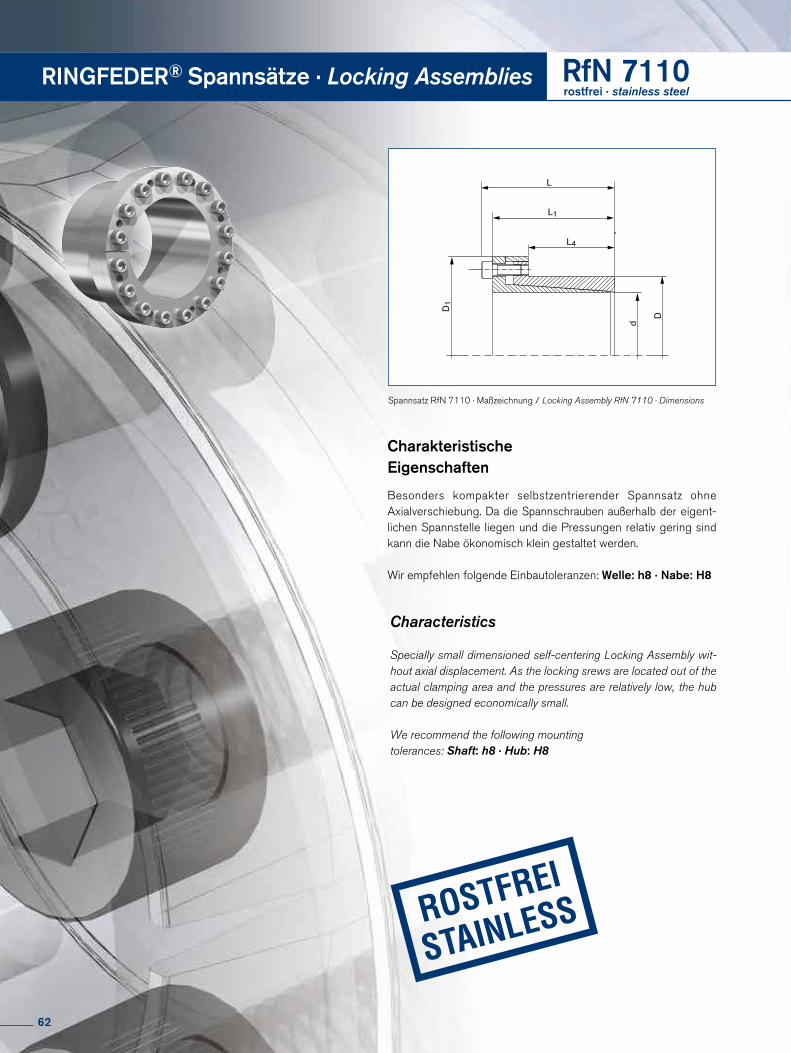
RINGFEDER® Spannsätze · Locking Assemblies RfN 7110rostfrei · stainless steel
D
d
L
L1
L4
D1
Charakteristische Eigenschaften
Besonders kompakter selbstzentrierender Spannsatz ohne Axialver schiebung. Da die Spannschrauben außer halb der eigent-lichen Spannstelle liegen und die Pressungen relativ gering sind kann die Nabe ökonomisch klein gestaltet werden.
Wir empfehlen folgende Einbautoleranzen: Welle: h8 · Nabe: H8
Characteristics
Specially small dimensioned self-centering Locking Assembly wit-hout axial displacement. As the locking srews are located out of the actual clamping area and the pressures are relatively low, the hub can be designed economically small.
We recommend the following mounting tolerances: Shaft: h8 · Hub: H8
Spannsatz RfN 7110 · Maßzeichnung / Locking Assembly RfN 7110 · Dimensions
62
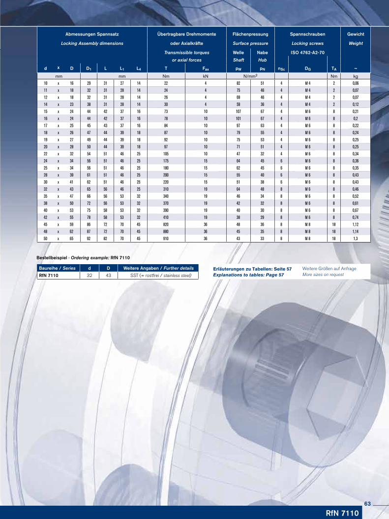
RfN 7110
Baureihe / Series d D Weitere Angaben / Further details
RfN 7110 32 43 SST (= rostfrei / stainless steel)
Bestellbeispiel · Ordering example: RfN 7110
Abmessungen Spannsatz Übertragbare Drehmomente Flächenpressung Spannschrauben Gewicht
Locking Assembly dimensions oder Axialkräfte Surface pressure Locking screws Weight
Transmissible torques Welle Nabe ISO 4762-A2-70
or axial forces Shaft Hub
d x D D1 L L1 L4 T Fax pW pN nSc DG TA ~
mm mm Nm kN N/mm2 Nm kg
10 x 16 29 31 27 14 22 4 82 51 4 M 4 2 0,06
11 x 18 32 31 28 14 24 4 75 46 4 M 4 2 0,07
12 x 18 32 31 28 14 26 4 69 46 4 M 4 2 0,07
14 x 23 38 31 28 14 30 4 59 36 4 M 4 2 0,12
15 x 24 44 42 37 16 73 10 107 67 4 M 6 8 0,21
16 x 24 44 42 37 16 78 10 101 67 4 M 6 8 0,2
17 x 25 45 43 37 16 84 10 97 63 4 M 6 8 0,22
18 x 26 47 44 39 18 87 10 79 55 4 M 6 8 0,24
19 x 27 49 44 39 18 92 10 75 53 4 M 6 8 0,25
20 x 28 50 44 39 18 97 10 71 51 4 M 6 8 0,25
22 x 32 54 51 46 25 105 10 47 32 4 M 6 8 0,34
24 x 34 56 51 46 25 175 15 64 45 6 M 6 8 0,36
25 x 34 56 51 46 25 180 15 62 45 6 M 6 8 0,35
28 x 39 61 51 46 25 200 15 55 40 6 M 6 8 0,43
30 x 41 62 51 46 25 220 15 51 38 6 M 6 8 0,43
32 x 43 65 56 46 25 310 19 64 48 8 M 6 8 0,46
35 x 47 66 56 53 32 340 19 46 34 8 M 6 8 0,52
38 x 50 72 56 53 32 370 19 42 32 8 M 6 8 0,61
40 x 53 75 58 53 32 390 19 40 30 8 M 6 8 0,67
42 x 55 78 58 53 32 410 19 38 29 8 M 6 8 0,74
45 x 59 86 72 70 45 820 36 48 36 8 M 8 18 1,12
48 x 62 87 72 70 45 880 36 45 35 8 M 8 18 1,14
50 x 65 92 82 70 45 910 36 43 33 8 M 8 18 1,3
Weitere Größen auf Anfrage More sizes on request
Erläuterungen zu Tabellen: Seite 57 Explanations to tables: Page 57
63
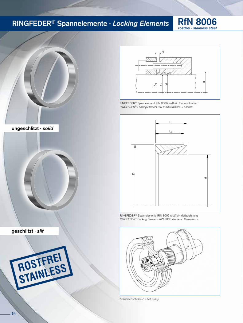
RINGFEDER® Spannelemente · Locking Elements RfN 8006rostfrei · stainless steel
L
L3D
d
X
d 1D1 d
D
Keilriemenscheibe / V-belt pulley
RINGFEDER® Spannelement RfN 8006 rostfrei · EinbausituationRINGFEDER® Locking Element RfN 8006 stainless · Location
RINGFEDER® Spannelemente RfN 8006 rostfrei · MaßzeichnungRINGFEDER® Locking Elements RfN 8006 stainless · Dimensions
ungeschlitzt · solid
geschlitzt · slit
64
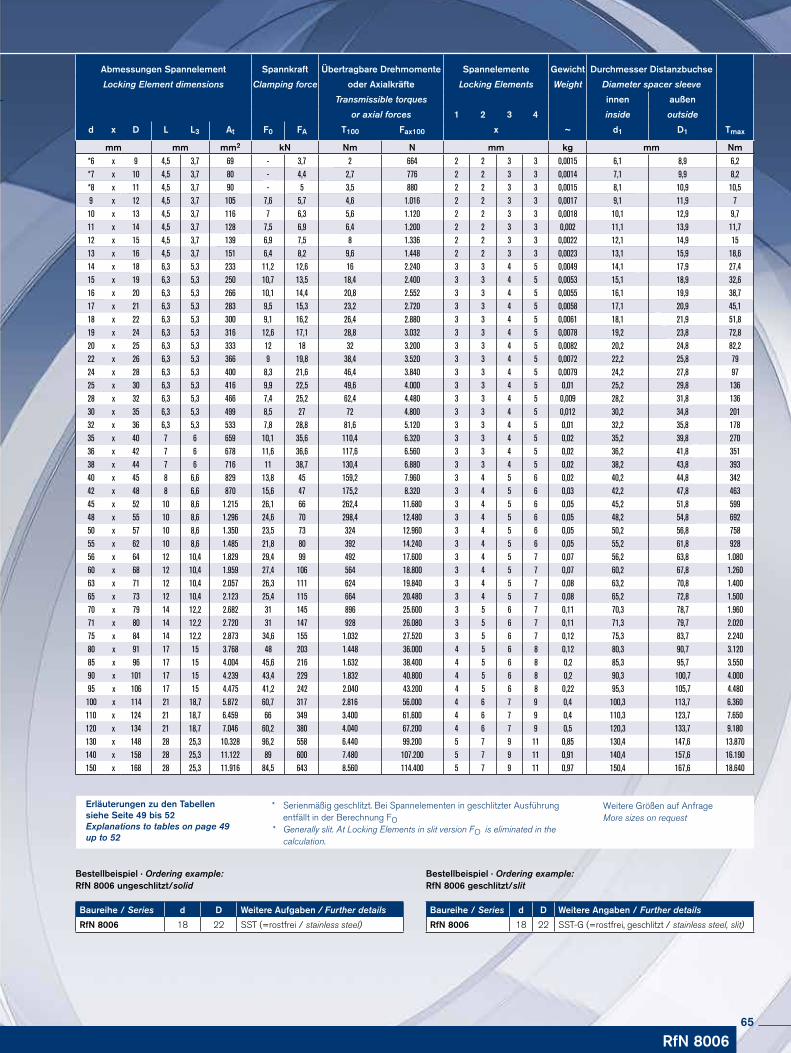
RfN 8006
Baureihe / Series d D Weitere Angaben / Further details
RfN 8006 18 22 SST-G (=rostfrei, geschlitzt / stainless steel, slit)
Bestellbeispiel · Ordering example: RfN 8006 geschlitzt/slit
Baureihe / Series d D Weitere Aufgaben / Further details
RfN 8006 18 22 SST (=rostfrei / stainless steel)
Bestellbeispiel · Ordering example: RfN 8006 ungeschlitzt/solid
* Serienmäßig geschlitzt. Bei Spannelementen in geschlitzter Ausführung entfällt in der Berechnung FO* Generally slit. At Locking Elements in slit version FO is eliminated in the calculation.
Weitere Größen auf Anfrage More sizes on request
Erläuterungen zu den Tabellen siehe Seite 49 bis 52Explanations to tables on page 49 up to 52
Abmessungen Spannelement Spannkraft Übertragbare Drehmomente Spannelemente Gewicht Durchmesser Distanzbuchse
Locking Element dimensions Clamping force oder Axialkräfte Locking Elements Weight Diameter spacer sleeve
Transmissible torques innen außen
or axial forces 1 2 3 4 inside outside
d x D L L3 At F0 FA T100 Fax100 x ~ d1 D1 Tmax
mm mm mm2 kN Nm N mm kg mm Nm*6 x 9 4,5 3,7 69 - 3,7 2 664 2 2 3 3 0,0015 6,1 8,9 6,2*7 x 10 4,5 3,7 80 - 4,4 2,7 776 2 2 3 3 0,0014 7,1 9,9 8,2*8 x 11 4,5 3,7 90 - 5 3,5 880 2 2 3 3 0,0015 8,1 10,9 10,59 x 12 4,5 3,7 105 7,6 5,7 4,6 1.016 2 2 3 3 0,0017 9,1 11,9 710 x 13 4,5 3,7 116 7 6,3 5,6 1.120 2 2 3 3 0,0018 10,1 12,9 9,711 x 14 4,5 3,7 128 7,5 6,9 6,4 1.200 2 2 3 3 0,002 11,1 13,9 11,712 x 15 4,5 3,7 139 6,9 7,5 8 1.336 2 2 3 3 0,0022 12,1 14,9 1513 x 16 4,5 3,7 151 6,4 8,2 9,6 1.448 2 2 3 3 0,0023 13,1 15,9 18,614 x 18 6,3 5,3 233 11,2 12,6 16 2.240 3 3 4 5 0,0049 14,1 17,9 27,415 x 19 6,3 5,3 250 10,7 13,5 18,4 2.400 3 3 4 5 0,0053 15,1 18,9 32,616 x 20 6,3 5,3 266 10,1 14,4 20,8 2.552 3 3 4 5 0,0055 16,1 19,9 38,717 x 21 6,3 5,3 283 9,5 15,3 23,2 2.720 3 3 4 5 0,0058 17,1 20,9 45,118 x 22 6,3 5,3 300 9,1 16,2 26,4 2.880 3 3 4 5 0,0061 18,1 21,9 51,819 x 24 6,3 5,3 316 12,6 17,1 28,8 3.032 3 3 4 5 0,0078 19,2 23,8 72,820 x 25 6,3 5,3 333 12 18 32 3.200 3 3 4 5 0,0082 20,2 24,8 82,222 x 26 6,3 5,3 366 9 19,8 38,4 3.520 3 3 4 5 0,0072 22,2 25,8 7924 x 28 6,3 5,3 400 8,3 21,6 46,4 3.840 3 3 4 5 0,0079 24,2 27,8 9725 x 30 6,3 5,3 416 9,9 22,5 49,6 4.000 3 3 4 5 0,01 25,2 29,8 13628 x 32 6,3 5,3 466 7,4 25,2 62,4 4.480 3 3 4 5 0,009 28,2 31,8 13630 x 35 6,3 5,3 499 8,5 27 72 4.800 3 3 4 5 0,012 30,2 34,8 20132 x 36 6,3 5,3 533 7,8 28,8 81,6 5.120 3 3 4 5 0,01 32,2 35,8 17835 x 40 7 6 659 10,1 35,6 110,4 6.320 3 3 4 5 0,02 35,2 39,8 27036 x 42 7 6 678 11,6 36,6 117,6 6.560 3 3 4 5 0,02 36,2 41,8 35138 x 44 7 6 716 11 38,7 130,4 6.880 3 3 4 5 0,02 38,2 43,8 39340 x 45 8 6,6 829 13,8 45 159,2 7.960 3 4 5 6 0,02 40,2 44,8 34242 x 48 8 6,6 870 15,6 47 175,2 8.320 3 4 5 6 0,03 42,2 47,8 46345 x 52 10 8,6 1.215 26,1 66 262,4 11.680 3 4 5 6 0,05 45,2 51,8 59948 x 55 10 8,6 1.296 24,6 70 298,4 12.480 3 4 5 6 0,05 48,2 54,8 69250 x 57 10 8,6 1.350 23,5 73 324 12.960 3 4 5 6 0,05 50,2 56,8 75855 x 62 10 8,6 1.485 21,8 80 392 14.240 3 4 5 6 0,05 55,2 61,8 92856 x 64 12 10,4 1.829 29,4 99 492 17.600 3 4 5 7 0,07 56,2 63,8 1.08060 x 68 12 10,4 1.959 27,4 106 564 18.800 3 4 5 7 0,07 60,2 67,8 1.26063 x 71 12 10,4 2.057 26,3 111 624 19.840 3 4 5 7 0,08 63,2 70,8 1.40065 x 73 12 10,4 2.123 25,4 115 664 20.480 3 4 5 7 0,08 65,2 72,8 1.50070 x 79 14 12,2 2.682 31 145 896 25.600 3 5 6 7 0,11 70,3 78,7 1.96071 x 80 14 12,2 2.720 31 147 928 26.080 3 5 6 7 0,11 71,3 79,7 2.02075 x 84 14 12,2 2.873 34,6 155 1.032 27.520 3 5 6 7 0,12 75,3 83,7 2.24080 x 91 17 15 3.768 48 203 1.448 36.000 4 5 6 8 0,12 80,3 90,7 3.12085 x 96 17 15 4.004 45,6 216 1.632 38.400 4 5 6 8 0,2 85,3 95,7 3.55090 x 101 17 15 4.239 43,4 229 1.832 40.800 4 5 6 8 0,2 90,3 100,7 4.00095 x 10⁶ 17 15 4.475 41,2 242 2.040 43.200 4 5 6 8 0,22 95,3 105,7 4.480100 x 114 21 18,7 5.872 60,7 317 2.816 56.000 4 6 7 9 0,4 100,3 113,7 6.360110 x 124 21 18,7 6.459 66 349 3.400 61.600 4 6 7 9 0,4 110,3 123,7 7.650120 x 134 21 18,7 7.046 60,2 380 4.040 67.200 4 6 7 9 0,5 120,3 133,7 9.180130 x 148 28 25,3 10.328 96,2 558 6.440 99.200 5 7 9 11 0,85 130,4 147,6 13.870140 x 158 28 25,3 11.122 89 600 7.480 107.200 5 7 9 11 0,91 140,4 157,6 16.190150 x 168 28 25,3 11.916 84,5 643 8.560 114.400 5 7 9 11 0,97 150,4 167,6 18.640
65

Sonderlösungen · Special Solutions
66
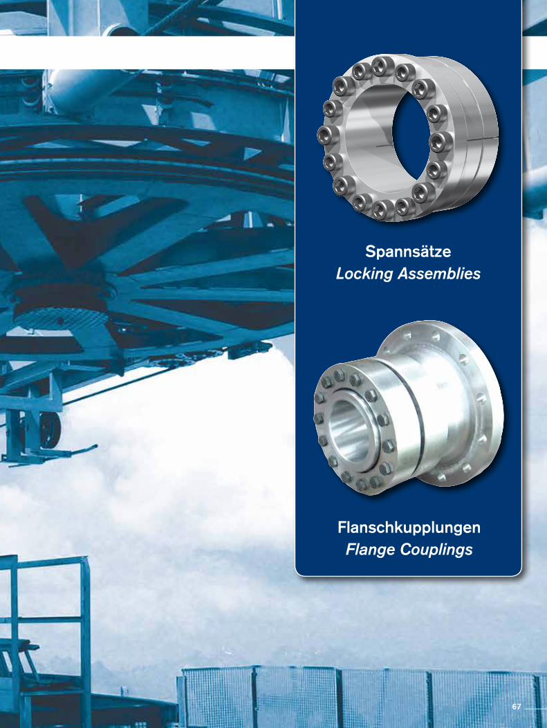
SpannsätzeLocking Assemblies
FlanschkupplungenFlange Couplings
67

RfN 7006.2
Sonderlösung SpannsätzeWo der Einsatz von Standard-Spannsätzen nicht ausreicht, entwickeln wir spezielle, auf die jeweiligen Kundenanforderungen optimierte Lösungen und bieten so den optimalen Nutzen. Anwendungen die bisher nicht möglich waren, können so in vielen Fällen trotzdem realisiert werden.
Special Solution Locking AssembliesWhere the use of standard Locking Assemblies is not sufficient we develop special solutions optimised to specific customer requirements so that the parts are ideal for the specific applica-tion. In this way it is possible to make use of applications which previously were not possible.
Sonderlösungen · Special Solutions
68

Sonderlösung FlanschkupplungenFlanschkupplungen werden von uns speziell auf die jeweilige Situation ausgelegt um so hinsichtlich des übertragbaren Dreh momentes, der Massen etc. eine bestmögliche Lösung zu bieten.
Special Solution Flange CouplingsFlange Couplings are designed by us for the specific situation in order to offer the best possible solution for the transmitted torque, masses etc.
Sonderlösungen · Special Solutions
69
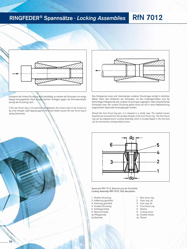
RINGFEDER® Spannsätze · Locking Assemblies RfN 7012
Entspannt der hintere Druckring nicht selbsttätig, so werden die Schrauben um einige Gänge herausgedreht. Nach einigen leichten Schlägen gegen die Schraubenköpfe springt der Druckring nach.
If the rear thrust ring is not automatically released, the screws have to be turned out by a few threads. Light tapping against the screw heads causes the rear thrust ring to spring backwards.
Das Entspannen eines evtl. klemmenden vorderen Druckringes erfolgt in ähnlicher Weise. Nach dem Entfernen der Schrauben mit den Unterlegscheiben sind die Demontage-Hilfsgewinde des vorderen Druckringes zugänglich. Über entsprechende Schrauben kann der vordere Druckring gelöst sowie ein tief in einer Nabenbohrung angeordneter Spannsatz herausgezogen werden.
Should the front thrust ring jam, it is released in a similar way. The marked screws (washer) are removed from the auxiliary threads of the front thrust ring. The front thrust ring can be released and a Locking Assembly which is located deeply in the hub bore can be removed by corresponding screws.
Spannsatz RfN 7012. Bezeichnung der Einzelteile.Locking Assembly RfN 7012. Part description.
1 Rear thrust ring 2 Outer ring, slit3 Inner ring, slit4 Front thrust ring5 Washer 6 Locking screwdD Auxiliary threaddG Thread
1 Hinterer Druckring2 Außenring, geschlitzt3 Innenring, geschlitzt4 Vorderer Druckring5 Unterlegscheibe6 SpannschraubedD HilfsgewindedG Gewinde
70

RfN 7012
Montage- und Demontageanweisungen
Spannsatz RfN 7012, RfN 7012 rostfrei
Montage
Die Kraftübertragung erfolgt durch Pressung und Reibung zwischen den Funktionsflächen. Auf kontrolliertes Anziehen der Spannschrauben und Beschaffenheit der Kontaktflächen ist daher besonders zu achten.
1. Sämtliche Kontaktflächen, einschließlich Gewinde und Kopfauflage der Spannschrauben müssen sauber und mit einem Ölfilm versehen sein (kein Molybdän-Disulfid ver-wenden). Welle, Nabe und Spannsätze in diesem Zustand montieren.
2. Spannschrauben leicht anziehen und Nabe ausrichten.
3. Schrauben in zwei bis drei Stufen gleichmäßig und über-kreuz auf das angegebene Anziehdrehmoment TA anziehen.
4. Kontrolle des Anziehdrehmomentes der Schrauben in der Reihenfolge ihrer Anordnung. Erst wenn sich keine Schraube mehr anziehen läßt, ist die Montage beendet.
Demontage
Spannsätze RINGFEDER® RfN 7012 sind nicht selbsthem-mend. Der Konus der einzelnen Ringe wurde so gewählt, daß keine Selbsthemmung eintreten kann. Nach dem Lösen der letzten Schraube ist die Verbindung in der Regel frei.
Die unter den Schrauben liegenden Unterlegscheiben schüt-zen die Demontage-Hilfsgewinde vor Beschädigung.
Sind größere Kräfte zum Herausnehmen des bereits gelösten Spannsatzes erforderlich (wenn der Spannsatz z.B. gegen das Gewicht einer schweren Nabe verschoben werden soll), so dürfen bei Verwendung einer Demontage-Hilfsvorrichtung die Schrauben nur gelockert, aber keinesfalls zu weit herausge-dreht werden. Bei Beachtung dieses Hinweises ist gegen die Verwendung von Demontage-Hilfsvorrichtungen nichts einzu-wenden, solange die Kräfte gering bleiben.
Die Demontage-Hilfsgewinde besitzen nur ca. 3-5 tragende Gewindegänge und sind nicht durchgeschnitten. Es sind also keine Bohrungen für Abdrückschrauben.
Verschmutzte, unbeschädigte Spannsätze sind vor der er-neuten Verwendung zu zerlegen und zu reinigen.
Installation and removal instructions
Locking Assembly RfN 7012, RfN 7012 stainless
Installation
Since the force is transmitted by contact pressure and friction between functional surfaces, condition of contact surfaces and proper tightening of the locking screws are of great im-portance.
1. All contact surfaces, including screw threads and screw head bearing surfaces, must be clean and slightly oiled (Do not use Molybdenum Disulphide!). In this condition, the shaft, hub and Locking Assemblies are to be assembled.
2. Tighten locking screws lightly and align hub.
3. Tighten screws evenly in diametrically opposite sequence and do this in two or three stages up to the indicated tighte-ning torque TA.
4. Re-check tightening torque by applying it to all screws all the way around. When no screw will turn anymore, the as-sembly is completed.
Removal
Locking Assemblies RINGFEDER® RfN 7012 are not self- locking. The taper of the individual rings is such that the inner and outer rings spring apart. After loosening the last screw the connection is usually disengaged.
The washers under the screws protect the auxiliary (removal) threads against damage.
If relatively great forces are needed to extract a Locking Assembly that has already been loosened (e. g. if the Lock-ing Assembly has to be pushed against the weight of a heavy boss or hub), any type of removal device may be used, but the screws must only be slackened and not screwed out too far. As long as this instruction is followed, there is no objec-tion against the use of a removal device, provided the forces applied are kept low.
The auxiliary threads have only about 3-5 effective courses and are not cut right through. Do not use these holes for jack screws.
Dismount and clean dirty undamaged Locking Assemblies before re-use.
71
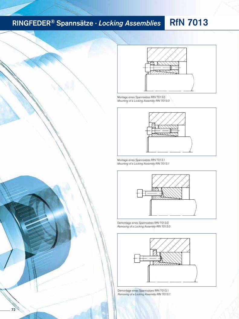
Montage eines Spannsatzes RfN 7013.0Mounting of a Locking Assembly RfN 7013.0
Montage eines Spannsatzes RfN 7013.1Mounting of a Locking Assembly RfN 7013.1
Demontage eines Spannsatzes RfN 7013.0Removing of a Locking Assembly RfN 7013.0
Demontage eines Spannsatzes RfN 7013.1Removing of a Locking Assembly RfN 7013.1
RINGFEDER® Spannsätze · Locking Assemblies RfN 7013
72
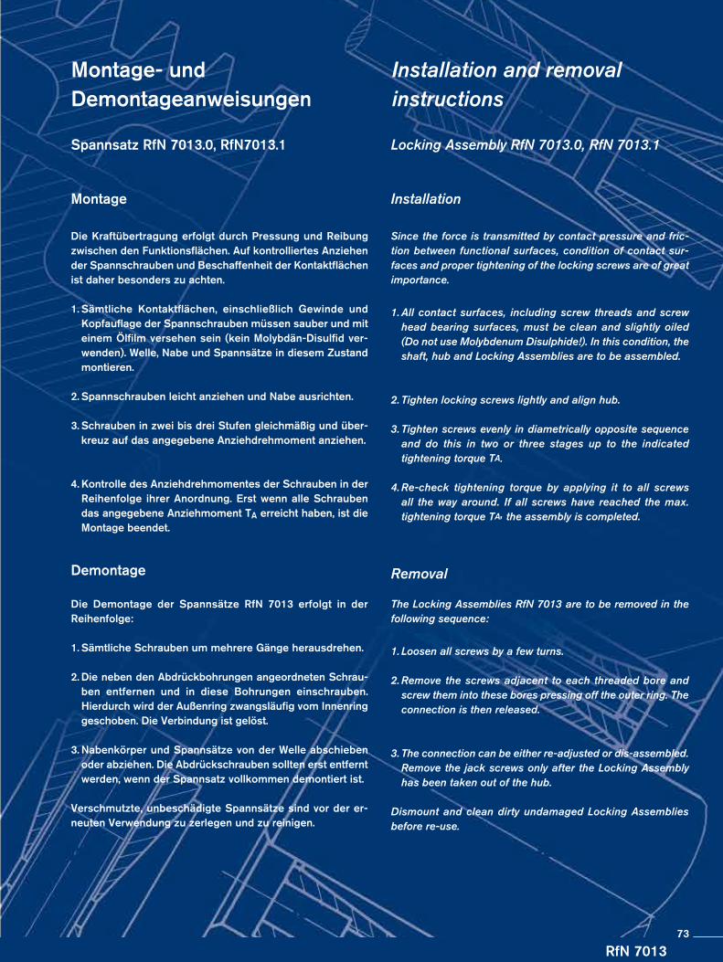
RfN 7013
Montage- und Demontageanweisungen
Spannsatz RfN 7013.0, RfN7013.1
Montage
Die Kraftübertragung erfolgt durch Pressung und Reibung zwischen den Funktionsflächen. Auf kontrolliertes Anziehen der Spannschrauben und Beschaffenheit der Kontaktflächen ist daher besonders zu achten.
1. Sämtliche Kontaktflächen, einschließlich Gewinde und Kopfauflage der Spannschrauben müssen sauber und mit einem Ölfilm versehen sein (kein Molybdän-Disulfid ver-wenden). Welle, Nabe und Spannsätze in diesem Zustand montieren.
2. Spannschrauben leicht anziehen und Nabe ausrichten.
3. Schrauben in zwei bis drei Stufen gleichmäßig und über-kreuz auf das angegebene Anziehdrehmoment anziehen.
4. Kontrolle des Anziehdrehmomentes der Schrauben in der Reihenfolge ihrer Anordnung. Erst wenn alle Schrauben das angegebene Anziehmoment TA erreicht haben, ist die Montage beendet.
Demontage
Die Demontage der Spannsätze RfN 7013 erfolgt in der Reihenfolge:
1. Sämtliche Schrauben um mehrere Gänge herausdrehen.
2. Die neben den Abdrückbohrungen angeordneten Schrau-ben entfernen und in diese Bohrungen einschrauben. Hierdurch wird der Außenring zwangsläufig vom Innenring geschoben. Die Verbindung ist gelöst.
3. Nabenkörper und Spannsätze von der Welle abschieben oder abziehen. Die Abdrückschrauben sollten erst entfernt werden, wenn der Spannsatz vollkommen demontiert ist.
Verschmutzte, unbeschädigte Spannsätze sind vor der er-neuten Verwendung zu zerlegen und zu reinigen.
Installation and removal instructions
Locking Assembly RfN 7013.0, RfN 7013.1
Installation
Since the force is transmitted by contact pressure and fric-tion between functional surfaces, condition of contact sur-faces and proper tightening of the locking screws are of great importance.
1. All contact surfaces, including screw threads and screw head bearing surfaces, must be clean and slightly oiled (Do not use Molybdenum Disulphide!). In this condition, the shaft, hub and Locking Assemblies are to be assembled.
2. Tighten locking screws lightly and align hub.
3. Tighten screws evenly in diametrically opposite sequence and do this in two or three stages up to the indicated tightening torque TA.
4. Re-check tightening torque by applying it to all screws all the way around. If all screws have reached the max. tightening torque TA, the assembly is completed.
Removal
The Locking Assemblies RfN 7013 are to be removed in the following sequence:
1. Loosen all screws by a few turns.
2. Remove the screws adjacent to each threaded bore and screw them into these bores pressing off the outer ring. The connection is then released.
3. The connection can be either re-adjusted or dis-assembled. Remove the jack screws only after the Locking Assembly has been taken out of the hub.
Dismount and clean dirty undamaged Locking Assemblies before re-use.
73
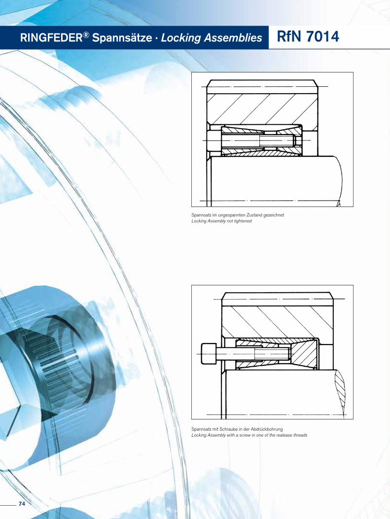
Spannsatz im ungespannten Zustand gezeichnetLocking Assembly not tightened
Spannsatz mit Schraube in der Abdrückbohrung Locking Assembly with a screw in one of the realease threads
RINGFEDER® Spannsätze · Locking Assemblies RfN 7014
74
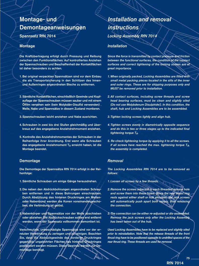
RfN 7014
Montage- und DemontageanweisungenSpannsatz RfN 7014
Montage
Die Kraftübertragung erfolgt durch Pressung und Reibung zwischen den Funktionsflächen. Auf kontrolliertes Anziehen der Spannschrauben und Beschaffenheit der Kontaktflächen ist daher besonders zu achten.
1. Bei original verpackten Spannsätzen sind vor dem Einbau die als Transportsicherung in den Schlitzen des Innen- und Außenringes angeordneten Bleche zu entfernen.
2. Sämtliche Kontaktflächen, einschließlich Gewinde und Kopf-auflage der Spannschrauben müssen sauber und mit einem Ölfilm versehen sein (kein Molybdän-Disulfid verwenden) .
Welle, Nabe und Spannsätze in diesem Zustand montieren.
3. Spannschrauben leicht anziehen und Nabe ausrichten.
4. Schrauben in zwei bis drei Stufen gleichmäßig und über-kreuz auf das angegebene Anziehdrehmoment anziehen.
5. Kontrolle des Anziehdrehmomentes der Schrauben in der Reihenfolge ihrer Anordnung. Erst wenn alle Schrauben das angegebene Anziehmoment TA erreicht haben, ist die Montage beendet.
Demontage
Die Demontage der Spannsätze RfN 7014 erfolgt in der Rei-henfolge:
1. Sämtliche Schrauben um einige Gänge herausdrehen.
2. Die neben den Abdrückbohrungen angeordneten Schrau-ben entfernen und in diese Bohrungen einschrauben. Durch Abstützung des hinteren Druckringes am Wellen- oder Nabenbund werden die Konen voneinandergescho-ben, die Verbindung ist gelöst.
3. Nabenkörper und Spannsätze von der Welle abschieben oder abziehen. Die Abdrückschrauben sollten erst entfernt werden, wenn der Spannsatz vollkommen demontiert ist.
Verschmutzte, unbeschädigte Spannsätze sind vor der er-neuten Verwendung zu zerlegen und zu reinigen. Beachten Sie, dass die Abdrückgewinde des vorderen Druckringes gegenüber ungebohrten Flächen des hinteren Druckringes positioniert werden müssen. Diese Gewinde werden zur De-montage benötigt.
Installation and removal instructionsLocking Assembly RfN 7014 Installation
Since the force is transmitted by contact pressure and friction between the functional surfaces, the condition of the contact surfaces and correct tightening of the locking screws are of great importance.
1. When originally packed, Locking Assemblies are fitted with small metal packing pieces located in the slits of the inner and outer rings. These are for shipping purposes only and MUST be removed prior to installation.
2. All contact surfaces, including screw threads and screw head bearing surfaces, must be clean and slightly oiled (Do not use Molybdenum Disulphide!). In this condition, the shaft, hub and Locking Assemblies are to be assembled.
3. Tighten locking screws lightly and align hub.
4. Tighten screws evenly in diametrically opposite sequence and do this in two or three stages up to the indicated final tightening torque TA.
5. Re-check tightening torque by applying it to all the screws. If all screws have reached the max. tightening torque TA, the assembly is completed.
Removal
The Locking Assemblies RfN 7014 are to be removed as follows:
1. Loosen all screws by a few threads.
2. Remove the screws adjacent to each threaded release hole and screw them into these holes. Since the rear thrust ring rests against either shaft or hub shoulder, the jack screws will automatically push apart both tapers, thus releasing the connection.
3. The connection can be either re-adjusted or dis-assembled. Remove the jack screws only after the Locking Assembly has been taken out of the hub.
Used Locking Assemblies have to be replaced and slightly oiled prior to reinstallation. Note that the release threads of the front thrust ring have to be positioned opposite to undrilled spaces of the rear thrust ring. These threads are used for removal.
75
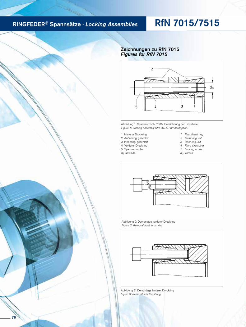
Abbildung 2: Demontage vorderer DruckringFigure 2: Removal front thrust ring
Abbildung 1: Spannsatz RfN 7015. Bezeichnung der Einzelteile.Figure 1: Locking Assembly RfN 7015. Part description.
Abbildung 3: Demontage hinterer DruckringFigure 3: Removal rear thrust ring
RINGFEDER® Spannsätze · Locking Assemblies
Zeichnungen zu RfN 7015Figures for RfN 7015
RfN 7015/7515
1 Rear thrust ring 2 Outer ring, slit3 Inner ring, slit4 Front thrust ring5 Locking screwdG Thread
1 Hinterer Druckring2 Außenring, geschlitzt3 Innenring, geschlitzt4 Vorderer Druckring5 SpannschraubedG Gewinde
76

Montage- und Demontageanweisungen
Spannsatz RfN 7015.0, 7015.1, 7515 Montage
Die Kraftübertragung erfolgt durch Pressung und Reibung zwischen den Funktionsflächen. Auf kontrolliertes Anziehen der Spannschrauben und Beschaffenheit der Kontaktflächen (s. Punkt 1) ist daher besonders zu achten.
1. Sämtliche Kontaktflächen, einschließlich Gewinde und Kopfauflage der Spannschrauben müssen sauber und mit einem Ölfilm versehen sein (kein Molybdän-Disulfid ver- wenden). Welle, Nabe und Spannsätze in diesem Zustand montieren.
1.1 Es empfiehlt sich, die aus Transportgründen tief einge- schraubten Spannschrauben soweit herauszudrehen, dass nur noch wenige Gänge im hinteren Druckring verbleiben.
1.2 Bei größeren Spannsätzen ist es vorteilhaft, einige Spannschrauben gemäß Abb. 2 in den vorderen Druck- ring einzuschrauben, um das Einbauen des Spannsatzes durch Druck auf diese Schrauben zu vereinfachen.
2. Bei eingebautem Spannsatz nun alle Spannschrauben (eingesetzt in den Gewindebohrungen des hinteren Druckringes) leicht anziehen und die Nabe ausrichten.
3. Schrauben in zwei bis drei Stufen gleichmäßig und über- kreuz auf das angegebene Anziehdrehmoment (TA) an- ziehen.
4. Kontrolle des Anziehdrehmomentes der Schrauben in der Reihenfolge ihrer Anordnung. Erst wenn alle Schrau- ben das angegebene Anziehmoment TA erreicht haben, ist die Montage beendet.
Gebrauchte Spannsätze vor dem Einbau reinigen, leicht ein-ölen und nach Abb. 1 zusammensetzen.
Beim Zusammenbau ist darauf zu achten, daß allen Gewin-debohrungen des hinteren Druckringes (1) Durchgangsboh-rungen des Steges des Innenringes (3) und des vorderen Druckringes (4) zugeordnet sind. Den Abdrückgewinden im vorderen Druckring sind bohrungsfreie Stellen im Innenring und den Abdrückgewinden im Innenring bohrungsfreie Stel-len im hinteren Druckring zuzuordnen, s. Abb. 1.
Installation and removal instructions
Locking Assembly RfN 7015.0, 7015.1, 7515 Installation
Since the force is transmitted by contact pressure and friction between functional surfaces, condition of contact surfaces and proper tightening of the locking screws are of great im-portance (see point 1).
1. All contact surfaces, including screw threads and screw head bearing surfaces, must be clean and slightly oiled (Do not use Molybdenum Disulphide!). In this condition, the shaft, hub and Locking Assemblies are to be assembled.
1.1 Unscrew all locking screws far enough so that only few threads are engaged in the rear thrust ring. For shipping purposes, these screws have been screwed in quite deep.
1.2 With larger Locking Assemblies, it is advantageous to insert several locking screws into the corresponding threads of the front thrust ring according to Fig. 2 and push against them.
2. After the Locking Assembly is placed in position, slightly tighten all locking screws (screwed into the rear thrust ring) and make final alignment and adjustment of the con- nection.
3. Tighten screws evenly in diametrically opposite se- quence and do this in two or three steps up to the indicated tightening torque TA.
4. Re-check tightening torque by applying it to all screws all the way around. If all screws have reached the max. tightening torque TA, the assembly is completed.
Used Locking Assemblies have to be cleaned and slightly oiled prior to installation and re-assembled according to Fig. 1 When re-assembling, it is important to make sure that all threaded holes of the rear thrust ring (1) are in line with the holes in web of inner ring (3) and front thrust ring (4). Threa-ded removal holes in front thrust ring must be located op-posite blanc spaces in web of inner ring, and the threaded removal holes in web of inner ring must be located opposite blanc spaces of rear thrust ring, see Fig. 1.
RfN 7015/751577
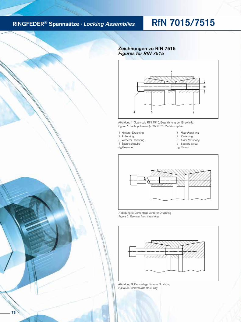
RINGFEDER® Spannsätze · Locking Assemblies RfN 7015/7515
dG
134
2
Abbildung 1: Spannsatz RfN 7515. Bezeichnung der Einzelteile.Figure 1: Locking Assembly RfN 7515. Part description.
Abbildung 2: Demontage vorderer DruckringFigure 2: Removal front thrust ring
Abbildung 3: Demontage hinterer DruckringFigure 3: Removal rear thrust ring
1 Rear thrust ring 2 Outer ring3 Front thrust ring4 Locking screwdG Thread
1 Hinterer Druckring2 Außenring3 Vorderer Druckring4 SpannschraubedG Gewinde
Zeichnungen zu RfN 7515Figures for RfN 7515
78

RfN 7015/7515
Locking Assembly RfN 7015.0, 7015.1, 7515
Removal
The Locking Assemblies RfN 7015 are to be removed as follows:
1. Loosen all screws by a few turns.
2. Remove the screws adjacent to each threaded bore and screw them into these bores.
2.1 The front thrust ring is released by having the jack screws pressed against the web of the inner ring (see Fig. 2).
2.2 The rear thrust ring is released by having the jack screws inserted in the threaded bore of the inner ring web and thus pushing it out (Fig. 3).
3. Pull or push hub and Locking Assemblies off the shaft. The jack screws should be removed only after the Locking Assembly has been taken out of the hub.
Dis-assemble and clean dirty, undamaged Locking Assemblies before re-use.
Spannsatz RfN 7015.0, 7015.1, 7515
Demontage
Die Demontage der Spannsätze RfN 7015 erfolgt in der Rei-henfolge:
1. Sämtliche Schrauben um mehrere Gänge herausdrehen.
2. Die neben den Abdrückbohrungen angeordneten Schrau- ben entfernen und in diese Bohrungen einschrauben.
2.1 Der vordere Druckring wird dann dadurch gelöst, daß er durch in seine Abdrückgewinde eingeschraubte Schrau- ben, die sich am Steg des Innenringes abstützen, aus seiner Position geschoben wird (Abb. 2).
2.2 Der hintere Druckring wird in entsprechender Weise gemäß Abb. 3 gelöst.
3. Nabenkörper und Spannsätze von der Welle abschieben oder abziehen. Die Abdrückschrauben sollten erst ent- fernt werden, wenn der Spannsatz vollkommen demon- tiert ist.
Verschmutzte, unbeschädigte Spannsätze sind vor der er-neuten Verwendung zu zerlegen und zu reinigen.
Montage- und Demontageanweisungen
Installation and removal instructions
79
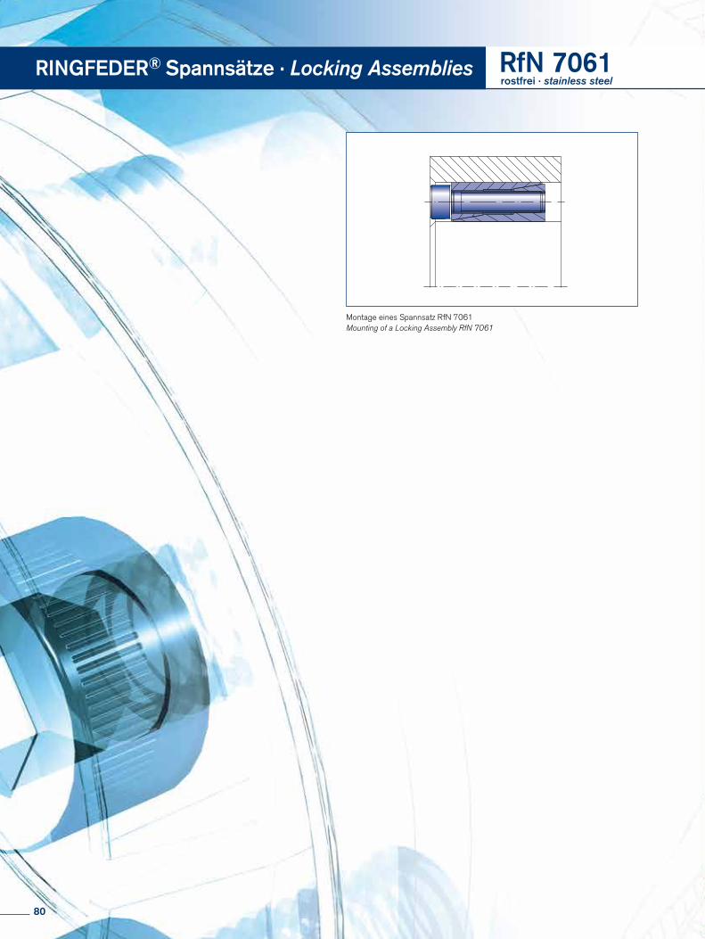
A
A
RINGFEDER® Spannsätze · Locking Assemblies RfN 7061rostfrei · stainless steel
Montage eines Spannsatz RfN 7061Mounting of a Locking Assembly RfN 7061
80
RfN 7061
Montage- und DemontageanweisungenSpannsatz RfN 7061rostfrei
Montage
Die Kraftübertragung erfolgt durch Pressung und Reibung zwischen den Funktionsflächen. Auf kontrolliertes Anziehen der Spannschrauben und Beschaffenheit der Kontaktflächen (siehe Punkt 1) ist daher besonders zu achten.
1. Sämtliche Kontaktflächen, einschließlich Gewinde und Kopfauflage der Spannschrauben müssen sauber und mit einem leichten Ölfilm versehen sein (Kein Molybdän-Di-sulfid verwenden). Welle, Nabe und Spannsätze in diesem Zustand montieren.
2. Spannschrauben leicht anziehen und die Einheit den Er-fordernissen entsprechend ausrichten.
3. Schrauben in zwei bis drei Stufen gleichmäßig und über-kreuz auf das angegebene Anziehdrehmoment anziehen.
4. Kontrolle des Anziehdrehmomentes der Schrauben in der Reihenfolge ihrer Anordnung. Erst wenn alle Schrauben das angegebene Anziehmoment TA erreicht haben, ist die Montage beendet.
Demontage
Die Demontage der Spannsätze RfN 7061 erfolgt in der Reihenfolge:
1. Sämtliche Schrauben um einige Gewindegänge heraus- drehen.
2. Einige Schrauben ganz herausdrehen und in die Gewinde- bohrungen des Flansches einschrauben.
3. Die zum Abdrücken umgesetzten Schrauben in mehreren Stufen, in Reihenfolge, bis zum Lösen der Verbindung an- ziehen. Hierbei sollte mit dem Abdrücken möglichst nicht in direkter Schlitznähe begonnen werden. Der Außenring wird hierdurch zwangsläufig vom Innenring geschoben. Die Verbindung ist gelöst.
4. Nabenkörper und Spannsätze von der Welle abschieben oder abziehen.
Verschmutzte, unbeschädigte Spannsätze sind vor der erneu-ten Verwendung zu zerlegen, zu reinigen und entsprechend Punkt 1der Montage leicht einzuölen.
Installation and removal instructionsLocking Assembly RfN 7061 stainless
Installation
Since the force is transmitted by contact pressure and friction between functional surfaces, the condition of the contact surfaces and proper tightening of the locking screws are of great importance (see point 1).
1. All contact surfaces, including screw threads and screw head bearing surfaces, must be clean and slightly oiled (Do not use Molybdenum Disulphide!). In this condition, the shaft, hub and Locking Assemblies are to be assembled.
2. Tighten locking screws lightly and align hub.
3. Tighten screws evenly in diametrically opposite sequence and do so in two or three steps up to the indicated tightening torque.
4. Re-check tightening torque by applying it to all screws all the way around. If all screws have reached the max. tightening torque TA, the assembly is completed.
Removal
The Locking Assemblies RfN 7061 are to be removed in the following sequence:
1. Loosen all screws by a few turns.
2. Remove the screws adjacent to each threaded jacking hole and screw them into these bores.
3. Tighten the jacking screws, starting with the positions furthest away from the slit first, in several steps until the connection is released.
4. The connection can then either be readjusted or disas- sembled. Remove the jacking screws only after the Locking Assembly has been removed from the hub.
Dismount and clean dirty undamaged Locking Assemblies before re-use and slightly oil them as described in point 1of the mounting instructions.
81
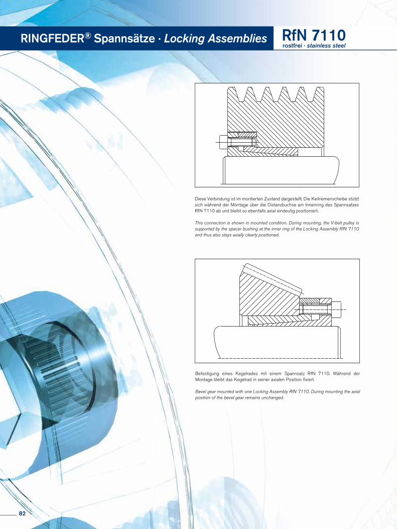
Diese Verbindung ist im montierten Zustand dargestellt. Die Keilriemenscheibe stützt sich während der Montage über die Distanzbuchse am Innenring des Spannsatzes RfN 7110 ab und bleibt so ebenfalls axial eindeutig positioniert.
This connection is shown in mounted condition. During mounting, the V-belt pulley is supported by the spacer bushing at the inner ring of the Locking Assembly RfN 7110 and thus also stays axially clearly positioned.
Befestigung eines Kegelrades mit einem Spannsatz RfN 7110. Während der Montage bleibt das Kegelrad in seiner axialen Position fixiert.
Bevel gear mounted with one Locking Assembly RfN 7110. During mounting the axial position of the bevel gear remains unchanged.
RINGFEDER® Spannsätze · Locking Assemblies RfN 7110rostfrei · stainless steel
82
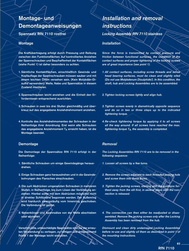
RfN 7110
Montage- und DemontageanweisungenSpannsatz RfN 7110 rostfrei
Montage
Die Kraftübertragung erfolgt durch Pressung und Reibung zwischen den Funktionsflächen. Auf kontrolliertes Anziehen der Spannschrauben und Beschaffenheit der Kontaktflächen (siehe Punkt 1) ist daher besonders zu achten.
1. Sämtliche Kontaktflächen, einschließlich Gewinde und Kopfauflage der Spannschrauben müssen sauber und mit einem leichten Ölfilm versehen sein. (Kein Molybdän-Di-sulfid verwenden). Welle, Nabe und Spannsätze in diesem Zustand montieren.
2. Spannschrauben leicht anziehen und die Einheit den Er-fordernissen entsprechend ausrichten.
3. Schrauben in zwei bis drei Stufen gleichmäßig und über-kreuz auf das angegebene Anziehdrehmoment anziehen.
4. Kontrolle des Anziehdrehmomentes der Schrauben in der Reihenfolge ihrer Anordnung. Erst wenn alle Schrauben das angegebene Anziehmoment TA erreicht haben, ist die Montage beendet.
Demontage
Die Demontage der Spannsätze RfN 7110 erfolgt in der Reihenfolge:
1. Sämtliche Schrauben um einige Gewindegänge heraus- drehen.
2. Einige Schrauben ganz herausdrehen und in die Gewinde- bohrungen des Flansches einschrauben.
3. Die zum Abdrücken umgesetzten Schrauben in mehreren Stufen, in Reihenfolge, bis zum Lösen der Verbindung an- ziehen. Hierbei sollte mit dem Abdrücken möglichst nicht in direkter Schlitznähe begonnen werden. Der Außenring wird hierdurch zwangsläufig vom Innenring geschoben. Die Verbindung ist gelöst.
4. Nabenkörper und Spannsätze von der Welle abschieben oder abziehen.
Verschmutzte, unbeschädigte Spannsätze sind vor der erneu-ten Verwendung zu zerlegen, zu reinigen und entsprechend Punkt 1 der Montage leicht einzuölen.
Installation and removal instructionsLocking Assembly RfN 7110 stainless
Installation
Since the force is transmitted by contact pressure and friction between functional surfaces, the condition of the contact surfaces and proper tightening of the locking screws are of great importance (see point 1).
1. All contact surfaces, including screw threads and screw head bearing surfaces, must be clean and slightly oiled (Do not use Molybdenum Disulphide!). In this condition, the shaft, hub and Locking Assemblies are to be assembled.
2. Tighten locking screws lightly and align hub.
3. Tighten screws evenly in diametrically opposite sequence and do so in two or three steps up to the indicated tightening torque.
4. Re-check tightening torque by applying it to all screws all the way around. If all screws have reached the max. tightening torque TA, the assembly is completed.
Removal
The Locking Assemblies RfN 7110 are to be removed in the following sequence:
1. Loosen all screws by a few turns.
2. Remove the screws adjacent to each threaded jacking hole and screw them into these bores.
3. Tighten the jacking screws, starting with the positions fur- thest away from the slit first, in several steps until the con- nection is released.
4. The connection can then either be readjusted or disas- sembled. Remove the jacking screws only after the Locking Assembly has been removed from the hub.
Dismount and clean dirty undamaged Locking Assemblies before re-use and slightly oil them as described in point 1 of the mounting instructions.
83
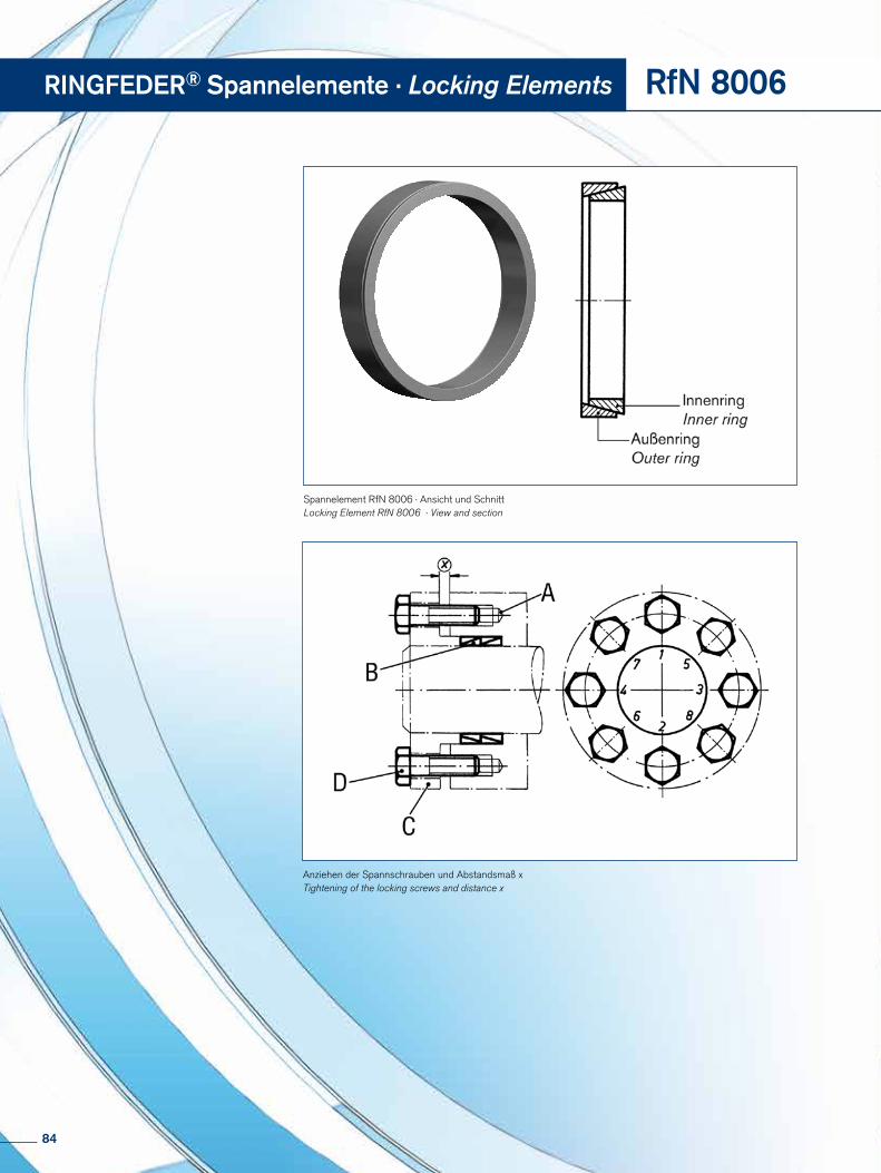
Anziehen der Spannschrauben und Abstandsmaß xTightening of the locking screws and distance x
Spannelement RfN 8006 · Ansicht und SchnittLocking Element RfN 8006 · View and section
RINGFEDER® Spannelemente · Locking Elements RfN 8006
84
RfN 8006
Montage- und Demontageanweisungen
Die Kraftübertragung erfolgt durch Pressung und Reibung zwischen den Funktionsflächen. Auf kontrolliertes Anziehen der Spannschrauben und korrekte Beschaffenheit der Kon-taktfläche (s. Punkt 1) ist daher besonders zu achten.
1. Sämtliche Kontaktflächen, einschließlich Gewinde und Kopf auflage der Spannschrauben müssen sauber und mit einem Öl film versehen sein.
2. Montage der Einzelteile in der Reihenfolge A = Nabe Spannelementringe (B) entsprechend Montagezeichnung
einsetzen (beide Teile müssen sich leicht montieren las-sen und dürfen keinesfalls klemmen).
C = Druckflansch (Distanzbuchse, wenn erforderlich) oder Druckflansch mit Bund einsetzen. Auf leichte Verschieb-barkeit beider Teile ist zu achten.
D = Spannschrauben Die Spannschrauben sind vor dem Einbau gut zu ölen. Dies gilt besonders für die Schraubenkopfauflage. ACHTUNG: Nicht mit Molybdän-Disulfid arbeiten! Die Schrauben müssen sich leicht und genügend tief ein- drehen lassen. Keine Federringe oder Fächerscheiben verwenden!
3. Spannschrauben leicht anziehen und Nabe ausrichten.
4. Schrauben in mehreren Stufen gleichmäßig und über- kreuz auf das angegebene Anziehdrehmoment TA mittels Drehmoment schlüssel anziehen.
5. Kontrolle des Anziehdrehmomentes der Schrauben in der Reihen folge ihrer Anordung. Erst wenn alle Schrauben das angegebene Anziehmoment TA erreicht haben, ist die Mon- tage beendet.
6. Kontrolle des Abstandsmaßes x: Der Druckflansch darf die Stirnseite der Nabe in kei- nem Fall berühren. Der verbleibende Spalt sollte mög- lichst gleichmäßig sein.
Demontage
1. Sämtliche Schrauben in mehreren Umläufen der Reihe nach lösen.
2. Flansch herausnehmen.
3. Spannelemente herausnehmen – die Spannelemente entspannen sich nach Lösen der Schrauben selbständig. Falls nicht, genügen leichte Schläge, um den Lösevorgang einzuleiten.
Installation and removal instructions
Since the force is transmitted by contact pressure and friction between functional surfaces, condition of contact surfaces and proper tightening of the locking screws are of great importance (see point 1).
1. All contact surfaces, including screw threads and screw head contact surface, must be clean and slightly oiled.
2. Fit the parts in the following order: A = Hub Insert the Locking Element rings (B) according to the
assembly drawing (both parts must be easy to install and must not jam under any circumstances).
C = Insert compression flange (distance sleeve if necessary) or compression flange with collar. Ensure that both parts are easy to move.
D = Locking screws Carefully oil the locking screws before fitting. This applies in particular to the screw head seat. ATTENTION: Do not use molybdenum disulphide! The screws must turn easily and to an adequate depth. Do not use spring washers or serrated locking washers.
3. Tighten locking screws lightly and align hub.
4. Tighten screws evenly in diametrically opposite sequence and do this with a torque wrench in several stages up to the indicated tightening torque ( TA) .
5. Re-check tightening torque by applying it to all screws all the way around. If all screw have reached the max. tightening torque TA , the assembly is completed.
6. Check distance x: The thrust ring must never contact the face of the hub. The
gap between thrust ring and hub face should be as uniform as possible.
Removal
1. Loosen all screws one after the other in several steps.
2. Remove the flange.
3. Take out the Locking Elements – the Locking Elements re-lease automatically after the screws have been loosened. If not, light tapping is enough to start the releasing process.
85

Online Service
In order to meet the complex requirements on the correct design and selection of RINGFEDER products under practise-relevant de-mands, RINGFEDER POWER TRANSMISSION GMBH has deve-loped a calculation program.
This calculation program offers the engineer a valuable aid in his or her daily work and simplifies the calculation of a wide range of tasks.
Once a product and the desired product size have been selected the program carries out the calculation, taking into account additional user input e.g. transmissible torque and axial forces, resulting hub and shaft pressure, the outer diameter of the hub, the inner diameter of the hollow shaft and for special tasks even the forces and loads under bending moment loads.
Interested? Visit our Website at www.ringfeder.com!
Um der komplexen Anforderung bei der richtigen Auslegung und Auswahl der RINGFEDER Produkte unter praxisrelevanten Bean-spruchungen zu entsprechen, wurde von der RINGFEDER POWER TRANSMISSION GMBH ein Berechnungsprogramm entwickelt.
Dieses Berechnungsprogramm bietet den Ingenieuren eine wert-volle Hilfestellung bei der täglichen Arbeit und erleichtert die Be-rechnung unterschiedlichster Aufgabenstellungen.
Nach Anwahl eines Produktes und der gewünschten Produktgröße errechnet das Programm unter Berücksichtigung zusätzlicher Benutzereingaben z.B. übertragbare Drehmomente und Axi-alkräfte, resultierende Naben- und Wellenpressungen, Na-benaußendurchmesser, Hohlwelleninnendurchmesser und für besondere Aufgaben sogar die auftretenden Kräfte und Bela-stungen unter Biegemomentbeanspruchungen.
Interessiert? Besuchen Sie unsere Webseite www.ringfeder.com!
Berechnungsprogramm für Spannsätze und Spann-elemente
Calculation program for Locking Assemblies and Locking Elements
86

Online Service www.ringfeder.com
Unsere WebsiteInformationen im schnellen Zugriff. RINGFEDER POWER TRANSMISSION - eine der ersten Adressen, wenn es um antriebs- und dämpfungstechnische Lö-sungen im Maschinenbau geht. Service und Informationen aus erster Hand finden Sie auf unserer Website. Neben Details zu unserem gesamten Produktportfolio halten wir auf unserer Web-site zahlreiche Dokumente wie Produktkataloge, Datenblätter und Montageanleitungen für Sie zum Download bereit. Ein Besuch auf www.ringfeder.com bringt Sie auf den neuesten Stand.
Abrufbare Anleitungen für Montage, Demontage und erneute Montage
Available Instructions for Installation, Removal and Maintaining
Our WebsiteEasily accessible information. RINGFEDER POWER TRANSMISSION – one of the top addresses for drive and damping technology in mechanical engineering. You can find first-hand service details and informa-tion on our website. It contains both details on our entire range of products and numerous documents such as product catalo-gues, data sheets and assembly instruction for you to download. Visit www.ringfeder.com to get right up to date.
Download-Bereich für Lieferprogramm und Kataloge
Download area Product Range and catalogues
87
Notizen · Notes
88
Notizen · Notes
89
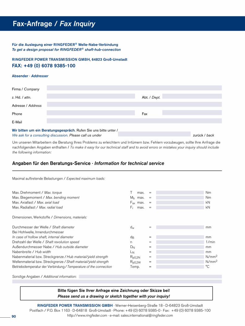
Für die Auslegung einer RINGFEDER® Welle-Nabe-VerbindungTo get a design proposal for RINGFEDER® shaft-hub-connection
RINGFEDER POWER TRANSMISSION GMBH, 64823 Groß-Umstadt
FAX: +49 (0) 6078 9385-100 Absender · Addresser
Firma / Company
z. Hd. / attn. Abt. / Dept.
Adresse / Address
Phone Fax
Wir bitten um ein Beratungsgespräch. Rufen Sie uns bitte unter /We ask for a consulting discussion. Please call us under zurück / back
Um unseren Mitarbeitern die Beratung Ihres Problems zu erleichtern und Irrtümern bzw. Fehlern vorzubeugen, sollte Ihre Anfrage die nachfolgenden Angaben enthalten / To make it easy for our technical staff and to avoid errors or mistakes your inquiry should include the following information:
Angaben für den Beratungs-Service · Information for technical service
Maximal auftretende Belastungen / Expected maximum loads:
Max. Drehmoment / Max. torque T max. = NmMax. Biegemoment / Max. bending moment Mb max. = NmMax. Axiallast / Max. axial load Fax max. = kNMax. Radiallast / Max. radial load Fr max. = kN
Dimensionen, Werkstoffe / Dimensions, materials:
Durchmesser der Welle / Shaft diameter dw = mmBei Hohlwelle, InnendurchmesserIn case of hollow shaft, internal diameter dB = mmDrehzahl der Welle / Shaft revolution speed n = 1/minAußendurchmesser Nabe / Hub outside diameter DN = mmNabenbreite / Hub width LN = mmNabenmaterial bzw. Streckgrenze / Hub material/yield strength Rp0,2N = N/mm2
Wellenmaterial bzw. Streckgrenze / Shaft material/yield strength Rp0,2W = N/mm2
Betriebstemperatur der Verbindung / Temperature of the connection Temp. = °C
Sonstige Angaben / Additional information:
Fax-Anfrage / Fax Inquiry
RINGFEDER POWER TRANSMISSION GMBH · Werner-Heisenberg-Straße 18 · D-64823 Groß-Umstadt Postfach / P.O. Box 1163 · D-64818 Groß-Umstadt · Phone: +49 (0) 6078 9385-0 · Fax: +49 (0) 6078 9385-100
http://www.ringfeder.com · e-mail: [email protected]
Bitte fügen Sie Ihrer Anfrage eine Zeichnung oder Skizze bei!Please send us a drawing or sketch together with your inquiry!
90
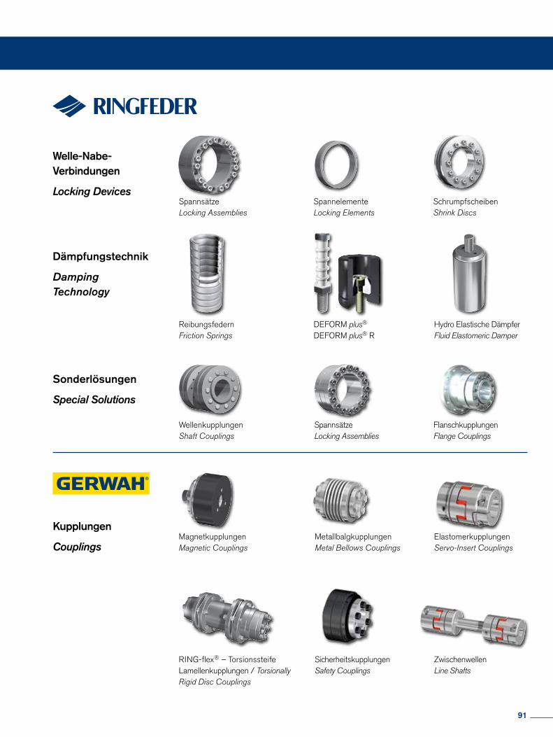
Welle-Nabe- Verbindungen
Locking DevicesSpannsätzeLocking Assemblies
SpannelementeLocking Elements
SchrumpfscheibenShrink Discs
Dämpfungstechnik
Damping Technology
ReibungsfedernFriction Springs
DEFORM plus®
DEFORM plus® RHydro Elastische DämpferFluid Elastomeric Damper
Sonderlösungen
Special Solutions
Kupplungen
CouplingsMagnetkupplungenMagnetic Couplings
ElastomerkupplungenServo-Insert Couplings
SpannsätzeLocking Assemblies
FlanschkupplungenFlange Couplings
WellenkupplungenShaft Couplings
MetallbalgkupplungenMetal Bellows Couplings
RING-flex® – Torsionssteife Lamellenkupplungen / TorsionallyRigid Disc Couplings
SicherheitskupplungenSafety Couplings
ZwischenwellenLine Shafts
91
www.ringfeder.comRINGFEDER POWER TRANSMISSION
RINGFEDER POWER TRANSMISSION GMBHWerner-Heisenberg-Straße 18, D-64823 Groß-Umstadt, Germany · Phone: +49 (0) 6078 9385-0 · Fax: +49 (0) 6078 9385-100 E-mail: [email protected] · E-mail: [email protected]
RINGFEDER POWER TRANSMISSION USA CORPORATION165 Carver Avenue, P.O. Box 691 Westwood, NJ 07675, USA · Toll Free: +1 888 746-4333 · Phone: +1 201 666 3320Fax: +1 201 664 6053 · E-mail: [email protected] · E-mail: [email protected]
RINGFEDER POWER TRANSMISSION INDIA PRIVATE LIMITEDPlot No. 4, Door No. 220, Mount - Poonamallee Road, Kattupakkam, Chennai – 600 056, IndiaPhone: +91 (0) 44-2679-1411 · Fax: +91 (0) 44-2679-1422 · E-mail: [email protected] · E-mail: [email protected]
KUNSHAN RINGFEDER POWER TRANSMISSION COMPANY LIMITEDGerman Industry Park, No. 508 Hengguanjing Road, Zhangpu Town 215321, Kunshan City, P.R. ChinaPhone: +86 (0) 512-5745-3960 · Fax: +86 (0) 512-5745-3961 · E-mail [email protected]