Transmission Line Dehydrator 300 L 30 hPa · LL_DOC0302-R5 FM Gerätebau Seite 9 von 36 08.02.16 4....
36
Transmission Line Dehydrator 300 L 30 hPa Manual Date: 02/16 LL_DOC302-R5
Transcript of Transmission Line Dehydrator 300 L 30 hPa · LL_DOC0302-R5 FM Gerätebau Seite 9 von 36 08.02.16 4....

Transmission Line Dehydrator
300 L 30 hPa
Manual
Date: 02/16
LL_DOC302-R5

LL_DOC0302-R5
FM Gerätebau Page 2 of 36 08.02.16

LL_DOC0302-R5
FM Gerätebau Page 3 of 36 08.02.16
Contents Page
1. Specifications............................................................................................................................... 5
2. General notes .............................................................................................................................. 6
3. Short description.......................................................................................................................... 7
4. Preparatory work and operation .................................................................................................. 9
5. USB interface............................................................................................................................. 11
5.1 Driver installation.......................................................................................................... 11
5.2 Terminal program......................................................................................................... 12
6. Initialization ................................................................................................................................ 13
7. Mode of operation...................................................................................................................... 13
8. Maintenance .............................................................................................................................. 14
8.1 Removal of top part...................................................................................................... 14
8.2 Removal of pump and membrane exchange............................................................... 15
8.3 Exchange of filters........................................................................................................ 17
8.4 Spare Parts .................................................................................................................. 19
9. Firmware.................................................................................................................................... 20
10. Description of the device control electronics ............................................................................. 20
10.1 Regeneration................................................................................................................ 21
10.2 Pressure control circuit................................................................................................. 22
10.3 Humidity monitoring ..................................................................................................... 23
10.4 Operational hours meter .............................................................................................. 23
10.5 Fault detection.............................................................................................................. 24
10.6 Control panel................................................................................................................ 25
11. Menu functions: ......................................................................................................................... 26
11.1 Basic functions ............................................................................................................. 26
11.2 Show parameters ......................................................................................................... 26
12. List of all commands sorted by function .................................................................................... 27
12.1 Control commands: ...................................................................................................... 27
12.2 Display commands:...................................................................................................... 28
12.3 Input commands:.......................................................................................................... 30
13. 16-bit software switch ................................................................................................................ 32
14. Schaltpläne................................................................................................................................ 33
15. Revision history ......................................................................................................................... 35
LL_DOC0302-R5
Friedl & Müller
Gerätebau GmbH Karl-Benz-Str. 14
85221 Dachau
Telefon 0 81 31 / 31 33 2-0 Telefax 0 81 31 / 1 55 45
http://www.friedl-mueller.de
e-mail: [email protected]
Änderungen vorbehalten - Specifications subject to change
FM Gerätebau Seite 4 von 36 08.02.16
Illustrations Figure 1 – Front view .......................................................................................................................... 4
Figure 2 – Operating elements ........................................................................................................... 8
Figure 3 - Mounting............................................................................................................................. 9
Figure 4 – Power supply ................................................................................................................... 10
Figure 5 – Pin assignment of connector ........................................................................................... 10
Figure 6 – Terminal settings ............................................................................................................. 12
Figure 7 - Air flow chart..................................................................................................................... 13
Figure 8 – Control panel ................................................................................................................... 25
Figure 9 – Circuit diagram 230 VAC ................................................................................................. 33
Figure 10 – Circuit diagram 24 + 60 VDC......................................................................................... 34
Figure 1 – Front view

LL_DOC0302-R5
FM Gerätebau Seite 5 von 36 08.02.16
1. Specifications
Effective air output ca. 300 l/h
Start-up pressure 20 hPa ± 10% *
Shut-off pressure 30 hPa ± 10% *
Alarm pressure 10 hPa + 1 hPa
Over pressure Safety valve opens at ca. 30 hPa *
Ambient temperature - 25° C to + 50° C
Ambient humidity 83 % at ambient temperature of + 23° C
Dew point reduction >--35 K in relation to ambient temperature
Desiccant Molecular sieve
Power supply**
230 V AC/50 Hz ±10% 230 V AC/60 Hz ±10% 115 V AC/60 Hz ±10% 48 - 72 VDC
Signal connection e.g. with 24 V external voltage
Power consumption at 230 V/50 Hz ca. 160 VA
Fuse protection 3.0 A automat
Air supply Air outlet for ½“ hose
Dimensions (h x w x d) 133/440/245 mm
Weight ca. 10 kg
Mounting options Mounted in ETSI-/19”-rack, floor- or wall-mounting
* Other pressures on request ** Dpending on the veresion

LL_DOC0302-R5
FM Gerätebau Seite 6 von 36 08.02.16
2. General notes
This manual refers to DC- and AC-devices. This manual does not contain order details, with the exception of part numbers in the section "Maintenance".
Important! Please make sure:
Caution! Draw the main plug before opening the case!
Even when the device is switched off, some of the components remain live!
When work on the boards is carried out, the precautions for the work on
ESD must be taken!

LL_DOC0302-R5
FM Gerätebau Seite 7 von 36 08.02.16
3. Short description
The dehydrator supplies dry air. This dry air is filled into transmission lines such as waveguides of radio link systems to prevent the occurrence of humidity and condensation. The dehydrator is designed for installation in ETSI standard cabinets, in 19” racks, and for wall or floor mounting. It requires a height clearance of 3 units.
After connecting the mains voltage (4), the dehydrator is switched on with the power switch (11) and a green LED (10) signals operational readiness.
During the first filling operation the dehydrator keeps working until a pressure of 30 hPa is reached in the connected feeder lines. If the air pressure drops to about 20 hPa, the pump switches on again until the pressure returns to 30 hPa.
As protection against overpressure in the connected waveguide system (e.g. heat caused by solar radiation or faults in the pressure regulator), a relief valve is installed in the dehydrator. This valve opens at an overpressure of about 40 hPa and ventilates until normal pressure is restored in the waveguide or coax cable system.
The valve relief setting is fixed at the factory. Never change the setting of the overpressure valve!
A pressure sensor in the dehydrator system automatically controls within preset limits the correct air pressure inside the waveguide. An external air distribution may be connected by hose to the ½ “ air outlet (each outlet with shut-off valve) to supply several antennas. A number of air distributors may be cascaded, if this is required.
The cartridge that will be checked by a humidity sensor is fitted with an internal heating element, which is surrounded by the desiccant. The cartridge will be regenerated cyclically.
The compressor inside the dehydrator draws air in, which passes through the solenoid valve into the drying cartridge. The desiccant inside the drying cartridge removes moisture from the air. The desiccant inside the drying cartridge removes moisture from the air. A humidity sensor monitors the desiccant (molecular sieve). If the preset humidity setting is exceeded, the pumping process will be interrupted and this will be indicated by the generation of an error. The duration of the regeneration depends on the operational time of the pump. Accordingly, the tightness and the volume of the connected line system have an influence the regeneration.
Regeneration is done:
� after 168 operating hours (1 week)
� after a certain working time of the compressor, adjustable between 1 and 1500 minutes
� after exceeding the humidity limit (maximal humidity - 10 %)
� after one week (168 hours)
� manually via the keypad
� via the USB interface
LL_DOC0302-R5
FM Gerätebau Seite 8 von 36 08.02.16
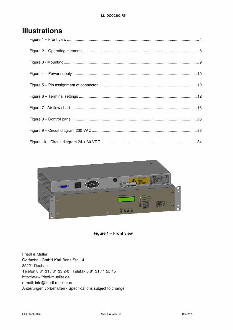
Figure 2 – Operating elements
Item Name
1 Mounting bracket for 19” rack, ETSI rack and wall mounting
2 Signaling interface Sub-D-15 pole (jack)
3 USB interface
4Power supply connection, optional power connector for115/230 VAC or high current connector Sub-D-3 Pin for DC
5 Automatic cut-out
6 Air outlet for ½“ hose (inside diameter Ø 13 mm)
7 Signaling (LED flashes when output is off)
8 LCD display to show functional state (operational status)
9 Menu keys
10 LED display to show line fault and operation
11 Power switch
12 Switch for switching signal output off
13 Air distributor (optional)
8 9 7 12 3 1
10
6 5 4 11 2
13
LL_DOC0302-R5
FM Gerätebau Seite 9 von 36 08.02.16
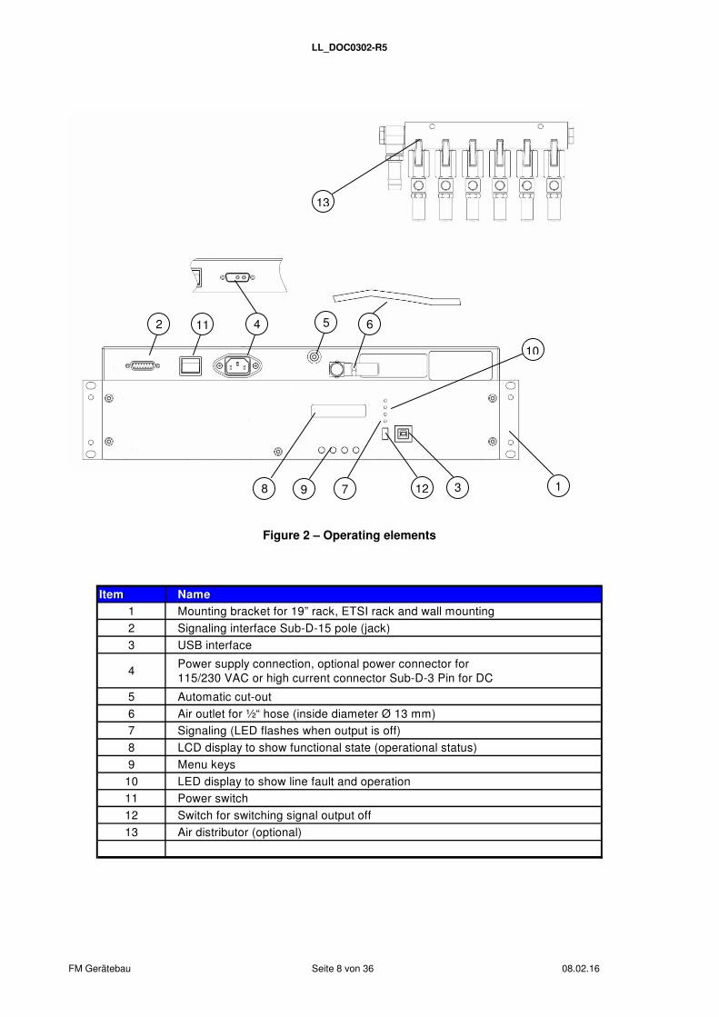
4. Preparatory work and operation
The dehydrator is to be installed using the mounting brackets provided, either in a 19” rack or a ETSI cabinet. Ground mounting using universal mounting brackets is also possible.
ETSI
Bodenbefestigungbottom attachment
19"
Figure 3 - Mounting
The power cable for mains voltage (115VAC 60Hz, 230VAC 50Hz, 230VAC 60Hz) is to be plugged into the front panel, using, depending on the device type, a power connector, or for 24 V respectively 40-70 V direct current a D-Sub high-current type.
Signaling is by 15 pin D-Sub connector (included in the supply).
24 V and 40 V to 70 VDC
115 V - 230 VAC
Attention when operating device initially or resumption of operation after a longer period of time:
After > 3 weeks time and date must be set again!

LL_DOC0302-R5
FM Gerätebau Seite 10 von 36 08.02.16
Figure 4 – Power supply
Figure 5 – Pin assignment of connector
Pin (D-Sub) Signal Pin (D-Sub) Signal
1 NO 9 OPEN
2 NC 10 OPEN
3 COM 11 OPEN
4 OPEN 12 OPEN
5 OPEN 13 OPEN
6 OPEN 14 OPEN
7 OPEN 15 OPEN
8 OPEN
Floating relay (change-over) contact In quiescent state (device switch off or alarm) the COM port is interconnected to NC. COM and NO are opened. In operation (no alarm) COM and NC are opened, and COM is connected to NO.
A2 +
A3 -
24 V DC high current D-Sub
connector A1
- A2
+
40 - 70 V DC high current D-Sub
connector
1 2 3
15 Pin D-Sub Signaling / telecontrol
connector
LL_DOC0302-R5
FM Gerätebau Seite 11 von 36 08.02.16
5. USB interface
5.1 Driver installation
Download the driver „CP210x_VCP_*.exe“ from the website http://www.silabs.com/products/interface/usbtouart/Pages/usb-to-uart-bridge.aspx => tab "Tools". => Virtual Com Port (VCP) Download .
Follow the steps below to install the driver:
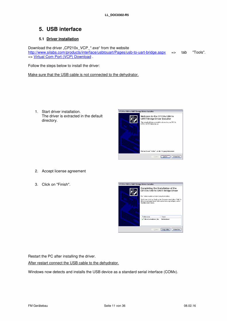
Make sure that the USB cable is not connected to the dehydrator.
1. Start driver installation. The driver is extracted in the default directory.
2. Accept license agreement
3. Click on "Finish".
Restart the PC after installing the driver.
After restart connect the USB cable to the dehydrator.
Windows now detects and installs the USB device as a standard serial interface (COMx).
LL_DOC0302-R5
FM Gerätebau Seite 12 von 36 08.02.16
5.2 Terminal program
The terminal program settings explained below focus on HyperTerminal (up to Windows XP© included by default). Other terminal programs are suitable as well.
Command sequences can be automatized via a "text file" (sample file is included). For Windows XP© HyperTerminal follow the steps below:
Select "Transfer>Send text file". => Pop up window opens. Select the file that you want to transfer and click "Open".
Note!
HyperTerminal is not scriptable. Therefore the text file transfer must be timed properly (do not change the order of commands in the sample script / for terminal settings see "ASCII Setup" below). Use a suitable terminal program (see link above) to run scripts.
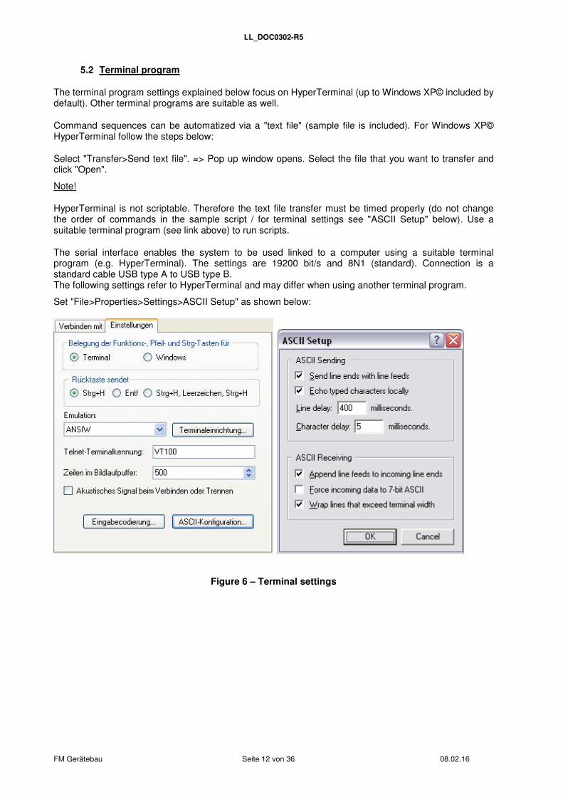
The serial interface enables the system to be used linked to a computer using a suitable terminal program (e.g. HyperTerminal). The settings are 19200 bit/s and 8N1 (standard). Connection is a standard cable USB type A to USB type B. The following settings refer to HyperTerminal and may differ when using another terminal program.
Set "File>Properties>Settings>ASCII Setup" as shown below:
Figure 6 – Terminal settings
LL_DOC0302-R5
FM Gerätebau Seite 13 von 36 08.02.16
6. Initialization
The section helps you to understand the internal processes on device switch-on respectively to analyze errors.
On device switch-on
the processor starts.
ports, timer and ADC initialize.
all LEDs switch on.
initialize RTC, sensors, LCD display, serial interface and I²C bus.
center LED 2 switches off.
current on pump, ventiles and heating system is measured.
lower LED 1 switches off.
the initial screen is displayed.
the main loop starts.
7. Mode of operation
Models with automatic regeneration
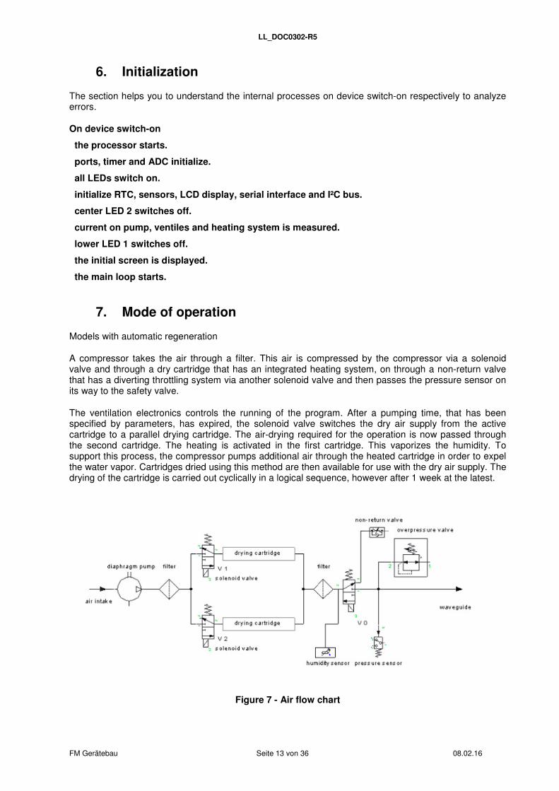
A compressor takes the air through a filter. This air is compressed by the compressor via a solenoid valve and through a dry cartridge that has an integrated heating system, on through a non-return valve that has a diverting throttling system via another solenoid valve and then passes the pressure sensor on its way to the safety valve.
The ventilation electronics controls the running of the program. After a pumping time, that has been specified by parameters, has expired, the solenoid valve switches the dry air supply from the active cartridge to a parallel drying cartridge. The air-drying required for the operation is now passed through the second cartridge. The heating is activated in the first cartridge. This vaporizes the humidity. To support this process, the compressor pumps additional air through the heated cartridge in order to expel the water vapor. Cartridges dried using this method are then available for use with the dry air supply. The drying of the cartridge is carried out cyclically in a logical sequence, however after 1 week at the latest.
Figure 7 - Air flow chart

LL_DOC0302-R5
FM Gerätebau Seite 14 von 36 08.02.16
8. Maintenance
FM dehydrators contain only high quality components and operate largely maintenance-free.
The desiccant does not require any exchange, since it is continuously and automatically regenerated.
The pump membrane has a life expectancy of >10,000 h assuming a 100% duty cycle. The pump membrane must be exchanged after reaching this operating time (see 8.2 Removal of pump and membrane exchange).
The filters must also be changed after reaching this operating time (see 8.3 Filter exchange).
Extreme environmental influences may demand an earlier exchange.
Follow the steps below to exchange the drying cartridge:
Warning: Withdraw main plug!
8.1 Removal of top part
I. Remove screws 6 x
I. Remove connector (black) of 24 V
power supply

LL_DOC0302-R5
FM Gerätebau Seite 15 von 36 08.02.16
II. Release hose connection:
Press blue ring and loosen hose.
8.2 Removal of pump and membrane exchange
II. Loosen hose connection
III. Remove pump connector
IV. Remove 4 nuts, remove pump
V. Unscrew pump cover
VI. Pump cover from below
LL_DOC0302-R5
FM Gerätebau Seite 16 von 36 08.02.16
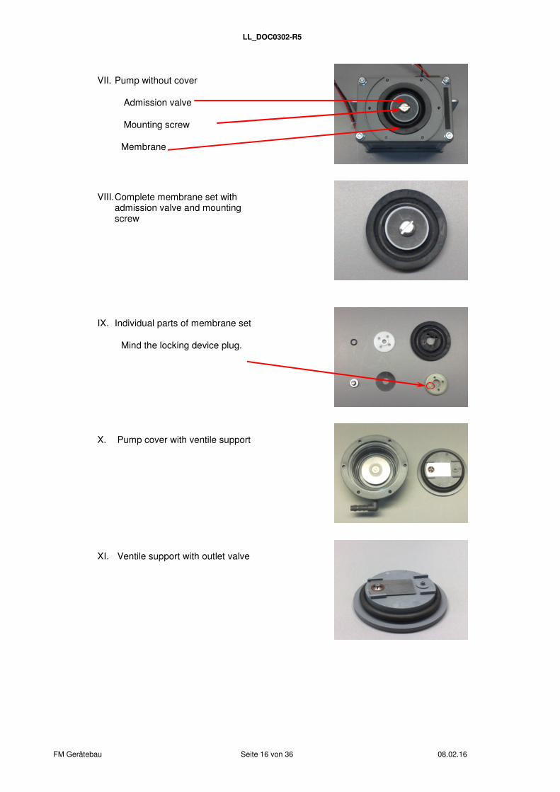
VII. Pump without cover
Admission valve
Mounting screw
Membrane
VIII. Complete membrane set with
admission valve and mounting screw
IX. Individual parts of membrane set
Mind the locking device plug.
X. Pump cover with ventile support
XI. Ventile support with outlet valve
LL_DOC0302-R5
FM Gerätebau Seite 17 von 36 08.02.16
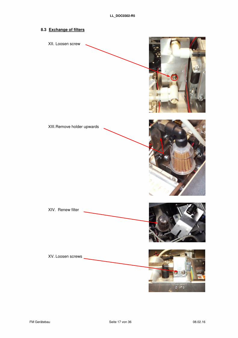
8.3 Exchange of filters
XII. Loosen screw
XIII. Remove holder upwards
XIV. Renew filter
XV. Loosen screws
LL_DOC0302-R5
FM Gerätebau Seite 18 von 36 08.02.16
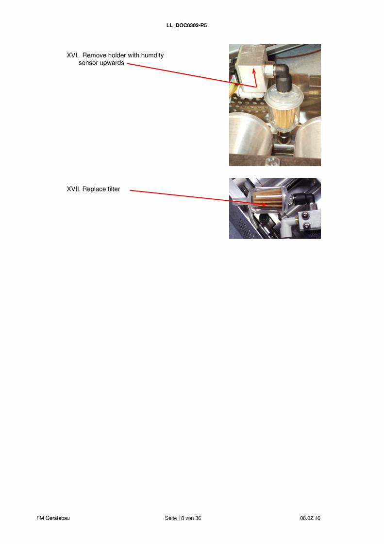
XVI. Remove holder with humdity
sensor upwards
XVII. Replace filter
LL_DOC0302-R5
FM Gerätebau Seite 19 von 36 08.02.16
Note:
After maintenance, the corresponding meter has to be restarted with the command "set rate" and the desired number of hours until the next maintenance.
8.4 Spare Parts
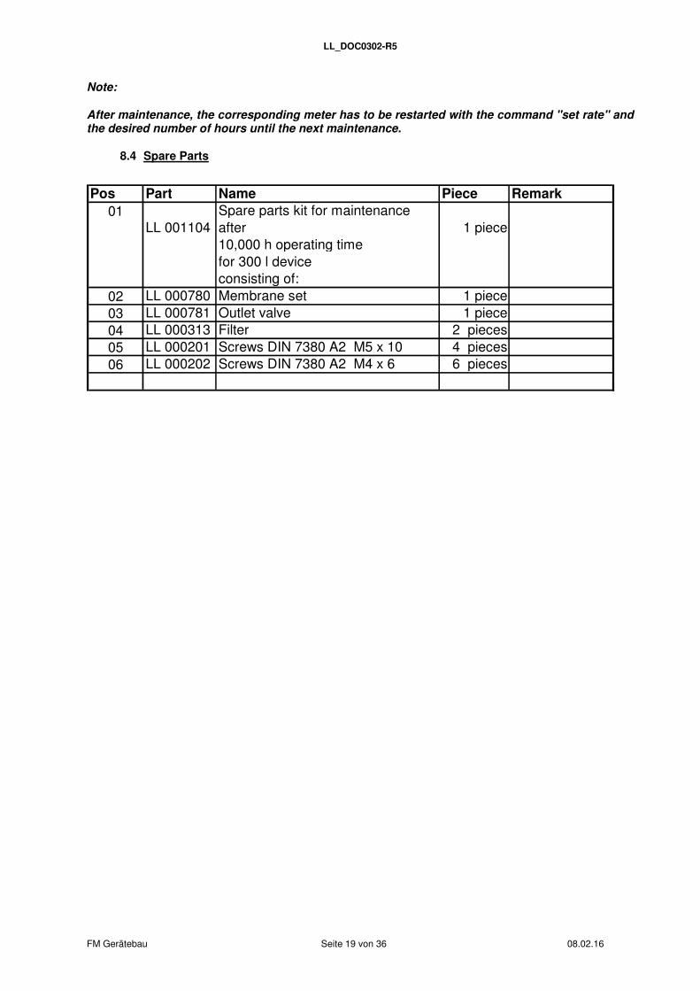
Pos Part Name Piece Remark
01LL 001104
Spare parts kit for maintenance after 1 piece10,000 h operating timefor 300 l deviceconsisting of:
02 LL 000780 Membrane set 1 piece03 LL 000781 Outlet valve 1 piece04 LL 000313 Filter 2 pieces05 LL 000201 Screws DIN 7380 A2 M5 x 10 4 pieces06 LL 000202 Screws DIN 7380 A2 M4 x 6 6 pieces
LL_DOC0302-R5
FM Gerätebau Seite 20 von 36 08.02.16
9. Firmware
If the dehydrator is connected to the terminal on switch-on, and at the same time, the escape key on the device is pressed, the following menu is displayed:
Bootloader Menu
===============
1..Firmware update
2..Main program
>_
Firmware update
Enter "1". The text "Send binary data" is displayed.
Select "Transfer>Send file".
Select "Xmodem" protocol.
Use "Browse" to select the binary file for the firmare update.
Click on "Send". Note: Make sure to conclude all steps within 30 seconds after accessing the firmware update, otherwise the update will be canceled.
Enter "2" to start the main program.
If the firmware update is interrupted with a error message (error number is displayed in the terminal program), you can try to start the firmware update again. If this is unsuccessful, the mainboard must be sent to FM for reprogramming.
After a successful firmware update "Restart System" is displayed.
Either disconnect the terminal connection or enter "2" in the bootloader menu. Now restart the dehydrator by switching it on and off.
Error description
Number: Type of error:
1 File write or delete failed2 „Command Sequence error“ delete failed flash memory Flash memory3 „Command Sequence error“ file write failed
5 Incorrect data package received6 XMODEM transfer error7 Checksum error
Incorrect ones´ complement - XMODEM transfer error
Terminal settings: see USB interface, page 11.
10. Description of the device control electronics
The device control monitors the ventilation of the aerial system with dry air. It regulates the pressure inside the waveguide at a pre-determined pressure interval. The automatic control system is comprised of the processor, a pressure sensor, the waveguide system, a pump, and up to three solenoid valves.
Furthermore, the dew point (optional) in the pressurized air system and the internal equipment temperature are monitored. The dew point can be displayed (this can be configurated via a software switch, see page 32). If the dew point display is suppressed, there will only be a warning if the relevant limit is exceeded.
LL_DOC0302-R5
FM Gerätebau Seite 21 von 36 08.02.16
The controller can be set to dry the air with two cartridges. These are used alternatively and can be regenerated through heating by using the heating element and by ventilating with air pumped in opposite direction to the normal flow direction.
This is conducted:
� after 168 operating hours
� after an adjustable working time of the compressor (between 1 and 25 hours)
� after exceeding the humidity limit (maximal humidity - 10 %)
� manually via the keypad
� via the USB interface
Via the software switch of the serial interface settings regarding installation of two drying cartridges and humidity sensor can be made (password required).
There are numbers of hour-meters, for recording the periods of operation (total hours, operational tie of the pump and duration of the ventilation), the totals being saved automatically each hour to a non-volatile memory (EEProm). The hours of operation may also be saved manually. The system may therefore be shut down with the current meter readings, and switched back on again, to resume the count.
While the system is in operation, various error conditions are detected, shown by the LEDs, and saved to the EEProm. All conditions referring to a fatal error continue to be shown on an alarm contact. The error messages are saved to storage so that they may be displayed again after the power supply has been interrupted.
The system may be operated via serial interface, or from the control panel on the controller. The software is available in English and German. The language can be selected via the menu or the serial interface. Typos on the edit line can be deleted with backspace.
The firmware can be updated via the serial interface (see page 20).
10.1 Regeneration
During regeneration the drying cartridges in the device are being dried. The switching between the drying cartridges is carried out cyclically according to the value "regpt". During the regeneration process the active cartridge, which has been used to dry the air, is replaced by the second cartridge, which will be active now. The previously active cartridge is passive during air ventilation and is being regenerated. Regeneration consists of two phases which together amount to a duration of at least theat + 5 minutes. theat is the heating time and is adjustable to a duration between 30 and 180 minutes.
In the first phase (theat minutes), the cartridge is heated using a heating power that can be set to be between 10 and 100 %. The air flows from outside through the active cartridge and in the opposite direction through the regenerating cartridge to the outside.
The second phase is used to let the cartridge cool down, i.e. it will not be heated any more, but will be ventilated with air.
The center LED indicates a regeneration process. This is permanently lit during the first phase and blinks during the second phase.
If overheating (ϑ>65°C) of the equipment occurs during the heating phase, a temporary thermal error will be displayed. The heating phase will be interrupted and the cooling down phase will start immediately. In this case there will also be a regeneration period of at least 35 minutes.
However, if the time remaining until the next regeneration is reduced to 6 hours. A fatal thermal error will be displayed after four successive unsuccessful attempts. This method ensures that the regeneration is shifted to a more convenient time of day, e.g. the night hours. An alarm-contact will be generated during a fatal error even though a temporary error will not be displayed here, but this can be read from the error LED.

LL_DOC0302-R5
FM Gerätebau Seite 22 von 36 08.02.16
If it is necessary to ventilate the waveguide during the regeneration process (pressure drop), valve 0 will open and the necessary air will be diverted from the regeneration operation.
Regeneration can be instigated in 5 different ways:
� after 168 operating hours
� after an adjustable working time of the compressor (between 1 and 25 hours, adjustable in 1 minute steps)
� after exceeding the humidity limit (maximal humidity - 10 %)
� manually via the keypad
� via the serial interface
The reason for regeneration is displayed via the serial interface. An exception is the manually initiated regeneration. Regeneration can be canceled by a command via the serial interface. If the software switch 7 is "on", regeneration starts after device switch-on.
10.2 Pressure control circuit
The pressure in the waveguide system is measured several times per second. If the pressure fails to reach the pressure limit setting (pressure low limit),valve 0 will be opened (and in the two-cartridge version valve 1 or 2 belonging to the active cartridge) and the pump with the preset power setting will be switched on. When the maximum pressure (also adjustable / pressure up limit) is reached, the relevant valve will be closed and the pump will be switched off again. If the ventilating process time period is exceeded (tpmax), an air pressure drop will be recognized and this will be displayed via the LED and the alarm-contact. This error can only be reset manually, however it does not deactivate the pressure control circuit. If the air pressure is less than the pressure setting (pressure min), this will be evaluated as a low-pressure error after tplow is expired and will be displayed via the LED and the alarm-contact.
The following pressure control circuit parameters can be configured:
� Pressure interval. The standard start threshold is 20 hPa, the standard shut-down threshold is 30 hPa. The start threshold can be set between low pressure limit + 1 hPa and shut-down threshold - 1 hPa; the shut-down threshold can be set between start threshold + 1 hPa and 40 hPa.
� Low pressure limit (Low Pressure / default = 10 hPa). If the pressure is lower than or equal to this threshold, a low pressure error will be displayed after a pre-set time has expired (0 sec. to 4 min. 59 sec.). This monitoring is only carried out if the alarm time is inactive or the upper limit of the pressure interval has been reached at least once.
� Alarm time talarm. Counts the maximum time that can expire to reach the lower limit of the pressure interval. If this time is exceeded, a pressure drop error is displayed. If the lower limit has been reached once, the alarm time will be deactivated. Furthermore, the alarm time is only active if the maximum pump time tpmax is set on indefinite. Before the alarm time or tpmax are expired, exceeding humidity will not be displayed.
� Pump duty cycle. This is the duty cycle of the alternating current voltage that operates the pump. The pump duty cycle be adjusted between 10% and 100% (maximum power setting = default) in 10% steps.
� Maximum ventilation time. The maximum ventilation time can be adjusted between 0 und 600 min. - the standard setting is 10 min. (high pressure sensor 300 min.). If this time is exceeded during ventilation, a "pressure loss error" is displayed. The value can be set on indefinite ("inactive" is displayed), then the error report is intermitted. The setting for indefinite („inactive“) is „0 min."

LL_DOC0302-R5
FM Gerätebau Seite 23 von 36 08.02.16
10.3 Humidity monitoring
A sensor monitors the waveguide system humidity and temperature. If a limit is exceeded, any ongoing ventilation process will be interrupted and it will not be allowed to restart until the humidity level drops beneath the limit setting. The pump will be switched off and the valve will be closed. However, regeneration can take place whilst this error exists. This error will be displayed via LED and an alarm-contact, and will be automatically reset, when the humidity level falls beneath the humidity limit setting once again. However, it remains saved and can be polled from the error list.
If the maximum ventilating time is set on "inactive", valve 0 will not be switched off when exceeding the threshold.
The dehydrator system might contain humid air on initial operation. Accordingly, humidity control is activated only 120 sec. after switching the device on. Prior to that the value on the LCD display (dew point) is *. Prior to expiry of talarm / tpmax errors are not displayed or saved.
If humidity exceeds hmax - ∆h, regeneration is started (if possible). The constant Dh is a value of 10%.
The threshold hmax can be set via serial interface on values between 2% and 99%. The default value is 30%.
10.4 Operational hours meter
The following hours are recorded:
the total operational time of the device
the total operational time of the pump
the ventilating time of the waveguide system
The meter readings are saved to EEProm (non-volatile memory) as soon as a full hour is reached. This kind of storage can store only a limited number of write cycle times (106), so it is not possible to keep on saving readings indefinitely. To keep the meter reading when the device is shut down it is possible to save all readings from the control panel or via the serial interface (shut down).
The ventilating time of the pump is recorded every second (the display is updated only every minute), the total operating time every minute.

LL_DOC0302-R5
FM Gerätebau Seite 24 von 36 08.02.16
10.5 Fault detection
Fault indication takes place several times each second. The detected errors are shown by LED and with one exception on the alarm contact. (temporary over temperature). When an error occurs, it sets a bit corresponding to the type of error in the non-volatile store. After switching off and on, the device can be operated normally, provided the error does not reoccur. The error list remains as it is and can be queried from the control panel or the serial interface. Errors can be reset via the serial interface.
The following errors are recorded:
• RTC error: If the VL flag (voltage low) is set in the RTC status register on switch-on, a RTC error is displayed. This means that the real time clock was without power supply, i.e date and time must be reset. This error may be shown on inital operation.
• Humidity error: Indicates that the humidity limit setting has been exceeded. Prior to expiry of talarm errors are not displayed or saved.
• Pressure loss: The maximum ventilating time has been exceeded. Prior to expiry of talarm errors are not displayed or saved.
• Temporary thermal error: Temporary thermal error occurred when regenerating.
• Fatal thermal error: Fatal thermal error occurred when regenerating
• Low pressure error: The falling below of an adjustable low-pressure limit. The lower of the pressure interval must have been reached at least once. Prior to expiry of talarm errors are not displayed or saved.
• Hardware error: During the current measurement at least one component, e.g. the pump, at least one valve and/or the heating system, has a failure.
• Maintenance: The (set) operational time of the pump was reached. The pump must be maintained. This is a count down meter. When reaching 90% of the operational time, the error LED turns yellow. When reaching 100% of the operational time, the LED turns red and the alarm is activated.
LL_DOC0302-R5
FM Gerätebau Seite 25 von 36 08.02.16
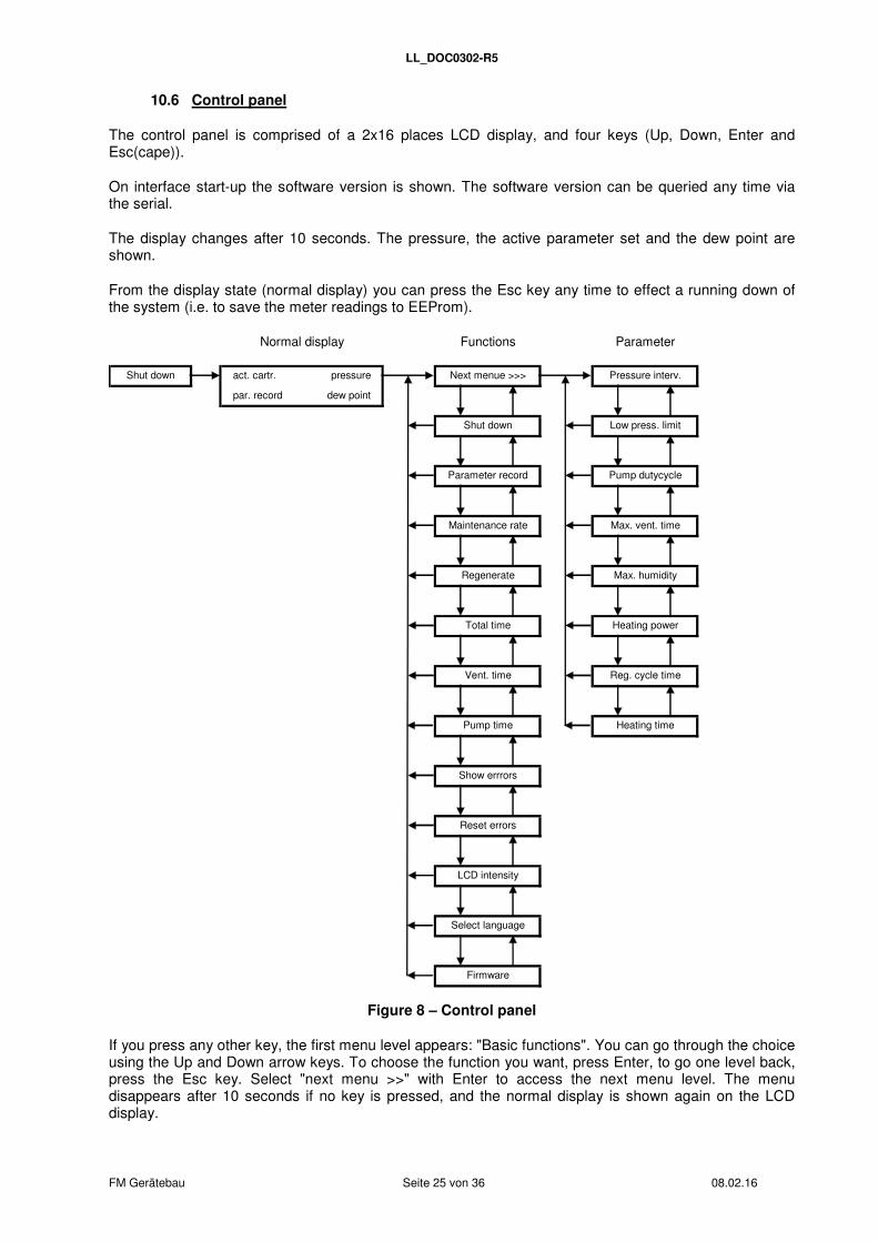
10.6 Control panel
The control panel is comprised of a 2x16 places LCD display, and four keys (Up, Down, Enter and Esc(cape)).
On interface start-up the software version is shown. The software version can be queried any time via the serial.
The display changes after 10 seconds. The pressure, the active parameter set and the dew point are shown.
From the display state (normal display) you can press the Esc key any time to effect a running down of the system (i.e. to save the meter readings to EEProm).
Firmware
Select language
Parameter
Reset errors
Pressure interv.
Parameter record
Reg. cycle time
Heating time
Maintenance rate
Regenerate
Pump time
Low press. limit
Pump dutycycle
Max. vent. time
Max. humidity
Heating power
Shut down
Normal display
Shut down Next menue >>>
LCD intensity
Functions
Show errrors
pressure
dew point
act. cartr.
par. record
Total time
Vent. time
Figure 8 – Control panel
If you press any other key, the first menu level appears: "Basic functions". You can go through the choice using the Up and Down arrow keys. To choose the function you want, press Enter, to go one level back, press the Esc key. Select "next menu >>" with Enter to access the next menu level. The menu disappears after 10 seconds if no key is pressed, and the normal display is shown again on the LCD display.
LL_DOC0302-R5
FM Gerätebau Seite 26 von 36 08.02.16
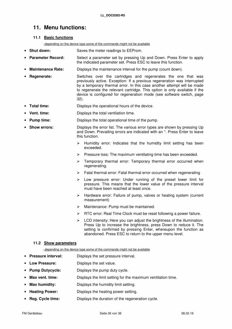
11. Menu functions:
11.1 Basic functions
- depending on the device type some of the commands might not be available
• Shut down: Saves the meter readings to EEProm.
• Parameter Record: Select a parameter set by pressing Up and Down. Press Enter to apply the indicated parameter set. Press ESC to leave this function.
• Maintenance Rate: Displays the maintenance interval for the pump (count down).
• Regenerate: Switches over the cartridges and regenerates the one that was previously active. Exception: If a previous regeneration was interrupted by a temporary thermal error. In this case another attempt will be made to regenerate the relevant cartridge. This option is only available if the device is configured for regeneration mode (see software switch, page 32).
• Total time: Displays the operational hours of the device.
• Vent. time: Displays the total ventilation time.
• Pump time: Displays the total operational time of the pump.
• Show errors: Displays the error list. The various error types are shown by pressing Up and Down. Prevailing errors are indicated with an *. Press Enter to leave this function.
� Humidity error: Indicates that the humidity limit setting has been exceeded.
� Pressure loss: The maximum ventilating time has been exceeded.
� Temporary thermal error: Temporary thermal error occurred when regenerating.
� Fatal thermal error: Fatal thermal error occurred when regenerating
� Low pressure error: Under running of the preset lower limit for pressure. This means that the lower value of the pressure interval must have been reached at least once.
� Hardware error: Failure of pump, valves or heating system (current measurement)
� Maintenance: Pump must be maintained.
� RTC error: Real Time Clock must be reset following a power failure.
� LCD intensity: Here you can adjust the brightness of the illumination. Press Up to increase the brightness, press Down to reduce it. The setting is confirmed by pressing Enter, whereupon the function as abandoned. Press ESC to return to the upper menu level.
11.2 Show parameters
- depending on the device type some of the commands might not be available
• Pressure interval: Displays the set pressure interval.
• Low Pressure: Displays the set value.
• Pump Dutycycle: Displays the pump duty cycle.
• Max vent. time: Displays the limit setting for the maximum ventilation time.
• Max humidity: Displays the humidity limit setting.
• Heating Power: Displays the heating power setting.
• Reg. Cycle time: Displays the duration of the regeneration cycle.

LL_DOC0302-R5
FM Gerätebau Seite 27 von 36 08.02.16
• Heating time: Displays the heating time for regeneration.
12. List of all commands sorted by function
(in alphabetical order)
The serial interface has a wider range of functions than the control panel. Via serial interface you can access additonal commands that are helpful for initial operation and service.
12.1 Control commands:
-depending on the device type some of the commands might not be available
alarm <on|off> Turns the alarm relay on and off.
cal ps Calibrates the pressure sensor. You need a manometer/measuring tool to compare the values. Connect it to the air output of the dehydrator. Enter the command cal ps - the dehydrator calibrates in dialogue with the device control. First step is to indicate the ambient pressure. When the manometer displays 0 h/kPa, confirm with Enter, to set the offset of the pressure sensor. Second step is to produce a pressure of 34 h/kPa with + by switching on the pump (- switches the pump off again). The pressure should rise slightly over 34 k/hPa and should be confirmed with Enter when falling down on 34 h/kPa. This correlation of the two pressures and internally measured voltage values is saved to EEProm. The displayed values are then calculated based on the saved values. Calibration can be interrupted by pressing Enter twice without switching on the pump before => an error message is displayed, but the values are not memorized.
heat 1 <on|off>
heat 2 <on|off>
Switches the corresponding heating element on or off. These manual settings are changed by the automatic procedural sequence of the device control.
pump <on|off> Activates the pump. The automatic control system is not interrupted, so that the pump will switch itself off if it reaches or exceeds the maximum pressure.
regen Regenerates the active cartridge
reset error Resets all errors that are displayed and switches off the error LED. Errors that continue to exist are reactivated after the reset.
reset parrec <1…3> Resets the selected parameter set to the basic sets. If a customized setting is selected, it is overridden by the corresponding basic set. Basic set 4 replaces customized setting 1 Basic set 5 replaces customized setting 2 Basic set 6 replaces customized setting 3 Note: The basic sets 4-6 are the default settings. They cannot be changed by the costumer.
LL_DOC0302-R5
FM Gerätebau Seite 28 von 36 08.02.16
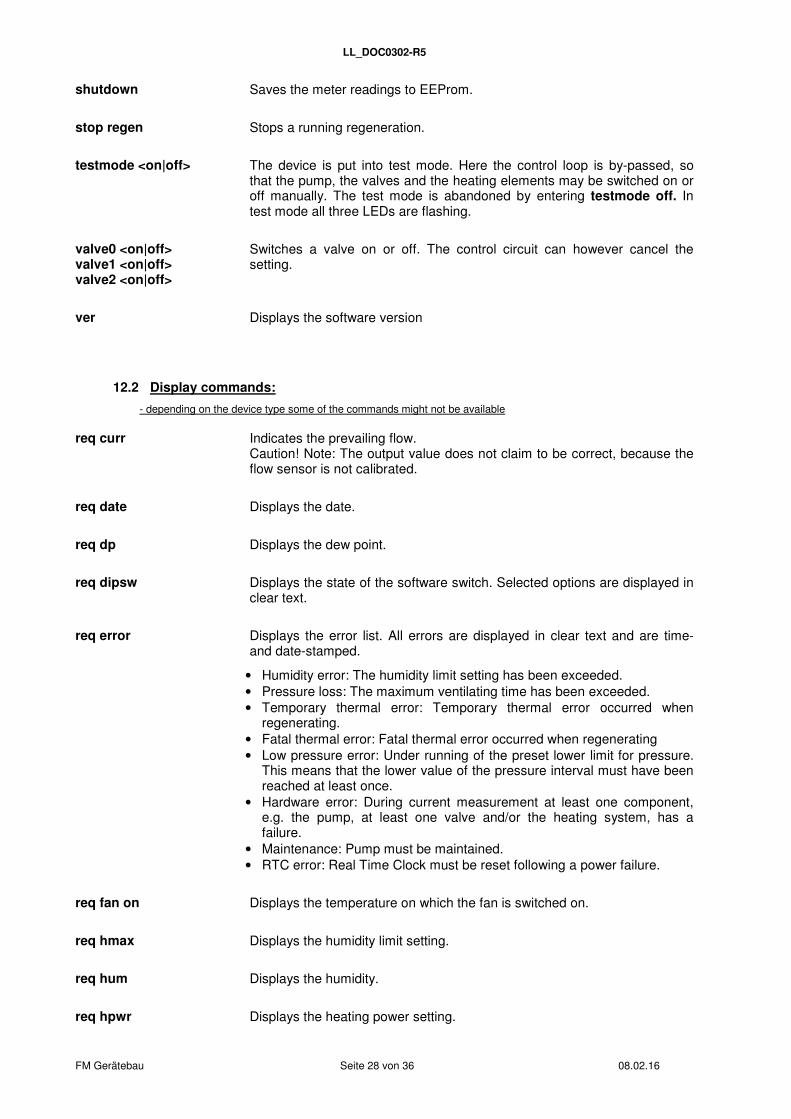
shutdown Saves the meter readings to EEProm.
stop regen Stops a running regeneration.
testmode <on|off> The device is put into test mode. Here the control loop is by-passed, so that the pump, the valves and the heating elements may be switched on or off manually. The test mode is abandoned by entering testmode off. In test mode all three LEDs are flashing.
valve0 <on|off> valve1 <on|off> valve2 <on|off>
Switches a valve on or off. The control circuit can however cancel the setting.
ver Displays the software version
12.2 Display commands:
- depending on the device type some of the commands might not be available
req curr Indicates the prevailing flow. Caution! Note: The output value does not claim to be correct, because the flow sensor is not calibrated.
req date Displays the date.
req dp Displays the dew point.
req dipsw Displays the state of the software switch. Selected options are displayed in clear text.
req error Displays the error list. All errors are displayed in clear text and are time- and date-stamped.
• Humidity error: The humidity limit setting has been exceeded. • Pressure loss: The maximum ventilating time has been exceeded. • Temporary thermal error: Temporary thermal error occurred when
regenerating. • Fatal thermal error: Fatal thermal error occurred when regenerating • Low pressure error: Under running of the preset lower limit for pressure.
This means that the lower value of the pressure interval must have been reached at least once.
• Hardware error: During current measurement at least one component, e.g. the pump, at least one valve and/or the heating system, has a failure.
• Maintenance: Pump must be maintained. • RTC error: Real Time Clock must be reset following a power failure.
req fan on Displays the temperature on which the fan is switched on.
req hmax Displays the humidity limit setting.
req hum Displays the humidity.
req hpwr Displays the heating power setting.
LL_DOC0302-R5
FM Gerätebau Seite 29 von 36 08.02.16
req parrec Displays the current parameter set (1 ... 3).
req pduty Displays the pump duty cycle.
req plim Displays the set pressure interval.
req plow Displays the lower pressure limit.
req press Indicates the current pressure.
req rate Displays the duration until the next necessary maintenance.
req regpt Displays the set pumping time for regeneration.
req status Displays the regeneration status. Active cartridge: Cartridge being used Total time to regeneration: Operating hours remaining before the next regeneration Pump time to regeneration: Pumping hours before the next regeneration. Temporary thermal error: Temporary thermal error occurred when regenerating. Fatal thermal error: Fatal thermal error occurred when regenerating Regeneration attempts: Number of regeneration attempts with thermal error since the last successful regeneration
req talarm Displays the alarm time. The alarm time is a count down meter and displays the maximum amount of minutes that can pass before reaching the lower limit of the pressure interval after device switch-on. If the limit has not been reached after count down, a low pressure alarm is activated. The display consists of the set alarm time and the remaining time until alarm activation. During count down, the remaining time is labeled with a *. If the lower pressure limit is reached within count down, the meter is stopped and the remaining time is displayed without a *. If tpmax is not zero, "deactivated" is displayed.
req temp Displays the temperature measured by the humditiy sensor. If the humidity sensor is not installed, "no humidity sensor" is displayed.
req temp mb Displays the mainboard temperature.
req theat Displays the heating time for regeneration.
Pump time Displays the time.
req tplow Displays the set maximum duration for falling below the lower pressure limit.
req tpmax Displays the limit setting for the maximum ventilation time.
req tpumptot Displays the operational hours of the pump.
LL_DOC0302-R5
FM Gerätebau Seite 30 von 36 08.02.16
req tpumpvnt Displays the total ventilation time.
req ttot Displays the operational hours of the device.
12.3 Input commands:
- depending on the device type some of the commands might not be available
set date < 00.00.00 > Here you can adjust the date. A RTC error is deactivated by resetting the date and the time.
set fan on < 1…99°C > Here you can set the switch-on temperature of the fan from 1°C to 99°C in 1°C steps.
set hmax < 2…99% > Here you can set the humidity threshold from 2% to 99% in 1% steps.
set hpwr < 10…100% > Here you can adjust the heating power for 10% to 100% in 10% steps.
Setlang <english /german> Here you can set the language (English or German).
set lcd < 0…100% > Here you can adjust the display brightness from 0% to 100% in 5% steps.
set parrec < 1 … 3 > Here you can select the parameter set. If one of the three parameter sets is selected, the corresponding customized settings are implemented. After selecting a parameter set with "set parrec (1 .. 3)", the settings can be adjusted. They are automatically saved to the selected parameter set.
set pduty < 0…100% > Here you can set the pump duty cycle from 0% to 100% in 10% steps.
set plim < 00 00 > Here you can set the upper and lower pressure limit in k/hPa for the selected parameter set. Examples: set plim 11 25 sets the pressure interval from 11 to 25 k/hPa set plim 20 40 sets the pressure interval from 20 to 40 k/hPa
set plow < 0…29 > Here you can set the lower pressure limit in k/hPa. An error is displayed if falling below this limit.
set rate < hour > Here you can set the maintenance interval for the pump from 0 to 20,000 hours. The interval must be reset after each maintenance.
set regpt < minutes > Here you can set the pumping time for regeneration in 1 minute steps. The setting range is 1 to 1,500 minutes. Note that this can generate a conflict with theat. The set time should not be lower than theat + 30 minutes.
set talarm < minutes > Here you can set the alarm time. Valid parameters are between 1 and 10 (minutes). CAUTION: The alarm time is initialized when switching on. The count down is continuing normally if the alarm time is changed. The new alarm time is only set in function after switching off and on.
LL_DOC0302-R5
FM Gerätebau Seite 31 von 36 08.02.16
set theat < minuten > Here you can set the heating time for regeneration. The value can be set between 30 and 180 minutes. Note that this can generate a conflict with regpt. The set time should not be higher than regpt - 30 minutes.
set time < 00:00:00 > Here you can set the time. A RTC error is deactivated by resetting the time and the date.
set tplow < m > {<s >} Here you can set the maximum duration for falling below the lower pressure limit (see set plow). If the pressure remains below the limit after this set duration, an alarm is activated. Permitted values are between 0 seconds and 4 minutes 59 seconds. If talarm is active, the algorithm is disabled. Examples: set tplow 0 sets the corresponding meter to 0 minutes (und 0 sec.). set tplow 4 30 sets the corresponding meter to 4 minutes und 30 sec.
set tpmax < minutes > Here you can set the maximum ventilation time in 1 minute steps. The setting range is 0 to 600 minutes. The setting "0" equals endless duration, .i.e. tpmax is inactive.

LL_DOC0302-R5
FM Gerätebau Seite 32 von 36 08.02.16
13. 16-bit software switch
The device can be configured via the software switch.
bit Value Meaning Value Meaning
0 0 one drying cartridge 1 two drying cartridges1 0 Pump control DC, no current measurement 1 Current measurement of pump2 0 Humidity sensor not available 1 Humidity sensor available3 0 Valve 0 not available 1 Valve 0 available4 0 Pressure sensor MPX5010 (hPa) 1 Pressure sensor MPX5050 (hPa)5 0 No current measurement of heating cartridge 1 Current measurement of heating cartridge6 0 Do not show dew point 1 Show dew point7 0 Regeneration after 1st cycle 1 Regeneration after switch-on
DIPSW7 on: During regeneration, the pump will be switched off, when the maximum pressure is reached, and switched on again, when the minimal pressure is underrun. When the pumps are not running, the cartridges are not heated. In this case, the regeneration time is still running.
LL_DOC0302-R5
FM Gerätebau Seite 33 von 36 08.02.16
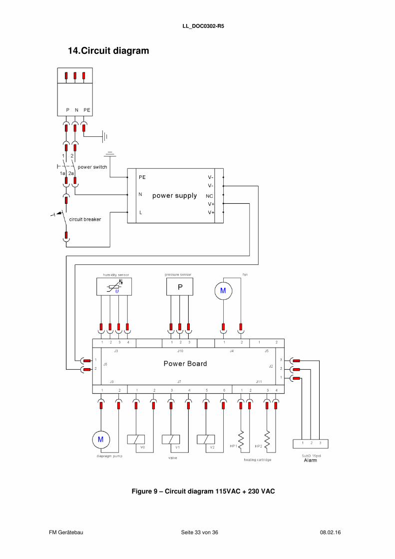
14. Circuit diagram
Figure 9 – Circuit diagram 115VAC + 230 VAC
LL_DOC0302-R5
FM Gerätebau Seite 34 von 36 08.02.16
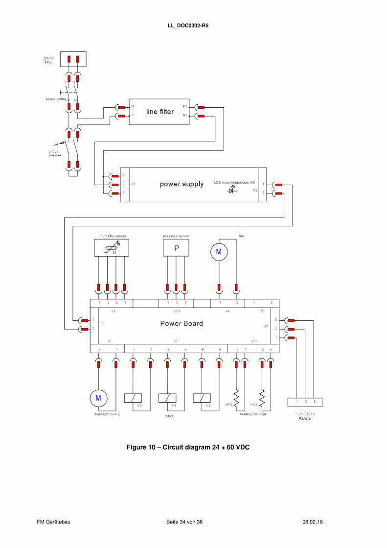
Figure 10 – Circuit diagram 24 + 60 VDC
LL_DOC0302-R5
FM Gerätebau Seite 35 von 36 08.02.16
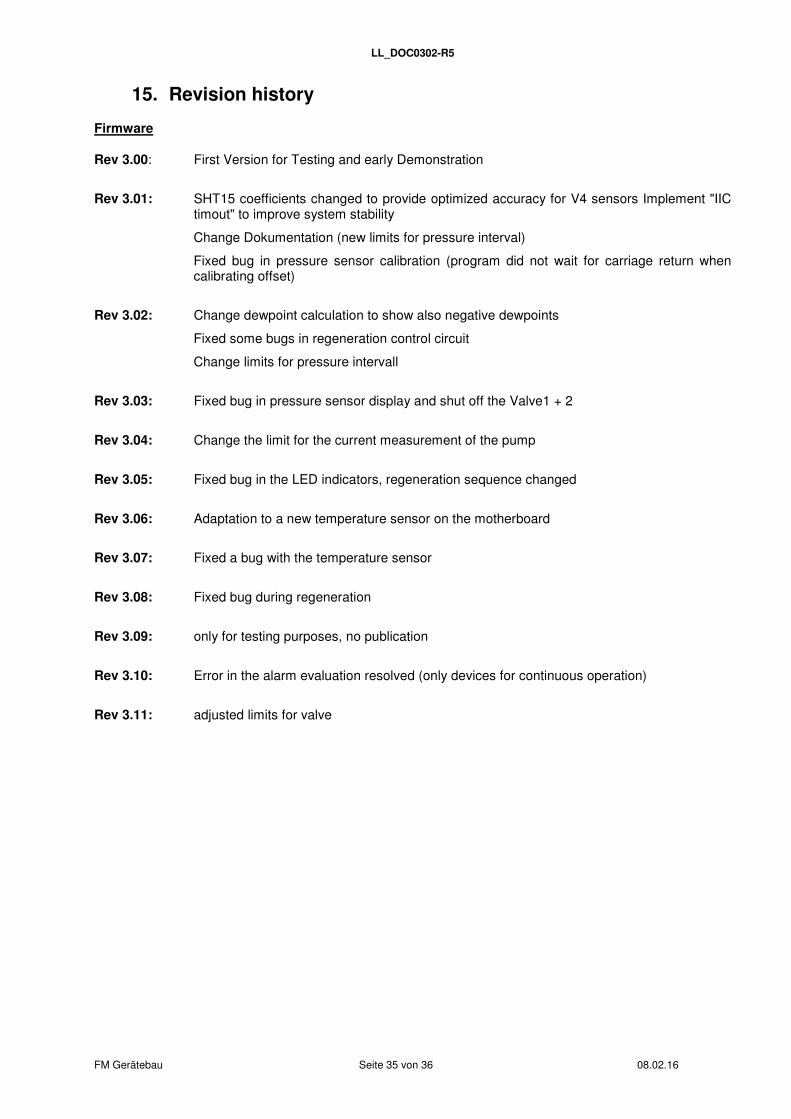
15. Revision history
Firmware
Rev 3.00: First Version for Testing and early Demonstration
Rev 3.01: SHT15 coefficients changed to provide optimized accuracy for V4 sensors Implement "IIC timout" to improve system stability
Change Dokumentation (new limits for pressure interval)
Fixed bug in pressure sensor calibration (program did not wait for carriage return when calibrating offset)
Rev 3.02: Change dewpoint calculation to show also negative dewpoints
Fixed some bugs in regeneration control circuit
Change limits for pressure intervall
Rev 3.03: Fixed bug in pressure sensor display and shut off the Valve1 + 2
Rev 3.04: Change the limit for the current measurement of the pump
Rev 3.05: Fixed bug in the LED indicators, regeneration sequence changed
Rev 3.06: Adaptation to a new temperature sensor on the motherboard
Rev 3.07: Fixed a bug with the temperature sensor
Rev 3.08: Fixed bug during regeneration
Rev 3.09: only for testing purposes, no publication
Rev 3.10: Error in the alarm evaluation resolved (only devices for continuous operation)
Rev 3.11: adjusted limits for valve

LL_DOC0302-R5