TSCHAN -S SV
20
TSCHAN GmbH Zweibrücker Straße 104 D-66538 Neunkirchen-Saar Telefon: +49(0) 6821 866 0 Telefax: +49(0) 6821 883 53 www.tschan.de BAWS 014-EX-GBR-2 04/2004 Installation and Operation Manual TSCHAN ® Flexible Coupling TSCHAN ® -S SV for use in potentially explosive atmospheres Design according to Dircective 94/9/EC
Transcript of TSCHAN -S SV

TSCHAN GmbH Zweibrücker Straße 104 D-66538 Neunkirchen-Saar Telefon: +49(0) 6821 866 0 Telefax: +49(0) 6821 883 53 www.tschan.de
BAWS 014-EX-GBR-2 04/2004
Installation and Operation Manual TSCHAN ® Flexible Coupling
TSCHAN®-S SV for use in potentially explosive atmospheres Design according to Dircective 94/9/EC

04/2004 TSCHAN-S SV - 2 -
Contents Chapter Page 1 Safety Instructions ............................................................................................................2 2 Technical Description .......................................................................................................3
2.1 Intended Application ..................................................................................................3 3 Coupling Marking..............................................................................................................4
3.1 Marking of Buffer Rings .............................................................................................4 3.2 Marking of Coupling...................................................................................................4
4 Storage.............................................................................................................................5 5 Construction .....................................................................................................................5 6 Technical Data..................................................................................................................6 7 Installation ........................................................................................................................8
7.1 To be observed prior to installation............................................................................8 7.2 Finish bores...............................................................................................................9 Coupling installation ...........................................................................................................10
8 Coupling Alignment ........................................................................................................11 8.1 Angular Misalignment ..............................................................................................12 8.2 Radial Misalignment ................................................................................................13 8.3 Axial Misalignment...................................................................................................13
9 Operation........................................................................................................................14 10 Maintenance ..................................................................................................................17
10.1 Inspection and maintenance intervals .....................................................................17 10.2 Wear measurement - equipment at standstill ..........................................................18 10.3 Replacement of buffer ring ......................................................................................19
11 Disposal .........................................................................................................................19 12 EC-Declaration of Conformity ........................................................................................20 1 Safety Instructions This installation and operation manual is an essential component of the coupling delivery. Always keep this manual in a readily accessible place near the coupling. Take care that all persons being charged with the installation, operation, maintenance and repair of the coupling have read and understood this manual and that all instructions con-tained therein are carefully observed in order to: - avoid danger to life and limb of the user or third persons, - ensure the operational safety of the coupling, - preclude operation failures and environmental damages due to wrong handling and
misuse. The relevant instructions and regulations regarding safety at work and environmental protec-tion have to be observed while transporting, mounting and dismounting the coupling. The handling and use of aluminium parts in potentially explosive areas requires special measures in order to avoid spark formation. Make sure that appropriate transportation means and tools are at disposal.
04/2004 TSCHAN-S SV - 3 -
The coupling shall be operated, mounted, maintained and repaired by authorized, trained and instructed personnel only. In the interest of further development, we reserve the right to carry out modifications serving the technical progress. It is of utmost importance to strictly observe the installation instructions for devices and machines intended for use in potentially explosive atmospheres. We do not assume any liability or warranty for any damages resulting from the use of accessories and parts that are not originally manufactured by TSCHAN GmbH. 2 Technical Description The TSCHAN®-S SV coupling is a torsionally flexible, puncture proof claw coupling which is particularly suited for use with hydrodynamic high-speed couplings. It compensates for angular, radial and axial shaft misalignments within defined limits. The coupling transmits torque through elastic buffers loaded in shear. These buffers come in Perbunan (Pb), Pb82 as a standard, or polyurethane (Vk), and are connected to each other to form an elastic buffer ring. This buffer ring dampens shocks and torsional vibrations and is resistant to oil. Buffer rings made of Perbunan are electrically conductive. The coupling is suitable for use in every direction of rotation and installation position. 2.1 Intended Application • The coupling is suitable for use in potentially explosive atmospheres according to Direc-
tive 94/9/EC. The coupling is classified for equipment groups I and II and equipment cate-gories 2 and 3, and is thus intended to be used in areas in which explosive atmospheres due to the presence of gases, vapours and dust/ air mixtures may occur. In dependence on the maximum permissible ambient temperatures in the vicinity of the coupling, the temperature classes are defined with 80°C, 45°C, 30 °C for T4, T5 and T6. This is valid on the condition, that the operation temperature of the machinery shafts also does not ex-ceed these values.
• In order to ensure trouble-free and reliable operation, the coupling has to be sized according to the design specifications, e.g. according to DIN 740, part 2, (or acc. to cata-logue TSCHAN -S), with a service factor appropriate for the service conditions.
• Except for the production of a finish bore with keyway, no further modifications are allowed to be carried out on the coupling!
• The coupling shall only be used and operated within the frame of the conditions as defined in the performance or delivery contract.
• Any change in the operation conditions or service parameters requires the verification of the coupling design.

04/2004 TSCHAN-S SV - 4 -
3 Coupling Marking 3.1 Marking of Buffer Rings The buffer rings are marked on the face of one buffer element as follows: - Coupling size and material abbreviation (Vk for Polyurethane or Pb for Perbunan) - Year of construction - Pb72 = buffer ring of Perbunan, 72 Shore(A) / black - Pb82 = buffer ring of Perbunan, 82 Shore(A) / black - VkB = buffer ring of Polyurethane, 83 Shore(A) / blue - VkR = buffer ring of Polyurethane, 93 Shore(A) / red - Vk60D = buffer ring of Polyurethane, 60 Shore(D) white/beige
3.2 Marking of Coupling TSCHAN® -S couplings which are approved for use in explosive atmospheres are identified in the factory by a sticker:
X TSCHAN-S coupling type, size, material of buffer ring, cal. week/ year of construction, Order Ref. / Item No.
The letter X in this marking stands for: TSCHAN GmbH / D-66538 Neunkirchen II 2 G T4/T5/T6 –20°C ≤ Ta ≤ +80°C/+45°C/+30°C II 2 D T130°C I M 2 The sticker is covered by a protective film which has to be removed after an eventual paint-ing, so as to make the marking visible.
Size DA [mm]
h [mm]
z
50 48 12 4 70 70 18 6 85 82 18 6 100 100 20 6 125 121 25 6 145 139 30 6 170 166 30 8 200 194 35 8 230 222 35 10 260 253 45 10 300 294 50 10 360 350 55 12 400 393 55 14

04/2004 TSCHAN-S SV - 5 -
4 Storage On receipt of the goods, immediately check that all parts are on hand and are as ordered. Eventual shipping damages and/or missing parts have to be reported in writing. The coupling parts can be stored in the delivered state in a dry place under roof at normal ambient temperatures for a time period of 6 months. Storage for a longer period requires the application of a long-term preservation. (Please consult TSCHAN GmbH in this respect.) The buffer rings must not be exposed to ozonic media, direct sun light or intensive light sources with UV light. The air humidity should not exceed 65 %. If the parts are properly stored, the quality characteristics of the elastic buffer rings remains almost unchanged for up to three years.
5 Construction
1 Coupling hub (hub directed to the inside) part 260 2 Elastic buffer ring part 020 3 Coupling flange part 230, made of aluminium as a standard
Fig. 1 Main Components of TSCHAN-S SV

04/2004 TSCHAN-S SV - 6 -
6 Technical Data
Table 1 Technical Data:
Size SV
nmax
[min-1]
TKnom Pb72 [Nm]
TKmax Pb72 [Nm]
TKnom Pb82 [Nm]
TKmax Pb82 [Nm]
TKnom VkR [Nm]
TKmax VkR [Nm]
TKnom VkB [Nm]
TKmax VkB [Nm]
m unbored
[kg] 100 7250 40 120 70 210 130 390 76 228 1,7 125 6000 70 210 128 385 250 750 140 420 2,7 145 5250 120 360 220 660 400 1200 240 720 4,3 170 4500 180 540 340 1020 630 1900 370 1110 6,8 200 3750 330 990 590 1770 1100 3300 640 1920 10,4 230 3250 500 1500 900 2700 1700 5150 980 2940 13,4 260 3000 800 2400 1400 4200 2650 7950 1530 4590 22,7 300 2500 1180 3540 2090 6270 3900 11700 2280 6840 36,3 360-650 71,4 360-750
2150 1940 5820 3450 10350 6500 19500 3760 11280 75,3
400 95,2 400-866 101,0 400-1000 110,3 400-1150
1900 2670 8010 4750 14250 8900 26700 5180 15540
124,6
- Pb72 = buffer ring of Perbunan - 72 Shore(A) / black - Pb82 = buffer ring of Perbunan - 82 Shore(A) / black - VkR = buffer ring of Polyurethane / red - Vk60D = buffer ring of Polyurethane / white-beige - VkB = buffer ring of Polyurethane / blue
Fig. 2 TSCHAN-S SV

04/2004 TSCHAN-S SV - 7 -
Size SV
d1
max [mm]
D1
[mm]
D2
[mm]
D3
H7 [mm]
D4
[mm]
D5
[mm]
z x dL L
[mm]
l1
[mm]
l3
[mm]
l4
[mm]
S
[mm] 100 27 105 38 100 128 145 6 x 9 42 50 2 10 2,0 125 34 126 48 130 148 170 6 x 9 47 57 2 10 2,0 145 42 145 60 150 172 194 6 x 9 55 65 4 12 2,0 170 58 170 82 170 195 220 6 x 13,5 60 75 4 14 2,5 200 65 200 95 195 228 250 8 x 13,5 65 85 4 14 2,5 230 70 230 102 220 265 290 8 x 13,5 70 90 4 15 4,5 260 90 260 130 265 310 335 12 x 13,5 85 110 4 18 4,5 300 105 300 147 315 360 385 16 x 13,5 100 130 4 24 4,5 360-650 360 420 455 16 x 17,5 123 5 28 360-750
150 360 210 420 480 514 20 x 17,5 125
175 5 30
7,5
400 420 480 514 20 x 17,5 125 5 30 400-866 485 555 595 12 x 22 125 6 30 400-1000 580 650 690 16 x 22 125 6 30 400-1150
160 400 230
770 840 890 16 x 30 122
180
-6 27
7,5
The torques TKnom and TKmax. are valid for: - Ambient temperatures of –30°C up to +30°C for Polyu rethane (Vk), - Ambient temperatures of -30°C up to + 60°C for Perb unan (Pb) - Operation within the range of the specified alignment values. For determining the size of the coupling according to DIN 740, part 2, (or to catalogue TSCHAN®-S) various factors have to be taken into account: - the temperature factor Sυ in case of higher temperatures, - the start-up factor Sz depending on the frequency of starts, - the shock factor SA, SL depending on the service conditions. For circumferential speeds above 22 m/s, referred to the nominal size of the coupling, we recommend balancing the steel parts of the coupling.

04/2004 TSCHAN-S SV - 8 -
7 Installation 7.1 To be observed prior to installation • Danger of injuries!
• Disconnect the drive before carrying out any work o n the cou-pling!
• Secure the drive against unintentional re-start and rotation! • Incorrectly tightened bolts can cause serious perso nal injuries
and property damages!
• For equipment group I in mining applications, pay c areful attention to the particular hazards that exist when using alumin-ium parts. Assemble the coupling outside of the dan ger zone. Take care that suitable transportation means are at disposal and that the transportation ways are free of obstacles. Do not use tools containing iron when mounting the parts in ex plosive ar-eas.
• Make sure that the speeds, torques and ambient temperatures as stated in chapter 6
‘Technical Data’ are not exceeded. • The maximum permissible bore diameters must not be exceeded. • Check whether the shaft-hub connections safely transmit the occurring operating torques. • The standard tolerance of TSCHAN for finish bores is fit H7. • Standard keyways comply with DIN 6885, sheet 1. • Check the dimensions and tolerances of shafts, hub bores, keys and keyways. • Set screws as required. • In compliance with accident prevention regulations, you are
obliged to protect all freely rotating parts by mea ns of perma-nently installed guards/ covers against unintention al contact and falling down objects.
• To avoid sparks, the covers for couplings used in e xplosive atmospheres should be made of stainless steel!
• As a minimum, the covers have to fulfil the require ments of protection type IP2X.
• The covers have to be designed to prevent dust from depos iting on the coupling.
• The cover must not contact the coupling or impair t he proper function of the coupling.

04/2004 TSCHAN-S SV - 9 -
7.2 Finish bores The following procedure has to be observed to produce a finish bore in a coupling hub: • Clean and remove all preservatives from the coupling hub. • Mount the coupling hub between the surfaces marked with and carefully align the
coupling hub according to the claw pattern. • The values for ød1max listed in table 1 are valid for keyed connections according to DIN
6885/1 and must not be exceeded. • Select the bore fit so that an interference fit such as H7/m6 results when mating it with the
shaft tolerance. • Axially lock the hub, for example by means of a setscrew on the back of the hub above
the keyway Consult TSCHAN GmbH in case of other shaft-hub connections. • The stated maximum bore diameters are valid for key ed connec-
tions according to DIN 6885/1 and must not be excee ded. • If these values are exceeded, the coupling can brea k. • Flying off coupling fragments are a danger to life!
04/2004 TSCHAN-S SV - 10 -
Fig. 4
Fig. 3
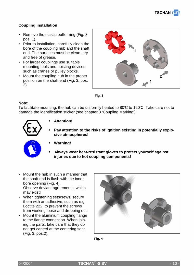
Coupling installation • Remove the elastic buffer ring (Fig. 3,
pos. 1). • Prior to installation, carefully clean the
bore of the coupling hub and the shaft end. The surfaces must be clean, dry and free of grease.
• For larger couplings use suitable mounting tools and hoisting devices such as cranes or pulley blocks.
• Mount the coupling hub in the proper position on the shaft end (Fig. 3, pos. 2).
Note: To facilitate mounting, the hub can be uniformly heated to 80°C to 120°C. Take care not to damage the identification sticker (see chapter 3 ‘Coupling Marking’)!
� Attention! � Pay attention to the risks of ignition existing in potentially explo-
sive atmospheres!
� Warning! � Always wear heat-resistant gloves to protect yourse lf against
injuries due to hot coupling components!
• Mount the hub in such a manner that
the shaft end is flush with the inner bore opening (Fig. 4). Observe deviant agreements, which may exist!
• When tightening setscrews, secure them with an adhesive, such as e.g. Loctite 222, to prevent the screws from working loose and dropping out.
• Mount the aluminium coupling flange to the flange connection. When join-ing the parts, take care that they do not get canted at the centering seat. (Fig. 3, pos.2).

04/2004 TSCHAN-S SV - 11 -
Fig. 5
ATTENTION! The contact surfaces of coupling hub and flange con nection must be clean, dry and free of grease. Let the hot hub cool down to ambient temperature, b efore inserting the buffer ring. • To facilitate mounting, the buffer ring
can be coated with a lubricant (for ex. talcum for Perbunan Pb, or commercial roller bearing grease for polyurethane Vk).
• Install the buffer ring on one of the coupling halves.
• Push together the shaft end with the mounted coupling half and the coupling flange (Fig. 5).
• Align the coupling in accordance with the instructions given in chapter 8 ‘Coupling Alignment’.
8 Coupling Alignment
� Danger of Injuries! � Disconnect the drive before carrying out any work o n the
coupling. � Secure the drive against unintentional re-start and rotation!
� Note: � Accurate alignment of the coupling prolongs the lif etime of the
elastic buffer ring and reduces the risks when oper ating the cou-pling in explosive atmospheres.
� It is of utmost importance to observe the recommend ed alignment values. Exceeding the permissible misalignment valu es results in coupling damages and failures!
� When aligning the cold equipment take into account the expected thermal growth of the
components, so that the permissible misalignment values for the coupling are not exceeded in operation.
� Be aware that the coupling under misalignment imposes restoring forces on the adjacent shafts and bearings. Take into account that the larger the misalignment, the greater the restoring forces will be.

04/2004 TSCHAN-S SV - 12 -
� The maximum permissible misalignments stated in tables 2 to 4 are guiding values. We recommend utilizing these values up to 50 % only when aligning the coupling, so as to have sufficient reserves for thermal growth, foundation settlings etc. during service. In special applications with high demands on quiet running characteristics or higher speeds, alignment accuracies of ≤ 0,1 mm may be necessary for the three alignment levels.
� If the coupling is mounted in a closed housing/ guard, so that alignment at a later point of time will no longer be possible, make sure that the geometry and the fitting accuracy of the contact surfaces ensure true alignment of the shafts within the specified tolerances during service.
8.1 Angular Misalignment • Measure one complete revolution
(360°) on the face of the outer di-ameter. Determine the largest devia-tion Kw1 and the smallest deviation Kw2 (Fig. 6). Calculate the angular misalignment: ∆Kw = Kw1 – Kw2.
• When aligning, observe the max. permissible angular misalignment ∆Kwmax acc. to table 2.
• The values are applicable for a reference speed of 1500 rpm.
Table 2 Maximum permissible angular misalignment va lues:
Size 100 125 145 170 200 230 260 300 360 400 ∆Kwmax [mm] 0,2 0,3 0,3 0,3 0,3 0,3 0,3 0,3 0,3 0,3
Fig. 6

04/2004 TSCHAN-S SV - 13 -
8.2 Radial Misalignment • Measure one complete revolution
(360°). Determine the largest devia-tion Kr1 and the smallest deviation Kr2 (Fig. 7). Calculate the radial misalignment: ∆Kr = 0,5 x (Kr1 – Kr2). Observe the preceding sign of the measured val-ues.
• When aligning, observe 50 % of the maximum permissible radial mis-alignment ∆Kr max acc. to table 3.
• The values are applicable for a reference speed of 1500 rpm.
Table 3 Maximum permissible radial misalignment va lues:
Größe 100 125 145 175 200 230 260 300 360 400
∆Krmax [mm] 0,3 0,35 0,35 0,35 0,4 0,4 0,45 0,45 0,5 0,5
8.3 Axial Misalignment • Measure the axial claw overlap ‘h’
as shown in Fig. 8. • The dimension of h must be in bet-
ween the values hmin and hmax stated in table 4.
ATTENTION! Consult TSCHAN GmbH if larger axial misalignments are expected during operation.
Table 4 Recommended axial alignment values:
Größe 100 125 145 170 200 230 260 300 360 400 hmax [mm] 20 25 30 30 35 35 45 50 55 55 hmin [mm] 18 22,5 27,5 27 32 31,5 41 46 51 51
Fig. 7
Fig. 8

04/2004 TSCHAN-S SV - 14 -
9 Operation When operating the coupling, its specific technical data have to be carefully observed (see chapter 6 ‘Technical Data’). These values must never be exceeded without the prior written approval by TSCHAN GmbH. In order to ensure trouble-free and reliable performance of the coupling, the coupling has to be designed according to the selection specifications, e.g. according to DIN 740, part 2, (or acc. to catalogue TSCHAN-S), with a service factor appropriate to the service conditions. Any change in the service conditions or service parameters always necessitates the verifica-tion of the coupling design.
� Danger of injuries! � Disconnect the drive before carrying out any work o n the cou-
pling! � Secure the drive against unintentional re-start and rotation! � Improperly tightened screws may cause parts to fly off what
leads to most serious personal injuries and propert y damages! � Before putting the coupling into operation, check t he alignment
and all screwed connections for correct tightening torque and firm!
� Before starting up the equipment, install all prote ctive guards in order to avoid unintentional contact with freely mo ving or rotat-ing parts.
� To avoid sparks, the covers for couplings used in e xplosive atmospheres should be made of stainless steel!
� The covers have to comply with protection type IP2X as a minimum.
� The cover shall be designed to prevent dust from de positing on the coupling parts.
� The cover must not touch the coupling and impair th e proper operation of the coupling.
� For equipment group I in mining applications, pay c areful attention to the particular hazards that exist when using alumin-ium parts!
While operating the coupling, pay attention to: � Changes in operation noises � Occurring vibrations Attention! • Disconnect the drive immediately, if any irregulari ties are observed while operating
the coupling! • Identify the cause for the problem using table 5 “Operation Faults and Possible Causes“
and correct the fault. The listed problems are some examples to assist you in troubleshooting.
• All the machinery components and operation modes ha ve to be considered for the determination and correction of faults !

04/2004 TSCHAN-S SV - 15 -
Table 5 Operation Faults and Possible Causes:
Trouble Cause Risk Warning Correction Alignment fault Risk of ignition
due to hot surfaces and spark forma-tion
- Disconnect drive - Remove cause for alignment fault - Re-align coupling - Inspect elastomer for wear
Elastomer worn out
Risk of ignition due to spark formation
- Disconnect drive - Check coupling components for
damages and replace parts, if necessary
- Replace elastomer Unbalance Risk of ignition due
to hot surfaces
- Disconnect drive - Verify balance state of plant
components and correct it, if nec-essary
- Inspect elastomer for wear
Irregular running noises/ vibrations
Loose screw connections
Risk of ignition due to hot surfaces and spark formation
- Disconnect drive - Check coupling parts for damages,
replace parts, if necessary - Verify alignment of coupling - Tighten screws to the specified
tightening torque and secure them against working loose, if necessary,
- Inspect elastomer for wear Alignment fault Risk of ignition due
to hot surfaces and spark formation
- Disconnect drive - Remove cause for alignment fault - Re-align coupling - Inspect elastomer for wear
Unacceptable temperatures
Risk of ignition due to hot surfaces and spark formation
- Disconnect drive - Replace elastomer - Re-align coupling - Adjust ambient temperature
Contact with aggressive products
Risk of ignition due to spark formation
- Disconnect drive - Check coupling parts for damages
and replace parts, if necessary - Replace elastomer - Verify alignment of coupling - Prevent contact with aggressive
products
Premature wear of elastomer
Torsional vibrations in the drive line
Risk of ignition due to hot surfaces and spark formation
- Disconnect drive - Analyse and eliminate cause for
torsional vibrations - Check coupling parts for damages
and replace parts, if necessary - Replace elastomer and consult
TSCHAN GmbH concerning even-tual use of another Shore-hardness
- Verify coupling alignment

04/2004 TSCHAN-S SV - 16 -
Trouble Cause Risk Warning Correction Wear limit of elas-tomer exceeded ===> contact with claws
Risk of ignition due to hot surfaces and spark formation
- Disconnect drive - Replace coupling - Inspect the elastomer for wear at
shorter intervals
Claw breakage
Overload due to too high torque
Risk of ignition due to hot surfaces and spark formation
- Disconnect drive - Verify coupling design in coopera-
tion with TSCHAN GmbH - Replace coupling - Install larger coupling, if necessary

04/2004 TSCHAN-S SV - 17 -
10 Maintenance The flexible coupling TSCHAN® -S SV only requires little maintenance during operation. The elastic buffer ring is subject to wear. The time at which the wear limit of the elastic buffer ring is reached depends on the service parameters and application conditions. On account of the increased risk of spark formation , the claws of coupling combina-tions consisting of steel and aluminium must not co ntact each other. The buffer ring prevents such contact as long as the permissible wear limit is not exceeded. On the occasion of routine inspections or maintenance of the equipment, check:
• alignment of coupling, • state of the elastomer, and • remove dust deposits from coupling parts and buffer ring.
10.1 Inspection and maintenance intervals
� Danger of injuries! � Disconnect the drive before carrying out any work o n the
coupling! � Secure the drive against unintentional re-start and rotation!
Perform wear checks, inspections and maintenance operations according to the intervals stated in table 6. If excessive wear is already detected on the occasion of the first inspection, check whether the cause for the problem is listed in table 5 “Operation faults and possible causes”. In such a case the inspection intervals must be adapted to the prevailing service conditions. Special operation conditions may necessitate to perform inspections at shorter time intervals than stated.
Table 6 Inspection and Maintenance Intervals
Industry II 2 G / II 2 D 1st inspection after 2 weeks visual inspection and wear check of elastomer 1st mainte-nance
after 3 months visual inspection and wear check of elastomer
2nd mainte-nance
after 6 months visual inspection and wear check of elastomer, removal of dust deposits from coupling components
each further maintenance
every 6 months visual inspection and wear check of elastomer, removal of dust deposits from coupling components
Mines I M 2 1st inspection after 2 weeks visual inspection and wear check of elastomer 1st mainte-nance
after 3 months visual inspection and wear check of elastomer
2nd mainte-nance
after 3 months visual inspection and wear check of elastomer, removal of dust deposits from coupling components
each further maintenance
every 3 months visual inspection and wear check of elastomer, removal of dust deposits from coupling components

04/2004 TSCHAN-S SV - 18 -
Fig. 9
On the occasion of maintenance operations on the drive equipment, however, after 3 years at latest:
• Replace the elastic buffer ring. • If the wear limit has been reached or exceeded, replace the buffer ring immediately,
irrespective of the inspection intervals of the equipment. • Remove dust deposits from coupling components and buffer ring.
10.2 Wear measurement - equipment at standstill • To check the wear of the elastomer,
the plant has to be shut down and must be unloaded. Turn the cou-pling halves in such a manner that the claws rest without clearance at the buffer of the elastic ring.
• Measure the claw distance ‘V’ in circumferential direction across the buffers to which the claws rest on both sides (see fig. 9). The adjacent buffers do not contact the claws.
• Repeat this measurement on the adjacent buffers after having turned the couplings halves against each other in opposed direction.
• If dimension ‘V’ attains or exceeds the value ‘Vmin’ listed in table 7 for the individual coupling sizes, the elastic buffer ring has to be replaced immediately.
Table 7 Distance dimension V min for wear measurement while the equipment is at standstill:
Size 100 125 145 170 200 230 260 300 360 400 Vmin [mm] 11,5 12,7 13,8 13,6 14,3 15,4 15,3 12,1 12,1 15,4 Upon completion of the wear measurement, re-install all the protective devices and covers.

04/2004 TSCHAN-S SV - 19 -
Fig. 10
10.3 Replacement of buffer ring
� Danger of injuries! � Disconnect the drive before carrying out any work o n the
coupling! � Secure the drive against unintentional re-start and rotation!
• Push back one of the coupling
halves (Fig. 10, pos. 1). • Remove the buffer ring (part 020) -
(Fig. 10, pos. 2). • To facilitate mounting, the new
buffer ring can be coated with a lubricant before installing it (e.g. talcum for Perbunan Pb, or com-mercial roller bearing grease for Polyurethane Vk).
• Mount a new buffer ring of correct material and size.
• Push the coupling halves together again.
• Align the coupling according to the instructions given in chapter 8 ‘Cou-pling Alignment’.
Warning! � Before putting the equipment into service, all safe ty guards must
be installed to prevent unintentional contact with freely rotating parts.
� To avoid sparks, the covers for couplings used in e xplosive atmospheres should be made of stainless steel.
� The covers have to fulfil the requirements of prote ction type IP2X as a minimum.
� The covers have to be designed to prevent dust from depositing on the coupling parts.
� The cover must not touch the coupling and impair th e proper operation of the coupling.
We do not assume any responsibility or warranty for any damages resulting from the use of accessories or spare parts, which have not been originally manufactured by TSCHAN GmbH.
11 Disposal Disposal of the parts must be arranged in accordance with the regulations and laws of the country where the equipment is installed.

TSCHAN GmbH Zweibrücker Straße 104 D-66538 Neunkirchen-Saar Telefon: +49(0) 6821 866 0 Telefax: +49(0) 6821 883 53 www.tschan.de
12 EC-Declaration of Conformity
to confirm the compliance of a sub-assembly with the ATEX Directive 94/9/EC (ATEX 95), Annex X.B
The manufacturer
TSCHAN GmbH , Zweibrücker Straße 104, DE 66538 Neunkirchen-Saar declares that the following sub-assembly
of type flexible shaft coupling
TSCHAN®-S SV
Serial number: see delivery documents
Identification: C E II 2 G T4/T5/T6 –20°C ≤ Ta ≤ +80°C/+45°C/+30°C and E II 2 D T130°C and E I M 2 - complies with the provisions of the following harmonized standards valid at the date of signature: EN 1127-1 Explosive atmospheres, explosion prevention and protection,
Part 1: Basic concepts and methodology EN 1127-2 Explosive atmospheres, explosion prevention and protection,
Part 2: Basic concepts and methodology for mining EN 13463-1 Non-electrical equipment intended for use in potentially explosive atmos-
pheres, part 1: Basic methods and requirements EN 13463-5 Non-electrical equipment intended for use in potentially explosive atmos-
pheres, part 5: Protection by constructional safety EN 1710 Equipment and components intended for use in potentially explosive
atmospheres in underground mines
- and also complies with the following European and national standards and technical provisions valid at the date of signature: Technical safety regulations TRBS 2153
Avoidance of ignition hazards resulting from electrostatic charging
Neunkirchen, 29.12.2009 Norbert Telaar
General Manager i. V. Volker Carl
Technical Director