
Unser Lieferprogramm - bullinger-antriebstechnik.de · 2 Schmalkeilriemenscheiben nach DIN 2211 aus...
47
Unser Lieferprogramm Taperkeilriemenscheiben von 50 – 1 x SPZ – 1008 bis 1250 – 12 x SPC – 5050 Einschweißnaben, Anschraubnaben und Zwischenhülsen für Taperspannbuchsen Taperspannbuchsen von 1008 bis 6050 Taperregelscheiben für Leistungen von 0,18 bis 5,5 KW Taperflachriemenscheiben von 63 x 32 – 1108 bis 630 x 200 – 5050 Regelscheiben von 0,18 bis 30 KW Kettenräder und Zubehör Motorspannschlitten aus Stahl für Baugrößen von 63 bis 280 Keilriemen ummantelt und flankenoffen-gezahnt Motorspannschienen aus Stahl für Baugrößen von 63 bis 355 Keilriemenscheiben von 40 – 1 x SPZ bis 630 – 6 x SPB
-
Upload
vuongduong -
Category
Documents
-
view
221 -
download
4
Transcript of Unser Lieferprogramm - bullinger-antriebstechnik.de · 2 Schmalkeilriemenscheiben nach DIN 2211 aus...

Unser Lieferprogramm
Taperkeilriemenscheibenvon 50–1xSPZ–1008 bis 1250–12xSPC–5050
Einschweißnaben, Anschraubnaben und Zwischenhülsen für Taperspannbuchsen
Taperspannbuchsen von 1008 bis 6050
Taperregelscheibenfür Leistungen von 0,18 bis 5,5 KW
Taperflachriemenscheibenvon 63x32–1108bis 630x200–5050
Regelscheiben von 0,18 bis 30 KW
Kettenräder und Zubehör
Motorspannschlitten aus Stahlfür Baugrößen von 63 bis 280
Keilriemenummantelt und flankenoffen-gezahnt
Motorspannschienen aus Stahlfür Baugrößen von 63 bis 355
Keilriemenscheibenvon 40–1xSPZ bis 630–6xSPB

Technische Liste KeilriementriebeDimension list for V-belt-drive
1
Inhalt egaP/etieSxednI
Ausführung 3–2noitucexE
Keilriemenscheiben 6–4ZPSsyellup-tleb-VSPA 7–9SPB 10–13SPC 14–15
Techn. Informationen 71–61noitamrofni lacinhceT
Taperspannbuchsen 81sehsubrepaT
Regelscheiben 12–91syellup deeps elbairaV

2
Schmalkeilriemenscheiben nach DIN 2211 aus GG 20v-belt pulleys DIN 2211 material GG 20
Ausführungen von Naben-KeilriemenscheibenExecution of full hub pulleys
Kranzbreiten b2width of border
1 2 3 4 5 6 8 10 12SPZ 16 28 40 52 64 76SPA 20 35 50 65 80 95SPB 25 44 63 82 101 120 158 196SPC 59,5 85 110,5 136 161,5 212,5 263,5 314,5
Schmalkeilriemen for v-belts DIN 7753 SPZ SPA SPB SPCfür Keilriemen for v-belts DIN 2215 10 13 17 22b1 � mm 9,7 12,7 16,3 22bw mm 8,5 11 14 19c mm 2 2,8 3,5 4,8e mm 12�0,3 15�0,3 19�0,4 25,5�0,5f mm 8�0,6 10�0,6 12,5�0,8 17�1tmin mm 11 14 18 24Da =dw +mm 4 5,6 7 9,6� =34�, dw ≤ 80 118 190 315� =38�, dw > 80 118 190 315dw min für Dauerbetrieb · for continuous use 63 90 140 224

3
Ausführung von TaperkeilriemenscheibenExecution of Taper-V-belt pulleys

Wirk. Max. Nabe Nabenlänge GewichtØ Bohrung hub length weight
pitch bore of hubdiameter Ø Ø L Type S T U kg
50 22 35 28 5 � - - - 0,356 22 35 28 5 � - - - 0,4
63 28 45 28 5 � - - - 0,5
71 28 45 28 5 � - - - 0,675 28 45 28 5 � - - - 0,680 28 45 28 5 � - - - 0,785 28 45 28 5 � - - - 0,890 28 45 28 5 � - - - 0,895 30 50 28 1 � 4,5 7 4,5 1,0100 30 50 28 1 � 4,5 7 4,5 1,1106 30 50 28 1 � 4,5 7 4,5 1,1112 35 55 28 1 � 4,5 7 4,5 1,1118 35 55 28 1 � 4,5 7 4,5 1,1125 35 55 28 1 � 4,5 7 4,5 1,3132 35 55 28 1 � 4,5 7 4,5 1,4140 35 55 28 1 � 4,5 7 4,5 1,4150 35 55 28 1 � 4,5 7 4,5 1,6160 35 55 32 1 � 4,5 7 4,5 1,8
180 35 55 32 1 � 4,5 7 4,5 2,2
200 42 70 30 1 � 4,5 7 4,5 2,6224 45 75 35 1 � 3,5 9 3,5 3,7250 45 32 35 1 � 3,5 9 3,5 4,5280 45 75 35 1 � 3,5 9 3,5 5,3315 45 75 35 1 � 3 10 3 6,1355 45 75 35 1 � 3 10 3 7,5400 45 75 35 1 � 3 10 3 7,1
4
1 x SPZb2 =16 mm Taperscheibe · Taper pulley
Wirk. Buchse Nabe GewichtØ bush hub weight
pitch Längediameter length L Type S T U kg
50 1008 37 rü15 3 � 13 - - 0,456 1008 37 rü15 3 � - - - 0,560 1008 23 bü 1 � - - - 0,563 1108 23 bü 1 � - - - 0,467 1108 23 bü 1 � - - - 0,571 1108 23 bü 1 � - - - 0,575 1108 23 bü 1 � - - - 0,680 1210 26 bü 1 � - - - 0,685 1210 26 bü 1 � - - - 0,890 1210 26 bü 1 � - - - 0,895 1210 26 bü 1 � - - - 0,9100 1210 26 bü 1 � - - - 0,9106 1610 26 bü 1 � - - - 1,0112 1610 26 bü 1 � - - - 1,1118 1610 26 bü 1 � - - - 1,3125 1610 26 bü 1 � - - - 1,4132 1610 26 bü 1 � - - - 1,5140 1610 26 bü 1 � - - - 1,5150 1610 26 bü 1 � 4 8 4 1,6160 1610 26 bü 1 � 4 8 4 1,7170 1610 26 bü 1 � 4 8 4 1,8180 1610 26 bü 1 � 4 8 4 2,0190 2012 32 bü 1 � 3 10 3 2,2200 2012 32 bü 1 � 3 10 3 2,6224 2012 32 bü 1 � 3 10 3 2,8250 2012 32 bü 1 � 3 10 3 3,2280 2012 32 bü 1 � 2 12 2 3,5315 2012 32 bü 1 � 1 14 1 3,8355 2012 32 bü 1 � 1 14 1 4,2400 2012 32 bü 1 � 1 14 1 6,0
Wirk. Max. Nabe Nabenlänge GewichtØ Bohrung hub length weight
pitch bore of hubdiameter Ø Ø L Type S T U kg
50 20 35 35 5 � - - - 0,456 25 40 35 5 � - - - 0,5
63 25 40 35 5 � - - - 0,6
71 25 40 35 5 � - - - 0,875 25 40 35 5 � - - - 0,980 32 55 35 5 � - - - 1,085 32 55 35 5 � - - - 1,290 32 55 35 5 � - - - 1,395 32 55 35 5 � - - - 1,4100 32 55 35 5 � - - - 1,6106 32 55 35 5 � - - - 1,8112 32 55 35 1 � 9,5 9 9,5 1,6118 32 55 35 1 � 9,5 9 9,5 1,6125 32 55 35 1 � 9,5 9 9,5 1,7132 38 55 35 1 � 9,5 9 9,5 1,9140 40 65 40 1 � 9,5 9 9,5 2.3150 40 65 50 1 � 9,5 9 9,5 2,5160 40 65 40 1 � 9,5 9 9,5 2,7
180 40 65 40 1 � 9,5 9 9,5 3,1
200 40 65 40 1 � 9,5 9 9,5 3,6224 45 75 40 1 � 8,5 11 8,5 5,1250 45 75 40 1 � 8,5 11 8,5 5,0280 48 75 45 1 � 8,5 11 8,5 6,3315 48 75 45 1 � 7,5 13 7,5 9,2355 50 80 45 1 � 7,5 13 7,5 10,9400 50 80 50 1 � 7,5 13 7,5 12,6
2 x SPZb2 =28 mm Taperscheibe · Taper pulley Nabenscheibe · Full hub pulley
Wirk. Buchse Nabe GewichtØ bush hub weight
pitch Längediameter length L Type S T U kg
50 1008 23 rü 26 3 � 25 - - 0,356 1108 23 rü 26 3 � - - - 0,660 1108 23 bü 1 � - - - 0,663 1108 23 bü 1 � - - - 0,567 1108 23 bü 1 � - - - 0,571 1108 23 bü 1 � - - - 0,575 1210 26 bü 2 � - - 2 0,680 1210 26 bü 2 � - - 2 0,785 1610 26 bü 1 � - - 2 0,790 1610 26 bü 2 � - - 2 0,895 1610 26 bü 2 � - - 2 0,8100 1610 26 bü 2 � - - 2 1,2106 1610 26 bü 2 � - - 2 1,2112 1610 26 bü 2 � - - 2 1,3118 1610 26 bü 2 � - - 2 1,4125 1610 26 bü 2 � - - 2 1,7132 1610 26 bü 2 � - - 2 2,0140 1610 26 bü 2 � - - 2 2,2150 2012 32 bü 1 � - - - 2,3160 2012 32 bü 1 � - - - 2,5170 2012 32 bü 1 � 10 8 10 2,6180 2012 32 bü 1 � 10 8 10 2,9190 2012 28 bü 1 � 10 8 10 3,3200 2012 32 bü 1 � 9 10 9 3,5224 2012 32 bü 1 � 10 8 10 3,7250 2012 32 bü 1 � 9 10 9 3,9280 2012 32 bü 1 � 7,5 13 7,5 4,9315 2012 32 bü 1 � 7,5 13 7,5 5,8355 2012 32 bü 1 � 7 14 7 6,3400 2517 45 bü 1 � 7 14 7 7,1450 2517 45 bü 1 � 8 12 8 9,4500 2517 45 bü 1 � 8 12 8 10,5630 2517 45 bü 1 � 8 12 8 12,5
Nabenscheibe · Full hub pulley
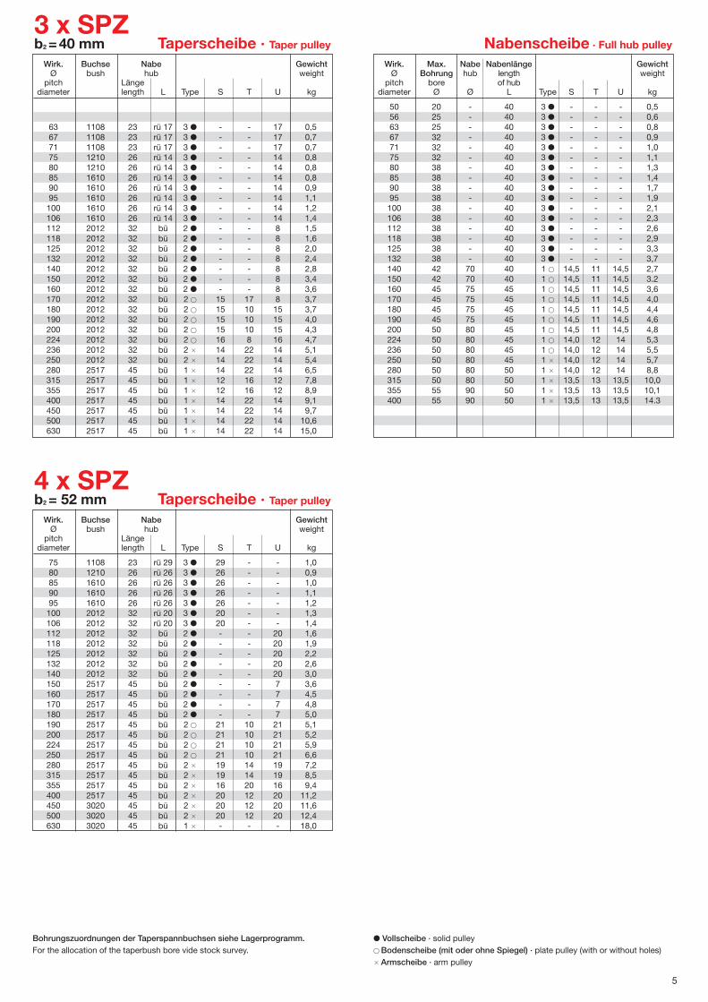
Bohrungszuordnungen der Taperspannbuchsen siehe Lagerprogramm. � Vollscheibe · solid pulleyFor the allocation of the taperbush bore vide stock survey. � Bodenscheibe (mit oder ohne Spiegel) · plate pulley (with or without holes)
� Armscheibe · arm pulley
5
Wirk. Max. Nabe Nabenlänge GewichtØ Bohrung hub length weight
pitch bore of hubdiameter Ø Ø L Type S T U kg
50 20 - 40 3 � - - - 0,556 25 - 40 3 � - - - 0,663 25 - 40 3 � - - - 0,867 32 - 40 3 � - - - 0,971 32 - 40 3 � - - - 1,075 32 - 40 3 � - - - 1,180 38 - 40 3 � - - - 1,385 38 - 40 3 � - - - 1,490 38 - 40 3 � - - - 1,795 38 - 40 3 � - - - 1,9100 38 - 40 3 � - - - 2,1106 38 - 40 3 � - - - 2,3112 38 - 40 3 � - - - 2,6118 38 - 40 3 � - - - 2,9125 38 - 40 3 � - - - 3,3132 38 - 40 3 � - - - 3,7140 42 70 40 1 � 14,5 11 14,5 2,7150 42 70 40 1 � 14,5 11 14,5 3.2160 45 75 45 1 � 14,5 11 14,5 3,6170 45 75 45 1 � 14,5 11 14,5 4,0180 45 75 45 1 � 14,5 11 14,5 4,4190 45 75 45 1 � 14,5 11 14,5 4,6200 50 80 45 1 � 14,5 11 14,5 4,8224 50 80 45 1 � 14,0 12 14 5,3236 50 80 45 1 � 14,0 12 14 5,5250 50 80 45 1 � 14,0 12 14 5,7280 50 80 50 1 � 14,0 12 14 8,8315 50 80 50 1 � 13,5 13 13,5 10,0355 55 90 50 1 � 13,5 13 13,5 10,1400 55 90 50 1 � 13,5 13 13,5 14.3
3 x SPZb2 =40 mm Taperscheibe · Taper pulley Nabenscheibe · Full hub pulley
Wirk. Buchse Nabe GewichtØ bush hub weight
pitch Längediameter length L Type S T U kg
63 1108 23 rü 17 3 � - - 17 0,567 1108 23 rü 17 3 � - - 17 0,771 1108 23 rü 17 3 � - - 17 0,775 1210 26 rü 14 3 � - - 14 0,880 1210 26 rü 14 3 � - - 14 0,885 1610 26 rü 14 3 � - - 14 0,890 1610 26 rü 14 3 � - - 14 0,995 1610 26 rü 14 3 � - - 14 1,1100 1610 26 rü 14 3 � - - 14 1,2106 1610 26 rü 14 3 � - - 14 1,4112 2012 32 bü 2 � - - 8 1,5118 2012 32 bü 2 � - - 8 1,6125 2012 32 bü 2 � - - 8 2,0132 2012 32 bü 2 � - - 8 2,4140 2012 32 bü 2 � - - 8 2,8150 2012 32 bü 2 � - - 8 3,4160 2012 32 bü 2 � - - 8 3,6170 2012 32 bü 2 � 15 17 8 3,7180 2012 32 bü 2 � 15 10 15 3,7190 2012 32 bü 2 � 15 10 15 4,0200 2012 32 bü 2 � 15 10 15 4,3224 2012 32 bü 2 � 16 8 16 4,7236 2012 32 bü 2 � 14 22 14 5,1250 2012 32 bü 2 � 14 22 14 5,4280 2517 45 bü 1 � 14 22 14 6,5315 2517 45 bü 1 � 12 16 12 7,8355 2517 45 bü 1 � 12 16 12 8,9400 2517 45 bü 1 � 14 22 14 9,1450 2517 45 bü 1 � 14 22 14 9,7500 2517 45 bü 1 � 14 22 14 10,6630 2517 45 bü 1 � 14 22 14 15,0
4 x SPZb2 = 52 mm Taperscheibe · Taper pulley
Wirk. Buchse Nabe GewichtØ bush hub weight
pitch Längediameter length L Type S T U kg
75 1108 23 rü 29 3 � 29 - - 1,080 1210 26 rü 26 3 � 26 - - 0,985 1610 26 rü 26 3 � 26 - - 1,090 1610 26 rü 26 3 � 26 - - 1,195 1610 26 rü 26 3 � 26 - - 1,2100 2012 32 rü 20 3 � 20 - - 1,3106 2012 32 rü 20 3 � 20 - - 1,4112 2012 32 bü 2 � - - 20 1,6118 2012 32 bü 2 � - - 20 1,9125 2012 32 bü 2 � - - 20 2,2132 2012 32 bü 2 � - - 20 2,6140 2012 32 bü 2 � - - 20 3,0150 2517 45 bü 2 � - - 7 3,6160 2517 45 bü 2 � - - 7 4,5170 2517 45 bü 2 � - - 7 4,8180 2517 45 bü 2 � - - 7 5,0190 2517 45 bü 2 � 21 10 21 5,1200 2517 45 bü 2 � 21 10 21 5,2224 2517 45 bü 2 � 21 10 21 5,9250 2517 45 bü 2 � 21 10 21 6,6280 2517 45 bü 2 � 19 14 19 7,2315 2517 45 bü 2 � 19 14 19 8,5355 2517 45 bü 2 � 16 20 16 9,4400 2517 45 bü 2 � 20 12 20 11,2450 3020 45 bü 2 � 20 12 20 11,6500 3020 45 bü 2 � 20 12 20 12,4630 3020 45 bü 1 � - - - 18,0
Bohrungszuordnungen der Taperspannbuchsen siehe Lagerprogramm. � Vollscheibe · solid pulleyFor the allocation of the taperbush bore vide stock survey. � Bodenscheibe (mit oder ohne Spiegel) · plate pulley (with or without holes)
� Armscheibe · arm pulley

6
5 x SPZb2 =64 mm Taperscheibe · Taper pulley
Wirk. Buchse Nabe GewichtØ bush hub weight
pitch Längediameter length L Type S T U kg
85 1610 26 rü 38 3 � 38 - - 1,290 1610 26 rü 38 3 � 38 - - 1,495 1610 26 rü 38 3 � 38 - - 1,5100 2012 32 rü 32 3 � 32 - - 1,6106 2012 32 rü 32 3 � 32 - - 1,8112 2012 32 bü 2 � - - 32 1,9118 2012 32 bü 2 � - - 32 2,4125 2012 32 bü 2 � - - 32 2,8132 2517 45 bü 2 � - - 19 2,8140 2517 45 bü 2 � - - 19 3,2150 2517 45 bü 2 � - - 19 3,9160 2517 45 bü 2 � - - 19 4,7170 2517 45 bü 2 � 10 35 19 5,5180 2517 45 bü 2 � - - 19 6,2190 2517 45 bü 2 � 27 10 27 6,4200 2517 45 bü 2 � 27 10 27 6,5224 2517 45 bü 2 � 26 10 26 7,2250 2517 45 bü 2 � 26 12 26 7,6280 2517 45 bü 2 � 25 14 25 9,0315 2517 45 bü 2 � 22 20 22 10,0355 2517 45 bü 2 � 22 20 22 12,1400 3020 52 bü 2 � 23 18 23 13,8450 3020 45 bü 2 � 20 14 20 16,0500 3030 77 bü 1 � 25 14 25 20,5630 3030 77 bü 1 � 25 14 25 27,6
Wirk. Buchse Nabe GewichtØ bush hub weight
pitch Längediameter length L Type S T U kg
100 2012 32 rü 44 3 � 44 - - 1,8106 2012 32 rü 44 3 � 44 - - 2,0112 2012 32 rü 44 3 � 44 - - 2,2118 2517 45 rü 31 3 � 31 - - 2,4125 2517 45 bü 2 � - - 31 2,9132 2517 45 bü 2 � - - 31 3,2140 2517 45 bü 2 � - - 31 3,5150 2517 45 bü 2 � - - 31 4,5160 2517 45 bü 2 � - - 31 5,5180 2517 45 bü 2 � - - 31 6,5190 2517 45 bü 2 � 27 9 40 6,4200 2517 45 bü 2 � 27 9 40 6,2224 2517 45 bü 2 � 27 10 39 7,1250 2517 45 bü 2 � 27 11 38 8,3280 2517 45 bü 2 � 27 14 35 9,9315 2517 45 bü 2 � 23 16 37 11,5355 2517 45 bü 2 � 20 16 40 14,0400 3030 77 bü 1 � 30 16 30 17,6450 3030 77 bü 1 � 29 16 31 21,6500 3030 77 bü 1 � 28 18 30 23,0630 3535 89 bü 1 � 28 18 30 33,0
6 x SPZb2 =76 mm Taperscheibe · Taper pulley
Bohrungszuordnungen der Taperspannbuchsen siehe Lagerprogramm. � Vollscheibe · solid pulleyFor the allocation of the taperbush bore vide stock survey. � Bodenscheibe (mit oder ohne Spiegel) · plate pulley (with or without holes)
� Armscheibe · arm pulley

7
Wirk. Max. Nabe Nabenlänge GewichtØ Bohrung hub length weight
pitch bore of hubdiameter Ø Ø L Type S T U kg
50 20 35 35 5 � - - - 0,456 20 35 35 5 � - - - 0,463 25 41 35 5 � - - - 0,5
71 25 41 35 5 � - - - 0,775 25 41 35 5 � - - - 0,980 35 55 35 5 � - - - 0,985 35 55 35 5 � - - - 1,090 35 55 35 5 � - - - 1,195 35 55 35 5 � - - - 1,2100 35 55 35 5 � - - - 1,3106 35 55 35 1 � 6,5 7 6,5 1,3112 35 55 35 1 � 6,5 7 6,5 1,4118 35 55 35 1 � 6,5 7 6,5 1,4125 35 55 35 1 � 6,5 7 6,5 1,5132 35 55 35 1 � 6,5 7 6,5 1,6140 35 55 35 1 � 6,5 7 6,5 1,8150 35 55 40 1 � 6,5 7 6,5 2,0160 38 60 40 1 � 6,5 7 6,5 2,3170 38 60 40 1 � 6,5 7 6,5 2,5180 40 65 40 1 � 6,5 7 6,5 2,8190 40 65 40 1 � 6,5 7 6,5 3,0200 40 65 40 1 � 6,5 7 6,5 2,9212 40 65 40 1 � 6,5 7 6,5 3,2224 40 65 40 1 � 5,5 9 5,5 3,5236 40 65 50 1 � 5,5 9 5,5 4,5250 45 75 50 1 � 5,5 9 5,5 5,2280 45 75 50 1 � 5,5 9 5,5 5,8300 45 75 45 1 � 5 10 5 6,4315 50 80 50 1 � 5 10 5 6,9355 50 80 50 1 � 5 10 5 8,0400 55 90 50 1 � 5 10 5 8,5450 60 100 50 1 � 5 10 5 13,7500 60 100 50 1 � 5 10 5 16,6
1 x SPAb2 =20 mm Taperscheibe · Taper pulley Nabenscheibe · Full hub pulley
Wirk. Buchse Nabe GewichtØ bush hub weight
pitch Längediameter length L Type S T U kg
63 1108 40 rü 17 3 � 17 - - 0,767 1108 23 bü 1 � - - - 0,571 1108 23 bü 1 � - - - 0,575 1108 23 bü 1 � - - - 0,680 1210 26 bü 1 � - - - 0,685 1210 26 bü 1 � - - - 0,790 1210 26 bü 1 � - - - 0,795 1210 26 bü 1 � - - - 0,8100 1610 26 bü 1 � - - - 0,9106 1610 26 bü 1 � - - - 1,0112 1610 26 bü 1 � - - - 1,2118 1610 26 bü 1 � - - - 1,3125 1610 26 bü 1 � - - - 1,4132 1610 26 bü 1 � - - - 1,5140 1610 26 bü 1 � - - - 1,6150 1610 26 bü 1 � - - - 1,7160 1610 26 bü 1 � 6 8 6 2,0170 1610 26 bü 1 � 6 8 6 1,8180 1610 26 bü 1 � 6 8 6 1,9190 2012 32 bü 1 � 6 8 6 2,5200 2012 32 bü 1 � 6 8 6 2,8212 2012 32 bü 1 � 6 8 6 2,9224 2012 32 bü 1 � 6 8 6 3,0236 2012 32 bü 1 � 5 10 5 3,2250 2012 32 bü 1 � 5 10 5 3,6280 2012 32 bü 1 � 4 12 4 4,2300 2012 32 bü 1 � 4 12 4 4,3315 2012 32 bü 1 � 4 12 4 5,2355 2012 32 bü 1 � 4 12 4 5,9400 2012 32 bü 1 � 3 14 3 6,3450 2012 32 bü 1 � 4 12 4 6,8500 2517 45 bü 1 � 3 14 3 8,3
Wirk. Max. Nabe Nabenlänge GewichtØ Bohrung hub length weight
pitch bore of hubdiameter Ø Ø L Type S T U kg
50 24 - - 3 � - - - 0,556 24 - - 3 � - - - 0,663 28 45 40 5 � - - - 0,7
71 30 50 45 5 � - - - 1,075 35 55 45 5 � - - - 1,180 35 55 45 5 � - - - 1,385 35 55 45 5 � - - - 1,490 35 55 45 5 � - - - 1,695 35 55 45 5 � - - - 1,7100 35 55 45 5 � - - - 1,9106 35 55 45 5 � - - - 2,1112 40 65 45 1 � 13 9 13 2,1118 40 65 45 1 � 13,5 8 13,5 2,2125 40 65 45 1 � 13 9 13 2,4132 40 65 45 1 � 13 9 13 2,6140 40 65 45 1 � 13 9 13 2,8150 40 65 45 1 � 13 9 13 2,9160 40 65 45 1 � 13 9 13 3,1170 45 75 45 1 � 13 9 13 3,7180 45 75 50 1 � 13 9 13 4,1190 45 75 50 1 � 13 9 13 4,3200 45 75 50 1 � 13 9 13 4,7212 45 75 50 1 � 13 9 13 4,9224 45 75 50 1 � 12 11 12 5,0236 45 75 50 1 � 12 11 12 6,0250 50 80 50 1 � 12 11 12 7,0280 50 80 50 1 � 12 11 12 6,7300 50 80 50 1 � 12 11 12 7,9315 50 80 50 1 � 12 11 12 8,5355 50 80 60 1 � 12 11 12 10,2400 55 90 60 1 � 12 11 12 11,7450 60 100 60 1 � 10 15 10 17,2500 60 100 60 1 � 10 15 10 20,0560 60 100 60 1 � 10 15 10 21,8630 65 100 80 1 � 10 15 10 25,7
2 x SPAb2 =35 mm Taperscheibe · Taper pulley Nabenscheibe · Full hub pulley
Wirk. Buchse Nabe GewichtØ bush hub weight
pitch Längediameter length L Type S T U kg
63 1108 24 rü 32 3 � 32 - - 0,567 1108 23 rü 12 3 � 12 - - 0,671 1108 23 rü 13 3 � 12 - - 0,675 1108 23 rü 13 3 � 12 - - 0,780 1210 26 rü 9 3 � 9 - - 0,785 1210 26 rü 9 3 � 9 - - 0,890 1610 26 rü 9 3 � 9 - - 0,995 1610 26 rü 9 3 � 9 - - 1,0100 1610 26 bü 2 � - - 9 1,0106 1610 26 bü 2 � - - 9 1,2112 1610 26 bü 2 � - - 9 1,4118 1610 26 bü 2 � - - 9 1,7125 1610 26 bü 2 � - - 9 1,9132 2012 32 bü 2 � - - 3 2,1140 2012 32 bü 2 � - - 3 2,6150 2012 32 bü 2 � - - 3 3,2160 2012 32 bü 2 � - - 3 3,6170 2012 32 bü 2 � - 21 14 4,0180 2012 32 bü 2 � 13 10 12 5,0190 2517 45 bü 1 � 12.5 5 12,5 4,4200 2517 45 bü 1 � 9 17 9 4,5212 2517 45 bü 1 � 12.5 10 14,5 4,7224 2517 45 bü 1 � 12.5 10 12,5 5,0236 2517 45 bü 1 � 12.5 10 12,5 5,4250 2517 45 bü 1 � 12.5 10 12,5 5,6280 2517 45 bü 1 � 11,5 12 11,5 6,2300 2517 45 bü 1 � 11,5 12 11,5 6,8315 2517 45 bü 1 � 11,5 12 11,5 7,2355 2517 45 bü 1 � 10,5 14 10,5 9,4400 2517 45 bü 1 � 11,5 12 11,5 10,0450 2517 45 bü 1 � 11,5 12 11,5 11,0500 2517 45 bü 1 � 11,5 12 11,5 14,0560 3020 52 bü 1 � 11,5 12 11,5 16,2630 3020 52 bü 1 � 10,5 14 10,5 20,5
Bohrungszuordnungen der Taperspannbuchsen siehe Lagerprogramm. � Vollscheibe · solid pulleyFor the allocation of the taperbush bore vide stock survey. � Bodenscheibe (mit oder ohne Spiegel) · plate pulley (with or without holes)
� Armscheibe · arm pulley

Wirk. Max. Nabe Nabenlänge GewichtØ Bohrung hub length weight
pitch bore of hubdiameter Ø Ø L Type S T U kg
80 35 - 80 3 � - - - 2,485 35 - 80 3 � - - - 2,790 42 - 80 3 � - - - 3,095 42 - 80 4 � - - 30 3,5100 42 - 50 4 � - - 30 3,1106 42 - 50 4 � - - 30 3,4112 42 - 50 4 � - - 30 3,8118 48 - 50 4 � - - 30 4,2125 48 - 50 4 � - - 30 4,9132 48 - 50 4 � - - 30 5,3140 48 - 50 4 � - - 30 6,1150 50 80 50 2 � 33,5 13 33,5 5,3160 50 80 50 2 � 33,5 13 33,5 5,8170 50 80 50 2 � 33,5 13 33,5 6,6180 55 90 65 2 � 33,5 13 33,5 7,5190 55 90 65 2 � 32,5 15 32,5 8,0200 60 100 65 2 � 32,5 15 32,5 9,3
224 60 100 65 2 � 32,5 15 32,5 10,0236 60 100 65 2 � 32,5 15 32,5 10,7250 65 105 65 2 � 32,5 15 32,5 11,0280 65 105 65 2 � 32,5 15 32,5 13,8300 65 105 70 2 � 32,5 15 32,5 14,5315 65 105 70 2 � 32,5 15 32,5 15,2355 70 110 70 2 � 32,5 15 32,5 16,3400 70 110 70 2 � 32,5 15 32,5 17,2450 70 110 70 2 � 32,5 15 32,5 21,8500 75 120 70 2 � 32,5 15 32,5 29,7560 75 120 70 2 � 32,5 15 32,5 32,7630 75 120 75 2 � 32,5 15 32,5 37,2
5 x SPAb2 =80 mm Taperscheibe · Taper pulley Nabenscheibe · Full hub pulley
6 x SPAb2 =95 mm Taperscheibe · Taper pulley
Wirk. Buchse Nabe GewichtØ bush hub weight
pitch Längediameter length L Type S T U kg
100 1615 38 rü 28 4 � - - - 2,5106 2012 32 rü 63 3 � 63 - - 2,6112 2012 32 rü 32 4 � 32 - 31 2,9118 2012 32 rü 32 4 � 32 - 31 3,3125 2012 32 rü 32 4 � 32 - 31 3,5132 2517 45 rü 25 4 � 25 - 25 3,8140 2517 45 bü 2 � - - 50 4,1150 2517 45 bü 2 � - - 50 4,9160 2517 45 bü 2 � - - 50 5,7170 2517 45 bü 2 � - - 50 6,8180 3030 77 bü 2 � - - 18 8,5190 3030 77 bü 2 � - - 18 10,0200 3030 77 bü 2 � - - 18 11,0212 3030 77 bü 2 � 14 54 27 12,1224 3030 77 bü 2 � 10 67 18 13,4236 3030 77 bü 2 � - 77 18 14,9250 3030 77 bü 2 � 25 36 34 16,4280 3535 89 bü 2 � 42 12 41 17,3300 3535 89 bü 2 � 41 14 40 18,4315 3535 89 bü 2 � 40 16 39 19,5355 3535 89 bü 2 � 40 16 39 23,2400 3535 89 bü 2 � 39 18 38 22,4450 3535 89 bü 2 � 39 18 38 29,9500 3535 89 bü 2 � 39 18 38 30,4560 3535 89 bü 2 � 39 18 38 40,2630 4040 102 bü 1 � 38,5 18 38,5 48,0
Wirk. Buchse Nabe GewichtØ bush hub weight
pitch Längediameter length L Type S T U kg
90 1615 38 rü 42 3 � 42 - - 1,795 1615 38 rü 42 3 � 42 - - 1,9100 1615 38 rü 42 3 � 42 - - 2,1106 2012 32 rü 48 3 � 48 - - 2,3112 2012 32 rü 48 3 � 48 - - 2,5118 2012 32 bü 2 � - - 48 2,8125 2012 32 bü 2 � - - 48 3,0132 2517 45 bü 2 � - - 35 3,5140 2517 45 bü 2 � - - 35 3,9150 2517 45 bü 2 � - - 35 4,4160 2517 45 bü 2 � - - 35 5,7170 2517 45 bü 2 � - - 35 6,3180 3020 52 bü 2 � - - 28 6,9190 3020 52 bü 2 � - - 28 7,7200 3020 52 bü 2 � - - 28 9,0212 3020 52 bü 2 � - - 28 9,8224 3020 52 bü 2 � - - 28 10,2236 3020 52 bü 2 � 35 10 35 11,2250 3020 52 bü 2 � 35 10 35 12,4280 3535 89 bü 1 � 34 12 34 15,0300 3535 89 bü 1 � 34 12 34 16,5315 3535 89 bü 1 � 34 12 34 18,1355 3535 89 bü 1 � 33 14 33 19,2400 3535 89 bü 1 � 33 14 33 21,5450 3535 89 bü 1 � 33 14 33 23,0500 3535 89 bü 1 � 33 14 33 26,5560 3535 89 bü 1 � 33 14 33 30,0630 3535 89 bü 1 � 33 14 33 34,5800 4040 102 bü 1 � 30 20 30 55,5
9
Bohrungszuordnungen der Taperspannbuchsen siehe Lagerprogramm. � Vollscheibe · solid pulleyFor the allocation of the taperbush bore vide stock survey. � Bodenscheibe (mit oder ohne Spiegel) · plate pulley (with or without holes)
� Armscheibe · arm pulley

10
Wirk. Max. Nabe Nabenlänge GewichtØ Bohrung hub length weight
pitch bore of hubdiameter Ø Ø L Type S T U kg
71 28 45 40 5 � - - - 0,980 28 55 35 5 � - - - 1,090 35 55 35 5 � - - - 1,295 35 55 35 5 � - - - 1,3100 35 55 35 5 � - - - 1,4106 35 55 35 5 � - - - 1,6112 35 55 35 5 � - - - 1,8118 35 55 35 1 � 9,5 6 9,5 1,6125 35 55 35 1 � 9 7 9 1,7132 35 55 35 1 � 9 7 9 1,8140 35 55 35 1 � 9,5 6 9,5 1,9150 35 55 40 1 � 9 6 9 2,2160 40 65 40 1 � 9 6 9 2,6170 40 65 40 1 � 9 6 9 2,8180 40 65 40 1 � 9 6 9 3,1190 40 65 40 1 � 9 6 9 3,2200 40 65 40 1 � 9 6 9 3,3212 40 65 40 1 � 8 9 8 3,9224 45 75 45 1 � 8 9 8 4,5236 45 75 45 1 � 8 9 8 5,2250 45 75 45 1 � 8 9 8 5,3280 50 80 50 1 � 8 9 8 6,3300 50 80 50 1 � 8 9 8 7,3315 50 80 50 1 � 7,5 10 7,5 7,8355 50 80 50 1 � 7,5 10 7,5 9,9400 50 80 55 1 � 7,5 10 7,5 12,2450 50 80 55 1 � 7,5 10 7,5 17,0500 50 80 55 1 � 7,5 10 7,5 19,9
1 x SPBb2 =25 mm Taperscheibe · Taper pulley Nabenscheibe · Full hub pulley
Wirk. Buchse Nabe GewichtØ bush hub weight
pitch Längediameter length L Type S T U kg
100 1610 26 bü 1 � - - - 0,9106 1610 26 bü 1 � - - - 1,0112 1610 26 bü 1 � - - - 1,2118 1610 26 bü 1 � - - - 1,3125 1610 26 bü 1 � - - - 1,5132 1610 26 bü 1 � - - - 1,7140 1610 26 bü 1 � - - - 1,8150 1610 26 bü 1 � - - - 2,1160 1610 26 bü 1 � - - - 2,5170 1610 26 bü 1 � 7,5 10 7,5 2,9180 1610 26 bü 1 � 7,5 10 7,5 3,2190 2012 32 bü 1 � 7,5 10 7,5 3,8200 2012 32 bü 1 � 7,5 10 7,5 4,2212 2012 32 bü 1 � 7,5 10 7,5 4,4224 2012 32 bü 1 � 7,5 10 7,5 4,7236 2012 32 bü 1 � 7,5 10 7,5 4,6250 2012 32 bü 1 � 7,5 10 7,5 5,3280 2012 32 bü 1 � 6,5 12 6,5 6,0300 2012 32 bü 1 � 6,5 12 6,5 6,5315 2012 32 bü 1 � 4,5 15 4,5 7,0
Wirk. Max. Nabe Nabenlänge GewichtØ Bohrung hub length weight
pitch bore of hubdiameter Ø Ø L Type S T U kg
80 28 - 60 5 � - - - 1,690 38 60 60 5 � - - - 2,095 38 60 60 5 � - - - 2,2100 40 65 60 5 � - - - 2,3106 40 65 60 5 � - - - 2,8112 40 65 55 5 � - - - 2,9118 40 65 55 5 � - - - 3,3125 40 65 55 5 � - - - 4,0132 40 65 55 1 � 17 10 17 3,6140 40 65 55 1 � 17 10 17 3,8150 40 65 55 1 � 17 10 17 4,1160 45 75 55 1 � 17 10 17 4,8170 45 75 55 1 � 17 10 17 5,1180 45 75 50 1 � 17 10 17 5,3190 50 80 50 1 � 17 10 17 5,8200 50 80 50 1 � 17 10 17 5,9212 50 80 50 1 � 17 10 17 6,3224 50 80 50 1 � 16 12 16 6,7236 55 90 50 1 � 16 12 16 7,0250 55 90 50 1 � 16 12 16 8,4280 55 90 50 1 � 16 12 16 9,5300 55 90 50 1 � 16 12 16 10,5315 60 100 60 1 � 15,5 13 15,5 12,3
355 60 100 60 1 � 15,5 13 15,5 14,3400 65 105 60 1 � 15,5 13 15,5 17,7450 65 105 60 1 � 15 14 15 21,0500 70 115 65 1 � 15 14 15 26,0560 70 115 75 1 � 15 14 15 30,2630 70 115 75 1 � 15 14 15 32,4
2 x SPBb2 =44 mm Taperscheibe · Taper pulley Nabenscheibe · Full hub pulley
Wirk. Buchse Nabe GewichtØ bush hub weight
pitch Längediameter length L Type S T U kg
100 1610 26 rü 18 3 � - - - 1,4106 1610 26 rü 18 3 � - - - 1,6112 2012 32 rü 12 3 � 12 - - 1,7118 2012 32 rü 12 3 � 12 - - 1,8125 2012 32 bü 2 � 12 - - 1,9132 2012 32 bü 2 � 12 - - 2,5140 2012 32 bü 2 � 12 - - 2,7150 2012 32 bü 2 � 12 - - 3,2160 2012 32 bü 2 � 12 - - 3,8170 2012 32 bü 2 � 12 - - 4,8180 2517 45 bü 1 � - - - 6,3190 2517 45 bü 1 � - - - 7,2200 2517 45 bü 1 � 7,5 29 7,5 8,2212 2517 45 bü 1 � 17 10 17 5,4224 2517 45 bü 1 � 17 10 17 5,9236 2517 45 bü 1 � 17 10 17 6,6250 2517 45 bü 1 � 17 10 17 7,1280 2517 45 bü 1 � 15 14 15 7,4300 2517 45 bü 1 � 15 14 15 8,6315 2517 45 bü 1 � 15 14 15 9,9335 2517 45 bü 1 � 15 14 15 11,3355 3020 52 bü 1 � 15 14 15 12,0400 3020 52 bü 1 � 14 16 14 13,0450 3020 52 bü 1 � 15 14 15 13,5500 3020 52 bü 1 � 15 14 15 15,0560 3020 52 bü 1 � 15 14 15 17,0630 3030 77 bü 1 � 14 16 14 19,3710 3535 89 bü 1 � 12 20 12 24,5800 3535 89 bü 1 � 12 20 12 30,0
Bohrungszuordnungen der Taperspannbuchsen siehe Lagerprogramm. � Vollscheibe · solid pulleyFor the allocation of the taperbush bore vide stock survey. � Bodenscheibe (mit oder ohne Spiegel) · plate pulley (with or without holes)
� Armscheibe · arm pulley

11
Wirk. Max. Nabe Nabenlänge GewichtØ Bohrung hub length weight
pitch bore of hubdiameter Ø Ø L Type S T U kg
80 38 - 55 4 � - - 8 2,090 38 - 55 4 � - - 8 2,2100 38 - 55 4 � - - 8 2,8106 38 - 55 4 � - - 8 3,2112 38 - 50 4 � - - 8 3,4118 42 - 50 4 � - - 13 3,8125 42 - 50 4 � - - 13 4,2132 42 - 50 4 � - - 13 4,7140 42 - 50 4 � - - 13 5,3150 45 75 50 2 � 26 11 26 4,8160 50 80 50 2 � 26 11 26 5,1170 50 80 50 2 � 26 11 26 5,5180 50 80 50 2 � 26 11 26 5,8190 55 90 50 2 � 26 11 26 6,7200 55 90 50 2 � 25,5 12 25,5 7,2212 55 90 50 2 � 25,5 12 25,5 7,8224 55 90 50 2 � 25,5 12 25,5 7,9236 55 90 50 2 � 25,5 12 25,5 8,4250 60 100 60 2 � 25,5 12 25,5 10,3280 60 100 60 2 � 25,5 12 25,5 11,7300 60 100 60 2 � 24,5 14 24,5 12,7315 65 105 60 2 � 24,5 14 24,5 14,4
355 65 105 60 2 � 24,5 14 24,5 15,3400 70 110 65 1 � 24,5 14 24,5 17,8450 70 110 65 1 � 24 15 24 23,0500 75 120 75 1 � 24 15 24 27,0560 75 120 75 1 � 24 15 24 33,0630 75 120 75 1 � 24 15 24 36,7
3 x SPBb2 =63 mm Taperscheibe · Taper pulley Nabenscheibe · Full hub pulley
Wirk. Buchse Nabe GewichtØ bush hub weight
pitch Längediameter length L Type S T U kg
100 1610 26 rü 37 3 � - - - 1,9106 1610 26 rü 37 3 � - - - 2,2112 2012 32 rü 31 3 � - - - 2,4118 2012 32 rü 31 3 � - - - 2,6125 2012 32 bü 2 � - - 31 3,2132 2012 32 bü 2 � - - 31 3,2140 2012 32 bü 2 � - - 31 3,6150 2517 45 bü 2 � - - 18 4,0160 2517 45 bü 2 � - - 18 4,5170 2517 45 bü 2 � - - 18 5,3180 2517 45 bü 2 � - - 18 5,9190 2517 45 bü 2 � - - 18 6,5200 2517 45 bü 2 � - - 18 6,7212 2517 45 bü 2 � 19 18,5 25,5 6,9224 2517 45 bü 2 � 25,5 12 25,5 7,5236 2517 45 bü 2 � 26,5 10 26,5 8,8250 3020 52 bü 2 � 26 12 25 10,2280 3020 52 bü 2 � 25,5 12 25,5 11,3300 3020 52 bü 2 � 25,5 12 25,5 12,3315 3020 52 bü 2 � 24,5 14 24,5 13,5335 3020 52 bü 2 � 24,5 14 24,5 14,7355 3020 52 bü 2 � 24,5 14 24,5 15,9400 3535 89 bü 1 � 24,5 14 24,5 18,8450 3535 89 bü 1 � 24,5 14 24,5 22,5500 3535 89 bü 5 � 24,5 14 24,5 24,0560 3535 89 bü 5 � 23,5 16 23,5 30,0630 3535 89 bü 5 � 23,5 16 23,5 33,5710 3535 89 bü 1 � 23,5 16 23,5 35,0800 3535 89 bü 1 � 22,5 20 20,5 38,0900 3535 89 bü 1 � 22,5 20 20,5 48,01000 4040 102 bü 1 � 20,5 24 18,5 55,01120 4040 102 bü 1 � 19,5 26 17,5 89,41250 4040 102 bü 1 � 19,5 26 17,5 100,0
Wirk. Max. Nabe Nabenlänge GewichtØ Bohrung hub length weight
pitch bore of hubdiameter Ø Ø L Type S T U kg
80 42 50 4 � - - 32 2,590 42 50 4 � - - 32 2,6100 42 - 50 4 � - - 32 3,1106 42 - 50 4 � - - 32 3,5112 42 - 50 4 � - - 32 3,8118 42 - 50 4 � - - 32 4,3125 42 - 50 4 � - - 32 4,8132 42 - 50 4 � - - 32 5,3140 42 - 50 4 � - - 32 6,0150 42 - 50 4 � - - 32 6,8160 50 80 60 2 � 35 12 35 6,5170 50 80 60 2 � 35 12 35 7,2180 55 90 60 2 � 35 12 35 7,7190 55 90 60 2 � 35 12 35 8,2200 55 90 60 2 � 35 12 35 8,9212 60 100 60 2 � 34,5 13 34,5 10,0224 60 100 60 2 � 34,5 13 34,5 10,6236 60 100 60 2 � 34,5 13 34,5 10,6250 65 105 65 2 � 34,5 13 34,5 13,1280 65 105 65 2 � 34 14 34 14,0300 65 105 65 2 � 34 14 34 15,2315 70 110 65 2 � 34 14 34 16,4
355 70 110 65 2 � 34 14 34 17,9400 75 120 75 2 � 33,5 15 33,5 21,9450 75 120 75 2 � 33,5 15 33,5 26,8500 75 125 85 2 � 33,5 15 33,5 30,3560 80 130 85 1 � 33,5 15 33,5 37,9630 80 130 90 1 � 33,5 15 33,5 43,5
4 x SPBb2 =82 mm Taperscheibe · Taper pulley Nabenscheibe · Full hub pulley
Wirk. Buchse Nabe GewichtØ bush hub weight
pitch Längediameter length L Type S T U kg
125 2012 32 rü 25 4 � 25 - 25 3,5132 2012 32 rü 25 4 � 25 - 25 3,7140 2517 45 rü 18,5 4 � 18,5 - 18,5 4,3150 2517 45 rü 18,5 4 � 18,5 - 18,5 4,6160 2517 45 bü 2 � - - 37 5,2170 2517 45 bü 2 � - - 37 6,1180 2517 45 bü 2 � - - 37 7,2190 2517 45 bü 2 � - - 30 7,9200 3020 52 bü 2 � - - 30 9,1212 3020 52 bü 2 � - - 30 10,0224 3020 52 bü 2 � - - 30 11,5236 3020 52 bü 2 � - - 30 12,8250 3020 52 bü 2 � 34 14 34 13,5280 3020 52 bü 2 � 34 14 34 14,1300 3535 89 bü 1 � 34 14 34 15,8315 3535 89 bü 1 � 34 14 34 17,5335 3535 89 bü 1 � 34 14 34 18,4355 3535 89 bü 1 � 34 14 34 19,2400 3535 89 bü 1 � 34 14 34 21,0450 3535 89 bü 1 � 34 14 34 25,0500 3535 89 bü 1 � 34 14 34 27,0560 3535 89 bü 1 � 34 14 34 33,2630 3535 89 bü 1 � 34 14 34 36,0710 3535 89 bü 1 � 32 18 32 42,0800 4040 102 bü 1 � 32 18 32 53,5900 4040 102 bü 1 � 32 18 32 62,0
1000 4040 102 bü 1 � 28 26 28 68,01120 4040 102 bü 1 � 28 26 28 93,01250 4545 114 bü 1 � 27 28 27 114,5
Bohrungszuordnungen der Taperspannbuchsen siehe Lagerprogramm. � Vollscheibe · solid pulleyFor the allocation of the taperbush bore vide stock survey. � Bodenscheibe (mit oder ohne Spiegel) · plate pulley (with or without holes)
� Armscheibe · arm pulley

12
Wirk. Max. Nabe Nabenlänge GewichtØ Bohrung hub length weight
pitch bore of hubdiameter Ø Ø L Type S T U kg
112 42 - 50 4 � - - 51 4,4118 42 - 50 4 � - - 51 4,8125 42 - 50 4 � - - 51 5,4132 42 - 50 4 � - - 51 5,9140 48 - 60 4 � - - 41 7,2150 48 - 60 4 � - - 41 8,3160 55 90 60 2 � 25 26 50 8,1170 60 100 60 2 � 25 26 50 9,4180 60 100 70 2 � 28 20 53 10,0190 60 100 70 2 � 25 26 50 10,7200 60 100 70 2 � 28 20 53 11,6212 65 105 70 2 � 25 26 50 13,4224 65 105 70 2 � 44 13 44 12,7236 65 105 70 2 � 44 13 44 15,5250 75 120 75 2 � 44 13 44 15,7280 75 120 75 2 � 43,5 14 43,5 17,2300 75 120 75 2 � 43,5 14 43,5 18,9315 75 120 75 2 � 43 15 43 20,6
355 75 120 75 2 � 43 15 43 21,8
400 80 130 85 2 � 43 15 43 28,0450 80 130 85 2 � 42,5 16 42,5 31,4500 85 135 90 2 � 42,5 16 42,5 37,5560 85 140 90 2 � 42,5 16 42,5 43,4630 85 140 105 1 � 42,5 16 42,5 53,6
5 x SPBb2 =101 mm Taperscheibe · Taper pulley Nabenscheibe · Full hub pulley
Wirk. Buchse Nabe GewichtØ bush hub weight
pitch Längediameter length L Type S T U kg
125 2012 32 rü 69 3 � 69 - - 4,2132 2517 45 rü 56 3 � 56 - - 4,4140 2517 45 rü 28 4 � 28 - 28 4,8150 2517 45 rü 28 4 � 28 - 28 5,4160 2517 45 rü 28 4 � 28 - 28 6,2170 3020 52 bü 2 � - - 49 7,1180 3020 52 bü 2 � - - 49 7,5190 3020 52 bü 2 � - - 49 8,5200 3020 52 bü 2 � - - 49 9,6212 3020 52 bü 2 � - - 49 11,5224 3020 52 bü 2 � - - 49 13,0236 3535 89 bü 2 � - - 12 16,2250 3535 89 bü 2 � - - 12 17,2280 3535 89 bü 2 � 43 15 43 18,5300 3535 89 bü 2 � 43,5 14 43,5 19,0315 3535 89 bü 2 � 42,5 16 42,5 19,5335 3535 89 bü 2 � 42,5 16 42,5 20,4355 3535 89 bü 2 � 42,5 16 42,5 21,5
400 3535 89 bü 2 � 41,5 18 41,5 24,5450 3535 89 bü 2 � 41,5 18 41,5 29,0500 3535 89 bü 2 � 41,5 18 41,5 31,5560 4040 102 bü 1 � 41,5 18 41,5 36,0630 4040 102 bü 1 � 40,5 20 40,5 48,5710 4040 102 bü 1 � 38,5 24 38,5 52,0800 4040 102 bü 1 � 40,5 20 40,5 56,2900 4545 114 bü 1 � 39,5 22 39,5 76,01000 4545 114 bü 1 � 39,5 22 39,5 85,31120 4545 114 bü 1 � 38,5 26 36,5 100,01250 5050 127 bü 1 � 38,5 26 36,5 150,7
Wirk. Max. Nabe Nabenlänge GewichtØ Bohrung hub length weight
pitch bore of hubdiameter Ø Ø L Type S T U kg
125 48 - 60 4 � - - 60 6,4132 48 - 60 4 � - - 60 7,2140 48 - 60 4 � - - 60 8,4150 48 - 60 4 � - - 60 9,7160 55 - 65 4 � - - 55 11,1170 55 - 65 4 � - - 55 11,8180 60 - 70 4 � - - 50 13,8190 60 - 70 4 � - - 50 15,3200 60 - 80 4 � - - 40 18,6
224 70 110 80 2 � 52 16 52 15,3236 70 110 80 2 � 52 16 52 16,1250 75 120 80 2 � 52 16 52 18,5280 75 120 100 2 � 53 14 53 21,1300 75 120 85 2 � 51 18 51 23,5315 75 125 90 2 � 52 16 52 25,4
355 75 125 90 2 � 51 18 51 31,2
400 85 135 100 2 � 51 18 51 33,2450 85 135 100 2 � 51 18 51 38,8500 85 140 105 2 � 51 18 51 44,0560 85 145 105 2 � 51 18 51 51,3630 85 145 115 2 � 51 18 51 61,5
6 x SPBb2 =120 mm Taperscheibe · Taper pulley Nabenscheibe · Full hub pulley
Wirk. Buchse Nabe GewichtØ bush hub weight
pitch Längediameter length L Type S T U kg
140 2517 45 rü 37,5 4 � 37,5 - 37,5 5,8150 2517 45 rü 37,5 4 � 37,5 - 37,5 6,8160 3020 52 rü 34 4 � 34 - 34 6,9170 3020 52 rü 34 4 � 34 - 34 8,1180 3020 52 rü 34 4 � 34 - 34 8,2190 3020 52 rü 34 4 � 34 - 34 9,7200 3020 52 rü 34 4 � 34 - 34 10,5212 3535 89 bü 2 � - - 31 14,5224 3535 89 bü 2 � - - 31 17,5236 3535 89 bü 2 � - - 31 20,0250 3535 89 bü 2 � - - 31 21,5280 3535 89 bü 2 � 52 16 52 22,1300 3535 89 bü 2 � 52 16 52 23,5315 3535 89 bü 2 � 52 16 52 24,6335 3535 89 bü 2 � 52 16 52 26,3355 3535 89 bü 2 � 52 16 52 28,4
400 3535 89 bü 2 � 52 18 50 32,9450 4040 102 bü 2 � 50 20 50 36,5500 4040 102 bü 2 � 51 18 51 40,0560 4040 102 bü 2 � 51 18 51 47,5630 4040 102 bü 2 � 50 20 50 55,0710 4545 114 bü 2 � 49 22 49 62,5800 4545 114 bü 2 � 49 22 49 71,0900 4545 114 bü 2 � 49 22 49 83,71000 4545 114 bü 2 � 47 26 47 100,41120 5050 127 bü 2 � 47 26 47 121,01250 5050 127 bü 2 � 48 24 48 136,0
Bohrungszuordnungen der Taperspannbuchsen siehe Lagerprogramm. � Vollscheibe · solid pulleyFor the allocation of the taperbush bore vide stock survey. � Bodenscheibe (mit oder ohne Spiegel) · plate pulley (with or without holes)
� Armscheibe · arm pulley

13
8 x SPBb2 =158 mm Taperscheibe · Taper pulley
Wirk. Buchse Nabe GewichtØ bush hub weight
pitch Längediameter length L Type S T U kg
160 3030 77 rü 41 4 � 40,5 - 40,5 11,6170 3030 77 rü 41 4 � 40,5 - 40,5 12,5180 3030 77 rü 41 4 � 40,5 - 40,5 13,7190 3030 77 rü 41 4 � 40,5 - 40,5 15,6200 3535 89 bü 2 � - - 69 17,6212 3535 89 bü 2 � - - 69 20,5224 3535 89 bü 2 � - - 69 22,5236 3535 89 bü 2 � - - 69 24,0250 3535 89 bü 2 � - - 69 26,5280 3535 89 bü 2 � 65 18 75 28,0300 3535 89 bü 2 � 65 18 75 30,1315 3535 89 bü 2 � 65 18 75 31,2335 3535 89 bü 2 � 65 18 75 33,5355 3535 89 bü 2 � 65 18 75 35,7400 4040 102 bü 2 � 66 20 72 37,0450 4040 102 bü 2 � 69 20 69 42,0500 4040 102 bü 2 � 69 20 69 46,5560 4545 114 bü 2 � 68 22 68 58,0630 4545 114 bü 2 � 68 22 68 64,0710 4545 114 bü 2 � 67 24 67 72,8800 4545 114 bü 2 � 66 26 66 92,0900 4545 114 bü 2 � 67 24 67 115,0
1000 5050 127 bü 2 � 63 30 65 140,01120 5050 127 bü 2 � 67 24 67 134,01250 5050 127 bü 2 � 64 30 64 204,0
10 x SPBb2 =196 mm Taperscheibe · Taper pulley
Wirk. Buchse Nabe GewichtØ bush hub weight
pitch Längediameter length L Type S T U kg
200 3535 89 bü 2 � - - 107 19,2212 3535 89 bü 2 � - - 107 20,9224 3535 89 bü 2 � - - 107 22,5236 3535 89 bü 2 � - - 107 25,0250 3535 89 bü 2 � - - 107 29,0280 3535 89 bü 2 � 65 18 113 31,5300 3535 89 bü 2 � 65 18 113 33,0315 3535 89 bü 2 � 65 18 113 35,0335 4040 102 bü 2 � 66 20 110 37,0355 4040 102 bü 2 � 66 20 110 38,5400 4040 102 bü 2 � 66 20 110 40,5450 4545 114 bü 2 � 75 22 99 53,5500 4545 114 bü 2 � 75 22 99 58,0560 4545 114 bü 2 � 74 24 98 64,5630 4545 114 bü 2 � 80 24 92 72,0710 4545 114 bü 2 � 74 24 98 82,4800 4545 114 bü 2 � 72 28 96 103,0900 5050 127 bü 2 � 87 24 75 131,5
1000 5050 127 bü 2 � 80 30 86 153,01120 5050 127 bü 2 � 80 30 86 180,01250 5050 127 bü 2 � 81 34 81 225,5
Bohrungszuordnungen der Taperspannbuchsen siehe Lagerprogramm. � Vollscheibe · solid pulleyFor the allocation of the taperbush bore vide stock survey. � Bodenscheibe (mit oder ohne Spiegel) · plate pulley (with or without holes)
� Armscheibe · arm pulley

14
3 x SPCb2 =85 mm Taperscheibe · Taper pulley
Wirk. Buchse Nabe GewichtØ bush hub weight
pitch Längediameter length L Type S T U kg
200 2517 45 bü 2 � - - 40 10,2212 2517 45 bü 2 � 15 30 40 11,0224 3020 52 bü 2 � - - 33 12,0236 3020 52 bü 2 � 15 30 40 13,0250 3020 52 bü 2 � 29 18 38 15,5265 3535 89 bü 1 � - 74 15 17,2280 3535 89 bü 1 � 33,5 18 33,5 19,4300 3535 89 bü 1 � 33,5 18 33,5 22,6315 3535 89 bü 1 � 33,5 16 35,5 21,5335 3535 89 bü 1 � 34,5 16 34,5 23,5355 3535 89 bü 1 � 35,5 14 35,5 24,8375 3535 89 bü 1 � 34,5 16 34,5 25,5400 3535 89 bü 1 � 34,5 16 34,5 26,4425 3535 89 bü 1 � 34,5 16 34,5 27,0450 3535 89 bü 1 � 33,5 18 33,5 28,6475 3535 89 bü 1 � 33,5 18 33,5 30,0500 3535 89 bü 1 � 33,5 18 33,5 31,9530 3535 89 bü 1 � 32,5 20 32,5 34,5560 3535 89 bü 1 � 32,5 20 32,5 37,0630 4040 102 bü 1 � 32,5 20 32,5 44,5710 4040 102 bü 1 � 32,5 20 32,5 54,2800 4545 114 bü 1 � 31,5 22 31,5 65,01000 5050 127 bü 1 � 29,5 26 29,5 93,01120 5050 127 bü 1 � 29,5 26 29,5 151,0
Bohrungszuordnungen der Taperspannbuchsen siehe Lagerprogramm. � Vollscheibe · solid pulleyFor the allocation of the taperbush bore vide stock survey. � Bodenscheibe (mit oder ohne Spiegel) · plate pulley (with or without holes)
� Armscheibe · arm pulley
4 x SPCb2 =110,5 mm Taperscheibe · Taper pulley
5 x SPCb2 =136 mm Taperscheibe · Taper pulley
Wirk. Buchse Nabe GewichtØ bush hub weight
pitch Längediameter length L Type S T U kg
200 3535 89 rü 16 4 � 16 - 31 14,7212 3535 89 rü 16 4 � 16 - 31 15,0224 3535 89 bü 2 � - - 47 17,2236 3535 89 bü 2 � - - 47 20,2250 3535 89 bü 2 � - - 47 23,5265 3535 89 bü 2 � - - 47 25,5280 3535 89 bü 2 � 58 20 58 27,2300 3535 89 bü 2 � 58 20 58 28,5315 3535 89 bü 2 � 60 16 60 29,5335 3535 89 bü 2 � 60 16 60 31,0355 3535 89 bü 2 � 59 18 59 33,5375 3535 89 bü 2 � 59 18 59 36,0400 3535 89 bü 2 � 59 18 59 37,0425 3535 89 bü 2 � 59 18 59 43,0450 4040 102 bü 2 � 59 18 59 46,0475 4040 102 bü 2 � 59 18 59 50,3500 4040 102 bü 2 � 59 18 59 54,0530 4545 114 bü 2 � 58 20 58 57,5560 4545 114 bü 2 � 57 22 57 61,0630 5050 127 bü 2 � 56 24 56 75,0710 5050 127 bü 2 � 56 24 56 79,0800 5050 127 bü 2 � 55 26 56 96,5
1000 5050 127 bü 2 � 53 30 53 139,01120 5050 127 bü 2 � 53 30 53 200,0
Wirk. Buchse Nabe GewichtØ bush hub weight
pitch Längediameter length L Type S T U kg
200 3020 52 rü 30 4 � 30 - 28,5 12,5212 3020 52 rü 30 4 � 30 - 28,5 13,5224 3535 89 bü 2 � - - 21,5 15,0236 3535 89 bü 2 � - - 21,5 18,2250 3535 89 bü 2 � - - 21,5 21,7265 3535 89 bü 2 � - - 21,5 23,0280 3535 89 bü 2 � 46 18,5 46 24,1300 3535 89 bü 2 � 45 14 51,5 25,0315 3535 89 bü 2 � 46 16 48,5 26,4335 3535 89 bü 2 � 46,5 18 46 27,5355 3535 89 bü 2 � 47 14 49,5 29,3375 3535 89 bü 2 � 47 14 49,5 31,0400 3535 89 bü 2 � 46,5 18 46 32,8425 3535 89 bü 2 � 46,5 18 46 33,4450 3535 89 bü 2 � 47 18 45,5 36,8475 3535 89 bü 2 � 47 18 45,5 38,0500 3535 89 bü 2 � 47 18 45,5 40,0530 4040 102 bü 2 � 45,5 20 45 45,0560 4040 102 bü 2 � 45,5 20 45 50,0630 4545 114 bü 1 � 44 22 44,5 58,0710 4545 114 bü 1 � 43,5 24 43 64,0800 5050 127 bü 1 � 43 24 43,5 76,51000 5050 127 bü 1 � 42,5 26 42 105,0
1250 5050 127 bü 1 � 42,5 26 42 178,0
6 x SPCb2 =161,5 mm Taperscheibe · Taper pulley
Wirk. Buchse Nabe GewichtØ bush hub weight
pitch Längediameter length L Type S T U kg
200 3535 89 rü 36 4 � 36 - 36,5 17,5212 3535 89 rü 36 4 � 36 - 36,5 19,0224 3535 89 bü 2 � - - 72,5 21,0236 3535 89 bü 2 � - - 72,5 23,0250 3535 89 bü 2 � - - 72,5 26,0265 3535 89 bü 2 � - - 72,5 27,0280 3535 89 bü 2 � 56 18 87,5 29,0300 3535 89 bü 2 � 55 18 88,5 31,5315 3535 89 bü 2 � 57 18 86,5 33,2335 3535 89 bü 2 � 56 18 87,5 35,0355 3535 89 bü 2 � 58 18 85,5 37,0375 4040 102 bü 2 � 69 18 74,5 42,5400 4040 102 bü 2 � 71 18 72,5 47,5425 4040 102 bü 2 � 70 20 71,5 55,6450 4545 114 bü 2 � 70,5 20 71 62,5475 4545 114 bü 2 � 70,5 20 71 65,0500 4545 114 bü 2 � 70,5 20 71 68,2530 5050 127 bü 2 � 70 22 69,5 73,0560 5050 127 bü 2 � 70 22 69,5 86,0630 5050 127 bü 2 � 69 24 68,5 96,0710 5050 127 bü 2 � 67,5 26 68 102,0800 5050 127 bü 2 � 67,5 26 68 120,01000 5050 127 bü 2 � 66,5 30 65 160,0
1250 5050 127 bü 2 � 66 30 65,5 232,7

15
Bohrungszuordnungen der Taperspannbuchsen siehe Lagerprogramm. � Vollscheibe · solid pulleyFor the allocation of the taperbush bore vide stock survey. � Bodenscheibe (mit oder ohne Spiegel) · plate pulley (with or without holes)
� Armscheibe · arm pulley
8 x SPCb2 =212,5 mm Taperscheibe · Taper pulley
Wirk. Buchse Nabe GewichtØ bush hub weight
pitch Längediameter length L Type S T U kg
212 3535 89 bü 2 � - - 123,5 24,0224 3535 89 bü 2 � - - 123,5 25,0236 3535 89 bü 2 � - - 123,5 27,0250 3535 89 bü 2 � - - 123,5 30,5265 3535 89 bü 2 � - - 123,5 34,5280 3535 89 bü 2 � 56 23 133 38,5300 4040 102 bü 2 � - - 110,5 47,5315 4040 102 bü 2 � 67 18 127,5 51,0335 4040 102 bü 2 � 68 18 126,5 44,5355 4040 102 bü 2 � 71 18 123,5 57,0375 4545 114 bü 2 � 78 20 114,5 62,0400 4545 114 bü 2 � 88 20 104,5 66,5425 4545 114 bü 2 � 75 22 115,5 75,0450 5050 127 bü 2 � 95,5 22 95 80,5475 5050 127 bü 2 � 95,5 22 95 85,5500 5050 127 bü 2 � 95,5 22 95 90,2530 5050 127 bü 2 � 95,5 22 95 92,5560 5050 127 bü 2 � 86 22 104,5 109,0630 5050 127 bü 2 � 85 24 103,5 120,2710 5050 127 bü 2 � 93 26 93,5 124,7800 5050 127 bü 2 � 89 30 93,5 148,01000 5050 127 bü 2 � 85 30 97,5 188,21250 5050 127 bü 2 � 61,5 35 116 260,0
10 x SPCb2 =263,5 mm Taperscheibe · Taper pulley
12 x SPCb2 =314,5 mm Taperscheibe · Taper pulley
Wirk. Buchse Nabe GewichtØ bush hub weight
pitch Längediameter length L Type S T U kg
315 5050 127 rü 50 4 � 50 - 137,5 68,6335 5050 127 rü 50 4 � 50 - 137,5 82,0355 5050 127 rü 50 4 � 50 - 137,5 86,0375 5050 127 rü 50 4 � 50 - 137,5 92,0400 5050 127 rü 50 4 � 121 22 171,5 97,5425 5050 127 rü 50 4 � 119,5 24 171 100,0450 5050 127 rü 50 4 � 119,5 24 171 113,0475 5050 127 rü 50 4 � 120 26 168,5 120,0500 5050 127 rü 50 4 � 120 26 168,5 127,0530 5050 127 rü 50 4 � 120 26 168,5 140,0560 5050 127 rü 50 4 � 120 26 168,5 145,0630 5050 127 rü 50 4 � 115 32 167,5 160,0710 5050 127 rü 50 4 � 134 30 150,5 170,0800 5050 127 rü 50 4 � 115 32 167,5 220,01000 5050 127 rü 50 4 � 114 35 165,5 270,01250 5050 127 rü 50 4 � 118 35 161,5 310,0
Wirk. Buchse Nabe GewichtØ bush hub weight
pitch Längediameter length L Type S T U kg
224 3535 89 rü 50 4 � 50 - 124,5 29,0236 3535 89 rü 50 4 � 50 - 124,5 33,0250 4040 102 rü 50 4 � 50 - 111,5 39,6265 4040 102 rü 50 4 � 50 - 111,5 44,0280 4040 102 rü 50 4 � 50 - 111,5 51,4300 4545 114 rü 50 4 � 50 - 97,5 57,9315 4545 114 rü 50 4 � 50 - 97,5 72,0335 4545 114 rü 50 4 � 50 - 97,5 76,5355 4545 114 rü 50 4 � 50 - 97,5 83,4375 4545 114 rü 50 4 � 50 - 99,5 87,5400 5050 127 rü 50 4 � 121 22 120,5 80,5425 5050 127 rü 50 4 � 119,5 24 120 95,6450 5050 127 rü 50 4 � 120 26 117,5 100,9475 5050 127 rü 50 4 � 120 26 117,5 98,4500 5050 127 rü 50 4 � 120 26 117,5 114,0530 5050 127 rü 50 4 � 120 26 117,5 120,0560 5050 127 rü 50 4 � 120 26 117,5 125,0630 5050 127 rü 50 4 � 116 30 117,5 145,0710 5050 127 rü 50 4 � 134 30 99,5 165,0800 5050 127 rü 50 4 � 115 32 116,5 182,01000 5050 127 rü 50 4 � 114 35 114,5 240,01250 5050 127 rü 50 4 � 117 35 111,5 280,0
16
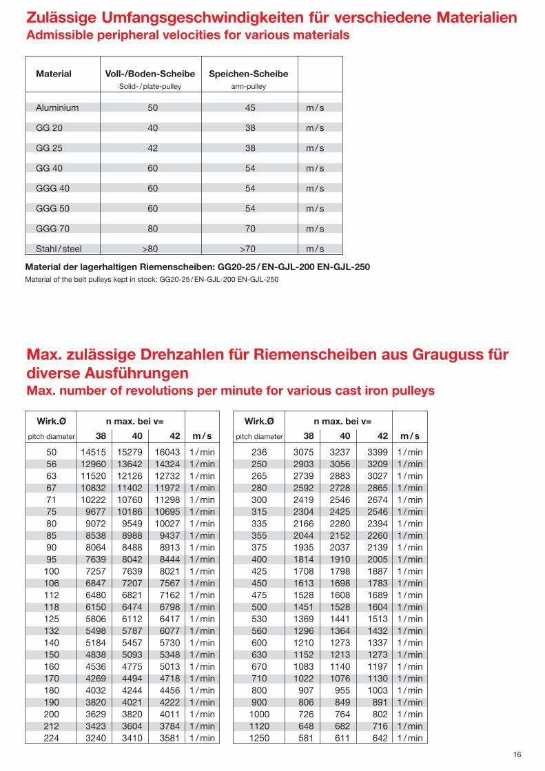
Wirk.Ø n max. bei v=
pitch diameter 38 40 42 m/s
236 3075 3237 3399 1 /min250 2903 3056 3209 1 /min265 2739 2883 3027 1 /min280 2592 2728 2865 1 /min300 2419 2546 2674 1 /min315 2304 2425 2546 1 /min335 2166 2280 2394 1 /min355 2044 2152 2260 1 /min375 1935 2037 2139 1 /min400 1814 1910 2005 1 /min425 1708 1798 1887 1 /min450 1613 1698 1783 1 /min475 1528 1608 1689 1 /min500 1451 1528 1604 1 /min530 1369 1441 1513 1 /min560 1296 1364 1432 1 /min600 1210 1273 1337 1 /min630 1152 1213 1273 1 /min670 1083 1140 1197 1 /min710 1022 1076 1130 1 /min800 907 955 1003 1 /min900 806 849 891 1 /min1000 726 764 802 1 /min1120 648 682 716 1 /min1250 581 611 642 1 /min
Material Voll-/Boden-Scheibe Speichen-ScheibeSolid- /plate-pulley arm-pulley
Aluminium 50 45 m/s
GG 20 40 38 m/s
GG 25 42 38 m/s
GG 40 60 54 m/s
GGG 40 60 54 m/s
GGG 50 60 54 m/s
GGG 70 80 70 m/s
Stahl / steel >80 >70 m/s
Wirk.Ø n max. bei v=
pitch diameter 38 40 42 m/s
50 14515 15279 16043 1 /min56 12960 13642 14324 1 /min63 11520 12126 12732 1 /min67 10832 11402 11972 1 /min71 10222 10760 11298 1 /min75 9677 10186 10695 1 /min80 9072 9549 10027 1 /min85 8538 8988 9437 1 /min90 8064 8488 8913 1 /min95 7639 8042 8444 1 /min100 7257 7639 8021 1 /min106 6847 7207 7567 1 /min112 6480 6821 7162 1 /min118 6150 6474 6798 1 /min125 5806 6112 6417 1 /min132 5498 5787 6077 1 /min140 5184 5457 5730 1 /min150 4838 5093 5348 1 /min160 4536 4775 5013 1 /min170 4269 4494 4718 1 /min180 4032 4244 4456 1 /min190 3820 4021 4222 1 /min200 3629 3820 4011 1 /min212 3423 3604 3784 1 /min224 3240 3410 3581 1 /min
Material der lagerhaltigen Riemenscheiben: GG20-25 /EN-GJL-200 EN-GJL-250Material of the belt pulleys kept in stock: GG20-25 /EN-GJL-200 EN-GJL-250
Zulässige Umfangsgeschwindigkeiten für verschiedene MaterialienAdmissible peripheral velocities for various materials
Max. zulässige Drehzahlen für Riemenscheiben aus Grauguss fürdiverse AusführungenMax. number of revolutions per minute for various cast iron pulleys
17
Buchsen
Typ
1008
1108
12101215
1310
16101615
2012
25172525
30203030
35253535
40304040
45354545
50405050
6050
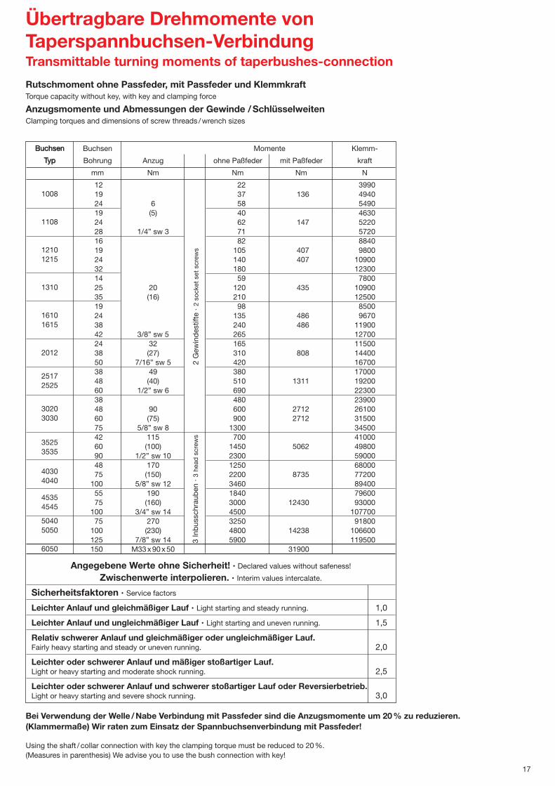
Buchsen Buchsen Momente Klemm-
Typ Bohrung Anzug ohne Paßfeder mit Paßfeder kraft
mm Nm Nm Nm N
12 22 399019 37 136 494024 6 58 549019 (5) 40 463024 62 147 522028 1/4” sw 3 71 572016 82 884019 105 407 980024 140 407 1090032 180 1230014 59 780025 20 120 435 1090035 (16) 210 1250019 98 850024 135 486 967038 240 486 1190042 3/8” sw 5 265 1270024 32 165 1150038 (27) 310 808 1440050 7/16” sw 5 420 1670038 49 380 1700048 (40) 510 1311 1920060 1/2” sw 6 690 2230038 480 2390048 90 600 2712 2610060 (75) 900 2712 3150075 5/8” sw 8 1300 3450042 115 700 4100060 (100) 1450 5062 4980090 1/2” sw 10 2300 5900048 170 1250 6800075 (150) 2200 8735 77200
100 5/8” sw 12 3460 8940055 190 1840 7960075 (160) 3000 12430 93000
100 3/4” sw 14 4500 10770075 270 3250 91800
100 (230) 4800 14238 106600125 7/8” sw 14 5900 119500150 M33x90x50 31900
Angegebene Werte ohne Sicherheit! · Declared values without safeness!
Zwischenwerte interpolieren. · Interim values intercalate.
Sicherheitsfaktoren · Service factors
Leichter Anlauf und gleichmäßiger Lauf · Light starting and steady running. 1,0
Leichter Anlauf und ungleichmäßiger Lauf · Light starting and uneven running. 1,5
Relativ schwerer Anlauf und gleichmäßiger oder ungleichmäßiger Lauf.Fairly heavy starting and steady or uneven running. 2,0
Leichter oder schwerer Anlauf und mäßiger stoßartiger Lauf.Light or heavy starting and moderate shock running. 2,5
Leichter oder schwerer Anlauf und schwerer stoßartiger Lauf oder Reversierbetrieb.Light or heavy starting and severe shock running. 3,0
3 In
bus
schr
aub
en2
Gew
ind
estif
te
Übertragbare Drehmomente von Taperspannbuchsen-VerbindungTransmittable turning moments of taperbushes-connection
Rutschmoment ohne Passfeder, mit Passfeder und KlemmkraftTorque capacity without key, with key and clamping force
Anzugsmomente und Abmessungen der Gewinde /SchlüsselweitenClamping torques and dimensions of screw threads /wrench sizes
Bei Verwendung der Welle /Nabe Verbindung mit Passfeder sind die Anzugsmomente um 20% zu reduzieren. (Klammermaße) Wir raten zum Einsatz der Spannbuchsenverbindung mit Passfeder!
Using the shaft / collar connection with key the clamping torque must be reduced to 20%.(Measures in parenthesis) We advise you to use the bush connection with key!
3 In
bus
schr
aub
en ·
3 he
ad s
crew
s2
Gew
ind
estif
te ·
2 so
cket
set
scr
ews

18
D
Einbau:1.Alle blanken Oberflächen, wie Bohrung und Kegel der
Taper Spannbuchse sowie die kegelige Bohrung derScheibe säubern und entfetten. Taper Spannbuchse in die Nabe einsetzen und alle Bohrungen zur Deckung bringen /halbe Gewindebohrungen müssen jeweils hal-ben glatten Bohrungen gegenüberstehen).
2.Gewindestift (Gr.1008 –3030) bzw. Zylinderschrauben(Gr. 3525–6050) leicht einölen und einschrauben. Schrauben noch nicht festziehen.
3.Welle säubern und entfetten. Scheibe mit Taper Spann-buchse bis zur gewünschten Lage auf die Welle schieben.
4.Bei Verwendung einer Paßfeder ist diese zuerst in die Nut der Welle einzulegen. Zwischen der Paßfeder und der Bohrungsnut muss ein Rückenspiel vorhanden sein.
5.Mittels Schraubendreher, DIN 911, Gewindestifte bzw.Zylinderschrauben gleichmäßig mit den in der Tabelle an-gegebenen Anzugsmomenten anziehen.
6.Nach kurzer Betriebszeit 1/2 bis 1 Stunde Anzugsmomentder Schrauben überprüfen und evtl. korrigieren.
7.Um das Eindringen von Fremdkörpern zu verhindern,leere Bohrungen mit Fett füllen.
Ausbau:1.Alle Schrauben lösen. Je nach Buchsengröße ein oder
zwei Schrauben ganz herausschrauben und in die Ab-drückbohrungen einschrauben.
2.Die Schraube bzw. Schrauben gleichmäßig anziehen, bis sich die Buchse aus der Nabe löst und die Scheibe sichfrei auf der Welle bewegen läßt.
3.Scheibe mit Buchse von der Welle abnehmen.
To assemble:1.Clean and degrease the bore and taper surfaces of the
bush and the tapered bore of the pulley. Insert the bushin the pulley hub and line up the holes (half thread holesmust line up with half straight holes).
2.Lightly oil the socket set screw (bush size 1008 to 3030) or the head screw (bush size 3525 to 6050) and screw them in, do not tighten yet.
3.Clean and degrease the shaft. Fit pulley on shaft andlocate in desired position.
4.When using a key it should first be fitted in the shaft keyway. There should be a top clearance between the key and the keyway in the bore.
5.Using a hexagon socket wrench (DIN 911) gradually tighten the socket set /head screws in accordance with the torques as listed in the schedule of screw tighteningtorques.
6.When the drive has been operating and load for a short period (1/2 to 1 hour) check and ensure that the screwsremain at the appropriate tightening torque.
7. In order to eliminate the ingress of dirt fill all emptyholes with grease.
Removal:1.Slacken all screws. Depending on the size of the bush
remove one or two. After oiling point and thread of socket set screws or under head and thread of head screwsinsert them into the jacking off hole(s) in bush.
2.Tighten screw(s) uniformly and alternately until the bushis loose in the hub and pulley is free on the shaft.
3.Remove pulley/bush assembly from shaft.
Montageanleitung für Taper Spannbuchsen • Installation instructions for taper bushes
Type Buchse Nabe Befestigungbush hub tightening
.
1008 11081210121513101610161520122517252530203030352535354030404045354545504050506050
Lagerprogramm TaperspannbuchsenStocksurvey for taperbushes
10081108121012151310161016152012251730203030
11
0,130,160,28
12
0,120,160,28
0,41
14
0,120,150,270,390,320,390,60
15
0,110,150,270,390,310,380,600,74
16
0,110,140,260,380,300,370,570,73
18
0,110,130,250,360,280,350,550,71
19
0,100,120,240,340,270,340,530,691,06
20
0,100,110,230,320,260,330,500,661,03
22
0,100,100,220,300,250,320,470,631,00
24
0,090,100,220,280,240,300,440,600,98
25
0,080,100,210,260,220,290,410,570,982,50
28
0,100,210,240,200,280,380,540,942,45
30
0,200,220,190,260,350,510,912,35
32
0,200,200,170,240,320,480,882,25
35
0,150,230,290,450,832,203,75
38
0,220,260,430,812,153,65
40
0,200,230,400,792,103,50
42
0,180,200,370,772,053,35
45
0,340,742,003,20
48
0,300,691,953,05
50
0,300,671,852,90
55
0,651,802,75
60
0,631,752,60
65
0,601,652,40
70
1,602,30
75
1,502,15
80
Type Gewicht in kg (ca.) · weight in kg (ca.)
Mit metrischer Bohrung · with metric bore Toleranzen: Bohrung G7 Nut JS9
0,0 = Liefergröße mit DIN Nut 6885 /1 · size of delivery with DIN keyway 6885 /1 • 0,0 = Liefergröße mit Flachnut · size of delivery with shallow keyway
Nut nach britischem StandardKeyway regarding British Standard
Zwischenbohrungen, die hier nichtaufgeführt sind, können kurzfristighergestellt werden.In-between bores which aren’t listed can be manufactured.
352535354030404045354545504050506050
35
3,665,13
38
3,564,98
40
3,454,836,22
42
3,344,686,10
45
3,234,535,76
48
3,134,385,707,60
50
3,024,235,637,50
55
4,125,785,557,40
12,70
60
2,803,945,407,20
12,40
65
2,703,805,257,00
12,00
70
2,603,665,106,80
11,70 12,14 15,17
75
2,503,524,956,608,8111,30 12,00 15,00
80
2,403,384,806,408,5010,90 11,52 14,40
85
2,303,244,656,208,1110,40 11,04 13,80
90
2,203,104,506,007,729,9010,56 13,20
95
2,10
4,355,807,339,4010,08 12,6028,50
100
2,00
4,205,607,029,009,60 12,0027,80
105
4,05
6,638,509,12 11,4027,00
110
3,90
6,248,008,64 10,8026,40
115
3,75
5,857,508,16 10,2025,40
120
5,46
7,68 9,6024,60
125
5,07
7,20 9,0023,70
130
22,80
135
21,80
140
20,80
145
19,80
150
18,80
Type Gewicht in kg (ca.) · weight in kg (ca.)
100811081210121513101610161520122517
1/2
0,120,160,28
0,320,410,60
5/8
0,110,150,27
0,300,380,60
3/4
0,100,120,240,34
0,340,530,69
7/8
0,090,100,22
0,250,320,470,63
1
0,080,090,210,260,220,290,410,57
1 1/8
0,090,210,24
0,280,380,54
1 1/4
0,200,200,170,240,320,48
1 3/8
0,23
0,45
1 7/16
0,22
1 1/2
0,220,260,43
1 5/8
0,20
0,40
1 3/4
0,34
1 7/8
0,30
2
0,30
3/4
1,06
7/8
1,00
1
0,96
1 1/8
0,94
Mit Inch Bohrung · with inch bore
Type Gewicht in kg (ca.) · weight in kg (ca.)
25173020303035354040454550506050
1 1/4
2,30
1 3/8
0,432,20
1 1/2
0,432,20
4,90
1 5/8
0,402,00
4,80
1 3/4
0,702,00
4,50
1 7/8
0,702,40
4,30
2
0,341,902,904,207,5012,70
2 1/8
0,301,80
7,4012,70
2 1/4
0,301,80
3,907,20
2 3/8
0,301,70
3,90
2 1/2
0,301,60
3,80
12,00
2 3/4
1,60
3,606,8011,70
2 7/8
1,502,203,50
11,30
3
1,502,203,50
3 1/4
3,40
10,9013,80
3 3/8
3,24
3 1/2
3,10
9,90
4
9,00
Type Gewicht in kg (ca.) · weight in kg (ca.)
�max.
25283232 354242 5065507575 10090115100125115125125150
d x l x swBSW x mm
1/4 x 1/2 x 3
3/8 x 5/8 x 5
7/16 x 7/8 x 5
1/2 x 1 x 6
5/8 x 1 1/4 x 8
1/2 x 1 1/2 x 10
5/8 x 1 3/4 x 12
3/4 x 2 x 14
7/8 x 2 5/16 x 14
M33 x 90 x 50
L
20,320,325,438,125,425,438,130,543,263,550,876,263,589
76,210189114101127127
D
35,2038,2847,6247,6250,8057,1557,1569,8585,7385,73
107,95107,95127,00127,00146,05146,05161,93161,93177,80177,80
235
d
32364442475452668077
10197
118115135132150146164160217
GG
55608073859082110125120155146178178215215240240265265432
St
4952736776827698111110143137165165197197222222241241350
3 he
ad s
crew
s2
sock
et s
et s
crew
s

Type Buchse max. Bohrung Wirkdurchmesser Regelfaktor Verstellfaktor Riemenleistung in Gesamtlänge Gewichtmit DIN Nut pitch diameter regulating adjusting kW für n = 1450 Upm total length weight
ni rewop lanimonrotcafrotcafhtiw erob.xamDIN-keyway dm dw1-dw2 kW for n = 1450 rpm
mittel min -maxmedium
dw1 -dw2 kg
RST 84Z1 1108 25 71 62-80 1,29 1,64 0,8 -1,6 28 0,65RST 95Z1 1108 25 82 73-91 1,24 1,64 1,3 -2,1 30 0,85RST 100Z1 1108 25 87 78-96 1,23 1,64 1,5 -2,3 30 1,0RST 108Z1 1108 30 97 90-104 1,16 1,45 2,0 -2,7 35 1,3RST 108A1 1210 24 89 76-102 1,34 1,64 1,0 -2,8 40 1,8RST 120A1 1210 30 101 88-114 1,29 1,64 1,8 -3,7 35 1,6RST 129A1 1210 30 110 97-123 1,26 1,64 2,5 -4,2 35 1,9RST 139A1 1610 40 121 109-133 1,22 1,54 3,4 -5,0 35 2,5RST 146A1 1610 40 128 116-140 1,20 1,54 3,8 -5,5 35 2,7RST 156A1 1610 40 138 126-150 1,19 1,54 4,5 -6,2 35 3,1RST 164A1 1610 40 146 134-158 1,18 1,54 5,1 -6,7 35 3,5RST 177A1 2012 50 160 149-171 1,15 1,45 6,1 -7,5 40 4,3RST 187A1 2012 50 170 159-181 1,14 1,45 6,8 -8,2 40 4,7RST 178B1 2012 50 155 139-171 1,23 1,64 5,9 -9,3 40 4,3RST 187B1 2012 50 164 148-180 1,22 1,64 6,8 -10,3 40 4,7RST 120A2 1215 30 101 88-114 1,29 1,64 3,6 -7,4 65 4,4RST 129A2 1215 30 110 97-123 1,26 1,64 5,0 -8,4 65 4,6RST 139A2 1615 40 121 109-133 1,22 1,54 6,8 -10,0 70 4,9RST 146A2 1615 40 128 116-140 1,20 1,54 7,6 -11,0 70 5,3RST 156A2 1615 40 138 126-150 1,19 1,54 9,0 -12,4 70 5,7RST 164A2 1615 40 146 134-158 1,18 1,54 10,2 -13,4 70 6,1RST 177A2 2012 50 160 149-171 1,15 1,45 12,2 -15,0 90 8,1RST 187A2 2012 50 170 159-181 1,14 1,45 13,6 -16,4 90 8,7RST 178B2 2012 50 155 139-171 1,23 1,64 11,8 -18,6 90 8,1RST 187B2 2012 50 164 148-180 1,22 1,64 13,6 -20,6 90 8,7
19
10/Z 13/A 17/B
Type SPZ-Riemen SPA-Riemen SPB-RiemenSPZ-belts SPA-belts SPB-belts RS RST
84 Z1 62 - 80 * 62 - 78 - 1,23 1,6495 Z1 73 - 91 * 73 - 89 - 1,23 1,64100 Z1 78 - 96 * 78 - 94 - 1,23 1,64108 Z1 90 - 104 * 86 - 102 - 1,45 1,45
108 A1 /A2 76 - 96 76 - 102 * 84 - 101 1,64 *1,64120 A1 /A2 88 - 104 88 - 114 * 93 - 113 1,64 1,64129 A1 /A2 97 - 115 97 - 123 *102 - 122 1,54 1,64139 A1 /A2 109 - 125 109 - 133 *114 - 132 1,54 1,54146 A1 /A2 116 - 132 116 - 140 *121 - 139 1,54 1,54156 A1 /A2 126 - 142 126 - 150 *131 - 149 1,54 1,54164 A1 /A2 134 - 150 134 - 158 139 - 157 1,54 1,54177 A1 /A2 149 - 163 149 - 171 154 - 170 1,45 1,45187 A1 /A2 159 - 173 159 - 181 164 - 180 1,45 1,45
160 B2 117 - 135 117 - 142 121 - 153 1,64 -178 B1 /B2 135 - 153 135 - 160 139 - 171 1,64 1,64187 B1 /B2 144 - 162 144 - 169 148 - 180 1,64 1,64200 B1 /B2 160 - 175 160 - 182 163 - 193 1,54 -215 B1 /B2 175 - 190 175 - 197 178 - 208 1,54 -226 B1 /B2 186 - 201 186 - 208 189 - 219 1,54 -244 B1 /B2 206 - 219 206 - 226 211 - 237 1,45 -
250 B2 212 - 225 212 - 232 217 - 243 1,45 -256 B1 /B2 218 - 231 218 - 238 223 - 249 1,45 -
320 B2 282 - 295 282 - 302 287 - 313 1,45 -335 B2 297 - 310 297 - 317 302 - 328 1,45 -
* nur Profil 13 * nur Profil 17 * nur bei A1
Regelscheiben für TaperspannbuchsenVariable speed pulleys for taperbushes
Regelbereiche für Regelscheiben Adjustment range for variable speed pulleys
Alle Maße in mm · all dimensions in mm
Verstellfaktoradjusting factor
Achtung! Zweirillige Regelscheiben möglichst nur mit dem dafür vorgesehenen Profil verwenden.Attention! Variable speed pulleys with two grooves are just for use with their designated profile.
RS = Regelscheibe mit Bohrung, Nut und Stellschraube · Variable speed pulleys with bore, keyway and set screwRST = Regelscheibe für Taperspannbuchsen · Variable speed pulleys with taperbushes

thciweGegnältmaseGni gnutsielnemeiRrotkaflletsreVrotkaflegeRressemhcrudkriWgnurhoB .xamepyTkW für n = 1450 Upm
max. bore pitch diameter regulating adjusting nominal power in total length weightdm dw1-dw2 factor factor kW for n = 1450 rpm
mittel min -maxmedium
dw1 -dw2 kg
6,0536,1-8,032,192,108-2617021Z48 SR8,0531,2-3,132,142,119-3728021Z59 SR0,1533,2-5,132,132,169-8778021Z001 SR7,1047,2-0,254,161,1401-0979421Z801 SR8,1048,2-0,146,143,1201-6798421A801 SR8,1047,3-8,146,192,1411-88101821A021 SR1,2542,4-5,245,152,1321-79011031A921 SR2,2540,5-4,345,122,1331-901121031A931 SR4,2545,5-8,345,102,1041-611821031A641 SR2,3542,6-5,445,191,1051-621831041A651 SR6,3547,6-1,545,181,1851-431641041A461 SR0,6565,7-1,654,151,1171-941061051A771 SR5,6562,8-8,654,141,1181-951071051A781 SR0,6563,9-9,546,132,1171-931551051B871 SR
5,6563,01-8,646,122,1081-841461051B781 SR0,7067,11-5,845,181,1391-361871051B002 SR4,7064,8-0,545,171,1802-871391051B512 SR6,7062,31-1,0145,161,1912-981402051B622 SR7,9072,41-3,1154,121,1732-112422061B442 SR6,11072,71-6,4154,121,1942-322632061B652 SR5,3076,5-0,246,143,1201-6798822A801 SR8,4564,7-6,346,192,1411-88101032A021 SR2,5074,8-0,545,162,1321-99111032A921 SR8,5070,01-8,645,122,1331-901121042A931 SR8,5070,11-6,745,102,1041- 611821042A641 SR1,6074,21-0,945,191,1051-621831042A651 SR5,6074,31-2,0145,181,1851- 431641042A461 SR2,9090,51-2,2154,151,1171-941061052A771 SR8,9094,61-6,3154,141,1181-951071052A781 SR3,6888,41-0,846,162,1351-121731242B061 SR2,9096,81-8,1146,132,1171-931551052B871 SR8,9096,02-6,3146,122,1081-841461052B781 SR5,115014,32-0,7145,181,1391-361871052B002 SR5,115014,62-2,0245,171,1802-871391052B512 SR8,115014,82-6,2245,161,1912-981402052B622 SR3,410110,23-0,7254,121,1732-112422062B442 SR3,410112,33-0,8254,121,1342-712032062B052 SR2,710114,43-2,9254,121,1942- 322632062B652 SR7,630116,54-0,1454,190,1313-782003062B023 SR0,140114,84-6,3454,190,1823-203513062B553 SR
Regelscheiben mit Bohrung, Nut und StellschraubeVariable speed pulleys with bore, keyway and set screw
20
Alle Maße in mm · all dimensions in mm

21
Gebrauchsanweisung · Using instructions
SRTSR
Die Regelscheiben bestehen aus einer Regelnabe mit Taper Spannbuchse bzw. mit Bohrung und Nut und einer bzw. zweiRegelmuttern.Die Regelmutter kann man auf der Nabe um je 1/4 Umdrehung mittels eines Feingewindes feinstufig verstellen.
Die jeweils erreichbaren kleinsten und größten Wirkdurchmesser für die einzelnen Profile finden Sie in den Tabellen.Die Sicherung der Regelmutter erfolgt bei den Regelscheiben aus GG durch 4 Innensechskantschrauben mit Schneidring, eine von den Schrauben wird in eine Nut gedreht. Die anderen 3 Schrauben werden auf die Abflachungen fest aufgeschraubt.
Bei kleinen Achsabständen möglichst einrillige Scheiben verwenden.
Die angegebenen Leistungswerte sind dem min. und max. Wirk-Ø zugeordnet.min-Ø für SPZ = 63 mm; für SPA = 90 mm; für SPB = 140 mm.Der Verstellfaktor gibt den Wert an, um den sich der Wirk-Ø bei 1/4-Umdrehung der Regelmutter verändert.
Beispiel:
= = 2 3/4 Umdrehung der Regelmutter
Variable speed pulleys consist of hub part with taper or cylindric bore and one or two screw on nuts.The screw on nut can be adjusted at hub part every quarter turning at sensitive thread.
Maximum and minimum possible pitch diameter regarding to used profile you will find at dimension list.
Fixing of screw on part is be done by 4 hexagon socket set screws with cutting ring, one of the screws must be turned inside the keywayat hub part, the three other ones will be fixed at flat areas atsides.
Values for transferable power of V-belts are regarding to minimum and maximum pitch diameter for 1450 rpm.
Allowed minimum pitch diameters:SPZ = 63 mm; SPA = 90 mm; SPB = 140 mm
The adjusting factor gives the value for changing of pitch diameter each quarter turning of screw on nut.
Example:To adjust type RS 187 A1 to pitch diameter 165 mm. At totally closed pulley pitch diameter is 181 mm.So you have to calculate:
= = 2 3/4 turns of screw on nut
noitangiseD gnunhciezeB
RST = Regelscheibe für Taper Spannbuchse Variable speed pulley for taper bush
RS = Regelscheibe mit Bohrung, Nut und Stellschraube Variable speed pulley with bore, keyway and set screw
84 retemaid edistuoressemhcrudneßuA=
Z ZPS epyt tleb-V ZPS liforpnemeirlieklamhcS=
1 sevoorg fo rebmun lhaznelliR=
max. Wirk-Ø n. Tabelle - Soll-Wirk-Ø 4 x Verstellfaktor nach Tabelle
181 - 1654 x 1,45
max. pcd - wished pcd4 x adjusting factor
181 - 1654 x 1,45

B
H
B
H
e
DIN 7753
SPZ
SPA
SPB
SPC
DIN 2215
A/HA
B/HB
RMA/MPTA
3V
5V
8V
DIN 7753
XPA
XPB
6
8
7
8
7
7
6
7
9
Ummantelt · wrapped
Profil
Profile
DIN 7753
SPZ
SPA
SPB
SPC
DIN 2215
Z/10
A /13
B/17
DIN 7753
XPZ
XPA
XPB
XPC
Datenblatt Keilriemen und KraftbänderData Sheet v-belts and banded belts
Keilriemen · v-belts
Länge mm
length
Ld
512 - 3550
732 - 4750
1250 - 8000
2000 - 14000
Li
525 - 2500
560 - 4500
630 - 8000
Querschnitt B x H
cross section W x H
mm
9,7 x 8
12,7 x 10
16,3 x 13
22 x 18
10 x 6
13 x 8
17 x 11
Winkel
angle
40 0
40 0
40 0
40 0
40 0
40 0
40 0
Gewicht
weight
kg/m
0,086
0,128
0,210
0,390
0,057
0,108
0,179
Vmax
belt speed
m/s
40
40
40
40
30
30
30
fb max
bendingfrequency
1/s
100
100
100
100
60
60
60
dw min
min.pulleydiameter
mm
63
90
140
224
45
71
112
Temperatur-bereich
temparature range
C 0
-40 – 100
-40 – 100
-40 – 100
-40 – 100
-40 – 80
-40 – 80
-40 – 80
Anzahl der Zugstränge
number of cord cables
6
8
7
8
5
7
7
19
Ld
512 - 3550
707 - 4000
1250 - 6000
2000 - 6700
9,7 x 8
12,7 x 10
16,3 x 13
22 x 18
40 0
40 0
40 0
40 0
0,075
0,112
0,184
0,343
50
50
50
50
120
120
120
120
50
63
100
160
-40 – 100
-40 – 100
-40 – 100
-40 – 100
6
8
7
8
Flankenoffen gezahnt · raw edge cogged
Ummantelt · wrapped
Kraftbänder · banded belts
Ld
1562 - 2240
732 - 4750
1250 - 8000
2000 - 14000
Li
1300 - 2500
1700 - 9200
La
1300 - 2500
1600 - 9017
2540 - 12065
9,7 x 11
12,7 x 10
16,3 x 13
22 x 18
13 x 11
17 x 14,3
9,5 x 11
15,9 x 16,5
25 x 27
40 0
40 0
40 0
40 0
40 0
40 0
40 0
40 0
40 0
0,119
0,128
0,210
0,390
0,162
0,260
0,113
0,262
0,685
30
40
40
40
30
30
30
30
30
60
60
60
60
60
60
60
60
60
71
100
160
250
85
118
71
160
315
-40 – 100
-40 – 100
-40 – 100
-40 – 100
-40 – 100
-40 – 100
-40 – 100
-40 – 100
-40 – 100
Ld
1700 - 2182
2100 - 3350
12,7 x 13
16,3 x 16,5
40 0
40 0
0,172
0,231
40
40
100
100
75
112
-40 – 100
-40 – 100
8
7
15+ / -0,3
19+ / -0,3
Flankenoffen gezahnt · raw edge cogged
Mittenabstand
Centre distance e
mm
12+ / -0,3
15+ / -0,3
19+ / -0,3
25,5+ / -0,5
12+ / -0,3
17+ / -0,3
10,3+ / -0,25
17,5+ / -0,5
28,6+ / -0,8
weitere Typen und Längen auf Anfrage · other types and lengths on request

1
Technische Liste FlachriementriebeDimensions list for flat belt pulleys
Inhalt Index Seite
Technische Informationen Technical information 1-4
Taper-Flachriemenscheiben Flat belt pulleys 5-8
Taper-Spannbuchsen Taper bushes 9
Übertragbare Drehmomente Transmittable turning moments 10
X-Motorspannschlitten X-Motorbase 11
So finden Sie uns How to find us 12
Einige Bemerkungen zu Flachriementrieben
Der Flachriementrieb findet heute wieder mehr Verbreitung, da er einige Vorteile gegenüberdem Keilriementrieb aufweisen kann:
➨ Hoher Wirkungsgrad, bis zu 99 % (Keilriementrieb einrillig ca. 97%, mehrrillig ca. 92%).➨ Die Lebensdauer gegenüber einem Keilriementrieb ist 4 mal so hoch.➨ Die Geräuschemission ist 10 -20 db geringer als beim Keilriementrieb.➨ Nahezu verschleißfreier Betrieb und damit Wartungsarmut, ein Nachspannen ist
normalerweise nicht nötig.
Für den Einsatz von Flachriementrieben ist jedoch zu beachten, daß für einen einwandfreienBetrieb eine stabile Konstruktion vorliegen muss, die ein korrektes Ausrichten der Flachriemenscheiben dauerhaft gewährleistet.Die Anschaffungskosten für einen Flachriementrieb sind höher als für einen Keilriementrieb.
Montageanleitung
Jeder Flachriementrieb muss entsprechend der Antriebsdaten dimensioniert werden, wobei dieerrechnete Auflagendehnung bei der Montage beachtet werden muss.Auf dem Riemen wird eine definierte Länge markiert, die nach dem Spannen um dieVorspannung länger sein muss (z.B. 1000 mm + 2% = 1020 mm im gespannten Zustand).Es ist ein exaktes Ausrichten der Flachriemenscheiben nötig, ein zu großer Fluchtfehler machtsich durch ein Abdriften des Riemens bemerkbar. Vor dem Probelauf die Scheiben in beidenRichtungen von Hand drehen um den Lauf des Riemens zu kontrollieren.Bei Erstmontage: Erst mit 70 % der errechneten Auflagedehnung vorspannen, 30 -60 Minutenin Betrieb nehmen und dann auf die endgültige Vorspannung erhöhen.Ein Nachspannen ist nach dem Erreichen der vorgegebenen Vorspannung normalerweise nichtmehr erforderlich.
Einsatz von Flachriemenscheiben mit Bund
Gerade im Einsatz in der Lüftungsindustrie kommen verstärkt Flachriemenscheiben mit Bundzum Einsatz, um das Abdriften der Riemen während der Anlaufphase zu unterbinden.Dauerhafter Kontakt des Riemens mit dem Bund führt zur Zerstörung des Riemens, es mussalso auch unbedingt auf korrektes Ausrichten der Scheiben geachtet werden.
Stand 9/2006

3
Kranzform für Flachriemenscheiben nach DIN 111 / ISO 100
d [mm] Kranzbreite b [mm] n max
width of border ca.
32 50 80 100 125 160 200 [1/min]63 0,3 12.13067 0,3 11.40071 0,3 10.76075 0,3 10.19080 0,3 0,3 0,3 9.55085 0,3 0,3 8.99090 0,3 0,3 0,3 0,3 8.49095 0,3 0,3 8.040100 0,3 0,3 0,3 0,3 7.640106 0,3 0,3 7.210112 0,3 0,3 6.820118 0,3 0,3 6.470125 0,3 0,3 0,4 0,4 0,4 6.110132 0,3 0,3 0,4 5.790140 0,3 0,3 0,4 0,4 0,4 5.460150 0,3 0,3 0,4 0,4 0,4 0,4 5.090160 0,3 0,3 0,4 0,4 0,5 0,5 4.770170 0,3 0,4 4.490180 0,3 0,3 0,4 0,4 0,5 0,5 4.240190 0,3 0,3 0,4 4.020200 0,3 0,3 0,5 0,5 0,6 0,6 3.820212 0,3 0,3 0,5 0,5 3.600224 0,3 0,3 0,5 0,5 0,6 0,6 3.410236 0,3 0,5 0,5 0,8 3.240250 0,3 0,3 0,5 0,5 0,8 0,8 3.060265 0,3 0,8 2.885280 0,3 0,3 0,5 0,5 0,8 0,8 0,8 2.730300 0,3 0,5 0,5 2.550315 0,3 0,3 0,5 0,5 0,8 0,8 0,8 2.430335 0,5 0,8 2.280355 0,3 0,3 0,5 0,5 0,8 0,8 0,8 2.150400 0,3 0,3 0,6 0,6 1,0 1,0 1,0 1.910450 0,3 0,3 0,6 0,6 1,0 1,0 1,0 1.700500 0,3 0,3 0,6 0,6 1,0 1,0 1,0 1.530560 0,3 0,6 0,6 1,2 1,2 1,2 1.360630 0,3 0,3 0,6 0,6 1,2 1,2 1,2 1.210
Wölbhöhe h [mm]
Voll-/Boden- Speichen-
Material Scheibe Scheibe
Aluminium 50 45GG 20 40 35GG 25 42 38GG 40 60 54GGG 40 60 54GGG 50 60 54GGG 70 80 70Stahl >80 >70
Scheiben mit Wölbhöhenangabe sind ab Lager lieferbar.Andere Abmessungen und Ausführungen bitte Anfragen.
Pulleys with bulging height indication are available ex -stock.Please inquire regarding other dimensions and versions.
Wuchtung in einer Ebene nach G 6,3 für n =1450 1/min bzw. 30 m/s ab d=355 mm
Balancing quality grade G 6,3 for n=1450 1/min or 30 m/s as from d=355 mm
Zulässige Umfangsgeschwindigkeiten in m/s für verschiedene Materialien.
Admissible peripheral velocities in m/s for various materials. Material of the flat belt pulleys kept in stock: GG 20.25
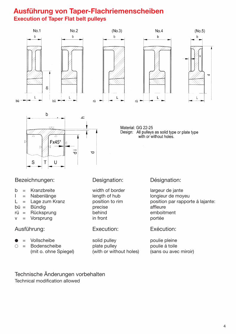
Bezeichnungen: Designation: Désignation:
b = Kranzbreite width of border largeur de janteI = Nabenlänge length of hub longieur de moyeuL = Lage zum Kranz position to rim position par rapporte á lajante:bü = Bündig precise affleurerü = Rücksprung behind emboitmentv = Vorsprung in front portée
Ausführung: Execution: Exécution:
� = Vollscheibe solid pulley poulie pleine� = Bodenscheibe plate pulley poulie á toile
(mit o. ohne Spiegel) (with or without holes) (sans ou avec miroir)
Technische Änderungen vorbehaltenTechnical modification allowed
4
Ausführung von Taper-FlachriemenscheibenExecution of Taper Flat belt pulleysExéction de taper poulies

Nabe Gewichthub weight
d Buchse Länge Lage Bild Typbush length Position illustr. type S T U kg
63 1108 23 bü 2 � 0 23 27 0,4580 1210 26 bü 2 � 0 26 24 0,9085 1210 26 bü 2 � 0 26 24 1,2090 1610 26 bü 2 � 0 26 24 1,6095 1610 26 bü 2 � 0 26 24 1,60100 1610 26 bü 2 � 0 26 24 1,60106 1610 26 bü 2 � 0 26 24 1,80112 2012 32 bü 2 � 0 32 18 1,82118 2012 32 bü 2 � 0 32 18 1,88125 2012 32 bü 2 � 0 32 18 2,60132 2012 32 bü 2 � 0 32 18 2,80140 2012 32 bü 2 � 0 32 18 3,20150 2012 32 bü 2 � 0 32 18 3,60160 2012 32 bü 2 � 10 25 15 4,12170 2517 45 bü 2 � 10 25 15 4,60180 2517 45 bü 2 � 10 25 15 5,00190 2517 45 bü 2 � 10 25 15 5,50200 2517 45 bü 2 � 20 10 20 6,30212 2517 45 bü 2 � 20 10 20 6,50224 2517 45 bü 2 � 20 10 20 7,00250 2517 45 bü 2 � 20 10 20 7,50280 2517 45 bü 2 � 20 10 20 8,50300 3020 45 bü 2 � 19 12 19 10,00315 3020 52 bü 1 � 18 14 18 11,20355 3020 52 bü 1 � 19 14 17 12,80400 3020 52 bü 1 � 19 14 17 17,20450 3020 52 bü 1 � 17 18 15 16,00500 3535 89 bü 1 � 17 18 15 17,20560 3535 89 bü 1 � 17 18 15 18,10630 3020 52 bü 1 � 17 18 15 19,20
Nabe Gewichthub weight
d Buchse Länge Lage Bild Typbush length Position illustr. type S T U kg
63 1108 23 bü 2 � 0 23 9 0,4067 1108 23 bü 2 � 0 23 9 0,4571 1210 26 bü 2 � 0 26 6 0,5275 1210 26 bü 2 � 0 26 6 0,6180 1210 26 bü 2 � 0 26 6 0,7085 1210 26 bü 2 � 0 26 6 0,7890 1610 26 bü 2 � 0 26 6 0,8095 1610 26 bü 2 � 0 26 6 0,96
100 1610 26 bü 2 � 0 26 6 1,04106 1610 26 bü 2 � 0 26 6 1,18112 1610 32 bü 2 � 0 26 6 1,30118 1610 26 bü 2 � 0 26 6 1,60125 1610 26 bü 2 � 0 26 6 1,66132 2012 32 bü 2 � 0 26 6 2,06140 2012 32 bü 2 � 0 32 0 1,90150 2012 32 bü 2 � 10 12 10 3,00160 2012 32 bü 2 � 8 14 10 3,50180 2012 32 bü 2 � 12 8 12 3,80190 2517 45 bü 2 � 12 8 12 4,15200 2517 45 bü 1 � 12 8 12 4,32212 2517 45 bü 1 � 12 8 12 4,70224 2517 45 bü 1 � 12 8 12 4,90236 2517 45 bü 1 � 12 8 12 5,40250 2517 45 bü 1 � 12 8 12 5,60265 2517 45 bü 1 � 9 14 9 5,90280 2517 45 bü 1 � 13 9 10 6,20315 2517 45 bü 1 � 11 12 8 7,60355 2517 45 bü 1 � 10 12 10 11,10400 2517 45 bü 1 � 8 16 8 14,60450 2517 45 bü 1 � 9 14 9 16,20500 3020 52 bü 1 � 10 10 12 14,00630 3020 52 bü 1 � 10 10 12 17,00
b = 32
b = 50
5

Nabe Gewichthub weight
d Buchse Länge Lage Bild Typ kgbush length Position illustr. type S T U
90 1615 38 rü 31 4 � 40 38 22 2,20100 1615 38 rü 31 4 � 31 39 30 2,70125 2517 45 rü 27 4 � 27 45 28 3,80140 3020 52 bü 2 � 0 52 48 4,90150 3020 52 bü 2 � 0 52 48 6,20160 3020 52 bü 2 � 0 52 48 7,50180 3020 52 bü 2 � 0 52 48 8,00200 3020 52 bü 2 � 22 30 48 10,40212 3020 52 bü 2 � 15 30 55 11,00224 3020 52 bü 2 � 15 30 55 12,70236 3020 52 bü 2 � 15 30 55 16,00250 3020 52 bü 2 � 15 30 55 13,10280 3020 52 bü 2 � 31 14 55 14,60300 3020 52 bü 2 � 31 14 55 15,40315 3020 52 bü 2 � 42 16 42 17,00335 3020 52 bü 2 � 42 16 42 18,00355 3030 52 bü 2 � 42 16 42 19,30400 3535 89 bü 2 � 41 18 41 26,80450 3535 89 bü 2 � 41 18 41 30,20500 4040 102 bü 1 � 41 18 41 46,00560 4040 102 bü 1 � 42 19 39 50,00630 4545 114 bü 1 � 40 20 40 61,60
6
b = 80
b = 100
Nabe Gewichthub weight
d Buchse Länge Lage Bild Typ kgbush length Position illustr. type S T U
80 1615 38 bü 2 � 21 38 21 1,5090 1615 38 bü 2 � 0 38 42 1,90100 1615 38 bü 2 � 0 38 42 2,40125 2517 45 bü 2 � 0 45 35 3,40132 2517 45 bü 2 � 0 45 35 3,90140 2517 45 bü 2 � 0 45 35 4,16150 2517 45 bü 2 � 0 45 35 5,00160 2517 45 bü 2 � 0 45 35 5,90170 2517 45 bü 2 � 0 45 35 7,10180 2517 45 bü 2 � 30 10 40 8,50190 2517 45 bü 2 � 30 10 40 9,50200 2517 45 bü 2 � 30 10 40 6,00212 3020 52 bü 2 � 30 15 35 11,80224 3020 52 bü 2 � 30 15 35 10,80236 3020 52 bü 2 � 30 15 35 11,80250 3020 52 bü 2 � 34 12 34 12,80280 3020 52 bü 2 � 34 12 34 13,80300 3020 52 bü 2 � 34 12 34 18,00315 3020 52 bü 2 � 34 12 34 19,60355 3030 77 bü 2 � 34 12 34 17,40400 3535 89 bü 1 � 33 14 33 24,30450 3535 89 bü 1 � 33 14 33 28,40500 4040 102 bü 1 � 33 14 33 43,00560 4040 102 bü 1 � 33 14 33 46,40630 4545 114 v17 5 � 33 14 33 62,00

Nabe Gewichthub weight
d Buchse Länge Lage Bild Typ kgbush length Position illustr. type S T U
280 4040 102 bü 2 � 78 6 116 29,00315 4040 102 bü 2 � 78 6 116 33,00355 4040 102 bü 2 � 78 6 116 36,00400 4040 102 bü 2 � 90 20 90 41,00450 4040 102 bü 2 � 90 20 90 55,00500 4545 114 rü 43 4 � 90 20 90 69,00560 4545 114 rü 43 4 � 90 25 85 87,00630 5050 127 rü 36 4 � 90 25 85 105,00
Nabe Gewichthub weight
d Buchse Länge Lage Bild Typ kgbush length Position illustr. type S T U
150 3030 77 bü 2 � 0 77 83 7,60160 3030 77 bü 2 � 0 77 83 10,00180 3030 77 bü 2 � 0 77 83 14,00200 3030 77 bü 2 � 0 77 83 18,00224 3030 77 bü 2 � 30 47 83 17,00250 3030 77 bü 2 � 54 16 90 17,50280 3535 89 bü 2 � 61 20 79 21,80315 3535 89 bü 2 � 64 16 80 26,00335 3535 89 bü 2 � 62 18 80 28,00355 3535 89 bü 2 � 62 18 80 27,00400 3535 89 bü 2 � 62 18 80 32,00450 3535 89 bü 2 � 62 18 80 42,50500 4040 102 rü 29 4 � 62 18 80 53,00560 4040 102 rü 29 4 � 62 18 80 66,50630 4545 114 rü 23 4 � 62 18 80 80,00
b = 125
b = 160
b = 200
7
Nabe Gewichthub weight
d Buchse Länge Lage Bild Typ kgbush length Position illustr. type S T U
125 2517 45 rü 40 4 � 40 45 40 4,50140 3030 77 bü 2 � 0 77 48 5,20150 3030 77 bü 2 � 0 77 48 6,70160 3030 77 bü 2 � 0 77 48 8,50180 3030 77 bü 2 � 20 55 50 12,00200 3030 77 bü 2 � 30 40 55 15,50224 3030 77 bü 2 � 34 35 56 14,20236 3030 77 bü 2 � 34 35 56 22,20250 3030 77 bü 2 � 34 35 56 17,50265 3030 77 bü 2 � 34 35 56 32,60280 3030 77 bü 2 � 55 14 56 17,50315 3030 77 bü 2 � 55 14 56 19,00335 3535 89 bü 2 � 54 16 55 21,40355 3030 77 bü 2 � 54 16 55 22,00400 3535 89 bü 2 � 54 16 55 29,00450 3535 89 bü 2 � 54 16 55 33,00500 4040 102 bü 4 � 54 16 55 45,00560 4040 102 bü 4 � 54 16 55 54,00630 4545 114 bü 4 � 54 16 55 72,00

Nabe Gewichthub weight
d Buchse h Länge Lage Bild Typ kgbush length Position illustr. type S T U
63 1108 0,3 23 bü 2 � - - 17 1,067 1108 0,3 23 bü 2 � - - 17 1,071 1210 0,3 26 bü 2 � - - 14 1,075 1210 0,3 26 bü 2 � - - 14 1,080 1210 0,3 26 bü 2 � - - 14 1,285 1210 0,3 26 bü 2 � - - 14 1,290 1610 0,3 26 bü 2 � - - 14 1,395 1610 0,3 26 bü 2 � - - 14 1,3
.100 1610 0,3 26 bü 2 � - - 14 1,3106 1610 0,3 26 bü 2 � - - 15 1,5112 1610 0,3 32 bü 2 � - - 14 1,6118 1610 0,3 26 bü 2 � - - 14 2,0125 1610 0,3 26 bü 2 � - - 14 2,1132 2012 0,3 32 bü 2 � - - 8 2,6140 2012 0,3 32 bü 2 � - - 7 2,6150 2012 0,3 32 bü 2 � 13 5 14 3,8160 2012 0,3 32 bü 2 � 13 5 14 4,4180 2012 0,3 32 bü 2 � 14 4 14 4,8190 2517 0,3 45 bü 1 � 15 3 14 4,8200 2517 0,3 45 bü 1 � 15 3 14 5,0212 2517 0,3 45 bü 1 � 15 3 14 5,4224 2517 0,3 45 bü 1 � 15 3 14 5,6236 2517 0,3 45 bü 1 � 15 2 15 6,2250 2517 0,3 45 bü 1 � 14 3 15 6,4280 2517 0,3 45 bü 1 � 14 3 15 7,1
b = 32
8
Flachriemenscheiben mit Bund · Flat belt pulleys with collarab Lager lieferbar · ex stock available
b = 50 Nabe Gewichthub weight
d Buchse h Länge Lage Bild Typ kgbush length Position illustr. type S T U
100 1610 0,3 26 bü 2 � - - 32 3,0106 1610 0,3 26 bü 2 � - - 32 3,0112 2012 0,3 32 bü 2 � - - 26 3,2118 2012 0,3 32 bü 2 � - - 26 3,2125 2012 0,3 32 bü 2 � - - 26 3,5132 2012 0,3 32 bü 2 � - - 26 3,5140 2012 0,3 32 bü 2 � - - 26 3,7150 2012 0,3 32 bü 2 � - - 26 4,2160 2012 0,3 32 bü 2 � 8 14 28 4,8180 2517 0,3 45 bü 2 � 23 4 23 5,8190 2517 0,3 45 bü 2 � 22 4 24 6,4200 2517 0,3 45 bü 2 � 23 5 22 6,8212 2517 0,3 45 bü 2 � 22 6 22 7,0224 2517 0,3 45 bü 2 � 24 5 21 7,3236 2517 0,3 45 bü 2 � 23 4 23 7,6250 2517 0,3 45 bü 2 � 23 4 23 8,1280 2517 0,3 45 bü 2 � 22 7 21 9,2300 3020 0,3 45 bü 2 � 21 5 24 11,0
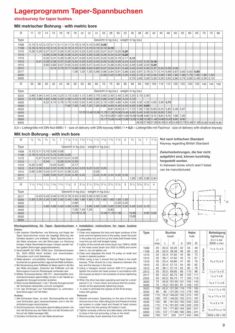
9
Einbau:1.Alle blanken Oberflächen, wie Bohrung und Kegel der
Taper Spannbuchse sowie die kegelige Bohrung derScheibe säubern und entfetten. Taper Spannbuchse in die Nabe einsetzen und alle Bohrungen zur Deckung bringen /halbe Gewindebohrungen müssen jeweils hal-ben glatten Bohrungen gegenüberstehen).
2.Gewindestift (Gr.1008 –3030) bzw. Zylinderschrauben(Gr. 3525 –6050) leicht einölen und einschrauben. Schrauben noch nicht festziehen.
3.Welle säubern und entfetten. Scheibe mit Taper Spann-buchse bis zur gewünschten Lage auf die Welle schieben.
4.Bei Verwendung einer Paßfeder ist diese zuerst in die Nut der Welle einzulegen. Zwischen der Paßfeder und der Bohrungsnut muss ein Rückenspiel vorhanden sein.
5.Mittels Schraubendreher, DIN 911, Gewindestifte bzw.Zylinderschrauben gleichmäßig mit den in der Tabelle an-gegebenen Anzugsmomenten anziehen.
6.Nach kurzer Betriebszeit 1/2 bis 1 Stunde Anzugsmomentder Schrauben überprüfen und evtl. korrigieren.
7.Um das Eindringen von Fremdkörpern zu verhindern,leere Bohrungen mit Fett füllen.
Ausbau:1.Alle Schrauben lösen. Je nach Buchsengröße ein oder
zwei Schrauben ganz herausschrauben und in die Ab-drückbohrungen einschrauben.
2.Die Schraube bzw. Schrauben gleichmäßig anziehen, bis sich die Buchse aus der Nabe löst und die Scheibe sichfrei auf der Welle bewegen läßt.
3.Scheibe mit Buchse von der Welle abnehmen.
To assemble:1.Clean and degrease the bore and taper surfaces of the
bush and the tapered bore of the pulley. Insert the bushin the pulley hub and line up the holes (half thread holesmust line up with half straight holes).
2.Lightly oil the socket set screw (bush size 1008 to 3030) or the head screw (bush size 3525 to 6050) and screw them in, do not tighten yet.
3.Clean and degrease the shaft. Fit pulley on shaft andlocate in desired position.
4.When using a key it should first be fitted in the shaft keyway. There should be a top clearance between the key and the keyway in the bore.
5.Using a hexagon socket wrench (DIN 911) gradually tighten the socket set /head screws in accordance with the torques as listed in the schedule of screw tighteningtorques.
6.When the drive has been operating and load for a short period (1/2 to 1 hour) check and ensure that the screwsremain at the appropriate tightening torque.
7. In order to eliminate the ingress of dirt fill all emptyholes with grease.
Removal:1.Slacken all screws. Depending on the size of the bush
remove one or two. After oiling point and thread of socket set screws or under head and thread of head screwsinsert them into the jacking off hole(s) in bush.
2.Tighten screw(s) uniformly and alternately until the bushis loose in the hub and pulley is free on the shaft.
3.Remove pulley/bush assembly from shaft.
Montageanleitung für Taper Spannbuchsen • Installation instructions for taper bushes
Type Buchse Nabe Befestigungbush hub tightening
.
1008 11081210121513101610161520122517252530203030352535354030404045354545504050506050
Lagerprogramm Taper-Spannbuchsenstocksurvey for taper bushes
10081108121012151310161016152012251730203030
11
0,130,160,28
12
0,120,160,28
0,41
14
0,120,150,270,390,320,390,60
15
0,110,150,270,390,310,380,600,74
16
0,110,140,260,380,300,370,570,73
18
0,110,130,250,360,280,350,550,71
19
0,100,120,240,340,270,340,530,691,06
20
0,100,110,230,320,260,330,500,661,03
22
0,100,100,220,300,250,320,470,631,00
24
0,090,100,220,280,240,300,440,600,98
25
0,080,100,210,260,220,290,410,570,982,50
28
0,100,210,240,200,280,380,540,942,45
30
0,200,220,190,260,350,510,912,35
32
0,200,200,170,240,320,480,882,25
35
0,150,230,290,450,832,203,75
38
0,220,260,430,812,153,65
40
0,200,230,400,792,103,50
42
0,180,200,370,772,053,35
45
0,340,742,003,20
48
0,300,691,953,05
50
0,300,671,852,90
55
0,651,802,75
60
0,631,752,60
65
0,601,652,40
70
1,602,30
75
1,502,15
80
Type Gewicht in kg (ca.) · weight in kg (ca.)
Mit metrischer Bohrung · with metric bore
0,0 = Liefergröße mit DIN Nut 6885 /1 · size of delivery with DIN keyway 6885 /1 • 0,0 = Liefergröße mit Flachnut · size of delivery with shallow keyway
Nut nach britischem StandardKeyway regarding British Standard
Zwischenbohrungen, die hier nichtaufgeführt sind, können kurzfristighergestellt werden.In-between bores which aren’t listed can be manufactured.
352535354030404045354545504050506050
35
3,665,13
38
3,564,98
40
3,454,836,22
42
3,344,686,10
45
3,234,535,76
48
3,134,385,707,60
50
3,024,235,637,50
55
4,125,785,557,40
12,70
60
2,803,945,407,20
12,40
65
2,703,805,257,00
12,00
70
2,603,665,106,80
11,70 12,14 15,17
75
2,503,524,956,608,8111,30 12,00 15,00
80
2,403,384,806,408,5010,90 11,52 14,40
85
2,303,244,656,208,1110,40 11,04 13,80
90
2,203,104,506,007,729,9010,56 13,20
95
2,10
4,355,807,339,4010,08 12,6028,50
100
2,00
4,205,607,029,009,60 12,0027,80
105
4,05
6,638,509,12 11,4027,00
110
3,90
6,248,008,64 10,8026,40
115
3,75
5,857,508,16 10,2025,40
120
5,46
7,68 9,6024,60
125
5,07
7,20 9,0023,70
130
22,80
135
21,80
140
20,80
145
19,80
150
18,80
Type Gewicht in kg (ca.) · weight in kg (ca.)
100811081210121513101610161520122517
1/2
0,120,16
0,320,410,60
5/8
0,110,150,27
0,300,380,60
3/4
0,100,120,240,34
0,340,530,69
7/8
0,090,100,22
0,250,320,470,63
1
0,080,090,210,260,220,290,410,57
1 1/8
0,090,210,24
0,280,380,54
1 1/4
0,200,200,170,240,320,48
1 3/8
0,23
0,45
1 7/16
0,22
1 1/2
0,220,260,43
1 5/8
0,20
0,40
1 3/4
0,34
1 7/8
0,30
2
0,30
3/4
1,06
7/8
1,00
1
0,96
1 1/8
0,94
Mit Inch Bohrung · with inch bore
Type Gewicht in kg (ca.) · weight in kg (ca.)
25173020303035354040454550506050
1 1/4
2,30
1 3/8
0,432,20
1 1/2
0,432,20
4,90
1 5/8
0,402,00
4,80
1 3/4
0,702,00
4,50
1 7/8
0,702,40
4,30
2
0,341,902,904,207,5012,70
2 1/8
0,301,80
7,4012,70
2 1/4
0,301,80
3,907,20
2 3/8
0,301,70
3,90
2 1/2
0,301,60
3,80
12,00
2 3/4
1,60
3,606,8011,70
2 7/8
1,502,203,50
11,30
3
1,502,203,50
3 1/4
3,40
10,9013,80
3 3/8
3,24
3 1/2
3,10
9,90
4
9,00
Type Gewicht in kg (ca.) · weight in kg (ca.)
�max.
252832323542425065507575
10090
115100125115125125150
d x l x swBSW x mm
1/4 x 1/2 x 3
3/8 x 5/8 x 5
7/16 x 7/8 x 5
1/2 x 1 x 6
5/8 x 1 1/4 x 8
1/2 x 1 1/2 x 10
5/8 x 1 3/4 x 12
3/4 x 2 x 14
7/8 x 2 5/16 x 14
M33 x 90 x 50
L
20,320,325,438,125,425,438,130,543,263,550,876,263,589
76,210189
114101127127
D
35,2038,3847,6247,6250,8057,1557,1569,8585,7385,73107,95107,95127,00127,00146,05146,05161,93161,93177,80177,80
235
d
32364442475452668077
10197
118115135132150146164160217
GG
55608073859082110125120155146178178215215240240265265432
St
4952736776827698111110143137165165197197222222241241350
3 he
ad s
crew
s2
sock
et s
et s
crew
s
D
Ø
Ø
Ø
Ø

10
Buchsen
Typ
1008
1108
12101215
1310
16101615
2012
25172525
30203030
35253535
40304040
45354545
50405050
6050
Buchsen Buchsen Momente Klemm-
Typ Bohrung Anzug ohne Paßfeder mit Paßfeder kraft
mm Nm Nm Nm N
12 22 399019 37 136 494024 6 58 549019 (5) 40 463024 62 147 522028 1/4” sw 3 71 572016 82 884019 105 407 980024 140 407 1090032 180 1230014 59 780025 20 120 435 1090035 (16) 210 1250019 98 850024 135 486 967038 240 486 1190042 3/8” sw 5 265 1270024 32 165 1150038 (27) 310 808 1440050 7/16” sw 5 420 1670038 49 380 1700048 (40) 510 1311 1920060 1/2” sw 6 690 2230038 480 2390048 90 600 2712 2610060 (75) 900 2712 3150075 5/8” sw 8 1300 3450042 115 700 4100060 (100) 1450 5062 4980090 1/2” sw 10 2300 5900048 170 1250 6800075 (150) 2200 8735 77200
100 5/8” sw 12 3460 8940055 190 1840 7960075 (160) 3000 12430 93000
100 3/4” sw 14 4500 10770075 270 3250 91800
100 (230) 4800 14238 106600125 7/8” sw 14 5900 119500150 M33x90x50 31900
Angegebene Werte ohne Sicherheit! · Declared values without safeness!
Zwischenwerte interpolieren. · Interim values intercalate.
Sicherheitsfaktoren · Service factors
Leichter Anlauf und gleichmäßiger Lauf · Light starting and steady running. 1,0
Leichter Anlauf und ungleichmäßiger Lauf · Light starting and uneven running. 1,5
Relativ schwerer Anlauf und gleichmäßiger oder ungleichmäßiger Lauf.Fairly heavy starting and steady or uneven running. 2,0
Leichter oder schwerer Anlauf und mäßiger stoßartiger Lauf.Light or heavy starting and moderate shock running. 2,5
Leichter oder schwerer Anlauf und schwerer stoßartiger Lauf oder Reversierbetrieb.Light or heavy starting and severe shock running. 3,0
3 In
bus
schr
aub
en2
Gew
ind
estif
te
Übertragbare Drehmomente von Taperspannbuchsen-VerbindungTransmittable turning moments of taperbushes-connection
Rutschmoment ohne Passfeder, mit Passfeder und KlemmkraftTorque capacity without key, with key and clamping force
Anzugsmomente und Abmessungen der Gewinde /SchlüsselweitenClamping torques and dimensions of screw threads /wrench sizes
Bei Verwendung der Welle /Nabe Verbindung mit Passfeder sind die Anzugsmomente um 20% zu reduzieren. (Klammermaße) Wir raten zum Einsatz der Spannbuchsenverbindung mit Passfeder!
Using the shaft / collar connection with key the clamping torque must be reduced to 20%.(Measures in parenthesis) We advise you to use the bush connection with key!
3 In
bus
schr
aub
en ·
3 he
ad s
crew
s2
Gew
ind
estif
te ·
2 so
cket
set
scr
ews

23
Motorspannschienen aus StahlSteel slide bases
Type Gesamtlänge Gleitlänge Motor-Baugröße Gewichttotal length slide length motor-type weight
L G1 Mxh exS G2 a b b ø d B H1 H22
312 / 6 312 240 63/71 M 6x19 75x 6 262 16 280 – 12 40 28 30 1,4
312 / 8 312 240 80/90 M 8x27 75x 6 262 16 280 – 12 40 28 30 1,5
375 / 6 375 305 63/71 M 6x19 75x 6 325 16 343 – 12 40 28 30 1,5
375 / 8 375 305 80/90 M 8x27 75x 6 325 16 343 – 12 40 28 30 1,6
375 /10 375 305 100/112 M 10x32 75x 6 325 16 343 – 12 40 28 30 1,6
395 / 8 395 302 80/90 M 8x28 97x 8 325 20 355 – 12 50 40 43 3,4
395 /10 395 302 100/112 M 10x35 97x 8 325 20 355 – 12 50 40 43 3,4
495 / 8 495 405 80/90 M 8x29 97x 8 425 20 455 – 12 50 40 43 4,0
495 /10 495 405 100/112/132 M 10x35 97x 8 425 20 455 – 12 50 40 43 4,0
495 /12 495 405 160 M 12x49 97x 8 425 20 455 – 12 50 40 43 4,0
530 /10 530 413 132 M 10x37 119x 9 442 25 480 – 14 60 50 54 6,4
530 /12 530 413 160 M 12x49 119x 9 442 25 480 – 14 60 50 54 6,4
630 /10 630 515 132 M 10x37 119x 9 542 25 580 – 14 60 50 54 8,2
630 /12 630 515 160/180 M 12x45 119x 9 542 25 580 – 14 60 50 54 8,2
686 /12 686 538 160/180 M 12x43 154x12 575 28 630 315 18 75 60 64 12,8
686 /16 686 538 200/225 M 16x62 154x12 575 28 630 315 18 75 60 64 12,8
864 /16 864 700 200/225 M 16x60 300x16 810 32 800 400 24 90 75 – 16,6
864 /20 864 700 250/280 M 20x68 300x16 810 32 800 400 24 90 75 – 16,6
1072 /20 1072 865 250/280 M 20x77 360x19 995 36 1000 500 30 112 100 – 33,4
1072 /24 1072 865 315 M 24x88 360x19 995 36 1000 500 30 112 100 – 33,5
1330 /24 1330 1065 315/355 M 24x 95 430x21 1215 40 1250 625 30 130 125 – 56,6
mit versetzbaren Spannkloben · with movable blocks
mit angeschweißten Spannkloben · with welded blocks
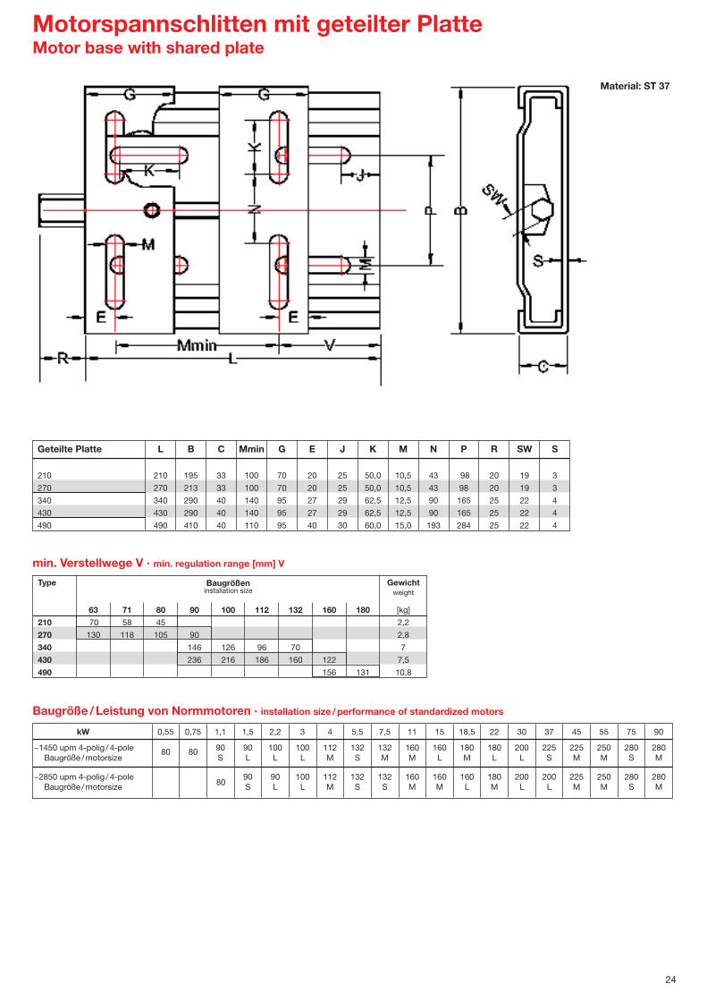
Motorspannschlitten mit geteilter PlatteMotor base with shared plate
24
Material: ST 37
Type Gewicht weight
63 71 80 90 100 112 132 160 180 [kg]
210 70 58 45 2,2
270 130 118 105 90 2,8
340 146 126 96 70 7
430 236 216 186 160 122 7,5
490 156 131 10,8
min. Verstellwege V · min. regulation range [mm] V
Baugrößeninstallation size
Geteilte Platte L B C Mmin G E J K M N P R SW S
210 210 195 33 100 70 20 25 50,0 10,5 43 98 20 19 3
270 270 213 33 100 70 20 25 50,0 10,5 43 98 20 19 3
340 340 290 40 140 95 27 29 62,5 12,5 90 165 25 22 4
430 430 290 40 140 95 27 29 62,5 12,5 90 165 25 22 4
490 490 410 40 110 95 40 30 60,0 15,0 193 284 25 22 4
kW 0,55 0,75 1,1 1,5 2,2 3 4 5,5 7,5 11 15 18,5 22 30 37 45 55 75 90
~1450 upm 4-polig /4-pole 90 90 100 100 112 132 132 160 160 180 180 200 225 225 250 280 280Baugröße /motorsize S L L L M S M M L M L L S M M S M
~2850 upm 4-polig /4-pole 90 90 100 112 132 132 160 160 160 180 200 200 225 250 280 280Baugröße /motorsize S L L M S S M M L M L L M M S M
Baugröße/Leistung von Normmotoren · installation size /performance of standardized motors
80 80
80

25
Motorspannschlitten mit MonoplatteMotor base with monoplate
Material: ST 37
min. Verstellwege L-G · min. regulation range [mm] L-G
Monoplate-MP L B C E1 E2 E3 G H J K1 K2 M N P R SW S
270 -63 /90-MP 270 194 33 100 125 140 190 25 25 50 50 10,5 33 98 20 19 3
307 -90 /112-MP 307 213 33 140 160 190 255 32,5 28 50 50 10,5 62 108 20 19 3
340 -100 /132-2-MP 340 290 40 160 190 216 286 35 28 63 47,5 12,5 120 165 25 22 4
430 -100 /132-MP 430 290 40 160 190 216 286 35 28 63 47,5 12,5 120 165 25 22 4
430 -160 /180-2-MP 430 370 40 254 279 379 50 30 62 62 12,5 163 248 25 22 4
490 -160 /180-MP 490 370 40 254 279 379 50 30 62 62 12,5 163 248 25 22 4
490 -180 /200-MP 490 410 40 279 318 420 50 30 60 52 17 225 285 25 22 4
585 -200 /225-MP 585 450 50 318 356 468 56 30 60 52 17 248 300 25 22 5
600 -250-MP 600 470 65 406 515 54,5 30 60 70 22 229 320 25 22 5
735 -280-MP 735 570 65 457 585 64 30 70 70 22 320 420 25 22 5
Type Gewicht weight
63 80 90 100 112 132 160 180 200 225 250 280 [kg]
270 80 3,1
307 52 4,1
340 54 7,9
430 144 8,9
430 51 12,0
490 111 12,7
490 70 14,6
585 117 23,7
600 85 28,1
735 150 38,2
Die Typen 250 und 280 sind je mit zwei Verstellspindeln bestückt. Der Abstand zwischen den Spindeln beträgt 195 mm.The types 250 and 280 are equiped with two adjusting spindles. The distance between spindles is 195 mm.
Baugrößeninstallation size

Type Gewicht zul. Zugkraftweight allowed tractive force
63 71 80 90 100 112 132 160 180 200 225 [kg] [N]270 55 4,0 680307 37 5,5 940340 39 10,5 1380430 129 11,5 1380430 36 16,8 2000490 96 17,5 2000585 77 33,0 3800
Monoplate-FA-X L B C E1 E2 E3 G H J K1 K2 M N P R SW S
270-63 /90-MP-FA-X 270 192 36 100 125 140 215 40 25 50 50 10,5 33 98 20 19 3
307-90 /112-MP-FA-X 307 213 36 140 160 190 270 40 28 50 50 10,5 62 108 20 19 3
340-100 /132-2-MP-FA-X 340 290 44 160 190 216 301 50 28 63 47,5 12,5 120 165 25 22 4
430-100 /132-MP-FA-X 430 290 44 160 190 216 301 50 28 63 47,5 12,5 120 165 25 22 4
430-160 /180-2-MP-FA-X 430 370 44 254 279 394 60 30 62 62 12,5 163 248 25 22 4
490-160 /180-MP-FA-X 490 370 44 254 279 394 60 30 62 62 12,5 163 248 25 22 4
585-200 /225-MP-FA-X 585 450 55 318 356 508 76 30 60 52 17,0 248 300 25 22 5
26
Bei der Type 270 für Baugröße 71 befinden sich im linken Bereich 2 Langlochpaare im Abstand von 28 mm ummit E3 das Abstandsmaß 112 mm zu erhalten.The type 270 will be produced with 2 long holes at the left side with a distance of 28 mm so that it is possible to mount the motorsize 71.
X-Motorspannschlitten 2-Ebenen verstellbar X-Motorbase 2 planes adjustable
Material: ST 37
Baugrößeninstallation size
min. Verstellwege [mm] L-G · min. regulation range [mm] L-G

Flanschnaben · Flange hubs
Type Buchse øDA øDz øDk B BK BZ øDf Lf F s dmax Gewichtbush [mm] [mm] [mm] [mm] [mm] [mm] [mm] [mm] [mm] [mm] [mm] weight
[kg]EN 1108 58 50 48 23 15 9 – – 2 2 25 0,10EN 1210 73 60 58 26 16,5 10 – – 4 4 30 0,20EN 1215 73 60 58 38 22,0 16 – – 4 4 30 0,50EN 1610 83 70 68 26 16,5 10 – – 4 4 40 0,55EN 1615 83 70 68 38 22,0 11 56,0 25 4 4 40 0,60EN 2012 96 90 88 32 22,0 12 – – 4 5 50 0,70EN 2517 127 110 108 45 26,0 13 84,0 31 5 5 60 1,80EN 3020 152 130 128 51 27,0 18 106,0 26 10 6 75 3,50EN 3030 152 130 128 76 51,0 19 106,0 45 10 6 75 4,50EN 3535 184 155 152 89 67,0 25 124,0 52 16 6 90 6,50EN 4040 225 195 188 102 70,0 35 132,0 70 14 8 100 13,50EN 4545 254 220 214 114 76,0 40 156,5 75 14 8 110 20,30EN 5050 276 242 235 127 89,0 40 172,0 85 14 10 125 25,50EN 6050 350 315 287 127 89,0 40 230,0 80 10 12 150 52,00
Einschweißnaben WM · Weld-on-hubs
Mat. St 52-3
27
Ausführung bisTyp EN3030
Ausführung abTyp EN3535Mat. St 52-3
Type Buchse B Bn da dn dz dN Ba Bz Gewichtbush weight
[kg]FN 12 1210 25 4 180 60 90 73 9 3 2,0FN 16 1615 38 9 200 70 110 83 10 3 2,5FN 20 2517 44 11 270 110 140 127 11 3 6,0FN 25 2517 44 10 340 110 170 127 12 3 9,2
FN 30-1 3030 76 32 430 130 220 152 15 4 20,0FN 30-2 3030 76 31 485 130 250 152 15 5 25,0FN 40 4040 102 45 630 190 270 225 20 5 58,0
s: Schweißnaht · welded joint

Mat. EN-GJL-250
Mat. EN-GJL-250
Type Buchse øDA øDz øDO n x d B dn BA Gewichtbush weight
[kg]AN 1210/1 120 80 100 6 x 8,5 26 75 6,5 1,60AN 1210/2 180 90 135 6 x 7,5 26 75 9,0 1,80AN 1610/1 130 90 110 6 x 8,5 26 85 7,5 2,60AN 1610/2 200 110 150 6 x 7,5 26 90 9,0 2,90AN 1615 200 110 150 6 x 7,5 38 85 10,0 3,00AN 2012 270 140 190 6 x 9,5 32 110 11,0 5,20AN 2517 340 170 240 8 x 11,5 45 125 12,0 9,00AN 3020/1 430 220 300 8 x 13,5 51 160 16,0 18,00AN 3020/2 485 250 340 8 x 13,5 51 160 17,0 24,00AN 3535 500 400 89 180 20,0 34,50
28
Zwischenhülsen · Adaptors
Type Buchse øDz B Nut Gewichtbush keyway weight
bx t [kg]ZH 1008 45 22 0,10
ZHN 1008 45 22 5x 2,5 0,10ZH 1210 60 25 – 0,20
ZHN 1210 60 25 6x 3,0 0,20ZH 1215 60 38 – 0,15
ZHN 1215 60 38 6x 3,0 0,15ZH 1610 70 25 – 0,25
ZHN 1610 70 25 10x 4,0 0,25ZH 1615 70 38 – 0,40
ZHN 1615 70 38 10x 4,0 0,40ZH 2517 105 45 – 1,00
ZHN 2517 105 45 16x 4,0 1,00ZH 2525 105 64 – 2,50
ZHN 2525 105 64 16x 4,0 2,50ZH 3030 130 76 – 2,80
ZHN 3030 130 76 20x 5,0 2,80ZH 3535 160 89 – 3,20
ZHN 3535 160 89 22x 5,0 3,20ZH 4040 185 102 – 4,50
ZHN 4040 185 102 25x 6,5 4,50
Bezeichnung DesignationZH: Zwischenhülse ohne Nut Adaptor without keywayZHN: Zwischenhülse mit Nut Adaptor with keyway Alle Maße in mm · all dimensions in mm
Anschraubnaben · Screw-on-hubs

1
Technische Liste Kettentriebe · Technical list for sprocket-drives
Inhalt egaP/etieSxednI
Ausführungen Executions 2
Rollenketten Rollerchains 2
Kettenspannräder Chain stretcher sprockets 2
Kettenräder und Kettenradscheiben Sprockets and plate wheels 06B 3
08B 4
10B 5
12B 6
16B 7
20B 8
24B 9
Taperspannbuchsen Taperbushes 10
Einschweißnaben Weld-on-hubs 10
Motorspannschienen Motor rails 11
Motorspannschlitten Adjustable motor mountings 12

06 B1 08 B1 10 B1 12 B1 16 B1 20 B1
Zähne teeth Z 21 18 17 15 12 13
Bohrung bore d 16 16 16 16 20 25
Gesamtbreite total length L 18,30 18,30 18,30 18,30 17,70 21,00
Teilkreis � � circlepart Dt 63,90 73,14 86,39 91,63 98,14 132,65
Außen � � outside Da 68,00 77,80 93,00 99,80 109,00 147,80
Zahnbreite width of teeth b1 5,30 7,20 9,10 11,10 16,20 18,50
Gewicht weight kg 0,095 0,120 0,200 0,250 1,000 1,900
Type 06 08 10 12 16 20 24 28 32DIN 8187 3/8˝x 7/32˝ 1/2˝x 5/16˝ 5/8˝x 3/8˝ 3/4˝x 7/16˝ 1̋ x17,02mm 11/4˝x 3/4˝ 11/2˝x1˝ 13/4˝x11/4˝ 2˝x11/4˝
Teilung pitch p 9,525 12,70 15,875 19,05 25,40 31,75 38,10 44,45 50,80Lichte Weite inner weight b1 5,72 7,75 9,65 11,68 17,02 19,56 25,40 30,99 30,99Rollen � roller � d 1 6,35 8,51 10,16 12,07 15,88 19,05 25,40 27,94 29,21
06 B1 08 B1 10 B1 12 B1 16 B1 20 B1 24 B1 28 B1 32 B 1Bruchlast tensile strength kN 9,00 18,00 22,40 29,00 60,00 95,00 160,00 200,00 250,00Gewicht weight kg/m 0,41 0,70 0,95 1,25 2,70 3,60 6,70 8,30 10,50
06 B2 08 B2 10 B2 12 B2 16 B2 20 B2 24 B2 28 B 2 32 B 2Bruchlast tensile strength kN 16,00 32,00 40,00 53,00 106,00 170,00 280,00 360,00 450,00Gewicht weight kg/m 0,78 1,35 1,85 2,40 5,40 7,20 13,40 18,00 19,00
06 B3 08 B3 10 B3 12 B3 16 B3 20 B3 24 B3 28 B3 32 B 3Bruchlast tensile strength kN 23,60 47,50 60,00 80,00 160,00 250,00 425,00 530,00 670,00Gewicht weight kg/m 1,20 2,00 2,80 3,80 7,70 11,20 20,70 27,00 28,30
2
ISO-DYN Rollenketten · Rollerchains
Ausführung von Kettenrädern immer einerseits bündig.Execution of sprockets always one-sided precise.
Technische Änderungen vorbehalten.Technical subject to change.
Kettenspannräder · Chain stretcher sprockets
für Kette DIN 8187to chainTeilung pitch P 3/8 ˝ x 7/32 ˝ 1/2 ˝ x 5/16 ˝ 5/8 ˝ x 3/8 ˝ 3/4 ˝ x 7/16 ˝ 1˝x17,02 mm 1 1/4˝

06 B1 Taperkettenrad Kettenrad mit Nabe Kettenradscheibe3/8 ˝x 7/32 ˝ Tapersprocket Sprocket Plate wheelb1=5,3 mm
8 24,89 28,0 6 15 22 0,018 6 0,019 27,85 31,0 6 18 22 0,025 7 0,01
10 30,82 34,0 8 20 22 0,034 7 0,0211 33,81 37,0 8 22 25 0,054 8 0,0212 36,80 40,0 8 25 25 0,068 8 0,0313 39,79 43,0 10 28 25 0,087 8 0,0414 42,81 46,3 10 31 25 0,11 8 0,0415 45,81 49,3 10 34 25 0,13 8 0,0616 48,82 52,3 10 37 28 0,14 10 0,0617 51,84 55,3 1008 24 25 22 0,12 10 40 28 0,15 10 0,0718 54,85 58,3 1008 24 25 22 0,15 10 43 28 0,16 10 0,0819 57,87 61,3 1008 24 25 22 0,20 10 45 28 0,17 10 0,0920 60,89 64,3 1008 24 25 22 0,22 10 46 28 0,18 10 0,1021 63,91 68,0 1008 24 25 22 0,26 12 48 28 0,25 10 0,1022 66,93 71,0 1008 24 25 22 0,30 12 50 28 0,26 10 0,1123 69,95 73,5 1210 30 32 25 0,33 12 52 28 0,27 10 0,1224 72,97 77,0 1210 30 32 25 0,37 12 54 28 0,28 10 0,1425 76,00 80,0 1210 30 32 25 0,40 12 57 28 0,30 10 0,1626 79,02 83,0 1210 30 32 25 0,42 12 60 28 0,37 10 0,1727 82,05 86,0 1210 30 32 25 0,44 12 60 28 0,39 10 0,1928 85,07 89,0 1210 30 32 25 0,47 12 60 28 0,41 10 0,2029 88,09 92,0 1210 30 32 25 0,47 12 60 28 0,43 10 0,2230 91,12 94,7 1210 30 32 25 0,45 12 60 28 0,45 10 0,2431 94,15 98,3 14 65 30 0,46 12 0,2532 97,18 101,3 14 65 30 0,47 12 0,2633 100,20 104,3 14 65 30 0,49 12 0,2734 103,23 107,3 14 65 30 0,51 12 0,2835 106,26 110,4 14 65 30 0,53 12 0,3036 109,29 113,4 16 70 30 0,56 12 0,3237 112,32 116,4 16 70 30 0,58 12 0,3538 115,34 119,5 1210 30 32 25 0,68 16 70 30 0,60 12 0,3839 118,37 122,5 16 70 30 0,62 12 0,4040 121,40 125,5 16 70 30 0,63 12 0,42
* 38 115,34 119,5 1210 30 32 25 0,68 19 70 32 0,99* 45 136,55 140,7 1210 30 32 25 1,10 19 70 32 1,20 16 0,52* 57 172,91 176,9 1210 30 32 25 1,32 19 70 32 1,48 16 0,85* 76 230,49 234,9 1210 30 32 25 1,86 19 70 32 2,41 20 1,52* 95 288,08 292,5 1210 30 32 25 2,58 19 80 40 3,13 20 2,20* 114 345,50 349,5 19 80 40 3,88 20 3,50
Buchse max. Bohrung Gewicht Gewicht Gewichtbush max. bore weight weight weight
DIN Nut FlachnutZ Dt Da DIN keyway shallow keyway I kg do ND I kg do kg
8 24,89 28,0 6 15 22 0,06 6 0,049 27,85 31,0 8 18 22 0,07 8 0,05
10 30,82 34,0 8 20 22 0,08 8 0,0511 33,81 37,0 10 22 25 0,10 10 0,0612 36,80 40,0 10 25 25 0,12 10 0,0813 39,79 43,0 10 28 25 0,16 10 0,1014 42,81 46,3 10 31 25 0,18 10 0,1215 45,81 49,3 10 34 25 0,20 10 0,1416 48,82 52,3 1008 24 25 22 0,16 12 37 30 0,22 12 0,1717 51,84 55,3 1008 24 25 22 0,21 12 40 30 0,25 12 0,1918 54,85 58,3 1008 24 25 22 0,23 12 43 30 0,27 12 0,2119 57,87 61,3 1008 24 25 22 0,25 12 46 30 0,29 12 0,2420 60,89 64,3 1008 24 25 22 0,30 12 49 30 0,30 12 0,2621 63,91 68,0 1008 24 25 22 0,32 12 52 30 0,41 12 0,3022 66,93 71,0 1210 30 32 25 0,34 12 55 30 0,45 12 0,3223 69,95 73,5 1210 30 32 25 0,36 12 58 30 0,48 12 0,3624 72,97 77,0 1210 30 32 25 0,38 12 61 30 0,51 12 0,4025 76,00 80,0 1210 30 32 25 0,41 12 64 30 0,56 12 0,4526 79,02 83,0 1210 30 32 25 0,46 12 67 30 0,62 12 0,5027 82,05 86,0 1210 30 32 25 0,51 12 70 30 0,68 12 0,5528 85,07 89,0 1210 30 32 25 0,55 12 73 30 0,74 12 0,5829 88,09 92,0 1210 30 32 25 0,60 12 76 30 0,80 12 0,6130 91,12 94,7 1210 30 32 25 0,65 12 79 30 0,86 12 0,6531 94,15 98,3 16 80 30 0,92 14 0,6932 97,18 101,3 16 80 30 0,98 14 0,7333 100,20 104,3 16 80 30 1,10 14 0,8134 103,23 107,3 16 80 30 1,20 14 0,8935 106,26 110,4 16 80 30 1,30 14 0,9736 109,29 113,4 16 90 30 1,40 14 0,9937 112,32 116,4 16 90 30 1,50 14 1,0038 115,34 119,5 1610 40 42 25 0,95 19 90 30 1,60 14 1,1039 118,37 122,5 19 90 30 1,75 14 1,1240 121,40 125,5 19 90 30 1,90 14 1,15
* 38 115,34 119,5 19 80 40 1,90* 45 136,55 140,7 1610 40 42 25 1,15 19 80 40 2,10 16 1,90* 57 172,91 176,9 1610 40 42 25 1,56 19 80 40 2,34 16 2,10* 76 230,49 234,9 1610 40 42 25 2,34 19 80 40 3,13 20 4,60* 95 288,08 292,5 19 90 45 4,80 20 7,40* 114 345,50 349,5 19 90 45 6,50 20 9,00
06 B23/8 ˝x 7/32 ˝b2 =15,4 mm
* Grauguss-Kettenräder · cast-iron sprockets
Bohrungszuordnungen der Taperspannbuchsen siehe Lagerprogramm.Allocations of the bore for the taperbushes vide our stock survey.
3

08 B1 Taperkettenrad Kettenrad mit Nabe Kettenradscheibe1/2 ˝x 5/16 ˝ Tapersprocket Sprocket Plate wheelb1=7,2 mm
8 33,18 37,2 10 20 25 0,05 8 0,039 37,13 41,0 10 24 25 0,07 8 0,04
10 41,10 45,2 10 26 25 0,09 8 0,0511 45,07 48,7 10 29 25 0,10 10 0,0612 49,07 53,0 10 33 28 0,16 10 0,0713 53,06 57,4 10 37 28 0,20 10 0,0914 57,07 61,8 10 41 28 0,23 10 0,1015 61,09 65,5 1008 24 25 22 0,25 10 45 28 0,28 10 0,1216 65,10 69,5 1108 25 28 22 0,27 12 50 28 0,41 10 0,1417 69,11 73,6 1210 30 32 25 0,29 12 52 28 0,44 10 0,1618 73,14 77,8 1210 30 32 25 0,33 12 56 28 0,48 10 0,1819 77,16 81,7 1210 30 32 25 0,42 12 60 28 0,49 10 0,2020 81,19 85,8 1210 30 32 25 0,41 12 64 28 0,52 10 0,2321 85,22 89,7 1610 40 42 25 0,43 14 68 28 0,64 12 0,2622 89,24 93,8 1610 40 42 25 0,46 14 70 28 0,67 12 0,2923 93,27 98,2 1610 40 42 25 0,56 14 70 28 0,70 12 0,3224 97,29 101,8 1610 40 42 25 0,53 14 70 28 0,73 12 0,3425 101,33 105,8 1610 40 42 25 0,61 14 70 28 0,81 12 0,3626 105,36 110,0 1610 40 42 25 0,67 15 70 30 1,08 16 0,3927 109,40 114,0 1610 40 42 25 0,73 15 70 30 1,10 16 0,4228 113,42 118,0 1610 40 42 25 0,79 15 70 30 1,16 16 0,4529 117,46 122,0 1610 40 42 25 0,90 15 80 30 1,22 16 0,4930 121,50 126,1 2012 50 32 1,00 15 80 30 1,26 16 0,5331 125,54 130,2 16 90 30 1,29 16 0,5732 129,56 134,3 16 90 30 1,31 16 0,6033 133,60 138,4 16 90 30 1,36 16 0,6534 137,64 142,6 16 90 30 1,40 16 0,6935 141,68 146,7 16 90 30 1,45 16 0,7336 145,72 151,0 20 90 35 1,61 16 0,7837 149,76 154,6 20 90 35 1,66 16 0,8338 153,80 158,6 2012 50 32 1,34 20 90 35 1,72 16 0,8739 157,83 162,7 20 90 35 1,76 16 0,9340 161,87 166,8 20 90 35 1,80 16 0,99
* 38 153,80 158,6 19 70 40 1,50* 45 182,07 188,0 2012 50 32 1,70 19 70 40 2,46 20 1,22* 57 230,54 236,4 2012 50 32 2,56 19 70 40 3,18 20 2,10* 76 307,33 313,3 2012 50 32 3,40 23 80 40 4,18 25 3,60* 95 348,11 390,1 23 80 45 6,10 25 5,80* 114 460,90 466,9 23 90 45 7,60 25 10,30
8 33,18 37,2 10 20 32 0,16 10 0,109 37,13 41,0 10 24 32 0,17 10 0,12
10 41,10 45,2 10 28 32 0,18 10 0,1511 45,07 48,7 10 32 35 0,21 10 0,1812 49,07 53,0 10 35 35 0,30 10 0,2013 53,06 57,4 10 38 35 0,35 10 0,2714 57,07 61,8 10 42 35 0,42 10 0,3015 61,09 65,5 1008 24 25 22 0,25 10 46 35 0,50 10 0,3516 65,10 69,5 1108 25 28 22 0,27 12 50 35 0,58 12 0,4017 69,11 73,6 1210 30 32 25 0,29 12 54 35 0,64 12 0,4518 73,14 77,8 1210 30 32 25 0,33 12 58 35 0,70 12 0,5019 77,16 81,7 1210 30 32 25 0,42 12 62 35 0,77 12 0,5820 81,19 85,8 1210 30 32 25 0,41 12 66 35 0,85 12 0,6321 85,22 89,7 1610 40 42 25 0,43 14 70 40 1,12 16 0,7222 89,24 93,8 1610 40 42 25 0,46 14 70 40 1,20 16 0,8323 93,27 98,2 1610 40 42 25 0,56 14 70 40 1,29 16 0,9024 97,29 101,8 1610 40 42 25 0,53 14 75 40 1,39 16 0,9625 101,33 105,8 2012 40 42 25 0,61 14 80 40 1,48 16 1,0526 105,36 110,0 2012 40 42 25 0,67 15 85 40 1,61 16 1,1427 109,40 114,0 2012 40 42 25 0,73 15 85 40 1,74 16 1,2528 113,42 118,0 2012 40 42 25 0,79 15 90 40 1,87 16 1,3529 117,46 122,0 2012 40 42 25 0,90 15 95 40 2,01 16 1,4530 121,50 126,1 2012 50 32 1,00 15 100 40 2,14 16 1,5531 125,54 130,2 16 100 40 2,27 16 1,6332 129,56 134,3 16 100 40 2,40 16 1,7033 133,60 138,4 16 100 40 2,53 16 1,9034 137,64 142,6 16 100 40 2,66 16 2,1035 141,68 146,7 16 100 40 2,79 16 2,2036 145,72 151,0 20 110 40 2,92 20 2,3037 149,76 154,6 20 110 40 3,05 20 2,5038 153,80 158,6 2012 50 32 1,34 20 110 40 3,18 20 2,7039 157,83 162,7 20 110 40 3,32 20 2,8540 161,87 166,8 20 110 40 3,50 20 3,00
* 38 153,80 158,6 19 90 50 3,60* 45 182,07 188,0 2012 50 32 1,70 19 90 50 4,10 20 3,20* 57 230,54 236,4 2012 50 32 2,56 19 90 50 5,25 20 6,00* 76 307,33 313,3 2012 50 32 3,40 23 100 56 6,65 25 11,50* 95 348,11 390,1 23 100 56 10,70 25 18,00* 114 460,90 466,9 23 100 63 13,25 25 24,40
4
Buchse max. Bohrung Gewicht Gewicht Gewichtbush max. bore weight weight weight
DIN Nut FlachnutZ Dt Da DIN keyway shallow keyway I kg do ND I kg do kg
08 B21/2 ˝x5/16 ˝b2 =21,0 mm
* Grauguss-Kettenräder · cast-iron sprockets
Bohrungszuordnungen der Taperspannbuchsen siehe Lagerprogramm.Allocations of the bore for the taperbushes vide our stock survey.

10 B1 Taperkettenrad Kettenrad mit Nabe Kettenradscheibe5/8 ˝x 3/8 ˝ Tapersprocket Sprocket Plate wheelb1=9,1 mm
5
8 41,48 47,0 10 25 25 0,09 10 0,089 46,42 52,6 10 30 25 0,13 10 0,09
10 51,37 57,5 10 35 25 0,18 10 0,1011 56,34 63,0 12 37 28 0,26 10 0,1312 61,34 68,0 12 42 28 0,35 10 0,1513 66,32 73,0 1008 24 25 22 0,29 12 47 28 0,40 10 0,1914 71,34 78,0 1108 25 28 22 0,32 12 52 28 0,49 10 0,2215 76,36 83,0 1210 30 32 25 0,37 12 57 28 0,60 10 0,2616 81,37 88,0 1210 30 32 25 0,44 14 60 30 0,74 12 0,3017 86,39 93,0 1610 40 42 25 0,44 14 60 30 0,79 12 0,3518 91,42 98,3 1610 40 42 25 0,52 14 70 30 0,83 12 0,4019 96,45 103,3 1610 40 42 25 0,53 14 70 30 0,89 12 0,4420 101,49 108,4 1610 40 42 25 0,68 14 75 30 0,94 12 0,4821 106,52 113,4 1610 40 42 25 0,72 16 75 30 1,17 12 0,5222 111,55 118,0 1610 40 42 25 0,76 16 80 30 1,23 12 0,5723 116,58 123,4 1610 40 42 25 1,10 16 80 30 1,27 12 0,6224 121,62 128,3 1610 40 42 25 1,18 16 80 30 1,33 12 0,6725 126,66 134,0 2012 50 32 1,25 16 80 30 1,41 12 0,7126 131,70 139,0 2012 50 32 1,29 20 85 35 1,85 16 0,7827 136,75 144,0 2012 50 32 1,33 20 85 35 1,90 16 0,8528 141,78 148,7 2012 50 32 1,38 20 90 35 2,06 16 0,9229 146,83 153,8 2012 50 32 1,43 20 90 35 2,08 16 0,9930 151,87 158,8 2012 50 32 1,48 20 90 35 2,10 16 1,0531 156,92 163,9 20 95 35 2,19 16 1,1332 161,95 168,9 20 95 35 2,27 16 1,2233 167,00 174,5 20 95 35 2,35 16 1,3034 172,05 179,0 20 95 35 2,42 16 1,3835 177,10 184,1 20 95 35 2,54 16 1,4536 182,15 189,1 20 100 35 2,63 20 1,5637 187,20 194,2 20 100 35 2,72 20 1,6538 192,24 199,2 2012 50 32 2,34 20 100 35 2,81 20 1,7539 197,29 204,2 20 100 35 2,95 20 1,8340 202,34 209,3 20 100 35 3,10 20 2,00
* 38 192,24 199,2 19 80 40 2,50* 45 227,58 235,0 2012 50 32 3,05 19 80 40 3,00 20 2,40* 57 288,18 296,0 2012 50 32 4,40 23 90 45 4,65 25 4,00* 76 384,16 392,1 2012 50 32 6,20 23 90 50 8,00 25 6,90* 95 480,14 488,5 3020 75 51 11,30 23 100 56 11,00 30 11,50* 114 576,13 584,1 23 100 56 13,50 30 17,00
8 41,48 47,0 12 25 40 0,20 10 0,309 46,42 52,6 12 30 40 0,30 10 0,32
10 51,37 57,5 12 35 40 0,40 10 0,3311 56,34 63,0 14 39 40 0,40 12 0,3512 61,34 68,0 14 44 40 0,50 12 0,4013 66,32 73,0 14 49 40 0,65 12 0,4814 71,34 78,0 14 54 40 0,80 12 0,5515 76,36 83,0 1210 30 32 25 0,46 14 59 40 0,94 12 0,6516 81,37 88,0 1210 30 32 25 0,58 16 64 45 1,20 12 0,8017 86,39 93,0 1610 40 42 25 0,54 16 69 45 1,30 12 0,9018 91,42 98,3 1610 40 42 25 0,66 16 74 45 1,45 12 0,9519 96,45 103,3 1610 40 42 25 0,72 16 79 45 1,58 12 1,0320 101,49 108,4 1610 40 42 25 0,76 16 84 45 1,70 12 1,3021 106,52 113,4 1610 40 42 25 0,93 16 85 45 2,00 16 1,4222 111,55 118,0 1610 40 42 25 1,10 16 90 45 2,15 16 1,5423 116,58 123,4 1610 40 42 25 1,30 16 95 45 2,30 16 1,7024 121,62 128,3 1610 40 42 25 1,60 16 100 45 2,41 16 1,8525 126,66 134,0 2012 50 32 1,66 16 105 45 2,65 16 1,9726 131,70 139,0 2012 50 32 1,80 20 110 45 2,88 16 2,3027 136,75 144,0 2012 50 32 1,95 20 110 45 3,10 16 2,5028 141,78 148,7 2012 50 32 2,10 20 115 45 3,35 16 2,7029 146,83 153,8 2012 50 32 2,35 20 115 45 3,55 16 2,9030 151,87 158,8 2012 50 32 2,60 20 120 45 3,80 16 3,1031 156,92 163,9 20 120 45 4,05 20 3,2532 161,95 168,9 20 120 45 4,30 20 3,5033 167,00 174,5 20 120 45 4,60 20 3,8034 172,05 179,0 20 120 45 4,90 20 4,0035 177,10 184,1 20 120 45 5,20 20 4,2036 182,15 189,1 20 120 45 5,45 20 4,5037 187,20 194,2 20 120 45 5,70 20 4,9038 192,24 199,2 2517 65 32 4,44 20 120 45 5,90 20 5,2039 197,29 204,2 20 120 45 6,25 20 5,6040 202,34 209,3 20 120 45 6,50 20 6,20
* 38 192,24 199,2 29 100 40 6,10* 45 227,58 235,0 2517 65 44 7,10 29 100 40 7,75 20 7,32* 57 288,18 296,0 3020 75 51 11,50 29 100 45 8,80 25 11,90* 76 384,16 392,1 29 100 50 13,70 25 21,70* 95 480,14 488,5 29 110 56 18,30 30 31,00* 114 576,13 584,1 29 125 56 23,00 30 43,00
Buchse max. Bohrung Gewicht Gewicht Gewichtbush max. bore weight weight weight
DIN Nut FlachnutZ Dt Da DIN keyway shallow keyway I kg do ND I kg do kg
10 B25/8 ˝x 3/8 ˝b2 =25,5 mm
* Grauguss-Kettenräder · cast-iron sprockets
Bohrungszuordnungen der Taperspannbuchsen siehe Lagerprogramm.Allocations of the bore for the taperbushes vide our stock survey.

12 B1 Taperkettenrad Kettenrad mit Nabe Kettenradscheibe3/4 ˝x 7/16 ˝ Tapersprocket Sprocket Plate wheelb1=11,1 mm
8 49,78 57,6 12 31 30 0,22 12 0,129 55,70 62,0 12 37 30 0,28 12 0,15
10 61,64 69,0 12 42 30 0,35 12 0,2011 67,61 75,0 14 46 35 0,45 14 0,2412 73,61 81,5 14 52 35 0,57 14 0,2913 79,59 87,5 1210 30 32 25 0,50 14 58 35 0,84 14 0,3514 85,61 93,6 1210 30 32 25 0,55 14 64 35 0,88 14 0,4115 91,63 99,8 1610 40 42 25 0,60 14 70 35 1,10 14 0,4716 97,65 105,5 1610 40 42 25 0,65 16 75 35 1,33 14 0,5417 103,67 111,5 1610 40 42 25 0,71 16 80 35 1,38 14 0,6218 109,71 118,0 1610 40 42 25 0,80 16 80 35 1,46 14 0,7019 115,75 124,2 2012 50 32 1,00 16 80 35 1,54 14 0,7820 121,78 129,7 2012 50 32 1,28 16 80 35 1,63 14 0,8721 127,82 136,0 2517 65 44 1,38 20 90 40 2,18 16 0,9522 133,86 141,8 2517 65 44 1,45 20 90 40 2,28 16 1,0523 139,90 149,0 2517 65 44 2,00 20 90 40 2,38 16 1,1524 145,94 153,9 2517 65 44 2,25 20 90 40 2,49 16 1,2625 152,00 160,0 2517 65 44 2,52 20 90 40 2,60 16 1,3726 158,04 165,9 2517 65 44 2,57 20 100 40 2,87 16 1,5027 164,09 172,3 2517 65 44 2,63 20 100 40 3,01 16 1,6428 170,13 178,0 2517 65 44 2,67 20 100 40 3,12 16 1,7829 176,19 184,1 2517 65 44 2,77 20 100 40 3,32 16 1,8830 182,25 190,5 2517 65 44 2,88 20 100 40 3,53 16 1,9931 188,31 196,3 20 100 40 3,70 20 2,1532 194,35 203,3 20 100 40 3,87 20 2,2633 200,40 209,3 20 100 40 4,00 20 2,4134 206,46 214,6 20 100 40 4,12 20 2,5635 212,52 221,0 20 100 40 4,22 20 2,7036 218,58 226,8 20 100 40 4,32 20 2,8437 224,64 232,9 20 100 40 4,53 20 3,0038 230,69 239,0 2517 65 44 4,48 20 100 40 4,74 20 3,2139 236,75 245,1 20 100 40 4,87 20 3,3640 242,81 251,3 20 100 40 5,00 20 3,58
* 38 230,69 239,0 2517 65 44 4,48 23 100 56 4,30* 45 273,10 282,5 2517 65 44 4,57 23 100 56 5,00 25 4,60* 57 345,81 355,4 2517 65 44 7,50 29 100 56 7,50 25 7,56* 76 460,99 469,9 2517 65 44 9,80 29 100 56 10,00 30 13,08* 95 576,17 585,1 3020 75 65 51 15,50 29 100 65 15,60 30 20,12* 114 691,36 700,6 29 100 65 20,10 30 27,15
12 B23/4 ˝x 7/16 ˝b2 =30,3 mm
8 49,78 57,6 12 31 45 0,30 12 0,209 55,70 62,0 12 37 45 0,40 12 0,35
10 61,64 69,0 12 42 45 0,53 12 0,5011 67,61 75,0 16 47 50 0,73 14 0,6512 73,61 81,5 16 53 50 0,95 14 0,8013 79,59 87,5 16 59 50 1,17 14 0,9114 85,61 93,6 16 65 50 1,45 14 1,0615 91,63 99,8 1615 40 42 38 0,65 16 71 50 1,71 14 1,2116 97,65 105,5 1615 40 42 38 0,88 20 77 50 2,00 16 1,3717 103,67 111,5 1615 40 42 38 1,06 20 83 50 2,18 16 1,5718 109,71 118,0 1615 40 42 38 1,35 20 89 50 2,40 16 1,7819 115,75 124,2 2012 50 32 1,30 20 95 50 2,60 16 2,0020 121,78 129,7 2012 50 32 1,54 20 100 50 2,90 16 2,2221 127,82 136,0 2517 65 44 1,84 20 100 50 3,25 16 2,5022 133,86 141,8 2517 65 44 2,08 20 100 50 3,52 16 2,7723 139,90 149,0 2517 65 44 2,22 20 110 50 3,80 16 3,0524 145,94 153,9 2517 65 44 2,57 20 110 50 4,15 16 3,3325 152,00 160,0 2517 65 44 2,90 20 120 50 4,50 16 3,6926 158,04 165,9 2517 65 44 3,05 20 120 50 4,90 20 4,0527 164,09 172,3 2517 65 44 3,20 20 120 50 5,30 20 4,4028 170,13 178,0 2517 65 44 3,25 20 120 50 5,80 20 4,7329 176,19 184,1 2517 65 44 3,60 20 120 50 6,10 20 5,0630 182,25 190,5 2517 65 44 3,39 20 120 50 6,40 20 5,4031 188,31 196,3 20 130 50 6,80 20 5,8132 194,35 203,3 20 130 50 7,20 20 6,2233 200,40 209,3 20 130 50 7,65 20 6,6334 206,46 214,6 20 130 50 8,80 20 7,0435 212,52 221,0 20 130 50 9,10 20 7,4636 218,58 226,8 25 130 50 9,40 25 7,9437 224,64 232,9 25 130 50 9,60 25 8,4038 230,69 239,0 3020 75 51 7,40 25 130 50 9,90 25 8,9039 236,75 245,1 25 130 50 10,30 25 9,4040 242,81 251,3 25 130 50 10,90 25 9,80
* 38 230,69 239,0 3020 75 51 7,40 29 110 63 10,30* 45 273,10 282,5 3020 75 51 9,30 29 110 63 12,10 25 20,50* 57 345,81 355,4 3020 75 51 10,10 29 120 63 14,70 25 34,46* 76 460,99 469,9 3020 75 51 23,20 29 135 63 22,10 30 47,40* 95 576,17 585,1 3020 75 51 25,80 29 135 70 26,90 30 79,70* 114 691,36 700,6 44 135 70 38,70 30 93,90
6
Buchse max. Bohrung Gewicht Gewicht Gewichtbush max. bore weight weight weight
DIN Nut FlachnutZ Dt Da DIN keyway shallow keyway I kg do ND I kg do kg
* Grauguss-Kettenräder · cast-iron sprockets
Bohrungszuordnungen der Taperspannbuchsen siehe Lagerprogramm.Allocations of the bore for the taperbushes vide our stock survey.

16 B1 Taperkettenrad Kettenrad mit Nabe Kettenradscheibe1 ˝x 17,02 mm Tapersprocket Sprocket Plate wheelb1=16,2 mm
8 66,37 77,0 16 42 65 0,75 16 0,709 74,27 85,0 16 50 65 0,84 16 0,90
10 82,19 93,0 16 56 65 1,39 16 1,2011 90,14 99,5 20 64 70 1,95 20 1,6012 98,14 109,0 20 72 70 2,52 20 2,0013 106,12 117,0 20 80 70 3,10 20 2,4014 114,15 125,0 20 88 70 3,75 20 2,8015 122,17 133,0 2012 50 32 1,90 20 96 70 4,40 20 3,4016 130,20 141,0 2012 50 32 2,36 20 104 70 4,96 20 3,9017 138,22 149,0 2517 65 44 2,66 20 112 70 5,53 20 4,5018 146,28 157,0 2517 65 44 2,95 20 120 70 6,17 20 5,0019 154,33 165,2 2517 65 44 3,24 20 128 70 6,82 20 5,6020 162,38 173,2 2517 65 44 3,40 20 130 70 7,56 20 6,2521 170,43 181,2 3020 75 51 4,20 25 130 70 8,30 25 7,0022 178,48 189,3 3020 75 51 4,82 25 130 70 9,09 25 7,7023 186,53 197,5 3020 75 51 5,44 25 130 70 9,88 25 8,5024 194,59 205,5 3020 75 51 6,45 25 130 70 10,69 25 9,2425 202,66 213,5 3020 75 51 7,40 25 130 70 11,50 25 10,5026 210,72 221,6 3020 75 51 8,00 25 130 70 12,58 25 11,0027 218,79 229,6 3020 75 51 8,70 25 130 70 13,66 25 12,0028 226,85 237,7 3020 75 51 9,30 25 130 70 14,74 25 12,9029 234,92 245,8 3020 75 51 11,50 25 130 70 15,82 25 13,4030 243,00 254,0 3030 75 76 13,70 25 130 70 16,90 25 14,9031 251,08 262,0 25 140 70 17,98 25 16,0032 259,13 270,0 25 140 70 19,06 25 17,1033 267,21 278,5 25 140 70 20,16 25 18,2034 275,28 287,0 25 140 70 21,36 25 19,4035 283,36 296,2 25 140 70 22,66 25 20,6036 291,44 304,6 25 140 70 24,06 25 21,9037 299,51 312,6 25 140 70 25,46 25 23,2038 307,59 320,7 3030 75 76 14,90 25 140 70 26,96 25 24,6039 315,67 328,8 25 140 70 28,46 25 26,1040 323,75 336,9 3030 75 76 30,00 25 140 70 30,16 25 27,50
* 38 307,59 320,7 3030 75 76 13,80 39 140 75 23,80* 45 364,13 377,1 3030 75 76 21,50 39 148 75 27,10 25 35,00* 57 461,08 474,0 3535 90 89 25,00 39 160 90 30,40 30 57,00* 76 614,65 627,0 3535 90 89 32,00 39 175 95 49,30 30 103,00* 95 768,22 781,1 3535 90 89 59,00 44 175 95 65,00 30 163,00* 114 921,81 934,3 44 175 95 81,20 40 190,00
8 66,37 77,0 16 42 35 0,43 12 0,519 74,27 85,0 16 50 35 0,59 12 0,59
10 82,19 93,0 16 55 35 0,80 12 0,6711 90,14 99,5 16 61 40 1,08 16 0,7512 98,14 109,0 16 69 40 1,35 16 0,8313 106,12 117,0 1615 40 42 38 1,06 16 78 40 1,71 16 0,9114 114,15 125,0 1615 40 42 38 1,20 16 84 40 2,06 16 1,0615 122,17 133,0 1615 40 42 38 1,34 16 92 40 2,44 16 1,2316 130,20 141,0 2012 50 32 1,48 20 100 45 3,16 20 1,4017 138,22 149,0 2012 50 32 1,62 20 100 45 3,35 20 1,6018 146,28 157,0 2012 50 32 2,00 20 100 45 3,56 20 1,8019 154,33 165,2 2517 65 44 2,40 20 100 45 3,77 20 2,0020 162,38 173,2 2517 65 44 2,70 20 100 45 4,02 20 2,2521 170,43 181,2 2517 65 44 3,16 20 110 50 4,93 20 2,5022 178,48 189,3 2517 65 44 3,48 20 110 50 5,20 20 2,7523 186,53 197,5 2517 65 44 3,72 20 110 50 5,47 20 3,0224 194,59 205,5 2517 65 44 4,05 20 110 50 5,74 20 3,3025 202,66 213,5 2517 65 44 4,28 20 110 50 6,03 20 3,5926 210,72 221,6 2517 65 44 4,60 20 120 50 6,50 20 3,9027 218,79 229,6 2517 65 44 4,95 20 120 50 7,10 20 4,1728 226,85 237,7 2517 65 44 5,14 20 120 50 7,40 20 4,4629 234,92 245,8 2517 65 44 5,60 20 120 50 7,75 20 4,8130 243,00 254,0 2517 65 44 6,00 20 120 50 8,17 20 5,2031 251,08 262,0 25 120 50 8,40 25 5,6032 259,13 270,0 25 120 50 8,60 25 6,0033 267,21 278,5 25 120 50 8,75 25 6,4534 275,28 287,0 25 120 50 8,90 25 6,8035 283,36 296,2 25 120 50 9,35 25 7,1036 291,44 304,6 25 120 50 9,71 25 7,5037 299,51 312,6 25 120 50 10,15 25 7,9038 307,59 320,7 3020 75 51 9,70 25 120 50 10,55 25 8,3039 315,67 328,8 25 120 50 10,95 25 8,9140 323,75 336,9 25 120 50 11,40 25 9,45
* 38 307,59 320,7 3020 75 51 9,50 29 110 65 9,80* 45 364,13 377,1 3020 75 51 13,40 29 110 70 14,50 25 11,82* 57 461,08 474,0 3020 75 51 15,00 34 125 70 19,00 30 18,90* 76 614,65 627,0 3020 75 51 23,80 34 140 80 26,30 30 33,40* 95 768,22 781,1 3535 90 89 36,50 39 140 80 38,20 30 53,00* 114 921,81 934,3 39 150 80 51,00 30 76,20
7* Grauguss-Kettenräder · cast-iron sprockets
Buchse max. Bohrung Gewicht Gewicht Gewichtbush max. bore weight weight weight
DIN Nut FlachnutZ Dt Da DIN keyway shallow keyway I kg do ND I kg do kg
16 B21 ˝x 17,2 mmb2 =47,7 mm
Bohrungszuordnungen der Taperspannbuchsen siehe Lagerprogramm.Allocations of the bore for the taperbushes vide our stock survey.
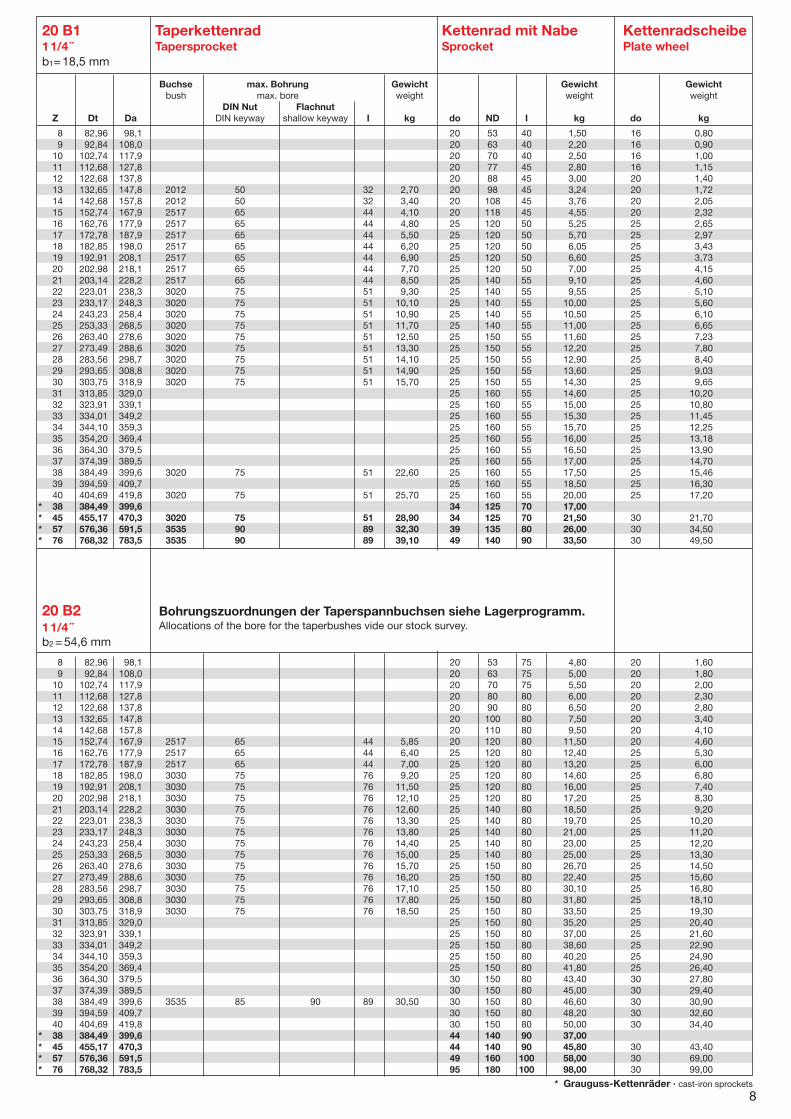
20 B1 Taperkettenrad Kettenrad mit Nabe Kettenradscheibe11/4 ˝ Tapersprocket Sprocket Plate wheelb1=18,5 mm
8 82,96 98,1 20 53 75 4,80 20 1,609 92,84 108,0 20 63 75 5,00 20 1,80
10 102,74 117,9 20 70 75 5,50 20 2,0011 112,68 127,8 20 80 80 6,00 20 2,3012 122,68 137,8 20 90 80 6,50 20 2,8013 132,65 147,8 20 100 80 7,50 20 3,4014 142,68 157,8 20 110 80 9,50 20 4,1015 152,74 167,9 2517 65 44 5,85 20 120 80 11,50 20 4,6016 162,76 177,9 2517 65 44 6,40 25 120 80 12,40 25 5,3017 172,78 187,9 2517 65 44 7,00 25 120 80 13,20 25 6,0018 182,85 198,0 3030 75 76 9,20 25 120 80 14,60 25 6,8019 192,91 208,1 3030 75 76 11,50 25 120 80 16,00 25 7,4020 202,98 218,1 3030 75 76 12,10 25 120 80 17,20 25 8,3021 203,14 228,2 3030 75 76 12,60 25 140 80 18,50 25 9,2022 223,01 238,3 3030 75 76 13,30 25 140 80 19,70 25 10,2023 233,17 248,3 3030 75 76 13,80 25 140 80 21,00 25 11,2024 243,23 258,4 3030 75 76 14,40 25 140 80 23,00 25 12,2025 253,33 268,5 3030 75 76 15,00 25 140 80 25,00 25 13,3026 263,40 278,6 3030 75 76 15,70 25 150 80 26,70 25 14,5027 273,49 288,6 3030 75 76 16,20 25 150 80 22,40 25 15,6028 283,56 298,7 3030 75 76 17,10 25 150 80 30,10 25 16,8029 293,65 308,8 3030 75 76 17,80 25 150 80 31,80 25 18,1030 303,75 318,9 3030 75 76 18,50 25 150 80 33,50 25 19,3031 313,85 329,0 25 150 80 35,20 25 20,4032 323,91 339,1 25 150 80 37,00 25 21,6033 334,01 349,2 25 150 80 38,60 25 22,9034 344,10 359,3 25 150 80 40,20 25 24,9035 354,20 369,4 25 150 80 41,80 25 26,4036 364,30 379,5 30 150 80 43,40 30 27,8037 374,39 389,5 30 150 80 45,00 30 29,4038 384,49 399,6 3535 85 90 89 30,50 30 150 80 46,60 30 30,9039 394,59 409,7 30 150 80 48,20 30 32,6040 404,69 419,8 30 150 80 50,00 30 34,40
* 38 384,49 399,6 44 140 90 37,00* 45 455,17 470,3 44 140 90 45,80 30 43,40* 57 576,36 591,5 49 160 100 58,00 30 69,00* 76 768,32 783,5 95 180 100 98,00 30 99,00
8* Grauguss-Kettenräder · cast-iron sprockets
Buchse max. Bohrung Gewicht Gewicht Gewichtbush max. bore weight weight weight
DIN Nut FlachnutZ Dt Da DIN keyway shallow keyway I kg do ND I kg do kg
20 B211/4 ˝b2 =54,6 mm
8 82,96 98,1 20 53 40 1,50 16 0,809 92,84 108,0 20 63 40 2,20 16 0,90
10 102,74 117,9 20 70 40 2,50 16 1,0011 112,68 127,8 20 77 45 2,80 16 1,1512 122,68 137,8 20 88 45 3,00 20 1,4013 132,65 147,8 2012 50 32 2,70 20 98 45 3,24 20 1,7214 142,68 157,8 2012 50 32 3,40 20 108 45 3,76 20 2,0515 152,74 167,9 2517 65 44 4,10 20 118 45 4,55 20 2,3216 162,76 177,9 2517 65 44 4,80 25 120 50 5,25 25 2,6517 172,78 187,9 2517 65 44 5,50 25 120 50 5,70 25 2,9718 182,85 198,0 2517 65 44 6,20 25 120 50 6,05 25 3,4319 192,91 208,1 2517 65 44 6,90 25 120 50 6,60 25 3,7320 202,98 218,1 2517 65 44 7,70 25 120 50 7,00 25 4,1521 203,14 228,2 2517 65 44 8,50 25 140 55 9,10 25 4,6022 223,01 238,3 3020 75 51 9,30 25 140 55 9,55 25 5,1023 233,17 248,3 3020 75 51 10,10 25 140 55 10,00 25 5,6024 243,23 258,4 3020 75 51 10,90 25 140 55 10,50 25 6,1025 253,33 268,5 3020 75 51 11,70 25 140 55 11,00 25 6,6526 263,40 278,6 3020 75 51 12,50 25 150 55 11,60 25 7,2327 273,49 288,6 3020 75 51 13,30 25 150 55 12,20 25 7,8028 283,56 298,7 3020 75 51 14,10 25 150 55 12,90 25 8,4029 293,65 308,8 3020 75 51 14,90 25 150 55 13,60 25 9,0330 303,75 318,9 3020 75 51 15,70 25 150 55 14,30 25 9,6531 313,85 329,0 25 160 55 14,60 25 10,2032 323,91 339,1 25 160 55 15,00 25 10,8033 334,01 349,2 25 160 55 15,30 25 11,4534 344,10 359,3 25 160 55 15,70 25 12,2535 354,20 369,4 25 160 55 16,00 25 13,1836 364,30 379,5 25 160 55 16,50 25 13,9037 374,39 389,5 25 160 55 17,00 25 14,7038 384,49 399,6 3020 75 51 22,60 25 160 55 17,50 25 15,4639 394,59 409,7 25 160 55 18,50 25 16,3040 404,69 419,8 3020 75 51 25,70 25 160 55 20,00 25 17,20
* 38 384,49 399,6 34 125 70 17,00* 45 455,17 470,3 3020 75 51 28,90 34 125 70 21,50 30 21,70* 57 576,36 591,5 3535 90 89 32,30 39 135 80 26,00 30 34,50* 76 768,32 783,5 3535 90 89 39,10 49 140 90 33,50 30 49,50
Bohrungszuordnungen der Taperspannbuchsen siehe Lagerprogramm.Allocations of the bore for the taperbushes vide our stock survey.

24 B1 Taperkettenrad Kettenrad mit Nabe Kettenradscheibe11/2˝x 1˝ Tapersprocket Sprocket Plate wheel b1=24,1 mm
8 99,55 115,0 20 58 45 2,60 20 0,909 111,40 126,4 20 70 45 3,80 20 1,10
10 123,29 138,0 20 80 45 4,25 20 1,9011 135,21 150,0 25 90 50 4,80 20 2,4012 147,22 162,0 25 102 50 5,10 20 2,9013 159,18 174,2 25 114 50 5,50 20 3,1014 171,22 186,2 25 128 50 6,40 20 3,7015 183,26 198,2 2517 65 44 3,90 25 140 50 7,70 20 4,3016 195,30 210,3 25 140 55 8,90 25 4,9017 207,34 222,3 3535 90 89 6,40 25 140 55 9,70 25 5,5018 219,42 234,3 3535 90 89 25 140 55 10,30 25 6,3019 231,49 246,5 3535 90 89 7,85 25 140 55 11,20 25 7,0020 243,57 258,6 3535 90 89 9,50 25 140 55 11,90 25 7,8021 255,56 270,6 3535 90 89 9,50 25 150 60 15,50 25 8,6022 267,73 282,7 25 150 60 16,30 25 9,4023 279,80 294,8 3535 90 89 11,30 25 140 60 17,00 25 10,5024 291,88 306,8 25 150 60 17,90 25 11,2025 304,00 319,0 3535 90 89 13,30 25 150 60 18,70 25 12,8026 316,08 331,0 30 160 60 19,70 30 13,6027 328,19 343,2 3535 90 89 15,50 30 160 60 20,80 30 14,3028 340,27 355,2 30 160 60 22,00 30 15,7029 352,38 367,3 3535 90 89 15,50 30 160 60 23,20 30 16,8030 364,50 379,5 3535 90 89 22,70 30 160 60 24,30 30 18,1031 376,62 391,6 30 160 60 24,90 30 19,3032 388,69 403,7 30 160 60 25,50 30 20,8033 400,81 415,8 30 160 60 26,00 30 21,9034 412,93 427,8 30 160 60 26,70 30 22,5035 425,04 440,0 30 160 60 27,20 30 24,2036 437,16 452,0 30 160 60 28,10 30 26,8037 449,27 464,2 30 160 60 28,90 30 28,1038 461,39 476,2 3535 90 89 31,60 30 160 60 29,90 30 29,1039 473,50 488,5 30 160 60 31,50 30 32,8040 485,62 500,6 30 160 60 34,00 30 44,50
* 38 461,39 476,2 44 140 90 28,90* 45 546,20 561,2 44 140 90 37,70 30 56,70* 57 691,63 706,5 4545 110 114 45,90 44 160 100 44,20 30 70,00* 76 921,98 936,9 44 170 100 58,60 40 86,00
8 99,55 115,0 25 58 95 5,609 111,40 126,4 25 70 95 5,80
10 123,29 138,0 25 80 95 6,1011 135,21 150,0 25 90 100 7,5012 147,22 162,0 25 102 100 9,4013 159,18 174,2 25 114 100 11,2014 171,22 186,2 25 128 100 13,3015 183,26 198,2 3020 75 51 10,10 25 140 100 15,2016 195,30 210,3 25 140 100 17,5017 207,34 222,3 3535 90 89 10,90 25 150 100 19,8018 219,42 234,3 25 160 100 22,5019 231,49 246,5 3535 90 89 11,50 25 160 100 25,2020 243,57 258,6 25 160 100 28,1021 255,56 270,6 3535 90 89 13,00 25 160 100 31,1022 267,73 282,7 25 160 100 34,2023 279,80 294,8 3535 90 89 13,90 25 160 100 37,5024 291,88 306,8 25 160 100 41,0025 304,00 319,0 4040 100 101 15,00 25 160 100 43,0026 316,08 331,0 30 160 100 45,0027 328,19 343,2 4040 100 101 17,00 30 160 100 48,0028 340,27 355,2 30 160 100 52,0029 352,38 367,3 4545 110 114 45,00 30 160 100 54,0030 364,50 379,5 4545 110 114 46,80 30 160 100 56,0031 376,62 391,6 30 170 100 58,0032 388,69 403,7 30 170 100 61,0033 400,81 415,8 30 170 100 63,0034 412,93 427,8 30 170 100 65,0035 425,04 440,0 30 170 100 67,0036 437,16 452,0 30 170 100 69,0037 449,27 464,2 30 170 100 74,0038 461,39 476,2 4545 110 114 75,00 30 170 100 77,0039 473,50 488,5 30 170 100 81,0040 485,62 500,6 30 170 100 88,00
* 38 461,39 476,2 44 180 100 61,00* 45 546,20 561,2 54 190 100 79,00* 57 691,63 706,5 54 200 110 97,00* 76 921,98 936,9 54 220 120 166,00
Buchse max. Bohrung Gewicht Gewicht Gewichtbush max. bore weight weight weight
DIN Nut FlachnutZ Dt Da DIN keyway shallow keyway I kg do ND I kg do kg
24 B2 11/2 ˝ x 1 ˝b2=72 mm Kettenradsc
9* Grauguss-Kettenräder · cast-iron sprockets
Bohrungszuordnungen der Taperspannbuchsen siehe Lagerprogramm.Allocations of the bore for the taperbushes vide our stock survey.
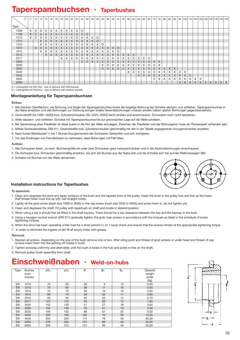
Montageanleitung für Taperspannbuchsen
Einbau:
1. Alle blanken Oberflächen, wie Bohrung und Kegel der Taperspannbuchse sowie die kegelige Bohrung der Scheibe säubern und entfetten. Taperspannbuchse indie Nabe einsetzen und alle Bohrungen zur Deckung bringen (halbe Gewindebohrungen müssen jeweils halben glatten Bohrungen gegenüberstehen).
2. Gewindestift (Gr.1008–3030) bzw. Zylinderschrauben (Gr. 3525–6050) leicht einölen und einschrauben. Schrauben noch nicht festziehen.
3. Welle säubern und entfetten. Scheibe mit Taperspannbuchse bis zur gewünschten Lage auf die Welle schieben.
4. Bei Verwendung einer Passfeder ist diese zuerst in die Nut der Welle einzulegen. Zwischen der Passfeder und der Bohrungsnut muss ein Rückenspiel vorhanden sein.
5. Mittels Schraubendreher, DIN 911, Gewindestifte bzw. Zylinderschrauben gleichmäßig mit den in der Tabelle angegebenen Anzugsmomenten anziehen.
6. Nach kurzer Betriebszeit 1/2 bis 1 Stunde Anzugsmoment der Schrauben überprüfen und evtl. korrigieren.
7. Um das Eindringen von Fremdkörpern zu verhindern, leere Bohrungen mit Fett füllen.
Ausbau:
1. Alle Schrauben lösen. Je nach Buchsengröße ein oder zwei Schrauben ganz herausschrauben und in die Abdrückbohrungen einschrauben.
2. Die Schraube bzw. Schrauben gleichmäßig anziehen, bis sich die Buchse aus der Nabe löst und die Scheibe sich frei auf der Welle bewegen läßt.
3. Scheibe mit Buchse von der Welle abnehmen.
Installation instructions for Taperbushes
To assemble:
1. Clean and degrease the bore and taper surfaces of the bush and the tapered bore of the pulley. Insert the bush in the pulley hub and line up the holes (half thread holes must line up with half straight holes).
2. Lightly oil the grub screw (bush size 1008 to 3030) or the cap screw (bush size 3535 to 5050) and screw them in, do not tighten yet.
3. Clean and degrease the shaft. Fit pulley with taperbush on shaft and locate in desired position.
4. When using a key it should first be fitted in the shaft keyway. There should be a top clearance between the key and the keyway in the bore.
5. Using a hexagon socket wrench (DIN 911) gradually tighten the grub/cap screws in accordance with the torques as listed in the schedule of screw tightening torques.
6. When the drive has been operating under load for a short period (1/2 to 1 hour) check and ensure that the screws remain at the appropriate tightening torque.
7. In order to eliminate the ingress of dirt fill all empty holes with grease.
Removal:
1. Slacken all screws. Depending on the size of the bush remove one or two. After oiling point and thread of grub screws or under head and thread of capscrews insert them into the jacking off hole(s) in bush.
2. Tighten screw(s) uniformly and alternately until the bush is loose in the hub and pulley is free on the shaft.
3. Remove pulley/bush assembly from shaft.
Type Buchse øDA øDz B BK BZ Gewichtbush weightmoyeur poids
[kg]EN 1210 70 60 26 9 10 0,20EN 1215 70 60 38 11 16 0,50EN 1610 70 70 26 16 10 0,55EN 1615 83 70 38 22 11 0,60EN 2012 95 90 32 22 12 0,70EN 2517 127 110 45 26 13 1,80EN 3020 152 130 51 27 18 3,50EN 3030 152 130 76 51 19 4,50EN 3535 184 155 89 67 25 6,50EN 4040 225 195 102 70 35 13,50EN 4545 254 220 114 76 40 20,30EN 5050 276 242 127 89 40 25,50EN 6050 359 315 127 89 40 52,00
1008110812101215131016101615201225173020303035354040454550506050
10
Taperspannbuchsen · Taperbushes
Einschweißnaben · Weld-on-hubs
�
Type
11
XXX
12
XXX
X
14
XXXXXXX
15
XXXXXXXX
16
XXXXXXXX
18
XXXXXXXX
19
XXXXXXXXX
20
XXXXXXXXX
22
XXXXXXXXX
24
XXXXXXXXX
25
OXXXXXXXXX
28
OXXXXXXXX
30
XXXXXXXX
32
OOXXXXXX
35
OXXXXXXX
38
XXXXXXX
40
XXXXXXX
42
OOXXXXX
45
XXXXX
48
XXXXXX
50
XXXXXX
55
XXXXXX
60
XXXXXX
65
XXXXXX
70
XXXXXX
75
XXXXXX
80
XXXX
85
XXXX
90
XXXX
95
XXXX
100
XXXX
110
XXX
120
XX
125
XX
130
X
135
X
140
X
145
X
150
X
X = Liefergröße mit DIN -Nut · size of delivery with DIN-keywayO = Liefergröße mit Flachnut · size of delivery with shallow keyway