
Unterarbeitskreis Signalisierung Specification of the NGN ... · UAK-S: NGN Ici Interface Seite 1...
98
UAK-S: NGN Ici Interface Seite 1 von 98 Ausgabestand: V2.0.0 vom 23.03.2018 Spec_UAKS_NGN_Ici_Interface_V_2_0_0 Unterarbeitskreis Signalisierung Specification of the NGN-Interconnection Interface 3GPP Release 12 Ausgabestand: V2.0.0 vom 23.03.2018 Verabschiedet in der 170. Tagung des AKNN am 20.02.2018 Herausgegeben vom Arbeitskreis für technische und betriebliche Fragen der Nummerierung und Netzzusammenschaltung (AKNN) Erarbeitet vom Unterarbeitskreis Signalisierung (UAK-S) Editor: Stefan Krämer DB Netz AG E-Mail: stefan.kraemer(at)deutschebahn(dot)com
Transcript of Unterarbeitskreis Signalisierung Specification of the NGN ... · UAK-S: NGN Ici Interface Seite 1...

UAK-S: NGN Ici Interface Seite 1 von 98
Ausgabestand: V2.0.0 vom 23.03.2018 Spec_UAKS_NGN_Ici_Interface_V_2_0_0
Unterarbeitskreis Signalisierung
Specification
of the
NGN-Interconnection Interface
3GPP Release 12
Ausgabestand: V2.0.0
vom 23.03.2018
Verabschiedet in der 170. Tagung des AKNN am 20.02.2018
Herausgegeben vom Arbeitskreis für technische und betriebliche Fragen der Nummerierung und Netzzusammenschaltung (AKNN)
Erarbeitet vom Unterarbeitskreis Signalisierung (UAK-S)
Editor: Stefan Krämer DB Netz AG
E-Mail: stefan.kraemer(at)deutschebahn(dot)com
UAK-S: NGN Ici Interface Seite 2 von 98
Ausgabestand: V2.0.0 vom 23.03.2018 Spec_UAKS_NGN_Ici_Interface_V_2_0_0
0 Contents 0 Contents ................................................................................................................................ 2
0.1 List of Figures ..................................................................................................................................... 6
0.2 List of Tables ...................................................................................................................................... 6
1 History ................................................................................................................................... 8
2 Foreword ............................................................................................................................. 10
3 Scope .................................................................................................................................. 10
4 References .......................................................................................................................... 11
4.1 General ............................................................................................................................................. 11
4.2 Basis Specification ........................................................................................................................... 11
4.3 Further References ........................................................................................................................... 11
4.3.1 Protocols .................................................................................................................................. 11
4.3.2 Numbering and Addressing ..................................................................................................... 11
4.3.3 Emulation Services .................................................................................................................. 11
4.3.4 Emergency Calls ...................................................................................................................... 11
4.3.5 National References ................................................................................................................ 12
5 Definitions and Abbreviations ............................................................................................... 13
5.1 Definitions ......................................................................................................................................... 13
5.1.1 Nature of SIP ........................................................................................................................... 13
5.1.2 Reference Points of Interfaces ................................................................................................ 13
5.1.3 Trust Domain and Topology Hiding ......................................................................................... 13
5.1.4 P-Asserted-Identity .................................................................................................................. 14
5.2 Abbreviations .................................................................................................................................... 15
6 Architecture .......................................................................................................................... 17
6.1 Ici Interface ....................................................................................................................................... 17
6.2 Izi Interface ....................................................................................................................................... 17
7 Numbering and Addressing at the Ic-Interface ..................................................................... 18
7.1 Format of SIP URIs .......................................................................................................................... 18
7.1.1 Global Number Format ............................................................................................................ 18
7.1.2 SIP Request URI ..................................................................................................................... 18
7.1.2.1 Number Portability ...................................................................................................... 18
7.1.2.2 Emergency Calls ("Notruf") ......................................................................................... 19
7.1.2.2.1 PSAP in PSTN Technology ....................................................................................... 19
7.1.2.2.2 PSAP in NGN Technology ......................................................................................... 19
7.1.2.3 Harmonised Numbers for Harmonised Services of Social Value ("Harmonisierte Dienste von sozialem Wert") ........................................................................................................ 19
7.1.2.4 Authority Bureau Call ("Einheitlicher Behördenruf") ................................................... 20
7.1.2.5 Directory Enquiries ("Auskunft") ................................................................................. 20
7.1.2.6 Tollfree Callback Service for Directory Enquiries ("Entgeltfreie Rückrufnummer für Vermittlungsdienste") ................................................................................................................... 21
7.1.2.7 International Freephone Services ............................................................................... 21
7.1.2.8 International Service Numbers ................................................................................... 21
7.1.2.9 Test Numbers for Carrier Selection Calls ................................................................... 21
7.1.3 P-Asserted-Identity Header Field............................................................................................. 21
7.1.4 From Header Field ................................................................................................................... 22
7.1.5 To Header Field ....................................................................................................................... 22
7.1.6 History-Info Header Field ......................................................................................................... 22

UAK-S: NGN Ici Interface Seite 3 von 98
Ausgabestand: V2.0.0 vom 23.03.2018 Spec_UAKS_NGN_Ici_Interface_V_2_0_0
7.2 Routing of SIP Requests .................................................................................................................. 22
7.2.1 Scenario 1: Termination ........................................................................................................... 22
7.2.2 Scenario 2a: Determination of the Destination Network is not possible in the A-Domain ....... 23
7.2.3 Scenario 2b: Determination of the Destination Network is possible in the A-Domain, but there is no Traffic Relation to the Destination Domain .................................................................................... 23
7.3 Charged / Non Charged Telephone Traffic ...................................................................................... 24
7.4 Mobile Service Prefix ("Mobilfunkservicevorwahl") .......................................................................... 24
7.4.1 Introduction .............................................................................................................................. 24
7.4.2 Definition .................................................................................................................................. 24
7.4.3 Transmission............................................................................................................................ 24
7.5 Service Calls handed over from International Carriers .................................................................... 25
8 Ic-Profile Endorsement for 3GPP TS 29.165 ........................................................................ 26
8.1 Global Modifications ......................................................................................................................... 26
8.2 Major Capabilities ............................................................................................................................. 26
8.3 Profiling of 3GPP TS 29.165 ............................................................................................................ 33
8.3.1 Supported SIP Methods ........................................................................................................... 33
8.3.2 Supported Status Codes .......................................................................................................... 34
8.3.3 Supported Header Fields ......................................................................................................... 38
8.3.4 Supported SDP Types ............................................................................................................. 42
8.3.5 Supported Media Attribute Lines ............................................................................................. 43
8.3.6 Supported MIME Bodies .......................................................................................................... 45
9 Simulation Services Supported for NGN-Voice-Interconnection ........................................... 48
9.1 Supported Services on the Interconnection Interface ...................................................................... 48
9.2 Description of Services ..................................................................................................................... 48
9.2.1 CDIV ........................................................................................................................................ 48
9.2.2 OIP/OIR ................................................................................................................................... 49
9.2.3 TIP/TIR ..................................................................................................................................... 49
9.2.4 HOLD ....................................................................................................................................... 49
9.2.5 ACR&CB .................................................................................................................................. 49
9.2.6 ECT .......................................................................................................................................... 49
9.2.7 CONF ....................................................................................................................................... 49
9.2.8 CUG ......................................................................................................................................... 49
9.2.9 MWI .......................................................................................................................................... 49
9.2.10 MCID ........................................................................................................................................ 49
9.2.11 Call Completion........................................................................................................................ 49
9.2.12 CW ........................................................................................................................................... 49
9.2.13 Emergency Calls (Notruf) ........................................................................................................ 49
10 Bearer Aspects ............................................................................................................... 50
10.1 Bearer Services ............................................................................................................................ 50
10.2 Bearer Control .............................................................................................................................. 50
10.2.1 Through Connection of the Media Path (speech-/data-transmission) ..................................... 50
10.2.1.1 General Remarks ........................................................................................................ 50
10.2.1.2 Scenarios described ................................................................................................... 50
10.2.1.2.1 Remarks and Symbols used .................................................................................... 50
10.2.1.2.2 Scenario 1: Connection Set-up to User Equipment B, which is Not Trusted concerning Early Media ................................................................................................................ 51
10.2.1.2.3 Scenario 2: Connection Set-up to User Equipment B, which is Trusted concerning Early Media ................................................................................................................................. 52
UAK-S: NGN Ici Interface Seite 4 von 98
Ausgabestand: V2.0.0 vom 23.03.2018 Spec_UAKS_NGN_Ici_Interface_V_2_0_0
10.2.1.2.4 Scenario 3: Connection Set-up with Tones/Announcements from the Transit-/ Destination Network ..................................................................................................................... 53
10.2.1.2.5 Scenario 4: Originator has an Early Media Dialogue with an IVR in the Transit-/ Destination Network ..................................................................................................................... 54
10.2.1.3 Description of the Procedures .................................................................................... 54
10.2.1.3.1 Actions required at the Origination Network ............................................................ 54
10.2.1.3.2 Actions required at an Intermediate National Network (Transit) .............................. 57
10.2.1.3.3 Actions required at the Termination Network ........................................................... 58
10.2.1.3.4 Overview of the Media Handling in the Relevant Network Types ............................ 60
10.2.2 MIME Type Handling ............................................................................................................... 61
10.3 Tones and Announcements ......................................................................................................... 61
10.3.1 Actions required at the Origination Network ............................................................................ 61
10.3.2 Actions required at an Intermediate National Network (Transit) .............................................. 61
10.3.3 Actions required at the Terminating Network .......................................................................... 61
10.3.4 Media Clipping ......................................................................................................................... 61
10.4 Codecs ......................................................................................................................................... 61
10.5 IP Version, IP Header Interworking and Fragmentation .............................................................. 61
11 Forward Address Signalling ............................................................................................ 62
11.1 En Bloc Forward Address Signalling only .................................................................................... 62
11.2 Multiple Invite Method in Combination with En Bloc Forward Address Signalling ....................... 62
11.3 Usage of both Variants in Interconnection Scenarios .................................................................. 62
12 Charging Aspects ........................................................................................................... 64
12.1 Begin of Charging ........................................................................................................................ 64
12.2 End of Charging ........................................................................................................................... 64
12.3 SIP Support of Charging .............................................................................................................. 64
13 Roaming ......................................................................................................................... 65
14 Emergency Calls ............................................................................................................. 66
14.1 Requirements for Emergency Calls ............................................................................................. 66
14.2 Number Format ............................................................................................................................ 66
14.3 Transmission of Additional Information ........................................................................................ 66
14.3.1 SIP UUI Header Field .............................................................................................................. 67
14.3.1.1 General ....................................................................................................................... 67
14.3.1.2 Civic Location ............................................................................................................. 67
14.3.1.3 Geographic Location ................................................................................................... 68
14.3.2 SIP Geolocation Header Field ................................................................................................. 68
14.3.2.1 General ....................................................................................................................... 69
14.3.2.2 Civic Location ............................................................................................................. 69
14.3.2.3 Geographic Location ................................................................................................... 71
14.3.2.3.1 Point ......................................................................................................................... 71
14.3.2.3.2 Ellipse ....................................................................................................................... 72
14.3.2.3.3 Polygon .................................................................................................................... 73
14.3.2.3.4 Arc Band .................................................................................................................. 75
14.3.2.3.5 Description of Radio Cell ......................................................................................... 76
14.3.2.3.6 Mobile Radio Cell Identification ................................................................................ 76
14.3.2.3.7 Confidence ............................................................................................................... 77
14.4 Exemplary Encoding .................................................................................................................... 78
14.4.1 Civic Location........................................................................................................................... 78
14.4.2 Ellipsoid Arc/Arc Band ............................................................................................................. 81

UAK-S: NGN Ici Interface Seite 5 von 98
Ausgabestand: V2.0.0 vom 23.03.2018 Spec_UAKS_NGN_Ici_Interface_V_2_0_0
14.5 Emergency Calls for Voice Service Provider ............................................................................... 83
Annex A Address Formats (informative) ................................................................................ 84
A.1 Number Portability ........................................................................................................................ 84
A.2 Emergency Calls .......................................................................................................................... 84
Annex B SIP/SDP MIME Type Signalling on the Ici-Interface (informative) ............................ 85
B.1 Scope ........................................................................................................................................... 85
B.2 application/SDP ............................................................................................................................ 85
B.3 application/ISUP ........................................................................................................................... 85
B.4 multipart/mixed ............................................................................................................................. 85
B.5 application/vnd.etsi.pstn+xml ....................................................................................................... 86
B.6 application/vnd.etsi.sci+xml ......................................................................................................... 86
B.7 application/vnd.etsi.cug+xml ........................................................................................................ 87
Annex C Forward Address Signalling (informative) ................................................................ 88
C.1 General ......................................................................................................................................... 88
C.2 Overlap Signalling Methods ......................................................................................................... 88
C.2.1 In-dialogue Method .................................................................................................................. 88
C.2.2 Multiple-INVITE Method ........................................................................................................... 88
C.2.2.1 General............................................................................................................................ 88
C.3 Routing Impacts ........................................................................................................................... 88
C.3.1 General .................................................................................................................................... 88
C.3.2 Deterministic Routing ............................................................................................................... 88
C.3.3 Digit Collection ......................................................................................................................... 89
Annex D Calling Party's Category (normative) ....................................................................... 90
D.1 Introduction................................................................................................................................... 90
D.2 Definition ...................................................................................................................................... 90
D.3 Transmission ................................................................................................................................ 90
D.4 Interworking .................................................................................................................................. 90
D.5 Example ....................................................................................................................................... 90
Annex E Nationally Ported International Service Numbers (informative) ................................ 92
Annex F Complex Call Setup/Termination Handling at the Ic-Interface (informative) ............. 93
F.1 Error Handling for Call Scenarios with multiple Transit Carriers ...................................................... 93
F.2 Announcement Handling in complex Call Scenarios ....................................................................... 95
Annex G Use of SIP Options to Query the Operational Status of an IBCF (informative) ......... 98
UAK-S: NGN Ici Interface Seite 6 von 98
Ausgabestand: V2.0.0 vom 23.03.2018 Spec_UAKS_NGN_Ici_Interface_V_2_0_0
0.1 List of Figures Figure 5-1: SIP at the NNI between NGN providers ..................................................................................... 13
Figure 6-1: NGN Interconnection .................................................................................................................. 17
Figure 7-1: Scenario 1: Termination .............................................................................................................. 22
Figure 7-2: Scenario 2a: Determination of the Destination Network is not possible in the A-Domain .......... 23
Figure 7-3: Scenario 2b: Determination of the Destination Network is possible in the A-Domain, but there is no Traffic Relation to the Destination Domain ............................................................................................... 23
Figure 10-1: Symbols used............................................................................................................................ 51
Figure 10-2: Scenario 1: Connection set-up to user equipment B, which is not trusted concerning early media ............................................................................................................................................................. 51
Figure 10-3: Scenario 2: Connection set-up to user equipment B, which is trusted concerning early media ....................................................................................................................................................................... 52
Figure 10-4: Scenario 3: Connection set-up with tones/announcements from the transit-/destination network ....................................................................................................................................................................... 53
Figure 10-5: Scenario 4: Originator has an early media dialogue with an IVR in the transit-/destination network .......................................................................................................................................................... 54
Figure 10-6: Signalling events and media handling in the originating network ............................................. 56
Figure 10-7: Signalling events and media handling in the intermediate national network ............................ 57
Figure 10-8: Signalling events and media handling in the terminating network ............................................ 59
Figure 10-9: Signalling events and media handling in the originating, transit and terminating network ....... 60
Figure 11-1: Conversion from Multiple Invite method to En Bloc method ..................................................... 63
Figure 14-1: Description of a point as two coordinates ................................................................................. 72
Figure 14-2: Description of an Ellipse ........................................................................................................... 73
Figure 14-3: Description of a Polygon ........................................................................................................... 74
Figure 14-4: Description of an Arc Band ....................................................................................................... 75
Figure A-1: Number Portability with Routing Number ................................................................................... 84
Figure A-2: Emergency Call with Routing Number ....................................................................................... 84
Figure D-1: Example for the use of the cpc Parameter ................................................................................. 90
Figure F-1: Temporarily unavailable Announcement without final Error Response ...................................... 96
Figure F-2: Wrong Announcement in parallel Call / Forking Scenario .......................................................... 97
0.2 List of Tables Table 5-1: Definition of SIP............................................................................................................................ 13
Table 5-2: Abbreviations ................................................................................................................................ 16
Table 8-1: Meaning of Indication in the last Column ..................................................................................... 26
Table 8-2: Major Capabilities over II-NNI ...................................................................................................... 32
Table 8-3: Supported Methods ...................................................................................................................... 33
Table 8-4: Supported Status Codes .............................................................................................................. 37
Table 8-5: Supported Header Fields ............................................................................................................. 42
Table 8-6: Supported SDP Types ................................................................................................................. 43
Table 8-7: Media Attribute Lines ................................................................................................................... 44
Table 8-8: List of supported MIME Bodies .................................................................................................... 47
Table 9-1: Simulation Services ...................................................................................................................... 48
Table 14-1: Scenarios for the Transmission of additional Information (informative) ..................................... 66
Table 14-2: General UUI Information Elements ............................................................................................ 67
Table 14-3: UUI Encoding of a Civic Location............................................................................................... 68
Table 14-4: UUI Encoding of a Geographic Location .................................................................................... 68
UAK-S: NGN Ici Interface Seite 7 von 98
Ausgabestand: V2.0.0 vom 23.03.2018 Spec_UAKS_NGN_Ici_Interface_V_2_0_0
Table 14-5: Service Provider ID .................................................................................................................... 69
Table 14-6: Additional Data Parameters ....................................................................................................... 69
Table 14-7: Usage of PIDF-LO types ............................................................................................................ 69
Table 14-8: Encoding of German Characters................................................................................................ 70
Table 14-9: PIDF-LO Encoding of a Civic Location ...................................................................................... 70
Table 14-10: Encoding of a Geographic Location ......................................................................................... 71
Table F-1: Q.850 Interworking ....................................................................................................................... 94
UAK-S: NGN Ici Interface Seite 8 von 98
Ausgabestand: V2.0.0 vom 23.03.2018 Spec_UAKS_NGN_Ici_Interface_V_2_0_0
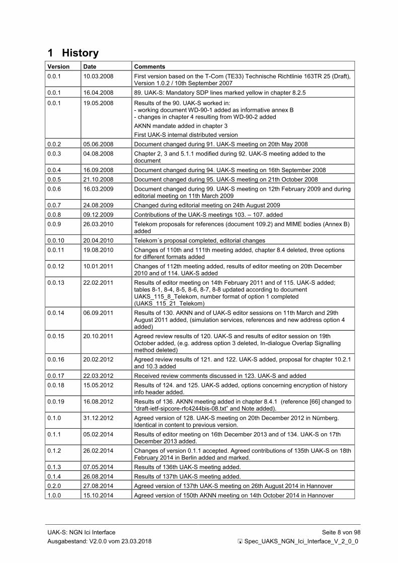
1 History Version Date Comments
0.0.1 10.03.2008 First version based on the T-Com (TE33) Technische Richtlinie 163TR 25 (Draft), Version 1.0.2 / 10th September 2007
0.0.1 16.04.2008 89. UAK-S: Mandatory SDP lines marked yellow in chapter 8.2.5
0.0.1 19.05.2008 Results of the 90. UAK-S worked in: - working document WD-90-1 added as informative annex B - changes in chapter 4 resulting from WD-90-2 added
AKNN mandate added in chapter 3
First UAK-S internal distributed version
0.0.2 05.06.2008 Document changed during 91. UAK-S meeting on 20th May 2008
0.0.3 04.08.2008 Chapter 2, 3 and 5.1.1 modified during 92. UAK-S meeting added to the document
0.0.4 16.09.2008 Document changed during 94. UAK-S meeting on 16th September 2008
0.0.5 21.10.2008 Document changed during 95. UAK-S meeting on 21th October 2008
0.0.6 16.03.2009 Document changed during 99. UAK-S meeting on 12th February 2009 and during editorial meeting on 11th March 2009
0.0.7 24.08.2009 Changed during editorial meeting on 24th August 2009
0.0.8 09.12.2009 Contributions of the UAK-S meetings 103. – 107. added
0.0.9 26.03.2010 Telekom proposals for references (document 109.2) and MIME bodies (Annex B) added
0.0.10 20.04.2010 Telekom´s proposal completed, editorial changes
0.0.11 19.08.2010 Changes of 110th and 111th meeting added, chapter 8.4 deleted, three options for different formats added
0.0.12 10.01.2011 Changes of 112th meeting added, results of editor meeting on 20th December 2010 and of 114. UAK-S added
0.0.13 22.02.2011 Results of editor meeting on 14th February 2011 and of 115. UAK-S added; tables 8-1, 8-4, 8-5, 8-6, 8-7, 8-8 updated according to document UAKS_115_8_Telekom, number format of option 1 completed (UAKS_115_21_Telekom)
0.0.14 06.09.2011 Results of 130. AKNN and of UAK-S editor sessions on 11th March and 29th August 2011 added, (simulation services, references and new address option 4 added)
0.0.15 20.10.2011 Agreed review results of 120. UAK-S and results of editor session on 19th October added, (e.g. address option 3 deleted, In-dialogue Overlap Signalling method deleted)
0.0.16 20.02.2012 Agreed review results of 121. and 122. UAK-S added, proposal for chapter 10.2.1 and 10.3 added
0.0.17 22.03.2012 Received review comments discussed in 123. UAK-S and added
0.0.18 15.05.2012 Results of 124. and 125. UAK-S added, options concerning encryption of history info header added.
0.0.19 16.08.2012 Results of 136. AKNN meeting added in chapter 8.4.1 (reference [66] changed to “draft-ietf-sipcore-rfc4244bis-08.txt” and Note added).
0.1.0 31.12.2012 Agreed version of 128. UAK-S meeting on 20th December 2012 in Nürnberg. Identical in content to previous version.
0.1.1 05.02.2014 Results of editor meeting on 16th December 2013 and of 134. UAK-S on 17th December 2013 added.
0.1.2 26.02.2014 Changes of version 0.1.1 accepted. Agreed contributions of 135th UAK-S on 18th February 2014 in Berlin added and marked.
0.1.3 07.05.2014 Results of 136th UAK-S meeting added.
0.1.4 26.08.2014 Results of 137th UAK-S meeting added.
0.2.0 27.08.2014 Agreed version of 137th UAK-S meeting on 26th August 2014 in Hannover
1.0.0 15.10.2014 Agreed version of 150th AKNN meeting on 14th October 2014 in Hannover
UAK-S: NGN Ici Interface Seite 9 von 98
Ausgabestand: V2.0.0 vom 23.03.2018 Spec_UAKS_NGN_Ici_Interface_V_2_0_0
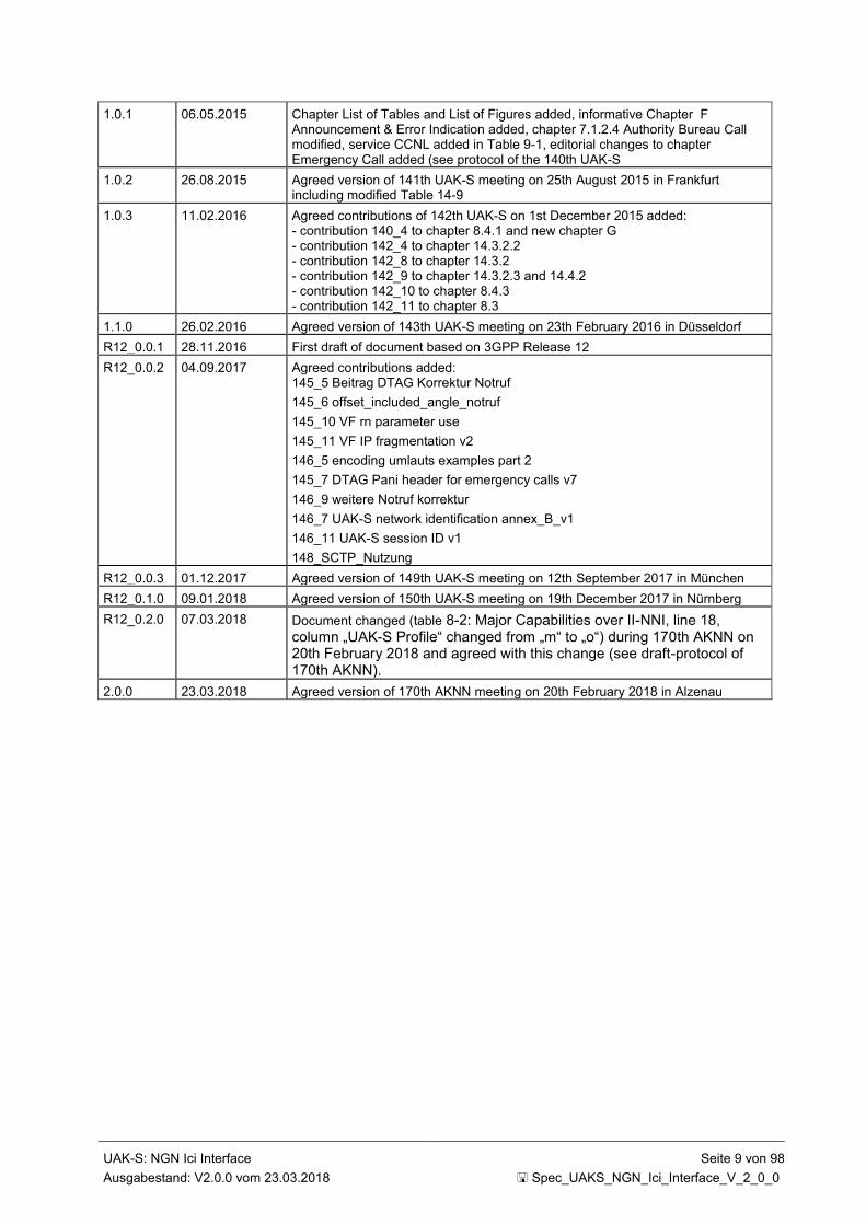
1.0.1 06.05.2015 Chapter List of Tables and List of Figures added, informative Chapter F Announcement & Error Indication added, chapter 7.1.2.4 Authority Bureau Call modified, service CCNL added in Table 9-1, editorial changes to chapter Emergency Call added (see protocol of the 140th UAK-S
1.0.2 26.08.2015 Agreed version of 141th UAK-S meeting on 25th August 2015 in Frankfurt including modified Table 14-9
1.0.3 11.02.2016 Agreed contributions of 142th UAK-S on 1st December 2015 added: - contribution 140_4 to chapter 8.4.1 and new chapter G - contribution 142_4 to chapter 14.3.2.2 - contribution 142_8 to chapter 14.3.2 - contribution 142_9 to chapter 14.3.2.3 and 14.4.2 - contribution 142_10 to chapter 8.4.3 - contribution 142_11 to chapter 8.3
1.1.0 26.02.2016 Agreed version of 143th UAK-S meeting on 23th February 2016 in Düsseldorf
R12_0.0.1 28.11.2016 First draft of document based on 3GPP Release 12
R12_0.0.2 04.09.2017 Agreed contributions added: 145_5 Beitrag DTAG Korrektur Notruf
145_6 offset_included_angle_notruf
145_10 VF rn parameter use
145_11 VF IP fragmentation v2
146_5 encoding umlauts examples part 2
145_7 DTAG Pani header for emergency calls v7
146_9 weitere Notruf korrektur
146_7 UAK-S network identification annex_B_v1
146_11 UAK-S session ID v1
148_SCTP_Nutzung
R12_0.0.3 01.12.2017 Agreed version of 149th UAK-S meeting on 12th September 2017 in München
R12_0.1.0 09.01.2018 Agreed version of 150th UAK-S meeting on 19th December 2017 in Nürnberg
R12_0.2.0 07.03.2018 Document changed (table 8-2: Major Capabilities over II-NNI, line 18, column „UAK-S Profile“ changed from „m“ to „o“) during 170th AKNN on 20th February 2018 and agreed with this change (see draft-protocol of 170th AKNN).
2.0.0 23.03.2018 Agreed version of 170th AKNN meeting on 20th February 2018 in Alzenau
UAK-S: NGN Ici Interface Seite 10 von 98
Ausgabestand: V2.0.0 vom 23.03.2018 Spec_UAKS_NGN_Ici_Interface_V_2_0_0
2 Foreword This technical specification defines the Interconnection Interface between NGN Service Providers for the service Voice over NGN (VoNGN) and has been produced by subworkinggroup UAK-S of AKNN.
The present document may refer to technical specifications or reports of 3GPP identities, UMTS identities, GSM identities, ETSI identities, ITU-T identities or IETF identities. These should be interpreted as being references to the corresponding deliverables.
3 Scope This document provides the specification for Inter-IMS Network-to-Network-Interface (II-NNI) between Next Generation Networks (NGNs) of NGN Service Providers.
For the services defined in the AKNN document "Konzept für die Zusammenschaltung von Next Generation Networks" [uaks-24] this specification provides in detail the requirements for the service layer interface (Ici Interface) and, as far as needed, requirements for the transport layer interface (Izi Interface).
IP Multimedia Subsystem (IMS) architecture, as described in 3GPP TS 23.228 [4], is used for this specification.
The II-NNI Ici reference point for this document is described as profile definition of 3GPP and IETF standards.
UAK-S: NGN Ici Interface Seite 11 von 98
Ausgabestand: V2.0.0 vom 23.03.2018 Spec_UAKS_NGN_Ici_Interface_V_2_0_0
4 References
4.1 General This specification uses 3GPP TS 29.165 as basis specification. Therefore, the references listed in this document are valid and referenced with [x]. Further references are listed below in chapter 4.3. To distinguish them from the basis references, they are marked with [uaks-x], where x denotes the index.
4.2 Basis Specification [uaks-1] 3GPP TS 29.165: "Inter-IMS Network to Network Interface" Release 12
4.3 Further References
4.3.1 Protocols [uaks-2] IETF RFC 4040 (April 2005): "RTP Payload Format for a 64 kbit/s Transparent Call" [uaks-3] IETF RFC 3362 (August 2002): "Real-time Facsimile (T.38) - image/t38 MIME Sub-type
Registration” [uaks-4] ITU-T Recommendation V.152 (November 2004): "Procedures for supporting Voice-Band Data
over IP Networks" [uaks-5] ITU-T Recommendation T.38 (September 2010, pre-published): "Procedures for real-time
Group 3 facsimile communication over IP networks"
4.3.2 Numbering and Addressing [uaks-6] ETSI TR 184 003 V3.1.1 (2010-06): "Portability of telephone numbers between operators for
Next Generation Networks (NGN)" [uaks-7] ETSI TS 184 011 V3.1.1 (2011-02): "Requirements and usage of E.164 numbers in NGN and
NGCN"
4.3.3 Emulation Services [uaks-8] IETF RFC 3204 (December 2001): "MIME media types for ISUP and QSIG Objects" [uaks-9] ETSI TS 183 043 V2.3.1 (2009-03): "Telecommunications and Internet converged Services and
Protocols for Advanced Networking (TISPAN); IMS - based PSTN/ISDN Emulation; Stage 3 specification"
[uaks-10] IETF Draft draft-ietf-bliss-call-completion-10 (May 2011): "Call Completion for Session Initiation Protocol (SIP)"
[uaks-11] IETF RFC 4575 (August 2006): "A Session Initiation (SIP) Event Package for Conference State"
4.3.4 Emergency Calls [uaks-12] IETF Draft draft-ietf-ecrit-additional-data-11 (July 2013): "Additional Data related to an
Emergency Call" [uaks-13] ITU-T Recommendation Q.763 (December 1999): "Signalling System No. 7 – ISDN user part
formats and codes" [uaks-14] ITU-T Recommendation Q.931 (May 1998): "Digital subscriber Signalling System No. 1 –
Network layer" [uaks-15] IETF RFC 5139 (February 2008): "Revised Civic Location Format for Presence Information Data
Format Location Object (PIDF-LO)" [uaks-16] IETF RFC 5491 (March 2009): "GEOPRIV Presence Information Data Format Location Object
(PIDF-LO) Usage Clarification, Considerations, and Recommendations"

UAK-S: NGN Ici Interface Seite 12 von 98
Ausgabestand: V2.0.0 vom 23.03.2018 Spec_UAKS_NGN_Ici_Interface_V_2_0_0
[uaks-17] 3GPP TS 23.032 V11.0.0 (2012-09): "3rd Generation Partnership Project; Technical Specification Group Services and System Aspects; Universal Geographical Area Description (GAD) (Release 11)"
[uaks-18] OGC 06-142r1 V1.0 (2007-04-10): "Open Geospatial Consortium Inc; GML 3.1.1 PIDF-LO Shape Application Schema for use by the Internet Engineering Task Force (IETF) "
[uaks-19] IETF Draft draft-thomson-geopriv-confidence-03 (October 2010): "Expressing Confidence in a Location Object"
[uaks-20] IETF Draft draft-thomson-geopriv-uncertainty-07 (March 2012): "Representation of Uncertainty and Confidence in PIDF-LO"
[uaks-21] IETF RFC 4119 (December 2005): "A Presence-based GEOPRIV Location Object Format"
[uaks-22] IETF RFC 7315 (July 2014):"Private Header (P-Header) Extensions to the Session Initiation Protocol (SIP) for the 3GPP"
[uaks-23] IETF RFC 20 (October 1969):"ASCII format for Network Interchange"
4.3.5 National References [uaks-24] AKNN UAK-NGN V2.0.0 (31.03.2009): "Konzept für die Zusammenschaltung von Next
Generation Networks" [uaks-25] Bundesnetzagentur V1.0 (June 2011): "Technische Richtlinie Notruf (TR-Notruf)" [uaks-26] Vfg Nr. 14/2013 der Bundesnetzagentur (April 2013): "§108 Telekommunikationsgesetz (TKG)
in Verbindung mit §7 Absatz 7 Verordnung über Notrufverbindungen (NotrufV); hier: Erweiterung der Standortbeschreibungsformen in der Technische Richtlinie Notrufverbindungen (TR Notruf)"
[uaks-27] AKNN V5.0.0 (April 2008): "Zentralglossar"
UAK-S: NGN Ici Interface Seite 13 von 98
Ausgabestand: V2.0.0 vom 23.03.2018 Spec_UAKS_NGN_Ici_Interface_V_2_0_0
5 Definitions and Abbreviations
5.1 Definitions
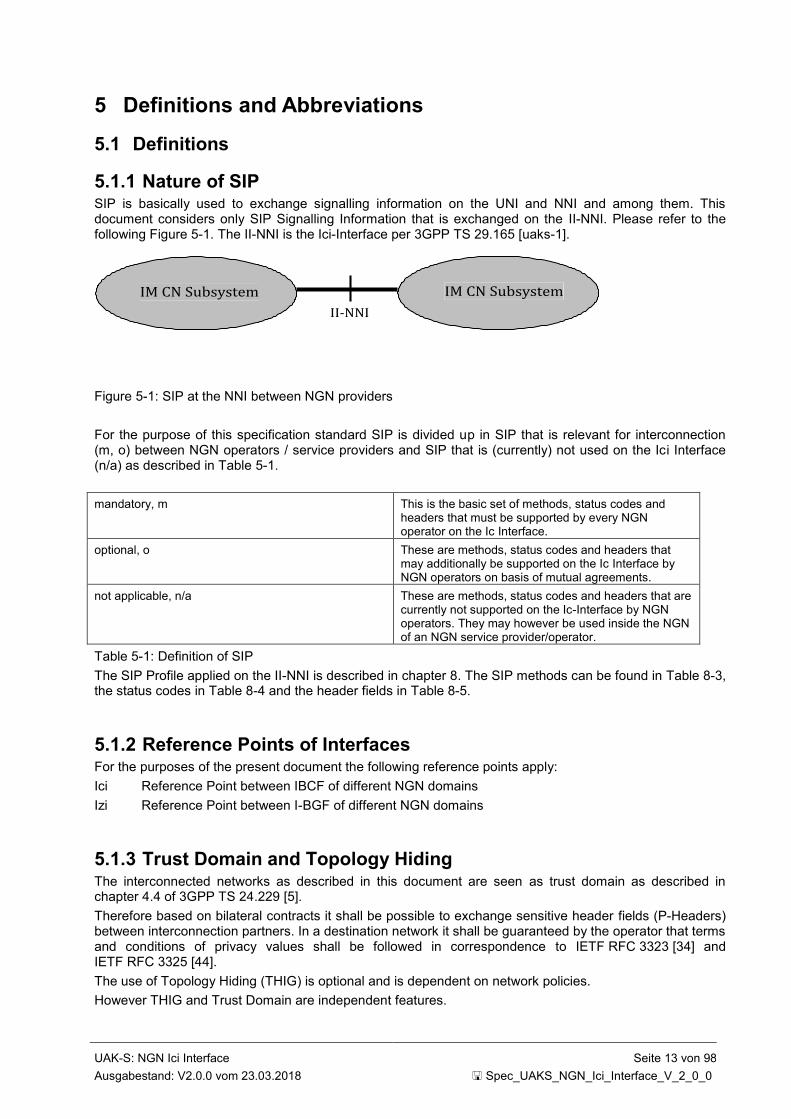
5.1.1 Nature of SIP SIP is basically used to exchange signalling information on the UNI and NNI and among them. This document considers only SIP Signalling Information that is exchanged on the II-NNI. Please refer to the following Figure 5-1. The II-NNI is the Ici-Interface per 3GPP TS 29.165 [uaks-1].
IM CN Subsystem
II-NNI
IM CN Subsystem
Figure 5-1: SIP at the NNI between NGN providers
For the purpose of this specification standard SIP is divided up in SIP that is relevant for interconnection (m, o) between NGN operators / service providers and SIP that is (currently) not used on the Ici Interface (n/a) as described in Table 5-1.
mandatory, m This is the basic set of methods, status codes and headers that must be supported by every NGN operator on the Ic Interface.
optional, o These are methods, status codes and headers that may additionally be supported on the Ic Interface by NGN operators on basis of mutual agreements.
not applicable, n/a These are methods, status codes and headers that are currently not supported on the Ic-Interface by NGN operators. They may however be used inside the NGN of an NGN service provider/operator.
Table 5-1: Definition of SIP
The SIP Profile applied on the II-NNI is described in chapter 8. The SIP methods can be found in Table 8-3, the status codes in Table 8-4 and the header fields in Table 8-5.
5.1.2 Reference Points of Interfaces For the purposes of the present document the following reference points apply:
Ici Reference Point between IBCF of different NGN domains
Izi Reference Point between I-BGF of different NGN domains
5.1.3 Trust Domain and Topology Hiding The interconnected networks as described in this document are seen as trust domain as described in chapter 4.4 of 3GPP TS 24.229 [5].
Therefore based on bilateral contracts it shall be possible to exchange sensitive header fields (P-Headers) between interconnection partners. In a destination network it shall be guaranteed by the operator that terms and conditions of privacy values shall be followed in correspondence to IETF RFC 3323 [34] and IETF RFC 3325 [44].
The use of Topology Hiding (THIG) is optional and is dependent on network policies.
However THIG and Trust Domain are independent features.

UAK-S: NGN Ici Interface Seite 14 von 98
Ausgabestand: V2.0.0 vom 23.03.2018 Spec_UAKS_NGN_Ici_Interface_V_2_0_0
5.1.4 P-Asserted-Identity The transmission of a trusted identity in form of a calling party number in the P-Asserted-Identity header field among interconnection partners is mandatory. The originating network shall ensure that the subscriber’s information in the P-Asserted Identity header field (both user part and host portion) are verified, screened and hence can uniquely be assigned to a certain subscriber. The P-Asserted-Identity header field shall be set up by the originating network operator and shall be transmitted transparently through the networks.
For calls originating from a circuit switched network, the P-Asserted-Identity header field is set up in general by the interworking network.
Note 1: For calls originating from circuit switched networks carrying no or an incomplete CLI (see table 12 of 3GPP TS 29.163 [168]) or for international calls, a P-Asserted-Identity SIP header field needs not necessarily be present.
For the format of a P-Asserted-Identity header field, please refer to chapter 7.1.3.
Note 2: In the future case of a roaming mobile customer, the domain of the P-Asserted-Identity header field needs not necessarily match the domain of the originating network operator (VPLMN).

UAK-S: NGN Ici Interface Seite 15 von 98
Ausgabestand: V2.0.0 vom 23.03.2018 Spec_UAKS_NGN_Ici_Interface_V_2_0_0
5.2 Abbreviations Abbreviation Explanation
A-BGF Access-Border Gateway Function, definition: see C-BGF:
ABNF Augmented Backus-Naur Form
ACR Anonymous Communication Rejection
AGS Allgemeiner Gemeindeschlüssel
B2BUA Back to Back User Agent
BNetzA Bundesnetzagentur
BSS Base Station Subsystem
C-BGF Core-Border Gateway Function
CAT Customised Alerting Tone
CB Communication Barring
CCBS Completion of Communications to Busy Subscriber
CCNL Completion of Communications on Not Logged-in
CCNR Completion of Communications on No Reply
CDIV Call Diversion Service
CGI Cell Global Identification
CI Cell Identity
CRS Customised Ringing Tone
CSCF Call Session Control Function
CUG Closed User Group
ECT Explicit Communication Transfer
ENUM E.164 Number Mapping
ffs for further study
GML Geographic Markup Language
HDSW Harmonised Services of Social Value (z.B. Sperrnotruf)
HSS Home Subscriber Service
I-BGF Interconnect Border Gateway Function
IBCF Interconnect Border Control Function
IC Interconnection
Ic / Ici Reference Point between IBCF of two networks (Referenzpunkt zwischen IBCF zweier Netze)
ICS IP Multimedia Core Network subsystem Centralized Services
IMSI International Mobile Subscriber Identity
Iz / Izi Reference Point between I-BGF of two networks (Referenzpunkt zwischen I-BGF zweier Netze)
IVR Interactive Voice Response System
Iw Reference Point between Interworking function and other networks (Referenzpunkt zwischen Interworkingfunktion und anderen IP-Netzen)
LAC Location Area Code
LAI Location Area Identification
MCC Mobile Country Code
MGC Media Gateway Controller
MNC Mobile Network Code
MCID Malicious Communication Identification
MIME Multipurpose Internet Mail Extensions

UAK-S: NGN Ici Interface Seite 16 von 98
Ausgabestand: V2.0.0 vom 23.03.2018 Spec_UAKS_NGN_Ici_Interface_V_2_0_0
MRF Multimedia Resource Function
MSB Most Significant Bit
MSV Mobilfunk Service Vorwahl
MWI Message Waiting Indication
NDC National Destination Code
NGCN Next Generation Corporate Networks
NGN Next Generation Networks
NNI Network Network Interface
OIP Originating Identification Presentation
OIR Originating Identification Restriction
ONKZ Ortsnetzkennzahl (NDC)
oTNB originating Network Provider (Ursprungsteilnehmernetzbetreiber)
P-CSCF Proxy CSCF
PAC Payphone Access Charge
PSAP Public Safety Answering Point (Notrufabfragestelle)
RTCP RealTime Control Protocol
SDP Session Description Protocol
SIP Session Initiation Protocol
THIG Topology Hiding Inter-network Gateway
TIP Terminating Identification Presentation
TIR Originating Identification Restriction
UA User Agent
URI Uniform Resource Identifier
UUS User to User Signalling
VLN Verkehrslenkungsnummer (routing prefix)
VoNGN Voice over Next Generation Networks
VPLMN Visited PLMN
VSP Voice Service Provider
Table 5-2: Abbreviations
Further abbreviations can be found in Zentralglossar [uaks-27] and 3GPP TS 29.165 [uaks-1].
UAK-S: NGN Ici Interface Seite 17 von 98
Ausgabestand: V2.0.0 vom 23.03.2018 Spec_UAKS_NGN_Ici_Interface_V_2_0_0
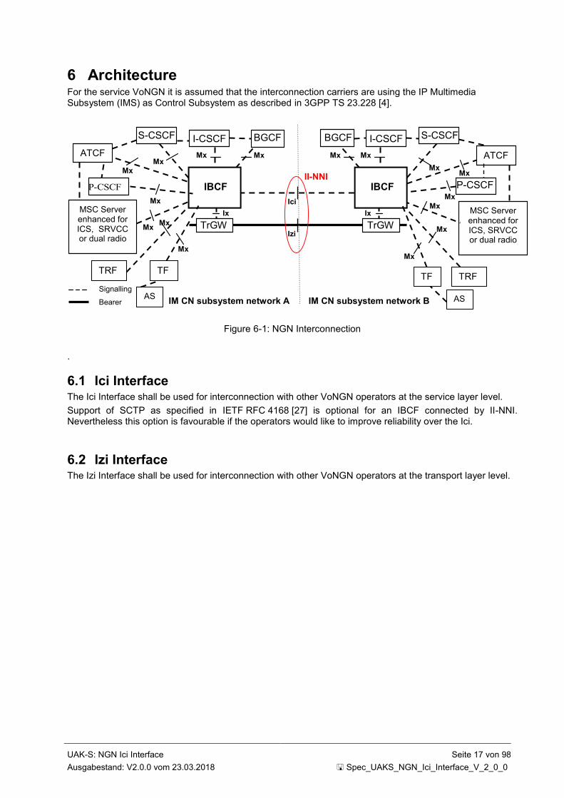
6 Architecture For the service VoNGN it is assumed that the interconnection carriers are using the IP Multimedia Subsystem (IMS) as Control Subsystem as described in 3GPP TS 23.228 [4].
IM CN subsystem network A IM CN subsystem network B
Ici
Izi
II-NNI
Mx
Ix
Mx Mx
Mx
TrGW Ix
Mx
TrGW
IBCF
S-CSCF I-CSCF
P-CSCF
S-CSCF I-CSCF
MSC Server enhanced for ICS, SRVCC or dual radio
Mx
IBCF
Signalling Bearer
ATCFF
Mx
ATCFF
Mx
MSC Server enhanced for ICS, SRVCC or dual radio
P-CSCF
Mx Mx
Mx
Mx
BGCF BGCF
Mx
TRF
Mx
TRF TF
TF
Mx Mx
AS AS
Figure 6-1: NGN Interconnection
.
6.1 Ici Interface The Ici Interface shall be used for interconnection with other VoNGN operators at the service layer level.
Support of SCTP as specified in IETF RFC 4168 [27] is optional for an IBCF connected by II-NNI. Nevertheless this option is favourable if the operators would like to improve reliability over the Ici.
6.2 Izi Interface The Izi Interface shall be used for interconnection with other VoNGN operators at the transport layer level.

UAK-S: NGN Ici Interface Seite 18 von 98
Ausgabestand: V2.0.0 vom 23.03.2018 Spec_UAKS_NGN_Ici_Interface_V_2_0_0
7 Numbering and Addressing at the Ic-Interface
7.1 Format of SIP URIs For the purpose of interconnection the URI format of a SIP URI shall be used. The user part is formatted as specified within IETF RFC 3966 [14].
The SIP URI is marked with "user = phone".
The alias format for SIP URI is not allowed at the NNI (Ici).
Notes:
Currently the alias format for a SIP-URI is not supported
The following formats can occur in combination (e.g. ported international service number)
The set up of telephone numbers shall be done in accordance with regulatory requirements
DNS forward lookups for the SIP URI's <hostportion> (e.g. operator.de) do not have to be supported by the domain owner (e.g. operator.de)
Editorial remark: In the following examples blanks are included due to a better readability.
7.1.1 Global Number Format The global-number format as specified in chapter 5.1.4 of IETF RFC 3966 [14] for a SIP URI using E.164 numbers is defined as follows:
sip: +<CC> <NDC> <SN> @ <hostportion>; user=phone
with:
CC: Country Code
NDC: National Destination Code
SN: Subscriber Number
Example:
sip: +49 30 12345678 @ operator.de; user=phone
7.1.2 SIP Request URI For a SIP Request URI, the global number format according to clause 7.1.1 shall be used.
However, for certain call scenarios as described in the following sub-clauses the transmission of additional routing information is necessary.
To route calls including additional information like hexadecimal digits (e.g. calls to PSAPs or ported destinations) the use of the rn-Parameter defined in IETF RFC 4694 [75] is mandatory, since the use of hexadecimal digits in the Request-URI using the Global Number Format is not allowed.
Being a TEL-URI parameter the rn-parameter shall be used before the "@" in the user part of a Request URI (see also Annex A of this specification).
If an rn-Parameter is available in a SIP Request URI, its evaluation shall take precedence in the user part.
Please note that the use of the rn parameter is defined only for the use cases described in the following subsections. All other scenarios are out of scope of this document and will be subject to bilateral agreements.
7.1.2.1 Number Portability
For a call with a ported destination ("Export Fall"), the following form shall be used:
sip: +<CC> <NDC> <SN> [;npdi] ;rn = +<CC> D<xyz> <NDC> <SN> @ <hostportion>; user = phone
The parameter npdi denotes that a check of the porting in the LNP database has already been done. The porting identifier (Portierungskennung) D<xyz> denotes the target network operator.
The set up of the npdi parameter is optional but if received it shall be analysed.
The +<CC>, <NDC>, <SN> in the Request-URI and in the rn TEL-URI parameter are of equal value.

UAK-S: NGN Ici Interface Seite 19 von 98
Ausgabestand: V2.0.0 vom 23.03.2018 Spec_UAKS_NGN_Ici_Interface_V_2_0_0
Example:
sip: +49 6151 1234567 [;npdi] ;rn = +49 D123 6151 1234567 @ operator.de; user = phone
7.1.2.2 Emergency Calls ("Notruf")
This chapter describes the number format of an emergency call (Notruf) dependent on the technology (NGN and PSTN, respectively) of the Public Safety Answering Point (Notrufabfragestelle, PSAP) and gives an example in each case.
For the transmission of information accompanying the emergency call, please refer to clause 14.
7.1.2.2.1 PSAP in PSTN Technology
On the NNI the following format is required for emergency calls to a PSTN PSAP:
sip: +<CC> <VLN> <NDC> <x(y)>; rn = + <CC> <NDC> CC<x(y)> @ <host portion>; user=phone
For the so called directory number (the part of the Request-URI before the (rn-)Parameter(s)), the normalized PSAP encoding into global number format with stripped hex-CC and added routing number ("Verkehrslenkungsnummer", VLN) (0)1982 between CC and NDC shall be used. Please note also the difference between the abbreviation <CC> denoting the country code and the hexdigits CC in the encoding of the PSAP.
The use of the rn-Parameter is necessary, since the encoding of the PSAP contains hexadecimal digits.
An exemplary SIP Request URI is shown below:
sip: +49 1982 911 21; rn = +49 911 CC21 @ telekom.de; user=phone
Please note that the VLN (0)1982 has not yet been assigned by the BNetzA. As an interim solution until the VLN has finally been allocated, the <VLN> in the directory number could also be omitted.
7.1.2.2.2 PSAP in NGN Technology
On the NNI the following format is required for emergency calls to an NGN PSAP:
sip: +<CC> <VLN> <NCbnetza> @ <host portion>; user=phone
The number NCbnetza will be assigned by BNetzA in conjunction with the coding of the destination PSAP access line. Also, due to limitations in the existing PSTN technology, the length of such a PSAP number (VLN and NCbnetza) may be 12 digits (including the leading "0") at the most. This is to ensure that an NGN PSAP can also be reached from PSTN customers. For the time being the length of NCbnetza is thus limited to 7 digits.
Note 1: After the last ISDN switch has been shut down, the length restriction of twelve digits does not apply anymore and the format of an NGN PSAP routing number could be revised.
The routing number ("Verkehrslenkungsnummer", VLN) (0)1982 shall be used between Country Code and NCbnetza. Please note that the VLN (0)1982 has not yet been assigned by the BNetzA.
Note 2: Details will be provided in TR Notruf (section covering the “Notrufanschlüsse in IP Technik”)
An exemplary SIP Request URI is shown below:
sip: +49 1982 4711815 @ telekom.de; user=phone
7.1.2.3 Harmonised Numbers for Harmonised Services of Social Value ("Harmonisierte Dienste von sozialem Wert")
The so called Harmonised Services of Social Value (HDSW) are called party numbers of the format 116xyz. On the interconnection interface the part xyz of the called number 116xyz has to be preceded by the routing prefix (0)1987.
sip: +<CC> 1987 <xyz> @ <hostportion>; user = phone
UAK-S: NGN Ici Interface Seite 20 von 98
Ausgabestand: V2.0.0 vom 23.03.2018 Spec_UAKS_NGN_Ici_Interface_V_2_0_0
Example:
For a call to a service to get a lost bank - or credit card locked (dialled number 116116) the interconnection format looks like:
sip: +49 1987 116 @ operator.de; user = phone
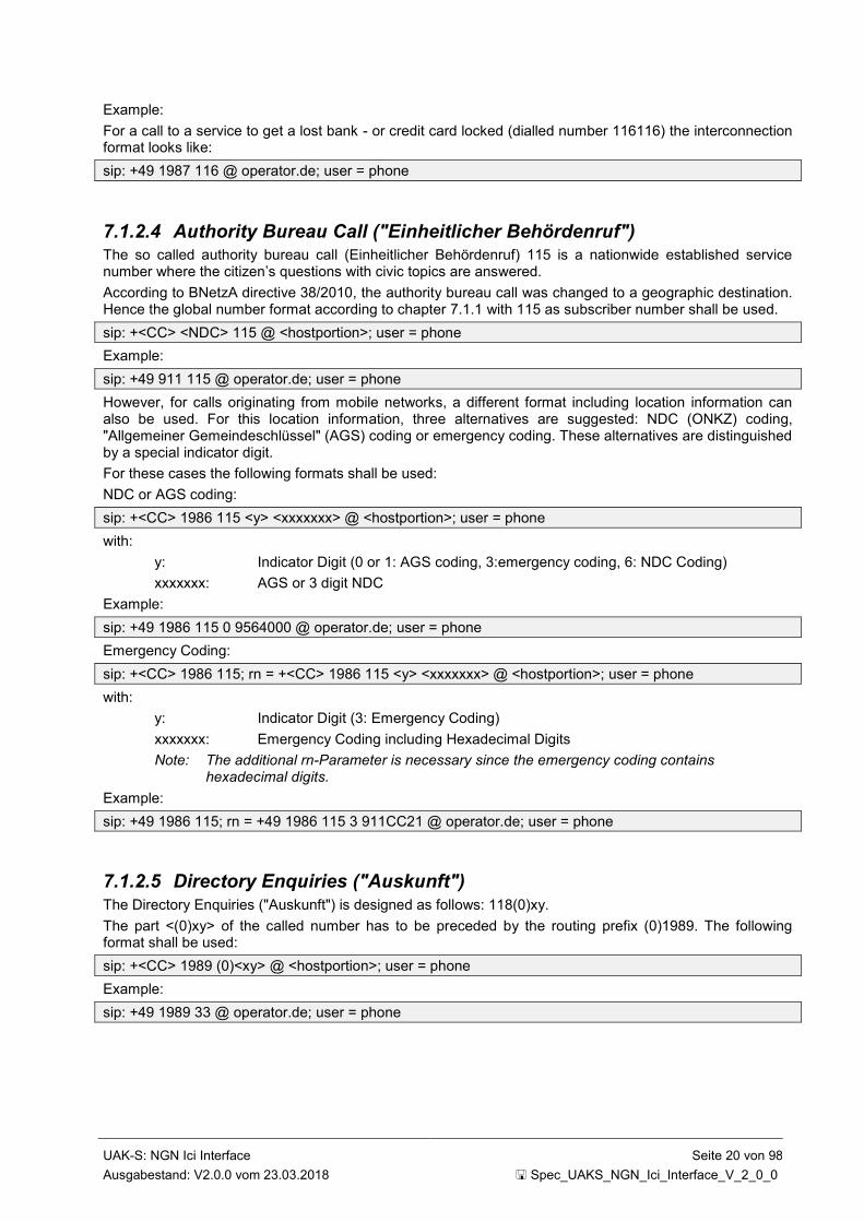
7.1.2.4 Authority Bureau Call ("Einheitlicher Behördenruf") The so called authority bureau call (Einheitlicher Behördenruf) 115 is a nationwide established service number where the citizen’s questions with civic topics are answered.
According to BNetzA directive 38/2010, the authority bureau call was changed to a geographic destination. Hence the global number format according to chapter 7.1.1 with 115 as subscriber number shall be used.
sip: +<CC> <NDC> 115 @ <hostportion>; user = phone
Example:
sip: +49 911 115 @ operator.de; user = phone
However, for calls originating from mobile networks, a different format including location information can also be used. For this location information, three alternatives are suggested: NDC (ONKZ) coding, "Allgemeiner Gemeindeschlüssel" (AGS) coding or emergency coding. These alternatives are distinguished by a special indicator digit.
For these cases the following formats shall be used:
NDC or AGS coding:
sip: +<CC> 1986 115 <y> <xxxxxxx> @ <hostportion>; user = phone
with:
y: Indicator Digit (0 or 1: AGS coding, 3:emergency coding, 6: NDC Coding)
xxxxxxx: AGS or 3 digit NDC
Example:
sip: +49 1986 115 0 9564000 @ operator.de; user = phone
Emergency Coding:
sip: +<CC> 1986 115; rn = +<CC> 1986 115 <y> <xxxxxxx> @ <hostportion>; user = phone
with:
y: Indicator Digit (3: Emergency Coding)
xxxxxxx: Emergency Coding including Hexadecimal Digits
Note: The additional rn-Parameter is necessary since the emergency coding contains hexadecimal digits.
Example:
sip: +49 1986 115; rn = +49 1986 115 3 911CC21 @ operator.de; user = phone
7.1.2.5 Directory Enquiries ("Auskunft")
The Directory Enquiries ("Auskunft") is designed as follows: 118(0)xy.
The part <(0)xy> of the called number has to be preceded by the routing prefix (0)1989. The following format shall be used:
sip: +<CC> 1989 (0)<xy> @ <hostportion>; user = phone
Example:
sip: +49 1989 33 @ operator.de; user = phone

UAK-S: NGN Ici Interface Seite 21 von 98
Ausgabestand: V2.0.0 vom 23.03.2018 Spec_UAKS_NGN_Ici_Interface_V_2_0_0
7.1.2.6 Tollfree Callback Service for Directory Enquiries ("Entgeltfreie Rückrufnummer für Vermittlungsdienste")
The Tollfree Callback Service for Directory Enquiries ("Entgeltfreie Rückrufnummer für Vermittlungs-dienste") is designed as follows: 0118(0)xy
According to BNetzA directive 53/2011, the Tollfree Callback Service for Directory Enquiries is introduced to the national networks. From the view of originating network operators it shall be handled in same manner as the freephone services are handled.
sip: +49 118 (0) xy @ <hostportion>; user = phone
Example:
sip: +49 118 10 @ operator.de; user = phone
For this procedure the CDIV service according to 3GPP TS 24.604 [117] shall be used. Additionally the From header field can be set to the number of the toll free callback service.
7.1.2.7 International Freephone Services
For the International Freephone Service (IFS) the following format shall be used:
sip: +<CC> 1988 <xy>[*z] @ <hostportion>; user = phone
Please note that additional digits *z will follow the carrier code <xy> based on bilateral agreements.
Example:
sip: +49 1988 23 54321 @ operator.de; user = phone
7.1.2.8 International Service Numbers International service numbers (e.g. +800, +808) shall be transmitted in the following format:
sip: + <International Service Number> @ <host portion>; user = phone
This format is required in order to distinguish between International service numbers and National service numbers.
An exemplary SIP Request URI is shown below:
sip: +800 12345678 @ operator.de; user=phone
7.1.2.9 Test Numbers for Carrier Selection Calls
The test numbers to identify the selected carrier are allocated as follows:
(0)310: Test of Carrier Selection for long distant calls
and
(0)311: Test of Carrier Selection for short distant calls
These numbers shall be transmitted in the following format:
sip: +<CC> <Carrier Selection Test number> @ tariff.<host portion>; user=phone
including the special tariff subdomain according to sub-clause 7.3.
An exemplary SIP Request URI is shown below:
sip: +49 310 @ tariff.operator.de; user=phone
7.1.3 P-Asserted-Identity Header Field Only Domain Names shall be used for the host portion of the P-Asserted-Identity header field. The user part of the P-Asserted-Identity header field shall be set up as a Global Number Format as defined in clause 7.1.1.
Optionally, a display name can also be set into the P-Asserted-Identity header field.
UAK-S: NGN Ici Interface Seite 22 von 98
Ausgabestand: V2.0.0 vom 23.03.2018 Spec_UAKS_NGN_Ici_Interface_V_2_0_0
An exemplary P-Asserted-Identity header field is shown below:
P-Asserted-Identity: "Hans Mustermann" <sip:+49 911 1234567 @ operator.de; user=phone>
7.1.4 From Header Field In general, the From header field is screened by the originating party’s network operator and hence carries a Global Number Format as defined in clause 7.1.1.
If the special "no screening" arrangement is used, the originating party's network operator forwards the From Header field as originally set up by the end customer. Thus, the From Header field needs not necessarily carry a Global Number Format in this case. However, the end customer may only set up a number he has been allocated. In this case, a trusted number set up by the originating network operator in the P-Asserted-Identity header field according to clause 7.1.3 shall be transmitted alongside the From header field.
7.1.5 To Header Field No requirements are made regarding the format of the To header field.
7.1.6 History-Info Header Field For the SIP History-Info header field, a Global Number Format as defined in clause 7.1.1 shall be used.
7.2 Routing of SIP Requests The domain name of the target network shall in any case be set up correctly according to IETF RFC 3261 [13] and ETSI TR 184 003 [uaks-6].
The use of host portion dependent routing is based on bilateral agreements.
In any case the transit is based on bilateral agreements.
Note: The following call scenarios only depict exemplary codings.
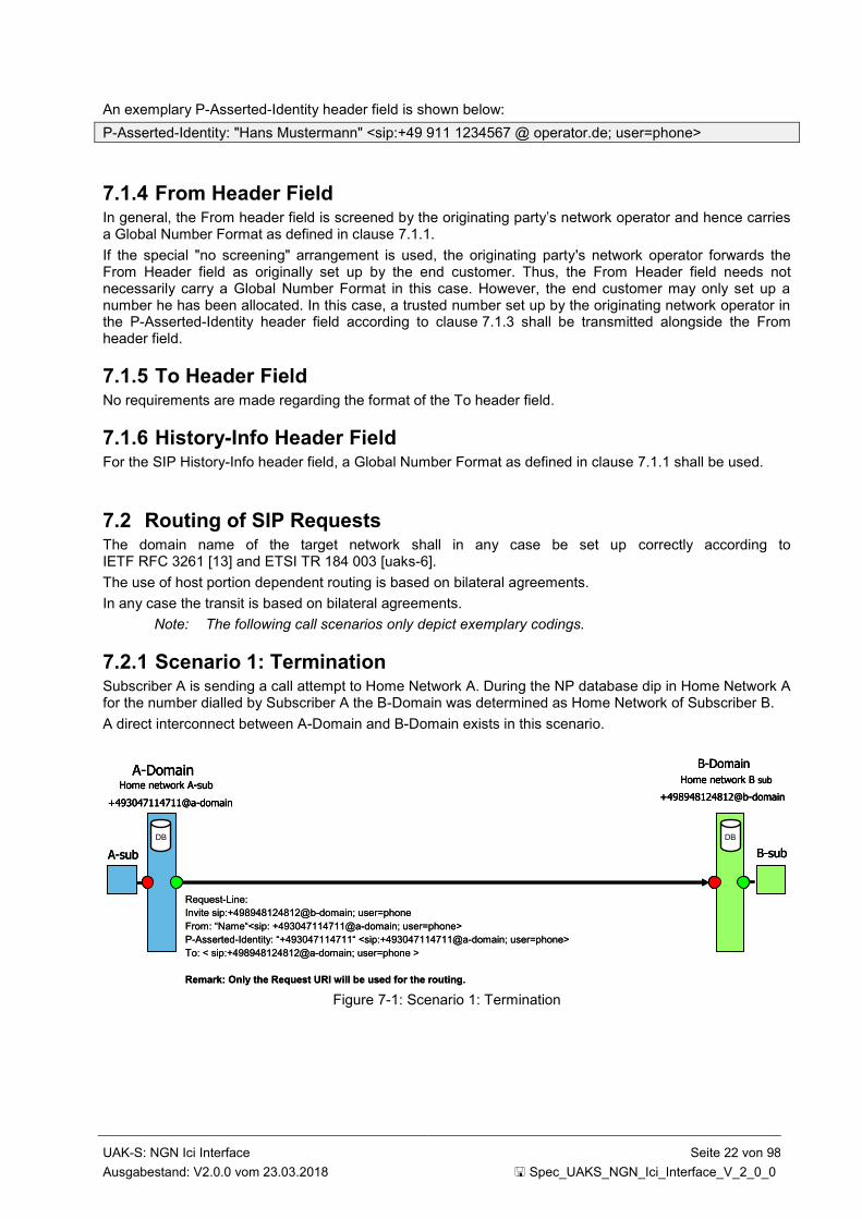
7.2.1 Scenario 1: Termination Subscriber A is sending a call attempt to Home Network A. During the NP database dip in Home Network A for the number dialled by Subscriber A the B-Domain was determined as Home Network of Subscriber B.
A direct interconnect between A-Domain and B-Domain exists in this scenario.
Figure 7-1: Scenario 1: Termination
Request-Line:
Invite sip:+498948124812@b-domain; user=phone
From: “Name“<sip: +493047114711@a-domain; user=phone>
P-Asserted-Identity: “+493047114711“ <sip:+493047114711@a-domain; user=phone>
To: < sip:+498948124812@a-domain; user=phone >
Remark: Only the Request URI will be used for the routing.
A-sub B-sub
DB DB
A-DomainHome network A-sub
+493047114711@a-domain
B-Domain
Home network B sub
+498948124812@b-domain
Request-Line:
Invite sip:+498948124812@b-domain; user=phone
From: “Name“<sip: +493047114711@a-domain; user=phone>
P-Asserted-Identity: “+493047114711“ <sip:+493047114711@a-domain; user=phone>
To: < sip:+498948124812@a-domain; user=phone >
Remark: Only the Request URI will be used for the routing.
A-sub B-sub
DB DB
A-sub B-sub
DB DB
A-DomainHome network A-sub
+493047114711@a-domain
A-DomainHome network A-sub
+493047114711@a-domain
B-Domain
Home network B sub
+498948124812@b-domain
B-Domain
Home network B sub
+498948124812@b-domain

UAK-S: NGN Ici Interface Seite 23 von 98
Ausgabestand: V2.0.0 vom 23.03.2018 Spec_UAKS_NGN_Ici_Interface_V_2_0_0
7.2.2 Scenario 2a: Determination of the Destination Network is not possible in the A-Domain
In case of transit situations, where based on bilateral agreements the transiting network will perform a number portability query to determine the FQDN of the destination, the originating network will use the domain name of this transit network to set up the request (Scenario 2a).
Figure 7-2: Scenario 2a: Determination of the Destination Network is not possible in the A-Domain
7.2.3 Scenario 2b: Determination of the Destination Network is possible in the A-Domain, but there is no Traffic Relation to the Destination Domain
P-Domain is receiving a call attempt from A-Domain directed to B-Domain in order to transmit this request based on Hostportion Dependent Routing.
During the NP database dip in Home Network A for the Number dialled by Subscriber A the B-Domain was determined as Home Network of Subscriber B. A direct interconnect between A-Domain and B-Domain does not exist in this transit scenario. Based on bilateral agreements A-Domain is using P-Domain as transit in order to reach B-Domain.
Figure 7-3: Scenario 2b: Determination of the Destination Network is possible in the A-Domain, but there is no Traffic Relation to the Destination Domain
A-sub B-sub
DB DB DB
A-DomainHome Network A-sub
+493047114711@a-domain
B-DomainHome Network B-sub
+498948124812@b-domain
*1 The P-Domain determines the home network of the B-Subscriber with a database query. There exist bi-/trilateraleagreements beween A-, P- and B-domain concerning the transfer of these connections.
P-Domain *1
Request-Line:
Invite sip:+498948124812@p-domain; user=phone
From: “Name“<sip: +493047114711@a-domain; user=phone>
P-Asserted-Identity: “+493047114711 “
<sip:+493047114711@a-domain; user=phone>
To: < sip:+498948124812@a-domain; user=phone >
Remark: Only the Request URI will be used for the routing.
Request-Line:
Invite sip:+498948124812@b-domain; user=phone
From: “Name“<sip: +493047114711@a-domain; user=phone
P-Asserted-Identity: “+493047114711 “
<sip:+493047114711@a-domain; user=phone>
To: < sip:+498948124812@a-domain; user=phone >
A-sub B-sub
DB DB DB
A-sub B-sub
DB DBDB DB
A-DomainHome Network A-sub
+493047114711@a-domain
A-DomainHome Network A-sub
+493047114711@a-domain
B-DomainHome Network B-sub
+498948124812@b-domain
B-DomainHome Network B-sub
+498948124812@b-domain
*1 The P-Domain determines the home network of the B-Subscriber with a database query. There exist bi-/trilateraleagreements beween A-, P- and B-domain concerning the transfer of these connections.
P-Domain *1P-Domain *1
Request-Line:
Invite sip:+498948124812@p-domain; user=phone
From: “Name“<sip: +493047114711@a-domain; user=phone>
P-Asserted-Identity: “+493047114711 “
<sip:+493047114711@a-domain; user=phone>
To: < sip:+498948124812@a-domain; user=phone >
Remark: Only the Request URI will be used for the routing.
Request-Line:
Invite sip:+498948124812@b-domain; user=phone
From: “Name“<sip: +493047114711@a-domain; user=phone
P-Asserted-Identity: “+493047114711 “
<sip:+493047114711@a-domain; user=phone>
To: < sip:+498948124812@a-domain; user=phone >
*1 The P-Domain determines the home network of the B-Subscriber with a database query. There exist bi-/trilateral agreements beween A-, P- and B-Domain concerning the transfer of these connections.
A-sub B-sub
DB DB DB
A-Domain *1
Home Network A-sub
+493047114711@a-domain
B-DomainHome Network B-sub
+498948124812@b-domainP-Domain *1
Request-Line:
Invite sip:+498948124812@b-domain; user=phone
From: “Name“<sip: +493047114711@a-domain; user=phone>
P-Asserted-Identity: “+493047114711 “
<sip:+493047114711@a-domain; user=phone>
To: < sip:+498948124812@a-domain; user=phone >
Request-Line:
Invite sip:+498948124812@b-domain; user=phone
From: “Name“<sip: +493047114711@a-domain; user=phone
P-Asserted-Identity: “+493047114711 “
<sip:+493047114711@a-domain; user=phone>
To: < sip:+498948124812@a-domain; user=phone >
A-sub B-sub
DB DB DB
A-sub B-sub
DB DBDB DB
A-Domain *1
Home Network A-sub
+493047114711@a-domain
A-Domain *1
Home Network A-sub
+493047114711@a-domain
B-DomainHome Network B-sub
+498948124812@b-domain
B-DomainHome Network B-sub
+498948124812@b-domainP-Domain *1P-Domain *1
Request-Line:
Invite sip:+498948124812@b-domain; user=phone
From: “Name“<sip: +493047114711@a-domain; user=phone>
P-Asserted-Identity: “+493047114711 “
<sip:+493047114711@a-domain; user=phone>
To: < sip:+498948124812@a-domain; user=phone >
Request-Line:
Invite sip:+498948124812@b-domain; user=phone
From: “Name“<sip: +493047114711@a-domain; user=phone
P-Asserted-Identity: “+493047114711 “
<sip:+493047114711@a-domain; user=phone>
To: < sip:+498948124812@a-domain; user=phone >

UAK-S: NGN Ici Interface Seite 24 von 98
Ausgabestand: V2.0.0 vom 23.03.2018 Spec_UAKS_NGN_Ici_Interface_V_2_0_0
7.3 Charged / Non Charged Telephone Traffic There is a need to distinguish between charged and non charged traffic. Charged traffic means that a connection is charged by the originating network carrier (TNB). Non charged traffic means that a connection has to be charged by the selected carrier (VNB).
For non charged traffic, an additional marking "tariff." in the beginning of the host portion of the SIP Request URI shall be used. An exemplary SIP Request URI is shown below:
sip: + 49 911 1234567 @ tariff.operator.de; user = phone
For charged traffic, no marking shall be used, e.g.
sip: +49 911 1234567 @ operator.de; user=phone
This additional marking shall only be used for carrier selection traffic. Value added services will not be marked, since they can be distinguished by the number range.
7.4 Mobile Service Prefix ("Mobilfunkservicevorwahl") This chapter describes the handling of the Mobile Service Prefix ("Mobilfunkservicevorwahl") using a P Germany-Tariff header field.
7.4.1 Introduction When a number of the prefix range 0900 is dialled from a mobile network, additional tariff information is forwarded to the VNB/SP in the PSTN. This tariff information is realised using the Mobile service prefix and begins with the prefix C1C and is followed by two digits (tt), which include the current tariff information.
Hence such a number is of the structure:
(0) C1C tt 900 xxxxxx
This information shall also be kept for calls transported via an NGN. Therefore, a P-Germany-Tariff header field as defined in chapter 7.4.2 shall be used to transmit this information as part of an INVITE method.
7.4.2 Definition Syntax Notation in accordance to ABNF:
P-Germany-Tariff = "P-Germany-Tariff" HCOLON
tariff
tariff = tariff-tag "=" tariff-value
tariff-tag = "tariff"
tariff-value = 2*2 DIGIT
An exemplary SIP INVITE Request is shown below:
INVITE SIP: +49 900 [email protected]; user=phone SIP/2.0
…
P-Germany-Tariff: tariff=23
…
7.4.3 Transmission When received in a SIP INVITE request, the P-Germany-Tariff header field shall be transmitted transparently through the networks and shall not be discarded.
UAK-S: NGN Ici Interface Seite 25 von 98
Ausgabestand: V2.0.0 vom 23.03.2018 Spec_UAKS_NGN_Ici_Interface_V_2_0_0
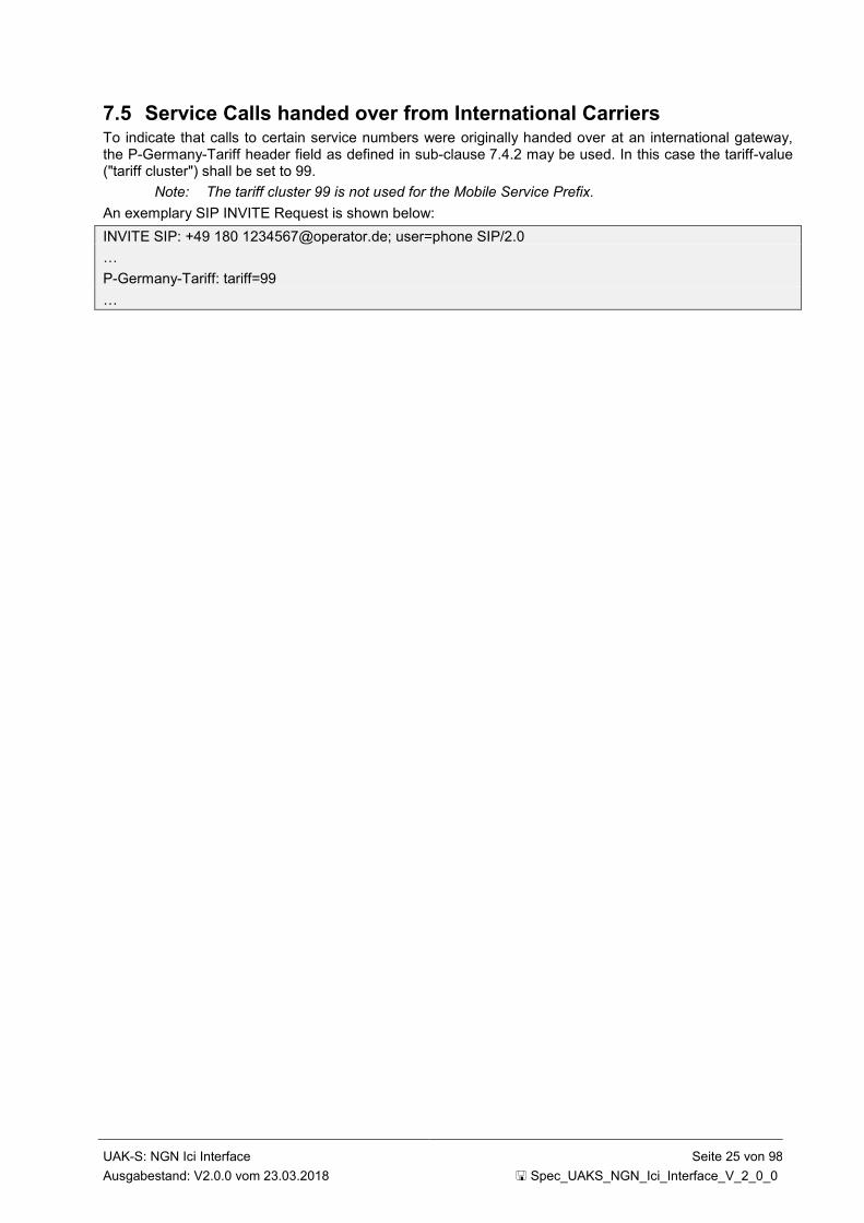
7.5 Service Calls handed over from International Carriers To indicate that calls to certain service numbers were originally handed over at an international gateway, the P-Germany-Tariff header field as defined in sub-clause 7.4.2 may be used. In this case the tariff-value ("tariff cluster") shall be set to 99.
Note: The tariff cluster 99 is not used for the Mobile Service Prefix.
An exemplary SIP INVITE Request is shown below:
INVITE SIP: +49 180 [email protected]; user=phone SIP/2.0
…
P-Germany-Tariff: tariff=99
…

UAK-S: NGN Ici Interface Seite 26 von 98
Ausgabestand: V2.0.0 vom 23.03.2018 Spec_UAKS_NGN_Ici_Interface_V_2_0_0
8 Ic-Profile Endorsement for 3GPP TS 29.165 This section provides the endorsement of 3GPP TS 29.165 [uaks-1]. This chapter describes modifications to reflect the supported functionalities and e.g. methods and headers applicable for the Ici interface.
The conditions e.g. A.x of the following tables can also be found in 3GPP TS 24.229 [5].
8.1 Global Modifications The meaning of indication of the following tables is shown in Table 8-1.
Indication Meaning
n/a not applicable; not supported
m mandatory; supported by sending and receiving
o optional; may be supported based on bilateral agreements
x prohibited/excluded; it is not allowed to use the capability
i irrelevant; outside the scope of this specification
c<integer> conditional; the requirement on the capability depends on the support of other items. <integer> is the identifier of the conditional expression.
p<integer> prerequisite
Table 8-1: Meaning of Indication in the last Column
In general the base specifications defined in clause 4 are valid. An "m" in the last column of Table 8-3, Table 8-4, Table 8-5, Table 8-6 and Table 8-8 does not necessarily mean that the entire reference is valid.
8.2 Major Capabilities This clause contains the major capabilities to be supported over the II-NNI based on [uaks-1], Table 6.1.3.1.
The Table 8-2 specifies which capabilities are applicable for II-NNI. The profile status codes within Table 8-2 are defined in Table 8-1.
For the "Basic SIP" capabilities part of Table 8-2, the penultimate column "Profile status over II-NNI" specifies the general status of applicability of the IETF RFC 3261 [13] main mechanisms described in the 2
nd column "Capability over the Ici".
For the "Extensions to basic SIP" capabilities part, the penultimate column "Profile status over II-NNI" specifies the general status of applicability of the RFC referenced in the 2
nd column "Capability over the Ici".
If necessary, the applicability of RFCs at the II-NNI level is further detailed in the present Technical Specification.
The columns "Reference item in 3GPP TS 24.229 [5] for the profile status" provide informative references for comparison purposes into the UA and Proxy role major capabilities tables in 3GPP TS 24.229 [5], where the capabilities are defined via additional references.
The last column "UAK-S profile" specifies the applicability of the major capabilities for this document.
Item Capability over the Ici Reference item in 3GPP TS 24.229 [5] for the profile status
Profile status
over II-NNI
UAK-S Profile
UA role (NOTE 1)
Proxy role (NOTE 2)
Basic SIP (IETF RFC 3261 [13])
1 registrations 1, 2, 2A - c2 n/a
2 initiating a session 2B, 3, 4 - m m
3 terminating a session 5 3 m m
4 General proxy behaviour - 4, 5, 14, 15 n/a n/a
5 Managing several responses due to forking 9,10 6 m NOTE 6
6 support of indication of TLS connections in the - 7, 8 n/a n/a

UAK-S: NGN Ici Interface Seite 27 von 98
Ausgabestand: V2.0.0 vom 23.03.2018 Spec_UAKS_NGN_Ici_Interface_V_2_0_0
Item Capability over the Ici Reference item in 3GPP TS 24.229 [5] for the profile status
Profile status
over II-NNI
UAK-S Profile
Record-Route header
7 Support of authentication 7, 8, 8A 8A c2 n/a
8 Timestamped requests (Timestamp header field) 6 - m o
9 Presence of date in requests and responses (Date
header field)
11 9 m n/a
10 Presence of alerting information data (Alert-info
header field)
12 10 o o
11 Support and handling of the Require header field for
REGISTER and other requests or responses for
methods other than REGISTER
- 11, 12, 13 m o
12 Support and reading of the Supported and
Unsupported header fields
- 16, 17, 18 m m
13 Support of the Error-Info header field in 3xx - 6xx
responses
- 19 o o
14 Support and handling of the Organization header field - 19A, 19B m o
15 Support and handling of the Call-Info header field - 19C, 19D m o
16 Support of the Contact header field in 3xx response - 19E m n/a
16A Proxy reading the contents of a body or including a
body in a request or response
- 19F n/a n/a
Extensions to basic SIP
16B 3GPP TS 24.237 [131]: proxy modifying the content
of a body
- 19G n/a n/a
17 IETF RFC 6086 [39]: SIP INFO method and package
framework
13 20 o o
17A IETF RFC 6086 [39]: legacy INFO usage
(NOTE 5)
13A 20A o o
18 IETF RFC 3262 [18]: reliability of provisional
responses in SIP (PRACK method)
14 21 m o
19 IETF RFC 3515 [22]: the SIP REFER method 15 22 o n/a
19A IETF RFC 7647 [194]: Clarifications for the Use of
REFER with RFC6665
15A 22A n/a n/a
19B IETF RFC 7614 [195]: Explicit Subscriptions for the
REFER Method
15B 22B o n/a
20 IETF RFC 3312 [40] and IETF RFC 4032 [41]:
integration of resource management and SIP
(Preconditions framework)
2C, 16 23 o o
21 IETF RFC 3311 [23]: the SIP UPDATE method 17 24 m m
22 IETF RFC 3313 [42]: SIP extensions for media
authorization (P-Media-Authorization header field)
19 26 n/a n/a
23 IETF RFC 6665 [20]: SIP specific event notification
(SUBSCRIBE/NOTIFY methods)
20, 22,
23
27 c1 o
23A IETF RFC 7621 [196]: A Clarification on the Use of
Globally Routable User Agent URIs (GRUUs) in the
Session Initiation Protocol SIP Event Notification
Framework
22A 28 n/a n/a
24 IETF RFC 3327 [43]: session initiation protocol
extension header field for registering non-adjacent
contacts (Path header field)
24 29 c2 n/a
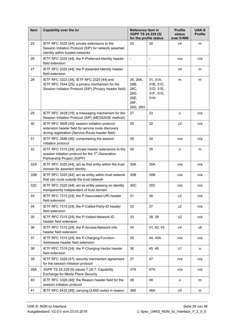
UAK-S: NGN Ici Interface Seite 28 von 98
Ausgabestand: V2.0.0 vom 23.03.2018 Spec_UAKS_NGN_Ici_Interface_V_2_0_0
Item Capability over the Ici Reference item in 3GPP TS 24.229 [5] for the profile status
Profile status
over II-NNI
UAK-S Profile
25 IETF RFC 3325 [44]: private extensions to the
Session Initiation Protocol (SIP) for network asserted
identity within trusted networks
25 30 c4 m
26 IETF RFC 3325 [44]: the P-Preferred-Identity header
field extension
- - n/a n/a
27 IETF RFC 3325 [44]: the P-Asserted-Identity header
field extension
- c4 m
28 IETF RFC 3323 [34], IETF RFC 3325 [44] and
IETF RFC 7044 [25]: a privacy mechanism for the
Session Initiation Protocol (SIP) (Privacy header field)
26, 26A,
26B,
26C,
26D,
26E,
26F,
26G, 26H
31, 31A,
31B, 31C,
31D, 31E,
31F, 31G,
31H
m m
29 IETF RFC 3428 [19]: a messaging mechanism for the
Session Initiation Protocol (SIP) (MESSAGE method)
27 33 o n/a
30 IETF RFC 3608 [45]: session initiation protocol
extension header field for service route discovery
during registration (Service-Route header field)
28 32 c2 n/a
31 IETF RFC 3486 [46]: compressing the session
initiation protocol
29 34 n/a n/a
32 IETF RFC 7315 [24]: private header extensions to the
session initiation protocol for the 3rd
-Generation
Partnership Project (3GPP)
30 35 o m
32A IETF RFC 3325 [44]: act as first entity within the trust
domain for asserted identity
30A 30A n/a n/a
32B IETF RFC 3325 [44]: act as entity within trust network
that can route outside the trust network
30B 30B n/a n/a
32C IETF RFC 3325 [44]: act as entity passing on identity
transparently independent of trust domain
30C 30C n/a n/a
33 IETF RFC 7315 [24]: the P-Associated-URI header
field extension
31 36 c2 n/a
34 IETF RFC 7315 [24]: the P-Called-Party-ID header
field extension
32 37 c2 n/a
35 IETF RFC 7315 [24]: the P-Visited-Network-ID
header field extension
33 38, 39 c2 n/a
36 IETF RFC 7315 [24]: the P-Access-Network-Info
header field extension
34 41, 42, 43 c4 c6
37 IETF RFC 7315 [24]: the P-Charging-Function-
Addresses header field extension
35 44, 44A n/a n/a
38 IETF RFC 7315 [24]: the P-Charging-Vector header
field extension
36 45, 46 c1 o
39 IETF RFC 3329 [47]: security mechanism agreement
for the session initiation protocol
37 47 n/a n/a
39A 3GPP TS 24.229 [5] clause 7.2A.7: Capability
Exchange for Media Plane Security
37A 47A n/a n/a
40 IETF RFC 3326 [48]: the Reason header field for the
session initiation protocol
38 48 o m
41 IETF RFC 6432 [49]: carrying Q.850 codes in reason 38A 48A c4 m
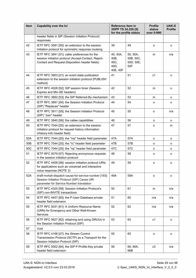
UAK-S: NGN Ici Interface Seite 29 von 98
Ausgabestand: V2.0.0 vom 23.03.2018 Spec_UAKS_NGN_Ici_Interface_V_2_0_0
Item Capability over the Ici Reference item in 3GPP TS 24.229 [5] for the profile status
Profile status
over II-NNI
UAK-S Profile
header fields in SIP (Session Initiation Protocol)
responses
42 IETF RFC 3581 [50]: an extension to the session
initiation protocol for symmetric response routeing
39 49 o o
43 IETF RFC 3841 [51]: caller preferences for the
session initiation protocol (Accept-Contact, Reject-
Contact and Request-Disposition header fields)
40, 40A,
40B,
40C,
40D,
40E, 40F
50, 50A,
50B, 50C,
50D, 50E,
50F
m n/a
44 IETF RFC 3903 [21]: an event state publication
extension to the session initiation protocol (PUBLISH
method)
41 51 c1 o
45 IETF RFC 4028 [52]: SIP session timer (Session-
Expires and Min-SE headers)
42 52 m o
46 IETF RFC 3892 [53]: the SIP Referred-By mechanism 43 53 m o
47 IETF RFC 3891 [54]: the Session Initiation Protocol
(SIP) "Replaces" header
44 54 o o
48 IETF RFC 3911 [55]: the Session Initiation Protocol
(SIP) "Join" header
45 55 o n/a
49 IETF RFC 3840 [56]: the callee capabilities 46 56 o o
50 IETF RFC 7044 [25]: an extension to the session
initiation protocol for request history information
(History-Info header field)
47 57 o m
50A IETF RFC 7044 [25]: the "mp" header field parameter 47A 57A o o
50B IETF RFC 7044 [25]: the "rc" header field parameter 47B 57B o o
50C IETF RFC 7044 [25]: the "np" header field parameter 47C 57C o o
51 IETF RFC 5079 [57]: Rejecting anonymous requests
in the session initiation protocol
48 58 o o
52 IETF RFC 4458 [58]: session initiation protocol URIs
for applications such as voicemail and interactive
voice response (NOTE 3)
49 59 o o
52A draft-mohali-dispatch-cause-for-service-number [193]:
Session Initiation Protocol (SIP) Cause URI
parameter for Service Number translation
49A 59A o o
53 IETF RFC 4320 [59]: Session Initiation Protocol's
(SIP) non-INVITE transactions
50 61 m n/a
54 IETF RFC 4457 [60]: the P-User-Database private
header field extension
51 60 n/a n/a
55 IETF RFC 5031 [61]: A Uniform Resource Name
(URN) for Emergency and Other Well-Known
Services
52 62 n/a n/a
56 IETF RFC 5627 [62]: obtaining and using GRUUs in
the Session Initiation Protocol (SIP)
53 63 c1 o
57 Void
58 IETF RFC 4168 [27]: the Stream Control
Transmission Protocol (SCTP) as a Transport for the
Session Initiation Protocol (SIP)
55 65 o o
59 IETF RFC 5002 [64]: the SIP P-Profile-Key private
header field extension
56 66, 66A,
66B
c3 n/a

UAK-S: NGN Ici Interface Seite 30 von 98
Ausgabestand: V2.0.0 vom 23.03.2018 Spec_UAKS_NGN_Ici_Interface_V_2_0_0
Item Capability over the Ici Reference item in 3GPP TS 24.229 [5] for the profile status
Profile status
over II-NNI
UAK-S Profile
60 IETF RFC 5626 [65]: managing client initiated
connections in SIP
57 67 c1 o
61 IETF RFC 5768 [66]: indicating support for interactive
connectivity establishment in SIP
58 68 n/a n/a
62 IETF RFC 5365 [67]: multiple-recipient MESSAGE
requests in the session initiation protocol
59 69 o if 29, else
n/a
n/a
63 IETF RFC 6442 [68]: Location conveyance for the
Session Initiation Protocol
60 70, 70A,
70B
m m
64 IETF RFC 5368 [69]: referring to multiple resources in
the session initiation protocol
61 71 o if 19, else
n/a
n/a
65 IETF RFC 5366 [70]: conference establishment using
request-contained lists in the session initiation
protocol
62 72 o o
66 IETF RFC 5367 [71]: subscriptions to request-
contained resource lists in the session initiation
protocol
63 73 o if 23, else
n/a
o if 23,
else n/a
67 IETF RFC 4967 [72]: dialstring parameter for the
session initiation protocol uniform resource identifier
64 74 c2 n/a
68 IETF RFC 4964 [73]: the P-Answer-State header
extension to the session initiation protocol for the
open mobile alliance push to talk over cellular
65 75 o o
69 IETF RFC 5009 [74]: the SIP P-Early-Media private
header field extension for authorization of early media
66 76 c4 c4
70 IETF RFC 4694 [75]: number portability parameters
for the 'tel' URI
67, 67A,
67B
77, 77A,
77B
o o
71 Void
72 IETF RFC 4411 [77]: extending the session initiation
protocol Reason header for preemption events
69 79 o o
73 IETF RFC 4412 [78]: communications resource
priority for the session initiation protocol (Resource-
Priority header field)
70, 70A,
70B
80, 80A,
80B
o o
74 IETF RFC 5393 [79]: addressing an amplification
vulnerability in session initiation protocol forking
proxies
71 81 m m
75 IETF RFC 5049 [80]: the remote application
identification of applying signalling compression to
SIP
72 82 n/a n/a
76 IETF RFC 5688 [81]: a session initiation protocol
media feature tag for MIME application sub-types
73 83 c1 o
77 IETF RFC 6050 [26]: Identification of communication
services in the session initiation protocol
74 84, 84A o o
78 IETF RFC 5360 [82]: a framework for consent-based
communications in SIP
75, 75A,
75B
85 o o
79 IETF RFC 7433 [83]: a mechanism for transporting
user-to-user call control information in SIP
76 86 c1 o
79A IETF RFC 7434 [83A]: interworking ISDN call control
user information with SIP
76A - c1 o
80 IETF RFC 7316 [84]: The SIP P-Private-Network-
Indication private header (P-Header)
77 87 c1 o

UAK-S: NGN Ici Interface Seite 31 von 98
Ausgabestand: V2.0.0 vom 23.03.2018 Spec_UAKS_NGN_Ici_Interface_V_2_0_0
Item Capability over the Ici Reference item in 3GPP TS 24.229 [5] for the profile status
Profile status
over II-NNI
UAK-S Profile
81 IETF RFC 5502 [85]: the SIP P-Served-User private
header
78 88 c2 n/a
82 Void
83 draft-dawes-sipping-debug [87]: the P-Debug-ID
header extension
80 90 o o
84 IETF RFC 6228 [88]: the 199 (Early Dialog
Terminated) response code
81 91 m m
85 IETF RFC 5621 [89]: message body handling in SIP 82 92 m m
86 IETF RFC 6223 [90]: indication of support for keep-
alive
83 93 o o
87 IETF RFC 5552 [91]: SIP Interface to VoiceXML
Media Services
84 94 n/a n/a
88 IETF RFC 3862 [92]: common presence and instant
messaging (CPIM): message format
85 95 o o
89 IETF RFC 5438 [93]: instant message disposition
notification
86 96 o o
90 IETF RFC 5373 [94]: requesting answering modes for
SIP (Answer-Mode and Priv-Answer-Mode header
fields)
87 97, 97A o o
91 Void
92 IETF RFC 3959 [96]: the early session disposition
type for SIP
89 99 o o
93 Void
94 draft-ietf-insipid-session-id [124]: End-to-End Session
Identification in IP-Based Multimedia Communication
Networks
91 101 o o
95 IETF RFC 6026 [125]: correct transaction handling for
200 responses to Session Initiation Protocol INVITE
requests
92 102 m m
96 IETF RFC 5658 [126]: addressing Record-Route
issues in the Session Initiation Protocol (SIP)
93 103 o o
97 IETF RFC 5954 [127]: essential correction for IPv6
ABNF and URI comparison in IETF RFC 3261 [13]
94 104 m m
98 IETF RFC 4488 [135]: suppression of session
initiation protocol REFER method implicit subscription
95 105 m if 19,
else n/a
m if 19,
else n/a
99 IETF RFC 7462 [136]: Alert-Info URNs for the
Session Initiation Protocol
96 106 o o
100 3GPP TS 24.229 [5] clause 3.1: multiple registrations 97 107 c2 n/a
101 IETF RFC 5318 [141]: the SIP P-Refused-URI-List
private-header
98 108 c5 c5
102 IETF RFC 4538 [140]: request authorization through
dialog Identification in the session initiation protocol
(Target-Dialog header field)
99 109 o o
103 IETF RFC 6809 [143]: Mechanism to indicate support
of features and capabilities in the Session Initiation
Protocol (SIP)
100 110 o o
104 IETF RFC 6140 [160]: registration of bulk number
contacts
101 111 c3 n/a

UAK-S: NGN Ici Interface Seite 32 von 98
Ausgabestand: V2.0.0 vom 23.03.2018 Spec_UAKS_NGN_Ici_Interface_V_2_0_0
Item Capability over the Ici Reference item in 3GPP TS 24.229 [5] for the profile status
Profile status
over II-NNI
UAK-S Profile
105 IETF RFC 6230 [161]: media control channel
framework
102 112 o o
105A 3GPP TS 24.229 [5] clause 4.14: S-CSCF restoration
procedures
103 113 c3 n/a
106 IETF RFC 6357 [164]: SIP overload control 104 114 o o
107 IETF RFC 7339 [165]: feedback control 104A 114A o o
108 IETF RFC 7200 [167]: distribution of load filters 104B 114B o o
109 3GPP TS 24.229 [5] clauses 5.1.2A.1.1, 5.1.3.1,
5.1.6.8, and 5.2.10: Handling of a 380 (Alternative
service) response
105 115 n/a n/a
110 IETF RFC 7090 [184]: Public Safety Answering Point
(PSAP) Callback
107 117 o o
111 draft-holmberg-sipcore-received-realm [185]: Via
header field parameter to indicate received realm
106 116 n/a n/a
112 IETF RFC 7549 [188]: SIP URI parameter to indicate
traffic leg
108 118 o
(NOTE 4)
o
(NOTE 4)
113 3GPP TS 24.229 [5] clause 4.14: PCRF based P-
CSCF restoration
109 119 c3 n/a
114 3GPP TS 24.229 [5] clause 4.14: HSS based P-
CSCF restoration
110 120 c3 n/a
115 3GPP TS 24.229 [5] clause 7.2.12: the Relayed-
Charge header extension
111 121 n/a n/a
116 3GPP TS 24.229 [5]: resource sharing 112 122 c3 n/a
c1: m in case of roaming II-NNI, else o
c2: m in case of roaming II-NNI, else n/a
c3: o in case of roaming II-NNI, else n/a
c4: m in case of trust relationship between the interconnected networks, else n/a
c5: o in case of non-roaming II-NNI and loopback traversal scenario, else n/a
c6 IF emergency call originated from a mobile operator THEN m ELSE o
NOTE 1: The item numbering corresponds to the one provided in table A.4 in 3GPP TS 24.229 [5].
NOTE 2: The item numbering corresponds to the one provided in table A.162 in 3GPP TS 24.229 [5].
NOTE 3: A common URI namespace is required to apply this feature on the II-NNI.
NOTE 4: For the roaming II-NNI the support of this major capability is recommended.
NOTE 5: Used for SIP support of charging
NOTE 6 If the originating network does not support forking and the terminating network does not support the no-
fork directive then call attempts may be unsuccessful.
Table 8-2: Major Capabilities over II-NNI
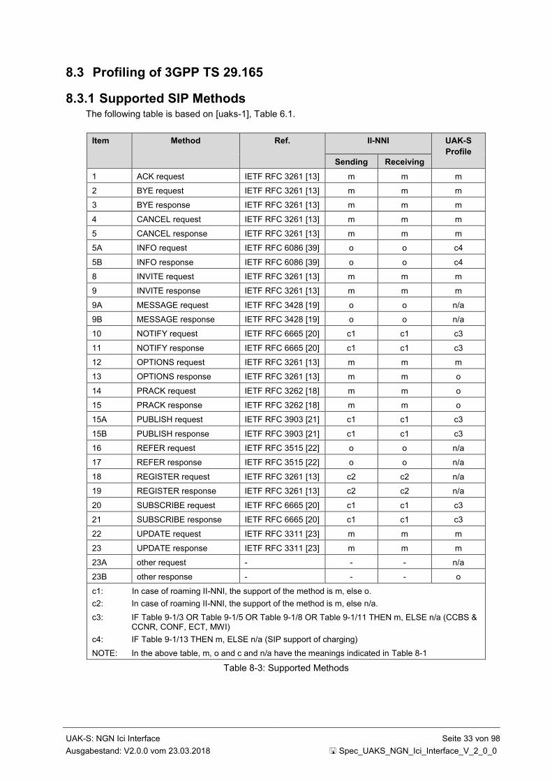
UAK-S: NGN Ici Interface Seite 33 von 98
Ausgabestand: V2.0.0 vom 23.03.2018 Spec_UAKS_NGN_Ici_Interface_V_2_0_0
8.3 Profiling of 3GPP TS 29.165
8.3.1 Supported SIP Methods The following table is based on [uaks-1], Table 6.1.
Item Method Ref. II-NNI UAK-S
Profile
Sending Receiving
1 ACK request IETF RFC 3261 [13] m m m
2 BYE request IETF RFC 3261 [13] m m m
3 BYE response IETF RFC 3261 [13] m m m
4 CANCEL request IETF RFC 3261 [13] m m m
5 CANCEL response IETF RFC 3261 [13] m m m
5A INFO request IETF RFC 6086 [39] o o c4
5B INFO response IETF RFC 6086 [39] o o c4
8 INVITE request IETF RFC 3261 [13] m m m
9 INVITE response IETF RFC 3261 [13] m m m
9A MESSAGE request IETF RFC 3428 [19] o o n/a
9B MESSAGE response IETF RFC 3428 [19] o o n/a
10 NOTIFY request IETF RFC 6665 [20] c1 c1 c3
11 NOTIFY response IETF RFC 6665 [20] c1 c1 c3
12 OPTIONS request IETF RFC 3261 [13] m m m
13 OPTIONS response IETF RFC 3261 [13] m m o
14 PRACK request IETF RFC 3262 [18] m m o
15 PRACK response IETF RFC 3262 [18] m m o
15A PUBLISH request IETF RFC 3903 [21] c1 c1 c3
15B PUBLISH response IETF RFC 3903 [21] c1 c1 c3
16 REFER request IETF RFC 3515 [22] o o n/a
17 REFER response IETF RFC 3515 [22] o o n/a
18 REGISTER request IETF RFC 3261 [13] c2 c2 n/a
19 REGISTER response IETF RFC 3261 [13] c2 c2 n/a
20 SUBSCRIBE request IETF RFC 6665 [20] c1 c1 c3
21 SUBSCRIBE response IETF RFC 6665 [20] c1 c1 c3
22 UPDATE request IETF RFC 3311 [23] m m m
23 UPDATE response IETF RFC 3311 [23] m m m
23A other request - - - n/a
23B other response - - - o
c1: In case of roaming II-NNI, the support of the method is m, else o.
c2: In case of roaming II-NNI, the support of the method is m, else n/a.
c3: IF Table 9-1/3 OR Table 9-1/5 OR Table 9-1/8 OR Table 9-1/11 THEN m, ELSE n/a (CCBS & CCNR, CONF, ECT, MWI)
c4: IF Table 9-1/13 THEN m, ELSE n/a (SIP support of charging)
NOTE: In the above table, m, o and c and n/a have the meanings indicated in Table 8-1
Table 8-3: Supported Methods
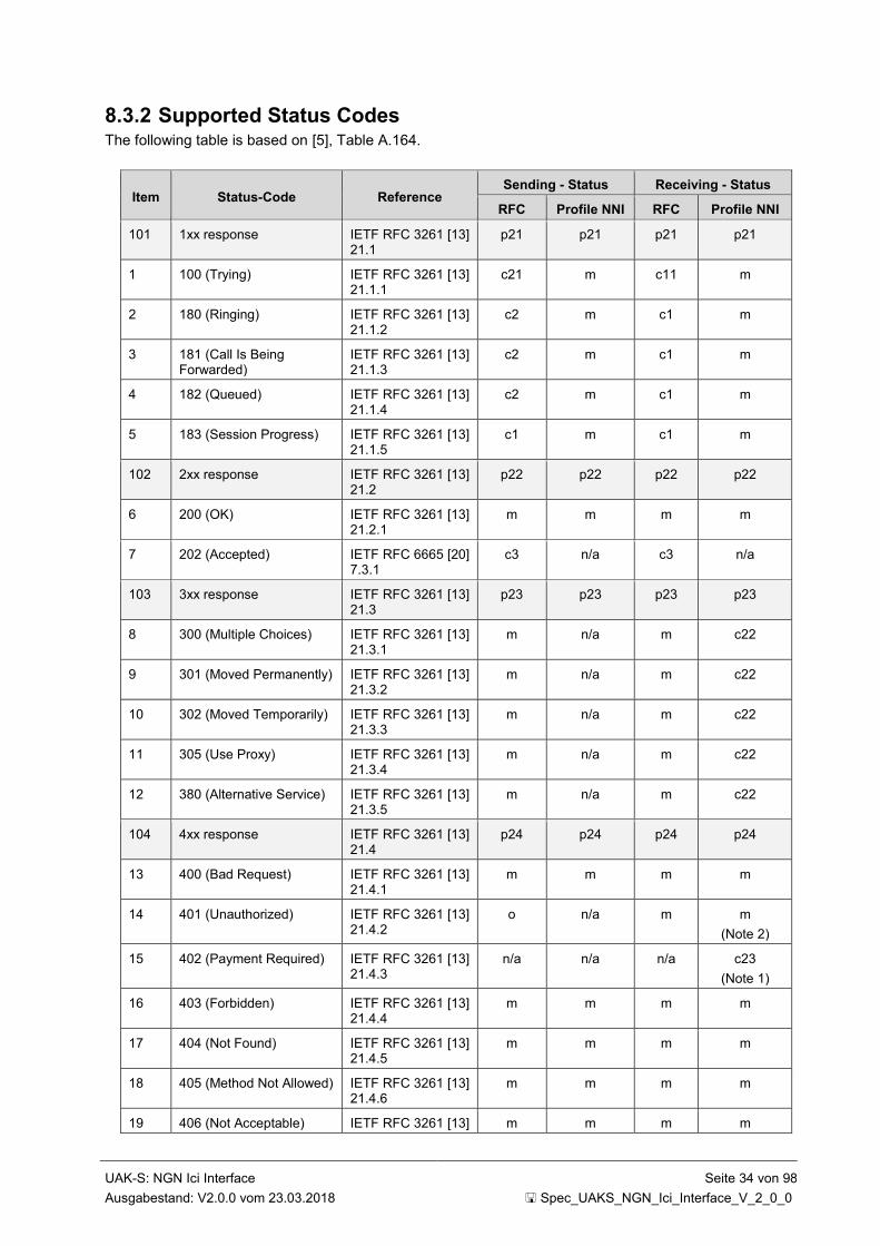
UAK-S: NGN Ici Interface Seite 34 von 98
Ausgabestand: V2.0.0 vom 23.03.2018 Spec_UAKS_NGN_Ici_Interface_V_2_0_0
8.3.2 Supported Status Codes The following table is based on [5], Table A.164.
Item Status-Code Reference Sending - Status Receiving - Status
RFC Profile NNI RFC Profile NNI
101 1xx response IETF RFC 3261 [13] 21.1
p21 p21 p21 p21
1 100 (Trying) IETF RFC 3261 [13] 21.1.1
c21 m c11 m
2 180 (Ringing) IETF RFC 3261 [13] 21.1.2
c2 m c1 m
3 181 (Call Is Being Forwarded)
IETF RFC 3261 [13] 21.1.3
c2 m c1 m
4 182 (Queued) IETF RFC 3261 [13] 21.1.4
c2 m c1 m
5 183 (Session Progress) IETF RFC 3261 [13] 21.1.5
c1 m c1 m
102 2xx response IETF RFC 3261 [13] 21.2
p22 p22 p22 p22
6 200 (OK) IETF RFC 3261 [13] 21.2.1
m m m m
7 202 (Accepted) IETF RFC 6665 [20] 7.3.1
c3 n/a c3 n/a
103 3xx response IETF RFC 3261 [13] 21.3
p23 p23 p23 p23
8 300 (Multiple Choices) IETF RFC 3261 [13] 21.3.1
m n/a m c22
9 301 (Moved Permanently) IETF RFC 3261 [13] 21.3.2
m n/a m c22
10 302 (Moved Temporarily) IETF RFC 3261 [13] 21.3.3
m n/a m c22
11 305 (Use Proxy) IETF RFC 3261 [13] 21.3.4
m n/a m c22
12 380 (Alternative Service) IETF RFC 3261 [13] 21.3.5
m n/a m c22
104 4xx response IETF RFC 3261 [13] 21.4
p24 p24 p24 p24
13 400 (Bad Request) IETF RFC 3261 [13] 21.4.1
m m m m
14 401 (Unauthorized) IETF RFC 3261 [13] 21.4.2
o n/a m m
(Note 2)
15 402 (Payment Required) IETF RFC 3261 [13] 21.4.3
n/a n/a n/a c23
(Note 1)
16 403 (Forbidden) IETF RFC 3261 [13] 21.4.4
m m m m
17 404 (Not Found) IETF RFC 3261 [13] 21.4.5
m m m m
18 405 (Method Not Allowed) IETF RFC 3261 [13] 21.4.6
m m m m
19 406 (Not Acceptable) IETF RFC 3261 [13] m m m m
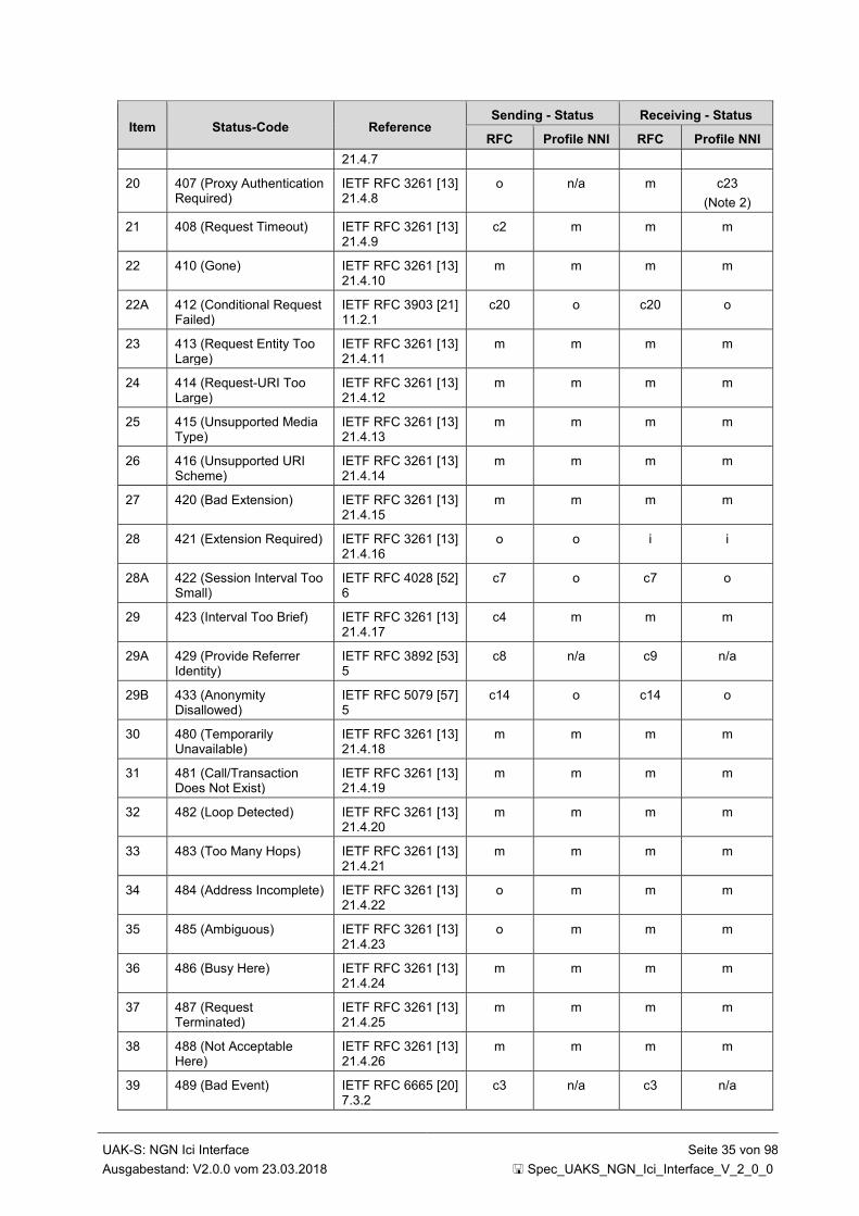
UAK-S: NGN Ici Interface Seite 35 von 98
Ausgabestand: V2.0.0 vom 23.03.2018 Spec_UAKS_NGN_Ici_Interface_V_2_0_0
Item Status-Code Reference Sending - Status Receiving - Status
RFC Profile NNI RFC Profile NNI
21.4.7
20 407 (Proxy Authentication Required)
IETF RFC 3261 [13] 21.4.8
o n/a m c23
(Note 2)
21 408 (Request Timeout) IETF RFC 3261 [13] 21.4.9
c2 m m m
22 410 (Gone) IETF RFC 3261 [13] 21.4.10
m m m m
22A 412 (Conditional Request Failed)
IETF RFC 3903 [21] 11.2.1
c20 o c20 o
23 413 (Request Entity Too Large)
IETF RFC 3261 [13] 21.4.11
m m m m
24 414 (Request-URI Too Large)
IETF RFC 3261 [13] 21.4.12
m m m m
25 415 (Unsupported Media Type)
IETF RFC 3261 [13] 21.4.13
m m m m
26 416 (Unsupported URI Scheme)
IETF RFC 3261 [13] 21.4.14
m m m m
27 420 (Bad Extension) IETF RFC 3261 [13] 21.4.15
m m m m
28 421 (Extension Required) IETF RFC 3261 [13] 21.4.16
o o i i
28A 422 (Session Interval Too Small)
IETF RFC 4028 [52] 6
c7 o c7 o
29 423 (Interval Too Brief) IETF RFC 3261 [13] 21.4.17
c4 m m m
29A 429 (Provide Referrer Identity)
IETF RFC 3892 [53] 5
c8 n/a c9 n/a
29B 433 (Anonymity Disallowed)
IETF RFC 5079 [57] 5
c14 o c14 o
30 480 (Temporarily Unavailable)
IETF RFC 3261 [13] 21.4.18
m m m m
31 481 (Call/Transaction Does Not Exist)
IETF RFC 3261 [13] 21.4.19
m m m m
32 482 (Loop Detected) IETF RFC 3261 [13] 21.4.20
m m m m
33 483 (Too Many Hops) IETF RFC 3261 [13] 21.4.21
m m m m
34 484 (Address Incomplete) IETF RFC 3261 [13] 21.4.22
o m m m
35 485 (Ambiguous) IETF RFC 3261 [13] 21.4.23
o m m m
36 486 (Busy Here) IETF RFC 3261 [13] 21.4.24
m m m m
37 487 (Request Terminated)
IETF RFC 3261 [13] 21.4.25
m m m m
38 488 (Not Acceptable Here)
IETF RFC 3261 [13] 21.4.26
m m m m
39 489 (Bad Event) IETF RFC 6665 [20] 7.3.2
c3 n/a c3 n/a

UAK-S: NGN Ici Interface Seite 36 von 98
Ausgabestand: V2.0.0 vom 23.03.2018 Spec_UAKS_NGN_Ici_Interface_V_2_0_0
Item Status-Code Reference Sending - Status Receiving - Status
RFC Profile NNI RFC Profile NNI
40 491 (Request Pending) IETF RFC 3261 [13] 21.4.27
m m m m
41 493 (Undecipherable) IETF RFC 3261 [13] 21.4.28
m m m m
41A 494 (Security Agreement Required)
IETF RFC 3329 [47] 2
c5 n/a c6 n/a
105 5xx response IETF RFC 3261 [13] 21.5
p25 p25 p25 p25
42 500 (Internal Server Error)
IETF RFC 3261 [13] 21.5.1
m m m m
43 501 (Not Implemented) IETF RFC 3261 [13] 21.5.2
m m m m
44 502 (Bad Gateway) IETF RFC 3261 [13] 21.5.3
o m m m
45 503 (Service Unavailable) IETF RFC 3261 [13] 21.5.4
m m m m
46 504 (Server Time-out) IETF RFC 3261 [13] 21.5.5
m m m m
47 505 (Version not supported)
IETF RFC 3261 [13] 21.5.6
m m m m
48 513 (Message Too Large) IETF RFC 3261 [13] 21.5.7
m m m m
49 580 (Precondition Failure) IETF RFC 3312 [40] 8
o o o o
106 6xx response IETF RFC 3261 [13] 21.6
p26 p26 p26 p26
50 600 (Busy Everywhere) IETF RFC 3261 [13] 21.6.1
m m m m
51 603 (Decline) IETF RFC 3261 [13] 21.6.2
c10 m m m
52 604 (Does Not Exist Anywhere)
IETF RFC 3261 [13] 21.6.3
m m m m
53 606 (Not Acceptable) IETF RFC 3261 [13] 21.6.4
m m m m
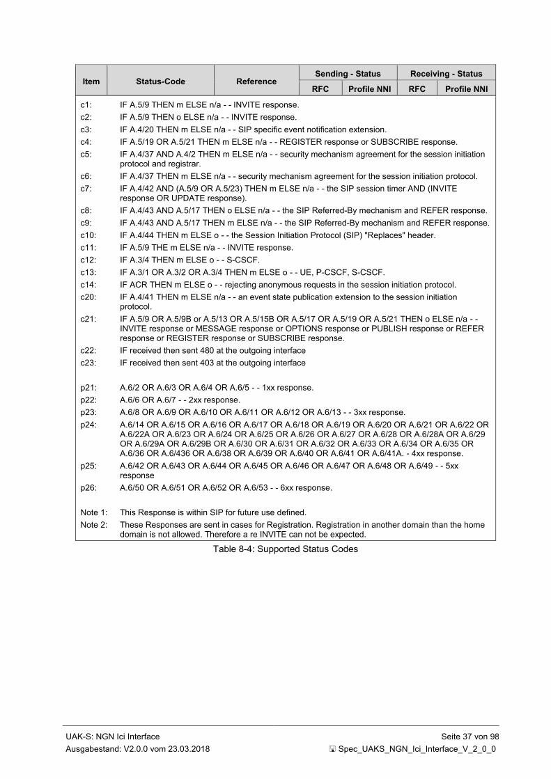
UAK-S: NGN Ici Interface Seite 37 von 98
Ausgabestand: V2.0.0 vom 23.03.2018 Spec_UAKS_NGN_Ici_Interface_V_2_0_0
Item Status-Code Reference Sending - Status Receiving - Status
RFC Profile NNI RFC Profile NNI
c1: IF A.5/9 THEN m ELSE n/a - - INVITE response.
c2: IF A.5/9 THEN o ELSE n/a - - INVITE response.
c3: IF A.4/20 THEN m ELSE n/a - - SIP specific event notification extension.
c4: IF A.5/19 OR A.5/21 THEN m ELSE n/a - - REGISTER response or SUBSCRIBE response.
c5: IF A.4/37 AND A.4/2 THEN m ELSE n/a - - security mechanism agreement for the session initiation protocol and registrar.
c6: IF A.4/37 THEN m ELSE n/a - - security mechanism agreement for the session initiation protocol.
c7: IF A.4/42 AND (A.5/9 OR A.5/23) THEN m ELSE n/a - - the SIP session timer AND (INVITE response OR UPDATE response).
c8: IF A.4/43 AND A.5/17 THEN o ELSE n/a - - the SIP Referred-By mechanism and REFER response.
c9: IF A.4/43 AND A.5/17 THEN m ELSE n/a - - the SIP Referred-By mechanism and REFER response.
c10: IF A.4/44 THEN m ELSE o - - the Session Initiation Protocol (SIP) "Replaces" header.
c11: IF A.5/9 THE m ELSE n/a - - INVITE response.
c12: IF A.3/4 THEN m ELSE o - - S-CSCF.
c13: IF A.3/1 OR A.3/2 OR A.3/4 THEN m ELSE o - - UE, P-CSCF, S-CSCF.
c14: IF ACR THEN m ELSE o - - rejecting anonymous requests in the session initiation protocol.
c20: IF A.4/41 THEN m ELSE n/a - - an event state publication extension to the session initiation protocol.
c21: IF A.5/9 OR A.5/9B or A.5/13 OR A.5/15B OR A.5/17 OR A.5/19 OR A.5/21 THEN o ELSE n/a - - INVITE response or MESSAGE response or OPTIONS response or PUBLISH response or REFER response or REGISTER response or SUBSCRIBE response.
c22: IF received then sent 480 at the outgoing interface
c23: IF received then sent 403 at the outgoing interface
p21: A.6/2 OR A.6/3 OR A.6/4 OR A.6/5 - - 1xx response.
p22: A.6/6 OR A.6/7 - - 2xx response.
p23: A.6/8 OR A.6/9 OR A.6/10 OR A.6/11 OR A.6/12 OR A.6/13 - - 3xx response.
p24: A.6/14 OR A.6/15 OR A.6/16 OR A.6/17 OR A.6/18 OR A.6/19 OR A.6/20 OR A.6/21 OR A.6/22 OR A.6/22A OR A.6/23 OR A.6/24 OR A.6/25 OR A.6/26 OR A.6/27 OR A.6/28 OR A.6/28A OR A.6/29 OR A.6/29A OR A.6/29B OR A.6/30 OR A.6/31 OR A.6/32 OR A.6/33 OR A.6/34 OR A.6/35 OR A.6/36 OR A.6/436 OR A.6/38 OR A.6/39 OR A.6/40 OR A.6/41 OR A.6/41A. - 4xx response.
p25: A.6/42 OR A.6/43 OR A.6/44 OR A.6/45 OR A.6/46 OR A.6/47 OR A.6/48 OR A.6/49 - - 5xx response
p26: A.6/50 OR A.6/51 OR A.6/52 OR A.6/53 - - 6xx response.
Note 1: This Response is within SIP for future use defined.
Note 2: These Responses are sent in cases for Registration. Registration in another domain than the home domain is not allowed. Therefore a re INVITE can not be expected.
Table 8-4: Supported Status Codes
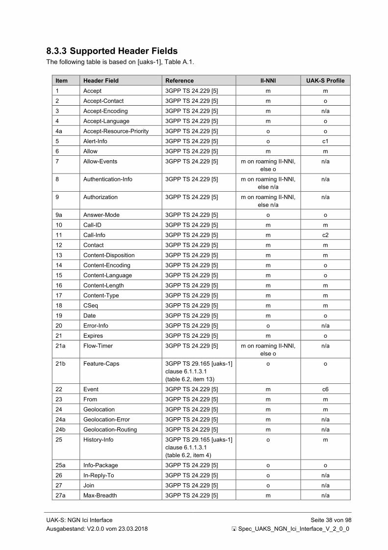
UAK-S: NGN Ici Interface Seite 38 von 98
Ausgabestand: V2.0.0 vom 23.03.2018 Spec_UAKS_NGN_Ici_Interface_V_2_0_0
8.3.3 Supported Header Fields The following table is based on [uaks-1], Table A.1.
Item Header Field Reference II-NNI UAK-S Profile
1 Accept 3GPP TS 24.229 [5] m m
2 Accept-Contact 3GPP TS 24.229 [5] m o
3 Accept-Encoding 3GPP TS 24.229 [5] m n/a
4 Accept-Language 3GPP TS 24.229 [5] m o
4a Accept-Resource-Priority 3GPP TS 24.229 [5] o o
5 Alert-Info 3GPP TS 24.229 [5] o c1
6 Allow 3GPP TS 24.229 [5] m m
7 Allow-Events 3GPP TS 24.229 [5] m on roaming II-NNI,
else o
n/a
8 Authentication-Info 3GPP TS 24.229 [5] m on roaming II-NNI,
else n/a
n/a
9 Authorization 3GPP TS 24.229 [5] m on roaming II-NNI,
else n/a
n/a
9a Answer-Mode 3GPP TS 24.229 [5] o o
10 Call-ID 3GPP TS 24.229 [5] m m
11 Call-Info 3GPP TS 24.229 [5] m c2
12 Contact 3GPP TS 24.229 [5] m m
13 Content-Disposition 3GPP TS 24.229 [5] m m
14 Content-Encoding 3GPP TS 24.229 [5] m o
15 Content-Language 3GPP TS 24.229 [5] m o
16 Content-Length 3GPP TS 24.229 [5] m m
17 Content-Type 3GPP TS 24.229 [5] m m
18 CSeq 3GPP TS 24.229 [5] m m
19 Date 3GPP TS 24.229 [5] m o
20 Error-Info 3GPP TS 24.229 [5] o n/a
21 Expires 3GPP TS 24.229 [5] m o
21a Flow-Timer 3GPP TS 24.229 [5] m on roaming II-NNI,
else o
n/a
21b Feature-Caps 3GPP TS 29.165 [uaks-1]
clause 6.1.1.3.1
(table 6.2, item 13)
o o
22 Event 3GPP TS 24.229 [5] m c6
23 From 3GPP TS 24.229 [5] m m
24 Geolocation 3GPP TS 24.229 [5] m m
24a Geolocation-Error 3GPP TS 24.229 [5] m n/a
24b Geolocation-Routing 3GPP TS 24.229 [5] m n/a
25 History-Info 3GPP TS 29.165 [uaks-1]
clause 6.1.1.3.1
(table 6.2, item 4)
o m
25a Info-Package 3GPP TS 24.229 [5] o o
26 In-Reply-To 3GPP TS 24.229 [5] o n/a
27 Join 3GPP TS 24.229 [5] o n/a
27a Max-Breadth 3GPP TS 24.229 [5] m n/a
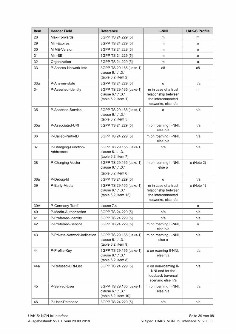
UAK-S: NGN Ici Interface Seite 39 von 98
Ausgabestand: V2.0.0 vom 23.03.2018 Spec_UAKS_NGN_Ici_Interface_V_2_0_0
Item Header Field Reference II-NNI UAK-S Profile
28 Max-Forwards 3GPP TS 24.229 [5] m m
29 Min-Expires 3GPP TS 24.229 [5] m o
30 MIME-Version 3GPP TS 24.229 [5] m o
31 Min-SE 3GPP TS 24.229 [5] m o
32 Organization 3GPP TS 24.229 [5] m o
33 P-Access-Network-Info 3GPP TS 29.165 [uaks-1]
clause 6.1.1.3.1
(table 6.2, item 2)
c8 c8
33a P-Answer-state 3GPP TS 24.229 [5] o n/a
34 P-Asserted-Identity 3GPP TS 29.165 [uaks-1]
clause 6.1.1.3.1
(table 6.2, item 1)
m in case of a trust
relationship between
the interconnected
networks, else n/a
m
35 P-Asserted-Service 3GPP TS 29.165 [uaks-1]
clause 6.1.1.3.1
(table 6.2, item 5)
o n/a
35a P-Associated-URI 3GPP TS 24.229 [5] m on roaming II-NNI,
else n/a
n/a
36 P-Called-Party-ID 3GPP TS 24.229 [5] m on roaming II-NNI,
else n/a
n/a
37 P-Charging-Function-
Addresses
3GPP TS 29.165 [uaks-1]
clause 6.1.1.3.1
(table 6.2, item 7)
n/a n/a
38 P-Charging-Vector 3GPP TS 29.165 [uaks-1]
clause 6.1.1.3.1
(table 6.2, item 6)
m on roaming II-NNI,
else o
o (Note 2)
38a P-Debug-Id 3GPP TS 24.229 [5] o n/a
39 P-Early-Media 3GPP TS 29.165 [uaks-1]
clause 6.1.1.3.1
(table 6.2, item 12)
m in case of a trust
relationship between
the interconnected
networks, else n/a
o (Note 1)
39A P-Germany-Tariff clause 7.4 - o
40 P-Media-Authorization 3GPP TS 24.229 [5] n/a n/a
41 P-Preferred-Identity 3GPP TS 24.229 [5] n/a n/a
42 P-Preferred-Service 3GPP TS 24.229 [5] m on roaming II-NNI,
else n/a
o
43 P-Private-Network-Indication 3GPP TS 29.165 [uaks-1]
clause 6.1.1.3.1
(table 6.2, item 9)
m on roaming II-NNI,
else o
n/a
44 P-Profile-Key 3GPP TS 29.165 [uaks-1]
clause 6.1.1.3.1
(table 6.2, item 8)
o on roaming II-NNI,
else n/a
n/a
44a P-Refused-URI-List 3GPP TS 24.229 [5] o on non-roaming II-
NNI and for the
loopback traversal
scenario else n/a
n/a
45 P-Served-User 3GPP TS 29.165 [uaks-1]
clause 6.1.1.3.1
(table 6.2, item 10)
m on roaming II-NNI,
else n/a
n/a
46 P-User-Database 3GPP TS 24.229 [5] n/a n/a

UAK-S: NGN Ici Interface Seite 40 von 98
Ausgabestand: V2.0.0 vom 23.03.2018 Spec_UAKS_NGN_Ici_Interface_V_2_0_0
Item Header Field Reference II-NNI UAK-S Profile
47 P-Visited-Network-ID 3GPP TS 24.229 [5] m on roaming II-NNI,
else n/a
n/a
47a Path 3GPP TS 24.229 [5] m on roaming II-NNI,
else n/a
n/a
47b Permission-Missing 3GPP TS 24.229 [5] o n/a
47c Policy-Contact IETF RFC 6794 [133]
and 3GPP TS 29.165
[uaks-1] clause 15.6.2
o o
48 Priority 3GPP TS 29.165 [uaks-1]
clause 6.1.1.3.1
(table 6.2, item 14)
o o
48a Priv-Answer-Mode 3GPP TS 24.229 [5] o n/a
49 Privacy 3GPP TS 24.229 [5] m m
50 Proxy-Authenticate 3GPP TS 24.229 [5] m on roaming II-NNI,
else n/a
n/a
51 Proxy-Authorization 3GPP TS 24.229 [5] m on roaming II-NNI,
else n/a
n/a
52 Proxy-Require 3GPP TS 24.229 [5] m n/a
52a RAck 3GPP TS 24.229 [5] m o
53 Reason 3GPP TS 24.229 [5] and
3GPP TS 29.165 [uaks-1]
clause 6.1.1.3.1
(table 6.2, item 11)
o when in a request.
When in a response,
m in case of a trust
relationship between
the interconnected
networks, else n/a
m
54 Record-Route 3GPP TS 24.229 [5] m o
54a Recv-Info 3GPP TS 24.229 [5] o o
55 Referred-By 3GPP TS 24.229 [5] m c3
55a Refer-Sub 3GPP TS 24.229 [5] m in the case the
REFER request is
supported, else n/a
n/a
55b Refer-To 3GPP TS 24.229 [5] m in the case the
REFER request is
supported, else n/a
n/a
56 Reject-Contact 3GPP TS 24.229 [5] m n/a
56a Relayed-Charge 3GPP TS 29.165 [uaks-1]
clause 6.1.1.3.1
(table 6.2, item 19)
n/a n/a
57 Replaces 3GPP TS 24.229 [5] o c4
58 Reply-To 3GPP TS 24.229 [5] o n/a
59 Request-Disposition 3GPP TS 24.229 [5] m n/a
60 Require 3GPP TS 24.229 [5] m o
61 Resource-Priority 3GPP TS 29.165 [uaks-1]
clause 6.1.1.3.1
(table 6.2, item 3)
o o
61a Resource-Share 3GPP TS 24.229 [5]
clause 7.2.13
o o
61b Restoration-Info 3GPP TS 29.165 [uaks-1]
clause 6.1.1.3.1
o on roaming II-NNI,
else n/a
n/a

UAK-S: NGN Ici Interface Seite 41 von 98
Ausgabestand: V2.0.0 vom 23.03.2018 Spec_UAKS_NGN_Ici_Interface_V_2_0_0
Item Header Field Reference II-NNI UAK-S Profile
(table 6.2, item 18)
61a Retry-After 3GPP TS 24.229 [5] o o
62 Route 3GPP TS 24.229 [5] m o
62a RSeq 3GPP TS 24.229 [5] m o
63 Security-Client 3GPP TS 24.229 [5] n/a n/a
63a Security-Server 3GPP TS 24.229 [5] n/a n/a
64 Security-Verify 3GPP TS 24.229 [5] n/a n/a
65 Server 3GPP TS 24.229 [5] o n/a
65c Service-Interact-Info 3GPP TS 29.165 [uaks-1]
clause 6.1.1.3.1
(table 6.2, item 20)
o o
65a Service-Route 3GPP TS 24.229 [5] m on roaming II-NNI,
else n/a
n/a
65b Session-ID 3GPP TS 24.229 [5] o o
66 Session-Expires 3GPP TS 24.229 [5] m o
66a SIP-ETag 3GPP TS 24.229 [5] m in the case the
PUBLISH request is
supported, else n/a
n/a
66b SIP-If-Match 3GPP TS 24.229 [5] m in the case the
PUBLISH request is
supported, else n/a
n/a
67 Subject 3GPP TS 24.229 [5] o n/a
67a Subscription-State 3GPP TS 24.229 [5] m in the case the
NOTIFY request is
supported, else n/a
c5
67b Suppress-If-Match IETF RFC 5839 [144]
and 3GPP TS 29.165
[uaks-1] clause 15.6.4
o o
68 Supported 3GPP TS 24.229 [5] m m
68a Target-Dialog 3GPP TS 24.229 [5] o o
69 Timestamp 3GPP TS 24.229 [5] m o
70 To 3GPP TS 24.229 [5] m m
71 Trigger-Consent 3GPP TS 24.229 [5] m m
71a Unsupported 3GPP TS 24.229 [5] m o
72 User-Agent 3GPP TS 24.229 [5] m o
73 User-to-User 3GPP TS 24.229 [5] o m
74 Via 3GPP TS 24.229 [5] m m
75 Warning 3GPP TS 24.229 [5] o o
76 WWW-Authenticate 3GPP TS 24.229 [5] m on roaming II-NNI,
else n/a
n/a
c1: IF Table 9-1/7 THEN m ELSE o (CW)
c2: IF Table 9-1/3 THEN m ELSE n/a (CCxx)
c3: IF Table 9-1/5 OR Table 9-1/8 THEN m ELSE n/a (CONF, ECT)
c4: IF Table 9-1/8 THEN m ELSE n/a (ECT)
c5: IF Table 8-6/12 THEN m ELSE n/a (NOTIFY request)
c6: IF Table 9-1/5 THEN m ELSE n/a (CONF)
c7: void

UAK-S: NGN Ici Interface Seite 42 von 98
Ausgabestand: V2.0.0 vom 23.03.2018 Spec_UAKS_NGN_Ici_Interface_V_2_0_0
Item Header Field Reference II-NNI UAK-S Profile
c8 IF emergency call originated from a mobile operator THEN m ELSE o
Note 1: see clause 10.2: A transit network shall forward a P-Early-Media header as received.
Note 2: The usage of this parameter requires multilateral agreements. This will be clarified in a later version of
this specification.
Table 8-5: Supported Header Fields
8.3.4 Supported SDP Types The following table is based on [5], Table A.318.
Item Type Reference
Sending - Status Receiving - Status
RFC Profile NNI
RFC Profile NNI
Session level description
1 v= (protocol version) IETF RFC 4566 [147] 5.1
m m m m
2 o= (owner/creator and session identifier)
IETF RFC 4566 [147] 5.2
m m m m
3 s= (session name) IETF RFC 4566 [147] 5.3
m m m m
4 i= (session information) IETF RFC 4566 [147] 5.4
o o m o
5 u= (URI of description) IETF RFC 4566 [147] 5.5
o n/a o n/a
6 e= (email address) IETF RFC 4566 [147] 5.6
o n/a o n/a
7 p= (phone number) IETF RFC 4566 [147] 5.6
o n/a o n/a
8 c= (connection information)
IETF RFC 4566 [147] 5.7
c5 o m m
9 b= (bandwidth information)
IETF RFC 4566 [147] 5.8
o o
(Note 1)
m m
Time description (one or more per description)
10 t= (time the session is active)
IETF RFC 4566 [147] 5.9
m m
(Note 2)
m m
11 r= (zero or more repeat times)
IETF RFC 4566 [147] 5.10
o n/a o n/a
Session level description (continued)
12 z= (time zone adjustments)
IETF RFC 4566 [147] 5.11
o n/a o n/a
13 k= (encryption key) IETF RFC 4566 [147] 5.12
x n/a n/a n/a
14 a= (zero or more session attribute lines)
IETF RFC 4566 [147] 5.13
o o m m
Media description (zero or more per description)
15 m= (media name and transport address)
IETF RFC 4566 [147] 5.14
o o m m
16 i= (media title) IETF RFC 4566 [147] 5.4
o n/a o n/a
17 c= (connection information)
IETF RFC 4566 [147] 5.7
c1 c1 c1 c1
18 b= (bandwidth IETF RFC 4566 [147] o o o o

UAK-S: NGN Ici Interface Seite 43 von 98
Ausgabestand: V2.0.0 vom 23.03.2018 Spec_UAKS_NGN_Ici_Interface_V_2_0_0
Item Type Reference
Sending - Status Receiving - Status
RFC Profile NNI
RFC Profile NNI
information) 5.8 (Note 1)
19 k= (encryption key) IETF RFC 4566 [147] 5.12
x n/a n/a n/a
20 a= (zero or more media attribute lines)
IETF RFC 4566 [147] 5.13
o o m m
c1: IF A.318/15 THEN m ELSE n/a.
c5: IF A.318/17 THEN o ELSE m - - "c=" contained in all media description.
Note 1: For "video" and "audio" media types that utilise RTP/RTCP, it shall be specified. For other media types, it may be specified.
Note 2: Shall be set to 00. IF CONF is used than other values can appear but this is out of scope of this specification.
Table 8-6: Supported SDP Types
Prerequisite table line Table 8-6/14 OR table line Table 8-6/20 - - a= (if at least one “a=” attribute exists )
8.3.5 Supported Media Attribute Lines The following table is based on 3GPP TS 24.229 [5], Table A.319.
Item Type Ref. in 3GPP TS 24.229 [5]
Sending - Status Receiving - Status
RFC Profile NNI RFC Profile NNI
1 category (a=cat) [39] 6 c8 c8 c9 c9
2 keywords (a=keywds) [39] 6 c8 c8 c9 c9
3 name and version of tool (a=tool)
[39] 6 c8 c8 c9 c9
4 packet time (a=ptime) [39] 6 c10 c10 c11 c11
5 maximum packet time (a=maxptime)
[39] 6, [28A] 8
c10 c10 c11 c11
6 receive-only mode (a=recvonly)
[39] 6 o o m m
7 send and receive mode (a=sendrecv)
[39] 6 o o m m
8 send-only mode (a=sendonly)
[39] 6 o o m m
8A Inactive mode (a=inactive) [39] 6 o o m m
9 whiteboard orientation (a=orient)
[39] 6 c10 c10 c11 c11
10 conference type (a=type) [39] 6 c8 c8 c9 c9
11 character set (a=charset) [39] 6 c8 c8 c9 c9
12 language tag (a=sdplang) [39] 6 o o m m
13 language tag (a=lang) [39] 6 o o m m
14 frame rate (a=framerate) [39] 6 c10 c10 c11 c11
15 quality (a=quality) [39] 6 c10 c10 c11 c11
16 format specific parameters (a=fmtp)
[39] 6 c10 c10 c11 c11

UAK-S: NGN Ici Interface Seite 44 von 98
Ausgabestand: V2.0.0 vom 23.03.2018 Spec_UAKS_NGN_Ici_Interface_V_2_0_0
Item Type Ref. in 3GPP TS 24.229 [5]
Sending - Status Receiving - Status
RFC Profile NNI RFC Profile NNI
17 rtpmap attribute (a=rtpmap)
[39] 6 c10 c10 c11 c11
18 current-status attribute (a=curr)
[30] 4 c1 n/a c2 c2
19 desired-status attribute (a=des)
[30] 4 c1 n/a c2 c2
20 confirm-status attribute (a=conf)
[30] 4 c1 n/a c2 c2
21 media stream identification attribute (a=mid)
[53] 3 c3 n/a c4 n/a
22 group attribute (a=group) [53] 4 c5 n/a c6 n/a
23 setup attribute (a=setup) [83] 4 c7 n/a c7 n/a
24 connection attribute (a=connection)
[83] 5 c7 n/a c7 n/a
c1: IF A.317/22 AND A.318/20 THEN o ELSE n/a - - integration of resource management and
SIP, media level attribute name "a=".
c2: IF A.317/22 AND A.318/20 THEN m ELSE n/a - - integration of resource management and
SIP, media level attribute name "a=".
c3: IF A.317/23 AND A.318/20 THEN o ELSE n/a - - integration of resource management and
SIP, media level attribute name "a=".
c4: IF A.317/23 AND A.318/20 THEN m ELSE n/a - - integration of resource management and
SIP, media level attribute name "a=".
c5: IF A.317/24 AND A.318/20 THEN o ELSE n/a - - integration of resource management and
SIP, media level attribute name "a=".
c6: IF A.317/24 AND A.318/20 THEN m ELSE n/a - - integration of resource management and
SIP, media level attribute name "a=".
c7: IF A.317/26 AND A.318/20 THEN m ELSE n/a - - integration of resource management and
S IP, media level attribute name "a=".
c8: IF A.318/14 THEN o ELSE x - - session level attribute name "a=".
c9: IF A.318/14 THEN m ELSE n/a - - session level attribute name "a=".
c10: IF A.318/20 THEN o ELSE x - - media level attribute name "a=".
c11: IF A.318/20 THEN m ELSE n/a - - media level attribute name "a=".
Table 8-7: Media Attribute Lines

UAK-S: NGN Ici Interface Seite 45 von 98
Ausgabestand: V2.0.0 vom 23.03.2018 Spec_UAKS_NGN_Ici_Interface_V_2_0_0
8.3.6 Supported MIME Bodies The following table is based on [uaks-1], Table 6.1.4.1.
Item MIME Body Name II-NNI requirements in
reference (Note 1)
Defined in reference
(Note 2)
UAK-S Profile
1 application/3gpp-ims+xml - 3GPP TS 24.229 [5],
clause 7.6
o
3 message/cpim - IETF RFC 3862 [92] o
4 message/imdn+xml - IETF RFC 5438 [93] o
5 application/im-
iscomposing+xml
3GPP TS 29.165 [uaks-1]
clause 16.2
IETF RFC 3994 [175] o
6 multipart/mixed 3GPP TS 29.165 [uaks-1]
clause 15.1,
3GPP TS 29.165 [uaks-1]
clause 15.4,
3GPP TS 29.165 [uaks-1]
clause 15.6.2,
3GPP TS 29.165 [uaks-1]
clause 15.6.3,
3GPP TS 29.165 [uaks-1]
clause 15.6.4,
3GPP TS 29.165 [uaks-1]
clause 18.3.3
IETF RFC 2046 [169] m
7 multipart/related 3GPP TS 29.165 [uaks-1]
clause 15.1,
3GPP TS 29.165 [uaks-1]
clause 15.2,
3GPP TS 29.165 [uaks-1]
clause 15.6.5
IETF RFC 2387 [170] o
8 multipart/alternative - IETF RFC 2046 [169] o
9 application/pidf+xml 3GPP TS 29.165 [uaks-1]
clause 15.1
IETF RFC 3863 [174] m
10 application/pidf-diff+xml 3GPP TS 29.165 [uaks-1]
clause 15.1
IETF RFC 5262 [179] o
11 application/resource-lists+xml 3GPP TS 29.165 [uaks-1]
clause 12.19,
3GPP TS 29.165 [uaks-1]
clause 15.1,
3GPP TS 29.165 [uaks-1]
clause 15.6.3,
3GPP TS 29.165 [uaks-1]
clause 16.5
IETF RFC 4826 [178] o
12 application/rlmi+xml 3GPP TS 29.165 [uaks-1]
clause 15.2,
3GPP TS 29.165 [uaks-1]
clause 15.6.5
IETF RFC 4662 [177] o
13 application/sdp - IETF RFC 4566 [147] m
14 application/simple-filter+xml 3GPP TS 29.165 [uaks-1]
clause 15.1,
3GPP TS 29.165 [uaks-1]
clause 15.6.4
IETF RFC 4661 [176] o
15 application/simple-message-
summary+xml
3GPP TS 29.165 [uaks-1]
clause 12.9
IETF RFC 3842 [172] c2
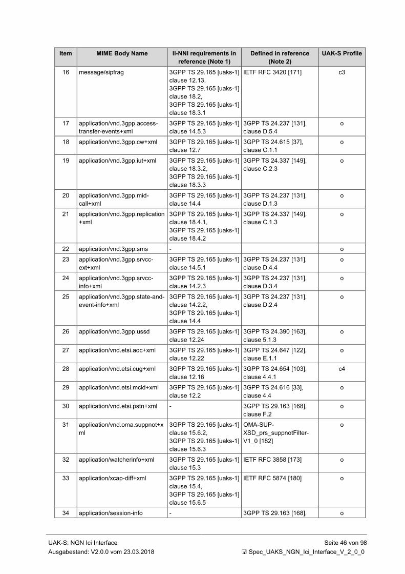
UAK-S: NGN Ici Interface Seite 46 von 98
Ausgabestand: V2.0.0 vom 23.03.2018 Spec_UAKS_NGN_Ici_Interface_V_2_0_0
Item MIME Body Name II-NNI requirements in
reference (Note 1)
Defined in reference
(Note 2)
UAK-S Profile
16 message/sipfrag 3GPP TS 29.165 [uaks-1]
clause 12.13,
3GPP TS 29.165 [uaks-1]
clause 18.2,
3GPP TS 29.165 [uaks-1]
clause 18.3.1
IETF RFC 3420 [171] c3
17 application/vnd.3gpp.access-
transfer-events+xml
3GPP TS 29.165 [uaks-1]
clause 14.5.3
3GPP TS 24.237 [131],
clause D.5.4
o
18 application/vnd.3gpp.cw+xml 3GPP TS 29.165 [uaks-1]
clause 12.7
3GPP TS 24.615 [37],
clause C.1.1
o
19 application/vnd.3gpp.iut+xml 3GPP TS 29.165 [uaks-1]
clause 18.3.2,
3GPP TS 29.165 [uaks-1]
clause 18.3.3
3GPP TS 24.337 [149],
clause C.2.3
o
20 application/vnd.3gpp.mid-
call+xml
3GPP TS 29.165 [uaks-1]
clause 14.4
3GPP TS 24.237 [131],
clause D.1.3
o
21 application/vnd.3gpp.replication
+xml
3GPP TS 29.165 [uaks-1]
clause 18.4.1,
3GPP TS 29.165 [uaks-1]
clause 18.4.2
3GPP TS 24.337 [149],
clause C.1.3
o
22 application/vnd.3gpp.sms - o
23 application/vnd.3gpp.srvcc-
ext+xml
3GPP TS 29.165 [uaks-1]
clause 14.5.1
3GPP TS 24.237 [131],
clause D.4.4
o
24 application/vnd.3gpp.srvcc-
info+xml
3GPP TS 29.165 [uaks-1]
clause 14.2.3
3GPP TS 24.237 [131],
clause D.3.4
o
25 application/vnd.3gpp.state-and-
event-info+xml
3GPP TS 29.165 [uaks-1]
clause 14.2.2,
3GPP TS 29.165 [uaks-1]
clause 14.4
3GPP TS 24.237 [131],
clause D.2.4
o
26 application/vnd.3gpp.ussd 3GPP TS 29.165 [uaks-1]
clause 12.24
3GPP TS 24.390 [163],
clause 5.1.3
o
27 application/vnd.etsi.aoc+xml 3GPP TS 29.165 [uaks-1]
clause 12.22
3GPP TS 24.647 [122],
clause E.1.1
o
28 application/vnd.etsi.cug+xml 3GPP TS 29.165 [uaks-1]
clause 12.16
3GPP TS 24.654 [103],
clause 4.4.1
c4
29 application/vnd.etsi.mcid+xml 3GPP TS 29.165 [uaks-1]
clause 12.2
3GPP TS 24.616 [33],
clause 4.4
o
30 application/vnd.etsi.pstn+xml - 3GPP TS 29.163 [168],
clause F.2
o
31 application/vnd.oma.suppnot+x
ml
3GPP TS 29.165 [uaks-1]
clause 15.6.2,
3GPP TS 29.165 [uaks-1]
clause 15.6.3
OMA-SUP-
XSD_prs_suppnotFilter-
V1_0 [182]
o
32 application/watcherinfo+xml 3GPP TS 29.165 [uaks-1]
clause 15.3
IETF RFC 3858 [173] o
33 application/xcap-diff+xml 3GPP TS 29.165 [uaks-1]
clause 15.4,
3GPP TS 29.165 [uaks-1]
clause 15.6.5
IETF RFC 5874 [180] o
34 application/session-info - 3GPP TS 29.163 [168], o
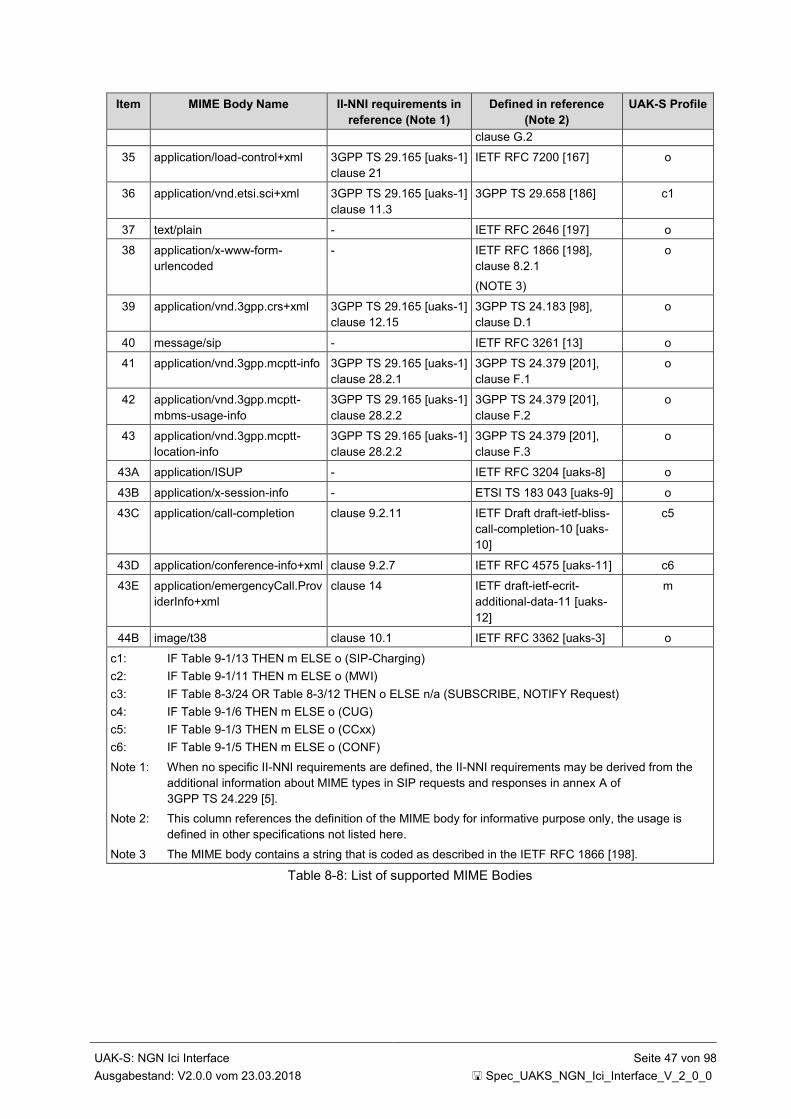
UAK-S: NGN Ici Interface Seite 47 von 98
Ausgabestand: V2.0.0 vom 23.03.2018 Spec_UAKS_NGN_Ici_Interface_V_2_0_0
Item MIME Body Name II-NNI requirements in
reference (Note 1)
Defined in reference
(Note 2)
UAK-S Profile
clause G.2
35 application/load-control+xml 3GPP TS 29.165 [uaks-1]
clause 21
IETF RFC 7200 [167] o
36 application/vnd.etsi.sci+xml 3GPP TS 29.165 [uaks-1]
clause 11.3
3GPP TS 29.658 [186] c1
37 text/plain - IETF RFC 2646 [197] o
38 application/x-www-form-
urlencoded
- IETF RFC 1866 [198],
clause 8.2.1
(NOTE 3)
o
39 application/vnd.3gpp.crs+xml 3GPP TS 29.165 [uaks-1]
clause 12.15
3GPP TS 24.183 [98],
clause D.1
o
40 message/sip - IETF RFC 3261 [13] o
41 application/vnd.3gpp.mcptt-info 3GPP TS 29.165 [uaks-1]
clause 28.2.1
3GPP TS 24.379 [201],
clause F.1
o
42 application/vnd.3gpp.mcptt-
mbms-usage-info
3GPP TS 29.165 [uaks-1]
clause 28.2.2
3GPP TS 24.379 [201],
clause F.2
o
43 application/vnd.3gpp.mcptt-
location-info
3GPP TS 29.165 [uaks-1]
clause 28.2.2
3GPP TS 24.379 [201],
clause F.3
o
43A application/ISUP - IETF RFC 3204 [uaks-8] o
43B application/x-session-info - ETSI TS 183 043 [uaks-9] o
43C application/call-completion clause 9.2.11 IETF Draft draft-ietf-bliss-
call-completion-10 [uaks-
10]
c5
43D application/conference-info+xml clause 9.2.7 IETF RFC 4575 [uaks-11] c6
43E application/emergencyCall.Prov
iderInfo+xml
clause 14 IETF draft-ietf-ecrit-
additional-data-11 [uaks-
12]
m
44B image/t38 clause 10.1 IETF RFC 3362 [uaks-3] o
c1: IF Table 9-1/13 THEN m ELSE o (SIP-Charging)
c2: IF Table 9-1/11 THEN m ELSE o (MWI)
c3: IF Table 8-3/24 OR Table 8-3/12 THEN o ELSE n/a (SUBSCRIBE, NOTIFY Request)
c4: IF Table 9-1/6 THEN m ELSE o (CUG)
c5: IF Table 9-1/3 THEN m ELSE o (CCxx)
c6: IF Table 9-1/5 THEN m ELSE o (CONF)
Note 1: When no specific II-NNI requirements are defined, the II-NNI requirements may be derived from the
additional information about MIME types in SIP requests and responses in annex A of
3GPP TS 24.229 [5].
Note 2: This column references the definition of the MIME body for informative purpose only, the usage is
defined in other specifications not listed here.
Note 3 The MIME body contains a string that is coded as described in the IETF RFC 1866 [198].
Table 8-8: List of supported MIME Bodies
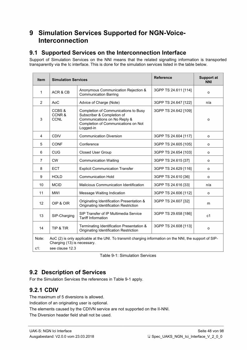
UAK-S: NGN Ici Interface Seite 48 von 98
Ausgabestand: V2.0.0 vom 23.03.2018 Spec_UAKS_NGN_Ici_Interface_V_2_0_0
9 Simulation Services Supported for NGN-Voice-Interconnection
9.1 Supported Services on the Interconnection Interface Support of Simulation Services on the NNI means that the related signalling information is transported transparently via the Ic interface. This is done for the simulation services listed in the table below.
Item Simulation Services Reference Support at
NNI
1 ACR & CB Anonymous Communication Rejection & Communication Barring
3GPP TS 24.611 [114] o
2 AoC Advice of Charge (Note) 3GPP TS 24.647 [122] n/a
3
CCBS & CCNR & CCNL
Completion of Communications to Busy Subscriber & Completion of Communications on No Reply & Completion of Communications on Not Logged-in
3GPP TS 24.642 [109]
o
4 CDIV Communication Diversion 3GPP TS 24.604 [117] o
5 CONF Conference 3GPP TS 24.605 [105] o
6 CUG Closed User Group 3GPP TS 24.654 [103] o
7 CW Communication Waiting 3GPP TS 24.615 [37] o
8 ECT Explicit Communication Transfer 3GPP TS 24.629 [116] o
9 HOLD Communication Hold 3GPP TS 24.610 [36] o
10 MCID Malicious Communication Identification 3GPP TS 24.616 [33] n/a
11 MWI Message Waiting Indication 3GPP TS 24.606 [112] o
12 OIP & OIR Originating Identification Presentation & Originating Identification Restriction
3GPP TS 24.607 [32] m
13 SIP-Charging SIP Transfer of IP Multimedia Service Tariff Information
3GPP TS 29.658 [186] c1
14 TIP & TIR Terminating Identification Presentation & Originating Identification Restriction
3GPP TS 24.608 [113] o
Note: AoC (2) is only applicable at the UNI. To transmit charging information on the NNI, the support of SIP- Charging (13) is necessary.
c1: see clause 12.3
Table 9-1: Simulation Services
9.2 Description of Services For the Simulation Services the references in Table 9-1 apply.
9.2.1 CDIV The maximum of 5 diversions is allowed.
Indication of an originating user is optional.
The elements caused by the CDIVN service are not supported on the II-NNI.
The Diversion header field shall not be used.
UAK-S: NGN Ici Interface Seite 49 von 98
Ausgabestand: V2.0.0 vom 23.03.2018 Spec_UAKS_NGN_Ici_Interface_V_2_0_0
9.2.2 OIP/OIR No special requirements beyond that defined within clause 8 on the II-NNI needed.
9.2.3 TIP/TIR No special requirements beyond that defined within clause 8 on the II-NNI needed.
9.2.4 HOLD No special requirements beyond that defined within clause 8 on the II-NNI needed.
9.2.5 ACR&CB No special requirements beyond that defined within clause 8 on the II-NNI needed.
9.2.6 ECT The Interworking of the REFER Request to an INVITE shall be done by the serving network operator. See clause 4.7.2.9.7 of 3GPP TS 24.628 [38] for details.
9.2.7 CONF The Interworking of the REFER Request to an INVITE shall be done by the serving network operator. See clause 4.7.2.9.7 of 3GPP TS 24.628 [38] for details.
The event package "conference" and the Event header field shall be supported
9.2.8 CUG No special requirements beyond that defined within clause 8 on the II-NNI needed.
9.2.9 MWI The event package name "message-summary" in the SUBSCRIBE and NOTIFY request shall be supported.
9.2.10 MCID MCID is not applicable on the Ic interface (see also clause 5.1.4).
9.2.11 Call Completion The event package name "call-completion" and the Call-Info header field with a purpose parameter set to 'call-completion' and the m parameter set to "BS" or "NR" or "NL" shall be supported.
9.2.12 CW No special requirements beyond that defined within clause 8 on the II-NNI needed.
9.2.13 Emergency Calls (Notruf) The transmission of information accompanying the emergency call (e.g. emergency caller location, supplier recognition) is described in clause 14.
UAK-S: NGN Ici Interface Seite 50 von 98
Ausgabestand: V2.0.0 vom 23.03.2018 Spec_UAKS_NGN_Ici_Interface_V_2_0_0
10 Bearer Aspects
10.1 Bearer Services Fax and Modem transmission via G.711a shall be supported as default setting.
Two optional alternatives are proposed:
ITU-T T.38 [uaks-5]: MIME Type: image (IETF RFC 3362 [uaks-3]) using UDPTL (only for Fax)
ITU-T V.152 [uaks-4] in transparent mode
10.2 Bearer Control
10.2.1 Through Connection of the Media Path (speech-/data-transmission)
10.2.1.1 General Remarks
The following chapters describe the establishment of the transmission path with respect to the offer/answer procedure and the early-media handling. The usage of the P-Early-Media header field is an option. All statements made regarding the P-Early-Media header field are conform to IETF RFC 5009 [74]. Although the through connection is done based on local policies it is described for the purpose of clarifying the relation between charging and establishing the transmission path.
Please consider that the originating and terminating network discard the P-Early-Media header field received from the not trusted user equipment.
If the destination network sends an SDP information with 18x this network or a trusted UE connected to it is responsible to play appropriate tones or announcements.
10.2.1.2 Scenarios described
10.2.1.2.1 Remarks and Symbols used The B-subscriber is trusted concerning early media := the early media in backward direction is already available in the early dialogue in the destination network.
The B-subscriber is not trusted concerning early media := the early media in backward direction is not available in the early dialogue in the destination network.
Scenario 4 is only successful if the P-Early-Media header is supported across all involved networks.
Scenario 4 (bidirectional media channel before 200 OK available in the originating network) applies only if this was explicitly covered by a contract which was approved by the originating operator.

UAK-S: NGN Ici Interface Seite 51 von 98
Ausgabestand: V2.0.0 vom 23.03.2018 Spec_UAKS_NGN_Ici_Interface_V_2_0_0
Through connection of media path in backward direction
Through connection of media path in forward direction
Through connection of media path in forward and backward direction
Reservation of media path in forward and backward direction without
through connection
Charging begins
Disconnection of the media path through the node
Symbols used:
Remarks:
(i) The segment symbols used represent the state of the connection in the BGF
(ii) The forward direction is defined by the direction of the connection set-up
(iii) The blue marked signalling events are optional informations
Figure 10-1: Symbols used
10.2.1.2.2 Scenario 1: Connection Set-up to User Equipment B, which is Not Trusted concerning Early Media
INVITE: user B SIP/2.0
SDPINVITE: user B SIP/2.0
P-Early-Media: supported
SDP INVITE: user B SIP/2.0
P-Early-Media: supported
SDP
200 OK
SDP
200 OK
SDP
INVITE: user B SIP/2.0
P-Early-Media: supported
SDP
User
Equipment A
Originating Node
(P-CSCF/C-BGF, A-BGF)Transit Node
(IBCF/I-BGF)Transit Node
(IBCF/I-BGF)
Terminating Node
(P-CSCF/C-BGF, A-BGF)
User Equipment B
(not trusted concern.
early media)
INVITE: user B SIP/2.0
SDP
18x yyyyy
SDP
18x yyyyy
SDP
200 OK
SDP200 OK
SDP200 OK
SDP
18x yyyyy
P-Early-Media: inactive
SDP18x yyyyy
P-Early-Media: inactive
SDP
18x yyyyy
P-Early-Media: inactive
SDP
The blue marked signalling events are optional informations
Figure 10-2: Scenario 1: Connection set-up to user equipment B, which is not trusted concerning early media
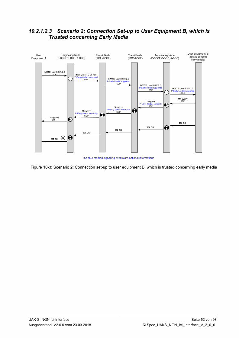
UAK-S: NGN Ici Interface Seite 52 von 98
Ausgabestand: V2.0.0 vom 23.03.2018 Spec_UAKS_NGN_Ici_Interface_V_2_0_0
10.2.1.2.3 Scenario 2: Connection Set-up to User Equipment B, which is Trusted concerning Early Media
INVITE: user B SIP/2.0
SDP INVITE: user B SIP/2.0
P-Early-Media: supported
SDP INVITE: user B SIP/2.0
P-Early-Media: supported
SDP
200 OK
200 OK
INVITE: user B SIP/2.0
P-Early-Media: supported
SDP
User
Equipment A
Originating Node
(P-CSCF/C-BGF, A-BGF)Transit Node
(IBCF/I-BGF)Transit Node
(IBCF/I-BGF)
Terminating Node
(P-CSCF/C-BGF, A-BGF)
User Equipment B
(trusted concern.
early media)
INVITE: user B SIP/2.0
P-Early-Media: supported
SDP
18x yyyyy
SDP18x yyyy
P-Early-Media: sendonly
SDP
18x yyyyy
SDP
200 OK
200 OK
200 OK
18x yyyy
P-Early-Media: sendonly
SDP18x yyyy
P-Early-Media: sendonlySDP
The blue marked signalling events are optional informations
Figure 10-3: Scenario 2: Connection set-up to user equipment B, which is trusted concerning early media

UAK-S: NGN Ici Interface Seite 53 von 98
Ausgabestand: V2.0.0 vom 23.03.2018 Spec_UAKS_NGN_Ici_Interface_V_2_0_0
10.2.1.2.4 Scenario 3: Connection Set-up with Tones/Announcements from the Transit-/ Destination Network
Figure 10-4: Scenario 3: Connection set-up with tones/announcements from the transit-/destination network
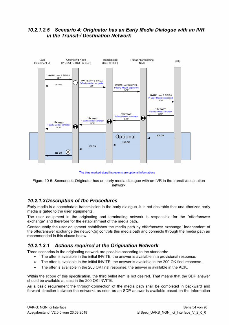
UAK-S: NGN Ici Interface Seite 54 von 98
Ausgabestand: V2.0.0 vom 23.03.2018 Spec_UAKS_NGN_Ici_Interface_V_2_0_0
10.2.1.2.5 Scenario 4: Originator has an Early Media Dialogue with an IVR in the Transit-/ Destination Network
Optional
INVITE: user B SIP/2.0
SDP
TRYING
INVITE: user B SIP/2.0
P-Early-Media: supported
SDP INVITE: user B SIP/2.0
P-Early-Media: supported
SDP
200 OK
200 OK
User
Equipment A
Originating Node
(P-CSCF/C-BGF, A-BGF)Transit Node
(IBCF/I-BGF)Transit-/Terminating-
NodeIVR
INVITE: user B SIP/2.0
P-Early-Media: supported
SDP
18x yyyyy
P-Early-Media: sendrecv
SDP18x yyyyy
P-Early-Media: sendrecv
SDP18x yyyyy
P-Early-Media: sendrecv
SDP18x yyyyy
P-Early-Media: sendrecv
SDP
200 OK
200 OK
The blue marked signalling events are optional informations
Figure 10-5: Scenario 4: Originator has an early media dialogue with an IVR in the transit-/destination network
10.2.1.3 Description of the Procedures Early media is a speech/data transmission in the early dialogue. It is not desirable that unauthorized early media is gated to the user equipments.
The user equipment in the originating and terminating network is responsible for the "offer/answer exchange" and therefore for the establishment of the media path.
Consequently the user equipment establishes the media path by offer/answer exchange. Independent of the offer/answer exchange the network(s) controls this media path and connects through the media path as recommended in this clause below.
10.2.1.3.1 Actions required at the Origination Network
Three scenarios in the originating network are possible according to the standards:
The offer is available in the initial INVITE; the answer is available in a provisional response.
The offer is available in the initial INVITE; the answer is available in the 200 OK final response.
The offer is available in the 200 OK final response; the answer is available in the ACK.
Within the scope of this specification, the third bullet item is not desired. That means that the SDP answer should be available at least in the 200 OK INVITE.
As a basic requirement the through-connection of the media path shall be completed in backward and forward direction between the networks as soon as an SDP answer is available based on the information

UAK-S: NGN Ici Interface Seite 55 von 98
Ausgabestand: V2.0.0 vom 23.03.2018 Spec_UAKS_NGN_Ici_Interface_V_2_0_0
delivered, the originating network has no knowledge whether early media is authorized or not (see Figure 10-6 case A).
The transmission path is completed in the forward and backward direction between the user equipment in the originating and destination network on receipt of a 200 OK to the INVITE request from the destination network (see Figure 10-6 case E).
If media are modified with subsequent SDP offer-answer exchanges during the call establishment or while the call is confirmed, any updates of the transmission path required to support the adjusted media should be performed when the new SDP offer-answer exchange is completed.
If the originating network supports the early media authorization according to the requirements in IETF RFC 5009 [74]:
A P-Early-Media header field is present in the initial INVITE request set to 'supported'
When a P-Early-Media header field is received in a provisional response, the early media is
authorized according to the value of the received P-Early-Media header field towards the user
equipment (see Figure 10-6 cases B, C and D).The through connection in forward direction shall
be completed based on bilateral agreements
If early media authorization according to the requirements in IETF RFC 5009 [74] is not supported, the originating network has to trust the early media handling in the terminating network and the transmission path is controlled only with the information received in the SDP towards the user equipment (see Figure 10-6 cases A and E).

UAK-S: NGN Ici Interface Seite 56 von 98
Ausgabestand: V2.0.0 vom 23.03.2018 Spec_UAKS_NGN_Ici_Interface_V_2_0_0
UE-A
INVITE: user B SIP/2.0
SDP INVITE: user B SIP/2.0
P-Early-Media: supported
SDPINVITE: user B SIP/2.0
P-Early-Media: supported
SDP
18x yyyyy
SDP18x yyyyy
SDP18x yyyyy
SDP
18x yyyyy
P-Early-Media: inactive
SDP
18x yyyyy
P-Early-Media: inactive
SDP
18x yyyyy
SDP
Media in forward direction
CASE A
Media in backward direction
CASE B
18x yyyyy
P-Early-Media: sendonly
SDP
18x yyyyy
Early-Media: sendonly
SDP
CASE C
18x yyyyy
SDP
18x yyyyy
P-Early-Media: sendrecv
SDP
18x yyyyy
P-Early-Media: sendrecv
SDP
CASE D
18x yyyyy
SDP
The blue marked events are applicable if RFC 5009 is supported in the originating or terminating network
C-BGF
A-BGF
Media in backward direction
Media in forward direction
CASE E
Media in forward direction
Media in backward direction
Media in forward direction
Media in backward direction
Media in forward direction
Media in backward direction
Media path enabled
Media path disabled
200 OK INVITE
200 OK INVITE200 OK INVITE
IBCF
I-BGF
P-CSCF
Media in forward direction
Media in backward direction
Media in forward direction
Media in backward direction
Media in forward direction
Media in backward direction
Media in forward direction
Media in backward direction
Media in forward direction
Media in backward direction
Figure 10-6: Signalling events and media handling in the originating network

UAK-S: NGN Ici Interface Seite 57 von 98
Ausgabestand: V2.0.0 vom 23.03.2018 Spec_UAKS_NGN_Ici_Interface_V_2_0_0
10.2.1.3.2 Actions required at an Intermediate National Network (Transit) The establishment of the transmission path in forward and backward direction is completed via the transit network as soon as an SDP answer is available.
If the intermediate national network supports the procedures of IETF RFC 5009 [74] it can selectively open or close the media gate(s) corresponding to an authorized early media as indicated in the P-Early-Media header field. The intermediate national network sends a P-Early-Media header field as received.
If media are modified with subsequent SDP offer-answer exchanges during the call establishment or while the call is ongoing, any updates of the transmission path required to support the adjusted media should be performed when the new SDP offer-answer exchange is completed
If Tones and Announcements are applicable the MRF sends an SDP that contains an 'a' attribute set to 'sendonly' and
if the destination network receives a P-Early-Media header field set to 'supported' in the initial INVITE request and if the early media authorization according to the requirements in IETF RFC 5009 is supported, a P-Early-Media header field is present in the 18x provisional response set to 'sendonly' (see Figure 10-7 case B).
IBCF
I-BGF
IBCF
I-BGF
INVITE: user B SIP/2.0
P-Early-Media: supported
SDPINVITE: user B SIP/2.0
P-Early-Media: supported
SDPINVITE: user B SIP/2.0
P-Early-Media: supported
SDP
18x yyyyyy
P-Early-Media: xxx
SDP
18x yyyyyy
P-Early-Media: xxx
SDP
18x yyyyyy
P-Early-Media: xxx
SDP
Media in forward direction
Media in backward direction
The blue marked events are applicable if IETF RFC 5009 [74] is supported in the originating or terminating network
Announ.
IVR
18x yyyyyy
P-Early-Media: sendonly
SDP18x yyyyyy
P-Early-Media: sendonly
SDP
18x yyyyyy
P-Early-Media: sendrecv
SDP18x yyyyyy
P-Early-Media: sendrecv
SDP
Media path enabled
Media path disabled
Media in forward direction Media in forward direction
Media in backward direction Media in backward direction
CASE A
CASE B
CASE C
Media in forward direction
Media in backward direction
Media in forward direction
Media in backward direction
Media in forward direction
Media in backward direction
Media in forward direction
Media in backward direction
Figure 10-7: Signalling events and media handling in the intermediate national network

UAK-S: NGN Ici Interface Seite 58 von 98
Ausgabestand: V2.0.0 vom 23.03.2018 Spec_UAKS_NGN_Ici_Interface_V_2_0_0
10.2.1.3.3 Actions required at the Termination Network Since the terminating network has the knowledge based on local policies whether early media in forward or backward direction is authorized it is responsible whether the media stream in the early dialogue is allowed and is gated from/to the terminating user equipment.
The scenarios for the "offer/answer exchange" as described in clause 10.2.1.3.1 are also applicable in this section.
The establishment of the transmission path in the early dialogue is suppressed towards the called party.
Based on local policies if the destination user is trusted regarding early media, the through-connection of the media path will be completed in the backward direction as soon as an SDP answer from the SIP user equipment at the called party's side is available.
If the destination network receives a P-Early-Media header field set to 'supported' in the initial INVITE request and if the early media authorization according to the requirements in IETF RFC 5009 [74] is supported, a P-Early-Media header field is present in the 18x provisional response set to 'sendonly' (see Figure 10-8 case B).
Based on local policies if the destination user is not trusted regarding early media, the through-connection of the media path is suppressed towards the calling party user equipment (see Figure 10-8 case A).
If the destination network receives a P-Early-Media header field set to 'supported' in the initial INVITE request and if the early media authorization according to the requirements in IETF RFC 5009 [74] is supported, a P-Early-Media header field is present in the 18x provisional response set to 'inactive'.
When the called party answers with a 200 OK INVITE, the destination network shall connect through the transmission path to the terminating user in forward and backward direction and the ringing tone is removed if applicable. A 200 OK to the preceding exchange is sent (see Figure 10-7 case A and case B).
If media are modified with subsequent SDP offer-answer exchanges during the call establishment or while the call is ongoing, any updates of the transmission path required to support the adjusted media should be performed when the new SDP offer-answer exchange is completed.
If Tones and Announcements are applicable the MRF sends an SDP that contains an 'a' attribute set to 'sendonly' and if the destination network receives a P-Early-Media header field in the initial INVITE request set to 'supported' and if the early media authorization according to the requirements in IETF RFC 5009 [74] is supported, a P-Early-Media header field is present in the 18x provisional response set to 'sendonly' (see Figure 10-8 case C).

UAK-S: NGN Ici Interface Seite 59 von 98
Ausgabestand: V2.0.0 vom 23.03.2018 Spec_UAKS_NGN_Ici_Interface_V_2_0_0
INVITE: user B SIP/2.0
P-Early-Media:supported
SDPINVITE: user B SIP/2.0
P-Early-Media:supported
SDP
INVITE: user B SIP/2.0
SDP
18x yyyyy
SDP18x yyyyy
P-Early-Media: inactive
SDP
18x yyyyy
P-Early-Media: inactive
SDP
UE-BNon trusted
UE-Btrusted
18x yyyyy
SDP18x yyyyy
P-Early-Media: sendonly
SDP
18x yyyyy
P-Early-Media: sendonly
SDP
Announ.
IVR
18x yyyyy
P-Early-Media: sendonly
SDP
18x yyyyy
P-Early-Media: sendonly
SDP
Media in forward direction
18x yyyyyP-Early-Media: sendrecv
SDP
18x yyyyyP-Early-Media: sendrecv
SDP
The blue marked events are applicable if RFC 5009 is supported in the originating or terminating network
Media path enabled
Media path disabled
IBCF
C-BGF
A-BGF
P-CSCF
Media in backward directionMedia in forward direction
Media in backward direction
200 OK INVITE200 OK INVITE
200 OK INVITE
Media in forward directionMedia in backward direction
Media in forward directionMedia in backward direction
Media in forward directionMedia in backward direction
Media in forward directionMedia in backward direction
200 OK INVITE200 OK INVITE
200 OK INVITE
Media in forward directionMedia in backward direction
Media in forward directionMedia in backward direction
I-BGF
Media in forward directionMedia in backward direction
Media in forward directionMedia in backward direction
Media in forward directionMedia in backward direction
Media in forward directionMedia in backward direction
CASE A
CASE B
CASE C
CASE D
Figure 10-8: Signalling events and media handling in the terminating network
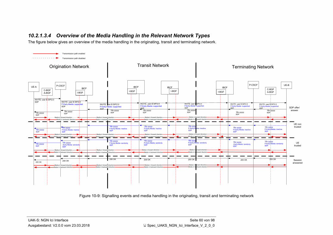
UAK-S: NGN Ici Interface Seite 60 von 98
Ausgabestand: V2.0.0 vom 23.03.2018 Spec_UAKS_NGN_Ici_Interface_V_2_0_0
10.2.1.3.4 Overview of the Media Handling in the Relevant Network Types The figure below gives an overview of the media handling in the originating, transit and terminating network.
Transmission path disabled
UE-AP-CSCF
IBCF
INVITE: user B SIP/2.0
SDP INVITE: user B SIP/2.0
P-Early-Media: supported
SDPINVITE: user B SIP/2.0
P-Early-Media: supported
SDP18x yyyyySDP
18x yyyyySDP18x yyyyy
SDP
18x yyyyyP-Early-Media: inactive
SDP
18x yyyyyP-Early-Media: inactive
SDP
18x yyyyySDP
Media in forward direction
Media in backward direction
UE non
trusted
18x yyyyy-Early-Media: sendonly
SDP
UE
trusted18x yyyyySDP
C-BGF
A-BGF
Media in forward direction
Media in backward direction
I-BGF
Transmission path enabled
Media in forward direction
Media in backward direction
Media in forward direction
Media in backward direction
Media in forward direction
Media in backward direction
Media in forward direction
Media in backward direction
Session
answered
200 OK200 OK
200 OK
Media in forward direction
Media in backward direction
Media in forward direction
Media in backward direction
18x yyyyyP-Early-Media: sendonly
SDP
IBCF
I-BGF
IBCF
I-BGF
INVITE: user B SIP/2.0
P-Early-Media: supported
SDP18x yyyyySDP
18x yyyyyP-Early-Media: inactive
SDP
Media in forward direction
Media in backward direction
Media in forward direction
Media in backward direction
Media in forward direction
Media in backward direction
200 OK
Media in forward direction
Media in backward direction
18x yyyyyP-Early-Media: sendonly
SDP
IBCF
I-BGF
P-CSCF
C-BGF
A-BGF
UE-B
INVITE: user B SIP/2.0
P-Early-Media: supported
SDP
INVITE: user B SIP/2.0
P-Early-Media: supported
SDP
18x yyyyySDP18x yyyyy
SDP
18x yyyyyP-Early-Media: inactive
SDP
18x yyyyyP-Early-Media: inactive
SDP
18x yyyyy-Early-Media: sendonly
SDP
200 OK200 OK
18x yyyyyP-Early-Media: sendonly
SDP
INVITE: user B SIP/2.0
P-Early-Media: supported
SDP
18x yyyyySDP
18x yyyyyP-Early-Media: inactive
SDP
Media in forward direction
Media in backward direction
Media in forward direction
Media in backward direction
Media in backward direction
200 OK
Media in forward direction
Media in backward direction
18x yyyyyP-Early-Media: sendonly
SDP
Media in forward direction
SDP offer/
answer
Terminating NetworkTransit NetworkOrigination Network
Figure 10-9: Signalling events and media handling in the originating, transit and terminating network
UAK-S: NGN Ici Interface Seite 61 von 98
Ausgabestand: V2.0.0 vom 23.03.2018 Spec_UAKS_NGN_Ici_Interface_V_2_0_0
10.2.2 MIME Type Handling For the Ic interface it is necessary to define the various SIP message bodies amongst SIP functionalities (e.g. methods, header, parameter, numbering formats) in order to reach a minimum interoperability at the Ici interface between two IBCF or B2BUA. The IBCF shall support the MIME types defined in Table 8-6.
According to 3GPP TS 24.229 [5], chapter 5.10.6.3, the IBCF can screen the SIP message body and handle it according to network policies.
10.3 Tones and Announcements
10.3.1 Actions required at the Origination Network If the originating network receives an 18x with SDP then it has to connect the backward path. However, if the originating network receives a P-Early-Media header field indicating that inband information is available and the early media authorization according the requirements in IETF RFC 5009 [74] is supported, it shall rather through-connect the bearer in backward direction.
10.3.2 Actions required at an Intermediate National Network (Transit)
The intermediate network shall pass tones and announcements in backward and forward direction once the bearer is through-connected. Please refer also to clause 10.2.1.3.2.
10.3.3 Actions required at the Terminating Network If the terminating network sends an 18x with SDP then it has to send a ring back tone or early media to the originating network. The terminating network may insert tones and announcements in backward or forward direction as applicable once the early media is authorized.
If it inserts tones and announcements, it may provide a P-Early-Media-header field indicating that inband information is available in SIP signalling towards the originating network and if the early media authorization according to the requirements in IETF RFC 5009 [74] is supported. Please refer to clause 10.2.1.3.3.
10.3.4 Media Clipping Media Clipping can occur in certain scenarios. However, no feasible solution has been standardised yet.
10.4 Codecs A successful setup to all targets is guaranteed only in that case, when at least the G.711a-Codec with a packet-size of 20 ms is included in the SDP-offer. This does not necessarily apply for ISDN data services, where the negotiation of clearmode channel according to IETF RFC 4040 [uaks-2] is sufficient and precondition for a successful connection.
10.5 IP Version, IP Header Interworking and Fragmentation Version 4 or 6 of the internet protocol is used for NGN interconnection according to the AKNN Konzept für die Zusammenschaltung von Next Generation Networks [uaks-24]. The interworking shall be done according to 3GPP TS 29.162 [8].
To reduce the risk of DoS attacks on the NNI interface in case there is no dedicated transmission path available between interconnection partners the use of IP fragmentation of VoIP (RTP) packets should not be supported.

UAK-S: NGN Ici Interface Seite 62 von 98
Ausgabestand: V2.0.0 vom 23.03.2018 Spec_UAKS_NGN_Ici_Interface_V_2_0_0
11 Forward Address Signalling There is no consensus about a single dialling procedure to be used in Germany. Amongst the Forward Address Signalling methods, the following two variants are preferred: The En Bloc Forward Address Signalling (see chapter 11.1) and the Multiple Invite Overlap Signalling method in combination with en bloc forward address signalling (see chapter 11.2). The choice of using one of these procedures over the Ici interface will be basis for bilateral agreements.
11.1 En Bloc Forward Address Signalling only En bloc procedure shall be used.
11.2 Multiple Invite Method in Combination with En Bloc Forward Address Signalling
As long as subscribers are using overlap signalling, there is a need for a solution to deal with this scenario within SIP networks.
If all addressable numbers would have a length known by the originating network, overlap-to-en-bloc conversion would solve this scenario.
With respect to e.g. private branch exchanges (PBX) with extended dial-in range, the overlap-to-en-bloc conversion would lead to a post dial delay, because the originating network does not know the end of dialling until the last interdigit timer interval timed out.
The Multiple Invite method according to annex C.2.2 shall be used. Please note that this procedure also includes the en bloc procedure.
11.3 Usage of both Variants in Interconnection Scenarios In case that a transit network allows as a receiving entity to use the Multiple Invite method and has to terminate such call attempts towards a network allowing the en bloc forward signalling only this transit network has to perform an overlap-to-en bloc conversion function as described in chapter 4.9.3 ff and annex N.3 of 3GPP TS 24.229 [5].
Please be aware that this also applies to possible cases of several transit networks. The conversion shall be applied by the last network in the chain supporting the Multiple Invite method.
Also, in case of a direct interconnection between two operators using different dialling procedures, the overlap-to-en bloc conversion shall be performed by the network supporting the Multiple Invite method, i.e. the originating network.
The basic problem to be solved by this procedure is the determination of the end of dialling. Two possibilities are described by 3GPP: First based on the knowledge of the dialling plan and second based on a timer supervision. To use the knowledge of the dialling plan only the (last) transit network operator or (depending on the exact interconnection scenario) the originating network operator needs to have full information about the length of all valid subscriber numbers to be received including PBX numbers. In case the timer solution is selected to determine the end of dialling the preconditions described in 3GPP TS 24.229 [5] have to be met.
This includes the following scenario:

UAK-S: NGN Ici Interface Seite 63 von 98
Ausgabestand: V2.0.0 vom 23.03.2018 Spec_UAKS_NGN_Ici_Interface_V_2_0_0
1. INVITE (+49211)
Call-id=4711
3. INVITE (+4921153)
Call-id=4711
5. 484/404)
4. INVITE (+492115333)
Call-id=4711
2. 484/404
9. 180 (Ringing)
7. INVITE (+49211533 3944)
8. 180 (Ringing)
Network
Supporting
Multi Invite
Overlap to En bloc
Conversion
Function
Network
Supporting
En Bloc only
6. INVITE (+49211533 3944)
Call-id=4711
Timer supervision (+ digit length)
X
Timer supervision (+ digit length)
Timer supervision (+ digit length)
X
X
Timer supervision (+ digit length)
Figure 11-1: Conversion from Multiple Invite method to En Bloc method
Please be aware that the network performing the overlap-to-en bloc conversion has to be capable of receiving several parallel INVITE methods with the same Call-ID and From header but different CSeq IDs for the same call attempt. Also the routing of these parallel INVITE methods has to be ensured via the same network entities (Case: message 3 and 4).
UAK-S: NGN Ici Interface Seite 64 von 98
Ausgabestand: V2.0.0 vom 23.03.2018 Spec_UAKS_NGN_Ici_Interface_V_2_0_0
12 Charging Aspects
12.1 Begin of Charging When the originating network receives a 200 OK indicating the requested session establishment has been completed, the transmission path shall be connected through in both directions. If the originating network is the network controlling charging, charging shall begin if applicable.
The ACK method shall not be used for the determination of the begin of charging.
12.2 End of Charging When the originating network receives a BYE indicating that the established session has to be released, the transmission path shall be released in both directions. If the originating network is the network controlling charging, charging shall be terminated, if applicable.
12.3 SIP Support of Charging To support Advice of Charge for destinations in offline charging the SIP Transfer of IP Multimedia Service Tariff Information according to 3GPP TS 29.658 [186] shall be supported to convey tariff information provided by a Charge Determination Point via network boundaries.

UAK-S: NGN Ici Interface Seite 65 von 98
Ausgabestand: V2.0.0 vom 23.03.2018 Spec_UAKS_NGN_Ici_Interface_V_2_0_0
13 Roaming Currently Roaming of SIP-subscribers in fixed public networks is not supported.
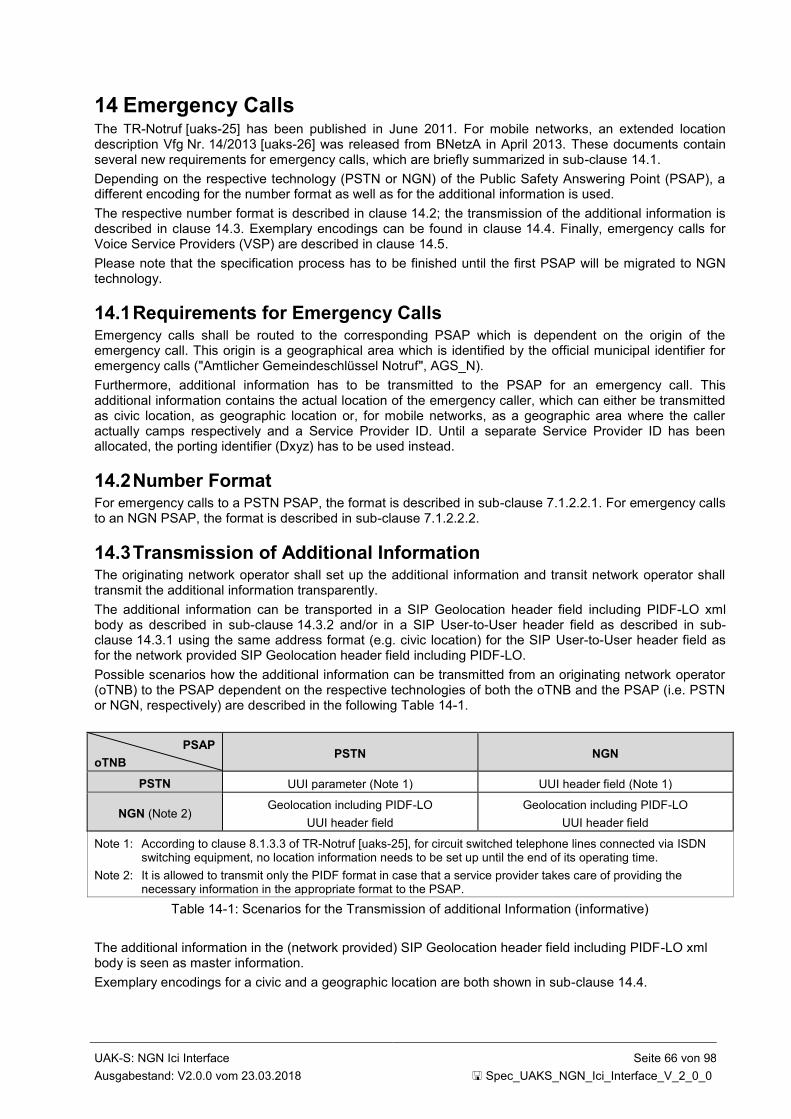
UAK-S: NGN Ici Interface Seite 66 von 98
Ausgabestand: V2.0.0 vom 23.03.2018 Spec_UAKS_NGN_Ici_Interface_V_2_0_0
14 Emergency Calls The TR-Notruf [uaks-25] has been published in June 2011. For mobile networks, an extended location description Vfg Nr. 14/2013 [uaks-26] was released from BNetzA in April 2013. These documents contain several new requirements for emergency calls, which are briefly summarized in sub-clause 14.1.
Depending on the respective technology (PSTN or NGN) of the Public Safety Answering Point (PSAP), a different encoding for the number format as well as for the additional information is used.
The respective number format is described in clause 14.2; the transmission of the additional information is described in clause 14.3. Exemplary encodings can be found in clause 14.4. Finally, emergency calls for Voice Service Providers (VSP) are described in clause 14.5.
Please note that the specification process has to be finished until the first PSAP will be migrated to NGN technology.
14.1 Requirements for Emergency Calls Emergency calls shall be routed to the corresponding PSAP which is dependent on the origin of the emergency call. This origin is a geographical area which is identified by the official municipal identifier for emergency calls ("Amtlicher Gemeindeschlüssel Notruf", AGS_N).
Furthermore, additional information has to be transmitted to the PSAP for an emergency call. This additional information contains the actual location of the emergency caller, which can either be transmitted as civic location, as geographic location or, for mobile networks, as a geographic area where the caller actually camps respectively and a Service Provider ID. Until a separate Service Provider ID has been allocated, the porting identifier (Dxyz) has to be used instead.
14.2 Number Format For emergency calls to a PSTN PSAP, the format is described in sub-clause 7.1.2.2.1. For emergency calls to an NGN PSAP, the format is described in sub-clause 7.1.2.2.2.
14.3 Transmission of Additional Information The originating network operator shall set up the additional information and transit network operator shall transmit the additional information transparently.
The additional information can be transported in a SIP Geolocation header field including PIDF-LO xml body as described in sub-clause 14.3.2 and/or in a SIP User-to-User header field as described in sub-clause 14.3.1 using the same address format (e.g. civic location) for the SIP User-to-User header field as for the network provided SIP Geolocation header field including PIDF-LO.
Possible scenarios how the additional information can be transmitted from an originating network operator (oTNB) to the PSAP dependent on the respective technologies of both the oTNB and the PSAP (i.e. PSTN or NGN, respectively) are described in the following Table 14-1.
PSAP
oTNB PSTN NGN
PSTN UUI parameter (Note 1) UUI header field (Note 1)
NGN (Note 2) Geolocation including PIDF-LO
UUI header field
Geolocation including PIDF-LO
UUI header field
Note 1: According to clause 8.1.3.3 of TR-Notruf [uaks-25], for circuit switched telephone lines connected via ISDN switching equipment, no location information needs to be set up until the end of its operating time.
Note 2: It is allowed to transmit only the PIDF format in case that a service provider takes care of providing the necessary information in the appropriate format to the PSAP.
Table 14-1: Scenarios for the Transmission of additional Information (informative)
The additional information in the (network provided) SIP Geolocation header field including PIDF-LO xml body is seen as master information.
Exemplary encodings for a civic and a geographic location are both shown in sub-clause 14.4.
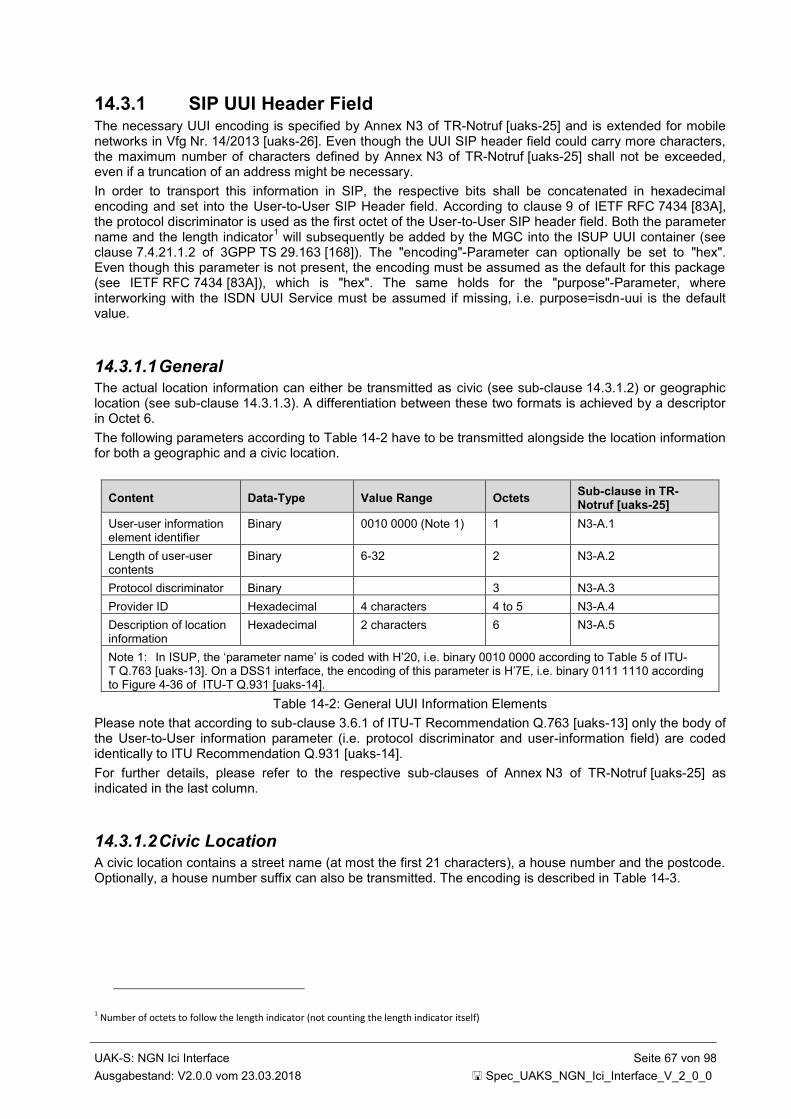
UAK-S: NGN Ici Interface Seite 67 von 98
Ausgabestand: V2.0.0 vom 23.03.2018 Spec_UAKS_NGN_Ici_Interface_V_2_0_0
14.3.1 SIP UUI Header Field The necessary UUI encoding is specified by Annex N3 of TR-Notruf [uaks-25] and is extended for mobile networks in Vfg Nr. 14/2013 [uaks-26]. Even though the UUI SIP header field could carry more characters, the maximum number of characters defined by Annex N3 of TR-Notruf [uaks-25] shall not be exceeded, even if a truncation of an address might be necessary.
In order to transport this information in SIP, the respective bits shall be concatenated in hexadecimal encoding and set into the User-to-User SIP Header field. According to clause 9 of IETF RFC 7434 [83A], the protocol discriminator is used as the first octet of the User-to-User SIP header field. Both the parameter name and the length indicator
1 will subsequently be added by the MGC into the ISUP UUI container (see
clause 7.4.21.1.2 of 3GPP TS 29.163 [168]). The "encoding"-Parameter can optionally be set to "hex". Even though this parameter is not present, the encoding must be assumed as the default for this package (see IETF RFC 7434 [83A]), which is "hex". The same holds for the "purpose"-Parameter, where interworking with the ISDN UUI Service must be assumed if missing, i.e. purpose=isdn-uui is the default value.
14.3.1.1 General The actual location information can either be transmitted as civic (see sub-clause 14.3.1.2) or geographic location (see sub-clause 14.3.1.3). A differentiation between these two formats is achieved by a descriptor in Octet 6.
The following parameters according to Table 14-2 have to be transmitted alongside the location information for both a geographic and a civic location.
Content Data-Type Value Range Octets Sub-clause in TR-Notruf [uaks-25]
User-user information element identifier
Binary 0010 0000 (Note 1) 1 N3-A.1
Length of user-user contents
Binary 6-32 2 N3-A.2
Protocol discriminator Binary 3 N3-A.3
Provider ID Hexadecimal 4 characters 4 to 5 N3-A.4
Description of location information
Hexadecimal 2 characters 6 N3-A.5
Note 1: In ISUP, the ‘parameter name’ is coded with H’20, i.e. binary 0010 0000 according to Table 5 of ITU-T Q.763 [uaks-13]. On a DSS1 interface, the encoding of this parameter is H’7E, i.e. binary 0111 1110 according to Figure 4-36 of ITU-T Q.931 [uaks-14].
Table 14-2: General UUI Information Elements
Please note that according to sub-clause 3.6.1 of ITU-T Recommendation Q.763 [uaks-13] only the body of the User-to-User information parameter (i.e. protocol discriminator and user-information field) are coded identically to ITU Recommendation Q.931 [uaks-14].
For further details, please refer to the respective sub-clauses of Annex N3 of TR-Notruf [uaks-25] as indicated in the last column.
14.3.1.2 Civic Location
A civic location contains a street name (at most the first 21 characters), a house number and the postcode. Optionally, a house number suffix can also be transmitted. The encoding is described in Table 14-3.
1 Number of octets to follow the length indicator (not counting the length indicator itself)
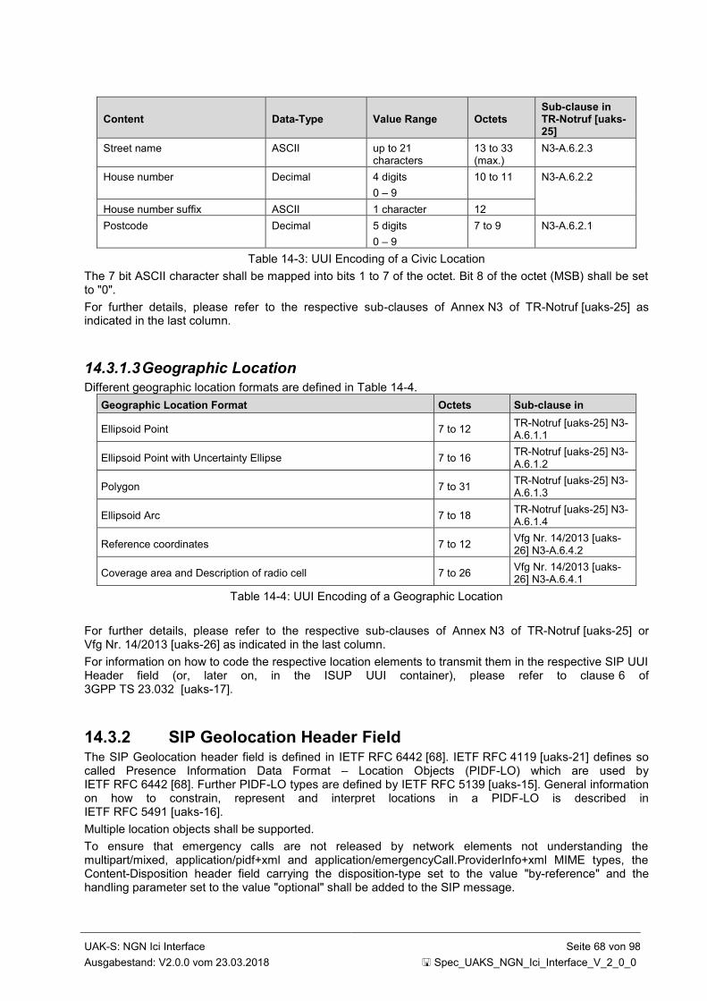
UAK-S: NGN Ici Interface Seite 68 von 98
Ausgabestand: V2.0.0 vom 23.03.2018 Spec_UAKS_NGN_Ici_Interface_V_2_0_0
Content Data-Type Value Range Octets Sub-clause in TR-Notruf [uaks-25]
Street name ASCII up to 21 characters
13 to 33 (max.)
N3-A.6.2.3
House number Decimal 4 digits
0 – 9
10 to 11 N3-A.6.2.2
House number suffix ASCII 1 character 12
Postcode Decimal 5 digits
0 – 9
7 to 9 N3-A.6.2.1
Table 14-3: UUI Encoding of a Civic Location
The 7 bit ASCII character shall be mapped into bits 1 to 7 of the octet. Bit 8 of the octet (MSB) shall be set to "0".
For further details, please refer to the respective sub-clauses of Annex N3 of TR-Notruf [uaks-25] as indicated in the last column.
14.3.1.3 Geographic Location
Different geographic location formats are defined in Table 14-4.
Geographic Location Format Octets Sub-clause in
Ellipsoid Point 7 to 12 TR-Notruf [uaks-25] N3-A.6.1.1
Ellipsoid Point with Uncertainty Ellipse 7 to 16 TR-Notruf [uaks-25] N3-A.6.1.2
Polygon 7 to 31 TR-Notruf [uaks-25] N3-A.6.1.3
Ellipsoid Arc 7 to 18 TR-Notruf [uaks-25] N3-A.6.1.4
Reference coordinates 7 to 12 Vfg Nr. 14/2013 [uaks-26] N3-A.6.4.2
Coverage area and Description of radio cell 7 to 26 Vfg Nr. 14/2013 [uaks-26] N3-A.6.4.1
Table 14-4: UUI Encoding of a Geographic Location
For further details, please refer to the respective sub-clauses of Annex N3 of TR-Notruf [uaks-25] or Vfg Nr. 14/2013 [uaks-26] as indicated in the last column.
For information on how to code the respective location elements to transmit them in the respective SIP UUI Header field (or, later on, in the ISUP UUI container), please refer to clause 6 of 3GPP TS 23.032 [uaks-17].
14.3.2 SIP Geolocation Header Field The SIP Geolocation header field is defined in IETF RFC 6442 [68]. IETF RFC 4119 [uaks-21] defines so called Presence Information Data Format – Location Objects (PIDF-LO) which are used by IETF RFC 6442 [68]. Further PIDF-LO types are defined by IETF RFC 5139 [uaks-15]. General information on how to constrain, represent and interpret locations in a PIDF-LO is described in IETF RFC 5491 [uaks-16].
Multiple location objects shall be supported.
To ensure that emergency calls are not released by network elements not understanding the multipart/mixed, application/pidf+xml and application/emergencyCall.ProviderInfo+xml MIME types, the Content-Disposition header field carrying the disposition-type set to the value "by-reference" and the handling parameter set to the value "optional" shall be added to the SIP message.

UAK-S: NGN Ici Interface Seite 69 von 98
Ausgabestand: V2.0.0 vom 23.03.2018 Spec_UAKS_NGN_Ici_Interface_V_2_0_0
14.3.2.1 General The actual location information can either be transmitted as civic (see sub-clause 14.3.2.2) or geographic location (see sub-clause 14.3.2.1).
The service provider ID according to Table 14-6Table 14-5 shall be transmitted alongside the location information for both a geographic and a civic location.
Content Data-Type Value Range Reference
Service Provider ID Hexadecimal 4 characters draft-ietf-ecrit-additional-data-11 [uaks-12]
Table 14-5: Service Provider ID
The IETF Draft draft-ietf-ecrit-additional-data-11 [uaks-12] shall be used to transmit the service provider ID.
Parameter SIP (Additional Data)
Anbieterkennung/Portierungskennung ProviderID
DataProviderString
Data Provider (=”BNetzA”) ProviderIDSeries
TypeOfProviderID
ContactURI
Table 14-6: Additional Data Parameters
The PIDF-LO types "tuple", "device" und "person" shall be used according to Table 14-7.
PIDF-LO type Description Support
tuple used for location information determined and sent by the network
m
device used for location information determined and sent by the end device
c1
person used for location information entered by the user and sent by the end device
c1
c1: IF location information is sent from end device THEN m ELSE n/a
Table 14-7: Usage of PIDF-LO types
If the PIDF-LO types "device" or "person" are present in a SIP message, they shall also be forwarded transparently.
14.3.2.2 Civic Location
A civic location transmitted in the SIP Geolocation header field can contain more information as defined for the User-to-User container in ISUP (see sub-clause 14.3.1). For the emergency call originating network provider, the only mandatory location information elements for a civic location are Country, A1 (State) and A3 (Town Name). However, any further location information needed to fully describe the civic location shall also be transmitted in the corresponding PIDF-LO Element. The encoding is described in Table 14-9 and is based on IETF RFC 4119 [uaks-21] and IETF RFC 5139 [uaks-15].
UTF-8 encoding shall be used with a Unicode character set that includes Basic Latin (US ASCII repertoire) and the Latin-1 Supplement that is Unicode code points U+0000 – U+00FF. This means that special German characters (e.g. umlauts) shall be encoded according to Latin-1 Supplement script.
If the address database contains special German characters in a converted format (e.g. oe, ue, ae, ss, sz) this format shall be transmitted unchanged.
Note that UTF-8 requires a 2-byte encoding of Unicode code points U+0080 – U+00FF.
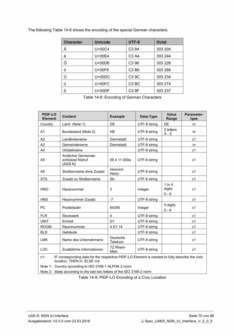
UAK-S: NGN Ici Interface Seite 70 von 98
Ausgabestand: V2.0.0 vom 23.03.2018 Spec_UAKS_NGN_Ici_Interface_V_2_0_0
The following Table 14-8 shows the encoding of the special German characters.
Character Unicode UTF-8 Octal
Ä U+00C4 C3 84 303 204
ä U+00E4 C3 A4 303 244
Ö U+00D6 C3 96 303 226
ö U+00F6 C3 B6 303 266
Ü U+00DC C3 9C 303 234
ü U+00FC C3 BC 303 274
ß U+00DF C3 9F 303 237
Table 14-8: Encoding of German Characters
PIDF-LO Element
Content Example Data-Type Value Range
Parameter-type
Country Land (Note 1) DE UTF-8 string DE m
A1 Bundesland (Note 2) HE UTF-8 string 2 letters A - Z
m
A2 Landkreisname Darmstadt UTF-8 string c1
A3 Gemeindename Darmstadt UTF-8 string m
A4 Ortsteilname UTF-8 string c1
A5 Amtlicher Gemeinde-schlüssel Notruf (AGS N)
06 4 11 000a UTF-8 string c1
A6 Straßenname ohne Zusatz Heinrich-Hertz-
UTF-8 string c1
STS Zusatz zu Straßenname Str. UTF-8 string c1
HNO Hausnummer 3 Integer
1 to 4 digits
0 - 9
c1
HNS Hausnummer Zusatz -7 UTF-8 string c1
PC Postleitzahl 64295 Integer 5 digits
0 - 9 c1
FLR Stockwerk 4 UTF-8 string c1
UNIT Einheit D1 UTF-8 string c1
ROOM Raumnummer 4.D1.14 UTF-8 string c1
BLD Gebäude UTF-8 string c1
LMK Name des Unternehmens Deutsche Telekom
UTF-8 string c1
LOC Zusätzliche Informationen TZ Rhein-Main
UTF-8 string c1
c1: IF corresponding data for the respective PIDF-LO Element is needed to fully describe the civic location, THEN m, ELSE n/a
Note 1: Country according to ISO 3166-1 ALPHA 2 norm
Note 2: State according to the last two letters of the ISO 3166-2 norm
Table 14-9: PIDF-LO Encoding of a Civic Location
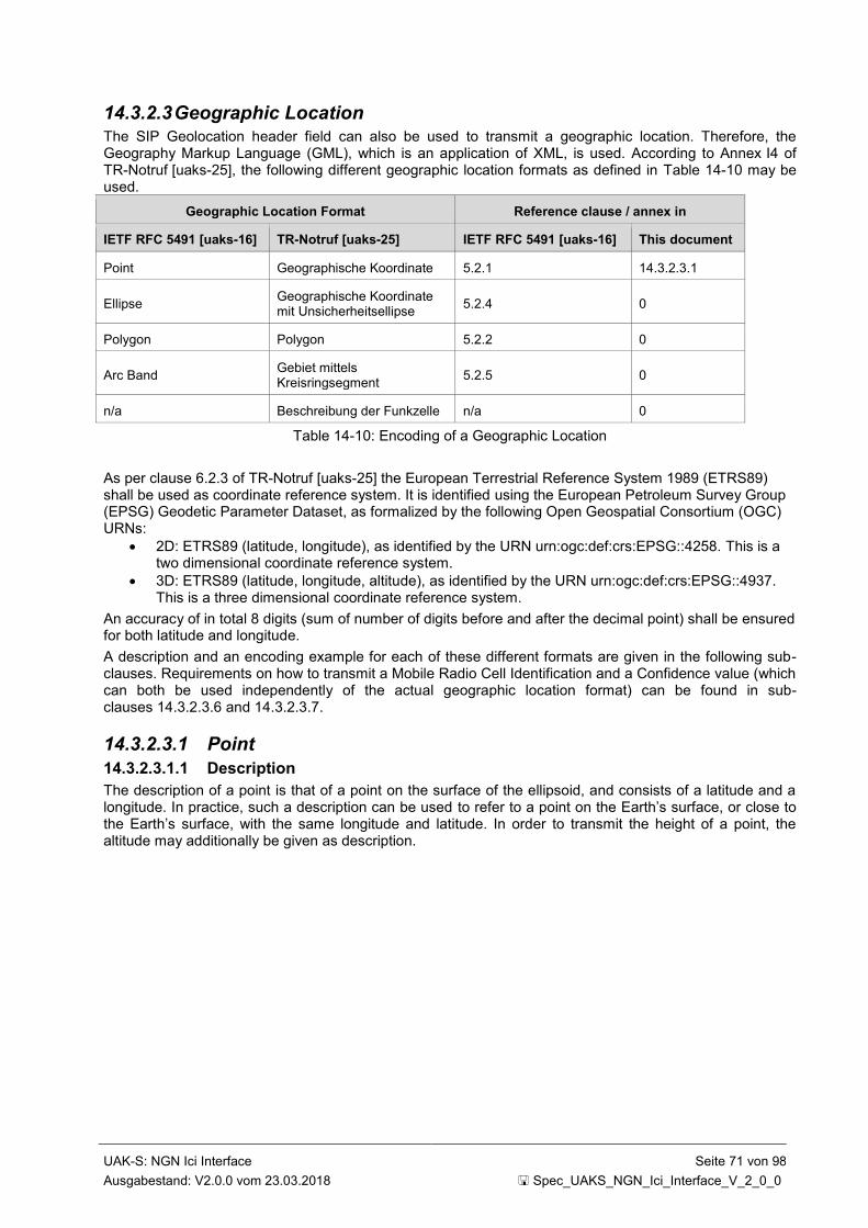
UAK-S: NGN Ici Interface Seite 71 von 98
Ausgabestand: V2.0.0 vom 23.03.2018 Spec_UAKS_NGN_Ici_Interface_V_2_0_0
14.3.2.3 Geographic Location The SIP Geolocation header field can also be used to transmit a geographic location. Therefore, the Geography Markup Language (GML), which is an application of XML, is used. According to Annex I4 of TR-Notruf [uaks-25], the following different geographic location formats as defined in Table 14-10 may be used.
Geographic Location Format Reference clause / annex in
IETF RFC 5491 [uaks-16] TR-Notruf [uaks-25] IETF RFC 5491 [uaks-16] This document
Point Geographische Koordinate 5.2.1 14.3.2.3.1
Ellipse Geographische Koordinate mit Unsicherheitsellipse
5.2.4 0
Polygon Polygon 5.2.2 0
Arc Band Gebiet mittels Kreisringsegment
5.2.5 0
n/a Beschreibung der Funkzelle n/a 0
Table 14-10: Encoding of a Geographic Location
As per clause 6.2.3 of TR-Notruf [uaks-25] the European Terrestrial Reference System 1989 (ETRS89) shall be used as coordinate reference system. It is identified using the European Petroleum Survey Group (EPSG) Geodetic Parameter Dataset, as formalized by the following Open Geospatial Consortium (OGC) URNs:
2D: ETRS89 (latitude, longitude), as identified by the URN urn:ogc:def:crs:EPSG::4258. This is a two dimensional coordinate reference system.
3D: ETRS89 (latitude, longitude, altitude), as identified by the URN urn:ogc:def:crs:EPSG::4937. This is a three dimensional coordinate reference system.
An accuracy of in total 8 digits (sum of number of digits before and after the decimal point) shall be ensured for both latitude and longitude.
A description and an encoding example for each of these different formats are given in the following sub-clauses. Requirements on how to transmit a Mobile Radio Cell Identification and a Confidence value (which can both be used independently of the actual geographic location format) can be found in sub-clauses 14.3.2.3.6 and 14.3.2.3.7.
14.3.2.3.1 Point
14.3.2.3.1.1 Description
The description of a point is that of a point on the surface of the ellipsoid, and consists of a latitude and a longitude. In practice, such a description can be used to refer to a point on the Earth’s surface, or close to the Earth’s surface, with the same longitude and latitude. In order to transmit the height of a point, the altitude may additionally be given as description.
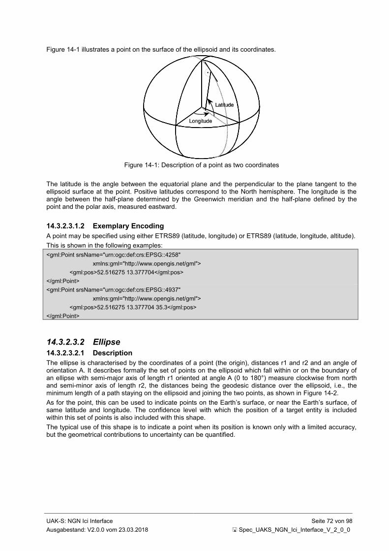
UAK-S: NGN Ici Interface Seite 72 von 98
Ausgabestand: V2.0.0 vom 23.03.2018 Spec_UAKS_NGN_Ici_Interface_V_2_0_0
Figure 14-1 illustrates a point on the surface of the ellipsoid and its coordinates.
Figure 14-1: Description of a point as two coordinates
The latitude is the angle between the equatorial plane and the perpendicular to the plane tangent to the ellipsoid surface at the point. Positive latitudes correspond to the North hemisphere. The longitude is the angle between the half-plane determined by the Greenwich meridian and the half-plane defined by the point and the polar axis, measured eastward.
14.3.2.3.1.2 Exemplary Encoding
A point may be specified using either ETRS89 (latitude, longitude) or ETRS89 (latitude, longitude, altitude).
This is shown in the following examples:
<gml:Point srsName="urn:ogc:def:crs:EPSG::4258"
xmlns:gml="http://www.opengis.net/gml">
<gml:pos>52.516275 13.377704</gml:pos>
</gml:Point>
<gml:Point srsName="urn:ogc:def:crs:EPSG::4937"
xmlns:gml="http://www.opengis.net/gml">
<gml:pos>52.516275 13.377704 35.3</gml:pos>
</gml:Point>
14.3.2.3.2 Ellipse
14.3.2.3.2.1 Description
The ellipse is characterised by the coordinates of a point (the origin), distances r1 and r2 and an angle of orientation A. It describes formally the set of points on the ellipsoid which fall within or on the boundary of an ellipse with semi-major axis of length r1 oriented at angle A (0 to 180°) measure clockwise from north and semi-minor axis of length r2, the distances being the geodesic distance over the ellipsoid, i.e., the minimum length of a path staying on the ellipsoid and joining the two points, as shown in Figure 14-2.
As for the point, this can be used to indicate points on the Earth’s surface, or near the Earth’s surface, of same latitude and longitude. The confidence level with which the position of a target entity is included within this set of points is also included with this shape.
The typical use of this shape is to indicate a point when its position is known only with a limited accuracy, but the geometrical contributions to uncertainty can be quantified.

UAK-S: NGN Ici Interface Seite 73 von 98
Ausgabestand: V2.0.0 vom 23.03.2018 Spec_UAKS_NGN_Ici_Interface_V_2_0_0
semi-major
axis, r1
North angle, A
semi-minor
axis, r2
Figure 14-2: Description of an Ellipse
14.3.2.3.2.2 Exemplary Encoding
The following example shows an ellipse.
<gs:Ellipse srsName="urn:ogc:def:crs:EPSG::4937"
xmlns:gs="http://www.opengis.net/pidflo/1.0"
xmlns:gml="http://www.opengis.net/gml">
<gml:pos>
52.516275 13.377704 35.3
</gml:pos>
<gs:semiMajorAxis uom="urn:ogc:def:uom:EPSG::9001">
7.7156
</gs:semiMajorAxis>
<gs:semiMinorAxis uom="urn:ogc:def:uom:EPSG::9001">
3.31
</gs:semiMinorAxis>
<gs:orientation uom="urn:ogc:def:uom:EPSG::9102">
142
</gs:orientation>
</gs:Ellipse>
14.3.2.3.3 Polygon
14.3.2.3.3.1 Description
A polygon is an arbitrary shape described by an ordered series of points (in the example pictured in Figure 14-3, A to E).
The minimum number of points allowed is 3, and the maximum number of points allowed is 15. The points shall be connected in the order that they are given. A connecting line is defined as the line over the ellipsoid joining the two points and of minimum distance (geodesic). The last point is connected to the first.
The list of points shall respect a number of conditions:
a connecting line shall not cross another connecting line;
two successive points must not be diametrically opposed on the ellipsoid.
The described area is situated to the right of the lines with the downward direction being toward the Earth's centre and the forward direction being from a point to the next.

UAK-S: NGN Ici Interface Seite 74 von 98
Ausgabestand: V2.0.0 vom 23.03.2018 Spec_UAKS_NGN_Ici_Interface_V_2_0_0
A
B
C
D
E
Figure 14-3: Description of a Polygon
Note: This definition does not permit connecting lines greater than roughly 20.000 km. If such a need arises, the polygon can be described by adding an intermediate point.
14.3.2.3.3.2 Exemplary Encoding
The following example shows a polygon that is specified using EPSG 4258 and the gml:pos element.
No altitude is included in this example, indicating that altitude is unknown.
<gml:Polygon srsName="urn:ogc:def:crs:EPSG::4258"
xmlns:gml="http://www.opengis.net/gml">
<gml:exterior>
<gml:LinearRing>
<gml:pos>52.516275 13.377704</gml:pos>
<gml:pos>52.516475 13.377904</gml:pos>
<gml:pos>52.515875 13.378004</gml:pos>
<gml:pos>52.515975 13.377404</gml:pos>
<gml:pos>52.516275 13.377304</gml:pos>
<gml:pos>52.516275 13.37730</gml:pos>
</gml:LinearRing>
</gml:exterior>
</gml:Polygon>
The following alternative example shows the same polygon with a constant altitude included that is specified using EPSG 4937 and the gml:posList element.
<gml:Polygon srsName="urn:ogc:def:crs:EPSG::4937"
xmlns:gml="http://www.opengis.net/gml">
<gml:exterior>
<gml:LinearRing>
<gml:posList>
52.516575 13.377704 35.3
52.516475 13.377904 35.3
52.515875 13.378004 35.5
52.515975 13.377404 35.3
52.516275 13.377304 35.3
52.516575 13.377704 35.3
</gml:posList>
</gml:LinearRing>
</gml:exterior>
</gml:Polygon>
The gml:posList element is interpreted as a list with the dimension of the CRS indicating how many values are required for each point.

UAK-S: NGN Ici Interface Seite 75 von 98
Ausgabestand: V2.0.0 vom 23.03.2018 Spec_UAKS_NGN_Ici_Interface_V_2_0_0
14.3.2.3.4 Arc Band
14.3.2.3.4.1 Description
An arc band is a shape characterised by the coordinates of a point o (the origin), inner radius r1 (gs:innerRadius), uncertainty radius r2
2 (gs:outerRadius), both radii being geodesic distances over the
surface of the ellipsoid, the offset angle (gs:startAngle) between the first defining radius of the arc band
and North, and the included angle (gs:openingAngle) being the angle between the first and second
defining radii. The offset angle is within the range of 0 to 359,999… while the included angle is within the
range from 0,000…1 to 360. This is to be able to describe a full circle, 0 to 360.
r1
Point (o)
r2
North
Figure 14-4: Description of an Arc Band
This shape definition can also be used to describe a sector (inner radius equal to zero), a circle (included
angle equal to 360) and other circular shaped areas.
2 Thus the outer radius is r1+r2.
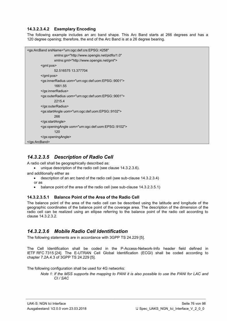
UAK-S: NGN Ici Interface Seite 76 von 98
Ausgabestand: V2.0.0 vom 23.03.2018 Spec_UAKS_NGN_Ici_Interface_V_2_0_0
14.3.2.3.4.2 Exemplary Encoding
The following example includes an arc band shape. This Arc Band starts at 266 degrees and has a 120 degree opening; therefore, the end of the Arc Band is at a 26 degree bearing.
<gs:ArcBand srsName="urn:ogc:def:crs:EPSG::4258"
xmlns:gs="http://www.opengis.net/pidflo/1.0"
xmlns:gml="http://www.opengis.net/gml">
<gml:pos>
52.516575 13.377704
</gml:pos>
<gs:innerRadius uom="urn:ogc:def:uom:EPSG::9001">
1661.55
</gs:innerRadius>
<gs:outerRadius uom="urn:ogc:def:uom:EPSG::9001">
2215.4
</gs:outerRadius>
<gs:startAngle uom="urn:ogc:def:uom:EPSG::9102">
266
</gs:startAngle>
<gs:openingAngle uom="urn:ogc:def:uom:EPSG::9102">
120
</gs:openingAngle>
</gs:ArcBand>
14.3.2.3.5 Description of Radio Cell
A radio cell shall be geographically described as:
unique description of the radio cell (see clause 14.3.2.3.6).
and additionally either as
description of an arc band of the radio cell (see sub-clause 14.3.2.3.4) or as
balance point of the area of the radio cell (see sub-clause 14.3.2.3.5.1)
14.3.2.3.5.1 Balance Point of the Area of the Radio Cell
The balance point of the area of the radio cell can be described using the latitude and longitude of the geographic coordinates of the balance point of the coverage area. The description of the dimension of the radio cell can be realized using an ellipse referring to the balance point of the radio cell according to clause 14.3.2.3.2.
14.3.2.3.6 Mobile Radio Cell Identification
The following statements are in accordance with 3GPP TS 24.229 [5].
The Cell Identification shall be coded in the P-Access-Network-Info header field defined in IETF RFC 7315 [24]. The E-UTRAN Cell Global Identification (ECGI) shall be coded according to chapter 7.2A.4.3 of 3GPP TS 24.229 [5].
The following configuration shall be used for 4G networks:
Note 1: If the MSS supports the mapping to PANI it is also possible to use the PANI for LAC and CI / SAC

UAK-S: NGN Ici Interface Seite 77 von 98
Ausgabestand: V2.0.0 vom 23.03.2018 Spec_UAKS_NGN_Ici_Interface_V_2_0_0
If the access-type header field parameter is either "3GPP-E-UTRAN-FDD" or "3GPP-E-UTRAN-TDD" or if the access-class header field parameter is "3GPP-E-UTRAN", the ECGI shall be added to the P-Access-Network-Info header field as an access-info header field parameter value "utran-cell-id-3gpp".
The ECGI shall be set to a concatenation of the MCC (3 decimal digits), MNC (2 or 3 decimal digits dependent on the MCC value), Tracking Area Code (4 hexadecimal digits as described in 3GPP TS 23.003 [35]) and the E-UTRAN Cell Identity (ECI) (7 hexadecimal digits as described in 3GPP TS 23.003 [35]) and shall be encoded in ASCII as defined in IETF RFC 20 [uaks-23].
Note 2: According to IETF RFC 7315 [24]. "utran-cell-id-3gpp" can either be a token or a quoted-string and is case-insensitive.
The network-provided header field parameter shall also be added to the P-Access-Network-Info header field.
An example is shown below:
P-Access-Network-Info: 3GPP-E-UTRAN-FDD;utran-cell-id-
3gpp=2620100791d31a00;network-provided
with:
MCC: 262
MNC: 01
TAC: 0079
ECI: 1d31a00
Additionally, a second P-Access-Network-Info header field set up by the UE can be present as well.
Note 3: A P-Access-Network-Info header field set up by the UE does not carry the network-provided header field parameter.
The P-Access-Network-Info header field can also be used for other access types and classes (e.g. Wifi, 5G). This topic is, however, for further study.
14.3.2.3.7 Confidence According to IETF draft-thomson-geopriv-confidence-03 [uaks-19], the confidence is transmitted as separate element within the location-info of the PIDF-LO. The confidence element expresses the confidence in the associated location information as a percentage and optionally includes an attribute that indicates the shape of the probability density function (PDF) of the associated region of uncertainty. Three values are possible for the shape of this PDF: unknown, normal and rectangular.
Further details on how to obtain or ascertain uncertainty and confidence can be found in IETF draft-thomson-geopriv-uncertainty-07 [uaks-20].
An exemplary encoding for a confidence of 75% which follows a normal distribution is shown below for a circular shape:
<gp:location-info>
<gs:Circle srsName="urn:ogc:def:crs:EPSG::4258">
<gml:pos>52.516575 13.37770</gml:pos>
<gs:radius uom="urn:ogc:def:uom:EPSG::9001">
850.24
</gs:radius>
</gs:Circle>
<con:confidence pdf="normal">75</con:confidence>
</gp:location-info>
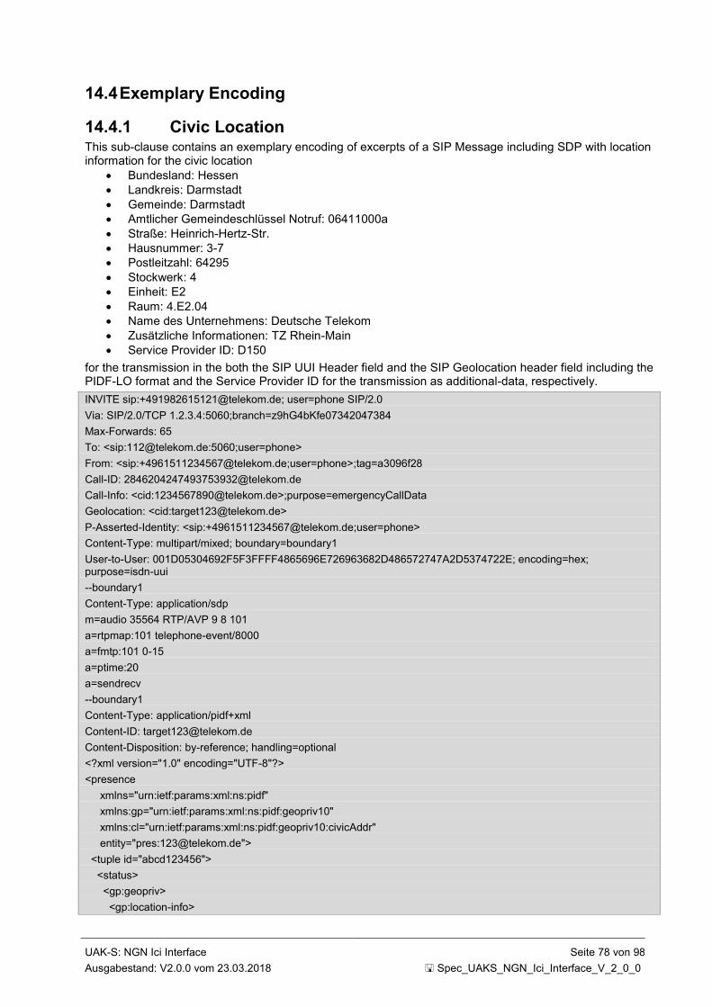
UAK-S: NGN Ici Interface Seite 78 von 98
Ausgabestand: V2.0.0 vom 23.03.2018 Spec_UAKS_NGN_Ici_Interface_V_2_0_0
14.4 Exemplary Encoding
14.4.1 Civic Location This sub-clause contains an exemplary encoding of excerpts of a SIP Message including SDP with location information for the civic location
Bundesland: Hessen
Landkreis: Darmstadt
Gemeinde: Darmstadt
Amtlicher Gemeindeschlüssel Notruf: 06411000a
Straße: Heinrich-Hertz-Str.
Hausnummer: 3-7
Postleitzahl: 64295
Stockwerk: 4
Einheit: E2
Raum: 4.E2.04
Name des Unternehmens: Deutsche Telekom
Zusätzliche Informationen: TZ Rhein-Main
Service Provider ID: D150
for the transmission in the both the SIP UUI Header field and the SIP Geolocation header field including the PIDF-LO format and the Service Provider ID for the transmission as additional-data, respectively.
INVITE sip:[email protected]; user=phone SIP/2.0
Via: SIP/2.0/TCP 1.2.3.4:5060;branch=z9hG4bKfe07342047384
Max-Forwards: 65
To: <sip:[email protected]:5060;user=phone>
From: <sip:[email protected];user=phone>;tag=a3096f28
Call-ID: [email protected]
Call-Info: <cid:[email protected]>;purpose=emergencyCallData
Geolocation: <cid:[email protected]>
P-Asserted-Identity: <sip:[email protected];user=phone>
Content-Type: multipart/mixed; boundary=boundary1
User-to-User: 001D05304692F5F3FFFF4865696E726963682D486572747A2D5374722E; encoding=hex; purpose=isdn-uui
--boundary1
Content-Type: application/sdp
m=audio 35564 RTP/AVP 9 8 101
a=rtpmap:101 telephone-event/8000
a=fmtp:101 0-15
a=ptime:20
a=sendrecv
--boundary1
Content-Type: application/pidf+xml
Content-ID: [email protected]
Content-Disposition: by-reference; handling=optional
<?xml version="1.0" encoding="UTF-8"?>
<presence
xmlns="urn:ietf:params:xml:ns:pidf"
xmlns:gp="urn:ietf:params:xml:ns:pidf:geopriv10"
xmlns:cl="urn:ietf:params:xml:ns:pidf:geopriv10:civicAddr"
entity="pres:[email protected]">
<tuple id="abcd123456">
<status>
<gp:geopriv>
<gp:location-info>

UAK-S: NGN Ici Interface Seite 79 von 98
Ausgabestand: V2.0.0 vom 23.03.2018 Spec_UAKS_NGN_Ici_Interface_V_2_0_0
<cl:civicAddress xml:lang="de">
<cl:country>DE</cl:country>
<cl:A1>HE</cl:A1>
<cl:A2>Darmstadt</cl:A2>
<cl:A3>Darmstadt</cl:A3>
<cl:A5>06411000a</cl:A5>
<cl:A6>Heinrich-Hertz-</cl:A6>
<cl:STS>Str.</cl:STS>
<cl:HNO>3</cl:HNO>
<cl:HNS>-7</cl:HNS>
<cl:PC>64295</cl:PC>
<cl:FLR>4</cl:FLR>
<cl:UNIT>E2</cl:UNIT>
<cl:ROOM>4.E2.04</cl:ROOM>
<cl:LMK>Deutsche Telekom</cl:LMK>
<cl:LOC>TZ Rhein-Main</cl:LOC>
</cl:civicAddress>
</gp:location-info>
<gp:usage-rules>
<gbp:retransmission-allowed>yes</gbp:retransmission-allowed>
<gbp:retention-expiry>2013-08-31T12:00:00Z</gbp:retention-expiry>
</gp:usage-rules>
</gp:geopriv>
</status>
<timestamp>2013-08-01T12:00:00Z</timestamp>
</tuple>
</presence>
--boundary1
Content-Type: application/emergencyCall.ProviderInfo+xml
Content-ID: [email protected]
Content-Disposition: by-reference; handling=optional
<?xml version="1.0" encoding="UTF-8"?>
<emergencyCall.ProviderInfo xmlns="urn:ietf:params:xml:ns:emergencyCall.ProviderInfo">
<DataProviderString>Telekom</DataProviderString>
<ProviderID>D150</ProviderID>
<contactURI>sip:[email protected];user=phone</contactURI>
<ProviderIDSeries>BNetzA</ProviderIDSeries>
</emergencyCall.ProviderInfo>
--boundary1--
Note 1: The two parameters "encoding" and "purpose" in the SIP UUI header field are optional and need not necessarily be present (see sub-clause 14.3.1.1). Both the parameter name and the length indicator (which would be 201D for the example above) are not transmitted in the SIP User-to-User header field and will subsequently be added by the MGC into the ISUP UUI container.
An excerpt of a location information that contains special characters as German umlauts is shown below. These special characters are highlighted in the examples below.
Location:
Bundesland: Bayern
Landkreis: Landkreis München
Gemeinde: Unterföhring
Amtlicher Gemeindeschlüssel Notruf: 09184147
Straße: Beta-Straße
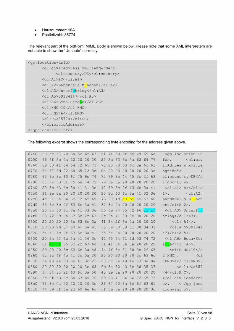
UAK-S: NGN Ici Interface Seite 80 von 98
Ausgabestand: V2.0.0 vom 23.03.2018 Spec_UAKS_NGN_Ici_Interface_V_2_0_0
Hausnummer: 10A
Postleitzahl: 85774
The relevant part of the pidf+xml MIME Body is shown below. Please note that some XML interpreters are not able to show the “Umlaute” correctly.
<gp:location-info>
<cl:civicAddress xml:lang="de">
<cl:country>DE</cl:country>
<cl:A1>BY</cl:A1>
<cl:A2>Landkreis München</cl:A2>
<cl:A3>Unterföhring</cl:A3>
<cl:A5>09184147</cl:A5>
<cl:A6>Beta-Straße</cl:A6>
<cl:HNO>10</cl:HNO>
<cl:HNS>A</cl:HNS>
<cl:PC>85774</cl:PC>
</cl:civicAddress>
</gp:location-info>
The following excerpt shows the corresponding byte encoding for the address given above.
0740 20 3c 67 70 3a 6c 6f 63 61 74 69 6f 6e 2d 69 6e <gp:loc ation-in
0750 66 6f 3e 0a 20 20 20 20 20 3c 63 6c 3a 63 69 76 fo>. <cl:civ
0760 69 63 41 64 64 72 65 73 73 20 78 6d 6c 3a 6c 61 icAddres s xml:la
0770 6e 67 3d 22 64 65 22 3e 0a 20 20 20 20 20 20 3c ng="de"> . <
0780 63 6c 3a 63 6f 75 6e 74 72 79 3e 44 45 3c 2f 63 cl:count ry>DE</c
0790 6c 3a 63 6f 75 6e 74 72 79 3e 0a 20 20 20 20 20 l:countr y>.
07a0 20 3c 63 6c 3a 41 31 3e 42 59 3c 2f 63 6c 3a 41 <cl:A1> BY</cl:A
07b0 31 3e 0a 20 20 20 20 20 20 3c 63 6c 3a 41 32 3e 1>. <cl:A2>
07c0 4c 61 6e 64 6b 72 65 69 73 20 4d c3 bc 6e 63 68 Landkrei s M..nch
07d0 65 6e 3c 2f 63 6c 3a 41 32 3e 0a 20 20 20 20 20 en</cl:A 2>.
07e0 20 3c 63 6c 3a 41 33 3e 55 6e 74 65 72 66 c3 b6 <cl:A3> Unterf..
07f0 68 72 69 6e 67 3c 2f 63 6c 3a 41 33 3e 0a 20 20 hring</c l:A3>.
0800 20 20 20 20 3c 63 6c 3a 41 34 2f 3e 0a 20 20 20 <cl: A4/>.
0810 20 20 20 3c 63 6c 3a 41 35 3e 30 39 31 38 34 31 <cl:A 5>091841
0820 34 37 3c 2f 63 6c 3a 41 35 3e 0a 20 20 20 20 20 47</cl:A 5>.
0830 20 3c 63 6c 3a 41 36 3e 42 65 74 61 2d 53 74 72 <cl:A6> Beta-Str
0840 61 c3 9f 65 3c 2f 63 6c 3a 41 36 3e 0a 20 20 20 a..e</cl :A6>.
0850 20 20 20 3c 63 6c 3a 48 4e 4f 3e 31 30 3c 2f 63 <cl:H NO>10</c
0860 6c 3a 48 4e 4f 3e 0a 20 20 20 20 20 20 3c 63 6c l:HNO>. <cl
0870 3a 48 4e 53 3e 41 3c 2f 63 6c 3a 48 4e 53 3e 0a :HNS>A</ cl:HNS>.
0880 20 20 20 20 20 20 3c 63 6c 3a 50 43 3e 38 35 37 <c l:PC>857
0890 37 34 3c 2f 63 6c 3a 50 43 3e 0a 20 20 20 20 20 74</cl:P C>.
08a0 3c 2f 63 6c 3a 63 69 76 69 63 41 64 64 72 65 73 </cl:civ icAddres
08b0 73 3e 0a 20 20 20 20 3c 2f 67 70 3a 6c 6f 63 61 s>. < /gp:loca
08c0 74 69 6f 6e 2d 69 6e 66 6f 3e 0a 20 20 20 20 3c tion-inf o>. <
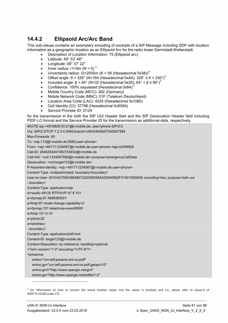
UAK-S: NGN Ici Interface Seite 81 von 98
Ausgabestand: V2.0.0 vom 23.03.2018 Spec_UAKS_NGN_Ici_Interface_V_2_0_0
14.4.2 Ellipsoid Arc/Arc Band This sub-clause contains an exemplary encoding of excerpts of a SIP Message including SDP with location information as a geographic location as an Ellipsoid Arc for the radio tower Darmstadt-Weiterstadt
Description of Location Information: 75 (Ellipsoid arc)
Latitude: 49° 53' 48''
Longitude: 08° 37' 22''
Inner radius: r1=0m (N = 0) 3
Uncertainty radius: r2=2005m (K = 56 (Hexadecimal 0x38))3
Offset angle: θ = 328° (N=164 (Hexadecimal 0xA4); 328° ≤ θ < 330°)3
Included angle: β = 64° (N=32 (Hexadecimal 0x20); 64° < β ≤ 66°)3
Confidence: 100% requested (Hexadecimal 0x64) 3
Mobile Country Code (MCC): 262 (Germany)
Mobile Network Code (MNC): 01F (Telekom Deutschland)
Location Area Code (LAC): 4224 (Hexadecimal 0x1080)
Cell Identity (CI): 37786 (Hexadecimal 0x939A)
Service Provider ID: D124
for the transmission in the both the SIP UUI Header field and the SIP Geolocation Header field including PIDF-LO format and the Service Provider ID for the transmission as additional-data, respectively.
INVITE sip:[email protected]; user=phone SIP/2.0
Via: SIP/2.0/TCP 1.2.3.4:5060;branch=z9hG4bKfe07342047384
Max-Forwards: 65
To: <sip:[email protected]:5060;user=phone>
From: <sip:[email protected];user=phone>;tag=a3096f28
Call-ID: [email protected]
Call-Info: <cid:[email protected]>;purpose=emergencyCallData
Geolocation: <cid:[email protected]>
P-Asserted-Identity: <sip:[email protected];user=phone>
Content-Type: multipart/mixed; boundary=boundary1
User-to-User: 001D4275943584807322000038A420640062F210010839A9; encoding=hex; purpose=isdn-uui
--boundary1
Content-Type: application/sdp
m=audio 49120 RTP/AVP 97 8 101
a=rtpmap:97 AMR/8000/1
a=fmtp:97 mode-change-capability=2
a=rtpmap:101 telephone-event/8000
a=fmtp:101 0-15
a=ptime:20
a=sendrecv
--boundary1
Content-Type: application/pidf+xml
Content-ID: [email protected]
Content-Disposition: by-reference; handling=optional
<?xml version="1.0" encoding="UTF-8"?>
<presence
xmlns="urn:ietf:params:xml:ns:pidf"
xmlns:gp="urn:ietf:params:xml:ns:pidf:geopriv10"
xmlns:gml="http://www.opengis.net/gml"
xmlns:gs="http://www.opengis.net/pidflo/1.0"
3 For information on how to convert the actual location values into the values in brackets and v.v., please refer to clause 6 of 3GPP TS 23.032 [uaks-17].
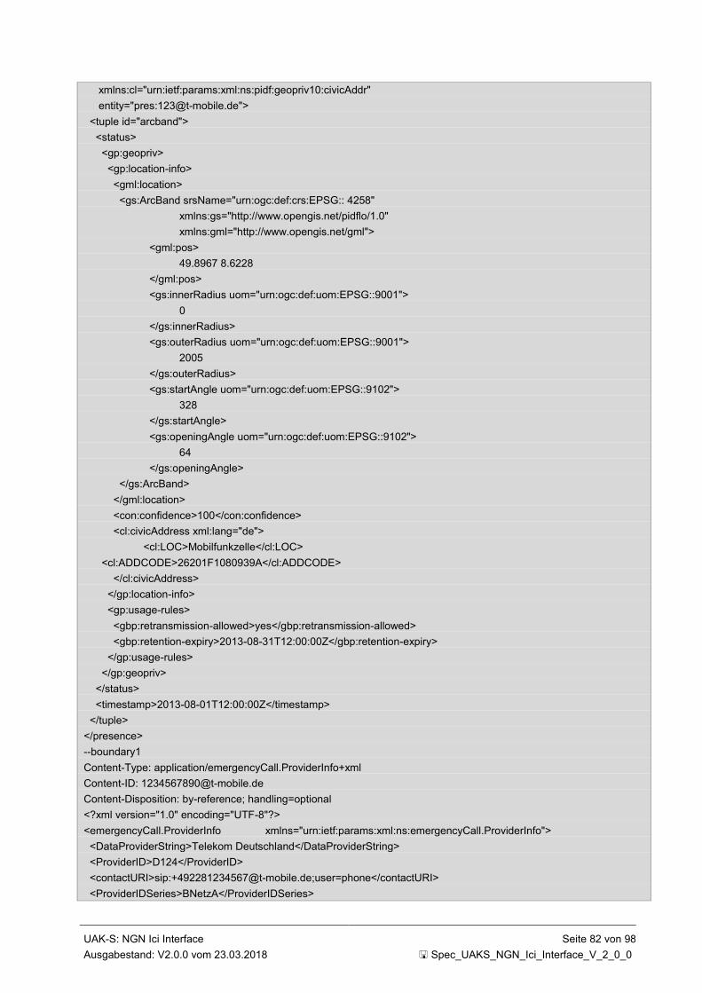
UAK-S: NGN Ici Interface Seite 82 von 98
Ausgabestand: V2.0.0 vom 23.03.2018 Spec_UAKS_NGN_Ici_Interface_V_2_0_0
xmlns:cl="urn:ietf:params:xml:ns:pidf:geopriv10:civicAddr"
entity="pres:[email protected]">
<tuple id="arcband">
<status>
<gp:geopriv>
<gp:location-info>
<gml:location>
<gs:ArcBand srsName="urn:ogc:def:crs:EPSG:: 4258"
xmlns:gs="http://www.opengis.net/pidflo/1.0"
xmlns:gml="http://www.opengis.net/gml">
<gml:pos>
49.8967 8.6228
</gml:pos>
<gs:innerRadius uom="urn:ogc:def:uom:EPSG::9001">
0
</gs:innerRadius>
<gs:outerRadius uom="urn:ogc:def:uom:EPSG::9001">
2005
</gs:outerRadius>
<gs:startAngle uom="urn:ogc:def:uom:EPSG::9102">
328
</gs:startAngle>
<gs:openingAngle uom="urn:ogc:def:uom:EPSG::9102">
64
</gs:openingAngle>
</gs:ArcBand>
</gml:location>
<con:confidence>100</con:confidence>
<cl:civicAddress xml:lang="de">
<cl:LOC>Mobilfunkzelle</cl:LOC>
<cl:ADDCODE>26201F1080939A</cl:ADDCODE>
</cl:civicAddress>
</gp:location-info>
<gp:usage-rules>
<gbp:retransmission-allowed>yes</gbp:retransmission-allowed>
<gbp:retention-expiry>2013-08-31T12:00:00Z</gbp:retention-expiry>
</gp:usage-rules>
</gp:geopriv>
</status>
<timestamp>2013-08-01T12:00:00Z</timestamp>
</tuple>
</presence>
--boundary1
Content-Type: application/emergencyCall.ProviderInfo+xml
Content-ID: [email protected]
Content-Disposition: by-reference; handling=optional
<?xml version="1.0" encoding="UTF-8"?>
<emergencyCall.ProviderInfo xmlns="urn:ietf:params:xml:ns:emergencyCall.ProviderInfo">
<DataProviderString>Telekom Deutschland</DataProviderString>
<ProviderID>D124</ProviderID>
<contactURI>sip:[email protected];user=phone</contactURI>
<ProviderIDSeries>BNetzA</ProviderIDSeries>
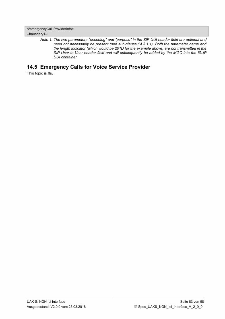
UAK-S: NGN Ici Interface Seite 83 von 98
Ausgabestand: V2.0.0 vom 23.03.2018 Spec_UAKS_NGN_Ici_Interface_V_2_0_0
</emergencyCall.ProviderInfo>
--boundary1--
Note 1: The two parameters "encoding" and "purpose" in the SIP UUI header field are optional and need not necessarily be present (see sub-clause 14.3.1.1). Both the parameter name and the length indicator (which would be 201D for the example above) are not transmitted in the SIP User-to-User header field and will subsequently be added by the MGC into the ISUP UUI container.
14.5 Emergency Calls for Voice Service Provider This topic is ffs.

UAK-S: NGN Ici Interface Seite 84 von 98
Ausgabestand: V2.0.0 vom 23.03.2018 Spec_UAKS_NGN_Ici_Interface_V_2_0_0
Annex A Address Formats (informative)
A.1 Number Portability Settings:
Figure A-1: Number Portability with Routing Number
A.2 Emergency Calls Settings:
A
DB
Provider A
B
DB
Provider B INVITE sip: +49 1982 6151 23; rn = +49 6151 CC23 @ doesntmatter.de; user = phone From: <sip: +49 6151 1234567 @ provider_a.de; user = phone> To: <sip: 110 @ provider_a.de; user = phone> P-Asserted-Identity: <sip: +49 6151 1234567 @ provider_a.de; user = phone> …
PSAP 06151CC23 A: 06151 1234567
Figure A-2: Emergency Call with Routing Number
A
DB
Provider A
A: 06151 1234567
B
DB
Provider B INVITE sip: +49 911 7654321; npdi; rn = +49 D987 911 7654321 @ provider_b.de; user = phone From: <sip: +49 6151 1234567 @ provider_a.de; user = phone> To: <sip: +49 911 7654321 @ provider_a.de; user = phone> P-Asserted-Identity: <sip: +49 6151 1234567 @ provider_a.de; user = phone> …
B: 0911 7654321 Ported to Provider B with
Porting Identifier D987
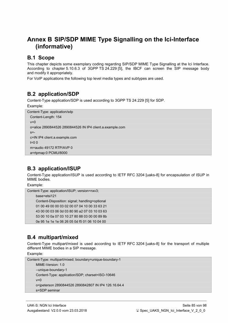
UAK-S: NGN Ici Interface Seite 85 von 98
Ausgabestand: V2.0.0 vom 23.03.2018 Spec_UAKS_NGN_Ici_Interface_V_2_0_0
Annex B SIP/SDP MIME Type Signalling on the Ici-Interface (informative)
B.1 Scope This chapter depicts some exemplary coding regarding SIP/SDP MIME Type Signalling at the Ici Interface. According to chapter 5.10.6.3 of 3GPP TS 24.229 [5], the IBCF can screen the SIP message body and modify it appropriately.
For VoIP applications the following top level media types and subtypes are used.
B.2 application/SDP Content-Type application/SDP is used according to 3GPP TS 24.229 [5] for SDP.
Example:
Content-Type: application/sdp
Content-Length: 154
v=0
o=alice 2890844526 2890844526 IN IP4 client.a.example.com
s=-
c=IN IP4 client.a.example.com
t=0 0
m=audio 49172 RTP/AVP 0
a=rtpmap:0 PCMU/8000
B.3 application/ISUP Content-Type application/ISUP is used according to IETF RFC 3204 [uaks-8] for encapsulation of ISUP in MIME bodies.
Example:
Content-Type: application/ISUP; version=nxv3;
base=etsi121
Content-Disposition: signal; handling=optional
01 00 49 00 00 03 02 00 07 04 10 00 33 63 21
43 00 00 03 06 0d 03 80 90 a2 07 03 10 03 63
53 00 10 0a 07 03 10 27 80 88 03 00 00 89 8b
0e 95 1e 1e 1e 06 26 05 0d f5 01 06 10 04 00
B.4 multipart/mixed Content-Type multipart/mixed is used according to IETF RFC 3204 [uaks-8] for the transport of multiple different MIME bodies in a SIP message.
Example:
Content-Type: multipart/mixed; boundary=unique-boundary-1
MIME-Version: 1.0
--unique-boundary-1
Content-Type: application/SDP; charset=ISO-10646
v=0
o=jpeterson 2890844526 2890842807 IN IP4 126.16.64.4
s=SDP seminar

UAK-S: NGN Ici Interface Seite 86 von 98
Ausgabestand: V2.0.0 vom 23.03.2018 Spec_UAKS_NGN_Ici_Interface_V_2_0_0
c=IN IP4 MG122.level3.com
t= 2873397496 2873404696
m=audio 9092 RTP/AVP 0 3 4
--unique-boundary-1
Content-Type: application/ISUP; version=nxv3;
base=etsi121
Content-Disposition: signal; handling=optional
01 00 49 00 00 03 02 00 07 04 10 00 33 63 21
43 00 00 03 06 0d 03 80 90 a2 07 03 10 03 63
53 00 10 0a 07 03 10 27 80 88 03 00 00 89 8b
0e 95 1e 1e 1e 06 26 05 0d f5 01 06 10 04 00
--unique-boundary-1—
B.5 application/vnd.etsi.pstn+xml Content-Type application/vnd.etsi.pstn+xml is used according to 3GPP TS 24.229 [5] for the transport of PSTN/ISDN information.
Example:
Content-type: application/vnd.etsi.pstn+xml
Content-Disposition: signal; handling=optional
<?xml version="1.0" encoding="utf-8"?>
<tns:PSTN xmlns:tns="http://uri.etsi.org/ngn/params/xml/simservs/pstn" xmlns:xsi=http://www.w3.org/2001/XMLSchema-instance
<tns:BearerCapability>
<tns:BCoctet3>
<tns:CodingStandard>00</tns:CodingStandard>
<tns:InformationTransferCabability>
00000
</tns:InformationTransferCabability>
</tns:BCoctet3>
<tns:BCoctet4>
<tns:TransferMode>00</tns:TransferMode>
<tns:InformationTransferRate>10000</tns:InformationTransferRate>
</tns:BCoctet4>
<tns:BCoctet5>
<tns:Layer1Identification>01</tns:Layer1Identification>
<tns:UserInfoLayer1Protocol>10000</tns:UserInfoLayer1Protocol>
</tns:BCoctet5>
</tns:BearerCapability>
</tns:PSTN>
B.6 application/vnd.etsi.sci+xml Content-Type application/vnd.etsi.sci+xml is used according to 3GPP TS 29.658 [186] in a 183 Session Progress or INFO Request to transmit tariff information on the Ici Interface
Example:
Content-type: application/vnd.etsi.sci+xml
<?xml version="1.0" encoding="utf-8"?>
<tns:messageType xmlns:tns="http://uri.etsi.org/ngn/params/xml/simservs/sci" xmlns:xsi="http://www.w3.org/2001/XMLSchema-instance">
<tns:crgt>
<tns:chargingControlIndicators>
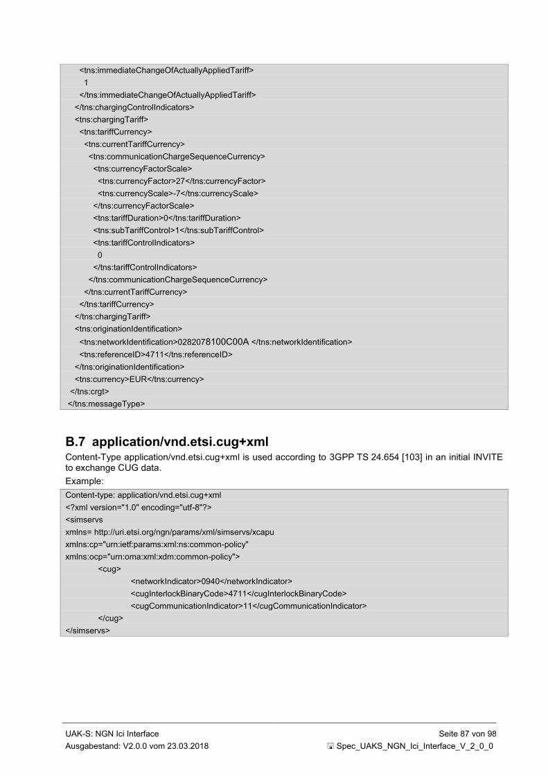
UAK-S: NGN Ici Interface Seite 87 von 98
Ausgabestand: V2.0.0 vom 23.03.2018 Spec_UAKS_NGN_Ici_Interface_V_2_0_0
<tns:immediateChangeOfActuallyAppliedTariff>
1
</tns:immediateChangeOfActuallyAppliedTariff>
</tns:chargingControlIndicators>
<tns:chargingTariff>
<tns:tariffCurrency>
<tns:currentTariffCurrency>
<tns:communicationChargeSequenceCurrency>
<tns:currencyFactorScale>
<tns:currencyFactor>27</tns:currencyFactor>
<tns:currencyScale>-7</tns:currencyScale>
</tns:currencyFactorScale>
<tns:tariffDuration>0</tns:tariffDuration>
<tns:subTariffControl>1</tns:subTariffControl>
<tns:tariffControlIndicators>
0
</tns:tariffControlIndicators>
</tns:communicationChargeSequenceCurrency>
</tns:currentTariffCurrency>
</tns:tariffCurrency>
</tns:chargingTariff>
<tns:originationIdentification>
<tns:networkIdentification>0282078100C00A </tns:networkIdentification>
<tns:referenceID>4711</tns:referenceID>
</tns:originationIdentification>
<tns:currency>EUR</tns:currency>
</tns:crgt>
</tns:messageType>
B.7 application/vnd.etsi.cug+xml Content-Type application/vnd.etsi.cug+xml is used according to 3GPP TS 24.654 [103] in an initial INVITE to exchange CUG data.
Example:
Content-type: application/vnd.etsi.cug+xml
<?xml version="1.0" encoding="utf-8"?>
<simservs
xmlns= http://uri.etsi.org/ngn/params/xml/simservs/xcapu
xmlns:cp="urn:ietf:params:xml:ns:common-policy"
xmlns:ocp="urn:oma:xml:xdm:common-policy">
<cug>
<networkIndicator>0940</networkIndicator>
<cugInterlockBinaryCode>4711</cugInterlockBinaryCode>
<cugCommunicationIndicator>11</cugCommunicationIndicator>
</cug>
</simservs>

UAK-S: NGN Ici Interface Seite 88 von 98
Ausgabestand: V2.0.0 vom 23.03.2018 Spec_UAKS_NGN_Ici_Interface_V_2_0_0
Annex C Forward Address Signalling (informative)
C.1 General This subclause explains the overlap signalling impacts on the core entities of the IM CN subsystem.
The support of overlap signalling and each of the overlap signalling method within the IM CN subsystem are optional and is dependent on the network policy.
Only one overlap signalling method shall be used within one IM CN subsystem.
C.2 Overlap Signalling Methods
C.2.1 In-dialogue Method not applicable
C.2.2 Multiple-INVITE Method
C.2.2.1 General The multiple-INVITE method uses INVITE requests with the same Call ID and From header in order to transport digits (as specified in 3GPP TS 29.163 [168]).
C.3 Routing Impacts
C.3.1 General If overlap signalling is supported, the IM CN subsystem needs to be configured in such a manner that erroneous routing of INVITE requests with incomplete numbers towards others entities than the corresponding INVITE requests with full numbers is avoided, for instance towards a default destination for unknown numbers such as a PSTN. Possibly impacted nodes include the S-CSCF for the UE-originated case, the transit routing function, the I-CSCF, and application servers.
A misrouting can be avoided by configuring the entity sending overlap signalling in such a manner that it will send the first INVITE request with a sufficient number of digits to find a suitable entry in the translation database. If ENUM is used, the ENUM database in a typical deployment contains sufficient information about the first digits, as required to identify the destination IP domain. Therefore, ENUM is able to handle incomplete numbers in such deployments. As another alternative, the routing entity can reject calls with unknown numbers with a 404 (Not Found) response, using entries in the routing database to identify calls towards the PSTN. The S-CSCF for the UE-originated case could also forward calls with unknown numbers to the BGCF, if the BGCF is configured to reject calls to unknown destinations with a 404 (Not Found) response.
C.3.2 Deterministic Routing If the multiple-INVITE method is used for overlap signalling, if an entity receives an INVITE request outside an existing dialogue with the same Call ID and From header field as a previous INVITE request during a certain period of time, the entity shall route the new INVITE request to the same next hop as the previous INVITE request.
Note: INVITE requests with the same Call ID and From header fields received in sequence during a certain period of time belong to the same call. The routing towards the same next hop could be achieved by an appropriately configured database or by the entity comparing the Call ID and From header fields of each INVITE request outside an existing dialogue with Call IDs and tag From header field parameters of previous INVITE requests. If the entity compares the Call ID and From header, it stores the information about received Call ID and From headers at least for a time in the order of call setup times. If paths have been established at registration time, deterministic routing will be automatic for entities on these paths.
UAK-S: NGN Ici Interface Seite 89 von 98
Ausgabestand: V2.0.0 vom 23.03.2018 Spec_UAKS_NGN_Ici_Interface_V_2_0_0
C.3.3 Digit Collection Entities performing routing decisions may require additional digits for a decision where to route an INVITE request. These entities may interact with a routing database to reach this decision.
If no suitable entry in a database is found for the digits received in an INVITE request, an entity can reject the INVITE request with a 404 (Not Found) or 484 (Address Incomplete) response. This method of digit collection can be performed by a SIP proxy and is suitable both for the in-dialogue and multiple-INVITE overlap signalling methods. Replying with a 404 (Not Found) response avoids the need to keep apart incomplete and unknown numbers. The 484 (Address Incomplete) response requires the recognition of incomplete numbers.
Note: An HSS does not support the recognition of incomplete numbers. A routing database being queried by ENUM also does not support the recognition of incomplete numbers.
As an alternative for the in-dialogue method, the digit collection function described in annex N.2 of 3GPP TS 24.229 [5] may be invoked. It shall be performed by an entity acting as a B2BUA. The digit collection function requires the ability to recognise incomplete number.
Only clause 4.9 and ANNEX N of 3GPP TS 24.229 [5] is applicable for the current specification.

UAK-S: NGN Ici Interface Seite 90 von 98
Ausgabestand: V2.0.0 vom 23.03.2018 Spec_UAKS_NGN_Ici_Interface_V_2_0_0
Annex D Calling Party's Category (normative) This annex describes the "cpc" URI parameter for use in SIP requests and is based on chapter 7.2A.12 of 3GPP TS 24.229 [5].
D.1 Introduction In ISUP, a cpc parameter is defined which characterizes the station at which a call was originated and carries other information which can describe the originating party. For example if a call is originated from a payphone a call can be handled in a specific way. When telephone numbers are contained in URIs, e.g. in tel URI or equivalent SIP URI it may be necessary to transmit any cpc associated to that telephone number. Such a method is described in this annex.
It is an option to set up the cpc parameter.
D.2 Definition The Calling Party's Category is represented as URI parameter for the tel URI scheme and SIP URI representation of telephone numbers. The ABNF syntax is as follows and extends the formal syntax for the tel URI as specified in IETF RFC 3966 [14]:
par =/ cpc
cpc = cpc-tag "=" cpc-value
cpc-tag = "cpc"
cpc-value = "ordinary" / "test" / "operator" / "payphone" / "unknown" / "mobile-hplmn" / "mobile-vplmn" / genvalue
genvalue = 1*(alphanum / "-" / ".")
The semantics of these Calling Party's Category values are described below:
ordinary: The caller has been identified, and has no special features.
test: This is a test call that has been originated as part of a maintenance procedure.
operator: The call was generated by an operator position.
payphone: The calling station is a payphone.
unknown: The CPC could not be ascertained.
mobile-hplmn: The call was generated by a mobile device in its home PLMN.
mobile-vplmn: The call was generated by a mobile device in a visited PLMN.
The detection of a public phone as A-party can only be done using the cpc parameter in the P-Asserted-Identity header field of an Invite message.
D.3 Transmission When received in a SIP request, the cpc parameter shall be transmitted transparently through the network and shall not be discarded.
D.4 Interworking The SIP/ISUP interworking of the cpc parameter shall be done as described in Annex C of 3GPP TS 29.163 [168].
D.5 Example One example for the use of the cpc parameter is the following:
Figure D-1: Example for the use of the cpc Parameter
Public phone (booth)
NGN Service Provider

UAK-S: NGN Ici Interface Seite 91 von 98
Ausgabestand: V2.0.0 vom 23.03.2018 Spec_UAKS_NGN_Ici_Interface_V_2_0_0
Invite sip: +49 800 1234567 @ operator.de; user=phone
P-Asserted-Identity: <sip:+493087654321; cpc=payphone@a-domain; user=phone>
To: < sip: +49 800 1234567@a-domain; user=phone>
From: "Name"<sip: +493087654321@a-domain; user=phone>
….
Consider that the A-party calls a freephone number (0800 or 00800) from a payphone. It is possible to charge an additional fee (the payphone access charge, PAC) besides the delivery fee, which has to be paid by the service provider (B-party), if the call originated from a payphone. This PAC is charged as an additional fee per minute and is booked to the split second.

UAK-S: NGN Ici Interface Seite 92 von 98
Ausgabestand: V2.0.0 vom 23.03.2018 Spec_UAKS_NGN_Ici_Interface_V_2_0_0
Annex E Nationally Ported International Service Numbers (informative)
To distinguish ported International Service Numbers (see chapter 7.1.2.8) from ported National Service Numbers, the following format:
sip: +<International Service Number> [;npdi] ;rn=+49 D<xyz> 0 <International Service Number> @ <host portion>; user=phone
including an additional "0" in the rn-Parameter between Porting Identifier D<xyz> and International Service Number shall be used for ported International Service Numbers.
An exemplary SIP Request URI is shown below:
sip:+80012345678;npdi;[email protected];user=phone
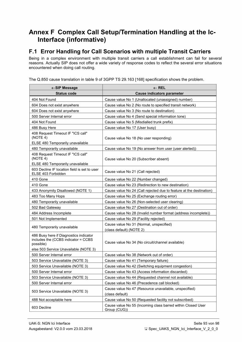
UAK-S: NGN Ici Interface Seite 93 von 98
Ausgabestand: V2.0.0 vom 23.03.2018 Spec_UAKS_NGN_Ici_Interface_V_2_0_0
Annex F Complex Call Setup/Termination Handling at the Ic-Interface (informative)
F.1 Error Handling for Call Scenarios with multiple Transit Carriers Being in a complex environment with multiple transit carriers a call establishment can fail for several reasons. Actually SIP does not offer a wide variety of response codes to reflect the several error situations encountered when doing call routing.
The Q.850 cause translation in table 9 of 3GPP TS 29.163 [168] specification shows the problem.
SIP Message REL
Status code Cause indicators parameter
404 Not Found Cause value No 1 (Unallocated (unassigned) number)
604 Does not exist anywhere Cause value No 2 (No route to specified transit network)
604 Does not exist anywhere Cause value No 3 (No route to destination)
500 Server Internal error Cause value No 4 (Send special information tone)
404 Not Found Cause value No 5 (Misdialled trunk prefix)
486 Busy Here Cause value No 17 (User busy)
408 Request Timeout IF "ICS call" (NOTE 4)
ELSE 480 Temporarily unavailable
Cause value No 18 (No user responding)
480 Temporarily unavailable Cause value No 19 (No answer from user (user alerted))
408 Request Timeout IF "ICS call" (NOTE 4)
ELSE 480 Temporarily unavailable
Cause value No 20 (Subscriber absent)
603 Decline IF location field is set to user ELSE 403 Forbidden
Cause value No 21 (Call rejected)
410 Gone Cause value No 22 (Number changed)
410 Gone Cause value No 23 (Redirection to new destination)
433 Anonymity Disallowed (NOTE 1) Cause value No 24 (Call rejected due to feature at the destination)
483 Too Many Hops Cause value No 25 (Exchange routing error)
480 Temporarily unavailable Cause value No 26 (Non-selected user clearing)
502 Bad Gateway Cause value No 27 (Destination out of order)
484 Address Incomplete Cause value No 28 (Invalid number format (address incomplete))
501 Not Implemented Cause value No 29 (Facility rejected)
480 Temporarily unavailable Cause value No 31 (Normal, unspecified)
(class default) (NOTE 2)
486 Busy here if Diagnostics indicator includes the (CCBS indicator = CCBS possible)
else 503 Service Unavailable (NOTE 3)
Cause value No 34 (No circuit/channel available)
500 Server Internal error Cause value No 38 (Network out of order)
503 Service Unavailable (NOTE 3) Cause value No 41 (Temporary failure)
503 Service Unavailable (NOTE 3) Cause value No 42 (Switching equipment congestion)
500 Server Internal error Cause value No 43 (Access information discarded)
503 Service Unavailable (NOTE 3) Cause value No 44 (Requested channel not available)
500 Server Internal error Cause value No 46 (Precedence call blocked)
503 Service Unavailable (NOTE 3) Cause value No 47 (Resource unavailable, unspecified)
(class default)
488 Not acceptable here Cause value No 50 (Requested facility not subscribed)
603 Decline Cause value No 55 (Incoming class barred within Closed User Group (CUG))

UAK-S: NGN Ici Interface Seite 94 von 98
Ausgabestand: V2.0.0 vom 23.03.2018 Spec_UAKS_NGN_Ici_Interface_V_2_0_0
Table F-1: Q.850 Interworking
There are 49 different Q.850 cause indicators versus 18 "corresponding" SIP Response Codes.
To be able to act on the different error situations it is necessary for the involved parties to recognize the situation. Since the Q.850 cause indicators in the REASON header will extinct with the PSTN, it‘s not advisable to act on Q.850 cause values.
However there is the possibility to indicate the different failure conditions using the SIP Reason header according to IETF RFC 3326 [48]:
The Reason header field MAY appear in any request within a dialogue, in any CANCEL request and in any response whose status code explicitly allows the presence of this header field. The syntax of the header field follows the standard SIP parameter syntax.
Reason = "Reason" HCOLON reason-value *(COMMA reason-value)
reason-value = protocol *(SEMI reason-params)
protocol = "SIP" / "Q.850" / token
reason-params = protocol-cause / reason-text / reason-extension
603 Decline Cause value No 57 (Bearer capability not authorised)
503 Service Unavailable (NOTE 3) Cause value No 58 (Bearer capability not presently available)
501 Not Implemented Cause value No 63 (Service option not available, unspecified) (class default)
500 Server Internal error Cause value No 65 (Bearer capability not implemented)
501 Not Implemented Cause value No 69 (Requested facility not implemented)
501 Not Implemented Cause value No 70 (Only restricted digital information capability is available)
501 Not Implemented
Cause value No 79 (Service or option not implemented, unspecified)
(class default)
403 Forbidden Cause value No 87 (User not member of Closed User Group (CUG))
606 Not Acceptable Cause value No 88 (Incompatible destination)
403 Forbidden Cause value No 90 (Non existing Closed User Group (CUG))
500 Server Internal error Cause value No 91 (Invalid transit network selection)
513 Message too large Cause value No 95 (Invalid message, unspecified) (class default)
501 Not Implemented Cause value No 97 (Message type non-existent or not implemented)
501 Not Implemented Cause value No 98 (Message not compatible with call state or message type non-existent or not implemented)
501 Not Implemented Cause value No 99 (Information element/parameter non-existent or not implemented)
504 Server timeout Cause value No 102 (Recovery on timer expiry)
501 Not Implemented Cause value No 103 (Parameter non-existent or not implemented, passed on)
501 Not Implemented Cause value No 110 (Message with unrecognised parameter, discarded)
400 Bad Request Cause value No 111 (Protocol error, unspecified) (class default)
500 Server Internal error Cause value No 127 (Interworking, unspecified) (class default)
NOTE 1: Anonymity Disallowed, IETF RFC 5079 [77] refers
NOTE 2: Class 0 and class 1 have the same default value.
NOTE 3: No Retry-After header field shall be included.
NOTE 4: The I-MGCF identifies a call as an "ICS call" as specified in subclause 7.2.3.1.2.12 of 3GPP TS 29.163 [168].
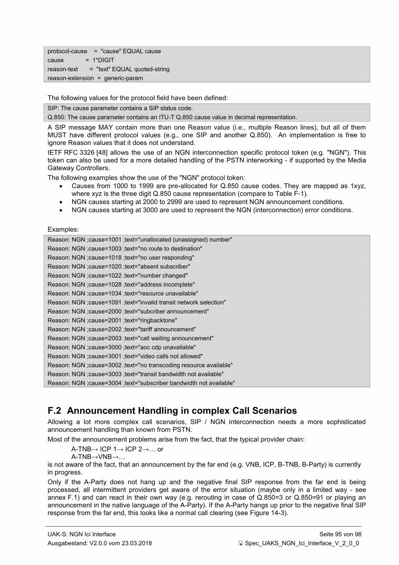
UAK-S: NGN Ici Interface Seite 95 von 98
Ausgabestand: V2.0.0 vom 23.03.2018 Spec_UAKS_NGN_Ici_Interface_V_2_0_0
protocol-cause = "cause" EQUAL cause
cause = 1*DIGIT
reason-text = "text" EQUAL quoted-string
reason-extension = generic-param
The following values for the protocol field have been defined:
SIP: The cause parameter contains a SIP status code.
Q.850: The cause parameter contains an ITU-T Q.850 cause value in decimal representation.
A SIP message MAY contain more than one Reason value (i.e., multiple Reason lines), but all of them MUST have different protocol values (e.g., one SIP and another Q.850). An implementation is free to ignore Reason values that it does not understand.
IETF RFC 3326 [48] allows the use of an NGN interconnection specific protocol token (e.g. "NGN"). This token can also be used for a more detailed handling of the PSTN interworking - if supported by the Media Gateway Controllers.
The following examples show the use of the "NGN" protocol token:
Causes from 1000 to 1999 are pre-allocated for Q.850 cause codes. They are mapped as 1xyz, where xyz is the three digit Q.850 cause representation (compare to Table F-1).
NGN causes starting at 2000 to 2999 are used to represent NGN announcement conditions.
NGN causes starting at 3000 are used to represent the NGN (interconnection) error conditions.
Examples:
Reason: NGN ;cause=1001 ;text="unallocated (unassigned) number"
Reason: NGN ;cause=1003 ;text="no route to destination"
Reason: NGN ;cause=1018 ;text="no user responding"
Reason: NGN ;cause=1020 ;text="absent subscriber"
Reason: NGN ;cause=1022 ;text="number changed"
Reason: NGN ;cause=1028 ;text="address incomplete"
Reason: NGN ;cause=1034 ;text="resource unavailable"
Reason: NGN ;cause=1091 ;text="invalid transit network selection"
Reason: NGN ;cause=2000 ;text="subcriber announcement"
Reason: NGN ;cause=2001 ;text="ringbacktone"
Reason: NGN ;cause=2002 ;text="tariff announcement"
Reason: NGN ;cause=2003 ;text="call waiting announcement"
Reason: NGN ;cause=3000 ;text="aoc cdp unavailable"
Reason: NGN ;cause=3001 ;text="video calls not allowed"
Reason: NGN ;cause=3002 ;text="no transcoding resource available"
Reason: NGN ;cause=3003 ;text="transit bandwidth not available"
Reason: NGN ;cause=3004 ;text="subscriber bandwidth not available"
F.2 Announcement Handling in complex Call Scenarios Allowing a lot more complex call scenarios, SIP / NGN interconnection needs a more sophisticated announcement handling than known from PSTN.
Most of the announcement problems arise from the fact, that the typical provider chain:
A-TNB→ ICP 1→ ICP 2→… or A-TNB→VNB→… is not aware of the fact, that an announcement by the far end (e.g. VNB, ICP, B-TNB, B-Party) is currently in progress.
Only if the A-Party does not hang up and the negative final SIP response from the far end is being processed, all intermittent providers get aware of the error situation (maybe only in a limited way - see annex F.1) and can react in their own way (e.g. rerouting in case of Q.850=3 or Q.850=91 or playing an announcement in the native language of the A-Party). If the A-Party hangs up prior to the negative final SIP response from the far end, this looks like a normal call clearing (see Figure 14-3).
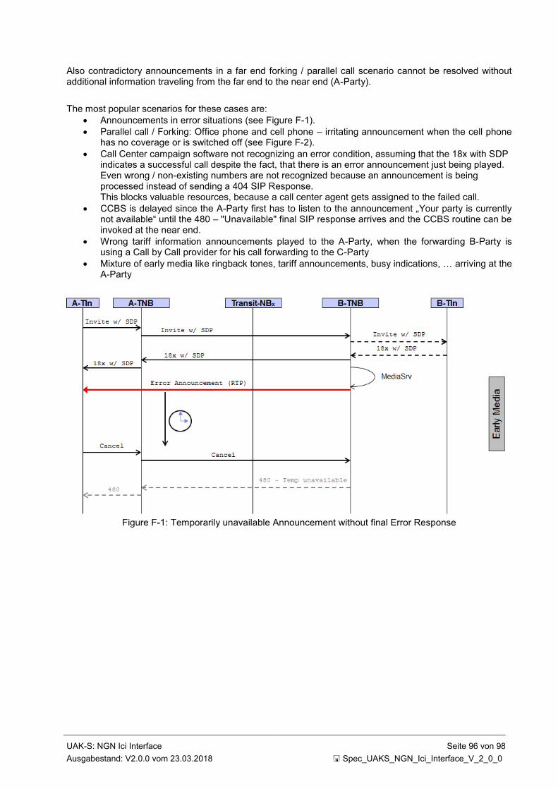
UAK-S: NGN Ici Interface Seite 96 von 98
Ausgabestand: V2.0.0 vom 23.03.2018 Spec_UAKS_NGN_Ici_Interface_V_2_0_0
Also contradictory announcements in a far end forking / parallel call scenario cannot be resolved without additional information traveling from the far end to the near end (A-Party).
The most popular scenarios for these cases are:
Announcements in error situations (see Figure F-1).
Parallel call / Forking: Office phone and cell phone – irritating announcement when the cell phone has no coverage or is switched off (see Figure F-2).
Call Center campaign software not recognizing an error condition, assuming that the 18x with SDP indicates a successful call despite the fact, that there is an error announcement just being played. Even wrong / non-existing numbers are not recognized because an announcement is being processed instead of sending a 404 SIP Response. This blocks valuable resources, because a call center agent gets assigned to the failed call.
CCBS is delayed since the A-Party first has to listen to the announcement „Your party is currently not available“ until the 480 – "Unavailable" final SIP response arrives and the CCBS routine can be invoked at the near end.
Wrong tariff information announcements played to the A-Party, when the forwarding B-Party is using a Call by Call provider for his call forwarding to the C-Party
Mixture of early media like ringback tones, tariff announcements, busy indications, … arriving at the A-Party
Figure F-1: Temporarily unavailable Announcement without final Error Response
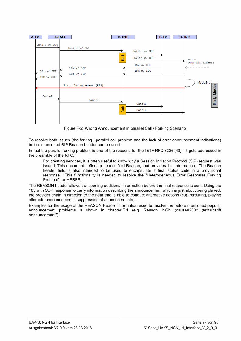
UAK-S: NGN Ici Interface Seite 97 von 98
Ausgabestand: V2.0.0 vom 23.03.2018 Spec_UAKS_NGN_Ici_Interface_V_2_0_0
Figure F-2: Wrong Announcement in parallel Call / Forking Scenario
To resolve both issues (the forking / parallel call problem and the lack of error announcement indications) before mentioned SIP Reason header can be used.
In fact the parallel forking problem is one of the reasons for the IETF RFC 3326 [48] - it gets addressed in the preamble of the RFC:
For creating services, it is often useful to know why a Session Initiation Protocol (SIP) request was issued. This document defines a header field Reason, that provides this information. The Reason header field is also intended to be used to encapsulate a final status code in a provisional response. This functionality is needed to resolve the "Heterogeneous Error Response Forking Problem", or HERFP.
The REASON header allows transporting additional information before the final response is sent. Using the 183 with SDP response to carry information describing the announcement which is just about being played, the provider chain in direction to the near end is able to conduct alternative actions (e.g. rerouting, playing alternate announcements, suppression of announcements, ).
Examples for the usage of the REASON Header information used to resolve the before mentioned popular announcement problems is shown in chapter F.1 (e.g. Reason: NGN ;cause=2002 ;text="tariff announcement").
UAK-S: NGN Ici Interface Seite 98 von 98
Ausgabestand: V2.0.0 vom 23.03.2018 Spec_UAKS_NGN_Ici_Interface_V_2_0_0
Annex G Use of SIP Options to Query the Operational Status of an IBCF (informative)
An IBCF may send a SIP OPTIONS method outside of an existing dialogue periodically or when necessary to query the operational status of another IBCF. This procedure can be used to find out whether or not one or more IBCFs are currently available and can process messages. In case of non availability, an alternative route can be selected.
An IBCF that transmits an OPTIONS request for this purpose might set the Max-Forwards header to a field value of 0 (zero) in order to ensure that the receiving IBCF does not forward but answer to this request.
An IBCF that receives a SIP OPTIONS method must, in accordance with clause 11.2 of IETF RFC 3261 [13], respond with a SIP status code that corresponds to the IBCF’s current capability to process messages. No response or a response other than 200 OK shall indicate that the IBCF that sends this response is not willing to accept INVITE requests. Deviating from clause 11.2 of IETF RFC 3261 [13] the header fields Allow, Accept, Accept-Encoding, Accept-Language, and Supported MAY be present in a 200 (OK) response to an OPTIONS request.
It is recommended to send OPTIONS messages even when there is already ongoing active communication (calls) as it allows the querying IBCF to learn when the peer IBCF has changed its operational status (e. g. has been put into maintenance mode or is reaching an overload status).
The frequency with which OPTIONS messages are exchanged for the purpose described in this section is outside the scope of this document.
<end of document>