
Vierreihige Kugelumlaufeinheit KUVE..-B (-KT) Montage- … · DIN 71412, Form B (45°) DIN 71412,...
32
Vierreihige Kugelumlaufeinheit KUVE..-B (-KT) Montage- und Wartungsanleitung Four-row linear ball bearing and guideway assembly KUVE..-B (-KT) Fitting and maintenance manual
Transcript of Vierreihige Kugelumlaufeinheit KUVE..-B (-KT) Montage- … · DIN 71412, Form B (45°) DIN 71412,...
Vierreihige Kugelumlaufeinheit KUVE..-B (-KT)Montage- und Wartungsanleitung
Four-row linear ball bearing and guideway assembly KUVE..-B (-KT)Fitting and maintenance manual
2 MON 38 Schaeffler Group Industrial
Warn- und GefahrensymboleDie Definition der Warn- und Gefahrensymbole folgt ANSI Z535.6–2006.Die verwendeten Hinweise und Zeichen haben folgende Bedeutung:
AchtungBei Nichtbeachtung treten Schäden oder Funktionsstörungen am Produkt oderan der Umgebungskonstruktion ein!
Warning and hazard symbolsThe warning and hazard symbols are defined alongthe lines of ANSI Z535.6–2006.The meaning of the guidelines and symbolsis as follows:
AttentionIf these safety guidelines are not observed,damage or malfunctions in the product or the adjacent construction will occur.
Schaeffler Group Industrial MON 38 3
SeiteInhaltsverzeichnis
Warn- und Gefahrensymbole .................................. 2Gültigkeit der Anleitung ......................................... 4Montageplatz, Montagewerkzeuge......................... 4Lieferausführung kontrollieren ............................... 5Mehrteilige Führungsschienen ............................... 6Anschlaghöhen und Eckenradien kontrollieren....... 7Form- und Lagetoleranzen kontrollieren ................. 9Parallelität der Anschlagflächen kontrollieren ........ 10Befestigungsschrauben, Anziehdrehmomente........ 11Übersicht: Kugelumlaufeinheiten einbauen ............ 15Hinweis bei unverschlossenen Senkungen ............. 16Führungsschiene auf der Referenzseite einbauen ... 17Führungswagen montieren oder demontieren......... 20Führungsschiene auf der Folgeseite einbauen ........ 21Schmierung ........................................................... 24Mindestölmenge, Ölimpulsmenge.......................... 27Mindestölmenge bei Inbetriebnahme Qmind/Ölimpulsmenge Qimp ............................................. 28Erstbefettungsmenge, Befettungsmenge ................ 29Erstbefettungsmenge (UG), Befettungsmenge ........ 30
PageContents
Warning and hazard symbols .................................. 2Scope of the manual............................................... 4Fitting area, fitting tools.......................................... 4Checking the delivered condition............................ 5Multi-piece guideways............................................ 6Checking the locating heights and corner radii ........ 7Checking the dimensional and geometrical tolerances .............................................................. 9Checking the parallelism of the locating surfaces .... 10Fixing screws, tightening torques ............................ 11Overview: Fitting of linear recirculating ball bearing and guideway assemblies....................................... 15Advice on open counterbores.................................. 16Fitting the guideway on the datum side ................... 17Fitting and dismounting of carriages ....................... 20Fitting the guideway on the adjustment side ........... 21Lubrication............................................................. 24Minimum oil quantity, oil impulse quantity ............. 27Minimum oil quantity for initial operation Qmin/oil impulse quantity Qimp........................................ 28Initial grease quantity, grease quantity ................... 29Initial grease quantity (UG), grease quantity............ 30
4 MON 38 Schaeffler Group Industrial
Gültigkeit der AnleitungDiese Anleitung gilt fürVierreihige Kugelumlaufeinheiten KUVE..-B (-KT)!Führungen nur danach einbauen!
Montageplatz, Montagewerkzeuge
AchtungIn der Nähe des Montageplatzes nicht mit spanabhebenden oder stauberzeugenden Maschinen, Geräten oder Anlagen arbeiten!Elemente nur mit vorgeschriebenen, sauberen Werk-zeugen montieren!Schmutz, Feuchtigkeit und ungeeignete Werkzeuge beeinträchtigen die Funktion der Elemente erheblich und verringern ihre Gebrauchsdauer nachhaltig!
Scope of the manualThis manual is valid for four-row linear recirculatingball bearing and guideway assemblies KUVE..-B (-KT). Guidance systems must only be fitted in accordance with the manual.
Fitting area, fitting tools
AttentionMachines, devices or equipment that generatecutting debris or dust must not be used in the vicinity of the fitting area.Elements should only be fitted using the tools specified and in a clean condition.Contamination, moisture and unsuitable tools will impair the function of the elements considerably and lead to an ongoing reduction in their operating life.
Schaeffler Group Industrial MON 38 5
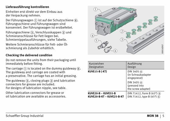
Lieferausführung kontrollierenEinheiten erst direkt vor dem Einbau ausder Verpackung nehmen.Der Führungswagen � ist auf der Schutzschiene �.Führungsschiene und Führungswagen sind konserviert. Der Führungswagen ist erstbefettet.Führungsschiene �, Verschlusskappen � und Schmieranschlüsse für Fett liegen bei. Schmiernippelausführungen, siehe Tabelle.Weitere Schmieranschlüsse für Fett- oder Öl-schmierung als Zubehör erhältlich.
Checking the delivered conditionDo not remove the units from their packaging until immediately before fitting.The carriage � is located on the dummy guideway �. The guideway and carriage are coated witha preservative. The carriage has an initial greasing.The guideway �, closing plugs � and lubrication connectors for grease are included.For designs of lubrication nipple, see table.Other lubrication connectors for grease oroil lubrication are available as accessories.
1
3
4
26
5
0001
6D07
KurzzeichenDesignation
AusführungDesign
KUVE15-B (-KT) DIN 3405 �(in Schraubadapter eingepresst)
DIN 3405 �(pressed intothe screw adapter)
KUVE20-B – KUVE55-BKUVE20-B-KT – KUVE25-B-KT
DIN 71412, Form B (45°) �DIN 71412, type B (45°) �
6 MON 38 Schaeffler Group Industrial
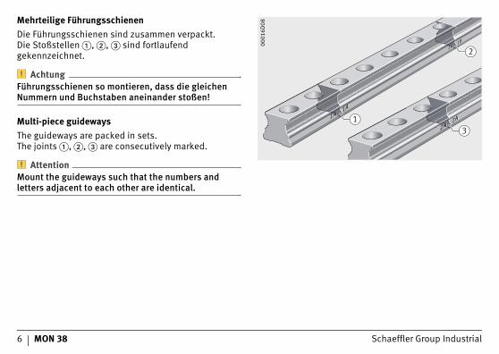
Mehrteilige FührungsschienenDie Führungsschienen sind zusammen verpackt.Die Stoßstellen �, �, � sind fortlaufend gekennzeichnet.
AchtungFührungsschienen so montieren, dass die gleichen Nummern und Buchstaben aneinander stoßen!
Multi-piece guidewaysThe guideways are packed in sets.The joints �, �, � are consecutively marked.
AttentionMount the guideways such that the numbers and letters adjacent to each other are identical.
1A1A1A1A
1B1B1B1B
2A2A2A2A1
3
2
0001
6D08
Schaeffler Group Industrial MON 38 7
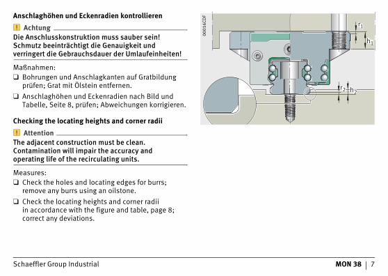
Anschlaghöhen und Eckenradien kontrollieren
AchtungDie Anschlusskonstruktion muss sauber sein! Schmutz beeinträchtigt die Genauigkeit undverringert die Gebrauchsdauer der Umlaufeinheiten!
Maßnahmen:❑ Bohrungen und Anschlagkanten auf Gratbildung
prüfen; Grat mit Ölstein entfernen.❑ Anschlaghöhen und Eckenradien nach Bild und
Tabelle, Seite 8, prüfen; Abweichungen korrigieren.
Checking the locating heights and corner radii
AttentionThe adjacent construction must be clean. Contamination will impair the accuracy andoperating life of the recirculating units.
Measures:❑ Check the holes and locating edges for burrs;
remove any burrs using an oilstone.❑ Check the locating heights and corner radii
in accordance with the figure and table, page 8;correct any deviations.
r1
h1
r2 h2
0001
6CD
F
8 MON 38 Schaeffler Group Industrial
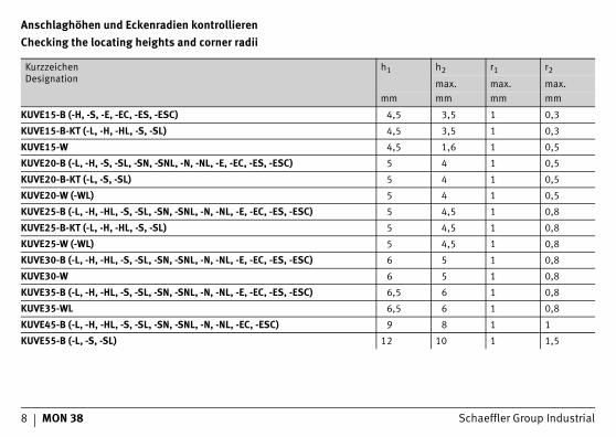
Anschlaghöhen und Eckenradien kontrollierenChecking the locating heights and corner radii
KurzzeichenDesignation
h1 h2 r1 r2
max. max. max.mm mm mm mm
KUVE15-B (-H, -S, -E, -EC, -ES, -ESC) 4,5 3,5 1 0,3
KUVE15-B-KT (-L, -H, -HL, -S, -SL) 4,5 3,5 1 0,3
KUVE15-W 4,5 1,6 1 0,5
KUVE20-B (-L, -H, -S, -SL, -SN, -SNL, -N, -NL, -E, -EC, -ES, -ESC) 5 4 1 0,5
KUVE20-B-KT (-L, -S, -SL) 5 4 1 0,5
KUVE20-W (-WL) 5 4 1 0,5
KUVE25-B (-L, -H, -HL, -S, -SL, -SN, -SNL, -N, -NL, -E, -EC, -ES, -ESC) 5 4,5 1 0,8
KUVE25-B-KT (-L, -H, -HL, -S, -SL) 5 4,5 1 0,8
KUVE25-W (-WL) 5 4,5 1 0,8
KUVE30-B (-L, -H, -HL, -S, -SL, -SN, -SNL, -N, -NL, -E, -EC, -ES, -ESC) 6 5 1 0,8
KUVE30-W 6 5 1 0,8
KUVE35-B (-L, -H, -HL, -S, -SL, -SN, -SNL, -N, -NL, -E, -EC, -ES, -ESC) 6,5 6 1 0,8
KUVE35-WL 6,5 6 1 0,8
KUVE45-B (-L, -H, -HL, -S, -SL, -SN, -SNL, -N, -NL, -EC, -ESC) 9 8 1 1
KUVE55-B (-L, -S, -SL) 12 10 1 1,5
Schaeffler Group Industrial MON 38 9
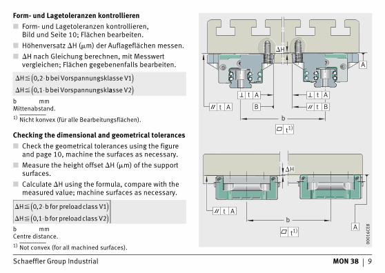
Form- und Lagetoleranzen kontrollieren■ Form- und Lagetoleranzen kontrollieren,
Bild und Seite 10; Flächen bearbeiten.■ Höhenversatz �H (�m) der Auflageflächen messen.■ �H nach Gleichung berechnen, mit Messwert
vergleichen; Flächen gegebenenfalls bearbeiten.
b mmMittenabstand.1) Nicht konvex (für alle Bearbeitungsflächen).
Checking the dimensional and geometrical tolerances■ Check the geometrical tolerances using the figure
and page 10, machine the surfaces as necessary.■ Measure the height offset �H (�m) of the support
surfaces.■ Calculate �H using the formula, compare with the
measured value; machine surfaces as necessary.
b mmCentre distance.1) Not convex (for all machined surfaces).
� �
� �
H bbei Vorspannungsklasse V
H bbei Vorspannungskl
0 2 1
0 1
,
,
⋅( )⋅ aasse V2( )
� �
� �
H b for preloadclass V
H b for preloadclass V
0 2 1
0 1 2
,
,
⋅( )⋅( )
A
AA
B BA
b
A
Ab
t
t
t
t
t1)
t
�H
�H
t1)
0001
6CE8
10 MON 38 Schaeffler Group Industrial
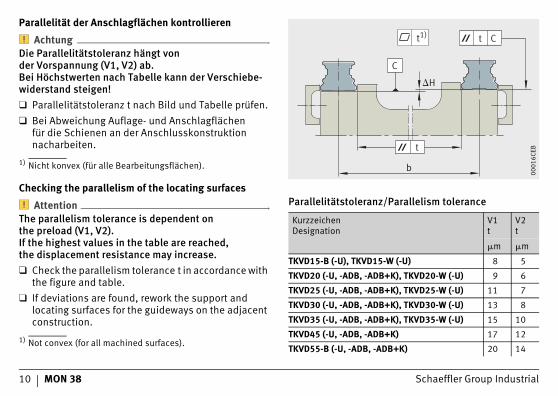
Parallelität der Anschlagflächen kontrollieren
AchtungDie Parallelitätstoleranz hängt vonder Vorspannung (V1, V2) ab.Bei Höchstwerten nach Tabelle kann der Verschiebe-widerstand steigen!❑ Parallelitätstoleranz t nach Bild und Tabelle prüfen.❑ Bei Abweichung Auflage- und Anschlagflächen
für die Schienen an der Anschlusskonstruktion nacharbeiten.
1) Nicht konvex (für alle Bearbeitungsflächen).
Checking the parallelism of the locating surfaces
AttentionThe parallelism tolerance is dependent onthe preload (V1, V2).If the highest values in the table are reached,the displacement resistance may increase.❑ Check the parallelism tolerance t in accordance with
the figure and table.❑ If deviations are found, rework the support and
locating surfaces for the guideways on the adjacent construction.
1) Not convex (for all machined surfaces).
�H
C
t
b
t Ct1)
0001
6CEB
Parallelitätstoleranz/Parallelism tolerance
KurzzeichenDesignation
V1t
V2t
�m �m
TKVD15-B (-U), TKVD15-W (-U) 8 5
TKVD20 (-U, -ADB, -ADB+K), TKVD20-W (-U) 9 6
TKVD25 (-U, -ADB, -ADB+K), TKVD25-W (-U) 11 7
TKVD30 (-U, -ADB, -ADB+K), TKVD30-W (-U) 13 8
TKVD35 (-U, -ADB, -ADB+K), TKVD35-W (-U) 15 10
TKVD45 (-U, -ADB, -ADB+K) 17 12
TKVD55-B (-U, -ADB, -ADB+K) 20 14
Schaeffler Group Industrial MON 38 11
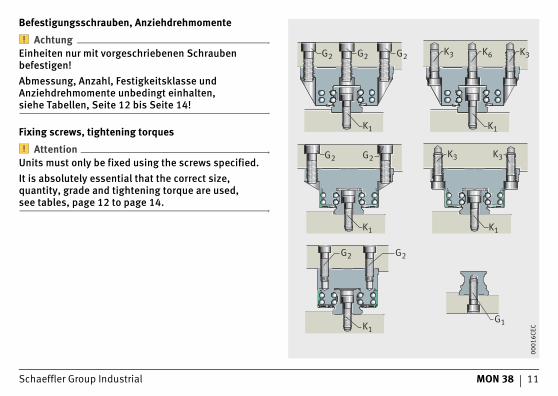
Befestigungsschrauben, Anziehdrehmomente
AchtungEinheiten nur mit vorgeschriebenen Schrauben befestigen!Abmessung, Anzahl, Festigkeitsklasse und Anziehdrehmomente unbedingt einhalten,siehe Tabellen, Seite 12 bis Seite 14!
Fixing screws, tightening torques
AttentionUnits must only be fixed using the screws specified.It is absolutely essential that the correct size, quantity, grade and tightening torque are used,see tables, page 12 to page 14.
G1
G2 G2
K1
K1
K1K1
K1
K3
K3 K3K6
K3G2 G2
G2 G2 G2
0001
6CEC
12 MON 38 Schaeffler Group Industrial
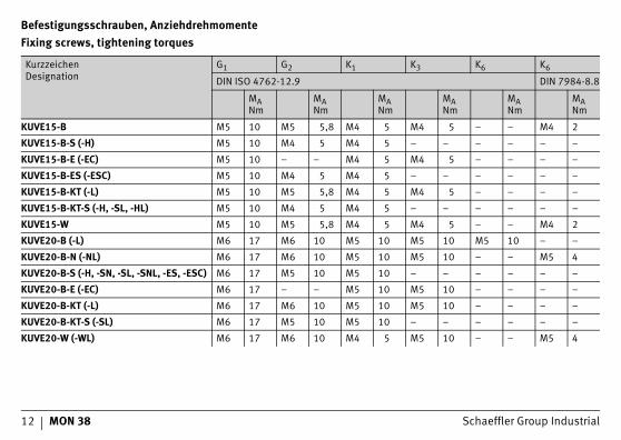
Befestigungsschrauben, AnziehdrehmomenteFixing screws, tightening torques
KurzzeichenDesignation
G1 G2 K1 K3 K6 K6
DIN ISO 4762-12.9 DIN 7984-8.8
MANm
MANm
MANm
MANm
MANm
MANm
KUVE15-B M5 10 M5 5,8 M4 5 M4 5 – – M4 2
KUVE15-B-S (-H) M5 10 M4 5 M4 5 – – – – – –
KUVE15-B-E (-EC) M5 10 – – M4 5 M4 5 – – – –
KUVE15-B-ES (-ESC) M5 10 M4 5 M4 5 – – – – – –
KUVE15-B-KT (-L) M5 10 M5 5,8 M4 5 M4 5 – – – –
KUVE15-B-KT-S (-H, -SL, -HL) M5 10 M4 5 M4 5 – – – – – –
KUVE15-W M5 10 M5 5,8 M4 5 M4 5 – – M4 2
KUVE20-B (-L) M6 17 M6 10 M5 10 M5 10 M5 10 – –
KUVE20-B-N (-NL) M6 17 M6 10 M5 10 M5 10 – – M5 4
KUVE20-B-S (-H, -SN, -SL, -SNL, -ES, -ESC) M6 17 M5 10 M5 10 – – – – – –
KUVE20-B-E (-EC) M6 17 – – M5 10 M5 10 – – – –
KUVE20-B-KT (-L) M6 17 M6 10 M5 10 M5 10 – – – –
KUVE20-B-KT-S (-SL) M6 17 M5 10 M5 10 – – – – – –
KUVE20-W (-WL) M6 17 M6 10 M4 5 M5 10 – – M5 4
Schaeffler Group Industrial MON 38 13
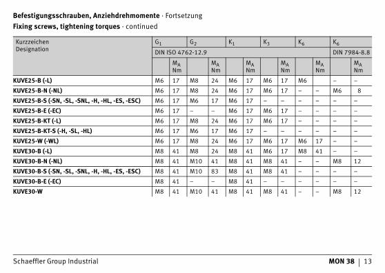
Befestigungsschrauben, Anziehdrehmomente · FortsetzungFixing screws, tightening torques · continued
KurzzeichenDesignation
G1 G2 K1 K3 K6 K6
DIN ISO 4762-12.9 DIN 7984-8.8
MANm
MANm
MANm
MANm
MANm
MANm
KUVE25-B (-L) M6 17 M8 24 M6 17 M6 17 M6 – –
KUVE25-B-N (-NL) M6 17 M8 24 M6 17 M6 17 – – M6 8
KUVE25-B-S (-SN, -SL, -SNL, -H, -HL, -ES, -ESC) M6 17 M6 17 M6 17 – – – – – –
KUVE25-B-E (-EC) M6 17 – – M6 17 M6 17 – – – –
KUVE25-B-KT (-L) M6 17 M8 24 M6 17 M6 17 – – – –
KUVE25-B-KT-S (-H, -SL, -HL) M6 17 M6 17 M6 17 – – – – – –
KUVE25-W (-WL) M6 17 M8 24 M6 17 M6 17 M6 17 – –
KUVE30-B (-L) M8 41 M8 24 M8 41 M6 17 M8 41 – –
KUVE30-B-N (-NL) M8 41 M10 41 M8 41 M8 41 – – M8 12
KUVE30-B-S (-SN, -SL, -SNL, -H, -HL, -ES, -ESC) M8 41 M10 83 M8 41 M8 41 – – – –
KUVE30-B-E (-EC) M8 41 – – M8 41 – – – – – –
KUVE30-W M8 41 M10 41 M8 41 M8 41 – – M8 12
14 MON 38 Schaeffler Group Industrial
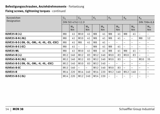
Befestigungsschrauben, Anziehdrehmomente · FortsetzungFixing screws, tightening torques · continued
KurzzeichenDesignation
G1 G2 K1 K3 K6 K6
DIN ISO 4762-12.9 DIN 7984-8.8
MANm
MANm
MANm
MANm
MANm
MANm
KUVE35-B (-L) M8 41 M10 41 M8 41 M8 41 M8 41 – –
KUVE35-B-N (-NL) M8 41 M10 41 M8 41 M8 41 – – M8 12
KUVE35-B-S (-SN, -SL, -SNL, -H, -HL, -ES, -ESC) M8 41 M8 41 M8 41 – – – – – –
KUVE35-B-E (-EC) M8 41 – – M8 41 M8 41 – – – –
KUVE35-WL M8 41 M10 41 M8 41 M8 41 M8 41 – –
KUVE45-B (-L) M12 140 M12 83 M12 140 M10 83 M10 83 – –
KUVE45-B-N (-NL) M12 140 M12 83 M12 140 M10 83 – – M10 35
KUVE45-B-S (-SN, -SL, -SNL, -H, -HL, -ESC) M12 140 M10 83 M12 140 – – – – – –
KUVE45-B-EC M12 140 – – M12 140 M10 83 – – – –
KUVE55-B M14 220 M14 140 M14 220 M12 140 M12 140 – –
KUVE55-B-S (-SL) M14 220 M12 140 M14 220 – – – – – –
Schaeffler Group Industrial MON 38 15
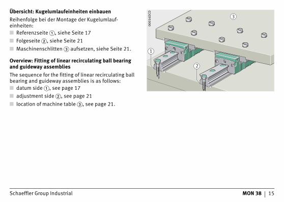
Übersicht: Kugelumlaufeinheiten einbauenReihenfolge bei der Montage der Kugelumlauf-einheiten:■ Referenzseite �, siehe Seite 17■ Folgeseite �, siehe Seite 21■ Maschinenschlitten � aufsetzen, siehe Seite 21.
Overview: Fitting of linear recirculating ball bearing and guideway assembliesThe sequence for the fitting of linear recirculating ball bearing and guideway assemblies is as follows:■ datum side �, see page 17■ adjustment side �, see page 21■ location of machine table �, see page 21.
1
2
3
0001
6DCD
16 MON 38 Schaeffler Group Industrial
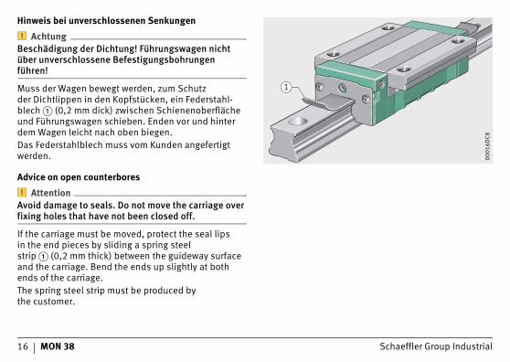
Hinweis bei unverschlossenen Senkungen
AchtungBeschädigung der Dichtung! Führungswagen nicht über unverschlossene Befestigungsbohrungen führen!
Muss der Wagen bewegt werden, zum Schutzder Dichtlippen in den Kopfstücken, ein Federstahl-blech � (0,2 mm dick) zwischen Schienenoberfläche und Führungswagen schieben. Enden vor und hinter dem Wagen leicht nach oben biegen.Das Federstahlblech muss vom Kunden angefertigt werden.
Advice on open counterbores
AttentionAvoid damage to seals. Do not move the carriage over fixing holes that have not been closed off.
If the carriage must be moved, protect the seal lipsin the end pieces by sliding a spring steel strip � (0,2 mm thick) between the guideway surface and the carriage. Bend the ends up slightly at both ends of the carriage.The spring steel strip must be produced bythe customer.
1
0001
6DC8
Schaeffler Group Industrial MON 38 17
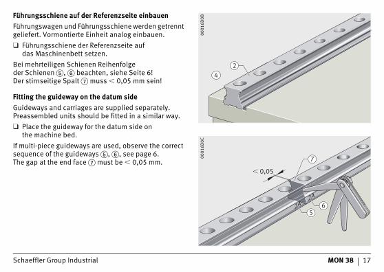
Führungsschiene auf der Referenzseite einbauenFührungswagen und Führungsschiene werden getrennt geliefert. Vormontierte Einheit analog einbauen.❑ Führungsschiene der Referenzseite auf
das Maschinenbett setzen.Bei mehrteiligen Schienen Reihenfolgeder Schienen �, � beachten, siehe Seite 6!Der stirnseitige Spalt � muss � 0,05 mm sein!
Fitting the guideway on the datum sideGuideways and carriages are supplied separately. Preassembled units should be fitted in a similar way.❑ Place the guideway for the datum side on
the machine bed.If multi-piece guideways are used, observe the correct sequence of the guideways �, �, see page 6.The gap at the end face � must be � 0,05 mm.
24
0001
6D0B
� 0,05
5
7
62A
2A00
016D
0C
18 MON 38 Schaeffler Group Industrial
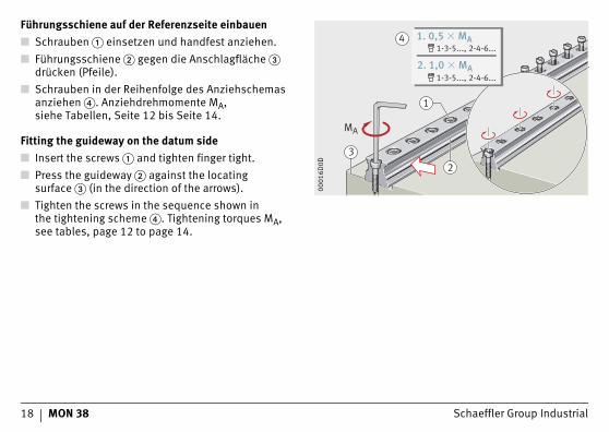
Führungsschiene auf der Referenzseite einbauen■ Schrauben � einsetzen und handfest anziehen.■ Führungsschiene � gegen die Anschlagfläche �
drücken (Pfeile).■ Schrauben in der Reihenfolge des Anziehschemas
anziehen �. Anziehdrehmomente MA,siehe Tabellen, Seite 12 bis Seite 14.
Fitting the guideway on the datum side■ Insert the screws � and tighten finger tight.■ Press the guideway � against the locating
surface � (in the direction of the arrows).■ Tighten the screws in the sequence shown in
the tightening scheme �. Tightening torques MA, see tables, page 12 to page 14.
23
MA
4 1. 0,5 � MA1-3-5..., 2-4-6...
2. 1,0 � MA1-3-5..., 2-4-6...
1
0001
6D0D

Schaeffler Group Industrial MON 38 19
Führungsschiene auf der Referenzseite einbauen
AchtungCorrotect®-beschichtete Führungsschienen und Kunststoff-Verschlusskappen nicht mit Ölstein oder ähnlichem bearbeiten!
❑ Andruckringe � in Bohrungen einlegen.❑ Verschlusskappen � mit Einpressklotz � bündig
einpressen.❑ Flächen mit Ölstein � abziehen.
Fitting the guideway on the datum side
AttentionDo not use oil stones or similar devices on guideways with Corrotect® coating and plastic closing plugs.
❑ Insert the clinch rings � in the holes.❑ Press the closing plugs � in flush using
a pressing-in block �.❑ Smooth the surfaces using an oilstone �.
2 3
1
0001
6D0F
4
0001
6D10
20 MON 38 Schaeffler Group Industrial
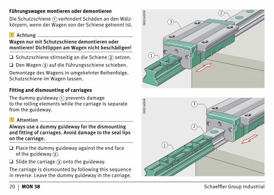
Führungswagen montieren oder demontierenDie Schutzschiene � verhindert Schäden an den Wälz-körpern, wenn der Wagen von der Schiene getrennt ist.
AchtungWagen nur mit Schutzschiene demontieren oder montieren! Dichtlippen am Wagen nicht beschädigen!
❑ Schutzschiene stirnseitig an die Schiene � setzen.❑ Den Wagen � auf die Führungsschiene schieben.Demontage des Wagens in umgekehrter Reihenfolge. Schutzschiene im Wagen lassen.
Fitting and dismounting of carriagesThe dummy guideway � prevents damageto the rolling elements while the carriage is separate from the guideway.
AttentionAlways use a dummy guideway for the dismounting and fitting of carriages. Avoid damage to the seal lips on the carriage.
❑ Place the dummy guideway against the end faceof the guideway �.
❑ Slide the carriage � onto the guideway.The carriage is dismounted by following this sequence in reverse. Leave the dummy guideway in the carriage.
3
2
1
0001
6D09
3
2
100
016D
0A
Schaeffler Group Industrial MON 38 21
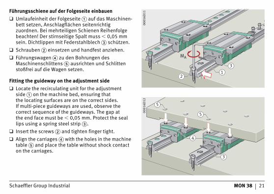
Führungsschiene auf der Folgeseite einbauen❑ Umlaufeinheit der Folgeseite � auf das Maschinen-
bett setzen, Anschlagflächen seitenrichtig zuordnen. Bei mehrteiligen Schienen Reihenfolge beachten! Der stirnseitige Spalt muss � 0,05 mm sein. Dichtlippen mit Federstahlblech � schützen.
❑ Schrauben � einsetzen und handfest anziehen.❑ Führungswagen � zu den Bohrungen des
Maschinenschlittens � ausrichten und Schlitten stoßfrei auf die Wagen setzen.
Fitting the guideway on the adjustment side❑ Locate the recirculating unit for the adjustment
side � on the machine bed, ensuring thatthe locating surfaces are on the correct sides.If multi-piece guideways are used, observe the correct sequence of the guideways. The gap atthe end face must be � 0,05 mm. Protect the seal lips using a spring steel strip �.
❑ Insert the screws � and tighten finger tight.❑ Align the carriages � with the holes in the machine
table � and place the table without shock contact on the carriages.
MA
13
2
0001
6D11
5
4
5
3
0001
6D12

22 MON 38 Schaeffler Group Industrial
Führungsschiene auf der Folgeseite einbauen❑ Schrauben � in die Bohrungen im Schlitten setzen
und handfest anziehen.❑ Wagen � gegen die Anschlagflächen �
des Schlittens � drücken und Schrauben � mit Anziehdrehmoment MA nach Tabelle, Seite 12 bis Seite 14 anziehen.
❑ Schlitten � verfahren und dadurch die Schiene � auf der Folgeseite ausrichten.
❑ Schrauben � in der Führungsschiene nach Anziehschema anziehen, �.
Fitting the guideway on the adjustment side❑ Insert the screws � in the holes in the table and
tighten finger tight.❑ Press the carriages � against the locating
surfaces � of the table � and tighten the screws � to the tightening torque MA in accordance withthe table, page 12 to page 14.
❑ Move the table � in order to align the guideway � on the adjustment side.
❑ Tighten the screws � in the guideway in accordance with the tightening scheme, �.
1
53
2
4
0001
6D13
7 1. 0,5 � MA1-3-5..., 2-4-6...
2. 1,0 � MA1-3-5..., 2-4-6...
MA
6
0001
6D14
Schaeffler Group Industrial MON 38 23
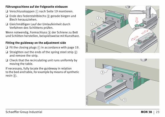
Führungsschiene auf der Folgeseite einbauen❑ Verschlusskappen � nach Seite 19 montieren.❑ Ende des Federstahlblechs � gerade biegen und
Blech herausziehen.❑ Gleichmäßigen Lauf der Umlaufeinheit durch
Verfahren des Schlittens prüfen.Wenn notwendig, Formschluss � der Schiene zu Bett und Schlitten herstellen, beispielsweise mit Kunstharz.
Fitting the guideway on the adjustment side❑ Fit the closing plugs � in accordance with page 19.❑ Straighten out the ends of the spring steel strip �
and remove the strip.❑ Check that the recirculating unit runs uniformly by
moving the table.If necessary, fully locate the guideway in relationto the bed and table, for example by means of synthetic resin �.
1
2
0001
6D15
3
3
0001
6D16
24 MON 38 Schaeffler Group Industrial
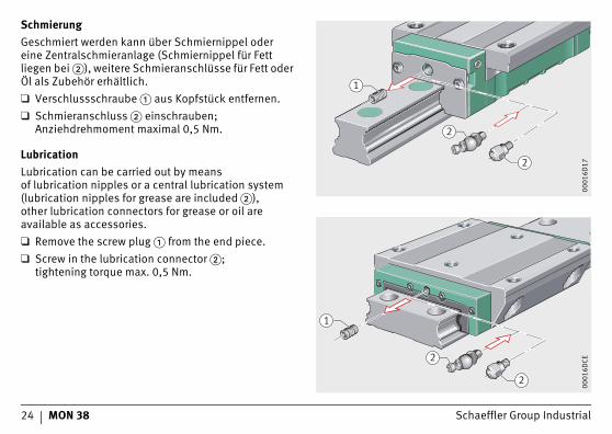
SchmierungGeschmiert werden kann über Schmiernippel odereine Zentralschmieranlage (Schmiernippel für Fett liegen bei �), weitere Schmieranschlüsse für Fett oder Öl als Zubehör erhältlich.❑ Verschlussschraube � aus Kopfstück entfernen.❑ Schmieranschluss � einschrauben;
Anziehdrehmoment maximal 0,5 Nm.
LubricationLubrication can be carried out by meansof lubrication nipples or a central lubrication system (lubrication nipples for grease are included �),other lubrication connectors for grease or oil are available as accessories.❑ Remove the screw plug � from the end piece.❑ Screw in the lubrication connector �;
tightening torque max. 0,5 Nm.
2
2
1
0001
6D17
2
2
1
0001
6DCE
Schaeffler Group Industrial MON 38 25
Schmierung
AchtungWagen beim Schmieren immer verfahren! Mindesthub ist viermal Tragkörperlänge! Siehe auch Katalog PF 1, Profilschienenführungen, Kapitel Schmierung!
Schmierintervalle■ Schmierfrist beachten
– max. 12 Monate bei Fettschmierung.■ Wird über eine Zentralschmieranlage geschmiert,
Ölimpulsmenge Qimp beachten, siehe Seite 28.
Lubrication
AttentionAlways move the carriage during lubrication.The minimum stroke is four times the lengthof the saddle plate. See also Catalogue PF 1,Monorail Guidance Systems, chapter Lubrication.
Lubrication intervals■ Observe the lubrication interval
– max. 12 months when using if grease lubrication.■ If lubrication is carried out by means
of a central lubrication system, observe the oil impulse quantity Qimp, see page 28.
26 MON 38 Schaeffler Group Industrial
SchmierungVor Inbetriebnahme
AchtungNasskonservierte Wagen (Nachsetzzeichen UG) müssen vor Inbetriebnahme geschmiert werden!
❑ Führungsschienen leicht ölen oder fetten– abhängig ob Öl- oder Fettschmierung.
❑ Wagen bei Ölschmierung mit Mindestölmenge schmieren; Ölmengen siehe Seite 29.
❑ Bei Fettschmierung Wagen fetten bis frisches Schmierfett austritt; Fettmengen siehe Seite 30.
LubricationBefore initial operation
AttentionCarriages with an oil-based preservative (suffix UG) must be lubricated before initial operation.
❑ Lightly oil or grease the guideways– depending on whether oil or grease lubrication
is used.❑ If using oil lubrication, lubricate the carriages
with the minimum oil quantity; for oil quantities,see page 29.
❑ If using grease lubrication, continue greasingthe carriage until fresh grease appears; for grease quantities, see page 30.
Schaeffler Group Industrial MON 38 27
Mindestölmenge, ÖlimpulsmengeDie Werte gelten für die Bedingungen:■ Einschaltdauer 100%■ C0/P = 8■ = 0,8 m/s■ Hub 500 mm bis 1000 mm.Exakte Werte lassen sich nur unter Betriebs-bedingungen ermitteln.
Minimum oil quantity, oil impulse quantityThe values apply under the following conditions:■ operating duration 100%■ C0/P = 8■ = 0,8 m/s■ stroke 500 mm to 1000 mm.Precise values can only be determined under operating conditions.
v v
28 MON 38 Schaeffler Group Industrial
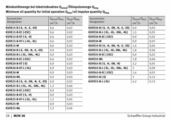
Mindestölmenge bei Inbetriebnahme Qmind/Ölimpulsmenge QimpMinimum oil quantity for initial operation Qmin/oil impulse quantity Qimp
KurzzeichenDesignation
Qmind/Qmin Qimp/Qimp
cm3/h cm3/h
KUVE15-B (-S, -H, -E, -ES) 0,6 0,02
KUVE15-B-EC (-ESC) 0,6 0,02
KUVE15-B-KT (-S, -H) 0,6 0,02
KUVE15-B-KT-L (-HL, -SL) 0,6 0,02
KUVE15-W 0,6 0,02
KUVE20-B (-S, -SN, -N, -E, -ES) 0,9 0,03
KUVE20-B-L (-SL, -SNL, -NL) 0,9 0,03
KUVE20-B-EC (-ESC) 0,6 0,02
KUVE20-B-KT (-S) 0,9 0,03
KUVE20-B-KT-L (-SL) 0,9 0,03
KUVE20-W 0,9 0,03
KUVE20-WL 0,9 0,03
KUVE25-B (-S, -H, -SN, -N, -E, -ES) 0,9 0,03
KUVE25-B-L (-SL, -HL, -SNL, -NL) 1,2 0,04
KUVE25-B-EC (-ESC) 0,9 0,02
KUVE25-B-KT (-S, -H) 0,9 0,03
KUVE25-B-KT-L (-SL, -HL) 1,2 0,04
KUVE25-W 0,9 0,03
KUVE25-WL 1,2 0,04
KurzzeichenDesignation
Qmind/Qmin Qimp/Qimp
cm3/h cm3/h
KUVE30-B (-S, -H, -SN, -N, -E, -ES) 0,9 0,03
KUVE30-B-L (-SL, -HL, -SNL, -NL) 1,5 0,05
KUVE30-B-EC (-ESC) 0,9 0,02
KUVE30-W 0,9 0,03
KUVE35-B (-S, -H, -SN, -N, -E, -ES) 1,4 0,04
KUVE35-B-L (-SL, -HL, SNL, -NL) 1,8 0,06
KUVE35-B-EC (-ESC) 0,9 0,02
KUVE35-WL 1,8 0,06
KUVE45-B (-S, -H, -SN, -N) 2,2 0,05
KUVE45-B-L (-SL, -HL, -SNL, -NL) 3 0,09
KUVE45-B-EC (-ESC) 1,4 0,03
KUVE55-B (-S) 3 0,12
KUVE55-B-L (-SL) 4,2 0,12
Schaeffler Group Industrial MON 38 29
Erstbefettungsmenge, BefettungsmengeDie Werte gelten für die Bedingungen:■ Einschaltdauer 100%■ C0/P = 8■ = 0,8 m/s■ Hub 500 mm bis 1000 mm.Exakte Werte lassen sich nur unter Betriebs-bedingungen ermitteln.
AchtungFührungswagen KUVE..-B und KUVE..-B-KT sind erstbefettet (Standard)!
Initial grease quantity, grease quantityThe values apply under the following conditions:■ operating duration 100%■ C0/P = 8■ = 0,8 m/s■ stroke 500 mm to 1000 mm.Precise values can only be determined under operating conditions.
AttentionCarriages KUVE..-B and KUVE..-B-KT are supplied with initial greasing (as standard).
v v
30 MON 38 Schaeffler Group Industrial
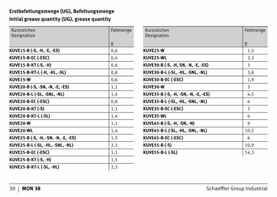
Erstbefettungsmenge (UG), BefettungsmengeInitial grease quantity (UG), grease quantity
KurzzeichenDesignation
Fettmenge
g
KUVE15-B (-S, -H, -E, -ES) 0,6
KUVE15-B-EC (-ESC) 0,4
KUVE15-B-KT (-S, -H) 0,6
KUVE15-B-KT-L (-H, -HL, -SL) 0,8
KUVE15-W 0,6
KUVE20-B (-S, -SN, -N, -E, -ES) 1,1
KUVE20-B-L (-SL, -SNL, -NL) 1,4
KUVE20-B-EC (-ESC) 0,8
KUVE20-B-KT (-S) 1,1
KUVE20-B-KT-L (-SL) 1,4
KUVE20-W 1,1
KUVE20-WL 1,4
KUVE25-B (-S, -H, -SN, -N, -E, -ES) 1,5
KUVE25-B-L (-SL, -HL, -SNL, -NL) 2,3
KUVE25-B-EC (-ESC) 1,1
KUVE25-B-KT (-S, -H) 1,5
KUVE25-B-KT-L (-SL, -HL) 2,3
KurzzeichenDesignation
Fettmenge
g
KUVE25-W 1,5
KUVE25-WL 2,3
KUVE30-B (-S, -H, SN, -N, -E, -ES) 3
KUVE30-B-L (-SL, -HL, -SNL, -NL) 3,8
KUVE30-B-EC (-ESC) 1,9
KUVE30-W 3
KUVE35-B (-S, -H, -SN, -N, -E, -ES) 4,5
KUVE35-B-L (-SL, -HL, -SNL, -NL) 6
KUVE35-B-EC (-ESC) 3
KUVE35-WL 6
KUVE45-B (-S, -H, -SN, -N) 9
KUVE45-B-L (-SL, -HL, -SNL, -NL) 10,5
KUVE45-B-EC (-ESC) 6
KUVE55-B (-S) 10,9
KUVE55-B-L (-SL) 14,3

Schaeffler Group Industrial MON 38 31

MAT
NR
0211
1037
9-00
00 /
MO
N 3
8 /
D/G
B-D
/GB
/ 20
1010
/ p
df o
nly
Schaeffler Technologies
GmbH & Co. KG
Geschäftsbereich LineartechnikBerliner Straße 13466424 Homburg (Saar)Internet www.ina.comE-Mail [email protected]
In Deutschland:Telefon 0180 5003872Telefax 0180 5003873
Aus anderen Ländern:Telefon +49 6841 701-0Telefax +49 6841 701-2625
Schaeffler (UK) Ltd
Forge LaneMinworthSutton ColdfieldWest MidlandsB76 1APPhone 0121 313 5870Fax 0121 313 0080E-Mail [email protected] www.schaeffler.co.uk
Nachdruck, auch auszugsweise, nur mitunserer Genehmigung.This publication or parts thereof may notbe reproduced without our permission.
© Schaeffler Technologies GmbH & Co. KGAusgabe/Issued: 2010, Oktober/October
MON 38 D/GB-D/GB

![Big Data - und nun? [1Ex] Was kann die Bioinformatik?...Small Data vs. Big Data 0 B B B B B B B B B B B B @ p1 p2 p3 n1 a1 a2 a3 n2 b1 b2 b3 n3 c1 c2 c3..... ns ns1 ns2 ns3 1 C C C](https://static.fdokument.com/doc/165x107/60bd3a8cc639206cca521795/big-data-und-nun-1ex-was-kann-die-bioinformatik-small-data-vs-big-data.jpg)


![^ Â - D j - ì Ò Á [ Ó æ ] B [ Ó · B B®BoB¦. B_B®B B BrB]. B B^B¥B B . B¤BeBt. BfB®B BsB]. B B B B . ã Ä. U + X o ^ ã1b. . " " Ð TUFS . . U + X o ^ ê y ù â æ](https://static.fdokument.com/doc/165x107/6022f7bf357d3803107a3b74/-d-j-b-b-bbob-bbb-b-brb-b-bbb-b-bbebt.jpg)