Wand-/Deckenverdampfer Unit coolers · 2012. 7. 16. · Anwendungsvorteile Application benefi ts...
16
2 GHN.2 50 Hz R404A, R507, R134a, R22, … schwenkbare Seitenverkleidung hinged side covering - Verbesserter Tauwasserrücklauf und verbesserte Luftführung durch Güntner Incline Design - Gute Zugänglichkeit: aufklappbare Seitenverkleidung + optional schwenkbare Ventilatoren - Hohe Wurfweiten durch optionale Güntner Streamer - Kondenswasserfreie Wannenkonstruktion - 2 Ventilatorausführungen - Improved condensation water drain and routing of air flow with Güntner Incline Design - Good accessibility: hinged side covering + optional: swiveling fans - Improved air throw with optional Güntner Streamer - Condensation-water-free drip tray - 2 types of fans available www.guentner.de 1 10.09 GHN.2 Wand-/Deckenverdampfer Unit coolers
Transcript of Wand-/Deckenverdampfer Unit coolers · 2012. 7. 16. · Anwendungsvorteile Application benefi ts...

2GHN.2
50 Hz
R404A, R507, R134a, R22, …
schwenkbare Seitenverkleidung
hinged side covering
- Verbesserter Tauwasserrücklauf und verbesserte Luftführung durch Güntner Incline Design
- Gute Zugänglichkeit: aufklappbare Seitenverkleidung + optional schwenkbare Ventilatoren
- Hohe Wurfweiten durch optionale Güntner Streamer
- Kondenswasserfreie Wannenkonstruktion
- 2 Ventilatorausführungen
- Improved condensation water drain and routing of air flow with Güntner Incline Design
- Good accessibility: hinged side covering + optional: swiveling fans
- Improved air throw with optional Güntner Streamer
- Condensation-water-free drip tray
- 2 types of fans available
www.guentner.de
110.09GHN.2
Wand-/DeckenverdampferUnit coolers

Nomenklatur / Nomenclature
Anwendungsvorteile Application benefi tsfür Betreiber for operators
Wand-/DeckenverdampferUnit coolersVentilatorFan
∅ 710 mm
GenerationGenerationBlockgrößeCoil sizeAnzahl der VentilatorenNumber of fansLamellenteilungFin spacing
Luftabtauung oder keine Abtauung Air defrost or non defrost
Abtauung auf Wunsch elektrisch Electric defrost on request
Heißgasabtauung auf Wunsch Hot gas defrost on request
Ventilatoren normale Ausführung fans standard design
Ventilatoren verstärkte Ausführung fans reinforced design
Spannung / Phase / Frequenz 400 V 3~ 50 Hz Δ
Voltage / Phase / Frequency 230 V 1~ 50 Hz
400 V 3~ 50 Hz Y
Güntner Incline Design
• Bessere Luftführung• Besserer Tauwasserrücklauf
Kondenswasser-freie Wannenkonstruktion
Die thermisch entkoppelte Tropf-wanne reduziert Kondenswasser-bildung an der Außenseite.
Zeitsparende Reinigung
Hygienevorschriften verlangen eine gründliche Reinigung des gesamten Verdampfers. Durch schwenkbare Ventilatoren (optional) können – mit einfachen Handgriffen – Öffnungen zum Reinigen des Wärmeaus-tauscherblockes und Innenraums geschaffen werden.
Abtauklappe
• Sichere und vollständige Abtauung• Die Abtauwärme bleibt im inneren
des Gehäuses
incline design3°
Güntner Incline Design
• Better routing of air flow• Improved condensation water
drain
Condensation-water-free driptray construction
The drip tray prevents formation of condensation water at the outside due to its thermal properties.
Timesaving cleaning
Hygiene regulations require thorough cleaning of the entire evaporator coil.The swiveling fans (optional) make it possible to create without much ado openings for the cleaning of the heat exchanger coil and of the unit’s interior.
Defrost fl ap
• Safe and complete defrosting• The defrosting heat remains in the
evaporator casing
GHN 071 .2 F / 2 7 - A - E - H - N - H D W S
210.09GHN.2

Anwendungsvorteile Application benefi tsfür Anlagenbauer und Planer for contractors and planners
Montage / Service / MessungAufklappen - LoslegenDie Anschlüsse sind einfach durch die aufklappbaren Seitenwände erreichbar. Noch leichter zu öffnen mit den Schnappverschlüssen für die Baugrößen 071 und 080.
Kostenreduzierung bei der InstallationWerkseitig vormontierte Baugruppen (optional) reduzieren die Kosten bei der Installation.
• Expansionsventil werkseitig einge-baut
• Verrohrung der Heißgasabtauung zwischen Tropfwanne und Block
• Montage Rückschlagventil Heißgasabtauung
Sie müssen vor Ort nur noch den Verdampfer positionieren, an die Elektroversorgung anklemmen und das Rohrsystem anschließen.
Ventilator• Bewährte Qualitätsventilatoren• Hohe Wurfweiten durch optionale
Güntner-Streamer• Hohe Luftmenge• Guter Wirkungsgrad• 2 Ventilatorausführungen
– normal– verstärkt
... keep(s) your quality• Zuverlässiger Betrieb durch aus-
gereiftes und bewährtes Produkt• Ansprechendes Design• Kein Kondensatauswurf durch
optimierte Luftgeschwindigkeiten in der Grundversion
• Optional verstärkte Ventilatoren für erhöhte Luftumwälzung
• Realisierung von kundenspezifi-schen Lösungen außerhalb des Standards möglich
Assembly/Maintenance/Gauging Open and get startedThe connections are easily accessible through the hinged side coverings. Even easier to open with the snap-locks which are available for sizes 071 and 080.
Reduced installation costs
Components pre-assembled ex works (optional) of certain components reduce installation costs.
• Expansion valve installed ex works• Pipe installation for hot gas
defrosting between drip tray and coil
• Fitting of return valve for hot gas defrosting
All that remains to be done on site is to position the evaporator and connect it to the power supply and the pipe system.
Fan• Reliable high-quality fans• Extended air throw due to optional
Güntner Streamer• Large air quantity• High efficiency• 2 types of fans available
– standard– reinforced
... keep(s) your quality• Reliable operation of a tried and
tested unit• Pleasing design• No spouting of condensation water
due to optimised air velocities in the basic version
• Optional: more powerful fans for increased air circulation
• It is possible to realise customised solutions beyond the standard
310.09GHN.2

GHN.2 - 1 Ventilator - 1 Fan
Typ
Type
NennleistungNominalcapacityR404A
Wur
fwei
te o
hne
Stre
amer
Air
thro
w w
ithou
t St
ream
er
Wur
fwei
te m
it St
ream
erA
ir th
row
with
Str
eam
er
Scha
lldru
ckSo
und
pres
sure
AnschlüsseConnections
El. AbtauheizungEl. defrost
400 V
Ans
chlu
sskl
emm
en o
ptio
nale
Ve
ntila
torv
erka
belu
ngco
nnec
tion
term
inal
s op
tiona
l fa
n w
iring
Fläc
heSu
rfac
e
Luftvo
lum
enst
rom
Air
volu
me fl o
wKältemittelRefrigerant
Hei
ßgas
Blo
ck e
inH
ot g
as c
oil i
nlet
Hei
ßgas
Wan
ne e
in/a
usH
ot g
as tr
ay in
let/
outle
t
aufg
enom
men
eel
ektr
isch
e Le
istu
ngpo
wer
con
sum
ptio
n
Blo
ckC
oil
Trop
fwan
neD
rip t
ray
Ges
amt
Tota
l
Ans
chlu
sssc
hem
aC
onne
ctio
n di
agra
m
SC2 SC3
EinInlet
AusOutlet
DT1
= 8
Kt o
= –
8 °
C
DT1
= 7
Kt o
= –
25 °
C
Pel total
kW kW m² m³/h m m dB(A)/3m mm ∅ mm ∅ mm ∅ mm ∅ W W kW kW040.2D/14-ANW50 5,2 4,1 32,7 3060 11 24 52 16* 22,0 15 15 1620 700 2,32 1 × A 0,22 1 × E040.2F/14-ANW50 6,6 5,3 49,0 2810 10 23 52 16* 22,0 15 15 2700 1000 3,70 1 × B 0,22 1 × E045.2D/14-ANW50 8,5 6,6 51,3 5110 15 33 56 16* 22,0 15 15 2580 1200 3,78 1 × B 0,50 1 × E045.2E/14-ANW50 9,8 8,0 64,2 4860 14 32 56 16* 28,0 15 15 3440 1200 4,64 1 × B 0,51 1 × E050.2D/14-ANS50 11,1 8,7 67,3 6650 19 38 56 16* 28,0 15 15 3000 1300 4,30 1 × B 0,52 1 × I050.2E/14-ANS50 12,9 10,2 84,1 6470 19 36 56 16* 28,0 15 15 3750 1300 5,05 1 × B 0,53 1 × I050.2F/14-ANS50 14,5 11,7 100,9 6300 18 34 56 22* 35,0 15 15 4500 1950 6,45 1 × B 0,54 1 × I071.2D/14-AND50 19,6 15,8 117,6 11760 32 57 55 22* 42,0 15 15 6250 2700 8,95 1 × C 0,80 1 × G071.2E/14-AND50 22,6 18,0 147,0 11230 32 56 55 22* 42,0 15 15 7500 2700 10,20 1 × C 0,81 1 × G071.2F/14-AND50 24,7 19,3 176,4 10790 31 54 55 22* 42,0 22 22 8750 2700 11,45 1 × C 0,82 1 × G080.2D/14-AND50 30,3 24,0 184,5 17970 39 68 63 22* 42,0 22 22 9000 3450 12,45 1 × C 1,35 1 × G080.2E/14-AND50 35,2 28,1 230,7 17280 38 66 63 28* 54,0 22 22 12000 3450 15,45 2 × C 1,36 1 × G080.2F/14-AND50 38,9 31,4 276,8 16720 37 64 63 28* 64,0 22 22 13500 3450 16,95 2 × C 1,36 1 × G040.2F/17-ANW50 5,6 4,5 28,8 3100 12 24 52 16* 22,0 15 15 2700 1000 3,70 1 × B 0,22 1 × E040.2H/17-ANW50 6,6 5,4 38,4 2930 11 23 52 16* 28,0 15 15 3240 1000 4,24 1 × B 0,22 1 × E045.2E/17-ANW50 7,9 6,2 37,7 5320 15 36 56 16* 22,0 15 15 3440 1200 4,64 1 × B 0,49 1 × E045.2F/17-ANW50 9,2 7,3 45,3 5190 14 35 56 16* 28,0 15 15 4300 1800 6,10 1 × B 0,50 1 × E045.2H/17-ANW50 10,9 8,8 60,4 4840 14 33 56 16* 35,0 15 15 6020 1800 7,82 1 × B 0,51 1 × E050.2F/17-ANS50 12,0 9,6 59,4 6700 20 38 56 16* 35,0 15 15 4500 1950 6,45 1 × B 0,51 1 × I050.2H/17-ANS50 14,3 11,5 79,1 6420 19 36 56 22* 35,0 15 15 6750 1950 8,70 1 × B 0,53 1 × I071.2E/17-AND50 18,4 14,7 86,5 12200 32 58 55 22* 42,0 15 15 7500 2700 10,20 1 × C 0,78 1 × G071.2F/17-AND50 21,0 16,7 103,8 11890 32 57 55 22* 42,0 22 22 8750 2700 11,45 1 × C 0,80 1 × G071.2H/17-AND50 25,0 20,1 138,4 11190 32 54 55 22* 42,0 22 22 11250 2700 13,95 1 × C 0,81 1 × G080.2E/17-AND50 28,2 22,4 135,7 18520 40 69 63 22* 42,0 22 22 12000 3450 15,45 2 × C 1,33 1 × G080.2F/17-AND50 32,1 25,0 162,8 18170 39 68 63 22* 42,0 22 22 13500 3450 16,95 2 × C 1,34 1 × G080.2H/17-AND50 38,4 30,3 217,1 17210 38 66 63 28* 54,0 22 22 18000 3450 21,45 2 × C 1,36 1 × G040.2F/110-ANW50 4,6 3,6 20,8 3210 13 25 52 16* 22,0 15 15 2700 1000 3,70 1 × B 0,21 1 × E040.2H/110-ANW50 5,7 4,6 27,7 3060 12 24 52 16* 22,0 15 15 3240 1000 4,24 1 × B 0,22 1 × E045.2E/110-ANW50 6,5 5,1 27,2 5530 15 37 56 16* 22,0 15 15 3440 1200 4,64 1 × B 0,48 1 × E045.2F/110-ANW50 7,7 6,1 32,6 5400 15 36 56 16* 28,0 15 15 4300 1800 6,10 1 × B 0,49 1 × E045.2H/110-ANW50 9,3 7,3 43,5 5070 14 34 56 16* 28,0 15 15 6020 1800 7,82 1 × B 0,50 1 × E050.2H/110-ANS50 12,3 9,9 57,0 6620 20 39 56 22* 35,0 15 15 6750 1950 8,70 1 × B 0,52 1 × I071.2E/110-AND50 14,9 12,0 62,3 12550 33 59 55 22* 42,0 15 15 7500 2700 10,20 1 × C 0,77 1 × G071.2F/110-AND50 17,5 14,0 74,8 12330 33 58 55 22* 42,0 22 22 8750 2700 11,45 1 × C 0,78 1 × G071.2H/110-AND50 21,4 16,7 99,7 11720 32 56 55 22* 42,0 22 22 11250 2700 13,95 1 × C 0,80 1 × G080.2F/110-AND50 26,8 21,2 117,3 18660 40 70 63 22* 42,0 22 22 13500 3450 16,95 2 × C 1,33 1 × G080.2H/110-AND50 33,4 26,6 156,4 17970 39 68 63 28* 54,0 22 22 18000 3450 21,45 2 × C 1,35 1 × G040.2F/112-ANW50 4,2 3,3 17,6 3300 14 24 52 16* 22,0 15 15 2700 1000 3,70 1 × B 0,21 1 × E040.2H/112-ANW50 5,3 4,2 23,5 3140 13 24 52 16* 22,0 15 15 3240 1000 4,24 1 × B 0,21 1 × E045.2E/112-ANW50 5,9 4,7 23,1 5650 16 37 56 16* 22,0 15 15 3440 1200 4,64 1 × B 0,48 1 × E045.2F/112-ANW50 6,9 5,4 27,7 5550 15 37 56 16* 22,0 15 15 4300 1800 6,10 1 × B 0,48 1 × E045.2H/112-ANW50 8,6 6,8 37,0 5260 15 35 56 16* 28,0 15 15 6020 1800 7,82 1 × B 0,49 1 × E050.2H/112-ANS50 11,3 9,1 48,4 6750 20 40 56 22* 35,0 15 15 6750 1950 8,70 1 × B 0,51 1 × I071.2E/112-AND50 13,4 10,8 52,9 12770 33 60 55 22* 42,0 15 15 7500 2700 10,20 1 × C 0,76 1 × G071.2F/112-AND50 15,9 12,8 63,5 12600 33 59 55 22* 42,0 22 22 8750 2700 11,45 1 × C 0,77 1 × G071.2H/112-AND50 19,8 15,6 84,7 12070 32 57 55 22* 42,0 22 22 11250 2700 13,95 1 × C 0,79 1 × G080.2F/112-AND50 24,3 19,4 99,6 19000 40 70 63 22* 42,0 22 22 13500 3450 16,95 2 × C 1,32 1 × G080.2H/112-AND50 30,7 24,6 132,9 18310 40 68 63 28* 54,0 22 22 18000 3450 21,45 2 × C 1,33 1 × G
* Mehrfacheinspritzung* Multiple injection
Leistungstabellen 50 Hz Capacity tables 50 Hz
Technische Änderungen vorbehalten. Subject to technical amendments without prior notice!
410.09GHN.2
Die Wurfweitenangabe stellt die Entfernung vom Gerät dar, bei der isotherm in einem idealen Raum noch eine Luftgeschwindigkeit von 0,5 m/s messbar ist. Die Ein-dringtiefe des Luftstroms in den Kühlraum ist von den örtlichen Gegebenheiten (Raumgeometrie, Einbauten, Luftabkühlung, Platzierung und Bereifung der Geräte, Beladung des Kühlraums) abhängig.
The indicated air throw represents the distance from the unit to a point where an air velocity of 0.5 m/s can still be measured isothermally in an ideal space. The penetration depth of the air flow in the cold room depends on the surrounding conditions (spatial geo-metry, installed equipment, air cooling, positioning of units and frost formation, load in cold room).

Gewicht und Maße Weights and Measures
30
21
40
∅ 14 ∅ 18
60 7035
30
50
3060
18
25 65
∅ 13
Deckenaufhänger Fußplatteceiling hangers base plate
Baugröße / Size040 – 050 071 – 080 040 – 080
C E
L
K
H
∅ D
400
100
M
F
Luftrichtung
Air direction
B
S
45°
A
Wandkonsolen für Typen 040.2, 045.2, 050.2wall brackets for types 040.2, 045.2, 050.2
Technische Änderungen vorbehalten. Subject to technical amendments without prior notice!
GHN.2 - 1 Ventilator - 1 Fan
Typ
Type
Roh
rvol
umen
Tube
vol
ume
Net
toge
wic
htN
et w
eigh
t
Abmessungen
Dimensions
AblaufG-Gewindefl achdich-
tend
DrainG-thread fl at sealing
DIN-ISO228-1
L B H E F C M S A
l kg mm mm mm mm mm mm mm mm mm K040.2D/14-ANW50 6,0 42 1090 540 550 680 425 210 870 580 400 G1¼“040.2F/14-ANW50 9,0 57 1090 815 560 680 700 210 870 855 400 G1¼“045.2D/14-ANW50 8,9 55 1360 665 650 890 545 240 970 700 500 G1¼“045.2E/14-ANW50 11,1 67 1360 665 650 890 545 240 970 700 500 G1¼“050.2D/14-ANS50 11,5 73 1470 645 750 1000 545 240 1070 700 550 G1¼“050.2E/14-ANS50 14,3 82 1470 645 750 1000 545 240 1070 700 550 G1¼“050.2F/14-ANS50 17,2 96 1470 825 760 1000 700 240 1070 855 550 G1¼“071.2D/14-AND50 19,1 192 2100 900 955 1360 715 380 1350 885 700 G2“071.2E/14-AND50 23,9 208 2100 900 955 1360 715 380 1350 885 700 G2“071.2F/14-AND50 28,7 236 2100 1050 965 1360 865 380 1350 1040 700 G2“080.2D/14-AND50 29,4 254 2340 910 1250 1600 715 380 1650 890 700 G2“080.2E/14-AND50 36,8 278 2340 910 1250 1600 715 380 1650 890 700 G2“080.2F/14-AND50 44,1 345 2340 1060 1260 1600 865 380 1650 1040 700 G2“040.2F/17-ANW50 9,0 52 1090 815 560 680 700 210 870 855 400 G1¼“040.2H/17-ANW50 12,0 57 1090 815 560 680 700 210 870 855 400 G1¼“045.2E/17-ANW50 11,1 60 1360 625 650 890 545 240 970 700 500 G1¼“045.2F/17-ANW50 13,4 70 1360 815 660 890 700 240 970 850 500 G1¼“045.2H/17-ANW50 17,8 78 1360 815 660 890 700 240 970 850 500 G1¼“050.2F/17-ANS50 17,2 81 1470 825 760 1000 700 240 1070 855 550 G1¼“050.2H/17-ANS50 22,9 96 1470 825 760 1000 700 240 1070 855 550 G1¼“071.2E/17-AND50 23,9 177 2100 900 955 1360 715 380 1350 885 700 G2“071.2F/17-AND50 28,7 220 2100 1050 965 1360 865 380 1350 1040 700 G2“071.2H/17-AND50 38,2 235 2100 1050 965 1360 865 380 1350 1040 700 G2“080.2E/17-AND50 36,8 255 2340 910 1250 1600 715 380 1650 890 700 G2“080.2F/17-AND50 44,1 291 2340 1060 1260 1600 865 380 1650 1040 700 G2“080.2H/17-AND50 58,8 320 2340 1060 1260 1600 865 380 1650 1040 700 G2“040.2F/110-ANW50 9,0 50 1090 815 560 680 700 210 870 855 400 G1¼“040.2H/110-ANW50 11,7 57 1090 815 560 680 700 210 870 855 400 G1¼“045.2E/110-ANW50 11,1 58 1360 665 650 890 545 240 970 700 500 G1¼“045.2F/110-ANW50 13,4 67 1360 815 660 890 700 240 970 850 500 G1¼“045.2H/110-ANW50 17,8 77 1360 815 660 890 700 240 970 850 500 G1¼“050.2H/110-ANS50 22,9 96 1470 825 760 1000 700 240 1070 855 550 G1¼“071.2E/110-AND50 23,9 188 2100 900 955 1360 715 380 1350 885 700 G2“071.2F/110-AND50 28,7 212 2100 1050 965 1360 865 380 1350 1040 700 G2“071.2H/110-AND50 38,2 235 2100 1050 965 1360 865 380 1350 1040 700 G2“080.2F/110-AND50 44,1 280 2340 1060 1260 1600 865 380 1650 1040 700 G2“080.2H/110-AND50 58,8 320 2340 1060 1260 1600 865 380 1650 1040 700 G2“040.2F/112-ANW50 9,0 49 1090 815 560 680 700 210 870 855 400 G1¼“040.2H/112-ANW50 11,7 55 1090 815 560 680 700 210 870 855 400 G1¼“045.2E/112-ANW50 11,1 56 1360 665 650 890 545 240 970 700 500 G1¼“045.2F/112-ANW50 13,4 65 1360 815 660 890 700 240 970 850 500 G1¼“045.2H/112-ANW50 17,8 75 1360 815 660 890 700 240 970 850 500 G1¼“050.2H/112-ANS50 22,9 92 1470 825 760 1000 700 240 1070 855 550 G1¼“071.2E/112-AND50 23,9 183 2100 900 955 1360 715 380 1350 885 700 G2“071.2F/112-AND50 28,7 209 2100 1050 965 1360 865 380 1350 1040 700 G2“071.2H/112-AND50 38,2 231 2100 1050 965 1360 865 380 1350 1040 700 G2“080.2F/112-AND50 44,1 275 2340 1060 1260 1600 865 380 1650 1040 700 G2“080.2H/112-AND50 58,8 314 2340 1060 1260 1600 865 380 1650 1040 700 G2“
510.09GHN.2

Leistungstabellen 50 Hz Capacity tables 50 Hz
Technische Änderungen vorbehalten. Subject to technical amendments without prior notice!
GHN.2 - 2 Ventilatoren - 2 Fans
Typ
Type
NennleistungNominalcapacityR404A
Wur
fwei
te o
hne
Stre
amer
Air
thro
w w
ithou
t St
ream
er
Wur
fwei
te m
it St
ream
erA
ir th
row
with
Str
eam
er
Scha
lldru
ckSo
und
pres
sure
AnschlüsseConnections
El. AbtauheizungEl. defrost
400 V
Ans
chlu
sskl
emm
en o
ptio
nale
Ve
ntila
torv
erka
belu
ngco
nnec
tion
term
inal
s op
tiona
l fa
n w
iring
Fläc
heSu
rfac
e
Luftvo
lum
enst
rom
Air
volu
me fl o
wKältemittelRefrigerant
Hei
ßgas
Blo
ck e
inH
ot g
as c
oil i
nlet
Hei
ßgas
Wan
ne e
in/a
usH
ot g
as tr
ay in
let/
outle
t
aufg
enom
men
eel
ektr
isch
e Le
istu
ngpo
wer
con
sum
ptio
n
Blo
ckC
oil
Trop
fwan
neD
rip t
ray
Ges
amt
Tota
l
Ans
chlu
sssc
hem
aC
onne
ctio
n di
agra
m
SC2 SC3
EinInlet
AusOutlet
DT1
= 8
Kt o
= –
8 °
C
DT1
= 7
Kt o
= –
25 °
C
Pel total
kW kW m² m³/h m m dB(A)/3m mm ∅ mm ∅ mm ∅ mm ∅ W W kW kW040.2D/24-ANW50 10,5 8,3 65,4 6120 12 27 55 16* 28,0 15 15 3750 1200 4,95 1 × A 0,43 1 × E040.2F/24-ANW50 13,2 10,4 98,0 5620 11 26 55 16* 28,0 15 15 6250 1700 7,95 1 × B 0,44 1 × E045.2D/24-ANW50 17,0 13,3 102,6 10220 17 36 59 16* 35,0 15 15 4500 2300 6,80 1 × B 0,99 1 × E045.2E/24-ANW50 19,7 15,9 128,3 9720 16 35 59 22* 42,0 15 15 6000 2300 8,30 1 × B 1,01 1 × E050.2D/24-ANS50 21,9 16,9 134,5 13300 21 41 59 22* 35,0 22 22 7000 2400 9,40 1 × B 1,03 1 × I050.2E/24-ANS50 25,5 20,4 168,2 12940 21 39 59 22* 42,0 22 22 8750 2400 11,15 1 × B 1,05 1 × I050.2F/24-ANS50 29,0 23,5 201,8 12600 20 37 59 28* 54,0 22 22 10500 3600 14,10 1 × B 1,07 1 × I071.2D/24-AND50 39,3 31,6 235,3 23520 35 64 57 28* 64,0 22 22 12500 4500 17,00 2 × C 1,59 2 × G071.2E/24-AND50 44,7 34,7 294,1 22460 35 63 57 28* 54,0 22 22 15000 4500 19,50 2 × C 1,61 2 × G071.2F/24-AND50 50,1 40,8 352,9 21580 34 61 57 35* 76,1 22 22 17500 4500 22,00 2 × C 1,64 2 × G080.2D/24-AND50 60,6 48,2 369,0 35940 43 75 66 28* 64,0 22 22 18000 6000 24,00 2 × C 2,69 2 × G080.2E/24-AND50 70,4 56,4 461,3 34560 42 73 66 35* 76,1 22 22 24000 6000 30,00 3 × C 2,71 2 × G080.2F/24-AND50 78,0 62,9 553,6 33440 41 71 66 42* 76,1 28 28 27000 6000 33,00 3 × C 2,72 2 × G040.2F/27-ANW50 11,3 9,0 57,7 6200 13 27 55 16* 28,0 15 15 6250 1700 7,95 1 × B 0,43 1 × E040.2H/27-ANW50 13,1 10,2 76,9 5860 12 26 55 16* 28,0 15 15 7500 1700 9,20 1 × B 0,43 1 × E045.2E/27-ANW50 15,9 12,4 75,5 10640 17 39 59 16* 35,0 15 15 6000 2300 8,30 1 × B 0,98 1 × E045.2F/27-ANW50 18,4 14,8 90,6 10380 16 38 59 22* 42,0 22 22 7500 3450 10,95 1 × B 0,99 1 × E045.2H/27-ANW50 21,3 16,5 120,8 9680 16 36 59 22* 42,0 22 22 10500 3450 13,95 1 × B 1,01 1 × E050.2F/27-ANS50 23,4 18,6 118,7 13400 22 41 59 22* 42,0 22 22 10500 3600 14,10 1 × B 1,01 1 × I050.2H/27-ANS50 28,7 23,1 158,3 12840 21 39 59 28* 54,0 22 22 15750 3600 19,35 2 × B 1,05 1 × I071.2E/27-AND50 36,6 28,9 173,0 24400 35 65 57 28* 54,0 22 22 15000 4500 19,50 2 × C 1,56 2 × G071.2F/27-AND50 42,1 33,4 207,6 23780 35 64 57 28* 64,0 22 22 17500 4500 22,00 2 × C 1,59 2 × G071.2H/27-AND50 50,0 40,2 276,8 22380 35 61 57 28* 64,0 22 22 22500 4500 27,00 2 × C 1,61 2 × G080.2E/27-AND50 55,8 43,3 271,3 37040 44 76 66 28* 64,0 22 22 24000 6000 30,00 3 × C 2,66 2 × G080.2F/27-AND50 64,4 50,2 325,6 36340 43 75 66 28* 64,0 28 28 27000 6000 33,00 3 × C 2,68 2 × G080.2H/27-AND50 76,4 60,9 434,2 34420 42 73 66 35* 76,1 28 28 36000 6000 42,00 4 × C 2,71 2 × G040.2F/210-ANW50 9,4 7,5 41,6 6420 14 28 55 16* 28,0 15 15 6250 1700 7,95 1 × B 0,42 1 × E040.2H/210-ANW50 11,5 9,0 55,4 6120 13 27 55 16* 28,0 15 15 7500 1700 9,20 1 × B 0,43 1 × E045.2E/210-ANW50 13,1 10,4 54,4 11060 17 40 59 16* 35,0 15 15 6000 2300 8,30 1 × B 0,96 1 × E045.2F/210-ANW50 15,1 11,8 65,3 10800 17 39 59 16* 35,0 22 22 7500 3450 10,95 1 × B 0,98 1 × E045.2H/210-ANW50 18,6 14,6 87,0 10140 16 37 59 22* 42,0 22 22 10500 3450 13,95 1 × B 0,99 1 × E050.2H/210-ANS50 24,6 19,9 114,1 13240 22 42 59 28* 54,0 22 22 15750 3600 19,35 2 × B 1,03 1 × I071.2E/210-AND50 29,9 23,9 124,7 25100 36 66 57 28* 54,0 22 22 15000 4500 19,50 2 × C 1,54 2 × G071.2F/210-AND50 35,1 28,1 149,6 24660 36 65 57 28* 64,0 22 22 17500 4500 22,00 2 × C 1,56 2 × G071.2H/210-AND50 42,8 33,7 199,5 23440 35 63 57 28* 64,0 22 22 22500 4500 27,00 2 × C 1,59 2 × G080.2F/210-AND50 53,7 42,5 234,7 37320 44 77 66 28* 64,0 28 28 27000 6000 33,00 3 × C 2,66 2 × G080.2H/210-AND50 66,8 53,3 312,9 35940 43 75 66 35* 76,1 28 28 36000 6000 42,00 4 × C 2,69 2 × G040.2F/212-ANW50 8,6 6,9 35,3 6600 15 27 55 16* 28,0 15 15 6250 1700 7,95 1 × B 0,41 1 × E040.2H/212-ANW50 10,6 8,4 47,1 6280 14 27 55 16* 28,0 15 15 7500 1700 9,20 1 × B 0,42 1 × E045.2E/212-ANW50 11,8 9,4 46,2 11300 18 40 59 16* 35,0 15 15 6000 2300 8,30 1 × B 0,95 1 × E045.2F/212-ANW50 13,8 10,8 55,4 11100 17 40 59 16* 35,0 22 22 7500 3450 10,95 1 × B 0,96 1 × E045.2H/212-ANW50 17,3 13,7 73,9 10520 17 38 59 22* 42,0 22 22 10500 3450 13,95 1 × B 0,98 1 × E050.2H/212-ANS50 22,6 18,3 96,9 13500 22 43 59 28* 54,0 22 22 15750 3600 19,35 2 × B 1,01 1 × I071.2E/212-AND50 26,9 21,6 105,9 25540 36 67 57 28* 54,0 22 22 15000 4500 19,50 2 × C 1,52 2 × G071.2F/212-AND50 31,8 25,6 127,0 25200 36 66 57 28* 64,0 22 22 17500 4500 22,00 2 × C 1,54 2 × G071.2H/212-AND50 39,7 31,4 169,4 24140 35 64 57 28* 64,0 22 22 22500 4500 27,00 2 × C 1,58 2 × G080.2F/212-AND50 48,7 38,8 199,3 38000 44 77 66 28* 64,0 28 28 27000 6000 33,00 3 × C 2,64 2 × G080.2H/212-AND50 61,5 49,3 265,7 36620 44 75 66 35* 76,1 28 28 36000 6000 42,00 4 × C 2,66 2 × G
* Mehrfacheinspritzung* Multiple injection
610.09GHN.2
Die Wurfweitenangabe stellt die Entfernung vom Gerät dar, bei der isotherm in einem idealen Raum noch eine Luftgeschwindigkeit von 0,5 m/s messbar ist. Die Ein-dringtiefe des Luftstroms in den Kühlraum ist von den örtlichen Gegebenheiten (Raumgeometrie, Einbauten, Luftabkühlung, Platzierung und Bereifung der Geräte, Beladung des Kühlraums) abhängig.
The indicated air throw represents the distance from the unit to a point where an air velocity of 0.5 m/s can still be measured isothermally in an ideal space. The penetration depth of the air flow in the cold room depends on the surrounding conditions (spatial geo-metry, installed equipment, air cooling, positioning of units and frost formation, load in cold room).
Gewicht und Maße Weights and Measures
30
21
40
∅ 14 ∅ 18
60 7035
30
50
3060
18
25 65
∅ 13
Deckenaufhänger Fußplatteceiling hangers base plate
Baugröße / Size040 – 050 071 – 080 040 – 080
C E
K
L
H
∅ D
400
100
M
F
Luftrichtung
Air direction
B
S
45°
A
Technische Änderungen vorbehalten. Subject to technical amendments without prior notice!
Wandkonsolen für Typen 040.2, 045.2, 050.2wall brackets for types 040.2, 045.2, 050.2
GHN.2 - 2 Ventilatoren - 2 Fans
Typ
Type
Roh
rvol
umen
Tube
vol
ume
Net
toge
wic
htN
et w
eigh
t
Abmessungen
Dimensions
AblaufG-Gewindefl achdich-
tend
DrainG-thread fl at sealing
DIN-ISO228-1
L B H E F C M S A
l kg mm mm mm mm mm mm mm mm mm K040.2D/24-ANW50 10,6 75 1770 540 550 1360 425 210 870 580 400 G1¼“040.2F/24-ANW50 15,9 101 1770 815 560 1360 700 210 870 855 400 G1¼“045.2D/24-ANW50 16,2 97 2250 665 650 1780 545 240 970 700 500 G1¼“045.2E/24-ANW50 20,2 121 2250 665 650 1780 545 240 970 700 500 G1¼“050.2D/24-ANS50 21,0 131 2470 645 750 2000 545 240 1070 700 550 G1¼“050.2E/24-ANS50 24,7 150 2470 645 750 2000 545 240 1070 700 550 G1¼“050.2F/24-ANS50 31,4 184 2470 825 760 2000 700 240 1070 855 550 G1¼“071.2D/24-AND50 35,7 313 3460 900 955 2720 715 380 1350 885 700 G2“071.2E/24-AND50 44,7 342 3460 900 955 2720 715 380 1350 885 700 G2“071.2F/24-AND50 53,6 392 3460 1050 965 2720 865 380 1350 1040 700 G2“080.2D/24-AND50 55,5 424 3960 910 1250 3200 715 380 1650 890 700 G2“080.2E/24-AND50 69,3 470 3950 910 1250 3200 715 380 1650 890 700 G2“080.2F/24-AND50 83,2 580 3950 1060 1260 3200 865 380 1650 1040 700 G2“040.2F/27-ANW50 15,9 92 1770 815 560 1360 700 210 870 855 400 G1¼“040.2H/27-ANW50 21,2 100 1770 815 560 1360 700 210 870 855 400 G1¼“045.2E/27-ANW50 20,2 108 2250 665 650 1780 545 240 970 700 500 G1¼“045.2F/27-ANW50 24,3 125 2250 815 660 1780 700 240 970 850 500 G1¼“045.2H/27-ANW50 32,3 138 2250 815 660 1780 700 240 970 850 500 G1¼“050.2F/27-ANS50 29,9 154 2470 825 760 2000 700 240 1070 855 550 G1¼“050.2H/27-ANS50 41,9 184 2470 825 760 2000 700 240 1070 855 550 G1¼“071.2E/27-AND50 44,7 279 3460 900 955 2720 715 380 1350 885 700 G2“071.2F/27-AND50 53,6 357 3460 1050 965 2720 865 380 1350 1040 700 G2“071.2H/27-AND50 71,5 387 3460 1050 965 2720 865 380 1350 1040 700 G2“080.2E/27-AND50 69,3 425 3950 910 1250 3200 715 380 1650 890 700 G2“080.2F/27-AND50 83,2 483 3950 1060 1260 3200 865 380 1650 1040 700 G2“080.2H/27-AND50 111,0 531 3950 1060 1260 3200 865 380 1650 1040 700 G2“040.2F/210-ANW50 15,9 88 1770 815 560 1360 700 210 870 855 400 G1¼“040.2H/210-ANW50 21,2 100 1770 815 560 1360 700 210 870 855 400 G1¼“045.2E/210-ANW50 20,2 103 2250 665 650 1780 545 240 970 700 500 G1¼“045.2F/210-ANW50 24,3 117 2250 815 660 1780 700 240 970 850 500 G1¼“045.2H/210-ANW50 32,3 138 2250 815 660 1780 700 240 970 850 500 G1¼“050.2H/210-ANS50 41,9 185 2470 825 760 2000 700 240 1070 855 550 G1¼“071.2E/210-AND50 44,7 302 3460 900 955 2720 715 380 1350 885 700 G2“071.2F/210-AND50 53,6 341 3460 1050 965 2720 865 380 1350 1040 700 G2“071.2H/210-AND50 71,5 386 3460 1050 965 2720 865 380 1350 1040 700 G2“080.2F/210-AND50 83,2 461 3950 1060 1260 3200 865 380 1650 1040 700 G2“080.2H/210-AND50 111,0 531 3950 1060 1260 3200 865 380 1650 1040 700 G2“040.2F/212-ANW50 15,9 85 1770 815 560 1360 700 210 870 855 400 G1¼“040.2H/212-ANW50 21,2 96 1770 815 560 1360 700 210 870 855 400 G1¼“045.2E/212-ANW50 20,2 98 2250 665 650 1780 545 240 970 700 500 G1¼“045.2F/212-ANW50 24,3 114 2250 815 655 1780 700 240 970 850 500 G1¼“045.2H/212-ANW50 32,3 135 2250 815 655 1780 700 240 970 850 500 G1¼“050.2H/212-ANS50 41,9 176 2470 825 760 2000 700 240 1070 855 550 G1¼“071.2E/212-AND50 44,7 292 3460 900 955 2720 715 380 1350 885 700 G2“071.2F/212-AND50 53,6 334 3460 1050 965 2720 865 380 1350 1040 700 G2“071.2H/212-AND50 71,5 377 3460 1050 965 2720 865 380 1350 1040 700 G2“080.2F/212-AND50 83,2 451 3950 1060 1260 3200 865 380 1650 1040 700 G2“080.2H/212-AND50 111,0 518 3950 1060 1260 3200 865 380 1650 1040 700 G2“
710.09GHN.2
Leistungstabellen 50 Hz Capacity tables 50 Hz
Technische Änderungen vorbehalten. Subject to technical amendments without prior notice!
GHN.2 - 3 Ventilatoren - 3 Fans
Typ
Type
NennleistungNominalcapacityR404A
Wur
fwei
te o
hne
Stre
amer
Air
thro
w w
ithou
t St
ream
er
Wur
fwei
te m
it St
ream
erA
ir th
row
with
Str
eam
er
Scha
lldru
ckSo
und
pres
sure
AnschlüsseConnections
El. AbtauheizungEl. defrost
400 V
Ans
chlu
sskl
emm
en o
ptio
nale
Ve
ntila
torv
erka
belu
ngco
nnec
tion
term
inal
s op
tiona
l fa
n w
iring
Fläc
heSu
rfac
e
Luftvo
lum
enst
rom
Air
volu
me fl o
wKältemittelRefrigerant
Hei
ßgas
Blo
ck e
inH
ot g
as c
oil i
nlet
Hei
ßgas
Wan
ne e
in/a
usH
ot g
as tr
ay in
let/
outle
t
aufg
enom
men
eel
ektr
isch
e Le
istu
ngpo
wer
con
sum
ptio
n
Blo
ckC
oil
Trop
fwan
neD
rip t
ray
Ges
amt
Tota
l
Ans
chlu
sssc
hem
aC
onne
ctio
n di
agra
m
SC2 SC3
EinInlet
AusOutlet
DT1
= 8
Kt o
= –
8 °
C
DT1
= 7
Kt o
= –
25 °
C
Pel total
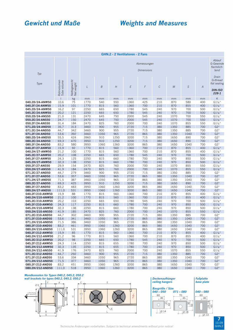
kW kW m² m³/h m m dB(A)/3m mm ∅ mm ∅ mm ∅ mm ∅ W W kW kW040.2D/34-ANW50 15,5 12,0 98,0 9180 13 29 57 16* 28,0 15 15 4800 1800 6,60 1 × B 0,65 1 × E040.2F/34-ANW50 20,0 16,2 147,0 8430 12 28 57 22* 42,0 22 22 8000 2400 10,40 1 × B 0,66 1 × E045.2D/34-ANW50 25,2 19,4 154,0 15330 18 38 60 22* 42,0 22 22 6900 3000 9,90 1 × B 1,49 1 × E045.2E/34-ANW50 29,6 23,8 192,4 14580 17 37 60 28* 54,0 22 22 9200 3000 12,20 1 × B 1,52 1 × E050.2D/34-ANS50 33,5 26,8 201,8 19950 22 43 60 28* 54,0 22 22 9600 3200 12,80 1 × B 1,55 1 × I050.2E/34-ANS50 38,7 31,1 252,3 19410 22 41 60 28* 54,0 22 22 12000 3200 15,20 1 × B 1,58 1 × I050.2F/34-ANS50 43,6 35,3 302,7 18900 21 39 60 28* 64,0 22 22 14400 4800 19,20 2 × B 1,61 1 × I071.2D/34-AND50 57,8 44,4 352,9 35280 37 67 58 28* 64,0 22 22 19000 6300 25,30 2 × C 2,39 3 × G071.2E/34-AND50 66,5 51,6 441,1 33690 37 66 58 28* 64,0 22 22 22800 6300 29,10 3 × C 2,42 3 × G071.2F/34-AND50 74,3 58,4 529,3 32370 36 64 58 35* 76,1 28 28 26600 6300 32,90 3 × C 2,46 3 × G080.2D/34-AND50 90,8 73,6 553,6 53910 45 78 67 2 x 28* 2 x 64 28 28 27000 8700 35,70 3 × C 4,04 3 × G080.2E/34-AND50 102,1 77,2 692,0 51840 44 76 67 35* 76,1 28 28 36000 8700 44,70 4 × C 4,07 3 × G080.2F/34-AND50 113,6 87,1 830,3 50160 43 74 67 42* 76,1 35 35 40500 8700 49,20 4 × C 4,08 3 × G040.2F/37-ANW50 16,6 12,9 86,5 9300 14 29 57 16* 35,0 22 22 8000 2400 10,40 1 × B 0,65 1 × E040.2H/37-ANW50 19,8 15,6 115,3 8790 13 28 57 22* 42,0 22 22 9600 2400 12,00 1 × B 0,65 1 × E045.2E/37-ANW50 24,0 19,0 113,2 15960 18 41 60 22* 42,0 22 22 9200 3000 12,20 1 × B 1,47 1 × E045.2F/37-ANW50 27,6 21,9 135,8 15570 17 40 60 22* 42,0 22 22 11500 4500 16,00 2 × B 1,49 1 × E045.2H/37-ANW50 32,0 24,9 181,1 14520 17 38 60 22* 42,0 22 22 16100 4500 20,60 2 × B 1,52 1 × E050.2F/37-ANS50 35,6 28,0 178,1 20100 23 43 60 28* 54,0 22 22 14400 4800 19,20 2 × B 1,52 1 × I050.2H/37-ANS50 42,3 33,6 237,4 19260 22 41 60 28* 64,0 22 22 21600 4800 26,40 2 × B 1,58 1 × I071.2E/37-AND50 54,5 43,0 259,5 36600 37 68 58 28* 64,0 22 22 22800 6300 29,10 3 × C 2,34 3 × G071.2F/37-AND50 63,1 50,2 311,4 35670 37 67 58 35* 76,1 28 28 26600 6300 32,90 3 × C 2,39 3 × G071.2H/37-AND50 75,0 60,4 415,2 33570 37 64 58 42* 76,1 28 28 34200 6300 40,50 4 × C 2,42 3 × G080.2E/37-AND50 83,8 65,0 407,0 55560 46 79 67 35* 76,1 28 28 36000 8700 44,70 4 × C 3,99 3 × G080.2F/37-AND50 96,6 75,4 488,4 54510 45 78 67 42* 76,1 35 35 40500 8700 49,20 4 × C 4,02 3 × G080.2H/37-AND50 114,7 91,4 651,2 51630 44 76 67 2 x 28* 2 x 64 35 35 54000 8700 62,70 5 × C 4,07 3 × G040.2F/310-ANW50 14,0 11,0 62,3 9630 15 30 57 16* 35,0 22 22 8000 2400 10,40 1 × B 0,62 1 × E040.2H/310-ANW50 17,3 13,7 83,1 9180 14 29 57 22* 42,0 22 22 9600 2400 12,00 1 × B 0,65 1 × E045.2E/310-ANW50 19,6 15,7 81,6 16590 18 42 60 22* 42,0 22 22 9200 3000 12,20 1 × B 1,44 1 × E045.2F/310-ANW50 23,0 18,5 97,9 16200 18 41 60 22* 42,0 22 22 11500 4500 16,00 2 × B 1,47 1 × E045.2H/310-ANW50 27,9 22,0 130,5 15210 17 39 60 22* 42,0 22 22 16100 4500 20,60 2 × B 1,49 1 × E050.2H/310-ANS50 36,2 28,0 171,1 19860 23 44 60 28* 54,0 22 22 21600 4800 26,40 2 × B 1,55 1 × I071.2E/310-AND50 43,6 33,1 187,0 37650 38 69 58 28* 54,0 22 22 22800 6300 29,10 3 × C 2,31 3 × G071.2F/310-AND50 52,6 42,2 224,4 36990 38 68 58 35* 76,1 28 28 26600 6300 32,90 3 × C 2,34 3 × G071.2H/310-AND50 65,0 52,5 299,2 35160 37 66 58 42* 76,1 28 28 34200 6300 40,50 4 × C 2,39 3 × G080.2F/310-AND50 80,6 63,8 352,0 55980 46 80 67 42* 76,1 35 35 40500 8700 49,20 4 × C 3,99 3 × G080.2H/310-AND50 100,2 80,1 469,3 53910 45 78 67 2 x 28* 2 x 64 35 35 54000 8700 62,70 5 × C 4,04 3 × G040.2F/312-ANW50 12,8 10,1 52,9 9900 16 29 57 16* 35,0 22 22 8000 2400 10,40 1 × B 0,62 1 × E040.2H/312-ANW50 16,0 12,8 70,6 9420 15 29 57 22* 42,0 22 22 9600 2400 12,00 1 × B 0,63 1 × E045.2E/312-ANW50 17,7 14,3 69,3 16950 19 42 60 22* 42,0 22 22 9200 3000 12,20 1 × B 1,43 1 × E045.2F/312-ANW50 20,7 16,3 83,1 16650 18 42 60 22* 42,0 22 22 11500 4500 16,00 2 × B 1,44 1 × E045.2H/312-ANW50 26,0 20,6 110,9 15780 18 40 60 22* 42,0 22 22 16100 4500 20,60 2 × B 1,47 1 × E050.2H/312-ANS50 33,4 26,1 145,3 20250 23 45 60 28* 54,0 22 22 21600 4800 26,40 2 × B 1,52 1 × I071.2E/312-AND50 39,6 30,5 158,8 38310 38 70 58 28* 54,0 22 22 22800 6300 29,10 3 × C 2,28 3 × G071.2F/312-AND50 47,7 38,4 190,6 37800 38 69 58 35* 76,1 28 28 26600 6300 32,90 3 × C 2,31 3 × G071.2H/312-AND50 59,1 46,0 254,1 36210 37 67 58 28* 64,0 28 28 34200 6300 40,50 4 × C 2,37 3 × G080.2F/312-AND50 73,1 58,3 298,9 57000 46 80 67 42* 76,1 35 35 40500 8700 49,20 4 × C 3,96 3 × G080.2H/312-AND50 92,2 74,0 398,6 54930 46 78 67 2 x 28* 2 x 64 35 35 54000 8700 62,70 5 × C 3,99 3 × G
* Mehrfacheinspritzung* Multiple injection
810.09GHN.2
Die Wurfweitenangabe stellt die Entfernung vom Gerät dar, bei der isotherm in einem idealen Raum noch eine Luftgeschwindigkeit von 0,5 m/s messbar ist. Die Ein-dringtiefe des Luftstroms in den Kühlraum ist von den örtlichen Gegebenheiten (Raumgeometrie, Einbauten, Luftabkühlung, Platzierung und Bereifung der Geräte, Beladung des Kühlraums) abhängig.
The indicated air throw represents the distance from the unit to a point where an air velocity of 0.5 m/s can still be measured isothermally in an ideal space. The penetration depth of the air flow in the cold room depends on the surrounding conditions (spatial geo-metry, installed equipment, air cooling, positioning of units and frost formation, load in cold room).

Gewicht und Maße Weights and Measures
30
21
40
∅ 14 ∅ 18
60 7035
30
50
3060
18
25 65
∅ 13
Deckenaufhänger Fußplatteceiling hangers base plate
Baugröße / Size040 – 050 071 – 080 040 – 080
E E EC
K
L
H
∅ D
400
100
M
F
Luftrichtung
Air direction
B
S
45°
A
Technische Änderungen vorbehalten. Subject to technical amendments without prior notice!
Wandkonsolen für Typen 040.2, 045.2, 050.2wall brackets for types 040.2, 045.2, 050.2
GHN.2 - 3 Ventilatoren - 3 Fans
Typ
Type
Roh
rvol
umen
Tube
vol
ume
Net
toge
wic
htN
et w
eigh
t
Abmessungen
Dimensions
AblaufG-Gewindefl achdich-
tend
DrainG-thread fl at sealing
DIN-ISO228-1
L B H E F C M S A
l kg mm mm mm mm mm mm mm mm mm K040.2D/34-ANW50 15,2 105 2550 540 550 680 425 260 870 580 400 G1¼“040.2F/34-ANW50 22,9 143 2550 815 560 680 700 260 870 855 400 G1¼“045.2D/34-ANW50 23,4 134 3240 665 650 890 545 290 970 700 500 G1¼“045.2E/34-ANW50 29,3 170 3240 665 650 890 545 290 970 700 500 G1¼“050.2D/34-ANS50 30,5 183 3570 645 750 1000 545 290 1070 700 550 G1¼“050.2E/34-ANS50 37,0 211 3570 645 750 1000 545 290 1070 700 550 G1¼“050.2F/34-ANS50 45,7 245 3570 825 760 1000 700 290 1070 855 550 G1¼“071.2D/34-AND50 52,4 435 4820 900 955 1360 715 380 1350 885 700 G2“071.2E/34-AND50 64,0 481 4820 900 955 1360 715 380 1350 885 700 G2“071.2F/34-AND50 78,5 546 4820 1050 965 1360 865 380 1350 1040 700 G2“080.2D/34-AND50 81,5 592 5550 910 1250 1600 715 380 1650 890 700 G2“080.2E/34-AND50 101,9 670 5550 910 1250 1600 715 380 1650 890 700 G2“080.2F/34-AND50 122,3 819 5550 1060 1260 1600 865 380 1650 1040 700 G2“040.2F/37-ANW50 22,9 128 2550 815 560 680 700 260 870 855 400 G1¼“040.2H/37-ANW50 30,5 140 2550 815 560 680 700 230 870 855 400 G1¼“045.2E/37-ANW50 29,3 150 3240 665 650 890 545 290 970 700 500 G1¼“045.2F/37-ANW50 35,1 173 3240 815 655 890 700 290 970 850 500 G1¼“045.2H/37-ANW50 46,8 193 3240 815 655 890 700 290 970 850 500 G1¼“050.2F/37-ANS50 45,7 200 3570 825 760 1000 700 290 1070 855 550 G1¼“050.2H/37-ANS50 58,7 243 3570 825 760 1000 700 290 1070 855 550 G1¼“071.2E/37-AND50 64,0 386 4820 900 955 1360 715 380 1350 885 700 G2“071.2F/37-AND50 78,5 495 4820 1050 965 1360 865 380 1350 1040 700 G2“071.2H/37-AND50 104,7 539 4820 1050 965 1360 865 380 1350 1040 700 G2“080.2E/37-AND50 101,9 592 5550 910 1250 1600 715 380 1650 890 700 G2“080.2F/37-AND50 122,3 675 5550 1060 1260 1600 865 380 1650 1040 700 G2“080.2H/37-AND50 163,1 751 5550 1060 1260 1600 865 380 1650 1040 700 G2“040.2F/310-ANW50 22,9 121 2550 815 560 680 700 260 870 855 400 G1¼“040.2H/310-ANW50 30,5 141 2550 815 560 680 700 230 870 855 400 G1¼“045.2E/310-ANW50 29,3 142 3240 665 650 890 545 290 970 700 500 G1¼“045.2F/310-ANW50 35,1 162 3240 815 660 890 700 290 970 850 500 G1¼“045.2H/310-ANW50 46,8 192 3240 815 660 890 700 290 970 850 500 G1¼“050.2H/310-ANS50 60,9 252 3570 825 760 1000 700 290 1070 855 550 G1¼“071.2E/310-AND50 65,4 418 4820 900 955 1360 715 380 1350 885 700 G2“071.2F/310-AND50 78,5 470 4820 1050 965 1360 865 380 1350 1040 700 G2“071.2H/310-AND50 104,7 540 4820 1050 965 1360 865 380 1350 1040 700 G2“080.2F/310-AND50 122,3 642 5550 1060 1260 1600 865 380 1650 1040 700 G2“080.2H/310-AND50 163,1 751 5550 1060 1260 1600 865 380 1650 1040 700 G2“040.2F/312-ANW50 22,9 117 2550 815 560 680 700 260 870 855 400 G1¼“040.2H/312-ANW50 30,5 135 2550 815 560 680 700 230 870 855 400 G1¼“045.2E/312-ANW50 29,3 135 3240 665 650 890 545 290 970 700 500 G1¼“045.2F/312-ANW50 35,1 158 3240 815 660 890 700 290 970 850 500 G1¼“045.2H/312-ANW50 46,8 187 3240 815 660 890 700 290 970 850 500 G1¼“050.2H/312-ANS50 60,9 230 3570 825 760 1000 700 290 1070 855 550 G1¼“071.2E/312-AND50 65,4 403 4820 900 955 1360 715 380 1350 885 700 G2“071.2F/312-AND50 78,5 460 4820 1050 965 1360 865 380 1350 1040 700 G2“071.2H/312-AND50 104,7 525 4820 1050 965 1360 865 380 1350 1040 700 G2“080.2F/312-AND50 122,3 627 5550 1060 1260 1600 865 380 1650 1040 700 G2“080.2H/312-AND50 163,1 731 5550 1060 1260 1600 865 380 1650 1040 700 G2“
910.09GHN.2

Leistungstabellen 50 Hz Capacity tables 50 Hz
Technische Änderungen vorbehalten. Subject to technical amendments without prior notice!
GHN.2 - 4 Ventilatoren - 4 Fans
Typ
Type
NennleistungNominalcapacityR404A
Wur
fwei
te o
hne
Stre
amer
Air
thro
w w
ithou
t St
ream
er
Wur
fwei
te m
it St
ream
erA
ir th
row
with
Str
eam
er
Scha
lldru
ckSo
und
pres
sure
AnschlüsseConnections
El. AbtauheizungEl. defrost
400 V
Ans
chlu
sskl
emm
en o
ptio
nale
Ve
ntila
torv
erka
belu
ngco
nnec
tion
term
inal
s op
tiona
l fa
n w
iring
Fläc
heSu
rfac
e
Luftvo
lum
enst
rom
Air
volu
me fl o
wKältemittelRefrigerant
Hei
ßgas
Blo
ck e
inH
ot g
as c
oil i
nlet
Hei
ßgas
Wan
ne e
in/a
usH
ot g
as tr
ay in
let/
outle
t
aufg
enom
men
eel
ektr
isch
e Le
istu
ngpo
wer
con
sum
ptio
n
Blo
ckC
oil
Trop
fwan
neD
rip t
ray
Ges
amt
Tota
l
Ans
chlu
sssc
hem
aC
onne
ctio
n di
agra
m
SC2 SC3
EinInlet
AusOutlet
DT1
= 8
Kt o
= –
8 °
C
DT1
= 7
Kt o
= –
25 °
C
Pel total
kW kW m² m³/h m m dB(A)/3m mm ∅ mm ∅ mm ∅ mm ∅ W W kW kW040.2D/44-ANW50 21,1 17,0 130,7 12240 14 31 58 22* 42,0 15 15 6900 2200 9,10 1 × B 0,86 1 × E040.2F/44-ANW50 26,4 20,9 196,1 11240 13 30 58 22* 42,0 22 22 11500 3000 14,50 1 × B 0,88 1 × E045.2D/44-ANW50 34,0 26,6 205,3 20440 19 40 61 22* 42,0 22 22 9300 3600 12,90 1 × B 1,98 1 × E045.2E/44-ANW50 39,3 31,1 256,6 19440 18 39 61 28* 54,0 22 22 12400 3600 16,00 2 × B 2,02 1 × E050.2D/44-ANS50 44,0 33,7 269,1 26600 23 45 61 28* 54,0 22 22 14000 3600 17,60 2 × B 2,06 1 × I050.2E/44-ANS50 50,8 39,5 336,4 25880 23 43 61 28* 54,0 22 22 17500 3600 21,10 2 × B 2,10 1 × I050.2F/44-ANS50 57,5 45,2 403,6 25200 22 41 61 28* 64,0 28 28 21000 5400 26,40 3 × B 2,14 1 × I040.2F/47-ANW50 22,6 18,0 115,3 12400 15 31 58 22* 42,0 22 22 11500 3000 14,50 1 × B 0,86 1 × E040.2H/47-ANW50 26,3 20,5 153,8 11720 14 30 58 22* 42,0 22 22 13800 3000 16,80 2 × B 0,87 1 × E045.2E/47-ANW50 32,1 25,7 150,9 21280 19 43 61 28* 54,0 22 22 12400 3600 16,00 2 × B 1,96 1 × E045.2F/47-ANW50 36,9 29,7 181,1 20760 18 42 61 28* 64,0 22 22 15500 5400 20,90 2 × B 1,98 1 × E045.2H/47-ANW50 43,5 35,3 241,5 19360 18 40 61 28* 64,0 22 22 21700 5400 27,10 3 × B 2,02 1 × E050.2F/47-ANS50 47,8 38,1 237,4 26800 24 45 61 28* 64,0 28 28 21000 5400 26,40 3 × B 2,02 1 × I050.2H/47-ANS50 57,4 46,2 316,6 25680 23 43 61 35* 76,1 28 28 31500 5400 36,90 4 × B 2,10 1 × I040.2F/410-ANW50 18,8 15,1 83,1 12840 16 32 58 22* 42,0 22 22 11500 3000 14,50 1 × B 0,83 1 × E040.2H/410-ANW50 23,0 18,1 110,8 12240 15 31 58 22* 42,0 22 22 13800 3000 16,80 2 × B 0,86 1 × E045.2E/410-ANW50 25,9 20,1 108,8 22120 19 44 61 22* 42,0 22 22 12400 3600 16,00 2 × B 1,92 1 × E045.2F/410-ANW50 30,3 23,6 130,5 21600 19 43 61 22* 42,0 22 22 15500 5400 20,90 2 × B 1,96 1 × E045.2H/410-ANW50 37,3 29,4 174,0 20280 18 41 61 28* 54,0 22 22 21700 5400 27,10 3 × B 1,98 1 × E050.2H/410-ANS50 49,2 39,8 228,1 26480 24 46 61 35* 76,1 28 28 31500 5400 36,90 4 × B 2,06 1 × I040.2F/412-ANW50 17,1 13,8 70,6 13200 17 31 58 22* 42,0 22 22 11500 3000 14,50 1 × B 0,82 1 × E040.2H/412-ANW50 21,3 16,9 94,1 12560 16 31 58 22* 42,0 22 22 13800 3000 16,80 2 × B 0,84 1 × E045.2E/412-ANW50 23,5 18,4 92,4 22600 20 44 61 22* 42,0 22 22 12400 3600 16,00 2 × B 1,90 1 × E045.2F/412-ANW50 27,7 21,8 110,9 22200 19 44 61 22* 42,0 22 22 15500 5400 20,90 2 × B 1,92 1 × E045.2H/412-ANW50 34,7 27,5 147,8 21040 19 42 61 28* 54,0 22 22 21700 5400 27,10 3 × B 1,96 1 × E050.2H/412-ANS50 45,2 36,7 193,8 27000 24 47 61 35* 76,1 28 28 31500 5400 36,90 4 × B 2,02 1 × I
* Mehrfacheinspritzung* Multiple injection
1010.09GHN.2
Die Wurfweitenangabe stellt die Entfernung vom Gerät dar, bei der isotherm in einem idealen Raum noch eine Luftgeschwindigkeit von 0,5 m/s messbar ist. Die Ein-dringtiefe des Luftstroms in den Kühlraum ist von den örtlichen Gegebenheiten (Raumgeometrie, Einbauten, Luftabkühlung, Platzierung und Bereifung der Geräte, Beladung des Kühlraums) abhängig.
The indicated air throw represents the distance from the unit to a point where an air velocity of 0.5 m/s can still be measured isothermally in an ideal space. The penetration depth of the air flow in the cold room depends on the surrounding conditions (spatial geo-metry, installed equipment, air cooling, positioning of units and frost formation, load in cold room).
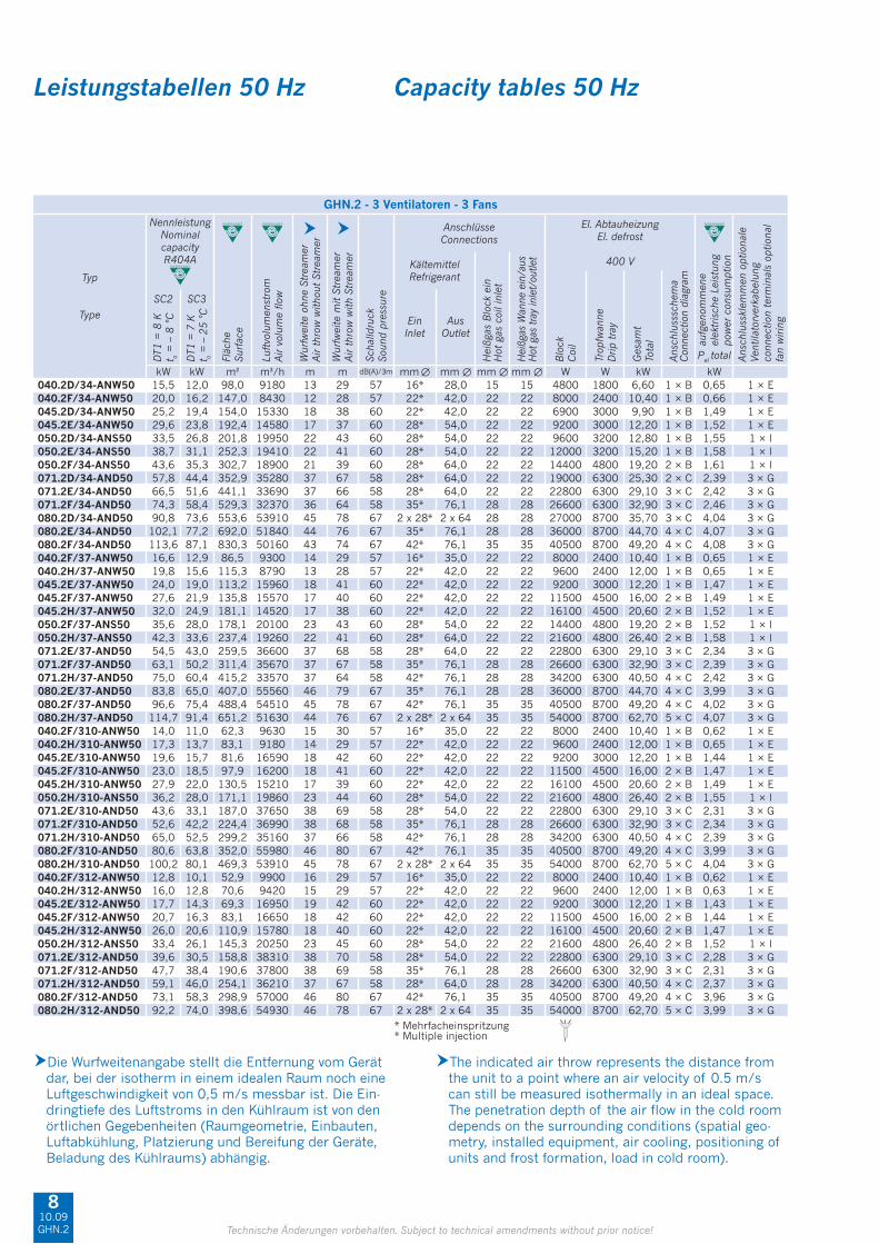
Gewicht und Maße Weights and Measures
30
21
40
∅ 14 ∅ 18
60 7035
30
50
3060
18
25 65
∅ 13
Deckenaufhänger Fußplatteceiling hangers base plate
Baugröße / Size040 – 050 071 – 080 040 – 080
E E EEC
K
L
H
∅ D
400
100
M
F
Luftrichtung
Air direction
B
S
45°
A
Technische Änderungen vorbehalten. Subject to technical amendments without prior notice!
Wandkonsolen für Typen 040.2, 045.2, 050.2wall brackets for types 040.2, 045.2, 050.2
GHN.2 - 4 Ventilatoren - 4 Fans
Typ
Type
Roh
rvol
umen
Tube
vol
ume
Net
toge
wic
htN
et w
eigh
t
Abmessungen
Dimensions
AblaufG-Gewindefl achdich-
tend
DrainG-thread fl at sealing
DIN-ISO228-1
L B H E F C M S A
l kg mm mm mm mm mm mm mm mm mm K040.2D/44-ANW50 19,9 144 3230 540 550 680 425 260 870 580 400 G1¼“040.2F/44-ANW50 29,8 189 3230 815 560 680 700 260 870 855 400 G1¼“045.2D/44-ANW50 30,7 184 4130 665 650 890 545 290 970 700 500 G1¼“045.2E/44-ANW50 38,3 231 4130 665 650 890 545 290 970 700 500 G1¼“050.2D/44-ANS50 40,0 251 4570 645 750 1000 545 290 1070 700 550 G1¼“050.2E/44-ANS50 48,5 288 4570 645 750 1000 545 290 1070 700 550 G1¼“050.2F/44-ANS50 59,9 346 4570 825 760 1000 700 290 1070 855 550 G1¼“040.2F/47-ANW50 29,8 170 3230 815 560 680 700 260 870 855 400 G1¼“040.2H/47-ANW50 39,7 186 3230 815 560 680 700 230 870 855 400 G1¼“045.2E/47-ANW50 38,3 206 4130 665 650 890 545 290 970 700 500 G1¼“045.2F/47-ANW50 46,0 241 4130 815 660 890 700 290 970 850 500 G1¼“045.2H/47-ANW50 61,3 267 4130 815 660 890 700 290 970 850 500 G1¼“050.2F/47-ANS50 59,9 289 4570 825 760 1000 700 290 1070 855 550 G1¼“050.2H/47-ANS50 79,9 344 4570 825 760 1000 700 290 1070 855 550 G1¼“040.2F/410-ANW50 29,8 162 3230 815 560 680 700 260 870 855 400 G1¼“040.2H/410-ANW50 39,7 187 3230 815 560 680 700 230 870 855 400 G1¼“045.2E/410-ANW50 38,3 194 4130 665 650 890 545 290 970 700 500 G1¼“045.2F/410-ANW50 46,0 201 4130 815 660 890 700 290 970 850 500 G1¼“045.2H/410-ANW50 61,3 263 4130 815 660 890 700 290 970 850 500 G1¼“050.2H/410-ANS50 79,9 346 4570 825 760 1000 700 290 1070 855 550 G1¼“040.2F/412-ANW50 29,8 156 3230 815 560 680 700 260 870 855 400 G1¼“040.2H/412-ANW50 39,7 178 3230 815 560 680 700 230 870 855 400 G1¼“045.2E/412-ANW50 38,3 186 4130 665 650 890 545 290 970 700 500 G1¼“045.2F/412-ANW50 46,0 217 4130 815 660 890 700 290 970 850 500 G1¼“045.2H/412-ANW50 61,3 256 4130 815 660 890 700 290 970 850 500 G1¼“050.2H/412-ANS50 79,9 329 4570 825 760 1000 700 290 1070 855 550 G1¼“
1110.09GHN.2
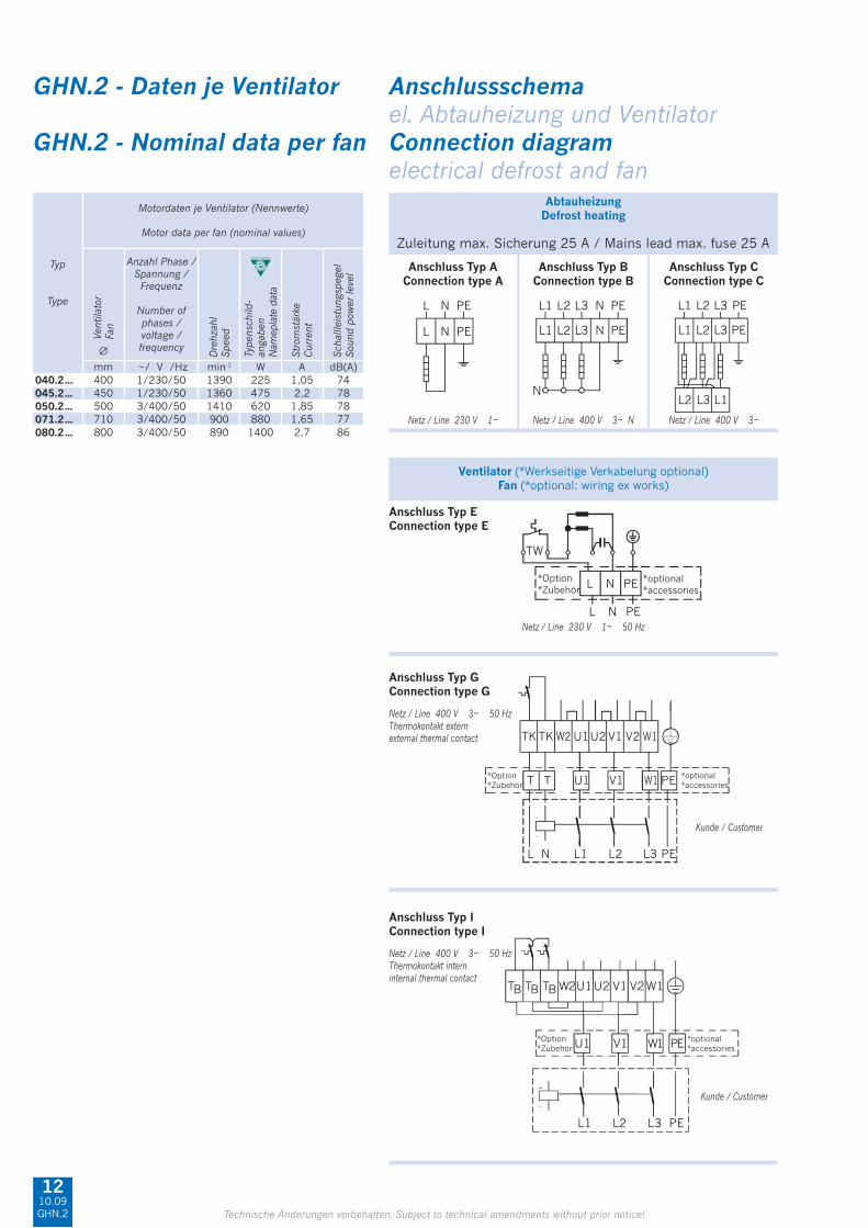
GHN.2 - Daten je Ventilator Anschlussschema el. Abtauheizung und VentilatorGHN.2 - Nominal data per fan Connection diagram electrical defrost and fan
Anschluss Typ AConnection type A
AbtauheizungDefrost heating
Zuleitung max. Sicherung 25 A / Mains lead max. fuse 25 A
Netz / Line 230 V 1~
Anschluss Typ BConnection type B
Anschluss Typ CConnection type C
Netz / Line 400 V 3~ N Netz / Line 400 V 3~
Ventilator (*Werkseitige Verkabelung optional)Fan (*optional: wiring ex works)
Anschluss Typ EConnection type E
Anschluss Typ GConnection type G
Netz / Line 230 V 1~ 50 Hz
Netz / Line 400 V 3~ 50 Hz Thermokontakt externexternal thermal contact
Kunde / Customer
Technische Änderungen vorbehalten. Subject to technical amendments without prior notice!
Anschluss Typ IConnection type I
Netz / Line 400 V 3~ 50 Hz Thermokontakt interninternal thermal contact
Kunde / Customer
Typ
Type
Motordaten je Ventilator (Nennwerte)
Motor data per fan (nominal values)
Vent
ilato
rFa
n
Anzahl Phase /Spannung /Frequenz
Number of phases / voltage / frequency
Dre
hzah
lSp
eed
Stro
mst
ärke
Cur
rent
Scha
lllei
stun
gspe
gel
Soun
d po
wer
leve
l
Type
nsch
ild-
anga
ben
Nam
epla
te d
ata
∅
mm ~/ V /Hz min-1 W A dB(A)040.2… 400 1/230/50 1390 225 1,05 74045.2… 450 1/230/50 1360 475 2,2 78050.2… 500 3/400/50 1410 620 1,85 78071.2… 710 3/400/50 900 880 1,65 77080.2… 800 3/400/50 890 1400 2,7 86
1210.09GHN.2

KältemittelRefrigerant
LuftfeuchteAir humidity
Epoxidharzbeschichtete LamellenEpoxy resin coated fi ns
Güntner Product Calculator Güntner Product Calculatordie bessere Wahl the perfect choice
Für eine genaue thermodynamische Auslegung mit anderen Betriebs-bedingungen (auch für andere Kältemittel, Luftfeuchte und Epoxidharz-beschichtete Lamellen) empfehlen wir die Verwendung des Güntner Product Calculator.
We recommend using theGüntner Product Calculatorfor an exact thermo dynamic de-sign in different conditions (also for other refrigerants, air humidity and epoxy resin coated fi ns).
Korrekturfaktoren Correction factorsnach Eurovent acc. to Eurovent
Korrekturfaktoren (fR)für andere Kältemittelnach Eurovent
Correction factors (fR)for other refrigerants acc. to Eurovent
Korrekturfaktoren (fM)für andere Lamellenmaterialien nach Eurovent
Correction factors (fM)for other fi n materials acc. to Eurovent
effektive Kälteleistung Q.
lo = nominale Kälteleistung Q
.o × Korrekturfaktor fR
actual refrigerating capacity Q.
lo = nominal refrigerating capacity Q
.o × correction factor fR
SC2 = Standard condition DT1 = 8 K, t0 = –8 °C SC3 = Standard condition DT1 = 7 K, t0 = –25 °C
effektive Kälteleistung Q.
lo = nominale Kälteleistung Q
.o × Korrekturfaktor fM
actual refrigerating capacity Q.
lo = nominal refrigerating capacity Q
.o × correction factor fM
fR
Kältemittel / Refrigerant SC 2 SC 3
R507 0.97 0.97
R134a 0.91 0.85
R22 0.95 0.95
fM
Lamellenmaterial / Fin material Faktor / Factor
Aluminium / aluminium 1
Aluminium beschichtet / coated aluminium 0.97
1310.09GHN.2

Ausführung GHN.2 Construction GHN.2
Lamellen aus Aluminium,Rohrteilung 50 × 50 mm fluchtend,innenberippte Spezialkupferrohre ∅ 15 mm.Lamellenteilung 4, 7, 10 und 12 mmDie kältemittelführenden Kernrohre sind durch die bewährte Güntner Tragrohrkonstruktion entlastet. Dadurch ergibt sich eine erhöhte Sicherheit gegen Undichtigkeit.
Baugröße 040 – 050: AlMg3, Pulver-beschichtet RAL 9003 (Signalweiß), Baugröße 071 – 080: Stahl verzinkt,Pulverbeschichtet RAL 9003 (Signal-weiß), durch aufklappbare Seitenverkleidung einfacher Zugang zu den Anschlüssen.
AlMg3, Pulverbeschichtet RAL 9003 (Signalweiß)Zur leichteren Reinigung ist die Tropfwanne abklapp- bzw. abnehmbar.Einwandfreier Tauwasserablauf durch optimal gestalteten Ablauf.Ablaufstutzen unter 45° montiert, mit G-Gewinde flachdichtend nach DIN-ISO 228-1.
Geräuscharme Axialventilatoren mit wartungsfreien Motoren mit Schutz-art IP 54, ISO F und DIN VDE 0530,Wuchtgüte Q 6,3 n. VDI 2060,Schutzgitter gemäß EN 294Drehstrom 400 V 3~ 50 Hz bzw.Wechselstrom 230 V 1~ 50 Hz,zulässige Lufttemperatur (Einsatz-bereich) –30 °C bis +45 °C.Wir behalten uns vor, verschiedene Ventilatorfabrikate einzusetzen. Je nach Ventilatorfabrikat können die Motordaten geringfügig abweichen. Die entsprechenden elektrischen Daten müssen dem Typenschild entnommen werden, elektrische Leistungsangaben gemäß EN 328.Die Stromaufnahme erhöht sich mit tiefer Umgebungstemperatur und höheren Gegendrücken. Der Motorschutz muss über die ein-gebauten Thermo kontakte (Öffner) erfolgen.
KühlerblockCooler coil
GehäuseCasing
TropfwanneDrip tray
VentilatorenFans
Fins made of aluminium,tube pattern aligned 50 × 50 mm,special copper tubes, internally grooved ∅ 15 mm.Fin spacing 4, 7, 10 and 12 mmThe fluid-carrying core tubes are stressed less due to Güntner’s proven floating coil design. This results in increased safety against leakage.
Sizes 040 – 050: AlMg3, powder-coated, RAL 9003 (signal white), Sizes 071 – 080: galvanised steel, powder-coated RAL 9003 (signal white), connections are easily accessible due to hinged side covering.
AlMg3, powder-coated, RAL 9003 (signal white)For easy cleaning the drip tray can be folded down or removed.Perfect condensation water drain due to optimal drain design. Drain nozzle mounted at an angle below 45°, with G-thread flat sealing acc. to DIN-ISO 228-1.
Low-noise axial fans, with maintenance-free motors in protection class IP 54, ISO F and DIN VDE 0530, balance quality Q 6.3 acc. to VDI 2060, protection guard acc. to EN 294 three-phase current 400 V 3~ 50 Hz or alternating current 230 V 1~ 50 Hz, admissible air temperature (operating range) –30 °C to +45 °C.We reserve the right to use fans of different manufacturers.Depending on the fan type, the motor data may slightly vary. For the corresponding electrical data, please refer to the nameplate, electrial capacity specifications acc. to EN 328.At low ambient tempe ratures and different air resistance the power consumption will increase. The built-in thermal contacts (thermistors) must be used as motor protection.
1410.09GHN.2
Bei werkseitiger Verkabelung der Ventilatoren auf Klemmkasten oder Reparaturschalter der Baugrößen 040 – 050 sind die Thermokontakte bereits intern verschaltet (s. Anschlussschema).
Nach Standardverfahren zur Berech-nung des Schalldruckpegels gemäß EN 13487; Anhang C (normativ).Da Kühlräume nur ein sehr geringes Absorptionsverhalten aufweisen, empfehlen wir, mit einer nur geringen Abnahme des Schalldruckpegels in größeren Entfernungen zu rechnen.
gegen Mehrpreis wahlweise:• Elektrisch, nach VDE Bestimmungen,
Abtauleistung reduzierbar durch einfaches Umklemmen,Typenbezeichnung: GHN..../..-E
• Heißgas unverrohrt,Typenbezeichnung: GHN..../..-H
• Heißgas verrohrt, inkl. Rückschlag-ventil.
Die Leistungsangaben gelten für R404A.Die Kühlerleistungen beziehen sich dabei auf eine Lufteintrittstemperatur differenz, die sich aus der Differenz zwischen Lufteintrittstemperatur am Kühler tL1 und Verdampfungstemperatur to, DT1 = tL1 – to ergibt. Diese Bedingungen sind mit DT1 ge kenn zeichnet und entsprechen den Vor gaben der EN 328 und der Eurovent Organisation. Die zertifi-zierten Leistungs angaben sind im Katalog durch das Eurovent Symbol
gekennzeichnet.
Mit unserer Auslegungssoftware Güntner Product Calculator erhalten Sie eine genaue thermo dynamische Auslegung der gewünschten Geräte-variante mit anderen Betriebs-parametern (auch für andere Kälte-mittel, Luftfeuchte und Epoxidharz- beschichtete Lamellen).
SchallangabenSound specifi cations
AbtauungDefrosting
LeistungsangabenCapacity
Ausführung GHN Construction GHN
If the fans for the sizes 040-050 are pre-wired at factory to the terminal box or the isolator switch, the thermal contacts are already internally wired (see connection diagram).
In compliance with the standard procedure for calculation of sound pressure level acc. to EN 13487; annex C (normative).As cooling rooms only have a very low absorbing capacity, we recommend to count with only a slight reduction in the sound pressure level for greater distances.
available on request at additional charge:• Electrical acc. to VDE regulations,
may be reduced through simple reconnection
Type designation: GHN..../..-E• Hot gas, without tubing
Type designation: GHN..../..-H• Hot gas, with tubing, incl. non-
return valve
The capacity specifications are valid for R404A. The refrigerating capacities refer to an air inlet temperature difference which results from the difference between cooler air inlet tem perature tL1 and evaporating tem pe rature to, DT1 = tL1 – to.These conditions are marked with DT1 and comply with the guidelines of EN 328 and Eurovent Organisation. In the catalogue the certified capac-ity data specifications are marked with the Eurovent symbol .
We recommend using our software package Güntner Product Calculator for an exact thermodynamic design in different operating conditions (also for other refrigerants, air humidity values and epoxy resin coated fins).
1510.09GHN.2

KAT
110/2
009-1
0
Güntner AG & Co. KGHans-Güntner-Straße 2 – 682256 FÜRSTENFELDBRUCKGERMANY
Telefon +49 8141 242-0Telefax +49 8141 242-155E-Mail [email protected] www.guentner.de
Technische Änderungen vorbehalten.Vorangegangene Prospekte verlieren ihre Gültigkeit.Beachten Sie bitte unsere AGB, eine Kopie erhalten Sie auf Anfrage.Subject to technical amendments without prior notice!Supersedes previously published data.Apply our general terms and conditions of sale, a copy of which is available on request.
Ausführung GHN Construction GHN
Die Geräte werden in Einbaulage verpackt mit montierter Wanne geliefert.
Beim Einsatz der Kühler im Tief-temperaturbereich empfehlen wir elektrische Ringheizung für die Ventilatoren. Bei Betrieb der Ge räte unter to = –40 °C wegen der speziellen Materialanfor de rung und -auswahl bitte Rücksprache mit dem Vertrieb halten. Alle elektrischen Teile sind entsprechend den EN-Normen ausgeführt. Andere Rohrwanddicken und La-mellenteilungen sind auf Anfrage lieferbar.
(gegen Mehrpreis lieferbar)• Elektrische Abtauung für Block
und Wanne• Elektrische Ventilator-Ringheizung• Aufstellfüße• Wandkonsolen
(Typen 040.2, 045.2, 050.2)• Güntner Streamer• Anschluss für Luftverteilschlauch• Abtauklappe• Reparaturschalter für Ventilatoren• Verkabelung der Ventilatoren auf
gemeinsamen Klemmkasten
Zubehörteile verändern die Funktion des Gerätes.
• Expansionsventil werkseitig eingebaut
• Heißgas Block- und Wannen-heizung
• Rückschlagventil verrohrt• Isolierte Wanne• Verstärkte Ventilatoren• Gehäuse in Edelstahl• Epoxidharz-beschichtete Aluminium
Lamellen• Schwenkbare Ventilatoreinheit• Edelstahlrohre• Wasserabtauung
VerpackungPackaging
AnmerkungNotes
ZubehörAccessories
Optionen und VariantenOptions and variants
The units are delivered packaged in installation position with mounted drip tray.
In case of use of the coolers for low temperatures, we recommend an electrical ring heater for the fans. For unit operation below to = –40 °C please consult our sales department because of the special material requirement and selection.All electrical parts are in compliance with the EN-standards. Other tube wall thicknesses and fin spacings on request.
(available at additional charge)• Electric defrost in coil and
drip tray• Electrical fan ring heaters• Feet for floor mounting• Wall brackets (Types 040.2, 045.2, 050.2)• Güntner Streamer• Connection for air distribution sock• Defrost flap• Repair switch for fans• Wiring of fans on conjoint terminal
box
Accessories change the function ofthe unit.
• Expansion valve installed ex works• Hot gas defrost in coil and tray• Check valve, tubed• Insulated drip tray• Reinforced fans• Casing made of stainless steel• Epoxy resin coated aluminium fins• Swiveling fans• Tubes made of stainless steel• Water spray defrost
1610.09GHN.2