
Wartsila SP a Id Energopac
4
30 indetail [ MARINE / IN DETAIL ] [ M A R I N E / I N D E T A I L ] More ef fi cient propulsion solutions with Wärtsilä’s Energopac AUTHORS: Maarten Nijland, Project Engineer, Propulsion Systems, Wärtsilä Ship Power in the Netherlands a n d Teus van Beek, Director of R&D, Energy Efficiency, Wärtsilä Ship Power in the Netherlands The price of fuel is dominating the operational costs of coastal and seagoing vessels . Wärtsilä is striving to improve the fuel efficiency of propul- sion systems, and thereby reduce these costs. Reduc ing fuel consumption goes hand in hand with reducing emissions . During recent years, the environmental impact of marine transportation has become a major field of focus throughout the entire maritime industry . Nevertheless, for many ship operators commercial considerations take a higher priority than the environment. While these two interests may appear to be incompatible, the fact is that by improving energy efficiency, both fuel consumption and emissions of carbon-, nitrogen- and sulphur-oxides, as well as solid particle s, can b e red uced. In June 2008 the price of heavy fuel oil in Rotterdam was around USD 550 per ton (see Figure 1), and USD 1100 for marine diesel oil. Driven by these high fuel prices, operators are willing to invest more and more in new technology, which w ill hel p them to inc rease energ y efficiency throughout their fleets. Improving energy efficiency affects both fuel consumption and emissions, meaning that both commercial and environmental interests will benefit. Wärtsil ä contri butes to its c ustomers ’ businesses by continuously looking for measures that improve energy efficiency onboard their ships. This article will mainly concentrate on the new Energopac, an integrated propulsion and manoeuvring solution, fully optimized to save fuel costs. Energopac will be officially introduced to the market at the SMM 2008 trade fair in Hamburg, 23–26 September. Energopac The key objective is to reduce the vessel’s fuel consumption by integrating both propeller and rudder design. Each Energopac will be designed to meet the specific vessel’s requirements; this allows for Energopac to be optimized for maximum possible fuel savings. This is done without compromising on either manoeuvrability or comfort levels. Figure 2 shows a schematic view of the concept, which consists of a rudder bulb behind the propeller hub, mounted on a sophisticated spade rudder, with a fairing hubcap to guide the propeller slipstream around the rudder bulb. The propeller blade design is also adapted to this configuration. This means we make the best use of the propeller-rudder interaction by minimizing losses and maximizing gains in the design procedure. Energopac is a joint development of two pioneering companies in the field of energy efficient ship propulsion and manoeuvring: Wärtsilä and Becker Marine Systems. Each of these companies has built a notable track record in this field with cu stomer s all over th e world . The basis of Wärtsilä’s efficient rudder technology dates back to the 1990s. Althou gh this techn ology w as pate nted at that time, the patent still remains pending today . Well over 30 vessels have been equipped with the concept since then, and all have achieved successful energy savings. The Energopac lay-out is somewhat different from earlier fuel-saving rudders from Wärtsilä. In the new design, the bulb is fixed to the rudder blade and will turn, together with the rudder, for a non zero steering angle. This separation of physical components allows for easier installation at the shipyard. Additionally, maintenance and repair works on the propeller and rudder can be carried out more easily. The patented KSR rudder support results in very slim rudder blade designs. This is very favourable in terms of rudder drag. Additionally, the leading edge of the rudder will be twisted and aligned with the incoming Fig. 1 – History graph showing marine fuel prices in Rotterdam, the Netherlands. F u e l p r i c e [ U S $ p e r t o n ] 01.01.03 1200 1000 800 600 400 200 0 01.01.04 01.01.05 01 .01.06 01.01.07 01.01.08 Source: Bunkerworld HFO LSHFO MDO MGO
Transcript of Wartsila SP a Id Energopac

7/29/2019 Wartsila SP a Id Energopac
http://slidepdf.com/reader/full/wartsila-sp-a-id-energopac 1/4
30 indetail
[ MARINE / IN DETAIL ]
[ M A R I N E / I N
D E T A
I L ]
More efficient propulsion solutionswith Wärtsilä’s Energopac
A UT H O RS : M a a r t e n N i j l a n d , P r o j e c t E n g i n e e r , P r o p u l si o n S y s t e m s , W ä r t s i l ä S h i p P o w er i n t h e N e t h e r l a n d s
a n d Teus van Beek , D i r e c t o r o f R & D , E n e r g y E f f i c i e n c y , W ä r t s i l ä S h i p P o w e r i n t h e N e t h e r l a n d s
The price of fuel is dominatingthe operational costs of coastal and
seagoing vessels. Wärtsilä is striving toimprove the fuel efficiency of propul-sion systems, and thereby reduce thesecosts. Reducing fuel consumption goeshand in hand with reducing emissions.
During recent years, the environmentalimpact of marine transportation hasbecome a major field of focus throughoutthe entire maritime industry. Nevertheless,for many ship operators commercialconsiderations take a higher priority thanthe environment. While these two interestsmay appear to be incompatible, the fact
is that by improving energy efficiency,both fuel consumption and emissions of carbon-, nitrogen- and sulphur-oxides, as well as solid particles, can be reduced.
In June 2008 the price of heavy fuel oilin Rotterdam was around USD 550 per ton(see Figure 1), and USD 1100 for marinediesel oil. Driven by these high fuel
prices, operators are willing to investmore and more in new technology,
which will help them to increase energy efficiency throughout their fleets.Improving energy efficiency affectsboth fuel consumption and emissions,meaning that both commercial andenvironmental interests will benefit.
Wärtsilä contributes to its customers’businesses by continuously looking formeasures that improve energy efficiency onboard their ships. This article willmainly concentrate on the new Energopac,an integrated propulsion and manoeuvring solution, fully optimized to save fuel costs.Energopac will be officially introduced
to the market at the SMM 2008 tradefair in Hamburg, 23–26 September.
EnergopacThe key objective is to reduce thevessel’s fuel consumption by integrating both propeller and rudder design. EachEnergopac will be designed to meet
the specific vessel’s requirements; thisallows for Energopac to be optimized for
maximum possible fuel savings. This isdone without compromising on eithermanoeuvrability or comfort levels.
Figure 2 shows a schematic view of the concept, which consists of a rudderbulb behind the propeller hub, mountedon a sophisticated spade rudder, witha fairing hubcap to guide the propellerslipstream around the rudder bulb. Thepropeller blade design is also adaptedto this configuration. This means wemake the best use of the propeller-rudderinteraction by minimizing losses andmaximizing gains in the design procedure.
Energopac is a joint development of two pioneering companies in the fieldof energy efficient ship propulsion andmanoeuvring: Wärtsilä and Becker MarineSystems. Each of these companies hasbuilt a notable track record in this field with customers all over the world.
The basis of Wärtsilä’s efficient ruddertechnology dates back to the 1990s. Although this technology was patented atthat time, the patent still remains pending today. Well over 30 vessels have beenequipped with the concept since then, andall have achieved successful energy savings.
The Energopac lay-out is somewhatdifferent from earlier fuel-saving ruddersfrom Wärtsilä. In the new design, thebulb is fixed to the rudder blade and willturn, together with the rudder, for a nonzero steering angle. This separation of physical components allows for easierinstallation at the shipyard. Additionally,maintenance and repair works on thepropeller and rudder can be carried outmore easily. The patented KSR ruddersupport results in very slim rudderblade designs. This is very favourablein terms of rudder drag. Additionally,the leading edge of the rudder will betwisted and aligned with the incoming Fig. 1 – History graph showing marine fuel prices in Rotterdam, the Netherlands.
F u e l p r i c e [ U S $ p e r t o n ]
01.01.03
1200
1000
800
600
400
200
0
01.01.04 01.01.05 01 .01.06 01.01.07 01.01.08
Source: Bunkerworld
HFO
LSHFO
MDO
MGO

7/29/2019 Wartsila SP a Id Energopac
http://slidepdf.com/reader/full/wartsila-sp-a-id-energopac 2/4
WÄRTSILÄ TECHNICAL JOURNAL 02.2008
31indetail
flow from behind the propeller. This willnot only reduce the rudder drag, but it will, to a very high degree, also reducecavitation erosion on the rudder blade.The flap system allows for the rudderblade area to be reduced significantly.Furthermore, the vessel can maintain itscourse in transit with relatively minorsteering angles, again reducing the rudder
drag. The fairing cap and rudder bulbare designed to reduce separation lossesbehind the propeller hub. Another effectof the bulb is that it will lower propellerinduced pressure pulses. Subsequently,the propeller design is matched to this,resulting in maximized propeller efficiency.
Research reveals the working principlesSeveral model tests were carried out toascertain the effects of Energopac onpropulsion performance and steering capabilities. The results were comparedand verified with in-house CFD
(computational fluid dynamics)calculations. This was done for both singlescrew and twin screw applications, of which the latter is shown in Figure 3.
The results of these tests show a significant reduction in required power. When Energopac is compared with othersophisticated rudder designs, the decrease
Fig. 3 – Combined model tests and CFD calculations (left and right respectively) have been performed for a series
of six RoPax vessels on order
Fig. 2 – Example arrangement of
a typical Energopac solution,showing the main components.
in power – and thus in fuel consumption– can already be 2%. However, whencompared with a standard propeller andrudder arrangement, the combinedefficiency gain can reach as much as 8%for the example vessel shown in Figure 3.
The research has focused heavily
on improving energy efficiency, whileat the same time not compromising manoeuvring capability. Model tests haveshown that the rudder bulb in itself has nonegative effect on the course-keeping abilities of Energopac. Lift and drag curves were established and the results are very p

7/29/2019 Wartsila SP a Id Energopac
http://slidepdf.com/reader/full/wartsila-sp-a-id-energopac 3/4
32 indetail
[ MARINE / IN DETAIL ]
[ M A R I N E / I N
D E T A
I L ]
Fig. 5 – CFD was used to visualize the turbulent kinetic energy in the flow. The rudder bulb of Energopac (on the right)
shows a significant reduction when compared to a standard rudder (left).
positive. They indicate that Energopachas even lower resistance thana standard rudder, for the samesteering effort (Figure 4).
Of course, the rudder bulb will causeadditional drag for larger steering angles.However these steering angles are usedalmost exclusively when a vessel ismanoeuvring in port, and not while it is
sailing at transit speed. In such operationsa higher rudder drag is actually anadvantage, as the vessel will have moresideward motion instead of forward.
Extensive CFD calculations have beencorrelated with the performed model tests.The results show that the predictions with CFD are well in line with those of the model tests. With CFD calculations
the working principles of Energopaccan be visualized more easily. Figure 5gives an impression of the turbulentkinetic energy in the flow field, whichis a measure for the energy losses. Sincethe red colour means high turbulentkinetic energy levels, it can be seen inan instant that Energopac performsmuch better than standard rudders.
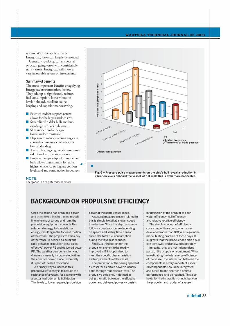
More design freedomPressure pulse measurements onthe concept have indicated that theapplication of a rudder bulb helps toreduce vibration levels significantly. Thisis illustrated in Figure 6, in which anoriginal propeller design is compared withan improved one and with Energopac,
both on model scale and full scale.
The reduction in vibration is causedby the rudder bulb, as it creates a morehomogeneous inflow of water into thepropeller. This effect means eitheran increase in comfort level onboardthe vessel, or more design freedomfor the same level of pressure pulses,meaning that the propeller’s efficiency can be increased even further.
Because of the good correlationbetween CFD and model tests, all newly designed Energopac systems will beanalyzed through CFD calculations, inorder to ensure that the best fuel-saving
solution is presented to each customer.
Applicability and savingsThe reduction in fuel consumption, when applying Energopac, depends very much on the vessel type, the operationalprofile of the vessel and on the referencepropeller and rudder. Consequently, a good estimate of the annual fuel savingscan be given after a detailed investigationof both the vessel design and thealternative propulsion solutions. Withthe working principles in mind however,some rules of thumb can be stated.
The Energopac system works very well for propellers with a relatively largepropeller hub, such as highly loadedcontrollable pitch propeller systems ason RoRo-vessels, ferries, container andmultipurpose vessels, or cargo vessels withan ice class notation. Due to the largerpropeller hub diameters, the hub losses would be significant for a conventional
Fig. 4 – Energopac yields a much lower resistance force than a standard rudder
for the same steering effort (plotted as produced steering force or lift).
–100% –80% –60% –40% –20% 0% 20% 40% 60% 80% 100%Rudder steering force [% of prop. thrust]
Wärtsilä Energopac
Standard semi-spade rudder
R u d d e r r e s i s t a n c e [ % o
f p r o p .
t h r u s t ]
25%
20%
15%
10%
5%
0%
7/29/2019 Wartsila SP a Id Energopac
http://slidepdf.com/reader/full/wartsila-sp-a-id-energopac 4/4
WÄRTSILÄ TECHNICAL JOURNAL 02.2008
33indetail
BACKGROUND ON PROPULSIVE EFFICIENCY
Once the engine has produced power
and transferred this to the main shaft
line in terms of torque and rpm, the
propulsion equipment converts this
rotational energy to translationalenergy, resulting in the forward motion
of the vessel. The propulsive efficiency
of the vessel is defined as being the
ratio between propulsion (also called
effective) power PE and delivered power
PD. The weather component for wind
& waves is usually incorporated within
the effective power, since technically
it is part of the hull resistance.
A primary way to increase this
propulsive efficiency is to reduce the
resistance of a vessel, for example with
a better hydrodynamic hull design.
This leads to lower required propulsion
power at the same vessel speed.
A second measure closely related to
this is simply to sail at a lower speed
than before. Since the ship resistance
follows a quadratic curve dependingon speed, and sailing time a linear
curve, the total fuel consumption
during the voyage is reduced.
Finally, a third option for the
propulsion system to be readily
improved is if it is optimized to
meet the specific characteristics
and requirements of the vessel.
The prediction of the sailing speed of
a vessel for a certain power is usually
done through model scale tests. The
propulsive efficiency – defined as
being the ratio between the effective
power and delivered power – consists
by definition of the product of open
water efficiency, hull efficiency,
and relative rotative efficiency.
The simple concept of efficiency
consisting of three components wasdeveloped more than 100 years ago in the
model testing practice of those days. It
suggests that the propeller and ship’s hull
can be viewed and analyzed separately.
In reality, they are not independent
parts of the propulsion equipment. When
investigating the total energy efficiency
of the vessel, the interaction between the
components is a very important aspect.
All components should be integrated
and tuned to one another if optimal
performance is to be reached. This also
holds for the interaction effects between
the propeller and rudder of a vessel.
Fig. 6 – Pressure pulse measurements on the ship’s hull reveal a reduction invibration levels onboard the vessel; at full scale this is even more noticeable.
system. With the application of
Energopac, losses can largely be avoided.Generally speaking, for any coastal
or ocean going vessel with considerabletransit times, Energopac will show a very favourable return on investment.
Summary of benefitsThe most important benefits of applying Energopac are summarized below.They add up to significantly reducedfuel consumption, lower vibrationlevels onboard, excellent course-keeping and superior manoeuvring.
Patented rudder support systemallows for the largest rudder sizes.Streamlined rudder bulb and hubcap design reduces hub losses.Slim rudder profile designlowers rudder resistance.Flap system reduces steering angles incourse-keeping mode, which giveslow rudder drag.Twisted leading edge rudder minimizesrisk of rudder cavitation erosion.Propeller design adapted to rudder andbulb allows optimization for eitherhighest efficiency or highest comfort
levels, and any combination in-between
NOTE:Energopac is a registered trademark.
Q Q Q Q
Q Q
V i b
r a t i o n l e v e l ( a m p l i t u d e i n k P a )
R e f e r e
n c e d e s
i g n
I m p r o v e
d p r o p
e l l e r d e
s i g n
M o d e l
s c a l e E
n e r g o p
a c
F u l l s c a
l e E n e r
g o p a c 3rd
2nd
1st
6
5
4
3
2
1
0
5,4
2,7
1,1
1,2
2,8
2,9
0, 9
1,8
1,8
0, 3
0, 3
1,9
Vibration frequency(n
thharmonic of blade passage)
Design configuration