Z F -S y n c h ro m a -G e a rbSo x5 -1 8 /3 6 E h lftln g io rc e s g u a r6 n t9 6 e a s y 9 n d a...
38
ZF-Synchroma-Gearbox S 5-18/3 Assembly, Maintenance and Operating Instructions ZAHNRADTABRIK FRIEDRICHSHAFEN AG SCHWAEBISCH GMUEND WORKS D-7070 Schwaebisch Gmuend Graf.von-Sodon-Stra0e $9 Germany phone 07171 /601-l . telex 07 248 80.| . cable: Zahnradfabrik SdrwaeblsdEnuond 07 24A825 for servlc€ deoartmsnt 1255 751 l0 Prlnted In Germany
Transcript of Z F -S y n c h ro m a -G e a rbSo x5 -1 8 /3 6 E h lftln g io rc e s g u a r6 n t9 6 e a s y 9 n d a...
ZF-Synchroma-Gearbox S 5-18/3
Assembly, Maintenanceand Operating Instructions
ZAHNRADTABRIK FRIEDRICHSHAFEN AGSCHWAEBISCH GMUEND WORKS
D-7070 Schwaebisch GmuendGraf.von-Sodon-Stra0e $9
Germany
phone 07171 /601-l . telex 07 248 80.| . cable: Zahnradfabrik SdrwaeblsdEnuond07 24A825 for servlc€ deoartmsnt
1255 751 l0 Prlnted In Germany

Pag€
I
1 2
1 2
23
24
3l
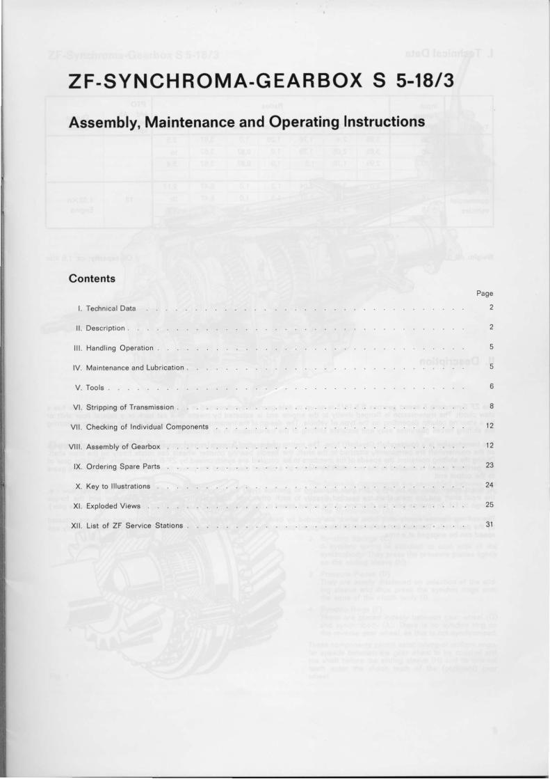
ZF.SYNCHROMA.GEARBOX S 5-18/3Assembly, Maintenance and Operating Instructions
Contentg
L Todrnical Data
l l . Do8crlpt ion
l l l . Handling Operation .
lV. Mgint6n6nc6 and Lubrication .
V. Tools .
Vl. Stripping ot Tranambsion .
Vl l . Ch6cklng of Individu.l Compon6nts
Vlll. Ass.mbly of G€arbor
lX. Ordering Sp6r6 Parts
X. Koy to lllustrationa
xl. Erplod6d Views
Xll. List of ZF Servico Stations .
Typc
InputTorqu6max. kpm
Bdor
t.Gear ] 2.Gear I s.c*. ll.o"". ls.cea. i R.c"a. I speedo
PTOM d . A b . . I o u t o u tpgrm|agaDrg | ^kpm' I uPooo
for CAR
2,4 t,76 1,26 t ,0 3,67 2,52,08 1,39 t . 0 0.87 3,67 to
30 2,99 I ,76 t ,3 't.0 0,87 3,67 3,4
for lightconmercialvqhlcl€8
't6 3,24 | 2,U t ,3 't,0 5,47 2 ,1712 t ,02xn
Engln6t 6 6,0 3,03 | ,81 1,3 1 , 0 5,47 IO
t 8 5,33 3,24 2,U t ,3 1 , 0 5,47 4,0
' For cor€ct value, rovcr to ZFF t€drniqal d€pgrtment.
l. Tedrnical Data
W.lghk ca. $ kg
ll. Description
Oll crprclty! ca. 1,6 liter
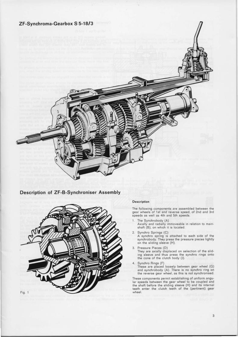
The ZF Synchroma 5 sp€od ggarbox S $18/3 is an up to date ge€rbox syn.hronlsod ln all forward geara. Thg rcvora€ 96ar haa aclaw clutdl. Ths traosrnis8lon ls flangod dlrotly to tho sngine and lo actueted by meana of a sst b;ck or a centrol flo6r Ehift orbJ a atoerlng column dqpendlng on th€ type of vehlcle. Thg dosign ofthe transmlssion and the us6 of of push rods ior trEnsmttdngth6 Ehlftlng iorces guar6nt96 easy 9nd accurats shifting of th6 trahsmission in all sttuations.Ths.tr6namisslon ls a countershaft (layshsft) typ€. Thg mating gears of all speed8 remain conatantly in m€8h. Whllst thg who€lson thq countsrshaft aro permanontly gttadr€d to ths shaft. the nssdls bearing count€r wh€ele can rdtatg freely on the mEtn 8h9ft.During tho rhlftlng opgration, the 6pe€d8 of tho membcrs to bo coupled 619 eyndrronleed by ZF-B syndtrontggre. The Idler gear ofthg pertinsnt Bpe6d 19 couplgd to tho mainshatt by m€ang of a clawed eleevi and the powlr flow d gutded by the perinqni geargto ths outoul snd.
At dirsct epeod (that can bg 4th or sth g€ar according to gEarbox type) the countsrahaft is not Includsd in the powor flow i. e.thg Input thaft.and th6 maln shaft ar€ coupled diroctly to eadr othg. and conaoqu€ntly tho ongine r€volution end the torquodlango to l:1. In revsrse gear ths diroction of tho output sp€ed i6 .fi6n9qd by I built-in intermedlatg ggar (so-called reveree geir).Tho shiftlng El€9vqs 8upply 8hlft forke whldr are guided by bearing gplgots €nt€.ino th6 gesrbox housinq and wht.h ar€ actuatodby thg push rod8. Tho Ehlft forks arg hgld in th6 engsged pgsition by spring dot6nt8. A butlt-in shift lock luarantees that only onoBpo6d qan be snggg€d at a timo.
ZF-Synchroma-Gearbox S 5-t 8/3
Descript ion of ZF-B-Synchroniser Assembly
Oescr ipt ion
The fo l low ng components are assembled between lhegear wheels of ls t and reverse speed, of 2nd and 3rdspeeds as wel l as 4th and sth speeds.1 The Synchrobody (A)
A x r a l l y a n d r a d r a l l y r m m o v e a b l e I n r e l a t i o n t o m a n -shaf t (B) on wh ch r l rs located
2 Synchro Sprrngs (C)A synchro spf lng is at tached to each s ide of thesynchrobody. They press the pressure preces l ight lyon the s l rdrng s leeve (H)
3 Pressure Preces (D)They are axral ly drsplaced on selectron of the s l rd-ng s leeve and thus press the synchro rrngs onto
the cone of the c lutch body ( l )
4 Synchro Brngs (F)These are placed loosely between gear wheel (G)and synchrobody (A) There rs no synchro r ing onthe reverse gear wheel . as th is is not synchrontsed
These components permrt establ shrng of unrtorm angu-lar speeds between the gear wheel to be coupled andthe shaf i before the s l rdrng s leeve (H) and r ts Internalteeth enter lhe c lu ich teeth of lhe (pert inent) gear

Op€retion ot Syndronl.or A...nbly
1 . l d l i ng (F igs . I and2 )
Sliding slsevo (H) is in th€ centre positaon. h i9 hsld inthis position by 6 shift fork whidt is located by tho sslgctorof the dstent bolt. The gear wheels (G) can rotate froelyon thg mainshaft.HIN
JtShift ing Opsration (Figs.3 and 4)
Th€ sliding sleev€ (H) as pushgd forward axially in onodirection (in th€ exampl€ shown to the left). The pr€g8urepiecos are tsk6n along by tho 8liding slosvo, as th€pressurs pigcsa 9re push€d by th6 preloaded gynchronissr8prin96 (C) with th€i. trapoziuh shop€d tops into the some-$rhat wider 6nnular groov€ of tho sliding als€v€. Th6 twosyndrro rings (F) lie to lgft and right of the prossurepieces. When the sliding slogve movos to the left afterpassing through ths fre€ lravol botw€on the sliding slsgvoand the preasurs piece. the lgft Byndrro ring will be movodto the left side in the sam6 way by thg prosgure pigcea.After approximatgly 0.5 mm the syndtro ring with lts conical6urfaco is adjacent to the simil6r conical surfaca of theclutdl body. This will rotate thg synciro ring by app.oxi-mately 2 mm In relat ion to thg sl iding sle€ve and thesynchro body (A) until ih6 syndrro.lng and its lugg 619resting in tho slots of the gynchro body. The position of thosyndrro ring in rolation to the sliding gleeve is thgrgforegudr that thg tggth on th€ out6r diam€ter of the rang areoffset in rel6tlon to the toothgaps ot the sliding 8le6ve(Fig.3).Wh9n the sleeve i3 pushod on further. i tg tgeth wil lrest againSt those of the aynchro ring and submit anaxial force against the r ing. Th€ f lat adjoining angl6 onthe Eliding Eurface of the clutdr body (J) and the blockingring will €stablish forcos in radial direction whidl ar9stronger than thg forces whidr are trsn6mitted to th6 slid-ing slegve in axial direction. Thio $rill continually r€ducetho diffgrgncs in sps€d betwe€n the g€ar to be 6ng6ggdand th6 mainshaft (es well ae the 8liding sleevo). Onlywh€n the two apeeds aae synchronig6d will the synchroring and ths gsgr whe€l turn back slightly (approx. I to 2mm) until thg teoth of ths sliding slsove are in line withthe tooth gaps of the syndrro ring. At thig momsnt, thgrcsistanco whidr has prcvonted 9ny furthgr movsment ofthe sliding 8la6ve during thg shifting operation will b€overcomg and the slg€v€ is now pushod into thg couplingteeth of th6 appropriate goar whesl (Fig. 4). This is th6 endof th6 shifting cycl€.
IIFR
A) Syndrro BodyB) MainshattC) Syn.hro SpringsD) Prgsgure PieceE) N€€dle B€aringF) Syn.hro RingG) Geer whe€lH) Sl iding Sleeve.,) Clutch Body
4
l l l . Handling Operation
Economic driving of a vehicle requires the engine to run constantly in the most favourablo speed range. On most €ngines, thi6speed range is restr icted but a s-speed transmiasion permits easy adaptation of th€ engine to the varying driving condit ions.Since al l forward gears on the S5-18/3 are ful ly syn.f ironised, a fast rel iable and noiseless g€ar change can be effected withoutdouble de-clutdring on shif t ing up and without rewing up when 6hift ing down.On shifting, the sel€ctor lever of the syndrronised forward gears should b€ pressed in smoothly and evenly. Only when the synchro-process is at an 6nd does the Eelector lever move into f inal selected posit ion.
To protect synchronising components in the transmission, in the main clutc$ and the engine, shif t ing down should be effectedonly when the driving speed corresponds to the max. speed of the next lower gear.The rever6e gear may be engaged only when the vehicle is stat ionary as otherwise the dog teeth may be damaged.The clutdl pedal should always be depressed when selecting both forward and reverseclutdr contribute! considorably to the prov€ntion of .hifting trouble. The clutci should6pecif ied pedal play should ther€fore be checked regularly.
speeds. Por'oct adiustmeni of lhe mainengage and disengage completely. The
lV, Maintenance and Lubrication
The fol lowing typ€s of oi l can be used for lubrication of the gearbox unl6s5 the lubrication instruct ions of the vehicle manufac-turer are different.
1. Mild €P-Goarbox oll., prctcrably of viscosity cla3! SAE 8{,2. HD-Engins oil3 ot vi.co3ity cla33 SAE 30
Mild gear oi l types are those EP oi l grade6 whiah in the presence of condensation do not cause corrosion on steel and non-fer-rous metal parts and hardening of gaskets and Eeals. So-cal led mult i-purpose or universal oi ls can be used i f they meet our"Lubrication Oil Roquirements for ZF Transmission Nr. 13-118". In case of doubt, please aek an oi l supplier.To faci l i tate the choico of oi l for vehicles used abroad, i t should be mentioned that mult i-purpose oi l SAE 80, with rni ld EP-Addi-tives, as per specification MIL-L- 2105 (A), can meet these requirements.
Oil Lovol Ch€d(
The oi l level in the transmission should be ch€cked regularly (approx. every 10.000 km). The dleck should be undertaken onlywhen tho vehicle is in a horizontal posit ion. l f this is carr i€d out after drivjng, ' then some t ime should be al lowed to elapse unti l theoi l has sett led in the transmigsion.
Ths oil filler plug should be removed fron the sid€ of the gearbox (to the right as seen on th6 output flange) to check the oil level.The area around th6 plug should be cleaned so that no dirt c6n fal l anto the transmission. l f ths oi l level has dropped below theedge of the bore, then the oi l should be f i l led to overf lowing again. Then close the oi l f i l ler plug. l f possible, the sam6 type ofoi l should always be used.
Oil Change
The gearbox oil in.a new or repaired gearbox should be .tianged first after 4000 to 5000 km or 6fter 100/125 working hours, andthen every 16 000/20 000 km or 400/500 working hours. The old oi l should always be drained after driving as i t i6 th€n warm,flows easily and flushes th6 driving parts and possibly removes the w6ter condonsation which has tormed tiom the gearbox moreea9ry.
The oi l drain is on the underside of the transmigsion, set furthest back. Prior to screwing the drain plug back, the magnet shouldbe cleaned of adhering abragiv€s.
The now oi l should be put in vja the oi l f i l l€r and should in fact overt low at the €nd of the bore (required oi l capacity approx. 1,6 l) .Oft€n, lubricants and addit ives are offored in addit ion to the oi l . The oi ls meeting our instruct ions alrsady have their addit iveswhidl the transmission needs. An)4hing further is not nece9s6ry, and could even cause damage.
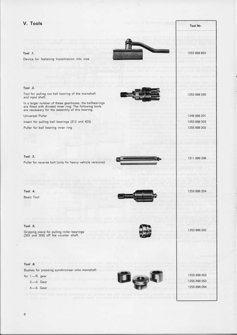
V. Tools
Tool .1.
Device for fastening transmission into vice
f ool .2.
Tool for pul l ing out bal l bearing of the mainshaftand input shaft.
ln a larggr numb€r of these gearboxeg, the bal lbearingsar€ f i t ted with divid€d inner r ing. The fol lowlng toolsare necegsary for the assembly of thi6 boaring.
Universal Pul ler
fnsert for pufling ball bearings (212 and 423)
Puller for bal l bearing inner r ing
Tool .3.
Pul ler for reverse bolt (only for heavy vehicle versions)
Tool .4.
Ba6ac Tool
Tool .5.
Gripping piece for pul l ing rol l€r bearings(303 and 309) off the counter shaft.
Tool .6.
Bu6hes for presging synchroni66r onto mainshaft
for 1.--+l- g€ar
2.---3. Gear
4.-5. Gear
ts
Tool Nr.
1253 898 6s3
1 253 898 205
1 248 898 20r1253 898 203r 255 898 202
r 2 1 1 8 9 8 2 0 6
r 253 898 204
1253 898 202
1 255 898 052
1255 898 053
1255 898 054trga
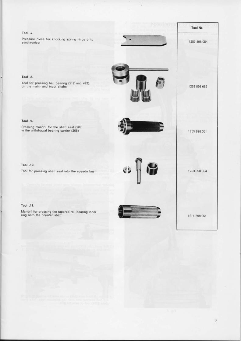
Tool .t.
Preasura pi€c€ for knocking spring rings ontoSyncnronlaaa
Tool .8.
Tool for pr€8slng ball b€aring (212 a d 423)on tho main- and input shafts
Tool .0.
Prssslng mandril for tho sh6ft 8€al (207in tho wlthdraviral bgaring carrlor (206)
Tool .t0.Tool for preeelng Bhaft ssal Into thg sp6€do bush
Tool .l |,
Mandril for presglng th6 tapergd roll bearing Innerrlng onto ths countor shaft
,,$e
Tool Nr.
r 2s3 898 054
| 253 898 652
| 25s 898 051
1253 898 631
| 2r | 898 051
Vl. Stripping of TransmissionNoi€: The numerals In brackets e.g. (611) refer to part numbers in exploded view at end of instruct ions.
Screw tool .1. into the thread of the oi l drain plug (to fasten transmission more socurely, the ful l thread in the housing shouldbe used) and secure gearbox with the tool in the vice- Pul l the lock nut of the tool .1. l ightly.
A) Bemov.l of G€ar Shift
l. Remote lloor shllt (Car)
1.1 Remove boot (643). Remove circl ips (642) from the grooveof the gear lever turret (Fig. 1). Pul l the geardrang€ con-trol lever (640) with the bushes (641) from the gear changeturret (Fig.2).
1.2 Loosen the 4 screws (637) (Fig. 3) and l i f t off the gearchange turret from the selector arm (Fig- 4). Take off guideprare.
F i g . 41 3 Pull pivot pins (630) from the gear change turret. Take out
interlock swing (625) with torsion springs (633 and 633.1).
Screw off the 4 nuts (648) on the selector arm (619) (Fig. 5)and pl l l selector arm over the selection rods. Take pivotpiece (624) out of solector arm.
F i g . 2
2 Loosen nuts (808) and screws (803). Take off speedo cover(801). S ip off short drstance bushes (428). speedo worm(427) and long spacing bushes (426).
I 5
F s . 5
T a L e o u t c y l ' n d ' r c a l s c e w s ( 6 4 5 ) r F gvibrat ion damper (644)
6) and take of f
1
F iq I
Snap sprrng ang (425) out of bal l bearing groove (423)and sl ide off the spacer (424) Pul l the bal l bearing frornthe marnshaft wth tool 2. Attach the spacer (424) to theba l l bca r i ng .
Dismantl ing of Front Part of HousingLoosen nuts (20r) (Frg. 9) and front cover (203)
F rg . 6
2. Central ly located direct gear change (commercial vehicle)2.1 Sl p off the gaiter (643) Unhook cap (655) frorn the prvot
pins (652) and p!l l select on lever completely out of thegearchange turret.
2 2 Loosen the 4 nuts (648) and lrf t up gearchange turret fromhousing (629) Remove selector gate (653).
2.3 Pull pivot plns (630) from the gearchange turret Take outinterlock swing (625) with tors on spring (633 and 633.1)
B) Dismanll ing of Speedo CoverI Push back the safety tab on the nut (430) and loosen nut
(Fig 7). For this, 2 gears must be engaged Pull the outputf lange (429) from the mainshaft.
Fig 9
Bemove crrcl p (208) (Fig. 10) and take off spacer (209)
D sman t l e sp r ng r i ng Pu l l o f f ba l l bea r i ng (212 ) w r th t oo l. 2
2
3
4 . P u s h b a c k t h e 2 d o w e l s ( 1 0 6 ) ( F r g l l )
F t g 1 2
U n s c r e w n u t s ( 1 0 2 ) a n d t u r n c y l r n d r c a l s c r e w s ( F r g l 3 )
D) Oi3mantl ing of Gearbor Shaft3l. Take off selector fork 4th and 5th gear (601).2 D i sman t l e se lec to r r ods (608 ,612 and 61a ) (F rg . l 5 ) .
Loosen set screws (602) on the prvot prns (604 and 610)(F ig 12 ) and pu l l pvo t pLns f r om the hous rng
F 9 1 5
Take gearbox shat l f rom the housrng (Frg 16) Pul l the2 detent p lungers and lhe 2 ccmpressron spnngs (616)
F i g l 3
Take o f f f r on t pa r t o f hous rng (101 ) (F rg 1a ) Pu l l de ten rp unge r (61 7 ) and compress ron sp r ng (616 ) f r om the bo re
F g 1 6
E) Oismantl ing of Bever6e GearI Undo the sc rews (118 ) and t ake o f f t he cove r p l a te (117 )
2 Remove the set screws (507) from the hous ng (Frg. 17)o r pu l l ou t t he dowe l ( 511 ) Pu l l ou t t he reve rse rd l e r sha f l
F g 1 7
(505) wrth specra too 3 or knock towards the outputs de wrth a frt teC mandri l (Frg l8) Take out the reversegear (502) wrth the 2 thrust washers (501) Pul l the 2need e cages (503) from the bore of the gear.
i t
F)
I
F ig . 18
Dismantl ing ol Mainshah
Berrove thrust washers (422) and 1st gear (421) wrthsynchro r ing (402) and needle cage (408) from the main-shaft.Remove synchro spring (403) from the pressure piece(aoa) (Fig. 19). Pul l slrding sleeve (420) from the synchro
body (419) and take off pressure piece (404). Bemove cir 'cl ip (409) from groove (Fig.20) and mark posrtron of thesvnchro bodv on the mainshaft.
F i g . 2 0
Clamp mainshaft with the input side upwards between softjaw6 of a vice. Remove input shaft (213). rol ler cage bear-tng (214) and synchro r ing (402). Remove synchro spring(403). Pul l off sl iding sleeve (406) and dismantle pressurepiece (404). Remove circl ip (401) and mark posit ion of thesynchrobody on the shaft (Fig. 2i).
F i g . 2 1
Pull off synchro body 4th and 5th gear (405) wrth 2 screwsM 8 and conventional pul lrng bridge (Fig. 22). Take offsynchro r ing (402), 5th gear (a07) and needle cage (408).
Remove circl ip (409). Push the thrust washer (410) withthe 3rd gear (41 1) from the cyl indrical spl ining of the shaft.Take off synchro r ing (402) and needle cage (412).
F ig .1 9
F is .
7 .
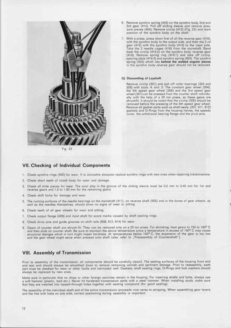
B€move synchro spring (403) on the syncfiro body 2nd and3rd gear (414). Pul l off sl iding sle6ve and r€move pres-sure pieces (404). Remove circl ip (413) (Fig. 23) and markposition of the synchro body on the shaft.
With a press, press down first of all the roverEe gear (418),with the synchro body to the output side, and then the 2 ndgear (415) with the 6ynchro body (414) to the input sid€.Take the 2 needle cages (416) from the mainshaft. Bendback the circlip (419-2) on the synciro body rev€rse gear(419). Bemove spring r ing (419.1) and take off circl ip,spacing plate (419.3) and Eynchro spring (403). The synchrospring (403) which lies bohind tho weldod angular plccc.an the synchro body reverse gear should not be removed.
Di3mantling of Layshaft
Remove circl ip (301) and pul l off rol ler bearings (303 and309) with tools .4. and .5. The constant gear wheel (304),the sth speed gear wheel (306) and the 3rd speed gearwheel (307) can be pressed from the counter shaft individu-al ly with the help of a 20 ton pres6, as theso geara areshrunkfi t . l t should be noted that the circl ip (305) should beremoved before the pres6ing of the sth speed gear wheel.Remove al l gasket parts such as shaft seals, (207, 81 1 , 812)gaskets and O-Rangs from the housing halves, the speedocover, the withdrawal bearing f lange and the pivot pins.
G)
Fig.
t .2.3.
5.
6 .
1 .
8.
Vl l . Checking of Individual Components
Check synchro r ings (402) for wear. l t is advisable alwaysto replace synciro r ings with new ones when repair ing transmissions.
Check short teeth of clutch body for wear and damage.
Check al l sl ide pieces for wear. The axaal play in the groove of the sl idang 6leeve must be 0,2 mm to 0.45 mm for 15t andreverse gears and 1 ,6 to 1,85 mm for the remaining gears.
Check shif t forks for damage and wear.
The running surfacos of th6 needle bearings on the mainshaft (417), on reverse shaft (505) and in the bores of gear wheels, aswell as the n€odles themselves, should show no signs of wear or pit t ing.
Check teeth of al l gear wheels for wear and pit t ing.
Check output f lange (429) 6nd input shaft for ecore marks caused by shaft seal ing r ings.
Ch€ck drive pins and guide grooves on shif t rai ls (608. 612, 614) for wear.
Gears of counter shaft are shrunk-f i t . They can be removed only on a 20 ton press. For shrinking, heat gear6 to 150 to l80o Cand then slide on counter shaft. Be sure to maintain the above temp€rature since a temperaturs in excess of l80o C may causestructural dtanges which in turn might impair hardness. At temperatures below t50o C, the- expansion- of thg gear i9 too lowand the gear w-heol might seize when pressed onto shaft (also refer to "Prca66embly of Countershaft").
Vlll. Assembly of TransmissionPrior to assembly of the transmission, al l components should be careful ly cleand. The seal ing surfaces of the housing front endand rear end should always be smooth€d down to remove remaining varni6h and p€rt inent damage. Prior to reassembly, ead!part must be ctecked for w€ar or oth6r faults and lubricated well . Gaskets. shaft seal ing r ings, O-Rings and lock washers shouldalwayg be replaced by new ones.
Mak€ sure in part icular that no dl ip6 or other foreign part icles remain in the hou6ing. For insert ing shafts and bolts, always usea soft hammer (plast ic, lead etc.). N€ver hit hardened transmission parts with a ste€l hammer. When instal l ing studs, make surethat they are inserted into tapped-through holes together with seal ing compound (for good seal ing).
The assembly of the individual shaft and of the entire transmission proceeds vice versa to str ipping. When assembling gear leversand the l ik€ with hubs on one side, correct posit ioning during assembly as important.
A) Preassembly of Housing Components
Sc rew s tuds (104 . 105 , 108 , 109 110 ,805 and 806 ) i n totapped ho les o f hous rng .
Note: New studs for through holes are Insta ed coatedwr th sea l i ng compound .
B) Assembly oI Reverse Gear Wheel
1 Put needle cages (503) nto reverse gear bore (502) andstrck needles with grease. Stick a thrust washer (501 and510) on each side of the wheei with grease (the turneddown faps lre outwards). Put the reverse gear Into thehousing. Push the reverse dler shaft wth the sma er . 'f i rst into posrtron n the housrng bore from the output s de(Fig 24). Take care that the thrust washers are not damaged by the shaft
2. Insert screws (507) wrth spnng washer (506) (underneath)and t i gh ten t o 2 .0 t o 2 .5 kpm (see F ig . l 7 ) The sec ! rngbolt must come to l ie behrnd the shaft (not rn the groove)On various gearbox types a dowel (511) must be pLrtthrough the housing nto the shaft bore
3 Fasten gasket (1 16) and cover (1 1 7) onto the housrng w thse t sc rews (118 ) and spnng washe rs (103 ) ( unde rnea th )Trghten torque of the screws to 2 to 2.5 kpm
' \I t l
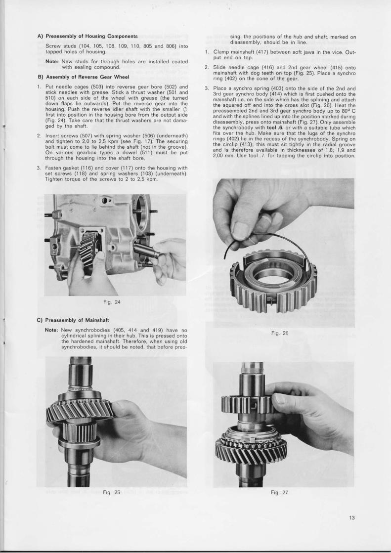
srng, the posrtrons ot the hub and shafi , marked ond sassemb y . shou ld be I n l r ne .
C lamp marnsha f t ( 417 ) be tween so f r j aws i n t he v i ce . Ou t -put end on top.
S l i de need le cage (416 ) and 2nd gea r whee (415 ) on tornainshaft with dog teeth on top (Fig. 25). Place a synchronng (402) on the cone of the gear
Placc a synchro spnng (403) onto the side of the 2nd and3rd gear synchro body (414) whrch rs f irst pushed onto thema insha f t i e on t he s i de whLch has t he sp l n rng and a t t achthe squared off end into the cross slot (Fig. 26) Heat thepreassembled 2nd and 3rd gear synchro body up to 80o Cand wrth the spl nes Ined up Into the posit ion marked duringdrsassembly, press onto ma nshaft (Frg. 27). Only assemblethe synchrobody wrth tool .6. or wrth a suitab e tube whrchfi ts over the hub. Make sure that the lugs of the synchror ngs (402) l ie in the recess of the synchrobody. SprLng onthe circl p (413)i this must si t t ightly in the radral grooveand i s t he re fo re ava r l ab le rn t h i cknesses o f 1 .8 i 1 ,9 and2,00 mm Use loo 1 fot tapprng the circl ip into posrlron.
2 .
3
1 .
c) Preassembly of Mainshaft
Note: New synchrobodies (405, 414 and 419) have nocyl ndncal sp rn ng n their hob. Thrs rs pressed ontothe hardened ma nshaft Therefore. when Lrs ing o dsynchrobodres, r t should be noted, that before pres-
F ig 26
ll
F g 25 F'g 21
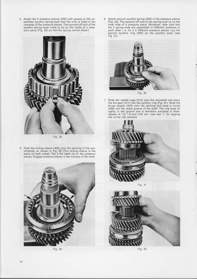
Attach the 3 pressure preces (404) wrth grease to the as-sembled synchro spring such that the wire is frxed In therecesses of the pressure pieces. The squared off end of thesynch ro sp lng mus t come to l e on t he i ns rde o f a p ressu re p rece (F ig .28 ) so t ha t t he spnng canno t d r s to r t
Push the s l rdrng s leeve (406) onto the spLrn ng of the syn'c h r o b o d y a s s h o w n i n F i g . 2 9 ( T h i s s l i d i n g s l e e v e i s t h esame on both s ides). The 3 f lat teeth l ie on the pressurepieces. Engage pressure pieces In the notches of the teeth
Attach second synchro spnng (403) in the pressure preces(Frg. 30) The squared off end of the spring must le on thenner srde of a pressure piece. Moreover, take care thatthe 2 sprLng ends are assembled In drfferent pos trons toeach other r. e lre In 2 drfferent pressure peces. Lay thesecond synchro rng (402) on the synchro body (seeF i o . 3 1 )
F i g . 3 0
Slide the needle cage (412) onto the mainshaft and placethe 3 rd gea r (411 ) i n to t he synch ro r i ng (F ig . 31 ) . S l i de t heth rus t washe r (410 ) on to t he sp l i n rng and snap a c r r c l i p(409) Into the radial groove of the shaft The r ing must sittrghtly In the groove and rs therefore avai lable in thick'nesses o f 1 ,8 i 1 ,9 and 2 ,00 mm. Use too l . 7 . f o r t app rngthe circl ip into posit ion.
28F ig
F r g . 3 1
F g . 2 9 Fig 32
9
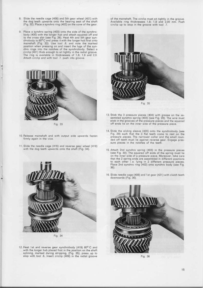
Sl ide the needle cage (408) and 5th gear wheel (407) w ththe dog teeth upwards onto the bear ng seat of the shaf l(F g.32). Place a synchro r ing (402) on the cone of the gear
Place a synchro spnng (403) onto the s ide of the synchro-body (405) wi th the longer hub and at tach squared of f endto the cross s lot (see Fig 26) Heat 4th and 5th gear syn-chrobody toS0oCand press i twi th the ongerhub f r rst ontom a r n s h a f t ( F i g . 3 3 ) . U s e t o o l . 6 . a n d n o t e t h e m a r k e dposi t ion when pressrng on and insert the lugs of the syn-chro r ings Into the notches of the synchrobody. Select acrrc lLp (401) th ick enough to s i t t ight ly In the rad al grooveT h e r n g s a v a i l a b l e i n t h r c k n e s s e s o f 1 , 8 i 1 , 9 a n d 2 . 0Attach crrc l p and wi th tool .7 push into groove
o f t he ma insha f t The c r r c l i p mus t sL t t r gh t y I n t he g rooveAva i l ab le nng t h i cknesses 1 ,8 i 1 ,9 and 2 ,00 mm Pushclrcl p up to stop In the groove with tool 7.
Frq 35
I3 .S t ck t he 3 p ressu re peces (404 ) w r th g rease on t he assembled synchro spang (403) (see Fig.28). The wire muststrck in the grooves of the pressure pieces and the squaredoff ends l ie on the inner srde of the pressure prece
14. SlLde the sl drng sleeve (420) onto the synchrobody (seeF g. 29) such that the 3 f lat teeth come to rest on thepressure pteces The narrower col lar and the small roun-ded off teeth must l ie agarfst reverse gear. Engage p.essure p eces In the notches of the teeth
15 Attach 2nd synchro spflng (403) In the pressure pieces(see Fig. 30) The squared off ends of the spring must l ieon the nner side of a pressure ptece Moreover, take carethat the 2 spnng ends are assembled in dif ferent posrt ionsto each other . e lying in 2 dif ferent pressure pieces.P ace 2nd synchro r ing (402) onto synchro body (see Frg36).
16 S l i de need le cage (408 ) and l s t gea r ( 421 ) w th c l u t ch t ee thdownwards (F ig .36 )
AFig 33
10. Belease rnarnshaft and wrth output srde upwards fastenfrrmly again In the vice.
l 1 .S l i de t he need le cage (416 ) and reve rse gea r whee (418 )wrth the dog teeth upwards onto the shaft (Fig 34).
F r g . 3 4
l2 Heat lst and reverse gear synchrobody (419) B0oC andwrth the longer hub placed f irst in the positron on the shaftsp l i n i ng , marked du rLng s t r i pp lng , (F ig .35 ) , p ress up t ostop wth tool .6. Insert crrcIp (409) in the radial groove F g 3 6
1 5
Frg 37
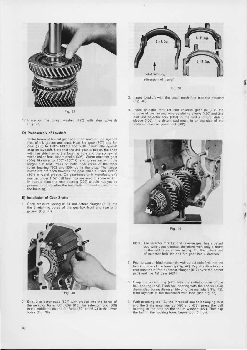
l7 Plece on the thrust washer $22\ wl lh step upwards(Fr9 37)
D) Preassembly ot Layshari
Make bores of helrcal gear and frt ted seats on the layshafltree ot oi l , grease and dust. Heat 3rd gear (307) and sthgea r (306 ) t o 150o - 180o C and push I nd rv rdua l y aga ins tstop on layshaft. Note that the 3rd gear is put on the shaftwith the side hav ng lhe locatrng hole and the somewhatwider col lar f i rst Insert c rcl p (305) Warm constant gear(304) lrkewise to l50o- 180oC and press on wrth rhelonger hub f irst. Press on both Inner races of the taperrol ler beanng (303 and 309) up to the stop The largerdrameters are each towards the gear wheels Place c rclrp(301) n radral groove On gearboxes wrth manufacturersnumber under 1 152, bal l bear|ngs are used to some extentIn such a case the rear beanng (309) should not yet bepressed on (only after the Instal latron of gearbox shaft Intothe housing).
E) Instal lat ion ot Gear Shatts1 S t i ck p ressu re sp rLng (616 ) and de ten t p l unge r (617 ) r n to
the 3 retain ng bores of the gearbox front and rear withg rease (F ig .38 )
Fohrtr ichtung(directron of travel)
F,9 39
lnsert layshat t wth the smal l teeth f i rs t Into the housrng(F 9. a0).
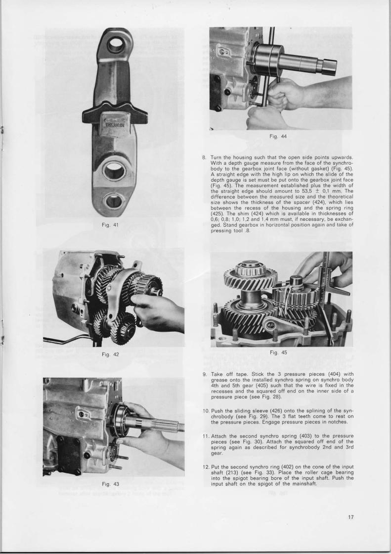
Place selector fork 1st and reverse gear (613) rn thegroove of the 1st and reverse slrdrng sleeve (420) and 2ndand 3rd selector fork (609) In the 2nd and 3rd sldrngsleeve (406). The detent pad must le on the side of the'nstal led reverse gearwheel (502)
F,g 40
Note: The selector fork 1st and reverse gear has a detentpad with open detenls, therefore with only 1 notchin t he mdd le as shown l n F ig 41 . The de ten t padof selector tork 4th and 5th gear has 3 notches
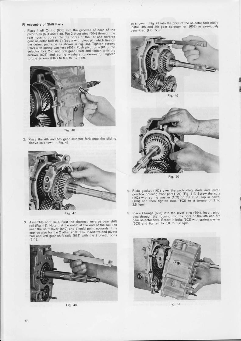
Push preassembled marnshatt with output srde frrst into thebeaflng base of the housrng (Frg.42). Pay attention to cor-rect posit ion of forks (detent plunger (617) over the detentpad ) and t he 1s t gea r ( 421 ) .
Snap the spnng nng (425) Into the radral groove of theball bearing (423) Push bal l bearrng wrth the spacer (424)d rsman t l ed du r i ng d rsassemb ly on to t he ma insha f t (F t9 .45 )Brnd layshaft to the marnshaft wrth tape (see F g. 45).
Wrth pressing tool .8., the threaded p eces belonging to l tand the 2 distance bushes (426 and 428), press the bal lbearing to the stop on the thrust washer (422) Then tapthe bal l in the housrng bore Leave tool .8. t ight.
F ,9
Stick 2 selector pads (607) with grease Into the bores ofthe selector forks (601 609, 613), for selector fork (609)In t he m idd le ho les and f o r f o r ks (601 and613 ) i n the owerho es (F ig .39 ) .
l
F 9 . 4 1
F g 4 4
Turn the housrng such that the open side pornts upwafdsWith a depth gauge measure from the face of the synchro-body to the gearbox joint face (without gasket) (Fig. 451.A stralght edge with the hrgh l ip on which the sl ide of thedepth gauge rs set must be put onto the gearbox Joint face(Fig.45). The measurement establ ished plus the width ofthe straight edge should amount to 53,5 1 0, i mm. Thedifference between the measured size and the theoreticalsize shows the thickness of the spacer (424), which lesbetween the recess of the housrng and the spring r ing(425). The shrm (424) which is avai lable n thicknesses of0,6: 0,8; 1,0: 1 ,2 and 1,4 r irm must, i f necessary, be exchan'ged. Stand gearbox in horizontal pos t ion again and take ofpressing tool .8
9 Take off tape. Stick the 3 pressure preces (404) withgrease onto the instal led synchro spring on synchro body4th and sth gear (405) such that the wire is f ixed in therecesses and the squared off end on the lnner side of apressure piece (see Frg. 28).
l0 Push the sl iding sleeve (426) onto the spl ining of the syn'chrobody (see Fig.29). The 3 f lat teeth come to rest onthe pressure pieces. Engage pressure pieces in notches.
l l .Attach the second synchro spring (403) to the pressurepreces (see Fig. 30). Attach the squared otf end of thespring again as described for synchrobody 2nd and 3rdgear.
12. Put the second synchro r ing (402) on the cone of the inputshaft (213) (see Fig. 33). Place the rol ler cage bearinginto the spigot bearing bore of the input shaft. Push theinput shaft on the spigot of the mainshaft.
Tfr/
Fig 45
F) A!3embly of Shift Part.
1. Place 1 off O-ring (605) into the grooves of each of thepivot pins (604 and 610). Put 2 pivot pins (604) through therear housrnq bor€3 into the bores of the lst and reverseaear eelect; fork (613) (begin with pivot prn which l ies onihe d.tent p"d side ss shown In Fig 46) Tighten screws(602) with sgrinq washers (603) Push pivot prns (610) Intosetei: tor fot i 2nd and 3rd gear (609) and fasten wrth thescrews (602) and spring tashers (underneath). Tightentorque screws (602) to 0,8 to 1 2 kpm.
as shown in Fiq.49 into the bore of the selector fork (609)Install 4th and- sth gear selector rail (608) as prevaouslydescribed (Fig. 50).
,
I
Place the 4th and sth gear selector fork onto the sl idingsleeve as shown in Fig.47
Assemble shif t rai ls. First the shortest reverse gear shaftra' l (Fig.48). Note that the notch at the end of the rarl l resneai t l ie shif t lever (640) and should pornt upwards. Thisaoolies also for the 2 other shif t rai ls. Insert welded pivots2nd and 3rd gear shif t rai ls (612) with the 2 plast ic bolts(61 1 ) .
Slrde qasket ( l07) over the protrudrng studs and Instal loearbo-x housrng front part (101) (Fig. 51) Screw the nuts(l02) with sorinq washer (103) on the stud Tap in doweli tOOi ana t iren-trghten nuts ( l02) to a torque of 2 to2,5 kpm.
Place O-rinq6 (605) into the pivot prns (604) lnsert pivotorns throuoh the housinq into the bore of the 4th and sthoear selec-tor fork. Screw in bolts (602) wrth sprrng washeta6O3) and t ighten to 0,8 to 1,2 kpm.
50Fig.
Fig 46
F r g . 4 7
F i g . 4 8
1 8
F'ig 51
G ) Instal l ing Inpul Shaft
W t h a p l a s t c h a m m e r . t a p t h e b a l b e a r n 9 ( 4 2 3 ) o n t h eo u t p u t s h a f t n t o t h e h o u s n g u n t r t c o m e s u p a g a n s t t h es p r n g r n g ( a 2 5 ) ( t o e n s u r e t h a t m e a s u . e m e n t s a r e n o r
W t h a d e p t h g a u g e m e a s u r e t h e s p a c e f r o m t h e f r o n t o lt h e h o u s i n q t o t h e s e t t r n g s u r t a c e o f t h e b a l l b e a r n g ( 2 1 2 )o n t h e r n p u t s h a f t ( F r g 5 2 ) P r e s s n p u t s h a f t w t h h a n L iI r m l y a n d e v e n y t o m a k e i l e n t h e b o r e o t t h e s y n c h r or n g
F q 5 2
n s e r t s p l n g r f q l 2 1 l ) I n t o t h e q r o o v e o f t h e b a b e a r n l r( 2 T 2 ) M e a s u r e f r o m t h e u p p e r s L r r f a c e o f t h e b e . r n q t ot h e s D n n g f l n g T h e s p r n g r n g m u s t b e p r e s s e d o n t o t h eo u t e f e d q e o f t h e b e a n n g g r o o v e ( F g 5 3 )
-F
F r q S 3
T h e d f f e r e n c e b e t w e e n t h e 2 m e a s ! r e m e n t s e s s 0 5 m n it o 0 I m m f o r t h e a x r a p l a y o f t h e 4 t h g e a . s y n c h r o r n f r{ a 0 2 ) g v e s t h e t h c k n c s s o f t h e s p a c e r ( 2 0 9 ) w h , c h n ! s tb e p l a c e d u n d e r t h e b a I b e a r n q ( 2 1 2 ) T h e s h m s a r ea v a a b l e n t h c k n e s s e s o f 0 5 : 0 6 : 0 . 7 . 0 8 i 0 9 l 0 1 lI 2 1 1 3 : 1 4 a n d I 5 m m
P u s h t h e s p a c , n q w a s h e r o v e r t h e I n p u t s h a f t P r e s s t h eb a b e a r n g ( 2 1 2 ) w t h p r e s s n g t o o 8 u p t o t h e s t o p o r ,t h e n p u t s h a f t a n d n t o t h e h o u s r n q ( F g 5 4 )
N o t e : W h e n p r e s s n g n r h e b a l l b e a r n q . t h e b a l b e . r n qm l s t D e d r v e n n t o t h e h o u s n g b o ' e w , t h a p . s t ch a n r n r e r a t t e r a p p r o x m a t e y 2 t u r n s o f t h e t o o
F q 5 4
S e l e c l a s p r c e r ( 2 C g ) s l c h t h a t t h e c r c r p ( 2 0 8 ) s t s t L g h t l yr n t h e r a d a l q r o o v e o f t h e I n p u t s h a f t A s s e m b e t h e s p a c e ,d n d c , c p ( F s 5 s )
F c t 5 5
Assembl ing Speed Cover
F r s t y t a p t h e o L r t e , ' n g o f t h e r o e r b e a f i r c t { 3 0 3 ) o rt h e a r g e s t d r a m e t e r n t o t h e h o u s n g b o r e F o r t h s L r s e i lp a s t c o r e a d h a m m e r
P a c e q a s k e t ( 8 0 2 ) o n t h e g e a r b o x , e a r h o L r s n g
C e n t l y w t h a p a s t c o r e a d h a n r n r e r t a p t h e o u t e r r n go f t h e b a I b e a n n g ( a 2 3 ) I n t o t h e h o u s , n g ! p t o t h e s t o pW t h a d e p t h g a u g e m e . s u r e t h e d s t a n c e f r o m t h e u p p e ,s u r f a c e o f t h e o u t e r b e a r n g r n g t o t h e g e a r b o x l o n t f a c ew r t h q . s k e t n p l a c e ( F r q 5 6 )
tf
tJ_II
t ^-\i'. \-Er. ' i f fn Dt\
t
\
H )
llnI
I
" \ \
r 9

4 Determine the depth of the matinq bore In the speedo cover(Fig 57). The drfference of the 2 measurements less O to0,1 mm play gives the thickness of the spacer (804) whichmust be placed in the bore of the speedo cover. The spa,cers are avai lble in thrcknesses of 0,4t 0,5: 0,6; 0,7; 0,8t0 .9 and 1 .0 mm.
Press the needle bearing (810) and shaft seal (81l) wthhot bearing grease between seal ing l ip and dust l ip up tothe stop on the output bore of the speedo cover. Withsealing l ip to the inside of the gearbox.
Stick the spacer (804) for the mainshaft bearing wrth greasein the appropriate bore of the speedo. cover. On layshaftswith bal l bearings ( instal led up to gearbox No. 1152) aspacer (302) 1,5 mm thick mu6t be placed into the smallerbore of the speedo cover. The shim rs equivalent to thedifference in width between the bal l bearing and the equi-valent rol ler bearing. The instal lat ion of both bearing ver,sions is carr ied out on the input srde.
F i g . 5 7
Place long distance bush (426), speedo worm (427) andshort distance bush (428) on the mainshaft (Fig.58). Setspl i t r ing into the groove of the hainshaft and push circl ip over- With a depth gauge measure the space betweenthe spl i t r ing and the shorter bush (a28). The space mustbe 0,17 to 0,22 mm. l t can be corrected by f i t t ing varyingsized drstance bushes 33,35i 33,4; 33,45;33,5; 33,55t 33.6;33,65 or 33,7 mm. long.
Fig. 58
Push the speedo cover over the studs and up to the hou,sing Screw on nut (808) with spring washer underneath(807) and r ighten to 2 to 2,5 kpm.
F r q . 5 9
Push the output f lange (429) onto the mainshaft. Screw nui(430) onto the thread and t ighten to 14 to 16 kpm (forthis.2 gears must be engaged). Tap lock tab of nut with a dri f tInto the groove of the mainshaft (Fig. 60).
F i g . 6 0
10. Place O-ring (815) in the radial groove of the speedo bush(814). Press shaft seal (812) with tool -10. jnto the speedobush (seal ing l ip upwards). Put speedo shaft (813) into thespeedo bush and insert both together in the bore of thespeedo cover. Screw in self locking bolt (816) with springwasher (807).
4 .
1
Assembling Withdrawal Bearing Carrier
With the larger internal dia facing the inside of the gear-box, place the outer r ing of bearing (303) into the borefor the layshaft bearing of the front cover (101).
Push gasket (204) over the threaded studs.
Press shaft seal (207) into the bors of the withdrawal be-aring carf ler (206) with tool No. .9. Sealing l ip must pointto inside of the housing.
Gently tap layshaft with a plast ic or lead hammer towardsrear (output side) unti l the bearing outer r ing l jes on thespeedo cover- Press down the front b€aring outer r ing andwith a depth gauge, measure the distance from the upperedge of the bearing outer r ing to the gearbox joint facewith the gasket in place (Fig. 61).
20
1 . Strck the spacer for the input shaft beanng and for the lay,shaft bearing with grease Into the appropnate bore of thewithdrawal bearing barrier
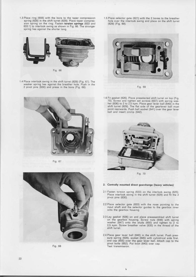
Push the wrthdrawal bearng carner over the tnput shaftand posit ion on the hous ng Tghten nuts (201) with springwasher (202) underneath to 2 to 2,5 kpm.
I
i
F i g . 6 1
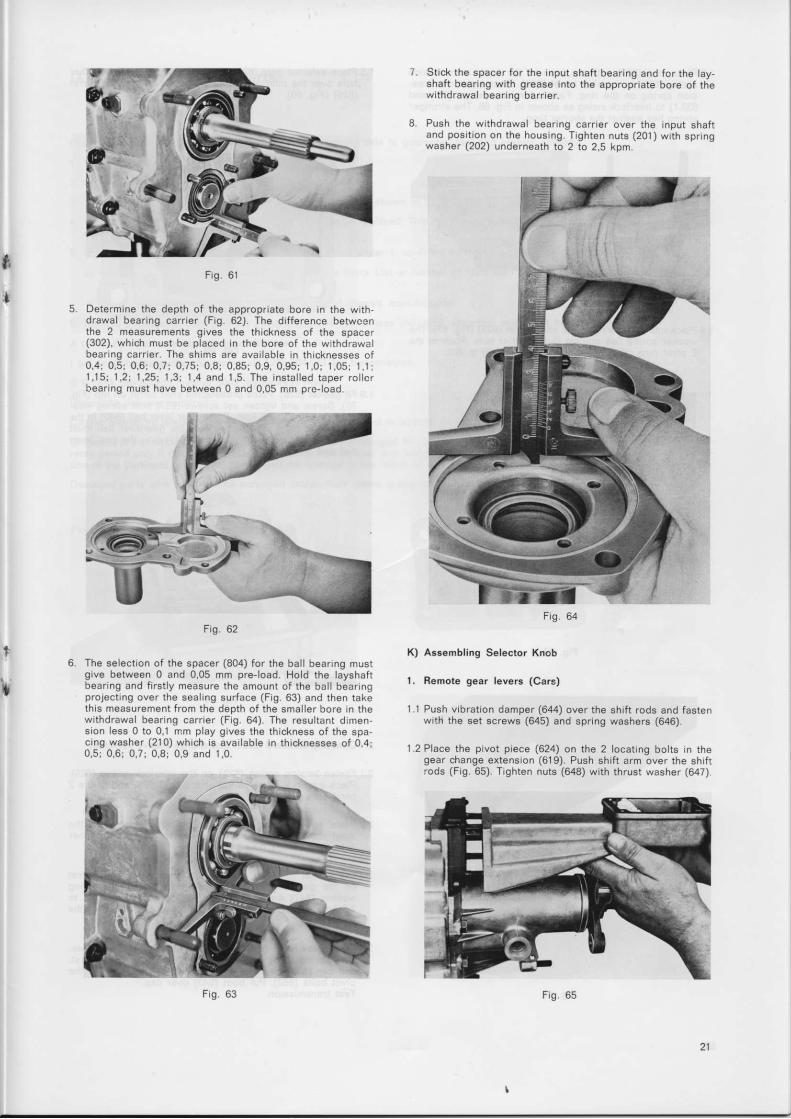
Determine the depth of the appropriate bore in the wthdrawal bearing carr ier (Fig.62). The drfference betweenthe 2 measurements gives the thickness of the spacer(302), which must be placed Ln the bore of the withdrawalbeaflng carner. The sh ms are aval lable In thtcknesses of0 , 4 : 0 , 5 ; 0 , 6 ; 0 , 7 ; 0 , 7 5 : 0 , 8 : 0 , 8 5 ; 0 , 9 , 0 , 9 5 r 1 , 0 ; 1 , 0 5 ; 1 . 1 r1 ,15 : 1 ,2 ; 1 ,25 r 1 ,3 i 1 ,4 and 1 ,5 . The i ns ta l l ed t ape r r o l c rhearing must have between 0 and 0,05 mm prc-load
F i g . 6 2
The selecnon of the spacer (804) for the bal l bea ng mustgive between 0 and 0,05 mm pre-load. Hold the layshaftbearing and f irst y measure the amount of the bal l bear ngprolecting over the seal ing surface (Fig.63) and then takethrs measurement from the depth of the smaller bore n thew i thd rawa l bea r i ng ca r r i e r (F ig .64 ) . The resu l t an t d rmension less 0 to 0,1 mm play gives the thtckness of the spa-cing washer (210) which rs avarlable in thicknesses of 0,4i0 ,5 ; 0 ,6 t 0 ,7 ; 0 ,8 ; 0 ,9 and 1 ,0
F r g . 6 4
K) Assembling Selector Knob
l. Eemote gear levers (Cars)
1.1 Push vibrat ion damper (644) over the shrft rods and fastenwith the set screws (645) and spring washers (646).
1.2 Place the pivot piece (624) on the 2 locating bolts In thegear change extenslon (619). Push shif t arm over the shif trods (Fig.65). Trghten nuts (648) with thrust washer (647)
21
F i g . 6 3
1 . 4
l.3Place r ing (659) wrth the bore to the taper compressronspring (628) in the shif t turret (629). Place taper compres-son spring on the r ing. Fasten torsion 3prings (633 and633.i) to Interlock swing as shown in Frg 66 The strongerspr ng l les agarnst the shorter tang.
F i q . 6 6
Place interlock swrng In the shrft turret (629) (F g. 67). Theweaker sping l ies against the breather hole Push n the2 pivot prns (630) and press n the bore (Fig 68).
I 5 Place selector gate (627) with the 2 bores to the breatherhole over the interlock swing and place on the shif t turret(629) (Fis. 69)
F r g . 6 9
1.6 Frt gasket (626). Place preselected shif t turret on top (Frg70). Screw and t ghten set screws (637) with spflng was-her (636) to 2 to 2,5 kpm. Place gear lever bal l (640) n theshift turret (629). The f lat side of the gearlever bal l mustpoint rearwards. Push bal l socket (641) over the gear leverbal l and insert circl ip (642)
2.1
F i g . 7 0
Ceniral ly mounted direct gearchange (heavy vehicles)
Fasten torsron spring (633) on the Interlock swLng (625)Place nterlock swing in the shif t turret (629) and f i t the 2prvot pins (630).
Place selector gate (653) with the nose potntrng to theinput shaft and the selector guides to the gearbox inneronto the gearbox housrng.
Lay gasket (626) on and place preassembled shifr turreton the gearbox housing. Screw nuts (648) with springwasher (647) onto the studs (650) and t ighten to 2 to2,5 kpm. Screw breather valve (635) in the thread of theshift turret.
Place gear lever bal l (640) in the shif t turret. Push pres-sure spring (628), socket (645) with cyl indrical side f irst.and cap (655) over the gear lever bal l . Attach cap to thepivot bolts (652). Pur boot (643) over cap.Test transm ssion.
t
)L
Ftg 61
a - -
ld"-r
22
F i g . 6 8
2 .4

lX. Ordering of Spare Parta
Od€rs for sparr part! should alwa!€ provld. th9 iollowlng dat6 to guar6nl!! f6st and conact dlllvary.l. Type ld6ntlflcatlon (on typ! ratlng plote)2. Produqilon numbor of t lmmilslon (on typ€ ratlng pl€t6)3. DlrlgnEtlon of daslBd lpgra paft!. Ahlvay! uga ngma 9a ghown In Spsro Parts List and Assombly In8tructlonB.4, Stats ten-dlglt nunb.r pundrsdin or cast on part to b6 roplacod. Thls numbsr ls tndlspen8ebb, lf th! type numbqr oi thc tron!-
mlaslgn c€nnot bc glvln.5. lf you cannot suppv rny or sov6ral of th6 dats listod undgr t. to 4. th! iollowlng Ingtructlon. aro lmportant.
a) Nuntlr of lllulrr.t d tabb eupplled wlth Spa.e Parts Llst or numbsr of illustretld iable In tha plrthqnt Alsambvlnstruction8,
b) Makg and typ€ deslgnadon of whicle, nano of drassis manufacturar-6. Mathod of de8pstdr audr !r Poet, F,rlght, Expro6s otc. Unl€ss lndic€tsd, shipinsnt wlll be as sslectsd by ue.A part ctly cl.ar ord.r should br rs iollowa:I am ordcrlng harowtlfi onc malnshaft 1255 3{X 073 for fanlml.slon:S $18/3, productlon numbqr dX{}, by express meil.Inmodlato doliwry requlrsd.Ordors placsd by tolophonc or c.bb lhould ba acknowledgod In wrltlng.Shlpmant et rlsk of bqor, awn wh.n rgsr! pertr !r. not drarged ior. Sprro plrt !r! .xdungad ft.. of dr.rg. durlng thc war-ranty p€rlod only lf dsmlgrd parta ar! alnt to us frla of coEt 6nd withor^ p]lrloit! dungar msdr thcrcon, and whln sn Insplc-tlon of ths pgrtlngnt compgnaot lhov.' trat the d!rugc ls tho rulult of a productlon or matadal fault.Drnlged p!rt! lrnt to u! wlll ba ecrapped unlee thelr roturn ls aN'fr|.ly raqurltld whsn shlppgd.
Prtmut: All Ep6r9 part8 aro dollv6r c.o.d.
a
X. Key to lllustrations
Hou6ing G.oup
101 Front Housing102 Nut103 Spring Washer104 Stud105 Stud106 Dowel107 Gasket108 Stud109 Stud1 10 S tud11 i Sea l i ng Washe r112 Magnetic Drain Plug113 Dra in P lug114 Boar Housing115 Type Plate116 Gaske t117 Cover118 Bo l tI l9 Cover120 Stop Plate121 Stud122 Spring Washer123 Nut124 Set Screw125 Spring Ring126 Operating Shaft (Rev. Light)
Input Sh.ft Group
404 Pressure Piece405 4th & sth gear synchro body406 Sliding sieeve407 Complete 5th gear/cpl.4th g.408 Needle Bearrnq40S Circl ip410 Thrust Washer411 Complete 3rd Gear412 Needle Bearing413 C i r c l i p414 2nd & 3rd gear synchro body415 Complete 2nd gear416 Needle Bearing411 Mainshaft418 Reverse Gcar419 .1 Sp r i ng B ing419 .2 C i r c l i p419.3 Cover Plate420 Sliding sleeve for tst & Rev.421 Complete 16t gear422 Thrust Washer423 Ball bearing424 Shim425 Spring Ring426 Distance Bush421 Speedo Worm428 Distance Bush429 Output flange430 Nut431 Washer
Reverse Gear Group501 Thrust Washer502 Reverse ldler503 Needle Bearing504 Distance Bing505 Flevers€ ldler Shaft506 Spring Washer507 Bolt508 Boller Bearing509 Washer510 Thrust Washcr511 Dowe l
Gear Change Group
601 4th & sth gear selector fork602 Bolt603 Spring Washer604 Pivot Pin605 O Bing607 Selector Pad608 4th & 5th gear selector Flod609 2nd & 3rd gear selector fork610 Pivot Pin6l I Pivot Bolt612 2nd & 3rd gear selector Bod613 lst & Rev. Gear Selector Fork614 lot & Rev. Cear Selector Rod615 Ba l l616 Pressure Spring617 Detent Plunger618 Casket619 Gear change extension
620 Washer621 Pressure Spring622 Pressure Spring623 Guide Body624 Guade Piec€625 Interlock Swing626 Gasket627 Selector Gate62A Conical corl spring629 Gear lever turret630 Pivot Pin631 Spring Washer632 Bolt633 Gear lever bias sorino633.1 Gear lever bias sfr ini634 Pivot pinoJc breather636 Spring Ring637 Short Set Screw638 Long Set Screw639 Selector Pad640 Shift lever bal l641 Shift lever socket642 V Ring643 Bubber Gaiter644 Vibration Damper645 Set Screw646 Spring Ring647 Spring Washer648 Nut650 Stud651 Bayonet Cap652 Guide Pin653 Interlock Plate654 Dust Cap655 Cap656 Locating Block657 Gear Knob658 Nut659 Locking Bing660 Intermediate Plate661 Gasket
Speedo Driva Group801 Speedo Cover802 Gasket803 Set Screw804 Washer805 Stud806 Stud806.1 Stud807 Spring Washer808 Nut809 Stud810 Needle Bearing Housing811 O i l Sea lA12 Oil Seal813 Speedo Shaft814 Speedo bush815 R ing816 Self Locking Nut817 Cover818 Gaske t819 Set Screw
201202203204205206
207204209210211212
214
NutSpring WasherCentral ising FlangeGasketStudClutch Withdrawal BearinaCarrier
Circl ipShimShimSpring RingBall BearingInput ShaftRoller Cage Bearing
Layshaft Group
301 Circl ip302 Shim303 Ball /Rol lerBearing304 Constant Gear305 Circl ip306 5th gearl4th Cear307 3rd Gear308 Layshaft309 Ball Bearing
Mainshaft Group
C i r c l i pSynchro BingSynchro Ring
401402403
24
8046[@'
805 - f t@807 808
e,q,
Gear HousingSpeedo Drive
ds@-806#
tr\ 0---- to3102
.sifsr05
802
9u,
ZF-Synchroma-Gearbox S 5-18/3
ffi't't5{^)
lr-/-'ll5
fltlb_)
ttt ,or'@\D
118
66@'t08
@109rc
I,fu,
Fig.30-l/b
@
NstmdW*7::.nxsrr ir \.t aaba, _:. rr{C\\ \t W t - 406
-K$_ V f., s ** *^^^i@@'w' .,)- !o*'''o'|'z'22'3 #')ffi@@gffiYi-" :-- 'ffi"s'@S-ffinr@#ryXffi-N 1''pffi4qoor -Y='- '
*"SM dInput Shaft
Ewsl@,'*"a*;},50r
Main Shaft r^.r' 62E eq-;, J:t*" ;";,,:,, s-,8,3 Fig.30-2/b
t
&",<=D 642f=-,4 04 |
{
t-g 65!
q^@ 2 v0os @^
604605
615 0
sro psrz S
611
#e-o, o 615
><\ 628\-,#3d W''ed
*d#i,o 615
$em0 617
6@*t*, & ^
610605
qSsr.r $8
ZF-Synchroma-Gearbox S 5-1813
A f,\ 633.r,6il /'\k 62s M
_1, \l / \9srr ft\ Ul\\ l f I*-ffi eV! '
I609
fl,'oozlP
a^^- @uo'" 604 6oa %
602
@*'-"Frso$ 630
F 637tilo 636
I
fl*r&"tn 5
N-a
Gear Change
Fig.30-3/o
@@811
0 816807
s@'"m 0804
@u,
ZF-Synchroma-Gearbox S 5-18/3
6s6@6@805
@--td806
*=- @Ool o @ 8r3 s11 .; ^.-
a\ 103-qD lrg
|0, eoe 815 812
Gear HousingSpeedo Drive
@'- d106
.fr)I.Q,
Fig.30-4
@
P,$i}{l:, 2'?2'82@'e
^".ff\f\5ffin'WqW -:,-')r \ \\-n * ^. Nffi%@o$@q::Hr'[
otr:*- l'- -1'- -(Ac\ .,}u.fl";2osi'zozn3 q1a01
-ffiNN@€ "n04,0 - ̂ ffi,mowD\J\J ime
r\g3uouO0qY)\ )i) zot --l0') // 206q*
211
213 *^mNw@''
/ j\[email protected]@!}$ )" 430
Input ShaftMain ShaftLay Shaft
Reverse Gear
7 ,ln^
JUC3040
?o?^^. JUZ
,^^ 127 ZF-Synchroma-Gearbox S 5-18/3
o 515
tr*0 617
o 615
t srs0oz
o 5r5
I sro
gKgVq.a
bq
@
!o,F *u
q:ot^'(h^610 8o"s
fl,*oozlF
@u&sos %
fiz
65r
d 630
5 652
q^uo'u# @60/' a
605@ott
613
Q.,&t6*;-, o
GD
E648617
650
*?"5@
ZF-Synchroma-Gearbox S 5-18/3
GNM"40,
#,h;*,,P'605
Fig.30-6
Gear Change
X]l. List of ZF-Service-Stations
G E R M A N Y
Zahnradfabrik Friedrichshafen AG. Werk Berl in1000 Berfin 26. Wilhelmsruher Damm 2311245, Postfa.h 24
ZF-Kundendienst Hannover GmbHZweigstel le Bielefeld
4800 Bielefeld, Fleichenberger Str. 42
Richard Urbanek Ing., GmbH & Co. KGZF-Kundendienst
2870 Delmenhorst, Fiedeweg 280, Postfach 74
Zahnradfabrik Friedrichshafen AC.Kundendienst Dortmund
4600 Dortmund, BornstraRe 207
Gustav Hennig & Co. GmbH., ZF-Kundendienst4300 Essen-Buhr, KruppstraRe 74, Postfach 673
Franz Bucher KG, ZF-Kundendienst6000 Frankfurt 1/Main. Hanauer LandstraBe 336
Zahnradfabrik Friedricf i shafen AG,Kundendienst - Werk l l
7990 Friedrichshafen/Bodensee, Postfach 307
ZF-Kundendienst FuldaArnold Fikentscher KG,
6400 Fulda, Frankfurter StraBe 45
Bichard Urban€k Ing., GmbH & Co. KGZF-Kundendienst
2000 Hamburg 70, Angerburger StraRe 18
ZF-Kundendienst Hannover Gmbn3000 Hannover-Linden, Bernhard-Caspar-Straoe 7,
Postfach 21265
ZF-Kundendienst Kassel, Arnold Fikentscher KG3501 Sandershausen-Kassel, Bettenhauser Str. 39, Postfach 120
(on the hagh way tributary road Kassel East, entranceOsterholz street.)
Gerhard von Umbscheiden, ZF-Kundendienst5000 K6ln 30, Ehrenfeldgi ir tel 112l122
Franz Bu.her KG, ZF-Kundendienst6800 Mannheim 1, WaldhofstraBe 82-84, Postfach 369
Beis6barth & MLil ler oHG. ZF-Kundendienst8000 Mrinc$en 80, Zamdorfer StraRe 90, Postfach 8002 60
(on the high road to the airport Riem)
Lang GmbH & Co. KG, ZF-Kundendienst8504 Stein-NUrnberg. Bogenstra[Je 3
Zahnradfabrik Passau GmbH, Kundendienst8390 Passau 2, Postfaci 1, Grubweg
Erich Bonn GmbH, ZF-Kundendienst6600 Saarbriicken 3, Mainzer StraRe 269, Postfach 733
Workshop and Spare parts storel6604 Galdingen. Saargemunder StraRe 48
Zahnradlabrik Friedrichshafen AG.Werk Schwabisch GmUnd, Kundendienst
7070 Scfiwiibisch Gmund, Graf v. Soden Str. 5-9, Postfach 119
Erich Bonn GmbH, ZF-Kundendienst5500 Trier-Euren, lm Speyer 4
B.rlin
EL
Blelefeld
EL
Dglm6nho13t
Dortm!nd
EL
Ecagn
Franklun
Frlcdrldr!hatcn
EL
Fulda
EL
Hamburg
Hannovcr
EL
K.'3.1
EL
Katln
Mannhelrn
Miindr6n
EL
Niimberg
Paosau
EL
S.arbriid(cn
Sdrwebisdr Gmiind
EL
Tri6rEL
Telephon€
030/4r r 209r
0521t200071t2000721200073
0422 t I60025/60026
023r /8r 2891181A441
o21411221951
061 1 /41 5021
075411a4-1
0661/3028/3029
040/6932041
051 1 /456045/456046/456047
056r /5 21 4115 21 42t5 21 43
0221 /5510r 1
0621/372066
089/93105r
09r 1 /6 70 1r1 6 7 0 t 2
0851/207r
068r /6 61 61/6 80 35
0681/6 61 61/6 80 35
071711601-1
0651/42815h2@2
Teler
0t 81 789zfbln d
09 32 596zfbie d
02 49 285zfkdd d
0€227 @2zfdo d
08 57 785
0417 272buffm d
07 34 363zfkd d
M 9 7 5 6erzll d
02 r4 907
09 22 151zfhan d
09 97 25ahfk d
08 88r 01 rumoa o
04 63 236frabu d
05 22 793bei d
06 22 867zfnbg d
05 78 49zetpe d
04 428 959DOnn o04 428 605DOnn o
07 248 825zfgk d
04 ?2 634
'W = WorkshopEL = Spare parts store
ZF-Service-Stations outside Germany
EUROPE lo l ophono To lo r
Au.trfa Zahnradfabrik Friedrichshafen Ges. m. b. H. Wien 0222167 1548 Ot t 291W ZF-Kundendienst fur Osterrei.h zfwien aEL Triester Stresse 134-136. 1232 Wl€n.ln2erldorf
Cables: ZF-Getriebe Wien
B.lgfun Agence ZF-Service S.P.B.L. 021724064 22 451W 1440, Chaussde de Wavre, 1160 Bruxellcr-Audorgh.m 1727032 zetefservis bruEL Cables: Zetefservis Bruxelles
Donmark Skandia-Motorimport, Sjgel lsnd A/S 01/451599 2i 444ry Lf""selager 21, 2600 Glo.trup/Kobenhavn skaglo dkEL C6bl€s: Skandiamotor
Branch:W Skandia-Motorimport, Fr. l€ns€n A/S 0a1132244 69771EL Egholmsgade 7, g(x)o Aalborg, P.O.Box l l7 skamo dk
Flnland Atoy OY, Industry department 6?337, 12555W Lauttasaarentie 54, P.O.Box 10137, 00200 Hel.inki 20 atoy sfEL Cables: Atoy Helsinki
F6ncc ZF-France S.a.r.L. 6 86 68 40 26 954W Bue de Vi l leneuve 3/11, 94533 Rungi. Si l lc zl teEL
w o .M .A . - zF 890239 43 463EL Zone Industrielle fra
28. 4Cne Avenue, 13700 Vitrollo.
W Etablissement Cauchois 53 93 21EL 150, Bue d€s Marqui l l ies, 59013 Li l lo CodoxW Str€sbourg Gadouis, S.A. 333838 87 083EL l-3, Bue des Pompisrs,673q) Sdtl l t lgh.lrn
Post adresse: 9.P.27,67042 Strasbourg CederGroece U. J. Phostiropoulos & Cia. E. E. 520/.23 216 360
W Leoforos Athinon 26, Ath€n 2m, P.O.Box 1 122 52 05 42 fost grEL Cables: lngphosti Athen 533910
Branch:EL U. J. Pho6tiropoulo6 & Cia. E. E. 51 3313
Monastir iou Str. 61, Tho$alonlki 51 64 06Gr.at Britain ZF Gears (Great Britain) Ltd. 0602/25 35 50 377 062
W Lilac Grove, Beeston, Nottinghan NG 9l QX 1221865 transgear nottmEL Cables: Transgear Nottm. 1221a66
Italy S.A.|.M. o2l38 15 70 33 393W S.p.A. Svi luppo Applicazioni Industr ial i Meccani.fre l3A44A1 saimspaEL Via Leon Battista Alberti t0. 20149 Mllano
Cablesr Svi luooosaim Milano
Spare parts store: 31 51 93Servicio Assistenza e Ricambi 34 47 43Workshop: 9 04 60 15Officina di Assistenza20090 LiBiro/Milano, Nuova Strada FlivoltanaBranch:s.A.r.M.S.p.A. Sviluppo Applicazioni Industriali Meccanidte 578 440Viale Aventino 32la, 00.|53 Fona
W CETRULLO VITTORIO 60 335EL Viale Pindaro, 45---65, 65100 P.rc.raW SCARPAZZA BALDO 66 11 76EL Zona Industriale 90 strada, 18, 35ldt Padoya
W Autoriparazioni BOMBARA 3217 1AEL Strade del Barocchio. 39. 10136 Torino
W IGNAZIO ZAPPA S.r. l . 4233 A1EL Circonvallazione Nomentana, 474. 00l6il Bona 42 53 59w Bossr BoMANo 26s47EL Viale Trento. 204, 36100 VlcsnzaW AVLES-SELVA 53M 15EL Via E. Mattei,50, Strada per Ravenna,,Ol3,l Bologn.w FADES 33 00 42EL Largo S. Maria del Pianto, 40/41, 8|tlilit Napoli 51 57 6l
32
lugo.lavlawEL
Ndh.rl.ndtwFI
NorwaywEL
Portug.l
wEL
wELwEL
SI|E rl.ndwEL
Spdn
T.lcphonr
9 f i 3 5
432504 39 /tg
2t 2a 46
24 66 34
2a 44
23864
06r /32 30 46
06t /34 20 | 0
0t 14 (}20t 14 210t t4 36
070/98 25 20
02113 24 g
53 79 53stt 86 0556 28 4056 37 59
08/25 26 60
03r /53 04 60
060/! 2 t9 45
040/93 23 45
0t /50 50
Tcbr
3r r8g31 299Ecllb yu
31 427
fi 328acbgd yu
3t 087mqdia nl
fi 629aaEo n
t5 04kgk s
72113lga g
36 7t8gln o
wEL
wELwEL
w
w
wEL
RICCI FRANCOVla Rusqslll, 50, 47qfa S. Pbro In B|gno (Forll)
AUTOCAFVla Au|llla Owst. 8l/a. 5al0 Mr..
SAPIENZA LUCIANOVla Golso Blanco. 28. 05121 6t nh
LONGO ROCCOVla S. Csterina, 2 (Fione S. Glorglo), 70l2a B.rl
MONACHESI & MOZZONIVia T6r.la, 4, 6:1100 lLc.r.tr
VALLEBONA S.p.A.C.P. 2Ol (andrq per GM), OI00 C.glld
AutocommgrcgZastopnlako PodlotleTrdlnova Ulica ,1, Et00O qub[.n., P.O.Box 422Cobles: Autocon€rco Llubllana
Workshoo:G.al-AvtoobnovaTitova Ulica 136, 61000 qubU.n|' P.O.Box 280Cablse: Gral LJubllana
Branch:Autocomm€rcgZEetopnlako PodretleKatanlcova 18, B.og.d
Todrnlsdr Bureau M€dia B.V.Trqubatrsat 31, 2100 Bl.wllk CZ-H), Postbus 2
A/S Auto Supply Co.Ringedkevn, 243, Odo l, l3l4 SkuiCabl6s: AutoBupply
SIPAVEL, Soclededs do lsolamsntos parE Velculoa, Lda,Rua Ramalho Ortlg6o, +rldlLl.bor ICablee: SIPAVEL LISBOA
K.G. Knutsson AktiobolagUlvslndevdg€n 146, t6lit Bronn. | | /Stodrholrn, P.O.Box I l0@Cabl6s: Knutlng Stockholm
Brandls:Ruekvtd.rEgrtan 10, /m77 Gdbborf 48, P.O.Box 48019
Koepmengaten 29, ESiI't Sond|vdl
Mumansgalan 112, zlZE il.|fr
SKAG - Steuerungen und Kupplungrn AGAndroaestraoo 17, m50 Zorldr P.O.Box 636Cableo: SKAG Zorlcfrto. g..r borat grrr drlv|t, .d.r, 9..8,loddng dlti.rnd.b |nd punp.:l.S.A. Industrl€8 Avlscl6n da Subeldlerlae, SA.Apartado 250, Canetora d6 Carmona, Scvlll.Pollgono Industrlal d€ Calong6Cablss: ISA Sevlllafor d..rlng grrn whh pump. .nd .rhaurt bnkat:IMENASAIndu8tdas Mstdllcas de Navarra, S.A.Apartado Cor.eos li|o, CanoterE do Baratlain lT, Pamplon!Cables: IMENASA
EL
S0cdcnwEL
12 25fmtl p
20 955kgk I
w
wEL
3528(D35 29 00
25 f i @
Tr|rklywEL
ArsimldisMusss€asaFotomobll.Malz€meslTlcErotlTA.S, 447460Fue Okcu Musa Cadd€sl $/5'1, P.O.Box 8112, lttrnbul-lbr.kdyC8blosr Archlmldis lstEnbul
22 585ardr tt
3:'
A F E I C A Tclcphonc Tcler
lvory Coa.t SociCtd d lmportataon de Padces Automobiles 32 30 18 698w S.A.B.L. (S.|.P.A.) 3s s7 s0EL B.P. 21 71, 34, Autorout€ do lAeroporl
AbldJan/C6te d'lvol.cGabon ^,,,--, , - , ,J Eastern Trading Company (Hamburg) G.m.b.H. 04 /34901 212 5,23;::::-' Krppingstr. 6, 2qr0 H.nburg 13 aerco diJiJirr" ra,"a Post adre6se: Hamburg 1, P.O.8ox fl4'Cliiiliiiii-"i
Rcoubtic cables, Ethrope Hamburg
Company in charge of 6ervice:Gabon Hatton & Cookson Matforce, B- P. No.75
W Libr.Ylll., (F.p|lblic of cabon)EL
Camcrun Ciacam Matforce, B. P. No. 4025W Dou.la, (Fode.al R.publlc of Camorun)
".";: s. c. K. N. conso Matforce, B. P. No. 6s2
W Pointe Noirs, (R.publlc ot Congo)
B.public Tchad G. B. Oll ivant (Congo) Ltd., P. B 712W Avenue du Gen6ral de Gaulle,EL Forl Latny, (Republic of Tdrad)
Ccntr.l Afric.n R.public S. C. K. N- CAW B. P. No. 799 et 809EL Bangul, (C6ntral Afrlcan Republic)
R.public of South Afr lca TRADE BELATIONS INTERNATIONAL (Pty.) Ltd. 834-4559Rhod..ia P-O.Box 2259, lohenn.rburg (R.publlc ol South Atrics)
W Office and Workshoo:EL P.O.Box 4007, Bosworth Street.
Al.od€/Albonon, Transvaal, (Republic of South Af. ica) 869-82 16 43-0927Cables: ZAFBUBG
South-We3t-Afr lca O&O Electr ic and Engineering (f iY) Ltd 2-66 50 56465W P.O.Box 5056, Krupp Str. 33. WtndhoGk/S.W.A.EL
A M E B I C A
Aig€ntin. Rehm S. C. P. A. 791-40 88W Avonide Maipi 3146/50, Casi l la de Correo No. I 797-5394EL Ollvor (Prov. Buenos Aires)
Cables: ZETAEFE-SERVICE Olivog
Brazl l ZF-DO BBASIL, S. A.W Caixa Postal 1626. S5o P.ulo,EL Work6 and Administrat ionl
Bua Senador Vergueiro, 428, 09500 Sao Caeteno do Sul 42-21 22 023 865Cablos: Ultramaran-Seo-Paulo zf sco
Ghllc Robert Bosch de Chile, Equipos y Maquinarias, S. A. 25 96 48 03 53W Av. San Eugenio 68, Santiago dc Chll . , Casi l la 832 259691 emasa sgoEL Cables: CHILEBOSCH 25 97 93
Colombia Automotora LEMKO, Ltda. 37 27 16EL Apartado A6reo 4989 37 46 83
Carrera 30/15-16, Bogoti D. E.Cables: LEMKOBranch:Carrera 5/24-10. Cali 77 1563
EL Safvador Servicio Centroamericano ZF, S.A. 21 3217Guatamal. Boulevard Venezuela No. 1 153Hondura. San Salvador / El Salv.dor, C.A.Nlc.r.gu. Cables: ZETAFEZACo.ta Rica
P.ru Tecnica lmport. S. A. 32 30 88EL Llma, Palca 201 -Casi l la 171
Cables: TECNICAIMPORT
V.d.zueb SEBVEPESA, Servicaos de Vehiculos Pe6ados. S.A. 342355 21 136W Av€nida R€p0blica Dominicana Boleito Norte. 34 24 55 zico servepesaEL C.r6c.. l0?
Cables: Serveoesa
34
lnnwEL
lordrnwEL
A S I A
G. Reza Sanaty,Ave. Saadl, Passags Saadl No. l l, Trh.r.nCablss: Sonesadl TehranWorkshop:Ave. Ghazvln Eetegaho Soloymanlysh No. l42fl,|:}l, Teh€rqn
Ad66b M. Sabbagh Bros. Co., Motor Englnsera & AgentgP.O.Box 868. Ann.nCEbles: AMS-Amman
GLOBE. Commsrclal EstabllshmontP.O.Box 4580, ltuwelt/AnbleCables: Globecom
Ado€b M. Sabbagh, Motor Englnsers & Agent8,P.O.Box 3694, BcyrourhCablea: AMS-Beyrouth
Dlesel-Elqctrlc ConpanyP.O.Box l(Xg. ,rd&htsludl Ar.bhCables: Delcent,laddahBlandrgslP.O.Box 297. J.ddlhrsludl Ar.bhC6bl6s: Dios€ctrlc roddah
P.O.Box 86, myldhrsludl AnblaCEblsB: Dlesoctlc Rlyedh
P.O.Box 24, Dlmn.mr8ludl Arrbl.Cablos: Dissectrlc Dammam
Adoeb M. Sabbagh, Motor Enghsers & AgenteB.O,Box 743, D.m... .CableE: AMs-Damascus
A U S T R A L I A
Transpsq Llmltsd570, Geelong Road, BrooklFr Cboum., vlc 3025?.O.Box 223, Footscray/Vlc. 3011Cablos: Transmotor Mslboume
Brandrss:
l,|4, W6lahpool Roadlryd.hpoolrP.t||r, w. A 6106Cablsg: Trangmotor P€rth
5(l9. Grsnd Junctlon Roadwlngfr.ldr^dcldd., S. A. 5lrl3Cables: Transmotor Adolelde'180, Sllverwator RoadAubunrsydrry, N. S. lY. 2l+lCablss: Transrptor Sydney
l&Il, lpswldr RoldRo*ltrrBdtb.n., Qld. /tl6CablsE: Trsnsnotor Brlsbang
Tggmsnls Transpec LlmibdG. P. O. Box 90Llr|nccdoo t25O
T.l.phon. Tolcr
3S 38 39
95539l
2 21 95 Oftics2 3089 Workohop
429829ia l0 73
41275
22222
Kur.hwFI
Lb.nonFI
s.udl Ar.bl.w
22122221?3EL
wEL
FI
strl.EL
VlcbrLwFI
22222225?2,
22 444
'| 84 05
3t4@22 30 225transp€c aa
W..irm-Audrdl!
Sou F^u.trdl.w
N.w Soulh W.lorwFI
Q0..ndrndwEL
T!.n.nhwEL
68 32 36
62 6r 15
6482892
47 4!i 3!i
31 20 18
9:] 009
82 891
2l il43tranap6c
41 296
35