ZU 160 - hydraulika.de · Cylindre hydraulique. Betriebsdruck max. 16 MPa ( 160 bar ) Operating...
10
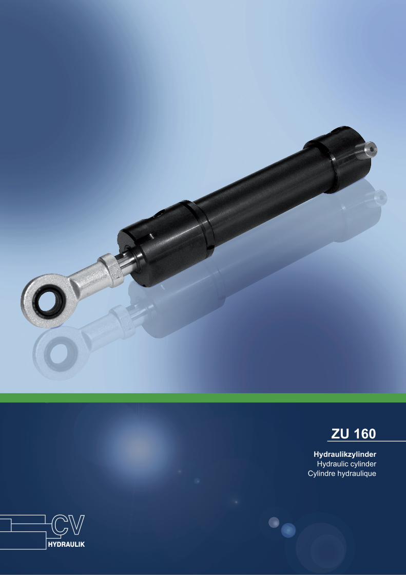
ZU 160 Hydraulikzylinder Hydraulic cylinder Cylindre hydraulique
Transcript of ZU 160 - hydraulika.de · Cylindre hydraulique. Betriebsdruck max. 16 MPa ( 160 bar ) Operating...
ZU 160HydraulikzylinderHydraulic cylinder
Cylindre hydraulique
Betriebsdruck max. 16 MPa ( 160 bar )Operating pressureService de pression
Betriebsdruck max. 16 MPa ( 160 bar )Operating pressureService de pression
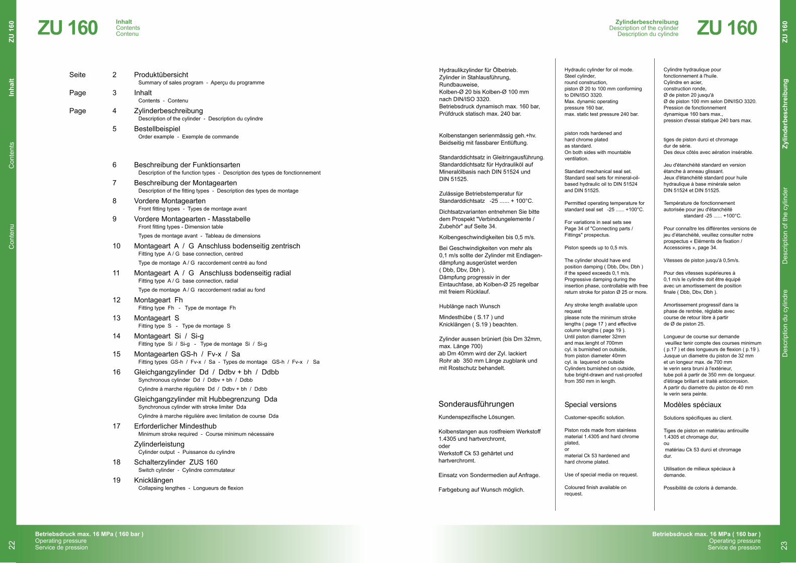
Hydraulikzylinder für Ölbetrieb.Zylinder in Stahlausführung,Rundbauweise,Kolben-Ø 20 bis Kolben-Ø 100 mmnach DIN/ISO 3320.Betriebsdruck dynamisch max. 160 bar,Prüfdruck statisch max. 240 bar.
Kolbenstangen serienmässig geh.+hv.Beidseitig mit fassbarer Entlüftung.
Standarddichtsatz in Gleitringausführung.Standarddichtsatz für Hydrauliköl auf Mineralölbasis nach DIN 51524 undDIN 51525.
Zulässige Betriebstemperatur fürStandarddichtsatz -25 ...... + 100°C.
Dichtsatzvarianten entnehmen Sie bittedem Prospekt "Verbindungelemente /Zubehör" auf Seite 34.
Kolbengeschwindigkeiten bis 0,5 m/s.
Bei Geschwindigkeiten von mehr als0,1 m/s sollte der Zylinder mit Endlagen-dämpfung ausgerüstet werden( Dbb, Dbv, Dbh ).Dämpfung progressiv in derEintauchfase, ab Kolben-Ø 25 regelbarmit freiem Rücklauf.
Hublänge nach Wunsch
Mindesthübe ( S.17 ) undKnicklängen ( S.19 ) beachten.
Zylinder aussen brüniert (bis Dm 32mm,max. Länge 700)ab Dm 40mm wird der Zyl. lackiertRohr ab 350 mm Länge zugblank undmit Rostschutz behandelt.
Kundenspezifische Lösungen.
Kolbenstangen aus rostfreiem Werkstoff1.4305 und hartverchromt,oderWerkstoff Ck 53 gehärtet undhartverchromt.
Einsatz von Sondermedien auf Anfrage.
Farbgebung auf Wunsch möglich.
Sonderausführungen Special versions Modèles spéciaux
Hydraulic cylinder for oil mode.Steel cylinder,round construction,piston Ø 20 to 100 mm conformingto DIN/ISO 3320.Max. dynamic operatingpressure 160 bar,max. static test pressure 240 bar.
piston rods hardened and hard chrome platedas standard.On both sides with mountableventilation.
Standard mechanical seal set.Standard seal sets for mineral-oil-based hydraulic oil to DIN 51524and DIN 51525.
Permitted operating temperature forstandard seal set -25 ...... +100°C.
For variations in seal sets seePage 34 of "Connecting parts /Fittings" prospectus.
Piston speeds up to 0,5 m/s.
The cylinder should have endposition damping ( Dbb, Dbv, Dbh )if the speed exceeds 0,1 m/s. Progressive damping during theinsertion phase, controllable with freereturn stroke for piston Ø 25 or more.
Any stroke length available uponrequest please note the minimum strokelengths ( page 17 ) and effectivecolumn lengths ( page 19 ).Until piston diameter 32mmand max.lenght of 700mmcyl. is burnished on outside,from piston diameter 40mmcyl. is laquered on outsideCylinders burnished on outside,tube bright-drawn and rust-proofedfrom 350 mm in length.
Customer-specific solution.
Piston rods made from stainlessmaterial 1.4305 and hard chromeplated,ormaterial Ck 53 hardened andhard chrome plated.
Use of special media on request.
Coloured finish available onrequest.
Cylindre hydraulique pourfonctionnement à l'huile.Cylindre en acier,construction ronde,Ø de piston 20 jusqu'àØ de piston 100 mm selon DIN/ISO 3320.Pression de fonctionnementdynamique 160 bars max.,pression d'essai statique 240 bars max.
tiges de piston durci et chromage dur de série.Des deux côtés avec aération insérable.
Jeu d'étanchéité standard en versionétanche à anneau glissant.Jeux d'étanchéité standard pour huilehydraulique à base minérale selonDIN 51524 et DIN 51525.
Température de fonctionnementautorisée pour jeu d'étanchéité
standard -25 ...... +100°C.
Pour connaître les différentes versions dejeu d’étanchéité, veuillez consulter notreprospectus « Eléments de fixation /Accessoires », page 34.
Vitesses de piston jusqu'à 0,5m/s.
Pour des vitesses supérieures à0,1 m/s le cylindre doit être équipéavec un amortissement de positionfinale ( Dbb, Dbv, Dbh ).
Amortissement progressif dans laphase de rentrée, réglable aveccourse de retour libre à partirde Ø de piston 25.
Longueur de course sur demande veuillez tenir compte des courses minimum ( p.17 ) et des longueurs de flexion ( p.19 ).Jusque un diametre du piston de 32 mmet un longeur max. de 700 mmle verin sera bruni à l'extérieur, tube poli à partir de 350 mm de longueur.d'étirage brillant et traité anticorrosion.A partir du diametre du piston de 40 mmle verin sera peinte.
Solutions spécifiques au client.
Tiges de piston en matériau antirouille1.4305 et chromage dur,ou matériau Ck 53 durci et chromagedur.
Utilisation de milieux spéciaux àdemande.
Possibilité de coloris à demande.
ZylinderbeschreibungDescription of the cylinderDescription du cylindre
4
Subject to changeSous réserve de modification
Änderungen vorbehalten
Betriebsdruck max. 16 MPa ( 160 bar )Operating pressureService de pression
2017
ZU 160
Des
crip
tion
du c
ylin
dre
Des
crip
tion
of th
e cy
linde
rZy
linde
rbes
chre
ibun
g Z
U 1
60ZylinderbeschreibungDescription of the cylinder
Description du cylindre ZU 160
23
Seite 2 Produktübersicht
Page 3 Inhalt
Page 4 Zylinderbeschreibung
5 Bestellbeispiel
6 Beschreibung der Funktionsarten
7 Beschreibung der Montagearten
8 Vordere Montagearten
9 Vordere Montagearten - Masstabelle
10 Montageart A / G Anschluss bodenseitig zentrisch
11 Montageart A / G Anschluss bodenseitig radial
12 Montageart Fh
13 Montageart S
14 Montageart Si / Si-g
15 Montagearten GS-h / Fv-x / Sa
16 Gleichgangzylinder Dd / Ddbv + bh / Ddbb
Gleichgangzylinder mit Hubbegrenzung Dda
17 Erforderlicher Mindesthub
Zylinderleistung
18 Schalterzylinder ZUS 160
19 Knicklängen
Summary of sales program - Aperçu du programme
Contents - Contenu
Description of the cylinder - Description du cylindre
Order example - Exemple de commande
Description of the function types - Description des types de fonctionnement
Description of the fitting types - Description des types de montage
Front fitting types - Types de montage avant
Front fitting types - Dimension table
Types de montage avant - Tableau de dimensions
Fitting type A / G base connection, centred
Type de montage A / G raccordement centré au fond
Fitting type A / G base connection, radial
Type de montage A / G raccordement radial au fond
Fitting type Fh - Type de montage Fh
Fitting type S - Type de montage S
Fitting type Si / Si-g - Type de montage Si / Si-g
Fitting types GS-h / Fv-x / Sa - Types de montage GS-h / Fv-x / Sa
Synchronous cylinder Dd / Ddbv + bh / Ddbb
Cylindre à marche régulière Dd / Ddbv + bh / Ddbb
Synchronous cylinder with stroke limiter Dda
Cylindre à marche régulière avec limitation de course Dda
Minimum stroke required - Course minimum nécessaire
Cylinder output - Puissance du cylindre
Switch cylinder - Cylindre commutateur
Collapsing lengthes - Longueurs de flexion
InhaltContentsContenu
3
Subject to changeSous réserve de modification
Änderungen vorbehalten
Betriebsdruck max. 16 MPa ( 160 bar )Operating pressureService de pression
2017
ZU 160
InhaltContentsContenuZU 160
C
onte
nuC
onte
nts
Inha
ltZU
160
22
Betriebsdruck max. 16 MPa ( 160 bar )Operating pressureService de pression
Betriebsdruck max. 16 MPa ( 160 bar )Operating pressureService de pression
Beschreibung der FunktionsartenDescription of the function types
Description des types de fonctionnement ZU 160
Des
crip
tion
des
type
s de
fonc
tionn
emen
tD
escr
iptio
n of
the
func
tion
type
sB
esch
reib
ung
der F
unkt
ions
arte
n Z
U 1
60
E
Ez
D
Dd
Dda
Dbb
Dbv
Dbh
Ddbb
Ddb_
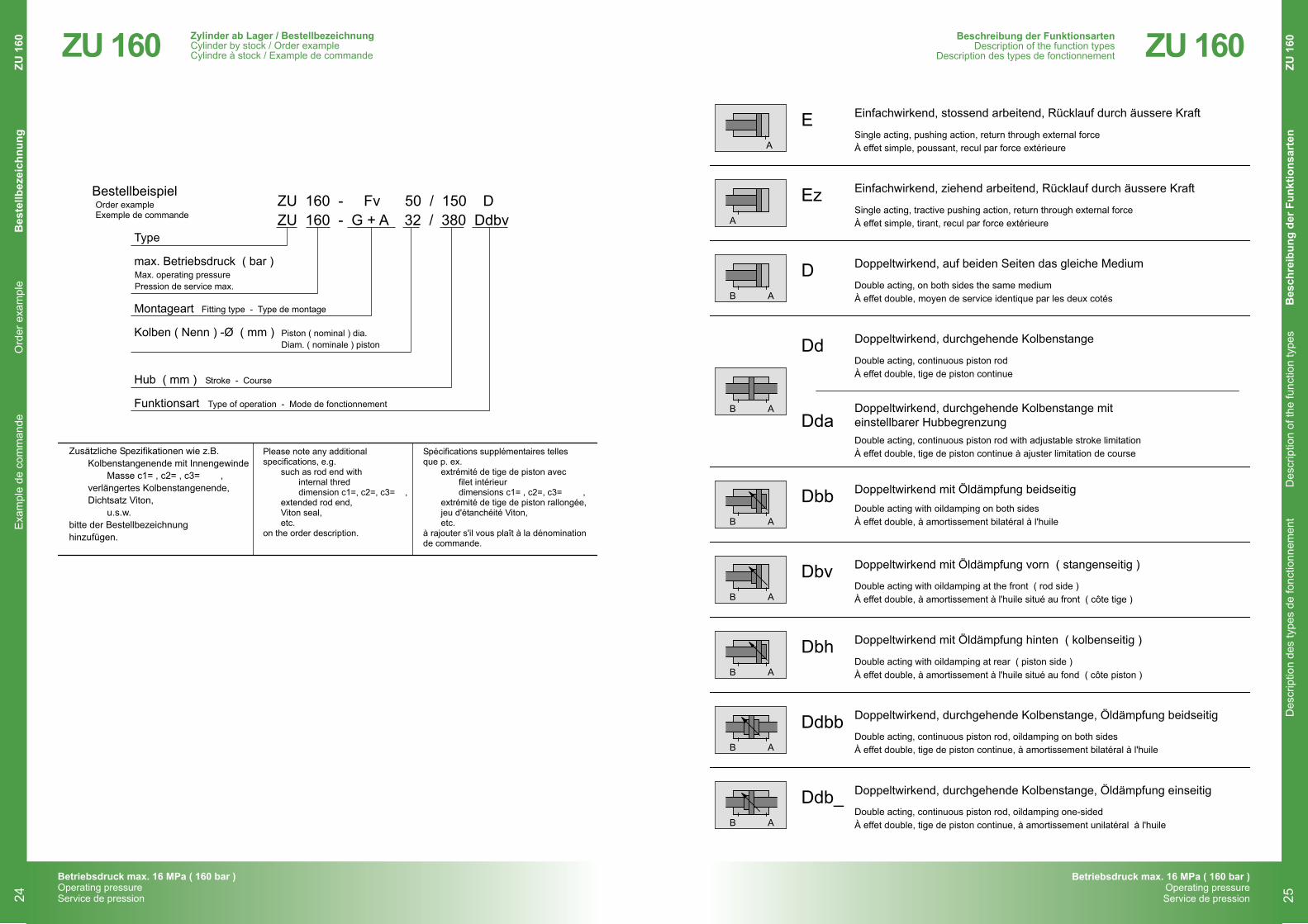
Einfachwirkend, stossend arbeitend, Rücklauf durch äussere Kraft
Single acting, pushing action, return through external forceÀ effet simple, poussant, recul par force extérieure
Single acting, tractive pushing action, return through external forceÀ effet simple, tirant, recul par force extérieure
Einfachwirkend, ziehend arbeitend, Rücklauf durch äussere Kraft
Doppeltwirkend, auf beiden Seiten das gleiche Medium
Double acting, on both sides the same mediumÀ effet double, moyen de service identique par les deux cotés
Double acting, continuous piston rodÀ effet double, tige de piston continue
Double acting, continuous piston rod with adjustable stroke limitationÀ effet double, tige de piston continue à ajuster limitation de course
Doppeltwirkend, durchgehende Kolbenstange
Doppeltwirkend, durchgehende Kolbenstange miteinstellbarer Hubbegrenzung
Doppeltwirkend mit Öldämpfung beidseitigDouble acting with oildamping on both sidesÀ effet double, à amortissement bilatéral à l'huile
Doppeltwirkend mit Öldämpfung vorn ( stangenseitig )
Double acting with oildamping at the front ( rod side )À effet double, à amortissement à l'huile situé au front ( côte tige )
Doppeltwirkend mit Öldämpfung hinten ( kolbenseitig )
Double acting with oildamping at rear ( piston side )À effet double, à amortissement à l'huile situé au fond ( côte piston )
Double acting, continuous piston rod, oildamping on both sidesÀ effet double, tige de piston continue, à amortissement bilatéral à l'huile
Doppeltwirkend, durchgehende Kolbenstange, Öldämpfung beidseitig
Beschreibung der FunktionsartenDescription of the function typesDescription des types de fonctionnement
6
Subject to changeSous réserve de modification
Änderungen vorbehalten
Betriebsdruck max. 16 MPa ( 160 bar )Operating pressureService de pression
2017
ZU 160
A
A
A
A
A
A
A
A
A
B
B
B
B
B
B
B
Double acting, continuous piston rod, oildamping one-sidedÀ effet double, tige de piston continue, à amortissement unilatéral à l'huile
Doppeltwirkend, durchgehende Kolbenstange, Öldämpfung einseitig
25
Zylinder ab Lager / BestellbezeichnungCylinder by stock / Order exampleCylindre à stock / Example de commandeZU 160
E
xam
ple
de c
omm
ande
Ord
er e
xam
ple
Bes
tellb
ezei
chnu
ngZU
160
Zusätzliche Spezifikationen wie z.B.Kolbenstangenende mit Innengewinde
Masse c1= , c2= , c3= ,verlängertes Kolbenstangenende,Dichtsatz Viton,
u.s.w.bitte der Bestellbezeichnunghinzufügen.
BestellbeispielZU 160 - Fv 50 / 150 DZU 160 - G + A 32 / 380 Ddbv
Type
max. Betriebsdruck ( bar )
Montageart
Kolben ( Nenn ) -Ø ( mm )
Hub ( mm )
Funktionsart
Stroke - Course
Piston ( nominal ) dia.Diam. ( nominale ) piston
Order exampleExemple de commande
Fitting type - Type de montage
Max. operating pressurePression de service max.
Type of operation - Mode de fonctionnement
Please note any additionalspecifications, e.g.
such as rod end withinternal threddimension c1=, c2=, c3= ,
extended rod end,Viton seal,etc.
on the order description.
Spécifications supplémentaires tellesque p. ex.
extrémité de tige de piston avecfilet intérieurdimensions c1= , c2=, c3= ,
extrémité de tige de piston rallongée,jeu d'étanchéité Viton,etc.
à rajouter s'il vous plaît à la dénominationde commande.
Zylinder ab Lager / BestellbezeichnungCylinder by stock / Order example
Cylindre à stock / Example de commande
5
Subject to changeSous réserve de modification
Änderungen vorbehalten
Betriebsdruck max. 16 MPa ( 160 bar )Operating pressureService de pression
2017
ZU 160
24
Betriebsdruck max. 16 MPa ( 160 bar )Operating pressureService de pression
Betriebsdruck max. 16 MPa ( 160 bar )Operating pressureService de pression
ZU 160
Type
s de
mon
tage
ava
ntFr
ont fi
tting
type
sVo
rder
e M
onta
gear
ten
ZU
160
A
Sm
Fv
Sv
Wv + Wh = Wb
G
Bei ZU 160 nicht möglich
For ZU 160 not possiblePour ZU 160 pas possible
GS
β° nur Dbb, Dbvβ° only Dbb, Dbvβ° seulement Dbb, Dbv
L7min.
d8
b10
b11
S2
h1
d6
L8
S1
b1
b2
r1
L22
L5
d1
d3
d8
L6
b3 b4
d7
S2
b6
b5
β°
Vordere MontageartenFront fitting typesTypes de montage avant
8
Subject to changeSous réserve de modification
Änderungen vorbehalten
Betriebsdruck max. 16 MPa ( 160 bar )Operating pressureService de pression
2017
ZU 160
VerschiebbarMovable - Déplacable
Vordere MontageartenFront fitting types
Types de montage avant
27
ZU 160 D
escr
iptio
n de
s ty
pes
de m
onta
geD
escr
iptio
n of
the
fittin
g ty
pes
Bes
chre
ibun
g de
r Mon
tage
arte
nZU
160
Beschreibung der MontageartenDescription of the fitting types
Description des types de montage
7
Subject to changeSous réserve de modification
Änderungen vorbehalten
2017
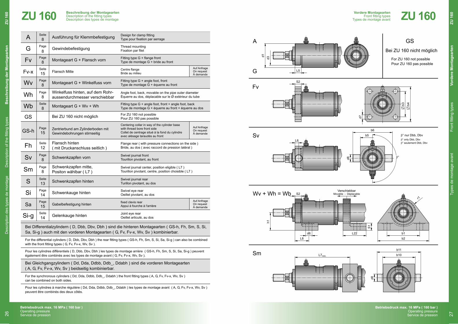
Ausführung für Klemmbefestigung
Gewindebefestigung
Montageart G + Flansch vorn
Flansch Mitte
Montageart G + Winkelfuss vorn
Winkelfuss hinten, auf dem Rohr-aussendurchmesser verschiebbar
Zentrierbund am Zylinderboden mitGewindebohrungen stirnseitig
Montageart G + Wv + Wh
Bei ZU 160 nicht möglich
Gabelbefestigung hinten
Gelenkauge hinten
Flansch hinten( mit Druckanschluss seitlich )
Schwenkzapfen vorn
Schwenkzapfen mitte,Positon wählbar ( L7 )
Schwenkauge hinten
Schwenkzapfen hinten
Design for clamp fittingType pour fixation par serrage
Thread mountingFixation par filet
Fitting type G + flange frontType de montage G + bride au front
Centre flangeBride au milieu
Fitting type G + angle foot, frontType de montage G + équerre au front
Angle foot, back, movable on the pipe outer diameterÉquerre au dos, déplacable sur le Ø extérieur du tube
Centering collar in way of the cylinder basewith thread bore front sideCollet de centrage situé à la fond du cylindreavec alésage taraudés au front
Fitting type G + angle foot, front + angle foot, backType de montage G + équerre au front + équerre au dos
For ZU 160 not possiblePour ZU 160 pas possible
Joint eye rearOeillet articulé, au dos
Flange rear ( with pressure connections on the side )Bride, au dos ( avec raccord de pression latéral )
Swivel journal frontTourillon pivotant, au front
Swivel journal center, position eligible ( L7 )Tourillon pivotant, centre, position choisible ( L7 )
Swivel eye rearOeillet pivotant, au dos
Swivel journal rearTurillon pivotant, au dos
A
Fv
Fv-x
Si
S
Sm
Sv
Fh
Wb
GS
Sa
Si-g
Wh
GS-h
Wv
G
Bei Differentialzylindern ( D, Dbb, Dbv, Dbh ) sind die hinteren Montagearten ( GS-h, Fh, Sm, S, Si,Sa, Si-g ) auch mit den vorderen Montagearten ( G, Fv, Fv-x, Wv, Sv ) kombinierbar.
Bei Gleichgangzylindern ( Dd, Dda, Ddbb, Ddb_, Ddabh ) sind die vorderen Montagearten( A, G, Fv, Fv-x, Wv, Sv ) beidseitig kombinierbar.
For the differential cylinders ( D, Dbb, Dbv, Dbh ) the rear fitting types ( GS-h, Fh, Sm, S, Si, Sa, Si-g ) can also be combinedwith the front fitting types ( G, Fv, Fv-x, Wv, Sv ).
For the synchronous cylinders ( Dd, Dda, Ddbb, Ddb_, Ddabh ) the front fitting types ( A, G, Fv, Fv-x, Wv, Sv )can be combined on both sides.
Pour les cylindres différentiels ( D, Dbb, Dbv, Dbh ) les types de montage arrière ( GS-h, Fh, Sm, S, Si, Sa, Si-g ) peuventégalement être combinés avec les types de montage avant ( G, Fv, Fv-x, Wv, Sv ).
Pour les cylindres à marche régulière ( Dd, Dda, Ddbb, Ddb_, Ddabh ) les types de montage avant ( A, G, Fv, Fv-x, Wv, Sv )peuvent être combinés des deux côtés.
Auf AnfrageOn requestÀ demande
Auf AnfrageOn requestÀ demande
Auf AnfrageOn requestÀ demande
fixed clevis rearAppui à fourche à l'arrière
8
14
13
12
8
15
8
8
15
14
8
8
15
8
8
Seite
Seite
Seite
Seite
Seite
Seite
Page
Page
Page
Page
Page
Page
Page
Page
Page
Betriebsdruck max. 16 MPa ( 160 bar )Operating pressureService de pression
ZU 160Beschreibung der MontageartenDescription of the fitting typesDescription des types de montage
26
Betriebsdruck max. 16 MPa ( 160 bar )Operating pressureService de pression
Betriebsdruck max. 16 MPa ( 160 bar )Operating pressureService de pression
ZU 160
10080635040322520Nenn-Ø
SW
d2
A
d1
d2
d3
d4
d5
d13
L1
L1
L1
L1
L2
L3
L4
L5
L9
L10
L21
SW
β
G "
52
38
M42x1,5
20
M16
38
114
162
138
138
92
47
26
14
35
53
5
17
90°
G "
65
48
M52x2
25
M20
48
130
182
156
156
104
58
32
16
43
60
6
21
90°
G "
75
60
M60x2
32
M24
55
152
212
182
182
123
68
40
18
45
74
6
27
90°
G "
140
120
M110x3
60
M48
90
215
287
251
251
185
120
75
35
73
112
10
50
45°
G "
115
95
M92x2
50
M42
80
199
259
229
229
165
98
60
30
66
98
8
41
45°
G "
95
75
M76x2
40
M33
65
170
222
196
196
137
81
50
23
60
80
6
32
90°
G "
37
25
M32x1,5
12
M10
28
92
124
108
108
72
32
16
9
28
42
4
10
-
G "
45
30
M38x1,5
16
M12
34
104
144
124
124
80
39
20
13
32
47
4
12
90°
D
Dbb
Dbv
Dbh
β° nur Dbb, Dbv, Dbhβ° only Dbb, Dbv, Dbhβ° seulement Dbb, Dbv, Dbh
d5d4d13
d1
L21
L4
L3
A
L10
L2
β°
L5
d3
A / G
A d1
L9
L1 + Hub ; Stroke ; Course
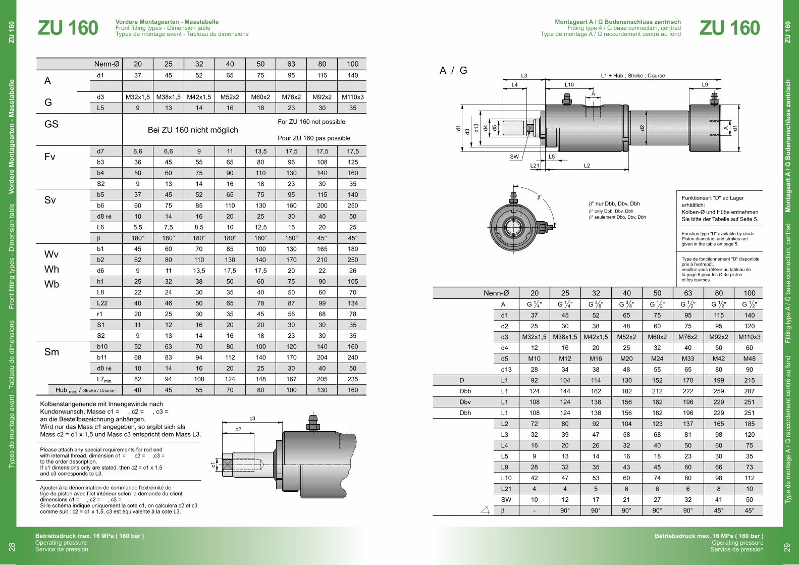
Funktionsart "D" ab Lagererhältlich:Kolben-Ø und Hübe entnehmenSie bitte der Tabelle auf Seite 5.
Function type "D" available by stock.Piston diameters and strokes aregiven in the table on page 5.
Type de fonctionnement "D" disponiblepris à l'entrepôt,veuillez vous référer au tableau dela page 5 pour les Ø de pistonet les courses.
38
12
12
12
12
14
14
38
Montageart A / G Bodenanschluss zentrischFitting type A / G base connection, centredType de montage A / G raccordement centré au fond
10
Subject to changeSous réserve de modification
Änderungen vorbehalten
Betriebsdruck max. 16 MPa ( 160 bar )Operating pressureService de pression
2017
ZU 160
Type
de
mon
tage
A /
G ra
ccor
dem
ent c
entré
au
fond
Fitti
ng ty
pe A
/ G
bas
e co
nnec
tion,
cen
tred
Mon
tage
art A
/ G
Bod
enan
schl
uss
zent
risch
ZU
160Montageart A / G Bodenanschluss zentrisch
Fitting type A / G base connection, centredType de montage A / G raccordement centré au fond
29
ZU 160 10080635040322520Nenn-Ø
d1
d3
L5
d7
b3
b4
S2
b5
b6
d8 h6
L6
b1
b2
d6
h1
L8
L22
r1
S1
S2
b10
b11
d8 h6
L7min.
β
52
M42x1,5
14
9
55
75
14
52
85
16
8,5
180°
70
110
13,5
38
30
50
30
16
14
70
94
16
108
55
37
M32x1,5
9
6,6
36
50
9
37
60
10
5,5
180°
45
62
9
25
22
40
20
11
9
52
68
10
82
40
140
M110x3
35
17,5
125
160
35
140
250
50
25
45°
180
250
26
105
70
134
78
35
35
160
240
50
235
160
115
M92x2
30
17,5
108
140
30
115
200
40
20
45°
165
210
22
90
60
99
68
30
30
140
204
40
205
130
95
M76x2
23
17,5
96
130
23
95
160
30
15
180°
130
170
20
75
50
87
56
30
23
120
170
30
167
100
75
M60x2
18
13,5
80
110
18
75
130
25
12,5
180°
100
140
17,5
60
40
78
45
20
18
100
140
25
148
80
65
M52x2
16
11
65
90
16
65
110
20
10
180°
85
130
17,5
50
35
65
35
20
16
80
112
20
124
70
45
M38x1,5
13
6,6
45
60
13
45
75
14
7,5
180°
60
80
11
32
24
46
25
12
13
63
83
14
94
45
Bei ZU 160 nicht möglichFor ZU 160 not possible
Pour ZU 160 pas possible
A
Fv
Sm
WvWhWb
Sv
GS
G
Vordere Montagearten - MasstabelleFront fitting types - Dimension table
Types de montage avant - Tableau de dimensions
9
Subject to changeSous réserve de modification
Änderungen vorbehalten
Betriebsdruck max. 16 MPa ( 160 bar )Operating pressureService de pression
2017
ZU 160
c1
c2
c3
Kolbenstangenende mit Innengewinde nachKundenwunsch, Masse c1 = , c2 = , c3 = an die Bestellbezeichnung anhängen.Wird nur das Mass c1 angegeben, so ergibt sich alsMass c2 = c1 x 1,5 und Mass c3 entspricht dem Mass L3.
Please attach any special requirements for rod endwith internal thread, dimension c1 = ,c2 = ,c3 =to the order description.If c1 dimensions only are stated, then c2 = c1 x 1.5and c3 corresponds to L3.
Ajouter à la dénomination de commande l'extrémité detige de piston avec filet intérieur selon la demande du clientdimensions c1 = , c2 = , c3 = .Si le schéma indique uniquement la cote c1, on calculera c2 et c3comme suit : c2 = c1 x 1,5, c3 est équivalente à la cote L3.
Hub min. / Stroke / Course
Vordere Montagearten - MasstabelleFront fitting types - Dimension tableTypes de montage avant - Tableau de dimensions
Type
s de
mon
tage
ava
nt -
Tabl
eau
de d
imen
sion
sFr
ont fi
tting
type
s - D
imen
sion
tabl
eVo
rder
e M
onta
gear
ten
- Mas
stab
elle
ZU 1
6028
Betriebsdruck max. 16 MPa ( 160 bar )Operating pressureService de pression
Betriebsdruck max. 16 MPa ( 160 bar )Operating pressureService de pression
ZU 160
10080635040322520Nenn-Ø
SW
d2
A
b3
b4
d1
d2
d4
d5
d7
d13
L2
L3
L4
L10
L16
L16
L16
L16
L21
L23
S3
SW
β
G "
55
75
52
38
20
M16
9
38
92
47
26
53
125
173
149
149
5
14
27
17
90°
G "
36
50
37
25
12
M10
6,6
28
72
32
16
42
100
132
116
116
4
12
23
10
-
G "
80
110
75
60
32
M24
13,5
55
123
68
40
74
162
222
192
192
6
18
35
27
90°
G "
125
160
140
120
60
M48
17,5
90
185
120
75
112
215
287
251
251
10
18
36
50
45°
G "
108
140
115
95
50
M42
17,5
80
165
98
60
98
199
259
229
229
8
16
32
41
45°
G "
96
130
95
75
40
M33
17,5
65
137
81
50
80
170
222
196
196
6
18
35
32
90°
G "
65
90
65
48
25
M20
11
48
104
58
32
60
136
188
162
162
6
15
30
21
90°
G "
45
60
45
30
16
M12
6,6
34
80
39
20
47
110
150
130
130
4
12
23
12
90°
D
Dbb
Dbv
Dbh
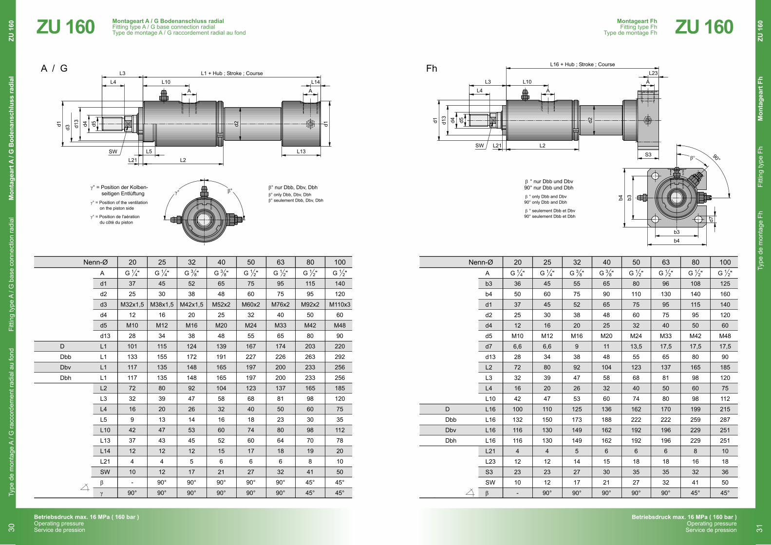
° only Dbb and Dbv90° only Dbb and Dbh
° seulement Dbb et Dbv90° seulement Dbb et Dbh
β
β
d5d4d13
d1
L21
L4
L3
A
L10 A
S3
L16 + Hub ; Stroke ; Course
d7
b3
b3
b4
b4
90°
L2
Fh
° nur Dbb und Dbv90° nur Dbb und Dbhβ
L23
β°
38
12
12
12
12
14
14
38
Montageart FhFitting type FhType de montage Fh
12
Subject to changeSous réserve de modification
Änderungen vorbehalten
Betriebsdruck max. 16 MPa ( 160 bar )Operating pressureService de pression
2017
ZU 160
Type
de
mon
tage
Fh
Fitti
ng ty
pe F
hM
onta
gear
t Fh
ZU
160Montageart Fh
Fitting type FhType de montage Fh
31
ZU 160
10080635040322520Nenn-Ø
SW
d2
A
d1
d2
d3
d4
d5
d13
L1
L1
L1
L1
L2
L3
L4
L5
L10
L13
L14
L21
SW
β
γ
G "
52
38
M42x1,5
20
M16
38
124
172
148
148
92
47
26
14
53
45
12
5
17
90°
90°
G "
65
48
M52x2
25
M20
48
139
191
165
165
104
58
32
16
60
52
15
6
21
90°
90°
G "
75
60
M60x2
32
M24
55
167
227
197
197
123
68
40
18
74
60
17
6
27
90°
90°
G "
140
120
M110x3
60
M48
90
220
292
256
256
185
120
75
35
112
78
20
10
50
45°
45°
G "
115
95
M92x2
50
M42
80
203
263
233
233
165
98
60
30
98
70
19
8
41
45°
45°
G "
95
75
M76x2
40
M33
65
174
226
200
200
137
81
50
23
80
64
18
6
32
90°
90°
G "
37
25
M32x1,5
12
M10
28
101
133
117
117
72
32
16
9
42
37
12
4
10
-
90°
G "
45
30
M38x1,5
16
M12
34
115
155
135
135
80
39
20
13
47
43
12
4
12
90°
90°
D
Dbb
Dbv
Dbh
β° nur Dbb, Dbv, Dbhγ° = Position der Kolben-seitigen Entlüftung β° only Dbb, Dbv, Dbh
β° seulement Dbb, Dbv, Dbhγ° = Position of the ventilationon the piston side
γ° = Position de l'aérationdu côté du piston
d5d4d13
d1
L21
L4
L3
A A
L10
L2
β°γ°
L5
d3
d1
L14
L1 + Hub ; Stroke ; CourseA / G
L13
38
12
12
12
12
14
14
38
Montageart A / G Bodenanschluss radialFitting type A / G base connection, radial
Type de montage A / G raccordement radial au fond
11
Subject to changeSous réserve de modification
Änderungen vorbehalten
Betriebsdruck max. 16 MPa ( 160 bar )Operating pressureService de pression
2017
ZU 160
Montageart A / G Bodenanschluss radialFitting type A / G base connection radialType de montage A / G raccordement radial au fond
Type
de
mon
tage
A /
G ra
ccor
dem
ent r
adia
l au
fond
Fitti
ng ty
pe A
/ G
bas
e co
nnec
tion
radi
alM
onta
gear
t A /
G B
oden
ansc
hlus
s ra
dial
ZU 1
6030
Betriebsdruck max. 16 MPa ( 160 bar )Operating pressureService de pression
Betriebsdruck max. 16 MPa ( 160 bar )Operating pressureService de pression
ZU 160
2017
Si-g
Si
Si Si-g10080635040322520Nenn-Ø
SW
d2
A
b7
b8
b9
d1
d2
d4
d5
d9 H7
d13
L2
L3
L4
L10
L18
L18
L18
L18
L21
L25
r2
S5
SW
G "
17
11
14
52
38
20
M16
17
38
92
47
26
53
153
201
177
177
5
13
26
28
17
G "
25
17
20
75
60
32
M24
25
55
123
68
40
74
200
260
230
230
6
15
37,5
38
27
G "
50
29
35
140
120
60
M48
50
90
185
120
75
112
285
357
321
321
10
15
70
70
50
G "
40
23
28
115
95
50
M42
40
80
165
98
60
98
256
316
286
286
8
15
57,5
57
41
G "
30
19
22
95
75
40
M33
30
65
137
81
50
80
217
269
243
243
6
17
47,5
47
32
G "
20
13
16
65
48
25
M20
20
48
104
58
32
60
168
220
194
194
6
14
32,5
32
21
G "
10
7
9
37
25
12
M10
10
28
72
32
16
42
120
152
136
136
4
11
18,5
20
10
G "
15
10
12
45
30
16
M12
15
34
80
39
20
47
134
174
154
154
4
10
22,5
24
12
D
Dbb
Dbv
Dbh
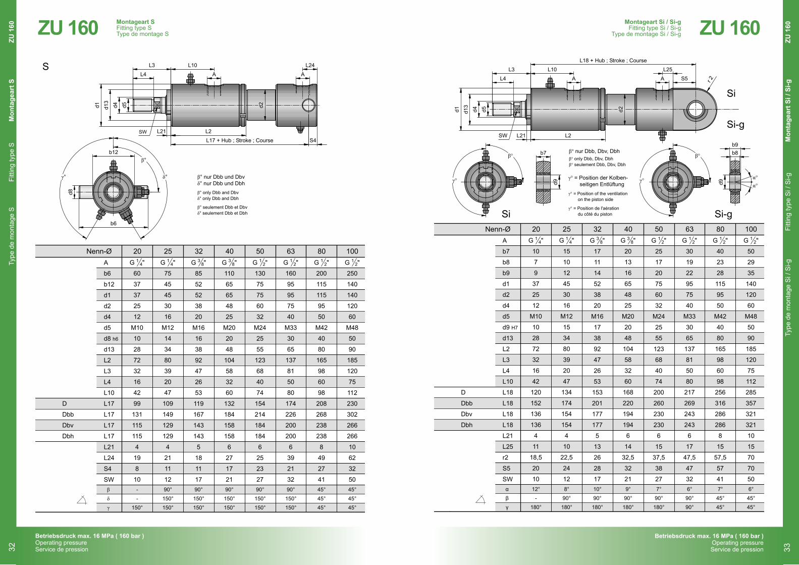
β° nur Dbb, Dbv, Dbh
α°α°
γ° = Position der Kolben-seitigen Entlüftung
β° only Dbb, Dbv, Dbhβ° seulement Dbb, Dbv, Dbh
γ° = Position of the ventilationon the piston side
γ° = Position de l'aérationdu côté du piston
d5d4d13
d1
L21
L4
L3
A A
L10
L2
S5
L18 + Hub ; Stroke ; Course
r 2
β°β° b7
d9 d9
b8b9
L25
γ°γ°
α
β
γ
12°
-
180°
7°
90°
180°
7°
45°
45°
6°
45°
45°
6°
90°
90°
9°
90°
180°
10°
90°
180°
8°
90°
180°
38
12
12
12
12
14
14
38
Montageart Si / Si-gFitting type Si / Si-gType de montage Si / Si-g
14
Subject to changeSous réserve de modification
Änderungen vorbehalten
Betriebsdruck max. 16 MPa ( 160 bar )Operating pressureService de pression
ZU 160
Type
de
mon
tage
Si /
Si-g
Fitti
ng ty
pe S
i / S
i-g
Mon
tage
art S
i / S
i-g Z
U 1
60Montageart Si / Si-gFitting type Si / Si-g
Type de montage Si / Si-g
33
ZU 160
10080635040322520Nenn-Ø
SW
d2A
b6
b12
d1
d2
d4
d5
d8 h6
d13
L2
L3
L4
L10
L17
L17
L17
L17
L21
L24
S4
SW
G "
85
52
52
38
20
M16
16
38
92
47
26
53
119
167
143
143
5
18
11
17
G "
110
65
65
48
25
M20
20
48
104
58
32
60
132
184
158
158
6
27
17
21
G "
130
75
75
60
32
M24
25
55
123
68
40
74
154
214
184
184
6
25
23
27
G "
250
140
140
120
60
M48
50
90
185
120
75
112
230
302
266
266
10
62
32
50
G "
200
115
115
95
50
M42
40
80
165
98
60
98
208
268
238
238
8
49
27
41
G "
160
95
95
75
40
M33
30
65
137
81
50
80
174
226
200
200
6
39
21
32
G "
60
37
37
25
12
M10
10
28
72
32
16
42
99
131
115
115
4
19
8
10
G "
75
45
45
30
16
M12
14
34
80
39
20
47
109
149
129
129
4
21
11
12
D
Dbb
Dbv
Dbh
β° only Dbb and Dbvδ° only Dbb and Dbh
β° seulement Dbb et Dbvδ° seulement Dbb et Dbh
d5d4d13
d1
L21
L4
L3
A A
L10
L2
S
L17 + Hub ; Stroke ; Course S4
β° nur Dbb und Dbvδ° nur Dbb und Dbh
L24
b12
b6
d8
β°
δ°
β
δ
γ
90°
150°
150°
90°
150°
150°
45°
45°
45°
45°
45°
45°
90°
150°
150°
90°
150°
150°
90°
150°
150°
-
-
150°
γ°
38
12
12
12
12
14
14
38
Montageart SFitting type S
Type de montage S
13
Subject to changeSous réserve de modification
Änderungen vorbehalten
Betriebsdruck max. 16 MPa ( 160 bar )Operating pressureService de pression
2017
ZU 160Montageart SFitting type SType de montage S
Type
de
mon
tage
SFi
tting
type
SM
onta
gear
t SZU
160
32
Betriebsdruck max. 16 MPa ( 160 bar )Operating pressureService de pression
Betriebsdruck max. 16 MPa ( 160 bar )Operating pressureService de pression
ZU 160
10080635040322520Nenn-Ø
SW
SW
d2d2
A
d1
d2
d3
d4
d5
d13
L2
L3
L4
L5
L10
L19
L19
L19
L21
SW
β
G "
52
38
M42x1,5
20
M16
38
92
47
26
14
53
164
212
188
5
17
90°
G "
65
48
M52x2
25
M20
48
104
58
32
16
60
182
234
208
6
21
90°
G "
75
60
M60x2
32
M24
55
123
68
40
18
74
219
279
249
6
27
90°
G "
140
120
M110x3
60
M48
90
185
120
75
35
112
312
384
348
10
50
45°
G "
115
95
M92x2
50
M42
80
165
98
60
30
98
283
343
313
8
41
45°
G "
95
75
M76X2
40
M33
65
137
81
50
23
80
235
287
261
6
32
90°
G "
37
25
M32x1,5
12
M10
28
72
32
16
9
42
130
162
146
4
10
-
G "
45
30
M38x1,5
16
M12
34
80
39
20
13
47
145
185
165
4
12
90°
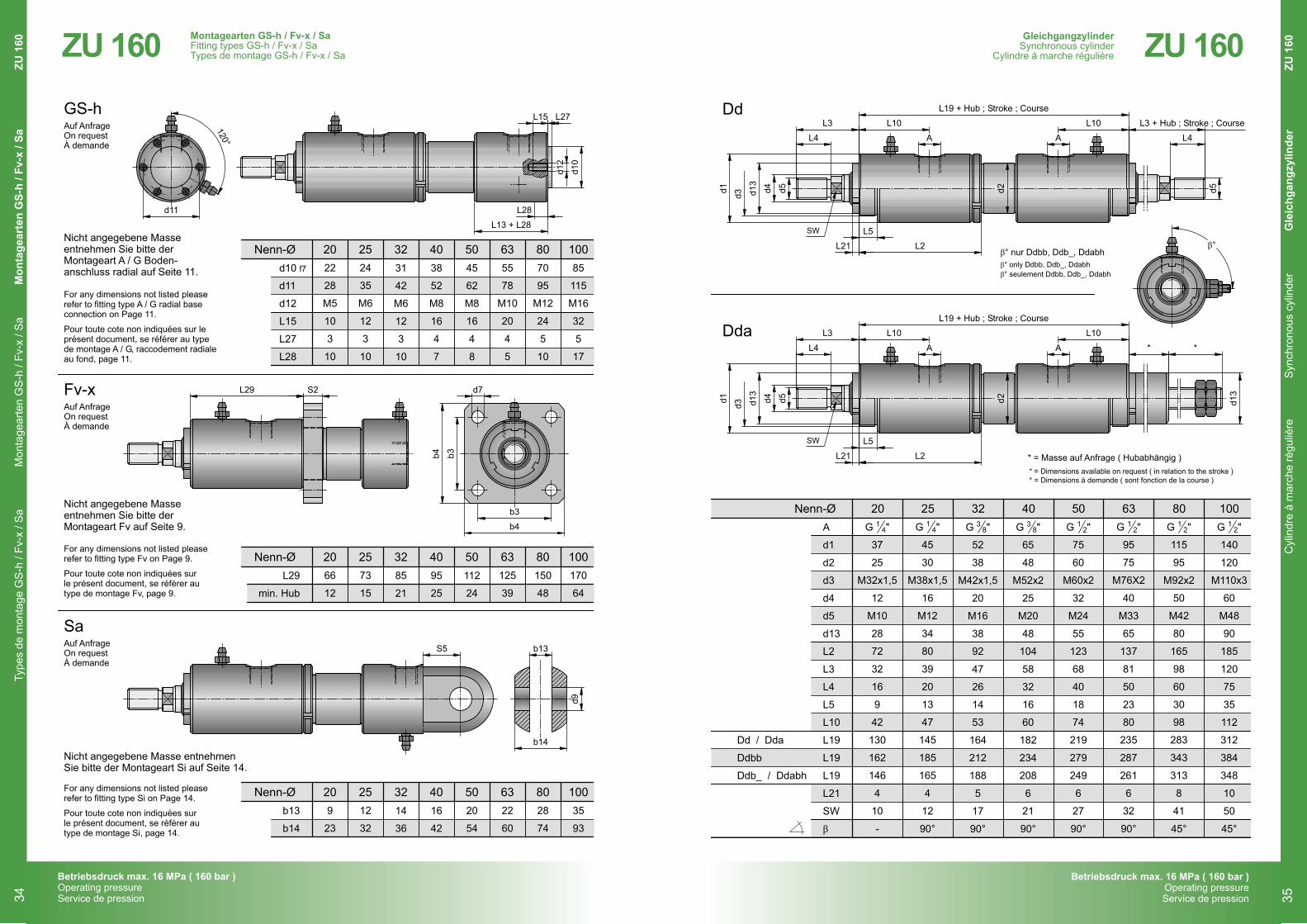
* = Masse auf Anfrage ( Hubabhängig )
Dd / Dda
Ddbb
Ddb_ / Ddabh
β° nur Ddbb, Ddb_, Ddabhβ° only Ddbb, Ddb_, Ddabhβ° seulement Ddbb, Ddb_, Ddabh
d5 d5
d5
d4d4
d13
d13
d1d1
L21
L21
L4 L4
L4
L3 L3 + Hub ; Stroke ; Course
L3
A
A
A
A
L10
L10
L10
L10
L2
L2
β°L5
L5
d3d3
Dd
Dda
L19 + Hub ; Stroke ; Course
L19 + Hub ; Stroke ; Course
d13
* *
* = Dimensions available on request ( in relation to the stroke )* = Dimensions à demande ( sont fonction de la course )
38
12
12
12
12
14
14
38
GleichgangzylinderSynchronous cylinderCylindre à marche régulière
16
Subject to changeSous réserve de modification
Änderungen vorbehalten
Betriebsdruck max. 16 MPa ( 160 bar )Operating pressureService de pression
2017
ZU 160
Cyl
indr
e à
mar
che
régu
lière
Syn
chro
nous
cyl
inde
rG
leic
hgan
gzyl
inde
r Z
U 1
60GleichgangzylinderSynchronous cylinder
Cylindre à marche régulière
35
ZU 160
L29 S2
b4 b3
b3
b4
L27
d10
d12
L13 + L28
L28
120°
100
100
100
80
80
80
63
63
63
50
50
50
40
40
40
32
32
32
25
25
25
20
20
20
Nenn-Ø
Nenn-Ø
Nenn-Ø
d10 f7
d11
d12
L15
L27
L28
b13
b14
L29
min. Hub
31
42
M6
12
3
10
14
36
85
21
38
52
M8
16
4
7
16
42
95
25
45
62
M8
16
4
8
20
54
112
24
85
115
M16
32
5
17
35
93
170
64
70
95
M12
24
5
10
28
74
150
48
55
78
M10
20
4
5
22
60
125
39
22
28
M5
10
3
10
9
23
66
12
24
35
M6
12
3
10
12
32
73
15
Auf AnfrageOn requestÀ demande
Auf AnfrageOn requestÀ demande
Auf AnfrageOn requestÀ demande
d7
Montagearten GS-h / Fv-x / SaFitting types GS-h / Fv-x / Sa
Types de montage GS-h / Fv-x / Sa
15
Subject to changeSous réserve de modification
Änderungen vorbehalten
Betriebsdruck max. 16 MPa ( 160 bar )Operating pressureService de pression
2017
ZU 160
Sa
GS-h
Fv-x
S5 b13
b14
L15
d9
d11
Nicht angegebene Masseentnehmen Sie bitte derMontageart A / G Boden-anschluss radial auf Seite 11.
Nicht angegebene Masseentnehmen Sie bitte derMontageart Fv auf Seite 9.
Nicht angegebene Masse entnehmenSie bitte der Montageart Si auf Seite 14.
For any dimensions not listed pleaserefer to fitting type A / G radial baseconnection on Page 11.
Pour toute cote non indiquées sur leprésent document, se référer au typede montage A / G, raccodement radialeau fond, page 11.
For any dimensions not listed pleaserefer to fitting type Fv on Page 9.
Pour toute cote non indiquées surle présent document, se référer autype de montage Fv, page 9.
For any dimensions not listed pleaserefer to fitting type Si on Page 14.
Pour toute cote non indiquées surle présent document, se référer autype de montage Si, page 14.
Montagearten GS-h / Fv-x / SaFitting types GS-h / Fv-x / SaTypes de montage GS-h / Fv-x / Sa
Type
s de
mon
tage
GS
-h /
Fv-x
/ S
aM
onta
gear
ten
GS
-h /
Fv-x
/ S
aM
onta
gear
ten
GS-
h / F
v-x
/ Sa
ZU 1
6034
Betriebsdruck max. 16 MPa ( 160 bar )Operating pressureService de pression
Betriebsdruck max. 16 MPa ( 160 bar )Operating pressureService de pression
ZU 160
X2
63
68
80
91
Nenn-Ø
20
25
32
40
50
63
80
100
X1
58
63
72
80
44
48
51
55
G / Fv / Fv-x / Wv / Fh /GS-h / S / Sm / Si / Sa / Si-g
Sv
L3
L3
Lx* + X1 + Hub ; Stroke ; Course
Lx* + X2 + Hub ; Stroke ; Course
X2
M8×1
Schaltpunkt :Kolbenstange in denZylinder eingefahren
Schaltpunkt :Kolbenstange aus demZylinder ausgefahren
90° 90°
45° 45°
X1
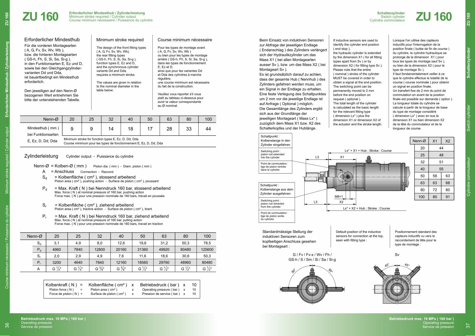
Standardmässige Stellung derinduktiven Sensoren zumkopfseitigen Anschluss gesehenbei Montageart :
Default position of the inductivesensors for connection at the top,seen with fitting type :
Positionnement standard descapteurs inductifs vu vers leraccordement de tête pour letype de montage :
If inductive sensors are used toidentify the cylinder end position( end stop ),the hydraulic cylinder is extendedby the dimension X1 ( for all fittingtypes apart from Sv ) or bydimension X2 ( for fitting type Sv ).Please note that the entire( nominal ) stroke of the cylinderMUST be covered in order toobtain a signal at the end position.The switching point can bepermanently moved to 2 mmbefore the end position onrequest ( optional ).The total length of the cylinderis calculated as the basic lengthfor the relevant fitting type( dimension Lx* ) plus thedimension X1 or dimension X2 ofthe actuator and the stroke length.
Lorsque l'on utilise des capteursinductifs pour l'interrogation de laposition finale ( butée de fin de course )du cylindre, le cylindre hydraulique seprolonge de la dimension X1 ( pourtous les types de montage sauf Sv ),ou bien de la dimension X2 ( pour letype de montage Sv ).Il faut fondamentalement veiller à ceque le cylindre effectue la totalité de lacourse ( course nominale ) pour obtenirun signal en position finale.Un transfert fixe de 2 mm du point decommutation en avant de la positionfinale est possible sur demande ( option ).La longueur totale du cylindre secalcule à partir de la longueur de basedu type de montage considéré( dimension Lx* ) avec en sus ladimension X1 ou bien dimension X2de la tête du commutateur et de lalongueur de course.
Beim Einsatz von induktiven Sensorenzur Abfrage der jeweiligen Endlage( Endanschlag ) des Zylinders verlängertsich der Hydraulikzylinder um dasMass X1 ( bei allen Montageartenausser Sv ), bzw. um das Mass X2 ( beiMontageart Sv ).Es ist grundsätzlich darauf zu achten,dass der gesamte Hub ( Nennhub ) desZylinders gefahren werden muss, umein Signal in der Endlage zu erhalten.Eine feste Verlegung des Schaltpunktesum 2 mm vor die jeweilige Endlage istauf Anfrage ( Optional ) möglich.Die Gesamtlänge des Zylinders ergibtsich aus der Grundlänge derjeweiligen Montageart ( Mass Lx* )zuzüglich dem Mass X1 bzw. X2 desSchalterkopfes und der Hublänge.
Switching point :piston rod extendedinto the cylinder
Point de commutation :tige de piston rentréedans le cylindre
Switching point :piston rod retractedfrom the cylinder
Point de commutation :tige de piston sortiedu cylindre
SchalterzylinderSwitch cylinderCylindre commutateur
18
Subject to changeSous réserve de modification
Änderungen vorbehalten
Betriebsdruck max. 16 MPa ( 160 bar )Operating pressureService de pression
2017
ZUS 160
Cyl
indr
e co
mm
utat
eur
Sw
itch
cylin
der
Scha
lterz
ylin
der
ZU
160
SchalterzylinderSwitch cylinder
Cylindre commutateur
37
ZU 160
10080635040322520Nenn-ØSd
Pd
Sr
Pr
A
4,9
7840
2,9
4640
G "
12,6
20160
7,6
12160
G "
50,3
80480
30,6
48960
G "
78,5
125600
50,3
80480
G "
31,2
49920
18,6
29760
G "
19,6
31360
11,6
18560
G "
8,0
12800
4,9
7840
G "
3,1
4960
2,0
3200
G "
10080635040322520Nenn-Ø
Mindesthub ( mm )
bei Funktionsarten
E, Ez, D, Dd, Dda
14 44332817189 9
Erforderlicher MindesthubFür die vorderen Montagearten( A, G, Fv, Sv, Wv, Wb ),bzw. die hinteren Montagearten( GS-h, Fh, S, Si, Sa, Si-g ),in den Funktionsarten E, Ez und D,sowie bei den Gleichgangzylinder-varianten Dd und Dda,ist bauartbedingt ein Mindesthuberforderlich.
Den jeweiligen auf den Nenn-Øbezogenen Wert entnehmen Siebitte der untenstehenden Tabelle.
Nenn-Ø = Kolben-Ø ( mm )A = AnschlussSd = Kolbenfläche ( cm² ), stossend arbeitend
Pd = Max. Kraft ( N ) bei Nenndruck 160 bar, stossend arbeitend
Sr = Kolbenfläche ( cm² ), ziehend arbeitend
Pr = Max. Kraft ( N ) bei Nenndruck 160 bar, ziehend arbeitend
Kolbenkraft ( N ) = Kolbenfläche ( cm² ) x Betriebsdruck ( bar ) x 10Piston force ( N ) = Piston area ( cm² ) x Operating pressure ( bar ) x 10Force de piston ( N ) = Surface de piston ( cm² ) x Pression de service ( bar ) x 10
Piston dia. ( mm ) - Diam. piston ( mm )
Connection - Raccord
Piston area ( cm² ), pushing action - Surface de piston ( cm² ), poussant
Max. force ( N ) at nominal pressure of 160 bar, pushing actionForce max. ( N ) pour une pression nominale de 160 bars, travail en poussée
Piston area ( cm² ), tractive action - Surface de piston ( cm² ), tirant
Max. force ( N ) at nominal pressure of 160 bar, pulling actionForce max. ( N ) pour une pression nominale de 160 bars, travail en traction
Minimum stroke for function types E, Ez, D, Dd, DdaCourse minimum pour les types de fonctionnement E, Ez, D, Dd, Dda
Zylinderleistung
Minimum stroke required Course minimum nécessaire
The design of the front fitting types( A, G, Fv, Sv, Wv, Wb),the rear fitting types( GS-h, Fh, S, Si, Sa, Si-g ),function types E, Ez and D,and the synchronous cylindervariants Dd and Dda,requires a minimum stroke.
The values are given in relationto the nominal diameter in thetable below.
Pour les types de montage avant( A, G, Fv, Sv, Wv, Wb )ou bien pour les types de montagearrière ( GS-h, Fh, S, Si, Sa, Si-g ),dans les types de fonctionnementE, Ez et D,ainsi que pour les variantes Ddet Dda des cylindres à marcherégulière,une course minimum est nécessairedu fait de la construction.
Veuillez vous reporter s'il vousplaît au tableau ci-dessous pouravoir la valeur correspondanteau Ø nominal.
38
38
12
12
12
12
14
14
Erforderlicher Mindesthub / ZylinderleistungMinimum stroke required / Cylinder output
Course minimum nécessaire / Puissance du cylindre
17
Subject to changeSous réserve de modification
Änderungen vorbehalten
Betriebsdruck max. 16 MPa ( 160 bar )Operating pressureService de pression
2017
ZU 160
Cylinder output - Puissance du cylindre
Erforderlicher Mindesthub / ZylinderleistungMinimum stroke required / Cylinder outputCourse minimum nécessaire / Puissance du cylindre
Cour
se m
inim
um n
éces
saire
/ Pu
issan
ce d
u cy
lindr
eM
inim
um s
troke
requ
ired
/ Cyli
nder
out
put
Erfo
rder
liche
r Min
dest
hub
/ Zyl
inde
rleis
tung
ZU 1
6036
Betriebsdruck max. 16 MPa ( 160 bar )Operating pressureService de pression
ZU 160
10080635040322520Nenn-Ød4
d5
bar
25
50
80
100
120
160
25
50
80
100
120
160
16
M12
1040
740
585
520
475
410
575
375
280
240
210
165
25
M20
1590
1125
890
795
725
630
905
605
450
390
345
285
50
M42
3180
2250
1780
1590
1450
1255
1875
1275
970
850
760
635
60
M48
3665
2590
2050
1830
1675
1450
2165
1470
1120
980
880
735
40
M33
2585
1830
1445
1295
1180
1020
1520
1030
785
685
610
510
32
M24
2085
1475
1165
1040
950
825
1200
810
610
530
470
390
20
M16
1270
900
710
635
580
505
710
470
350
300
265
215
12
M10
735
520
410
365
335
290
390
250
180
155
130
105
... für Montagearten
... für Montagearten
... for fitting Types
... pour types de montage
... for fitting Types
... pour types de montage
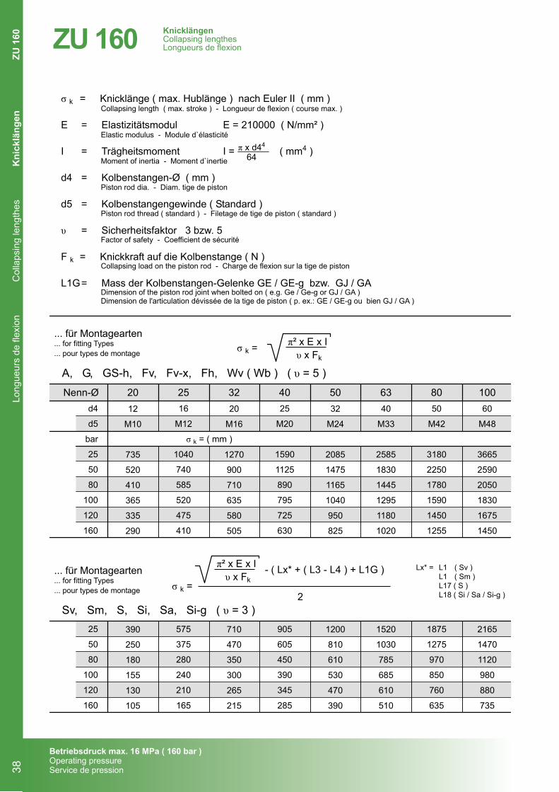
σ k = Knicklänge ( max. Hublänge ) nach Euler II ( mm )
E = Elastizitätsmodul E = 210000 ( N/mm² )
I = Trägheitsmoment I = ( mm4 )
d4 = Kolbenstangen-Ø ( mm )
d5 = Kolbenstangengewinde ( Standard )
υ = Sicherheitsfaktor 3 bzw. 5
F k = Knickkraft auf die Kolbenstange ( N )
L1G= Mass der Kolbenstangen-Gelenke GE / GE-g bzw. GJ / GA
Collapsing length ( max. stroke ) - Longueur de flexion ( course max. )
Elastic modulus - Module d`élasticité
Moment of inertia - Moment d`inertie
Piston rod dia. - Diam. tige de piston
Piston rod thread ( standard ) - Filetage de tige de piston ( standard )
Factor of safety - Coefficient de sécurité
Collapsing load on the piston rod - Charge de flexion sur la tige de piston
Dimension of the piston rod joint when bolted on ( e.g. Ge / Ge-g or GJ / GA )Dimension de l'articulation dévissée de la tige de piston ( p. ex.: GE / GE-g ou bien GJ / GA )
π x d44
64
σ k = ( mm )
σ k =
π² x E x I υ x Fk
- ( Lx* + ( L3 - L4 ) + L1G )
2
σ k =π² x E x I υ x Fk
KnicklängenCollapsing lengthes
Longueurs de flexion
19
Subject to changeSous réserve de modification
Änderungen vorbehalten
Betriebsdruck max. 16 MPa ( 160 bar )Operating pressureService de pression
2017
ZU 160
Sv, Sm, S, Si, Sa, Si-g ( υ = 3 )
A, G, GS-h, Fv, Fv-x, Fh, Wv ( Wb ) ( υ = 5 )
Lx* = L1 ( Sv )L1 ( Sm )L17 ( S )L18 ( Si / Sa / Si-g )
KnicklängenCollapsing lengthesLongueurs de flexion
Long
ueur
s de
flex
ion
Col
laps
ing
leng
thes
Kni
cklä
ngen
ZU 1
6038