


Sprachen
Seiten
Rechtliche

AT-1
Art.
-no
.: 2.
5101
71 r
ev.
: g *2.510171*
3-Channel Electrocardiograph3-Kanal-Elektrokardiograph
Electrocardiographe à 3 canaux
User GuideGebrauchsanweisungMode d’emploi


ENG
LISH
DEUT
SCH
ENG
LISH
DEUT
SCH
FRAN
ÇAIS
FRAN
ÇAIS
AT-13-Channel Electrocardiograph
3-Kanal-ElektrokardiographElectrocardiographe à 3 canaux
AT-13-Channel Electrocardiograph
3-Kanal-ElektrokardiographElectrocardiographe à 3 canaux
AAAAATTTTT-1 User Guide - English-1 User Guide - English-1 User Guide - English-1 User Guide - English-1 User Guide - EnglishAAAAATTTTT-1Gebrauchsanweisung -Deutsch-1Gebrauchsanweisung -Deutsch-1Gebrauchsanweisung -Deutsch-1Gebrauchsanweisung -Deutsch-1Gebrauchsanweisung -Deutsch
Mode d'emploi pour l’AMode d'emploi pour l’AMode d'emploi pour l’AMode d'emploi pour l’AMode d'emploi pour l’ATTTTT-1 - F-1 - F-1 - F-1 - F-1 - Françaisrançaisrançaisrançaisrançais
Article Number 2.510171gArticle Number 2.510171gArticle Number 2.510171gArticle Number 2.510171gArticle Number 2.510171g
a Sept. 1995, b Jun. 1999, c Feb. 2000, d Feb. 2001, e Jan. 2002
f Aug. 2004, g Nov. 2005
Associated Document
Guide to the SCHILLER Interpretation and Measurement Program E/ D/ F Article Number 2.510179
SCHILLER AGAltgasse 68
CH - 6341 Baar, Switzerland
Phone: ++ 41 41 766 42 42
Fax: ++ 41 41 761 08 80
www.schiller.ch
AAAAATTTTT-1User Guide - English-1User Guide - English-1User Guide - English-1User Guide - English-1User Guide - EnglishAAAAATTTTT-1 Gebrauchsanweisung -Deutsch-1 Gebrauchsanweisung -Deutsch-1 Gebrauchsanweisung -Deutsch-1 Gebrauchsanweisung -Deutsch-1 Gebrauchsanweisung -DeutschMode d'emploi pour l’AMode d'emploi pour l’AMode d'emploi pour l’AMode d'emploi pour l’AMode d'emploi pour l’ATTTTT-1 - F-1 - F-1 - F-1 - F-1 - Françaisrançaisrançaisrançaisrançais
Article Number 2.510171 gArticle Number 2.510171 gArticle Number 2.510171 gArticle Number 2.510171 gArticle Number 2.510171 g
a Sept. 1995, b Jun. 1999, c Feb. 2000, d Feb. 2001, e Jan. 2002
f Aug. 2004, g Nov.2005
Associated Document
Guide to the SCHILLER Interpretation and Measurement Program E/ D/ F Article Number 2.510179
SCHILLER AGAltgasse 68
CH - 6341 Baar, Switzerland
Phone: ++ 41 41 766 42 42
Fax: ++ 41 41 761 08 80
www.schiller.ch

ENG
LISH
DEUT
SCH
ENG
LISH
DEUT
SCH
FRAN
ÇAIS
FRAN
ÇAIS
Where to Obtain SerWhere to Obtain SerWhere to Obtain SerWhere to Obtain SerWhere to Obtain Service and Sales Advicevice and Sales Advicevice and Sales Advicevice and Sales Advicevice and Sales AdviceKundendienst und VKundendienst und VKundendienst und VKundendienst und VKundendienst und Verkerkerkerkerkaufs-/Beratungsstellenaufs-/Beratungsstellenaufs-/Beratungsstellenaufs-/Beratungsstellenaufs-/BeratungsstellenCoordonnées de nos serCoordonnées de nos serCoordonnées de nos serCoordonnées de nos serCoordonnées de nos services d’assistance technique et commercialevices d’assistance technique et commercialevices d’assistance technique et commercialevices d’assistance technique et commercialevices d’assistance technique et commerciale
The SCHILLER sales and service centre network is worldwide.For the address of your local distributor, contact your nearest
SCHILLER subsidiary. In case of difficulty a complete list of alldistributors and subsidiaries is provided on our internet site:
http://www.schiller.ch
SCHILLER besitzt ein weltweites Netz von Kundendienst-, Verkaufs- undBeratungsstellen. Fragen Sie bei der nächsten SCHILLER-
Niederlassung nach Ihrer lokalen Vertretung. Eine vollständige Listealler Vertreter und Niederlassungen finden Sie auf unserer Internet-Site:
http://www.schiller.ch
SCHILLER entretient un réseau international composé de servicesclients, de services commerciaux et d’agences de conseil. Pour obtenirles coordonnées de votre représentant local, veuillez vous adresser àla filiale SCHILLER la plus proche de votre domicile. Vous trouverezune liste complète de tou(te)s les représentants et filiales sur notre
http://www.schiller.ch

i
i
EN
GLI
SH
EN
GLI
SH
AT-1Operating Instructions
English
AT-1Operating Instructions
English
ii
ii
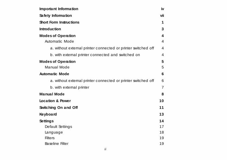
Important Information iv
Safety Information vii
Short Form Instructions 1
Introduction 3
Modes of Operation 4Automatic Mode 4
a. without external printer connected or printer switched off 4
b. with external printer connected and switched on 4
Modes of Operation 5Manual Mode 5
Automatic Mode 6
a. without external printer connected or printer switched off 6
b. with external printer 7
Manual Mode 8
Location & Power 10
Switching On and Off 11
Keyboard 13
Settings 14Default Settings 17Language 18Filters 19Baseline Filter 19
iii
iii
EN
GLI
SH
EN
GLI
SH
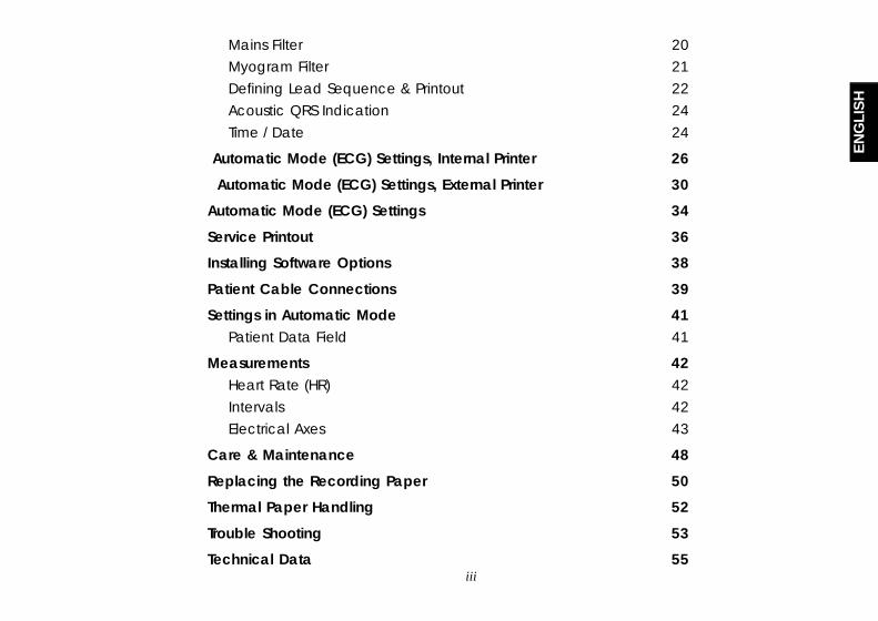
Mains Filter 20Myogram Filter 21Defining Lead Sequence & Printout 22Acoustic QRS Indication 24Time / Date 24
Automatic Mode (ECG) Settings, Internal Printer 26
Automatic Mode (ECG) Settings, External Printer 30
Automatic Mode (ECG) Settings 34
Service Printout 36
Installing Software Options 38
Patient Cable Connections 39
Settings in Automatic Mode 41Patient Data Field 41
Measurements 42Heart Rate (HR) 42Intervals 42Electrical Axes 43
Care & Maintenance 48
Replacing the Recording Paper 50
Thermal Paper Handling 52
Trouble Shooting 53
Technical Data 55
iv
iv
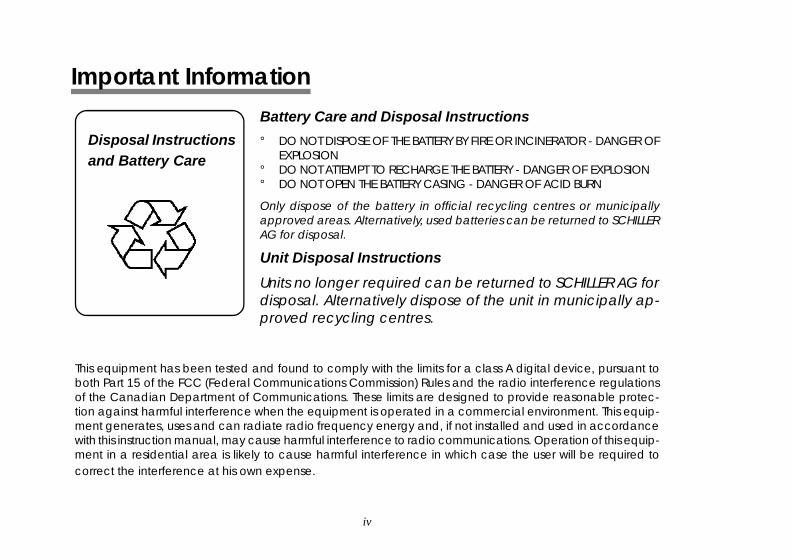
Disposal Instructionsand Battery Care
Battery Care and Disposal Instructions
° DO NOT DISPOSE OF THE BATTERY BY FIRE OR INCINERATOR - DANGER OFEXPLOSION
° DO NOT ATTEMPT TO RECHARGE THE BATTERY - DANGER OF EXPLOSION° DO NOT OPEN THE BATTERY CASING - DANGER OF ACID BURN
Only dispose of the battery in official recycling centres or municipallyapproved areas. Alternatively, used batteries can be returned to SCHILLERAG for disposal.
Unit Disposal Instructions
Units no longer required can be returned to SCHILLER AG fordisposal. Alternatively dispose of the unit in municipally ap-proved recycling centres.
This equipment has been tested and found to comply with the limits for a class A digital device, pursuant toboth Part 15 of the FCC (Federal Communications Commission) Rules and the radio interference regulationsof the Canadian Department of Communications. These limits are designed to provide reasonable protec-tion against harmful interference when the equipment is operated in a commercial environment. This equip-ment generates, uses and can radiate radio frequency energy and, if not installed and used in accordancewith this instruction manual, may cause harmful interference to radio communications. Operation of this equip-ment in a residential area is likely to cause harmful interference in which case the user will be required tocorrect the interference at his own expense.
Important Information
Important Information
v
v
EN
GLI
SH
EN
GLI
SH
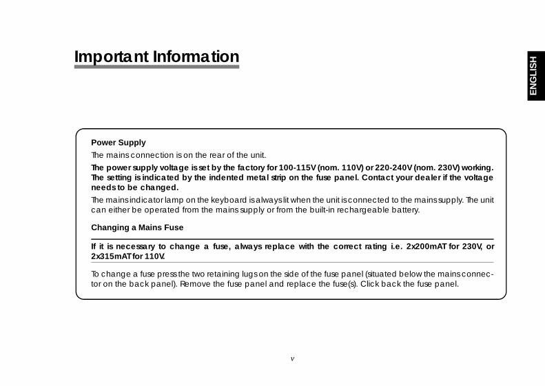
Power Supply
The mains connection is on the rear of the unit.The power supply voltage is set by the factory for 100-115V (nom. 110V) or 220-240V (nom. 230V) working.The setting is indicated by the indented metal strip on the fuse panel. Contact your dealer if the voltageneeds to be changed.The mains indicator lamp on the keyboard is always lit when the unit is connected to the mains supply. The unitcan either be operated from the mains supply or from the built-in rechargeable battery.
Changing a Mains Fuse
If it is necessary to change a fuse, always replace with the correct rating i.e. 2x200mAT for 230V, or2x315mAT for 110V.
To change a fuse press the two retaining lugs on the side of the fuse panel (situated below the mains connec-tor on the back panel). Remove the fuse panel and replace the fuse(s). Click back the fuse panel.
Important Information
Important Information
vi
vi
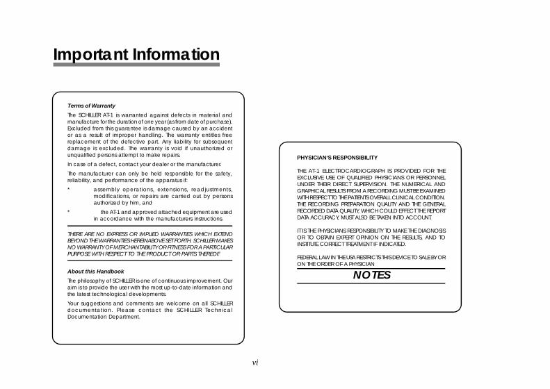
Terms of Warranty
The SCHILLER AT-1 is warranted against defects in material andmanufacture for the duration of one year (as from date of purchase).Excluded from this guarantee is damage caused by an accidentor as a result of improper handling. The warranty entitles freereplacement of the defective part. Any liability for subsequentdamage is excluded. The warranty is void if unauthorized orunqualified persons attempt to make repairs.
In case of a defect, contact your dealer or the manufacturer.
The manufacturer can only be held responsible for the safety,reliability, and performance of the apparatus if:
* assembly operations, extensions, readjustments,modifications, or repairs are carried out by personsauthorized by him, and
* the AT-1 and approved attached equipment are usedin accordance with the manufacturers instructions.
THERE ARE NO EXPRESS OR IMPLIED WARRANTIES WHICH EXTENDBEYOND THE WARRANTIES HEREINABOVE SET FORTH. SCHILLER MAKESNO WARRANTY OF MERCHANTABILITY OR FITNESS FOR A PARTICULARPURPOSE WITH RESPECT TO THE PRODUCT OR PARTS THEREOF.
About this Handbook
The philosophy of SCHILLER is one of continuous improvement. Ouraim is to provide the user with the most up-to-date information andthe latest technological developments.
Your suggestions and comments are welcome on all SCHILLERdocumentation. Please contact the SCHILLER TechnicalDocumentation Department.
PHYSICIAN‘S RESPONSIBILITY
THE AT-1 ELECTROCARDIOGRAPH IS PROVIDED FOR THEEXCLUSIVE USE OF QUALIFIED PHYSICIANS OR PERSONNELUNDER THEIR DIRECT SUPERVISION. THE NUMERICAL ANDGRAPHICAL RESULTS FROM A RECORDING MUST BE EXAMINEDWITH RESPECT TO THE PATIENTS OVERALL CLINICAL CONDITION.THE RECORDING PREPARATION QUALITY AND THE GENERALRECORDED DATA QUALITY, WHICH COULD EFFECT THE REPORTDATA ACCURACY, MUST ALSO BE TAKEN INTO ACCOUNT.
IT IS THE PHYSICIANS RESPONSIBILITY TO MAKE THE DIAGNOSISOR TO OBTAIN EXPERT OPINION ON THE RESULTS, AND TOINSTITUTE CORRECT TREATMENT IF INDICATED.
FEDERAL LAW IN THE USA RESTRICTS THIS DEVICE TO SALE BY ORON THE ORDER OF A PHYSICIAN
NOTES
Terms of Warranty
The SCHILLER AT-1 / AT-1 smartprint is warranted against defects inmaterial and manufacture for the duration of one year (as fromdate of purchase). Excluded from this guarantee is damage causedby an accident or as a result of improper handling. The warrantyentitles free replacement of the defective part. Any liability forsubsequent damage is excluded. The warranty is void ifunauthorized or unqualified persons attempt to make repairs.
In case of a defect, contact your dealer or the manufacturer.
The manufacturer can only be held responsible for the safety,reliability, and performance of the apparatus if:
* assembly operations, extensions, readjustments,modifications, or repairs are carried out by personsauthorized by him, and
* the AT-1 / AT-1 smartprint and approved attachedequipment are used in accordance with themanufacturers instructions.
THERE ARE NO EXPRESS OR IMPLIED WARRANTIES WHICH EXTENDBEYOND THE WARRANTIES HEREINABOVE SET FORTH. SCHILLER MAKESNO WARRANTY OF MERCHANTABILITY OR FITNESS FOR A PARTICULARPURPOSE WITH RESPECT TO THE PRODUCT OR PARTS THEREOF.
About this Handbook
The philosophy of SCHILLER is one of continuous improvement. Ouraim is to provide the user with the most up-to-date information andthe latest technological developments.
Your suggestions and comments are welcome on all SCHILLERdocumentation. Please contact the SCHILLER TechnicalDocumentation Department.
PHYSICIAN‘S RESPONSIBILITY
THE AT-1 / AT-1 SMARTPRINT ELECTROCARDIOGRAPH ISPROVIDED FOR THE EXCLUSIVE USE OF QUALIFIED PHYSICIANSOR PERSONNEL UNDER THEIR DIRECT SUPERVISION. THENUMERICAL AND GRAPHICAL RESULTS FROM A RECORDINGMUST BE EXAMINED WITH RESPECT TO THE PATIENTS OVERALLCLINICAL CONDITION. THE RECORDING PREPARATION QUALITYAND THE GENERAL RECORDED DATA QUALITY, WHICH COULDEFFECT THE REPORT DATA ACCURACY, MUST ALSO BE TAKENINTO ACCOUNT.
IT IS THE PHYSICIANS RESPONSIBILITY TO MAKE THE DIAGNOSISOR TO OBTAIN EXPERT OPINION ON THE RESULTS, AND TOINSTITUTE CORRECT TREATMENT IF INDICATED.
FEDERAL LAW IN THE USA RESTRICTS THIS DEVICE TO SALE BY ORON THE ORDER OF A PHYSICIAN
Important Information
Important Information
vii
vii
EN
GLI
SH
EN
GLI
SH
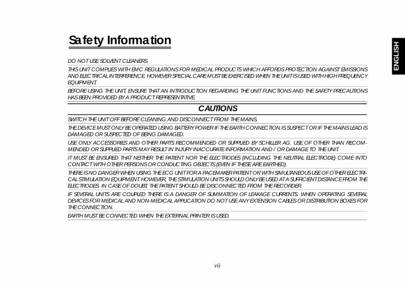
DO NOT USE SOLVENT CLEANERS.
THIS UNIT COMPLIES WITH EMC REGULATIONS FOR MEDICAL PRODUCTS WHICH AFFORDS PROTECTION AGAINST EMISSIONSAND ELECTRICAL INTERFERENCE. HOWEVER SPECIAL CARE MUST BE EXERCISED WHEN THE UNIT IS USED WITH HIGH FREQUENCYEQUIPMENT.BEFORE USING THE UNIT, ENSURE THAT AN INTRODUCTION REGARDING THE UNIT FUNCTIONS AND THE SAFETY PRECAUTIONSHAS BEEN PROVIDED BY A PRODUCT REPRESENTATIVE.
CAUTIONSSWITCH THE UNIT OFF BEFORE CLEANING AND DISCONNECT FROM THE MAINS.THE DEVICE MUST ONLY BE OPERATED USING BATTERY POWER IF THE EARTH CONNECTION IS SUSPECT OR IF THE MAINS LEAD ISDAMAGED OR SUSPECTED OF BEING DAMAGED.
USE ONLY ACCESSORIES AND OTHER PARTS RECOMMENDED OR SUPPLIED BY SCHILLER AG. USE OF OTHER THAN RECOM-MENDED OR SUPPLIED PARTS MAY RESULT IN INJURY INACCURATE INFORMATION AND / OR DAMAGE TO THE UNIT.
IT MUST BE ENSURED THAT NEITHER THE PATIENT NOR THE ELECTRODES (INCLUDING THE NEUTRAL ELECTRODE) COME INTOCONTACT WITH OTHER PERSONS OR CONDUCTING OBJECTS (EVEN IF THESE ARE EARTHED).
THERE IS NO DANGER WHEN USING THE ECG UNIT FOR A PACEMAKER PATIENT OR WITH SIMULTANEOUS USE OF OTHER ELECTRI-CAL STIMULATION EQUIPMENT. HOWEVER, THE STIMULATION UNITS SHOULD ONLY BE USED AT A SUFFICIENT DISTANCE FROM THEELECTRODES. IN CASE OF DOUBT, THE PATIENT SHOULD BE DISCONNECTED FROM THE RECORDER.IF SEVERAL UNITS ARE COUPLED THERE IS A DANGER OF SUMMATION OF LEAKAGE CURRENTS. WHEN OPERATING SEVERALDEVICES FOR MEDICAL AND NON-MEDICAL APPLICATION DO NOT USE ANY EXTENSION CABLES OR DISTRIBUTION BOXES FORTHE CONNECTION.
EARTH MUST BE CONNECTED WHEN THE EXTERNAL PRINTER IS USED.
NOTESDO NOT USE SOLVENT CLEANERS.
THIS UNIT COMPLIES WITH EMC REGULATIONS FOR MEDICAL PRODUCTS WHICH AFFORDS PROTECTION AGAINST EMISSIONSAND ELECTRICAL INTERFERENCE. HOWEVER SPECIAL CARE MUST BE EXERCISED WHEN THE UNIT IS USED WITH HIGH FREQUENCYEQUIPMENT.BEFORE USING THE UNIT, ENSURE THAT AN INTRODUCTION REGARDING THE UNIT FUNCTIONS AND THE SAFETY PRECAUTIONSHAS BEEN PROVIDED BY A PRODUCT REPRESENTATIVE.
CAUTIONSSWITCH THE UNIT OFF BEFORE CLEANING AND DISCONNECT FROM THE MAINS.THE DEVICE MUST ONLY BE OPERATED USING BATTERY POWER IF THE EARTH CONNECTION IS SUSPECT OR IF THE MAINS LEAD ISDAMAGED OR SUSPECTED OF BEING DAMAGED.
USE ONLY ACCESSORIES AND OTHER PARTS RECOMMENDED OR SUPPLIED BY SCHILLER AG. USE OF OTHER THAN RECOM-MENDED OR SUPPLIED PARTS MAY RESULT IN INJURY INACCURATE INFORMATION AND / OR DAMAGE TO THE UNIT.
IT MUST BE ENSURED THAT NEITHER THE PATIENT NOR THE ELECTRODES (INCLUDING THE NEUTRAL ELECTRODE) COME INTOCONTACT WITH OTHER PERSONS OR CONDUCTING OBJECTS (EVEN IF THESE ARE EARTHED).
THERE IS NO DANGER WHEN USING THE ECG UNIT FOR A PACEMAKER PATIENT OR WITH SIMULTANEOUS USE OF OTHER ELECTRI-CAL STIMULATION EQUIPMENT. HOWEVER, THE STIMULATION UNITS SHOULD ONLY BE USED AT A SUFFICIENT DISTANCE FROM THEELECTRODES. IN CASE OF DOUBT, THE PATIENT SHOULD BE DISCONNECTED FROM THE RECORDER.IF SEVERAL UNITS ARE COUPLED THERE IS A DANGER OF SUMMATION OF LEAKAGE CURRENTS. WHEN OPERATING SEVERALDEVICES FOR MEDICAL AND NON-MEDICAL APPLICATION DO NOT USE ANY EXTENSION CABLES OR DISTRIBUTION BOXES FORTHE CONNECTION.
EARTH MUST BE CONNECTED WHEN THE EXTERNAL PRINTER IS USED.
Safety Information
Safety Information

viii
viii
WARNINGSTO PREVENT ELECTRIC SHOCK DO NOT DISASSEMBLE THE UNIT. NO SERVICEABLE PARTS INSIDE. REFER SERVICING TO QUALIFIEDPERSONNEL ONLY.
DO NOT USE THIS UNIT IN AREAS WHERE THERE IS ANY DANGER OF EXPLOSION OR THE PRESENCE OF FLAMMABLE GASES SUCHAS ANAESTHETIC AGENTS.THIS PRODUCT IS NOT DESIGNED FOR STERILE USE.
THIS PRODUCT IS NOT DESIGNED FOR OUTDOOR USE.
DO NOT, UNDER ANY CIRCUMSTANCES, IMMERSE THE UNIT OR CABLE ASSEMBLIES IN LIQUID.
DO NOT USE HIGH TEMPERATURE STERILISATION PROCESSES (SUCH AS AUTOCLAVING). DO NOT USE E-BEAM OR GAMMARADIATION STERILISATION.
THIS UNIT IS CF CLASSIFIED ACCORDING TO IEC EN 60601-1. THIS MEANS THAT THE PATIENT CONNECTION IS FULLYISOLATED AND DEFIBRILLATION PROTECTED. SCHILLER CAN ONLY GUARANTEE PROTECTION AGAINST DEFIBRILLATION VOLTAGEHOWEVER, WHEN THE ORIGINAL SCHILLER PATIENT CABLE IS USED.DO NOT TOUCH THE CASING DURING DEFIBRILLATION.
IF THE PATIENT CABLE SHOULD BECOME DEFECTIVE AFTER DEFIBRILLATION, LEAD OFF WILL BE DISPLAYED AND AN ACOUSTICALARM GIVEN.
WARNINGSTO PREVENT ELECTRIC SHOCK DO NOT DISASSEMBLE THE UNIT. NO SERVICEABLE PARTS INSIDE. REFER SERVICING TO QUALIFIEDPERSONNEL ONLY.
DO NOT USE THIS UNIT IN AREAS WHERE THERE IS ANY DANGER OF EXPLOSION OR THE PRESENCE OF FLAMMABLE GASES SUCHAS ANAESTHETIC AGENTS.
THIS PRODUCT IS NOT DESIGNED FOR STERILE USE.
THIS PRODUCT IS NOT DESIGNED FOR OUTDOOR USE.DO NOT, UNDER ANY CIRCUMSTANCES, IMMERSE THE UNIT OR CABLE ASSEMBLIES IN LIQUID.
DO NOT USE HIGH TEMPERATURE STERILISATION PROCESSES (SUCH AS AUTOCLAVING). DO NOT USE E-BEAM OR GAMMARADIATION STERILISATION.
THIS UNIT IS CF CLASSIFIED ACCORDING TO IEC EN 60601-1. THIS MEANS THAT THE PATIENT CONNECTION IS FULLYISOLATED AND DEFIBRILLATION PROTECTED. SCHILLER CAN ONLY GUARANTEE PROTECTION AGAINST DEFIBRILLATION VOLTAGEHOWEVER, WHEN THE ORIGINAL SCHILLER PATIENT CABLE IS USED.
DO NOT TOUCH THE CASING DURING DEFIBRILLATION.
IF THE PATIENT CABLE SHOULD BECOME DEFECTIVE AFTER DEFIBRILLATION, LEAD OFF WILL BE DISPLAYED AND AN ACOUSTICALARM GIVEN.
Safety Information
Safety Information
1AT-1 User Guide Art. No. 2.510171 g
1AT-1 User Guide Art. No. 2.510171 g
ENG
LISH
ENG
LISH
AAAAATTTTT-1-1-1-1-1
ShorShorShorShorShort Ft Ft Ft Ft Form Instructionsorm Instructionsorm Instructionsorm Instructionsorm Instructions
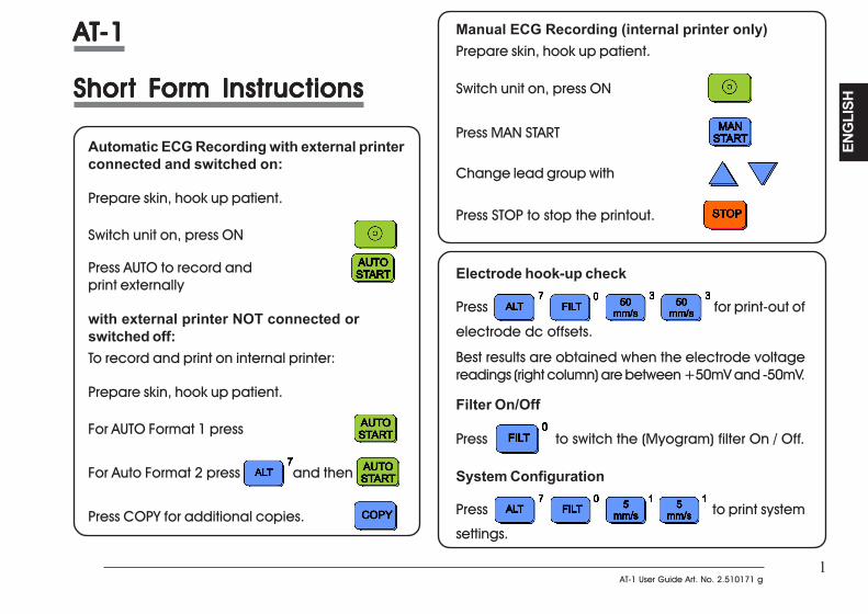
Automatic ECG Recording with external printerconnected and switched on:
Prepare skin, hook up patient.
Switch unit on, press ON
Press AUTO to record andprint externally
with external printer NOT connected orswitched off:To record and print on internal printer:
Prepare skin, hook up patient.
For AUTO Format 1 press
For Auto Format 2 press and then
Press COPY for additional copies.
Manual ECG Recording (internal printer only)Prepare skin, hook up patient.
Switch unit on, press ON
Press MAN START
Change lead group with
Press STOP to stop the printout.
Electrode hook-up check
Press for print-out of
electrode dc offsets.
Best results are obtained when the electrode voltagereadings (right column) are between +50mV and -50mV.
Filter On/Off
Press to switch the (Myogram) filter On / Off.
System Configuration
Press to print system
settings.
AAAAATTTTT-1-1-1-1-1
ShorShorShorShorShort Ft Ft Ft Ft Form Instructionsorm Instructionsorm Instructionsorm Instructionsorm Instructions
Automatic ECG Recording with external printerconnected and switched on:
Prepare skin, hook up patient.
Switch unit on, press ON
Press AUTO to record andprint externally
with external printer NOT connected orswitched off:To record and print on internal printer:
Prepare skin, hook up patient.
For AUTO Format 1 press
For Auto Format 2 press and then
Press COPY for additional copies.
Manual ECG Recording (internal printer only)Prepare skin, hook up patient.
Switch unit on, press ON
Press MAN START
Change lead group with
Press STOP to stop the printout.
Electrode hook-up check
Press for print-out of
electrode dc offsets.
Best results are obtained when the electrode voltagereadings (right column) are between +50mV and -50mV.
Filter On/Off
Press to switch the (Myogram) filter On / Off.
System Configuration
Press to print system
settings.
2
2
IntroductionIntroductionIntroductionIntroductionIntroduction
IntroductionIntroductionIntroductionIntroductionIntroduction

3AT-1 User Guide Art. No. 2.510171 g
3AT-1 User Guide Art. No. 2.510171 g
ENG
LISH
ENG
LISH
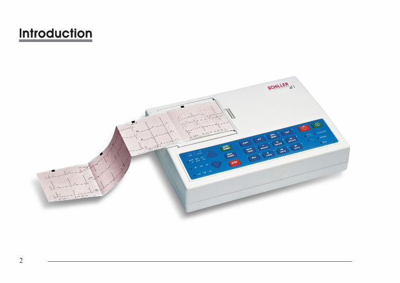
IntroductionIntroductionIntroductionIntroductionIntroduction
NOTE:NOTE:NOTE:NOTE:NOTE: The only difference between AThe only difference between AThe only difference between AThe only difference between AThe only difference between ATTTTT-1 and A-1 and A-1 and A-1 and A-1 and ATTTTT-1 smar-1 smar-1 smar-1 smar-1 smartprint is that Atprint is that Atprint is that Atprint is that Atprint is that ATTTTT-1-1-1-1-1smarsmarsmarsmarsmartprint has a connector for an external ink-jet printertprint has a connector for an external ink-jet printertprint has a connector for an external ink-jet printertprint has a connector for an external ink-jet printertprint has a connector for an external ink-jet printer, which, which, which, which, whichmakes it possible to generate printouts in A4 size.makes it possible to generate printouts in A4 size.makes it possible to generate printouts in A4 size.makes it possible to generate printouts in A4 size.makes it possible to generate printouts in A4 size.
The ECG unit is a 3-channel ECG recorder with all (12) ECG signals simultaneously processed toprovide instant ECG recordings. Three automatic recording modes - two for the internal printerand one for the external printer - can be individually preset to enable one button ECGrecording of preferred print formats.
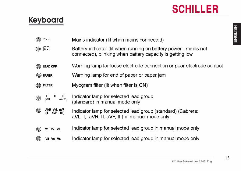
Individual lamps are provided to give power, paper error, filter, lead group and lead offindications. In addition, any detected disturbance (i.e. loose electrode or end of paper),gives an audible alarm and the corresponding indicator lamp flashes.
The ECG unit includes the following features:
• Low weight and compact dimensions• Printout from integrated quality thermal printer - OR - from external A4 inkjet printer• Built-in rechargeable battery for mains-independent use - 2 hours normal use on one
battery charge• Simple one key operation for main functions• Automatic or manual recording modes• Selectable printing formats - external and internal printer• Choice of 10 languages (AT-1) and 9 languages (AT-1 smartprint) for printing.• Interpretation program option (including measurements) for children and adults
IntroductionIntroductionIntroductionIntroductionIntroduction
NOTE:NOTE:NOTE:NOTE:NOTE: The only difference between AThe only difference between AThe only difference between AThe only difference between AThe only difference between ATTTTT-1 and A-1 and A-1 and A-1 and A-1 and ATTTTT-1 smar-1 smar-1 smar-1 smar-1 smartprint is that Atprint is that Atprint is that Atprint is that Atprint is that ATTTTT-1-1-1-1-1smarsmarsmarsmarsmartprint has a connector for an external ink-jet printertprint has a connector for an external ink-jet printertprint has a connector for an external ink-jet printertprint has a connector for an external ink-jet printertprint has a connector for an external ink-jet printer, which, which, which, which, whichmakes it possible to generate printouts in A4 size.makes it possible to generate printouts in A4 size.makes it possible to generate printouts in A4 size.makes it possible to generate printouts in A4 size.makes it possible to generate printouts in A4 size.
The ECG unit is a 3-channel ECG recorder with all (12) ECG signals simultaneously processed toprovide instant ECG recordings. Three automatic recording modes - two for the internal printerand one for the external printer - can be individually preset to enable one button ECGrecording of preferred print formats.
Individual lamps are provided to give power, paper error, filter, lead group and lead offindications. In addition, any detected disturbance (i.e. loose electrode or end of paper),gives an audible alarm and the corresponding indicator lamp flashes.
The ECG unit includes the following features:
• Low weight and compact dimensions• Printout from integrated quality thermal printer - OR - from external A4 inkjet printer• Built-in rechargeable battery for mains-independent use - 2 hours normal use on one
battery charge• Simple one key operation for main functions• Automatic or manual recording modes• Selectable printing formats - external and internal printer• Choice of 10 languages (AT-1) and 9 languages (AT-1 smartprint) for printing.• Interpretation program option (including measurements) for children and adults
4
4
Modes of OperationModes of OperationModes of OperationModes of OperationModes of Operation
Automatic Modea. without external printer connected or printer switched off
Automatic Mode provides a printout giving 10 seconds of ECG recording of all 12 leads with achoice of 2 different formats (only for S version).
The following can be programmed freely for each of the 2 formats before recording:
• Lead Format
• Chart Speed
• With the optional interpretation program installed it is also possible to select themeasurement table, average cycles with optional markings and interpretationstatements for the printout.
For further information see paragraph ̀ Automatic Mode (ECG) Settings` on page 26.
b. with external printer connected and switched on
Only one Automatic Mode format possible. Other details as above.
For further information see paragraph ̀ Automatic Mode (ECG) Settings` on page 30.
5AT-1 User Guide Art. No. 2.510171 g
5AT-1 User Guide Art. No. 2.510171 g
ENG
LISH
ENG
LISH
Modes of OperationModes of OperationModes of OperationModes of OperationModes of Operation
Manual ModeManual Mode provides a real-time printout of 3 selected leads and is only possible on theinternal thermal printer.
The following can be freely selected before or during recording:
• Lead Group
• Chart Speed
• Sensitivity
• Myogram Filter
For further information see paragraph ̀ Manual Mode` on page 8.
6
6
Automatic ModeAutomatic ModeAutomatic ModeAutomatic ModeAutomatic Modea. without external printer connected or printer switched off
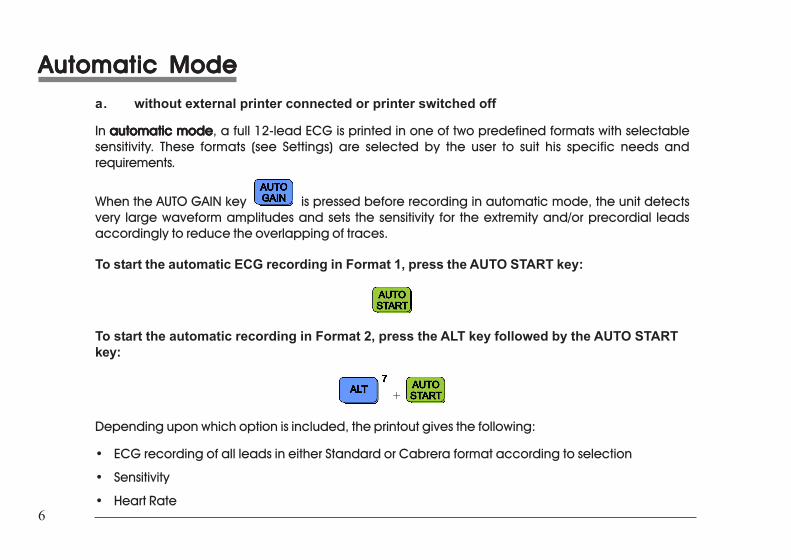
In automatic modeautomatic modeautomatic modeautomatic modeautomatic mode, a full 12-lead ECG is printed in one of two predefined formats with selectablesensitivity. These formats (see Settings) are selected by the user to suit his specific needs andrequirements.
When the AUTO GAIN key is pressed before recording in automatic mode, the unit detectsvery large waveform amplitudes and sets the sensitivity for the extremity and/or precordial leadsaccordingly to reduce the overlapping of traces.
To start the automatic ECG recording in Format 1, press the AUTO START key:
To start the automatic recording in Format 2, press the ALT key followed by the AUTO STARTkey:
+
Depending upon which option is included, the printout gives the following:
• ECG recording of all leads in either Standard or Cabrera format according to selection
• Sensitivity
• Heart Rate
Automatic ModeAutomatic ModeAutomatic ModeAutomatic ModeAutomatic Modea. without external printer connected or printer switched off
In automatic modeautomatic modeautomatic modeautomatic modeautomatic mode, a full 12-lead ECG is printed in one of two predefined formats with selectablesensitivity. These formats (see Settings) are selected by the user to suit his specific needs andrequirements.
When the AUTO GAIN key is pressed before recording in automatic mode, the unit detectsvery large waveform amplitudes and sets the sensitivity for the extremity and/or precordial leadsaccordingly to reduce the overlapping of traces.
To start the automatic ECG recording in Format 1, press the AUTO START key:
To start the automatic recording in Format 2, press the ALT key followed by the AUTO STARTkey:
+
Depending upon which option is included, the printout gives the following:
• ECG recording of all leads in either Standard or Cabrera format according to selection
• Sensitivity
• Heart Rate
7AT-1 User Guide Art. No. 2.510171 g
7AT-1 User Guide Art. No. 2.510171 g
ENG
LISH
ENG
LISH
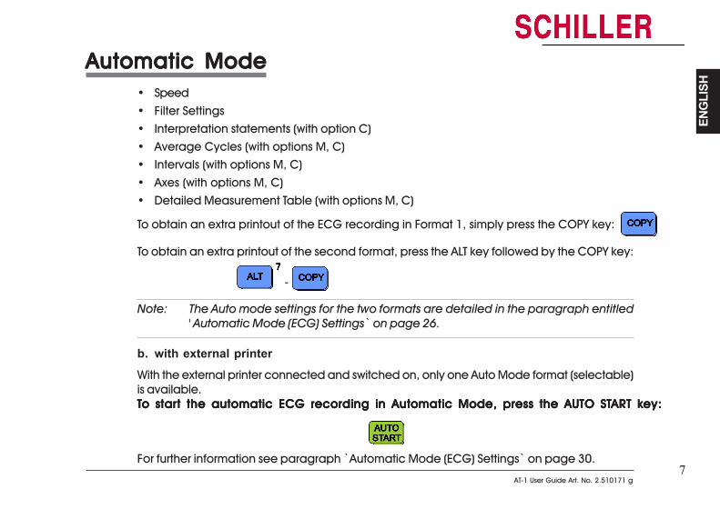
Automatic ModeAutomatic ModeAutomatic ModeAutomatic ModeAutomatic Mode• Speed• Filter Settings• Interpretation statements (with option C)• Average Cycles (with options M, C)• Intervals (with options M, C)• Axes (with options M, C)• Detailed Measurement Table (with options M, C)
To obtain an extra printout of the ECG recording in Format 1, simply press the COPY key:
To obtain an extra printout of the second format, press the ALT key followed by the COPY key:
-
Note: The Auto mode settings for the two formats are detailed in the paragraph entitled' Automatic Mode (ECG) Settings` on page 26.
b. with external printerWith the external printer connected and switched on, only one Auto Mode format (selectable)is available.TTTTTo staro staro staro staro start the automatic ECG recording in Automatic Mode, press the AUTO STt the automatic ECG recording in Automatic Mode, press the AUTO STt the automatic ECG recording in Automatic Mode, press the AUTO STt the automatic ECG recording in Automatic Mode, press the AUTO STt the automatic ECG recording in Automatic Mode, press the AUTO START kART kART kART kART key:ey:ey:ey:ey:
For further information see paragraph ̀ Automatic Mode (ECG) Settings` on page 30.
8
8
Manual ModeManual ModeManual ModeManual ModeManual Mode
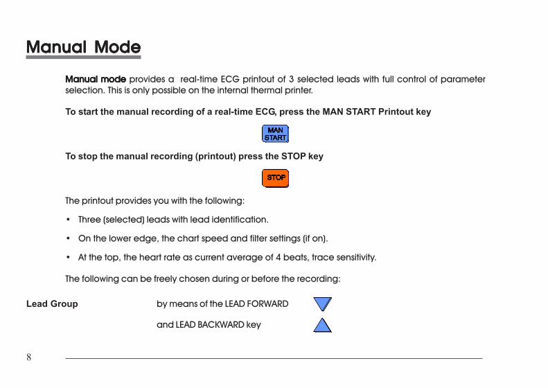
Manual modeManual modeManual modeManual modeManual mode provides a real-time ECG printout of 3 selected leads with full control of parameterselection. This is only possible on the internal thermal printer.
To start the manual recording of a real-time ECG, press the MAN START Printout key
To stop the manual recording (printout) press the STOP key
The printout provides you with the following:
• Three (selected) leads with lead identification.
• On the lower edge, the chart speed and filter settings (if on).
• At the top, the heart rate as current average of 4 beats, trace sensitivity.
The following can be freely chosen during or before the recording:
Lead Group by means of the LEAD FORWARD
and LEAD BACKWARD key
Manual ModeManual ModeManual ModeManual ModeManual Mode
Manual modeManual modeManual modeManual modeManual mode provides a real-time ECG printout of 3 selected leads with full control of parameterselection. This is only possible on the internal thermal printer.
To start the manual recording of a real-time ECG, press the MAN START Printout key
To stop the manual recording (printout) press the STOP key
The printout provides you with the following:
• Three (selected) leads with lead identification.
• On the lower edge, the chart speed and filter settings (if on).
• At the top, the heart rate as current average of 4 beats, trace sensitivity.
The following can be freely chosen during or before the recording:
Lead Group by means of the LEAD FORWARD
and LEAD BACKWARD key
9AT-1 User Guide Art. No. 2.510171 g
9AT-1 User Guide Art. No. 2.510171 g
ENG
LISH
ENG
LISH
Manual ModeManual ModeManual ModeManual ModeManual Mode
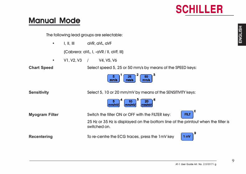
The following lead groups are selectable:
• I, II, III aVR, aVL, aVF
(Cabrera: aVL, I, -aVR / II, aVF, III)
• V1, V2, V3 / V4, V5, V6
Chart Speed Select speed 5, 25 or 50 mm/s by means of the SPEED keys:
Sensitivity Select 5, 10 or 20 mm/mV by means of the SENSITIVITY keys:
Myogram Filter Switch the filter ON or OFF with the FILTER key:
25 Hz or 35 Hz is displayed on the bottom line of the printout when the filter isswitched on.
Recentering To re-centre the ECG traces, press the 1mV key
Manual ModeManual ModeManual ModeManual ModeManual Mode
The following lead groups are selectable:
• I, II, III aVR, aVL, aVF
(Cabrera: aVL, I, -aVR / II, aVF, III)
• V1, V2, V3 / V4, V5, V6
Chart Speed Select speed 5, 25 or 50 mm/s by means of the SPEED keys:
Sensitivity Select 5, 10 or 20 mm/mV by means of the SENSITIVITY keys:
Myogram Filter Switch the filter ON or OFF with the FILTER key:
25 Hz or 35 Hz is displayed on the bottom line of the printout when the filter isswitched on.
Recentering To re-centre the ECG traces, press the 1mV key
10
10
LLLLLocation & Pocation & Pocation & Pocation & Pocation & Powerowerowerowerower
LocationDo not keep or operate the apparatus in a wet, moist, or dusty environment. Also, avoid exposure todirect sunlight or heat from other sources. Do not allow the unit to come into contact with acidicvapours or liquids, as such contact may cause irreparable damage. The unit should not be placednear X-ray or diathermy units, large transformers or motors. The unit must be placed on a flat surfaceand must not be operated in areas where there is any danger of explosion.
Power SupplyThe mains connection is on the rear of the unit. The mains indicator lamp on the keyboard is always litwhen the unit is connected to the mains supply. The unit can either be operated from the mains supplyor from the built-in rechargeable battery. The power source is indicated by the respective indicatorlamp. When battery capacity is limited, the battery symbol flashes on and off.
To recharge the battery, connect the apparatus to the mains supply by means of the supplied powercable. A totally discharged battery needs less than 15 hours to be fully recharged (60% in less than 3hours, 90% in less than 7 hours). A fully charged battery gives approximately 2 hours of normal use. Theunit can remain connected to the mains supply without any danger of damage to either the battery orthe unit.
11AT-1 User Guide Art. No. 2.510171 g
11AT-1 User Guide Art. No. 2.510171 g
ENG
LISH
ENG
LISH
Switching On and OffSwitching On and OffSwitching On and OffSwitching On and OffSwitching On and Off
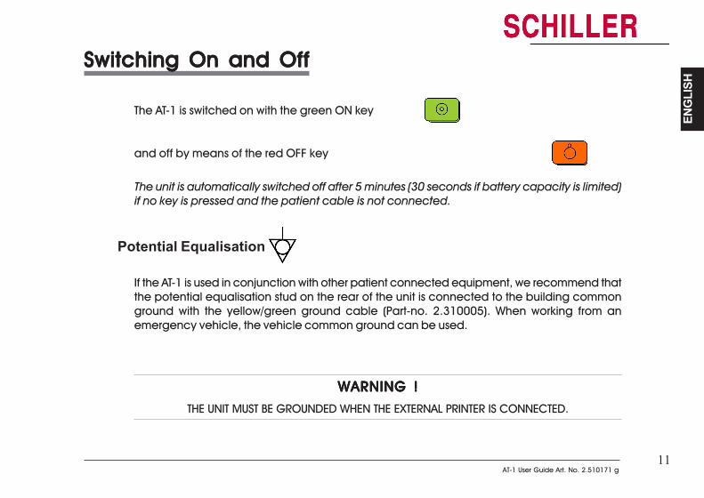
The AT-1 is switched on with the green ON key
and off by means of the red OFF key
The unit is automatically switched off after 5 minutes (30 seconds if battery capacity is limited)if no key is pressed and the patient cable is not connected.
Potential Equalisation
If the AT-1 is used in conjunction with other patient connected equipment, we recommend thatthe potential equalisation stud on the rear of the unit is connected to the building commonground with the yellow/green ground cable (Part-no. 2.310005). When working from anemergency vehicle, the vehicle common ground can be used.
WARNING !WARNING !WARNING !WARNING !WARNING !
THE UNIT MUST BE GROUNDED WHEN THE EXTERNAL PRINTER IS CONNECTED.
Switching On and OffSwitching On and OffSwitching On and OffSwitching On and OffSwitching On and Off
The AT-1 is switched on with the green ON key
and off by means of the red OFF key
The unit is automatically switched off after 5 minutes (30 seconds if battery capacity is limited)if no key is pressed and the patient cable is not connected.
Potential Equalisation
If the AT-1 is used in conjunction with other patient connected equipment, we recommend thatthe potential equalisation stud on the rear of the unit is connected to the building commonground with the yellow/green ground cable (Part-no. 2.310005). When working from anemergency vehicle, the vehicle common ground can be used.
WARNING !WARNING !WARNING !WARNING !WARNING !
THE UNIT MUST BE GROUNDED WHEN THE EXTERNAL PRINTER IS CONNECTED.
12
12
KKKKKeyboardeyboardeyboardeyboardeyboard
KKKKKeyboardeyboardeyboardeyboardeyboard
13AT-1 User Guide Art. No. 2.510171 g
13AT-1 User Guide Art. No. 2.510171 g
ENG
LISH
ENG
LISH
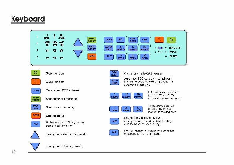
KKKKKeyboardeyboardeyboardeyboardeyboard
KKKKKeyboardeyboardeyboardeyboardeyboard
14
14
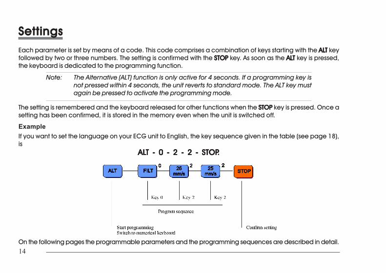
SettingsSettingsSettingsSettingsSettingsEach parameter is set by means of a code. This code comprises a combination of keys starting with the ALALALALALTTTTT keyfollowed by two or three numbers. The setting is confirmed with the STOPSTOPSTOPSTOPSTOP key. As soon as the ALALALALALTTTTT key is pressed,the keyboard is dedicated to the programming function.
Note: The Alternative (ALT) function is only active for 4 seconds. If a programming key isnot pressed within 4 seconds, the unit reverts to standard mode. The ALT key mustagain be pressed to activate the programming mode.
The setting is remembered and the keyboard released for other functions when the STOPSTOPSTOPSTOPSTOP key is pressed. Once asetting has been confirmed, it is stored in the memory even when the unit is switched off.
ExampleIf you want to set the language on your ECG unit to English, the key sequence given in the table (see page 18),is
ALALALALALT - 0 - 2 - 2 - STOPT - 0 - 2 - 2 - STOPT - 0 - 2 - 2 - STOPT - 0 - 2 - 2 - STOPT - 0 - 2 - 2 - STOP.....
On the following pages the programmable parameters and the programming sequences are described in detail.
15AT-1 User Guide Art. No. 2.510171 g
15AT-1 User Guide Art. No. 2.510171 g
ENG
LISH
ENG
LISH
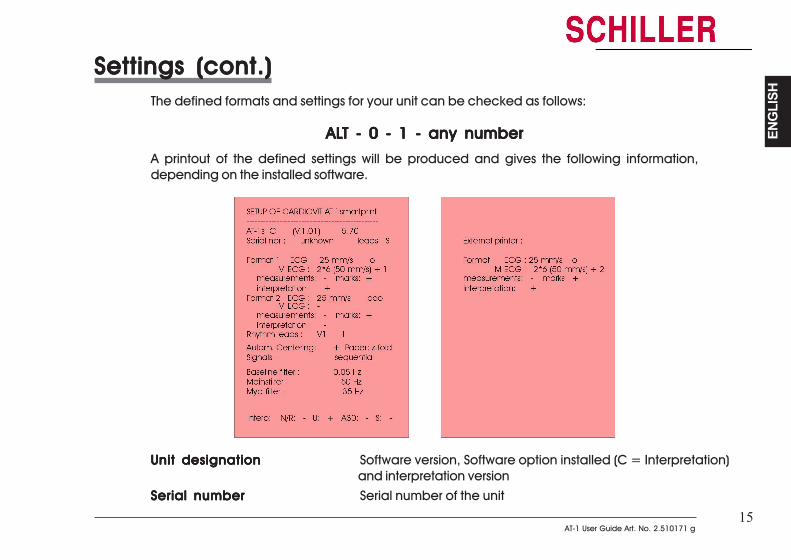
Settings (cont.)Settings (cont.)Settings (cont.)Settings (cont.)Settings (cont.)The defined formats and settings for your unit can be checked as follows:
ALALALALALT - 0 - 1 - any numberT - 0 - 1 - any numberT - 0 - 1 - any numberT - 0 - 1 - any numberT - 0 - 1 - any number
A printout of the defined settings will be produced and gives the following information,depending on the installed software.
Unit designationUnit designationUnit designationUnit designationUnit designation Software version, Software option installed (C = Interpretation)and interpretation version
Serial numberSerial numberSerial numberSerial numberSerial number Serial number of the unit
16
16
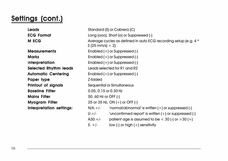
Settings (cont.)Settings (cont.)Settings (cont.)Settings (cont.)Settings (cont.)LeadsLeadsLeadsLeadsLeads Standard (S) or Cabrera (C)ECG FormatECG FormatECG FormatECG FormatECG Format Long (ooo), Short (o) or Suppressed (-)M ECGM ECGM ECGM ECGM ECG Average cycles as defined in auto ECG recording setup (e.g. 4 *
3 (25 mm/s) + 2)MeasurementsMeasurementsMeasurementsMeasurementsMeasurements Enabled (+) or Suppressed (-)MarksMarksMarksMarksMarks Enabled (+) or Suppressed (-)Interpretationnterpretationnterpretationnterpretationnterpretation Enabled (+) or Suppressed (-)Selected Rhythm leadsSelected Rhythm leadsSelected Rhythm leadsSelected Rhythm leadsSelected Rhythm leads Leads selected for R1 and R2Automatic CenteringAutomatic CenteringAutomatic CenteringAutomatic CenteringAutomatic Centering Enabled (+) or Suppressed (-)Paper typePaper typePaper typePaper typePaper type Z-folded
Printout of signalsPrintout of signalsPrintout of signalsPrintout of signalsPrintout of signals Sequential or SimultaneousBaseline FilterBaseline FilterBaseline FilterBaseline FilterBaseline Filter 0.05, 0.15 or 0.30 HzMains FilterMains FilterMains FilterMains FilterMains Filter 50, 60 Hz or OFF (-)Myogram FilterMyogram FilterMyogram FilterMyogram FilterMyogram Filter 25 or 35 Hz, ON (+) or OFF (-)
Interpretation settings:Interpretation settings:Interpretation settings:Interpretation settings:Interpretation settings: N/A:+/- ‘normal/abnormal’ is written (+) or suppressed (-)U:+/- ‘unconfirmed report’ is written (+) or suppressed (-)A30:+/- patient age is assumed to be < 30 (-) or >30 (+)S: +/- low (-) or high (+) sensitivity
Settings (cont.)Settings (cont.)Settings (cont.)Settings (cont.)Settings (cont.)LeadsLeadsLeadsLeadsLeads Standard (S) or Cabrera (C)ECG FormatECG FormatECG FormatECG FormatECG Format Long (ooo), Short (o) or Suppressed (-)
M ECGM ECGM ECGM ECGM ECG Average cycles as defined in auto ECG recording setup (e.g. 4 *3 (25 mm/s) + 2)
MeasurementsMeasurementsMeasurementsMeasurementsMeasurements Enabled (+) or Suppressed (-)MarksMarksMarksMarksMarks Enabled (+) or Suppressed (-)Interpretationnterpretationnterpretationnterpretationnterpretation Enabled (+) or Suppressed (-)Selected Rhythm leadsSelected Rhythm leadsSelected Rhythm leadsSelected Rhythm leadsSelected Rhythm leads Leads selected for R1 and R2
Automatic CenteringAutomatic CenteringAutomatic CenteringAutomatic CenteringAutomatic Centering Enabled (+) or Suppressed (-)Paper typePaper typePaper typePaper typePaper type Z-foldedPrintout of signalsPrintout of signalsPrintout of signalsPrintout of signalsPrintout of signals Sequential or SimultaneousBaseline FilterBaseline FilterBaseline FilterBaseline FilterBaseline Filter 0.05, 0.15 or 0.30 Hz
Mains FilterMains FilterMains FilterMains FilterMains Filter 50, 60 Hz or OFF (-)Myogram FilterMyogram FilterMyogram FilterMyogram FilterMyogram Filter 25 or 35 Hz, ON (+) or OFF (-)Interpretation settings:Interpretation settings:Interpretation settings:Interpretation settings:Interpretation settings: N/A:+/- ‘normal/abnormal’ is written (+) or suppressed (-)
U:+/- ‘unconfirmed report’ is written (+) or suppressed (-)A30:+/- patient age is assumed to be < 30 (-) or >30 (+)S: +/- low (-) or high (+) sensitivity
17AT-1 User Guide Art. No. 2.510171 g
17AT-1 User Guide Art. No. 2.510171 g
ENG
LISH
ENG
LISH
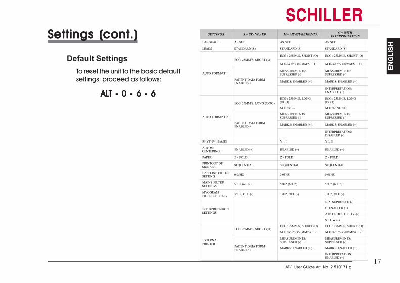
Settings (cont.)Settings (cont.)Settings (cont.)Settings (cont.)Settings (cont.)
Default SettingsTo reset the unit to the basic defaultsettings, proceed as follows:
ALALALALALT - 0 - 6 - 6T - 0 - 6 - 6T - 0 - 6 - 6T - 0 - 6 - 6T - 0 - 6 - 6
SETTINGS S = STANDARD M = MEASUREMENTS C = WITHINTERPRETATION
LANGUAGE AS SET AS SET AS SET
LEADS STANDARD (S) STANDARD (S) STANDARD (S)
AUTO FORMAT 1
ECG: 25MM/S, SHORT (O)ECG : 25MM/S, SHORT (O) ECG : 25MM/S, SHORT (O)
M ECG :6*2 (50MM/S + 1) M ECG: 6*2 (50MM/S + 1)
PATIENT DATA FORMENABLED +
MEASUREMENTS:SUPRESSED (-)
MEASUREMENTS:SUPRESSED (-)
MARKS: ENABLED (+) MARKS: ENABLED (+)
INTERPRETATION:ENABLED (+)
AUTO FORMAT 2
ECG: 25MM/S, LONG (OOO)ECG : 25MM/S, LONG(OOO)
ECG : 25MM/S, LONG(OOO)
M ECG: -- M ECG: NONE
PATIENT DATA FORMENABLED +
MEASUREMENTS:SUPRESSED (-)
MEASUREMENTS:SUPRESSED (-)
MARKS: ENABLED (+) MARKS: ENABLED (+)
INTERPRETATION:DISABLED (-)
RHYTHM LEADS V1, II V1, II
AUTOM.CENTERING ENABLED (+) ENABLED (+) ENABLED (+)
PAPER Z - FOLD Z - FOLD Z - FOLD
PRINTOUT OFSIGNALS SEQUENTIAL SEQUENTIAL SEQUENTIAL
BASELINE FILTERSETTING 0.05HZ 0.05HZ 0.05HZ
MAINS FILTERSETTINGS 50HZ (60HZ) 50HZ (60HZ) 50HZ (60HZ)
MYOGRAMFILTER SETTING 35HZ, OFF (-) 35HZ, OFF (-) 35HZ, OFF (-)
INTERPRETATIONSETTINGS
N/A: SUPRESSED (-)
U: ENABLED (+)
A30: UNDER THIRTY (-)
S: LOW (-)
EXTERNALPRINTER
ECG: 25MM/S, SHORT (O)ECG : 25MM/S, SHORT (O) ECG : 25MM/S, SHORT (O)
M ECG: 6*2 (50MM/S) + 2 M ECG: 6*2 (50MM/S) + 2
PATIENT DATA FORMENABLED +
MEASUREMENTS:SUPRESSED (-)
MEASUREMENTS:SUPRESSED (-)
MARKS: ENABLED (+) MARKS: ENABLED (+)
INTERPRETATION:ENABLED (+)
18
18
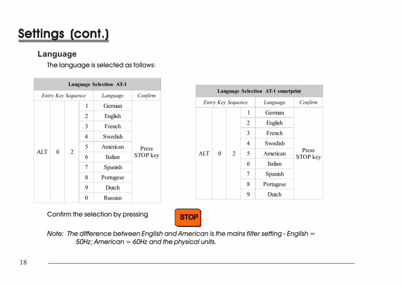
Settings (cont.)Settings (cont.)Settings (cont.)Settings (cont.)Settings (cont.)
LanguageThe language is selected as follows:
Language Selection AT-1
Entry Key Sequence Language Confirm
ALT 0 2
1 German
PressSTOP key
2 English
3 French
4 Swedish
5 American
6 Italian
7 Spanish
8 Portugese
9 Dutch
0 Russian
Language Selection AT-1 smartprint
Entry Key Sequence Language Confirm
ALT 0 2
1 German
PressSTOP key
2 English
3 French
4 Swedish
5 American
6 Italian
7 Spanish
8 Portugese
9 Dutch
Confirm the selection by pressing
Note: The difference between English and American is the mains filter setting - English =50Hz; American = 60Hz and the physical units.

19AT-1 User Guide Art. No. 2.510171 g
19AT-1 User Guide Art. No. 2.510171 g
ENG
LISH
ENG
LISH
Settings (cont.)Settings (cont.)Settings (cont.)Settings (cont.)Settings (cont.)
FiltersThere are three different filters which can be set individually as follows:
• Baseline filter
• Mains filter
• Myogram filter
Baseline FilterThe digital Baseline filter Baseline filter Baseline filter Baseline filter Baseline filter suppresses excessive baseline drifts. The setting options are asfollows:
Baseline Filter
Entry Key Sequence Filter Setting Confirm
ALT 50 0.05 Hz (default)
Press STOPkey1 0.15 Hz
3 0.30 Hz
20
20
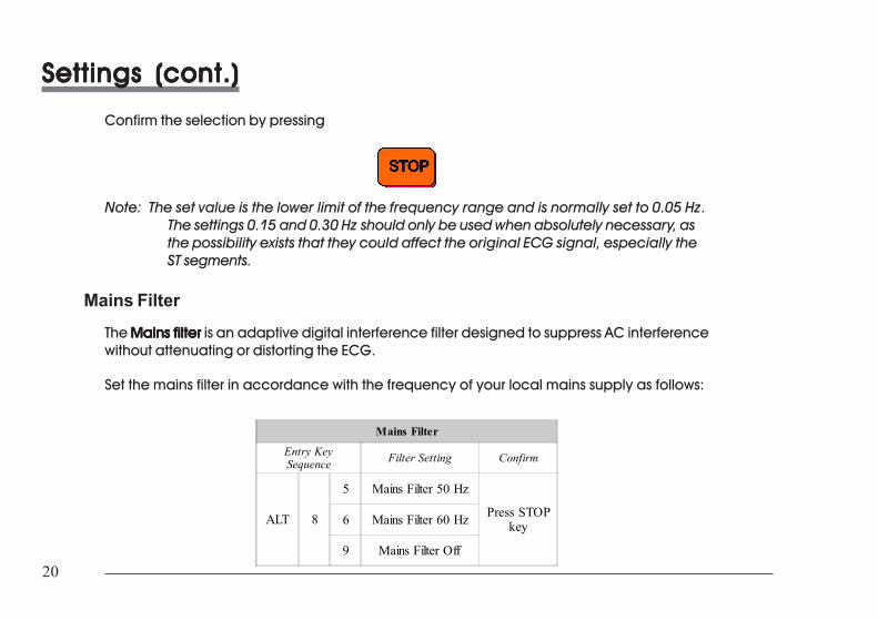
Settings (cont.)Settings (cont.)Settings (cont.)Settings (cont.)Settings (cont.)
Confirm the selection by pressing
Note: The set value is the lower limit of the frequency range and is normally set to 0.05 Hz.The settings 0.15 and 0.30 Hz should only be used when absolutely necessary, asthe possibility exists that they could affect the original ECG signal, especially theST segments.
Mains FilterThe Mains filterMains filterMains filterMains filterMains filter is an adaptive digital interference filter designed to suppress AC interferencewithout attenuating or distorting the ECG.
Set the mains filter in accordance with the frequency of your local mains supply as follows:
Mains Filter
Entry KeySequence Filter Setting Confirm
ALT 8
5 Mains Filter 50 Hz
Press STOPkey6 Mains Filter 60 Hz
9 Mains Filter Off
Settings (cont.)Settings (cont.)Settings (cont.)Settings (cont.)Settings (cont.)
Confirm the selection by pressing
Note: The set value is the lower limit of the frequency range and is normally set to 0.05Hz. The settings 0.15 and 0.30 Hz should only be used when absolutely necessary,as the possibility exists that they could affect the original ECG signal, especiallythe ST segments.
Mains FilterThe Mains filterMains filterMains filterMains filterMains filter is an adaptive digital interference filter designed to suppress AC interferencewithout attenuating or distorting the ECG.
Set the mains filter in accordance with the frequency of your local mains supply as follows:
Mains Filter
Entry KeySequence Filter Setting Confirm
ALT 8
5 Mains Filter 50 Hz
Press STOPkey6 Mains Filter 60 Hz
9 Mains Filter Off
21AT-1 User Guide Art. No. 2.510171 g
21AT-1 User Guide Art. No. 2.510171 g
ENG
LISH
ENG
LISH
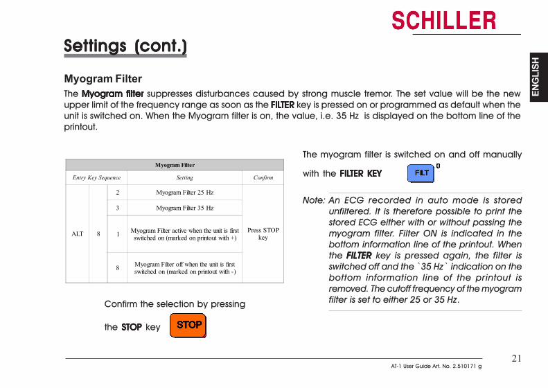
Settings (cont.)Settings (cont.)Settings (cont.)Settings (cont.)Settings (cont.)
Myogram FilterThe Myogram filter Myogram filter Myogram filter Myogram filter Myogram filter suppresses disturbances caused by strong muscle tremor. The set value will be the newupper limit of the frequency range as soon as the FILFILFILFILFILTERTERTERTERTER key is pressed on or programmed as default when theunit is switched on. When the Myogram filter is on, the value, i.e. 35 Hz is displayed on the bottom line of theprintout.
Myogram Filter
Entry Key Sequence Setting Confirm
ALT 8
2 Myogram Filter 25 Hz
Press STOPkey
3 Myogram Filter 35 Hz
1 Myogram Filter active when the unit is firstswitched on (marked on printout with +)
8 Myogram Filter off when the unit is firstswitched on (marked on printout with -)
Confirm the selection by pressing
the STOP STOP STOP STOP STOP key
The myogram filter is switched on and off manually
with the FILFILFILFILFILTER KEYTER KEYTER KEYTER KEYTER KEY
Note: An ECG recorded in auto mode is storedunfiltered. It is therefore possible to print thestored ECG either with or without passing themyogram filter. Filter ON is indicated in thebottom information line of the printout. Whenthe FILTERFILTERFILTERFILTERFILTER key is pressed again, the filter isswitched off and the ̀ 35 Hz` indication on thebottom information line of the printout isremoved. The cutoff frequency of the myogramfilter is set to either 25 or 35 Hz.
22
22
Settings (cont.)Settings (cont.)Settings (cont.)Settings (cont.)Settings (cont.)
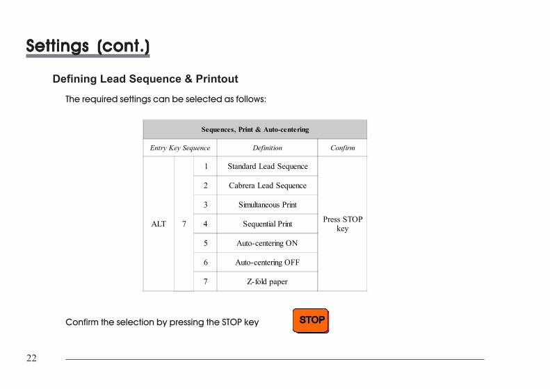
Defining Lead Sequence & PrintoutThe required settings can be selected as follows:
Sequences, Print & Auto-centering
Entry Key Sequence Definition Confirm
ALT 7
1 Standard Lead Sequence
Press STOPkey
2 Cabrera Lead Sequence
3 Simultaneous Print
4 Sequential Print
5 Auto-centering ON
6 Auto-centering OFF
7 Z-fold paper
Confirm the selection by pressing the STOP key
Settings (cont.)Settings (cont.)Settings (cont.)Settings (cont.)Settings (cont.)
Defining Lead Sequence & PrintoutThe required settings can be selected as follows:
Sequences, Print & Auto-centering
Entry Key Sequence Definition Confirm
ALT 7
1 Standard Lead Sequence
Press STOPkey
2 Cabrera Lead Sequence
3 Simultaneous Print
4 Sequential Print
5 Auto-centering ON
6 Auto-centering OFF
7 Z-fold paper
Confirm the selection by pressing the STOP key
23AT-1 User Guide Art. No. 2.510171 g
23AT-1 User Guide Art. No. 2.510171 g
ENG
LISH
ENG
LISH
Settings (cont.)Settings (cont.)Settings (cont.)Settings (cont.)Settings (cont.)
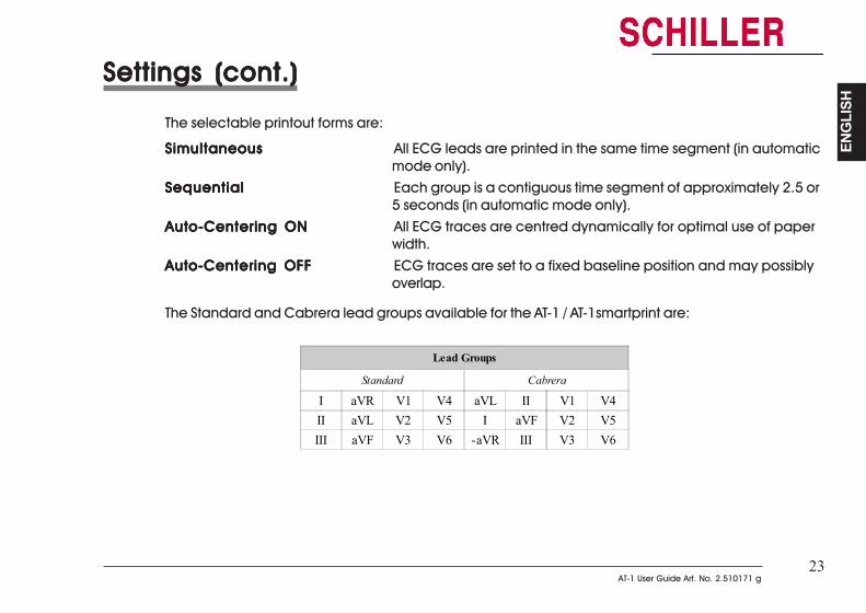
The selectable printout forms are:
SimultaneousSimultaneousSimultaneousSimultaneousSimultaneous All ECG leads are printed in the same time segment (in automaticmode only).
SequentialSequentialSequentialSequentialSequential Each group is a contiguous time segment of approximately 2.5 or5 seconds (in automatic mode only).
Auto-Centering ONAuto-Centering ONAuto-Centering ONAuto-Centering ONAuto-Centering ON All ECG traces are centred dynamically for optimal use of paperwidth.
Auto-Centering OFFAuto-Centering OFFAuto-Centering OFFAuto-Centering OFFAuto-Centering OFF ECG traces are set to a fixed baseline position and may possiblyoverlap.
The Standard and Cabrera lead groups available for the AT-1 / AT-1smartprint are:
Lead Groups
Standard Cabrera
I aVR V1 V4 aVL II V1 V4II aVL V2 V5 I aVF V2 V5III aVF V3 V6 -aVR III V3 V6
Settings (cont.)Settings (cont.)Settings (cont.)Settings (cont.)Settings (cont.)
The selectable printout forms are:
SimultaneousSimultaneousSimultaneousSimultaneousSimultaneous All ECG leads are printed in the same time segment (in automaticmode only).
SequentialSequentialSequentialSequentialSequential Each group is a contiguous time segment of approximately 2.5 or5 seconds (in automatic mode only).
Auto-Centering ONAuto-Centering ONAuto-Centering ONAuto-Centering ONAuto-Centering ON All ECG traces are centred dynamically for optimal use of paperwidth.
Auto-Centering OFFAuto-Centering OFFAuto-Centering OFFAuto-Centering OFFAuto-Centering OFF ECG traces are set to a fixed baseline position and may possiblyoverlap.
The Standard and Cabrera lead groups available for the AT-1 / AT-1smartprint are:
Lead Groups
Standard Cabrera
I aVR V1 V4 aVL II V1 V4II aVL V2 V5 I aVF V2 V5III aVF V3 V6 -aVR III V3 V6
24
24
Settings (cont.)Settings (cont.)Settings (cont.)Settings (cont.)Settings (cont.)
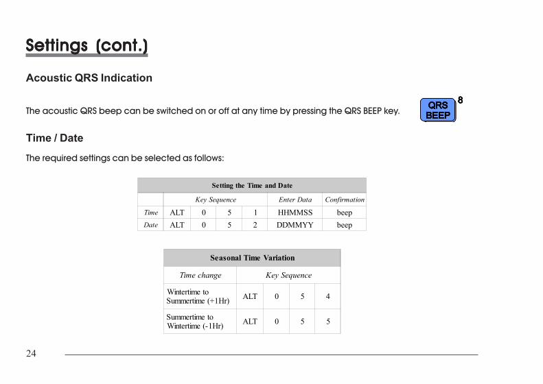
Acoustic QRS Indication
The acoustic QRS beep can be switched on or off at any time by pressing the QRS BEEP key.
Time / DateThe required settings can be selected as follows:
Setting the Time and Date
Key Sequence Enter Data Confirmation
Time ALT 0 5 1 HHMMSS beepDate ALT 0 5 2 DDMMYY beep
Seasonal Time Variation
Time change Key Sequence
Wintertime toSummertime (+1Hr) ALT 0 5 4
Summertime toWintertime (-1Hr) ALT 0 5 5
Settings (cont.)Settings (cont.)Settings (cont.)Settings (cont.)Settings (cont.)
Acoustic QRS Indication
The acoustic QRS beep can be switched on or off at any time by pressing the QRS BEEP key.
Time / DateThe required settings can be selected as follows:
Setting the Time and Date
Key Sequence Enter Data Confirmation
Time ALT 0 5 1 HHMMSS beepDate ALT 0 5 2 DDMMYY beep
Seasonal Time Variation
Time change Key Sequence
Wintertime toSummertime (+1Hr) ALT 0 5 4
Summertime toWintertime (-1Hr) ALT 0 5 5
25AT-1 User Guide Art. No. 2.510171 g
25AT-1 User Guide Art. No. 2.510171 g
ENG
LISH
ENG
LISH
Settings (cont.)Settings (cont.)Settings (cont.)Settings (cont.)Settings (cont.)
Note: If the battery has been disconnected for more than half an hour, the clock oscillatormust be restarted before setting the time. To do this the following key sequencemust be pressed:
ALALALALALT - 0 - 5 - 9T - 0 - 5 - 9T - 0 - 5 - 9T - 0 - 5 - 9T - 0 - 5 - 9
This will start the oscillator and the time can be set.
Note: The time and date only appear on the AUTO printout from the external printer.
26
26
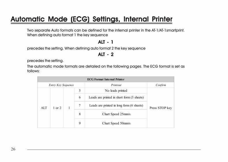
Automatic Mode (ECG) Settings, Internal PrinterAutomatic Mode (ECG) Settings, Internal PrinterAutomatic Mode (ECG) Settings, Internal PrinterAutomatic Mode (ECG) Settings, Internal PrinterAutomatic Mode (ECG) Settings, Internal PrinterTwo separate Auto formats can be defined for the internal printer in the AT-1/AT-1smartprint.When defining auto format 1 the key sequence
ALALALALALT - 1T - 1T - 1T - 1T - 1precedes the setting. When defining auto format 2 the key sequence
ALALALALALT - 2T - 2T - 2T - 2T - 2precedes the setting.The automatic mode formats are detailed on the following pages. The ECG format is set asfollows:
ECG Format Internal Printer
Entry Key Sequence Printout Confirm
ALT 1 or 2 1
5 No leads printed
Press STOP key
6 Leads are printed in short form (3 sheets)
7 Leads are printed in long form (6 sheets)
8 Chart Speed 25mm/s
9 Chart Speed 50mm/s
27AT-1 User Guide Art. No. 2.510171 g
27AT-1 User Guide Art. No. 2.510171 g
ENG
LISH
ENG
LISH
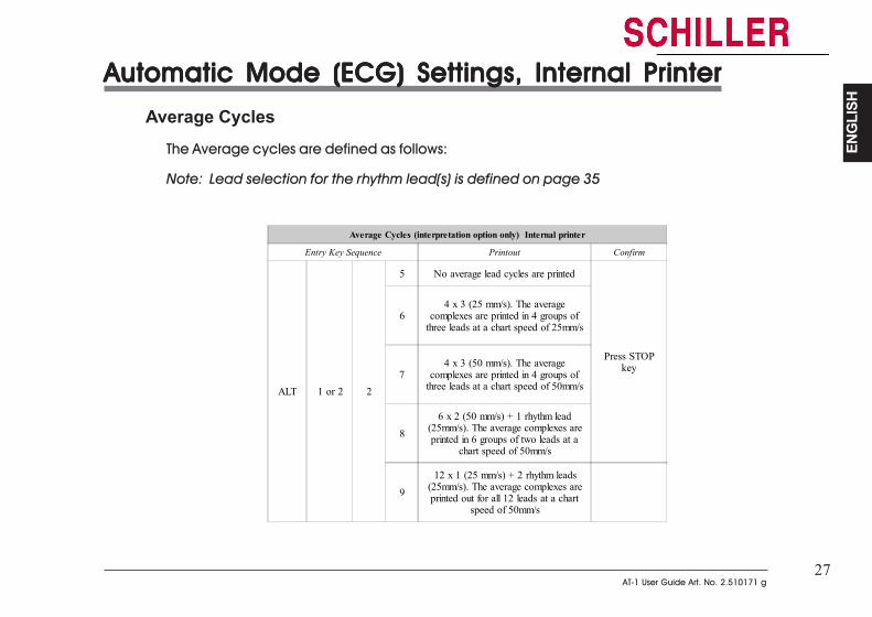
Automatic Mode (ECG) Settings, Internal PrinterAutomatic Mode (ECG) Settings, Internal PrinterAutomatic Mode (ECG) Settings, Internal PrinterAutomatic Mode (ECG) Settings, Internal PrinterAutomatic Mode (ECG) Settings, Internal Printer
Average CyclesThe Average cycles are defined as follows:
Note: Lead selection for the rhythm lead(s) is defined on page 35
Average Cycles (interpretation option only) Internal printer
Entry Key Sequence Printout Confirm
ALT 1 or 2 2
5 No average lead cycles are printed
Press STOPkey
64 x 3 (25 mm/s). The average
complexes are printed in 4 groups ofthree leads at a chart speed of 25mm/s
74 x 3 (50 mm/s). The average
complexes are printed in 4 groups ofthree leads at a chart speed of 50mm/s
8
6 x 2 (50 mm/s) + 1 rhythm lead(25mm/s). The average complexes areprinted in 6 groups of two leads at a
chart speed of 50mm/s
9
12 x 1 (25 mm/s) + 2 rhythm leads(25mm/s). The average complexes areprinted out for all 12 leads at a chart
speed of 50mm/s
28
28
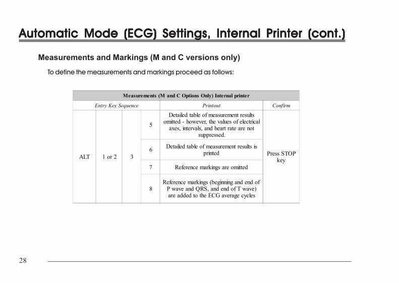
Automatic Mode (ECG) Settings, Internal Printer (cont.)Automatic Mode (ECG) Settings, Internal Printer (cont.)Automatic Mode (ECG) Settings, Internal Printer (cont.)Automatic Mode (ECG) Settings, Internal Printer (cont.)Automatic Mode (ECG) Settings, Internal Printer (cont.)
Measurements and Markings (M and C versions only)To define the measurements and markings proceed as follows:
Measurements (M and C Options Only) Internal printer
Entry Key Sequence Printout Confirm
ALT 1 or 2 3
5
Detailed table of measurement resultsomitted - however, the values of electrical
axes, intervals, and heart rate are notsuppressed.
Press STOPkey
6 Detailed table of measurement results isprinted
7 Reference markings are omitted
8Reference markings (beginning and end of
P wave and QRS, and end of T wave)are added to the ECG average cycles

29AT-1 User Guide Art. No. 2.510171 g
29AT-1 User Guide Art. No. 2.510171 g
ENG
LISH
ENG
LISH
Automatic Mode (ECG) Settings, Internal Printer (cont.)Automatic Mode (ECG) Settings, Internal Printer (cont.)Automatic Mode (ECG) Settings, Internal Printer (cont.)Automatic Mode (ECG) Settings, Internal Printer (cont.)Automatic Mode (ECG) Settings, Internal Printer (cont.)
Interpretation (C version only)To print or suppress interpretation statements on the printout proceed as follows:
Interpretation (Interpretation Option Only) Internal printerEntry Key Sequence Printout Confirm
ALT 1 or 2 45 Interpretation is omitted Press STOP
key6 Interpretation is printed
Confirm the selection by pressing the STOP key
Full details of the interpretation option are given in the SCHILLER ECG Measurement andInterpretation booklet (art. No. 2.510179).
30
30
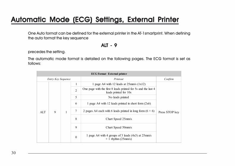
Automatic Mode (ECG) Settings, External PrinterAutomatic Mode (ECG) Settings, External PrinterAutomatic Mode (ECG) Settings, External PrinterAutomatic Mode (ECG) Settings, External PrinterAutomatic Mode (ECG) Settings, External Printer
One Auto format can be defined for the external printer in the AT-1smartprint. When definingthe auto format the key sequence
ALALALALALT - 9T - 9T - 9T - 9T - 9precedes the setting.
The automatic mode format is detailed on the following pages. The ECG format is set asfollows:
ECG Format External printer
Entry Key Sequence Printout Confirm
ALT 9 1
1 1 page A4 with 12 leads at 25mm/s (1x12)
Press STOP key
2 One page with the first 8 leads printed for 5s and the last 4leads printed for 10s
5 No leads printed
6 1 page A4 with 12 leads printed in short form (2x6)
7 2 pages A4 each with 6 leads printed in long form (6 + 6)
8 Chart Speed 25mm/s
9 Chart Speed 50mm/s
0 1 page A4 with 4 groups of 3 leads (4x3) at 25mm/s+ 1 rhythm (25mm/s)
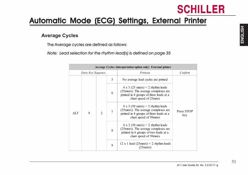
31AT-1 User Guide Art. No. 2.510171 g
31AT-1 User Guide Art. No. 2.510171 g
ENG
LISH
ENG
LISH
Automatic Mode (ECG) Settings, External PrinterAutomatic Mode (ECG) Settings, External PrinterAutomatic Mode (ECG) Settings, External PrinterAutomatic Mode (ECG) Settings, External PrinterAutomatic Mode (ECG) Settings, External Printer
Average CyclesThe Average cycles are defined as follows:
Note: Lead selection for the rhythm lead(s) is defined on page 35
Average Cycles (interpretation option only) External printer
Entry Key Sequence Printout Confirm
ALT 9 2
5 No average lead cycles are printed
Press STOPkey
6
4 x 3 (25 mm/s) + 2 rhythm leads(25mm/s). The average complexes areprinted in 4 groups of three leads at a
chart speed of 25mm/s
7
4 x 3 (50 mm/s) + 2 rhythm leads(25mm/s). The average complexes areprinted in 4 groups of three leads at a
chart speed of 50mm/s
8
6 x 2 (50 mm/s) + 2 rhythm leads(25mm/s). The average complexes areprinted in 6 groups of two leads at a
chart speed of 50mm/s
9 12 x 1 lead (25mm/s) + 2 rhythm leads(25mm/s)
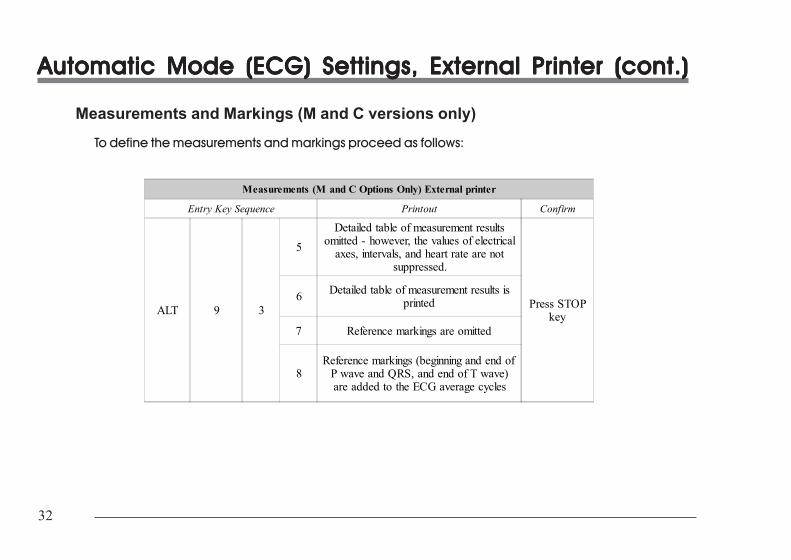
32
32
Automatic Mode (ECG) Settings, External Printer (cont.)Automatic Mode (ECG) Settings, External Printer (cont.)Automatic Mode (ECG) Settings, External Printer (cont.)Automatic Mode (ECG) Settings, External Printer (cont.)Automatic Mode (ECG) Settings, External Printer (cont.)
Measurements and Markings (M and C versions only)To define the measurements and markings proceed as follows:
Measurements (M and C Options Only) External printer
Entry Key Sequence Printout Confirm
ALT 9 3
5
Detailed table of measurement resultsomitted - however, the values of electrical
axes, intervals, and heart rate are notsuppressed.
Press STOPkey
6 Detailed table of measurement results isprinted
7 Reference markings are omitted
8Reference markings (beginning and end of
P wave and QRS, and end of T wave)are added to the ECG average cycles
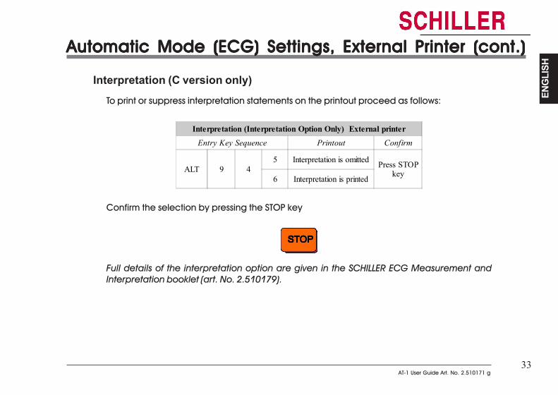
33AT-1 User Guide Art. No. 2.510171 g
33AT-1 User Guide Art. No. 2.510171 g
ENG
LISH
ENG
LISH
Automatic Mode (ECG) Settings, External Printer (cont.)Automatic Mode (ECG) Settings, External Printer (cont.)Automatic Mode (ECG) Settings, External Printer (cont.)Automatic Mode (ECG) Settings, External Printer (cont.)Automatic Mode (ECG) Settings, External Printer (cont.)
Interpretation (C version only)To print or suppress interpretation statements on the printout proceed as follows:
Interpretation (Interpretation Option Only) External printerEntry Key Sequence Printout Confirm
ALT 9 45 Interpretation is omitted Press STOP
key6 Interpretation is printed
Confirm the selection by pressing the STOP key
Full details of the interpretation option are given in the SCHILLER ECG Measurement andInterpretation booklet (art. No. 2.510179).
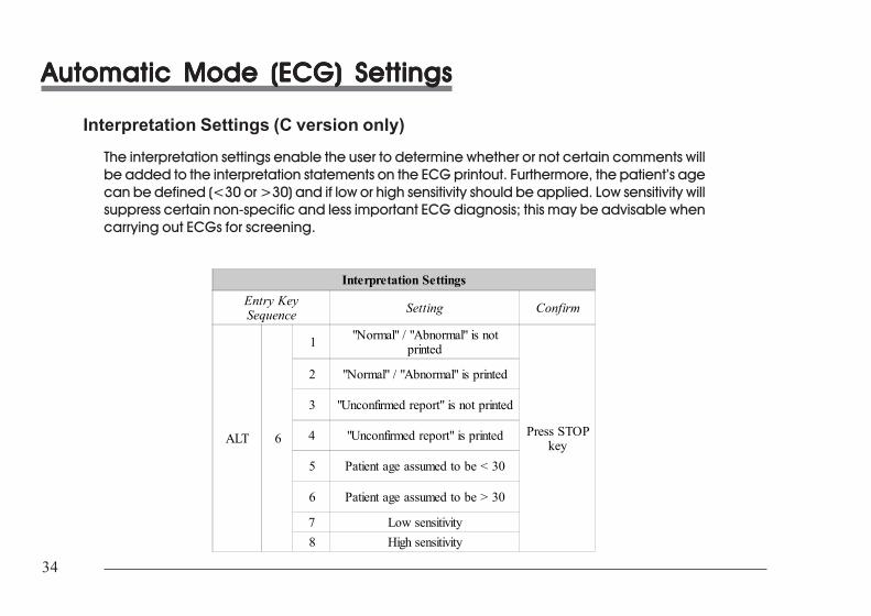
34
34
Automatic Mode (ECG) SettingsAutomatic Mode (ECG) SettingsAutomatic Mode (ECG) SettingsAutomatic Mode (ECG) SettingsAutomatic Mode (ECG) Settings
Interpretation Settings (C version only)The interpretation settings enable the user to determine whether or not certain comments willbe added to the interpretation statements on the ECG printout. Furthermore, the patient’s agecan be defined (<30 or >30) and if low or high sensitivity should be applied. Low sensitivity willsuppress certain non-specific and less important ECG diagnosis; this may be advisable whencarrying out ECGs for screening.
Interpretation SettingsEntry KeySequence Setting Confirm
ALT 6
1 "Normal" / "Abnormal" is notprinted
Press STOPkey
2 "Normal" / "Abnormal" is printed
3 "Unconfirmed report" is not printed
4 "Unconfirmed report" is printed
5 Patient age assumed to be < 30
6 Patient age assumed to be > 30
7 Low sensitivity8 High sensitivity
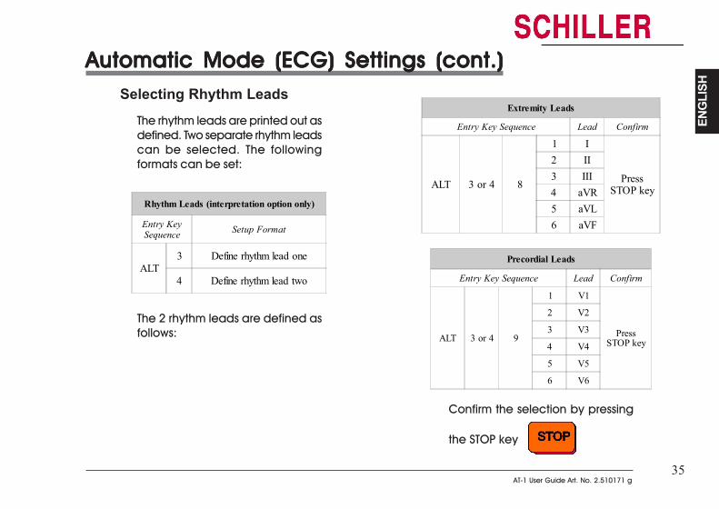
35AT-1 User Guide Art. No. 2.510171 g
35AT-1 User Guide Art. No. 2.510171 g
ENG
LISH
ENG
LISH
Automatic Mode (ECG) Settings (cont.)Automatic Mode (ECG) Settings (cont.)Automatic Mode (ECG) Settings (cont.)Automatic Mode (ECG) Settings (cont.)Automatic Mode (ECG) Settings (cont.)Selecting Rhythm Leads
The rhythm leads are printed out asdefined. Two separate rhythm leadscan be selected. The followingformats can be set:
Rhythm Leads (interpretation option only)
Entry KeySequence Setup Format
ALT3 Define rhythm lead one
4 Define rhythm lead two
The 2 rhythm leads are defined asfollows:
Extremity Leads
Entry Key Sequence Lead Confirm
ALT 3 or 4 8
1 I
PressSTOP key
2 II3 III4 aVR5 aVL6 aVF
Precordial Leads
Entry Key Sequence Lead Confirm
ALT 3 or 4 9
1 V1
PressSTOP key
2 V2
3 V3
4 V4
5 V5
6 V6
Confirm the selection by pressing
the STOP key
Extremity Leads
Entry Key Sequence Lead Confirm
ALT 3 or 4 8
1 I
PressSTOP key
2 II3 III4 aVR5 aVL6 aVF
Precordial Leads
Entry Key Sequence Lead Confirm
ALT 3 or 4 9
1 V1
PressSTOP key
2 V2
3 V3
4 V4
5 V5
6 V6
Confirm the selection by pressing
the STOP key
Automatic Mode (ECG) Settings (cont.)Automatic Mode (ECG) Settings (cont.)Automatic Mode (ECG) Settings (cont.)Automatic Mode (ECG) Settings (cont.)Automatic Mode (ECG) Settings (cont.)Selecting Rhythm Leads
The rhythm leads are printed out asdefined. Two separate rhythm leadscan be selected. The followingformats can be set:
Rhythm Leads (interpretation option only)
Entry KeySequence Setup Format
ALT3 Define rhythm lead one
4 Define rhythm lead two
The 2 rhythm leads are defined asfollows:
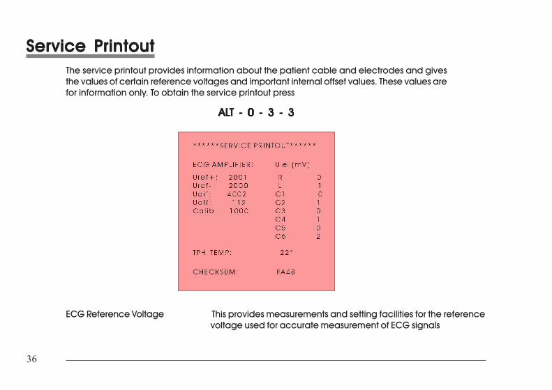
36
36
Service PrintoutService PrintoutService PrintoutService PrintoutService PrintoutThe service printout provides information about the patient cable and electrodes and givesthe values of certain reference voltages and important internal offset values. These values arefor information only. To obtain the service printout press
ALALALALALT - 0 - 3 - 3T - 0 - 3 - 3T - 0 - 3 - 3T - 0 - 3 - 3T - 0 - 3 - 3
ECG Reference Voltage This provides measurements and setting facilities for the referencevoltage used for accurate measurement of ECG signals
37AT-1 User Guide Art. No. 2.510171 g
37AT-1 User Guide Art. No. 2.510171 g
ENG
LISH
ENG
LISH
Service PrintoutService PrintoutService PrintoutService PrintoutService Printout• Uref + This gives the value of the reference voltage used in the multiplexer circuit on the ECG
Amplifier. The value of the reference voltage is 2000 mV ±20 mV.• Uref - This is a negative reference voltage used on the ECG Amplifier board. The value of this
voltage should be -2000 mV ±20 mV.• Udif This is the sum of the two reference values above (Uref+and Uref-). This value must be
4000 mV ± 20 mV.• Uoff This is the value of the offset voltage on the multiplexer circuit. This value should be
between + 150 mV and - 150 mV.• Calib This value is the Udif value divided by 4. The nominal value is 1000 ±5 mV.Electrode dc offset This gives the voltage drop in the patient cable and can indicate any faults in the
patient cable or patient electrode. The value given is the dc voltage between the leftleg electrode and all other electrodes. The measurements obtained will indicate anycable short circuits or open circuits. The measured voltage value will depend on wherethe electrodes are connected. The voltage readings that can be expected are asfollows:• With patient connected: ± 100mV• With patient simulator connected: ± 20 mV. This will depend on the patient simulator used and must be taken as a flexible measurement.• With all electrodes shorted together: ± 20 mV• No patient cable connected: -350 to -450mV
TPH TEMP This is the measured ambient temperature that the processor uses to correct print quality.This reading should be ambient temperature ± 5o.
EPROM This is the checksum for the EPROM. Its value varies from one software version to another.
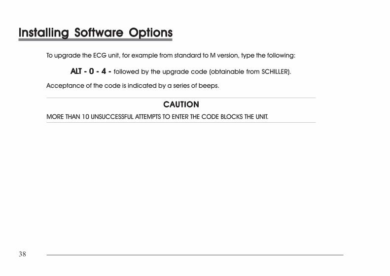
38
38
Installing Software OptionsInstalling Software OptionsInstalling Software OptionsInstalling Software OptionsInstalling Software Options
To upgrade the ECG unit, for example from standard to M version, type the following:
ALALALALALT - 0 - 4 - T - 0 - 4 - T - 0 - 4 - T - 0 - 4 - T - 0 - 4 - followed by the upgrade code (obtainable from SCHILLER).
Acceptance of the code is indicated by a series of beeps.
CAUTIONCAUTIONCAUTIONCAUTIONCAUTION
MORE THAN 10 UNSUCCESSFUL ATTEMPTS TO ENTER THE CODE BLOCKS THE UNIT.
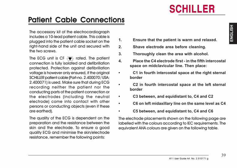
39AT-1 User Guide Art. No. 2.510171 g
39AT-1 User Guide Art. No. 2.510171 g
ENG
LISH
ENG
LISH
PPPPPatient Cable Connectionsatient Cable Connectionsatient Cable Connectionsatient Cable Connectionsatient Cable Connections
1. Ensure that the patient is warm and relaxed.2. Shave electrode area before cleaning.3. Thoroughly clean the area with alcohol.4. Place the C4 electrode first - in the fifth intercostal
space on midclavicular line. Then place:• C1 in fourth intercostal space at the right sternal
border• C2 in fourth intercostal space at the left sternal
border• C3 between, and equidistant to, C4 and C2• C6 on left midaxillary line on the same level as C4
• C5 between, and equidistant to, C4 and C6
The electrode placements shown on the following page arelabelled with the colours according to IEC requirements. Theequivalent AHA colours are given on the following table.
The accessory kit of the electrocardiographincludes a 10-lead patient cable. This cable isplugged into the patient cable socket on theright-hand side of the unit and secured withthe two screws.
The ECG unit is CF rated. The patientconnection is fully isolated and defibrillationprotected. Protection against defibrillationvoltage is however only ensured, if the originalSCHILLER patient cable (Part-no. 2.400070 / USA:2.400071) is used. Make sure that during ECGrecording neither the patient nor theconducting parts of the patient connection orthe electrodes (including the neutralelectrode) come into contact with otherpersons or conducting objects (even if theseare earthed).
The quality of the ECG is dependent on thepreparation and the resistance between theskin and the electrode. To ensure a goodquality ECG and minimise the skin/electroderesistance, remember the following points:
PPPPPatient Cable Connectionsatient Cable Connectionsatient Cable Connectionsatient Cable Connectionsatient Cable Connections
The accessory kit of the electrocardiographincludes a 10-lead patient cable. This cable isplugged into the patient cable socket on theright-hand side of the unit and secured withthe two screws.
The ECG unit is CF rated. The patientconnection is fully isolated and defibrillationprotected. Protection against defibrillationvoltage is however only ensured, if the originalSCHILLER patient cable (Part-no. 2.400070 / USA:2.400071) is used. Make sure that during ECGrecording neither the patient nor theconducting parts of the patient connection orthe electrodes (including the neutralelectrode) come into contact with otherpersons or conducting objects (even if theseare earthed).
The quality of the ECG is dependent on thepreparation and the resistance between theskin and the electrode. To ensure a goodquality ECG and minimise the skin/electroderesistance, remember the following points:
1. Ensure that the patient is warm and relaxed.2. Shave electrode area before cleaning.3. Thoroughly clean the area with alcohol.4. Place the C4 electrode first - in the fifth intercostal
space on midclavicular line. Then place:• C1 in fourth intercostal space at the right sternal
border• C2 in fourth intercostal space at the left sternal
border• C3 between, and equidistant to, C4 and C2• C6 on left midaxillary line on the same level as C4
• C5 between, and equidistant to, C4 and C6
The electrode placements shown on the following page arelabelled with the colours according to IEC requirements. Theequivalent AHA colours are given on the following table.
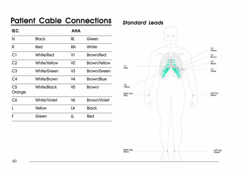
40
40
PPPPPatient Cable Connectionsatient Cable Connectionsatient Cable Connectionsatient Cable Connectionsatient Cable ConnectionsIECIECIECIECIEC AHAAHAAHAAHAAHA
N Black RL Green
R Red RA White
C1 White/Red V1 Brown/Red
C2 White/Yellow V2 Brown/Yellow
C3 White/Green V3 Brown/Green
C4 White/Brown V4 Brown/Blue
C5 White/Black V5 Brown/Orange
C6 White/Violet V6 Brown/Violet
L Yellow LA Black
F Green LL Red
Standard LStandard LStandard LStandard LStandard Leadseadseadseadseads
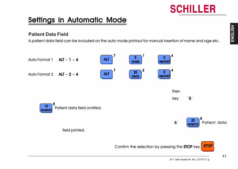
41AT-1 User Guide Art. No. 2.510171 g
41AT-1 User Guide Art. No. 2.510171 g
ENG
LISH
ENG
LISH
Settings in Automatic ModeSettings in Automatic ModeSettings in Automatic ModeSettings in Automatic ModeSettings in Automatic Mode
Patient Data FieldA patient data field can be included on the auto mode printout for manual insertion of name and age etc.
Auto Format 1 ALALALALALT - 1 - 4T - 1 - 4T - 1 - 4T - 1 - 4T - 1 - 4 .
Auto Format 2 ALALALALALT - 2 - 4T - 2 - 4T - 2 - 4T - 2 - 4T - 2 - 4 .
then
key `55555`
Patient data field omitted.
`66666` Patient data
field printed.
Confirm the selection by pressing the STOP STOP STOP STOP STOP key .
Settings in Automatic ModeSettings in Automatic ModeSettings in Automatic ModeSettings in Automatic ModeSettings in Automatic Mode
Patient Data FieldA patient data field can be included on the auto mode printout for manual insertion of name and age etc.
Auto Format 1 ALALALALALT - 1 - 4T - 1 - 4T - 1 - 4T - 1 - 4T - 1 - 4 .
Auto Format 2 ALALALALALT - 2 - 4T - 2 - 4T - 2 - 4T - 2 - 4T - 2 - 4 .
then
key `55555` Patient data field omitted.
`66666` Patient data field printed.
Confirm the selection by pressing the STOP STOP STOP STOP STOP key .
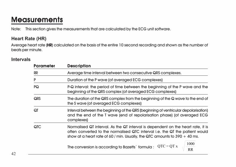
42
42
MeasurementsMeasurementsMeasurementsMeasurementsMeasurementsNote: This section gives the measurements that are calculated by the ECG unit software.
Heart Rate (HR)Average heart rate (HRHRHRHRHR) calculated on the basis of the entire 10 second recording and shown as the number ofbeats per minute.
IntervalsParameterParameterParameterParameterParameter DescriptionDescriptionDescriptionDescriptionDescription
RR Average time interval between two consecutive QRS complexes.
P Duration of the P wave (of averaged ECG complexes)
PQ P-Q interval: the period of time between the beginning of the P wave and thebeginning of the QRS complex (of averaged ECG complexes)
QRS The duration of the QRS complex from the beginning of the Q wave to the end ofthe S wave (of averaged ECG complexes)
QT Interval between the beginning of the QRS (beginning of ventricular depolarisation)and the end of the T wave (end of repolarisation phase) (of averaged ECGcomplexes)
QTC Normalised QT interval. As the QT interval is dependent on the heart rate, it isoften converted to the normalised QTC interval i.e. the QT the patient wouldshow at a heart rate of 60 / min. Usually, the QTC amounts to 390 + 40 ms.
The conversion is according to Bazetts` formula : QTC = QT x 1000RR
MeasurementsMeasurementsMeasurementsMeasurementsMeasurementsNote: This section gives the measurements that are calculated by the AT-1/AT-1smartprint software.
Heart Rate (HR)Average heart rate (HRHRHRHRHR) calculated on the basis of the entire 10 second recording and shown as the number ofbeats per minute.
IntervalsParameterParameterParameterParameterParameter DescriptionDescriptionDescriptionDescriptionDescription
RR Average time interval between two consecutive QRS complexes.
P Duration of the P wave (of averaged ECG complexes)
PQ P-Q interval: the period of time between the beginning of the P wave and thebeginning of the QRS complex (of averaged ECG complexes)
QRS The duration of the QRS complex from the beginning of the Q wave to the end ofthe S wave (of averaged ECG complexes)
QT Interval between the beginning of the QRS (beginning of ventricular depolarisation)and the end of the T wave (end of repolarisation phase) (of averaged ECGcomplexes)
QTC Normalised QT interval. As the QT interval is dependent on the heart rate, it isoften converted to the normalised QTC interval i.e. the QT the patient wouldshow at a heart rate of 60 / min. Usually, the QTC amounts to 390 + 40 ms.
The conversion is according to Bazetts` formula : QTC = QT x 1000RR
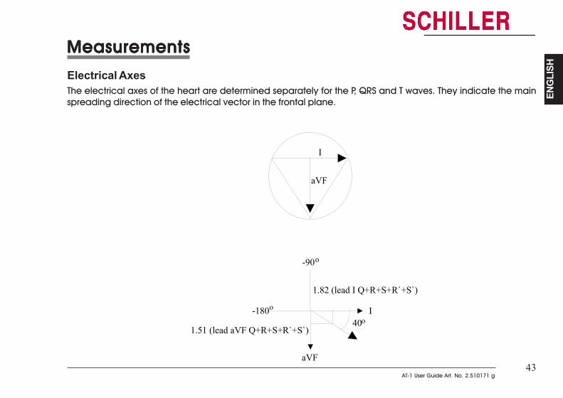
43AT-1 User Guide Art. No. 2.510171 g
43AT-1 User Guide Art. No. 2.510171 g
ENG
LISH
ENG
LISH
MeasurementsMeasurementsMeasurementsMeasurementsMeasurements
Electrical AxesThe electrical axes of the heart are determined separately for the P, QRS and T waves. They indicate the mainspreading direction of the electrical vector in the frontal plane.
I
aVF
40o
1.82 (lead I Q+R+S+R`+S`)
aVF
I
1.51 (lead aVF Q+R+S+R`+S`)
-90
-180
o
o
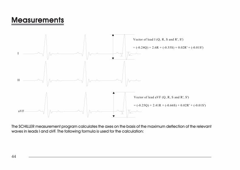
44
44
MeasurementsMeasurementsMeasurementsMeasurementsMeasurements
Vector of lead I (Q, R, S and R', S')
= (-0.24Q) + 2.6R + (-0.55S) + 0.02R' + (-0.01S')
I
II
Vector of lead aVF (Q, R, S and R', S')
= (-0.25Q) + 2.41R + (-0.66S) + 0.02R' + (-0.01S')
aVF
The SCHILLER measurement program calculates the axes on the basis of the maximum deflection of the relevantwaves in leads I and aVF. The following formula is used for the calculation:
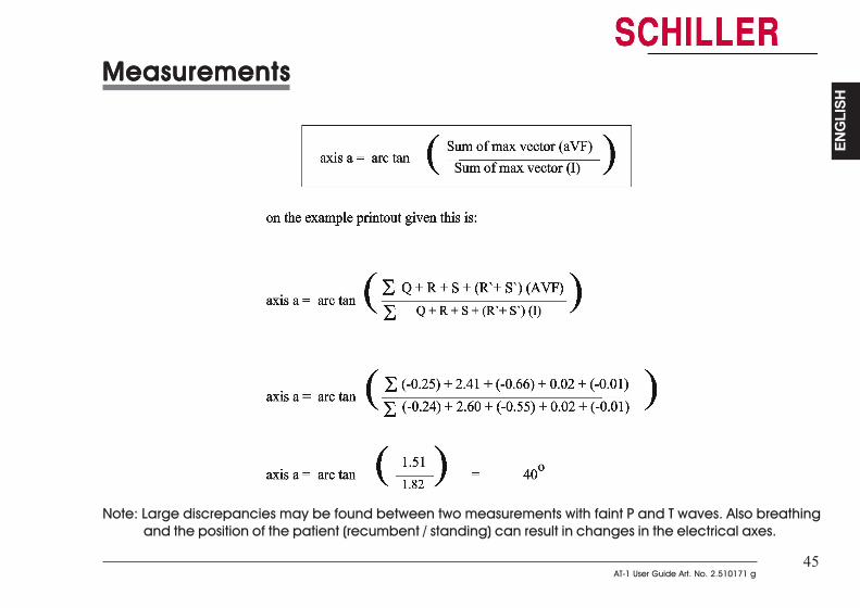
45AT-1 User Guide Art. No. 2.510171 g
45AT-1 User Guide Art. No. 2.510171 g
ENG
LISH
ENG
LISH
MeasurementsMeasurementsMeasurementsMeasurementsMeasurements
Note: Large discrepancies may be found between two measurements with faint P and T waves. Also breathingand the position of the patient (recumbent / standing) can result in changes in the electrical axes.
MeasurementsMeasurementsMeasurementsMeasurementsMeasurements
Note: Large discrepancies may be found between two measurements with faint P and T waves. Also breathingand the position of the patient (recumbent / standing) can result in changes in the electrical axes.
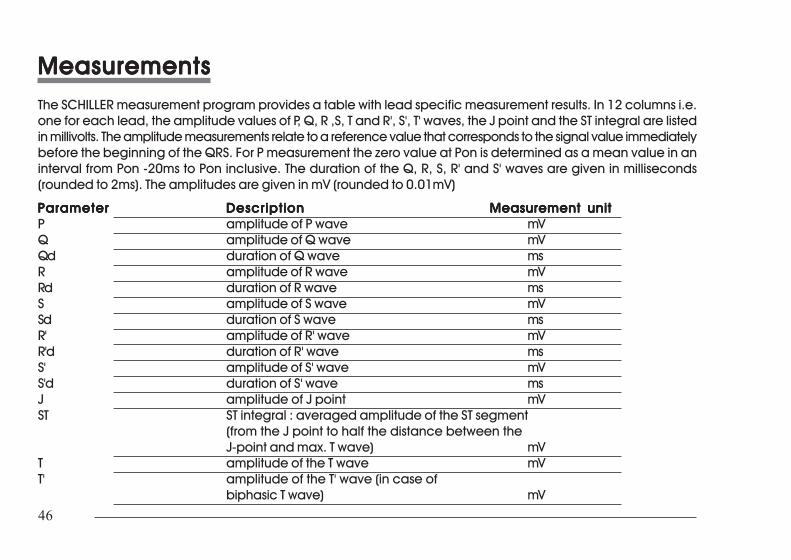
46
46
MeasurementsMeasurementsMeasurementsMeasurementsMeasurementsThe SCHILLER measurement program provides a table with lead specific measurement results. In 12 columns i.e.one for each lead, the amplitude values of P, Q, R ,S, T and R', S', T' waves, the J point and the ST integral are listedin millivolts. The amplitude measurements relate to a reference value that corresponds to the signal value immediatelybefore the beginning of the QRS. For P measurement the zero value at Pon is determined as a mean value in aninterval from Pon -20ms to Pon inclusive. The duration of the Q, R, S, R' and S' waves are given in milliseconds(rounded to 2ms). The amplitudes are given in mV (rounded to 0.01mV)
ParameterParameterParameterParameterParameter DescriptionDescriptionDescriptionDescriptionDescription Measurement unitMeasurement unitMeasurement unitMeasurement unitMeasurement unitP amplitude of P wave mVQ amplitude of Q wave mVQd duration of Q wave msR amplitude of R wave mVRd duration of R wave msS amplitude of S wave mVSd duration of S wave msR' amplitude of R' wave mVR'd duration of R' wave msS' amplitude of S' wave mVS'd duration of S' wave msJ amplitude of J point mVST ST integral : averaged amplitude of the ST segment
(from the J point to half the distance between theJ-point and max. T wave) mV
T amplitude of the T wave mVT' amplitude of the T' wave (in case of
biphasic T wave) mV
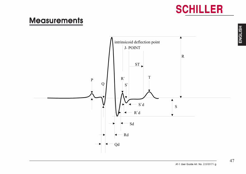
47AT-1 User Guide Art. No. 2.510171 g
47AT-1 User Guide Art. No. 2.510171 g
ENG
LISH
ENG
LISH
MeasurementsMeasurementsMeasurementsMeasurementsMeasurements
P
Qd
Q
Rd
Sd
R
ST
J- POINT
S
TR`S`
R`d
S`d
intrinsicoid deflection point
MeasurementsMeasurementsMeasurementsMeasurementsMeasurements
P
Qd
Q
Rd
Sd
R
ST
J- POINT
S
TR`S`
R`d
S`d
intrinsicoid deflection point

48
48
Care & MaintenanceCare & MaintenanceCare & MaintenanceCare & MaintenanceCare & Maintenance
12 Monthly CheckThe unit should undergo a technical safety check every 12 months. This safety check shouldinclude the following:
• Visual inspection of the unit and cables.
• Electrical safety tests according to IEC 601-1 Clause 19
The test results must be documented.
Cleaning the Casing
CAUTIONCAUTIONCAUTIONCAUTIONCAUTION
SWITCH THE UNIT OFF BEFORE CLEANING AND DISCONNECT THE MAINS AND THESWITCH THE UNIT OFF BEFORE CLEANING AND DISCONNECT THE MAINS AND THESWITCH THE UNIT OFF BEFORE CLEANING AND DISCONNECT THE MAINS AND THESWITCH THE UNIT OFF BEFORE CLEANING AND DISCONNECT THE MAINS AND THESWITCH THE UNIT OFF BEFORE CLEANING AND DISCONNECT THE MAINS AND THEEXTERNAL PRINTER (IF PRESENT). DO NOTEXTERNAL PRINTER (IF PRESENT). DO NOTEXTERNAL PRINTER (IF PRESENT). DO NOTEXTERNAL PRINTER (IF PRESENT). DO NOTEXTERNAL PRINTER (IF PRESENT). DO NOT, UNDER ANY CIRCUMST, UNDER ANY CIRCUMST, UNDER ANY CIRCUMST, UNDER ANY CIRCUMST, UNDER ANY CIRCUMSTANCES, IMMERSEANCES, IMMERSEANCES, IMMERSEANCES, IMMERSEANCES, IMMERSETHE APPTHE APPTHE APPTHE APPTHE APPARAARAARAARAARATUS INTO A CLEANING LIQUID OR STERILIZE WITH HOT WTUS INTO A CLEANING LIQUID OR STERILIZE WITH HOT WTUS INTO A CLEANING LIQUID OR STERILIZE WITH HOT WTUS INTO A CLEANING LIQUID OR STERILIZE WITH HOT WTUS INTO A CLEANING LIQUID OR STERILIZE WITH HOT WAAAAATERTERTERTERTER, STEAM, OR, STEAM, OR, STEAM, OR, STEAM, OR, STEAM, ORAIR.AIR.AIR.AIR.AIR.
The casing of the ECG unit can be cleaned with a soft damp cloth on the surface only. Wherenecessary a domestic non-caustic cleaner can be used for grease and finger marks.

49AT-1 User Guide Art. No. 2.510171 g
49AT-1 User Guide Art. No. 2.510171 g
ENG
LISH
ENG
LISH
Care & MaintenanceCare & MaintenanceCare & MaintenanceCare & MaintenanceCare & Maintenance
Patient Cable
CAUTIONCAUTIONCAUTIONCAUTIONCAUTION
ALIGN THE LEADS IN SUCH A WAY AS TO PREVENT ANYONE STUMBLING OVER THEM OR ANY DAMAGECAUSED BY THE WHEELS OF INSTRUMENT TROLLEYS. THE SAME CAUTION APPLIES TO THE STORAGEOF THE LEADS.
The patient cable should not be exposed to excessive mechanical stress. Wheneverdisconnecting the leads, hold the plugs and not the cables.
The cable can be wiped with soapy water. Sterilization, if required, should be done with gasonly and not with steam. To disinfect, wipe the cable with hospital standard disinfectant.
Cleaning the Thermal Printhead of the Internal PrinterIf the printer is used a lot, a residue of printers ink ( from the grid on the paper) can build up onthe printhead. This can cause the print quality to deteriorate. We recommend therefore thatevery month the printhead is cleaned with alcohol as follows:
Remove the paper tray. The thermal printhead is found under the paper tray release catch.With a tissue dampened in alcohol, gently rub the printhead to remove the ink residue. If theprinthead is badly soiled, the colour of the paper grid ink (i.e. red or green) will show on thetissue.
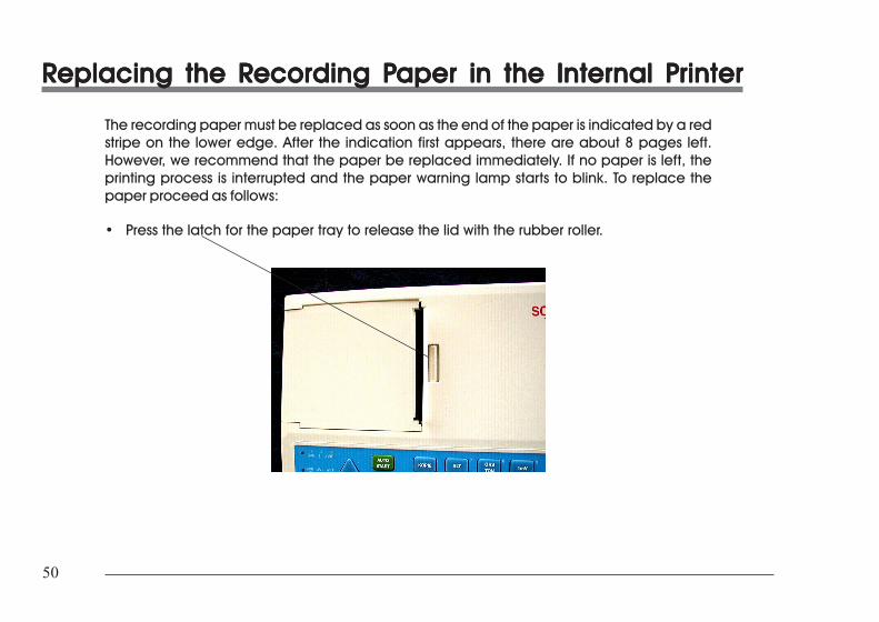
50
50
RRRRReplacing the Replacing the Replacing the Replacing the Replacing the Recording Pecording Pecording Pecording Pecording Paper in the Internal Paper in the Internal Paper in the Internal Paper in the Internal Paper in the Internal Printerrinterrinterrinterrinter
The recording paper must be replaced as soon as the end of the paper is indicated by a redstripe on the lower edge. After the indication first appears, there are about 8 pages left.However, we recommend that the paper be replaced immediately. If no paper is left, theprinting process is interrupted and the paper warning lamp starts to blink. To replace thepaper proceed as follows:
• Press the latch for the paper tray to release the lid with the rubber roller.
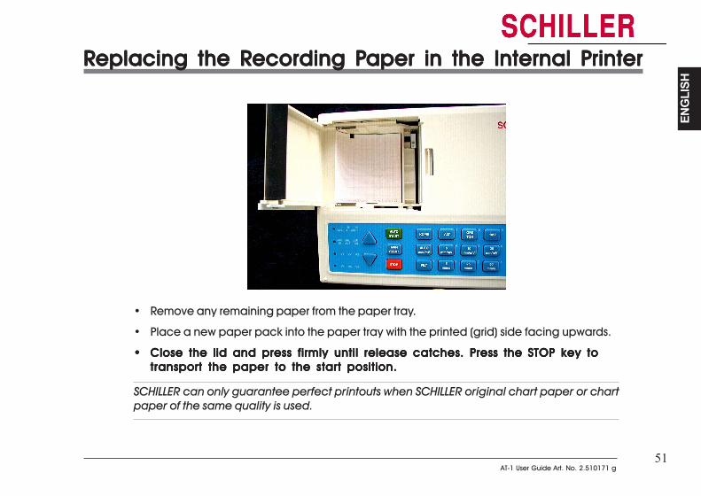
51AT-1 User Guide Art. No. 2.510171 g
51AT-1 User Guide Art. No. 2.510171 g
ENG
LISH
ENG
LISH
RRRRReplacing the Replacing the Replacing the Replacing the Replacing the Recording Pecording Pecording Pecording Pecording Paper in the Internal Paper in the Internal Paper in the Internal Paper in the Internal Paper in the Internal Printerrinterrinterrinterrinter
• Remove any remaining paper from the paper tray.
• Place a new paper pack into the paper tray with the printed (grid) side facing upwards.
••••• Close the lid and press firmly until release catches. Press theClose the lid and press firmly until release catches. Press theClose the lid and press firmly until release catches. Press theClose the lid and press firmly until release catches. Press theClose the lid and press firmly until release catches. Press the STOP key toSTOP key toSTOP key toSTOP key toSTOP key totransport the paper to the start position.transport the paper to the start position.transport the paper to the start position.transport the paper to the start position.transport the paper to the start position.
SCHILLER can only guarantee perfect printouts when SCHILLER original chart paper or chartpaper of the same quality is used.

52
52
Thermal PThermal PThermal PThermal PThermal Paper Handlingaper Handlingaper Handlingaper Handlingaper Handling
The thermal paper used in the ECG unit requires slightly different handling to normal paper asit can react with chemicals and to heat. However, when the following points are remembered,the paper will give reliable results:
The following points apply to both storage and when archiving the results.
1. Before use, keep the paper in its original cardboard cover. Do not remove thecardboard cover until the paper is to be used.
2. Store in a cool, dark and dry area.
3. Do not store near chemicals e.g. sterilisation liquids.
4. In particular do not store in a plastic cover.
5. Certain glues can react with the paper - do not attach the printout onto a mountingsheet with glue.
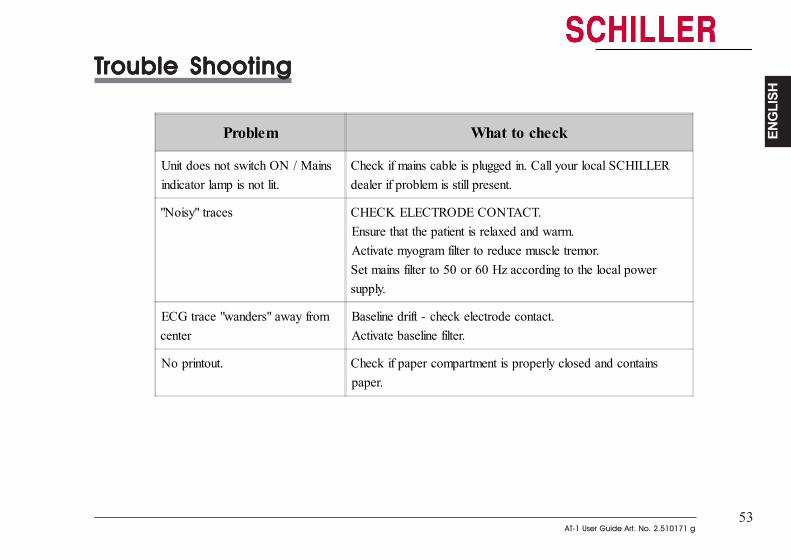
53AT-1 User Guide Art. No. 2.510171 g
53AT-1 User Guide Art. No. 2.510171 g
ENG
LISH
ENG
LISH
TTTTTrouble Shootingrouble Shootingrouble Shootingrouble Shootingrouble Shooting
Problem What to check
Unit does not switch ON / Mainsindicator lamp is not lit.
Check if mains cable is plugged in. Call your local SCHILLERdealer if problem is still present.
"Noisy" traces CHECK ELECTRODE CONTACT.Ensure that the patient is relaxed and warm.Activate myogram filter to reduce muscle tremor.Set mains filter to 50 or 60 Hz according to the local powersupply.
ECG trace "wanders" away fromcenter
Baseline drift - check electrode contact.Activate baseline filter.
No printout. Check if paper compartment is properly closed and containspaper.
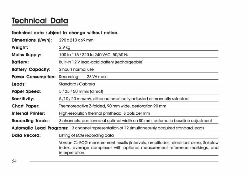
54
54
TTTTTechnical Dataechnical Dataechnical Dataechnical Dataechnical DataTTTTTechnical data subject to change without notice.echnical data subject to change without notice.echnical data subject to change without notice.echnical data subject to change without notice.echnical data subject to change without notice.
Dimensions (l/w/h):Dimensions (l/w/h):Dimensions (l/w/h):Dimensions (l/w/h):Dimensions (l/w/h): 290 x 210 x 69 mm
Weight:Weight:Weight:Weight:Weight: 2.9 kg
Mains Supply:Mains Supply:Mains Supply:Mains Supply:Mains Supply: 100 to 115 / 220 to 240 VAC, 50/60 Hz
Battery:Battery:Battery:Battery:Battery: Built-in 12 V lead-acid battery (rechargeable)
Battery Capacity:Battery Capacity:Battery Capacity:Battery Capacity:Battery Capacity: 2 hours normal use
Power Consumption:Power Consumption:Power Consumption:Power Consumption:Power Consumption: Recording: 28 VA max.
Leads:Leads:Leads:Leads:Leads: Standard / Cabrera
Paper Speed:Paper Speed:Paper Speed:Paper Speed:Paper Speed: 5 / 25 / 50 mm/s (direct)
Sensit ivity:Sensit ivity:Sensit ivity:Sensit ivity:Sensit ivity: 5 /10 / 20 mm/mV, either automatically adjusted or manually selected
Chart Paper:Chart Paper:Chart Paper:Chart Paper:Chart Paper: Thermoreactive Z-folded, 90 mm wide, perforation 90 mm
Internal Printer:Internal Printer:Internal Printer:Internal Printer:Internal Printer: High-resolution thermal printhead, 8 dots per mm
RRRRRecording Tecording Tecording Tecording Tecording Tracks:racks:racks:racks:racks: 3 channels, positioned at optimal width on 80 mm, automatic baseline adjustment
Automatic Lead Programs:Automatic Lead Programs:Automatic Lead Programs:Automatic Lead Programs:Automatic Lead Programs: 3 channel representation of 12 simultaneously acquired standard leads
Data Record:Data Record:Data Record:Data Record:Data Record: Listing of ECG recording data
Version C: ECG measurement results (intervals, amplitudes, electrical axes), Sokolowindex, average complexes with optional measurement reference markings, andinterpretation.
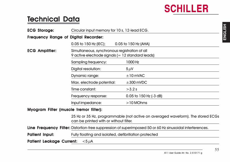
55AT-1 User Guide Art. No. 2.510171 g
55AT-1 User Guide Art. No. 2.510171 g
ENG
LISH
ENG
LISH
TTTTTechnical Dataechnical Dataechnical Dataechnical Dataechnical DataECG Storage:ECG Storage:ECG Storage:ECG Storage:ECG Storage: Circular input memory for 10 s, 12-lead ECG.
Frequency Range of Digital Recorder:Frequency Range of Digital Recorder:Frequency Range of Digital Recorder:Frequency Range of Digital Recorder:Frequency Range of Digital Recorder:
0.05 to 150 Hz (IEC); 0.05 to 150 Hz (AHA)
ECG Amplifier:ECG Amplifier:ECG Amplifier:ECG Amplifier:ECG Amplifier: Simultaneous, synchronous registration of all9 active electrode signals (= 12 standard leads)
Sampling frequency: 1000 Hz
Digital resolution: 5 µV
Dynamic range: ±10 mVAC
Max. electrode potential: ±300 mVDC
Time constant: >3.2 s
Frequency response: 0.05 to 150 Hz (-3 dB)
Input impedance: >10 MOhms
Myogram Filter (muscle tremor filter):Myogram Filter (muscle tremor filter):Myogram Filter (muscle tremor filter):Myogram Filter (muscle tremor filter):Myogram Filter (muscle tremor filter):
25 Hz or 35 Hz, programmable (not active on averaged waveform). The stored ECGscan be printed with or without filter.
Line Frequency Filter:Line Frequency Filter:Line Frequency Filter:Line Frequency Filter:Line Frequency Filter: Distortion-free suppression of superimposed 50 or 60 Hz sinusoidal interferences.
Patient Input:Patient Input:Patient Input:Patient Input:Patient Input: Fully floating and isolated, defibrillation protected
Patient Leakage Current:Patient Leakage Current:Patient Leakage Current:Patient Leakage Current:Patient Leakage Current: <5 µA
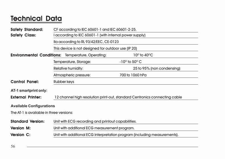
56
56
TTTTTechnical Dataechnical Dataechnical Dataechnical Dataechnical DataSafety Standard:Safety Standard:Safety Standard:Safety Standard:Safety Standard: CF according to IEC 60601-1 and IEC 60601-2-25.Safety Class:Safety Class:Safety Class:Safety Class:Safety Class: I according to IEC 60601-1 (with internal power supply)
IIa according to RL 93/42/EEC, CE-0123
This device is not designed for outdoor use (IP 20)
Environmental Conditions:Environmental Conditions:Environmental Conditions:Environmental Conditions:Environmental Conditions: Temperature, Operating: 10O to 40OC
Temperature, Storage: -10O to 50O C
Relative humidity: 25 to 95% (non condensing)
Atmospheric pressure: 700 to 1060 hPa
Control Panel:Control Panel:Control Panel:Control Panel:Control Panel: Rubber keys
AT-1 smartprint only:
External Printer:External Printer:External Printer:External Printer:External Printer: 12 channel high resolution print-out, standard Centronics connecting cable
Available ConfigurationsThe AT-1 is available in three versions:
Standard VStandard VStandard VStandard VStandard Version:ersion:ersion:ersion:ersion: Unit with ECG recording and printout capabilities.
VVVVVersion M:ersion M:ersion M:ersion M:ersion M: Unit with additional ECG measurement program.
VVVVVersion C:ersion C:ersion C:ersion C:ersion C: Unit with additional ECG Interpretation program (including measurements).
TTTTTechnical Dataechnical Dataechnical Dataechnical Dataechnical DataSafety Standard:Safety Standard:Safety Standard:Safety Standard:Safety Standard: CF according to IEC 60601-1 and IEC 60601-2-25.
Safety Class:Safety Class:Safety Class:Safety Class:Safety Class: I according to IEC 60601-1 (with internal power supply)
IIa according to RL 93/42/EEC, CE-0123
This device is not designed for outdoor use (IP 20)
Environmental Conditions:Environmental Conditions:Environmental Conditions:Environmental Conditions:Environmental Conditions: Temperature, Operating: 10O to 40OC
Temperature, Storage: -10O to 50O C
Relative humidity: 25 to 95% (non condensing)
Atmospheric pressure: 700 to 1060 hPa
Control Panel:Control Panel:Control Panel:Control Panel:Control Panel: Rubber keys
AT-1 smartprint only:External Printer:External Printer:External Printer:External Printer:External Printer: 12 channel high resolution print-out, standard Centronics connecting cable
Available ConfigurationsThe AT-1 is available in three versions:
Standard VStandard VStandard VStandard VStandard Version:ersion:ersion:ersion:ersion: Unit with ECG recording and printout capabilities.
VVVVVersion M:ersion M:ersion M:ersion M:ersion M: Unit with additional ECG measurement program.
VVVVVersion C:ersion C:ersion C:ersion C:ersion C: Unit with additional ECG Interpretation program (including measurements).
i
i
DE
UTS
CH
DE
UTS
CH
AT-1Gebrauchsanweisung
Deutsch
AT-1Gebrauchsanweisung
Deutsch
ii
ii
Wichtige Hinweise iv
Sicherheitshinweise vii
Kurzanleitungen 1
Einleitung 3
Betriebsarten 4Automatische Aufnahmen 4
a. externer Drucker ist nicht angeschlossen bzw. ausgeschaltet 4
b. externer Drucker ist angeschlossen und eingeschaltet 4
Betriebsarten 5Manuelle Aufnahmen 5
Automatische Aufnahmen 6
a. externer Drucker ist nicht angeschlossen bzw. ausgeschaltet 6
b. mit externem Drucker 7
Manuelle Aufnahmen 9
Aufstellungsort und Stromversorgung 10
Ein- und Ausschalten 11
Tastatur 12
Einstellungen 14Basiseinstellungen 17Sprache 18Filter 19Basislinienfilter 19
Service Hinweise iv
Sicherheitshinweise vii
Kurzanleitungen 1
Einleitung 3
Betriebsarten 4Automatische Aufnahmen 4
a. externer Drucker ist nicht angeschlossen bzw. ausgeschaltet 4
b. externer Drucker ist angeschlossen und eingeschaltet 4
Betriebsarten 5Manuelle Aufnahmen 5
Automatische Aufnahmen 6
a. externer Drucker ist nicht angeschlossen bzw. ausgeschaltet 6
b. mit externem Drucker 7
Manuelle Aufnahmen 9
Aufstellungsort und Stromversorgung 10
Ein- und Ausschalten 11
Tastatur 12
Einstellungen 14Basiseinstellungen 17Sprache 18Filter 19Basislinienfilter 19
iii
iii
DE
UTS
CH
DE
UTS
CH
Netzfilter 20Myogrammfilter 21Ableitungsfolge und Ausdruck wählen 22Akustische QRS-Anzeige 24Uhrzeit/Datum 24
Einstellungen für automatische Aufnahmen (EKG), interner Drucker 26
Einstellungen für automatische Aufnahmen (EKG), externer Drucker 30
Einstellungen für automatische Aufnahmen (EKG) 34
Serviceausdruck 36
Softwareoptionen installieren 38
Patientenanschlüsse 39
Einstellungen bei automatischen Aufnahmen 41Feld für Patientendaten 41
Messungen 42Herzfrequenz (HF) 42Intervalle 42Elektrische Achsen 43
Pflege und Wartung 48
Auswechseln des Registrierpapiers 50
Handhabung von Thermopapier 52
Fehlerbehebung 53
Technische Daten 54
iv
iv
Entsorgungshinweise für
Batterien und Geräte
Anleitung zur Batterieentsorgung und Sicherheitshinweise° DIE BATTERIE DARF NICHT MITTELS FEUER ODER IN EINER VER-
BRENNUNGSANLAGE ENTSORGT WERDEN - EXPLOSIONSGEFAHR° VERSUCHEN SIE NICHT, DIE BATTERIE WIEDER AUFZULADEN -
EXPLOSIONSGEFAHR° VERSUCHEN SIE NICHT, DIE BATTERIEHÜLLE ZU ÖFFNEN - GEFAHR VON
VERÄTZUNGEN
Entsorgen Sie die Batterie in einer offiziellen Recyclingsstelle oder in eineranerkannten städtischen Entsorgungsstelle. Es besteht die Möglichkeit, dieentladene Batterie an SCHILLER AG zur Entsorgung einzusenden.
Anleitung für die Entsorgung des GerätesGeräte, die nicht mehr verwendet werden, können an SCHILLER AG zwecksEntsorgung retourniert werden. Es besteht die Möglichkeit, das Gerät in eineranerkannten städtischen Entsorgungstelle abzugeben.
Das Gerät entspricht den EMV-Bestimmungen für Medizinprodukte zum Schutz von Emissionen undEinstrahlungen. Bei der Verwendung zusammen mit Hochfrequenzgeräten ist mit besonderer Vorsichtvorzugehen.
Wichtige Hinweise
Wichtige Hinweise
v
v
DE
UTS
CH
DE
UTS
CH
StromversorgungDer Netzanschluss befindet sich auf der Rückseite des Gerätes.Die Stromspannung des Gerätes ist vom Hersteller für 100-115V(nom. 110V) oder 220-240V (nom. 230V)eingestellt.Die Einstellung ist anhand des versenkten Metallanzeigers auf dem Sicherungshalter ersichtlich. KontaktierenSie Ihre Verkaufsstelle, wenn die Spannung geändert werden muss.Die Kontrollanzeige auf der Tastatur ist immer an, wenn das Gerät ans Netz angeschlossen ist. Das Gerät kannentweder übers Netz oder die eingebaute, wiederaufladbare Batterie betrieben werden.
Auswechseln einer Netzsicherung
Wenn eine Sicherung ersetzt werden muss, achten Sie auf die Aufschrift, damit die richtige Sicherungeingesetzt wird, d.h. 2x200mAT für 230V, oder 2x315 mAT für 110V .
Um eine Sicherung auszuwechseln, drücken Sie die beiden senkrechten Sperrvorrichtungen, die sich seitlichdes Sicherungshalters (auf der Geräterückseite neben dem Netzanschluss) befinden, um den Halter aus demSteckplatz herauszuheben. Ersetzen Sie die Sicherung(en) und setzen Sie den Sicherungshalter wieder in denSteckplatz zurück.
Wichtige Hinweise
Wichtige Hinweise
vi
vi
Garantiebestimmungen
Für Ihren AT-1 besteht für die Dauer eines Jahres (ab Kaufdatum)Garantie auf Material- und Fabrikationsfehler. Davonausgenommen sind Schäden, die durch Unachtsamkeit oderunsachgemässen Gebrauch verursacht werden. Die Garantieerstreckt sich auf den kostenlosen Ersatz des defekten Teils. EineHaftung für Folgeschäden ist dabei ausgeschlossen. DerGarantieanspruch entfällt, wenn Reparaturversuche durch nichtautorisierte oder unqualifizierte Personen vorgenommenwerden.
Im Falle eines Defekts ist das beanstandete Gerät an die nächsteSCHILLER-Vertretung oder direkt an den Hersteller zu senden.
SCHILLER kann die Sicherheit, Zuverlässigkeit undFunktionstüchtigkeit des Gerätes nur dann gewährleisten, wenn
* Montagearbeiten, Ergänzungen, Neueinstellungen,Modifikationen oder Reparaturen von Personendurchgeführt werden, die von SCHILLER hierzuermächtigt sind, und
* das Gerät und die vom Hersteller zugelassenenZubehörteile entsprechend den Anweisungen desHerstellers verwendet werden.
ES WERDEN KEINE WEITEREN GARANTIEN, WEDER AUSDRÜCKLICHNOCH IMPLIZIERT, AUSSER DEN GENANNTEN ÜBERNOMMEN.SCHILLER ÜBERNIMMT KEINE GARANTIE FÜR DIE GEWERBLICHENUTZUNGSFÄHIGKEIT UND EIGNUNG FÜR EINEN BESTIMMTENZWECK DES PRODUKTES ODER DER PRODUKTKOMPONENTEN.
Über diese Gebrauchsanweisung
Konsequente Weiterentwicklung ist charakteristisch für diePhilosophie des Hauses SCHILLER. Unser Ziel ist es, den Benutzernjeweils die aktuellsten Informationen und neuesten Technologienzur Verfügung zu stellen. Ihre Vorschläge und Kommentare zuunseren Dokumentationen sind uns jederzeit willkommen. Bittewenden Sie sich an unsere Technische Redaktion.
VERANTWORTUNG DES ARZTES
DER AT-1 DARF NUR VON ÄRZTEN ODER DEREN DIREKTUNTERSTELLTEM PERSONAL VERWENDET WERDEN. DIENUMERISCHEN UND GRAFISCHEN ERGEBNISSE SOWIE DIEVOM GERÄT BEREITGESTELLTEN BEFUNDHINWEISE FÜR DIEAUFNAHME DÜRFEN NICHT ISOLIERT BETRACHTET WERDEN,SONDERN IMMER NUR IM ZUSAM-MENHANG MIT DERGESAMTHEIT DER VOR-LIEGENDEN DATEN DES PATIENTEN.DIE AUF-NAHMEVORBEREITUNG SOWIE DIE QUALITÄT DERAUFZEICHNUNG, DIE DIE GENAUIGKEIT DERAUFNAHMEDATEN BEEINFLUSSEN, SIND EBEN-FALLSFAKTOREN, DIE BERÜCKSICHTIGT WERDEN MÜSSEN.
DIE DIAGNOSESTELLUNG ODER DAS HINZUZIEHEN EINESFACHARZTES ZUR BEURTEILUNG DER ERGEBNISSE SOWIEDIE EINLEITUNG GEEIGNETER BEHANDLUNGSMETHODENFALLEN AUSSCHLIESS-LICH IN DIE ZUSTÄNDIGKEIT DESARZTES.
Wichtige Hinweise
Wichtige Hinweise

vii
vii
DE
UTS
CH
DE
UTS
CH
HINWEISVERWENDEN SIE KEINE LÖSLICHEN REINIGUNGSMITTEL.
DAS GERÄT ENTSPRICHT DEN EMV-BESTIMMUNGEN FÜR MEDIZINPRODUKTE ZUM SCHUTZ VOR EMISSIONEN UND STÖRUNGEN.BEI VERWENDUNG VON HOCHFREQUENZ-GERÄTEN ZUSAMMEN MIT DEM AT-1 IST MIT BESONDERER VORSICHT VORZUGEHEN.
VOR VERWENDUNG DES GERÄTES IST SICHERZUSTELLEN, DASS DIE EINFÜHRUNG IN DIE FUNKTION UND VORSICHTSMASSNAHMENDURCH DEN MEDIZINPRODUKTEBERATER ERFOLGT IST.
VORSICHTVOR DER REINIGUNG IST DAS GERÄT AUSZUSCHALTEN UND DER NETZSTECKER ZU ZIEHEN.
DAS GERÄT DARF NUR VOM BATTERIE BETRIEBEN WERDEN, WENN ZWEIFEL AN DER ISOLIERUNG GEGEN ERDE ODER DER INTEGRITÄTDES NETZKABELS BESTEHEN.
VERWENDEN SIE NUR DAS VON SCHILLER GELIEFERTE ODER EMPFOHLENE ZUBEHÖR ODER VERBRAUCHSMATERIAL. DIEVERWENDUNG VON FREMDZUBEHÖR ODER VERBRAUCHSMATERIAL KANN ZU UNGENAUEN INFORMATIONEN UND / ODERBESCHÄDIGUNG DES GERÄTES FÜHREN.ES IST SICHERZUSTELLEN, DASS WEDER DER PATIENT NOCH DIE LEITFÄHIGEN TEILE DES PATIENTENANSCHLUSSES ODER DERELEKTRODEN (AUCH DER NEUTRALEN ELEKTRODE) MIT ANDEREN LEITFÄHIGEN GEGENSTÄNDEN (AUCH WENN DIESE GEERDETSIND) ODER PERSONEN IN BERÜHRUNG KOMMEN.
BEI VERWENDUNG DES AT-1 FÜR EINEN HERZSCHRITTMACHER-PATIENTEN ODER AUCH BEI VERWENDUNG ANDERER ELEKTRISCHERSTIMULATIONSGERÄTE BESTEHT KEINE GEFÄHRDUNG. ABER AUCH HIER IST EINE GEWISSE VORSICHT GEBOTEN. DIE STIMULATIONS-GERÄTE SOLLTEN NUR IN GENÜGENDEM ABSTAND ZU DEN ABLEITELEKTRODEN VERWENDET WERDEN. IM ZWEIFELSFALL IST DERPATIENT VOM AUFNAHMEGERÄT ZU TRENNEN.
BEI KOPPLUNG VON MEHREREN GERÄTEN BESTEHT DIE GEFAHR, DASS SICH DIE ABLEITSTRÖME SUMMIEREN. WENN ZWEI ODERMEHR GERÄTE GEKOPPLELT SIND, MUSS EIN ISOLIERTRANSFORMATOR IN DER STROMZUFUHR ZWISCHENGESCHALTET WERDEN.MEHRERE MEDIZINISCHE UND NICHT MEDIZINISCHE GERÄTE DÜRFEN NICHT ÜBER EINE VERLÄNGERUNG UND VERTEILDOSEANGESCHLOSSEN WERDEN.
WENN DER EXTERNE DRUCKER ANGESCHLOSSEN IST, MUSS DAS GERÄT GEERDET SEIN.
HINWEISVERWENDEN SIE KEINE LÖSLICHEN REINIGUNGSMITTEL.DAS GERÄT ENTSPRICHT DEN EMV-BESTIMMUNGEN FÜR MEDIZINPRODUKTE ZUM SCHUTZ VOR EMISSIONEN UND STÖRUNGEN.BEI VERWENDUNG VON HOCHFREQUENZ-GERÄTEN ZUSAMMEN MIT DEM AT-1 IST MIT BESONDERER VORSICHT VORZUGEHEN.
VOR VERWENDUNG DES GERÄTES IST SICHERZUSTELLEN, DASS DIE EINFÜHRUNG IN DIE FUNKTION UND VORSICHTSMASSNAHMENDURCH DEN MEDIZINPRODUKTEBERATER ERFOLGT IST.
VORSICHTVOR DER REINIGUNG IST DAS GERÄT AUSZUSCHALTEN UND DER NETZSTECKER ZU ZIEHEN.
DAS GERÄT DARF NUR VOM BATTERIE BETRIEBEN WERDEN, WENN ZWEIFEL AN DER ISOLIERUNG GEGEN ERDE ODER DER INTEGRITÄTDES NETZKABELS BESTEHEN.
VERWENDEN SIE NUR DAS VON SCHILLER GELIEFERTE ODER EMPFOHLENE ZUBEHÖR ODER VERBRAUCHSMATERIAL. DIEVERWENDUNG VON FREMDZUBEHÖR ODER VERBRAUCHSMATERIAL KANN ZU UNGENAUEN INFORMATIONEN UND / ODERBESCHÄDIGUNG DES GERÄTES FÜHREN.
ES IST SICHERZUSTELLEN, DASS WEDER DER PATIENT NOCH DIE LEITFÄHIGEN TEILE DES PATIENTENANSCHLUSSES ODER DERELEKTRODEN (AUCH DER NEUTRALEN ELEKTRODE) MIT ANDEREN LEITFÄHIGEN GEGENSTÄNDEN (AUCH WENN DIESE GEERDETSIND) ODER PERSONEN IN BERÜHRUNG KOMMEN.BEI VERWENDUNG DES AT-1 FÜR EINEN HERZSCHRITTMACHER-PATIENTEN ODER AUCH BEI VERWENDUNG ANDERER ELEKTRISCHERSTIMULATIONSGERÄTE BESTEHT KEINE GEFÄHRDUNG. ABER AUCH HIER IST EINE GEWISSE VORSICHT GEBOTEN. DIE STIMULATIONS-GERÄTE SOLLTEN NUR IN GENÜGENDEM ABSTAND ZU DEN ABLEITELEKTRODEN VERWENDET WERDEN. IM ZWEIFELSFALL IST DERPATIENT VOM AUFNAHMEGERÄT ZU TRENNEN.
BEI KOPPLUNG VON MEHREREN GERÄTEN BESTEHT DIE GEFAHR, DASS SICH DIE ABLEITSTRÖME SUMMIEREN. WENN ZWEI ODERMEHR GERÄTE GEKOPPLELT SIND, MUSS EIN ISOLIERTRANSFORMATOR IN DER STROMZUFUHR ZWISCHENGESCHALTET WERDEN.MEHRERE MEDIZINISCHE UND NICHT MEDIZINISCHE GERÄTE DÜRFEN NICHT ÜBER EINE VERLÄNGERUNG UND VERTEILDOSEANGESCHLOSSEN WERDEN.
WENN DER EXTERNE DRUCKER ANGESCHLOSSEN IST, MUSS DAS GERÄT GEERDET SEIN.
Sicherheitshinweise
Sicherheitshinweise

viii
viii
GEFAHRZUR VERMEIDUNG VON ELEKTROSCHOCKS DARF DAS GERÄT NICHT DEMONTIERT WERDEN. ES ENTHÄLT KEINE TEILE, DIE VONLAIEN REPARIERT WERDEN KÖNNEN. SERVICEARBEITEN SIND NUR QUALIFIZIERTEM FACHPERSONAL VORBEHALTEN.
DAS GERÄT IST NICHT FÜR DEN BETRIEB IN EXPLOSIONSGEFÄHRDETER UMGEBUNG BESTIMMT ODER IN BEREICHEN, WOENTZÜNDBARE GASE, WIE Z.B. ANÄSTHESIEGASE, VERWENDET WERDEN.DIESES GERÄT IST NICHT FÜR DEN STERILEN EINSATZ BESTIMMT.
DIESES GERÄT IST NICHT FÜR DEN GEBRAUCH IM FREIEN BESTIMMT.
UNTER KEINEN UMSTÄNDEN DÜRFEN DAS GERÄT ODER DIE KABEL IN EINE REINIGUNGSFLÜSSIGKEIT EINGETAUCHT WERDEN.
ES DARF KEINE HOCHTEMPERATUR-STERILISATION (WIE AUTOCLAVING) VORGENOMMEN WERDEN, EBENSOWENIG WIE EINESTERILISATION MIT E-STRAHL ODER GAMMASTRAHLEN.
ES HANDELT SICH UM EIN GERÄT DES TYPS CF NACH IEC EN 60601-1. DAS BEDEUTET, DASS DER PATIENTENANSCHLUSSVOLLISOLIERT UND DEFIBRILLATIONSFEST IST. SCHILLER KANN DEN DEFIBRILLATIONSSCHUTZ JEDOCH NUR GEWÄHRLEISTEN, WENNDAS ORIGINAL-SCHILLER-PATIENTENKABEL VERWENDET WIRD.DAS GEHÄUSE DARF WÄHREND EINER DEFIBRILLATION NICHT BERÜHRT WERDEN.
WENN DAS PATIENTENKABEL NACH EINER DEFIBRILLATION BESCHÄDIGT IST, WIRD DIE MELDUNG 'ELEKTRODE LOSE' ANGEZEIGTUND EIN AKUSTISCHER ALARM AUSGELÖST.
GEFAHRZUR VERMEIDUNG VON ELEKTROSCHOCKS DARF DAS GERÄT NICHT DEMONTIERT WERDEN. ES ENTHÄLT KEINE TEILE, DIE VONLAIEN REPARIERT WERDEN KÖNNEN. SERVICEARBEITEN SIND NUR QUALIFIZIERTEM FACHPERSONAL VORBEHALTEN.
DAS GERÄT IST NICHT FÜR DEN BETRIEB IN EXPLOSIONSGEFÄHRDETER UMGEBUNG BESTIMMT ODER IN BEREICHEN, WOENTZÜNDBARE GASE, WIE Z.B. ANÄSTHESIEGASE, VERWENDET WERDEN.
DIESES GERÄT IST NICHT FÜR DEN STERILEN EINSATZ BESTIMMT.DIESES GERÄT IST NICHT FÜR DEN GEBRAUCH IM FREIEN BESTIMMT.
UNTER KEINEN UMSTÄNDEN DÜRFEN DAS GERÄT ODER DIE KABEL IN EINE REINIGUNGSFLÜSSIGKEIT EINGETAUCHT WERDEN.
ES DARF KEINE HOCHTEMPERATUR-STERILISATION (WIE AUTOCLAVING) VORGENOMMEN WERDEN, EBENSOWENIG WIE EINESTERILISATION MIT E-STRAHL ODER GAMMASTRAHLEN.
ES HANDELT SICH UM EIN GERÄT DES TYPS CF NACH IEC EN 60601-1. DAS BEDEUTET, DASS DER PATIENTENANSCHLUSSVOLLISOLIERT UND DEFIBRILLATIONSFEST IST. SCHILLER KANN DEN DEFIBRILLATIONSSCHUTZ JEDOCH NUR GEWÄHRLEISTEN, WENNDAS ORIGINAL-SCHILLER-PATIENTENKABEL VERWENDET WIRD.
DAS GEHÄUSE DARF WÄHREND EINER DEFIBRILLATION NICHT BERÜHRT WERDEN.WENN DAS PATIENTENKABEL NACH EINER DEFIBRILLATION BESCHÄDIGT IST, WIRD DIE MELDUNG 'ELEKTRODE LOSE' ANGEZEIGTUND EIN AKUSTISCHER ALARM AUSGELÖST.
Sicherheitshinweise
Sicherheitshinweise
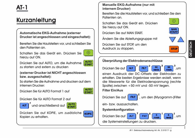
1AT-1 Gebrauchsanweisung Art.-Nr. 2.510171 g
AT-1 Gebrauchsanweisung Art.-Nr. 2.510171 g
DEUT
SCH
DEUT
SCH
1
AAAAATTTTT-1-1-1-1-1
KKKKKurururururzanleitungzanleitungzanleitungzanleitungzanleitung
Automatische EKG-Aufnahme (externerDrucker ist angeschlossen und eingeschaltet):
Bereiten Sie die Hautstellen vor, und schließen Sieden Patienten an.
Schalten Sie das Gerät ein. Drücken Siehierzu auf ON.
Drücken Sie auf AUTO, um die Aufnahmezu starten und extern zu drucken
(externer Drucker ist NICHT angeschlossenbzw. ausgeschaltet):So starten Sie die Aufnahme und drucken auf deminternen Drucker:
Drücken Sie für AUTO Format 1 auf
Drücken Sie für AUTO Format 2 auf
und anschließend auf
Drücken Sie auf KOPIE, um zusätzlicheKopien zu erhalten.
Manuelle EKG-Aufnahme (nur mitinternem Drucker)Bereiten Sie die Hautstellen vor, und schließen Sie denPatienten an.
Schalten Sie das Gerät ein. DrückenSie hierzu auf ON.
Drücken Sie auf MAN START.
Ändern Sie die Ableitungsgruppe mit
Drücken Sie auf STOP, um denAusdruck zu stoppen.
Überprüfung der Elektrodenanschlüsse
Drücken Sie auf ,um
einen Ausdruck der DC-Offsets der Elektroden zuerhalten. Die besten Ergebnisse werden erzielt, wenndie Messwerte für die Elektrodenspannung (rechteSpalte) zwischen +50 mV und -50 mV liegen.Filter Ein/Aus
Drücken Sie auf , um den (Myogramm-)Filter
ein- bzw. auszuschalten.
Systemkonfiguration
Drücken Sie auf , um
die Systemeinstellungen zu drucken.
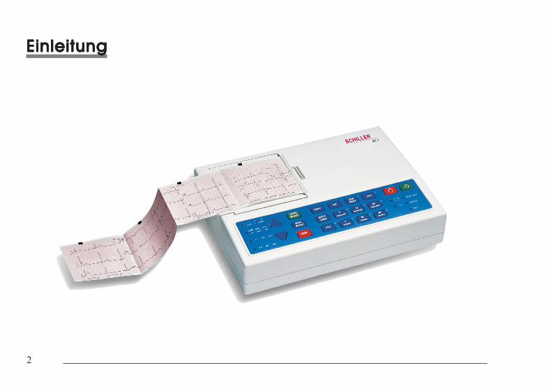
2
2
EinleitungEinleitungEinleitungEinleitungEinleitung
EinleitungEinleitungEinleitungEinleitungEinleitung
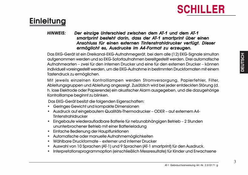
3AT-1 Gebrauchsanweisung Art.-Nr. 2.510171 g
AT-1 Gebrauchsanweisung Art.-Nr. 2.510171 g
DEUT
SCH
DEUT
SCH
3
EinleitungEinleitungEinleitungEinleitungEinleitungHINWEIS:HINWEIS:HINWEIS:HINWEIS:HINWEIS: Der einzige Unterschied zwischen dem ADer einzige Unterschied zwischen dem ADer einzige Unterschied zwischen dem ADer einzige Unterschied zwischen dem ADer einzige Unterschied zwischen dem ATTTTT-1 und dem A-1 und dem A-1 und dem A-1 und dem A-1 und dem ATTTTT-1-1-1-1-1
smarsmarsmarsmarsmartprint besteht darin, dass der Atprint besteht darin, dass der Atprint besteht darin, dass der Atprint besteht darin, dass der Atprint besteht darin, dass der ATTTTT-1 smar-1 smar-1 smar-1 smar-1 smartprint über einentprint über einentprint über einentprint über einentprint über einenAnschluss für einen externen Tintenstrahldrucker verfügt. DieserAnschluss für einen externen Tintenstrahldrucker verfügt. DieserAnschluss für einen externen Tintenstrahldrucker verfügt. DieserAnschluss für einen externen Tintenstrahldrucker verfügt. DieserAnschluss für einen externen Tintenstrahldrucker verfügt. Dieserermöglicht es, Ausdrucke im A4-Format zu erzeugen.ermöglicht es, Ausdrucke im A4-Format zu erzeugen.ermöglicht es, Ausdrucke im A4-Format zu erzeugen.ermöglicht es, Ausdrucke im A4-Format zu erzeugen.ermöglicht es, Ausdrucke im A4-Format zu erzeugen.
Das EKG-Gerät ist ein Dreikanal-EKG-Aufnahmegerät, bei dem alle (12) EKG-Signale simultanaufgenommen werden und so EKG-Sofortaufnahmen bereitgestellt werden. Drei automatischeAufnahmearten – zwei für den internen Drucker und eine für den externen Drucker – könnenindividuell voreingestellt werden, um die EKG-Aufnahme in bestimmten Druckformaten mit einemTastendruck zu ermöglichen.Mit jeweils einzelnen Kontrolllampen werden Stromversorgung, Papierfehler, Filter,Ableitungsgruppen und Ableitung angezeigt. Zusätzlich wird bei jeder entdeckten Störung (d.h. lose Elektrode oder Papierende) ein akustischer Alarm ausgegeben, und die dazugehörigeKontrolllampe beginnt zu blinken. Das EKG-Gerät besitzt die folgenden Eigenschaften:• Geringes Gewicht und kompakte Dimensionen• Ausdruck auf eingebautem Qualitäts-Thermodrucker – ODER – auf externem A4-
Tintenstrahldrucker• Eingebaute wiederaufladbare Batterie für netzunabhängigen Betrieb – 2 Stunden
ununterbrochener Betrieb mit einer Batterieladung• Einfache Bedienung der Hauptfunktionen• Automatische oder manuelle Aufnahmemöglichkeiten• Wählbare Druckformate – externer und interner Drucker• Auswahl von 10 Sprachen (AT-1) und 9 Sprachen (AT-1 smartprint) für den Ausdruck.• Interpretationsprogrammoption (einschließlich Messresultate) für Kinder und Erwachsene
EinleitungEinleitungEinleitungEinleitungEinleitungHINWEIS:HINWEIS:HINWEIS:HINWEIS:HINWEIS: Der einzige Unterschied zwischen dem ADer einzige Unterschied zwischen dem ADer einzige Unterschied zwischen dem ADer einzige Unterschied zwischen dem ADer einzige Unterschied zwischen dem ATTTTT-1 und dem A-1 und dem A-1 und dem A-1 und dem A-1 und dem ATTTTT-1-1-1-1-1
smarsmarsmarsmarsmartprint besteht darin, dass der Atprint besteht darin, dass der Atprint besteht darin, dass der Atprint besteht darin, dass der Atprint besteht darin, dass der ATTTTT-1 smar-1 smar-1 smar-1 smar-1 smartprint über einentprint über einentprint über einentprint über einentprint über einenAnschluss für einen externen Tintenstrahldrucker verfügt. DieserAnschluss für einen externen Tintenstrahldrucker verfügt. DieserAnschluss für einen externen Tintenstrahldrucker verfügt. DieserAnschluss für einen externen Tintenstrahldrucker verfügt. DieserAnschluss für einen externen Tintenstrahldrucker verfügt. Dieserermöglicht es, Ausdrucke im A4-Format zu erzeugen.ermöglicht es, Ausdrucke im A4-Format zu erzeugen.ermöglicht es, Ausdrucke im A4-Format zu erzeugen.ermöglicht es, Ausdrucke im A4-Format zu erzeugen.ermöglicht es, Ausdrucke im A4-Format zu erzeugen.
Das EKG-Gerät ist ein Dreikanal-EKG-Aufnahmegerät, bei dem alle (12) EKG-Signale simultanaufgenommen werden und so EKG-Sofortaufnahmen bereitgestellt werden. Dreiautomatische Aufnahmearten – zwei für den internen Drucker und eine für den externenDrucker – können individuell voreingestellt werden, um die EKG-Aufnahme in bestimmtenDruckformaten mit einem Tastendruck zu ermöglichen.Mit jeweils einzelnen Kontrolllampen werden Stromversorgung, Papierfehler, Filter,Ableitungsgruppen und Ableitung angezeigt. Zusätzlich wird bei jeder entdeckten Störung(d. h. lose Elektrode oder Papierende) ein akustischer Alarm ausgegeben, und diedazugehörige Kontrolllampe beginnt zu blinken. Das EKG-Gerät besitzt die folgenden Eigenschaften:• Geringes Gewicht und kompakte Dimensionen• Ausdruck auf eingebautem Qualitäts-Thermodrucker – ODER – auf externem A4-
Tintenstrahldrucker• Eingebaute wiederaufladbare Batterie für netzunabhängigen Betrieb – 2 Stunden
ununterbrochener Betrieb mit einer Batterieladung• Einfache Bedienung der Hauptfunktionen• Automatische oder manuelle Aufnahmemöglichkeiten• Wählbare Druckformate – externer und interner Drucker• Auswahl von 10 Sprachen (AT-1) und 9 Sprachen (AT-1 smartprint) für den Ausdruck.• Interpretationsprogrammoption (einschließlich Messresultate) für Kinder und
Erwachsene
4
4
BetriebsartenBetriebsartenBetriebsartenBetriebsartenBetriebsarten
Automatische Aufnahmena. externer Drucker ist nicht angeschlossen bzw. ausgeschaltet
Der automatische Aufnahmemodus bietet einen Ausdruck von 10 Sekunden aus dem Speicheraller 12 Ableitungen der EKG-Aufnahme in 2 verschiedenen, wählbaren Formaten (nur VersionS).
Die folgenden Positionen können vor der Aufnahme in jedem der 2 Formate frei programmiertwerden:
• Ableitungsformat
• Geschwindigkeit
• Wenn das optionale Interpretationsprogramm installiert ist, können außerdem eineTabelle der Messresultate, Mittelwertzyklen mit optionalen Markierungen sowieInterpretationsaussagen für den Ausdruck gewählt werden.
Weitere Informationen finden Sie im Abschnitt ‘Einstellungen für automatische Aufnahmen (EKG)’auf Seite 26.
b. externer Drucker ist angeschlossen und eingeschaltet
Es ist nur ein Format für die automatische Aufnahme möglich. Andere Details: siehe oben.
Weitere Informationen finden Sie im Abschnitt ‘Einstellungen für automatische Aufnahmen (EKG)’auf Seite 30.
BetriebsartenBetriebsartenBetriebsartenBetriebsartenBetriebsarten
Automatische Aufnahmena. externer Drucker ist nicht angeschlossen bzw. ausgeschaltet
Der automatische Aufnahmemodus bietet einen Ausdruck von 10 Sekunden aus dem Speicheraller 12 Ableitungen der EKG-Aufnahme in 2 verschiedenen, wählbaren Formaten (nur VersionS).
Die folgenden Positionen können vor der Aufnahme in jedem der 2 Formate frei programmiertwerden:
• Ableitungsformat
• Geschwindigkeit
• Wenn das optionale Interpretationsprogramm installiert ist, können außerdem eineTabelle der Messresultate, Mittelwertzyklen mit optionalen Markierungen sowieInterpretationsaussagen für den Ausdruck gewählt werden.
Weitere Informationen finden Sie im Abschnitt ‘Einstellungen für automatische Aufnahmen(EKG)’ auf Seite 26.
b. externer Drucker ist angeschlossen und eingeschaltet
Es ist nur ein Format für die automatische Aufnahme möglich. Andere Details: siehe oben.
Weitere Informationen finden Sie im Abschnitt ‘Einstellungen für automatische Aufnahmen (EKG)’auf Seite 30.
5AT-1 Gebrauchsanweisung Art.-Nr. 2.510171 g
AT-1 Gebrauchsanweisung Art.-Nr. 2.510171 g
DEUT
SCH
DEUT
SCH
5
BetriebsartenBetriebsartenBetriebsartenBetriebsartenBetriebsarten
Manuelle AufnahmenDer manuelle Betrieb bietet einen Echtzeitausdruck von 3 ausgewählten Ableitungen und istnur auf dem internen Thermodrucker möglich.
Die folgenden Positionen können vor oder während der Aufnahme frei gewählt werden:
• Ableitungsgruppe
• Geschwindigkeit
• Empfindlichkeit
• Myogrammfilter
Weitere Informationen finden Sie im Abschnitt ‘Manuelle Aufnahmen’ auf Seite 8.
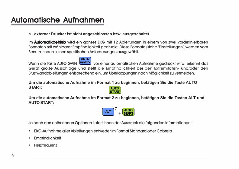
6
6
Automatische AufnahmenAutomatische AufnahmenAutomatische AufnahmenAutomatische AufnahmenAutomatische Aufnahmen
a. externer Drucker ist nicht angeschlossen bzw. ausgeschaltet
Im AutomatikbetriebAutomatikbetriebAutomatikbetriebAutomatikbetriebAutomatikbetrieb wird ein ganzes EKG mit 12 Ableitungen in einem von zwei vordefinierbarenFormaten mit wählbarer Empfindlichkeit gedruckt. Diese Formate (siehe ‘Einstellungen’) werden vomBenutzer nach seinen spezifischen Anforderungen ausgewählt.
Wenn die Taste AUTO GAIN vor einer automatischen Aufnahme gedrückt wird, erkennt dasGerät große Ausschläge und stellt die Empfindlichkeit bei den Extremitäten- und/oder denBrustwandableitungen entsprechend ein, um Überlappungen nach Möglichkeit zu vermeiden.
Um die automatische Aufnahme im Format 1 zu beginnen, betätigen Sie die Taste AUTOSTART:
Um die automatische Aufnahme im Format 2 zu beginnen, betätigen Sie die Tasten ALT undAUTO START:
+
Je nach den enthaltenen Optionen liefert Ihnen der Ausdruck die folgenden Informationen:
• EKG-Aufnahme aller Ableitungen entweder im Format Standard oder Cabrera
• Empfindlichkeit
• Herzfrequenz
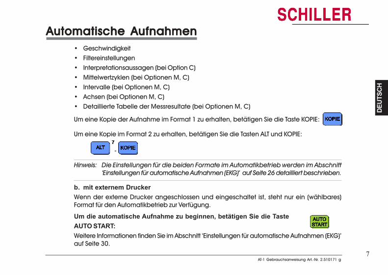
7AT-1 Gebrauchsanweisung Art.-Nr. 2.510171 g
AT-1 Gebrauchsanweisung Art.-Nr. 2.510171 g
DEUT
SCH
DEUT
SCH
7
Automatische AufnahmenAutomatische AufnahmenAutomatische AufnahmenAutomatische AufnahmenAutomatische Aufnahmen• Geschwindigkeit• Filtereinstellungen• Interpretationsaussagen (bei Option C)• Mittelwertzyklen (bei Optionen M, C)• Intervalle (bei Optionen M, C)• Achsen (bei Optionen M, C)• Detaillierte Tabelle der Messresultate (bei Optionen M, C)
Um eine Kopie der Aufnahme im Format 1 zu erhalten, betätigen Sie die Taste KOPIE:
Um eine Kopie im Format 2 zu erhalten, betätigen Sie die Tasten ALT und KOPIE:
-
Hinweis: Die Einstellungen für die beiden Formate im Automatikbetrieb werden im Abschnitt‘Einstellungen für automatische Aufnahmen (EKG)’ auf Seite 26 detailliert beschrieben.
b. mit externem DruckerWenn der externe Drucker angeschlossen und eingeschaltet ist, steht nur ein (wählbares)Format für den Automatikbetrieb zur Verfügung.
Um die automatische Aufnahme zu beginnen, betätigen Sie die TasteAUTO START:Weitere Informationen finden Sie im Abschnitt ‘Einstellungen für automatische Aufnahmen (EKG)’auf Seite 30.
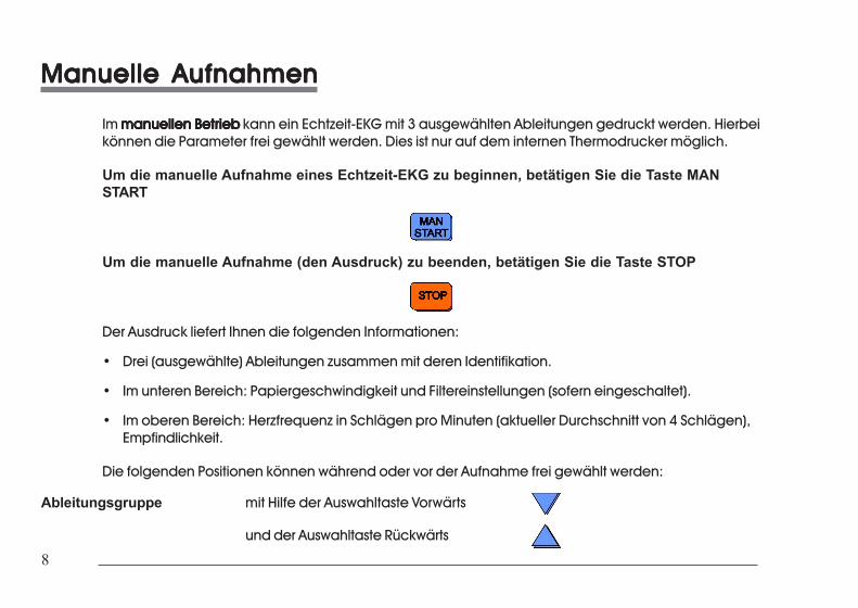
8
8
Manuelle AufnahmenManuelle AufnahmenManuelle AufnahmenManuelle AufnahmenManuelle Aufnahmen
Im manuellen Betriebmanuellen Betriebmanuellen Betriebmanuellen Betriebmanuellen Betrieb kann ein Echtzeit-EKG mit 3 ausgewählten Ableitungen gedruckt werden. Hierbeikönnen die Parameter frei gewählt werden. Dies ist nur auf dem internen Thermodrucker möglich.
Um die manuelle Aufnahme eines Echtzeit-EKG zu beginnen, betätigen Sie die Taste MANSTART
Um die manuelle Aufnahme (den Ausdruck) zu beenden, betätigen Sie die Taste STOP
Der Ausdruck liefert Ihnen die folgenden Informationen:
• Drei (ausgewählte) Ableitungen zusammen mit deren Identifikation.
• Im unteren Bereich: Papiergeschwindigkeit und Filtereinstellungen (sofern eingeschaltet).
• Im oberen Bereich: Herzfrequenz in Schlägen pro Minuten (aktueller Durchschnitt von 4 Schlägen),Empfindlichkeit.
Die folgenden Positionen können während oder vor der Aufnahme frei gewählt werden:
Ableitungsgruppe mit Hilfe der Auswahltaste Vorwärts
und der Auswahltaste Rückwärts
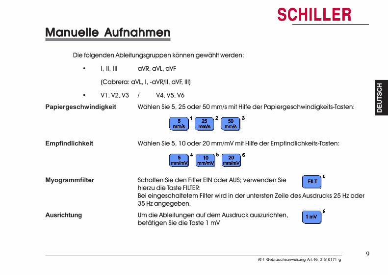
9AT-1 Gebrauchsanweisung Art.-Nr. 2.510171 g
AT-1 Gebrauchsanweisung Art.-Nr. 2.510171 g
DEUT
SCH
DEUT
SCH
9
Manuelle AufnahmenManuelle AufnahmenManuelle AufnahmenManuelle AufnahmenManuelle Aufnahmen
Die folgenden Ableitungsgruppen können gewählt werden:
• I, II, III aVR, aVL, aVF
(Cabrera: aVL, I, -aVR/II, aVF, III)
• V1, V2, V3 / V4, V5, V6
Papiergeschwindigkeit Wählen Sie 5, 25 oder 50 mm/s mit Hilfe der Papiergeschwindigkeits-Tasten:
Empfindlichkeit Wählen Sie 5, 10 oder 20 mm/mV mit Hilfe der Empfindlichkeits-Tasten:
Myogrammfilter Schalten Sie den Filter EIN oder AUS; verwenden Siehierzu die Taste FILTER:Bei eingeschaltetem Filter wird in der untersten Zeile des Ausdrucks 25 Hz oder35 Hz angegeben.
Ausrichtung Um die Ableitungen auf dem Ausdruck auszurichten,betätigen Sie die Taste 1 mV

10
10
Aufstellungsort und StromversorgungAufstellungsort und StromversorgungAufstellungsort und StromversorgungAufstellungsort und StromversorgungAufstellungsort und Stromversorgung
AufstellungsortDas Gerät sollte weder in nasser noch in feuchter oder staubiger Umgebung gelagert oder betriebenwerden. Zudem ist zu vermeiden, dass das Gerät direkter Sonneneinstrahlung oder der Hitze andererWärmequellen ausgesetzt ist. Säurehaltige Dämpfe oder Flüssigkeiten sollten unter keinen Umständenmit dem Gerät in Berührung kommen, da sonst irreparable Schäden auftreten können. Das Gerät solltenicht in der Nähe von Röntgen- oder Diathermieanlagen, großen Transformatoren oder Motorenaufgestellt werden. Das Gerät muss auf einer ebenen Fläche stehen und darf nicht in Gebieten betriebenwerden, in denen Explosionsgefahr besteht.
StromversorgungDer Anschluss für die Stromversorgung befindet sich an der Rückseite des Geräts. Die Kontrolllampe fürdie Stromversorgung auf der Tastatur leuchtet auf, solange das Gerät an das Stromnetz angeschlossenist. Das Gerät kann entweder über die Netzstromversorgung oder über die eingebaute wiederaufladbareBatterie betrieben werden. Die Stromquelle wird durch die jeweilige Kontrolllampe angezeigt. Sobalddie Batterieleistung ein bestimmtes Minimum erreicht, beginnt das Batteriesymbol zu blinken.
Schließen Sie das Gerät zum Wiederaufladen der Batterie mit dem Netzkabel an das Stromnetz an. Einevöllig entladene Batterie wird innerhalb von 15 Stunden vollständig wiederaufgeladen (60 % in wenigerals 3 Stunden, 90 % in weniger als 7 Stunden). Eine vollständig aufgeladene Batterie ermöglicht einenununterbrochenen Betrieb von ca. 2 Stunden. Das Gerät kann dauernd an das Stromnetz angeschlossensein, ohne dass dabei Schäden an der Batterie oder am Gerät entstehen.
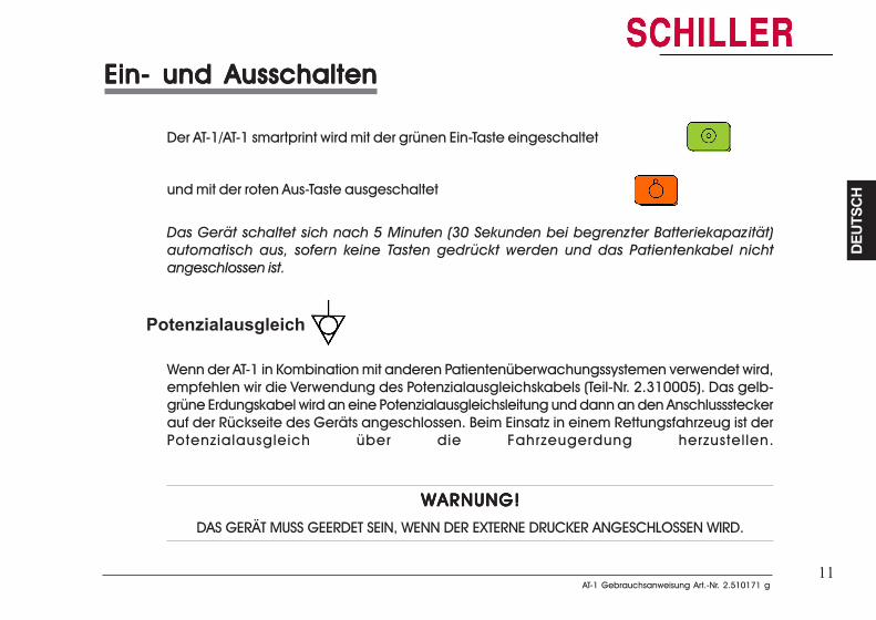
11AT-1 Gebrauchsanweisung Art.-Nr. 2.510171 g
AT-1 Gebrauchsanweisung Art.-Nr. 2.510171 g
DEUT
SCH
DEUT
SCH
11
Ein- und AusschaltenEin- und AusschaltenEin- und AusschaltenEin- und AusschaltenEin- und Ausschalten
Der AT-1/AT-1 smartprint wird mit der grünen Ein-Taste eingeschaltet
und mit der roten Aus-Taste ausgeschaltet
Das Gerät schaltet sich nach 5 Minuten (30 Sekunden bei begrenzter Batteriekapazität)automatisch aus, sofern keine Tasten gedrückt werden und das Patientenkabel nichtangeschlossen ist.
Potenzialausgleich
Wenn der AT-1 in Kombination mit anderen Patientenüberwachungssystemen verwendet wird,empfehlen wir die Verwendung des Potenzialausgleichskabels (Teil-Nr. 2.310005). Das gelb-grüne Erdungskabel wird an eine Potenzialausgleichsleitung und dann an den Anschlusssteckerauf der Rückseite des Geräts angeschlossen. Beim Einsatz in einem Rettungsfahrzeug ist derPotenzialausgleich über die Fahrzeugerdung herzustellen.
WARNUNG!WARNUNG!WARNUNG!WARNUNG!WARNUNG!
DAS GERÄT MUSS GEERDET SEIN, WENN DER EXTERNE DRUCKER ANGESCHLOSSEN WIRD.
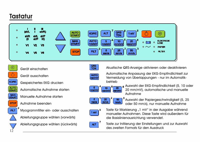
12
12
TTTTTastaturastaturastaturastaturastatur
Gerät einschalten
Gerät ausschalten
Gespeichertes EKG drucken
Automatische Aufnahme starten
Manuelle Aufnahme starten
Aufnahme beenden
Myogrammfilter ein- oder ausschalten
Ableitungsgruppe wählen (vorwärts)
Ableitungsgruppe wählen (rückwärts)
Akustische QRS-Anzeige aktivieren oder deaktivieren
Automatische Anpassung der EKG-Empfindlichkeit zurVermeidung von Überlappungen - nur im Automatik-betrieb
Auswahl der EKG-Empfindlichkeit (5, 10 oder20 mm/mV), automatische und manuelleAufnahme
Auswahl der Papiergeschwindigkeit (5, 25oder 50 mm/s), nur manuelle Aufnahme
Taste für Markierung „1 mV“ in der Ausgabe währendmanueller Aufnahmen. Diese Taste wird außerdem fürdie Basislinienausrichtung verwendet.
Taste zur Initiierung der Einstellungen und zur Auswahldes zweiten Formats für den Ausdruck
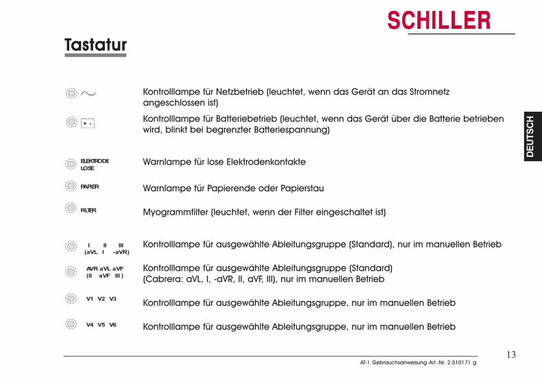
13AT-1 Gebrauchsanweisung Art.-Nr. 2.510171 g
AT-1 Gebrauchsanweisung Art.-Nr. 2.510171 g
DEUT
SCH
DEUT
SCH
13
Kontrolllampe für Netzbetrieb (leuchtet, wenn das Gerät an das Stromnetzangeschlossen ist)
Kontrolllampe für Batteriebetrieb (leuchtet, wenn das Gerät über die Batterie betriebenwird, blinkt bei begrenzter Batteriespannung)
Warnlampe für lose Elektrodenkontakte
Warnlampe für Papierende oder Papierstau
Myogrammfilter (leuchtet, wenn der Filter eingeschaltet ist)
Kontrolllampe für ausgewählte Ableitungsgruppe (Standard), nur im manuellen Betrieb
Kontrolllampe für ausgewählte Ableitungsgruppe (Standard)(Cabrera: aVL, I, -aVR, II, aVF, III), nur im manuellen Betrieb
Kontrolllampe für ausgewählte Ableitungsgruppe, nur im manuellen Betrieb
Kontrolllampe für ausgewählte Ableitungsgruppe, nur im manuellen Betrieb
TTTTTastaturastaturastaturastaturastatur
+ -
I II III
V1 V2 V3
AVR aVL aVF(II aVF III )
V4 V5 V6
(aVL I -aVR )
ELEKTRODELOSE
PAPIER
FILTER
TTTTTastaturastaturastaturastaturastatur
Kontrolllampe für Netzbetrieb (leuchtet, wenn das Gerät an das Stromnetzangeschlossen ist)
Kontrolllampe für Batteriebetrieb (leuchtet, wenn das Gerät über die Batterie betriebenwird, blinkt bei begrenzter Batteriespannung)
Warnlampe für lose Elektrodenkontakte
Warnlampe für Papierende oder Papierstau
Myogrammfilter (leuchtet, wenn der Filter eingeschaltet ist)
Kontrolllampe für ausgewählte Ableitungsgruppe (Standard), nur im manuellen Betrieb
Kontrolllampe für ausgewählte Ableitungsgruppe (Standard)(Cabrera: aVL, I, -aVR, II, aVF, III), nur im manuellen Betrieb
Kontrolllampe für ausgewählte Ableitungsgruppe, nur im manuellen Betrieb
Kontrolllampe für ausgewählte Ableitungsgruppe, nur im manuellen Betrieb
+ -
I II III
V1 V2 V3
AVR aVL aVF(II aVF III )
V4 V5 V6
(aVL I -aVR )
ELEKTRODELOSE
PAPIER
FILTER
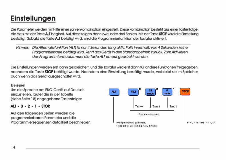
14
14
EinstellungenEinstellungenEinstellungenEinstellungenEinstellungenDie Parameter werden mit Hilfe einer Zahlenkombination eingestellt. Diese Kombination besteht aus einer Tastenfolge,die stets mit der Taste ALALALALALTTTTT beginnt. Auf diese folgen dann zwei oder drei Zahlen. Mit der Taste STOPSTOPSTOPSTOPSTOP wird die Einstellungbestätigt. Sobald die Taste ALALALALALTTTTT betätigt wird, wird die Programmierfunktion der Tastatur aktiviert.
Hinweis: Die Alternativfunktion (ALT) ist nur 4 Sekunden lang aktiv. Falls innerhalb von 4 Sekunden keineProgrammiertaste betätigt wird, kehrt das Gerät in den Standardbetrieb zurück. Zum Aktivierendes Programmiermodus muss die Taste ALT erneut gedrückt werden.
Die Einstellungen werden erst dann gespeichert, und die Tastatur wird erst dann für andere Funktionen freigegeben,nachdem die Taste STOPSTOPSTOPSTOPSTOP betätigt wurde. Nachdem eine Einstellung bestätigt wurde, verbleibt sie im Speicher,auch wenn das Gerät ausgeschaltet wird.
BeispielUm die Sprache am EKG-Gerät auf Deutscheinzustellen, lautet die in der Tabelle(siehe Seite 18) angegebene Tastenfolge:
ALALALALALT - 0 - 2 - 1 - STOPT - 0 - 2 - 1 - STOPT - 0 - 2 - 1 - STOPT - 0 - 2 - 1 - STOPT - 0 - 2 - 1 - STOP.....
Auf den folgenden Seiten werden dieprogrammierbaren Parameter und dieProgrammiersequenzen detailliert beschrieben
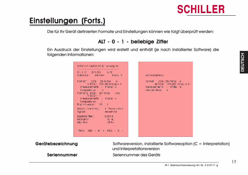
15AT-1 Gebrauchsanweisung Art.-Nr. 2.510171 g
AT-1 Gebrauchsanweisung Art.-Nr. 2.510171 g
DEUT
SCH
DEUT
SCH
15
Einstellungen (FEinstellungen (FEinstellungen (FEinstellungen (FEinstellungen (Forororororts.)ts.)ts.)ts.)ts.)Die für Ihr Gerät definierten Formate und Einstellungen können wie folgt überprüft werden:
ALALALALALT - 0 - 1 - beliebige ZifferT - 0 - 1 - beliebige ZifferT - 0 - 1 - beliebige ZifferT - 0 - 1 - beliebige ZifferT - 0 - 1 - beliebige Ziffer
Ein Ausdruck der Einstellungen wird erstellt und enthält (je nach installierter Software) diefolgenden Informationen:
GerätebezeichnungGerätebezeichnungGerätebezeichnungGerätebezeichnungGerätebezeichnung Softwareversion, installierte Softwareoption (C = Interpretation)und Interpretationsversion
SeriennummerSeriennummerSeriennummerSeriennummerSeriennummer Seriennummer des Geräts
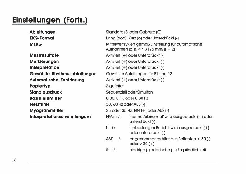
16
16
Einstellungen (FEinstellungen (FEinstellungen (FEinstellungen (FEinstellungen (Forororororts.)ts.)ts.)ts.)ts.)AbleitungenAbleitungenAbleitungenAbleitungenAbleitungen Standard (S) oder Cabrera (C)EKG-FormatEKG-FormatEKG-FormatEKG-FormatEKG-Format Lang (ooo), Kurz (o) oder Unterdrückt (-)MEKGMEKGMEKGMEKGMEKG Mittelwertzyklen gemäß Einstellung für automatische
Aufnahmen (z. B. 4 * 3 (25 mm/s) + 2)MessresultateMessresultateMessresultateMessresultateMessresultate Aktiviert (+) oder Unterdrückt (-)MarkierungenMarkierungenMarkierungenMarkierungenMarkierungen Aktiviert (+) oder Unterdrückt (-)
InterpretationInterpretationInterpretationInterpretationInterpretation Aktiviert (+) oder Unterdrückt (-)Gewählte RhythmusableitungenGewählte RhythmusableitungenGewählte RhythmusableitungenGewählte RhythmusableitungenGewählte Rhythmusableitungen Gewählte Ableitungen für R1 und R2Automatische ZentrierungAutomatische ZentrierungAutomatische ZentrierungAutomatische ZentrierungAutomatische Zentrierung Aktiviert (+) oder Unterdrückt (-)PapiertypPapiertypPapiertypPapiertypPapiertyp Z-gefaltet
SignalausdruckSignalausdruckSignalausdruckSignalausdruckSignalausdruck Sequenziell oder SimultanBasisl inienfi lterBasisl inienfi lterBasisl inienfi lterBasisl inienfi lterBasisl inienfi lter 0,05, 0,15 oder 0,30 HzNetzf i l terNetzf i l terNetzf i l terNetzf i l terNetzf i l ter 50, 60 Hz oder AUS (-)MyogrammfilterMyogrammfilterMyogrammfilterMyogrammfilterMyogrammfilter 25 oder 35 Hz, EIN (+) oder AUS (-)
Interpretationseinstellungen:Interpretationseinstellungen:Interpretationseinstellungen:Interpretationseinstellungen:Interpretationseinstellungen: N/A: +/- ‘normal/abnormal’ wird ausgedruckt (+) oderunterdrückt (-)
U: +/- ‘unbestätigter Bericht’ wird ausgedruckt (+)oder unterdrückt (-)
A30: +/- angenommenes Alter des Patienten < 30 (-)oder >30 (+)
S: +/- niedrige (-) oder hohe (+) Empfindlichkeit
Einstellungen (FEinstellungen (FEinstellungen (FEinstellungen (FEinstellungen (Forororororts.)ts.)ts.)ts.)ts.)AbleitungenAbleitungenAbleitungenAbleitungenAbleitungen Standard (S) oder Cabrera (C)
EKG-FormatEKG-FormatEKG-FormatEKG-FormatEKG-Format Lang (ooo), Kurz (o) oder Unterdrückt (-)MEKGMEKGMEKGMEKGMEKG Mittelwertzyklen gemäß Einstellung für automatische
Aufnahmen (z. B. 4 * 3 (25 mm/s) + 2)MessresultateMessresultateMessresultateMessresultateMessresultate Aktiviert (+) oder Unterdrückt (-)MarkierungenMarkierungenMarkierungenMarkierungenMarkierungen Aktiviert (+) oder Unterdrückt (-)InterpretationInterpretationInterpretationInterpretationInterpretation Aktiviert (+) oder Unterdrückt (-)
Gewählte RhythmusableitungenGewählte RhythmusableitungenGewählte RhythmusableitungenGewählte RhythmusableitungenGewählte Rhythmusableitungen Gewählte Ableitungen für R1 und R2Automatische ZentrierungAutomatische ZentrierungAutomatische ZentrierungAutomatische ZentrierungAutomatische Zentrierung Aktiviert (+) oder Unterdrückt (-)PapiertypPapiertypPapiertypPapiertypPapiertyp Z-gefaltetSignalausdruckSignalausdruckSignalausdruckSignalausdruckSignalausdruck Sequenziell oder Simultan
Basisl inienfi lterBasisl inienfi lterBasisl inienfi lterBasisl inienfi lterBasisl inienfi lter 0,05, 0,15 oder 0,30 HzNetzf i l terNetzf i l terNetzf i l terNetzf i l terNetzf i l ter 50, 60 Hz oder AUS (-)MyogrammfilterMyogrammfilterMyogrammfilterMyogrammfilterMyogrammfilter 25 oder 35 Hz, EIN (+) oder AUS (-)Interpretationseinstellungen:Interpretationseinstellungen:Interpretationseinstellungen:Interpretationseinstellungen:Interpretationseinstellungen: N/A: +/- ‘normal/abnormal’ wird ausgedruckt (+) oder
unterdrückt (-)U: +/- ‘unbestätigter Bericht’ wird ausgedruckt (+)
oder unterdrückt (-)A30: +/- angenommenes Alter des Patienten < 30 (-)
oder >30 (+)S: +/- niedrige (-) oder hohe (+) Empfindlichkeit
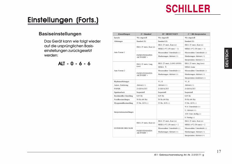
17AT-1 Gebrauchsanweisung Art.-Nr. 2.510171 g
AT-1 Gebrauchsanweisung Art.-Nr. 2.510171 g
DEUT
SCH
DEUT
SCH
17
Einstellungen (FEinstellungen (FEinstellungen (FEinstellungen (FEinstellungen (Forororororts.)ts.)ts.)ts.)ts.)
BasiseinstellungenDas Gerät kann wie folgt wiederauf die ursprünglichen Basis-einstellungen zurückgesetztwerden:
ALALALALALT - 0 - 6 - 6T - 0 - 6 - 6T - 0 - 6 - 6T - 0 - 6 - 6T - 0 - 6 - 6
Einstelllungen S = Standard M = MESSUNGEN C = Mit Interpretation
Sprache Wie eingestellt Wie eingestellt Wie eingestellt
Ableitungen Standard (S) Standard (S) Standard (S)
Auto Format 1
EKG: 25 mm/s, Kurz (o)EKG: 25 mm/s, Kurz (o) EKG: 25 mm/s, Kurz (o)
MEKG: 6*2 (50 mm/s + 1) MEKG: 6*2 (50 mm/s + 1)
PATIENTENDATENAKTIVIERT +
Messresultate: Unterdrückt (-) Messresultate: Unterdrückt (-)
Markierungen: Aktiviert (+) Markierungen: Aktiviert (+)
Interpretation: Aktiviert (+)
Auto Format 2
EKG: 25 mm/s, Lang(ooo)
EKG: 25 mm/s, LANG (OOO) EKG: 25 mm/s, lang (ooo)
MEKG: Ñ MEKG: keine
PATIENTENDATENAKTIVIERT +
Messresultate: Unterdrückt (-) Messresultate: Unterdrückt (-)
Markierungen: Aktiviert (+) Markierungen: Aktiviert (+)
Interpretation: deaktiviert (-)
Rhythmusableitungen V1, II V1, II
Autom. Zentrierung Aktiviert (+) Aktiviert (+) Aktiviert (+)
PAPIER Z-GEFALTET Z-GEFALTET Z-GEFALTET
Signalausdruck Sequenziell Sequenziell Sequenziell
Basislinienfilter-Einstellung 0,05 Hz 0,05 Hz 0,05 Hz
Netzfiltereinstellungen 50 Hz (60 Hz) 50 Hz (60 Hz) 50 Hz (60 Hz)
Myogrammfiltereinstellung 35 Hz, AUS (-) 35 Hz, AUS (-) 35 Hz, AUS (-)
Interpretationseinstellungen
N/A: Unterdrückt (-)
U: Aktiviert (+)
A30: Unter dreißig (-)
S: Niedrig (-)
EXTERNER DRUCKER
EKG: 25 mm/s, Kurz (o)EKG: 25 mm/s, Kurz (o) EKG: 25 mm/s, Kurz (o)
MEKG: 6*2 (50 mm/s) + 2 MEKG: 6*2 (50 mm/s) + 2
PATIENTENDATENAKTIVIERT +
Messresultate: Unterdrückt (-) Messresultate: Unterdrückt (-)
Markierungen: Aktiviert (+) Markierungen: Aktiviert (+)
Interpretation: Aktiviert (+)
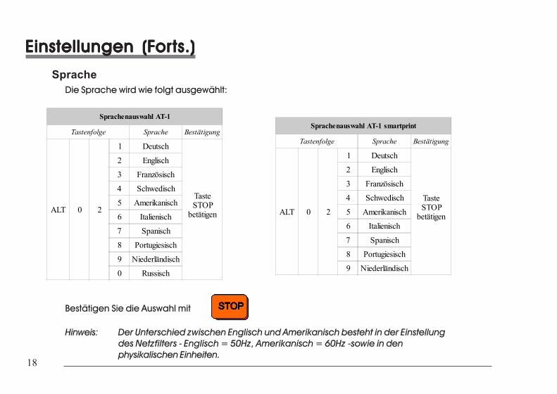
18
18
Einstellungen (FEinstellungen (FEinstellungen (FEinstellungen (FEinstellungen (Forororororts.)ts.)ts.)ts.)ts.)
SpracheDie Sprache wird wie folgt ausgewählt:
Sprachenauswahl AT-1
Tastenfolge Sprache Bestätigung
ALT 0 2
1 Deutsch
TasteSTOP
betätigen
2 Englisch
3 Französisch
4 Schwedisch
5 Amerikanisch
6 Italienisch
7 Spanisch
8 Portugiesisch
9 Niederländisch
0 Russisch
Sprachenauswahl AT-1 smartprint
Tastenfolge Sprache Bestätigung
ALT 0 2
1 Deutsch
TasteSTOP
betätigen
2 Englisch
3 Französisch
4 Schwedisch
5 Amerikanisch
6 Italienisch
7 Spanisch
8 Portugiesisch
9 Niederländisch
Bestätigen Sie die Auswahl mit
Hinweis: Der Unterschied zwischen Englisch und Amerikanisch besteht in der Einstellungdes Netzfilters - Englisch = 50Hz, Amerikanisch = 60Hz -sowie in denphysikalischen Einheiten.
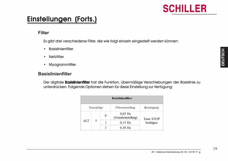
19AT-1 Gebrauchsanweisung Art.-Nr. 2.510171 g
AT-1 Gebrauchsanweisung Art.-Nr. 2.510171 g
DEUT
SCH
DEUT
SCH
19
Einstellungen (FEinstellungen (FEinstellungen (FEinstellungen (FEinstellungen (Forororororts.)ts.)ts.)ts.)ts.)
FilterEs gibt drei verschiedene Filter, die wie folgt einzeln eingestellt werden können:
• Basislinienfilter
• Netzfilter
• Myogrammfilter
BasislinienfilterDer digitale BasislinienfilterBasislinienfilterBasislinienfilterBasislinienfilterBasislinienfilter hat die Funktion, übermäßige Verschiebungen der Basislinie zuunterdrücken. Folgende Optionen stehen für diese Einstellung zur Verfügung:
Basislinienfilter
Tastenfolge Filtereinstellung Bestätigung
ALT 50 0,05 Hz
(Grundeinstellung) Taste STOPbetätigen1 0,15 Hz
3 0,30 Hz
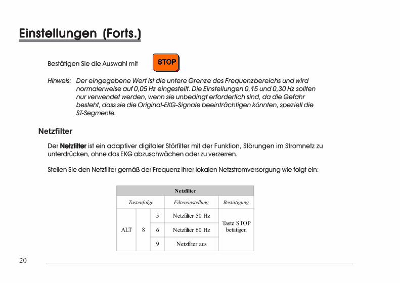
20
20
Einstellungen (FEinstellungen (FEinstellungen (FEinstellungen (FEinstellungen (Forororororts.)ts.)ts.)ts.)ts.)
Bestätigen Sie die Auswahl mit
Hinweis: Der eingegebene Wert ist die untere Grenze des Frequenzbereichs und wirdnormalerweise auf 0,05 Hz eingestellt. Die Einstellungen 0,15 und 0,30 Hz solltennur verwendet werden, wenn sie unbedingt erforderlich sind, da die Gefahrbesteht, dass sie die Original-EKG-Signale beeinträchtigen könnten, speziell dieST-Segmente.
NetzfilterDer NetzfilterNetzfilterNetzfilterNetzfilterNetzfilter ist ein adaptiver digitaler Störfilter mit der Funktion, Störungen im Stromnetz zuunterdrücken, ohne das EKG abzuschwächen oder zu verzerren.
Stellen Sie den Netzfilter gemäß der Frequenz Ihrer lokalen Netzstromversorgung wie folgt ein:
Netzfilter
Tastenfolge Filtereinstellung Bestätigung
ALT 8
5 Netzfilter 50 HzTaste STOP
betätigen6 Netzfilter 60 Hz
9 Netzfilter aus
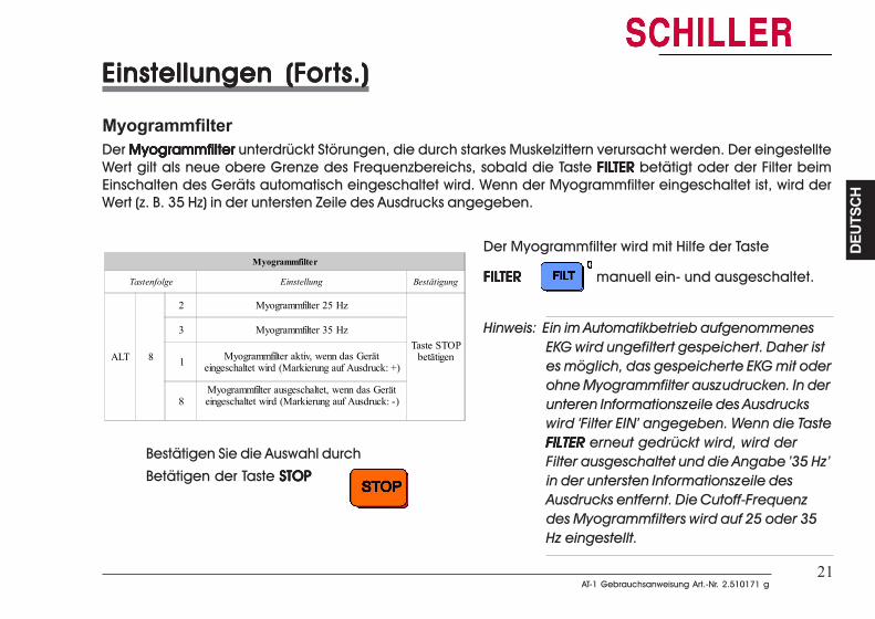
21AT-1 Gebrauchsanweisung Art.-Nr. 2.510171 g
AT-1 Gebrauchsanweisung Art.-Nr. 2.510171 g
DEUT
SCH
DEUT
SCH
21
Einstellungen (FEinstellungen (FEinstellungen (FEinstellungen (FEinstellungen (Forororororts.)ts.)ts.)ts.)ts.)
MyogrammfilterDer MyogrammfilterMyogrammfilterMyogrammfilterMyogrammfilterMyogrammfilter unterdrückt Störungen, die durch starkes Muskelzittern verursacht werden. Der eingestellteWert gilt als neue obere Grenze des Frequenzbereichs, sobald die Taste FILFILFILFILFILTERTERTERTERTER betätigt oder der Filter beimEinschalten des Geräts automatisch eingeschaltet wird. Wenn der Myogrammfilter eingeschaltet ist, wird derWert (z. B. 35 Hz) in der untersten Zeile des Ausdrucks angegeben.
Myogrammfilter
Tastenfolge Einstellung Bestätigung
ALT 8
2 Myogrammfilter 25 Hz
Taste STOPbetätigen
3 Myogrammfilter 35 Hz
1 Myogrammfilter aktiv, wenn das Geräteingeschaltet wird (Markierung auf Ausdruck: +)
8Myogrammfilter ausgeschaltet, wenn das Geräteingeschaltet wird (Markierung auf Ausdruck: -)
Bestätigen Sie die Auswahl durch
Betätigen der Taste STOPSTOPSTOPSTOPSTOP
Der Myogrammfilter wird mit Hilfe der Taste
FILFILFILFILFILTERTERTERTERTER manuell ein- und ausgeschaltet.
Hinweis: Ein im Automatikbetrieb aufgenommenesEKG wird ungefiltert gespeichert. Daher istes möglich, das gespeicherte EKG mit oderohne Myogrammfilter auszudrucken. In derunteren Informationszeile des Ausdruckswird ‘Filter EIN’ angegeben. Wenn die TasteFILTERFILTERFILTERFILTERFILTER erneut gedrückt wird, wird derFilter ausgeschaltet und die Angabe ’35 Hz’in der untersten Informationszeile desAusdrucks entfernt. Die Cutoff-Frequenzdes Myogrammfilters wird auf 25 oder 35Hz eingestellt.
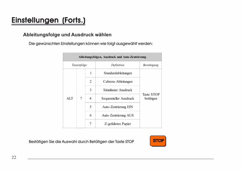
22
22
Einstellungen (FEinstellungen (FEinstellungen (FEinstellungen (FEinstellungen (Forororororts.)ts.)ts.)ts.)ts.)
Ableitungsfolge und Ausdruck wählenDie gewünschten Einstellungen können wie folgt ausgewählt werden:
Ableitungsfolgen, Ausdruck und Auto-Zentrierung
Tastenfolge Definition Bestätigung
ALT 7
1 Standardableitungen
Taste STOPbetätigen
2 Cabrera-Ableitungen
3 Simultaner Ausdruck
4 Sequenzieller Ausdruck
5 Auto-Zentrierung EIN
6 Auto-Zentrierung AUS
7 Z-gefaltetes Papier
Bestätigen Sie die Auswahl durch Betätigen der Taste STOP
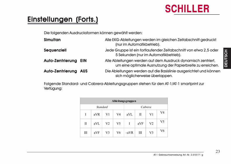
23AT-1 Gebrauchsanweisung Art.-Nr. 2.510171 g
AT-1 Gebrauchsanweisung Art.-Nr. 2.510171 g
DEUT
SCH
DEUT
SCH
23
Einstellungen (FEinstellungen (FEinstellungen (FEinstellungen (FEinstellungen (Forororororts.)ts.)ts.)ts.)ts.)
Die folgenden Ausdrucksformen können gewählt werden:
SimultanSimultanSimultanSimultanSimultan Alle EKG-Ableitungen werden im gleichen Zeitabschnitt gedruckt(nur im Automatikbetrieb).
SequenziellSequenziellSequenziellSequenziellSequenziell Jede Gruppe ist ein fortlaufender Zeitabschnitt von etwa 2,5 oder5 Sekunden (nur im Automatikbetrieb).
Auto-ZentrierungAuto-ZentrierungAuto-ZentrierungAuto-ZentrierungAuto-Zentrierung EINEINEINEINEIN Alle Ableitungen werden auf dem Ausdruck dynamisch zentriert,um eine optimale Ausnutzung der Papierbreite zu erreichen.
Auto-ZentrierungAuto-ZentrierungAuto-ZentrierungAuto-ZentrierungAuto-Zentrierung AUSAUSAUSAUSAUS Die Ableitungen werden auf die Basislinie ausgerichtet und könnensich möglicherweise überlappen.
Folgende Standard- und Cabrera-Ableitungsgruppen stehen für den AT-1/AT-1 smartprint zurVerfügung:
Ableitungsgruppen
Standard Cabrera
I aVR V1 V4 aVL II V1 V4
II aVL V2 V5 I aVF V2 V5
III aVF V3 V6 -aVR III V3 V6
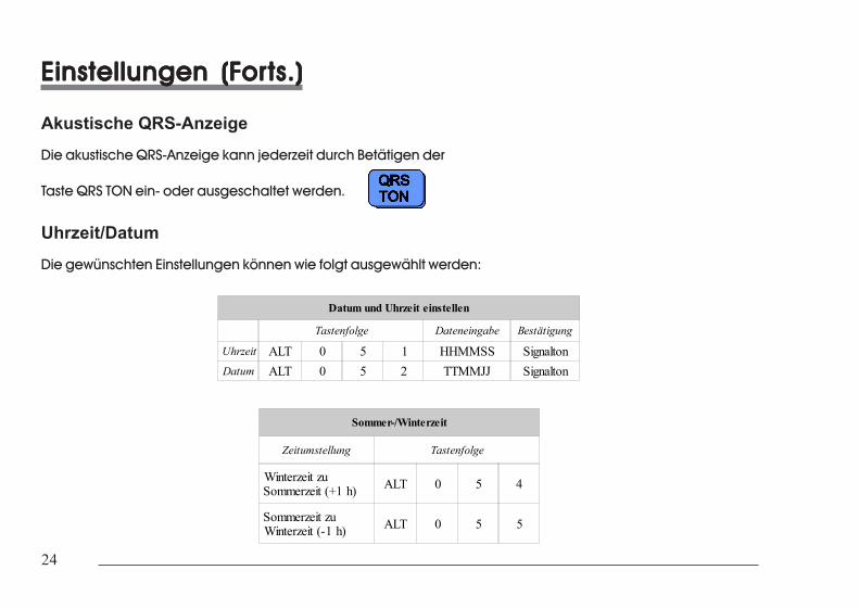
24
24
Einstellungen (FEinstellungen (FEinstellungen (FEinstellungen (FEinstellungen (Forororororts.)ts.)ts.)ts.)ts.)
Akustische QRS-AnzeigeDie akustische QRS-Anzeige kann jederzeit durch Betätigen der
Taste QRS TON ein- oder ausgeschaltet werden.
Uhrzeit/DatumDie gewünschten Einstellungen können wie folgt ausgewählt werden:
Datum und Uhrzeit einstellen
Tastenfolge Dateneingabe Bestätigung
Uhrzeit ALT 0 5 1 HHMMSS SignaltonDatum ALT 0 5 2 TTMMJJ Signalton
Sommer-/Winterzeit
Zeitumstellung Tastenfolge
Winterzeit zuSommerzeit (+1 h) ALT 0 5 4
Sommerzeit zuWinterzeit (-1 h) ALT 0 5 5
25AT-1 Gebrauchsanweisung Art.-Nr. 2.510171 g
AT-1 Gebrauchsanweisung Art.-Nr. 2.510171 g
DEUT
SCH
DEUT
SCH
25
Einstellungen (FEinstellungen (FEinstellungen (FEinstellungen (FEinstellungen (Forororororts.)ts.)ts.)ts.)ts.)
Hinweis: Falls die Batterie länger als eine halbe Stunde vom Gerät getrennt war, muss derTaktgeber vor dem Einstellen der Uhrzeit neu gestartet werden. Hierzu muss diefolgende Tastenfolge betätigt werden:
ALALALALALT - 0 - 5 - 9T - 0 - 5 - 9T - 0 - 5 - 9T - 0 - 5 - 9T - 0 - 5 - 9
Hierdurch wird der Taktgeber gestartet, und die Uhrzeit kann eingestellt werden.
Hinweis: Uhrzeit und Datum sind nur im AUTO-Ausdruck auf dem externen Drucker enthalten.
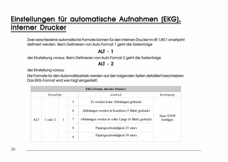
26
26
Einstellungen für automatische Aufnahmen (EKG),Einstellungen für automatische Aufnahmen (EKG),Einstellungen für automatische Aufnahmen (EKG),Einstellungen für automatische Aufnahmen (EKG),Einstellungen für automatische Aufnahmen (EKG),interner Druckerinterner Druckerinterner Druckerinterner Druckerinterner Drucker
Zwei verschiedene automatische Formate können für den internen Drucker im AT-1/AT-1 smartprintdefiniert werden. Beim Definieren von Auto Format 1 geht die Tastenfolge
ALALALALALT - 1T - 1T - 1T - 1T - 1der Einstellung voraus. Beim Definieren von Auto Format 2 geht die Tastenfolge
ALALALALALT - 2T - 2T - 2T - 2T - 2der Einstellung voraus.Die Formate für den Automatikbetrieb werden auf den folgenden Seiten detailliert beschrieben.Das EKG-Format wird wie folgt eingestellt:
EKG-Format, interner Drucker
Tastenfolge Ausdruck Bestätigung
ALT 1 oder 2 1
5 Es werden keine Ableitungen gedruckt
Taste STOPbetätigen
6 Ableitungen werden in Kurzform (3 Blatt) gedruckt
7 Ableitungen werden in voller Länge (6 Blatt) gedruckt
8 Papiergeschwindigkeit 25 mm/s
9 Papiergeschwindigkeit 50 mm/s
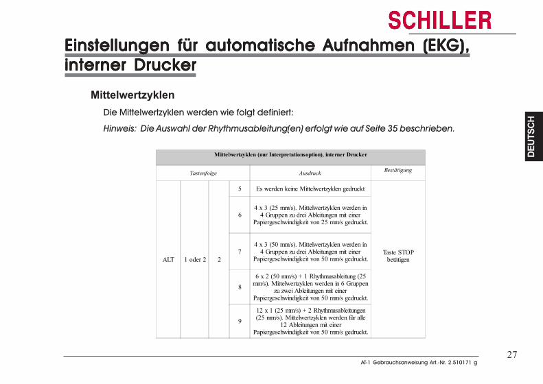
27AT-1 Gebrauchsanweisung Art.-Nr. 2.510171 g
AT-1 Gebrauchsanweisung Art.-Nr. 2.510171 g
DEUT
SCH
DEUT
SCH
27
Einstellungen für automatische Aufnahmen (EKG),Einstellungen für automatische Aufnahmen (EKG),Einstellungen für automatische Aufnahmen (EKG),Einstellungen für automatische Aufnahmen (EKG),Einstellungen für automatische Aufnahmen (EKG),interner Druckerinterner Druckerinterner Druckerinterner Druckerinterner Drucker
MittelwertzyklenDie Mittelwertzyklen werden wie folgt definiert:
Hinweis: Die Auswahl der Rhythmusableitung(en) erfolgt wie auf Seite 35 beschrieben.
Mittelwertzyklen (nur Interpretationsoption), interner Drucker
Tastenfolge Ausdruck Bestätigung
ALT 1 oder 2 2
5 Es werden keine Mittelwertzyklen gedruckt
Taste STOPbetätigen
64 x 3 (25 mm/s). Mittelwertzyklen werden in
4 Gruppen zu drei Ableitungen mit einerPapiergeschwindigkeit von 25 mm/s gedruckt.
74 x 3 (50 mm/s). Mittelwertzyklen werden in
4 Gruppen zu drei Ableitungen mit einerPapiergeschwindigkeit von 50 mm/s gedruckt.
8
6 x 2 (50 mm/s) + 1 Rhythmusableitung (25mm/s). Mittelwertzyklen werden in 6 Gruppen
zu zwei Ableitungen mit einerPapiergeschwindigkeit von 50 mm/s gedruckt.
9
12 x 1 (25 mm/s) + 2 Rhythmusableitungen(25 mm/s). Mittelwertzyklen werden für alle
12 Ableitungen mit einerPapiergeschwindigkeit von 50 mm/s gedruckt.

28
28
Einstellungen für automatische Aufnahmen (EKG),Einstellungen für automatische Aufnahmen (EKG),Einstellungen für automatische Aufnahmen (EKG),Einstellungen für automatische Aufnahmen (EKG),Einstellungen für automatische Aufnahmen (EKG),interner Druckinterner Druckinterner Druckinterner Druckinterner Drucker (Fer (Fer (Fer (Fer (Forororororts.)ts.)ts.)ts.)ts.)
Messungen und Markierungen (nur Versionen M und C)Die Messungen und Markierungen werden wie folgt definiert:
Messungen (nur Optionen M und C), interner Drucker
Tastenfolge Ausdruck Bestätigung
ALT 1 oder 2 3
5
Die detaillierte Tabelle der Messresultateentfällt - die Werte der elektrischen
Achsen, der Intervalle und derHerzfrequenz werden jedoch aufgeführt.
Taste STOPbetätigen
6 Die detaillierte Tabelle der Messresultatewird gedruckt.
7 Die Referenzmarkierungen entfallen.
8
Die Referenzmarkierungen (Anfang undEnde von P-Welle und QRS sowie dasEnde der T-Welle) werden zusätzlich zuden EKG-Mittelwertzyklen aufgeführt.
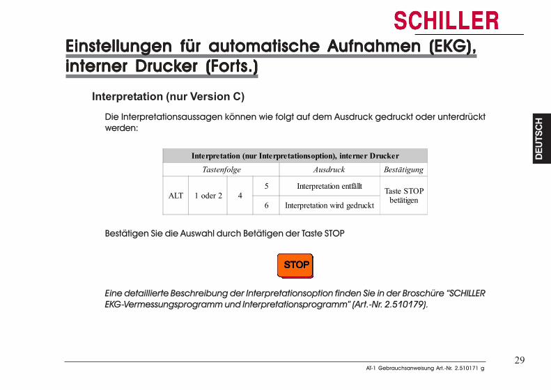
29AT-1 Gebrauchsanweisung Art.-Nr. 2.510171 g
AT-1 Gebrauchsanweisung Art.-Nr. 2.510171 g
DEUT
SCH
DEUT
SCH
29
Einstellungen für automatische Aufnahmen (EKG),Einstellungen für automatische Aufnahmen (EKG),Einstellungen für automatische Aufnahmen (EKG),Einstellungen für automatische Aufnahmen (EKG),Einstellungen für automatische Aufnahmen (EKG),interner Druckinterner Druckinterner Druckinterner Druckinterner Drucker (Fer (Fer (Fer (Fer (Forororororts.)ts.)ts.)ts.)ts.)
Interpretation (nur Version C)Die Interpretationsaussagen können wie folgt auf dem Ausdruck gedruckt oder unterdrücktwerden:
Interpretation (nur Interpretationsoption), interner DruckerTastenfolge Ausdruck Bestätigung
ALT 1 oder 2 45 Interpretation entfällt Taste STOP
betätigen6 Interpretation wird gedruckt
Bestätigen Sie die Auswahl durch Betätigen der Taste STOP
Eine detaillierte Beschreibung der Interpretationsoption finden Sie in der Broschüre “SCHILLEREKG-Vermessungsprogramm und Interpretationsprogramm” (Art.-Nr. 2.510179).
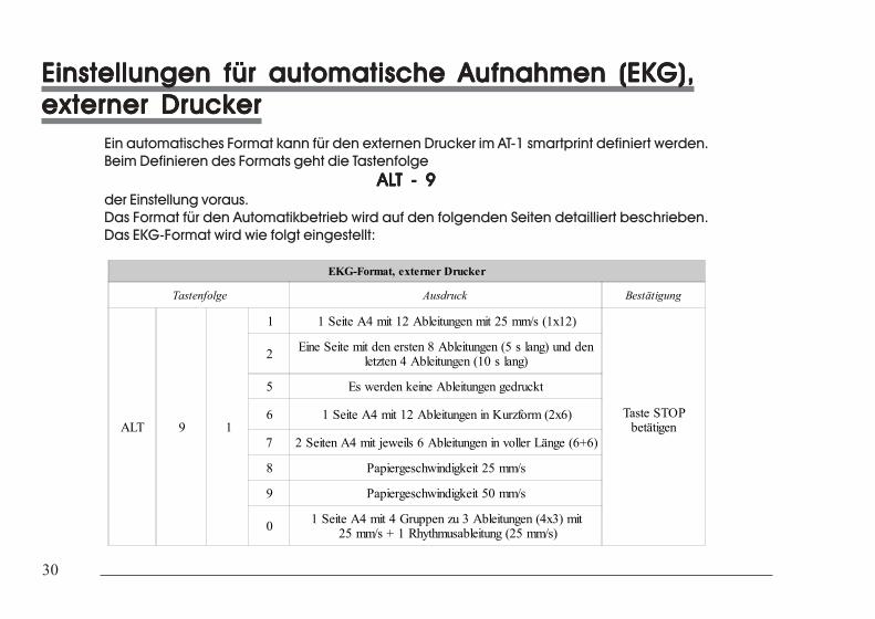
30
30
Einstellungen für automatische Aufnahmen (EKG),Einstellungen für automatische Aufnahmen (EKG),Einstellungen für automatische Aufnahmen (EKG),Einstellungen für automatische Aufnahmen (EKG),Einstellungen für automatische Aufnahmen (EKG),externer Druckerexterner Druckerexterner Druckerexterner Druckerexterner Drucker
Ein automatisches Format kann für den externen Drucker im AT-1 smartprint definiert werden.Beim Definieren des Formats geht die Tastenfolge
ALALALALALT - 9T - 9T - 9T - 9T - 9der Einstellung voraus.Das Format für den Automatikbetrieb wird auf den folgenden Seiten detailliert beschrieben.Das EKG-Format wird wie folgt eingestellt:
EKG-Format, externer Drucker
Tastenfolge Ausdruck Bestätigung
ALT 9 1
1 1 Seite A4 mit 12 Ableitungen mit 25 mm/s (1x12)
Taste STOPbetätigen
2 Eine Seite mit den ersten 8 Ableitungen (5 s lang) und denletzten 4 Ableitungen (10 s lang)
5 Es werden keine Ableitungen gedruckt
6 1 Seite A4 mit 12 Ableitungen in Kurzform (2x6)
7 2 Seiten A4 mit jeweils 6 Ableitungen in voller Länge (6+6)
8 Papiergeschwindigkeit 25 mm/s
9 Papiergeschwindigkeit 50 mm/s
0 1 Seite A4 mit 4 Gruppen zu 3 Ableitungen (4x3) mit 25 mm/s + 1 Rhythmusableitung (25 mm/s)

31AT-1 Gebrauchsanweisung Art.-Nr. 2.510171 g
AT-1 Gebrauchsanweisung Art.-Nr. 2.510171 g
DEUT
SCH
DEUT
SCH
31
Einstellungen für automatische Aufnahmen (EKG),Einstellungen für automatische Aufnahmen (EKG),Einstellungen für automatische Aufnahmen (EKG),Einstellungen für automatische Aufnahmen (EKG),Einstellungen für automatische Aufnahmen (EKG),externer Druckerexterner Druckerexterner Druckerexterner Druckerexterner Drucker
MittelwertzyklenDie Mittelwertzyklen werden wie folgt definiert:
Hinweis: Die Auswahl der Rhythmusableitung(en) erfolgt wie auf Seite 35 beschrieben.
Mittelwertzyklen (nur Interpretationsoption), externer Drucker
Tastenfolge Ausdruck Bestätigung
ALT 9 2
5 Es werden keine Mittelwertzyklen gedruckt
Taste STOPbetätigen
6
4 x 3 (25 mm/s) + 2 Rhythmusableitungen(25 mm/s). Mittelwertzyklen werden in
4 Gruppen zu drei Ableitungen mit einerPapiergeschwindigkeit von 25 mm/s gedruckt.
7
4 x 3 (50 mm/s) + 2 Rhythmusableitungen(25 mm/s). Mittelwertzyklen werden in
4 Gruppen zu drei Ableitungen mit einerPapiergeschwindigkeit von 50 mm/s gedruckt.
8
6 x 2 (50 mm/s) + 2 Rhythmusableitungen(25 mm/s). Mittelwertzyklen werden in
6 Gruppen zu zwei Ableitungen mit einerPapiergeschwindigkeit von 50 mm/s gedruckt.
9 12 x 1 Ableitung (25 mm/s)+ 2 Rhythmusableitungen (25 mm/s).
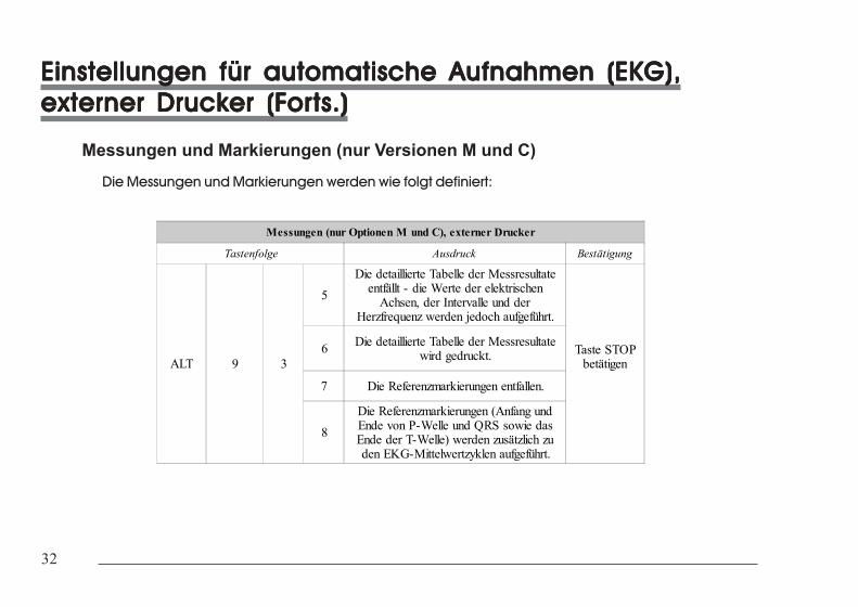
32
32
Einstellungen für automatische Aufnahmen (EKG),Einstellungen für automatische Aufnahmen (EKG),Einstellungen für automatische Aufnahmen (EKG),Einstellungen für automatische Aufnahmen (EKG),Einstellungen für automatische Aufnahmen (EKG),externer Druckexterner Druckexterner Druckexterner Druckexterner Drucker (Fer (Fer (Fer (Fer (Forororororts.)ts.)ts.)ts.)ts.)
Messungen und Markierungen (nur Versionen M und C)Die Messungen und Markierungen werden wie folgt definiert:
Messungen (nur Optionen M und C), externer Drucker
Tastenfolge Ausdruck Bestätigung
ALT 9 3
5
Die detaillierte Tabelle der Messresultateentfällt - die Werte der elektrischen
Achsen, der Intervalle und derHerzfrequenz werden jedoch aufgeführt.
Taste STOPbetätigen
6 Die detaillierte Tabelle der Messresultatewird gedruckt.
7 Die Referenzmarkierungen entfallen.
8
Die Referenzmarkierungen (Anfang undEnde von P-Welle und QRS sowie dasEnde der T-Welle) werden zusätzlich zuden EKG-Mittelwertzyklen aufgeführt.
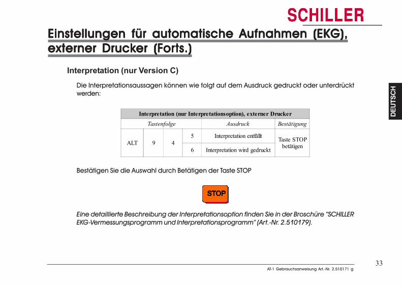
33AT-1 Gebrauchsanweisung Art.-Nr. 2.510171 g
AT-1 Gebrauchsanweisung Art.-Nr. 2.510171 g
DEUT
SCH
DEUT
SCH
33
Einstellungen für automatische Aufnahmen (EKG),Einstellungen für automatische Aufnahmen (EKG),Einstellungen für automatische Aufnahmen (EKG),Einstellungen für automatische Aufnahmen (EKG),Einstellungen für automatische Aufnahmen (EKG),externer Druckexterner Druckexterner Druckexterner Druckexterner Drucker (Fer (Fer (Fer (Fer (Forororororts.)ts.)ts.)ts.)ts.)
Interpretation (nur Version C)Die Interpretationsaussagen können wie folgt auf dem Ausdruck gedruckt oder unterdrücktwerden:
Interpretation (nur Interpretationsoption), externer DruckerTastenfolge Ausdruck Bestätigung
ALT 9 45 Interpretation entfällt Taste STOP
betätigen6 Interpretation wird gedruckt
Bestätigen Sie die Auswahl durch Betätigen der Taste STOP
Eine detaillierte Beschreibung der Interpretationsoption finden Sie in der Broschüre “SCHILLEREKG-Vermessungsprogramm und Interpretationsprogramm” (Art.-Nr. 2.510179).
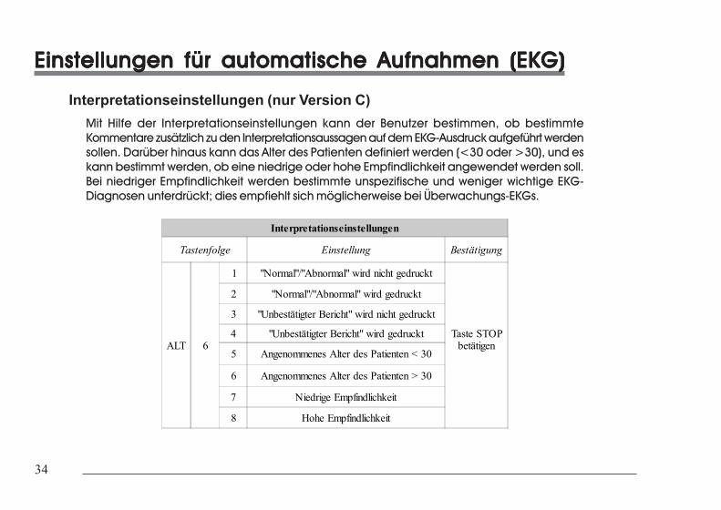
34
34
Einstellungen für automatische Aufnahmen (EKG)Einstellungen für automatische Aufnahmen (EKG)Einstellungen für automatische Aufnahmen (EKG)Einstellungen für automatische Aufnahmen (EKG)Einstellungen für automatische Aufnahmen (EKG)
Interpretationseinstellungen (nur Version C)Mit Hilfe der Interpretationseinstellungen kann der Benutzer bestimmen, ob bestimmteKommentare zusätzlich zu den Interpretationsaussagen auf dem EKG-Ausdruck aufgeführt werdensollen. Darüber hinaus kann das Alter des Patienten definiert werden (<30 oder >30), und eskann bestimmt werden, ob eine niedrige oder hohe Empfindlichkeit angewendet werden soll.Bei niedriger Empfindlichkeit werden bestimmte unspezifische und weniger wichtige EKG-Diagnosen unterdrückt; dies empfiehlt sich möglicherweise bei Überwachungs-EKGs.
Interpretationseinstellungen
Tastenfolge Einstellung Bestätigung
ALT 6
1 "Normal"/"Abnormal" wird nicht gedruckt
Taste STOPbetätigen
2 "Normal"/"Abnormal" wird gedruckt
3 "Unbestätigter Bericht" wird nicht gedruckt
4 "Unbestätigter Bericht" wird gedruckt
5 Angenommenes Alter des Patienten < 30
6 Angenommenes Alter des Patienten > 30
7 Niedrige Empfindlichkeit
8 Hohe Empfindlichkeit
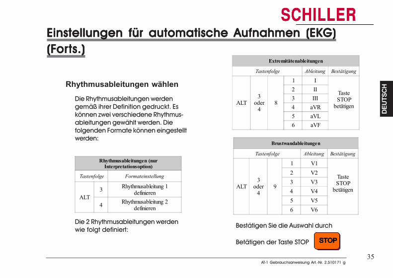
35AT-1 Gebrauchsanweisung Art.-Nr. 2.510171 g
AT-1 Gebrauchsanweisung Art.-Nr. 2.510171 g
DEUT
SCH
DEUT
SCH
35
Einstellungen für automatische Aufnahmen (EKG)Einstellungen für automatische Aufnahmen (EKG)Einstellungen für automatische Aufnahmen (EKG)Einstellungen für automatische Aufnahmen (EKG)Einstellungen für automatische Aufnahmen (EKG)(F(F(F(F(Forororororts.)ts.)ts.)ts.)ts.)
Rhythmusableitungen wählenDie Rhythmusableitungen werdengemäß ihrer Definition gedruckt. Eskönnen zwei verschiedene Rhythmus-ableitungen gewählt werden. Diefolgenden Formate können eingestelltwerden:
Rhythmusableitungen (nurInterpretationsoption)
Tastenfolge Formateinstellung
ALT3 Rhythmusableitung 1
definieren
4 Rhythmusableitung 2definieren
Die 2 Rhythmusableitungen werdenwie folgt definiert:
Extremitätenableitungen
Tastenfolge Ableitung Bestätigung
ALT3
oder4
8
1 I
TasteSTOP
betätigen
2 II3 III4 aVR5 aVL6 aVF
Brustwandableitungen
Tastenfolge Ableitung Bestätigung
ALT3
oder4
9
1 V1
TasteSTOP
betätigen
2 V23 V34 V45 V56 V6
Bestätigen Sie die Auswahl durch
Betätigen der Taste STOP
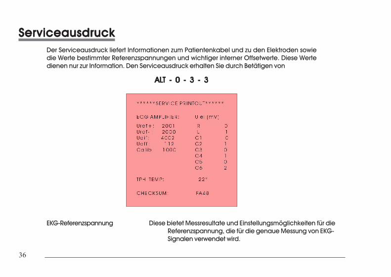
36
36
ServiceausdruckServiceausdruckServiceausdruckServiceausdruckServiceausdruckDer Serviceausdruck liefert Informationen zum Patientenkabel und zu den Elektroden sowiedie Werte bestimmter Referenzspannungen und wichtiger interner Offsetwerte. Diese Wertedienen nur zur Information. Den Serviceausdruck erhalten Sie durch Betätigen von
ALALALALALT - 0 - 3 - 3T - 0 - 3 - 3T - 0 - 3 - 3T - 0 - 3 - 3T - 0 - 3 - 3
EKG-Referenzspannung Diese bietet Messresultate und Einstellungsmöglichkeiten für dieReferenzspannung, die für die genaue Messung von EKG-Signalen verwendet wird.
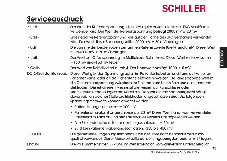
37AT-1 Gebrauchsanweisung Art.-Nr. 2.510171 g
AT-1 Gebrauchsanweisung Art.-Nr. 2.510171 g
DEUT
SCH
DEUT
SCH
37
ServiceausdruckServiceausdruckServiceausdruckServiceausdruckServiceausdruck• Uref + Der Wert der Referenzspannung, die im Multiplexer-Schaltkreis des EKG-Verstärkers
verwendet wird. Der Wert der Referenzspannung beträgt 2000 mV ± 20 mV.• Uref - Eine negative Referenzspannung, die auf der Platine des EKG-Verstärkers verwendet
wird. Der Wert dieser Spannung sollte -2000 mV ± 20 mV betragen.• Udif Die Summe der beiden oben genannten Referenzwerte (Uref+ und Uref-). Dieser Wert
muss 4000 mV ± 20 mV betragen.• Uoff Der Wert der Offsetspannung im Multiplexer-Schaltkreis. Dieser Wert sollte zwischen
+150 mV und -150 mV liegen.• Calib Der Wert von Udif dividiert durch 4. Der Nennwert beträgt 1000 ± 5 mV.DC-Offset der Elektrode Dieser Wert gibt den Spannungsabfall im Patientenkabel an und kann auf Fehler am
Patientenkabel oder an der Patientenelektrode hinweisen. Der angegebene Wert istdie Gleichstromspannung zwischen der Elektrode am linken Bein und allen anderenElektroden. Die erhaltenen Messresultate weisen auf Kurzschlüsse oderStromkreisunterbrechungen am Kabel hin. Der gemessene Spannungswert hängtdavon ab, an welcher Stelle die Elektroden angeschlossen sind. Die folgendenSpannungsmesswerte können erwartet werden:• Patient ist angeschlossen: ± 100 mV• Patientensimulator ist angeschlossen: ± 20 mV. Dieser Wert hängt vom verwendeten
Patientensimulator ab und muss als flexibles Messresultat angesehen werden.• Alle Elektroden sind miteinander kurzgeschlossen: ± 20 mV.• Es ist kein Patientenkabel angeschlossen: -350 bis -450 mV
TPH TEMP Die gemessene Umgebungstemperatur, die der Prozessor zur Korrektur der Druck-qualität verwendet. Dieser Messwert sollte bei der Umgebungstemperatur ± 5o liegen.
EPROM Die Prüfsumme für den EPROM. Ihr Wert ist je nach Softwareversion unterschiedlich.
38
38
Softwareoptionen installierenSoftwareoptionen installierenSoftwareoptionen installierenSoftwareoptionen installierenSoftwareoptionen installieren
Betätigen Sie zum Aktualisieren des EKG-Geräts, beispielsweise von der Standardversion aufdie Version M, die folgenden Tasten:
ALALALALALT - 0 - 4 - T - 0 - 4 - T - 0 - 4 - T - 0 - 4 - T - 0 - 4 - gefolgt vom Aktualisierungscode (von SCHILLER erhältlich).
Die Annahme des Codes wird durch eine Reihe von Signaltönen angezeigt.
VORSICHTVORSICHTVORSICHTVORSICHTVORSICHT
BEI MEHR ALS 10 FEHLVERSUCHEN BEI DER EINGABE DES CODES WIRD DAS GERÄT BLOCKIERT.
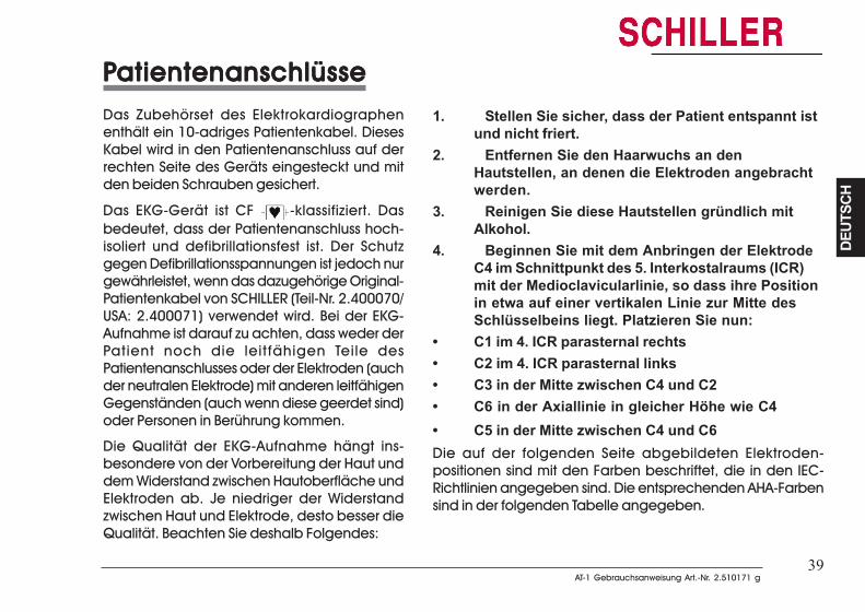
39AT-1 Gebrauchsanweisung Art.-Nr. 2.510171 g
AT-1 Gebrauchsanweisung Art.-Nr. 2.510171 g
DEUT
SCH
DEUT
SCH
39
PPPPPatientenanschlüsseatientenanschlüsseatientenanschlüsseatientenanschlüsseatientenanschlüsseDas Zubehörset des Elektrokardiographenenthält ein 10-adriges Patientenkabel. DiesesKabel wird in den Patientenanschluss auf derrechten Seite des Geräts eingesteckt und mitden beiden Schrauben gesichert.
Das EKG-Gerät ist CF -klassifiziert. Dasbedeutet, dass der Patientenanschluss hoch-isoliert und defibrillationsfest ist. Der Schutzgegen Defibrillationsspannungen ist jedoch nurgewährleistet, wenn das dazugehörige Original-Patientenkabel von SCHILLER (Teil-Nr. 2.400070/USA: 2.400071) verwendet wird. Bei der EKG-Aufnahme ist darauf zu achten, dass weder derPatient noch die leitfähigen Teile desPatientenanschlusses oder der Elektroden (auchder neutralen Elektrode) mit anderen leitfähigenGegenständen (auch wenn diese geerdet sind)oder Personen in Berührung kommen.
Die Qualität der EKG-Aufnahme hängt ins-besondere von der Vorbereitung der Haut unddem Widerstand zwischen Hautoberfläche undElektroden ab. Je niedriger der Widerstandzwischen Haut und Elektrode, desto besser dieQualität. Beachten Sie deshalb Folgendes:
1. Stellen Sie sicher, dass der Patient entspannt istund nicht friert.
2. Entfernen Sie den Haarwuchs an denHautstellen, an denen die Elektroden angebrachtwerden.
3. Reinigen Sie diese Hautstellen gründlich mitAlkohol.
4. Beginnen Sie mit dem Anbringen der ElektrodeC4 im Schnittpunkt des 5. Interkostalraums (ICR)mit der Medioclavicularlinie, so dass ihre Positionin etwa auf einer vertikalen Linie zur Mitte desSchlüsselbeins liegt. Platzieren Sie nun:
• C1 im 4. ICR parasternal rechts• C2 im 4. ICR parasternal links• C3 in der Mitte zwischen C4 und C2• C6 in der Axiallinie in gleicher Höhe wie C4• C5 in der Mitte zwischen C4 und C6Die auf der folgenden Seite abgebildeten Elektroden-positionen sind mit den Farben beschriftet, die in den IEC-Richtlinien angegeben sind. Die entsprechenden AHA-Farbensind in der folgenden Tabelle angegeben.
PPPPPatientenanschlüsseatientenanschlüsseatientenanschlüsseatientenanschlüsseatientenanschlüsseDas Zubehörset des Elektrokardiographenenthält ein 10-adriges Patientenkabel. DiesesKabel wird in den Patientenanschluss auf derrechten Seite des Geräts eingesteckt und mitden beiden Schrauben gesichert.
Das EKG-Gerät ist CF -klassifiziert. Dasbedeutet, dass der Patientenanschluss hoch-isoliert und defibrillationsfest ist. Der Schutzgegen Defibrillationsspannungen ist jedoch nurgewährleistet, wenn das dazugehörige Original-Patientenkabel von SCHILLER (Teil-Nr. 2.400070/USA: 2.400071) verwendet wird. Bei der EKG-Aufnahme ist darauf zu achten, dass weder derPatient noch die leitfähigen Teile desPatientenanschlusses oder der Elektroden (auchder neutralen Elektrode) mit anderen leitfähigenGegenständen (auch wenn diese geerdet sind)oder Personen in Berührung kommen.
Die Qualität der EKG-Aufnahme hängt ins-besondere von der Vorbereitung der Haut unddem Widerstand zwischen Hautoberfläche undElektroden ab. Je niedriger der Widerstandzwischen Haut und Elektrode, desto besser dieQualität. Beachten Sie deshalb Folgendes:
1. Stellen Sie sicher, dass der Patient entspannt istund nicht friert.
2. Entfernen Sie den Haarwuchs an den Hautstellen,an denen die Elektroden angebracht werden.
3. Reinigen Sie diese Hautstellen gründlich mitAlkohol.
4. Beginnen Sie mit dem Anbringen der Elektrode C4im Schnittpunkt des 5. Interkostalraums (ICR) mitder Medioclavicularlinie, so dass ihre Position inetwa auf einer vertikalen Linie zur Mitte desSchlüsselbeins liegt. Platzieren Sie nun:
• C1 im 4. ICR parasternal rechts• C2 im 4. ICR parasternal links• C3 in der Mitte zwischen C4 und C2• C6 in der Axiallinie in gleicher Höhe wie C4• C5 in der Mitte zwischen C4 und C6Die auf der folgenden Seite abgebildeten Elektroden-positionen sind mit den Farben beschriftet, die in den IEC-Richtlinien angegeben sind. Die entsprechenden AHA-Farbensind in der folgenden Tabelle angegeben.
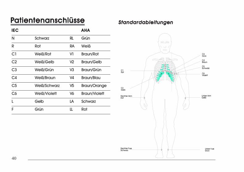
40
40
PPPPPatientenanschlüsseatientenanschlüsseatientenanschlüsseatientenanschlüsseatientenanschlüsseIECIECIECIECIEC AHAAHAAHAAHAAHA
N Schwarz RL Grün
R Rot RA Weiß
C1 Weiß/Rot V1 Braun/Rot
C2 Weiß/Gelb V2 Braun/Gelb
C3 Weiß/Grün V3 Braun/Grün
C4 Weiß/Braun V4 Braun/Blau
C5 Weiß/Schwarz V5 Braun/Orange
C6 Weiß/Violett V6 Braun/Violett
L Gelb LA Schwarz
F Grün LL Rot
StandardableitungenStandardableitungenStandardableitungenStandardableitungenStandardableitungen
PPPPPatientenanschlüsseatientenanschlüsseatientenanschlüsseatientenanschlüsseatientenanschlüsse
IECIECIECIECIEC AHAAHAAHAAHAAHA
N Schwarz RL Grün
R Rot RA Weiß
C1 Weiß/Rot V1 Braun/Rot
C2 Weiß/Gelb V2 Braun/Gelb
C3 Weiß/Grün V3 Braun/Grün
C4 Weiß/Braun V4 Braun/Blau
C5 Weiß/Schwarz V5 Braun/Orange
C6 Weiß/Violett V6 Braun/Violett
L Gelb LA Schwarz
F Grün LL Rot
StandardableitungenStandardableitungenStandardableitungenStandardableitungenStandardableitungen
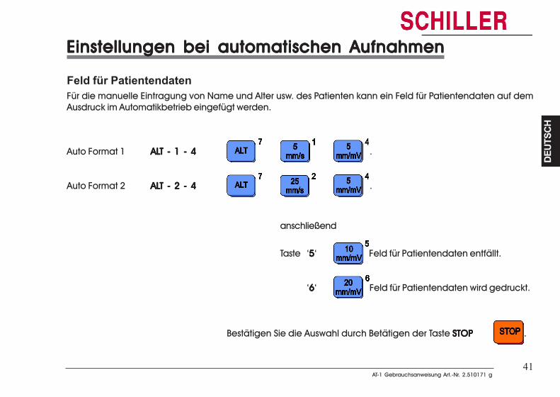
41AT-1 Gebrauchsanweisung Art.-Nr. 2.510171 g
AT-1 Gebrauchsanweisung Art.-Nr. 2.510171 g
DEUT
SCH
DEUT
SCH
41
Einstellungen bei automatischen AufnahmenEinstellungen bei automatischen AufnahmenEinstellungen bei automatischen AufnahmenEinstellungen bei automatischen AufnahmenEinstellungen bei automatischen Aufnahmen
Feld für PatientendatenFür die manuelle Eintragung von Name und Alter usw. des Patienten kann ein Feld für Patientendaten auf demAusdruck im Automatikbetrieb eingefügt werden.
Auto Format 1 ALALALALALT - 1 - 4T - 1 - 4T - 1 - 4T - 1 - 4T - 1 - 4 .
Auto Format 2 ALALALALALT - 2 - 4T - 2 - 4T - 2 - 4T - 2 - 4T - 2 - 4 .
anschließend
Taste ‘55555‘ Feld für Patientendaten entfällt.
‘66666‘ Feld für Patientendaten wird gedruckt.
Bestätigen Sie die Auswahl durch Betätigen der Taste STOPSTOPSTOPSTOPSTOP .
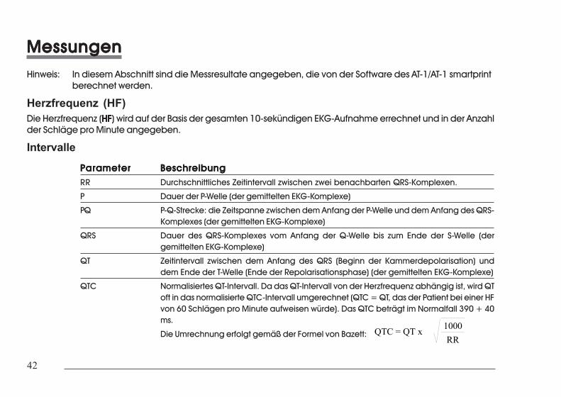
42
42
MessungenMessungenMessungenMessungenMessungenHinweis: In diesem Abschnitt sind die Messresultate angegeben, die von der Software des AT-1/AT-1 smartprint
berechnet werden.
Herzfrequenz (HF)Die Herzfrequenz (HFHFHFHFHF) wird auf der Basis der gesamten 10-sekündigen EKG-Aufnahme errechnet und in der Anzahlder Schläge pro Minute angegeben.
Intervalle
ParameterParameterParameterParameterParameter BeschreibungBeschreibungBeschreibungBeschreibungBeschreibungRR Durchschnittliches Zeitintervall zwischen zwei benachbarten QRS-Komplexen.
P Dauer der P-Welle (der gemittelten EKG-Komplexe)
PQ P-Q-Strecke: die Zeitspanne zwischen dem Anfang der P-Welle und dem Anfang des QRS-Komplexes (der gemittelten EKG-Komplexe)
QRS Dauer des QRS-Komplexes vom Anfang der Q-Welle bis zum Ende der S-Welle (dergemittelten EKG-Komplexe)
QT Zeitintervall zwischen dem Anfang des QRS (Beginn der Kammerdepolarisation) unddem Ende der T-Welle (Ende der Repolarisationsphase) (der gemittelten EKG-Komplexe)
QTC Normalisiertes QT-Intervall. Da das QT-Intervall von der Herzfrequenz abhängig ist, wird QToft in das normalisierte QTC-Intervall umgerechnet (QTC = QT, das der Patient bei einer HFvon 60 Schlägen pro Minute aufweisen würde). Das QTC beträgt im Normalfall 390 + 40ms.
Die Umrechnung erfolgt gemäß der Formel von Bazett: QTC = QT x 1000RR
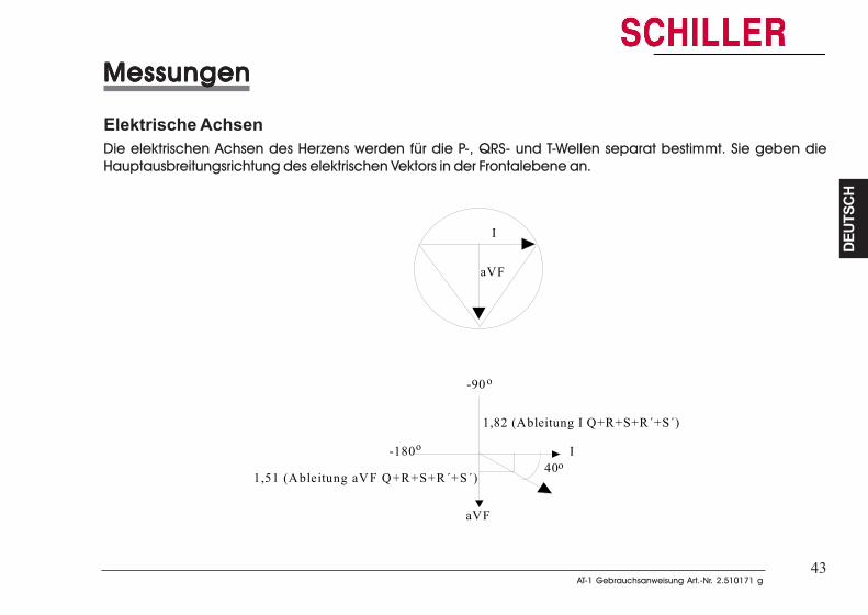
43AT-1 Gebrauchsanweisung Art.-Nr. 2.510171 g
AT-1 Gebrauchsanweisung Art.-Nr. 2.510171 g
DEUT
SCH
DEUT
SCH
43
MessungenMessungenMessungenMessungenMessungen
Elektrische AchsenDie elektrischen Achsen des Herzens werden für die P-, QRS- und T-Wellen separat bestimmt. Sie geben dieHauptausbreitungsrichtung des elektrischen Vektors in der Frontalebene an.
I
aVF
40o
1,82 (Ableitung I Q+R+S+R´+S´)
aVF
I
1,51 (A bleitung aVF Q+R+S+R´+S´)
-90
-180
o
o
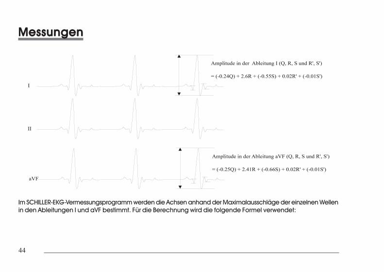
44
44
MessungenMessungenMessungenMessungenMessungen
Im SCHILLER-EKG-Vermessungsprogramm werden die Achsen anhand der Maximalausschläge der einzelnen Wellenin den Ableitungen I und aVF bestimmt. Für die Berechnung wird die folgende Formel verwendet:
MessungenMessungenMessungenMessungenMessungen
Im SCHILLER-EKG-Vermessungsprogramm werden die Achsen anhand der Maximalausschläge der einzelnen Wellenin den Ableitungen I und aVF bestimmt. Für die Berechnung wird die folgende Formel verwendet:
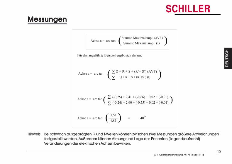
45AT-1 Gebrauchsanweisung Art.-Nr. 2.510171 g
AT-1 Gebrauchsanweisung Art.-Nr. 2.510171 g
DEUT
SCH
DEUT
SCH
45
MessungenMessungenMessungenMessungenMessungen
Hinweis: Bei schwach ausgeprägten P- und T-Wellen können zwischen zwei Messungen größere Abweichungenfestgestellt werden. Außerdem können Atmung und Lage des Patienten (liegend/aufrecht)Veränderungen der elektrischen Achsen bewirken.
MessungenMessungenMessungenMessungenMessungen
Hinweis: Bei schwach ausgeprägten P- und T-Wellen können zwischen zwei Messungen größere Abweichungenfestgestellt werden. Außerdem können Atmung und Lage des Patienten (liegend/aufrecht)Veränderungen der elektrischen Achsen bewirken.
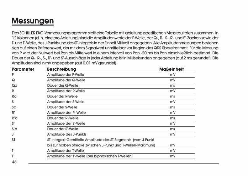
46
46
MessungenMessungenMessungenMessungenMessungenDas SCHILLER EKG-Vermessungsprogramm stellt eine Tabelle mit ableitungsspezifischen Messresultaten zusammen. In12 Kolonnen (d. h. eine pro Ableitung) sind die Amplitudenwerte der P-Welle, der Q-, R-, S-, R’- und S’-Zacken sowie derT- und T’-Welle, des J-Punkts und des ST-Integrals in der Einheit Millivolt angegeben. Alle Amplitudenmessungen beziehensich auf einen Referenzwert, der mit dem Signalwert unmittelbar vor Beginn des QRS übereinstimmt. Für die Messungvon P wird der Nullwert bei Pon als Mittelwert in einem Intervall von Pon -20 ms bis Pon einschließlich bestimmt. DieDauer der Q-, R-, S-, R’- und S’-Ausschläge in jeder Ableitung ist in Millisekunden angegeben (auf 2 ms gerundet). DieAmplituden sind in mV angegeben (auf 0,01 mV gerundet)
ParameterParameterParameterParameterParameter BeschreibungBeschreibungBeschreibungBeschreibungBeschreibung MaßeinheitMaßeinheitMaßeinheitMaßeinheitMaßeinheitP Amplitude der P-Welle mVQ Amplitude der Q-Welle mVQd Dauer der Q-Welle msR Amplitude der R-Welle mVRd Dauer der R-Welle msS Amplitude der S-Welle mVSd Dauer der S-Welle msR’ Amplitude der R’-Welle mVR’d Dauer der R’-Welle msS’ Amplitude der S’-Welle mVS’d Dauer der S’-Welle msJ Amplitude des J-Punkts mVST ST-Integral: Gemittelte Amplitude des ST-Segments (vom J-Punkt
bis zur halben Strecke zwischen J-Punkt und T-Wellen-Maximum) mVT Amplitude der T-Welle mVT’ Amplitude der T’-Welle (bei biphasischen T-Wellen) mV
MessungenMessungenMessungenMessungenMessungenDas SCHILLER EKG-Vermessungsprogramm stellt eine Tabelle mit ableitungsspezifischen Messresultaten zusammen. In12 Kolonnen (d. h. eine pro Ableitung) sind die Amplitudenwerte der P-Welle, der Q-, R-, S-, R’- und S’-Zacken sowie derT- und T’-Welle, des J-Punkts und des ST-Integrals in der Einheit Millivolt angegeben. Alle Amplitudenmessungen beziehensich auf einen Referenzwert, der mit dem Signalwert unmittelbar vor Beginn des QRS übereinstimmt. Für die Messungvon P wird der Nullwert bei Pon als Mittelwert in einem Intervall von Pon -20 ms bis Pon einschließlich bestimmt. DieDauer der Q-, R-, S-, R’- und S’-Ausschläge in jeder Ableitung ist in Millisekunden angegeben (auf 2 ms gerundet). DieAmplituden sind in mV angegeben (auf 0,01 mV gerundet)ParameterParameterParameterParameterParameter BeschreibungBeschreibungBeschreibungBeschreibungBeschreibung MaßeinheitMaßeinheitMaßeinheitMaßeinheitMaßeinheitP Amplitude der P-Welle mVQ Amplitude der Q-Welle mVQd Dauer der Q-Welle msR Amplitude der R-Welle mVRd Dauer der R-Welle msS Amplitude der S-Welle mVSd Dauer der S-Welle msR’ Amplitude der R’-Welle mVR’d Dauer der R’-Welle msS’ Amplitude der S’-Welle mVS’d Dauer der S’-Welle msJ Amplitude des J-Punkts mVST ST-Integral: Gemittelte Amplitude des ST-Segments (vom J-Punkt
bis zur halben Strecke zwischen J-Punkt und T-Wellen-Maximum) mVT Amplitude der T-Welle mVT’ Amplitude der T’-Welle (bei biphasischen T-Wellen) mV
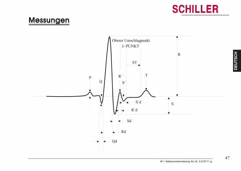
47AT-1 Gebrauchsanweisung Art.-Nr. 2.510171 g
AT-1 Gebrauchsanweisung Art.-Nr. 2.510171 g
DEUT
SCH
DEUT
SCH
47
MessungenMessungenMessungenMessungenMessungen
MessungenMessungenMessungenMessungenMessungen
48
48
Pflege und WPflege und WPflege und WPflege und WPflege und Wararararartungtungtungtungtung
Jährliche KontrolleDas Gerät sollte in Abständen von 12 Monaten einer sicherheitstechnischen Kontrolle unterzogenwerden. Diese Kontrolle sollte folgende Punkte umfassen:
• Optische Prüfung des Geräts und des Patientenkabels.
• Prüfung nach IEC 601-1 Klausel 19
Die Testresultate müssen schriftlich festgehalten werden.
Reinigung des Gehäuses
VORSICHTVORSICHTVORSICHTVORSICHTVORSICHT
SCHALSCHALSCHALSCHALSCHALTEN SIE DTEN SIE DTEN SIE DTEN SIE DTEN SIE DAS GERÄT VAS GERÄT VAS GERÄT VAS GERÄT VAS GERÄT VOR DER REINIGUNG AUS, UND TRENNEN SIE ES VOR DER REINIGUNG AUS, UND TRENNEN SIE ES VOR DER REINIGUNG AUS, UND TRENNEN SIE ES VOR DER REINIGUNG AUS, UND TRENNEN SIE ES VOR DER REINIGUNG AUS, UND TRENNEN SIE ES VOM NETZOM NETZOM NETZOM NETZOM NETZUND VUND VUND VUND VUND VOM EXTERNEN DRUCKER (FOM EXTERNEN DRUCKER (FOM EXTERNEN DRUCKER (FOM EXTERNEN DRUCKER (FOM EXTERNEN DRUCKER (FALLS VALLS VALLS VALLS VALLS VORHANDEN). DAS GERÄT DORHANDEN). DAS GERÄT DORHANDEN). DAS GERÄT DORHANDEN). DAS GERÄT DORHANDEN). DAS GERÄT DARF UNTER KEINENARF UNTER KEINENARF UNTER KEINENARF UNTER KEINENARF UNTER KEINENUMSTÄNDEN IN EINE REINIGUNGSFLÜSSIGKEIT EINGETUMSTÄNDEN IN EINE REINIGUNGSFLÜSSIGKEIT EINGETUMSTÄNDEN IN EINE REINIGUNGSFLÜSSIGKEIT EINGETUMSTÄNDEN IN EINE REINIGUNGSFLÜSSIGKEIT EINGETUMSTÄNDEN IN EINE REINIGUNGSFLÜSSIGKEIT EINGETAUCHT ODER EINERAUCHT ODER EINERAUCHT ODER EINERAUCHT ODER EINERAUCHT ODER EINERHEIßSTERILISAHEIßSTERILISAHEIßSTERILISAHEIßSTERILISAHEIßSTERILISATION MIT WASSERTION MIT WASSERTION MIT WASSERTION MIT WASSERTION MIT WASSER, DAMPF ODER LUFT UNTERZOGEN WERDEN., DAMPF ODER LUFT UNTERZOGEN WERDEN., DAMPF ODER LUFT UNTERZOGEN WERDEN., DAMPF ODER LUFT UNTERZOGEN WERDEN., DAMPF ODER LUFT UNTERZOGEN WERDEN.
Das Gehäuse des EKG-Geräts sollte nur mit einem weichen, angefeuchteten Lappen abgeriebenwerden. Bei Bedarf kann ein nicht ätzender Haushaltsreiniger zur Entfernung von Fettspurenund Fingerabdrücken verwendet werden.
49AT-1 Gebrauchsanweisung Art.-Nr. 2.510171 g
AT-1 Gebrauchsanweisung Art.-Nr. 2.510171 g
DEUT
SCH
DEUT
SCH
49
Pflege und WPflege und WPflege und WPflege und WPflege und Wararararartungtungtungtungtung
Patientenkabel
VORSICHTVORSICHTVORSICHTVORSICHTVORSICHT
RICHTEN SIE DIE LEITUNGEN SO AUS, DASS KEINE STOLPERGEFAHR BESTEHT UND MIT DEMGERÄTEWAGEN NICHT DARÜBER GEFAHREN WERDEN KANN. DIE GLEICHEN VORSICHTS-MAßNAHMEN GELTEN FÜR DIE AUFBEWAHRUNG DER LEITUNGEN.
Die Patientenleitungen dürfen nicht zu großen mechanischen Belastungen ausgesetzt werden.Beim Lösen der Steckerverbindungen sollte grundsätzlich an den Steckern und nicht an denLeitungen gezogen werden.
Zum Reinigen kann das Kabel mit Seifenlauge abgerieben werden. Eine Sterilisation darf, wennsie erforderlich ist, nur mit Gas und nicht mit Dampf vorgenommen werden. Zur Desinfektionwird das Kabel mit einem im Krankenhaus gebräuchlichen Desinfektionsmittel abgerieben.
Reinigung des Thermodruckkopfs des internen DruckersWenn der Drucker häufig verwendet wird, können sich Ablagerungen aus Druckerfarbe (vomGitter auf dem Papier) auf dem Druckkopf bilden. Hierdurch kann die Druckqualitätbeeinträchtigt werden. Wir empfehlen daher, den Druckkopf jeden Monat wie folgt mit Alkoholzu reinigen:
Entfernen Sie das Papierfach. Der Thermodruckkopf befindet sich unter dem Schnapp-verschlussdes Papierfachs. Entfernen Sie die Ablagerungen durch leichtes Abreiben des Druckkopfs miteinem mit Alkohol befeuchteten Tuch. Falls der Druckkopf stark verschmutzt ist, ist die Farbedes Gitters auf dem Papier (d. h. rot oder grün) auf dem Tuch zu sehen.
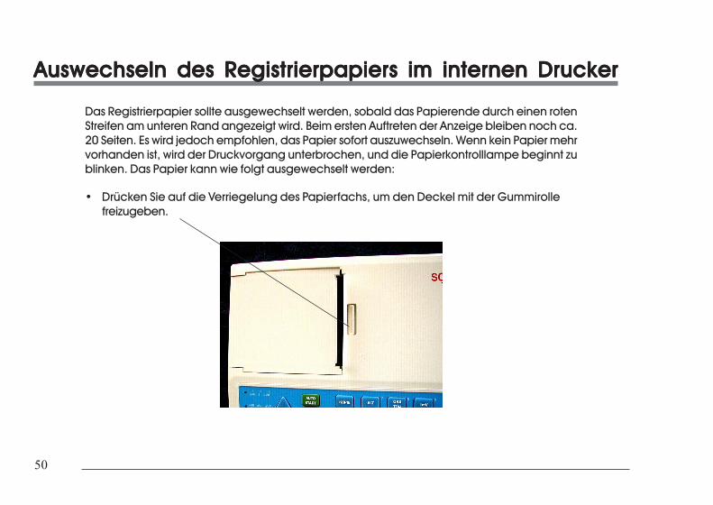
50
50
Auswechseln des Registrierpapiers im internen DruckerAuswechseln des Registrierpapiers im internen DruckerAuswechseln des Registrierpapiers im internen DruckerAuswechseln des Registrierpapiers im internen DruckerAuswechseln des Registrierpapiers im internen Drucker
Das Registrierpapier sollte ausgewechselt werden, sobald das Papierende durch einen rotenStreifen am unteren Rand angezeigt wird. Beim ersten Auftreten der Anzeige bleiben noch ca.20 Seiten. Es wird jedoch empfohlen, das Papier sofort auszuwechseln. Wenn kein Papier mehrvorhanden ist, wird der Druckvorgang unterbrochen, und die Papierkontrolllampe beginnt zublinken. Das Papier kann wie folgt ausgewechselt werden:
• Drücken Sie auf die Verriegelung des Papierfachs, um den Deckel mit der Gummirollefreizugeben.
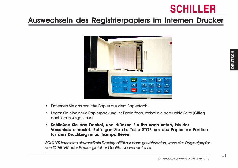
51AT-1 Gebrauchsanweisung Art.-Nr. 2.510171 g
AT-1 Gebrauchsanweisung Art.-Nr. 2.510171 g
DEUT
SCH
DEUT
SCH
51
Auswechseln des Registrierpapiers im internen DruckerAuswechseln des Registrierpapiers im internen DruckerAuswechseln des Registrierpapiers im internen DruckerAuswechseln des Registrierpapiers im internen DruckerAuswechseln des Registrierpapiers im internen Drucker
• Entfernen Sie das restliche Papier aus dem Papierfach.
• Legen Sie eine neue Papierpackung ins Papierfach, wobei die bedruckte Seite (Gitter)nach oben zeigen muss.
••••• Schließen Sie den Deckel, und drücken Sie ihn nach unten, bis derSchließen Sie den Deckel, und drücken Sie ihn nach unten, bis derSchließen Sie den Deckel, und drücken Sie ihn nach unten, bis derSchließen Sie den Deckel, und drücken Sie ihn nach unten, bis derSchließen Sie den Deckel, und drücken Sie ihn nach unten, bis derVVVVVerschluss einrastet. Betätigen Sie die Terschluss einrastet. Betätigen Sie die Terschluss einrastet. Betätigen Sie die Terschluss einrastet. Betätigen Sie die Terschluss einrastet. Betätigen Sie die Tasteasteasteasteaste STOPSTOPSTOPSTOPSTOP, um das P, um das P, um das P, um das P, um das Papier zur Papier zur Papier zur Papier zur Papier zur Positionositionositionositionositionfür den Druckbeginn zu transportieren.für den Druckbeginn zu transportieren.für den Druckbeginn zu transportieren.für den Druckbeginn zu transportieren.für den Druckbeginn zu transportieren.
SCHILLER kann eine einwandfreie Druckqualität nur dann gewährleisten, wenn das Originalpapiervon SCHILLER oder Papier gleicher Qualität verwendet wird.

52
52
Handhabung von ThermopapierHandhabung von ThermopapierHandhabung von ThermopapierHandhabung von ThermopapierHandhabung von Thermopapier
Das im EKG-Gerät verwendete Thermopapier erfordert eine etwas andere Handhabung alsNormalpapier, da es mit Chemikalien und auf Wärme reagieren kann. Wenn die folgendenPunkte beachtet werden, wird das Papier jedoch zuverlässige Resultate erbringen:
Die folgenden Punkte gelten sowohl für die Aufbewahrung des Papiers als auch für dieArchivierung der Ergebnisse.
1. Bewahren Sie das Papier vor der Verwendung in der Original-Pappverpackung auf.Entfernen Sie die Pappverpackung erst, wenn das Papier verwendet werden soll.
2. Bewahren Sie das Papier an einem kühlen, dunklen und trockenen Ort auf.
3. Lagern Sie das Papier nicht in der Nähe von Chemikalien, z. B. Sterilisationsflüssigkeiten.
4. Bewahren Sie das Papier insbesondere nicht in einer Plastikverpackung auf.
5. Bestimmte Klebstoffe können mit dem Papier reagieren – befestigen Sie den Ausdrucknicht mit Klebstoff auf einer Unterlage.
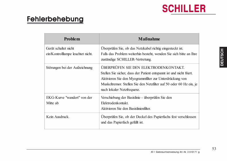
53AT-1 Gebrauchsanweisung Art.-Nr. 2.510171 g
AT-1 Gebrauchsanweisung Art.-Nr. 2.510171 g
DEUT
SCH
DEUT
SCH
53
FFFFFehlerbehebungehlerbehebungehlerbehebungehlerbehebungehlerbehebung
Problem Maßnahme
Gerät schaltet nichtein/Kontrolllampe leuchtet nicht.
Überprüfen Sie, ob das Netzkabel richtig eingesteckt ist.Falls das Problem weiterhin besteht, wenden Sie sich bitte an Ihrezuständige SCHILLER-Vertretung.
Störungen bei der Aufzeichnung ÜBERPRÜFEN SIE DEN ELEKTRODENKONTAKT.Stellen Sie sicher, dass der Patient entspannt ist und nicht friert.Aktivieren Sie den Myogrammfilter zur Unterdrückung vonMuskeltremor. Stellen Sie den Netzfilter auf 50 oder 60 Hz ein, jenach lokaler Netzfrequenz.
EKG-Kurve "wandert" von derMitte ab
Verschiebung der Basislinie - überprüfen Sie denElektrodenkontakt.Aktivieren Sie den Basislinienfilter.
Kein Ausdruck. Überprüfen Sie, ob der Deckel des Papierfachs fest verschlossenund das Papierfach gefüllt ist.
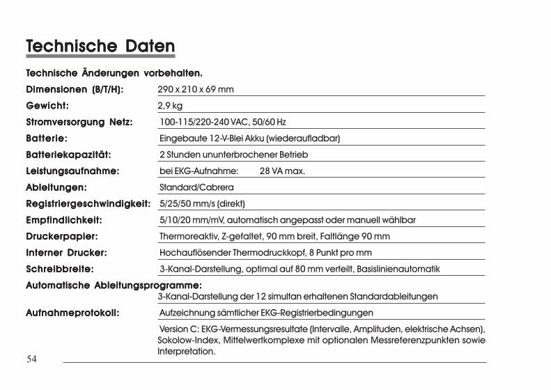
54
54
TTTTTechnische Datenechnische Datenechnische Datenechnische Datenechnische DatenTTTTTechnische Änderungen vorbehaltenechnische Änderungen vorbehaltenechnische Änderungen vorbehaltenechnische Änderungen vorbehaltenechnische Änderungen vorbehalten.....
Dimensionen (B/T/H):Dimensionen (B/T/H):Dimensionen (B/T/H):Dimensionen (B/T/H):Dimensionen (B/T/H): 290 x 210 x 69 mm
Gewicht:Gewicht:Gewicht:Gewicht:Gewicht: 2,9 kg
Stromversorgung Netz:Stromversorgung Netz:Stromversorgung Netz:Stromversorgung Netz:Stromversorgung Netz: 100-115/220-240 VAC, 50/60 Hz
Batter ie:Batter ie:Batter ie:Batter ie:Batter ie: Eingebaute 12-V-Blei Akku (wiederaufladbar)
Batteriekapazität:Batteriekapazität:Batteriekapazität:Batteriekapazität:Batteriekapazität: 2 Stunden ununterbrochener Betrieb
Leistungsaufnahme:Leistungsaufnahme:Leistungsaufnahme:Leistungsaufnahme:Leistungsaufnahme: bei EKG-Aufnahme: 28 VA max.
Ableitungen:Ableitungen:Ableitungen:Ableitungen:Ableitungen: Standard/Cabrera
Registriergeschwindigkeit:Registriergeschwindigkeit:Registriergeschwindigkeit:Registriergeschwindigkeit:Registriergeschwindigkeit: 5/25/50 mm/s (direkt)
Empfindlichkeit:Empfindlichkeit:Empfindlichkeit:Empfindlichkeit:Empfindlichkeit: 5/10/20 mm/mV, automatisch angepasst oder manuell wählbar
Druckerpapier:Druckerpapier:Druckerpapier:Druckerpapier:Druckerpapier: Thermoreaktiv, Z-gefaltet, 90 mm breit, Faltlänge 90 mm
Interner Drucker:Interner Drucker:Interner Drucker:Interner Drucker:Interner Drucker: Hochauflösender Thermodruckkopf, 8 Punkt pro mm
Schreibbreite:Schreibbreite:Schreibbreite:Schreibbreite:Schreibbreite: 3-Kanal-Darstellung, optimal auf 80 mm verteilt, Basislinienautomatik
Automatische Ableitungsprogramme:Automatische Ableitungsprogramme:Automatische Ableitungsprogramme:Automatische Ableitungsprogramme:Automatische Ableitungsprogramme:3-Kanal-Darstellung der 12 simultan erhaltenen Standardableitungen
Aufnahmeprotokoll:Aufnahmeprotokoll:Aufnahmeprotokoll:Aufnahmeprotokoll:Aufnahmeprotokoll: Aufzeichnung sämtlicher EKG-Registrierbedingungen
Version C: EKG-Vermessungsresultate (Intervalle, Amplituden, elektrische Achsen),Sokolow-Index, Mittelwertkomplexe mit optionalen Messreferenzpunkten sowieInterpretation.
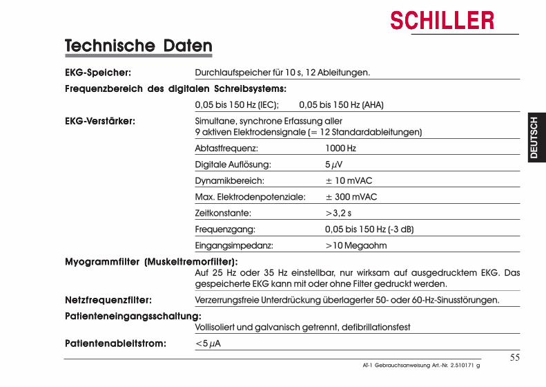
55AT-1 Gebrauchsanweisung Art.-Nr. 2.510171 g
AT-1 Gebrauchsanweisung Art.-Nr. 2.510171 g
DEUT
SCH
DEUT
SCH
55
TTTTTechnische Datenechnische Datenechnische Datenechnische Datenechnische DatenEKG-Speicher:EKG-Speicher:EKG-Speicher:EKG-Speicher:EKG-Speicher: Durchlaufspeicher für 10 s, 12 Ableitungen.
Frequenzbereich des digitalen Schreibsystems:Frequenzbereich des digitalen Schreibsystems:Frequenzbereich des digitalen Schreibsystems:Frequenzbereich des digitalen Schreibsystems:Frequenzbereich des digitalen Schreibsystems:
0,05 bis 150 Hz (IEC); 0,05 bis 150 Hz (AHA)
EKGEKGEKGEKGEKG-----VVVVVerstärkerstärkerstärkerstärkerstärker:er:er:er:er: Simultane, synchrone Erfassung aller9 aktiven Elektrodensignale (= 12 Standardableitungen)
Abtastfrequenz: 1000 Hz
Digitale Auflösung: 5 µV
Dynamikbereich: ± 10 mVAC
Max. Elektrodenpotenziale: ± 300 mVAC
Zeitkonstante: >3,2 s
Frequenzgang: 0,05 bis 150 Hz (-3 dB)
Eingangsimpedanz: >10 Megaohm
Myogrammfilter (Muskeltremorfilter):Myogrammfilter (Muskeltremorfilter):Myogrammfilter (Muskeltremorfilter):Myogrammfilter (Muskeltremorfilter):Myogrammfilter (Muskeltremorfilter):Auf 25 Hz oder 35 Hz einstellbar, nur wirksam auf ausgedrucktem EKG. Dasgespeicherte EKG kann mit oder ohne Filter gedruckt werden.
Netzfrequenzfilter:Netzfrequenzfilter:Netzfrequenzfilter:Netzfrequenzfilter:Netzfrequenzfilter: Verzerrungsfreie Unterdrückung überlagerter 50- oder 60-Hz-Sinusstörungen.
Patienteneingangsschaltung:Patienteneingangsschaltung:Patienteneingangsschaltung:Patienteneingangsschaltung:Patienteneingangsschaltung:Vollisoliert und galvanisch getrennt, defibrillationsfest
Patientenableitstrom:Patientenableitstrom:Patientenableitstrom:Patientenableitstrom:Patientenableitstrom: <5 µA
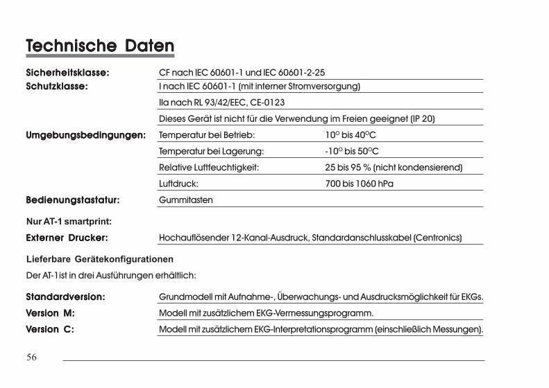
56
56
TTTTTechnische Datenechnische Datenechnische Datenechnische Datenechnische DatenSicherheitsklasse:Sicherheitsklasse:Sicherheitsklasse:Sicherheitsklasse:Sicherheitsklasse: CF nach IEC 60601-1 und IEC 60601-2-25Schutzklasse:Schutzklasse:Schutzklasse:Schutzklasse:Schutzklasse: I nach IEC 60601-1 (mit interner Stromversorgung)
IIa nach RL 93/42/EEC, CE-0123
Dieses Gerät ist nicht für die Verwendung im Freien geeignet (IP 20)
Umgebungsbedingungen:Umgebungsbedingungen:Umgebungsbedingungen:Umgebungsbedingungen:Umgebungsbedingungen: Temperatur bei Betrieb: 10O bis 40OC
Temperatur bei Lagerung: -10O bis 50OC
Relative Luftfeuchtigkeit: 25 bis 95 % (nicht kondensierend)
Luftdruck: 700 bis 1060 hPa
Bedienungstastatur:Bedienungstastatur:Bedienungstastatur:Bedienungstastatur:Bedienungstastatur: Gummitasten
Nur AT-1 smartprint:
Externer Drucker:Externer Drucker:Externer Drucker:Externer Drucker:Externer Drucker: Hochauflösender 12-Kanal-Ausdruck, Standardanschlusskabel (Centronics)
Lieferbare GerätekonfigurationenDer AT-1ist in drei Ausführungen erhältlich:
Standardversion:Standardversion:Standardversion:Standardversion:Standardversion: Grundmodell mit Aufnahme-, Überwachungs- und Ausdrucksmöglichkeit für EKGs.
VVVVVersion M:ersion M:ersion M:ersion M:ersion M: Modell mit zusätzlichem EKG-Vermessungsprogramm.
VVVVVersion C:ersion C:ersion C:ersion C:ersion C: Modell mit zusätzlichem EKG-Interpretationsprogramm (einschließlich Messungen).
i
i
FRA
NÇ
AIS
FRA
NÇ
AIS
AT-1Mode d'emploi
Français
AT-1Mode d'emploi
Français
ii
ii
Instructions importantes iv
Sécurité vii
Instructions succinctes 1
Introduction 2
Modes de fonctionnement 4Mode automatique 4
a. l'imprimante externe n'étant pas raccordée ou hors tension 4
b. l'imprimante externe étant raccordée et sous tension 4Mode manuel 5
Mode automatique 6
a. l'imprimante externe n'étant pas raccordée ou hors tension 6
b. avec l'imprimante externe 7
Mode manuel 8
Lieu d'installation & Alimentation 10
Mise sous/hors tension 11
Clavier 12
Réglages 14Réglages par défaut 17Langues 18Filtres 19Filtre des lignes de base 19Filtre secteur 20
Instructions du service iv
Sécurité vii
Instructions succinctes 1
Introduction 2
Modes de fonctionnement 4Mode automatique 4
a. l'imprimante externe n'étant pas raccordée ou hors tension 4
b. l'imprimante externe étant raccordée et sous tension 4Mode manuel 5
Mode automatique 6
a. l'imprimante externe n'étant pas raccordée ou hors tension 6
b. avec l'imprimante externe 7
Mode manuel 8
Lieu d'installation & Alimentation 10
Mise sous/hors tension 11
Clavier 12
Réglages 14Réglages par défaut 17Langues 18Filtres 19Filtre des lignes de base 19Filtre secteur 20
iii
iii
FRA
NÇ
AIS
FRA
NÇ
AIS
Filtre de myogramme 21Sélection de la séquence de dérivations & mode d'impression 22Signal sonore QRS 24Heure / Date 24
Réglages pour le mode automatique (ECG), imprimante intégrée 26
Réglages pour le mode automatique (ECG), imprimante externe 30
Réglages pour le mode automatique (ECG) 34
Impression pour les besoins internes 36
Installation des logiciels en option 38
Raccordement du câble patient 39
Réglages pour le mode automatique 41Page pour entrer les données du patient 41
Mesures 42Fréquence cardiaque (FC) 42Intervalles 42Axes électriques 43
Entretien & Maintenance 48
Remplacement du papier d'enregistrement 50
Maniement du papier thermique 52
Dépannage 53
Caractéristiques techniques 54

iv
iv
Elimination etManipulation de la Pile
Elimination et Manipulation de la Pile° NE JAMAIS JETER LA PILE OU BATTERIE DANS LE FEU OU DANS UN
INCINERATEUR - DANGER D'EXPLOSION° NE JAMAIS RECHARGER LA PILE OU BATTERIE - DANGER D'EXPLOSION° NE JAMAIS OUVRIR LE BOITIER DE LA PILE - DANGER DE BRULURE A
L'ACIDE
N'éliminer la pile ou batterie que dans les centres de recyclages officiels ou dans leszones autorisées par la municipalité. Il est aussi possible de renvoyer à SCHILLER AGles piles ou batteries usagées.
Elimination des AppareilsLes appareils qui ne sont plus en usage peuvent être renvoyés à SCHILLER AG qui sechargera de leur recyclage. vous pouvez aussi les déposer aux centres de recyclage dela municipalité.
Cet appareil a été testé et s'est avèré conforme aux limites prévues pour les appareils numéreques de classe A et à partie 15des réglements FCC et à la réglementation des radio-interférences du Canadian Department of communications. Ces limitessont destinées à fournier une protection adéquate contre les interférences néfastes lorsque l'appareil est utilisé dans unenvironnement commercial. Cet appareil génère, utilise et peut radier une énergie à fréquence radioélectrique; il est en autresusceptible d'engendrer des interférences avec les communications radio, s'il n'est pas installé et utilisé conformément auxinstructions du mode d'emploi. L'utilisation de cet appareil dans les zones résidentielles peut causer des interférences néfastes,auquel cas l'explaitant sera amené à pendre les dispositions utiles pour parlier aux interférences à ses propres frais.
Instructions importantes
Instructions importantes
v
v
FRA
NÇ
AIS
FRA
NÇ
AIS
Alimentation ElectriqueLe branchement secteur se trouve à l'arrière de l'appareil.Le voltage est fixé par l'entreprise à 100-115V (nom. 110V) ou 220-240V (nom. 230V).Le réglage est indiqué à l'aide de la petite bande de métal qui se trouve sur la plaque de fusibles. Appeler votre agentSchiller, si vous devez changer le voltage.Le voyant lumineux du secteur, sur le clavier, s'allume dès que l'appareil est branché. L'appareil peut être alimenté soit parle secteur soit par la batterie interne rechargeable.
Changement de fusible secteur
S'il est nécessaire de changer un fusible, remplacez le toujours avec la référence correcte, c'est à dire 2x200mAT pour230V ou 2x315 mAT pour 110V.
Pour changer un fusible, appuyer sur les deux languettes de chaque côté du fusible (sous le connecteur secteur à l'arrière).Enlever la plaquette du fusible et remplacer le(s) fusible(s). Replacer la plaquette du fusible.
Alimentation Electrique
Le branchement secteur se trouve à l'arrière de l'appareil.Le voltage est fixé par l'entreprise à 100-115V (nom. 110V) ou 220-240V (nom. 230V).
Le réglage est indiqué à l'aide de la petite bande de métal qui se trouve sur la plaque de fusibles. Appeler votre agentSchiller, si vous devez changer le voltage.Le voyant lumineux du secteur, sur le clavier, s'allume dès que l'appareil est branché. L'appareil peut être alimenté soit par lesecteur soit par la batterie interne rechargeable.
Changement de fusible secteur
S'il est nécessaire de changer un fusible, remplacez le toujours avec la référence correcte, c'est à dire 2x200mAT pour230V ou 2x315 mAT pour 110V.
Pour changer un fusible, appuyer sur les deux languettes de chaque côté du fusible (sous le connecteur secteur à l'arrière).Enlever la plaquette du fusible et remplacer le(s) fusible(s). Replacer la plaquette du fusible.
Instructions importantes
Instructions importantes
vi
vi
Conditions de garantieL’appareil SCHILLER AT-1 est garanti contre les défauts de matériauxet les vices de fabrication pour une durée d’un an (à partir de la dated’achat). Les dommages causés par un accident ou résultant d’unemanipulation incorrecte sont exclus de cette garantie. La garantie donnedroit au remplacement gratuit de la pièce défectueuse. Toute responsabilitérelativement à des dommages ultérieurs est exclue. La garantie est annuléesi des personnes non autorisées ou non qualifiées tentent de faire desréparations.
En cas de défectuosité, contactez votre revendeur ou le fabricant.
Le fabricant ne peut être tenu responsable de la sûreté, de la fiabilité et desperformances de l’appareil que si :
* les opérations d’assemblage, les extensions, les réajustements,les modifications ou les réparations sont exécutés par despersonnes qu’il a autorisées, et
* l’AT-1 et le matériel agréé qui y est monté sont utilisésconformément aux instructions du fabricant.
AUCUNE GARANTIE EXPLICITE OU IMPLICITE NE DEPASSE LESGARANTIES PRESENTEES CI-DESSUS. SCHILLER N’OFFREAUCUNE GARANTIE DE QUALITE LOYALE ET MARCHANDE OUD’APTITUDE A UNE FONCTION PARTICULIERE RELATIVEMENTAU PRODUIT OU A DES PIECES DU PRODUIT.
A propos de ce manuelSCHILLER a pour principe d’améliorer continuellement ses produits.Notre objectif est de fournir à l’utilisateur les informations les à jour et lestout derniers progrès technologiques.
Vos suggestions et commentaires concernant la documentation deSCHILLER sont les bienvenus. Veuillez contacter le service dedocumentation technique de SCHILLER (Technical DocumentationDepartment).
RESPONSABILITE DU MEDECIN
L’ELECTROCARDIOGRAMME DE L’AT-1 EST DESTINEA L’USAGE EXCLUSIF DE MEDECINS QUALIFIES, OUDE PERSONNEL PLACE DIRECTEMENT SOUS LESORDRES DE CES MEDECINS. LES RESULTATSNUMERIQUES ET GRAPHIQUES D’UNENREGISTREMENT DOIVENT ETRE ETUDIESRELATIVEMENT A L’ETAT CLINIQUE GLOBAL DUPATIENT. LA QUALITE DE LA PREPARATION DEL’ENREGISTREMENT ET LA QUALITE GENERALE DESDONNEES ENREGISTREES, QUI PEUVENT INFLUENCERL’EXACTITUDE DES DONNEES DU RAPPORT, DOIVENTEGALEMENT ETRE PRISES EN COMPTE.
IL INCOMBE AU MEDECIN DE FAIRE LE DIAGNOSTICOU D’OBTENIR L’OPINION D’UN EXPERT SUR LESRESULTATS, ET D’ENTREPRENDRE UN TRAITEMENTADEQUAT LE CAS ECHEANT.
AUX ETATS-UNIS, LA LOI FEDERALE LIMITE LACOMMERCIALISATION DE CET APPAREIL A LA VENTEPAR UN MEDECIN, OU SUR COMMANDE D’UNMEDECIN.
Instructions importantes
Instructions importantes
vii
vii
FRA
NÇ
AIS
FRA
NÇ
AIS
NOTEN’UTILISEZ PAS DE PRODUITS DE NETTOYAGE A BASE DE SOLVANTS.
L’APPAREIL AT-1 EST CONFORME AUX REGLEMENTS SUR LA COMPATIBILITE ELECTROMAGNETIQUE VISANT LESPRODUITS MEDICAUX, CE QUI OFFRE UNE PROTECTION CONTRE LES EMISSIONS ET INTERFERENCES ELECTRIQUES.IL FAUT TOUTEFOIS ETRE PARTICULIEREMENT VIGILANT LORSQUE L’APPAREIL EST UTILISÉ AVEC DU MATERIELHAUTE FREQUENCE.
AVANT DE FAIRE FONCTIONNER L'APPAREIL, IL EST PRÉFÉRABLE D'ASSISTER À LA DÉMONSTRATION PAR UN AGENTDE SCHILLER ET DE CONNAÎTRE LES PRÉCAUTIONS À PRENDRE POUR TRAVAILLER EN TOUTE SÉCURITÉ.
ATTENTIONAVANT DE NETTOYER L’APPAREIL, STOPPEZ-LE ET DEBRANCHEZ-LE DU SECTEUR.
ACTIONNEZ L’APPAREIL SEULEMENT AVEC ALIMENTATION BATTERIE SI LE BRANCHEMENT DE TERRE EST SUSPECT,OU SI LE CABLE DU SECTEUR EST ENDOMMAGE, OU SI VOUS PENSEZ QU’IL EST ENDOMMAGE.
UTILISEZ EXCLUSIVEMENT DES ACCESSOIRES ET AUTRES PIECES RECOMMANDES OU FOURNIS PAR SCHILLER AG.L’UTILISATION DE PIECES AUTRES QUE LES PIECES RECOMMANDEES OU FOURNIES RISQUE D’ENTRAINER DES LESIONS,DE FAUSSER LES INFORMATIONS ET/OU D’ENDOMMAGER L’APPAREIL.
IL FAUT S’ASSURER QUE NI LE PATIENT NI LES ELECTRODES (Y COMPRIS L’ELECTRODE NEUTRE) N’ENTRENT EN CON-TACT AVEC D’AUTRES PERSONNES OU AVEC DES OBJETS CONDUCTEURS (MEME SI CEUX-CI SONT MIS A LA TERRE).
IL N’Y A AUCUN DANGER EN CAS D’UTILISATION DE L’APPAREIL ECG SUR UN PATIENT PORTANT UN PACEMAKER OUDURANT L’UTILISATION D’AUTRES DISPOSITIFS DE STIMULATION CARDIAQUE. TOUTEFOIS, LES APPAREILS DE STIMULA-TION NE DEVRAIENT ETRE UTILISES QU’A UNE DISTANCE SUFFISANTE DES ELECTRODES. EN CAS DE DOUTE, IL FAUTDEBRANCHER LE PATIENT DE L’ENREGISTREUR.
SI PLUSIEURS APPAREILS SONT COUPLÉS, IL Y A UN RISQUE ACCENTUÉ DE COURANT DE FUITE. NE PAS UTILISER DERALLONGE OU DE PRISE MULTIPLE AU CAS OU PLUSIEURS APPAREILS MÉDICAUX OU NON MÉDICAUX OPÈRENTSIMULTANÉMENT.
VERIFIER QUE L'APPAREIL EST BIEN CONNECTÉS À LA PRISE DE TERRE PENDANT LE FONCTIONNEMENT DE L'IMPRIMANTEEXTERNE.
Securité
Securité
viii
viii
DANGERPOUR EVITER LES DECHARGES ELECTRIQUES, NE DEMONTEZ PAS L’APPAREIL. IL NE CONTIENT AUCUNE PIECE REPARA-BLE. LES REPARATIONS SONT STRICTEMENT RESERVEES A UN PERSONNEL QUALIFIE.
N’UTILISEZ PAS CET APPAREIL DANS DES ZONES OU IL EXISTE UN RISQUE D’EXPLOSION QUELCONQUE, OU EN PRES-ENCE DE GAZ INFLAMMABLES COMME LES AGENTS ANESTHESIQUES.
CE PRODUIT N’EST PAS CONCU POUR UNE UTILISATION ASEPTIQUE.
CE PRODUIT N'EST PAS CONCU POUR UNE UTILISATION À L'EXTÉERIEUR.
VOUS NE DEVEZ EN AUCUN CAS PLONGER L’APPAREIL OU LES CABLES DANS DU LIQUIDE.
N’UTILISEZ PAS DE PROCEDES DE STERILISATION A HAUTE TEMPERATURE (P.EX. L’AUTOCLAVAGE). N’UTILISEZ PAS LASTERILISATION PAR FAISCEAU ELECTRONIQUE OU AUX RAYONS GAMMA.
L’APPAREIL EST CLASSE CF CONFORMEMENT A IEC EN 60601-1. CELA SIGNIFIE QUE LA CONNEXION DU PATIENTEST TOTALEMENT ISOLEE ET PROTEGEE CONTRE LA DEFIBRILLATION. SCHILLER NE PEUT TOUTEFOIS GARANTIR LAPROTECTION CONTRE LA TENSION DE DEFIBRILLATION QUE LORSQUE LE CABLE DE PATIENT D’ORIGINE DE SCHILLEREST UTILISE.
NE PAS TOUCHER LE BOÎTER DURANT UNE DEFIBRILLATION.
SI LE CÂBLE PATIENT A ÉTÉ ENDOMMAGÉ PAR UNE DEFIBRILLATION, LA MENTION 'ÉLECTRODE DÉTACHÉ' S'AFFICHE ETUNE ALARME SONORE SE DÉCLANCHE.
Securité
Securité
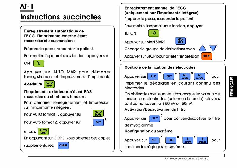
1AT-1 Mode d'emploi art. n°. 2.510171 g
1AT-1 Mode d'emploi art. n°. 2.510171 g
FRAN
ÇAIS
FRAN
ÇAIS
AAAAATTTTT-1-1-1-1-1
Enregistrement automatique del'ECG, l'imprimante externe étantraccordée et sous tension :
Préparer la peau, raccorder le patient.
Pour mettre l'appareil sous tension, appuyer sur
ON
Appuyer sur AUTO MAR pour démarrerl'enregistrement et l'impression sur l'imprimante
extérieure
l'imprimante extérieure n'étant PASraccordée ou étant hors tension :Pour démarrer l'enregistrement et l'impressionsur l'imprimante intégrée :
Pour AUTO format 1, appuyer sur
Pour Auto format 2, appuyer sur
et puis
En appuyant sur COPIE, vous obtenez des copies
supplémentaires.
Enregistrement manuel de l'ECG(uniquement sur l'imprimante intégrée)Préparer la peau, raccorder le patient.
Pour mettre l'appareil sous tension, appuyer
sur ON
Appuyer sur MAN START
Changer le groupe de dérivations avec
Appuyer sur STOP pour arrêter l'impression
Contrôle de la fixation des électrodes
Appuyer sur pour
imprimer le décalage en courant continu desélectrodes.On obtient les meilleurs résultats lorsque les valeurs detension des électrodes (colonne de droite) relevéessont comprises entre +50mV et -50mV.Activation/Désactivation du filtre
Appuyer sur pour activer/désactiver le filtre
de myogrammeConfiguration du système
Appuyer sur pour
imprimer les réglages du système.
Instructions succinctesInstructions succinctesInstructions succinctesInstructions succinctesInstructions succinctes
AAAAATTTTT-1-1-1-1-1
Enregistrement automatique de l'ECG,l'imprimante externe étant raccordée et soustension :
Préparer la peau, raccorder le patient.
Pour mettre l'appareil sous tension, appuyer sur
ON
Appuyer sur AUTO MAR pour démarrerl'enregistrement et l'impression sur l'imprimante
extérieure
l'imprimante extérieure n'étant PASraccordée ou étant hors tension :Pour démarrer l'enregistrement et l'impressionsur l'imprimante intégrée :
Pour AUTO format 1, appuyer sur
Pour Auto format 2, appuyer sur
et puis
En appuyant sur COPIE, vous obtenez des copies
supplémentaires.
Enregistrement manuel de l'ECG (uniquement surl'imprimante intégrée)Préparer la peau, raccorder le patient.
Pour mettre l'appareil sous tension, appuyer
sur ON
Appuyer sur MAN START
Changer le groupe de dérivations avec
Appuyer sur STOP pour arrêter l'impression
Contrôle de la fixation des électrodes
Appuyer sur pour
imprimer le décalage en courant continu desélectrodes.On obtient les meilleurs résultats lorsque les valeurs detension des électrodes (colonne de droite) relevéessont comprises entre +50mV et -50mV.Activation/Désactivation du filtre
Appuyer sur pour activer/désactiver le filtre
de myogrammeConfiguration du système
Appuyer sur pour
imprimer les réglages du système.
Instructions succinctesInstructions succinctesInstructions succinctesInstructions succinctesInstructions succinctes

2
2
IntroductionIntroductionIntroductionIntroductionIntroduction
IntroductionIntroductionIntroductionIntroductionIntroduction
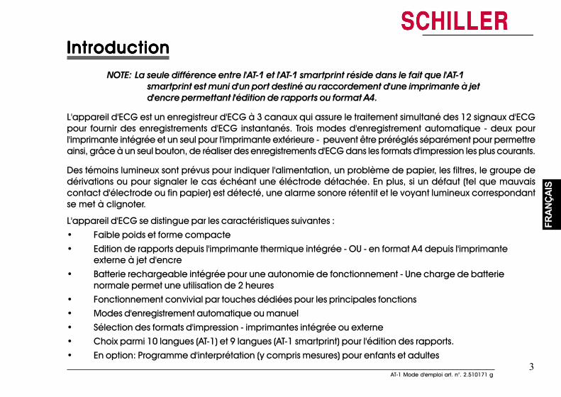
3AT-1 Mode d'emploi art. n°. 2.510171 g
3AT-1 Mode d'emploi art. n°. 2.510171 g
FRAN
ÇAIS
FRAN
ÇAIS
IntroductionIntroductionIntroductionIntroductionIntroductionNOTE: La seule différence entre l'AT-1 et l'AT-1 smartprint réside dans le fait que l'AT-1
smartprint est muni d'un port destiné au raccordement d'une imprimante à jetd'encre permettant l'édition de rapports ou format A4.
L'appareil d'ECG est un enregistreur d'ECG à 3 canaux qui assure le traitement simultané des 12 signaux d'ECGpour fournir des enregistrements d'ECG instantanés. Trois modes d'enregistrement automatique - deux pourl'imprimante intégrée et un seul pour l'imprimante extérieure - peuvent être préréglés séparément pour permettreainsi, grâce à un seul bouton, de réaliser des enregistrements d'ECG dans les formats d'impression les plus courants.
Des témoins lumineux sont prévus pour indiquer l'alimentation, un problème de papier, les filtres, le groupe dedérivations ou pour signaler le cas échéant une éléctrode détachée. En plus, si un défaut (tel que mauvaiscontact d'électrode ou fin papier) est détecté, une alarme sonore rétentit et le voyant lumineux correspondantse met à clignoter.
L'appareil d'ECG se distingue par les caractéristiques suivantes :• Faible poids et forme compacte• Edition de rapports depuis l'imprimante thermique intégrée - OU - en format A4 depuis l'imprimante
externe à jet d'encre• Batterie rechargeable intégrée pour une autonomie de fonctionnement - Une charge de batterie
normale permet une utilisation de 2 heures• Fonctionnement convivial par touches dédiées pour les principales fonctions• Modes d'enregistrement automatique ou manuel• Sélection des formats d'impression - imprimantes intégrée ou externe• Choix parmi 10 langues (AT-1) et 9 langues (AT-1 smartprint) pour l'édition des rapports.• En option: Programme d'interprétation (y compris mesures) pour enfants et adultes
IntroductionIntroductionIntroductionIntroductionIntroductionNOTE: La seule différence entre l'AT-1 et l'AT-1 smartprint réside dans le fait que l'AT-1
smartprint est muni d'un port destiné au raccordement d'une imprimante à jetd'encre permettant l'édition de rapports ou format A4.
L'appareil d'ECG est un enregistreur d'ECG à 3 canaux qui assure le traitement simultané des 12 signaux d'ECGpour fournir des enregistrements d'ECG instantanés. Trois modes d'enregistrement automatique - deux pourl'imprimante intégrée et un seul pour l'imprimante extérieure - peuvent être préréglés séparément pour permettreainsi, grâce à un seul bouton, de réaliser des enregistrements d'ECG dans les formats d'impression les plus courants.
Des témoins lumineux sont prévus pour indiquer l'alimentation, un problème de papier, les filtres, le groupe dedérivations ou pour signaler le cas échéant une éléctrode détachée. En plus, si un défaut (tel que mauvaiscontact d'électrode ou fin papier) est détecté, une alarme sonore rétentit et le voyant lumineux correspondantse met à clignoter.
L'appareil d'ECG se distingue par les caractéristiques suivantes :
• Faible poids et forme compacte• Edition de rapports depuis l'imprimante thermique intégrée - OU - en format A4 depuis l'imprimante
externe à jet d'encre• Batterie rechargeable intégrée pour une autonomie de fonctionnement - Une charge de batterie
normale permet une utilisation de 2 heures• Fonctionnement convivial par touches dédiées pour les principales fonctions• Modes d'enregistrement automatique ou manuel• Sélection des formats d'impression - imprimantes intégrée ou externe• Choix parmi 10 langues (AT-1) et 9 langues (AT-1 smartprint) pour l'édition des rapports.• En option: Programme d'interprétation (y compris mesures) pour enfants et adultes
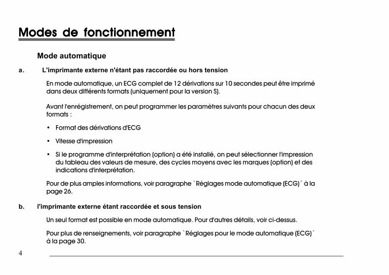
4
4
Modes de fonctionnementModes de fonctionnementModes de fonctionnementModes de fonctionnementModes de fonctionnement
Mode automatiquea. L'imprimante externe n'étant pas raccordée ou hors tension
En mode automatique, un ECG complet de 12 dérivations sur 10 secondes peut être imprimédans deux différents formats (uniquement pour la version S).
Avant l'enrégistrement, on peut programmer les paramètres suivants pour chacun des deuxformats :
• Format des dérivations d'ECG
• Vitesse d'impression
• Si le programme d'interprétation (option) a été installé, on peut sélectionner l'impressiondu tableau des valeurs de mesure, des cycles moyens avec les marques (option) et desindications d'interprétation.
Pour de plus amples informations, voir paragraphe ̀ Réglages mode automatique (ECG)´ à lapage 26.
b. l'imprimante externe étant raccordée et sous tension
Un seul format est possible en mode automatique. Pour d'autres détails, voir ci-dessus.
Pour plus de renseignements, voir paragraphe ̀ Réglages pour le mode automatique (ECG)´à la page 30.
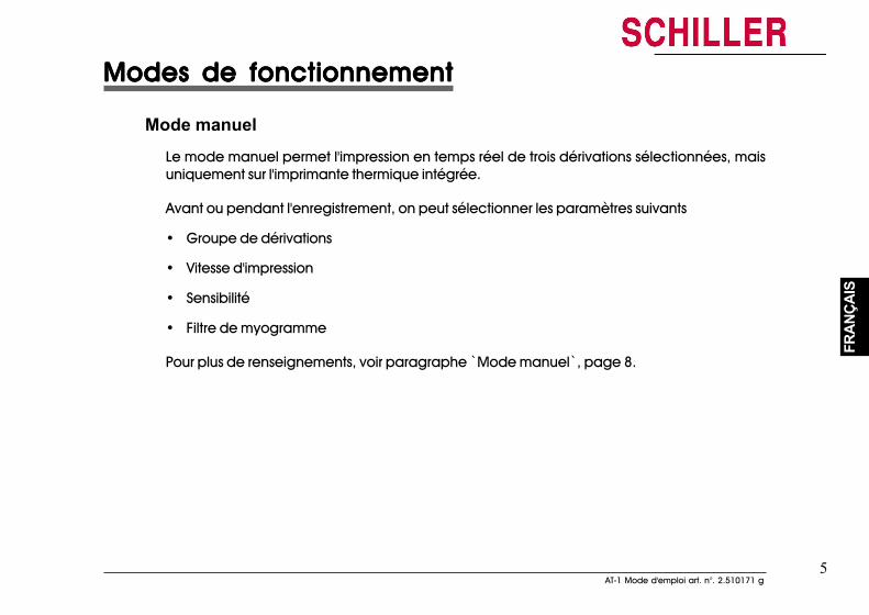
5AT-1 Mode d'emploi art. n°. 2.510171 g
5AT-1 Mode d'emploi art. n°. 2.510171 g
FRAN
ÇAIS
FRAN
ÇAIS
Modes de fonctionnementModes de fonctionnementModes de fonctionnementModes de fonctionnementModes de fonctionnement
Mode manuelLe mode manuel permet l'impression en temps réel de trois dérivations sélectionnées, maisuniquement sur l'imprimante thermique intégrée.
Avant ou pendant l'enregistrement, on peut sélectionner les paramètres suivants
• Groupe de dérivations
• Vitesse d'impression
• Sensibilité
• Filtre de myogramme
Pour plus de renseignements, voir paragraphe ̀ Mode manuel`, page 8.
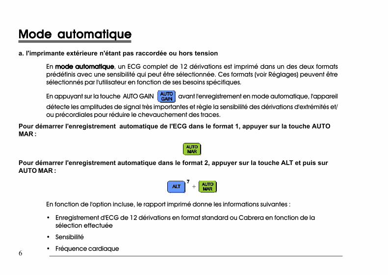
6
6
Mode automatiqueMode automatiqueMode automatiqueMode automatiqueMode automatiquea. l'imprimante extérieure n'étant pas raccordée ou hors tension
En mode automatiquemode automatiquemode automatiquemode automatiquemode automatique, un ECG complet de 12 dérivations est imprimé dans un des deux formatsprédéfinis avec une sensibilité qui peut être sélectionnée. Ces formats (voir Réglages) peuvent êtresélectionnés par l'utilisateur en fonction de ses besoins spécifiques.
En appuyant sur la touche AUTO GAIN avant l'enregistrement en mode automatique, l'appareil
détecte les amplitudes de signal très importantes et règle la sensibilité des dérivations d'extrémités et/ou précordiales pour réduire le chevauchement des traces.
Pour démarrer l'enregistrement automatique de l'ECG dans le format 1, appuyer sur la touche AUTOMAR :
Pour démarrer l'enregistrement automatique dans le format 2, appuyer sur la touche ALT et puis surAUTO MAR :
+
En fonction de l'option incluse, le rapport imprimé donne les informations suivantes :
• Enregistrement d'ECG de 12 dérivations en format standard ou Cabrera en fonction de lasélection effectuée
• Sensibilité
• Fréquence cardiaque
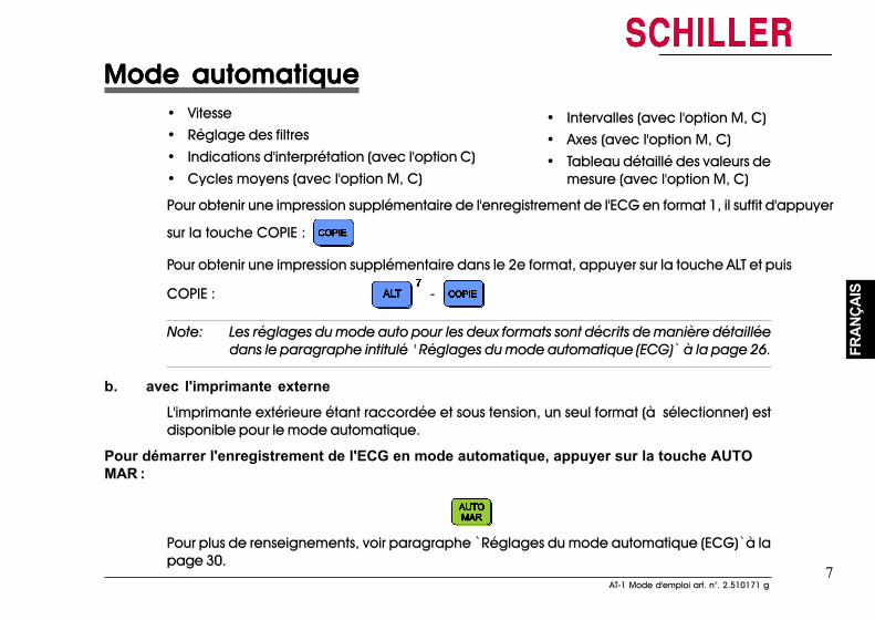
7AT-1 Mode d'emploi art. n°. 2.510171 g
7AT-1 Mode d'emploi art. n°. 2.510171 g
FRAN
ÇAIS
FRAN
ÇAIS
Mode automatiqueMode automatiqueMode automatiqueMode automatiqueMode automatique• Vitesse• Réglage des filtres• Indications d'interprétation (avec l'option C)• Cycles moyens (avec l'option M, C)
• Intervalles (avec l'option M, C)• Axes (avec l'option M, C)• Tableau détaillé des valeurs de
mesure (avec l'option M, C)
Pour obtenir une impression supplémentaire de l'enregistrement de l'ECG en format 1, il suffit d'appuyer
sur la touche COPIE :
Pour obtenir une impression supplémentaire dans le 2e format, appuyer sur la touche ALT et puis
COPIE : -
Note: Les réglages du mode auto pour les deux formats sont décrits de manière détailléedans le paragraphe intitulé ' Réglages du mode automatique (ECG)` à la page 26.
b. avec l'imprimante externeL'imprimante extérieure étant raccordée et sous tension, un seul format (à sélectionner) estdisponible pour le mode automatique.
Pour démarrer l'enregistrement de l'ECG en mode automatique, appuyer sur la touche AUTOMAR :
Pour plus de renseignements, voir paragraphe ̀ Réglages du mode automatique (ECG)`à lapage 30.
Mode automatiqueMode automatiqueMode automatiqueMode automatiqueMode automatique• Vitesse• Réglage des filtres• Indications d'interprétation (avec l'option C)• Cycles moyens (avec l'option M, C)
• Intervalles (avec l'option M, C)• Axes (avec l'option M, C)• Tableau détaillé des valeurs de
mesure (avec l'option M, C)Pour obtenir une impression supplémentaire de l'enregistrement de l'ECG en format 1, il suffit d'appuyer
sur la touche COPIE :
Pour obtenir une impression supplémentaire dans le 2e format, appuyer sur la touche ALT et puis
COPIE : -
Note: Les réglages du mode auto pour les deux formats sont décrits de manière détailléedans le paragraphe intitulé ' Réglages du mode automatique (ECG)` à la page 26.
b. avec l'imprimante externeL'imprimante extérieure étant raccordée et sous tension, un seul format (à sélectionner) estdisponible pour le mode automatique.
Pour démarrer l'enregistrement de l'ECG en mode automatique, appuyer sur la touche AUTOMAR :
Pour plus de renseignements, voir paragraphe ̀ Réglages du mode automatique (ECG)`à lapage 30.
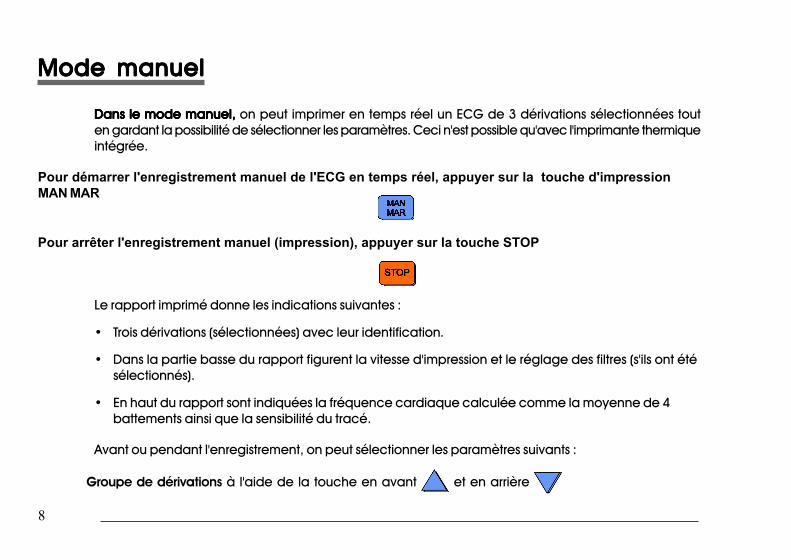
8
8
Mode manuelMode manuelMode manuelMode manuelMode manuel
Dans le mode manuel,Dans le mode manuel,Dans le mode manuel,Dans le mode manuel,Dans le mode manuel, on peut imprimer en temps réel un ECG de 3 dérivations sélectionnées touten gardant la possibilité de sélectionner les paramètres. Ceci n'est possible qu'avec l'imprimante thermiqueintégrée.
Pour démarrer l'enregistrement manuel de l'ECG en temps réel, appuyer sur la touche d'impressionMAN MAR
Pour arrêter l'enregistrement manuel (impression), appuyer sur la touche STOP
Le rapport imprimé donne les indications suivantes :
• Trois dérivations (sélectionnées) avec leur identification.
• Dans la partie basse du rapport figurent la vitesse d'impression et le réglage des filtres (s'ils ont étésélectionnés).
• En haut du rapport sont indiquées la fréquence cardiaque calculée comme la moyenne de 4battements ainsi que la sensibilité du tracé.
Avant ou pendant l'enregistrement, on peut sélectionner les paramètres suivants :
Groupe de dérivations à l'aide de la touche en avant et en arrière
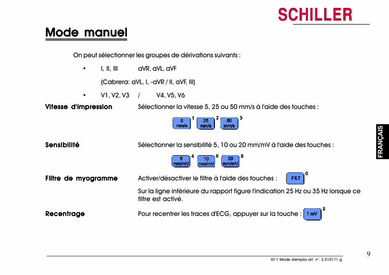
9AT-1 Mode d'emploi art. n°. 2.510171 g
9AT-1 Mode d'emploi art. n°. 2.510171 g
FRAN
ÇAIS
FRAN
ÇAIS
Mode manuelMode manuelMode manuelMode manuelMode manuel
On peut sélectionner les groupes de dérivations suivants :
• I, II, III aVR, aVL, aVF
(Cabrera: aVL, I, -aVR / II, aVF, III)
• V1, V2, V3 / V4, V5, V6
Vitesse d'impressionVitesse d'impressionVitesse d'impressionVitesse d'impressionVitesse d'impression Sélectionner la vitesse 5, 25 ou 50 mm/s à l'aide des touches :
Sensibil itéSensibil itéSensibil itéSensibil itéSensibil ité Sélectionner la sensibilité 5, 10 ou 20 mm/mV à l'aide des touches :
Filtre de myogrammeFiltre de myogrammeFiltre de myogrammeFiltre de myogrammeFiltre de myogramme Activer/désactiver le filtre à l'aide des touches :
Sur la ligne inférieure du rapport figure l'indication 25 Hz ou 35 Hz lorsque cefiltre est activé.
RecentrageRecentrageRecentrageRecentrageRecentrage Pour recentrer les traces d'ECG, appuyer sur la touche :
10
10
Lieu d'installation & alimentationLieu d'installation & alimentationLieu d'installation & alimentationLieu d'installation & alimentationLieu d'installation & alimentation
Lieu d'installationL'appareil doit être entreposé ou utilisé à l'abri de toute humidité ou poussière. Par ailleurs, éviter qu'ilsoit soumis à une exposition directe aux rayons solaires ou à d'autres sources de chaleur. Veiller à ceque l'appareil n'entre pas en contact avec des vapeurs ou liquides contenant des acides ce quirisquerait d'entraîner des dommages irréparables. Ne pas installer l'appareil à proximité d'installationsde radiographie ou de diathermie, de puissants moteurs ou transformateurs. L'appareil doit être installésur une surface plane et ne doit en aucun cas être utilisé dans des atmosphères explosives.
AlimentationLe raccordement secteur est situé sur la face arrière de l'appareil. Le voyant lumineux du clavier estallumé lorsque l'appareil est raccordé au secteur. L'appareil peut fonctionner sur secteur ou par labatterie intégrée, rechargeable. Le type d'alimentation est indiqué par le témoin lumineuxcorrespondant. Lorsque la charge de la batterie est faible, le voyant lumineux de la batterie se met àclignoter.
Pour recharger la batterie, raccorder l'appareil sur le secteur à l'aide du câble d'alimentation fourni.La durée de chargement d'une batterie complètement déchargée est inférieure à 15 heures (60% enmoins de 3 heures, 90% en moins de 7 heures). Une batterie complètement chargée permet uneutilisation normale de 2 heures. L'appareil peut rester raccordé sur le secteur sans aucun risque dedétérioration ni pour la batterie ni pour l'appareil.
Lieu d'installation & alimentationLieu d'installation & alimentationLieu d'installation & alimentationLieu d'installation & alimentationLieu d'installation & alimentation
Lieu d'installationL'appareil doit être entreposé ou utilisé à l'abri de toute humidité ou poussière. Par ailleurs, éviter qu'ilsoit soumis à une exposition directe aux rayons solaires ou à d'autres sources de chaleur. Veiller à ceque l'appareil n'entre pas en contact avec des vapeurs ou liquides contenant des acides ce quirisquerait d'entraîner des dommages irréparables. Ne pas installer l'appareil à proximité d'installationsde radiographie ou de diathermie, de puissants moteurs ou transformateurs. L'appareil doit être installésur une surface plane et ne doit en aucun cas être utilisé dans des atmosphères explosives.
Alimentation
Le raccordement secteur est situé sur la face arrière de l'appareil. Le voyant lumineux du clavier estallumé lorsque l'appareil est raccordé au secteur. L'appareil peut fonctionner sur secteur ou par labatterie intégrée, rechargeable. Le type d'alimentation est indiqué par le témoin lumineuxcorrespondant. Lorsque la charge de la batterie est faible, le voyant lumineux de la batterie se met àclignoter.
Pour recharger la batterie, raccorder l'appareil sur le secteur à l'aide du câble d'alimentation fourni.La durée de chargement d'une batterie complètement déchargée est inférieure à 15 heures (60% enmoins de 3 heures, 90% en moins de 7 heures). Une batterie complètement chargée permet uneutilisation normale de 2 heures. L'appareil peut rester raccordé sur le secteur sans aucun risque dedétérioration ni pour la batterie ni pour l'appareil.
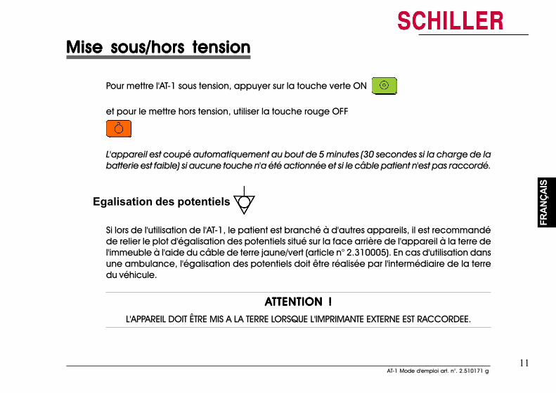
11AT-1 Mode d'emploi art. n°. 2.510171 g
11AT-1 Mode d'emploi art. n°. 2.510171 g
FRAN
ÇAIS
FRAN
ÇAIS
Mise sous/hors tensionMise sous/hors tensionMise sous/hors tensionMise sous/hors tensionMise sous/hors tension
Pour mettre l'AT-1 sous tension, appuyer sur la touche verte ON
et pour le mettre hors tension, utiliser la touche rouge OFF
L'appareil est coupé automatiquement au bout de 5 minutes (30 secondes si la charge de labatterie est faible) si aucune touche n'a été actionnée et si le câble patient n'est pas raccordé.
Egalisation des potentiels
Si lors de l'utilisation de l'AT-1, le patient est branché à d'autres appareils, il est recommandéde relier le plot d'égalisation des potentiels situé sur la face arrière de l'appareil à la terre del'immeuble à l'aide du câble de terre jaune/vert (article n° 2.310005). En cas d'utilisation dansune ambulance, l'égalisation des potentiels doit être réalisée par l'intermédiaire de la terredu véhicule.
AAAAATTENTION !TTENTION !TTENTION !TTENTION !TTENTION !
L'APPAREIL DOIT ÊTRE MIS A LA TERRE LORSQUE L'IMPRIMANTE EXTERNE EST RACCORDEE.
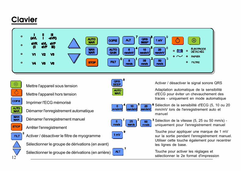
12
12
ClavierClavierClavierClavierClavier
Mettre l'appareil sous tension
Mettre l'appareil hors tension
Imprimer l'ECG mémorisé
Démarrer l'enregistrement automatique
Démarrer l'enregistrement manuel
Arrêter l'enregistrement
Activer / désactiver le filtre de myogramme
Sélectionner le groupe de dérivations (en avant)
Sélectionner le groupe de dérivations (en arrière)
Activer / désactiver le signal sonore QRS
Adaptation automatique de la sensibilitéd'ECG pour éviter un chevauchement destraces - uniquement en mode automatique
Sélection de la sensibilité d'ECG (5, 10 ou 20mm/mV lors de l'enregistrement auto etmanuel
Sélection de la vitesse (5, 25 ou 50 mm/s) -uniquement pour l'enregistrement manuel
Touche pour appliquer une marque de 1 mVsur la sortie pendant l'enregistrement manuel.Utiliser cette touche également pour recentrerles lignes de base.
Touche pour activer les réglages etsélectionner le 2e format d'impression
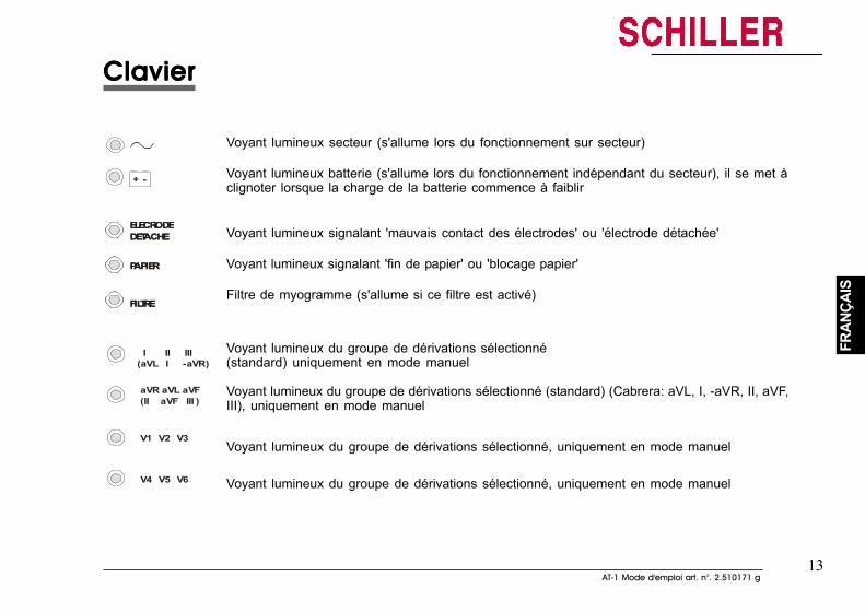
13AT-1 Mode d'emploi art. n°. 2.510171 g
13AT-1 Mode d'emploi art. n°. 2.510171 g
FRAN
ÇAIS
FRAN
ÇAIS
ClavierClavierClavierClavierClavier
I II III
V1 V2 V3
aVR aVL aVF(II aVF III )
V4 V5 V6
(aVL I -aVR )
ELECRODEDETACHE
PAPIER
FILTRE
+ -
Voyant lumineux secteur (s'allume lors du fonctionnement sur secteur)
Voyant lumineux batterie (s'allume lors du fonctionnement indépendant du secteur), il se met àclignoter lorsque la charge de la batterie commence à faiblir
Voyant lumineux signalant 'mauvais contact des électrodes' ou 'électrode détachée'
Voyant lumineux signalant 'fin de papier' ou 'blocage papier'
Filtre de myogramme (s'allume si ce filtre est activé)
Voyant lumineux du groupe de dérivations sélectionné(standard) uniquement en mode manuel
Voyant lumineux du groupe de dérivations sélectionné (standard) (Cabrera: aVL, I, -aVR, II, aVF,III), uniquement en mode manuel
Voyant lumineux du groupe de dérivations sélectionné, uniquement en mode manuel
Voyant lumineux du groupe de dérivations sélectionné, uniquement en mode manuel
ELECRODEDETACHE
PAPIER
FILTRE
ELECRODEDETACHE
PAPIER
FILTRE
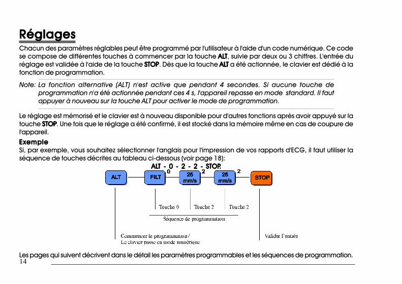
14
14
RéglagesRéglagesRéglagesRéglagesRéglagesChacun des paramètres réglables peut être programmé par l'utilisateur à l'aide d'un code numérique. Ce codese compose de différentes touches à commencer par la touche ALALALALALTTTTT, suivie par deux ou 3 chiffres. L'entrée duréglage est validée à l'aide de la touche STOPSTOPSTOPSTOPSTOP. Dès que la touche ALALALALALTTTTT a été actionnée, le clavier est dédié à lafonction de programmation.
Note: La fonction alternative (ALT) n'est active que pendant 4 secondes. Si aucune touche deprogrammation n'a été actionnée pendant ces 4 s, l'appareil repasse en mode standard. Il fautappuyer à nouveau sur la touche ALT pour activer le mode de programmation.
Le réglage est mémorisé et le clavier est à nouveau disponible pour d'autres fonctions après avoir appuyé sur latouche STOPSTOPSTOPSTOPSTOP. Une fois que le réglage a été confirmé, il est stocké dans la mémoire même en cas de coupure del'appareil.ExempleExempleExempleExempleExempleSi, par exemple, vous souhaitez sélectionner l'anglais pour l'impression de vos rapports d'ECG, il faut utiliser laséquence de touches décrites au tableau ci-dessous (voir page 18):
ALALALALALT - 0 - 2 - 2 - STOPT - 0 - 2 - 2 - STOPT - 0 - 2 - 2 - STOPT - 0 - 2 - 2 - STOPT - 0 - 2 - 2 - STOP.....
Les pages qui suivent décrivent dans le détail les paramètres programmables et les séquences de programmation.
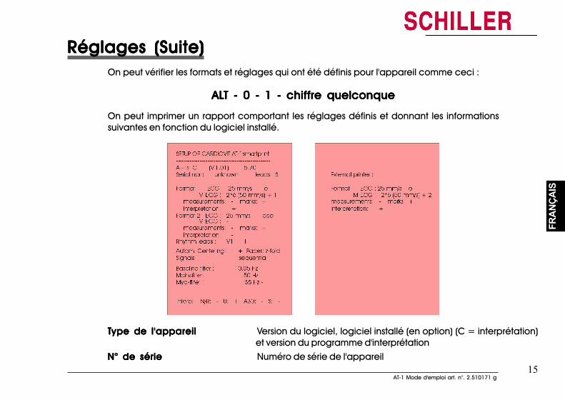
15AT-1 Mode d'emploi art. n°. 2.510171 g
15AT-1 Mode d'emploi art. n°. 2.510171 g
FRAN
ÇAIS
FRAN
ÇAIS
Réglages (Suite)Réglages (Suite)Réglages (Suite)Réglages (Suite)Réglages (Suite)On peut vérifier les formats et réglages qui ont été définis pour l'appareil comme ceci :
ALALALALALT - 0 - 1 - chiffre quelconqueT - 0 - 1 - chiffre quelconqueT - 0 - 1 - chiffre quelconqueT - 0 - 1 - chiffre quelconqueT - 0 - 1 - chiffre quelconque
On peut imprimer un rapport comportant les réglages définis et donnant les informationssuivantes en fonction du logiciel installé.
TTTTType de l'appareilype de l'appareilype de l'appareilype de l'appareilype de l'appareil Version du logiciel, logiciel installé (en option) (C = interprétation)et version du programme d'interprétation
N° de sérieN° de sérieN° de sérieN° de sérieN° de série Numéro de série de l'appareil
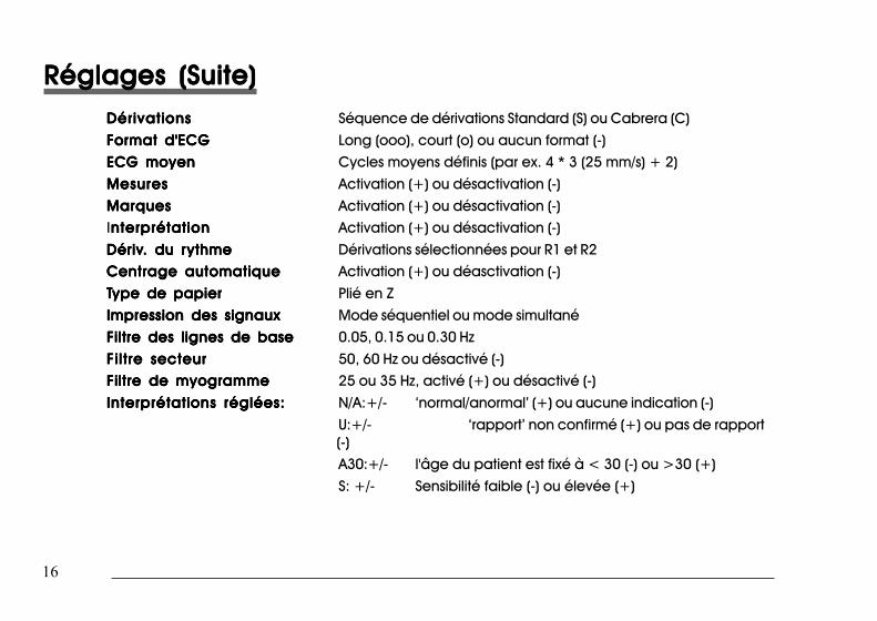
16
16
Réglages (Suite)Réglages (Suite)Réglages (Suite)Réglages (Suite)Réglages (Suite)DérivationsDérivationsDérivationsDérivationsDérivations Séquence de dérivations Standard (S) ou Cabrera (C)
Format d'ECGFormat d'ECGFormat d'ECGFormat d'ECGFormat d'ECG Long (ooo), court (o) ou aucun format (-)ECG moyenECG moyenECG moyenECG moyenECG moyen Cycles moyens définis (par ex. 4 * 3 (25 mm/s) + 2)
MesuresMesuresMesuresMesuresMesures Activation (+) ou désactivation (-)
MarquesMarquesMarquesMarquesMarques Activation (+) ou désactivation (-)Interprétationnterprétationnterprétationnterprétationnterprétation Activation (+) ou désactivation (-)
DérivDérivDérivDérivDériv. du r. du r. du r. du r. du rythmeythmeythmeythmeythme Dérivations sélectionnées pour R1 et R2Centrage automatiqueCentrage automatiqueCentrage automatiqueCentrage automatiqueCentrage automatique Activation (+) ou déasctivation (-)
TTTTType de papierype de papierype de papierype de papierype de papier Plié en Z
Impression des signauxImpression des signauxImpression des signauxImpression des signauxImpression des signaux Mode séquentiel ou mode simultanéFiltre des lignes de baseFiltre des lignes de baseFiltre des lignes de baseFiltre des lignes de baseFiltre des lignes de base 0.05, 0.15 ou 0.30 Hz
Filtre secteurFiltre secteurFiltre secteurFiltre secteurFiltre secteur 50, 60 Hz ou désactivé (-)Filtre de myogrammeFiltre de myogrammeFiltre de myogrammeFiltre de myogrammeFiltre de myogramme 25 ou 35 Hz, activé (+) ou désactivé (-)
Interprétations réglées:Interprétations réglées:Interprétations réglées:Interprétations réglées:Interprétations réglées: N/A:+/- ‘normal/anormal’ (+) ou aucune indication (-)U:+/- ‘rapport’ non confirmé (+) ou pas de rapport(-)A30:+/- l'âge du patient est fixé à < 30 (-) ou >30 (+)S: +/- Sensibilité faible (-) ou élevée (+)
Réglages (Suite)Réglages (Suite)Réglages (Suite)Réglages (Suite)Réglages (Suite)DérivationsDérivationsDérivationsDérivationsDérivations Séquence de dérivations Standard (S) ou Cabrera (C)Format d'ECGFormat d'ECGFormat d'ECGFormat d'ECGFormat d'ECG Long (ooo), court (o) ou aucun format (-)
ECG moyenECG moyenECG moyenECG moyenECG moyen Cycles moyens définis (par ex. 4 * 3 (25 mm/s) + 2)
MesuresMesuresMesuresMesuresMesures Activation (+) ou désactivation (-)MarquesMarquesMarquesMarquesMarques Activation (+) ou désactivation (-)Interprétationnterprétationnterprétationnterprétationnterprétation Activation (+) ou désactivation (-)DérivDérivDérivDérivDériv. du r. du r. du r. du r. du rythmeythmeythmeythmeythme Dérivations sélectionnées pour R1 et R2
Centrage automatiqueCentrage automatiqueCentrage automatiqueCentrage automatiqueCentrage automatique Activation (+) ou déasctivation (-)
TTTTType de papierype de papierype de papierype de papierype de papier Plié en ZImpression des signauxImpression des signauxImpression des signauxImpression des signauxImpression des signaux Mode séquentiel ou mode simultané
Filtre des lignes de baseFiltre des lignes de baseFiltre des lignes de baseFiltre des lignes de baseFiltre des lignes de base 0.05, 0.15 ou 0.30 Hz
Filtre secteurFiltre secteurFiltre secteurFiltre secteurFiltre secteur 50, 60 Hz ou désactivé (-)Filtre de myogrammeFiltre de myogrammeFiltre de myogrammeFiltre de myogrammeFiltre de myogramme 25 ou 35 Hz, activé (+) ou désactivé (-)
Interprétations réglées:Interprétations réglées:Interprétations réglées:Interprétations réglées:Interprétations réglées: N/A:+/- ‘normal/anormal’ (+) ou aucune indication (-)U:+/- ‘rapport’ non confirmé (+) ou pas de rapport (-)A30:+/- l'âge du patient est fixé à < 30 (-) ou >30 (+)S: +/- Sensibilité faible (-) ou élevée (+)
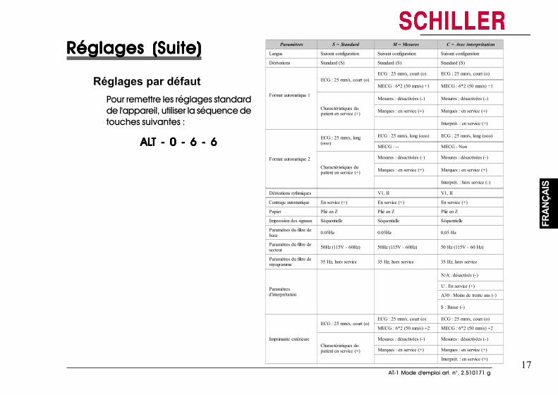
17AT-1 Mode d'emploi art. n°. 2.510171 g
17AT-1 Mode d'emploi art. n°. 2.510171 g
FRAN
ÇAIS
FRAN
ÇAIS
Réglages (Suite)Réglages (Suite)Réglages (Suite)Réglages (Suite)Réglages (Suite)
Réglages par défautPour remettre les réglages standardde l'appareil, utiliser la séquence detouches suivantes :
ALALALALALT - 0 - 6 - 6T - 0 - 6 - 6T - 0 - 6 - 6T - 0 - 6 - 6T - 0 - 6 - 6
Paramètres S = Standard M = Mesures C = Avec interprétation
Langue Suivant configuration Suivant configuration Suivant configuration
Dérivations Standard (S) Standard (S) Standard (S)
Format automatique 1
ECG : 25 mm/s, court (o)ECG : 25 mm/s, court (o) ECG : 25 mm/s, court (o)
MECG : 6*2 (50 mm/s) +1 MECG : 6*2 (50 mm/s) +1
Charactéristiques dupatient en service (+)
Mesures : désactivées (-) Mesures : désactivées (-)
Marques : en service (+) Marques : en service (+)
Interprét. : en service (+)
Format automatique 2
ECG : 25 mm/s, long(ooo)
ECG : 25 mm/s, long (ooo) ECG : 25 mm/s, long (ooo)
MECG : -- MECG : Non
Charactéristiques dupatient en service (+)
Mesures : désactivées (-) Mesures : désactivées (-)
Marques : en service (+) Marques : en service (+)
Interprét. : hors service (-)
Dérivations rythmiques V1, II V1, II
Centrage automatique En service (+) En service (+) En service (+)
Papier Plié en Z Plié en Z Plié en Z
Impression des signaux Séquentielle Séquentielle Séquentielle
Paramètres du filtre debase 0.05Hz 0.05Hz 0,05 Hz
Paramètres du filtre desecteur 50Hz (115V - 60Hz) 50Hz (115V - 60Hz) 50 Hz (115V - 60 Hz)
Paramètres du filtre demyogramme 35 Hz, hors service 35 Hz, hors service 35 Hz, hors service
Paramètresd'interprétation
N/A : désactivés (-)
U : En service (+)
A30 : Moins de trente ans (-)
S : Basse (-)
Imprimante extérieure
ECG : 25 mm/s, court (o)ECG : 25 mm/s, court (o) ECG : 25 mm/s, court (o)
MECG : 6*2 (50 mm/s) +2 MECG : 6*2 (50 mm/s) +2
Charactéristiques dupatient en service (+)
Mesures : désactivées (-) Mesures : désactivées (-)
Marques : en service (+) Marques : en service (+)
Interprét. : en service (+)
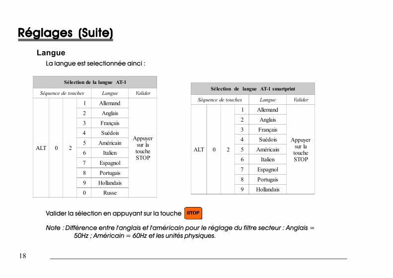
18
18
Réglages (Suite)Réglages (Suite)Réglages (Suite)Réglages (Suite)Réglages (Suite)
LangueLa langue est selectionnée ainci :
Sélection de la langue AT-1
Séquence de touches Langue Valider
ALT 0 2
1 Allemand
Appuyersur latoucheSTOP
2 Anglais
3 Français
4 Suédois
5 Américain
6 Italien
7 Espagnol
8 Portugais
9 Hollandais
0 Russe
Sélection de langue AT-1 smartprint
Séquence de touches Langue Valider
ALT 0 2
1 Allemand
Appuyersur latoucheSTOP
2 Anglais
3 Français
4 Suédois
5 Américain
6 Italien
7 Espagnol
8 Portugais
9 Hollandais
Valider la sélection en appuyant sur la touche
Note : Différence entre l'anglais et l'américain pour le réglage du filtre secteur : Anglais =50Hz ; Américain = 60Hz et les unités physiques.
Réglages (Suite)Réglages (Suite)Réglages (Suite)Réglages (Suite)Réglages (Suite)
LangueLa langue est selectionnée ainci :
Sélection de la langue AT-1
Séquence de touches Langue Valider
ALT 0 2
1 Allemand
Appuyersur latoucheSTOP
2 Anglais
3 Français
4 Suédois
5 Américain
6 Italien
7 Espagnol
8 Portugais
9 Hollandais
0 Russe
Sélection de langue AT-1 smartprint
Séquence de touches Langue Valider
ALT 0 2
1 Allemand
Appuyersur latoucheSTOP
2 Anglais
3 Français
4 Suédois
5 Américain
6 Italien
7 Espagnol
8 Portugais
9 Hollandais
Valider la sélection en appuyant sur la touche
Note : Différence entre l'anglais et l'américain pour le réglage du filtre secteur : Anglais= 50Hz ; Américain = 60Hz et les unités physiques.
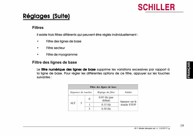
19AT-1 Mode d'emploi art. n°. 2.510171 g
19AT-1 Mode d'emploi art. n°. 2.510171 g
FRAN
ÇAIS
FRAN
ÇAIS
Réglages (Suite)Réglages (Suite)Réglages (Suite)Réglages (Suite)Réglages (Suite)
FiltresIl existe trois filtres différents qui peuvent être réglés individuellement :
• Filtre des lignes de base
• Filtre secteur
• Filtre de myogramme
Filtre des lignes de base
Le filtre numérique des lignes de base filtre numérique des lignes de base filtre numérique des lignes de base filtre numérique des lignes de base filtre numérique des lignes de base supprime les variations excessives par rapport àla ligne de base. Pour régler les différentes options de ce filtre, appuyer sur les touchessuivantes :
Filtre des lignes de base
Séquence de touches Réglage du filtre Valider
ALT 50 0.05 Hz (par
défaut) Appuyer sur latouche STOP1 0.15 Hz
3 0.30 Hz
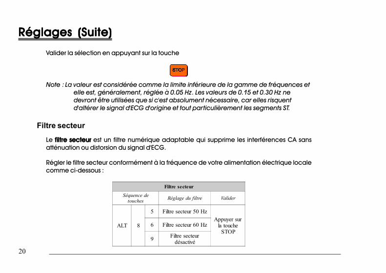
20
20
Réglages (Suite)Réglages (Suite)Réglages (Suite)Réglages (Suite)Réglages (Suite)
Valider la sélection en appuyant sur la touche
Note : La valeur est considérée comme la limite inférieure de la gamme de fréquences etelle est, généralement, réglée à 0.05 Hz. Les valeurs de 0.15 et 0.30 Hz nedevront être utilisées que si c'est absolument nécessaire, car elles risquentd'altérer le signal d'ECG d'origine et tout particulièrement les segments ST.
Filtre secteur
Le filtre secteurfiltre secteurfiltre secteurfiltre secteurfiltre secteur est un filtre numérique adaptable qui supprime les interférences CA sansatténuation ou distorsion du signal d'ECG.
Régler le filtre secteur conformément à la fréquence de votre alimentation électrique localecomme ci-dessous :
Filtre secteur
Séquence detouches Réglage du filtre Valider
ALT 8
5 Filtre secteur 50 HzAppuyer sur
la toucheSTOP
6 Filtre secteur 60 Hz
9 Filtre secteurdésactivé
Réglages (Suite)Réglages (Suite)Réglages (Suite)Réglages (Suite)Réglages (Suite)
Valider la sélection en appuyant sur la touche
Note : La valeur est considérée comme la limite inférieure de la gamme de fréquenceset elle est, généralement, réglée à 0.05 Hz. Les valeurs de 0.15 et 0.30 Hz nedevront être utilisées que si c'est absolument nécessaire, car elles risquentd'altérer le signal d'ECG d'origine et tout particulièrement les segments ST.
Filtre secteurLe filtre secteurfiltre secteurfiltre secteurfiltre secteurfiltre secteur est un filtre numérique adaptable qui supprime les interférences CA sansatténuation ou distorsion du signal d'ECG.
Régler le filtre secteur conformément à la fréquence de votre alimentation électrique localecomme ci-dessous :
Filtre secteur
Séquence detouches Réglage du filtre Valider
ALT 8
5 Filtre secteur 50 HzAppuyer sur
la toucheSTOP
6 Filtre secteur 60 Hz
9 Filtre secteurdésactivé
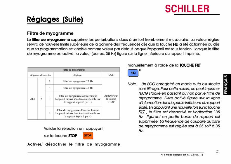
21AT-1 Mode d'emploi art. n°. 2.510171 g
21AT-1 Mode d'emploi art. n°. 2.510171 g
FRAN
ÇAIS
FRAN
ÇAIS
Réglages (Suite)Réglages (Suite)Réglages (Suite)Réglages (Suite)Réglages (Suite)
Filtre de myogrammeLe filtre de myogramme filtre de myogramme filtre de myogramme filtre de myogramme filtre de myogramme supprime les perturbations dues à un fort tremblement musculaire. La valeur régléeservira de nouvelle limite supérieure de la gamme des fréquences dès que la touche FILFILFILFILFILTTTTT a été actionnée ou dèsque sa programmation est choisie comme valeur par défaut lorsque l'appareil est sous tension. Lorsque le filtrede myogramme est activé, la valeur (par ex. 35 Hz) figure sur la ligne inférieure du rapport imprimé.
Filtre de myogramme
Séquence de touches Réglages Valider
ALT 8
2 Filtre de myogramme 25 Hz
Appuyer surla touche
STOP
3 Filtre de myogramme 35 Hz
1Filtre de myogramme activé lorsque
l'appareil est mis sous tension (identifié surle rapport imprimé par +)
8Filtre de myogramme désactivé lorsque
l'appareil est mis hors tension (identifié surle rapport imprimé par -)
Valider la sélection en appuyant
sur la touche STOPSTOPSTOPSTOPSTOP
Activer/ désactiver le fi ltre de myogramme
manuellement à l'aide de la TOUCHE FILTOUCHE FILTOUCHE FILTOUCHE FILTOUCHE FILTTTTT
Note: Un ECG enregistré en mode auto est stockésans filtrage. Pour cette raison, on peut imprimerl'ECG stocké en passant ou non par le filtre demyogramme. Filtre activé figure sur la ligned'information dans la partie inférieure du rapportédité. En appuyant une nouvelle fois sur la toucheFILTFILTFILTFILTFILT , le filtre est désactivé et l'indication `35Hz` figurant en partie basse du rapport estsupprimée. La fréquence de coupure du filtrede myogramme est réglée soit à 25 soit à 35Hz.
Réglages (Suite)Réglages (Suite)Réglages (Suite)Réglages (Suite)Réglages (Suite)
Filtre de myogrammeLe filtre de myogramme filtre de myogramme filtre de myogramme filtre de myogramme filtre de myogramme supprime les perturbations dues à un fort tremblement musculaire. La valeur régléeservira de nouvelle limite supérieure de la gamme des fréquences dès que la touche FILFILFILFILFILTTTTT a été actionnée ou dèsque sa programmation est choisie comme valeur par défaut lorsque l'appareil est sous tension. Lorsque le filtrede myogramme est activé, la valeur (par ex. 35 Hz) figure sur la ligne inférieure du rapport imprimé.
Filtre de myogramme
Séquence de touches Réglages Valider
ALT 8
2 Filtre de myogramme 25 Hz
Appuyer surla touche
STOP
3 Filtre de myogramme 35 Hz
1Filtre de myogramme activé lorsque
l'appareil est mis sous tension (identifié surle rapport imprimé par +)
8Filtre de myogramme désactivé lorsque
l'appareil est mis hors tension (identifié surle rapport imprimé par -)
Valider la sélection en appuyant
sur la touche STOPSTOPSTOPSTOPSTOP
Activer/ désactiver le fi ltre de myogramme
manuellement à l'aide de la TOUCHE FILTOUCHE FILTOUCHE FILTOUCHE FILTOUCHE FILTTTTT
Note: Un ECG enregistré en mode auto est stocké sansfiltrage. Pour cette raison, on peut imprimerl'ECG stocké en passant ou non par le filtre demyogramme. Filtre activé figure sur la ligned'information dans la partie inférieure du rapportédité. En appuyant une nouvelle fois sur la toucheFILTFILTFILTFILTFILT , le filtre est désactivé et l'indication `35Hz` figurant en partie basse du rapport estsupprimée. La fréquence de coupure du filtrede myogramme est réglée soit à 25 soit à 35Hz.
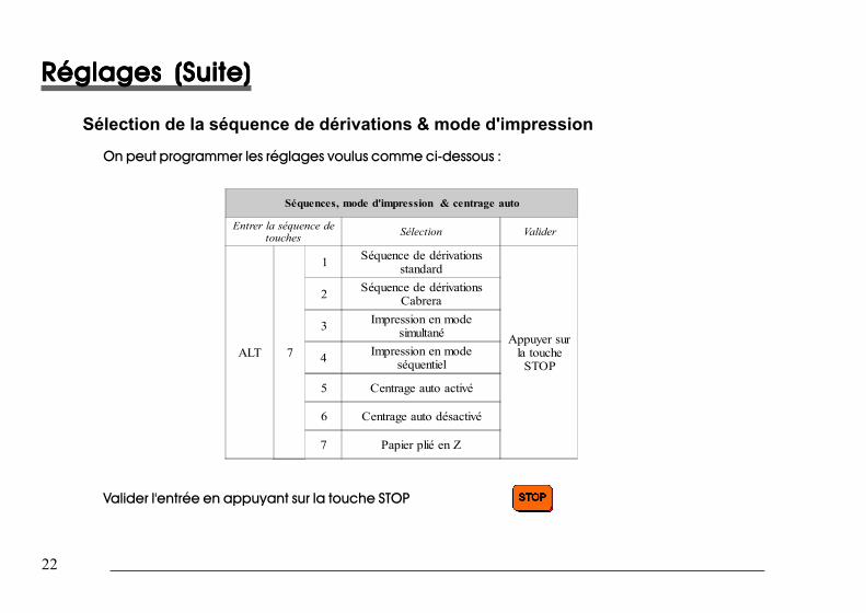
22
22
Réglages (Suite)Réglages (Suite)Réglages (Suite)Réglages (Suite)Réglages (Suite)
Sélection de la séquence de dérivations & mode d'impression
On peut programmer les réglages voulus comme ci-dessous :
Séquences, mode d'impression & centrage auto
Entrer la séquence detouches Sélection Valider
ALT 7
1 Séquence de dérivationsstandard
Appuyer surla touche
STOP
2 Séquence de dérivationsCabrera
3 Impression en modesimultané
4 Impression en modeséquentiel
5 Centrage auto activé
6 Centrage auto désactivé
7 Papier plié en Z
Valider l'entrée en appuyant sur la touche STOP
Réglages (Suite)Réglages (Suite)Réglages (Suite)Réglages (Suite)Réglages (Suite)
Sélection de la séquence de dérivations & mode d'impressionOn peut programmer les réglages voulus comme ci-dessous :
Séquences, mode d'impression & centrage auto
Entrer la séquence detouches Sélection Valider
ALT 7
1 Séquence de dérivationsstandard
Appuyer surla touche
STOP
2 Séquence de dérivationsCabrera
3 Impression en modesimultané
4 Impression en modeséquentiel
5 Centrage auto activé
6 Centrage auto désactivé
7 Papier plié en Z
Valider l'entrée en appuyant sur la touche STOP
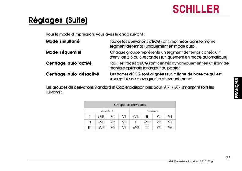
23AT-1 Mode d'emploi art. n°. 2.510171 g
23AT-1 Mode d'emploi art. n°. 2.510171 g
FRAN
ÇAIS
FRAN
ÇAIS
Réglages (Suite)Réglages (Suite)Réglages (Suite)Réglages (Suite)Réglages (Suite)
Pour le mode d'impression, vous avez le choix suivant :
Mode simultanéMode simultanéMode simultanéMode simultanéMode simultané Toutes les dérivations d'ECG sont imprimées dans le mêmesegment de temps (uniquement en mode auto).
Mode séquentielMode séquentielMode séquentielMode séquentielMode séquentiel Chaque groupe représente un segment de temps consécutifd'environ 2.5 ou 5 secondes (uniquement en mode automatique).
Centrage auto activéCentrage auto activéCentrage auto activéCentrage auto activéCentrage auto activé Tous les traces d'ECG sont centrés dynamiquement en utilisant demanière optimale la largeur du papier.
Centrage auto désactivéCentrage auto désactivéCentrage auto désactivéCentrage auto désactivéCentrage auto désactivé Les traces d'ECG sont alignées sur la ligne de base ce qui estsusceptible de provoquer un chevauchement.
Les groupes de dérivations Standard et Cabrera disponibles pour l'AT-1 / l'AT-1smartprint sont lessuivants :
Groupes de dérivations
Standard Cabrera
I aVR V1 V4 aVL II V1 V4II aVL V2 V5 I aVF V2 V5III aVF V3 V6 -aVR III V3 V6
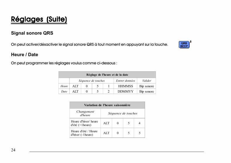
24
24
Réglages (Suite)Réglages (Suite)Réglages (Suite)Réglages (Suite)Réglages (Suite)
Signal sonore QRS
On peut activer/désactiver le signal sonore QRS à tout moment en appuyant sur la touche.
Heure / DateOn peut programmer les réglages voulus comme ci-dessous :
Réglage de l'heure et de la date
Séquence de touches Entrer données Valider
Heure ALT 0 5 1 HHMMSS Bip sonoreDate ALT 0 5 2 DDMMYY Bip sonore
Variation de l'heure saisonnière
Changementd'heure Séquence de touches
Heure d'hiver/ heured'été (+1heure) ALT 0 5 4
Heure d'été / Heured'hiver (-1heure) ALT 0 5 5
Réglages (Suite)Réglages (Suite)Réglages (Suite)Réglages (Suite)Réglages (Suite)
Signal sonore QRS
On peut activer/désactiver le signal sonore QRS à tout moment en appuyant sur la touche.
Heure / Date
On peut programmer les réglages voulus comme ci-dessous :
Réglage de l'heure et de la date
Séquence de touches Entrer données Valider
Heure ALT 0 5 1 HHMMSS Bip sonoreDate ALT 0 5 2 DDMMYY Bip sonore
Variation de l'heure saisonnière
Changementd'heure Séquence de touches
Heure d'hiver/ heured'été (+1heure) ALT 0 5 4
Heure d'été / Heured'hiver (-1heure) ALT 0 5 5

25AT-1 Mode d'emploi art. n°. 2.510171 g
25AT-1 Mode d'emploi art. n°. 2.510171 g
FRAN
ÇAIS
FRAN
ÇAIS
Réglages (Suite)Réglages (Suite)Réglages (Suite)Réglages (Suite)Réglages (Suite)
Note: Si la batterie est restée débranchée pendant plus d'une demi-heure, l'oscillateurd'horloge doit être redémarré avant le réglage de l'heure. Pour ce faire, utiliser laséquence de touches suivante :
ALALALALALT - 0 - 5 - 9T - 0 - 5 - 9T - 0 - 5 - 9T - 0 - 5 - 9T - 0 - 5 - 9
Cela redémarre l'oscillateur et permet de régler l'heure.
Note: L'heure et la date figurent uniquement sur le rapport édité en mode AUTO depuisl'imprimante externe.
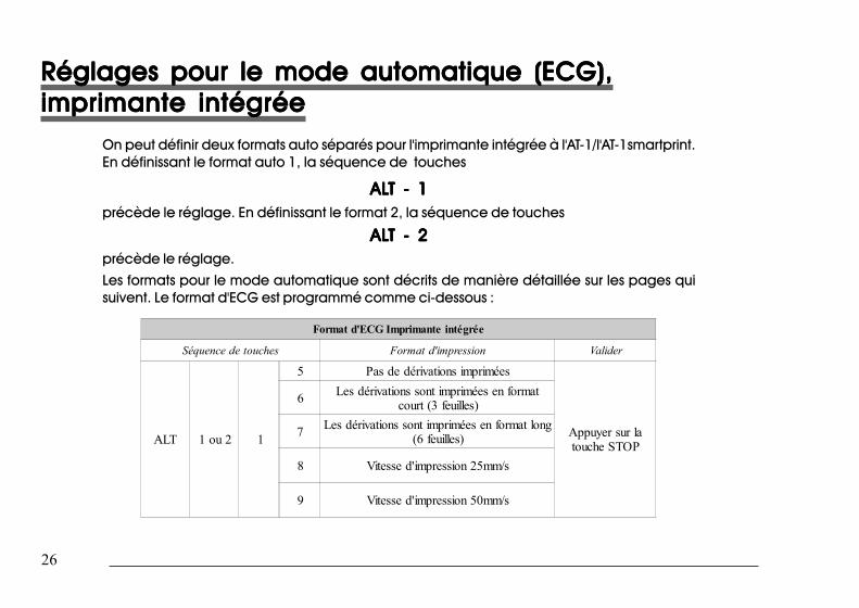
26
26
Réglages pour le mode automatique (ECG),Réglages pour le mode automatique (ECG),Réglages pour le mode automatique (ECG),Réglages pour le mode automatique (ECG),Réglages pour le mode automatique (ECG),imprimante intégréeimprimante intégréeimprimante intégréeimprimante intégréeimprimante intégrée
On peut définir deux formats auto séparés pour l'imprimante intégrée à l'AT-1/l'AT-1smartprint.En définissant le format auto 1, la séquence de touches
ALALALALALT - 1T - 1T - 1T - 1T - 1précède le réglage. En définissant le format 2, la séquence de touches
ALALALALALT - 2T - 2T - 2T - 2T - 2précède le réglage.Les formats pour le mode automatique sont décrits de manière détaillée sur les pages quisuivent. Le format d'ECG est programmé comme ci-dessous :
Format d'ECG Imprimante intégrée
Séquence de touches Format d'impression Valider
ALT 1 ou 2 1
5 Pas de dérivations imprimées
Appuyer sur latouche STOP
6 Les dérivations sont imprimées en formatcourt (3 feuilles)
7 Les dérivations sont imprimées en format long(6 feuilles)
8 Vitesse d'impression 25mm/s
9 Vitesse d'impression 50mm/s
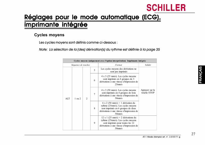
27AT-1 Mode d'emploi art. n°. 2.510171 g
27AT-1 Mode d'emploi art. n°. 2.510171 g
FRAN
ÇAIS
FRAN
ÇAIS
Réglages pour le mode automatique (ECG),Réglages pour le mode automatique (ECG),Réglages pour le mode automatique (ECG),Réglages pour le mode automatique (ECG),Réglages pour le mode automatique (ECG),imprimante intégréeimprimante intégréeimprimante intégréeimprimante intégréeimprimante intégrée
Cycles moyens
Les cycles moyens sont définis comme ci-dessous :
Note: La sélection de la (des) dérivation(s) du rythme est définie à la page 35
Cycles moyens (uniquement avec l'option interprétation) Imprimante intégrée
Séquence de touches Format Valider
ALT 1 ou 2 2
5 Les cycles moyens des dérivations nesont pas imprimés
Appuyer sur latouche STOP
64 x 3 (25 mm/s). Les cycles moyens
sont imprimés en 4 groupes de 3dérivations à une vitesse d'impression de
25mm/s
74 x 3 (50 mm/s). Les cycles moyenssont imprimés en 4 groupes de trois
dérivations à une vitesse d'impression de50mm/s
8
6 x 2 (50 mm/s) + 1 dérivation durythme (25mm/s). Les cycles moyenssont imprimés en 6 groupes de deux
dérivations à une vitesse d'impression de50mm/s
9
12 x 1 (25 mm/s) + 2 dérivations durythme (25mm/s). Les cycles moyens
sont imprimés pour toutes les 12dérivations à une vitesse d'impression de
50mm/s
Réglages pour le mode automatique (ECG),Réglages pour le mode automatique (ECG),Réglages pour le mode automatique (ECG),Réglages pour le mode automatique (ECG),Réglages pour le mode automatique (ECG),imprimante intégréeimprimante intégréeimprimante intégréeimprimante intégréeimprimante intégrée
Cycles moyens
Les cycles moyens sont définis comme ci-dessous :
Note: La sélection de la (des) dérivation(s) du rythme est définie à la page 35
Cycles moyens (uniquement avec l'option interprétation) Imprimante intégrée
Séquence de touches Format Valider
ALT 1 ou 2 2
5 Les cycles moyens des dérivations nesont pas imprimés
Appuyer sur latouche STOP
64 x 3 (25 mm/s). Les cycles moyens
sont imprimés en 4 groupes de 3dérivations à une vitesse d'impression de
25mm/s
7
4 x 3 (50 mm/s). Les cycles moyenssont imprimés en 4 groupes de trois
dérivations à une vitesse d'impression de50mm/s
8
6 x 2 (50 mm/s) + 1 dérivation durythme (25mm/s). Les cycles moyenssont imprimés en 6 groupes de deux
dérivations à une vitesse d'impression de50mm/s
9
12 x 1 (25 mm/s) + 2 dérivations durythme (25mm/s). Les cycles moyens
sont imprimés pour toutes les 12dérivations à une vitesse d'impression de
50mm/s
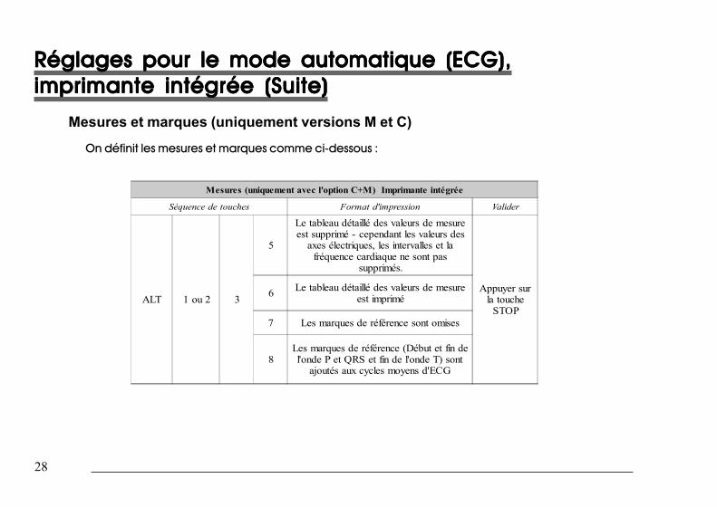
28
28
Réglages pour le mode automatique (ECG),Réglages pour le mode automatique (ECG),Réglages pour le mode automatique (ECG),Réglages pour le mode automatique (ECG),Réglages pour le mode automatique (ECG),imprimante intégrée (Suite)imprimante intégrée (Suite)imprimante intégrée (Suite)imprimante intégrée (Suite)imprimante intégrée (Suite)
Mesures et marques (uniquement versions M et C)On définit les mesures et marques comme ci-dessous :
Mesures (uniquement avec l'option C+M) Imprimante intégrée
Séquence de touches Format d'impression Valider
ALT 1 ou 2 3
5
Le tableau détaillé des valeurs de mesureest supprimé - cependant les valeurs des
axes électriques, les intervalles et lafréquence cardiaque ne sont pas
supprimés.
Appuyer surla touche
STOP
6 Le tableau détaillé des valeurs de mesureest imprimé
7 Les marques de référence sont omises
8Les marques de référence (Début et fin del'onde P et QRS et fin de l'onde T) sont
ajoutés aux cycles moyens d'ECG
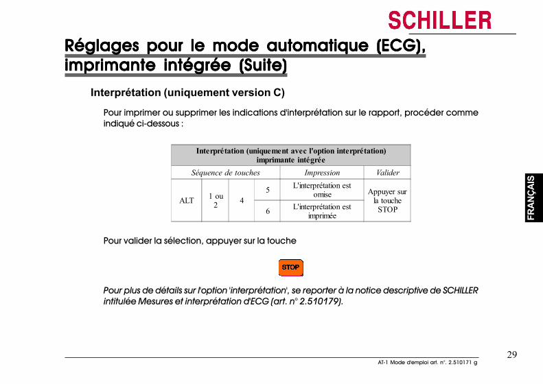
29AT-1 Mode d'emploi art. n°. 2.510171 g
29AT-1 Mode d'emploi art. n°. 2.510171 g
FRAN
ÇAIS
FRAN
ÇAIS
Réglages pour le mode automatique (ECG),Réglages pour le mode automatique (ECG),Réglages pour le mode automatique (ECG),Réglages pour le mode automatique (ECG),Réglages pour le mode automatique (ECG),imprimante intégrée (Suite)imprimante intégrée (Suite)imprimante intégrée (Suite)imprimante intégrée (Suite)imprimante intégrée (Suite)
Interprétation (uniquement version C)
Pour imprimer ou supprimer les indications d'interprétation sur le rapport, procéder commeindiqué ci-dessous :
Interprétation (uniquement avec l'option interprétation)imprimante intégrée
Séquence de touches Impression Valider
ALT 1 ou2 4
5 L'interprétation estomise Appuyer sur
la toucheSTOP6 L'interprétation est
imprimée
Pour valider la sélection, appuyer sur la touche
Pour plus de détails sur l'option 'interprétation', se reporter à la notice descriptive de SCHILLERintitulée Mesures et interprétation d'ECG (art. n° 2.510179).
Réglages pour le mode automatique (ECG),Réglages pour le mode automatique (ECG),Réglages pour le mode automatique (ECG),Réglages pour le mode automatique (ECG),Réglages pour le mode automatique (ECG),imprimante intégrée (Suite)imprimante intégrée (Suite)imprimante intégrée (Suite)imprimante intégrée (Suite)imprimante intégrée (Suite)
Interprétation (uniquement version C)Pour imprimer ou supprimer les indications d'interprétation sur le rapport, procéder commeindiqué ci-dessous :
Interprétation (uniquement avec l'option interprétation)imprimante intégrée
Séquence de touches Impression Valider
ALT 1 ou2 4
5 L'interprétation estomise Appuyer sur
la toucheSTOP6 L'interprétation est
imprimée
Pour valider la sélection, appuyer sur la touche
Pour plus de détails sur l'option 'interprétation', se reporter à la notice descriptive de SCHILLERintitulée Mesures et interprétation d'ECG (art. n° 2.510179).
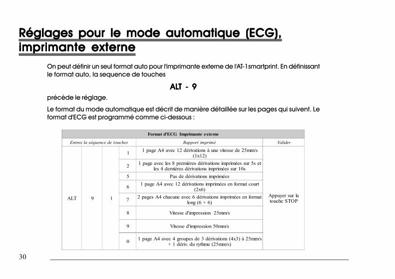
30
30
Réglages pour le mode automatique (ECG),Réglages pour le mode automatique (ECG),Réglages pour le mode automatique (ECG),Réglages pour le mode automatique (ECG),Réglages pour le mode automatique (ECG),imprimante externeimprimante externeimprimante externeimprimante externeimprimante externe
On peut définir un seul format auto pour l'imprimante externe de l'AT-1smartprint. En définissantle format auto, la sequence de touches
ALALALALALT - 9T - 9T - 9T - 9T - 9précède le réglage.
Le format du mode automatique est décrit de manière détaillée sur les pages qui suivent. Leformat d'ECG est programmé comme ci-dessous :
Format d'ECG Imprimante externe
Entrez la séquence de touches Rapport imprimé Valider
ALT 9 1
1 1 page A4 avec 12 dérivations à une vitesse de 25mm/s(1x12)
Appuyer sur latouche STOP
2 1 page avec les 8 premières dérivations imprimées sur 5s etles 4 dernières dérivations imprimées sur 10s
5 Pas de dérivations imprimées
6 1 page A4 avec 12 dérivations imprimées en format court(2x6)
7 2 pages A4 chacune avec 6 dérivations imprimées en formatlong (6 + 6)
8 Vitesse d'impression 25mm/s
9 Vitesse d'impression 50mm/s
0 1 page A4 avec 4 groupes de 3 dérivations (4x3) à 25mm/s+ 1 dériv. du rythme (25mm/s)
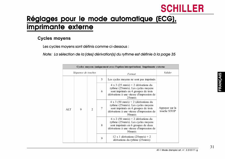
31AT-1 Mode d'emploi art. n°. 2.510171 g
31AT-1 Mode d'emploi art. n°. 2.510171 g
FRAN
ÇAIS
FRAN
ÇAIS
Réglages pour le mode automatique (ECG),Réglages pour le mode automatique (ECG),Réglages pour le mode automatique (ECG),Réglages pour le mode automatique (ECG),Réglages pour le mode automatique (ECG),imprimante externeimprimante externeimprimante externeimprimante externeimprimante externe
Cycles moyensLes cycles moyens sont définis comme ci-dessous :
Note: La sélection de la (des) dérivation(s) du rythme est définie à la page 35
Cycles moyens (uniquement avec l'option interprétation) Imprimante externe
Séquence de touches Format Valider
ALT 9 2
5 Les cycles moyens ne sont pas imprimés
Appuyer sur latouche STOP
6
4 x 3 (25 mm/s) + 2 dérivations durythme (25mm/s). Les cycles moyenssont imprimés en 4 groupes de trois
dérivations à une vitesse d'impression de25mm/s
7
4 x 3 (50 mm/s) + 2 (dérivations durythme (25mm/s). Les cycles moyenssont imprimés en 4 groupes de trois
dérivations à une vitesse d'impression de50mm/s
8
6 x 2 (50 mm/s) + 2 dérivations durythme (25mm/s). Les cycles moyenssont imprimés en 6 groupes de deux
dérivations à une vitesse d'impression de50mm/s
9 12 x 1 dérivations (25mm/s) + 2dérivations du rythme (25mm/s)
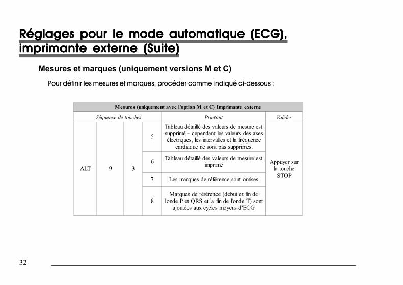
32
32
Réglages pour le mode automatique (ECG),Réglages pour le mode automatique (ECG),Réglages pour le mode automatique (ECG),Réglages pour le mode automatique (ECG),Réglages pour le mode automatique (ECG),imprimante externe (Suite)imprimante externe (Suite)imprimante externe (Suite)imprimante externe (Suite)imprimante externe (Suite)
Mesures et marques (uniquement versions M et C)
Pour définir les mesures et marques, procéder comme indiqué ci-dessous :
Mesures (uniquement avec l'option M et C) Imprimante externe
Séquence de touches Printout Valider
ALT 9 3
5
Tableau détaillé des valeurs de mesure estsupprimé - cependant les valeurs des axesélectriques, les intervalles et la fréquence
cardiaque ne sont pas supprimés.
Appuyer surla touche
STOP
6 Tableau détaillé des valeurs de mesure estimprimé
7 Les marques de référence sont omises
8Marques de référence (début et fin de
l'onde P et QRS et la fin de l'onde T) sontajoutées aux cycles moyens d'ECG
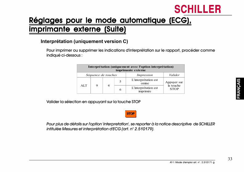
33AT-1 Mode d'emploi art. n°. 2.510171 g
33AT-1 Mode d'emploi art. n°. 2.510171 g
FRAN
ÇAIS
FRAN
ÇAIS
Réglages pour le mode automatique (ECG),Réglages pour le mode automatique (ECG),Réglages pour le mode automatique (ECG),Réglages pour le mode automatique (ECG),Réglages pour le mode automatique (ECG),imprimante externe (Suite)imprimante externe (Suite)imprimante externe (Suite)imprimante externe (Suite)imprimante externe (Suite)
Interprétation (uniquement version C)Pour imprimer ou supprimer les indications d'interprétation sur le rapport, procéder commeindiqué ci-dessous :
Interprétation (uniquement avec l'option interprétation)imprimante externe
Séquence de touches Impression Valider
ALT 9 45 L'interprétation est
omise Appuyer surla touche
STOP6 L'interprétation estimprimée
Valider la sélection en appuyant sur la touche STOP
Pour plus de détails sur l'option 'interpretation', se reporter à la notice descriptive de SCHILLERintitulée Mesures et interprétation d'ECG (art. n° 2.510179).
Réglages pour le mode automatique (ECG),Réglages pour le mode automatique (ECG),Réglages pour le mode automatique (ECG),Réglages pour le mode automatique (ECG),Réglages pour le mode automatique (ECG),imprimante externe (Suite)imprimante externe (Suite)imprimante externe (Suite)imprimante externe (Suite)imprimante externe (Suite)
Interprétation (uniquement version C)
Pour imprimer ou supprimer les indications d'interprétation sur le rapport, procéder commeindiqué ci-dessous :
Interprétation (uniquement avec l'option interprétation)imprimante externe
Séquence de touches Impression Valider
ALT 9 45 L'interprétation est
omise Appuyer surla touche
STOP6 L'interprétation estimprimée
Valider la sélection en appuyant sur la touche STOP
Pour plus de détails sur l'option 'interpretation', se reporter à la notice descriptive de SCHILLERintitulée Mesures et interprétation d'ECG (art. n° 2.510179).
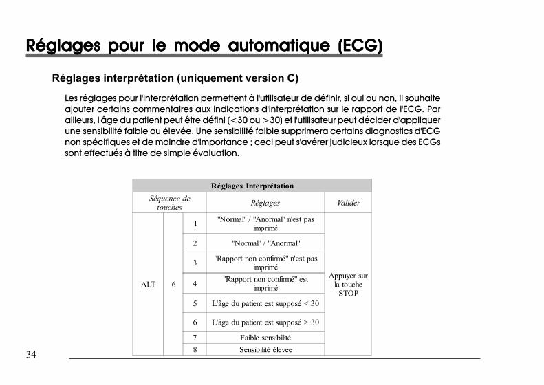
34
34
Réglages pour le mode automatique (ECG)Réglages pour le mode automatique (ECG)Réglages pour le mode automatique (ECG)Réglages pour le mode automatique (ECG)Réglages pour le mode automatique (ECG)
Réglages interprétation (uniquement version C)Les réglages pour l'interprétation permettent à l'utilisateur de définir, si oui ou non, il souhaiteajouter certains commentaires aux indications d'interprétation sur le rapport de l'ECG. Parailleurs, l'âge du patient peut être défini (<30 ou >30) et l'utilisateur peut décider d'appliquerune sensibilité faible ou élevée. Une sensibilité faible supprimera certains diagnostics d'ECGnon spécifiques et de moindre d'importance ; ceci peut s'avérer judicieux lorsque des ECGssont effectués à titre de simple évaluation.
Réglages Interprétation
Séquence detouches Réglages Valider
ALT 6
1 "Normal" / "Anormal" n'est pasimprimé
Appuyer surla touche
STOP
2 "Normal" / "Anormal"
3 "Rapport non confirmé" n'est pasimprimé
4 "Rapport non confirmé" estimprimé
5 L'âge du patient est supposé < 30
6 L'âge du patient est supposé > 30
7 Faible sensibilité8 Sensibilité élevée
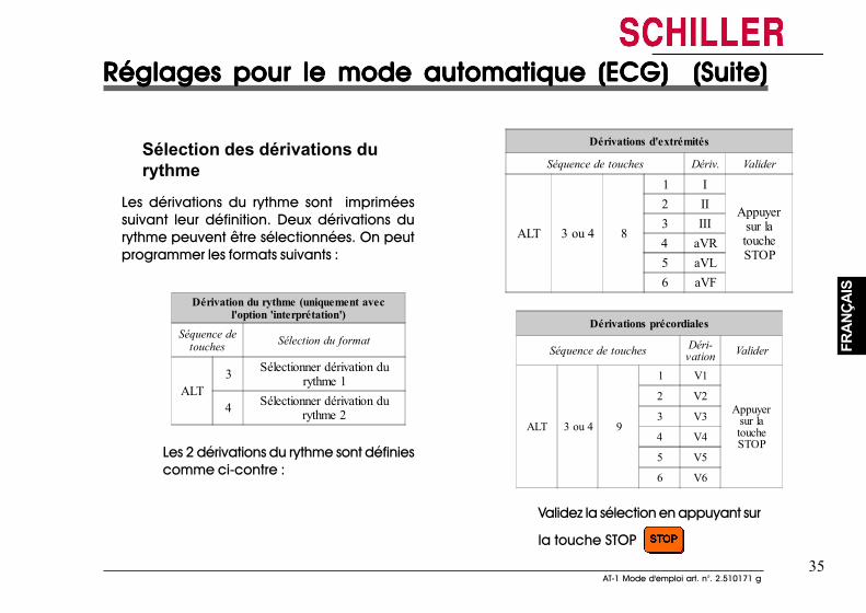
35AT-1 Mode d'emploi art. n°. 2.510171 g
35AT-1 Mode d'emploi art. n°. 2.510171 g
FRAN
ÇAIS
FRAN
ÇAIS
Réglages pour le mode automatique (ECG) (Suite)Réglages pour le mode automatique (ECG) (Suite)Réglages pour le mode automatique (ECG) (Suite)Réglages pour le mode automatique (ECG) (Suite)Réglages pour le mode automatique (ECG) (Suite)
Sélection des dérivations durythme
Les dérivations du rythme sont impriméessuivant leur définition. Deux dérivations durythme peuvent être sélectionnées. On peutprogrammer les formats suivants :
Dérivation du rythme (uniquement avecl'option 'interprétation')
Séquence detouches Sélection du format
ALT3 Sélectionner dérivation du
rythme 1
4 Sélectionner dérivation durythme 2
Les 2 dérivations du rythme sont définiescomme ci-contre :
Dérivations d'extrémités
Séquence de touches Dériv. Valider
ALT 3 ou 4 8
1 I
Appuyersur latoucheSTOP
2 II3 III4 aVR5 aVL6 aVF
Dérivations précordiales
Séquence de touches Déri-vation Valider
ALT 3 ou 4 9
1 V1
Appuyersur latoucheSTOP
2 V2
3 V3
4 V4
5 V5
6 V6
Validez la sélection en appuyant sur
la touche STOP
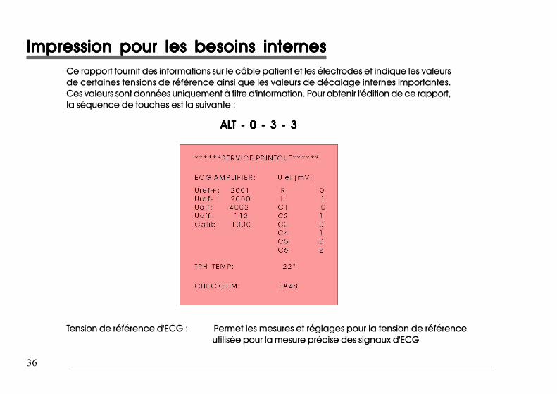
36
36
Impression pour les besoins internesImpression pour les besoins internesImpression pour les besoins internesImpression pour les besoins internesImpression pour les besoins internesCe rapport fournit des informations sur le câble patient et les électrodes et indique les valeursde certaines tensions de référence ainsi que les valeurs de décalage internes importantes.Ces valeurs sont données uniquement à titre d'information. Pour obtenir l'édition de ce rapport,la séquence de touches est la suivante :
ALALALALALT - 0 - 3 - 3T - 0 - 3 - 3T - 0 - 3 - 3T - 0 - 3 - 3T - 0 - 3 - 3
Tension de référence d'ECG : Permet les mesures et réglages pour la tension de référenceutilisée pour la mesure précise des signaux d'ECG
37AT-1 Mode d'emploi art. n°. 2.510171 g
37AT-1 Mode d'emploi art. n°. 2.510171 g
FRAN
ÇAIS
FRAN
ÇAIS
Impression pour les besoins internesImpression pour les besoins internesImpression pour les besoins internesImpression pour les besoins internesImpression pour les besoins internes• Uref + Indique la valeur de la tension de référence utilisée par le circuit multiplexeur de
l'amplificateur d'ECG. La valeur de la tension de référence est de 2000 mV ±20 mV.• Uref - C'est une tension de référence négative utilisée sur la carte de l'amplificateur d'ECG.
La valeur de cette tension devrait être de -2000 mV ±20 mV.• Udif Ceci est la somme des deux valeurs de référence mentionnées ci-dessus (Uref+et Uref-
). Cette valeur doit être de 4000 mV ± 20 mV.• Uoff C'est la valeur de la tension de décalage présente sur le circuit multiplexeur. Cette
valeur devrait être comprise entre + 150 mV et - 150 mV.• Calib Cette valeur est la valeur Udif divisée par 4. La valeur nominale est de 1000 ±5 mV.Décalage CA électrodes Indique la chute de tension dans le câble patient et est susceptible de signaler les
défauts au niveau du câble patient ou de l'électrode du patient. La valeur indiquée estla tension CA entre la branche gauche de l'électrode et toutes les autres électrodes.Les valeurs de mesure obtenues signalent les éventuels courts-circuits ou circuits ouverts.La valeur de tension mesurée varie en fonction de la configuration de connexion desélectrodes. On peut prévoir un relevé des valeurs de tension comme ci-dessous :• le patient étant connecté : ± 100mV• le simulateur du patient étant connecté : ± 20 mV. La valeur dépend du simulateurdu patient utilisé et doit être considérée comme une mesure flexible.• toutes les électrodes court-circuitées ensemble : ± 20 mV• Pas de câble patient connecté : -350 à -450mV
TPH TEMP C'est la température ambiante mesurée qu'utilise le processeur pour obtenir une bonnequalité d'impression.On doit relever comme valeur de la température ambiante ± 5o.
EPROM C'est la somme de contrôle pour l'EPROM. Sa valeur varie d'une version du logiciel àl'autre.
Impression pour les besoins internesImpression pour les besoins internesImpression pour les besoins internesImpression pour les besoins internesImpression pour les besoins internes• Uref + Indique la valeur de la tension de référence utilisée par le circuit multiplexeur de
l'amplificateur d'ECG. La valeur de la tension de référence est de 2000 mV ±20 mV.• Uref - C'est une tension de référence négative utilisée sur la carte de l'amplificateur d'ECG. La
valeur de cette tension devrait être de -2000 mV ±20 mV.• Udif Ceci est la somme des deux valeurs de référence mentionnées ci-dessus (Uref+et Uref-
). Cette valeur doit être de 4000 mV ± 20 mV.• Uoff C'est la valeur de la tension de décalage présente sur le circuit multiplexeur. Cette
valeur devrait être comprise entre + 150 mV et - 150 mV.• Calib Cette valeur est la valeur Udif divisée par 4. La valeur nominale est de 1000 ±5 mV.Décalage CA électrodes Indique la chute de tension dans le câble patient et est susceptible de signaler les
défauts au niveau du câble patient ou de l'électrode du patient. La valeur indiquée estla tension CA entre la branche gauche de l'électrode et toutes les autres électrodes.Les valeurs de mesure obtenues signalent les éventuels courts-circuits ou circuits ouverts.La valeur de tension mesurée varie en fonction de la configuration de connexion desélectrodes. On peut prévoir un relevé des valeurs de tension comme ci-dessous :• le patient étant connecté : ± 100mV• le simulateur du patient étant connecté : ± 20 mV. La valeur dépend du simulateur dupatient utilisé et doit être considérée comme une mesure flexible.• toutes les électrodes court-circuitées ensemble : ± 20 mV• Pas de câble patient connecté : -350 à -450mV
TPH TEMP C'est la température ambiante mesurée qu'utilise le processeur pour obtenir une bonnequalité d'impression.On doit relever comme valeur de la température ambiante ± 5o.
EPROM C'est la somme de contrôle pour l'EPROM. Sa valeur varie d'une version du logiciel àl'autre.
38
38
Installation des logiciels prévus en optionInstallation des logiciels prévus en optionInstallation des logiciels prévus en optionInstallation des logiciels prévus en optionInstallation des logiciels prévus en option
Pour l'évolution de l'appareil d'ECG, par exemple pour passer de la version standard à laversion M, utiliser la séquence de touches suivante :
ALALALALALT - 0 - 4 - T - 0 - 4 - T - 0 - 4 - T - 0 - 4 - T - 0 - 4 - suivi du code spécifique (peut être obtenu chez SCHILLER).
Une série de bips sonores indique que le code a été accepté.
AAAAATTENTIONTTENTIONTTENTIONTTENTIONTTENTION
AU BOUT DE DIX TENTATIVES INFRUCTUEUSES D'ENTREE DU CODE, L'APPAREIL SE BLOQUE.
39AT-1 Mode d'emploi art. n°. 2.510171 g
39AT-1 Mode d'emploi art. n°. 2.510171 g
FRAN
ÇAIS
FRAN
ÇAIS
Raccordement duRaccordement duRaccordement duRaccordement duRaccordement dupatientpatientpatientpatientpatientLe kit d'accessoires de l'AT-1_AT-1 comprend uncâble patient10 brins. Il faut mettre ce câbledans la prise prévue à cet effet sur la partiedroite de l'appareil et le fixer en bien serrantles deux vis.
L'appareil d'ECG est classé CF . Leraccordement du patient est entièrement isoléet protégé contre les décharges dedéfibrillateurs. La protection anti défibrillationn'est assurée, cependant, que lorsque le câblepatient d'origine de SCHILLER est utilisé (articlen° 2.400070 / USA: 2.400071). Vérifier quependant l'enregistrement de l'ECG, ni le patientni les parties conductrices du raccordement dupatient ou les électrodes (y compris l'électrodeneutre) n'entrent en contact avec d'autrespersonnes ou des objets conducteurs (mêmes'ils ont été mis à la terre).
La qualité de l'ECG dépend de la préparationde la peau et de la résistance entre la peau etl'électrode. Pour garantir une bonne qualité del'ECG et minimiser la résistance peau /électrode,il convient de tenir compte des points suivants:
1. Vérifiez que le patient est détendu et qu'il n'a pasfroid.
2. Avant de nettoyer, rasez les poils gênants dans leszones du corps où seront collées les électrodes.
3. Bien nettoyer ces zones à l'aide d'alcool.4. Commencez par appliquer l'électrode C4 - à
hauteur du cinquième espace intercostal, sur laligne médio-claviculaire. Enfinite, placer les autrescomme indiqué ci-dessous :
• C1, à hauteur du quatrième espace intercostal, aubord droit du sternum
• C2, à hautur du cinquième espace intercostal, aubord gauche du sternum
• C3, entre C4 et C2• C6 sur la ligne médio-axilliaire gauche, à hauteur
du C4
• C5, entre C4 et C6, à la même distance
Les points de collage des électrodes représentés sur la pagesuivante sont repèrés par des couleurs selon les normes CEI.Les couleurs équivalentes selon AHA figurent sur le tableausuivant.
Raccordement duRaccordement duRaccordement duRaccordement duRaccordement dupatientpatientpatientpatientpatientLe kit d'accessoires de l'AT-1_AT-1 comprend uncâble patient10 brins. Il faut mettre ce câbledans la prise prévue à cet effet sur la partiedroite de l'appareil et le fixer en bien serrantles deux vis.
L'appareil d'ECG est classé CF . Leraccordement du patient est entièrement isoléet protégé contre les décharges dedéfibrillateurs. La protection anti défibrillationn'est assurée, cependant, que lorsque le câblepatient d'origine de SCHILLER est utilisé (articlen° 2.400070 / USA: 2.400071). Vérifier quependant l'enregistrement de l'ECG, ni le patientni les parties conductrices du raccordement dupatient ou les électrodes (y compris l'électrodeneutre) n'entrent en contact avec d'autrespersonnes ou des objets conducteurs (mêmes'ils ont été mis à la terre).
La qualité de l'ECG dépend de la préparationde la peau et de la résistance entre la peau etl'électrode. Pour garantir une bonne qualité del'ECG et minimiser la résistance peau /électrode,il convient de tenir compte des points suivants:
1. Vérifiez que le patient est détendu et qu'il n'a pasfroid.
2. Avant de nettoyer, rasez les poils gênants dans leszones du corps où seront collées les électrodes.
3. Bien nettoyer ces zones à l'aide d'alcool.4. Commencez par appliquer l'électrode C4 - à hauteur
du cinquième espace intercostal, sur la ligne médio-claviculaire. Enfinite, placer les autres commeindiqué ci-dessous :
• C1, à hauteur du quatrième espace intercostal, aubord droit du sternum
• C2, à hautur du cinquième espace intercostal, aubord gauche du sternum
• C3, entre C4 et C2• C6 sur la ligne médio-axilliaire gauche, à hauteur
du C4
• C5, entre C4 et C6, à la même distance
Les points de collage des électrodes représentés sur la pagesuivante sont repèrés par des couleurs selon les normes CEI.Les couleurs équivalentes selon AHA figurent sur le tableausuivant.
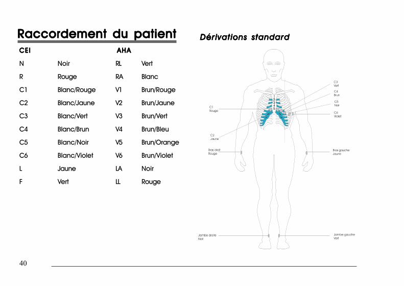
40
40
Raccordement du patientRaccordement du patientRaccordement du patientRaccordement du patientRaccordement du patientCEICEICEICEICEI AHAAHAAHAAHAAHA
N Noir RL Vert
R Rouge RA Blanc
C1 Blanc/Rouge V1 Brun/Rouge
C2 Blanc/Jaune V2 Brun/Jaune
C3 Blanc/Vert V3 Brun/Vert
C4 Blanc/Brun V4 Brun/Bleu
C5 Blanc/Noir V5 Brun/Orange
C6 Blanc/Violet V6 Brun/Violet
L Jaune LA Noir
F Vert LL Rouge
Dérivations standardDérivations standardDérivations standardDérivations standardDérivations standard
Raccordement du patientRaccordement du patientRaccordement du patientRaccordement du patientRaccordement du patientCEICEICEICEICEI AHAAHAAHAAHAAHA
N Noir RL Vert
R Rouge RA Blanc
C1 Blanc/Rouge V1 Brun/Rouge
C2 Blanc/Jaune V2 Brun/Jaune
C3 Blanc/Vert V3 Brun/Vert
C4 Blanc/Brun V4 Brun/Bleu
C5 Blanc/Noir V5 Brun/Orange
C6 Blanc/Violet V6 Brun/Violet
L Jaune LA Noir
F Vert LL Rouge
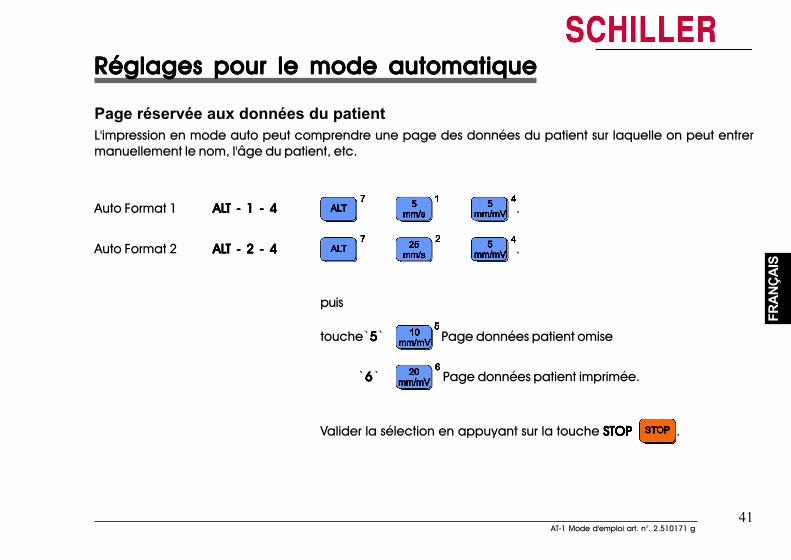
41AT-1 Mode d'emploi art. n°. 2.510171 g
41AT-1 Mode d'emploi art. n°. 2.510171 g
FRAN
ÇAIS
FRAN
ÇAIS
Réglages pour le mode automatiqueRéglages pour le mode automatiqueRéglages pour le mode automatiqueRéglages pour le mode automatiqueRéglages pour le mode automatique
Page réservée aux données du patientL'impression en mode auto peut comprendre une page des données du patient sur laquelle on peut entrermanuellement le nom, l'âge du patient, etc.
Auto Format 1 ALALALALALT - 1 - 4T - 1 - 4T - 1 - 4T - 1 - 4T - 1 - 4 .
Auto Format 2 ALALALALALT - 2 - 4T - 2 - 4T - 2 - 4T - 2 - 4T - 2 - 4 .
puis
touche`55555` Page données patient omise
`66666` Page données patient imprimée.
Valider la sélection en appuyant sur la touche STOP STOP STOP STOP STOP .
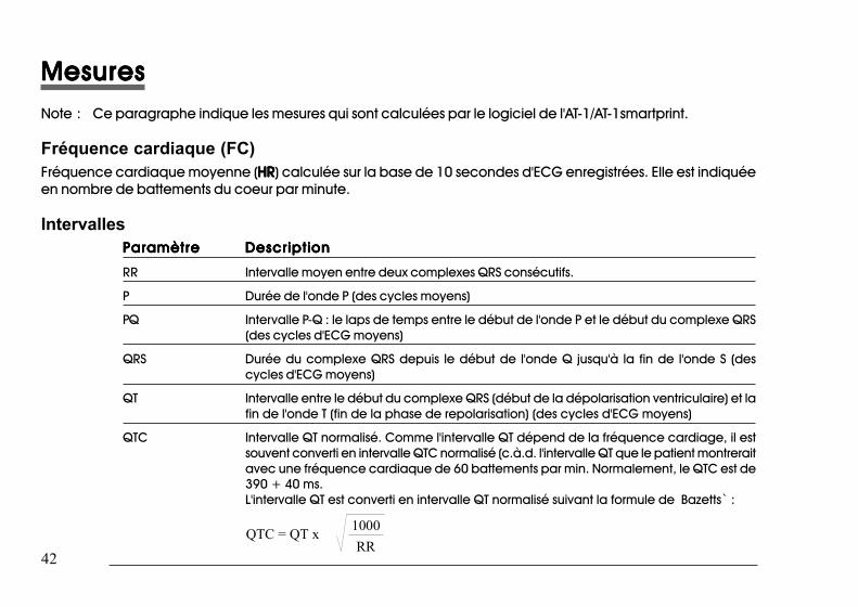
42
42
MesuresMesuresMesuresMesuresMesuresNote : Ce paragraphe indique les mesures qui sont calculées par le logiciel de l'AT-1/AT-1smartprint.
Fréquence cardiaque (FC)Fréquence cardiaque moyenne (HRHRHRHRHR) calculée sur la base de 10 secondes d'ECG enregistrées. Elle est indiquéeen nombre de battements du coeur par minute.
IntervallesParamètreParamètreParamètreParamètreParamètre DescriptionDescriptionDescriptionDescriptionDescription
RR Intervalle moyen entre deux complexes QRS consécutifs.
P Durée de l'onde P (des cycles moyens)
PQ Intervalle P-Q : le laps de temps entre le début de l'onde P et le début du complexe QRS(des cycles d'ECG moyens)
QRS Durée du complexe QRS depuis le début de l'onde Q jusqu'à la fin de l'onde S (descycles d'ECG moyens)
QT Intervalle entre le début du complexe QRS (début de la dépolarisation ventriculaire) et lafin de l'onde T (fin de la phase de repolarisation) (des cycles d'ECG moyens)
QTC Intervalle QT normalisé. Comme l'intervalle QT dépend de la fréquence cardiage, il estsouvent converti en intervalle QTC normalisé (c.à.d. l'intervalle QT que le patient montreraitavec une fréquence cardiaque de 60 battements par min. Normalement, le QTC est de390 + 40 ms.L'intervalle QT est converti en intervalle QT normalisé suivant la formule de Bazetts` :
QTC = QT x 1000RR
MesuresMesuresMesuresMesuresMesuresNote :Ce paragraphe indique les mesures qui sont calculées par le logiciel de l'AT-1/AT-1smartprint.
Fréquence cardiaque (FC)Fréquence cardiaque moyenne (HRHRHRHRHR) calculée sur la base de 10 secondes d'ECG enregistrées. Elle est indiquéeen nombre de battements du coeur par minute.
IntervallesParamètreParamètreParamètreParamètreParamètre DescriptionDescriptionDescriptionDescriptionDescription
RR Intervalle moyen entre deux complexes QRS consécutifs.
P Durée de l'onde P (des cycles moyens)
PQ Intervalle P-Q : le laps de temps entre le début de l'onde P et le début du complexe QRS(des cycles d'ECG moyens)
QRS Durée du complexe QRS depuis le début de l'onde Q jusqu'à la fin de l'onde S (descycles d'ECG moyens)
QT Intervalle entre le début du complexe QRS (début de la dépolarisation ventriculaire) et lafin de l'onde T (fin de la phase de repolarisation) (des cycles d'ECG moyens)
QTC Intervalle QT normalisé. Comme l'intervalle QT dépend de la fréquence cardiage, il estsouvent converti en intervalle QTC normalisé (c.à.d. l'intervalle QT que le patient montreraitavec une fréquence cardiaque de 60 battements par min. Normalement, le QTC est de390 + 40 ms.L'intervalle QT est converti en intervalle QT normalisé suivant la formule de Bazetts` :
QTC = QT x 1000RR
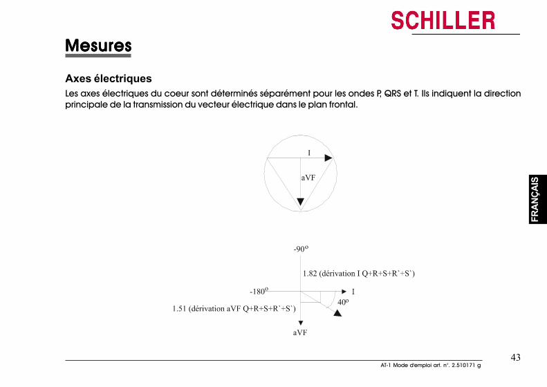
43AT-1 Mode d'emploi art. n°. 2.510171 g
43AT-1 Mode d'emploi art. n°. 2.510171 g
FRAN
ÇAIS
FRAN
ÇAIS
MesuresMesuresMesuresMesuresMesures
Axes électriquesLes axes électriques du coeur sont déterminés séparément pour les ondes P, QRS et T. Ils indiquent la directionprincipale de la transmission du vecteur électrique dans le plan frontal.
MesuresMesuresMesuresMesuresMesures
Axes électriquesLes axes électriques du coeur sont déterminés séparément pour les ondes P, QRS et T. Ils indiquent la directionprincipale de la transmission du vecteur électrique dans le plan frontal.
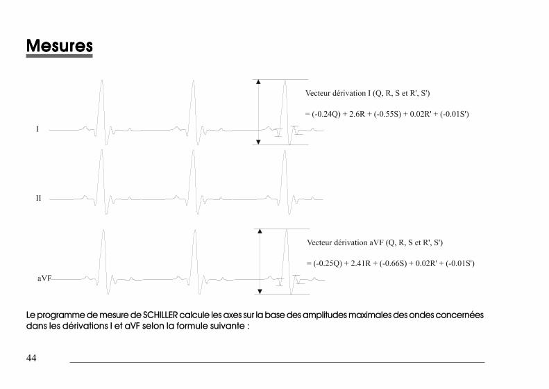
44
44
MesuresMesuresMesuresMesuresMesures
Le programme de mesure de SCHILLER calcule les axes sur la base des amplitudes maximales des ondes concernéesdans les dérivations I et aVF selon la formule suivante :
MesuresMesuresMesuresMesuresMesures
Le programme de mesure de SCHILLER calcule les axes sur la base des amplitudes maximales des ondes concernéesdans les dérivations I et aVF selon la formule suivante :
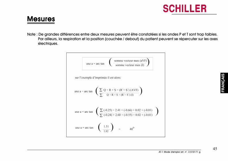
45AT-1 Mode d'emploi art. n°. 2.510171 g
45AT-1 Mode d'emploi art. n°. 2.510171 g
FRAN
ÇAIS
FRAN
ÇAIS
MesuresMesuresMesuresMesuresMesures
Note : De grandes différences entre deux mesures peuvent être constatées si les ondes P et T sont trop faibles.Par ailleurs, la respiration et la position (couchée / debout) du patient peuvent se répercuter sur les axesélectriques.
MesuresMesuresMesuresMesuresMesures
Note : De grandes différences entre deux mesures peuvent être constatées si les ondes P et T sont trop faibles.Par ailleurs, la respiration et la position (couchée / debout) du patient peuvent se répercuter sur les axesélectriques.
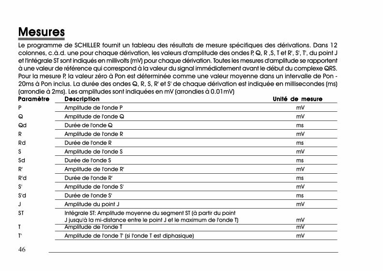
46
46
MesuresMesuresMesuresMesuresMesuresLe programme de SCHILLER fournit un tableau des résultats de mesure spécifiques des dérivations. Dans 12colonnes, c.à.d. une pour chaque dérivation, les valeurs d'amplitude des ondes P, Q, R ,S, T et R', S', T', du point Jet l'intégrale ST sont indiqués en millivolts (mV) pour chaque dérivation. Toutes les mesures d'amplitude se rapportentà une valeur de référence qui correspond à la valeur du signal immédiatement avant le début du complexe QRS.Pour la mesure P, la valeur zéro à Pon est déterminée comme une valeur moyenne dans un intervalle de Pon -20ms à Pon inclus. La durée des ondes Q, R, S, R' et S' de chaque dérivation est indiquée en millisecondes (ms)(arrondie à 2ms). Les amplitudes sont indiquées en mV (arrondies à 0.01mV)ParamètreParamètreParamètreParamètreParamètre Descript ionDescript ionDescript ionDescript ionDescript ion Unité de mesureUnité de mesureUnité de mesureUnité de mesureUnité de mesure
P Amplitude de l'onde P mV
Q Amplitude de l'onde Q mV
Qd Durée de l'onde Q ms
R Amplitude de l'onde R mV
Rd Durée de l'onde R ms
S Amplitude de l'onde S mV
Sd Durée de l'onde S ms
R' Amplitude de l'onde R' mV
R'd Durée de l'onde R' ms
S' Amplitude de l'onde S' mV
S'd Durée de l'onde S' ms
J Amplitude du point J mV
ST Intégrale ST: Amplitude moyenne du segment ST (à partir du pointJ jusqu'à la mi-distance entre le point J et le maximum de l'onde T) mV
T Amplitude de l'onde T mV
T' Amplitude de l'onde T' (si l'onde T est diphasique) mV
MesuresMesuresMesuresMesuresMesuresLe programme de SCHILLER fournit un tableau des résultats de mesure spécifiques des dérivations. Dans 12 colonnes,c.à.d. une pour chaque dérivation, les valeurs d'amplitude des ondes P, Q, R ,S, T et R', S', T', du point J et l'intégraleST sont indiqués en millivolts (mV) pour chaque dérivation. Toutes les mesures d'amplitude se rapportent à unevaleur de référence qui correspond à la valeur du signal immédiatement avant le début du complexe QRS. Pourla mesure P, la valeur zéro à Pon est déterminée comme une valeur moyenne dans un intervalle de Pon -20ms àPon inclus. La durée des ondes Q, R, S, R' et S' de chaque dérivation est indiquée en millisecondes (ms) (arrondieà 2ms). Les amplitudes sont indiquées en mV (arrondies à 0.01mV)ParamètreParamètreParamètreParamètreParamètre Descript ionDescript ionDescript ionDescript ionDescript ion Unité de mesureUnité de mesureUnité de mesureUnité de mesureUnité de mesure
P Amplitude de l'onde P mV
Q Amplitude de l'onde Q mV
Qd Durée de l'onde Q ms
R Amplitude de l'onde R mV
Rd Durée de l'onde R ms
S Amplitude de l'onde S mV
Sd Durée de l'onde S ms
R' Amplitude de l'onde R' mV
R'd Durée de l'onde R' ms
S' Amplitude de l'onde S' mV
S'd Durée de l'onde S' ms
J Amplitude du point J mV
ST Intégrale ST: Amplitude moyenne du segment ST (à partir du pointJ jusqu'à la mi-distance entre le point J et le maximum de l'onde T) mV
T Amplitude de l'onde T mV
T' Amplitude de l'onde T' (si l'onde T est diphasique) mV
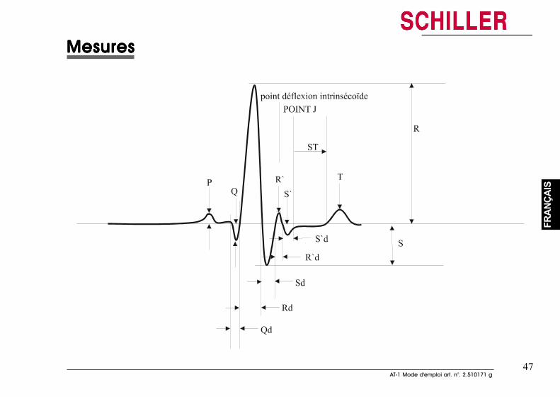
47AT-1 Mode d'emploi art. n°. 2.510171 g
47AT-1 Mode d'emploi art. n°. 2.510171 g
FRAN
ÇAIS
FRAN
ÇAIS
MesuresMesuresMesuresMesuresMesures
MesuresMesuresMesuresMesuresMesures
48
48
Entretien & MaintenanceEntretien & MaintenanceEntretien & MaintenanceEntretien & MaintenanceEntretien & Maintenance
12 Contrôle mensuelTous les 12 mois, l'appareil devra subir un contrôle de sécurité technique. Ce contrôle desécurité technique devra comporter ce qui suit :
• Contrôle visuel de l'appareil et des câbles.
• Tests de sécurité électrique selon les normes CEI 601-1, clause 19
Les résultats de ces tests seront consignés sur un rapport de contrôle.
Nettoyage de l'appareil
AAAAATTENTIONTTENTIONTTENTIONTTENTIONTTENTION
AAAAAVVVVVANT LE NETTOANT LE NETTOANT LE NETTOANT LE NETTOANT LE NETTOYYYYYAAAAAGE, COUPER L'APPGE, COUPER L'APPGE, COUPER L'APPGE, COUPER L'APPGE, COUPER L'APPAREIL, RETIRER LAREIL, RETIRER LAREIL, RETIRER LAREIL, RETIRER LAREIL, RETIRER LA FICHE SECTEUR ET DEBRANCHERA FICHE SECTEUR ET DEBRANCHERA FICHE SECTEUR ET DEBRANCHERA FICHE SECTEUR ET DEBRANCHERA FICHE SECTEUR ET DEBRANCHERL'IMPRIMANTE EXTERNE (LE CAS ECHEANT). EN AUCUN CAS, L'APPL'IMPRIMANTE EXTERNE (LE CAS ECHEANT). EN AUCUN CAS, L'APPL'IMPRIMANTE EXTERNE (LE CAS ECHEANT). EN AUCUN CAS, L'APPL'IMPRIMANTE EXTERNE (LE CAS ECHEANT). EN AUCUN CAS, L'APPL'IMPRIMANTE EXTERNE (LE CAS ECHEANT). EN AUCUN CAS, L'APPAREIL NE DOIT ETREAREIL NE DOIT ETREAREIL NE DOIT ETREAREIL NE DOIT ETREAREIL NE DOIT ETREIMMERGE DIMMERGE DIMMERGE DIMMERGE DIMMERGE DANS UN LIQUIDE DE NETTOANS UN LIQUIDE DE NETTOANS UN LIQUIDE DE NETTOANS UN LIQUIDE DE NETTOANS UN LIQUIDE DE NETTOYYYYYAAAAAGE OU SUBIR UNE STERILISAGE OU SUBIR UNE STERILISAGE OU SUBIR UNE STERILISAGE OU SUBIR UNE STERILISAGE OU SUBIR UNE STERILISATION A L'EAUTION A L'EAUTION A L'EAUTION A L'EAUTION A L'EAUCHAUDE, LA VAPEUR OU L'AIR.CHAUDE, LA VAPEUR OU L'AIR.CHAUDE, LA VAPEUR OU L'AIR.CHAUDE, LA VAPEUR OU L'AIR.CHAUDE, LA VAPEUR OU L'AIR.
Nettoyer la surface du carter de l'appareil d'ECG uniquement à l'aide d'un chiffon doux. Sinécessaire, utiliser un nettoyant ménager non caustique pour éliminer les traces de graisse etde doigts.
49AT-1 Mode d'emploi art. n°. 2.510171 g
49AT-1 Mode d'emploi art. n°. 2.510171 g
FRAN
ÇAIS
FRAN
ÇAIS
Entretien & MaintenanceEntretien & MaintenanceEntretien & MaintenanceEntretien & MaintenanceEntretien & Maintenance
Câble patient
ATTENTIONATTENTIONATTENTIONATTENTIONATTENTION
POSER LES CABLES DE MANIERE A EXCLURE TOUT RISQUE DE TREBUCHEMENT OU DE DETERIORATIONDUES AUX ROUES DES CHARIOTS A INSTRUMENTS. LE MEME SOIN DOIT ETRE PORTE AU STOCKAGEDES CABLES.
Ne pas soumettre le câble patient à des efforts mécaniques trop forts. En déconnectant lescâbles, tirer la fiche et ne pas tirer sur les câbles.
On peut nettoyer le câble avec de l'eau savonneuse. Si une stérilisation est nécessaire, elledoit être faite au gaz et non pas à la vapeur. Les désinfectants standard utilisés dans leshôpitaux conviennent pour désinfecter le câble.
Nettoyage de la tête thermique de l'imprimante intégréeEn cas de forte utilisation, des résidus d'encre (du quadrillage du papier) peuvent se formersur la tête thermique. Ces résidus risquent d'altérer la qualité d'impression. Nous recommandonspour cette raison de nettoyer la tête thermique chaque mois avec de l'alcool
Retirer le bac à paper. Vous trouvez la tête thermique sous le verouillage/déverrouillage dubac à papier. A l'aide d'un chiffon imprégné d'alcool, nettoyer la tête thermique pour éliminerles résidus d'encre. Si la tête thermique est fortement encrassée, la couleur de l'encre dugrillage du papier (par ex. rouge ou vert) apparaît sur le tissu.
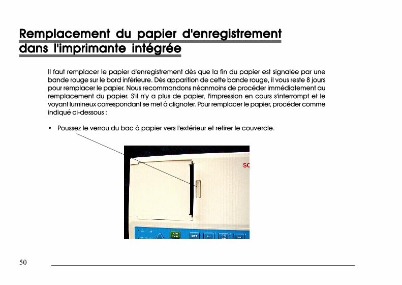
50
50
Remplacement du papier d'enregistrementRemplacement du papier d'enregistrementRemplacement du papier d'enregistrementRemplacement du papier d'enregistrementRemplacement du papier d'enregistrementdans l'imprimante intégréedans l'imprimante intégréedans l'imprimante intégréedans l'imprimante intégréedans l'imprimante intégrée
Il faut remplacer le papier d'enregistrement dès que la fin du papier est signalée par unebande rouge sur le bord inférieure. Dès apparition de cette bande rouge, il vous reste 8 jourspour remplacer le papier. Nous recommandons néanmoins de procéder immédiatement auremplacement du papier. S'il n'y a plus de papier, l'impression en cours s'interrompt et levoyant lumineux correspondant se met à clignoter. Pour remplacer le papier, procéder commeindiqué ci-dessous :
• Poussez le verrou du bac à papier vers l'extérieur et retirer le couvercle.
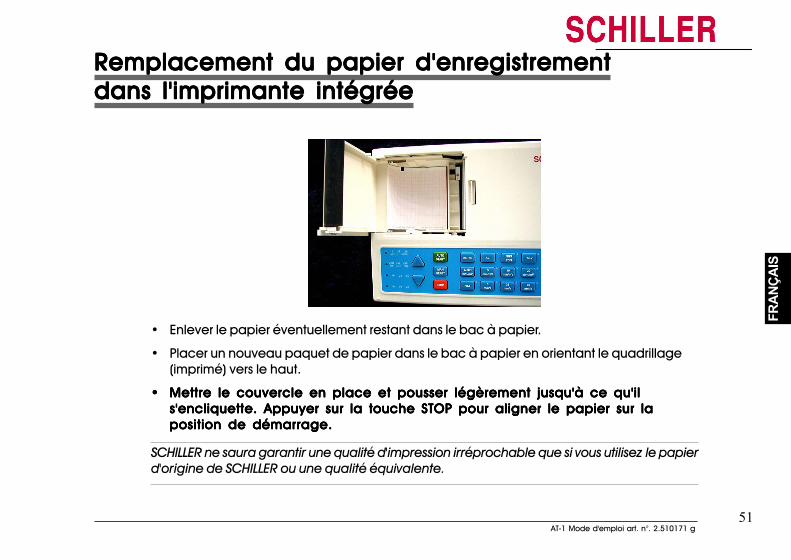
51AT-1 Mode d'emploi art. n°. 2.510171 g
51AT-1 Mode d'emploi art. n°. 2.510171 g
FRAN
ÇAIS
FRAN
ÇAIS
Remplacement du papier d'enregistrementRemplacement du papier d'enregistrementRemplacement du papier d'enregistrementRemplacement du papier d'enregistrementRemplacement du papier d'enregistrementdans l'imprimante intégréedans l'imprimante intégréedans l'imprimante intégréedans l'imprimante intégréedans l'imprimante intégrée
• Enlever le papier éventuellement restant dans le bac à papier.
• Placer un nouveau paquet de papier dans le bac à papier en orientant le quadrillage(imprimé) vers le haut.
••••• Mettre le couvercle en place et pousser légèrement jusqu'à ce qu'ilMettre le couvercle en place et pousser légèrement jusqu'à ce qu'ilMettre le couvercle en place et pousser légèrement jusqu'à ce qu'ilMettre le couvercle en place et pousser légèrement jusqu'à ce qu'ilMettre le couvercle en place et pousser légèrement jusqu'à ce qu'ils'encliquette. Appuyer sur la touches'encliquette. Appuyer sur la touches'encliquette. Appuyer sur la touches'encliquette. Appuyer sur la touches'encliquette. Appuyer sur la touche STOP pour aligner le papier sur laSTOP pour aligner le papier sur laSTOP pour aligner le papier sur laSTOP pour aligner le papier sur laSTOP pour aligner le papier sur laposition de démarrage.position de démarrage.position de démarrage.position de démarrage.position de démarrage.
SCHILLER ne saura garantir une qualité d'impression irréprochable que si vous utilisez le papierd'origine de SCHILLER ou une qualité équivalente.
52
52
Maniement du papier thermiqueManiement du papier thermiqueManiement du papier thermiqueManiement du papier thermiqueManiement du papier thermique
Le papier thermique utilisé pour l'appareil d'ECG nécessite un maniement légèrement différentpar rapport au papier normal car il peut réagir avec les produits chimiques et la chaleur.Cependant, lorsque vous respectez les points suivants, le papier thermique donnera des résultatsfiables :
Les points suivants concernent aussi bien le stockage que l'archivage des rapports.
1. Avant de l'utiliser, garder le papier dans son emballage en carton. Ne pas retirerl'emballage en carton jusqu'à l'utilisation du papier.
2. Entreposer le papier dans un endroit froid, à l'abri de la lumière et de l'humidité.
3. Ne pas l'entreposer à proximité des produits chimiques tels que les liquides destérilisation.
4. Tout particulièrement, ne pas entreposer ce papier sous un emballage en plastique.
5. Certaines colles risquent de réagir avec le papier - ne pas coller le rapport imprimé surune feuille.
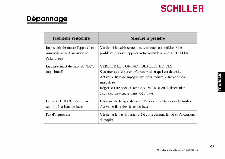
53AT-1 Mode d'emploi art. n°. 2.510171 g
53AT-1 Mode d'emploi art. n°. 2.510171 g
FRAN
ÇAIS
FRAN
ÇAIS
DépannageDépannageDépannageDépannageDépannage
Problème rencontré Mesure à prendre
Impossible de mettre l'appareil enmarche/le voyant lumineux nes'allume pas
Vérifier si le câble secteur est correctement enfiché. Si leproblème persiste, appelez votre revendeur local SCHILLER .
Enregistrement du tracé de l'ECGtrop "bruité"
VERIFIER LE CONTACT DES ELECTRODESS'assurer que le patient n'a pas froid et qu'il est détenduActiver le filtre de myogramme pour réduire le tremblementmusculaire.Régler le filtre secteur sur 50 ou 60 Hz selon l'alimentationélectrique en vigueur dans votre pays.
Le tracé de l'ECG dérive parrapport à la ligne de base
Décalage de la ligne de base. Vérifier le contact des électrodesActiver le filtre des lignes de base.
Pas d'impression Vérifier si le bac à papier a été correctement fermé et s'il contientdu papier.
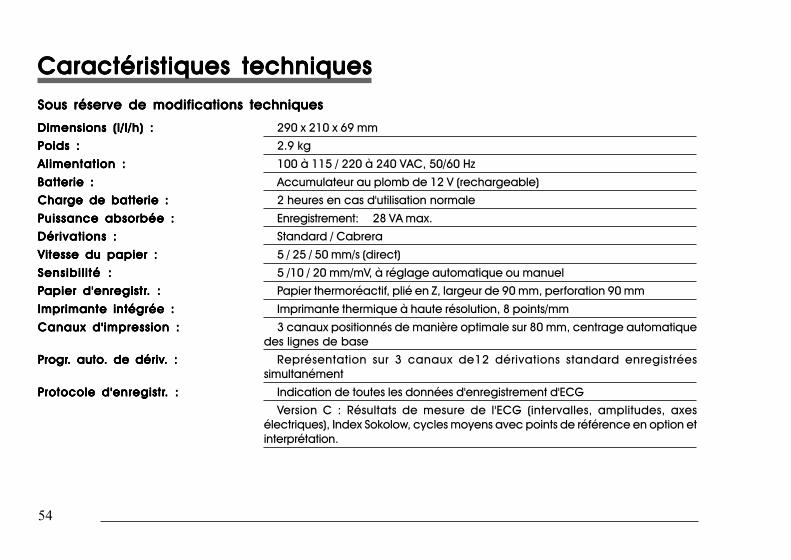
54
54
Caractéristiques techniquesCaractéristiques techniquesCaractéristiques techniquesCaractéristiques techniquesCaractéristiques techniquesSous réserve de modifications techniquesSous réserve de modifications techniquesSous réserve de modifications techniquesSous réserve de modifications techniquesSous réserve de modifications techniques
Dimensions (l/l/h) :Dimensions (l/l/h) :Dimensions (l/l/h) :Dimensions (l/l/h) :Dimensions (l/l/h) : 290 x 210 x 69 mm
Poids :Poids :Poids :Poids :Poids : 2.9 kg
Alimentation :Alimentation :Alimentation :Alimentation :Alimentation : 100 à 115 / 220 à 240 VAC, 50/60 Hz
Batterie :Batterie :Batterie :Batterie :Batterie : Accumulateur au plomb de 12 V (rechargeable)
Charge de batterie :Charge de batterie :Charge de batterie :Charge de batterie :Charge de batterie : 2 heures en cas d'utilisation normale
Puissance absorbée :Puissance absorbée :Puissance absorbée :Puissance absorbée :Puissance absorbée : Enregistrement: 28 VA max.
Dérivations :Dérivations :Dérivations :Dérivations :Dérivations : Standard / Cabrera
Vitesse du papier :Vitesse du papier :Vitesse du papier :Vitesse du papier :Vitesse du papier : 5 / 25 / 50 mm/s (direct)
Sensibil i té :Sensibil i té :Sensibil i té :Sensibil i té :Sensibil i té : 5 /10 / 20 mm/mV, à réglage automatique ou manuel
PPPPPapier d'enregistrapier d'enregistrapier d'enregistrapier d'enregistrapier d'enregistr. :. :. :. :. : Papier thermoréactif, plié en Z, largeur de 90 mm, perforation 90 mm
Imprimante intégrée :Imprimante intégrée :Imprimante intégrée :Imprimante intégrée :Imprimante intégrée : Imprimante thermique à haute résolution, 8 points/mm
Canaux d'impression :Canaux d'impression :Canaux d'impression :Canaux d'impression :Canaux d'impression : 3 canaux positionnés de manière optimale sur 80 mm, centrage automatiquedes lignes de base
PPPPProgrrogrrogrrogrrogr. auto. auto. auto. auto. auto. de dériv. de dériv. de dériv. de dériv. de dériv. :. :. :. :. : Représentation sur 3 canaux de12 dérivations standard enregistréessimultanément
PPPPProtocole d'enregistrrotocole d'enregistrrotocole d'enregistrrotocole d'enregistrrotocole d'enregistr. :. :. :. :. : Indication de toutes les données d'enregistrement d'ECG
Version C : Résultats de mesure de l'ECG (intervalles, amplitudes, axesélectriques), Index Sokolow, cycles moyens avec points de référence en option etinterprétation.
Caractéristiques techniquesCaractéristiques techniquesCaractéristiques techniquesCaractéristiques techniquesCaractéristiques techniquesSous réserve de modifications techniquesSous réserve de modifications techniquesSous réserve de modifications techniquesSous réserve de modifications techniquesSous réserve de modifications techniques
Dimensions (l/l/h) :Dimensions (l/l/h) :Dimensions (l/l/h) :Dimensions (l/l/h) :Dimensions (l/l/h) : 290 x 210 x 69 mm
Poids :Poids :Poids :Poids :Poids : 2.9 kg
Alimentation :Alimentation :Alimentation :Alimentation :Alimentation : 100 à 115 / 220 à 240 VAC, 50/60 Hz
Batterie :Batterie :Batterie :Batterie :Batterie : Accumulateur au plomb de 12 V (rechargeable)
Charge de batterie :Charge de batterie :Charge de batterie :Charge de batterie :Charge de batterie : 2 heures en cas d'utilisation normale
Puissance absorbée :Puissance absorbée :Puissance absorbée :Puissance absorbée :Puissance absorbée : Enregistrement: 28 VA max.
Dérivations :Dérivations :Dérivations :Dérivations :Dérivations : Standard / Cabrera
Vitesse du papier :Vitesse du papier :Vitesse du papier :Vitesse du papier :Vitesse du papier : 5 / 25 / 50 mm/s (direct)
Sensibil i té :Sensibil i té :Sensibil i té :Sensibil i té :Sensibil i té : 5 /10 / 20 mm/mV, à réglage automatique ou manuel
PPPPPapier d'enregistrapier d'enregistrapier d'enregistrapier d'enregistrapier d'enregistr. :. :. :. :. : Papier thermoréactif, plié en Z, largeur de 90 mm, perforation 90 mm
Imprimante intégrée :Imprimante intégrée :Imprimante intégrée :Imprimante intégrée :Imprimante intégrée : Imprimante thermique à haute résolution, 8 points/mm
Canaux d'impression :Canaux d'impression :Canaux d'impression :Canaux d'impression :Canaux d'impression : 3 canaux positionnés de manière optimale sur 80 mm, centrage automatiquedes lignes de base
PPPPProgrrogrrogrrogrrogr. auto. auto. auto. auto. auto. de dériv. de dériv. de dériv. de dériv. de dériv. :. :. :. :. : Représentation sur 3 canaux de12 dérivations standard enregistrées simultanément
PPPPProtocole d'enregistrrotocole d'enregistrrotocole d'enregistrrotocole d'enregistrrotocole d'enregistr. :. :. :. :. : Indication de toutes les données d'enregistrement d'ECG
Version C : Résultats de mesure de l'ECG (intervalles, amplitudes, axes électriques),Index Sokolow, cycles moyens avec points de référence en option et interprétation.
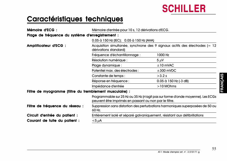
55AT-1 Mode d'emploi art. n°. 2.510171 g
55AT-1 Mode d'emploi art. n°. 2.510171 g
FRAN
ÇAIS
FRAN
ÇAIS
Caractéristiques techniquesCaractéristiques techniquesCaractéristiques techniquesCaractéristiques techniquesCaractéristiques techniquesMémoire d'ECG :Mémoire d'ECG :Mémoire d'ECG :Mémoire d'ECG :Mémoire d'ECG : Mémoire d'entrée pour 10 s, 12 dérivations d'ECG.
Plage de fréquence du système d'enregistrement :Plage de fréquence du système d'enregistrement :Plage de fréquence du système d'enregistrement :Plage de fréquence du système d'enregistrement :Plage de fréquence du système d'enregistrement :
0.05 à 150 Hz (IEC); 0.05 à 150 Hz (AHA)
Amplificateur d'ECG :Amplificateur d'ECG :Amplificateur d'ECG :Amplificateur d'ECG :Amplificateur d'ECG : Acquisition simultanée, synchrone des 9 signaux actifs des électrodes (= 12dérivations standard)
Fréquence d'échantillonnage : 1000 Hz
Résolution numérique : 5 µV
Plage dynamique : ±10 mVAC
Potentiel max. des électrodes : ±300 mVDC
Constante de temps : >3.2 s
Réponse en fréquence : 0.05 à 150 Hz (-3 dB)
Impédance d'entrée >10 MOhms
Filtre de myogramme (filtre du tremblement musculaire) :Filtre de myogramme (filtre du tremblement musculaire) :Filtre de myogramme (filtre du tremblement musculaire) :Filtre de myogramme (filtre du tremblement musculaire) :Filtre de myogramme (filtre du tremblement musculaire) :
Programmable sur 25 Hz ou 35 Hz (n'agit pas sur forme d'onde moyenne). Les ECGspeuvent être imprimés en passant ou non par le filtre.
Filtre de fréquence du réseau :Filtre de fréquence du réseau :Filtre de fréquence du réseau :Filtre de fréquence du réseau :Filtre de fréquence du réseau : Suppression sans distortion des perturbations harmoniques superposées de 50 ou60 Hz.
Circuit d'entrée du patient :Circuit d'entrée du patient :Circuit d'entrée du patient :Circuit d'entrée du patient :Circuit d'entrée du patient : Entièrement isolé et séparé galvaniquement, résistant aux défibrillations
Courant de fuite du patient :Courant de fuite du patient :Courant de fuite du patient :Courant de fuite du patient :Courant de fuite du patient : <5 µA
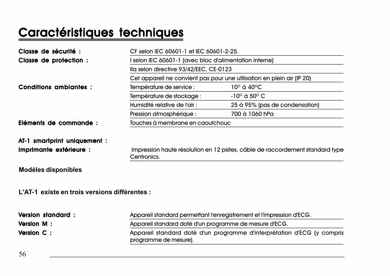
56
56
Caractéristiques techniquesCaractéristiques techniquesCaractéristiques techniquesCaractéristiques techniquesCaractéristiques techniquesClasse de sécurité :Classe de sécurité :Classe de sécurité :Classe de sécurité :Classe de sécurité : CF selon IEC 60601-1 et IEC 60601-2-25.
Classe de protectionClasse de protectionClasse de protectionClasse de protectionClasse de protection : : : : : I selon IEC 60601-1 (avec bloc d'alimentation interne)
IIa selon directive 93/42/EEC, CE-0123
Cet appareil ne convient pas pour une utilisation en plein air (IP 20)
Conditions ambiantesConditions ambiantesConditions ambiantesConditions ambiantesConditions ambiantes : : : : : Température de service : 10O à 40OC
Température de stockage : -10O à 50O C
Humidité relative de l'air : 25 à 95% (pas de condensation)
Pression atmosphérique : 700 à 1060 hPa
Eléments de commande :Eléments de commande :Eléments de commande :Eléments de commande :Eléments de commande : Touches à membrane en caoutchouc
AAAAATTTTT-1 smar-1 smar-1 smar-1 smar-1 smartprint uniquement :tprint uniquement :tprint uniquement :tprint uniquement :tprint uniquement :
Imprimante extérieure :Imprimante extérieure :Imprimante extérieure :Imprimante extérieure :Imprimante extérieure : Impression haute résolution en 12 pistes, câble de raccordement standard typeCentronics.
Modèles disponibles
L'AT-1 existe en trois versions différentes :
VVVVVersion standard :ersion standard :ersion standard :ersion standard :ersion standard : Appareil standard permettant l'enregistrement et l'impression d'ECG.
VVVVVersion M :ersion M :ersion M :ersion M :ersion M : Appareil standard doté d'un programme de mesure d'ECG.
VVVVVersion C :ersion C :ersion C :ersion C :ersion C : Appareil standard doté d'un programme d'interprétation d'ECG (y comprisprogramme de mesure).
Caractéristiques techniquesCaractéristiques techniquesCaractéristiques techniquesCaractéristiques techniquesCaractéristiques techniquesClasse de sécurité :Classe de sécurité :Classe de sécurité :Classe de sécurité :Classe de sécurité : CF selon IEC 60601-1 et IEC 60601-2-25.
Classe de protection :Classe de protection :Classe de protection :Classe de protection :Classe de protection : I selon IEC 60601-1 (avec bloc d'alimentation interne)
IIa selon directive 93/42/EEC, CE-0123
Cet appareil ne convient pas pour une utilisation en plein air (IP 20)
Conditions ambiantes :Conditions ambiantes :Conditions ambiantes :Conditions ambiantes :Conditions ambiantes : Température de service : 10O à 40OC
Température de stockage : -10O à 50O C
Humidité relative de l'air : 25 à 95% (pas de condensation)
Pression atmosphérique : 700 à 1060 hPa
Eléments de commande :Eléments de commande :Eléments de commande :Eléments de commande :Eléments de commande : Touches à membrane en caoutchouc
AAAAATTTTT-1 smar-1 smar-1 smar-1 smar-1 smartprint uniquement :tprint uniquement :tprint uniquement :tprint uniquement :tprint uniquement :
Imprimante extérieure :Imprimante extérieure :Imprimante extérieure :Imprimante extérieure :Imprimante extérieure : Impression haute résolution en 12 pistes, câble de raccordement standard typeCentronics.
Modèles disponibles
L'AT-1 existe en trois versions différentes :
VVVVVersion standard :ersion standard :ersion standard :ersion standard :ersion standard : Appareil standard permettant l'enregistrement et l'impression d'ECG.
VVVVVersion M :ersion M :ersion M :ersion M :ersion M : Appareil standard doté d'un programme de mesure d'ECG.
VVVVVersion C :ersion C :ersion C :ersion C :ersion C : Appareil standard doté d'un programme d'interprétation d'ECG (y comprisprogramme de mesure).
Top Related