2340-2341-2342-2343-HALO anulado 10-04-13 - flinders.be · eléctrica en el bloque de conexión de...
7
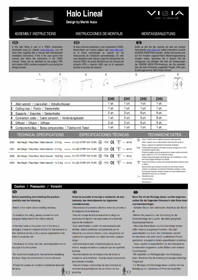
Class I. Product with an additional protection cable (grounds). Clase I. Aparato con un cable protector adicional (toma de tierra). Klasse I. Apparat mit zusätzlichen Schutzleiter (Erdkabel). Product protected against solid object as big as or bigger than 12 mm. No protection against water. Producto protegido contra la penetración de cuerpos sólidos de tamaño igual o superior a 12 mm. Sin protección al agua. Produkt ist geschützt gegen das Eindringen von Fremdkörpern >12mm. Kein Schutz gegen Eindringen von Wasser. Product that CAN be in contact with normally-flammable materials (wood or others). Está permitido que el producto marcado con este simbolo esté en contacto con materiales normalmente inflamables (maderas u otros). Es ist erlaubt Produkte mit diesem Etikett auf normal entflammbaren Oberflächen (Holz usw.) zu montieren. Alternating current Corriente alterna Wechselstrom TECHNICAL SPECIFICATIONS ESPECIFICACIONES TÉCNICAS TECHNISCHE DATEN Halo Lineal Design by Martín Azúa ASSEMBLY INSTRUCTIONS INSTRUCCIONES DE MONTAJE MONTAGEANLEITUNG 2340 2341 2342 2343 1 A len wrench / Llave allen / Imbußschlüssel 1 un. 1 un. 1 un. 1 un. 2 Ceiling rose / Florón / Deckenteller 1 un. 1 un. 1 un. 1 un. 3 Supports / Soportes / Deckenhalter 2 un. 3 un. 6 un. 9 un. 4 Connection cable / Cable conexión / Verbindungskabel 1 un. 2 un. 5 un. 8 un. 5 Diffuser / Difusor / Diffuser 2 un. 3 un. 6 un. 9 un. 6 Components Bag / Bolsa componentes / Tütchen mit Teilen 1 un. 1 un. 1 un. 1 un. If this light fitting is part of a CREA composition developed using our website www.vibia.com , you will have been supplied with a manual with individualised installation instructions. If this is the case ignore this manual and follow the instructions in the CREA manual. These can be identified by the project (PR) and creation (MO) numbers assigned to you during the design process. EN ES D Si esta luminaria pertenece a una composición CREA, desarrollada con nuestra página web www.vibia.com , se le habrá suministrado un manual con las instrucciones de instalación personalizadas. En este caso desestime este manual y siga las indicaciones del manual CREA, las podrá identificar por los números de proyecto (PR) y creación (MO) que se le asignaron durante el proceso de creación. Sollte es sich bei der Leuchte um eine auf unserer Internetseite www.vibia.com selbst entworfene Leuchte (EIGENE KREATION) handeln, dürften Sie bereits eine auf Ihre Kreation zugeschnittene Bedienungsanleitung erhalten haben. Ignorieren Sie in diesem Fall die vorliegende und befolgen Sie bitte die Anweisungen der EIGENE KREATION-Anleitung, die Sie entweder über die beim Entwerfen zugeteilten Projekt- (PR) oder Erstellungsnummer (MO) finden können. 3. 1. 2. 5. 4. 6.
Transcript of 2340-2341-2342-2343-HALO anulado 10-04-13 - flinders.be · eléctrica en el bloque de conexión de...
Class I. Product with an additional protection cable (grounds).
Clase I. Aparato con un cable protector adicional (toma de tierra).
Klasse I. Apparat mit zusätzlichen Schutzleiter (Erdkabel).
Product protected against solid object as big as or bigger than 12 mm. No protection against water.Producto protegido contra la penetración de cuerpos sólidos de tamaño igual o superior a 12 mm. Sin protección al agua.Produkt ist geschützt gegen das Eindringen von Fremdkörpern >12mm. Kein Schutz gegen Eindringen von Wasser.
Product that CAN be in contact with normally-flammable materials (wood or others).
Está permitido que el producto marcado con este simbolo esté en contacto con materiales normalmente inflamables (maderas u otros).Es ist erlaubt Produkte mit diesem Etikett auf normal entflammbaren Oberflächen (Holz usw.) zu montieren.Alternating current
Corriente alterna
Wechselstrom
TECHNICAL SPECIFICATIONS ESPECIFICACIONES TÉCNICAS TECHNISCHE DATEN
Halo LinealDesign by Martín Azúa
ASSEMBLY INSTRUCTIONS INSTRUCCIONES DE MONTAJE MONTAGEANLEITUNG
2340 2341 2342 2343
1 Allen wrench / Llave allen / Imbußschlüssel 1 un. 1 un. 1 un. 1 un.
2 Ceiling rose / Florón / Deckenteller 1 un. 1 un. 1 un. 1 un.
3 Supports / Soportes / Deckenhalter 2 un. 3 un. 6 un. 9 un.
4 Connect ion cable / Cable conexión / Verbindungskabel 1 un. 2 un. 5 un. 8 un.
5 Diffuser / Difusor / Diffuser 2 un. 3 un. 6 un. 9 un.
6 Components Bag / Bolsa componentes / Tütchen mit Teilen 1 un. 1 un. 1 un. 1 un.
If this light fitting is part of a CREA composition developed using our website www.vibia.com, you will have been supplied with a manual with individualised installation instructions. If this is the case ignore this manual and follow the instructions in the CREA manual. These can be identified by the project (PR) and creation (MO) numbers assigned to you during the design process.
EN ES DSi esta luminaria pertenece a una composición CREA, desarrollada con nuestra página web www.vibia.com, se le habrá suministrado un manual con las instrucciones de instalación personalizadas. En este caso desestime este manual y siga las indicaciones del manual CREA, las podrá identificar por los números de proyecto (PR) y creación (MO) que se le asignaron durante el proceso de creación.
Sollte es sich bei der Leuchte um eine auf unserer Internetseite www.vibia.com selbst entworfene Leuchte (EIGENE KREATION) handeln, dürften Sie bereits eine auf Ihre Kreation zugeschnittene Bedienungsanleitung erhalten haben. Ignorieren Sie in diesem Fall die vorliegende und befolgen Sie bitte die Anweisungen der EIGENE KREATION-Anleitung, die Sie entweder über die beim Entwerfen zugeteilten Projekt- (PR) oder Erstellungsnummer (MO) finden können. 3. 1. 2. 5. 4. 6.
A
D
DB
C
ES
C
I I
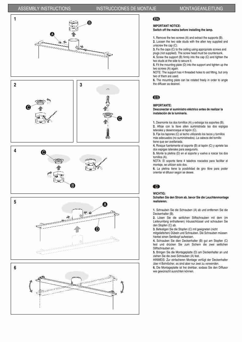
1. Remove the two screws (A) and extract the supports (B). 2. Loosen the two side studs with the allen key supplied and unscrew the cap (C). 3. Fix the caps (C) to the ceiling using appropriate screws and plugs (not supplied). The screw head must be countersunk. 4. Screw the support (B) firmly into the cap (C) and tighten the two studs at the side to secure it. 5. Fit the mounting plate (D) into the support and tighten up the two screws (A) again. NOTE: The support has 4 threaded holes to aid fitting, but only two of them are used. 6. The mounting plate can be rotated freely in order to angle the diffuser as desired.
ENB
A
1
ASSEMBLY INSTRUCTIONS INSTRUCCIONES DE MONTAJE MONTAGEANLEITUNG
2 3
4
5
6
IMPORTANT NOTICE:
Switch off the mains before installing the lamp.
IMPORTANTE: Desconectar el suministro eléctrico antes de realizar la
instalación de la luminaria.
WICHTIG: Schalten Sie den Strom ab. bevor Sie die Leuchtenmontage realisieren.
1. Desmonte los dos tornillos (A) y extraiga los soportes (B). 2. Afloje con la llave allen suministrada las dos espigas laterales y desenrosque el tapón (C). 3. Fije los tapones (C) al techo utilizando los tacos y tornillos más adecuados (no suministrados). La cabeza del tornillo tiene que ser avellanada. 4. Rosque fuertemente el soporte (B) al tapón (C) y apriete las dos espigas laterales para asegurarlo. 5. Monte la pletina (D) en el soporte y vuelva a roscar los dos tornillos (A). NOTA: El soporte tiene 4 taladros roscados para facilitar el montaje, se utilizan solo dos. 6. La pletina tiene la posibilidad de giro libre para poder orientar el difusor según se desee.
1. Schrauben Sie die Schrauben (A) ab und entfernen Sie die Deckenhalter (B). 2. Lösen Sie die seitlichen Stiftschrauben mit dem (im Lieferumfang enthaltenen) Inbusschlüssel und schrauben Sie den Stopfen (C) ab. 3. Befestigen Sie die Stopfen (C) mit geeigneten (nicht mitgelieferten) Dübeln und Schrauben. Die Schrauben müssen hierbei einen Senkkopf aufweisen. 4. Schrauben Sie dien Deckenhalter (B) gut am Stopfen (C) fest und drücken Sie zum Sichern die zwei seitlichen Stiftschrauben an. 5. Bringen Sie die Montageplatte (D) am Deckenhalter an und ziehen Sie die zwei Schrauben (A) fest. HINWEIS: Zur einfacheren Montage verfügt der Deckenhalter über 4 Bohrlöcher, es sind aber nur zwei zu verwenden. 6. Die Montageplatte ist frei drehbar, sodass Sie den Diffusor wie gewünscht ausrichten können.
C
G
F
H
E
ASSEMBLY INSTRUCTIONS INSTRUCCIONES DE MONTAJE MONTAGEANLEITUNG
7
8
9
D
ES
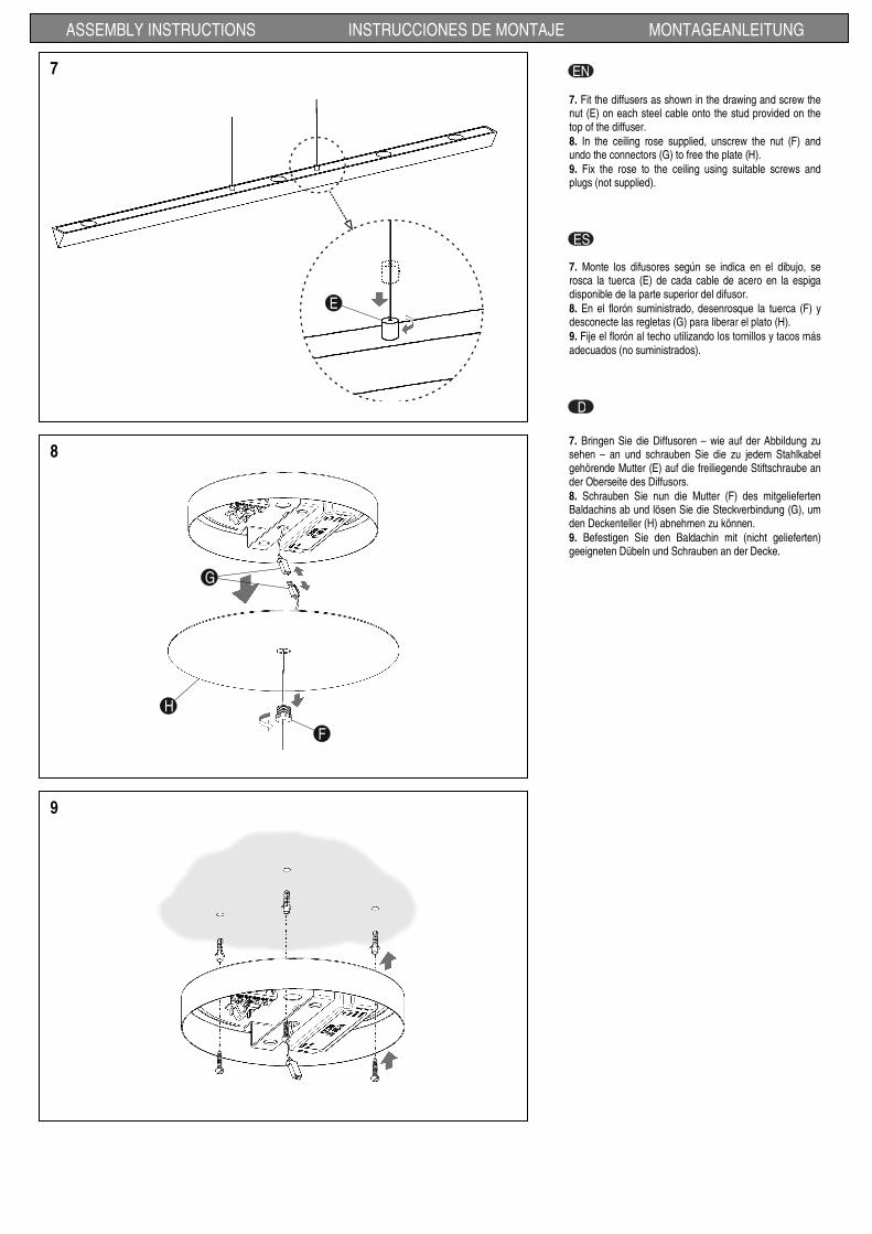
7. Fit the diffusers as shown in the drawing and screw the nut (E) on each steel cable onto the stud provided on the top of the diffuser. 8. In the ceiling rose supplied, unscrew the nut (F) and undo the connectors (G) to free the plate (H). 9. Fix the rose to the ceiling using suitable screws and plugs (not supplied).
EN
7. Monte los difusores según se indica en el dibujo, se rosca la tuerca (E) de cada cable de acero en la espiga disponible de la parte superior del difusor. 8. En el florón suministrado, desenrosque la tuerca (F) y desconecte las regletas (G) para liberar el plato (H). 9. Fije el florón al techo utilizando los tornillos y tacos más adecuados (no suministrados).
7. Bringen Sie die Diffusoren – wie auf der Abbildung zu sehen – an und schrauben Sie die zu jedem Stahlkabel gehörende Mutter (E) auf die freiliegende Stiftschraube an der Oberseite des Diffusors. 8. Schrauben Sie nun die Mutter (F) des mitgelieferten Baldachins ab und lösen Sie die Steckverbindung (G), um den Deckenteller (H) abnehmen zu können. 9. Befestigen Sie den Baldachin mit (nicht gelieferten) geeigneten Dübeln und Schrauben an der Decke.
N
L
--Interruptor-
Switch
Ein-/Ausschalter
N
1
2
3
N
L
--Bloque de conexión-
Connector
Anschlussblock
C1+
C0--
--On/Off - Regulador-
Dimmer switch
Dimmer
+
--+
N
1
2
3
10
ASSEMBLY INSTRUCTIONS INSTRUCCIONES DE MONTAJE MONTAGEANLEITUNG
H
F
G
11
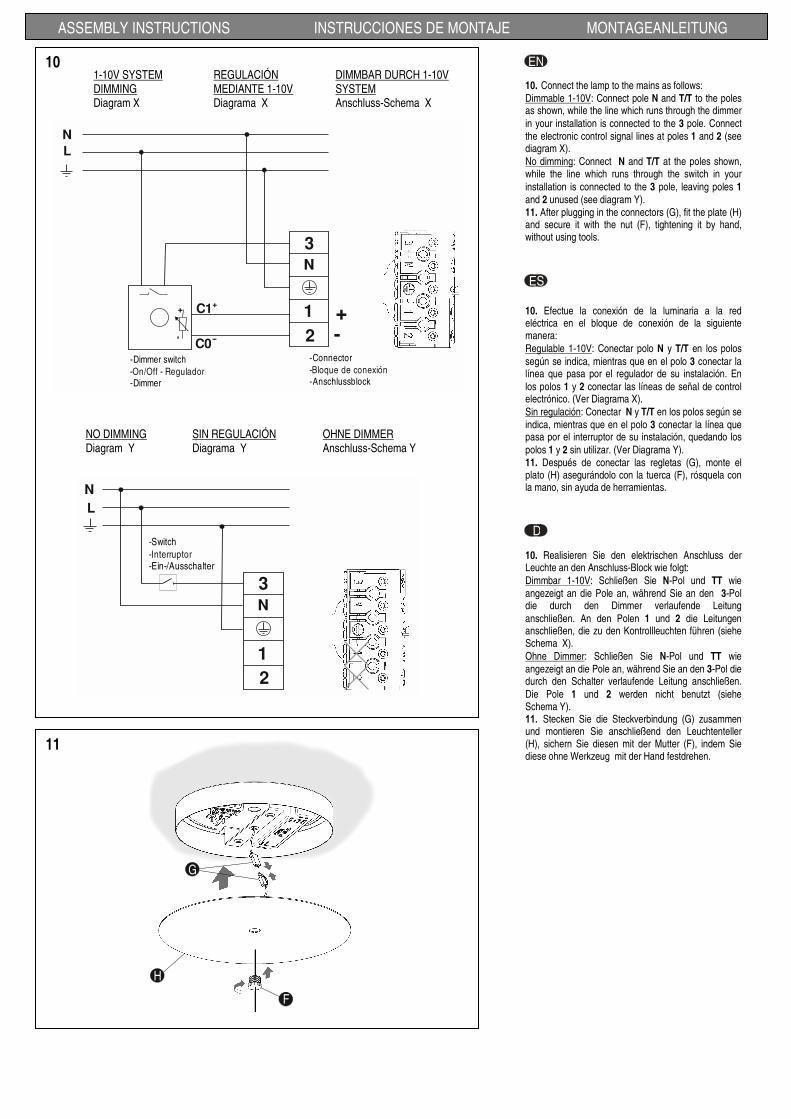
10. Connect the lamp to the mains as follows: Dimmable 1-10V: Connect pole N and T/T to the poles as shown, while the line which runs through the dimmer in your installation is connected to the 3 pole. Connect the electronic control signal lines at poles 1 and 2 (see diagram X). No dimming: Connect N and T/T at the poles shown, while the line which runs through the switch in your installation is connected to the 3 pole, leaving poles 1 and 2 unused (see diagram Y). 11. After plugging in the connectors (G), fit the plate (H) and secure it with the nut (F), tightening it by hand, without using tools.
EN
D
ES
10. Efectue la conexión de la luminaria a la red eléctrica en el bloque de conexión de la siguiente manera: Regulable 1-10V: Conectar polo N y T/T en los polos según se indica, mientras que en el polo 3 conectar la línea que pasa por el regulador de su instalación. En los polos 1 y 2 conectar las líneas de señal de control electrónico. (Ver Diagrama X). Sin regulación: Conectar N y T/T en los polos según se indica, mientras que en el polo 3 conectar la línea que pasa por el interruptor de su instalación, quedando los polos 1 y 2 sin utilizar. (Ver Diagrama Y). 11. Después de conectar las regletas (G), monte el plato (H) asegurándolo con la tuerca (F), rósquela con la mano, sin ayuda de herramientas.
10. Realisieren Sie den elektrischen Anschluss der Leuchte an den Anschluss-Block wie folgt: Dimmbar 1-10V: Schließen Sie N-Pol und TT wie angezeigt an die Pole an, während Sie an den 3-Pol die durch den Dimmer verlaufende Leitung anschließen. An den Polen 1 und 2 die Leitungen anschließen, die zu den Kontrollleuchten führen (siehe Schema X). Ohne Dimmer: Schließen Sie N-Pol und TT wie angezeigt an die Pole an, während Sie an den 3-Pol die durch den Schalter verlaufende Leitung anschließen. Die Pole 1 und 2 werden nicht benutzt (siehe Schema Y). 11. Stecken Sie die Steckverbindung (G) zusammen und montieren Sie anschließend den Leuchtenteller (H), sichern Sie diesen mit der Mutter (F), indem Sie diese ohne Werkzeug mit der Hand festdrehen.
1-10V SYSTEM DIMMING Diagram X
REGULACIÓN MEDIANTE 1-10V Diagrama X
DIMMBAR DURCH 1-10V SYSTEM Anschluss-Schema X
NO DIMMING Diagram Y
SIN REGULACIÓN Diagrama Y
OHNE DIMMER Anschluss-Schema Y

ASSEMBLY INSTRUCTIONS INSTRUCCIONES DE MONTAJE MONTAGEANLEITUNG
13
12. Plug the end connector (I) of the electrical cable into the diffuser and the connection cables supplied between the diffusers, following these steps: First, remove one of the caps (J), whichever you want. Second, unscrew the cover (K) and slide it along the cable. Third, locate the end connector (I) on the diffuser and tighten the three screws to fix it in place. Fourth, screw on the cover (K) once more. 13. You can set the angle of the diffusers by pulling on one of the cables until the desired position is reached.
EN
D
ES
12. Conecte al difusor el terminal eléctrico (I) del cable y los cables de conexión suministrados entre los difusores, siguiendo los pasos indicados: Primero, de las tapas (J), quitar una, la que quiera. Segundo, desenroscar y deslizar a través del cable la tapeta (K). Tercero, posicionar el terminal (I) al difusor y apretar los tres tornillos para fijarlo. Cuarto, Volver a roscar la tapeta (K). 13. Puede regular la inclinación de los difusores estirando de uno de los cables hasta alcanzar la posición deseada.
12. Schließen Sie am Diffusor das Kabel-Endstück (I) und die die Diffusoren untereinander verbindenden Kabel an. Gehen Sie hierbei wie folgt vor: Erstens: Eine beliebige der Abdeckungen (J) entfernen. Zweitens: Den Deckel (K) abschrauben und über das Kabel streifen. Drittens: Das Endstück (I) an den Diffusor ansetzen und mit den drei Schrauben befestigen. Viertens: Den Deckel (K) wieder anschrauben. 13. Den Neigungswinkel des Diffusors können Sie regulieren, indem Sie so lange an einem der Kabel ziehen, bis die gewünschte Position erreicht ist.
2nd1st
4th3 rd
I
JK
I
K
12
Use a slightly-wet cotton cloth for cleaning.
Para limpiar la luminaria, usar un paño de algodón ligeramente humedecido en agua.
Zur Reinigung der Leuchte nutzen Sie einen leicht angefeuchteten Baumwoll-Lappen.
ASSEMBLY INSTRUCTIONS INSTRUCCIONES DE MONTAJE MONTAGEANLEITUNG
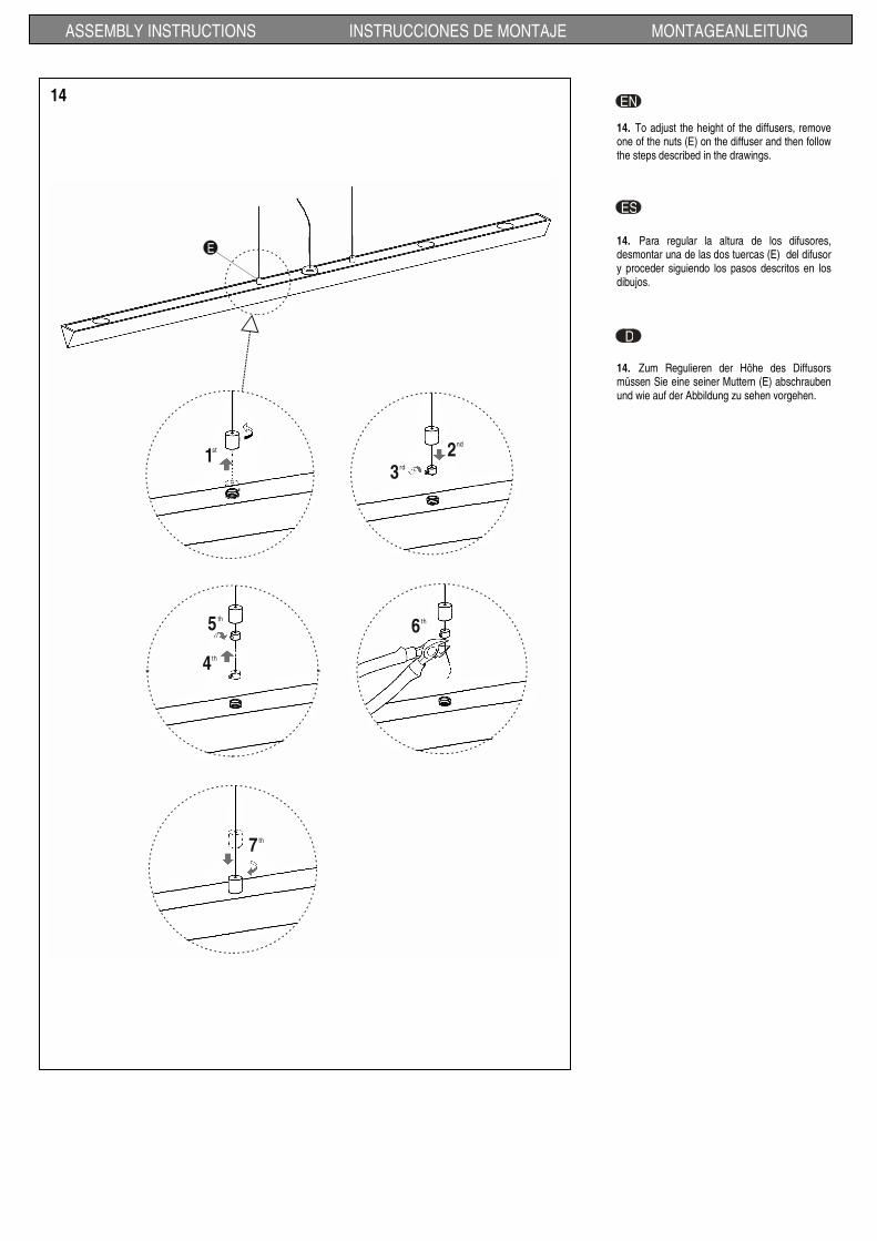
14. To adjust the height of the diffusers, remove one of the nuts (E) on the diffuser and then follow the steps described in the drawings.
EN
D
ES
14. Para regular la altura de los difusores, desmontar una de las dos tuercas (E) del difusor y proceder siguiendo los pasos descritos en los dibujos.
14. Zum Regulieren der Höhe des Diffusors müssen Sie eine seiner Muttern (E) abschrauben und wie auf der Abbildung zu sehen vorgehen.
1st 2
nd
3rd
4th
5 th
7 th
E
6 th
14
ASSEMBLY INSTRUCTIONS INSTRUCCIONES DE MONTAJE MONTAGEANLEITUNG
D
EN
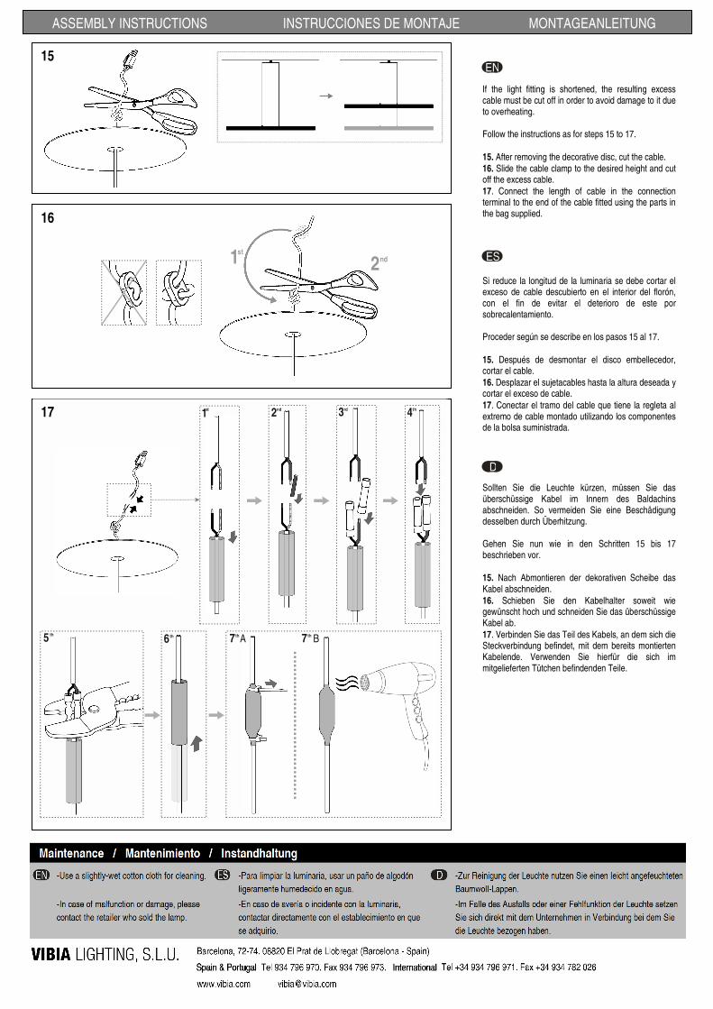
If the light fitting is shortened, the resulting excess cable must be cut off in order to avoid damage to it due to overheating. Follow the instructions as for steps 15 to 17. 15. After removing the decorative disc, cut the cable. 16. Slide the cable clamp to the desired height and cut off the excess cable. 17. Connect the length of cable in the connection terminal to the end of the cable fitted using the parts in the bag supplied.
16
ES
Si reduce la longitud de la luminaria se debe cortar el exceso de cable descubierto en el interior del florón, con el fin de evitar el deterioro de este por sobrecalentamiento. Proceder según se describe en los pasos 15 al 17. 15. Después de desmontar el disco embellecedor, cortar el cable. 16. Desplazar el sujetacables hasta la altura deseada y cortar el exceso de cable. 17. Conectar el tramo del cable que tiene la regleta al extremo de cable montado utilizando los componentes de la bolsa suministrada.
Sollten Sie die Leuchte kürzen, müssen Sie das überschüssige Kabel im Innern des Baldachins abschneiden. So vermeiden Sie eine Beschädigung desselben durch Überhitzung. Gehen Sie nun wie in den Schritten 15 bis 17 beschrieben vor. 15. Nach Abmontieren der dekorativen Scheibe das Kabel abschneiden. 16. Schieben Sie den Kabelhalter soweit wie gewünscht hoch und schneiden Sie das überschüssige Kabel ab. 17. Verbinden Sie das Teil des Kabels, an dem sich die Steckverbindung befindet, mit dem bereits montierten Kabelende. Verwenden Sie hierfür die sich im mitgelieferten Tütchen befindenden Teile.
15
2nd1st
2nd 3rd 4th
5 th
6 th 7 th 7 thA B
1st17