AC 40-1 - alquilerdegruasroman.com 40-1 4 Dimensions Abmessungen Encombrement Type of tyres Level...
20
AC 40-1 ABS SERIENMÄßIG AS STANDARD DE SÉRIE
-
Upload
duongthuan -
Category
Documents
-
view
215 -
download
1
Transcript of AC 40-1 - alquilerdegruasroman.com 40-1 4 Dimensions Abmessungen Encombrement Type of tyres Level...

AC 40-1
ABS SERIENMÄßIGAS STANDARD
DE SÉRIE

www. terex-cranes.com
Most compact 3-axle crane in itscategory
Fast on the road and exceptionally manoeuvrable off road
Clearance height is just 3 m
Runner for indoor applications
Kompaktester 3-Achser seiner Klasse
Schnell auf der Straße und wendigim Gelände
Nur 3 m Durchfahrtshöhe
Montagespitze für Halleneinsätze
La 3 essieux la plus compacte desa catégorie
Rapide sur route et extrêmementmaniable sur chantier
Hauteur de passage de seulement3 mètre
Potence pour utilisation en atelier
AC 40-1
2
Demag AC 40-1

1
2
3
4
5
AC 40-1
3
ContentsInhaltContenu
Specifications · Technische Daten · CaractéristiquesDimensions · Abmessungen · Encombrement . . . . . . . . . . . . . . . . . . . . . . . . . . . . . . . . . . . . . . . . . . . . . . . . . . . . . . . . . . . . . . . . . . . . . . . . . 4Specifications · Technische Daten · Caractéristiques . . . . . . . . . . . . . . . . . . . . . . . . . . . . . . . . . . . . . . . . . . . . . . . . . . . . . . . . . . . . . . . . . . . . 6
Main boom · Hauptausleger · Flèche principaleWorking ranges · Arbeitsbereiche · Portées . . . . . . . . . . . . . . . . . . . . . . . . . . . . . . . . . . . . . . . . . . . . . . . . . . . . . . . . . . . . . . . . . . . . . . . . . . 7Lifting capacities · Tragfähigkeiten · Capacités de levage . . . . . . . . . . . . . . . . . . . . . . . . . . . . . . . . . . . . . . . . . . . . . . . . . . . . . . . . . . . . . . . 8
Main boom extension · Hauptauslegerverlängerung · Rallonge de flècheWorking ranges · Arbeitsbereiche · Portées . . . . . . . . . . . . . . . . . . . . . . . . . . . . . . . . . . . . . . . . . . . . . . . . . . . . . . . . . . . . . . . . . . . . . . . . . . 10Lifting capacities · Tragfähigkeiten · Capacités de levage . . . . . . . . . . . . . . . . . . . . . . . . . . . . . . . . . . . . . . . . . . . . . . . . . . . . . . . . . . . . . . . 11
Runner · Montagespitze · PotenceRunner for workshop applications · Montagespitze für Halleneinsätze · Potence pour utilisation en atelier . . . . . . . . . . . . . . . . . . . . . . 12Lifting capacities · Tragfähigkeiten · Capacités de levage . . . . . . . . . . . . . . . . . . . . . . . . . . . . . . . . . . . . . . . . . . . . . . . . . . . . . . . . . . . . . . . 13Runner and searcher hook for workshop applications · Montagespitze und Kopftraverse für HalleneinsätzePotence et crochet compact pour utilisation en atelier . . . . . . . . . . . . . . . . . . . . . . . . . . . . . . . . . . . . . . . . . . . . . . . . . . . . . . . . . . . . . . . . . 14
Technical description · Technische Beschreibung · Descriptif techniqueCarrier · Superstructure · Optional equipment . . . . . . . . . . . . . . . . . . . . . . . . . . . . . . . . . . . . . . . . . . . . . . . . . . . . . . . . . . . . . . . . . . . . . . . . 15Unterwagen · Oberwagen · Zusatzausrüstung . . . . . . . . . . . . . . . . . . . . . . . . . . . . . . . . . . . . . . . . . . . . . . . . . . . . . . . . . . . . . . . . . . . . . . . . 16Châssis · Partie supérieure · Equipements optionnels . . . . . . . . . . . . . . . . . . . . . . . . . . . . . . . . . . . . . . . . . . . . . . . . . . . . . . . . . . . . . . . . . . . 17
Page · Seite:

AC 40-1
4
Dimensions AbmessungenEncombrement
Type of tyres LevelBereifung Niveau A B C DType de pneus Niveau
Road14.00 Straße 3195 3085 340 1490
Route
Lowered14.00 Abgelassen 3115 3005 260 1410
Rabaissée
Road445 / 65 Straße 3095 2985 240 1390
Route
Lowered445 / 65 Abgelassen 2995 2885 140 1290
Rabaissée

1
AC 40-1
5
( ) with independent rear axle steering( ) mit unabhängiger Hinterachslenkung( ) avec direction indépendante de l’essieu arrière

AC 40-1
6
SpecificationsTechnische DatenCaractéristiques
Axle loads · Achslasten · Poids d’essieuxCrane with main boom,13.0 m main boom extension, counterweight, tyres 445/65 R 22.5, hook block · Kran mit Hauptausleger,Hauptauslegerverlängerung 13,0 m, Gegengewicht, Bereifung 445/65 R 22.5, Unterflasche · Grue avec flèche principale, rallonge de flèche 13,0 m, contrepoids, pneumatiques 445/65 R 22.5, crochet-moufle.Axles · Achsen · Essieux Axles · Achse · Essieux 1 9 000 kg
Axles · Achse · Essieux 2+3 11 500 kgTotal · Gesamt · Total
32 000 kg
Working speeds (infinitely variable) · Arbeitsgeschwindigkeiten (stufenlos regelbar)Vitesses de travail (réglables sans paliers)Mechanisms Normal speed High speed Max. permissible line pull 1) Rope diameter / Rope lengthAntriebe Normalgang Schnellgang Max. zulässiger Seilzug 1) Seil ø / SeillängeMécanismes Marche normale Marche rapide Effort max. admis sur câble1) Diamètre du câble / Longueur du câble
Hoist I 60 m/min 115 m /min 43 kN 16 mm /140 mHubwerk ITreuil de levage I
Slewing · Drehwerk · Orientation max. 2 1/min
Telescoping speed · Ausleger-Teleskopieren · Vitesse de télescopage 7,8 – 31,2 m: 90 s
Boom elevation · Ausleger-Winkelverstellung · Relevage de flèche –10° – +78°: 50 s
Carrier performance · Fahrleistungen · Performance du porteurTravel speed · Fahrgeschwindigkeit · Vitesse sur route 0 . . 80/85 km/h2)
Gradeability in travel order · Steigfähigkeit bei Transportgewicht · Capacité sur rampes en état de transport sur route > 60%Ground clearance · Bodenfreiheit · Dégagement au sol 300/400 mm2)
Hook block / Single line hook · Unterflasche / Hakengehänge · Crochet-moufle / BouletType Possible load 1) Number of sheaves Weight „D“ max. reeving Heavy-lift attachmentTyp mögliche Traglast 1) Anzahl der Rollen Gewicht max. Einscherung SchwerlasteinrichtungType Charge possible 1) Nombre de poulies Poids mouflage maxi Equipement levage lourd
63 50,0 t 6 480 kg 2,00 m 10 1 add. sheave / Zusatzrolle / poulie suppl.32 30,1 t 3 325 kg 1,30 m 1716 12,9 t 1 250 kg 1,10 m 1315 14,3 t Single line hook / 130 kg 0,80 m 11
Hakengehänge /Boulet
Remarks · Bemerkungen · Remarques
1) varies depending on national regulations1) variiert je nach Ländervorschrift1) varie on fonction des normes nationales
2) depending on type of tyres2) je nach Bereifung2) en fonction du type de pneus

AC 40-1
7
Working ranges main boom Arbeitsbereiche HauptauslegerPortées flèche principale

* 0° over rear* 0° nach hinten* 0° sur l’arrière
** only stationary** nur stationär** uniquement stationnaire
1) with horizontal boom1) horizontal1) avec flèche horizontale
AC 40-1
8
Lifting capacities main boomTragfähigkeiten HauptauslegerCapacités de levage flèche principale
Remarks · Bemerkungen · Remarques
6,35 m x 6,20 m 360°Radius Main boom · Hauptausleger · Flèche principaleAusladungPortée m
DIN/ISO 0°*Main boom · Hauptausleger · Flèche principale
DIN/ISO
7,8t,0
40,034,332,430,528,3
-,0-,0-,0-,0-,0-,0-,0-,0-,0-,0-,0-,0-,0-,0-,0-,0
20,0
10,7t,0-,0
25,025,025,025,024,020,317,0
-,0-,0-,0-,0-,0-,0-,0-,0-,0-,0-,0-,0-,0
14,0
13,6t,0-,0
21,021,021,020,719,717,916,015,412,610,5
-,0-,0-,0-,0-,0-,0-,0-,0-,0-,0
8,8
19,5t,0-,0-,0-,0
16,016,016,016,015,314,012,310,38,16,35,1-,0-,0-,0-,0-,0-,0-,0
4,5
25,3t,0-,0-,0-,0-,0-,0-,0
14,013,212,211,210,37,65,95,04,33,53,0-,0-,0-,0-,0
2,5
28,4t,0-,0-,0-,0-,0-,0-,0-,0
11,110,810,19,47,66,04,94,03,42,82,3-,0-,0-,0
1,8
31,2t,0-,0-,0-,0-,0-,0-,0-,0
9,08,88,37,35,94,73,83,12,62,11,71,4-,0
1,1
7,8t,0-,0
14,512,911,510,4
-,0-,0-,0-,0-,0-,0-,0-,0-,0-,0-,0-,0-,0-,0-,0-,0
8,0
10,7t,0-,0
14,012,411,110,09,07,56,1-,0-,0-,0-,0-,0-,0-,0-,0-,0-,0-,0-,0-,0
4,0
13,6t,0-,0
15,113,412,111,010,08,47,25,94,84,1-,0-,0-,0-,0-,0-,0-,0-,0-,0-,0
3,0
6,35 m x 2,34 m 360°Radius Main boom · Hauptausleger · Flèche principaleAusladungPortée m
DIN/ISO 360°**Main boom · Hauptausleger · Flèche principale
DIN/ISO
7,8t,0
11,89,8-,0-,0-,0-,0-,0-,0-,0-,0-,0
8,0
10,7t,0
11,29,27,75,74,3-,0-,0-,0-,0-,0-,0
2,8
13,6t,0
12,610,58,96,75,34,33,63,0-,0-,0-,0
2,1
19,5t,0
12,910,89,27,05,54,53,83,22,31,71,3
-,0
7,8t,0-,05,9-,0-,0-,0-,0-,0-,0-,0-,0-,0
4,8
10,7t,0-,05,44,73,62,8-,0-,0-,0-,0-,0-,0
1,9
13,6t,0-,06,65,84,73,83,12,62,2-,0-,0-,0
1,3
*
* * *1m131313,51414,515161718191012141618202224262830Capacities · TraglastCharges1)
1m1313
13,514
14,515161718191012141618202224262830
Capacities · TraglastCharges1)
1m1414,5151617181910121416Capacities · TraglastCharges1)
1m14
14,5151617181910121416
Capacities · TraglastCharges1)

AC 40-1
9
2
6,35 m x 4,40 m 360°Radius Main boom · Hauptausleger · Flèche principale RadiusAusladung AusladungPortée m Portée
DIN/ISO
7,8t,0
34,331,228,323,8
-,0-,0-,0-,0-,0-,0-,0-,0-,0-,0-,0-,0-,0-,0-,0
20,0
10,7t,0
25,025,025,023,018,413,09,8-,0-,0-,0-,0-,0-,0-,0-,0-,0-,0-,0-,0
7,0
13,6t,0
21,021,021,020,718,014,411,18,97,36,2-,0-,0-,0-,0-,0-,0-,0-,0-,0
5,2
19,5t,0-,0-,0
16,016,016,014,211,49,27,66,44,83,73,0-,0-,0-,0-,0-,0-,0
2,5
25,3t,0-,0-,0-,0-,0-,0
13,610,98,77,76,54,93,83,02,52,11,7-,0-,0-,0
1,5
28,4t,0-,0-,0-,0-,0-,0-,0
10,88,87,46,34,73,62,82,31,81,51,2-,0-,0
0,8
31,2t,0-,0-,0-,0-,0-,0-,0-,08,87,26,14,53,42,72,11,71,31,00,80,6
-,0
1m1313,51414,5151617181910121416182022242628Capacities · TraglastCharges1)
1m13
13,514
14,5151617181910121416182022242628
Capacities · TraglastCharges1)

AC 40-1
10
Working ranges main boom extensionArbeitsbereiche HauptauslegerverlängerungPortées rallonge de flèche

AC 40-1
11
Lifting capacities main boom extensionTragfähigkeiten HauptauslegerverlängerungCapacités de levage rallonge de flèche
3
Radius Extension · Verlängerung · Rallonge de flècheAusladungPortée1m1819101214161820222426283032343638
DIN/ISO
t,06,56,25,95,44,94,54,03,32,82,31,91,6-,0-,0-,0-,0-,0
t,0-,0-,04,24,03,83,73,53,42,92,4-,0-,0-,0-,0-,0-,0-,0
7,1 m0° 30°
t,0-,0-,03,63,33,02,82,62,42,32,12,01,71,51,21,0-,0-,0
t,0-,0-,0-,0-,0-,02,22,12,01,91,91,81,81,6-,0-,0-,0-,0
13,0 m0° 30°
6,35 m x 6,20 m 360°
25,3 m Main boom · Hauptausleger · Flèche principaleRadius Extension · Verlängerung · Rallonge de flècheAusladungPortée1m1819101214161820222426283032343638
DIN/ISO
t,06,56,25,94,73,62,82,31,81,51,20,90,7-,0-,0-,0-,0-,0
t,0-,0-,04,24,03,83,12,52,01,61,3-,0-,0-,0-,0-,0-,0-,0
7,1 m0° 30°
t,0-,0-,03,63,33,02,82,41,91,61,31,00,80,6-,0-,0-,0-,0
t,0-,0-,0-,0-,0-,02,22,12,01,91,61,31,00,8-,0-,0-,0-,0
13,0 m0° 30°
6,35 m x 4,40 m 360°
25,3 m Main boom · Hauptausleger · Flèche principale
1m1819101214161820222426283032343638
t,0-,0-,05,04,84,64,44,03,32,72,21,81,51,20,90,7-,0-,0
t,0-,0-,0-,03,93,73,53,33,12,92,42,01,61,3-,0-,0-,0-,0
t,0-,0-,0-,03,02,92,82,72,52,42,21,91,61,31,10,90,7-,0
t,0-,0-,0-,0-,0-,0-,02,12,01,91,91,81,81,61,31,0-,0-,0
31,2 m Main boom · Hauptausleger · Flèche principale
1m1819101214161820222426283032343638
t,0-,0-,05,04,63,52,82,21,71,41,10,80,6-,0-,0-,0-,0-,0
t,0-,0-,0-,03,93,73,12,52,01,61,31,00,7-,0-,0-,0-,0-,0
t,0-,0-,0-,03,02,92,82,31,81,51,20,90,7-,0-,0-,0-,0-,0
t,0-,0-,0-,0-,0-,0-,02,12,01,81,51,21,00,7-,0
#-,0-,0-,0
31,2 m Main boom · Hauptausleger · Flèche principale

AC 40-1
12
Runner for workshop applicationsMontagespitze für HalleneinsätzePotence pour utilisation en atelier

AC 40-1
13
4
1) Working range – max. offset for runner1) Arbeitsbereich – lange Absteckung Montagespitze1) Portée – inclinaison max. pour potence
2) Working range – medium offset for runner2) Arbeitsbereich – mittlere Absteckung Montagespitze2) Portée – inclinaison moyenne pour potence
3) Working range – min. offset for runner3) Arbeitsbereich – kurze Absteckung Montagespitze3) Portée – inclinaison min. pour potence
4) with horizontal boom4) horizontal4) avec flèche horizontal
Lifting capacities runnerTragfähigkeiten MontagespitzeCapacités de levage potence
Remarks · Bemerkungen · Remarques
6,35 m x 6,20 m 360°Radius Main boom · Hauptausleger · Flèche principale RadiusAusladung AusladungPortée m Portée1m1313,51414,5151617181910121416182022242628Capacities · TraglastCharges4)
1m13
13,514
14,5151617181910121416182022242628
Capacities · TraglastCharges4)
7,8t,0
15,015,015,015,015,0
-,0-,0-,0-,0-,0-,0-,0-,0-,0-,0-,0-,0-,0-,0
15,0
10,7t,0
15,015,015,015,015,015,015,014,1
-,0-,0-,0-,0-,0-,0-,0-,0-,0-,0-,0
11,0
13,6t,0
15,015,015,015,015,015,015,014,312,610,5
-,0-,0-,0-,0-,0-,0-,0-,0
7,5
19,5t,0-,0-,0-,0
15,015,014,513,612,511,610,37,56,25,0-,0-,0-,0-,0-,0-,0
3,8
25,3t,0-,0-,0-,0-,0-,0
11,911,010,29,57,65,84,54,03,42,9-,0-,0-,0
2,2
28,4t,0-,0-,0-,0-,0-,0-,0-,09,89,18,67,65,84,83,93,22,62,11,8-,0
1,4
31,2t,0-,0-,0-,0-,0-,0-,0-,0-,08,37,86,85,84,63,72,92,31,91,51,2
0,8
1)
1)
2)
2)
3)
2+3)
1)
1)
1)
1)
1)
1)
2)
3)
2+3)
1)
1)
1)
1)
1)
1)
1)
1)
2)
2)
2+3)
1)
1)
1)
1)
1)
1)
1)
1)
2)
3)
2+3)
1)
1)
1)
1)
1)
1)
1)
2)
2)
3)
2+3)
1)
1)
1)
1)
1)
1)
1)
2)
2)
3)
3)
2+3)
1)
1)
1)
1)
1)
1)
1)
2)
2)
2)
3)
2+3)
DIN/ISO
6,35 m x 4,40 m 360°Radius Main boom · Hauptausleger · Flèche principale RadiusAusladung AusladungPortée m Portée1m1313,51414,5151617181910121416182022242628Capacities · TraglastCharges4)
1m13
13,514
14,5151617181910121416182022242628
Capacities · TraglastCharges4)
7,8t,0
15,015,015,015,015,0
-,0-,0-,0-,0-,0-,0-,0-,0-,0-,0-,0-,0-,0-,0
15,0
10,7t,0
15,015,015,015,015,013,310,07,9-,0-,0-,0-,0-,0-,0-,0-,0-,0-,0-,0
6,8
13,6t,0
15,015,015,015,015,014,711,28,97,46,2-,0-,0-,0-,0-,0-,0-,0-,0-,0
4,8
19,5t,0-,0-,0-,0
15,015,014,411,09,27,66,44,73,62,9-,0-,0-,0-,0-,0-,0
2,3
25,3t,0-,0-,0-,0-,0
11,08,77,26,54,83,72,92,41,91,6-,0-,0-,0-,0-,0
1,2
28,4t,0-,0-,0-,0-,0-,0-,0-,08,77,46,24,63,52,72,11,71,31,10,8-,0
-,0
31,2t,0-,0-,0-,0-,0-,0-,0-,0-,07,26,04,33,32,51,91,51,10,8-,0-,0
-,0
1)
1)
2)
2)
3)
2+3)
1)
1)
1)
1)
1)
1)
2)
3)
2+3)
1)
1)
1)
1)
1)
1)
1)
1)
2)
2)
2+3)
1)
1)
1)
1)
1)
1)
1)
1)
2)
3)
2+3)
1)
1)
1)
1)
1)
1)
1)
2)
2)
3)
2+3)
1)
1)
1)
1)
1)
1)
1)
2)
2)
3)
3)
1)
1)
1)
1)
1)
1)
1)
2)
2)
DIN/ISO
AC 40-1
14
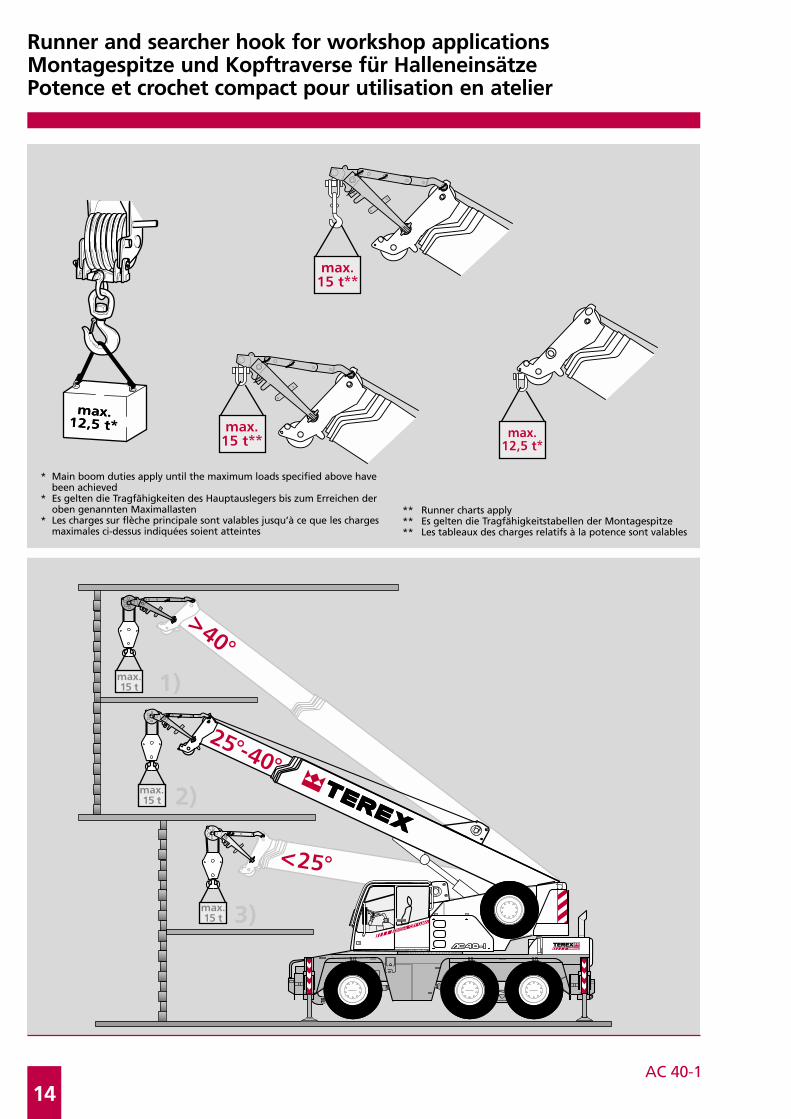
Runner and searcher hook for workshop applicationsMontagespitze und Kopftraverse für HalleneinsätzePotence et crochet compact pour utilisation en atelier
* Main boom duties apply until the maximum loads specified above havebeen achieved
* Es gelten die Tragfähigkeiten des Hauptauslegers bis zum Erreichen der oben genannten Maximallasten
* Les charges sur flèche principale sont valables jusqu’à ce que les chargesmaximales ci-dessus indiquées soient atteintes
** Runner charts apply** Es gelten die Tragfähigkeitstabellen der Montagespitze** Les tableaux des charges relatifs à la potence sont valables

AC 40-1
15
CarrierDrive / steering 6 x 4 x 6.
Frame Monobox main frame with outrigger boxes integral, of high-strength fine-grain structural steel.
Outriggers 4 hydraulically telescoping outrigger beams with hydraulic jack legs.
Engine DaimlerChrysler OM 906 LA water-cooled 6-cylinder engine, output to DIN: 205 kW (279 hp), max. torque 1100 Nm at 1300 1/min. Fuel tank capacity: 300 l.
Transmission Allison automatic transmission with torque-converter, 6 forward speeds and 1 reverse, transfer case withoff-road range and longitudinal differential lock-out control incl. ADM.
Axles Axle 1: with ext. planetary hubs, steering, transverse differential locks; axle 2: non-driving, steering forcrab steer mode; axle 3: with ext. planetary hubs, steering for crab steer mode, transverse differentiallocks.
Suspension Hydropneumatic suspension, blockable hydraulically.
Wheels and tyres 6 wheels fitted with 445/65 R 22.5 tyres.
Travel speed 80 km/h.
Steering ZF dual-circuit hydraulic steering with mech. steering end stop. 1 engine-driven master steering pump,1 emergency steering pump. Independent, electronic-hydraulic rear axle steering.
Brakes Service brake: dual-line air system. Parking brake: spring-loaded type. Sustained action brake: engineexhaust brake and constant decompression valve. ABS as standard.
Electrical equipment 24 V system, 3-phase alternator 80 A, 2 batteries 12 V/120 Ah. Lighting in compliance with EC-directives.
SuperstructureMain boom Boom base and 4 telescopic sections, fabricated from fine-grain structural steel, telescoping with partial
load, anti-deflection Demag ovaloid design.
Counterweight Integrated into superstructure.
Hydraulic system Powered by carrier engine, 1 variable-displacement axial piston pump to enable 3 simultaneous,independent working movements, separate fixed-displacement pump for slew unit.
Hoist Fixed-displacement axial-piston motor, hoist drum with planetary reduction integral and spring-appliedmulti-disk brake.
Slew unit Hydraulic motor with planetary gear reducer, pedal-operated service brake and spring-applied holdingbrake. Slewing speed infinitely variable.
Boom elevation 1 differential cylinder with pilot-controlled lowering brake valve.
Crane cab Spacious all-steel comfortable cab with sliding door, large folding-out windscreen, roof window witharmoured glass, air-sprung and heated dirver’s seat, controls and instrumentation for all crane move-ments, washer and interval control wiper for windscreen and roof window, electrically adjustable andheated outside mirrors.
Safety devices Electronic safe load indicator with graphic display and digital readout for hook load, rated load, boomlength, boom angle, load radius. Integrated display to indicate the percentage of tele sequence, limitswitches on hoist and lowering motions, pressure-relief and safety holding valves.
Optional equipmentDrive / steering 6 x 6 x 6.
Wheels and tyres 14.00 R 25 or 17.5 R 25.
Main boom extension Side-folding 1 or 2-part jib, 7.1 m or 13.0 m. 0° and 30° offset.
Heavy-lift attachment 1 additional sheave on boom head.
Heavy-lift runner 1.20 m long, 3-sheave with several offset positions for working inside buildings.
Cabin Air-suspended and heated driver’s seat, heated and electrically adjustable outside mirrors, sliding rearwindow.
Searcher hook
Air-conditioning
Cool box
Technical description

AC 40-1
16
UnterwagenAntrieb / Lenkung 6 x 4 x 6.
Rahmen Geschlossenes Kastenprofil mit integrierten Abstützkästen aus hochfestem Feinkornbaustahl.
Abstützung 4-Punkt-Abstützung, hydraulisch horizontal und vertikal auszufahrende Abstützungen.
Motor Wassergekühlter 6-Zylinder DaimlerChrysler OM 906 LA, Leistung nach DIN: 205 kW (279 PS),max. Drehmoment 1100 Nm bei 1300 1/min. Inhalt des Kraftstoffbehälters: 300 l.
Getriebe Allison-Automatikgetriebe mit Drehmomentwandler, 6 Vorwärts- und 1 Rückwärtsgang, Verteiler-getriebe mit Geländestufe und Längsdifferentialsperre incl. ADM.
Achsen Achse 1: Außen-Planetenachse mit Querdifferentialsperre, lenkbar; Achse 2: Laufachse, lenkbar beiunabhängiger Hinterachslenkung; Achse 3: Außen-Planetenachse mit Querdifferentialsperre, lenkbarbei unabhängiger Hinterachslenkung.
Federung Alle Achsen hydropneumatisch gefedert und hydraulisch blockierbar.
Bereifung 6-fach, 445/65 R 22.5.
Fahrgeschwindigkeit 80 km/h.
Lenkung ZF-Hydro-Zweikreis-Lenkung mit mechanischer Lenkbegrenzung. 1 motorgetriebene Lenkhauptpumpe,1 Notlenkpumpe. Unabhängige, elektronisch-hydraulische Hinterachslenkung.
Bremsen Betriebsbremse: Zweikreis-Druckluft-Bremsanlage; Feststellbremse: Federspeicherbremse; Dauerbremse:Auspuffklappenbremse, Konstantdrossel. ABS Standard.
Elektrische Anlage Betriebsspannung 24 V, Drehstrom-Lichmaschine 80 A, 2 Batterien 12 V/120 Ah. Beleuchtung nach EG-Richtlinien.
OberwagenHauptausleger Grundkasten und 4 Teleskope aus Feinkornbaustahl, unter Teillast teleskopierbar, beulsteifer Demag-
Ovaloidquerschnitt.
Gegengewicht Im Oberwagen integriert.
Hydraulikanlage Antrieb über Unterwagen-Motor, 1 Axialkolben-Verstellpumpe für 3 gleichzeitige, unabhängigeArbeitsbewegungen, separate Konstantpumpe für das Drehwerk.
Hubwerk Axialkolben-Konstantmotor, Hubwerkstrommel mit integriertem Planetengetriebe und federbelasteterLamellenbremse.
Drehwerk Hydromotor mit Planetengetriebe, fußbetätigte Betriebsbremse, federbelastete Haltebremse.Drehgeschwindigkeit stufenlos.
Wippwerk 1 Differentialzylinder mit vorgesteuertem Senk-Bremsventil.
Krankabine Großräumige Ganzstahl-Komfortkabine mit Schiebetür und großem ausstellbarem Frontfenster, Dachfenster mit Panzerglas, luftgefedertem und beheizbarem Fahrersitz, Betätigungs- und Kontroll-instrumente für alle Kranfunktionen, Front- und Dachscheibenwischer mit Intervallschaltung undScheibenwaschanlage, elektrisch verstell- und beheizbaren Außenspiegeln.
Sicherheitseinrichtungen Elektronischer Lastmomentbegrenzer und Graphik-Display zur digitalen Anzeige von Hakenlast,Nenntraglast, Auslegerlänge, Auslegerwinkel, Ausladung. Integrierte prozentuale Anzeige der Teleskop-ausfahrfolgen. Weitere Sicherheitseinrichtungen: Hub- und Senkendschaltung, Druckbegrenzungsventil,Rohrbruchsicherungen.
ZusatzausrüstungAntrieb / Lenkung 6 x 6 x 6.
Bereifung 14.00 R 25 oder 17.5 R 25.
Hauptauslegerverlängerung Seitlich klappbar, 1- bzw. 2-teilige Spitze, 7,1 m bzw. 13,0 m Länge. Einstellbereich 0° und 30°.
Schwerlasteinrichtung 1 Zusatzrolle am Hauptauslegerkopf.
Schwerlast-Montagespitze Länge 1,20 m, 3-rollig mit einstellbaren Arbeitswinkeln für den Halleneinsatz.
Kabine Fahrersitz pneumatisch gefedert und beheizbar, beheizbare und elektrisch verstellbare Außenspiegel,Heckschiebefenster.
Kopftraverse
Klimaanlage
Kühlfach
Technische Beschreibung
AC 40-1
17
5
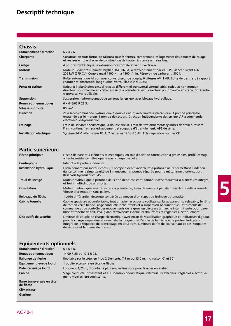
ChâssisEntraînement / direction 6 x 4 x 6.
Charpente Construction sous forme de caissons soudés fermés, comprenant les logements des poutres de calageet réalisés en tôle d’acier de construction de haute résistance à grains fins.
Calage 4 poutres hydrauliques à extension horizontale et vérins verticaux.
Moteur Moteur 6 cylindres DaimlerChrysler OM 906 LA, à refroidissement par eau. Puissance suivant DIN:205 kW (279 CV). Couple maxi 1100 Nm à 1300 1/min. Réservoir de carburant: 300 l.
Transmission Boîte automatique Allison avec convertisseur de couple, 6 vitesses AV, 1 AR. Boîte de transfert à rapportchantier et différentiel longitudinal verrouillable incl. ADM.
Ponts et essieux Essieu 1: à planétaires ext., directeur, différentiel transversal verrouillable; essieu 2: non-moteur,directeur pour marche en crabe; essieu 3: à planétaires ext., directeur pour marche en crabe, différentieltransversal verrouillable.
Suspension Suspension hydropneumatique sur tous les essieux avec blocage hydraulique.
Roues et pneumatiques 6 x 445/65 R 22.5.
Vitesse sur route 80 km/h.
Direction ZF à servo-commande hydraulique à double circuit, avec limiteur mécanique, 1 pompe principaleentrainée par le moteur, 1 pompe de secours. Direction indépendante des essieux AR à commandeélectronique-hydraulique.
Freinage Frein de service: pneumatique, à double circuit. Frein de stationnement: cylindres de frein à ressort.Frein continu: frein sur échappement et soupape d’étranglement. ABS de série.
Installation électrique Système 24 V, alternateur 80 A, 2 batteries 12 V/120 Ah. Eclairage selon normes CE.
Partie supérieureFlèche principale Flèche de base et 4 éléments télescopiques, en tôle d’acier de construction à grains fins, profil Demag
à haute résistance, télescopage avec charge partielle.
Contrepoids Intégré à la partie supérieure.
Installation hydraulique Entraînement par moteur châssis, 1 pompe à débit variable et à pistons axiaux permettant l’indépen-dance comme la simultanéité de 3 mouvements, pompe séparée pour le mécanisme d’orientation.Réservoir hydraulique: 345 l.
Treuil de levage Moteur hydraulique à pistons axiaux et à débit constant, tambour avec réducteur à planétaires intégré,et frein multi-disque à ressorts.
Orientation Moteur hydraulique avec réducteur à planétaires, frein de service à pédale, frein de tourelle à ressorts.Vitesse d’orientation sans paliers.
Relevage de flèche 1 vérin différentiel, descente contrôlée au moyen d’un clapet de freinage automatisé.
Cabine tourelle Cabine spacieuse et confortable, tout en acier, avec porte coulissante, large pare-brise relevable, fenêtrede toit en verre blindé, siège conducteur chauffants et à suspension pneumatique, instruments decommande et de contrôle des mouvements de la grue, essuie-glace à marche intermittente pour pare-brise et fenêtre de toit, lave-glace, rétroviseurs extérieurs chauffants et réglables électriquement.
Dispositifs de sécurité Limiteur de couple de charge électronique avec écran de visualisation graphique et indicateurs digitauxpour la charge suspendue et nominale, la longueur et l’angle de la flèche et la portée. Indicateurintégré de la séquence de télescopage en pour-cent. Limiteurs de fin de course haut et bas, soupapesde sécurité et limiteurs de pression.
Equipements optionnelsEntraînement / direction 6 x 6 x 6.
Roues et pneumatiques 14.00 R 25 ou 17.5 R 25.
Rallonge de flèche Repliable sur le côté, en 1 ou 2 éléments, 7,1 m ou 13,0 m, inclinaison 0° et 30°.
Equipement levage lourd 1 poulie accessoire en tête de flèche.
Potence levage lourd Longueur 1,20 m, 3 poulies à plusieurs inclinaisons pour levages en atelier.
Cabine Siège conducteur chauffant et à suspension pneumatique, rétroviseurs extérieurs réglables électrique-ment, vitre arrière coulissante.
Barre transversale en têtede flèche
Climatiseur
Glacière
Descriptif technique

AC 40-1
18
Notes to lifting capacityAnmerkungen zu den TragfähigkeitenConditions d’utilisation
Ratings are in compliance with ISO 4305 and DIN 15019.2 (test load = 1.25 x suspended load + 0.1 x dead weight of boom head).Weight of hook blocks and slings is part of the load, and is to be deducted from the capacity ratings.
Crane operation with main boom is permissible up to awind pressure of . . . . . . . . . . . . . . . . . . . . . . . . . . . . . . . . . . . . . . . . . . . . . . . . . . . . . . . . . . . . . . . . . . . . . . . . . . . . . . . . . . . . . . . . . 60 N/m2
wind speed of . . . . . . . . . . . . . . . . . . . . . . . . . . . . . . . . . . . . . . . . . . . . . . . . . . . . . . . . . . . . . . . . . . . . . . . . . . . . . . . . . . . . . . . . . . . 9.8 m/s
Consult operation manual for further details.
Note: Data published herein is intended as a guide only and shall not be construed to warrant applicability for lifting purposes. Crane operation is subject to the computer charts and operation manual both supplied with the crane.
Tragfähigkeiten entsprechen ISO 4305 und DIN 15019.2 (Prüflast = 1,25 x Hublast + 0,1 x Kopfgewicht).Das Gewicht der Unterflaschen, sowie die Lastaufnahmemittel, sind Bestandteile der Last und sind von den Tragfähigkeitsangabenabzuziehen.
Kranbetrieb mit Hauptausleger zulässig bis:Staudruck . . . . . . . . . . . . . . . . . . . . . . . . . . . . . . . . . . . . . . . . . . . . . . . . . . . . . . . . . . . . . . . . . . . . . . . . . . . . . . . . . . . . . . . . . . . . . . . 60 N/m2
Windgeschwindigkeit . . . . . . . . . . . . . . . . . . . . . . . . . . . . . . . . . . . . . . . . . . . . . . . . . . . . . . . . . . . . . . . . . . . . . . . . . . . . . . . . . . . . . 9,8 m/s
Weitere Angaben in der Bedienungsanleitung des Kranes.
Anmerkung: Die Daten dieser Broschüre dienen nur zur allgemeinen Information; für ihre Richtigkeit übernehmen wir keine Haftung.Der Betrieb des Kranes ist nur mit den Original-Tragfähigkeitstabellen und mit der Bedienungsanleitung zulässig, die mit dem Kran mitgeliefert werden.
Le tableau de charges est conforme à la norme ISO 4305 et DIN 15019.2 (charge d’essai = 1,25 x charge suspendue + 0,1 x poids de latête de flèche).Les poids du crochet-moufle et de tous les accessoires d’élingage font partie de la charge et sont à déduire des charges indiquées.
La grue peut travailler avec flèche principale jusqu’à unepression du vent de . . . . . . . . . . . . . . . . . . . . . . . . . . . . . . . . . . . . . . . . . . . . . . . . . . . . . . . . . . . . . . . . . . . . . . . . . . . . . . . . . . . . . . . 60 N/m2
vitesse du vent de . . . . . . . . . . . . . . . . . . . . . . . . . . . . . . . . . . . . . . . . . . . . . . . . . . . . . . . . . . . . . . . . . . . . . . . . . . . . . . . . . . . . . . . . 9,8 m/s
Pour plus de détails consulter la notice d’utilisation de la grue.
Nota: Les renseignements ci-inclus sont donnés à titre indicatif et ne représentent aucune garantie d’utilisation pour les opérationsde levage. La mise en service de la grue n’est autorisée qu’à condition que les tableaux de charges ainsi que le manuel de service,tels que fournis avec la grue, soient observés.

AC 40-1
19
5
KeyZeichenerklärungLégende
Lifting capacities on outriggers · Tragfähigkeiten, abgestützt · Capacités de levage sur stabilisateurs · 360°
free on wheels · frei auf Rädern · sur pneus
„D“

The information contained in this bro-chure merely consists of general descrip-tions and a broad compilation of perfor-mance features which might not applyprecisely as described under specific app-lication conditions or which may changeas a result of further product develop-ment. The desired performance features onlybecome binding once expressly agreedin the final contract.
Subject to change without notice!
Die Informationen in dieser Broschüreenthalten lediglich allgemeine Beschrei-bungen bzw. Leistungsmerkmale, wel-che im konkreten Anwendungsfall nichtimmer in der beschriebenen Form zu-treffen bzw. welche sich durch Weiter-entwicklung der Produkte ändern kön-nen. Die gewünschten Leistungsmerkmalesind nur dann verbindlich, wenn sie beiVertragsschluss ausdrücklich vereinbartwerden.
Änderungen vorbehalten!
Les informations figurant dans la présen-te brochure sont de simples descriptionsou des caractéristiques de performancesgénérales qui ne correspondent pastoujours à la forme décrite dans lecas d’applications spécifiques concrètesou qui peuvent varier en fonction des perfectionnements apportés aux pro-duits. Seules les caractéristiques de performan-ces expressément convenues à la signa-ture du contrat engagent notre société.
Sous réserve de modification!
08 /03
Postbox address / Postanschrift / Adresse boîte postale: Registered office / Lieferanschrift / Siège social:
Terex-Demag GmbH & Co.KG Terex-Demag GmbH & Co.KGP.O. Box 1552, D-66465 Zweibrücken Dinglerstraße 24, D-66482 ZweibrückenPhone: +49 6332 83-0 · Fax: +49 6332 1 67 15
Order Nr. AC 40-1 G2 – 201 010 12