Berichte, Gutachten etc. - WUFI · 7.1 SketchUp Plugin 109 7.2 gbXML-Import 112 8 Passive House...
172
WUFI ® Passive 3.0 Manual Authors: Florian Antretter Marcus Fink Matthias Pazold Jan Radon Matthias Winkler created: Tuesday, May 19, 2015
Transcript of Berichte, Gutachten etc. - WUFI · 7.1 SketchUp Plugin 109 7.2 gbXML-Import 112 8 Passive House...
WUFI® Passive 3.0
Manual
Authors:
Florian Antretter
Marcus Fink
Matthias Pazold
Jan Radon
Matthias Winkler
created: Tuesday, May 19, 2015
WUFI® Passive Manual 2
Bericht Nr. Anzuzeigender Text darf nicht mehr als eine Zeile beanspruchen!
Introduction System Requirements
Preamble
This manual describes the installation and the main features of WUFI® Passive.
Using a theoretical building as an example, this manual will show how to create
a 3D visualization of the building, how to set boundary and initial conditions
and finally how to calculate and assess this example. Some hints will be given
at each step. It is advised that you follow this example when working with WU-
FI® Passive for the first time.
For detailed information please refer to our WUFI®-Wiki (www.wufi-wiki.com).
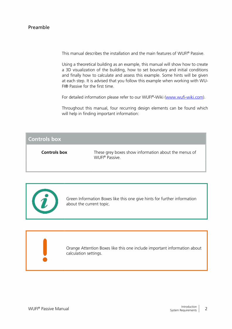
Throughout this manual, four recurring design elements can be found which
will help in finding important information:
Controls box
Controls box
These grey boxes show information about the menus of WUFI® Passive.
Green Information Boxes like this one give hints for further information about the current topic.
Orange Attention Boxes like this one include important information about calculation settings.

WUFI® Passive Manual 3
Bericht Nr. Anzuzeigender Text darf nicht mehr als eine Zeile beanspruchen!
Introduction System Requirements
Blue Difference Boxes like this one remind the user of different inputs de-pending on the selected Passive House verification criteria. All differences are summed up in chapter 4.2.1.
WUFI® Passive Manual 4
Bericht Nr. Anzuzeigender Text darf nicht mehr als eine Zeile beanspruchen!
Introduction System Requirements
Contents
1 Introduction 7
2 Installation 9
2.1 System Requirements 9
2.2 Installation & Update 9
3 Menus 16
3.1 Main Window 16
3.2 Menu Bar 17
3.2.1 File 18
3.2.2 Input 18
3.2.3 Options 19
3.2.4 Database 20
3.2.5 Help 21
3.3 Tool Bar 23
3.4 Visualization Box 24
3.4.1 Inserting Windows and Openings 26
3.4.2 Creating and Modifying the Building Geometry 30
3.5 Status & Results Box 32
4 Project Tree 34
4.1 Project Information 37
4.2 Case Menu 38
4.2.1 Differences between “Default” and “PHIUS+ 2015”
Certification Modes 38
4.3 Localization & Climate 40
4.3.1 Climate Data 41
4.3.2 Primary Energy/ CO2-Factors 43
4.4 Building Menu 44
4.4.1 Creating a Building 45
4.4.2 PH Case 47
4.4.3 Simulated Zones 51
4.4.4 Visualized Components 53
4.4.5 Not Visualized Components 54
4.4.6 Attached Zones 55
4.4.7 Internal Loads & Occupancy 56
4.4.8 Ventilation/ Rooms 65
4.4.9 Thermal Bridges 71
4.4.10 Remaining Elements 72
4.5 HVAC-Systems Menu 73
4.5.1 Ideal User-Defined Systems 75
WUFI® Passive Manual 5
Bericht Nr. Anzuzeigender Text darf nicht mehr als eine Zeile beanspruchen!
Introduction System Requirements
4.5.2 Detailed Predefined Systems 77
4.5.3 Distribution 78
5 Components 83
5.1 Opaque Components 83
5.1.1 General Settings 84
5.1.2 Assembly – Selection 85
5.1.3 Assembly – Editing 86
5.1.4 Surface 88
5.1.5 Exterior Door 89
5.2 Transparent Components 90
5.2.1 General Settings 91
5.2.2 Window Parameters 92
5.2.3 Solar Protection 94
6 HVAC-Devices 97
6.1 Mechanical Ventilation 97
6.2 Electric Heating/ DHW 98
6.3 Boiler 98
6.4 Combined Heat and Power (CHP) 99
6.5 District Heating 99
6.6 Heat Pump 100
6.7 Solar Collector 102
6.8 Water Storage 104
6.9 Photovoltaics 105
6.10 User-Defined 105
6.11 Creating Database Entries for HVAC Devices 106
7 Importing geometry data 109
7.1 SketchUp Plugin 109
7.2 gbXML-Import 112
8 Passive House Verification 115
8.1 General Reports 115
8.2 Passive House Verification Report 118
9 Hygrothermal building simulation 119
9.1 Data-transfer between the Calculation Modes 119
10 DIN 4108-2 Thermal Protection/ Building Simulation 121
11 Example Case 123
11.1 Step 01: Creating a new project 125
WUFI® Passive Manual 6
Bericht Nr. Anzuzeigender Text darf nicht mehr als eine Zeile beanspruchen!
Introduction System Requirements
11.2 Step 02: Defining climatic conditions 126
11.3 Step 03: Creating the building geometry 128
11.4 Step 04: Adding windows and an external door 130
11.4.1 Windows 130
11.4.2 Exterior door 132
11.5 Step 05: General Passive House settings 134
11.6 Step 06: Zonal settings 137
11.7 Step 07: Defining the visualized components 138
11.7.1 Floor Slab 138
11.7.2 Ceiling 142
11.7.3 Exterior Walls 143
11.7.4 Windows 148
11.7.5 Exterior Door 150
11.8 Step 08: Setting internal loads and occupancy schedule 151
11.9 Step 09: Ventilation settings 152
11.10 Step 10: Thermal bridges 156
11.11 Step 11: Connection with attached zone 157
11.12 Step 12: Including HVAC 158
11.12.1 Creating a HVAC system and its devices 158
11.12.2 Distribution 160
11.12.3 Heat Pump 162
11.12.4 Mechanical Ventilation 163
11.13 Step 13: Viewing the results and adjusting the building 164
11.14 Step 14: Passive House Verification Report 165
11.15 Step 15: Switching to dynamic hygrothermal simulations 166

WUFI® Passive Manual 7
Bericht Nr. Anzuzeigender Text darf nicht mehr als eine Zeile beanspruchen!
Introduction System Requirements
1 Introduction
WUFI® Passive allows a double assessment of buildings based on the same
building model:
A monthly energy balance method following EN 13790 is used for the
design and verification of buildings meeting the Passive House criteria.
The dynamic building simulation of WUFI® Plus is used for the detailed dynamic assessment of the hygrothermal behavior of buildings meeting the passive house criteria, as well as individual components. This feature can be used as soon as the building meets the certification criteria.
Combining the monthly energy balance and the dynamic method allows de-
signers to optimize passive buildings for local climate conditions while main-
taining indoor comfort.
Passive buildings are characterized by extremely low energy consumption. Dy-
namic hygrothermal models are necessary to accurately model the hygrother-
mal behavior of buildings in dynamically changing climates or climates where
cooling and dehumidification of the indoor air play an important role. Thermal
and hygric inertia can be considered in detail to further reduce energy demand
and to eliminate limitations on indoor comfort (e.g. overheating).
In many climate zones, the use of highly insulated components presents risks –
such as moisture issues to designers and construction professionals. Managing
this risk requires a dynamic hygrothermal assessment under real climatic condi-
tions.
To meet this need, the Fraunhofer-Institute for Building Physics (IBP) and the
Passive House Institute US (PHIUS) developed WUFI® Passive. WUFI® Passive
combines the WUFI® Plus building simulation tool with the PHIUS+ verification
criteria.
WUFI® Passive allows the user to switch through different calculation scopes at
any time. Building data that is applicable to multiple scopes is carried over from
one scope to another, avoiding double entry. WUFI® Passive comes with the
following scopes:
Passive House Verification: This scope offers the complete passive house
design and verification method, as described in this manual.
WUFI® Plus: This scope provides access to the dynamic building simula-
tion of WUFI® Plus. As long as the building doesn’t fulfill the certifica-
tion criteria only thermal simulations are possible. As soon as the build-
ing meets the certification criteria the full hygrothermal building simula-
tion capabilities of WUFI® Plus are available. Please refer to chapter 9
and the WUFI® Plus manual for further information.
WUFI® Passive Manual 8
Bericht Nr. Anzuzeigender Text darf nicht mehr als eine Zeile beanspruchen!
Introduction System Requirements
DIN 4108-2 Thermal Protection / Building Simulation: The German
thermal protection standard DIN 4108-2 describes verification methods
to reduce overheating during summer. One of these methods is thermal
building simulation with boundary conditions defined by the standard.
This scope of WUFI® Passive can be used to perform calculations ac-
cording to the standard. After the simulation is finished a report with all
results and a classification according to the standard can be exported
for every zone. Please refer to chapter 10 for further information.
WUFI® Passive Manual 9
Bericht Nr. Anzuzeigender Text darf nicht mehr als eine Zeile beanspruchen!
Installation System Requirements
2 Installation
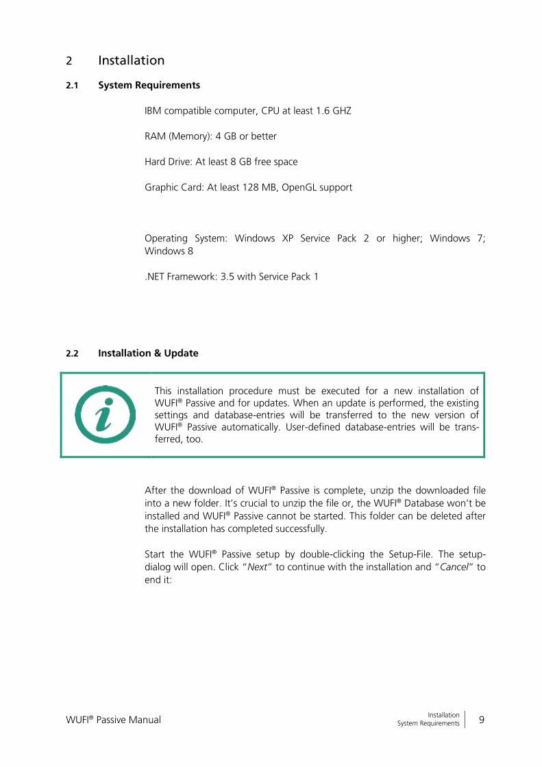
2.1 System Requirements
IBM compatible computer, CPU at least 1.6 GHZ
RAM (Memory): 4 GB or better
Hard Drive: At least 8 GB free space
Graphic Card: At least 128 MB, OpenGL support
Operating System: Windows XP Service Pack 2 or higher; Windows 7;
Windows 8
.NET Framework: 3.5 with Service Pack 1
2.2 Installation & Update
This installation procedure must be executed for a new installation of WUFI® Passive and for updates. When an update is performed, the existing settings and database-entries will be transferred to the new version of WUFI® Passive automatically. User-defined database-entries will be trans-ferred, too.
After the download of WUFI® Passive is complete, unzip the downloaded file
into a new folder. It’s crucial to unzip the file or, the WUFI® Database won’t be
installed and WUFI® Passive cannot be started. This folder can be deleted after
the installation has completed successfully.
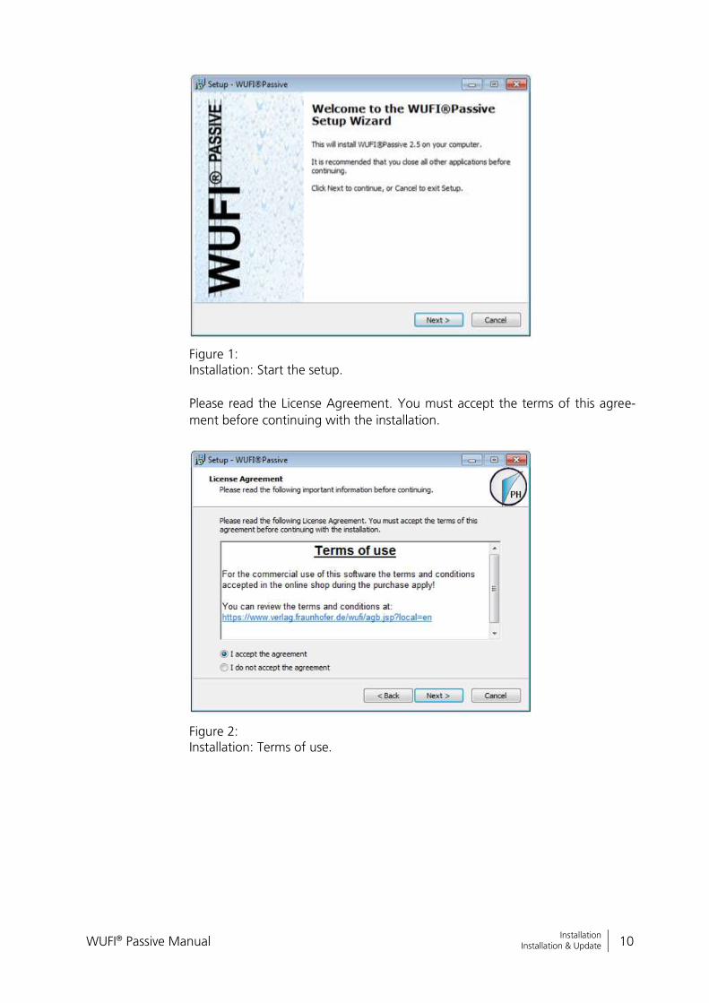
Start the WUFI® Passive setup by double-clicking the Setup-File. The setup-
dialog will open. Click “Next” to continue with the installation and “Cancel” to
end it:
WUFI® Passive Manual 10
Bericht Nr. Anzuzeigender Text darf nicht mehr als eine Zeile beanspruchen!
Installation Installation & Update
Figure 1: Installation: Start the setup.
Please read the License Agreement. You must accept the terms of this agree-
ment before continuing with the installation.
Figure 2: Installation: Terms of use.
WUFI® Passive Manual 11
Bericht Nr. Anzuzeigender Text darf nicht mehr als eine Zeile beanspruchen!
Installation Installation & Update
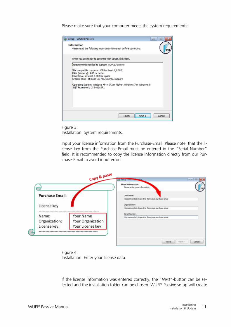
Please make sure that your computer meets the system requirements:
Figure 3: Installation: System requirements.
Input your license information from the Purchase-Email. Please note, that the li-
cense key from the Purchase-Email must be entered in the “Serial Number”
field. It is recommended to copy the license information directly from our Pur-
chase-Email to avoid input errors:
Figure 4: Installation: Enter your license data.
If the license information was entered correctly, the “Next”-button can be se-
lected and the installation folder can be chosen. WUFI® Passive setup will create
WUFI® Passive Manual 12
Bericht Nr. Anzuzeigender Text darf nicht mehr als eine Zeile beanspruchen!
Installation Installation & Update
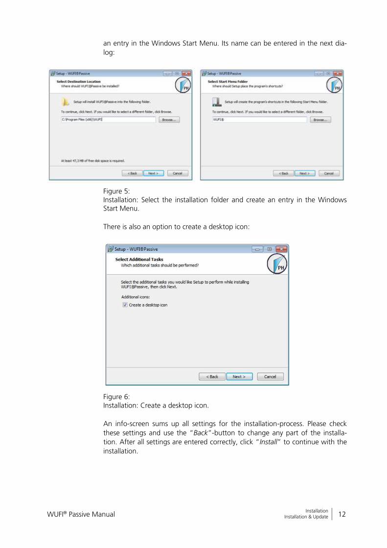
an entry in the Windows Start Menu. Its name can be entered in the next dia-
log:
Figure 5: Installation: Select the installation folder and create an entry in the Windows Start Menu.
There is also an option to create a desktop icon:
Figure 6: Installation: Create a desktop icon.
An info-screen sums up all settings for the installation-process. Please check
these settings and use the “Back”-button to change any part of the installa-
tion. After all settings are entered correctly, click “Install” to continue with the
installation.
WUFI® Passive Manual 13
Bericht Nr. Anzuzeigender Text darf nicht mehr als eine Zeile beanspruchen!
Installation Installation & Update
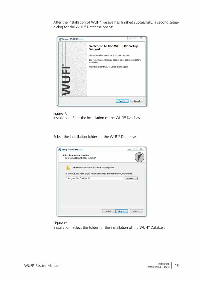
After the installation of WUFI® Passive has finished successfully, a second setup-
dialog for the WUFI® Database opens:
Figure 7: Installation: Start the installation of the WUFI® Database.
Select the installation folder for the WUFI® Database:
Figure 8: Installation: Select the folder for the installation of the WUFI® Database.
WUFI® Passive Manual 14
Bericht Nr. Anzuzeigender Text darf nicht mehr als eine Zeile beanspruchen!
Installation Installation & Update
An info-screen sums up all settings for the installation-process. Please check
these settings and use the “Back”-button to change any part of the installa-
tion. After all settings are entered correctly, click “Install” to continue with the
installation.
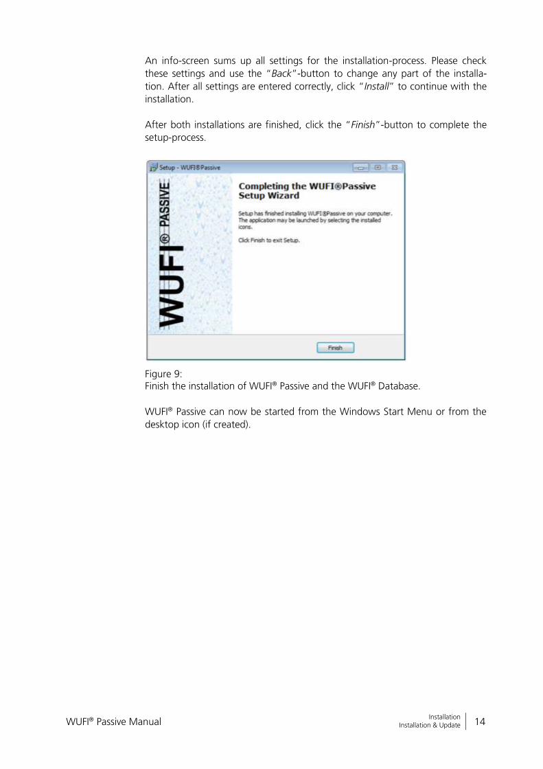
After both installations are finished, click the “Finish”-button to complete the
setup-process.
Figure 9: Finish the installation of WUFI® Passive and the WUFI® Database.
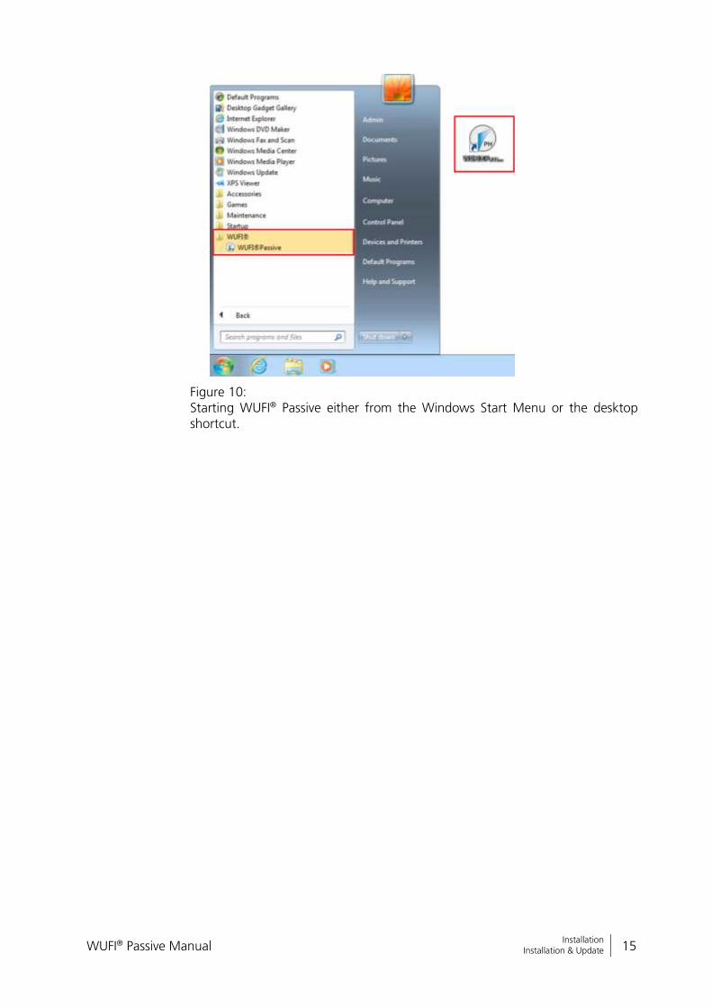
WUFI® Passive can now be started from the Windows Start Menu or from the
desktop icon (if created).
WUFI® Passive Manual 15
Bericht Nr. Anzuzeigender Text darf nicht mehr als eine Zeile beanspruchen!
Installation Installation & Update
Figure 10: Starting WUFI® Passive either from the Windows Start Menu or the desktop shortcut.

WUFI® Passive Manual 16
Bericht Nr. Anzuzeigender Text darf nicht mehr als eine Zeile beanspruchen!
Menus Main Window
3 Menus
This chapter gives a short overview of WUFI® Passive and its menu structure.
3.1 Main Window
After starting WUFI® Passive, the main window will appear, as shown below.
This window provides access to all dialogs and menus. A short description of
each element follows.
Figure 11: Main Window of WUFI® Passive.
Elements of the Main Window
(1) Caption Bar
The product name (WUFI® Passive) and its version number are shown here together with the name of the current pro-ject.
(2) Menu Bar The menu bar contains different main menus. To see indi-vidual menu items and submenus, please open the main menus.
(3) Tool Bar Very basic and frequently used commands can be quickly reached using the tool bar. It also allows switching through the different calculation scopes of WUFI® Passive.
WUFI® Passive Manual 17
Bericht Nr. Anzuzeigender Text darf nicht mehr als eine Zeile beanspruchen!
Menus Menu Bar
(4) Project Tree As an alternative to the “Input” menu in the tool bar, the
project tree offers easy and quick access to different panels. It is advised to follow the project tree structure while work-ing on a project to ensure that no important information is left out.
(5) Dialog Box Dependent of the selections in the “Project Tree” or “In-put” menu, all user inputs or simulation results will be shown in this box. Chapter 4 and its subsections will ex-plain them in detail.
(6) Visualization Box The geometry of the building is visualized here. The 3D Edi-tor menu is located along the left side of this box. Its func-tions are described in chapter 3.4.
(7) Status & Results Box Missing user inputs or errors in the simulation are displayed here. After all necessary data is input, the output of main calculation results are shown.
3.2 Menu Bar
Five different drop down menus are available in the Menu Bar: “File”, “Input”,
“Options”, “Database” and “Help”.
WUFI® Passive Manual 18
Bericht Nr. Anzuzeigender Text darf nicht mehr als eine Zeile beanspruchen!
Menus Menu Bar
3.2.1 File
Controls
New Project
The memory will be reset and a new empty project will be created.
Open The standard Windows dialog for opening a project file will be shown.
Reopen Enables quick access to the last ten projects.
Save Saves the project input data and the calculated results if a simulation has already been completed. The project should be saved before periodically.
Save as Saves the current project with a new name, while the origi-nal project will remain unchanged and with its original name.
Exit Closes WUFI® Passive. If any input has been changed, a safety query will ensure that no data is lost.
3.2.2 Input
This menu allows for fast navigation. Clicking on one of the items makes the
program jump to the corresponding entry in the “Project Tree”. For further in-
formation refer to chapter 4.
WUFI® Passive Manual 19
Bericht Nr. Anzuzeigender Text darf nicht mehr als eine Zeile beanspruchen!
Menus Menu Bar
3.2.3 Options
Options Categories
General
General settings which include Language, Unit system, us-er-information and the default project directory. This menu also has a very important option, which defines if the visu-alized geometry displays the outer or inner surfaces of the building.
Colors Direct link to the color setting menu for the visualized ge-ometry.
View Direct link to the view properties menu for the visualized geometry.
Edit data Settings concerning tool tips and result export.
SketchUp Plugin Options for the WUFI® Plus SketchUp plugin, see chapter 7.1 for further information

WUFI® Passive Manual 20
Bericht Nr. Anzuzeigender Text darf nicht mehr als eine Zeile beanspruchen!
Menus Menu Bar
3.2.4 Database
This menu directs the user to subsections of the WUFI® Passive database.
Controls
Materials
List of predefined building materials and their physical properties. These materials can be used, and new materials can be created.
Assemblies List of predefined combinations of the materials mentioned above. New assemblies can be created, as well.
Windows List of predefined window data. New entries can be added.
Emission sources
List of possible sources of heat, moisture, or carbon dioxide emissions. New entries can be added.
Day profiles List of predefined day profiles representing the usage of a zone. New en-tries can be added.
HVAC device List of predefined HVAC devices. New entries can be added.
Climates List of available climate files. New entries can be added.
Visit our WUFI®-Wiki (www.wufi-wiki.com) to learn more about the data-base. Its usage is described on our Wiki-pages and a tutorial movie provides detail of how to work with the database.

WUFI® Passive Manual 21
Bericht Nr. Anzuzeigender Text darf nicht mehr als eine Zeile beanspruchen!
Menus Menu Bar
3.2.5 Help
Controls
About
Information about the current WUFI® Passive installation, including its program and database version.
WUFI Wiki Link to the WUFI®-Wiki (www.wufi-wiki.com) where addi-tional information and tutorials can be found.
WUFI Forum Link to the WUFI®-Forum (www.wufi-forum.com), which can be used to discuss and exchange information about the WUFI®-family with other users.
WUFI® Passive offers tool tips for many input parameters. These tool tips explain the current input and give hints to recommended values or further sources of data. The tool tips will appear if the mouse is held for one sec-ond over an input field:

WUFI® Passive Manual 22
Bericht Nr. Anzuzeigender Text darf nicht mehr als eine Zeile beanspruchen!
Menus Menu Bar
WUFI® Passive categorizes the user input:
All inputs that are inside an “Additional Data” box further specify the currently selected element. Usually, they must be entered and WUFI® Passive will show an error message in the “Status & Results Box” (chapter 3.5), if the data is missing.
All inputs inside an “Optional data” box don’t have to be entered by the user. WUFI® Passive assumes default values or calculates them from necessary inputs. However, the calculation accuracy will be improved when the optional data is entered by the user.
WUFI® Passive Manual 23
Bericht Nr. Anzuzeigender Text darf nicht mehr als eine Zeile beanspruchen!
Menus Tool Bar
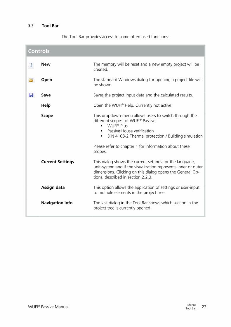
3.3 Tool Bar
The Tool Bar provides access to some often used functions:
Controls
New
The memory will be reset and a new empty project will be created.
Open The standard Windows dialog for opening a project file will be shown.
Save Saves the project input data and the calculated results.
Help Open the WUFI® Help. Currently not active.
Scope This dropdown-menu allows users to switch through the different scopes of WUFI® Passive:
WUFI® Plus Passive House verification DIN 4108-2 Thermal protection / Building simulation
Please refer to chapter 1 for information about these scopes.
Current Settings This dialog shows the current settings for the language, unit-system and if the visualization represents inner or outer dimensions. Clicking on this dialog opens the General Op-tions, described in section 2.2.3.
Assign data This option allows the application of settings or user-input to multiple elements in the project tree.
Navigation Info The last dialog in the Tool Bar shows which section in the project tree is currently opened.
WUFI® Passive Manual 24
Bericht Nr. Anzuzeigender Text darf nicht mehr als eine Zeile beanspruchen!
Menus Visualization Box
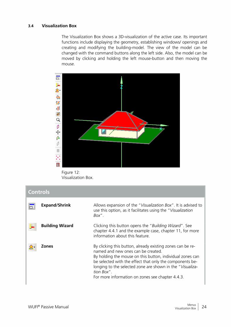
3.4 Visualization Box
The Visualization Box shows a 3D-visualization of the active case. Its important
functions include displaying the geometry, establishing windows/ openings and
creating and modifying the building-model. The view of the model can be
changed with the command buttons along the left side. Also, the model can be
moved by clicking and holding the left mouse-button and then moving the
mouse.
Figure 12: Visualization Box.
Controls
Expand/Shrink
Allows expansion of the “Visualization Box”. It is advised to use this option, as it facilitates using the “Visualization Box”.
Building Wizard Clicking this button opens the “Building Wizard”. See
chapter 4.4.1 and the example case, chapter 11, for more information about this feature.
Zones By clicking this button, already existing zones can be re-
named and new ones can be created. By holding the mouse on this button, individual zones can be selected with the effect that only the components be-longing to the selected zone are shown in the “Visualiza-tion Box”. For more information on zones see chapter 4.4.3.

WUFI® Passive Manual 25
Bericht Nr. Anzuzeigender Text darf nicht mehr als eine Zeile beanspruchen!
Menus Visualization Box
Rotating These Buttons allow rotating the building around all three axes (X,Y & Z). Clockwise and counterclockwise rotation is possible by clicking with the left or right mouse-button. Also the building can be rotated around an axis by clicking on the axis and then using the scroll wheel of the mouse.
Center Centers the view of the “Visualization Box” to its original
position.
Zoom This Button allows zooming in (left mouse button) and
zooming out (right mouse button). The zoom function can also be used by clicking the button and scrolling with the mouse wheel.
Transparency With this button viewing of components can be changed
from transparent to opaque. Transparent mode allows users to look "through" compo-nents to see some otherwise hidden components.
Orientation The orientation of the building can be displayed by left
clicking this button. Right clicking opens the "Change orientation" window, where the orientation of the building can be altered.
Normal vector The normal vector of every component can be viewed as
well. It is visualized as a green arrow on the selected com-ponent and points from the inner side of a component to its outer side. This is important for setting the attachments of every component, see chapter 3.4.2.
Conditionally not visible/ selectable
This button allows the user to make a component condi-tionally not “visible/ selectable”, for example to making hidden components accessible. The difference of this button to the "transparent/opaque" button is, that after clicking on this button, the component is neither visible nor selectable, whereas it is still selectable if only the view is switched from opaque to transparent. In order to use this button for a component, it is important to checkmark the Option "conditionally not visible/ se-lectable" in its properties, which can be accessed by right-clicking on the component in the “Visualization Box”.
Windows & Openings Creates new windows and openings. See chapter 3.4.1 for
further information.
Vertices Shows or hides the vertices. Chapter 3.4.2 shows how ver-
tices can be used to create or modify a building.
Options Settings for the “Visualization Box”, as described in chapter
3.2.3.
WUFI® Passive Manual 26
Bericht Nr. Anzuzeigender Text darf nicht mehr als eine Zeile beanspruchen!
Menus Visualization Box
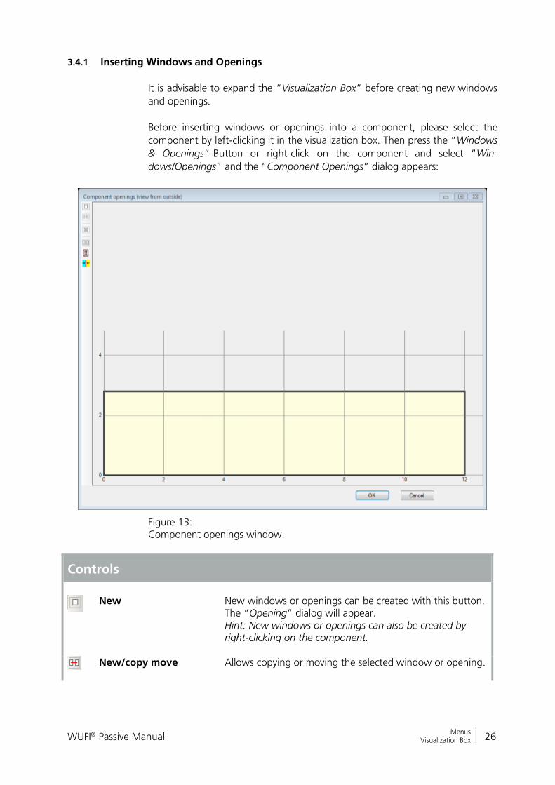
3.4.1 Inserting Windows and Openings
It is advisable to expand the “Visualization Box” before creating new windows
and openings.
Before inserting windows or openings into a component, please select the
component by left-clicking it in the visualization box. Then press the “Windows
& Openings”-Button or right-click on the component and select “Win-
dows/Openings” and the “Component Openings” dialog appears:
Figure 13: Component openings window.
Controls
New
New windows or openings can be created with this button. The “Opening” dialog will appear. Hint: New windows or openings can also be created by right-clicking on the component.
New/copy move
Allows copying or moving the selected window or opening.

WUFI® Passive Manual 27
Bericht Nr. Anzuzeigender Text darf nicht mehr als eine Zeile beanspruchen!
Menus Visualization Box
Delete Delete the currently selected window or opening. Hint: Selected windows or openings can also be deleted by pressing the “Delete”-key on the keyboard.
Select All Select all windows and openings in this component.
Edit list Shows a list of all windows and openings and allows edit-ing or adding new windows and openings.
Change view Change the view of the component. The currently active
view is displayed in the caption bar of this menu.
New windows or openings can be created by clicking the “New”-Button or by
right-clicking on the component. The “Opening” dialog appears and the win-
dow type (1), its position along the grid (2) and its measurements (3) can be en-
tered, shown in the figure below:
Figure 14: Creating a new window or opening.
With the “Opening” dialog these types of window geometries can be entered:
Rectangle
WUFI® Passive Manual 28
Bericht Nr. Anzuzeigender Text darf nicht mehr als eine Zeile beanspruchen!
Menus Visualization Box
Triangle
Circle
Rectangle with arch above
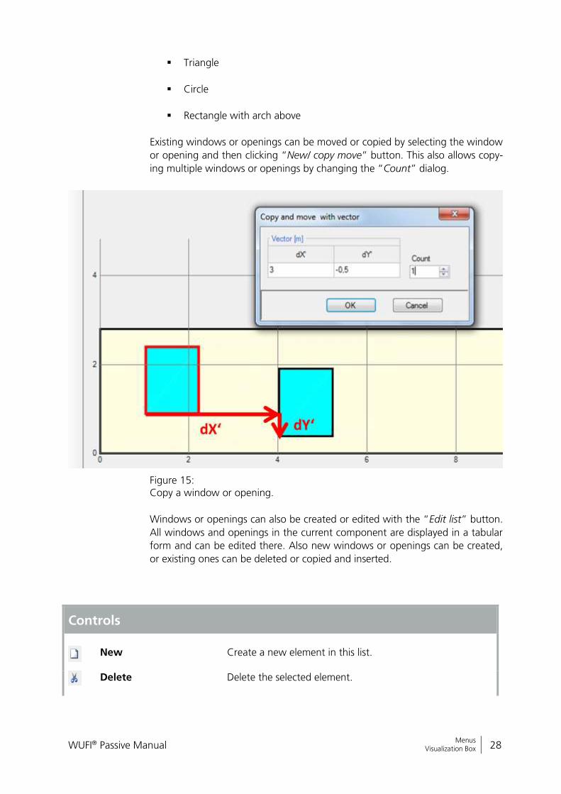
Existing windows or openings can be moved or copied by selecting the window
or opening and then clicking “New/ copy move” button. This also allows copy-
ing multiple windows or openings by changing the “Count” dialog.
Figure 15: Copy a window or opening.
Windows or openings can also be created or edited with the “Edit list” button.
All windows and openings in the current component are displayed in a tabular
form and can be edited there. Also new windows or openings can be created,
or existing ones can be deleted or copied and inserted.
Controls
New
Create a new element in this list.
Delete Delete the selected element.
WUFI® Passive Manual 29
Bericht Nr. Anzuzeigender Text darf nicht mehr als eine Zeile beanspruchen!
Menus Visualization Box
Copy Copy the selected element.
Insert Insert a copied element. The “Insert Position” specifies where the copied element will be positioned.
Insert Position Controls where a copied element will be inserted: “after” the selected element “before” the selected element “exchange” the selected element with the copied
one
Visit our WUFI®-Wiki (www.wufi-wiki.com) to learn more about this fea-ture. A tutorial movie shows in detail how to insert windows in compo-nents.
WUFI® Passive Manual 30
Bericht Nr. Anzuzeigender Text darf nicht mehr als eine Zeile beanspruchen!
Menus Visualization Box
3.4.2 Creating and Modifying the Building Geometry
The geometry of the building can be expanded and changed in the “Visualiza-
tion Box”, by using vertices and connecting them to components. This 3D edit-
ing allows the input of complex building shapes within WUFI® Passive and can
also be used to create the whole building geometry.
It is advisable to first expand the “Visualization Box” and also the vertices must
be switched to visible with the “Vertices” button.
New vertices can be defined by right clicking into the “Visualization Box”,
choosing "New Vertices" and then entering the coordinates. By clicking on ex-
isting vertices, the “Vertex Operations” become available, which allows for ex-
ample copying and moving or making components from vertices. By selecting
two vertices, the “Two Point Operations” become available, which will find in-
tersection points or show the distance between the two vertices, for example.
Also components can be edited in the “Visualization Box”. The options are for
example showing the component properties, grouping or ungrouping them.
Another important feature is changing their inner and outer orientation, which
is visualized with a little green arrow that points from the inside to the outside
of a component.
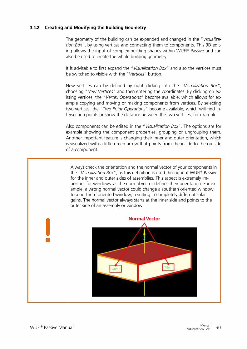
Always check the orientation and the normal vector of your components in the “Visualization Box”, as this definition is used throughout WUFI® Passive for the inner and outer sides of assemblies. This aspect is extremely im-portant for windows, as the normal vector defines their orientation. For ex-ample, a wrong normal vector could change a southern oriented window to a northern oriented window, resulting in completely different solar gains. The normal vector always starts at the inner side and points to the outer side of an assembly or window.
WUFI® Passive Manual 31
Bericht Nr. Anzuzeigender Text darf nicht mehr als eine Zeile beanspruchen!
Menus Visualization Box
Please refer to our WUFI®-Wiki (www.wufi-wiki.com) for detailed infor-mation about 3D editing in WUFI® Passive. It also shows how to edit a building using vertices in a tutorial video.
WUFI® Passive Manual 32
Bericht Nr. Anzuzeigender Text darf nicht mehr als eine Zeile beanspruchen!
Menus Status & Results Box
3.5 Status & Results Box
The “Status & Results Box” helps the user during the process of completing a
model. It shows the current status of a calculation and gives a brief summary of
its main results.
Controls
Close/ Reestablish
Hides or shows the “Status & Results”-Box.
Status indicator The status indicator shows if all necessary input are entered. As soon as WUFI® Passive has all of the inputs needed to perform its calculations, it turns from red to yellow or green and the main results are shown in the “Status & Results”-Box. As long as warnings are shown, the yellow symbol appears. After the Pas-sive House Verification is successful, the green symbol appears.
Warnings/ Results After all necessary data is entered, the main calculation results will be shown in the “Status & Results”-Box. WUFI® Passive also gives warnings if certain inputs are missing or seem to be unreal-istic. This button switches between the calculation results and the warnings.
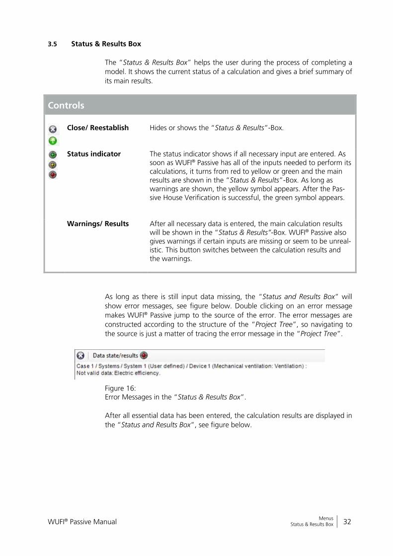
As long as there is still input data missing, the “Status and Results Box” will
show error messages, see figure below. Double clicking on an error message
makes WUFI® Passive jump to the source of the error. The error messages are
constructed according to the structure of the “Project Tree”, so navigating to
the source is just a matter of tracing the error message in the “Project Tree”.
Figure 16: Error Messages in the “Status & Results Box”.
After all essential data has been entered, the calculation results are displayed in
the “Status and Results Box”, see figure below.

WUFI® Passive Manual 33
Bericht Nr. Anzuzeigender Text darf nicht mehr als eine Zeile beanspruchen!
Menus Status & Results Box
Figure 17: Summary of main calculation results in the “Status & Results Box”.
WUFI® Passive Manual 34
Bericht Nr. Anzuzeigender Text darf nicht mehr als eine Zeile beanspruchen!
Project Tree Status & Results Box
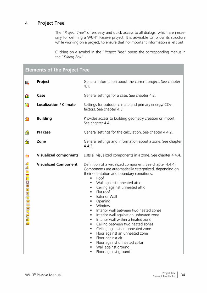
4 Project Tree
The “Project Tree” offers easy and quick access to all dialogs, which are neces-
sary for defining a WUFI® Passive project. It is advisable to follow its structure
while working on a project, to ensure that no important information is left out.
Clicking on a symbol in the “Project Tree” opens the corresponding menus in
the “Dialog Box”.
Elements of the Project Tree
Project
General information about the current project. See chapter 4.1.
Case General settings for a case. See chapter 4.2.
Localization / Climate Settings for outdoor climate and primary energy/ CO2-factors. See chapter 4.3.
Building Provides access to building geometry creation or import. See chapter 4.4.
PH case General settings for the calculation. See chapter 4.4.2.
Zone General settings and information about a zone. See chapter 4.4.3.
Visualized components Lists all visualized components in a zone. See chapter 4.4.4.
Visualized Component Definition of a visualized component. See chapter 4.4.4. Components are automatically categorized, depending on their orientation and boundary conditions:
Roof Wall against unheated attic Ceiling against unheated attic Flat roof Exterior Wall Opening Window Interior wall between two heated zones Interior wall against an unheated zone Interior wall within a heated zone Ceiling between two heated zones Ceiling against an unheated zone Floor against an unheated zone Floor against air Floor against unheated cellar Wall against ground Floor against ground
WUFI® Passive Manual 35
Bericht Nr. Anzuzeigender Text darf nicht mehr als eine Zeile beanspruchen!
Project Tree Status & Results Box
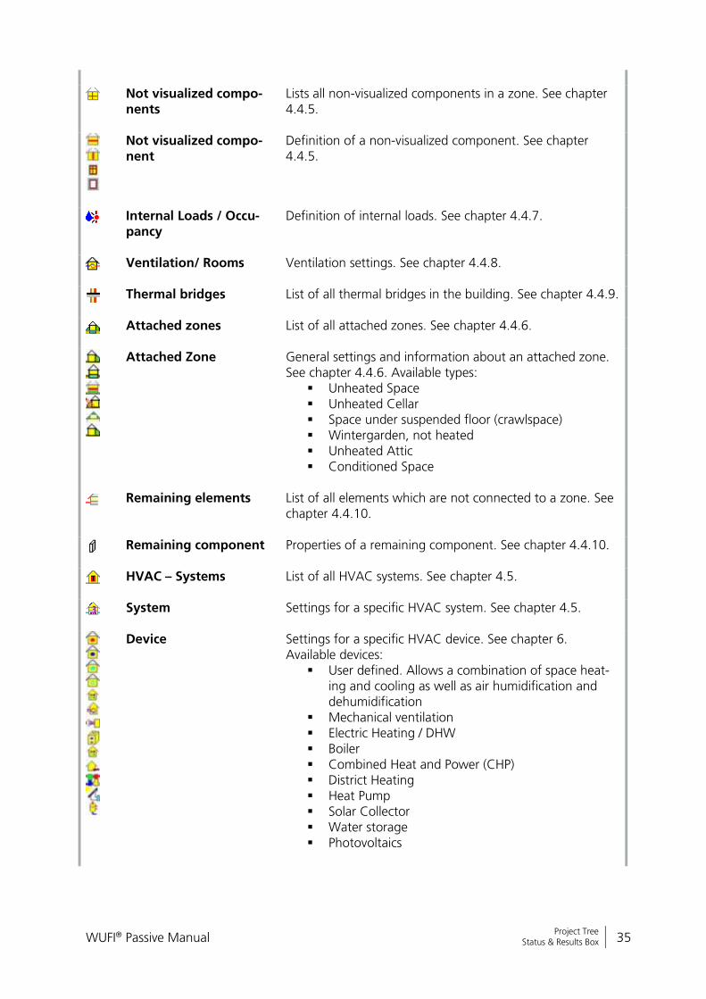
Not visualized compo-nents
Lists all non-visualized components in a zone. See chapter 4.4.5.
Not visualized compo-nent
Definition of a non-visualized component. See chapter 4.4.5.
Internal Loads / Occu-pancy
Definition of internal loads. See chapter 4.4.7.
Ventilation/ Rooms Ventilation settings. See chapter 4.4.8.
Thermal bridges List of all thermal bridges in the building. See chapter 4.4.9.
Attached zones List of all attached zones. See chapter 4.4.6.
Attached Zone General settings and information about an attached zone. See chapter 4.4.6. Available types:
Unheated Space Unheated Cellar Space under suspended floor (crawlspace) Wintergarden, not heated Unheated Attic Conditioned Space
Remaining elements List of all elements which are not connected to a zone. See chapter 4.4.10.
Remaining component Properties of a remaining component. See chapter 4.4.10.
HVAC – Systems List of all HVAC systems. See chapter 4.5.
System Settings for a specific HVAC system. See chapter 4.5.
Device Settings for a specific HVAC device. See chapter 6. Available devices:
User defined. Allows a combination of space heat-ing and cooling as well as air humidification and dehumidification
Mechanical ventilation Electric Heating / DHW Boiler Combined Heat and Power (CHP) District Heating Heat Pump Solar Collector Water storage Photovoltaics
WUFI® Passive Manual 36
Bericht Nr. Anzuzeigender Text darf nicht mehr als eine Zeile beanspruchen!
Project Tree Status & Results Box
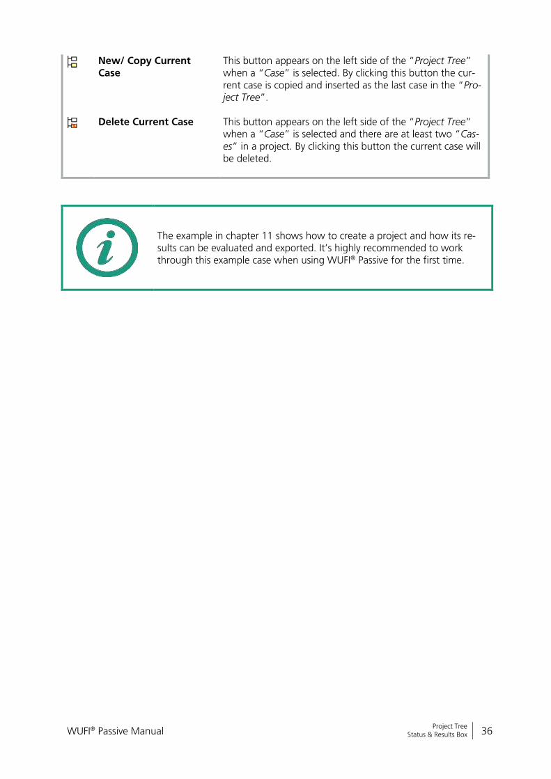
New/ Copy Current Case
This button appears on the left side of the “Project Tree” when a “Case” is selected. By clicking this button the cur-rent case is copied and inserted as the last case in the “Pro-ject Tree”.
Delete Current Case This button appears on the left side of the “Project Tree” when a “Case” is selected and there are at least two “Cas-es” in a project. By clicking this button the current case will be deleted.
The example in chapter 11 shows how to create a project and how its re-sults can be evaluated and exported. It’s highly recommended to work through this example case when using WUFI® Passive for the first time.

WUFI® Passive Manual 37
Bericht Nr. Anzuzeigender Text darf nicht mehr als eine Zeile beanspruchen!
Project Tree Project Information
4.1 Project Information
Information about the current project can be entered with this dialog, including
the client, the building, its owner and your personal information. Also a picture
of the building can be added, either from the current view in the “Visualization
Box” or from an external image.
The data entered in this dialog will appear on the results report, which can be
created and exported after a simulation. Please refer to section 5 for further in-
formation about the results reports.
If you add your personal information in the “General Options”, see chapter 3.2.3, it will be filled in the “Project Information” automatically.
WUFI® Passive Manual 38
Bericht Nr. Anzuzeigender Text darf nicht mehr als eine Zeile beanspruchen!
Project Tree Case Menu
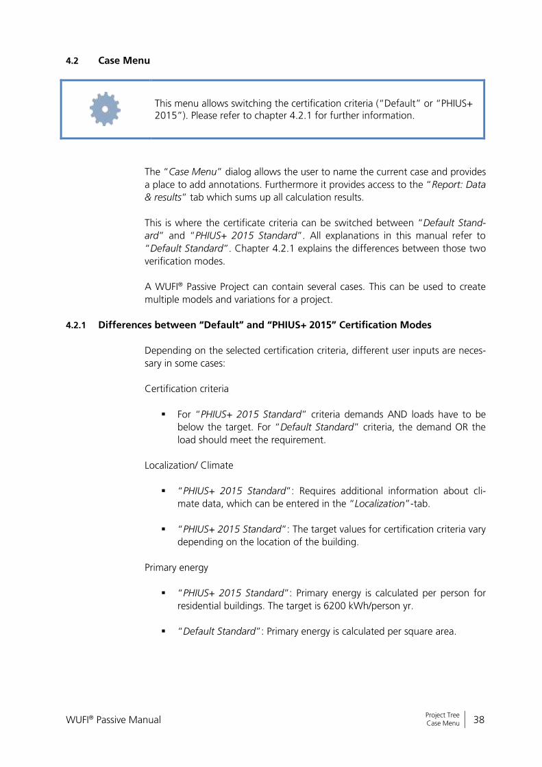
4.2 Case Menu
This menu allows switching the certification criteria (“Default” or “PHIUS+ 2015”). Please refer to chapter 4.2.1 for further information.
The “Case Menu” dialog allows the user to name the current case and provides
a place to add annotations. Furthermore it provides access to the “Report: Data
& results” tab which sums up all calculation results.
This is where the certificate criteria can be switched between “Default Stand-
ard” and “PHIUS+ 2015 Standard”. All explanations in this manual refer to
“Default Standard”. Chapter 4.2.1 explains the differences between those two
verification modes.
A WUFI® Passive Project can contain several cases. This can be used to create
multiple models and variations for a project.
4.2.1 Differences between “Default” and “PHIUS+ 2015” Certification Modes
Depending on the selected certification criteria, different user inputs are neces-
sary in some cases:
Certification criteria
For “PHIUS+ 2015 Standard” criteria demands AND loads have to be
below the target. For “Default Standard” criteria, the demand OR the
load should meet the requirement.
Localization/ Climate
“PHIUS+ 2015 Standard”: Requires additional information about cli-
mate data, which can be entered in the “Localization”-tab.
“PHIUS+ 2015 Standard”: The target values for certification criteria vary
depending on the location of the building.
Primary energy
“PHIUS+ 2015 Standard”: Primary energy is calculated per person for
residential buildings. The target is 6200 kWh/person yr.
“Default Standard”: Primary energy is calculated per square area.
WUFI® Passive Manual 39
Bericht Nr. Anzuzeigender Text darf nicht mehr als eine Zeile beanspruchen!
Project Tree Case Menu
“PHIUS+ 2015 Standard”: Primary energy factor for electricity mix in
the United States is 3.16 (“Default Standard”: 2.70).
“PHIUS+ 2015 Standard”: Photovoltaic savings are considered in the
Primary Energy calculation.
PH case, zone information
“PHIUS+ 2015 Standard”: The resulting net volume for the PH case has
to be calculated from the real building geometry and must be entered
directly.
“Default Standard”: In contrary to the “PHIUS+ 2015 Standard”, the
net volume is calculated with the treated floor area multiplied by the
clearance height.
Recommend user input for “PHIUS+ 2015 Standard”
The input for infiltration should be changed to the envelope airtightness
coefficient, instead of the ACH50.
PHIUS+ 2015 Standard internal loads should be added as devices for
residential buildings. 80% of the RESNET load is calculated.
Differences in calculation for “PHIUS+ 2015 Standard”:
Mostly the calculation of the cooling demand, the peak cooling load
and cooling devices is changed. It includes per default the dehumidifica-
tion energy demand, which requires the monthly dew point tempera-
ture from the climate data.
The summer internal heat gains are calculated apart from the winter in-
ternal gains (slightly increased, e.g. the DHW count in).
The peak cooling load can be calculated comparing two different
weather conditions. The resulting higher peak cooling load is used.
Different cooling devices (cooling with supply air, recirculation air, or
dehumidification) can be regarded with different COP’s.
Renewable on site produced energy, like from photovoltaics are regard-
ed by decreasing the primary energy demand.
Blue Difference Boxes like this one are shown throughout the manual where user input differs because of the two certification criteria.
WUFI® Passive Manual 40
Bericht Nr. Anzuzeigender Text darf nicht mehr als eine Zeile beanspruchen!
Project Tree Localization & Climate
4.3 Localization & Climate
Buildings are exposed to outer climatic boundary conditions. For Passive House
calculations, the climate data must be provided in a special format:
Monthly mean values of ambient temperature are always necessary. In
addition, monthly mean values of dew point temperature are highly
recommended, and necessary for the “PHIUS+ 2015 Standard” to cal-
culate the latent cooling demand. Sky and ground temperatures are op-
tional and if there is no input, they are calculated by the foundation in-
terface and the ambient temperature. For further information about the
foundation interface refer to chapter 4.4.2.
Monthly mean values of solar radiation are always necessary: Global,
North, East, South and West.
Also extreme (peak) weather conditions for the above described tem-
perature and solar radiation parameters are necessary: Two for the cal-
culation of heating load and two for cooling load (the second weather
conditions for cooling load are optional).
Climate data can either be selected from standard-values or user-defined data
can be entered. A user-defined climate can be imported from an external file
(Text- or Excel-files) or it can be entered manually into WUFI® Passive. Also, cli-
mate files can be selected in the WUFI® Database. The WUFI® Database allows
storing a connected climatic dataset for a specific location consisting of the
monthly data for the Passive House calculation and detailed hourly climate data
for the dynamic simulations with WUFI® Plus. This simplifies switching through
the calculation scopes.
Please refer to our WUFI®-Wiki (www.wufi-wiki.com) to learn how external climate files can be included into WUFI® Passive calculations. A tutorial vid-eo shows how this is done.
WUFI® Passive Manual 41
Bericht Nr. Anzuzeigender Text darf nicht mehr als eine Zeile beanspruchen!
Project Tree Localization & Climate
4.3.1 Climate Data
There are different inputs depending on the certification criteria (“Default” or “PHIUS+ 2015”) including the PHIUS+ 2015 performance targets. Please refer to chapter 4.2.1 for further information.
Necessary climate data can be entered in the “Localization”- and the “Climate”
tab. See figures below:
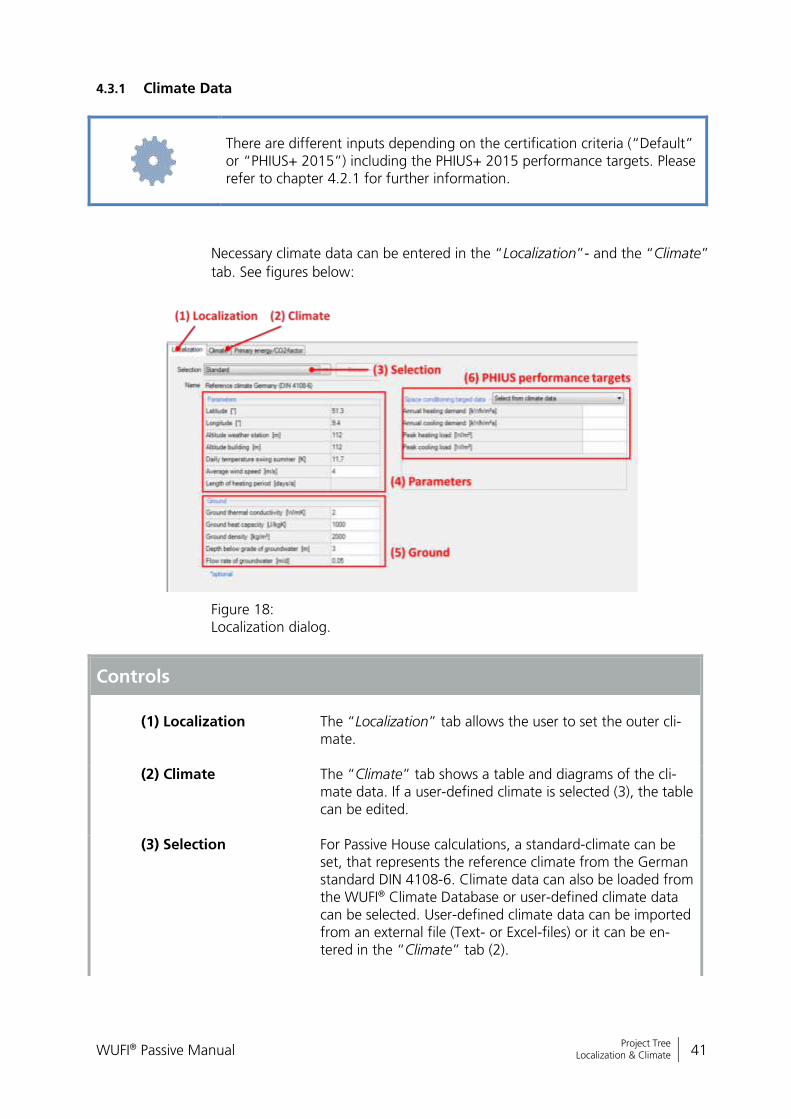
Figure 18: Localization dialog.
Controls
(1) Localization
The “Localization” tab allows the user to set the outer cli-mate.
(2) Climate The “Climate” tab shows a table and diagrams of the cli-mate data. If a user-defined climate is selected (3), the table can be edited.
(3) Selection For Passive House calculations, a standard-climate can be set, that represents the reference climate from the German standard DIN 4108-6. Climate data can also be loaded from the WUFI® Climate Database or user-defined climate data can be selected. User-defined climate data can be imported from an external file (Text- or Excel-files) or it can be en-tered in the “Climate” tab (2).
WUFI® Passive Manual 42
Bericht Nr. Anzuzeigender Text darf nicht mehr als eine Zeile beanspruchen!
Project Tree Localization & Climate
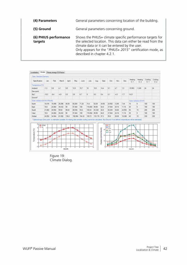
(4) Parameters General parameters concerning location of the building.
(5) Ground General parameters concerning ground.
(6) PHIUS performance targets
Shows the PHIUS+ climate specific performance targets for the selected location. This data can either be read from the climate data or it can be entered by the user. Only appears for the “PHIUS+ 2015” certification mode, as described in chapter 4.2.1.
Figure 19: Climate Dialog.

WUFI® Passive Manual 43
Bericht Nr. Anzuzeigender Text darf nicht mehr als eine Zeile beanspruchen!
Project Tree Localization & Climate
4.3.2 Primary Energy/ CO2-Factors
Depending on the energy source used, the energy demand is multiplied by a
“Primary Energy Factor”. This “Primary Energy Factor” takes the generation
process and the transportation of an energy source into account. The “CO2-
Factor” allows the conversion of the energy use into an equivalent amount of
CO2.
WUFI® Passive comes with predefined standard-values for both factors for
Germany, USA and Italy. User-defined values can also be entered.
There are different values for the primary energy factor of electricity mix in the United States depending on the certification criteria (“Default” or “PHIUS+ 2015”). Please refer to chapter 4.2.1 for further information.
WUFI® Passive Manual 44
Bericht Nr. Anzuzeigender Text darf nicht mehr als eine Zeile beanspruchen!
Project Tree Building Menu
4.4 Building Menu
All user inputs which describe a building are grouped in this section. It provides
access to available elements of the building, gives methods for geometry crea-
tion or import, and allows changing the orientation:
Available elements: Lists available elements of the current building.
Double-clicking on an element opens the corresponding dialog.
Building Wizard: Opens the “Building Wizard” which helps to create
simple geometries by combining predefined footprints, roof and foun-
dation constructions. Refer to chapter 4.4.1 for further information.
Change orientation: Changes the orientation of the building.
3-D Editor: Creates or modifies a building geometry directly in WUFI®
Plus. Clicking this button expands the “Visualization Box” to facilitate
working with the 3-D Editor. Refer to chapter 3.4.2 for further infor-
mation.
SketchUp-Import: Imports geometry data from a wps-file created with
the WUFI® Plus SketchUp-plugin. Refer to chapter 7.1 for further infor-
mation.
gbXML-Import: Imports geometry data from a gbXML-file. Refer to
chapter 7.2 for further information.

WUFI® Passive Manual 45
Bericht Nr. Anzuzeigender Text darf nicht mehr als eine Zeile beanspruchen!
Project Tree Building Menu
4.4.1 Creating a Building
WUFI® Passive offers multiple ways to create or import 3D-geometries, which
can all be accessed by clicking the “Building”-entry in the “Project Tree”:
Building Wizard, as described in this chapter.
Modifying vertices, as described in chapter 3.4.2.
Importing a SketchUp-Geometry, see chapter 7.1.
Importing gbXML-data, see chapter 7.2.
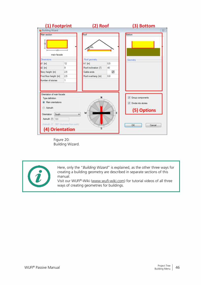
The “Building Wizard” is the easiest way to create a building in WUFI® Passive.
It uses a collection of predefined footprints (1) as well as roof (2) and founda-
tion (3) constructions to create building geometry, see figure below. The di-
mensions of these presets can be changed by the user.
On the bottom side of the dialog, the orientation of the main facade needs to
be defined either by means of the main orientations or by Azimuth (4). The
main facade depends on the footprint of the building and is shown in the se-
lection graph of the footprint selection.
On the right side there are two other options which allow grouping of similar
components and dividing components by stories (5). Components can be un-
grouped in the “Visualization Box” by right-clicking on them.
Geometries created with the “Building Wizard” can be modified with the 3D
editing methods described in chapter 3.4.2.
WUFI® Passive Manual 46
Bericht Nr. Anzuzeigender Text darf nicht mehr als eine Zeile beanspruchen!
Project Tree Building Menu
Figure 20: Building Wizard.
Here, only the “Building Wizard” is explained, as the other three ways for creating a building geometry are described in separate sections of this manual. Visit our WUFI®-Wiki (www.wufi-wiki.com) for tutorial videos of all three ways of creating geometries for buildings.
WUFI® Passive Manual 47
Bericht Nr. Anzuzeigender Text darf nicht mehr als eine Zeile beanspruchen!
Project Tree Building Menu
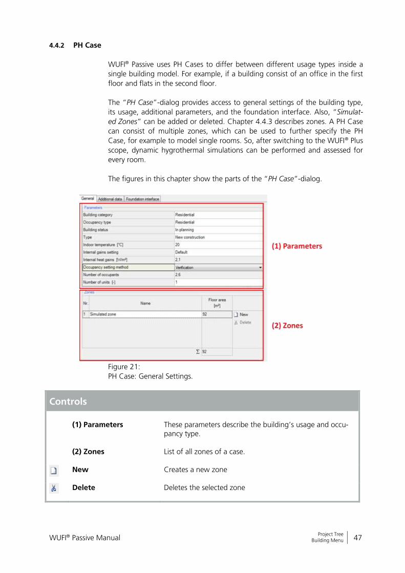
4.4.2 PH Case
WUFI® Passive uses PH Cases to differ between different usage types inside a
single building model. For example, if a building consist of an office in the first
floor and flats in the second floor.
The “PH Case”-dialog provides access to general settings of the building type,
its usage, additional parameters, and the foundation interface. Also, “Simulat-
ed Zones” can be added or deleted. Chapter 4.4.3 describes zones. A PH Case
can consist of multiple zones, which can be used to further specify the PH
Case, for example to model single rooms. So, after switching to the WUFI® Plus
scope, dynamic hygrothermal simulations can be performed and assessed for
every room.
The figures in this chapter show the parts of the “PH Case”-dialog.
Figure 21:
PH Case: General Settings.
Controls
(1) Parameters
These parameters describe the building’s usage and occu-pancy type.
(2) Zones List of all zones of a case.
New Creates a new zone
Delete Deletes the selected zone

WUFI® Passive Manual 48
Bericht Nr. Anzuzeigender Text darf nicht mehr als eine Zeile beanspruchen!
Project Tree Building Menu
Figure 22:
PH Case: Additional Data.
Controls
(1) Required Data
Necessary data that must be entered for a calculation.
(2) Optional Data Optional data, no input must be made here. If not defined, default values will be calculated.
(3) Dehumidification This table describes the monthly dehumidification potential, which is calculated from the outdoor temperature, the dew point, and the inner moisture loads. This table is only in-formative.
WUFI® Passive Manual 49
Bericht Nr. Anzuzeigender Text darf nicht mehr als eine Zeile beanspruchen!
Project Tree Building Menu
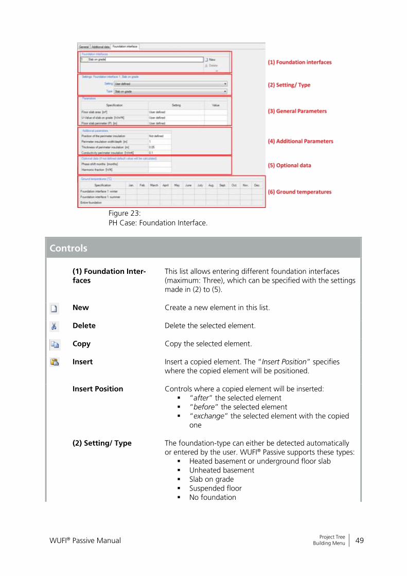
Figure 23:
PH Case: Foundation Interface.
Controls
(1) Foundation Inter-faces
This list allows entering different foundation interfaces (maximum: Three), which can be specified with the settings made in (2) to (5).
New Create a new element in this list.
Delete Delete the selected element.
Copy Copy the selected element.
Insert Insert a copied element. The “Insert Position” specifies where the copied element will be positioned.
Insert Position Controls where a copied element will be inserted: “after” the selected element “before” the selected element “exchange” the selected element with the copied
one
(2) Setting/ Type The foundation-type can either be detected automatically or entered by the user. WUFI® Passive supports these types:
Heated basement or underground floor slab Unheated basement Slab on grade Suspended floor No foundation
WUFI® Passive Manual 50
Bericht Nr. Anzuzeigender Text darf nicht mehr als eine Zeile beanspruchen!
Project Tree Building Menu
Depending on the selected foundation-type, further inputs are required in (3) to (5).
(3) General Parameters These parameters describe the geometry of the foundation and physical properties.
(4) Additional Parame-ters
Additional parameters, that were not defined in (2) or (3).
(5) Optional Data Optional parameters that describe the ground.
(6) Ground tempera-tures
Ground temperatures are shown in this table. These tem-peratures are calculated depending on the user input in this tab and the outdoor climate. The “entire foundation” ground temperature is calculated from the “winter” and “summer” temperatures. If the selected exterior climate provides information about ground temperature, these values will always be used for further calculations and the values shown in this table won’t be considered further. This table is only informative. No direct user input is possi-ble.
WUFI® Passive Manual 51
Bericht Nr. Anzuzeigender Text darf nicht mehr als eine Zeile beanspruchen!
Project Tree Building Menu
4.4.3 Simulated Zones
There are different inputs for the net volume depending on the certification criteria (“Default” or “PHIUS+ 2015”). Please refer to chapter 4.2.1 for fur-ther information.
In WUFI® Passive a building is created and then calculated using PH Cases and
zones. In general there are two kinds of zones:
Heated Zones are simulated zones. They will be calculated during the
verification process.
“Attached Zones” are not part of the calculation, for example an un-
heated attic. However, they influence the conditions in the simulation
area and must be precisely defined. See chapter 4.4.6 for further infor-
mation.
These zones and climates must be assigned to the components of the building.
See chapter 5 for more information about components.
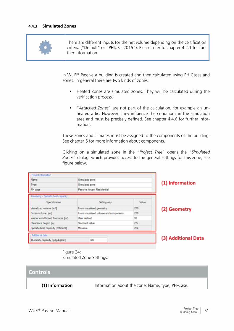
Clicking on a simulated zone in the “Project Tree” opens the “Simulated
Zones” dialog, which provides access to the general settings for this zone, see
figure below.
Figure 24:
Simulated Zone Settings.
Controls
(1) Information
Information about the zone: Name, type, PH-Case.
WUFI® Passive Manual 52
Bericht Nr. Anzuzeigender Text darf nicht mehr als eine Zeile beanspruchen!
Project Tree Building Menu
(2) Geometry Information about the zone’s geometry and its specific heat capacity, which depends on the construction type of the building.
(3) Additional Data Humidity capacity is defined here, which specifies the
amount of water stored in the building components.
Always double-check that the geometry-data was entered correctly, as these values can have a huge impact on calculation results.

WUFI® Passive Manual 53
Bericht Nr. Anzuzeigender Text darf nicht mehr als eine Zeile beanspruchen!
Project Tree Building Menu
4.4.4 Visualized Components
All components of the building that require a definition of structure, materials
or environment are listed under "Visualized Components" and can to be edited
here. Clicking on the respective component in the entry window table or in the
“Project Tree” opens the “Component” dialog, where its properties are de-
fined. WUFI® Passive distinguishes three component types:
Opaque components, like for example walls, ceilings or roof construc-
tion.
Transparent components, like windows.
Openings, which are not relevant here, as they need no further user in-
put.
Depending on the selected component type, there are various subsections to
input all necessary data. These are described in detail in chapter 5. Also the ex-
ample at the end of this manual shows how components can be entered into
WUFI® Passive.
Visit our WUFI®-Wiki (www.wufi-wiki.com) for detailed information about components and tutorial videos about creating them.

WUFI® Passive Manual 54
Bericht Nr. Anzuzeigender Text darf nicht mehr als eine Zeile beanspruchen!
Project Tree Building Menu
4.4.5 Not Visualized Components
These components can't be seen in the “Visualization Box”. In the Passive
House calculation scope they are only part of the calculation, as long as an out-
er climate is assigned either on their inner or outer side. Theoretically, all com-
ponents of the building envelope can be entered as not visualized components
and no visualization is necessary for the Passive House calculation.
In the WUFI® Plus scope, the indoor components have an impact on dynamic
hygrothermal simulations. So in “Not Visualized Components” components af-
fecting the indoor environment can be included in the simulation, like for ex-
ample partitions or furniture.
“Not Visualized Components” can be entered in the list of this dialog. The def-
inition of these components, their properties, and their parameters are the
same as that of “Visualized Components”.
Controls
New
Create a new element in this list.
Delete Delete the selected element.
Copy Copy the selected element.
Insert Insert a copied element. The “Insert Position” specifies where the copied element will be positioned.
Insert Position Controls where a copied element will be inserted: “after” the selected element “before” the selected element “exchange” the selected element with the copied
one
Don't forget to make input concerning the area of “Not Visualized Compo-nents”.
WUFI® Passive Manual 55
Bericht Nr. Anzuzeigender Text darf nicht mehr als eine Zeile beanspruchen!
Project Tree Building Menu
4.4.6 Attached Zones
“Attached Zones” are areas that do not belong to the simulation volume, such
as an unheated attic. These zones are not considered directly in the calcula-
tions. However, they influence the conditions in the simulated zone and must
be precisely defined. The adjacent zones can be named and the type of zone
can be selected in the drop-down menu. Dependent on the type, additional in-
put can be required:
For unheated cellars additional geometry information is necessary
Other types require a temperature difference reduction factor that ad-
justs the heat loss as it would occur, relative to outer climate conditions.
“Attached zones” can include visualized and not visualized components..
WUFI® Passive Manual 56
Bericht Nr. Anzuzeigender Text darf nicht mehr als eine Zeile beanspruchen!
Project Tree Building Menu
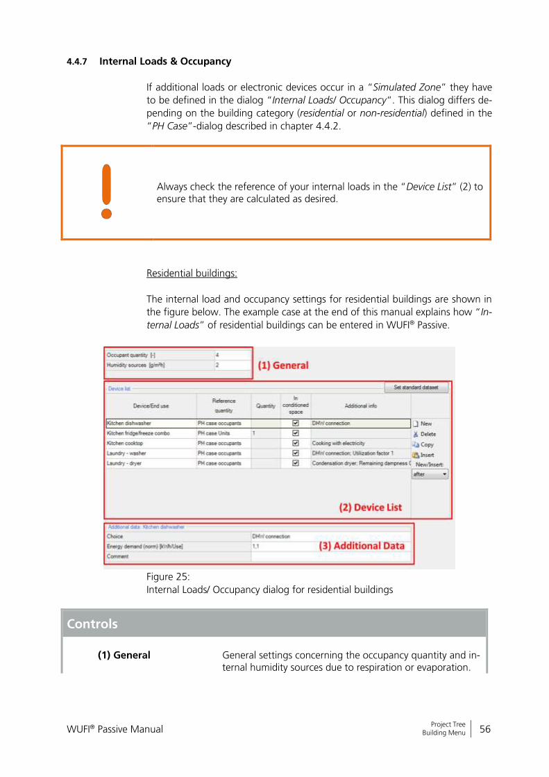
4.4.7 Internal Loads & Occupancy
If additional loads or electronic devices occur in a “Simulated Zone” they have
to be defined in the dialog “Internal Loads/ Occupancy“. This dialog differs de-
pending on the building category (residential or non-residential) defined in the
“PH Case”-dialog described in chapter 4.4.2.
Always check the reference of your internal loads in the “Device List” (2) to ensure that they are calculated as desired.
Residential buildings:
The internal load and occupancy settings for residential buildings are shown in
the figure below. The example case at the end of this manual explains how “In-
ternal Loads” of residential buildings can be entered in WUFI® Passive.
Figure 25:
Internal Loads/ Occupancy dialog for residential buildings
Controls
(1) General
General settings concerning the occupancy quantity and in-ternal humidity sources due to respiration or evaporation.

WUFI® Passive Manual 57
Bericht Nr. Anzuzeigender Text darf nicht mehr als eine Zeile beanspruchen!
Project Tree Building Menu
Please refer to the information in the attention box below!
(2) Device List Lists all devices in this zone. Devices can either be chosen from presets or user-defined. Also a “Standard-dataset” representing a common household can be created with the button on the right side. This “Standard dataset” can be used if the exact number or type of household appliances are not yet know. It does not contain predefined energy consumptions or similar requirements. This must be defined by the user. Also, the reference quantity of a device can be selected.
(3) Additional Data Here, additional data that describes the selected device can
be entered, for example energy demand.
New Create a new element in this list.
Delete Delete the selected element.
Copy Copy the selected element.
Insert Insert a copied element. The “Insert Position” specifies where the copied element will be positioned.
Insert Position Controls where a copied element will be inserted: “after” the selected element “before” the selected element “exchange” the selected element with the copied
one
There are different recommended inputs depending on the certification cri-teria (“Default” or “PHIUS+ 2015”). Please refer to chapter 4.2.1 for fur-ther information.
Depending on the occupancy setting method, defined in the “PH case” dia-log (chapter 4.4.2) the count of occupants can be defined in (1), if the method is set to “design”. If it’s set to “verification” the occupants are cal-culated depending on the interior conditioned floor area.
WUFI® Passive Manual 58
Bericht Nr. Anzuzeigender Text darf nicht mehr als eine Zeile beanspruchen!
Project Tree Building Menu
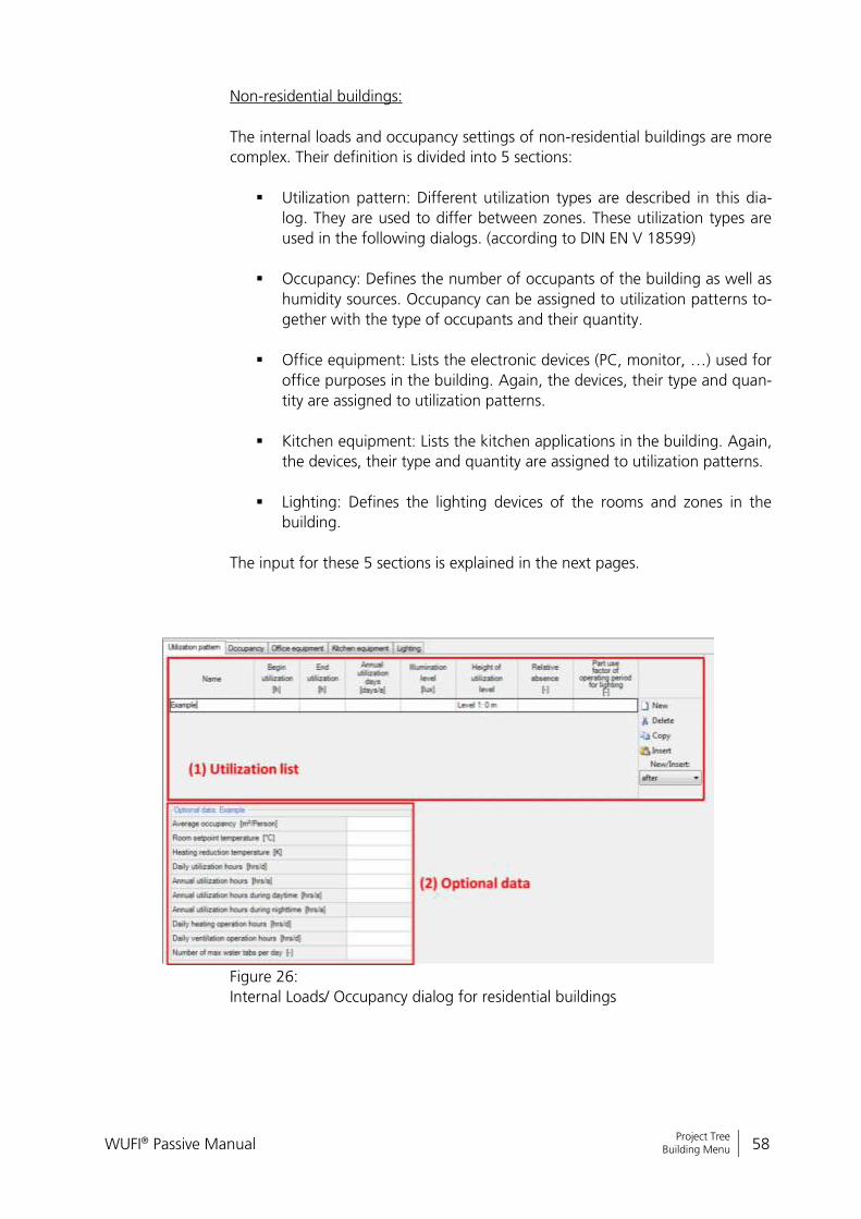
Non-residential buildings:
The internal loads and occupancy settings of non-residential buildings are more
complex. Their definition is divided into 5 sections:
Utilization pattern: Different utilization types are described in this dia-
log. They are used to differ between zones. These utilization types are
used in the following dialogs. (according to DIN EN V 18599)
Occupancy: Defines the number of occupants of the building as well as
humidity sources. Occupancy can be assigned to utilization patterns to-
gether with the type of occupants and their quantity.
Office equipment: Lists the electronic devices (PC, monitor, …) used for
office purposes in the building. Again, the devices, their type and quan-
tity are assigned to utilization patterns.
Kitchen equipment: Lists the kitchen applications in the building. Again,
the devices, their type and quantity are assigned to utilization patterns.
Lighting: Defines the lighting devices of the rooms and zones in the
building.
The input for these 5 sections is explained in the next pages.
Figure 26:
Internal Loads/ Occupancy dialog for residential buildings
WUFI® Passive Manual 59
Bericht Nr. Anzuzeigender Text darf nicht mehr als eine Zeile beanspruchen!
Project Tree Building Menu
Controls
(1) Utilization list
The different utilization patterns (zones) of the building are defined in this list.
(2) Optional data Additional data can be provided here, to specify the usage of a certain utilization profile. This input is optional. Please note: In the “Occupancy” tab, the number of occu-pants can be calculated automatically from the floor area of a zone. To do this, an input is necessary in the “Average occupancy” field.
New Create a new element in this list.
Delete Delete the selected element.
Copy Copy the selected element.
Insert Insert a copied element. The “Insert Position” specifies where the copied element will be positioned
Insert Position Controls where a copied element will be inserted: “after” the selected element “before” the selected element “exchange” the selected element with the copied
one
WUFI® Passive Manual 60
Bericht Nr. Anzuzeigender Text darf nicht mehr als eine Zeile beanspruchen!
Project Tree Building Menu
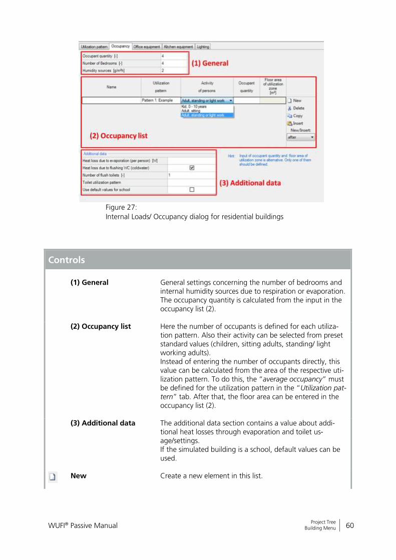
Figure 27:
Internal Loads/ Occupancy dialog for residential buildings
Controls
(1) General
General settings concerning the number of bedrooms and internal humidity sources due to respiration or evaporation. The occupancy quantity is calculated from the input in the occupancy list (2).
(2) Occupancy list Here the number of occupants is defined for each utiliza-tion pattern. Also their activity can be selected from preset standard values (children, sitting adults, standing/ light working adults). Instead of entering the number of occupants directly, this value can be calculated from the area of the respective uti-lization pattern. To do this, the “average occupancy” must be defined for the utilization pattern in the “Utilization pat-tern” tab. After that, the floor area can be entered in the occupancy list (2).
(3) Additional data
The additional data section contains a value about addi-tional heat losses through evaporation and toilet us-age/settings. If the simulated building is a school, default values can be used.
New Create a new element in this list.

WUFI® Passive Manual 61
Bericht Nr. Anzuzeigender Text darf nicht mehr als eine Zeile beanspruchen!
Project Tree Building Menu
Delete Delete the selected element.
Copy Copy the selected element.
Insert Insert a copied element. The “Insert Position” specifies where the copied element will be positioned.
Insert Position Controls where a copied element will be inserted: “after” the selected element “before” the selected element “exchange” the selected element with the copied
one
WUFI® Passive Manual 62
Bericht Nr. Anzuzeigender Text darf nicht mehr als eine Zeile beanspruchen!
Project Tree Building Menu
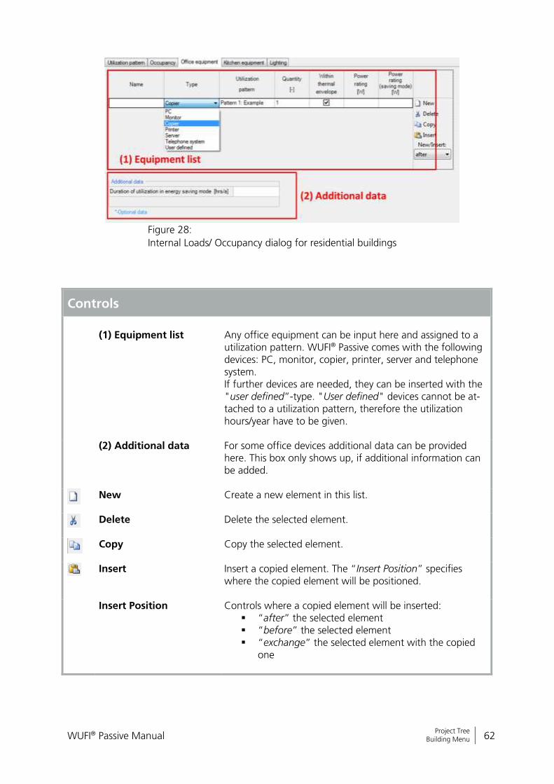
Figure 28:
Internal Loads/ Occupancy dialog for residential buildings
Controls
(1) Equipment list
Any office equipment can be input here and assigned to a utilization pattern. WUFI® Passive comes with the following devices: PC, monitor, copier, printer, server and telephone system. If further devices are needed, they can be inserted with the "user defined”-type. "User defined" devices cannot be at-tached to a utilization pattern, therefore the utilization hours/year have to be given.
(2) Additional data For some office devices additional data can be provided here. This box only shows up, if additional information can be added.
New Create a new element in this list.
Delete Delete the selected element.
Copy Copy the selected element.
Insert Insert a copied element. The “Insert Position” specifies where the copied element will be positioned.
Insert Position Controls where a copied element will be inserted: “after” the selected element “before” the selected element “exchange” the selected element with the copied
one
WUFI® Passive Manual 63
Bericht Nr. Anzuzeigender Text darf nicht mehr als eine Zeile beanspruchen!
Project Tree Building Menu
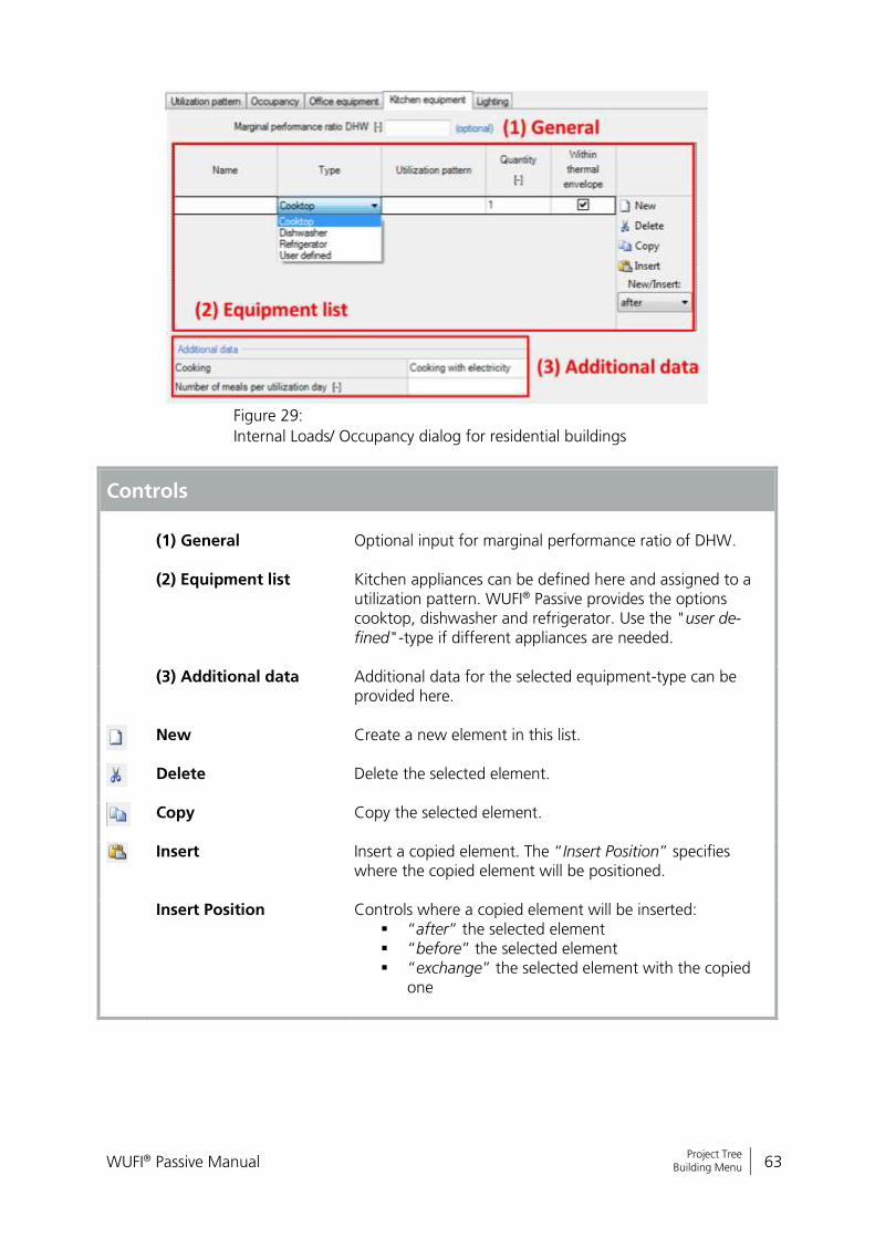
Figure 29:
Internal Loads/ Occupancy dialog for residential buildings
Controls
(1) General
Optional input for marginal performance ratio of DHW.
(2) Equipment list Kitchen appliances can be defined here and assigned to a utilization pattern. WUFI® Passive provides the options cooktop, dishwasher and refrigerator. Use the "user de-fined"-type if different appliances are needed.
(3) Additional data
Additional data for the selected equipment-type can be provided here.
New Create a new element in this list.
Delete Delete the selected element.
Copy Copy the selected element.
Insert Insert a copied element. The “Insert Position” specifies where the copied element will be positioned.
Insert Position Controls where a copied element will be inserted: “after” the selected element “before” the selected element “exchange” the selected element with the copied
one
WUFI® Passive Manual 64
Bericht Nr. Anzuzeigender Text darf nicht mehr als eine Zeile beanspruchen!
Project Tree Building Menu
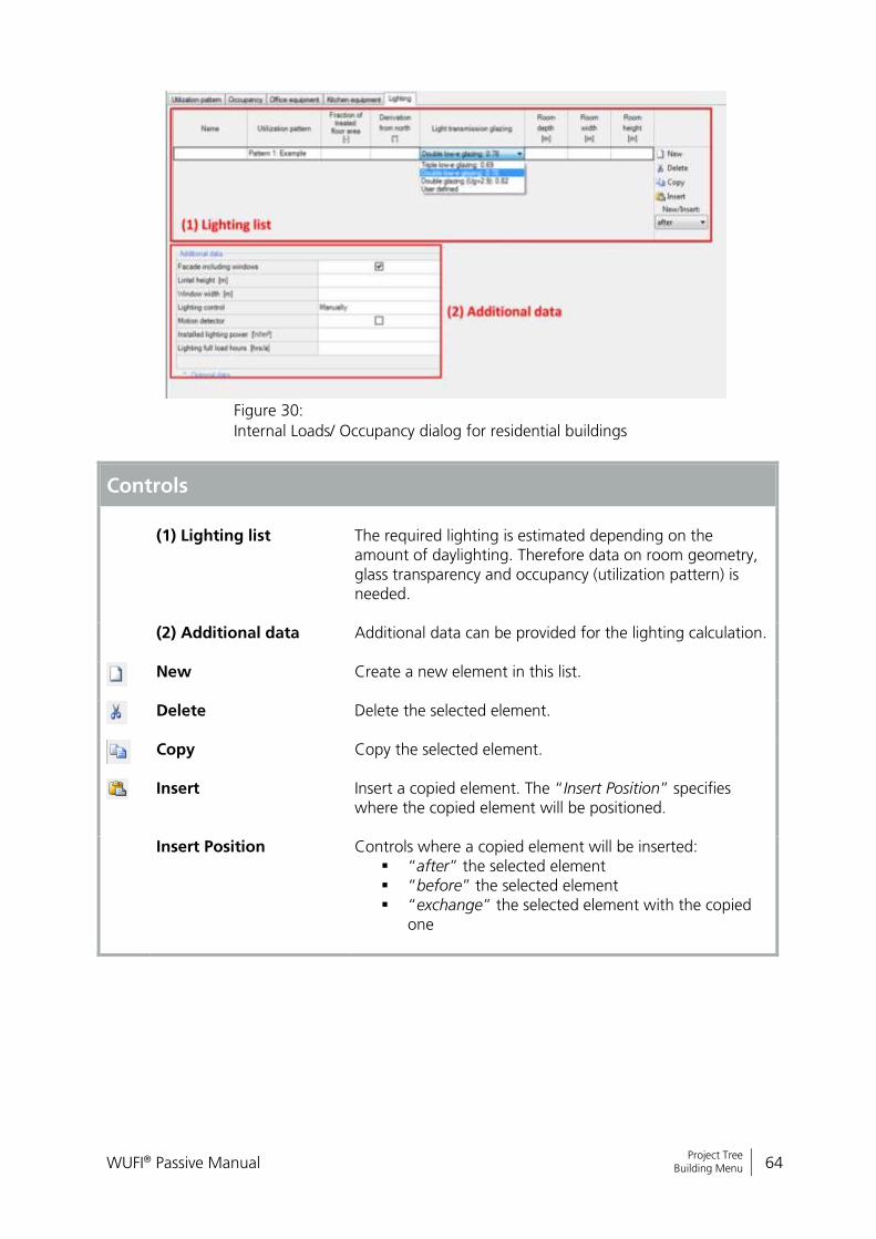
Figure 30:
Internal Loads/ Occupancy dialog for residential buildings
Controls
(1) Lighting list
The required lighting is estimated depending on the amount of daylighting. Therefore data on room geometry, glass transparency and occupancy (utilization pattern) is needed.
(2) Additional data Additional data can be provided for the lighting calculation.
New Create a new element in this list.
Delete Delete the selected element.
Copy Copy the selected element.
Insert Insert a copied element. The “Insert Position” specifies where the copied element will be positioned.
Insert Position Controls where a copied element will be inserted: “after” the selected element “before” the selected element “exchange” the selected element with the copied
one
WUFI® Passive Manual 65
Bericht Nr. Anzuzeigender Text darf nicht mehr als eine Zeile beanspruchen!
Project Tree Building Menu
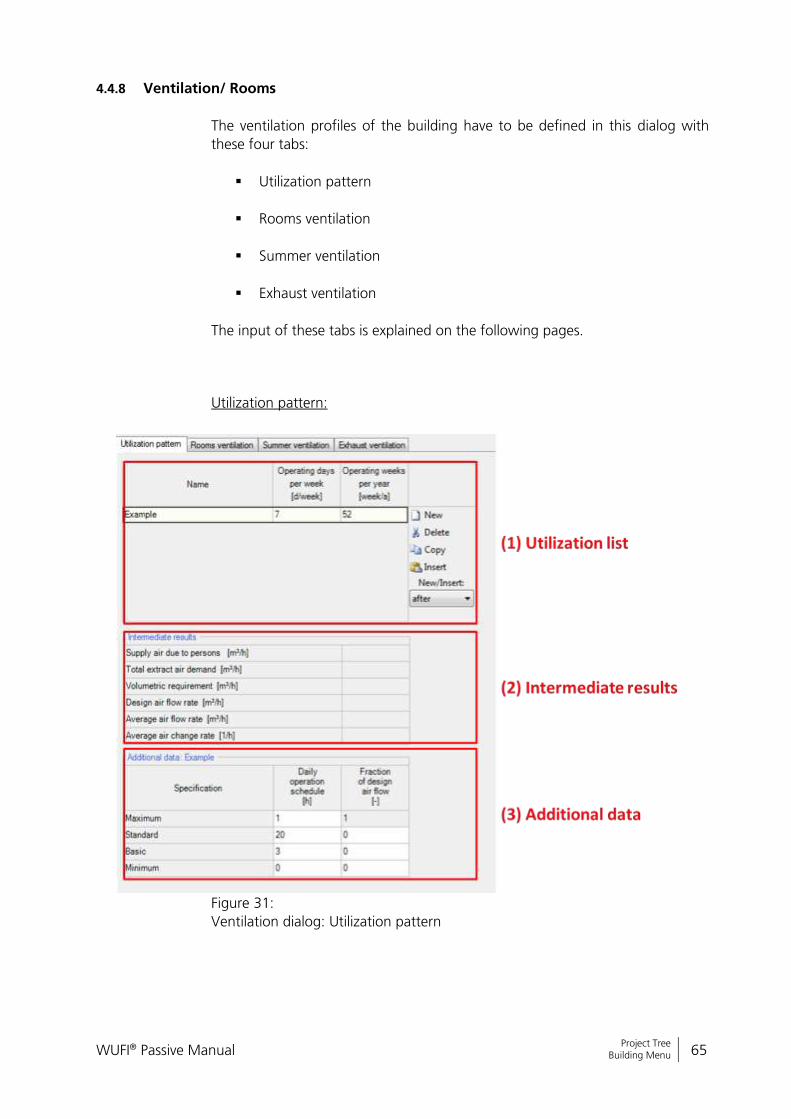
4.4.8 Ventilation/ Rooms
The ventilation profiles of the building have to be defined in this dialog with
these four tabs:
Utilization pattern
Rooms ventilation
Summer ventilation
Exhaust ventilation
The input of these tabs is explained on the following pages.
Utilization pattern:
Figure 31:
Ventilation dialog: Utilization pattern

WUFI® Passive Manual 66
Bericht Nr. Anzuzeigender Text darf nicht mehr als eine Zeile beanspruchen!
Project Tree Building Menu
Controls
(1) Utilization list
This section defines the utilization pattern of the ventilation system. If you have different patterns for different rooms, this is the place to create them. They are assigned to the different rooms in the "rooms ventilation"-tab.
(2) Intermediate results Sums up the intermediate results of the ventilation calcula-tion. This facilitates the design of ventilation systems. For the “design air flow rate” the maximum of “supply air per person” and “total extract air demand” is used. The “volumetric requirement” is only informative. However, WUFI® Passive will show a warning, if the “design air flow rate” is below the “volumetric requirement”.
(3) Additional data Here, a daily operation schedule with different air flow rates and associated running hours must be defined.
New Create a new element in this list.
Delete Delete the selected element.
Copy Copy the selected element.
Insert Insert a copied element. The “Insert Position” specifies where the copied element will be positioned.
Insert Position Controls where a copied element will be inserted: “after” the selected element “before” the selected element “exchange” the selected element with the copied
one
WUFI® Passive Manual 67
Bericht Nr. Anzuzeigender Text darf nicht mehr als eine Zeile beanspruchen!
Project Tree Building Menu
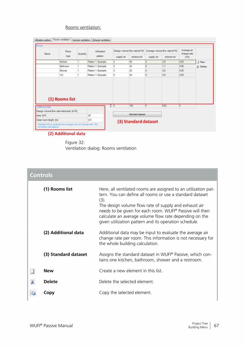
Rooms ventilation:
Figure 32:
Ventilation dialog: Rooms ventilation
Controls
(1) Rooms list
Here, all ventilated rooms are assigned to an utilization pat-tern. You can define all rooms or use a standard dataset (3). The design volume flow rate of supply and exhaust air needs to be given for each room. WUFI® Passive will then calculate an average volume flow rate depending on the given utilization pattern and its operation schedule.
(2) Additional data Additional data may be input to evaluate the average air change rate per room. This information is not necessary for the whole building calculation.
(3) Standard dataset Assigns the standard dataset in WUFI® Passive, which con-tains one kitchen, bathroom, shower and a restroom.
New Create a new element in this list.
Delete Delete the selected element.
Copy Copy the selected element.

WUFI® Passive Manual 68
Bericht Nr. Anzuzeigender Text darf nicht mehr als eine Zeile beanspruchen!
Project Tree Building Menu
Insert Insert a copied element. The “Insert Position” specifies where the copied element will be positioned.
Insert Position Controls where a copied element will be inserted: “after” the selected element “before” the selected element “exchange” the selected element with the copied
one
WUFI® Passive Manual 69
Bericht Nr. Anzuzeigender Text darf nicht mehr als eine Zeile beanspruchen!
Project Tree Building Menu
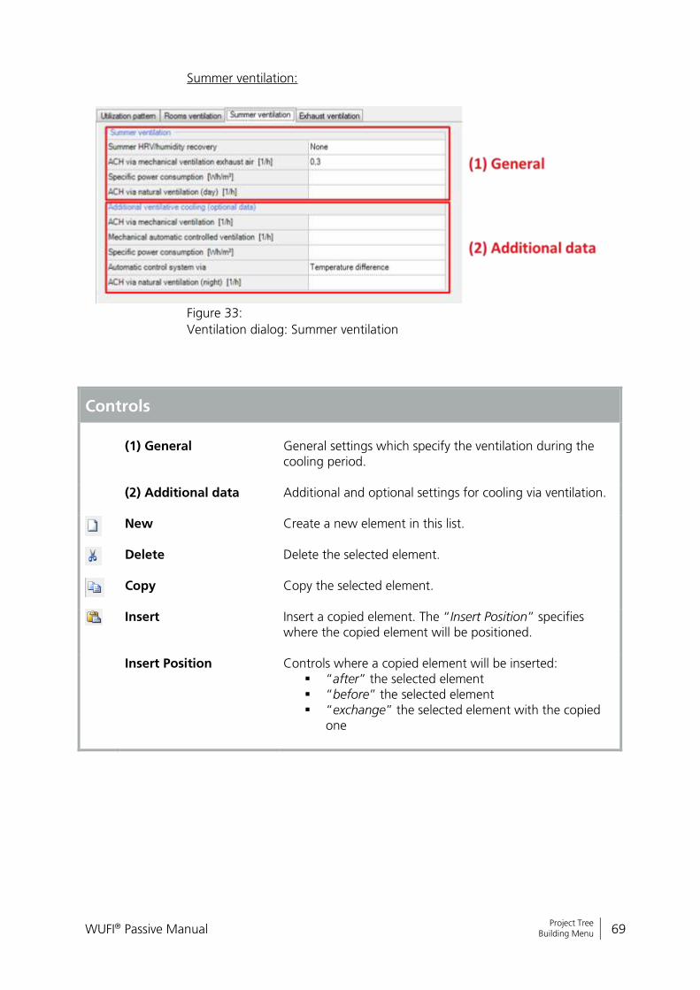
Summer ventilation:
Figure 33:
Ventilation dialog: Summer ventilation
Controls
(1) General
General settings which specify the ventilation during the cooling period.
(2) Additional data Additional and optional settings for cooling via ventilation.
New Create a new element in this list.
Delete Delete the selected element.
Copy Copy the selected element.
Insert Insert a copied element. The “Insert Position” specifies where the copied element will be positioned.
Insert Position Controls where a copied element will be inserted: “after” the selected element “before” the selected element “exchange” the selected element with the copied
one
WUFI® Passive Manual 70
Bericht Nr. Anzuzeigender Text darf nicht mehr als eine Zeile beanspruchen!
Project Tree Building Menu
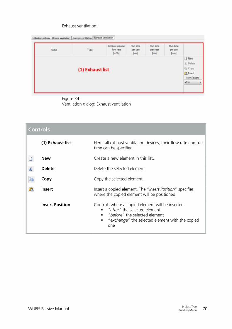
Exhaust ventilation:
Figure 34:
Ventilation dialog: Exhaust ventilation
Controls
(1) Exhaust list
Here, all exhaust ventilation devices, their flow rate and run time can be specified.
New Create a new element in this list.
Delete Delete the selected element.
Copy Copy the selected element.
Insert Insert a copied element. The “Insert Position” specifies where the copied element will be positioned
Insert Position Controls where a copied element will be inserted: “after” the selected element “before” the selected element “exchange” the selected element with the copied
one
WUFI® Passive Manual 71
Bericht Nr. Anzuzeigender Text darf nicht mehr als eine Zeile beanspruchen!
Project Tree Building Menu
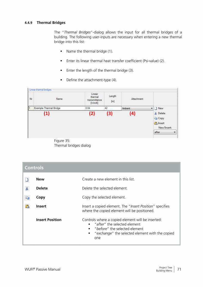
4.4.9 Thermal Bridges
The “Thermal Bridges”-dialog allows the input for all thermal bridges of a
building. The following user-inputs are necessary when entering a new thermal
bridge into this list:
Name the thermal bridge (1).
Enter its linear thermal heat transfer coefficient (Psi-value) (2).
Enter the length of the thermal bridge (3).
Define the attachment-type (4).
Figure 35:
Thermal bridges dialog
Controls
New
Create a new element in this list.
Delete Delete the selected element.
Copy Copy the selected element.
Insert Insert a copied element. The “Insert Position” specifies where the copied element will be positioned.
Insert Position Controls where a copied element will be inserted: “after” the selected element “before” the selected element “exchange” the selected element with the copied
one

WUFI® Passive Manual 72
Bericht Nr. Anzuzeigender Text darf nicht mehr als eine Zeile beanspruchen!
Project Tree Building Menu
4.4.10 Remaining Elements
This dialog lists all elements which are not connected to a zone. In the “Passive
House Calculation”-scope, these components are only used for visualization.
In the “WUFI® Plus”-scope they also do not directly affect the simulation, ex-
cept for the shading calculation. In this scope, they also can be used to create a
reference for automated detection of height above ground for other compo-
nents. To do this, define the inner side of a remaining component as “Ground”
and the outer side as “Outer air”. WUFI® Plus will now use this component as
ground-reference with a height of 0. Please refer also to the WUFI® Plus manu-
al for further information.
WUFI® Passive Manual 73
Bericht Nr. Anzuzeigender Text darf nicht mehr als eine Zeile beanspruchen!
Project Tree HVAC-Systems Menu
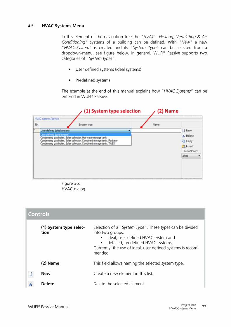
4.5 HVAC-Systems Menu
In this element of the navigation tree the "HVAC - Heating, Ventilating & Air
Conditioning" systems of a building can be defined. With "New" a new
“HVAC-System” is created and its “System Type” can be selected from a
dropdown-menu, see figure below. In general, WUFI® Passive supports two
categories of “System types”:
User defined systems (ideal systems)
Predefined systems
The example at the end of this manual explains how “HVAC Systems” can be
entered in WUFI® Passive.
Figure 36:
HVAC dialog
Controls
(1) System type selec-tion
Selection of a “System Type”. These types can be divided into two groups:
Ideal, user defined HVAC system and detailed, predefined HVAC systems.
Currently, the use of ideal, user defined systems is recom-mended.
(2) Name This field allows naming the selected system type.
New Create a new element in this list.
Delete Delete the selected element.

WUFI® Passive Manual 74
Bericht Nr. Anzuzeigender Text darf nicht mehr als eine Zeile beanspruchen!
Project Tree HVAC-Systems Menu
Copy Copy the selected element.
Insert Insert a copied element. The “Insert Position” specifies where the copied element will be positioned.
Insert Position Controls where a copied element will be inserted: “after” the selected element “before” the selected element “exchange” the selected element with the copied
one
WUFI® Passive Manual 75
Bericht Nr. Anzuzeigender Text darf nicht mehr als eine Zeile beanspruchen!
Project Tree HVAC-Systems Menu
4.5.1 Ideal User-Defined Systems
“User-defined HVAC-Systems” in WUFI® Passive allow a custom combination of
certain devices of a “HVAC-System” to be input. New “Devices” can be added
with the “New”-Button and their “Type” can be specified with a dropdown
menu. These devices are assigned to different uses, specified by clicking on the
checkboxes. Chapter 6 lists all available HVAC-devices and describes the neces-
sary user input.
Figure 37:
List of HVAC Devices
Controls
(1) Name
Naming the current HVAC-system
(2) Device List Here, all devices of the current HVAC-system are listed. Their usage is defined with the checkboxes.
(3) Coverage
Defines the coverage between different HVAC-devices. Their sum must be “1” for each column.
New Create a new element in this list.
Delete Delete the selected element.
Copy Copy the selected element.
Insert Insert a copied element. The “Insert Position” specifies where the copied element will be positioned.
Insert Position Controls where a copied element will be inserted:
WUFI® Passive Manual 76
Bericht Nr. Anzuzeigender Text darf nicht mehr als eine Zeile beanspruchen!
Project Tree HVAC-Systems Menu
“after” the selected element “before” the selected element “exchange” the selected element with the copied
one
After “HVAC-Devices” were created in the dialog above, they appear in the
“Project Tree”. Selecting one of them opens a new dialog where the properties
of a “Device” can be entered. Each device and the necessary input is explained
in chapter 6.
A detailed explanation and a tutorial video on our WUFI®-Wiki (www.wufi-wiki.com) show how “User-defined HVAC systems” can be entered in WU-FI® Passive. The example at the end of this manual shows how this is done, too.
WUFI® Passive Manual 77
Bericht Nr. Anzuzeigender Text darf nicht mehr als eine Zeile beanspruchen!
Project Tree HVAC-Systems Menu
4.5.2 Detailed Predefined Systems
WUFI® Passive also offers several predefined and detailed “HVAC-Systems”:
Condensing gas boiler, Solar collector, Hot water storage tank
Condensing gas boiler, Solar collector, Combined storage tank, Radia-
tor
Condensing gas boiler, Solar collector, Combined storage tank, TABS
In WUFI® Passive, the devices of the predefined systems are treated like the de-
vices of user-defined systems. Please refer to chapters 4.5.1 and 4.5.3 for fur-
ther information.
The advantage of the predefined systems comes after switching to WUFI® Plus:
These predefined system allow a detailed dynamic simulation of each of their
parts in the dynamic simulations of WUFI® Plus. These detailed HVAC systems
were created by Fraunhofer ISE and are currently implemented in WUFI® Plus.
All single parts of these systems were already validated by Fraunhofer ISE.
However, the implementation in WUFI® Plus is not fully validated, yet. So, these
detailed HVAC systems must be regarded as experimental and provide a view
on future improvements of WUFI® Plus. Currently, their usage is not recom-
mended and is at the risk of the user.
Currently more detailed HVAC systems are developed. As soon as all systems
are included and validated, an additional manual will explain their usage.
Please refer to our WUFI®-Wiki (www.wufi-wiki.com) for detailed infor-mation about predefined HVAC-Systems.
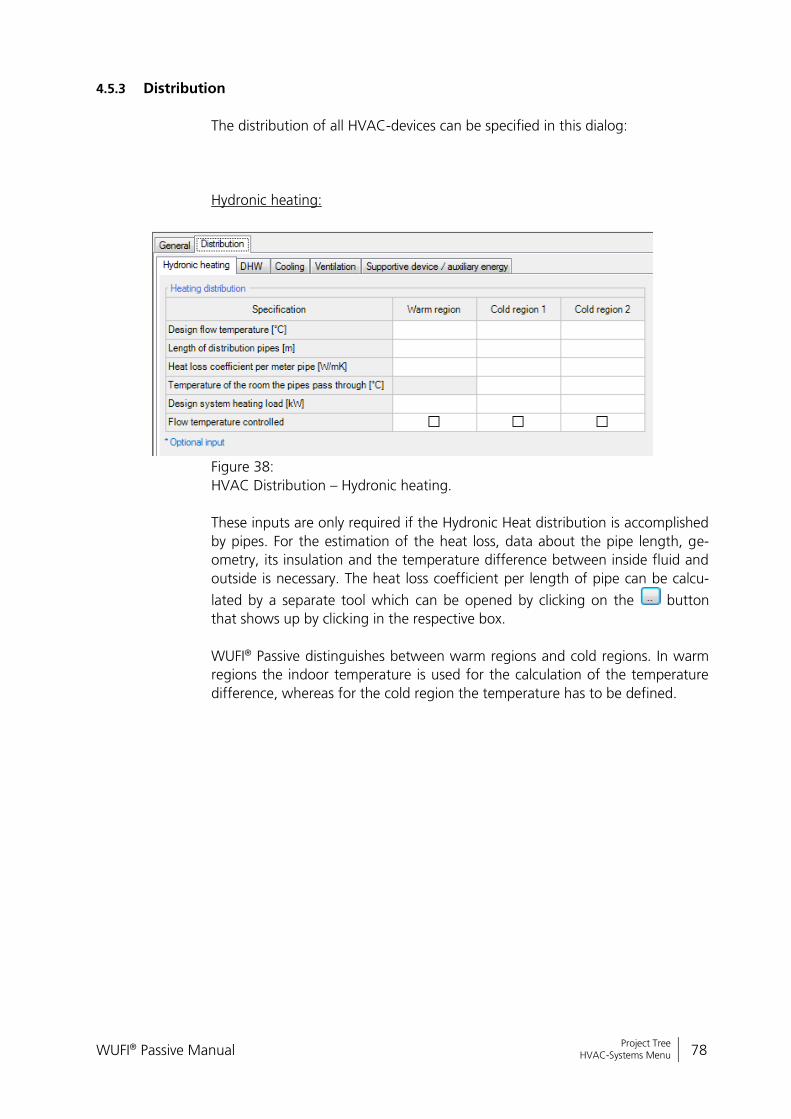
WUFI® Passive Manual 78
Bericht Nr. Anzuzeigender Text darf nicht mehr als eine Zeile beanspruchen!
Project Tree HVAC-Systems Menu
4.5.3 Distribution
The distribution of all HVAC-devices can be specified in this dialog:
Hydronic heating:
Figure 38:
HVAC Distribution – Hydronic heating.
These inputs are only required if the Hydronic Heat distribution is accomplished
by pipes. For the estimation of the heat loss, data about the pipe length, ge-
ometry, its insulation and the temperature difference between inside fluid and
outside is necessary. The heat loss coefficient per length of pipe can be calcu-
lated by a separate tool which can be opened by clicking on the button
that shows up by clicking in the respective box.
WUFI® Passive distinguishes between warm regions and cold regions. In warm
regions the indoor temperature is used for the calculation of the temperature
difference, whereas for the cold region the temperature has to be defined.

WUFI® Passive Manual 79
Bericht Nr. Anzuzeigender Text darf nicht mehr als eine Zeile beanspruchen!
Project Tree HVAC-Systems Menu
DHW:
Figure 39:
HVAC Distribution – DHW.
The DHW distribution is very similar to the Hydronic Heating distribution. Addi-
tional information about the hours of operation for the circulation hot water
systems are required. Usually the DHW circulation is running 24 hours per day
for buildings with recirculation systems. Single family houses rarely have true
recirculation systems, and therefore this section may be left blank.
Furthermore, the length (sum) and diameter of individual pipes needs to be en-
tered. The pipe lengths are calculated starting from the circulation loop and
end at the water tap.
In the case where no circulation system is used, only the sum of the individual
pipes should be entered and the lengths calculated from the hot water tank/
source to each individual tapping point.
The Design Flow Temperature must always be entered, regardless of recircula-
tion or not.
The heat loss coefficient per length of pipe can be calculated by a separate tool
which can be opened by clicking on the button that shows up by clicking in
the respective box.
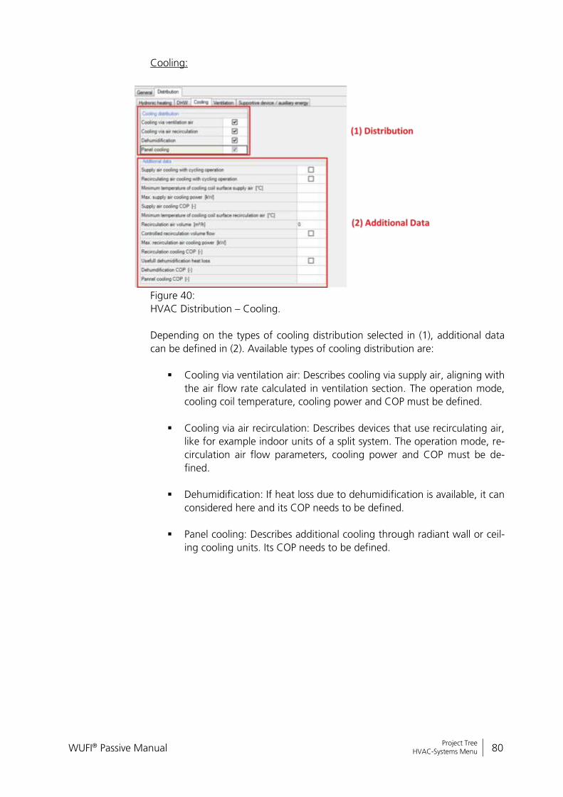
WUFI® Passive Manual 80
Bericht Nr. Anzuzeigender Text darf nicht mehr als eine Zeile beanspruchen!
Project Tree HVAC-Systems Menu
Cooling:
Figure 40:
HVAC Distribution – Cooling.
Depending on the types of cooling distribution selected in (1), additional data
can be defined in (2). Available types of cooling distribution are:
Cooling via ventilation air: Describes cooling via supply air, aligning with
the air flow rate calculated in ventilation section. The operation mode,
cooling coil temperature, cooling power and COP must be defined.
Cooling via air recirculation: Describes devices that use recirculating air,
like for example indoor units of a split system. The operation mode, re-
circulation air flow parameters, cooling power and COP must be de-
fined.
Dehumidification: If heat loss due to dehumidification is available, it can
considered here and its COP needs to be defined.
Panel cooling: Describes additional cooling through radiant wall or ceil-
ing cooling units. Its COP needs to be defined.
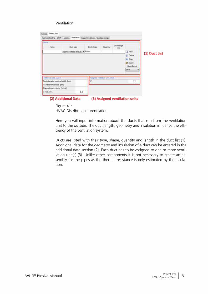
WUFI® Passive Manual 81
Bericht Nr. Anzuzeigender Text darf nicht mehr als eine Zeile beanspruchen!
Project Tree HVAC-Systems Menu
Ventilation:
Figure 41:
HVAC Distribution – Ventilation.
Here you will input information about the ducts that run from the ventilation
unit to the outside. The duct length, geometry and insulation influence the effi-
ciency of the ventilation system.
Ducts are listed with their type, shape, quantity and length in the duct list (1).
Additional data for the geometry and insulation of a duct can be entered in the
additional data section (2). Each duct has to be assigned to one or more venti-
lation unit(s) (3). Unlike other components it is not necessary to create an as-
sembly for the pipes as the thermal resistance is only estimated by the insula-
tion.
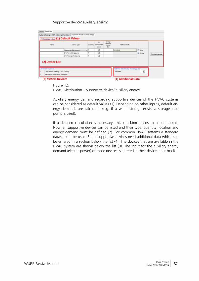
WUFI® Passive Manual 82
Bericht Nr. Anzuzeigender Text darf nicht mehr als eine Zeile beanspruchen!
Project Tree HVAC-Systems Menu
Supportive device/ auxiliary energy:
Figure 42:
HVAC Distribution – Supportive device/ auxiliary energy.
Auxiliary energy demand regarding supportive devices of the HVAC systems
can be considered as default values (1). Depending on other inputs, default en-
ergy demands are calculated (e.g. if a water storage exists, a storage load
pump is used).
If a detailed calculation is necessary, this checkbox needs to be unmarked.
Now, all supportive devices can be listed and their type, quantity, location and
energy demand must be defined (2). For common HVAC systems a standard
dataset can be used. Some supportive devices need additional data which can
be entered in a section below the list (4). The devices that are available in the
HVAC system are shown below the list (3). The input for the auxiliary energy
demand (electric power) of those devices is entered in their device input mask.
WUFI® Passive Manual 83
Bericht Nr. Anzuzeigender Text darf nicht mehr als eine Zeile beanspruchen!
Components Opaque Components
5 Components
Clicking on the respective component in the entry table or the in the “Project
Tree” opens the “Component” dialog, where its properties are defined. WUFI®
Passive distinguishes three component types:
“Opaque Components” like walls, ceilings or roof construction.
“Transparent Components” like windows.
“Openings”, which are not relevant here, as they need no further user
input.
Depending on the selected component type, there are various tabs to input all
necessary data. These are described in detail in the following subsections of this
chapter. The example at the end of this manual shows how components can be
entered into WUFI® Passive.
Please refer to our WUFI®-Wiki (www.wufi-wiki.com) for detailed infor-mation about “Components” and their settings.
5.1 Opaque Components
Various steps are necessary for the definition of an “Opaque Component”.
Clicking on a component opens a dialog with three tabs:
General
Assembly
Surface
These tabs are explained in detail in the next chapters.
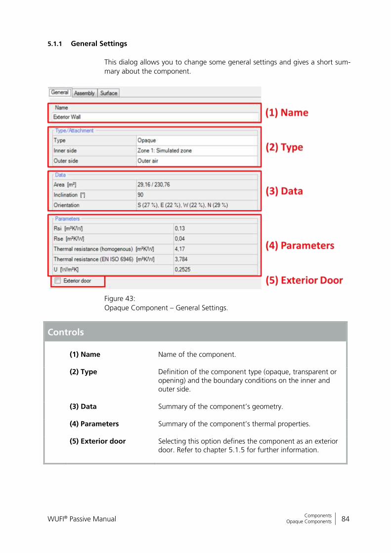
WUFI® Passive Manual 84
Bericht Nr. Anzuzeigender Text darf nicht mehr als eine Zeile beanspruchen!
Components Opaque Components
5.1.1 General Settings
This dialog allows you to change some general settings and gives a short sum-
mary about the component.
Figure 43:
Opaque Component – General Settings.
Controls
(1) Name
Name of the component.
(2) Type Definition of the component type (opaque, transparent or opening) and the boundary conditions on the inner and outer side.
(3) Data Summary of the component’s geometry.
(4) Parameters Summary of the component’s thermal properties.
(5) Exterior door Selecting this option defines the component as an exterior door. Refer to chapter 5.1.5 for further information.
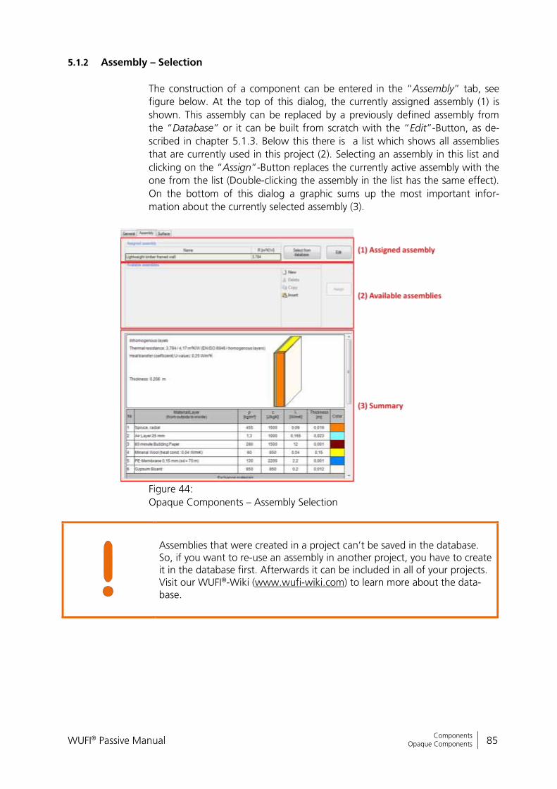
WUFI® Passive Manual 85
Bericht Nr. Anzuzeigender Text darf nicht mehr als eine Zeile beanspruchen!
Components Opaque Components
5.1.2 Assembly – Selection
The construction of a component can be entered in the “Assembly” tab, see
figure below. At the top of this dialog, the currently assigned assembly (1) is
shown. This assembly can be replaced by a previously defined assembly from
the “Database” or it can be built from scratch with the “Edit”-Button, as de-
scribed in chapter 5.1.3. Below this there is a list which shows all assemblies
that are currently used in this project (2). Selecting an assembly in this list and
clicking on the “Assign”-Button replaces the currently active assembly with the
one from the list (Double-clicking the assembly in the list has the same effect).
On the bottom of this dialog a graphic sums up the most important infor-
mation about the currently selected assembly (3).
Figure 44:
Opaque Components – Assembly Selection
Assemblies that were created in a project can’t be saved in the database. So, if you want to re-use an assembly in another project, you have to create it in the database first. Afterwards it can be included in all of your projects. Visit our WUFI®-Wiki (www.wufi-wiki.com) to learn more about the data-base.

WUFI® Passive Manual 86
Bericht Nr. Anzuzeigender Text darf nicht mehr als eine Zeile beanspruchen!
Components Opaque Components
5.1.3 Assembly – Editing
Clicking the “Edit”-Button in the “Assembly”-tab, see chapter 5.1.2, opens the
“Edit assembly”-window:
Figure 45:
Opaque Component – Edit Assembly
Controls
(1) Name
Name of the assembly.
(2) Material/ Layer A component is built from several material layers. Here, all layers are listed in a table and their thickness can be modi-fied by clicking the corresponding element. New layers can be added with the “New”-button and existing materials can be replaced by clicking the “Material database”-button.
(3) Subdivision & Ex-
change With this dialog, each layer defined in (2) can be divided in-to several horizontal and vertical parts. Each of these parts can be assigned with different exchange materials with help of the 2D-View (4). Exchange materials can be added with the “Exchange materials”-list. This function allows the input of inhomogeneous assem-blies. When switching to the dynamic hygrothermal simulations scope of WUFI® Plus, the inhomogeneous assemblies can-not be transferred! Only the main layers, without subdivi-sions, are transferred.
WUFI® Passive Manual 87
Bericht Nr. Anzuzeigender Text darf nicht mehr als eine Zeile beanspruchen!
Components Opaque Components
(4) 2D-View This window shows a 2D-visualization of the layer selected in (2) and, if available, its subdivisions (3). Materials can be exchanged by clicking them first in the “Exchange materi-als”-list (3) and then clicking the desired subdivision in the 2D-View to assign that material to the subdivision.
(5) 3D-Visualization This window shows a 3D-visualization of the assembly. The controls for this 3D-view are similar to the “3D-Visualization Box” described in chapter 3.4.
(6) Status Bar This status bar helps to identify potential errors.
New Create a new element in this list.
Delete Delete the selected element.
Copy Copy the selected element.
Insert Insert a copied element. The “Insert Position” specifies where the copied element will be positioned.
Insert Position Controls where a copied element will be inserted: “after” the selected element “before” the selected element “exchange” the selected element with the copied
one
Pay attention that your assemblies are built in the correct order. The table (2) always lists the material layers from outside to inside. You can also use the visualizations (4) & (5) to check your components.
When switching to the dynamic hygrothermal simulations scope of WUFI® Plus, the inhomogeneous assemblies cannot be transferred! Only the main layers, without subdivisions, are transferred. Please refer to chapter 9 to learn more about the data transfer between the different calculation scopes.
The example case in chapter 11 shows how homogeneous and inhomogeneous
assemblies are entered in WUFI® Passive.
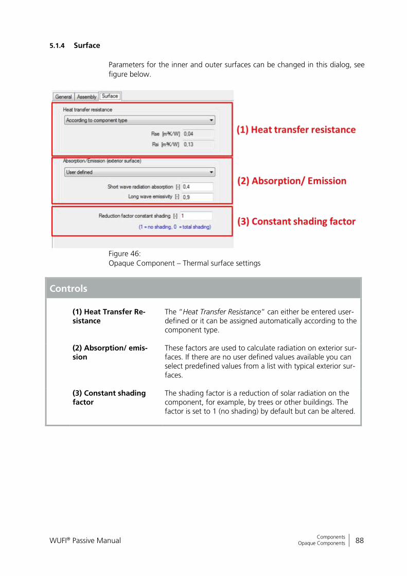
WUFI® Passive Manual 88
Bericht Nr. Anzuzeigender Text darf nicht mehr als eine Zeile beanspruchen!
Components Opaque Components
5.1.4 Surface
Parameters for the inner and outer surfaces can be changed in this dialog, see
figure below.
Figure 46:
Opaque Component – Thermal surface settings
Controls
(1) Heat Transfer Re-sistance
The “Heat Transfer Resistance” can either be entered user-defined or it can be assigned automatically according to the component type.
(2) Absorption/ emis-sion
These factors are used to calculate radiation on exterior sur-faces. If there are no user defined values available you can select predefined values from a list with typical exterior sur-faces.
(3) Constant shading factor
The shading factor is a reduction of solar radiation on the component, for example, by trees or other buildings. The factor is set to 1 (no shading) by default but can be altered.

WUFI® Passive Manual 89
Bericht Nr. Anzuzeigender Text darf nicht mehr als eine Zeile beanspruchen!
Components Opaque Components
5.1.5 Exterior Door
To create an exterior door, select an exterior, vertical and opaque component
and check mark the option “Exterior Door” in the components “General”-Tab,
see chapter 5.1.1.
The Example Case in chapter 11 shows, how exterior doors can be included in
WUFI® Passive.

WUFI® Passive Manual 90
Bericht Nr. Anzuzeigender Text darf nicht mehr als eine Zeile beanspruchen!
Components Transparent Components
5.2 Transparent Components
The procedure for defining “Transparent Components” is very similar to that of
“Opaque Components”, yet there are differences.
Chapter 3.4.1 describes how geometries of “Transparent Components” or “Openings” can be entered into WUFI® Plus.
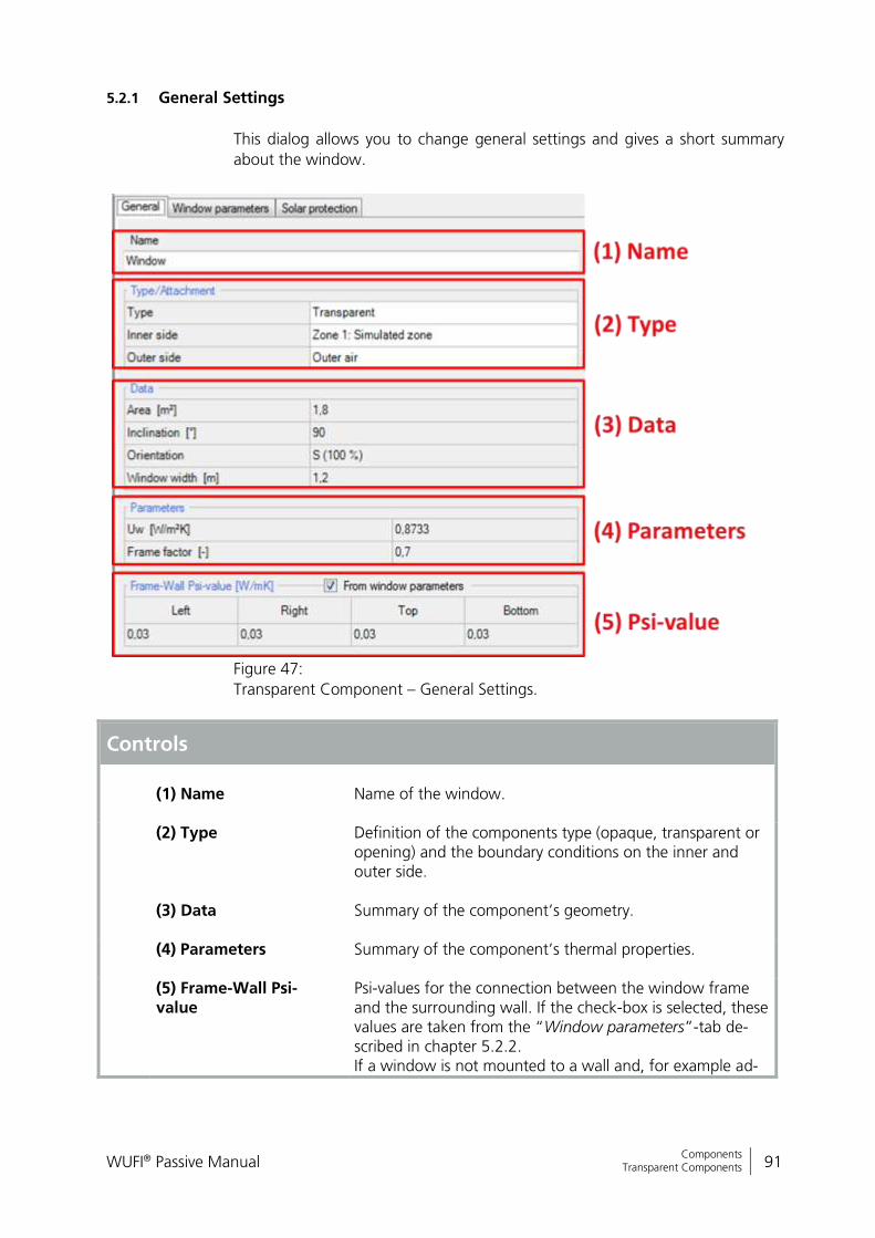
WUFI® Passive Manual 91
Bericht Nr. Anzuzeigender Text darf nicht mehr als eine Zeile beanspruchen!
Components Transparent Components
5.2.1 General Settings
This dialog allows you to change general settings and gives a short summary
about the window.
Figure 47:
Transparent Component – General Settings.
Controls
(1) Name
Name of the window.
(2) Type Definition of the components type (opaque, transparent or opening) and the boundary conditions on the inner and outer side.
(3) Data Summary of the component’s geometry.
(4) Parameters Summary of the component’s thermal properties.
(5) Frame-Wall Psi-value
Psi-values for the connection between the window frame and the surrounding wall. If the check-box is selected, these values are taken from the “Window parameters”-tab de-scribed in chapter 5.2.2. If a window is not mounted to a wall and, for example ad-
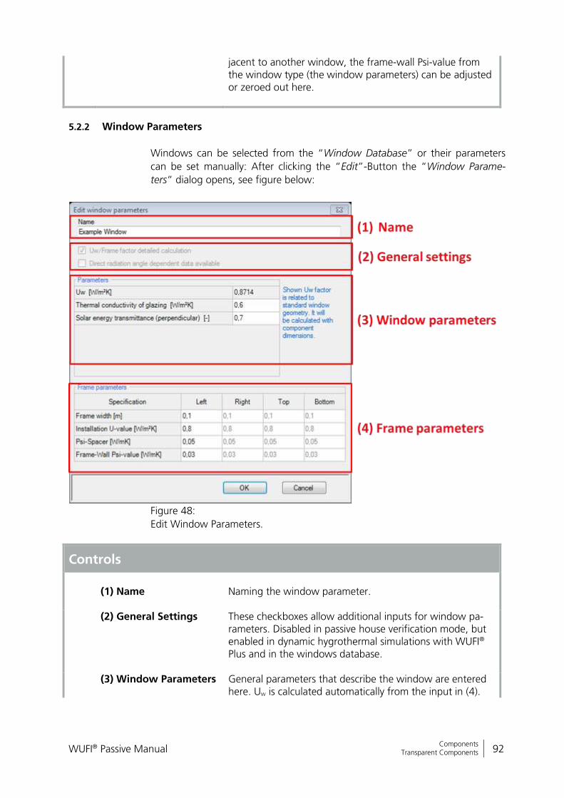
WUFI® Passive Manual 92
Bericht Nr. Anzuzeigender Text darf nicht mehr als eine Zeile beanspruchen!
Components Transparent Components
jacent to another window, the frame-wall Psi-value from the window type (the window parameters) can be adjusted or zeroed out here.
5.2.2 Window Parameters
Windows can be selected from the “Window Database” or their parameters
can be set manually: After clicking the “Edit”-Button the “Window Parame-
ters” dialog opens, see figure below:
Figure 48:
Edit Window Parameters.
Controls
(1) Name
Naming the window parameter.
(2) General Settings These checkboxes allow additional inputs for window pa-rameters. Disabled in passive house verification mode, but enabled in dynamic hygrothermal simulations with WUFI® Plus and in the windows database.
(3) Window Parameters General parameters that describe the window are entered here. Uw is calculated automatically from the input in (4).
WUFI® Passive Manual 93
Bericht Nr. Anzuzeigender Text darf nicht mehr als eine Zeile beanspruchen!
Components Transparent Components
Please note: This Uw value is calculated for a standard win-dow with standard measurements (1.23 m x 1.48 m). The real Uw value for the selected window can be found in the “General Settings” tab, described in chapter 5.2.1.
(4) Frame Parameters Here, detailed about the window frame is entered. These
values are used for calculation of Uw in (3).
New Create a new element in this list.
Delete Delete the selected element.
Copy Copy the selected element
Insert Insert a copied element. The “Insert Position” menu speci-fies where the copied element will be positioned
Insert Position Controls where a copied element will be inserted: “after” the selected element “before” the selected element “exchange” the selected element with the copied
one

WUFI® Passive Manual 94
Bericht Nr. Anzuzeigender Text darf nicht mehr als eine Zeile beanspruchen!
Components Transparent Components
5.2.3 Solar Protection
General settings for solar protection can be entered in the “Solar protection -
General”-tab:
Figure 49:
General settings for solar protection of a transparent component.
Controls
(1) Parameters
General parameters for the calculation of shading factors (2) can be entered here. The shading factor refers to the in-coming solar radiation. It can take a value from 0 to 1, where 0 means total shading and 1 means total exposure. These general parameters include window reveals, land-scape obstruction and factors for other shading types. There is also an input for a special summer shading factor for the calculation of the cooling load and overheating fre-quency.
(2) Shading factors This table sums up the shading factors calculated from the values entered in (1).
WUFI® Passive supports two additional solar protection types: “Sunscreen De-
vices” and “Window Overhangs”:
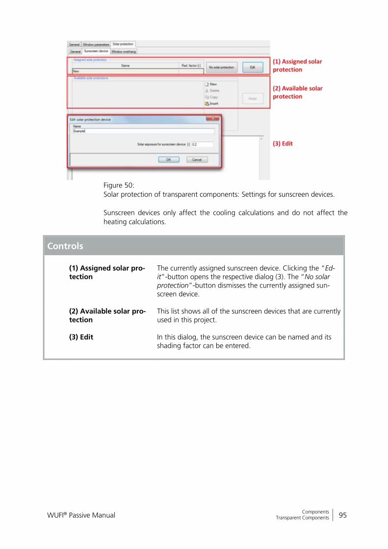
WUFI® Passive Manual 95
Bericht Nr. Anzuzeigender Text darf nicht mehr als eine Zeile beanspruchen!
Components Transparent Components
Figure 50:
Solar protection of transparent components: Settings for sunscreen devices.
Sunscreen devices only affect the cooling calculations and do not affect the
heating calculations.
Controls
(1) Assigned solar pro-tection
The currently assigned sunscreen device. Clicking the “Ed-it”-button opens the respective dialog (3). The “No solar protection”-button dismisses the currently assigned sun-screen device.
(2) Available solar pro-tection
This list shows all of the sunscreen devices that are currently used in this project.
(3) Edit In this dialog, the sunscreen device can be named and its shading factor can be entered.
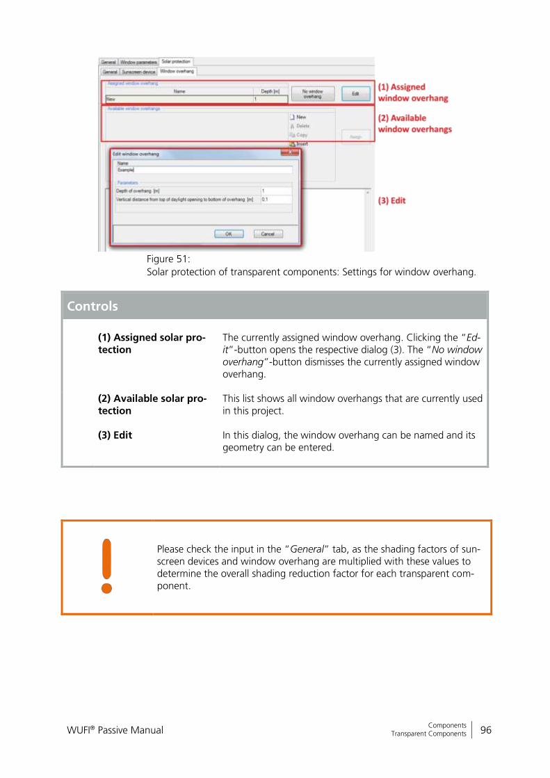
WUFI® Passive Manual 96
Bericht Nr. Anzuzeigender Text darf nicht mehr als eine Zeile beanspruchen!
Components Transparent Components
Figure 51:
Solar protection of transparent components: Settings for window overhang.
Controls
(1) Assigned solar pro-tection
The currently assigned window overhang. Clicking the “Ed-it”-button opens the respective dialog (3). The “No window overhang”-button dismisses the currently assigned window overhang.
(2) Available solar pro-tection
This list shows all window overhangs that are currently used in this project.
(3) Edit In this dialog, the window overhang can be named and its geometry can be entered.
Please check the input in the “General” tab, as the shading factors of sun-screen devices and window overhang are multiplied with these values to determine the overall shading reduction factor for each transparent com-ponent.
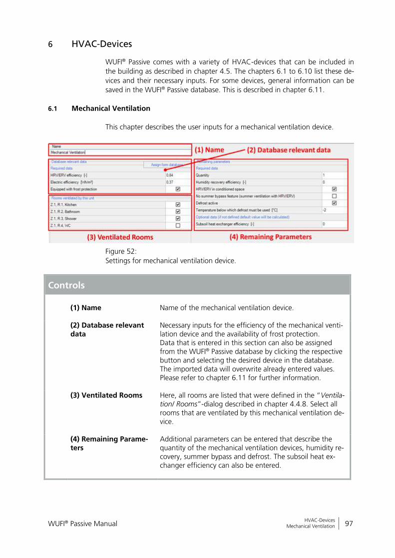
WUFI® Passive Manual 97
Bericht Nr. Anzuzeigender Text darf nicht mehr als eine Zeile beanspruchen!
HVAC-Devices Mechanical Ventilation
6 HVAC-Devices
WUFI® Passive comes with a variety of HVAC-devices that can be included in
the building as described in chapter 4.5. The chapters 6.1 to 6.10 list these de-
vices and their necessary inputs. For some devices, general information can be
saved in the WUFI® Passive database. This is described in chapter 6.11.
6.1 Mechanical Ventilation
This chapter describes the user inputs for a mechanical ventilation device.
Figure 52:
Settings for mechanical ventilation device.
Controls
(1) Name
Name of the mechanical ventilation device.
(2) Database relevant data
Necessary inputs for the efficiency of the mechanical venti-lation device and the availability of frost protection. Data that is entered in this section can also be assigned from the WUFI® Passive database by clicking the respective button and selecting the desired device in the database. The imported data will overwrite already entered values. Please refer to chapter 6.11 for further information.
(3) Ventilated Rooms Here, all rooms are listed that were defined in the “Ventila-tion/ Rooms”-dialog described in chapter 4.4.8. Select all rooms that are ventilated by this mechanical ventilation de-vice.
(4) Remaining Parame-
ters Additional parameters can be entered that describe the quantity of the mechanical ventilation devices, humidity re-covery, summer bypass and defrost. The subsoil heat ex-changer efficiency can also be entered.
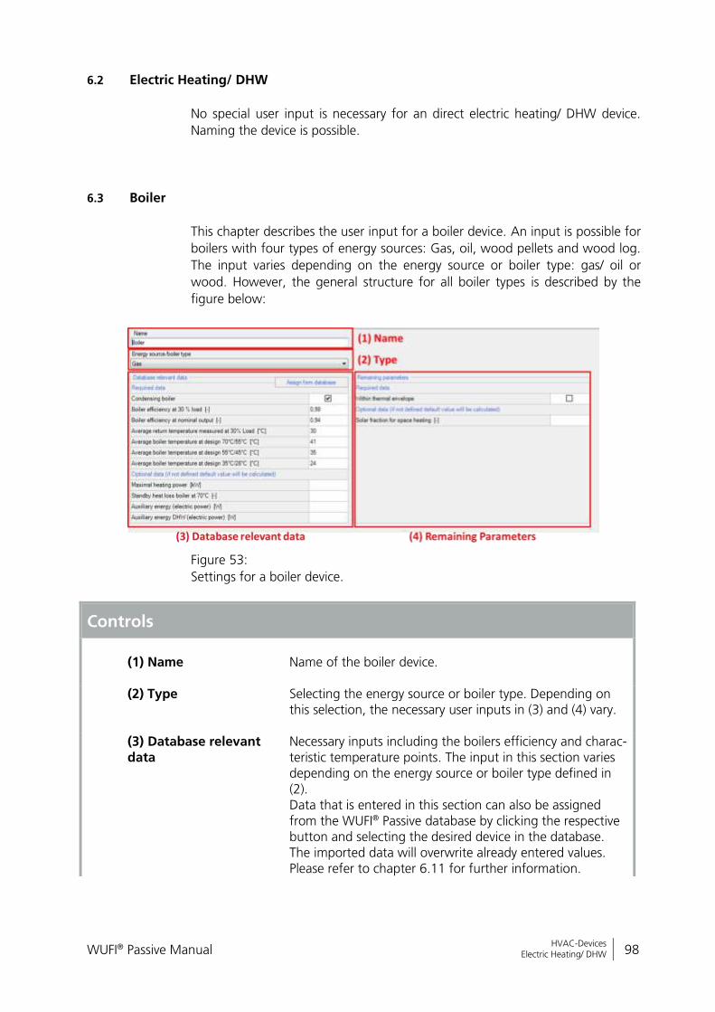
WUFI® Passive Manual 98
Bericht Nr. Anzuzeigender Text darf nicht mehr als eine Zeile beanspruchen!
HVAC-Devices Electric Heating/ DHW
6.2 Electric Heating/ DHW
No special user input is necessary for an direct electric heating/ DHW device.
Naming the device is possible.
6.3 Boiler
This chapter describes the user input for a boiler device. An input is possible for
boilers with four types of energy sources: Gas, oil, wood pellets and wood log.
The input varies depending on the energy source or boiler type: gas/ oil or
wood. However, the general structure for all boiler types is described by the
figure below:
Figure 53:
Settings for a boiler device.
Controls
(1) Name
Name of the boiler device.
(2) Type Selecting the energy source or boiler type. Depending on this selection, the necessary user inputs in (3) and (4) vary.
(3) Database relevant data
Necessary inputs including the boilers efficiency and charac-teristic temperature points. The input in this section varies depending on the energy source or boiler type defined in (2). Data that is entered in this section can also be assigned from the WUFI® Passive database by clicking the respective button and selecting the desired device in the database. The imported data will overwrite already entered values. Please refer to chapter 6.11 for further information.
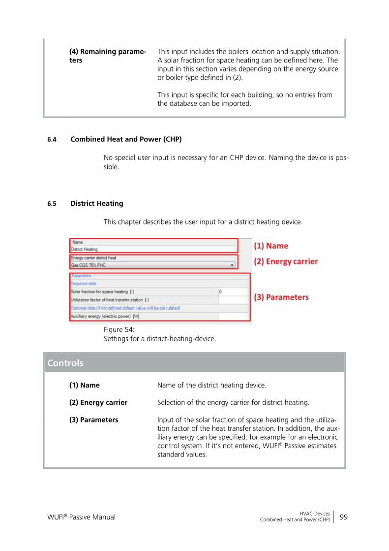
WUFI® Passive Manual 99
Bericht Nr. Anzuzeigender Text darf nicht mehr als eine Zeile beanspruchen!
HVAC-Devices Combined Heat and Power (CHP)
(4) Remaining parame-
ters This input includes the boilers location and supply situation. A solar fraction for space heating can be defined here. The input in this section varies depending on the energy source or boiler type defined in (2). This input is specific for each building, so no entries from the database can be imported.
6.4 Combined Heat and Power (CHP)
No special user input is necessary for an CHP device. Naming the device is pos-
sible.
6.5 District Heating
This chapter describes the user input for a district heating device.
Figure 54:
Settings for a district-heating-device.
Controls
(1) Name
Name of the district heating device.
(2) Energy carrier Selection of the energy carrier for district heating.
(3) Parameters Input of the solar fraction of space heating and the utiliza-tion factor of the heat transfer station. In addition, the aux-iliary energy can be specified, for example for an electronic control system. If it’s not entered, WUFI® Passive estimates standard values.
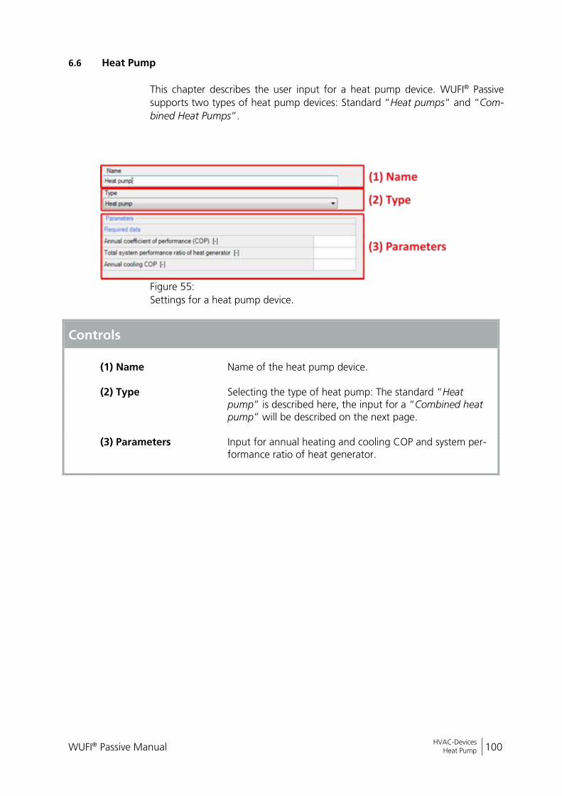
WUFI® Passive Manual 100
Bericht Nr. Anzuzeigender Text darf nicht mehr als eine Zeile beanspruchen!
HVAC-Devices Heat Pump
6.6 Heat Pump
This chapter describes the user input for a heat pump device. WUFI® Passive
supports two types of heat pump devices: Standard “Heat pumps” and “Com-
bined Heat Pumps”.
Figure 55:
Settings for a heat pump device.
Controls
(1) Name
Name of the heat pump device.
(2) Type Selecting the type of heat pump: The standard “Heat pump” is described here, the input for a “Combined heat pump” will be described on the next page.
(3) Parameters Input for annual heating and cooling COP and system per-formance ratio of heat generator.
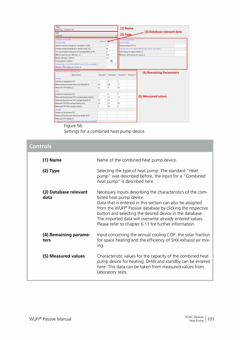
WUFI® Passive Manual 101
Bericht Nr. Anzuzeigender Text darf nicht mehr als eine Zeile beanspruchen!
HVAC-Devices Heat Pump
Figure 56:
Settings for a combined heat pump device.
Controls
(1) Name
Name of the combined heat pump device.
(2) Type Selecting the type of heat pump: The standard “Heat pump” was described before, the input for a “Combined heat pump” is described here.
(3) Database relevant data
Necessary inputs describing the characteristics of the com-bined heat pump device. Data that is entered in this section can also be assigned from the WUFI® Passive database by clicking the respective button and selecting the desired device in the database. The imported data will overwrite already entered values. Please refer to chapter 6.11 for further information.
(4) Remaining parame-
ters
Input concerning the annual cooling COP, the solar fraction for space heating and the efficiency of SHX exhaust air mix-ing.
(5) Measured values Characteristic values for the capacity of the combined heat pump device for heating, DHW and standby can be entered here. This data can be taken from measured values from laboratory tests.
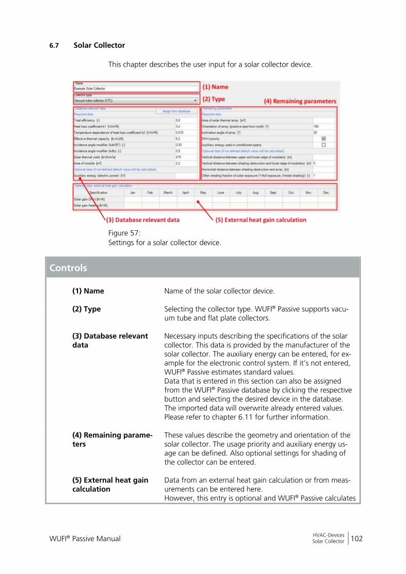
WUFI® Passive Manual 102
Bericht Nr. Anzuzeigender Text darf nicht mehr als eine Zeile beanspruchen!
HVAC-Devices Solar Collector
6.7 Solar Collector
This chapter describes the user input for a solar collector device.
Figure 57:
Settings for a solar collector device.
Controls
(1) Name
Name of the solar collector device.
(2) Type Selecting the collector type. WUFI® Passive supports vacu-um tube and flat plate collectors.
(3) Database relevant data
Necessary inputs describing the specifications of the solar collector. This data is provided by the manufacturer of the solar collector. The auxiliary energy can be entered, for ex-ample for the electronic control system. If it’s not entered, WUFI® Passive estimates standard values. Data that is entered in this section can also be assigned from the WUFI® Passive database by clicking the respective button and selecting the desired device in the database. The imported data will overwrite already entered values. Please refer to chapter 6.11 for further information.
(4) Remaining parame-
ters
These values describe the geometry and orientation of the solar collector. The usage priority and auxiliary energy us-age can be defined. Also optional settings for shading of the collector can be entered.
(5) External heat gain calculation
Data from an external heat gain calculation or from meas-urements can be entered here. However, this entry is optional and WUFI® Passive calculates

WUFI® Passive Manual 103
Bericht Nr. Anzuzeigender Text darf nicht mehr als eine Zeile beanspruchen!
HVAC-Devices Solar Collector
these values internally if left blank.
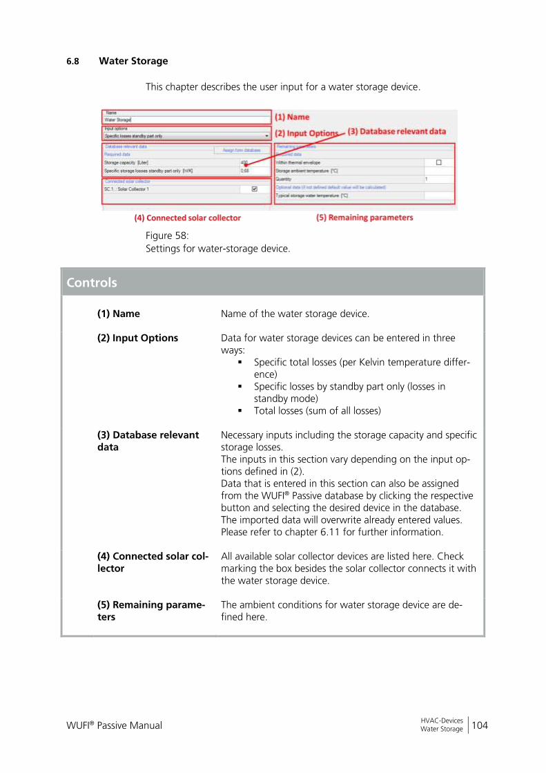
WUFI® Passive Manual 104
Bericht Nr. Anzuzeigender Text darf nicht mehr als eine Zeile beanspruchen!
HVAC-Devices Water Storage
6.8 Water Storage
This chapter describes the user input for a water storage device.
Figure 58:
Settings for water-storage device.
Controls
(1) Name
Name of the water storage device.
(2) Input Options Data for water storage devices can be entered in three ways:
Specific total losses (per Kelvin temperature differ-ence)
Specific losses by standby part only (losses in standby mode)
Total losses (sum of all losses)
(3) Database relevant data
Necessary inputs including the storage capacity and specific storage losses. The inputs in this section vary depending on the input op-tions defined in (2). Data that is entered in this section can also be assigned from the WUFI® Passive database by clicking the respective button and selecting the desired device in the database. The imported data will overwrite already entered values. Please refer to chapter 6.11 for further information.
(4) Connected solar col-lector
All available solar collector devices are listed here. Check marking the box besides the solar collector connects it with the water storage device.
(5) Remaining parame-ters
The ambient conditions for water storage device are de-fined here.
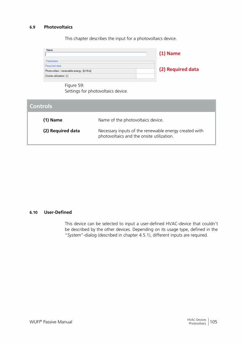
WUFI® Passive Manual 105
Bericht Nr. Anzuzeigender Text darf nicht mehr als eine Zeile beanspruchen!
HVAC-Devices Photovoltaics
6.9 Photovoltaics
This chapter describes the input for a photovoltaics device.
Figure 59:
Settings for photovoltaics device.
Controls
(1) Name
Name of the photovoltaics device.
(2) Required data Necessary inputs of the renewable energy created with photovoltaics and the onsite utilization.
6.10 User-Defined
This device can be selected to input a user-defined HVAC-device that couldn’t
be described by the other devices. Depending on its usage type, defined in the
“System”-dialog (described in chapter 4.5.1), different inputs are required.

WUFI® Passive Manual 106
Bericht Nr. Anzuzeigender Text darf nicht mehr als eine Zeile beanspruchen!
HVAC-Devices Creating Database Entries for HVAC Devices
6.11 Creating Database Entries for HVAC Devices
Some of the HVAC devices described in the previous chapters allow assigning
their settings from database entries:
Mechanical ventilation unit
Boiler
Heat pump
Solar collector
Water storage
Some predefined examples are saved in the database when installing the soft-
ware. Additional entries can be entered by the user. This chapter shows how to
do this.
Settings for HVAC devices that were created in a project can’t be saved in the database. So, if you want to re-use settings for a HVAC device in an-other project, you have to create it in the database first. Afterwards it can be included in all of your projects. Visit our WUFI®-Wiki (www.wufi-wiki.com) to learn more about the data-base.
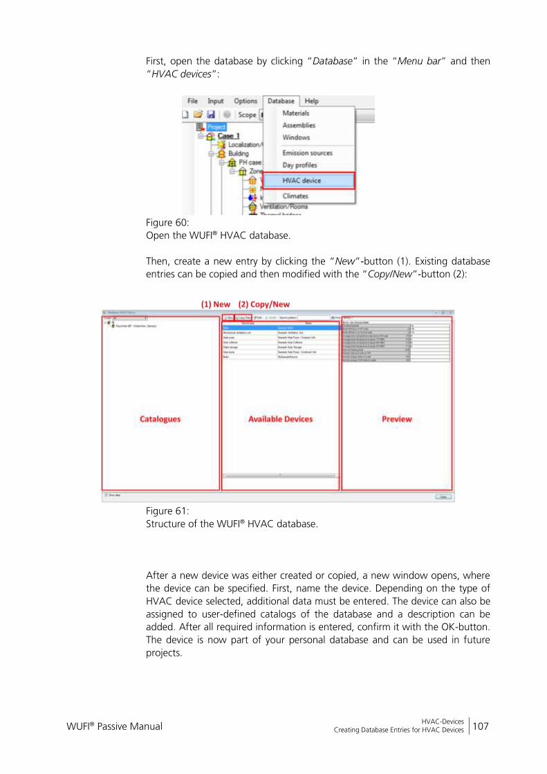
WUFI® Passive Manual 107
Bericht Nr. Anzuzeigender Text darf nicht mehr als eine Zeile beanspruchen!
HVAC-Devices Creating Database Entries for HVAC Devices
First, open the database by clicking “Database” in the “Menu bar” and then
“HVAC devices”:
Figure 60:
Open the WUFI® HVAC database.
Then, create a new entry by clicking the “New”-button (1). Existing database
entries can be copied and then modified with the “Copy/New”-button (2):
Figure 61:
Structure of the WUFI® HVAC database.
After a new device was either created or copied, a new window opens, where
the device can be specified. First, name the device. Depending on the type of
HVAC device selected, additional data must be entered. The device can also be
assigned to user-defined catalogs of the database and a description can be
added. After all required information is entered, confirm it with the OK-button.
The device is now part of your personal database and can be used in future
projects.
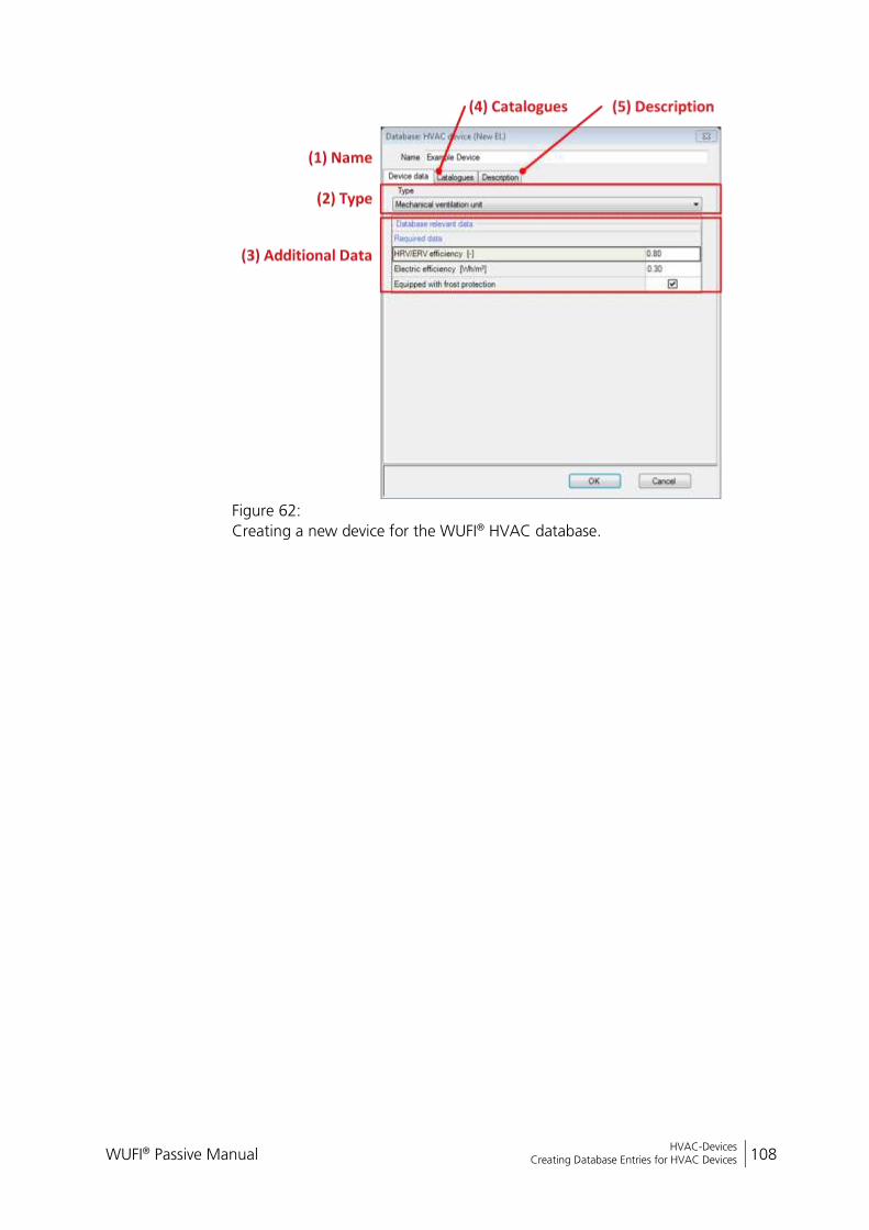
WUFI® Passive Manual 108
Bericht Nr. Anzuzeigender Text darf nicht mehr als eine Zeile beanspruchen!
HVAC-Devices Creating Database Entries for HVAC Devices
Figure 62:
Creating a new device for the WUFI® HVAC database.

WUFI® Passive Manual 109
Bericht Nr. Anzuzeigender Text darf nicht mehr als eine Zeile beanspruchen!
Importing geometry data SketchUp Plugin
7 Importing geometry data
WUFI® Passive imports 3D geometries from other applications:
SketchUp: A plugin for SketchUp allows defining zones and properties
of components directly in SketchUp. This geometry data is then trans-
ferred directly to WUFI® Plus.
gbXML: With the gbXML-format, geometry data can be imported from
CAD-programs like Revit®.
7.1 SketchUp Plugin
WUFI® Passive imports 3D geometries from SketchUp by using a plugin.
The plugin has to be installed manually after the installation of WUFI® Passive
and requires an existing installation of SketchUp version 8 or higher. To install
the plugin, open “Menu Bar > Options > WUFIplus SketchUp plugin”, as de-
scribed in chapter 3.2.3. The following dialog appears:
Figure 63:
Options for the WUFI® Passive SketchUp Plugin.
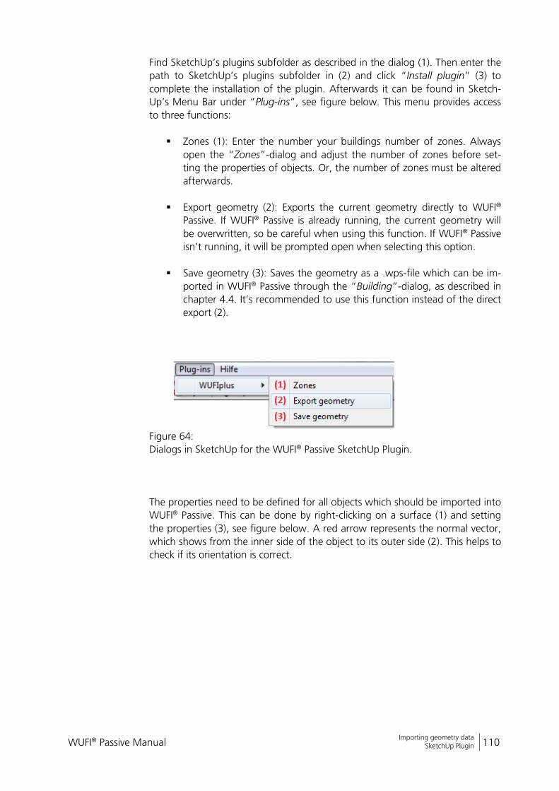
WUFI® Passive Manual 110
Bericht Nr. Anzuzeigender Text darf nicht mehr als eine Zeile beanspruchen!
Importing geometry data SketchUp Plugin
Find SketchUp’s plugins subfolder as described in the dialog (1). Then enter the
path to SketchUp’s plugins subfolder in (2) and click “Install plugin” (3) to
complete the installation of the plugin. Afterwards it can be found in Sketch-
Up’s Menu Bar under “Plug-ins”, see figure below. This menu provides access
to three functions:
Zones (1): Enter the number your buildings number of zones. Always
open the “Zones”-dialog and adjust the number of zones before set-
ting the properties of objects. Or, the number of zones must be altered
afterwards.
Export geometry (2): Exports the current geometry directly to WUFI®
Passive. If WUFI® Passive is already running, the current geometry will
be overwritten, so be careful when using this function. If WUFI® Passive
isn’t running, it will be prompted open when selecting this option.
Save geometry (3): Saves the geometry as a .wps-file which can be im-
ported in WUFI® Passive through the “Building”-dialog, as described in
chapter 4.4. It’s recommended to use this function instead of the direct
export (2).
Figure 64:
Dialogs in SketchUp for the WUFI® Passive SketchUp Plugin.
The properties need to be defined for all objects which should be imported into
WUFI® Passive. This can be done by right-clicking on a surface (1) and setting
the properties (3), see figure below. A red arrow represents the normal vector,
which shows from the inner side of the object to its outer side (2). This helps to
check if its orientation is correct.
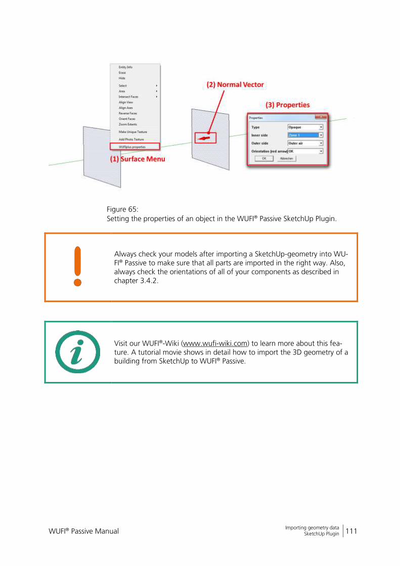
WUFI® Passive Manual 111
Bericht Nr. Anzuzeigender Text darf nicht mehr als eine Zeile beanspruchen!
Importing geometry data SketchUp Plugin
Figure 65:
Setting the properties of an object in the WUFI® Passive SketchUp Plugin.
Always check your models after importing a SketchUp-geometry into WU-FI® Passive to make sure that all parts are imported in the right way. Also, always check the orientations of all of your components as described in chapter 3.4.2.
Visit our WUFI®-Wiki (www.wufi-wiki.com) to learn more about this fea-ture. A tutorial movie shows in detail how to import the 3D geometry of a building from SketchUp to WUFI® Passive.
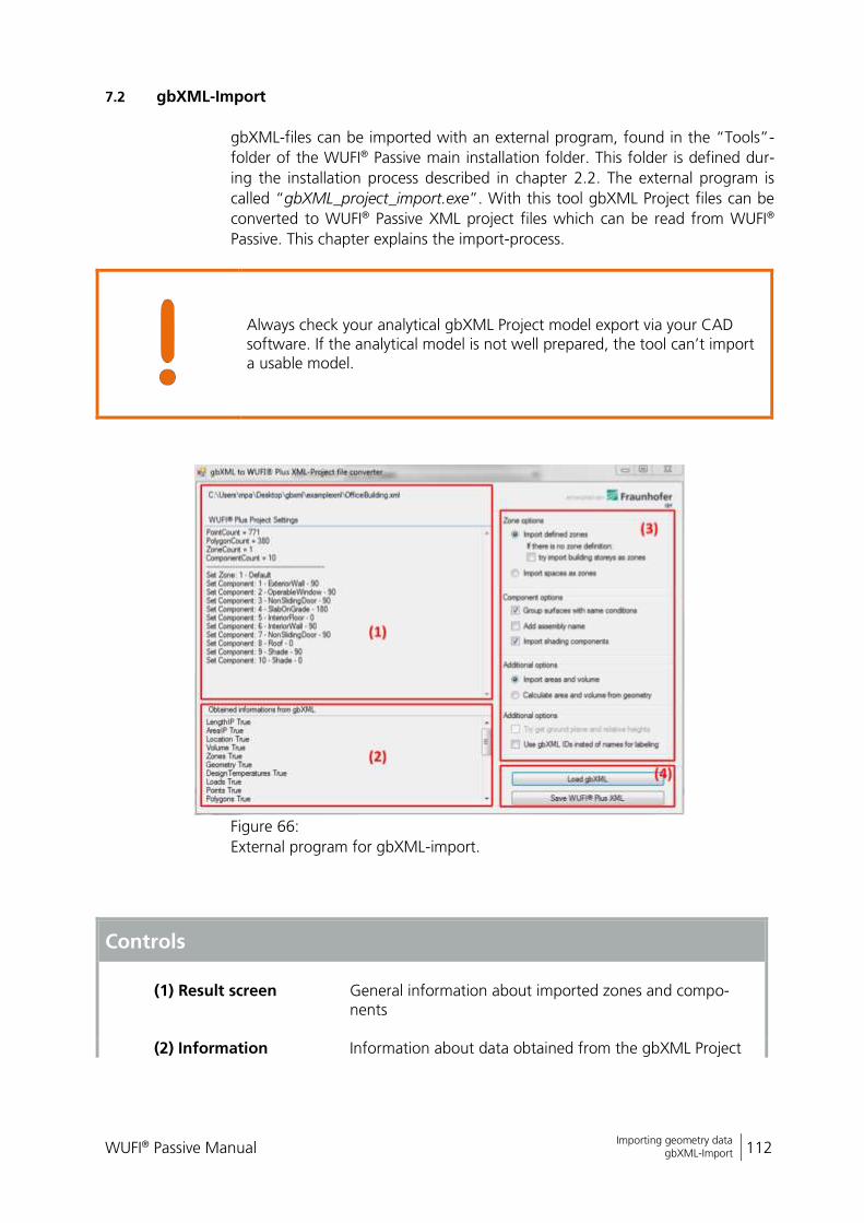
WUFI® Passive Manual 112
Bericht Nr. Anzuzeigender Text darf nicht mehr als eine Zeile beanspruchen!
Importing geometry data gbXML-Import
7.2 gbXML-Import
gbXML-files can be imported with an external program, found in the “Tools”-
folder of the WUFI® Passive main installation folder. This folder is defined dur-
ing the installation process described in chapter 2.2. The external program is
called “gbXML_project_import.exe”. With this tool gbXML Project files can be
converted to WUFI® Passive XML project files which can be read from WUFI®
Passive. This chapter explains the import-process.
Always check your analytical gbXML Project model export via your CAD software. If the analytical model is not well prepared, the tool can’t import a usable model.
Figure 66:
External program for gbXML-import.
Controls
(1) Result screen
General information about imported zones and compo-nents
(2) Information Information about data obtained from the gbXML Project
WUFI® Passive Manual 113
Bericht Nr. Anzuzeigender Text darf nicht mehr als eine Zeile beanspruchen!
Importing geometry data gbXML-Import
translated to the WUFI® Passive Project
(3) Import options General settings concerning the import of the gbXML ge-ometry, zone definition, and additional data. Further infor-mation about these options is provided below the box.
(4) Load and Save options
Two functions are available: “Load gbXML”: Choose the gbXML file you want to
use with WUFI® Plus. “Save WUFI® Plus XML Project”: Saves the loaded
gbXML Project with the defined import options, as WUFI® Plus XML Project, openable in WUFI® Passive.
Some import options (2) are available:
Zone options:
“Import defined zones”: Import the zones defined (in Revit the Export
Category should be set to MEP-spaces for the gbXML-Project export). If
you have set the Export Category to architecture rooms, you can import
different building stories as WUFI® Passive zones, or the building will
consist of only one zone.
“Import spaces as zones”: Ignores zone definition in the gbXML-Project
(may not obtainable). All defined rooms or spaces are imported as sepa-
rate WUFI® Passive zones.
Component options:
You can “Group surfaces with same conditions” for a tidy project tree.
If you uncheck this option, each Surface of the building will become a
new WUFI® Passive component.
The import tool tries to get the construction information (assembly) of
each component. If you check “Add Assembly Name” the Name of the
construction will be added to the component Name.
Additional options:
“Import areas and volume”: The area and volume of each space is cal-
culated with the CAD software (Revit) and stored in gbXML. You can
import this information, or you can let WUFI® Passive calculate it, de-
pending on the building geometry data.
“Use gbXML IDs instead of names for labelling”: If no names for zones
or components is defined within the gbXML project, you can take the
IDs for labelling.
WUFI® Passive Manual 114
Bericht Nr. Anzuzeigender Text darf nicht mehr als eine Zeile beanspruchen!
Importing geometry data gbXML-Import
Open WUFI® Passive xml project files
Click on open in the WUFI® Passive “Menu Bar”, choose “XML Project
Files (*.xml)“ as data type and search for the WUFI® Passive XML Project
file you have saved before with the Convert-Tool. Refer to chapter 3.2.1
for further information.
Another option is found in the “Building”-entry of the “Project Tree”.
There, choose “gbXML Import” and select and browse to the WUFI®
Passive XML Project file you have saved before with the Convert-Tool.
Refer to chapter 4.4.1 for further information.
WUFI® Passive Manual 115
Bericht Nr. Anzuzeigender Text darf nicht mehr als eine Zeile beanspruchen!
Passive House Verification General Reports
8 Passive House Verification
Once all necessary data is input to WUFI® Passive a variety of reports including
the Passive House verification report can be accessed through the “Report: Da-
ta & Results”-tab in the “Case”-entry of the “Project Tree”.
8.1 General Reports
After the calculation, the results for the whole building can be accessed
through the “Report: Data & Results”-Tab in the “Case”-dialog, see figure be-
low. WUFI® Passive comes with a variety of predefined reports:
Passive House verification: Creates the Passive House verification report.
Please refer to chapter 8.2 for further information.
Project Data: Information about the current project, as described in
chapter 4.1.
Climate: Information and visualization of the selected outdoor climate.
Passive house data: Summary of passive house data, mainly from the
“PH case” dialog, described in chapter 4.4.2.
Zones/ components: General information about all zones in the build-
ing. In addition, their internal loads and ventilation settings as well as
general information about their components are described.
Assemblies: Lists and visualizes all assemblies used in the building.
HVAC: Summarizes all HVAC systems including their devices and distri-
bution. The settings for each device are described, too.
Results: Sums up the main calculation results, like for example specific
heating demand or specific heat load.
User defined: A custom combination of the reports described above.
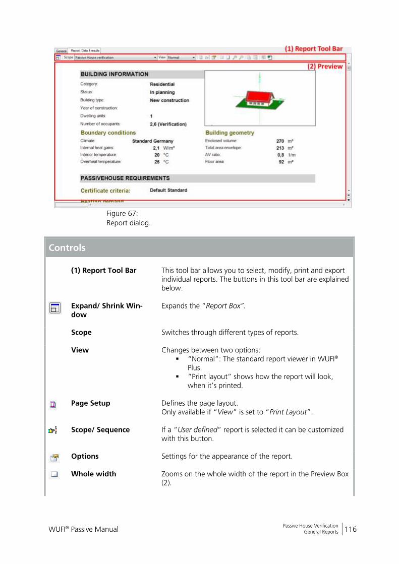
WUFI® Passive Manual 116
Bericht Nr. Anzuzeigender Text darf nicht mehr als eine Zeile beanspruchen!
Passive House Verification General Reports
Figure 67:
Report dialog.
Controls
(1) Report Tool Bar
This tool bar allows you to select, modify, print and export individual reports. The buttons in this tool bar are explained below.
Expand/ Shrink Win-dow
Expands the “Report Box”.
Scope Switches through different types of reports.
View Changes between two options: “Normal”: The standard report viewer in WUFI®
Plus. “Print layout” shows how the report will look,
when it’s printed.
Page Setup Defines the page layout.
Only available if “View” is set to “Print Layout”.
Scope/ Sequence If a “User defined” report is selected it can be customized with this button.
Options Settings for the appearance of the report.
Whole width Zooms on the whole width of the report in the Preview Box (2).
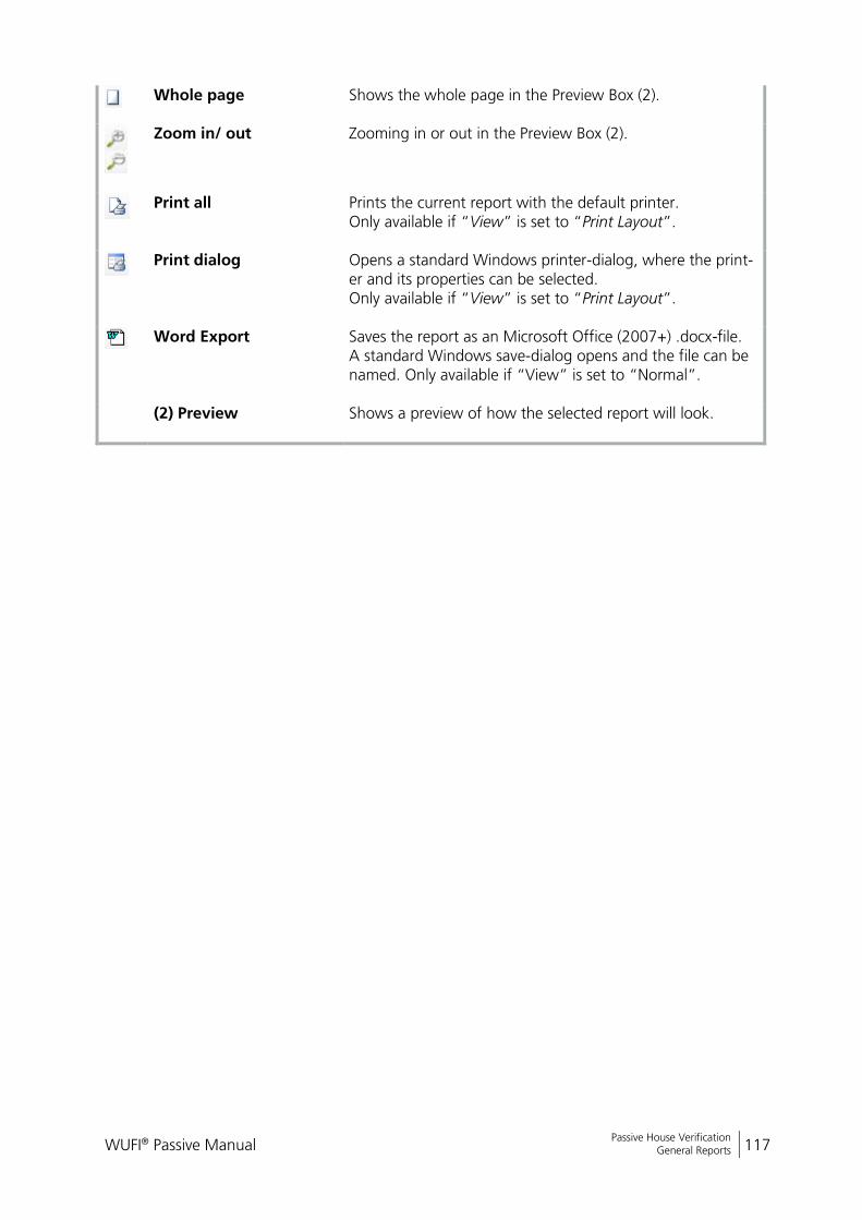
WUFI® Passive Manual 117
Bericht Nr. Anzuzeigender Text darf nicht mehr als eine Zeile beanspruchen!
Passive House Verification General Reports
Whole page Shows the whole page in the Preview Box (2).
Zoom in/ out Zooming in or out in the Preview Box (2).
Print all
Prints the current report with the default printer. Only available if “View” is set to “Print Layout”.
Print dialog
Opens a standard Windows printer-dialog, where the print-er and its properties can be selected. Only available if “View” is set to “Print Layout”.
Word Export
Saves the report as an Microsoft Office (2007+) .docx-file. A standard Windows save-dialog opens and the file can be named. Only available if “View” is set to “Normal”.
(2) Preview Shows a preview of how the selected report will look.
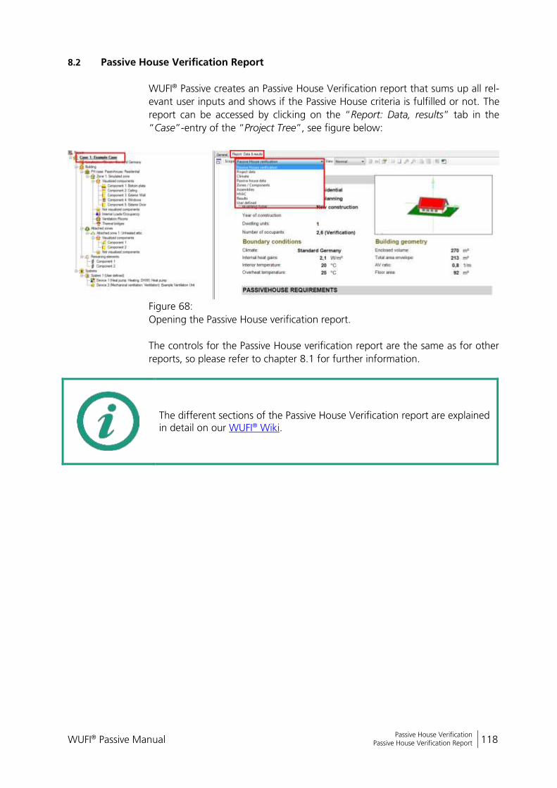
WUFI® Passive Manual 118
Bericht Nr. Anzuzeigender Text darf nicht mehr als eine Zeile beanspruchen!
Passive House Verification Passive House Verification Report
8.2 Passive House Verification Report
WUFI® Passive creates an Passive House Verification report that sums up all rel-
evant user inputs and shows if the Passive House criteria is fulfilled or not. The
report can be accessed by clicking on the “Report: Data, results” tab in the
“Case”-entry of the “Project Tree”, see figure below:
Figure 68:
Opening the Passive House verification report.
The controls for the Passive House verification report are the same as for other
reports, so please refer to chapter 8.1 for further information.
The different sections of the Passive House Verification report are explained in detail on our WUFI® Wiki.
WUFI® Passive Manual 119
Bericht Nr. Anzuzeigender Text darf nicht mehr als eine Zeile beanspruchen!
Hygrothermal building simulation Data-transfer between the Calculation Modes
9 Hygrothermal building simulation
The major advantage of WUFI® Passive is the possibility to compare the results
of the static passive house calculation method with the dynamic hygrothermal
building simulation of WUFI® Plus. Please note that the simulation of WUFI® Plus
requires additional input data, especially for materials, which require data like
heat storage capacity and hygrothermal properties. This data can be taken from
the WUFI® database.
Once the certification criteria are met in the Passive House Verification scope,
the full hygrothermal building simulation of WUFI® Plus is available for this
building model. Switching between the calculation scopes is possible with the
respective dropdown menu in the “Tool Bar”, as described in chapter 3.3.
Please refer to the WUFI® Plus manual for detailed information on working with
hygrothermal simulations.
9.1 Data-transfer between the Calculation Modes
Most parts of the building can be transferred between the different calculation
modes of WUFI® Passive and WUFI® Plus:
The structure of the “Project Tree” is transferred in most parts.
The whole building geometry including simulated and attached zones,
visualized and not-visualized components and remaining elements is
transferred.
HVAC-systems and their devices are transferred. However, most of their
settings made in passive house verification mode cannot be transferred.
Limitations:
A new outdoor climate has to be selected. This is necessary because the
passive house verification uses monthly climate data and the dynamic
hygrothermal simulations of WUFI® Plus need hourly climate data (or
even a higher resolution). These detailed climate files can either be se-
lected from the WUFI® Plus database, which comes with a huge variety
of worldwide climate locations, or external climate files can be import-
ed.
WUFI® Plus can only calculate the 1D-heat and moisture transfer
through assemblies. This means, that inhomogeneous assemblies en-
tered in the passive house verification mode cannot be transferred to
the WUFI® Plus mode. However, these assemblies are simplified auto-
matically, so they remain compatible: Only the main layers, without
subdivisions are transferred.
WUFI® Passive Manual 120
Bericht Nr. Anzuzeigender Text darf nicht mehr als eine Zeile beanspruchen!
Hygrothermal building simulation Data-transfer between the Calculation Modes
Linear thermal bridges cannot be transferred. However, WUFI® Plus
supports dynamic calculations of 3D- and 2D-objects, which allows
modeling thermal bridges.
Primary energy is not calculated in WUFI® Plus.
DHW is not calculated in WUFI® Plus.
WUFI® Passive Manual 121
Bericht Nr. Anzuzeigender Text darf nicht mehr als eine Zeile beanspruchen!
DIN 4108-2 Thermal Protection/ Building Simulation Data-transfer between the Calculation Modes
10 DIN 4108-2 Thermal Protection/ Building Simulation
WUFI® Passive and WUFI® Plus come with a special calculation mode for simula-
tions used in context of the German thermal protection standard DIN 4108-2.
These simulations differ from “usual” WUFI® Plus simulations as some user-
inputs are pre-allocated with default values and some calculation options can-
not be chosen, according to the assumptions made by the standard. After the
calculation a report is created which sums up the results. The most important
differences are:
Only thermal simulations.
Calculation time is predefined and can’t be changed.
For exterior climate data only three German Test-Reference-Years can
be chosen. These are representative for climate regions A, B and C de-
fined in the standard.
In the “Case”-Dialog and the “Zone”-Dialog the building-category
must be specified as “Residential” or “Non-residential”.
The “Floor Area” must be entered in the “Zone”-dialog.
Calculation options in the “Numeric”-Tab of a component are preset
and can’t be changed.
“Internal Loads” are predefined and can’t be changed.
“Design Conditions” are predefined and can’t be changed.
Predefined “Ventilation” profiles can be set according to the standard.
A special “DIN 4108-2 Verification”-Report is created after a simulation.
It can be accessed from the “Results”-Tab in the “Case”-Dialog. The
report sums up all necessary data according to the standard and evalu-
ates if the simulation results fulfill its criteria. This report includes the re-
sults of all simulated zones. The figure below shows an example of this
report.
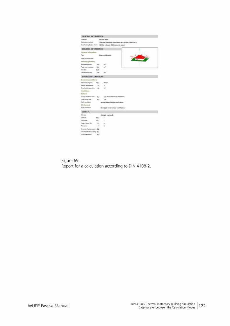
WUFI® Passive Manual 122
Bericht Nr. Anzuzeigender Text darf nicht mehr als eine Zeile beanspruchen!
DIN 4108-2 Thermal Protection/ Building Simulation Data-transfer between the Calculation Modes
Figure 69:
Report for a calculation according to DIN 4108-2.
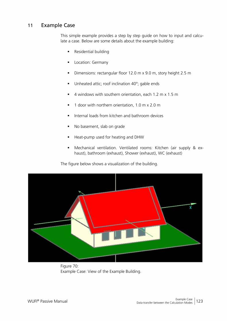
WUFI® Passive Manual 123
Bericht Nr. Anzuzeigender Text darf nicht mehr als eine Zeile beanspruchen!
Example Case Data-transfer between the Calculation Modes
11 Example Case
This simple example provides a step by step guide on how to input and calcu-
late a case. Below are some details about the example building:
Residential building
Location: Germany
Dimensions: rectangular floor 12.0 m x 9.0 m, story height 2.5 m
Unheated attic; roof inclination 40°; gable ends
4 windows with southern orientation, each 1.2 m x 1.5 m
1 door with northern orientation, 1.0 m x 2.0 m
Internal loads from kitchen and bathroom devices
No basement, slab on grade
Heat-pump used for heating and DHW
Mechanical ventilation. Ventilated rooms: Kitchen (air supply & ex-
haust), bathroom (exhaust), Shower (exhaust), WC (exhaust)
The figure below shows a visualization of the building.
Figure 70:
Example Case: View of the Example Building.

WUFI® Passive Manual 124
Bericht Nr. Anzuzeigender Text darf nicht mehr als eine Zeile beanspruchen!
Example Case Data-transfer between the Calculation Modes
Tutorial videos on our WUFI®-Wiki (www.wufi-wiki.com) show how this ex-ample was created.
WUFI® Passive comes with a project file of this example. It can be found the “Projects” folder of the main installation directory of WUFI® Passive.
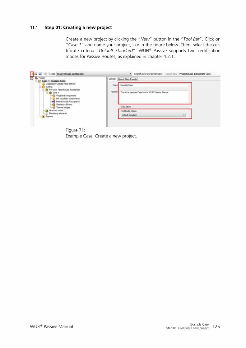
WUFI® Passive Manual 125
Bericht Nr. Anzuzeigender Text darf nicht mehr als eine Zeile beanspruchen!
Example Case Step 01: Creating a new project
11.1 Step 01: Creating a new project
Create a new project by clicking the “New” button in the “Tool Bar”. Click on
“Case 1” and name your project, like in the figure below. Then, select the cer-
tificate criteria “Default Standard”. WUFI® Passive supports two certification
modes for Passive Houses, as explained in chapter 4.2.1.
Figure 71:
Example Case: Create a new project.

WUFI® Passive Manual 126
Bericht Nr. Anzuzeigender Text darf nicht mehr als eine Zeile beanspruchen!
Example Case Step 02: Defining climatic conditions
11.2 Step 02: Defining climatic conditions
In this example, we use the standard-climate that is predefined in WUFI® Pas-
sive as it describes a reference climate for Germany. So, in the “Localization/
Climate”-dialog, select “Standard”:
Figure 72:
Example Case: Define climatic conditions
In the “Climate”-Tab, all climatic values can be observed:
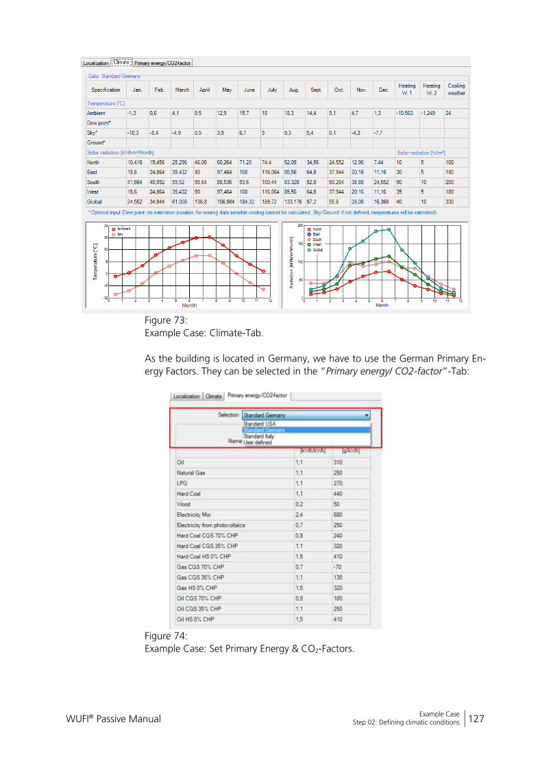
WUFI® Passive Manual 127
Bericht Nr. Anzuzeigender Text darf nicht mehr als eine Zeile beanspruchen!
Example Case Step 02: Defining climatic conditions
Figure 73:
Example Case: Climate-Tab.
As the building is located in Germany, we have to use the German Primary En-
ergy Factors. They can be selected in the “Primary energy/ CO2-factor”-Tab:
Figure 74:
Example Case: Set Primary Energy & CO2-Factors.
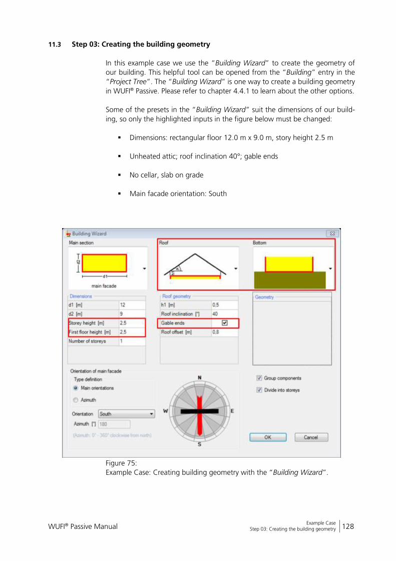
WUFI® Passive Manual 128
Bericht Nr. Anzuzeigender Text darf nicht mehr als eine Zeile beanspruchen!
Example Case Step 03: Creating the building geometry
11.3 Step 03: Creating the building geometry
In this example case we use the “Building Wizard” to create the geometry of
our building. This helpful tool can be opened from the “Building” entry in the
“Project Tree”. The “Building Wizard” is one way to create a building geometry
in WUFI® Passive. Please refer to chapter 4.4.1 to learn about the other options.
Some of the presets in the “Building Wizard” suit the dimensions of our build-
ing, so only the highlighted inputs in the figure below must be changed:
Dimensions: rectangular floor 12.0 m x 9.0 m, story height 2.5 m
Unheated attic; roof inclination 40°; gable ends
No cellar, slab on grade
Main facade orientation: South
Figure 75:
Example Case: Creating building geometry with the “Building Wizard”.

WUFI® Passive Manual 129
Bericht Nr. Anzuzeigender Text darf nicht mehr als eine Zeile beanspruchen!
Example Case Step 03: Creating the building geometry
After all necessary information is entered confirm with the “OK” button. The
building is now automatically created. All relevant zones and components ap-
pear in the “Project Tree” and an interactive 3D visualization is shown in the
“Visualization Box” in the lower left corner of WUFI® Passive. Working with the
“Visualization Box” is explained in detail in chapter 3.4.
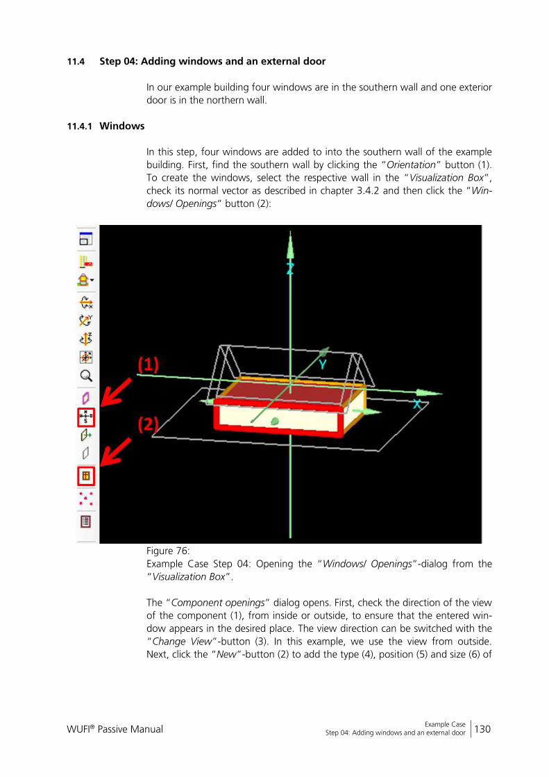
WUFI® Passive Manual 130
Bericht Nr. Anzuzeigender Text darf nicht mehr als eine Zeile beanspruchen!
Example Case Step 04: Adding windows and an external door
11.4 Step 04: Adding windows and an external door
In our example building four windows are in the southern wall and one exterior
door is in the northern wall.
11.4.1 Windows
In this step, four windows are added to into the southern wall of the example
building. First, find the southern wall by clicking the “Orientation” button (1).
To create the windows, select the respective wall in the “Visualization Box”,
check its normal vector as described in chapter 3.4.2 and then click the “Win-
dows/ Openings” button (2):
Figure 76:
Example Case Step 04: Opening the “Windows/ Openings”-dialog from the
“Visualization Box”.
The “Component openings” dialog opens. First, check the direction of the view
of the component (1), from inside or outside, to ensure that the entered win-
dow appears in the desired place. The view direction can be switched with the
“Change View”-button (3). In this example, we use the view from outside.
Next, click the “New”-button (2) to add the type (4), position (5) and size (6) of
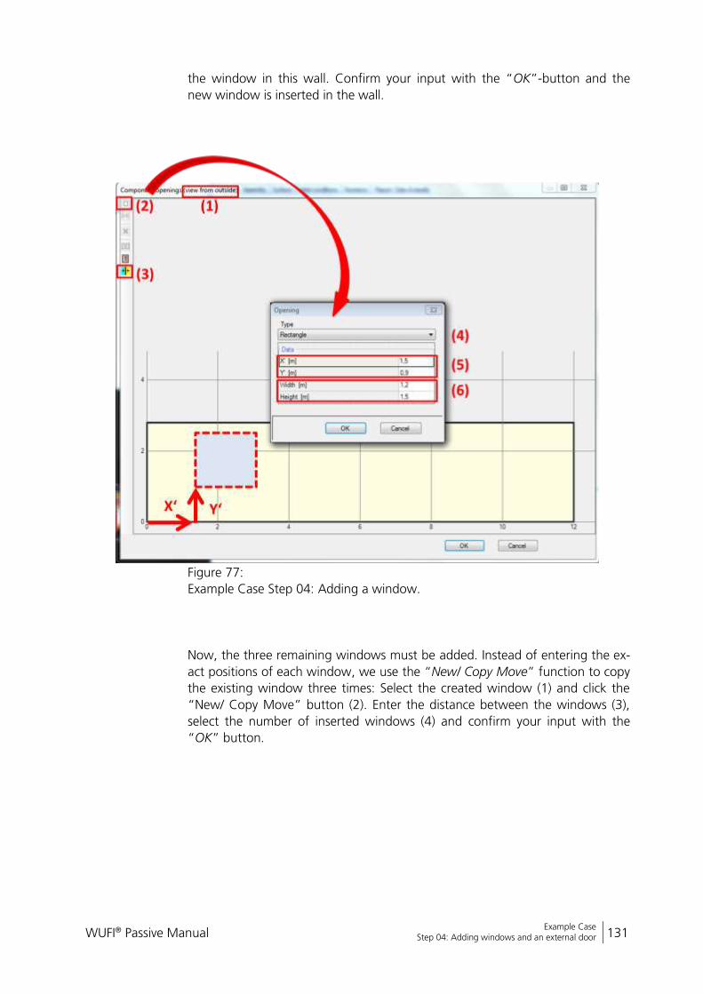
WUFI® Passive Manual 131
Bericht Nr. Anzuzeigender Text darf nicht mehr als eine Zeile beanspruchen!
Example Case Step 04: Adding windows and an external door
the window in this wall. Confirm your input with the “OK”-button and the
new window is inserted in the wall.
Figure 77:
Example Case Step 04: Adding a window.
Now, the three remaining windows must be added. Instead of entering the ex-
act positions of each window, we use the “New/ Copy Move” function to copy
the existing window three times: Select the created window (1) and click the
“New/ Copy Move” button (2). Enter the distance between the windows (3),
select the number of inserted windows (4) and confirm your input with the
“OK” button.

WUFI® Passive Manual 132
Bericht Nr. Anzuzeigender Text darf nicht mehr als eine Zeile beanspruchen!
Example Case Step 04: Adding windows and an external door
Figure 78:
Example Case Step 04: Copying the existing window.
Now, all windows in the southern wall are created. Close the “Component
openings” dialog with “OK” and the windows appear both in the “Visualiza-
tion Box” and the “Project Tree”.
11.4.2 Exterior door
Exterior doors are added in the same way as windows. Rotate the view of the
visualization box to the northern wall, check the normal vector and orientation
and insert an opening with the measurements shown in the figure below:
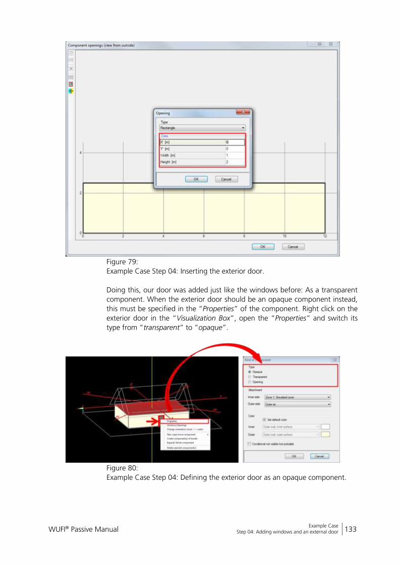
WUFI® Passive Manual 133
Bericht Nr. Anzuzeigender Text darf nicht mehr als eine Zeile beanspruchen!
Example Case Step 04: Adding windows and an external door
Figure 79:
Example Case Step 04: Inserting the exterior door.
Doing this, our door was added just like the windows before: As a transparent
component. When the exterior door should be an opaque component instead,
this must be specified in the “Properties” of the component. Right click on the
exterior door in the “Visualization Box”, open the “Properties” and switch its
type from “transparent” to “opaque”.
Figure 80:
Example Case Step 04: Defining the exterior door as an opaque component.
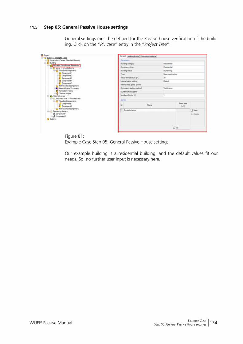
WUFI® Passive Manual 134
Bericht Nr. Anzuzeigender Text darf nicht mehr als eine Zeile beanspruchen!
Example Case Step 05: General Passive House settings
11.5 Step 05: General Passive House settings
General settings must be defined for the Passive house verification of the build-
ing. Click on the “PH case” entry in the “Project Tree”:
Figure 81:
Example Case Step 05: General Passive House settings.
Our example building is a residential building, and the default values fit our
needs. So, no further user input is necessary here.
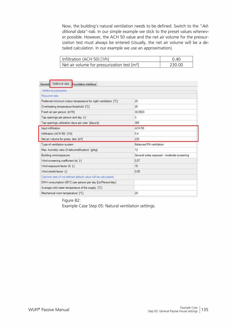
WUFI® Passive Manual 135
Bericht Nr. Anzuzeigender Text darf nicht mehr als eine Zeile beanspruchen!
Example Case Step 05: General Passive House settings
Now, the building’s natural ventilation needs to be defined. Switch to the “Ad-
ditional data”-tab. In our simple example we stick to the preset values whenev-
er possible. However, the ACH 50 value and the net air volume for the pressur-
ization test must always be entered (Usually, the net air volume will be a de-
tailed calculation. In our example we use an approximation).
Infiltration (ACH 50) [1/h] 0.40
Net air volume for pressurization test [m³] 230.00
Figure 82:
Example Case Step 05: Natural ventilation settings.
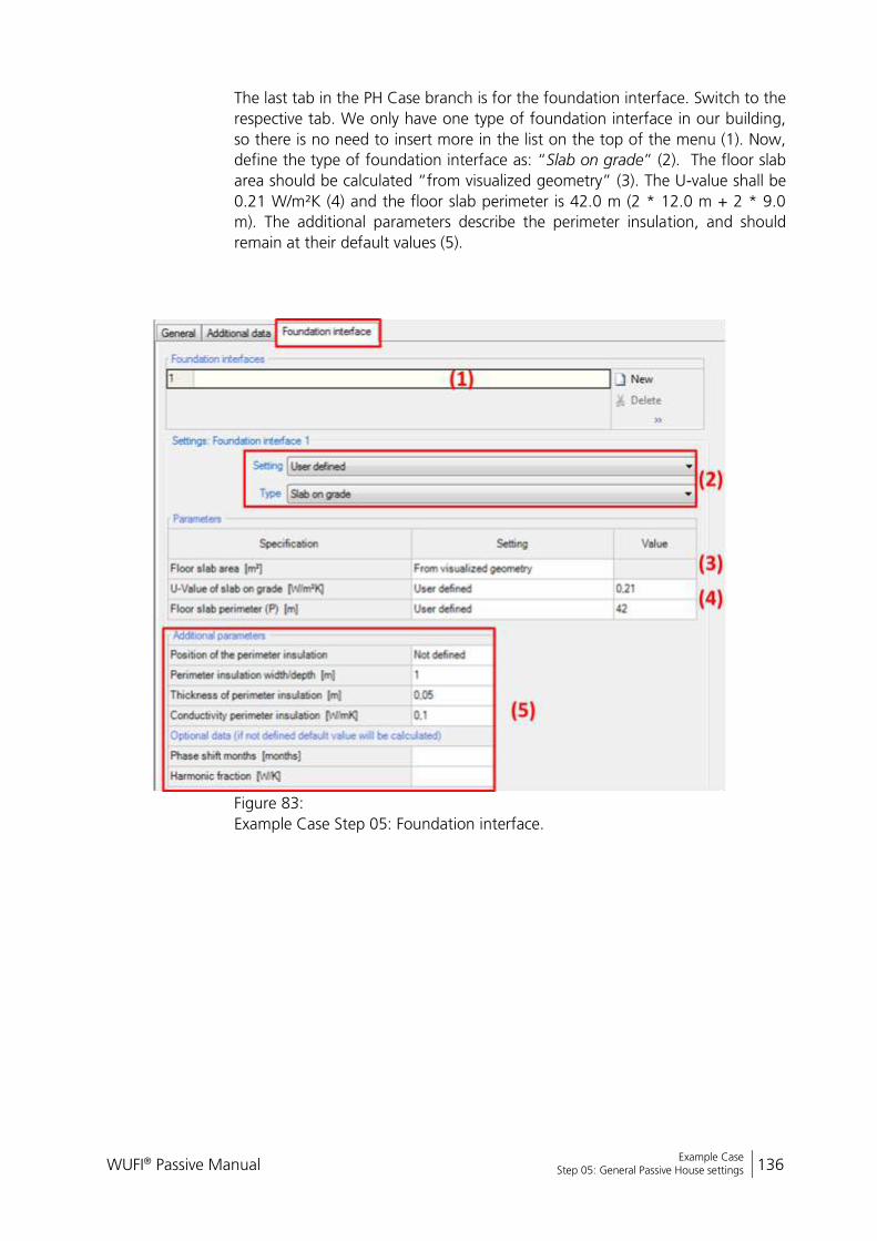
WUFI® Passive Manual 136
Bericht Nr. Anzuzeigender Text darf nicht mehr als eine Zeile beanspruchen!
Example Case Step 05: General Passive House settings
The last tab in the PH Case branch is for the foundation interface. Switch to the
respective tab. We only have one type of foundation interface in our building,
so there is no need to insert more in the list on the top of the menu (1). Now,
define the type of foundation interface as: “Slab on grade” (2). The floor slab
area should be calculated “from visualized geometry” (3). The U-value shall be
0.21 W/m²K (4) and the floor slab perimeter is 42.0 m (2 * 12.0 m + 2 * 9.0
m). The additional parameters describe the perimeter insulation, and should
remain at their default values (5).
Figure 83:
Example Case Step 05: Foundation interface.
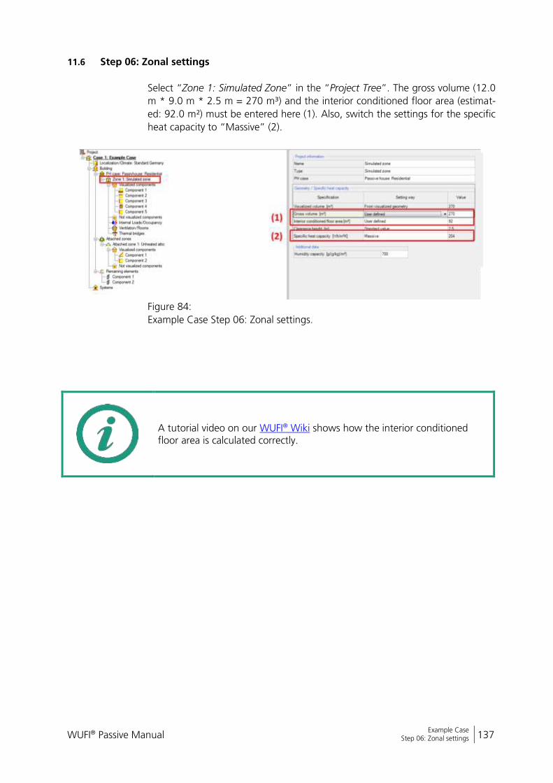
WUFI® Passive Manual 137
Bericht Nr. Anzuzeigender Text darf nicht mehr als eine Zeile beanspruchen!
Example Case Step 06: Zonal settings
11.6 Step 06: Zonal settings
Select “Zone 1: Simulated Zone” in the “Project Tree”. The gross volume (12.0
m * 9.0 m * 2.5 m = 270 m³) and the interior conditioned floor area (estimat-
ed: 92.0 m²) must be entered here (1). Also, switch the settings for the specific
heat capacity to “Massive” (2).
Figure 84:
Example Case Step 06: Zonal settings.
A tutorial video on our WUFI® Wiki shows how the interior conditioned floor area is calculated correctly.
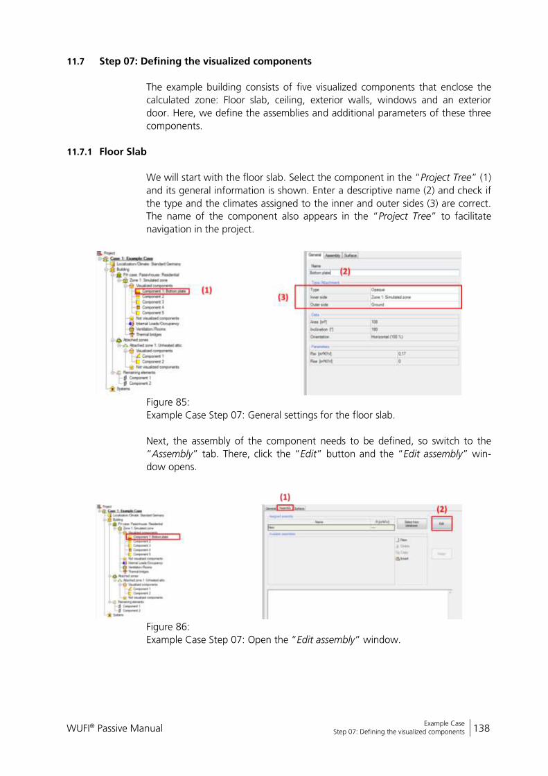
WUFI® Passive Manual 138
Bericht Nr. Anzuzeigender Text darf nicht mehr als eine Zeile beanspruchen!
Example Case Step 07: Defining the visualized components
11.7 Step 07: Defining the visualized components
The example building consists of five visualized components that enclose the
calculated zone: Floor slab, ceiling, exterior walls, windows and an exterior
door. Here, we define the assemblies and additional parameters of these three
components.
11.7.1 Floor Slab
We will start with the floor slab. Select the component in the “Project Tree” (1)
and its general information is shown. Enter a descriptive name (2) and check if
the type and the climates assigned to the inner and outer sides (3) are correct.
The name of the component also appears in the “Project Tree” to facilitate
navigation in the project.
Figure 85:
Example Case Step 07: General settings for the floor slab.
Next, the assembly of the component needs to be defined, so switch to the
“Assembly” tab. There, click the “Edit” button and the “Edit assembly” win-
dow opens.
Figure 86:
Example Case Step 07: Open the “Edit assembly” window.
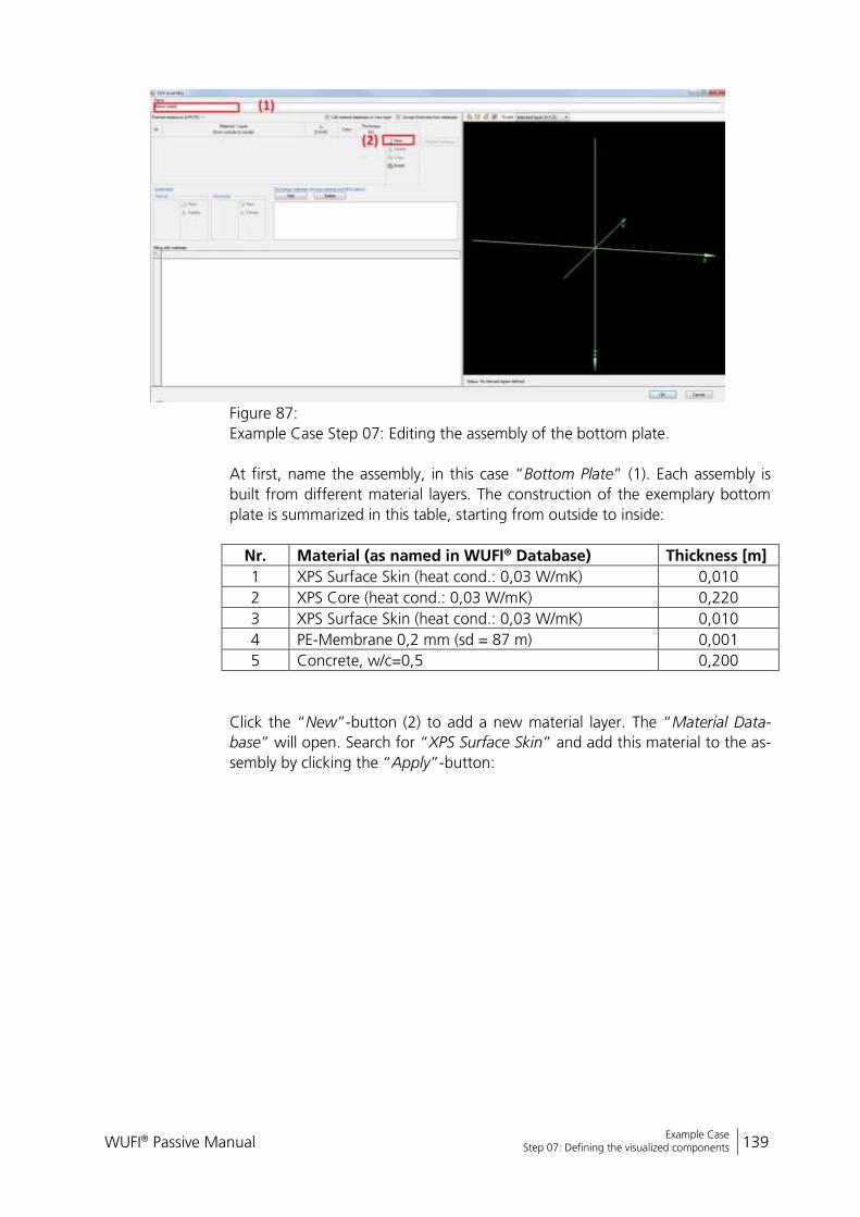
WUFI® Passive Manual 139
Bericht Nr. Anzuzeigender Text darf nicht mehr als eine Zeile beanspruchen!
Example Case Step 07: Defining the visualized components
Figure 87:
Example Case Step 07: Editing the assembly of the bottom plate.
At first, name the assembly, in this case “Bottom Plate” (1). Each assembly is
built from different material layers. The construction of the exemplary bottom
plate is summarized in this table, starting from outside to inside:
Nr. Material (as named in WUFI® Database) Thickness [m]
1 XPS Surface Skin (heat cond.: 0,03 W/mK) 0,010
2 XPS Core (heat cond.: 0,03 W/mK) 0,220
3 XPS Surface Skin (heat cond.: 0,03 W/mK) 0,010
4 PE-Membrane 0,2 mm (sd = 87 m) 0,001
5 Concrete, w/c=0,5 0,200
Click the “New”-button (2) to add a new material layer. The “Material Data-
base” will open. Search for “XPS Surface Skin” and add this material to the as-
sembly by clicking the “Apply”-button:

WUFI® Passive Manual 140
Bericht Nr. Anzuzeigender Text darf nicht mehr als eine Zeile beanspruchen!
Example Case Step 07: Defining the visualized components
Figure 88:
Example Case Step 07: Select a material from the WUFI® database.
The material now appears in the “Edit assembly”-window. Check, if the thick-
ness is entered correct and make adjustments when necessary. Add all other
material layers in the same way. When finished, the assembly should look like
this:
Figure 89:
Example Case Step 07: Assembly for the bottom plate.
Click the “OK”-button and the assembly is assigned to the component.

WUFI® Passive Manual 141
Bericht Nr. Anzuzeigender Text darf nicht mehr als eine Zeile beanspruchen!
Example Case Step 07: Defining the visualized components
The heat transfer resistance on the surfaces can be adjusted in the “Surface”
tab. Check, if the automatically detected values are correct:
Figure 90:
Example Case Step 07: Heat transfer resistance for the floor slab.

WUFI® Passive Manual 142
Bericht Nr. Anzuzeigender Text darf nicht mehr als eine Zeile beanspruchen!
Example Case Step 07: Defining the visualized components
11.7.2 Ceiling
Now enter the assembly for the ceiling. Select the corresponding component in
the “Project Tree” and proceed like before: Name the component, check the
general settings and create a custom assembly with the “Edit assembly” win-
dow. The construction for the ceiling can be found in the table below:
Nr. Material (as named in WUFI® Database) Thickness [m]
1 Mineral Wool (heat cond.: 0,04 W/mK) 0,300
2 Concrete, w/c=0,5 0,200
In the end, the assembly should look like this:
Figure 91:
Example Case Step 07: Assembly for the ceiling.
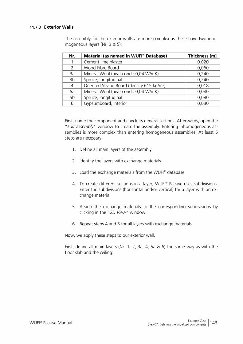
WUFI® Passive Manual 143
Bericht Nr. Anzuzeigender Text darf nicht mehr als eine Zeile beanspruchen!
Example Case Step 07: Defining the visualized components
11.7.3 Exterior Walls
The assembly for the exterior walls are more complex as these have two inho-
mogeneous layers (Nr. 3 & 5):
Nr. Material (as named in WUFI® Database) Thickness [m]
1 Cement lime plaster 0.020
2 Wood-Fibre Board 0,060
3a Mineral Wool (heat cond.: 0,04 W/mK) 0,240
3b Spruce, longitudinal 0,240
4 Oriented Strand Board (density 615 kg/m³) 0,018
5a Mineral Wool (heat cond.: 0,04 W/mK) 0,080
5b Spruce, longitudinal 0,080
6 Gypsumboard, interior 0,030
First, name the component and check its general settings. Afterwards, open the
“Edit assembly” window to create the assembly. Entering inhomogeneous as-
semblies is more complex than entering homogeneous assemblies. At least 5
steps are necessary:
1. Define all main layers of the assembly.
2. Identify the layers with exchange materials.
3. Load the exchange materials from the WUFI® database
4. To create different sections in a layer, WUFI® Passive uses subdivisions.
Enter the subdivisions (horizontal and/or vertical) for a layer with an ex-
change material
5. Assign the exchange materials to the corresponding subdivisions by
clicking in the “2D View” window.
6. Repeat steps 4 and 5 for all layers with exchange materials.
Now, we apply these steps to our exterior wall.
First, define all main layers (Nr. 1, 2, 3a, 4, 5a & 6) the same way as with the
floor slab and the ceiling:
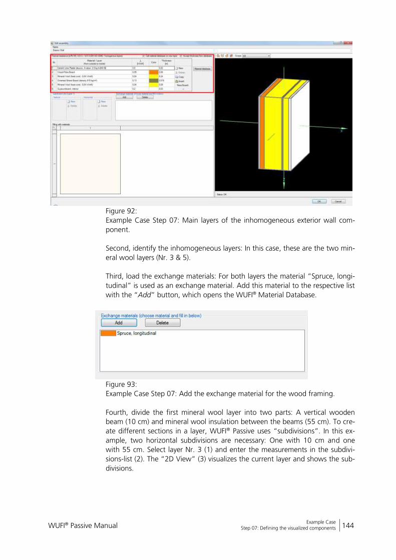
WUFI® Passive Manual 144
Bericht Nr. Anzuzeigender Text darf nicht mehr als eine Zeile beanspruchen!
Example Case Step 07: Defining the visualized components
Figure 92:
Example Case Step 07: Main layers of the inhomogeneous exterior wall com-
ponent.
Second, identify the inhomogeneous layers: In this case, these are the two min-
eral wool layers (Nr. 3 & 5).
Third, load the exchange materials: For both layers the material “Spruce, longi-
tudinal” is used as an exchange material. Add this material to the respective list
with the “Add” button, which opens the WUFI® Material Database.
Figure 93:
Example Case Step 07: Add the exchange material for the wood framing.
Fourth, divide the first mineral wool layer into two parts: A vertical wooden
beam (10 cm) and mineral wool insulation between the beams (55 cm). To cre-
ate different sections in a layer, WUFI® Passive uses “subdivisions”. In this ex-
ample, two horizontal subdivisions are necessary: One with 10 cm and one
with 55 cm. Select layer Nr. 3 (1) and enter the measurements in the subdivi-
sions-list (2). The “2D View” (3) visualizes the current layer and shows the sub-
divisions.
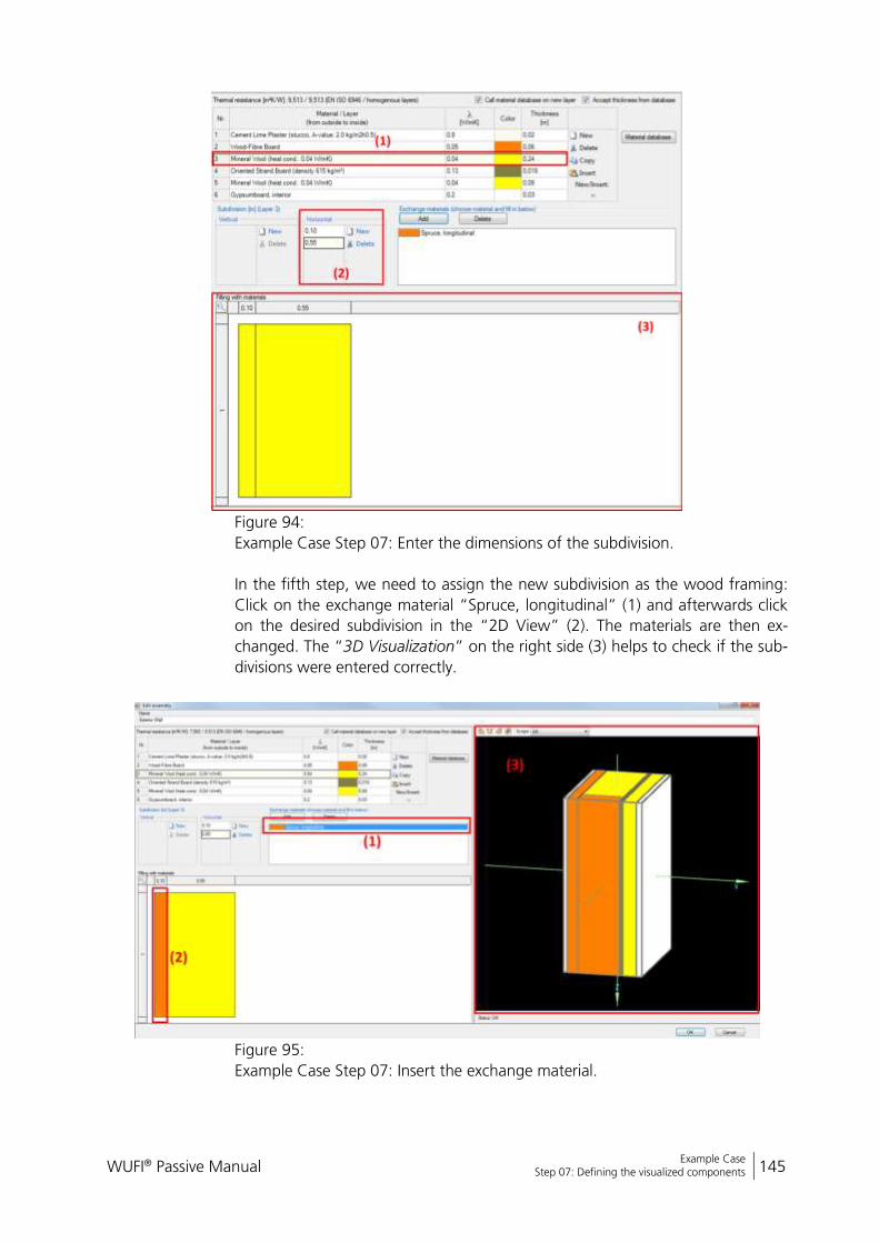
WUFI® Passive Manual 145
Bericht Nr. Anzuzeigender Text darf nicht mehr als eine Zeile beanspruchen!
Example Case Step 07: Defining the visualized components
Figure 94:
Example Case Step 07: Enter the dimensions of the subdivision.
In the fifth step, we need to assign the new subdivision as the wood framing:
Click on the exchange material “Spruce, longitudinal” (1) and afterwards click
on the desired subdivision in the “2D View” (2). The materials are then ex-
changed. The “3D Visualization” on the right side (3) helps to check if the sub-
divisions were entered correctly.
Figure 95:
Example Case Step 07: Insert the exchange material.
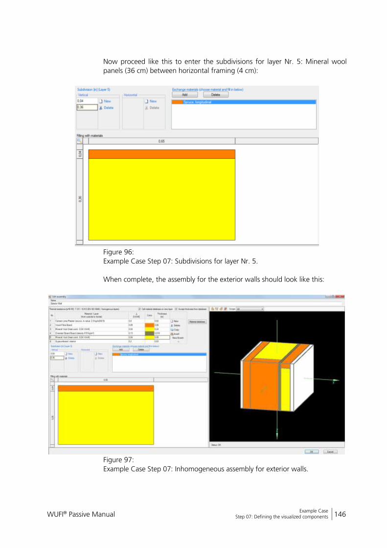
WUFI® Passive Manual 146
Bericht Nr. Anzuzeigender Text darf nicht mehr als eine Zeile beanspruchen!
Example Case Step 07: Defining the visualized components
Now proceed like this to enter the subdivisions for layer Nr. 5: Mineral wool
panels (36 cm) between horizontal framing (4 cm):
Figure 96:
Example Case Step 07: Subdivisions for layer Nr. 5.
When complete, the assembly for the exterior walls should look like this:
Figure 97:
Example Case Step 07: Inhomogeneous assembly for exterior walls.
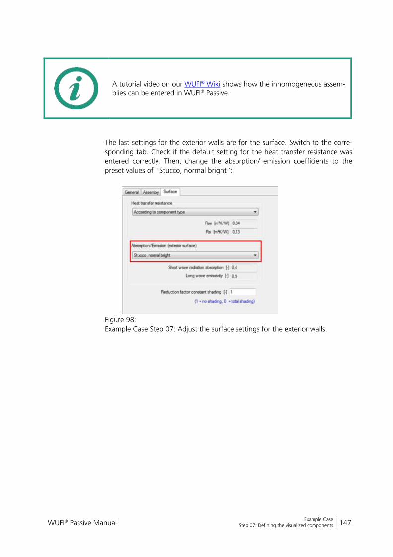
WUFI® Passive Manual 147
Bericht Nr. Anzuzeigender Text darf nicht mehr als eine Zeile beanspruchen!
Example Case Step 07: Defining the visualized components
A tutorial video on our WUFI® Wiki shows how the inhomogeneous assem-blies can be entered in WUFI® Passive.
The last settings for the exterior walls are for the surface. Switch to the corre-
sponding tab. Check if the default setting for the heat transfer resistance was
entered correctly. Then, change the absorption/ emission coefficients to the
preset values of “Stucco, normal bright”:
Figure 98:
Example Case Step 07: Adjust the surface settings for the exterior walls.
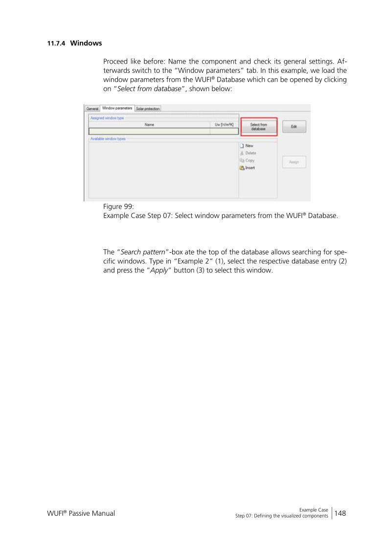
WUFI® Passive Manual 148
Bericht Nr. Anzuzeigender Text darf nicht mehr als eine Zeile beanspruchen!
Example Case Step 07: Defining the visualized components
11.7.4 Windows
Proceed like before: Name the component and check its general settings. Af-
terwards switch to the “Window parameters” tab. In this example, we load the
window parameters from the WUFI® Database which can be opened by clicking
on “Select from database”, shown below:
Figure 99:
Example Case Step 07: Select window parameters from the WUFI® Database.
The “Search pattern”-box ate the top of the database allows searching for spe-
cific windows. Type in “Example 2” (1), select the respective database entry (2)
and press the “Apply” button (3) to select this window.
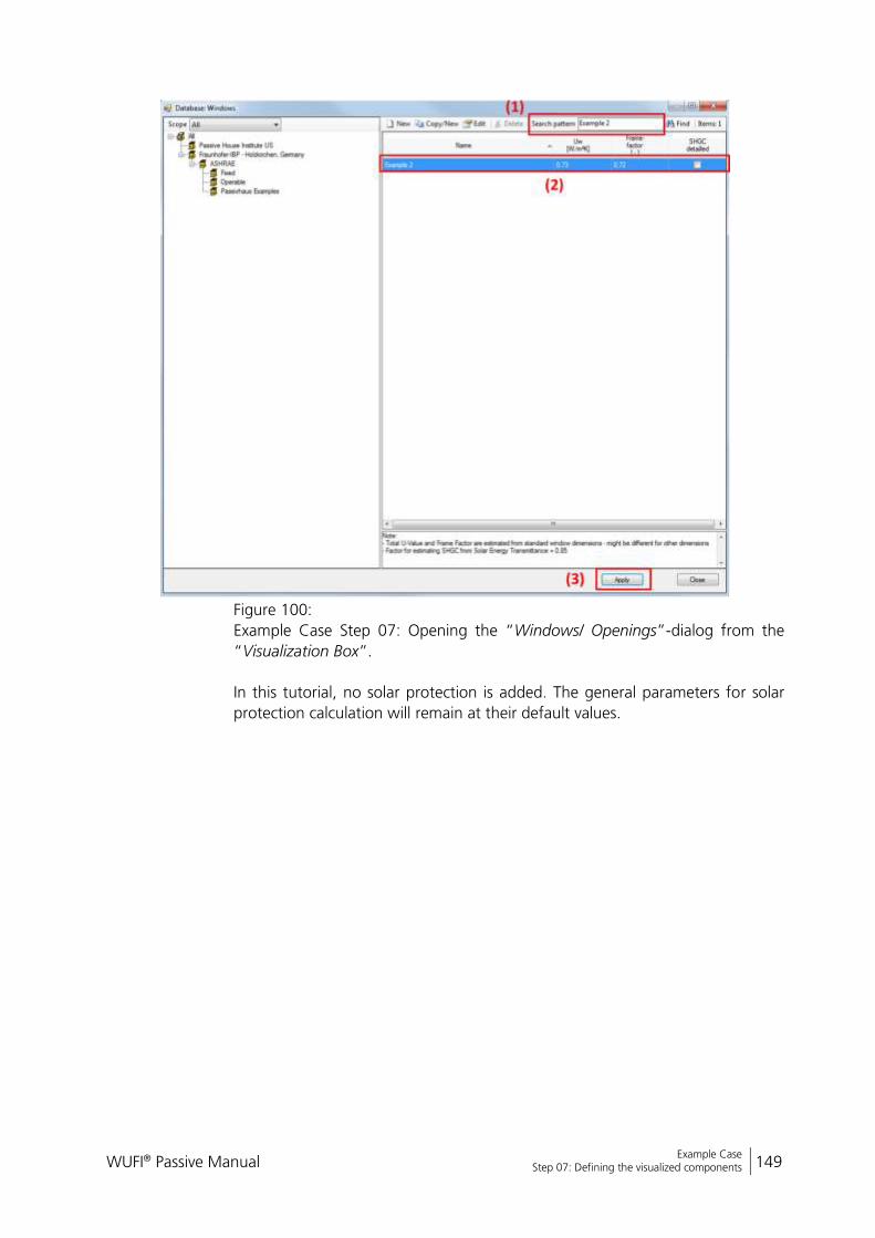
WUFI® Passive Manual 149
Bericht Nr. Anzuzeigender Text darf nicht mehr als eine Zeile beanspruchen!
Example Case Step 07: Defining the visualized components
Figure 100:
Example Case Step 07: Opening the “Windows/ Openings”-dialog from the
“Visualization Box”.
In this tutorial, no solar protection is added. The general parameters for solar
protection calculation will remain at their default values.

WUFI® Passive Manual 150
Bericht Nr. Anzuzeigender Text darf nicht mehr als eine Zeile beanspruchen!
Example Case Step 07: Defining the visualized components
11.7.5 Exterior Door
Select the exterior door in the “Project Tree”. Name it (1), check the general
settings (2) and checkmark the “Exterior door” box (3).
Figure 101:
Example Case Step 07: General settings for the exterior door.
Create this assembly:
Figure 102:
Example Case Step 07: Assembly for the exterior door.
Check if the surface settings are entered correctly. All settings should remain at
their default values in this example.
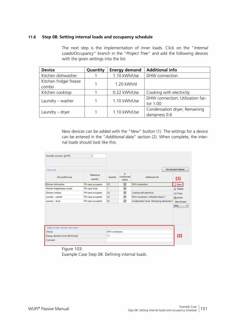
WUFI® Passive Manual 151
Bericht Nr. Anzuzeigender Text darf nicht mehr als eine Zeile beanspruchen!
Example Case Step 08: Setting internal loads and occupancy schedule
11.8 Step 08: Setting internal loads and occupancy schedule
The next step is the implementation of inner loads. Click on the "Internal
Loads/Occupancy" branch in the “Project Tree” and add the following devices
with the given settings into the list:
Device Quantity Energy demand Additional info
Kitchen dishwasher 1 1.10 kWh/Use DHW connection
Kitchen fridge/ freeze
combo 1 1.20 kWh/d
Kitchen cooktop 1 0.22 kWh/Use Cooking with electricity
Laundry – washer 1 1.10 kWh/Use DHW connection; Utilization fac-
tor 1.00
Laundry – dryer 1 1.10 kWh/Use Condensation dryer; Remaining
dampness 0.6
New devices can be added with the “New” button (1). The settings for a device
can be entered in the “Additional data” section (2). When complete, the inter-
nal loads should look like this:
Figure 103:
Example Case Step 08: Defining internal loads.

WUFI® Passive Manual 152
Bericht Nr. Anzuzeigender Text darf nicht mehr als eine Zeile beanspruchen!
Example Case Step 09: Ventilation settings
11.9 Step 09: Ventilation settings
Select the “Ventilation/ Rooms” branch in the “Project Tree”. The “Utilization
Pattern” tab shows up first. In this tab, different utilization patterns are de-
fined. The will be assigned to the rooms of the building later. To simplify this
example, only one utilization pattern is defined and then used for every room.
Click on the "New" button (1) to create a new utilization pattern. In this exam-
ple, we define the operation days and weeks so that it covers the whole year
(2). Finally, enter the daily operation schedule (3) as shown in the figure below:
Figure 104:
Example Case Step 09: Ventilation settings – Utilization pattern.
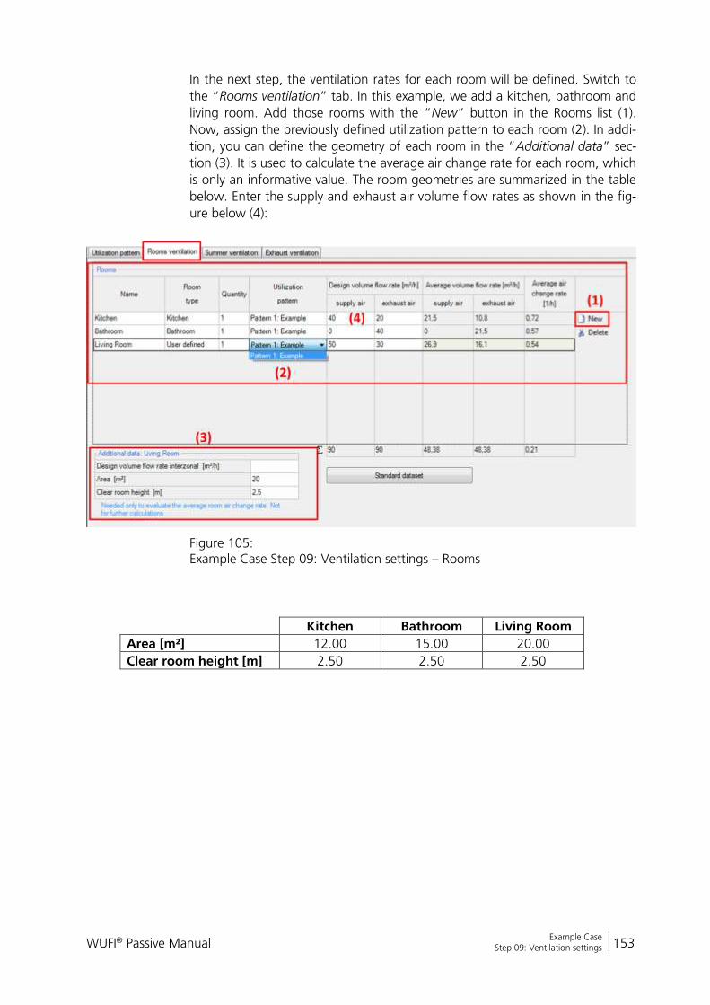
WUFI® Passive Manual 153
Bericht Nr. Anzuzeigender Text darf nicht mehr als eine Zeile beanspruchen!
Example Case Step 09: Ventilation settings
In the next step, the ventilation rates for each room will be defined. Switch to
the “Rooms ventilation” tab. In this example, we add a kitchen, bathroom and
living room. Add those rooms with the “New” button in the Rooms list (1).
Now, assign the previously defined utilization pattern to each room (2). In addi-
tion, you can define the geometry of each room in the “Additional data” sec-
tion (3). It is used to calculate the average air change rate for each room, which
is only an informative value. The room geometries are summarized in the table
below. Enter the supply and exhaust air volume flow rates as shown in the fig-
ure below (4):
Figure 105: Example Case Step 09: Ventilation settings – Rooms
Kitchen Bathroom Living Room
Area [m²] 12.00 15.00 20.00
Clear room height [m] 2.50 2.50 2.50
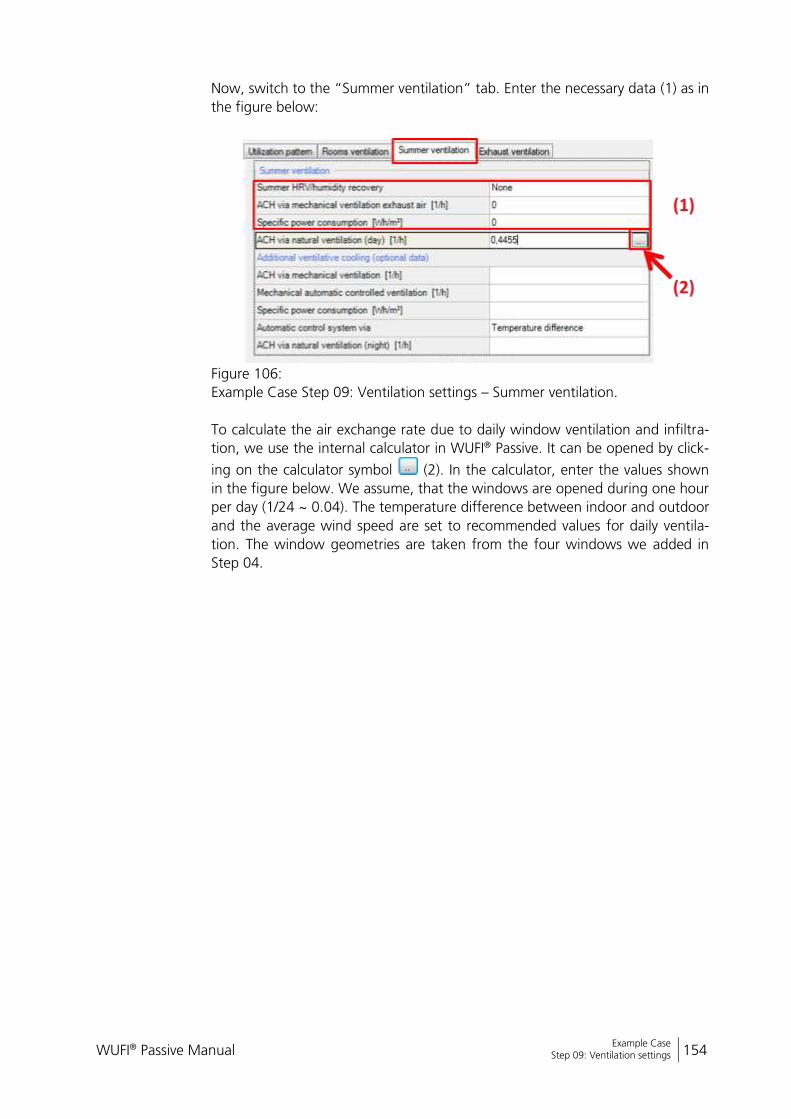
WUFI® Passive Manual 154
Bericht Nr. Anzuzeigender Text darf nicht mehr als eine Zeile beanspruchen!
Example Case Step 09: Ventilation settings
Now, switch to the “Summer ventilation” tab. Enter the necessary data (1) as in
the figure below:
Figure 106:
Example Case Step 09: Ventilation settings – Summer ventilation.
To calculate the air exchange rate due to daily window ventilation and infiltra-
tion, we use the internal calculator in WUFI® Passive. It can be opened by click-
ing on the calculator symbol (2). In the calculator, enter the values shown
in the figure below. We assume, that the windows are opened during one hour
per day (1/24 ~ 0.04). The temperature difference between indoor and outdoor
and the average wind speed are set to recommended values for daily ventila-
tion. The window geometries are taken from the four windows we added in
Step 04.
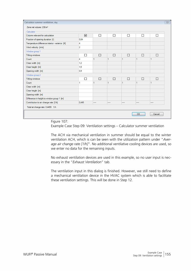
WUFI® Passive Manual 155
Bericht Nr. Anzuzeigender Text darf nicht mehr als eine Zeile beanspruchen!
Example Case Step 09: Ventilation settings
Figure 107:
Example Case Step 09: Ventilation settings – Calculator summer ventilation
The ACH via mechanical ventilation in summer should be equal to the winter
ventilation ACH, which is can be seen with the utilization pattern under “Aver-
age air change rate [1/h]”. No additional ventilative cooling devices are used, so
we enter no data for the remaining inputs.
No exhaust ventilation devices are used in this example, so no user input is nec-
essary in the “Exhaust Ventilation” tab.
The ventilation input in this dialog is finished. However, we still need to define
a mechanical ventilation device in the HVAC system which is able to facilitate
these ventilation settings. This will be done in Step 12.
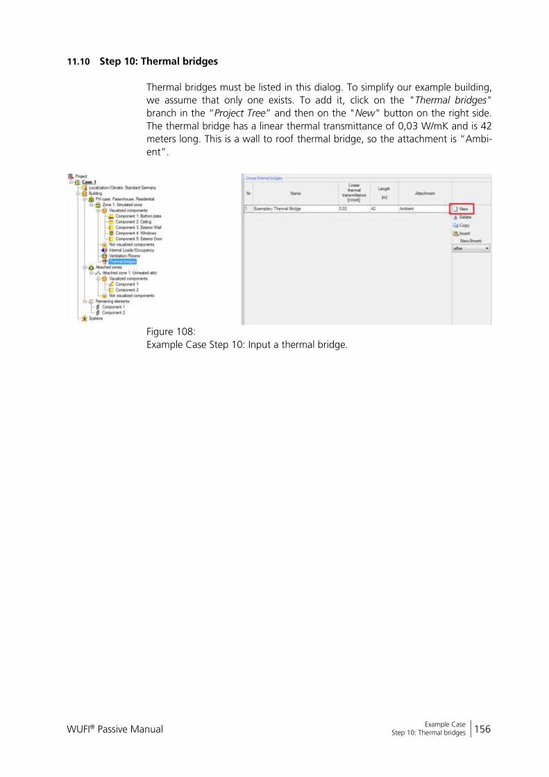
WUFI® Passive Manual 156
Bericht Nr. Anzuzeigender Text darf nicht mehr als eine Zeile beanspruchen!
Example Case Step 10: Thermal bridges
11.10 Step 10: Thermal bridges
Thermal bridges must be listed in this dialog. To simplify our example building,
we assume that only one exists. To add it, click on the "Thermal bridges"
branch in the “Project Tree” and then on the "New" button on the right side.
The thermal bridge has a linear thermal transmittance of 0,03 W/mK and is 42
meters long. This is a wall to roof thermal bridge, so the attachment is “Ambi-
ent”.
Figure 108:
Example Case Step 10: Input a thermal bridge.

WUFI® Passive Manual 157
Bericht Nr. Anzuzeigender Text darf nicht mehr als eine Zeile beanspruchen!
Example Case Step 11: Connection with attached zone
11.11 Step 11: Connection with attached zone
To simplify this example, the attic is unheated and non-ventilated. Only the
temperature difference reduction factor must be entered. Set this value to
0.75:
Figure 109:
Example Case Step 11: Connection with unheated attic.
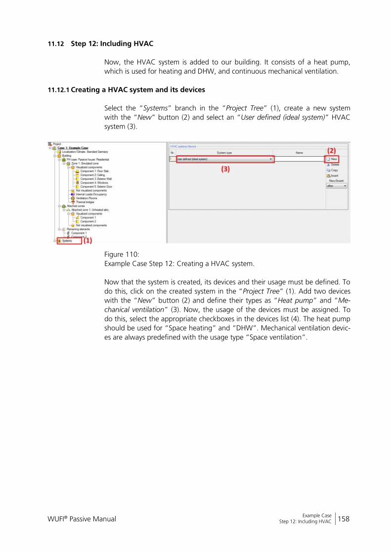
WUFI® Passive Manual 158
Bericht Nr. Anzuzeigender Text darf nicht mehr als eine Zeile beanspruchen!
Example Case Step 12: Including HVAC
11.12 Step 12: Including HVAC
Now, the HVAC system is added to our building. It consists of a heat pump,
which is used for heating and DHW, and continuous mechanical ventilation.
11.12.1 Creating a HVAC system and its devices
Select the “Systems” branch in the “Project Tree” (1), create a new system
with the “New” button (2) and select an “User defined (ideal system)” HVAC
system (3).
Figure 110:
Example Case Step 12: Creating a HVAC system.
Now that the system is created, its devices and their usage must be defined. To
do this, click on the created system in the “Project Tree” (1). Add two devices
with the “New” button (2) and define their types as “Heat pump” and “Me-
chanical ventilation” (3). Now, the usage of the devices must be assigned. To
do this, select the appropriate checkboxes in the devices list (4). The heat pump
should be used for “Space heating” and “DHW”. Mechanical ventilation devic-
es are always predefined with the usage type “Space ventilation”.
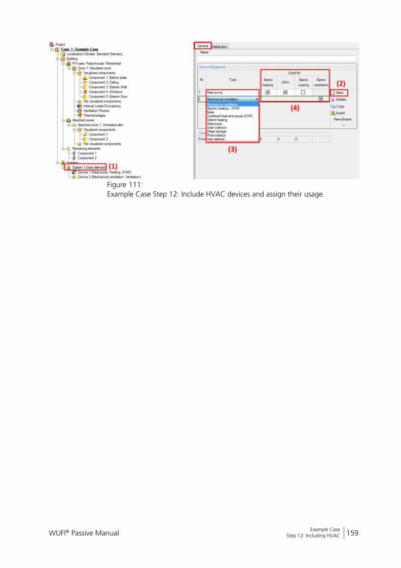
WUFI® Passive Manual 159
Bericht Nr. Anzuzeigender Text darf nicht mehr als eine Zeile beanspruchen!
Example Case Step 12: Including HVAC
Figure 111:
Example Case Step 12: Include HVAC devices and assign their usage.
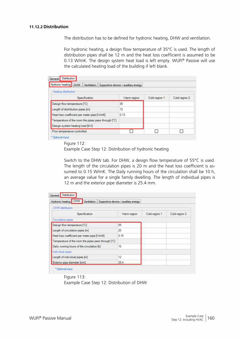
WUFI® Passive Manual 160
Bericht Nr. Anzuzeigender Text darf nicht mehr als eine Zeile beanspruchen!
Example Case Step 12: Including HVAC
11.12.2 Distribution
The distribution has to be defined for hydronic heating, DHW and ventilation.
For hydronic heating, a design flow temperature of 35°C is used. The length of
distribution pipes shall be 12 m and the heat loss coefficient is assumed to be
0.13 W/mK. The design system heat load is left empty. WUFI® Passive will use
the calculated heating load of the building if left blank.
Figure 112:
Example Case Step 12: Distribution of hydronic heating
Switch to the DHW tab. For DHW, a design flow temperature of 55°C is used.
The length of the circulation pipes is 20 m and the heat loss coefficient is as-
sumed to 0.15 W/mK. The Daily running hours of the circulation shall be 10 h,
an average value for a single family dwelling. The length of individual pipes is
12 m and the exterior pipe diameter is 25.4 mm.
Figure 113:
Example Case Step 12: Distribution of DHW
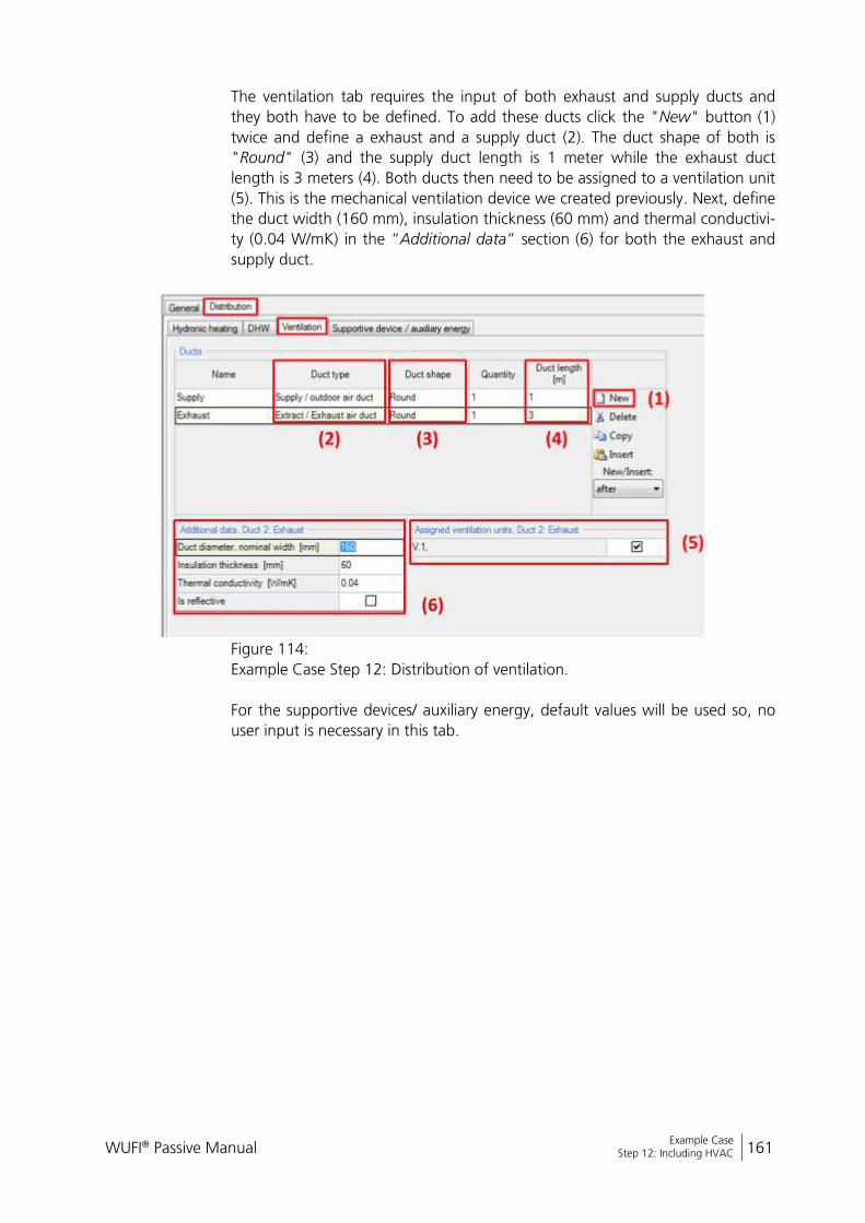
WUFI® Passive Manual 161
Bericht Nr. Anzuzeigender Text darf nicht mehr als eine Zeile beanspruchen!
Example Case Step 12: Including HVAC
The ventilation tab requires the input of both exhaust and supply ducts and
they both have to be defined. To add these ducts click the "New" button (1)
twice and define a exhaust and a supply duct (2). The duct shape of both is
"Round" (3) and the supply duct length is 1 meter while the exhaust duct
length is 3 meters (4). Both ducts then need to be assigned to a ventilation unit
(5). This is the mechanical ventilation device we created previously. Next, define
the duct width (160 mm), insulation thickness (60 mm) and thermal conductivi-
ty (0.04 W/mK) in the “Additional data” section (6) for both the exhaust and
supply duct.
Figure 114:
Example Case Step 12: Distribution of ventilation.
For the supportive devices/ auxiliary energy, default values will be used so, no
user input is necessary in this tab.

WUFI® Passive Manual 162
Bericht Nr. Anzuzeigender Text darf nicht mehr als eine Zeile beanspruchen!
Example Case Step 12: Including HVAC
11.12.3 Heat Pump
Now, the settings for the heat pump device must be entered. Select the heat
pump device in the “Project Tree” (1). Switch its type to “Heat pump” (2). Two
parameters must be entered: The COP (3.5) and the total system performance
ratio of heat generator (0.28).
Figure 115:
Example Case Step 12: Settings for the heat pump device
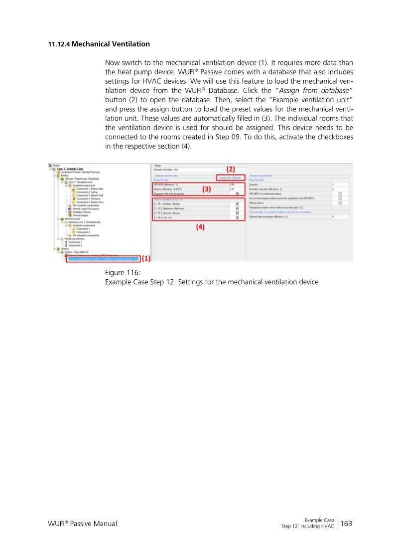
WUFI® Passive Manual 163
Bericht Nr. Anzuzeigender Text darf nicht mehr als eine Zeile beanspruchen!
Example Case Step 12: Including HVAC
11.12.4 Mechanical Ventilation
Now switch to the mechanical ventilation device (1). It requires more data than
the heat pump device. WUFI® Passive comes with a database that also includes
settings for HVAC devices. We will use this feature to load the mechanical ven-
tilation device from the WUFI® Database. Click the “Assign from database”
button (2) to open the database. Then, select the “Example ventilation unit”
and press the assign button to load the preset values for the mechanical venti-
lation unit. These values are automatically filled in (3). The individual rooms that
the ventilation device is used for should be assigned. This device needs to be
connected to the rooms created in Step 09. To do this, activate the checkboxes
in the respective section (4).
Figure 116:
Example Case Step 12: Settings for the mechanical ventilation device
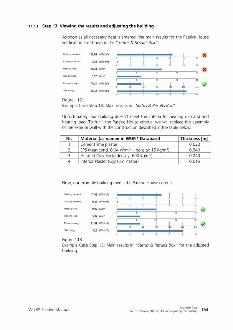
WUFI® Passive Manual 164
Bericht Nr. Anzuzeigender Text darf nicht mehr als eine Zeile beanspruchen!
Example Case Step 13: Viewing the results and adjusting the building
11.13 Step 13: Viewing the results and adjusting the building
As soon as all necessary data is entered, the main results for the Passive House
verification are shown in the “Status & Results Box”:
Figure 117:
Example Case Step 13: Main results in “Status & Results Box”.
Unfortunately, our building doesn’t meet the criteria for heating demand and
heating load. To fulfill the Passive House criteria, we will replace the assembly
of the exterior wall with the construction described in the table below.
Nr. Material (as named in WUFI® Database) Thickness [m]
1 Cement lime plaster 0.020
2 EPS (heat cond. 0.04 W/mK – density: 15 kg/m³) 0.340
3 Aerated Clay Brick (density: 600 kg/m³) 0.240
4 Interior Plaster (Gypsum Plaster) 0.015
Now, our example building meets the Passive House criteria:
Figure 118:
Example Case Step 13: Main results in “Status & Results Box” for the adjusted
building.
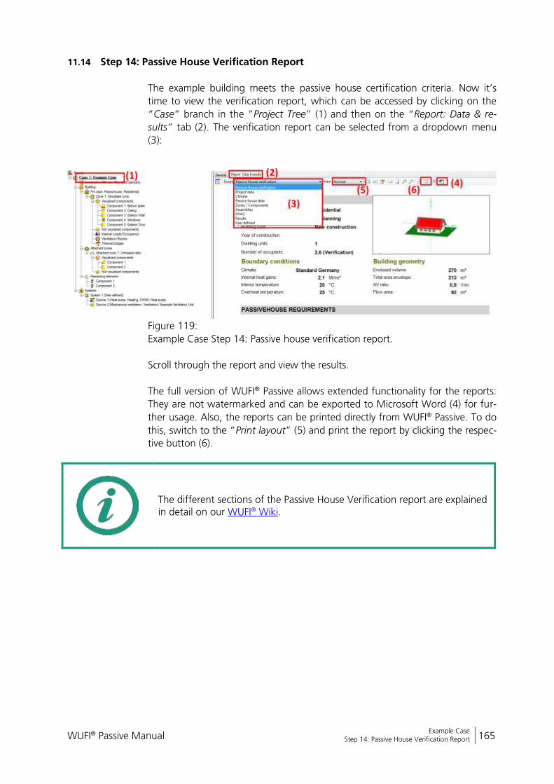
WUFI® Passive Manual 165
Bericht Nr. Anzuzeigender Text darf nicht mehr als eine Zeile beanspruchen!
Example Case Step 14: Passive House Verification Report
11.14 Step 14: Passive House Verification Report
The example building meets the passive house certification criteria. Now it’s
time to view the verification report, which can be accessed by clicking on the
“Case” branch in the “Project Tree” (1) and then on the “Report: Data & re-
sults” tab (2). The verification report can be selected from a dropdown menu
(3):
Figure 119:
Example Case Step 14: Passive house verification report.
Scroll through the report and view the results.
The full version of WUFI® Passive allows extended functionality for the reports:
They are not watermarked and can be exported to Microsoft Word (4) for fur-
ther usage. Also, the reports can be printed directly from WUFI® Passive. To do
this, switch to the “Print layout” (5) and print the report by clicking the respec-
tive button (6).
The different sections of the Passive House Verification report are explained in detail on our WUFI® Wiki.
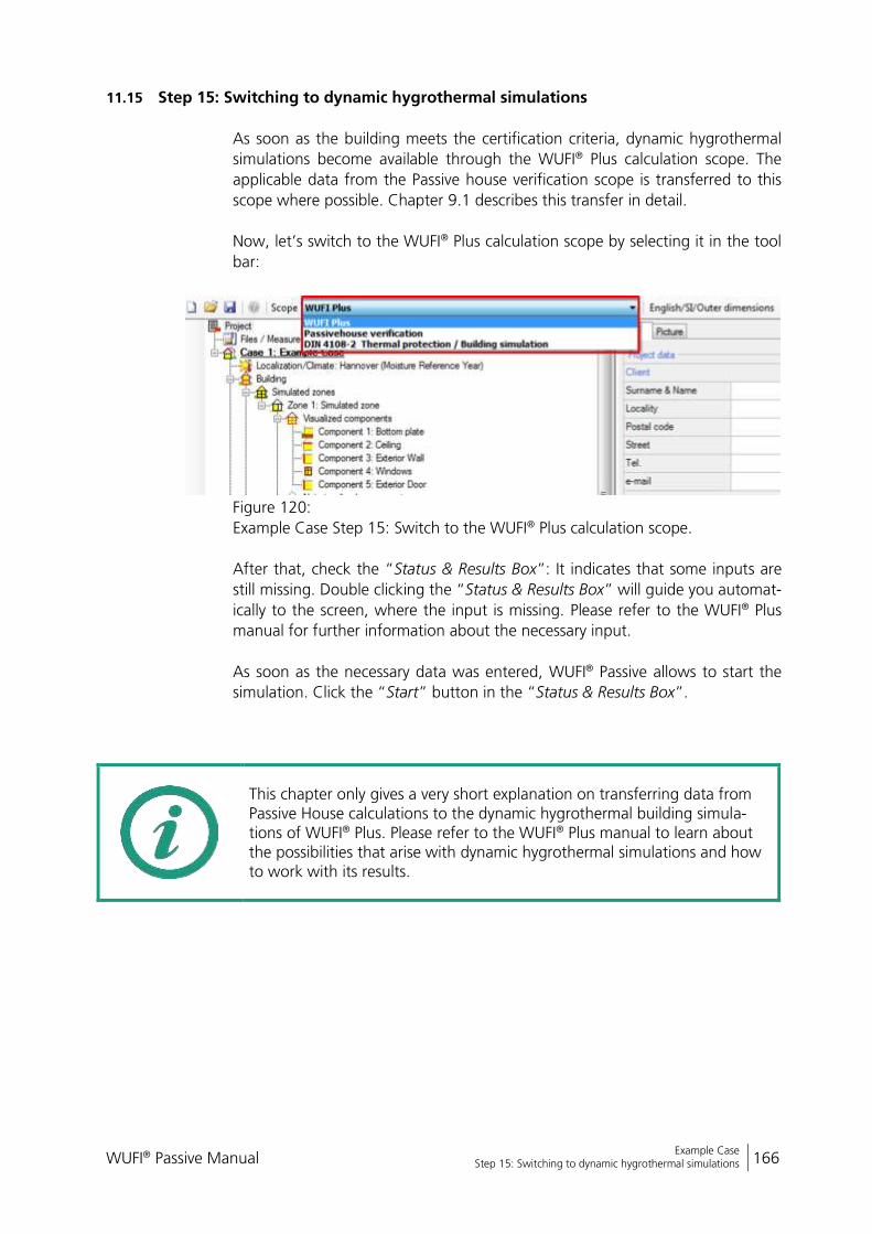
WUFI® Passive Manual 166
Bericht Nr. Anzuzeigender Text darf nicht mehr als eine Zeile beanspruchen!
Example Case Step 15: Switching to dynamic hygrothermal simulations
11.15 Step 15: Switching to dynamic hygrothermal simulations
As soon as the building meets the certification criteria, dynamic hygrothermal
simulations become available through the WUFI® Plus calculation scope. The
applicable data from the Passive house verification scope is transferred to this
scope where possible. Chapter 9.1 describes this transfer in detail.
Now, let’s switch to the WUFI® Plus calculation scope by selecting it in the tool
bar:
Figure 120:
Example Case Step 15: Switch to the WUFI® Plus calculation scope.
After that, check the “Status & Results Box”: It indicates that some inputs are
still missing. Double clicking the “Status & Results Box” will guide you automat-
ically to the screen, where the input is missing. Please refer to the WUFI® Plus
manual for further information about the necessary input.
As soon as the necessary data was entered, WUFI® Passive allows to start the
simulation. Click the “Start” button in the “Status & Results Box”.
This chapter only gives a very short explanation on transferring data from Passive House calculations to the dynamic hygrothermal building simula-tions of WUFI® Plus. Please refer to the WUFI® Plus manual to learn about the possibilities that arise with dynamic hygrothermal simulations and how to work with its results.
WUFI® Passive Manual 167
Bericht Nr. Anzuzeigender Text darf nicht mehr als eine Zeile beanspruchen!
Example Case Step 15: Switching to dynamic hygrothermal simulations
List of figures
Figure 1: Installation: Start the setup. 10
Figure 2: Installation: Terms of use. 10
Figure 3: Installation: System requirements. 11
Figure 4: Installation: Enter your license data. 11
Figure 5: Installation: Select the installation folder and create an entry in the Windows Start Menu. 12
Figure 6: Installation: Create a desktop icon. 12
Figure 7: Installation: Start the installation of the WUFI® Database. 13
Figure 8: Installation: Select the folder for the installation of the WUFI® Database. 13
Figure 9: Finish the installation of WUFI® Passive and the WUFI® Database. 14
Figure 10: Starting WUFI® Passive either from the Windows Start Menu or the desktop shortcut. 15
Figure 11: Main Window of WUFI® Passive. 16
Figure 12: Visualization Box. 24
Figure 13: Component openings window. 26
Figure 14: Creating a new window or opening. 27
Figure 15: Copy a window or opening. 28
Figure 16: Error Messages in the “Status & Results Box”. 32
Figure 17: Summary of main calculation results in the “Status & Results Box”. 33
Figure 18: Localization dialog. 41
Figure 19: Climate Dialog. 42
Figure 20: Building Wizard. 46
Figure 21: PH Case: General Settings. 47
Figure 22: PH Case: Additional Data. 48
Figure 23: PH Case: Foundation Interface. 49
WUFI® Passive Manual 168
Bericht Nr. Anzuzeigender Text darf nicht mehr als eine Zeile beanspruchen!
Example Case Step 15: Switching to dynamic hygrothermal simulations
Figure 24: Simulated Zone Settings. 51
Figure 25: Internal Loads/ Occupancy dialog for residential buildings 56
Figure 26: Internal Loads/ Occupancy dialog for residential buildings 58
Figure 27: Internal Loads/ Occupancy dialog for residential buildings 60
Figure 28: Internal Loads/ Occupancy dialog for residential buildings 62
Figure 29: Internal Loads/ Occupancy dialog for residential buildings 63
Figure 30: Internal Loads/ Occupancy dialog for residential buildings 64
Figure 31: Ventilation dialog: Utilization pattern 65
Figure 32: Ventilation dialog: Rooms ventilation 67
Figure 33: Ventilation dialog: Summer ventilation 69
Figure 34: Ventilation dialog: Exhaust ventilation 70
Figure 35: Thermal bridges dialog 71
Figure 36: HVAC dialog 73
Figure 37: List of HVAC Devices 75
Figure 38: HVAC Distribution – Hydronic heating. 78
Figure 39: HVAC Distribution – DHW. 79
Figure 40: HVAC Distribution – Cooling. 80
Figure 41: HVAC Distribution – Ventilation. 81
Figure 42: HVAC Distribution – Supportive device/ auxiliary energy. 82
Figure 43: Opaque Component – General Settings. 84
Figure 44: Opaque Components – Assembly Selection 85
Figure 45: Opaque Component – Edit Assembly 86
Figure 46: Opaque Component – Thermal surface settings 88
Figure 47: Transparent Component – General Settings. 91
Figure 48: Edit Window Parameters. 92
Figure 49: General settings for solar protection of a transparent component. 94
Figure 50: Solar protection of transparent components: Settings for sunscreen devices. 95
WUFI® Passive Manual 169
Bericht Nr. Anzuzeigender Text darf nicht mehr als eine Zeile beanspruchen!
Example Case Step 15: Switching to dynamic hygrothermal simulations
Figure 51: Solar protection of transparent components: Settings for window overhang. 96
Figure 52: Settings for mechanical ventilation device. 97
Figure 53: Settings for a boiler device. 98
Figure 54: Settings for a district-heating-device. 99
Figure 55: Settings for a heat pump device. 100
Figure 56: Settings for a combined heat pump device. 101
Figure 57: Settings for a solar collector device. 102
Figure 58: Settings for water-storage device. 104
Figure 59: Settings for photovoltaics device. 105
Figure 60: Open the WUFI® HVAC database. 107
Figure 61: Structure of the WUFI® HVAC database. 107
Figure 62: Creating a new device for the WUFI® HVAC database. 108
Figure 63: Options for the WUFI® Passive SketchUp Plugin. 109
Figure 64: Dialogs in SketchUp for the WUFI® Passive SketchUp Plugin. 110
Figure 65: Setting the properties of an object in the WUFI® Passive SketchUp Plugin. 111
Figure 66: External program for gbXML-import. 112
Figure 67: Report dialog. 116
Figure 68: Opening the Passive House verification report. 118
Figure 70: Report for a calculation according to DIN 4108-2. 122
Figure 71: Example Case: View of the Example Building. 123
Figure 72: Example Case: Create a new project. 125
Figure 73: Example Case: Define climatic conditions 126
Figure 74: Example Case: Climate-Tab. 127
Figure 75: Example Case: Set Primary Energy & CO2-Factors. 127
Figure 76: Example Case: Creating building geometry with the “Building Wizard”. 128
WUFI® Passive Manual 170
Bericht Nr. Anzuzeigender Text darf nicht mehr als eine Zeile beanspruchen!
Example Case Step 15: Switching to dynamic hygrothermal simulations
Figure 77: Example Case Step 04: Opening the “Windows/ Openings”-dialog from the “Visualization Box”. 130
Figure 78: Example Case Step 04: Adding a window. 131
Figure 79: Example Case Step 04: Copying the existing window. 132
Figure 80: Example Case Step 04: Inserting the exterior door. 133
Figure 81: Example Case Step 04: Defining the exterior door as an opaque component. 133
Figure 82: Example Case Step 05: General Passive House settings. 134
Figure 83: Example Case Step 05: Natural ventilation settings. 135
Figure 84: Example Case Step 05: Foundation interface. 136
Figure 85: Example Case Step 06: Zonal settings. 137
Figure 86: Example Case Step 07: General settings for the floor slab. 138
Figure 87: Example Case Step 07: Open the “Edit assembly” window. 138
Figure 88: Example Case Step 07: Editing the assembly of the bottom plate. 139
Figure 89: Example Case Step 07: Select a material from the WUFI® database. 140
Figure 90: Example Case Step 07: Assembly for the bottom plate. 140
Figure 91: Example Case Step 07: Heat transfer resistance for the floor slab. 141
Figure 92: Example Case Step 07: Assembly for the ceiling. 142
Figure 93: Example Case Step 07: Main layers of the inhomogeneous exterior wall component. 144
Figure 94: Example Case Step 07: Add the exchange material for the wood framing. 144
Figure 95: Example Case Step 07: Enter the dimensions of the subdivision. 145
Figure 96: Example Case Step 07: Insert the exchange material. 145
Figure 97: Example Case Step 07: Subdivisions for layer Nr. 5. 146
Figure 98: Example Case Step 07: Inhomogeneous assembly for exterior walls. 146
WUFI® Passive Manual 171
Bericht Nr. Anzuzeigender Text darf nicht mehr als eine Zeile beanspruchen!
Example Case Step 15: Switching to dynamic hygrothermal simulations
Figure 99: Example Case Step 07: Adjust the surface settings for the exterior walls. 147
Figure 100: Example Case Step 07: Select window parameters from the WUFI® Database. 148
Figure 101: Example Case Step 07: Opening the “Windows/ Openings”-dialog from the “Visualization Box”. 149
Figure 102: Example Case Step 07: General settings for the exterior door. 150
Figure 103: Example Case Step 07: Assembly for the exterior door. 150
Figure 104: Example Case Step 08: Defining internal loads. 151
Figure 105: Example Case Step 09: Ventilation settings – Utilization pattern. 152
Figure 106: Example Case Step 09: Ventilation settings – Rooms 153
Figure 107: Example Case Step 09: Ventilation settings – Summer ventilation. 154
Figure 108: Example Case Step 09: Ventilation settings – Calculator summer ventilation 155
Figure 109: Example Case Step 10: Input a thermal bridge. 156
Figure 110: Example Case Step 11: Connection with unheated attic. 157
Figure 111: Example Case Step 12: Creating a HVAC system. 158
Figure 112: Example Case Step 12: Include HVAC devices and assign their usage. 159
Figure 113: Example Case Step 12: Distribution of hydronic heating 160
Figure 114: Example Case Step 12: Distribution of DHW 160
Figure 115: Example Case Step 12: Distribution of ventilation. 161
Figure 116: Example Case Step 12: Settings for the heat pump device 162
Figure 117: Example Case Step 12: Settings for the mechanical ventilation device 163
Figure 118: Example Case Step 13: Main results in “Status & Results Box”. 164
Figure 119: Example Case Step 13: Main results in “Status & Results Box” for the adjusted building. 164
Figure 120: Example Case Step 14: Passive house verification report. 165

WUFI® Passive Manual 172
Bericht Nr. Anzuzeigender Text darf nicht mehr als eine Zeile beanspruchen!
Example Case Step 15: Switching to dynamic hygrothermal simulations
Figure 121: Example Case Step 15: Switch to the WUFI® Plus calculation scope. 166