BETAflam® / BETAdrive Sicherheits- und Installationskabel ... · BETAflam® Sicherheitskabel nach...
69
BETAflam® / BETAdrive Sicherheits- und Installationskabel BETAflam® / BETAdrive Safety and Installation cables Seite Übersicht 8 NHXH FE180 / E30-E60 10 NHXCH FE180 / E30-E60 14 NHXH FE180 / E90 16 NHXCH FE180 / E90 20 JE-H(St)H FE180 / E30 22 JE-H(St)H FE180 / E30-E90 24 JE-H(St)HRH FE180 / E30-E90 26 J-H(St)H 28 N2XH 30 N2XCH 34 NHXMH 36 Kabel nach Schweizer Norm FE0 38 INSTAflex 40 FE5 44 FE180 / E30 48 FE180 / E30-CLE 52 BETAdrive C-flex 56 Technische Informationen 59 Allg. Verkaufs- und Lieferbedingungen 146 page Summary 8 NHXH FE180 / E30-E60 10 NHXCH FE180 / E30-E60 14 NHXH FE180 / E90 16 NHXCH FE180 / E90 20 JE-H(St)H FE180 / E30 22 JE-H(St)H FE180 / E30-E90 24 JE-H(St)HRH FE180 / E30-E90 26 J-H(St)H 28 N2XH 30 N2XCH 34 NHXMH 36 Cables according to Swiss standard FE0 38 INSTAflex 40 FE5 44 FE180 / E30 48 FE180 / E30-CLE 52 BETAdrive C-flex 56 Technical information 59 General conditions of sale and delivery 146 7 August 2009 www.leoni-infrastructure-datacom.com BETAflam® / BETAdrive
Transcript of BETAflam® / BETAdrive Sicherheits- und Installationskabel ... · BETAflam® Sicherheitskabel nach...

BETAflam® / BETAdrive
Sicherheits- und Installationskabel
BETAflam® / BETAdrive
Safety and Installation cables Seite
Übersicht 8
NHXH FE180 / E30-E60 10NHXCH FE180 / E30-E60 14NHXH FE180 / E90 16NHXCH FE180 / E90 20
JE-H(St)H FE180 / E30 22JE-H(St)H FE180 / E30-E90 24JE-H(St)HRH FE180 / E30-E90 26J-H(St)H 28
N2XH 30N2XCH 34NHXMH 36
Kabel nach Schweizer NormFE0 38INSTAflex 40FE5 44FE180 / E30 48FE180 / E30-CLE 52BETAdrive C-flex 56
Technische Informationen 59
Allg. Verkaufs- und Lieferbedingungen 146
page
Summary 8
NHXH FE180 / E30-E60 10NHXCH FE180 / E30-E60 14NHXH FE180 / E90 16NHXCH FE180 / E90 20
JE-H(St)H FE180 / E30 22JE-H(St)H FE180 / E30-E90 24JE-H(St)HRH FE180 / E30-E90 26J-H(St)H 28
N2XH 30N2XCH 34NHXMH 36
Cables according to Swiss standard FE0 38INSTAflex 40FE5 44FE180 / E30 48FE180 / E30-CLE 52BETAdrive C-flex 56
Technical information 59
General conditions of sale and delivery 146
7August 2009 www.leoni-infrastructure-datacom.com
BETAflam® / BETAdrive

BETAflam® Sicherheitskabelnach DIN VDE 0266
BETAflam® Safety cablesacc. to DIN VDE 0266
NHXH FE180 / E30-E60 NHXH FE180 / E30-E60
Seite / Page 10
NHXCH FE180 / E30-E60NHXCH FE180 / E30-E60
Seite / Page 14
NHXH FE180 / E90NHXH FE180 / E90
Seite / Page 16
NHXCH FE180 / E90NHXCH FE180 / E90
Seite / Page 20
BETAflam®Signal- und Brandmeldekabelnach DIN VDE 0815
BETAflam® Signal and fire alarm cableacc. to DIN VDE 0815
JE-H(St)H FE180 / E30JE-H(St)H FE180 / E30
Seite / Page 22
JE-H(St)H FE180 / E30-E90JE-H(St)H FE180 / E30-E90
Seite / Page 24
JE-H(St)HRH FE180 / E30-E90JE-H(St)HRH FE180 / E30-E90
Seite / Page 26
J-H(St)HJ-H(St)H
Seite / Page 28
BETAflam® Halogenfreie Kabel nach DIN VDE 0276-604
BETAflam® Halogen free cable acc. to DIN VDE 0276-604
N2XHN2XH
Seite / Page 30
N2XCHN2XCH
Seite / Page 34
BETAflam® Mantelleitung nach DIN VDE 0250-214
BETAflam® Installation cable acc. to DIN VDE 0250-214
NHXMHNHXMH
Seite / Page 36
Kabel nach Schweizer Norm
Swiss standard cable
BETAflam® FE0BETAflam® FE0
Seite / Page 38
BETAflam® INSTAflexBETAflam® INSTAflex
Seite / Page 40
BETAflam® FE5BETAflam® FE5
Seite / Page 44
BETAflam® FE180 / E30BETAflam® FE180 / E30
Seite / Page 48
BETAflam® FE180 / E30-CLEBETAflam® FE180 / E30-CLE
Seite / Page 52
BETAdrive C-flexAbgeschirmte Motoranschlusskabel BETAdrive C-flexShielded connection cable for motors Seite / Page 56
Übersicht BETAflam® / BETAdrive KabelSummary BETAflam® / BETAdrive Cables
8 www.leoni-infrastructure-datacom.com August 2009
BETAflam® / BETAdrive

BETAflam® Sicherheitskabelnach DIN VDE 0266
BETAflam® Safety cablesacc. to DIN VDE 0266
NHXH FE180 / E30-E60 NHXH FE180 / E30-E60
Seite / Page 10
NHXCH FE180 / E30-E60NHXCH FE180 / E30-E60
Seite / Page 14
NHXH FE180 / E90NHXH FE180 / E90
Seite / Page 16
NHXCH FE180 / E90NHXCH FE180 / E90
Seite / Page 20
BETAflam®Signal- und Brandmeldekabelnach DIN VDE 0815
BETAflam® Signal and fire alarm cableacc. to DIN VDE 0815
JE-H(St)H FE180 / E30JE-H(St)H FE180 / E30
Seite / Page 22
JE-H(St)H FE180 / E30-E90JE-H(St)H FE180 / E30-E90
Seite / Page 24
JE-H(St)HRH FE180 / E30-E90JE-H(St)HRH FE180 / E30-E90
Seite / Page 26
J-H(St)HJ-H(St)H
Seite / Page 28
BETAflam® Halogenfreie Kabel nach DIN VDE 0276-604
BETAflam® Halogen free cable acc. to DIN VDE 0276-604
N2XHN2XH
Seite / Page 30
N2XCHN2XCH
Seite / Page 34
BETAflam® Mantelleitung nach DIN VDE 0250-214
BETAflam® Installation cable acc. to DIN VDE 0250-214
NHXMHNHXMH
Seite / Page 36
Kabel nach Schweizer Norm
Swiss standard cable
BETAflam® FE0BETAflam® FE0
Seite / Page 38
BETAflam® INSTAflexBETAflam® INSTAflex
Seite / Page 40
BETAflam® FE5BETAflam® FE5
Seite / Page 44
BETAflam® FE180 / E30BETAflam® FE180 / E30
Seite / Page 48
BETAflam® FE180 / E30-CLEBETAflam® FE180 / E30-CLE
Seite / Page 52
BETAdrive C-flexAbgeschirmte Motoranschlusskabel BETAdrive C-flexShielded connection cable for motors Seite / Page 56
9August 2009 www.leoni-infrastructure-datacom.com
BETAflam® / BETAdrive

BETAflam® SicherheitskabelNHXH FE180 / E30-E60 0,6 / 1 kV, nach DIN VDE 0266, orange
BETAflam® Safety cablesNHXH FE180 / E30-E60 0,6 / 1 kV, acc. to DIN VDE 0266, orange
AnwendungStarkstromkabel 0,6 / 1 kV für ortsfeste Verlegung in elektrischen Kabelanlagen mit verbessertem Verhalten im Brandfall und Funktionserhalt nach DIN 4102 Teil 12, z.B. für Sicherheitsbeleuchtungsanlagen, Brandmeldeanlagen, Rauch- abzugsanlagen usw. Empfohlen in Gebäuden mit Menschenansammlungen und zum Schutz von Sachwerten.
Aufbau Leiter: Kupfer blank Bandierung: MICA-Band Aderisolation: BETAflam® vernetzt Gemeinsame Aderumhüllung: Band oder Füller Mantel: BETAflam® Copolymer Aderfarben: Nach VDE 0266 bzw. HD 308 S2 Mantelfarbe: Orange
Technische Daten Nennspannung: U0/U 0,6 / 1 kV Prüfspannung: 4 kV mit 50 Hz Zulässige Temperaturen:
Betriebstemperatur von – 30 °C bis + 90 °C Verlegetemperatur von – 5 °C bis + 70 °C Kurzschlusstemperatur + 250 °C (Temperaturspitze < 5 s)
Biegeradien: Einleiter Mehrleiter bei Verlegung > 15 × Aussen- > 12 × Aussen- fest verlegt > 8 × Aussen- > 7 × Aussen-
Verlegebedingungen: Ortsfest in Innenräumen, in Luft oder Beton. Verlegung in Erde oder Wasser nur in trockenen Rohren. Verlegung im Freien nur geschützt vor direkter Sonneneinstrahlung und Fremdeinflüssen.
Normen / Materialeigenschaften Halogenfrei: IEC 60754-1, EN 50267-2-1, VDE 0482-267-2-1 Keine korrosiven Gase: IEC 60754-2, EN 50267-2-2, VDE 0482-267-2-2 Keine toxischen Gase: NES 02-713, NF C20-454 Geringe Rauchdichte: IEC 61034-1 und -2, EN 61034-1 und -2,
VDE 0482-1034-1 und -2 Flammwidrig: IEC 60332-1, EN 60332-1, VDE 0482-332-1 Keine Brandfortleitung: IEC 60332-3-10 und -3-24, EN 60332-3-10, -24,
VDE 0482-266-1, -2-4 Isolationserhalt FE180: IEC 60331-11 und -21, VDE 0472-814 Isolationserhalt mit Schlag: EN 50200 PH90 (bis 20 mm) Funktionserhalt: DIN 4102-12, E30 oder E60, abhängig vom Verlegesystem
ApplicationPower cable 0,6 / 1 kV for fixed installation in cable systems with improved fire perfor-mance and system circuit integrity to DIN 4102 part 12 for lighting of escape routes, fire alarm systems, smoke exhaust systems etc. Recommended in areas where people gather and for protection of valuables.
Construction Conductors: Bare annealed copper Flame barrier: MICA tape Insulation: BETAflam® crosslinked Inner covering: Tape or filler Sheath: BETAflam® copolymer Core identification: According to VDE 0266 resp. HD 308 S2 Sheath colour: Orange
Technical data Rated voltage: U0/U 0,6 / 1 kV Test voltage: 4 kV with 50 Hz Temperature range:
Operation temperature from – 30 °C to + 90 °C Laying temperature from – 5 °C to + 70 °C Short circuit temperature + 250 °C (temperature peak < 5 s)
Bending radius: Single core Multiple core during laying > 15 × outer > 12 × outer fixed > 8 × outer > 7 × outer
Laying conditions: Fixed installation indoor, in air or concrete. Laying in earth or water only in water-proof dry tubes. Outdoor laying only when protected from direct sunlight and other external impacts.
Standards / Material Properties Halogen free: IEC 60754-1, EN 50267-2-1, VDE 0482-267-2-1 No corrosive gases: IEC 60754-2, EN 50267-2-2, VDE 0482-267-2-2 No toxic gases: NES 02-713, NF C20-454 Low smoke density: IEC 61034-1 and -2, EN 61034-1 and -2,
VDE 0482-1034-1 and -2 Flame retardant: IEC 60332-1, EN 60332-1, VDE 0482-332-1 No flame propagation: IEC 60332-3-10 and -3-24, EN 60332-3-10, -24,
VDE 0482-266-1, -2-4 Circuit integrity FE180: IEC 60331-11 and -21, VDE 0472-814 Circuit integrity with shock: EN 50200 PH90 (up to 20 mm) System circuit integrity: DIN 4102-12, E30 or E60, depending on laying system
10 www.leoni-infrastructure-datacom.com August 2009
BETAflam®

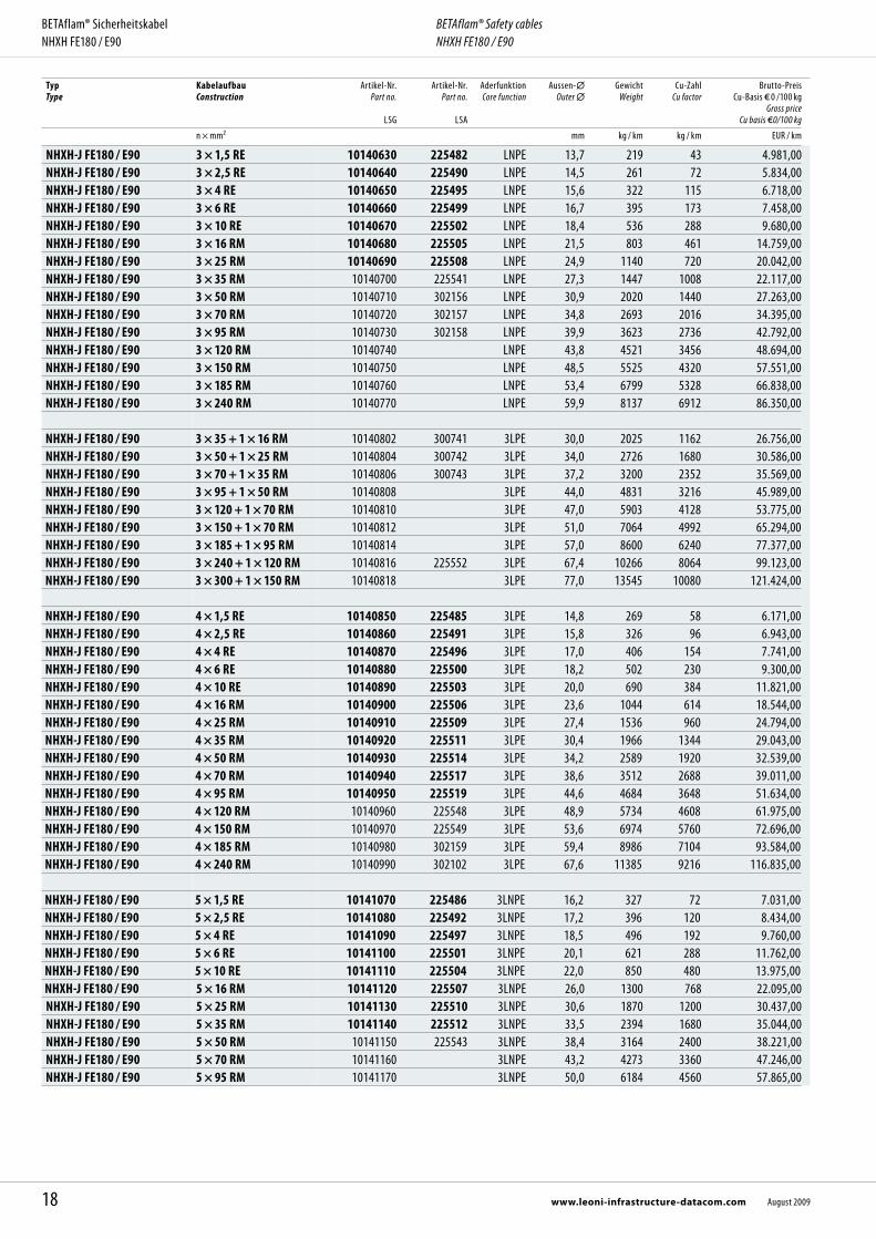
Vorteile
Höchste Sicherheitseigenschaften Funktionserhalt nach DIN 4102 Teil 12 Halogenfrei und silikonfrei RoHS-konform Kabel und Verlegesystem aus einer Hand
Abmessungen, Gewichte / Dimensions, WeightTyp Type
KabelaufbauConstruction
Artikel-Nr. Part no.
LSG
Artikel-Nr.Part no.
LSA
Aderfunktion Core function
Aussen- Outer
GewichtWeight
Cu-ZahlCu factor
Brutto-Preis Cu-Basis 0 /100 kg
Gross price Cu basis 0/100 kg
n × mm² mm kg / km kg / km EUR / km
NHXH-J FE180 / E30-E60 1 × 4 RE 10100200 PE 7,3 101 38 1.558,00NHXH-J FE180 / E30-E60 1 × 6 RE 10100210 PE 7,8 121 58 1.850,00NHXH-J FE180 / E30-E60 1 × 10 RE 10100220 PE 8,6 166 96 2.171,00NHXH-J FE180 / E30-E60 1 × 16 RM 10100230 PE 10,3 251 154 2.754,00NHXH-J FE180 / E30-E60 1 × 25 RM 10100240 PE 11,9 358 240 3.455,00NHXH-J FE180 / E30-E60 1 × 35 RM 10100250 PE 13,0 457 336 3.989,00NHXH-J FE180 / E30-E60 1 × 50 RM 10100260 PE 14,8 603 480 4.671,00NHXH-J FE180 / E30-E60 1 × 70 RM 10100270 PE 16,6 813 672 5.595,00NHXH-J FE180 / E30-E60 1 × 95 RM 10100280 PE 19,0 1094 912 6.656,00NHXH-J FE180 / E30-E60 1 × 120 RM 10100290 PE 20,8 1350 1152 7.563,00NHXH-J FE180 / E30-E60 1 × 150 RM 10100300 PE 22,9 1647 1440 8.380,00NHXH-J FE180 / E30-E60 1 × 185 RM 10100310 PE 25,3 1986 1776 9.901,00NHXH-J FE180 / E30-E60 1 × 240 RM 10100320 PE 28,3 2623 2304 12.250,00NHXH-J FE180 / E30-E60 1 × 300 RM 10100330 PE 32,2 3471 2880 17.225,00NHXH-J FE180 / E30-E60 1 × 400 RM 10100340 PE 35,9 4300 3840 21.981,00NHXH-J FE180 / E30-E60 1 × 500 RM 10100350 PE 39,7 5400 4800 32.448,00 NHXH-O FE180 / E30-E60 1 × 4 RE 10110200 L 7,3 101 38 1.558,00NHXH-O FE180 / E30-E60 1 × 6 RE 10110210 L 7,8 121 58 1.850,00NHXH-O FE180 / E30-E60 1 × 10 RE 10110220 L 8,6 166 96 2.171,00NHXH-O FE180 / E30-E60 1 × 16 RM 10110230 211997 L 10,3 251 154 2.754,00NHXH-O FE180 / E30-E60 1 × 25 RM 10110240 L 11,9 358 240 3.455,00NHXH-O FE180 / E30-E60 1 × 35 RM 10110250 L 13,0 457 336 3.989,00NHXH-O FE180 / E30-E60 1 × 50 RM 10110260 L 14,8 603 480 4.671,00NHXH-O FE180 / E30-E60 1 × 70 RM 10110270 L 16,6 813 672 5.595,00NHXH-O FE180 / E30-E60 1 × 95 RM 10110280 L 19,0 1094 912 6.656,00NHXH-O FE180 / E30-E60 1 × 120 RM 10110290 L 20,8 1350 1152 7.563,00NHXH-O FE180 / E30-E60 1 × 150 RM 10110300 L 22,9 1647 1440 8.380,00NHXH-O FE180 / E30-E60 1 × 185 RM 10110310 301226 L 25,3 1986 1776 9.901,00NHXH-O FE180 / E30-E60 1 × 240 RM 10110320 L 28,3 2623 2304 12.250,00NHXH-O FE180 / E30-E60 1 × 300 RM 10110330 L 32,2 3471 2880 17.225,00NHXH-O FE180 / E30-E60 1 × 400 RM 10110340 L 35,9 4300 3840 21.981,00NHXH-O FE180 / E30-E60 1 × 500 RM 10110350 L 39,7 5400 4800 32.448,00
NHXH-O FE180 / E30-E60 2 × 1,5 RE 10110410 191225 LN 11,8 167 29 1.915,00NHXH-O FE180 / E30-E60 2 × 2,5 RE 10110420 300060 LN 12,6 198 48 2.040,00NHXH-O FE180 / E30-E60 2 × 4 RE 10110430 302803 LN 13,1 233 77 2.761,00NHXH-O FE180 / E30-E60 2 × 6 RE 10110440 LN 14,1 285 115 3.587,00NHXH-O FE180 / E30-E60 2 × 10 RE 10110450 LN 15,7 408 192 4.350,00NHXH-O FE180 / E30-E60 2 × 16 RM 10110460 LN 18,9 604 307 5.163,00NHXH-O FE180 / E30-E60 2 × 25 RM 10110470 LN 22,0 839 480 6.470,00
Advantages
Highest safety standards System circuit integrity to DIN 4102 part 12 Halogen free and silicone free In compliance with RoHS directive One source for cables and laying system
11August 2009 www.leoni-infrastructure-datacom.com
BETAflam® SicherheitskabelNHXH FE180 / E30-E60
BETAflam® Safety cablesNHXH FE180 / E30-E60
Typ Type
KabelaufbauConstruction
Artikel-Nr. Part no.
LSG
Artikel-Nr.Part no.
LSA
Aderfunktion Core function
Aussen- Outer
GewichtWeight
Cu-ZahlCu factor
Brutto-Preis Cu-Basis 0 /100 kg
Gross price Cu basis 0/100 kg
n × mm² mm kg / km kg / km EUR / km
NHXH-J FE180 / E30-E60 3 × 1,5 RE 10100630 191227 LNPE 12,4 183 43 1.956,00NHXH-J FE180 / E30-E60 3 ×1,5 RE *10100635 *19122705 LNPE 12,4 183 43 2.029,00NHXH-J FE180 / E30-E60 3 × 2,5 RE 10100640 191232 LNPE 13,3 221 72 2.368,00NHXH-J FE180 / E30-E60 3 × 2,5 RE *10100645 *19123205 LNPE 13,3 221 72 2.441,00NHXH-J FE180 / E30-E60 3 × 4 RE 10100650 212066 LNPE 13,7 268 115 3.233,00NHXH-J FE180 / E30-E60 3 × 6 RE 10100660 213927 LNPE 14,9 337 173 3.947,00NHXH-J FE180 / E30-E60 3 × 10 RE 10100670 213945 LNPE 16,6 472 288 5.186,00NHXH-J FE180 / E30-E60 3 × 16 RM 10100680 213946 LNPE 20,1 763 461 6.821,00NHXH-J FE180 / E30-E60 3 × 25 RM 10100690 213928 LNPE 23,4 1115 720 9.242,00NHXH-J FE180 / E30-E60 3 × 35 RM 10100700 217705 LNPE 25,9 1420 1008 12.955,00NHXH-J FE180 / E30-E60 3 × 50 RM 10100710 LNPE 29,8 2198 1440 14.175,00NHXH-J FE180 / E30-E60 3 × 70 RM 10100720 LNPE 33,7 3023 2016 16.835,00NHXH-J FE180 / E30-E60 3 × 95 RM 10100730 220789 LNPE 38,8 3461 2736 21.124,00NHXH-J FE180 / E30-E60 3 × 120 RM LNPE 42,7 4600 3456 27.669,00NHXH-J FE180 / E30-E60 3 × 150 RM LNPE 47,3 5400 4320 30.998,00NHXH-J FE180 / E30-E60 3 × 185 RM LNPE 52,4 6200 5328 36.113,00 NHXH-J FE180 / E30-E60 3 × 25 +16 RM 10100800 3LPE 25,2 1505 874 11.016,00NHXH-J FE180 / E30-E60 3 × 35 +16 RM 10100802 3LPE 27,4 1850 1162 13.629,00NHXH-J FE180 / E30-E60 3 × 50 + 25 RM 10100804 3LPE 32,1 2490 1680 15.216,00NHXH-J FE180 / E30-E60 3 × 70 + 35 RM 10100806 3LPE 36,4 3389 2352 19.253,00NHXH-J FE180 / E30-E60 3 × 95 + 50 RM 10100808 3LPE 41,0 4529 3216 24.464,00NHXH-J FE180 / E30-E60 3 × 120 + 70 RM 10100810 3LPE 45,6 5562 4128 31.025,00NHXH-J FE180 / E30-E60 3 × 150 + 70 RM 10100812 3LPE 49,5 6918 4992 36.373,00NHXH-J FE180 / E30-E60 3 × 185 + 95 RM 10100814 3LPE 54,2 7351 6240 43.450,00NHXH-J FE180 / E30-E60 3 × 240 +120 RM 3LPE 61,3 9810 8064 57.564,00 NHXH-J FE180 / E30-E60 4 × 1,5 RE 10100850 191228 3LPE 13,4 212 58 2.242,00NHXH-J FE180 / E30-E60 4 × 2,5 RE 10100860 191233 3LPE 14,4 275 96 2.528,00NHXH-J FE180 / E30-E60 4 × 4 RE 10100870 213706 3LPE 15,0 340 154 3.950,00NHXH-J FE180 / E30-E60 4 × 6 RE 10100880 191236 3LPE 16,2 427 230 4.582,00NHXH-J FE180 / E30-E60 4 × 10 RE 10100890 191238 3LPE 18,0 592 384 6.220,00NHXH-J FE180 / E30-E60 4 × 16 RM 10100900 191240 3LPE 22,1 944 614 9.962,00NHXH-J FE180 / E30-E60 4 × 25 RM 10100910 191242 3LPE 26,0 1434 960 12.456,00NHXH-J FE180 / E30-E60 4 × 35 RM 10100920 191244 3LPE 28,8 1864 1344 14.982,00NHXH-J FE180 / E30-E60 4 × 50 RM 10100930 214474 3LPE 33,2 2485 1920 18.147,00NHXH-J FE180 / E30-E60 4 × 70 RM 10100940 217706 3LPE 37,7 3321 2688 22.052,00NHXH-J FE180 / E30-E60 4 × 95 RM 10100950 217616 3LPE 43,2 4565 3648 28.638,00NHXH-J FE180 / E30-E60 4 × 120 RM 10100960 220506 3LPE 47,8 5610 4608 34.343,00NHXH-J FE180 / E30-E60 4 × 150 RM 10100970 3LPE 52,8 6914 5760 41.268,00NHXH-J FE180 / E30-E60 4 × 185 RM 10100980 3LPE 58,4 8890 7104 50.157,00NHXH-J FE180 / E30-E60 4 × 240 RM 10100990 3LPE 65,7 10960 9216 62.619,00
NHXH-J FE180 / E30-E60 5 × 1,5 RE 10101070 191229 3LNPE 14,6 268 72 3.395,00NHXH-J FE180 / E30-E60 5 × 2,5 RE 10101080 191234 3LNPE 15,7 336 120 3.755,00NHXH-J FE180 / E30-E60 5 × 4 RE 10101090 191235 3LNPE 16,2 411 192 5.514,00NHXH-J FE180 / E30-E60 5 × 6 RE 10101100 191237 3LNPE 17,7 545 288 6.319,00NHXH-J FE180 / E30-E60 5 × 10 RE 10101110 191239 3LNPE 20,0 739 480 8.083,00NHXH-J FE180 / E30-E60 5 × 16 RM 10101120 191241 3LNPE 24,3 1168 768 11.858,00NHXH-J FE180 / E30-E60 5 × 25 RM 10101130 191243 3LNPE 28,8 1725 1200 14.691,00NHXH-J FE180 / E30-E60 5 × 35 RM 10101140 191245 3LNPE 32,2 2341 1680 17.347,00NHXH-J FE180 / E30-E60 5 × 50 RM 10101150 213861 3LNPE 37,5 3120 2400 21.431,00NHXH-J FE180 / E30-E60 5 × 70 RM 10101160 301273 3LNPE 42,2 4252 3360 26.042,00NHXH-J FE180 / E30-E60 5 × 95 RM 10101170 212659 3LNPE 48,1 5766 4560 31.683,00NHXH-J FE180 / E30-E60 5 × 120 RM 10101180 3LNPE 53,7 7300 5760 39.427,00
12 www.leoni-infrastructure-datacom.com August 2009
BETAflam® SicherheitskabelNHXH FE180 / E30-E60
BETAflam® Safety cablesNHXH FE180 / E30-E60

Typ Type
KabelaufbauConstruction
Artikel-Nr. Part no.
LSG
Artikel-Nr.Part no.
LSA
Aderfunktion Core function
Aussen- Outer
GewichtWeight
Cu-ZahlCu factor
Brutto-Preis Cu-Basis 0 /100 kg
Gross price Cu basis 0/100 kg
n × mm² mm kg / km kg / km EUR / km
NHXH-J FE180 / E30-E60 7 × 1,5 RE 10101510 191230 NRPE 16,1 334 101 4.115,00NHXH-J FE180 / E30-E60 7 × 2,5 RE 10101520 214473 NRPE 17,3 422 168 4.663,00NHXH-J FE180 / E30-E60 7 × 4 RE 10101530 NRPE 17,5 520 269 6.205,00NHXH-J FE180 / E30-E60 12 × 1,5 RE 10102520 191231 NRPE 20,5 520 173 6.220,00NHXH-J FE180 / E30-E60 12 × 2,5 RE 10102530 303193 NRPE 22,2 661 288 6.879,00NHXH-J FE180 / E30-E60 19 × 1,5 RE 10103360 NRPE 23,9 755 274 11.002,00NHXH-J FE180 / E30-E60 19 × 2,5 RE 10103370 NRPE 25,9 1186 456 12.712,00NHXH-J FE180 / E30-E60 24 × 1,5 RE 10103870 213960 NRPE 27,7 961 346 13.105,00NHXH-J FE180 / E30-E60 24 × 2,5 RE 10103880 NRPE 30,1 1255 576 14.051,00NHXH-J FE180 / E30-E60 30 × 1,5 RE 10104410 NRPE 29,6 1105 432 13.907,00NHXH-J FE180 / E30-E60 30 × 2,5 RE 10104420 NRPE 32,4 1522 720 15.700,00
-J = mit grün-gelber Ader -O = ohne grün-gelbe Ader RE = rund eindrähtig RM = rund mehrdrähtig L = Phasenleiter braun, schwarz, grauN = Neutralleiter blauNR = Phasenleiter schwarz, nummeriertPE = Schutzleiter grün-gelb
* = in einer Länge 1 × 500 m
Fett gedruckte Artikel-Nr. = Lagerartikel Weitere Ausführungen auf Anfrage.
-J = with green-yellow conductor -O = without green-yellow conductor RE = round solid RM = round stranded L = phase conductor brown, black, greyN = neutral conductor blueNR = phase conductors black, numberedPE = earth conductor green-yellow
* = in one length 1 × 500 m Bold printed part no. = stock item Further designs upon request.
13August 2009 www.leoni-infrastructure-datacom.com
BETAflam® SicherheitskabelNHXH FE180 / E30-E60
BETAflam® Safety cablesNHXH FE180 / E30-E60

BETAflam® SicherheitskabelNHXCH FE180 / E30-E60 0,6 / 1 kV, nach DIN VDE 0266, orange
BETAflam® Safety cablesNHXCH FE180 / E30-E60 0,6 / 1 kV, acc. to DIN VDE 0266, orange
AnwendungStarkstromkabel 0,6 / 1 kV mit konzentrischem Aussenleiter für ortsfeste Verlegung in elektrischen Kabelanlagen mit verbessertem Verhalten im Brandfall und Funkti-onserhalt nach DIN 4102 Teil 12, z.B. für Sicherheitsbeleuchtungsanlagen, Brand-meldeanlagen, Rauchabzugsanlagen usw. Empfohlen in Gebäuden mit Menschen-ansammlungen und zum Schutz von Sachwerten.
Aufbau Leiter: Kupfer blank Bandierung: MICA-Band Aderisolation: BETAflam® vernetzt Konzentrischer Aussenleiter: Kupferdrähte mit Haltewendel Gemeinsame Aderumhüllung: Band oder Füller Mantel: BETAflam® Copolymer Aderfarben: Nach VDE 0266 bzw. HD 308 S2 Mantelfarbe: Orange
Technische Daten Nennspannung: U0/U 0,6 / 1 kV Prüfspannung: 4 kV mit 50 Hz Zulässige Temperaturen:
Betriebstemperatur von – 30 °C bis + 90 °C Verlegetemperatur von – 5 °C bis + 70 °C Kurzschlusstemperatur + 250 °C (Temperaturspitze < 5 s)
Biegeradien: Einleiter Mehrleiter bei Verlegung > 15 × Aussen- > 12 × Aussen- fest verlegt > 8 × Aussen- > 7 × Aussen-
Verlegebedingungen: Ortsfest in Innenräumen, in Luft oder Beton. Verlegung in Erde oder Wasser nur in Rohren, in denen sich kein Wasser sammeln kann. Verlegung im Freien nur geschützt vor direkter Sonneneinstrahlung und Fremd- einflüssen.
Normen / Materialeigenschaften Halogenfrei: IEC 60754-1, EN 50267-2-1, VDE 0482-267-2-1 Keine korrosiven Gase: IEC 60754-2, EN 50267-2-2, VDE 0482-267-2-2 Keine toxischen Gase: NES 02-713, NF C20-454 Geringe Rauchdichte: IEC 61034-1 und -2, EN 61034-1 und -2,
VDE 0482-1034-1 und -2 Flammwidrig: IEC 60332-1, EN 60332-1, VDE 0482-332-1 Keine Brandfortleitung: IEC 60332-3-10 und -3-24, EN 60332-3-10, -24,
VDE 0482-266-1, -2-4 Isolationserhalt FE180: IEC 60331-11 und -21, VDE 0472-814 Isolationserhalt mit Schlag: EN 50200 PH90 (bis 20 mm) Funktionserhalt: DIN 4102-12, E30 oder E60, abhängig vom Verlegesystem
ApplicationPower cable 0,6 / 1 kV with concentric conductor for fixed installation in cable systems with improved fire performance and system circuit integrity to DIN 4102 part 12 for lighting of escape routes, fire alarm systems, smoke exhaust systems etc. Recommen-ded in areas where people gather and for protection of valuables.
Construction Conductors: Bare annealed copper Flame barrier: MICA tape Insulation: BETAflam® crosslinked Concentric conductor: Copper wires, with helix of copper tape Inner covering: Tape or filler Sheath: BETAflam® copolymer Core identification: According to VDE 0266 resp. HD 308 S2 Sheath colour: Orange
Technical data Rated voltage: U0/U 0,6 / 1 kV Test voltage: 4 kV with 50 Hz Temperature range:
Operation temperature from – 30 °C to + 90 °C Laying temperature from – 5 °C to + 70 °C Short circuit temperature + 250 °C (temperature peak < 5 s)
Bending radius: Single core Multiple core during laying > 15 × outer > 12 × outer fixed > 8 × outer > 7 × outer
Laying conditions: Fixed installation indoor, in air or concrete. Laying in earth or water only in water-proof dry tubes. Outdoor laying only when protected from direct sunlight and other external impacts.
Standards / Material Properties Halogen free: IEC 60754-1, EN 50267-2-1, VDE 0482-267-2-1 No corrosive gases: IEC 60754-2, EN 50267-2-2, VDE 0482-267-2-2 No toxic gases: NES 02-713, NF C20-454 Low smoke density: IEC 61034-1 and -2, EN 61034-1 and -2,
VDE 0482-1034-1 and -2 Flame retardant: IEC 60332-1, EN 60332-1, VDE 0482-332-1 No flame propagation: IEC 60332-3-10 and -3-24, EN 60332-3-10, -24,
VDE 0482-266-1, -2-4 Circuit integrity FE180: IEC 60331-11 and -21, VDE 0472-814 Circuit integrity with shock: EN 50200 PH90 (up to 20 mm) System circuit integrity: DIN 4102-12, E30 or E60, depending on laying system
14 www.leoni-infrastructure-datacom.com August 2009
BETAflam®
Vorteile
Höchste Sicherheitseigenschaften Funktionserhalt nach DIN 4102 Teil 12 Halogenfrei und silikonfrei RoHS-konform Kabel und Verlegesystem aus einer Hand
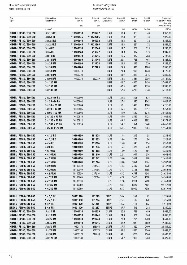
Abmessungen, Gewichte / Dimensions, WeightTyp Type
KabelaufbauConstruction
Artikel-Nr. Part no.
LSG
Artikel-Nr.Part no.
LSA
Aderfunktion Core function
Aussen- Outer
GewichtWeight
Cu-ZahlCu factor
Brutto-Preis Cu-Basis 0 /100 kg
Gross price Cu basis 0/100 kg
n × mm² mm kg / km kg / km EUR / km
NHXCH FE180 / E30-E60 2 × 1,5 RE/1,5 10120410 LN 14,8 287 52 2.608,00NHXCH FE180 / E30-E60 2 × 2,5 RE/2,5 10120420 LN 15,6 331 80 3.096,00NHXCH FE180 / E30-E60 2 × 4 RE/4 10120430 LN 16,1 408 123 3.487,00NHXCH FE180 / E30-E60 2 × 6 RE/6 10120440 LN 17,2 463 182 4.244,00NHXCH FE180 / E30-E60 2 × 10 RE/10 10120450 LN 18,7 643 312 5.651,00
NHXCH FE180 / E30-E60 3 × 1,5 RE/1,5 10120630 217727 3L 15,7 392 66 3.280,00NHXCH FE180 / E30-E60 3 × 2,5 RE/2,5 10120640 217730 3L 17,2 430 104 3.680,00NHXCH FE180 / E30-E60 3 × 4 RE/4 10120650 3L 17,5 510 161 3.963,00NHXCH FE180 / E30-E60 3 × 6 RE/6 10120660 3L 17,7 600 240 4.760,00NHXCH FE180 / E30-E60 3 × 10 RE/10 10120670 3L 19,9 736 408 6.302,00NHXCH FE180 / E30-E60 3 × 16 RM/16 10120680 3L 23,6 1161 643 7.357,00NHXCH FE180 / E30-E60 3 × 25 RM/16 10120690 3L 27,3 1707 902 9.583,00NHXCH FE180 / E30-E60 3 × 35 RM/16 10120700 3L 29,5 2190 1190 13.018,00NHXCH FE180 / E30-E60 3 × 50 RM/25 10120710 3L 34,3 3646 1728 16.016,00NHXCH FE180 / E30-E60 3 × 70 RM/35 10120720 3L 38,2 4042 2415 20.370,00NHXCH FE180 / E30-E60 3 × 95 RM/50 10120730 3L 43,7 5134 3311 25.884,00NHXCH FE180 / E30-E60 3 × 120 RM/70 10120740 3L 47,2 6300 4261 32.266,00NHXCH FE180 / E30-E60 3 × 150 RM/70 10120750 3L 51,8 7020 5100 36.419,00NHXCH FE180 / E30-E60 3 × 185 RM/95 10120760 300409 3L 57,2 8378 6383 44.473,00NHXCH FE180 / E30-E60 3 × 240 RM/120 10120770 3L 64,2 11323 8242 49.863,00
NHXCH FE180 / E30-E60 4 × 1,5 RE/1,5 10120850 217244 3LN 14,8 320 81 4.343,00NHXCH FE180 / E30-E60 4 × 2,5 RE/2,5 10120860 3LN 15,8 358 128 4.622,00NHXCH FE180 / E30-E60 4 × 4 RE/4 10120870 213942 3LN 16,3 516 200 5.591,00NHXCH FE180 / E30-E60 4 × 6 RE/6 10120880 300558 3LN 17,2 612 297 6.553,00NHXCH FE180 / E30-E60 4 × 10 RE/10 10120890 213963 3LN 20,5 842 504 9.214,00NHXCH FE180 / E30-E60 4 × 16 RM/16 10120900 213964 3LN 25,0 1196 796 10.987,00NHXCH FE180 / E30-E60 4 × 25 RM/16 10120910 213965 3LN 27,7 1654 1142 13.097,00NHXCH FE180 / E30-E60 4 × 35 RM/16 10120920 213966 3LN 30,3 2113 1526 16.004,00NHXCH FE180 / E30-E60 4 × 50 RM/25 10120930 213967 3LN 35,2 2774 2203 19.575,00NHXCH FE180 / E30-E60 4 × 70 RM/35 10120940 213968 3LN 39,5 3833 3082 22.220,00NHXCH FE180 / E30-E60 4 × 95 RM/50 10120950 213969 3LN 45,8 5216 4208 27.393,00NHXCH FE180 / E30-E60 4 × 120 RM/70 10120960 213970 3LN 50,4 6519 5388 36.444,00NHXCH FE180 / E30-E60 4 × 150 RM/70 10120970 213971 3LN 55,4 7849 6540 41.917,00NHXCH FE180 / E30-E60 4 × 185 RM/95 10120980 213972 3LN 61,6 9800 8159 50.945,00NHXCH FE180 / E30-E60 4 × 240 RM/120 10120990 300470 3LN 69,0 12983 10546 63.756,00
NHXCH FE180 / E30-E60 7 × 1,5 RE/2,5 10121510 NR 18,7 412 133 5.495,00NHXCH FE180 / E30-E60 7 × 2,5 RE/2,5 10121520 NR 18,3 488 200 5.948,00NHXCH FE180 / E30-E60 12 × 1,5 RE/2,5 10122520 217736 NR 21,5 612 205 10.028,00NHXCH FE180 / E30-E60 12 × 2,5 RE/4 10122530 NR 25,3 780 334 10.581,00NHXCH FE180 / E30-E60 24 × 1,5 RE/6 10123870 NR 28,5 1052 413 17.221,00NHXCH FE180 / E30-E60 24 × 2,5 RE/10 10123880 NR 30,4 1398 696 18.463,00
Advantages
Highest safety standards System circuit integrity to DIN 4102 part 12 Halogen free and silicone free In compliance with RoHS One source for cables and laying system
RE = rund eindrähtig RM = rund mehrdrähtig L = Phasenleiter braun, schwarz, grauN = Neutralleiter blauNR = Phasenleiter schwarz, nummeriert Fett gedruckte Artikel-Nr. = Lagerartikel
RE = round solid RM = round stranded L = phase conductor brown, black, greyN = neutral conductor blueNR = phase conductors black, numberedBold printed part no. = stock item
15August 2009 www.leoni-infrastructure-datacom.com
BETAflam® SicherheitskabelNHXCH FE180 / E30-E60
BETAflam® Safety cablesNHXCH FE180 / E30-E60

BETAflam® SicherheitskabelNHXH FE180 / E90 0,6 / 1 kV, nach DIN VDE 0266, orange
BETAflam® Safety cablesNHXH FE180 / E90 0,6 / 1 kV, acc. to DIN VDE 0266, orange
AnwendungStarkstromkabel 0,6/1 kV für ortsfeste Verlegung in elektrischen Kabelanlagen mit verbessertem Verhalten im Brandfall und Funktionserhalt nach DIN 4102 Teil 12, z.B. für Druckerhöhungsanlagen zur Löschwasserversorgung, Rauchabzugsanlagen usw. Empfohlen in Gebäuden mit Menschenansammlungen und zum Schutz von Sachwerten.
Aufbau Leiter: Kupfer blank Bandierung: MICA-Band Aderisolation: BETAflam® vernetzt Gemeinsame Aderumhüllung: Band oder Füller Mantel: BETAflam® Copolymer Aderfarben: Nach VDE 0266 bzw. HD 308 S2 Mantelfarbe: Orange
Technische Daten Nennspannung: U0/U 0,6 / 1 kV Prüfspannung: 4 kV mit 50 Hz Zulässige Temperaturen:
Betriebstemperatur von – 30 °C bis + 90 °C Verlegetemperatur von – 5 °C bis + 70 °C Kurzschlusstemperatur + 250 °C (Temperaturspitze < 5 s)
Biegeradien: Einleiter Mehrleiter bei Verlegung > 15 × Aussen- > 12 × Aussen- fest verlegt > 8 × Aussen- > 7 × Aussen-
Verlegebedingungen: Ortsfest in Innenräumen, in Luft oder Beton. Verlegung in Erde oder Wasser nur in Rohren, in denen sich kein Wasser sammeln kann. Verlegung im Freien nur geschützt vor direkter Sonneneinstrahlung und Fremd-einflüssen.
Normen / Materialeigenschaften Halogenfrei: IEC 60754-1, EN 50267-2-1, VDE 0482-267-2-1 Keine korrosiven Gase: IEC 60754-2, EN 50267-2-2, VDE 0482-267-2-2 Keine toxischen Gase: NES 02-713, NF C20-454 Geringe Rauchdichte: IEC 61034-1 und -2, EN 61034-1 und -2,
VDE 0482-1034-1 und -2 Flammwidrig: IEC 60332-1, EN 60332-1, VDE 0482-332-1 Keine Brandfortleitung: IEC 60332-3-10 und -3-24, EN 60332-3-10, -24,
VDE 0482-266-1, -2-4 Isolationserhalt FE180: IEC 60331-11 und -21, VDE 0472-814 Isolationserhalt mit Schlag: EN 50200 PH 90 (bis 20 mm) und
EN 50362 P 90 (> 20 mm bis 45 mm) Funktionserhalt: DIN 4102-12 E90, abhängig vom Verlegesystem Wasserlöschanlagen: VdS ≥ 2,5 mm²
ApplicationPower cable 0,6/1 kV for fixed installation in cable systems with improved fire perfor-mance and system circuit integrity to DIN 4102 part 12 for water pumps for fire fighting, smoke exhaust systems etc. Recommended in areas where people gather and for protection of valuables.
Construction Conductors: Bare annealed copper Flame barrier: MICA tape Insulation: BETAflam® crosslinked Inner covering: Tape or filler Sheath: BETAflam® copolymer Core identification: According to VDE 0266 resp. HD 308 S2 Sheath colour: Orange
Technical data Rated voltage: U0/U 0,6 / 1 kV Test voltage: 4 kV with 50 Hz Temperature range:
Operation temperature from – 30 °C to + 90 °C Laying temperature from – 5 °C to + 70 °C Short circuit temperature + 250 °C (temperature peak < 5 s)
Bending radius: Single core Multiple core during laying > 15 × outer > 12 × outer fixed > 8 × outer > 7 × outer
Laying conditions: Fixed installation indoor, in air or concrete. Laying in earth or water only in water-proof dry tubes. Outdoor laying only when protected from direct sunlight and other external impacts.
Standards / Material properties Halogen free: IEC 60754-1, EN 50267-2-1, VDE 0482-267-2-1 No corrosive gases: IEC 60754-2, EN 50267-2-2, VDE 0482-267-2-2 No toxic gases: NES 02-713, NF C20-454 Low smoke density: IEC 61034-1 and -2, EN 61034-1 and -2,
VDE 0482-1034-1 and -2 Flame retardant: IEC 60332-1, EN 60332-1, VDE 0482-332-1 No flame propagation: IEC 60332-3-10 and -3-24, EN 60332-3-10, -24,
VDE 0482-266-1, -2-4 Circuit integrity FE180: IEC 60331-11 and -21, VDE 0472-814 Circuit integrity with shock: EN 50200 PH 90 (up to 20 mm ) and
EN 50362 P 90 (> 20 mm up to 45 mm ) System circuit integrity: DIN 4102-12, E90, depending on laying system Water extinguishing systems: VdS ≥ 2,5 mm²
16 www.leoni-infrastructure-datacom.com August 2009
BETAflam®

Vorteile
Höchste Sicherheitseigenschaften Funktionserhalt nach DIN 4102 Teil 12 Halogenfrei und silikonfrei RoHS-konform Kabel und Verlegesystem aus einer Hand
Abmessungen, Gewichte / Dimensions, WeightTyp Type
KabelaufbauConstruction
Artikel-Nr. Part no.
LSG
Artikel-Nr.Part no.
LSA
Aderfunktion Core function
Aussen- Outer
GewichtWeight
Cu-ZahlCu factor
Brutto-Preis Cu-Basis 0 /100 kg
Gross price Cu basis 0/100 kg
n × mm² mm kg / km kg / km EUR / km
NHXH-J FE180 / E90 1 × 10 RE 10140220 PE 9,5 178 96 4.585,00NHXH-J FE180 / E90 1 × 16 RM 10140230 PE 10,9 271 154 5.633,00NHXH-J FE180 / E90 1 × 25 RM 10140240 218783 PE 12,5 383 240 6.821,00NHXH-J FE180 / E90 1 × 35 RM 10140250 PE 13,6 485 336 8.291,00NHXH-J FE180 / E90 1 × 50 RM 10140260 PE 15,2 631 480 9.471,00NHXH-J FE180 / E90 1 × 70 RM 10140270 PE 17,0 846 672 11.659,00NHXH-J FE180 / E90 1 × 95 RM 10140280 PE 19,4 1218 912 14.779,00NHXH-J FE180 / E90 1 × 120 RM 10140290 PE 21,2 1491 1152 15.910,00NHXH-J FE180 / E90 1 × 150 RM 10140300 PE 23,2 1807 1440 18.533,00NHXH-J FE180 / E90 1 × 185 RM 10140310 PE 25,6 2230 1776 21.844,00NHXH-J FE180 / E90 1 × 240 RM 10140320 225551 PE 28,6 2664 2304 24.951,00NHXH-J FE180 / E90 1 × 300 RM 10140330 PE 32,5 3232 2880 30.243,00NHXH-J FE180 / E90 1 × 400 RM 10140340 PE 36,5 4400 3840 37.825,00NHXH-J FE180 / E90 1 × 500 RM 10140350 PE 40,6 5500 4800 49.809,00
NHXH-O FE180 / E90 1 × 10 RE 10150220 L 9,5 178 96 4.585,00NHXH-O FE180 / E90 1 × 16 RM 10150230 300667 L 10,9 271 154 5.633,00NHXH-O FE180 / E90 1 × 25 RM 10150240 225539 L 12,5 383 240 6.821,00NHXH-O FE180 / E90 1 × 35 RM 10150250 225540 L 13,6 485 336 8.291,00NHXH-O FE180 / E90 1 × 50 RM 10150260 225513 L 15,2 631 480 9.471,00NHXH-O FE180 / E90 1 × 70 RM 10150270 225516 L 17,0 846 672 11.659,00NHXH-O FE180 / E90 1 × 95 RM 10150280 225518 L 19,4 1218 912 14.779,00NHXH-O FE180 / E90 1 × 120 RM 10150290 225520 L 21,2 1491 1152 15.910,00NHXH-O FE180 / E90 1 × 150 RM 10150300 225521 L 23,2 1807 1440 18.533,00NHXH-O FE180 / E90 1 × 185 RM 10150310 225522 L 25,6 2230 1776 21.844,00NHXH-O FE180 / E90 1 × 240 RM 10150320 225523 L 28,6 2664 2304 24.951,00NHXH-O FE180 / E90 1 × 300 RM 10150320 225553 L 32,5 3232 2880 30.243,00NHXH-O FE180 / E90 1 × 400 RM 10150340 L 36,5 4400 3840 37.825,00NHXH-O FE180 / E90 1 × 500 RM 10150350 L 40,6 5500 4800 49.809,00
NHXH-O FE180 / E90 2 × 1,5 RE 10150410 301214 LN 13,0 200 29 4.157,00NHXH-O FE180 / E90 2 × 2,5 RE 10150420 LN 13,8 231 48 4.796,00NHXH-O FE180 / E90 2 × 4 RE 10150430 LN 14,8 278 77 5.406,00NHXH-O FE180 / E90 2 × 6 RE 10150440 302628 LN 15,8 345 115 6.174,00NHXH-O FE180 / E90 2 × 10 RE 10150450 LN 17,4 443 192 7.603,00NHXH-O FE180 / E90 2 × 16 RM 10150460 LN 20,2 654 307 12.311,00NHXH-O FE180 / E90 2 × 25 RM 10150470 LN 23,4 909 480 15.917,00NHXH-O FE180 / E90 2 × 35 RM 10150480 LN 25,6 1115 672 17.947,00NHXH-O FE180 / E90 2 × 50 RM 10150490 LN 28,8 1443 960 21.273,00
Advantages
Highest safety standards System circuit integrity to DIN 4102 part 12 Halogen free and silicone free In compliance with RoHS directive One source for cables and laying system
17August 2009 www.leoni-infrastructure-datacom.com
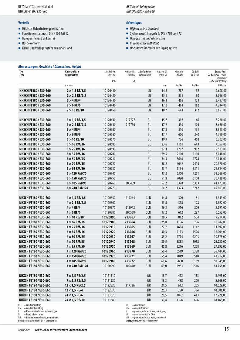
BETAflam® SicherheitskabelNHXH FE180 / E90
BETAflam® Safety cablesNHXH FE180 / E90
Typ Type
KabelaufbauConstruction
Artikel-Nr. Part no.
LSG
Artikel-Nr.Part no.
LSA
Aderfunktion Core function
Aussen- Outer
GewichtWeight
Cu-ZahlCu factor
Brutto-Preis Cu-Basis 0 /100 kg
Gross price Cu basis 0/100 kg
n × mm² mm kg / km kg / km EUR / km
NHXH-J FE180 / E90 3 × 1,5 RE 10140630 225482 LNPE 13,7 219 43 4.981,00NHXH-J FE180 / E90 3 × 2,5 RE 10140640 225490 LNPE 14,5 261 72 5.834,00NHXH-J FE180 / E90 3 × 4 RE 10140650 225495 LNPE 15,6 322 115 6.718,00NHXH-J FE180 / E90 3 × 6 RE 10140660 225499 LNPE 16,7 395 173 7.458,00NHXH-J FE180 / E90 3 × 10 RE 10140670 225502 LNPE 18,4 536 288 9.680,00NHXH-J FE180 / E90 3 × 16 RM 10140680 225505 LNPE 21,5 803 461 14.759,00NHXH-J FE180 / E90 3 × 25 RM 10140690 225508 LNPE 24,9 1140 720 20.042,00NHXH-J FE180 / E90 3 × 35 RM 10140700 225541 LNPE 27,3 1447 1008 22.117,00NHXH-J FE180 / E90 3 × 50 RM 10140710 302156 LNPE 30,9 2020 1440 27.263,00NHXH-J FE180 / E90 3 × 70 RM 10140720 302157 LNPE 34,8 2693 2016 34.395,00NHXH-J FE180 / E90 3 × 95 RM 10140730 302158 LNPE 39,9 3623 2736 42.792,00NHXH-J FE180 / E90 3 × 120 RM 10140740 LNPE 43,8 4521 3456 48.694,00NHXH-J FE180 / E90 3 × 150 RM 10140750 LNPE 48,5 5525 4320 57.551,00NHXH-J FE180 / E90 3 × 185 RM 10140760 LNPE 53,4 6799 5328 66.838,00NHXH-J FE180 / E90 3 × 240 RM 10140770 LNPE 59,9 8137 6912 86.350,00
NHXH-J FE180 / E90 3 × 35 + 1 × 16 RM 10140802 300741 3LPE 30,0 2025 1162 26.756,00NHXH-J FE180 / E90 3 × 50 + 1 × 25 RM 10140804 300742 3LPE 34,0 2726 1680 30.586,00NHXH-J FE180 / E90 3 × 70 + 1 × 35 RM 10140806 300743 3LPE 37,2 3200 2352 35.569,00NHXH-J FE180 / E90 3 × 95 + 1 × 50 RM 10140808 3LPE 44,0 4831 3216 45.989,00NHXH-J FE180 / E90 3 × 120 + 1 × 70 RM 10140810 3LPE 47,0 5903 4128 53.775,00NHXH-J FE180 / E90 3 × 150 + 1 × 70 RM 10140812 3LPE 51,0 7064 4992 65.294,00NHXH-J FE180 / E90 3 × 185 + 1 × 95 RM 10140814 3LPE 57,0 8600 6240 77.377,00NHXH-J FE180 / E90 3 × 240 + 1 × 120 RM 10140816 225552 3LPE 67,4 10266 8064 99.123,00NHXH-J FE180 / E90 3 × 300 + 1 × 150 RM 10140818 3LPE 77,0 13545 10080 121.424,00
NHXH-J FE180 / E90 4 × 1,5 RE 10140850 225485 3LPE 14,8 269 58 6.171,00NHXH-J FE180 / E90 4 × 2,5 RE 10140860 225491 3LPE 15,8 326 96 6.943,00NHXH-J FE180 / E90 4 × 4 RE 10140870 225496 3LPE 17,0 406 154 7.741,00NHXH-J FE180 / E90 4 × 6 RE 10140880 225500 3LPE 18,2 502 230 9.300,00NHXH-J FE180 / E90 4 × 10 RE 10140890 225503 3LPE 20,0 690 384 11.821,00NHXH-J FE180 / E90 4 × 16 RM 10140900 225506 3LPE 23,6 1044 614 18.544,00NHXH-J FE180 / E90 4 × 25 RM 10140910 225509 3LPE 27,4 1536 960 24.794,00NHXH-J FE180 / E90 4 × 35 RM 10140920 225511 3LPE 30,4 1966 1344 29.043,00NHXH-J FE180 / E90 4 × 50 RM 10140930 225514 3LPE 34,2 2589 1920 32.539,00NHXH-J FE180 / E90 4 × 70 RM 10140940 225517 3LPE 38,6 3512 2688 39.011,00NHXH-J FE180 / E90 4 × 95 RM 10140950 225519 3LPE 44,6 4684 3648 51.634,00NHXH-J FE180 / E90 4 × 120 RM 10140960 225548 3LPE 48,9 5734 4608 61.975,00NHXH-J FE180 / E90 4 × 150 RM 10140970 225549 3LPE 53,6 6974 5760 72.696,00NHXH-J FE180 / E90 4 × 185 RM 10140980 302159 3LPE 59,4 8986 7104 93.584,00NHXH-J FE180 / E90 4 × 240 RM 10140990 302102 3LPE 67,6 11385 9216 116.835,00
NHXH-J FE180 / E90 5 × 1,5 RE 10141070 225486 3LNPE 16,2 327 72 7.031,00NHXH-J FE180 / E90 5 × 2,5 RE 10141080 225492 3LNPE 17,2 396 120 8.434,00NHXH-J FE180 / E90 5 × 4 RE 10141090 225497 3LNPE 18,5 496 192 9.760,00NHXH-J FE180 / E90 5 × 6 RE 10141100 225501 3LNPE 20,1 621 288 11.762,00NHXH-J FE180 / E90 5 × 10 RE 10141110 225504 3LNPE 22,0 850 480 13.975,00NHXH-J FE180 / E90 5 × 16 RM 10141120 225507 3LNPE 26,0 1300 768 22.095,00NHXH-J FE180 / E90 5 × 25 RM 10141130 225510 3LNPE 30,6 1870 1200 30.437,00NHXH-J FE180 / E90 5 × 35 RM 10141140 225512 3LNPE 33,5 2394 1680 35.044,00NHXH-J FE180 / E90 5 × 50 RM 10141150 225543 3LNPE 38,4 3164 2400 38.221,00NHXH-J FE180 / E90 5 × 70 RM 10141160 3LNPE 43,2 4273 3360 47.246,00NHXH-J FE180 / E90 5 × 95 RM 10141170 3LNPE 50,0 6184 4560 57.865,00
18 www.leoni-infrastructure-datacom.com August 2009
BETAflam® SicherheitskabelNHXH FE180 / E90
BETAflam® Safety cablesNHXH FE180 / E90

-J = mit grün-gelber Ader -O = ohne grün-gelbe Ader RE = rund eindrähtig RM = rund mehrdrähtig L = Phasenleiter braun, schwarz, grauN = Neutralleiter blauNR = Phasenleiter schwarz, nummeriertPE = Schutzleiter grün-gelb
Fett gedruckte Artikel-Nr. = Lagerartikel Weitere Ausführungen auf Anfrage.
-J = with green-yellow conductor -O = without green-yellow conductor RE = round solid RM = round stranded L = phase conductor brown, black, greyN = neutral conductor blueNR = phase conductors black, numberedPE = earth conductor green-yellow Bold printed part no. = stock item Further designs upon request.
Typ Type
KabelaufbauConstruction
Artikel-Nr. Part no.
LSG
Artikel-Nr.Part no.
LSA
Aderfunktion Core function
Aussen- Outer
GewichtWeight
Cu-ZahlCu factor
Brutto-Preis Cu-Basis 0 /100 kg
Gross price Cu basis 0/100 kg
n × mm² mm kg / km kg / km EUR / km
NHXH-J FE180 / E90 7 × 1,5 RE 10141510 225487 NRPE 17,3 398 101 9.852,00NHXH-J FE180 / E90 7 × 2,5 RE 10141520 225493 NRPE 18,5 489 168 12.152,00NHXH-J FE180 / E90 7 × 4 RE 10141530 225498 NRPE 20,0 623 269 13.881,00NHXH-J FE180 / E90 10 × 1,5 RE 10142170 NRPE 22,5 664 144 15.415,00NHXH-J FE180 / E90 10 × 2,5 RE 10142180 NRPE 24,1 798 240 17.795,00NHXH-J FE180 / E90 12 × 1,5 RE 10142520 225489 NRPE 22,5 629 173 16.303,00NHXH-J FE180 / E90 12 × 2,5 RE 10142530 225494 NRPE 24,1 781 288 19.914,00NHXH-J FE180 / E90 24 × 1,5 RE 10143870 225535 NRPE 30,6 1261 346 30.136,00NHXH-J FE180 / E90 24 × 2,5 RE 10143880 NRPE 33,2 1576 576 39.133,00NHXH-J FE180 / E90 30 × 1,5 RE 10144410 NRPE 32,6 1398 432 42.951,00
19August 2009 www.leoni-infrastructure-datacom.com
BETAflam® SicherheitskabelNHXH FE180 / E90
BETAflam® Safety cablesNHXH FE180 / E90

BETAflam® SicherheitskabelNHXCH FE180 / E90 0,6 / 1 kV, nach DIN VDE 0266, orange
BETAflam® Safety cablesNHXCH FE180 / E90 0,6 / 1 kV, acc. to DIN VDE 0266, orange
AnwendungStarkstromkabel 0,6 / 1 kV mit konzentrischem Aussenleiter für ortsfeste Verlegung in elektrischen Kabelanlagen mit verbessertem Verhalten im Brandfall und Funkti-onserhalt nach DIN 4102 Teil 12, z.B. für Druckerhöhungsanlagen zur Löschwasser-versorgung, Rauchabzugsanlagen usw. Empfohlen in Gebäuden mit Menschen- ansammlungen und zum Schutz von Sachwerten.
Aufbau Leiter: Kupfer blank Bandierung: MICA-Band Aderisolation: BETAflam® vernetzt Konzentrischer Aussenleiter: Kupferdrähte mit Haltewendel Gemeinsame Aderumhüllung: Band oder Füller Mantel: BETAflam® Copolymer Aderfarben: Nach VDE 0266 bzw. HD 308 S2 Mantelfarbe: Orange
Technische Daten Nennspannung: U0/U 0,6/ 1 kV Prüfspannung: 4 kV mit 50 Hz Zulässige Temperaturen:
Betriebstemperatur von – 30 °C bis + 90 °C Verlegetemperatur von – 5 °C bis + 70 °C Kurzschlusstemperatur + 250 °C (Temperaturspitze < 5 s)
Biegeradien: Einleiter Mehrleiter bei Verlegung > 15 × Aussen- > 12 × Aussen- fest verlegt > 8 × Aussen- > 7 × Aussen-
Verlegebedingungen: Ortsfest in Innenräumen, in Luft oder Beton. Verlegung in Erde oder Wasser nur in Rohren, in denen sich kein Wasser sammeln kann. Verlegung im Freien nur geschützt vor direkter Sonneneinstrahlung und Fremd-einflüssen.
Normen / Materialeigenschaften Halogenfrei: IEC 60754-1, EN 50267-2-1, VDE 0482-267-2-1 Keine korrosiven Gase: IEC 60754-2, EN 50267-2-2, VDE 0482-267-2-2 Keine toxischen Gase: NES 02-713, NF C20-454 Geringe Rauchdichte: IEC 61034-1 und -2, EN 61034-1 und -2,
VDE 0482-1034-1 und -2 Flammwidrig: IEC 60332-1, EN 60332-1, VDE 0482-332-1 Keine Brandfortleitung: IEC 60332-3-10 und -3-24, EN 60332-3-10, -24,
VDE 0482-266-1, -2-4 Isolationserhalt FE180: IEC 60331-11 und -21, VDE 0472-814 Isolationserhalt mit Schlag: EN 50200 PH90 (bis 20 mm) Funktionserhalt: DIN 4102-12 E90, abhängig vom Verlegesystem Wasserlöschanlagen: VdS ≥ 2,5 mm²
ApplicationPower cable 0,6 / 1 kV with concentric conductor for fixed installation in cable systems with improved fire performance and system circuit integrity to DIN 4102 part 12 for water pumps for fire fighting, smoke exhaust systems etc. Recommended in areas where people gather and for protection of valuables.
Construction Conductors: Bare annealed copper Flame barrier: MICA tape Insulation: BETAflam® crosslinked Concentric conductor: Copper wires, with helix of copper tape Inner covering: Tape or filler Sheath: BETAflam® copolymer Core identification: According to VDE 0266 resp. HD 308 S2 Sheath colour: Orange
Technical data Rated voltage: U0/U 0,6 / 1 kV Test voltage: 4 kV with 50 Hz Temperature range:
Operation temperature from – 30 °C to + 90 °C Laying temperature from – 5 °C to + 70 °C Short circuit temperature + 250 °C (temperature peak < 5 s)
Bending radius: Single core Multiple core during laying > 15 × outer > 12 × outer fixed > 8 × outer > 7 × outer
Laying conditions: Fixed installation indoor, in air or concrete. Laying in earth or water only in water-proof dry tubes. Outdoor laying only when protected from direct sunlight and other external impacts.
Standards / Material Properties Halogen free: IEC 60754-1, EN 50267-2-1, VDE 0482-267-2-1 No corrosive gases: IEC 60754-2, EN 50267-2-2, VDE 0482-267-2-2 No toxic gases: NES 02-713, NF C20-454 Low smoke density: IEC 61034-1 and -2, EN 61034-1 and -2,
VDE 0482-1034-1 and -2 Flame retardant: IEC 60332-1, EN 60332-1, VDE 0482-332-1 No flame propagation: IEC 60332-3-10 and -3-24, EN 60332-3-10, -24,
VDE 0482-266-1, -2-4 Circuit integrity FE180: IEC 60331-11 and -21, VDE 0472-814 Circuit integrity with shock: EN 50200 PH90 (up to 20 mm) System circuit integrity: DIN 4102-12 E90, depending on laying system Water extinguishing systems: VdS ≥ 2,5 mm²
20 www.leoni-infrastructure-datacom.com August 2009
BETAflam®

Vorteile
Höchste Sicherheitseigenschaften Funktionserhalt nach DIN 4102 Teil 12 Halogenfrei und silikonfrei RoHS-konform Kabel und Verlegesystem aus einer Hand
Advantages
Highest safety standards System circuit integrity to DIN 4102 part 12 Halogen free and silicone free In compliance with RoHS directive One source for cables and laying system
Abmessungen, Gewichte / Dimensions, WeightTyp Type
KabelaufbauConstruction
Artikel-Nr. Part no.
LSG
Artikel-Nr.Part no.
LSA
Aderfunktion Core function
Aussen- Outer
GewichtWeight
Cu-ZahlCu factor
Brutto-Preis Cu-Basis 0 /100 kg
Gross price Cu basis 0/100 kg
n × mm² mm kg / km kg / km EUR / km
NHXCH FE180 / E90 2 × 1,5 RE/1,5 10160410 LN 15,8 337 52 5.811,00NHXCH FE180 / E90 2 × 2,5 RE/2,5 10160420 LN 17,2 414 80 6.321,00NHXCH FE180 / E90 2 × 4 RE/4 10160430 LN 17,9 451 123 7.056,00NHXCH FE180 / E90 2 × 6 RE/6 10160440 LN 18,6 539 182 9.034,00NHXCH FE180 / E90 2 × 10 RE/10 10160450 LN 20,4 679 312 10.007,00NHXCH FE180 / E90 3 × 1,5 RE/1,5 10160630 303222 3L 17,3 394 66 6.721,00NHXCH FE180 / E90 3 × 2,5 RE/2,5 10160640 3L 17,4 423 104 7.093,00NHXCH FE180 / E90 3 × 4 RE/4 10160650 3L 18,7 511 161 8.516,00NHXCH FE180 / E90 3 × 6 RE/6 10160660 3L 19,7 601 240 9.741,00NHXCH FE180 / E90 3 × 10 RE/10 10160670 225559 3L 21,5 792 408 12.200,00NHXCH FE180 / E90 3 × 16 RM/16 10160680 303337 3L 24,9 1078 643 14.321,00NHXCH FE180 / E90 3 × 25 RM/16 10160692 303338 3L 28,3 1484 902 20.978,00NHXCH FE180 / E90 3 × 35 RM/16 10160702 3L 30,9 1753 1190 24.689,00NHXCH FE180 / E90 3 × 50 RM/25 10160712 3L 35,4 2358 1728 29.103,00NHXCH FE180 / E90 3 × 70 RM/35 10160722 3L 38,5 3161 2415 35.908,00NHXCH FE180 / E90 3 × 95 RM/50 10160732 3L 44,3 4215 3311 47.271,00NHXCH FE180 / E90 3 × 120 RM/70 10160742 3L 48,2 5323 4261 58.267,00NHXCH FE180 / E90 3 × 150 RM/70 10160750 303239 3L 52,9 6286 5100 69.714,00NHXCH FE180 / E90 3 × 185 RM/95 10160760 3L 58,4 7636 6383 85.661,00NHXCH FE180 / E90 3 × 240 RM/120 10160770 3L 65,3 9714 8242 109.965,00NHXCH FE180 / E90 4 × 1,5 RE/1,5 10160850 225554 3LN 15,9 332 81 9.279,00NHXCH FE180 / E90 4 × 2,5 RE/2,5 10160860 225556 3LN 18,6 481 128 10.101,00NHXCH FE180 / E90 4 × 4 RE/4 10160870 225557 3LN 20,1 601 200 11.330,00NHXCH FE180 / E90 4 × 6 RE/6 10160880 225558 3LN 21,3 841 297 12.797,00NHXCH FE180 / E90 4 × 10 RE/10 10160890 225524 3LN 21,5 879 504 15.027,00NHXCH FE180 / E90 4 × 16 RM/16 10160900 225525 3LN 25,2 1262 796 19.843,00NHXCH FE180 / E90 4 × 25 RM/16 10160910 225526 3LN 29,0 1786 1142 25.210,00NHXCH FE180 / E90 4 × 35 RM/16 10160920 225527 3LN 31,9 2375 1526 28.521,00NHXCH FE180 / E90 4 × 50 RM/25 10160930 225528 3LN 36,6 3122 2203 31.995,00NHXCH FE180 / E90 4 × 70 RM/35 10160940 225529 3LN 40,6 4129 3082 40.081,00NHXCH FE180 / E90 4 × 95 RM/50 10160950 225530 3LN 47,0 5447 4208 53.697,00NHXCH FE180 / E90 4 × 120 RM/70 10160960 225531 3LN 51,9 6657 5388 66.968,00NHXCH FE180 / E90 4 × 150 RM/70 10160970 225532 3LN 56,5 8039 6540 80.074,00NHXCH FE180 / E90 4 × 185 RM/95 10160980 225533 3LN 63,6 10157 8159 101.957,00NHXCH FE180 / E90 4 × 240 RM/120 10160990 225534 3LN 70,8 12990 10546 130.709,00NHXCH FE180 / E90 7 × 1,5 RE/2,5 10161510 NR 18,3 488 133 12.621,00NHXCH FE180 / E90 7 × 2,5 RE/2,5 10161520 NR 21,3 576 200 14.363,00NHXCH FE180 / E90 12 × 1,5 RE/2,5 10162520 300676 NR 23,5 702 205 19.324,00NHXCH FE180 / E90 12 × 2,5 RE/4 10162530 NR 25,4 901 334 22.213,00NHXCH FE180 / E90 24 × 1,5 RE/6 10163870 NR 32,7 1335 413 36.717,00NHXCH FE180 / E90 24 × 2,5 RE/10 10163880 226143 NR 34,7 1655 696 42.460,00NHXCH FE180 / E90 30 × 1,5 RE/6 10164410 NR 34,8 1596 499 46.832,00NHXCH FE180 / E90 30 × 2,5 RE/10 10164420 NR 38,0 2263 840 51.087,00
RE = rund eindrähtig RM = rund mehrdrähtig L = Phasenleiter braun, schwarz, grauN = Neutralleiter blauNR = Phasenleiter schwarz, nummeriert Fett gedruckte Artikel-Nr. = Lagerartikel
RE = round solid RM = round stranded L = phase conductor brown, black, greyN = neutral conductor blueNR = phase conductors black, numberedBold printed part no. = stock item
21August 2009 www.leoni-infrastructure-datacom.com
BETAflam® SicherheitskabelNHXCH FE180 / E90
BETAflam® Safety cablesNHXCH FE180 / E90
BETAflam® Signalkabel und Brandmeldekabel BMKJE-H(St)H FE180 / E30 nach DIN VDE 0815, orange oder rot (BMK)
BETAflam® Signal cables and fire alarm cables BMKJE-H(St)H FE180 / E30 acc. to DIN VDE 0815, orange or red (BMK)
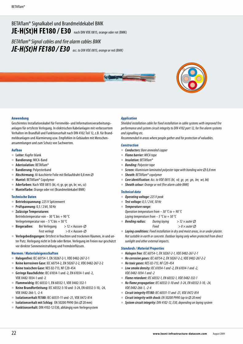
AnwendungGeschirmtes Installationskabel für Fernmelde- und Informationsverarbeitungs- anlagen für ortsfeste Verlegung. In elektrischen Kabelanlagen mit verbessertem Verhalten im Brandfall und Funktionserhalt nach DIN 4102 Teil 12, z.B. für Brand-meldeanlagen und Alarmierung usw. Empfohlen in Gebäuden mit Menschen- ansammlungen und zum Schutz von Sachwerten.
Aufbau Leiter: Kupfer blank Bandierung: MICA-Band Aderisolation: BETAflam® Bandierung: Polyesterband Abschirmung: Al-kaschierte Folie mit Beilaufdraht 0,8 mm Mantel: BETAflam® Copolymer Aderfarben: Nach VDE 0815 (bl, rt; gr, ge; gn, br; ws, sz) Mantelfarbe: Orange oder rot (Brandmeldekabel BMK)
Technische Daten Betriebsspannung: 225 V Spitzenwert Prüfspannung: 0,5 / 2 kV, 50 Hz Zulässige Temperaturen:
Betriebstemperatur von – 30 °C bis + 90 °C Verlegetemperatur von – 5 °C bis + 50 °C
Biegeradien: Bei Verlegung > 12 × Aussen- Fest verlegt > 8 × Aussen-
Verlegebedingungen: Ortsfest in feuchten und trockenen Räumen, in und un-ter Putz. Verlegung nicht in Erde oder Beton. Verlegung im Freien nur geschützt vor direkter Sonneneinstrahlung und Fremdeinflüssen.
Normen / Materialeigenschaften Halogenfrei: IEC 60754-1, EN 50267-2-1, VDE 0482-267-2-1 Keine korrosiven Gase: IEC 60754-2, EN 50267-2-2, VDE 0482-267-2-2 Keine toxischen Gase: NES 02-713, NF C20-454 Geringe Rauchdichte: IEC 61034-1 und -2, EN 61034-1 und -2,
VDE 0482-1034-1 und -2 Flammwidrig: IEC 60332-1, EN 60332-1, VDE 0482-332-1 Keine Brandfortleitung: IEC 60332-3-10 und -3-24, EN 60332-3-10, -24,
VDE 0482-266-1, -2-4 Isolationserhalt FE180: IEC 60331-11 und -21, VDE 0472-814 Isolationserhalt mit Schlag: EN 50200 PH90 (bis 20 mm) Funktionserhalt: DIN 4102-12 E30, abhängig vom Verlegesystem
ApplicationShielded installation cable for fixed installation in cable systems with improved fire performance and system circuit integrity to DIN 4102 part 12, for fire alarm systems and signalling etc. Recommended in areas where people gather and for protection of valuables.
Construction Conductors: Bare annealed copper Flame barrier: MICA tape Insulation: BETAflam® Banding: Polyester tape Screen: Aluminium laminated polyester tape with bonding wire 0,8 mm Sheath: BETAflam® copolymer Core identification: Acc. to VDE 0815 (bl, rd; gr, ye; gn, bn; wt, bk) Sheath colour: Orange or red (fire alarm cable BMK)
Technical data Operating voltage: 225 V peak Test voltage: 0,5 / 2 kV, 50 Hz Temperature range:
Operation temperature from – 30 °C to + 90 °C Laying temperature from – 5 °C to + 50 °C
Bending radius: During laying > 12 × outer Fixed > 8 × outer Laying conditions: Fixed installation in dry and moist areas, in or under plaster.
Not suitable in earth or concrete. Outdoor laying only when protected from direct sunlight and other external impacts.
Standards / Material Properties Halogen free: IEC 60754-1, EN 50267-2-1, VDE 0482-267-2-1 No corrosive gases: IEC 60754-2, EN 50267-2-2, VDE 0482-267-2-2 No toxic gases: NES 02-713, NF C20-454 Low smoke density: IEC 61034-1 and -2, EN 61034-1 and -2,
VDE 0482-1034-1 and -2 Flame retardant: IEC 60332-1, EN 60332-1, VDE 0482-332-1 No flame propagation: IEC 60332-3-10 and -3-24, EN 60332-3-10, -24,
VDE 0482-266-1, -2-4 Circuit integrity FE180: IEC 60331-11 and -21, VDE 0472-814 Circuit integrity with shock: EN 50200 PH90 (up to 20 mm) System circuit integrity: DIN 4102-12, E30, depending on laying system
22 www.leoni-infrastructure-datacom.com August 2009
BETAflam®

Vorteile
Höchste Sicherheitseigenschaften Funktionserhalt nach DIN 4102 Teil 12 Halogenfrei und silikonfrei RoHS-konform Kabel und Verlegesystem aus einer Hand
Advantages
Highest safety standards System circuit integrity to DIN 4102 part 12 Halogen free and silicone free In compliance with RoHS directive One source for cables and laying system
* in einer Länge 1 × 500 m
Fett gedruckte Artikel-Nr. = Lagerartikel Weitere Ausführungen auf Anfrage.
* in one length 1 × 500 m Bold printed part no. = stock item Further designs upon request.
Abmessungen, Gewichte / Dimensions, WeightTyp Type
KabelaufbauConstruction
Artikel-Nr. Part no.
LSG
Artikel-Nr.Part no.
LSA
Aussen- Outer
GewichtWeight
Cu-ZahlCu factor
Brutto-Preis Cu-Basis 100 /100 kg
Gross price Cu basis 100/100 kg
n × 2 × mm mm kg / km kg / km EUR / km
JE-H(St)H FE180 / E30 orange 1 × 2 × 0,8 10180389 221829 6,2 50 15 1.505,00JE-H(St)H FE180 / E30 orange 2 × 2 × 0,8 10180390 216772 8,0 78 25 1.925,00JE-H(St)H FE180 / E30 orange 2 × 2 × 0,8 *10180395 *21677205 8,0 78 25 1.988,00JE-H(St)H FE180 / E30 orange 4 × 2 × 0,8 10180830 218365 11,2 135 45 3.549,00JE-H(St)H FE180 / E30 orange 8 × 2 × 0,8 10181710 224115 16,4 258 85 6.884,00JE-H(St)H FE180 / E30 orange 12 × 2 × 0,8 10182500 224116 18,3 337 126 9.532,00JE-H(St)H FE180 / E30 orange 16 × 2 × 0,8 10182980 22,1 480 166 12.331,00JE-H(St)H FE180 / E30 orange 20 × 2 × 0,8 10183460 224117 22,6 532 206 14.741,00
JE-H(St)H FE180 / E30 BMK rot 1 × 2 × 0,8 10220385 220380 6,2 50 15 1.555,00JE-H(St)H FE180 / E30 BMK rot 2 × 2 × 0,8 10220390 216771 8,0 78 25 1.961,00JE-H(St)H FE180 / E30 BMK rot 2 × 2 × 0,8 *10220395 *21677105 8,0 78 25 2.024,00JE-H(St)H FE180 / E30 BMK rot 4 × 2 × 0,8 10220830 218366 11,2 135 45 3.583,00JE-H(St)H FE180 / E30 BMK rot 8 × 2 × 0,8 10221710 224112 16,4 258 85 7.017,00JE-H(St)H FE180 / E30 BMK rot 12 × 2 × 0,8 10222500 224113 18,3 337 126 9.720,00JE-H(St)H FE180 / E30 BMK rot 16 × 2 × 0,8 10222980 300138 22,1 480 166 12.570,00JE-H(St)H FE180 / E30 BMK rot 20 × 2 × 0,8 10223460 224114 22,6 532 206 15.029,00
JE-H(St)H FE180 / E30 BMK rot 1 × 2 × 1,0 mm² 10220382 225981 8,1 78 24 1.884,00JE-H(St)H FE180 / E30 BMK rot 1 × 2 × 1,5 mm² 10220384 220570 9,0 95 34 2.066,00JE-H(St)H FE180 / E30 BMK rot 1 × 2 × 2,5 mm² 10220383 221703 9,7 151 53 2.306,00JE-H(St)H FE180 / E30 BMK rot 2 × 2 × 1,5 mm² 10220386 221907 10,4 145 62 2.794,00
23August 2009 www.leoni-infrastructure-datacom.com
BETAflam® Signal- und Brandmeldekabel JE-H(St)H FE180 / E30
BETAflam® Signal and fire alarm cable JE-H(St)H FE180 / E30
BETAflam® Signalkabel und Brandmeldekabel BMKJE-H (St) H FE180 / E30-E90 nach DIN VDE 0815, orange oder rot (BMK)
BETAflam® Signal cables and fire alarm cables BMKJE-H (St) H FE180 / E30-E90 acc. to DIN VDE 0815, orange or red (BMK)
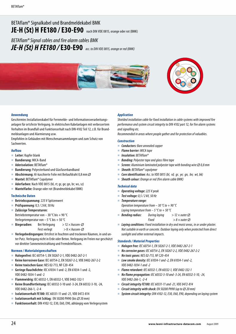
AnwendungGeschirmtes Installationskabel für Fernmelde- und Informationsverarbeitungs- anlagen für ortsfeste Verlegung. In elektrischen Kabelanlagen mit verbessertem Verhalten im Brandfall und Funktionserhalt nach DIN 4102 Teil 12, z.B. für Brand-meldeanlagen und Alarmierung usw. Empfohlen in Gebäuden mit Menschenansammlungen und zum Schutz von Sachwerten.
Aufbau Leiter: Kupfer blank Bandierung: MICA-Band Aderisolation: BETAflam® Bandierung: Polyesterband und Glasfaserbandband Abschirmung: Al-kaschierte Folie mit Beilaufdraht 0,8 mm Mantel: BETAflam® Copolymer Aderfarben: Nach VDE 0815 (bl, rt; gr, ge; gn, br; ws, sz) Mantelfarbe: Orange oder rot (Brandmeldekabel BMK)
Technische Daten Betriebsspannung: 225 V Spitzenwert Prüfspannung: 0,5 / 2 kV, 50 Hz Zulässige Temperaturen:
Betriebstemperatur von – 30 °C bis + 90 °C Verlegetemperatur von – 5 °C bis + 50 °C
Biegeradien: Bei Verlegung > 12 × Aussen- Fest verlegt > 8 × Aussen-
Verlegebedingungen: Ortsfest in feuchten und trockenen Räumen, in und un-ter Putz. Verlegung nicht in Erde oder Beton. Verlegung im Freien nur geschützt vor direkter Sonneneinstrahlung und Fremdeinflüssen.
Normen / Materialeigenschaften Halogenfrei: IEC 60754-1, EN 50267-2-1, VDE 0482-267-2-1 Keine korrosiven Gase: IEC 60754-2, EN 50267-2-2, VDE 0482-267-2-2 Keine toxischen Gase: NES 02-713, NF C20-454 Geringe Rauchdichte: IEC 61034-1 und -2, EN 61034-1 und -2,
VDE 0482-1034-1 und -2 Flammwidrig: IEC 60332-1, EN 60332-1, VDE 0482-332-1 Keine Brandfortleitung: IEC 60332-3-10 und -3-24, EN 60332-3-10, -24,
VDE 0482-266-1, -2-4 Isolationserhalt FE180: IEC 60331-11 und -21, VDE 0472-814 Isolationserhalt mit Schlag: EN 50200 PH90 (bis 20 mm) Funktionserhalt: DIN 4102-12, E30, E60, E90, abhängig vom Verlegesystem
ApplicationShielded installation cable for fixed installation in cable systems with improved fire performance and system circuit integrity to DIN 4102 part 12, for fire alarm systems and signalling etc. Recommended in areas where people gather and for protection of valuables.
Construction Conductors: Bare annealed copper Flame barrier: MICA tape Insulation: BETAflam® Banding: Polyester tape and glass fibre tape Screen: Aluminium laminated polyester tape with bonding wire 0,8 mm Sheath: BETAflam® copolymer Core identification: Acc. to VDE 0815 (bl, rd; gr, ye; gn, bn; wt, bk) Sheath colour: Orange or red (fire alarm cable BMK)
Technical data Operating voltage: 225 V peak Test voltage: 0,5 / 2 kV, 50 Hz Temperature range:
Operation temperature from – 30 °C to + 90 °C Laying temperature from – 5 °C to + 50 °C
Bending radius: During laying > 12 × outer Fixed > 8 × outer Laying conditions: Fixed installation in dry and moist areas, in or under plaster.
Not suitable in earth or concrete. Outdoor laying only when protected from direct sunlight and other external impacts.
Standards / Material Properties Halogen free: IEC 60754-1, EN 50267-2-1, VDE 0482-267-2-1 No corrosive gases: IEC 60754-2, EN 50267-2-2, VDE 0482-267-2-2 No toxic gases: NES 02-713, NF C20-454 Low smoke density: IEC 61034-1 and -2, EN 61034-1 and -2,
VDE 0482-1034-1 and -2 Flame retardant: IEC 60332-1, EN 60332-1, VDE 0482-332-1 No flame propagation: IEC 60332-3-10 and -3-24, EN 60332-3-10, -24,
VDE 0482-266-1, -2-4 Circuit integrity FE180: IEC 60331-11 and -21, VDE 0472-814 Circuit integrity with shock: EN 50200 PH90 (up to 20 mm) System circuit integrity: DIN 4102-12, E30, E60, E90, depending on laying system
24 www.leoni-infrastructure-datacom.com August 2009
BETAflam®

Abmessungen, Gewichte / Dimensions, WeightTyp Type
KabelaufbauConstruction
Artikel-Nr. Part no.
LSG
Artikel-Nr.Part no.
LSA
Aussen- Outer
GewichtWeight
Cu-ZahlCu factor
Brutto-Preis Cu-Basis 100 /100 kg
Gross price Cu basis 100/100 kg
n × 2 × mm mm kg / km kg / km EUR / km
JE-H(St)H FE180 / E30-E90 orange 1 × 2 × 0,8 10200380 190552 7,6 65 15 2.030,00JE-H(St)H FE180 / E30-E90 orange 2 × 2 × 0,8 10200390 190245 8,5 88 25 2.711,00JE-H(St)H FE180 / E30-E90 orange 2 × 2 × 0,8 *10200395 *19024505 8,5 88 25 2.774,00JE-H(St)H FE180 / E30-E90 orange 4 × 2 × 0,8 10200830 190517 12,1 147 45 4.858,00JE-H(St)H FE180 / E30-E90 orange 8 × 2 × 0,8 10201710 190987 17,6 280 85 8.347,00JE-H(St)H FE180 / E30-E90 orange 12 × 2 × 0,8 10202500 191019 19,8 365 126 11.559,00JE-H(St)H FE180 / E30-E90 orange 16 × 2 × 0,8 10202980 23,3 480 166 14.951,00JE-H(St)H FE180 / E30-E90 orange 20 × 2 × 0,8 10203460 190988 24,5 590 206 17.874,00JE-H(St)H FE180 / E30-E90 orange 32 × 2 × 0,8 10204540 191271 35,9 1116 327 32.104,00JE-H(St)H FE180 / E30-E90 orange 40 × 2 × 0,8 10205020 37,7 1230 407 38.659,00JE-H(St)H FE180 / E30-E90 orange 52 × 2 × 0,8 10205740 211492 40,7 1441 529 48.483,00JE-H(St)H FE180 / E30-E90 orange 80 × 2 × 0,8 10207500 46,4 1850 810 59.727,00JE-H(St)H FE180 / E30-E90 orange 100 × 2 × 0,8 10208620 52,6 2235 1030 64.036,00
JE-H(St)H FE180 / E30-E90 BMK rot 1 × 2 × 0,8 10200375 190674 7,6 65 15 2.063,00JE-H(St)H FE180 / E30-E90 BMK rot 2 × 2 × 0,8 10240390 190093 8,5 88 25 2.762,00JE-H(St)H FE180 / E30-E90 BMK rot 2 × 2 × 0,8 *10240395 *19009305 8,5 88 25 2.825,00JE-H(St)H FE180 / E30-E90 BMK rot 4 × 2 × 0,8 10240830 190094 12,1 147 45 4.903,00JE-H(St)H FE180 / E30-E90 BMK rot 8 × 2 × 0,8 10241710 190270 17,6 280 85 8.509,00JE-H(St)H FE180 / E30-E90 BMK rot 12 × 2 × 0,8 10242500 190670 19,8 365 126 11.785,00JE-H(St)H FE180 / E30-E90 BMK rot 16 × 2 × 0,8 10242980 23,3 480 166 15.240,00JE-H(St)H FE180 / E30-E90 BMK rot 20 × 2 × 0,8 10243460 190669 24,5 590 206 18.224,00JE-H(St)H FE180 / E30-E90 BMK rot 32 × 2 × 0,8 10244540 211487 35,9 1116 327 32.732,00JE-H(St)H FE180 / E30-E90 BMK rot 40 × 2 × 0,8 10245020 37,7 1230 407 39.412,00JE-H(St)H FE180 / E30-E90 BMK rot 52 × 2 × 0,8 10245740 211244 40,7 1441 529 49.425,00JE-H(St)H FE180 / E30-E90 BMK rot 80 × 2 × 0,8 46,4 1850 810 62.374,00JE-H(St)H FE180 / E30-E90 BMK rot 100 × 2 × 0,8 10248620 52,6 2235 1030 64.686,00
Vorteile
Höchste Sicherheitseigenschaften Funktionserhalt nach DIN 4102 Teil 12 Halogenfrei und silikonfrei RoHS-konform Kabel und Verlegesystem aus einer Hand
Advantages
Highest safety standards System circuit integrity to DIN 4102 part 12 Halogen free and silicone free In compliance with RoHS directive One source for cables and laying system
Aderfarben nach VDE 0815: blau, rot; grau, gelb; grün, braun; weiss, schwarz
* in einer Länge 1 × 500 m
Fett gedruckte Artikel-Nr. = Lagerartikel Weitere Ausführungen auf Anfrage.
Core identification according to VDE 0815: blue, red; grey, yellow; green, brown; white, black
* in one length 1 × 500 m Bold printed part no. = stock item Further designs upon request.
25August 2009 www.leoni-infrastructure-datacom.com
BETAflam® Signalkabel und Brandmeldekabel JE-H (St) H FE180 / E30-E90
BETAflam® Signal cables and fire alarm cables JE-H (St) H FE180 / E30-E90
BETAflam® Brandmeldekabel BMKJE-H(St)HRH FE180 / E30-E90 nach DIN VDE 0815, rot (BMK)
BETAflam® Fire alarm cables BMKJE-H(St)HRH FE180 / E30-E90 acc. to DIN VDE 0815, red (BMK)
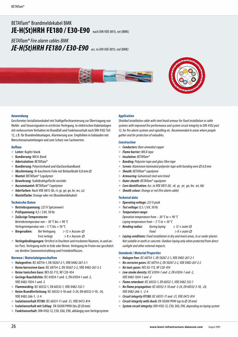
AnwendungGeschirmtes Installationskabel mit Stahlgeflechtarmierung zur Übertragung von Melde- und Steuersignalen in ortsfester Verlegung. In elektrischen Kabelanlagen mit verbessertem Verhalten im Brandfall und Funktionserhalt nach DIN 4102 Teil 12, z.B. für Brandmeldeanlagen, Alarmierung usw. Empfohlen in Gebäuden mit Menschenansammlungen und zum Schutz von Sachwerten.
Aufbau Leiter: Kupfer blank Bandierung: MICA-Band Aderisolation: BETAflam® Bandierung: Polyesterband und Glasfaserbandband Abschirmung: Al-kaschierte Folie mit Beilaufdraht 0,8 mm Mantel: BETAflam® Copolymer Bewehrung: Stahldrahtgeflecht verzinkt Aussenmantel: BETAflam® Copolymer Aderfarben: Nach VDE 0815 (bl, rt; gr, ge; gn, br; ws, sz) Mantelfarbe: Orange oder rot (Brandmeldekabel)
Technische Daten Betriebsspannung: 225 V Spitzenwert Prüfspannung: 0,5 / 2 kV, 50 Hz Zulässige Temperaturen:
Betriebstemperatur von – 30 °C bis + 90 °C Verlegetemperatur von – 5 °C bis + 50 °C
Biegeradien: Bei Verlegung > 12 × Aussen- Fest verlegt > 8 × Aussen-
Verlegebedingungen: Ortsfest in feuchten und trockenen Räumen, in und un-ter Putz. Verlegung nicht in Erde oder Beton. Verlegung im Freien nur geschützt vor direkter Sonneneinstrahlung und Fremdeinflüssen.
Normen / Materialeigenschaften Halogenfrei: IEC 60754-1, EN 50267-2-1, VDE 0482-267-2-1 Keine korrosiven Gase: IEC 60754-2, EN 50267-2-2, VDE 0482-267-2-2 Keine toxischen Gase: NES 02-713, NF C20-454 Geringe Rauchdichte: IEC 61034-1 und -2, EN 61034-1 und -2,
VDE 0482-1034-1 und -2 Flammwidrig: IEC 60332-1, EN 60332-1, VDE 0482-332-1 Keine Brandfortleitung: IEC 60332-3-10 und -3-24, EN 60332-3-10, -24,
VDE 0482-266-1, -2-4 Isolationserhalt FE180: IEC 60331-11 und -21, VDE 0472-814 Isolationserhalt mit Schlag: EN 50200 PH90 (bis 20 mm) Funktionserhalt: DIN 4102-12, E30, E60, E90, abhängig vom Verlegesystem
ApplicationShielded installation cable with steel braid armour for fixed installation in cable systems with improved fire performance and system circuit integrity to DIN 4102 part 12, for fire alarm systems and signalling etc. Recommended in areas where people gather and for protection of valuables.
Construction Conductors: Bare annealed copper Flame barrier: MICA tape Insulation: BETAflam® Banding: Polyester tape and glass fibre tape Screen: Aluminium laminated polyester tape with bonding wire 0,8 mm Sheath: BETAflam® copolymer Armouring: Galvanised steel wire braid Outer sheath: BETAflam® copolymer Core identification: Acc. to VDE 0815 (bl, rd; gr, ye; gn, bn; wt, bk) Sheath colour: Orange or red (fire alarm cable)
Technical data Operating voltage: 225 V peak Test voltage: 0,5 / 2 kV, 50 Hz Temperature range:
Operation temperature from – 30 °C to + 90 °C Laying temperature from – 5 °C to + 50 °C
Bending radius: During laying > 12 × outer Fixed > 8 × outer Laying conditions: Fixed installation in dry and moist areas, in or under plaster.
Not suitable in earth or concrete. Outdoor laying only when protected from direct sunlight and other external impacts.
Standards / Material Properties Halogen free: IEC 60754-1, EN 50267-2-1, VDE 0482-267-2-1 No corrosive gases: IEC 60754-2, EN 50267-2-2, VDE 0482-267-2-2 No toxic gases: NES 02-713, NF C20-454 Low smoke density: IEC 61034-1 and -2, EN 61034-1 and -2,
VDE 0482-1034-1 and -2 Flame retardant: IEC 60332-1, EN 60332-1, VDE 0482-332-1 No flame propagation: IEC 60332-3-10 and -3-24, EN 60332-3-10, -24,
VDE 0482-266-1, -2-4 Circuit integrity FE180: IEC 60331-11 and -21, VDE 0472-814 Circuit integrity with shock: EN 50200 PH90 (up to 20 mm) System circuit integrity: DIN 4102-12, E30, E60, E90, depending on laying system
26 www.leoni-infrastructure-datacom.com August 2009
BETAflam®
Vorteile
Höchste Sicherheitseigenschaften Funktionserhalt nach DIN 4102 Teil 12 Halogenfrei und silikonfrei RoHS-konform Kabel und Verlegesystem aus einer Hand
Advantages
Highest safety standards System circuit integrity to DIN 4102 part 12 Halogen free and silicone free In compliance with RoHS directive One source for cables and laying system
Aderfarben nach VDE 0815: blau, rot; grau, gelb; grün, braun; weiss, schwarz
Fett gedruckte Artikel-Nr. = Lagerartikel Weitere Ausführungen z.B. Signalkabel mit orangen Aussenmantel auf Anfrage.
Core identification according to VDE 0815: blue, red; grey, yellow; green, brown; white, black
Bold printed part no. = stock item Further designs e.g. signal cables with orange outer sheath upon request.
Abmessungen, Gewichte / Dimensions, WeightTyp Type
KabelaufbauConstruction
Artikel-Nr. Part no.
LSG
Artikel-Nr.Part no.
LSA
Aussen- Outer
GewichtWeight
Cu-ZahlCu factor
Brutto-Preis Cu-Basis 100 /100 kg
Gross price Cu basis 100/100 kg
n × 2 × mm mm kg / km kg / km EUR / km
JE-H(St)HRH FE180 / E30-E90 2 × 2 × 0,8 10280390 190671 11,7 185 25 5.328,00JE-H(St)HRH FE180 / E30-E90 4 × 2 × 0,8 10280830 191735 15,7 298 45 9.831,00JE-H(St)HRH FE180 / E30-E90 8 × 2 × 0,8 10281710 210811 21,6 509 85 17.303,00JE-H(St)HRH FE180 / E30-E90 12 × 2 × 0,8 10282500 210812 23,8 620 126 23.965,00JE-H(St)HRH FE180 / E30-E90 16 × 2 × 0,8 10282980 27,7 730 166 29.145,00JE-H(St)HRH FE180 / E30-E90 20 × 2 × 0,8 10283460 210813 28,9 942 206 31.947,00JE-H(St)HRH FE180 / E30-E90 32 × 2 × 0,8 10284540 211939 41,1 1702 326 49.332,00JE-H(St)HRH FE180 / E30-E90 40 × 2 × 0,8 10285020 225700 42,3 1880 407 61.379,00JE-H(St)HRH FE180 / E30-E90 52 × 2 × 0,8 10288740 45,2 2130 529 78.838,00JE-H(St)HRH FE180 / E30-E90 80 × 2 × 0,8 10284580 52,0 2800 810 107.326,00JE-H(St)HRH FE180 / E30-E90 100 × 2 × 0,8 10288620 60,5 3000 1030 130.240,00
27August 2009 www.leoni-infrastructure-datacom.com
BETAflam® Brandmeldekabel BMKJE-H(St)HRH FE180 / E30-E90
BETAflam® Fire alarm cables BMK JE-H(St)HRH FE180 / E30-E90

BETAflam® Signal- und Brandmeldekabel BMKJ-H(St)H nach DIN VDE 0815, grau oder rot (BMK)
BETAflam® Signal and fire alarm cable BMKJ-H(St)H acc. to DIN VDE 0815, grey or red (BMK)
AnwendungHalogenfreies Installationskabel mit ver bessertem Verhalten im Brandfall für Fernsprech-, Mess- und Signalzwecke. Brandmeldekabel in Gebäuden mit hoher Personen- und/oder Sachwert- konzentration.
Aufbau Leiter: Kupfer blank Aderisolation: BETAflam® Copolymer Verseilart: Bündelverseilung Abschirmung: Aluminium-kaschierte Folie mit Beilaufdraht Mantel: BETAflam® Copolymer Aderfarben: Nach VDE 0815 Mantelfarbe: Grau oder rot (Brandmeldekabel BMK)
Technische Daten Betriebsspannung: 300 V Spitzenwert Prüfspannung: 800 V, 50 Hz Zulässige Temperaturen:
Betriebstemperatur von – 30 °C bis + 70 °C Verlegetemperatur von – 5 °C bis + 50 °C
Biegeradien: Bei Verlegung > 12 × Aussen- Fest verlegt > 8 × Aussen-
Verlegebedingungen: Ortsfest in Installationskanälen und -rohren, über und unter Putz, in trockenen und feuchten Betriebsstätten. Verlegung nicht in Erde oder Beton. Verlegung im Freien nur geschützt vor direkter Sonneneinstrahlung und Fremdeinflüssen.
Normen / Materialeigenschaften Halogenfrei: IEC 60754-1, EN 50267-2-1, VDE 0482-267-2-1 Keine korrosiven Gase: IEC 60754-2, EN 50267-2-2, VDE 0482-267-2-2 Keine toxischen Gase: NES 02-713, NF C20-454 Geringe Rauchdichte: IEC 61034-1 und -2, EN 61034-1 und -2,
VDE 0482-1034-1 und -2 Flammwidrig: IEC 60332-1, EN 60332-1, VDE 0482-332-1 Keine Brandfortleitung: IEC 60332-3-10 und -3-24, EN 60332-3-10, -24,
VDE 0482-266-1, -2-4
ApplicationHalogen free installation cable with improved fire performance for telephone, measuring and signalling systems. Fire alarm cables in buildings and areas where people gather and in facilities with high requirements regarding safeguarding of valuables.
Construction Conductors: Bare annealed copper Insulation: BETAflam® Copolymer Screen: Aluminium laminated polyester tape with bonding wire Sheath: BETAflam® copolymer Core identification: Acc. to VDE 0815 Sheath colour: Grey or red (fire alarm cable BMK)
Technical data Operating voltage: 300 V peak Test voltage: 800 V, 50 Hz Temperature range:
Operation temperature from – 30 °C to + 70 °C Laying temperature from – 5 °C to + 50 °C
Bending radius: During laying > 12 × outer Fixed > 8 × outer Laying conditions: Fixed installation in dry and moist areas, in or under plaster.
Not suitable in earth or concrete. Outdoor laying only when protected from direct sunlight and other external impacts.
Standards / Material Properties Halogen free: IEC 60754-1, EN 50267-2-1, VDE 0482-267-2-1 No corrosive gases: IEC 60754-2, EN 50267-2-2, VDE 0482-267-2-2 No toxic gases: NES 02-713, NF C20-454 Low smoke density: IEC 61034-1 and -2, EN 61034-1 and -2,
VDE 0482-1034-1 and -2 Flame retardant: IEC 60332-1, EN 60332-1, VDE 0482-332-1 No flame propagation: IEC 60332-3-10 and -3-24, EN 60332-3-10, -24,
VDE 0482-266-1, -2-4
28 www.leoni-infrastructure-datacom.com August 2009
BETAflam®

Aderfarben nach VDE 0815Die Kennzeichnung der Adern eines Vierers erfolgt durch schwarze Ringe. Die Adern der fünf Stern-Vierer eines Grundbündels sind in folgenden Grund- farben eingefärbt:
Vierer 1: rotVierer 2: grünVierer 3: grauVierer 4: gelbVierer 5: weiss
Kabel mit mehr als fünf Stern-Vierern werden wie folgt gezählt: Grund- und Hauptbündel mit dem Zählbündel der 1. Innenlage beginnend durch alle Lagen ebenso fortlaufend nach aussen.
Fett gedruckte Artikel-Nr. = Lagerartikel
Weitere Ausführungen und auf Anfrage.
Core identification according to VDE 0815The cores of a quad have black rings. Four cores (= one quad) are coloured:
Quad 1: redQuad 2: greenQuad 3: grayQuad 4: yellowQuad 5: white
Cables having more than five quads: Consecutive quads are marked with coloured plastic tapes.
Bold printed part no. = stock item
Further designs and upon request.
Abmessungen, Gewichte / Dimensions, WeightTyp Type
KabelaufbauConstruction
Artikel-Nr. Part no.
LSG
Aussen- Outer
GewichtWeight
Cu-ZahlCu factor
Brutto-Preis Cu-Basis 100 /100 kg
Gross price Cu basis 100/100 kg
n × 2 × mm mm kg / km kg / km EUR / km
J-H(St)H grau 0,6 2 × 2 × 0,6 12180370 5,4 42 14 541,00J-H(St)H grau 0,6 4 × 2 × 0,6 12180810 7,4 69 25 801,00J-H(St)H grau 0,6 6 × 2 × 0,6 12181250 7,7 86 37 1.040,00J-H(St)H grau 0,6 10 × 2 × 0,6 12182130 9,1 124 59 1.393,00J-H(St)H grau 0,6 20 × 2 × 0,6 12183440 13,5 237 116 2.208,00J-H(St)H grau 0,6 30 × 2 × 0,6 12184370 15,1 324 172 3.097,00J-H(St)H grau 0,6 50 × 2 × 0,6 12185600 18,6 515 286 4.478,00
J-H(St)H grau 0,8 2 × 2 × 0,8 12200390 6,8 69 25 760,00J-H(St)H grau 0,8 4 × 2 × 0,8 12200830 9,1 112 45 1.234,00J-H(St)H grau 0,8 6 × 2 × 0,8 12201270 9,6 141 65 1.574,00J-H(St)H grau 0,8 10 × 2 × 0,8 12202150 11,2 204 106 2.258,00J-H(St)H grau 0,8 20 × 2 × 0,8 12203460 16,0 370 206 3.976,00J-H(St)H grau 0,8 40 × 2 × 0,8 12205020 19,5 666 407 6.519,00J-H(St)H grau 0,8 50 × 2 × 0,8 12205620 21,4 810 508 7.715,00
J-H(St)H BMK rot 0,8 2 × 2 × 0,8 12220390 6,8 69 25 804,00J-H(St)H BMK rot 0,8 4 × 2 × 0,8 12220830 9,1 112 45 1.247,00J-H(St)H BMK rot 0,8 6 × 2 × 0,8 12221270 9,6 141 65 1.607,00J-H(St)H BMK rot 0,8 10 × 2 × 0,8 12222150 11,2 204 106 2.257,00
Vorteile
Hohe Sicherheitseigenschaften Halogenfrei und silikonfrei RoHS-konform
Advantages
High safety standards Halogen free and silicone free In compliance with RoHS directive
29August 2009 www.leoni-infrastructure-datacom.com
BETAflam® Signal- und BrandmeldekabelJ-H(St)H
BETAflam® Signal and fire alarm cableJ-H(St)H

BETAflam® Halogenfreie KabelN2XH 0,6 / 1 kV, nach DIN VDE 0276-604, schwarz
BETAflam® Halogen free cableN2XH 0,6 / 1 kV, acc. to DIN VDE 0276-604, black
AnwendungStarkstromkabel 0,6/1 kV für ortsfeste Verlegung in elektrischen Kabelanlagen mit verbessertem Verhalten im Brandfall für Kraftwerke oder Gebäude mit hoher Personen- und/oder Sachwertkonzentration.
Aufbau Leiter: Kupfer blank Aderisolation: Polyäthylen vernetzt Gemeinsame Aderumhüllung: Band oder Füller Mantel: BETAflam® Copolymer Aderfarben: Nach VDE 0276-604 bzw. HD 308 S2 Mantelfarbe: Schwarz
Technische Daten Nennspannung: U0/U 0,6 / 1 kV Prüfspannung: 4 kV mit 50 Hz Zulässige Temperaturen:
Betriebstemperatur von – 30 °C bis + 90 °C Verlegetemperatur von – 5 °C bis + 70 °C Kurzschlusstemperatur + 250 °C (Temperaturspitze < 5 s)
Biegeradien: Einleiter Mehrleiter bei Verlegung > 15 × Aussen- > 12 × Aussen- fest verlegt > 8 × Aussen- > 7 × Aussen-
Verlegebedingungen: Ortsfest in Innenräumen, in Luft oder Beton. Verlegung in Erde oder Wasser nur in Rohren, in denen sich kein Wasser sammeln kann. Verlegung im Freien nur geschützt vor direkter Sonneneinstrahlung und Fremd-einflüssen.
Normen / Materialeigenschaften Halogenfrei: IEC 60754-1, EN 50267-2-1, VDE 0482-267-2-1 Keine korrosiven Gase: IEC 60754-2, EN 50267-2-2, VDE 0482-267-2-2 Keine toxischen Gase: NES 02-713, NF C20-454 Geringe Rauchdichte: IEC 61034-1 und -2, EN 61034-1 und -2,
VDE 0482-1034-1 und -2 Flammwidrig: IEC 60332-1, EN 60332-1, VDE 0482-332-1 Keine Brandfortleitung: IEC 60332-3-10 und -3-24, EN 60332-3-10, -24,
VDE 0482-266-1, -2-4
ApplicationPower cable 0,6 / 1 kV for fixed installation in cable systems with improved fire performance. For power stations or buildings and areas where people gather and for protection of valuables.
Construction Conductors: Bare annealed copper Insulation: Polyethylene crosslinked Inner covering: Tape or filler Sheath: BETAflam® copolymer Core identification: According to VDE 0276-604 resp. HD 308 S2 Sheath colour: Black
Technical data Rated voltage: U0/U 0,6 / 1 kV Test voltage: 4 kV with 50 Hz Temperature range:
Operation temperature from – 30 °C to + 90 °C Laying temperature from – 5 °C to + 70 °C Short circuit temperature + 250 °C (temperature peak < 5 s)
Bending radius: Single core Multiple core during laying > 15 × outer > 12 × outer fixed > 8 × outer > 7 × outer
Laying conditions: Fixed installation indoor, in air or concrete. Laying in earth or water only in water-proof dry tubes. Outdoor laying only when protected from direct sunlight and other external impacts.
Standards / Material Properties Halogen free: IEC 60754-1, EN 50267-2-1, VDE 0482-267-2-1 No corrosive gases: IEC 60754-2, EN 50267-2-2, VDE 0482-267-2-2 No toxic gases: NES 02-713, NF C20-454 Low smoke density: IEC 61034-1 and -2, EN 61034-1 and -2,
VDE 0482-1034-1 and -2 Flame retardant: IEC 60332-1, EN 60332-1, VDE 0482-332-1 No flame propagation: IEC 60332-3-10 and -3-24, EN 60332-3-10, -24,
VDE 0482-266-1, -2-4
30 www.leoni-infrastructure-datacom.com August 2009
BETAflam®

Abmessungen, Gewichte / Dimensions, WeightTyp Type
KabelaufbauConstruction
Artikel-Nr. Part no.
LSG
Aderfunktion Core function
Aussen- Outer
GewichtWeight
Cu-ZahlCu factor
Brutto-Preis Cu-Basis 0 /100 kg
Gross price Cu basis 0/100 kg
n × mm² mm kg / km kg / km EUR / km
N2XH-J 1 × 4 RE 12100200 PE 6,0 69 38 664,00N2XH-J 1 × 6 RE 12100210 PE 6,5 90 58 752,00N2XH-J 1 × 10 RE 12100220 PE 7,3 131 96 860,00N2XH-J 1 × 16 RM 12100230 PE 8,6 197 154 1.075,00N2XH-J 1 × 25 RM 12100240 PE 10,2 293 240 1.945,00N2XH-J 1 × 35 RM 12100250 PE 11,3 389 336 2.075,00N2XH-J 1 × 50 RM 12100260 PE 12,7 517 480 2.565,00N2XH-J 1 × 70 RM 12100270 PE 14,6 717 672 3.665,00N2XH-J 1 × 95 RM 12100280 PE 16,3 972 912 4.710,00N2XH-J 1 × 120 RM 12100290 PE 18,3 1215 1152 5.535,00N2XH-J 1 × 150 RM 12100300 PE 20,0 1494 1440 6.125,00N2XH-J 1 × 185 RM 12100310 PE 22,6 1855 1776 7.800,00N2XH-J 1 × 240 RM 12100320 PE 25,2 2387 2304 9.600,00N2XH-J 1 × 300 RM 12100330 PE 27,9 2971 2880 12.185,00
N2XH-O 1 × 4 RE 12110200 L 6,0 69 38 665,00N2XH-O 1 × 6 RE 12110210 L 6,5 90 58 755,00N2XH-O 1 × 10 RE 12110220 L 7,3 131 96 865,00N2XH-O 1 × 16 RM 12110230 L 8,6 197 154 1.075,00N2XH-O 1 × 25 RM 12110240 L 10,2 293 240 2.000,00N2XH-O 1 × 35 RM 12110250 L 11,3 389 336 2.130,00N2XH-O 1 × 50 RM 12110260 L 12,7 517 480 2.635,00N2XH-O 1 × 70 RM 12110270 L 14,6 717 672 3.760,00N2XH-O 1 × 95 RM 12110280 L 16,3 972 912 4.835,00N2XH-O 1 × 120 RM 12110290 L 18,3 1215 1152 5.735,00N2XH-O 1 × 150 RM 12110300 L 20,0 1494 1440 6.285,00N2XH-O 1 × 185 RM 12110310 L 22,6 1855 1776 8.080,00N2XH-O 1 × 240 RM 12110320 L 25,2 2387 2304 10.220,00N2XH-O 1 × 300 RM 12110330 L 27,9 2971 2880 12.495,00
N2XH-J 3 × 1,5 RE 12100630 LNPE 8,9 125 43 1.025,00N2XH-J 3 × 2,5 RE 12100640 LNPE 9,8 163 72 1.188,00N2XH-J 3 × 4 RE 12100650 LNPE 10,8 219 115 1.285,00N2XH-J 3 × 6 RE 12100660 LNPE 11,8 289 173 1.515,00N2XH-J 3 × 10 RE 12100670 LNPE 13,6 431 288 2.045,00N2XH-J 3 × 16 RM 12100680 LNPE 16,7 638 461 2.650,00N2XH-J 3 × 25 RM 12100690 LNPE 20,2 1015 720 N2XH-J 3 × 35 RM 12100700 LNPE 22,3 1231 1008 N2XH-J 3 × 50 RM 12100710 LNPE 25,5 1652 1440
Vorteile
Hohe Sicherheitseigenschaften Halogenfrei und silikonfrei RoHS-konform
Advantages
High safety standards Halogen free and silicone free In compliance with RoHS directive
31August 2009 www.leoni-infrastructure-datacom.com
BETAflam® Halogenfreie KabelN2XH
BETAflam® Halogen free cablesN2XH

Typ Type
KabelaufbauConstruction
Artikel-Nr. Part no.
LSG
Aderfunktion Core function
Aussen- Outer
GewichtWeight
Cu-ZahlCu factor
Brutto-Preis Cu-Basis 0 /100 kg
Gross price Cu basis 0/100 kg
n × mm² mm kg / km kg / km EUR / km
N2XH-J 4 × 1,5 RE 12100850 3LPE 9,7 147 58 1.169,00N2XH-J 4 × 2,5 RE 12100860 3LPE 10,6 195 96 1.330,00N2XH-J 4 × 4 RE 12100870 3LPE 11,7 266 154 1.535,00N2XH-J 4 × 6 RE 12100880 3LPE 12,9 355 230 1.755,00N2XH-J 4 × 10 RE 12100890 3LPE 15,2 547 384 2.237,00N2XH-J 4 × 16 RM 12100900 3LPE 18,3 839 614 2.930,00N2XH-J 4 × 25 RM 12100910 3LPE 22,6 1294 960 6.680,00N2XH-J 4 × 35 RM 12100920 3LPE 25,8 1605 1344 7.515,00N2XH-J 4 × 50 RM 12100930 3LPE 29,4 2154 1920 8.200,00N2XH-J 4 × 70 RM 12100940 3LPE 34,4 3047 2688 11.700,00N2XH-J 4 × 95 RM 12100950 3LPE 38,6 4102 3648 15.350,00N2XH-J 4 × 120 RM 12100960 3LPE 42,4 5062 4608 18.800,00N2XH-J 4 × 150 RM 12100970 3LPE 47,2 6256 5760 N2XH-J 4 × 185 RM 12100980 3LPE 52,0 7751 7104 N2XH-J 4 × 240 RM 12100990 3LPE 58,6 10047 9216
N2XH-J 5 × 1,5 RE 12101070 3LNPE 10,5 174 72 1.360,00N2XH-J 5 × 2,5 RE 12101080 3LNPE 11,5 233 120 1.525,00N2XH-J 5 × 4 RE 12101090 3LNPE 12,7 319 192 1.760,00N2XH-J 5 × 6 RE 12101100 3LNPE 14,2 437 288 1.975,00N2XH-J 5 × 10 RE 12101110 3LNPE 17,0 682 480 2.625,00N2XH-J 5 × 16 RM 12101120 3LNPE 20,2 1036 768 3.400,00N2XH-J 5 × 25 RM 12101130 3LNPE 24,9 1584 1200 8.100,00
N2XH-J 7 × 1,5 RE 12101510 NRPE 11,3 214 101 1.900,00N2XH-J 7 × 2,5 RE 12101520 NRPE 12,4 291 168 2.055,00N2XH-J 10 × 1,5 RE 12102170 NRPE 14,0 299 144 2.390,00N2XH-J 10 × 2,5 RE 12102180 NRPE 15,8 419 240 2.695,00N2XH-J 12 × 1,5 RE 12102520 NRPE 14,7 342 173 2.500,00N2XH-J 12 × 2,5 RE 12102530 NRPE 16,4 480 288 2.855,00N2XH-J 24 × 1,5 RE 12103870 NRPE 20,2 625 346 4.790,00N2XH-J 30 × 1,5 RE 12104410 NRPE 21,3 738 432 5.680,00N2XH-J 30 × 2,5 RE 12104420 NRPE 23,7 1045 720 5.990,00
-J = mit grün-gelber Ader -O = ohne grün-gelbe Ader RE = rund eindrähtig RM = rund mehrdrähtig L = Phasenleiter braun, schwarz, grauN = Neutralleiter blauNR = Phasenleiter schwarz, nummeriertPE = Schutzleiter grün-gelb Fett gedruckte Artikel-Nr. = Lagerartikel
Weitere Ausführungen und auf Anfrage.
-J = with green-yellow conductor -O = without green-yellow conductor RE = round solid RM = round stranded L = phase conductor brown, black, greyN = neutral conductor blueNR = phase conductors black, numberedPE = earth conductor green-yellow
Bold printed part no. = stock item
Further designs and upon request.
32 www.leoni-infrastructure-datacom.com August 2009
BETAflam® Halogenfreie KabelN2XH
BETAflam® Halogen free cablesN2XH

33August 2009 www.leoni-infrastructure-datacom.com
BETAflam® Halogenfreie Kabel BETAflam® Halogen free cables

BETAflam® Halogenfreie KabelN2XCH 0,6 / 1 kV, nach DIN VDE 0276-604, schwarz
BETAflam® Halogen free cableN2XCH 0,6 / 1 kV, acc. to DIN VDE 0276-604, black
AnwendungStarkstromkabel 0,6/1 kV mit konzentrischem Aussenleiter für ortsfeste Verlegung in elektrischen Kabelanlagen mit verbessertem Verhalten im Brandfall für Kraft-werke oder Gebäude mit hoher Personen- und/oder Sachwertkonzentration.
Aufbau Leiter: Kupfer blank Aderisolation: Polyäthylen vernetzt Gemeinsame Aderumhüllung: Band oder Füller Konzentrischer Aussenleiter: Kupferdrähte mit Haltewendel Mantel: BETAflam® Copolymer Aderfarben: Nach VDE 0276-604 bzw. HD 308 S2 Mantelfarbe: Schwarz
Technische Daten Nennspannung: U0/U 0,6 / 1 kV Prüfspannung: 4 kV mit 50 Hz Zulässige Temperaturen:
Betriebstemperatur von – 30 °C bis + 90 °C Verlegetemperatur von – 5 °C bis + 70 °C Kurzschlusstemperatur + 250 °C (Temperaturspitze < 5 s)
Biegeradien: Einleiter Mehrleiter bei Verlegung > 15 × Aussen- > 12 × Aussen- fest verlegt > 8 × Aussen- > 7 × Aussen-
Verlegebedingungen: Ortsfest in Innenräumen, in Luft oder Beton. Verlegung in Erde oder Wasser nur in Rohren, in denen sich kein Wasser sammeln kann. Verlegung im Freien nur geschützt vor direkter Sonneneinstrahlung und Fremd-einflüssen.
Normen / Materialeigenschaften Halogenfrei: IEC 60754-1, EN 50267-2-1, VDE 0482-267-2-1 Keine korrosiven Gase: IEC 60754-2, EN 50267-2-2, VDE 0482-267-2-2 Keine toxischen Gase: NES 02-713, NF C20-454 Geringe Rauchdichte: IEC 61034-1 und -2, EN 61034-1 und -2,
VDE 0482-1034-1 und -2 Flammwidrig: IEC 60332-1, EN 60332-1, VDE 0482-332-1 Keine Brandfortleitung: IEC 60332-3-10 und -3-24, EN 60332-3-10, -24,
VDE 0482-266-1, -2-4
ApplicationPower cable 0,6 / 1 kV with concentric conductor for fixed installation in cable systems with improved fire performance. For power stations or buildings and areas where people gather and for protection of valuables.
Construction Conductors: Bare annealed copper Insulation: Polyethylene crosslinked Inner covering: Tape or filler Concentric conductor: Copper wires, with helix of copper tape Sheath: BETAflam® copolymer Core identification: According to VDE 0276-604 resp. HD 308 S2 Sheath colour: Black
Technical data Rated voltage: U0/U 0,6 / 1 kV Test voltage: 4 kV with 50 Hz Temperature range:
Operation temperature from – 30 °C to + 90 °C Laying temperature from – 5 °C to + 70 °C Short circuit temperature + 250 °C (temperature peak < 5 s)
Bending radius: Single core Multiple core during laying > 15 × outer > 12 × outer fixed > 8 × outer > 7 × outer
Laying conditions: Fixed installation indoor, in air or concrete. Laying in earth or water only in water-proof dry tubes. Outdoor laying only when protected from direct sunlight and other external impacts.
Standards / Material Properties Halogen free: IEC 60754-1, EN 50267-2-1, VDE 0482-267-2-1 No corrosive gases: IEC 60754-2, EN 50267-2-2, VDE 0482-267-2-2 No toxic gases: NES 02-713, NF C20-454 Low smoke density: IEC 61034-1 and -2, EN 61034-1 and -2,
VDE 0482-1034-1 and -2 Flame retardant: IEC 60332-1, EN 60332-1, VDE 0482-332-1 No flame propagation: IEC 60332-3-10 and -3-24, EN 60332-3-10, -24,
VDE 0482-266-1, -2-4
34 www.leoni-infrastructure-datacom.com August 2009
BETAflam®

Abmessungen, Gewichte / Dimensions, WeightTyp Type
KabelaufbauConstruction
Artikel-Nr. Part no.
LSG
Aderfunktion Core function
Aussen- Outer
GewichtWeight
Cu-ZahlCu factor
Brutto-Preis Cu-Basis 0 /100 kg
Gross price Cu basis 0/100 kg
n × mm² mm kg / km kg / km EUR / km
N2XCH 2 × 1,5 RE / 1,5 12120410 LN 11,1 172 52 1.535,00N2XCH 2 × 2,5 RE / 2,5 12120420 LN 11,9 213 80 1.610,00
N2XCH 3 × 1,5 RE / 1,5 12120630 3L 11,5 190 66 1.635,00N2XCH 3 × 2,5 RE / 2,5 12120640 3L 12,3 239 104 1.660,00N2XCH 3 × 4 RE / 4 12120650 3L 13,5 314 161 1.880,00N2XCH 3 × 6 RE / 6 12120660 3L 14,9 410 240 2.045,00N2XCH 3 × 10 RE / 10 12120670 3L 16,8 600 408 2.760,00N2XCH 3 × 16 RM / 16 12120680 3L 19,9 896 643 3.600,00N2XCH 3 × 25 RM / 16 12120690 3L 25,3 1360 902 9.710,00N2XCH 3 × 35 RM / 16 12120700 3L 29,2 1795 1190 10.950,00
N2XCH 4 × 1,5 RE / 1,5 12120850 3LN 12,2 217 81 1.728,00N2XCH 4 × 2,5 RE / 2,5 12120860 3LN 13,2 275 128 1.900,00N2XCH 4 × 4 RE / 4 12120870 3LN 14,5 365 200 2.175,00N2XCH 4 × 6 RE / 6 12120880 3LN 15,9 479 297 2.585,00N2XCH 4 × 10 RE / 10 12120890 3LN 18,0 709 504 3.380,00N2XCH 4 × 16 RM / 16 12120900 3LN 21,5 1068 796 4.200,00N2XCH 4 × 25 RM / 16 12120910 3LN 25,6 1526 1142 8.795,00N2XCH 4 × 35 RM / 16 12120920 3LN 26,9 1814 1526 9.745,00N2XCH 4 × 50 RM / 25 12120930 3LN 29,6 2405 2203 9.340,00N2XCH 4 × 70 RM / 35 12120940 3LN 34,0 3378 3082 12.450,00N2XCH 4 × 95 RM / 50 12120950 3LN 38,5 4568 4208 17.700,00N2XCH 4 × 120 RM / 70 12120960 3LN 42,7 5773 5388 20.600,00N2XCH 4 × 150 RM / 70 12120970 3LN 46,6 6921 6540 26.450,00N2XCH 4 × 185 RM / 95 12120980 3LN 51,8 8666 8195 31.000,00N2XCH 4 × 240 RM / 120 12120990 3LN 57,6 11167 10546 37.400,00
N2XCH 7 × 1,5 RE / 2,5 12121510 NR 13,9 295 133 2.255,00N2XCH 7 × 2,5 RE / 2,5 12121520 NR 15,0 378 200 2.670,00N2XCH 12 × 1,5 RE / 2,5 12122520 NR 17,2 437 205 2.935,00N2XCH 12 × 2,5 RE / 4 12122530 NR 19,0 589 334 3.210,00N2XCH 24 × 1,5 RE / 6 12123870 NR 22,7 764 413 6.185,00N2XCH 30 × 1,5 RE / 6 12124410 NR 23,9 880 499 7.860,00N2XCH 30 × 2,5 RE / 10 12124420 NR 26,6 1238 840 9.050,00
RE = rund eindrähtig RM = rund mehrdrähtig L = Phasenleiter braun, schwarz, grauN = Neutralleiter blauNR = Phasenleiter schwarz, nummeriert Fett gedruckte Artikel-Nr. = Lagerartikel Weitere Ausführungen auf Anfrage.
RE = round solid RM = round stranded L = phase conductor brown, black, greyN = neutral conductor blueNR = phase conductors black, numbered
Bold printed part no. = stock item Further designs upon request.
Vorteile
Hohe Sicherheitseigenschaften Halogenfrei und silikonfrei RoHS-konform
Advantages
High safety standards Halogen free and silicone free In compliance with RoHS directive
35August 2009 www.leoni-infrastructure-datacom.com
BETAflam® Halogenfreie KabelN2XCH
BETAflam® Halogen free cableN2XCH
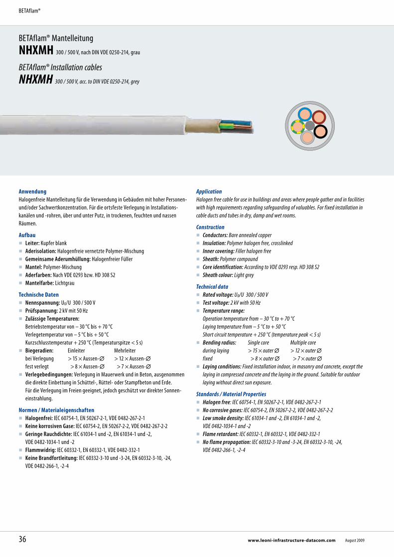
BETAflam® MantelleitungNHXMH 300 / 500 V, nach DIN VDE 0250-214, grau
BETAflam® Installation cablesNHXMH 300 / 500 V, acc. to DIN VDE 0250-214, grey
AnwendungHalogenfreie Mantelleitung für die Verwendung in Gebäuden mit hoher Personen- und/oder Sachwertkonzentration. Für die ortsfeste Verlegung in Installations- kanälen und -rohren, über und unter Putz, in trockenen, feuchten und nassen Räumen.
Aufbau Leiter: Kupfer blank Aderisolation: Halogenfreie vernetzte Polymer-Mischung Gemeinsame Aderumhüllung: Halogenfreier Füller Mantel: Polymer-Mischung Aderfarben: Nach VDE 0293 bzw. HD 308 S2 Mantelfarbe: Lichtgrau
Technische Daten Nennspannung: U0/U 300 / 500 V Prüfspannung: 2 kV mit 50 Hz Zulässige Temperaturen:
Betriebstemperatur von – 30 °C bis + 70 °C Verlegetemperatur von – 5 °C bis + 50 °C Kurzschlusstemperatur + 250 °C (Temperaturspitze < 5 s)
Biegeradien: Einleiter Mehrleiter bei Verlegung > 15 × Aussen- > 12 × Aussen- fest verlegt > 8 × Aussen- > 7 × Aussen-
Verlegebedingungen: Verlegung in Mauerwerk und in Beton, ausge nommen die direkte Einbettung in Schüttel-, Rüttel- oder Stampfbeton und Erde. Für die Verlegung im Freien geeignet, jedoch geschützt vor direkter Sonnen- einstrahlung.
Normen / Materialeigenschaften Halogenfrei: IEC 60754-1, EN 50267-2-1, VDE 0482-267-2-1 Keine korrosiven Gase: IEC 60754-2, EN 50267-2-2, VDE 0482-267-2-2 Geringe Rauchdichte: IEC 61034-1 und -2, EN 61034-1 und -2,
VDE 0482-1034-1 und -2 Flammwidrig: IEC 60332-1, EN 60332-1, VDE 0482-332-1 Keine Brandfortleitung: IEC 60332-3-10 und -3-24, EN 60332-3-10, -24,
VDE 0482-266-1, -2-4
ApplicationHalogen free cable for use in buildings and areas where people gather and in facilities with high requirements regarding safeguarding of valuables. For fixed installation in cable ducts and tubes in dry, damp and wet rooms.
Construction Conductors: Bare annealed copper Insulation: Polymer halogen free, crosslinked Inner covering: Filler halogen free Sheath: Polymer compound Core identification: According to VDE 0293 resp. HD 308 S2 Sheath colour: Light grey
Technical data Rated voltage: U0/U 300 / 500 V Test voltage: 2 kV with 50 Hz Temperature range:
Operation temperature from – 30 °C to + 70 °C Laying temperature from – 5 °C to + 50 °C Short circuit temperature + 250 °C (temperature peak < 5 s)
Bending radius: Single core Multiple core during laying > 15 × outer > 12 × outer fixed > 8 × outer > 7 × outer
Laying conditions: Fixed installation indoor, in masonry and concrete, except the laying in compressed concrete and the laying in the ground. Suitable for outdoor laying without direct sun exposure.
Standards / Material Properties Halogen free: IEC 60754-1, EN 50267-2-1, VDE 0482-267-2-1 No corrosive gases: IEC 60754-2, EN 50267-2-2, VDE 0482-267-2-2 Low smoke density: IEC 61034-1 and -2, EN 61034-1 and -2,
VDE 0482-1034-1 and -2 Flame retardant: IEC 60332-1, EN 60332-1, VDE 0482-332-1 No flame propagation: IEC 60332-3-10 and -3-24, EN 60332-3-10, -24,
VDE 0482-266-1, -2-4
36 www.leoni-infrastructure-datacom.com August 2009
BETAflam®

Abmessungen, Gewichte / Dimensions, WeightTyp Type
KabelaufbauConstruction
Artikel-Nr. Part no.
LSG
Aderfunktion Core function
Aussen- Outer
GewichtWeight
Cu-ZahlCu factor
Brutto-Preis Cu-Basis 150 /100 kg
Gross price Cu basis 150/100 kg
n × mm² mm kg / km kg / km EUR / km
NHXMH-J 1 × 4 RE 12140200 PE 6,4 75 38 863,00NHXMH-J 1 × 6 RE 12140210 PE 6,9 98 58 1.076,00NHXMH-J 1 × 10 RE 12140220 PE 7,9 141 96 1.151,00NHXMH-J 1 × 16 RM 12140230 PE 9,3 210 154 1.987,00
NHXMH-J 3 × 1,5 RE 12140630 LNPE 8,3 113 43 805,00NHXMH-J 3 × 2,5 RE 12140640 LNPE 9,1 151 72 1.115,00NHXMH-J 3 × 4 RE 12140650 LNPE 11,3 240 115 1.756,00NHXMH-J 3 × 6 RE 12140660 LNPE 12,2 310 173 2.023,00NHXMH-J 3 × 10 RE 12140670 LNPE 14,4 465 288 2.908,00
NHXMH-J 4 × 1,5 RE 12140850 3LPE 9,0 135 58 1.003,00NHXMH-J 4 × 2,5 RE 12140860 3LPE 10,0 188 96 1.352,00NHXMH-J 4 × 4 RE 12140870 3LPE 12,0 284 154 2.070,00NHXMH-J 4 × 6 RE 12140880 3LPE 13,3 383 230 2.785,00NHXMH-J 4 × 10 RE 12140890 3LPE 15,8 580 384 4.250,00NHXMH-J 4 × 16 RM 12140900 3LPE 19,1 887 614 6.307,00NHXMH-J 4 × 25 RM 12140910 3LPE 24,7 1442 960 9.510,00NHXMH-J 4 × 35 RM 12140920 3LPE 26,5 1838 1344 9.849,00
NHXMH-J 5 × 1,5 RE 12141070 3LNPE 9,8 163 72 1.181,00NHXMH-J 5 × 2,5 RE 12141080 3LNPE 10,8 223 120 1.586,00NHXMH-J 5 × 4 RE 12141090 3LNPE 13,0 339 192 2.474,00NHXMH-J 5 × 6 RE 12141100 3LNPE 14,4 459 288 3.061,00NHXMH-J 5 × 10 RE 12141110 3LNPE 17,2 700 480 5.043,00NHXMH-J 5 × 16 RM 12141120 3LNPE 22,2 1145 768 7.619,00NHXMH-J 5 × 25 RM 12141130 3LNPE 26,0 1690 1200 10.923,00
NHXMH-J 7 × 1,5 RE 12141510 NRPE 10,5 197 101 1.695,00NHXMH-J 7 × 2,5 RE 12141520 NRPE 11,8 281 168 2.175,00NHXMH-J 10 × 1,5 RE 12142170 NRPE 12,8 291 144 2.324,00NHXMH-J 12 × 1,5 RE 12142520 NRPE 13,2 319 173 2.633,00
-J = mit grün-gelber Ader -O = ohne grün-gelbe Ader RE = rund eindrähtig RM = rund mehrdrähtig L = Phasenleiter braun, schwarz, grauN = Neutralleiter blauNR = Phasenleiter schwarz, nummeriertPE = Schutzleiter grün-gelb Fett gedruckte Artikel-Nr. = Lagerartikel Weitere Ausführungen auf Anfrage.
-J = with green-yellow conductor -O = without green-yellow conductor RE = round solid RM = round stranded L = phase conductor brown, black, greyN = neutral conductor blueNR = phase conductor black, numberedPE = earth conductor green-yellow
Bold printed part no. = stock items Further designs upon request.
Vorteile
Vernetzte Isolation Flammwidrig Halogenfrei und silikonfrei RoHS-konform
Advantages
Cross-linked insulation Flame retardant Halogen free and silicone free In compliance with RoHS directive
37August 2009 www.leoni-infrastructure-datacom.com
BETAflam® MantelleitungNHXMH
BETAflam® Installation cablesNHXMH
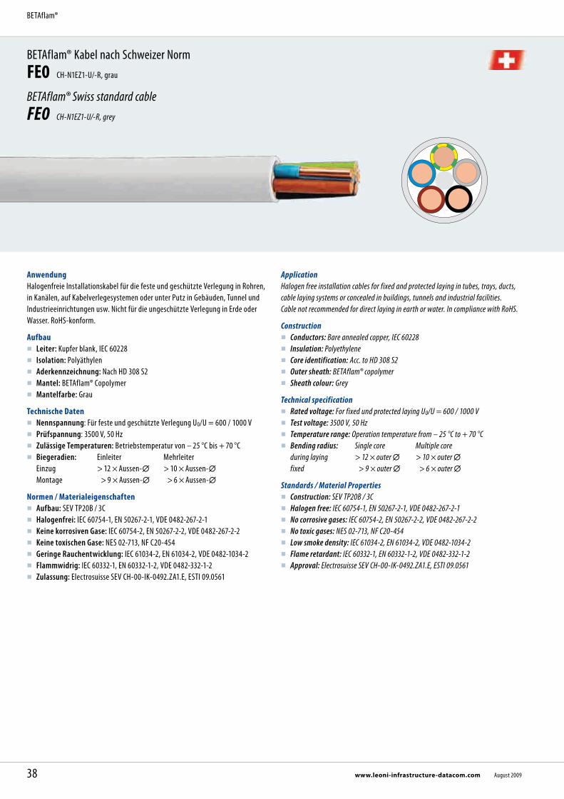
BETAflam® Kabel nach Schweizer NormFE0 CH-N1EZ1-U/-R, grau
BETAflam® Swiss standard cableFE0 CH-N1EZ1-U/-R, grey
AnwendungHalogenfreie Installationskabel für die feste und geschützte Verlegung in Rohren, in Kanälen, auf Kabelverlegesystemen oder unter Putz in Gebäuden, Tunnel und Industrieeinrichtungen usw. Nicht für die ungeschützte Verlegung in Erde oder Wasser. RoHS-konform.
Aufbau Leiter: Kupfer blank, IEC 60228 Isolation: Polyäthylen Aderkennzeichnung: Nach HD 308 S2 Mantel: BETAflam® Copolymer Mantelfarbe: Grau
Technische Daten Nennspannung: Für feste und geschützte Verlegung U0/U = 600 / 1000 V Prüfspannung: 3500 V, 50 Hz Zulässige Temperaturen: Betriebstemperatur von – 25 °C bis + 70 °C Biegeradien: Einleiter Mehrleiter
Einzug > 12 × Aussen- > 10 × Aussen- Montage > 9 × Aussen- > 6 × Aussen-
Normen / Materialeigenschaften Aufbau: SEV TP20B / 3C Halogenfrei: IEC 60754-1, EN 50267-2-1, VDE 0482-267-2-1 Keine korrosiven Gase: IEC 60754-2, EN 50267-2-2, VDE 0482-267-2-2 Keine toxischen Gase: NES 02-713, NF C20-454 Geringe Rauchentwicklung: IEC 61034-2, EN 61034-2, VDE 0482-1034-2 Flammwidrig: IEC 60332-1, EN 60332-1-2, VDE 0482-332-1-2 Zulassung: Electrosuisse SEV CH-00-IK-0492.ZA1.E, ESTI 09.0561
ApplicationHalogen free installation cables for fixed and protected laying in tubes, trays, ducts, cable laying systems or concealed in buildings, tunnels and industrial facilities. Cable not recommended for direct laying in earth or water. In compliance with RoHS.
Construction Conductors: Bare annealed copper, IEC 60228 Insulation: Polyethylene Core identification: Acc. to HD 308 S2 Outer sheath: BETAflam® copolymer Sheath colour: Grey
Technical specification Rated voltage: For fixed und protected laying U0/U = 600 / 1000 V Test voltage: 3500 V, 50 Hz Temperature range: Operation temperature from – 25 °C to + 70 °C Bending radius: Single core Multiple core
during laying > 12 × outer > 10 × outer fixed > 9 × outer > 6 × outer
Standards / Material Properties Construction: SEV TP20B / 3C Halogen free: IEC 60754-1, EN 50267-2-1, VDE 0482-267-2-1 No corrosive gases: IEC 60754-2, EN 50267-2-2, VDE 0482-267-2-2 No toxic gases: NES 02-713, NF C20-454 Low smoke density: IEC 61034-2, EN 61034-2, VDE 0482-1034-2 Flame retardant: IEC 60332-1, EN 60332-1-2, VDE 0482-332-1-2 Approval: Electrosuisse SEV CH-00-IK-0492.ZA1.E, ESTI 09.0561
38 www.leoni-infrastructure-datacom.com August 2009
BETAflam®

Vorteile Umweltfreundlich und halogenfrei, geeignet als Ersatz für PVC-Kabel Leicht und gut abisolierbar Vorzügliche Isolationseigenschaften, auch bei Nässe! Optimales Preis-/Leistungsverhältnis
Advantages Environment friendly and halogen free, qualified to replace cables containing PVC Easy to strip Best electrical insulation properties, also in wet environment! Optimal cost efficiency
G = mit grün-gelber Ader RE = rund eindrähtig RM = rund mehrdrähtig L = Phasenleiter braun, schwarz, grauN = Neutralleiter blauNR = Phasenleiter schwarz, nummeriertPE = Schutzleiter grün-gelb Fett gedruckte Artikel-Nr. = Lagerartikel LSA Weitere Ausführungen auf Anfrage.
G = with green-yellow conductor RE = round solid RM = round stranded L = phase conductor brown, black, greyN = neutral conductor blueNR = phase conductors black, numberedPE = earth conductor green-yellow
Bold printed part no. = stock item LSA Further designs upon request.
Abmessungen, Gewichte / Dimensions, WeightTyp Type
KabelaufbauConstruction
Artikel-Nr.Part no.
LSA
Aderfunktion Core function
Aussen- Outer
GewichtWeight
Cu-ZahlCu factor
Brutto-Preis Cu-Basis 0 /100 kg
Gross price Cu basis 0/100 kg
n × mm² mm kg / km kg / km EUR / km
FE0 1 G 6 RE 212900 PE 5,6 76 58 440,00FE0 1 G 16 RM 212909 PE 8,5 192 154 780,00
FE0 2 × 1,5 RE 212879 2L 6,4 58 29 365,00
FE0 3 G 1,5 RE 212880 LNPE 6,7 74 43 425,00FE0 3 G 2,5 RE 212891 LNPE 7,9 109 72 565,00FE0 3 G 4 RE 212898 LNPE 9,1 162 115 1.190,00FE0 3 G 6 RE 212902 LNPE 10,5 226 173 1.220,00
FE0 4 G 1,5 RE 212882 3LPE 7,5 95 58 525,00FE0 4 G 2,5 RE 212893 3LPE 8,8 141 96 720,00
FE0 5 G 1,5 RE 212884 3LNPE 8,2 116 72 660,00FE0 5 G 2,5 RE 212895 3LNPE 9,8 174 120 1.200,00FE0 5 G 4 RE 212899 3LNPE 11,1 261 192 1.300,00FE0 5 G 6 RE 212904 3LNPE 12,9 371 288 1.625,00FE0 5 G 10 RM 212908 3LNPE 18,1 652 480 2.780,00FE0 5 G 16 RM 212911 3LNPE 20,9 963 768 3.910,00FE0 5 G 25 RM 212916 3LNPE 26,0 1519 1200 6.780,00
FE0 7 G 1,5 RE 212885 NRPE 9,0 153 101 940,00
FE0 10 G 1,5 RE 214729 NRPE 11,1 217 144 1.330,00
FE0 12 G 1,5 RE 212887 NRPE 11,8 257 173 1.530,00
39August 2009 www.leoni-infrastructure-datacom.com
BETAflam® Kabel nach Schweizer NormFE0
BETAflam® Swiss standard cableFE0

Installationskabel – halogenfrei, keine Brandfortleitung, einfache InstallationBETAflam® INSTAflex CH-N07Z1Z1-F
Installation Cable – halogen free, no flame propagation, simple installationBETAflam® INSTAflex CH-N07Z1Z1-F
AnwendungInstallationskabel mit flexiblem Leiteraufbau für Anlagen im Hoch- und Tiefbau, Maschinenbau, Heiz- und Klimatechnik, insbesondere dort wo Halogenfreiheit, keine Brandfortleitung, Schadstofffreiheit und eine anspruchsvolle Verlegeart gefordert sind.
Aufbau Leiter: Kupferlitze blank, feindrähtig nach IEC 60228, Klasse 5 Isolation: BETAflam® Copolymer, halogenfrei Aderfarben:
≤ 5 Adern nach HD 308 S2 ≥ 6 Adern schwarz mit weissen Ziffern
Mantel: BETAflam® Copolymer, halogenfrei Mantelfarbe: Grau
Technische Daten Nennspannung:
U₀/U 450 / 750 V U₀/U 600 / 1000 V bei fester Installation
Prüfspannung: 3500 V Temperaturbereiche:
– 40 °C bis + 80 °C bei fester Installation – 25 °C bis + 80 °C bei gelegentlicher Bewegung
Biegeradien: ≥ 4 × Aussen- bei fester Installation ≥ 8 × Aussen- bei gelegentlicher Bewegung Wechselbiegeprüfung Stufe 2 nach SEV TP 20B/3C
Materialeigenschaften Halogenfrei: IEC 60754-1, EN 50267-2-1 Keine korrosiven Gase: IEC 60754-2, EN 50267-2-2 Geringe Rauchdichte: IEC 61034-2, EN 61034-2 Flammwidrig: IEC 60332-1, EN 60332-1 Keine Brandfortleitung: IEC 60332-3-24, EN 60332-3-10, -24
Standard / Spezifikation Electrosuisse SEV TP 20B/3C - d ESTI Bewilligung Nr. 09.0264
ApplicationInstallation cable with flexible conductor make-up for use in constructions, industrial machinery, plant engineering, heating and air-conditioning technology. Especially where halogen free materials, no flame propagation, no pollutants and demanding laying conditions are required.
Construction Conductor: Bare fine copper strands according to IEC 60228, class 5 Insulation: BETAflam® copolymer, halogen free Core identification:
≤ 5 conductors coloured according to HD 308 S2 ≥ 6 conductors black with white numbers
Outer sheath: BETAflam® copolymer, halogen free Outer sheath colour: Grey
Technical data Nominal voltage:
U₀/U 450 / 750 V U₀/U 600 / 1000 V for fixed installation
Test voltage: 3500 V Temperature range:
– 40 °C to + 80 °C for fixed installation – 25 °C to + 80 °C occasionally moved
Bending radius: ≥ 4 × outer diameter for fixed installation ≥ 8 × outer diameter occasionally moved Bending test category 2 acc. to SEV TP 20B/3C
Material properties Halogen free: IEC 60754-1, EN 50267-2-1 No corrosive gases: IEC 60754-2, EN 50267-2-2 Low smoke density: IEC 61034-2, EN 61034-2 Flame retardant: IEC 60332-1, EN 60332-1 No flame propagation: IEC 60332-3-24, EN 60332-3-10, -24
Standard / specification Electrosuisse ASE TP 20B/3C - d ESTI authorisation no. 09.0264
40 www.leoni-infrastructure-datacom.com August 2009
BETAflam®
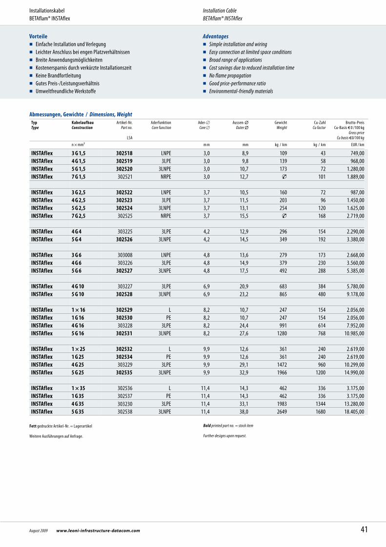
Abmessungen, Gewichte / Dimensions, WeightTyp Type
KabelaufbauConstruction
Artikel-Nr.Part no.
LSA
Aderfunktion Core function
Ader-Core
Aussen- Outer
GewichtWeight
Cu-ZahlCu factor
Brutto-Preis Cu-Basis 0 /100 kg
Gross price Cu basis 0/100 kg
n × mm² m m mm kg / km kg / km EUR / km
INSTAflex 3 G 1,5 302518 LNPE 3,0 8,9 109 43 749,00INSTAflex 4 G 1,5 302519 3LPE 3,0 9,8 139 58 968,00INSTAflex 5 G 1,5 302520 3LNPE 3,0 10,7 173 72 1.280,00INSTAflex 7 G 1,5 302521 NRPE 3,0 12,7 101 1.889,00
INSTAflex 3 G 2,5 302522 LNPE 3,7 10,5 160 72 987,00INSTAflex 4 G 2,5 302523 3LPE 3,7 11,5 203 96 1.450,00INSTAflex 5 G 2,5 302524 3LNPE 3,7 13,1 254 120 1.625,00INSTAflex 7 G 2,5 302525 NRPE 3,7 15,5 168 2.719,00
INSTAflex 4 G 4 303225 3LPE 4,2 12,9 296 154 2.290,00INSTAflex 5 G 4 302526 3LNPE 4,2 14,5 349 192 3.380,00
INSTAflex 3 G 6 303008 LNPE 4,8 13,6 279 173 2.668,00INSTAflex 4 G 6 303226 3LPE 4,8 14,9 379 230 3.560,00INSTAflex 5 G 6 302527 3LNPE 4,8 17,5 492 288 5.385,00 INSTAflex 4 G 10 303227 3LPE 6,9 20,9 683 384 5.780,00INSTAflex 5 G 10 302528 3LNPE 6,9 23,2 865 480 9.178,00 INSTAflex 1 × 16 302529 L 8,2 10,7 247 154 2.056,00INSTAflex 1 G 16 302530 PE 8,2 10,7 247 154 2.056,00INSTAflex 4 G 16 303228 3LPE 8,2 24,4 991 614 7.952,00INSTAflex 5 G 16 302531 3LNPE 8,2 27,6 1280 768 10.985,00
INSTAflex 1 × 25 302532 L 9,9 12,6 361 240 2.619,00INSTAflex 1 G 25 302534 PE 9,9 12,6 361 240 2.619,00INSTAflex 4 G 25 303229 3LPE 9,9 29,1 1472 960 10.299,00INSTAflex 5 G 25 302535 3LNPE 9,9 32,9 1966 1200 14.990,00 INSTAflex 1 × 35 302536 L 11,4 14,3 462 336 3.175,00INSTAflex 1 G 35 302537 PE 11,4 14,3 462 336 3.175,00INSTAflex 4 G 35 303230 3LPE 11,4 33,1 1983 1344 13.280,00INSTAflex 5 G 35 302538 3LNPE 11,4 38,0 2649 1680 18.405,00
Vorteile Einfache Installation und Verlegung Leichter Anschluss bei engen Platzverhältnissen Breite Anwendungsmöglichkeiten Kostenersparnis durch verkürzte Installationszeit Keine Brandfortleitung Gutes Preis-/Leistungsverhältnis Umweltfreundliche Werkstoffe
Advantages Simple installation and wiring Easy connection at limited space conditions Broad range of applications Cost savings due to reduced installation time No flame propagation Good price-performance ratio Environmental-friendly materials
Fett gedruckte Artikel-Nr. = Lagerartikel Weitere Ausführungen auf Anfrage.
Bold printed part no. = stock item Further designs upon request.
41August 2009 www.leoni-infrastructure-datacom.com
InstallationskabelBETAflam® INSTAflex
Installation Cable BETAflam® INSTAflex

Typ Type
KabelaufbauConstruction
Artikel-Nr.Part no.
LSA
Aderfunktion Core function
Ader-Core
Aussen- Outer
GewichtWeight
Cu-ZahlCu factor
Brutto-Preis Cu-Basis 0 /100 kg
Gross price Cu basis 0/100 kg
n × mm² m m mm kg / km kg / km EUR / km
INSTAflex 1 × 50 L 13,2 16,3 630 480 4.780,00INSTAflex 1 G 50 PE 13,2 16,3 630 480 4.780,00INSTAflex 4 G 50 303231 3LPE 13,2 38,1 2726 1920 16.454,00INSTAflex 5 G 50 3LNPE 13,2 42,7 3438 2400 20.568,00 INSTAflex 1 × 70 L 15,1 18,7 915 672 6.540,00INSTAflex 1 G 70 PE 15,1 18,7 915 672 6.540,00 INSTAflex 1 × 95 303115 L 16,6 20,4 1174 912 7.982,00INSTAflex 1 G 95 PE 16,6 20,4 1174 912 7.982,00 INSTAflex 1 × 120 303116 L 18,6 22,6 1395 1152 9.180,00INSTAflex 1 G 120 PE 18,6 22,6 1395 1152 9.180,00 INSTAflex 1 × 150 303117 L 21,2 25,6 1726 1440 10.295,00INSTAflex 1 G 150 PE 21,2 25,6 1726 1440 10.295,00
INSTAflex 1 × 185 303119 L 23,4 28,0 2077 1776 11.975,00INSTAflex 1 G 185 PE 23,4 28,0 2077 1776 11.975,00 INSTAflex 1 × 240 303118 L 26,3 31,1 2688 2304 15.620,00INSTAflex 1 G 240 PE 26,3 31,1 2688 2304 15.620,00 INSTAflex 1 × 300 303120 L 28,6 33,8 3255 2880 17.890,00INSTAflex 1 G 300 PE 28,6 33,8 3255 2880 17.890,00
Fett gedruckte Artikel-Nr. = Lagerartikel Weitere Ausführungen auf Anfrage.
Bold printed part no. = stock item Further designs upon request.
42 www.leoni-infrastructure-datacom.com August 2009
InstallationskabelBETAflam® INSTAflex
Installation Cable BETAflam® INSTAflex

43August 2009 www.leoni-infrastructure-datacom.com
InstallationskabelBETAflam® INSTAflex
Installation Cable BETAflam® INSTAflex

BETAflam® Kabel nach Schweizer NormFE5 CH-N1EZ1-U/-R, orange
BETAflam® Swiss standard cableFE5 CH-N1EZ1-U/-R, orange
AnwendungHalogenfreie Installationskabel mit verbessertem Verhalten im Brandfall für die feste und geschützte Verlegung in Rohren, in Kanälen, auf Kabelverlegesystemen oder unter Putz in Gebäuden, Tunnel und Industrieeinrichtungen usw. Nicht für die ungeschützte Verlegung in Erde oder Wasser. RoHS-konform.
Aufbau Leiter: Kupfer blank, IEC 60228 Isolation: Thermoplast halogenfrei Aderkennzeichnung: Nach HD 308 S2 Mantel: BETAflam® Copolymer Mantelfarbe: Orange
Technische Daten Nennspannung: Für feste und geschützte Verlegung U0/U = 600 / 1000 V Prüfspannung: 3500 V, 50 Hz Zulässige Temperaturen: Betriebstemperatur von – 40 °C bis + 70 °C Biegeradien: Einleiter Mehrleiter
Einzug > 12 × Aussen- > 10 × Aussen- Montage > 9 × Aussen- > 6 × Aussen-
Normen / Materialeigenschaften Aufbau: SEV TP20B / 3C Halogenfrei: IEC 60754-1, EN 50267-2-1, VDE 0482-267-2-1 Keine korrosiven Gase: IEC 60754-2, EN 50267-2-2, VDE 0482-267-2-2 Keine toxischen Gase: NES 02-713, NF C20-454 Geringe Rauchentwicklung: IEC 61034-2, EN 61034-2, VDE 0482-1034-2 Flammwidrig: IEC 60332-1, EN 60332-1-2, VDE 0482-332-1-2 Keine Brandfortleitung: IEC 60332-3-24, EN 60332-3-10, -24, VDE 0482-266-2-4 Zulassung: Electrosuisse SEV CH-00-IK-0492.ZA1.E, ESTI 09.0561
ApplicationHalogen free installation cables with improved fire performance for fixed and pro-tected laying in tubes, trays, ducts, cable laying systems or concealed in buildings, tunnels and industrial facilities. Cable not recommended for direct laying in earth or water. In compliance with RoHS.
Construction Conductors: Bare annealed copper, IEC 60228 Insulation: Thermoplast halogen free Core identification: Acc. to HD 308 S2 Outer sheath: BETAflam® copolymer Sheath colour: Orange
Technical specification Rated voltage: For fixed und protected laying U0/U = 600 / 1000 V Test voltage: 3500 V, 50 Hz Temperature range: Operation temperature from – 40 °C to + 70 °C Bending radius: Single core Multiple core
during laying > 12 × outer > 10 × outer fixed > 9 × outer > 6 × outer
Standards / Material Properties Construction: SEV TP20B / 3C Halogen free: IEC 60754-1, EN 50267-2-1, VDE 0482-267-2-1 No corrosive gases: IEC 60754-2, EN 50267-2-2, VDE 0482-267-2-2 No toxic gases: NES 02-713, NF C20-454 Low smoke density: IEC 61034-2, EN 61034-2, VDE 0482-1034-2 Flame retardant: IEC 60332-1, EN 60332-1-2, VDE 0482-332-1-2 No flame propagation: IEC 60332-3-24, EN 60332-3-10, -24, VDE 0482-266-2-4 Approval: Electrosuisse SEV CH-00-IK-0492.ZA1.E, ESTI 09.0561
44 www.leoni-infrastructure-datacom.com August 2009
BETAflam®

Vorteile Umweltfreundlich und halogenfrei, geeignet als Ersatz für PVC-Kabel Leicht und gut abisolierbar Kältebeständig bis – 40 °C: Anwendbar in Kühlhäusern, Tiefkühlräumen usw. Vorzügliche Isolationseigenschaften, auch bei Nässe! Optimales Preis-/Leistungsverhältnis
Advantages Environment friendly and halogen free, qualified to replace cables containing PVC Easy to strip Low temperature resistance to – 40 °C: Applicable in cold storing houses,
deep-freeze rooms etc. Best electrical insulation properties, also in wet environment! Optimal cost efficiency
Abmessungen, Gewichte / Dimensions, WeightTyp Type
KabelaufbauConstruction
Artikel-Nr.Part no.
LSA
Aderfunktion Core function
Aussen- Outer
GewichtWeight
Cu-ZahlCu factor
Brutto-Preis Cu-Basis 0 /100 kg
Gross price Cu basis 0/100 kg
n × mm² mm kg / km kg / km EUR / km
FE5 1 G 4 RE PE 6,0 78 38 723,00FE5 1 G 6 RE PE 6,6 93 58 810,00FE5 1 G 10 RM PE 8,3 150 96 995,00FE5 1 G 16 RM PE 9,4 210 154 1.237,00FE5 1 G 25 RM 191099 PE 10,9 305 240 1.647,00FE5 1 G 35 RM PE 12,1 420 336 1.978,00FE5 1 G 50 RM 210808 PE 13,4 518 480 2.223,00FE5 1 G 70 RM PE 15,6 727 672 2.892,00FE5 1 G 95 RM 210810 PE 17,9 987 912 3.292,00FE5 1 G 120 RM 211287 PE 19,9 1240 1152 3.950,00FE5 1 G 150 RM 211187 PE 22,0 1600 1440 4.469,00FE5 1 G 185 RM PE 24,2 2000 1776 5.540,00FE5 1 G 240 RM 211189 PE 27,2 2600 2304 6.852,00FE5 1 G 300 RM PE 31,1 3500 2880 8.727,00
FE5 1 × 4 RE L 6,0 78 38 723,00FE5 1 × 6 RE L 6,6 93 58 810,00FE5 1 × 10 RM L 8,3 150 96 995,00FE5 1 × 16 RM L 9,4 210 154 1.237,00FE5 1 × 25 RM L 10,9 305 240 1.647,00FE5 1 × 35 RM L 12,1 420 336 1.978,00FE5 1 × 50 RM 210807 L 13,4 518 480 2.223,00FE5 1 × 70 RM 211183 L 15,6 727 672 2.892,00FE5 1 × 95 RM 210809 L 17,9 987 912 3.292,00FE5 1 × 120 RM 211286 L 19,9 1240 1152 3.950,00FE5 1 × 150 RM 211186 L 22,0 1600 1440 4.469,00FE5 1 × 185 RM 211288 L 24,2 2000 1776 5.540,00FE5 1 × 240 RM 211188 L 27,2 2600 2304 6.852,00FE5 1 × 300 RM L 31,1 3500 2880 8.727,00
FE5 2 × 1,5 RE 191079 2L 7,3 72 29 1.028,00FE5 2 × 2,5 RE 2L 8,3 97 48 1.178,00FE5 2 × 4 RE 2L 9,5 163 77 1.495,00FE5 2 × 6 RE 2L 10,7 203 115 1.755,00FE5 2 × 10 RM 2L 14,1 329 192 2.177,00FE5 2 × 16 RM 2L 15,9 459 307 2.892,00FE5 2 × 25 RM 2L 19,4 697 480 4.067,00
45August 2009 www.leoni-infrastructure-datacom.com
BETAflam® Kabel nach Schweizer NormFE5
BETAflam® Swiss standard cableFE5
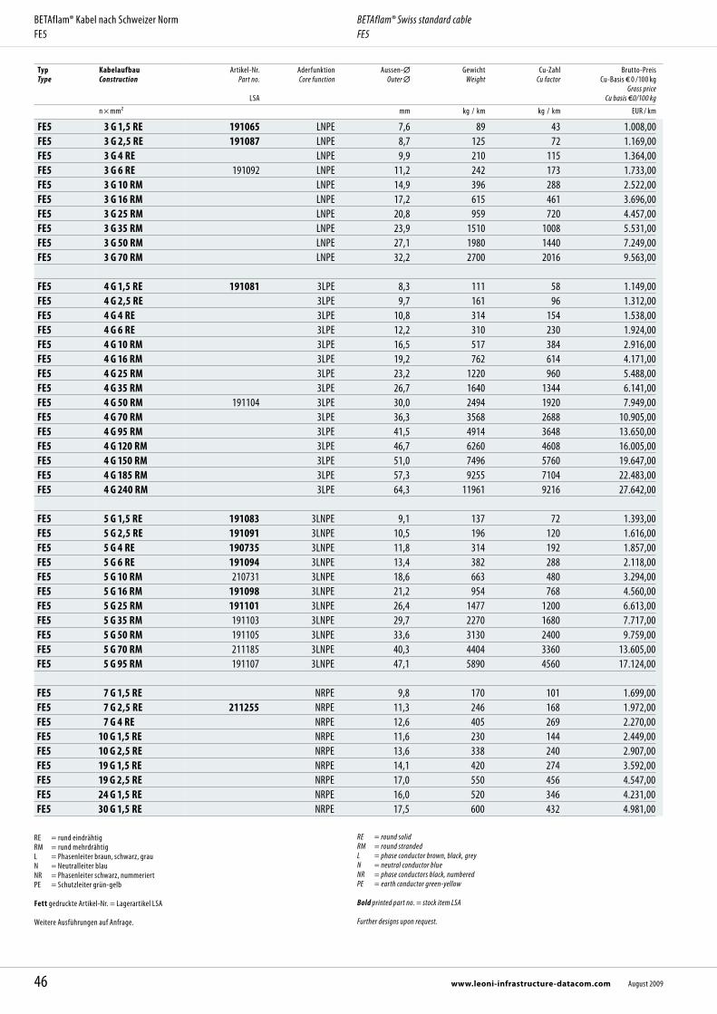
Typ Type
KabelaufbauConstruction
Artikel-Nr.Part no.
LSA
Aderfunktion Core function
Aussen- Outer
GewichtWeight
Cu-ZahlCu factor
Brutto-Preis Cu-Basis 0 /100 kg
Gross price Cu basis 0/100 kg
n × mm² mm kg / km kg / km EUR / km
FE5 3 G 1,5 RE 191065 LNPE 7,6 89 43 1.008,00FE5 3 G 2,5 RE 191087 LNPE 8,7 125 72 1.169,00FE5 3 G 4 RE LNPE 9,9 210 115 1.364,00FE5 3 G 6 RE 191092 LNPE 11,2 242 173 1.733,00FE5 3 G 10 RM LNPE 14,9 396 288 2.522,00FE5 3 G 16 RM LNPE 17,2 615 461 3.696,00FE5 3 G 25 RM LNPE 20,8 959 720 4.457,00FE5 3 G 35 RM LNPE 23,9 1510 1008 5.531,00FE5 3 G 50 RM LNPE 27,1 1980 1440 7.249,00FE5 3 G 70 RM LNPE 32,2 2700 2016 9.563,00
FE5 4 G 1,5 RE 191081 3LPE 8,3 111 58 1.149,00FE5 4 G 2,5 RE 3LPE 9,7 161 96 1.312,00FE5 4 G 4 RE 3LPE 10,8 314 154 1.538,00FE5 4 G 6 RE 3LPE 12,2 310 230 1.924,00FE5 4 G 10 RM 3LPE 16,5 517 384 2.916,00FE5 4 G 16 RM 3LPE 19,2 762 614 4.171,00FE5 4 G 25 RM 3LPE 23,2 1220 960 5.488,00FE5 4 G 35 RM 3LPE 26,7 1640 1344 6.141,00FE5 4 G 50 RM 191104 3LPE 30,0 2494 1920 7.949,00FE5 4 G 70 RM 3LPE 36,3 3568 2688 10.905,00FE5 4 G 95 RM 3LPE 41,5 4914 3648 13.650,00FE5 4 G 120 RM 3LPE 46,7 6260 4608 16.005,00FE5 4 G 150 RM 3LPE 51,0 7496 5760 19.647,00FE5 4 G 185 RM 3LPE 57,3 9255 7104 22.483,00FE5 4 G 240 RM 3LPE 64,3 11961 9216 27.642,00
FE5 5 G 1,5 RE 191083 3LNPE 9,1 137 72 1.393,00FE5 5 G 2,5 RE 191091 3LNPE 10,5 196 120 1.616,00FE5 5 G 4 RE 190735 3LNPE 11,8 314 192 1.857,00FE5 5 G 6 RE 191094 3LNPE 13,4 382 288 2.118,00FE5 5 G 10 RM 210731 3LNPE 18,6 663 480 3.294,00FE5 5 G 16 RM 191098 3LNPE 21,2 954 768 4.560,00FE5 5 G 25 RM 191101 3LNPE 26,4 1477 1200 6.613,00FE5 5 G 35 RM 191103 3LNPE 29,7 2270 1680 7.717,00FE5 5 G 50 RM 191105 3LNPE 33,6 3130 2400 9.759,00FE5 5 G 70 RM 211185 3LNPE 40,3 4404 3360 13.605,00FE5 5 G 95 RM 191107 3LNPE 47,1 5890 4560 17.124,00
FE5 7 G 1,5 RE NRPE 9,8 170 101 1.699,00FE5 7 G 2,5 RE 211255 NRPE 11,3 246 168 1.972,00FE5 7 G 4 RE NRPE 12,6 405 269 2.270,00FE5 10 G 1,5 RE NRPE 11,6 230 144 2.449,00FE5 10 G 2,5 RE NRPE 13,6 338 240 2.907,00FE5 19 G 1,5 RE NRPE 14,1 420 274 3.592,00FE5 19 G 2,5 RE NRPE 17,0 550 456 4.547,00FE5 24 G 1,5 RE NRPE 16,0 520 346 4.231,00FE5 30 G 1,5 RE NRPE 17,5 600 432 4.981,00
RE = rund eindrähtig RM = rund mehrdrähtig L = Phasenleiter braun, schwarz, grauN = Neutralleiter blauNR = Phasenleiter schwarz, nummeriertPE = Schutzleiter grün-gelb Fett gedruckte Artikel-Nr. = Lagerartikel LSA Weitere Ausführungen auf Anfrage.
RE = round solid RM = round stranded L = phase conductor brown, black, greyN = neutral conductor blueNR = phase conductors black, numberedPE = earth conductor green-yellow
Bold printed part no. = stock item LSA Further designs upon request.
46 www.leoni-infrastructure-datacom.com August 2009
BETAflam® Kabel nach Schweizer NormFE5
BETAflam® Swiss standard cableFE5
47August 2009 www.leoni-infrastructure-datacom.com
BETAflam® Kabel nach Schweizer Norm BETAflam® Swiss standard cable
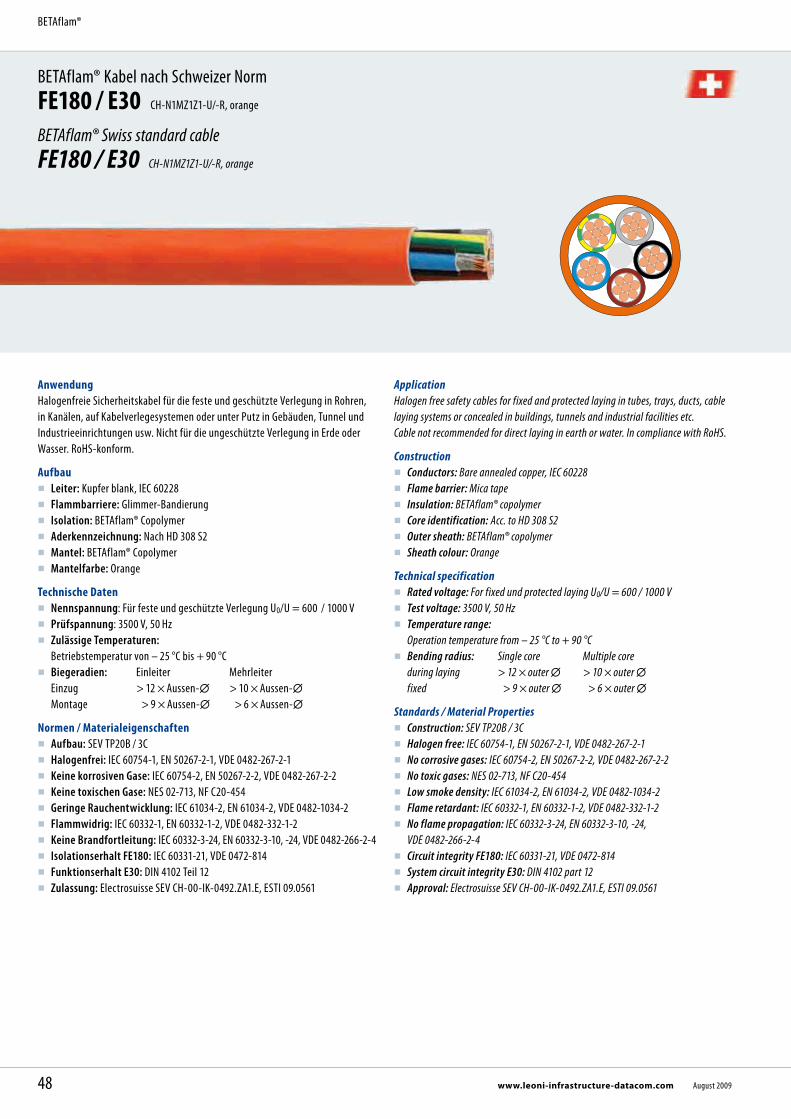
BETAflam® Kabel nach Schweizer NormFE180 / E30 CH-N1MZ1Z1-U/-R, orange
BETAflam® Swiss standard cableFE180 / E30 CH-N1MZ1Z1-U/-R, orange
AnwendungHalogenfreie Sicherheitskabel für die feste und geschützte Verlegung in Rohren, in Kanälen, auf Kabelverlegesystemen oder unter Putz in Gebäuden, Tunnel und Industrieeinrichtungen usw. Nicht für die ungeschützte Verlegung in Erde oder Wasser. RoHS-konform.
Aufbau Leiter: Kupfer blank, IEC 60228 Flammbarriere: Glimmer-Bandierung Isolation: BETAflam® Copolymer Aderkennzeichnung: Nach HD 308 S2 Mantel: BETAflam® Copolymer Mantelfarbe: Orange
Technische Daten Nennspannung: Für feste und geschützte Verlegung U0/U = 600 / 1000 V Prüfspannung: 3500 V, 50 Hz Zulässige Temperaturen:
Betriebstemperatur von – 25 °C bis + 90 °C Biegeradien: Einleiter Mehrleiter
Einzug > 12 × Aussen- > 10 × Aussen- Montage > 9 × Aussen- > 6 × Aussen-
Normen / Materialeigenschaften Aufbau: SEV TP20B / 3C Halogenfrei: IEC 60754-1, EN 50267-2-1, VDE 0482-267-2-1 Keine korrosiven Gase: IEC 60754-2, EN 50267-2-2, VDE 0482-267-2-2 Keine toxischen Gase: NES 02-713, NF C20-454 Geringe Rauchentwicklung: IEC 61034-2, EN 61034-2, VDE 0482-1034-2 Flammwidrig: IEC 60332-1, EN 60332-1-2, VDE 0482-332-1-2 Keine Brandfortleitung: IEC 60332-3-24, EN 60332-3-10, -24, VDE 0482-266-2-4 Isolationserhalt FE180: IEC 60331-21, VDE 0472-814 Funktionserhalt E30: DIN 4102 Teil 12 Zulassung: Electrosuisse SEV CH-00-IK-0492.ZA1.E, ESTI 09.0561
ApplicationHalogen free safety cables for fixed and protected laying in tubes, trays, ducts, cable laying systems or concealed in buildings, tunnels and industrial facilities etc. Cable not recommended for direct laying in earth or water. In compliance with RoHS.
Construction Conductors: Bare annealed copper, IEC 60228 Flame barrier: Mica tape Insulation: BETAflam® copolymer Core identification: Acc. to HD 308 S2 Outer sheath: BETAflam® copolymer Sheath colour: Orange
Technical specification Rated voltage: For fixed und protected laying U0/U = 600 / 1000 V Test voltage: 3500 V, 50 Hz Temperature range:
Operation temperature from – 25 °C to + 90 °C Bending radius: Single core Multiple core
during laying > 12 × outer > 10 × outer fixed > 9 × outer > 6 × outer
Standards / Material Properties Construction: SEV TP20B / 3C Halogen free: IEC 60754-1, EN 50267-2-1, VDE 0482-267-2-1 No corrosive gases: IEC 60754-2, EN 50267-2-2, VDE 0482-267-2-2 No toxic gases: NES 02-713, NF C20-454 Low smoke density: IEC 61034-2, EN 61034-2, VDE 0482-1034-2 Flame retardant: IEC 60332-1, EN 60332-1-2, VDE 0482-332-1-2 No flame propagation: IEC 60332-3-24, EN 60332-3-10, -24,
VDE 0482-266-2-4 Circuit integrity FE180: IEC 60331-21, VDE 0472-814 System circuit integrity E30: DIN 4102 part 12 Approval: Electrosuisse SEV CH-00-IK-0492.ZA1.E, ESTI 09.0561
48 www.leoni-infrastructure-datacom.com August 2009
BETAflam®

Abmessungen, Gewichte / Dimensions, WeightTyp Type
KabelaufbauConstruction
Artikel-Nr.Part no.
LSA
Aderfunktion Core function
Aussen- Outer
GewichtWeight
Cu-ZahlCu factor
Brutto-Preis Cu-Basis 0 /100 kg
Gross price Cu basis 0/100 kg
n × mm² mm kg / km kg / km EUR / km
FE180 / E30 1 G 4 RE PE 5,5 101 38 1.104,00FE180 / E30 1 G 6 RE PE 6,2 121 58 1.311,00FE180 / E30 1 G 10 RM PE 8,0 160 96 1.541,00FE180 / E30 1 G 16 RM PE 9,2 254 154 1.954,00FE180 / E30 1 G 25 RM PE 10,8 358 240 2.376,00FE180 / E30 1 G 35 RM PE 12,3 426 336 2.744,00FE180 / E30 1 G 50 RM 223284 PE 14,1 570 480 3.214,00FE180 / E30 1 G 70 RM 223285 PE 16,4 796 672 3.848,00FE180 / E30 1 G 95 RM 223286 PE 19,1 1080 912 4.579,00FE180 / E30 1 G 120 RM 223287 PE 21,1 1353 1152 5.202,00FE180 / E30 1 G 150 RM 223288 PE 23,0 1637 1440 5.765,00FE180 / E30 1 G 185 RM 223289 PE 25,4 2020 1776 6.811,00FE180 / E30 1 G 240 RM 223290 PE 28,5 2608 2304 8.427,00FE180 / E30 1 G 300 RM PE 32,6 3190 2880 11.850,00
FE180 / E30 1 × 4 RE L 5,5 101 38 1.104,00FE180 / E30 1 × 6 RE L 6,2 121 58 1.311,00FE180 / E30 1 × 10 RM L 8,0 160 96 1.541,00FE180 / E30 1 × 16 RM L 9,2 254 154 1.954,00FE180 / E30 1 × 25 RM L 10,8 358 240 2.376,00FE180 / E30 1 × 35 RM L 12,2 426 336 2.744,00FE180 / E30 1 × 50 RM 222107 L 14,1 570 480 3.214,00FE180 / E30 1 × 70 RM 221756 L 16,4 796 672 3.848,00FE180 / E30 1 × 95 RM 221758 L 19,1 1080 912 4.579,00FE180 / E30 1 × 120 RM 221760 L 21,1 1353 1152 5.202,00FE180 / E30 1 × 150 RM 221762 L 23,0 1637 1440 5.765,00FE180 / E30 1 × 185 RM 221764 L 25,4 2020 1776 6.811,00FE180 / E30 1 × 240 RM 221766 L 28,5 2608 2304 8.427,00FE180 / E30 1 × 300 RM 221768 L 32,6 3190 2880 11.850,00
FE180 / E30 2 × 1,5 RE 221838 2L 8,4 100 29 1.700,00FE180 / E30 2 × 2,5 RE 221960 2L 9,5 134 48 1.809,00FE180 / E30 2 × 4 RE 2L 9,6 157 77 2.449,00FE180 / E30 2 × 6 RE 2L 10,9 208 115 3.183,00FE180 / E30 2 × 10 RM 2L 14,6 380 192 3.859,00FE180 / E30 2 × 16 RM 2L 17,1 500 307 4.320,00FE180 / E30 2 × 25 RM 2L 20,5 700 480 5.563,00
Vorteile
Höchste Sicherheitseigenschaften Funktionserhalt nach DIN 4102 Teil 12 Halogenfrei und silikonfrei RoHS-konform
Advantages
Highest safety standards System circuit integrity to DIN 4102 part 12 Halogen free and silicone free In compliance with RoHS directive
49August 2009 www.leoni-infrastructure-datacom.com
BETAflam® Kabel nach Schweizer NormFE180 / E30
BETAflam® Swiss standard cableFE180 / E30

Typ Type
KabelaufbauConstruction
Artikel-Nr.Part no.
LSA
Aderfunktion Core function
Aussen- Outer
GewichtWeight
Cu-ZahlCu factor
Brutto-Preis Cu-Basis 0 /100 kg
Gross price Cu basis 0/100 kg
n × mm² mm kg / km kg / km EUR / km
FE180 / E30 3 G 1,5 RE 221839 LNPE 8,8 106 43 1.814,00FE180 / E30 3 G 2,5 RE 221845 LNPE 9,9 144 72 2.196,00FE180 / E30 3 G 4 RE 302455 LNPE 10,1 188 115 2.868,00FE180 / E30 3 G 6 RE LNPE 11,4 255 173 3.501,00FE180 / E30 3 G 10 RM LNPE 15,6 524 288 4.423,00FE180 / E30 3 G 16 RM LNPE 18,1 764 461 5.451,00FE180 / E30 3 G 25 RM LNPE 21,7 1099 720 7.792,00FE180 / E30 3 G 35 RM LNPE 25,0 1426 1008 11.140,00FE180 / E30 3 G 50 RM LNPE 29,0 1900 1440 12.189,00FE180 / E30 3 G 70 RM LNPE 34,0 2603 2016 14.477,00
FE180 / E30 3 G 25 + 16 RM 3LPE 25,0 1400 874 9.781,00FE180 / E30 3 G 35 + 16 RM 3LPE 27,4 1594 1162 12.337,00FE180 / E30 3 G 50 + 25 RM 3LPE 31,1 2161 1680 13.599,00FE180 / E30 3 G 70 + 35 RM 3LPE 37,1 3080 2352 16.556,00FE180 / E30 3 G 95 + 50 RM 3LPE 41,6 4070 3216 21.038,00FE180 / E30 3 G 120 + 70 RM 3LPE 47,6 5217 4128 26.680,00FE180 / E30 3 G 150 + 70 RM 3LPE 51,4 6148 4992 31.278,00FE180 / E30 3 G 185 + 95 RM 3LPE 57,4 7670 6240 37.363,00FE180 / E30 3 G 240 +120 RM 3LPE 62,0 9900 8064 49.501,00
FE180 / E30 4 G 1,5 RE 221840 3LPE 9,6 133 58 1.988,00FE180 / E30 4 G 2,5 RE 221846 3LPE 10,9 196 96 2.242,00FE180 / E30 4 G 4 RE 3LPE 11,2 302 154 3.504,00FE180 / E30 4 G 6 RE 3LPE 12,8 419 230 4.064,00FE180 / E30 4 G 10 RM 3LPE 17,4 666 384 5.518,00FE180 / E30 4 G 16 RM 221852 3LPE 20,0 835 614 8.837,00FE180 / E30 4 G 25 RM 221854 3LPE 24,2 1263 960 11.123,00FE180 / E30 4 G 35 RM 222774 3LPE 27,9 1760 1344 12.669,00FE180 / E30 4 G 50 RM 221857 3LPE 32,3 2403 1920 16.276,00FE180 / E30 4 G 70 RM 3LPE 38,0 4094 2688 18.962,00FE180 / E30 4 G 95 RM 221860 3LPE 44,2 4592 3648 23.232,00FE180 / E30 4 G 120 RM 3LPE 48,9 5660 4608 29.533,00FE180 / E30 4 G 150 RM 3LPE 54,0 6951 5760 35.487,00FE180 / E30 4 G 185 RM 3LPE 59,2 8600 7104 43.131,00FE180 / E30 4 G 240 RM 3LPE 67,4 11000 9216 53.847,00
FE180 / E30 5 G 1,5 RE 221841 3LNPE 10,7 171 72 3.148,00FE180 / E30 5 G 2,5 RE 221847 3LNPE 12,2 244 120 3.481,00FE180 / E30 5 G 4 RE 221848 3LNPE 12,4 306 192 4.891,00FE180 / E30 5 G 6 RE 221849 3LNPE 14,2 424 288 5.234,00FE180 / E30 5 G 10 RM 221851 3LNPE 19,5 731 480 6.428,00FE180 / E30 5 G 16 RM 221853 3LNPE 22,6 1070 768 10.231,00FE180 / E30 5 G 25 RM 221855 3LNPE 26,8 1593 1200 12.633,00FE180 / E30 5 G 35 RM 221856 3LNPE 30,8 2213 1680 14.343,00FE180 / E30 5 G 50 RM 221858 3LNPE 36,3 3015 2400 18.429,00FE180 / E30 5 G 70 RM 221859 3LNPE 42,2 4219 3360 22.395,00FE180 / E30 5 G 95 RM 221861 3LNPE 49,0 5712 4560 27.246,00
FE180 / E30 7 G 1,5 RE 221842 NRPE 11,5 209 101 3.544,00FE180 / E30 7 G 2,5 RE 221870 NRPE 13,2 370 168 4.016,00FE180 / E30 7 G 4 RE NRPE 13,6 423 269 5.344,00
FE180 / E30 12 G 1,5 RE 221844 NRPE 15,4 357 173 4.972,00FE180 / E30 12 G 2,5 RE NRPE 17,7 632 288 5.352,00
50 www.leoni-infrastructure-datacom.com August 2009
BETAflam® Kabel nach Schweizer NormFE180 / E30
BETAflam® Swiss standard cableFE180 / E30

Typ Type
KabelaufbauConstruction
Artikel-Nr.Part no.
LSA
Aderfunktion Core function
Aussen- Outer
GewichtWeight
Cu-ZahlCu factor
Brutto-Preis Cu-Basis 0 /100 kg
Gross price Cu basis 0/100 kg
n × mm² mm kg / km kg / km EUR / km
FE180 / E30 19 G 1,5 RE NRPE 18,2 571 274 9.759,00FE180 / E30 19 G 2,5 RE NRPE 21,2 840 456 11.277,00FE180 / E30 21 G 1,5 RE 215079 NRPE 19,3 608 302 11.626,00FE180 / E30 27 G 1,5 RE 222106 NRPE 22,2 769 389 12.336,00
RE = rund eindrähtig RM = rund mehrdrähtig L = Phasenleiter braun, schwarz, grauN = Neutralleiter blauNR = Phasenleiter schwarz, nummeriertPE = Schutzleiter grün-gelb Fett gedruckte Artikel-Nr. = Lagerartikel LSA Weitere Ausführungen auf Anfrage.
RE = round solid RM = round stranded L = phase conductor brown, black, greyN = neutral conductor blueNR = phase conductors black, numberedPE = earth conductor green-yellow
Bold printed part no. = stock item LSA Further designs upon request.
51August 2009 www.leoni-infrastructure-datacom.com
BETAflam® Kabel nach Schweizer NormFE180 / E30
BETAflam® Swiss standard cableFE180 / E30
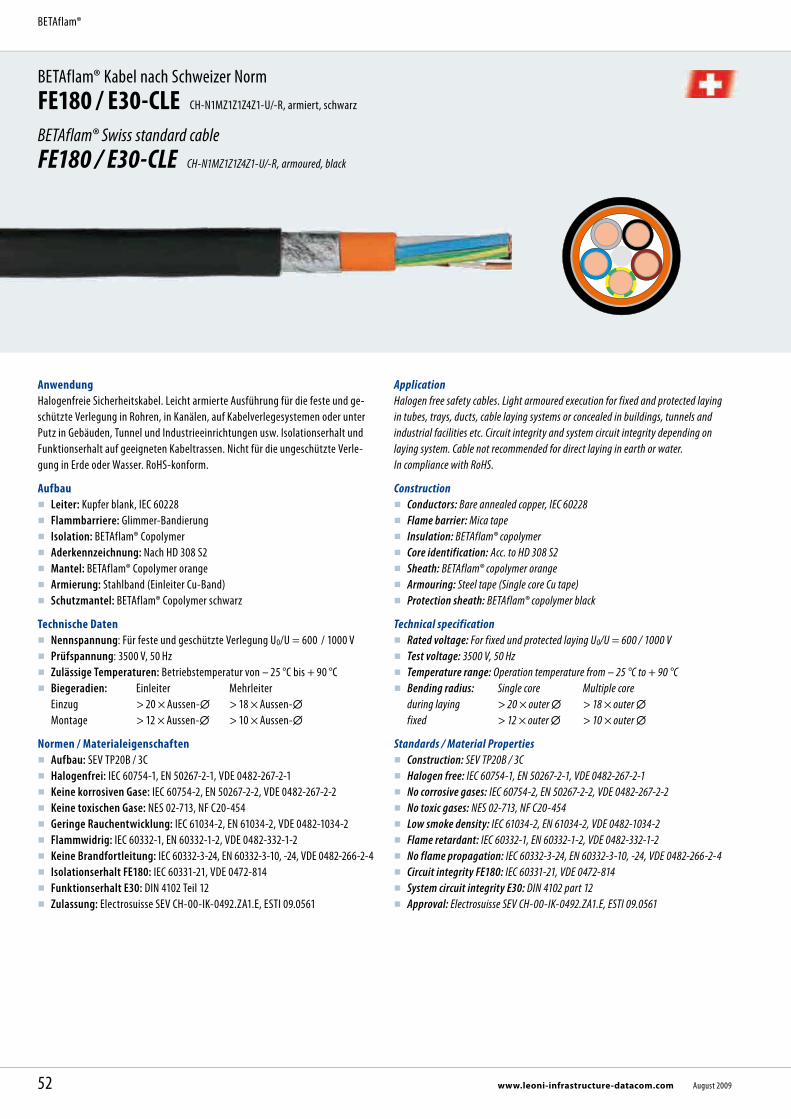
BETAflam® Kabel nach Schweizer NormFE180 / E30-CLE CH-N1MZ1Z1Z4Z1-U/-R, armiert, schwarz
BETAflam® Swiss standard cableFE180 / E30-CLE CH-N1MZ1Z1Z4Z1-U/-R, armoured, black
AnwendungHalogenfreie Sicherheitskabel. Leicht armierte Ausführung für die feste und ge-schützte Verlegung in Rohren, in Kanälen, auf Kabelverlegesystemen oder unter Putz in Gebäuden, Tunnel und Industrieeinrichtungen usw. Isolationserhalt und Funktionserhalt auf geeigneten Kabeltrassen. Nicht für die ungeschützte Verle-gung in Erde oder Wasser. RoHS-konform.
Aufbau Leiter: Kupfer blank, IEC 60228 Flammbarriere: Glimmer-Bandierung Isolation: BETAflam® Copolymer Aderkennzeichnung: Nach HD 308 S2 Mantel: BETAflam® Copolymer orange Armierung: Stahlband (Einleiter Cu-Band) Schutzmantel: BETAflam® Copolymer schwarz
Technische Daten Nennspannung: Für feste und geschützte Verlegung U0/U = 600 / 1000 V Prüfspannung: 3500 V, 50 Hz Zulässige Temperaturen: Betriebstemperatur von – 25 °C bis + 90 °C Biegeradien: Einleiter Mehrleiter
Einzug > 20 × Aussen- > 18 × Aussen- Montage > 12 × Aussen- > 10 × Aussen-
Normen / Materialeigenschaften Aufbau: SEV TP20B / 3C Halogenfrei: IEC 60754-1, EN 50267-2-1, VDE 0482-267-2-1 Keine korrosiven Gase: IEC 60754-2, EN 50267-2-2, VDE 0482-267-2-2 Keine toxischen Gase: NES 02-713, NF C20-454 Geringe Rauchentwicklung: IEC 61034-2, EN 61034-2, VDE 0482-1034-2 Flammwidrig: IEC 60332-1, EN 60332-1-2, VDE 0482-332-1-2 Keine Brandfortleitung: IEC 60332-3-24, EN 60332-3-10, -24, VDE 0482-266-2-4 Isolationserhalt FE180: IEC 60331-21, VDE 0472-814 Funktionserhalt E30: DIN 4102 Teil 12 Zulassung: Electrosuisse SEV CH-00-IK-0492.ZA1.E, ESTI 09.0561
ApplicationHalogen free safety cables. Light armoured execution for fixed and protected laying in tubes, trays, ducts, cable laying systems or concealed in buildings, tunnels and industrial facilities etc. Circuit integrity and system circuit integrity depending on laying system. Cable not recommended for direct laying in earth or water. In compliance with RoHS.
Construction Conductors: Bare annealed copper, IEC 60228 Flame barrier: Mica tape Insulation: BETAflam® copolymer Core identification: Acc. to HD 308 S2 Sheath: BETAflam® copolymer orange Armouring: Steel tape (Single core Cu tape) Protection sheath: BETAflam® copolymer black
Technical specification Rated voltage: For fixed und protected laying U0/U = 600 / 1000 V Test voltage: 3500 V, 50 Hz Temperature range: Operation temperature from – 25 °C to + 90 °C Bending radius: Single core Multiple core
during laying > 20 × outer > 18 × outer fixed > 12 × outer > 10 × outer
Standards / Material Properties Construction: SEV TP20B / 3C Halogen free: IEC 60754-1, EN 50267-2-1, VDE 0482-267-2-1 No corrosive gases: IEC 60754-2, EN 50267-2-2, VDE 0482-267-2-2 No toxic gases: NES 02-713, NF C20-454 Low smoke density: IEC 61034-2, EN 61034-2, VDE 0482-1034-2 Flame retardant: IEC 60332-1, EN 60332-1-2, VDE 0482-332-1-2 No flame propagation: IEC 60332-3-24, EN 60332-3-10, -24, VDE 0482-266-2-4 Circuit integrity FE180: IEC 60331-21, VDE 0472-814 System circuit integrity E30: DIN 4102 part 12 Approval: Electrosuisse SEV CH-00-IK-0492.ZA1.E, ESTI 09.0561
52 www.leoni-infrastructure-datacom.com August 2009
BETAflam®

Abmessungen, Gewichte / Dimensions, WeightTyp Type
KabelaufbauConstruction
Artikel-Nr.Part no.
LSA
Aderfunktion Core function
Aussen- Outer
GewichtWeight
Cu-ZahlCu factor
Brutto-Preis Cu-Basis 0 /100 kg
Gross price Cu basis 0/100 kg
n × mm² mm kg / km kg / km EUR / km
FE180 / E30-CLE 2 × 1,5 RE 301445 2L 12,8 276 29 2.344,00FE180 / E30-CLE 2 × 2,5 RE 222517 2L 13,9 330 48 3.265,00
FE180 / E30-CLE 3 G 1,5 RE 224050 LNPE 13,2 288 43 2.645,00FE180 / E30-CLE 3 G 2,5 RE 217088 LNPE 14,3 347 72 3.412,00FE180 / E30-CLE 3 G 4 RE 217400 LNPE 14,5 401 115 3.872,00FE180 / E30-CLE 3 G 6 RE 221621 LNPE 15,8 490 173 4.962,00FE180 / E30-CLE 3 G 10 RM 226080 LNPE 20,0 700 288 6.373,00FE180 / E30-CLE 3 G 16 RM LNPE 22,5 921 461 8.890,00FE180 / E30-CLE 3 G 25 RM LNPE 26,1 1400 720 11.229,00FE180 / E30-CLE 3 G 35 RM LNPE 29,4 1880 1008 13.820,00FE180 / E30-CLE 3 G 50 RM LNPE 33,4 2300 1440 16.252,00FE180 / E30-CLE 3 G 70 RM LNPE 38,4 3200 2016 18.854,00FE180 / E30-CLE 3 G 95 RM LNPE 44,7 4000 2736 22.417,00FE180 / E30-CLE 3 G 120 RM LNPE 50,0 5200 3456 26.698,00FE180 / E30-CLE 3 G 150 RM LNPE 55,2 6500 4320 30.135,00FE180 / E30-CLE 3 G 185 RM LNPE 60,2 7925 5328 37.073,00FE180 / E30-CLE 3 G 240 RM LNPE 66,0 10000 6912 45.260,00
FE180 / E30-CLE 3 G 70 + 35 RM 3LPE 41,1 3643 2352 21.874,00FE180 / E30-CLE 3 G 95 + 50 RM 3LPE 47,0 4800 3216 25.533,00FE180 / E30-CLE 3 G 120 + 70 RM 3LPE 53,0 5900 4128 29.647,00FE180 / E30-CLE 3 G 150 + 70 RM 3LPE 56,8 7121 4992 34.249,00FE180 / E30-CLE 3 G 185 + 95 RM 3LPE 63,6 9195 6240 41.447,00FE180 / E30-CLE 3 G 240 + 120 RM 3LPE 69,3 11119 8064 49.150,00
FE180 / E30-CLE 4 G 1,5 RE 3LPE 14,0 330 58 3.308,00FE180 / E30-CLE 4 G 2,5 RE 3LPE 15,3 418 96 3.961,00FE180 / E30-CLE 4 G 4 RE 3LPE 15,6 560 154 5.069,00FE180 / E30-CLE 4 G 6 RE 3LPE 17,2 660 230 6.520,00FE180 / E30-CLE 4 G 10 RM 3LPE 21,8 920 384 9.564,00FE180 / E30-CLE 4 G 16 RM 224631 3LPE 24,4 1228 614 11.182,00FE180 / E30-CLE 4 G 25 RM 3LPE 28,6 1800 960 13.193,00FE180 / E30-CLE 4 G 35 RM 3LPE 32,3 2440 1344 15.282,00FE180 / E30-CLE 4 G 50 RM 224024 3LPE 36,7 3030 1920 17.393,00FE180 / E30-CLE 4 G 70 RM 226082 3LPE 42,4 4000 2688 20.945,00FE180 / E30-CLE 4 G 95 RM 226081 3LPE 49,2 5200 3648 25.666,00FE180 / E30-CLE 4 G 120 RM 3LPE 53,9 6300 4608 31.155,00FE180 / E30-CLE 4 G 150 RM 3LPE 59,8 7700 5760 35.829,00FE180 / E30-CLE 4 G 185 RM 3LPE 65,0 9800 7104 42.154,00FE180 / E30-CLE 4 G 240 RM 3LPE 74,0 12000 9216 50.531,00
Vorteile
Höchste Sicherheitseigenschaften Funktionserhalt nach DIN 4102 Teil 12 Halogenfrei und silikonfrei RoHS-konform Für erhöhte mechanische Beanspruchung, z.B. als Kabel mit Nagetierschutz
Advantages
Highest safety standards System circuit integrity to DIN 4102 part 12 Halogen free and silicone free In compliance with RoHS directive For increased mechanical stress, e.g. as cables with rodent protection
53August 2009 www.leoni-infrastructure-datacom.com
BETAflam® Kabel nach Schweizer NormFE180 / E30-CLE
BETAflam® Swiss standard cableFE180 / E30-CLE

Typ Type
KabelaufbauConstruction
Artikel-Nr.Part no.
Aderfunktion Core function
Aussen- Outer
GewichtWeight
Cu-ZahlCu factor
Brutto-Preis Cu-Basis 0 /100 kg
Gross price Cu basis 0/100 kg
n × mm² mm kg / km kg / km EUR / km
FE180 / E30-CLE 5 G 1,5 RE 3LNPE 15,1 388 72 3.966,00FE180 / E30-CLE 5 G 2,5 RE 222518 3LNPE 16,6 490 120 4.244,00FE180 / E30-CLE 5 G 4 RE 223897 3LNPE 16,8 555 192 5.619,00FE180 / E30-CLE 5 G 6 RE 222176 3LNPE 18,6 706 288 6.381,00FE180 / E30-CLE 5 G 10 RM 222775 3LNPE 23,9 1108 480 8.127,00FE180 / E30-CLE 5 G 16 RM 222512 3LNPE 27,0 1504 768 12.059,00FE180 / E30-CLE 5 G 25 RM 220518 3LNPE 31,2 2198 1200 13.610,00FE180 / E30-CLE 5 G 35 RM 224807 3LNPE 35,2 2811 1680 17.633,00FE180 / E30-CLE 5 G 50 RM 217101 3LNPE 40,7 3720 2400 20.634,00FE180 / E30-CLE 5 G 70 RM 3LNPE 47,2 5200 3360 25.879,00FE180 / E30-CLE 5 G 95 RM 224092 3LNPE 54,0 6785 4560 30.030,00
FE180 / E30-CLE 7 G 1,5 RE NRPE 15,9 440 101 5.172,00FE180 / E30-CLE 7 G 2,5 RE 217102 NRPE 17,6 634 168 5.532,00FE180 / E30-CLE 7 G 4 RE 300677 NRPE 18,0 720 269 7.540,00FE180 / E30-CLE 12 G 1,5 RE NRPE 19,8 740 173 8.478,00FE180 / E30-CLE 12 G 2,5 RE NRPE 22,1 977 288 9.818,00FE180 / E30-CLE 19 G 1,5 RE NRPE 22,7 980 274 10.887,00
RE = rund eindrähtig RM = rund mehrdrähtig L = Phasenleiter braun, schwarz, grauN = Neutralleiter blauNR = Phasenleiter schwarz, nummeriertPE = Schutzleiter grün-gelb Fett gedruckte Artikel-Nr. = Lagerartikel LSA Weitere Ausführungen auf Anfrage.
RE = round solid RM = round stranded L = phase conductor brown, black, greyN = neutral conductor blueNR = phase conductors black, numberedPE = earth conductor green-yellow
Bold printed part no. = stock item LSA Further designs upon request.
54 www.leoni-infrastructure-datacom.com August 2009
BETAflam® Kabel nach Schweizer NormFE180 / E30-CLE
BETAflam® Swiss standard cableFE180 / E30-CLE

55August 2009 www.leoni-infrastructure-datacom.com
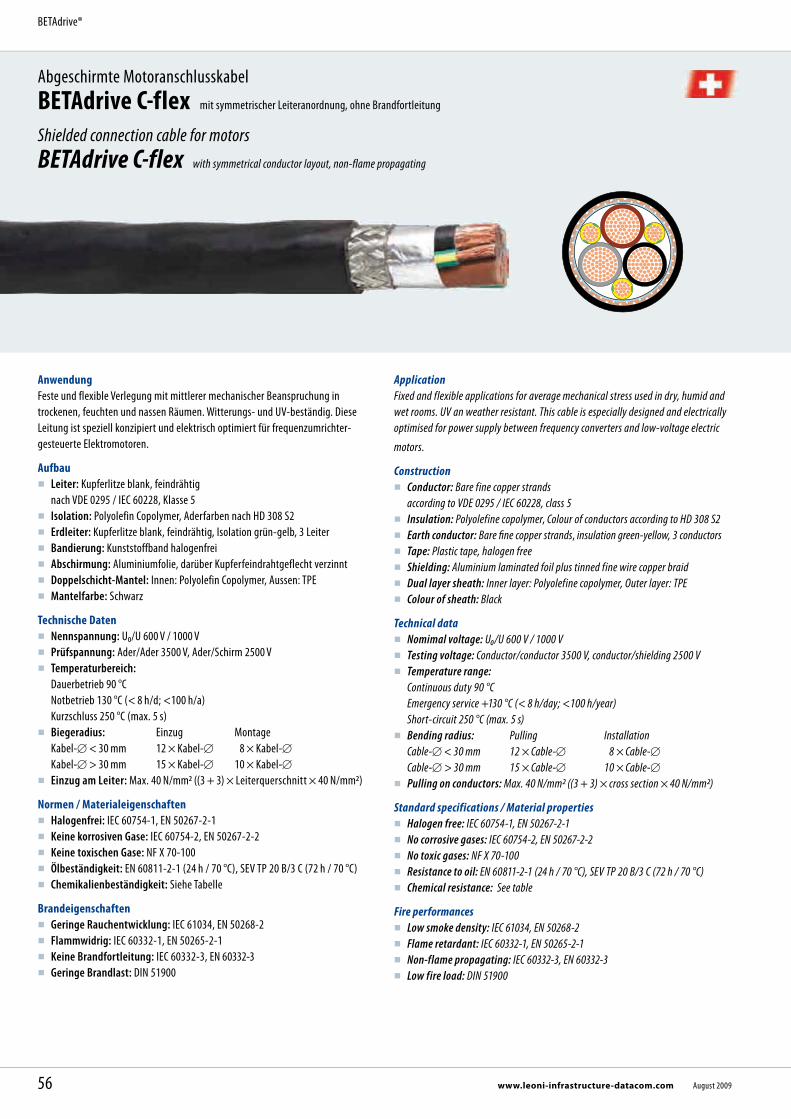
AnwendungFeste und flexible Verlegung mit mittlerer mechanischer Beanspruchung in trockenen, feuchten und nassen Räumen. Witterungs- und UV-beständig. Diese Leitung ist speziell konzipiert und elektrisch optimiert für frequenzumrichter- gesteuerte Elektromotoren.
Aufbau Leiter: Kupferlitze blank, feindrähtig
nach VDE 0295 / IEC 60228, Klasse 5 Isolation: Polyolefin Copolymer, Aderfarben nach HD 308 S2 Erdleiter: Kupferlitze blank, feindrähtig, Isolation grün-gelb, 3 Leiter Bandierung: Kunststoffband halogenfrei Abschirmung: Aluminiumfolie, darüber Kupferfeindrahtgeflecht verzinnt Doppelschicht-Mantel: Innen: Polyolefin Copolymer, Aussen: TPE Mantelfarbe: Schwarz
Technische Daten Nennspannung: U₀/U 600 V / 1000 V Prüfspannung: Ader/Ader 3500 V, Ader/Schirm 2500 V Temperaturbereich:
Dauerbetrieb 90 °C Notbetrieb 130 °C (< 8 h/d; <100 h/a) Kurzschluss 250 °C (max. 5 s)
Biegeradius: Einzug Montage Kabel- < 30 mm 12 × Kabel- 8 × Kabel- Kabel- > 30 mm 15 × Kabel- 10 × Kabel- Einzug am Leiter: Max. 40 N/mm2 ((3 + 3) × Leiterquerschnitt × 40 N/mm2)
Normen / Materialeigenschaften Halogenfrei: IEC 60754-1, EN 50267-2-1 Keine korrosiven Gase: IEC 60754-2, EN 50267-2-2 Keine toxischen Gase: NF X 70-100 Ölbeständigkeit: EN 60811-2-1 (24 h / 70 °C), SEV TP 20 B/3 C (72 h / 70 °C) Chemikalienbeständigkeit: Siehe Tabelle
Brandeigenschaften Geringe Rauchentwicklung: IEC 61034, EN 50268-2 Flammwidrig: IEC 60332-1, EN 50265-2-1 Keine Brandfortleitung: IEC 60332-3, EN 60332-3 Geringe Brandlast: DIN 51900
Abgeschirmte MotoranschlusskabelBETAdrive C-flex mit symmetrischer Leiteranordnung, ohne Brandfortleitung
Shielded connection cable for motorsBETAdrive C-flex with symmetrical conductor layout, non-flame propagating
ApplicationFixed and flexible applications for average mechanical stress used in dry, humid and wet rooms. UV an weather resistant. This cable is especially designed and electrically optimised for power supply between frequency converters and low-voltage electric
motors.
Construction Conductor: Bare fine copper strands
according to VDE 0295 / IEC 60228, class 5 Insulation: Polyolefine copolymer, Colour of conductors according to HD 308 S2 Earth conductor: Bare fine copper strands, insulation green-yellow, 3 conductors Tape: Plastic tape, halogen free Shielding: Aluminium laminated foil plus tinned fine wire copper braid Dual layer sheath: Inner layer: Polyolefine copolymer, Outer layer: TPE Colour of sheath: Black
Technical data Nomimal voltage: U₀/U 600 V / 1000 V Testing voltage: Conductor/conductor 3500 V, conductor/shielding 2500 V Temperature range:
Continuous duty 90 °C Emergency service +130 °C (< 8 h/day; <100 h/year) Short-circuit 250 °C (max. 5 s)
Bending radius: Pulling Installation Cable- < 30 mm 12 × Cable- 8 × Cable- Cable- > 30 mm 15 × Cable- 10 × Cable- Pulling on conductors: Max. 40 N/mm2 ((3 + 3) × cross section × 40 N/mm2)
Standard specifications / Material properties Halogen free: IEC 60754-1, EN 50267-2-1 No corrosive gases: IEC 60754-2, EN 50267-2-2 No toxic gases: NF X 70-100 Resistance to oil: EN 60811-2-1 (24 h / 70 °C), SEV TP 20 B/3 C (72 h / 70 °C) Chemical resistance: See table
Fire performances Low smoke density: IEC 61034, EN 50268-2 Flame retardant: IEC 60332-1, EN 50265-2-1 Non-flame propagating: IEC 60332-3, EN 60332-3 Low fire load: DIN 51900
56 www.leoni-infrastructure-datacom.com August 2009
BETAdrive®

Vorteile EMV-optimierte Abschirmung Mehradrig und flexibel Symmetrische Anordnung der Leiter, insbesondere PE gegenüber Phasen Sehr gute Öl- und Chemikalienbeständigkeit Sehr hohe Brandschutzeigenschaften Halogenfrei UV- und witterungsbeständig
Advantages EMC optimised braided shielding Multicore and flexible Symmetrical conductor layout, especially earth conductor to phase conductor Very good oil and chemical resistance High fire performance Halogen free UV and weather resistant
Strombelastbarkeit Current rating
KabelaufbauConstruction
Verlegung in Rohr in Erde 4
Laying in tube in earth 4Verlegung auf Trasse
Laying on traces
Dauerlast 1 / Industrielast 2
Current load 1 / industrial load 2Notbetrieb 3
Emergency service 3Dauerlast 1
Current load 1Notbetrieb 3
Emergency service 3
3 × n + 3 × n mm² 60 °CA
90 °CA
130 °CA
60 °CA
90 °CA
130 °CA
3 × 1,5 + 3 × 0,25 17 / 19 21 / 25 25 16 24 303 × 2,5 + 3 × 0,5 22 / 26 28 / 33 33 22 32 413 × 4 + 3 × 0,75 29 / 34 37 / 43 43 30 43 553 × 6 + 3 × 1 36 / 43 46 / 54 54 37 54 693 × 10 + 3 × 2,5 52 / 61 65 / 77 77 55 79 1013 × 16 + 3 × 2,5 67 / 79 84 / 99 100 72 103 1323 × 25 + 3 × 4 87 / 103 110 / 129 130 95 137 1743 × 35 + 3 × 6 105 / 124 132 / 156 157 116 166 2123 × 50 + 3 × 10 132 / 156 167 / 196 197 149 214 2723 × 70 + 3 × 16 164 / 193 207 / 244 245 189 270 3443 × 95 + 3 × 16 190 / 224 240 / 282 283 219 314 3993 × 120 + 3 × 25 222 / 261 280 / 329 331 261 373 4743 × 150 + 3 × 25 252 / 296 318 / 374 376 299 428 5453 × 185 + 3 × 35 281 / 331 355 / 418 421 337 482 6133 × 240 + 3 × 50 330 / 388 417 / 491 495 403 576 733
1 Belastungsgrad 24 h, 100 % Nennstrom (Anwendung vor allem für Energieerzeugungsanlagen)2 Belastungsgrad 10 h, 100 % und 14 h, 60 % Nennstrom (Standardanwendung)3 Maximal während 8 h pro Tag und maximal 100 h pro Jahr 4 Rohrinnendurchmesser mindestens 1,5 × Kabeldurchmesser
Berechnungsgrundlagen: Verlegetiefe 1 m, Bodentemperatur 20 °C, Lufttemperatur 30 °C, Schirme beid-seitig geerdet, spezifischer thermischer Widerstand des Bodens 1K m/W, gegen direkte Sonneneinstrahlung geschützt, ein Kabelsystem einzeln verlegt.
1 Load factor 24 h, 100 % nominal current (principal application in power plants)2 Load factor 10 h, 100 % and 14 h, 60 % nominal current (standard application)3 Maximum 8 h/day and 100 h/year4 Minimal inner diameter of the tube: minimum 1,5 × diameter of the cable
Basis of calculation: Laying depth 1 m, soil temperature 20 °C, ambient temperature 30 °C, shield on both sides earthed, thermal resistance of soil 1 K m/W, protected against direct solar radiation, one cable system single laid.
Abmessungen, Gewichte Dimensions, Weights
KabelaufbauConstruction
Artikel-Nr.Part no.
Ader- funktion
Core function
Aussen-Outer
GewichtWeight
Schirm- querschnitt
Shield cross section
BrandlastFire load
Cu-ZahlCu factor
Brutto-Preis Cu-Basis 0 /100 kg
Gross price Cu basis 0/100 kg
3 × n + 3 × n mm² mm kg / km mm2 kWh / m kg / km EUR / km
3 × 1,5 + 3 × 0,25 302799 3L+3PE 9,7 151 2,8 0,33 90 2.913,003 × 2,5 + 3 × 0,5 302800 3L+3PE 11,4 216 4,2 0,44 126 3.889,003 × 4 + 3 × 0,75 302801 3L+3PE 13,0 294 4,2 0,54 182 4.955,003 × 6 + 3 × 1 302802 3L+3PE 13,8 372 4,2 0,60 250 5.726,003 × 10 + 3 × 2,5 302270 3L+3PE 19,1 683 8 1,08 452 7.134,003 × 16 + 3 × 2,5 301017 3L+3PE 21,7 907 10 1,32 641 12.012,003 × 25 + 3 × 4 301018 3L+3PE 25,9 1'335 10 1,81 964 18.438,003 × 35 + 3 × 6 302271 3L+3PE 30,0 1'888 19 2,43 1381 21.367,003 × 50 + 3 × 10 301019 3L+3PE 33,9 2'498 19 2,86 1941 33.678,003 × 70 + 3 × 16 302272 3L+3PE 40,7 3'500 19 4,03 2735 41.075,003 × 95 + 3 × 16 302273 3L+3PE 41,8 4'088 19 4,23 3462 58.302,003 × 120 + 3 × 25 301020 3L+3PE 48,8 5'431 19 5,42 4492 76.010,003 × 150 + 3 × 25 301021 3L+3PE 52,3 6'327 19 5,76 5378 82.047,003 × 185 + 3 × 35 302274 3L+3PE 57,9 7'946 19 8,23 6711 95.051,003 × 240 + 3 × 50 302275 3L+3PE 65,0 10'429 19 9,53 8779 117.704,00
57August 2009 www.leoni-infrastructure-datacom.com
Abgeschirmte MotoranschlusskabelBETAdrive C-flex
Shielded connection cable for motorsBETAdrive C-flex
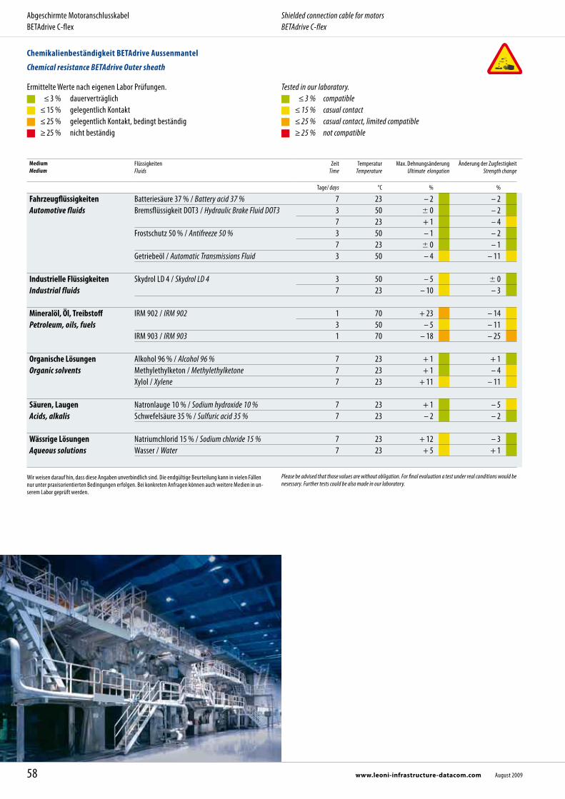
MediumMedium
Flüssigkeiten Fluids
Zeit Time
Temperatur Temperature
Max. DehnungsänderungUltimate elongation
Änderung der ZugfestigkeitStrength change
Tage/ days °C % %
Fahrzeugflüssigkeiten Automotive fluids
Batteriesäure 37 % / Battery acid 37 % 7 23 – 2 – 2Bremsflüssigkeit DOT3 / Hydraulic Brake Fluid DOT3
3 50 0 – 27 23 + 1 – 4
Frostschutz 50 % / Antifreeze 50 % 3 50 – 1 – 27 23 0 – 1
Getriebeöl / Automatic Transmissions Fluid 3 50 – 4 – 11
Industrielle Flüssigkeiten Industrial fluids
Skydrol LD 4 / Skydrol LD 4
3 50 – 5 07 23 – 10 – 3
Mineralöl, Öl, Treibstoff Petroleum, oils, fuels
IRM 902 / IRM 902 1 70 + 23 – 143 50 – 5 – 11
IRM 903 / IRM 903 1 70 – 18 – 25
Organische Lösungen Organic solvents
Alkohol 96 % / Alcohol 96 % 7 23 + 1 + 1Methylethylketon / Methylethylketone 7 23 + 1 – 4Xylol / Xylene 7 23 + 11 – 11
Säuren, Laugen Acids, alkalis
Natronlauge 10 % / Sodium hydroxide 10 % 7 23 + 1 – 5Schwefelsäure 35 % / Sulfuric acid 35 % 7 23 – 2 – 2
Wässrige Lösungen Aqueous solutions
Natriumchlorid 15 % / Sodium chloride 15 % 7 23 + 12 – 3Wasser / Water 7 23 + 5 + 1
Ermittelte Werte nach eigenen Labor Prüfungen. ≤ 3 % dauerverträglich ≤ 15 % gelegentlich Kontakt ≤ 25 % gelegentlich Kontakt, bedingt beständig ≥ 25 % nicht beständig
Tested in our laboratory. ≤ 3 % compatible ≤ 15 % casual contact ≤ 25 % casual contact, limited compatible ≥ 25 % not compatible
Wir weisen darauf hin, dass diese Angaben unverbindlich sind. Die endgültige Beurteilung kann in vielen Fällen nur unter praxisorientierten Bedingungen erfolgen. Bei konkreten Anfragen können auch weitere Medien in un-serem Labor geprüft werden.
Please be advised that those values are without obligation. For final evaluation a test under real conditions would be nesessary. Further tests could be also made in our laboratory.
58 www.leoni-infrastructure-datacom.com August 2009
Abgeschirmte MotoranschlusskabelBETAdrive C-flex
Shielded connection cable for motorsBETAdrive C-flex
Chemikalienbeständigkeit BETAdrive Aussenmantel
Chemical resistance BETAdrive Outer sheath
Technische Informationen
Technical information
Seite
Strombelastbarkeit 60Brandlast 62Aderkennzeichnung 65Halogenfreiheit und Brandverhalten 66Funktionserhaltsdauer im Baurecht 74
Allg. Verkaufs- und Lieferbedingungen 146
Page
Current rating 60Fire load 62Core identification 65Halogen free and fire performance 66Duration of system circuit integrity in the building laws 74
General conditions of sale and delivery 146
59August 2009 www.leoni-infrastructure-datacom.com
BETAflam®

Einleiterkabel, Leitertemperatur max. 70 ºCmit Kupferleiter, Umgebungstemperatur 30 ºC Single core cables, Conductor temperature max. 70 ºCwith copper conductors, ambient temperature 30 ºC
KabelaufbauConstruction
Verlegeart A1 Kabel in Rohr
in gedämmter Wand
Mode of laying A1 Cables in tubes
in insulated walls
Verlegeart B1 In Rohren auf oder unter Putz
oder geschlossenen Kanälen
Mode of laying B1 In tubes, on or in wall or in closed conduits
Verlegeart C Kabel offen auf Trasse verlegt,
oder Einzelbefestigung
Mode of laying C Clipped direct or laid
in open troughs or ducts
Verlegeart F Offen auf gelochten Trassen
oder frei in Luft
Mode of laying F Open laying on perforated trays
or in air
Anzahl belastete Adern / Number of energized cores 2 3 2 3 2 3 2 3
mm² A A A A A A A A
240 320 286 400 346 461 403 546 485300 367 328 458 394 530 464 629 561400 396 355 500 434 580 524 754 656500 432 387 536 477 638 580 868 749
Mehrleiterkabel, Leitertemperatur max. 70 ºCmit Kupferleiter, Umgebungstemperatur 30 ºC Multicore cables, Conductor temperature max. 70 ºCwith copper conductors, ambient temperature 30 ºC
KabelaufbauConstruction
Verlegeart A Kabel in Rohr
in gedämmter Wand
Mode of laying A Cables in tubes
in insulated walls
Verlegeart B In Rohren auf oder unter Putz
oder geschlossenen Kanälen
Mode of laying B In tubes, on or in wall or in closed conduits
Verlegeart C Kabel offen auf Trasse verlegt,
oder Einzelbefestigung
Mode of laying C Clipped direct or laid
in open troughs or ducts
Verlegeart E Offen auf gelochten Trassen
oder frei in Luft
Mode of laying E Open laying on perforated trays
or in air
Anzahl belastete Adern / Number of energized cores 2 3 2 3 2 3 2 3
mm² A A A A A A A A
1,5 15 13 16 15 19 17 22 18 2,5 18 17 23 20 27 24 30 25 4 25 23 30 27 36 32 40 34 6 32 29 38 34 46 41 51 43 10 43 39 52 46 63 57 70 60 16 57 52 69 62 85 76 94 80 25 75 68 90 80 112 96 119 101 35 92 83 111 99 138 119 148 126 50 110 99 133 118 168 144 180 153 70 139 125 168 149 213 184 232 196 95 167 150 201 179 258 223 282 238120 192 172 232 206 299 259 328 276150 219 223 258 225 344 299 379 319185 248 245 294 255 392 341 434 364240 291 261 344 297 461 403 514 430
Strombelastbarkeit Current ratings
Angaben gelten für Dauerbetrieb. AC 50-60 Hz, DC
Für abweichende Verlegebedingungen (Häufung, abweichende Umgebungstemperaturen, andere Bela-stungsgrade, vieladrige Kabel) müssen Korrekturfaktoren berücksichtigt werden.
Valid for continuous operation. AC 50-60 Hz, DC
For operating conditions different from the above, corrective factors must be taken into account (multiple cables, other load factors, ambient temperatures or multicore cables).
60 www.leoni-infrastructure-datacom.com August 2009
Technische Informationen Technical information
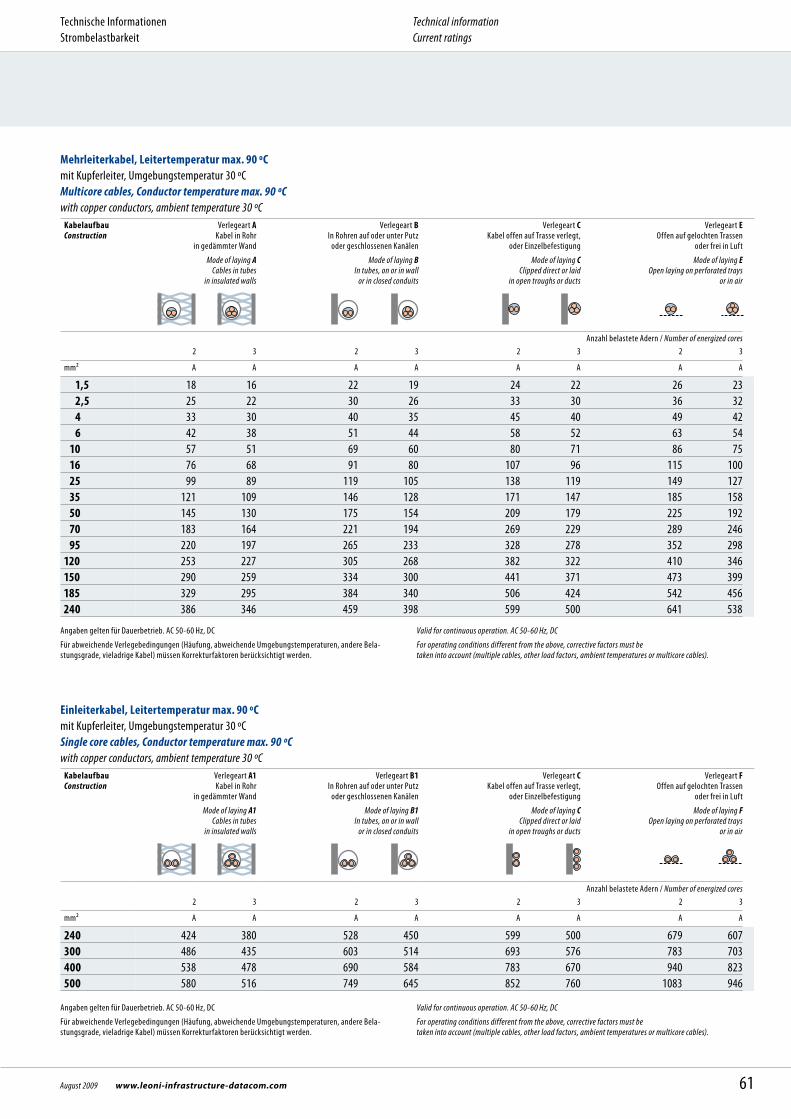
Einleiterkabel, Leitertemperatur max. 90 ºCmit Kupferleiter, Umgebungstemperatur 30 ºC Single core cables, Conductor temperature max. 90 ºCwith copper conductors, ambient temperature 30 ºC
KabelaufbauConstruction
Verlegeart A1 Kabel in Rohr
in gedämmter Wand
Mode of laying A1 Cables in tubes
in insulated walls
Verlegeart B1 In Rohren auf oder unter Putz
oder geschlossenen Kanälen
Mode of laying B1 In tubes, on or in wall or in closed conduits
Verlegeart C Kabel offen auf Trasse verlegt,
oder Einzelbefestigung
Mode of laying C Clipped direct or laid
in open troughs or ducts
Verlegeart F Offen auf gelochten Trassen
oder frei in Luft
Mode of laying F Open laying on perforated trays
or in air
Anzahl belastete Adern / Number of energized cores 2 3 2 3 2 3 2 3
mm² A A A A A A A A
240 424 380 528 450 599 500 679 607300 486 435 603 514 693 576 783 703400 538 478 690 584 783 670 940 823500 580 516 749 645 852 760 1083 946
Angaben gelten für Dauerbetrieb. AC 50-60 Hz, DC
Für abweichende Verlegebedingungen (Häufung, abweichende Umgebungstemperaturen, andere Bela-stungsgrade, vieladrige Kabel) müssen Korrekturfaktoren berücksichtigt werden.
Valid for continuous operation. AC 50-60 Hz, DC
For operating conditions different from the above, corrective factors must be taken into account (multiple cables, other load factors, ambient temperatures or multicore cables).
Mehrleiterkabel, Leitertemperatur max. 90 ºCmit Kupferleiter, Umgebungstemperatur 30 ºC Multicore cables, Conductor temperature max. 90 ºCwith copper conductors, ambient temperature 30 ºC
KabelaufbauConstruction
Verlegeart A Kabel in Rohr
in gedämmter Wand
Mode of laying A Cables in tubes
in insulated walls
Verlegeart B In Rohren auf oder unter Putz
oder geschlossenen Kanälen
Mode of laying B In tubes, on or in wall or in closed conduits
Verlegeart C Kabel offen auf Trasse verlegt,
oder Einzelbefestigung
Mode of laying C Clipped direct or laid
in open troughs or ducts
Verlegeart E Offen auf gelochten Trassen
oder frei in Luft
Mode of laying E Open laying on perforated trays
or in air
Anzahl belastete Adern / Number of energized cores 2 3 2 3 2 3 2 3
mm² A A A A A A A A
1,5 18 16 22 19 24 22 26 23 2,5 25 22 30 26 33 30 36 32 4 33 30 40 35 45 40 49 42 6 42 38 51 44 58 52 63 54 10 57 51 69 60 80 71 86 75 16 76 68 91 80 107 96 115 100 25 99 89 119 105 138 119 149 127 35 121 109 146 128 171 147 185 158 50 145 130 175 154 209 179 225 192 70 183 164 221 194 269 229 289 246 95 220 197 265 233 328 278 352 298120 253 227 305 268 382 322 410 346150 290 259 334 300 441 371 473 399185 329 295 384 340 506 424 542 456240 386 346 459 398 599 500 641 538
Angaben gelten für Dauerbetrieb. AC 50-60 Hz, DC
Für abweichende Verlegebedingungen (Häufung, abweichende Umgebungstemperaturen, andere Bela-stungsgrade, vieladrige Kabel) müssen Korrekturfaktoren berücksichtigt werden.
Valid for continuous operation. AC 50-60 Hz, DC
For operating conditions different from the above, corrective factors must be taken into account (multiple cables, other load factors, ambient temperatures or multicore cables).
61August 2009 www.leoni-infrastructure-datacom.com
Technische Informationen Strombelastbarkeit
Technical informationCurrent ratings
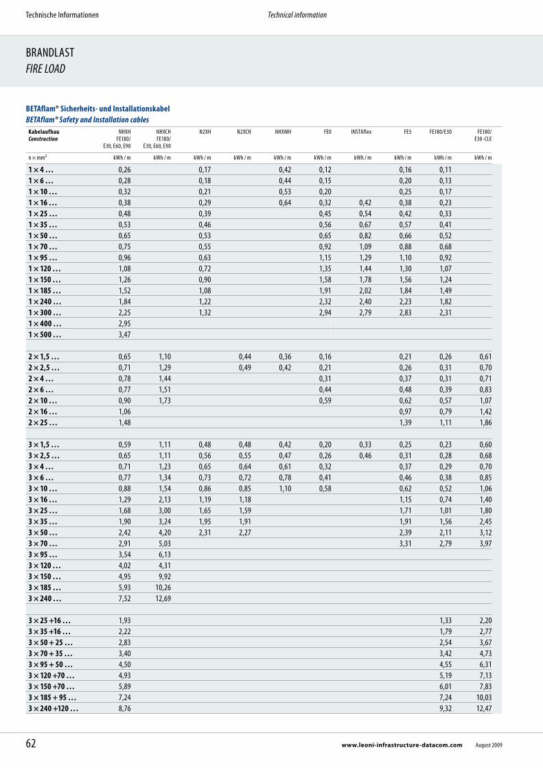
BRANDLASTFIRE LOAD
BETAflam® Sicherheits- und Installationskabel BETAflam® Safety and Installation cables
KabelaufbauConstruction
NHXH FE180/
E30, E60, E90
NHXCH FE180/
E30, E60, E90
N2XH N2XCH NHXMH FE0 INSTAflex FE5 FE180/E30 FE180/ E30-CLE
n × mm² kWh / m kWh / m kWh / m kWh / m kWh / m kWh / m kWh / m kWh / m kWh / m kWh / m
1 × 4 … 0,26 0,17 0,42 0,12 0,16 0,111 × 6 … 0,28 0,18 0,44 0,15 0,20 0,131 × 10 … 0,32 0,21 0,53 0,20 0,25 0,171 × 16 … 0,38 0,29 0,64 0,32 0,42 0,38 0,231 × 25 … 0,48 0,39 0,45 0,54 0,42 0,331 × 35 … 0,53 0,46 0,56 0,67 0,57 0,411 × 50 … 0,65 0,53 0,65 0,82 0,66 0,521 × 70 … 0,75 0,55 0,92 1,09 0,88 0,681 × 95 … 0,96 0,63 1,15 1,29 1,10 0,921 × 120 … 1,08 0,72 1,35 1,44 1,30 1,071 × 150 … 1,26 0,90 1,58 1,78 1,56 1,241 × 185 … 1,52 1,08 1,91 2,02 1,84 1,491 × 240 … 1,84 1,22 2,32 2,40 2,23 1,821 × 300 … 2,25 1,32 2,94 2,79 2,83 2,311 × 400 … 2,951 × 500 … 3,47
2 × 1,5 … 0,65 1,10 0,44 0,36 0,16 0,21 0,26 0,612 × 2,5 … 0,71 1,29 0,49 0,42 0,21 0,26 0,31 0,702 × 4 … 0,78 1,44 0,31 0,37 0,31 0,712 × 6 … 0,77 1,51 0,44 0,48 0,39 0,832 × 10 … 0,90 1,73 0,59 0,62 0,57 1,072 × 16 … 1,06 0,97 0,79 1,422 × 25 … 1,48 1,39 1,11 1,86
3 × 1,5 … 0,59 1,11 0,48 0,48 0,42 0,20 0,33 0,25 0,23 0,603 × 2,5 … 0,65 1,11 0,56 0,55 0,47 0,26 0,46 0,31 0,28 0,683 × 4 … 0,71 1,23 0,65 0,64 0,61 0,32 0,37 0,29 0,703 × 6 … 0,77 1,34 0,73 0,72 0,78 0,41 0,46 0,38 0,853 × 10 … 0,88 1,54 0,86 0,85 1,10 0,58 0,62 0,52 1,063 × 16 … 1,29 2,13 1,19 1,18 1,15 0,74 1,403 × 25 … 1,68 3,00 1,65 1,59 1,71 1,01 1,803 × 35 … 1,90 3,24 1,95 1,91 1,91 1,56 2,453 × 50 … 2,42 4,20 2,31 2,27 2,39 2,11 3,123 × 70 … 2,91 5,03 3,31 2,79 3,973 × 95 … 3,54 6,133 × 120 … 4,02 4,313 × 150 … 4,95 9,923 × 185 … 5,93 10,263 × 240 … 7,52 12,69
3 × 25 +16 … 1,93 1,33 2,203 × 35 +16 … 2,22 1,79 2,773 × 50 + 25 … 2,83 2,54 3,673 × 70 + 35 … 3,40 3,42 4,733 × 95 + 50 … 4,50 4,55 6,313 × 120 +70 … 4,93 5,19 7,133 × 150 +70 … 5,89 6,01 7,833 × 185 + 95 … 7,24 7,24 10,033 × 240 +120 … 8,76 9,32 12,47
62 www.leoni-infrastructure-datacom.com August 2009
Technische Informationen Technical information
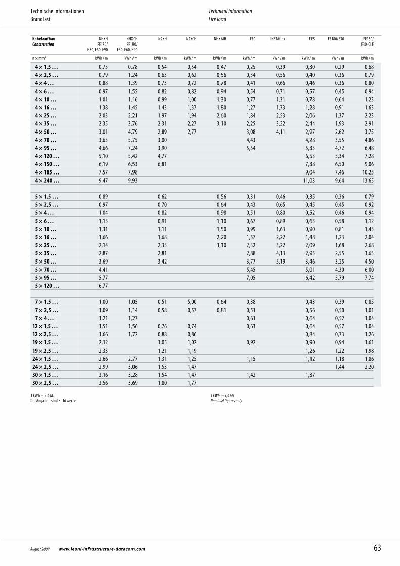
KabelaufbauConstruction
NHXH FE180/
E30, E60, E90
NHXCH FE180/
E30, E60, E90
N2XH N2XCH NHXMH FE0 INSTAflex FE5 FE180/E30 FE180/ E30-CLE
n × mm² kWh / m kWh / m kWh / m kWh / m kWh / m kWh / m kWh / m kW h/ m kWh / m kWh / m
4 × 1,5 … 0,73 0,78 0,54 0,54 0,47 0,25 0,39 0,30 0,29 0,68 4 × 2,5 … 0,79 1,24 0,63 0,62 0,56 0,34 0,56 0,40 0,36 0,79 4 × 4 … 0,88 1,39 0,73 0,72 0,78 0,41 0,66 0,46 0,36 0,80 4 × 6 … 0,97 1,55 0,82 0,82 0,94 0,54 0,71 0,57 0,45 0,94 4 × 10 … 1,01 1,16 0,99 1,00 1,30 0,77 1,31 0,78 0,64 1,23 4 × 16 … 1,38 1,45 1,43 1,37 1,80 1,27 1,73 1,28 0,91 1,63 4 × 25 … 2,03 2,21 1,97 1,94 2,60 1,84 2,53 2,06 1,37 2,23 4 × 35 … 2,35 3,76 2,31 2,27 3,10 2,25 3,22 2,44 1,93 2,91 4 × 50 … 3,01 4,79 2,89 2,77 3,08 4,11 2,97 2,62 3,75 4 × 70 … 3,63 5,75 3,00 4,43 4,28 3,55 4,86 4 × 95 … 4,66 7,24 3,90 5,54 5,35 4,72 6,48 4 × 120 … 5,10 5,42 4,77 6,53 5,34 7,28 4 × 150 … 6,19 6,53 6,81 7,38 6,50 9,06 4 × 185 … 7,57 7,98 9,04 7,46 10,25 4 × 240 … 9,47 9,93 11,03 9,64 13,65
5 × 1,5 … 0,89 0,62 0,56 0,31 0,46 0,35 0,36 0,79 5 × 2,5 … 0,97 0,70 0,64 0,43 0,65 0,45 0,45 0,92 5 × 4 … 1,04 0,82 0,98 0,51 0,80 0,52 0,46 0,94 5 × 6 … 1,15 0,91 1,10 0,67 0,89 0,65 0,58 1,12 5 × 10 … 1,31 1,11 1,50 0,99 1,63 0,90 0,81 1,45 5 × 16 … 1,66 1,68 2,20 1,57 2,22 1,48 1,23 2,04 5 × 25 … 2,14 2,35 3,10 2,32 3,22 2,09 1,68 2,68 5 × 35 … 2,87 2,81 2,88 4,13 2,95 2,55 3,63 5 × 50 … 3,69 3,42 3,77 5,19 3,46 3,25 4,50 5 × 70 … 4,41 5,45 5,01 4,30 6,00 5 × 95 … 5,77 7,05 6,42 5,79 7,74 5 × 120 … 6,77
7 × 1,5 … 1,00 1,05 0,51 5,00 0,64 0,38 0,43 0,39 0,85 7 × 2,5 … 1,09 1,14 0,58 0,57 0,81 0,51 0,56 0,50 1,01 7 × 4 … 1,21 1,27 0,61 0,64 0,52 1,0412 × 1,5 … 1,51 1,56 0,76 0,74 0,63 0,64 0,57 1,0412 × 2,5 … 1,66 1,72 0,88 0,86 0,84 0,73 1,2619 × 1,5 … 2,12 1,05 1,02 0,92 0,90 0,94 1,6119 × 2,5 … 2,33 1,21 1,19 1,26 1,22 1,9824 × 1,5 … 2,66 2,77 1,31 1,25 1,15 1,12 1,18 1,8624 × 2,5 … 2,99 3,06 1,53 1,47 1,44 2,2030 × 1,5 … 3,16 3,28 1,54 1,47 1,42 1,3730 × 2,5 … 3,56 3,69 1,80 1,77
1 kWh = 3,6 MJDie Angaben sind Richtwerte
1 kWh = 3,6 MJNominal figures only
63August 2009 www.leoni-infrastructure-datacom.com
Technische InformationenBrandlast
Technical information Fire load
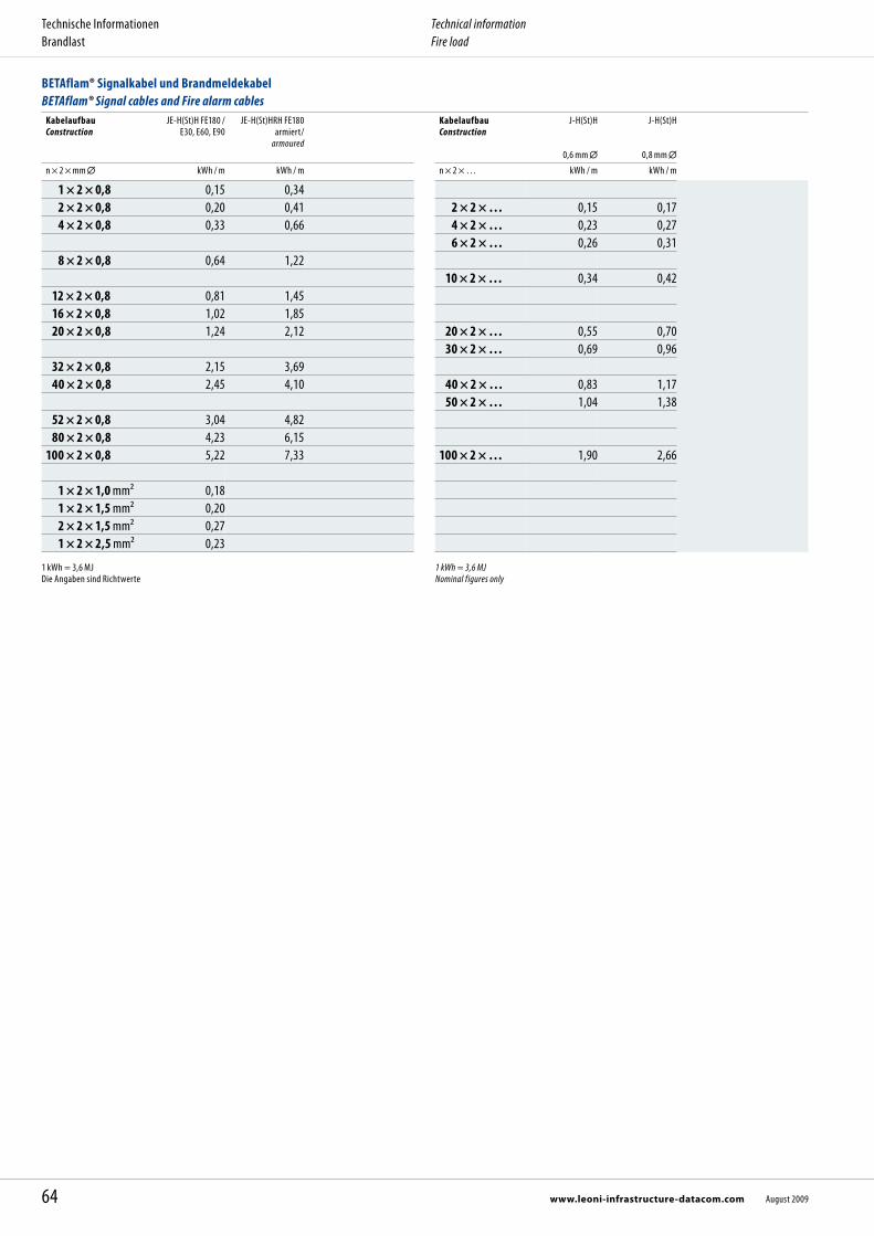
BETAflam® Signalkabel und Brandmeldekabel BETAflam® Signal cables and Fire alarm cables
KabelaufbauConstruction
JE-H(St)H FE180 / E30, E60, E90
JE-H(St)HRH FE180 armiert/
armoured
KabelaufbauConstruction
J-H(St)H
0,6 mm
J-H(St)H
0,8 mm
n × 2 × mm kWh / m kWh / m n × 2 × … kWh / m kWh / m
1 × 2 × 0,8 0,15 0,34 2 × 2 × 0,8 0,20 0,41 2 × 2 × … 0,15 0,17 4 × 2 × 0,8 0,33 0,66 4 × 2 × … 0,23 0,27
6 × 2 × … 0,26 0,31 8 × 2 × 0,8 0,64 1,22
10 × 2 × … 0,34 0,42 12 × 2 × 0,8 0,81 1,45 16 × 2 × 0,8 1,02 1,85 20 × 2 × 0,8 1,24 2,12 20 × 2 × … 0,55 0,70
30 × 2 × … 0,69 0,96 32 × 2 × 0,8 2,15 3,69 40 × 2 × 0,8 2,45 4,10 40 × 2 × … 0,83 1,17
50 × 2 × … 1,04 1,38 52 × 2 × 0,8 3,04 4,82 80 × 2 × 0,8 4,23 6,15100 × 2 × 0,8 5,22 7,33 100 × 2 × … 1,90 2,66
1 × 2 × 1,0 mm² 0,18 1 × 2 × 1,5 mm² 0,20 2 × 2 × 1,5 mm² 0,27 1 × 2 × 2,5 mm² 0,23
1 kWh = 3,6 MJDie Angaben sind Richtwerte
1 kWh = 3,6 MJNominal figures only
64 www.leoni-infrastructure-datacom.com August 2009
Technische InformationenBrandlast
Technical information Fire load
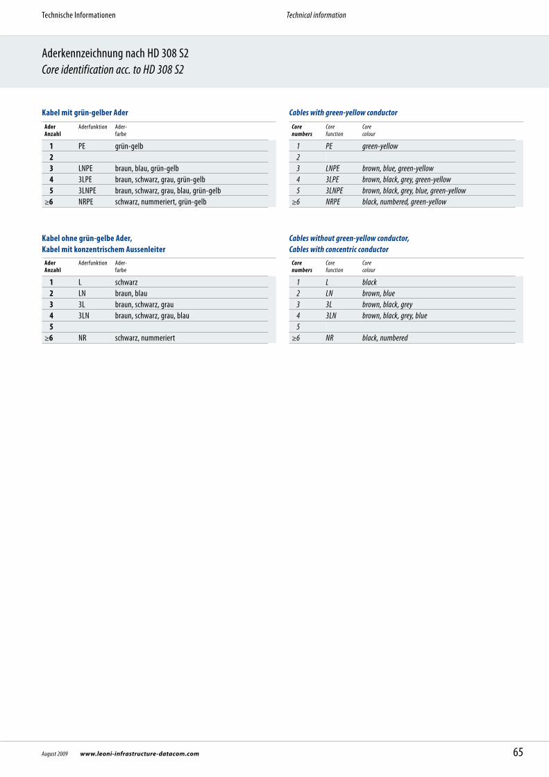
Aderkennzeichnung nach HD 308 S2Core identification acc. to HD 308 S2
Kabel mit grün-gelber Ader
Ader Anzahl
Aderfunktion Ader- farbe
1 PE grün-gelb 2 3 LNPE braun, blau, grün-gelb 4 3LPE braun, schwarz, grau, grün-gelb 5 3LNPE braun, schwarz, grau, blau, grün-gelb≥6 NRPE schwarz, nummeriert, grün-gelb
Kabel ohne grün-gelbe Ader, Kabel mit konzentrischem Aussenleiter
Ader Anzahl
Aderfunktion Ader- farbe
1 L schwarz 2 LN braun, blau 3 3L braun, schwarz, grau 4 3LN braun, schwarz, grau, blau 5 ≥6 NR schwarz, nummeriert
Cables with green-yellow conductor
Core numbers
Core function
Core colour
1 PE green-yellow 2 3 LNPE brown, blue, green-yellow 4 3LPE brown, black, grey, green-yellow 5 3LNPE brown, black, grey, blue, green-yellow≥6 NRPE black, numbered, green-yellow
Cables without green-yellow conductor,Cables with concentric conductor
Core numbers
Core function
Core colour
1 L black 2 LN brown, blue 3 3L brown, black, grey 4 3LN brown, black, grey, blue 5≥6 NR black, numbered
65August 2009 www.leoni-infrastructure-datacom.com
Technische Informationen Technical information

Halogenfreiheit und BrandverhaltenHalogen free and Fire performance
Halogenfreiheit
Als Halogene bezeichnet man die Elemente der Gruppe 7 im Periodensystem: Chlor (Cl), Fluor (F), Brom (Br), Jod (I).
Halogenfreie Kabel sind frei von all diesen Elementen. Sie werden Halogene genannt, weil sie mit Laugen zusammen Salze bilden (Hals: griechisch für Salz); Chlor bildet mit Natrium Kochsalz (NaCl).
Die Halogene bilden einen Bestandteil vieler Säuren HCl = Salzsäure HF = Hydrogenfluorid HBr = Hydrogenbromid
Der weitest verbreitete halogenhaltige Kunststoff ist PVC (Polyvinylchlorid). Im Brandfall wird Salzsäure abgespalten. Daher besteht die Tendenz, halogenhaltige Kunststoffe durch halogenfreie zu ersetzen. So wird beispielsweise PVC in grossem Masse durch Polyolefine ersetzt, wie zum Beispiel Polyäthylen. Dank halogenfreier Kabel verhindert man das Entstehen von korrosiven und gif-tigen Gasen.
Prüfverfahren 1000 mg Material werden auf einem vorher ausgeglühten Kupferdraht an den äusseren Rand einer Gasflamme gehalten.
Anforderung Der Werkstoff gilt als halogenfrei, wenn keine grüne bis blaugrüne Verfärbung der Flamme auftritt. Chlor und Brom verfärben die Flamme, Fluor kann nicht sicher nach gewiesen werden.
Prüfnorm IEC 60754-1, EN 50267-2-1
Halogen free
The halogens are the elements of the 7th group in the Periodic Table of Elements: chlorine (Cl), fluorine (F), bromine (Br), iodine (I).
Halogen free cables must be free of chlorine, fluorine and bromine (PVC cables contain halogen, PVC = Polyvinylchloride).
The halogens are an integrated component of many acids HCl = Salt acid (hydrochloric acid) HF = Hydrogenfluorid HBr = Hydrogenbromid
The most popular plastic containing halogens is PVC (polyvinyl chloride). In case of fire or at high temperature PVC starts to degradate. Hydrochloric acid and other fission products are generated and leads to extremely aggressive corrosion. Therefore the cur-rent trend is to replace the halogen containing plastics with halogen free ones. For in-stance PVC is currently being replaced at a large scale with polyolefin i.e. polyethylene.Thanks to halogen free cables the formation of corrosive and toxic gases can be pre-vented.
Test procedures1000 mg of the testing material must be hold at one termination of an pre-annealed copper wire in a gas flame.
RequirementThe material is considered to be halogen free if no green to blue-green flame discolou-ration occurs. The chlorine and the bromine would cause such a discolouration, however the existence of fluorine cannot be proven like that.
Test standards IEC 60754-1, EN 50267-2-1
66 www.leoni-infrastructure-datacom.com August 2009
Technische Informationen Technical information

Korrosivität der Brandgase
Korrosiv wirkende Gase verbinden sich mit der Feuchtigkeit zu aggressiven Säuren, die Metallteile angreifen und hier, selbst bei geringem direkten Brandschaden, grosse Folgeschäden verursachen. Dies betrifft auch nicht direkt vom Brandereignis betroffene Stellen. Besonders gefährdet sind elektrische Kontakte, elektronische Bauteile und Apparate, Maschinen und Metallkonstruktionen. Sogar das von Beton eingeschlossene Armierungseisen wird angegriffen.
Prüfverfahren1000 mg Isoliermaterial wird in einem Verbrennungsofen bei ≥ 935 °C mit defi-nierter Luftzufuhr verbrannt (≥ 30 min). Mit zwei Gaswasch flaschen im Abluft-strom wird die Leitfähigkeit und der pH-Wert gemessen. Damit lassen sich schon geringe Mengen halogenhaltiger Stoffe nachweisen.
Die Prüfung ist bestanden, wenn der pH-Wert > 4,3 die Leitfähigkeit < 10 µS/mm betragen.
Prüfnorm IEC 60754-2, EN 50267-2-2
Degree of acidity of combustion gases
Corrosive gases act with moisture to produce aggressive acids which corrode metal parts and cause extensive long-term damage, eben though the fire damage may only be limited; this is because corrosive gases often spread throughout a building through the ventilation system or withing whole installations. The damage may not be limited to the area immediately affected by the fire. Electronic units and electronic contacts are particularly vulnerable, as are free-standing or concrete encolsed steel constructions.
Test procedures1000 mg insulation material is burned in a combustion furnace at ≥ 935 °C with pre-defined air supply for over 30 minutes. By means of two gas washing containers, held in the airflow the conductivity and the pH-value are measured. Like that even small quantities of halogen containing substances can be detected and proven.
The test is considered to be passed when the ph-value > 4,3 the conductivity < 10 µS/mm
Test standards IEC 60754-2, EN 50267-2-2
67August 2009 www.leoni-infrastructure-datacom.com
Technische Informationen Halogenfreiheit und Brandverhalten
Technical information Halogen free and Fire performance
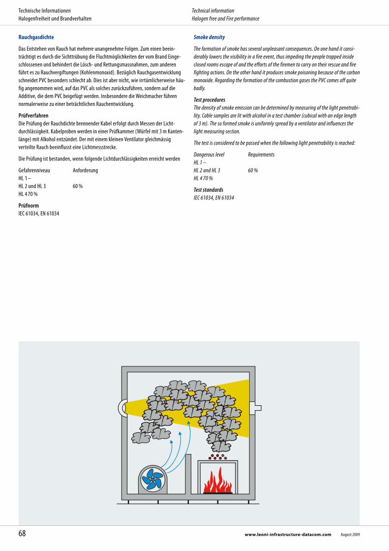
Rauchgasdichte
Das Entstehen von Rauch hat mehrere unangenehme Folgen. Zum einen beein-trächtigt es durch die Sichttrübung die Fluchtmöglichkeiten der vom Brand Einge-schlossenen und behindert die Lösch- und Rettungs massnahmen, zum anderen führt es zu Rauchvergiftungen (Kohlen monoxid). Bezüglich Rauchgasentwicklung schneidet PVC besonders schlecht ab. Dies ist aber nicht, wie irrtümlicherweise häu-fig angenommen wird, auf das PVC als solches zurückzuführen, sondern auf die Additive, die dem PVC beigefügt werden. Insbesondere die Weichmacher führen normalerweise zu einer beträchtlichen Rauchentwicklung.
Prüfverfahren Die Prüfung der Rauchdichte brennender Kabel erfolgt durch Messen der Licht-durchlässigkeit. Kabelproben werden in einer Prüfkammer (Würfel mit 3 m Kanten-länge) mit Alkohol entzündet. Der mit einem kleinen Ventilator gleichmässig verteilte Rauch beeinflusst eine Lichtmess strecke.
Die Prüfung ist bestanden, wenn folgende Lichtdurchlässigkeiten erreicht werden
Gefahrenniveau AnforderungHL 1 –HL 2 und HL 3 60 %HL 4 70 %
Prüfnorm IEC 61034, EN 61034
Smoke density
The formation of smoke has several un pleasant consequences. On one hand it consi-derably lowers the visibility in a fire event, thus impeding the people trapped inside closed rooms escape of and the efforts of the firemen to carry on their rescue and fire fighting actions. On the other hand it produces smoke poisoning because of the carbon monoxide. Regarding the formation of the combustion gases the PVC comes off quite badly.
Test procedures The density of smoke emission can be determined by measuring of the light penetrabi-lity. Cable samples are lit with alcohol in a test chamber (cubical with an edge length of 3 m). The so formed smoke is uniformly spread by a ventilator and influences the light measuring section.
The test is considered to be passed when the following light penetrability is reached:
Dangerous level RequirementsHL 1 –HL 2 and HL 3 60 %HL 4 70 %
Test standards IEC 61034, EN 61034
68 www.leoni-infrastructure-datacom.com August 2009
Technische Informationen Halogenfreiheit und Brandverhalten
Technical information Halogen free and Fire performance
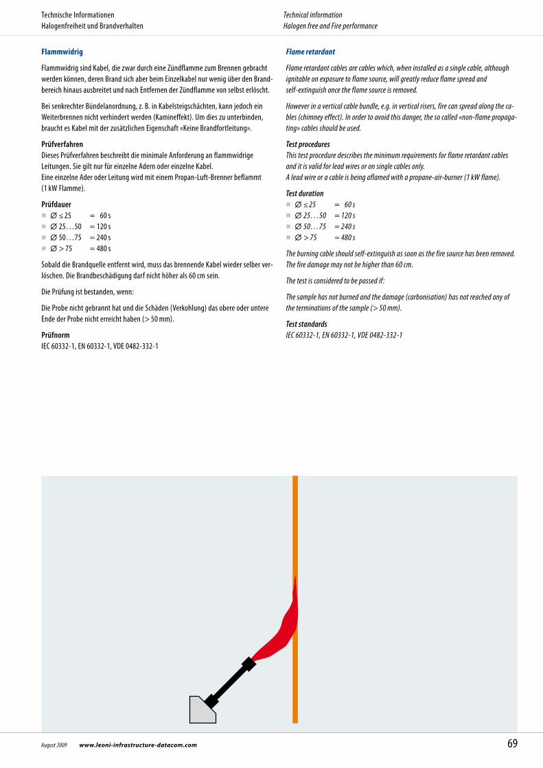
Flame retardant
Flame retardant cables are cables which, when installed as a single cable, although ignitable on exposure to flame source, will greatly reduce flame spread and self-extinguish once the flame source is removed.
However in a vertical cable bundle, e.g. in vertical risers, fire can spread along the ca-bles (chimney effect). In order to avoid this danger, the so called «non-flame propaga-ting» cables should be used.
Test procedures This test procedure describes the minimum requirements for flame retardant cables and it is valid for lead wires or on single cables only.A lead wire or a cable is being aflamed with a propane-air-burner (1 kW flame).
Test duration ≤ 25 = 60 s 25…50 = 120 s 50…75 = 240 s > 75 = 480 s
The burning cable should self-extinguish as soon as the fire source has been removed. The fire damage may not be higher than 60 cm.
The test is considered to be passed if:
The sample has not burned and the damage (carbonisation) has not reached any of the terminations of the sample (> 50 mm).
Test standards IEC 60332-1, EN 60332-1, VDE 0482-332-1
Flammwidrig
Flammwidrig sind Kabel, die zwar durch eine Zündflamme zum Brennen gebracht werden können, deren Brand sich aber beim Einzelkabel nur wenig über den Brand-bereich hinaus ausbreitet und nach Entfernen der Zündflamme von selbst erlöscht.
Bei senkrechter Bündelanordnung, z. B. in Kabelsteigschächten, kann jedoch ein Weiterbrennen nicht verhin dert werden (Kamineffekt). Um dies zu unterbinden, braucht es Kabel mit der zusätzlichen Eigenschaft «Keine Brandfortleitung».
Prüfverfahren Dieses Prüfverfahren beschreibt die minimale Anforderung an flammwidrige Leitungen. Sie gilt nur für einzelne Adern oder einzelne Kabel. Eine einzelne Ader oder Leitung wird mit einem Propan-Luft-Brenner beflammt (1 kW Flamme).
Prüfdauer ≤ 25 = 60 s 25…50 = 120 s 50…75 = 240 s > 75 = 480 s
Sobald die Brandquelle entfernt wird, muss das brennende Kabel wieder selber ver-löschen. Die Brandbeschädigung darf nicht höher als 60 cm sein.
Die Prüfung ist bestanden, wenn:
Die Probe nicht gebrannt hat und die Schäden (Verkohlung) das obere oder untere Ende der Probe nicht erreicht haben (> 50 mm).
Prüfnorm IEC 60332-1, EN 60332-1, VDE 0482-332-1
69August 2009 www.leoni-infrastructure-datacom.com
Technische Informationen Halogenfreiheit und Brandverhalten
Technical information Halogen free and Fire performance

Keine Brandfortleitung
Nicht brandfortleitend sind Kabel, die durch eine Zündflamme entzündet werden können, deren Brand aber auch bei senkrechter Anordnung von Kabelbündeln nicht weitergeleitet wird und die beim Verlöschen des Brandherdes von selbst erlöschen.
PrüfverfahrenDiese Prüfung simuliert die Kaminwirkung von vertikalen Kabelanlagen. In einem genormten Schrank wird das Kabelbündel mit einem Brenner während 20 - 40 Mi-nuten in Brand gehalten (Gasbrenner 75 ± 5 MJ/h). Die Temperatur wird dabei auf 750 °C reguliert. Man unterscheidet je nach dem Volumen nichtmetallischen (brennbaren) Materials pro Laufmeter die Kategorien A F/R, A, B, C und D.
Kategorie A F/R A B C D Liter (dm³) Isolierstoff 7 7 3.5 1,5 0,5
auf 1 m Probe Beflammungszeit (min) 40 40 40 20 20
Nach dem Test müssen die Kabel selber verlöschen. Sie dürfen bis zu einer Höhe von 2,5 m ab Brenner abgebrannt sein. Bei Studer-Kabeln beträgt diese Höhe etwa 50 bis 60 cm.
Prüfnorm
No flame propagation
No flame propagating cables are those cables which can be ignited by a flame source, however they do not allow the fire to spread even if the cable bundle is placed vertical-ly; they are self extinguishing once the fire source is removed.
Test procedures This test simulates the chimney effect in vertical cable installations. In a standardized cabinet the cable bundle is kept in a burner fire for 20 - 40 minutes (gas burner 75 ± 5 MJ/h). Thereby the temperature is kept constant to 750 °C. Depending on the volume of the non-metal (combustible) materials per running meter it can be differen-tiated in the categories A F/R, A, B, C und D as follows.
Category A F/R A B C D Liter (dm³) of insulation 7 7 3.5 1,5 0,5
material per 1 m sample Aflame time (min) 40 40 40 20 20
The cables must self-extinguish after removing the fire source. The fire may not have propagated any further than 2,5 m from the burner. With the cables of LEONI Studer AG this should reach no further than 50 to 60 cm.
Test standards
Kategorie IEC EN VDE 0482
A F/R 60332-3-21 60332-3-21 Teil 266-2-1A 60332-3-22 60332-3-22 Teil 266-2-2B 60332-3-23 60332-3-23 Teil 266-2-3C 60332-3-24 60332-3-24 Teil 266-2-4D 60332-3-25 60332-3-25 Teil 266-2-5Norm Prüfgerät 60332-3-10 60332-3-10 Teil 266-1
Category IEC EN VDE 0482
A F/R 60332-3-21 60332-3-21 part 266-2-1A 60332-3-22 60332-3-22 part 266-2-2B 60332-3-23 60332-3-23 part 266-2-3C 60332-3-24 60332-3-24 part 266-2-4D 60332-3-25 60332-3-25 part 266-2-5Standard test equipment 60332-3-10 60332-3-10 part 266-1
70 www.leoni-infrastructure-datacom.com August 2009
Technische Informationen Halogenfreiheit und Brandverhalten
Technical information Halogen free and Fire performance
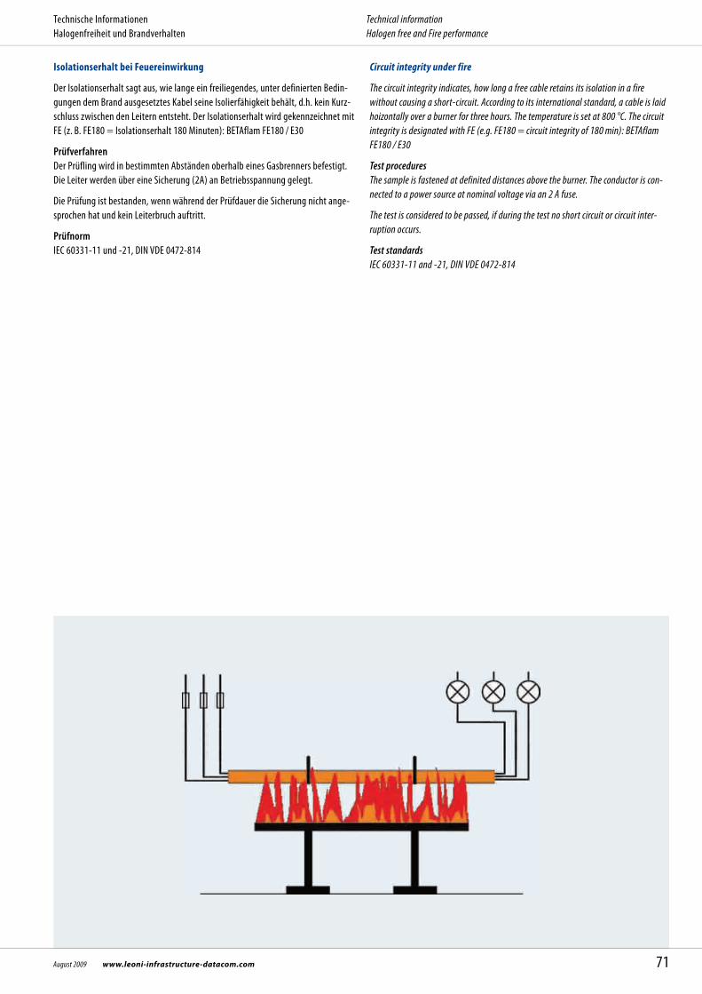
Isolationserhalt bei Feuereinwirkung
Der Isolationserhalt sagt aus, wie lange ein freiliegendes, unter definierten Bedin-gungen dem Brand ausgesetztes Kabel seine Isolierfähigkeit behält, d.h. kein Kurz-schluss zwischen den Leitern entsteht. Der Isolationserhalt wird gekennzeichnet mit FE (z. B. FE180 = Isolations erhalt 180 Minuten): BETAflam FE180 / E30
Prüfverfahren Der Prüfling wird in bestimmten Abständen oberhalb eines Gasbrenners befestigt. Die Leiter werden über eine Sicherung (2A) an Betriebsspannung gelegt.
Die Prüfung ist bestanden, wenn während der Prüfdauer die Sicherung nicht ange-sprochen hat und kein Leiterbruch auftritt.
Prüfnorm IEC 60331-11 und -21, DIN VDE 0472-814
Circuit integrity under fire
The circuit integrity indicates, how long a free cable retains its isolation in a fire without causing a short-circuit. According to its international standard, a cable is laid hoizontally over a burner for three hours. The temperature is set at 800 °C. The circuit integrity is designated with FE (e.g. FE180 = circuit integrity of 180 min): BETAflam FE180 / E30
Test procedures The sample is fastened at definited distances above the burner. The conductor is con-nected to a power source at nominal voltage via an 2 A fuse.
The test is considered to be passed, if during the test no short circuit or circuit inter- ruption occurs.
Test standards IEC 60331-11 and -21, DIN VDE 0472-814
71August 2009 www.leoni-infrastructure-datacom.com
Technische Informationen Halogenfreiheit und Brandverhalten
Technical information Halogen free and Fire performance

Isolationserhalt mit Schlagbeanspruchung
Notlaufkabel mit Durchmesser bis 20 mm werden nach dieser Norm unter Bean-spruchung durch Feuer und mechanischen Schock geprüft.
Prüfverfahren Ein einzelnes Kabel wird unter Vorgabe der kleinsten zulässigen Biegeradien auf einer Prüfwand befestigt und bei einer Prüftemperatur von mindestens 830 °C und Schlägen auf die Halterung des Kabels geprüft. Während der Dauer des Isolations-erhalts muss die Spannung gehalten werden und Strom geleitet werden. Die gemessene Beständigkeitsdauer dient zur Klassifizierung der Kabel nach der Europäischen Bauprodukte-Richtlinie in der Klassen PH15 bis PH 90.
Die Prüfung ist bestanden, wenn während der Prüfdauer die Sicherung nicht ange-sprochen hat.
Prüfnorm EN 50200, EN 50362, VDE 0482 Teil 200
Circuit integrity with mechanical shock
Cables for emergency circuits up to 20 mm diameter are sub-jected to fire with mecha-nical shock during a survival time of maximum 90 minutes.
Test procedures A single cable is fastened to a test wall under conditions of minimum bending radii and is tested at a minimum test temperature of 830 °C and impacts on the cable sup-port. During the test no rupture of conductors shall appear and voltage must be maintained. For the purposes of the European Construction Products Directive the survival time serves to classify the cables into PH classes from PH15 to PH90.
The test is considered to be passed, if during the test no short circuit occurred.
Test standards EN 50200, EN 50362, VDE 0482 part 200
72 www.leoni-infrastructure-datacom.com August 2009
Technische Informationen Halogenfreiheit und Brandverhalten
Technical information Halogen free and Fire performance

Funktionserhalt bei Feuereinwirkung
Nachweis des Funktionserhalts von Kabelanlagen im Brandfall. Die Prüfung umfasst sowohl die Kabel, wie auch die Verlegesysteme.
Prüfverfahren Die Prüfmuster verschiedener Querschnitte sind mit dem Befestigungssystem in einem Prüfofen über eine Länge von min. 3 m zu installieren. Die Prüftemperatur steigt nach einer vorgegebenen Kurve auf 850 -1000 °C. Die Leiter werden über eine Sicherung (2 A) an Betriebsspannung (110 resp. 400 V) gelegt.
Die Prüfung ist bestanden, wenn während der Prüfdauer kein Kurzschluss und keine Unterbrechung des Stromflusses auftreten.Für die Einstufung in die Klassen E30, E60, E90 zählt das ungünstigste Ergebnis der Prüfung an mindestens zwei gleichen Probekörpern.Die temperaturbedingte Widerstandserhöhung der Kabel wird in der Prüfung nicht berücksichtigt.
Prüfnorm DIN 4102 Teil 12 :1998 -11
System integrity
The evidence of the conservation of the functionality of cable installations in event of fire. The test involves the cable as well as the fastening resp. the laying system.
Test procedures The profiles are installed together with the fastening system in a testing oven with a minimum length of 3 m. The conductors are connected to a 400 V (for control cables 110 V) power source and fused with 2 A. The testing temperature is 850 °C up to 1000 °C.
The test is considered to be passed, if during the test there is no short circuit or circuit interruption in the cable system. The classification E30, E60, E90 bases on the least favourable result obtained on at least two identical specimens.The heat-induced increase in conductor resistance is not taken into account during the test.
Test standards DIN 4102 part 12 :1998 -11
73August 2009 www.leoni-infrastructure-datacom.com
Technische Informationen Halogenfreiheit und Brandverhalten
Technical information Halogen free and Fire performance

The duration of the system circuit integrity depends on how long the supply of electri-cal services must continue in the event of a fire. National legislations in most countries provide requirements for safety systems which have to be met.
EvacuationIn many countries a duration of 30 minutes is considered sufficient for alarm and evacuation of people.Compliance with this requirement with regard to the systems (fire alarm systems, emergency lighting, passenger hoists, smoke exhaust, voice alarm and acoustic signalling, escape route signalling) can be achieved by means of a «Class E30» cable system. For special buildings like high-rise buildings, hospitals, tunnels, prisons, a duration of 60 to 90 minutes can also adequate. In this case a «Class E60» or even «E90» cable system could be required (e.g. for the supply of lifts for in-patients etc.).
Fire fightingBesides rescuing time for people extra time for the work of the fire brigades must be allocated. Mostly 90 minutes after the fire starts are regarded sufficient for fire fighting. The uninterrupted power supply of the electrical systems used for this (e.g. sprinkler water pumps, mechanical smoke exhausts, firemen lifts) can be attained with «Class E90» cable systems.
PlanningPlanning an electrical safety system means finding answers to the questions: Which parts of the building requires which level of safety? Which electrical system has to be supplied for how long? Which circuits are involved (safety circuits)? Which is the best cable routing for these circuits? Are there restrictions concerning fire load, etc.?
Only then the selection of appropriate cables and support systems can begin.
Die Dauer des Funktionserhalts der Kabelanlage richtet sich danach, wie lange die angeschlossenen elektrischen Verbraucher im Brandfall ihre Funktion weiter aus- üben müssen. In praktisch allen nationalen Gesetzen bestehen dazu Forderungen für Sicherheitseinrichtungen, die eingehalten werden müssen.
EvakuierungIn vielen Ländern gilt für die Alarmierung und Evakuierung von Personen eine Zeit von 30 Minuten als ausreichend.Diese Funktionsdauer der Anlagen (z.B. Brandmeldeanlagen, Sicherheitsbeleuch-tungsanlagen, Personenaufzüge, natürlichen Rauchabzugsanlagen, Systeme zur akustischen Signalisierung und Ansage) lässt sich mit Kabelanlagen der Klasse E30 erreichen. In besonderen Gebäuden, wie Hochhäusern, Krankenhäusern, Tunneln, Gefängnis-sen, kann auch eine Funktionsdauer von 60 oder 90 Minuten erforderlich sein. Hier sind Kabelanlagen der Klasse E60 und E90 erforderlich (z.B. für die Versorgung von Bettenaufzügen usw.).
Brandbekämpfung Nach der Personenrettung muss eine zusätzliche Zeit für die Arbeiten der Feuer-wehr gerechnet werden. Meist gilt für die Brandbekämpfung eine Zeit von 90 Minuten ab Brandausbruch als ausreichend. Die Versorgung der dazu benötig- ten elektrischen Anlagen (z.B. Wasserdruckerhöhungsanlagen, Feuerwehraufzüge, maschinelle Rauchabzugsanlagen) lässt sich mit Kabelanlagen der Klasse E90 erreichen.
PlanungZur Planung der elektrischen Anlage gehören die Festlegungen zu den Fragen: Welche Gebäudeteile erfordern welche Stufe Sicherheit? Welche elektrischen Verbraucher sind über welche Funktionserhaltsdauer zu
versorgen? Welche Zuleitungen sind betroffen (Sicherheits-Stromkreise) Über welche Wege sind diese Leitungen zu führen? Gibt es Einschränkungen z.B. bezüglich Brandlast, usw.?
Erst dann kann die Auswahl der passenden Tragesysteme und Kabel beginnen.
Funktionserhaltsdauer im Baurecht Duration of system circuit integrity in the building laws
74 www.leoni-infrastructure-datacom.com August 2009
Technische Informationen Technical information

8. 20
09 /
d +
e /
4000
Expl
. / G
edru
ckt i
n der
Schw
eiz
Herrenmattstrasse 20
Postfach 63
CH - 4658 Däniken
Telefon +41 (0)62 288 82 82
Telefax +41 (0)62 288 83 83
E-Mail [email protected]
www.leoni-infrastructure-datacom.com
www.leoni-studer.ch
Stahlbaustraße 56
D - 64560 Riedstadt-Goddelau
Telefon +49 (0)6158 9208 0
Telefax +49 (0)6158 9208 19
E-Mail [email protected]
www.leoni-studer.de
www.leoni.com
LEONI Studer AGBusiness Unit
Infrastructure & Datacom
LEONI Studer GmbH