CFD Untersuchung von im Ölbad rotierenden · PDF fileCFD Untersuchung von im Ölbad...
27
CFD Untersuchung von im Ölbad rotierenden Zahnrädern mit Fluent CFD investigation of rotating gears in oil with Fluent Paul Illg, Alexander Berg, Dmitrij Neufeld John Deere GmbH & Co. KG, Mannheim
-
Upload
nguyenngoc -
Category
Documents
-
view
214 -
download
0
Transcript of CFD Untersuchung von im Ölbad rotierenden · PDF fileCFD Untersuchung von im Ölbad...
CFD Untersuchung von im Ölbad rotierenden Zahnrädern mit Fluent CFD investigation of rotating gears in oil with Fluent
Paul Illg, Alexander Berg, Dmitrij Neufeld John Deere GmbH & Co. KG, Mannheim
P. Illg, A. Berg, D. Neufeld 2 ANSYS Conference & 33rd CADFEM Users' Meeting
June 24 – 26, 2015, Messe Bremen |
Content
John Deere – Today
Background & Objectives
Verification Procedure
Results
Conclusion
P. Illg, A. Berg, D. Neufeld 3 ANSYS Conference & 33rd CADFEM Users' Meeting
June 24 – 26, 2015, Messe Bremen |
Content
John Deere – Today
Background & Objectives
Verification Procedure
Results
Conclusion
P. Illg, A. Berg, D. Neufeld 4 ANSYS Conference & 33rd CADFEM Users' Meeting
June 24 – 26, 2015, Messe Bremen |
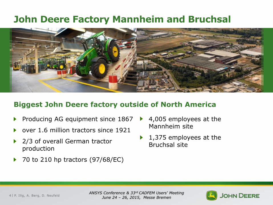
John Deere Factory Mannheim and Bruchsal
Producing AG equipment since 1867
over 1.6 million tractors since 1921
2/3 of overall German tractor production
70 to 210 hp tractors (97/68/EC)
4,005 employees at the Mannheim site
1,375 employees at the Bruchsal site
Biggest John Deere factory outside of North America
P. Illg, A. Berg, D. Neufeld 5 ANSYS Conference & 33rd CADFEM Users' Meeting
June 24 – 26, 2015, Messe Bremen |
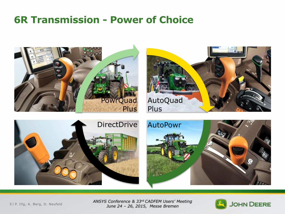
6R Transmission - Power of Choice
PowrQuad Plus
AutoQuad Plus
DirectDrive AutoPowr
P. Illg, A. Berg, D. Neufeld 6 ANSYS Conference & 33rd CADFEM Users' Meeting
June 24 – 26, 2015, Messe Bremen |
Content
John Deere – Today
Background & Objectives
Verification Procedure
Results
Conclusion
P. Illg, A. Berg, D. Neufeld 7 ANSYS Conference & 33rd CADFEM Users' Meeting
June 24 – 26, 2015, Messe Bremen |
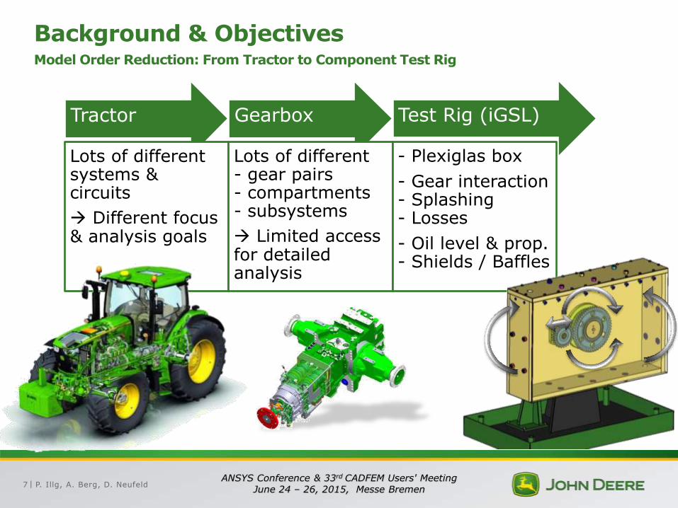
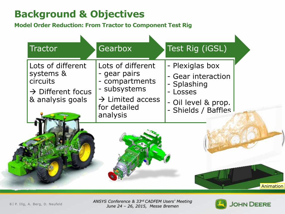
Background & Objectives Model Order Reduction: From Tractor to Component Test Rig
Tractor
Lots of different systems & circuits
Different focus & analysis goals
Gearbox
Lots of different - gear pairs - compartments - subsystems
Limited access for detailed analysis
Test Rig (iGSL)
- Plexiglas box
- Gear interaction - Splashing - Losses
- Oil level & prop. - Shields / Baffles
P. Illg, A. Berg, D. Neufeld 8 ANSYS Conference & 33rd CADFEM Users' Meeting
June 24 – 26, 2015, Messe Bremen |
Background & Objectives Model Order Reduction: From Tractor to Component Test Rig
Tractor
Lots of different systems & circuits
Different focus & analysis goals
Gearbox
Lots of different - gear pairs - compartments - subsystems
Limited access for detailed analysis
Test Rig (iGSL)
- Plexiglas box
- Gear interaction - Splashing - Losses
- Oil level & prop. - Shields / Baffles
Animation
P. Illg, A. Berg, D. Neufeld 9 ANSYS Conference & 33rd CADFEM Users' Meeting
June 24 – 26, 2015, Messe Bremen |
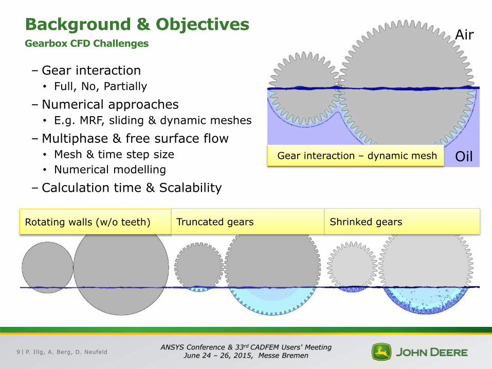
Background & Objectives Gearbox CFD Challenges
–Gear interaction
• Full, No, Partially
– Numerical approaches
• E.g. MRF, sliding & dynamic meshes
–Multiphase & free surface flow
• Mesh & time step size
• Numerical modelling
– Calculation time & Scalability
Rotating walls (w/o teeth) Truncated gears Shrinked gears
Gear interaction – dynamic mesh
Air
Oil
P. Illg, A. Berg, D. Neufeld 10 ANSYS Conference & 33rd CADFEM Users' Meeting
June 24 – 26, 2015, Messe Bremen |
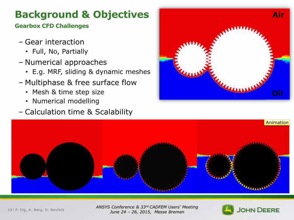
Background & Objectives Gearbox CFD Challenges
–Gear interaction
• Full, No, Partially
– Numerical approaches
• E.g. MRF, sliding & dynamic meshes
–Multiphase & free surface flow
• Mesh & time step size
• Numerical modelling
– Calculation time & Scalability
Rotating walls (w/o teeth) Truncated gears Shrinked gears
Gear interaction – dynamic mesh
Air
Oil
Animation
Air
Oil
P. Illg, A. Berg, D. Neufeld 11 ANSYS Conference & 33rd CADFEM Users' Meeting
June 24 – 26, 2015, Messe Bremen |
Content
John Deere – Today
Background & Objectives
Verification Procedure
Results
Conclusion
P. Illg, A. Berg, D. Neufeld 12 ANSYS Conference & 33rd CADFEM Users' Meeting
June 24 – 26, 2015, Messe Bremen |
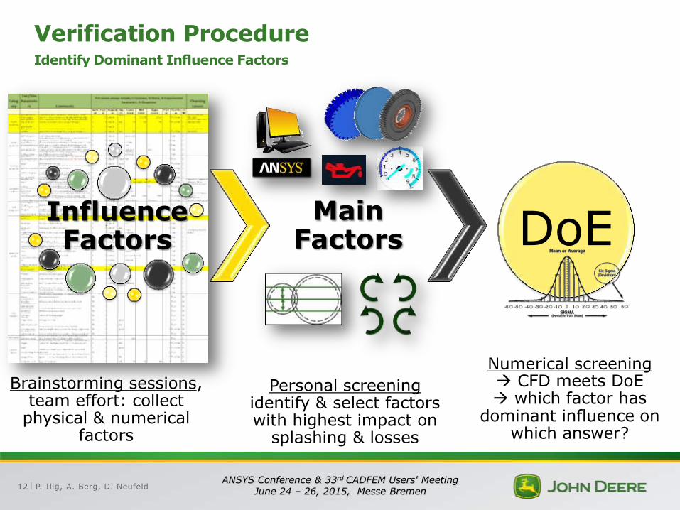
Verification Procedure Identify Dominant Influence Factors
Brainstorming sessions, team effort: collect
physical & numerical factors
Influence Factors
Main Factors
Personal screening identify & select factors with highest impact on
splashing & losses
DoE
Numerical screening CFD meets DoE which factor has
dominant influence on which answer?
P. Illg, A. Berg, D. Neufeld 13 ANSYS Conference & 33rd CADFEM Users' Meeting
June 24 – 26, 2015, Messe Bremen |
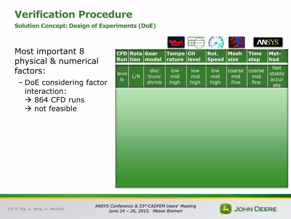
Verification Procedure Solution Concept: Design of Experiments (DoE)
CFD Run
Rotation
Gear model
Temperature
Oil level
Rot. Speed
Mesh size
Time step
Met-hod
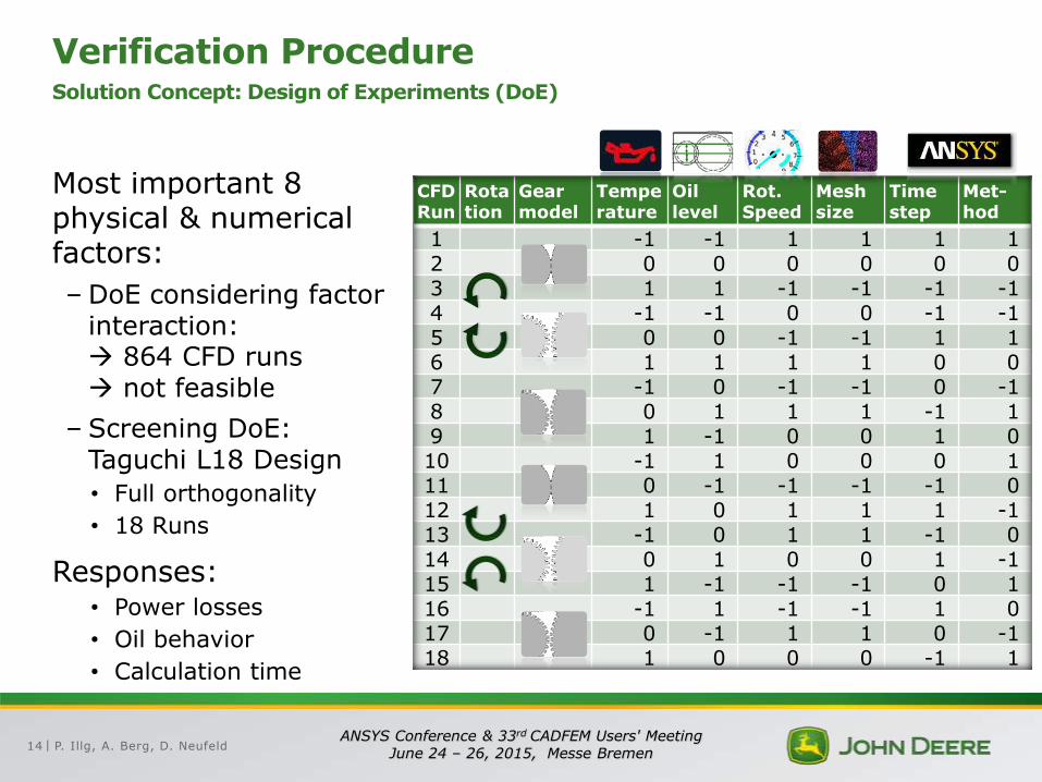
1 -1 -1 1 1 1 1 2 0 0 0 0 0 0 3 1 1 -1 -1 -1 -1 4 -1 -1 0 0 -1 -1 5 0 0 -1 -1 1 1 6 1 1 1 1 0 0 7 -1 0 -1 -1 0 -1 8 0 1 1 1 -1 1 9 1 -1 0 0 1 0 10 -1 1 0 0 0 1 11 0 -1 -1 -1 -1 0 12 1 0 1 1 1 -1 13 -1 0 1 1 -1 0 14 0 1 0 0 1 -1 15 1 -1 -1 -1 0 1 16 -1 1 -1 -1 1 0 17 0 -1 1 1 0 -1 18 1 0 0 0 -1 1
Most important 8 physical & numerical factors:
–DoE considering factor interaction: 864 CFD runs not feasible
levels
L/R disc trunc shrink
low mid high
low mid high
low mid high
coarse mid fine
coarse mid fine
fast stable accurate
P. Illg, A. Berg, D. Neufeld 14 ANSYS Conference & 33rd CADFEM Users' Meeting
June 24 – 26, 2015, Messe Bremen |
Verification Procedure Solution Concept: Design of Experiments (DoE)
CFD Run
Rotation
Gear model
Temperature
Oil level
Rot. Speed
Mesh size
Time step
Met-hod
1 -1 -1 1 1 1 1 2 0 0 0 0 0 0 3 1 1 -1 -1 -1 -1 4 -1 -1 0 0 -1 -1 5 0 0 -1 -1 1 1 6 1 1 1 1 0 0 7 -1 0 -1 -1 0 -1 8 0 1 1 1 -1 1 9 1 -1 0 0 1 0 10 -1 1 0 0 0 1 11 0 -1 -1 -1 -1 0 12 1 0 1 1 1 -1 13 -1 0 1 1 -1 0 14 0 1 0 0 1 -1 15 1 -1 -1 -1 0 1 16 -1 1 -1 -1 1 0 17 0 -1 1 1 0 -1 18 1 0 0 0 -1 1
Most important 8 physical & numerical factors:
–DoE considering factor interaction: 864 CFD runs not feasible
– Screening DoE: Taguchi L18 Design
• Full orthogonality
• 18 Runs
Responses: • Power losses
• Oil behavior
• Calculation time
P. Illg, A. Berg, D. Neufeld 15 ANSYS Conference & 33rd CADFEM Users' Meeting
June 24 – 26, 2015, Messe Bremen |
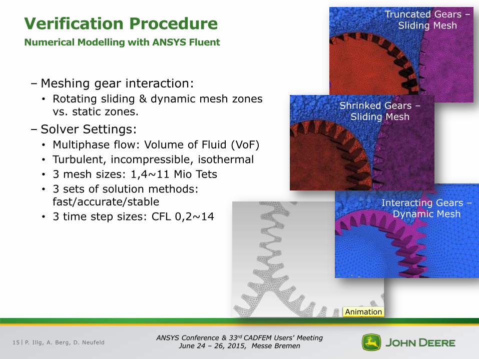
Verification Procedure Numerical Modelling with ANSYS Fluent
–Meshing gear interaction:
• Rotating sliding & dynamic mesh zones vs. static zones.
– Solver Settings:
• Multiphase flow: Volume of Fluid (VoF)
• Turbulent, incompressible, isothermal
• 3 mesh sizes: 1,4~11 Mio Tets
• 3 sets of solution methods: fast/accurate/stable
• 3 time step sizes: CFL 0,2~14
Truncated Gears – Sliding Mesh
Interacting Gears – Dynamic Mesh
Shrinked Gears – Sliding Mesh
Animation

P. Illg, A. Berg, D. Neufeld 16 ANSYS Conference & 33rd CADFEM Users' Meeting
June 24 – 26, 2015, Messe Bremen |
Content
John Deere – Today
Background & Objectives
Verification Procedure
Results
Conclusion
P. Illg, A. Berg, D. Neufeld 17 ANSYS Conference & 33rd CADFEM Users' Meeting
June 24 – 26, 2015, Messe Bremen |
0%
10%
20%
30%
40%
50%
60%
70%
80%
90%
100%
Rela
tive C
oeffic
ient
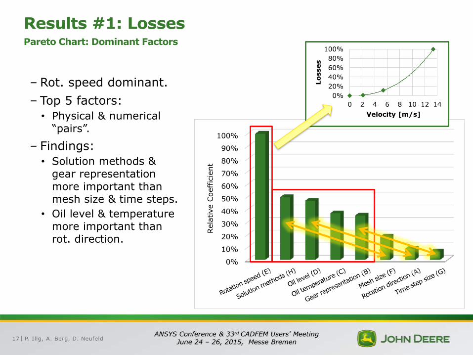
Results #1: Losses Pareto Chart: Dominant Factors
– Rot. speed dominant.
– Top 5 factors:
• Physical & numerical “pairs”.
– Findings:
• Solution methods & gear representation more important than mesh size & time steps.
• Oil level & temperature more important than rot. direction.
0%
20%
40%
60%
80%
100%
0 2 4 6 8 10 12 14
Lo
sses
Velocity [m/s]
P. Illg, A. Berg, D. Neufeld 18 ANSYS Conference & 33rd CADFEM Users' Meeting
June 24 – 26, 2015, Messe Bremen |
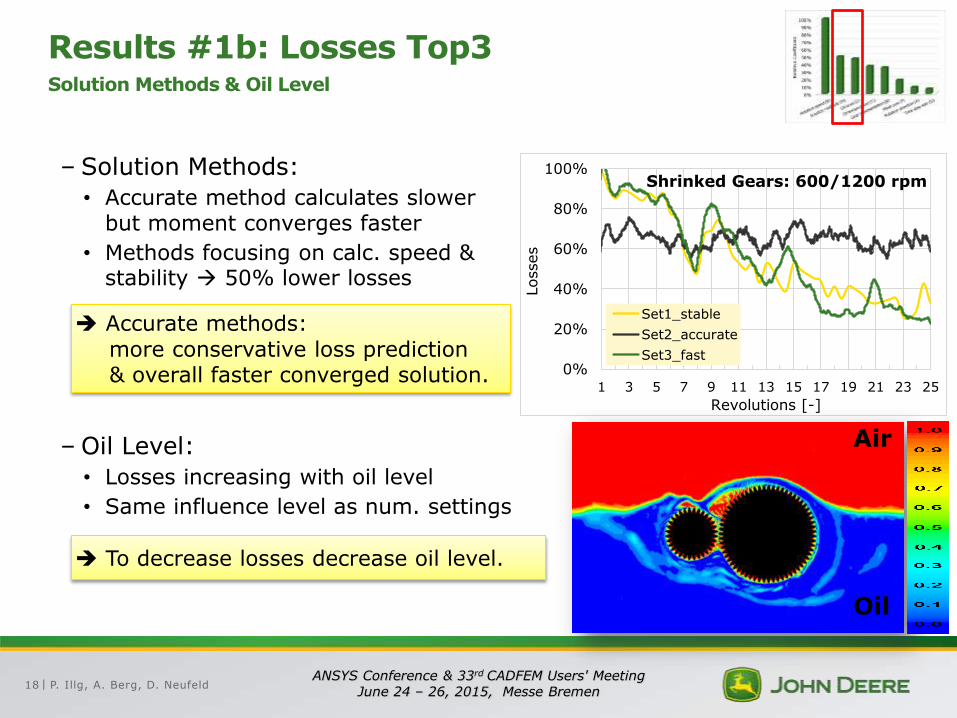
Results #1b: Losses Top3 Solution Methods & Oil Level
– Solution Methods:
• Accurate method calculates slower but moment converges faster
• Methods focusing on calc. speed & stability 50% lower losses
–Oil Level:
• Losses increasing with oil level
• Same influence level as num. settings
0%
20%
40%
60%
80%
100%
1 3 5 7 9 11 13 15 17 19 21 23 25
Losses
Revolutions [-]
Shrinked Gears: 600/1200 rpm
Set1_stable
Set2_accurate
Set3_fast
Accurate methods:
more conservative loss prediction & overall faster converged solution.
To decrease losses decrease oil level.
Air
Oil
P. Illg, A. Berg, D. Neufeld 19 ANSYS Conference & 33rd CADFEM Users' Meeting
June 24 – 26, 2015, Messe Bremen |
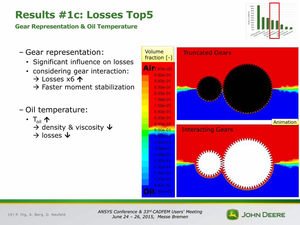
Results #1c: Losses Top5 Gear Representation & Oil Temperature
–Gear representation:
• Significant influence on losses
• considering gear interaction: Losses x6 Faster moment stabilization
–Oil temperature:
• Toil density & viscosity losses
Truncated Gears
Interacting Gears
Volume fraction [-]
Air
Oil
Animation
P. Illg, A. Berg, D. Neufeld 20 ANSYS Conference & 33rd CADFEM Users' Meeting
June 24 – 26, 2015, Messe Bremen |
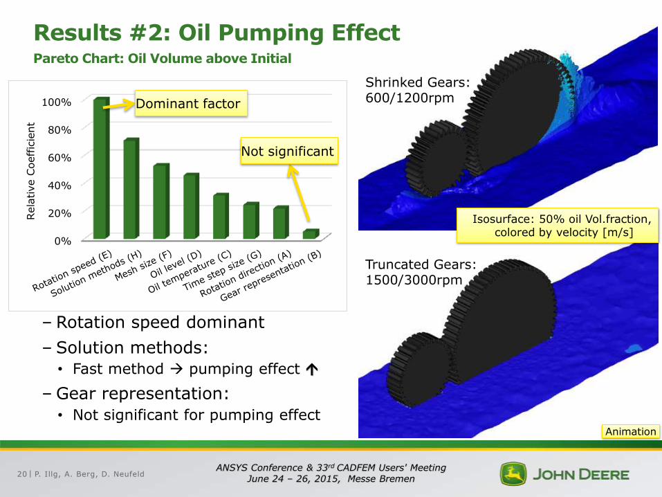
Results #2: Oil Pumping Effect Pareto Chart: Oil Volume above Initial
– Rotation speed dominant
– Solution methods:
• Fast method pumping effect
–Gear representation:
• Not significant for pumping effect
0%
20%
40%
60%
80%
100%
Rela
tive C
oeffic
ient
Dominant factor
Not significant
Shrinked Gears: 600/1200rpm
Truncated Gears: 1500/3000rpm
Isosurface: 50% oil Vol.fraction, colored by velocity [m/s]
Animation
P. Illg, A. Berg, D. Neufeld 21 ANSYS Conference & 33rd CADFEM Users' Meeting
June 24 – 26, 2015, Messe Bremen |
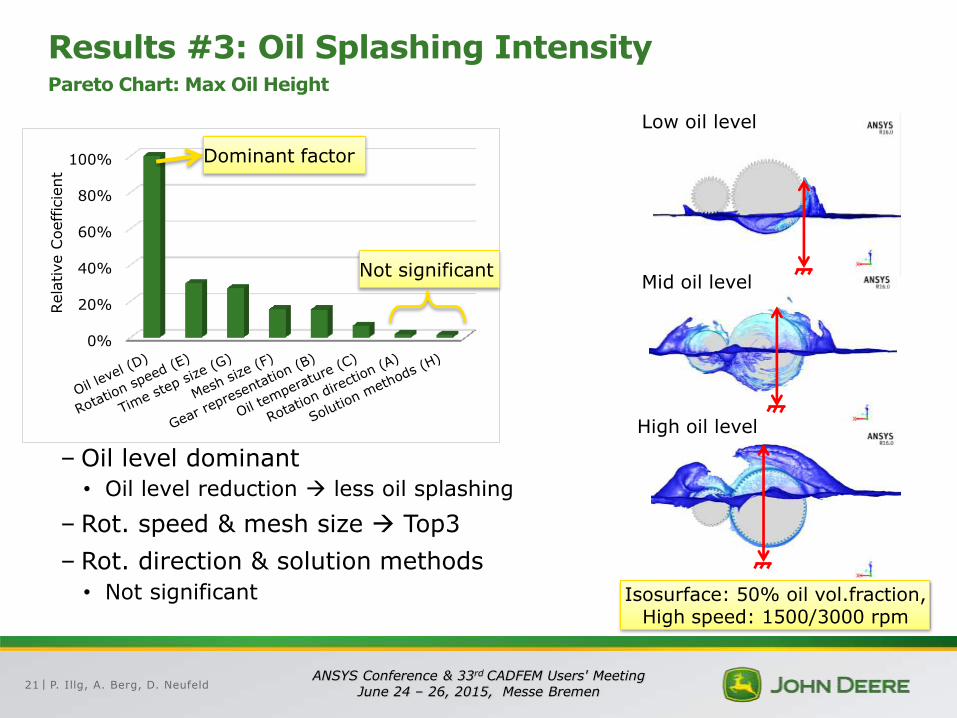
Results #3: Oil Splashing Intensity Pareto Chart: Max Oil Height
–Oil level dominant
• Oil level reduction less oil splashing
– Rot. speed & mesh size Top3
– Rot. direction & solution methods
• Not significant
Low oil level
Mid oil level
High oil level
Isosurface: 50% oil vol.fraction, High speed: 1500/3000 rpm
0%
20%
40%
60%
80%
100%
Rela
tive C
oeffic
ient
Dominant factor
Not significant
P. Illg, A. Berg, D. Neufeld 22 ANSYS Conference & 33rd CADFEM Users' Meeting
June 24 – 26, 2015, Messe Bremen |
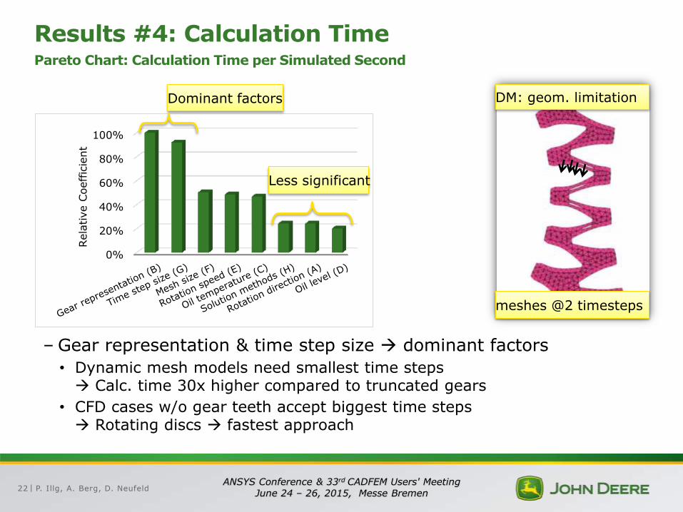
Results #4: Calculation Time Pareto Chart: Calculation Time per Simulated Second
0%
20%
40%
60%
80%
100%
Rela
tive C
oeffic
ient
Dominant factors
Less significant
–Gear representation & time step size dominant factors
• Dynamic mesh models need smallest time steps Calc. time 30x higher compared to truncated gears
• CFD cases w/o gear teeth accept biggest time steps Rotating discs fastest approach
DM: geom. limitation
meshes @2 timesteps
P. Illg, A. Berg, D. Neufeld 23 ANSYS Conference & 33rd CADFEM Users' Meeting
June 24 – 26, 2015, Messe Bremen |
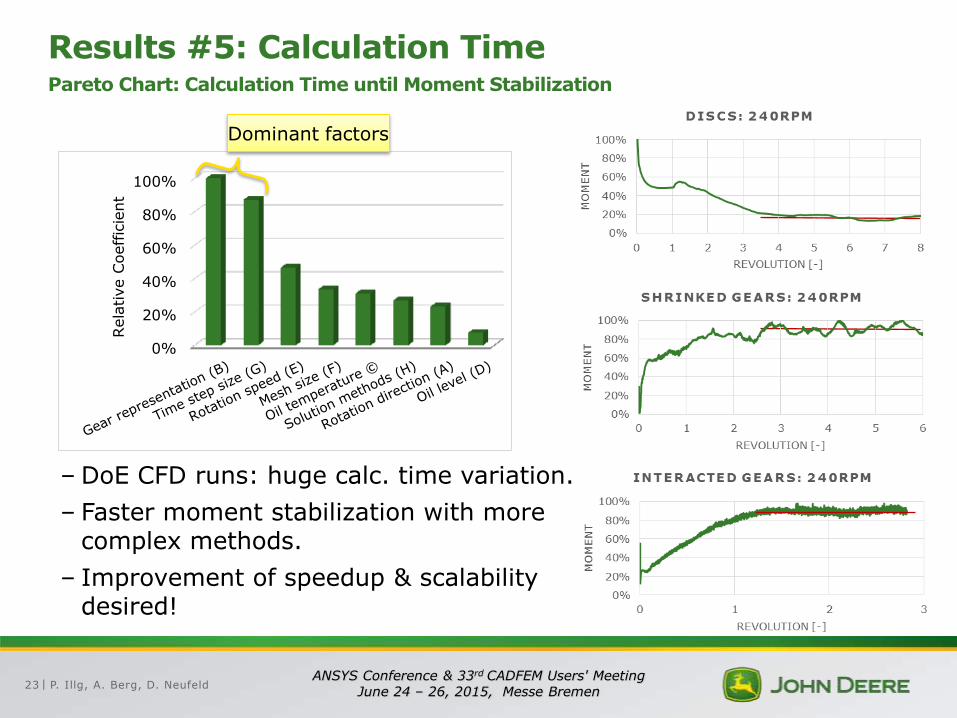
Results #5: Calculation Time Pareto Chart: Calculation Time until Moment Stabilization
–DoE CFD runs: huge calc. time variation.
– Faster moment stabilization with more complex methods.
– Improvement of speedup & scalability desired!
0%
20%
40%
60%
80%
100%
Rela
tive C
oeffic
ient
Dominant factors
P. Illg, A. Berg, D. Neufeld 24 ANSYS Conference & 33rd CADFEM Users' Meeting
June 24 – 26, 2015, Messe Bremen |
Content
John Deere – Today
Background & Objectives
Verification Procedure
Results
Conclusions & Outlook
P. Illg, A. Berg, D. Neufeld 25 ANSYS Conference & 33rd CADFEM Users' Meeting
June 24 – 26, 2015, Messe Bremen |
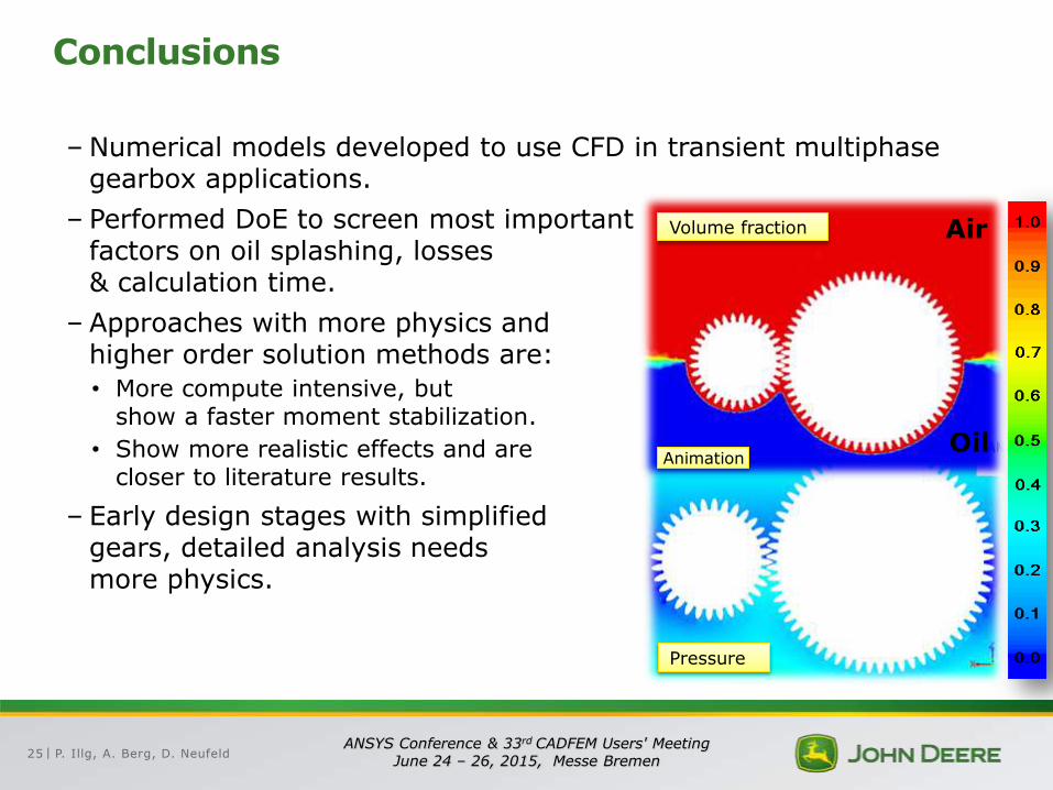
Conclusions
– Numerical models developed to use CFD in transient multiphase gearbox applications.
– Performed DoE to screen most important factors on oil splashing, losses & calculation time.
– Approaches with more physics and higher order solution methods are:
• More compute intensive, but show a faster moment stabilization.
• Show more realistic effects and are closer to literature results.
– Early design stages with simplified gears, detailed analysis needs more physics.
Volume fraction Air
Oil
Pressure
Animation
P. Illg, A. Berg, D. Neufeld 26 ANSYS Conference & 33rd CADFEM Users' Meeting
June 24 – 26, 2015, Messe Bremen |
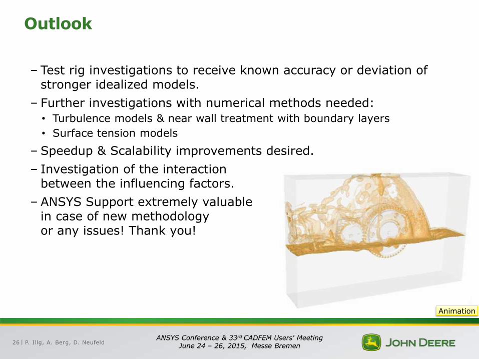
Outlook
– Test rig investigations to receive known accuracy or deviation of stronger idealized models.
– Further investigations with numerical methods needed:
• Turbulence models & near wall treatment with boundary layers
• Surface tension models
– Speedup & Scalability improvements desired.
– Investigation of the interaction between the influencing factors.
– ANSYS Support extremely valuable in case of new methodology or any issues! Thank you!
Animation


![HL965 spec [DE] - wienaeber-hyundai.de 23.5-25, 20PR, L5 BREMSEN Betriebsbremsen Hydraulisch betriebene und im Ölbad laufende Lamellenbremsen wirken bei achsweiser Einzelradaufhängung](https://static.fdokument.com/doc/165x107/605c8936aff4b5185561e4ce/hl965-spec-de-wienaeber-235-25-20pr-l5-bremsen-betriebsbremsen-hydraulisch.jpg)