
Coherent Dynamics and State Detection of Single Atoms in a ...
104
MAX-PLANCK-INSTITUT FÜR QUANTENOPTIK Coherent Dynamics and State Detection of Single Atoms in a Cavity Jörg Bochmann MPQ 336 Juli 2010
Transcript of Coherent Dynamics and State Detection of Single Atoms in a ...

MAX-PLANCK-INSTITUT FÜR QUANTENOPTIK
Coherent Dynamics and State Detectionof Single Atoms in a Cavity
Jörg Bochmann
MPQ 336 Juli 2010

TECHNISCHE UNIVERSITAT MUNCHEN
Max-Planck-Institut fur Quantenoptik
Coherent Dynamics and State Detectionof Single Atoms in a Cavity
Jorg Bochmann
Vollstandiger Abdruck der von der Fakultat fur Physikder Technischen Universitat Munchenzur Erlangung des akademischen Grades eines
Doktors der Naturwissenschaften (Dr. rer. nat.)
genehmigten Dissertation.
Vorsitzender: Univ.-Prof. Dr. H. Friedrich
Prufer der Dissertation:1. Hon.-Prof. Dr. G. Rempe2. Univ.-Prof. Dr. Dr. h.c. A. Laubereau
Die Dissertation wurde am 17.06.2010bei der Technischen Universitat Munchen eingereichtund durch die Fakultat fur Physik am 12.07.2010 angenommen.

Abstract
A single quantum emitter embedded in an optical resonator provides a model systemfor the interaction of light and matter. This thesis reports on experiments in which asingle Rubidium atom is coupled to a high-finesse optical cavity. For this purpose, a newapparatus has been constructed which enables quasi-permanent trapping of single atoms.
First, we study the excitation of the atom-cavity system with short laser pulses. Weobserve vacuum Rabi oscillations between the atom and the cavity field. Further, weshow how the wave packet shape and frequency spectrum of the emitted single photonscan be controlled. Our results are in excellent agreement with theory and illustrate thefundamentals of cavity quantum electrodynamics.
In a second experiment, we introduce efficient state detection of single neutral atoms basedon cavity-enhanced fluorescence. We achieve a hyperfine-state detection fidelity of 99.4 %within 85µs while the atom can be interrogated many hundreds times without loss fromits trap.
Further, this thesis reports on the observation of electromagnetically induced transparencywith a single atom and on the control of the optical phase of single-photon wave packets.
Kurzfassung
Ein einzelner Quantenemitter in einem optischen Resonator stellt ein Modellsystem furdie Untersuchung der Wechselwirkung von Licht und Materie dar. Die vorliegende Arbeitbeschreibt Experimente, in denen ein einzelnes Rubidiumatom an einen optischen Res-onator hoher Finesse koppelt. Zu diesem Zweck wurde eine Apparatur aufgebaut, welchedie quasi-permanente Speicherung einzelner Atome erlaubt.
Zunachst untersuchen wir die Anregung des gekoppelten Atom-Resonator-Systems mit-tels kurzer Laserpulse. Wir beobachten Vakuum-Rabi-Oszillationen zwischen Resonator-feld und Einzelatom. Ferner zeigen wir, wie die Wellenpaketform und das Spektrum deremittierten Einzelphotonen kontrolliert werden konnen. Unsere Beobachtungen stimmenexzellent mit theoretischen Vorhersagen uberein und illustrieren grundlegende Phanomeneder Resonator-Quantenelektrodynamik.
Danach stellen wir eine effiziente Methode zur Zustandsdetektion einzelner Neutralatomevor. Mittels resonatorverstarkter Fluoreszenz erreichen wir eine Hyperfeinzustandsdetek-tion mit einer Sicherheit von 99,4 % innerhalb von 85µs. Der Hyperfeinzustand kann dabeimehrere hundert Male ohne Atomverlust ausgelesen werden.
Desweiteren beschreibt die vorliegende Arbeit Experimente zur elektromagnetisch-induziertenTransparenz eines Einzelatoms und zur Kontrolle der optischen Phase einzelner Photonen.

Contents
1 Introduction 1
2 Experimental Setup 5
2.1 A new single atom-cavity setup . . . . . . . . . . . . . . . . . . . . . . . . . 5
2.2 Vacuum system and lasers . . . . . . . . . . . . . . . . . . . . . . . . . . . . 7
2.3 Cavity . . . . . . . . . . . . . . . . . . . . . . . . . . . . . . . . . . . . . . . 8
2.4 Trapping and transporting atoms . . . . . . . . . . . . . . . . . . . . . . . . 9
2.5 Single atom imaging and single photon detection . . . . . . . . . . . . . . . 12
2.6 Performance of the new atom-cavity system . . . . . . . . . . . . . . . . . . 13
3 Short pulse excitation of a single atom-cavity system 17
3.1 Single photons from an atom in free space . . . . . . . . . . . . . . . . . . . 17
3.2 Dynamics of the atom-cavity system . . . . . . . . . . . . . . . . . . . . . . 19
3.3 Single photons from a coupled atom-cavity system . . . . . . . . . . . . . . 21
3.4 Experiment and results . . . . . . . . . . . . . . . . . . . . . . . . . . . . . 24
3.4.1 Experimental protocol . . . . . . . . . . . . . . . . . . . . . . . . . . 24
3.4.2 Single photon generation with a resonant cavity . . . . . . . . . . . . 26
3.4.3 Observation of vacuum Rabi oscillations . . . . . . . . . . . . . . . . 27
3.4.4 Short pulse excitation of the cavity mode . . . . . . . . . . . . . . . 29
3.5 Discussion and Outlook . . . . . . . . . . . . . . . . . . . . . . . . . . . . . 30
4 State detection of a single atom in a cavity 33
4.1 Introduction . . . . . . . . . . . . . . . . . . . . . . . . . . . . . . . . . . . . 33
4.1.1 Methods for atomic state detection . . . . . . . . . . . . . . . . . . . 33
i

4.1.2 Definition and calculation of the fidelity . . . . . . . . . . . . . . . . 35
4.2 Cavity-enhanced fluorescence state detection . . . . . . . . . . . . . . . . . 36
4.2.1 Fluorescence scattering of an atom coupled to a cavity . . . . . . . . 36
4.2.2 Statistical analysis . . . . . . . . . . . . . . . . . . . . . . . . . . . . 37
4.2.3 Simulation of fluorescence state detection . . . . . . . . . . . . . . . 41
4.2.4 Experimental results . . . . . . . . . . . . . . . . . . . . . . . . . . . 44
4.3 State detection by differential transmission . . . . . . . . . . . . . . . . . . 47
4.3.1 Transmission of the atom-cavity system . . . . . . . . . . . . . . . . 47
4.3.2 Experimental results . . . . . . . . . . . . . . . . . . . . . . . . . . . 48
4.4 Comparison and discussion of the results . . . . . . . . . . . . . . . . . . . . 50
4.5 Applications of cavity-enhanced fluorescence . . . . . . . . . . . . . . . . . . 52
4.5.1 Stark shift spectroscopy . . . . . . . . . . . . . . . . . . . . . . . . . 52
4.5.2 Measurement of the magnetic field . . . . . . . . . . . . . . . . . . . 54
5 EIT with single atoms in a cavity 57
5.1 EIT: Controlling light with light . . . . . . . . . . . . . . . . . . . . . . . . 57
5.2 Observation of EIT with single atoms in a cavity . . . . . . . . . . . . . . . 58
6 Phase shaping of single-photon wave packets 61
6.1 Hong-Ou-Mandel effect revisited . . . . . . . . . . . . . . . . . . . . . . . . 61
6.2 Experiment and results . . . . . . . . . . . . . . . . . . . . . . . . . . . . . 62
7 Summary and outlook 65
8 Appendix 69
8.1 Atom-cavity coupling strength . . . . . . . . . . . . . . . . . . . . . . . . . 69
8.2 Single atom imaging system . . . . . . . . . . . . . . . . . . . . . . . . . . . 72
ii

8.3 Dimensions of the vacuum system . . . . . . . . . . . . . . . . . . . . . . . 73
8.4 Schematic layout of the optical table . . . . . . . . . . . . . . . . . . . . . . 74
8.5 Frequency comb . . . . . . . . . . . . . . . . . . . . . . . . . . . . . . . . . 75
Bibliography 79
Publications 93
Acknowledgment 95


1 Introduction
Current efforts in experimental physics aim at gaining control over fundamental quantumsystems. On the one hand, this development is driven by scientific curiosity. What hadbeen gedankenexperimente in the past can now be tested in real-world experiments rangingfrom tests of local realism to investigations of the measurement process in quantum physics[1, 2, 3, 4, 5, 6, 7]. On the other hand, the control of quantum phenomena is of increasingimportance for technological progress. Already today, quantum effects are the basis forapplications ranging from medical diagnostics [8] to information technology [9] and timestandards [10, 11, 12]. These examples indicate that future technologies may not only needto cope with quantum phenomena but use them as a resource. What we witness todayhas therefore been termed a second quantum revolution which is marked by the controland application of quantum effects [13].
In modern quantum physics, information has become a central concept which reaches farbeyond the traditional wave-particle duality and uncertainty relations. The potential ofquantum physics for computing or communication purposes has already been recognizedin the 1980’s [14, 15, 16, 17]. In recent years, the promises of quantum information sciencehave been driving forces for the progress of experimental quantum physics. A yet-to-be-built universal quantum computer not only incorporates all capabilities of a classicalcomputer, but also solves certain problems more efficiently than its classical counterpart[18, 19, 20, 21, 22]. Alternatively, well-controlled model quantum systems are proposed tosimulate problems of quantum physics [14, 23, 24, 25, 26]. Finally, quantum cryptographycan provide intrinsically secure communication [27, 28, 29]. Some of the basic experimentalrequirements for exploring these vistas [30] have been summarized by diVincenzo [31].
Achieving control over fundamental quantum systems faces two conflicting requirements.While the ”fragile” quantum objects must be isolated from the environment to avoid de-coherence, the manipulation and measurement of the quantum system necessarily requiresinteraction with the environment. A desirable controlled coupling between quantum sys-tem and environment can be established using, for example, well-tailored electromagneticfields which control isolated trapped atoms. Indeed, the interaction of light with matteris at the heart of quantum control as light can be used to prepare, manipulate, readout,and to connect quantum systems.
In this thesis, the interaction of light and matter is controlled at the level of single atomsand single photons. Scaling into this regime is achieved by coupling individual atomsto the mode of a high-finesse optical cavity. In this model system of quantum optics,the dynamics of a single atom interacting with single photon fields can be measured andcontrolled. The observed physical phenomena are naturally described by cavity quantumelectrodynamics (CQED).
CQED is an active and rapidly progressing field of research. Today, its basic conceptshave spread across very different fields of physics. A central idea of CQED is that the
1

2 Introduction
radiative properties of a quantum emitter can be dramatically altered when boundaryconditions are imposed on the electromagnetic field. It has been pointed out early byPurcell [32] that the atomic spontaneous emission rate is modified in the presence of aresonator. Moreover, embedding an atom into a cavity affects the energy spectrum ofthe system such that atom and resonator field can no longer be considered as separateentities [33, 34]. In fact, correlations between atomic state and cavity field occur and leadto intrinsic entanglement [35]. Likewise, a cavity can establish long-range interactionsamong multiple quantum emitters coupled to its field mode [36, 37].
Pioneering experiments in CQED have been performed with Rydberg atoms coupled tomicrowave cavities [38, 39, 40, 41, 42, 43] and have soon been followed by experimentsin the optical domain [44, 45, 46, 47, 48, 49, 50]. The concepts of CQED are, however,applicable to a variety of other physical realizations, for example quantum dots embeddedin microcavities [51, 52, 53, 54] or superconducting circuits coupled to strip-line cavities[55, 56, 57]. In the optical domain, new resonator concepts are currently emerging [58,59, 60, 61, 62] aiming at ever higher coupling strength between light and matter. Anothersubject of interest is the study of back-action of the cavity field onto intracavity atomsor the resonator itself – which can be exploited for cooling and quantum state squeezing[63, 64, 65, 66, 67]. A fascinating perspective are distributed quantum networks of atom-cavity systems which allow the distribution and exchange of quantum information overlarge distances [68, 69].
This thesis reports on experiments in which a single Rubidium atom is coupled to a high-finesse optical cavity. These experiments have been performed in a new CQED apparatuswhich has been entirely constructed during the course of this thesis. The findings presentedhere are fundamental examples of quantum optics and mark a high level of control oversingle quanta of matter and light.
The new atom-cavity system is an ideal interface between single atoms and single photons.The parameters of the cavity are chosen to provide sufficient coupling of the intracavityfield to a single atom as well as an efficient mapping of the intracavity field to the cavityoutput mode. Hence, the new system is well-suited for the controlled generation of singlephotons and for the readout of the intracavity field and atomic state. Moreover, quantumnetworking experiments based on the emission and retrieval of single photons are withinreach.
Preparation and quasi-permanent storage of single atoms is achieved using different strate-gies of laser cooling and trapping. Naturally, individually trapped neutral atoms presentwell-defined single quantum systems and are prime candidates for quantum informationscience [70, 71, 72, 73, 74, 75]. Embedding the atoms in an optical resonator boosts thesecapabilities by enhancing control and connectivity.
The content of this thesis is organized as follows.
Chapter (2) introduces the essential features of the new single atom-cavity setup. Thechapter briefly describes the apparatus, the methods with which cold atoms are preparedinside the cavity, and the detection tools for atoms and photons. The overall performance
3
of the new setup is characterized using the example of a single photon server based onone atom. This example demonstrates that a quantum protocol can be efficiently run ona single atom which is quasi-permanently trapped in the cavity.
In chapter (3), we study the excitation of the atom-cavity system by short laser pulses.We observe vacuum Rabi oscillations between an atom and a single photon in the cavityfield. The dynamics of the coupled system and the suitability of short pulse excitation forphoton generation are analyzed in detail. We use the fast excitation scheme to generatesingle photons at a high repetition rate and with a tunable wave packet shape. Theexperimental results are in excellent agreement with theory and illustrate a textbook-typeexample of CQED in the optical domain.
In chapter (4), we investigate schemes for internal state detection of single neutral atomsby means of a cavity. A theoretical analysis of atomic hyperfine state detection identifiesproblems associated with state readout of neutral atoms and indicates how they can besolved in a CQED setting. We introduce a readout technique based on cavity-enhancedfluorescence which enables the efficient detection of the atomic hyperfine state. Most im-portant, this technique does not cause the loss of the atom upon readout and establishessingle atoms as truly stationary carriers of quantum information. The experiments oncavity-enhanced fluorescence are complemented by an investigation of atomic state detec-tion using differential cavity transmission. The two methods are compared and specificadvantages are discussed.
Chapter (5) briefly describes an experiment on electromagnetically induced transparency(EIT) with a single atom. We observe the interaction of two weak light beams mediatedby a single atom. This proof-of-principle experiment opens perspectives for the controlledgeneration, retrieval and storage of photons in single atom-cavity systems.
Chapter (6) reports on a study of phase-controlled single-photon wave packets. By imprint-ing phase patterns on propagating photon wave packets we are able to control two-photoninterference. A time-resolved analysis of the experiment leads to a generalized descriptionof two-photon interference in which the usual Hong-Ou-Mandel effect can be modified andeven reversed.

4 Introduction

2 Experimental Setup
2.1 A new single atom-cavity setup
A major goal of this thesis work was the construction of a new CQED experiment inwhich a single Rb atom is permanently coupled to a high-finesse optical resonator. Thenew apparatus conceptually follows a prototype by S. Nußmann and co-workers [76, 77, 78].Improvements in the new setup described here aim at simplification, increased reliabilityand extended functionality. To this end, improved optical access, additional degrees ofcontrol, new software and new detection schemes have been implemented. After threeyears of construction, the new experiment became operational in 2008.
The parameter ranges of this experiment span many orders of magnitude - from macro-scopic dimensions to the quantum regime (Fig. 2.1). Atoms at temperatures of only afew µK coexist with materials at temperatures of many hundred Kelvin in the vicinity ofa few mm. The strength of optical fields ranges from 10 W continuous laser power for theoptical dipole traps to the level of single photons generated in the cavity output. The timescales of the experiment span from atom trapping times on the order of many seconds tomonitoring the cavity output with nanosecond resolution.
Figure 2.1: Time and energy scales of the experiment. a) The macroscopic time scaleof the experiment is given by the trapping time of single atoms in the cavity of up to 60 s. Theshortest time scale is given by the time resolution of single-photon detection (1 ns). Typical cycletimes of the measurement protocol are on the order of 1 ms. b) The flux of photons along differentaxes of the experiment spans 18 orders of magnitude. The dipole trap laser beam traversing thecavity has a power of a few Watts, while simultaneously we observe single photons in the cavityoutput.
5

6 Experimental Setup
At the heart of the experimental setup is a high-finesse optical cavity (Sec. 2.3). Thecavity operates in an intermediate regime of atom-cavity coupling with (g;κ; γ)/2π =(3; 3; 3) MHz where g denotes the coherent atom-cavity coupling rate, and (κ,γ) denotethe decay rates of cavity field and atomic polarization, respectively. Quasi-permanentstorage of a single 87Rb atom inside this resonator is achieved by a combination of differenttechniques for laser cooling and trapping of neutral atoms [79].
The basic operating principle of the apparatus follows a three-step process (Fig. 2.2).First, a magneto-optical trap (MOT) provides a reservoir of cold 87Rb atoms. Second,the atoms are loaded into a running wave dipole trap and are probabilistically transferredinto the cavity mode. Inside the cavity, single atoms are localized in a standing waveoptical dipole trap and are cooled by transversally applied laser beams. The number andlocation of atoms trapped inside the cavity is determined with a high numerical apertureCCD-camera system. As a third step, a repetitive measurement protocol is applied withone atom permanently trapped inside the cavity mode. Information about the quantumstate of the atom-cavity system is obtained by monitoring the cavity output at the singlephoton level.
The details of this setup and a first benchmark measurement in which the new apparatusis operated as a single photon server (Sec. 2.6) are presented in the following sections.
Figure 2.2: Experimental setup. A reservoir of cold 87Rb atoms (a) is prepared in a magneto-optical trap. An optical dipole trap (b) guides a few atoms into the high-finesse cavity (c). There,a single atom is quasi-permanently trapped and a repetitive measurement protocol is applied usingnear resonant laser beams (d). The cavity output mode (e) is coupled to a detection setup andmonitored at the single photon level.

2.2 Vacuum system and lasers 7
2.2 Vacuum system and lasers
The vacuum system used for the experiment is similar to the design described in [76] and atechnical drawing can be found in the appendix (8.3). It consists of an octagon-shaped steelchamber (415LN, non-magnetic) which is designed for maximum optical access. Whileeight of its ten ports are used as optical windows (optical quality fused silica, AR coating750-1100 nm), two ports are occupied by electrical feedthroughs and the connection to apump system (Titan sublimation pump, Ion-getter pump). The system operates in the10−10 mbar regime at room temperature. The background gas pressure would limit thelifetime of a trapped Rb atom to between 30 s and 1 min (estimated). A major differenceto the original design by S. Nußmann is the mounting of the cavity holder. In the newsystem, the holder can be retracted from the vacuum system by only opening two of thesmall side flanges (”rear window” and electrical feedthroughs). This means that the cavitycan be exchanged more easily for repair or mirror replacement. So far, neither mechanicalinstability nor additional vibration noise have been observed for the altered cavity-holderdesign.
In the new experiment, the atom-cavity setup is separated from the remaining infrastruc-ture: One separate optical table carries the vacuum chamber with cavity and essentialoptics. A second optical table carries all lasers, optics and electronics. The two tablesare only coupled by optical fibers which deliver all necessary light beams to the experi-ment. Thereby, the experiment is mechanically (vibrations) and electronically (groundingof voltages, shielding from radio-frequency cross-talk) decoupled from the laser table. Ad-ditionally, the optical fibers precisely define spatial modes. In combination with shortoptical path lengths at the experiment, this ensures stable adjustment of the laser beamsdirected onto the single atom-cavity system. A layout sketch of the experimental table ispresented in the appendix (8.4).
As light sources we use 3 diode lasers (Toptica models DL100 and DLX110) operating atwavelengths of 780 nm and 785 nm and one high-power fiber laser at 1064 nm (IPG YLM-1064-10). The laser light at 780 nm is frequency-shifted and intensity-controlled by severalacousto-optic modulators (AOM’s) to address each transition of the Rb D2-line. The twodiode lasers at 780 nm are locked to Rb vapour cells with the Pound-Drever-Hall technique(linewidth 100-500 kHz). The light at 785 nm is used as a reference to stabilize the cavitylength. This diode laser is locked to a frequency comb reference using a beat-lock scheme(linewidth <100 kHz). The high-power fiber laser is not frequency stabilized and deliversa single mode (spatial and frequency) beam at a cw-power of up to 10 W which is splitand independently controlled by two electro-optic modulators (Linos EOM LM0202 highpower, 3 mm aperture, control voltage 0-600 V provided by TREK PZD700). This light isused to create two far-detuned optical dipole traps.
In our laboratory, we have introduced a frequency comb laser system as an absolute fre-quency standard. The frequency comb was manufactured by MenloSystems and was in-stalled in 2009. At its core is a pulsed fiber laser with a repetition rate frep = 250 MHz. Asa 10 MHz reference signal for the beat note stabilization (repetition rate, carrier-envelopeoffset) we use a stable hydrogen maser signal supplied by the group of Prof. Hansch. Ad-

8 Experimental Setup
ditionally installed modules amplify and frequency-double the optical output spectrum foruse in the spectral ranges 775 to 795 nm and 1000 to 2000 nm. The comb delivers approx.100 mW of optical power in the spectral range 760 to 800 nm. This output is coupled intoan optical fiber network which supplies the laboratories of our group. Typically 10 mW ofoptical power are delivered to each laboratory. More information on the frequency combsystem can be found in the appendix (8.5).
2.3 Cavity
At the heart of the experimental setup is a high-finesse optical cavity. The cavity param-eters have been chosen to achieve an intermediate regime of atom-cavity coupling and ahighly directional optical output.
The cavity consists of two fused silica conic substrates with high-reflectivity dielectriccoatings on their top faces (coating: REO, Boulder, USA). The total round trip losses ofthe cavity (113 ppm) are dominated by the transmission of one of the mirrors (101 ppm).Therefore, photons present inside the cavity are mapped to the well-defined output modethrough this outcoupling mirror with 89 % probability. The mirror distance of d=495µmis chosen small enough for a sufficient atom-cavity coupling g, but large enough to accomo-date traversing laser beams (diameters approx. 200µm). The measured cavity parametersfor light at wavelength 780 nm are summarized in the following table. The measured cavitylinewidths at 785 nm and 795 nm agree with the value at 780 nm and we therefore assumeall other parameters are identical as well.
mirror transmission T1 = (2± 0.5) ppm, T2 = (101± 2) ppmmirror distance d = (495± 2)µm
mirror curvature r = 50 mmmode waist w = 29.6µm (1/e2 intensity radius)
mode Rayleigh length zR = 3.5 mmdissipative loss L = (10± 1) ppm
total round-trip loss L = (113± 2) ppmcavity finesse F = 56 000 (TEM00)
free spectral range FSR = 303 GHzcavity decay rate κ/2π = (2.8± 0.1) MHzcavity decay time τ = 26 ns (1/e intensity decay)
power enhancement η = 630 (circulating/impinging power)maximum transmission Tcav = 6 %
output directionality ηout = 89 %
Mechanically, the cavity mirrors are mounted into the cavity holder in a stack of mirrorholders, ceramic spacers and a piezo-electric element (”piezo”). The mirror holders clampthe mirror substrates with even pressure around the circumference to avoid unidirectionalmechanical stress and concomitant optical birefringence. The cavity has been tested after

2.4 Trapping and transporting atoms 9
bake-out in the vacuum system and no birefringence was found. The piezo is of cylindricalshape and has 8 drilled holes of diameters between 1.5 mm and 7 mm which allow foroptical access perpendicular to the cavity mode. The inner and outer surface of the piezoare metal-coated and constitute the electrical contacts.
Precise tuning of the cavity frequency is achieved by applying control voltages of 0-150 Vwith sub-mV precision to the piezo. The control voltages are derived from an active feed-back loop which stabilizes the cavity frequency to better than ±0.5 MHz, corresponding toan uncertainty in the absolute cavity length of approx. 1 pm. The cavity stabilization isbased on the Pound-Drever-Hall technique. A phase-modulated laser beam at wavelength785 nm (modulation frequency 20 MHz) serves as a reference and is detected in transmis-sion. This was found to improve the signal-to-noise ratio compared to a lock based on thesignal reflected by the cavity. The reference light is allowed to have arbitrary polarizationand is separated from light at 780 nm after the cavity by a dichroic mirror.
The coherent atom-cavity coupling rate g is determined by the atomic transition strength(dipole matrix element µge) and the cavity mode volume V . It is further spatially modu-lated by the standing wave structure of cavity field ψc(r).
g(r) = ψc(r)√
ωc2ε0V ~
· µge (2.1)
The effective atom-cavity coupling depends on the atomic position via ψc(r) and on theinternal atomic state and the polarization of the cavity field mode via µge. Thus, certainaveraging strategies must be applied to account for atomic motion or undefined lightpolarization (appendix 8.1). For the strongest dipole transition |F = 2,mF = 2〉 ↔ |F ′ =3,m′F = 3〉 and an atom localized at a cavity field maximum, the coupling is as large asgmax/2π = 7.9 MHz. Combined spatial and polarization averaging reduce the effectivecoupling to g ≈ 3 MHz on the transition F = 2 ↔ F ′ = 3. Indeed, we have observedin several experiments that the measured effective g is typically 40 % of the theoreticalmaximum of g for a given atomic transition (see appendix 8.1 for details).
2.4 Trapping and transporting atoms
The single Rb atoms which are eventually transported to and stored in the cavity aretaken from a larger ensemble of cold atoms provided by a magneto-optical trap (MOT). AMOT combines radiation pressure and position-dependent atomic Zeeman shifts to achievephase space reduction of atomic motion in the momentum and spatial domain [79]. For thedescribed experimental setup, a new geometry has been invented which further simplifiesexisting mirror-MOT schemes. The new scheme reduces the number of laser beams, thenecessary optical power and the number of optical elements (see appendix). This MOTtypically operates with a total optical power of 2 mW for the cooling laser while the numberof atoms in the MOT is efficiently controlled by varying the power of the repump laserbetween 0 and 100µW. As a source of Rb atoms we use an ohmically heated dispenserca. 1 cm away from the location of the MOT. The steady state temperature of atoms in
10 Experimental Setup
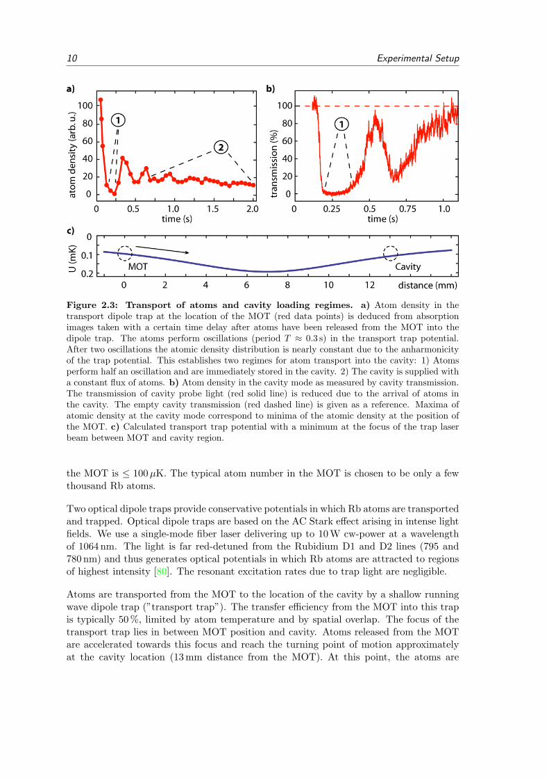
Figure 2.3: Transport of atoms and cavity loading regimes. a) Atom density in thetransport dipole trap at the location of the MOT (red data points) is deduced from absorptionimages taken with a certain time delay after atoms have been released from the MOT into thedipole trap. The atoms perform oscillations (period T ≈ 0.3 s) in the transport trap potential.After two oscillations the atomic density distribution is nearly constant due to the anharmonicityof the trap potential. This establishes two regimes for atom transport into the cavity: 1) Atomsperform half an oscillation and are immediately stored in the cavity. 2) The cavity is supplied witha constant flux of atoms. b) Atom density in the cavity mode as measured by cavity transmission.The transmission of cavity probe light (red solid line) is reduced due to the arrival of atoms inthe cavity. The empty cavity transmission (red dashed line) is given as a reference. Maxima ofatomic density at the cavity mode correspond to minima of the atomic density at the position ofthe MOT. c) Calculated transport trap potential with a minimum at the focus of the trap laserbeam between MOT and cavity region.
the MOT is ≤ 100µK. The typical atom number in the MOT is chosen to be only a fewthousand Rb atoms.
Two optical dipole traps provide conservative potentials in which Rb atoms are transportedand trapped. Optical dipole traps are based on the AC Stark effect arising in intense lightfields. We use a single-mode fiber laser delivering up to 10 W cw-power at a wavelengthof 1064 nm. The light is far red-detuned from the Rubidium D1 and D2 lines (795 and780 nm) and thus generates optical potentials in which Rb atoms are attracted to regionsof highest intensity [80]. The resonant excitation rates due to trap light are negligible.
Atoms are transported from the MOT to the location of the cavity by a shallow runningwave dipole trap (”transport trap”). The transfer efficiency from the MOT into this trapis typically 50 %, limited by atom temperature and by spatial overlap. The focus of thetransport trap lies in between MOT position and cavity. Atoms released from the MOTare accelerated towards this focus and reach the turning point of motion approximatelyat the cavity location (13 mm distance from the MOT). At this point, the atoms are

2.4 Trapping and transporting atoms 11
tranferred into a second dipole trap (”storage trap”) which has a tight focus at the cavitylocation. It is retro-reflected by a piezo-tiltable mirror creating a periodic standing wavepotential. The properties of transport and storage trap are summarized in the followingtable (calculations based on [80]).
transport trap storage trapFocus size (1/e2 radius) 45µm 16µmRayleigh length 6 mm 0.7 mmTrap depth at focus 48µK/W 1.5 mK/WD2-line Stark shift 1.6 MHz/W 52 MHz/WTypical input power 4 W 2.5 W
The motion of atoms in the anharmonic potential of the transport trap has been numer-ically and experimentally studied. We identify two regimes for loading atoms into thecavity (Fig. 2.3). In the first and most often used regime, the atoms are released fromthe MOT, drift to the cavity region, and are immediately localized in the storage trap.In the second regime, the storage trap is not used and the atoms perform oscillations inthe transport trap (Fig. 2.3). However, the anharmonicity of the trap potential leadsto dispersion. After a few hundred milliseconds, a stable density distribution of atoms isestablished across the whole transport trap. In this regime, the cavity is supplied with aconstant flux of slow atoms. Despite its probabilistic nature, operation in this regime hasseveral advantages. As the maximum AC-Stark shifts are small (∆s ≤ 6 MHz), the atomiclevel structure is only minimally disturbed. Also, when permanent trapping of atomsis abandoned, arbitrarily high magnetic fields and arbitrary cavity and laser frequenciescan be used. Further, the slow overall atom loss in this regime can be compensated byintermittent use of the MOT while the transport trap remains permanently present.
In addition to the dipole traps at 1064 nm, the cavity reference light at 785 nm providesa standing-wave potential which is oriented along the cavity axis. The trap depth for Rbground state atoms is approximately 3µK per 1µW of linearly polarized light impingingon the cavity. This value holds for perfect mode-overlap (spatial and frequency) of thecavity input coupling. The value includes power-built up inside the cavity (4x630 at afield antinode) and the combined ground state level shifts due to coupling to the Rb D2transition (780 nm, red-detuned) and D1 transition (795 nm, blue-detuned). In practice,the spatial input mode-matching is on the order of 50 %. For typical stabilization lightpowers of 20µW, we find an intracavity dipole trap depth of 30µK. The exact frequencyof the cavity reference light is chosen to be an even number (N=8) of free spectral rangesdetuned from the cavity mode at 780 nm. As a consequence, the cavity field at 780 nm andthe dipole potential at 785 nm wavelength exhibit a spatial beat pattern with a periodicityof 50µm. The anti-nodes of the two fields overlap at the geometric center of the cavity(see appendix for an image). Atoms trapped in the 785 nm trap in these anti-nodesshould therefore optimally couple to the resonant cavity mode at 780 nm. However, anenhancement of the atom-cavity coupling due to atomic confinement in this intracavitytrap has not been convincingly demonstrated in our experiment.

12 Experimental Setup
2.5 Single atom imaging and single photon detection
A CCD-camera system with a high numerical aperture objective images the fluorescenceof atoms during optical cooling inside the cavity. The objective has a numerical apertureof NA = 0.4 and a spatial resolution of 1.3µm in the object plane. With a total mag-nification of M = 29, one pixel in the image plane (CCD-camera chip, actual pixel size16×16µm) corresponds to 0.55µm in the object plane (all values confirmed by calibrationmeasurements). The objective is homebuilt and follows the design described in [81], butit deviates in the use of the final focussing lens (see appendix) and the mechanical mount-ing. The objective is mechanically disconnected from the camera and the vacuum system.It can be independently translated along all three spatial axes with µm-precision. Themechanics of mounting is reduced to a minimum in weight and size while the overall sta-bility remains excellent. The CCD-camera chip (AndorIXON DU897) is Peltier-cooled to170 K and optimized for high quantum efficiency (specified 90 %, back-illuminated design).Low intrinsic noise and near-perfect stray light shielding enable high-contrast fluorescenceimaging of single trapped atoms within 100 ms exposure time. The typical exposure timeduring a measurement protocol with intermittent cooling is 400 ms. Single-shot raw imagesare evaluated in real-time to determine the number and location of atoms loaded in thecavity TEM00 mode profile. Based on this evaluation, a software trigger can either start anew loading attempt or the repetitive measurement protocol. However, we can not resolvesingle anti-nodes of the dipole trap potential or the cavity mode. In future experiments,advanced algorithms for image evaluation may be used to achieve single site resolutionbeyond the standard resolution limit of the objective [82]. A detailed technical sketchof the single atom imaging system is given in the appendix (8.2). A sample fluorescenceimage of a single atom is shown in figure (2.4a).
Alternatively, the atom-cavity system can be probed via the cavity output at the levelof single photons and with high temporal resolution. A single photon present inside thecavity is emitted through the outcoupling mirror with a probability of 89 % (Sec. 2.3)and is detected with a total efficiency above 30 %. After the cavity output mirror and justoutside the vacuum system, the cavity output mode is collimated and after free propagationfor less than 1 m it is coupled into a single-mode optical fiber with up to 90 % efficiency.Along the free propagation path, the stabilization light at 785 nm is separated from lightat 780 nm with three filters (Semrock Laserline, specified transmission at 780 nm: 99.9 %,at 785 nm: 10−5). With these filters, the measured total transmission of 785 nm light isless than 10−11, the total transmission at 780 nm is better than 95 %. Finally, the opticalfiber delivers light at 780 nm to a single photon counting module (SPCM, Perkin ElmerAQR-16 avalanche photodiodes). The SPCM has an intrinsic electronic dark count rate of25 Hz. The total ”dark count rate” of the detector is typically 50 Hz including an additional25 Hz stray light count rate. This background signal is extremely low and requires light-tight housing of the detection path from the fiber input coupler to the detector – eventhe optical fiber itself must be covered. The quantum efficiency of the AQR-16 model is50 % (measured) in accordance with the technical specifications (50 to 60 %). The totalscattering and absorption losses along the whole detection path (10 optical elements)amount to approximately 10 %. Taken together, the measured total detection efficiency

2.6 Performance of the new atom-cavity system 13
Figure 2.4: Observation and storage of single atoms. a) Typical CCD-camera image ofa single trapped atom (exposure time 400 ms, raw data). The size of the fluorescence spot of theatom (2×6 pixels) is due to the resolution of the objective (2 pixels correspond to 1.1 µm) andfinite atomic temperature. Along the dipole trap axis, the atom is confined to less than half awavelength of light (< 500 nm, horizontal axis in the image). Along the radial direction of thestanding wave trap, the spatial confinement is weaker and the finite atomic temperature resultsin a atomic position spread within an anti-node of the dipole trap (6 pixels correspond to 3.3 µmand temperatures below 100µK, vertical axis in the image). b) The coupling of the atom to thecavity mode is signalled by emission of cooling light into the cavity output. Shown is a singleatom trace with a trapping time of 65 s. c) The probability distribution of observed atom trappingtimes (permanent optical cooling) is well described by an exponential decay with time constantτ = 24± 0.5 s.
is 34 ± 3 %. This number refers to the probability to obtain a detector click for a singlephoton present inside the cavity. The electronic output pulses of the SPCM are recordedby a counter card (FastComTec P7888) with a time-resolution of 2 ns in four separatechannels (1 ns resolution when only two channels are used). For Hanbury Brown-Twissand for two-photon interference measurements, the single mode fiber in the detection pathis replaced by one or more single mode fiber beam splitters coupled to up to four SPCM’s.The fiber beam splitters exhibit near perfect mode overlap and power splitting ratio. Theobserved visibility of interference fringes is better than 99 % for coherent probe light.
2.6 Performance of the new atom-cavity system
The apparatus described in this thesis became operational in 2008 and has worked reliablysince. In this section, the standard performance of the system is briefly characterized usingthe example of a single photon server [83].
A first important result of the new setup is the observation of efficient trapping and coolingof single atoms outside the previously studied cavity-cooling regime [78]. The new regimeexplored here is characterized by frequencies of the cooling laser which are red-detunedby ∆ = 1 . . . 10 γ with respect to the unperturbed atomic 52S1/2 F = 2 to 52P3/2 F = 3′

14 Experimental Setup
transition. Atomic cooling is observed to work well for all cavity frequencies which areat least one γ blue-detuned of the cooling laser. This suggests that the dominant coolingmechanism is independent of the cavity, i.e. Doppler and Sisyphus-like cooling [84]. As aconsequence, we obtain the cavity frequency as a quasi-free experimental parameter. As astandard parameter set, the cooling beam (45 axis, retro-reflected, lin⊥lin, power 2µW)is set to a frequency 10 MHz red-detuned of the unperturbed F = 2 to F ′ = 3 transition.Along the same beam axis, we apply a repump laser (power 0.5µW) resonant with theunperturbed atomic F = 1 to F ′ = 2 transition. The dipole traps operate at powers of4 W (transport trap) and 2.5 W (storage trap, measured Stark shift 100 to 120 MHz). Thepresence of atoms in the cavity is monitored with the CCD-camera and by emission ofcooling light into the cavity output mode. A typical cavity emission trace is shown infigure (2.4). An evaluation of the trapping times of individual atoms yields a 1/e lifetimeof 24 s for continuous optical cooling.
A complete atom loading cycle, including MOT (0.2 s), transport (0.2 s) and real-timeevaluation (0.7 s) of atom location in the cavity takes about 1 s. The ratio between usefulmeasurement time and total experimental run time is termed duty cycle of the experiment.For long trapping times (≥ 5 s), the duty cycle is governed mainly by the repetitivemeasurement protocol itself. However, taking into account failed attempts of probabilisticatom loading reduces the duty cycle which can partly be compensated by quick reloadingafter failure.
From the camera images we can not only count atoms, but also estimate their temperature.In our setup, a trapped single atom typically creates a fluorescence spot of 2 × 6 pixels.The small extension along the axis of strong atomic confinement in the standing wavetrap is dominated by the resolution of the objective. The fluorescence spot extensionalong the long axis stems from the spread of atomic position transverse to the dipole trapaxis. Compared with a single well of the optical dipole potential, this is consistent withan average atomic temperature of T ≤ 100µK.
As an example, we have implemented a protocol for the generation of single photons with avacuum STIRAP process [85, 83]. A beautiful second-order correlation function recordedwith only one atom is shown in figure (2.5). In these first trials, the photon productionefficiency was 20 % for a photon wave packet duration of 300 ns. By the time of writingthis thesis, photon production efficiencies of up to 60 % have been measured at photondurations of 2µs.
Measuring a photon correlation function with only one atom (Fig. 2.5) nicely summarizesthe capabilities of the new setup: A single atom is quasi-permanently stored in the cavity,its presence and location are verified in real-time. We can further run a repetitive quantumprotocol on this atom and efficiently measure the cavity output at the single photon level.
2.6 Performance of the new atom-cavity system 15
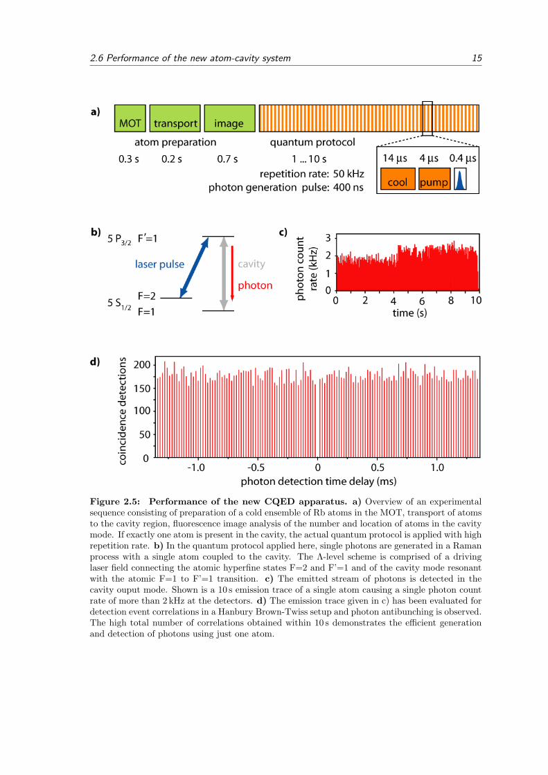
Figure 2.5: Performance of the new CQED apparatus. a) Overview of an experimentalsequence consisting of preparation of a cold ensemble of Rb atoms in the MOT, transport of atomsto the cavity region, fluorescence image analysis of the number and location of atoms in the cavitymode. If exactly one atom is present in the cavity, the actual quantum protocol is applied with highrepetition rate. b) In the quantum protocol applied here, single photons are generated in a Ramanprocess with a single atom coupled to the cavity. The Λ-level scheme is comprised of a drivinglaser field connecting the atomic hyperfine states F=2 and F’=1 and of the cavity mode resonantwith the atomic F=1 to F’=1 transition. c) The emitted stream of photons is detected in thecavity ouput mode. Shown is a 10 s emission trace of a single atom causing a single photon countrate of more than 2 kHz at the detectors. d) The emission trace given in c) has been evaluated fordetection event correlations in a Hanbury Brown-Twiss setup and photon antibunching is observed.The high total number of correlations obtained within 10 s demonstrates the efficient generationand detection of photons using just one atom.

16 Experimental Setup

3 Short pulse excitation of a single atom-cavity
system
In this chapter, we investigate the excitation of a single atom coupled to an optical cavityby means of short laser pulses. The observed dynamics present a fundamental exampleof cavity quantum electrodynamics in the optical domain. The emitted single photonsexhibit distinct wave packet shapes and are in a superposition of two tunable frequencies.We investigate possible control parameters and the efficiency of this photon generationprocess.
After a brief introduction of pulsed atomic excitation in free space (section 3.1), we theo-retically describe the dynamics of the coupled atom-cavity system (section 3.2) and ana-lyze the photon emission process (section 3.3). We then present the experimental results(section 3.4), followed by a discussion (section 3.5).
The content of this chapter has partially been published in:”Fast Excitation and Photon Emission of a Single-Atom-Cavity System”,J. Bochmann, M. Mucke, G. Langfahl-Klabes, C. Erbel, B. Weber, H. P. Specht, D. L.Moehring, and G. Rempe, Physical Review Letters 101, 223601 (2008).
3.1 Single photons from an atom in free space
We introduce the basic nomenclature by considering the case of a single two-level atom infree space excited by a near resonant continuous wave laser beam. The light emitted bythe atom exhibits photon-antibunching which is characterized by an intensity correlationfunction g(2)(τ = 0) = 0. Under the influence of the driving laser field the atomic pop-ulation performs coherent Rabi oscillations between the ground state |g〉 and the excitedstate |e〉 at a Rabi frequency ΩR. The coherent oscillation is randomly interrupted byspontaneous decay from |e〉 to |g〉 accompanied by the emission of a single photon. Theprobability of spontaneous emission events is proportional to the excited state decay rateΓ = 2γ. When averaging over many emission events one obtains a characteristic g(2)(τ)function (Fig. 3.1). We find antibunching at τ = 0 because detection of a photon at τ = 0projects the atom into |g〉. Thus the probability of a second photon emission at τ = 0vanishes. In the transient regime (0 < τ < 5/Γ), oscillations at the Rabi frequency ΩR
appear and fade to uncorrelated emission for τ Γ. We conclude that in the case of con-tinuous excitation, antibunching only occurs on time scales much shorter than the inverseRabi frequency.
For a useful single photon source, however, one requires to find no more than one photonin any given macroscopic time interval of length T such that g(2)(0 ≤ τ ≤ T ) = 0. Theinterval [0, T ] constitutes a single photon pulse if it contains exactly one excitation of the
17

18 Short pulse excitation of a single atom-cavity system
Figure 3.1: Photon emission of a single atom in free space. a) The atom is continuouslydriven by a coherent field. Rabi oscillations of the atomic population lead to modulations ofintensity correlation function g(2)(τ) of the emitted light. b) The atom is excited by short laserpulses. The expected intensity correlation function g(2)(τ) shows discrete peaks at a distancegiven by the pulse repetition rate frep. c) Wave packet shape (exponential decay) of single photonsemitted after short pulse excitation.
electromagnetic field. Such single photon pulses can be generated by exciting a singleatom with a laser pulse of duration τp much shorter than the spontaneous decay time 1/Γ.After the excitation, the atom is subject to spontaneous decay. It will emit a single photonwith a temporal probability distribution ρphot(t) = Γe−Γt which is equivalent to the wavepacket shape of the photon (Fig. 3.1). For example, upon excitation of the atom at t = 0a photon is emitted in the time interval t = [0; 5/Γ] with 99.3% probability and no photonemission occurs with a probability of 0.7%. For the Rb D2-transition (Γ = 2π 6 MHz,1/Γ = 26.2 ns) this yields T = 131 ns and a maximum repetition rate of the excitationpulses frep = 7.6 MHz.
The probability pm(τp) to generate more than one photon from one excitation pulse of du-ration τp is bounded by the probability of spontaneous atomic decay during the excitationpulse. This would allow a second sequential excitation of the atom and a second photonemission event. For infinite excitation pulse power the bound pm is given by:
pm(τp) ≤ 1− e−Γ τp . (3.1)
Any higher order multiple photon emission events are included in this bound. For the87Rb D2-line and a pulse duration of τp = 1 ns we obtain pm = 3.7 %.
All in all, the generation of single photons by short pulse excitation in free space hasproven as a versatile method in a multitude of physical systems such as neutral atoms,ions, quantum dots, NV-centers in diamond and molecules [86, 87, 88, 89, 90]. Exploitingthe multi-level structure of atoms, short pulse excitation can be extended to generateentanglement between the internal atomic state and the emitted photon [86]. The schemeoffers high repetition rates and its conceptual simplicity facilitates implementation.
A severe drawback of short pulse excitation in free space is its low photon collection effi-ciency. The photon generation process is mediated by spontaneous emission which occursin random directions. Only a small fraction of all emitted photons can be coupled into asingle spatial mode which may eventually be used for an experiment. Typical single photonretrieval efficiencies are on the order of 1 %. Further research towards the entanglement of

3.2 Dynamics of the atom-cavity system 19
remote atoms and the demonstration of quantum repeaters in single-atom single-photonnetworks would benefit if the advantages of short pulse excitation could be combined withcontrolled emission schemes as provided by cavity quantum electrodynamics.
3.2 Dynamics of the atom-cavity system
In this section, we analyze the evolution of a coupled atom-cavity system after short pulseexcitation. This provides the basis for the description of the photon emission process,which is the subject of section (3.3).
Similar to the excitation of an atom in free space, a short laser pulse can transfer anintracavity atom to the excited state |e〉. However, the state |e, n = 0〉, where n is theintracavity photon number, is not an eigenstate of the coupled atom-cavity system. Inthe following, we restrict ourselves to the case of exactly one excitation in the system.The evolution of the coupled atom-cavity system is determined by the Jaynes-CummingsHamiltonian
H = Ha +Hc +Hac. (3.2)
Here, Ha = ~ωegσ+σ is the Hamiltonian of a two-level atom with transition frequencyωeg using the convention σ+ = |e〉 〈g| and σ = |g〉 〈e|. The energy of the cavity modeat frequency ωc is given by Hc = ~ωc(a†a) using the bosonic annihilation and creationoperators a and a†. The atom-cavity coupling Hamiltonian Hac = ~g(a†σ + σ+a) scaleswith the atom-cavity coupling constant g. Here, we have implicitly assumed the rotatingwave and dipole approximation. When allowing an atom-cavity detuning ∆ac = ωeg −ωc (ωeg, ωc) we find for the eigenenergies of the coupled system:
E± = ~ωc + ~∆ac
2± ~
2
√4g2 + ∆2
ac. (3.3)
These eigenvalues correspond to the first excited state doublet of the Jaynes-Cummingsmodel with the eigenvectors (dressed states):
|+〉 = cos θ |e, 0〉+ sin θ |g, 1〉|−〉 = sin θ |e, 0〉 − cos θ |g, 1〉 . (3.4)
The mixing angle θ is defined as
tan θ =2g
∆ac +√
4g2 + ∆2ac
. (3.5)
It corresponds to a basis rotation in Hilbert-space |e, 0〉 , |g, 1〉 θ⇐⇒ |+〉 , |−〉 and quan-tifies the mixing of the bare states caused by the atom-cavity coupling.
We can express the time evolution of the system again in the uncoupled basis using equa-tions (3.4). For the resonant case ∆ac = 0 and starting in |e, 0〉, this leads to a full-amplitude vacuum Rabi oscillation of the bare-state amplitudes at frequency g (while thevacuum Rabi frequency is defined as Ω0 = 2g):
|Ψ(t)〉 = cos(gt) |e, 0〉 − i sin(gt) |g, 1〉 . (3.6)

20 Short pulse excitation of a single atom-cavity system
This evolution constitutes a coherent exchange of one energy quantum between the atomand the cavity field. These vacuum Rabi oscillations have been studied in some detail inmicrowave CQED experiments [91]. The phenomenon contains rich physics both from abasic CQED and a quantum information perspective [35]. For example, the dressed statesexhibit entanglement between atom and field.
In any real experiment, the coherent evolution considered above is accompanied by dissi-pation. The two dissipation channels present in our system are atomic polarization decayquantified by a rate γ and damping of the intracavity field quantified by a rate κ. Thespontaneous atomic decay rate γ is in good approximation unaffected by the presence ofthe cavity because the cavity mode covers only a negligible part of the solid angle.
The description of dissipation in open quantum systems requires considerable effort. Onepossibility is to derive a master equation which describes the time evolution of the system’sdensity matrix under inclusion of the coupling to the environment. Detailed descriptionscan be found in [76, 92, 93, 94, 95]. However, the correct solutions for the evolutionof the atom-cavity system coincide with a phenomenological treatment of decay whenthe environmental bath is large and has negligible back-action on the system. Assumingtime-independent coupling and decay constants, the time-evolution ci(t) of the bare statepopulations
|ψ(t)〉 = ce(t) |e, 0〉+ cg(t) |g, 1〉+ c0(t) |g, 0〉 (3.7)
is given by a system of differential equations of the form:
ce = igcg − i∆ac
2ce − γce
cg = igce + i∆ac
2cg − κcg . (3.8)
An analysis of limiting cases gives insight into the physical processes at play. In the limitof strong atom-cavity coupling (g (κ, γ)), the amplitudes ce,g oscillate at frequency2g as expected from the dissipation-free Jaynes-Cummings model. However, in the badcavity regime (κ (γ, g)) the oscillations are strongly suppressed. In fact, for a resonant”bad” cavity (∆ac = 0), the atomic excited state population decays exponentially at arate 2γ′ = 2γ + 2g2/κ which is a manifestation of the Purcell effect. Another limitingcase is defined by large atom-cavity detuning ∆ac (g, κ, γ) where the mixing angle θ issmall. Here, the system evolves with a high-frequency low-amplitude oscillation close tothe uncoupled states of atom and cavity.
The exact solutions of equations (3.8) for different parameter sets are given in figure (3.2).The different temporal evolutions illustrate the influence of (g, κ, γ,∆ac) on the dynamicsof an atom-cavity system which is initialized in state |e, 0〉 by a short pulse.

3.3 Single photons from a coupled atom-cavity system 21
Figure 3.2: Time evolution of bare state populations for different parameter sets.The probabilities |cg(t)|2 (red solid line) and |ce(t)|2 (blue solid line) are shown for a systeminitialized in ce(0) = 1 and cg(0) = 0. The exponential decay of atomic excitation in free space isgiven as a reference (dashed line). a) Intermediate coupling regime, resonant case: The coherentoscillations are damped by cavity and atomic decay. Parameters: (g, κ, γ,∆ac)/2π=(3.0, 2.8, 3.0,0) MHz. b) Strong coupling regime, resonant case: Vacuum Rabi oscillations are well resolvedand exhibit a conversion of atomic excitation into a cavity photon and vice versa. Parameters:(g, κ, γ,∆ac)/2π=(10.0, 2.8, 3.0, 0) MHz. c) Strong coupling regime, detuned case: The atom-cavity detuning increases the generalized vacuum Rabi frequency and decreases the mixing angleof the bare states. Parameters: (g, κ, γ,∆ac)/2π=(10.0, 2.8, 3.0, 40) MHz.
3.3 Single photons from a coupled atom-cavity system
The evolution of the atom-cavity system as described in the previous section governs thephoton emission from the cavity. In this section, we first derive the properties of theemitted single photons and then investigate the efficiency of photon generation.
The excitation of the cavity mode is mapped to the cavity output via |g, 1〉⊗ |n = 0〉outκ→
|g, 0〉 ⊗ |n = 1〉out. Therefore, the photon inherits its properties from the atom-cavitydynamics. The temporal wave packet shape of the single photon in the cavity output|Ψphot(t)|2 is equivalent to the probability density to emit a photon at time t:∫ t+dt
t
∣∣Ψphot(t′)∣∣2 dt′ = 2κ |cg(t)|2 dt. (3.9)
Typical wave packet shapes of the emitted single photon are shown in figure (3.3). Themodulations of the envelope reflect the evolution of cg(t). Alternatively, the emissionprocess can be interpreted as a quantum beat of the two normal-modes of the atom-cavitysystem. The frequency components of the single photon correspond to the energies of thefirst excited doublet of the dressed states. The relative phase of the frequency componentsis set by the initialization in state |e, 0〉.
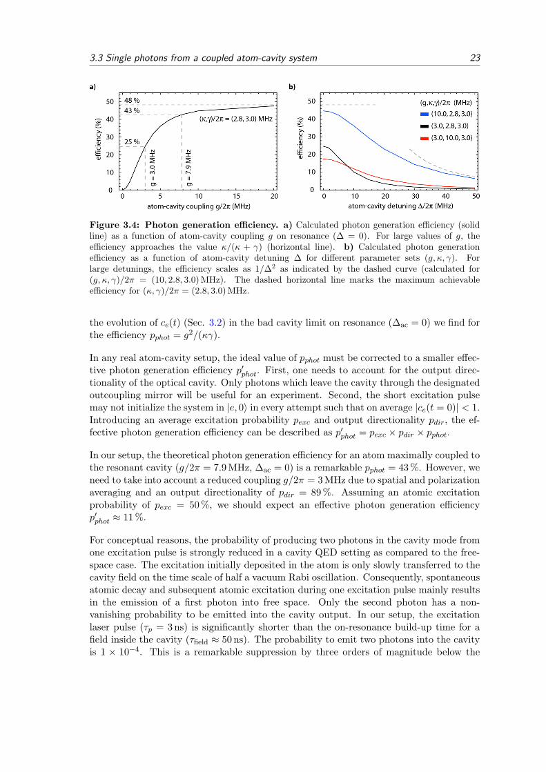
In the remainder of this section, we analyze the efficiency with which single photons arecreated with the short pulse scheme. We define the photon generation efficiency pphot asthe probability to retrieve a single photon in the cavity output mode after the atom-cavitysystem has been initialized in |e, 0〉. We calculate:
pphot =2κ∫∞
0 |cg(t)|2 dt
2κ∫∞
0 |cg(t)|2 dt+ 2γ
∫∞0 |ce(t)|
2 dt. (3.10)

22 Short pulse excitation of a single atom-cavity system
Figure 3.3: Photon shape and spectrum. a) Calculated wave packet shape ofthe emitted single photon for parameters (g, κ, γ,∆ac)/2π=(3, 3, 3, 0) MHz (red curve) and for(g, κ, γ,∆ac)/2π=(50, 3, 3, 0) MHz (blue curve). The amplitudes of the wave packets are indepen-dently normalized. b) Frequency spectrum of the photons of a). The two frequency componentsof each spectrum correspond to the dressed state energies of the coupled atom-cavity system. Thenormal-mode splitting is clearly visible for large g. The frequency axis is offset by the eigenfre-quency of the uncoupled atom and cavity ν0 = νc = νeg.
This equation can be solved based on the known time evolution of ce and cg. In figure (3.4),the efficiency pphot is plotted as a function of atom-cavity detuning ∆ac and for differentparameter sets (g;κ; γ) close to our experiment. In general, we find that the efficiency ishighest for small detunings ∆ac and large coupling g.
In order to obtain analytic expressions for pphot, we now consider limiting cases of equation(3.10). When the coherent oscillation between |e, 0〉 and |g, 1〉 is much faster than theincoherent decay, the average population of the bare states is determined by the mixingangle θ (Eq. 3.5) such that |ce(t)|2 = 1−2 sin2 θ cos2 θ and |cg(t)|2 = 2 sin2 θ cos2 θ. Hence,the photon generation efficiciency simplifies to
pphot =κ 2 sin2 θ cos2 θ
κ 2 sin2 θ cos2 θ + γ (1− 2 sin2 θ cos2 θ). (3.11)
It follows that
pphot =
κ
κ+γ for g ∆ac
κγ
2g2
∆2ac
for g ∆ac.(3.12)
For large g, the photon production efficiency is solely determined by the ratio of cavityand free space decay rate pphot = κ/(κ + γ). The obtained expression is an importantbenchmark. It presents a universal upper bound for the photon production efficiencywith the short pulse scheme. For large detunings ∆ac, the photon production efficiencydecreases quadratically with atom-cavity detuning while cavity and free space decay areweighted by the ratio κ/γ.
We conclude that the efficiency of photon generation with the fast excitation scheme isgenerally not correctly described by a Purcell factor of the type g2/κ. However, based on
3.3 Single photons from a coupled atom-cavity system 23
Figure 3.4: Photon generation efficiency. a) Calculated photon generation efficiency (solidline) as a function of atom-cavity coupling g on resonance (∆ = 0). For large values of g, theefficiency approaches the value κ/(κ + γ) (horizontal line). b) Calculated photon generationefficiency as a function of atom-cavity detuning ∆ for different parameter sets (g, κ, γ). Forlarge detunings, the efficiency scales as 1/∆2 as indicated by the dashed curve (calculated for(g, κ, γ)/2π = (10, 2.8, 3.0) MHz). The dashed horizontal line marks the maximum achievableefficiency for (κ, γ)/2π = (2.8, 3.0) MHz.
the evolution of ce(t) (Sec. 3.2) in the bad cavity limit on resonance (∆ac = 0) we find forthe efficiency pphot = g2/(κγ).
In any real atom-cavity setup, the ideal value of pphot must be corrected to a smaller effec-tive photon generation efficiency p′phot. First, one needs to account for the output direc-tionality of the optical cavity. Only photons which leave the cavity through the designatedoutcoupling mirror will be useful for an experiment. Second, the short excitation pulsemay not initialize the system in |e, 0〉 in every attempt such that on average |ce(t = 0)| < 1.Introducing an average excitation probability pexc and output directionality pdir, the ef-fective photon generation efficiency can be described as p′phot = pexc × pdir × pphot.
In our setup, the theoretical photon generation efficiency for an atom maximally coupled tothe resonant cavity (g/2π = 7.9 MHz, ∆ac = 0) is a remarkable pphot = 43 %. However, weneed to take into account a reduced coupling g/2π = 3 MHz due to spatial and polarizationaveraging and an output directionality of pdir = 89 %. Assuming an atomic excitationprobability of pexc = 50 %, we should expect an effective photon generation efficiencyp′phot ≈ 11 %.
For conceptual reasons, the probability of producing two photons in the cavity mode fromone excitation pulse is strongly reduced in a cavity QED setting as compared to the free-space case. The excitation initially deposited in the atom is only slowly transferred to thecavity field on the time scale of half a vacuum Rabi oscillation. Consequently, spontaneousatomic decay and subsequent atomic excitation during one excitation pulse mainly resultsin the emission of a first photon into free space. Only the second photon has a non-vanishing probability to be emitted into the cavity output. In our setup, the excitationlaser pulse (τp = 3 ns) is significantly shorter than the on-resonance build-up time for afield inside the cavity (τfield ≈ 50 ns). The probability to emit two photons into the cavityis 1 × 10⁻⁴. This is a remarkable suppression by three orders of magnitude below the
24 Short pulse excitation of a single atom-cavity system
free-space bound pm(τp = 3 ns) = 11 % deduced in section (3.1).
The possible repetition rate of photon generation is given by the duration of the photonwave packet. The short pulse scheme is based on an atomic two-level system and does notrequire atomic state repumping. In our system, the photon wave packet amplitude vanishesapproximately 150 ns after the excitation pulse. The repetition rate of the excitation pulsesmay therefore be as high as 6.7 MHz. At reasonable photon generation efficiencies, a singlephoton source with an emission rate of 1 MHz into a single mode seems feasible.
In summary, the short pulse scheme applied in a cavity QED setting compares well to thefree-space case. The retrieval efficiency of photons in a designated spatial output modeis intrinsically high and the contribution of higher order Fock states in the output fieldis significantly suppressed. We find that the photon generation efficiency is highest onresonance (∆ac = 0) and is ultimately bound by the ratio κ/(κ + γ). Compared to thepreviously studied STIRAP process for photon generation (see section 2.6), the short pulsescheme can produce short photon wave packets (≈100 ns) while potentially operating atMHz repetition rates.
3.4 Experiment and results
3.4.1 Experimental protocol
Single 87Rb atoms are trapped inside the cavity mode at the focus of a standing waveoptical dipole trap as described in chapter (2). The experimental protocol for a trappedatom consists of atom cooling intervals (25µs) alternating with photon production intervals(25µs). During the photon production intervals, the atom is repeatedly excited with shortpulses at a rate of 670 kHz propagating along the +45 axis of the setup. Each photonproduction interval contains 15 short pulses. The pulses are near-resonant with the atomicF = 2↔ F ′ = 3 transition. A schematic of the experimental setup and the sequence timingis displayed in figure (3.5).
Short excitation pulses with a duration of τp = 3 ns are created by amplitude modulation ofcontinuous-wave light using a fiber-coupled electro-optic modulator (EOM)1. The on:offratio of the EOM is finite (company specified 800:1) and we use different strategies toimprove the on:off ratio eventually ”seen” by the atom. In a first step, we pre-chop theEOM input light with an AOM (AOM pulse duration 300 ns). Secondly, we trigger theEOM to switch only at the end of every AOM pulse such that the trailing edges of AOMpulse and EOM pulse coincide and both contribute to a rapid intensity reduction. Wemeasure an intensity reduction of better than 10−3 reached within 8 ns after the pulsepeak and decreasing further thereafter (3.6). We observe drifts in the EOM contrast at a
1Jenoptik model AM780HF, half-wave voltage 3 V, modulation frequencies DC to 5 GHz, insertion loss6 dB. The functional principle of the EOM is that of a Mach-Zehnder interferometer in which the pathlength difference is controlled by an electro-optically induced phase shift. The transmitted optical powercan be controlled by tuning the interferometer from constructive to destructive interference at its output.

3.4 Experiment and results 25
Figure 3.5: Experimental setup for the fast excitation scheme. a) Single Rb atoms aretrapped within the TEM00 mode of the cavity at the focus of the standing wave dipole trap. Tworesonant beams at ±45 with respect to the standing wave trap and perpendicular to the cavityaxis provide cooling and short pulse excitation. The cavity output is coupled to an optical fiber andguided to the detection setup. SPCM: single photon counting module, NPBS: non-polarizing beamsplitter, λ/4: quarter-wave plate, EOM: electro-optic modulator, MOT: magneto-optical trap. b)Experimental protocol used for short pulse excitation. Intervals of atom cooling are interleavedwith intervals for fast excitation of the atom-cavity system. One excitation interval contains 15short laser pulses with a duration of 3 ns at a temporal distance of 1.5µs.
given fixed offset voltage due to patch charges and thermal effects. Therefore, the opticaloutput of the EOM is permanently monitored and the applied offset voltage is adapted in afeedback loop. Finally, we detune the center frequency of the cw-input light from the Starkshifted atomic resonance and cavity resonance by −30 MHz to suppress continuous-waveexcitations [96]. Nevertheless, the atom is excited by the short pulse (measured bandwidth∼ 100 MHz). The excitation pulse energy impinging on the atom (pulse area) is chosenhigh enough such that the average atomic excitation probability saturates at pexc=50%.We have not been able to reproducibly apply exact π-pulses as the Rabi frequency variesfrom shot to shot. This is due to atomic Stark shift variations and indeterminate transitionstrengths because the atom is not prepared in a well-defined Zeeman sublevel.
The cavity output mode is coupled into a single-mode optical fiber and directed to aHanbury Brown-Twiss photon detection setup consisting of a nonpolarizing beamsplitterand two single-photon counting modules. The total detection efficiency for a single photonpresent inside the cavity is 34%. The photon detection events on each detector and atrigger time stamp of every short excitation pulse (gate signal) are recorded on a digitalcounter card (P7888, time resolution 1 ns).

26 Short pulse excitation of a single atom-cavity system
Figure 3.6: Generation of short laser pulses. a) Schematic of the pulse generation setup.Light from a cw-source is chopped by an acousto-optic modulator (AOM) and an electro-opticmodulator (EOM) to achieve a high on:off ratio. b) The measured pulse intensity shows a peakwith 3 ns full width at half maximum. Electronic after-pulsing of the photodetector (grey signal)appears with a probability of 10−3 approx. 50 ns after a detection event. This effect is negligiblein our measurements.
3.4.2 Single photon generation with a resonant cavity
In a first measurement, we set the cavity frequency resonant with the Stark-shifted F = 2to F ′ = 3 transition (atom-cavity detuning ∆ac = 0 MHz). We infer the wave packet shapeof the emitted photons from the temporal probability distribution of photon detectionevents after each excitation pulse. The measured shape of the photon wave packet isshown in figure (3.7). The peak of the photon emission probability is significantly delayedwith respect to a free space exponential decay. The photon wave packet exhibits a smoothenvelope function as the vacuum Rabi oscillation is critically damped due to atomic andcavity decay.
Quantitatively, the measured data agrees well with theory. From a numerical fit to themeasured wave packet, we obtain a vacuum Rabi frequency Ω = 5± 1 MHz which is con-sistent with an expected average coupling g = 3 MHz. The extracted incoherent dampingrate of 3.0 ± 0.2 MHz matches the a priori known values κ = 2.8 MHz and γ = 3.0 MHz.The measured probability of emitting a photon into the cavity mode following an excita-tion pulse is p′phot = 8± 1 % close to the theoretical prediction (section 3.3). The photongeneration efficiency is mainly limited by spatial g-averaging due to residual atomic motionand by the average atomic excitation probability of pexc ≈ 50 %. Options for improvementare the localization of the atom at a cavity field maximum and improved atomic excitationusing well-tailored π-pulses. Together this could lead to an effective photon productionefficiency of up to p′phot = 38 % in the existing experimental setup.
The single-photon nature of emission is verified by an analysis of the intensity correla-tion function g(2)(τ) evaluated from photons arriving within 200 ns after each excitationpulse. We find a g(2)(τ) function with three distinct features (Fig. 3.7). The comb-liketime structure with separations of 1.5µs corresponds to the succession of short excitationpulses with a repetition rate of 670 kHz. The probability to record coincidences in each

3.4 Experiment and results 27
Figure 3.7: Single photons from pulsed excitation. a) Histogram: Shape of the emittedphoton wave packets as given by the detection event distribution after the excitation pulse (greybar). The observed wave packet shape agrees well with theory (black solid line). A calculatedphoton wave packet shape for emission in free space is given for comparison (dashed line). b)Measured second-order correlation function g(2)(τ) (gated) of the emitted photons. The suppressionof coincidences at τ = 0 verifies the single photon character of the emission. The triangular envelopefunction is a convolution of photon production and cooling intervals (see text for details).
of these time bins is modulated with a triangular envelope function. It stems from theconvolution of photon production intervals (25µs) with interleaved cooling intervals of thesame duration. Most important, we observe a high suppression (> 90 %) of coincidenceevents at time τ = 0 demonstrating that the protocol does indeed result in single pho-tons. The remaining coincident detections stem from dark counts of the SPCM’s (≤ 2 %)and from multiple trapped atoms (≤ 8 % due to probabilistic atom loading, single atomimaging was not implemented at this point).
3.4.3 Observation of vacuum Rabi oscillations
The coherent exchange of energy between a single atom and the cavity mode is most strik-ingly observed when the characteristic oscillation frequency is higher than the incoherentdamping rates (see section 3.2). In the following measurements, we increase the general-ized vacuum Rabi frequency Ω by detuning the cavity frequency from the Stark-shiftedatomic resonance by ∆ac. The system then oscillates at a frequency
Ω =√
4g2 + ∆2ac (3.13)
between the states |e, 0〉 and |g, 1〉 (Eq. 3.3). Note that κ ≈ γ in our setup and hencefrequency shifts due to damping are negligible. However, for single atoms loaded intothe deep standing-wave dipole trap, Stark shift variations lead to an uncertainty in ∆ac.A more precise Ω is maintained in the shallow running-wave dipole trap. In this dipoletrap configuration, atoms drift through the cavity at low overall densities. We ensurethat the average number of atoms in the cavity is much less than one (verification byg(2)(τ) measurements). The intermittent atom cooling and photon production intervals aresimply replaced by one long photon production interval spanning the whole experimental
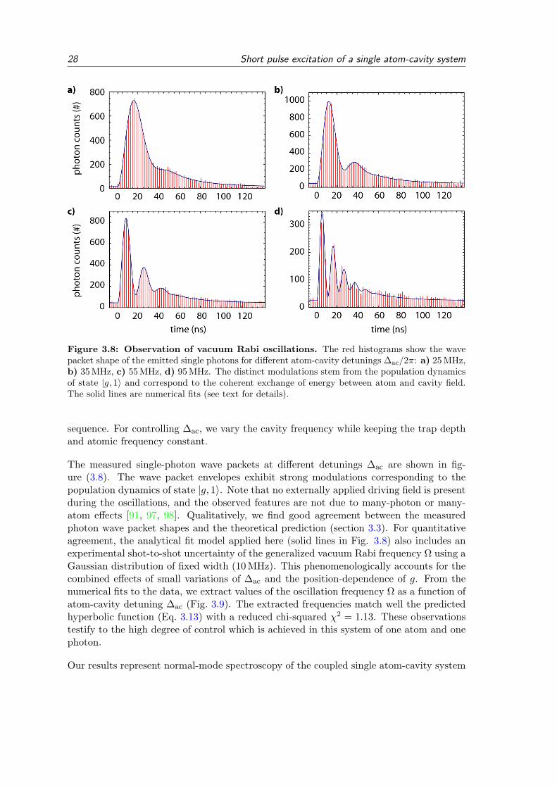
28 Short pulse excitation of a single atom-cavity system
Figure 3.8: Observation of vacuum Rabi oscillations. The red histograms show the wavepacket shape of the emitted single photons for different atom-cavity detunings ∆ac/2π: a) 25 MHz,b) 35 MHz, c) 55 MHz, d) 95 MHz. The distinct modulations stem from the population dynamicsof state |g, 1〉 and correspond to the coherent exchange of energy between atom and cavity field.The solid lines are numerical fits (see text for details).
sequence. For controlling ∆ac, we vary the cavity frequency while keeping the trap depthand atomic frequency constant.
The measured single-photon wave packets at different detunings ∆ac are shown in fig-ure (3.8). The wave packet envelopes exhibit strong modulations corresponding to thepopulation dynamics of state |g, 1〉. Note that no externally applied driving field is presentduring the oscillations, and the observed features are not due to many-photon or many-atom effects [91, 97, 98]. Qualitatively, we find good agreement between the measuredphoton wave packet shapes and the theoretical prediction (section 3.3). For quantitativeagreement, the analytical fit model applied here (solid lines in Fig. 3.8) also includes anexperimental shot-to-shot uncertainty of the generalized vacuum Rabi frequency Ω using aGaussian distribution of fixed width (10 MHz). This phenomenologically accounts for thecombined effects of small variations of ∆ac and the position-dependence of g. From thenumerical fits to the data, we extract values of the oscillation frequency Ω as a function ofatom-cavity detuning ∆ac (Fig. 3.9). The extracted frequencies match well the predictedhyperbolic function (Eq. 3.13) with a reduced chi-squared χ2 = 1.13. These observationstestify to the high degree of control which is achieved in this system of one atom and onephoton.
Our results represent normal-mode spectroscopy of the coupled single atom-cavity system

3.4 Experiment and results 29
Figure 3.9: Normal-mode spectroscopy in the time domain. From numerical fits to themeasured photon shapes we extract the coherent atom-cavity oscillation frequencies (dots) as afunction of atom-cavity detuning ∆ac. The solid line shows the calculated generalized vacuum Rabifrequency Ω =
√4g2 + ∆2
ac. Our data matches this hyperbolic function with a reduced chi-squaredχ2 = 1.13. The deduced average coupling constant is g = 2π × (2± 1) MHz.
in the time domain. The observed modulation in the photon shape originates from aquantum beat of the first pair of atom-cavity dressed states [99]. The emitted singlephotons are in a superposition of two frequencies with a fixed relative phase.
3.4.4 Short pulse excitation of the cavity mode
A complementary illustration of the coherent exchange of one quantum of energy betweenatom and cavity is investigated by short pulse excitation of the cavity mode. In thiscase, the system is (approximately) initialized in state |g, 1〉. With respect to the previousexperiments, this swaps the role of cg(t) and ce(t) in the temporal evolution of the coupledsystem (Fig. 3.10).
The experimental protocol follows that of the experiment described in section (3.4.3) butwith on average one atom present in the cavity (continuous loading regime, chapter (2)).The excitation pulses are coupled into the cavity through the input mirror. The pulsesare weak such that one photon is deposited in the cavity in only 10 % of all attemptsand contributions of higher Fock states are negligible. The atom-cavity detuning is set to∆ac = 0.
The light pulse emitted from the atom-cavity system exhibits a clear deviation from apurely exponential decay of the intracavity field (Fig. 3.10). The observed behavior isexplained by the temporary storage of excitation in the atom during half of a vacuumRabi oscillation. Quantitatively, we can retrieve the temporal evolution of the populationin state |e, 0〉 by subtracting the measured pulse from the exponential decay curve of the

30 Short pulse excitation of a single atom-cavity system
Figure 3.10: Short pulse excitation of the cavity mode. a) Histogram: Measured photonarrival time distribution after excitation of the cavity with ∼ 1 atom present. Dashed line: Expo-nential decay of the cavity field intensity without atoms. b) The difference between the two curvesin a) reflects the occupation of state |e, 0〉. This extracted difference signal (dots) is comparedwith the emitted photon shape when the atom is excited (solid line, data of section 3.4.2). Thenearly identical time evolution of cg(t) when the atom-cavity system is initialized in state |e, 0〉(solid line) and the evolution of ce(t) when the system is initialized in |g, 1〉 (dots) illustrates thecomplementary role of cg(t) and ce(t) in the coupled atom-cavity system.
empty cavity. In Fig. (3.10b), the obtained curve for ce(t) is compared with the measuredevolution of cg(t) (i.e. photon shape) from the experiment of section (3.4.2). The nearlyidentical time dependence of the two signals shows the complementary role of cg(t) andce(t) when the system is initialized in either |e, 0〉 or |g, 1〉.
3.5 Discussion and Outlook
In this chapter we have theoretically analyzed and experimentally implemented shortpulse excitation of a single atom-cavity system. The presence of the cavity dramaticallyalters the dynamics of the emission process compared to an atom in free space. Thecoupled system evolves with a coherent oscillatory energy exchange between the atomand the cavity, damped by atomic and cavity decay. The wave packet of the emittedphoton is governed by the evolution of the coupled atom-cavity system – independentof the excitation pulse shape and frequency. The cavity frequency constitutes a controlparameter by which the shape and the frequency spectrum of the emitted photon can becontrolled. The observed behaviour constitutes a fundamental example of cavity QED atthe level of one atom and one photon.
Compared to photon generation with an atom in free space, the cavity scheme benefitsfrom a high efficiency with which photons are generated in a designated output mode.Further, two-photon emission events are strongly suppressed. A single photon generationefficiency of 8 % at a repetition rate on the order of 1 MHz has been achieved in theexperiment. The parameters of our setup may in the future allow a generation efficiencyof close to 40 % when a single atom can be permanently located at a maximum of the

3.5 Discussion and Outlook 31
cavity field.
Photon generation by the short pulse scheme also presents an alternative to the previouslystudied cavity-mediated STIRAP process (chapter 2, [100]). Pulsed excitation is based ona closed two-level transition and does not require atomic state repumping. The generatedphotons are much shorter (100 ns) than photons typically created in the STIRAP process(1µs). Even at moderate absolute efficiency, this potentially translates into the generationof single photons in a well-defined mode at a retrieval rate on the order of 1 MHz.
A drawback of the pulse scheme is the mapping of atomic Stark shift variations onto thefrequency spectrum of the photon. This problem can be avoided by using very shallowdipole traps (low absolute Stark shifts), using traps at ”magic wavelengths” or by coolingthe atom to the ground state of a deep trap. Further, the generation of time symmetricphoton wave packets can only be accomplished at low efficiencies [101] – while such photonswould be desirable for quantum networking [68]. The generation of frequency entangledatom-photon pairs from short pulse excitation [102] is complicated by the spectral filteringof the cavity. However, a solution to this might be frequency matching of an integermultiple of the atomic hyperfine splitting with the free spectral range of the cavity.
In future experiments, our scheme may find application in the investigation of higher-lying dressed states in cavity QED systems [50] and for generation of multi-photon Fockstates [103]. Additionally, a single photon in a superposition of two tunable frequencies,as demonstrated here, may be useful as a frequency qubit [104, 105]. Finally, this tech-nique can improve existing atom-photon entanglement experiments by reducing unwantedmultiple-photon events [100] and is extendable to multi-photon entanglement protocols[106].

32 Short pulse excitation of a single atom-cavity system

4 State detection of a single atom in a cavity
Efficient internal state detection of single neutral atoms is at the basis of atomic physicsand is highly relevant for quantum information science. In a single atom, the quantumbit (qubit) is often encoded in or mapped onto atomic hyperfine states. In this chapter,we show that coupling the atom to a cavity establishes a superior readout channel forinternal atomic states. We introduce a state detection scheme based on cavity-enhancedfluorescence and realize state readout by differential cavity transmission. In an experimentwith a single trapped 87Rb atom, we achieve a hyperfine state detection fidelity of 99.4%in 85µs while a result is obtained in every readout attempt. Most important, the qubitis interrogated many hundred times without loss of the atom. This presents an essentialadvancement for the speed and scalability of quantum information protocols based onneutral atoms. Further, the general principles outlined here may be applied to the readoutof other optically accessible systems such as cold molecules, NV-centers in diamond orquantum dots.
This chapter is organized as follows. We first introduce basic concepts of state detectionand give a definition of the readout fidelity (sec. 4.1). In section (4.2), cavity-enhancedfluorescence detection is theoretically studied, followed by the presentation of the experi-mental results (sec. 4.2.4). The use of a cavity also allows for atomic hyperfine state read-out via differential transmission (sec. 4.3). A comparative discussion of the two detectionschemes is given in section (4.4). Finally, we present applications of the cavity-enhancedfluorescence method for Stark shift spectroscopy and magnetic field measurement (sec.4.5).
The results presented in this chapter have partially been published in:”Lossless state detection of single neutral atoms”J. Bochmann, M. Mucke, C. Guhl, S. Ritter, G. Rempe, and D. L. Moehring,Physical Review Letters 104, 203601 (2010).
4.1 Introduction
4.1.1 Methods for atomic state detection
In view of quantum information, internal atomic states may serve as stationary quantumbits. In a single atom, the quantum bit (qubit) is typically encoded in or can be mappedonto atomic hyperfine states. However, hyperfine qubit readout has proven remarkablydifficult for neutral atoms and an adequate concept remained to be shown. Existingprotocols either do not obtain an answer in every readout attempt [107, 108], they requirestrong atom-cavity coupling [109, 110, 111] or they are intrinsically destructive and causeloss of the atom during detection [112, 113, 114, 115, 71, 43, 116]. In this chapter, we
33
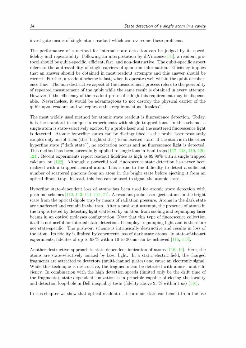
34 State detection of a single atom in a cavity
investigate means of single atom readout which can overcome these problems.
The performance of a method for internal state detection can be judged by its speed,fidelity and repeatability. Following an interpretation by diVincenzo [31], a readout pro-tocol should be qubit-specific, efficient, fast, and non-destructive. The qubit-specific aspectrefers to the addressability of single carriers of quantum information. Efficiency impliesthat an answer should be obtained in most readout attempts and this answer should becorrect. Further, a readout scheme is fast, when it operates well within the qubit decoher-ence time. The non-destructive aspect of the measurement process refers to the possibilityof repeated measurement of the qubit while the same result is obtained in every attempt.However, if the efficiency of the readout protocol is high this requirement may be dispens-able. Nevertheless, it would be advantageous to not destroy the physical carrier of thequbit upon readout and we rephrase this requirement as ”lossless”.
The most widely used method for atomic state readout is fluorescence detection. Today,it is the standard technique in experiments with single trapped ions. In this scheme, asingle atom is state-selectively excited by a probe laser and the scattered fluorescence lightis detected. Atomic hyperfine states can be distinguished as the probe laser resonantlycouples only one of them (the ”bright state”) to an excited state. If the atom is in the otherhyperfine state (”dark state”), no excitation occurs and no fluorescence light is detected.This method has been successfully applied to single ions in Paul traps [117, 118, 119, 120,121]. Recent experiments report readout fidelities as high as 99.99% with a single trappedcalcium ion [122]. Although a powerful tool, fluorescence state detection has never beenrealized with a trapped neutral atom. This is due to the difficulty to detect a sufficientnumber of scattered photons from an atom in the bright state before ejecting it from anoptical dipole trap. Instead, this loss can be used to signal the atomic state.
Hyperfine state-dependent loss of atoms has been used for atomic state detection withpush-out schemes [112, 113, 114, 115, 71]. A resonant probe laser ejects atoms in the brightstate from the optical dipole trap by means of radiation pressure. Atoms in the dark stateare unaffected and remain in the trap. After a push-out attempt, the presence of atoms inthe trap is tested by detecting light scattered by an atom from cooling and repumping laserbeams in an optical molasses configuration. Note that this type of fluorescence collectionitself is not useful for internal state detection. It employs repumping light and is thereforenot state-specific. The push-out scheme is intrinsically destructive and results in loss ofthe atom. Its fidelity is limited by concurrent loss of dark state atoms. In state-of-the-artexperiments, fidelites of up to 98 % within 10 to 30 ms can be achieved [115, 113].
Another destructive approach is state-dependent ionization of atoms [116, 42]. Here, theatoms are state-selectively ionized by laser light. In a static electric field, the chargedfragments are attracted to detectors (multi-channel plates) and cause an electronic signal.While this technique is destructive, the fragments can be detected with almost unit effi-ciency. In combination with the high detection speeds (limited only be the drift time ofthe fragments), state-dependent ionization is in principle capable of closing the localityand detection loop-hole in Bell inequality tests (fidelity above 95 % within 1µs) [116].
In this chapter we show that optical readout of the atomic state can benefit from the use

4.1 Introduction 35
of a cavity in two ways. On the one hand, the optical resonator can amplify the couplingbetween the probing light field and the atom. In a typical realization, the probe lighttransmission of the atom-cavity system depends on the hyperfine state of the atom. Thisconcept is well suited for the strong-coupling regime of cavity QED [111]. On the otherhand, the optical resonator can amplify the coupling between the atom and the detectorvia the Purcell effect. This situation corresponds to cavity-enhanced fluorescence detectionand is well suited for the ”bad cavity” regime of CQED.
The theoretical analysis and experimental implementation of both differential transmissionand cavity-enhanced fluorescence detection are the subject of the following sections.
4.1.2 Definition and calculation of the fidelity
We consider a physical system prepared in one of the two quantum states |0〉 and |1〉.We define the fidelity F of state detection as the minimum probability with which thecorrect quantum state is obtained in any readout attempt. First, we identify all possibledecisions for a given measurement outcome in a tree diagram (Fig. 4.1). The probabilityfor a false decision is E|0〉 and E|1〉 respectively. The probabilities for correct or no answerare labelled Ci and Ni (i ∈ |0〉, |1〉) with Ci +Ni + Ei = 1.
h|0〉 x|1〉atomic state
?
@@@R
?
@@@R
identified as”|0〉” ”no answer””|1〉” ”|0〉” ”no answer””|1〉”≡ C|0〉 ≡ N|0〉 ≡ E|0〉 ≡ E|1〉 ≡ N|1〉 ≡ C|1〉
Figure 4.1: Tree diagram of state detection. We can identify all possible decisions for agiven measurement outcome. The probability for a false decision is E|0〉 and E|1〉 respectively. Theprobabilities for correct or no answer are labelled Ci and Ni (i ∈ |0〉, |1〉) with Ci +Ni +Ei = 1.
We require that a decision is made for every measurement outcome and therefore Ni = 0.We can now define the fidelity as
F = 1−maxE|0〉, E|1〉
= min
C|0〉, C|1〉
. (4.1)
We note that this is a conservative yet not the only possible definition of a state detectionfidelity. In the literature, one also finds F = 1 −
(E|0〉 + E|1〉
)/2 [122], which a priori
assumes preparation of the atom in either of two states with equal probability.
In optical state readout schemes, a certain number of photons Ndet is detected in a givenreadout attempt. A decision about the atom’s state is made by comparison of Ndet witha discrimination level d: Ndet ≤ d or Ndet > d. The fidelity of the readout protocol canbe optimized by appropriate choice of d. The number of detected photons may be givenby probability distributions p|0〉(n) and p|1〉(n) with mean values λ|0〉 and λ|1〉. We choose

36 State detection of a single atom in a cavity
λ|0〉 ≤ λ|1〉. Using the relations
C|0〉 =d∑
n=0
p|0〉(n) and C|1〉 =∞∑
n=d+1
p|1〉(n) (4.2)
we can find the optimum discrimination level d by calculating the achievable fidelity ac-cording to:
F = maxd
min
d∑
n=0
p|0〉(n), 1−d∑
n=0
p|1〉(n)
. (4.3)
The probability distributions pi(n) are normalized to 1 (∑∞
n=0 pi(n) = 1). While theactual probability distributions p|0〉(n) and p|1〉(n) may take arbitrary forms, shot-noisedominated Poisson distributions with mean values λ|0〉 and λ|1〉 are often reasonable ap-proximations:
p (λi, n) =λnin!e−λi . (4.4)
The standard deviation 1/√λi is relatively large for small λ. The overlap of the two
distributions can be reduced by detecting a larger number of photons.
We can obtain a first insight into the achievable fidelity by introducing a contrast pa-rameter K ≡ 1 − λ|0〉/λ|1〉 taking values between 0 and 1. The fidelity F(K,λ|1〉) as afunction of contrast and mean detected photon number is depicted in (Fig. 4.2). At highvalues of contrast (K ' 1), a fidelity of more than 99% is achievable with λ|1〉 ≥ 5. Ata contrast of K = 50%, a fidelity of 99% requires appriximately λ|1〉 = 80 detected pho-tons (λ|0〉 = 40). We will see later, that these two cases correspond to the experimentalsituations of cavity-enhanced fluorescence detection and differential cavity transmission.
4.2 Cavity-enhanced fluorescence state detection
4.2.1 Fluorescence scattering of an atom coupled to a cavity
We consider a single atom coupled to a cavity and continuously driven by a probe laserwhich is applied transverse to the cavity axis. The rate of scattered photons Rscat at thecavity output can be obtained from a master equation approach [92, 76]. The rate scaleswith the excitation probability Pe of the intracavity atom as
Rscat,cav = 2κg2
∆2c + κ2
Pe, (4.5)
where the excitation probability of the atom in free space Pe,free is affected by the presenceof the cavity as
Pe = Pe,free/(|1− ν|2) (4.6)
ν = g2/ ((∆a − iγ) (∆c − iκ)) . (4.7)

4.2 Cavity-enhanced fluorescence state detection 37
Figure 4.2: Fidelity of state detection for Poissonian detection event distributions.Shown here is the maximum achievable fidelity as a function of contrast K ≡ 1−λ|0〉/λ|1〉 and meannumber of detected photons λ|1〉 assuming Poissonian probability distributions p|0〉(n) and p|1〉(n)for the number of detected photons n. In view of the experiments presented in this chapter, theregimes of cavity-enhanced fluorescence detection (circle) and of differential transmission (square)are indicated. The numbers in the graph indicate the achievable fidelity in (%).
The complex cooperativity ν includes the detuning of atom ∆a and cavity ∆c with respectto the probe laser, where γ and κ are the atomic polarization and the cavity field decayrate and g is the coherent atom-cavity coupling constant. Equation (4.5) is valid in thelimit of weak driving (low saturation of the atom) and care must be taken for correctlyevaluating the limit ∆c → 0 and κ→ 0 [92].
4.2.2 Statistical analysis
In this section, we derive a statistical description of the fluorescence state detectionmethod. Our main goal is to calculate the achievable fidelity. The central problem weneed to solve is the analytic description of the probability distribution p(n) for n detectionevents taking into account optical pumping and dark counts.
We want to distinguish the two hyperfine ground states |52S1/2 F = 2〉 and |52S1/2 F = 1〉of a single 87Rb atom by the number of detected fluorescence photons in a given probepulse of duration τD. We choose probe laser and cavity frequencies to be resonant withthe cycling transition |52S1/2 F = 2〉 ↔ |52P3/2 F
′ = 3〉, making F = 2 the bright stateand F = 1 the dark state. While for an atom in F = 2 the scattering rate Rscat,cav ishigh, for an atom prepared in F = 1 it vanishes due to a large detuning ∆a/2π ' 6.8 GHz.This contrast should in principle allow a high state detection fidelity. However, the fidelityis limited by the occurence of detector dark counts and atomic hyperfine state pumpinginduced by the probe laser. The probability distributions for the number n of detectionevents pk(n) with k=(dark, bright) are affected by these processes in a complex way.

38 State detection of a single atom in a cavity
Figure 4.3: Off-resonant optical pumping induced by the probe laser. The probe laser(red arrow) is near-resonant with the F = 2 ↔ F ′ = 3 transition (D2 line of 87Rb). Off-resonantexcitation of F ′ = 2 und F ′ = 1 can lead to spontaneous decay into either of the ground statesF = 1 and F = 2 which introduces an unwanted pumping process between the hyperfine groundstates during state detection (gray arrows). However, the large ground state hyperfine splittingωHFS = 6.8 GHz effectively suppresses dark-to-bright state pumping via F = 1 ↔ F ′ = 1, 2 asthe probe is then detuned by the same amount. Bright-to-dark pumping is governed by the muchsmaller excited state hyperfine splittings ωHFP/2π ≈ 0.3 GHz but its probability is significantlyaffected by probe laser polarization (see text for details).
Atomic state pumping induced by the probe laser is a fundamental problem of fluorescencestate detection (Fig. 4.3). While resonant with the cycling transition F = 2↔ F ′ = 3, theprobe laser can off-resonantly couple the dark state F = 1 to the excited states F ′ = 1, 2from where decay into the bright state F = 2 can occur. If the probe polarization is notwell-defined, the probe laser can also off-resonantly couple F = 2 to F ′ = 1, 2 from wheredecay into the dark state F = 1 is possible. In the following, we neglect higher orderprocesses (multiple pumping between bright and dark state). The probability of opticalpumping at time t is given by
f(t) =1τke− tτk (4.8)
where τk is the average time until optical pumping occurs and 0 ≤ t ≤ τD. The averagenumber of detected photons λ′ is proportional to the time the atom is in the bright state:
λ′(t) =
(
1− tτD
)λ (atom initially in dark state)(
tτD
)λ (atom initially in bright state)
(4.9)
with λ the mean detected photon number for an atom in the bright state during the wholeprobe interval. The time-based probability distribution f(t) can be transformed into adistribution gk(λ′). We define
αk =τDη
τkλ(4.10)
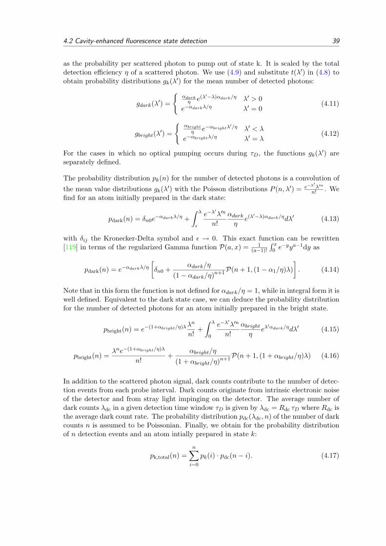
4.2 Cavity-enhanced fluorescence state detection 39
as the probability per scattered photon to pump out of state k. It is scaled by the totaldetection efficiency η of a scattered photon. We use (4.9) and substitute t(λ′) in (4.8) toobtain probability distributions gk(λ′) for the mean number of detected photons:
gdark(λ′) =
αdarkη e(λ′−λ)αdark/η λ′ > 0
e−αdarkλ/η λ′ = 0(4.11)
gbright(λ′) =
αbrightη e−αbrightλ
′/η λ′ < λ
e−αbrightλ/η λ′ = λ(4.12)
For the cases in which no optical pumping occurs during τD, the functions gk(λ′) areseparately defined.
The probability distribution pk(n) for the number of detected photons is a convolution of
the mean value distributions gk(λ′) with the Poisson distributions P (n, λ′) = e−λ′λ′n
n! . Wefind for an atom initially prepared in the dark state:
pdark(n) = δn0e−αdarkλ/η +
∫ λ
ε
e−λ′λ′n
n!αdarkη
e(λ′−λ)αdark/ηdλ′ (4.13)
with δij the Kronecker-Delta symbol and ε → 0. This exact function can be rewritten[119] in terms of the regularized Gamma function P(a, x) = 1
(a−1)!
∫ x0 e−yya−1dy as
pdark(n) = e−αdarkλ/η[δn0 +
αdark/η
(1− αdark/η)n+1P(n+ 1, (1− α1/η)λ)]. (4.14)
Note that in this form the function is not defined for αdark/η = 1, while in integral form it iswell defined. Equivalent to the dark state case, we can deduce the probability distributionfor the number of detected photons for an atom initially prepared in the bright state.
pbright(n) = e−(1+αbright/η)λλn
n!+∫ λ
0
e−λ′λ′n
n!αbrightη
eλ′αdark/ηdλ′ (4.15)
pbright(n) =λne−(1+αbright/η)λ
n!+
αbright/η
(1 + αbright/η)n+1P(n+ 1, (1 + αbright/η)λ) (4.16)
In addition to the scattered photon signal, dark counts contribute to the number of detec-tion events from each probe interval. Dark counts originate from intrinsic electronic noiseof the detector and from stray light impinging on the detector. The average number ofdark counts λdc in a given detection time window τD is given by λdc = Rdc τD where Rdc isthe average dark count rate. The probability distribution pdc(λdc, n) of the number of darkcounts n is assumed to be Poissonian. Finally, we obtain for the probability distributionof n detection events and an atom intially prepared in state k:
pk,total(n) =n∑i=0
pk(i) · pdc(n− i). (4.17)

40 State detection of a single atom in a cavity
For high fidelity readout, αk must be small. For our choice of the fluorescence detectionscheme, the most relevant process is bright-to-dark state pumping enabled by off-resonantexcitation of the F ′ = 2 (F ′ = 1) level which is only separated by 267 MHz (424 MHz)from F ′ = 3 (Fig. 4.3). These hyperfine splittings must be compared with the transitionlinewidth of 2γ = 6 MHz. Bright-to-dark pumping can be significantly suppressed bydefining a quantization axis (magnetic field) in combination with circularly polarized probelight which renders the off-resonant transitions dipole-forbidden. However, dark-to-brightstate pumping can not be avoided although it generally occurs with very low probability(Fig. 4.3). The reason is the large S-state hyperfine splitting (ωHFS = 6.8 GHz ωHFP = 267 MHz).
In the following, we determine αk quantitatively. The concept is straightforward: We needto evaluate the probabilities of all dipole-allowed paths connecting possible initial and finalatomic states for a fluorescence photon scattering event. From these values, the relativeprobability of paths which lead to hyperfine ground state pumping can be determined.Hence we find for the normalized optical pump probabilities αk per scattered photon:
αk =
∑e,i6=f pi,e,f∑i,e,f pi,e,f
. (4.18)
The indices (i,e,f) denote the initial hyperfine ground state F=i, the excited hyperfinestate F’=e and the final hyperfine ground state F=f. The probability pi,e,f of a singleexcitation-decay path is a product of three terms:
pi,e,f = CGi,e,f ×s/2
1 + s+ (δi,e/γ)2× βe,f . (4.19)
The first term incorporates the transition probabilities as given by the dipole matrix ele-ments (Clebsch-Gordan coefficients) of the path. The second term determines the prob-ability with which state F’=e is excited by the probe laser. The third term takes intoaccount the Purcell-enhancement of certain decay paths due to the presence of the cavity.
The Clebsch-Gordan term CGi,e,f is a sum of all paths from i via e to f over all allowedZeeman-sublevel transitions. However, in the excitation step of each path (i→e) onlyZeeman-levels coupled by the probe laser polarization q = (−1, 0, 1) = (σ−, π, σ+) mustbe taken into account whereas in the decay process all polarizations q′ are allowed.
CGi,e,f =∑q
1qrel
+F∑mF=−F
C(F = i, F ′ = e;mF ,mF + q)+1∑
q′=−1
C(F = f, F ′ = e;mF ′ − q′,mF ′)
(4.20)
Here, C(F, F ′;mF ,mF ′) is the squared Clebsch-Gordan coefficient of the transition |F,mF 〉 ↔|F ′,mF ′〉 (following the conventions in [79, 119]) and qrel is the relative power of each probelaser polarization component with sum normalized to 1.
The second term of (Eq. 4.19) determines the probability with which state F’=e is ex-cited by the probe laser with a detuning δi,e from the i→e transition and a saturationparameter s = I/Isat.

4.2 Cavity-enhanced fluorescence state detection 41
The third term βe,f of equation (4.19) makes a correction to the free space atomic transitionprobabilities as given by the Clebsch-Gordan coefficients. The presence of the cavityenhances the atomic polarization decay by means of the Purcell effect. For an atom inthe excited state, this leads to a competition between emission into 4π solid angle andemission into the cavity mode. In analogy to equation (4.5), we find βe,f = 1 + |νe,f |. Thepresence of the cavity changes the branching ratio for decay into the two hyperfine groundstates by means of a Purcell enhancement. With regard to state detection, this leads to arelative suppression of unwanted bright-to-dark state pumping.
We are now able to calculate the values αk for our experiment. For low saturation (s ≈0.1), lin⊥lin-polarized probe laser and vanishing probe detuning (δ2,3 = 0), the pumpprobabilities per scattered photon are αdark = 5× 10⁻⁸ and αbright = 2× 10⁻⁵. Equation(4.18) for the pump probabilities αk usually involves a large number of terms and requiresnumerical evaluation. However, many of these terms are small. We can obtain a simplifiedexpression when δ2,3 ωHFP and s ≤ 0.1. The denominator of equation (4.18) is thendominated by the (2,3,2) path, all other terms are strongly suppressed by (δi,e/γ)2. Theapproximated bright-to-dark state pump probability per scattered photon reads:
αbright =(
CG2,2,1
1 + (δ2,2/γ)2+
CG2,1,1
1 + (δ2,1/γ)2
)1 + (δ3,2/γ)2
β3,2(4.21)
An equivalent expression can be obtained for αdark.
The analytic expressions for pdark,total(n) and pbright,total(n) derived in this section are thebasis for calculating the state detection fidelity. The achievable fidelity is calculated for agiven parameter set (λ, s, τD, Rdc, η, δi,e) by numerically finding an optimum discriminationlevel d for the two detection event distributions.
F = maxd
min
d∑
n=0
pdark, total(n), 1−d∑
n=0
pbright, total(n)
. (4.22)
In practice, the atomic transition frequencies and detunings δi,e may not be well-defined,for example due to variation of the atomic Stark shift ∆s. We can include this effectinto our model by using a probability distribution of Stark shifts ρ(∆s). The resultingdetection event distributions and the achievable fidelity FStark are an integral over allpossible distributions pk,total(n) weighted with ρ(∆s) such that
FStark =∫ ∞−∞
ρ(∆s)×F(∆s)d∆s. (4.23)
4.2.3 Simulation of fluorescence state detection
In this section, we use the model introduced above to analyze the hyperfine state readoutof a single 87Rb atom. We contrast the case of an atom coupled to a cavity with thecase of an atom in free space. The fluorescence signal is therefore either collected in thecavity output mode or with a high numerical aperture (NA) objective. With regard to

42 State detection of a single atom in a cavity
Figure 4.4: Fidelity in free space and with a cavity (fluorescence method). Calculatedmaximum fidelities for fluorescence state detection of a single 87Rb atom with a cavity (η=20 %)and with a high numerical aperture (NA) objective (η=0.6 %), where η is the detection probabilityof a scattered photon. Fidelities are limited by an insufficient number of detected photons, opticalpumping, and detector dark counts. Unidirectional probe light can expel the atom from an opticaldipole trap after scattering ≈ 100 photons (dashed line) for a trap depth of 2 mK (see text fordetails). The novel regime of cavity-enhanced fluorescence readout introduced in this work isindicated by a black circle. A state detection fidelity of 99.98 % is feasible with less than 100scattered photons.
atom loss and unwanted state pumping, the detection efficiency η will emerge as a crucialparameter. The detection efficiency is defined as the probability with which a scatteredphoton causes a ”click” at the detector.
Ideally, a σ+-polarized probe laser drives the |F = 2,mF = 2〉 ↔ |F ′ = 3,mF ′ = 3〉 cyclingtransition such that off-resonant pumping into the dark hyperfine state is suppressed. Inpractice, such a unidirectional laser beam easily ejects the atom from an optical dipoletrap before scattering a number1 of photons sufficient to identify the atomic hyperfinestate. For this reason, counter-propagating laser beams are advantageous to balance ra-diation pressure. Using a lin⊥lin polarization configuration avoids standing light waveeffects. However, off-resonant excitation of the nearby F ′ = 2 state opens a decay channel
1Scattering of 100 photons from an unidirectional laser beam can be sufficient to expel a Rb atom from a2 mK deep trap. This assumes all momentum transfer due to absorption is in one direction and correspondsto an atom with a slow periodic motion in the trap. In our example, this holds for a photon scatteringrate on the order of 1 MHz and a trap frequency of less than 5 kHz along the propagation direction of theprobe laser beam. However, for higher trap frequencies the periodic atomic motion randomizes the sign ofmomentum kicks caused by absorption. In this case, the atom is heated out of the trap due to a randomwalk in momentum space after scattering approximately 3000 photons. In a counterpropagating probebeam configuration, the number of scattered photons at which loss occurs is not well-defined as it dependson heating or cooling effects induced by the probe beam.

4.2 Cavity-enhanced fluorescence state detection 43
to the dark state. Therefore, high-fidelity state readout requires a sufficient number offluorescence photons to be detected before pumping into the dark state occurs.
With a high numerical aperture objective the total photon detection efficiency is low. Oneof the best reported values in a single-atom setup is η=0.6 % [87]. This experiment used aspecifically optimized lens system with a high NA = 0.7 resulting in a collection efficiencyof spontaneously emitted photons of 15 %. However, the output of the objective is farfrom single-mode. Stray light suppression and difficult detector mode matching lead toan overall performance with small η. In this parameter range for free space fluorescencedetection, the theoretically achievable fidelity is limited to 99.0 % and requires scatteringof thousands of photons (Fig. 4.4).
However, η is dramatically increased with an optical cavity. The coupling of the atomto the cavity enhances the total fluorescence scattering rate and channels the photonsinto a well-defined cavity output mode. For the experiment described here, this causesabout 60 % of all scattered photons to be emitted into the cavity mode resulting in a totaldetection probability of η=20 % per scattered photon. Moreover, the Purcell-enhancementof the fluorescence transition leads to a relative suppression of off-resonant decay pathsand therefore reduces the effect of unwanted bright to dark state pumping. In our model,a remarkably high atomic state readout fidelity of 99.98 % can be achieved with less than100 scattered photons. This novel regime of cavity-enhanced fluorescence state detectionis indicated by a circle in figure (4.4). While operating at such low numbers of scatteredphotons minimizes the heating caused by state detection, it also enables high readoutspeeds.
The calculated achievable fidelities as a function of the average number of scattered pho-tons N are shown for the two scenarios in (Fig. 4.4). At low numbers of scattered photons,the fidelity is limited by an insufficient number of detection events for the bright state.At high numbers of scattered photons the fidelity is limited by optical pumping. Darkcounts reduce the fidelity for low and intermediate numbers of scattered photons. Non-monotonic behaviour of F(N) appears at shifts of the discrimination level d. For allregions where F(N) is rising, we find Cbright < Cdark. F(N) decreases in the small regionswhere Cbright > Cdark. This counterintuitive behaviour stems from our conservative defi-nition of fidelity. Fidelities above 99% are reached for average scattered photon numbersof N ≥ 24 (cavity case) and N ≥ 2700 (free space). In these caluclations, we have useds = 0.1, Rdc = 25 s−1, ∆a = ∆c = 0 and assume equal populations of the availableZeeman-sublevels throughout the probe interval.
The high detection efficiency with a cavity can also enhance the speed of state readout.Calculations at probe power level s = 1 (at the validity limit of our model) suggest thatstate detection can be performed with a fidelity F > 99 % in a probe interval of τD = 10µsfor the parameters of our experimental setup.

44 State detection of a single atom in a cavity
Figure 4.5: Experimental setup and protocol for cavity-enhanced fluorescence statedetection. a) Experimental apparatus. A single 87Rb atom is trapped in the cavity at the focusof the standing wave dipole-trap. A CCD camera system monitors the position of the atom (inset:CCD camera image of a single intracavity atom, image size 15 µm× 25 µm). For optical cooling andstate preparation of the atom, laser beams near-resonant with the 5S1/2 ↔ 5P3/2 transitions areapplied orthogonal to the cavity axis and retro-reflected with a lin⊥lin polarization (λ/4: quarterwave-plate). For atomic state detection, a probe laser resonant with the F = 2↔F ′ = 3 transitionis applied orthogonal to the cavity axis for cavity-enhanced fluorescence state detection. Photonsemitted into the cavity output mode are detected by a single photon counting module (SPCM).b) Energy level diagram of the 87Rb D2-transition, not to scale. c) Experimental protocol usedfor atomic state detection (see text).
4.2.4 Experimental results
In the experiment (Fig. 4.5), a single 87Rb atom is trapped at the focus of the standing-wave dipole trap in the center of the cavity mode. To characterize cavity-enhanced fluo-rescence state detection, we repeatedly apply a protocol of optical cooling, atomic statepreparation and atomic state readout at a rate of 400 Hz. The atom is first cooled (2 ms),alternately prepared in the F = 1 or F = 2 hyperfine ground state by optical pumping(100 µs) and finally probed during a state-detection interval (85 µs). We set the cavityand probe laser frequencies equal (∆c = 0) and red-detuned from the F = 2↔F ′ = 3atomic resonance by ∆a/2π = 30 MHz, where ∆a refers to the detuning between probelaser and the maximally Stark-shifted atomic transition. The detuning is chosen to avoidprobe-light induced heating of the atom. The probe laser is applied orthogonal to the cav-ity axis and retro-reflected in a lin⊥lin polarization configuration with a power of 40 nWand a beam waist radius of ≈ 50µm. With the CCD-camera system we determine theposition of single atoms trapped in the cavity by collecting light scattered during opticalcooling of the atoms. For the data presented here, we trap exactly one atom in the center(±10µm) of the cavity mode.
4.2 Cavity-enhanced fluorescence state detection 45
Figure 4.6: Cavity-enhanced fluorescence state detection. Measured probability distribu-tions of the number of detected photons N per probe interval with the atom either prepared inthe F = 2 (red histogram) or in the F = 1 hyperfine ground state (blue histogram). The atom isilluminated with a 85 µs pulse of probe light orthogonal to the cavity axis and near-resonant withthe 5S1/2 F = 2↔ 5P3/2 F
′ = 3 transition. Identifying probe intervals with N = 0 as the F = 1state and intervals with N ≥ 1 as the F = 2 state (dashed discrimination line) results in a hyperfinestate detection fidelity of 99.4±0.1% (uncertainty is statistical) mainly limited by detector darkcounts and state preparation errors (contribution to infidelity 0.4% and 0.1%, respectively). Thebright state photon number distribution is nearly Poissonian, but broadened due to uncertaintiesin atomic position and Stark shift (Mandel Q parameter Q=0.5).
Analyzing the number of detected fluorescence photons N during each probe interval,we find a clear distinction between the dark F = 1 and the bright F = 2 hyperfine state(Fig. 4.6). The presented histograms are based on 23200 state readout attempts of 29single atoms, corresponding to 800 attempts per atom. This means that the hyperfinestate of each atom was interrogated 800 times without loss of the atom. Identifying probeintervals with N = 0 as the F = 1 state and intervals with N ≥ 1 as the F = 2 stateresults in a hyperfine state detection fidelity of 99.4±0.1 % (uncertainty is statistical).The measured fidelity is close to the theoretically achievable 99.6 % for the experimentalparameters. The measured fidelity is limited by state preparation errors (contribution toinfidelity ≈ 0.1 %) as well as detector dark counts (contribution to infidelity ≈ 0.5 %).
The readout fidelities for dark and bright state evaluated separately are Fdark = 99.4 % andFbright = 99.8 %. We conclude that the total fidelity is limited by failure of identifyingthe dark state as dark. The dark state infidelity of 0.6 % is dominated by ”one-click”events (pdark(1) = 0.5 %, while pdark(n ≥ 2) = 0.1 %). The occurence of intervals withone registered click n = 1 is consistent with a measured total dark count rate of thedetector of approximately Rdc ≈ 55 Hz causing a false click with 0.5 % probability withinthe 85 µs gate interval. Readout intervals with more than one registered detector clickare supposedly caused by failure of dark state preparation as the expected dark to bright
46 State detection of a single atom in a cavity
Figure 4.7: The cavity-enhanced fluorescence scheme is robust against detuning. Mea-sured fidelity (dots) as a function of atomic detuning for hyperfine state detection by cavity-enhanced fluorescence. The probe laser power is adjusted such that for every value of the detuningthe average number of detected photons is N = 8. The fidelity proves robust against atomic de-tuning. At small detunings ∆a/2π ≤ 40 MHz, the measured fidelity is limited by dark counts andstate preparation errors, at larger detunings it is limited by bright-to-dark state pumping. Solidline: Calculated fidelity for on average N = 8 detected photons for an atom in the bright stateand an assumed atomic Stark shift distribution as measured in section (4.5).
pumping probability is exceedingly small (αdark ≈ 10−7). The measured bright stateinfidelity of 0.2 % is larger than the expected effect of bright to dark pumping (0.06%) aswell as the 0.03 % probability of detecting 0 clicks in a Poissonian distribution with a meanof 8 clicks. We therefore attribute the measured infidelity to failure of state preparationand to a non-Poissonian distribution of the detection events (Mandel Q parameter Q=0.5)due to residual atomic motion (g-averaging, Stark shift sampling).
Next, we investigate the dependence of the state readout fidelity on atomic detuning(Fig. 4.7). This is important because neutral atoms are usually trapped in optical dipolepotentials and may experience significant AC-Stark shift variations. We mimic this effectby keeping the probe laser and cavity resonant (∆c = 0) and by detuning them from theStark-shifted atomic resonance (probe-atom detuning ∆a/2π = 0...100 MHz). We notethat the atom experiences position-dependent Stark shifts in the dipole trap and the de-tuning we apply here is additionally superimposed. The probe laser power is increasedwith ∆a such that the mean photon number detected from the bright state is kept con-stant (λbright ≈8). Fidelities on the order of 99% are maintained up to 40 MHz detuning,decreasing to 91% at ∆a/2π = 100 MHz due to off-resonant excitation of the F ′ = 2 stateas ∆a approaches the excited state hyperfine splitting (ωHFP /2π = 267 MHz). The ob-served robustness of cavity-enhanced fluorescence readout is confirmed by our statisticalmodel (Fig. 4.7). Conceptually, the fidelities remain high because the detection rate offluorescence photons is large compared to the hyperfine pumping rate. Additionally, thecavity favours the F ′ = 3 to F = 2 decay path and thereby lowers the probability ofbright-to-dark state pumping.

4.3 State detection by differential transmission 47
4.3 State detection by differential transmission
4.3.1 Transmission of the atom-cavity system
The internal state-dependent response of an atom to a light field naturally opens twoavenues for optical state readout: fluorescence light detection (as discussed above) anddifferential transmission of a probe beam. In free space, differential transmission showsminute effects for a single atom and is difficult to detect at all [123]. The effect canbe enhanced by an optical cavity, where the presence of a single atom can drasticallychange the transmission [110, 109, 124, 48]. Differential transmission measurements areclosely linked to normal-mode spectroscopy of the coupled atom-cavity system. A highdifferential transmission contrast therefore requires the strong-coupling regime of cavityquantum electrodynamics. Here, we briefly introduce the necessary parameters whichaffect the contrast.
The steady-state intracavity photon number Ncav of a coupled atom-cavity system drivenalong the cavity axis at a rate ηc by a probe laser is given by
Ncav =|ηc|2
∆2c + κ2
1|1− ν|2
. (4.24)
We recall the complex cooperativity ν = g2/ ((∆a − iγ) (∆c − iκ)), with the detuning ofatom ∆a and cavity ∆c with respect to the probe laser . Equation (4.24) is valid in thelimit of weak driving (low saturation of the atom, [92]). The atomic state dependence ofthe transmission is incorporated in (4.24) via the atom-probe laser detuning ∆a.
In the following, we choose probe laser and cavity resonant (∆c = 0) and approximatelyresonant with the Stark-shifted atomic F = 2 ↔ F ′ = 3 transition. With the atomprepared in the F = 1 state, the atom is effectively detuned from cavity and probe laserby about the ground state hyperfine splitting ∆a ≈ ωHFS ≈ 6.8 GHz. Hence, the effectivecooperativity vanishes (∆a (κ, γ, g)) and the transmission remains at the empty cavity(no atom) value. With the atom prepared in the F = 2 state, cavity and atom are resonant(∆a ≈ 0) and the intracavity photon number reduces according to equation (4.24). Thedifferential transmission ratio for an atom prepared in either F = 2 or F = 1 is thus givenby:
T =T2
T1=Ncav,2
Ncav,1
∼=1
|1− ν|2. (4.25)
The expected transmission of the coupled atom-cavity system (Eq. 4.25) is shown in fig-ure (4.8) for different values of g while assuming ∆a = ∆c = 0. In our setup, a singlemaximally coupled atom (gmax/2π = 7.9 MHz) can reduce the transmitted intensity toT=1.5 %. With an effective coupling of g/2π = 3.0 MHz due to spatial and polarizationaveraging, we can expect a transmission of T = 24 %. This reduction would be sufficientto discriminate the atomic hyperfine states with a fidelity of 99 % at a probe level of onaverage 20 detected photons per readout interval for an atom in F = 1.

48 State detection of a single atom in a cavity
Figure 4.8: Cavity transmission. The transmission of the atom-cavity system depends onthe coupling strength g and the atomic detuning ∆a. Probe laser and cavity are assumed to beresonant (∆c = 0). a) Relative transmission as a function of coupling constant g for (κ, γ,∆a)/2π =(2.8, 3.0, 0) MHz. b) Relative transmission as a function of atomic detuning ∆a for the cases ofg = 7.9 MHz, g = 5.4 MHz and g = 3.0 MHz.
4.3.2 Experimental results
The experimental sequence for atomic state detection by differential cavity transmissionis equivalent to the fluorescence measurement. A single atom centrally trapped inside thecavity mode is repeatedly cooled (9 ms), prepared in F = 1 or F = 2 (100µs) and probed bya cavity transmission measurement (300µs). However, the transmission contrast for a sin-gle atom has proven very sensitive to AC-Stark shifts. Therefore, we reduce the dipole trapdepth from 3 mK to 0.6 mK during the transmission probe interval to minimize the Starkshift and concomitant variations in ∆a. The cavity and probe laser frequencies are set equal(∆c = 0) and resonant with the Stark shifted atomic F = 2↔F ′ = 3 transition. The probelaser is applied along the cavity axis for 300µs and is σ+-polarized such that it in princi-ple drives the |F = 2,mF = 2〉 ↔|F ′ = 3,mF ′ = 3〉 cycling transition. A magnetic field of≈ 250 mG is applied along the cavity axis to provide a quantization axis. However, testsat different probe polarizations have revealed uncompensated off-axis magnetic fields. Wecan therefore not exclusively address the transition |F = 2,mF = 2〉 ↔|F ′ = 3,mF ′ = 3〉leading to Clebsch-Gordan averaging of g.
We analyze the number of photons detected during each transmission probe interval andobtain two well separated probability distributions corresponding to atom preparation inthe two hyperfine states (Fig. 4.9). The presented data is based on 75 separately trappedsingle atoms subject to 240 readout attempts. With the atom prepared in the F = 1 state,the cavity transmission is virtually unaffected by the presence of the atom and remainsat T = 100 %. With the atom prepared in the F = 2 state, the measured transmissionreduces to approximately 40 %. From the data we deduce a readout fidelity of 99.0±0.5 %for a single 300µs probe interval (quoted error is statistical).
The measured attenuation of the probe beam by a single atom to 40 % is less than expectedfrom theory (24 % for g/2π = 3.0 MHz). We attribute this discrepancy to remainingStark shift variations of the probe transition on the order of ≈ 10 MHz and a detailed

4.3 State detection by differential transmission 49
Figure 4.9: Atomic hyperfine state readout by differential cavity transmission yieldsa fidelity of 99.0 ± 0.5 %. The histograms show the probability distributions of photon detectionevents for atoms prepared in F = 2 (red) and F = 1 (blue). The average transmission values areλ|2〉 = 32 and λ|1〉 = 79 resulting in T = 40 %. The discrimination level is set to d = 55 detectionevents, such that an atom is identified as being in F = 2 for n ≤ 55 and in F = 1 for n > 55.
investigation is given below. For the measured average values of λ|2〉 = 32 and λ|1〉 = 79detected photons, two ideal Poissonian distributions would overlap by only 0.07% andwould allow a fidelity of 99.9 %. The measured fidelity of 99.0±0.5% is lower due tofailure of state preparation (estimated 0.6 %) and due to the non-Poissonian shape ofthe detected probability distributions (reduction of fidelity 0.4 %). These deviations areexplainable by a time-varying Stark shift (atomic motion, intensity ramp down of dipoletrap) and technical limitations such as cavity lock stability and drift of the probe laserpower (estimated transmitted intensity variations ≈ 5 %).
By increasing the duration of the probe interval or the intensity of the probe laser, theoverlap of the two probability distributions could theoretically be reduced. However, thenumber of detected photons per probe interval is in practice limited by atom loss. Fromextensive test measurements (probe power, probe duration, probe polarization, detunings),the paramter range with probe intervals of a few hundred microseconds, low absolute Starkshift and minimized atom-cavity detuning emerged as an optimum for short detection time,high fidelity and tolerable atom heating. In this regime, a sufficient number of detectedphotons requires a sufficiently high probe intensity, which is ultimately limited by the onsetof saturation of the atom-cavity system and by atom loss due to heating. The effect ofunwanted state-pumping during probing is negligible as has been verified by time-resolvedevaluation of probe intervals.
We find evidence for the crucial role of ∆a by deliberately detuning probe laser and cavityfrom the Stark-shifted atomic transition. We keep cavity and probe laser frequenciesequal (∆c = 0) and shift them to realize different values of ∆a. The measured contrastand hence the fidelity reduces dramatically when the atomic detuning is increased to∆a/2π = 20 MHz and ∆a/2π = 40 MHz (Fig. 4.10).

50 State detection of a single atom in a cavity
Figure 4.10: Fidelity as a function detuning for differential transmission. a) Thetransmission contrast decreases as the atom-cavity detuning is increased to ∆a/2π = 20 MHz(gray histogram: resonant case, shown for comparison). b) Measured fidelity (dots) as a functionof detuning for differential cavity transmission and for cavity-enhanced fluorescence. Solid lines:Theoretical model.
Even on resonance (∆a = 0), the measured average transmission reduction of 60 % by asingle trapped atom is far from the maximum achievable 98.5 % at gmax/2π = 7.9 MHz.How much transmission contrast can in principle be gained is demonstrated with a differentdipole trap configuration. We use the transport dipole trap as a shallow potential in whichthe atoms probabilistically drift through the cavity mode (maximum Stark shift at thecavity ∆s/2π = 3 MHz). The density of the atomic cloud passing through the cavityis chosen low enough such that two-atom events are negligible. Typical examples of theobserved transmission dips of cavity probe light caused by single atoms are shown infigure (4.11). Depending on the individual trajectories, atoms may fly through a cavityfield node or anti-node. The transmission for single maximally coupled atoms is found tobe as low as 5%. Applied to atomic state readout via differential cavity transmission thiscontrast could enable high fidelities with few detected photons. However, to achieve thiscontrast with a permanently trapped atom, the atom would need to be cold (Stark shiftvariations ∆s ≤ γ) and localized at a cavity field maximum [111].
4.4 Comparison and discussion of the results
The internal state-dependent response of an atom to a light field naturally opens twoavenues for atomic state readout: fluorescence light detection and differential transmissionof a probe beam. Both methods benefit from enhanced light-matter interaction in anoptical cavity. In our setup, we have achieved hyperfine state detection fidelities of 99 %with both techniques for a single trapped 87Rb atom. The performed protocols give a resultin every readout attempt and no post-selection is required. Most important, the readoutdoes not cause loss of the atom. We have thus demonstrated an efficient realization ofdiVincenzo’s requirement for qubit readout [31] in neutral atoms. Further, the eliminationof atom-loss at detection establishes neutral atoms as truly stationary carriers of quantuminformation.

4.4 Comparison and discussion of the results 51
Figure 4.11: Transit of single atoms through the cavity. In a shallow transport dipole trap,the atoms experience only small Stark shifts and probabilistically drift through the cavity mode.Some trajectories cross a maximum of the cavity mode and atoms couple strongly to the cavityresulting in a reduction of the transmitted probe light (histogram bars). Single optimally coupledatoms can reduce the transmission to T/T0 ' 5%.
As a first method, a cavity-enhanced fluorescence detection scheme has been introduced.From statistical analysis, the detection efficiency η emerges as a crucial parameter. Inour setup, a remarkably high η = 20 % enables hyperfine state detection with a fidelityof 99.4 % in 85µs. The achievable fidelity is mainly limited by dark counts. Cavity-enhanced fluorescence proves robust against atomic detuning allowing operation in deepoptical dipole traps. It does not require the strong-coupling regime of cavity quantumelectrodynamics which simplifies technical implementation. In the presence of unwanteddecay channels (i.e. state pumping during probing), the Purcell effect supports a prefer-ential decay path and establishes an efficient coupling to the detector. The combinationof high fidelity, experimental robustness and readout speeds which are fast compared tohyperfine qubit decoherence times [72] makes cavity-enhanced fluorescence a useful toolfor quantum protocols based on neutral atoms [73, 75, 74]. Finally, this scheme is appli-cable to other physical systems with optically accessible qubits such as quantum dots, NVcenters in diamond or cold molecules.
The second readout method studied in this chapter is based on cavity transmission. Wefound that the differential transmission contrast critically depends on variations of theatomic Stark shift and the coupling g. For a cavity operating in the intermediate couplingregime, the transmission method appears to be less suitable than the fluorescence tech-nique. In comparison, the cavity-enhanced fluorescence technique achieves higher fidelitiesover a large range of detunings while operating at higher readout speeds. Moreover, therequired cavity parameters (moderate size and coupling, moderate linewidth) are generallyeasier to implement.
In future experiments, cavity-enhanced fluorescence readout may be achieved within afew microseconds. Operating at higher probe power, a fidelity F ≥ 99% within a probeinterval of 10µs is expected. With an adaptive technique [122], the average readout time

52 State detection of a single atom in a cavity
Figure 4.12: Sequence for Stark shift spectroscopy. First, a reference signal level is gener-ated by preparing atoms in F = 2 and probing with a |52S1/2 F = 2〉 ↔ |52P3/2 F
′ = 3〉 resonantlaser. Next, the atoms are prepared in F = 1 and a weak pump laser of variable frequency partiallytransfers atoms into F = 2. The final population in F = 2 is probed again. By comparison of thissignal with the reference, we determine the transfer efficiency as a function of pump laser frequencywhich corresponds to a Stark shift spectrum. The total repetition rate is 400 Hz.
may be further reduced: In our data, the first photon detection event is sufficient to iden-tify the atomic state. All additional information aquired during the same probe intervalis redundant. Using the existing capabilities for deterministic atom transport in opticaldipole traps [77, 70, 125], a cavity may serve as a readout head into and out of which neu-tral atom qubit registers are shifted. Lossless atomic state detection can also improve theperformance of atomic clocks [126]. The two schemes outlined here discriminate atomichyperfine states but can be extended to the detection of Zeeman states. This is rele-vant for applications in atom-photon and atom-atom entanglement experiments. In thisrespect, hyperfine state detection should be complemented by hyperfine qubit rotationsand capabilities for mapping a Zeeman qubit onto the hyperfine qubit. Both rotation andmapping are standard techniques and have been demonstrated in other experiments byuse of microwaves or Raman laser pairs [113, 115].
4.5 Applications of cavity-enhanced fluorescence
4.5.1 Stark shift spectroscopy
Hyperfine state detection can be used for Stark shift spectroscopy of the atom-cavitysystem. The basic concept is to measure the Stark shift-dependent efficiency of opticalpumping between the states F = 1 and F = 2. The experimental protocol for Stark shiftspectroscopy involves three sequential steps. In a first step, the atoms are prepared inF = 1. Next, a weak pump laser beam is applied coupling F = 1 and F ′ = 2 which canoptically pump atoms from F = 1 to F = 2. The efficiency of this state transfer is highestwhen the laser is resonant with the actual Stark-shifted F = 1 to F ′ = 2 transition.In a third step, the final population of state F = 2 is measured via cavity-enhancedfluorescence. We repeatedly apply this protocol and determine the transfer efficiency as afunction of the pump laser frequency.
In practice, the experimental sequence is complemented by a reference measurement withatoms directly prepared in F = 2. This allows to remove systematic drifts in the signal leveland to work with many atoms loaded into the cavity which improves the data aquisitionrate. A typical protocol used for Stark shift spectroscopy is depicted in figure (4.12). Ingeneral, the area of the optical pump pulse must be chosen low enough to avoid high

4.5 Applications of cavity-enhanced fluorescence 53
Figure 4.13: Stark shift spectroscopy. Graphs a) and b) show the hyperfine state transferefficiency as a function of the F = 1 to F ′ = 2 pump laser frequency for high and low power of thedipole trap laser: a) standing wave trap at 2.5 W, b) transport trap at 4 W. The transfer is mostefficient when the weak pump laser is resonant with the Stark-shifted atomic transition. Fromnumerical fits (solid lines), we obtain Stark shift distributions centered at ∆s/2π = 100 MHz for a)and ∆s/2π = 6 MHz for b) and a full width at half maximum of 21 MHz and 9 MHz, respectively.
transfer efficiencies on resonance as this would distort the obtained Stark shift spectra.
As an example, measurements of the transfer efficiencies as a function of pump laserfrequency are shown in figure (4.13) for two settings of the optical dipole trap. The firstsetting (standing wave trap, P = 2.5 W) represents the standard atom trapping conditionof our experiment. We find a near-Lorentzian distribution with a width of 21 MHz centeredat ∆s/2π = 100 MHz. This agrees well with the predicted Stark shift of 100 to 125 MHz(uncertainty due to laser beam alignment) and indicates the finite temperature of theatoms. For the transport trap (running wave, P = 4 W) with weak dipole potential inthe cavity region, we find the atomic center frequency at ∆s/2π = 6 MHz and a width ofapproximately 9 MHz.

54 State detection of a single atom in a cavity
Figure 4.14: Sequence for microwave spectroscopy. A microwave pulse of variable frequencyis applied to atoms prepared in F = 1 and partially transfers atoms into F = 2. The populationin F = 2 is probed to determine the transfer efficiency as a function of microwave frequency. Asignal derived from atoms directly prepared in F = 2 serves as a reference level.
4.5.2 Measurement of the magnetic field
Knowledge and control of the magnetic field at the position of the atom is essential forfull control over the atom-cavity system. The influence of the magnetic field is especiallyrelevant for entanglement experiments employing the atomic Zeeman states. Non-zero orfluctuating magnetic field components are a major source of decoherence [127, 72]. Here,we use cavity-enhanced fluorescence state detection in combination with microwave fieldsfor a direct measurement of the magnetic field at the position of the atom.
The experimental protocol is equivalent to the Stark shift spectroscopy outlined above.However, the optical pumping via the atomic excited states is replaced by direct statetransfer between F = 1 and F = 2 using microwave radiation. The ground state pop-ulation transfer is monitored as a function of microwave frequency in order to identifytransitions between the Zeeman sublevels. Once these Zeeman state resonances can bemeasured, the absolute magnetic field at the position of the atom is known and can beminimized by applying counteracting fields using the external Helmholtz compensationcoils.
Quantitatively, a magnetic field ~B lifts the degeneracy of the Zeeman sublevels with quan-tum number mF and shifts their energy by
∆E|FmF 〉 = µB · gF ·mF ·B (4.26)
where µB denotes the Bohr Magneton, B is the absolute value of the magnetic field, andgF is the Lande factor of the atomic hyperfine state. For the hyperfine states 52S1/2 F = 1and 52S1/2 F = 2 of 87Rb the effective shifts are:
52S1/2 F = 1 : ∆E|1m1〉 = −B ·m1 · 0.7 MHz/ G m1 ∈ −1, . . . ,+1 (4.27)
52S1/2 F = 2 : ∆E|2m2〉 = B ·m2 · 0.7 MHz/ G m2 ∈ −2, . . . ,+2
The microwave (magnetic dipole) transition frequencies depend on the absolute value ofthe magnetic field as:
ωn = 6.834683 GHz +B · n · 0.7 MHz/ G n ∈ −3, . . . ,+3 (4.28)
The microwave radiation is applied with a microwave horn mounted above the vacuumsystem and pointing towards the cavity assembly at a distance of approx. 10 cm. The

4.5 Applications of cavity-enhanced fluorescence 55
mF −2 −1 0 +1 +2
mF −1 0 +1
52S1/2 F = 2
52S1/2 F = 1
6.834 683 GHz
6?∆ω 6
?
66
6
@@@@I
JJJJJJ]
AAAAAAAAK
Figure 4.15: Microwave transition scheme. Arrows indicate microwave transitions betweenmagnetic sublevels of the hyperfine states 52S1/2 F = 1 and 52S1/2 F = 2 of 87Rb. A non-zeromagnetic field lifts the degeneracy of the Zeeman states with quantum number mF . The energyof levels with mF = 0 remains unaffected.
horn can be adjusted to emit all microwave polarizations. As a microwave source, weuse a high-frequency function generator. Its cw-output is switched and amplified (finaloutput power 32 dBm). To our disadvantage, the piezo tube stabilizing the cavity lengthis plated and shields the microwaves from the intracavity region. Only the mm-size holesin the piezo permit an evanescent microwave field to leak into the cavity volume. In theexperiment, we find that the microwave field at the location of the atom is too weak toobserve coherent Rabi oscillations of the hyperfine state populations. Yet the signal issufficient for microwave spectroscopy. The fact that the piezo partially absorbs microwavepower is substantiated by the microwave-induced thermal drifts of the cavity length.
In a first test measurement, we disable the external magnetic field compensation coils andobserve the Zeeman splitting caused by the background magnetic field (figure 4.16) 2. Theaverage frequency difference of the microwave resonances is ∆ω/2π = 456 kHz correspond-ing to a background magnetic field of B ' 651 mG. The resonance frequencies and widthsof the microwave resonances as deduced from individual Lorentz fits are summarized inthe following table.
Resonance −3. −2. −1. −0. +1. +2. +3.FWHM (kHz) 36 21 12 4 12 27 44
Peak Pos.(kHz) −1365 −908 −455 0 455 910 1369
We notice that the peak width grows linearly with detuning from the |F = 1,mF = 0〉 ↔|F = 2,mF = 0〉 transition. This points at a fluctuating absolute value of the magneticfield. The length of the microwave pulses of 1 ms corresponds to 1 kHz in the frequencydomain – the observed peak width is therefore not Fourier-limited.
2In central Europe the earth’s magnetic field components in horizontal and vertical direction areBhor,vert ' (0.2; 0.4) G.

56 State detection of a single atom in a cavity
Figure 4.16: Magnetic field optimization. a) Measured microwave spectrum of the|52S1/2 F = 1〉 ↔ |52S1/2 F = 2〉 transition with compensation field coils turned off (blue dots).The microwave detuning ∆µ is given with respect to the |52S1/2 F = 1,m1 = 0〉 ↔ |52S1/2 F =2,m2 = 0〉 transition at 6.834683 GHz. The resonances at which hyperfine state transfer occursare separated by ∆ω = 456 kHz corresponding to a background magnetic field of B ' 651 mG.b) Measured microwave spectrum (blue curve) with the background magnetic field compensatedby 3 pairs of external Helmholtz coils. The microwave resonances have merged and the residualmagnetic field is estimated to be B = (24± 7) mG. A corresponding theoretical spectrum is shownfor comparison using a linewidth of 4 kHz (red curve). The measured spectrum is considerablyblurred – probably due to temporal fluctuations of the magnetic field during the measurement.
In a second experiment, we reduce the magnetic field at the location of the atom by ap-plying compensation fields using three pairs of Helmholtz coils surrounding the vacuumsystem. Our goal is to merge all microwave resonances at the value of the |52S1/2 F =1,m1 = 0〉 ↔ |52S1/2 F = 2,m2 = 0〉 transition. We finally obtain a microwave spectrumas depicted in figure (4.16). We estimate the remaining magnetic field by assuming anunderlying spectrum with an average peak separation of ∆ω/2π ' (17 ± 5) kHz corre-sponding to an absolute magnetic field value of B = (24± 7) mG. However, the observedblurred spectrum is most certainly caused by temporal fluctuations of the magnetic field.A further reduction of the absolute magnetic field and its temporal fluctuations requiresconsiderable technical effort. The passive stability can be improved by removing labora-tory equipment causing fluctuating stray fields or by proper magnetic shielding. An activestabilization scheme involves precise monitoring of the magnetic field on all relevant timescales (sub-millisecond to days) with a precision of ≈ 1 mG in the vicinity of the atom.The measured values would serve as an input for electronic feedback onto the compensa-tion field coils. It has been shown in [72] that these techniques can reduce magnetic fieldfluctuations to less than 2 mG corresponding to atomic Zeeman state coherence times of150µs.

5 EIT with single atoms in a cavity
This chapter gives a brief summary of experiments in which we observe electromagneticallyinduced transparency (EIT) with single trapped atoms in the cavity.
The content of this chapter has partially been published in:”Electromagnetically induced transparency with single atoms in a cavity”,M. Mucke, E. Figueroa, J. Bochmann, C. Hahn, K. Murr, S. Ritter, C. J. Villas-Boas, andG. Rempe, Nature 465, 755 (2010).
5.1 EIT: Controlling light with light
Electromagnetically induced transparency (EIT) allows the coherent control of the trans-mission of a probe beam through an optically dense medium [128, 129]. The physicalconcept behind EIT is the creation of a coherent dark state when a three-level mediumis driven by two coherent fields. Typically, EIT is observed in atomic ensembles (alkalivapour cells at room temperature) employing a Λ-type level scheme. In this scheme, twohyperfine ground states are coupled to one common excited state by two laser beams(equivalent to Fig. 5.1c). One of the laser beams is used to probe the transmission ofthe medium, while the second beam can coherently control the optical properties of themedium. The atomic system driven by the laser fields is appropriately described in a basisof new eigenstates which are superpositions of the uncoupled atomic states. Remarkably,when the two laser fields are Raman resonant, one of these eigenstates is a superpositionof the two atomic ground states and does not contain the atomic excited state. Atoms inthis ”dark” state do not interact with light and become transparent for the probe beam.Therefore the transmission spectrum of the atomic medium exhibits a characteristic trans-parency feature at the probe beam frequency for which the Raman resonance conditionis fulfilled. The width, height and absolute frequency of the EIT transmission windowis adjustable via the frequency and strength of the control laser field. In this sense, theoptical properties of the medium can be externally controlled.
The phenomenon of EIT has a multitude of interesting aspects. A prime example isthe observation of slow light [130, 131], while in other experiments, the EIT scheme hasbeen extended to the storage and controlled read-out of light pulses [132, 133, 134, 135].Naturally, EIT provides a tool to switch light with light [136] and the inclusion of additionalatomic states and field modes can result in complex behaviour of light fields inside amedium [129, 137].
An exciting prospect which we will follow in this chapter is the scaling of EIT into theregime of a few atoms and eventually a single atom. The interest in EIT with a singleatom has been put forward in several theory works over the past decade, especially in thecontext of nonlinear optics and quantum information [138, 139, 140, 141, 142, 143]. In the
57

58 EIT with single atoms in a cavity
quantum domain of few atoms and few photons, EIT may enable control of the photonstatistics of propagating light fields [142] or the realization of strongly interacting photongases [144, 145]. However, a single atom in free space has minute effects on a propagatinglaser beam [123] and can not be considered as an optically dense medium. Nevertheless,we have seen in chapter (4) that an optical cavity can enhance the matter-light interactionsuch that a single atom has an appreciable effect on the transmission of a probe field. Thisallows us to create an optically dense medium with only a few atoms. The presence of thecavity adds cavity QED features to the phenomenon of EIT. In fact, cavity EIT (CEIT)has attracted considerable interest, both theoretically and experimentally [146, 147, 148].
5.2 Observation of EIT with single atoms in a cavity
The characteristic features of CEIT are best observed in our apparatus when many atomscouple to the cavity simultaneously and create an optically dense medium. The collectiveatom-cavity coupling strength is then given by gN =
√Ng where g is the average coupling
constant per atom as introduced in the previous chapters. With N ≈ 15 atoms in thecavity and g = 2π × 2 MHz for the F = 1↔ F ′ = 1 transition the system operates in thecollective strong coupling regime and can be considered as optically dense for a resonanttransmission probe beam (see section 4.3).
The basis for the observation of cavity EIT is the measurement protocol previously usedfor differential transmission (Sec. 4.3). Here, the cavity frequency is set resonant withthe F = 1 to F ′ = 1 transition and approximately 15 atoms are trapped inside the cavity.We record the transmission of the probe laser for three distinct conditions (Fig. 5.1). Inthe first step of the experimental protocol, we shelve the atoms in the hyperfine stateF = 2 which effectively decouples them from the cavity. This yields an empty-cavitytransmission spectrum used as a reference. In the second step, the atoms are prepared inF = 1, such that we realize the case of two-level atoms coupled to the cavity. In the thirdstep, we apply an additional control laser transverse to the cavity axis and resonant withthe F = 2↔ F ′ = 1 transition. This forms a Λ-level scheme suitable for the generation ofa coherent dark state (Fig. 5.1). The experimental protocol is continuously repeated at arate of 25 Hz while the probe laser frequency is shifted for every repetition cycle. Thus, wesimultaneously measure the three transmission spectra for a given set of trapped atoms.
The recorded spectra are shown in figure (5.1). The empty cavity transmission (atomsprepared in F = 2, black data points and theory curve) is of the expected Lorentzian shape.The transmission with atoms prepared in F = 1 and only the probe light present (red dataand dashed curve) displays the characteristic normal-mode spectrum with a vacuum-Rabisplitting of 2gN . At the empty cavity resonance (probe-cavity detuning ∆ ≈ 0) thetransmission is less than 5 % and the atom-cavity system is optically dense. However,this typical cavity QED spectrum changes significantly when the control laser is added tothe system (blue data and theory curve) and we obtain a characteristic CEIT spectrum.First, the normal-mode resonances are shifted further apart due to the ”dressing” of theatom-cavity energy levels by the control laser. Second, and most important, a narrow

5.2 Observation of EIT with single atoms in a cavity 59
Figure 5.1: Experimental protocol and cavity EIT. The transmission of the atom-cavitysystem is probed with a weak laser (probe laser-cavity detuning ∆) under three conditions. Thecavity frequency is set resonant with the atomic F = 1 ↔ F ′ = 1 transition (D2-line). a) Withatoms shelved in the hyperfine state F = 2, we record the empty cavity transmission as a reference(black data and curve in d)). b) With atoms prepared in F = 1, we realize a situation of ”two-levelatoms” coupled to the cavity and observe a vacuum Rabi splitting with a large collective g (reddata and curve in d)). c) An additional laser is used to coherently control the optical propertiesof the atom-cavity system (cavity EIT, blue data and curve in d)). d) Measured transmissionspectra for on average 15 atoms coupled to the cavity. A narrow transparency window (full widthat half maximum ≈ 900 kHz) at the two-photon resonance testifies to the existence of a coherentdark state. Experimental parameters: maximum intracavity photon number 0.02, control power9µW (equivalent Rabi frequency 1.3κ). Error bars are statistical.
transmission window emerges corresponding to the coherent dark state. We verified thatthis transmission feature appears at the two-photon resonance by shifting the control laserfrequency.
In the next experiment, the transmission measurements introduced above are performedwith a single atom trapped in the cavity. The results of these measurements are shown infigure (5.2). The data are an average over 169 complete spectra each obtained using ex-actly one trapped atom. Without control light present (red data points), the on-resonancetransmission is lowered but the vacuum-Rabi splitting is not resolved 1. This is a conse-quence of a low effective cooperativity. However, with the control field added, we observecavity EIT with one atom (blue data points and curve). The transmitted spectrum is no-
1The lower transmission contrast for a single atom as compared to section (4.3) is due to the weakerdipole moment of the F = 1 to F ′ = 1 transition which limits the maximum achievable coupling togmax = 2π × 5 MHz. The measured effective g (spatial averaging) on this transition is on the order ofg ≈ 2π × 2 MHz. Position dependent Stark shift variations and optical pumping into F = 2 further limitthe measured transmission contrast.

60 EIT with single atoms in a cavity
Figure 5.2: Cavity EIT with a single atom. Measured transmission spectra for exactlyone atom coupled to the cavity and a control laser power of 3µW (equivalent Rabi frequency0.8κ). Colour coding same as in figure (5.1). Under the conditions of CEIT, the transmittedspectrum is notably narrowed, and a nearly perfect transparency is obtained (96 %). The measuredtransmission contrast is 20 % with respect to the control laser switched off. The inset shows a CCDcamera image of a single atom trapped in the cavity (image size 33µm × 16µm).
tably narrowed, and a nearly perfect transparency is obtained. In this respect, the systemrealizes a quantum light switch based on a single atom with a contrast of about 20%.
Our results present an implementation of CEIT in a completely new regime as the numberof atoms is many orders of magnitude smaller than in previous realizations with atomicensembles [147, 148]. For the concept of CEIT with a single atom our experiment servesas an important proof-of-principle. However, further research which fully exploits thepromises of CEIT with single atoms may require higher single atom-cavity coupling.
A detailed analysis of the CEIT experiments and the scaling with atoms added one by onewill be subject of the PhD thesis by my colleague Martin Mucke.

6 Phase shaping of single-photon wave packets
While the phase of a coherent light field can be precisely known, the phase of individualphotons is not defined [149, 150]. Phase changes within single-photon wave packets, how-ever, have observable effects. In the experiment presented in this chapter, we make useof the atom-cavity system as a deterministic photon source and control the phase withinthe duration of single-photon wave packets. This phase control is probed in a two-photoninterference experiment in which the well-known Hong-Ou-Mandel effect can be reversed.
The results presented in this chapter have been published in:”Phase shaping of single-photon wave packets”,H. P. Specht, J. Bochmann, M. Mucke, B. Weber, E. Figueroa, D. L. Moehring, and G.Rempe, Nature Photonics 3, 469 (2009).
6.1 Hong-Ou-Mandel effect revisited
A single atom coupled to a cavity is an excellent source of photons with well controlledproperties. Using a cavity-mediated Raman process, the generation of single photons withcontrolled wave packet shape, frequency and polarization has been shown in our group[93, 151, 152, 153, 154]. A distinguishing feature of this photon generation scheme is theability to produce photons with durations that are much longer than the time resolution ofthe photodetectors. In two-photon interference experiments, the generated photons havefurther proven to be indistinguishable [152, 153]. Moreover, the long photon wave packetdurations have enabled the time-resolved investigation of two-photon interference [152].
Two-photon interference is a fundamental example of quantum optics and finds applica-tions in linear optical quantum computing [155, 156]. The effect has first been studied in agroundbreaking experiment by Hong, Ou and Mandel in 1987 [157, 158]. In the standardsetting of two-photon interference, two identical photons impinge on the two input ports(A and B) of a 50/50 non-polarizing beam splitter (NPBS), represented by the initial state|Ψi〉 = |1A1B〉 (see Fig. 6.1). Due to the indistinguishability of the photons, the detectionof one photon in output port C or D at time t0 projects the initial product state |Ψi〉 intothe “which path” superposition state |Ψ±(t0)〉 = (|1A, 0B〉±|0A, 1B〉)/
√2 of the remaining
photon. For the detection of the second photon, the probability amplitudes of all possiblemeasurement outcomes interfere which gives rise to the Hong-Ou-Mandel effect: In anideal experiment, the second photon is always detected in the same output port of thebeam splitter as the first photon. The Hong-Ou-Mandel effect has attracted continuedinterest over the past years and various versions of two-photon interference experimentshave been discussed [158, 159, 160, 161].
Here, we extend the conventional setting of the Hong-Ou-Mandel effect by allowing anarbitrary phase ∆φ between the components of the superposition states |Ψ±〉 after the
61

62 Phase shaping of single-photon wave packets
Figure 6.1: Experimental setup. Single photons are generated in a Raman process from single87Rb atoms traversing the cavity mode. A polarizing beam splitter (PBS) directs the photonsrandomly into one of two optical paths. In the first path, an electro-optic modulator (EOM)is used to arbitrarily shape the phase of the single photon wave packets. A delay fiber in thesecond optical path allows two subsequently generated photons to synchronously impinge on a50/50 non-polarizing beam splitter (NPBS). The photons are detected by single photon countingmodules (SPCMs) which are connected to a time to digital converter (TDC). A half wave-plate(λ/2) rotates the polarization in the delay path to erase which-way information after the PBS.
detection of the first photon. The phase-dependent wave function of the remaining singlephoton reads
|Ψ±(t0 + τ)〉 = (|1A, 0B〉 ± ei∆φ(τ)|0A, 1B〉)/√
2. (6.1)
As a consequence, the probability with which the second photon is detected in either ofthe two output ports depends on the phase shift ∆φ. Quantitatively, the probability todetect the two photons of an impinging pair in opposite output ports – the coincidenceprobability pcoinc – depends on the magnitude of the accumulated phase shift between thetwo photon detection events as
pcoinc = sin2(∆φ/2). (6.2)
Hence, with well tailored phase shifts, one gains control over the photon detection corre-lations, i. e. wether the two photons are detected in the same or opposite output ports ofthe beam splitter. Remarkably, at a phase shift of ∆φ = π the usual photon coalescenceof the Hong-Ou-Mandel effect is turned into anti-coalescence.
The phase shift between the photon detection events can, for example, be induced by afrequency difference between the photons [162, 152]. In the experiment considered in thefollowing, arbitray phase patterns can be imprinted on the single photon superpositionstate |Ψ±〉 using a fast electro-optic modulator in one input port of the beam splitter.
6.2 Experiment and results
In our experiment, we can indeed realize the ideal situation of two indistinguishable singlephotons simultaneously impinging on a beam splitter (Fig. 6.1). The photons are gener-ated one-after-the-other using a cavity-mediated STIRAP process (see chapter (2.6) and[93, 151]). After emission from the cavity, the photons are randomly distributed into two

6.2 Experiment and results 63
optical paths which are later recombined on a NPBS. One of the two paths acts as a delayline such that a photon which has travelled this path can arrive at the NPBS simultane-ously with a subsequently generated photon which has taken the other path. Thus, thestream of independent photons at the cavity ouput is (randomly) converted into photonpairs which are spatially and temporally mode-matched at the input ports of the NPBS.
In our setup, the delay path consists of an optical fiber with a length of 270 m whichintroduces a propagation time delay of 1.35µs. The other optical path accomodates afiber-based electro-optic modulator (EOM) which is used as a fast optical phase shifter.The two output ports of the NPBS are mapped onto single photon detectors (SPCM’s,see figure 6.1). Note that when a photon pair causes both detectors to click this is calleda ”coincidence” event. However, for the spatial correlation of the photons in the outputmodes of the NPBS this actually means ”anti-coalescence”.
The photons are generated at a rate of 740 kHz with a Gaussian wave packet shape anda duration of 150 ns. The photon duration is chosen to be much longer than the detectortime resolution (2 ns) and the switching times of the EOM (approx. 1 ns) but shorterthan the time delay introduced by the delay path (1.35µs). The rate of photon generationmatches this propagation time delay. We operate the experiment in the continuous loadingregime (chapter 2) where single atoms probabilistically drift through the cavity in a shallowoptical dipole potential. The single photon nature of emission from the atom-cavity systemis verified in a Hanbury Brown-Twiss correlation measurement.
The EOM can create arbitrary optical phase shifts between 0 and 3π at a modulationbandwidth of 10 GHz. In principle, any phase structure within this parameter rangecan be imprinted on a photon wave packet propagating through the EOM. Temporalstep functions, linear ramps and sawtooth patterns of the phase shift have been realizedexperimentally. In the following, we restrict ourselves to the case of a step function typephase modulation. It is applied as a sudden phase shift at the center of the photon wavepacket’s temporal shape.
For an analysis of the photon coalescence behaviour, the recorded data must be post-selectively grouped into two subensembles depending on wether the applied phase shiftoccured between the two detection events or not. This is because the phase shift ∆φ
introduced by the EOM only becomes effective for photon pairs in which one photon isdetected before the phase shift and the other photon is detected after the phase shift.
In figure (6.2) the measured coincidence detection probability is shown as function of theapplied phase shift ∆φ for the two subensembles of detected photon pairs. We find thatphoton pairs for which both detections occured before or after the phase shift alwayscoalesce. This is in agreement with the Hong-Ou-Mandel effect and testifies to the indis-tinguishability of the impinging photons. However, photon pairs for which the phase shiftoccured between the detections events exhibit a sin2(∆φ/2) dependence of the coincidenceprobability, as given by equation (6.2). As expected, a maximum number of coincidencesis observed for phase shifts of odd multiples of π, whereas the photons coalesce for evenmultiples of π.
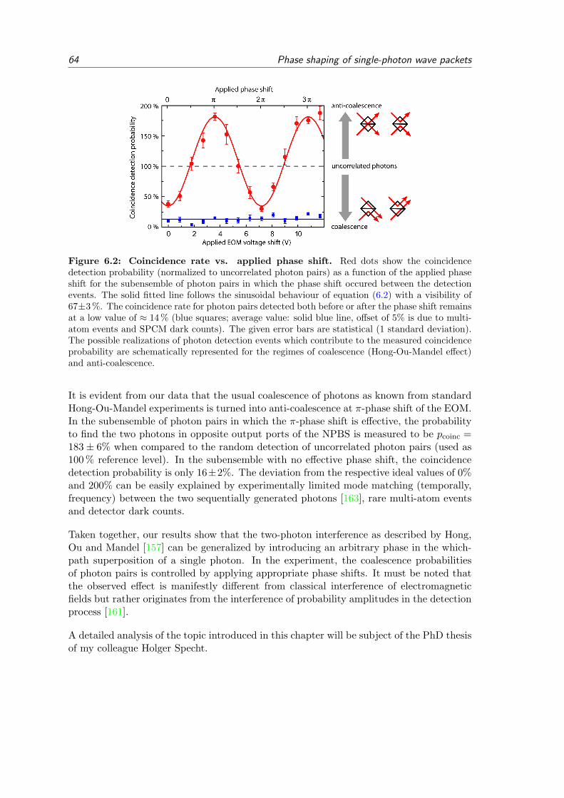
64 Phase shaping of single-photon wave packets
Figure 6.2: Coincidence rate vs. applied phase shift. Red dots show the coincidencedetection probability (normalized to uncorrelated photon pairs) as a function of the applied phaseshift for the subensemble of photon pairs in which the phase shift occured between the detectionevents. The solid fitted line follows the sinusoidal behaviour of equation (6.2) with a visibility of67±3 %. The coincidence rate for photon pairs detected both before or after the phase shift remainsat a low value of ≈ 14 % (blue squares; average value: solid blue line, offset of 5% is due to multi-atom events and SPCM dark counts). The given error bars are statistical (1 standard deviation).The possible realizations of photon detection events which contribute to the measured coincidenceprobability are schematically represented for the regimes of coalescence (Hong-Ou-Mandel effect)and anti-coalescence.
It is evident from our data that the usual coalescence of photons as known from standardHong-Ou-Mandel experiments is turned into anti-coalescence at π-phase shift of the EOM.In the subensemble of photon pairs in which the π-phase shift is effective, the probabilityto find the two photons in opposite output ports of the NPBS is measured to be pcoinc =183± 6% when compared to the random detection of uncorrelated photon pairs (used as100 % reference level). In the subensemble with no effective phase shift, the coincidencedetection probability is only 16±2%. The deviation from the respective ideal values of 0%and 200% can be easily explained by experimentally limited mode matching (temporally,frequency) between the two sequentially generated photons [163], rare multi-atom eventsand detector dark counts.
Taken together, our results show that the two-photon interference as described by Hong,Ou and Mandel [157] can be generalized by introducing an arbitrary phase in the which-path superposition of a single photon. In the experiment, the coalescence probabilitiesof photon pairs is controlled by applying appropriate phase shifts. It must be noted thatthe observed effect is manifestly different from classical interference of electromagneticfields but rather originates from the interference of probability amplitudes in the detectionprocess [161].
A detailed analysis of the topic introduced in this chapter will be subject of the PhD thesisof my colleague Holger Specht.

7 Summary and outlook
A new single atom-cavity apparatus has been constructed during the course of this work. Itoperates in the intermediate-coupling regime of cavity quantum electrodynamics (CQED)and allows the quasi-permanent storage of single atoms. The new atom-cavity systemis well-suited as a light-matter interface at the level of single atoms and single photons.In the experiments reported in this thesis, we have observed fundamental phenomena ofquantum optics and cavity quantum electrodynamics. We use the enhanced light-matterinteraction in the cavity for the controlled generation of single photons, for the efficientdetection of atomic states and for realizing light-light interaction mediated by just oneatom. As will be explained in the following, the single atom-cavity system described hereopens many fascinating perspectives for future experiments.
In the first experiment reported here, we have observed the coherent exchange of energybetween a single atom and the intracavity field upon excitation with a short laser pulse.The time-resolved observation of such vacuum Rabi oscillations presents a textbook-typeexample of CQED in the optical domain. The agreement of the data with theoreticalprediction is excellent and a quantitative analysis of the vacuum Rabi oscillations enabledtime-domain normal-mode spectroscopy of the atom-cavity system. The short pulse ex-citation scheme employed in this experiment also allows to produce single photons in awell-defined output mode at the push of a button. Single photon generation by short pulseexcitation operates in a regime which significantly differs from the previously studied STI-RAP scheme. The emitted photon wave packets have a duration on the order of 100 ns andthe repetition rate can be several MHz. Further, this scheme can generate single photonsin a superposition of two tunable frequencies.
In a second series of experiments, we have studied schemes for internal state detectionof single neutral atoms. Internal state readout of single atoms is at the heart of atomicphysics but is also an essential prerequisite for quantum information with neutral atoms.So far, state readout of single atoms had been hampered by atom loss, comparably longreadout times or extremely difficult experimental requirements. Here, we overcome theseproblems and introduce an efficient readout scheme for atomic hyperfine states based oncavity-enhanced fluorescence. This technique has proven to be robust against experimentalparameter variations and does not require the strong-coupling regime of CQED. We achieveatomic state readout with a fidelity of better than 99 % in less than 100µs. Most important,a single atom can be interrogated many hundred times without loss from the opticaldipole trap. This presents an essential advancement and establishes neutral atoms astruly stationary carriers of quantum information.
The subsequent investigations of atomic state dependent transmission of the cavity lead tothe observation of electromagnetically induced transparency with a single trapped atom.In these measurements, the transmission of a weak light beam through the atom-cavitysystem has been coherently controlled by means of a transversally applied control laser.
65

66 Summary and outlook
With careful choice of experimental parameters, the optical properties of the atom-cavitysystem are determined by a coherent dark state. This proof-of-principle experiment marksthe starting point for a wealth of related phenomena which remain to be explored in thefuture (see below).
Finally, we have used the atom-cavity system as a source for exceptionally well-definedsingle photons. The photon wave packet duration is much larger than the detector timeresolution and long enough to imprint user-defined optical phase patterns onto singlepropagating photons. In a two-photon interference experiment, these phase shaped pho-tons exhibit a tunable coalescence behaviour which emerges as a generalization of thewell-known Hong-Ou-Mandel effect.
The experiments named above indicate the high degree of control over single atoms andsingle photons which has already been achieved. However, future experiments could bespurred by a precise localization of the atom at an antinode of the cavity field and by theelimination of atomic Stark shift variations. Both problems can be solved when the atom iscooled to the motional ground state of the intracavity dipole trap potential [60, 110, 164].Further, the probabilistic loading of atoms into the cavity may in the future be aided bydeterministic re-positioning of atoms into the geometric center of the TEM00-mode of thecavity [77] in order to achieve a high and reproducible value of the atom-cavity coupling.
The experiments presented in this thesis draw their strength from trapping exactly oneatom in the cavity and from generating exactly one photon at a time. While working at thislevel has been a long standing goal in optical CQED and quantum optics, this approachdoes not yet take advantage of the scalability which neutral atoms and in particular atom-cavity systems offer. In future experiments, the controlled scaling to finite atom numbersand the scaling to two or more connected atom-cavity systems may supersede the nowfamiliar single atom-single photon regime of CQED.
In our setup, the single atom-imaging system already allows to work with a defined num-ber of atoms coupled to the cavity mode. This enables future experiments on two-atomentanglement via projective measurements [165, 102] and possibly cavity-mediated quan-tum gate operations [166, 167, 168]. Extension to larger atom numbers opens perspectivesfor spin squeezing [66, 169] and the realization of infinitely long-range interactions inmany-body quantum systems [36, 37].
Further exploration of the cavity EIT phenomenon naturally includes the slowing andstorage of photons. Of particular interest are effects which depend on the number ofatoms and photons such as Fock state dependent slowing of a light pulse or the Fockstate specific transmission of light pulses through the cavity. First numerical evaluationshave shown that these effects may be observable. However, the signatures are small dueto the currently low average atom-cavity coupling strength. With these options at hand,coherent dark states and EIT with a defined number of atoms in a high-finesse cavitypresent tools with which quantum states of light can be generated, stored and filteredphoton by photon.
An exciting prospect for atom-cavity systems is the scalability to distributed quantum

67
networks [68, 69, 170]. In such a network, photons communicate quantum informationto remote locations and establish correlations between distant stationary atoms. Indeed,during the course of this work, first steps have been taken to couple two independentatom-cavity systems. Among a variety of coupling schemes, two options appear especiallyrelevant. In a first scheme, a joint measurement on photons emitted by two atom-cavitysystems projects the remote atoms into an entangled state [165, 102]. In another possiblerealization, one atom-cavity system sends a photon which is entangled with the intracav-ity atom directly to the second atom-cavity system where the photon is absorbed [68].Naturally, such quantum networks are testbeds for long-distance teleportation [171] andthe construction of a quantum repeater [172].

68 Summary and outlook

8 Appendix
8.1 Atom-cavity coupling strength
The atom-light interaction in a cavity is characterized by the coherent coupling rate g andthe cooperativity C. The cooperativity is defined as
C =g2
2γκ. (8.1)
With atom and cavity on resonance in the bad cavity limit, the ratio of the probabilitiesfor atomic polarization decay into the cavity output mode and decay into free space issimply
RcavRspont
=2g2/κ
2γ= 2C . (8.2)
The cooperativity is directly related to the critical atom number in the cavity Na = 1/Cat which the on-resonance cavity transmission T/T0 = (1 + 2C)−2 is significantly altered(T (Na)/T0 = 1/9). Equivalently, the critical photon number Np = γ2/(2g2) gives theaverage number of intracavity photons which are necessary to saturate a given atomictransition. Note that the effective cooperativity ν = g2/[(∆a − iγ)(∆c − iκ)] introducedin [92] and chapter (4) is a generalization of −2C.
The coherent atom-cavity coupling rate g0 at a cavity-field antinode is determined bythe dipole matrix element µge of the atomic transition and the cavity mode volume V(V = πw0d/4, mode waist w0, cavith length d).
g0 =√
ωc2ε0V ~
· µge (8.3)
The applicable value of µge depends on the polarization of the cavity field and the internalstate of the atom.
For the strongest electric dipole transition of the Rubidium D2-line 52S1/2 F = 2,mF = 2to 52P3/2 F ′ = 3,mF ′ = 3, we find g0/2π = 7.9 MHz in our cavity. This results in amaximum cooperativity C = 3.6, a critical atom number of Na = 0.3 and a critical photonnumber of Np = 0.07. For isotropic light polarization the coupling is g0/2π=5.4 MHz(C = 1.7, Na = 0.6, Np = 0.16) for the F = 2↔ F ′ = 3 transition. The values of g0 in ourexperiment for all transitions of the Rb D2-line are listed in tables a)-d) at the end of thissection.
The atom-cavity coupling rate g0 is spatially modulated by the standing wave structureof cavity field mode ψc(r):
g(r) = g0ψc(r) . (8.4)
69
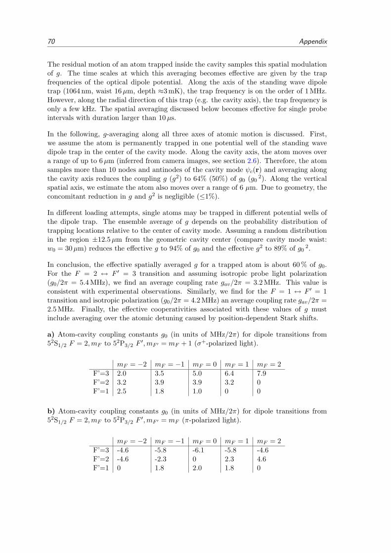
70 Appendix
The residual motion of an atom trapped inside the cavity samples this spatial modulationof g. The time scales at which this averaging becomes effective are given by the trapfrequencies of the optical dipole potential. Along the axis of the standing wave dipoletrap (1064 nm, waist 16µm, depth ≈3 mK), the trap frequency is on the order of 1 MHz.However, along the radial direction of this trap (e.g. the cavity axis), the trap frequency isonly a few kHz. The spatial averaging discussed below becomes effective for single probeintervals with duration larger than 10µs.
In the following, g-averaging along all three axes of atomic motion is discussed. First,we assume the atom is permanently trapped in one potential well of the standing wavedipole trap in the center of the cavity mode. Along the cavity axis, the atom moves overa range of up to 6µm (inferred from camera images, see section 2.6). Therefore, the atomsamples more than 10 nodes and antinodes of the cavity mode ψc(r) and averaging alongthe cavity axis reduces the coupling g (g2) to 64% (50%) of g0 (g0
2). Along the verticalspatial axis, we estimate the atom also moves over a range of 6 µm. Due to geometry, theconcomitant reduction in g and g2 is negligible (≤1%).
In different loading attempts, single atoms may be trapped in different potential wells ofthe dipole trap. The ensemble average of g depends on the probability distribution oftrapping locations relative to the center of cavity mode. Assuming a random distributionin the region ±12.5µm from the geometric cavity center (compare cavity mode waist:w0 = 30µm) reduces the effective g to 94% of g0 and the effective g2 to 89% of g0
2.
In conclusion, the effective spatially averaged g for a trapped atom is about 60 % of g0.For the F = 2 ↔ F ′ = 3 transition and assuming isotropic probe light polarization(g0/2π = 5.4 MHz), we find an average coupling rate gav/2π = 3.2 MHz. This value isconsistent with experimental observations. Similarly, we find for the F = 1 ↔ F ′ = 1transition and isotropic polarization (g0/2π = 4.2 MHz) an average coupling rate gav/2π =2.5 MHz. Finally, the effective cooperativities associated with these values of g mustinclude averaging over the atomic detuning caused by position-dependent Stark shifts.
a) Atom-cavity coupling constants g0 (in units of MHz/2π) for dipole transitions from52S1/2 F = 2,mF to 52P3/2 F
′,mF ′ = mF + 1 (σ+-polarized light).
mF = −2 mF = −1 mF = 0 mF = 1 mF = 2F’=3 2.0 3.5 5.0 6.4 7.9F’=2 3.2 3.9 3.9 3.2 0F’=1 2.5 1.8 1.0 0 0
b) Atom-cavity coupling constants g0 (in units of MHz/2π) for dipole transitions from52S1/2 F = 2,mF to 52P3/2 F
′,mF ′ = mF (π-polarized light).
mF = −2 mF = −1 mF = 0 mF = 1 mF = 2F’=3 -4.6 -5.8 -6.1 -5.8 -4.6F’=2 -4.6 -2.3 0 2.3 4.6F’=1 0 1.8 2.0 1.8 0
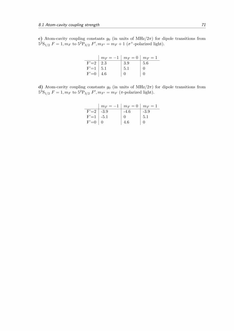
8.1 Atom-cavity coupling strength 71
c) Atom-cavity coupling constants g0 (in units of MHz/2π) for dipole transitions from52S1/2 F = 1,mF to 52P3/2 F
′,mF ′ = mF + 1 (σ+-polarized light).
mF = −1 mF = 0 mF = 1F’=2 2.3 3.9 5.6F’=1 5.1 5.1 0F’=0 4.6 0 0
d) Atom-cavity coupling constants g0 (in units of MHz/2π) for dipole transitions from52S1/2 F = 1,mF to 52P3/2 F
′,mF ′ = mF (π-polarized light).
mF = −1 mF = 0 mF = 1F’=2 -3.9 -4.6 -3.9F’=1 -5.1 0 5.1F’=0 0 4.6 0

72 Appendix
8.2 Single atom imaging system
Figure 8.1: Imaging system. a) Layout of vacuum chamber and imaging system. b) Schematicof objective and lenses. c) Sample image of atoms trapped inside the cavity. The position of atomsrelative to the geometric center of the cavity mode is determined with ±5µm precision. Scatteringof light in the cavity mode at the cavity mirror surfaces (example shown in left column) serves asgeometric reference for localizing the cavity mode.

8.3 Dimensions of the vacuum system 73
8.3 Dimensions of the vacuum system
Figure 8.2: Vacuum system. a) Scale drawing of the vacuum chamber and cavity holder (sideview). b) Scale drawing of the vacuum chamber and cavity holder (top view). The electrical wiringfor the Rb dispenser and cavity piezo is indicated by black solid lines. Laser beams are indicatedby arrows.

74 Appendix
8.4 Schematic layout of the optical table

8.5 Frequency comb 75
8.5 Frequency comb
In our experimental setup, a frequency comb system serves as an absolute frequencystandard. In the years 2006 to 2009, a frequency comb signal was provided by the precisionmeasurement group of Prof. Hansch (T. Udem, R. Holzwarth) via a 120 m optical fiberlink. Initially, it had served as a reference for the cavity stabilization laser at 785 nm buthas later been adopted for other purposes as well. As of 2009, our laboratory hosts itsown frequency comb system whose signal is supplied to all laboratories of our group.
At the heart of the frequency comb system is a pulsed laser with repetition rate frep whoseoutput spectrum exhibits a distinct comb structure of frequency components with spacingfrep (Fig. 8.3). Further, the absolute position of this comb structure is given by the offsetfrequency fCEO. It depends on the carrier-envelope phase which is the temporal phaseof the electromagnetic field oscillation with respect to the envelope function of each laserpulse. A shift of the carrier-envelope phase from one pulse to the next is called carrier-envelope phase slip (Fig. 8.3). The absolute optical frequencies of the comb spectrum arecompletely determined by the simple equation
fn = fCEO + nfrep (8.5)
where n is a large integer number. Both frequencies frep and fCEO are in the 10 ... 300 MHzrange which is easily accessible with electronic counters and AD-converters. Therefore, afrequency comb system universally maps the precision of standard atomic clocks (radiofrequency domain) to the optical domain (1015 Hz).
Our frequency comb was manufactured by MenloSystems and set up in our laboratory inSeptember 2009. It consists of several independent modules. At its core is a pulsed fiberlaser with a repetition rate frep = 250 MHz. This rate is fine-tuned and stabilized via apiezo-electric element which controls the pulse round trip time in the laser. The opticaloutput spectrum is centered around 1550 nm. Self-mode locking operation is optimized byadditional piezo-elements which tweak the optical fiber. A second essential module is thef-2f interferometer which is needed for determining the carrier-envelope offset-frequencyfCEO. In this module, a share of the original comb spectrum interferes with its frequency-doubled counterpart. The value of fCEO can be extracted by interfering a comb peak A atthe blue end of the original spectrum with a frequency-doubled comb peak B from the redend of the spectrum one octave away (nA = 2nB). The CEO frequency emerges as a lowestbeat frequency because 2(fCEO+nBfrep)−(fCEO+nAfrep) = fCEO. This self-referencingof the comb requires an originally octave spanning optical spectrum. The broad spectrumis obtained by broadening of the pulsed laser output using non-linear processes in a hollowcore fiber. The CEO frequency can be actively stabilized to a desired value (here: 10 MHz)via the power of the pump laser diodes of the fiber laser.
The feedback loops for the stabilization of CEO and repetition rate are based on opticalbeat note detection. Direct feedback circuitry is accompanied by control software whichensures long term stability. In the current operation mode, the frequency comb system canrun independently for weeks. As a 10 MHz reference signal for the beat note stabilizationwe use a stable hydrogen-maser signal supplied by the group of Prof. Hansch. Additionally
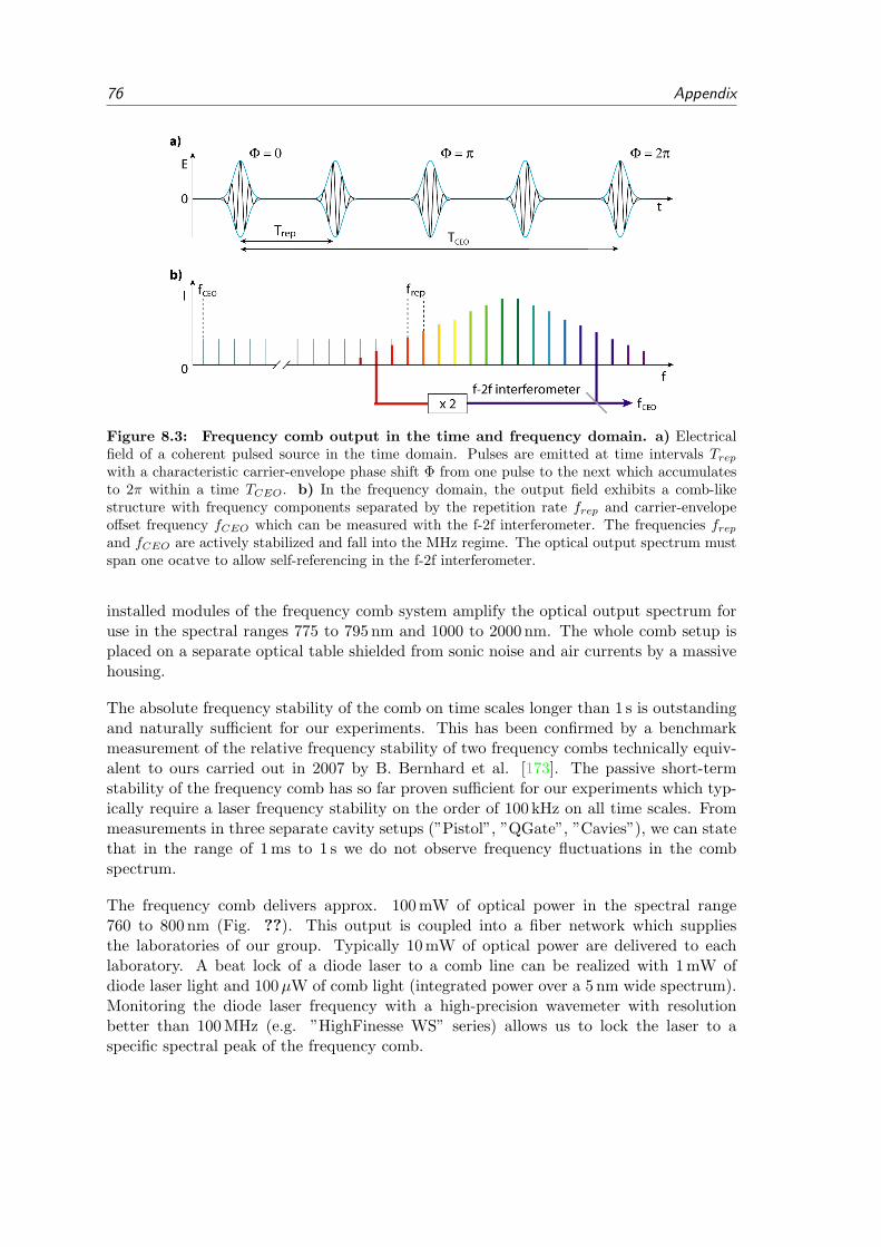
76 Appendix
Figure 8.3: Frequency comb output in the time and frequency domain. a) Electricalfield of a coherent pulsed source in the time domain. Pulses are emitted at time intervals Trepwith a characteristic carrier-envelope phase shift Φ from one pulse to the next which accumulatesto 2π within a time TCEO. b) In the frequency domain, the output field exhibits a comb-likestructure with frequency components separated by the repetition rate frep and carrier-envelopeoffset frequency fCEO which can be measured with the f-2f interferometer. The frequencies frepand fCEO are actively stabilized and fall into the MHz regime. The optical output spectrum mustspan one ocatve to allow self-referencing in the f-2f interferometer.
installed modules of the frequency comb system amplify the optical output spectrum foruse in the spectral ranges 775 to 795 nm and 1000 to 2000 nm. The whole comb setup isplaced on a separate optical table shielded from sonic noise and air currents by a massivehousing.
The absolute frequency stability of the comb on time scales longer than 1 s is outstandingand naturally sufficient for our experiments. This has been confirmed by a benchmarkmeasurement of the relative frequency stability of two frequency combs technically equiv-alent to ours carried out in 2007 by B. Bernhard et al. [173]. The passive short-termstability of the frequency comb has so far proven sufficient for our experiments which typ-ically require a laser frequency stability on the order of 100 kHz on all time scales. Frommeasurements in three separate cavity setups (”Pistol”, ”QGate”, ”Cavies”), we can statethat in the range of 1 ms to 1 s we do not observe frequency fluctuations in the combspectrum.
The frequency comb delivers approx. 100 mW of optical power in the spectral range760 to 800 nm (Fig. ??). This output is coupled into a fiber network which suppliesthe laboratories of our group. Typically 10 mW of optical power are delivered to eachlaboratory. A beat lock of a diode laser to a comb line can be realized with 1 mW ofdiode laser light and 100µW of comb light (integrated power over a 5 nm wide spectrum).Monitoring the diode laser frequency with a high-precision wavemeter with resolutionbetter than 100 MHz (e.g. ”HighFinesse WS” series) allows us to lock the laser to aspecific spectral peak of the frequency comb.

8.5 Frequency comb 77
Figure 8.4: Photograph of the installed frequency comb system without the acousticnoise shielding.
Figure 8.5: Measured spectral power distribution of the comb output at 760 - 800 nm.Upper blue curve: Standard spectrum with a total power of 100 mW, individual comb lines arenot resolved in this measurement. In one attempt, the spectral maximum of the output hasbeen shifted to longer wavelengths (lower red curve) by tuning of temperature and angle of thefrequency-doubler crystal. The shift is accompanied by a loss in total power and does not increasethe signal at 795 nm.

78 Appendix

Bibliography
[1] Freedman, S. J. and Clauser, J. F. Experimental test of local hidden-variable theo-ries. Phys. Rev. Lett., 28 938–941 (1972).
[2] Aspect, A., Grangier, P., and Roger, G. Experimental tests of realistic local theoriesvia bell’s theorem. Phys. Rev. Lett., 47 460–463 (1981).
[3] Bouwmeester, D., Pan, J.-W., Mattle, K., Eibl, M., Weinfurter, H., and Zeilinger,A. Experimental Quantum Teleportation. Nature, 390 575–579 (1997).
[4] Bergquist, J. C., Hulet, R. G., Itano, W. M., and Wineland, D. J. Observation ofquantum jumps in a single atom. Phys. Rev. Lett., 57 1699–1702 (1986).
[5] Leibfried, D., Knill, E., Seidelin, S., Britton, J., Blakestad, R. B., Chiaverini, J.,Hume, D. B., Itano, W. M., Jost, J. D., Langer, C., et al. Creation of a six-atom“Schrodinger cat” state. Nature, 438 639–642 (2005).
[6] Duerr, S., Nonn, T., and Rempe, G. Fringe visibility and which-way information inan atom interferometer. Phys. Rev. Lett., 81 5705–5709 (1998).
[7] Nogues, G., Rauschenbeutel, A., Osnaghi, S., Brune, M., Raimond, J. M., andHaroche, S. Seeing a single photon without destroying it. Nature, 400 239 – 242(1999).
[8] Hamalainen, M., Hari, R., Ilmoniemi, R. J., Knuutila, J., and Lounasmaa, O. V.Magnetoencephalography—theory, instrumentation, and applications to noninvasivestudies of the working human brain. Rev. Mod. Phys., 65 413–497 (1993).
[9] Grunberg, P. A. Nobel lecture: From spin waves to giant magnetoresistance andbeyond. Rev. Mod. Phys., 80 1531–1540 (2008).
[10] Wineland, D. J., Bollinger, J. J., Itano, W. M., Moore, F. L., and Heinzen, D. J.Spin squeezing and reduced quantum noise in spectroscopy. Physical Review A, 46R6797–R6800 (1992).
[11] Bergquist, J., Jefferts, S., and Wineland, D. Time measurement at the millennium.Physics Today, 54 37–42 (2001).
[12] Chou, C. W., Hume, D. B., Koelemeij, J. C. J., Wineland, D. J., and Rosenband,T. Frequency comparison of two high-accuracy Al+ optical clocks. Phys. Rev. Lett.,104 070802 (2010).
[13] Dowling, J. and Milburn, G. Quantum technology: The second quantum revolution.Philos. Trans. R. Soc. Lond. Ser. A-Math. Phys. Eng. Sci., 361 1655–1674 (2003).
[14] Feynman, R. Simulating physics with computers. Int. J. Theor. Phys., 21 467–488(1982).
79

80 BIBLIOGRAPHY
[15] Deutsch, D. Quantum theory, the Church-Turing principle and the universal quan-tum computer. Proc. R. Soc. Lond. A, 400 97–117 (1985).
[16] Bennett, C. H. Quantum Information and Computation. Phys. Today, October24–30 (1995).
[17] Benioff, P. The computer as a physical system: A microscopic quantum mechanicalHamiltonian model of computers as represented by Turing machines. Journal ofStatistical Physics, 22 563 (1980).
[18] Grover, L. Proc. 28 Annual ACM Symposium on the Theory of Computing. ACMPress New York (1996).
[19] Deutsch, D. and Jozsa, R. Rapid Solution of Problems by by Quantum Computation.Proc. R. Soc. Lond., 439 553 (1992).
[20] Shor, P. W. Polynomal-time algorithms for prime factorization and discrete loga-rithms on a quantum computer. SIAM Review, 41 303–332 (1997).
[21] Cleve, R., Ekert, A., Macchiavello, C., and Mosca, M. Quantum algorithms revisited.arXiv, pages quant–ph/9708016 (1997).
[22] Gershenfeld, N. A. and Chuang, I. L. Bulk Spin-Resonance Quantum Computation.Science, 275 350–356 (1997).
[23] Lloyd, S. Universal Quantum Simulators. Science, 273 1073–1078 (1996).
[24] Friedenauer, A., Schmitz, H., Glueckert, J. T., Porras, D., and Schaetz, T. Simulat-ing a quantum magnet with trapped ions. Nature Phys., 4 757–761 (2008).
[25] Bloch, I., Dalibard, J., and Zwerger, W. Many-body physics with ultracold gases.Rev. Mod. Phys., 80 885–964 (2008).
[26] Gerritsma, R., Kirchmair, G., Zaehringer, F., Solano, E., Blatt, R., and Roos, C. F.Quantum simulation of the Dirac equation. Nature, 463 68–72 (2010).
[27] Bennett, C. and Brassard, G. In Proc. IEEE Int. Conference on Computers, Systemsand Signal Processing. IEEE, New York (1984).
[28] Jennewein, T., Simon, C., Weihs, G., Weinfurter, H., and Zeilinger, A. Quantumcryptography with entangled photons. Phys. Rev. Lett., 84 4729–4732 (2000).
[29] Gisin, N., Ribordy, G., Tittel, W., and Zbinden, H. Quantum Cryptography. Rev.Mod. Phys., 74 145 – 195 (2002).
[30] Zoller, P., Beth, T., Binosi, D., Blatt, R., Briegel, H., Bruss, D., Calarco, T., Cirac,J., Deutsch, D., Eisert, J., et al. Quantum information processing and communica-tion - Strategic report on current status, visions and goals for research in Europe.Eur. Phys. J. D, 36 203–228 (2005).
[31] DiVincenzo, D. P. The Physical Implementation of Quantum Computation.Fortschr. Phys., 48 771 (2000).

BIBLIOGRAPHY 81
[32] Purcell, E. M. Spontaneous Emission Probabilities at Radio Frequencies. Phys.Rev., 69 681 (1946).
[33] Jaynes, E. T. and Cummings, F. W. Comparison of Quantum and SemiclassicalRadiation Theories with Application to the Beam Maser. Proc. IEEE, 51 89–109(1963).
[34] Shore, B. W. and Knight, P. L. The Jaynes-Cummings model. Journal of ModernOptics, 40 1195–1238 (1993).
[35] Raimond, J. M., Brune, M., and Haroche, S. Colloquium: Manipulating quantumentanglement with atoms and photons in a cavity. Rev. Mod. Phys., 73 565 – 582(2001).
[36] Solano, E., Agarwal, G., and Walther, H. Strong-driving-assisted multipartite en-tanglement in cavity QED. Phys. Rev. Lett., 90 (2003).
[37] Baumann, C., Guerlin, C., Brennecke, F., and Esslinger, T. Dicke quantum phasetransition with a superfluid gas in an optical cavity. Nature, 464 1301–1306 (2010).
[38] Kaluzny, Y., Goy, P., Gross, M., Raimond, J. M., and Haroche, S. Observation ofself-induced rabi oscillations in two-level atoms excited inside a resonant cavity: Theringing regime of superradiance. Phys. Rev. Lett., 51 1175–1178 (1983).
[39] Meschede, D., Walther, H., and Muller, G. One-atom MASER. Phys. Rev. Lett., 54551–554 (1985).
[40] Rempe, G. and Walther, H. Observation of quantum collapse and revival in a one-atom MASER. Phys. Rev. Lett., 58 353–356 (1987).
[41] Brune, M., Raimond, J. M., Goy, P., Davidovich, L., and Haroche, S. Realization ofa two-photon maser oscillator. Phys. Rev. Lett., 59 1899–1902 (1987).
[42] Brune, M., Nussenzveig, P., Schmidt-Kaler, F., Bernardot, F., Maali, A., Raimond,J. M., and Haroche, S. From lamb shift to light shifts: Vacuum and subphotoncavity fields measured by atomic phase sensitive detection. Phys. Rev. Lett., 723339–3342 (1994).
[43] Gleyzes, S., Kuhr, S., Guerlin, C., Bernu, J., Deleglise, S., Hoff, U. B., Brune, M.,Raimond, J.-M., and Haroche, S. Quantum jumps of light recording the birth anddeath of a photon in a cavity. Nature, 446 297–300 (2007).
[44] Rempe, G., Thompson, R. J., Brecha, R. J., Lee, W. D., and Kimble, H. J. OpticalBistability and Photon Statistics in Cavity Quantum Electrodynamics. Phys. Rev.Lett., 67 1727–1730 (1991).
[45] Thompson, R. J., Rempe, G., and Kimble, H. J. Observation of Normal-ModeSplitting for an Atom in an Optical Cavity. Phys. Rev. Lett., 68 1132–1135 (1992).
[46] Pinkse, P. W. H., Fischer, T., Maunz, P., and Rempe, G. Trapping an Atom withSingle Photons. Nature, 404 365–368 (2000).
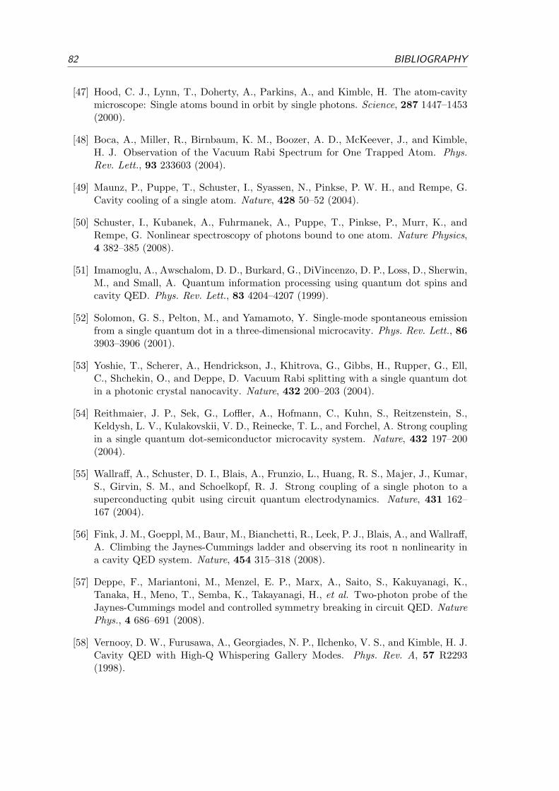
82 BIBLIOGRAPHY
[47] Hood, C. J., Lynn, T., Doherty, A., Parkins, A., and Kimble, H. The atom-cavitymicroscope: Single atoms bound in orbit by single photons. Science, 287 1447–1453(2000).
[48] Boca, A., Miller, R., Birnbaum, K. M., Boozer, A. D., McKeever, J., and Kimble,H. J. Observation of the Vacuum Rabi Spectrum for One Trapped Atom. Phys.Rev. Lett., 93 233603 (2004).
[49] Maunz, P., Puppe, T., Schuster, I., Syassen, N., Pinkse, P. W. H., and Rempe, G.Cavity cooling of a single atom. Nature, 428 50–52 (2004).
[50] Schuster, I., Kubanek, A., Fuhrmanek, A., Puppe, T., Pinkse, P., Murr, K., andRempe, G. Nonlinear spectroscopy of photons bound to one atom. Nature Physics,4 382–385 (2008).
[51] Imamoglu, A., Awschalom, D. D., Burkard, G., DiVincenzo, D. P., Loss, D., Sherwin,M., and Small, A. Quantum information processing using quantum dot spins andcavity QED. Phys. Rev. Lett., 83 4204–4207 (1999).
[52] Solomon, G. S., Pelton, M., and Yamamoto, Y. Single-mode spontaneous emissionfrom a single quantum dot in a three-dimensional microcavity. Phys. Rev. Lett., 863903–3906 (2001).
[53] Yoshie, T., Scherer, A., Hendrickson, J., Khitrova, G., Gibbs, H., Rupper, G., Ell,C., Shchekin, O., and Deppe, D. Vacuum Rabi splitting with a single quantum dotin a photonic crystal nanocavity. Nature, 432 200–203 (2004).
[54] Reithmaier, J. P., Sek, G., Loffler, A., Hofmann, C., Kuhn, S., Reitzenstein, S.,Keldysh, L. V., Kulakovskii, V. D., Reinecke, T. L., and Forchel, A. Strong couplingin a single quantum dot-semiconductor microcavity system. Nature, 432 197–200(2004).
[55] Wallraff, A., Schuster, D. I., Blais, A., Frunzio, L., Huang, R. S., Majer, J., Kumar,S., Girvin, S. M., and Schoelkopf, R. J. Strong coupling of a single photon to asuperconducting qubit using circuit quantum electrodynamics. Nature, 431 162–167 (2004).
[56] Fink, J. M., Goeppl, M., Baur, M., Bianchetti, R., Leek, P. J., Blais, A., and Wallraff,A. Climbing the Jaynes-Cummings ladder and observing its root n nonlinearity ina cavity QED system. Nature, 454 315–318 (2008).
[57] Deppe, F., Mariantoni, M., Menzel, E. P., Marx, A., Saito, S., Kakuyanagi, K.,Tanaka, H., Meno, T., Semba, K., Takayanagi, H., et al. Two-photon probe of theJaynes-Cummings model and controlled symmetry breaking in circuit QED. NaturePhys., 4 686–691 (2008).
[58] Vernooy, D. W., Furusawa, A., Georgiades, N. P., Ilchenko, V. S., and Kimble, H. J.Cavity QED with High-Q Whispering Gallery Modes. Phys. Rev. A, 57 R2293(1998).

BIBLIOGRAPHY 83
[59] Spillane, S. M., Kippenberg, T. J., Vahala, K. J., Goh, K. W., Wilcut, E., and Kim-ble, H. J. Ultrahigh-Q toroidal microresonators for cavity quantum electrodynamics.Phys. Rev. A, 71 013817 (2005).
[60] Colombe, Y., Steinmetz, T., Dubois, G., Linke, F., Hunger, D., and Reichel, J.Strong atom-field coupling for Bose-Einstein condensates in an optical cavity on achip. Nature, 450 272–276 (2007).
[61] Dayan, B., Parkins, A. S., Aoki, T., Ostby, E. P., Vahala, K. J., and Kimble, H. J.A photon turnstile dynamically regulated by one atom. Science, 319 1062–1065(2008).
[62] Poellinger, M., O’Shea, D., Warken, F., and Rauschenbeutel, A. Ultrahigh-Q Tun-able Whispering-Gallery-Mode Microresonator. Phys. Rev. Lett., 103 (2009).
[63] Arcizet, O., Cohadon, P. F., Briant, T., Pinard, M., and Heidmann, A. Radiation-pressure cooling and optomechanical instability of a micromirror. Nature, 444 71–74(2006).
[64] Brennecke, F., Ritter, S., Donner, T., and Esslinger, T. Cavity optomechanics witha Bose-Einstein condensate. Science, 322 235–238 (2008).
[65] Murch, K. W., Moore, K. L., Gupta, S., and Stamper-Kurn, D. M. Observationof quantum-measurement backaction with an ultracold atomic gas. Nature Phys., 4561–564 (2008).
[66] Leroux, I. D., Schleier-Smith, M. H., and Vuletic, V. Implementation of cavitysqueezing of a collective atomic spin. Phys. Rev. Lett., 104 073602 (2010).
[67] Schliesser, A., Arcizet, O., Riviere, R., Anetsberger, G., and Kippenberg, T. J.Resolved-sideband cooling and position measurement of a micromechanical oscillatorclose to the Heisenberg uncertainty limit. Nature Phys., 5 509–514 (2009).
[68] Cirac, J. I., Zoller, P., Kimble, H. J., and Mabuchi, H. Quantum state transfer andentanglement distribution among distant nodes in a quantum network. Phys. Rev.Lett., 78 3221–3224 (1997).
[69] Kimble, H. J. The quantum internet. Nature, 453 1023–1030 (2008).
[70] Schrader, D., Dotsenko, I., Khudaverdyan, M., Miroshnychenko, Y., Rauschenbeu-tel, A., and Meschede, D. Neutral atom quantum register. Phys. Rev. Lett., 93150501 (2004).
[71] Lengwenus, A., Kruse, J., Volk, M., Ertmer, W., and Birkl, G. Coherent manipula-tion of atomic qubits in optical micropotentials. Appl. Phys. B: Lasers and Optics,86 377–383 (2007).
[72] Rosenfeld, W., Hocke, F., Henkel, F., Krug, M., Volz, J., Weber, M., and Weinfurter,H. Towards long-distance atom-photon entanglement. Phys. Rev. Lett., 101 260403(2008).

84 BIBLIOGRAPHY
[73] Karski, M., Forster, L., Choi, J.-M., Steffen, A., Alt, W., Meschede, D., and Widera,A. Quantum walk in position space with single optically trapped atoms. Science,325 174 (2009).
[74] Wilk, T., Gaetan, A., Evellin, C., Wolters, J., Miroshnychenko, Y., Grangier, P., andBrowaeys, A. Entanglement of two individual neutral atoms using rydberg blockade.Phys. Rev. Lett., 104 010502 (2010).
[75] Isenhower, L., Urban, E., Zhang, X. L., Gill, A. T., Henage, T., Johnson, T. A.,Walker, T. G., and Saffman, M. Demonstration of a neutral atom controlled-notquantum gate. Phys. Rev. Lett., 104 010503 (2010).
[76] Nußmann, S. Kuhlen und Positionieren eines Atoms in einem optischen Resonator.Ph.D. thesis, Max-Planck Institut fur Quantenoptik (2005).
[77] Nußmann, S., Hijlkema, M., Weber, B., Rohde, F., Rempe, G., and Kuhn, A. Sub-Micron Positioning of Single Atoms in Micro Cavities. Phys. Rev. Lett., 95 173602(2005).
[78] Nußmann, S., Murr, K., Hijlkema, M., Weber, B., Kuhn, A., and Rempe, G.Vacuum-stimulated cooling of single atoms in three dimensions. Nature Physics,1 122 (2005).
[79] Metcalf, H. J. and van der Straten, P. Laser Cooling and Trapping. Springer, NewYork (1999).
[80] Grimm, R., Weidemuller, M., and Ovchinnikov, Y. B. Optical dipole traps forneutral atoms. Adv. At. Mol. Opt. Phys., 42 95–170 (2000).
[81] Hijlkema, M. Single photons from a single atom trapped in a high-finesse optical cav-ity. Ph.D. thesis, Max-Planck-Institut fur Quantenoptik und Technische UniversitatMunchen (2007).
[82] Karski, M., Forster, L., Choi, J. M., Alt, W., Widera, A., and Meschede, D. Nearest-neighbor detection of atoms in a 1d optical lattice by fluorescence imaging. Phys.Rev. Lett., 102 053001 (2009).
[83] Hijlkema, M., Weber, B., Specht, H. P., Webster, S. C., Kuhn, A., and Rempe, G.A single-photon server with just one atom. Nature Physics, 3 253–255 (2007).
[84] Murr, K., Nußmann, S., Puppe, T., Hijlkema, M., Weber, B., Webster, S., Kuhn,A., and Rempe, G. Three-dimensional cavity cooling and trapping in an opticallattice. Phys. Rev. Lett., 96 253001 (2006).
[85] Kuhn, A. and Rempe, G. Optical cavity QED: Fundamentals and application as asingle-photon light source. In F. D. Martini and C. Monroe, editors, ExperimentalQuantum Computation and Information, vol. CXLVIII, pages 37–66. Int. School ofPhysics Enrico Fermi, IOS Press, Amsterdam (2002).

BIBLIOGRAPHY 85
[86] Blinov, B. B., Moehring, D. L., Duan, L.-M., and Monroe, C. Observation of entan-glement between a single trapped atom and a single photon. Nature, 428 153–157(2004).
[87] Darquie, B., Jones, M. P. A., Dingjan, J., Beugnon, J., Bergamini, S., Sortais, Y.,Messin, G., Browaeys, A., and Grangier, P. Controlled single-photon emission froma single trapped two-level atom. Science, 309 454–456 (2005).
[88] Santori, C., Fattal, D., Vuckovic, J., Solomon, G. S., and Yamamoto, Y. Indistin-guishable photons from a single-photon device. Nature, 419 594 – 597 (2002).
[89] Gaebel, T., Popa, I., Gruber, A., Domhan, M., Jelezko, F., and Wrachtrup, J. Stablesingle-photon source in the near infrared. New Journal of Physics, 6 98 (2004).
[90] Grangier, P. e. Focus on single photons on demand. New Journal of Physics, 6(2004).
[91] Brune, M., Schmidt-Kaler, F., Maali, A., Dreyer, J., Hagley, E., Raimond, J. M.,and Haroche, S. Quantum Rabi oscillation: A direct test of field quantization in acavity. Phys. Rev. Lett., 76 1800–1803 (1996).
[92] Murr, K. On the suppression of the diffusion and the quantum nature of a cavitymode. Optical bistability: Forces and friction in driven cavities. J. Phys. B, 36 2515(2003).
[93] Hennrich, M. Kontrollierte Erzeugung einzelner Photonen in einem optischen Res-onator hoher Finesse. Ph.D. thesis, Max-Planck-Institut fur Quantenoptik und Tech-nische Universitat Munchen (2003).
[94] Schuster, I. Nonlinear spectroscopy of single atom-cavity system. Ph.D. thesis, Max-Planck-Institut fur Quantenoptik und Technische Universitat Munchen (2008).
[95] Plenio, M. B. and Knight, P. L. The quantum-jump approach to dissipative dynamicsin quantum optics. Rev. Mod. Phys., 70 101–144 (1998).
[96] Hennrich, M., Legero, T., Kuhn, A., and Rempe, G. Vacuum-stimulated ramanscattering based on adiabatic passage in a high-finesse optical cavity. Phys. Rev.Lett., 85 4872–4875 (2000).
[97] Brecha, R. J., Orozco, L. A., Raizen, M. G., Xiao, M., and Kimble, H. J. Observationof oscillatory energy exchange in a coupled-atom-cavity system. J. Opt. Soc. Am.B, 12 2329 (1995).
[98] Mielke, S. L., Foster, G. T., Gripp, J., and Orozco, L. A. Time response of a coupledatoms-cavity system. Opt. Lett., 22 325–327 (1997).
[99] Haroche, S., Paisner, J. A., and Schawlow, A. L. Hyperfine quantum beats observedin cs vapor under pulsed dye laser excitation. Phys. Rev. Lett., 30 948–951 (1973).
[100] Wilk, T., Webster, S. C., Kuhn, A., and Rempe, G. Single-atom single-photonquantum interface. Science, 317 488–490 (2007).
86 BIBLIOGRAPHY
[101] DiFidio, C., Vogel, W., Khanbekyan, M., and Welsch, D.-G. Photon emission by anatom in a lossy cavity. Phys. Rev. A, 77 043822 (2008).
[102] Moehring, D. L., Maunz, P., Olmschenk, S., Younge, K. C., Matsukevich, D. N.,Duan, L.-M., and Monroe, C. Entanglement of single-atom quantum bits at adistance. Nature, 449 68 (2007).
[103] Kubanek, A., Ourjoumtsev, A., Schuster, I., Koch, M., Pinkse, P. W. H., Murr, K.,and Rempe, G. Two-photon gateway in one-atom cavity quantum electrodynamics.Phys. Rev. Lett., 101 203602 (2008).
[104] Duan, L.-M., Madsen, M. J., Moehring, D. L., Maunz, P., Kohn, Jr., R. N., andMonroe, C. Probabilistic quantum gates between remote atoms through interferenceof optical frequency qubits. Phys. Rev. A, 73 062324 (2006).
[105] Lan, S.-Y., Jenkins, S. D., Chaneliere, T., Matsukevich, D. N., Campbell, C. J.,Zhao, R., Kennedy, T. A. B., and Kuzmich, A. Dual-species matter qubit entangledwith light. Phys. Rev. Lett., 98 123602 (2007).
[106] Schon, C., Solano, E., Verstraete, F., Cirac, J. I., and Wolf, M. M. Sequentialgeneration of entangled multiqubit states. Phys. Rev. Lett., 95 110503 (2005).
[107] Terraciano, M. L., Olson Knell, R., Norris, D. G., Jing, J., Fernandez, A., andOrozco, L. A. Cavity-based single atom preparation and high-fidelity hyperfinestate readout. Nature Phys., 5 480–484 (2009).
[108] Takeuchi, M., Takei, N., Zhang, P., Ueda, M., and Kozuma, M. Single nuclear spincavity qed. arXiv:0907.0336v3 [quant-ph] (2009).
[109] Khudaverdyan, M., Alt, W., Kampschulte, T., Reick, S., Thobe, A., Widera, A.,and Meschede, D. Quantum jumps and spin dynamics of interacting atoms in astrongly coupled atom-cavity system. Phys. Rev. Lett., 103 123006 (2009).
[110] Boozer, A. D., Boca, A., Miller, R., Northup, T. E., and Kimble, H. J. Cooling tothe ground state of axial motion for one atom strongly coupled to an optical cavity.Phys. Rev. Lett., 97 083602 (2006).
[111] Gehr, R., Volz, J., Dubois, G., Steinmetz, T., Colombe, Y., Lev, B. L., Long, R.,Esteve, J., and Reichel, J. Cavity-based single atom preparation and high-fidelityhyperfine state readout. Phys. Rev. Lett., 104 203602 (2010).
[112] Kuhr, S., Alt, W., Schrader, D., Dotsenko, I., Miroshnychenko, Y., Rauschenbeutel,A., and Meschede, D. Analysis of dephasing mechanisms in a standing-wave dipoletrap. Phys. Rev. A, 72 023406 (2005).
[113] Volz, J., Weber, M., Schlenk, D., Rosenfeld, W., Vrana, J., Saucke, K., Kurtsiefer,C., and Weinfurter, H. Observation of entanglement of a single photon with atrapped atom. Phys. Rev. Lett., 96 030404 (2006).
BIBLIOGRAPHY 87
[114] Yavuz, D. D., Kulatunga, P. B., Urban, E., Johnson, T. A., Proite, N., Henage, T.,Walker, T. G., and Saffman, M. Fast ground state manipulation of neutral atomsin microscopic optical traps. Phys. Rev. Lett., 96 063001 (2006).
[115] Jones, M. P. A., Beugnon, J., Gaetan, A., Zhang, J., Messin, G., Browaeys, A., andGrangier, P. Fast quantum state control of a single trapped neutral atom. Phys.Rev. A, 75 040301 (2007).
[116] Rosenfeld, W., Weber, M., Volz, J., Henkel, F., Krug, M., Cabello, A., Zukowski,M., and Weinfurter, H. Towards a Loophole-Free Test of Bell’s Inequality withEntangled Pairs of Neutral Atoms. Advanced Science Letters, 2 469–474 (2009).
[117] Blatt, R. and Zoller, P. Quantum jumps in atomic systems. Eur. J. Phys., 9 250–256(1988).
[118] Blatt, R., Haffner, H., Roos, C. F., Becher, C., and Schmidt-Kaler, F. Ion trapquantum computing with Ca+ ions. Quantum Inf. Proc., 3 61–73 (2004).
[119] Acton, M., Brickman, K.-A., Haljan, P. C., Lee, P. J., Deslauriers, L., and Monroe,C. Near-perfect simultaneous measurement of a qubit register. Quant. Inf. Comp.,6 465–482 (2006).
[120] Hume, D. B., Rosenband, T., and Wineland, D. J. High-fidelity adaptive qubit de-tection through repetitive quantum nondemolition measurements. Phys. Rev. Lett.,99 120502 (2007).
[121] Olmschenk, S., Younge, K. C., Moehring, D. L., Matsukevich, D. N., Maunz, P.,and Monroe, C. Manipulation and detection of a trapped yb hyperfine qubit. Phys.Rev. A, 76 052314 (2007).
[122] Myerson, A. H., Szwer, D. J., Webster, S. C., Allcock, D. T. C., Curtis, M. J., Imreh,G., Sherman, J. A., Stacey, D. N., Steane, A. M., and Lucas, D. M. High-fidelityreadout of trapped-ion qubits. Phys. Rev. Lett., 100 200502 (2008).
[123] Tey, M. K., Chen, Z., Aljunid, S. A., Chng, B., Huber, F., Maslennikov, G., andKurtsiefer, C. Strong interaction between light and a single trapped atom withoutthe need for a cavity. Nature Phys., 4 924–927 (2008).
[124] Maunz, P., Puppe, T., Schuster, I., Syassen, N., Pinkse, P. W. H., and Rempe, G.Normal-mode spectroscopy of a single-bound-atom˘cavity system. Phys. Rev. Lett.,94 033002 (2005).
[125] Fortier, K. M., Kim, S. Y., Gibbons, M. J., Ahmadi, P., and Chapman, M. S.Deterministic loading of individual atoms to a high-finesse optical cavity. Phys.Rev. Lett., 98 233601 (2007).
[126] Lodewyck, J., Westergaard, P. G., and Lemonde, P. Nondestructive measurementof the transition probability in a sr optical lattice clock. Phys. Rev. A, 79 061401(2009).

88 BIBLIOGRAPHY
[127] Weber, B., Specht, H. P., Muller, T., Bochmann, J., Mucke, M., Moehring, D. L.,and Rempe, G. Photon-photon entanglement with a single trapped atom. Phys.Rev. Lett., 102 030501 (2009).
[128] Harris, S. E. Electromagnetically induced transparency. Phys. Today, 50 36–42(1997).
[129] Lukin, M. D. Colloquium: Trapping and manipulating photon states in atomicensembles. Rev. Mod. Phys., 75 457–472 (2003).
[130] Kasapi, A., Jain, M., Yin, G. Y., and Harris, S. E. Electromagnetically inducedtransparency: Propagation dynamics. Phys. Rev. Lett., 74 2447–2450 (1995).
[131] Hau, L. V., Harris, S. E., Dutton, Z., and Behroozi, C. H. Light speed reduction to17 metres per second in an ultracold atomic gas. Nature, 397 594–598 (1999).
[132] Fleischhauer, M. and Lukin, M. D. Dark-State Polaritons in ElectromagneticallyInduced Transparency. Phys. Rev. Lett., 84 5094–5097 (2000).
[133] Hammerer, K., Mølmer, K., Polzik, E. S., and Cirac, J. I. Light-matter quantuminterface. arXiv, pages quant–ph/0312156 (2003).
[134] Julsgaard, B., Sherson, J., Cirac, I., Fiurassek, J., and Polzik, E. S. Experimentaldemonstration of quantum memory for light. Nature, 432 482 – 486 (2004).
[135] Chaneliere, T., Matsukevich, D. N., Jenkins, S. D., Lan, S. Y., Kennedy, T. A. B.,and Kuzmich, A. Storage and retrieval of single photons transmitted between remotequantum memories. Nature, 438 833–836 (2005).
[136] Bajcsy, M., Hofferberth, S., Balic, V., Peyronel, T., Hafezi, M., Zibrov, A. S., Vuletic,V., and Lukin, M. D. Efficient all-optical switching using slow light within a hollowfiber. Phys. Rev. Lett., 102 203902 (2009).
[137] Fleischhauer, M., Imamoglu, A., and Marangos, J. P. Electromagnetically inducedtransparency: Optics in coherent media. Rev. Mod. Phys., 77 633–673 (2005).
[138] Werner, M. J. and Imamoglu, A. Photon-photon interactions in cavity electromag-netically induced transparency. Phys. Rev. A, 61 011801 (1999).
[139] Rebic, S., Tan, S. M., Parkins, A. S., and Walls, D. F. Large kerr nonlinearity witha single atom. J. Opt. B: Quantum Semiclass. Opt., 1 490–495 (1999).
[140] Bermel, P., Rodriguez, A., Johnson, S. G., Joannopoulos, J. D., and Soljacic, M.Single-photon all-optical switching using waveguide-cavity quantum electrodynam-ics. Phys. Rev. A, 74 043818 (2006).
[141] Cardimona, D. A., Alsing, P. M., Mozer, H., and Rhodes, C. Interference effects ina three-level atom in a cavity beyond the weak-field approximation. Phys. Rev. A,79 063817 (2009).

BIBLIOGRAPHY 89
[142] Rebic, S., Parkins, A. S., and Tan, S. M. Photon statistics of a single-atom intra-cavity system involving electromagnetically induced transparency. Phys. Rev. A, 65063804 (2002).
[143] Nikoghosyan, G. and Fleischhauer, M. Photon-number selective group delay incavity induced transparency. arXiv:0910.1900 (2009).
[144] Hartmann, M. J., Brandao, F. G. S. L., and Plenio, M. B. Strongly interactingpolaritons in coupled arrays of cavities. Nature Phys., 2 849–855 (2006).
[145] Greentree, A. D., Tahan, C., Cole, J. H., and Hollenberg, L. C. L. Quantum phasetransitions of light. Nature Phys., 2 856–861 (2006).
[146] Lukin, M. D., Fleischhauer, M., Scully, M. O., and Velichansky, V. L. Intracavityelectromagnetically induced transparency. Opt. Lett., 23 295–297 (1998).
[147] Hernandez, G., Zhang, J., and Zhu, Y. Vacuum rabi splitting and intracavity darkstate in a cavity-atom system. Phys. Rev. A, 76 053814 (2007).
[148] Wu, H., Gea-Banacloche, J., and Xiao, M. Observation of intracavity electromag-netically induced transparency and polariton resonances in a doppler-broadenedmedium. Phys. Rev. Lett., 100 173602 (2008).
[149] Carruthers, P. and Nieto, M. M. Phase and angle variables in quantum mechanics.Rev. Mod. Phys., 40 411–440 (1968).
[150] Lvovsky, A. I. and Raymer, M. G. Continuous-variable optical quantum-state to-mography. Rev. Mod. Phys., 81 299–332 (2009).
[151] Kuhn, A., Hennrich, M., and Rempe, G. Deterministic single-photon source fordistributed quantum networking. Phys. Rev. Lett., 89 067901 (2002).
[152] Legero, T., Wilk, T., Hennrich, M., Rempe, G., and Kuhn, A. Quantum beat of twosingle photons. Phys. Rev. Lett., 93 070503 (2004).
[153] Wilk, T., Webster, S. C., Specht, H. P., Rempe, G., and Kuhn, A. Polarization-controlled single photons. Phys. Rev. Lett., 98 063601 (2007).
[154] Wilk, T. Single-Atom Single-Photon Quantum Interface. Ph.D. thesis, Max-Planck-Institut fur Quantenoptik und Technische Universitat Munchen (2008).
[155] Knill, E., Laflamme, R., and Milburn, G. J. A scheme for efficient quantum com-puting with linear optics. Nature, 409 46–52 (2001).
[156] Kok, P., Munro, W. J., Nemoto, K., Ralph, T. C., Dowling, J. P., and Milburn,G. J. Linear optical quantum computing with photonic qubits. Rev. Mod. Phys., 79135–174 (2007).
[157] Hong, C. K., Ou, Z. Y., and Mandel, L. Measurement of Subpicosecond TimeIntervals between Two Photons by Interference. Phys. Rev. Lett., 59 2044 – 2046(1987).

90 BIBLIOGRAPHY
[158] Shih, Y. H. and Alley, C. O. New Type of Einstein-Podolsky-Rosen-Bohm experi-ment using pairs of light quanta produced by optical parametric down conversion.Phys. Rev. Lett., 61 2921 – 2924 (1988).
[159] Kwiat, P. G., Steinberg, A. M., and Chiao, R. Y. Observation of a “quantum eraser”:A revival of coherence in a two-photon interference experiment. Phys. Rev. A, 457729–7739 (1992).
[160] Herzog, T. J., Kwiat, P. G., Weinfurter, H., and Zeilinger, A. Complementarity andthe quantum eraser. Phys. Rev. Lett., 75 3034–3037 (1995).
[161] Pittman, T. B., Strekalov, D. V., Migdall, A., Rubin, M. H., Sergienko, A. V.,and Shih, Y. H. Can two-photon interference be considered the interference of twophotons? Phys. Rev. Lett., 77 1917–1920 (1996).
[162] Legero, T., Wilk, T., Kuhn, A., and Rempe, G. Time-Resolved Two-Photon Quan-tum Interference. Appl. Phys. B, 77 797–802 (2003).
[163] Legero, T. Ph.D. thesis, Technische Universitat Munchen (2005).
[164] Forster, L., Karski, M., Choi, J.-M., Steffen, A., Alt, W., Meschede, D., Widera,A., Montano, E., Lee, J. H., Rakreungdet, W., et al. Microwave control of atomicmotion in optical lattices. Phys. Rev. Lett., 103 233001 (2009).
[165] Simon, C. and Irvine, W. T. M. Robust long-distance entanglement and a loophole-free bell test with ions and photons. Phys. Rev. Lett., 91 110405 (2003).
[166] van Enk, S. J., Cirac, J. I., and Zoller, P. Purifying two-bit quantum gates and jointmeasurements in cavity QED. Phys. Rev. Lett., 79 5178–5181 (1997).
[167] Yi, X. X., Su, X. H., and You, L. Conditional quantum phase gate between two3-state atoms. Phys. Rev. Lett., 90 (2003).
[168] Duan, L. M., Wang, B., and Kimble, H. J. Robust quantum gates on neutral atomswith cavity-assisted photon scattering. Phys. Rev. A, 72 032333 (2005).
[169] Mekhov, I. B. and Ritsch, H. Quantum nondemolition measurements and statepreparation in quantum gases by light detection. Phys. Rev. Lett., 102 020403(2009).
[170] van Enk, S., Cirac, J. I., Zoller, P., Kimble, H. J., and Mabuchi, H. Quantum statetransfer in a quantum network: A quantum optical implementation. J. Mod. Opt.,44 1727 (1997).
[171] Olmschenk, S., Matsukevich, D. N., Maunz, P., Hayes, D., Duan, L.-M., and Monroe,C. Quantum Teleportation Between Distant Matter Qubits. Science, 323 486–489(2009).
[172] Briegel, H.-J., Dur, W., Cirac, J. I., and Zoller, P. Quantum repeaters: The role ofimperfect local operations in quantum communication. Phys. Rev. Lett., 81 5932–5935 (1998).

BIBLIOGRAPHY 91
[173] Bernhardt, B., Haensch, T. W., and Holzwarth, R. Implementation and charac-terization of a stable optical frequency distribution system. Optics Express, 1716849–16860 (2009).

92 BIBLIOGRAPHY

Publications
• ”Electromagnetically induced transparency with single atoms in a cavity”,M. Mucke, E. Figueroa, J. Bochmann, C. Hahn, K. Murr, S. Ritter, C. J. Villas-Boas, and G. Rempe,Nature 465, 755 (2010).
• ”Lossless state detection of single neutral atoms”,J. Bochmann, M. Mucke, C. Guhl, S. Ritter, G. Rempe, and D. L. Moehring,Physical Review Letters 104, 203601 (2010).
• ”Phase shaping of single-photon wave packets”,H. P. Specht, J. Bochmann, M. Mucke, B. Weber, E. Figueroa, D. L. Moehring, andG. Rempe,Nature Photonics 3, 469 (2009).
• ”Photon-photon entanglement with a single trapped atom”,B. Weber, H. P. Specht, T. Muller, J. Bochmann, M. Mucke, D. L. Moehring andG. Rempe,Physical Review Letters 102, 030501 (2009).
• ”Fast excitation and photon emission of a single-atom-cavity system”,J. Bochmann, M. Mucke, G. Langfahl-Klabes, C. Erbel, B. Weber, H. P. Specht, D.L. Moehring and G. Rempe,Physical Review Letters 101, 223601 (2008).
93


Acknowledgment
This work has truly been a team effort to which many people contributed in many differentways. Foremost, I would like to thank Gerhard Rempe for his continued support.
I have had the pleasure to receive postdoctoral advice and lots of encouragement from AxelKuhn, Simon Webster, David Moehring, Eden Figueroa, Stephan Ritter and Karim Murr.I thank ”my” diploma students Gunnar Langfahl-Klabes, Christoph Erbel and ChristophGuhl for their friendship, enthusiasm and creative ideas. I appreciate the help I receivedfrom Bernhard Weber, Thomas Rieger and Niels Syassen in my first steps of setting up anew experiment. I acknowledge the outstanding work by Stefan Nußmann and Axel Kuhnwho devised the prototype of this setup. Tom Wiesmeier, Josef Bayerl, Franz Denk andHelmut Stehbeck provided excellent technical support. I also thank Birgitta Bernhardt,Thomas Udem and Ronald Holzwarth for providing a frequency comb signal.
Certainly one of the best things that happened was Martin Mucke’s decision to join thisexperiment in 2007. I’m glad to have shared the lab not only with a brilliant co-workerbut also with a good friend.
I want to thank all current and past members of Gerhard Rempe’s group and all thefriends I made at MPQ for the great time I had.
95


![Edge Detection by Helmholtz Principle - Paris …helios.mi.parisdescartes.fr/~desolneux/papers/DMM_Edge...Edge Detection 273 “detection” [8, 9, 12, 17, 20, 25, 26, 30, 33]. We](https://static.fdokument.com/doc/165x107/5f43514ee5762e0cb9160927/edge-detection-by-helmholtz-principle-paris-desolneuxpapersdmmedge-edge.jpg)