COMBIVERT - gongkongdownload.gongkong.com/file/2007/5/10/KEB-F4s.pdf · 10/98 COMBIVERT...
30
10/98 COMBIVERT 00.F4.S0B-K111 0,37...0,75 kW ANTRIEBSTECHNIK STOP Erst Betriebsanleitung Teil 1 lesen ! Read Instruction manual part 1 first ! Lisez d'abord le manuel d'instructions partie 1 ! Prima leggere le manuale di istruzione 1 parte ! Leer manual de instrucciones parte 1 antes ! BETRIEBSANLEITUNG KEB COMBIVERT F4-S INSTRUCTION MANUAL MANUEL D'INSTRUCTIONS MANUALE D'ISTRUZIONE MANUAL DE INSTRUCCIONES D GB F I E
Transcript of COMBIVERT - gongkongdownload.gongkong.com/file/2007/5/10/KEB-F4s.pdf · 10/98 COMBIVERT...

10/98
C O M B I V E R T
00.F
4.S
0B-K
111
0,37...0,75 kW
ANTRIEBSTECHNIK
STOP
Erst Betriebsanleitung Teil 1 lesen !
Read Instruction manual part 1 first !
Lisez d'abord le manuel d'instructions partie 1 !
Prima leggere le manuale di istruzione 1 parte !
Leer manual de instrucciones parte 1 antes !
BETRIEBSANLEITUNG KEB COMBIVERT F4-S
INSTRUCTION MANUAL
MANUEL D'INSTRUCTIONS
MANUALE D'ISTRUZIONE
MANUAL DE INSTRUCCIONES
DGBFIE

Diese Betriebsanleitung muß jedem Anwender zugänglich gemachtwerden.Vor jeglichen Arbeiten muß sich der Anwender mit dem Gerätvertraut machen. Darunter fällt insbesondere die Kenntnis und Beach-tung der Sicherheits- und Warnhinweise. Die in dieser Betriebsanlei-tung verwendeten Pictogramme entsprechen folgender Bedeutung:
Gefahr Achtung, InformationWarnung Unbedingt HilfeVorsicht beachten Tip
D
Seite 3 ............... 24
GB
Page 25 ............. 46
This instruction manual must be made available to any user. Beforeworking with this unit the user must be familiarized with it. This isespecially true for the attention, safety and warning guides. Themeaning of the pictograms used in this manual are:
Danger Attention, InformationWarning observe at HelpCaution all costs Tip
Page 47 ............. 68
F Ce manuel d'instructions doit être rendu accessible à tout utilisateur.Avant tous travaux, l'utilisateur doit se familiariser d'abord avec levariateur, notamment tenir compte des mesures de sécurité et desavertissements. Les pictogrammes utilisés dans ce manuel ont lessignifications suivantes:
Danger Attention, InformationAvertissement à respecter AidePrécaution obligatoirement Astuces
Página 69 ......... 90
Questo manuale di instruzioni deve essere messo a disposizione ditutti gli utenti. Prima di impregare questa apparecchiatura. L' utentedeve prima familiarizzare con essa. In particolar modo prestareattenzione alle sottoindicate direttive di avvertimento e sicurezzapersonale nell ' utilizzo dell ' apparecchiatura.
Pericolo Attenzione, InformazioneAvvertimento osservare AiutoCautela assolutamente Suggerimento
© KEB 00.F4.S0B-K111 10/98
Este manual de instrucciones debe ser accesible a todos los usuarios.Antes de conectar el convertidor, el usuario debe de familiarizarsecon el convertidor, especialmente debe de tener en cuenta lasmedias de seguridad y advertencias. Los pictogramas utilizados eneste manual tienen los significados siguientes:
PeligroAdvertenciaPrecaución
Atenciónde obligadocumplimiento
InformaciónAyudaNota
Pagina 91 ......... 112
I
IE

25
ANTRIEBSTECHNIK
GB
Table of Contents
1. General .......................................................... 261.1 Product Description ............................................... 261.2 Identifikation of the unit ......................................... 27
2. Power Circuit ................................................. 272.1 Performance Data................................................... 272.2 Dimensions ............................................................. 262.3 Installation Instructions ......................................... 262.4 Terminals ................................................................. 292.5 Connection of the Power Circuit ........................... 29
3. Control circuit ................................................... 303.1 Assignment of Terminal Strip X1 ........................... 303.2 Connection of the control ...................................... 303.2.1 Digital inputs ............................................................ 303.2.2 Analog input ............................................................. 303.2.3 Outputs ..................................................................... 31
4. Operation of the unit .................................... 314.1 Digital operator ....................................................... 314.1.1 Interface operator...................................................... 314.1.2 Keyboard .................................................................. 324.2 Parameter Summary............................................... 334.3 Password Input ....................................................... 334.4 Operating Display ................................................... 344.5 Basic Adjustment of the Drive ............................... 354.6 Special Adjustments .............................................. 374.7 The Drive Mode....................................................... 424.7.1 Start / Stop Drive ...................................................... 424.7.2 Change Direction of Rotation ................................... 424.7.3 Preset Set Value ....................................................... 424.7.4 Leave Drive Mode .................................................... 42
5. Error Diagnosis............................................. 43
6. Index............................................................... 44
7. Password ..................................................... 113

26
GB
General
In selecting the KEB COMBIVERT you have chosen a frequency inverterwith the highest demands on quality and dynamic.
It exclusively serves for a stepless speed regulation ofthe three-phase motor.
The operation of other electrical utilization equipment isforbidden and can lead to the destruction of the unit.
This instruction manual describes the COMBIVERT F4-S
- 0.37kW / 230V-class- 0.75kW / 230V-class
Through small dimensions and an optimal price the unit is convincing withfollowing features:- operator-friendly interface- low switching losses due to IGBT power circuit- short-time overload up to 200%- extensive protection devices for current, voltage and temperature- conditional short-circuit and earth-fault-proof- immunity to interference according to IEC1000- potential-separated digital inputs- programmable relay output- DC-brake- 3 fixed frequencies- slip compensation- auto-boost- output voltage stabilization- speed search- adjustable current limits for acceleration and constant operation- fast commissioning by way of keyboard (Drive-Mode)- optional networking via gateway with Interbus-S, CAN and Profibus
1. General
1.1 Product Description

27
ANTRIEBSTECHNIK
GB
General
1.2 Identification of the unit
Input Specifications:
Input mains perm. mains voltage rangeInput current during nominal load mains frequency
Output Specifications:
Output phases Output voltage rangeOutput current during nominal load Output frequency rangeMax. output rated power of the inverter in relation to 230VACRecommended nominal data of the motor to be usedCOMBIVIS Identification number:Part number: 07.F4.S0C-1220Serial number:
Unit Size
The following performancedata apply to 2/4-polestandard motors. For otherpole numbers the frequencyinverter must bedimensioned onto the ratedmotor current. With regardto special-purpose ormedium frequency motorsplease contact KEB.
2.1 Performance Data
2. Power Circuit Size 05 07
Nominal power output 1) [kVA] 0,9 1,6Peak current ( <30s) [A] 4,6 8,0Nominal output current [A] 2,3 4,0Max. rated motor power [kW] 0,37 0,75Max. switching frequency [kHz] 8 8Power loss [W] 35 50
Load capacity 30s max. peak current
Mains voltage [V] 180...264 ± 0 %
Network phase 1
Mains frequency [Hz] 50 / 60 ± 2
Output voltage [V] 3 x 0 ... UMains
Output frequency [Hz] 0...409,58
Max. permissible mains fuse [A] 10 20
Supply cross section 2) [mm2] 1,5 2,5
Permissible temp. limit value -25...70°C storage-10...45°C in operation
Relative humidity max.95% (without precipitation)
Design-/protective system IP20Noise suppression 3) EN 50081-1/ 50082-2Noise immunity IEC 1000 4-2/-3/-4/-5/-6Emitted interferences EN55011-B / EN 55022-A
1) In relation to 230V rated voltage2) Recommended minimal cross section at rated power and cable length up to 100m (copper).3) Only with optional built-in filter und shielded, grounded motor cable on both sides

28
GB
Power Circuit
Installation height max.2000 m. At installationheights over 1000 m a
power reduction of 1% per 100mmust be taken into con-sideration.
C / C1
B H
G
A
B2B1 B3
Ø F
Size A B B1 B2 B3 C C1 F G H H1 Weight [kG]
C 90 230 264 260 300 115 165 5 45 220 240 1,5
B1/C1/H1 with submounted filterB2 with screening plateB3 with submounted filter and screening plate
2.2 Dimensions
2.4 InstallationInstructions
30
150
100
F4 F4
max +45°C
min -10°C
Always install vertically!
Cooling agent inlettemperature/
ambient temperatureduring operation
max +70°C
min -25°C
Direction of the cooling fins minimum clearance in mm
Transport-/Storagetemperature

29
ANTRIEBSTECHNIK
GB
Power Circuit
2.3 Terminals
U V W L1 N
Earth terminals
Mainsconnection
Motorconnection
2.5 Connection of thePower Circuit
1 Mains fuse (see „Technical Data“)
2 Mains contactor !!! Generally switch only the phase !!!
3 Input reactor (Part.No. Size 05: 00.90.291-4848 / Size 07: 00.90.291-2948)
4 Interference suppression filter (GEN.No. Size 05: 05.U4.00C-B600 / 07: 07.U4.00C-B600)
5 KEB COMBIVERT F4-S
6 Motor choke (Part.No. Size 05: 00.90.290-4245 / Size 07: 00.90.291-2845)!!! Only use up to 4 KHz switching and 51 Hz output frequency !!!For other switching or output frequencies ask KEB.
7 Motor
8 Mounting plate
L1
N
PE
L1
N
PE
U
V
W
PEPE
M3~
U
V
WPE
U1
V1
W1
PE
1 2 4 5 6 7
8
L1
N
3
+

30
GB
Installation and Connection
1 2 3 4 5 6 7 8 9 10 11 12 13 14
PIN Function Name Description
X1.1 NO contact RLA Relay output (30V DC / 1A)X1.2 NC contact RLB Function see parameter CP.22X1.3 Main contact RLC ( factory setting: fault indication)
X1.4 Fixed frequency 1 I1 X1.4 + X1.5 = fixed frequency 3X1.5 Fixed frequency 2 I2 no input = analog set value
X1.6 Digital Ground 0V Zero potential for digital in-/outputs
X1.7 +10V CRF Supply voltage for set value potentiometer (max. 4mA)X1.8 Set value input REF 0...10VDC for analog set valueX1.9 Common COM Ground for analog in- and outputs
X1.10 Analog output AOUT Analog output of real frequency 0...10VDC = 0...100Hz
X1.11 15V +15V voltage supply for digital in-/outputs (max. 100mA)
X1.12 Reverse R Preset rotation; forward has priorityX1.13 Forward F
X1.14 Control release ST/RST Power modules are enabled; Reset at opening
In order to prevent a malfunction caused by interference voltage supply onthe control inputs, the following directions should be observed:
- Use shielded/drilled cables- Lay shield on one side of the inverter onto earth potential- Lay control and power cable separately (about 10...20 cm apart)- Lay crossings in a right angle (in case it cannot be prevented)
3.2 Connection of thecontrol
EMCEMCEMCEMCEMC
3.2.1 Digital input4 5 11 12 13 14 PE 4 6 12 13 14 PE
+
5
13...30VDC
ExternalExternalExternalExternalExternal voltage supplyInternalInternalInternalInternalInternal voltage supply
Internal analog set-pointsetting 0...10V
External analogset-point setting
3.2.2 Analog input
7 8 9 PE 8 9
+ -SPS
PE
R = 3...10 kΩ0...10 DCVRi = 56 kΩ
3. Control circuit
3.1 Assignment ofTerminal Strip X1

31
ANTRIEBSTECHNIK
GB
START
STOP
FUNC.
SPEED
ENTER
F/R
1 2 3 9 10
+
PE
Analog output:0...10VDC / max. 5mAat Ri 56 kΩ const.0...1mADC atRi ≤ 5 kΩ const.
3.2.3Outputs
Installation and Connection
As an accessory to the local operation an operator is necessary. Toprevent malfunctions, the inverter must be brought into nOP statusbefore connecting/disconnecting the operator (open control releaseterminal X1.14). When starting the inverter without an operator, it isstarted with the last stored values or factory setting. The operator isobtainable in different versions:
4. Operation of theunit
Interface controlTransmit "LED flickers"
Double function keyboard
Operating-/Error displayNormal "LED on"Error "LED blinks"
5-digit LED Display4.1 Digital operatorPart-No. 00.F4.010-2009
RS232/RS485
PIN RS485 Signal Meaning1 – – reserved2 – TxD Transmitter signal/RS2323 – RxD Receiver signal/RS2324 A' RxD-A Receiver signal A/RS4855 B' RxD-B Receiver signal B/RS4856 – VP Voltage supply-Plus +5V (I
max = 10 mA))
7 C/C' DGND Data reference potential8 A TxD-A Transmitter signal A/RS4859 B TxD-B Transmitter signal B/RS485
PE-Connection
4.1.1 Interface operatorPart-No. 00.F4.010-1009
In the Interface operator there is an additional isolated RS232/RS485-Interface integrated.
Informations about other versions of operators contact KEB!
Relay output:30V DC / 1A
12345
6789

32
GB
When switching on KEB COMBIVERT the value of parameter CP.1appears. (See Drive mode to switch the keyboard function)
The function key (FUNC)changes between theparameter value andparameter number.
With UP ( ) and DOWN( ) the value of theparameter number isincreased / decreased withchangeable parameters.
Principally during a change, parameter values are immediately acceptedand stored non-volatile. With some parameters it is not useful, that theadjusted value immediately be accepted. When this type of parameter ischanged, then a point appears behind the last digit.
By pressing ENTER theadjusted value isaccepted and non-volatilestored.
If a malfunction occurs during operation, then the actual display isoverwritten by the alarm message. The alarm message in the display isreset by ENTER.
With ENTER the error message is only reset in the display. Inorder to reset an error oneself, the cause must be removedand a reset on terminal X1.14 or a power-on reset must occur.In the Inverter status display (CP. 2) the error is still displayed.
Operation of the Unit
4.1.2 Keyboard
errorENTER
F/R
START
STOP
START
STOP
FUNC.
SPEED
ENTER
F/R

33
ANTRIEBSTECHNIK
GB
Operation of the Unit
4.2 Parameter Summary
Display Parameter Adjust. range Resolution Factory settingCP. 0 Password input 0...9999 1 -CP. 1 Actual frequency display - 0,1 Hz -CP. 2 Inverter status display - - -CP. 3 Actual load - 1 % -CP. 4 Peak load - 1 % -CP. 5 Rated frequency 0...409.58 Hz 0.0125 Hz 50.0 HzCP. 6 Boost 0...25.5 % 0.1 % 2 %CP. 7 Acceleration time 0.01...300 s 0.01 s 10 sCP. 8 Deceleration time 0.01...300 s 0.01 s 10 sCP. 9 Minimal frequency 0...409.58 Hz 0.0125 Hz 0 HzCP.10 Maximal frequency 0...409.58 Hz 0.0125 Hz 70 HzCP.11 Fixed frequency 1 ±0...409.58 Hz 0.0125 Hz 5 HzCP.12 Fixed frequency 2 ±0...409.58 Hz 0.0125 Hz 50 HzCP.13 Fixed frequency 3 ±0...409.58 Hz 0.0125 Hz 70 HzCP.14 Max. ramp current 10...200 % 1 % 140 %CP.15 Max. constant current 10...200 % 1 % 200 %CP.16 Speed search 0...7 1 0CP.17 Voltage stabilization 150...649 V,oFF 1 V oFFCP.18 Slip compensation -2.50...2.50 0.01 0=oFFCP.19 Autoboost -2.50...2.50 0.01 0=oFFCP.20 DC-braking 0...9 1 0CP.21 Braking time 0...100 s 0.01 s 10 sCP.22 Relay output 0...25 (0...24) 1) 1 2CP.23 Frequency level 0...409.58 Hz 0.0125 Hz 4 Hz
1) Value 0...24 is valid as of software version 1.1
Password
FUNC
ENTER
UP
Releasing theCP-Parameter
FUNC
ENTER
UP
PasswordLocking theCP-Parameter
4.3 Password Input Ex works the frequency inverter is supplied without password protection,this means that all changeable parameters can be adjusted. Afterparameterizing the unit can be barred against unauthorized access. Theadjusted mode is stored.

34
GB
The 4 parameters below serve to control the frequency inverter duringoperation.
Display of the actual output frequency with a resolution of 0.0125 Hz. Therotation of the inverter is indicated by the sign.
Output frequency 18.3 Hz, rotation forwardExamples:
Output frequency 18.3 Hz, rotation reverse
The status display shows the actual working conditions of the inverter.Possible displays and their meanings are:
" no Operation " control release (terminal X1.14) notbridged, modulation switched off, output voltage = 0 V,drive is not controlled.
" Low Speed " no rotation preset ( terminal X1.12 orX1.13), modulation switched off, output voltage = 0 V,drive is not controlled.
" Forward Acceleration " drive accelerates with a forwarddirection of rotation.
" Forward Deceleration " drive decelerates with a forwarddirection of rotation.
" Reverse Acceleration " drives accelerates with a reversedirection of rotation.
" Reverse Deceleration " drive decelerates with a reversedirection of rotation.
" Forward Constant " drive runs with a constant speedand a forward direction of rotation.
" Reverse Constant " drive runs with constant speed anda reverse direction of rotation.
Other status messages are described at the parameters, which they cause.
Display of the actual inverter rate of utilization in percent. 100% rate ofutilization is equal to the inverter rated current. Only positive values aredisplayed, meaning there is no differentiation between motor andregenerative operation.
This display makes it possible to recognize short-term fluctuations of therate of utilization by storing the highest value that occurred. The displayoccurs in percent (100% = inverter rated current).
With the UP or DOWN key the peak value can be reset when theunit is on. Switching off the unit deletes the peak value.
Operation of the Unit
4.4 Operating Display
Actual frequency display
Inverter status display
Actual load
Peak load

35
ANTRIEBSTECHNIK
GB
Operation of the Unit
4.5 Basic Adjustmentof the Drive
The following parameters determine the fundamental operating data ofthe drive. They should be checked and/or adapted to the application.
With the adjusted frequency here the inverter reaches a maximal outputvoltage. The adjustment of the motor rated frequency is typical here.Note: Motors can overheat when the rated frequency is incorrectlyadjusted!
Adjustment range: 0...409.58 HzResolution: 0.0125 HzFactory setting: 50.0 HzCustomer adjustment: _______ Hz
Rated frequency
UA
f
100%
CP. 5
Boost
UA
fCP. 5
CP. 6
Acceleration time
f
t
100 Hz
CP. 7
In the lower speed range a large part of the motor voltage decreases onthe stator resistance. In order that the breakdown torque of the motorremains almost constant in the entire speed range, the voltage decreasecan be compensated by the boost.
Adjustment range: 0...25.5 %Resolution: 0.1 %Factory setting: 2.0 %Customer adjustment: _______ %
Adjustment: - Determine the rate of utilization in no-load operation duringrated frequency
- Preset about 10 Hz and adjust the boost, so that about thesame rate of utilization is reached as with the rated frequency.
When the motor, during continuous operation, drives with lowspeed and too high voltage it can lead to an overheating of themotor.
The parameter determines the time needed, in order to accelerate from0 to 100 Hz. The actual acceleration time is proportional to the frequencychange.
CP. 7 x delta factual acceleration time =
100 Hz
Adjustment range: 0.01...300 sResolution: 0.01 sFactory setting: 10 sCustomer adjustment: _______ s
Example: CP. 7 = 10 s ; the drive should accelerate from 10 Hz to 60 Hzdelta f = 60 Hz - 10 Hz = 50 Hz
actual acceleration time = (50 Hz / 100 Hz) x 10s = 5 s

36
GB
Operation of the Unit
Deceleration time
Maximal frequency
f
t
100 Hz
CP. 8
f
UREFCP. 9
CP.10
10 V0 V
Minimal frequency
The parameter determines the time needed in order to decelerate from 100to 0 Hz. The actual deceleration time is proportional to the frequency change.
CP. 8 x delta f actual acceleration time =
100 Hz
Adjustment range: 0.01...300 sResolution: 0.01 sFactory setting: 10 sCustomer adjustment: _______ s
Example: CP. 8 = 10 s ; the drive should decelerate from 60 Hz to 10 Hzdelta f = 60 Hz - 10 Hz = 50 Hz
actual deceleration time = (50 Hz / 100 Hz) x 10s = 5 s
Frequency on which the inverter runs without presetting an analog setvalue. Internal limiting of the fixed frequencies CP.11…CP.13.
Adjustment range: 0.0...409.58 HzResolution: 0.0125 HzFactory setting: 0.0 HzCustomer adjustment: _______ Hz
Frequency on which the inverter runs with maximum analog set value.Internal limiting of the fixed frequencies CP.11…CP.13.
Adjustment range: 0.0...409.58 HzResolution: 0.0125 HzFactory setting: 70 HzCustomer adjustment: _______ Hz
Three fixed frequencies can be adjusted. The selection of the fixedfrequencies occurs with the terminals X1.4 and X1.5.
Adjustment range:0.0...±409.58 HzResolution: 0.0125 HzFactory setting: 5/50/70 HzCustomer adjustment 1:______ HzCustomer adjustment 2:______ HzCustomer adjustment 3:______ Hz
If presetting occurs outside of the fixed limits of CP.9 and CP.10, then thefrequency is internally limited.
Fixed frequency 1...3
terminal X1.4
terminal X1.5
terminals X1.4+X1.5

37
ANTRIEBSTECHNIK
GB
Operation of the Unit
4.6 SpecialAdjustments
The following parameters serve to optimize the drive and adaption ontocertain applications. These adjustments can be ignored at the initial startup.
This function protects the frequency inverter against switching off byovercurrent during the acceleration ramp. When the ramp reaches theadjusted value here, then it is stopped as long as the current decreasesagain. CP.2 displays "LAS" at active function.
Adjustment range:10...200%, 200% = oFFResolution: 1 %Factory setting: 140 %Customer adjustment: _______ %
This function protects the frequency inverter against switching off due toovercurrent during constant output frequency. When exceeding theadjusted value here, the output frequency is reduced until the value dropsbelow the adjusted value. CP. 2 displays "SSL" at active function.
Adjustment range:10...200%, 200% = oFFResolution: 1 %Factory Setting: 200 %Customer adjustment: _______ %
Max. ramp current
Max. constant current
t
fset
freal
on
off
on
off
CP.15
CP.14
LAD-stop
Current limit
t
t
t

38
GB
Operation of the Unit
Speed search When connecting the frequency inverter onto a decelerating motor, anerror can be triggered by the differing rotating field frequencies. Atactivated speed search the inverter searches the actual motor speed,adapts its output frequency and accelerates with the adjusted ramp ontothe given set value. During speed search CP.2 displays "SSF". Theparameter determines, under what conditions the functions operate. Withseveral conditions the sum of the value must be entered.Example: CP.16 = 5 means at control releas and after reset
Adjustment range: 0...7 Value CondtionResolution: 1 0 function offFactory setting: 0 1 at control releaseCustomer adjustment: _______ 2 at switch on
4 after reset
Voltage stabilization This parameter can adjust a regulated output voltage in relation to therated frequency. Because of this voltage variations at the input as well asin the intermediate circuit only have a small influence on the output voltage(U/f-characteristic). The function allows, among other things, an adaptionof the output voltage onto the special motors. In the example below theoutput voltage is stabilized onto 230 V (0% boost).
Adjustment range:150...649 V, oFFResolution: 1 VFactory setting: oFFCustomer adjustment: _______ V
250 V
CP.17 = 230 V
190 V
CP.5 = 50 Hzf
UN/UA
UA at UN = 250V stabilized
UA at U
N = 250V unstabilized
UA at UN = 190V stabilized
UA at UN = 190V unstabilized
UA= output voltageUN = mains voltage

39
ANTRIEBSTECHNIK
GB
Operation of the Unit
1) good - speed remains stable at increasing torque2) bad - speed decreases with increasing torque3) bad - speed is increased too much at load =
=
=
=
nreal
f
nreal
f
nreal
f
nreal
f
CP.18
OK !
CP.19
CP.18CP.19
loadf/nreal
M
n
1
2 3
Slip compensation Slip compensation balances the speed changes caused by the loadvariation. In order to activate the function, set the value at 1.00 andoptimize as directed in the examples below.
Adjustment range: -2.50...2.50Resolution: 0.01Factory setting: 0.00 (= oFF)Customer adjustment: _______
Autoboost causes an automatic I*R-compensation by raising the outputvoltage during high load torques. The magnetizing current remainsconstant. To activate the function set the value to 1.00 and optimize asdirected in the examples below. Check the motor voltage to see, whetherit returned to the normal value after no load of the drive. Otherwise reduceCP.19.
Adjustment range: -2.50...2.50Resolution: 0.01Factory setting: 0.00 (= oFF)Customer adjustment: _______
Slip compensation and autoboost work on the basis of presetmotor data. When using a special motor or in case ofoverdimensioning of more than one size, then both functionsshould be deactivated.
Autoboost

40
GB
With DC-braking the motor is not decelerated by the ramp. Quick brakingis caused by DC voltage, which is applied onto the motor winding. Thisparameter determines how the DC-braking is triggered.
Value Activation0 DC-braking deactivated1 DC-braking at switch off of the direction of rotation and in
reaching 0Hz. Braking time is dependent on CP.21 or untilthe next direction of rotation presetting.
2 DC-braking as soon as the direction of rotation presettingis absent. Braking time dependent on the real frequency
3 DC-braking, as soon as the direction of rotation changes.Braking time dependent on the real frequency.
4 DC-braking at switch off of the direction of rotation and thereal frequency goes below 4 Hz.
5 DC-braking, when the real frequency goes below 4 Hz.6 DC-braking, as soon as the set value goes below 4 Hz.7 DC-braking deactivated8 DC-braking deactivated9 DC-braking after switching on the modulation on. Braking
time is dependent on CP.21.
Factory setting: 0Note: Enter-ParameterCustomer adjustment: _______
The braking time is evaluated depending on CP.20 as follow:- entered time = braking time- entered time relates to 100 Hz and decreases/increases proportionally to the real frequency.
Adjustment range: 0.00...100 sResolution: 0.01 sFactory setting: 10 sCustomer adjustment: _______
Calculation of the braking time:
f
t
fist
CP.21
100 Hz
tBist
DC-braking
Braking time
freal
tBreal
tCP.21* f
100 HzB
realreal =
Operation of the Unit

41
ANTRIEBSTECHNIK
GB
Relay output Relay output (terminal X1.1...X1.3) is adjusted in the factory as a faultrelay. This parameter can adjust the function of the output onto anyfunction listed in the table below.
Value Function0 No function1 Generally on2 Fault relay3 No function4 Overload alert signal (10s before switch off)5 * Overtemperature alert signal inverter6 * Overtemperature alert signal motor (10s before switch off)7 No function8 Max. constant current (stall, CP.15) exceeded9 Max. LA-/LD-Stop (CP.14) exceeded
10 DC-braking active11 No function12 Rate of utilization (CP.3) > 100%13 No function14 Actual value=set value (CP.2 = Fcon, rcon; not at noP, LS, error, SSF)15 Accelerate (CP.2 = FAcc, rAcc, LAS)16 Decelerate (CP.2 = FdEc, rdEc, LdS)17 Right handed rotation (not at noP, LS error)18 Left handed rotation (not at noP, LS error)19 Real direction of rotation = set direction of rotation20 Real value > frequency level CP.2321 Set value > freqeuncy level CP.2322 No function23 Operating signal (after initialization as long as no error is active)24 Run signal25 No function (not available since software version 1.1)
Factory setting: 2Note: Enter-ParameterCustomer adjustment: _______
This parameter determines the switching point for the relay outputX1.1...X1.3 at CP.22 = "20” or “21”
After the switching of the relay, the frequency can move within a 0.5 Hzwindow, without the relay dropping off.
Adjustment range: 0.0...409.58 HzResolution: 0.0125 HzFactory setting: 4 HzCustomer adjustment: _______
Frequency level
Operation of the Unit
* available as of softwareversion 1.1

42
GB
4.7 The Drive Mode The drive mode is a operating mode of KEB COMBIVERT to start thedrive manually by the operator. After switching the control release the setvalue and rotation presetting is done exclusively by the keyboard. In orderto activate the drive mode the corresponding password in CP.0 must beentered. The display switches over as follows.
Direction of rotationF=forward / r=reverse
StatusnoP = no control release /
LS = neutral position
Set value can be changedwith UP/DOWN at pressedFUNC/SPEED key
4.7.1 Start / Stop Drive
4.7.2 Change Directionof Rotation
STOP
START
ENTER
F/R
To exit the drive mode the inverter must be in status “stop” (Display noPor LS). Press the FUNC and ENTER keys simultaneously for about 3seconds in order to leave the drive mode. The CP-parameters appear inthe display.
4.7.4 Leave Drive Mode
Drive mode
START
STOP
Modulation blockedDrive not controlled
Drive decreases to 0 Hz andswitches the modulation off
Drive accelerates ontothe adjusted set value
Drive operates withadjusted set value
Drive changes directionof rotation
FUNC.
SPEED + ENTER
F/R for 3 seconds
FUNC.
SPEED
Display changes when key ispressed to set value display/presetting
4.7.3 Preset Set Value

43
ANTRIEBSTECHNIK
GB
Error Diagnosis
Error messages are represented with an "E. " and the correspondingerror in the display of the KEB COMBIVERT. The displays and theircauses are described below.
Occurs, when the intermediate ciruict voltage falls below the permissible value.Possible causes are - input voltage too low or unstable
- inverter power too small- voltage loss due to incorrect cabling- power supply by generator/transformer breaks down, because ramps are too short
Occurs, when the intermediate circuit voltage rises above over thepermissible value.Possible causes are - input voltage too high
- disturbance voltages at the input- delay ramps too short
Occurs, when exceeding the peak current or at ground fault.
Occurs when a too high load is applied for more than the allowed time(see "Performance Data"). Possible causes for this are
- error or overload in the application- inverter incorrectly dimensioned- motor incorrectly wired
After error E. OL you must wait for a cooling down time. This messageappears after the cooling down phase is completed. The error can bereset.
Occurs, when the heat sink temperature > 85°C. Possible causes for thisare - insufficient cooling
- surrounding temperature too high
Internal or external excess-temperature error do not occur anymore.Error "E. OH" can be reset.
Current limit resistor not bridged, occurs for a short time during the turn onphase and is reset immediately. If the erorr message remains the followingmay be the cause - incorrect or input voltage too small
- high loss in the supply line
5. Error Diagnosis
Undervoltage
Overvoltage
Overcurrent
Overload
Cooling down phasecompleted
Overheat
no Overheat
Current limit resistor error

44
GB
7. Index
Indice
A
Acceleration time 33, 35, 45Actual frequency display 33, 34, 45Actual load 33, 34, 45Analog inputs 30Analog output 30Autoboost 33, 39, 45
B
Basic Adjustment 35Boost 33, 35, 45Braking time 33, 45
C
Change Direction 42Common 30Control circuit Version S 30Control release 30Cooling down phase 43Current limit 37current limit 37Current limit resistor error 43
D
DC-braking 33, 40, 45Decceleration time 36Deceleration time 33, 45Digital inputs 30Digital Mass 30Drive Mode 42
E
Error Diagnosis 43Error messages 43
F
Fixed frequency 30, 33, 36, 45Forward 30Frequency value 33, 41, 45
I
I*R-compensation 39Interface operator 31interference voltage supply 30Inverter status display 33, 34, 45
K
Keyboard 31, 32
L
LAD-stop 37
LED 31load variation 39
M
Max. constant current 33, 37, 45Max. ramp current 33, 37, 45Maximal frequency 33, 36, 45Minimal frequency 33, 36, 45modulation 34Modulation blocked 42Motor data 39
N
no Overheat 43
O
Operating Display 34optimize 39Overcurrent 43Overheat 43Overload 43Overvoltage 43
P
Password input 33, 45Peak load 33, 34, 45peak value 34
R
Rated frequency 33, 35, 45Relay output 30, 33, 41, 45Releasing 33RS232/485 31
S
Set value input 30Slip compensation 33, 39, 45Special Adjustments 37Speed search 33, 38, 45Start / Stop 42
U
Undervoltage 43
V
Voltage stabilization 33, 38, 45
X
X1 30
45
ANTRIEBSTECHNIK
GB
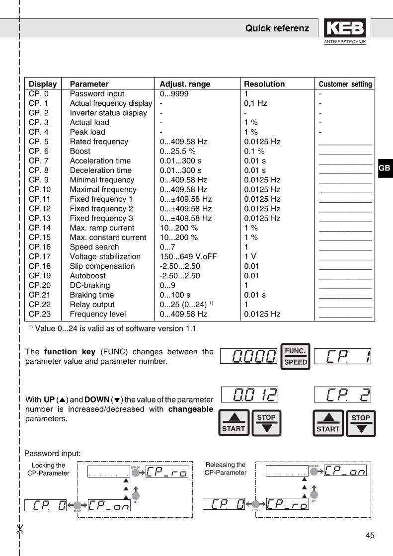
Display Parameter Adjust. range Resolution Customer settingCP. 0 Password input 0...9999 1 -CP. 1 Actual frequency display - 0,1 Hz -CP. 2 Inverter status display - - -CP. 3 Actual load - 1 % -CP. 4 Peak load - 1 % -CP. 5 Rated frequency 0...409.58 Hz 0.0125 Hz ____________CP. 6 Boost 0...25.5 % 0.1 % ____________CP. 7 Acceleration time 0.01...300 s 0.01 s ____________CP. 8 Deceleration time 0.01...300 s 0.01 s ____________CP. 9 Minimal frequency 0...409.58 Hz 0.0125 Hz ____________CP.10 Maximal frequency 0...409.58 Hz 0.0125 Hz ____________CP.11 Fixed frequency 1 0...±409.58 Hz 0.0125 Hz ____________CP.12 Fixed frequency 2 0...±409.58 Hz 0.0125 Hz ____________CP.13 Fixed frequency 3 0...±409.58 Hz 0.0125 Hz ____________CP.14 Max. ramp current 10...200 % 1 % ____________CP.15 Max. constant current 10...200 % 1 % ____________CP.16 Speed search 0...7 1 ____________CP.17 Voltage stabilization 150...649 V,oFF 1 V ____________CP.18 Slip compensation -2.50...2.50 0.01 ____________CP.19 Autoboost -2.50...2.50 0.01 ____________CP.20 DC-braking 0...9 1 ____________CP.21 Braking time 0...100 s 0.01 s ____________CP.22 Relay output 0...25 (0...24) 1) 1 ____________CP.23 Frequency level 0...409.58 Hz 0.0125 Hz ____________
1) Value 0...24 is valid as of software version 1.1
The function key (FUNC) changes between theparameter value and parameter number.
With UP ( ) and DOWN ( ) the value of the parameternumber is increased/decreased with changeableparameters.
START
STOP
START
STOP
FUNC.
SPEED
Password input:Releasing theCP-Parameter Password
FUNC
ENTER
UP
FUNC
ENTER
UP
PasswordLocking the
CP-Parameter
Quick referenz

46
GB

113
ANTRIEBSTECHNIK
7. Password
FUNC
ENTER
UP
Password
Password
FUNC
ENTER
UP
Password
FUNC
ENTER
UP
X Xc) Drive mode activ
a)100
c)500
b)200
b) CP-Parameter "read/write"
a) CP-Parameter "read only"

114

115
ANTRIEBSTECHNIK
D Vor Auslieferung durchlaufen alle Produkte mehrfach eine Qualitäts- und Funktionskontrolle, sodaß Fehler auszuschließen sind. Bei Beachtung unserer Betriebsanleitung sind keine Störungen zuerwarten. Sollte sich trotzdem ein Grund zur Reklamation ergeben, so ist das Gerät mit Angabe derRechnungsnummer, des Lieferdatums, der Fehlerursache und der Einsatzbedingungen an unszurückzusenden. Für Fehler, die aufgrund falscher Behandlung, falscher Lagerung oder sonstigenallgemeinen Irrtümern auftreten, übernehmen wir keine Verantwortung. Prospekte, Kataloge undAngebote enthalten nur Richtwerte. Technische Änderungen jeder Art behalten wir uns vor. Alle Rechtevorbehalten. Nachdruck, Vervielfältigung und fotomechanische Wiedergabe sind ohne schriftlicheGenehmigung durch KEB auch auszugsweise verboten.
GB Prior to delivery all products pass several quality and performance inspections so that malfunctionscan be ruled out. When used in accordance with the operating instructions failure is most unlikely.However, if you have cause for complaint the unit should be returned stating invoice number, deliverydate, cause of failure and field conditions. We do not accept the responsibility for failures due to misuse,wrong storage or similar causes. Leaflets, catalogues and quotations contain only standard values. Wereserve the right to make technical changes without obligation. All rights reserved. Any piratic printing,mimeograhing or photomechanical reproduction, even in extracts, is strictly prohibited.
F Avant la livraison tous les produits passent par différents contrôles fonctionnels et qualitatifs demanière à éliminer les mauvais fonctionnements. L'apparition de défauts sur ces produits est trèsimprobable s'ils sont raccordés et utilisés selon les recommandations des manuels d'instructions.Néanmoins, si un défaut apparaissait, le matériel doit être retourné en indiquant le numéro du bon delivraison, la date d'expédition et les détails apparents du défaut ainsi que le type d'application. Unmauvais emploi, de mauvaises conditions de stockage ou d'autres causes de ce type excluent notreresponsabilité en cas de défectuosité. Les documents techniques et commerciaux, les offres de prixne contiennent que des valeurs standards. Nous nous réservons le droit de procéder à desmodifications techniques sans préavis. Tout droit réservé. Toutes contrefaçons imprimées, oureproductions photomécaniques; même partielles, sont strictement interdites.
I Prima di essere spediti, tutti i nostri prodotti sono soggetti a severi controlli di qualità efunzionamento, questo al fine di evitare malfunzionamenti. Se utilizzati seguendo il manuale diistruzione si evita qualsiasi malfunzionamento. Comunque, qualora dovesse verificarsi un guasto,l'unità dovrà essere rispedita specificando il numero di bolla, la data di spedizione, i dettagli del guastoed il tipo di applicazione. Non si assumono responsabilità per errori dovuti a manomissioni, cattivostoccaggio o simili. Ci riserviamo di effettuare qualsiasi modifica senza preavviso alcuno. Tutti i dirittisono riservati. Qualsiasi riproduzione non autorizzata, anche parziale, è rigorosamente proibita.
Antes de la expedición, todos nuestros productos han sido sometidos a severos controles decalidad y funcionamiento, con la finalidad de evitar funcionamientos defectuosos. La posibilidad dedefectos es casi improable utilizando estos productos de acuerdo con el manual de instrucciones. Sinembargo, si sé detectase algún defecto, la unidad deberá ser devuelta indicando número deexpedición, fecha de envio, causa del fallo y condiciones de instalación. No sé aceptaránresponsabilidades debidas a un mal uso, almacenaje defectuoso o causas similares. Los documentosténicos y comerciales indican sólo valores estándar. Nos reservamos el derecho de efectuarmodificaciones técnicas sin previo aviso. Todos los derechos reservados. Cualquier reproducciónparcial o total, no autorizada, está totalmente prohibida.
IE

116

ANTRIEBSTECHNIK

Karl E. Brinkmann GmbHFörsterweg 36 - 38 • D - 32683 Barntrup
Telefon 00 49 / 52 63 / 4 01 - 0 • Fax 00 49 / 52 63 / 4 01 - 1 16Internet: www.keb.de • E-mail: [email protected]
KEB Antriebstechnik GmbH & Co. KGWildbacher Str. 5 • D - 08289 Schneeberg
Telefon 0049 / 37 72 / 67 - 0 • Telefax 0049 / 37 72 /67 - 2 81E-mail: [email protected]
KEB Antriebstechnik Austria GmbHRitzstraße 8 • A - 4614 Marchtrenk
Tel.: 0043 / 7243 / 53586 - 0 • FAX: 0043 / 7243 / 53586 - 21E-mail: [email protected]
KEB AntriebstechnikHerenveld 2 • B - 9500 Geraadsbergen
Tel.: 0032 / 5443 / 878 • FAX: 0032 / 5443 / 7898E-mail: [email protected]
KEB ChinaXianxia Road 299 • CHN - 200051 Shanghai
Tel.: 0086 / 21 / 62350922 • FAX: 0086 / 21 / 62350015E-mail: [email protected]
Société Française KEBZ.I. de la Croix St. Nicolas • 14, rue Gustave Eiffel
F - 94510 LA QUEUE EN BRIETél.: 0033 / 1 / 49620101 • FAX: 0033 / 1 / 45767495
E-mail: [email protected]
KEB (UK) Ltd.6 Chieftain Buisiness Park, Morris Close
Park Farm, Wellingborough, GB - Northants, NN8 6 XFTel.: 0044 / 1933 / 402220 • FAX: 0044 / 1933 / 400724
Internet: www.keb-uk.co.uk • E-mail: [email protected]
KEB Italia S.r.l.Via Newton, 2 • I - 20019 Settimo Milanese (Milano)
Tel.: 0039 / 02 / 33500782 • FAX: 0039 / 02 / 33500790Internet: www.keb.it • E-mail: [email protected]
KEB - YAMAKYU Ltd.711 Fukudayama, Fukuda
J - Shinjo-Shi, Yamagata (996-0053)Tel.: 0081 / 233 / 29 / 2800 • FAX: 0081 / 233 / 29 / 2802
E-mail: [email protected]
KEB Taiwan Co., Ltd.1F, No.19-5, Shi Chou Rd., Tounan Town
R.O.C. - Yin-Lin Hsian / TaiwanTel.: 00886 / 5 / 5964242 • FAX: 00886 / 5 / 5964240
E-mail: [email protected]
KEBCO Inc.1335 Mendota Heights Road
USA - Mendota Heights, MN 55120Tel.: 001 / 651 / 4546162 • FAX: 001 / 651 / 4546198Internet: www.kebco.com • E-mail: [email protected] ©
KE
B0
0.F
4.S
0B
-K1
11
03
/20
01


![Stirnrad-Schneckengetriebe SK 02040.1 EN - NORD...P 1 n 2 M 2 f B i ges F R F A Type [kW] [min-1] [Nm] [N] G1012 · 60 Hz B22 0,37 kW 0,55 kW 0,75 kW 1,10 kW 0,37 23 108 0,8 60,00](https://static.fdokument.com/doc/165x107/60cd1158af048c16d2492c5e/stirnrad-schneckengetriebe-sk-020401-en-nord-p-1-n-2-m-2-f-b-i-ges-f-r-f.jpg)