
Design of Linear Phase IIR Filters with Flat Magnitude ...
22
Design of Linear Phase IIR Filters with Flat Magnitude Response using Complex Coefficients Allpole Filters Diseño de Filtros IIR de Fase Lineal con Respuesta en Magnitud Plana usando Filtros Todopolo con Coeficientes Complejos Alfonso Fernandez Vazquez 1 and Gordana Jovanovic Dolecek 2 1 School of Electronic Engineering; Xidian University No.2 South TaiBai Road; Xian, Shaanxi 710071; P. R. China [email protected] 2 Department of Electronics; Instituto Nacional de Astrofisica, Optica, y Electronica, INAOE Luis Enrique Erro No. 1; Tonantzintla, Puebla 72840; Puebla, Mexico [email protected] Article received on March 15, 2007; accepted on September 03, 2007 Abstract This paper presents a new method for the design of linear phase IIR filters with flat magnitude response. The method is based on the design of flat digital allpole filters with complex coefficients. Depending on the parity of the allpole filter order the resulting IIR filter have either real or complex coefficients. The parameters of the design are the same as in traditional IIR filter design, i.e., passband and stopband frequencies, ω p and ω s , passband droop A p , and stopband attenuation A s . Several design examples are provided to illustrate the method. In addition, a design of linear phase modified two-band IIR filter banks and a design of stable IIR filter with an improved group delay are presented as two applications of the proposed method. Keywords: IIR filters, linear phase, allpole filters, allpass filters, filter banks, improved group delay. Resumen Este artículo presenta un nuevo método para el diseño de filtros IIR de fase lineal con respuesta en magnitud plana. El método esta basado en el diseño de filtros todopolo con respuesta plana y coeficientes complejos. Dependiendo de la paridad del orden del filtro todopolo, los filtros resultantes IIR tienen coeficientes reales o complejos. Los parámetros de diseño son los mimos que en el diseño tradicional de filtros IIR, esto es, frecuencias de paso y rechazo, ω p y ω s , y atenuaciones en la banda de paso y rechazo, A p y A s . Varios ejemplos de diseño son dados para ilustrar el método. Finalmente, el diseño de bancos de filtros modificado de dos bandas de fase lineal y el diseño de filtros IIR con retardo de grupo mejorado se presentan como dos aplicaciones del método propuesto. Palabras clave: Filtros IIR, fase lineal, filtros todopolo, filtros pasatodo, banco de filtros, retardo de grupo mejorado. 1 Introduction A filter H 0 (z) has linear phase if (Vaidyanathan, 1993), ) ( ~ ) ( 0 0 z H cz z H k − = , (1) where z −k is the delay, c is the complex constant with unit magnitude and ) ( ~ 0 z H is the paraconjugate of H(z), that is, it is obtained by conjugating the filter coefficients and by replacing z with z −1 . It is well known that causal Finite Impulse Response (FIR) filters can be designed to have linear phase. However, Infinite Impulse Response (IIR) filters can have linear phase only in the noncausal case (Mitra, 2006; Vaidyanathan, 1993; Vaidyanathan and Chen, 1998), (the phase response can be 0 or π). It has been recently shown that filters with a linear phase property are useful in the filter bank design and Nyquist filter design (Argenti et al., Computación y Sistemas Vol. 10 No. 4, 2007, pp 335-356 ISSN 1405-5546
Transcript of Design of Linear Phase IIR Filters with Flat Magnitude ...
Design of Linear Phase IIR Filters with Flat Magnitude Response using Complex Coefficients Allpole Filters
Diseño de Filtros IIR de Fase Lineal con Respuesta en Magnitud Plana usando Filtros Todopolo con Coeficientes Complejos
Alfonso Fernandez Vazquez1 and Gordana Jovanovic Dolecek2
1 School of Electronic Engineering; Xidian University No.2 South TaiBai Road; Xian, Shaanxi
710071; P. R. China [email protected]
2 Department of Electronics; Instituto Nacional de Astrofisica, Optica, y Electronica, INAOE Luis Enrique Erro No. 1; Tonantzintla, Puebla
72840; Puebla, Mexico [email protected]
Article received on March 15, 2007; accepted on September 03, 2007
Abstract This paper presents a new method for the design of linear phase IIR filters with flat magnitude response. The method is based on the design of flat digital allpole filters with complex coefficients. Depending on the parity of the allpole filter order the resulting IIR filter have either real or complex coefficients. The parameters of the design are the same as in traditional IIR filter design, i.e., passband and stopband frequencies, ωp and ωs, passband droop Ap, and stopband attenuation As. Several design examples are provided to illustrate the method. In addition, a design of linear phase modified two-band IIR filter banks and a design of stable IIR filter with an improved group delay are presented as two applications of the proposed method. Keywords: IIR filters, linear phase, allpole filters, allpass filters, filter banks, improved group delay. Resumen Este artículo presenta un nuevo método para el diseño de filtros IIR de fase lineal con respuesta en magnitud plana. El método esta basado en el diseño de filtros todopolo con respuesta plana y coeficientes complejos. Dependiendo de la paridad del orden del filtro todopolo, los filtros resultantes IIR tienen coeficientes reales o complejos. Los parámetros de diseño son los mimos que en el diseño tradicional de filtros IIR, esto es, frecuencias de paso y rechazo, ωp y ωs, y atenuaciones en la banda de paso y rechazo, Ap y As. Varios ejemplos de diseño son dados para ilustrar el método. Finalmente, el diseño de bancos de filtros modificado de dos bandas de fase lineal y el diseño de filtros IIR con retardo de grupo mejorado se presentan como dos aplicaciones del método propuesto. Palabras clave: Filtros IIR, fase lineal, filtros todopolo, filtros pasatodo, banco de filtros, retardo de grupo mejorado.
1 Introduction A filter H0(z) has linear phase if (Vaidyanathan, 1993),
)(~)( 00 zHczzH k−= , (1) where z−k is the delay, c is the complex constant with unit magnitude and )(~
0 zH is the paraconjugate of H(z), that is, it is obtained by conjugating the filter coefficients and by replacing z with z−1.
It is well known that causal Finite Impulse Response (FIR) filters can be designed to have linear phase. However, Infinite Impulse Response (IIR) filters can have linear phase only in the noncausal case (Mitra, 2006; Vaidyanathan, 1993; Vaidyanathan and Chen, 1998), (the phase response can be 0 or π). It has been recently shown that filters with a linear phase property are useful in the filter bank design and Nyquist filter design (Argenti et al.,
Computación y Sistemas Vol. 10 No. 4, 2007, pp 335-356 ISSN 1405-5546

Alfonso Fernández Vázquez and Gordana Jovanovic Dolecek 336 1996; Djokic et al.,1998; Powell and Chau, 1991; Selesnick, 1998; Willson and Orchard, 1994; Zhang et al., 2001, 2000).
As a difference to methods presented in (Djokic et al., 1998;Powell and Chau, 1991;Willson and Orchard, 1994), our goal is to propose here a new technique to design linear phase IIR filter with flat magnitude response based on complex allpole filters. Additionally, the design specification must be the same as in traditional IIR filter design based on analog filters, i.e., the passband and stopband frequencies, ωp and ωs, the passband droop Ap, and the stopband attenuation As, as shown in Fig. 1.
Fig. 1. Design parameters
The challenge with the proposed approach is in how to include the parameters of the design into the desired
linear phase IIR filter design. Using results from (Fernandez-Vazquez and Jovanovic-Dolecek, 2004), it follows that an auxiliary complex allpole filter with certain characteristics can be used to solve this problem.
The rest of the paper is organized as follows. In Section 2 we therefore use the known relation between linear phase IIR filter and the corresponding allpass filter. First, we establish design conditions which the allpass filter needs to satisfy, and later we determine design conditions for the auxiliary complex allpole filter. In Section 3, we present closed form equations of the singularities of the corresponding linear phase filter (1) which are used in the design procedures described in Sections 4-6. Detailed description of the algorithms for the lowpass and highpass filters are given in Sections 4 and 5, and are illustrated with different examples. Section 6 presents the applications of the proposed algorithm, including a design of linear phase modified two-band IIR filter banks and a design of a flat IIR filter with an improved group delay. 2 Design of allpole filter with complex coefficients In this section we design allpole filters with complex coefficients. First, we derive the design conditions that an allpass filter needs to satisfy such that the design of lowpass filter is obtained. Second, to design the corresponding allpole filters, we relate the allpole filter and the allpass filter.
It is well known that a linear phase lowpass IIR filter H0(z) can be expressed in terms of complex allpass filters as (Zhang et al., 2001),
[ ])(~)(21)(0 zAzAzH += , (2)
where A(z) is an allpass filter with complex-coefficients. Note that the filter H0(z) defined in (2) satisfies the relation (1) if k = 0 and c = 1.
From (2), the magnitude response of H0(z) can be expressed as,
πω0 )),ω(cos()e( jω0 ≤≤= AH φ , (3)
Computación y Sistemas Vol. 10 No. 4, 2007, pp 335-356 ISSN 1405-5546

Design of Linear Phase IIR Filters with Flat Magnitude Response using Complex Coefficients Allpole Filters 337
where φA(ω) is the phase response of A(z). Furthermore, we can observe that |H0(ejω)| has flat magnitude response at ω = 0, and ω = π, and the resulting
values |H0(ej0)| and |H0(ejπ)| equal 1 and 0, respectively. Since |H0(ejω)| has a flat magnitude response at ω = 0, and ω = π, the corresponding allpass filter A(z) has a flat
phase response at the same frequency points. As a consequence, the resulting group delays τA(0) and τA(π) of the allpass filter are equal to 0. Moreover, the values of φA(ω) at these two frequency points can be 0 and ±π/2, respectively.
Considering the value Ap in dB and using (3), it can be shown that the phase value φA(ω) evaluated at ωp is given by
( )20/1ppA
p10cos)(ω AA
−−== φφ , (4) In summary, the conditions that the auxiliary complex allpass filter in (2) needs to satisfy, are the following: A.1. The phase values of φA(ω) at ω = 0 and ω = π are 0 and ±π/2, respectively (see Fig. 2). A.2. The phase response of A(z) is flat at ω = 0 and ω = π. Therefore, τA(0) = τA(π) = 0. A.3. The phase value φpA is controlled by Ap (see (4) and Fig. 2).
Fig. 2. Relation between the passband droop and the phase value φpA
From the design conditions A.1-A.3, we can note that the complex allpass filter A(z) has causal component Ac(z)
and anticausal component Aa(z), such that A(z) = Ac(z)Aa(z). Figure 3 illustrates an implementation of the complex allpass filter. The block TR denotes the time reversal operator, i.e., r(n) = s(−n), and Aa(z−1) is now a causal allpass filter (Vaidyanathan and Chen, 1998). The anticausal filter works perfectly in a block by block manner if one correctly chooses initial conditions in the time reverse difference equations (Vaidyanathan and Chen, 1998).
Fig. 3. Structure for the complex allpass filter A(z)
Computación y Sistemas Vol. 10 No. 4, 2007, pp 335-356 ISSN 1405-5546

Alfonso Fernández Vázquez and Gordana Jovanovic Dolecek 338
In the following we relate a complex allpass filter satisfying conditions A.1-A.3 to the corresponding complex allpole filter.
A complex allpass filter A(z) is related to an allpole filter as follows (Vaidyanathan, 1993),
)(α
~α)(~)( * zF
(z)FzzD
D(z)zzA NN −− == , (5)
where D(z) is an allpole filter of order N given by,
)(α)(zF
zD = , (6)
the complex constant α has unit magnitude, and F(z) is a polynomial of degree N, that is,
∑=
−+=N
n
nn zfzF
11)( . (7)
The filter coefficients fn , for n = 1,…,N, are complex and are expressed as fn = fRn + jfIn, where fRn and fIn are the
real and imaginary part of fn, respectively. Note that the desired phase of the allpole filter φD(ω) depends on the phase φA(ω) of A(z) (see (5)). Therefore, it
can be shown that, Selesnick (1999),
2)ω(ω)ω( A
DN φφ +
= . (8)
Similarly, the group delay of the allpole filter can be expressed as, Selesnick (1999),
2)ω(τ)ω(τ NA −
= , (9)
where τA(ω) is the group delay of complex allpass filter.
Using (8) and the phase values φA(ω) at ω = 0 and ω = π (see Condition A.1), we arrive at φD(0) = 0 and φD(π) = (2N ±1) π/4.
From the relation (9) and Condition A.2, we further get τ(0) = τ(π) = −N/2. Finally, the following relation is obtained using Condition A.3 and (8),
( )2
ω10cos)ω( p
20/p1
ppNA
D+
==−−
φφ . (10)
As a consequence, the corresponding conditions that the allpole filter D(z) has to satisfy are:
B.1. The phase values of D(z) at ω = 0 and ω = π are 0, and π (2N ± 1)/4, respectively.
B.2. The group delays τ(ω) of D(z) at ω = 0 and ω = π are −N/2.
B.3. The phase value of D(z) at ωp, φp = φD(ωp), is given by (10).
Computación y Sistemas Vol. 10 No. 4, 2007, pp 335-356 ISSN 1405-5546

Design of Linear Phase IIR Filters with Flat Magnitude Response using Complex Coefficients Allpole Filters 339
Substituting conditions B.1 and B.2 into the set of linear equations proposed in (Fernandez-Vazquez and Jovanovic-Dolecek, 2004), we arrive at
odd,22
)tan(2 1
Iα1
R kNfNnfNnkN
nn
kN
nn
k
⎟⎠⎞
⎜⎝⎛−−=⎟
⎠⎞
⎜⎝⎛ −+⎟
⎠⎞
⎜⎝⎛ − ∑∑
==
φ , (11a)
even,22
)cot(2 1
Iα1
R kNfNnfNnkN
nn
kN
nn
k
⎟⎠⎞
⎜⎝⎛−−=⎟
⎠⎞
⎜⎝⎛ −−⎟
⎠⎞
⎜⎝⎛ − ∑∑
==
φ , (11b)
odd,22
)1()tan(1)tan(1
2)1(
1I
α
α
1R kNfNnfNn
kN
nn
kn
N
nn
kn ⎟
⎠⎞
⎜⎝⎛−−=⎟
⎠⎞
⎜⎝⎛ −−
−+
+⎟⎠⎞
⎜⎝⎛ −− ∑∑
== φφ , (11c)
even,22
)1()tan(1)tan(1
2)1(
1I
α
α
1R kNfNnfNn
kN
nn
kn
N
nn
kn ⎟
⎠⎞
⎜⎝⎛−−=⎟
⎠⎞
⎜⎝⎛ −−
+−
+⎟⎠⎞
⎜⎝⎛ −− ∑∑
== φφ , (11d)
where φα is the phase of α.
Unlike the method of Selesnick (1999), which proposes the design of flat allpole filters with real-value coefficients and different degree of flatness at ω = 0 and ω = π, in this method the degree of flatness at ω = 0 and ω = π is N−2.1 It makes that the passband frequency ωp becomes a continuous variable. Consequently, the values of k are 0,…, N−1.
Solving the set of equations (11) with the symbolic tool MAPLE (Heck, 2003), the filter coefficients are expressed as,
( )⎪⎪⎪
⎩
⎪⎪⎪
⎨
⎧
−⎟⎟⎠
⎞⎜⎜⎝
⎛
⎟⎟⎠
⎞⎜⎜⎝
⎛
=+ odd.,je2
even;,
)4/π2(j α nnN
nnN
fn
φ
(12)
Finally, from the general phase equation proposed in (Fernandez-Vazquez and Jovanovic-Dolecek, 2004), the
following relation gives the desired phase φp of the allpole filter (Condition B.3),
0)ωcos()ωsin(0
Ipαp0
Rpαp =−+−−+ ∑∑==
N
nn
N
nn fnfn φφφφ . (13)
From (15), the corresponding value of φα, for N even, is equal to
⎪⎭
⎪⎬⎫
⎪⎩
⎪⎨⎧
⎟⎟⎠
⎞⎜⎜⎝
⎛−−−−∠=
2ω
tan)1(1j p'p
2/α
NN Aφ , (14)
where ∠{⋅} stands for the angle of {⋅} and
1
The degree of flatness is defined as the number of null derivatives of the group delay (Fernandez-Vazquez and Jovanovic-Dolecek, 2004).
Computación y Sistemas Vol. 10 No. 4, 2007, pp 335-356 ISSN 1405-5546
Alfonso Fernández Vázquez and Gordana Jovanovic Dolecek 340
1110110
20/
20/'p
p
p
−−
+= A
A
A . (15)
Similarly, for odd values of N, we have
⎪⎭
⎪⎬⎫
⎪⎩
⎪⎨⎧
⎟⎟⎠
⎞⎜⎜⎝
⎛−+−−∠= +
2ω
tan)1(1j p'p
2/)1(α
NN Aφ . (16)
3 Closed form equations for the singularities of H0(z) In this section, we focus on the computation of the singularities of H0(z). 3.1 Poles Substituting (12) into (7) and using the two-polyphase components of (1 + z−1)N, we arrive at
[ ]NN zzzF )1(sin)1j()1)(sin(cose)( 1α
1αα
j α −− −−−+−= φφφφ . (17) From (17), it can be shown that the corresponding poles of H0(z) are
11
−+
=k
kkp
λλ , (18)
where k = 0,…,N−1, and
π4
18j/1
αe
cot12 N
kN
k
+−
⎟⎟⎠
⎞⎜⎜⎝
⎛
−=
φγ . (19)
3.2 Zeros It follows from (17) and (2) that the transfer function H0(z) is,
)(~)()()1()(
1
0 zFzFzzEzzH N
N
−
−+= , (20)
Where
NN zczzE )1)(1)2sin()2(cos()1))(2sin(1()( 1αα
1α
−− −−+++−= φφφ , (21) and
⎩⎨⎧−
=odd.j,even;,1
NN
c (22)
Observe that the transfer function H0(z) has N zeros at z = −1 and the other zeros at (cf. (21)),
1β1β
−+
=k
kkz , (23)
Computación y Sistemas Vol. 10 No. 4, 2007, pp 335-356 ISSN 1405-5546

Design of Linear Phase IIR Filters with Flat Magnitude Response using Complex Coefficients Allpole Filters 341
where k = 0,…,N−1, and the parameter βk is given by,
⎪⎪⎪
⎩
⎪⎪⎪
⎨
⎧
⎟⎟⎠
⎞⎜⎜⎝
⎛−−
⎟⎟⎠
⎞⎜⎜⎝
⎛−−
=
− odd.e)2sin(1)2cos(12
even,e)2sin(1)2cos(12
β
4/π)14j(2/1
α
α
/π2j2/1
α
α
N
N
NkN
NkN
k
φφ
φφ
, (24)
Note that there are N zeros away from the origin, which contribute to the passband (see (23) and (24)).
It is easily shown that the absolute values of zk in (23) for even values of N are always different from 1. However, for N odd, there is one absolute value of zk equal to 1, i.e., there is a zero on the unit circle. The resulting angle of zk is denoted by ω0. Furthermore, there exists a frequency ω1 at which H0(ejω) equals −1. Consequently, for odd values of N, the filter H0(z) has complex-valued coefficients.
Accordingly, the corresponding frequencies ω0 and ω1 are expressed as,
N2/1
α
α10 )2sin(1
)2cos(12tan2πω ⎟⎟⎠
⎞⎜⎜⎝
⎛−−
+= −
φφ ,
N2/1
α
α11 )2sin(1
)2cos(121tan2πω ⎟⎟
⎠
⎞⎜⎜⎝
⎛−−
+= −
φφ . (25)
4 Algorithm for lowpass filter design In the following we describe the algorithm for the design of linear phase lowpass IIR filters. At first, we compute the allpole filter order N using either (14) or (16).
To satisfy the design condition at ωs, we replace the passband frequency ωp with the stopband frequency ωs and the passband droop Ap with the stopband attenuation As in (14). Consequently, the relationship (14) becomes
⎭⎬⎫
⎩⎨⎧
⎟⎠⎞
⎜⎝⎛−−−−∠=
2ωtan)1(1j s'
s2/
αNN Aφ , (26)
Where
1110110
20/
20/'s
s
s
−−+
= A
AA . (27)
Solving (14) and (26) with respect to N, we arrive at
⎥⎥⎥⎥⎥
⎦
⎥
⎢⎢⎢⎢⎢
⎣
⎢
⎟⎟⎠
⎞⎜⎜⎝
⎛
⎟⎟⎠
⎞⎜⎜⎝
⎛
=
'
'
's
'p
p
s
ωω
log
logA
A
N , (28)
Computación y Sistemas Vol. 10 No. 4, 2007, pp 335-356 ISSN 1405-5546
Alfonso Fernández Vázquez and Gordana Jovanovic Dolecek 342 where ⎣⋅⎦ denotes the ceiling function and
⎟⎟⎠
⎞⎜⎜⎝
⎛=
2ω
tanω p'p , ⎟
⎠⎞
⎜⎝⎛=
2ωtanω s'
s . (29)
As we pointed out before, if the allpole filter order were odd, the resulting filter H0(z) would have complex-
valued coefficients, otherwise it has real-valued coefficients. The proposed algorithm consists of the following steps.
1. Estimate the order N of the allpole filter using (28). 2. From the values N, ωp and Ap, compute the phase value of the allpole filter φα using (14) for N even, and
using (16) for N odd. 3. Compute the allpole filter coefficients fn, using (12). 4. The poles and zeros of the desired filter H0(z) are computed using (18) and (23), respectively. Additionally,
if N is odd, compute the frequencies ω0 and ω1, using (25). 5. Calculate the filter coefficients of H0(z) using (2). We illustrate the procedure with the following two examples. The first one uses an even allpole filter order N,
whereas the second one use N odd. Example 1. We design an IIR linear phase lowpass filter with the passband and stopband frequencies ωp = 0.25π and ωp = 0.45π, respectively. The passband droop is Ap = 1 dB, while the stopband attenuation is As = 40 dB.
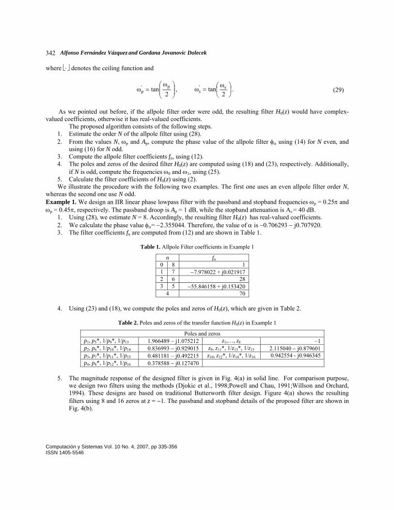
1. Using (28), we estimate N = 8. Accordingly, the resulting filter H0(z) has real-valued coefficients. 2. We calculate the phase value φα= −2.355044. Therefore, the value of α is −0.706293 − j0.707920. 3. The filter coefficients fn are computed from (12) and are shown in Table 1.
Table 1. Allpole Filter coefficients in Example 1
n fn0 8 1 1 7 −7.978022 + j0.021917 2 6 28 3 5 −55.846158 + j0.153420
4 70
4. Using (23) and (18), we compute the poles and zeros of H0(z), which are given in Table 2.
Table 2. Poles and zeros of the transfer function H0(z) in Example 1
Poles and zeros p1, p5*, 1/p9*, 1/p13 1.966489 − j1.075212 z1,…, z8 −1 p2, p6*, 1/p10*, 1/p14 0.836993 − j0.929015 z9, z11*, 1/z13*, 1/z15 2.115040 − j0.879601 p3, p7*, 1/p11*, 1/p15 0.481181 − j0.492215 z10, z12*, 1/z14*, 1/z16 0.942554 - j0.946345 p4, p8*, 1/p12*, 1/p16 0.378588 − j0.127470
5. The magnitude response of the designed filter is given in Fig. 4(a) in solid line. For comparison purpose,
we design two filters using the methods (Djokic et al., 1998;Powell and Chau, 1991;Willson and Orchard, 1994). These designs are based on traditional Butterworth filter design. Figure 4(a) shows the resulting filters using 8 and 16 zeros at z = −1. The passband and stopband details of the proposed filter are shown in Fig. 4(b).
Computación y Sistemas Vol. 10 No. 4, 2007, pp 335-356 ISSN 1405-5546
Design of Linear Phase IIR Filters with Flat Magnitude Response using Complex Coefficients Allpole Filters 343
0 0.2 0.4 0.6 0.8 10
0.2
0.4
0.6
0.8
1
Magnitude responses
ω/π
Proposed method
Eight zeros at z=−1
Sixteen zeros at z=−1
0 0.05 0.1 0.15 0.2 0.25 0.3 0.35−2
−1.5
−1
−0.5
0
Passband
Gai
n, d
B
0.35 0.4 0.45 0.5 0.55−50
−45
−40
−35
−30Stopband
ω/π (a) (b)
Fig. 4. Magnitude response of H0(z) in Example 1
Observe that for the same number of zeros at z = −1 (8 zeros) the proposed method exhibits better magnitude characteristic. Example 2. In this example, we illustrate the algorithm for the IIR filter design based on a complex allpole filter with odd order. The IIR filter specification includes the passband and stopband frequencies being 0.5π and 0.7π, and the passband droop and the stopband attenuation being 1 dB and 40 dB, respectively.
1. From (28), it follows that N = 9. Therefore, the resulting IIR filter H0(z) has complex filter coefficients. 2. The phase value φα is obtained from (18), i.e., φα = −2.906242 and α = −0.972433 − j0.233184. 3. The filter coefficients of F(z), which are obtained using (12), are shown in Table 3.
Table 3. Filter coefficients of F(z) in Example 2
n fn n fn0 1 5 55.155296 + j43.439940 1 3.939664 + j3.102853 6 84 2 36 7 15.758656 + j12.411411 3 36.770198 + j28.959960 8 9 4 126 9 0.437740 + j0.344761
4. From (23) and (18), we compute the poles and zeros of H0(z), which are shown in Table 4. Additionally, the
frequencies ω0 and ω1 are 1.483715π and 1.459303π, respectively (see (25)), where ω0 and ω1 are the frequencies at which H0(ejω) is 0 and −1, respectively.
Table 4. Poles and zeros of H0(z) in Example 2
Poles and zeros P1, 1/p10* −0.045592 − j0.131383 z1,…, z9 −1 P2, 1/p11* −0.047014 + j0.221228 z10, 1/z15* −0.025782 − j0.087431 P3, 1/p12* −0.062954 + j0.635273 z11, 1/z16* −0.031146 − j0.465936 P4, 1/p13* −0.120521 + j1.296186 z12, 1/z17* −0.378513 + j3.695906 P5, 1/p14* −0.485810 + j3.102542 z13, 1/z18* −0.077670 + j1.425310 P6, 1/p15* −11.469800 − j11.130423 z14 −0.051140 − j0.998691 P7, 1/p16* −0.302484 − j2.381486 P8, 1/p17* −0.097956 − j1.086518 P9, 1/p18* −0.056930 − j0.519239
Computación y Sistemas Vol. 10 No. 4, 2007, pp 335-356 ISSN 1405-5546

Alfonso Fernández Vázquez and Gordana Jovanovic Dolecek 344
5. Figure 5(a) shows the magnitude response of the designed filter. Figure 5(b) zooms the frequencies ω0 and ω1, while Fig. 5(c) gives the passband and stopband details.
0 0.5 1 1.5 20
0.2
0.4
0.6
0.8
1
Magnitude response of H0(z)
ω/π 1.4 1.45 1.5 1.55 1.60
0.2
0.4
0.6
0.8
1
Detail magnitude response of H0(z)
ω/π
ω1
ω0
(a) (b)
0 0.1 0.2 0.3 0.4 0.5 0.6−2
−1.5
−1
−0.5
0
Passband
Gai
n, d
B
0.6 0.65 0.7 0.75 0.8−50
−45
−40
−35
−30Stopband
ω/π (c)
Fig. 5. Magnitude response of the designed lowpass filter in Example 2 5 Algorithm for linear phase IIR highpass filter design Now, we consider the design of highpass filter using complex-valued allpole filters.
The relationship between a highpass filter and a corresponding allpass filter is expressed by (Vaidyanathan et al., 1987),
[ ])(~)(j2
1)(1 zAzAzH −= . (30)
Using (30) and Ap in dB, the phase value φpA is expressed as,
( )20/1p
p10sin AA
−−=φ . (31)
Computación y Sistemas Vol. 10 No. 4, 2007, pp 335-356 ISSN 1405-5546

Design of Linear Phase IIR Filters with Flat Magnitude Response using Complex Coefficients Allpole Filters 345
The frequencies defined in (29) become
⎟⎟⎠
⎞⎜⎜⎝
⎛=
2ω
cotω p'p , ⎟
⎠⎞
⎜⎝⎛=
2ωcotω s'
s . (32)
Similarly, the phase value φα is now given by,
⎪⎪⎪
⎩
⎪⎪⎪
⎨
⎧
⎪⎭
⎪⎬⎫
⎪⎩
⎪⎨⎧ −
++−∠
⎪⎭
⎪⎬⎫
⎪⎩
⎪⎨⎧ −
−+−∠
=−
odd.)1(2ω)1j(
even,)1(2ω)1j(
'p
2/)1('p
'p
2/'p
α
NA
NA
N
N
φ (33)
Following example illustrates the design. Example 3. The parameters of the design of the highpass filter are as follows. The passband frequency ωp = 0.7π and stopband frequency ωs = 0.4π. The stopband attenuation and passband droop are 45 dB and 2 dB, respectively.
The resulting filter order is equal to 6. The magnitude response, the passband and stopband details of the designed filter are shown in Fig. 6.
0 0.2 0.4 0.6 0.8 1−100
−80
−60
−40
−20
0
Magnitude response of H1(z)
ω/π
Gai
n, d
B
0.6 0.7 0.8 0.9 1−3
−2
−1
0Passband
Gai
n, d
B
0.35 0.4 0.45 0.5−55
−50
−45
−40
−35Stopband
ω/π (a) (b)
Fig. 6. Magnitude response of H1(z) in Example 3 6 Applications This section consider two applications of the proposed design of linear phase IIR filter, i.e., design of modified two-band filter banks and the design of IIR filter with improved group delay. 6.1. Design of Modified Two-Band Filter Banks The modified two-band filter bank (Galnad and Nussbaumer, 1984), is shown in Fig. 7. The analysis filter H0(z) and the synthesis filter G0(z) are lowpass filters, while the analysis filter H1(z) and the synthesis filter G1(z) are highpass filters. The difference from the traditional structure is manifested in two extra delays, one before the filter H1(z) and another after the filter G0(z) (see Fig. 7).
Computación y Sistemas Vol. 10 No. 4, 2007, pp 335-356 ISSN 1405-5546

Alfonso Fernández Vázquez and Gordana Jovanovic Dolecek 346
Fig. 7. Modified two-band filter bank
To avoid alias distortion, the synthesis filters are related to the analysis filter H0(z) in the following form
(Vaidyanathan et al., 1987), )(2)(),(~2)( 0100 zHzGzHzG −== . (34)
where )(~
0 zH is the paraconjugate of H0(z), and )(~)( 01 zHzH −= . According to (Vaidyanathan, 1993), the amplitude and phase distortions are eliminated if the analysis filter
H0(z) is chosen to satisfy (Vaidyanathan et al., 1987),
1)(~)()(~)( 0000 =−−+ zHzHzHzH . (35)
From (35), the relation between the passband droop Ap and the stopband attenuation As is given by (Vaidyanathan et al., 1987),
11010 10/10/ sp =+ −− AA . (36)
Additionally, using (34) and (35), we have (Vaidyanathan et al., 1987),
πωω sp =+ . (37) Methods for designing real linear phase modified two-band IIR filter banks based on complex allpass filter are
proposed in (Argenti et al., 1996; Zhang et al., 2001; Zhang and Yoshikawa, 1999). The analysis filters are given by (Argenti et al., 1996),
[ ])(~)(21)(0 zAzAzH += , (38)
[ ])(~)(j2
1)(1 zAzAzH −= , (39)
where A(z) is a complex allpass filter. In (Argenti et al., 1996; Zhang and Yoshikawa, 1999), the corresponding analysis IIR filters are real and have a
flat magnitude response in both passband and stopband. More general design of (Zhang and Yoshikawa, 1999) is given in (Zhang et al., 2001) and includes flat as well as equiripple design. In both cases the designed filters are real.
The perfect reconstruction condition for the modified two-band IIR filter banks is established in (Argenti et al., 1996; Vaidyanathan et al., 1987; Zhang et al., 2001; Zhang and Yoshikawa, 1999), which implies that the poles of H0(z) and H1(z) must appear on the imaginary axis and in pairs jp and 1/jp, where p is a pole. From this condition, it follows that the filter coefficients given in (12) must be imaginary for even values of n.
Computación y Sistemas Vol. 10 No. 4, 2007, pp 335-356 ISSN 1405-5546
Design of Linear Phase IIR Filters with Flat Magnitude Response using Complex Coefficients Allpole Filters 347
Consequently, the values of φα in (14) for an even N, must be
⎪⎩
⎪⎨
⎧
−
−=
odd.2/forπ83
even,2/forπ87
αN
Nφ . (40)
The corresponding zeros of H0(z) are computed from (23) and (40)
⎪⎪⎪⎪
⎩
⎪⎪⎪⎪
⎨
⎧
−
+
−
+
=
+
+
odd,2/
1e2
1e2
even,2/
1e2
1e2
2jπ21
2jπ21
12jπ21
12jπ21
N
N
z
Nk
N
Nk
N
Nk
N
Nk
N
k (41)
where k = 0,…,N−1, while the poles are computed using (see (18)),
⎪⎪⎪
⎩
⎪⎪⎪
⎨
⎧
⎟⎠⎞
⎜⎝⎛±
⎟⎠⎞
⎜⎝⎛±
=
+
+
odd.2/πtan
j
even,2/πtan
j
818
858
N
N
p
Nk
Nk
k (42)
Similarly, the values of φα when N odd are,
⎪⎩
⎪⎨⎧
=−
−
odd.2/foreven,2/for
π85
π83
NN
αφ (43)
The zeros of H0(z) are now given by,
⎪⎪⎪⎪
⎩
⎪⎪⎪⎪
⎨
⎧
+
−
+
+
−
+
=
+
+
+
+
odd,2/)1(
1e2
1e2
even,2/)1(
1e2
1e2
214jπ
21
214jπ
21
234jπ
21
234jπ
21
N
N
z
Nk
N
Nk
N
Nk
N
Nk
N
k (44)
Computación y Sistemas Vol. 10 No. 4, 2007, pp 335-356 ISSN 1405-5546

Alfonso Fernández Vázquez and Gordana Jovanovic Dolecek 348 where k = 0,…,N−1, and the poles are expressed as,
⎪⎪⎪⎪⎪⎪⎪
⎩
⎪⎪⎪⎪⎪⎪⎪
⎨
⎧
+
+
⎟⎠⎞
⎜⎝⎛
⎟⎠⎞
⎜⎝⎛
⎟⎠⎞
⎜⎝⎛
⎟⎠⎞
⎜⎝⎛
=
+
+
+
+
odd,2/)1(
even,2/)1(
πtan
j
πtan
j
πtan
j
πtan
j
8
78
8
58
8
38
8
18
N
N
p
N
k
N
k
N
k
N
k
k (45)
where k = 0,…,N−1. Using (25), we arrive at
( )N2/110 2tan2πω −+= , ( )N2/11
1 2tan2πω −−+= . (46) 6.1.1 Description of the algorithm In the following we describe how the proposed algorithm can be used for a design of linear phase modified two-band IIR filter banks. The algorithm has the following steps:
1. Calculate the order N of the allpole filter using (28), (36) and (37). 2. Depending on the parity of N, compute the filter coefficients fn using (12) and either (40) or (43). The
corresponding poles and zeros are obtained using (42) and (41) for N even. For N odd use (45) and (44). 3. Additionally, if N is odd, compute the frequencies ω0 and ω1 using (46).
We illustrate the method with the next two examples. Example 4. Passband frequency ωs of the analysis filter H0(z) equals 0.6π, whereas the stopband attenuation As is 45 dB
1. From (36) and (37), it follows that Ap = 1.373381 × 10⁻⁴ and ωp = 0.4π. Using (28), the order of the complex allpole filter is 18.
2. We compute the filter coefficients using (12) and (40), which are shown in Table 5. Poles and zero of H0(z) are presented in Table 6.
Table 5. Filter coefficients of F(z) in Example 4
n fn n fn0 18 1 5 13 −20684.981802j 1 17 −43.455844j 6 12 18564 2 16 153 7 11 −76829.932409j 3 15 −1969.998267j 8 10 43758 4 14 3060 9 −117379.063403j
Computación y Sistemas Vol. 10 No. 4, 2007, pp 335-356 ISSN 1405-5546

Design of Linear Phase IIR Filters with Flat Magnitude Response using Complex Coefficients Allpole Filters 349
Table 6. Poles and zeros in Example 4
Poles and zeros p1, 1/p10*, p19*, 1/p28 j45.829351 z1,…, z18 −1 p2, 1/p11*, p20*, 1/p29 j5.027339 z19, 1/z24*, z28, 1/z32 0.009926 + j0.176310 p3, 1/p12*, p21*, 1/p30 j2.571496 z20, 1/z25*, z29, 1/z33 0.010902 + j0.363932 p4, 1/p13*, p22*, 1/p31 j1.647949 z21, 1/z26*, z30, 1/z34 0.012835 + j0.577279 p5, 1/p14*, p23*, 1/p32 j1.140281 z22, 1/z27*, z31, 1/z35 0.016404 + j0.838967 p6, 1/p15*, p24*, 1/p33 j0.802585 z23, 1/z36 0.009626 p7, 1/p16*, p25*, 1/p34 j0.548619 p8, 1/p17*, p26*, 1/p35 j0.339454 p9, 1/p18*, p27*, 1/p36 j0.153915
Figure 8 shows the corresponding magnitude responses of H0(z) and H1(z).
0 0.2 0.4 0.6 0.8 1−60
−50
−40
−30
−20
−10
0
Frequency responses
ω/π
Gai
n, d
B
H0(z)
H1(z)
Fig. 8. Magnitude responses of the analysis filters in Example 4
As a difference to the methods (Argenti et al., 1996; Zhang and Yoshikawa, 1999), we give here a closed form equations to compute the IIR filter order and the singularities of H0(z). Furthermore, the proposed method includes the complex case.
The following example illustrates the complex case (N is odd).
Example 5. We design an IIR filter banks with the following specifications for the analysis filters H0(z): stopband frequency ωs = 0.8π and stopband attenuation As = 60 dB.
1. The estimated value of N is 7. 2. The allpole filter coefficients, and poles and zeros are shown in Tables 7 and 8, respectively. The magnitude
response of H0(z) is shown in Fig. 9.
Table 7. Allpole filter coefficients in Example 5
n fn N fn0 0.38268 + j 0.92388 4 13.39392 + j32.33578 1 15.61300 − j6.46716 5 46.83929 − j19.40147 2 8.03635 + j19.40147 6 2.67878 + j 6.46716 3 8.06549 − j32.33578 7 2.23044 − j 0.92388
Computación y Sistemas Vol. 10 No. 4, 2007, pp 335-356 ISSN 1405-5546

Alfonso Fernández Vázquez and Gordana Jovanovic Dolecek 350
Table 8. Poles and zeros of H0(z)
Poles and zeros p1, 1/p8* j17.80665 z1,…, z7 −1 p2, 1/p8* j1.80936 z8, 1/z11* 0.22576 − j2.84187 p3, 1/p8* j0.70954 z9, 1/z12* 0.02506 + j0.11260 p4, 1/p8* j0.16991 z10, 1/z13* 0.03451 + j0.62780 p5, 1/p8* −j0.28810 z14 0.04947 − j0.99877 p6, 1/p8* −j0.89365 p7, 1/p8* −j2.41421
3. From (46), we have ω0 = 1.51575π and ω0 = 1.48425π (see Fig. 9).
0 0.5 1 1.5 2−80
−70
−60
−50
−40
−30
−20
−10
0
Frequency responses
Gai
n, d
B
H0(z)
H1(z)
ω0
ω1
ω/πFig. 9. Magnitude responses in Example 5
6.2. Stable and causal flat IIR filters with an improved group delay In this section, we relate the linear phase filter with the corresponding causal IIR filters.
Using (1) and (2), we rewrite the relation for a linear phase IIR filter H0(z) as,
)(~)( 00 zHzH = . (47) Considering that the Fourier transform of H0(z) is real and positive for all ω, we have
)(~)()( cc0 zHzHzH = , (48) where Hc(z) is a causal and stable IIR filter.
Note that the condition (48) is satisfied using (2) for even values of N. Therefore, we design the filter Hc(z) from the linear phase filter H0(z).
From (20), it is easily shown that the polynomials E(z) and F(z) are symmetric for even values of N. Consequently, they can be expressed as,
)()()( 1
002/ −−= zEzEzzE N , (49)
)()()( 100
2/ −−= zFzFzzF N , (50)
Computación y Sistemas Vol. 10 No. 4, 2007, pp 335-356 ISSN 1405-5546

Design of Linear Phase IIR Filters with Flat Magnitude Response using Complex Coefficients Allpole Filters 351
where E0(z) and F0(z) are subfilters of E(z) and F(z), respectively. Substituting (49) and (50) into (20), the transfer function H0(z) can be rewritten as
)(~)()(~)()()()1()(
0000
0012/
0 zFzFzFzFzzEzEzzzH N
NN
−−−+
= −
−−
. (51)
Using (48) and (51), it follows that
)(~)()()1()(
00
02/1
c zFzFzEzzH
N
−+
=−
. (52)
Therefore, the transfer function Hc(z) has N/2 zeros at z = −1. In order that Hc(z) be stable, all zeros of F0(z) must be inside the unit circle. There exist different polynomials
E0(z) satisfying (52). The number of polynomials Npoly of E0(z) is expressed as,
⎣ ⎦4/poly 2 NN = . (53)
In the next example, we illustrate how we can get a causal stable IIR filter Hc(z) starting from a linear phase IIR
filter H0(z), using (47) and (52). Example 6. First, we design an IIR filter H0(z) with the passband frequency, ωp = 0.25π, and passband droop, Ap = 1 dB. The order of the filter is 24.
Consequently, H0(z) has 12 zeros at z = −1, while the remaining poles and zeros are calculated using (23) and (20), respectively. Table 9 shows the poles and zeros.
Table 9. Poles and zeros of H0(z) when N = 12, ωp = 0.25π and Ap = 1
Poles and zeros p1, 1/p7 0.394884 + j0.139937 z1,1/z4 0.578620 + j0.590536 p2, 1/p8 0.451398 + j0.374154 z2,1/z5 0.454151 + j0.339308 p3, 1/p9 0.587022 + j0.634737 z3,1/z6 0.403978 + j0.110475 p4, 1/p10 0.542650 + j0.566504 p5, 1/p11 0.431535 + j0.313685 p6, 1/p12 0.389148 + j0.083698
According to (53), there are eight different polynomials for E0(z), shown in Table 10. The group delays of Hc(z)
for all , l = 1,…,8, are shown in Fig. 10. )(0 zEl
Table 10. Different polynomials for E0(z)
z1, z1* z2, z2* z3, z3* z4, z4* z5, z5* z6, z6* E0
1 × × × E0
2 × × × E0
3 × × × E0
4 × × × E0
5 × × × E0
6 × × × E0
7 × × × E0
8 × × ×
Computación y Sistemas Vol. 10 No. 4, 2007, pp 335-356 ISSN 1405-5546

Alfonso Fernández Vázquez and Gordana Jovanovic Dolecek 352
0 0.2 0.4 0.6 0.8 1−5
0
5
10
15
20
25Group delays
ω/π
Sam
ples
E08(z)
E02(z)
E01(z)
Fig. 10. Different group delays for the IIR filter Hc(z) in Example 6
Figure 10 shows that there is one group delay for each polynomial , l = 1,…,8. We observe that the group
delay for is less nonlinear in the passband than the others. Therefore, for this example the best polynomial is
.
)(0 zEl
)(20 zE
)(20 zE
The next issue we address is how to select the best polynomial for E0(z) in general. We have designed many IIR filters and observed that only when the following two conditions are satisfied, the
IIR filter with an improved group delay can be obtained. • The number of zeros of Hc(z) inside and outside the unit circle, Ni and No, respectively, are related as
io NN ≤ , (54) Where
⎡ ⎤ ⎡ ⎤⎡ ⎤ ⎡ ⎤⎩⎨⎧
−−=
, ofparity same thehas 12/ if12/, ofparity same thehas 2/ if2/
o NNNNNN
N , (55)
and ⎡⋅⎤ indicates the floor function.
• For each zero zm inside, and each zero zl outside of the unit circle, we have,
|||/1| ml zz < . (56) 6.2.1 Description of the algorithm The design parameters of the causal stable IIR filters are passband and stopband frequencies, ωp and ωs, passband droop Ap, and stopband attenuation As. The algorithm has the following steps:
Computación y Sistemas Vol. 10 No. 4, 2007, pp 335-356 ISSN 1405-5546

Design of Linear Phase IIR Filters with Flat Magnitude Response using Complex Coefficients Allpole Filters 353
1. We estimate the order of the allpole filter D(z) using results from Section 4,
⎥⎥⎥⎥⎥
⎦
⎥
⎢⎢⎢⎢⎢
⎣
⎢
⎟⎟⎠
⎞⎜⎜⎝
⎛
⎟⎟⎠
⎞⎜⎜⎝
⎛
=
'
'
''s
''p
p
s
ωωlog
logA
A
N , (57)
Where
1110110
10/
10/''
pp
p
−−
+= A
A
A , 1110110
10/
10/''
ss
s
−−+
= A
AA . (58)
If the estimation filter order N is odd, increase it by one. 2. Using the estimated value of N, we calculate the value of φα as,
⎭⎬⎫
⎩⎨⎧
⎟⎠⎞
⎜⎝⎛−−−−∠=
2ωtan)1(1j s''
p2/
αNN Aφ . (59)
Compute poles and zeros of Hc(z) in the following form:
• Poles and zeros of H0(z) are obtained using (23) and (18), respectively. • The first N poles of H0(z) which are inside the unit circle become poles of Hc(z). • There are N/2 zeros of the filter Hc(z) at z = −1 (see (52)). The other N/2 zeros are zeros of H0(z)
satisfying conditions (54) and (56). 3. Using the poles and zeros, find the transfer function Hc(z).
Example 7. We design an IIR filter with the following specifications: the passband and stopband frequencies are 0.2π and 0.4π, respectively, the passband droop Ap = 1 dB and the stopband attenuation As = 25 dB.
1. From (59), it follows that N = 8. 2. Using the estimated value N and (59), we have φα = −2.356315. 3. The resulting poles and zeros of Hc(z) are shown in Table 11, whilst the pole/zero pattern is shown in Fig.
11(a).
Table 11. Poles and zeros of Hc(z)
Poles and zeros p1,2 0.675540 ± j0.493940 z1,…, z4 −1 p3,4 0.617787 ± j0.416300 z5,6 1.767678 ± j0.489703 p5,6 0.517503 ± j0.186396 z7,8 0.661569 ± j0.442466 p7,8 0.502595 ± j0.111476
Computación y Sistemas Vol. 10 No. 4, 2007, pp 335-356 ISSN 1405-5546

Alfonso Fernández Vázquez and Gordana Jovanovic Dolecek 354
The group delay of the designed filter is shown in Fig. 11(b), while Figs. 11(c) and 11(d) provide the magnitude response.
−1 −0.5 0 0.5 1 1.5
−1
−0.5
0
0.5
1
4
Real Part
Imag
inar
y P
art
z−plane
0 0.2 0.4 0.6 0.8 1
0
5
10
15Group delays
ω/π
Sam
ples
Proposed
Selesnick, 1999
(a) (b)
0 0.2 0.4 0.6 0.8 10
0.2
0.4
0.6
0.8
1
Magnitude responses
ω/π
Proposed
Selesnick, 1999
0 0.05 0.1 0.15 0.2 0.25 0.3−2
−1.5
−1
−0.5
0
Passband
Gai
n, d
B
0.35 0.4 0.45 0.5−35
−30
−25
−20
−15Stopband
ω/π (c) (d)
Fig. 11. Example 7
We compare our result with the direct method proposed in (Selesnick, 1999), where the parameters of the design are cutoff frequency ωc, degree of delay d, and the number of constraints assigned to ω = 0 and ω = π, are K and L, respectively. Additionally, the parameter d allows a trade-off between phase-linearity, delay and magnitude response. Using ωc = 0.248925π, K = 1, L = 7 and d = 6, the resulting filter has the degree of the denominator equal to 8. Figures 11(b) and 11(c) show the group delays and magnitude responses of the designed filter using the method (Selesnick, 1999) and the one proposed here.
We observe that the method (Selesnick, 1999) results in an improved overall group delay whereas the proposed filter Hc(z) has a better group delay in the passband.
7 Conclusions A new method, based on complex-valued allpole filters, for designing real and complex IIR filters with linear phase and flat magnitude response is presented. Since the complex-valued allpole filter can be expressed by the corresponding allpass filter, it follows that, the proposed IIR filter can be efficiently implemented using allpass filters, i.e., the structure based on allpass filters is less sensitivity to filter quantization, Mitra, (2006).
Computación y Sistemas Vol. 10 No. 4, 2007, pp 335-356 ISSN 1405-5546

Design of Linear Phase IIR Filters with Flat Magnitude Response using Complex Coefficients Allpole Filters 355
As a difference with others methods, this method is a direct design, i.e., it does not require the design of analog filters and bilinear transformation. Moreover, the parameters of the design are the same as in traditional IIR filter design, that is, passband and stopband frequencies, ωp and ωs, passband droop Ap, and stopband attenuation As. In contrast to the traditional design of IIR filters, the proposed method can design not only lowpass filters but also highpass filters.
Going to this goal, we establish the conditions that the auxiliary complex allpole filter needs to satisfy in order to design a linear phase IIR filter with the given design parameters. The resulting filter has flat magnitude response in both passband and stopband. Furthermore, closed form equations for the allpole filter coefficients and singularities of the resulting linear phase IIR filter are given. In the proposed filter, N zeros at z = −1 control the stopband attenuation while N zeros inside and outside the unit circle contribute to the passband.
Finally, we consider applications of the proposed method. We demonstrate that the new technique can be useful to design linear phase modified two-band filter banks. Other interesting application of the new method, presented in this paper, is the design of stable IIR filters with an improved group delay in the passband. Acknowledgments This work was supported by CONACyT Mexico under project number 49640. References 1. Argenti, F., Cappellini, V., Sciorpes, A., and Venestsanopoulos, A. N. “Design of IIR linear-phase QMF
banks based on complex allpass sections.” IEEE Trans. Signal Processing, vol. 44, no. 5, May 1996, pp. 1262-1267.
2. Djokic, B., Popovic, M., and Lutovac, M. “A new improvement to the Powell and Chau linear phase IIR filters.” IEEE Trans. Signal Processing, vol. 46, no. 6, June 1998, pp. 1685-1688.
3. Fernandez-Vazquez A., and Jovanovic-Dolecek G. “Design of complex allpass filters,” IEEE International Conference on Acoustics, Speech and Signal Processing, ICASSP 2004, Montreal, Quebec, Canada, May 2004.
4. Galand, C. R. and Nussbaumer, H. J. “New quadrature mirror filter structures.” IEEE Trans. Acoust., Speech, Signal Processing, vol. 32, no. 3, June 1984, pp. 522-531.
5. Heck, A. Introduction to Maple. Springer-Verlag, New York, third edition, 2003. 6. Herley, C. and Vetterli, M. “Wavelets and recursive filter banks.” IEEE Trans. Signal Processing, vol. 41, no.
8, August 1993, pp. 2536-2556. 7. Mitra, S. K. Digital Signal Processing: A computer based approach. Mc Graw Hill, third edition, 2006. 8. Powell, S. R. and Chau, P. M. “A technique for linear phase IIR filters.” IEEE Trans. Signal Processing, vol.
39, no. 11, November 1991, pp. 2425-2435. 9. Selesnick, I. W. “Formulas for orthogonal IIR wavelet filters.” IEEE Trans. Signal Processing, vol. 46, no. 4,
April 1998, pp. 1138-1141. 10. Selesnick, I. W. “Low-pass filter realizable as all-pass sums: Design via a new flat delay filter.” IEEE Trans.
Circuits Syst. II, vol. 46, no. 1, January 1999, pp. 40-50. 11. Vaidyanathan, P. P. Multirate Systems and Filter Banks. Englewood Cliffs, NJ: Prentice Hall, 1993. 12. Vaidyanathan, P. P. and Chen, T. “Structures for anticausal inverses and application in multirate filter banks.”
IEEE Trans. Signal Processing, vol. 46, no. 2, February 1998, pp. 507-514. 13. Vaidyanathan, P. P., Regalia, P. A., and Mitra, S. K. “Design of doubly complementary IIR digital filters
using a single complex allpass filter, with multirate applications.” IEEE Trans. Circuits Syst., vol. 34, no. 4, April 1987, pp. 378-389.
14. Willson, A. N. and Orchard, H. J. “An improvement to the Powell and Chau linear phase IIR filters.” IEEE Trans. Signal Processing, vol. 46, no. 6, June 1994, pp. 2842-2848.
Computación y Sistemas Vol. 10 No. 4, 2007, pp 335-356 ISSN 1405-5546

Alfonso Fernández Vázquez and Gordana Jovanovic Dolecek 356 15. Zhang, X., Kato, A., and Yoshikawa, T. “A new class of orthonormal symmetric wavelet bases using a
complex allpass filter.” IEEE Trans. Signal Processing, vol. 49, no. 11, November 2001, pp. 2640-2647. 16. Zhang, X., Muguruma, T., and Yoshikawa, T. “Design of orthogonal symmetric wavelet filter using real
allpass filters.” Signal Processing, vol. 80, no. 8, August 2000, pp. 1551-1559. 17. Zhang, X. and Yoshikawa, T. “Design of symmetric orthogonal wavelet filters using a single complex allpass
filter.” In Proc. IEEE Int. Symp. Circuits Syst. (ISCAS'99), vol. III. Phoenix, Arizona, March 1999, pp. 367-370.
Alfonso Fernandez Vazquez received the BS degree in Electronics Engineering from Instituto Tecnologico de Puebla in 1998, and MSc and PhD degrees from the Department of Electronics, Instituto Nacional de Astrofisica, Optica, y Electronica, INAOE, in 2000 and 2006, respectively. He was a postdoc position at the Universidad de las Americas, Puebla, from July to December 2006. Currently, he is an Assistant Professor at the School of Electronic Engineering; Xidian University; Xian; P. R. China. He is IEEE member and SNI (National Researcher System in Mexico) candidate. His current fields of interest include digital signal processing and digital communications.
Gordana Jovanovic Dolecek received a PhD degree from the Faculty of Electrical Engineering, University of Sarajevo. She was professor at the Faculty of Electrical Engineering, University of Sarajevo until 1993, and 1993-1995 she was with the Institute Mihailo Pupin, Belgrade. In 1995 she joined Institute INAOE, Department for Electronics, Puebla, Mexico, where she works as a professor and researcher. During 2001-2002 and 2006 she was at Department of Electrical & Computer Engineering, University of California, Santa Barbara, as visiting researcher. Her research interests include digital signal processing and digital communications.
Computación y Sistemas Vol. 10 No. 4, 2007, pp 335-356 ISSN 1405-5546


![Einführung in die Astronomie und Astrophysik I€¦ · Dimension von I ist ... -> logarithmische Helligkeitsskala m = - 2.5 log(S) + const Einheit [m] : mag (Magnitude) ; m1-m2 =](https://static.fdokument.com/doc/165x107/605dfdba117ab76e4256af73/einfhrung-in-die-astronomie-und-astrophysik-i-dimension-von-i-ist-logarithmische.jpg)