Durchflussmesser Flow meter - sera-web.com · G 2 101-03 d 01.201 Technische nderungen vorbehalten!...
6
1 10514-03 de/en / 01.2014 / PM Technische Änderungen vorbehalten! / Subject to technical modifications! © sera GmbH www.sera-web.com Durchflussmesser Flow meter Typen / Types: 8010.1 8011.1 8012.1 8013.1 8014.1 8015.1 8016.1 8017.1
Transcript of Durchflussmesser Flow meter - sera-web.com · G 2 101-03 d 01.201 Technische nderungen vorbehalten!...

1
1051
4-03
de/
en /
01.
2014
/ P
M
Tech
nisc
he Ä
nder
unge
n vo
rbeh
alte
n! /
Sub
ject
to te
chni
cal m
odifi
catio
ns!
© sera GmbH www.sera-web.com
DurchflussmesserFlow meter
Typen / Types:
8010.18011.18012.18013.18014.18015.18016.18017.1
© sera GmbH 2
1051
4-03
de/
en /
01.
2014
/ P
M
Tech
nisc
he Ä
nder
unge
n vo
rbeh
alte
n! /
Sub
ject
to te
chni
cal m
odifi
catio
ns!
www.sera-web.com
DurchflussmesserFlow meter
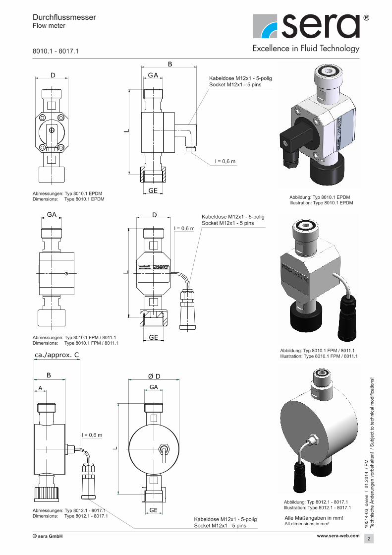
8010.1 - 8017.1
Alle Maßangaben in mm!All dimensions in mm!
A
B
ca./approx. C
L
GA
GE
Ø D
D G A
GE
L
B
L
G E
D GA
Abmessungen: Typ 8010.1 EPDMDimensions: Type 8010.1 EPDM
Abmessungen: Typ 8010.1 FPM / 8011.1Dimensions: Type 8010.1 FPM / 8011.1
Abbildung: Typ 8010.1 FPM / 8011.1Illustration: Type 8010.1 FPM / 8011.1
l = 0,6 m
Kabeldose M12x1 - 5-poligSocket M12x1 - 5 pins
l = 0,6 m
Abbildung: Typ 8010.1 EPDMIllustration: Type 8010.1 EPDM
Abbildung: Typ 8012.1 - 8017.1Illustration: Type 8012.1 - 8017.1
l = 0,6 m
Kabeldose M12x1 - 5-poligSocket M12x1 - 5 pins
Kabeldose M12x1 - 5-poligSocket M12x1 - 5 pins
Abmessungen: Typ 8012.1 - 8017.1Dimensions: Type 8012.1 - 8017.1

3
1051
4-03
de/
en /
01.
2014
/ P
M
Tech
nisc
he Ä
nder
unge
n vo
rbeh
alte
n! /
Sub
ject
to te
chni
cal m
odifi
catio
ns!
© sera GmbH www.sera-web.com
Abmessungen / Dimensions
Typ / type GA GE A B C D L
8010.1 G 3/4 G 3/4 16 74,5 --- 44 115
8011.1 G 3/4 G 3/4 16 45 --- 48 122
8012.1 G 3/4 G 3/4 18 45 90 73 131
8013.1 G 3/4 G 3/4 18 45 90 73 131
8014.1 G 3/4 G 3/4 18 45 90 73 131
8015.1
G 3/4 G 3/4 27 67 125 108 196
G 1 G1 27 67 125 108 200
G 1 1/4 G 1 1/4 27 67 125 108 194
8016.1G 1 G 1 27 67 125 108 200
G 1 1/4 G 1 1/4 27 67 125 108 194
8017.1 G 1 1/4 G 1 1/4 27 67 125 108 194
DurchflussmesserFlow meter
8010.1 - 8017.1
Technische Daten / Technical data
Typ type
Messbereich bei osz. Dosierpumpen
Measuring range of recipr. dosing pumps
Fördermenge pro Hub
Capacity / stroke
Max. BetriebdruckMax. operating
pressure
Max. Druckverlust 2)
Max. pressure loss SchutzartEnclosure
Vikosität 1)
Viscosity
l/h ml/Hub bar bar IP mPas
8010.1 3 - 14 0,3 - 2 8 0,5 65 1 - 200
8011.1 8 - 50 0,6 - 4 8 0,5 65 1 - 200
8012.1 6 - 30 0,7 - 4 10 0,5 65 1 - 1000
8013.1 10 - 80 2 - 10 10 0,5 65 1 - 1000
8014.1 40 - 180 4 - 22 10 0,5 65 1 - 1000
8015.1 70 - 350 8 - 40 10 0,5 65 1 - 1000
8016.1 80 - 600 15 - 100 10 0,5 65 1 - 1000
8017.1 120 - 1200 25 - 250 10 0,5 65 1 - 10001) Die max. Viskosität ist zusätzlich immer abhängig von der Ausführung des Pumpendosierkopfes. Additionally, the max. viscosity is always dependant on the design of the pump dosing head.2) Bei Medium Wasser, bei steigender Viskosität steigt der Durchfluss. When medium is water, in case of higher viscosity the flow rate will increase.

© sera GmbH 4
1051
4-03
de/
en /
01.
2014
/ P
M
Tech
nisc
he Ä
nder
unge
n vo
rbeh
alte
n! /
Sub
ject
to te
chni
cal m
odifi
catio
ns!
www.sera-web.com
Werkstoffe / Material
Typ type
Anschluss-gewindeconnection threadGE / GA
WerkstoffMaterial
Artikel-Nr,Article.no.
WellenShafts
OvalräderOval wheels
KörperBody
StutzenConnecting sleeves
DichtungenSeals
8010.1 G 3/4 Al2O3 ECTFE
ECTFE PP EPDM 37602336
ECTFE PP FPM 37602337
ECTFE PVC EPDM 37602338
ECTFE PVC FPM 37602339
ECTFE PVDF FPM 37602341
8011.1 G 3/4 Al2O3 ECTFE
ECTFE PP EPDM 37602342
ECTFE PP FPM 37602343
ECTFE PVC EPDM 37602344
ECTFE PVC FPM 37602345
ECTFE PVDF FPM 37602348
8012.1 G 3/4 Hastelloy 276 PVDF
PVC PVC EPDM 37602276
PVC PVC FPM 37602277
PVDF PVDF FPM 37602307
8013.1 G 3/4 Hastelloy 276 PVDF
PVC PVC EPDM 37602278
PVC PVC FPM 37602279
PVDF PVDF FPM 37602309
8014.1 G 3/4 Hastelloy 276 PVDF
PVC PVC EPDM 37602280
PVC PVC FPM 37602281
PVDF PVDF FPM 37602311
8015.1
G 3/4 Hastelloy 276 PVDF
PVC PVC EPDM 37602312
PVC PVC FPM 37602318
PVDF PVDF FPM 37602330
G 1 Hastelloy 276 PVDF
PVC PVC EPDM 37602313
PVC PVC FPM 37602319
PVDF PVDF FPM 37602331
G 1 1/4 Hastelloy 276 PVDF
PVC PVC EPDM 37602314
PVC PVC FPM 37602320
PVDF PVDF FPM 37602332
8016.1
G 1 Hastelloy 276 PVDF
PVC PVC EPDM 37602315
PVC PVC FPM 37602321
PVDF PVDF FPM 37602333
G 1 1/4 Hastelloy 276 PVDF
PVC PVC EPDM 37602316
PVC PVC FPM 37602322
PVDF PVDF FPM 37602334
8017.1 G 1 1/4 Hastelloy 276 PVDF
PVC PVC EPDM 37602317
PVC PVC FPM 37602323
PVDF PVDF FPM 37602335
DurchflussmesserFlow meter
8010.1 - 8017.1

5
1051
4-03
de/
en /
01.
2014
/ P
M
Tech
nisc
he Ä
nder
unge
n vo
rbeh
alte
n! /
Sub
ject
to te
chni
cal m
odifi
catio
ns!
© sera GmbH www.sera-web.com
DurchflussmesserFlow meter
8010.1 - 8017.1
Achtung !
Für eine zuverlässige Funktion ist ein Gegendruck von min. 1,5 bar erforderlich!
Allgemein
Der Anschluss eines sera-Durchflussmessers an ansteuerbaren Dosierpumpen der Typenreihen C/CS 204.1 und C/CS 409.2 ermöglicht eine erweiterte Förderstromanzeige mit Regelung des Förderstroms.
Funktion
Die Durchflussmesser der Baureihe 801x.1 dienen zur Messung und Überwachung des Förderstroms und sind ausschließlich in Ver-bindung mit ansteuerbaren Dosierpumpen der Typenreihen C/CS 204.1 und C/CS 409.2 einsetzbar. Die Medien müssen feststofffrei sein. Die Rotationsgeschwindigkeit der Ovalräder ist proportional zur Durchflussmenge. Die Rotation der Ovalräder wird mit einem Induktivsensor aufgenommen, deren Pulssignal von den ansteuer-baren Pumpen ausgewertet wird.
Installation
- Der Durchflussmesser ist senkrecht auf den Druckstutzen der Dosierpumpe aufzubauen und über den Eingang für Strömungsüberwachung mit der Pumpenelektronik zu verbinden (siehe Betriebsanleitungen von C/CS 204.1 und C/CS 409.2 Kapitel „Elektrische Anschlüsse“).
- Bei den selbstentlüftenden Dosierpumpen (CS-Baureihe) ist der Durchflussmesser auf dem Entlüftungsventil zu installieren.
- Der elektrische Anschluss erfolgt über den 5-poligen M12-Stecker an die Dosierpumpe der C204.1/ C409.2-Baureihe.
Symbol
START
STOP ENTER
Anschlussbuchse für dieDurchflussmessung
Achtung !
Lufteinschlüsse im Fördermedium können das Messergebnis verfälschen!
Achtung !
Bei veränderten Betriebsbedingungen ist eine Neu-Kalibrierung der Dosierpumpe erforderlich, um etwaige Messfehler auszu-schließen.
Caution !
A counterpressure of min. 1,5 bar is necessary for a reliable function!
General
The connection of a sera - flow meter to controllable dosing pumps of type series C/CS 204.1 and C/CS 409.2 enables an extended capacity indication with regulation of capacity.
Function
The flow meter of series 801x.1 are for the measuring and moni-toring of the capacity and can only be used in connection with the controllable dosing pumps of type series C/CS 204.1 and C/CS 409.2. The media must be free of solids. The rotation speed of the oval wheels is proportional to the rate of flow. The rotation of the oval wheels is started by an inductive sensor. The pulse signal of the oval wheels is evaluated by the controllable pumps.
Installation
- The flow meter has to be mounted vertically on the pressure joint of the dosing pump and has to be connected to the pump electronics via the input for flow monitoring (see operating instructions of C/CS 204.1 and C/CS 409.2 chapter “electrical connections”).
- The flow meter has to be mounted on the vent valve when using self-venting dosing pumps (CS-series).
- Electrical connection to the dosing pump of C204.1/C409.2 series by the 5-pole M12 plug.
Symbol
START
STOP ENTER
Connecting socket for the flow measuring
Caution !
Inclusions of air in the medium can falsify the measuring result!
Caution !
When the operating conditions change it is necessary to calibrate the dosing pump again in order to exclude any measuring errors.

© sera GmbH 6
1051
4-03
de/
en /
01.
2014
/ P
M
Tech
nisc
he Ä
nder
unge
n vo
rbeh
alte
n! /
Sub
ject
to te
chni
cal m
odifi
catio
ns!
www.sera-web.com