Elektromagnet- Kupplungen und Bremsenavsld.com.sg/wp-content/uploads/2017/03/Precima-OLK-OLG...4 Die...
20
Elektromagnet- Kupplungen und Bremsen Electromagnetic clutches and brakes Freins et embrayages électromagnétiques
Transcript of Elektromagnet- Kupplungen und Bremsenavsld.com.sg/wp-content/uploads/2017/03/Precima-OLK-OLG...4 Die...

Elektromagnet-
Kupplungen
und Bremsen
Electromagnetic
clutches and brakes
Freins et embrayages
électromagnétiques

2
InhaltsverzeichnisContents ∙ Table des matières
Das Unternehmen 3
Produktinformation 4/5
Technische Beschreibung 6/7
Abmessungen 8 - 11
Einbaubeispiele 12
Elektrische Versorgung 13
Schaltzeiten 14
Technische Auslegung 15 - 17
Typenschlüssel 18
Bestellbeispiele 19
Vertretungen 19
Our company 3
Product information 4/5
Technical specifications 6/7
Dimensions 8 - 11
Mounting example 12
Power supply 13
Switching times 14
Construction 15 - 17
Type code 18
Ordering example 19
Exemple de commande 19
La Firme 3
Information de produit 4/5
Descriptions technique 6/7
Dimensions 8 - 11
Exemples de montage 12
Alimentation électrique 13
Temps de commutation 14
Spécifications 15 - 17
Codification 18
Exemple de commande 19
Representatives 19

3
Das Unternehmen Our Company • La Firme
Die PRECIMA Magnettechnik GmbH wurde im Jahr 1981 gegründet und zählt heute zu einem innovativen, klassischen Unternehmen des Mittelstandes. Mit ca. 150 Mitarbeitern wird ein umfang-reiches Programm an elektrisch schalt-baren Kupplungen und Bremsen für sämtliche Bereiche aus Maschinen- und Apparatebau selbst entwickelt und herge-stellt. Das Standardprogramm umfasst je nach Anwendung einen Drehmomentbe-reich von 0,5 - 1500 Nm.
The PRECIMA Magnettechnik GmbH was founded in year 1981 and counts today to a classic innovative medium sized brake manufacturer. With a staff of more than 150 people we produce a wide range of electro- magnetic operated brakes and clutches for all kinds of applications in machine and drive industries. Our standard product range covers the performance range of braking torque between 0,5 - 1500 Nm.
La société PRECIMA Magnettechnik GmbH a été fondée en 1981 et est considérée aujourd‘hui comme entreprise classique et innovante de moyenne taille. Avec environ 1450 salariés, elle développe et construit une grande gamme d‘accouple ments à commutation électrique et de freins pour tous les domaines de construction de machines et appareils. La gamme standard comprend selon l‘application une plage de couple de 0,5 – 1500 Nm.
Mit moderner CNC-Fertigung und gut organisierten Montagelinien werden im Jahr über 500.000 Geräte hergestellt. Ein hoher Eigenfertigungsanteil erlaubt ein Maximum an Flexibilität und kurze Durchlaufzeiten. Unsere eigene Entwicklung ist spezialisiert, auf hohem technischen Niveau kundenorientierte Lösungen zu erstellen und umzusetzen.
Ein lebendiges Qualitäts- Management- System zertifiziert nach der DIN EN ISO 9001:2000 dokumentiert und sichert die hohen Qualitäts- und Fertigungsansprüche unserer Produkte.
With modern CNC machining and well organised assembling lines we produce more than 500.000 units per year. The high percentage of self manufactured parts allow us a maximum of flexibility and short reaction times. Our own highly qualified engineering and development is specialised to work out and realize customer suited solutions on a high technical standard.
A live quality-management-system certified according to the requirements of the DIN EN ISO 9001:2000 documents and secures our high standard of quality and manufacturing.
Grâce à la production CNC moderne et des lignes de montage parfaitement organisées, il est possible de fabriquer environ 500 000 appareils par an. Un pourcentage élevé de fabrication interne permet d‘atteindre une flexibilité maximale et des courtes durées d‘exécution. Notre service développement estspécialisé dans l’offre et la réalisation de solutions en fonction des besoins du client tout en garantissant un niveau technique élevé.
Le système de gestion qualité vivant, certifié selon la norme DIN EN ISO 9001:2000 permet de documenter un niveau de fabrication et de qualité élevé de nos produits.

4
Die in diesem Katalog vorgestellten Kupplungen und Bremsen arbeiten nach dem elektromagnetischen Prinzip.
Elektromagnet-Kupplung Typ OLK
Die Elektromagnet-Kupplungen Typ OLK sind flanschmontierte Kupplungen, siehe Seite 8.
Elektromagnet-Kupplung Typ OLG
Die Elektromagnet-Kupplungen Typ OLG sind wellenmontierte Kupplungen. Diese werden eingesetzt wenn keine geeig-neten Montageflächen zur Verfügung stehen, siehe Seite 9.
Elektromagnet-Bremse Typ OLB und
Elektromagnet-Bremse Typ OMB
Beide Elektromagnet- Bremsen sind flanschmontierte Bremsen, siehe Seite 10 und 11.
Vorteile der Elektromagnet Bremsen
Typ OLB:
Durch den aufgesetzten Polschuh kön-nen diese Bremsen bei hoher Schalthäu-figkeit und Reibarbeit eingesetzt werden, siehe Seite 11.
ProduktinformationProduct information . Information de produit
This catalogue describes clutches and brakes which working principal is electro magnetic.
Electro magnetic clutch Type OLK
The electro magnetic clutches type OLK are flange mounted clutches, shown on page 8.
Electro magnetic clutch Type OLG
The electro magnetic clutches type OLG are shaft mounted clutches, they are used for applications without suitable mounting surface, shown on page 9.
Electro magnetic brake Type OLB and
Electro magnetic brake Type OMB
Both electro magnetic brakes are flange mounted brakes, shown on page 10 and 11.
Advantage of the electro magnetic
brake type OLB:
Due to the attached pole shoe, these brakes can be used for applications with high switching frequency and friction work, shown on page 11.
Les embrayages et freins présentés dans ce catalogue travaillent selon le principe électromagnétique.
Embrayage électromagnétique type
OLK
Les embrayages électromagnétiques type OLK sont des embrayages montés sur flasques, cf. page 9. Embrayage électromagnétique type
OLG
Les embrayages électromagnétiques type OLG sont des embrayages montés sur arbres. Ils sont utilisés lorsqu‘aucune surface de montage appropriée n‘est disponible, cf. page 9.
Frein électromagnétique type OLB et
Frein électromagnétique type OMB
Les deux freins électromagnétiques sont montés sur flasques, cf. page 10 et 11.
Les avantages des freins
électromagnétiques type OLB:
Grâce à la pièce polaire superposée, ces freins peuvent être utilisés avec une fréquence de commutation et un travail de friction élevés, cf. page 11.

5
• Kupplungsmomente und Bremsmo-mente von 7,5 Nm bis 480 Nm
• Standardspannung 24 VDC; Sonderspannungen möglich
• Bremsen und Kupplungen für 100% ED ausgelegt
• Wärmeklasse B jedoch bis max. 145 °C ausgelegt
• Asbestfreie Reibbeläge: Durch die spezielle Bearbeitung der Beläge werden die Nennmomente nach einem kurzen Einlaufprozess erreicht
• Die Reibflächen sind öl- und fettfrei zu halten (nur abgedichtete Lager einsetzen)
• Festlager brems- bzw. kupplungsseitig erforderlich
• Verdrehspielfreie Drehmomentenüber-tragung
• Die vorgespannte Ringfeder des An-kerteils gewährleistet im spannungs-freien Zustand ein restmomentfreies Lüften.
• Kurze Schaltzeiten
• CE- Kennzeichnung für Niederspan-nungsrichtlinie
• Fertigung und Prüfung nach VDE 0580
ProduktinformationProduct information . Information de produit
• Clutch and brake torque range from 7,5 Nm to 480 Nm
• Standard voltage 24 V DC Special voltages are possible
• Brakes and clutches are designed for 100 % ED
• Nominal Temperature class B tested to max.145 ° C
• Asbestos free liners: Due to a special surface treatment of the liners the nominal torque is achieved after a short running-in procedure.
• Since the lining surfaces must be kept free of grease or oil, only sealed bearings should be used.
• Fixed bearing on brake- or clutch side are essential
• Backlash free torque transmission
• The pre-strained spring of the armature secures a stress free condition when the clutch is currentless.
• Fast reaction time
• CE label for low voltage directive
• Manufacturing and testing according to VDE 0589
• Couples d‘embrayage et couples de freinage de 7,5 Nm à 480 Nm
• Tension standard 24 VCC; Tensions spéciales possibles
• Freins et embrayages conçus pour 100% de durée de mise en circuit
• Classe de chaleur B mais conçue cependant pour jusqu‘à 145 °C max.
• Garnitures de friction sans amiante: L‘usinage spécial des garnitures permet d‘atteindre les couples nominaux après un bref processus d‘introduction
• Veillez à ce que les surfaces de friction demeurent sans huile et sans graisse (n‘utiliser que des paliers étanches)
• Palier fixe nécessaire côté frein et embrayage
• Transmission du moment de couple sans jeu torsionnel
• Les anneaux-ressorts prétendus de la partie induit assurent à l‘état hors tension un desserrage sans couple résiduel.
• Temps de commutation courts
• Marquage CE pour directive basse tension
• Fabrication et contrôle selon VDE 0580
6
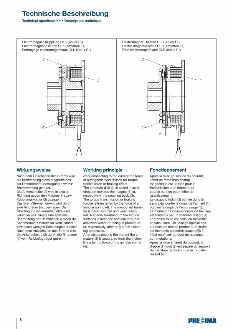
Wirkungsweise
Nach dem Einschalten des Stroms wird die Kraftwirkung eines Magnetfeldes zur Drehmomentübertragung bzw. zur Bremswirkung genutzt.Die Ankerscheibe (2) wird in axialer Richtung gegen den Magnet- (1) bzw. Kupplungskörper (3) gezogen.Das Dreh-/Bremsmoment wird durch eine Ringfeder (4) übertragen. Die Übertragung ist verdrehspielfrei und verschleißlos. Durch eine spezielle Bearbeitung der Reibflächen werden die Kennmomente bereits im Neuzustand bzw. nach wenigen Schaltungen erreicht.Nach dem Ausschalten des Stroms wird die Ankerscheibe (2) durch die Ringfeder (4) vom Reibbelagträger getrennt.
Technische BeschreibungTechnical specification • Description technique
Working principle
After connecting to the current the force of a magnetic field is used for torque transmission or braking effect.The armature disk (2) is pulled in axial direction towards the magnet (1) or, respectively, the coupling body (3).The torque transmission or braking torque is transferred by the force of an annular spring (4). The mentioned trans-fer is back lash free and wear resist-ant. A special treatment of the friction surfaces insures the nominal torque is achieved without running in procedure or, respectively, after only a few switch-ing processes.After disconnecting the current the ar-mature (2) is separated from the friction lining by the force of the annular spring (4).
Fonctionnement
Après la mise en service du courant,l‘effet de force d‘un champmagnétique est utilisée pour latransmission d‘un moment decouple ou bien pour l‘effet deralentissement.Le disque d‘induit (2) est tiré dans le sens axial contre le corps de l‘aimant (1) ou bien le corps de l‘embrayage (3).Le moment de couple/couple de freinage est transmis par un rondelle-ressort (4). La transmission est sans jeu torsionnel et sans usure. Un usinage spécial des surfaces de friction permet d‘atteindre les moments caractéristiques déjà à l‘état neuf, voir au bout de quelques commutations.Après la mise à l‘arrêt du courant, le disque d‘induit (2) est séparé du support de garniture de friction par le rondelle-ressort (4).
Elektromagnet-Kupplung OLK (Anker F1)Electro magnetic clutch OLK (armature F1)Embrayage électromagnétique OLK (induit F1)
Elektromagnet-Bremse OLB (Anker F1)Electro magnetic brake OLB (armature F1)Frein électromagnétique OLB (induit F1)
7
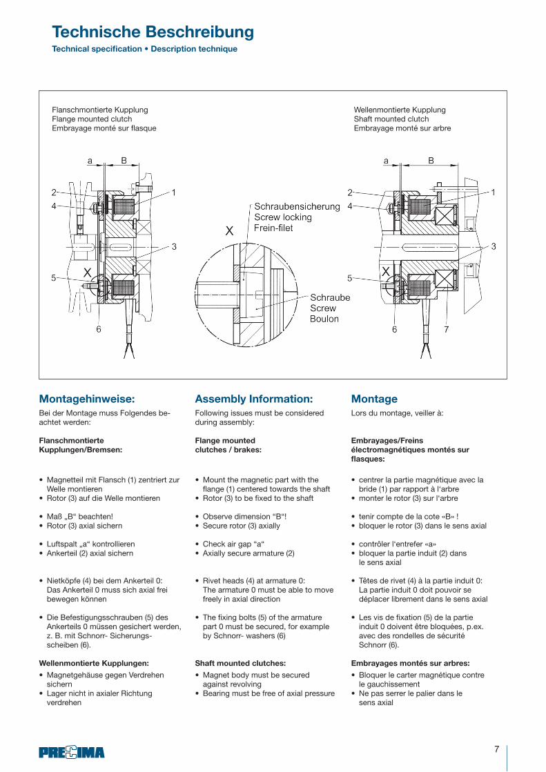
Montagehinweise:
Bei der Montage muss Folgendes be-achtet werden:
Flanschmontierte
Kupplungen/Bremsen:
• Magnetteil mit Flansch (1) zentriert zur Welle montieren
• Rotor (3) auf die Welle montieren
• Maß „B“ beachten!• Rotor (3) axial sichern
• Luftspalt „a“ kontrollieren• Ankerteil (2) axial sichern
• Nietköpfe (4) bei dem Ankerteil 0: Das Ankerteil 0 muss sich axial frei bewegen können
• Die Befestigungsschrauben (5) des Ankerteils 0 müssen gesichert werden, z. B. mit Schnorr- Sicherungs- scheiben (6).
Wellenmontierte Kupplungen:
• Magnetgehäuse gegen Verdrehen sichern
• Lager nicht in axialer Richtung verdrehen
Assembly Information:
Following issues must be considered during assembly:
Flange mounted
clutches / brakes:
• Mount the magnetic part with the flange (1) centered towards the shaft
• Rotor (3) to be fixed to the shaft
• Observe dimension “B“!• Secure rotor (3) axially
• Check air gap “a“• Axially secure armature (2)
• Rivet heads (4) at armature 0: The armature 0 must be able to move freely in axial direction
• The fixing bolts (5) of the armature part 0 must be secured, for example by Schnorr- washers (6)
Shaft mounted clutches:
• Magnet body must be secured against revolving
• Bearing must be free of axial pressure
Montage
Lors du montage, veiller à:
Embrayages/Freins
électromagnétiques montés sur
flasques:
• centrer la partie magnétique avec la bride (1) par rapport à l‘arbre
• monter le rotor (3) sur l‘arbre
• tenir compte de la cote «B» !• bloquer le rotor (3) dans le sens axial
• contrôler l‘entrefer «a» • bloquer la partie induit (2) dans
le sens axial
• Têtes de rivet (4) à la partie induit 0: La partie induit 0 doit pouvoir se déplacer librement dans le sens axial
• Les vis de fixation (5) de la partie induit 0 doivent être bloquées, p.ex. avec des rondelles de sécurité Schnorr (6).
Embrayages montés sur arbres:
• Bloquer le carter magnétique contre le gauchissement
• Ne pas serrer le palier dans le sens axial
Flanschmontierte KupplungFlange mounted clutchEmbrayage monté sur flasque
Wellenmontierte KupplungShaft mounted clutchEmbrayage monté sur arbre
Technische BeschreibungTechnical specification • Description technique

8
AbmessungenElektromagnet-Kupplung
OLK
DimensionsElectromagnetic clutch
OLK
DimensionsEmbrayage électromagnétique
OLK
Größe
Size
Taille
MK
(Nm)
P 20
°C
(Watt)
a A h9 A1 A2 BC
±0,1
d1
H7
max.
d2
H7
max.
d3
H7D
E
H8E2 F G H J K K2 K3
65 7,5 15 0,2 80 68 59,5 23,5 72 17 17 15 4,5 35 35 3,5 23 3 7 28 43 51,7
80 15 20 0,2 100 87 79 26 90 22 22 17 5,5 42 42 4,3 28,5 4 8 31 51 56,2
100 30 28 0,2 125 108 95 29,5 112 30 30 25 6,5 52 52 5 40 5 9 36 61 65,7
125 60 35 0,3 150 135 119,5 33 137 40 40 30 6,5 62 62 5,5 45 6 9 40,5 70,5 75,3
160 120 50 0,3 190 170 155 37,5 175 45 45 - 9 80 79,5 6 62 5 10 47 85 -
200 240 68 0,5 230 215 192 44 215 60 60 - 9 100 99,5 7 77 6 12 55,9 103,9 -
Standard-Passfedernut nach DIN 6885/1 - JS9
Nut für Sicherungsring nach DIN 472
Standard-keyway in accordance with DIN 6885/1 - JS9
Groove for circlip i.a.w. DIN 472
Rainure de clavette parallèle standard selon DIN 6885/1-JS9
Rainure pour circlip selon DIN 472
Maße in mmBestellbeispiel siehe Seite 19
Dimensions in mmOrder example see page 19
Dimensions en mmExemple de commande voir page 19
Größe
Size
Taille
l1 l2 l3 LM
±0,1N O P R R1 R2 S T U U1 V W X Y z1 z2
65 21,5 15 20,7 5,5 46 3,1 6,5 2 4,3 19,3 28 8 18,5 30 42 37 M3 10 25 0,03 0,15
80 23,5 20 22,2 7 60 4,1 8,5 2,5 4,8 24,8 30 8,8 19 39 50 42 M4 12 30 0,03 0,2
100 26,5 25 26,7 9 76 5,1 10 3 6,3 31,3 36 11 23 45 65 55 M5 15 40 0,03 0,2
125 29,5 30 30,8 10 95 6,1 12 3,5 7,2 37,2 42 13 29 51,5 75 65 M6 20 48 0,03 0,2
160 34 38 - 14 120 8,1 15 4,5 9,2 47,2 - 16,2 - 70 - - - - - 0,05 0,3
200 40 48 - 16 158 10,1 18 5 11,4 59,4 - 20,4 - 83 - - - - - 0,05 0,3
Anker LArmature L
Induit L
Anker F1Armature F1
Induit F1
Anker 0Armature 0
Induit 0
9
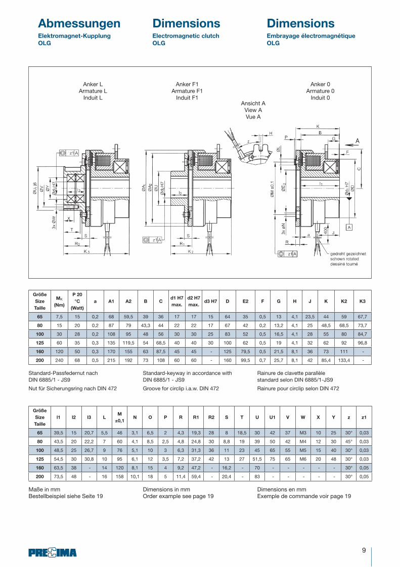
Abmessungen Dimensions DimensionsEmbrayage électromagnétique
OLG
Electromagnetic clutch
OLG
Elektromagnet-Kupplung
OLG
Standard-Passfedernut nach DIN 6885/1 - JS9
Nut für Sicherungsring nach DIN 472
Standard-keyway in accordance with DIN 6885/1 - JS9
Groove for circlip i.a.w. DIN 472
Rainure de clavette parallèle standard selon DIN 6885/1-JS9
Rainure pour circlip selon DIN 472
Größe
Size
Taille
MK
(Nm)
P 20
°C
(Watt)
a A1 A2 B Cd1 H7
max.
d2 H7
max.d3 H7 D E2 F G H J K K2 K3
65 7,5 15 0,2 68 59,5 39 36 17 17 15 64 35 0,5 13 4,1 23,5 44 59 67,7
80 15 20 0,2 87 79 43,3 44 22 22 17 67 42 0,2 13,2 4,1 25 48,5 68,5 73,7
100 30 28 0,2 108 95 48 56 30 30 25 83 52 0,5 16,5 4,1 28 55 80 84,7
125 60 35 0,3 135 119,5 54 68,5 40 40 30 100 62 0,5 19 4,1 32 62 92 96,8
160 120 50 0,3 170 155 63 87,5 45 45 - 125 79,5 0,5 21,5 8,1 36 73 111 -
200 240 68 0,5 215 192 73 108 60 60 - 160 99,5 0,7 25,7 8,1 42 85,4 133,4 -
Maße in mmBestellbeispiel siehe Seite 19
Dimensions in mmOrder example see page 19
Dimensions en mmExemple de commande voir page 19
Größe
Size
Taille
l1 l2 l3 LM
±0,1N O P R R1 R2 S T U U1 V W X Y z z1
65 39,5 15 20,7 5,5 46 3,1 6,5 2 4,3 19,3 28 8 18,5 30 42 37 M3 10 25 30° 0,03
80 43,5 20 22,2 7 60 4,1 8,5 2,5 4,8 24,8 30 8,8 19 39 50 42 M4 12 30 45° 0,03
100 48,5 25 26,7 9 76 5,1 10 3 6,3 31,3 36 11 23 45 65 55 M5 15 40 30° 0,03
125 54,5 30 30,8 10 95 6,1 12 3,5 7,2 37,2 42 13 27 51,5 75 65 M6 20 48 30° 0,03
160 63,5 38 - 14 120 8,1 15 4 9,2 47,2 - 16,2 - 70 - - - - - 30° 0,05
200 73,5 48 - 16 158 10,1 18 5 11,4 59,4 - 20,4 - 83 - - - - - 30° 0,05
Anker LArmature L
Induit L
Anker F1Armature F1
Induit F1
Anker 0Armature 0
Induit 0Ansicht A
View AVue A

10
AbmessungenElektromagnet-Bremse
OLB
DimensionsElectromagnetic brake
OLB
DimensionsFrein électromagnétique
OLB
Größe
Size
Taille
MK
(Nm)
P 20
°C
(Watt)
a A A1 A2 B Cd H7
max.D E H8 E2 F H J K K2 K3
65 7,5 15 0,2 80 68 59,5 23,5 72 17 4,5 35 35 3,5 3 7 28 43 31,7
80 15 20 0,2 100 87 79 26 90 22 5,5 42 42 4,3 4 8 31 51 35
100 30 28 0,2 125 108 95 29,5 112 30 6,5 52 52 5 5 9 36 61 40,7
125 60 35 0,3 150 135 119,5 33 137 40 6,5 62 62 5,5 6 9 40,5 70,5 46,3
160 120 50 0,3 190 170 155 37,5 175 45 9 80 79,5 6 5 10 47 85 54
200 240 68 0,5 230 215 192 44 215 60 9 100 99,5 7 6 12 55,9 103,9 64,9
Standard-Passfedernut nach DIN 6885/1 - JS9
Nut für Sicherungsring nach DIN 472
Standard-keyway in accordance with DIN 6885/1 - JS9
Groove for circlip i.a.w. DIN 472
Rainure de clavette parallèle standard selon DIN 6885/1-JS9
Rainure pour circlip selon DIN 472
Größe
Size
Taille
l1 LM
±0,1N P R R1 S U z1
65 15 5,5 46 3,1 2 4,3 19,3 8 30 0,16
80 20 7 60 4,1 2,5 4,8 24,8 8,8 39 0,16
100 25 9 76 5,1 3 6,3 31,3 11 45 0,16
125 30 10 95 6,1 3,5 7,2 37,2 13 51,5 0,2
160 38 14 120 8,1 4 9,2 47,2 16,2 70 0,2
200 48 16 158 10,1 5 11,4 59,4 20,4 83 0,2
Maße in mmBestellbeispiel siehe Seite 19
Dimensions in mmOrder example see page 19
Dimensions en mmExemple de commande voir page 19
Anker F2Armature F2
Induit F2
Anker F1Armature F1
Induit F1
Anker 0Armature 0
Induit 0

11
Standard-Passfedernut nach DIN 6885/1 - JS9
Nut für Sicherungsring nach DIN 472
Standard-keyway in accordance with DIN 6885/1 - JS9
Groove for circlip i.a.w. DIN 472
Rainure de clavette parallèle standard selon DIN 6885/1-JS9
Rainure pour circlip selon DIN 472
Größe
Size
Taille
MK
(Nm)
P 20
°C
(Watt)
a A A1 A2 B Cd H7
max.D E H8 E2 F H J K K2 K3
65 7,5 11,5 0,2 80 63 59,5 18 72 17 4,5 35 35 3,5 3 7 22,5 37,5 26,2
80 15 16 0,2 100 80 79 19,7 90 22 5,5 42 42 4,3 4 8 24,7 44,7 28,7
100 30 21 0,2 125 100 95 22 112 30 6,5 52 52 5 5 9 28,5 53,5 33,2
125 60 28 0,3 150 135 119,5 24,7 137 40 6,5 62 62 5,5 6 9 32,2 62,2 38
Maße in mmBestellbeispiel siehe Seite 19
Dimensions in mmOrder example see page 19
Dimensions en mmExemple de commande voir page 19
Größe
Size
Taille
l1 LM
±0,1N P R R1 S U z1
65 15 5,5 46 3,1 2 4,3 19,3 8 30 0,16
80 20 7 60 4,1 2,5 4,8 24,8 8,8 39 0,16
100 25 9 76 5,1 3 6,3 31,3 11 45 0,16
125 30 10 95 6,1 3,5 7,2 37,2 13 51,5 0,2
Anker F2Armature F2
Induit F2
Anker F1Armature F1
Induit F1
Anker 0Armature 0
Induit 0
AbmessungenElektromagnet-Bremse
OLB
DimensionsElectromagnetic brake
OLB
DimensionsFrein électromagnétique
OLBOMB OMB OMB

12
EinbaubeispieleMounting examples · Exemples de montage
Flanschmontierte Kupplung OLKFlange mounted clutch OLK
Embrayage monté sur flasque OLK
Wellenmontierte Kupplung OLGShaft mounted clutch OLG
Embrayage monté sur arbre OLG
Flanschmontierte Bremse OLBFlange mounted brake OLBFrein monté sur flasque OLB
Flanschmontierte Bremse OMBFlange mounted brake OMBFrein monté sur flasque OMB
13
Elektrische VersorgungPower supply · Alimentation électrique
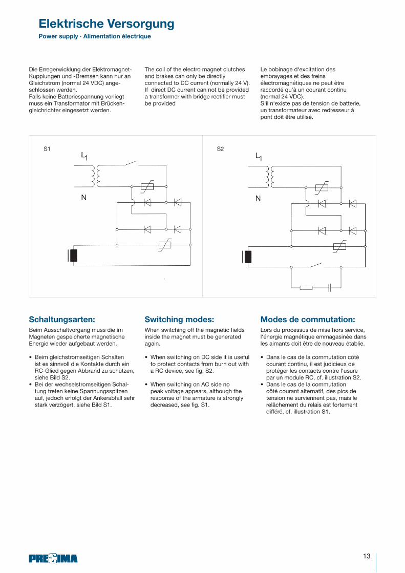
Die Erregerwicklung der Elektromagnet-Kupplungen und -Bremsen kann nur an Gleichstrom (normal 24 VDC) ange-schlossen werden.Falls keine Batteriespannung vorliegt muss ein Transformator mit Brücken-gleichrichter eingesetzt werden.
Switching modes:
When switching off the magnetic fields inside the magnet must be generated again.
• When switching on DC side it is useful to protect contacts from burn out with a RC device, see fig. S2.
• When switching on AC side no peak voltage appears, although the response of the armature is strongly decreased, see fig. S1.
Schaltungsarten:
Beim Ausschaltvorgang muss die im Magneten gespeicherte magnetische Energie wieder aufgebaut werden.
• Beim gleichstromseitigen Schalten ist es sinnvoll die Kontakte durch ein RC-Glied gegen Abbrand zu schützen, siehe Bild S2.
• Bei der wechselstromseitigen Schal-tung treten keine Spannungsspitzen auf, jedoch erfolgt der Ankerabfall sehr stark verzögert, siehe Bild S1.
Modes de commutation:
Lors du processus de mise hors service, l‘énergie magnétique emmagasinée dans les aimants doit être de nouveau établie.
• Dans le cas de la commutation côté courant continu, il est judicieux de protéger les contacts contre l‘usure par un module RC, cf. illustration S2.
• Dans le cas de la commutation côté courant alternatif, des pics de tension ne surviennent pas, mais le relâchement du relais est fortement différé, cf. illustration S1.
The coil of the electro magnet clutches and brakes can only be directly connected to DC current (normally 24 V).If direct DC current can not be provided a transformer with bridge rectifier must be provided
Le bobinage d‘excitation des embrayages et des freins électromagnétiques ne peut être raccordé qu‘à un courant continu (normal 24 VDC).S‘il n‘existe pas de tension de batterie, un transformateur avec redresseur à pont doit être utilisé.
S1 S2

14
Schaltzeiten & SchaltzyklenSwitching times & switching cycles • Temps de commutation & cycles de commutation
t2 = Trennzeit (Zeit vom Abschalten des Stromes bis zum Erreichen von 0,1 . MK) Release time (time from switching power off until reaching 0,1 . MK) Temps de coupure (temps depuis la mise hors service du courant jusqu‘à l‘atteinte de 0,1 . MK)
t11 = Ansprechverzug (Zeit vom Einschalten des Stromes bis zum Anstieg des Drehmomentes) Response delay (time from switching power on until achiving torque) Retard de réponse (temps depuis la mise en service du courant jusqu‘à la montée du couple)
t1 = Verknüpfungszeit Engaging time Temps de liaison
Größe
Size
Taille
nmax
(min-1)
J [10-4 kgm²]
WRmax
(J)
WRN
(J)
PR
(J/s)
t1 *
(ms)
t11
(ms)
t2
ms)Rotor OLK
Rotor OLK
Rotor OLK
Rotor OLG
Rotor OLG
Rotor OLG
Anker 0
Armature 0
Induit 0
Anker F1
Armature F1
Induit F1
Anker L
Armature L
Induit L
65 8000 1 1,2 0,39 0,55 0,85 1,8 x 10³ 8 x 10⁷ 30 43 13 12
80 6000 2,55 2,85 1,05 1,5 2,7 3 x 10³ 12 x 107 35 77 22 20
100 5000 7,5 8,5 4,5 6 8,5 5,5 x 10³ 24 x 107 60 100 26 30
125 4000 21 23 12 17,5 23 14 x 103 38 x 107 90 125 40 65
160 3000 62 65 4,5 5,5 7,8 20 x 103 58 x 107 120 175 50 90
200 3000 205 209 120 180 230 50 x 103 90 x 107 190 220 70 120
Elektromagnetkupplungen OLK und OLG / Electro magnetic clutches OLK and OLG /
Embrayages électromagnétiques OLK et OLG
Elektromagnetbremsen OLB und OMB / Electro magnetic brakes OLB and OMB /
Freins électromagnétiques OLB et OMB
Größe
Size
Taille
nmax
(min-1)
J [10-4 kgm²] OLB OMB
t1 *
(ms)
t11
(ms)
t2
ms)Anker 0
Armature 0
Induit 0
Anker F1
Armature F1
Induit F1
WRmax
(J) WRN
(J) PR (J/s) W
Rmax (J) W
RN (J) P
R (J/s)
65 8000 0,39 0,55 1,8 x 10³ 8 x 10⁷ 30 1,5 x 10³ 8 x 10⁷ 25 40 10 12
80 6000 1,05 1,5 3 x 10³ 12 x 107 35 2,5 x 10³ 12 x 107 30 45 18 16
100 5000 4,5 6 5,5 x 10³ 24 x 107 60 4,5 x 10³ 24 x 107 50 65 22 30
125 4000 12 17,5 14 x 103 38 x 107 90 11,5 x 10³ 38 x 107 75 85 36 55
160 3000 4,5 5,5 20 x 103 58 x 107 120 - - - 110 40 90
200 3000 120 180 50 x 103 90 x 107 190 - - - 125 45 120
* Mittelwerte für gleichstromseitiges Schalten bei Nennluftspalt
* Average value switching on DC side * Valeurs moyennes pour commutation côté courant continu à l‘entrefer nominal

15
Verwendete Kurzzeichen
und Definitionen
Ma = Beschleunigungs-/ Verzögerungsmoment (Nm)
Merf = Erforderliches Drehmoment (Nm)
MK = Kennmoment Bremse oder Kupplung (Nm)
ML = Lastmoment (Nm)
n = Drehzahl der Bremse oder Kupplung (min-1)
K = Sicherheitsfaktor K � 2
P = Antriebsleistung (kW)
JE = Eigenträgheitsmoment (kgm²)
Jzus = Massenträgheitsmoment reduziert auf die Brems- bzw. Kupplungswelle (kgm²)
t1 = Verknüpfungszeit [t1 = t11 + t12] (ms)
t11 = Ansprechverzugszeit (ms)
t2 = Trennzeit (ms)
t3 = Rutschzeit (ms)
PR = Reibleistung (J/s)
WR = Reibarbeit (J)
S = Schaltungen pro Sekunde (s-1)
Technische AuslegungConstruction ∙ Spécifications
List of abbreviations and
explanation
Ma = Acceleration or deceleration torque (Nm)
Merf = Required torque (Nm)
MK = Load torque (Nm)
ML = Load factor (Nm)
n = Speed of clutch/brake (min-1)
K = Safety factor K � 2
P = Input power (kW)
JE = Proper mass moment of inertia (kgm²)
Jzus = Mass moment of inertia reduced to braking or coupling shaft, respectively (kgm²)
t1 = Engaging time [t1 = t11 + t12] (ms)
t11 = Response delay time (ms)
t2 = Release time (ms)
t3 = Reaction delay (ms)
PR = Friction performance (J/s)
WR = Friction (J)
S = Switching per second (s-1)
Définition des sigles
utilisés
Ma = Couple d’accélération/de décélération
Merf = Moment de couple nécessaire
MK = Couple caractéristique frein ou embrayage
ML = Couple résistant (Nm)
n = Vitesse de rotation du frein ou de l’embrayage (min-1)
K = Facteur de sécurité K � 2
P = Puissance d’entraînement (kW)
JE = Moment d’inertie de sa propre masse (kgm²)
Jzus = Moment d’inertie réduit à l’arbre de frein ou d’embrayage (kgm²)
t1 = Temps de liaison [t1 = t11 + t12] (ms)
t11 = Retard de réponse (ms)
t2 = Temps de coupure (ms)
t3 = Temps de glissement (ms)
PR = Puissance de friction (J/s)
WR = Travail de friction (J)
S = Nombre de cycles à la seconde (s-1)
16
Ma = 1,046 . 102 . Jzus .n
(Nm) K � 2 Merf = Ma . K � MK (Nm)t3 – t11
Technische AuslegungConstruction ∙ Spécifications
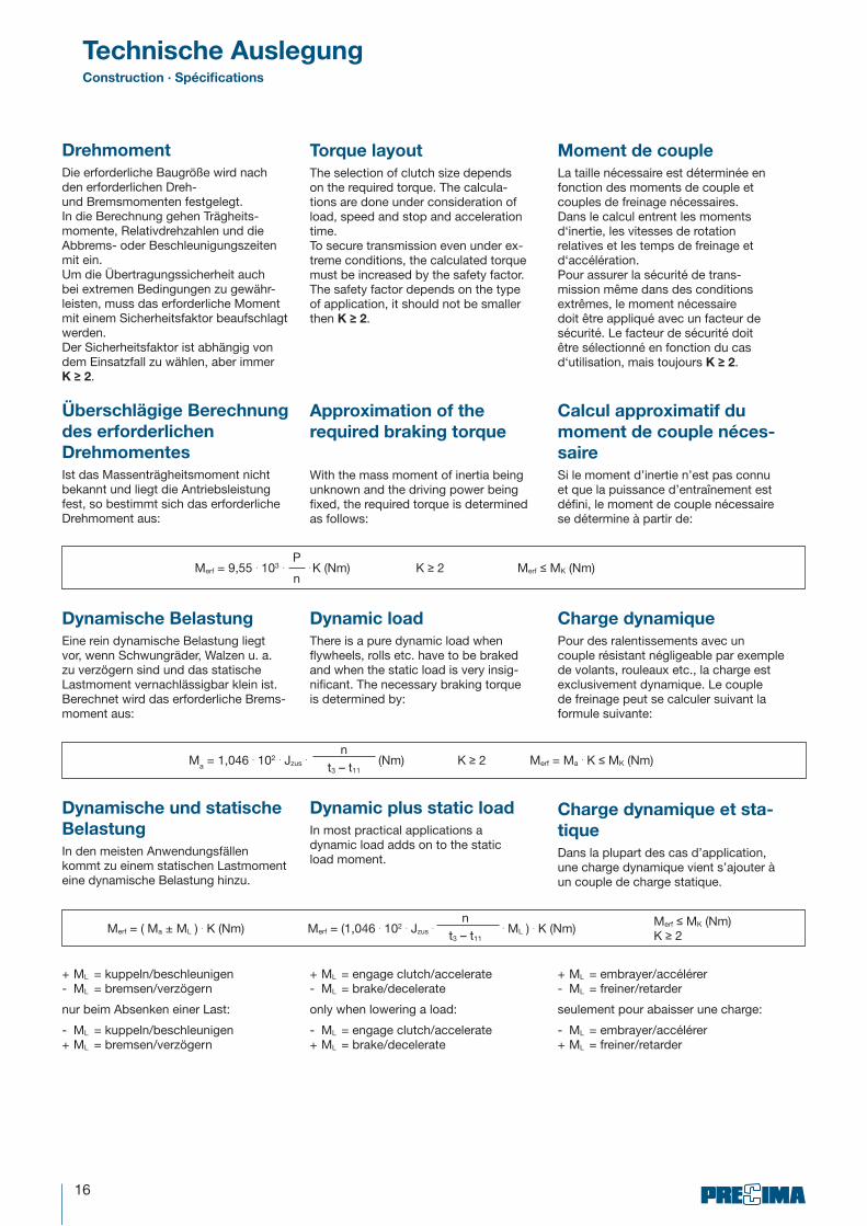
Drehmoment
Die erforderliche Baugröße wird nach den erforderlichen Dreh-und Bremsmomenten festgelegt.In die Berechnung gehen Trägheits-momente, Relativdrehzahlen und die Abbrems- oder Beschleunigungs zeiten mit ein.Um die Übertragungssicherheit auch bei extremen Bedingungen zu gewähr-leisten, muss das erforder liche Moment mit einem Sicherheits faktor beaufschlagt werden.Der Sicherheitsfaktor ist abhängig von dem Einsatzfall zu wählen, aber immer K � 2.
Überschlägige Berechnung
des erforderlichen
Drehmomentes
Ist das Massenträgheitsmoment nicht bekannt und liegt die Antriebsleistung fest, so bestimmt sich das erforderliche Drehmoment aus:
Merf = 9,55 . 103 .P
. K (Nm) K � 2 Merf � MK (Nm)n
Merf = ( Ma ± ML ) . K (Nm) Merf = (1,046 . 102 . Jzus .n
. ML ) . K (Nm)Merf � MK (Nm)K � 2t3 – t11
Torque layout
The selection of clutch size depends on the required torque. The calcula-tions are done under consideration of load, speed and stop and acceleration time.To secure transmission even under ex-treme conditions, the calculated torque must be increased by the safety factor. The safety factor depends on the type of application, it should not be smaller then K � 2.
Approximation of the
required braking torque
With the mass moment of inertia being unknown and the driving power being fixed, the required torque is determined as follows:
+ ML = embrayer/accélérer - ML = freiner/retarder
seulement pour abaisser une charge:
- ML = embrayer/accélérer + ML = freiner/retarder
+ ML = kuppeln/beschleunigen - ML = bremsen/verzögern
nur beim Absenken einer Last:
- ML = kuppeln/beschleunigen + ML = bremsen/verzögern
+ ML = engage clutch/accelerate - ML = brake/decelerate
only when lowering a load:
- ML = engage clutch/accelerate + ML = brake/decelerate
Moment de couple
La taille nécessaire est déterminée en fonction des moments de couple et couples de freinage nécessaires.Dans le calcul entrent les moments d‘inertie, les vitesses de rotation relatives et les temps de freinage et d‘accélération.Pour assurer la sécurité de trans-mission même dans des conditions extrêmes, le moment nécessaire doit être appliqué avec un facteur de sécurité. Le facteur de sécurité doit être sélectionné en fonction du cas d‘utilisation, mais toujours K � 2.
Calcul approximatif du
moment de couple néces-
saire
Si le moment d’inertie n’est pas connu et que la puissance d’entraînement est défini, le moment de couple nécessaire se détermine à partir de:
Dynamische Belastung
Eine rein dynamische Belastung liegt vor, wenn Schwungräder, Walzen u. a. zu verzögern sind und das statische Lastmoment vernachlässigbar klein ist. Berechnet wird das erforderliche Brems-moment aus:
Dynamic load
There is a pure dynamic load when flywheels, rolls etc. have to be braked and when the static load is very insig-nificant. The necessary braking torque is determined by:
Charge dynamique
Pour des ralentissements avec un couple résistant négligeable par exemple de volants, rouleaux etc., la charge est exclusivement dynamique. Le couple de freinage peut se calculer suivant la formule suivante:
Dynamische und statische
Belastung
In den meisten Anwendungsfällen kommt zu einem statischen Lastmoment eine dynamische Belastung hinzu.
Dynamic plus static load
In most practical applications a dynamic load adds on to the static load moment.
Charge dynamique et sta-
tique
Dans la plupart des cas d’application, une charge dynamique vient s’ajouter à un couple de charge statique.

17
Technische AuslegungConstruction ∙ Spécifications
t3 = 1,046 . 102 . Jzus . �n
+ t11 (ms)MK ± ML
Beschleunigungs- und
Verzögerungszeit
Ist die Zeit vom Beginn des Drehmo-mentanstieges bis zum Erreichen des Synchronisierungsmomentes.
- ML = kuppeln/beschleunigen + ML = bremsen/verzögern
nur beim Absenken einer Last:
+ ML = kuppeln/beschleunigen - ML = bremsen/verzögern
Acceleration and decele-
ration time:
Is the time from the beginning of the torque moment increase until the synchronization moment is reached.
- ML = engage clutch/accelerate + ML = brake/decelerate
only when lowering a load:
+ ML = engage clutch/accelerate - ML = brake/decelerate
Temps d‘accélération et de
retard
C’est le temps du début de la montée du moment de couple jusqu’à l’atteinte du couple de synchronisation.
- ML = embrayer/accélérer + ML = freiner/retarder
seulement pour abaisser une charge:
+ ML = embrayer/accélérer
- ML = freiner/retarder
Wärmebelastung
Beim Abbremsen oder Beschleunigen einer Last und der auf der Welle redu-zierten Massenträgheitsmomente (Jzus) wird eine Reibarbeit je Schaltspiel ver-richtet, die eine Erwärmung hervorruft.
Die Reibarbeit je Schaltspiel darf höch-stens so groß sein wie der zulässige Wert
WR < WRmax (J)
Thermal stress
During braking or torque transmission of the load plus the mass moment of inertia reduced to braking or coupling shaft (Jzus), a friction work for each switching is producing heat.
The friction work of each operation should not exceed the admissible value.
WR < WRmax (J)
Charge thermique
Lors du freinage ou de l‘accélération d‘une charge et des moments d‘inertie de masse (Jzus) sur l‘arbre, un travail de friction qui engendre un échauffement est effectué par jeu de commutation.
Le travail de friction par jeu de com-mutation doit au maximum être aussi grand que la valeur admissible
WR < WRmax (J)
WR =Jzus . n²
.MK
(J)182,5 MK ± ML
Die Reibleistung darf höchstens so groß sein wie der zulässige Wert
PR < PRmax (J/s)
RR = WR . S (J/s)
The friction performance should not exceed the admissible value.
PR < PRmax (J/s)
La puissance de frottement par jeu de commutation doit au maximum être aussi grande que la valeur admissible
PR < PRmax (J/s)
Reibleistung Friction performance Puissance de frottement

18
TypenschlüsselType code ∙ Codification
Typ
Elektromagnet-Bremse Typ OLB
Flanschmontierte Elektromagnet-Bremse
Größe: 65, 80, 100, 125, 160, 200 Ausführung: Anker 0 Anker F1 Anker F2
Elektromagnet-Bremse Typ OMB
Flanschmontierte Elektromagnet-Bremse
Größe: 65, 80, 100, 125 Ausführung: Anker 0 Anker F1 Anker F2
Elektromagnet-Kupplung Typ OLG
Wellenmontierte Elektromagnet-Kupplung
Größe: 65, 80, 100, 125, 160, 200 Ausführung: Anker 0 Anker F1 Anker L
Elektromagnet-Kupplung Typ OLK
Flanschmontierte Elektromagnet-Kupplung
Größe: 65, 80, 100, 125, 160, 200Ausführung: Anker 0 Anker F1 Anker L
Bohrung Flansch �������� ��������
Bohrung Rotor Bore rotor Trou rotor
Spannung Voltage Tension
Bremsmoment ������������� Couple de freinage
Ausführung Design Modèle
Größe Size Taille
Typ Type Type
Type
Electro magnetic brake Type OLB
Flange mounted version
Size: 65, 80, 100, 125, 160, 200 Version: Armature 0 Armature F1 Armature F2
Electro magnetic brake Type OMB
Flange mounted version
Size: 65, 80, 100, 125 Version: Armature 0 Armature F1 Armature F2
Electro magnetic clutch Type OLG
shaft mounted version
Size: 65, 80, 100, 125, 160, 200 Version: Armature 0 Armature F1 Armature L
Electro magnetic clutch Type OLK
Flange mounted version
Size: 65, 80, 100, 125, 160, 200 Version: Armature 0 ArmatureF1 Armature L
Type
Frein électromagnétique Type OLB
Frein électromagnétique monté sur flasque
Taille: 65, 80, 100, 125, 160, 200 Modèle: Partie induit 0 Partie induit F1 Partie induit L
Frein électromagnétique Type OMB
Frein électromagnétique monté sur flasque
Taille: 65, 80, 100, 125 Modèle: Partie induit 0 Partie induit F1 Partie induit F2
Embrayage électromagnétique Type
OLG
Embrayage électromagnétique monté sur arbre
Taille: 65, 80, 100, 125, 160, 200 Modèle: Partie induit 0 Partie induit F1 Partie induit L
Embrayage électromagnétique Type
OLK
Embrayage électromagnétique monté sur arbre
Taille: 65, 80, 100, 125, 160, 200, Modèle: Partie induit 0 Partie induit F1 Partie induit L

19
Bestellbeispiel:
Elektromagnet-Bremse OLB Größe: 80 Ausführung: Anker F2 Bremsmoment 15 Nm Spannung: 24 VDC Flanschnaben-ø: 20 mm H7 OLB 80 F2, 15 Nm, 24 VDC, 20 mm H7
Ordering example:
Electro magnetic brake OLB Size: 80 Version: Armature F2 Brake torque: 15 Nm Voltage : 24 V DC Bore : 20mm H7 OLB 80 F2, 15Nm, 24 VDC, 20 mm H7
Exemple de commande:
Frein électromagnétique OLBTaille: 80Modèle: F2Couple de freinage: 15 NmTension : 24 VCCDiamètre de moyeu à flasque: 20 mm H7OLB 80 F2, 15 Nm, 24 VDC, 20 mm H7
BestellbeispieleOrdering example • Exemple de commande
VertretungenRepresentatives · Représentations
Schweiz PFL Antralux SA Les Côtes 2 CH – 2525 Le Landeron Tel.: ++41 (0) 32 / 7 51 33 09 Fax: ++41 (0) 32 / 7 51 33 19
Afrika Magnibrake C.C. Factory no. Unit 4 MTL House Bruning Place Jacobs Box 33192 ZA – 4061 Durban/Montclair Tel.: ++27 (0) 31 / 4 67 85 76 Fax: ++27 (0) 31 / 4 67 85 20
Belgien ATB n.v.-s.a. Basteleusstraat 2 Langveldpark – Unit 11 B – 1600 Sint-Pieters-Leeuw Tel.: ++32 (0) 2 / 3 34 99 99 Fax: ++32 (0) 2 / 3 34 99 80
Finnland Oy Mekanex AB Sorronrinne 12 FI – 08500 Lohja AS. Tel.: ++3 58 (0) 19 / 3 28 31 Fax: ++3 58 (0) 19 / 38 38 03
Indien Chirayush Gandhi Emco Precima Engineering Pvt. Ltd. 5/6 Magnum Opus Plaza, Shantinagar, IND – Vakola, Mumbai 400055 Tel.: ++91 (0) 2 22 / 6 65 17 71 Fax: ++91 (0) 2 22 / 6 65 17 77
Karlsruhe PS-Antriebstechnik GmbH Zum Grenzgraben 29 76698 Ubstadt-Weiher Tel.: 0 72 51 / 96 28-0 Fax: 0 72 51 / 96 28 28
Schweden Mekanex Maskin AB Box 2208 SE – 16902 Solna Tel.: ++46 (0) 8 / 7 05 96 60 Fax: ++46 (0) 8 / 27 06 87
England Brown Group Ltd. Lordswood Industrial Estate Chatham GB - ME5 8UD Kent Tel.: ++44 (0) 16 34 / 68 71 41 Fax: ++44 (0) 16 34 / 68 63 47
Bielefeld Hans-Herrmann Wohlers Ellerbuscher Str. 179 32584 Löhne Tel.: 0 57 32 / 40 72 Fax: 0 57 32 / 1 23 18
PRECIMA MAGNETTECHNIK GmbH Röcker Straße 16 · D–31675 Bückeburg Telefon: 0 57 22 / 8 93 32-0 Telefon: 0 57 22 / 8 93 32-0E-mail: [email protected]
Zentrale/Head Office/Centrale

Technische Änderungen vorbehalten · Technical alterations reserved · Sous réserve de modifications techniques
PRECIMA MAGNETTECHNIK GmbH Röcker Straße 16 · D – 31675 Bückeburg Telefon: +49 (0) 57 22 / 8 93 32 - 0 Telefax: +49 (0) 57 22 / 8 93 32 - 2 E-mail: [email protected]
1-201
4