Experimentiereinrichtungen an der Geesthachter Neutronen ... · an der Geesthachter...
29
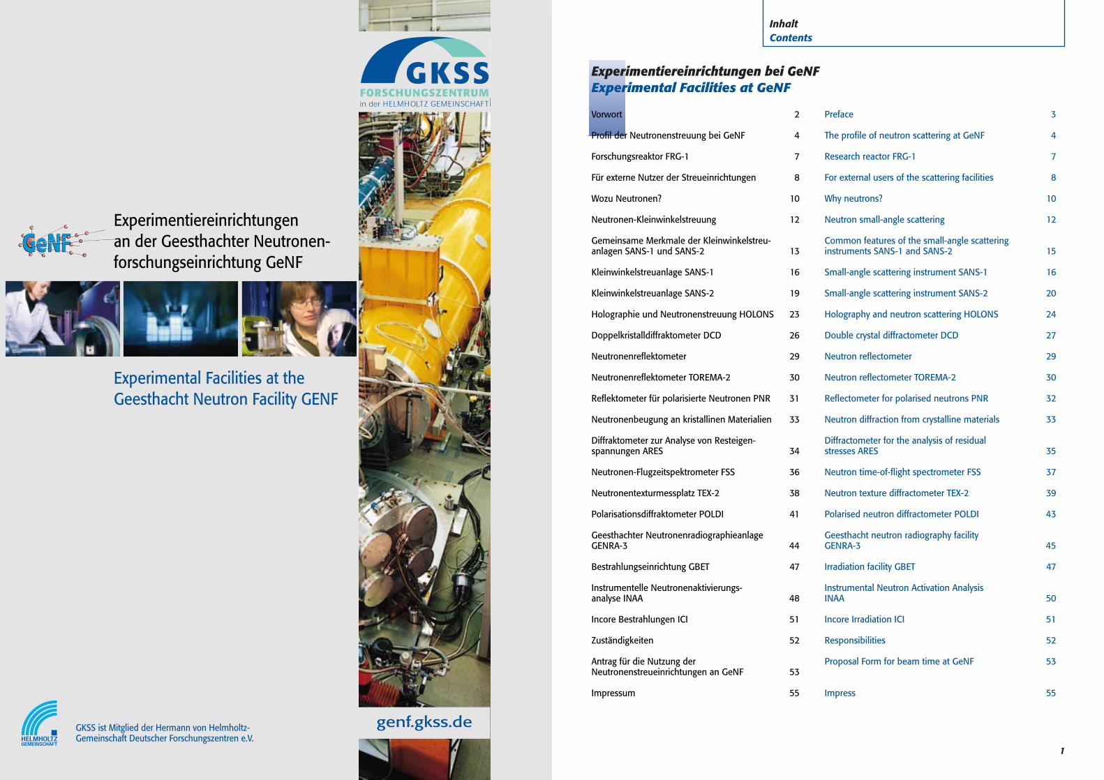
genf.gkss.de Experimentiereinrichtungen an der Geesthachter Neutronen- forschungseinrichtung GeNF GKSS ist Mitglied der Hermann von Helmholtz- Gemeinschaft Deutscher Forschungszentren e.V. Experimental Facilities at the Geesthacht Neutron Facility GENF 1 Inhalt Contents Vorwort 2 Profil der Neutronenstreuung bei GeNF 4 Forschungsreaktor FRG-1 7 Für externe Nutzer der Streueinrichtungen 8 Wozu Neutronen? 10 Neutronen-Kleinwinkelstreuung 12 Gemeinsame Merkmale der Kleinwinkelstreu- anlagen SANS-1 und SANS-2 13 Kleinwinkelstreuanlage SANS-1 16 Kleinwinkelstreuanlage SANS-2 19 Holographie und Neutronenstreuung HOLONS 23 Doppelkristalldiffraktometer DCD 26 Neutronenreflektometer 29 Neutronenreflektometer TOREMA-2 30 Reflektometer für polarisierte Neutronen PNR 31 Neutronenbeugung an kristallinen Materialien 33 Diffraktometer zur Analyse von Resteigen- spannungen ARES 34 Neutronen-Flugzeitspektrometer FSS 36 Neutronentexturmessplatz TEX-2 38 Polarisationsdiffraktometer POLDI 41 Geesthachter Neutronenradiographieanlage GENRA-3 44 Bestrahlungseinrichtung GBET 47 Instrumentelle Neutronenaktivierungs- analyse INAA 48 Incore Bestrahlungen ICI 51 Zuständigkeiten 52 Antrag für die Nutzung der Neutronenstreueinrichtungen an GeNF 53 Impressum 55 Preface 3 The profile of neutron scattering at GeNF 4 Research reactor FRG-1 7 For external users of the scattering facilities 8 Why neutrons? 10 Neutron small-angle scattering 12 Common features of the small-angle scattering instruments SANS-1 and SANS-2 15 Small-angle scattering instrument SANS-1 16 Small-angle scattering instrument SANS-2 20 Holography and neutron scattering HOLONS 24 Double crystal diffractometer DCD 27 Neutron reflectometer 29 Neutron reflectometer TOREMA-2 30 Reflectometer for polarised neutrons PNR 32 Neutron diffraction from crystalline materials 33 Diffractometer for the analysis of residual stresses ARES 35 Neutron time-of-flight spectrometer FSS 37 Neutron texture diffractometer TEX-2 39 Polarised neutron diffractometer POLDI 43 Geesthacht neutron radiography facility GENRA-3 45 Irradiation facility GBET 47 Instrumental Neutron Activation Analysis INAA 50 Incore Irradiation ICI 51 Responsibilities 52 Proposal Form for beam time at GeNF 53 Impress 55 Experimentiereinrichtungen bei GeNF Experimental Facilities at GeNF
Transcript of Experimentiereinrichtungen an der Geesthachter Neutronen ... · an der Geesthachter...
genf.gkss.de
Experimentiereinrichtungen an der Geesthachter Neutronen-forschungseinrichtung GeNF
GKSS ist Mitglied der Hermann von Helmholtz-Gemeinschaft Deutscher Forschungszentren e.V.
Experimental Facilities at the Geesthacht Neutron Facility GENF
1
InhaltContents
Vorwort 2
Profil der Neutronenstreuung bei GeNF 4
Forschungsreaktor FRG-1 7
Für externe Nutzer der Streueinrichtungen 8
Wozu Neutronen? 10
Neutronen-Kleinwinkelstreuung 12
Gemeinsame Merkmale der Kleinwinkelstreu-anlagen SANS-1 und SANS-2 13
Kleinwinkelstreuanlage SANS-1 16
Kleinwinkelstreuanlage SANS-2 19
Holographie und Neutronenstreuung HOLONS 23
Doppelkristalldiffraktometer DCD 26
Neutronenreflektometer 29
Neutronenreflektometer TOREMA-2 30
Reflektometer für polarisierte Neutronen PNR 31
Neutronenbeugung an kristallinen Materialien 33
Diffraktometer zur Analyse von Resteigen-spannungen ARES 34
Neutronen-Flugzeitspektrometer FSS 36
Neutronentexturmessplatz TEX-2 38
Polarisationsdiffraktometer POLDI 41
Geesthachter Neutronenradiographieanlage GENRA-3 44
Bestrahlungseinrichtung GBET 47
Instrumentelle Neutronenaktivierungs-analyse INAA 48
Incore Bestrahlungen ICI 51
Zuständigkeiten 52
Antrag für die Nutzung der Neutronenstreueinrichtungen an GeNF 53
Impressum 55
Preface 3
The profile of neutron scattering at GeNF 4
Research reactor FRG-1 7
For external users of the scattering facilities 8
Why neutrons? 10
Neutron small-angle scattering 12
Common features of the small-angle scattering instruments SANS-1 and SANS-2 15
Small-angle scattering instrument SANS-1 16
Small-angle scattering instrument SANS-2 20
Holography and neutron scattering HOLONS 24
Double crystal diffractometer DCD 27
Neutron reflectometer 29
Neutron reflectometer TOREMA-2 30
Reflectometer for polarised neutrons PNR 32
Neutron diffraction from crystalline materials 33
Diffractometer for the analysis of residual stresses ARES 35
Neutron time-of-flight spectrometer FSS 37
Neutron texture diffractometer TEX-2 39
Polarised neutron diffractometer POLDI 43
Geesthacht neutron radiography facilityGENRA-3 45
Irradiation facility GBET 47
Instrumental Neutron Activation AnalysisINAA 50
Incore Irradiation ICI 51
Responsibilities 52
Proposal Form for beam time at GeNF 53
Impress 55
Experimentiereinrichtungen bei GeNFExperimental Facilities at GeNF
VorwortPreface
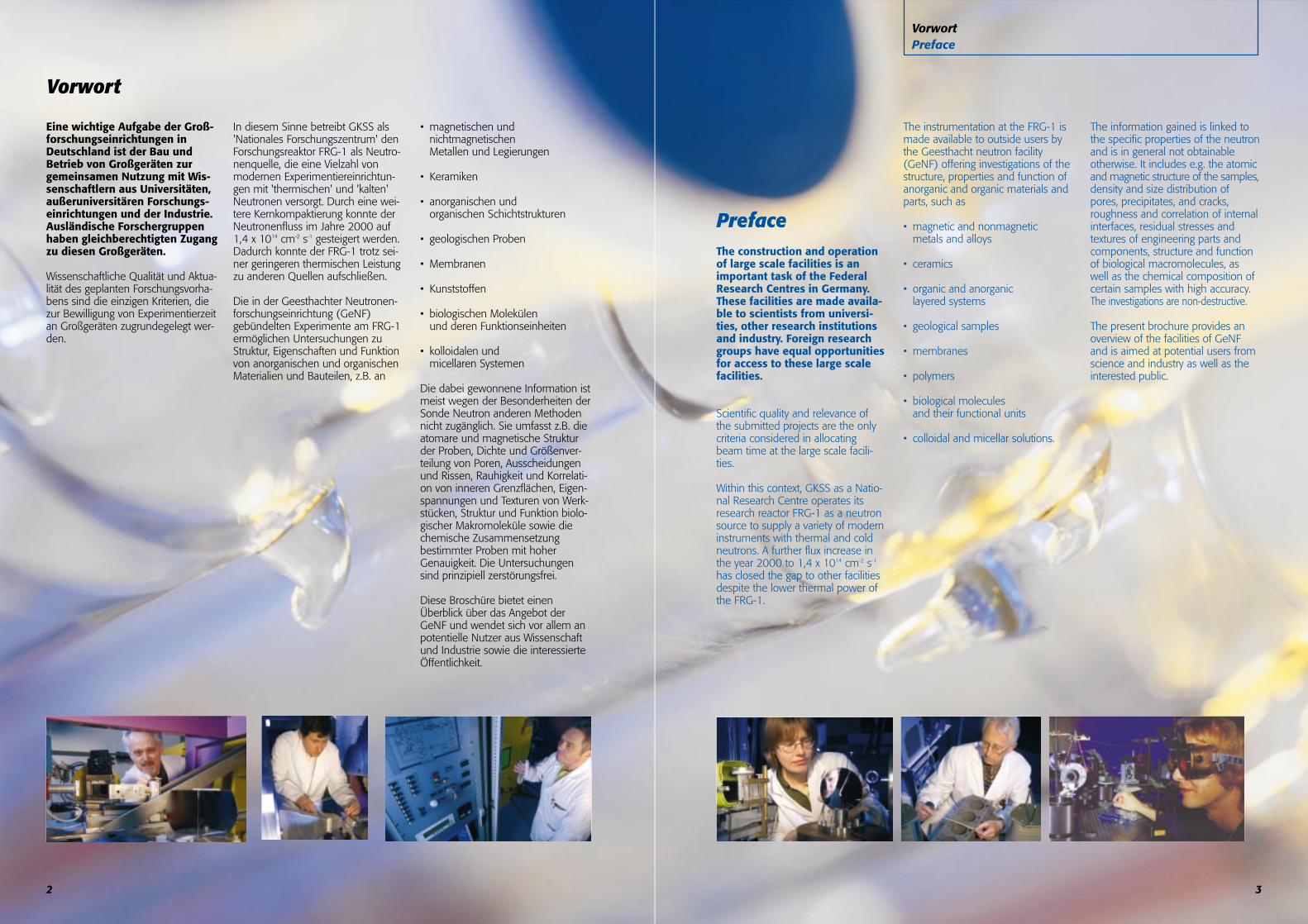
PrefaceThe construction and operationof large scale facilities is animportant task of the FederalResearch Centres in Germany.These facilities are made availa-ble to scientists from universi-ties, other research institutionsand industry. Foreign researchgroups have equal opportunitiesfor access to these large scalefacilities.
Scientific quality and relevance ofthe submitted projects are the onlycriteria considered in allocatingbeam time at the large scale facili-ties.
Within this context, GKSS as a Natio-nal Research Centre operates itsresearch reactor FRG-1 as a neutronsource to supply a variety of moderninstruments with thermal and coldneutrons. A further flux increase inthe year 2000 to 1,4 x 1014 cm-2 s-1
has closed the gap to other facilitiesdespite the lower thermal power ofthe FRG-1.
The instrumentation at the FRG-1 ismade available to outside users bythe Geesthacht neutron facility(GeNF) offering investigations of thestructure, properties and function ofanorganic and organic materials andparts, such as
• magnetic and nonmagneticmetals and alloys
• ceramics
• organic and anorganic layered systems
• geological samples
• membranes
• polymers
• biological molecules and their functional units
• colloidal and micellar solutions.
The information gained is linked tothe specific properties of the neutronand is in general not obtainableotherwise. It includes e.g. the atomicand magnetic structure of the samples,density and size distribution ofpores, precipitates, and cracks, roughness and correlation of internalinterfaces, residual stresses and textures of engineering parts andcomponents, structure and functionof biological macromolecules, aswell as the chemical composition ofcertain samples with high accuracy.The investigations are non-destructive.
The present brochure provides anoverview of the facilities of GeNFand is aimed at potential users fromscience and industry as well as theinterested public.
3
Vorwort
Eine wichtige Aufgabe der Groß-forschungseinrichtungen inDeutschland ist der Bau undBetrieb von Großgeräten zurgemeinsamen Nutzung mit Wis-senschaftlern aus Universitäten,außeruniversitären Forschungs-einrichtungen und der Industrie.Ausländische Forschergruppenhaben gleichberechtigten Zugangzu diesen Großgeräten.
Wissenschaftliche Qualität und Aktua-lität des geplanten Forschungsvorha-bens sind die einzigen Kriterien, diezur Bewilligung von Experimentierzeitan Großgeräten zugrundegelegt wer-den.
In diesem Sinne betreibt GKSS als'Nationales Forschungszentrum' denForschungsreaktor FRG-1 als Neutro-nenquelle, die eine Vielzahl vonmodernen Experimentiereinrichtun-gen mit 'thermischen' und 'kalten'Neutronen versorgt. Durch eine wei-tere Kernkompaktierung konnte derNeutronenfluss im Jahre 2000 auf1,4 x 1014 cm-2 s-1 gesteigert werden.Dadurch konnte der FRG-1 trotz sei-ner geringeren thermischen Leistungzu anderen Quellen aufschließen.
Die in der Geesthachter Neutronen-forschungseinrichtung (GeNF)gebündelten Experimente am FRG-1ermöglichen Untersuchungen zuStruktur, Eigenschaften und Funktionvon anorganischen und organischenMaterialien und Bauteilen, z.B. an
• magnetischen und nichtmagnetischenMetallen und Legierungen
• Keramiken
• anorganischen und organischen Schichtstrukturen
• geologischen Proben
• Membranen
• Kunststoffen
• biologischen Molekülen und deren Funktionseinheiten
• kolloidalen und micellaren Systemen
Die dabei gewonnene Information istmeist wegen der Besonderheiten derSonde Neutron anderen Methodennicht zugänglich. Sie umfasst z.B. dieatomare und magnetische Strukturder Proben, Dichte und Größenver-teilung von Poren, Ausscheidungenund Rissen, Rauhigkeit und Korrelati-on von inneren Grenzflächen, Eigen-spannungen und Texturen von Werk-stücken, Struktur und Funktion biolo-gischer Makromoleküle sowie diechemische Zusammensetzungbestimmter Proben mit hoherGenauigkeit. Die Untersuchungensind prinzipiell zerstörungsfrei.
Diese Broschüre bietet einenÜberblick über das Angebot derGeNF und wendet sich vor allem anpotentielle Nutzer aus Wissenschaftund Industrie sowie die interessierteÖffentlichkeit.
2
5
ProfilProfile
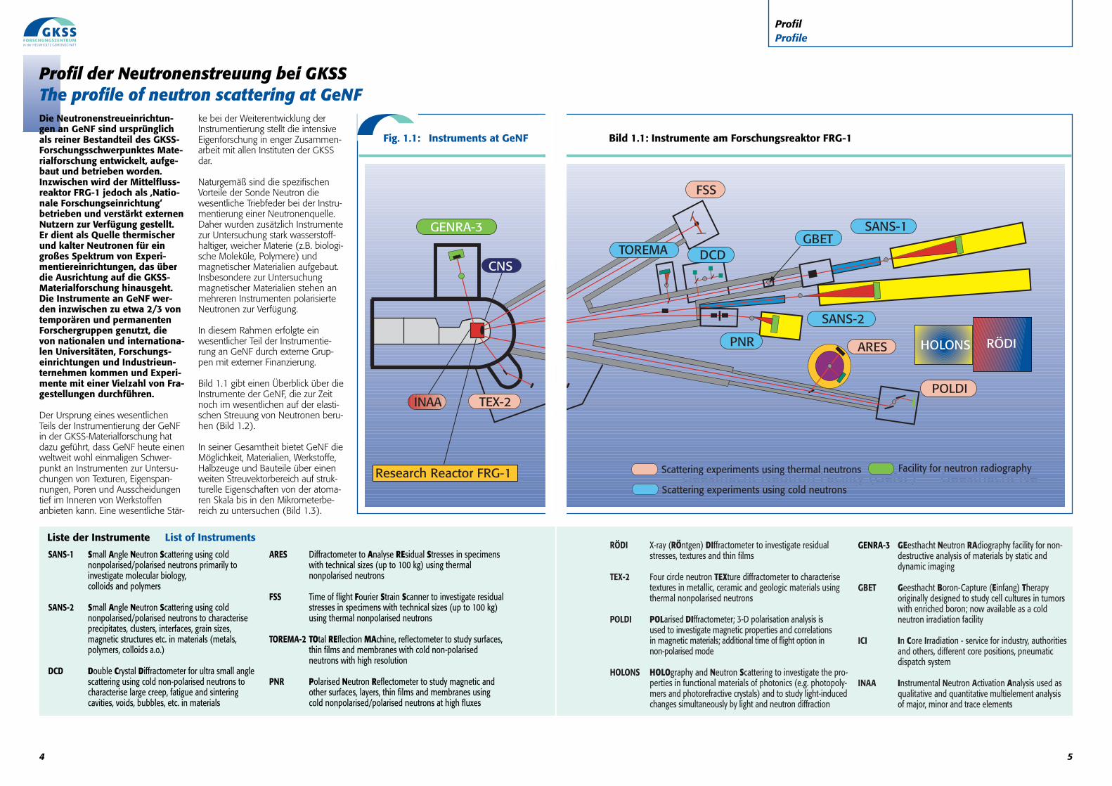
GENRA-3 GEesthacht Neutron RAdiography facility for non-destructive analysis of materials by static anddynamic imaging
GBET Geesthacht Boron-Capture (Einfang) Therapyoriginally designed to study cell cultures in tumorswith enriched boron; now available as a coldneutron irradiation facility
ICI In Core Irradiation - service for industry, authoritiesand others, different core positions, pneumaticdispatch system
INAA Instrumental Neutron Activation Analysis used asqualitative and quantitative multielement analysisof major, minor and trace elements
RÖDI X-ray (RÖntgen) DIffractometer to investigate residualstresses, textures and thin films
TEX-2 Four circle neutron TEXture diffractometer to characterisetextures in metallic, ceramic and geologic materials usingthermal nonpolarised neutrons
POLDI POLarised DIffractometer; 3-D polarisation analysis is used to investigate magnetic properties and correlations in magnetic materials; additional time of flight option in non-polarised mode
HOLONS HOLOgraphy and Neutron Scattering to investigate the pro-perties in functional materials of photonics (e.g. photopoly-mers and photorefractive crystals) and to study light-inducedchanges simultaneously by light and neutron diffraction
Bild 1.1: Instrumente am Forschungsreaktor FRG-1
Geesthacht Neutron Facility (GeNF) Geesthacht Ne
4
Profil der Neutronenstreuung bei GKSSThe profile of neutron scattering at GeNFDie Neutronenstreueinrichtun-gen an GeNF sind ursprünglichals reiner Bestandteil des GKSS-Forschungsschwerpunktes Mate-rialforschung entwickelt, aufge-baut und betrieben worden.Inzwischen wird der Mittelfluss-reaktor FRG-1 jedoch als ‚Natio-nale Forschungseinrichtung‘betrieben und verstärkt externenNutzern zur Verfügung gestellt.Er dient als Quelle thermischerund kalter Neutronen für eingroßes Spektrum von Experi-mentiereinrichtungen, das überdie Ausrichtung auf die GKSS-Materialforschung hinausgeht.Die Instrumente an GeNF wer-den inzwischen zu etwa 2/3 vontemporären und permanentenForschergruppen genutzt, dievon nationalen und internationa-len Universitäten, Forschungs-einrichtungen und Industrieun-ternehmen kommen und Experi-mente mit einer Vielzahl von Fra-gestellungen durchführen.
Der Ursprung eines wesentlichenTeils der Instrumentierung der GeNFin der GKSS-Materialforschung hatdazu geführt, dass GeNF heute einenweltweit wohl einmaligen Schwer-punkt an Instrumenten zur Untersu-chungen von Texturen, Eigenspan-nungen, Poren und Ausscheidungentief im Inneren von Werkstoffenanbieten kann. Eine wesentliche Stär-
ke bei der Weiterentwicklung derInstrumentierung stellt die intensiveEigenforschung in enger Zusammen-arbeit mit allen Instituten der GKSSdar.
Naturgemäß sind die spezifischenVorteile der Sonde Neutron diewesentliche Triebfeder bei der Instru-mentierung einer Neutronenquelle.Daher wurden zusätzlich Instrumentezur Untersuchung stark wasserstoff-haltiger, weicher Materie (z.B. biologi-sche Moleküle, Polymere) undmagnetischer Materialien aufgebaut.Insbesondere zur Untersuchungmagnetischer Materialien stehen anmehreren Instrumenten polarisierteNeutronen zur Verfügung.
In diesem Rahmen erfolgte einwesentlicher Teil der Instrumentie-rung an GeNF durch externe Grup-pen mit externer Finanzierung.
Bild 1.1 gibt einen Überblick über dieInstrumente der GeNF, die zur Zeitnoch im wesentlichen auf der elasti-schen Streuung von Neutronen beru-hen (Bild 1.2).
In seiner Gesamtheit bietet GeNF dieMöglichkeit, Materialien, Werkstoffe,Halbzeuge und Bauteile über einenweiten Streuvektorbereich auf struk-turelle Eigenschaften von der atoma-ren Skala bis in den Mikrometerbe-reich zu untersuchen (Bild 1.3).
Liste der Instrumente List of Instruments
SANS-1 Small Angle Neutron Scattering using cold nonpolarised/polarised neutrons primarily to investigate molecular biology, colloids and polymers
SANS-2 Small Angle Neutron Scattering using cold nonpolarised/polarised neutrons to characterise precipitates, clusters, interfaces, grain sizes,magnetic structures etc. in materials (metals,polymers, colloids a.o.)
DCD Double Crystal Diffractometer for ultra small angle scattering using cold non-polarised neutrons to characterise large creep, fatigue and sinteringcavities, voids, bubbles, etc. in materials
ARES Diffractometer to Analyse REsidual Stresses in specimenswith technical sizes (up to 100 kg) using thermalnonpolarised neutrons
FSS Time of flight Fourier Strain Scanner to investigate residualstresses in specimens with technical sizes (up to 100 kg)using thermal nonpolarised neutrons
TOREMA-2 TOtal REflection MAchine, reflectometer to study surfaces,thin films and membranes with cold non-polarisedneutrons with high resolution
PNR Polarised Neutron Reflectometer to study magnetic andother surfaces, layers, thin films and membranes usingcold nonpolarised/polarised neutrons at high fluxes
Fig. 1.1: Instruments at GeNF
INAA
GENRA-3
CNS
Research Reactor FRG-1
TEX-2
PNR
DCD
FSS
ARES
TOREMAGBET
POLDI
HOLONS RÖDI
SANS-2
SANS-1
7
Forschungsreaktor FRG-1Research reactor FRG-1
Der in jüngster Zeit grundlegendmodernisierte ForschungsreaktorFRG-1 am GKSS Forschungszen-trum Geesthacht ist ein Leicht-wasser-Schwimmbadreaktor miteiner thermischen Leistung von5 MW; er wird mit 12 MTR-Brennstäben mit niedriger U-235Anreicherung - sog. LEU-Brenn-elementen - betrieben (Bild 2.1).Die Neutronen treten aus denRandbereichen des Reaktorkernsin Strahlrohre hinein und wer-den dann in speziell konzipier-ten Kollimatoren oder Neutro-nenleitern den jeweiligen Experi-mentiereinrichtungen zugeführt.Der maximale ungestörte Flussthermischer Neutronen beträgtan den Strahlrohrnasen 1,4 x 10¹⁴
cm-2 s-1. Dieser für einen Reaktorvon nur 5 MW thermischer Lei-stung sehr hohe Wert resultiertdaraus, dass der FRG-1 miteinem Kompaktkern und einemBerylliumreflektor ausgestattetist, in den die Strahlrohrnasenhineinragen.
Viele Untersuchungen in der Materi-alforschung können nur bei hinrei-
chend großen Flüssen langwelliger(λ > 0,2 nm) Neutronen durchge-führt werden. Am FRG-1 werdendiese Voraussetzungen durch dieKalte Quelle (Bild 2.2) geschaffen: Inderen Moderatortopf wird dieGeschwindigkeit thermischer Neutro-nen, nach dem sie den Reaktorkernverlassen haben, durch Wechselwir-kung mit kaltem Wasserstoff (T = 25
K) herabgesetzt und somit ihre Wel-lenlänge erhöht.
Im Mittel stand der FRG-1 in denletzten Jahren ca. 250 Tage/Jahr fürExperimentatoren zur Verfügung. ZuBeginn eines jeden Jahres wird derReaktor ca. 6 Wochen für die jährli-che Sicherheitsüberprüfung abge-schaltet.
Forschungsreaktor FRG-1Research reactor FRG-1
Bild 2.2: Die Kalte Quelle: Schnitt durch die Vaku-umkammer mit Moderatortopf. Die thermischenNeutronen erreichen das kalte Wasserstoffgas (T =25 K, p > 14 bar) im Moderatortopf überwiegendvon links, werden dort weiter abgebremst und ent-weichen als kalte Neutronen über die Vakuumkam-mer und das rechts im Bild beginnende Strahlrohr 8in die kalten Neutronenleiter.
Fig. 2.2: The Cold Neutron Source: cross section of thevacuum chamber with moderator vessel. The thermalneutrons reach the cold hydrogen gas (T = 25 K, p >14 bar) in the moderator vessel mostly from the lefthand side in this figure and escape through the beamtube on the right hand side into the cold neutron guides.
Bild 2.1: Der neue Kompaktkern des FRG-1 mit 12 MTR-Brennelementen – 20%ige Urananreicherung, dieDichte des U-235 beträgt 4,8 g/cm – liefert 5MW thermische Leistung mit einem Fluss von 1,4 x 10¹⁴ thermi-schen Neutron je cm2 und je s.
Fig. 2.1: The new compact core of the FRG-1 with 12 MTR fuel elements - 20 % enriched uranium (LEU), U-235density: 4.8 g/cm3 - provides a thermal power of 5 MW at a flux of 1.4 x 10¹⁴ thermal neutrons per cm2 and per s.
The research reactor FRG-1 atthe GKSS Research Center Geest-hacht, which has been complete-ly modernized only recently, is aswimming pool reactor with athermal power of 5 MW. It isoperated with 12 MTR (materialstest reactor) fuel elements contai-ning of low enriched uranium(LEU)(fig. 2.1). The neutronsescape out of the edge of thereactor core into beam tubes.Then they are guided in speciallydesigned collimators or neutronguides to the various experimen-tal facilities. The maximumunpertubed thermal neutron fluxamounts to 1.4 x 1014 cm-2 s-1 atthe beam tube entrances. This isa large value compared with thethermal power of FRG-1 of only5 MW. This is a result of thecompact core and the beryllium
reflector into which the beamtube entrances project.
Many investigations can only be per-formed if sufficiently high fluxes oflong-wavelength neutrons (λ ≥ 0,2nm) are available. At GeNF theserequirements are achieved by meansof the Cold Neutron Source (fig 2.2):In its moderator vessel thermal neu-trons escaping from the reactor inter-act with cold hydrogen nuclei (T =25 K). In this way the velocity of theneutrons is reduced and thus, theirwavelength is increased.
On average, the FRG-1 has suppliedneutrons for experimentalists for aperiod of 250 days per year. At thebeginning of each year there is ascheduled shutdown of 6 weeks forsafety inspections.
6
The neutron scattering facilities atGeNF were originally designed,built and operated as part of theGKSS materials research programme.In the meantime, however, theresearch reactor FRG-1 is opera-ted as a national user facility andis dominantly made available tooutside users. It serves as a sourceof thermal and cold neutrons fora wide range of experimental facilities going well beyond thematerials research at GKSS. In themeantime the instruments atGeNF are used to 2/3 by temporaryand permanent external users.They come from national andinternational universities, research facilities and industryand perform experiments on awide range of subjects.
The origin of a significant part of theGeNF instrumentation from the GKSSmaterials research effort has lead to aconcentration of neutron instrumentsfor the investigation oft textures, resi-dual stresses, pores and precipitatesdeep inside of materials which is unique worldwide.
The strong internal research effort inmaterials science within GKSS conti-nues to be a strong driving force forimproving the instrumentation.Obviously, the specific properties ofthe neutron determine the instrumen-tation of a neutron source. Therefore,additional instruments for the investi-gation of hydrogenous soft matter (e.g.biological molecules, polymers) andmagnetic materials have been con-structed. Especially for the investigationof magnetic materials, polarised neu-trons are available on a number ofinstruments. Within this framework, asignificant part of the instrumentationat GeNF has been constructed andfinanced by external groups and insti-tutions.
Fig. 1.1 provides an overview of theinstrumentation of GeNF which cur-rently is still mainly based on elasticneutron scattering (fig. 1.2). As awhole, GeNF offers the possibility tostudy materials, semi-finished productsand components over a wide range ofscattering vectors concerning theirstructural properties from the atomicscale up to micrometers (fig. 1.3).
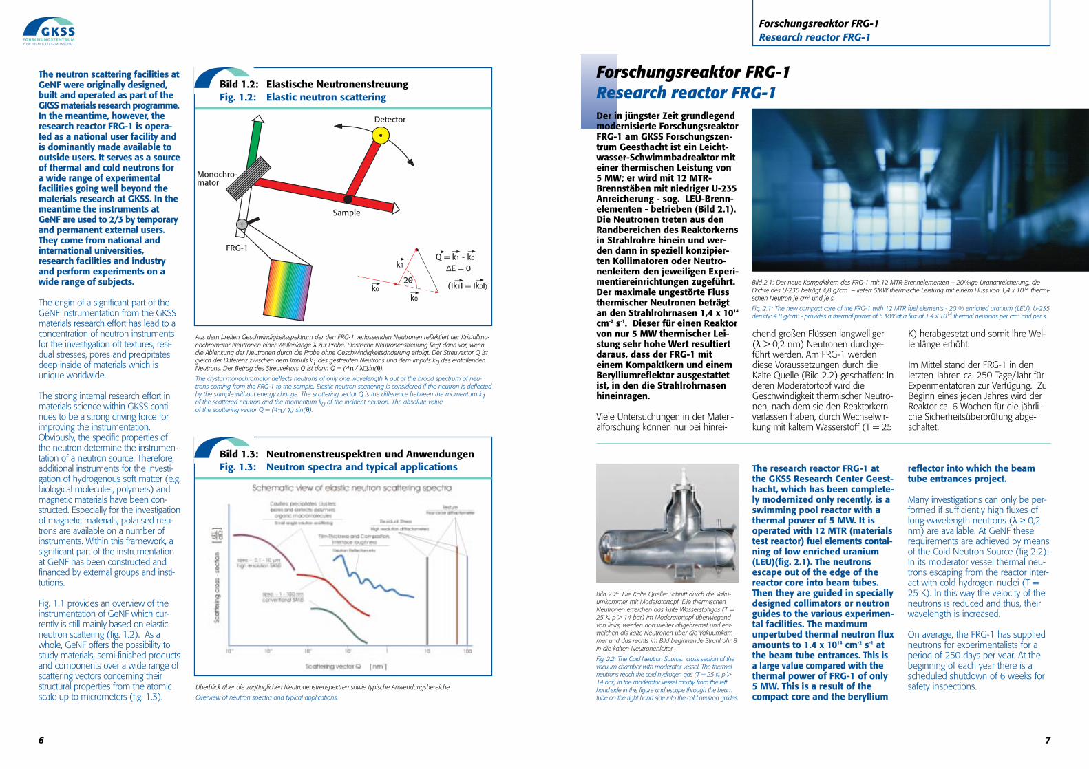
Aus dem breiten Geschwindigkeitsspektrum der den FRG-1 verlassenden Neutronen reflektiert der Kristallmo-nochromator Neutronen einer Wellenlänge λ zur Probe. Elastische Neutronenstreuung liegt dann vor, wenndie Ablenkung der Neutronen durch die Probe ohne Geschwindigkeitsänderung erfolgt. Der Streuvektor Q istgleich der Differenz zwischen dem Impuls k1 des gestreuten Neutrons und dem Impuls k0 des einfallendenNeutrons. Der Betrag des Streuvektors Q ist dann Q = (4π / λ) sin(θ).
The crystal monochromator deflects neutrons of only one wavelength λ out of the broad spectrum of neu-trons coming from the FRG-1 to the sample. Elastic neutron scattering is considered if the neutron is deflectedby the sample without energy change. The scattering vector Q is the difference between the momentum k1of the scattered neutron and the momentum k0 of the incident neutron. The absolute value of the scattering vector Q = (4π / λ) sin(θ).
Überblick über die zugänglichen Neutronenstreuspektren sowie typische Anwendungsbereiche
Overview of neutron spectra and typical applications.
FRG-1
Monochro-mator
Detector
Sample
Q = k1 - k0k1
k0
k0
(Ik1I = Ik0I)
∆E = 020
Bild 1.2: Elastische NeutronenstreuungFig. 1.2: Elastic neutron scattering
Bild 1.3: Neutronenstreuspektren und AnwendungenFig. 1.3: Neutron spectra and typical applications
9
Externe NutzungExternal use
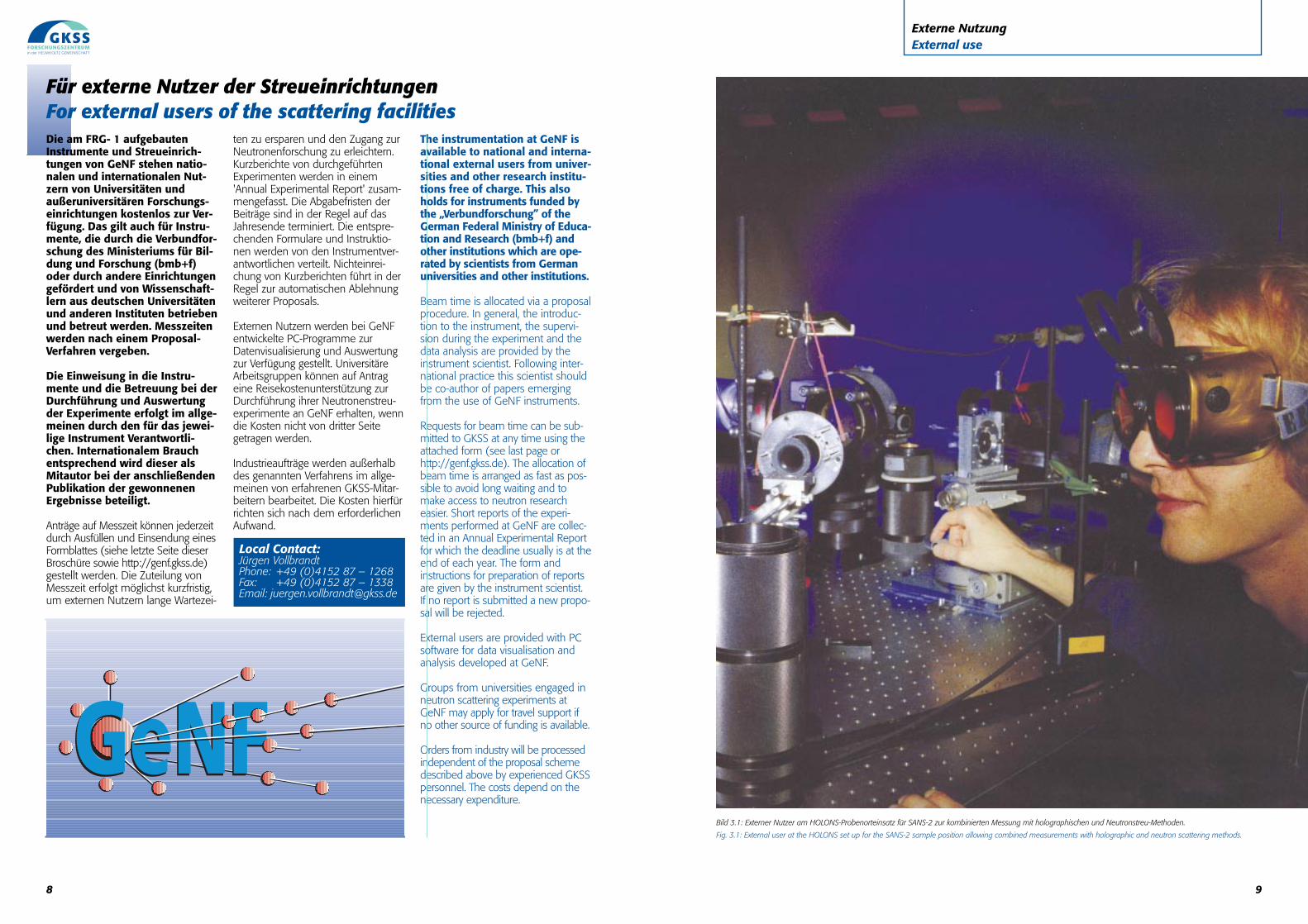
Bild 3.1: Externer Nutzer am HOLONS-Probenorteinsatz für SANS-2 zur kombinierten Messung mit holographischen und Neutronstreu-Methoden.
Fig. 3.1: External user at the HOLONS set up for the SANS-2 sample position allowing combined measurements with holographic and neutron scattering methods.
8
Für externe Nutzer der StreueinrichtungenFor external users of the scattering facilitiesDie am FRG- 1 aufgebautenInstrumente und Streueinrich-tungen von GeNF stehen natio-nalen und internationalen Nut-zern von Universitäten undaußeruniversitären Forschungs-einrichtungen kostenlos zur Ver-fügung. Das gilt auch für Instru-mente, die durch die Verbundfor-schung des Ministeriums für Bil-dung und Forschung (bmb+f)oder durch andere Einrichtungengefördert und von Wissenschaft-lern aus deutschen Universitätenund anderen Instituten betriebenund betreut werden. Messzeitenwerden nach einem Proposal-Verfahren vergeben.
Die Einweisung in die Instru-mente und die Betreuung bei derDurchführung und Auswertungder Experimente erfolgt im allge-meinen durch den für das jewei-lige Instrument Verantwortli-chen. Internationalem Brauchentsprechend wird dieser alsMitautor bei der anschließendenPublikation der gewonnenenErgebnisse beteiligt.
Anträge auf Messzeit können jederzeitdurch Ausfüllen und Einsendung einesFormblattes (siehe letzte Seite dieser Broschüre sowie http://genf.gkss.de)gestellt werden. Die Zuteilung vonMesszeit erfolgt möglichst kurzfristig,um externen Nutzern lange Wartezei-
ten zu ersparen und den Zugang zurNeutronenforschung zu erleichtern.Kurzberichte von durchgeführtenExperimenten werden in einem'Annual Experimental Report' zusam-mengefasst. Die Abgabefristen derBeiträge sind in der Regel auf dasJahresende terminiert. Die entspre-chenden Formulare und Instruktio-nen werden von den Instrumentver-antwortlichen verteilt. Nichteinrei-chung von Kurzberichten führt in derRegel zur automatischen Ablehnungweiterer Proposals.
Externen Nutzern werden bei GeNFentwickelte PC-Programme zurDatenvisualisierung und Auswertungzur Verfügung gestellt. UniversitäreArbeitsgruppen können auf Antrageine Reisekostenunterstützung zurDurchführung ihrer Neutronenstreu-experimente an GeNF erhalten, wenndie Kosten nicht von dritter Seitegetragen werden.
Industrieaufträge werden außerhalbdes genannten Verfahrens im allge-meinen von erfahrenen GKSS-Mitar-beitern bearbeitet. Die Kosten hierfürrichten sich nach dem erforderlichenAufwand.
The instrumentation at GeNF isavailable to national and interna-tional external users from univer-sities and other research institu-tions free of charge. This alsoholds for instruments funded bythe „Verbundforschung” of theGerman Federal Ministry of Educa-tion and Research (bmb+f) andother institutions which are ope-rated by scientists from Germanuniversities and other institutions.
Beam time is allocated via a proposalprocedure. In general, the introduc-tion to the instrument, the supervi-sion during the experiment and thedata analysis are provided by theinstrument scientist. Following inter-national practice this scientist shouldbe co-author of papers emergingfrom the use of GeNF instruments.
Requests for beam time can be sub-mitted to GKSS at any time using theattached form (see last page orhttp://genf.gkss.de). The allocation ofbeam time is arranged as fast as pos-sible to avoid long waiting and tomake access to neutron researcheasier. Short reports of the experi-ments performed at GeNF are collec-ted in an Annual Experimental Reportfor which the deadline usually is at theend of each year. The form andinstructions for preparation of reportsare given by the instrument scientist. If no report is submitted a new propo-sal will be rejected.
External users are provided with PCsoftware for data visualisation andanalysis developed at GeNF.
Groups from universities engaged inneutron scattering experiments atGeNF may apply for travel support ifno other source of funding is available.
Orders from industry will be processedindependent of the proposal schemedescribed above by experienced GKSSpersonnel. The costs depend on thenecessary expenditure.
Local Contact:Jürgen VollbrandtPhone: +49 (0)4152 87 – 1268Fax: +49 (0)4152 87 – 1338Email: [email protected]
11
Wozu Neutronen?Why neutrons?
Contrast from isotopic substitutionplays an important role in structuralstudies of polymers and biomolecu-les. The ordinary (light) hydrogenatom (1H) in the molecules is replacedby heavy hydrogen (2H or Deuteri-um). These isotopes differ considera-bly in their interaction with neutrons.
The dependence of neutron scatte-ring on the length scale of the cha-racterised structures is shown in fig.1.3. The relatively large pores resul-ting from cyclic mechanical loadingof solids (fatigue) give rise to a rathersmall broadening of the neutronbeam. At GeNF such ultra small-angle scattering is measured by thedouble crystal diffractometer DCD.Macromolecules and smaller defectsin materials deflect neutrons some-what more. This neutron small anglescattering is recorded by the instru-ments SANS-1 and SANS-2. Atsomewhat larger scattering vectorsthe reflectivity of neutrons from thinfilm structures reveals information onfilm thicknesses and interface roug-hnesses. Such measurements can beperformed with the reflectometersPNR and TOREMA.
Textures and residual stresses areinvestigated by means of reflectingneutrons at lattice planes of crystallinematerials. Therefore, the correspon-ding scattering spectra are characterisedby sharp lines (peaks) (fig. 1.3). Tex-tures are investigated at TEX-2 viameasurements of the peak intensi-ties as a function of the sample ori-entation. On the other hand, residualstresses are deduced from precisemeasurements of atomic latticeplane distances. This is performed bymeans of determining the angularposition or the wavelength of thecorresponding peaks at the highresolution diffractometers FSS andARES which are especially designedfor this purpose.
POLDI is especially adapted to studyferromagnetic domain structures andferromagnetic correlations. The infor-mation is obtained from the changesof the polarisation of the neutronbeam during the passage throughthe sample.
The interaction of neutrons withhydrogen is also used by the neutronradiography at GENRA-3. It allows to
detect materials which contain waterand hydrocarbons even if they areembedded in metals. This method isapplied for damage analysis as wellas for quality assessment of technicalcomponents, when other methodsfail.
By irradiation of many chemical ele-ments with neutrons the elements aswell as their concentration can beidentified due to the gamma radiati-on emitted by the decaying radionu-clides. The INAA at GeNF offers asensitive multielement analysismethod to analyse both qualitativelyand quantitatively major, minor andtrace elements.
In addition the features of materialsand components can be modifiedspecifically by irradiation with neu-trons as provided by the in-core irradiation service (ICI).
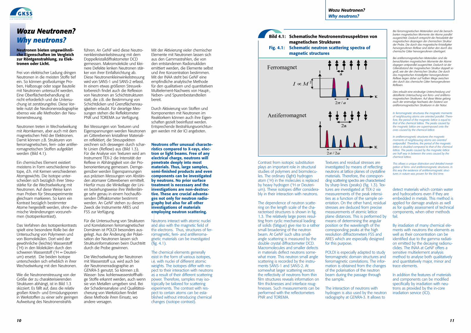
Bild 4.1: Schematische Neutronenstreuspektren von magnetischen Strukturen
Fig. 4.1: Schematic neutron scattering spectra of magnetic structures
Bei ferromagnetischen Materialien sind die benach-barten magnetischen Momente der Atome parallelausgerichtet. Dadurch entspricht die Periodizität dermagnetischen derjenigen der chemischen Strukturder Probe. Die durch das magnetische Kristallgitterhervorgerufenen Reflexe sind daher den durch daschemische Gitter hervorgerufenen überlagert.
Bei antiferromagnetischen Materialien sind diebenachbarten magnetischen Momente der Atomedagegen antiparallel ausgerichtet. Dadurch ist derGitterabstand der magnetischen Struktur doppelt sogroß, wie der der chemischen Struktur. Die durchdas magnetischen Kristallgitter hervorgerufenenReflexe liegen daher auf halben Wege zwischenden durch das chemische Gitter hervorgerufenenReflexen.
Dies erlaubt eine eindeutige Unterscheidung unddetaillierte Untersuchung von ferro- und antiferro-magnetischen Strukturen. Auf diese Weise gelangauch der erstmalige Nachweis der Existenz vonantiferromagnetischen Strukturen in der Natur.
In ferromagnetic structures the magnetic momentsof neighbouring atoms are oriented parallel. There-fore, the period of the magnetic lattice is equal tothat of the chemical lattice. The peaks caused bythe magnetic lattice are superimposed onto theones caused by the chemical lattice.
In antiferromagnetic structures the magneticmoments of neighbouring atoms are orientedantiparallel. Therefore, the period of the magneticlattice is doubled compared to that of the chemicallattice. The peaks caused by the magnetic latticeare half way in between the ones caused by thechemical lattice.
This allows a unique distinction and detailed investi-gation of ferro- and antiferromagnetic structures. Inthis way the existence of antiferromagnetic struc-tures in nature was proven for the first time.
10
Wozu Neutronen?Why neutrons?Neutronen bieten ungewöhnli-che Eigenschaften im Vergleichzur Röntgenstrahlung, zu Elek-tronen oder Licht.
Frei von elektrischer Ladung dringenNeutronen in die meisten Stoffe tiefein. So können großvolumige Pro-ben, Halbzeuge oder sogar Bauteilemit Neutronen untersucht werden.Eine Oberflächenbehandlung istnicht erforderlich und die Untersu-chung ist zerstörungsfrei. Diese Vor-teile nutzt die Neutronenradiographieebenso wie alle Methoden der Neu-tronenstreuung.
Neutronen treten in Wechselwirkungmit Atomkernen, aber auch mit demmagnetischen Feld der Elektronen.Damit können z.B. Strukturen vonferromagnetischen, ferri- oder antifer-romagnetischen Stoffen aufgeklärtwerden (Bild 4.1).
Ein chemisches Element existiertmeistens in Form verschiedener Iso-tope, d.h. mit Kernen verschiedenenAtomgewichts. Die Isotope unter-scheiden sich bezüglich ihrer Streu-stärke für die Wechselwirkung mitNeutronen. Auf diese Weise kannman Proben für Streuexperimentegleichsam markieren. So kann einKontrast bezüglich bestimmterAtome hergestellt werden, ohne che-mische Veränderungen vorzuneh-men (Isotopenkontrast).
Das Verfahren des Isotopenkontrastsspielt eine besondere Rolle bei derUntersuchung von Polymeren undvon Biomolekülen. Dort wird dergewöhnliche (leichte) Wasserstoff(1H) in den Molekülen durch denschweren Wasserstoff (2H = Deuteri-um) ersetzt. Die beiden Isotopeunterscheiden sich erheblich in ihrerWechselwirkung mit den Neutronen.
Wie die Neutronenstreuung von derGröße der zu charakterisierendenStrukturen abhängt, ist in Bild 1.3 skizziert. Es fällt auf, dass die relativgroßen Kriech- und Ermüdungsporenin Werkstoffen zu einer sehr geringenAufweitung des Neutronenstrahls
führen. An GeNF wird diese Neutro-nenkleinstwinkelstreuung mit demDoppelkristalldiffraktometer DCDgemessen. Makromoleküle und klei-nere Defekte lenken Neutronen stär-ker von ihrer Einfallsrichtung ab.Diese Neutronenkleinwinkelstreuungwird von SANS-1 und SANS-2 erfasst.In einem etwas größeren Streuvek-torbereich findet auch die Reflexionvon Neutronen an Schichtstrukturenstatt, die z.B. die Bestimmung vonSchichtdicken und Grenzflächenrau-igkeiten erlaubt. Für derartige Mes-sungen stehen die ReflektometerPNR und TOREMA zur Verfügung.
Bei Messungen von Texturen undEigenspannungen werden Neutronenan Gitterebenen kristalliner Materiali-en reflektiert, die Streuspektrenzeichnen sich deswegen durch schar-fe Linien (Reflexe) aus (Bild 1.3).Für die Analyse von Texturen wird amInstrument TEX-2 die Intensität derReflexe in Abhängigkeit von der Pro-benorientierung gemessen. Demge-genüber werden Eigenspannungenaus präzisen Messungen von Abstän-den atomarer Gitterebenen ermittelt.Hierfür muss die Winkellage der Lini-en beziehungsweise ihre Wellenlän-ge sehr genau in einem hochauflö-senden Diffraktometer bestimmtwerden. An GeNF stehen zu diesemZweck die Instrumente ARES undFSS zur Verfügung.
Für die Untersuchung von Strukturenund Korrelationen ferromagnetischerDomänen ist POLDI besonders aus-gelegt. Aus der Änderung der Polari-sation der Neutronen lassen sichStrukturinformationen beim Durchtrittdurch die Probe gewinnen.
Die Wechselwirkung der Neutronenmit Wasserstoff u.a. wird auch beider Neutronenradiographie anGENRA-3 genutzt. So können z.B.Wasser- bzw. kohlenwasserstoffhalti-ge Stoffe erkannt werden, auch wennsie von Metallen umgeben sind. Beider Schadensanalyse und Qualitätssi-cherung von Werkstücken findetdiese Methode ihren Einsatz, woandere versagen.
Mit der Aktivierung vieler chemischerElemente mit Neutronen lassen sichaus den Gammastrahlen, die vonden entstandenen Radionuklidenemittiert werden, die Elemente selbstund ihre Konzentration bestimmen.Mit der INAA steht bei GeNF eineempfindliche analytische Methodefür den qualitativen und quantitativenMultielement-Nachweis von Haupt-,Neben- und Spurenbestandteilenbereit.
Durch Aktivierung von Stoffen undKomponenten mit Neutronen imReaktorkern können auch ihre Eigen-schaften gezielt beeinflusst werden.Entsprechende Bestrahlungsvorrichtun-gen werden mit der ICI angeboten.
Neutrons offer unusual characte-ristics compared to X-rays, elec-tron or light beams. Free of anyelectrical charge, neutrons willpenetrate deeply into mostmaterials. Thus, large samples,semi-finished products and evencomponents can be investigatedby neutrons. No prior surfacetreatment is necessary and theinvestigations are non-destruc-tive. These are crucial advanta-ges not only for neutron radio-graphy but also for all otherinvestigations of materialsemploying neutron scattering.
Neutrons interact with atomic nucleiand also with the magnetic field ofthe electrons. Thus, structures of fer-romagnetic, ferri- and antiferroma-gnetic materials can be investigated(fig. 4.1).
The chemical elements generallyexist in the form of various isotopes,i.e. with nuclei of different atomicweights. The isotopes differ with res-pect to their interaction with neutronsas a result of their different scatteringpower. Therefore, samples may iso-topically be tailored for scatteringexperiments. The contrast with res-pect to certain atoms can be esta-blished without introducing chemicalchanges (isotope contrast).
13
Neutronen-KleinwinkelstreuungNeutron small-angle scattering
Gemeinsame Merkmale der KleinwinkelstreuanlagenSANS-1 und SANS-2Common features of the small-angle scattering instruments SANS-1 and SANS-2
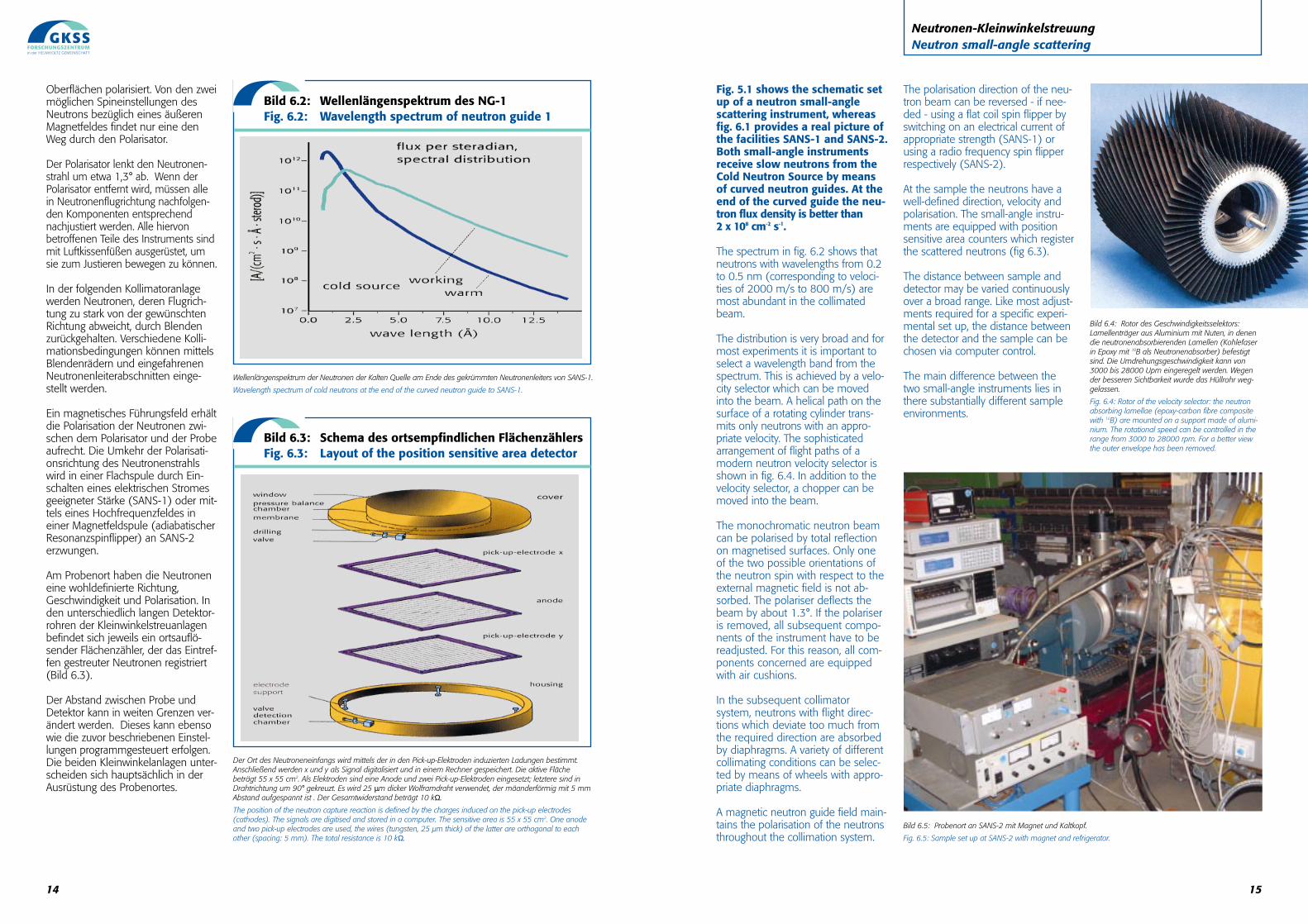
Bild 6.1: Blick auf die Kleinwinkelstreuanlagen SANS-1 (links im Bild) und SANS-2 (rechts im Bild). Die Kollimationsstrecken sind blau und die Detektorrohre gelb.
Fig. 6.1: View of the small-angle instruments SANS-1 (left hand side) and SANS-2 (right hand side). The collimators are blue and the detector tubes are yellow.
Bild 5.1 zeigt den schematischenAufbau einer Kleinwinkelstreu-anlage, während Bild 6.1 einenunmittelbaren Eindruck von derGröße der Anlagen SANS-1 undSANS-2 vermittelt. Beide Klein-winkelstreuanlagen erhaltenüber gekrümmte Neutronenleiterlangsame Neutronen der KaltenQuelle. Am Ende der gekrümm-ten Neutronenleiter wird einNeutronenfluss von mehr als 2 x 108 cm-2 s-1 gemessen.
Das Spektrum in Bild 6.2 zeigt, dassim kollimierten Strahl Neutronen mitWellenlängen zwischen 0,2 und 0,5nm (einer Geschwindigkeit von2000 m/s bis 800 m/s entspre-chend) besonders häufig sind. DieVerteilung ist sehr breit, und für diemeisten Experimente ist es erforder-lich, ein Wellenlängenband aus demSpektrum herauszuschneiden. Diesesgeschieht mit einem Geschwindig-keitsselektor, der in den Strahl gefah-ren werden kann. Ein schraubenför-
miger Gang auf der Oberfläche einesrotierenden Zylinders wird nur Neu-tronen mit passender Geschwindig-keit den berührungsfreien Durchtrittgestatten. Eine hochentwickelte Formder Anordnung solcher Neutronen-flugschneisen ist in Bild 6.4 zusehen. Zusätzlich zum Geschwindig-keitsselektor kann ein Chopper ('Zer-hacker') in den Strahl bewegt wer-den. Der monochromatische Neutro-nenstrahl wird im Bedarfsfall durchTotalreflexion an magnetisierten
12
Neutronen-KleinwinkelstreuungNeutron small-angle scattering
Neutronen-Kleinwinkelstreuungist eine der leistungsfähigstenMethoden zum Nachweis vondreidimensionalen chemischenHeterogenitäten und Dichtefluk-tuationen mit Abmessungen zwi-schen 1 nm und 100 nm.
Sie wird als Standardmethode bevor-zugt eingesetzt zur
• Defektanalyse in metallischenund keramischen Werkstoffen,
• zur Untersuchung kritischer Phä-nomene bei Phasenübergängen,
• zur Untersuchung der Kinetik beidiffusionskontrollierter Phasense-paration,
• zum Studium komplexer Flüssig-keiten wie Mikroemulsionen, Kol-loiden und flüssigen Kristallen,
• Untersuchung der Struktur undMorphologie polymerer Systeme,
• zur Strukturaufklärung biologi-scher Makromoleküle.
Neutron small-angle scattering isone of the most powerfulmethods for probing three-dimensional chemical heteroge-neities and density fluctuationswith sizes between 1 nm and100 nm.
It is preferably applied as a standardmethod for
• the analysis of defects in metallic and ceramic materials,
• the investigation of critical pheno-mena in phase transitions,
• the investigation of the kinetics of diffusion controlled phase separation,
• the study of complex liquids suchas microemulsions, colloids and liquid crystals,
• the investigation of the structure and morphology of polymer systems,
• structural studies of biological macromolecules.
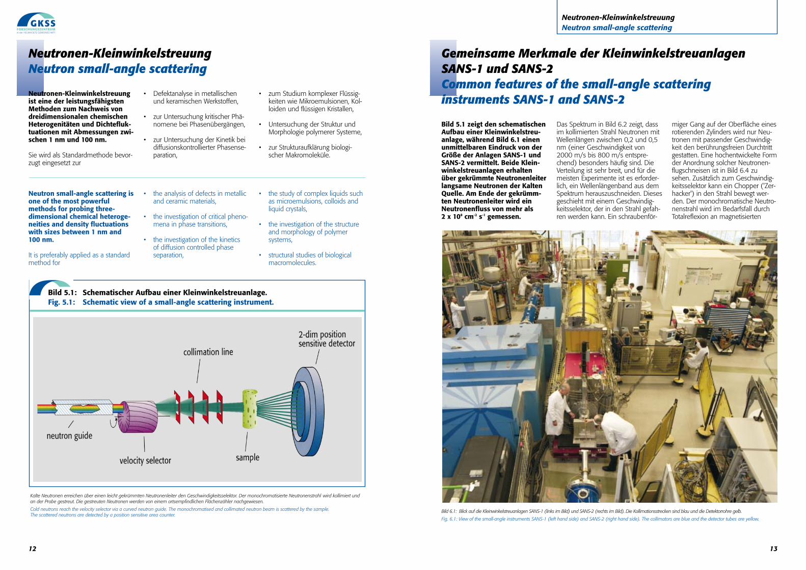
Kalte Neutronen erreichen über einen leicht gekrümmten Neutronenleiter den Geschwindigkeitsselektor. Der monochromatisierte Neutronenstrahl wird kollimiert undan der Probe gestreut. Die gestreuten Neutronen werden von einem ortsempfindlichen Flächenzähler nachgewiesen.
Cold neutrons reach the velocity selector via a curved neutron guide. The monochromatised and collimated neutron beam is scattered by the sample. The scattered neutrons are detected by a position sensitive area counter.
Bild 5.1: Schematischer Aufbau einer Kleinwinkelstreuanlage. Fig. 5.1: Schematic view of a small-angle scattering instrument.
15
Fig. 5.1 shows the schematic setup of a neutron small-anglescattering instrument, whereasfig. 6.1 provides a real picture ofthe facilities SANS-1 and SANS-2.Both small-angle instrumentsreceive slow neutrons from theCold Neutron Source by meansof curved neutron guides. At theend of the curved guide the neu-tron flux density is better than2 x 108 cm-2 s-1.
The spectrum in fig. 6.2 shows thatneutrons with wavelengths from 0.2to 0.5 nm (corresponding to veloci-ties of 2000 m/s to 800 m/s) aremost abundant in the collimatedbeam.
The distribution is very broad and formost experiments it is important toselect a wavelength band from thespectrum. This is achieved by a velo-city selector which can be movedinto the beam. A helical path on thesurface of a rotating cylinder trans-mits only neutrons with an appro-priate velocity. The sophisticatedarrangement of flight paths of amodern neutron velocity selector isshown in fig. 6.4. In addition to thevelocity selector, a chopper can bemoved into the beam.
The monochromatic neutron beamcan be polarised by total reflectionon magnetised surfaces. Only oneof the two possible orientations ofthe neutron spin with respect to theexternal magnetic field is not ab-sorbed. The polariser deflects thebeam by about 1.3°. If the polariseris removed, all subsequent compo-nents of the instrument have to bereadjusted. For this reason, all com-ponents concerned are equippedwith air cushions.
In the subsequent collimatorsystem, neutrons with flight direc-tions which deviate too much fromthe required direction are absorbedby diaphragms. A variety of differentcollimating conditions can be selec-ted by means of wheels with appro-priate diaphragms.
A magnetic neutron guide field main-tains the polarisation of the neutronsthroughout the collimation system.
The polarisation direction of the neu-tron beam can be reversed - if nee-ded - using a flat coil spin flipper byswitching on an electrical current ofappropriate strength (SANS-1) orusing a radio frequency spin flipperrespectively (SANS-2).
At the sample the neutrons have awell-defined direction, velocity andpolarisation. The small-angle instru-ments are equipped with positionsensitive area counters which registerthe scattered neutrons (fig 6.3).
The distance between sample anddetector may be varied continuouslyover a broad range. Like most adjust-ments required for a specific experi-mental set up, the distance betweenthe detector and the sample can bechosen via computer control.
The main difference between thetwo small-angle instruments lies inthere substantially different sampleenvironments.
Neutronen-KleinwinkelstreuungNeutron small-angle scattering
Bild 6.4: Rotor des Geschwindigkeitsselektors:Lamellenträger aus Aluminium mit Nuten, in denendie neutronenabsorbierenden Lamellen (Kohlefaserin Epoxy mit 10B als Neutronenabsorber) befestigtsind. Die Umdrehungsgeschwindigkeit kann von3000 bis 28000 Upm eingeregelt werden. Wegender besseren Sichtbarkeit wurde das Hüllrohr weg-gelassen.
Fig. 6.4: Rotor of the velocity selector: the neutronabsorbing lamellae (epoxy-carbon fibre compositewith 10B) are mounted on a support made of alumi-nium. The rotational speed can be controlled in therange from 3000 to 28000 rpm. For a better viewthe outer envelope has been removed.
Bild 6.5: Probenort an SANS-2 mit Magnet und Kaltkopf.
Fig. 6.5: Sample set up at SANS-2 with magnet and refrigerator.
14
Oberflächen polarisiert. Von den zweimöglichen Spineinstellungen desNeutrons bezüglich eines äußerenMagnetfeldes findet nur eine denWeg durch den Polarisator.
Der Polarisator lenkt den Neutronen-strahl um etwa 1,3° ab. Wenn derPolarisator entfernt wird, müssen allein Neutronenflugrichtung nachfolgen-den Komponenten entsprechendnachjustiert werden. Alle hiervonbetroffenen Teile des Instruments sindmit Luftkissenfüßen ausgerüstet, umsie zum Justieren bewegen zu können.
In der folgenden Kollimatoranlagewerden Neutronen, deren Flugrich-tung zu stark von der gewünschtenRichtung abweicht, durch Blendenzurückgehalten. Verschiedene Kolli-mationsbedingungen können mittelsBlendenrädern und eingefahrenenNeutronenleiterabschnitten einge-stellt werden.
Ein magnetisches Führungsfeld erhältdie Polarisation der Neutronen zwi-schen dem Polarisator und der Probeaufrecht. Die Umkehr der Polarisati-onsrichtung des Neutronenstrahlswird in einer Flachspule durch Ein-schalten eines elektrischen Stromesgeeigneter Stärke (SANS-1) oder mit-tels eines Hochfrequenzfeldes ineiner Magnetfeldspule (adiabatischerResonanzspinflipper) an SANS-2erzwungen.
Am Probenort haben die Neutroneneine wohldefinierte Richtung,Geschwindigkeit und Polarisation. Inden unterschiedlich langen Detektor-rohren der Kleinwinkelstreuanlagenbefindet sich jeweils ein ortsauflö-sender Flächenzähler, der das Eintref-fen gestreuter Neutronen registriert(Bild 6.3).
Der Abstand zwischen Probe undDetektor kann in weiten Grenzen ver-ändert werden. Dieses kann ebensowie die zuvor beschriebenen Einstel-lungen programmgesteuert erfolgen.Die beiden Kleinwinkelanlagen unter-scheiden sich hauptsächlich in derAusrüstung des Probenortes.
Der Ort des Neutroneneinfangs wird mittels der in den Pick-up-Elektroden induzierten Ladungen bestimmt.Anschließend werden x und y als Signal digitalisiert und in einem Rechner gespeichert. Die aktive Flächebeträgt 55 x 55 cm2. Als Elektroden sind eine Anode und zwei Pick-up-Elektroden eingesetzt; letztere sind inDrahtrichtung um 90° gekreuzt. Es wird 25 µm dicker Wolframdraht verwendet, der mäanderförmig mit 5 mmAbstand aufgespannt ist . Der Gesamtwiderstand beträgt 10 kΩ.
The position of the neutron capture reaction is defined by the charges induced on the pick-up electrodes(cathodes). The signals are digitised and stored in a computer. The sensitive area is 55 x 55 cm2. One anodeand two pick-up electrodes are used, the wires (tungsten, 25 µm thick) of the latter are orthogonal to eachother (spacing: 5 mm). The total resistance is 10 kΩ.
Wellenlängenspektrum der Neutronen der Kalten Quelle am Ende des gekrümmten Neutronenleiters von SANS-1.
Wavelength spectrum of cold neutrons at the end of the curved neutron guide to SANS-1.
Bild 6.2: Wellenlängenspektrum des NG-1Fig. 6.2: Wavelength spectrum of neutron guide 1
Bild 6.3: Schema des ortsempfindlichen FlächenzählersFig. 6.3: Layout of the position sensitive area detector
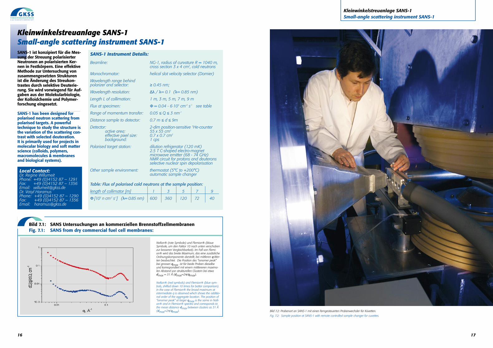
Bild 7.2: Probenort an SANS-1 mit einen ferngesteuerten Probenwechsler für Küvetten.
Fig. 7.2: Sample position at SANS-1 with remote controlled sample changer for cuvettes.
17
Kleinwinkelstreuanlage SANS-1Small-angle scattering instrument SANS-1
SANS-1 ist konzipiert für die Mes-sung der Streuung polarisierterNeutronen an polarisierten Ker-nen in Festkörpern. Eine effektiveMethode zur Untersuchung vonzusammengesetzten Strukturenist die Änderung des Streukon-trastes durch selektive Deuterie-rung. Sie wird vorwiegend für Auf-gaben aus der Molekularbiologie,der Kolloidchemie und Polymer-forschung eingesetzt.
SANS-1 has been designed forpolarised neutron scattering frompolarised targets. A powerful technique to study the structure isthe variation of the scattering con-trast with selected deuteration. It is primarily used for projects inmolecular biology and soft matterscience (colloids, polymers,macromolecules & membranesand biological systems).
16
Kleinwinkelstreuanlage SANS-1Small-angle scattering instrument SANS-1
SANS-1 Instrument Details:
Beamline: NG-1, radius of curvature R = 1040 m,cross section 3 x 4 cm2, cold neutrons
Monochromator: helical slot velocity selector (Dornier)
Wavelength range behindpolarizer and selector: ≥ 0.45 nm;
Wavelength resolution: ∆λ / λ= 0.1 (λ= 0.85 nm)
Length L of collimation: 1 m, 3 m, 5 m, 7 m, 9 m
Flux at specimen: Φ = 0.04 - 6·105 cm-2 s-1 see table
Range of momentum transfer: 0.05 ≤ Q ≤ 3 nm-1
Distance sample to detector: 0.7 m ≤ d ≤ 9m
Detector: 2-dim position-sensitive 3He-counteractive area: 55 x 55 cm2
effective pixel size: 0.7 x 0.7 cm2
background: 1 cps
Polarised target station: dilution refrigerator (120 mK)2.5 T C-shaped electro-magnetmicrowave emitter (68 - 74 GHz) NMR circuit for protons and deuteronsselective nuclear spin depolarisation
Other sample environment: thermostat (5°C to +200°C)automatic sample changer
Table: Flux of polarised cold neutrons at the sample position:
length of collimator [m] 1 3 5 7 9
Φ [103 n cm-2 s-1] (λ= 0.85 nm) 600 360 120 72 40
Bild 7.1: SANS Untersuchungen an kommerziellen BrennstoffzellmembranenFig. 7.1: SANS from dry commercial fuel cell membranes:
Nafion® (rote Symbole) und Flemion® (blaueSymbole, um den Faktor 10 nach unten verschobenzur besseren Vergleichbarkeit). Im Fall von Flemi-on® wird das breite Maximum, das eine zusätzlicheOrdnungskomponente darstellt, bei mittleren q-Wer-ten beobachtet. Die Position des “ionomer peak”bei grossen qmax ist für beide Proben dieselbeund korrespondiert mit einem mittlereren maxima-len Abstand von strukturellen Clustern bei etwadmax = 31 Å (dmax=2π/qmax).
Nafion® (red symbols) and Flemion® (blue sym-bols, shifted down 10 times for better comparison).In the case of Flemion® the broad maximum atintermediate q is observed which shows the additio-nal order of the aggregate location. The position of“ionomer peak” at larger qmax is the same in Nafi-on® and in Flemion® spectra and corresponds tothe mean distance dmax between clusters as 31 Å(dmax=2π/qmax).
Local Contact:Dr. Regine WillumeitPhone: +49 (0)4152 87 – 1291Fax: +49 (0)4152 87 – 1356Email: [email protected]. Vasyl HaramusPhone: +49 (0)4152 87 – 1290Fax: +49 (0)4152 87 – 1356Email: [email protected]
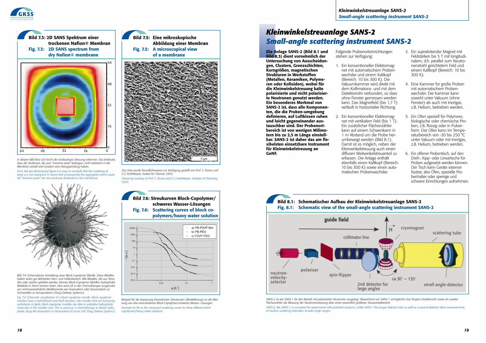
SANS-2 ist wie SANS-1 für den Betrieb mit polarisierten Neutronen ausgelegt. Abweichend von SANS-1 ermöglichen das längere Detektorrohr sowie ein zweiterFlächenzähler die Messung der Neutronenstreuung über einen wesentlich größeren Streuwinkelbereich.
SANS-2, like SANS-1, is conceived for experiments with polarized neutrons. Unlike SANS-1 the longer detector tube as well as a second detector allow measurements of neutron scattering intensities at wide angle ranges.
Bild 8.1: Schematischer Aufbau der Kleinwinkelstreuanlage SANS-2Fig. 8.1: Schematic view of the small-angle scattering instrument SANS-2
19
Kleinwinkelstreuanlage SANS-2Small-angle scattering instrument SANS-2
Die Anlage SANS-2 (Bild 8.1 undBild 8.3) dient vornehmlich derUntersuchung von Ausscheidun-gen, Clustern, Grenzschichten,Korngrößen, magnetischenStrukturen in Werkstoffen(Metallen, Keramiken, Polyme-ren oder Kolloiden), wobei fürdie Kleinwinkelstreuung kaltepolarisierte und nicht polarisier-te Neutronen genutzt werden.Ein besonderes Merkmal vonSANS-2 ist, dass alle Komponen-ten, die die Proben-umgebungdefinieren, auf Luftkissen ruhenund leicht gegeneinander aus-tauschbar sind. Der Probenort-bereich ist von wenigen Milime-tern bis zu 2,5 m Länge einstell-bar. SANS-2 ist daher das am fle-xibelsten einsetzbare Instrumentfür Kleinwinkelstreuung anGeNF.
Folgende Probenorteinrichtungenstehen zur Verfügung:
1. Ein konventioneller Elektromag-net mit automatischem Proben-wechsler und einem Kaltkopf(Bereich: 10 bis 300 K). DieVakuumkammer wird direkt mitdem Kollimations- und mit demDetektorrohr verbunden, so dassohne Fenster gemessen werdenkann. Das Magnetfeld (bis 1,7 T)verläuft in horizontaler Richtung.
2. Ein konventioneller Elektromag-net mit vertikalem Feld (bis 1 T).Ein zusätzlicher Flächenzählerkann auf einem Schwenkarm in 1 m Abstand um die Probe her-umbewegt werden (Bild 8.1).Damit ist es möglich, neben derKleinwinkelstreuung auch einendiffusen Weitwinkelstreuanteil zuerfassen. Die Anlage enthältebenfalls einen Kaltkopf (Bereich:10 bis 300 K) sowie einen auto-matischen Probenwechsler.
3. Ein supraleitender Magnet mitFeldstärken bis 5 T mit longitudi-nalem, d.h. parallel zum Neutro-nenstrahl gerichtetem Feld undeinem Kaltkopf (Bereich: 10 bis300 K).
4. Eine Kammer für große Probenmit automatischem Proben-wechsler. Die Kammer kannsowohl unter Vakuum (ohne Fenster) als auch mit Inertgas,z.B. Helium, betrieben werden.
5. Ein Ofen speziell für Polymere,biologische oder chemische Pro-ben, z.B. flüssig oder in Pulver-form. Der Ofen kann im Tempe-raturbereich von -30 bis 250 °Cunter Vakuum oder mit Inertgas,z.B. Helium, betrieben werden.
6. Ein offener Probentisch, auf denDreh-, Kipp- oder Lineartische fürProben aufgesetzt werden können.Der Tisch kann Geräte externerNutzer, also Öfen, spezielle Pro-benhalter oder sperrige undschwere Einrichtungen aufnehmen.
Kleinwinkelstreuanlage SANS-2Small-angle scattering instrument SANS-2
Beispiel für die Anpassung theoretischer Streukurven (Modellierung) an die Mes-sung von drei verschiedenen Block-Copolymer/schweres Wasser- Lösungen.
Example for fits to the measured scattering curves for three different block copolymers/heavy water solutions.
Das Foto wurde freundlicherweise zur Verfügung gestellt von Prof. S. Nunes undC.S. Karthikeyan, Institut für Chemie, GKSS.
Picture by courtesy of Prof. S. Nunes and C.S. Karthikeyan, Institute of Chemistry,GKSS.
18
Bild 7.3: 2D SANS Spektrum einertrockenen Nafion® Membran
Fig. 7.3: 2D SANS spectrum from dry Nafion® membrane
Bild 7.5: Eine mikroskopische Abbildung einer Membran
Fig. 7.5: A microscopical viewof a membrane
Bild 7.6: Streukurven Block-Copolymer/schweres Wasser-Lösungen
Fig. 7.6: Scattering curves of block co-polymers/heavy water solution
In diesem Bild lässt sich leicht die nichtisotrope Streuung erkennen. Das bedeutet,dass die Strukturen, die zum “ionomer peak” beitragen, nicht statistisch in derMembran verteilt sind sondern eine Vorzugsrichtung haben.
From the two-dimensional figure it is easy to conclude that the scattering at large q is not isotropical. It means that consequently the aggregates which causethe “ionomer peak” are not randomly distributed in the membrane.
Bild 7.4: Schematische Vorstellung einer Block-Copolymer Mizelle. Diese Mizellenhaben einen gut definierten Kern- und Hüllenbereich. Wie Mizellen, die aus Tensi-den oder Lipiden gebildet werden, können Block-Copolymer Mizellen hydrophobeMoleküle in ihrem Inneren lösen. Dies wird z.B. in der Chemotherapie ausgenutzt,um nicht-wasserlösliche Medikamente wie Doxorubicin oder Daunorubicin zuTumorzellen zu transportieren ('Drug Delivery Systems').
Fig. 7.4: Schematic visualisation of a block copolymer micelle. Block copolymermicelles have a well-defined core/shell structure. Like micelles that are formed bysurfactants or lipids, block copolymer micelles are able to solubilize hydrophobicmolecules in the micellar core. This is used e.g. in chemotherapy to deliver hydro-phobic drugs like doxorubicin or daunorubicin to tumor cell (‘Drug Delivery Systems’).
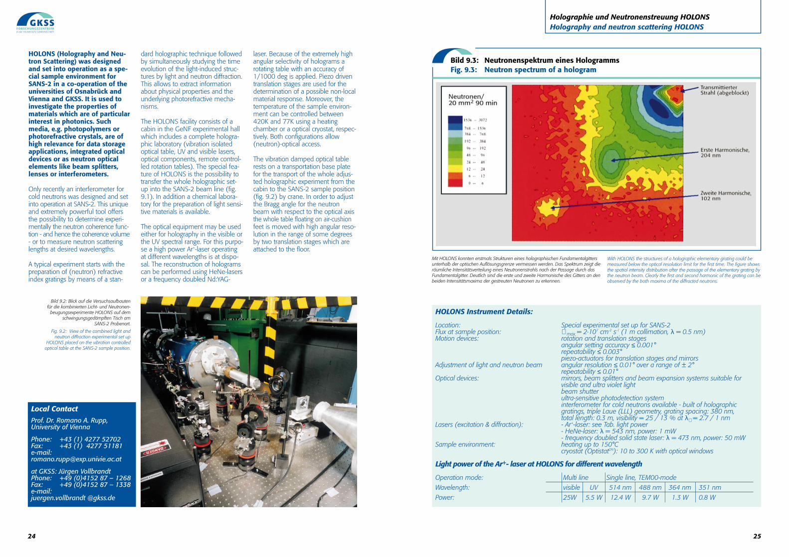
SANS-Streukurven eines Druckbehälterstahls 15NiCuMoNb5 (WB36) im vergüteten (as-produced) Zustand und nach Betrieb (after service;57000 h/350 °C). Die aus den Streukurvenbestimmte Größenverteilung zeigt, dass sichwährend des Betriebes Cu-reiche Ausscheidungenmit einem Volumenbruchteil von 0,36% und einemmittleren Radius von ca. 2,3 nm gebildet haben (Mit freundlicher Genehmigung der MPA Stuttgart).
SANS scattering curves from a presure vessel steel15NiCuMoNb5 (WB36) in the as-produced stateand after service (57000 h/350 °C). The sizedistribution determined from the scattering curvesreveals the formation of Cu-rich precipitates with avolume fraction of 0.36% and a mean radius ofabout 2.3 nm (courtesy of MPA Stuttgart).
21
Kleinwinkelstreuanlage SANS-2Small-angle scattering instrument SANS-2
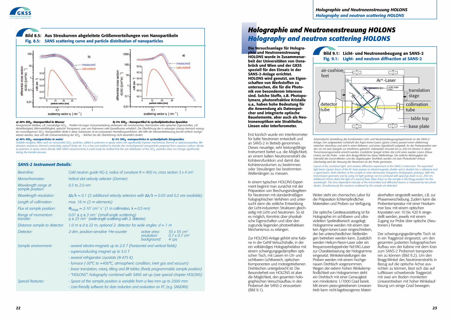
Bild 8.3: SANS-2 hat einen zweiten Flächenzähler für die Messung der Neutronenstreuung bei größeren Streuwinkeln.
Fig. 8.3: SANS-2 has a second area detector for measurement of neutron scattering intensity at larger angles.
Bild 8.4: SANS-Streukurven einesDruckbehälterstahls (WB 36)
Fig. 8.4: SANS scattering curves from apressure vessel steel (WB 36)
20
SANS-2 (fig. 8.1 and fig. 8.3) ismainly dedicated to neutronsmall-angle scattering studies ofprecipitates, clusters, interfaces,grain sizes, magnetic structuresetc. in materials like metals, cera-mics, polymers and colloids usingcold non-polarised and polarisedneutrons.A special feature is that all com-ponents which define the sampleenvironment are movable on aircushions. The sample environ-ment area is variable from a fewmm up to 2.5 m length. ThusSANS-2 is the most variableinstrument for small angle scattering at GeNF.
The following sample environmentsare available:
1. A conventional electro-magnetwith a remote controlled samplechanger. The vacuum chamber isdirectly connected to the collimatorand detector tubes, so that samplescan be measured without any windows.The magnetic field (up to 1.7 T) ishorizontal. A closed cycle refrigeratorwith a temperature range from 10 Kto 300 K is also available.
2. A conventional electro-magnetwith a vertical field (up to 1 T). Anadditional area detector can bemoved around the sample in adistance of about 1m. This allows thesimultaneous measurement of boththe small angle scattering and thediffuse wide angle scattering (fig.8.1). The system contains a refrigera-tor (10 - 300K) and a remote con-trolled sample changer.
3. A superconducting magnet (up to5 T) with a closed cycle refrigerator(10 - 300K). Its magnetic field direc-tion is parallel to the flight directionof the incident neutron beam.4. Chamber for large samples with aremote controlled sample changer.This set up can be operated eitherwith vacuum (without windows) orwith inert gas (e.g. He, etc.)
5. A furnace especially for polymeric,biological or chemical samples (e.g.liquids or powders), temperaturerange from -30 to 250 °C. The fur-nace can be operated either withinert gas (e.g. He etc.) or in vacuum.
6. Open sample table, with a rota-ting table, a tilting table and a lineartranslation table. This sample tablecan support equipment of externalusers such as furnaces, special sample holders, or other bulky andheavy instruments.
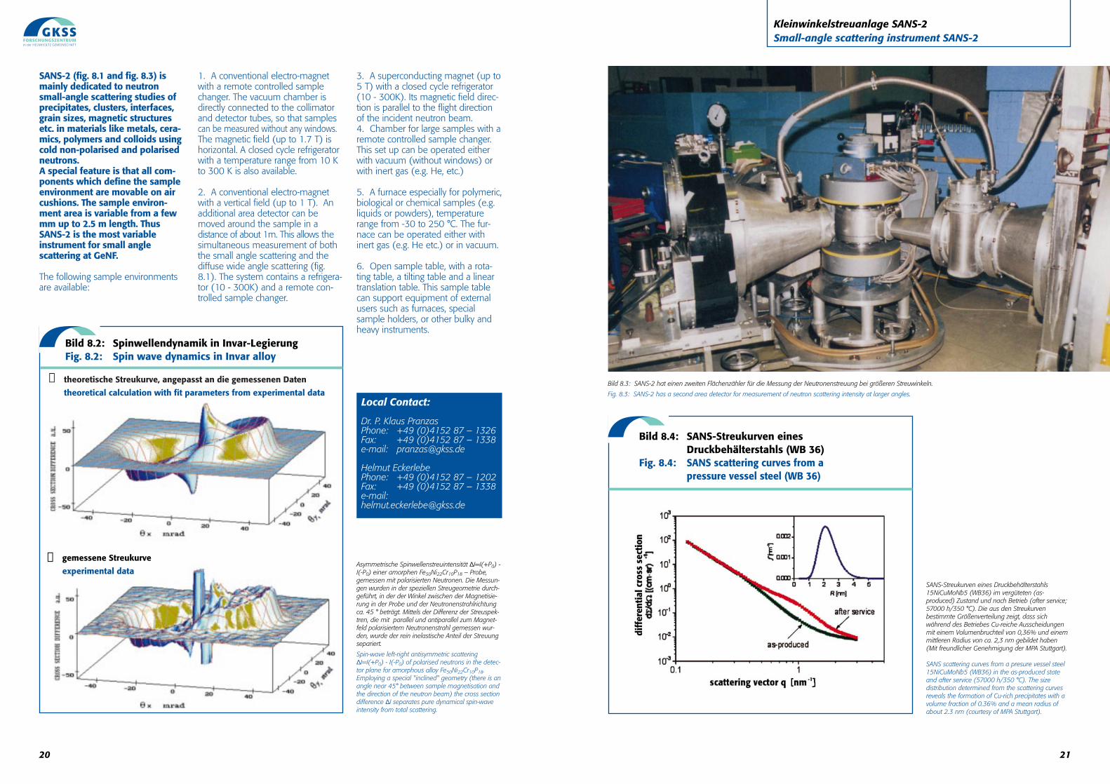
Asymmetrische Spinwellenstreuintensität ∆I=I(+P0) -I(-P0) einer amorphen Fe50Ni22Cr10P18 – Probe,gemessen mit polarisierten Neutronen. Die Messun-gen wurden in der speziellen Streugeometrie durch-geführt, in der der Winkel zwischen der Magnetisie-rung in der Probe und der Neutronenstrahlrichtungca. 45 ° beträgt. Mittels der Differenz der Streuspek-tren, die mit parallel und antiparallel zum Magnet-feld polarisiertem Neutronenstrahl gemessen wur-den, wurde der rein inelastische Anteil der Streuungsepariert.
Spin-wave left-right antisymmetric scattering∆I=I(+P0) - I(-P0) of polarised neutrons in the detec-tor plane for amorphous alloy Fe50Ni22Cr10P18.Employing a special "inclined" geometry (there is anangle near 45° between sample magnetisation andthe direction of the neutron beam) the cross sectiondifference ∆I separates pure dynamical spin-waveintensity from total scattering.
Local Contact:
Dr. P. Klaus PranzasPhone: +49 (0)4152 87 – 1326Fax: +49 (0)4152 87 – 1338e-mail: [email protected]
Helmut EckerlebePhone: +49 (0)4152 87 – 1202Fax: +49 (0)4152 87 – 1338e-mail: [email protected]
Bild 8.2: Spinwellendynamik in Invar-LegierungFig. 8.2: Spin wave dynamics in Invar alloy
❶ theoretische Streukurve, angepasst an die gemessenen Daten
theoretical calculation with fit parameters from experimental data
❷ gemessene Streukurve
experimental data
23
Holographie und Neutronenstreuung HOLONSHolography and neutron scattering HOLONS
Holographie und Neutronenstreuung HOLONSHolography and neutron scattering HOLONSDie Versuchsanlage für Hologra-phie und NeutronenstreuungHOLONS wurde in Zusammenar-beit der Universitäten von Osna-brück und Wien und der GKSSspeziell für den Einsatz in derSANS-2-Anlage errichtet.HOLONS wird genutzt, um Eigen-schaften von Werkstoffen zuuntersuchen, die für die Photo-nik von besonderem Interessesind. Solche Stoffe, z.B. Photopo-lymere, photorefraktive Kristalleu.a., haben hohe Bedeutung fürdie Anwendung als Datenspei-cher und integrierte optischeBauelemente, aber auch als Neu-tronenoptiken wie Strahlteiler,Linsen oder Interferometer.
Erst kürzlich wurde ein Interferometerfür kalte Neutronen entwickelt undan SANS-2 in Betrieb genommen.Dieses neuartige, sehr leistungsfähigeInstrument bietet u.a. die Möglichkeit,an einem kalten Neutronenstrahl dieKohärenzfunktion und damit dasKohärenzvolumen zu bestimmenoder Streulängen bei bestimmtenWellenlängen zu messen.
In einem typischen HOLONS-Experi-ment beginnt man zunächst mit derPräparation von Brechungsindexgitternfür Neutronen mit standardmäßigenholographischen Verfahren und unter-sucht dann die zeitliche Entwicklungder Licht-induzierten Strukturen gleich-zeitig mit Licht und Neutronen. So istes möglich, Kenntnis über physikali-sche Eigenschaften und über denzugrunde liegenden photorefraktivenMechanismus zu erlangen.
Zur HOLONS-Anlage gehört eine Kabi-ne in der GeNF-Versuchshalle, in derein vollständiges Holographielabor miteinem schwingungsgedämpften opti-schen Tisch, mit Lasern im UV- undsichtbaren Lichtbereich, optischenKomponenten und motorgetriebenenDrehtischen untergebracht ist. DieBesonderheit von HOLONS ist aberdie Möglichkeit, den gesamten holo-graphischen Versuchsaufbau in denProbenort der SANS-2 einzusetzen(Bild 9.1).
Weiter steht ein chemisches Labor fürdie Präparation lichtempfindlicherMaterialien und Proben zur Verfügung.
Die optische Geräteausstattung ist fürHolographie im sichtbaren und ultra-violetten Spektralbereich ausgelegt.Hologramme werden mit einem star-ken Argon-Ionen-Laser eingeschrieben,der bei unterschiedlichen Wellenlän-gen betrieben werden kann. Zusätzlichwerden Helium-Neon-Laser oder einfrequenzverdoppelnder Nd:YAG-Laserzur Charakterisierung der Hologrammeeingesetzt. Winkeleinstellungen derProben werden mit einem hochge-nauen Drehtisch vorgenommen.Wegen der extrem hohen Winkelemp-findlichkeit von Hologrammen stehtein Drehtisch mit einer Genauigkeitvon mindestens 1/1000 Grad bereit.Mit einem piezo-getriebenen Linearan-trieb kann nicht-lagebezogenes Materi-
alverhalten eingestellt werden, z.B. zurPhasenverschiebung. Zudem kann dieProbentemperatur mit einer Heizkam-mer bzw. mit einem optischenKryostaten von 10 bis 420 K einge-stellt werden, jeweils mit einemZugang zur Probe über optische (Neu-tronen-) Fenster.
Der schwingungsgedämpfte Tisch istin ein Traggerüst eingesetzt, um dengesamten justierten holographischenAufbau von der Kabine mit dem Kranzum SANS-2 Probenort transportie-ren zu können (Bild 9.2). Um denBragg-Winkel des Neutronenstrahls inBezug auf die optische Achse aus-richten zu können, lässt sich das aufLuftkissen schwebende Traggerüstmit zwei am Boden montiertenLinearantrieben mit hoher Winkelauf-lösung um einige Grad bewegen.
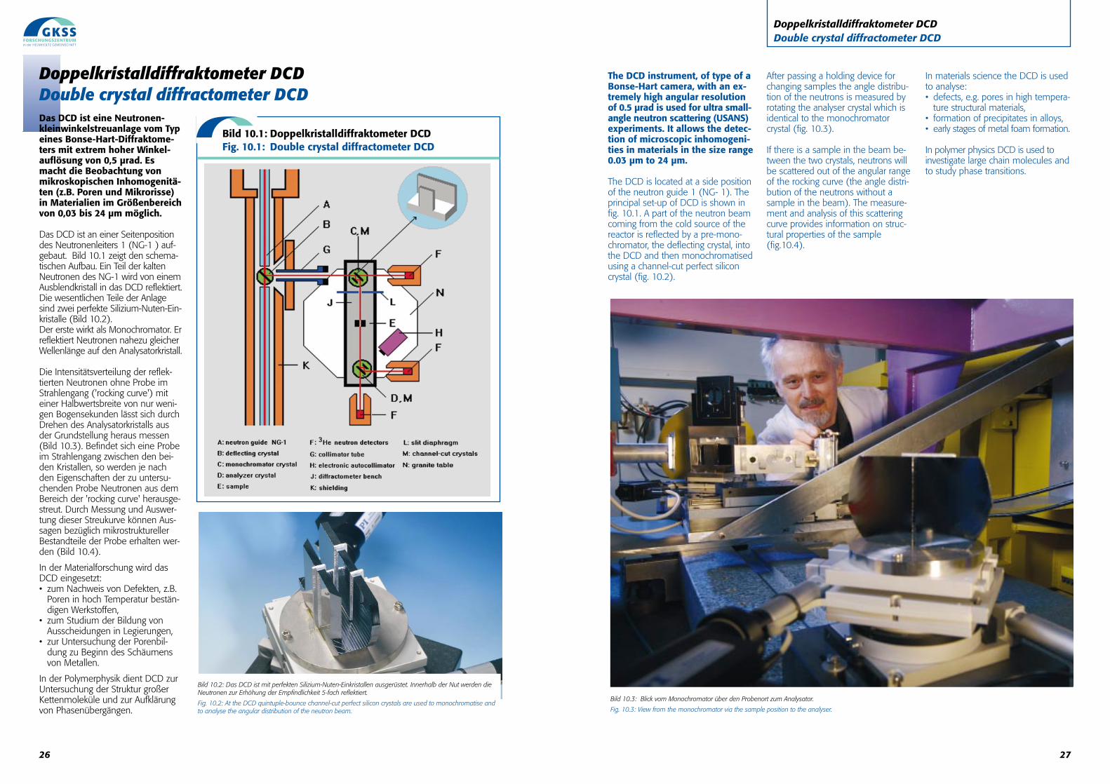
Schematische Darstellung des kombinierten Licht- und Neutronenbeugungsexperiments an der SANS-2-Anlage: Der aufgeweitete Lichtstrahl des Argon-Ionen-Lasers (grüne Linien) passiert einen elektromag-netischen Verschluss und wird in einen Referenz- und einen Signalstrahl aufgeteilt. An der Probenposition wer-den sie mit zwei Spiegeln zur Interferenz gebracht. Gitterweiten hinunter bis zu 200 nm können in dieserTransmissionsgeometrie erreicht werden. Zusätzliche Spiegel richten das Licht eines zweiten Lasers (blaueLinien) auf die Probe - unter dem Bragg-Winkel bei dieser Wellenlänge. Die zeitliche Abhängigkeit derIntensität des transmittierten und des abgebeugten Strahlteils werden mit zwei Photodioden erfasst.Gleichzeitig wird die Streuung der Neutronen an der Probe gemessen.
Layout of the combined light- and neutron diffraction experiment at the SANS-2 instrument. The expandedlight beam (green lines) of the Ar+-laser passes an electromagnetic shutter and is divided into a reference anda signal beam. Both interfere at the sample to write elementary holograms (holographic gratings). With thistransmission geometry and by using UV light gratings can be achieved with spacings down to ca. 200 nm.Additional mirrors direct the light of a second laser (blue lines) on the sample in the Bragg position for thiswavelength. The time dependent intensity of the transmitted and diffracted beams is measured by two photodiodes. Simultaneously the neutrons scattered by the sample are detected.
Bild 9.1: Licht- und Neutronenbeugung an SANS-2Fig. 9.1: Light- and neutron diffraction at SANS-2
22
SANS-2 Instrument Details:
Beamline: Cold neutron guide NG-2, radius of curvature R = 900 m, cross section 3 x 4 cm2
Monochromator: helical slot velocity selector (Dornier)
Wavelength range at 0.3 to 2.0 nmsample position:
Wavelength resolution: ∆λ/λ = 0.1 (2 additional velocity selectors with ∆λ/λ = 0.05 and 0.2 are available)
Length of collimation: max. 16 m (2 m elements)
Flux at sample position: Φmax = 2·107 cm-2 s-1 (1 m collimation, λ = 0.5 nm)
Range of momentum 0.01 ≤ q ≤ 3 nm-1 (small-angle scattering)transfer: q ≤ 25 nm-1 (wide-angle scattering with 2. detector)
Distance sample to detector: 1.0 m ≤ d ≤ 22 m, optional 2. detector for wide angles: d = 1 m
Detector: 2-dim. position-sensitive 3He-counter active area: 55 x 55 cm2
resolution: 0.7 x 0.7 cm2
background: 4 cps
Sample environment: - several electro-magnets up to 2.0 T (horizontal and vertical fields)
- superconducting magnet up to 5.0 T
- several refrigerator cryostats (8-475 K)
- furnace (-30°C to +400°C, atmospheric condition, inert gas and vacuum)
- linear translation, rotary, tilting and lift tables (freely programmable sample position)
- “HOLONS”: holography combined with SANS set up (see special chapter HOLONS)
Special features: - Space of the sample position is variable from a few mm up to 2500 mm
- User-friendly software for data reduction and evaluation on PC (e.g. SANDRA)
a) 40% SiO2 -Nanopartikel in Wasser b) 5% SiO2 - Nanopartikel in cycloaliphatischen EpoxidenAnorganische Additive, z.B. nanoskalige SiO2 - Partikel mit enger Grössenverteilung verbessern die mechanischen, thermischen oder optischen Eigenschaften, z.B.Abriebfestigkeit, Wärmeleitfähigkeit, optische Transparenz, usw. von Polymeren oder Epoxidharzen erheblich. Die Überführung der in wässriger Lösung chemisch erzeug-ten monodispersen SiO2 -Nanopartikeln direkt in diese Substanzen ist ein preiswertes Herstellungsverfahren. Mit Hilfe der Kleinwinkelstreuung konnte einfach nachge-wiesen werden, dass sich die Grössenverteilung der SiO2 - Teilchen bei der Überführung nicht wesentlich ändert.
a) 40% SiO2 -nanoparticles in water b) 5% SiO2 -nanoparticles in cycloaliphatic bisepoxidesSuitable inorganic fillers such as nanoscaled SiO2 -particles, added to polymers or epoxy resins can significantly improve mechanical, thermal or optical properties, likeabrasion resistance, thermal conductivity, optical clarity, etc. It is a low cost method to transfer the monodispersed nanoparticles prepared from aqueous sodium silicateto polymers or epoxy resins directly. With SANS measurements it could easily be verified that the size distribution of the SiO2 -particles does not change significantlyduring the transfer process.
Bild 8.5: Aus Streukurven abgeleitete Größenverteilungen von NanopartikelnFig. 8.5: SANS scattering curve and particle distribution of nanoparticles
25
Holographie und Neutronenstreuung HOLONSHolography and neutron scattering HOLONS
With HOLONS the structures of a holographic elementary grating could bemeasured below the optical resolution limit for the first time. The figure showsthe spatial intensity distribution after the passage of the elementary grating bythe neutron beam. Clearly the first and second harmonic of the grating can beobserved by the both maxima of the diffracted neutrons.
Bild 9.3: Neutronenspektrum eines HologrammsFig. 9.3: Neutron spectrum of a hologram
HOLONS Instrument Details:
Location: Special experimental set up for SANS-2Flux at sample position: ∅ max = 2·107 cm-2 s-1 (1 m collimation, λ = 0.5 nm)Motion devices: rotation and translation stages
angular setting accuracy ≤ 0.001°repeatability ≤ 0.003°piezo-actuators for translation stages and mirrors
Adjustment of light and neutron beam angular resolution ≤ 0.01° over a range of ± 2°repeatability ≤ 0.01°
Optical devices: mirrors, beam splitters and beam expansion systems suitable forvisible and ultra violet lightbeam shutterultra-sensitive photodetection systeminterferometer for cold neutrons available - built of holographicgratings, triple Laue (LLL) geometry, grating spacing: 380 nm, total length: 0.3 m, visibility = 25 / 13 % at λ+ = 2.7 / 1 nm
Lasers (excitation & diffraction): - Ar+-laser: see Tab. light power- HeNe-laser: λ = 543 nm, power: 1 mW- frequency doubled solid state laser: λ = 473 nm, power: 50 mW
Sample environment: heating up to 150°Ccryostat (OptistatDN): 10 to 300 K with optical windows
Light power of the Ar+- laser at HOLONS for different wavelength
Operation mode: Multi line Single line, TEM00-mode
Wavelength: visible UV 514 nm 488 nm 364 nm 351 nm
Power: 25W 5.5 W 12.4 W 9.7 W 1.3 W 0.8 W
Mit HOLONS konnten erstmals Strukturen eines holographischen Fundamentalgittersunterhalb der optischen Auflösungsgrenze vermessen werden. Das Spektrum zeigt dieräumliche Intensitätsverteilung eines Neutronenstrahls nach der Passage durch dasFundamentalgitter. Deutlich sind die erste und zweite Harmonische des Gitters an denbeiden Intensitätsmaxima der gestreuten Neutronen zu erkennen.
24
HOLONS (Holography and Neu-tron Scattering) was designedand set into operation as a spe-cial sample environment forSANS-2 in a co-operation of theuniversities of Osnabrück andVienna and GKSS. It is used toinvestigate the properties ofmaterials which are of particularinterest in photonics. Suchmedia, e.g. photopolymers orphotorefractive crystals, are ofhigh relevance for data storageapplications, integrated opticaldevices or as neutron opticalelements like beam splitters,lenses or interferometers.
Only recently an interferometer forcold neutrons was designed and setinto operation at SANS-2. This uniqueand extremely powerful tool offersthe possibility to determine experi-mentally the neutron coherence func-tion - and hence the coherence volume- or to measure neutron scatteringlengths at desired wavelengths.
A typical experiment starts with thepreparation of (neutron) refractiveindex gratings by means of a stan-
dard holographic technique followedby simultaneously studying the timeevolution of the light-induced struc-tures by light and neutron diffraction.This allows to extract informationabout physical properties and theunderlying photorefractive mecha-nisms.
The HOLONS facility consists of acabin in the GeNF experimental hallwhich includes a complete hologra-phic laboratory (vibration isolatedoptical table, UV and visible lasers,optical components, remote control-led rotation tables). The special fea-ture of HOLONS is the possibility totransfer the whole holographic set-up into the SANS-2 beam line (fig.9.1). In addition a chemical labora-tory for the preparation of light sensi-tive materials is available.
The optical equipment may be usedeither for holography in the visible orthe UV spectral range. For this purpo-se a high power Ar+-laser operatingat different wavelengths is at dispo-sal. The reconstruction of hologramscan be performed using HeNe-lasersor a frequency doubled Nd:YAG-
laser. Because of the extremely highangular selectivity of holograms arotating table with an accuracy of1/1000 deg is applied. Piezo driventranslation stages are used for thedetermination of a possible non-localmaterial response. Moreover, thetemperature of the sample environ-ment can be controlled between420K and 77K using a heatingchamber or a optical cryostat, respec-tively. Both configurations allow(neutron)-optical access.
The vibration damped optical tablerests on a transportation base platefor the transport of the whole adjus-ted holographic experiment from thecabin to the SANS-2 sample position(fig. 9.2) by crane. In order to adjustthe Bragg angle for the neutronbeam with respect to the optical axisthe whole table floating on air-cushionfeet is moved with high angular reso-lution in the range of some degreesby two translation stages which areattached to the floor.
Bild 9.2: Blick auf die Versuchsaufbauten für die kombinierten Licht- und Neutronen-
beugungsexperimente HOLONS auf demschwingungsgedämpften Tisch am
SANS-2 Probenort.
Fig. 9.2: View of the combined light and neutron diffraction experimental set up
HOLONS placed on the vibration controlled optical table at the SANS-2 sample position.
Local Contact
Prof. Dr. Romano A. Rupp, University of Vienna
Phone: +43 (1) 4277 52702Fax: +43 (1) 4277 51181 e-mail: [email protected]
at GKSS: Jürgen VollbrandtPhone: +49 (0)4152 87 – 1268Fax: +49 (0)4152 87 – 1338e-mail:juergen.vollbrandt @gkss.de
The DCD instrument, of type of aBonse-Hart camera, with an ex-tremely high angular resolutionof 0.5 µrad is used for ultra small-angle neutron scattering (USANS)experiments. It allows the detec-tion of microscopic inhomogeni-ties in materials in the size range0.03 µm to 24 µm.
The DCD is located at a side positionof the neutron guide 1 (NG- 1). Theprincipal set-up of DCD is shown infig. 10.1. A part of the neutron beamcoming from the cold source of thereactor is reflected by a pre-mono-chromator, the deflecting crystal, intothe DCD and then monochromatisedusing a channel-cut perfect siliconcrystal (fig. 10.2).
After passing a holding device forchanging samples the angle distribu-tion of the neutrons is measured byrotating the analyser crystal which isidentical to the monochromatorcrystal (fig. 10.3).
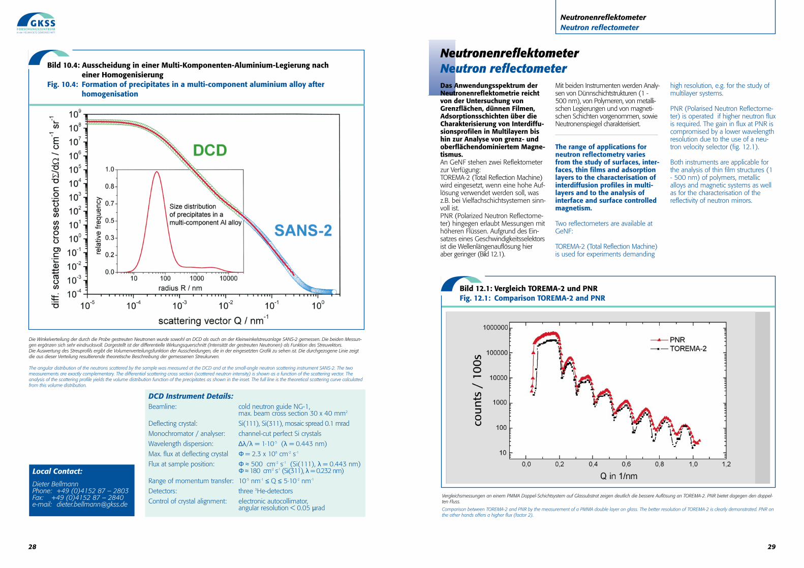
If there is a sample in the beam be-tween the two crystals, neutrons willbe scattered out of the angular rangeof the rocking curve (the angle distri-bution of the neutrons without asample in the beam). The measure-ment and analysis of this scatteringcurve provides information on struc-tural properties of the sample(fig.10.4).
In materials science the DCD is usedto analyse:• defects, e.g. pores in high tempera-
ture structural materials,• formation of precipitates in alloys,• early stages of metal foam formation.
In polymer physics DCD is used toinvestigate large chain molecules andto study phase transitions.
27
Doppelkristalldiffraktometer DCDDouble crystal diffractometer DCD
Bild 10.3: Blick vom Monochromator über den Probenort zum Analysator.
Fig. 10.3: View from the monochromator via the sample position to the analyser.
Bild 10.1: Doppelkristalldiffraktometer DCDFig. 10.1: Double crystal diffractometer DCD
26
Doppelkristalldiffraktometer DCDDouble crystal diffractometer DCD
Bild 10.2: Das DCD ist mit perfekten Silizium-Nuten-Einkristallen ausgerüstet. Innerhalb der Nut werden dieNeutronen zur Erhöhung der Empfindlichkeit 5-fach reflektiert.
Fig. 10.2: At the DCD quintuple-bounce channel-cut perfect silicon crystals are used to monochromatise andto analyse the angular distribution of the neutron beam.
Das DCD ist eine Neutronen-kleinwinkelstreuanlage vom Typeines Bonse-Hart-Diffraktome-ters mit extrem hoher Winkel-auflösung von 0,5 µrad. Esmacht die Beobachtung vonmikroskopischen Inhomogenitä-ten (z.B. Poren und Mikrorisse)in Materialien im Größenbereichvon 0,03 bis 24 µm möglich.
Das DCD ist an einer Seitenpositiondes Neutronenleiters 1 (NG-1 ) auf-gebaut. Bild 10.1 zeigt den schema-tischen Aufbau. Ein Teil der kaltenNeutronen des NG-1 wird von einemAusblendkristall in das DCD reflektiert.Die wesentlichen Teile der Anlagesind zwei perfekte Silizium-Nuten-Ein-kristalle (Bild 10.2). Der erste wirkt als Monochromator. Erreflektiert Neutronen nahezu gleicherWellenlänge auf den Analysatorkristall.
Die Intensitätsverteilung der reflek-tierten Neutronen ohne Probe imStrahlengang ('rocking curve') miteiner Halbwertsbreite von nur weni-gen Bogensekunden lässt sich durchDrehen des Analysatorkristalls ausder Grundstellung heraus messen(Bild 10.3). Befindet sich eine Probeim Strahlengang zwischen den bei-den Kristallen, so werden je nachden Eigenschaften der zu untersu-chenden Probe Neutronen aus demBereich der 'rocking curve' herausge-streut. Durch Messung und Auswer-tung dieser Streukurve können Aus-sagen bezüglich mikrostrukturellerBestandteile der Probe erhalten wer-den (Bild 10.4).
In der Materialforschung wird dasDCD eingesetzt:• zum Nachweis von Defekten, z.B.
Poren in hoch Temperatur bestän-digen Werkstoffen,
• zum Studium der Bildung vonAusscheidungen in Legierungen,
• zur Untersuchung der Porenbil-dung zu Beginn des Schäumensvon Metallen.
In der Polymerphysik dient DCD zurUntersuchung der Struktur großerKettenmoleküle und zur Aufklärungvon Phasenübergängen.
29
NeutronenreflektometerNeutron reflectometer
NeutronenreflektometerNeutron reflectometer Das Anwendungsspektrum derNeutronenreflektometrie reichtvon der Untersuchung vonGrenzflächen, dünnen Filmen,Adsorptionsschichten über dieCharakterisierung von Interdiffu-sionsprofilen in Multilayern bishin zur Analyse von grenz- undoberflächendominiertem Magne-tismus. An GeNF stehen zwei Reflektometerzur Verfügung:TOREMA-2 (Total Reflection Machine)wird eingesetzt, wenn eine hohe Auf-lösung verwendet werden soll, wasz.B. bei Vielfachschichtsystemen sinn-voll ist. PNR (Polarized Neutron Reflectome-ter) hingegen erlaubt Messungen mithöheren Flüssen. Aufgrund des Ein-satzes eines Geschwindigkeitsselektorsist die Wellenlängenauflösung hieraber geringer (Bild 12.1).
Mit beiden Instrumenten werden Analy-sen von Dünnschichtstrukturen (1 -500 nm), von Polymeren, von metalli-schen Legierungen und von magneti-schen Schichten vorgenommen, sowieNeutronenspiegel charakterisiert.
The range of applications forneutron reflectometry variesfrom the study of surfaces, inter-faces, thin films and adsorptionlayers to the characterisation ofinterdiffusion profiles in multi-layers and to the analysis ofinterface and surface controlledmagnetism.
Two reflectometers are available atGeNF:
TOREMA-2 (Total Reflection Machine)is used for experiments demanding
high resolution, e.g. for the study ofmultilayer systems.
PNR (Polarised Neutron Reflectome-ter) is operated if higher neutron fluxis required. The gain in flux at PNR iscompromised by a lower wavelengthresolution due to the use of a neu-tron velocity selector (fig. 12.1).
Both instruments are applicable forthe analysis of thin film structures (1- 500 nm) of polymers, metallicalloys and magnetic systems as wellas for the characterisation of thereflectivity of neutron mirrors.
Vergleichsmessungen an einem PMMA Doppel-Schichtsystem auf Glassubstrat zeigen deutlich die bessere Auflösung an TOREMA-2. PNR bietet dagegen den doppel-ten Fluss.
Comparison between TOREMA-2 and PNR by the measurement of a PMMA double layer on glass. The better resolution of TOREMA-2 is clearly demonstrated. PNR onthe other hands offers a higher flux (factor 2).
Bild 12.1: Vergleich TOREMA-2 und PNRFig. 12.1: Comparison TOREMA-2 and PNR
28
Local Contact:
Dieter BellmannPhone: +49 (0)4152 87 – 2803Fax: +49 (0)4152 87 – 2840e-mail: [email protected]
Die Winkelverteilung der durch die Probe gestreuten Neutronen wurde sowohl an DCD als auch an der Kleinwinkelstreuanlage SANS-2 gemessen. Die beiden Messun-gen ergänzen sich sehr eindrucksvoll. Dargestellt ist der differentielle Wirkungsquerschnitt (Intensität der gestreuten Neutronen) als Funktion des Streuvektors. Die Auswertung des Streuprofils ergibt die Volumenverteilungsfunktion der Ausscheidungen, die in der eingesetzten Grafik zu sehen ist. Die durchgezogene Linie zeigtdie aus dieser Verteilung resultierende theoretische Beschreibung der gemessenen Streukurven.
The angular distribution of the neutrons scattered by the sample was measured at the DCD and at the small-angle neutron scattering instrument SANS-2. The twomeasurements are exactly complementary. The differential scattering cross section (scattered neutron intensity) is shown as a function of the scattering vector. Theanalysis of the scattering profile yields the volume distribution function of the precipitates as shown in the inset. The full line is the theoretical scattering curve calculatedfrom this volume distribution.
Bild 10.4: Ausscheidung in einer Multi-Komponenten-Aluminium-Legierung nach einer Homogenisierung
Fig. 10.4: Formation of precipitates in a multi-component aluminium alloy after homogenisation
DCD Instrument Details:Beamline: cold neutron guide NG-1,
max. beam cross section 30 x 40 mm2
Deflecting crystal: Si(111), Si(311), mosaic spread 0.1 mrad
Monochromator / analyser: channel-cut perfect Si crystals
Wavelength dispersion: ∆λ/λ = 1·10-5 (λ = 0.443 nm)
Max. flux at deflecting crystal Φ = 2.3 x 108 cm-2 s-1
Flux at sample position: Φ ≈ 500 cm-2 s-1 (Si(111), λ = 0.443 nm) Φ ≈ 180 cm-2 s-1 (Si(311), λ = 0.232 nm)
Range of momentum transfer: 10-5 nm-1 ≤ Q ≤ 5·10-2 nm-1
Detectors: three 3He-detectors
Control of crystal alignment: electronic autocollimator, angular resolution < 0.05 µrad
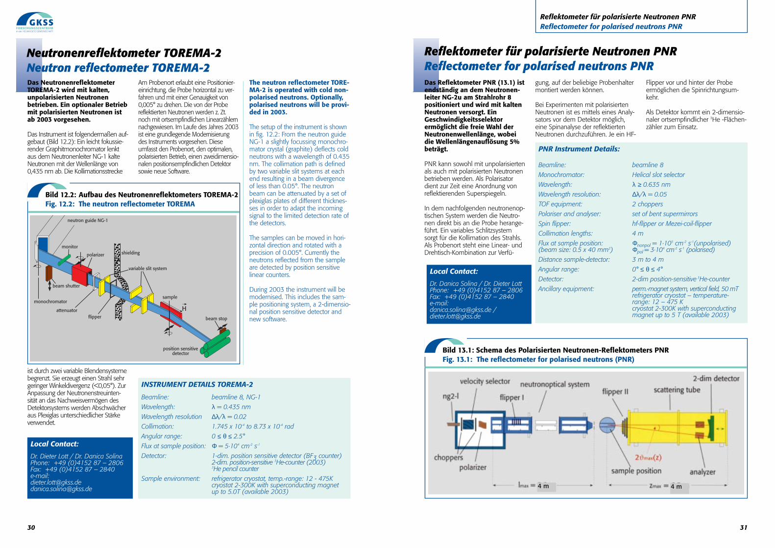
31
Reflektometer für polarisierte Neutronen PNR Reflectometer for polarised neutrons PNR
Das Reflektometer PNR (13.1) istendständig an dem Neutronen-leiter NG-2u am Strahlrohr 8positioniert und wird mit kaltenNeutronen versorgt. EinGeschwindigkeitsselektorermöglicht die freie Wahl derNeutronenwellenlänge, wobeidie Wellenlängenauflösung 5%beträgt.
PNR kann sowohl mit unpolarisiertenals auch mit polarisierten Neutronenbetrieben werden. Als Polarisatordient zur Zeit eine Anordnung vonreflektierenden Superspiegeln.
In dem nachfolgenden neutronenop-tischen System werden die Neutro-nen direkt bis an die Probe herange-führt. Ein variables Schlitzsystemsorgt für die Kollimation des Strahls.Als Probenort steht eine Linear- undDrehtisch-Kombination zur Verfü-
gung, auf der beliebige Probenhaltermontiert werden können.
Bei Experimenten mit polarisiertenNeutronen ist es mittels eines Analy-sators vor dem Detektor möglich,eine Spinanalyse der reflektiertenNeutronen durchzuführen. Je ein HF-
Flipper vor und hinter der Probeermöglichen die Spinrichtungsum-kehr.
Als Detektor kommt ein 2-dimensio-naler ortsempfindlicher 3He -Flächen-zähler zum Einsatz.
Reflektometer für polarisierte Neutronen PNRReflectometer for polarised neutrons PNR
PNR Instrument Details:
Beamline: beamline 8
Monochromator: Helical slot selector
Wavelength: λ ≥ 0.635 nm
Wavelength resolution: ∆λ/λ = 0.05
TOF equipment: 2 choppers
Polariser and analyser: set of bent supermirrors
Spin flipper: hf-flipper or Mezei-coil-flipper
Collimation lengths: 4 m
Flux at sample position: Φnonpol = 1·105 cm-2 s-1(unpolarised)(beam size: 0.5 x 40 mm2) Φpol = 3·104 cm-2 s-1 (polarised)
Distance sample-detector: 3 m to 4 m
Angular range: 0° ≤ θ ≤ 4°
Detector: 2-dim position-sensitive 3He-counter
Ancillary equipment: perm.-magnet system, vertical field, 50 mTrefrigerator cryostat – temperature-range: 12 – 475 K cryostat 2-300K with superconducting magnet up to 5 T (available 2003)
Local Contact:
Dr. Danica Solina / Dr. Dieter Lott Phone: +49 (0)4152 87 – 2806Fax: +49 (0)4152 87 – 2840e-mail: [email protected] /[email protected]
Bild 13.1: Schema des Polarisierten Neutronen-Reflektometers PNRFig. 13.1: The reflectometer for polarised neutrons (PNR)
4 m 4 m
30
INSTRUMENT DETAILS TOREMA-2
Beamline: beamline 8, NG-1
Wavelength: λ = 0.435 nm
Wavelength resolution ∆λ/λ = 0.02
Collimation: 1.745 x 10⁻⁴ to 8.73 x 10⁻⁴ rad
Angular range: 0 ≤ θ ≤ 2.5°
Flux at sample position: Φ = 5·104 cm-2 s-1
Detector: 1-dim. position sensitive detector (BF3 counter)2-dim. position-sensitive 3He-counter (2003)3He pencil counter
Sample environment: refrigerator cryostat, temp.-range: 12 - 475K cryostat 2-300K with superconducting magnet up to 5.0T (available 2003)
Local Contact:
Dr. Dieter Lott / Dr. Danica SolinaPhone: +49 (0)4152 87 – 2806Fax: +49 (0)4152 87 – 2840e-mail: [email protected]@gkss.de
Das NeutronenreflektometerTOREMA-2 wird mit kalten,unpolarisierten Neutronenbetrieben. Ein optionaler Betriebmit polarisierten Neutronen istab 2003 vorgesehen.
Das Instrument ist folgendermaßen auf-gebaut (Bild 12.2): Ein leicht fokussie-render Graphitmonochromator lenktaus dem Neutronenleiter NG-1 kalteNeutronen mit der Wellenlänge von0,435 nm ab. Die Kollimationsstrecke
ist durch zwei variable Blendensystemebegrenzt. Sie erzeugt einen Strahl sehrgeringer Winkeldivergenz (<0,05°). ZurAnpassung der Neutronenstreuinten-sität an das Nachweisvermögen desDetektorsystems werden Abschwächeraus Plexiglas unterschiedlicher Stärkeverwendet.
Am Probenort erlaubt eine Positionier-einrichtung, die Probe horizontal zu ver-fahren und mit einer Genauigkeit von0,005° zu drehen. Die von der Probereflektierten Neutronen werden z. Zt.noch mit ortsempfindlichen Linearzählernnachgewiesen. Im Laufe des Jahres 2003ist eine grundlegende Modernisierungdes Instruments vorgesehen. Dieseumfasst den Probenort, den optimalen,polarisierten Betrieb, einen zweidimensio-nalen positionsempfindlichen Detektorsowie neue Software.
The neutron reflectometer TORE-MA-2 is operated with cold non-polarised neutrons. Optionally,polarised neutrons will be provi-ded in 2003.
The setup of the instrument is shownin fig. 12.2: From the neutron guideNG-1 a slightly focussing monochro-mator crystal (graphite) deflects coldneutrons with a wavelength of 0.435nm. The collimation path is definedby two variable slit systems at eachend resulting in a beam divergenceof less than 0.05°. The neutronbeam can be attenuated by a set ofplexiglas plates of different thicknes-ses in order to adapt the incomingsignal to the limited detection rate ofthe detectors.
The samples can be moved in hori-zontal direction and rotated with aprecision of 0.005°. Currently theneutrons reflected from the sampleare detected by position sensitivelinear counters.
During 2003 the instrument will bemodernised. This includes the sam-ple positioning system, a 2-dimensio-nal position sensitive detector andnew software.
Neutronenreflektometer TOREMA-2Neutron reflectometer TOREMA-2
Bild 12.2: Aufbau des Neutronenreflektometers TOREMA-2 Fig. 12.2: The neutron reflectometer TOREMA
neutron guide NG-1
monitor
polarizer
beam shutter
monochromator
attenuatorflipper
variable slit system
sample
position sensitivedetector
beam stop
H
shielding
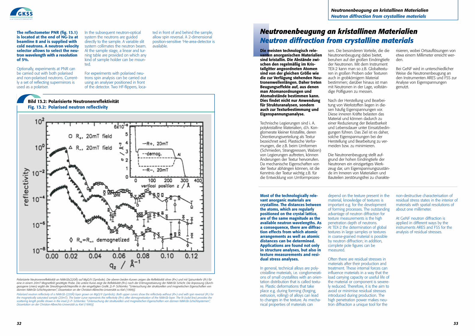
Neutronenbeugung an kristallinen MaterialienNeutron diffraction from crystalline materialsDie meisten technologisch rele-vanten anorganischen Materialiensind kristallin. Die Abstände zwi-schen den regelmäßig im Kris-tallgitter angeordneten Atomensind von der gleichen Größe wiedie zur Verfügung stehenden Neu-tronenwellenlängen. Daher tretenBeugungseffekte auf, aus denenman Atomanordnungen undAtomabstände bestimmen kann.Dies findet nicht nur Anwendungfür Strukturanalysen, sondernauch zur Texturbestimmung undEigenspannungsanalyse.
Technische Legierungen sind i. A.polykristalline Materialien, d.h. Kon-glomerate kleiner Kristallite, derenOrientierungsverteilung als Texturbezeichnet wird. Plastische Verfor-mungen, die z.B. beim Umformen(Schmieden, Strangpressen, Walzen)von Legierungen auftreten, könnenÄnderungen der Textur hervorrufen.Da mechanische Eigenschaften vonder Textur abhängen können, ist dieKenntnis der Textur wichtig z.B. fürdie Entwicklung von Umformprozes-
sen. Die besonderen Vorteile, die dieNeutronenbeugung dabei bietet,beruhen auf der großen Eindringtiefeder Neutronen. Mit dem InstrumentTEX-2 kann man so z.B. Globaltextu-ren in großen Proben oder Texturenauch in grobkörnigem Materialbestimmen; darüber hinaus ist manmit Neutronen in der Lage, vollstän-dige Polfiguren zu messen.
Nach der Herstellung und Bearbei-tung von Werkstoffen liegen in die-sen häufig Eigenspannungen vor.Diese inneren Kräfte belasten dasMaterial und können dadurch zueiner Reduzierung der Belastbarkeitund Lebensdauer unter Einsatzbedin-gungen führen. Das Ziel ist es daher,solche Eigenspannungen bei derHerstellung und Bearbeitung zu ver-meiden bzw. zu minimieren.
Die Neutronenbeugung stellt auf-grund der hohen Eindringtiefe derNeutronen ein einzigartiges Werk-zeug dar, um Eigenspannungszustän-de im Inneren von Materialien undBauteilen zerstörungsfrei zu charakte-
risieren, wobei Ortsauflösungen vonetwa einem Millimeter erreicht wer-den.
Bei GeNF wird in unterschiedlicherWeise die Neutronenbeugung anden Instrumenten ARES und FSS zurAnalyse von Eigenspannungengenutzt.
Most of the technologically rele-vant anorganic materials arecrystalline. The distances betweenthe atoms, which are regularlypositioned on the crystal lattice,are of the same magnitude as theavailable neutron wavelengths. Asa consequence, there are diffrac-tion effects from which atomicarrangements as well as atomicdistances can be determined.Applications are found not onlyin structure analyses, but also intexture measurements and resi-dual stress analyses.
In general, technical alloys are poly-cristalline materials, i.e. conglomerati-ons of small crystallites with an orien-tation distribution that is called textu-re. Plastic deformations that takeplace e.g. during forming (forging,extrusion, rolling) of alloys can leadto changes in the texture. As mecha-nical properties of materials can
depend on the texture present in thematerial, knowledge of textures isimportant e.g. for the developmentof forming processes. The outstandingadvantage of neutron diffraction fortexture measurements is the highpenetration depth of neutrons. At TEX-2 the determination of globaltextures in large samples or textures in coarse-grained material is possibleby neutron diffraction; in addition,complete pole figures can be measured.
Often there are residual stresses inmaterials after their production andtreatment. These internal forces caninfluence materials in a way that theload carrying capacity or useful life ofthe material or component is severe-ly reduced. Therefore, it is the aim toavoid or minimise residual stressesintroduced during production. Thehigh penetration power makes neu-tron diffraction a unique tool for the
non-destructive characterisation ofresidual stress states in the interior ofmaterials with spatial resolutions ofabout one millimeter.
At GeNF neutron diffraction isapplied in different ways by theinstruments ARES and FSS for theanalysis of residual stresses.
33
Neutronenbeugung an kristallinen MaterialienNeutron diffraction from crystalline materials
32
The reflectometer PNR (fig. 13.1)is located at the end of NG-2u atbeamline 8 and is supplied withcold neutrons. A neutron velocityselector allows to select the neu-tron wavelength with a resolutionof 5%.
Optionally, experiments at PNR canbe carried out with both polarisedand non-polarised neutrons. Current-ly a set of reflecting supermirrors isused as a polariser.
In the subsequent neutron-opticalsystem the neutrons are guideddirectly to the sample. A variable slitsystem collimates the neutron beam.At the sample stage, a linear and tur-ning table are provided on which anykind of sample holder can be moun-ted.
For experiments with polarised neu-trons spin analysis can be carried outusing an analyser positioned in frontof the detector. Two HF-flippers, loca-
ted in front of and behind the sample,allow spin reversal. A 2-dimensionalposition-sensitive 3He-area-detector isavailable.
Polarisierte Neutronenreflektivität an NiMnSb(220Å) auf MgO/V (Symbole). Die oberen beiden Kurven zeigen die Reflektivität ohne (R+) und mit Spinumkehr (R-) füreine in einem 20mT Magnetfeld gesättigte Probe. Die untere Kurve zeigt die Reflektivität (R+) nach der Entmagnetisierung der NiMnSb Schicht. Die Anpassung (durch-gezogene Linien) ergibt die Streulängendichteprofile in der eingefügten Grafik. [J.-P- Schlomka: ”Untersuchung der strukturellen und magnetischen Eigenschaften vondünnen NiMnSb-Schichtsystemen”, Dissertation an der Christian-Albrechts-Universität zu Kiel (1999)].
Polarised neutron reflectivity of a NiMnSb (220Å) layer grown on MgO/V (symbols). Both upper curves show the reflectivity without (R+) and with spin reversal (R-) forthe magnetically saturated sample (20mT). The lower curve represents the reflectivity (R+) after demagnetisation of the NiMnSb layer. The fit (solid line) provides thescattering length profile shown in the inset [J.-P- Schlomka: ”Untersuchung der strukturellen und magnetischen Eigenschaften von dünnen NiMnSb-Schichtsystemen”,Dissertation an der Christian-Albrechts-Universität zu Kiel (1999)].
Bild 13.2: Polarisierte Neutronenreflektivität Fig. 13.2: Polarised neutron reflectivity
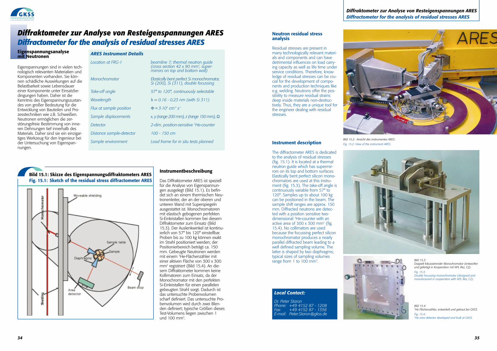
Neutron residual stress analysis
Residual stresses are present inmany technologically relevant materi-als and components and can havedetrimental influences on load carry-ing capacity as well as life time underservice conditions. Therefore, know-ledge of residual stresses can be cru-cial for the development of compo-nents and production techniques likee.g. welding. Neutrons offer the pos-sibility to measure residual strainsdeep inside materials non-destruc-tively. Thus, they are a unique tool forthe engineer dealing with residualstresses.
Instrument description
The diffractometer ARES is dedicatedto the analysis of residual stresses(fig. 15.1). It is located at a thermalneutron guide which has supermir-rors on its top and bottom surfaces.Elastically bent perfect silicon mono-chromators are used at this instru-ment (fig. 15.3). The take-off angle iscontinuously variable from 57° to120°. Samples up to about 100 kgcan be positioned in the beam. Thesample shift ranges are approx. 150mm. Diffracted neutrons are detec-ted with a position sensitive two-dimensional 3He-counter with anactive area of 300 x 300 mm2 (fig.15.4). No collimators are usedbecause the focussing perfect siliconmonochromator produces a nearlyparallel diffracted beam leading to awell defined sampling volume. Thelatter is shaped by two diaphragms;typical sizes of sampling volumesrange from 1 to 100 mm3.
Diffraktometer zur Analyse von Resteigenspannungen ARESDiffractometer for the analysis of residual stresses ARES
Bild 15.3:Doppelt fokussierender Monochromator (entworfenund gefertigt in Kooperation mit NPI, Rez, CZ).
Fig. 15.3:Double focussing monochromator (designed andmanufactured in cooperation with NPI, Rez, CZ).
Bild 15.4: 3He Flächenzähler, entwickelt und gebaut bei GKSS.
Fig. 15.4: 3He area detector developed and built at GKSS.
Local Contact:
Dr. Peter StaronPhone: +49 4152 87 - 1208Fax: +49 4152 87 - 1356E-mail: [email protected]
Bild 15.2: Ansicht des Instrumentes ARES.
Fig. 15.2: View of the instrument ARES.
34
Diffraktometer zur Analyse von Resteigenspannungen ARESDiffractometer for the analysis of residual stresses ARESEigenspannungsanalyse mit Neutronen
Eigenspannungen sind in vielen tech-nologisch relevanten Materialien undKomponenten vorhanden. Sie kön-nen schädliche Auswirkungen auf dieBelastbarkeit sowie Lebensdauereiner Komponente unter Einsatzbe-dingungen haben. Daher ist dieKenntnis des Eigenspannungszustan-des von großer Bedeutung für dieEntwicklung von Bauteilen und Pro-zesstechniken wie z.B. Schweißen.Neutronen ermöglichen die zer-störungsfreie Bestimmung von inne-ren Dehnungen tief innerhalb desMaterials. Daher sind sie ein einzigar-tiges Werkzeug für den Ingenieur beider Untersuchung von Eigenspan-nungen.
Instrumentbeschreibung
Das Diffraktometer ARES ist speziellfür die Analyse von Eigenspannun-gen ausgelegt (Bild 15.1). Es befin-det sich an einem thermischen Neu-tronenleiter, der an der oberen undunteren Wand mit Superspiegelnausgestattet ist. Monochromatorenmit elastisch gebogenen perfektenSi-Einkristallen kommen bei diesemDiffraktometer zum Einsatz (Bild15.3). Der Auslenkwinkel ist kontinu-ierlich von 57° bis 120° einstellbar.Proben bis zu 100 kg können exaktim Strahl positioniert werden; derPositionierbereich beträgt ca. 150mm. Gebeugte Neutronen werdenmit einem 3He-Flächenzähler miteiner aktiven Fläche von 300 x 300mm2 registriert (Bild 15.4). An die-sem Diffraktometer kommen keineKollimatoren zum Einsatz, da derMonochromator mit den perfektenSi-Einkristallen für einen parallelengebeugten Strahl sorgt. Dadurch istdas untersuchte Probenvolumenscharf definiert. Das untersuchte Pro-benvolumen wird durch zwei Blen-den definiert; typische Größen diesesTest-Volumens liegen zwischen 1und 100 mm3.
ARES Instrument Details
Location at FRG-1 beamline 7; thermal neutron guide (cross section 42 x 90 mm2, super-mirrors on top and bottom wall)
Monochromator Elastically bent perfect Si monochromator,Si (200), Si (311), double focussing
Take-off angle 57° to 120°, continuously selectable
Wavelength λ = 0.16 - 0.23 nm (with Si 311)
Flux at sample position Φ ≈ 3·105 cm-2 s-1
Sample displacements x, y (range 200 mm), z (range 150 mm), Ω
Detector 2-dim. position-sensitive 3He-counter
Distance sample-detector 100 - 150 cm
Sample environment Load frame for in situ tests planned
Bild 15.1: Skizze des Eigenspannungsdiffraktometers ARES Fig. 15.1: Sketch of the residual stress diffractometer ARES
35
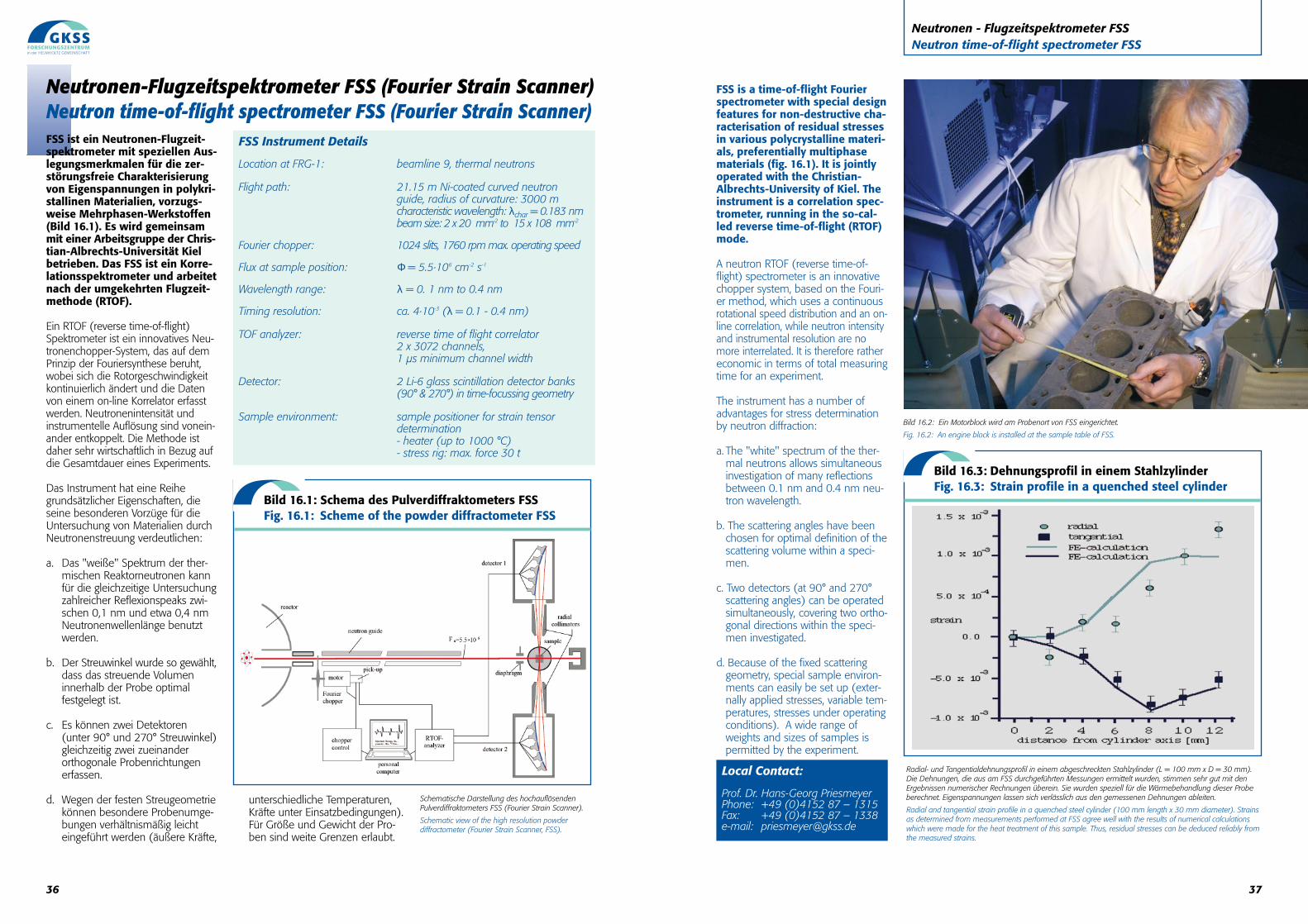
37
FSS is a time-of-flight Fourierspectrometer with special designfeatures for non-destructive cha-racterisation of residual stressesin various polycrystalline materi-als, preferentially multiphasematerials (fig. 16.1). It is jointlyoperated with the Christian-Albrechts-University of Kiel. Theinstrument is a correlation spec-trometer, running in the so-cal-led reverse time-of-flight (RTOF)mode.
A neutron RTOF (reverse time-of-flight) spectrometer is an innovativechopper system, based on the Fouri-er method, which uses a continuousrotational speed distribution and an on-line correlation, while neutron intensityand instrumental resolution are nomore interrelated. It is therefore rathereconomic in terms of total measuringtime for an experiment.
The instrument has a number ofadvantages for stress determinationby neutron diffraction:
a. The "white" spectrum of the ther-mal neutrons allows simultaneousinvestigation of many reflectionsbetween 0.1 nm and 0.4 nm neu-tron wavelength.
b. The scattering angles have beenchosen for optimal definition of thescattering volume within a speci-men.
c. Two detectors (at 90° and 270°scattering angles) can be operatedsimultaneously, covering two ortho-gonal directions within the speci-men investigated.
d. Because of the fixed scatteringgeometry, special sample environ-ments can easily be set up (exter-nally applied stresses, variable tem-peratures, stresses under operatingconditions). A wide range ofweights and sizes of samples ispermitted by the experiment.
Neutronen - Flugzeitspektrometer FSS Neutron time-of-flight spectrometer FSS
Bild 16.2: Ein Motorblock wird am Probenort von FSS eingerichtet.
Fig. 16.2: An engine block is installed at the sample table of FSS.
Radial- und Tangentialdehnungsprofil in einem abgeschreckten Stahlzylinder (L = 100 mm x D = 30 mm).Die Dehnungen, die aus am FSS durchgeführten Messungen ermittelt wurden, stimmen sehr gut mit denErgebnissen numerischer Rechnungen überein. Sie wurden speziell für die Wärmebehandlung dieser Probeberechnet. Eigenspannungen lassen sich verlässlich aus den gemessenen Dehnungen ableiten.
Radial and tangential strain profile in a quenched steel cylinder (100 mm length x 30 mm diameter). Strainsas determined from measurements performed at FSS agree well with the results of numerical calculationswhich were made for the heat treatment of this sample. Thus, residual stresses can be deduced reliably fromthe measured strains.
Local Contact:
Prof. Dr. Hans-Georg Priesmeyer Phone: +49 (0)4152 87 – 1315Fax: +49 (0)4152 87 – 1338e-mail: [email protected]
Bild 16.3: Dehnungsprofil in einem Stahlzylinder Fig. 16.3: Strain profile in a quenched steel cylinder
36
FSS ist ein Neutronen-Flugzeit-spektrometer mit speziellen Aus-legungsmerkmalen für die zer-störungsfreie Charakterisierungvon Eigenspannungen in polykri-stallinen Materialien, vorzugs-weise Mehrphasen-Werkstoffen(Bild 16.1). Es wird gemeinsammit einer Arbeitsgruppe der Chris-tian-Albrechts-Universität Kielbetrieben. Das FSS ist ein Korre-lationsspektrometer und arbeitetnach der umgekehrten Flugzeit-methode (RTOF).
Ein RTOF (reverse time-of-flight)Spektrometer ist ein innovatives Neu-tronenchopper-System, das auf demPrinzip der Fouriersynthese beruht,wobei sich die Rotorgeschwindigkeitkontinuierlich ändert und die Datenvon einem on-line Korrelator erfasstwerden. Neutronenintensität undinstrumentelle Auflösung sind vonein-ander entkoppelt. Die Methode istdaher sehr wirtschaftlich in Bezug aufdie Gesamtdauer eines Experiments.
Das Instrument hat eine Reihegrundsätzlicher Eigenschaften, dieseine besonderen Vorzüge für dieUntersuchung von Materialien durchNeutronenstreuung verdeutlichen:
a. Das "weiße" Spektrum der ther-mischen Reaktorneutronen kannfür die gleichzeitige Untersuchungzahlreicher Reflexionspeaks zwi-schen 0,1 nm und etwa 0,4 nmNeutronenwellenlänge benutztwerden.
b. Der Streuwinkel wurde so gewählt,dass das streuende Volumeninnerhalb der Probe optimal festgelegt ist.
c. Es können zwei Detektoren(unter 90° und 270° Streuwinkel)gleichzeitig zwei zueinanderorthogonale Probenrichtungenerfassen.
d. Wegen der festen Streugeometriekönnen besondere Probenumge-bungen verhältnismäßig leichteingeführt werden (äußere Kräfte,
unterschiedliche Temperaturen,Kräfte unter Einsatzbedingungen).Für Größe und Gewicht der Pro-ben sind weite Grenzen erlaubt.
Schematische Darstellung des hochauflösendenPulverdiffraktometers FSS (Fourier Strain Scanner).
Schematic view of the high resolution powderdiffractometer (Fourier Strain Scanner, FSS).
FSS Instrument Details
Location at FRG-1: beamline 9, thermal neutrons
Flight path: 21.15 m Ni-coated curved neutron guide, radius of curvature: 3000 mcharacteristic wavelength: λchar = 0.183 nmbeam size: 2 x 20 mm-2 to 15 x 108 mm-2
Fourier chopper: 1024 slits, 1760 rpm max. operating speed
Flux at sample position: Φ = 5.5·106 cm-2 s-1
Wavelength range: λ = 0. 1 nm to 0.4 nm
Timing resolution: ca. 4·10-3 (λ = 0.1 - 0.4 nm)
TOF analyzer: reverse time of flight correlator 2 x 3072 channels, 1 µs minimum channel width
Detector: 2 Li-6 glass scintillation detector banks (90° & 270°) in time-focussing geometry
Sample environment: sample positioner for strain tensor determination- heater (up to 1000 °C)- stress rig: max. force 30 t
Neutronen-Flugzeitspektrometer FSS (Fourier Strain Scanner)Neutron time-of-flight spectrometer FSS (Fourier Strain Scanner)
Bild 16.1: Schema des Pulverdiffraktometers FSS Fig. 16.1: Scheme of the powder diffractometer FSS
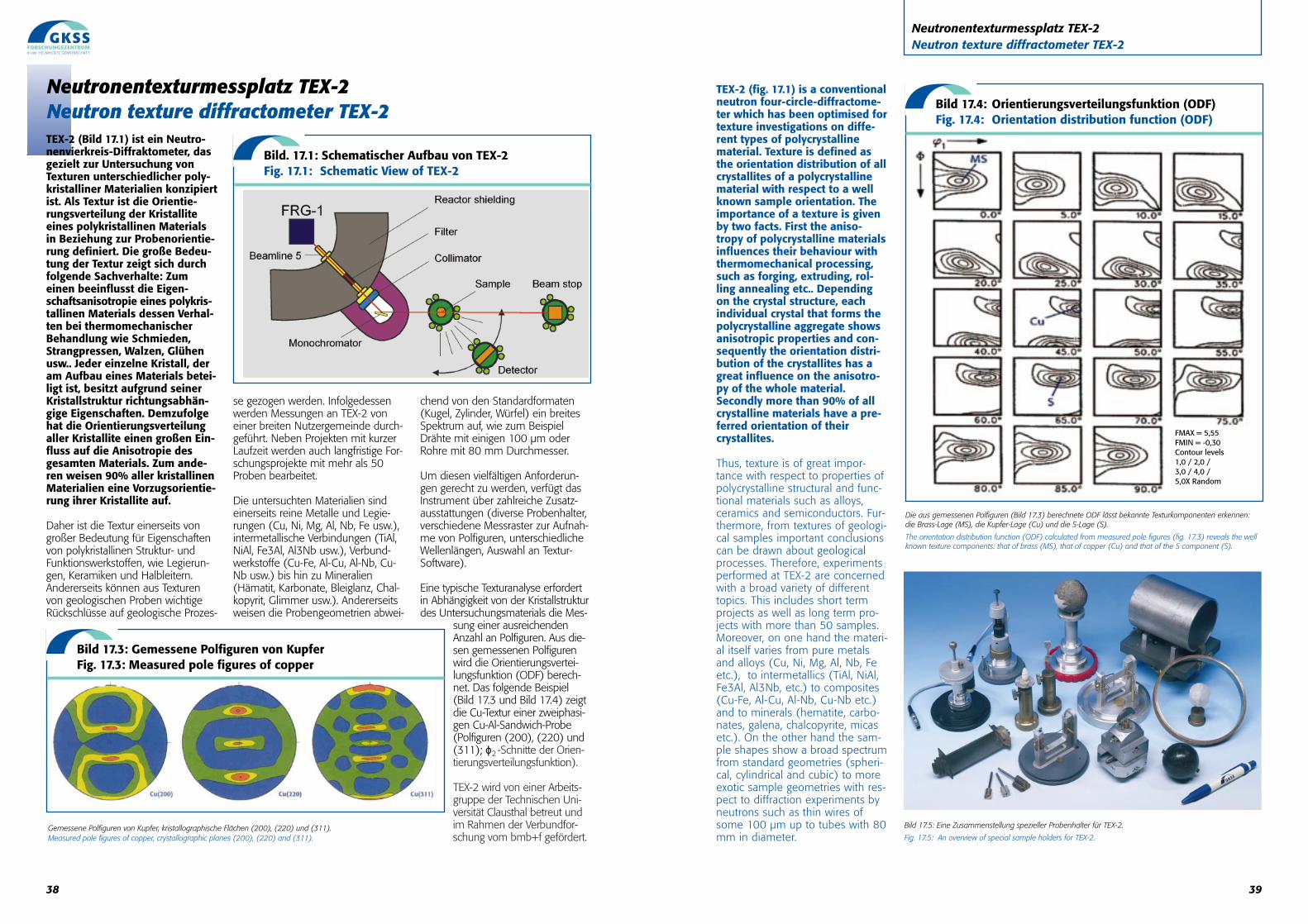
39
TEX-2 (fig. 17.1) is a conventionalneutron four-circle-diffractome-ter which has been optimised fortexture investigations on diffe-rent types of polycrystallinematerial. Texture is defined asthe orientation distribution of allcrystallites of a polycrystallinematerial with respect to a wellknown sample orientation. Theimportance of a texture is givenby two facts. First the aniso-tropy of polycrystalline materialsinfluences their behaviour withthermomechanical processing,such as forging, extruding, rol-ling annealing etc.. Dependingon the crystal structure, eachindividual crystal that forms thepolycrystalline aggregate showsanisotropic properties and con-sequently the orientation distri-bution of the crystallites has agreat influence on the anisotro-py of the whole material.Secondly more than 90% of allcrystalline materials have a pre-ferred orientation of theircrystallites.
Thus, texture is of great impor-tance with respect to properties ofpolycrystalline structural and func-tional materials such as alloys,ceramics and semiconductors. Fur-thermore, from textures of geologi-cal samples important conclusionscan be drawn about geologicalprocesses. Therefore, experimentsperformed at TEX-2 are concernedwith a broad variety of differenttopics. This includes short termprojects as well as long term pro-jects with more than 50 samples.Moreover, on one hand the materi-al itself varies from pure metalsand alloys (Cu, Ni, Mg, Al, Nb, Feetc.), to intermetallics (TiAl, NiAl,Fe3Al, Al3Nb, etc.) to composites(Cu-Fe, Al-Cu, Al-Nb, Cu-Nb etc.)and to minerals (hematite, carbo-nates, galena, chalcopyrite, micasetc.). On the other hand the sam-ple shapes show a broad spectrumfrom standard geometries (spheri-cal, cylindrical and cubic) to moreexotic sample geometries with res-pect to diffraction experiments byneutrons such as thin wires ofsome 100 µm up to tubes with 80mm in diameter.
Neutronentexturmessplatz TEX-2Neutron texture diffractometer TEX-2
Die aus gemessenen Polfiguren (Bild 17.3) berechnete ODF lässt bekannte Texturkomponenten erkennen: die Brass-Lage (MS), die Kupfer-Lage (Cu) und die S-Lage (S).
The orientation distribution function (ODF) calculated from measured pole figures (fig. 17.3) reveals the wellknown texture components: that of brass (MS), that of copper (Cu) and that of the S component (S).
Bild 17.4: Orientierungsverteilungsfunktion (ODF)Fig. 17.4: Orientation distribution function (ODF)
FMAX = 5,55FMIN = -0,30Contour levels1,0 / 2,0 / 3,0 / 4,0 /5,0X Random
Bild 17.5: Eine Zusammenstellung spezieller Probenhalter für TEX-2.
Fig. 17.5: An overview of special sample holders for TEX-2.
38
Neutronentexturmessplatz TEX-2Neutron texture diffractometer TEX-2TEX-2 (Bild 17.1) ist ein Neutro-nenvierkreis-Diffraktometer, dasgezielt zur Untersuchung vonTexturen unterschiedlicher poly-kristalliner Materialien konzipiertist. Als Textur ist die Orientie-rungsverteilung der Kristalliteeines polykristallinen Materialsin Beziehung zur Probenorientie-rung definiert. Die große Bedeu-tung der Textur zeigt sich durchfolgende Sachverhalte: Zumeinen beeinflusst die Eigen-schaftsanisotropie eines polykris-tallinen Materials dessen Verhal-ten bei thermomechanischerBehandlung wie Schmieden,Strangpressen, Walzen, Glühenusw.. Jeder einzelne Kristall, deram Aufbau eines Materials betei-ligt ist, besitzt aufgrund seinerKristallstruktur richtungsabhän-gige Eigenschaften. Demzufolgehat die Orientierungsverteilungaller Kristallite einen großen Ein-fluss auf die Anisotropie desgesamten Materials. Zum ande-ren weisen 90% aller kristallinenMaterialien eine Vorzugsorientie-rung ihrer Kristallite auf.
Daher ist die Textur einerseits vongroßer Bedeutung für Eigenschaftenvon polykristallinen Struktur- undFunktionswerkstoffen, wie Legierun-gen, Keramiken und Halbleitern.Andererseits können aus Texturenvon geologischen Proben wichtigeRückschlüsse auf geologische Prozes-
se gezogen werden. Infolgedessenwerden Messungen an TEX-2 voneiner breiten Nutzergemeinde durch-geführt. Neben Projekten mit kurzerLaufzeit werden auch langfristige For-schungsprojekte mit mehr als 50Proben bearbeitet.
Die untersuchten Materialien sindeinerseits reine Metalle und Legie-rungen (Cu, Ni, Mg, Al, Nb, Fe usw.),intermetallische Verbindungen (TiAl,NiAl, Fe3Al, Al3Nb usw.), Verbund-werkstoffe (Cu-Fe, Al-Cu, Al-Nb, Cu-Nb usw.) bis hin zu Mineralien(Hämatit, Karbonate, Bleiglanz, Chal-kopyrit, Glimmer usw.). Andererseitsweisen die Probengeometrien abwei-
chend von den Standardformaten(Kugel, Zylinder, Würfel) ein breitesSpektrum auf, wie zum BeispielDrähte mit einigen 100 µm oderRohre mit 80 mm Durchmesser.
Um diesen vielfältigen Anforderun-gen gerecht zu werden, verfügt dasInstrument über zahlreiche Zusatz-ausstattungen (diverse Probenhalter,verschiedene Messraster zur Aufnah-me von Polfiguren, unterschiedlicheWellenlängen, Auswahl an Textur-Software).
Eine typische Texturanalyse erfordertin Abhängigkeit von der Kristallstrukturdes Untersuchungsmaterials die Mes-
sung einer ausreichendenAnzahl an Polfiguren. Aus die-sen gemessenen Polfigurenwird die Orientierungsvertei-lungsfunktion (ODF) berech-net. Das folgende Beispiel(Bild 17.3 und Bild 17.4) zeigtdie Cu-Textur einer zweiphasi-gen Cu-Al-Sandwich-Probe(Polfiguren (200), (220) und(311); ϕ2 -Schnitte der Orien-tierungsverteilungsfunktion).
TEX-2 wird von einer Arbeits-gruppe der Technischen Uni-versität Clausthal betreut undim Rahmen der Verbundfor-schung vom bmb+f gefördert.
Bild. 17.1: Schematischer Aufbau von TEX-2Fig. 17.1: Schematic View of TEX-2
Bild 17.3: Gemessene Polfiguren von KupferFig. 17.3: Measured pole figures of copper
Gemessene Polfiguren von Kupfer, kristallographische Flächen (200), (220) und (311).Measured pole figures of copper, crystallographic planes (200), (220) and (311).
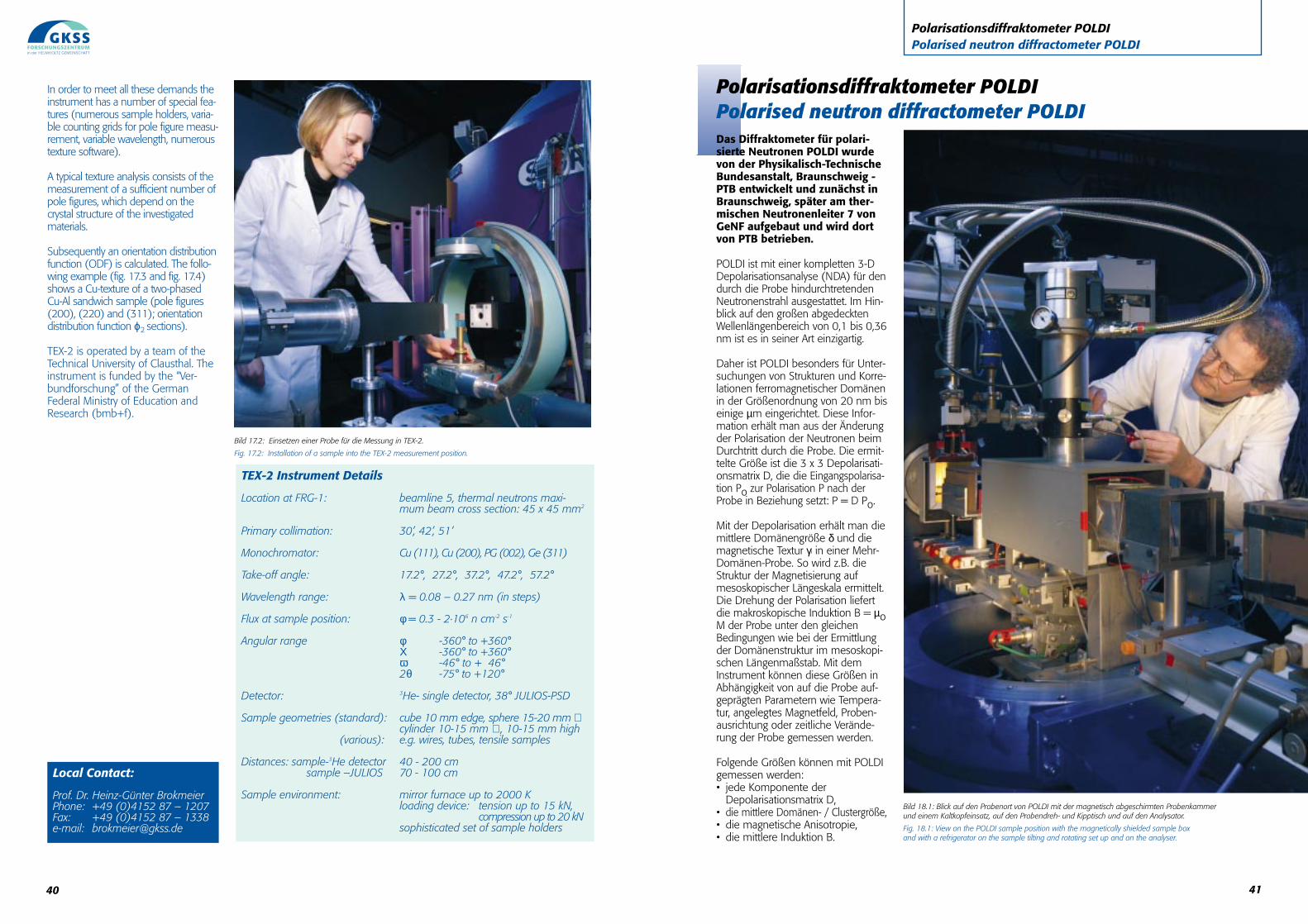
Polarisationsdiffraktometer POLDIPolarised neutron diffractometer POLDI
Das Diffraktometer für polari-sierte Neutronen POLDI wurdevon der Physikalisch-TechnischeBundesanstalt, Braunschweig -PTB entwickelt und zunächst inBraunschweig, später am ther-mischen Neutronenleiter 7 vonGeNF aufgebaut und wird dortvon PTB betrieben.
POLDI ist mit einer kompletten 3-DDepolarisationsanalyse (NDA) für dendurch die Probe hindurchtretendenNeutronenstrahl ausgestattet. Im Hin-blick auf den großen abgedecktenWellenlängenbereich von 0,1 bis 0,36nm ist es in seiner Art einzigartig.
Daher ist POLDI besonders für Unter-suchungen von Strukturen und Korre-lationen ferromagnetischer Domänenin der Größenordnung von 20 nm biseinige µm eingerichtet. Diese Infor-mation erhält man aus der Änderungder Polarisation der Neutronen beimDurchtritt durch die Probe. Die ermit-telte Größe ist die 3 x 3 Depolarisati-onsmatrix D, die die Eingangspolarisa-tion Po zur Polarisation P nach derProbe in Beziehung setzt: P = D Po.
Mit der Depolarisation erhält man diemittlere Domänengröße δ und diemagnetische Textur γi in einer Mehr-Domänen-Probe. So wird z.B. dieStruktur der Magnetisierung aufmesoskopischer Längeskala ermittelt.Die Drehung der Polarisation liefertdie makroskopische Induktion B = µoM der Probe unter den gleichenBedingungen wie bei der Ermittlungder Domänenstruktur im mesoskopi-schen Längenmaßstab. Mit demInstrument können diese Größen inAbhängigkeit von auf die Probe auf-geprägten Parametern wie Tempera-tur, angelegtes Magnetfeld, Proben-ausrichtung oder zeitliche Verände-rung der Probe gemessen werden.
Folgende Größen können mit POLDIgemessen werden:• jede Komponente der
Depolarisationsmatrix D,• die mittlere Domänen- / Clustergröße,• die magnetische Anisotropie,• die mittlere Induktion B.
Polarisationsdiffraktometer POLDIPolarised neutron diffractometer POLDI
Bild 18.1: Blick auf den Probenort von POLDI mit der magnetisch abgeschirmten Probenkammer und einem Kaltkopfeinsatz, auf den Probendreh- und Kipptisch und auf den Analysator.
Fig. 18.1: View on the POLDI sample position with the magnetically shielded sample box and with a refrigerator on the sample tilting and rotating set up and on the analyser.
40
In order to meet all these demands theinstrument has a number of special fea-tures (numerous sample holders, varia-ble counting grids for pole figure measu-rement, variable wavelength, numeroustexture software).
A typical texture analysis consists of themeasurement of a sufficient number ofpole figures, which depend on thecrystal structure of the investigatedmaterials.
Subsequently an orientation distributionfunction (ODF) is calculated. The follo-wing example (fig. 17.3 and fig. 17.4)shows a Cu-texture of a two-phasedCu-Al sandwich sample (pole figures(200), (220) and (311); orientationdistribution function ϕ2 sections).
TEX-2 is operated by a team of theTechnical University of Clausthal. Theinstrument is funded by the “Ver-bundforschung” of the GermanFederal Ministry of Education andResearch (bmb+f).
Local Contact:
Prof. Dr. Heinz-Günter BrokmeierPhone: +49 (0)4152 87 – 1207Fax: +49 (0)4152 87 – 1338e-mail: [email protected]
TEX-2 Instrument Details
Location at FRG-1: beamline 5, thermal neutrons maxi-mum beam cross section: 45 x 45 mm2
Primary collimation: 30’, 42’, 51’
Monochromator: Cu (111), Cu (200), PG (002), Ge (311)
Take-off angle: 17.2°, 27.2°, 37.2°, 47.2°, 57.2°
Wavelength range: λ = 0.08 – 0.27 nm (in steps)
Flux at sample position: φ = 0.3 - 2·106 n cm-2 s-1
Angular range φ -360° to +360°Χ -360° to +360°ω -46° to + 46°2θ -75° to +120°
Detector: 3He- single detector, 38° JULIOS-PSD
Sample geometries (standard): cube 10 mm edge, sphere 15-20 mm ∅cylinder 10-15 mm ∅ , 10-15 mm high
(various): e.g. wires, tubes, tensile samples
Distances: sample-3He detector 40 - 200 cmsample –JULIOS 70 - 100 cm
Sample environment: mirror furnace up to 2000 Kloading device: tension up to 15 kN,
compression up to 20 kNsophisticated set of sample holders
Bild 17.2: Einsetzen einer Probe für die Messung in TEX-2.
Fig. 17.2: Installation of a sample into the TEX-2 measurement position.
41
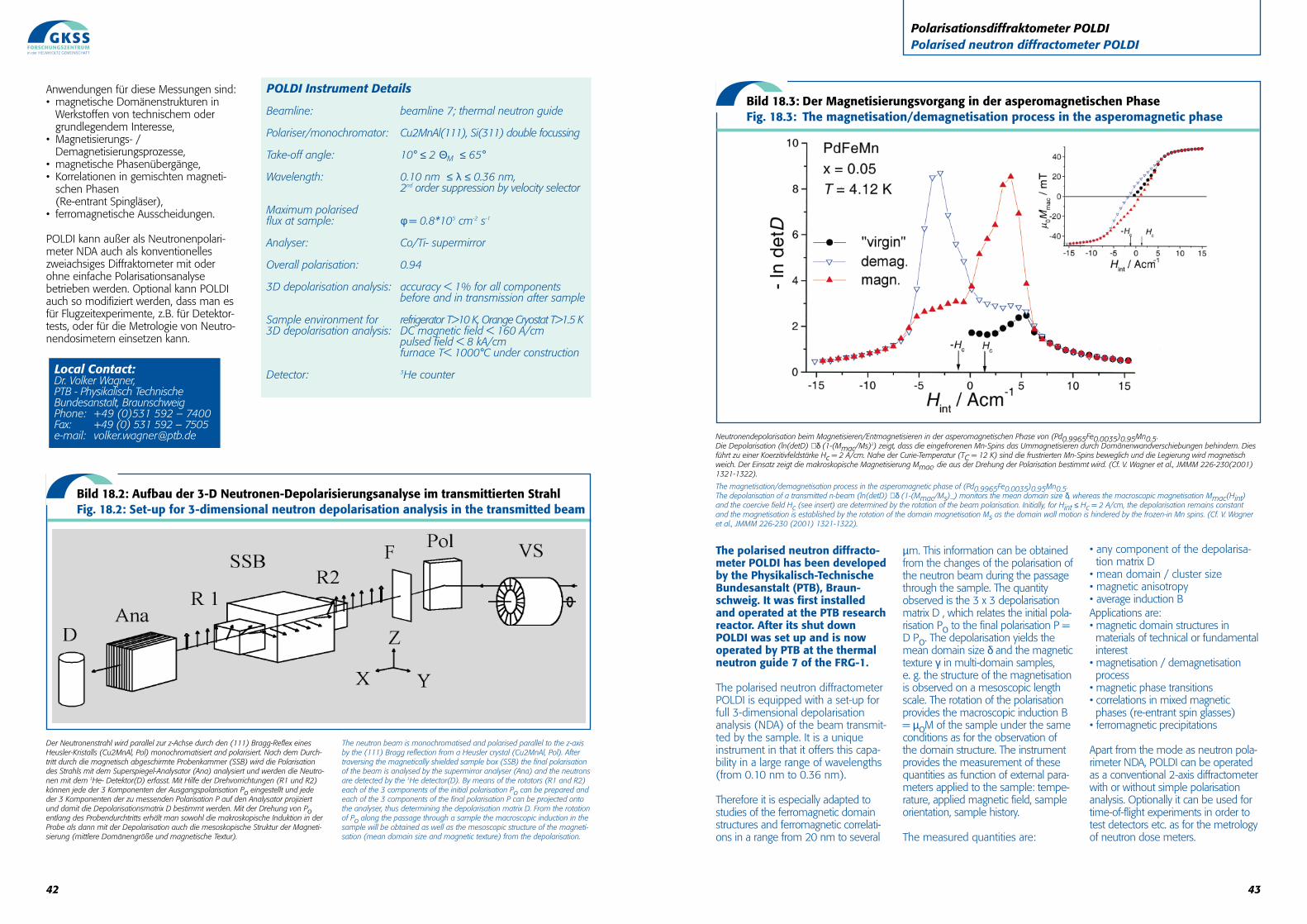
43
The polarised neutron diffracto-meter POLDI has been developedby the Physikalisch-TechnischeBundesanstalt (PTB), Braun-schweig. It was first installedand operated at the PTB researchreactor. After its shut downPOLDI was set up and is nowoperated by PTB at the thermalneutron guide 7 of the FRG-1.
The polarised neutron diffractometerPOLDI is equipped with a set-up forfull 3-dimensional depolarisationanalysis (NDA) of the beam transmit-ted by the sample. It is a uniqueinstrument in that it offers this capa-bility in a large range of wavelengths(from 0.10 nm to 0.36 nm).
Therefore it is especially adapted tostudies of the ferromagnetic domainstructures and ferromagnetic correlati-ons in a range from 20 nm to several
µm. This information can be obtainedfrom the changes of the polarisation ofthe neutron beam during the passagethrough the sample. The quantityobserved is the 3 x 3 depolarisationmatrix D , which relates the initial pola-risation Po to the final polarisation P =D Po. The depolarisation yields themean domain size δ and the magnetictexture γi in multi-domain samples, e. g. the structure of the magnetisationis observed on a mesoscopic lengthscale. The rotation of the polarisationprovides the macroscopic induction B= µoM of the sample under the sameconditions as for the observation ofthe domain structure. The instrumentprovides the measurement of thesequantities as function of external para-meters applied to the sample: tempe-rature, applied magnetic field, sampleorientation, sample history.
The measured quantities are:
• any component of the depolarisa-tion matrix D
• mean domain / cluster size • magnetic anisotropy• average induction BApplications are:• magnetic domain structures inmaterials of technical or fundamental interest
• magnetisation / demagnetisation process
• magnetic phase transitions• correlations in mixed magnetic phases (re-entrant spin glasses)
• ferromagnetic precipitations
Apart from the mode as neutron pola-rimeter NDA, POLDI can be operatedas a conventional 2-axis diffractometerwith or without simple polarisationanalysis. Optionally it can be used fortime-of-flight experiments in order totest detectors etc. as for the metrologyof neutron dose meters.
Polarisationsdiffraktometer POLDIPolarised neutron diffractometer POLDI
Neutronendepolarisation beim Magnetisieren/Entmagnetisieren in der asperomagnetischen Phase von (Pd0.9965Fe0.0035)0.95Mn0.5.Die Depolarisation (ln(detD) ∝δ (1-(Mmac/Ms)2) zeigt, dass die eingefrorenen Mn-Spins das Ummagnetisieren durch Domänenwandverschiebungen behindern. Diesführt zu einer Koerzitivfeldstärke Hc = 2 A/cm. Nahe der Curie-Temperatur (TC = 12 K) sind die frustrierten Mn-Spins beweglich und die Legierung wird magnetischweich. Der Einsatz zeigt die makroskopische Magnetisierung Mmac, die aus der Drehung der Polarisation bestimmt wird. (Cf. V. Wagner et al., JMMM 226-230(2001)1321-1322).
The magnetisation/demagnetisation process in the asperomagnetic phase of (Pd0.9965Fe0.0035)0.95Mn0.5.The depolarisation of a transmitted n-beam (ln(detD) ∝δ (1-(Mmac/Ms)_) monitors the mean domain size δ, whereas the macroscopic magnetisation Mmac(Hint)and the coercive field Hc (see insert) are determined by the rotation of the beam polarisation. Initially, for Hint ≤ Hc = 2 A/cm, the depolarisation remains constantand the magnetisation is established by the rotation of the domain magnetisation Ms as the domain wall motion is hindered by the frozen-in Mn spins. (Cf. V. Wagneret al., JMMM 226-230 (2001) 1321-1322).
Bild 18.3: Der Magnetisierungsvorgang in der asperomagnetischen PhaseFig. 18.3: The magnetisation/demagnetisation process in the asperomagnetic phase
42
Anwendungen für diese Messungen sind:• magnetische Domänenstrukturen in
Werkstoffen von technischem odergrundlegendem Interesse,
• Magnetisierungs- /Demagnetisierungsprozesse,
• magnetische Phasenübergänge,• Korrelationen in gemischten magneti-
schen Phasen (Re-entrant Spingläser),
• ferromagnetische Ausscheidungen.
POLDI kann außer als Neutronenpolari-meter NDA auch als konventionelleszweiachsiges Diffraktometer mit oderohne einfache Polarisationsanalysebetrieben werden. Optional kann POLDIauch so modifiziert werden, dass man esfür Flugzeitexperimente, z.B. für Detektor-tests, oder für die Metrologie von Neutro-nendosimetern einsetzen kann.
Der Neutronenstrahl wird parallel zur z-Achse durch den (111) Bragg-Reflex einesHeusler-Kristalls (Cu2MnAl, Pol) monochromatisiert and polarisiert. Nach dem Durch-tritt durch die magnetisch abgeschirmte Probenkammer (SSB) wird die Polarisationdes Strahls mit dem Superspiegel-Analysator (Ana) analysiert und werden die Neutro-nen mit dem 3He- Detektor(D) erfasst. Mit Hilfe der Drehvorrichtungen (R1 und R2)können jede der 3 Komponenten der Ausgangspolarisation Po eingestellt und jededer 3 Komponenten der zu messenden Polarisation P auf den Analysator projiziertund damit die Depolarisationsmatrix D bestimmt werden. Mit der Drehung von Poentlang des Probendurchtritts erhält man sowohl die makroskopische Induktion in derProbe als dann mit der Depolarisation auch die mesoskopische Struktur der Magneti-sierung (mittlere Domänengröße und magnetische Textur).
Bild 18.2: Aufbau der 3-D Neutronen-Depolarisierungsanalyse im transmittierten StrahlFig. 18.2: Set-up for 3-dimensional neutron depolarisation analysis in the transmitted beam
POLDI Instrument Details
Beamline: beamline 7; thermal neutron guide
Polariser/monochromator: Cu2MnAl(111), Si(311) double focussing
Take-off angle: 10° ≤ 2 ΘM ≤ 65°
Wavelength: 0.10 nm ≤ λ ≤ 0.36 nm, 2nd order suppression by velocity selector
Maximum polarised flux at sample: φ = 0.8*105 cm-2 s-1
Analyser: Co/Ti- supermirror
Overall polarisation: 0.94
3D depolarisation analysis: accuracy < 1% for all components before and in transmission after sample
Sample environment for refrigerator T>10 K, Orange Cryostat T>1.5 K3D depolarisation analysis: DC magnetic field < 160 A/cm
pulsed field < 8 kA/cm furnace T< 1000°C under construction
Detector: 3He counter
The neutron beam is monochromatised and polarised parallel to the z-axisby the (111) Bragg reflection from a Heusler crystal (Cu2MnAl, Pol). Aftertraversing the magnetically shielded sample box (SSB) the final polarisationof the beam is analysed by the supermirror analyser (Ana) and the neutronsare detected by the 3He detector(D). By means of the rotators (R1 and R2)each of the 3 components of the initial polarisation Po can be prepared andeach of the 3 components of the final polarisation P can be projected ontothe analyser, thus determining the depolarisation matrix D. From the rotationof Po along the passage through a sample the macroscopic induction in thesample will be obtained as well as the mesoscopic structure of the magneti-sation (mean domain size and magnetic texture) from the depolarisation.
Local Contact:Dr. Volker Wagner, PTB - Physikalisch Technische Bundesanstalt, BraunschweigPhone: +49 (0)531 592 – 7400Fax: +49 (0) 531 592 – 7505e-mail: [email protected]
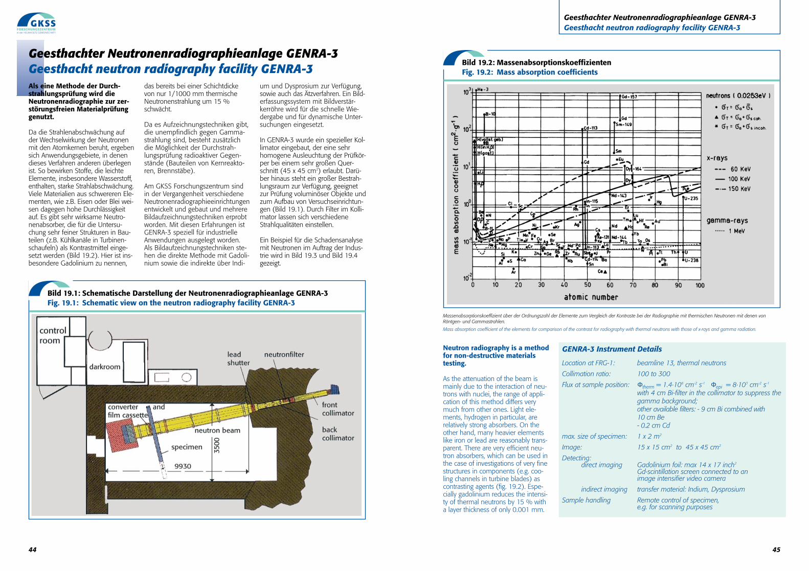
Neutron radiography is a methodfor non-destructive materialstesting.
As the attenuation of the beam ismainly due to the interaction of neu-trons with nuclei, the range of appli-cation of this method differs verymuch from other ones. Light ele-ments, hydrogen in particular, arerelatively strong absorbers. On theother hand, many heavier elementslike iron or lead are reasonably trans-parent. There are very efficient neu-tron absorbers, which can be used inthe case of investigations of very finestructures in components (e.g. coo-ling channels in turbine blades) ascontrasting agents (fig. 19.2). Espe-cially gadolinium reduces the intensi-ty of thermal neutrons by 15 % witha layer thickness of only 0.001 mm.
45
Geesthachter Neutronenradiographieanlage GENRA-3Geesthacht neutron radiography facility GENRA-3
Massenabsorptionskoeffizient über der Ordnungszahl der Elemente zum Vergleich der Kontraste bei der Radiographie mit thermischen Neutronen mit denen von Röntgen- und Gammastrahlen.
Mass absorption coefficient of the elements for comparison of the contrast for radiography with thermal neutrons with those of x-rays and gamma radiation.
GENRA-3 Instrument Details
Location at FRG-1: beamline 13, thermal neutrons
Collimation ratio: 100 to 300
Flux at sample position: Φtherm = 1.4·106 cm-2 s-1 Φepi = 8·103 cm-2 s-1
with 4 cm Bi-filter in the collimator to suppress thegamma background;other available filters: - 9 cm Bi combined with10 cm Be- 0.2 cm Cd
max. size of specimen: 1 x 2 m2
Image: 15 x 15 cm2 to 45 x 45 cm2
Detecting:direct imaging Gadolinium foil: max 14 x 17 inch2
Gd-scintillation screen connected to an image intensifier video camera
indirect imaging transfer material: Indium, Dysprosium
Sample handling Remote control of specimen, e.g. for scanning purposes
Bild 19.2: MassenabsorptionskoeffizientenFig. 19.2: Mass absorption coefficients
44
Geesthachter Neutronenradiographieanlage GENRA-3Geesthacht neutron radiography facility GENRA-3Als eine Methode der Durch-strahlungsprüfung wird dieNeutronenradiographie zur zer-störungsfreien Materialprüfunggenutzt.
Da die Strahlenabschwächung aufder Wechselwirkung der Neutronenmit den Atomkernen beruht, ergebensich Anwendungsgebiete, in denendieses Verfahren anderen überlegenist. So bewirken Stoffe, die leichteElemente, insbesondere Wasserstoff,enthalten, starke Strahlabschwächung.Viele Materialien aus schwereren Ele-menten, wie z.B. Eisen oder Blei wei-sen dagegen hohe Durchlässigkeitauf. Es gibt sehr wirksame Neutro-nenabsorber, die für die Untersu-chung sehr feiner Strukturen in Bau-teilen (z.B. Kühlkanäle in Turbinen-schaufeln) als Kontrastmittel einge-setzt werden (Bild 19.2). Hier ist ins-besondere Gadolinium zu nennen,
das bereits bei einer Schichtdickevon nur 1/1000 mm thermischeNeutronenstrahlung um 15 %schwächt.
Da es Aufzeichnungstechniken gibt,die unempfindlich gegen Gamma-strahlung sind, besteht zusätzlichdie Möglichkeit der Durchstrah-lungsprüfung radioaktiver Gegen-stände (Bauteilen von Kernreakto-ren, Brennstäbe).
Am GKSS Forschungszentrum sindin der Vergangenheit verschiedeneNeutronenradiographieeinrichtungenentwickelt und gebaut und mehrereBildaufzeichnungstechniken erprobtworden. Mit diesen Erfahrungen istGENRA-3 speziell für industrielleAnwendungen ausgelegt worden.Als Bildaufzeichnungstechniken ste-hen die direkte Methode mit Gadoli-nium sowie die indirekte über Indi-
um und Dysprosium zur Verfügung,sowie auch das Ätzverfahren. Ein Bild-erfassungssystem mit Bildverstär-kerröhre wird für die schnelle Wie-dergabe und für dynamische Unter-suchungen eingesetzt.
In GENRA-3 wurde ein spezieller Kol-limator eingebaut, der eine sehrhomogene Ausleuchtung der Prüfkör-per bei einem sehr großen Quer-schnitt (45 x 45 cm2) erlaubt. Darü-ber hinaus steht ein großer Bestrah-lungsraum zur Verfügung, geeignetzur Prüfung voluminöser Objekte undzum Aufbau von Versuchseinrichtun-gen (Bild 19.1). Durch Filter im Kolli-mator lassen sich verschiedeneStrahlqualitäten einstellen.
Ein Beispiel für die Schadensanalysemit Neutronen im Auftrag der Indus-trie wird in Bild 19.3 und Bild 19.4gezeigt.
Bild 19.1: Schematische Darstellung der Neutronenradiographieanlage GENRA-3 Fig. 19.1: Schematic view on the neutron radiography facility GENRA-3
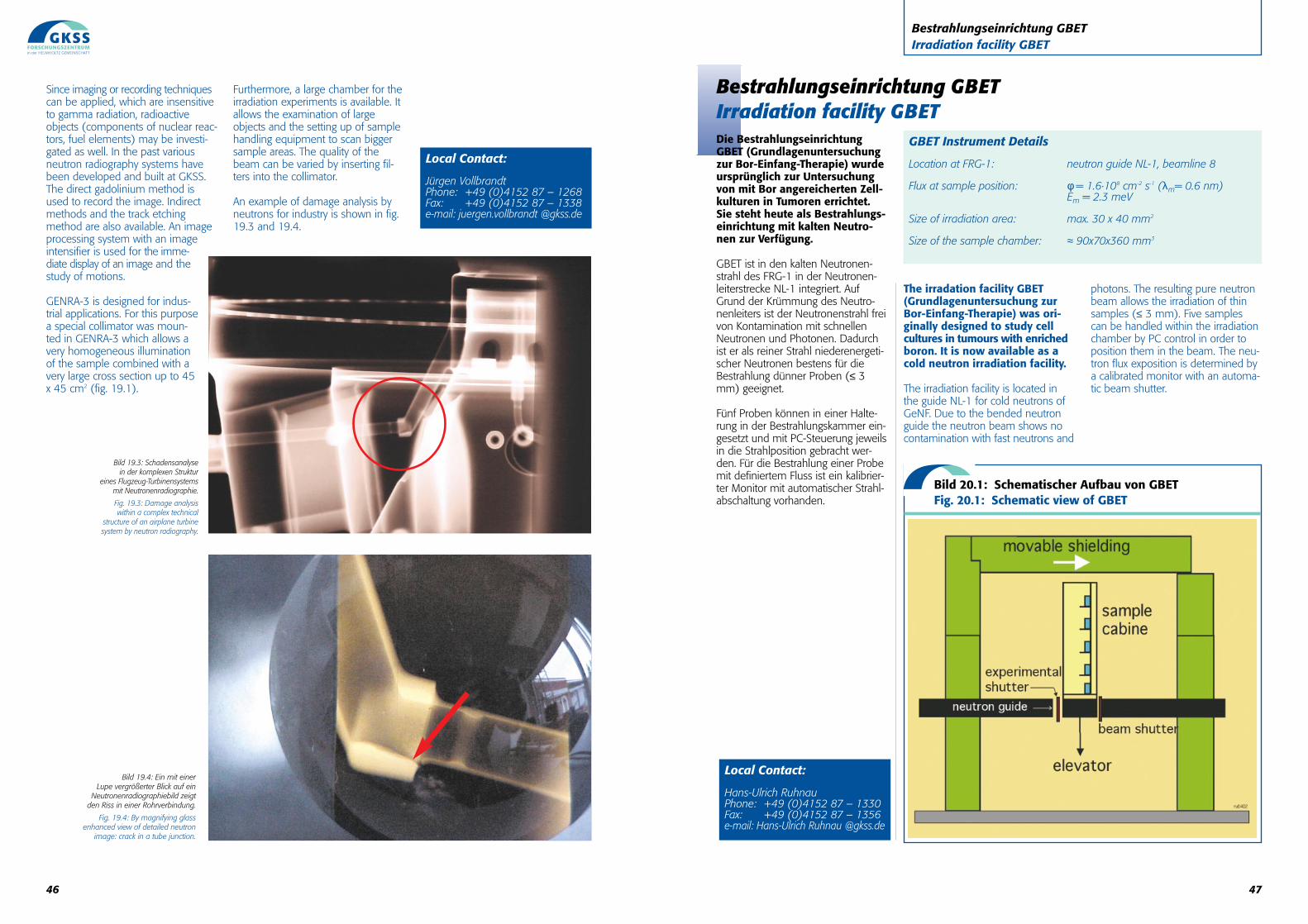
Die BestrahlungseinrichtungGBET (Grundlagenuntersuchungzur Bor-Einfang-Therapie) wurdeursprünglich zur Untersuchungvon mit Bor angereicherten Zell-kulturen in Tumoren errichtet.Sie steht heute als Bestrahlungs-einrichtung mit kalten Neutro-nen zur Verfügung.
GBET ist in den kalten Neutronen-strahl des FRG-1 in der Neutronen-leiterstrecke NL-1 integriert. AufGrund der Krümmung des Neutro-nenleiters ist der Neutronenstrahl freivon Kontamination mit schnellenNeutronen und Photonen. Dadurchist er als reiner Strahl niederenergeti-scher Neutronen bestens für dieBestrahlung dünner Proben (≤ 3mm) geeignet.
Fünf Proben können in einer Halte-rung in der Bestrahlungskammer ein-gesetzt und mit PC-Steuerung jeweilsin die Strahlposition gebracht wer-den. Für die Bestrahlung einer Probemit definiertem Fluss ist ein kalibrier-ter Monitor mit automatischer Strahl-abschaltung vorhanden.
The irradation facility GBET(Grundlagenuntersuchung zurBor-Einfang-Therapie) was ori-ginally designed to study cellcultures in tumours with enrichedboron. It is now available as acold neutron irradiation facility.
The irradiation facility is located inthe guide NL-1 for cold neutrons ofGeNF. Due to the bended neutronguide the neutron beam shows nocontamination with fast neutrons and
photons. The resulting pure neutronbeam allows the irradiation of thinsamples (≤ 3 mm). Five samplescan be handled within the irradiationchamber by PC control in order toposition them in the beam. The neu-tron flux exposition is determined bya calibrated monitor with an automa-tic beam shutter.
47
Bestrahlungseinrichtung GBETIrradiation facility GBET
Bestrahlungseinrichtung GBETIrradiation facility GBET
Local Contact:
Hans-Ulrich RuhnauPhone: +49 (0)4152 87 – 1330Fax: +49 (0)4152 87 – 1356e-mail: Hans-Ulrich Ruhnau @gkss.de
Bild 20.1: Schematischer Aufbau von GBETFig. 20.1: Schematic view of GBET
GBET Instrument Details
Location at FRG-1: neutron guide NL-1, beamline 8
Flux at sample position: φ = 1.6·108 cm-2 s-1 (λm= 0.6 nm)Em = 2.3 meV
Size of irradiation area: max. 30 x 40 mm2
Size of the sample chamber: ≈ 90x70x360 mm3
46
Since imaging or recording techniquescan be applied, which are insensitiveto gamma radiation, radioactiveobjects (components of nuclear reac-tors, fuel elements) may be investi-gated as well. In the past variousneutron radiography systems havebeen developed and built at GKSS.The direct gadolinium method isused to record the image. Indirectmethods and the track etchingmethod are also available. An imageprocessing system with an imageintensifier is used for the imme-diate display of an image and thestudy of motions.
GENRA-3 is designed for indus-trial applications. For this purposea special collimator was moun-ted in GENRA-3 which allows avery homogeneous illuminationof the sample combined with avery large cross section up to 45x 45 cm2 (fig. 19.1).
Furthermore, a large chamber for theirradiation experiments is available. Itallows the examination of largeobjects and the setting up of samplehandling equipment to scan biggersample areas. The quality of thebeam can be varied by inserting fil-ters into the collimator.
An example of damage analysis byneutrons for industry is shown in fig.19.3 and 19.4.
Local Contact:
Jürgen VollbrandtPhone: +49 (0)4152 87 – 1268Fax: +49 (0)4152 87 – 1338e-mail: juergen.vollbrandt @gkss.de
Bild 19.3: Schadensanalyse in der komplexen Struktur
eines Flugzeug-Turbinensystems mit Neutronenradiographie.
Fig. 19.3: Damage analysis within a complex technical
structure of an airplane turbine system by neutron radiography.
Bild 19.4: Ein mit einer Lupe vergrößerter Blick auf ein
Neutronenradiographiebild zeigt den Riss in einer Rohrverbindung.
Fig. 19.4: By magnifying glass enhanced view of detailed neutron
image: crack in a tube junction.
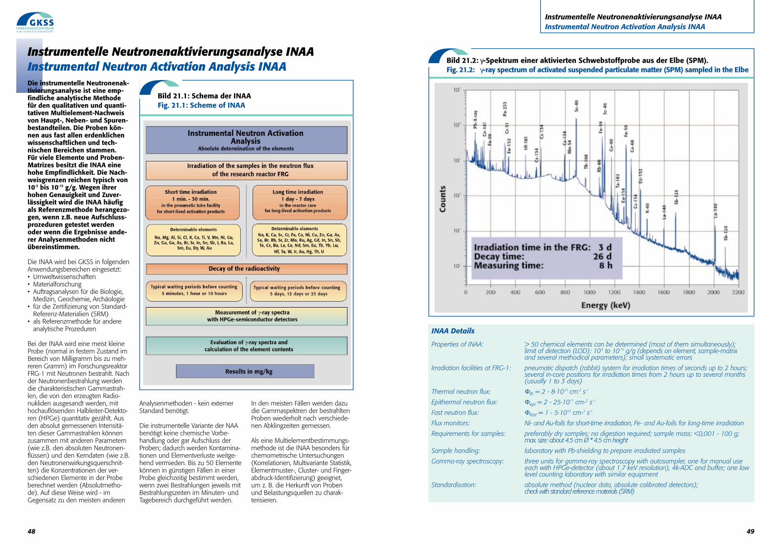
49
Instrumentelle Neutronenaktivierungsanalyse INAAInstrumental Neutron Activation Analysis INAA
Bild 21.2: γ-Spektrum einer aktivierten Schwebstoffprobe aus der Elbe (SPM).Fig. 21.2: γ-ray spectrum of activated suspended particulate matter (SPM) sampled in the Elbe
INAA Details
Properties of INAA: > 50 chemical elements can be determined (most of them simultaneously); limit of detection (LOD): 10-5 to 10-15 g/g (depends on element, sample-matrix and several methodical parameters); small systematic errors
Irradiation facilities at FRG-1: pneumatic dispatch (rabbit) system for irradiation times of seconds up to 2 hours;several in-core positions for irradiation times from 2 hours up to several months(usually 1 to 3 days)
Thermal neutron flux: Φth = 2 - 8·1013 cm-2 s-1
Epithermal neutron flux: Φepi = 2 - 25·1011 cm-2 s-1
Fast neutron flux: Φfast = 1 - 5·1012 cm-2 s-1
Flux monitors: Ni- and Au-foils for short-time irradiation, Fe- and Au-foils for long-time irradiation
Requirements for samples: preferably dry samples; no digestion required; sample mass: <0,001 - 100 g; max. size: about 4.5 cm Ø * 4.5 cm height
Sample handling: laboratory with Pb-shielding to prepare irradiated samples
Gamma-ray spectroscopy: three units for gamma-ray spectroscopy with autosampler, one for manual use each with HPGe-detector (about 1.7 keV resolution), 4k-ADC and buffer; one lowlevel counting laboratory with similar equipment
Standardisation: absolute method (nuclear data, absolute calibrated detectors); check with standard reference materials (SRM)
48
Instrumentelle Neutronenaktivierungsanalyse INAAInstrumental Neutron Activation Analysis INAA Die instrumentelle Neutronenak-tivierungsanalyse ist eine emp-findliche analytische Methodefür den qualitativen und quanti-tativen Multielement-Nachweisvon Haupt-, Neben- und Spuren-bestandteilen. Die Proben kön-nen aus fast allen erdenklichenwissenschaftlichen und tech-nischen Bereichen stammen. Für viele Elemente und Proben-Matrizes besitzt die INAA einehohe Empfindlichkeit. Die Nach-weisgrenzen reichen typisch von10-5 bis 10-15 g/g. Wegen ihrerhohen Genauigkeit und Zuver-lässigkeit wird die INAA häufigals Referenzmethode herangezo-gen, wenn z.B. neue Aufschluss-prozeduren getestet werdenoder wenn die Ergebnisse ande-rer Analysenmethoden nichtübereinstimmen.
Die INAA wird bei GKSS in folgendenAnwendungsbereichen eingesetzt:• Umweltwissenschaften• Materialforschung• Auftragsanalysen für die Biologie,
Medizin, Geochemie, Archäologie• für die Zertifizierung von Standard-
Referenz-Materialien (SRM)• als Referenzmethode für andere
analytische Prozeduren
Bei der INAA wird eine meist kleineProbe (normal in festem Zustand imBereich von Milligramm bis zu meh-reren Gramm) im ForschungsreaktorFRG-1 mit Neutronen bestrahlt. Nachder Neutronenbestrahlung werdendie charakteristischen Gammastrah-len, die von den erzeugten Radio-nukliden ausgesandt werden, mithochauflösenden Halbleiter-Detekto-ren (HPGe) quantitativ gezählt. Ausden absolut gemessenen Intensitä-ten dieser Gammastrahlen könnenzusammen mit anderen Parametern(wie z.B. den absoluten Neutronen-flüssen) und den Kerndaten (wie z.B.den Neutronenwirkungsquerschnit-ten) die Konzentrationen der ver-schiedenen Elemente in der Probeberechnet werden (Absolutmetho-de). Auf diese Weise wird - imGegensatz zu den meisten anderen
Analysenmethoden - kein externerStandard benötigt.
Die instrumentelle Variante der NAAbenötigt keine chemische Vorbe-handlung oder gar Aufschluss derProben; dadurch werden Kontamina-tionen und Elementverluste weitge-hend vermieden. Bis zu 50 Elementekönnen in günstigen Fällen in einerProbe gleichzeitig bestimmt werden,wenn zwei Bestrahlungen jeweils mitBestrahlungszeiten im Minuten- undTagebereich durchgeführt werden.
In den meisten Fällen werden dazudie Gammaspektren der bestrahltenProben wiederholt nach verschiede-nen Abklingzeiten gemessen.
Als eine Multielementbestimmungs-methode ist die INAA besonders fürchemometrische Untersuchungen(Korrelationen, Multivariante Statistik,Elementmuster-, Cluster- und Finger-abdruck-Identifizierung) geeignet, um z. B. die Herkunft von Probenund Belastungsquellen zu charak-terisieren.
Bild 21.1: Schema der INAAFig. 21.1: Scheme of INAA
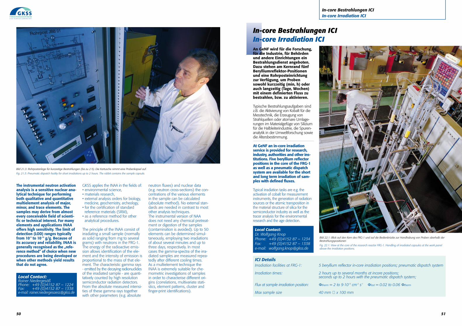
51
In-core Bestrahlungen ICI In-core Irradiation ICI
An GeNF wird für die Forschung,für die Industrie, für Behördenund andere Einrichtungen einBestrahlungsdienst angeboten.Dazu stehen am Kernrand fünfBerylliumreflektor-Positionenund eine Rohrposteinrichtungzur Verfügung, um Probensowohl kurzzeitig (min, h) oderauch langzeitig (Tage, Wochen)mit einem definierten Fluss zubestrahlen, bzw. zu aktivieren.
Typische Bestrahlungsaufgaben sindz.B. die Aktivierung von Kobalt für dieMesstechnik, die Erzeugung vonStrahlquellen oder atomare Umlage-rungen im Materialgefüge von Siliziumfür die Halbleiterindustrie, die Spuren-analytik in der Umweltforschung sowiedie Altersbestimmung.
At GeNF an in-core irradiation service is provided for research,industry, authorities and other ins-titutions. Five beryllium reflectorpositions in the core of the FRG-1as well as a pneumatic dispatchsystem are available for the shortand long term irradiation of sam-ples with defined fluxes.
Typical irradiation tasks are e.g. theactivation of cobalt for measurementinstruments, the generation of radiationsources or the atomic transposition inthe material structure of silica for thesemiconductor industry as well as thetracer analysis for the environmentalresearch and the age detection.
In-core Bestrahlungen ICI In-core Irradiation ICI
ICI DetailsIrradiation facilities at FRG-1: 5 beryllium reflector in-core irradiation positions; pneumatic dispatch system
Irradiation times: 2 hours up to several months at incore positions;seconds up to 2 hours with the pneumatic dispatch system;
Flux at sample irradiation position: Φtherm = 2 to 9·1013 cm-2 s-1 Φfast = 0.02 to 0.06 Φtherm
Max sample size 40 mm ∅ x 100 mm
Local Contact:Dr. Wolfgang KnopPhone: +49 (0)4152 87 – 1234Fax: +49 (0)4152 87 – 1338e-mail: [email protected]
Bild 22.1: Blick auf den Kern des FRG-1 und auf die Bedienbrücke zur Handhabung von Proben oberhalb der Bestrahlungspositionen
Fig. 22.1: View at the core of the research reactor FRG-1. Handling of irradiated capsules at the work panelabove the irradiation positions.
50
The instrumental neutron activationanalysis is a sensitive nuclear ana-lytical technique for performingboth qualitative and quantitativemultielement analysis of major,minor, and trace elements. Thesamples may derive from almostevery conceivable field of scienti-fic or technical interest. For manyelements and applications INAAoffers high sensitivity. The limit ofdetection (LOD) ranges typicallyfrom 10-5 to 10-15 g/g. Because ofits accuracy and reliability, INAA isgenerally recognised as the „refe-rence method“ of choice when newprocedures are being developed orwhen other methods yield resultsthat do not agree.
GKSS applies the INAA in the fields of:• environmental science,• materials research,• external analysis orders for biology,
medicine, geochemistry, archeology,• for the certification of standard reference materials (SRM),
• as a reference method for otheranalytical procedures.
The principle of the INAA consist ofirradiating a small sample (normallyas solid ranging from mg to severalgrams) with neutrons in the FRG-1.The energy of the radioactive emis-sion allows identification of the ele-ment and the intensity of emission isproportional to the mass of that ele-ment. The characteristic gamma rays- emitted by the decaying radionuclidesof the irradiated sample - are quanti-tatively counted by high resolutionsemiconductor radiation detectors.From the absolute measured intensi-ties of these gamma rays togetherwith other parameters (e.g. absolute
neutron fluxes) and nuclear data(e.g. neutron cross-sections) the con-centrations of the various elementsin the sample can be calculated(absolute method). No external stan-dards are needed in contrast to mostother analysis techniques.The instrumental version of NAAdoes not need any chemical pretreat-ment or digestion of the samples(contamination is avoided). Up to 50elements can be determined simul-taneously, employing two irradiationsof about several minutes and up tothree days, respectively. In mostcases the gamma-spectra of the irra-diated samples are measured repea-tedly after different cooling times. As a multielement technique theINAA is extremely suitable for che-mometric investigations of samplesin order to characterise different ori-gins (correlations, multivariate stati-stics, element patterns, cluster andfinger-print identifications).
Bild 21.3: Rohrpostanlage für kurzzeitige Bestrahlungen (bis zu 2 h). Die Kartusche nimmt eine Probenkapsel auf.
Fig. 21.3: Pneumatic dispatch facility for short irradiations up to 2 hours. The rabbit contains the sample capsule.
Local Contact:Rainer NiedergesäßPhone: +49 (0)4152 87 – 1224Fax: +49 (0)4152 87 – 1338e-mail: [email protected]
Institute of Materials ResearchGeesthacht Neutron Facility (GeNF)Max-PIanck-Str. 1 Phone +49 4152 87-1205D-21502 Geesthacht Telefax +49 4152 87-1338e-mail: [email protected]
Application for the use of Neutron Scattering Facilities at FRG-1
Experiment title:
Description of the proposed experiment:(Outline of the scientific background and relevant features of the envisaged experiment; aims of the experiment and results to be achieved; preliminary work carried out)
This is a new proposal a continuation proposal; please attach a report on previous results
Category Material Science Chemistry Biology Physics Engineering Geoscience Medicine Other
Proposer: (title, surname, initials) Address: Phone:Fax:E-mail:
Co-Proposer:
Instrument required: Days required: Requested starting date:
Experiment details: Polarized neutrons Wavelength (nm): Non-polarized neutrons Approx. range of momentum transfer:
For the electronic versionof this form please visit
http://genf.gkss.de
52
ZuständigkeitenResponsibilities
Leiter von GeNF: A. Schreyer
Stellvertreter: J. Vollbrandt
Kleinwinkelstreuanlage SANS-1: R. Willumeit / V. Haramus
Kleinwinkelstreuanlage SANS-2: H. Eckerlebe / K. P. Pranzas
Doppelkristalldiffraktometer DCD: D. Bellmann
Diffraktometer zur Analyse von Resteigenspannungen ARES: P. Staron
Reflektometer TOREMA-2: D. Lott / D. Solina
Reflektometer PNR: D. Solina / D. Lott
Diffraktometer TEX-2: H.-G. Brokmeier (TU Clausthal)
Flugzeit Fourier Spektrometer FSS: H.G. Priesmeyer (Uni Kiel)
Neutronenradiographie GENRA-3: J. Vollbrandt / H.-W. Schmitz
Polarisationsdiffraktometer POLDI: V. Wagner (PTB-Braunschweig) / J. Vollbrandt
Holographie- und Neutronenstreuexperiment HOLONS: R.A. Rupp (Uni Wien) / J. Vollbrandt
Neutronenaktivierungsanalyse R. Niedergesäss
In-core Bestrahlungen W. Knop
Datenerfassung und -auswertung: P. Biemann
Leiter des Forschungsreaktors FRG-1: P. Schreiner
Stellvertreter: W. Knop
Strahlenschutzbeauftragter: H. Renner
Stand: November 2002
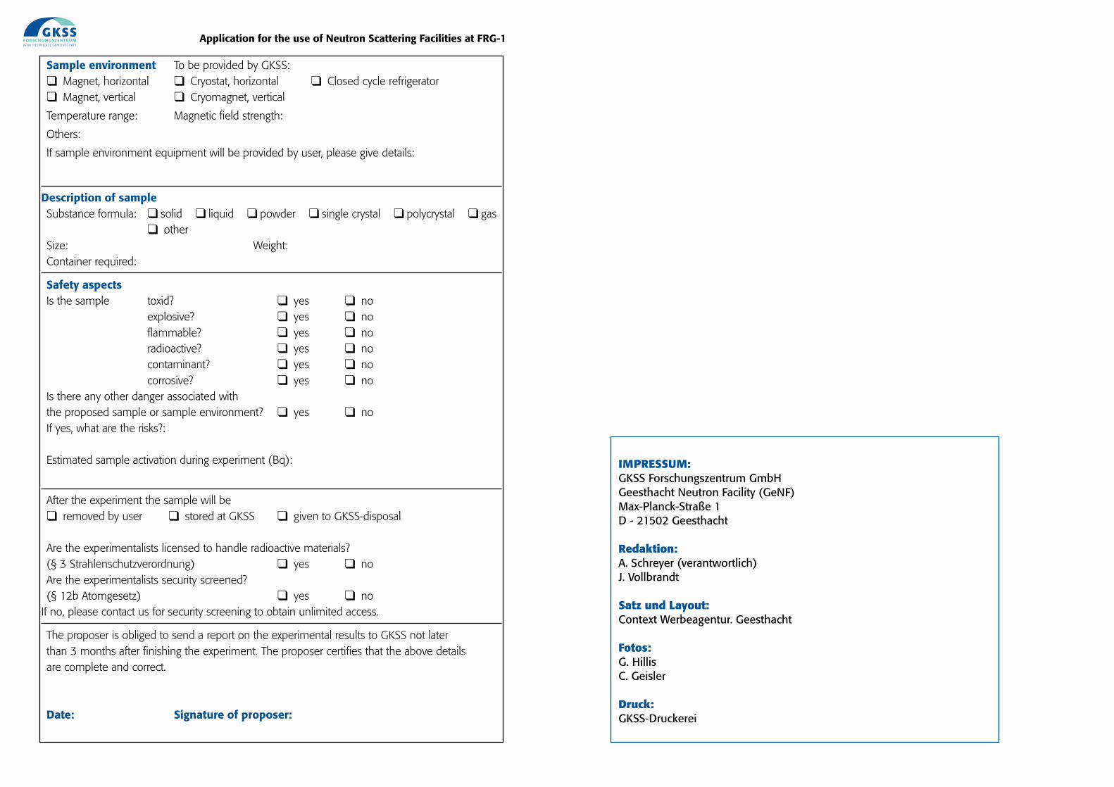
Sample environment To be provided by GKSS: Magnet, horizontal Cryostat, horizontal Closed cycle refrigerator Magnet, vertical Cryomagnet, vertical
Temperature range: Magnetic field strength:
Others:
If sample environment equipment will be provided by user, please give details:
Description of sampleSubstance formula: solid liquid powder single crystal polycrystal gas
otherSize: Weight:Container required:
Safety aspectsIs the sample toxid? yes no
explosive? yes noflammable? yes noradioactive? yes nocontaminant? yes nocorrosive? yes no
Is there any other danger associated withthe proposed sample or sample environment? yes noIf yes, what are the risks?:
Estimated sample activation during experiment (Bq):
After the experiment the sample will be removed by user stored at GKSS given to GKSS-disposal
Are the experimentalists licensed to handle radioactive materials?(§ 3 Strahlenschutzverordnung) yes noAre the experimentalists security screened? (§ 12b Atomgesetz) yes no
If no, please contact us for security screening to obtain unlimited access.
The proposer is obliged to send a report on the experimental results to GKSS not later than 3 months after finishing the experiment. The proposer certifies that the above details are complete and correct.
Date: Signature of proposer:
Application for the use of Neutron Scattering Facilities at FRG-1
IMPRESSUM:GKSS Forschungszentrum GmbHGeesthacht Neutron Facility (GeNF)Max-Planck-Straße 1D - 21502 Geesthacht
Redaktion:A. Schreyer (verantwortlich)J. Vollbrandt
Satz und Layout:Context Werbeagentur. Geesthacht
Fotos:G. HillisC. Geisler
Druck:GKSS-Druckerei